High temperature oxidation/corrosion behavior of metals and alloys under a hydrogen gradient
8
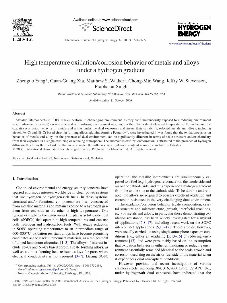
International Journal of Hydrogen Energy 32 (2007) 3770 – 3777 www.elsevier.com/locate/ijhydene High temperature oxidation/corrosion behavior of metals and alloys under a hydrogen gradient Zhenguo Yang ∗ , Guan-Guang Xia, Matthew S. Walker 1 , Chong-Min Wang, Jeffry W. Stevenson, Prabhakar Singh Pacific Northwest National Laboratory, 902 Battelle Blvd, Richland, WA 99352, USA Available online 11 October 2006 Abstract Metallic interconnects in SOFC stacks, perform in challenging environment, as they are simultaneously exposed to a reducing environment (e.g. hydrogen, reformate) on one side and an oxidizing environment (e.g. air) on the other side at elevated temperatures. To understand the oxidation/corrosion behavior of metals and alloys under the dual exposures and assess their suitability, selected metals and alloys, including nickel, Fe–Cr and Ni–Cr based chromia forming alloys, alumina forming Fecralloy , were investigated. It was found that the oxidation/corrosion behavior of metals and alloys in the presence of dual environment can be significantly different in terms of scale structure and/or chemistry from their exposure in a single oxidizing or reducing atmosphere. The anomalous oxidization/corrosion is attributed to the presence of hydrogen diffusion flux from the fuel side to the air side under the influence of a hydrogen gradient across the metallic substrates. 2006 International Association for Hydrogen Energy. Published by Elsevier Ltd. All rights reserved. Keywords: Solid oxide fuel cell; Interconnect; Stainless steel; Oxidation 1. Introduction Continued environmental and energy security concerns have spurred enormous interests worldwide in clean power systems that use hydrogen or hydrogen-rich fuels. In these systems, structural and/or functional components are often constructed from metallic materials and remain exposed to a hydrogen gra- dient from one side to the other at high temperatures. One typical example is the interconnect in planar solid oxide fuel cells (SOFCs) that operate at high temperatures and can use both hydrogen and hydrocarbon fuels. With steady reduction in SOFC operating temperatures to an intermediate range of 600–800 ◦ C, oxidation resistant alloys have become promising candidates as the stack interconnect materials, as a replacement of doped lanthanum chromites [1–3]. The alloys of interest in- clude Fe–Cr and Ni–Cr based chromia scale forming alloys, as well as alumina forming heat resistant alloys for parts where electrical conductivity is not required [3–7]. During SOFC ∗ Corresponding author. Tel.: +1 509 375 3756; fax: +1 509 375 2186. E-mail address: [email protected] (Z. Yang). 1 Now at Carnegie Mellon University, Pittsburgh, PA, USA. 0360-3199/$ - see front matter 2006 International Association for Hydrogen Energy. Published by Elsevier Ltd. All rights reserved. doi:10.1016/j.ijhydene.2006.08.056 operation, the metallic interconnects are simultaneously ex- posed to a fuel (e.g. hydrogen, reformate) on the anode side and air on the cathode side, and thus experience a hydrogen gradient from the anode side to the cathode side. To be durable and reli- able, the alloys are required to possess excellent oxidation and corrosion resistance in the very challenging dual environment. The oxidation/corrosion behavior (scale composition, crys- tal structure and microstructure, growth, interfacial reactions, etc.) of metals and alloys, in particular those demonstrating ox- idation resistance, has been widely investigated for a myriad of applications [5,8–17], including recent work on the SOFC interconnect applications [5,13–17]. These studies, however, were usually carried out using single atmosphere exposure con- ditions (i.e., either an oxidizing [5,13–16] or reducing envi- ronment [17], and were presumably based on the assumption that oxidation behavior in either an oxidizing or reducing envi- ronment essentially remained identical to the scale growth and corrosion occurring on the air or fuel side of the material when it experiences dual atmosphere conditions. However, previous and recent investigation of various stainless steels, including 304, 316, 430, Crofer 22 APU, etc., under hydrogen/air dual exposures have indicated that the
-
Upload
independent -
Category
Documents
-
view
0 -
download
0
Transcript of High temperature oxidation/corrosion behavior of metals and alloys under a hydrogen gradient
International Journal of Hydrogen Energy 32 (2007) 3770–3777www.elsevier.com/locate/ijhydene
High temperature oxidation/corrosion behavior of metals and alloysunder a hydrogen gradient
Zhenguo Yang∗, Guan-Guang Xia, Matthew S. Walker1, Chong-Min Wang, Jeffry W. Stevenson,Prabhakar Singh
Pacific Northwest National Laboratory, 902 Battelle Blvd, Richland, WA 99352, USA
Available online 11 October 2006
Abstract
Metallic interconnects in SOFC stacks, perform in challenging environment, as they are simultaneously exposed to a reducing environment(e.g. hydrogen, reformate) on one side and an oxidizing environment (e.g. air) on the other side at elevated temperatures. To understand theoxidation/corrosion behavior of metals and alloys under the dual exposures and assess their suitability, selected metals and alloys, includingnickel, Fe–Cr and Ni–Cr based chromia forming alloys, alumina forming Fecralloy�, were investigated. It was found that the oxidation/corrosionbehavior of metals and alloys in the presence of dual environment can be significantly different in terms of scale structure and/or chemistryfrom their exposure in a single oxidizing or reducing atmosphere. The anomalous oxidization/corrosion is attributed to the presence of hydrogendiffusion flux from the fuel side to the air side under the influence of a hydrogen gradient across the metallic substrates.� 2006 International Association for Hydrogen Energy. Published by Elsevier Ltd. All rights reserved.
Keywords: Solid oxide fuel cell; Interconnect; Stainless steel; Oxidation
1. Introduction
Continued environmental and energy security concerns havespurred enormous interests worldwide in clean power systemsthat use hydrogen or hydrogen-rich fuels. In these systems,structural and/or functional components are often constructedfrom metallic materials and remain exposed to a hydrogen gra-dient from one side to the other at high temperatures. Onetypical example is the interconnect in planar solid oxide fuelcells (SOFCs) that operate at high temperatures and can useboth hydrogen and hydrocarbon fuels. With steady reductionin SOFC operating temperatures to an intermediate range of600–800 ◦C, oxidation resistant alloys have become promisingcandidates as the stack interconnect materials, as a replacementof doped lanthanum chromites [1–3]. The alloys of interest in-clude Fe–Cr and Ni–Cr based chromia scale forming alloys, aswell as alumina forming heat resistant alloys for parts whereelectrical conductivity is not required [3–7]. During SOFC
∗ Corresponding author. Tel.: +1 509 375 3756; fax: +1 509 375 2186.E-mail address: [email protected] (Z. Yang).
1 Now at Carnegie Mellon University, Pittsburgh, PA, USA.
0360-3199/$ - see front matter � 2006 International Association for Hydrogen Energy. Published by Elsevier Ltd. All rights reserved.doi:10.1016/j.ijhydene.2006.08.056
operation, the metallic interconnects are simultaneously ex-posed to a fuel (e.g. hydrogen, reformate) on the anode side andair on the cathode side, and thus experience a hydrogen gradientfrom the anode side to the cathode side. To be durable and reli-able, the alloys are required to possess excellent oxidation andcorrosion resistance in the very challenging dual environment.
The oxidation/corrosion behavior (scale composition, crys-tal structure and microstructure, growth, interfacial reactions,etc.) of metals and alloys, in particular those demonstrating ox-idation resistance, has been widely investigated for a myriadof applications [5,8–17], including recent work on the SOFCinterconnect applications [5,13–17]. These studies, however,were usually carried out using single atmosphere exposure con-ditions (i.e., either an oxidizing [5,13–16] or reducing envi-ronment [17], and were presumably based on the assumptionthat oxidation behavior in either an oxidizing or reducing envi-ronment essentially remained identical to the scale growth andcorrosion occurring on the air or fuel side of the material whenit experiences dual atmosphere conditions.
However, previous and recent investigation of variousstainless steels, including 304, 316, 430, Crofer 22 APU, etc.,under hydrogen/air dual exposures have indicated that the

Z. Yang et al. / International Journal of Hydrogen Energy 32 (2007) 3770–3777 3771
oxidation/corrosion behavior of the steels under the dualatmosphere exposures could be very different from that un-der a single atmosphere exposure [18–24]. In particular, theoxidation/corrosion behavior observed on the air side ofthe air/hydrogen dual exposure sample differed significantlyfrom the behavior in a single air exposure, while the oxi-dation/corrosion behavior on the hydrogen side of the dualexposure sample was comparable to that when exposed to thehydrogen fuel on both sides. In addition to the hydrogen/airdual exposures, Nakagawa et al. [25], examined the oxidationbehavior of ferritic stainless steels in the steam/air (as wellas (argon + hydrogen)/air) dual environments that simulatedboiler tube exposure conditions in steam turbines. Similarly,an anomalous oxidation was found on the air side of the steelthat exhibited a significantly increased oxidation rate, due tohydrogen permeation from the (argon + hydrogen) side or thesteam side to the airside of stainless steels. This paper reportsand summarizes the oxidation behavior of Fe–Cr, Ni–Cr andFe–Cr–Al based alloys along with that of nickel.
2. Experimental
The materials under investigation are Fe–Cr based chro-mia forming ferritic stainless steels, Crofer 22 APU and 430,Fe–Cr–Al based alumina forming alloy Fecralloy�, Ni–Crbased chromia forming alloy HAYNES� 230�, and nickel(Ni-200, 99.5% purity). The nominal compositions of thealloys are listed in Table 1.
The oxidation/corrosion tests on metals and alloys in a dualenvironment were carried out in either planar or tubular config-urations. For materials such as Crofer 22 APU and HAYNES�
230�, they were not available in thin wall tube form. The dualenvironment tests were conducted on a circular disk specimen(0.5 mm thick, 25 mm diameter) that was sealed to the end of anE-brite tube using BNi-2 braze, a Ni-based braze. After braz-ing, a helium leak test was performed to assure that the metaldisk was hermetically sealed to the E-brite tube. After assur-ance of hermetic sealing, the E-brite tube and the metal diskwere placed in a test-stand, along with two coupons that wouldbe exposed to air or fuel only. Thus the set up allows for si-multaneous testing of separate alloy coupons in three differentatmospheres (air, fuel and dual atmospheres). Details of the ex-perimental apparatus and sample preparation can be referred
Table 1Nominal compositions of oxidation resistant alloys
Alloys Nominal composition (wt%)
Fe Ni Cr Mn Al Si W Mo Others
AISI 430 Bal — 17.0 0.50 0.51 — — —Crofer 22 APU Bal — 22.8 0.6 0.05 — — 0.08 Ti, 0.06 LaFecralloy� Bal — 22.0 — 5.0 — — — 0.1 Zr, 0.1 YHAYNES� 230� 3.0 Bal 22.0 0.50 0.40 14.0 2.0 —
Note: AISI 430 and E-brite were provided by Alleghany Ludlum; Crofer 22 APU by ThyssenKrupp VDM; Fecralloy� from GoodFellow, HAYNES� 230�
from Haynes International Inc.
to early publications [18,19]. Moist hydrogen (with ∼ 3% mois-ture) as the simulated fuel was introduced into the furnace byflowing hydrogen through a water bubbler at room temperature.Ambient air (∼ 1% H2O) or moist air (3%H2O) was introducedinto the furnace using a Tetratec AP200 pump. Alternatively,for metals or alloys (such as Ni) available in tube form, the dualatmosphere tests were carried out by flowing moist hydrogenthrough their tubes. Details regarding the dual exposures testsusing the tube form can be found in an early publication [20].
The surfaces of the tested samples were first analyzed ona Philips XRG-3100 X-ray Generator with Cu K� radiationand then under a JEOL scanning electron microscope (model5900LV) equipped with energy-dispersive spectroscopic (EDS)capability at an operating voltage of 20 kV. After surface analy-sis, the coupon samples were subsequently cross-sectioned forfurther SEM analyses. In addition, JEOL 2010 high resolutiontransmission electron microscopy (HRTEM) equipped with anEDS analytical system was also used to study the scales grownat high temperatures under different exposure conditions. A thinfoil cross-section for the TEM analysis was prepared by stan-dard tripod wedge polishing, followed by Ar-ion beam thinningfor electron transparency. The JEOL TEM 2010 microscopewas operated on a voltage of 200 keV, with a specified point-to-point resolution of 0.194 nm. Composition of the grain wasanalyzed using the EDS with an energy resolution of 136 eV(Oxford link EDS spectrometer running ISIS). Due to the thinsection of the specimen, the absorption effect was ignored dur-ing the quantification for the spectra.
3. Results and discussion
3.1. Ferritic stainless steels
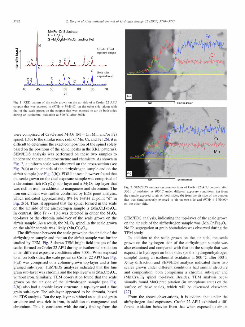
As an example of chromia forming ferritic stainless steels,the oxidation behavior of Crofer 22 APU under the hydro-gen/air dual environment is presented and summarized here.Fig. 1 shows the XRD pattern of the scale grown on the airsideof the sample that was exposed to moist hydrogen on the otherside (or air/hydrogen sample), along with that of the sample thatwas exposed to air on both sides (or air/air sample) during anisothermal oxidation at 800 ◦C after 300 h. The XRD analysis,as shown in Fig. 1(a), indicated that both the scale grown on theair side of the air/hydrogen sample and that on the air/air sample
3772 Z. Yang et al. / International Journal of Hydrogen Energy 32 (2007) 3770–3777
40 45 50 55 60 65 70
2θ
Inte
nsi
ty (
a.u
.)
M=Fe-Cr Substrate;C = Cr2O3S =M3O4(M=Mn,Cr, and/or Fe)
Both sidesexposed to air
Airside of dualexposure sample
M
M
S
S SSS
SS
S
C CC
C C
C
C
CC
CCC
Fig. 1. XRD pattern of the scale grown on the air side of a Crofer 22 APUcoupon that was exposed to (97H2 + 3%H2O) on the other side, along withthat of the scale grown on the coupon that was exposed to air on both sidesduring an isothermal oxidation at 800 ◦C after 300 h.
were comprised of Cr2O3 and M3O4 (M = Cr, Mn, and/or Fe)spinel. (Due to the similar ionic radii of Mn, Cr, and Fe [26], it isdifficult to determine the exact composition of the spinel solelybased on the positions of the spinel peaks in the XRD patterns).SEM/EDS analysis was performed on these two samples tounderstand the scale microstructure and chemistry. As shown inFig. 2, a uniform scale was observed on the cross-section (seeFig. 2(a)) at the air side of the air/hydrogen sample and on theair/air sample (see Fig. 2(b)). EDS line scan however found thatthe scale grown on the dual exposure sample was comprised ofa chromium rich (Cr2O3) sub-layer and a M3O4 top-layer thatwas rich in iron, in addition to manganese and chromium. Theiron enrichment was further confirmed by EDS point analysis,which indicated approximately 8% Fe (wt%) at point “d” inFig. 2(b). Thus, it appeared that the spinel formed in the scaleon the air side of the air/hydrogen sample is (Mn,Cr,Fe)3O4.In contrast, little Fe (< 1%) was detected in either the M3O4top-layer or the chromia sub-layer of the scale grown on theair/air sample. As a result, the M3O4 spinel in the scale grownon the air/air sample was likely (Mn,Cr)3O4.
The difference between the scale grown on the air side of theair/hydrogen sample and that on the air/air sample was furtherstudied by TEM. Fig. 3 shows TEM bright field images of thescales formed on Crofer 22 APU during an isothermal oxidationunder different exposure conditions after 300 h. When exposedto air on both sides, the scale grown on Crofer 22 APU (see Fig.3(a)) was comprised of a column-grown top-layer and a finegrained sub-layer. TEM/EDS analyses indicated that the finegrain sub-layer was chromia and the top-layer was (Mn,Cr)3O4,without iron. Similarly, TEM observation found that the scalegrown on the air side of the air/hydrogen sample (see Fig.2(b)) also had a double layer structure, a top-layer and a finegrain sub-layer. The sub-layer appeared to be chromia, basedthe EDS analysis. But the top-layer exhibited an equiaxed grainstructure and was rich in iron, in addition to manganese andchromium. This is consistent with the early finding from the
Fig. 2. SEM/EDS analysis on cross-sections of Crofer 22 APU coupons after300 h of oxidation at 800 ◦C under different exposure conditions: (a) fromthe sample exposed to air on both sides; (b) from the air side of the couponthat was simultaneously exposed to air on one side and (97H2 + 3%H2O)on the other side.
SEM/EDS analysis, indicating the top-layer of the scale grownon the air side of the air/hydrogen sample was (Mn,Cr,Fe)3O4.No Fe segregation at grain boundaries was observed during theTEM study.
In addition to the scale grown on the air side, the scalegrown on the hydrogen side of the air/hydrogen sample wasalso examined and compared with that on the sample that wasexposed to hydrogen on both sides (or the hydrogen/hydrogensample) during an isothermal oxidation at 800 ◦C after 300 h.X-ray diffraction and SEM/EDS analysis indicated these twoscales grown under different conditions had similar structureand composition, both comprising a chromia sub-layer and(Mn,Cr)3O4 spinel top-layer. Besides, TEM analysis occa-sionally found MnO precipitation (in amorphous state) on thesurface of these scales, which will be discussed elsewhere[27].
From the above observations, it is evident that under theair/hydrogen dual exposures, Crofer 22 APU exhibited a dif-ferent oxidation behavior from that when exposed to air on
Z. Yang et al. / International Journal of Hydrogen Energy 32 (2007) 3770–3777 3773
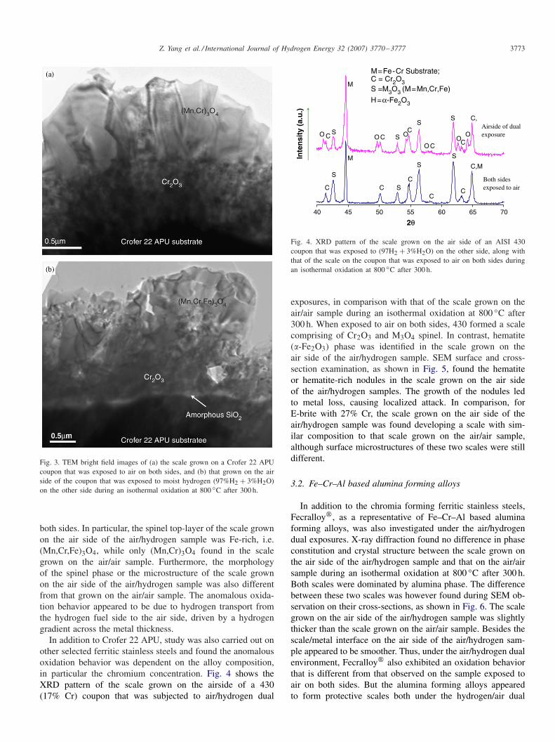
Fig. 3. TEM bright field images of (a) the scale grown on a Crofer 22 APUcoupon that was exposed to air on both sides, and (b) that grown on the airside of the coupon that was exposed to moist hydrogen (97%H2 + 3%H2O)on the other side during an isothermal oxidation at 800 ◦C after 300 h.
both sides. In particular, the spinel top-layer of the scale grownon the air side of the air/hydrogen sample was Fe-rich, i.e.(Mn,Cr,Fe)3O4, while only (Mn,Cr)3O4 found in the scalegrown on the air/air sample. Furthermore, the morphologyof the spinel phase or the microstructure of the scale grownon the air side of the air/hydrogen sample was also differentfrom that grown on the air/air sample. The anomalous oxida-tion behavior appeared to be due to hydrogen transport fromthe hydrogen fuel side to the air side, driven by a hydrogengradient across the metal thickness.
In addition to Crofer 22 APU, study was also carried out onother selected ferritic stainless steels and found the anomalousoxidation behavior was dependent on the alloy composition,in particular the chromium concentration. Fig. 4 shows theXRD pattern of the scale grown on the airside of a 430(17% Cr) coupon that was subjected to air/hydrogen dual
40 45 50 55 60 65 70
H=α-Fe2O3
M
M
C
C
C
C
C
C
C
CC
C,M
C,
S
CO
OO
OO
S
S
S
S
S
SSO
2θ
Inte
nsi
ty (
a.u
.)
M=Fe-Cr Substrate;C = Cr2O3S =M3O3 (M=Mn,Cr,Fe)
Both sidesexposed to air
Airside of dualexposure
Fig. 4. XRD pattern of the scale grown on the air side of an AISI 430coupon that was exposed to (97H2 + 3%H2O) on the other side, along withthat of the scale on the coupon that was exposed to air on both sides duringan isothermal oxidation at 800 ◦C after 300 h.
exposures, in comparison with that of the scale grown on theair/air sample during an isothermal oxidation at 800 ◦C after300 h. When exposed to air on both sides, 430 formed a scalecomprising of Cr2O3 and M3O4 spinel. In contrast, hematite(�-Fe2O3) phase was identified in the scale grown on theair side of the air/hydrogen sample. SEM surface and cross-section examination, as shown in Fig. 5, found the hematiteor hematite-rich nodules in the scale grown on the air sideof the air/hydrogen samples. The growth of the nodules ledto metal loss, causing localized attack. In comparison, forE-brite with 27% Cr, the scale grown on the air side of theair/hydrogen sample was found developing a scale with sim-ilar composition to that scale grown on the air/air sample,although surface microstructures of these two scales were stilldifferent.
3.2. Fe–Cr–Al based alumina forming alloys
In addition to the chromia forming ferritic stainless steels,Fecralloy�, as a representative of Fe–Cr–Al based aluminaforming alloys, was also investigated under the air/hydrogendual exposures. X-ray diffraction found no difference in phaseconstitution and crystal structure between the scale grown onthe air side of the air/hydrogen sample and that on the air/airsample during an isothermal oxidation at 800 ◦C after 300 h.Both scales were dominated by alumina phase. The differencebetween these two scales was however found during SEM ob-servation on their cross-sections, as shown in Fig. 6. The scalegrown on the air side of the air/hydrogen sample was slightlythicker than the scale grown on the air/air sample. Besides thescale/metal interface on the air side of the air/hydrogen sam-ple appeared to be smoother. Thus, under the air/hydrogen dualenvironment, Fecralloy� also exhibited an oxidation behaviorthat is different from that observed on the sample exposed toair on both sides. But the alumina forming alloys appearedto form protective scales both under the hydrogen/air dual

3774 Z. Yang et al. / International Journal of Hydrogen Energy 32 (2007) 3770–3777
Fig. 5. (a) Surface and (b) cross-section SEM images of an AISI 430 couponat the air side after 300 h of oxidation at 800 ◦C, with one side exposed toair and the other to moist hydrogen (97H2 + 3%H2O).
exposures and air single exposure. Thus the Fe–Cr–Al basedalloys have been proposed as construction materials for hightemperature fuel cell containers that, like the interconnects, areexposed to a dual environment during the fuel cell operation[28]. The anomalous oxidation behavior of Fecralloy� on theair side of the air/hydrogen sample is tentatively attributed to ahydrogen flux from the hydrogen fuel side to the air side.
3.3. Ni–Cr based chromia forming alloys
In addition to the Fe–Cr based chromia forming ferriticstainless steels and Fe–Cr–Al based alumina forming alloys,HAYNES� 230�, as an example of Ni–Cr based chromia form-ing alloys, was also investigated under the air/hydrogen dualexposures. Fig. 7 shows the XRD pattern of the scale grownon the air side of the air/hydrogen sample, along with thatof the scale grown on the air/air sample during an isothermaloxidation at 800 ◦C after 300 h. Indexing the XRD patternsfound NiO phase, in addition to chromia and spinel phases,
Fig. 6. SEM images of cross-sections of Fecralloy� after oxidation at 800 ◦Cfor 300 h under different exposure conditions: (a) from the coupon that wasexposed to moist air (3%H2O) on both sides; (b) from the air side couponthat was simultaneously exposed to moist air on one side and moist hydrogen(97%H2 + 3%H2O) on the other side.
in the scale on the air/air sample, but NiO unnoticeable inthe scale grown on the airside of the air/hydrogen sample.Surface SEM observation, as shown in Fig. 8, revealed thatthe surface microstructures of these two scales were also dif-ferent. Further SEM/EDX analysis on the cross-sections con-firmed that the scale grown on the air/air sample occasionallyexhibited a double layer microstructure with NiO forming thetop-layer. Porosity was noticeable along the scale/metal inter-face. In comparison, the scale grown on the air side of theair/hydrogen sample contained no NiO and was well bonded tothe substrate. No porosity was observable along the scale/metalinterface.
Thus similar to the chromia forming ferritic stainless steelsand alumina forming Fecralloy�, the oxidation/corrosion be-havior of the Ni–Cr based chromia forming alloy on the airside of the air/hydrogen sample was different from that whenexposed to air on both sides. But with the Ni–Cr base as itssubstrate, HAYNES� 230� was not susceptible to localized

Z. Yang et al. / International Journal of Hydrogen Energy 32 (2007) 3770–3777 3775
32 36 40 44 48 52 56 60
G: (Mo,W,Cr) carbides
C
C
C
C
CC
C
C
SC
SS
S
SS
S
S
C
N
N
MM
G
G
G
G
G
G
N: NiO
2θ
Inte
nsi
ty (
a.u
.)M: Ni-Cr-Substrate
C: Cr2O3S: M3O4
Both sidesexposed to air
Airside of dual exposure
M=Mn,Cr,Ni,Fe, etc.
Fig. 7. X-ray diffraction pattern of the scale grown on the airside of a HAYNES� 230� coupon that was exposed to moist hydrogen (97H2 + 3%H2O) onthe other side, along with that of the scale grown on the sample exposed to air on both sides during an isothermal oxidation at 800 ◦C after 300 h.
Fig. 8. Surface SEM images of HAYNES� 230� after 300 h of oxidation at 800 ◦C under different exposure conditions: (a) from the sample exposed toambient air (1%H2O) on both sides; (b) from the air side of the sample that was exposed to moist hydrogen (97%H2 + 3%H2O) on the other side.
nodular growth as observed in iron based chromia-forming al-loys under the air/hydrogen dual exposures. Instead, a uniform,well-adherent scale formed on the air side of the air/hydrogensample after 300 h at 800 ◦C. Less-detrimental effects of theair/hydrogen dual exposures on the scale stability on the Ni–Crbased alloys in comparison with the Fe–Cr based alloys appearsimilar to those of water vapor, as observed by Pint [29]. Thisis postulated to be due to Ni/NiO healing of any nodule growthby cutting off iron oxide formation and a higher Cr concentra-tion in the alloy that makes it difficult to develop localized ironoxide nodule.
3.4. Nickel metal
To develop a mechanistic understanding on the anomalousoxidation/corrosion behavior, nickel metal, as a simple metal-lic system, was selected and studied under both the single anddual exposure conditions utilizing the tubular experimental setup. Fig. 9 shows SEM cross-section of the outer wall of the Nitube exposed to a dual atmosphere in comparison to that of thetube that was exposed to ambient air on both inside and out-side during an isothermal oxidation at 800 ◦C after 100 h. Forthe sample exposed to air only, porosity was found along the

3776 Z. Yang et al. / International Journal of Hydrogen Energy 32 (2007) 3770–3777
Fig. 9. Cross-section SEM images of HAYNES� 230� after 300 h of oxidation at 800 ◦C under different exposure conditions: (a) from the sample that wasexposed to air on both sides; (b) from the air side of the sample that was exposed to moist hydrogen (97%H2 + 3%H2O) on the other side.
Fig. 10. Cross-section SEM images of the outer wall of Ni-tubes after 100 h of oxidation at 800 ◦C under different exposure conditions: (a) to air both insideand outside; (b) to air outside, while flowing inside with moist hydrogen (97%H2 + 3%H2O).
interface between the NiO scale and Ni-substrate during SEMobservation, as shown in Fig. 7(a). It is well documented [10]that NiO growth is dominated by Ni cation outward diffusion,creating porosity at the scale/metal interface. Under the dualexposures, however, the porosity disappeared along the NiO/Niinterface, as shown in Fig. 7(b). And the NiO scale was wellbonded to the Ni metal substrate. Further SEM observation alsofound that the NiO scale grown on the tube exposed to the dualatmospheres was slightly thicker than the NiO scale grown onthe tube exposed to air both inside and outside. Again, it is pos-tulated that the changes in the scale morphology is influencedby the presence of hydrogen and possibly transport throughthe tube wall that affected the NiO scale growth (Fig. 10).
4. Summary
When metals and alloys were simultaneously exposed to airon one side and hydrogen fuel on the other, the scale grown on
the air side differed from the scale observed during exposure to asingle air atmosphere only. In contrast, no substantial differencewas observed between the scales grown on the fuel side andthe scales grown on coupons exposed to a single hydrogenexposure. The anomalous scale growth on the air side of dualexposure coupons was dependent on the composition of thealloys.
The Fe–Cr based ferritic stainless steels, in particular thosewith a relative low Cr%, tended to be susceptible to a localizedattack on the air side via nodular scale growth. For example,AISI430, with 17% Cr, formed Fe2O3 hematite nodules on theair side of the air/hydrogen sample during isothermal heating at800 ◦C, while the spinel top-layer of the scale on the air side ofCrofer 22 APU (23%Cr) was merely enriched in iron and growninto a different morphology from that on the air/air sample. Asthe alumina forming Fecralloy�, the dual exposures led to aslightly thicker scale and a smoother scale/metal interface onthe air side of the air/hydrogen sample than those on the air/air

Z. Yang et al. / International Journal of Hydrogen Energy 32 (2007) 3770–3777 3777
sample. But the alumina scale formed on Fecralloy� appearedto be still protective against the dual exposures.
For Ni–Cr based alloys, the dual exposures also resulted in adifferent oxidation/corrosion behavior from that in a single airexposure. But unlike the ferritic chromia forming alloys, nickeland the Ni–Cr based alloys formed a uniform, well adherentscale on the air side of the air/hydrogen sample. Similarly, less-detrimental effects of the air/hydrogen dual exposures on thescale growth were found on Ni metal.
The anomalous oxidation behavior of the metal and alloyson the air side of the air/hydrogen dual exposure samples arecurrently attributed to the transport of hydrogen through themetal substrate from the fuel side to the air side, and its sub-sequent presence at the oxide scale/metal interface and in thescale. Further work is needed to achieve a mechanistic under-standing of this behavior.
Acknowledgments
The authors would like to thank Nat Saenz and Shelly Carl-son for their assistance in metallographic and SEM samplepreparation, and Jim Coleman for SEM analysis. The authorsalso thank Lee Flowers of Haynes International, Larry Paulof ThyssenKrupp VDM USA, Inc., and Jim Rakowski of Al-legheny Ludlum Inc., for technical input and for supplying thealloy materials used in this work. The work summarized in thispaper was funded as part of the Solid-State Energy ConversionAlliance (SECA) Core Technology Program by the U.S. De-partment of Energy’s National Energy Technology Laboratory(NETL). The authors would like to acknowledge helpful discus-sions with Wayne Surdoval, Lane Wilson, and Travis Schulz ofNETL, and Professor G.H. Meier of University of Pittsburgh.PNNL is operated by Battelle Memorial Institute for the U.S.Department of Energy under Contract DE-AC06-76RLO 1830.
References
[1] Minh NQ. J Am Ceram Soc 1994;76:563.[2] Steele BCH. Nature (London) 2001;414:345.
[3] Quadakkers WJ, Piron-Abellan J, Shemet V, Singheiser L. Mater HighTemp 2003;20:115.
[4] Yang Z, Weil KS, Paxton DM, Stevenson JW. J Electrochem Soc2003;150:A1188.
[5] Tietz F. In: Singhal SC, Kendal K, editors. High-temperature solid oxidefuel cells: fundamentals, designs and applications. The Netherlands:Elsevier Science; 2004. p. 173.
[6] Kofstad P, Bredesen R. Solid State Ionics 1992;52:69.[7] Zhu WZ, Deevi SC. Mater Res Bull 2003;38:957.[8] Young DJ, Watson S. Oxid Met 1985;44:239.[9] Gesmundo F, Gleeson B. Oxid Met 1985;44:211.
[10] Kofstad P. High-temperature corrosion. Amsterdam: Elsevier; 1988.[11] Gulbranssen EA, Copen TP. Nature 1960;186:959.[12] Ryan MP, Williams DE, Chater RJ, Hutton BM, McPhail DS. Nature
2002;415:770.[13] Quadakkers WJ, Malkow T, Piron-Abellan J, Flesch U, Shemet V,
Singheiser L. In: McEvoy A, editor. Proceedings of the fourth Europeansolid oxide fuel cell forum. Switzerland: European SOFC Forum; 2000.p. 827.
[14] Huang K, Hou PY, Goodenough JB. Solid State Ionics 2000;129:237.[15] Malkow T, Crone UVD, Laptev AM, Koppitz T, Breuer U, Quadakkers
WJ. In: Stimming U, Singal SC, Tagawa H, editors. Proceedings ofthe fifth international symposium solid oxide fuel cells, PV 97-40.Pennington, NJ: The Electrochemical Society; 1997. p. 1244.
[16] England DM, Virkar AN. J Electrochem Soc 1999;146:3196.[17] England DM, Virkar AN. J Electrochem Soc 2001;148:A330.[18] Yang Z, Walker MS, Singh P, Stevenson JW. Electrochem Solid State
Lett 2003;6:B35–7.[19] Yang Z, Walker MS, Singh P, Stevenson JW, Norby T. J Electrochem
Soc 2004;151:B669–78.[20] Sing P, Yang Z, Viswanathan V, Stevenson JW. J Mater Perform Eng
2004;13:287.[21] Yang Z, Xia G-G, Singh P, Stevenson JW. Solid State Ionics
2005;176:1495–503.[22] Ziomek-Moroz M, Covino BS, Cramer SD, Holcomb GR, Bullard SJ,
Singh P. In: Corrosion 2004. Houston, TX: NACE International; 2004.[23] Holcomb GR, Ziomek-Moroz M, Cramer SD, Covino Jr BS, Bullard
SJ. J Mater Perform Eng, 2006;15:404.[24] Singh P, Paetsch L, Maru HC, in Corrosion 86/87, Paper No. 86, NACE,
Houston, Tx, 2006.[25] Nakagawa K, Matsunaga Y, Yanagisawa T. Mater High Temp 2003;20:67.[26] Shannon RD. Acta Cryst 1976;A32:751.[27] Yang Z. In preparation.[28] Judkins RR, Singh P, Sikka VK. US Patent 6114058, 2000.[29] Pint BA. J Eng Gas Turbine Power-Trans ASME 2006;128:370.