REVIEW: COPPER BASED SHAPE MEMORY ALLOY FOR REINFORCING INTO ADAPTIVE COMPOSITES
Upload
khangminh22Category
view
1download
0
Shape Memory Alloys
Arnhild Jacobsen and Nora Borghildur KristjansdottirTFY 4205 Functional Materials
(Dated: October 25, 2007)
Shape Memory alloys (SMAs) are materials that have the ability to return to a previousshape or dimension, when subjected to an appropriate thermomechanical procedure. This ismade possible by a solid state phase transformation. In the present text we highlight the the-ory behind the solid state phase transformations that take place in shape memory materials.We then use this to explain the origin of the shape memory effect and superelasticity.
The fabrication of SMAs is essential for the properties of the alloy, therefore we havegone through the general fabrication method for the most used SMAs, the NiTi alloys. Theremarkable properties of shape memory alloys have motivated different applications in manyfields of science, engineering and even art, and in the last section of this text, we mention afew of the exciting applications.
PACS numbers:
I. INTRODUCTION
Shape memory alloys are fascinating materials with unique properties
such as shape memory effect and super elasticity. These properties make
them very interesting for applications in many different fields of science and
engineering.
A higher quality and reliability in combination with a significant decrease
in price has made SMAs more and more common. As a result, SMAs have
passed their introductionary state and are now enjoying a significant growth.
They are an important part of the development of smart materials. A new
and highly interesting field.
There are three main kinds of commercial SMAs: CU-based alloys, Fe-
based alloys and Ni-Ti alloys. Since Ni-Ti alloys are superior compared to
the other SMAs for most commercial applicaitons, we will here, especially
in the application part, focus mainly on these alloys.
This text consist of three main parts. The first section includes a thor-
ough description of the martensitic phase transformation, the basis of the
shape memory effect and superelasticity. The second section focuses on the
different steps of the traditional fabrication method of Ni-Ti SMAs. In the
last section we describe representative SMA applications from many differ-
ent fields, in order to show the diversity and possibilities these materials
represent.

2
II. THE THEORY BEHIND SHAPE MEMORY ALLOYS.
A. Martensite and Austenite
The unique properties of SMAs are made possible through a solid state
phase change. Instead of solidifying on cooling or liquifying on heating, a
solid state phase change means that the molecules in the alloy remain closely
packed after the phase transformation and the specimen remains solid. A
shape memory alloy therefore has two possible solid state phases; the austen-
ite (or the parent phase) and the martensite phase. Martensite is the phase
which exists at lower temperatures. It forms from austenite by displacive
transformation when the temperature is lowered below some characteristic
temperature Ms. The atoms in the lattice then move cooperatively from
their original phase to the martensic phase. While the austenite has a cubic
structure, the martensite has a lower symmetry structure and is relatively
soft and easily deformed(cite int?). The characteristic temperatures for a
shape memory alloy phase transition are listed in table I.
TABLE I: Characteristic temperatures of shape memory alloys
Ms martensite start temperature upon cooling.Mf martensite finish temperature upon cooling.As reverse transformation start temperature upon heating.Af reverse transformation finish temperature upon cooling.
Above this temperature martensite becomes completely unstable.
Even though the relative displacements of the atoms are small compared
to the inter-atomic distance, a macroscopic shape change occurs. This is
shown in Fig. 1 where the two distinct solid phases of a CuAlNi-alloy are
shown. The platelike structure of the martensite is seen in contrast to the
smooth structure of the austenite. In the following sections we will describe
the martensitic phase transformation in more detail, we will look closer at
the crystal structure of austenites, and show why plates may be internally
twin related in the martensite phase.12.

3
FIG. 1: Optical micrograph of a CuAlNi-alloy. The smooth, light surface of theaustenite is contrasted by the platelike martensite.
1. Crystal Structure of the Parent Phase
Most SMAs have superlattice structures where the sublattices of the par-
ent phases are body centered cubic, BCC. They are classified as β-phase
alloys and have an electron per atom ratio e/a close to 1.5. There are
also exceptional cases of alloys that have a disordered lattice in the parent
phase. Examples of these disordered alloys with face-centered cubic lattices
are In-Tl, In-Cd, Mn-Cu and all ferrous alloys (except Fe3Pt)3.
The β-phase alloys are divided into two types according to the superlat-
tice or composition ratio. The β2 phase, shown in figure 2, has a B2 super-
lattice (almost BCC, but with different atoms)(Cs-Cl) with about 50 : 50
composition ratio. The β1 phase has a composition ratio of 25 : 75 and a
Fe3Al-type DO3 superlattice. The crystal structure of the β2-phases shown
in figure 3. The tree dimensional structure is shown in (a), (b) illustrates
the atomic arrangement in the (110) plane, while (c) shows the arrangement
in the (110) plane above or below the plane in (b). It becomes clear that the
cubic structure in (a) can be obtained by alternate stacking of the planes
shown in (b) and (c)3.

4
B. Phase transformation
1. The martensitic transformation
The structural change of the austenite occurs by the cooperative move-
ment of atoms relative to their neighbors and is termed displacive trans-
formation. It is dominated by homogeneous lattice-distortive strains, that
converts the Bravais lattice of the parent phase into a different one.
The martensitic phase can grow at very low temperatures (Fe-34Ni-0.22C
wt% has a Ms temperature at around 4K), it can also grow at speeds that
can be as high as the speed of sound in the same material2. Although this
does not apply for all SMAs, it makes it clear that the phase transformation
cannot be diffusive, as the combination of the often rather low temperature
and high speed is inconsistent with diffusion during transformation. The
reason to make such a point out of this is to come to some conclusions
about the interface plane between the austenite and martensitic phase. As
the transformation is diffusionless, it is necessary that the interface has a
structure that does not require diffusion, i.e. that it is a glissile interface.
FIG. 2: The crystal structure of the B2 type structure or β2 parent phase. In (a)we see the unit cell, in (b) the (110) plane is depicted, while (c) shows the (110)plane above and below the plane in (b).
FIG. 3: The crystal structure of DO3 type structure or β1 parent phase. The unitcell is shown in (a), in (b) we see the (110) plane, while (c) shows the (110) planeabove and below the plane in (b). Picture from Miyazaki

5
Only coherent or semicoherent interfaces comply to this requirement2.
If an interface is semicoherent it will contain dislocations that periodi-
cally correct the misfit at the interface. If there are more than one array of
dislocations, they can interfere and lead to the formation of jogs that render
the interface sessile. This leads to a requirement for a semicoherent interface
to be diffusionless; it cannot contain more than one array of dislocations.
The interface must also include one line that remains undistorted and un-
rotated by the transformation strain, an invariant line that defines the line
vector of the interfacial dislocations2.
In 1924 Bain suggested that the change in crystal structure upon
martensitic transformation from face-centered cubic parent phase into body-
centered cubic martensitic phase could be achieved by a simple homogeneous
deformation. The deformation is a result of a strain, the Bain strain matrix
B, which transforms a vector y, into a new vector x 12.
x = B · y (1)
Although most SMAs in the austenite phase have a BCC structure, the Bain
transformation is so simple and general that it will suffice as a description of
a martensitic phase transition. It is a displacive transformation where the
lattices of the parent and product phases are intimately related. In Fig. 4
one can clearly see both the crystal structure of the parent phase and the
crystal strucure of the product phase before deformation. The austenite is
represented by a face-centered cubic unit cell which can also be represented
by a body-centered tetragonal unit cell. The BCT unit cell can be deformed
upon a contraction along the a3 axis and expanded along the a1 and a2 axes
into a body-centered cubic unit cell of the product phase. We have chosen
the a1-axis as the c-axis of the martensite, but we could equally choose the
a2 or a3 axes as the c axis. This leads to three possible correspondence
variants in the FCC to BCC transformation. The phase transformation
shows that the Bain strain consists of a contraction along one axis and
identical expansions along the other two axes. It can be seen from the figure
that the relationship between the lattice of the austenite and martensite is
[001]fcc|| [001]bcc [110]fcc|| [100]bcc [110]fcc|| [010]bcc. (2)

6
FIG. 4: The austenite lattice shown in (a) is deformed by the Bain strain and istransformed into the BCC martensite lattice shown in (d).
However, this is not observed in experiments. It is still worthwhile examining
if the described Bain strain actually leaves at least one line invariant, as this
is necessary for the transition to be diffusionless. If the parent phase is
represented as a sphere as in Fig. 5, the Bain strain will deform the sphere
into an ellipsoid of revolution. It is clear that there are no lines that are left
undistorted or unrotated in this figure. However, the lines wx and yz are not
distorted but only rotated to the new positions wx and yz. If the Bain strain,
B, is combined with a rigid body rotation R, the result is an invariant-line
strain as yz and yz is brought into coincidence. The rotation required to do
this also corrects the Bain orientation into what is observed experimentally.
But what is also observed is that the habit plane is left both undistorted
and unrotated, i.e. we have an invariant-plane strain. Unfortunately, there
is no rotation that can turn B into an invariant-plane strain - this would
require two non parallel invariant lines as illustrated in Fig. 5 (c).
The problem can be expressed in a more compact form; upon transforma-
tion a deformation which consists of a lattice invariant strain and a lattice
rotation occurs, but the end result is macroscopically represented by an
invariant plane strain. However, on applying an invariant-plane strain, the
result is a wrong crystal structure. The problem is solved by the phenomeno-
logical theory of martensite crystallography(ref, maybe?). If a second shear
P2 is combined with the first plane-invariant shear, P1, then the correct

7
FIG. 5: Illustration of the effect of the Bain strain. When the austenite is un-deformed, it is represented as a sphere of diameter wx = yz in three dimensions(a). The strain transforms the parent phase into an ellipsoid of revolution (b). Aninvariant-line strain is obtained by combining the Bain strain with a rigid bodyrotation through an angle θ (c).
structure is obtained, but the wrong shape since
P1P2 = RB. (3)
But the discrepancies are all resolved if the shape-changing effect of P2 is
FIG. 6: Illustration of the phenomenological theory of martensite crystallography.
cancelled macroscopically by an inhomogeneous lattice-invariant deforma-
tion, which may be slip or twinning, see Fig. 6. And these are observed
features of the martensite crystallography. The orientation relationship is

8
predicted by deducing the rotation needed to change the the Bain strain into
an invariant-line strain and we get a substructure in plates of martensite.
The strain energy in the martensitic transformation is minimized when the
interface between the martensite variant and parent phase becomes an un-
rotated and undistorted plane. In order to form such a martensite variant it
is necessary to introduce a lattice invariant shear such as twins, dislocations
or stacking faults. The lattice invariant shear is generally twinning, which
is reversible, in the shape memory alloys. Two twin crystals are generally
related by a symmetry operation with respect to a mirror plane or a rotation
axis.
We will not show the transformations here, but it is worth mentioning
that in β-phase alloys the phase transformation takes place as the (110)
plane deforms to a nearly hexagonal network and shifts in the [110] direcion
by a shear. This results in three different arrangement of atoms in the (110)
plane for the β2-phase, Fig. ?? while the β1-phase will have six different
crystal variants of martensite3, Fig. ??.
(a) (b)
FIG. 7: (a) The three different close packed stacking planes in martensite trans-formed from a β2 parent phase.(b) By a transformation from a β1 parent phase we get six different close packedstacking planes.
2. Thermodynamics of the martensitic transformation
It is worthwhile to examine what drives the martensitic transformation
in more detail as martensite deviates from equilibrium in two important
ways. It grows without diffusion and inherits the chemical composition of
its parent as opposed to an equilibrium transformation where the chemical
elements partition into parent and product phases in order to minimize the

9
free energy. This, however, makes it possible represent the free energy curves
of both the parent phase and the martensite in the same diagram as shown in
Fig. ??. Here Gm and Ga represents the Gibbs free energy of the martensite
and the austenite respectively. It is clear that the difference ∆Gp→m|Ms =
Gm−Gp will be the driving force for the nucleation of martensite when the
temperature is below Ms. When the temperature is above As we see that
the difference in free energy in stead will favor the reversed transformation
back to the austenite phase12.
The second property that makes martensite deviate from equilibrium
is the shape deformation that we have seen is associated with martensitic
transformation. This causes strains and it is clear that the resulting strain
energy must be accounted for before the transition can happen. If we write
the change in the chemical free energy term originating in the structural
change from parent to martensite as follows
∆G = ∆Gc + ∆Ge + ∆Gs = ∆Gc + ∆Gnc, (4)
then ∆Gc is a chemical energy term originating in the structural change
from parent to martensite, ∆Ge is an elastic strain energy term around the
martensite, and ∆Gs is a surface energy term between parent and marten-
site. ∆Gnc = ∆Ge + ∆Gs is a non-chemical energy term which in most
martensitic transformations is equally large as ∆Gc. This is essential as it
makes supercooling of ∆Ts necessary for the nucleation of martensite and
superheating necessary for the reverse transformation. Ms is not the same
as Mf since the elastic energy around the martensite resists the growth of
the martensite unless a further driving force (i.e. cooling) is given4.
3. Reverse transformation
As described, when a parent phase transforms to a martensite phase,
usually many variants of martensites are formed. Similarly, there is no
reason why different parent phases may not be formed on reverse transfor-
mation. The possible number of variants are restricted to a lower number
because martensite has lower symmetry, but why do most martensites re-
vert reversibly to their parent phase? As it turns out, the energetically most

10
favorable path is the reverse path of the forward transformation. This be-
comes clear as we examine the crystal structure of the product and parent
phase.
If we consider the reverse transformation in an ordered alloy, a typical
transformation is ordered BCC to ordered HCP, which is found in many or-
dered alloys such as Au-Cd, Ag-Cd and Ti-Ni. In Fig. 9 the atom positions
in the ordered HCP structure are shown projected on the plane perpendicu-
lar to the principal axis. The first layer is represented by large circles, while
the smaller circles represent the second layers of the basal plane. Closed
and open circles represent the two different types of atoms. The rectangle
labeled A is a unit cell of the ordered structure.
In an ordered structure, the interaction energy between unlike atoms is
lower than the interaction energy between like ones. So in the case of an
ordered lattice, the three cells A, B and C will have different energies as only
half of the nearest neighbor atoms in cell B and C are unlike ones. If now the
transformation would occur irreversibly, that is, by transforming the unit
cells B or C, the original ordered structure would be destroyed Fig. 9 (b).
We would end up with a structure with a higher energy than the original
parent phase being created. As it is, A has the lowest energy and will lead
to the parent phase with lowest energy upon transformation. This energy
FIG. 8: Gibbs free energy plotted against temperature for the parent phase Gp andthe martensite phase Gm. The difference in the chemical free energy, ∆G,drivesthe martensitic transformation below T0 while it drives the reverse transformationabove T0. From book.

11
restriction will therefore ensure that a given transformation in an ordered
alloy is reversible and guarantees crystallographic reversibility. This is even
true under high external stress which opposes the reverse transformations,
or in single crystal martensite specimens which devoid stress accumulation
to assist the reverse transformations.
However, if the alloy is disordered there is no guarantee for complete
reversibility. There is one exception to this statement, and that is the FCC
to FCT transformations which is reversible even in disordered alloys. The
reason for this is that the lattice correspondence is unique in the reverse
transformation because of a very simple lattice change512.
C. Shape memory effect
What characterizes the shape memory effect is that even though a spec-
imen is deformed below As, it can regain its original shape by virtue of
heating to a temperature above Af . The deformation can be of any kind
such as tension, compression or bending etc. as long as the strain is below
some critical value, see Fig. 12. The origin of this phenomenon is the pres-
ence of the reverse transformation upon heating. As we have seen, martensic
transformations are in general very reversible. A single crystal of the original
phase transforms on cooling into several crystals of the new phase. Over-
FIG. 9: The reverse transformation from a HCP into a BCC structure is ac-complished by a contraction along the x-direction and an expansion along they-direction so that the ratio ∆x/∆y becomes
√2 in cell A. This is followed by
a shuffling indicated by the small arrows. In (a) the three possible lattice corre-spondences are shown, A, B and C. The atomic configurations obtained by thereversed transformation for the variants A in (b) and B in (c). The projection planeis the (101)bcc plane. The larger and smaller circles represent atom positions in al-ternate (101)bcc planes. The arrows indicated by solid and broken lines representunlike and like atoms in the nearest neighbor positions, respectively5.

12
simplified, formed martensites are self-accomodated by two or four habit
plane variants and each variant contains twins as a lattice invariant shear.
The particular crystal variant is favored under the applied stress, the c.v.
which gives the largest transformation strain under the stress. The partic-
ular variant grows at the expense of others until the specimen becomes the
particular single variant if the stress is high enough12.The reverse change on
heating will then usually result in a single crystal of the same size, shape
and orientation as the original crystal. This reverse transformation is driven
by the difference in chemical free energy when the temperature is above the
reverse transformation start temperature As see Fig. 8. The complete shape
recovery is made possible because of crystallographic reversibility, i.e. the
original orientation of the parent phase can be restored3.
As already stated, the shape memory effect occurs when specimens are
deformed below Mf or at temperatures between Mf and As above which
the martensite becomes unstable. The mechanisms will be slightly different
depending on the tempreature regime. In the low temperature regime, below
Mf , martensite is formed in a self-accommodation manner as illustrated in
Fig. 10. In this process we see clearly that the shape of the specimen does
not change as the two crystal variants are twin-related and quite mobile.
Under such circumstances, the specimen only remembers the parent phase12.
When the temperature is in the intermediate regime, stress induced
martensite also contributes to the deformation12.
D. Two-way shape memory effect
We have seen that the martensite remembers its parent phase, and this
is sometimes referred to as one-way shape memory effect. In some cases
one will observe that it is also possible for an alloy to remember the shape
of the martensitic phase. If the applied stress on a sample is too large, an
irreversible slip occurs and the shape will not revert to its original shape
even when heated above Af . However, if the sample is cooled again it will
transform into the martensitic phase that is characteristic of the specimen.
A repeated heating and cooling will now change the shape of the specimen

13
between (c) and (d) in Fig. 11. The shape that the specimen remembers now
is the martensitic state, and so this effect is called the two-way shape memory
effect. The reason that the sample remembers the shape of the martensite is
that during such heavy deformations, dislocations will be introduced in the
martensite in order to stabilize the configuration of the phase. Upon heating
above Af and a reverse transformation, the dislocations will still exist in
the parent phase, and the stress field around them induces a paricular habit
plane variant of the martensite upon cooling 12.
E. Strain induced martensite or superelasticity
As briefly explained in section IV. A), shear stress always assists marten-
sitic transformations. Thus we can expect stress-induced martensitic trans-
formation above Ms. Superelasticity is usually realized when a specimen is
stressed above Af . Stress induced martensite is stable only under stress at
this temperature and so it will be unstable in the absence of stress above
Af . Therefore, no temperature change is needed to transform the alloy. 12
FIG. 10: The shape memory effect illustrated. Starting with the original parentsingle crystal (a), that is transformed into a self-accommodated martensite (b). Thedeformation in the martensite proceeds by the growth of one variant at the expenseof the other (c-d), i.e. twinning or detwinning. Upon heating to a temperatureabove Af , each variant reverts to the parent phase in the original orientation bythe reverse transformation.

14
(a) (b)
FIG. 11: Illustration of the one-way (a) and two-way shape memory effect (b).18
F. Conditions for good shape memory and superelastic characteristics
We will now consider a few conditions for good shape memory and su-
perelastic characteristics. As seen in Fig. 12, the two phenomena are closely
related. In principle they are both observable in the same specimen, de-
pending on the test temperature as long as the critical stress for slip is high
enough, as slip never recovers on heating or unloading. Below As, the shape
memory effect is observed followed by a heating above Af , while supere-
lasticity happens above Af where martensites are completely unstable in
absence of stress. But in the temperature range between As and Af they
both occur partially12. It is also essential for the conditions for good SME
FIG. 12: The regions of shape memory effect and superelasticity in temperature-stress coordinates. Here (A) represents the critical stress for the case of high criticalstress while (B) represents critical stress for low critical stress. The reason why thecritical stress (A) increases with increasing temperature is that the parent phase ismore stable in higher temperature ranges, and thus higher strains are required forstress induced martensite. No superelasticity is realized if the critical stress is aslow as the line (B), since slip occurs prior to the onset of stress induced martensite.

15
and SE effects is that the alloy is thermoelastic. Thermoelastic alloys need
only a small driving force for the transformation, this is evidenced by a small
temperature hysteresis, which avoids the introduction of dislocations. The
origin of the temperature hysteresis is that the transformations on heating
and cooling do not overlap. The interface between the martensite and the
parent phase is very mobile upon heating and cooling and the transforma-
tion is crystallographically reversible as the martensite reverts to the parent
austenite in the original orientation. This transition is called thermoelastic.
When the driving force is very large it implies that the interface between
marteniste/austenite is immobile once the martensite has reached a criti-
cal size. The reverse transformation occurs by the nucleation of the parent
phase and is therefore not reversible12.
We can simply sum up the essential conditions for the realization of
shape memory effect and superelasticity as crystallographic reversibility of
martenisitic transformations and the avoidance of slip during deformation
in a thermoelastic alloy. From this it becomes clear that by hardening the
alloys and increasing the critical stress for slip the characteristics of the
shape memory effect and superelasticity are improved12. However, here are
still some difficulties with shape memory alloys as many of them have poor
fatigue properties; this means that while under the same loading conditions
(i.e. twisting, bending, compressing) a steel component may survive for
more than one hundred times more cycles than an SMA element4.
III. FABRICATION
Fabrication of shape memory alloys consist of several steps. Fig. 13 shows
the steps of the traditional fabrication of Ni-Ti SMAs, which is similar to the
traditional fabrication of other SMAs. In the following of this chapter we will
have a closer look at each of these steps, and the end of the chapter will have
a brief look at a newer fabrication method, the method of powder metallurgy.
Initially there were a competition between Cu based and Ni-Ti based SMAs.
This resulted in detailed research, which in the end showed that Ni-Ti based
alloys are superior over Cu based alloys for most applications.11 For that

16
reason we will here, in this section and the next section, focus mainly on
applications of Ni-Ti SMAs.
A. Melting and casting
There are several possible melting methods for Ni-Ti alloys, including
high frequency induction melting, electron beam melting, argon arc melt-
ing and plasma arc melting. The preferred melting method in most cases
is induction melting. The induction of alternating currents has a mixing
effect that makes the alloy more homogeneous.12 Another advantage of the
induction melting is that the chemical composition is well controlled. As
a result the transition temperature, which is strongly dependent on alloy
composition (one percent shift in nickel content results in a 100K change in
the transition temperature of the SMA.), can be controlled within ±5 K.
Since molten titanium is very easily oxidized, Ni-Ti alloys have to be
melted in high vacuum or an inert gas atmosphere.12
B. Hot- and cold-working
After the Ni-TI ingot is made by melting and casting, it has to be forged
and rolled into a bar of a suitable size.
Hot-work like forging and rolling is optimal at a temperature around
1073◦C.12 The workability of the alloy is improved at higher temperatures,
but the material is also easier oxidized.
The next step for the alloy is cold-working, most commonly wire drawing.
Cold-working of Ni-Ti alloys is much more difficult than hot-working. One
reason for this is that work hardening occurs readily. As a result constant
annealing is usually required. For the wire drawing to carry out satisfactory,
it is important to have an optimal combination of the drawing and the
annealing process.1
FIG. 13: The different steps in fabrication of NiTi-SMAs.

17
Machining, and especially drilling, of Ni-Ti alloys is very hard. Conven-
tional methods are possible to use, but high wear on tools is very common.
It is possible to weld Ni-Ti alloys, but the joints tend to be very brittle.
C. Forming, shape memory treatment and finishing
In the end the cold-drawn wire is formed to it’s final shape, e.g a cylin-
drical spring. This can for instance be done by a coil forming machine.
The last process of Ni-Ti fabrication is shape memory treatment. The
most common treatment is the ”medium temperature treatment”. In this
procedure the formed spring is first attached to a jig and then heated to
memorize the shape. The heating temperature and time of heating is ad-
justed to fit the requirements of the product. It is important to control the
treatment temperature since the shape memory characteristics is strongly
affected by this temperature.12
Different Ni-Ti products require different a finishing. When needed metal
plating are used to make the surface of the SMA appear more beautiful and
surface coatings are used for some wires e.g bra supporting wires. However,
no treatment for corrosion protection is needed, because the Ni-Ti alloy
possesses excellent corrosion resistance, due to a protective titanium-oxide
(TiO2) layer.
D. Powder metallurgy
Powder metallurgy is a newer and more sophisticated fabrication method
than the one describes previously.
There are two kinds of power metallurgy techniques for Ni-Ti alloys: raw
metal powder sintering and alloy powder sintering. The first method uses
pure metal powders, while the second method uses a pre-alloyed powder.
The homogenity of the sintered alloy is better with the second method.12
In the fabrication process the powder is injected into a mold. Then
pressure and high temperatures are applied for a long time until the product
is finished.
Powder metallurgy does not involve a melting process that causes inac-

18
curacy in the alloy composition. Hence, the transformation temperature of
the alloy can be well controlled.
IV. APPLICATIONS
The unique properties of SMAs have been known since the beginning
of the 1930’s. Nevertheless, it was first after the shape memory effect was
discovered in a Ni-Ti alloy in 1962 that SMAs attracted some commercial
and technological interest7. Ni-Ti SMAs showed a larger recoverable strain
energy and a larger active temperature range than other SMAs known at
that time.
Although other reversible phase change materials were known at the time,
the Ni-Ti alloys showed a large recoverable strain value when compared to
other binary, ternary or quaternary shape memory alloy systems.
The original nickel-titanium alloy has some of the most useful charac-
teristics in terms of its active temperature range, cyclic performance, re-
coverable strain energy and relatively simple thermal processing. Ni-Ti and
other alloys have two generic properties thermally induced shape recovery
and super- or pseudo-elasticity. The latter means that an SMA in its elastic
form can undergo a deformation approximately ten times greater than that
of a spring-steel equivalent, and full elastic recovery to the original geometry
may be expected. This may be possible through several million cycles. The
energy density of the alloy can be used to good effect to make high-force
actuators - a modern DC brushless electric motor has a mass of 5-10 times
that of a thermally activated Ni-Ti alloy, to do the same work.
The first large scale industrial application of SMAs was a Ni-Ti coupling
developed during the 1960’s for the Grumman F-14 airplane.12 The Ni-Ti
couplings were chosen because of their light weight and reliability, despite
the fact that they were expensive. Since SMAs were very expensive at this
time, it was difficult to find a market for commercial use of SMAs. However,
some small niche markets, like the US defense world, existed. Here higher
prices were accepted when the performances were superior.
In 1975 the first SMA medical device was made, an orthodontic implant.6

19
This was the start of a new epoch for commercial applications of SMAs. The
unique properties of SMAs were ideal for developing new medical devices and
refining existing treatments. Today medical applications probably accounts
for the largest dollar value of SMAs.
In the 1980’s Japaneese companies were successful in SMA technology,
and the result were commercial applications in products such as air condi-
tioning vents and bra wires.17
Because of the great properties of SMAs, many people are eager to use
them. However, since SMAs are still relative expensive and difficult to
fabricate, it does not always represent the best commercial solution. It
should for each new product be considered if SMAs produces an unique
solution for the spesific use. If not, it will normally be cheaper and easier to
use a solution based on a normal material and another mechanical design.
Today SMAs are being applied in a wide range of different fields from
microactuators in space and cardiovascular devices to eye glass frames and
jewelry. In the following sections we will have a closer look at some of these
applications, starting with the important field of medical applications.
A. Medical applications
Medical applications of shape memory alloys have been a great techno-
logical and commercial success. From the first SMA orthodontic implant
was made in 1975 until today the use of SMA for medical applications has
been rapidly growing.6
Materials used for medical applications needs to satisfy two important
demands: biofunctionalbility and biocompatibility. The biofunctionability
of a material refers to the ability of the material to perform the desired func-
tion in the body for the expected period of time.12 Biocompatibility refers
to the ability of the material to be nontoxic during it’s period implanted in
the body.6
Among all shape memory alloys, Ti-Ni based alloys are mainly used for
medical applications.9 Ti-Ni alloys are considered to be the best because of
their superiority in mechanical stability, biofunctionability and biocompati-
20
bility.
Since nickel is a highly poisonous element, several studies has been carried
out to investigate the biocompatibility of Ni-Ti alloys.6 Resulting literature
reviews generally indicate that Ni-Ti alloys has extremely good biocompati-
bility. This is due to the formation of a passive titanium-oxide (TiO2) layer,
similar to that found on Ti alloys, which produces a physical and chemical
barrier against the oxidation of nickel.7
In the rest of this section some concrete medical applications of SMAs
will be presented.
1. Cardiovascular devices and surgical instruments
Cardiovascular devices and surgical instruments based on shape memory
alloys play an important part in the general trend of less invasive surgeries in
medical therapy7. Less invasive surgeries are important in order to minimize
patient risk.
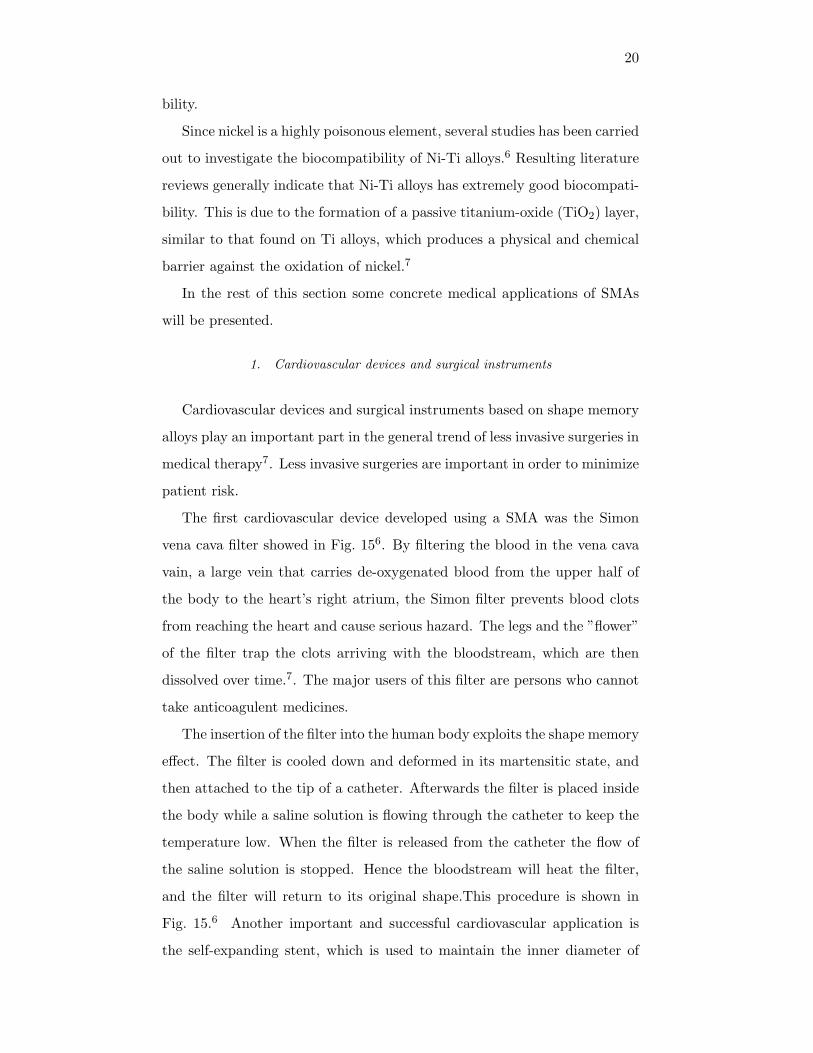
The first cardiovascular device developed using a SMA was the Simon
vena cava filter showed in Fig. 156. By filtering the blood in the vena cava
vain, a large vein that carries de-oxygenated blood from the upper half of
the body to the heart’s right atrium, the Simon filter prevents blood clots
from reaching the heart and cause serious hazard. The legs and the ”flower”
of the filter trap the clots arriving with the bloodstream, which are then
dissolved over time.7. The major users of this filter are persons who cannot
take anticoagulent medicines.
The insertion of the filter into the human body exploits the shape memory
effect. The filter is cooled down and deformed in its martensitic state, and
then attached to the tip of a catheter. Afterwards the filter is placed inside
the body while a saline solution is flowing through the catheter to keep the
temperature low. When the filter is released from the catheter the flow of
the saline solution is stopped. Hence the bloodstream will heat the filter,
and the filter will return to its original shape.This procedure is shown in
Fig. 15.6 Another important and successful cardiovascular application is
the self-expanding stent, which is used to maintain the inner diameter of

21
(a) (b)
FIG. 14: (a)The Simion filter as it looks when it is expanded in the vain.(fromduerig)(b)The procedure of realeasing the Simon vena cava filter. Picture 1 shows thefilter in it’s deformed state inside the catheter. The following pictures shows howthe filter expands as it is released from the catheter. In the last pircture the filterhas returned to its original shape.6
(a) (b)
FIG. 15: (a)Different Ni-Ti self-expanding stnets.(from machado)(b)A self expand-ing stent inside a blood vessel, keeping the vessel open and maintaining the bloodflow.7
a blood vessel.9 As with the Simon filter, the stent is cooled down and
compressed in its martensitic state and then delivered to the target place in
the body using a catheter. When the stent is released from the catheter it
expands as a result of heating from the body. The stent exert a constant
pressure on the blood vessel walls to avoid any obstacles in the bloodstream.
Fig. ?? shows an example of an self-expanding stent.
2. Orthopedic implants
Ortopedics is an attractive field for application of Ti-Ni shape memory
alloys. Applications include the spinal vertebra spacer, orthopedic staples
and bone plates6.
Bone plates are used to support and speed up the healing process of
broken and fractured bones. Usually they are applied to areas where casts
cannot be applied, like facial areas. The bone plates are attached to the
broken bones with screws as shown in Fig. 16. By exerting a constant

22
pressure on the fracture the bone plates help to compress and fix the broken
bones. Normally bone plates are made of titanium or stainless steel. These
(a) (b)
FIG. 16: (a) A SMA bone plate fixed to a human jaw. (b) Detailed picture of aSMA bone plate and a screw.8
bone plates will only exert a pressure on the fracture for a couple of days,
afterwards the tension is lost due to low flexibility of the material. The
advantage of bones plates made of superelastic SMAs is that they can apply
a constant pressure on the fracture for a longer amount of time and hence
speed up the healing process significantly.8
The SMA bone plates are first deformed, and then attached to the frac-
ture. Because of the shape memory effect they tend to recover their former
shape when they are heated. By choosing an Ni-Ti alloy that has a transi-
tion temperature below the body temperature the plates will constantly try
to transform back to their original shape and thereby exert a constant pres-
sure on the fracture.6 The constant pressure can be regulated by adjusting
the alloy composition and the manufacturing process.
3. Dental applications
One of the most successful dental application of shape memory alloy is
the dental arch wire which utilizes the long-time constant force generated
by the supereleastic effect.12 Other interesting applications include dental
implants and attachments for dentures which use the shape memory effect.
Here we will only take a closer look at SMA dental arch wires.
Traditionally many different metal and alloys have been used for dental
arch wires. For the teeth to move optimal, it is important that the force from
the wire is in the optimal force zone. In the excessive force zone, above the

23
optimal force zone, tissue damage may occur. And in the suboptimal force
zone the teeth do not move efficiently. Fig. 17(a) shows a stress-strain curve
for an elastic dental arch wire with a high elastic modulus (like stainless
steel), where the effective strain range corresponding to the optimal force
zone is small. When an alloy with a low elastic modulus is used, the effective
(a) (b)
FIG. 17: Schematic stress-strain curves: (a) for an elastic dental arch wire with ahigh elastic modulus, where the effective strain range corresponding to the optimalforce zone is small. (b) for stainless steel and Ni-Ti wires, where the optimal forcezone for the Ni-TI wire is much larger than for the stainless steel wire.12
strain range increases, which means the the optimal force zone increases.
This is shown in Fig. 17(b) where the stress-strain curve for stainless steel
and superelastic Ni-Ti are compared. Superelastic Ni-Ti wires are such low
elastic modulus materials and are hence very suitable for dental arch wires.
Compared to stainless steel arch wires the Ni-Ti arch wires are applying
a more gentle and constant pressure over a longer period and are thus much
more comfortable to wear, and physiologically more favourable for teeth
movement13. In addition Ni-Ti arch wires do not have to be re-tensioned as
often as stainless steel wires resulting in less visits to the orthodontist14.
B. Non-medical applications
Today medical technology is the largest market for applications of SMAs.
Nevertheless, there also exist many different niches for interesting and suc-
cessful non-medical applications of SMAs. These include everything from
technical applications like couplings, fasteners and actuators, to shoe im-
plants and art sculptures.
In this section we will have a closer look at some of these applications.

24
1. Shape memory alloy actuators
The most important non-medical application of SMAs is actuators. A
shape memory alloy actuator is one type of thermal actuator, which is is a
device that can convert thermal energy into mechanical energy. It exploits
the shape memory effect to generate a force that can be used to perform
work.12
When compared to other types of actuators like metal thermostatic
elements and wax actuators, shape memory alloy actuators show many
advantages11:
• Simplicity of mechanism
Only the phase transformation of the alloy is used for the actuator
mechanism. Hence many designs are possible. Shape memory actua-
tors can work in many different deformation modes, such as tension,
rotation and compression.
• Clean and quiet operation
Friction mechanisms can be avoided, hence production of dust parti-
cles can be avoided. Since there is no vibrating parts all movements
occur extremely silently.
• High power/weight and power/volume ratios
This makes shape memory alloy actuators very attractive in micro-
actuator technology.
But some drawbacks also have to be considered:
• Low energy efficiency
The energy efficiency of turning heat into mechanical work is very
low.
• Degradations and fatigue
The characteristics of a SMA changes over time when used. The shape
can only be recovered a certain amount of times.
25
As a result, SMA actuators are still a niche product and are not produced
in large scales, despite some of the great advantages.
Shape memory alloy actuators have a wide range of application possibil-
ities, which can be divided into two groups:
• Actuators that that act as both sensor and actuator. The phase
change in the shape memory alloy is triggered by the temperature
of the environment.
• Actuators that are heated by an external source and then perform the
required action.
Applications of the first kind can be found in safety control devices: water
kettles, coffee makers, thermostatic mixing valves, air flow control for an air
conditioner and etc.
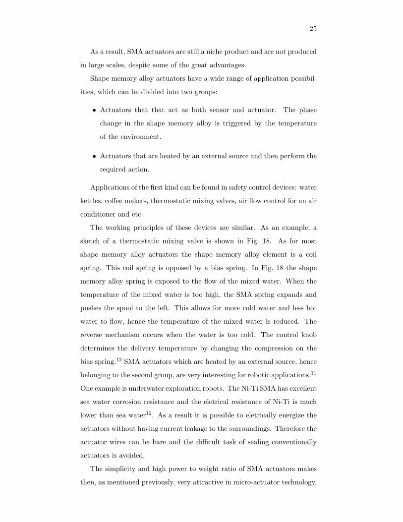
The working principles of these devices are similar. As an example, a
sketch of a thermostatic mixing valve is shown in Fig. 18. As for most
shape memory alloy actuators the shape memory alloy element is a coil
spring. This coil spring is opposed by a bias spring. In Fig. 18 the shape
memory alloy spring is exposed to the flow of the mixed water. When the
temperature of the mixed water is too high, the SMA spring expands and
pushes the spool to the left. This allows for more cold water and less hot
water to flow, hence the temperature of the mixed water is reduced. The
reverse mechanism occurs when the water is too cold. The control knob
determines the delivery temperature by changing the compression on the
bias spring.12 SMA actuators which are heated by an external source, hence
belonging to the second group, are very interesting for robotic applications.11
One example is underwater exploration robots. The Ni-Ti SMA has excellent
sea water corrosion resistance and the eletrical resistance of Ni-Ti is much
lower than sea water12. As a result it is possible to eletrically energize the
actuators without having current leakage to the surroundings. Therefore the
actuator wires can be bare and the difficult task of sealing conventionally
actuators is avoided.
The simplicity and high power to weight ratio of SMA actuators makes
then, as mentioned previously, very attractive in micro-actuator technology,

26
FIG. 18: Sketch of a thermal mixing valve with a shape memory spring.12
which is a rapidly growing field. One example is a micro robot that contains
SMA actuators that is heated by a photon beam. The use of SMAs eliminate
the need for batteries, allowing miniaturisation. And the heating by a pho-
ton beam also eliminate the need for wires and batteries. This technology
has made it possible to make micro robots which are 2 microns wide and
10 microns long, 50 times smaller than what is possible using conventional
actuators.16
The high power to weight ratio also makes SMA very interesting for space
applications. Clean operation also is very important in space, something
which is provided by SMA actuators.
2. Fashion and gadgets
For fashion and gadgets SMA has been applied successfully for many
years. Eye glass frames made of SMAs are very popular. The combination
of stiffness and super-elasticity makes the glasses comfortable to wear and
more robust. The same combination of stiffness and super-elasticity were
also exploited by Sony in the headband of their ”Eggo” headphones. Because
of the superelastic effect the headphones are very comfortable to wear and
can be folded up into an egg shape (hence the name).12
Superelastic wires have also been used as the core wire of a wedding

27
FIG. 19: The sculpture Hermaphrodite by Jean-Marc Philippe. It is made of aCu-Zn-Al alloy and it is reversible transformed form a man’s torso at 20◦C into awoman’s torso at 55◦C.15.
dress petticoat, allowing the the petticoat to be folded into a compact size
for transport. And they have been used in shoes to make them fit perfectly
and prevent them from being worn out.17
3. Other interesting applications
One recently introduced application for SMA is in the protection of his-
torical monuments from damage caused by earth quakes.A special wire con-
sisting of many thin Ni-Ti wires with different nickel and titanium composi-
tion (hence different transition temperature) has been developed. Together
the thin wires form a thicker wire that is capable of supporting the histor-
ical monuments over a large range of temperatures. The metal wires can
either be wrapped around the monuments from the outside or support the
monuments from the inside. Some of the energy from an earth quake will be
turned into heat that will trigger the shape memory effect in the supporting
wires.10
Finally, it is worth to mention that even artists see fascinating opportu-
nities using SMA. Fig. 19 shows the art-work Hermaphroditeby the French
artist Jean-Marc Philippe. The sculpture exploit the temperature depen-
dence of the shape memory effect. In the shade the sculpture represents a

28
man’s torso, but in the sun it is transformed into a woman’s torso.15
V. CONCLUDING REMARKS
In this text we have tried to give a short and basic introduction to the
field of shape memory alloys. The purpose of this text is not to give a
complete analysis of all aspects concerning SMAa, but rather to describe in
general some features that we find to be important.

29
VI. BIBLIOGRAPHY
1 http : //www.azom.com/details.asp?ArticleID = 13642 H. K. D. H. Bhadeshia, The Encyclopedia of Materials: Science and Technology
Pergamon Press, Elsevier Science.3 Shuichi Miyazaki and Kazuhiro Otsuka, Development of Shape Memory Alloys
ISU International Vol. 29 (1989), No. 5, pp. 353 ∼ 377.4 http : //www.cs.ualberta.ca/ database/MEMS/smamems/sma.html5 K. Otsuka and K. Shimizu, ”On the crystallographic reversibility of martensitic
transformations” Scripta Metallurgica, Vol. 11, pp.757-760 1977.6 L.G. Machado, M.A. Savi, Medical applications of shape memory alloys, Brazil-
ian Journal of Medical and Biologial Research Vol. 36 (2003), pp. 683-6917 T. Duerig, A. Pelton, D. Stckel, An overview of nitinol medical applications,
Materials Science and Engineering A273-275 (1999), pp. 149-1608 http://www.cs.ualberta.ca/database/MEMS/sma mems/bone.html9 T.Duerig, D. Stckel, D. Johnson, SMA - Smart materials for medical applica-
tions, European Workshop on Smart Structures in Engineering and Technology,Proceedings of SPIE Vol. 4763 (2003)
10 http://www.ntnu.no/gemini/2004-05/farao.htm11 J. Van Humbeeck, Non-medical applications of shape memory alloys, Materials
Science and Engineering A273-275 (1999), pp. 134-14812 K. Otsuka, C. M. Wayman, Shape memory materials, Cambridge university
press, 1st ed. 1999 (paperback)13 F. Miura, M. Mogi, Y. Ohura, H.Hamanaka, The super-elastic property of the
Japanese NiTi alloy wire for use in orthodontics, American journal of orthodon-tics and dentofacial orthopedics Vol. 90 (1986), pp. 1-10
14 http://www.azom.com/details.asp?articleID=13415 J-M. Philippe, Art and Shape-Memory Alloys, Leonardo, Vol. 22 (1989), pp.
117-12016 http://www.azom.com/details.asp?articleID=209917 Furakawa, Tokyo-Japan, commercial brochure,
http://www.fitec.co.jp/ftm/english/nt-e/appli/index.htm18 http : //en.wikipedia.org/wiki/Shapememoryalloys
All internet pages in this bibliography were last checked 25.10.2007
Copyright © 2022 FDOKUMEN