Carbon Nanotubes and Their Growth Methods - CyberLeninka
13
Procedia Materials Science 6 (2014) 716 – 728 Available online at www.sciencedirect.com 2211-8128 © 2014 Elsevier Ltd. This is an open access article under the CC BY-NC-ND license (http://creativecommons.org/licenses/by-nc-nd/3.0/). Selection and peer review under responsibility of the Gokaraju Rangaraju Institute of Engineering and Technology (GRIET) doi:10.1016/j.mspro.2014.07.088 ScienceDirect 3rd International Conference on Materials Processing and Characterisation (ICMPC 2014) Carbon Nanotubes and Their Growth Methods Rajesh Purohit a , Kuldeep Purohit b , Saraswati Rana, R. S. Rana a and Vivek Patel * a Department of Mechanical Engineering, Maulana Azad National Institute of Technology, Bhopal, MP, India . b Electrical Engineering Department, Indian Institute of Technology, Mandi, HP, India.E-mail: rpurohit73@ gmail.com; [email protected]; [email protected] Abstract Carbon Nanotubes (CNTs) are the allotropes of carbon which belong to the fullerene structural family. These are cylindrical structures with at least one end closed with a buckyball structure hemisphere. They are few nano meter in diameter and have tensile strength of ~63GPa and young’s modulus of ~1TPa. On the basis of structures carbon nanotubes can be classified as Single-walled (SWNT), Multi-walled (MWNT), Polymerized SWNT, Nanotorus and Nanobuds. Carbon Nanotubes can behave as metal or as a semiconductor depending on the nature of its helix. They are good thermal conductors along their axis but act as insulators in the lateral direction. Major manufacturing techniques employed for fabrication of CNTs are Arc discharge, Laser Ablation and Chemical vapor deposition. Carbon Nanotubes are extending our ability to fabricate devices such as molecular probes, pipes, wires, bearings, springs, gears and pumps Keywords: Carbon Nanotubes, CNT Growth Methods, Arc Discharge Method, Laser Ablation, Chemical Vapour Deposition. * Corresponding author. Tel.: +0-000-000-0000 ; fax: +0-000-000-0000 . E-mail address: rpurohit73@ gmail.com © 2014 Elsevier Ltd. This is an open access article under the CC BY-NC-ND license (http://creativecommons.org/licenses/by-nc-nd/3.0/). Selection and peer review under responsibility of the Gokaraju Rangaraju Institute of Engineering and Technology (GRIET)
-
Upload
khangminh22 -
Category
Documents
-
view
1 -
download
0
Transcript of Carbon Nanotubes and Their Growth Methods - CyberLeninka

Procedia Materials Science 6 ( 2014 ) 716 – 728
Available online at www.sciencedirect.com
2211-8128 © 2014 Elsevier Ltd. This is an open access article under the CC BY-NC-ND license (http://creativecommons.org/licenses/by-nc-nd/3.0/).Selection and peer review under responsibility of the Gokaraju Rangaraju Institute of Engineering and Technology (GRIET)doi: 10.1016/j.mspro.2014.07.088
ScienceDirect
3rd International Conference on Materials Processing and Characterisation (ICMPC 2014)
Carbon Nanotubes and Their Growth Methods
Rajesh Purohita, Kuldeep Purohitb, Saraswati Rana, R. S. Ranaa and Vivek Patel* a Department of Mechanical Engineering, Maulana Azad National Institute of Technology, Bhopal, MP, India
.bElectrical Engineering Department, Indian Institute of Technology, Mandi, HP, India.E-mail: rpurohit73@ gmail.com; [email protected]; [email protected]
Abstract
Carbon Nanotubes (CNTs) are the allotropes of carbon which belong to the fullerene structural family. These are cylindrical structures with at least one end closed with a buckyball structure hemisphere. They are few nano meter in diameter and have tensile strength of ~63GPa and young’s modulus of ~1TPa. On the basis of structures carbon nanotubes can be classified as Single-walled (SWNT), Multi-walled (MWNT), Polymerized SWNT, Nanotorus and Nanobuds. Carbon Nanotubes can behave as metal or as a semiconductor depending on the nature of its helix. They are good thermal conductors along their axis but act as insulators in the lateral direction. Major manufacturing techniques employed for fabrication of CNTs are Arc discharge, Laser Ablation and Chemical vapor deposition. Carbon Nanotubes are extending our ability to fabricate devices such as molecular probes, pipes, wires, bearings, springs, gears and pumps © 2014 The Authors. Published by Elsevier Ltd. Selection and peer-review under responsibility of the Gokaraju Rangaraju Institute of Engineering and Technology (GRIET).
Keywords: Carbon Nanotubes, CNT Growth Methods, Arc Discharge Method, Laser Ablation, Chemical Vapour Deposition.
* Corresponding author. Tel.: +0-000-000-0000 ; fax: +0-000-000-0000 . E-mail address: rpurohit73@ gmail.com
© 2014 Elsevier Ltd. This is an open access article under the CC BY-NC-ND license (http://creativecommons.org/licenses/by-nc-nd/3.0/).Selection and peer review under responsibility of the Gokaraju Rangaraju Institute of Engineering and Technology (GRIET)

717 Rajesh Purohit et al. / Procedia Materials Science 6 ( 2014 ) 716 – 728
1. Introduction
The Carbon nanotubes (CNT) are tubular structures made of carbon atoms, having diameter of nanometer order but length in micrometers. Right from its discovery, Qian D. et al. (2002) shows exciting quotations about CNT, viz.
- “CNT is 100 times stronger than stainless steel and six times lighter...”
- “CNT is as hard as diamond and its thermal capacity is twice that of pure diamond...”
- “CNT’s current-carrying capacity is 1000 times higher than that of copper...”
- “CNT is thermally stable up to 4000K...”
- “CNT can be metallic or semiconducting, depending on their diameter and chirality...”
However, it is important to note that all those superlative properties were predicted for an atomically-perfect ideal CNT which is far from the CNTs we are practically producing today.
Despite a huge progress in CNT research over the years, we are still unable to produce CNTs of well-defined properties in large quantities by a cost-effective technique. The root cause of this problem is the lack of proper understanding of the CNT growth mechanism. There are several questions at the growth level awaiting concrete answer. Till date no CNT growth method could be robustly established. Hence this paper is devoted to review the present state of CNT synthesis and growth mechanism.
1.1. Carbon nanotubes
Carbon Nanotube (CNT) is tubular form of carbon with diameter as small as 1nm and length of few nm to microns. CNT is configurationally equivalent to a two dimensional graphene sheet rolled into a tube. Its Young’s modulus is over 1 TPa and the tensile strength is an estimated 200 GPa. Depending on the atomic arrangement of the carbon atoms making up the nanotube (chirality), the electronic properties can be metallic or semiconducting in nature, making them widely used in several applications due to their unique electrical, mechanical, optical, thermal and other properties. The application of CNTs is usually given by the CNTs structure according to Dresselhaus MS. et al. (1995) & Jan Prasek (2011) (number of walls, diameter, length, chiral angle, etc.), which gives them the specific properties. The possible applications of CNTs include conductive films, solar cells, fuel cells, supercapacitors, transistors, memories, displays, separation membranes and filters, purification systems, sensors, clothes etc.
1.2. Classification
On the basis of structure carbon nanotubes are of five types: Single Walled Nano Tube: Most single-walled nanotubes (SWNT) have a diameter of close to
1 nanometer, with a tube length that can be several thousands times the diameter. Multi Walled Nano Tube: Multi-walled nanotubes (MWNT) consist of multiple layers of graphite rolled
on themselves to form a tube shape. Polymerized SWNT: These are the solid-state manifestation of fullerenes and related compounds and
materials. Many single walled nanotubes intertwine to form polymerized SWNTs, which are comparable to diamond in terms of hardness.
Nanotorus: A nanotorus is a theoretically described carbon nanotube bent into a torus (donut shape). Nanotori have many unique properties, such as magnetic moments 1000 times larger than previously expected for certain specific radii.
718 Rajesh Purohit et al. / Procedia Materials Science 6 ( 2014 ) 716 – 728
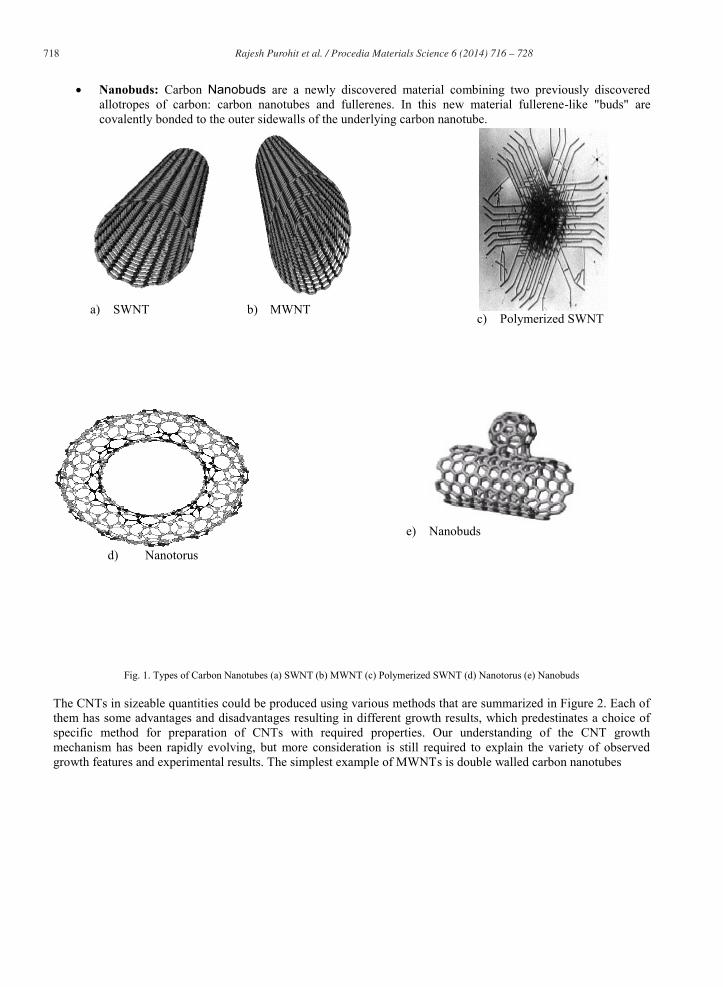
Nanobuds: Carbon Nanobuds are a newly discovered material combining two previously discovered allotropes of carbon: carbon nanotubes and fullerenes. In this new material fullerene-like "buds" are covalently bonded to the outer sidewalls of the underlying carbon nanotube.
Fig. 1. Types of Carbon Nanotubes (a) SWNT (b) MWNT (c) Polymerized SWNT (d) Nanotorus (e) Nanobuds The CNTs in sizeable quantities could be produced using various methods that are summarized in Figure 2. Each of them has some advantages and disadvantages resulting in different growth results, which predestinates a choice of specific method for preparation of CNTs with required properties. Our understanding of the CNT growth mechanism has been rapidly evolving, but more consideration is still required to explain the variety of observed growth features and experimental results. The simplest example of MWNTs is double walled carbon nanotubes
a) SWNT
b) MWNT
c) Polymerized SWNT
d) Nanotorus
e) Nanobuds

719 Rajesh Purohit et al. / Procedia Materials Science 6 ( 2014 ) 716 – 728
Fig. 2. Currently used methods for CNTs synthesis
a) DWNT as a simplest example of MWNTs.
b) TEM image of MWNTs
Fig. 3. (a) DWNT as a simplest example of MWNTs. (b) TEM image of MWNTs
1. CNTs GROWTH METHODS:
There are various techniques used for growth of CNTs. Three popular methods are arc discharge, laser ablation, & chemical vapor deposition (CVD). The common characteristic of these techniques is to provide energy to a carbon source for the creation of Carbon atoms that generate CNTs. The energy source is current in an arc discharge, the high-intensity light from a laser in the laser ablation & heat from a furnace in CVD.

720 Rajesh Purohit et al. / Procedia Materials Science 6 ( 2014 ) 716 – 728
1.1 Arc Discharge : Arc discharge belongs to the methods that use higher temperatures (above 1700°C) for CNT synthesis which usually results in growth of CNTs with fewer structural defects in comparison with other techniques. Initially this method was used for the preparation of C60 fullerence molecules, but during the production of these fullerenes it was observed that there is growth of CNTs which explain in textbook of Kamal K. Kar. (2011). The arc discharge setup consists of a furnace, a stainless steel vacuum chamber, graphite electrodes, a water cooled trap and high voltage power supply. The arc-discharge method is the one by which CNTs were first produced and recognized. Here CNTs are created through arc-vaporization of two carbon rods placed end to end, separated by approximately 1mm, in an enclosure that is usually filled with inert gas at low pressure (Figure 4). A direct current of 50 to 100 A, driven by a potential difference of approximately 20 V, creates a high temperature arc discharge between the two electrodes. The arc provides high temperature which is needed to vaporize carbon atoms into a plasma (>3000°C) Michael Wilson et al.(2012). If graphite rods are doped with metal catalyst (Fe, Co, etc.) and used as the anode with a pure graphite cathode, single-walled carbon nanotubes (SWNTs) are generated in the form of soot shown by ) Iijima S. (1991) & Bethune DS. et al. (1993). MWNTs are found on the top surface and also deep inside the cathode deposit as shown by Ebbesen TW et al. (1992). MWNTs with high crystallinity and few coexisting carbon nanoparticles were formed with methane. Therefore, pure graphite rods were arc evaporated in pure hydrogen gas experimentally shown by Bandow S. et al. (1998) & Rohsenow WM. Et al.(1985). In fact a gas that includes hydrogen atoms is more effective than an inert gas, such as He or Ar for MWNT production. The most probable reasons for this are the high temperature and high activity of the hydrogen arc faces by Ando Y. et al. (2004) & Ishigami M. et al. (2000). Mass production of SWNTs by arc discharge was achieved by Gang X. et al. (2007) using a bimetallic Ni-Y catalyst in He ambient gas. Graphite electrodes inclined at an angle of 30° instead of the usual 180° alignment proved to be an efficient modification. This is known as the arc-plasma-jet method and yields SWNTs at a rate of 1 g/min.
Fig. 4. Schematic of Arc Discharge Method
Under conditions similar to those of large-diameter SWNT formation by arc discharge method, the synthesis of double-walled nanotubes (DWNTs) has been observed by Shi Z. et al. (1999), Maschmann MR. et al. (2006) & Murata K. et al. (2001). Although partial alignment of SWNTs can be achieved by convection Sano N. et al. (2004)

721 Rajesh Purohit et al. / Procedia Materials Science 6 ( 2014 ) 716 – 728
or directed arc plasma, it is difficult to grow aligned CNTs (SWNTs, DWNTs or MWNTs) by arc discharge. On the other hand, the crystallinity and perfection of arc-produced CNTs are generally high and the yield per unit time is also higher than other methods mainly due to the high growth temperature involved in this method.
1.2 Laser Ablation: Laser ablation method is a promising technique for producing SWCNTs & MWCNTs. This method to synthesize CNTs has been first reported by Guo et al. (1995). A schematic for laser ablation is shown in figure 5. This method had been originally used as a source of clusters observed by In: Bernstein E R (1990) and ultrafine particles by Maser WK. et al. (1998) & Zhang H. et al. (2003). Graphite target is vaporized by laser beam (typically by Nd: YAG or CO2 laser) under high temperature in an inert atmosphere. The laser produces carbon species, which are swept by the flowing inert gas from the high temperature zone to a conical water- cooled copper collector. The quality & yield of these products have been found to depend on the reaction temperature. When a small amount of transition metal such as Ni, Fe or Co has been added to the carbon target, SWCNTs are produced. By varying the laser, catalyst composition, growth temperature, nature of gases & gas pressure, the average nanotube diameter & size distribution can be varied which reflect in the experiment done by Yudasaka M. et al. (1999) & Thess A. et al. (1996). As the vaporized species cool, small carbon molecules and atoms quickly condense to form larger clusters, possibly including fullerenes. The catalysts also begin to condense, but more slowly at first, and attach to carbon clusters. From these initial clusters, tubular molecules grow into single-wall carbon nanotubes until the catalyst particles become too large, or until conditions have cooled sufficiently that carbon no longer can diffuse through or over the surface of the catalyst particles. It has been shown by Maser WK. et al. (1998) that high yields of SWCNTs can also be obtained by using a very simple CO2 laser system operating in a continuous wave mode. Few recent papers W Braidy N. et al. (2002) have also pointed out the role of some laser parameters (such as laser power, repetition rate, pulse duration & laser wavelength) on the synthesis & characteristics of SWCNTs. In this method continuous wave CO2 laser is used without applying additional heat to the target. The average diameter of SWCNTs increases with increasing CO2 laser power from 500 to 800 W.
Fig. 5. Schematic of laser ablation
A hybrid of steady arc discharge and the laser-furnace method has been developed by Zhang Y. et al. (1999), Munoz E. et al. (1999) & Munoz E. et al. (2000) to achieve high quality DWNTs and SWNTs. This high-temperature pulsed arc discharge method uses a DC pulsed arc discharge to maintain homogeneous condition in arc discharge inside a furnace. The contaminants, such as amorphous carbon and catalytic metals present in CNTs were removed by purification processes based on oxidation by hot air (400-500°C) or chemicals such as H2O2 as given by Ebbesen T. et al. (1997). Chen X. et al.(2004) appropriately varying the furnace temperature, catalytic metals, and flow rate, SWNT diameter can be controlled. A higher furnace temperature results in SWNTs with larger diameters. The use of a Ni-Y alloy catalyst by Chen M. et al. (2003) also increases the SWNT diameter, whereas a Rh-Pd catalyst reduces it. Flow rate

722 Rajesh Purohit et al. / Procedia Materials Science 6 ( 2014 ) 716 – 728
affects the diameter distribution, which suggests that the growth process is fairly slow (on a timescale of seconds) compared with vaporization processes (nanosecond scale). Both arc discharge & laser ablation techniques are very expensive due to the high power equipment so they are mainly used for SWCNTs production. These methods also produce small quantities of CNTs with a lot of impurities.
1.3 Chemical Vapour Deposition: Chemical vapour deposition (CVD) is the best technique to synthesize CNTs. In this method, the decomposition of the carbon precursor & CNT formation take place on the surface of catalyst particles. The two most important CVD techniques for synthesis of CNT are the thermal CVD & plasma enhanced CVD (PECVD). CNTs can be produced at relatively low temperatures and their size can be controlled by varying the size of catalyst particles. CVD is used for the large scale production of CNTs. It is achieved by taking a carbon source in the gas phase & using an energy source, such a resistively heated coil, to impart energy to a gaseous carbon molecule. Commonly used carbon sources include methane, carbon monoxide, acetylene etc. This will result in the formation of CNTs, if the proper parameters are maintained. The CNT synthesis using CVD is essentially a two steps process. A catalyst preparation step is the first step followed by actual synthesis of nanotube. The catalyst is generally prepared by sputtering, physical vapor deposition (PVD), dip coating etc. The next step is heating up the substrate in a carbon rich gaseous environment. Temperature for the synthesis of nanotubes in this technique is generally 500 to 1000°C. When compared with the previous two methods, CVD is a simple and economic technique for synthesizing CNTs at relatively low temperature and ambient pressure, but at the cost of crystallinity. It is a versatile process as it harnesses a variety of hydrocarbons in any state (solid, liquid or gas), enables the use of various substrates and allows CNT growths in a variety of forms, such as powder, thin or thick films, aligned or entangled, straight or coiled, or even a desired architecture of nanotubes at predefined sites on a patterned substrate. It also offers better control over growth parameters.
Fig. 6. Schematic of thermal CVD
Figure 6 shows a schematic diagram of the setup used for CNT growth by CVD in its simplest form. The process involves passing a hydrocarbon vapor (typically for 15-60 minutes) through a tube furnace in which a catalyst material is present at sufficiently high temperature (600-1200°C) to decompose the hydrocarbon. CNTs grow over the catalyst and are collected when the system is cooled to room temperature. When a liquid hydrocarbon (benzene, alcohol, etc.) is being employed, it is heated in a flask and an inert gas is purged through it to carry the vapor into the reaction furnace. The design of the CVD reactor depends on whether the carbon precursors are liquid or gas. Liquid carbon precursors often use a bubbler to vaporize the reactants, and a carrier gas (reactive gases such as H2 or inert gas such as N2 or Ar) to transport the vaporized reactants into the CVD reactor. The three main parameters which affect CNT growth in CVD are the hydrocarbon, catalyst and growth temperature. Generally, low-temperature CVD (600-900°C) yields MWNTs, whereas a higher temperature (900-1200°C) reaction

723 Rajesh Purohit et al. / Procedia Materials Science 6 ( 2014 ) 716 – 728
favors SWNT growth, indicating that SWNTs have a higher energy of formation, probably owing to their small diameters, which results in high curvature and high strain energy. The catalyst particle size has been found to dictate the nanotube diameter. Hence, metal nanoparticles of controlled size can be used to grow CNTs of controlled diameter. Thin films of catalyst coated onto various substrates have also been proved successful in achieving uniform CNT deposits. In addition, the material, morphology and textural properties of the substrate greatly affect the yield and quality of the resulting CNTs. 2.4 Growth Parameters of Carbon Nanotubes: The yield & quality of CNTs synthesized by chemical vapor deposition (CVD) are greatly influenced by the growth parameters. There are many growth parameters involved in the synthesis of CNTs. Some of these parameters are:
a. Catalyst particle size b. Catalyst concentration c. Pressure d. Growth time e. Growth temperature f. Gas flow rate
2.5 Growth Mechanisms of Carbon Nanotubes: MWCNT can be grown without a metal catalyst in arc discharge & laser ablation methods, whereas the metal particle is essential to synthesize MWCNT by CVD technique. In contrast, metal particles are necessary for the growth of SWCNT in all these three methods. So, the growth mechanism of nanotube is different for different methods. Researchers have reported various mechanisms, such as vapor-solid-solid (VSS), vapor-liquid-solid (VLS) mechanism etc. 2.5.1 Vapor-solid-solid (VSS) Growth Mechanism: This mechanism consists of four steps which is explain by Jourdain V. et al. (2002). In the first step, nano sized metallic particles are formed on substrate. These particles can either deformed by laser ablation or by annealing a very thin metallic film. Second step is the decomposition of hydro carbon gas over the surface of metal catalyst particle to release the hydrogen and carbon, which dissolve in the particle. The third step is the diffusion of carbon through the metal particle and its precipitation. Finally over coating and deactivation of the catalyst & termination of nanotube growth takes place. Sinnot et al. have explored that the metal catalyst particles can float or are supported on graphite or another substrate. They have presumed that the catalyst particle are spherical or pear shaped, in which case the deposition will take place on only one half of the surface (this is the lower curvature side for the pear shaped particle). Carbon diffuses along the concentration gradients and precipitates on the opposite half, around and below the bisecting diameter. However, it does not precipitate from the apex of hemisphere, which accounts for the hollow cores that is characteristics of these filaments. For supported metals, filaments can be formed either by extrusion, also known as base or root growth in which the nanotube grows upward from the metal particles, as shown in figure 7. This mechanism believes that the metallic particle has strong interaction with catalyst support that cannot be easily separated by the graphite layer formed at the interface of metal support in a catalyst system. Another mechanism is that the particles detache & move at the head of growing nanotube, labeled as “tip growth”. Continuous formation of carbon atoms at the support side shows the growth of CNTs with the metal lifted at the tip of CNTs. The catalyst particle is pushed upward due to diffusion & osmotic pressure, depositing carbon in to the graphite structure below the catalyst [33]. If the carbon deposit is not removing from the surface of metallic particles, the carbon will encapsulate the metal surface & deactivate the catalyst. Figure 8 shows the SEM image of CNTs where the metal particles are found at the tips of nanotubes.

724 Rajesh Purohit et al. / Procedia Materials Science 6 ( 2014 ) 716 – 728
Fig. 7. SEM image reveals the base ends of the CNTs
Fig. 8. SEM image of metallic particles situated at the tips of
CNTs
Base-tip growth mechanism combines the concepts of base growth and tip growth mechanism. The hydrocarbon decomposes on the free surface on the metallic particle into hydrogen and carbon. At this temperature, the metal particle will be in the liquid state rather than in the solid state.
Fig. 9. TEM image of metallic particles situated at the tip & base of CNT
The concentration of carbon in metal particles increase until the super saturation is reached. This situation forces the carbon atom to accumulate on the surface of metallic particle and then initiate the growth by forming first graphitic layer. The stretching force elongates the liquid particle and breaks the liquid metallic particle into two parts. The bottom parts of metal have strong adhesion to the support, so they stay at the support & contribute the growth of CNTs. The metallic particles situated at the tips of CNTs are inactive during the reaction because of the metallic particles at the tips are fully encapsulated by graphitic layer. The morphology of the CNTs, where the metallic particles are found at the tip and at the base of CNTs, is shown in figure 9.
Fig. 10. Schematics of root growth & tip growth mechanism

725 Rajesh Purohit et al. / Procedia Materials Science 6 ( 2014 ) 716 – 728
Schematic representation of root and base growth mechanism is also shown in figure 10. Depending on size of the catalyst particle, SWCNTs & MWCNTs are grown. In the arc discharge, if the catalyst is not present or not used in graphite, MWCNTs will be grown on the C2 particles that are formed in the plasma. The root growth signifies the strong substrate and catalyst interaction and tip growth signifies the weak interaction between the substrate and the catalyst. Zhao et al. have outlined the slightly different theory for the growth of CNTs, which is known as sealed nanotube grown by CVD. Their growth is attributed to open tip growth and the inner layer is firstly sealed, which is induced by decreasing the concentration of carbon atom, then the outer layers of nanotube are sealed. The general CNTs grown by CVD also belong to open tip growth. However the inner and outer layers of tube are simultaneously sealed & CNTs growth is stopped according to Zhao Y. et al. (2006).
2.5.2 Vapor-liquid-solid (VLS) Growth Mechanism: The vapor-liquid-solid (VLS) mechanism consists of three main stages i.e., nucleation, precipitation and deposition. When the metal is evaporated together with the carbon by arc discharge, carbon metal alloy particles are formed on the cathode surface. In the initial stage, the alloy particles are presumably in liquid phase because of the high temperature on the cathode surface and the lowering of melting point due to alloying. Since the metal carbon compound soot is produced in carbon rich atmosphere, the initial alloy particles in a liquid phase contain more carbon then solubility limit in a solid state. Therefore with the decrease in temperature of cathode, liquid alloy particles begin to segregates access carbon on their surfaces.
2. Properties
Carbon nanotubes are one of the strongest and stiffest materials known, in terms of tensile strength and elastic modulus respectively.
Mechanical properties
A multi-walled carbon nanotube was tested by Saito R. (1998) to have a tensile strength of 63 GPa (for High Carbon Steel it is ~1.2 GPa).
According to Lu JP. (1997) CNTs have very high elastic moduli, of the order of 1 TPa (for Aluminium it is ~70Gpa).
Since carbon nanotubes have a low density for a solid of 1.3-1.4 gm/cm³, its specific strength of up to 48,462 kN·m/kg is the best of known materials, compared to high-carbon steel's 154 kN·m/kg.
Under excessive tensile strain, the nanotubes will undergo plastic deformation, which means the deformation is permanent. This deformation begins at strains of approximately 5 % and can increase the maximum strain the tube undergoes before fracture by releasing strain energy.
CNTs are not nearly as strong under compression. Because of their hollow structure and high aspect ratio, they tend to undergo buckling when placed under compressive, torsional or bending stress.
Kinetic properties
Multi-walled nanotubes, multiple concentric nanotubes precisely nested within one another, exhibit a striking telescoping property whereby an inner nanotube core may slide, almost without friction, within its outer nanotube shell thus creating an atomically perfect linear or rotational bearing.

726 Rajesh Purohit et al. / Procedia Materials Science 6 ( 2014 ) 716 – 728
Electrical properties
Because of the symmetry and unique electronic structure of graphene, Endo M. et al. (2001) find that the structure of a nanotube strongly affects its electrical properties It can act as a metal as well as semiconductor. Theoretically, metallic nanotubes can have an electrical current density more than 1,000 times greater than metals such as silver and copper.
Thermal properties
All nanotubes are expected to be very good thermal conductors along the tube, exhibiting a property known as "ballistic conduction," but good insulators laterally to the tube axis.
Defects
As with any material, the existence of defects affects the material properties. Defects can occur in the form of atomic vacancies. A single monoatomic vacancy induces magnetic properties. High levels of such defects can lower the tensile strength. Another form of defect that may occur in carbon nanotubes is known as the Stone Wales defect, which creates a pentagon and heptagon pair by rearrangement of the bonds, which reduces the tensile strength. The nanotube's electrical properties are also affected by the presence of defects. A common result is the lowered conductivity through the defective region of the tube. The tube's thermal properties are also heavily affected by the defects.
3. Applications
Current Applications
CNTs have extended our ability to fabricate devices such as molecular probes, pipes, wires, bearings, springs, gears, pumps etc. Baughman RH. Et al. (2002) & Forro L. et al. (2001) also find wide application in Metal and polymer matrix composites.
Potential Applications
(i) Structural: Clothes, Combat jackets, Sports equipments
(ii) Chemical: Air pollution filter, Hydrogen storage
(iii) Mechanical: Oscillator, Slick surface
(iv) Electric Circuits: Touted as the alternative to reduce the scale from MEMS to nano level.
4. Conclusions
CNT’s phenomenal mechanical properties and unique electronic properties make them both interesting as well as potentially useful in future technologies. Significant improvement over current state of electronics can be obtained, if controllable growth of CNTs is achieved. Though growth conditions play a significant role in deciding the electronic and mechanical properties of CNTs their mechanisms are yet to be fully established. In the foregoing sections, we raised several questions on the roles of precursor, catalyst, catalyst support and growth mechanism and indicated possible research directions. In addition to those basic issues, other growth-related challenges are briefly outlined below:

727 Rajesh Purohit et al. / Procedia Materials Science 6 ( 2014 ) 716 – 728
Researchers have succeeded in minimizing the diameter distribution of SWCNTs up to some extent. However, synthesis of SWCNTs of a given diameter is yet to be achieved. It would be possible only when we have the catalyst particles all of exactly the same diameter (say, 0.5 nm).
Chirality control is even more challenging. Re-growth from ordered arrays of open-ended SWCNTs may help up to some extent. Alternatively, we have to develop proper separation methods that could first sort out CNTs according to metallic or semiconducting nanotubes and then select nanotubes of specific chirality.
In MWCNTs, control on the number of walls is another big challenge. Synthesis of thin MWCNTs (3–6 walls) is a better choice than thick MWCNTs.
References
Ando Y., Zhao X., Sugai T., Kumar M., 2004. “Growing carbon nanotubes”; Mater. Today; 7(10):22-29. Bethune DS., Klang CH., de Varies MS., Gorman G., Savoy R., Vazquez J., Beyers R., 1993. “Cobalt-catalysed growth of carbon nanotubes with
single-atomic-layer walls”; Nature; 363(6430):605-607. Bandow S., Asaka S., Saito Y., Rao AM.,Grigorian L., Richter E., Eklund PC., 1998. “Effect of the growth temperature on the diameter of
distribution and chirality of single-wall carbon nanotubes”; Phys. Rev. Lett; 80(17): 3779. Braidy N., EI Khakani MA., Botton GM., 2002. “Single-wall carbon nanotubes synthesis by means of UV laser vaporization”; Chem. Phys. Lett.;
354(1-2):88-92. Baughman RH. Zakhidov AA. De Heer WA. 2002. “Carbon nanotubes- the route toward applications”; Science; 297(5582):787-792. Chen X., Wang R., Xu J., 2004. “TEM investigation on the growth mechanism of carbon nanotubes synthesized by hot- filament chemical vapor
deposition”. Micron; 35(6): 455-460. Chen M., Chen C-M., Koo H-S., 2003. “Catalyzed growth model of CNTs by microwave plasma vapor deposition using CH4 & CO2 gas
mixture”, Diamond Relat. Mater. 12(10-11):1829-1835. Dresselhaus MS., Dresslhaus G., Saito R., 1995. “Physics of Carbon Nanotubes” 33(7): 870- 886. Ebbesen TW. Ajayan PM., 1992. “Large scale synthesis of carbon nanotubes”; Nature; 358(6383):220-222. Ebbesen T., Ajayan PM., Hiura H., 1997. “Method of purifying CNTs”. US Patent 5641466. Endo M., Kim YA., Hayashi T., Nishimura K., Matusita T., Miyashita K., Dresselhaus MS., 2001. “Vapour-grown carbon fibres (VGCFs): Basic
properties and their battery applications” Carbon; 39(1):1287-1297. Forro L., Schonenberger C., 2001. “Physical properties of multi-wall nanotubes. In: Dresselhaus MS, Dresselhaus G, Avouris P, editor. Carbon
nanotubes: synthesis, structure, properties and applications”, Berlin Springer Verlag: 329-391. Guo T., Nilolaev P., Thess A., Colbert DT., Smalley RE., 1995. “CATALYTIC GROWTH OF SWNTS BY LASER VAPORIZATION”. Chem.
Phys. Lett; 243(1-2): 49-54 Gang X., Shenli J., Jian X., Zongqian S., 2007. “Analysis of carbon Nano- structures formation in liquid arcing”; Plasma Sci. Technol.; 9 770-
773. In: Bernstein E R, Editors, 1990. Atomic and Molecular Clusters, Elsevier Science B V; New York, 69. Iijima S., 1991. ”Helical microtubules of graphitic carbon; Nature”; 354(6348):56-58. Ishigami M., Cumings J., Zettl A., Chen S., 2000. “A simple method for the continuous production of carbon nanotubes”; Chem. Phys. Lett.
;319(5-6): 457-459 Jourdain V., Kanzow H., Castignolles M., Loiseau A., 2002. “Sequential catalytic growth of CNTs”, Chem. Phys. Lett.; 364(1-2): 27-33. Jan Prasek, 2011. “Methods for Carbon Nanotubes Synthesis”, Journal of Materials Chemistry. Kamal K. Kar, 2011. A textbook on “Carbon Nanotubes: Synthesis, Characterization & Application” Research Publishing Sigapore. Lu JP. 1997. “Elastic properties of carbon nanotubes and nanoropes”, Phys. Rev Lett.; 79(7): 1297-1300. Maser WK., Munoz E., Benito AM.,Martinez MT., de la Fuente GF., Maniette Y., Anglaret E., Sauvajol JL., 1998. “Production of high-density
single-walled nanotube material by a simple laser ablation method”; Chem. Phys. Lett.; 292(4-6): 587-593. Maser WK., Munoz E., Benito AM., Maniette Y., Sauvajol JL, 1998. “Production of high density SWNT material by a simple laser ablation
method”; Chem. Phys. Lett. 292(4-6): 587-593. Munoz E., Maser WK., Benito AM., de la Fuente GF., Martinez MT., 1999; “Single-walled carbon nanotubes produced by laser ablation under
different inert atmosphere”; Synth. Met.103 (1-3):2490-2491. Munoz E., Maser WK, Benito AM., Martinez MT, de la Fuente GF, Maniette Y, Righi A., Anglaret E., Sauvajol JL., 2000. “Gas and pressure
effects on the production of single-walled carbon nanotubes by laser ablation”, Carbon; 38(10):1445-1451. Murata K., Kaneko K., Steele WA., Kokai F., Takahashi K., Kasuya D., Hirahara K., Yudasaka M., Iijima S., 2001. “Molecular potential
structures of heat treated single-wall carbon nanohorn assemblies”;J. Phys. Chem B; 105(42):10210-10216. Maschmann MR., Franklin AD., Amama PB., Zakharov DN., Stach EA., Sands TD., Fisher TS., 2006. “Vertical single and double-walled
carbon nanotubes grown from modified porous anodic alumina templates”; Nanotechnology; 17 3925-3929. Michael Wilson, Kamali Kannangara, Geoff Smith and Michelle Simmons, 2012. “Study the Nanotechnology”: Basic Science and Emerging
Technologies. Qian D., Wagner GJ., Liu WK., Yu M-F., Ruoff RS, 2002. “Mechanics of Carbon Nanotubes”. Appl. Mech. Rev. 55: 480-545. Rohsenow WM., Hartnett JP. Ganic EN., 1985. “Handbook of heat transfer fundamentals”; MacGraw-Hill book Co.; New York.

728 Rajesh Purohit et al. / Procedia Materials Science 6 ( 2014 ) 716 – 728
Saito R., 1998. “Physical properties of carbon nanotubes”; Imperial college press; London: 259. Shi Z., Lian Y., Liao F., Zhou X., Gu Z., Zhang Y., Iijima S., 1999. “Purification of single-wall carbon nanotubes”; Solid State Commun.; 112
35-37. Sano N., Nakano J., Kanki T., 2004. “Synthesis of Single-Walled Nanotubes with Nanohorns by arc in liquid nitrogen”; Carbon; 42(3):686-688. Thess A., Lee R., Nikolaev P., Dai H., Petit P., Robert J., Xu C., Lee Yh., Kim Sg., Linzler Ag., Colbert Dt., Scuseria Ge., Tomanek D., Fischer
Je., Smalley Re., 1996.; “Crystalline ropes of metallic carbon nanotubes”; science; 273(5274): 483-487. Yudasaka M., Yamada R., Sensui N., Wilkins T., Ichihashi T., Iijima S., 1999. “Mechanism of the effect of NiCo , N and Co catalyst s on the
yield of single-wall carbon nanotubes formed by pulsed Nd:YAG laser ablation”; J. Phys. Chem; 130(30): 6224-6229. Zhang Y., Iijima S., 1999. “Formation of single-wall carbon nanotubes by laser ablation of fullerenes at low temperature”; Appl. Phys. Let;
75(20):3087-3089. Zhang H., Ding Y., Wu C., Chen Y., Zhu Y., Zhong S., 2003. “The effect of laser power on the formation of carbon nanotubes prepared in CO2
continuous wave laser ablation at room temperature” Physics B.; 325: 224-229. Zhao Y., Seko K., Saito Y., 2006. “Effects of process parameters & substrate structures on growth of SWCNTs by catalytic decomposition of
ethanol”. Jpm. J. Appl. Phys: 45(8A): 6508-6512.