Electrophoretic deposition of carbon nanotubes
14
Electrophoretic deposition of carbon nanotubes onto carbon-fiber fabric for production of carbon/epoxy composites with improved mechanical properties Qi An a,c , Andrew N. Rider b , Erik T. Thostenson a,c,d, * a Center for Composite Materials, University of Delaware, Newark, DE 19716, USA b Air Vehicles Division, Defence Science and Technology Organization, Fisherman’s Bend, Victoria 3207, Australia c Department of Materials Science and Engineering, University of Delaware, Newark, DE 19716, USA d Department of Mechanical Engineering, University of Delaware, Newark, DE 19716, USA ARTICLE INFO Article history: Received 16 January 2012 Accepted 23 April 2012 Available online 1 May 2012 ABSTRACT Carbon nanotubes (CNTs) have been deposited onto carbon-fiber fabric using electropho- retic deposition (EPD) prior to the infusion of epoxy resin for the production of carbon/ epoxy composites. The carbon-fiber fabric employed for EPD was used in the as-received condition, in which the proprietary epoxy sizing-agent was present. CNTs were functional- ized prior to EPD using ozone treatment for oxidation, followed by chemical reaction with polyethyleneimine. The CNT oxidation used a novel recirculating system which enabled ozonolysis to be conducted on large-volume solutions of CNTs in the presence of high- powered sonication, facilitating preparation of stable dispersions suitable for EPD. Signifi- cant increases in the shear strength and fracture toughness of the carbon/epoxy compos- ites with the CNT treatment have been measured relative to composites without the CNT treatment. Analysis of fracture surfaces revealed interlaminar regions with high levels of CNTs and evidence of good adhesion between the carbon nanotubes and sized carbon- fiber, which is believed to have contributed to the measured improvement in mechanical properties. Ó 2012 Elsevier Ltd. All rights reserved. 1. Introduction Carbon-fiber reinforced polymer (CFRP) composites offer good in-plane tensile properties for their equivalent weight in com- parison with traditional metallic materials, however, they may exhibit poor through-thickness strength and toughness properties. Efforts to improve the through-thickness proper- ties of CFRP composites have examined the addition of car- bon nanotubes (CNTs). CNTs offer high strength and stiffness on a sub-micron scale and, therefore, are potential candidates to be used to modify the interstitial regions be- tween the carbon-fibers, where the polymer matrix domi- nates the composite strength and toughness properties. An elegant approach to incorporating CNTs into CFRPs has in- volved the growth of CNTs directly onto the reinforcing fiber using chemical vapor deposition (CVD) prior to resin infusion. The direct growth approach enables perpendicularly-aligned CNTs to be grown at high coverage, leading to high-effective volume fractions of the CNTs in the matrix. Processing the composite with the high CNT volumes in the resin would be difficult to achieve due to factors such as viscosity increases, fabric filtering effects and adequate dispersion. The CVD approach leads to composite properties with improved mechanical and electrical properties [1,2]. The CVD approach, however, can cause a reduction in the strength of the carbon- fibers and, therefore, compromise the tensile properties [2,3], 0008-6223/$ - see front matter Ó 2012 Elsevier Ltd. All rights reserved. http://dx.doi.org/10.1016/j.carbon.2012.04.061 * Corresponding author at: Center for Composite Materials, University of Delaware, Newark, DE 19716, USA. Fax: +1 302 831 3619. E-mail address: [email protected] (E.T. Thostenson). CARBON 50 (2012) 4130 – 4143 Available at www.sciencedirect.com journal homepage: www.elsevier.com/locate/carbon
-
Upload
independent -
Category
Documents
-
view
1 -
download
0
Transcript of Electrophoretic deposition of carbon nanotubes

C A R B O N 5 0 ( 2 0 1 2 ) 4 1 3 0 – 4 1 4 3
.sc iencedi rect .com
Avai lab le at wwwjournal homepage: www.elsev ier .com/ locate /carbon
Electrophoretic deposition of carbon nanotubes ontocarbon-fiber fabric for production of carbon/epoxycomposites with improved mechanical properties
Qi An a,c, Andrew N. Rider b, Erik T. Thostenson a,c,d,*
a Center for Composite Materials, University of Delaware, Newark, DE 19716, USAb Air Vehicles Division, Defence Science and Technology Organization, Fisherman’s Bend, Victoria 3207, Australiac Department of Materials Science and Engineering, University of Delaware, Newark, DE 19716, USAd Department of Mechanical Engineering, University of Delaware, Newark, DE 19716, USA
A R T I C L E I N F O
Article history:
Received 16 January 2012
Accepted 23 April 2012
Available online 1 May 2012
0008-6223/$ - see front matter � 2012 Elsevihttp://dx.doi.org/10.1016/j.carbon.2012.04.061
* Corresponding author at: Center for CompoE-mail address: [email protected] (E.T. Th
A B S T R A C T
Carbon nanotubes (CNTs) have been deposited onto carbon-fiber fabric using electropho-
retic deposition (EPD) prior to the infusion of epoxy resin for the production of carbon/
epoxy composites. The carbon-fiber fabric employed for EPD was used in the as-received
condition, in which the proprietary epoxy sizing-agent was present. CNTs were functional-
ized prior to EPD using ozone treatment for oxidation, followed by chemical reaction with
polyethyleneimine. The CNT oxidation used a novel recirculating system which enabled
ozonolysis to be conducted on large-volume solutions of CNTs in the presence of high-
powered sonication, facilitating preparation of stable dispersions suitable for EPD. Signifi-
cant increases in the shear strength and fracture toughness of the carbon/epoxy compos-
ites with the CNT treatment have been measured relative to composites without the CNT
treatment. Analysis of fracture surfaces revealed interlaminar regions with high levels of
CNTs and evidence of good adhesion between the carbon nanotubes and sized carbon-
fiber, which is believed to have contributed to the measured improvement in mechanical
properties.
� 2012 Elsevier Ltd. All rights reserved.
1. Introduction
Carbon-fiber reinforced polymer (CFRP) composites offer good
in-plane tensile properties for their equivalent weight in com-
parison with traditional metallic materials, however, they
may exhibit poor through-thickness strength and toughness
properties. Efforts to improve the through-thickness proper-
ties of CFRP composites have examined the addition of car-
bon nanotubes (CNTs). CNTs offer high strength and
stiffness on a sub-micron scale and, therefore, are potential
candidates to be used to modify the interstitial regions be-
tween the carbon-fibers, where the polymer matrix domi-
nates the composite strength and toughness properties. An
er Ltd. All rights reserved
site Materials, Universityostenson).
elegant approach to incorporating CNTs into CFRPs has in-
volved the growth of CNTs directly onto the reinforcing fiber
using chemical vapor deposition (CVD) prior to resin infusion.
The direct growth approach enables perpendicularly-aligned
CNTs to be grown at high coverage, leading to high-effective
volume fractions of the CNTs in the matrix. Processing the
composite with the high CNT volumes in the resin would be
difficult to achieve due to factors such as viscosity increases,
fabric filtering effects and adequate dispersion. The CVD
approach leads to composite properties with improved
mechanical and electrical properties [1,2]. The CVD approach,
however, can cause a reduction in the strength of the carbon-
fibers and, therefore, compromise the tensile properties [2,3],
.
of Delaware, Newark, DE 19716, USA. Fax: +1 302 831 3619.

C A R B O N 5 0 ( 2 0 1 2 ) 4 1 3 0 – 4 1 4 3 4131
although recent work using fiber oxidation may be able to
minimize this strength loss [3]. While the process may be
scalable, the high temperatures typically employed for CVD,
between 600 and 1000 �C, also make it energy intensive. The
CVD process may also be less amenable to the control of
CNT purity and manipulation of surface chemistry and adhe-
sion of the CNT to the fiber surface. On this basis, some re-
search has been dedicated in recent years to alternative
methods to prepare these hierarchically-scaled composite
materials.
Electrophoretic deposition (EPD) is a widely used indus-
trial-coating process employed in areas ranging from auto-
motive to electronics production with assets which include
low-energy use and the ability to homogenously coat complex
shapes with well adhered films of controlled thickness and
density. A considerable research effort in developing reliable
methods to prepare nanostructured-ceramic materials using
EPD [4] has occurred in recent years. Detailed reviews of the
methods used to prepare carbon nanotube and ceramic com-
posites in a wide range of applications have indicated the
important processing parameters for preparing coatings and
films with tailored properties [5,6]. A variety of methods to
create stable-CNT dispersions in aqueous [7] solutions have
been used, with the aim of creating charged CNTs which will
migrate under the influence of an external electric field to the
coating surface [8]. The choice of solvent, CNT-functionaliza-
tion method and voltage can all influence the film formation,
with electrolysis of water affecting film-porosity levels [8]. A
recent review has also detailed some new techniques utilizing
aperiodic AC and pulsed DC EPD methods to provide more
uniform, low porosity coatings by minimizing the water elec-
trolysis reactions [9].
EPD has also been applied to preparing hierarchical-com-
posite structures with carbon-fiber fabrics [10,11] using aque-
ous-CNT solutions. The carbon/epoxy-composite laminates
have exhibited only modest improvements in mechanical
properties. However, electrical conductivity has shown con-
siderable increase, particularly in cases where copper has
been incorporated in the CNT coating during deposition [11].
The approach offers a similar outcome to CVD coating by
offering the potential to have high-effective CNT volume frac-
tions in the composite, although EPD work to date has used
relatively low-volume concentrations around 1%, where the
thin CNT coating is employed like a traditional sizing-agent
[11].
Successful EPD relies on the functionalization of the CNTs,
which enables a surface charge to develop. The surface
charge or zeta-potential is dependent on the solution pH
and helps repulse adjacent CNTs to aid dispersion and mobil-
ity under applied electric fields. While acid treatment has
been used traditionally to prepare stable dispersions [7],
ozone and ozone-uv oxidation has also been employed [12–
14]. While ozone treatment appears to produce fewer carbox-
ylic acid groups compared to aggressive acid treatments [15],
there is some evidence that the treatment is less harmful to
the CNT structure [16]. Depending on ozone treatment time
and CNT structure, zeta-potentials approach �40 mV in water
at neutral pH [12]. At neutral pH this high zeta-potential leads
to rapid and efficient anodic EPD [8]. Ozone has been used for
treating carbon materials for many years [17] and recent work
has also characterized the ozone oxidation of polyacryloni-
trile (PAN) based carbon-fibers [18]. Alkaline titration of the
ozone-treated carbon [16] is consistent with XPS analysis of
the ozone-uv treated CNTs [15] and carbon-fibers [18], indicat-
ing oxygen groups are a combination of mildly-acidic carbox-
ylic acid, alcohol and carbonyl-functional groups. Changes
observed in the graphitic structure of the PAN fibers were
not seen in Raman spectra, suggesting ozonolysis was limited
to the outer fiber surface, which is consistent with XPS [15]
and Raman analysis of ozone-treated multi-walled CNTs [16].
An alternative functionalization technique for CNTs in-
volves the use of polyelectrolytes such as polyethyleneimine
(PEI) [19]. PEI has a high-natural pH in aqueous solution, but
with addition of a mild acid, the amine groups protonate
and a +50 mV zeta-potential can be established below a pH
of 8 [20], enabling cathodic deposition of the PEI-functional-
ized CNTs. It is hypothesized that the high-pH gradients at
the cathode lead to precipitation of the CNTs and coating for-
mation [19]. The concentration of PEI used can influence the
adsorption efficiency onto the functionalized CNT [21], with
optimal coverage of acid-functionalized CNTs being achieved
with 30% by weight of PEI [22]. An extensive review of func-
tionalization methods for CNTs suggests that chemical treat-
ments leading to covalent bonding between CNTs and the
polymer matrix, such as oxidation, are suited to mechanical
applications but tend to compromise the electrical properties
due to damage to the CNT structure [23]. The adsorption of
PEI onto untreated CNTs is through weaker-van der Waals
interactions, which does not affect the graphitic-CNT struc-
ture, but may limit mechanical applications. Methods to
establish chemical bonding between the PEI and CNTs have
been developed using a benzoic-acid treatment, which has
facilitated deposition of composite films, while minimizing
damage to the CNTs [22].
The following work details an investigation into EPD of
ozone-oxidized CNTs, with and without additional PEI func-
tionalization, onto carbon-fiber fabric. A novel system which
uses temperature controlled, recirculating, high-energy soni-
cation and an ozone generator has enabled the preparation of
large volumes of stable-CNT dispersions suitable for EPD. For
the first time, the effect of chemically bonding PEI to CNTs for
modifying composite mechanical properties has been exam-
ined using significantly higher CNT concentrations than pre-
viously. Carbon-fiber fabric with EPD coatings of CNT have
been infused with epoxy resin to prepare composite lami-
nates. The shear strength and fracture toughness properties
of the composites have been measured and fracture surfaces
characterized.
2. Experimental
2.1. Materials and processing
Multi-walled carbon nanotubes (MWCNT) (CM-95, Hanwha
Nanotech, Korea) were oxidized using either ultrasonicated
ozonolysis or traditional-acid treatment. Ultrasonic ozonoly-
sis used the arrangement shown in Fig. 1. Moisture-free oxy-
gen with a flow rate of 500 mL/min passed through an ozone
generator (1000BT-12 from Taoture International) and treated
the aqueous-MWCNT solution cooled at 5 �C. Ozone levels

Recirculating water bath
MWCNT solution
Peristaltic Pump
Ozone Generator
Moisture trap
Flow-meter
Sonicator Cell
O2
Fig. 1 – Instrumental configuration used to functionalize the
MWCNTs using ozone and ultrasonication.
4132 C A R B O N 5 0 ( 2 0 1 2 ) 4 1 3 0 – 4 1 4 3
reached 20 mg/L after 2 h of operation as determined by iodo-
metric titration [24]. A peristaltic pump (Model MU-D01 from
Major Science, USA) circulated the MWCNT solution into the
sonicator cell (800B Flocell, Qsonica, USA), also maintained at
5 �C. High-powered sonication (Sonicator 3000 from Misonix,
USA) used a 12.7 mm diameter horn operating at 60 W. Total
sonication time during ozonolysis was 16 h. When the
ozone-treated MWCNTs were also mixed with polyethylene-
imine (H(NHCH2CH2)58NH2, Mw: 25,000 Sigma–Aldrich, USA)
at equal concentration to the MWCNTs, they were sonicated
for a further 4 h. The pH of the PEI and ozone-treated
MWCNTs was adjusted with glacial-acetic acid (Sigma–Al-
drich) to a pH around 6. Acid treatment involved 30 min
refluxing of CNTs in a 1:3 volume ratio of HNO3 and H2SO4
solution (Sigma Aldrich, USA) [7]. CNTs were then washed
in distilled water and ultrasonicated for 16 h prior to use.
When c-glycidoxypropyltrimethoxysilane (GPS), (Sigma–Al-
drich) was used it was added to the functionalized MWCNTs
at 0.5% by weight and sonicated for 4 h prior to use.
2.2. Electrophoretic deposition (EPD)
EPD of the ozone and acid-functionalized MWCNTs used a
field strength of 43 V/cm, whereas, deposition of the ozone
and PEI-functionalized MWCNTs used 28 V/cm field strength.
The lower-field strength used for the PEI-MWCNT deposition
was used to reduce Joule heating of the higher-conductivity
solution. Deposition times up to 40 min were used to coat
stainless steel (316 SS McMaster-Carr, USA) and unidirectional
(UD) carbon-fiber (T700S, Soller Composites, USA). EPD treat-
ment of UD carbon-fiber fabric used four electrodes each with
a coating area of 75 cm2 with opposing stainless-steel elec-
trodes placed either side of the fabric. Deposition used a 1 L
rectangular-glass cell and film-deposition rates were deter-
mined by weight change of the fabric electrode after set-treat-
ment times.
2.3. Material characterization
X-ray photoelectron spectroscopy (XPS) of functionalized
MWCNTs used an Omicron EA125 electron analyzer using
100 W Mg Ka 1,2 X-rays at constant-analyzer energy (CAE)
mode with a pass energy of 50 eV (survey spectra) or 20 eV (re-
gion spectra) and an analysis area of 6.75 mm2. Survey spec-
tra were quantified using Scofield cross-sections [25] after
correction of signal intensity for the transmission function
of the spectrometer, kinetic energy dependence of the photo-
electron escape depth and source to analyzer angle [26]. The
transmission function was determined by normalizing the
gold spectrum to the National Physical Laboratories reference
spectrum [27]. Shirley-background subtraction was used for
quantification and peak-fitting.
A Mettler Toledo thermal-gravimetric analyzer (TGA),
which comprised a TGA/DSC 1 STARe system with a GC200
gas controller and STARe software, was used to analyse
MWCNT films. Samples weighing 2–3 mg were placed in
150 lL-alumina crucibles and heated from 30 to 1000 �C at a
heating rate of 2 �C min�1 under a nitrogen flow rate of
80 mL min�1. SEM (JEOL JSM-7400F) characterized the CNT
film morphology after functionalization and electrophoresis,
as well as the composite fracture surfaces, using a 3 kV accel-
erating voltage. All samples were sputter coated with a 5 nm
Pt/Au layer prior to imaging.
2.4. Composite manufacture, testing and analysis
The composite laminates were prepared by the adhesive
bonding of three parts prepared separately, comprising an in-
ner four-ply laminate with the EPD-MWCNT coating and two
outer-laminates of untreated carbon-fiber fabric (T700S fibers,
Soller Composites, USA). The four-layers of MWCNT- coated
fabric used unidirectional (UD) carbon fiber with 139 g/cm2
areal density, whereas, each outer-laminate was comprised
of 305 g/cm2 UD fabric between four and eight-plies thick.
The outer surface of each laminate was lightly sanded, fol-
lowed by cleaning with distilled water and a final treatment
with an AtomfloTM plasma unit (Surfx Technologies, USA), be-
fore bonding with EA9309.3 NA paste adhesive (Henkel, USA).
The dry, MWCNT coated and uncoated UD-fabric layers were
infused separately prior to bonding using vacuum assisted re-
sin transfer molding (VARTM) with EPON 862 and Epi-Kure W
(Hexion Specialty Chemicals) at a ratio of 100/26.4. Infusion of
the vacuum-degassed resin occurred under full vacuum
(�100 kPa) and 55 �C using a flow media to aid through-thick-
ness resin diffusion. Infusion took place over several hours
before final cure under full vacuum at 130 �C for 6 h. The lam-
inate compositions were established from weight changes in
the fabric after MWCNT deposition and from density mea-
surements and nitric-acid digestion of the laminate after fab-
rication [28,29].
The in-plane shear strength and mode I fracture-energy
(GIc) of laminates were measured using the methods detailed
in ASTM D3846-02 [30] and ASTM D5528 [31], respectively.
Mode I analysis used the modified-beam theory to account
for adherend rotation of the loading blocks during testing
and GIc was determined from the fracture initiation. All test-
ing used an Instron 5565 load frame in displacement control
mode. Analysis of the failed in-plane shear and mode I frac-
ture-energy specimens used SEM conditions detailed above.
The configuration and dimensions of both specimen types
are shown in the Supplementary information Figs. S1 and S2
for the in-plane shear and mode I specimens, respectively.
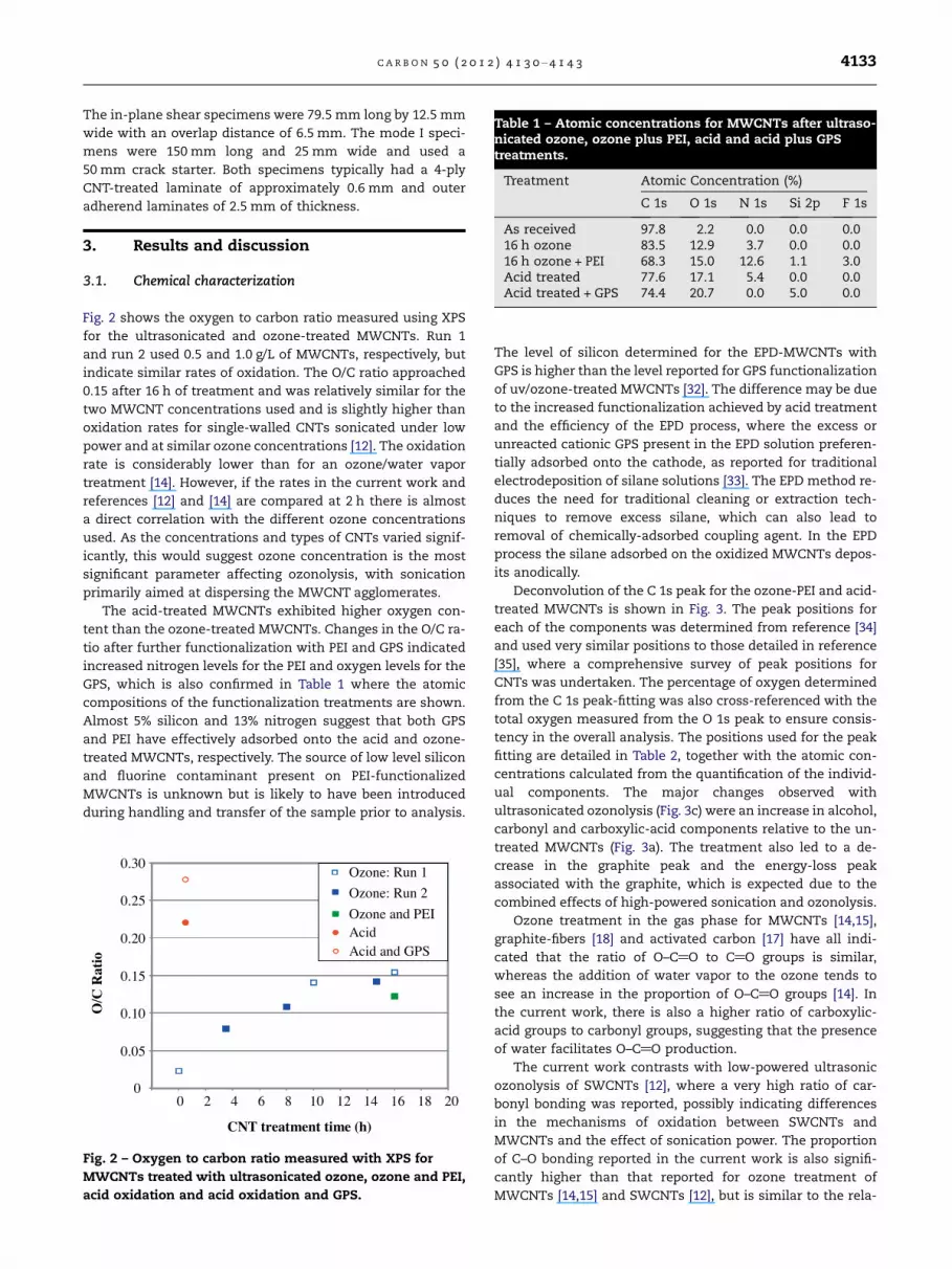
Table 1 – Atomic concentrations for MWCNTs after ultraso-nicated ozone, ozone plus PEI, acid and acid plus GPStreatments.
Treatment Atomic Concentration (%)
C 1s O 1s N 1s Si 2p F 1s
As received 97.8 2.2 0.0 0.0 0.016 h ozone 83.5 12.9 3.7 0.0 0.016 h ozone + PEI 68.3 15.0 12.6 1.1 3.0Acid treated 77.6 17.1 5.4 0.0 0.0Acid treated + GPS 74.4 20.7 0.0 5.0 0.0
C A R B O N 5 0 ( 2 0 1 2 ) 4 1 3 0 – 4 1 4 3 4133
The in-plane shear specimens were 79.5 mm long by 12.5 mm
wide with an overlap distance of 6.5 mm. The mode I speci-
mens were 150 mm long and 25 mm wide and used a
50 mm crack starter. Both specimens typically had a 4-ply
CNT-treated laminate of approximately 0.6 mm and outer
adherend laminates of 2.5 mm of thickness.
3. Results and discussion
3.1. Chemical characterization
Fig. 2 shows the oxygen to carbon ratio measured using XPS
for the ultrasonicated and ozone-treated MWCNTs. Run 1
and run 2 used 0.5 and 1.0 g/L of MWCNTs, respectively, but
indicate similar rates of oxidation. The O/C ratio approached
0.15 after 16 h of treatment and was relatively similar for the
two MWCNT concentrations used and is slightly higher than
oxidation rates for single-walled CNTs sonicated under low
power and at similar ozone concentrations [12]. The oxidation
rate is considerably lower than for an ozone/water vapor
treatment [14]. However, if the rates in the current work and
references [12] and [14] are compared at 2 h there is almost
a direct correlation with the different ozone concentrations
used. As the concentrations and types of CNTs varied signif-
icantly, this would suggest ozone concentration is the most
significant parameter affecting ozonolysis, with sonication
primarily aimed at dispersing the MWCNT agglomerates.
The acid-treated MWCNTs exhibited higher oxygen con-
tent than the ozone-treated MWCNTs. Changes in the O/C ra-
tio after further functionalization with PEI and GPS indicated
increased nitrogen levels for the PEI and oxygen levels for the
GPS, which is also confirmed in Table 1 where the atomic
compositions of the functionalization treatments are shown.
Almost 5% silicon and 13% nitrogen suggest that both GPS
and PEI have effectively adsorbed onto the acid and ozone-
treated MWCNTs, respectively. The source of low level silicon
and fluorine contaminant present on PEI-functionalized
MWCNTs is unknown but is likely to have been introduced
during handling and transfer of the sample prior to analysis.
CNT treatment time (h)
0
0.05
0.10
0.15
0.20
0.25
0.30
0 2 4 6 8 10 12 14 16 18 20
O/C
Rat
io
Ozone: Run 1
Ozone: Run 2
Acid Ozone and PEI
Acid and GPS
Fig. 2 – Oxygen to carbon ratio measured with XPS for
MWCNTs treated with ultrasonicated ozone, ozone and PEI,
acid oxidation and acid oxidation and GPS.
The level of silicon determined for the EPD-MWCNTs with
GPS is higher than the level reported for GPS functionalization
of uv/ozone-treated MWCNTs [32]. The difference may be due
to the increased functionalization achieved by acid treatment
and the efficiency of the EPD process, where the excess or
unreacted cationic GPS present in the EPD solution preferen-
tially adsorbed onto the cathode, as reported for traditional
electrodeposition of silane solutions [33]. The EPD method re-
duces the need for traditional cleaning or extraction tech-
niques to remove excess silane, which can also lead to
removal of chemically-adsorbed coupling agent. In the EPD
process the silane adsorbed on the oxidized MWCNTs depos-
its anodically.
Deconvolution of the C 1s peak for the ozone-PEI and acid-
treated MWCNTs is shown in Fig. 3. The peak positions for
each of the components was determined from reference [34]
and used very similar positions to those detailed in reference
[35], where a comprehensive survey of peak positions for
CNTs was undertaken. The percentage of oxygen determined
from the C 1s peak-fitting was also cross-referenced with the
total oxygen measured from the O 1s peak to ensure consis-
tency in the overall analysis. The positions used for the peak
fitting are detailed in Table 2, together with the atomic con-
centrations calculated from the quantification of the individ-
ual components. The major changes observed with
ultrasonicated ozonolysis (Fig. 3c) were an increase in alcohol,
carbonyl and carboxylic-acid components relative to the un-
treated MWCNTs (Fig. 3a). The treatment also led to a de-
crease in the graphite peak and the energy-loss peak
associated with the graphite, which is expected due to the
combined effects of high-powered sonication and ozonolysis.
Ozone treatment in the gas phase for MWCNTs [14,15],
graphite-fibers [18] and activated carbon [17] have all indi-
cated that the ratio of O–C@O to C@O groups is similar,
whereas the addition of water vapor to the ozone tends to
see an increase in the proportion of O–C@O groups [14]. In
the current work, there is also a higher ratio of carboxylic-
acid groups to carbonyl groups, suggesting that the presence
of water facilitates O–C@O production.
The current work contrasts with low-powered ultrasonic
ozonolysis of SWCNTs [12], where a very high ratio of car-
bonyl bonding was reported, possibly indicating differences
in the mechanisms of oxidation between SWCNTs and
MWCNTs and the effect of sonication power. The proportion
of C–O bonding reported in the current work is also signifi-
cantly higher than that reported for ozone treatment of
MWCNTs [14,15] and SWCNTs [12], but is similar to the rela-

280 285 290 295 280 285 290 295
280 285 290 295280 285 290 295
525 530 535 540
Cou
nts
(arb
.)
Binding Energy (eV)
Cou
nts
(arb
.)
Binding energy (eV)
Cou
nts
(arb
.)
Binding energy (eV)
Cou
nts
(arb
.)
Binding energy (eV)
Cou
nts
(arb
.)
Binding (eV)
395 400 405
Cou
nts
(arb
.)
Binding energy (eV)
a b
c d
e f
Fig. 3 – C 1s peak-fitting components for the MWCNTs (a) before functionalization and after (b) acid treatment, (c) ozone (d)
ozone plus PEI, and (e) O 1s and (f) N 1s peak-fitting components for the ozone plus PEI MWCNTs.
Table 2 – XPS peak fitting results for the untreated, acid oxidized, ozone and ozone plus PEI functionalized MWCNTs.
Treatment Atomic concentration (%)
C 1s Peak fitting component
Graphite C–C C–O/C–N C@O/C@N O–C@O/N–C@O p! p*
284.6 eV 285.0 eV 286.5 eV 288.2 eV 289.3 eV 291.4 eV
Untreated 72 10 2 1 0 15Acid 46 11 7 3 5 6Ozonolysis 57 9 6 2 3 7Ozone-PEI 10 18 25 9 4 1
Treatment N 1s Peak fitting component O 1s Peak fitting component
Pyridinic N–C@O Oxidized-Pyridinic N–C@O O–C/[email protected] eV 400.6 eV 402.1 eV 531.4 eV 533.0 eV
Ozone-PEI 1 10 2 4 10
4134 C A R B O N 5 0 ( 2 0 1 2 ) 4 1 3 0 – 4 1 4 3

Temperature (°C)
Mas
s (%
)
PEI Ozone CNT + PEI
Untreated CNT
Ozone CNT
0
20
40
60
80
100
250 350 450 550 650 750 150
Fig. 4 – Thermal-gravimetric analysis for MWCNTs after
ozonolysis and PEI treatment with PEI-reference compound.
C A R B O N 5 0 ( 2 0 1 2 ) 4 1 3 0 – 4 1 4 3 4135
tive amounts reported for ozone treatment of carbon-fibers
[18] and activated carbon [17]. Possibly, the relative water con-
centration and high-sonication power also influences the pro-
portion of C–OH groups that form during ozonolysis.
A comparison of the ozone (Fig. 3c) and acid-treated
(Fig. 3b) MWCNTs shows that the acid treatment produces a
higher proportion of carboxylic-acid groups compared to the
ozone treatment, consistent with previous characterizations
[7,15]. However, the main differences between the acid and
ozone-treated MWCNTs are simply the higher levels of oxida-
tion achieved with hot-acid treatment, as shown in Table 1.
The ozone and PEI-functionalized MWCNTs (Fig. 3d) show
significant changes in the C 1s spectrum due to the adsorp-
tion of the nitrogen-rich polyelectrolyte, with more than
30% of the carbon species attributable to amine or amide
bonding, as shown in Fig. 3. Some graphitic character is still
detected, which may suggest that the PEI-layer thickness is
less than the escape depth of C 1s photoelectrons produced
from the MWCNTs, estimated to be 3 to 5 nm. Similarly, the
ratio of C to N in the PEI is around 2 to 1, suggesting around
25% of the carbon signal is attributable to PEI, based on
Table 1.
The O 1s and N 1s-photoelectron peaks in Fig. 3e and
Fig. 3f, respectively, for the ozone and PEI-treated MWCNTs
may suggest the presence of amide bonding. The O 1s peak
shows a distinct shoulder and the two fitted components at
531.4 and 533.0 eV are likely to include amide and carbon in
oxygen bonding environments, respectively, based on previ-
ously reported measurements [34,36–38]. The major peak in
the N 1s spectrum at 400.6 eV is approximately 1.1 eV higher
than the position quoted for amine bonding in linear PEI
[34], electrochemically-deposited PEI [39] and PEI films on me-
tal where chemical bonding was absent [40]. The binding en-
ergy shift may be associated with chemical bonding between
the PEI and ozone-treated MWCNTs. However, amide and
imide bonding environments have been measured at values
between 399.8 to 400.6 eV [38,41] and the formation of pyrid-
inic-ring structures [36] in the same range can make accurate
assignment difficult. The peaks at 398.4 and 402.1 eV have
been associated with pyridinic and oxidized-pyridine struc-
tures [36], but several different nitrogen bonding environ-
ments also occur in these positions. Nevertheless, the
combined analysis of the C 1s, O 1s and N 1s peaks suggests
that amide bonds are likely to be present, indicative of a
chemical reaction between the PEI and ozone-treated
MWCNTs.
3.2. Physical characterization and film growth
Fig. 4 shows the TGA results for the MWCNTs after ultrasonic
ozonolysis and PEI functionalization. The results suggest that
the EPD coating contains around 25% PEI, which is within the
range estimated from the XPS measurements. The decompo-
sition temperatures are also quite similar to those reported
for benzoic acid and PEI-functionalized CNTs [22].
Fig. 5 shows the morphology of the ultrasonicated and
ozone-treated MWCNTs at 20 min (Fig. 5a) and 16 h (Fig. 5b)
treatment time. The images show a clear reduction in the
number of small agglomerates around the 1–2 lm range, sug-
gesting that the treatment has assisted in reducing the aver-
age size of MWCNT agglomerates present in the original
material. Despite the agglomerates present in the 20 min-
treated MWCNTs, the dispersion has remained stable after
several months. Fig. 5 also shows the EPD films deposited
on stainless steel produced from the acid treated (Fig. 5c)
and ozone-PEI MWCNTs (Fig. 5d). The two films both show
sub-micron-scale porosity resulting from evolved gas pro-
duced by water electrolysis, but indicate clear differences in
local alignment and size. The acid-treated MWCNT exhibit
some local alignment that has previously been observed for
films formed by filtration of dispersions with concentrations
greater than 5 g/L [7], whereas the ozone-PEI MWCNTs show
more random entanglement where the average length ap-
pears greater. Deposition of the acid (Fig. 5e) and ozone-PEI
MWCNTs (Fig. 5f) onto the T700S carbon-fibers for short treat-
ment times shows very uniform coverage and similar porosity
to the films deposited on the planar stainless-steel surfaces,
although the acid-treated MWCNTs do not exhibit the local
quasi-alignment.
Fig. 6 plots the mass increase in ozone-PEI MWCNTs with
deposition time on the carbon-fiber fabric. The peak in weight
occurs rapidly, corresponding to almost full depletion of the
MWCNT solution, which had an original concentration of
0.5 g/L. However, with time the mass decreases before re-
establishing the original peak weight at extended deposition
time. SEM images of the deposited films at 1 min (Fig. 7a),
4 min (Fig. 7b) and 20 min (Fig. 7c and d) suggest that a film
around 0.5 lm accumulates on the outer fibers quickly, but
at extended periods this film thins to less than 100 nm and
larger pores develop (Fig. 7c), particularly, in the inter-fiber re-
gions. Sub-micron porosity of the film also increases with
deposition time due to vigorous gas evolution. The deposition
cell also showed the gas-evolution reactions increased as the
EPD-cell temperature increased from Joule heating, displacing
the outer-coating, which redeposited the redispersed MWCNT
at extended times.
Modeling of EPD indicates processes such as Joule heating,
electrothermal flow and field-induced electro-osmotic fluid
flow affect film formation [42]. The electrokinetic factors lead
to particle aggregation and film formation, whereas Brownian

Fig. 5 – SEM images showing (a) and (b) the influence of the combined ozonolysis and ultrasonication on the MWCNT film
morphology, a comparison of EPD films of (c) acid and (d) ozone-PEI treated MWCNTs deposited on stainless-steel and (e) acid
and (f) ozone-PEI treated MWCNTs deposited on carbon-fiber.
4136 C A R B O N 5 0 ( 2 0 1 2 ) 4 1 3 0 – 4 1 4 3
diffusion acts to randomize the particle distribution in solu-
tion [43]. Potentially, at increased deposition times, Brownian
diffusion assists the redistribution of the MWCNTs into the
inner-fabric regions. A previously proposed mechanism for
the initial deposition of the PEI-functionalized MWCNTs in-
volves the hydroxyl ions, generated at the cathode through
water electrolysis, neutralizing the protonated amino groups
and aggregating at the electrode [44]. In the case of increased
heating and vigorous gas evolution displacing the coating, it
may be possible that a combination of electro-osmosis and
Brownian diffusion assist the movement of MWCNTs with
different zeta-potentials to the inner-fabric regions. Previous
work on EPD of ceramic particles suggests that if they possess
similar charges to the fiber then a repulsive force is estab-
lished, facilitating good penetration of the coating into the
fabric [45]. The high concentration of hydroxyl groups at the
cathode may assist in creating repulsive charge between the
solution and negatively-charged fibers, aiding diffusion of
the neutralized MWCNTs.
3.3. Laminate characterization and mechanical properties
Table 3 shows the composition of the carbon/epoxy laminates
with the different functionalized MWCNTs deposited on the

0
0.1
0.2
0.3
0.4
0.5
0.6
0
3
6
9
12
15
0 5 10 15 20 25
MWCNT weight %
Deposition Rate
Deposition time (min)
MW
CN
T w
eigh
t (%
)
Deposition rate (m
g.cm-2.m
in-1)
Fig. 6 – Weight increase and deposition rate for
electrophoretic coating of carbon-fiber fabric with ozone and
PEI-functionalized MWCNTs.
Fig. 7 – SEM micrographs indicating the change in film morpho
MWCNTs: (a) 1 min (7 wt.% MWCNTs), (b) 4 min (13 wt.% MWCN
Table 3 – Volume-fraction composition of carbon-fiber/epoxy lamMWCNTs prior to resin infusion, indicating fiber (f), coating, ma
Treatment Volume fraction composition (%)
Vf Vcoating
No treatment 63.2 0.0Std. dev. 1.3 0.0Ozone Treated 60.3 4.3Std dev. 0.3 0.1PEI ozone 48.5 6.6Std Dev. 0.2 0.1Acid treated 57.2 3.8Std dev. 3.1 0.2Acid treated + GPS 55.4 3.7Std dev. 1.7 0.1
C A R B O N 5 0 ( 2 0 1 2 ) 4 1 3 0 – 4 1 4 3 4137
fabric by EPD prior to resin infusion. The volume fraction of
MWCNTs in the epoxy matrix (VCNT/Vm) was around 10% for
each treatment, but there was a reduction in the fiber-volume
fraction (Vf) from the untreated laminate, particularly for the
ozone-PEI treated laminate. Aside from the acid-treated and
GPS-MWCNT treatment, all laminates exhibited similar void-
ing (Vv) between 1% and 3%. These results suggest that the
VARTM method has produced good-quality laminates. Addi-
tionally, for the purposes of examining the effect of MWCNTs
on matrix dominated properties such as shear strength, the
similar MWCNT concentrations should enable a reasonable
comparison of the deposition and functionalization methods
employed.
Initial tests examining the influence of the electrophoreti-
cally-deposited MWCNTs on the carbon/epoxy in-plane shear
strength are shown in Fig. 8. The ozone-treated MWCNTs do
not appear to make any significant difference to the baseline
shear strength, whereas the ozone-PEI treated MWCNTs show
almost 70% increase in baseline strength. The improvement is
logy and thickness with deposition times of ozone-PEI
Ts), (c) and (d) 20 min (13 wt.% MWCNTs).
inates in which the fiber was electrophoretically coated withtrix (m), void (v) and MWCNT (CNT) fractions.
Vm Vv VCNT/Vf VCNT/Vm
34.5 2.3 0.0 0.00.1 1.2 0.0 0.0
32.9 2.5 6.6 11.51.0 0.7 0.1 0.4
43.5 1.3 9.0 10.11.5 1.3 0.1 0.4
36.4 2.6 6.2 9.52.3 1.0 0.3 0.8
35.8 5.1 6.2 9.32.4 0.6 0.2 0.6

0
5
10
15
20
25
30
35
40
45
MWCNT treatment
No MWCNT Ozone Acid Acid+GPS
Ozone + PEI
Shea
r st
reng
th (
MP
a)
Fig. 8 – Shear strength measured for carbon/epoxy
composites where the unidirectional fiber was treated by
electrophoretic deposition of functionalized MWCNTs.
MWCNT deposition time (min)
0
10
20
30
40
50
60
0 0.5 10 10 40
Shea
r st
reng
th (
MP
a)
No MWCNT
Ozone + PEI
Ozone + PEI + GPS
MWCNT weight (%)0 4 12 12 13
Fig. 9 – Shear strength measured for carbon/epoxy
composites where the unidirectional carbon-fiber was
treated for increasing EPD times with ozone- PEI MWCNTs.
4138 C A R B O N 5 0 ( 2 0 1 2 ) 4 1 3 0 – 4 1 4 3
significantly greater than previously reported improvements
in shear properties for carbon/epoxy composites prepared
using EPD with PEI-functionalized CNTs [11]. The two lami-
nates prepared with the acid-treated MWCNTs showed signif-
icant variation in shear strength, which corresponded to
failure surfaces where the fracture plane propagated between
different plies. The variability in strength resulting from inho-
mogeneous-through-thickness coating of the fabric by the
MWCNTs, therefore, may have contributed to the experimen-
tal scatter. Due to the scatter in the results for the acid-trea-
ted MWCNTs, it is not possible to determine if the silane
functionalization led to improved strength.
The reasons for the lack of improvement observed for the
ozone-treated MWCNTs is not obvious, given previous work
suggests that ozone-treated MWCNTs can lead to increased
tensile properties of 20% for only 1% loading in an epoxy resin
[16]. In the present work, the XPS peak-fitting results (Fig. 3)
suggest that the ozone-functionalized MWCNTs had reduced
levels of oxidation and a lower concentration of carboxylic
acid groups compared to the acid-treated MWCNTs. Given
that some of the acid-treated MWCNT samples exhibited
good strength improvement, then the reduced number of O–
C@O groups in the ozone-treated MWCNTs may be a factor
affecting the shear-strength properties in the laminate. Previ-
ous studies on the adhesion strength of carbon-fibers to
epoxy resin suggest that the interfacial-shear strength in-
creases proportionally with oxygen content of the fiber [46].
The improvement in shear strength for the ozone-PEI
MWCNT treatment is quite significant relative to the baseline
and ozone only treatments and the variability is quite low
compared to the acid-functionalized MWCNT treatments.
The major difference in the deposited films is the addition
of the PEI polyelectrolyte to the matrix at around 5% by vol-
ume, resulting from reaction with the ozone-treated
MWCNTs. Previous work has used PEI as a graded-modulus
material for enhancing epoxy-resin toughness, while main-
taining stiffness [47]. At 2.5–5% addition of PEI to an epoxy re-
sin, the toughness was reported to have increased by 30–40%
with maintenance of stiffness, potentially facilitated by the
formation of localized, high cross-link density bonds between
the PEI-dendrimer branches and epoxy resin. In the present
work the 5% of PEI is also available where the PEI chemically
links between the MWCNT and the epoxy resin and this may
assist in toughening the film, without compromising the stiff-
ness increase provided by the MWCNTs. Further, the benefit
of the chemical link between the PEI and the ozone-treated
MWCNTs provides a strong bond via the PEI to the resin.
The additional toughening provided by the PEI links may pro-
vide some tolerance of the high-concentration MWCNT ma-
trix to voids, defects or localized agglomerates, which is not
present in the ozone or acid-treated MWCNT coatings, con-
tributing to the variability in those coatings measured
strength. Previous work has also shown small but measurable
increase in shear strength provided by EPD of PEI-functional-
ized MWCNTs [11], however, the MWCNTs were not oxygen
functionalized and the level of PEI and CNTs were at signifi-
cantly lower levels than the current work. It appears levels
above 2% PEI may be required to influence resin-toughness
properties [47]. The PEI may also offer improved bonding to
the as-received sized carbon-fiber.
Given the good initial results offered by the ozone-PEI
MWCNTs, further experiments were conducted to examine
the influence of deposition time on the in-plane shear
strength. Fig. 9 shows the shear strength for the carbon/epoxy
laminates as a function of deposition time for the ozone-PEI
functionalized MWCNTs. In one case, GPS was also added to
the ozone, MWCNT and PEI mixture to assess if a smaller
molecular-weight coupling agent may affect properties. The
results show that there is a clear increase in shear strength
with time and that the addition of GPS has no obvious effect.

C A R B O N 5 0 ( 2 0 1 2 ) 4 1 3 0 – 4 1 4 3 4139
The change in shear strength is also shown as a function of
the weight percentage of MWCNTs on the fabric in the upper
axis in Fig. 9. The increasing trend in strength to 12 weight
percent of MWCNTs is understandable, but the further in-
crease in strength at 40 min deposition time, where the in-
crease in MWCNT weight is small must be related to
changes in the coating morphology and distribution observed
in Fig. 7. A better coating distribution through the fabric is im-
plied by the similar weights of the 10 and 40 min coatings but
the thinner outer-film present for the longer coating times
(Fig. 7). Additionally, the increased porosity, particularly in
the inter-fiber region, created by the extended gas-evolution
at higher temperatures for the 40-min films, leads to a 20%
thinner laminate than the 10-min treatment. It is envisaged
that the large pores developing in the coating aid in resin per-
meation throughout the fabric, providing better laminate
consolidation.
The through-thickness distribution of the ozone-PEI
MWCNTs for the 40 min EPD treated laminate was further
examined by taking optical micrographs of polished 0.2 mm
cross-sections of the composite laminate. Fig. 10 shows that
the transmitted light for the laminate containing the
MWCNTs is very low compared to the baseline laminate with-
out MWCNTs. The clear line at the top of the MWCNT con-
taining laminate is due to the clear potting resin used to
prepare the cross-section. The optical image suggests that
the extended treatment time has facilitated diffusion of the
ozone-PEI MWCNTs through the laminate thickness and has
contributed to the improved shear strength for the 40 min
EPD treatment.
Fracture surfaces corresponding to the different treatment
times are shown in Fig. 11. Progressively, two changes in the
interfacial fiber to matrix fracture can be observed. Firstly,
there appears to be an increase in the plasticity of the fracture
in the resin-rich interlaminar area, which corresponds to
higher MWCNT concentrations in the matrix. Secondly, the
percentage of failure within a thin, MWCNT-resin-rich layer
on the fiber surface appears to increase. Both these changes
in fracture appearance would suggest that there is a better
coverage of MWCNTs and improved bonding between the
MWCNT coating and the as-received sized fiber, which would
both be expected to contribute to the improved mechanical
strength. The improved bonding between the resin-impreg-
Fig. 10 – Optical micrographs acquired at 100· magnification us
composite laminates (a) without and (b) with MWCNT coating.
nated coating and fiber with treatment time may be related
to either increased coating porosity leading to better resin
wetting and/or extended exposure to the alkaline hydrolysis
conditions favorably affecting adhesion.
Fig. 12 shows a high-magnification SEM image in the resin-
rich interlaminar zone of a failed carbon/epoxy-shear sample,
where the fabric was treated with a 10 min-EPD coating of
ozone-PEI MWCNTs. The MWCNTs that are exposed after
fracture show some degree of alignment in the fiber direction,
which may be expected in order to facilitate their diffusion
into the fabric tows. MWCNT alignment could also improve
the shear strength and stiffness of the matrix region and
may contribute to the observed increase in measured
strength.
The results presented for the ozone-PEI treatments in
Fig. 9 suggest that the improvement in strength with increas-
ing deposition time is due to a combination of improved inter-
facial adhesion between the MWCNTs and the fiber surface
(Fig. 11) and some through-thickness distribution of
MWCNTs, which could enable better laminate consolidation
and higher fiber volume fraction. However, whilst these con-
clusions may be drawn for the influence of EPD time on
ozone-PEI treated laminates, the influence of fiber volume
fraction, Vf, should also be considered for the different treat-
ments examined.
The ozone-PEI treatments exhibit lower Vf than the lami-
nates with the ozone and acid treated MWCNTs (Table 3)
and the baseline laminate. Table 4 shows the Vf for the differ-
ent ozone-PEI laminates and the average in-plane shear
strength for the results shown in Fig. 9, compared to the base-
line case. Also shown is a separate treatment which used
ozone treated MWCNTs and a longer treatment time to pro-
vide a higher volume fraction of MWCNTs around 6%. The
overall results do not suggest there is a clear trend in Vf and
shear strength. The 40 min ozone-PEI laminate has a lower
Vf than the 10 min treatment, despite the higher MWCNT
fraction, and would be consistent with increased Vf leading
to better shear strength. The ozone treatment exhibits similar
Vf to the 40 min ozone-PEI treatment but has strength similar
to the baseline laminate, suggesting that a higher matrix vol-
ume does not necessarily provide higher shear strength. Gen-
erally, the fracture surfaces of the lower strength laminates
exhibited clean fracture at the fiber and matrix interface, sug-
ing transmitted light for cross-sections of carbon-epoxy

Fig. 12 – High-magnification SEM image in the resin-rich
interlaminar zone of a failed carbon/epoxy-shear sample
where the fabric was treated with a 10 min-EPD coating of
ozone-PEI MWCNTs.
Fig. 11 – SEM micrographs indicating the fracture surfaces of failed in-plane shear specimens for carbon/epoxy composite
with (a) no treatment and EPD-MWCNT treatment for (b) 30 s, (c) 10 min and (d) 40 min.
Table 4 – Fiber volume fraction (Vf) and in-plane shearstrength for carbon-epoxy laminates prepared using ozone-PEI (Fig. 9) and ozone functionalized MWCNTS.
Treatment None Ozone-PEI
Ozone-PEI
Ozone-PEI
Ozone
EPD time(min)
0 0.5 10 40 40
Vf (%) 60 55 47 50 49Shear strength(MPa)
32 38 44 55 33
4140 C A R B O N 5 0 ( 2 0 1 2 ) 4 1 3 0 – 4 1 4 3
gesting that adhesion between the MWCNTs and fiber surface
is a critical factor and that the interfacial properties make a
significant contribution to the shear strength (See Table 4).
The results and modeling presented by Barbero for E-glass
composite laminates also suggest that in-plane shear
strength increases with increasing Vf [48], which would be
consistent with the 40 min ozone-PEI treatment exhibiting
higher shear strength. In theory, the addition of MWCNTs
should increase the shear modulus and the good interfacial
adhesion afforded by the PEI functionalization should enable
higher shear strain to be achieved, resulting in higher
strength. The results suggest there is a motivation to further
increase the Vf of the ozone-PEI laminates as this may lead to
higher shear strength. The other motivation to achieve higher
Vf in the ozone-PEI MWCNT treated laminates would be to
replicate the in-plane tensile properties of the baseline lami-
nate, which would be higher than the MWCNT laminate due
to the higher Vf.
Additional testing of the carbon/epoxy laminates with
MWCNT treatments examined the mode I fracture-energy.
Fig. 13 shows the mode I fracture-energy measured for car-
bon/epoxy composites where the unidirectional fiber was
treated for increasing EPD times with ozone-PEI MWCNTs.
There is approximately 80% increase in the fracture-energy
between the untreated laminate and the 40-min EPD treat-
ment. The scatter in the results make it difficult to identify
a definitive trend, but there is a clear increase in fracture en-
ergy which corresponds to an increase in the level of plastic
fracture between no-treatment and 40-min EPD treated sam-
ples, as shown in Fig. 14. As was observed with the shear-fail-
ure surfaces in Fig. 11, there appears to be an increase in the
fracture in the coating on the fiber surfaces, although, not to

0
50
100
150
200
250
MWCNT deposition time (min)0 0.5 10 40
GIc
(J/
m2 )
No MWCNT
Ozone + PEI
Fig. 13 – Mode-I fracture energy measured for carbon/epoxy
composites where the unidirectional fiber was treated for
increasing EPD times with ozone-PEI MWCNTs.
C A R B O N 5 0 ( 2 0 1 2 ) 4 1 3 0 – 4 1 4 3 4141
the same level as the shear-failure surfaces. The fracture en-
ergy values are modest compared to some examples where
the CNTs are grown by CVD and are oriented in a perpendic-
ular direction with respect to the fiber [49]. However, in cases
where MWCNTs have been added directly to epoxy resin, sim-
ilar levels of fracture energy were observed at 0.5% by weight
for well-dispersed systems [50]. The fact that the MWCNTs
are aligned more in a two-dimensional plane parallel with
the fiber may reduce their mode I-toughening capacity, com-
pared to perpendicular alignment or random-3D orientation.
Nevertheless, the increase in fracture energy is also associ-
ated with good increases in shear strength. Often with tradi-
tional rubber-toughening systems the increase in toughness
is at the expense of strength [47]. In relative terms, the frac-
ture energy levels measured for the MWCNT treated samples
are comparable to carbon/epoxy composites using toughened
resin systems [51].
Consideration should also be given to the influence of Vf
on the mode I fracture toughness. As for the in-plane shear
Fig. 14 – SEM micrographs indicating the fracture surfaces of fa
composite with no treatment (left) and 40-min EPD of ozone-PE
case, the 40 min EPD treatment had a higher Vf than the
10 min treatment, despite the higher MWCNT fraction. This
may also point towards higher Vf leading to improved fracture
toughness. The influence of resin volume on mode I fracture
toughness is also complicated by the fact that the introduc-
tion of the crack-starter film between the adjacent plies leads
to a localized increase in matrix volume in the region where
the crack initiation energy is measured. Given that the GIc va-
lue measured for the baseline laminate around 112 J/m2
(Fig. 13) is approaching the value of 130 J/m2 reported for the
neat resin [50] this may suggest that resin volume effects
are not making a significant contribution to the GIc value
measured for the laminate with the 40 min ozone-PEI
treatment.
Additional consideration should also be given to the po-
tential effect of resin-rich layers which may develop in the
interply regions as a result of the introduction of CNTs into
the carbon fabric, as identified in a recent review on factors
influencing the performance of hierarchical-composite mate-
rials [52]. Cross-sectional images of the ozone-PEI MWCNT
treated composites shown in the Supplemental information
(Fig. S3) for the different treatment times suggest that the re-
sin rich region in the CNT treated laminates are only margin-
ally thicker than the baseline case. The 10 min ozone-PEI
treated laminate has a resin rich region around 3 fiber diam-
eters or approximately 20 lm, whereas the 40 min treatment
is around 15 lm, compared to the baseline laminate which
is around 8 lm. If the resin-layer thickness was making a sig-
nificant contribution to the toughness then it would be ex-
pected the 10 min treatment should exhibit the highest
toughness, which is not the case, as shown in Fig. 13. Recent
work examining incorporation of resin-interply layers, using
the same resin system as the current work, suggested that
even quite thick resin-interleaf layers of the order of 50 lm
had minimal effect on initiation or propagation fracture
toughness [53]. Higher magnification images of the resin-rich
regions in the ozone-PEI treated CNT laminate (Fig. S4) also
show that the fracture propagates close to the fiber–matrix
interface, which suggests that improved bonding in this re-
gion makes a good contribution to the observed increases in
iled double-cantilever beam specimens for carbon/epoxy
I MCWNTs (right).

4142 C A R B O N 5 0 ( 2 0 1 2 ) 4 1 3 0 – 4 1 4 3
shear strength and fracture toughness. This conclusion is also
consistent with the observation that resin-interply layers
containing CNTs with different functionalization treatments
provided no toughness enhancement compared to a baseline
laminate [53].
4. Conclusions
The use of a recirculating, ultrasonicated, ozonolysis system
has provided an efficient and convenient method for prepar-
ing large volumes of stable-MWCNT dispersions that were
suitable for electrophoretic deposition onto carbon-fiber fab-
rics. The ozone-treated MWCNTs chemically reacted with
the PEI dendrimer and produced a functionalized-EPD coating
on carbon-fibers that enabled good adhesion with an epoxy
resin and the sized carbon-fiber surface. The hierarchical-
composite structures exhibited significant increases in shear
strength and fracture energy due to the relatively high levels
of MWCNTs that occupied the resin-rich interlaminar re-
gions. EPD offered a low-energy method to modify the
mechanical properties of carbon-fiber/epoxy composites in a
controlled manner.
Acknowledgements
This research is funded by the Air Force Office of Scientific Re-
search (AFOSR) Young Investigator Grant (FA9550-09-1-0218),
Dr. Byung-Lip Lee, Program Director and the US Army Pro-
gram Executive Office: Soldier and the Army Research Labora-
tory and was accomplished under Cooperative Agreement
Number W911NF-06-2-011. The authors would like to thank
Mr. Emre Yassitepe for acquisition of the XPS data and Dr.
Lin Gao for film deposition studies.
Appendix A. Supplementary data
Supplementary data associated with this article can be found,
in the online version, at http://dx.doi.org/10.1016/
j.carbon.2012.04.061.
R E F E R E N C E S
[1] Thostenson ET, Li WZ, Wang DZ, Ren ZF, Chou TW. Carbonnanotube/carbon fiber hybrid multiscale composites. J ApplPhys 2002;91(9):6034–7.
[2] Zhang Q, Liu J, Sager R, Dai L, Baur J. Hierarchical compositesof carbon nanotubes on carbon fiber: influence of growthcondition on fiber tensile properties. Comp Sci Technol2009;69(5):594–601.
[3] Qian H, Bismarck A, Greenhalgh ES, Shaffer MSP. Carbonnanotube grafted carbon fibres: A study of wetting and fibrefragmentation. Comp Pt A 2010;41:1107–14.
[4] Boccaccini AR, Roether JA, Thomas BJC, Shaffer MSP. Theelectrophoretic deposition of inorganic nanoscaled materials.J Ceram Soc Jpn 2006;114(1):1–14.
[5] Boccaccini AR, Cho J, Roether JA, Thomas BJC, Minay EJ,Shaffer MSP. Electrophoretic deposition of carbon nanotubes.Carbon 2006;44:3149–60.
[6] Boccaccini AR, Cho J, Subhani T, Kaya C, Kaya F.Electrophoretic deposition of carbon nanotube–ceramicnanocomposites. J Eur Cer Soc 2010;30:1115–29.
[7] Shaffer MSP, Fan X, Windle AH. Dispersion and packing ofcarbon nanotubes. Carbon 1998;36(11):1603–12.
[8] Cho J, Konopka K, Rozniatowski K, Garcıa-Lecina E, ShafferMSP, Boccaccini AR. Characterisation of carbon nanotubefilms deposited by electrophoretic deposition. Carbon2009;47:58–67.
[9] Chavez-Valdez A, Boccaccini AR. Innovations inelectrophoretic deposition: alternating current and pulseddirect current methods. Electrochim Acta 2012;65:70–89.
[10] Bekyarova E, Thostenson ET, Yu A, Kim H, Gao J, Tang J, et al.Multiscale carbon nanotube-carbon fiber reinforcement foradvanced epoxy composites. Langmuir 2007;23(7):3970–4.
[11] Lee S, Choi O, Lee W, Yi J, Kim B, Byun J, et al. Processing andcharacterisation of multi-scale hybrid composites reinforcedwith nanoscale carbon reinforcements and carbon fibers.Comp Pt A 2011;42:337–44.
[12] Li M, Boggs M, Beebe TP, Huang CP. Oxidation of single-walledcarbon nanotubes in dilute aqueous solutions by ozone asaffected by ultrasound. Carbon 2008;46:466–75.
[13] Sham M-L, Kim J-K. Surface functionalities of multi-wallcarbon nanotubes after UV/Ozone and TETA treatments.Carbon 2006;44:768–77.
[14] Peng K, Liu L, Li H, Meyer H, Zhang Z. Room temperaturefunctionalisation of carbon nanotubes using an ozone/watervapor mixture. Carbon 2011;49:70–6.
[15] Wepasnick KA, Smith BA, Schrote KE, Wilson HK,Diegelmann SR, Fairbrother DH. Surface and structuralcharacterization of multi-walled carbon nanotubes followingdifferent oxidative treatments. Carbon 2011;49:24–36.
[16] Tang L, Zhang H, Han J, Wu X, Zhang Z. Fracture mechanismsof epoxy filled with ozone functionalized multi-wall carbonnanotubes. Comp Sci Tech 2011;72:7–13.
[17] Chiang H, Huang CP, Chiang PC. The surface characteristicsof activated carbon as affected by ozone and alkalinetreatment. Chemosphere 2002;47(3):257–65.
[18] Osbeck S, Bradley RH, Liu C, Idriss H, Ward S. Effect of anultraviolet/ozone treatment on the surface texture andfunctional groups on polyacrylonitrile carbon fibres. Carbon2011;49:4322–30.
[19] Zhitomirsky I. Electrophoretic deposition of organic-inorganic nanocomposites. J Mater Sci 2006;41:8186–95.
[20] Sun J, Gao L. Development of a dispersion process for carbonnanotubes in ceramic matrix by heterocoagulation. Carbon2003;41(5):1063–8.
[21] Petrinca AR, Donia D, Cicchetti R, Valentini F, Argentin G,Carbone M, et al. J Virol Meth 2010;168(1–2):1–5.
[22] Casagrande T, Lawson G, Lia H, Wei J, Adronova A,Zhitomirsky I. Electrodeposition of composite materialscontaining functionalized carbon nanotubes. Mat Chem Phys2008;111(1):42–9.
[23] Bose S, Khare RA, Moldenaers P. Assessing the strengths andweaknesses of various types of pre-treatments of carbonnanotubes on the properties of polymer/carbon nanotubescomposites: A critical review. Polym 2010;51:975–93.
[24] Ibanez JG, Alatorre-Ordaz A, Mayen-Mondragon R, Moran-Moran, MT, Mattson B, et al. Laboratory experiments on theelectrochemical remediation of the environment, Part 7Microscale production of ozone. J Chem Edu 2005;82:1546–8.
[25] Scofield, JH. Theoretical photoionization cross sections from1 to 1500 keV. Lawrence Livermore National Laboratory,Report UCRL-51326. 1973.
[26] Fairley N. CasaXPS Manual 2.3.15. Casa Software Ltd, Acolyte,Science. 2009.
[27] Seah MP, Smith GC. Quantitative AES and XPS: Determinationof the electron spectrometer transmission function and the

C A R B O N 5 0 ( 2 0 1 2 ) 4 1 3 0 – 4 1 4 3 4143
detector sensitivity energy dependencies for the productionof true electron emission spectra in AES and XPS. Surf InterfAnal 1990;15:751–66.
[28] ASTM Standard D 1505. Test method for density of plastics bythe density-gradient technique. American Society for Testingand Materials, West Conshohocken, PA. 2003.
[29] ASTM Standard D 3171. Standard test methods forconstituent content of composite materials. AmericanSociety for Testing and Materials, West Conshohocken, PA.2006.
[30] ASTM Standard D 3846. Standard Test Method for In-PlaneShear Strength of Reinforced Plastics. American Society forTesting and Materials, West Conshohocken, PA. 2002.
[31] ASTM Standard D 5528–01. Standard Test Method for Mode IInterlaminar fracture toughness of unidirectional fiber-reinforced polymer matrix composites. American Society forTesting and Materials, West Conshohocken, PA. 2001.
[32] Ma PC, Kim J-K, Tang BZ. Functionalization of carbonnanotubes using a silane coupling agent. Carbon2006;44:3232–8.
[33] Woo H, Reucroft PJ, Jacob RJ. Electrodeposition oforganofunctional silanes and its influence on structuraladhesive bonding. J Adhesion Sci Technol 1993;7(7):681–97.
[34] Briggs D, Beamson G. High resolution XPS of organicpolymers: the Scienta ESCA300 Database. Chichester NewYork: Wiley; 1992.
[35] Okpalugo TIT, Papakonstantinou P, Murphy PH, McLaughlin J,Brown NMD. High resolution XPS characterization ofchemical functionalized MWCNTs and SWCNTs. Carbon2005;43:153–61.
[36] Burg P, Fydrych P, Cagniant D, Gerard N, Bimer J, Jankowsa A.The characterization of nitrogen-enriched activated carbonsby IR XPS and LSER methods. Carbon 2002;40:1521–31.
[37] Bradley RH, Beamson G, Ling X, Sutherland I. Surfacenitrogen chemistry of PAN carbon fibres. App Surf Sci1993;72:273–6.
[38] Shin DH, Kim N, Lee YT. Modification to the polyamide TFCRO membranes for improvement of chlorine-resistance. J.Memb Sci 2011;376:302–11.
[39] Segut O, Herlem G, Lakard B, Blondeau-Patissier V, Nardin M,Gree S, et al. Electrochemically deposited polyethyleneiminefilms and their characterization. Syn Met 2010;160:1359–64.
[40] Finsgar M, Fassbender S, Nicolini F, Milosev I.Polyethyleneimine as a corrosion inhibitor for ASTM 420stainless steel in near-neutral saline media. Corr Sci2009;51:525–33.
[41] Alexander MR, Jones FR. Effect of electrolytic oxidation uponthe surface chemistry of type A carbon fibres: III chemicalstate, source and location of surface nitrogen. Carbon1996;34(9):1093–102.
[42] Burg BR, Bianco V, Schneider J, Poulikakos D. Electrokineticframework of dielectrophoretic deposition devices. J ApplPhys 2010; 107, 124308–1-124308-11.
[43] Solomentsev Y, Guelcher SA, Bevan M, Anderson JL.Aggregation dynamics for two particles duringelectrophoretic deposition under steady fields. Langmuir2000;16:9208–16.
[44] Casagrande T, Imin P, Cheng F, Botton GA, Zhitomirsky I,Adronov A. Synthesis and electrophoretic deposition ofsingle-walled carbon nanotube complexes with a conjugatedpolyelectrolyte. Chem Mater 2010;22:2741–9.
[45] Stoll E, Mahr P, Kruger HG, Kern H, Thomas BJC, BoccacciniAR. Fabrication technologies for oxide-oxide ceramic matrixcomposites based on electrophoretic deposition. J Eur Cer Soc2006;26:1567–76.
[46] Drzal LT, Madhukar M, Waterbury MC. Adhesion to carbonfiber surfaces: surface chemical and energetic effects. CompStruct 1994;27:65–71.
[47] Nguyen FN, Saks AM, Berg JC. Use of polyethyleneiminedendrimer as a novel graded-modulus interphase material inpolymeric composites. J Adhesion Sci Technol2007;21(14):1375–93.
[48] Barbero EJ. Introduction to composite materials design. 2nded. Boca Raton FL: CRC Press. 103–106.
[49] Veedu VP, Cao A, Li X, Ma K, Soldano C, Kar S, et al.Multifunctional composites using reinforced laminae withcarbon-nanotube forests. Nat Mats 2006;5(6):457–62.
[50] Thostenson ET, Chou T-W. Processing-structure-multi-functional property relationship in carbon nanotube/epoxycomposites. Carbon 2006;44:3022–9.
[51] Lee S, Gaudert PC, Dainty RC, Scott RF. Characterization ofthe fracture toughness property (GIc) of composite laminatesusing the double cantilever beam specimen. Polym Comp1989;10(5):303–12.
[52] Qian H, Greenhalgh ES, Shaffer MSP, Bismarck A. Carbonnanotube-based hierarchical composites: a review. J MatChem 2010;20(23):4751–62.
[53] Sager RJ, Klein PJ, Davis DC, Lagoudas DC, Warren GL, Sue H-J.Interlaminar fracture toughness of woven fabric compositelaminates with carbon nanotube/epoxy interleaf films. J ApplPoly Sci 2011;121:2394–405.