Synthesis of Carbon Nanotubes
65
1 SYNTHESIS OF CARBON NANOTUBES Kalpana Awasthi, Anchal Srivastava and O.N. Srivastava* Physics Department, Banaras Hindu University, Varanasi-221 005, INDIA --------------- Corresponding author : Phone & Fax : +91-542-2368468 / 2307307 E-mail : [email protected]
-
Upload
independent -
Category
Documents
-
view
0 -
download
0
Transcript of Synthesis of Carbon Nanotubes
1
SYNTHESIS OF CARBON NANOTUBES
Kalpana Awasthi, Anchal Srivastava and O.N. Srivastava*
Physics Department, Banaras Hindu University, Varanasi-221 005, INDIA --------------- Corresponding author : Phone & Fax : +91-542-2368468 / 2307307 E-mail : [email protected]
2
CONTENTS
1. Introduction
2. Different Synthesis Techniques for Carbon Nanotubes
2.1 Electric-Arc Discharge
2.2 Laser Vaporization
2.3 Chemical Vapor Deposition
2.3.1 Thermal Chemical Vapor Deposition
2.3.2 Plasma Enhanced Chemical Vapor Deposition
2.3.3 Catalytic Pyrolysis of Hydrocarbon
2.4 Other Synthesis Techniques for Carbon Nanotubes
3. Purification of Carbon Nanotubes
4. Synthesis of Aligned Carbon Nanotubes
5. Synthesis of Special Carbon Nanotubes Configurations: Nanocoils, Nanohorns,
Bamboo-shaped CNTs and Carbon Cylinder made up from Carbon Nanotubes
6. Summary
Acknowledgements
References
3
1. INTRODUCTION
Until 1985 it was generally believed that solid elemental carbon occurs in two
different crystalline phases: diamond and graphite. Diamond is in thermodynamic
equilibrium at very high temperatures and pressures; it occurs, nevertheless, as a
metastable phase under atmospheric pressure and at room temperature. In the structure
of diamond [Fig. 1(a)] each carbon atom is tetrahedrally surrounded by four sp3
covalently bonded carbon atoms. The resulting spatial network of carbon is built on a
cubic face centred lattice. The structure of graphite [Fig. 1(b)] consists of graphene
layers in which the sp2 bonded carbon atoms form a planar hexagonal honeycomb
arrangement. The bonding of carbon atoms in a graphene plane is very strong
(covalent bonds), whereas the bonding between two graphene layers is weak (Vander
Waals bonds). In 1985 an important breakthrough in carbon research was realized by
the work of Kroto et al.,1 which resulted in the discovery of large family of all carbon
molecules, called ‘fullerenes’. They can be crystallized as molecular crystals, which
are thus a third form of crystalline elemental carbon. The fullerenes are closed cage
carbon molecules with the carbon atoms tiling spherical or nearly spherical surfaces,
the best known example being C60 with a truncated icosahedral structure formed by 12
pentagonal rings and 20 hexagonal rings [Fig.1(c)]. The coordination at every carbon
atom in fullerenes is not planar but rather slightly pyramidalized, with some sp3
bonding present in the essentially sp2 carbons. C60 molecular structure shows that
every pentagon of C60 is surrounded by five hexagons. The key feature is the presence
of five-membered rings, which provide the curvature necessary for forming a closed-
cage structure. In 1990, Kratschmer et al.2 found that the soot produced by arcing
graphite electrodes contained C60 and other fullerenes. It was the ability to generate
fullerenes in gram-scale quantities in the laboratory, using a relatively simple
apparatus that gave rise to intense research activity on these molecules and caused a
renaissance in the study of carbon.
4
Carbon nanotubes (CNTs) were discovered by S. Iijima, 3 who was looking
for new carbon structures, in the deposit formed on graphite cathode surfaces during
the electric-arc evaporation (or discharge) that is commonly employed to produce
fullerene soot. The CNTs, also known as tubular fullerenes, are cylindrical graphene
sheets of sp2 bonded carbon atoms. These nanotubes are concentric graphitic cylinders
closed at either end due to the presence of five-membered rings. The CNTs can be
multiwalled with a central tube of nanometric diameter surrounded by graphitic layers
separated by ~0.34nm [Fig.1 (d)]. Unlike the multi-walled carbon nanotubes
(MWNTs), in single-walled carbon nanotubes (SWNTs) there is only the tube and no
graphitic layers i.e. SWNTs consist of singular graphene cylindrical walls. In 1999,
Rode et al., 4,5 prepared a new form of carbon, a low-density cluster assembled carbon
nanofoam. Carbon nanofoam has been prepared by a high-repetition-rate, high-power
laser ablation of glassy carbon in Ar atmosphere. The nanofoam possesses a fractal-
like structure consisting of carbon clusters with an average diameter of 6-9 nm
randomly interconnected into a web-like foam.The nanofoam is the first form of pure
carbon to display ferromagnetism albeit temporary, at room temperature .6
Ever since, the discovery of CNTs, several ways of preparing them has been
explored. The CNTs have been synthesized by various methods e.g. electric arc
discharge, laser evaporation and chemical vapor deposition.7-9 These methods are very
useful and are of widespread importance. The CNTs can be inert and can have a high
aspect ratio, high tensile strength, low mass density, high heat conductivity, large
surface area and versatile electronic behavior including high electron conductivity.
The combination of these properties makes them ideal candidates for a large number
of applications provided their cost is sufficiently low. Electronically, CNTs are
expected to behave as ideal one-dimensional ‘Quantum Wires” with either
semiconducting or metallic behavior, depending upon the diameter and orientation of
tube axis (parallel or perpendicular to the C-C bond). 10-12 Collins et al. 13 reported an
experimentally functioning carbon nanodevice (diode) based on nanotube having, a
5
variety of structure cells. Room temperature transistor based on a single CNT has been
reported which marks an important step towards molecular electronics. 14,15 Recent
developments have focused considerable media attention on nanotube nanoelectronic
application with crossed SWNTs, three and four terminal electronic devices have been
made, as well as a nonvolatile memory that functions like an electromechanical
relay.16, 17 Integrated CNT devices involving two CNT transistors have been reported,
providing visions of large-scale integration. 18 The small diameter of CNTs is very
favorable for field emission- the process by which a device emits electrons when an
electric field or voltage is applied to it. Aligned CNTs are considered to be ideal for
the purpose because of their high packing density and hence for use as high brightness
field emitters. The use of CNTs as field emitters was first proposed by de Heer et al.
in 1995. 19 A current density of 0.1mA/cm2 was observed for voltages as low as 200V.
Lee et al. 20 have shown that aligned CNT bundles exhibit a high emission current
density of around 2.9mA/cm2 at 3.7V/µm.
The exceptional mechanical properties and low weight of nanotubes make
them potential filling materials in polymer composites. Nanotubes can improve the
strength and stiffness of a polymer, as well as add multifucntionality (such as
electrical conductivity) to polymer based composite systems. 21-25 The CNTs should
be ideal reinforcing fibres for composites due to their aspect ratio and high in axis
strength. 26 Nanotubes can also mechanically deflect under electric stimulation (e.g.
due to charge induced on the nanotubes) and this opens up applications such as
cantilevers or actuators. 25,27,28 The CNT containing ceramic-matrix composites are a
bit more frequently studied, most efforts made to obtain tougher ceramics. 29 It has
also been suggested that nanotubes might be used as membrane material for batteries
and fuel cells, anode for lithium ion batteries, capacitor and chemical sensors/
filters.30-32 The high electrical conductivity and relative inertness of nanotubes make
them potential candidates as electrodes in electrochemical reactions too. 33 The large
surface area of nanotubes, both inside and outside, can be usefully employed to
6
support reactant particles in catalytic conversion reactions. 34,35 Nanotube tips for
probe microscopies have also been designed and nanotubes also possess hydrogen
storage capability. 36-38 Many of these proposed applications will require large-scale
synthesis of CNTs in high purity. Recent reviews summarize possible technological
applications with focus on the properties and catalytic synthesis of CNTs. 39-43. Our
review begins with an overview of the different methods of preparation of CNTs.
Special CNTs configurations, such as nanocoils, nanohorns, bamboo-shaped CNTs
and carbon cylinder made up from CNT will also be discussed.
2. DIFFERENT SYNTHESIS TECHNIQUES FOR CARBON NANOTUBES
There are many techniques used to produce MWNTs or SWNTs. Methods such as
electric arc discharge, laser vaporization and chemical vapour deposition techniques
are well established to produce a wide variety of CNTs. These methods are described
in following sections.
2.1 Electric-Arc Discharge
Carbon nanotubes (CNTs) are commonly prepared by striking an arc between graphite
electrodes in an inert atmosphere (argon or helium), the process that also produces
carbon soot containing fullerene molecules. 1 The carbon arc provides a convenient
and traditional tool for generating the high temperatures needed to vaporize carbon
atoms into a plasma (>3000oC). 7,44,45 The yield of CNTs depends on the stability of
the plasma formed between the electrodes, the current density, inert gas pressure and
cooling of electrodes and chamber. 7,45 Among the various inert gases, helium (He)
gives the best results, probably due to its high ionization potential. 46 The well-cooled
electrodes and arc chamber help to maximize the nanotube yield in the arc growth
process. For the MWNTs production, the conditions are optimized so that during the
arc evaporation, the amount of soot production is minimized and 75% of the
evaporated carbon from a pure graphite anode is made to deposit onto the facing
graphite cathode surface. The arc deposit consists of a hard gray outer shell made of
pyrolitic graphite and an interior made of a soft black powder containing about two
7
thirds CNTs and one third graphitic nanoparticles. The optimized synthesis conditions
were at 20-25V, 50-100Amp. d.c. (direct current) and the helium pressure maintained
at 500 torr. Arc discharge is a simple process, and it is the method to obtain
structurally excellent high quality CNTs. However, conventional arc discharge is a
discontinuous and unstable process and it cannot produce the large quantity of CNTs.
The CNTs are produced on the cathode surface and the electrode spacing is not
constant, so the current flow is not uniform and the electric fields are non-
homogeneous. As the result, the density of carbon vapor and the temperature
distribution is non-uniform and carbon nanoparticles and impurities always co-exist
with nanotubes. In order to solve this problem, many efforts to generate the stable and
high efficient discharge have been made, and many studies to understand the growth
mechanism of nanotube have been done. 47,48 Lee et al. 49 prepared CNTs in large
amount by plasma rotating arc discharge method. In this process the graphite anode is
rotated at a high velocity for the synthesis of CNTs. The rotation of the anode
distributes the microdischarges uniformly and generates stable plasma. The centrifugal
force by the rotation generates the turbulence and accelerates carbon vapor
perpendicular to the anode. It is not condensed at the cathode surface but collected on
the graphite collector that was placed at the periphery of the plasma. The nanotube
yield increases as the rotation speed of the anode increases and the collector becomes
closer to the plasma. The reason for this is because two conditions are optimized. One
is high density of carbon vapor that is created by uniform and high temperature
plasma for nucleation and the other is the sufficient temperature of collectors for
nanotube growth. The plasma rotating electrode process is continuous process of the
stable discharge and it is expected to perform the mass production of high quality
nanotubes. The CNTs have been produced by using plasma arc jets and in large
quantities by optimizing the quenching process in an arc between a graphite anode and
a cooled copper electrode .50,51
8
Ishigami et al. 52 have reported the simplified arc method for the continuous
synthesis of CNTs. This method requires only a d.c. power supply, graphite electrodes
and a container of liquid nitrogen, there is no need for pumps, seals, water-cooled
vacuum chambers, or purge-gas handling systems, which are necessary for the
production of CNTs via conventional arc discharge. They reported that the reaction
can run in a continuous fashion and can be scaled up for industrial applications with a
CNT yield comparable to that of an optimized conventional arc reaction. In general,
the nanotubes were of high quality, had four to eight layers and had long and straight
parallel walls with only occasional surface contamination. In fact, the tubes grown
using the liquid-nitrogen method appear to have consistently cleaner surfaces than
tubes grown using other methods. The tubes are composed only of carbon and show
no evidence of nitrogen incorporation. This carbon arc nanotube synthesis method
eliminates nearly all the complex and expensive equipment associated with
conventional nanotube growth techniques.
In the arc discharge method synthesis of MWNTs require no catalyst, catalyst
species are however, necessary for the growth of SWNTs. The first report on the
production of SWNTs was by Ijima and Ichihashi.53 These authors produced SWNTs
material by arcing Fe-graphite electrode in a methane argon atmosphere. In this case,
a hole is made in the graphite anode, which is filled with a composite mixture of metal
and graphite powders, while the cathode is pure graphite. The catalyst used to prepare
isolated SWNTs include transition metals such as Fe, Co, Ni and rare earth metals
such as Y and Gd, 53-57 whereas composite catalyst such as Fe/Ni and Co/Ni have been
used to synthesize ropes (bundles) of SWNTs.58 In these experiments, the tubes
exhibited an average diameter of 1.2 nm. Saito et al. 59 compared SWNTs produced by
using different catalyst and found that a Co or a Fe/Ni bimetallic catalyst gives rise to
tubes forming a highway-junction pattern. Ni catalyst yield long and thin tubes
radially growing from the metal particles. High yield of SWNTs has been synthesized
by d.c. arc discharge under low pressure of helium gas (100 torr) with a small amount

9
of a mixture of Ni, Fe and graphite powders. 60 In addition, they introduced sulfur
promoter to improve the yield, which gave rise to again the highest yield at low gas
pressure. SWNTs were also prepared by using various oxides (Y2O3, La2O3, CeO2) as
catalysts. 61 For Ni-Y-graphite mixtures, Journet et al. 62 found that high yields
(~80%) of SWNTs (average diameter of ~1.4 nm) can be produced. This Ni-Y
mixture is now used worldwide for production of SWNTs in high yield. Shi et al. 63
reported the large-scale production of SWNTs under the arc conditions of 40~50A d.c.
and helium pressure of 500 or 700 torr by using a graphite rod with a hole filled with
the powder of a mixture of Y-Ni alloy and graphite or CaC2-Ni and Ni as anode.
In order to raise the production of SWNTs, Liu et al. 64 used a semi-continuous
hydrogen arc discharge method, they obtained ~2g/h SWNT bundles, the production
of SWNTs in the ropes about 30%, the diameter of SWNTs is about 1.72 nm. Ando et
al. 65 developed a d.c. arc plasma jet method and the highest yield was 1.24g/min and
the purity about 50%. Takizawa et al. 66 studied the effect of environmental
temperature for synthesizing SWNTs by arc vaporization. Recently, large scale and
high purity of SWNTs has been synthesized by an arc discharge under controlled
temperatures with multi-metal catalysts of Fe-Ni-Mg in He atmosphere.67 The
temperature strongly affects the yield of SWNTs and it increases as increasing
temperature. The SWNT bundles with diameters 7-20 nm and the production of 45.3
g/h were prepared at 600oC.
The arc method usually involves high-purity graphite electrodes, metal
powders (only for producing SWNTs), and high-purity He and Ar gases; thus the cost
associated with the production of SWNTs and MWNTs are high. Although the
crystallinity of the material is also high, there is no control over dimensions (length
and diameter) of the tubes. Unfortunately, by-products such as polyhedral graphite
particles (in the case of MWNTs), encapsulated metal particles (for SWNTs), and
amorphous carbon are also formed.
2.2 Laser Vaporization
10
An efficient route for the synthesis of bundles of SWNTs with a narrow
distribution is the laser evaporation technique. In this method, a piece of graphite
target is vaporized by laser irradiation under high temperature in an inert atmosphere.
MWNTs were found when a pure graphite target was used.8 The quality and yield of
these products have been found to depend on the reaction temperature. The best
quality is obtained at 1200oC reaction temperature. At lower temperatures, the
structure quality deceases and the CNTs start presenting many defects. As soon as
small quantities (few percents or less) of transition metals (Ni, Co) playing the role of
catalysts are incorporated into the graphite pellet, products yielded undergo significant
modifications and SWNTs are formed instead of MWNTs. The yield of SWNTs
strongly depends on the type of metal catalyst used and is seen to increase with
furnace temperature, among other factors. A high yield with about 50% conversion of
transition-metal/graphite composite rods to SWNTs was reported in the condensing
vapor in a heated flow tube (operating at 1200oC).68 Depending on the metal catalyst
used, the yield on the mono or bimetal catalysts are ordered as follows: Ni>Co>Pt>Cu
or Nb and Co/Ni, Co/Pt>Ni/Pt>Co/Cu, respectively. A remarkably high nanotube
yield of 50% on a Co/Ni run might have resulted from some uncertainty in the process
of catalyst preparation and pretreatment.69
In 1996, dual pulsed laser vaporization was used to optimize the laser oven
method further to produce SWNT yields of 70%.69 Samples were prepared by laser
vaporization of graphite rods with 1.2 at% of a 50:50 mixture of Co and Ni powder at
1200oC in flowing argon at 500 torr, followed by heat treatment in vacuum at 1000oC
to sublimate the C60 and other smaller fullerenes. In this method, the amount of carbon
deposited as soot is minimized by the use of two successive laser pulses: the first to
ablate the carbon-metal mixture and the second to break up the larger ablated particles
and feed them into the growing nanotube structures. These SWNTs were nearly
uniform in diameter and self-assemble into ropes (bundles) which consisting of 100 to
500 tubes in a two-dimensional triangular lattice. It is also possible to produce

11
SWNTs using a CO2-laser focused on a graphite-metal target in the absence of an
oven. 70,71 In this context, Ar and N2 were determined to be the best atmospheres to
generate SWNT bundles, whereas He produced only small amounts of CNTs.
Similarly, Dillon and coworkers 72 noticed that the diameter of the tubes depends upon
the laser power. Other laser experiments revealed that porous targets of graphite-Co-
Ni (nitrate) yield twice as much SWNT material from the standard metal carbon
target.69, 73 Recently, Eklund et al. 74 reported that ultrafast (subpicosecond) laser
pulses are able to produce large amounts of SWNTs.
Unfortunately, the laser technique is not economically advantageous
because the process involves high-purity graphite rods, the laser powers required are
high (in some cases two laser beams are required), and the amount of CNTs that can
be produced per day is not as high as arc discharge method.
2.3 Chemical Vapor Deposition
Chemical vapor deposition (CVD) is one of the most popular thin film deposition
method. CVD is very different from the other two common methods used for CNT
production, namely electric arc discharge and laser vaporization.7, 62,69 Arc discharge
and laser vaporization can be classified as high temperature (>3000K) and short time
reaction (µs-ms) techniques, whereas catalytic CVD is a medium temperature (700-
1473K) and long time reaction (typically minutes to hours) technique. The main
technological drawbacks with arc discharge and laser vaporization are that the CNTs
are produced as stand alone on their own.75,76 The CNTs do not grow on a
conventional or patterned substrate.
Earlier most CVD-grown CNTs were “spaghetti-like” and defective, but the
potential of the technique to satisfy technological requirements was recognized. From
1998 onward, substantial and rapid progress has been made in the development of
CVD to establish it as a highly controlled technology for the production of CNTs.
Today, it is possible to fabricate high quality multi-walled carbon nantoubes
12
(MWNTs) and single-walled carbon nantoubes (SWNTs) directly onto substrates or in
bulk as a raw material.9, 77-79 A major advantage of CVD is that the CNTs can be used
directly without further purification unless the catalyst particle is required to be
removed. In CVD method, CNTs are grown by decomposing an organic gas over a
substrate covered with metal catalyst particles. Some CVD methods are reported, such
as: thermal CVD, plasma enhanced CVD and catalytic pyrolysis of hydrocarbon.
2.3.1 Thermal Chemical Vapor Deposition (Decomposition of Hydrocarbon Gas
on Metal Catalysts)
A thermal CVD reactor is simple and inexpensive to construct and consists of a
quartz tube enclosed in a furnace. The substrate material may be Si, mica, silica quartz
or alumina. The nature and yield of the deposit obtained in the reaction are controlled
by varying different parameters such as the nature of the catalytic metals and their
supports, the hydrocarbon sources, the gas flows, the reaction temperature, and the
reaction time, etc. By selecting proper conditions, both the physical (e.g. length,
shape, diameter) and chemical properties (e.g. defects, graphitization) of CNTs can be
designed in advance. Most of the thermal CVD methods used to grow MWNTs use
acetylene (C2H2) or ethylene (C2H4) gas as the carbon feedstock and Fe, Ni or Co
nanoparticles as the catalyst. The growth temperature is typically in the range 500-
900oC. At these temperatures, the carbon atoms dissolve in the metal nanoparticles,
which eventually become saturated. The carbon then precipitates to form CNTs, the
diameters of which are determined by the sizes of the metal particles, which work as
catalyst. When other elements (e.g. Cu, Cr, Mn) are used, only a negligible amount of
CNTs is formed. The recently reported experimental results are shown in Table 1.
Fonseca et al. 80 produced large amounts of MWNTs by catalytic deposition of C2H2
over Co and Fe catalysts supported on silica or zeolite. They investigated the influence
of various parameters, such as catalysts preparation, the nature of the support, the size
of active metal particles and the reaction conditions on CNT formation. Clay supports
in the form of Co/Clay and Fe/Clay were found to have low activity in the formation
13
of CNTs (~10-12% in 30min). 81 Instead of single metal catalysts, Co/Mo, Co/V and
Co/Fe mixtures supported by either zeolite or alumina have also been used catalysts to
decompose C2H2 to produce MWNTs.82 Co is necessary for the formation of good
quality MWNTs, whereas Fe is actively responsible for the thickness of the tubes.
Mixtures of Co and V in equal amounts produced the highest yields and thinest tubes
compared to the other compositions.
The choice of the carbon feedstock also affects the growth of CNTs. Baker
and Harris 83 reported that unsaturated hydrocarbons such as C2H2 had much higher
yields and higher deposition rates than saturated gases. They also observed that
saturated carbon gases tend to produce highly graphitized filaments with fewer walls
compared with unsaturated gases. Thus, hydrocarbons such as CH4 and CO are
commonly used for SWNT growth 9,84-89, whereas hydrocarbons such as C2H2, C2H4
and C6H6, which are unsaturated and thus have high carbon content, are typically used
for MWNT growth .80,82, 90-94 Dai et al. 84 first synthesized SWNTs by CVD on a
Mo/Al2O3 catalyst with carbon monoxide (CO) as the carbon feedstock at 1200oC, but
the yield was very low. They found that Mo particles are localized at the tips of the
SWNTs (1-5 nm). Peigney et al. 85 then grew a mixture of SWNTs and MWNTs from
the decomposition of CH4 on Fe/Al2O3 nanoparticles. The optimized catalysts
consisted of Fe/Mo bimetallic species supported on a novel silica-alumina composite
material and produce ~42wt% SWNTs that consist of individual and bundles of
SWNTs that are free of defects and amorphous carbon coating. Kitiyanan et al. 86
tailored Co/ Mo catalysts to maximize the selectivity to SWNTs to minimize the
subsequent purification steps. They demonstrated “controlled production” of SWNTs,
based on a simple quantification method-temperature programmed oxidation (TPO)-
that; allow them to conduct systematic screening of catalyst formulations and
operation conditions. Colomer et al. 87 obtained a product with high yields (70-80%)
of SWNTs by catalytic decomposition of H2/CH4 mixture over well-dispersed metal
particles (Co, Ni, Fe) on MgO at 1000oC. The MgO based support is easily removed
14
by mild acidic treatment that does not damage the CNTs. The synthesis of composite
powders that contain well-dispersed CNTs via selective reduction in H2/CH4 of oxide
solid solutions has been reported between a non-reducible oxide such as Al2O3 or
MgAl2O4 and one or more transition metal oxide.85,95-97 The decomposition of CH4
over the freshly formed nanoparticles prevents further growth and results in a very
high proportion of SWNTs and less MWNTs. The mixtures of SWNTs and double-
walled CNTs (DWNTs) also were synthesized in the same way from a Mg0.9Co0.1O
solid solution that was prepared by combustion synthesis of a stoichiometric mixture
of metal nitrates and urea.98 The DWNTs, consist of two concentric graphene
cylinders, a structure that is intermediate between single and multi-walled CNTs.
Flahaut et al. 99 also have prepared gram - scale amounts of clean double-walled
carbon nanotubes (DWNTs), with a good selectivity and with low residual catalyst
content. In their experiment the fuel (urea) was replaced by the equivalent amount of
citric acid. They have shown that the addition of a very small amount of Mo is very
efficient at increasing the yield of CNTs and that it also increases the selectivity
towards DWNTs. Cumings et al. 100 have synthesized DWNTs by catalytic
decomposition of CH4 over Fe/ Al2O3 mixture. They utilized fumed alumina as a
catalyst support material and deposited iron salt onto the support from a methanol
solution. More recently, Endo et al. 101 reported the formation of DWNTs via
thermolytic processes involving Mo and Fe catalysts in conjunction with CH4.
The size of the catalyst is probably the most important parameter for the
nucleation of SWNTs. Li et al. 102 prepared catalyst nanoparticles of uniform
diameters (between 3 to 14 nm) by thermal decomposition of metal carbonyl
complexes using a mixture of long-chain carboxylic acid and long-chain amine as
protective agents. Their results indicate that the upper limit for SWNT growth
occurred at catalyst sizes between 4 and 8 nm. They also grew SWNTs from discrete
catalytic nanoparticles of various sizes.103 Discrete nanoparticles were prepared by
placing a controllable number of metal atoms into the cores of apoferritin. Smaller
15
nanoparticles (≤1.8nm) were more active in producing SWNTs, while nanoparticles
with diameters of ~7nm did not show SWNTs growth. Cheung et al. 104 prepared
monodispersed nanoclusters of Fe with diameters of 3, 9 and 13 nm. After growth
using C2H4, single-walled and double walled nanotubes were nucleated from the 3 and
9 nm diameter nanoclusters, whereas only MWNTs were observed from the 13 nm
nanoclusters. These works clearly suggest that SWNTs are favored when the catalyst
particle size is ~5nm or less. Recently, Zheng et al. 105 reported the synthesis of 4-cm
long individual SWNTs at a high growth rate of 11 µm/sec by catalytic CVD. The
ultralong SWNTs were synthesized by Fe-catalyzed decomposition of ethanol.
Supported catalyst (Fe, Co, Ni) that contain either a single metal or a
mixture of metals seem to induce the growth of isolated SWNTs or SWNTs bundles,
respectively, in the C2H4 atmosphere. 106 For the growth of CNTs, Fe/SiO2 shows the
highest activity in the decomposition of unsaturated compounds. The activity of Co/Y
is much lower, but the quality of CNTs is the best, displaying almost perfect
graphitization. 107 The amorphous carbon is deposited due to the decomposition of the
hydrocarbon gases used. Some attempts have been made to prevent the formation of
amorphous carbon such as the addition of hydrogen (which etches amorphous carbon)
into the deposition process together with the hydrocarbon gas or by performing
growth at very high gas pressures (> 1atm), which would inhibit the C species from
sticking to the substrates, and therefore prevent the accumulation of carbon.9, 108
Franklin et al. 108 found that for clean SWNT growth at 900oC, the optimum flow of
hydrogen was between 100 and 150 ml/min in a predominantly CH4 flow (~1500
ml/min). The flow of hydrogen had to be increased to 200 ml/min to maintain clean
growth if a temperature of 950oC was used. In the absence of hydrogen flow, the CH4
was found to decompose and form amorphous carbon deposits all over the substrate.
Recently, Lacerda et al. 109 have demonstrated a simple way to deposit SWNTs by
CVD without the co-deposition of unwanted amorphous carbon. Using a triple-layer
thin film of Al/Fe/Mo (with Fe as a catalyst) on an oxidized Si substrate, the sample

16
was exposed to a single short burst (5 sec) of C2H2 at 1000oC. They believe that the
high temperature is responsible for the high crystallinity/straightness of the nanotubes
and the rapid growth process allows us to achieve a clean amorphous carbon free
deposition, which is important for SWNT device fabrication.
Maruyama et al.110 have developed a method of producing high-quality
SWNTs that uses alcohol as a carbon feedstock. This method performs well not only
for the mass production of SWNTs, but also for the direct synthesis of SWNTs on
non-metallic substrates such as silicon and quartz. For the mass production of
SWNTs, this method can achieve a yield of >40wt% over the initial weight of
catalytic powder, that is, USY-zeolite supporting 5wt% catalytic metals, within the
CVD reaction time of 120 min. Fig. 2 shows a typical transmission electron
microscopy (TEM) image of as-grown SWNTs. Typical as-grown SWNTs
synthesized by the alcohol catalytic CVD method show no metal particles among the
bundles of SWNTs and almost no amorphous carbons adhering on the tube walls.
Furthermore, no MWNTs were observed in the sample shown in Fig. 2. This method
does not use a conventional deposition/sputtering technique in the mounting of
catalytic metals on the surface of substrate, but rather a unique, easy, and cost less
liquid – based dip-coat technique in which a piece of the substrate was vertically
drawn up from the metal acetate solution at a constant speed. Fig. 3 shows the
scanning electron microscope (SEM) image of a quartz substrate (thickness ~0.5 mm,
both sides optically polished) taken from a tilted angle including a broken cross-
section of the substrate. The substrate was blackened and a uniform mat of SWNTs
with a thickness of a few hundred nanometers was formed on both sides of the quartz
substrate.
2.3.2 Plasma Enhanced Chemical Vapor Deposition
Plasma-enhanced chemical vapor deposition (PECVD) is a promising up-coming
growth technique for the selective positioning and vertical alignment of CNTs.
Vertical alignment is important applications. This is very useful in field emitters,
17
which are currently being considered for use in flat panel displays. The conventional
wisdom in choosing plasma processing is that the precursor is dissociated by highly
energetic electrons and as a result, the substrate temperature can be substantially lower
than that in thermal CVD. The CNTs have been deposited from various plasma
techniques such as hot filament PECVD, 111-114 microwave PECVD, 115-119 d.c. (glow
discharge) PECVD, 120-122 and inductively coupled PECVD 123,124 and rf PECVD.125-127
It is clearly evident from these methods that PECVD is a high yield and controllable
method of producing vertically aligned CNTs. The details of the structure of CNTs are
outlined in section 4.
18
2.3.3 Catalytic Pyrolysis of Hydrocarbon
This method is commonly used for the bulk/mass production of CNTs by CVD. The
main advantage of using this technique is that purification is not required to recover
CNTs from the substrate. The simplest method is to inject catalyst nanoparticles (e.g.
in the form of a colloidal/particle suspension or organometallic precursors with a
carbon feedstock) directly into the CVD chamber. Organometallic compounds (e.g.
metallocenes, iron pentacarbonyl and iron (II) phthalocyanine) are often used as
precursors for the catalyst.128-134 These precursors on heating usually get sublimed and
catalyst nanoparticles are formed in situ when the compound is decomposed/reduced
by heat or hydrogen. A double stage furnace is typically needed because of the
different temperatures needed for organometallic sublimation and nanotube growth. In
general, the sublimation of metallocenes offers little control over the structural
parameters of the nanotubes such as length and diameter. However, it has been shown
that by varying the reactive concentration of the metallocene to carbon in the gas
phase the average diameter of the structures may be changed. 134,135. An improvement
over the double stage furnace is to use a syringe pump and atomizer to continuously
feed a metallocene-liquid carbon (e.g. benzene, xylene, toluene and n-hexane)
feedstock solution into a single stage furnace where nanotube growth occurs. 134, 136-139
In almost all cases, the nanotubes are grown on quartz (SiO2), in the form of either a
specific substrate or the reactor wall. The advantage of this method is that the aligned
CNTs bundles are produced in one step, at a relatively low-cost, without prior
preparation of substrates.
The earliest report of such a process-involved pyrolysis of mixture
containing benzene and an organometallic precursor e.g. metallocene (such as
ferrocene, cobaltocene or nickelocene). 129 In the absence of metallocene, only
nanospheres of carbon are found to result. However, a small amount of ferrocene
yielded large-quantities of MWNTs. Under controlled conditions of pyrolysis, dilute
hydrocarbon-organometallic mixtures yield SWNTs. 130 Gas-phase pyrolysis of C2H2

19
along with a metallocene or a binary mixture of metallocenes (Fe, Co, Ni) in flowing
Ar or Ar+H2 at 1100oC yields SWNTs. The pyrolysis of a iron pentacarbonyl
[Fe(CO)5] - C2H2 mixture in Ar at 1100oC also produces SWNTs. The diameter of
these nanotubes is generally around 1nm, showing that the organometallic precursors
give rise to fine particles essential for the formation of such nanotubes.
Recently, CNTs with controllable diameters from ~1 to 200 nm were
synthesized by pyrolysis of iron phthalacyanine (FePc) at ~900oC under argon gas
flow.140 The diameters of CNTs have been controlled by varying the metal
concentration, using the solid phase dilution of FePc with metal-free phthalocyanine
to various degrees. Self-assembled SWNTs have been obtained by using FePc
precursor diluted with metal-free phthalocyanine in 1:24 molar ratio. For the
production of CNTs the CVD method, a number of carbon-containing feedstock
including CH4, C2H2 and CO have been used as the carbon source, but these gases
were used individually in all cases. These carbon-containing gases are the main
components in coal gas in other words; coal gas is a mixture of CH4, CO and other
gases such as hydrogen and C2-C3 hydrocarbons. The MWNTs have been successfully
prepared from coal gas by CVD technique with ferrocene as catalyst. 141
The addition of trace amount of thiophene (C4H4S) to liquid hydrocarbon has
also been reported to promote the growth of SWNTs, 139,142,143 although higher
concentrations of thiophene were reported to revert the growth back to multi-walled in
structure (>5wt%). 143 Cheng et al. 143 prepared ropes of SWNTs bundles by the
pyrolysis of ferrocene-thiophene benzene mixtures at 1100-1200oC in the presence of
hydrogen gas. At present, it is possible to generate SWNTs using pyrolysis of various
carbon sources in the presence of metals and/or metal alloys. 144,145 However, a novel
production method involving the thermolysis of Fe(CO)5 in the presence of CO at
elevated pressures (<10 atm) and temperatures (800-12000C) was reported to be
extremely efficient, and nowadays bulk amounts can be produced using this method.
This method, called the HiPco (High pressure CO disproportionation) process, was
20
developed by Nikolaev et al.146 The average diameter of HiPco SWNTs is
approximately 1.1 nm. The current production rates approach 450 mg/h (or 10
gm/day) and nanotube typically have no more than 7 mol% of Fe impurities.147 The
standard running conditions are 30 atmosphere of CO pressure and 1050 0 C reaction
temperature. Fig. 4 shows a TEM image of the typical product. In the HiPco process
nanotube grow in high-temperature flowing CO on catalytic clusters of Fe. Catalyst is
formed in situ by thermal decomposition of Fe(CO)5, which is delivered intact within
a cold CO flow and then rapidly mixed with hot CO in the reaction zone.
2.4 Other Synthesis Techniques for Carbon Nanotubes
The production of CNTs also can be realized by diffusion flame synthesis, 148-157
electrolysis using graphite electrodes immersed in a molten ionic salts, 158-160 ball
milling of graphite161-164 and heat treatment of a polymer. 165,166 Mainly studies in co-
flow diffusion flames with the introduction of a catalyst in the form of nano-aerosol or
in the form of solid support have been reported. Yuan et al. 148 analyzed flame-based
growth of nanotubes on a Ni/Cr support in laminar co-flow methane air diffusion
flames. In related work, Yuan and coworkers 149 used a catalytic support in the form
of a stainless steel grid to produce CNTs in an ethylene-air diffusion flame. The CNTs
have been synthesized in a methane diffusion flame using a Ni-Cr-Fe wire as a
substrate. 150 The catalyst particles were Ni and Fe oxides formed on the wire surface
inside the flame. When Fe wire was oxidized using nitric acid more nanotubes could
be produced. In the flame method, the combustion of a hydrocarbon gas provides both
the high temperature and the pyrolyzed hydrocarbon products required for the growth
of CNTs. Merchan-Merchan et al. 151 discovered CNTs in O2 enriched counter-flow
methane diffusion flames. The metal catalyst dispersed on TiO2 substrate was used by
Vander Wal 152 to generate MWNTs in C2H4 /O2 and C2H2 /O2 diffusion Co-flow
flames. It was demonstrated that the structure of the obtained nanotubes strongly
depends on the catalytic particle shape and chemical composition. Recently, Vander
Wal and co-workers 153,154 also reported that single-walled CNTs could be grown in
21
premixed co-flow flames by seeding the fuel line with ferrocene and compositions of
metal nitrates serving as catalyst precursors for the formation of nantoubes. It was
demonstrated that ferrocene and Fe nanoparticles could yield bundles of self-
assembled single-walled CNTs with diameters as small as two nanometers. The rich
premixed flame synthesis of CNTs using supported catalyst was optimized by
selection of optimal flame conditions including fuel composition and fuel-to-air
ratio.155 The studied fuels include methane, ethane, ethylene, acetylene and propane. A
recent work by Height and co-workers 156 used premixed co-flow flames to grow
SWNTs. Lee et al. 157 prepared CNT on a catalytic metal substrate using an ethylene
fueled inverse diffusion flame. The CNTs with diameters of 20-60 nm were formed on
the substrate for the case using a stainless steel substrate coated with nickel nitrate.
The CNTs were formed in the region of 5-7 mm from the flame center along the radial
direction. The gas temperature for this region was ranging from 1027 0C to 527 0C. In
the case of a bare stainless steel substrate, the Fe, Ni and Cr particles originally
present in the substrate seemed act as the major catalysts. However, when the
substrate coated with nickel nitrate was used, the Ni was a major catalyst on the
substrate.
The condensed phase synthesis of CNTs was reported by Wen Kuang Hsu and
co-workers in 1995. 158 An electric current passing between graphite electrodes,
immersed in molten LiCl (electrolyte) at 600oC under an inert atmosphere, resulted in
the formation of a mixture of carbonaceous material containing 20-30% yield of
CNTs. In this synthesis process it was possible to isolate the CNTs, encapsulated
particles and amorphous carbon by filtration, after dissolving the electrolyte in water.
Subsequent studies carried out at Cambridge University indicated that the nanotube
synthesis strongly depends on the molten salt and the temperature of the
electrolyte.159, 160 In particular, Chen et al.160 suggested that nanotube formation is
caused by graphite intercalation processes occurring at the cathode. Various salts have
been successful in the production of nanoutbes by electrolysis: LiCl, KCl, NaCl, LiBr
22
etc. Matveev et al. 167 demonstrated the electrochemical synthesis of CNTs from
acetylene solution in liquid ammonia at temperature 233K, which is the lowest ever
reported for CNT growth. It is known that liquid ammonia is a good solvent for many
organic compounds, e.g. acetylene and nitromethane and at the same time it has a
remarkable capacity to stabilize radicals. 168 These features of liquid ammonia provide
a unique opportunity to obtain a hydrocarbon radical ‘solution’, if one chemically or
electrochemically initiates chain radical reactions in a solution of hydrocarbons in
liquid ammonia. The liquid-phase electrolytic method has not been widely used
probably because the nanotubes yield is difficult to control. It is proposed that chain
radical reactions may be involved in the CNT growth process. Large amounts of
CNTs were synthesized by reduction of CO2 with metallic Li and 550oC. 169 In this
process, CO2 was used as the carbon source and metallic Li as a reductant to
synthesize CNTs. Qian et al. 170 have reported the formation of CNTs by the
decomposition of liquefied petroleum gas (LPG) containing sulfur in the presence of
Fe/Mo/Al2O3 catalyst. Prokudina et al.171 have also reported CNT synthesis from
LPG, but no information on sulfur was given.
Ball milling and subsequent annealing is another simple method for the
production of CNTs and could be the key to cheap methods of industrial
production.161-164 Preparation of CNTs by ball milling was introduced in 1999 by the
Australian group led by Chen161 and by Huang et al.163 Chen et al.162 showed by X-ray
diffraction patterns (XRD) that the milling contaminates the graphite powder with Fe
from the steel balls. It is this fortuitous Fe contamination that seems to act as the
catalyst for the formation of CNTs. Although it is well established that mechanical
attrition of this type can lead to fully nanoporous microstructures, it was not until
recently that nanotubes of carbon and boron nitride were produced from these
powders by thermal annealing.172 The CNTs have been synthesized by heat-treating
the polymer at 400oC in air, which was obtained by polyesterification between citric
acid and ethylene glycol. 165 The CNTs with the wall thickness from several to more
23
than 100 carbon layers have been prepared by hydrothermal treatment of polyethylene
at 800oC in the presence of Ni under 60-100 MPa pressure. 166
In 2002, Wu et al. 173 have produced CNTs from picric acid. They reported
the formation of relatively homogenous (monodisperse) CNTs in very high yields
around 80%. Utschig et al. 174 have obtained CNTs by explosive decomposition of an
energetic precursor, 2,4,6-triazido-s-triazine (C3N12) in the presence of transition
metals Fe, Ni, Cu and Ti. The MWNTs with diameters from 50 nm to 150 nm and
verity of morphologies were found. Solutions of transition metal cluster compounds
were atomized by electro hydrodynamic means and the resultant aerosol was reacted
with ethyne in the gas phase to catalyze the formation of CNTs. 175 The use of an
aerosol of iron pentacarbonyl resulted in the formation of MWNTs, mostly 6 nm to 9
nm in diameter, whereas the use of iron pentacarbonyl gave results that were
concentration dependent. High concentrations resulted in a wide diameter range (30
nm to 200 nm) whereas lower concentrations gave MWNTs with diameters of 19 nm
to 23 nm. The CNTs were synthesized via a novel route using an iron catalyst at the
extremely low temperature of 180oC. 176 In this process, carbon suboxide was used as
carbon source, which changed to freshly form free carbon clusters through
disproportionation. The carbon clusters can grow into nanotubes in the presence of Fe
catalyst, which was obtained by the decomposition of iron carbonyl [Fe2(CO)9] at
250oC under N2 atmosphere.
3. PURIFICATION OF CARBON NANOTUBES
As-grown CNTs sample coexists with other carbon species such as amorphous
carbons, carbon nanoparticles and transition metals that were introduced as a catalyst
during the synthesis.7,61,69 Several attempts have been tried to purify the CNT
powders. Gas phase reaction or thermal annealing in air or O2 atmosphere has been
attempted, although the yield of final product (e.g. pure CNTs) was relatively
low.177,178 The key idea with these approaches is a selective oxidative etching process,
based on the fact that the etching rate of amorphous carbons and carbon nanoparticles

24
is faster than that of CNTs. Since the edge of the CNTs can be etched away as well as
carbonaceous particles during the annealing, it is crucial to have a keen control of
annealing temperatures and annealing times to obtain high yield, although the yield is
also dependent on the purity of the original sample. Liquid phase reaction in various
acids has been tried to remove transition metal.179-181 This process involves repeated
steps of filtering and sonications in acidic solution, where the transition metals were
melted into the solution. CNTs are usually cut into small lengths and sometimes
broken completely. Therefore, the choice of acids, the immersing time and
temperature are the key factors to have high yield, while maintaining the complete
wall of CNTs. When using a treatment in HNO3, the acid only has an effect on the
metal catalyst. It has no effect on the SWNTs and other carbon particles. 182,183
Purification of CNTs also was achieved by combining wet grinding,
hydrothermal treatment and oxidation processes.184 The acid reflux oxidation
procedure was first described by Rinzler et al., 185 who refluxed raw nanotube
materials in nitric acid to oxidize metals and unwanted carbons. They described this as
a readily scalable purification process that is capable of handling SWNT material in
large batches. Dillon et al. 186 described an oxidation process that produces >98 wt%
pure SWNTs. In their purifification process, raw nanotube soot first undergoes a
HNO3 fefluxing process.Oxidation of the acid-treated product is then carried out in air
at 550oC for 30 min,leaving behind SWNTs that have a weight of 20 wt% of the
material. Later, Dillon et al. 187 improved the purification procedure and developed
three-step purification method that includes another vacuum annealing at 1500oC to
recorder the tubes. Chiang et al. 188 developed a purification method that leads to
99.9% pure SWNTs with respect to metal content. It combines the well-known acid
reflux treatment with water reflux and a two-stage gas-phase oxidation process.
Reproducible high-yield purification process of CNTs was developed by combining
two-step process of thermal annealing in air and acid treatment. 189 This process
involves the thermal annealing in air with the powders rotated at temperatures of
25
470oC for 50 min, which burns out the carbonaceous particles and an acid treatment
with HCl for 24h, which etches away the catalytic metals. Control of the annealing
temperature and rotation of the sample were crucial for high yield.
Bandow et al. 190 reported a procedure for one-step SWNTs purification by
microfiltration in an aqueous solution in the presence of a cationic surfactant. Using
this procedure, they purified a sample containing 76-90% SWNTs. Micro filtration is
based on size or particle separation SWNTs and a small amount of carbon
nanoparticles are trapped in a filter. The other nanoparticles (catalyst metal, fullerenes
and carbon nanoparticles) are passing through filter. The advantage of this method is
that nanocapsules and amorphous carbon are removed simultaneously and nanotubes
are not chemically modified. Harutyunyan et al. 191 reported a novel technique to
purify SWNTs involving the microwave heating in air followed by HCl acid
reatments. The method allows the removal of residual metal to a level <0.2 wt%.
Multistep physicochemical methods have been designed to purify nanotubes from the
smaller particles. These methods are based on the dispersion of CNTs in polar
solvents assisted by surfactant (sodium dodecyl sulfact), followed by
ultracentrifugation, microfiltration and size exclusion chromatography.192 The CNTs
are pass over a column with a porous material, through which the CNTs will flow.
Size exclusion chromatography is an effective and size separation of CNTs. However
this method cannot be scaled up to obtain larger volumes of samples. It is important to
note that these methods alter the structural surface of the tubes, which may result in
abrupt changes in the electronic transport and mechanical response. Therefore, single-
step processes for producing clean nanotubes should be targeted in the future so that
chemical treatments and modifications do not alter the fascinating properties of CNTs.
4. SYNTHESIS OF ALIGNED CARBON NANOTUBES
Growing organized CNTs on large-scale surfaces is important for obtaining scaled-up
functional devices for use as scanning probes and sensors, as field emitters in
nanoelectronics and in several other applications. The first group to align MWNTs
26
was lead by Ajayan. 193 They generated aligned CNT arrays by cutting thin slices (50–
200 nm thick) of a nanotube-polymer-composite. However, this type of alignment
depends on the thickness of the composite slice, and the process is impractical for
generating larger areas of aligned tubes. Another possibility of aligning MWNTs
(produced in the arc-discharge) is by direct rubbing of the nanotube powder on a
substrate. Another approach to aligning the CNTs has been reported by de Heer et
al.,194 who prepared a uniform black deposit by drawing a nanotube suspension
through 0.2µm pore ceramic filter and then transferring the deposited material onto a
plastic surface (e.g. teflon) to form a film of aligned CNTs.
Aligned CNTs have been obtained by the CVD of C2H2 catalyzed by Fe nanoparticles
embedded in mesoporous silica, the pores of the silica controlling the growth direction
of the CNTs. 195,196 Terrones et al. 197 have reported the formation of aligned CNTs by
the pyrolysis of 2-amino-4, 6-Chloro-s-triazine over thin films of a Co catalyst
patterned on a silica substrate by laser etching. This method offers control over length
(up to 50 µm) and fairly uniform diameters (30-50 nm), as well as producing
nanotubes in high yield and uncontaminated by polyhedral particles. Nath et al. 198
have prepared aligned CNT bundles by the pyrolysis of C2H2 over Fe or Co
nanoparticles well dispersed on silica substrates. The catalyst was silica-supported Fe-
Co prepared by sol-gel method. Fan et al.199 also synthesized “towers” of densely
packed nanotubes by using a 5 nm thin film of evaporated Fe on electrochemically
etched porous silicon. The key factor in achieving dense, aligned growth of CNTs is
the preparation of dense and active catalyst particles on the substrate surface. Kong et
al. 200 showed catalyst islands fabricated on Si wafers using electron beam lithography
could be used to grow (by CVD) SWNTs oriented in the plane of the substrate.
Aligned CNT arrays was grown on the Fe2O3 /SiO2 / Si substrates by the pyrolysis of
ethanol as carbon source at 700oC. 201 Aligned CNTs arrays were synthesized in the
presence of Co nanoparticles. 202 By taking advantage of the fact that Co nanoparticles
27
are dispersible in organic solvent, an ink-jet technique has been applied to the Co
nanoparticle dispersion for CNT patterning.
Another common means of achieving aligned growth is through the use of
templates, the most popular of which are vertical nanopores created by the
electrochemical processing (anodization) of aluminum. Porous alumina membranes
typically contain vertical nanopores, which are a few to hundreds of nanometers in
diameter and lengths, which can range from a few micrometers to hundreds of
micrometers. The use of porous alumina in the synthesis of CNTs was first reported in
1995. 203 In general, two types of template grown structures are possible, namely
catalyzed and pyrolytic (no catalyst). The latter usually requires higher temperatures
in order to decompose the carbon feedstock gas. Che et al. 204 prepared CNTs with
diameters ~20 nm using an alumina template in ethylene/pyrene with a Ni catalyst at
545oC or without catalyst at 900oC. After growth, the alumina template can be
removed by dipping in HF or NaOH solution to reveal an array of well-ordered CNTs
standing perpendicular on the substrate. Li et al.205 prepared aligned CNTs using an
alumina template together with Co/Ni catalysis of C2H2 at 650oC. The smallest
nanotubes ~0.4 nm in diameter, have been fabricated using zeolite templates. 206
Another approach that has been successfully demonstrated is the use of plasma-
assisted hot filament chemical deposition in conjunction with plasma-assisted
modification of the catalyst surface (such as Ni deposited on Si). 113. Large-scale
arrays of vertically aligned (to the substrate) CNTs have been fabricated by this
method. Aligned MWNTs were grown normal to Ni-coated glass substrates below
666oC by plasma-enhanced hot filament CVD of a mixture of C2H2 and NH3. 111
Huang et al. 207 studied thin film Co, Fe and Ni catalysts on a Ti substrate using the
hot filament dc-PECVD process and found that the CNTs produced with Ni were
structurally the best in terms of graphitization, straightness, lack of amorphous carbon
over coating and structural defects such as openings in the walls. The CNTs nucleated
from Ni also had the fastest growth rate. They noted that the diameters of the Ni

28
catalyzed CNTs were larger than the CNTs catalyzed by Co and Fe, indicating that Ni
had the weakest interaction with the Ti substrate and hence formed the largest
catalytic clusters. Recently, large periodic arrays of CNTs have been grown by plasma
enhanced hot filament CVD on periodic arrays of Ni dots that were prepared by
polystyrene nanosphere lithography. 208 A single layer of self-assembled polystyrene
spheres was first uniformly deposited on Si wafer as a mask, and then electron beam
vaporization was used to deposit a Ni layer through the mask. A microwave PECVD
system was used to grow CNTs catalyzed from a Co thin film on a Si substrate. 115
The CNTs were deposited using PECVD and then the plasma was stopped for
conventional thermal CVD to continue. The resultant nanotubes were thus straight for
the plasma-grown section and curly for the thermally grown section. Additionally,
when non-planar or angled substrates were introduced into the plasma, the CNTs still
grew perpendicularly from the substrate surfaces because the microwave plasma
formed a sheath around these objects. Tsai et al., 209 who used microwave plasma to
synthesize, aligned CNTs, proposed as model based on anisotropic etching in order to
explain the vertical alignment of the CNTs. They suggested that nanotubes, which
grew in random orientations, were unprotected by their metal catalyst particle and
were hence anisotropically etched away in the plasma.
Chhowalla et al. 121 performed a parametric study of the dc-PECVD growth of
CNTs using C2H2 and NH3 gases with Ni catalyst. They studied the effect of the initial
catalyst thickness, the effect of the C2H2 ratio in the gas flow, the effect of pressure,
deposition time and the effect of the dc bias on the substrate. By optimizing the
plasma characteristics, it was determined that 0.15V/µm was the minimum electric
field in the plasma sheath necessary for vertical alignment of the CNTs. Clearly, to
obtain a high degree of vertical alignment, one should thus maximize the electric field
in the plasma sheath by increasing the substrate bias or by increasing the gas pressure
(which increases ionization, leading to a higher field in the sheath). Teo et al. 210,122
used the dc PECVD process to demonstrate the high yield and uniform growth of
29
patterned areas of CNTs and individual CNTs. In patterned growth especially, the
C2H2 to NH3 ratio was found to be important in achieving amorphous carbon free
growth. During growth, the C2H2 is continuously being decomposed by the plasma (at
a rate much faster than thermal pyrolysis) to form amorphous carbon on the substrate
surface and role of NH3 in the plasma is to etch away this unwanted amorphous
carbon. The N and H species in the NH3 plasma react with the amorphous carbon to
form volatile C-N and C-H species. Hence there exists an optimum condition, which
was determined to be a flow ratio of 40:200 sccm of C2H2: NH3 at 700oC, where the
production and etching of amorphous carbon is balanced, thus yielding substrates
which are free of amorphous carbon.
Regular arrays of freestanding single CNTs were prepared on Ni dot arrays
by dc plasma-enhanced CVD.211 The vertical alignment of a single CNT was directly
dependent on the location of the catalyst metals. Dielzeit et al. 124 performed a
parametric study of vertically aligned CNT growth in inductively coupled plasma.
They used thin film Fe catalyst that was deposited on an aluminum layer on Si
substrates and the CNTs were grown using CH4, H2 and Ar gases. Aligned CNTs have
been synthesized by hot-filament CVD on Ni film coated Si substrate. 212. These
CNTs were well-aligned perpendicular to the substrate. In this technique, the filament,
which is typically placed near the substrate, acts as a thermal source for decomposing
the gas, and often serves to heat the substrate as well.
Another strategy of obtaining aligned CNTs growth is through the use of
electric fields. Avigal et al. 213 used a vertical electric field during growth to achieve
vertical alignment of CNTs. Aligned CNTs were grown by electric arc discharge of
graphite rods under helium atmosphere and applying the electric field during the
growth process. 214 The electric fields were varied as 3, 6, 9, 12, 15 and 21 volts
during the growth process of CNTs in the carbon plasma. The best results have been
obtained with electric field corresponding to 6V where the as-formed tubes are in
parallel alignment and exist as bundles. As the electric field is increased, the
30
alignment of tubes in the bundle becomes randomly oriented. The degree of
randomness increases with increase of electric field after its optimum value
corresponding to 6V. A possible factor influencing the growth of parallel CNTs will
be the alignment of tube axis during its growth along the direction of the applied
electrical field. These directions are along the length of the graphite electrodes
perpendicular to their diameter. The experimental conditions prevalent involving
application of external field while the electrode tip was very hot, is suggestive of the
fact that the applied field leads to alignment of tubes during growth leading to CNT
bundles. Applying the standard model as developed by Rasch 215 for evaluation of
electric field under plasma arc in a gaseous ambient, it has been found that the field
for 6 volts corresponds to 1888.5 volts/cm. 216 Lateral electric fields can also be used
to guide nanotubes during growth. Zhang et al. 217 prepared electrode and catalyst
“fingers” on a quartz substrate which were biased during CVD in order to create a
lateral electric field. They found that electric fields of 0.13-0.5 volt/µm were needed
to guide and align SWNTs during growth. Lee et al. 218 also reported a technique for
the directed growth of lateral CNTs. They prepared a sandwich structure comprised of
SiO2-Ni-Nb on Si. Using microfabrication, only one face of the sandwich was left
exposed to the gases and it was from this face that the Ni catalyzed the outward/lateral
growth of CNTs in C2H2/N2 at 650oC. Zhang et al. 219 have reported the formation of
aligned CNTs by simple electrically heating a substrate in organic liquids. Si
substrates with a thin Fe film cover were electrically heated to 500-1000oC in organic
liquids. Aligned CNTs have been grown and have been found to adhere well on the Si
substrates by using methanol and ethanol. The top ends of the CNTs were closed with
seamless caps. Some other shaped CNTs have also been synthesized, in particular, a
special kind of coupled CNT of which the structure of one CNT is left hand rotated
and the other right hand rotated with bridging chains between them.
Self-assembly pyrolytic routes, which avoid patterning of any substrate, have
also been developed in order to obtain large and continuous arrays of MWNTs. Wang
31
et al. 220 and Araki et al. 221 grew pillar-like structures consisting of aligned CNTs by
heating powders of iron (II) phthalocyanine at 5500C under an Ar-H2 atmosphere.
Nerushev et al.222 successfully demonstrated that the simple thermolysis Fe(CO)5
resulted in the production of uniform films of aligned MWNTs. The thermolysis of
solid carbon-containing precursors (naphthalene, anthracene, pyridine, etc.) in the
presence ferrocene (or mixtures with other metallocenes) yields aligned CNTs .223
Good quantities of aligned CNTs bundles have been prepared by the gas phase (vapor)
and liquid phase pyrolysis of metallocene-hydrocarbon mixture.134,137,139,224-227 Aligned
CNTs bundles have been prepared by the gas (vapor) phase pyrolysis of a mixture of
ferrocene and C2H2 at 1097oC in flowing Ar. 224 The prevalent method is using
chemical dissociation of ferorcene (containing carbon and catalyst Fe) in conjunction
with some hydrocarbon compound e.g. C2H2, C2H4, benzene, xylene etc. The resulting
CNTs invariable carry Fe embedded in CNTs. For application purposes, for example,
for electronic application or storage material, pure CNTs devoid of catalytic particle
(e.g. Fe) filling are required. The CNTs without Fe inclusion and in aligned
configurations have been prepared by the gas phase pyrolysis of ferrocene in the
presence of C2H4. 225 This has been achieved through optimization of growth
parameters, for example, heating rate of ferrocene, pyrolysis temperature, flow rates
of Ar and C2H4. Table 2 gives an overview of the significant differences regarding the
morphology of the CNTs. The optimum results relating to synthesis of CNTs without
Fe inclusion and in aligned configurations were obtained at 1000oC pyrolysis
temperature under flow rates of Ar ~1000 sccm (standard cubic cm per min). The
cause for the alignment of CNTs is a dense orderly distribution for the Fe metal atoms.
This allows a dense aligned nucleation of CNTs, leading to the formation of aligned
tubes, which aggregate in bundles.
In liquid phase pyrolysis, solution containing both the hydrocarbon source
(xylene, benzene etc.) and metal catalyst precursor (ferorcene) were injected into the
furnace with a syringe and subsequently pyrolyzed, thus producing bulk amount of
32
aligned CNTs. 134,137,139,226,227 Kamalakaran et al. 137 prepared thick CNT arrays by
pyrolysing a jet (spray) solution of ferrocene and benzene in an Ar atmosphere at
850oC temperature.Fig.5 (a) illustrates large carpet-like areas of aligned nanotubes.
Fig. 5 (b) depicts arrays consisting of thick tubes exhibiting diameters <200 nm. Tube
diameter, degree of alignment and crystallinity can be controlled by varying the Ar
flow rate and the Fe:C ratio within the precursor solution. This low cost route for the
synthesis of CNTs is advantageous due to the absence of H2 as a carrier gas and the
low pyrolytic temperature. Aligned CNTs were also prepared by the spray pyrolysis of
ferrocene benzene solution. 226 In Table 3, we summarize the nature of products
obtained by the spray pyrolysis of ferrocene benzene solution. Fig. 6(a) reveals that
the CNTs exist in the form of bundles (≤0.01mm2) made up of aligned CNTs These
bundles made up of aligned CNTs. These bundles made up of CNTs are found to exist
in specific local regions often separated from each other forming soot like
configuration and without definite shape. The average length of CNTs is 100 µm. The
optimum growth parameter is given in Table 3 (S.N. 1). The magnified view of one of
the bundle is shown in Fig.6 (b). It shows the formation of dense and pure aligned
CNT having outer diameter ranging from ~ 60 nm to 100 nm.
High purity aligned CNTs films were grown on quartz substrates by injecting a
solution of ferrocene in toluene into a suitable reaction furnace. 134 In this case, by
varying the growth temperature, CNTs of various packing densities were produced.
Aligned CNTs grows within the temperature range 590 to 850oC, with a maximum
yield at 760oC. The diameter and diameter distribution of the nanotube increased with
increasing temperature and ferrocene concentration. The number of graphitic defects
present within the nanotubes was shown to be dependent on temperature and the
concentration of ferrocene within the toluene solution. The concentration of
encapsulated material within the nanotubes increases as the temperature and the
ferrocene increases and at the extremes of time and temperature explored, an
overgrowth of fine particles and fibrous materials appears on top of the aligned
33
nanotube films. Wei and coworkers 227 noticed that by pyrolyzing solutions of
ferrocene and xylene-aligned CNTs grow preferentially perpendicular to the SiOx
substrates. Subsequently, the same group used photolithographic techniques to pattern
Si substrates with multiple SiO2 structures and, for the first time, were able to grow
multidirectional aligned nanotube arrays (e.g., pillars, cylindrical ropes, square ropes,
flower-like structures, etc.) (Fig.7). Zhu et al. 139 fabricated extremely long bundles of
SWNTs of several centimeters (<20 cm), using n -hexane as carbon source in
conjunction with ferrocene and thiophene in the presence of H2 at 1150 0C.
Mayne et al. 138 developed a sophisticated aerosol generator in order to
pyrolyze homogeneously dispersed aerosols generated from benzene/ferrocene
solutions, at 800 - 950 0 C. This method, involving the pyrolysis of aerosols, opens up
new avenues in CNT synthesis using liquid hydrocarbons and catalyst precursors. The
advantage of this process is the continuous and simultaneous feeding of the reactor
with homogeneous hydrocarbon/catalyst aerosols, which results in high yields of
aligned CNTs. Subsequently, Grobert et al. 228 showed that the thermolysis of
organometallic mixtures (e.g., ferrocene-nickelocene) in benzene solutions, using the
aerosol generator, yields extremely clean flakes consisting of aligned CNTs. Recently,
CNTs with fairly uniform diameter and aligned CNT bundles have been prepared by
nebulized spray pyrolysis using ferrocene-hydrocarbon (acetylene, benzene, toluene,
xylene, n-hexane) mixture. 229 Nebulized spray is a spray generated by an ultrasonic
atomizer. The quality of the product is dependent on the pyrolysis temperature, carrier
gas flow rate, additional carbon sources used and the catalyst precursor concentration.
Many of the hydrocarbons yield aligned MWNT bundles and SWNTs were obtained
in certain instances. Well-graphitized MWNTs were obtained when xylene was used
as the additional carbon source. Nebulized spray pyrolysis of Fe (CO) 5 in the presence
of C2H2 also yields aligned CNT bundles.
34
5. SYNTHESIS OF SPECIAL CARBON NANOTUBES CONFIGURATIONS:
NANOCOILS, NANOHORNS, BAMBOO-SHAPED CNTs AND CARBON
CYLINDER MADE UP FROM CNT
Carbon structures have been a subject of extensive research since the synthesis of the
form of carbon: fullerenes and CNTs. 1,3 In recent years, considerable efforts have
been made to fabricate different CNT morphologies and explore their application.
Carbon nanotubes with helical /spiral form have received much attention recently
because of their unique helical/spiral structures and their special mechanical and
electromagnetic properties. Many efforts have been attracted in the synthesis and the
property study of carbon coils of micrometer scale size, which are also called carbon
micro-coils. 230-233 With the development of nanotechnologies, carbon coils of
nanometer scale size or carbon nanocoils are expected in the fabrication of
nanodevices such as a generator or detector of magnetic field, an inductive circuit, an
actuator, a spring etc. Hernadi et al. 234 reported on the formation of nanotubular coils
by Fe catalyzed pyrolysis of C2H2. The carbon coils have been prepared by the Ni-
catalyzed pyrolysis of C2H2 containing a small amount of thiophene as an impurity.232
Wen et al.235 prepared coiled CNTs by Ni-catalyze pyrolysis of C2H2. The coiling can
result from the introduction of pentagon-heptagon pairs at regular distances in the
hexagonal network forming the wall of a straight CNT.236 Carbon nanocoils have been
synthesized at high yield by catalytic thermal decomposition of C2H2 gas using Fe and
indium tin oxide (ITO) as the catalyst. 237 The coils generally consist of two or more
nanotubes. Each coil has its own external diameter and pitch, which is determined by
the structure of the catalyst at its tip. The effect of Fe and ITO on the growth of carbon
nanocoils has been investigated. 238 By increasing the content ratio of tin in the ITO
film, the yield of CNTs may be increased but that of nanocoils is decreased. It is found
that Fe-additions lead to the growth of CNTs, while ITO induces their helical growth.
Carbon nanocoils with twisting form have been synthesized by the Ni/Al2O3
catalyzed pyrolysis of C2H2. 239 Recently, single-helix twisted carbon nanocoils and
35
single-helix spring-like carbon micro/nanocoils have been prepared by the CVD
process of the catalytic pyrolysis of C2H2 at 700-800oC over Fe-containing alloys in
large scale.240 The results indicated that most of the twisted nanocoils grown by a two
directional growth mode; that is two twisting nanocoils grew out of a catalyst grain in
opposite chirality. Spring like carbon coils have been prepared with over sputtered Fe
alloys on ceramics supporters, with a high purity and good reproducibility.240 All of
the spring like carbon coils is of one directional growth mode and their coiling
diameter and coil pitch are about the same size of several hundred nanometers.
Single-wall carbon nanohorns (SWNHs) are a new type of carbon material having a
horn-shaped sheath of single-wall graphitic sheets and they associate with each other
to form a ‘Dahlia-flower’ like aggregate.241 Single-walled carbon nanotubes and
nanohorns have been fabricated by means of a torch arc method in open air.242 A
graphite target containing Ni/Y catalyst was used as a counter-electrode of the
welding arc torch. The target was blasted away by the d.c. arc and soot was deposited
on the substrate placed downstream of the arc plasma jet. Wang et al. 243 prepared
SWNHs by arc discharge of graphite electrodes submerged in liquid nitrogen. The
product in its powder form was found to consist of spherical aggregates with sizes in
the range of 50-100nm. A novel nanocarbon structure, carbon nanohorns particle that
includes one Ni-contained carbon nanocapsule in its center, is produced by submerged
arc in liquid nitrogen using Ni-contained (0.7 mol%) graphite anode.244 A method of
synthesizing bulk amounts of SWNHs on a significant low-cost basis is proposed
based on the arc in water method with N2 injection in to the arc plasma.245 It is
elucidated that rapid quenching of the carbon vapour in an inert gas environment is
necessary to form the delicate SWNH structure. To realize this reaction field, the arc
plasma between the graphite electrodes was isolated from the surrounding water by a
thin graphite wall with and N2 flow that excluded reactive gas species (H2O, CO and
H2) from the arc zone. High concentrations of SWNHs were found as fine powders
floating on the water surface.
36
A multi-walled CNT with a bamboo-like structure is one of the familiar
nanotubes. The bamboo-like MWNT can be prepared by various methods such as d.c.
arc discharge, thermal CVD and microplasma assisted CVD.246-253 Lee et al. 248 have
reported the growth of vertically aligned CNTs on Fe-deposited SiO2 substrate by
thermal CVD of C2H2 at 750-9500C. All the CNTs have no encapsulated catalytic
particles at the closed tip and a bamboo structure. Ma et al.251, 252 suggested that the
bamboo-like structure is formed by creating a positive curvature in the closed nanobell
structure when a five-membered ring and the catalyst metal nanoparticle serves only
as an initial nucleation center. However, Suenaga et al.254 measured the nitrogen
intensity profile across the tube axis of a MWNT with truncated cone-shaped graphitic
shells and argued that the accommodation of nitrogen in the graphitic intrashells
cannot be confirmed. Bamboo-like CNTs have been grown on silicon substrates by
microwave plasma enhanced CVD using C2H2/NH3 mixtures.253 The majority phase is
found to have a bamboo-like structure with concentric hollow structures also in
existence. Bamboo-like CNTs have been prepared by pyrolysis of Ni-
phthalocyanine.255
Over the past decade of nanotube research, a variety of organized nanotube
architectures have been fabricated using CVD technique.111,138,195,227,256,257 The idea of
using nanotube structures in separation technology has been proposed, but building
macroscopic structures that have controlled geometric shapes, density and dimensions
for specific applications still remains a challenge.258-260 In liquid phase pyrolysis
experiment soot containing CNTs were coated on the surface of quartz tube forming a
thin film (mat like), which motivated to grow bulk objects made up of CNTs.134,137,226
A micro-object of a specific shape (hollow-cylinder) containing high purity aligned
CNTs were prepared by the spray pyrolysis of ferrocene benzene solution.226 The
realization of the same was possible by controlled flow rate of ferrocene benzene
solution, reaction time and optimum nozzle dimension of the standard, spray pyrolysis
set up. The optimum parameter is listed in Table 3 (S.N. 2). The bulk tube (hollow
37
cylinder) so formed was having the outer diameter identical to the inner diameter of
the silica tube and the length was found to be several centimeters (~ 3-4cm). Fig. 8(a)
shows the optical photograph of the bulk tube formed by this route. The SEM
investigation along the thickness/diameter of the bulk tube reveals the growth of
aligned CNT bundles in radial direction [Fig. 8(b)]. 31 The growth of the CNTs takes
place all along the thickness of the bulk tube. This reveals a highly organized self-
aligned growth of CNTs. The magnified SEM studies show the high-density growth of
radially aligned CNT (Fig. 9). The average length of CNTs was ~300µm. The length
of CNTs corresponds to the wall thickness of the bulk tube.
6. SUMMARY
Carbon nanotubes clearly constitute a fascinating class of materials exhibiting a
variety of novel properties. Synthesis is the key issue of CNT research. There has been
wide variety of techniques for synthesizing CNTs. In this article, the different
synthesis methods of CNTs have been reviewed. The CNTs (single and multi-walled)
are produced by three main techniques, arc discharge, laser vaporization and chemical
vapor deposition. In addition to these three main synthesis routes for CNTs, other
methods e.g. diffusion flame, electrolysis of graphite electrodes in molten ionic salts,
ball-milling of graphite, heat treatment of polymer etc have also been used. The CNTs
from the arc discharge are often covered with amorphous carbon, which contains
metallic particles in the case of metal-carbon co-evaporation. The yield of CNTs from
arc discharge is not very high, whereas with laser vaporization, the yield is much
higher, but the quantities are small. With the laser vaporization method, CNTs are
very clean i.e. less covered with amorphous carbon. The yield and shape of CNTs
prepared by laser vaporization are determined by fewer parameters than are tubes
obtained by arc discharge synthesis. Catalytic CVD is an extremely versatile
technique for the production of CNTs. One major advantage of the CVD approach is
that CNTs can be made continuously, which could provide a very good way to
synthesize large quantities of CNTs under relatively controlled conditions. A variety
38
of hydrocarbons, catalyst and catalyst supports have been used successfully by various
groups worldwide to synthesize CNTs. Many investigations into the properties of
CNTs and their potential applications require clean and uniform CNTs that contain no
impurities. A number of purification methods have been developed to date. Care
should be taken when the technique is chosen, as the effect on the entire sample will
also depend on the composition and the amount of the sample. In last few years,
significant progress has been made for fabricating various alignments and patterns of
CNTs. The CVD technique can also be adopted for the controlled growth of CNTs at
particular sites on a substrate for various applications. Due to the great potential of
CNTs, it is clear that novel technologies will emerge in the near future.
Acknowledgements
The authors are extremely grateful to Prof. A.R. Verma, Prof. C.N.R. Rao,
Prof. P. Ramachandra Rao, Prof. S. Lele, Prof. P.M. Ajayan, Prof. H.S. Nalwa and
Prof. T.V. Ramakrishnan for their encouragements and support. Helpful discussion
with Prof. R.S. Tiwari is gratefully acknowledged. The authors acknowledge with
gratitude the financial support from MNES, UGC, CSIR (New Delhi) and
DST(NSTI).
39
References
1. H.W. Kroto, J.R. Heath, S.C. O’Brian, R.F. Curl and R.E. Smalley, Nature 381,
162 (1985)
2. W. Kratschmer, L.D. Lamb, K. Fostiropoulos, D.R. Huffman, Nature 347, 354
(1990)
3. S. Iijima, Nature 354, 56 (1991)
4. A.V. Rode, S.T. Hyde, E.G. Gamaly, R.G. Elliman, D.R. Mckenzie and S.
Bulcock, Appl. Phys. A. 69, S755 (1999)
5. A.V. Rode, E.G. Gamaly and B.L. Daview, Appl. Phys. A 70, 135 (2000)
6. Scientists create fifth form of carbon, (http://www.nature.com/NSU/040322
040322.5.html
7. T.W. Ebbesen and P.M. Ajayan, Nature 358, 220 (1992)
8. T. Guo, P. Nikolaev, A.G. Rinzler, D. Tomanek, D.T. Colbert and R.E.
Smalley, J. Phys. Chem. 99, 10694 (1995)
9. J. Kong, A. M. Cassell and H.J. Dai, Chem.Phys. Lett. 292, 567 (1998)
10. C. Dekkar, Physics Today 22, (1999)
11. J.W.G. Wildoer, L.C. Venema, A.G. Rinzler, R.E. Smalley and C. Dekker,
Nature 391, 60 (1998)
12. T.W. Odom, J.L. Huang, P. Kim and C.M. Lieber, J. Phys. Chem. B 104, 2794
(2000)
13. P.G. Collins, A. Zettle, H. Bando, A. Thess and R.E. Smalley, Science 278,
100 (1997)
14. S.J. Tans, A.R.M. Verschueren and C. Dekker, Nature 393, 49 (1998)

40
15. P.L. McEuen, Nature 393, 15 (1998)
16. M.S. Fuhrer, J. Nygard, L. Shih, M. Foreco, Y.G. Yoon, M.S.C. Mazzoni, H.J.
Choi, J. Ihm, S.G. Louie, A. Zettl, P.L. McEuen, Science 288, 494 (2000)
17. T. Rueckes, K. Kim, E. Joselevich, G.Y. Tseng, C.L. Cheung and C.M. Lieber,
Science 289, 94 (2000)
18. A. Bachtold, P. Hadley, T. Nakanishi and C. Dekker, Science 294, 131 (2001)
19. W.A. de Heer, A. Chatelain and D. Ugarte, Science 270, 1179 (1995)
20. C.J. Lee, J. Park, S.Y. Kang and J.H. Lee, Chem. Phys. Lett. 326, 175 (2000)
21. J. Sandler, P. Werner, M.S.P. Shaffer, V. Demchuk, V. Altstadt and A.H.
Windle, Compos. A 33, 1033 (2000)
22. J. Sandler, M.S.P. Shaffer, T. Prasse, W. Bauhofer, K. Schulte and A.H.
Windle, Polymer. 40, 5967 (1999)
23. E. Kymakis and G.A.J. Amaratunga, Appl. Phys. Lett. 80, 112 (2002)
24. P.A.O. Muisener, L. Clayton, J.D’Angelo, J.P. Harmon, A.K. Sikder, A.
Kumar, A.M. Cassel and M. Meyyappan, J. Mater. Res. 17, 2507 (2002)
25. R.H. Baughman, A.A. Zakhidov and W.A. de Heer, Science 297, 787 (2002)
26. P. Calvert, Nature 399, 210 (1999)
27. P. Kim and C.M. Lieber, Science 286, 2148 (1999)
28. J. Cumings and A. Zettl, Science 289, 602 (2000)
29. A. Peigney, Nature Mater. 2, 15 (2003)
30. J. Kong, N.R. Franklin, C. Zhou, M.G. Chapline, S. Peng, K. Cho and H. Dai,
Science 287, 622 (2000)
31. A. Srivastava, O. N. Srivastava, S. Talapatra, R. Vajtai and P. M. Ajayan
Nature Materials; 3, 610 (2004)

41
32. B. Bhushan, Handbook of Nanotechnology, Spinger-Verlag Berlin Heidelberg
(2004), p. 73.
33. J. Li, R. Stevens, L. Delzeit, H.T. Ng, A. Cassell, J. Han and M. Meyyappan,
Appl. Phys. Lett. 81, 910 (2002)
34. G.L.Che, B.B. Lakshmi, E.R. Fisher and C.R. Martin, Nature 393, 346 (1998)
35. E.S. Steigerwalt, G.A. Deluga, D.E. Cliffel and C.M. Lukehart, J. Phys. Chem.
B. 105, 8097 (2001)
36. H.J. Dai, J.H. Hafner, A.G. Rinzler, D.T. Colbert and R.E. Samlley, Nature
384, 147 (1996)
37. C.V. Nguyen, K.J. Chao, R.M.D. Stevens, L. Delzeit, A. Cassell, J. Han and M.
Meyyappan, Nanotechnology 13, 363 (2001)
38. A.C. Dillon, K.M. Jones, T.A. Bekkedahl, C. H. Kiang, D.S. Bethune and M.J.
Heben, Nature 386, 377 (1997)
39. P.M. Ajayan, in Handbook of Nanostructured Materials and Nanotechnology
edited by H.S. Nalwa, Academic Press, San Diego (2000), Vol.5, p.375
40. P.G. Collins and P. Avouris, Sci. Am. 283, 62 (2000)
41. C.N.R. Rao, B.C. Satishkumar, A. Govindaraj and M. Nath, Chem. Phys. Lett.
2, 78 (2001)
42. K.B.K. Teo, C. Singh, M. Chhowalla and W.I. Milne, Encyclopedia of
Nanoscience and Nanotechnology edited by H.S. Nalwa, (2003) Vol. 1,p.665.
43. M. Meyyappan, Encyclopedia of Nanoscience and Nanotechnology edited by
H.S. Nalwa, (2003) Vol. 1,p.581.
44. T.W. Ebbesen, H. Hiura, J. Fujita, Y. Ochiai, S. Matsui and K. Tanigaki,
Chem. Phys. Lett. 209, 83 (1993)
42
45. S. Seraphin, D. Zhou, J. Jiao, J.C. Withers and R. Loufty, Carbon 31, 685
(1993)
46. T.W. Ebbesen, Carbon Nanotubes: Preparations and Properties, CRC Press,
Baca Raton, FL, (1997)
47. E.G.Gamaly and T.W. Ebbesen, Phys. Rev. B 52, 2083 (1995)
48. P. Byszewski, H. Lange, A. Hucsko and J.F. Behnke, J. Phys. Chem. Solids,
58, 1679 (1997)
49. S.J. Lee, H.K. Baik, Jae-eun Yoo and J.H. Han, Diamond and Related
Materials 11, 914 (2002)
50. N. Hatta and K. Murata, Chem. Phys. Lett. 217, 398 (1994)
51. D.T. Colbert, J. Zhang, S.M. McClure, P. Nikolaev, Z. Chen, J.H. Hafner,
D.W. Owens, P.G. Kotula, C.B. Carter, J. H. Weaver and R.E. Samlley,
Science 266, 1284 (1994)
52. M. Ishigami, J. Cumings, A. Zettl and S. Chen, Chem. Phys. Lett. 319, 457
(2000)
53. S. Iijima and T. Ichihashi, Nature 363, 603 (1993)
54. D.S. Bethune, C.H. Kiang, M.S. de Vries, G. Gorman, R. Savoy, J. Vazquez
and R. Beyers, Nature 363, 605 (1993)
55. Y. Satio, M. Okuda, N. Fujimoto, T. Yoshikawa, M. Tomita and T. Hayashi,
Jpn. J. Appl. Phys. 33, L526 (1994)
56. D. Zhou, S. Seraphin and S. Wang, Appl. Phys. Lett. 65, 1593 (1994)
57. S. Subramoney, R.S. Ruoff, D.C. Lorents and R. Malhotra, Nature 366, 637
(1993)
58. S. Seraphin and D. Zhou, Appl. Phys. Lett. 64, 2087 (1994)
59. Y. Saito, M. Okuda, T. Koyama, Surf. Rev. Lett. 3, 63 (1996)
43
60. Y.S. Park, K.S. Kim, H.J. Jeong, W.S. Kim, J.M. Moon, K.H. An, D.J. Bae,
Y.S. Lee, G.S. Park and Y.H. Lee, Synt. Metals 126, 245 ( 2002)
61. Y. Saito, K. Kawabata and M. Okuda, J. Phys. Chem. 99, 16076 (1995)
62. C. Journet, W.K. Maser, P. Bernier, A. Loiseau, M. L. de la Chapelle, S.
Lefrant, P. Deniard, R. Lee and J.E. Fischer, Nature 388, 756 (1997)
63. Z. Shi, Y. Lian, F.H. Liao, X. Zhou. Z. Gu, Y. Zhang, S. Iijima, H. Li, K.T.
Yue and S.L. Zhang, J. Phys. Chem. Solids 61, 1031 (2000)
64. C. Liu, H.M. Cheng, H.T. Cong, F. Li, G. Su, B.L. Zhou et al. Adv.Mater 12,
1190 (2000)
65. Y. Ando, X.L. Zhao, K. Hirahara, K. Suenaga, S.J. Bandow and S. Iijima,
Chem. Phys. Lett.323, 580 (2000)
66. M. Takizawa, S.J. Bandow, T. Torii, S. Iijima, Chem. Phys. Lett.302, 146
(1999)
67. T.Zhao and Y. Liu, Carbon, (2004) in press
68. T. Guo et al. Chem. Phys. Lett. 243, 49 (1995)
69. A. Thess, R. Lee, P. Nikolaev, H. J. Dai, P. Petit, J. Robert, C. H. Xu, Y.H.
Lee, S.G. Kim, A.G. Rinzler, D.T. Colbert, G.E. Scuseria, D. Tomanek, J.E.
Fischer, R.E. Smalley, Science 273, 483 (1996)
70. W.K. Maser, E. Munoz, A.M. Benito, M.T. Martinez, G.F. de la Fuente et al.
Chem. Phys. Lett. 292, 587 (1998)
71. E. Munoz, W.K. Maser, A.M. Benito, M.T. Martinez, G.F. de la Fuente, et al.,
Carbon, 38, 1445 (2000)
72. C. Dillon, P.A. Parilla, J.L. Alleman, J.D. Perkins, M.J. Heben, Chem. Phys.
Lett. 316, 13 (2000)
73. M. Yudasaka, M.F. Zhang, S. Iijima, Chem. Phys. Lett. 323, 549 (2000)
44
74. P.C. Eklund, B.K. Pradhan, U.J. Kim, Q.Xiong, J.E. Fischer et al. Nano Letters
2, 561 (2002)
75. G.S. Duesberg, J. Muster, H.J. Byrne, S. Roth and M. Burghard, Appl. Phys. A 69,
269 (1999)
76. A.G. Rinzler, J. Liu, H. Dai, P. Nikolaev, C.B. Huffman, F.J. Rodriguez-
Macias, P.J. Boul, A.H. Lu, D.Heymann, D.T. Colbert, R.S. Lee, J.E. Fischer,
A.M. Rao, P.C. Eklund and R.E. Smalley, Appl. Phys. A 67, 29 (1998)
77. J.H.Hafner, M.J.Bronikowski, B.R.Azomian, P.Nikolaev, A.G.Rinzler, D.T.
Colbert, K.A.Smith and R.E. Smalley, Chem. Phys. Lett. 296, 195 (1998)
78. M. Endo, Chemtech. 18, 568 (1988)
79. H.G. Tennent, J.J. Barber and R. Hoch, Hyperion Catalysis, Cambridge, MA,
1996.
80. A. Fonseca, K. Hernadi, J.B. Nagy, D. Bernaerts and A.A. Lucas, J. Mol. Catal.
A 107, 159 (1996)
81. A. Fonseca, K. Hernadi, P. Piedigrosso, J.F. Colomer, K. Mukhopadhyay, R.
Doome, S. Lazarescu, L.P. Biro, Ph. Lambin, P.A. Thiry, D. Bernaerts and J.B.
Nagy, Appl. Phys. A 67, 11 (1998)
82. I. Williems, Z. Konya, J.F. Colomer, G. Van Tendeloo, N. Nagaraju, A.
Fonseca and J.B. Nagy, Chem. Phys. Lett. 317, 71 (2000)
83. R.T.K. Baker and P.S. Harris, in Chemistry and Physics of Carbon, edited by
J.P.L. Walker and P.A. Thrower, Deeker, New York / Basel (1978) Vol. 14, p.
83.
84. H.J. Dai, A.G. Rinzler, P. Nikolave, A. Thess, D.T.Colbert and R.E.Smallry,
Chem. Phys .Lett. 260, 471 (1996)
85. A. Peigney, Ch. Laurent, F. Dobigeon and A. Rousset, J. Mater Res. 12, (1997)
613
45
86. B. Kitiyanan, W.E. Alvarez, J.H. Harwell and D.E. Resasco, Chem. Phys. Lett
317, 497 (2000)
87. J.F. Colomer, C. Stephan, S. Lefrant, G. Van Tendeloo, I. Williems, Z. Konya,
A. Fonseca, Ch. Laurent and J.B. Nagy, Chem. Phys. Lett. 317, 83 (2000)
88. W.E. Alvarez, B. Kitiyanan, A. Borgna and D.E. Resasco, Carbon 39, 547
(2001)
89. J.E. Herrera, L. Balzano, A. Borgna, W.E. Alvarez and D.E. Resasco, J. Catal.
204, 129 (2001)
90. H.J. Dai, J. Kong, C.W. Zhou, N. Franklin, T. Tombler, A. Cassell, S.S.Fan
and M. Chapline, J. Phys. Chem. B 103, 11246 (1999)
91. A. Kukovecz, Z. Konya, N. Nagaraju, I. Willems, A. Tamasi, A. Fonseca, J.B
Nagy and I. Kiricsi, Phys. Chem. Phys. 2, 3071 (2000)
92. M. Endo, K. Takuchi, S. Igarashi, K. Kobori, M. Shiraishi and H. W. Kroto, J.
Phys.Chem. Solids 54, 1841 (1993)
93. A.M. Benito, Y. Maniette, E. Munoz and M.T. Martinez, Carbon 36, 681
(1998)
94. L.F. Sun, J.M. Mao, Z.W. Pan, B.H. Chang, W.Y. Zhou, G. Wang, L.X. Qian
and S.S. Xie, Appl. Phys. Lett. 74, 644 (1999)
95. A.M. Cassel, J.A. Raymakers, J. Kong and H. Dai, J. Phys. Chem. B103, 6484
(1999)
96. E. Flahaut, A. Govindarai, A. Peigney, Ch. Laurent, A. Rousset and C.N.R.
Rao, Chem. Phys. Lett. 300, 236 (1999)
97. A. Peigney, Ch. Laurent and A. Rousset, J. Mater Res. 9, 1167 (1997)
98. E. Flahaut, A. Peigney, Ch. Laurent and A. Rousset, J. Mater Chem. 10, 249
(2000)
46
99. E. Flahaut, R. Bacsa, A. Peigny and Ch. Laurent, Communication, 1442 (2003)
100. J. Cumings, W. Mickelson and A. Zettl, Solid State Communications 126, 359
(2003)
101. M. Endo, H. Muramatsu, T. Hayashi, Y.A. Kim, M. Terrones and M.S.
Dresselhaus, Nature 433, 476 (2005)
102. Y. Li, J. Liu, Y.Q. Wang and Z.L. Wang, Chem. Mater. 13, 1008 (2001)
103. Y.M. Li, W.Kim, Y.G. Zhang, M. Rolandi, D.W. Wang and H.J. Dai, J. Phys.
Chem. B 105, 11424 (2001)
104. C.L. Cheung, A. Kurtz, H. Park and C.M.. Lieber, J. Phys. Chem. B 106, 2429
(2002)
105. L.X. Zheng, M.J. O’ Connell, S.K. doorn, X.Z. Liao,Y. H. Zhao, E. A.
Akhadov, M.A. Hoffbauer, B.J. Roop, Q. X. Jia, R.C.Dye, D.E. Peterson, S.M.
Huang, J. Liu and Y.T. Zhu, Nature Mat.(14 Sept. 2004), (On line).
106. J.F. Colomer, G. Bister, I. Williems, Z. Konya, A. Fonseca, G. Van Tendeloo
and J.B. Nagy, Chem. Commun. 1343, (1999)
107. K. Hernadi, A. Fonseca, J.B. Nagy, A. Siska and I. Kiricsi, Appl. Catal. A 199,
245 (2000)
108. N.R. Franklin, Y.M. Li, R. J. Chen, A. Javey and H.J. Dai, Appl. Phys. Lett.
79, 4571 (2001)
109. R. G. Lacerda, A.S. Teh, M.H. Yang, K.B.K. Teo, N.L.Rupesinghe, S. H.
Dalal, K.K.K. Koziol, D. Roy, G.A.J. Amaratunga and W.I. Milne, Appl. Phys.
Lett. 84, 269 (2004)
110. S. Maruyama, Y. Murakami, Y. Shibuta, Y. Miyauchi and S. Chiashi, Jr. of
Nanosc. and Nanotech. 4, 360 (2004)

47
111. Z.F. Ren, Z.P. Huang, J.W. Xu, J.H. Wang, P. Bush, M.P. Siegal and P.N.
Provencio, Science 282, 1105 (1998)
112. Y. Chen, Z.L Wang, J.S. Yin, D.J Johson and R.H. Prince, Chem. Phys. Lett.
272, 178 (1997)
113. Y. Chen, S. Patel, Y.G. Ye, S.T. Shaw and L.P. Luo, Appl. Phys. Lett. 73, 2119
(1998)
114. Z.P. Huang, J.W. Wu, Z.E. Ren, J.H. Wang, M.P. Siegal and P.N. Provencio,
Appl. Phys. Lett. 73, 3845 (1998)
115. C. Bower, W. Zhu, S.H. Jin and O. Zhou, Appl. Phys. Lett. 77, 830 (2000)
116. L.C. Qin, D. Zhou, A.R. Krauss and D.M. Gruen, Appl. Phys. Lett. 72, 3437
(1998)
117. N. Wang and B.D. Yao, Appl. Phys. Lett. 78, 4028 (2001)
118. M. Okai, T. Muncyoshi, T. Yaguchi and S.Sasaki, Appl. Phys. Lett. 77, 3468
(2000)
119. Y. C. Choi, Y.M. Shin, S.C. Lim, D.J. Bae, Y.H. Lee, B.S. Lee and D.C.
Chung, J. Appl. Phys. 88, 4898 (2000)
120. V.I. Merkulov, D.H. Lowndes, Y.Y. Wei, G. Eres and E. Voelkl, Appl. Phys.
Lett. 76, 3555 (2000)
121. M. Chhowalla, K.B.K. Teo, C. Ducati, N.L. Rupesinghe, G.A.J. Amaratunga,
A.C. Ferrari, D. Roy, J. Robertson and W.I. Milne, J. Appl. Phys. 90, 5308
(2001)
122. K.B.K. Teo, S-B. Lee, M. Chhowalla, V. Semet, Vu. T. Binh, O. Groening, M.
Castignolles, A. Loiseau, G.A.J. Amaratunga, D.G. Hasko, G. Pirio, P. Legagneux, H.
Ahmed, D. Pribat and W.I. Milne, Nanotechnology 14, 204 (2003)
123. J. Li, R. Stevens, L. Delzeit, H.T. Ng, A. Cassell, J. Han and M. Meyyappan, Appl.
Phys. Lett. 81, 910 (2002)
48
124. L. Delzeit, I. M. Aninch, B.A. Cruden, D. Hash, B. Chen, J. Han and M.
Meyyappan, J. Appl. Phys. 91, 6027 (2002)
125. B.O. Boskovic, V. Stolojan, R.U.A. Khan, S. Haq and S.R.P. Silva, Nature
Mater 27 Oct. 2002, (online publication).
126. K.Y. Lee, K. Fujimoto, S. Ohkura, S. Honda, M. Katayama, T. Hirao and K.
Oura, Mater. Res. Soc. Symp. Proc. 675, W 3.1 (2001)
127. D. Park, Y.H.Kim and J.K.Lee, Carbon 41, 1025 (2003)
128. M. Endo, K. Takeuchi, K. Kobori, K. Takahashi, H.W. Kroto and A. Sarkar,
Carbon 33, 873 (1995)
129. R. Sen, A. Govindaraj and C.N.R. Rao, Chem. Phys. Lett. 267, 276 (1997)
130. B.C. Satishkumar, A. Govindaraj, R. Sen and C.N.R. Rao, Chem. Phys. Lett.
293, 47 (1998)
131. S.M. Huang, L.M Dai and A.W.H. Mau, J. Phys. Chem.B 103, 4223 (1999)
132. Y.Y. Yang, S.M. Huang, H.Z. He, L.M Dai and A.W.H. Mau, J. Am. Chem.
Soc. 121, 10832 (1999)
133. D.C. Li, Z.L. Wang, S.M. Huang, L.M Dai and A.W.H. Mau, Chem. Phys.
Lett. 316, 349 (2000)
134. C. Singh, M.S.P. Shaffer and A.H. Windle, Carbon 41, 363 (2003)
135. R. Sen, A. Govindaraj and C.N.R. Rao, Chem. Mater. 9, 2078 (1997)
136. R. Andrews, D. Jacques, A.M. Rao, F. Derbyshire, D. Qian, X. Fan, E.C.
Deckey and J. Chen, Chem. Phys. Lett. 303, 467 (1999)
137. R. Kamalakaran, M. Terrones, T. Seeger, Ph. Kohler-Redlich, M. Ruhle, Y.A.
Kim, T. Hayashi and M. Endo, Appl. Phys. Lett. 77, 3385 (2000)
138. M. Mayne, M. Terrones, N. Terrones, R. Kamalakaran, M. Ruhle, H.W. Kroto
and D.R.M. Walton, Chem. Phys. Lett. 338, 101 (2001)
49
139. H.W. Zhu, C.L. Xu, D.H. Wu, B.Q. Wei, R. Vajtai and P.M. Ajayan, Science
296, 884 (2002)
140. A.R. Harutyunyan, G. Chen and P.C. Eklun, Appl. Phys. Lett. 82, 4794 (2003)
141. J. Qui, Y. An, Z. Zhao,Y.Li and Y.Zhou, Fuel Proc. Tech. 85, 913 (2004)
142. H.Ago, S. Ohshima, K. Uchida and M. Yumura, J. Phys. Chem. B. 105, 10453
(2001)
143. H.M. Cheng, F. Li, G. Su, H.Y. Pan, L.L. He, S. Sun and M.S. Dresselhaus,
Appl. Phys. Lett. 72, 3282 (1998)
144. Q.W. Li, H.Yan, Y. Cheng, J. Zhang, Z.F. Liu, J. Mater. Chem. 12, 1179
(2002)
145. J.F. Colomer, J.M.Benoit, C. Stephan, S. Lefrant, G. Van Tendeloo and
J.B.Nagy, Chem. Phys. Lett. 345, 11 (2001)
146. P. Nikolaev, M.J. Bronikowski, R.K. Bradley, F. Rohmund, D.T. Colbert, K.A.
Smith and R.E. Smally, Chem. Phys. Lett. 313, 91 (1999)
147. P. Nikolaev, Jr. of Nanosc. and Nanotech. 4, 307 (2004)
148. L. Yuan, K. Saito, C. Pan, F.A. Williams and A.S. Gordon, Chem. Phys. Lett.
340, 237 (2001)
149. L. Yuan, K. Saito, W. Hu and Z.Chen, Chem. Phys. Lett. 346, 23 (2001)
150. L.Yuan, T.Li and K.Saito, Carbon 41, 1889 (2003)
151. W. Merchan-Merchan, A. Saveliev, L.A. Kennedy and A. Fridman, Chem.
Phys. Lett. 354, 20 (2002)
152. R.L. Vander Wal, Chem. Phys. Lett. 324, 217 (2000)
153. R.L. Vander Wal and J.H. Lee, Combust Flame 130, 27 (2002)
154. R.L. Vander Wal, Combust Flame 130, 37 (2002)

50
155. R.L. Vander Wal, L.J. Hall and G.M. Berger, J. Phys. Chem. B 106, 13122
(2002)
156. M.J. Height, J. B. Howard and J.W. Tester, Proceedings of the 3rd Joint
Meeting of the U.S. Section of the Combustion Institute, (2003)
157. G.W. Lee, J. Jurng and J. Hwang, Carbon 42 , 667 (2004)
158. W.K. Hsu, J.P. Hare, M. Terrones, H.W. Kroto, D.R.M. Walton and P.J.F.
Harris, Nature 377, 687 (1995)
159. G.Z. Chen, X.D. Fan, A. Luget, M.S.P. Shaffer, D.J. Fray and A.H.Windle ,J.
Electrochem.Chem. 446, 1 (1998)
160. G.Z.Chen, I. Kinloch, M.S.P. Shaffer, D.J. Fray and A.H. Windle,High Temp.
Mater. Process. 2, 459 (1998)
161. Y. Chen, J.F. Gerald, L.T. Chadderton and L. Chaffron, J. Matastable
Nanocrystalline Mater. 375, 2 (1999)
162. Y. Chen, J.F. Gerald, L.T. Chadderton and L. Chaffron, Appl. Phys. Lett. 74,
2782 (1999)
163. J.Y. Huang, H. Yasuda and H. Mori, Chem. Phys. Lett. 303, 130 (1999)
164. Kalpana Awasthi, R. Kamalakaran, A.K. Singh and O.N. Srivastava, Int. J.
Hyd. Eng. 27, 425 (2002)
165. W.S. Chao, E. Hamada, Y. Kondo and K. Takayanagi, Appl. Phys. Lett. 69,
278 (1996)
166. Y. Gogotsi, J.A. Libera and M. Yoshimura, J. Mater. Res. 15, 2591 (2000)
167. A.T. Matveev, D. Golberg, V.P. Novikov, L.L. Klimkovich and Y. Bando,
Carbon 39, 137 (2001)
51
168. H. Remy, In : Lehrbuch der Anorganischen Chemie. Elfte, neubearbitet
Auflage, band 11, Leiptzig : Academische Verlagsgesellschft Geest & Portig
K-C ; 1961.
169. Z. Lou, Q. Chen, W. Wang and Y. Zhagn, Carbon 41, 3063 (2003)
170. W. Qian, H. Yu, F. Wei, Q. Zhang and W.Wang, Carbon 40, 2961 (2002)
171. N.A. Prokudina, E.R. Shishchenko, O.S. Joo, D.Y. Kim and S.H. Han, Adv.
Mater.12, 1444 (2000)
172. Y. Chen, M. Conway and J.S. Williams, J. Mater. Res. 17, 1896 (2002)
173. W. Wu, Y. Lu, Z. Zhu, and Z. Liu, Chem. Comm., 27 (2002)
174. T. Utschig, M. Schwarz, G. Miehe and E. Kroke, Carbon 42, 823 (2004)
175. K. Edgar and J.L. Spencer, Curr. Appl. Phys. 4, 121 (2004)
176. M. Shao, D.Wang, G. Yu, B. Hu, W.Yu and Y.Qian, Carbon 42, 183 (2004)
177. P.M. Ajayan, T.W. Ebbesen, T. Ichihashi, S. Iijima, H. Hiura and K. Tanigaki,
Nature 362, 522 (1993)
178. L.S.K. Pang, J.D. Saxby and S.P. Chatfield, J. Phys. Chem. 97, 6941 (1993)
179. Z.J. Shi, Y.F. Lian, F.H. Liao, X.H. Zhou, Z.N. Gu, Y. Zhang and S. Iijima,
Solid State Commun. 112, 35 (1999)
180. K. Tohji, H. Takahashi, Y. Shinoda, N. Shimizu, B. Jeyadevan, I. Matsuoka, Y.
Saito, A. Kasuya, S. Ito and Y. Nishina, J. Phys. Chem. B 101, 1974 (1997)
181. B. Liu, T. Wagberg, E. Olssen, R. Yang, H. Li, S. Zhang, H. Yang, G. Zou and
B. Sundqvist, Chem. Phys. Lett. 320, 365 (2000)
182. E. Farkas, M.E. Anderson, Z.H. Chen and A.G. Rinzler, Chem. Phys. Lett. 363,
111 (2002)
183. H. Kajiura, S. Tsutsui, H.J. Huang and Y. Murakami, Chem. Phys. Lett. 364,
586 (2002)

52
184. Y. Sato, T. Ogawa, K. Motomiya, K. Shinoda, B. Jeyadevan and K. Tohji, J.
Phys. Chem. B 105, 3387 (2001)
185. A.G. Rinzler, J. Liu, H.J. Dai, P. Nikolaev, F. Rodriguez-Macias, P.J. Boul,
A.Lu, D. Heymann, D.T. Colbert, R.S. Lee, J.E. Fischer, A.M. Rao, P.C.
Eklund and R.E. Smalley, Appl. Phys. A 67, 29 (1998)
186. A.C. Dillon, K.M. Jones, T.A. Bekkedahl, C. H. Kiang, D.S. Bethune and M.J.
Heben, Nature 386, 377 (1997)
187. A.C. Dillon, T. Gennett, J. L. Alleman, K.M. Jones, P.A. Parilla and M.J.
Heben, in Proceedings of the U.S. DOE Hydrogen Program Review,1999.
188. J.W. Chiang, B.E. Brinson, R.E. Smalley, J.L. Margrave and R.H. Hauge, J.
Phys. Chem. B 105, 1157 (2001)
189. J.M. Moon, K.H. An, Y.H. Lee, Y.S. Park, D.J. Bae and G.S. Park, J. Phys.
Chem. B 105, 5677 (2001)
190. S. Bandow, K.A. Williams, A. Thess, R.E. Smalley and P.C. Eklund, J. Phys.
Chem. B 101, 8839 (1997)
191. A.R. Harutyunyan, B.K. Pradhan, J.P. Chang, G.G. Chen and P.C.Eklund, J.
Phys.Chem. B 106, 8671 (2002)
192. G.S. Duesberg, M. Burghard, J. Muster, G. Phillip and S. Roth, Chem.
Commun. 435, (1998)
193. P.M. Ajayan, O. Stephan, D. Trauth and C. Colliex, Science 265, 1212 (1994)
194. W.A. de Heer, W.S. Bacsa, A. Chatelain, T. Gerfin, R. H. Baker, L. Forro and
D. Ugarte, Science 268, 845 (1995)
195. W.Z. Li, S.S. Xie, L.X. Qian, B.H. Chang, B.S. Zou, W.Y. Zhou, R.A. Zhao
and G. Wang, Science 274, 1701 (1996)
53
196. Z.W. Pan, S.S. Xie, B.H. Chang, L.F. Sun, W.Y. Zhou and G. Wang, Chem.
Phys. Lett. 299, 97 (1999)
197. M. Terrones, N. Grobert, J. Olivares, J.P. Zhang, H. Terrones, K. Kordatos,
W.K. Hsu, J.P. Hare, P.D. Townsend, K. Prassides, A.K. Cheetham, H.W.
Kroto and D.R.M. Walton, Nature 388, 52 (1997)
198. M. Nath, B.C. Satishkumar, A. Govindaraj, C.P. Vinod and C.N.R. Rao, Chem.
Phys. Lett. 322, 333 (2000)
199. S. Fan, M.G. Chapline, N.R. Franklin, T.W. Tombler, A.M. Cassel and H. J.
Dai, Science 283, 512 (1999)
200. J. Kong, H. Soh, A.M. Cassel, C.F. Quate and H. Dai, Nature 395, 878 (1998)
201. X.P. Zou Physica E, (2004) In Press
202. H. Ago, J. Elect.Chem. 559, 25 (2003)
203. T. Kyotani, L.E. Tsai and A. Tomita, Chem. Mater. 7, 1427 (1995)
204. G. Che, B.B. Lakshmi, E.R. Fisher, C.R. Martin and R.S.Ruoff
Chem.Mater.10, 260 (1998)
205. J. Li, C. Papadopoulos, J.M. Xu and M. Moskovits, Appl. Phys. Lett. 75, 367
(1999)
206. N. Wang, Z.K. Tang, G.D. Li and J.S. Chen, Nature 408, 50 (2000)
207. Z.P. Huang, D.Z. Wang, J.G. Wen, M. Sennett, H. Gibson and Z.F. Ren, Appl.
Phys. A 74, 387 (2002)
208. Z.P. Huang, D.L. Carnahan, J. Rybczynski, M. Giersig, M. Sennett, D.Z.
Wang, J.G. Wen, K. Kempa and Z.F. Ren, Appl. Phys. Lett. 82, 460 (2003)
209. S.H. Tsai, C.W. Chao, C.L. Lee and H.C. Shih, Appl. Phys. Lett. 74, 3462
(1999)
54
210. K.B.K. Teo, M. Chhowalla, G.A.J. Amaratunga, D.G. Hasko, G. Pirio, P.
Legagneux, E. Wyczisk and W.I. Milne, Appl. Phys. Lett. 79, 1534 (2001)
211. D.H. Kim, D.S. Cho, H.S. Jang, C.D. Kim and H.R. Lee, Nanotechnology 14,
1269 (2003)
212. X. Chen, R. Wang, J. Xu and D. Yu, Micron 35, 455 (2004)
213. Y. Avigal and R. Kalish, Appl. Phys. Lett. 78, 2291 (2001)
214. Anchal Srivastava, A.K. Srivastava and O.N. Srivastava, Appl. Phys. Lett. 72,
1685 (1998)
215. L.B. Loeb. Fundamental processes of electrical discharge in gases John Wiley
of Sons Inc., London, Chapman & Hall Limited, p.622.
216. Anchal Srivastava, A.K. Srivastava and O.N. Srivastava, Carbon 39, 201
(2001)
217. Y.G. Zhang, A.L. Chang, J. Cao, Q. Wang, W. Kim, Y. M. Li, N. Morris, E.
Yenilmez, J. Kong and H.J. Dai, Appl. Phys. Lett. 79, 3155 (2001)
218. Y.H. Lee, Y.T. Jang, C.H. Choie, D.H. Kim, C.W. Lee, J.E. Lee, Y.S. Hann,
S.S. Yoon, J.K. Shin, S.T. Kim, E.K. Kim and B.K. Ju, Adv. Mater. 13, 1371
(2001)
219. Y.F. Zhang, M.N. Gamo, C.Y. Xiao and T. Ando, Physica B 323, 293 (2002)
220. X.B.Wang, Y.Q. Liu and D.B.Zhu, Adv. Mater. 14, 165 (2002)
221. H. Araki, T. Katayama and K.Yoshino, J. Phys. D. 35, 1076 (2002)
222. O. A.Nerushev, M.Sveningsson, L.K.L. Falk and F.Rohmund, 2001. J. Mater.
Chem.11, 1122 (2001)
223. W.Q. Han, P. Kohler-Redlich, T. Seeger, F.Ernst, M. Ruhle, et al. Appl. Phys.
Lett. 77, 1807 (2000)
55
224. C.N.R. Rao, R. Sen B.C. Satishkumar and A. Govindaraj, Chem. Commun.
152, (1998)
225. Kalpana Awasthi, A.K. Singh and O.N. Srivastava, Jr. of Nanosc. and
Nanotech. 3, 540 (2003)
226. Anchal Srivastava, in thesis Investigation on Synthesis and Characterization of
Carbon Nanotubes, Banaras Hindu University,Varanasi-221 005,India, (2002)
p.147.
227. B.Q.Wei , R.Vajtai,Y.Jung, J.Ward, R. Zhang and P.M. Ajayan, Nature 416,
495 (2002)
228. N. Grobert , M. Mayne, M. Terrones, J. Sloan, R.E. Dunin-Borkowski, et al.
Chem. Commun. 5, 471 (2001)
229. S.R.C. Vivekchand, L.M. Cele, F.L. Deepak, A.R. Raju and A. Govindaraj,
Chem. Phys. Lett. 386, 313 (2004)
230. J. Caluszka and M.H. Back, Carbon 22, 141 (1984)
231. S. Motojima, M. Kawaguchi, K. Nozaki and H. Iwanaga, Appl. Phys. Lett. 56 ,
321 (1990)
232. S. Motojima and Q. Chen, J. Appl. Phys. 85, 3919 (1999)
233. X. Chen, I.H. Wang, SG. Shimada, M. Fujii and S. Motojima, J. Mater. Res.
15, 808 (2000)
234. K. Hernadi, A. Fonseca, J.B. Nagy, D. Bernaerts and A.A. Lucas, Carbon 34,
1249 (1996)
235. Y. Wen and Z. Shen, Carbon 39, 2369 (2001)
236. D.H. Robertson, D.W. Brenner and J.W. Mintmire, Phys. Rev. B 45, 12592
(1992)
237. L. Pan, M. Zhang and Y. Nakayama, J. Appl. Phys. 91, 10058 (2002)
56
238. L. Pan, T. Hayashida, A. Harada and Y. Nakayama, Phyica B 323, 350 (2002)
239. X. Chen, Y. Yang, K. Takeuchi, T. Hashishin, H. Iwangaga and S. Motojiima,
Dia. Relt. Mat. 12, 1836 (2003)
240. S. Yang, X. Chen and S. Motojima, Dia Relt. Mat., (2004) in press.
241. S. Iijima, M. Yudasaka, R. Yamada, S.J. Bandow, K. Suenaga, F. Kokai et al.,
Chem. Phys. Lett.309, 165 (1999)
242. H. Takikawa, M. Ikeda, K. Mirahara, Y. Hibi, Y. Tao, P.A. Ruiz Jr., T.
Sakakibara, S. Itoh and S. Iijima, Physica B 323, 277 (2002)
243. H. Wang, M. Chhowalla, N. Sano, S. Jia and G.A.J. Amaratunga,
Nanotechnology, 15, 546 (2004)
244. N. Sano, T. Kikuchi, H. Wang, M. Chhowalla and G.A.J. Amaratunga, Carbon
42, 95 (2004)
245. N. Sano, Jr. Phys. D. Appl. Phys. 37, L17 (2004)
246. Y. Saito, Carbon 33, 979 (1995)
247. M. Terrones, A.M. Benito, C.M. Diego, W.K. Hsu, O.I. Osman, J.P. Hare,
D.G. Reid, H Terrones, K. Prassides, A.K. Cheetham, H.W. Kroto and D.R.M.
Walton, Chem. Phys. Lett. 257, 576 (1996)
248. C.J. Lee and J. Park, Appl. Phys. Lett. 77, 3397 (2000)
249. D.C. Li, Z.L. Wang, S.M. Huang, L.M Dai and A.W.H. Mau, Chem. Phys.
Lett. 316, 349 (2000)
250. M. Okai, T. Muneyoshi, T. Yaguchi and S. Sasaki, Appl. Phys. Lett. 77, 3468
(2000)
251. X. Ma, E. Wang, W. Zhou, D.A. Jefferson, J. Chen, S. Deng, N. Xu and J.
Yuan, Appl. Phys. Lett. 75, 3105 (1999)
252. X. Ma and E. Wang, Appl. Phys. Lett. 78, 978 (2001)
57
253. H. Cui, O. Zhou, and B.R. Stoner, J. Appl. Phys. 88, 6072 (2000)
254. K. Suenaga, M. Yudasaka, C. Colliex and S. Iijima, Chem. Phys. Lett.316, 365
(2000)
255. T. Katayama, H. Araki and K. Yoshino, J. Appl. Phys. 91, 6675 (2002)
256. S.M. Huang, L.M. Dai and A.W.H. Mau, Adv. Mater. 14, 1140 (2002)
257. R.Vajtai, B.Q.Wei, Z.J. Zhang, Y.Jung, G.Ramanth and P.M.Ajayan, Smart.
Mater.Struct.11, 691 (2002)
258. B.J. Hinds, N.Chopra,T. Rantell, R. Andrews, V .Gavalas and L.G.Bachas
Science 303, 62 (2004)
259. M.J. Casavant, D.A. Walters, J.J. Schmidt and R.E. Samlley, J. Appl. Phys. 93,
2153 (2003)
260. S.A. Miller, V.Y. Young and C.R. Martin, J. Am. Che. Soc. 123, 12335, (2001)
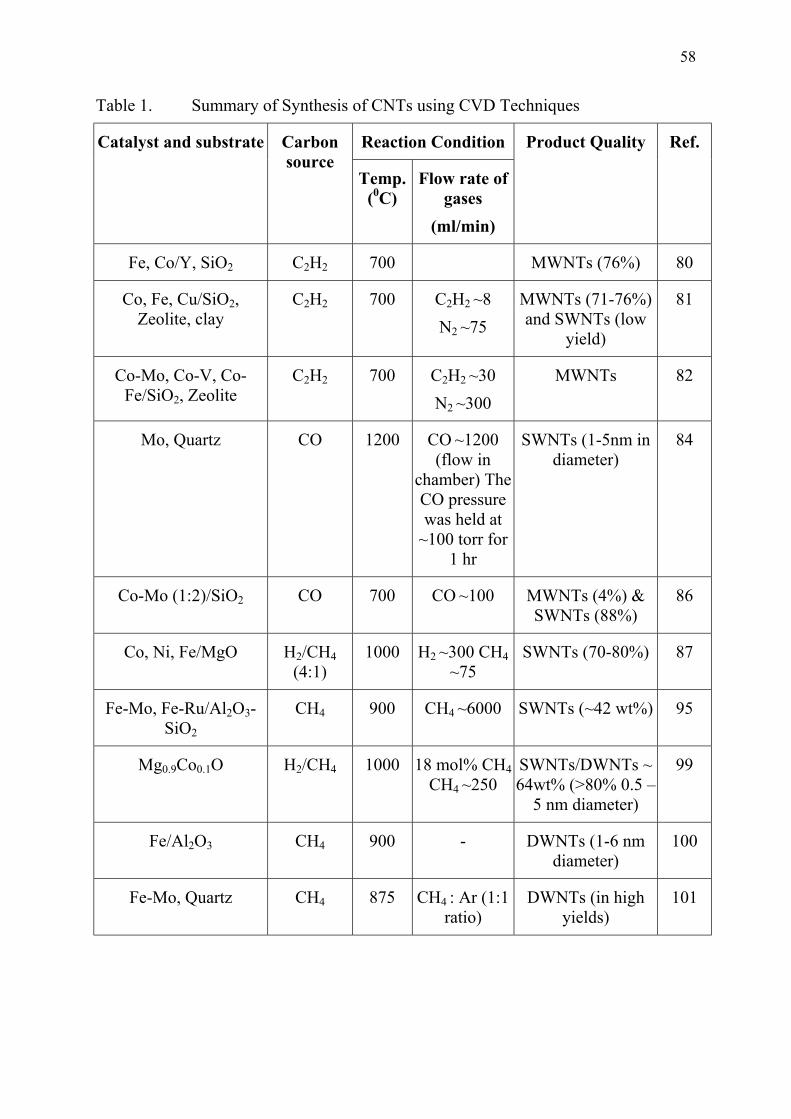
58
Table 1. Summary of Synthesis of CNTs using CVD Techniques
Reaction Condition Catalyst and substrate Carbon source
Temp. (0C)
Flow rate of gases
(ml/min)
Product Quality Ref.
Fe, Co/Y, SiO2 C2H2 700 MWNTs (76%) 80
Co, Fe, Cu/SiO2, Zeolite, clay
C2H2 700 C2H2 ~8 N2 ~75
MWNTs (71-76%) and SWNTs (low
yield)
81
Co-Mo, Co-V, Co-Fe/SiO2, Zeolite
C2H2 700 C2H2 ~30 N2 ~300
MWNTs 82
Mo, Quartz CO 1200 CO ~1200 (flow in
chamber) The CO pressure was held at
~100 torr for 1 hr
SWNTs (1-5nm in diameter)
84
Co-Mo (1:2)/SiO2 CO 700 CO ~100 MWNTs (4%) & SWNTs (88%)
86
Co, Ni, Fe/MgO H2/CH4 (4:1)
1000 H2 ~300 CH4 ~75
SWNTs (70-80%) 87
Fe-Mo, Fe-Ru/Al2O3-SiO2
CH4 900 CH4 ~6000 SWNTs (~42 wt%) 95
Mg0.9Co0.1O H2/CH4 1000 18 mol% CH4 CH4 ~250
SWNTs/DWNTs ~ 64wt% (>80% 0.5 –
5 nm diameter)
99
Fe/Al2O3 CH4 900 - DWNTs (1-6 nm diameter)
100
Fe-Mo, Quartz CH4 875 CH4 : Ar (1:1 ratio)
DWNTs (in high yields)
101
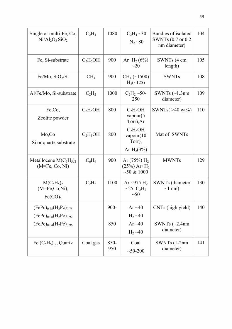
59
Single or multi-Fe, Co, Ni/Al2O3 SiO2
C2H4 1080 C2H4 ~30 N2 ~80
Bundles of isolated SWNTs (0.7 or 0.2
nm diameter)
104
Fe, Si-substrate C2H5OH 900 Ar+H2 (6%) ~20
SWNTs (4 cm length)
105
Fe/Mo, SiO2/Si CH4 900 CH4 (~1500) H2(~125)
SWNTs 108
Al/Fe/Mo, Si-substrate C2H2 1000 C2H2 ~50-250
SWNTs (~1.3nm diameter)
109
Fe,Co, Zeolite powder
Mo,Co Si or quartz substrate
C2H5OH
C2H5OH
800
800
C2H5OH vapour(5 Torr),Ar C2H5OH
vapour(10 Torr),
Ar-H2(3%)
SWNTs( >40 wt%)
Mat of SWNTs
110
Metallocene M(C5H5)2 (M=Fe, Co, Ni)
C6H6 900 Ar (75%) H2 (25%) Ar+H2 ~50 & 1000
MWNTs 129
M(C5H5)2 (M=Fe,Co,Ni),
Fe(CO)5
C2H2 1100 Ar ~975 H2 ~25 C2H2
~50
SWNTs (diameter ~1 nm)
130
(FePc)0.25(H2Pc)0.75 (FePc)0.08(H2Pc)0.92 (FePc)0.04(H2Pc)0.96
900-
850
Ar ~40 H2 ~40 Ar ~40 H2 ~40
CNTs (high yield)
SWNTs (~2.4nm diameter)
140
Fe (C5H5) 2, Quartz Coal gas 850-950
Coal ~50-200
SWNTs (1-2nm diameter)
141
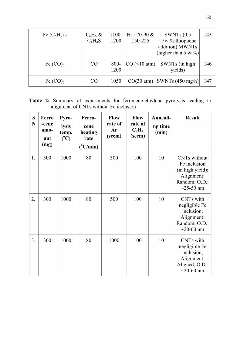
60
Fe (C5H5) 2 C6H6 & C4H4S
1100-1200
H2 ~70-90 & 150-225
SWNTs (0.5 ~5wt% thiophene addition) MWNTs
(higher than 5 wt%)
143
Fe (CO)5 CO 800-1200
CO (<10 atm) SWNTs (in high yields)
146
Fe (CO)5 CO 1050 CO(30 atm) SWNTs (450 mg/h) 147
Table 2: Summary of experiments for ferrocene-ethylene pyrolysis leading to
alignment of CNTs without Fe inclusion
SN
Ferro-cene amo- unt
(mg)
Pyro- lysis
temp. (oC)
Ferro- cene
heating rate
(oC/min)
Flow rate of
Ar (sccm)
Flow rate of C2H4
(sccm)
Anneali- ng time (min)
Result
1. 300 1000 80 300 100 10 CNTs without Fe inclusion
(in high yield); Alignment:
Random; O.D.: ~25-50 nm
2. 300 1000 80 500 100 10 CNTs with negligible Fe
inclusion; Alignment:
Random; O.D.: ~20-60 nm
3. 300 1000 80 1000 100 10 CNTs with negligible Fe
inclusion; Alignment:
Aligned; O.D.: ~20-60 nm
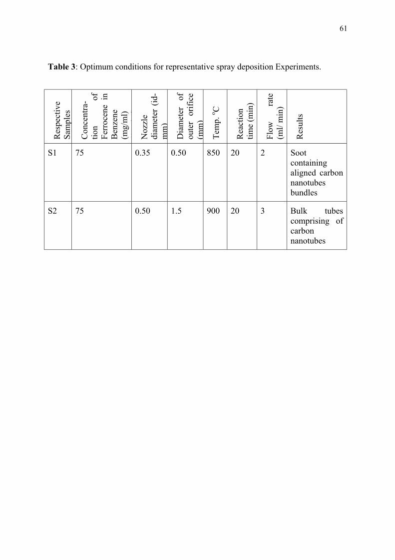
61
Table 3: Optimum conditions for representative spray deposition Experiments.
Res
pect
ive
Sam
ples
Con
cent
ra-
tion
of
Ferr
ocen
e in
B
enze
ne
(mg/
ml)
((/
l)N
ozzl
e di
amet
er (
id-
mm
)
Dia
met
er
of
oute
r or
ifice
(m
m)
Tem
p. o C
Rea
ctio
n tim
e (m
in)
Flow
ra
te
(ml/
min
)
Res
ults
S1 75 0.35 0.50 850 20 2 Soot containing aligned carbon nanotubes bundles
S2 75 0.50 1.5 900 20 3 Bulk tubes comprising of carbon nanotubes
62
Figure Captions:
Fig. 1: Different forms, (allotropes) of carbon.
Fig. 2: A TEM image of SWNTs synthesized by alcohol catalytic CVD method. Note
the absence of metallic impurities and MWNTs. Reprinted from Ref. 110 S.
Maruyama et al., Jr. of Nanosc. and Nanotech. 4, 360, (2004) with permission
from American Scientific Publishers.
Fig. 3: SEM image of SWNTs directly synthesized on a quartz substrate taken at a
tilted angle, including a broken cross-section of the substrate. The generated
mat of SWNTs on the quartz surface has a thickness of a few hundred
nanometers. Reprinted from Ref. 110 S. Maruyama et al., Jr. of Nanosc. and
Nanotech. 4, 360, (2004) with permission from American Scientific Publishers.
Fig. 4: TEM image of the typical SWNTs produced in the HiPco reactor. Reprinted
from Ref. 147 P. Nikolaev, Jr. of Nanosc. and Nanotech. 4, 307, (2004) with
permission from American Scientific Publishers.
Fig. 5: SEM images of (a) large mat of aligned CNTs formed by the spray pyrolysis of
ferrocene under optimized conditions and (b) higher magnification of (a)
exhibiting the presence of thick tubes (~150-200 nm) within the arrays.
Reprinted from Ref. 137 R. Kamalakaran et al., Appl. Phys. Lett. 77, 3385,
(2000) with permission from American Institute of Physics.
Fig. 6: (a) SEM micrograph showing bundle containing aligned CNTs, (b) magnified
SEM micrograph of one of the above bundle showing aligned CNTs. Reprinted
from Ref. 226 (unpublished).
Fig. 7(a-d) SEM images of CNT arrays grown using pyrolytic processes on silica
substrates. In, (a) growth in the vertical direction occurs from the top silica
surfaces, (seen as arrays emanating from the center of each pattern), growth on
the sides occurs as horizontal arrays, (sideways growth seen an each pattern;
the diameter of an individual flower is ~50µm). Reprinted from Ref. 227 and
63
courtesy of B.Q. Wei and P.M. Ajayan et al., Nature 416, 495 (2002) with
permission from Nature Publishing Group.
Fig. 8: (a) Optical photograph showing the bulk tube (hollow cylinder) synthesized by
spray pyrolysis technique and (b) SEM image of the aligned CNTs with radial
symmetry resulting in hollow cylindrical structure (scale 1mm). Reprinted from
Ref. 31 A. Srivastava et al., Nature Material 3, 610, (2004) with permission
from Nature Publishing Group.
Fig. 9: SEM micrograph showing highly aligned dense CNTs. Magnification: 3000x.
Reprinted from Ref 226 (unpublished).
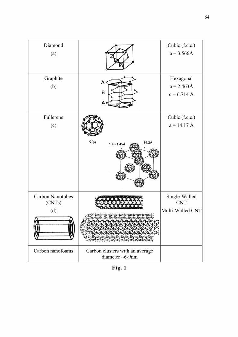
64
Diamond (a)
Cubic (f.c.c.) a = 3.566Å
Graphite (b)
Hexagonal a = 2.463Å c = 6.714 Å
Fullerene (c)
Cubic (f.c.c.) a = 14.17 Å
Carbon Nanotubes (CNTs)
(d)
Single-Walled CNT
Multi-Walled CNT
Carbon nanofoams Carbon clusters with an average diameter ~6-9nm
C60
Fig. 1

65