Synthesis of single-walled carbon nanotubes over a spin-coated Fe catalyst in an ethanol–PEG...
8
Synthesis of single-walled carbon nanotubes over a spin-coated Fe catalyst in an ethanol–PEG colloidal solution Choon-Ming Seah a , Siang-Piao Chai b , Satoshi Ichikawa c , Abdul Rahman Mohamed a, * a School of Chemical Engineering, Engineering Campus, Universiti Sains Malaysia, 14300 Nibong Tebal, Seberang Perai Selatan, P. Pinang, Malaysia b School of Engineering, Monash University, Jalan Lagoon Selatan, 46150 Bandar Sunway, Selangor, Malaysia c Institute for NanoScience Design, Osaka University, 1-3, Machikaneyama-cho, Toyonaka, Osaka 560-8531, Japan ARTICLE INFO Article history: Received 14 August 2011 Accepted 28 September 2011 Available online 6 October 2011 ABSTRACT Single-walled carbon nanotubes (SWCNTs) have been grown on flat silicon oxide substrates by the decomposition of methane. The spin-coated iron(III) nitrate with a concentration of 40 mmol/L diluted in a colloidal solution with ratio 1:1 (v/v) of absolute ethanol to PEG-400 was found to form iron nanoparticles that are small enough to grow SWCNTs. The role of PEG was to interact with iron ions and encapsulate the iron, thus preventing agglomera- tion, while the absolute ethanol isolated the PEG–iron micelles. The ratio of absolute etha- nol to PEG controlled the viscosity and the distance between PEG–encapsulated iron micelles, and subsequently governed the size and density of the iron nanoparticles formed. To reduce the effect of surface tension that will disturb the uniformity of a thin colloid film, –OH groups were introduced on the silicon wafer by a piranha solution and the hydrogen bonds formed with PEG preserved the uniformity of the iron nanoparticle distribution dur- ing the synthesis of SWCNTs. Ó 2011 Elsevier Ltd. All rights reserved. 1. Introduction Single-walled carbon nanotubes (SWCNTs) were first synthes- ised by Iijima and Ichihashi [1] and Bethune et al. [2] in 1993. SWCNTs, unlike multi-walled carbon nanotubes (MWCNTs), exhibit electric properties that make them suitable in nano- electronic applications, such as electrochemical capacitors [3], field-effect transistors [4] and probe electrodes for DNA [5]. The electrical and optical properties of SWCNTs strongly depend on their diameters [6]. Physical Vapour Deposition (PVD) is the most popular cat- alyst deposition approach for the synthesis of carbon nano- tubes (CNTs) on a flat substrate. A nanoscale catalytic thin film is first coated onto a substrate and is subsequently bro- ken into nanoparticle islands by thermal annealing [7]. How- ever, PVD is a relatively costly method requiring sophisticated equipment, high-vacuum and high-temperature conditions for the catalyst deposition. To avoid these shortcomings, solu- tion-based catalyst precursors have been developed for alter- native methods of coating active catalysts onto the flat substrate [8]. Dip-coating [9,10], spray coating [11], spin coat- ing [12,13] and microcontact printing [14] are the common ap- proaches used to prepare a thin film of solution containing catalytic precursor on the substrate. In these methods, the morphology of the grown CNTs depends greatly on the cata- lytic solution. Furthermore, the production of SWCNTs of a specific diameter is strongly dependent on the size of the cat- alyst nanoparticles [15]. The two major approaches to control the size of the active catalyst nanoparticles for the synthesis of SWCNTs involve either chemical state changing or physical control. In chemical state changing control, the dispersed nano-sized catalyst particles can be completed by adding pro- moters, such as molybdenum or alumina, that are able to form alloys with the active catalyst and modify its chemical 0008-6223/$ - see front matter Ó 2011 Elsevier Ltd. All rights reserved. doi:10.1016/j.carbon.2011.09.059 * Corresponding author: Fax: +60 594 1013. E-mail address: [email protected] (A.R. Mohamed). CARBON 50 (2012) 960 – 967 Available at www.sciencedirect.com journal homepage: www.elsevier.com/locate/carbon
-
Upload
independent -
Category
Documents
-
view
0 -
download
0
Transcript of Synthesis of single-walled carbon nanotubes over a spin-coated Fe catalyst in an ethanol–PEG...
C A R B O N 5 0 ( 2 0 1 2 ) 9 6 0 – 9 6 7
.sc iencedi rect .com
Avai lab le at wwwjournal homepage: www.elsev ier .com/ locate /carbon
Synthesis of single-walled carbon nanotubes over aspin-coated Fe catalyst in an ethanol–PEG colloidal solution
Choon-Ming Seah a, Siang-Piao Chai b, Satoshi Ichikawa c, Abdul Rahman Mohamed a,*
a School of Chemical Engineering, Engineering Campus, Universiti Sains Malaysia, 14300 Nibong Tebal, Seberang Perai Selatan,
P. Pinang, Malaysiab School of Engineering, Monash University, Jalan Lagoon Selatan, 46150 Bandar Sunway, Selangor, Malaysiac Institute for NanoScience Design, Osaka University, 1-3, Machikaneyama-cho, Toyonaka, Osaka 560-8531, Japan
A R T I C L E I N F O
Article history:
Received 14 August 2011
Accepted 28 September 2011
Available online 6 October 2011
0008-6223/$ - see front matter � 2011 Elsevidoi:10.1016/j.carbon.2011.09.059
* Corresponding author: Fax: +60 594 1013.E-mail address: [email protected]
A B S T R A C T
Single-walled carbon nanotubes (SWCNTs) have been grown on flat silicon oxide substrates
by the decomposition of methane. The spin-coated iron(III) nitrate with a concentration of
40 mmol/L diluted in a colloidal solution with ratio 1:1 (v/v) of absolute ethanol to PEG-400
was found to form iron nanoparticles that are small enough to grow SWCNTs. The role of
PEG was to interact with iron ions and encapsulate the iron, thus preventing agglomera-
tion, while the absolute ethanol isolated the PEG–iron micelles. The ratio of absolute etha-
nol to PEG controlled the viscosity and the distance between PEG–encapsulated iron
micelles, and subsequently governed the size and density of the iron nanoparticles formed.
To reduce the effect of surface tension that will disturb the uniformity of a thin colloid film,
–OH groups were introduced on the silicon wafer by a piranha solution and the hydrogen
bonds formed with PEG preserved the uniformity of the iron nanoparticle distribution dur-
ing the synthesis of SWCNTs.
� 2011 Elsevier Ltd. All rights reserved.
1. Introduction
Single-walled carbon nanotubes (SWCNTs) were first synthes-
ised by Iijima and Ichihashi [1] and Bethune et al. [2] in 1993.
SWCNTs, unlike multi-walled carbon nanotubes (MWCNTs),
exhibit electric properties that make them suitable in nano-
electronic applications, such as electrochemical capacitors
[3], field-effect transistors [4] and probe electrodes for DNA
[5]. The electrical and optical properties of SWCNTs strongly
depend on their diameters [6].
Physical Vapour Deposition (PVD) is the most popular cat-
alyst deposition approach for the synthesis of carbon nano-
tubes (CNTs) on a flat substrate. A nanoscale catalytic thin
film is first coated onto a substrate and is subsequently bro-
ken into nanoparticle islands by thermal annealing [7]. How-
ever, PVD is a relatively costly method requiring sophisticated
equipment, high-vacuum and high-temperature conditions
er Ltd. All rights reserved(A.R. Mohamed).
for the catalyst deposition. To avoid these shortcomings, solu-
tion-based catalyst precursors have been developed for alter-
native methods of coating active catalysts onto the flat
substrate [8]. Dip-coating [9,10], spray coating [11], spin coat-
ing [12,13] and microcontact printing [14] are the common ap-
proaches used to prepare a thin film of solution containing
catalytic precursor on the substrate. In these methods, the
morphology of the grown CNTs depends greatly on the cata-
lytic solution. Furthermore, the production of SWCNTs of a
specific diameter is strongly dependent on the size of the cat-
alyst nanoparticles [15]. The two major approaches to control
the size of the active catalyst nanoparticles for the synthesis
of SWCNTs involve either chemical state changing or physical
control. In chemical state changing control, the dispersed
nano-sized catalyst particles can be completed by adding pro-
moters, such as molybdenum or alumina, that are able to
form alloys with the active catalyst and modify its chemical
.

C A R B O N 5 0 ( 2 0 1 2 ) 9 6 0 – 9 6 7 961
state, thereby, maintaining a small catalyst size that is suit-
able for growing SWCNTs [16–19]. On the other hand, the size
of the catalyst can be controlled physically by regulating
either the thickness of the thin film coating in PVD [20] or
by diluting the catalyst in different solutions [21], such as cat-
alytic alcohol solution [13,22–24], magnetic fluid [25], block
copolymer micellar thin films [26], or a colloidal solution of
AOT[bis(2-ethylhexyl)-sulphosuccinate]-stabilized Co nano-
particles [27]. These solutions have been developed to build
catalyst nanoparticles on a flat surface substrate. However,
only Murakami and coworkers [22] reported the formation
of SWCNTs by controlling the size of cobalt nanoparticles
through chemical state change with the assistance of molyb-
denum. The study of the impact of catalyst size in solution
during synthesis of SWCNTs is limited.
Polyethylene glycol (PEG) is an amphiphilic polymer exhib-
iting both hydrophobic and hydrophilic interfaces with reac-
tive –OH groups at both ends. In wastewater research,
spherical metal nanoparticles are formed either in a water–
ethanol mixture [28] or in water alone [29] using PEG as a dis-
persion agent and stabiliser. In the work of Kim et al. [13], a
small amount of ethylene glycol added to ethanol with iron
acetate helps to dissolve the iron salt and MWCNTs obtained
after chemical vapour deposition (CVD) and yields a solution
with low vapour pressure and high viscosity.
In this work, iron nanoparticles were prepared in anhy-
drous ethanol and encapsulated with various ratios of PEG-
400. The present work is a study of the role of PEG in forming
nanoparticles of various sizes. The colloidal solutions were
spin coated on silicon oxide substrate to form thin films
and then immediately heat treated to decompose the PEG
and iron nitrate to fix the size and position of the catalyst
on the wafer. CNTs were found growing on the iron nanopar-
ticles coated on the silicon wafer under a simple CVD.
2. Experimental
2.1. Materials and chemicals
PEG-400 (Ph Eur), absolute ethanol (EMSURE� ACS, ISO, Reag.
PhEur), hydrogen peroxide 30% and sulphuric acid 95–97%
(EMSURE� ISO) were purchased from Merck Chemical. Iron(III)
nitrate nonahydrate, Fe(NO3)3Æ9H2O, was obtained from Sig-
ma–Aldrich Co. Gases for CVD, including methane (99.995%),
nitrogen (99.999%) (both supplied by Air Products Malaysia)
and hydrogen (99.999%) (supplied by MOX Malaysia).
2.2. Preparing iron nanoparticles on a silicon wafer
The iron nanoparticles were prepared by diluting Fe(NO3)3Æ9-
H2O in ethanol–PEG colloidal solution with absolute ethanol
compositions of 0%, 25%, 50%, 75% and 100%. Iron(III) nitrate
was subsequently diluted into the colloidal solutions to ob-
tain concentration of 40 mmol/L each. The solutions were vig-
orously stirred for 30 min and were later sonicated for
another 30 min to dissolve the iron(III) nitrate further and to
obtain homogeneous solutions. The substrate used was a
4 in. diameter silicon wafer (polished on one side) with a
1000 A thermal oxide layer. The substrate was first cut into
small squares with side lengths of 15 mm. Next, the wafers
were cleaned and treated with piranha solution (a mixture
of 1/1 (v/v) sulphuric acid and hydrogen peroxide) for
15 min to remove organic and inorganic contaminants. Soon
after this step, the wafers were rinsed in de-ionised water
and dried using a spin coater (Specialty Coating System,
G3P-8) with a spin speed of 8000 rpm for 30 s.
Ethanol/PEG-400 colloidal solutions were spin-coated on
the silicon wafers at 8000 rpm for 30 s. The coated wafers
were quickly heated to 500 �C to vaporise the ethanol and
decompose the PEG-400, leaving only iron oxide nanoparticles
on the wafers.
2.3. Growth of SWCNTs
The synthesis of SWCNTs was carried out at atmospheric
pressure using CVD inside a horizontal quartz reactor. The
detailed setup of the CVD has been reported previously [30].
Silicon wafers with deposited catalyst were placed inside
the quartz reactor and heated to 550 �C under 100 ml/min of
high purity N2 flow. The gas was subsequently switched to
H2 at the same temperature for 30 min to reduce the catalyst.
Next, the gas was switched back to N2 flow and further heated
to 850 �C. Subsequently, a mixture of high purity CH4 and N2
replaced the N2 flow when the desired reaction temperature
was reached. The volume ratio of N2 to CH4 was set at 2:1
(v/v), and the total flow rate at 150 ml/min for 30 min. Finally,
the quartz reactor was cooled to ambient temperature under
nitrogen flow after the reaction.
2.4. Characterisation
Field emission scanning electron microscopy (FE-SEM) was
performed using a Gemini LEO 1525 instrument operating at
15 keV. Transmission electron microscopy (TEM) was carried
out by a Philip CM 12 instrument operating at 200 keV. High
resolution TEM (HR-TEM) images of the carbon samples were
taken by a Tecnai 20 at 200 keV (Fei Company). A Reinashaw
inVia Raman Microscope with laser excitation at 532 nm
was used for Raman spectroscopy and functional group char-
acterisation was completed with the Thermo Scientific Nico-
let IS10 Fourier Transform InfraRed (FTIR) spectrometer.
3. Results
Fig. 1 shows the SEM images of the CNTs grown on the wafer
with five different absolute ethanol to PEG ratios and only di-
luted ethanol after 30 min of methane CVD. Dense CNT arrays
were grown when colloidal solutions with 0%, 25% and 50%
ethanol were applied. However, the morphologies of the
CNT arrays were different. The CNTs found were larger in
diameter and carbon nanocapsules were visible when colloi-
dal solutions with 0% and 25% ethanol (Fig. 1(a) and (b)) were
used as the catalyst precursor. However, when the ethanol ra-
tio increased to 50%, the CNT array was thicker, and the diam-
eter distribution of the CNTs was smaller (Fig. 1(c)). When 75%
of ethanol colloidal solution was used, the density of the
CNTs formed was much lower (Fig. 1(d)) compared with those
in the previous three observations. The iron catalyst

Fig. 1 – SEM images of CNTs grown on flat-substrate catalysts that were spin-coated with 40 mmol iron(III) nitrate
nonahydrate diluted in (a) pure PEG-400, (b) ethanol/PEG-400, 1/3 (v/v), (c) ethanol/PEG-400, 1/1 (v/v), (d) ethanol/PEG-400, 3/1
(v/v), (e) anhydrous ethanol and (f) diluted ethanol (96%).
962 C A R B O N 5 0 ( 2 0 1 2 ) 9 6 0 – 9 6 7
coalesced significantly only if absolute ethanol was used for
the solution preparation (Fig. 1(e)). This finding deviated from
those of Emmenegger et al. [23] and Mauron et al. [24]. The
solubility of iron(III) nitrate in absolute ethanol was limited
and a solution with large visible suspended iron(III) nitrate
particles formed rather than a homogeneous one. The thick
iron particle layer could be observed once spin-coated on a
silicon wafer and condensed after heat treatment. To increase
the solubility of iron(III) nitrate in the ethanol, 96% ethanol
was used. Ethanol is a volatile solvent and evaporated easily
after being spin coated on the silicon wafer. However, the
water content in the ethanol solution could not evaporate
easily and thus leaving the residue on the wafer. The
hydrophobicity of silicon oxide and the surface tension of
water enhanced the formation of small water droplets on
the wafer. The diluted iron salt that accumulated inside the
water droplets formed large iron particles after heat treat-
ment at 500 �C. The iron particles dispersed sparsely on the
silicon wafer as shown in Fig. 1(f).
Fig. 2 shows the TEM and HR-TEM images of the CNTs
grown from colloidal solutions prepared with 0%, 25%, 50%
and 75% ethanol. The CNTs grown from 0%, 25% and 75% eth-
anol were larger in diameter and also exhibited multi-shelled
carbon nanocapsules and a bamboo-like structure as shown
in Fig. 2(a)–(c), respectively. The diameter of the CNTs ranged
from 5 to 12 nm. Fig. 2(d) shows the HR-TEM image of

Fig. 2 – TEM images of CNTs grown on flat-substrate catalysts that were spin-coated with 40 mmol/L iron(III) nitrate
nonahydrate diluted in (a) pure PEG-400, (b) ethanol/PEG-400, 1/3 (v/v), (c) ethanol/PEG-400, 3/1 (v/v) and (d) HR-TEM image
showing SWCNTs grown by ethanol/PEG-400, 1/1(v/v) as a catalyst precursor solution.
C A R B O N 5 0 ( 2 0 1 2 ) 9 6 0 – 9 6 7 963
SWCNTs with a highly ordered wall structure that was grown
from iron nanoparticles prepared by a colloidal solution of
50% ethanol.
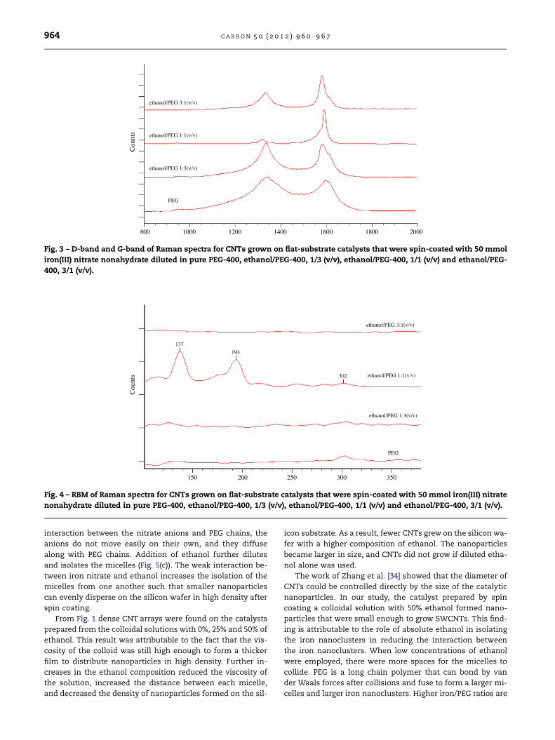
In Raman analysis, the peak at 1350 cm�1 is known as the
D-band, a Raman active mode of the defective carbon net-
work such as amorphous carbon that exists in the sample,
while the peak at 1580 cm�1 (G-band) corresponds to the tan-
gential modes of the graphitic planes in the CNTs. The inten-
sity of the D-band was stronger than that of the G-band for
CNTs grown from iron nanoparticles prepared by a colloidal
solution that was higher in PEG content. From Fig. 3 the IG/
ID ratios of the MWCNTs were 0.919 and 0.975 obtained from
the catalysts prepared from 0% and 25% ethanol colloidal
solutions, respectively, whereas IG/ID ratios drastically in-
creased to 16.98 for CNTs prepared by a 50% ethanol colloidal
solution. However, after the ethanol ratio increased to 75%,
the IG/ID ratio dropped to 1.77. The sample prepared by a
50% ethanol colloidal solution also exhibited Radial Breathing
Modes (RBM) from 150 to 400 cm�1 and a high IG/ID ratio,
which is an indication of the presence of high-quality
SWCNTs. There are two distinct peaks within the RBM region
at 137 cm�1 and 194 cm�1 (Fig. 4). The mode frequency, xRBM,
is related to the diameter of SWCNTs. The average diameters
of SWCNTs were estimated from the equation, 248 cm�1/xRBM
[31], to be 1.81 nm and 1.26 nm.
4. Discussion
4.1. Ethanol/PEG colloidal solutions
Iron(III) nitrate was not miscible in anhydrous ethanol and di-
luted ethanol was not suitable for spin coating. In order to
promote the solubility of iron(III) nitrate and prevent agglom-
eration, PEG-400 was added. This resulted in the formation of
colloids with reduced iron oxide nanoparticle size which was
suitable for SWCNT nucleation. A homogeneous solution was
formed after an appropriate amount of PEG-400 was added.
PEG with amphiphilic properties enabled iron(III) nitrate to
be miscible in ethanol. According to Johansson et al. [32],
when salts dissolve in a polymer matrix, the cations form
weak bonds with the ether oxygen of the polymer chain,
while the anions are believed to move between the available
voids in the polymer (Fig. 5(a)). The long chain of PEG causes
a certain amount of iron cations to bind and to form nanocl-
usters as shown in Fig. 5(b). The black dots denote the iron
nanoclusters encapsulated by PEG, while the grey dots repre-
sent the nitrate ions. After vigorous stirring and ultrasonica-
tion, PEG encapsulates several iron cations to form micelles,
isolating them from agglomeration. The iron ions exhibit a re-
duced diffusivity when dissolved in a polymer, therefore,
forming the stable micelles [33]. Although there is no
Cou
nts
800 1000 1200 1400 1600 1800 2000
PEG
ethanol/PEG 1:3(v/v)
ethanol/PEG 1:1(v/v)
ethanol/PEG 3:1(v/v)
Fig. 3 – D-band and G-band of Raman spectra for CNTs grown on flat-substrate catalysts that were spin-coated with 50 mmol
iron(III) nitrate nonahydrate diluted in pure PEG-400, ethanol/PEG-400, 1/3 (v/v), ethanol/PEG-400, 1/1 (v/v) and ethanol/PEG-
400, 3/1 (v/v).
Cou
nts
150 200 250 300 350
PEG
ethanol/PEG 1:3(v/v)
ethanol/PEG 1:1(v/v)
ethanol/PEG 3:1(v/v)
302
193
137
Fig. 4 – RBM of Raman spectra for CNTs grown on flat-substrate catalysts that were spin-coated with 50 mmol iron(III) nitrate
nonahydrate diluted in pure PEG-400, ethanol/PEG-400, 1/3 (v/v), ethanol/PEG-400, 1/1 (v/v) and ethanol/PEG-400, 3/1 (v/v).
964 C A R B O N 5 0 ( 2 0 1 2 ) 9 6 0 – 9 6 7
interaction between the nitrate anions and PEG chains, the
anions do not move easily on their own, and they diffuse
along with PEG chains. Addition of ethanol further dilutes
and isolates the micelles (Fig. 5(c)). The weak interaction be-
tween iron nitrate and ethanol increases the isolation of the
micelles from one another such that smaller nanoparticles
can evenly disperse on the silicon wafer in high density after
spin coating.
From Fig. 1 dense CNT arrays were found on the catalysts
prepared from the colloidal solutions with 0%, 25% and 50% of
ethanol. This result was attributable to the fact that the vis-
cosity of the colloid was still high enough to form a thicker
film to distribute nanoparticles in high density. Further in-
creases in the ethanol composition reduced the viscosity of
the solution, increased the distance between each micelle,
and decreased the density of nanoparticles formed on the sil-
icon substrate. As a result, fewer CNTs grew on the silicon wa-
fer with a higher composition of ethanol. The nanoparticles
became larger in size, and CNTs did not grow if diluted etha-
nol alone was used.
The work of Zhang et al. [34] showed that the diameter of
CNTs could be controlled directly by the size of the catalytic
nanoparticles. In our study, the catalyst prepared by spin
coating a colloidal solution with 50% ethanol formed nano-
particles that were small enough to grow SWCNTs. This find-
ing is attributable to the role of absolute ethanol in isolating
the iron nanoclusters in reducing the interaction between
the iron nanoclusters. When low concentrations of ethanol
were employed, there were more spaces for the micelles to
collide. PEG is a long chain polymer that can bond by van
der Waals forces after collisions and fuse to form a larger mi-
celles and larger iron nanoclusters. Higher iron/PEG ratios are

Adding ethanol
(a) (b)
(c)
Fig. 5 – (a) Iron cations interact with ether oxygen in PEG, (b) PEG encapsulated iron nanocluster and anions that fill the voids
in the polymer, (c) the micelles will further isolate after ethanol is added. Black circles denote iron cations nanocluster, grey
circles represent anions of nitrate ions.
1630
.93
3232
.62
0.04
0.06
0.08
0.10
0.12
0.14
0.16
0.18
Log(
1/R
)
1500 2000 2500 3000 3500 Wavenumbers (cm-1)
Plain silicon wafer
Piranha solution treated silicon wafer
Fig. 6 – FTIR spectrum of plain silicon wafer (green) and silicon wafer treated by piranha solution (red). (For interpretation of
the references to colour in this figure legend, the reader is referred to the web version of this article.).
C A R B O N 5 0 ( 2 0 1 2 ) 9 6 0 – 9 6 7 965
resulted from the higher ethanol percentages. Insufficient
PEG caused more iron ions to encapsulate inside a single mi-
celle and led to the formation of larger iron nanoclusters. It
was noted that only MWCNTs could be grown by the catalyst
prepared by the colloid with 75% of ethanol.
4.2. Role of piranha solution
The main drawback of spin coating preparation is the surface
tension effect of the fluid, which will reduce the uniformity of
coating when a non-volatile fluid is applied. In addition, the
silicon oxide is a hydrophobic surface. In order to form a more
uniform colloidal solution layer on silicon substrate, the wa-
fer must first undergo a treatment. Piranha solution is used
to clean organic and ionic matter from the silicon and quartz
substrates. The organic compounds are dehydrated by the
strong oxidising power of piranha solution. At the same time,
the piranha solution hydroxylates the silicon surfaces by
introducing –OH groups, thereby making them hydrophilic.
FTIR is a widely used technique for the qualitative analysis
of chemical functionalities. Fig. 6 shows the FTIR spectra for
both silicon wafers that are with and without substrate
treatment by piranha solution. There is a clear broad peak
around 3233 cm�1, which corresponds to the existence of an –
OH group on the silicon wafer after being treated with piranha
solution (red). This peak does not exist in the spectrum of the
untreated silicon wafer (green). The small peak observed at
1631 cm�1 corresponds to a –C@O group of carboxylic acid,
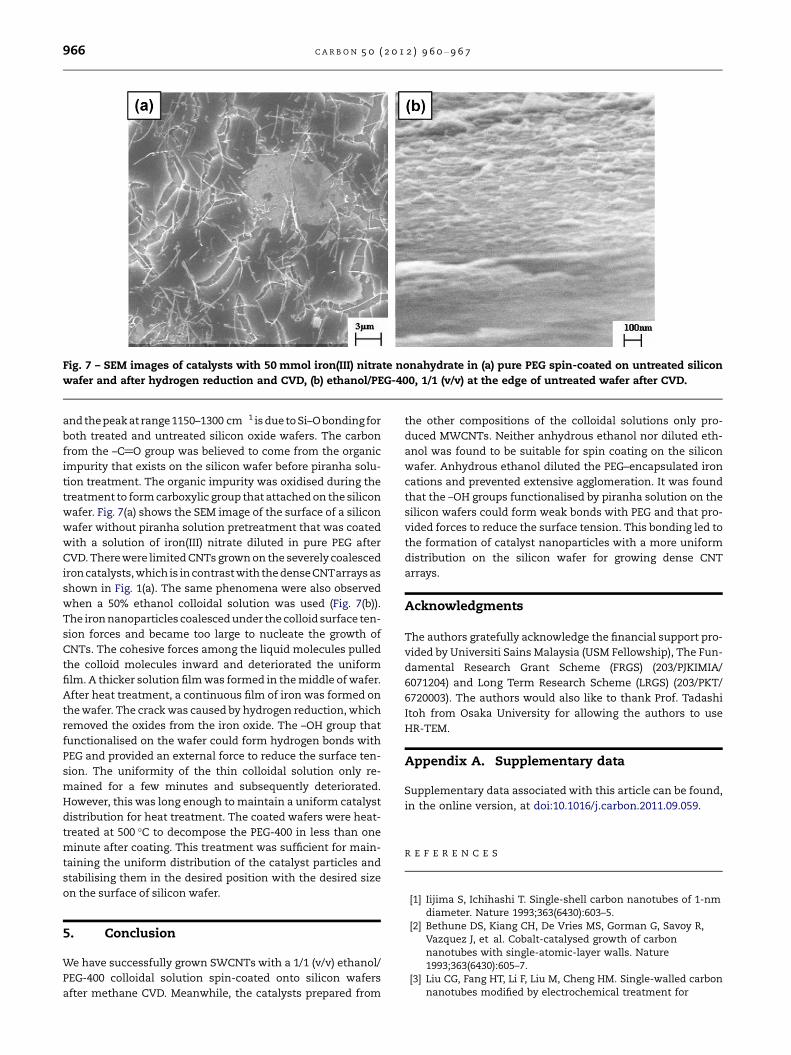
Fig. 7 – SEM images of catalysts with 50 mmol iron(III) nitrate nonahydrate in (a) pure PEG spin-coated on untreated silicon
wafer and after hydrogen reduction and CVD, (b) ethanol/PEG-400, 1/1 (v/v) at the edge of untreated wafer after CVD.
966 C A R B O N 5 0 ( 2 0 1 2 ) 9 6 0 – 9 6 7
and thepeak at range 1150–1300 cm�1 is due to Si–O bonding for
both treated and untreated silicon oxide wafers. The carbon
from the –C@O group was believed to come from the organic
impurity that exists on the silicon wafer before piranha solu-
tion treatment. The organic impurity was oxidised during the
treatment to form carboxylic group that attached on the silicon
wafer. Fig. 7(a) shows the SEM image of the surface of a silicon
wafer without piranha solution pretreatment that was coated
with a solution of iron(III) nitrate diluted in pure PEG after
CVD. There were limited CNTs grown on the severely coalesced
iron catalysts, which is in contrast with the dense CNTarrays as
shown in Fig. 1(a). The same phenomena were also observed
when a 50% ethanol colloidal solution was used (Fig. 7(b)).
The iron nanoparticles coalesced under the colloid surface ten-
sion forces and became too large to nucleate the growth of
CNTs. The cohesive forces among the liquid molecules pulled
the colloid molecules inward and deteriorated the uniform
film. A thicker solution film was formed in the middle of wafer.
After heat treatment, a continuous film of iron was formed on
the wafer. The crack was caused by hydrogen reduction, which
removed the oxides from the iron oxide. The –OH group that
functionalised on the wafer could form hydrogen bonds with
PEG and provided an external force to reduce the surface ten-
sion. The uniformity of the thin colloidal solution only re-
mained for a few minutes and subsequently deteriorated.
However, this was long enough to maintain a uniform catalyst
distribution for heat treatment. The coated wafers were heat-
treated at 500 �C to decompose the PEG-400 in less than one
minute after coating. This treatment was sufficient for main-
taining the uniform distribution of the catalyst particles and
stabilising them in the desired position with the desired size
on the surface of silicon wafer.
5. Conclusion
We have successfully grown SWCNTs with a 1/1 (v/v) ethanol/
PEG-400 colloidal solution spin-coated onto silicon wafers
after methane CVD. Meanwhile, the catalysts prepared from
the other compositions of the colloidal solutions only pro-
duced MWCNTs. Neither anhydrous ethanol nor diluted eth-
anol was found to be suitable for spin coating on the silicon
wafer. Anhydrous ethanol diluted the PEG–encapsulated iron
cations and prevented extensive agglomeration. It was found
that the –OH groups functionalised by piranha solution on the
silicon wafers could form weak bonds with PEG and that pro-
vided forces to reduce the surface tension. This bonding led to
the formation of catalyst nanoparticles with a more uniform
distribution on the silicon wafer for growing dense CNT
arrays.
Acknowledgments
The authors gratefully acknowledge the financial support pro-
vided by Universiti Sains Malaysia (USM Fellowship), The Fun-
damental Research Grant Scheme (FRGS) (203/PJKIMIA/
6071204) and Long Term Research Scheme (LRGS) (203/PKT/
6720003). The authors would also like to thank Prof. Tadashi
Itoh from Osaka University for allowing the authors to use
HR-TEM.
Appendix A. Supplementary data
Supplementary data associated with this article can be found,
in the online version, at doi:10.1016/j.carbon.2011.09.059.
R E F E R E N C E S
[1] Iijima S, Ichihashi T. Single-shell carbon nanotubes of 1-nmdiameter. Nature 1993;363(6430):603–5.
[2] Bethune DS, Kiang CH, De Vries MS, Gorman G, Savoy R,Vazquez J, et al. Cobalt-catalysed growth of carbonnanotubes with single-atomic-layer walls. Nature1993;363(6430):605–7.
[3] Liu CG, Fang HT, Li F, Liu M, Cheng HM. Single-walled carbonnanotubes modified by electrochemical treatment for
C A R B O N 5 0 ( 2 0 1 2 ) 9 6 0 – 9 6 7 967
application in electrochemical capacitors. J Power Sources2006;160(1):758–61.
[4] Liu S, Shen Q, Cao Y, Gan L, Wang Z, Steigerwald ML, et al.Chemical functionalization of single-walled carbon nanotubefield-effect transistors as switches and sensors. Coordi ChemRev 2010;254(9–10):1101–16.
[5] Zhang XZ, Jiao K. Aligned single-walled carbon nanotubesarray electrode: fabrication, characterization and application.Chinese Chem Lett 2009;20(1):76–8.
[6] Hasegawa K, Noda S. Diameter increase in millimeter-tallvertically aligned single-walled carbon nanotubes duringgrowth. Appl Phys Express 2010;3(4):0451031–3.
[7] Yen JH, Leu IC, Lin CC, Hon MH. Effect of catalystpretreatment on the growth of carbon nanotubes. Diam RelatMater 2004;13(4–8):1237–41.
[8] Seah CM, Chai SP, Mohamed AR. Synthesis of aligned carbonnanotubes. Carbon 2011;49(14):4613–35.
[9] Murakami Y, Miyauchi Y, Chiashi S, Maruyama S. Directsynthesis of high-quality single-walled carbon nanotubes onsilicon and quartz substrates. Chem Phys Lett 2003;377(1–2):49–54.
[10] Murakami Y, Yamakita S, Okubo T, Maruyama S. Single-walled carbon nanotubes catalytically grown frommesoporous silica thin film. Chem Phys Lett 2003;375(3–4):393–8.
[11] Terrado E, Redrado M, Munoz E, Maser WK, Benito AM,Martınez MT. Aligned carbon nanotubes grown on aluminaand quartz substrates by a simple thermal CVD process.Diam Relat Mater 2006;15(4–8):1059–63.
[12] Chaisitsak S, Yamada A, Konagai M. Hot filament enhancedCVD synthesis of carbon nanotubes by using a carbonfilament. Diam Relat Mater 2004;13(3):438–44.
[13] Kim DY, Yoo J-B, Han IT, Kim HJ, Jung JE, et al. The densitycontrol of carbon nanotubes using spin-coated nanoparticleand its application to the electron emitter with triodestructure. Diam Relat Mater 2005;14(11–12):2084–8.
[14] Quist AP, Pavlovic E, Oscarsson S. Recent advances inmicrocontact printing. Anal Bioanal Chem2005;381(3):591–600.
[15] Dai H, Rinzler AG, Nikolaev P, Thess A, Colbert DT, SmalleyRE. Single-wall nanotubes produced by metal-catalyzeddisproportionation of carbon monoxide. Chem Phys Lett1996;260(3–4):471–5.
[16] Pint CL, Nicholas N, Pheasant ST, Duque JG, Parra-VasquezANG, Eres G, et al. Temperature and gas pressure effects invertically aligned carbon nanotube growth from Fe–Mocatalyst. J Phys Chem C 2008;112(36):14041–51.
[17] Hu M, Murakami Y, Ogura M, Maruyama S, Okubo T.Morphology and chemical state of Co–Mo catalysts forgrowth of single-walled carbon nanotubes vertically alignedon quartz substrates. J Catal 2004;225(1):230–9.
[18] Futaba DN, Hata K, Namai T, Yamada T, Mizuno K, HayamizuY, et al. 84% Catalyst activity of water-assisted growth ofsingle walled carbon nanotube forest characterization by astatistical and macroscopic approach. J Phys Chem B2006;110(15):8035–8.
[19] Hu JL, Yang CC, Huang JH. Vertically-aligned carbonnanotubes prepared by water-assisted chemical vapordeposition. Diam Relat Mater 2008;17(12):2084–8.
[20] Nerushev OA, Morjan RE, Ostrovskii DI, Sveningsson M,Jonsson M, Rohmund F, et al. The temperature dependenceof Fe-catalysed growth of carbon nanotubes on siliconsubstrates. Physica B 2002;323(1–4):51–9.
[21] Huh Y, Lee JY, Lee CJ. Growth of vertically alignedcarbon nanotube emitters on patterned silicon trenchesfor field emission applications. Thin Solid Films2005;475(1–2):267–70.
[22] Murakami Y, Chiashi S, Miyauchi Y, Hu M, Ogura M, Okubo T,et al. Growth of vertically aligned single-walled carbonnanotube films on quartz substrates and their opticalanisotropy. Chem Phys Lett 2004;385(3–4):298–303.
[23] Emmenegger C, Bonard JM, Mauron P, Sudan P, Lepora A,Grobety B, et al. Synthesis of carbon nanotubes over Fecatalyst on aluminium and suggested growth mechanism.Carbon 2003;41(3):539–47.
[24] Mauron P, Emmenegger C, Zuttel A, Del Nutzena C,Sudan P, Schlapbach L. Synthesis of oriented nanotubefilms by chemical vapor deposition. Carbon2002;40(8):1339–44.
[25] Choi GS, Cho YS, Son KH, Kim DJ. Mass production of carbonnanotubes using spin-coating of nanoparticles.Microelectron Eng 2003;66(1–4):77–82.
[26] Bennett RD, Xiong GY, Ren ZF, Cohen RE. Using lockcopolymer micellar thin films as templates for theproduction of catalysts for carbon nanotube growth. ChemMater 2004;16(26):5589–95.
[27] Huh Y, Green MLH, Kim YH, Lee JY, Lee CJ. Control of carbonnanotube growth using cobalt nanoparticles as catalyst. ApplSurf Sci 2005;249(1–4):145–50.
[28] Wang W, Jin Zh, Li Tl, Zhang H, Gao S. Preparation ofspherical iron nanoclusters in ethanol–water solution fornitrate removal. Chemosphere 2006;65(8):1396–404.
[29] Parshetti GK, Doong RA. Dechlorination of trichloroethyleneby Ni/Fe nanoparticles immobilized in PEG/PVDF and PEG/nylon 66 membranes. Water Res 2009;43(12):3086–94.
[30] Yeoh WM, Lee KY, Chai SP, Lee KT, Mohamed AR. Synthesis ofhigh purity multi-walled carbon nanotubes over Co–Mo/MgOcatalyst by the catalytic chemical vapor deposition ofmethane. New Carbon Mater 2009;24(2):119–23.
[31] Jorio A, Saito R, Hafner JH, Lieber CM, Hunter M, McClure T,et al. Structural (n, m) determination of isolated single-wallcarbon nanotubes by resonant raman scattering. Phys RevLett 2001;86(6):1118.
[32] Johansson A, Lauenstein A, Tegenfeldt J. Effect of water ondiffusion and ionic conductivity in PEG and LiCF3SO3PEG10. JPhys Chem 1995;99(16):6163–6.
[33] Johansson A, Gogoll A, Tegenfeldt J. Diffusion and ionicconductivity in Li(CF3SO3)PEG10 and LiN(CF3SO2)2PEG10.Polymer 1996;37(8):1387–93.
[34] Zhang Y, Li Y, Kim W, Wang D, Dai H. Imaging as-grownsingle-walled carbon nanotubes originated from isolatedcatalytic nanoparticles. Appl Phys A: Mater 2002;74(3):325–8.