Hetero-doped Nanotubes: Theory, Synthesis and Characterization of Phosphorus-Nitrogen Doped...
8
Heterodoped Nanotubes: Theory, Synthesis, and Characterization of PhosphorusNitrogen Doped Multiwalled Carbon Nanotubes Eduardo Cruz-Silva, † David A. Cullen, ‡ Lin Gu, ‡ Jose Manuel Romo-Herrera, † Emilio Muñoz-Sandoval, † Florentino López-Urías, † Bobby G. Sumpter, § Vincent Meunier, § Jean-Christophe Charlier, David J. Smith, ‡ Humberto Terrones, † and Mauricio Terrones †, * † Advanced Materials Department, IPICyT, Camino a la Presa San José, 2055, San Luis Potosí 78216, México, ‡ School of Materials and Department of Physics, Arizona State University, Tempe, Arizona 85287, § Oak Ridge National Laboratory. P.O. Box 2008, Oak Ridge, Tennessee 37831-6367, and Université Catholique de Louvain, PCPM & ETSF, B-1348 Louvain-la-Neuve, Belgium C arbon nanotubes (CNT) 1,2 have at- tracted the attention of numerous research groups because of their outstanding mechanical and electronic properties. For example, carbon nanotubes can potentially be used as reinforcement for composite fabrication, 3 as components in nanoscale integrated circuits, 4 or as sup- ports for catalytic particles. 5 The cylindrical shape of carbon nanotubes leads to novel properties that are not present in bulk graphite, such as the ability to behave as a metal or as a semiconductor depending on the tube chirality and diameter. 6,7 The nan- otube curvature changes the chemically in- ert graphite surface and makes it easier to incorporate atoms on the tube surface. In this context, nitrogen, which is known to have low doping levels in bulk graphite, 8 can be easily incorporated into carbon nan- otubes by substitution. Inclusion of noncar- bon atoms into the hexagonal network of carbon nanotubes modifies the electronic and chemical properties due to variations in electronic structure. Nitrogen, for example, acts as an electron donor in a carbon nano- tube since it has five valence electrons, causing a shift in the Fermi level to the va- lence bands, and hence making all N-doped tubes metallic, regardless of their geom- etry. 9 Nitrogen can also be incorporated within nanotubes in a pyridine-like fashion. It is noteworthy that the doped sites within carbon nanotubes significantly modify chemical reactivity, thereby broadening the spectrum of possible applications. 9 Although phosphorus atoms are larger than carbon atoms, it has been shown that phosphorus can form substitutional defects in diamond sp 3 thin films, behaving as an n-type donor and thereby modifying the electronic and optical properties. 10 Theo- retical work has also shown that carbon tet- ragons containing phosphorus are stable in CP x sp 2 cage-like structures and that phosphorus atoms promote large curva- ture when incorporated into sp 2 -like fullerene structures. 11 Growth of carbon nanotubes in the presence of phosphorus has been previously reported. 12 In that case, phosphorus was incorporated in the cata- lytic particles before synthesis, either by us- ing an anodic alumina substrate (which has an inherent phosphorus contamination due to its production process) or by treating an alumina substrate with phosphoric acid and then using it as a support for iron/nickel particles. It was found that the nanotubes were sequentially grown (matchstick-like) *Address correspondence to [email protected]. Received for review October 28, 2007 and accepted February 14, 2008. Published online March 7, 2008. 10.1021/nn700330w CCC: $40.75 © 2008 American Chemical Society ABSTRACT Arrays of multiwalled carbon nanotubes doped with phosphorus (P) and nitrogen (N) are synthesized using a solution of ferrocene, triphenyl-phosphine, and benzylamine in conjunction with spray pyrolysis. We demonstrate that iron phosphide (Fe 3 P) nanoparticles act as catalysts during nanotube growth, leading to the formation of novel PN-doped multiwalled carbon nanotubes. The samples were examined by high resolution electron microscopy and microanalysis techniques, and their chemical stability was explored by means of thermogravimetric analysis in the presence of oxygen. The PN-doped structures reveal important morphology and chemical changes when compared to N-doped nanotubes. These types of heterodoped nanotubes are predicted to offer many new opportunities in the fabrication of fast-response chemical sensors. KEYWORDS: multiwalled carbon nanotubes · chemical vapor deposition · doping · electronic structure ARTICLE www.acsnano.org VOL. 2 ▪ NO. 3 ▪ 441–448 ▪ 2008 441
-
Upload
independent -
Category
Documents
-
view
6 -
download
0
Transcript of Hetero-doped Nanotubes: Theory, Synthesis and Characterization of Phosphorus-Nitrogen Doped...

Heterodoped Nanotubes: Theory,Synthesis, and Characterization ofPhosphorus�Nitrogen DopedMultiwalled Carbon NanotubesEduardo Cruz-Silva,† David A. Cullen,‡ Lin Gu,‡ Jose Manuel Romo-Herrera,† Emilio Muñoz-Sandoval,†
Florentino López-Urías,† Bobby G. Sumpter,§ Vincent Meunier,§ Jean-Christophe Charlier,� David J. Smith,‡
Humberto Terrones,† and Mauricio Terrones†,*†Advanced Materials Department, IPICyT, Camino a la Presa San José, 2055, San Luis Potosí 78216, México, ‡School of Materials and Department of Physics, Arizona StateUniversity, Tempe, Arizona 85287, §Oak Ridge National Laboratory. P.O. Box 2008, Oak Ridge, Tennessee 37831-6367, and �Université Catholique de Louvain, PCPM &ETSF, B-1348 Louvain-la-Neuve, Belgium
Carbon nanotubes (CNT)1,2 have at-
tracted the attention of numerous
research groups because of their
outstanding mechanical and electronic
properties. For example, carbon nanotubes
can potentially be used as reinforcement for
composite fabrication,3 as components in
nanoscale integrated circuits,4 or as sup-
ports for catalytic particles.5 The cylindrical
shape of carbon nanotubes leads to novel
properties that are not present in bulk
graphite, such as the ability to behave as a
metal or as a semiconductor depending on
the tube chirality and diameter.6,7 The nan-
otube curvature changes the chemically in-
ert graphite surface and makes it easier to
incorporate atoms on the tube surface. In
this context, nitrogen, which is known to
have low doping levels in bulk graphite,8
can be easily incorporated into carbon nan-
otubes by substitution. Inclusion of noncar-
bon atoms into the hexagonal network of
carbon nanotubes modifies the electronic
and chemical properties due to variations in
electronic structure. Nitrogen, for example,
acts as an electron donor in a carbon nano-
tube since it has five valence electrons,
causing a shift in the Fermi level to the va-
lence bands, and hence making all N-doped
tubes metallic, regardless of their geom-
etry.9 Nitrogen can also be incorporated
within nanotubes in a pyridine-like fashion.
It is noteworthy that the doped sites within
carbon nanotubes significantly modify
chemical reactivity, thereby broadening
the spectrum of possible applications.9
Although phosphorus atoms are largerthan carbon atoms, it has been shown thatphosphorus can form substitutional defectsin diamond sp3 thin films, behaving as ann-type donor and thereby modifying theelectronic and optical properties.10 Theo-retical work has also shown that carbon tet-ragons containing phosphorus are stablein CPx sp2 cage-like structures and thatphosphorus atoms promote large curva-ture when incorporated into sp2-likefullerene structures.11 Growth of carbonnanotubes in the presence of phosphorushas been previously reported.12 In that case,phosphorus was incorporated in the cata-lytic particles before synthesis, either by us-ing an anodic alumina substrate (whichhas an inherent phosphorus contaminationdue to its production process) or by treatingan alumina substrate with phosphoric acidand then using it as a support for iron/nickelparticles. It was found that the nanotubeswere sequentially grown (matchstick-like)
*Address correspondence [email protected].
Received for review October 28, 2007and accepted February 14, 2008.
Published online March 7, 2008.10.1021/nn700330w CCC: $40.75
© 2008 American Chemical Society
ABSTRACT Arrays of multiwalled carbon nanotubes doped with phosphorus (P) and nitrogen (N) are
synthesized using a solution of ferrocene, triphenyl-phosphine, and benzylamine in conjunction with spray
pyrolysis. We demonstrate that iron phosphide (Fe3P) nanoparticles act as catalysts during nanotube growth,
leading to the formation of novel PN-doped multiwalled carbon nanotubes. The samples were examined by high
resolution electron microscopy and microanalysis techniques, and their chemical stability was explored by means
of thermogravimetric analysis in the presence of oxygen. The PN-doped structures reveal important morphology
and chemical changes when compared to N-doped nanotubes. These types of heterodoped nanotubes are
predicted to offer many new opportunities in the fabrication of fast-response chemical sensors.
KEYWORDS: multiwalled carbon nanotubes · chemical vapordeposition · doping · electronic structure
ARTIC
LE
www.acsnano.org VOL. 2 ▪ NO. 3 ▪ 441–448 ▪ 2008 441

and that the catalytic particles werecomposed of a metal phosphide.12
An optimum set of experimentalconditions were later identified toincrease the yield of these types ofnanotubes, but whether phospho-rus was incorporated in the hexago-nal nanotube lattice was never dis-cussed.13
In the present work, we addressthe theory of PN-doped carbon nan-otubes as well as their successfulsynthesis by thermolysis of hydro-carbons and a floating catalystmethod. The growth of these nano-tubes is catalyzed by iron phosphideparticles. We show unequivocallyfor the first time that P and N are in-deed chemically incorporatedwithin the nanotube lattice.
RESULTS AND DISCUSSIONThe first step in this work was to
find the optimal synthesis condi-tions at which PN-doped nanotubes are grown. To dothis, two sets of experiments were performed. In thefirst, a solution with 2.5 wt% of triphenyl-phosphine(TPP) and 7.5% of ferrocene dissolved in benzylamine(see Materials and Methods section for more details)was pyrolyzed for 20 min inside a furnace operated atfixed temperature, ranging from 720 to 840 °C in incre-ments of 40 °C, and the Ar flow varied from 0.8 to 1.6L/min. It was found that the only conditions capable ofproducing nanotube materials occurred at 760 and 800°C with an Ar flow of 0.8 L/min; and a higher yield ofnanotubes occurred at the lower temperature. In thesecond set of experiments, the temperature was set to760 °C and the concentration of ferrocene dissolved inbenzylamine was set to 7.5 wt %, while the concentra-tion of the P dopant (TPP) was varied, using 0, 2.5, and3.3 wt %.
For scanning electron microscopy (SEM) analysis,we selected samples where the concentration of thephosphorus dopant was varied. It was observed thatfor a given synthesis temperature, and by increasing thephosphorus content in the solution, a reduction in theyield of carbon nanotubes occurred. SEM images con-firmed that samples consisted mainly of highly orderedarrays of multiwalled carbon nanotubes (MWCNTs),with very low content of amorphous carbon. The nano-tube length is also reduced as the P content in the so-lution is increased: in the absence of phosphorus thenanotubes are ca. 70 �m long (sample A, Figure 1a), butthe nanotube length is reduced to ca. 12 �m (sampleB, Figure 1b) when 2.5 wt% of TPP is added to the spraysolution. For experiments with 3.3 wt % of TPP, thelength of the nanotubes observed was ca. 2�3 �m
Figure 1. Scanning electron micrographs of PN-doped carbon nanotube (CNT) arrays, syn-thesized at the optimum temperature and carrier gas flow rate, and different TPP concen-trations: (a) pristine N-doped CNTs (sample A); (b) 2.5 wt % TPP (sample B); (c) 3.3 wt % TPP(sample C); (d) substrate side of a PN-CNT mat (sample B).
Figure 2. EDX elemental mappings for three different types of nano-tubes: pristine pure carbon nanotubes (CNTs) obtained by thermolaz-ing toluene (C6H5�CH3) and ferrocene at 850 °C (see top frame);N-doped CNTs described in the Materials and Methods section (seemiddle frame), and PN-doped CNTs described in the Materials andMethods section (see bottom frame). Samples were mounted on stan-dard aluminum pins to have contrast for the carbon map. It can beclearly observed that the PN-sample contains both phosphorus and ni-trogen in their structure, thus confirming the successful synthesis ofPN heteroatomic doping. The other samples did not show heteroat-omic doping.
ART
ICLE
VOL. 2 ▪ NO. 3 ▪ CRUZ-SILVA ET AL. www.acsnano.org442
(sample C, Figure 1c), and the disorder within the nan-otube arrays was significantly increased. After these ob-servations, sample B was chosen as the work sampleon the basis of its higher nanotube yield. The substrateside of the nanotube mats (Figure 1d) shows that mostof the nanotubes have either a metal particle in the car-bon nanotube base or a hole left by a missing particle.Note that these metal particles are rarely observed onthe opposite side. This is consistent with a base growthmodel, as previously reported forN-doped nanotubes grown using thesame synthesis method.14 It was noticedthat neither sequential nor tip growthcould be observed as a consequence ofphosphorus inclusion during the synthe-sis, as previously reported by Jourdain etal.12
Elemental maps from N-doped andPN-doped carbon nanotubes as well as apristine nanotube control sample wereobtained by EDX spectroscopy on theSEM (Figure 2). The samples weremounted on aluminum pins, and theircorresponding map is presented. The in-strument was able to detect traces of ni-trogen in the N-doped case. In the case ofPN-doped nanotubes, it is clear that bothphosphorus and nitrogen are present inthe entire sample. Quantification of theEDX spectra obtained in these nanotubesis shown in the maps, confirming very lowlevels of P doping (0.5 atom %) for the PN-doped case.
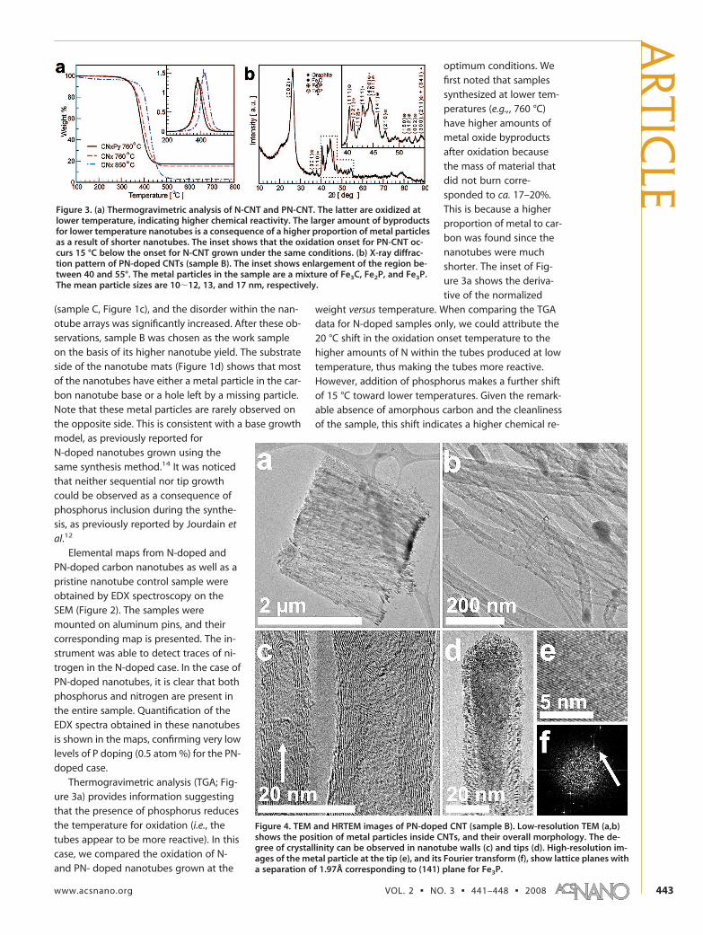
Thermogravimetric analysis (TGA; Fig-ure 3a) provides information suggestingthat the presence of phosphorus reducesthe temperature for oxidation (i.e., thetubes appear to be more reactive). In thiscase, we compared the oxidation of N-and PN- doped nanotubes grown at the
optimum conditions. Wefirst noted that samplessynthesized at lower tem-peratures (e.g.,, 760 °C)have higher amounts ofmetal oxide byproductsafter oxidation becausethe mass of material thatdid not burn corre-sponded to ca. 17–20%.This is because a higherproportion of metal to car-bon was found since thenanotubes were muchshorter. The inset of Fig-ure 3a shows the deriva-tive of the normalized
weight versus temperature. When comparing the TGAdata for N-doped samples only, we could attribute the20 °C shift in the oxidation onset temperature to thehigher amounts of N within the tubes produced at lowtemperature, thus making the tubes more reactive.However, addition of phosphorus makes a further shiftof 15 °C toward lower temperatures. Given the remark-able absence of amorphous carbon and the cleanlinessof the sample, this shift indicates a higher chemical re-
Figure 3. (a) Thermogravimetric analysis of N-CNT and PN-CNT. The latter are oxidized atlower temperature, indicating higher chemical reactivity. The larger amount of byproductsfor lower temperature nanotubes is a consequence of a higher proportion of metal particlesas a result of shorter nanotubes. The inset shows that the oxidation onset for PN-CNT oc-curs 15 °C below the onset for N-CNT grown under the same conditions. (b) X-ray diffrac-tion pattern of PN-doped CNTs (sample B). The inset shows enlargement of the region be-tween 40 and 55°. The metal particles in the sample are a mixture of Fe3C, Fe2P, and Fe3P.The mean particle sizes are 10�12, 13, and 17 nm, respectively.
Figure 4. TEM and HRTEM images of PN-doped CNT (sample B). Low-resolution TEM (a,b)shows the position of metal particles inside CNTs, and their overall morphology. The de-gree of crystallinity can be observed in nanotube walls (c) and tips (d). High-resolution im-ages of the metal particle at the tip (e), and its Fourier transform (f), show lattice planes witha separation of 1.97Å corresponding to (141) plane for Fe3P.
ARTIC
LE
www.acsnano.org VOL. 2 ▪ NO. 3 ▪ 441–448 ▪ 2008 443

activity for the heteroatomic PN-doped carbon nano-tubes when compared to the N-doped nanotubesample produced under the same experimentalconditions.
To understand the role of phosphorus and its rela-tion to iron during the growth of this type of nano-tube, X-ray powder diffraction studies were performedon a sample synthesized with 2.5 wt % of TPP (see Fig-ure 3b). The bulk diffraction pattern shows a combina-tion of two phases of iron phosphide (Fe2P and Fe3P) inaddition to iron carbide (Fe3C, bainite). The main peakin the diffraction pattern is due to the (002) reflection ofgraphite, which is characteristic of multiwalled carbonnanotubes. The peaks located between 40 and 50° (seeinset of Figure 3b) are due to a combination of reflec-tions arising from Fe2P, Fe3P and Fe3C (indicated in Fig-ure 3b). The major peak in this region is the sum of the(111) reflections from Fe3C, (420) from Fe3P, and (201)from Fe2P. When analyzing nonoverlapping peaks fromthe XRD spectra, it was found that the mean particlesize for Fe3P was close to 17 nm [calculated using Scher-rer’s equation with the full width at half-maximum(fwhm) of peaks (111) and (141)]; note that these val-ues are in agreement with the Fe3P particle sizes ob-served by TEM (see Figure 4). For the (301) and (210) re-flections of Fe2P, the mean particle size was found to
be close to 13 nm, and forthe Fe3C (111) and (112)reflections, the mean sizewas estimated as 10�12nm.
To develop a better un-derstanding of the compo-sition and growth process,we analyzed the nano-tubes and the catalyticmetal particles by highresolution electron micros-copy (HRTEM). It is note-worthy that PN-dopednanotubes are less stableunder the electron beamthan their N-doped coun-terparts, visibly degenerat-ing after shorter exposuretimes. Low-resolution TEMimages (Figure 4a,b) con-firm that most of the cata-lytic particles are locatedon one side of the nano-tube mat, and that theseare composed mainly ofbamboo-shaped nano-tubes. Good crystallinitycan be observed in somenanotube walls (see Figure4c), but they are less or-
dered in the regions close to the metal particles (Fig-ure 4d), and in the bamboo compartments (as indicatedby an arrow on Figure 4c). Most of the catalytic metalnanoparticles appear to be single crystal, and high-resolution images show interplanar distances thatmatch those of Fe3P. The particle diameter observedby TEM was ca. 20 nm, close to the mean value of 17nm obtained from X-ray powder diffraction data. Thelattice planes of a metal particle are clearly visible in Fig-ure 4e. The clear spot in the Fourier transform of this im-age (see arrow on Figure 4f) indicates the strong peri-odicity of these planes, with a separation of 1.97 Å,which corresponds closely to the (141) interplanar spac-ing of Fe3P. Other crystallographic planes were not eas-ily found aligned perpendicular to the electron beamdirection.
From energy filtered imaging, we find that most ofthe catalytic particles are primarily composed of Feand P (see Figure 5). Some particles exhibit smallamounts of oxygen at the ends of the nanotube tipsdue to oxidation (images not shown here). It was ob-served that some metallic particles (usually covered byamorphous-like carbon) do not contain phosphorus(see top right of each frame in Figure 5); these are prob-ably iron or iron carbide (note that Fe3C is present inthe X-ray powder diffraction pattern, see Figure 3b). The
Figure 5. EELS elemental mapping of PN-doped CNTs (sample B). Most of the metal par-ticles consist of FexP, with some exceptions (Fe only, top right of each frame). Phosphoruscontent in the nanotube walls is below the EELS detection threshold, and therefore thephosphorus mapping on the tube walls becomes noisy.
ART
ICLE
VOL. 2 ▪ NO. 3 ▪ CRUZ-SILVA ET AL. www.acsnano.org444

phosphorus content within the nanotubewalls is below the EELS detection threshold,and thus it could not be clearly observed by el-emental mapping. However, an EEL spectrumof PN-doped nanotubes (Figure 6) shows anintense carbon edge at 285 eV, as well as smallpeaks that correspond to phosphorus (ioniza-tion edge at ca. 130 eV) and nitrogen (ioniza-tion edge at ca. 400 eV). The inset of Figure 6shows the high angular annular dark field im-age (HAADF) of the nanotube used to obtainthis spectrum. It is important to note that thephosphorus signal was strongly masked by theplural scattering background, whereas the ni-trogen signal was masked by the tail of thecarbon edge. This masking effect results innoisy EELS maps for N and P. However, Figure2 clearly shows an EDX map that demonstrates
Figure 6. EELS spectrum of an individual PN-doped nanotube (seemarked region in the HAADF image inset). The carbon edge is very in-tense, while small concentrations of both phosphorus and nitrogencan be seen in the spectrum; these peaks are masked by the pluralscattering background (for P) and by the intense carbon edge (for N).
Figure 7. STEM elemental line-scans of individual PN-doped CNTs (sample B) using EDX (a) and EELS (b, c). Quantification ofthe EDX spectrum in metal nanoparticles confirms that their composition is Fe3P. EEL spectra provide evidence of phospho-rus doping in the nanotube walls, as well as the presence of gaseous N inside bamboo chambers and small amounts of Nin the walls.
ARTIC
LE
www.acsnano.org VOL. 2 ▪ NO. 3 ▪ 441–448 ▪ 2008 445

the presence of P, N, and C within the nanotubes. EDX
line profiles reveal a homogeneous composition within
the metal particle (Figure 7a), and quantitative analysis
indicates a stoichiometry close to 3:1 for Fe to P, in
agreement with the HRTEM image analysis correspond-
ing to Fe3P. All catalytic particles analyzed by EDX spec-
troscopy were this phase of iron phosphide. It is note-
worthy that Fe3C and Fe2P particles were not observed
in the carbon nanotube tips. Note that Fe2P particles
were not found in the nanotube tips because Fe2P does
not dissolve C at this temperature. Therefore, Fe2P is
not responsible for the nanotube growth. EELS line
scans in the nanotube region close to the catalytic par-
ticle indicate that the carbon nanotube has a homoge-
neous distribution of phosphorus, which has a weak sig-
nal that follows the profile of carbon (see Figure 7b).
To rule out possible noise effects originating from the
overlapping of the inelastic scattering peak with the
phosphorus signal, the silicon signal (ca. 30 eV lower
than phosphorus) was also integrated. It can be seen
that while the integrated Si signal has a value close to
zero, the integrated P signal increases and decreases to-
gether with the C signal. This indicates low but homo-
geneous doping of phosphorus within the carbon nan-
otube. Although the TEM images show bamboo-
shaped nanotubes, which is a characteristic of N-doped
nanotubes,9,14,15 EELS was only able to detect N traces
within the nanotube walls due to the dominating signal
of the C edge that masks the N edge. However, N was
clearly detected in the gaseous phase within the bam-
boo compartments; a feature observed only in N-doped
tubes (see Figure 7c).14
From extensive simulations of the stability and elec-
tronic structure of PN-doped carbon nanotubes using
Figure 8. (a) Molecular model of a (6,6) PN-doped carbon nanotube with the hexagonal carbon network drawn as wires; (b)detail of the defect with information of the bond lengths and angles; (c) band structure for PN-doped (10,0) and (6,6) nano-tubes compared with pristine (pure carbon) nanotubes; the effects of the doping are indicated by arrows; (d) charge den-sity plots of the top valence band in the �-point for a (6,6) nanotube and comparison with the HOMO of triphenylphosphine.
ART
ICLE
VOL. 2 ▪ NO. 3 ▪ CRUZ-SILVA ET AL. www.acsnano.org446

first principles calculations, we found that PN-doped nan-otubes, having P and N as first neighbors, exhibited lowerbinding energy than PN-doped nanotubes with noncon-tiguous dopants. A model representation of these nano-tubes is shown in Figure 8a. Further details regarding theelectronic structure of the various nanotubes are beyondthe scope of the present paper, and will be publishedelsewhere.16 Here, we limit our discussion only to the PN-doped case. As can be observed in Figures 8a and 8b,the P atom is pushed outward upon structural relaxation,extending P�C and P�N bonds from 1.44 to 1.79 Å forP�C bonds and 1.84 Å for P�N bonds, and the tube di-ameter increases from 8.3 to 9.3 Å at the P site. The bondangles consequently change from 119° to 96.54° forC�P�N and 96.71° for C�P�C, which correspond to atetragonal bonding typical of sp3 P, very close to the 98°value of TPP. The additional electrons of P and N thus cre-ate localized states around the defect (blue arrows), aswell as hybridization of the top valence band close to the�-point in the (6,6) case (red arrow), as indicated in Fig-ure 8c. The charge density associated with this state ina(6,6) nanotube is plotted in Figure 8d, and comparedwith the highest occupied molecular orbital (HOMO) ofTPP. Note that the presence of a band gap in the PN-doped (6,6) nanotube is an artifact of the supercellmethod. It can be observed that the spatial distributionof this nanotube orbital is very similar to that of theHOMO of triphenylphosphine, suggesting that it couldhave similar chemical behavior, enabling carbon nano-tubes to bind to atoms such as oxygen, sulfur, or chlorine.
CONCLUSIONSIn summary, we have successfully synthesized P-
and N-doped carbon nanotubes by a CVD method, us-
ing benzylamine and triphenylphosphine as nitrogenand phosphorus sources, respectively. Results obtainedfrom TGA show that these tubes have lower oxidationtemperature when compared to N-doped nanotubes. Adramatic reduction in the yield of carbon nanotubes isobserved as the TPP concentration is increased. This is aconsequence of the reduction of nanotube length,which suggests reduced catalytic activity for iron phos-phide when compared to pure iron. The heteroatomicdoped nanotubes obtained by this method are highlyordered, and grew from their root (substrate). EDX andEELS elemental maps and profiles confirmed that phos-phorus and nitrogen are homogenously incorporatedinto the nanotubes. Some iron particles are visible inthe elemental mapping, and X-ray diffraction measure-ments show that there is iron carbide present in thesample. However, EDX and EELS spectroscopy indicatethat most of the catalytic particles are composed of ironphosphide. Using ab initio electronic structure calcula-tions, it is shown that P and N can coexist as dopants incarbon nanotubes and that a PN defect is the moststable of the studied configurations. The ternary phasediagram of carbon�iron�phosphorus17 shows a meta-stable boundary between Fe3C and Fe3P at 700 °C,with an eutectic point close to 966 °C for 12.8 atom %of carbon in Fe3P. However, there is no stable or meta-stable boundary reported for Fe2P and Fe3C at the syn-thesis temperature range used in this study. If carbonnanotubes grow from supersaturated Fe3C, as shownrecently,18 it is possible to form this compound at thesurface of Fe3P while it is dissolving carbon, but not inFe2P. This would explain why the yield of carbon nano-tubes is reduced with increased phosphorus contentin the feedstock solution.
MATERIALS AND METHODSSynthesis. For the synthesis process, a solution composed of
benzylamine C6H5�CH2�NH2 (Sigma 99%) as carbon and nitro-gen sources, ferrocene Fe(C5H5)2 (Sigma, 98%) as catalyst andtriphenyl-phosphine P(C6H5)3 (TPP) (Sigma, 99%) as the phos-phorus source was atomized using an aerosol generator and car-ried by an inert gas flow (argon) inside a quartz tube with an in-ner diameter of ca. 24 mm, which was placed inside a two-stage furnace system. This spray pyrolysis technique is similarto that described by Pinault et al.19 and Kamalakaran et al.20 Thenanotubes were collected from the soot deposited on the sur-face of the quartz tube in the region located inside the furnace.
Characterization. The samples as synthesized were character-ized by X-ray powder diffraction (Brucker Advance D8), thermo-gravimetric analysis (Thermo Corp. Cahn Versatherm HS, 1.5g/0.1 �g), and scanning electron microscopy (FEI XL30-FEG 30kV). For high resolution transmission electron microscopy (JEOL4000EX HRTEM, operated at 400 kV) and scanning transmissionelectron microscopy (Philips CM200, Tecnai F20 with GIF, JEOL2010), the samples were mounted on a copper grid with holeycarbon coating after dispersion in isopropanol.
Electronic Structure Calculations. To complement the experimen-tal evidence and to understand the relationship between phos-phorus and nitrogen as dopants, we performed total energyelectronic structure calculations for pristine, N-doped, P-doped,and PN-doped metallic (6,6) and semiconducting (10,0) nano-
tubes, consisting of 192 and 200 atoms, respectively. The elec-tronic structure calculations were performed using density func-tional theory21,22 within the local spin density approximation(DFT-LSDA) using the Ceperley�Alder parametrization23 asimplemented in the code SIESTA.24 The wave functions were rep-resented by a linear combination of pseudoatomic valence orbit-als using a double-� polarized basis (DZP),25 while core– elec-trons were represented by norm-conserving Troullier�Martinspseudopotentials in the Kleynman�Bylander nonlocal form.26,27
The real-space grid used for charge and potential integration isequivalent to a planewave cutoff energy of 150 Ry. Periodicboundary conditions were used and the intertube distance waskept to a minimum of 10 Å to avoid lateral interactions. Given thesystem size, sampling of the 1D Brillouin zone with eight k-pointswas enough to converge the wave functions. The total energywas calculated when the forces were converged to less than 0.02eV/Å.
Acknowledgment. Authors are grateful to D. Ramírez, G.Ramírez, L. Noyola, and G. Pérez Assaf for technical assistance.This work was supported in part by CONACYT-México grants56787 (Laboratory for Nanoscience and NanotechnologyResearch-LINAN), 45762 (H.T.), 45772 (M.T.), 41464-Inter Ameri-can Materials Collaboration (M.T.), 42428-Inter American Materi-als Collaboration (H.T.), 2004-01-013/SALUD-CONACYT (M.T.),PUE-2004-CO2-9 Fondo Mixto de Puebla (M.T.) and Ph.D. schol-
ARTIC
LE
www.acsnano.org VOL. 2 ▪ NO. 3 ▪ 441–448 ▪ 2008 447

arships (E.C.S. and J.M.R.H.), as well as NSF Grant DMR-0303429(D.J.S.). V.M. and B.G.S. acknowledge work supported by the Cen-ter for Nanophase Materials Sciences (CNMS), sponsored by theDivision of Scientific User Facilities, U.S. Department of Energyand by the Division of Materials Science and Engineering, U.S.Department of Energy under Contract No. DEAC05-00OR22725with UT-Battelle, LLC at Oak Ridge National Laboratory (ORNL).Computations were performed using the resources of the Na-tional Center for Computational Sciences at ORNL. J.-C.C. is in-debted to FNRS of Belgium for financial support. Parts of thiswork are also directly connected to the Belgian Program on In-teruniversity Attraction Poles (PAI), to the ARC sponsored by theCommunauté Française de Belgique, and to the NANOQUANTAand FAME European Networks of Excellence. We acknowledgeuse of facilities within the John M. Cowley Center for High Reso-lution Electron Microscopy at Arizona State University.
REFERENCES AND NOTES1. Oberlin, A.; Endo, M.; Koyama, T. Filamentous Growth of
Carbon Through Benzene Decomposition. J. Cryst. Growth1976, 32, 335–349.
2. Iijima, S. Helical Microtubules of Graphitic Carbon. Nature1991, 354, 56–58.
3. Ajayan, P. M.; Stephan, O.; Colliex, C.; Trauth, D. AlignedCarbon Nanotube Arrays Formed by Cutting a PolymerResin-Nanotube Composite. Science 1994, 265,1212–1214.
4. Tans, S. J.; Verschueren, A. R. M.; Dekker, C. Room-Temperature Transistor Based on a Single CarbonNanotube. Nature 1998, 393, 49–52.
5. Plainex, J. M.; Coustel, N.; Coq, B.; Brotons, V.; Kumbhar,P. S.; Dutartre, R.; Genese, P.; Bernier, P.; Ajayan, P. M.Application of Carbon Nanotubes as Supports inHeterogeneous Catalysis. J. Am. Chem. Soc. 1994, 116,7935–7936.
6. Saito, R.; Fujita, M.; Dresselhaus, G.; Dresselhaus, M. S.Electronic Structure of Graphene Tubules Based on C60.Phys. Rev. B 1992, 46, 1804–1811.
7. Hamada, N.; Sawada, S.; Oshiyama, A. New One-Dimensional Conductors: Graphitic Microtubules. Phys.Rev. Lett. 1992, 68, 1579–1581.
8. Nozaki, T.; Yazawa, K. The Radioactivation Analysis ofGraphite for Nitrogen by the 14N(p,�) 11C Reaction. Bull.Chem. Soc. Jpn. 1964, 37, 1891–1892.
9. Terrones, M.; Jorio, A.; Endo, M.; Rao, A. M.; Kim, Y. A.;Hayashi, T.; Terrones, H.; Charlier, J.-C.; Dresselhaus, G.;Dresselhaus, M. S. New Direction in Nanotube Science.Mater. Today 2004, 7 (10), 30–45.
10. Sternschulte, H.; Thonke, K.; Sauer, R.; Koizumi, S. OpticalEvidence for 630 meV Phosphorus Donor in SyntheticDiamond. Phys. Rev. B 1999, 59, 12924–12927.
11. Gueorguiev, G. K.; Furlan, A.; Högberg, H.; Stafström, S.;and Hultman, L. First Principles Calculations on theStructural Evolution of Solid Fullerene-Like CPx. Chem.Phys. Lett. 2006, 426, 374–379.
12. Jourdain, V.; Stéphan, O.; Castignolles, M.; Loiseau, A.; andBernier, P. Controlling the Morphology of MultiwalledCarbon Nanotubes by Sequential Catalytic GrowthInduced by Phosphorus. Adv. Mater. 2004, 16, 447–453.
13. Jourdain, V.; Paillet, M.; Almairac, R.; Loiseau, A.; andBernier, P. Relevant Synthesis Parameters for theSequential Catalytic Growth of Carbon Nanotubes. J. Phys.Chem. B 2005, 109, 1380–1386.
14. Reyes-Reyes, M.; Grobert, N.; Kamalakaran, R.; Seeger, T.;Golberg, D.; Rühle, M.; Bando, Y.; Terrones, H.; Terrones, M.Efficient Encapsulation of Gaseous Nitrogen Inside CarbonNanotubes with Bamboo-Like Structure Using AerosolThermolysis. Chem. Phys. Lett. 2004, 396, 167–173.
15. Sumpter, B. G.; Meunier, V.; Romo-Herrera, J. M.; Cruz-Silva,E.; Cullen, D. A.; Terrones, H.; Smith, D. J.; and Terrones, M.Nitrogen-Mediated Carbon Nanotube Growth: DiameterReduction, Metallicity, Bundle Dispersability, and BambooFormation. ACS Nano 2007, 1, 396–375.
16. Cruz-Silva, E.; López-Urías, F.; Sumpter, B. G.; Meunier, V.;Terrones, H.; Terrones, M. Unpublished work.
17. C-Fe-P Phase Diagram. In Handbook of Ternary Alloy PhaseDiagrams; Villars, P., Prince,A., Okamoto, H., Eds.; ASMInternational: Materials Park, OH, 1995; Vol. 5, pp6786–6793..
18. Rodriguez-Manzo, J. A.; Terrones, M.; Terrones, H.; Kroto,H. W.; Sun, L.; Banhart, F. In Situ Nucleation of CarbonNanotubes by the Injection of Carbon Atoms into MetalParticles. Nat. Nanotechnol. 2007, 2, 307–311.
19. Pinault, M.; Mayne-L’Hermite, M.; Reynaud, C.; Pichot, V.;Launois, P.; Ballutadud, D. Growth of Multiwalled CarbonNanotubes During the Initial Stages of Aerosol-AssistedCCVD. Carbon 2005, 43, 2968–2976.
20. Kamalakaran, R.; Terrones, M.; Seeger, T.; Kohler-Redlich, P.;Rühle, M.; Kim, Y. A.; Hayashi, T.; Endo, M. Synthesis ofThick and Crystalline Nanotube Arrays by Spray Pyrolysis.Appl. Phys. Lett. 2000, 77, 3385–3387.
21. Hohenber, P.; Kohn, W. Inhomogeneous Electron Gas.Phys. Rev. 1964, 136, B864 –B871.
22. Kohn, W.; Sham, L. J. Self-Consistent Equations IncludingExchange and Correlation Effects. Phys. Rev. 1965, 140,A1133–A1138.
23. Ceperley, D. M.; Alder, B. J. Ground State of the ElectronGas by a Stochastic Method. Phys. Rev. Lett. 1980, 45, 566–569.
24. Soler, J. M.; Artacho, E.; Gale, J. D.; García, A.; Junquera, J.;Ordejón, P.; Sánchez-Portal, D. The Siesta Method for AbInitio Order-N Materials Simulation. J. Phys.: Condens.Matter 2002, 14, 2745–2779.
25. Junquera, J.; Paz, O.; Sánchez-Portal, D.; Artacho, E.Numerical Atomic Orbitals for Linear-Scaling Calculations.Phys. Rev. B 2001, 64, 235111.
26. Troullier, N.; Martins, J. L. Efficient Pseudopotentials forPlane-Wave Calculations. Phys. Rev. B 1991, 43, 1993–2006.
27. Kleinman, L.; Bylander, D. M. Efficacious Form for ModelPseudopotentials. Phys. Rev. Lett. 1982, 48, 1425–1428.
ART
ICLE
VOL. 2 ▪ NO. 3 ▪ CRUZ-SILVA ET AL. www.acsnano.org448