High-Power -Doped Phosphate Fiber Amplifier
10
IEEE JOURNAL OF SELECTED TOPICS IN QUANTUM ELECTRONICS, VOL. 15, NO. 1, JANUARY/FEBRUARY 2009 93 High-Power Yb 3+ -Doped Phosphate Fiber Amplifier Yin-Wen Lee, Michel J. F. Digonnet, Member, IEEE, Supriyo Sinha, Karel E. Urbanek, Robert L. Byer, Fellow, IEEE, and Shibin Jiang Abstract—We report on the development of novel high-power light sources utilizing a Yb 3+ -doped phosphate fiber as the gain element. This host presents several key benefits over silica, partic- ularly much higher Yb 2 O 3 concentrations (up to 26 wt%), a 50% weaker stimulated Brillouin scattering (SBS) gain cross section, and the absence of observable photodarkening even at high popu- lation inversion. These properties result in a greatly increased SBS threshold compared to silica fibers, and therefore, potentially much higher output powers out of either a multimode large mode area or a single-mode fiber, which means in the latter case a higher beam quality. To quantify these predictions, we show through numerical simulations that double-clad phosphate fibers should produce as much as ∼700 W of single-frequency output power in a step in- dex, single-mode core. As a step in this direction, we report a short phosphate fiber amplifier doped with 12 wt% Yb 2 O 3 that emits 16 W of single-frequency single-mode output. We also describe a single-mode phosphate fiber laser with a maximum output power of 57 W. The laser slope efficiency is currently limited by the fairly high fiber loss (∼3 dB/m). Measurements indicate that 77% of this loss originates from impurity absorption, and the rest from scattering. Index Terms—Fiber lasers and amplifiers, phosphate fiber, ytterbium. I. INTRODUCTION S PECTACULAR progress has been made over the past few years in the development of laboratory and commer- cial high-power Yb 3+ -doped silica fiber sources [1]–[4]. This achievement has required surmounting several key challenges. The first one is efficiently coupling large continuous-wave (CW) optical powers from the stacks of spatially incoherent pump diodes into the small core of the fiber where the Yb 3+ ions are confined. Coupling the pump beam into the multimode inner cladding of a double-clad fiber [5] is now the universal solution to this problem. The second challenge was, and to some degree still is, the onset of nonlinear effects in the fiber. By far, the most troublesome of these effects for a single-frequency source is stimulated Brillouin scattering (SBS). Since the SBS gain is proportional to fiber length, the first solution has been to increase Manuscript received September 2, 2008; revised October 8, 2008 and October 27, 2008; accepted October 28, 2008. Current version published February 4, 2009. This work was supported by the U.S. Army Research Office under ARO Contract DAAD19-01-1-0184. Y.-W. Lee, M. J. F. Digonnet, K. E. Urbanek, and R. L. Byer are with Edward L. Ginzton Laboratory, Stanford University, Stanford, CA 94305 USA (e-mail: [email protected]; [email protected]; kurbanek@ stanford.edu; [email protected]). S. Sinha was with Stanford University, Stanford, CA 94305 USA. He is now with Raydiance, Inc., Los Altos, CA 94022 USA (e-mail: [email protected]). S. Jiang was with NP Photonics, Inc., Tucson, AZ 85747 USA. He is now with AdValue Photonics, Inc., Tucson, AZ 85714 USA (e-mail: sjiang@ advaluephotonics.com). Color versions of one or more of the figures in this paper are available online at http://ieeexplore.ieee.org. Digital Object Identifier 10.1109/JSTQE.2008.2010263 the Yb 3+ concentration to reduce the length of fiber required to absorb the pump. However, in silica, the Yb 2 O 3 concentration can only be increased so much (of the order of 1–2 wt%) before the onset of other deleterious effects such as quenching [6] and photodarkening [7]. A second, widely used solution has been multimode large-mode-area (LMA) fibers [8], in which the core size is increased (and the fiber numerical aperture (NA) corre- spondingly decreased) to decrease the optical intensity, and thus, increase the SBS threshold. Single transverse-mode operation is usually obtained by coiling the fiber or designing the fiber or pump geometry so that the fundamental mode is preferentially amplified. This approach has made it possible to achieve output powers as high as 2 kW of near-diffraction-limited output from an LMA fiber laser [1]. Attaining such high powers in a single- frequency output is much more challenging, because the SBS gain of a single-frequency signal is considerably higher. Nev- ertheless, other clever solutions have been developed, which, in conjunction with an LMA fiber, have produced high-power single-frequency outputs, including SBS thermal broadening (500 W of output power) [4], and acoustic antiguiding fibers (502 W) [3]. This last scheme is believed to be capable of ul- timately producing up to ∼1 kW of single-frequency output power [3]. One major drawback of these solutions is that by making use of an LMA fiber, they compromise one of the most outstanding and beneficial properties of an optical fiber, which is its ability to carry a single transverse mode. As a consequence, most of these high-power single-frequency sources have a significantly lower mode quality (M 2 > 1.1 is typical) than a truly single- mode fiber source [1]–[4]. Furthermore, it has been reported that the interference of the fundamental mode with the residual weakly guided higher order modes in the fiber cores could sig- nificantly decrease their pointing stability [9]. The mode quality can, of course, always be restored to an acceptable level with a mode cleaner [10], but this additional filtering wastes power and introduces intensity noise. An alternative approach to high power from a fiber laser that shows great promise is to use phosphate glass instead of silica as the fiber material. The primary benefit of phosphate glass is the solubility of Yb 3+ and other rare-earth (RE) ions. Furthermore, we have shown that the SBS gain coefficient of a phosphate fiber is 50% weaker than that of silica [11]. Combined, these properties imply that the fiber length requirement for a single- frequency source is reduced by about an order of magnitude, or conversely, an order of magnitude more power can be ex- tracted from a fiber. Finally, we have also shown that phosphate fibers doped with even as much as 12 wt% of Yb 2 O 3 exhibit no measurable photodarkening [7]. These exceptional characteris- tics offer the potential of single-frequency fiber amplifiers in 1077-260X/$25.00 © 2009 IEEE Authorized licensed use limited to: Stanford University. Downloaded on July 27, 2009 at 17:25 from IEEE Xplore. Restrictions apply.
Transcript of High-Power -Doped Phosphate Fiber Amplifier

IEEE JOURNAL OF SELECTED TOPICS IN QUANTUM ELECTRONICS, VOL. 15, NO. 1, JANUARY/FEBRUARY 2009 93
High-Power Yb3+-Doped Phosphate Fiber AmplifierYin-Wen Lee, Michel J. F. Digonnet, Member, IEEE, Supriyo Sinha, Karel E. Urbanek,
Robert L. Byer, Fellow, IEEE, and Shibin Jiang
Abstract—We report on the development of novel high-powerlight sources utilizing a Yb3+-doped phosphate fiber as the gainelement. This host presents several key benefits over silica, partic-ularly much higher Yb2O3 concentrations (up to 26 wt%), a 50%weaker stimulated Brillouin scattering (SBS) gain cross section,and the absence of observable photodarkening even at high popu-lation inversion. These properties result in a greatly increased SBSthreshold compared to silica fibers, and therefore, potentially muchhigher output powers out of either a multimode large mode area ora single-mode fiber, which means in the latter case a higher beamquality. To quantify these predictions, we show through numericalsimulations that double-clad phosphate fibers should produce asmuch as ∼700 W of single-frequency output power in a step in-dex, single-mode core. As a step in this direction, we report a shortphosphate fiber amplifier doped with 12 wt% Yb2O3 that emits16 W of single-frequency single-mode output. We also describe asingle-mode phosphate fiber laser with a maximum output power of57 W. The laser slope efficiency is currently limited by the fairlyhigh fiber loss (∼3 dB/m). Measurements indicate that 77% ofthis loss originates from impurity absorption, and the rest fromscattering.
Index Terms—Fiber lasers and amplifiers, phosphate fiber,ytterbium.
I. INTRODUCTION
S PECTACULAR progress has been made over the pastfew years in the development of laboratory and commer-
cial high-power Yb3+-doped silica fiber sources [1]–[4]. Thisachievement has required surmounting several key challenges.The first one is efficiently coupling large continuous-wave (CW)optical powers from the stacks of spatially incoherent pumpdiodes into the small core of the fiber where the Yb3+ ions areconfined. Coupling the pump beam into the multimode innercladding of a double-clad fiber [5] is now the universal solutionto this problem. The second challenge was, and to some degreestill is, the onset of nonlinear effects in the fiber. By far, themost troublesome of these effects for a single-frequency sourceis stimulated Brillouin scattering (SBS). Since the SBS gain isproportional to fiber length, the first solution has been to increase
Manuscript received September 2, 2008; revised October 8, 2008 andOctober 27, 2008; accepted October 28, 2008. Current version publishedFebruary 4, 2009. This work was supported by the U.S. Army Research Officeunder ARO Contract DAAD19-01-1-0184.
Y.-W. Lee, M. J. F. Digonnet, K. E. Urbanek, and R. L. Byer arewith Edward L. Ginzton Laboratory, Stanford University, Stanford, CA94305 USA (e-mail: [email protected]; [email protected]; [email protected]; [email protected]).
S. Sinha was with Stanford University, Stanford, CA 94305 USA. He is nowwith Raydiance, Inc., Los Altos, CA 94022 USA (e-mail: [email protected]).
S. Jiang was with NP Photonics, Inc., Tucson, AZ 85747 USA. He isnow with AdValue Photonics, Inc., Tucson, AZ 85714 USA (e-mail: [email protected]).
Color versions of one or more of the figures in this paper are available onlineat http://ieeexplore.ieee.org.
Digital Object Identifier 10.1109/JSTQE.2008.2010263
the Yb3+ concentration to reduce the length of fiber required toabsorb the pump. However, in silica, the Yb2O3 concentrationcan only be increased so much (of the order of 1–2 wt%) beforethe onset of other deleterious effects such as quenching [6] andphotodarkening [7]. A second, widely used solution has beenmultimode large-mode-area (LMA) fibers [8], in which the coresize is increased (and the fiber numerical aperture (NA) corre-spondingly decreased) to decrease the optical intensity, and thus,increase the SBS threshold. Single transverse-mode operationis usually obtained by coiling the fiber or designing the fiber orpump geometry so that the fundamental mode is preferentiallyamplified. This approach has made it possible to achieve outputpowers as high as 2 kW of near-diffraction-limited output froman LMA fiber laser [1]. Attaining such high powers in a single-frequency output is much more challenging, because the SBSgain of a single-frequency signal is considerably higher. Nev-ertheless, other clever solutions have been developed, which,in conjunction with an LMA fiber, have produced high-powersingle-frequency outputs, including SBS thermal broadening(500 W of output power) [4], and acoustic antiguiding fibers(502 W) [3]. This last scheme is believed to be capable of ul-timately producing up to ∼1 kW of single-frequency outputpower [3].
One major drawback of these solutions is that by making useof an LMA fiber, they compromise one of the most outstandingand beneficial properties of an optical fiber, which is its abilityto carry a single transverse mode. As a consequence, most ofthese high-power single-frequency sources have a significantlylower mode quality (M 2 > 1.1 is typical) than a truly single-mode fiber source [1]–[4]. Furthermore, it has been reportedthat the interference of the fundamental mode with the residualweakly guided higher order modes in the fiber cores could sig-nificantly decrease their pointing stability [9]. The mode qualitycan, of course, always be restored to an acceptable level witha mode cleaner [10], but this additional filtering wastes powerand introduces intensity noise.
An alternative approach to high power from a fiber laser thatshows great promise is to use phosphate glass instead of silica asthe fiber material. The primary benefit of phosphate glass is thesolubility of Yb3+ and other rare-earth (RE) ions. Furthermore,we have shown that the SBS gain coefficient of a phosphatefiber is 50% weaker than that of silica [11]. Combined, theseproperties imply that the fiber length requirement for a single-frequency source is reduced by about an order of magnitude,or conversely, an order of magnitude more power can be ex-tracted from a fiber. Finally, we have also shown that phosphatefibers doped with even as much as 12 wt% of Yb2O3 exhibit nomeasurable photodarkening [7]. These exceptional characteris-tics offer the potential of single-frequency fiber amplifiers in
1077-260X/$25.00 © 2009 IEEE
Authorized licensed use limited to: Stanford University. Downloaded on July 27, 2009 at 17:25 from IEEE Xplore. Restrictions apply.

94 IEEE JOURNAL OF SELECTED TOPICS IN QUANTUM ELECTRONICS, VOL. 15, NO. 1, JANUARY/FEBRUARY 2009
the near-kilowatt (kW) range in a step-index single-mode fiberinstead of an LMA fiber, which would produce much cleanerand less noisy output beams.
To approach this goal, we report in this paper our lat-est progress in modeling and testing high-power single-modesingle-frequency phosphate fiber amplifiers. We describe in par-ticular a 16 W device of this kind doped with one of the high-est published concentrations for a Yb3+-doped fiber (12 wt%Yb2O3) and only 74.5 cm in length. This is the first report of awatt-class Yb3+-doped phosphate fiber master oscillator poweramplifier (MOPA). We also demonstrate power scaling to nearly60 W in a 71.6-cm Yb3+-doped phosphate fiber laser (not sin-gle frequency). Thermal loading calculations predict that withstandard cooling, this type of fiber should be capable of pro-ducing up to 700 W of single-frequency power in a step-index,single-mode core, and considerably more in a multimode LMAfiber.
II. MATERIAL PROPERTIES OF Yb3+-DOPED
PHOSPHATE FIBERS
The preforms used to fabricate the fibers tested in this paperwere made of alkaline-earth phosphate glasses. The glass iscomposed of more than 50 mol% P2O5 , as well as A12O3 ,BaO, ZnO, and La2O3 . Al2O3 (∼5 mol%) was added to ensurehigh mechanical strength and good chemical durability of theglass. Alkali ions and transition metals such as Fe and Cu wereeliminated to further enhance the glass properties.
The upper state lifetime of the Yb3+ ions in 12 wt% Yb3+-doped bulk phosphate glass was measured to be 1.2 ms, whichis longer than in highly doped silica glass host (∼0.8 ms) dueto the presence of germanium in the latter [12]. The measuredfluorescence relaxation curve showed a single exponential, thusdemonstrating negligible concentration quenching in spite ofthe extremely high Yb3+ concentration. The same phosphateglass host doped up to 26 wt% of Yb2O3 (∼15 times as much asis possible in silica without inducing quenching) but still doesnot exhibit notable concentration quenching, up-conversion, orcrystallization [13].
For the purposes of building high-power phosphate fiber lasersources, two types of double-clad phosphate fibers were fabri-cated, namely, a standard one with a circular inner cladding anda fiber with a slightly eccentric core and a small air hole somedistance from it. This second fiber was designed to provide modemixing (the role of the air hole) and improved spatial overlapbetween the pump modes and the doped core (the reason for theeccentricity of the core). These two effects increased the pumpabsorption in the doped core. Both fibers had two claddings onlyand were unjacketed. The outer cladding is made of phosphateglass and has thermal properties superior to the polymers widelyused as outer cladding in double-clad silica fibers. A photographof the cleaved ends of each of these fibers is shown in Fig. 1.
The preforms used to draw these fibers were manufacturedby the rod-in-tube technique at NP Photonics, Tuscon, AZ. Thiswell-developed technology is commonly used for producingsoft-glass fibers [14] and silica-based fibers with compound-glass core compositions [15]. The main reason is that some of the
Fig. 1. Photograph of the cleaved-end face of the two types of double-cladphosphate fibers used in this paper: (a) With a concentric core. (b) With an offsetcore and adjacent air hole to mix the pump modes.
chemicals required to fabricate a phosphate fiber by a chemicalvapor deposition procedure cannot be volatilized. A core glassrod and two cladding tubes were fabricated and assembled toform the fiber preform. The core rod was cored out of a largerbulk sample with a diamond-embedded core drill, and the barrelof the rod was polished. Both the inside and outside surfaces ofthe glass tubes for the inner and outer claddings were polished toa high surface quality. The inside diameter of the inner claddingtube was matched to the diameter of the core rod, and the insidediameter of the outer cladding tube was matched to the outerdiameter of the inner cladding tube. Both core and claddingglasses were prepared carefully to ensure that their chemical andthermomechanical characteristics were compatible, especiallytheir softening temperature and thermal expansion coefficient.The fiber was drawn in a special furnace optimized for softnonsilica glasses at a temperature of approximately 765 ◦C. Thedrawing process for both double-clad fibers was identical, exceptthat a slightly positive pressure was applied to produce the airhole in the air-hole fiber.
The propagation loss of the fundamental mode at 1310 nmwas measured to be ∼3 dB/m in both fibers. This figure ismuch lower than the loss published for Er/Yb-doped phosphatefibers fabricated by a similar process [16]. The mechanismscontributing to the 3 dB/m loss are studied in Section V.
III. THEORETICAL PREDICTIONS OF HIGH-POWER
Yb3+-DOPED PHOSPHATE FIBER AMPLIFIER
A. Modeling Phosphate Fiber Laser Sources
To predict the quantitative performance of Yb3+-doped fiberlasers and amplifiers based on phosphate and other hosts, andoptimize their physical parameters, we have developed a simu-lation code based on the original work of Wagener et al. [17].This simulator solves the coupled laser rate equations numeri-cally to predict the output performance of the fiber source, suchas the amount of pump power and the length of fiber requiredto achieve a certain output power level, the population inver-sion at every point along the fiber, the forward and backwardamplified spontaneous emission (ASE) powers and spectra, thegain spectrum, excess noise, etc., in either a core-pumped or acladding-pumped configuration. The input parameters includethe fiber structure and all the relevant spectroscopic parameters,such as the ion concentration, absorption and emission cross-section spectra, and excited state lifetime. Comparison of the
Authorized licensed use limited to: Stanford University. Downloaded on July 27, 2009 at 17:25 from IEEE Xplore. Restrictions apply.

LEE et al.: HIGH-POWER Yb3+ -DOPED PHOSPHATE FIBER AMPLIFIER 95
code prediction to the measured properties of Er-doped super-fluorescent fiber sources [18] and high-power Yb3+-doped silicaand phosphate fiber lasers [19], [20] has shown that this code isquite accurate.
B. 700 W Truly Single-Mode Phosphate Fiber MOPA
To evaluate the maximum output power that can be expectedfrom a single-frequency, truly single-mode phosphate fiber laseror amplifier before the onset of SBS, we used our code to com-pare the predicted performance of two fiber MOPAs, one madewith a phosphate fiber and the other one with a silica fiber. Forfair comparison, the two amplifiers had exactly the same fibercharacteristics, and they were seeded and pumped exactly thesame way. Both fibers were taken to have a step-index corediameter of 10 µm, a core NA of 0.07, and an inner claddingdiameter of 125 µm. The calculated effective core area was108 µm2 . To reflect actual differences between the two typesof fibers, namely their propagation loss, upper state lifetime,and Yb3+ concentration, each of these three parameters wasgiven its actual measured value for each fiber. For the silicafiber, we used the best current values reported for commer-cial fibers, i.e., a loss of 0.03 dB/m, an upper state lifetime of0.85 ms, and a concentration of 1.2 × 10²⁰ Yb3+ /cm3 [21].The corresponding values for the phosphate fiber were 3 dB/m,1.2 ms, and 14.2 × 10²⁰ Yb3+ /cm3 , respectively. The fiberlength was a free parameter. Each amplifier was seeded with15 W of single-frequency laser light at 1064 nm and cladding-pumped 700 W in the forward direction and 300 W in theopposite direction, both at 975 nm. The pump powers were se-lected such that at the optimum length, the output power justreaches the damage threshold power. This imbalanced bidirec-tional pumping was arranged to maintain an even thermal distri-bution. The simulator used the actual measured absorption andemission cross-section spectra of these two fibers as input.
Fig. 2(a) and (b) shows the theoretical prediction of the outputpower versus fiber length for the phosphate and silica fiberMOPAs (blue solid curves), respectively. These curves wereplotted for a total launched pump power of 1000 W, chosen sothat the output power of the phosphate fiber MOPA is as high aspossible. The maroon solid curves show the residual unabsorbedpump power. The red dashed curves represent the SBS thresholdpower, assuming the conventional SBS gain coefficient of 5 ×10⁻¹¹ m/W for the silica fiber and the measured value of 2.5 ×10⁻¹¹ m/W for our phosphate fiber [11].
Fig. 2 also shows the damage limitation for each fiber. Thedamage threshold for the silica fiber is 1.3 GW/cm2 [22]. Be-cause of the lack of experimental data, the damage threshold ofphosphate fibers was taken to be 0.65 GW/cm2 , estimated con-servatively by considering the bonding strength of P–O com-pared to Si–O and the measured damage threshold of Nd-dopedphosphate glasses [23].
Fig. 2(a) shows that as the length of the phosphate fiber isincreased, the output power first increases, then decreases, asa result of the fairly high fiber loss. The figure predicts thatat its optimum length (∼30 cm), the phosphate fiber MOPAwill produce 702 W of single-frequency output power without
Fig. 2. Theoretical predictions of the single-frequency output power depen-dence on fiber length. (a) Phosphate fiber MOPA. (b) Silica fiber MOPA. Theblue and maroon solid curves show the output signal and unabsorbed pumppower, respectively, as a function of the fiber length. The red, orange, and blackdashed curves trace the SBS and damage power thresholds, respectively.
suffering from SBS. This value is, in fact, limited not onlyby SBS but also by surface damage. Fig. 2(b) shows that atthe same pump power level, the silica fiber MOPA produces amaximum output power of 243 W only, limited this time by theonset of SBS. Also, note that at the optimum length, most of thepump power (81%) is absorbed in the phosphate fiber MOPA,so its conversion efficiency is very high (68.5%). In contrast, inthe optimized silica fiber amplifier, only ∼26% of the pump isabsorbed, and the efficiency is consequently much lower (23%).
The reason for this difference in absorption is that the un-saturated pump absorption coefficient in the cladding of thephosphate fiber is 58 dB/m. Therefore, most of the pump poweris absorbed in this 30 cm phosphate fiber, and the amplifier hasa high efficiency. In contrast, the corresponding absorption co-efficient for the silica fiber is 4.1 dB/m only. Furthermore, thesilica fiber cannot be any longer than 40 cm before the onsetof SBS. Therefore, and as can be seen in Fig. 2(b), these twolimitations result in a pump absorption efficiency of 26% only
Authorized licensed use limited to: Stanford University. Downloaded on July 27, 2009 at 17:25 from IEEE Xplore. Restrictions apply.
96 IEEE JOURNAL OF SELECTED TOPICS IN QUANTUM ELECTRONICS, VOL. 15, NO. 1, JANUARY/FEBRUARY 2009
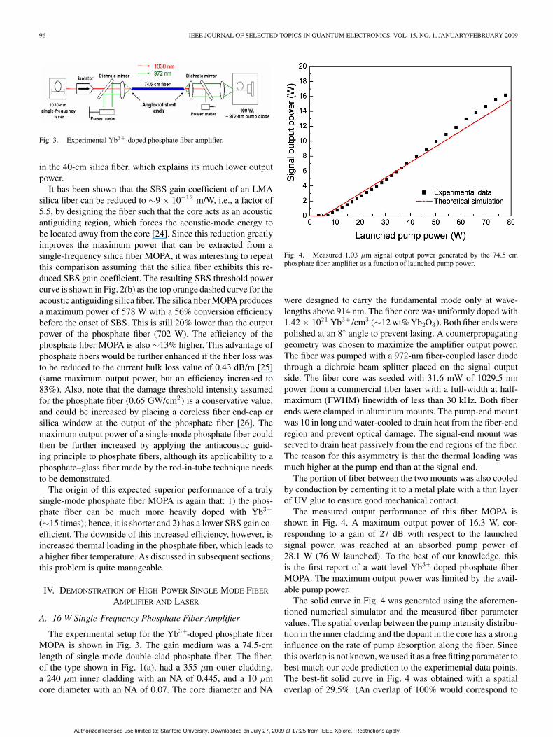
Fig. 3. Experimental Yb3+-doped phosphate fiber amplifier.
in the 40-cm silica fiber, which explains its much lower outputpower.
It has been shown that the SBS gain coefficient of an LMAsilica fiber can be reduced to ∼9 × 10⁻¹² m/W, i.e., a factor of5.5, by designing the fiber such that the core acts as an acousticantiguiding region, which forces the acoustic-mode energy tobe located away from the core [24]. Since this reduction greatlyimproves the maximum power that can be extracted from asingle-frequency silica fiber MOPA, it was interesting to repeatthis comparison assuming that the silica fiber exhibits this re-duced SBS gain coefficient. The resulting SBS threshold powercurve is shown in Fig. 2(b) as the top orange dashed curve for theacoustic antiguiding silica fiber. The silica fiber MOPA producesa maximum power of 578 W with a 56% conversion efficiencybefore the onset of SBS. This is still 20% lower than the outputpower of the phosphate fiber (702 W). The efficiency of thephosphate fiber MOPA is also ∼13% higher. This advantage ofphosphate fibers would be further enhanced if the fiber loss wasto be reduced to the current bulk loss value of 0.43 dB/m [25](same maximum output power, but an efficiency increased to83%). Also, note that the damage threshold intensity assumedfor the phosphate fiber (0.65 GW/cm2) is a conservative value,and could be increased by placing a coreless fiber end-cap orsilica window at the output of the phosphate fiber [26]. Themaximum output power of a single-mode phosphate fiber couldthen be further increased by applying the antiacoustic guid-ing principle to phosphate fibers, although its applicability to aphosphate–glass fiber made by the rod-in-tube technique needsto be demonstrated.
The origin of this expected superior performance of a trulysingle-mode phosphate fiber MOPA is again that: 1) the phos-phate fiber can be much more heavily doped with Yb3+
(∼15 times); hence, it is shorter and 2) has a lower SBS gain co-efficient. The downside of this increased efficiency, however, isincreased thermal loading in the phosphate fiber, which leads toa higher fiber temperature. As discussed in subsequent sections,this problem is quite manageable.
IV. DEMONSTRATION OF HIGH-POWER SINGLE-MODE FIBER
AMPLIFIER AND LASER
A. 16 W Single-Frequency Phosphate Fiber Amplifier
The experimental setup for the Yb3+-doped phosphate fiberMOPA is shown in Fig. 3. The gain medium was a 74.5-cmlength of single-mode double-clad phosphate fiber. The fiber,of the type shown in Fig. 1(a), had a 355 µm outer cladding,a 240 µm inner cladding with an NA of 0.445, and a 10 µmcore diameter with an NA of 0.07. The core diameter and NA
Fig. 4. Measured 1.03 µm signal output power generated by the 74.5 cmphosphate fiber amplifier as a function of launched pump power.
were designed to carry the fundamental mode only at wave-lengths above 914 nm. The fiber core was uniformly doped with1.42 × 1021 Yb3+ /cm3 (∼12 wt% Yb2O3). Both fiber ends werepolished at an 8◦ angle to prevent lasing. A counterpropagatinggeometry was chosen to maximize the amplifier output power.The fiber was pumped with a 972-nm fiber-coupled laser diodethrough a dichroic beam splitter placed on the signal outputside. The fiber core was seeded with 31.6 mW of 1029.5 nmpower from a commercial fiber laser with a full-width at half-maximum (FWHM) linewidth of less than 30 kHz. Both fiberends were clamped in aluminum mounts. The pump-end mountwas 10 in long and water-cooled to drain heat from the fiber-endregion and prevent optical damage. The signal-end mount wasserved to drain heat passively from the end regions of the fiber.The reason for this asymmetry is that the thermal loading wasmuch higher at the pump-end than at the signal-end.
The portion of fiber between the two mounts was also cooledby conduction by cementing it to a metal plate with a thin layerof UV glue to ensure good mechanical contact.
The measured output performance of this fiber MOPA isshown in Fig. 4. A maximum output power of 16.3 W, cor-responding to a gain of 27 dB with respect to the launchedsignal power, was reached at an absorbed pump power of28.1 W (76 W launched). To the best of our knowledge, thisis the first report of a watt-level Yb3+-doped phosphate fiberMOPA. The maximum output power was limited by the avail-able pump power.
The solid curve in Fig. 4 was generated using the aforemen-tioned numerical simulator and the measured fiber parametervalues. The spatial overlap between the pump intensity distribu-tion in the inner cladding and the dopant in the core has a stronginfluence on the rate of pump absorption along the fiber. Sincethis overlap is not known, we used it as a free fitting parameter tobest match our code prediction to the experimental data points.The best-fit solid curve in Fig. 4 was obtained with a spatialoverlap of 29.5%. (An overlap of 100% would correspond to
Authorized licensed use limited to: Stanford University. Downloaded on July 27, 2009 at 17:25 from IEEE Xplore. Restrictions apply.

LEE et al.: HIGH-POWER Yb3+ -DOPED PHOSPHATE FIBER AMPLIFIER 97
Fig. 5. Measured and simulated residual pump power as a function of launchedpump power.
a pump distribution that is uniform across the core and innercladding.) The theoretical curve agrees very well with the mea-sured data. The slightly higher measured efficiency at higherpump powers is simply the result of the pump wavelength beingred-shifted toward the 975-nm Yb3+ absorption peak at higherdiode drive currents.
The predicted 29.5% overlap was confirmed by studyingthe residual unabsorbed pump power transmitted by the fiberMOPA (see Fig. 3). Fig. 5 shows the measured unabsorbed pumppower as a function of launched pump power. At the maximumlaunched pump power of 76 W, the unabsorbed pump poweris as large as 28 W. Fig. 5 also shows the unabsorbed pumppower predicted by the code for this amplifier, using the sameparameter values as to generate the solid curve of Fig. 4, includ-ing a spatial overlap of 29.5%. The simulation curve matchesthe measured data well. This agreement confirms the numericalvalue of 29.5% for the pump/dopant overlap, and it explains why∼40% of the pump power was not absorbed in the fiber. Thisrelatively low overlap is believed to be due to the high azimuthalsymmetry of the core/inner cladding configuration that resultsin insufficient scattering of the pump modes in the fiber (whichwas kept straight). This overlap can be increased by using afiber with an air hole parallel to the core [see Fig. 1(b)] [20], asdemonstrated in the next section, or a polarization-maintainingfiber, where the stress rods then act as mode mixers.
The measured output spectrum of the fiber amplifier measuredat 14.6 W is shown in Fig. 6. It indicates that the ASE powerlevel is more than 25 dB below the 1029.5 nm signal level. Theratio of total ASE power to signal power was estimated as lessthan 1% from our code. As shown in the inset of Fig. 6, theoutput signal was in the fundamental fiber mode (LP01) and ofexcellent quality, as expected for a step-index single-mode core.
B. 57-W Single-Mode Phosphate Fiber Laser
Our early studies of phosphate fiber lasers taught us thatadding an air hole to the inner cladding and making the core ec-centric break the axial symmetry of the waveguide and greatlyimprove the pump/dopant spatial overlap [20]. It was therefore
Fig. 6. Measured amplifier spectrum at an output power of 14.6 W. The insetis the measured output beam profile.
Fig. 7. Experimental Yb3+-doped phosphate fiber laser.
interesting to test these air-hole fibers in our fiber MOPA. How-ever, a high-gain fiber MOPA requires angled fiber ends to avoidlasing. We could neither polish the fiber ends (without cloggingthe air hole with debris that would induce optical damage) norcleave them at an angle for lack of suitable equipment. As analternative, to study the power scalability of this Yb3+-dopedphosphate fiber beyond the power level that we were able toachieve in an amplifier, we cleaved the ends of the fiber at 90◦
and used the fiber to make a phosphate fiber laser.The experimental configuration of this laser is shown in Fig. 7.
It consisted of a 71.6 cm length of air-hole Yb3+-doped phos-phate fiber placed in an optical cavity. One cavity mirror wasa dielectric high reflector (HR) with a reflectivity greater than99% at 1064 nm, butt coupled to one of the cleaved fiber ends.The other mirror was the other cleaved fiber end, which pro-vided a 5% reflection and acted as the output coupler (OC). Thecleaved fiber end is shown in Fig. 1(b). This fiber has the samestructure as the fiber used in the fiber MOPA, except that theactive core is offset from the fiber center and an air hole is added.The core and the air hole are symmetrically located with respectto the center of the fiber, and 30 µm apart center to the center.The fiber was cladding-pumped with a fiber-coupled laser diodeat 977 nm through a dichroic beam splitter placed on the OCside. The fiber ends were cooled using the same arrangementas the MOPA, except that the 1-in mount at the mirror end wasalso water-cooled.
Our previous phosphate fiber laser [20] had a slope efficiencyof 25.8%, which was limited by the relatively low absorptionof the 940 nm pump. Significant efficiency improvement in the
Authorized licensed use limited to: Stanford University. Downloaded on July 27, 2009 at 17:25 from IEEE Xplore. Restrictions apply.

98 IEEE JOURNAL OF SELECTED TOPICS IN QUANTUM ELECTRONICS, VOL. 15, NO. 1, JANUARY/FEBRUARY 2009
Fig. 8. 1.06 µm laser power generated by the 71.6 cm phosphate fiber laser asa function of the launched pump power at 977 nm. The inset shows the measuredoutput beam profile.
same laser configuration was achieved by changing the pumpwavelength to 977 nm, where Yb3+ absorption is much stronger.
Fig. 8 shows the laser output power measured versus launchedpump power. The threshold was ∼3 W. The maximum out-put power was 56.9 W for 116.7 W of launched pump power(104.3 W absorbed). The output was in the LP01 mode, andthe laser FWHM linewidth was ∼4 nm. The measured slopeefficiency was 50.6% against launched pump power and 56.7%against absorbed pump power. These efficiencies are more thantwice as high as in our previous laser [20]. In addition, theseefficiencies are well predicted by our simulation if we assume aspatial overlap of 100% (solid curve in Fig. 8). At the maximumoutput power, we observed catastrophic damage of the fiber in-side the pump-input V-groove mount near where the fiber exitsthe mount. We believe that the damage was likely caused byexcessive stress applied to the fiber’s outer surface by imperfec-tions in the machined V-groove in which the fiber rested insidethe mount, combined with the pump-induced increase in thefiber temperature.
The fiber length used in this laser was, in fact, optimizedtheoretically to maximize the laser output power at the highestavailable pump power. Although the slope efficiency is fairlygood, it is not as high as could be, in spite of this optimization,because not all of the pump is absorbed, and further increas-ing the fiber length would increase the loss, at both the signaland pump, more than the gain. Simulations show that by re-ducing the fiber loss from 3 to 0.3 dB/m, the slope efficiency,after optimizing the length, would be as high as 86%, which iscomparable to what is achievable in silica fibers. This analysisshows that it is crucial to study the origin of the loss in thephosphate fibers, in particular, whether it comes from absorp-tion and scattering mechanisms. This information will provideuseful hints as to what steps should be taken to reduce this loss.The fact that phosphate glass can be have a much lower loss(∼0.43 dB/m) [25] than our current fibers suggests that thisgoal is achievable.
Fig. 9. Schematic diagram of the fiber calorimeter.
V. ANALYSIS OF FIBER LOSS
The propagation loss of our phosphate fibers is expectedto arise primarily from absorption and/or scattering. Absorp-tion converts light energy into heat that not only degrades thelaser efficiency but also increases the fiber temperature. Thelower efficiency results in a higher pump power requirement,which further increases the temperature. The higher tempera-ture may result in thermal damage and limit the power scala-bility of the system. In contrast, if scattering is only a sourceof loss, it reduces efficiency without generating heat. We usedthis fundamental difference to measure these two componentsindependently.
A. Absorption Loss Measurements
In the absorption measurements, the fiber was placed in acalorimeter and optically probed with a 1.55 µm laser, whereYb3+ does not absorb. Thermocouples inside the calorimetermeasured the fiber temperature increase, from which, after suit-able calibration, the amount of heat released by the fiber inthe calorimeter per unit time could be calculated. As shown inFig. 9, the calorimeter consisted of two identical glass capillar-ies placed inside a cylindrical aluminum shield [27]. The twocapillary tubes were 16.2 cm long and had an inner diameter of1 mm. The fiber under test was threaded through one capillary.The other capillary served as a reference. Six thermocoupleswere attached to both capillaries in series. They were evenlydistributed along the capillaries so as to provide the tempera-ture difference averaged over six points along the length of thecapillaries. Because only temperature differences are measured,environmental temperature fluctuations are subtracted. The roleof the aluminum shield was to maintain a homogeneous temper-ature distribution in the vicinity of the capillaries. The responseof the calorimeter was calibrated by placing a copper wire withknown resistance inside the capillary that normally receives thefiber, then sending a known current through it, giving us a knownamount of heat.
A 119 cm length of unjacketed single-mode 12% Yb-dopedphosphate fiber was used in this measurement. The fiber hada core diameter of 5 µm and a cladding diameter of 125 µm.Light from a 450 mW, 1551 nm laser pigtailed to a single-mode fiber was launched into the fiber core. Any light guidedby the cladding was stripped carefully before the point of entryof the fiber into the calorimeter by placing index-matching gelon the fiber surface. Since the capillary’ glass has negligibleabsorption around 1.55 µm, the portion of signal light scatteredby the fiber was absorbed only by the aluminum shield, and thus,did not induce any heating of the capillaries. After turning on the
Authorized licensed use limited to: Stanford University. Downloaded on July 27, 2009 at 17:25 from IEEE Xplore. Restrictions apply.

LEE et al.: HIGH-POWER Yb3+ -DOPED PHOSPHATE FIBER AMPLIFIER 99
laser, the fiber temperature rose above the ambient temperature,from the absorbed power at 1551 nm, then quickly (∼2 min)settled to a constant value. The absorption loss coefficient of thefiber was derived from the measured steady-state temperaturedifference between the capillaries and the measured transmittedlaser power. The absorption loss coefficient obtained by thisprocess is 2.27 dB/m.
B. Scattering Loss Measurements
To cross check this absorption loss measurement, we alsomeasured the scattering loss of a piece of fiber from the samespool. Portion of a 168 cm length of fiber was placed in 1-in-diameter integrating sphere coated with barium sulfate, and lightfrom the 1551 nm laser was launched into the fiber. An InGaAsphotodiode mounted in the output port of the integrating spheremeasured the portion of fiber-guided laser light scattered in thesphere. A baffle was mounted parallel to the fiber to shield thedetector from direct illumination with forward-scattered light.The fiber surface prior to its point of entry into the sphere wascovered with index-matching gel to strip out cladding modes.The response of the integrating sphere was calibrated by pullingthe fiber back until its free end was at the center of the sphere,then measuring the power collected by the detector and com-paring it to the known power released inside the sphere. Thisprocedure yielded a scattering coefficient of 0.68 dB/m.
The total loss of this fiber, measured by an independent cut-back method, is 2.95 dB/m at 1551 nm. This value is in verygood agreement with the sum of the measured absorption loss(2.27 dB/m) and scattering loss (0.68 dB/m) coefficients. Theabsorption loss, therefore, accounts for 77% of the total loss, andscattering for the remaining 23%. In principle, the absorptioncomponent is mainly due to impurities in source material, whilescattering arises from inhomogeneities in the bulk and/or irreg-ularities at the boundary between the core and inner cladding.This result (77%/23%) indicates that absorption loss must bereduced to improve the efficiency of the fiber laser.
VI. OPTICAL DAMAGE LIMIT
The limitation that ultimately prevents further power scalingof any laser is optical damage caused by breakdown, thermalloading, or stress fracture. This limitation is anticipated to bemore prominent in a soft glass such as a phosphate, compared,for example, to thermomechanically tougher glasses such assilica. To this end, it was interesting to study the thermal loadingof our high-power phosphate fiber laser, and forecast how higha single-mode phosphate fiber laser can be scaled in power.
Three main optical damage mechanisms need to be assessedwhen dealing with CW lasers, namely: 1) optical surface damagearising from the high electric field at the input and output endsof the fiber; 2) melting of the glass; and 3) stress fracturescaused by radial or longitudinal temperature gradients in thefiber. The surface damage threshold of a 10-µm single-modephosphate fiber has been discussed in Section III. Melting andstress fracture in lasers are induced by excessive thermal loadingof the laser material. Li et al. reported a 3-D thermal analysisof short-length phosphate fiber lasers [28]. Measurements have
shown that when cooled with thermoelectric coolers (TECs), afiber made with the same phosphate host as used in this paperexhibits no signs of damage at 1.5 µm at a thermal loading of180 W/m. In addition, the thermal simulation further predictedthat TEC-cooled phosphate fiber lasers have the potential todissipate thermal loads up to ∼1 kW/m with the same coolingdesign. Assuming a weak dependence of damage on wavelength,this value can be used as a lower bound value for stress fractureand melting in a cooled Yb3+-doped fiber source.
To evaluate how much power can be extracted from a Yb3+-doped fiber laser source before this level of thermal loading isreached, we developed an analytical model of thermal loading.As in other hosts, in a pumped phosphate fiber, heat is producedfirst by the relaxation of phonons that make up for the quantumdefect between the pump and laser photons, and second bythe absorption component of the fiber loss that originates fromimpurities. Both the pump and the laser signal contribute to thissecond mechanism.
The heat generated per unit time ∆H1 by the first mechanismalong a short length of fiber ∆z is given by
∆H1(z) = ηαabs(z)Pp(z)∆z (1)
where αabs(z) is the z-dependent, saturated absorption coeffi-cient of Yb3+ at the pump wavelength, η is the quantum defect(only ∼8.9% in a 1064 nm laser pumped at 977 nm), and Pp(z)is the remaining pump power at z.
The heat produced per unit time ∆H2 by absorption loss ofthe pump and signal along this same length of fiber ∆z is
∆H2 (z) = αa [Pp (z) + Ps (z)] ∆z (2)
where αa is the absorption loss coefficient and Ps(z) is the laserpower at z. The total heat ∆H generated along the gain fiber, orthermal load, is the sum of these two contributions
∆H(z) = ∆H1(z) + ∆H2(z). (3)
The thermal load of phosphate fiber lasers was evaluatednumerically by making use of our simulator, which calculates,among many other parameters, the distribution of the signal andpump powers along the fiber. For simplicity, and without loss ofaccuracy, we assumed that the pump absorption loss is uniformacross the core and inner cladding. The quantum-defect-inducedloss is generated only inside the core.
Fig. 10 shows the thermal load calculated for the parametersof our experimental fiber laser at its maximum output power of57 W. Both contributions, as well as the total thermal load, areplotted as a function of position along the fiber. All three curvesdecrease monotonically from the pumped (left) end of the fiber,as expected. The highest thermal loading is ∼200 W/m. Thefiber loss accounts for more than 50% of the thermal loading,which stresses again the importance of reducing the fiber loss. Ifthe absorption loss is removed, the loss contribution will becomenegligible, and the thermal loading will drop to ∼60 W/m, i.e.,about 1 W/m per watt of output power, suggesting that from thestandpoint of thermal loading and heat removal alone, at least∼1 kW could be extracted from this truly single-mode device.
The shaded area in Fig. 10 identifies the portion of the pump-side fiber-end that was cooled actively. As mentioned earlier, at
Authorized licensed use limited to: Stanford University. Downloaded on July 27, 2009 at 17:25 from IEEE Xplore. Restrictions apply.

100 IEEE JOURNAL OF SELECTED TOPICS IN QUANTUM ELECTRONICS, VOL. 15, NO. 1, JANUARY/FEBRUARY 2009
Fig. 10. Calculated thermal loading of the 56.9 W phosphate fiber laser.
Fig. 11. Calculated thermal loading of the proposed 700 W phosphate fiberMOPA.
the highest pump power, the fiber damaged at the point identifiedby the arrow that is near the uncooled portion of the fiber.When replaced, the next fiber also damaged at about the samepoint. This seems to suggest that the damage was caused byan excessive longitudinal temperature gradient in this region aswell as imperfections in the machined V-groove. Cooling theentire fiber should solve this problem.
In addition, we plot the calculated thermal loading for the700 W phosphate fiber MOPA, reported in Section II-B, asshown in Fig. 11. The launched pump power was taken to be700 W in the forward direction and 300 W in the backwarddirection. The fiber core diameter was 10 µm, the core NA 0.07,the inner cladding diameter 125 µm, and the pump wavelength975 nm. The total pump power was selected to produce a max-imum output of 700 W equal to the surface-damage thresholdfor this core size. Again, the loss contribution dominates. Thethermal loading is more uniform because of bidirectional pump-ing. The maximum thermal loading is approximately constantand under 800 W/m. This simulation shows that the thermal-loading limit (>1 kW/m) is not reached before the onset ofsurface damage. With suitable cooling, the maximum output
power of a single-mode Yb3+-doped fiber laser can be limitedby the ultimate damage mechanism, i.e., surface damage.
VII. CONCLUSION
Yb3+-doped phosphate fibers constitute a promising gain ele-ment for power-scaling truly single-mode single-frequency fiberamplifiers to near the kilowatt level. We have shown that as aresult of their extremely high doping level, low SBS gain coef-ficient, and absence of photodarkening. Numerical simulationspredict that in a double-clad, step-index phosphate fiber heavilydoped with Yb3+, up to ∼700 W of single-frequency single-mode power can be generated without the onset of SBS, at athermal-loading level that can be handled by a cooled fiber. Asa proof of principle, we report the first high-power sourcesin a Yb3+-doped phosphate fiber, namely, a 1.03 µm fiberMOPA producing 16 W of single-frequency power and a 57 Wmultiple-frequency 1.03 µm fiber laser. Both sources used only∼75 cm of a step-index single-mode fiber doped with as much as12 wt% Yb2O3 . The slope efficiency of these sources (51% and57% with respect to absorbed and launched pump power, re-spectively) is found to be limited by the fairly high fiber loss(∼3 dB/m). Measurements indicate that 77% of this loss is dueto impurity absorption, and the rest to scattering. By reducingthe fiber loss from 3 to 0.3 dB/m, the slope efficiency of thesephosphate fiber lasers will be as high as 86%, and the thermalloading can be decreased by more than 3 dB. Further studieswill focus on reducing this loss and developing cooling systemsto achieve higher powers.
ACKNOWLEDGMENT
The authors thank C. W. Rudy for assistance in the fiberscattering loss measurement.
REFERENCES
[1] V. Gapontsev, D. Gapontsev, N. Platonov, O. Shkurikh, V. Fomin,A. Mashkin, M. Abramov, and S. Ferin, “2 kW CW ytterbium fiberlaser with record diffraction-limited brightness,” in Proc. Conf. LasersElectro-Opt. Eur., Munich, Germany, Jun. 12–17, 2005, p. 508.
[2] Y. Jeong, J. Sahu, D. Payne, and J. Nilsson, “Ytterbium-doped large-corefiber laser with 1.36 kW continuous-wave output power,” Opt. Express,vol. 12, no. 25, pp. 6088–6093, 2004.
[3] S. Gray, A. Liu, D. T. Walton, J. Wang, M.-J. Li, X. Chen, A. B. Ruffin,J. A. DeMeritt, and L. A. Zenteno, “502 watt, single transverse mode,narrow linewidth, bidirectionally pumped Yb-doped fiber amplifier,” Opt.Express, vol. 15, no. 25, pp. 17044–17050, 2007.
[4] Y. Jeong, J. Nilsson, J. K. Sahu, D. N. Payne, L. M. B. Hickey, andP. W. Turner, “Power scaling of single-frequency ytterbium-doped fibermaster-oscillator power-amplifier sources up to 500 W,” IEEE J. QuantumElectron., vol. 13, no. 3, pp. 546–549, May/Jun. 2007.
[5] E. Snitzer, H. Po, F. Hakimi, R. Tumminelli, and B. C. McCollum,“Double-clad, offset core Nd fiber laser,” presented at the Opt. FiberSens. 1998, OSA Tech. Dig. Ser., Washington, DC, vol. 2, Paper PD5.
[6] Z. Burshtein, Y. Kalisky, S. Z. Levy, P. Le Boulanger, and S. Rotman,“Impurity local phonon nonradiative quenching of Yb3+ fluorescence inYtterbium-doped silicate glasses,” IEEE J. Quantum Electron., vol. 26,no. 8, pp. 1000–1007, Aug. 2000.
[7] Y.-W. Lee, S. Sinha, M. J. F. Digonnet, R. L. Byer, and S. Jiang, “Measure-ment of high photodarkening resistance in heavily Yb3+ -doped phosphatefibers Yb3+ -doped phosphate fiber laser,” Electron. Lett., vol. 44, no. 1,pp. 14–16, 2008.
[8] M. E. Fermann, “Single-mode excitation of multimode fibers with ultra-short pulses,” Opt. Lett., vol. 23, no. 1, pp. 52–54, 1998.
Authorized licensed use limited to: Stanford University. Downloaded on July 27, 2009 at 17:25 from IEEE Xplore. Restrictions apply.
LEE et al.: HIGH-POWER Yb3+ -DOPED PHOSPHATE FIBER AMPLIFIER 101
[9] J. W. Nicholson, A. D. Yablon, S. Ramachandran, and S. Ghalmi, “Spa-tially and spectrally resolved imaging of modal content in large-mode-areafibers,” Opt. Express, vol. 16, no. 10, pp. 7233–7243, 2008.
[10] B. Willke, N. Uehara, E. K. Gustafson, R. L. Byer, P. J. King, S. U. Seel,and R. L. Savage, Jr., “Spatial and temporal filtering of a 10-W Nd:YAGlaser with a Fabry–Perot ring-cavity premode cleaner,” Opt. Lett., vol. 23,no. 21, pp. 1704–1706, 1998.
[11] Y.-W. Lee, K. E. Urbanek, M. J. F. Digonnet, R. L. Byer, and S. Jiang,“Measurement of the stimulated Brillouin scattering gain coefficient of aphosphate fiber,” Proc. SPIE, vol. 6469, p. 64690L, 2007.
[12] R. Paschotta, J. Nilsson, A. Tropper, and D. C. Hanna, “Ytterbium-dopedfiber amplifiers,” IEEE J. Quantum Electron., vol. 33, no. 7, pp. 1049–1056, Jul. 1997.
[13] NP Photonics, Tuscon, AZ, unpublished.[14] S. Suzuki1, S. Jiang, N. Peyghambarian, and A. Chavez-Pirson, “Image
amplifier based on Yb3+ -doped multi-core phosphate optical fiber,” Opt.Express, vol. 15, no. 7, pp. 3759–3765, 2007.
[15] E. Snitzer and R. Tumminelli, “SiO2-clad fibers with selectivelyvolatilized soft-glass cores,” Opt. Lett., vol. 14, no. 14, pp. 757–759,1989.
[16] T. Qiu, L. Li, A. Schulagen, V. L. Temyanko, T. Luo, S. Jiang, A. Mafi,J. V. Moloney, and N. Peyghambarian, “Generation of 9.3-W multimodeand 4-W single-mode output from 7-cm short fiber lasers,” IEEE Photon.Technol. Lett., vol. 16, no. 12, pp. 2592–2594, Dec. 2004.
[17] J. L. Wagener, D. G. Falquier, M. J. F. Digonnet, and H. J. Shaw, “AMueller matrix formalism for modeling polarization effects in Erbium-doped fiber,” J. Lightw. Technol., vol. 16, no. 2, pp. 200–206, Feb. 1998.
[18] D. G. Falquier, J. L. Wagener, M. J. F. Digonnet, and H. J. Shaw, “Polarizedsuperfluorescent fiber sources,” Opt. Fiber Technol., vol. 4, no. 4, pp. 453–470, 1998.
[19] S. Sinha, “Power scaling long-wavelength Yb3+ -doped silica fiber lasersfor frequency doubling to yellow,” Ph.D. dissertation, Stanford Univ.,Stanford, CA, ch. 2, pp. 57–70.
[20] Y.-W. Lee, S. Sinha, M. J. F. Digonnet, R. L. Byer, and S. Jiang, “20W single-mode Yb3+ -doped phosphate fiber laser,” Opt. Lett., vol. 31,no. 22, pp. 3255–3257, 2006.
[21] J. Koponen, M. Soderlund, H. J. Hoffman, D. A. V. Kliner, and J. P.Koplow, “Photodarkening measurements in large mode area fibers,” Proc.SPIE, vol. 6453, p. 64531E, 2007.
[22] J. Limpert, F. Roser, S. Klingebiel, T. Schreiber, C. Wirth, T. Pesche,R. Eberhardt, and A. Tunnermannl, “The rising power of fiber lasersand amplifiers,” IEEE J. Sel. Topics Quantum Electron., vol. 13, no. 3,pp. 537–545, May/Jun. 2007.
[23] J. H. Campbell and T. I. Suratwala, “Nd-doped phosphate glasses forhigh-energy/high-peak-power lasers,” J. Non-Cryst. Solids, vol. 263/264,pp. 318–341, 2000.
[24] M.-J. Li, X. Chen, J. Wang, S. Gray, A. Liu, J. A. Demeritt, A. B. Ruffin,A. M. Crowley, D. T. Walton, and L. A. Zenteno, “Al/Ge co-doped largemode area fiber with high SBS threshold,” Opt. Express, vol. 15, no. 13,pp. 8290–8299, 2007.
[25] F. Hanson and G. Imthurn, “Efficient laser diode side pumped neodymiumglass slab laser,” IEEE J. Quantum Electron., vol. QE-24, no. 9, pp. 1811–1813, Sep. 1988.
[26] S. Sinha, K. E. Urbanek, A. Krzywicki, and R. L. Byer, “Investigationof the suitability of silicate bonding for facet termination in active fiberdevices,” Opt. Express, vol. 15, no. 20, pp. 13003–13022, 2007.
[27] D. H. Jundt, “Lithium niobate: Single crystal fiber growth and quasi-phase-matching,” Ph.D. dissertation, Stanford Univ., Stanford, CA, 1991,pp. A77–A83.
[28] L. Li, H. Li, T. Qiu, V. L. Temyanko, M. M. Morrell, and A. Schulzgen,“3-Dimensional thermal analysis and active cooling of short-length high-power fiber lasers,” Opt. Express, vol. 13, no. 59, pp. 3420–3428, 2005.
Yin-Wen Lee received the B.S. degree in atomicscience and the M.S. degree in electrical engineer-ing from National Tsinghua University, Hsinchu,Taiwan, in 1998 and 2000, respectively. She is cur-rently working toward the Ph.D. degree in appliedphysics at Stanford University, Stanford, CA.
Her current research interests include high-powerfiber lasers and amplifiers, with special focus onpower scaling capabilities of Yb-doped phosphatefibers.
Ms. Lee is a member of the Optical Society ofAmerica (OSA) and the International Society for Optical Engineering (SPIE).
Michel J. F. Digonnet (M’01) received the degreein engineering from Ecole Superieure de Physiqueet de Chimie de la Ville de Paris, Paris, France, theDiplome d’Etudes Approfondies in coherent opticsfrom the University of Paris, Paris, in 1978, and theM.S. and Ph.D. degrees from the Applied Physics De-partment, Stanford University, Stanford, CA, in 1980and 1983, respectively.
His doctoral research centered on wavelength-division multiplexing (WDM) fiber couplers andsingle-crystal fibers. From 1983 to 1986, he was a
Visiting Scholar at Stanford University, where he was engaged in conductingresearch on miniature solid-state sources and integrated optics for fiber sensors.From 1986 to 1990, he was involved in the development of dye and 2 µm solid-state lasers, fiber sensors, and fiber delivery systems for laser angioplasty withMCM Laboratories, Mountain View, CA. He is currently a Senior ResearchAssociate in the Department of Applied Physics, Stanford University, wherehe teaches a course entitled lasers, as well as short courses on fiber ampli-fiers and lasers and fiber sensors at international conferences. He has authoredor coauthored 190 articles, held nearly 60 patents, edited several books, andchaired numerous conferences on optical fiber devices, sensors, and materials.His current research interests include photonic bandgap fibers, fiber sensors,and sensor arrays, high-power ceramic lasers, fiber lasers and amplifiers, fibergratings, slow light, and optical microcavities.
Supriyo Sinha received the B.A.Sc. degree in com-puter engineering with physics from the Universityof Waterloo, Waterloo, ON, Canada, in 2000, and theM.S. and Ph.D. degrees in electrical engineering fromStanford University, Stanford, CA, in 2002 and 2007,respectively.
His doctoral research centered on long-wavelengthytterbium fiber lasers and amplifiers and low-noisehigh-power single-frequency fiber systems. In 2007,he was a Postdoctoral Scholar in Professor Byer’sResearch Group, where he was engaged in research
on ultrafast fiber lasers and silicate bonding. Since 2008, he has been an OpticalEngineer at Raydiance, Inc. Los Altos, CA, where he is engaged in research onultrafast fiber systems.
Dr. Sinha is a member of the Optical Society of America (OSA).
Karel E. Urbanek received the B.S. degree in ap-plied physics and the B.A. degree in economics fromthe University of California, Davis, in 1997, and theM.Sc. degree in applied physics from Stanford Uni-versity, Stanford, CA, in 2003.
From 1997 to 2000, he was initially a Technicianand later an Engineering Technician with Spectra-Physics, where he was engaged in gaining experiencewith gas, solid state, and ultrafast lasers. In 1996, hespent the summer working on rebuilding a COIL sys-tem at the National Science Institute, Prague, Czech
Republic. Since 2003, he has been a Physical Sciences Research Assistant in theByer and Fejer Research Groups, Stanford University. His current research in-terests include high-power fiber amplifiers, low-noise single-frequency sources,solid-state amplifiers, and nonlinear frequency conversion for use in near-IRand visible laser systems.
Authorized licensed use limited to: Stanford University. Downloaded on July 27, 2009 at 17:25 from IEEE Xplore. Restrictions apply.

102 IEEE JOURNAL OF SELECTED TOPICS IN QUANTUM ELECTRONICS, VOL. 15, NO. 1, JANUARY/FEBRUARY 2009
Robert L. Byer (M’75–M’83–F’87) received thePh.D. degree in applied physics from Stanford Uni-versity, Stanford, CA, in 1969.
He is a Professor of Applied Physics at StanfordUniversity, Stanford, CA, where he has conductedresearch and taught classes in lasers and nonlinearoptics since 1969. He was the Chair of the AppliedPhysics Department from 1981 to 1984, the Asso-ciate Dean of Humanities and Sciences from 1985to 1987, and the Vice Provost and Dean of Researchfrom 1987 to 1992. From 1997 to 2006, he was the
Director of Hansen Experimental Physics Laboratory. From 2006 to 2008, hewas the Director of Edward L. Ginzton Laboratory. He has made numerous con-tributions to laser science and technology including the demonstration of thefirst tunable visible parametric oscillator, the development of the Q-switchedunstable resonator Nd:YAG laser, remote sensing using tunable IR sources, andprecision spectroscopy using coherent anti-Stokes Raman scattering. He has au-thored or coauthored more than 500 scientific papers and holds 50 patents in thefields of lasers and nonlinear optics. His current research interests include thedevelopment of advanced nonlinear optical materials and laser-diode-pumpedsolid-state laser sources for application to gravitational wave detection and laserparticle acceleration.
Prof. Byer is a Fellow of the Optical Society of America, the American Phys-ical Society, and the American Association for the Advancement of Science.In 1985, he was the President of the IEEE Lasers and Electro-Optics Society,and in 1994, the President of the Optical Society of America. From 1995 to1998, he was the Chair of the California Council on Science and Technology,of which he is a Founding Member. He has served on the Engineering AdvisoryBoard of the National Science Foundation. In 1996, he received the QuantumElectronics Award from the IEEE Lasers and Electro-Optics Society. In 1998,he received the Schawlow Award of the Laser Institute of America and the R. W.Wood Prize of the Optical Society of America. He was elected to the NationalAcademy of Engineering in 1987.
Shibin Jiang received the Ph.D. degree from the Uni-versite de Rennes 1, Rennes, France, in 1996.
He is currently the President of AdValue Photon-ics, Inc, Tucson, AZ, and also an Adjunct ResearchProfessor in the College of Optical Sciences, Univer-sity of Arizona, Tucson, where he was an AssistantResearch Professor. He was the Chief TechnologyOfficer and the Co-Founder of NP Photonics, Inc.,Tucson. His current research interests include inno-vative glasses and fibers, high power fiber lasers andamplifiers, mode-locked fiber lasers, THz source gen-
eration, low noise single frequency fiber lasers, tunable lasers, and fiber sensorsystems. He authored/co-authored 60 peer-reviewed journal publications, edited12 proceedings books, and was awarded 23 US patents in the area of photonicglass materials and devices.
Dr. Jiang is the recipient of the 2005 Gottardi Prize from InternationalCommission on Glass. He is a Fellow of the International Society for OpticalEngineering (SPIE) and the American Ceramic Society.
Authorized licensed use limited to: Stanford University. Downloaded on July 27, 2009 at 17:25 from IEEE Xplore. Restrictions apply.