KAV-150a Power Amplifier - Krell
10
The Leaderin Audio Engineering KAV-150a Power Amplifier Instructions for Use,v 98.0 Owner’s Reference
-
Upload
khangminh22 -
Category
Documents
-
view
0 -
download
0
Transcript of KAV-150a Power Amplifier - Krell

The Leader in Audio Engineering
KAV-150aPower Amplifier
Instructions for Use, v 98.0
Owner’s Reference
ContentsKAV-150aPower Amplifier
Krell® Industries, Inc.
45 Connair Road
Orange, CT 06477-3650 USA
TEL 203-799-9954
FAX 203-799-9796
E-MAIL krell@ krellonline.com
WEB SITE www.krellonline.com
INTRODUCTION
UNPACKING
PLACEMENT
Cabinetry ConsiderationsAC Power Guidelines
CONNECTING THE KAV-150aTO YOUR SYSTEM
Input and Output ConnectionsConfiguring the KAV-150a
for Bridged Operation
AMPLIFIER OPERATION
On/Off and Stand-by OperationSystem Noise Considerations
WARRANTY
RETURN AUTHORIZATIONPROCEDURE
SPECIFICATIONS
Page
4
4
5
5
6
6
67
8
9
Back Cover
© 1998 by KRELL® Industries, Inc. All rights reserved P/N I960101900088
CE MarkingThis product complies with the EMC direc-tive (89/336/EEC) and the low-voltagedirective (73/23/EEC).
Introduction
Thank you for your purchase of the Krell®KAV-150a Power Amplifier. The nameKrell ® has always represented componentsthat are the premier performers in theirproduct categories. The KAV-150a poweramplifier continues in this Krell® tradition
The KAV-150a is a stereo amplifier thatmay be bridged into monaural operation.Designed as a compact component withexceptional sound, the KAV-150a may beinterfaced easily into multi-amplifier sys-tems using the 12 V trigger and the bridg-ing capability. The KAV-150a uses provenKrell®circuits built with the same high qual-ity resistors, output devices, and internalelectrical components used in all otherKrell®products. From input to output, theKAV-150a uses discrete, fully complemen-tary circuitry. All circuits up to the driverstage operate in pure Class A. TheKAV-150a employs a wide bandwidthdesign with a very low negative feedback forsonic accuracy throughout the frequencyspectrum.
This owner’s reference manual containsimportant information on the placement,installation, and operations of the KAV-150a.Please read this information carefully. Athorough understanding of these detailswill help insure satisfactory operation and along life for the KAV-150a and related sys-tem components.
The KAV-150a is backed by a comprehen-sive customer satisfaction policy and oneof the most advanced service facilities inthe industry. For detailed information onthe terms and conditions of service, pleaseconsult your warranty registration card, orcontact your dealer, distributor, or Krell®.
Unpacking
1. Open the box and remove the top layer offoam. You will see these items:1 KAV-150a1 AC power cord2 spare speaker fuses1 packet containing an introductory
letter from Dan D’Agostino, C.E.O.,the Owner’s Reference and theWarranty Registration Card
Noteff any of these items are not included, pleasecontact your authorized Krel/~ dea/er or dis-tributor immediate/y for assistance.
2. Carefully remove the unit and acces-sories from the box. Remove the protec-tive plastic wrap from the unit.
NoteSave all packing materials, ff you mustship your KA V-150a in the future, repackthe unit in its original packaging to preventtransit damage.
THERE ARE NO USER-SERVICEABLEPARTS INSIDE ANY KRELL® PRODUCT
Please contact your authorized dealer,distributor, or KrelP, if you have anyquestions not addressed in this refer-ence manual.
KRELL® KAV-150a English Page 3 of 12
PlacementWARNINGThe amplifier must not be located where itcould be exposed to dripping or splashingfluids.
Before you install the KAV-150a into yoursystem, review the following guidelines tochoose the location for the KAV-150a. Thiswill facilitate a clean, trouble-free installation.The KAV-150a does not require any type ofspecial rack or cabinet for installation. For thedimensions of the KA V- 150a, seeSpecifications on page 10.
Place the KAV-150a amplifier on a firm levelsurface away from dirt or moisture. Ideally,the amplifier should be placed as close tothe speakers as possible. Run long bal-anced interconnect cables to the amplifierand keep the speaker cable length to a min-imum. Speaker cable adds impedance tothe load the amplifier must drive, regardlessof the cable’s gauge. All KrelP amplifiers willdrive the lowest impedances with ease, butwhen impedance is added due to longcable lengths, amplifier power is wasted inthe cable. Long speaker cables reduce themaximum power that can be delivered tothe speakers.
CABINETRY CONSIDERATIONS
The KAV-150a amplifier can become quitewarm under normal operation. Install theKAV-150a in a location that provides unob-structed ventilation.
IMPORTANTThe ventilation grids on top of the KA V- 150aneed to be unobstructed at all times duringoperation. Do not place flammable materialon top of or beneath the KAV-150a. Forinstallation inside cabinet~ extra ventila-tion may be necessary. Make sure theKAV-150a has adequate air circulation.Generally two inches of clearance on eachside of the amplifier and eight inches ofclearance above the amplifier will provideadequate ventilation. In more extremeinstances, small fans can aid in removingexcess heat from internal spaces. Contactyour dealer, distributor, or Krell® for moreinformation.
AC POWER GUIDELINES
For best performance, Krell ® recommendsusing a dedicated AC power line rated at aminimum of fifteen amps with the KAV-150aamplifier. The KAV-150a amplifier shouldonly be operated with the power cord sup-plied. Please consult your dealer, distributor,or Krell ® before using any devices designedto alter or stabilize the AC power for theKAV-150a.
Page 4 of 12 English KRELL® KAV-150a
Connecting the KAV-150ato Your System
have 6dB more gain than single-endedconnections. When level matching is crit-ical, keep this specification in mind.
WARNINGWhen making connections to this compo-nent or any other, make sure the poweramplifier is off and the preamplifier is in themute or stand-by mode. Make sure all cableterminations are of the highest quality, freefrom frayed ends, shorts, or cold solder joints.
INPUT AND OUTPUT CONNECTIONS
To prevent the introduction of hum or othernoise into the system, organize all wiringbetween the KAV-150a and other systemcomponents neatly. Separate AC wiresfrom audio cables.
1. Connect the cables from your speakersto the output terminals of the amplifier.
The KAV-150a amplifier utilizes five-way binding post speaker terminals forthe left and right channels. The speakerterminals accept spade lugs, bare wire,banana plugs, or pins. The red termi-nals are used for positive connectionsand the black terminals are used for thenegative connections.
2. Connect the interconnect cables fromyour preamplifier to the input terminals ofthe amplifier.
The KAV-150a amplifier is equippedwith balanced and single-ended inputs.The balanced inputs use three pin XLRconnectors and the single-ended inputsuse RCA connectors. Krell ® recom-mends the use of balanced intercon-nects. Balanced interconnects not onlyhave the ability to minimize sonic lossbut also have immunity to induced noise,especially for installations using longcable lengths. Balanced connections
WARNINGUse only one set of inputs to the amplifier ata time. The KAV-150a amplifier is shippedwith shorting pins in the XLR inputs. Thesepins should remain in the XLR inputs if theKAV-150a amplifier is operating in the sin-gle-ended mode. When the shorting pin isinserted, pins 1 and 3 are shorted together.The shorting pins must be removed to con-nect the KAV-150a amplifier for balancedoperation.
The XLR pinbelow:
Pin 1Pin 2Pin 3
configuration is described
GroundNon-inverting (0°)
Inverting (180°)
Connect the receptacle end of the ACpower cord to the IEC power connector inthe back panel of the KAV-150a. Connectthe AC power cord wall plug into a stan-dard AC wall outlet.
4. The amplifier is now ready for operation.See Amplifier Operation, on page 6.
12 VDC REMOTE POWER INThis input accepts 12 volt power on/offsignals from other Krell ® components, aswell as from other devices that incorpo-rate a 12 volt power on/off trigger output.This allows for remote turn on/off of theKAV-150a with the power activation ofanother Krell ® component as well as withother components used in a custominstallation.
KRELL® KAV-150a English Page 5 of 12
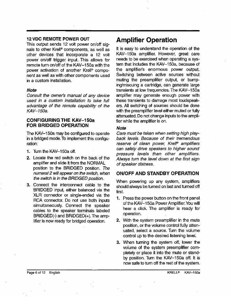
12 VDC REMOTE POWER OUTThis output sends 12 volt power on/off sig-nals to other Krell® components, as well asother devices that incorporate a 12 voltpower on/off trigger input. This allows forremote turn on/off of the KAV-150a with thepower activation of another Krell ® compo-nent as well as with other components usedin a custom installation.
NoteConsu/t the owner’s manua/ of any deviceused in a custom insta//ation to take furladvantage of the remote capabi/ity of theKAV-150a.
CONFIGURING THE KAV-150aFOR BRIDGED OPERATION
The KAV-150a may be configured to operatein a bridged mode. To implement this configu-ration:
1. Turn the KAV-150a off.2. Locate the red switch on the back of the
amplifier and slide it from the NORMALposition to the BRIDGED position. Thenumera/ 2 will appear on the switch, whenthe switch is in the BRIDGED position.
3. Connect the interconnect cable to theBRIDGED input, either balanced via theXLR connector or single-ended via theRCA connector. Do not use both inputssimultaneously. Connect the speakercables to the speaker terminals labeledBRIDGED(-) and BRIDGED(+). The lifier is now ready for bridged operation.
Amplifier OperationIt is easy to understand the operation of theKAV-150a amplifier. However, great careneeds to be exercised when operating a sys-tem that includes the KAV-150a, because ofthe amplifier’s enormous power output.Switching between active sources withoutmuting the preamplifier output, or bump-ing/miscuing a cartridge, can generate largetransients at low frequencies. The KAV-150aamplifier may generate enough power withthese transients to .damage most loudspeak-ers. All switching of sources should be donewith the preamplifier level either muted or fullyattenuated. Do not change inputs to the ampli-fier while the amplifier is on.
NoteCare must be taken when setting high p/ay-back leve/s. Because of their tremendousreserve of c/ean power, Kre//~ amp/ifierscan safe/y drive speakers to higher soundpressure /evels than other amplifiers.A/ways turn the/eve/down at the first signof speaker distress.
ON/OFF AND STANDBY OPERATION
When powering up any system, amplifiersshould always be turned on last and turned offfirst.1. Press the power button on the front panel
of the KAV-150a Power Amplifier.You willhear a click. The amplifier is ready foroperation.
2. With the system preamplifier in the muteposition, or the volume control fully atten-uated, select a source. Turn the volumecontrol up to the desired listening level.
3. When .turning the system off, lower thevolume of the system preamplifier com-pletely or place it into the mute or stand-by position. Turn the KAV-150a off. It isnow safe to tum off the rest of the system.
Page 6 of 12 English KRELL® KAV-150a
SYSTEM NOISE CONSIDERATIONS
AC grounding becomes critical when con-necting high performance audio components.When mixing and matching audio compo-nents, each with their own ground potential, alow frequency hum may occur in one or bothspeakers. This often occurs when introducinga new component into a system.
If there is a low frequency hum emanatingfrom the speakers when the KAV-150aamplifier is placed into the system, followthese simple troubleshooting steps beforecontacting your authorized KrelP dealer, dis-tributor, or Krell®:
1. Check all input and output connections,making sure they are of sound construc-tion. With the amplifier off, remove the in-
=
terconnect wiring and turn the amplifieron. If the hum disappears, turn the ampli-fier off and reinsert one of the intercon-nect cables. Then turn the amplifier backon. If the hum reappears with one or bothinterconnects reinserted, there may be adefective cable. Have the interconnectcabling checked before proceeding.If the interconnects prove to be sound,you may be experiencing a ground loop.This can often be easily eliminated. Con-tact your authorized KrelP dealer, distrib-utor, or Krell®.
KRELL® KAV-150a English Page 7 of 12
Warranty
Krell® warrants this product to be free fromdefects in material or workmanship for aperiod of five years for circuitry and threeyears for all mechanical components fromthe original date of purchase. Should thisproduct fail to perform at any time duringthe warranty, Krell® will repair it at no costto the owner, except as set forth in thiswarranty. Transfer of warranty to a secondowner occurs automatically. Please con-tact Krell ® to have the name on the war-ranty changed. Transfer of warranty doesnot extend the duration of the original war-ranty period.
NoteThis warranty does not apply to damagecaused by acts of God or nature.
The warranty period begins on the date ofretail purchase as noted on the retail salesslip provided by an authorized Krell® deal-er or distributor, or on the warranty regis-tration card sent to Krell®. In the event thatan adequate proof of purchase date isunavailable, the warranty period will beginon the date the product was originallyshipped from the factory. The warrantydescribed in this paragraph shall be in lieuof any other warranty, express or implied;including, but not limited to, any impliedwarranty of merchantability or fitness for aparticular purpose. There are no war-ranties which exceed beyond thosedescribed in this document. If this productdoes not perform as warranted herein, theowner’s sole remedy shall be repair. In noevent will Krell® be liable for incidental orconsequential damages arising from pur-chase, use, or inability to use this product,even if Krell® has been advised of the pos-sibility of such damages.
The warranty for this Krell® product is validonly in the country to which the productwas originally shipped, through the autho-rized Krell® distributor for that country, andat the factory. There may be restrictions onor changes to Krell’s warranty because ofregulations within a specific country.Please check with your distributor for acomplete understanding of the warranty inyour country.
Freight to the factory is your responsibility.Return freight within the United States(U.S.A.) is included in the warranty. If youhave purchased your Krell ® product out-side the U.S.A. and wish to have it ser-viced at the factory, all freight and associ-ated charges to the factory are yourresponsibility. Krell® will pay return freightto the U.S.A.-based freight forwarder ofyour choice. Freight and other charges toship the product from the freight forwarderto you are also your responsibility.
The operating voltage of this product isdetermined at the factory and can only bechanged by an authorized Krell ® distributoror at the factory. The voltage for this prod-uct in the U.S.A. cannot be changed for sixmonths from the original purchase date.
Any unauthorized voltage conversion,disassembly, component replacement,perforation of chassis, updates, ormodifications performed to the productwill void the warranty.
Page 8 of 12 English KRELL® KAV-150a

Return AuthorizationProcedureIMPORTANTff you believe there is a problem with yourcomponent, please contact your dealer, dis-tributor, or the Krell® factory to discuss theproblem before you return the componentfor repair. To expedite service, you maywish to complete and e-mail the ServiceRequest Form on our web site at:
ww~. krellon line. com
To return a product to Krell®, please fol-low this procedure so that we mayserve you better:
1. Obtain a Return Authorization Number(R/A number) and shipping addressfrom the Krell ® Service Department.
2. Insure and accept all liability for loss ordamage to the product during shipmentto the Krell® factory and prepay all ship-ping charges. The product may also behand delivered if arrangements with theService Department have been made inadvance. Proof of purchase may be re-quired for warranty validation at the timeof hand delivery.
3. Use the original packaging to insure thesafe transit of the product to the factory,dealer, or distributor. The use of anypackaging material other than the originalpackaging materials is not recommend-ed. KrelP may, at its discretion, return aproduct in new packaging and bill theowner for such packaging if the productreceived by Krell ® was boxed in non-standard packaging or if the originalpackaging was so damaged that it wasunusable. If Krell® determines that newpackaging is required, the owner will benotified before the product is returned.
To purchase additional packaging,please contact your authorized Krell®dealer, distributor, or the Krell® ServiceDepartment for assistance.
Krell ® is not responsible for any damageincurred in transit. KrelP will file claims fordamages as necessary for products dam-aged in transit to the factory. The owner isresponsible for filing claims for shipping dam-ages that occur during the return shipment.
Replacement parts and/or products will befurnished on an exchange basis only; anyparts and/or products returned to Krell® forexchange become the property of Krell®.
No expressed or implied warranty is madefor any Krell® product damaged by accident,abuse, misuse, natural or personal disaster,or unauthorized modification.
In the event that Krell® receives a product forwarranty service which has been modified inany way without Krell® authorization, all war-ranties on that product will be void. Theproduct will be returned to original factorylayout specifications at the owner’s expensebefore it is repaired. All repairs required afterthe product has been returned to originalfactory specification will be charged to thecustomer, at current parts and labor rates.
To contact the Krell Service De )artment
TEL 203-799-9954Monday-Friday9:00 am to 5:00 PM EST
FAX 203-799-9796
E-MAIL krell@ krellonline.com
KAV-150aPRODUCT SERIALNUMBER
To register your product for warranty benefits,
complete and return the Warranty RegistrationICard enclosed in the shipping box within 15 daysof purchase. Thank you.
KRELL® KAV-150a English Page 9 of 12
Krell® Industries, Inc.45Connair RoadOrange, CT 06477-3650USA
TEL 203-799-9954 FAX 203-799-9796E-MAIL [email protected] SITE www.krellonline.com
KAV-150aPower Amplifier
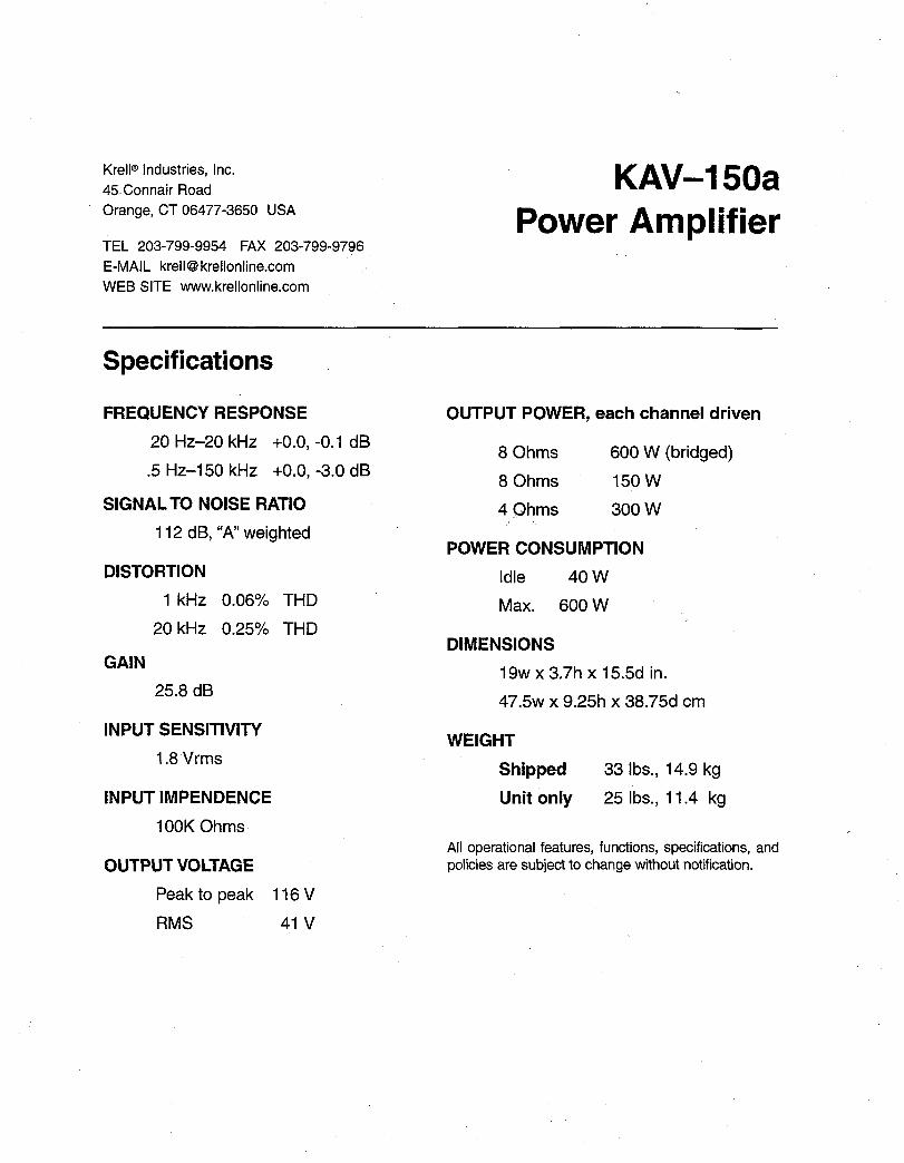
Specifications
FREQUENCY RESPONSE
20 Hz-20 kHz +0.0, -0.1 dB
.5 Hz-150 kHz +0.0, -3.0 dB
OUTPUT POWER, each channel driven
8 Ohms 600 W (bridged)
8 Ohms 150 WSIGNAL TO NOISE RATIO
112 dB, "A" weighted
DISTORTION
1 kHz 0.06% THD
20 kHz 0.25% THD
GAIN
25.8 dB
INPUT SENSITIVITY
1.8 Vrms
INPUT IMPENDENCE
100K Ohms
OUTPUT VOLTAGE
Peak to peak
RMS
116V
41 V
4 Ohms 300 W
POWER CONSUMPTION
Idle 40 W
Max. 600 W
DIMENSIONS
19w x 3.7h x 15.5d in.
47.5w x 9.25h x 38.75d cm
WEIGHT
Shipped
Unit only
33 Ibs., 14.9 kg
25 Ibs., 1 1.4 kg
All operational features, functions, specifications, andpolicies are subject to change without notification.