AP Amplifier Series RA2000 Series Amplifier Units
108
1WMPD4003505 A P A m p l i f i e r S e r i e s R A 2 0 0 0 S e r i e s A m p l i f i e r U n i t s
-
Upload
khangminh22 -
Category
Documents
-
view
0 -
download
0
Transcript of AP Amplifier Series RA2000 Series Amplifier Units

1WMPD4003505
AP Amplifier Series
RA2000 Series Amplifier Units


AP Amplifier Series
RA2000 Series Amplifier Units
Instruction Manual

1
INTRODUCTION Thank you very much for purchasing the Amplifier Units, Omniace RA2000 Series (RA2300MKⅡ, 2800A). Prior to using the units, please carefully read the instruction manual so that you can correctly use the amplifier units. This instruction manual provides operating instruction information on the following amplifier units:
2ch High-Resolution DC Amp Unit TC-DC Amp Unit 2ch FFT Amp Unit F/V Converter Unit 2ch High-Speed DC Amp Unit 2ch Vibration & RMS Amp Unit 2ch AC Strain Amp Unit 2ch DC Strain Amp Unit Event Amp Unit 2ch Zero Suppression Amp Unit 2ch TC-DC Amp Unit
This instruction manual is to provide information that is necessary for you to safely and correctly operate the amplifier units, Omniace RA2000 Series. Please always place this instruction manual together with the amplifier units whenever you use the units, so that you can access and refer to the manual at any time. This instruction manual involves operating instruction information, advice and suggestions on the use of the amplifier units, Omniace RA2000 Series, as well as their basic functions. For operating instruction information other than that described herein, please refer to the other instruction manuals attached hereto. If you have questions on any descriptions of this instruction manual, please contact marketing/sales personnel of A&D. The separate-volume instruction manuals related to amps are as follows:
Correspondence Product Titles of instruction manuals
RA2300MKⅡ Instruction Manual MAINFRAME For RA2300MKⅡ
RA2800A Instruction Manual MAINFRAME For RA2800A
Before Using Amplifier Units:
Instructions for unpacking Please unpack the package, only after the temperature of the content of the package becomes almost the same as that of the unpacking room or environment. This is because, particularly when it is cold in winter, dew condensation would occur on the surface of the equipment, thus creating a possibility of equipment failure, if you unpack the package in a warm environment right after bringing it from the open air.
Confirmation of contents A&D is always taking the utmost care of providing customers with flawless products, including through the use of its inspection system, etc. However, please confirm that no defects can be found in appearance of the equipment upon unpacking the package. Also, please confirm that you have had all accessories in place. In addition, please check the amplifier units as to the specifications of the equipment. If, at the worst, you find any defects or lack of contents, please contact your dealer.
Procedure of changing amplifier units Please refer to “Chapter 5. Procedure for Changing Amplifier Units”, when you want to change your amplifier units.
2
Notice If anything unusual happens during the use of the equipment, immediately switch off the
mainframe of the Omniace RA2000 Series and disconnect it from the power source.
If you cannot find the cause of the problem, contact our sales representative.
Contents of this instruction manual are subject to change without prior notice.
Reprinting or reproduction of this manual, in whole or in part, without permission is prohibited.
A&D has made every effort to attain the completeness in contents of this manual. Please feel free to contact our sales representative regarding any errors, omissions, questions or suggestions, if you find one.
Safety Considerations and Precautions - Warning and Caution
Notes for safely using Amplifier Units While the amplifier units have been manufactured by putting the highest priority on safety aspects, errors in handling or operating the equipment on the part of customers could lead to serious accidents. Please read carefully and comprehend thoroughly the Instruction Manual before using the amplifier units, so that such accidents can be avoided. Please be sure to observe the descriptions hereunder when using the equipment. No warranties or assurances will be provided or implied for any injuries or damages resulting from actions not complying with the handling or operating Warnings, Cautions or alike.
The designations described below are used throughout the instruction manual to secure the safe usage and operation of the amplifier units; the meaning the designations are explained in the following:
If any instructions in WARNING are ignored, the ignorance could lead to one or more of the following: 1. possibility of human deaths or serious injuries 2. high rate of occurrence of minor personal injuries or non-personal
physical damages
If any instructions in CAUTION are ignored, the ignorance could lead to one or more of the following: 1. risk of human injuries 2. possibility of non-personal physical injuries not involving human
injuries
CAUTION
WARNING
3
WARNING indication labels of amplifier units
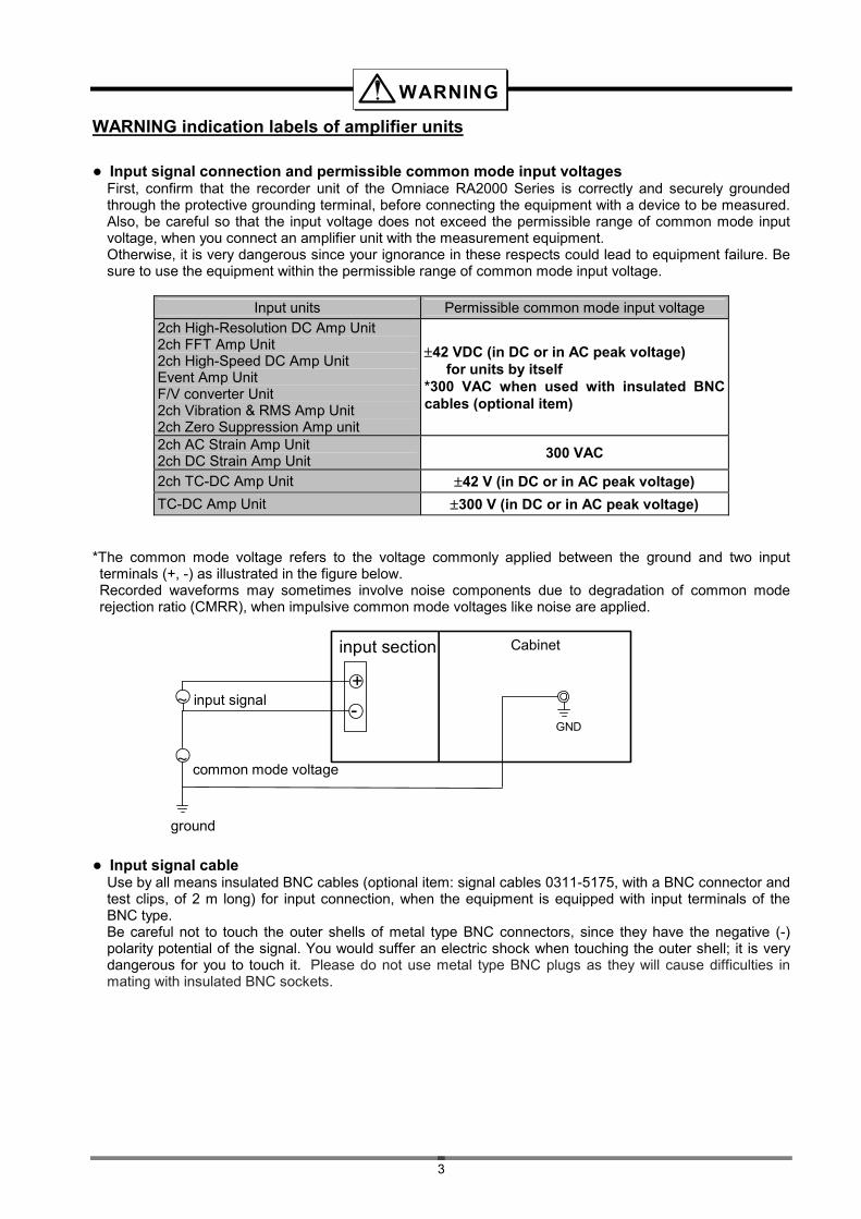
Input signal connection and permissible common mode input voltages First, confirm that the recorder unit of the Omniace RA2000 Series is correctly and securely grounded through the protective grounding terminal, before connecting the equipment with a device to be measured. Also, be careful so that the input voltage does not exceed the permissible range of common mode input voltage, when you connect an amplifier unit with the measurement equipment. Otherwise, it is very dangerous since your ignorance in these respects could lead to equipment failure. Be sure to use the equipment within the permissible range of common mode input voltage.
Input units Permissible common mode input voltage
2ch High-Resolution DC Amp Unit 2ch FFT Amp Unit 2ch High-Speed DC Amp Unit Event Amp Unit F/V converter Unit 2ch Vibration & RMS Amp Unit 2ch Zero Suppression Amp unit
42 VDC (in DC or in AC peak voltage) for units by itself *300 VAC when used with insulated BNC cables (optional item)
2ch AC Strain Amp Unit 2ch DC Strain Amp Unit
300 VAC
2ch TC-DC Amp Unit 42 V (in DC or in AC peak voltage)
TC-DC Amp Unit 300 V (in DC or in AC peak voltage) *The common mode voltage refers to the voltage commonly applied between the ground and two input terminals (+, -) as illustrated in the figure below.
Recorded waveforms may sometimes involve noise components due to degradation of common mode rejection ratio (CMRR), when impulsive common mode voltages like noise are applied.
Input signal cable Use by all means insulated BNC cables (optional item: signal cables 0311-5175, with a BNC connector and test clips, of 2 m long) for input connection, when the equipment is equipped with input terminals of the BNC type. Be careful not to touch the outer shells of metal type BNC connectors, since they have the negative (-) polarity potential of the signal. You would suffer an electric shock when touching the outer shell; it is very dangerous for you to touch it. Please do not use metal type BNC plugs as they will cause difficulties in mating with insulated BNC sockets.
WARNING
+
-
input section Cabinet
~
~
GND
input signal
common mode voltage
ground

4
Warning against electric shock and permissible input voltage Do not touch, by any means, metal portions of the input section, when a high voltage input signal is being applied, to avoid a risk of electric shock. Also, it is very dangerous to apply an input voltage exceeding the range of permissible input voltages for individual amplifier units, since application of such high voltages would cause equipment failures. Use the equipment within the range of permissible input voltages listed below.
Input units Permissible input voltages
(in DC or in AC peak values) Range and setting conditions
100 V 0.1,0.2,0.5,1,2,5 V-FS (in full scale)
2ch High-Resolution DC Amp Unit 2ch FFT Amp Unit 2ch High-Speed DC Amp Unit 2ch Vibration & RMS Amp Unit 500 V
10,20,50,100,200,500 V-FS (in full scale)
2ch TC-DC Amp Unit TC-DC Amp Unit 50 V
F/V converter Unit 100 V 2ch DC Strain Amp Unit 8 V
100 V 0.1,0.2,0.5,1,2 V-FS (in full scale)
2ch Zero Suppression Amp Unit 500 V
5,10,20,50,100,200,500 V-FS (in full scale)
Warning against electric shock and prevention of mainframe damages Always keep blank panels inserted/mounted at individual vacant slots for input amplifier units to prevent electric shock and also to prevent the mainframe from potential damages due to foreign matter penetration.
CAUTIONS for handling amplifier units Observe the CAUTIONS described below when handling amplifier units. Improper handling of the equipment could lead to operational errors or equipment failures.
1) The equipment shall be used only by those who completely know/understand the operating instructions
for the amplifier unit as well as the mainframe.
2) Storage environment and storage methods of amplifier units: Amplifier units shall be stored in an environment of the temperature between -10 and 70 °C Particularly during summer months, avoid storing them in the direct sunlight or in such places as having a high possibility of extreme temperature rise (e.g., in an enclosed vehicle) for a long period of time. In other aspects, electronic devices used in amplifier units are easily affected by electrostatic discharge. Store amplifier units in places or envelopes processed against electrostatic charge/discharge, paying attention to electrostatic charging phenomena.
3) When you want to change amplifier units in the mainframe, switch off the power source of the
mainframe and remove power and signal cables from the mainframe by all means, before changing them. The mainframe and amplifier units might be damaged if you change amplifier units with electrical source connected. In addition, be careful not to touch internal electronic parts when changing amplifier units. This is because you could damage the equipment if you touch electronic parts when your body is charged with electrostatic charges. Do not touch any parts other than equipment panels when you change amplifier units, since touching any parts other than panels could lead to equipment failures.
4) The amp units are carefully designed so that safety of users can be maintained. However, when
measuring high voltages, touching measurement subjects, probes, or output terminals without care may result in electric shock.
WARNING
CAUTION
5
5) Use the original packing box and crating materials, or the equivalent at the minimum, when you
transport amplifier units. In addition, when transporting units or parts after removing them that are incorporated with the recorder unit, cover them with antistatic bag or shock-absorbing sheets to protect them from damage due to drop or chock.
6) It is recommended that you regularly calibrate the equipment so that the accuracy of amplifier units can
be maintained. The high reliability of your measurement can be maintained by regularly calibrating your equipment once a year (service available by payment).
Warranty Application
A&D is making every effort in maintaining a high quality control level for its products from the design to shipping phases. However, in an unlikely event of finding a symptom of failures, you should check the operational status of the equipment, the status of the electric source voltage and the connection status of various cables, before asking A&D for repair. Consult with our sales representative for request for repair or for regular calibration of the equipment. Please do not forget to inform the equipment type, the serial number and the details of your failure. The warranty period and the warranty terms are provided in the next section.
Warranty Provisions
1. Period of warranties: The period of warranties for the product is one (1) year from the time of delivery.
2. Warranties: Failures that occurred during the period of warranties are repaired free of charge in principle. The following cases, however, are subject to your payment of repair charge:
(1) damages or failures due to incorrect handling of equipment (2) damages or failures due to fires, earthquakes, traffic accidents or any other acts of God. (3) damages or failures caused by repairs or modification of equipment that are carried by
someone other than A&D or any of those who are commissioned by A&D. (4) failures due to use or storage under the environment exceeding the prescribed conditions
for the equipment. (5) Regular calibration (6) failures or damages that occurred during transport or transfer of equipment after delivery.
3. Range of warranties: A&D is not responsible to any equipment not manufactured by A&D.
6
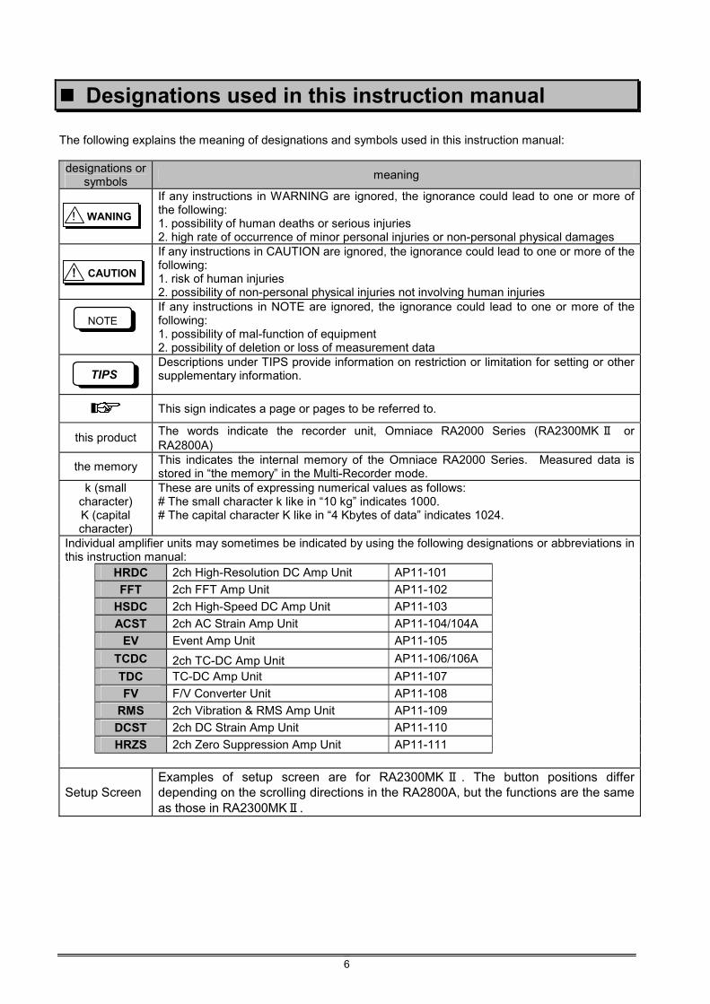
Designations used in this instruction manual The following explains the meaning of designations and symbols used in this instruction manual: designations or
symbols meaning
If any instructions in WARNING are ignored, the ignorance could lead to one or more of the following: 1. possibility of human deaths or serious injuries 2. high rate of occurrence of minor personal injuries or non-personal physical damages
If any instructions in CAUTION are ignored, the ignorance could lead to one or more of the following: 1. risk of human injuries 2. possibility of non-personal physical injuries not involving human injuries
If any instructions in NOTE are ignored, the ignorance could lead to one or more of the following: 1. possibility of mal-function of equipment 2. possibility of deletion or loss of measurement data
Descriptions under TIPS provide information on restriction or limitation for setting or other supplementary information.
This sign indicates a page or pages to be referred to.
this product The words indicate the recorder unit, Omniace RA2000 Series (RA2300MK Ⅱ or RA2800A)
the memory This indicates the internal memory of the Omniace RA2000 Series. Measured data is stored in “the memory” in the Multi-Recorder mode.
k (small character) K (capital character)
These are units of expressing numerical values as follows: # The small character k like in “10 kg” indicates 1000. # The capital character K like in “4 Kbytes of data” indicates 1024.
Individual amplifier units may sometimes be indicated by using the following designations or abbreviations in this instruction manual:
HRDC 2ch High-Resolution DC Amp Unit AP11-101
FFT 2ch FFT Amp Unit AP11-102
HSDC 2ch High-Speed DC Amp Unit AP11-103
ACST 2ch AC Strain Amp Unit AP11-104/104A
EV Event Amp Unit AP11-105
TCDC 2ch TC-DC Amp Unit AP11-106/106A
TDC TC-DC Amp Unit AP11-107
FV F/V Converter Unit AP11-108
RMS 2ch Vibration & RMS Amp Unit AP11-109
DCST 2ch DC Strain Amp Unit AP11-110
HRZS 2ch Zero Suppression Amp Unit AP11-111
Setup Screen Examples of setup screen are for RA2300MK Ⅱ . The button positions differ depending on the scrolling directions in the RA2800A, but the functions are the same as those in RA2300MKⅡ.
NOTE
TIPS
! WANING
! CAUTION
7
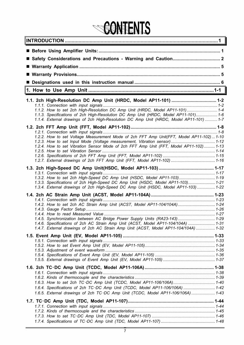
INTRODUCTION ...............................................................................................................1
Before Using Amplifier Units: ............................................................................................... 1
Safety Considerations and Precautions - Warning and Caution..................................... 2
Warranty Application .............................................................................................................. 5
Warranty Provisions................................................................................................................ 5
Designations used in this instruction manual ................................................................... 6
1. How to Use Amp Unit ...........................................................................................1-1
1.1. 2ch High-Resolution DC Amp Unit (HRDC, Model AP11-101) ................................... 1-2 1.1.1. Connection with input signals .....................................................................................................1-2 1.1.2. How to set 2ch High-Resolution DC Amp Unit (HRDC, Model AP11-101) ...........................1-4 1.1.3. Specifications of 2ch High-Resolution DC Amp Unit (HRDC, Model AP11-101)...................1-6 1.1.4. External drawings of 2ch High-Resolution DC Amp Unit (HRDC, Model AP11-101) ...........1-7
1.2. 2ch FFT Amp Unit (FFT, Model AP11-102)................................................................... 1-8 1.2.1. Connection with input signals .....................................................................................................1-8 1.2.2. How to set Voltage Measurement Mode of 2ch FFT Amp Unit(FFT, Model AP11-102) ...1-10 1.2.3. How to set Input Mode (Voltage measurement, Vibration sensor) .......................................1-12 1.2.4. How to set Vibration Sensor Mode of 2ch FFT Amp Unit (FFT, Model AP11-102)..........1-13 1.2.5. How to set Vibration Sensor ....................................................................................................1-14 1.2.6. Specifications of 2ch FFT Amp Unit (FFT, Model AP11-102) ..............................................1-15 1.2.7. External drawings of 2ch FFT Amp Unit (FFT, Model AP11-102) .......................................1-16
1.3. 2ch High-Speed DC Amp Unit(HSDC, Model AP11-103) ........................................... 1-17 1.3.1. Connection with input signals ...................................................................................................1-17 1.3.2. How to set 2ch High-Speed DC Amp Unit (HSDC, Model AP11-103)................................1-19 1.3.3. Specifications of 2ch High-Speed DC Amp Unit (HSDC, Model AP11-103)........................1-21 1.3.4. External drawings of 2ch High-Speed DC Amp Unit (HSDC, Model AP11-103) ................1-22
1.4. 2ch AC Strain Amp Unit (ACST, Model AP11-104A) ................................................. 1-23 1.4.1. Connection with input signals ...................................................................................................1-23 1.4.2. How to set 2ch AC Strain Amp Unit (ACST, Model AP11-104/104A).................................1-24 1.4.3. Gauge Factor Setup ..................................................................................................................1-26 1.4.4. How to read Measured Value ..................................................................................................1-27 1.4.5. Synchronization between AC Bridge Power Supply Units (RA23-143).................................1-29 1.4.6. Specifications of 2ch AC Strain Amp Unit (ACST, Model AP11-104/104A) ........................1-31 1.4.7. External drawings of 2ch AC Strain Amp Unit (ACST, Model AP11-104/104A) .................1-32
1.5. Event Amp Unit (EV, Model AP11-105) ....................................................................... 1-33 1.5.1. Connection with input signals ...................................................................................................1-33 1.5.2. How to set Event Amp Unit (EV, Model AP11-105)..............................................................1-34 1.5.3. Adjustment of event waveform .................................................................................................1-35 1.5.4. Specifications of Event Amp Unit (EV, Model AP11-105) .....................................................1-36 1.5.5. External drawings of Event Amp Unit (EV, Model AP11-105) ..............................................1-37
1.6. 2ch TC・DC Amp Unit (TCDC, Model AP11-106A) ...................................................... 1-38 1.6.1. Connection with input signals ...................................................................................................1-38 1.6.2. Kinds of thermocouple and the characteristics .......................................................................1-39 1.6.3. How to set 2ch TC・DC Amp Unit (TCDC, Model AP11-106/106A).....................................1-40 1.6.4. Specifications of 2ch TC・DC Amp Unit (TCDC, Model AP11-106/106A) ............................1-42 1.6.5. External drawings of 2ch TC・DC Amp Unit (TCDC, Model AP11-106/106A) .....................1-43
1.7. TC・DC Amp Unit (TDC, Model AP11-107)................................................................... 1-44 1.7.1. Connection with input signals ...................................................................................................1-44 1.7.2. Kinds of thermocouple and the characteristics .......................................................................1-45 1.7.3. How to set TC・DC Amp Unit (TDC, Model AP11-107) ........................................................1-46 1.7.4. Specifications of TC・DC Amp Unit (TDC, Model AP11-107) ................................................1-48
8
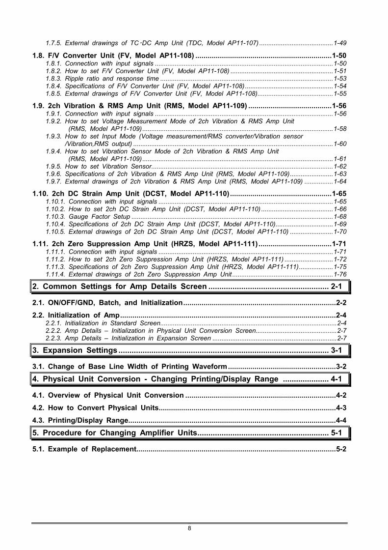
1.7.5. External drawings of TC・DC Amp Unit (TDC, Model AP11-107) .........................................1-49
1.8. F/V Converter Unit (FV, Model AP11-108) ...................................................................1-50 1.8.1. Connection with input signals ...................................................................................................1-50 1.8.2. How to set F/V Converter Unit (FV, Model AP11-108) .........................................................1-51 1.8.3. Ripple ratio and response time ................................................................................................1-53 1.8.4. Specifications of F/V Converter Unit (FV, Model AP11-108).................................................1-54 1.8.5. External drawings of F/V Converter Unit (FV, Model AP11-108)..........................................1-55
1.9. 2ch Vibration & RMS Amp Unit (RMS, Model AP11-109) .........................................1-56 1.9.1. Connection with input signals ...................................................................................................1-56 1.9.2. How to set Voltage Measurement Mode of 2ch Vibration & RMS Amp Unit
(RMS, Model AP11-109)..........................................................................................................1-58 1.9.3. How to set Input Mode (Voltage measurement/RMS converter/Vibration sensor
/Vibration,RMS output) ...............................................................................................................1-60 1.9.4. How to set Vibration Sensor Mode of 2ch Vibration & RMS Amp Unit
(RMS, Model AP11-109)..........................................................................................................1-61 1.9.5. How to set Vibration Sensor.....................................................................................................1-62 1.9.6. Specifications of 2ch Vibration & RMS Amp Unit (RMS, Model AP11-109)........................1-63 1.9.7. External drawings of 2ch Vibration & RMS Amp Unit (RMS, Model AP11-109) ................1-64
1.10. 2ch DC Strain Amp Unit (DCST, Model AP11-110)..................................................1-65 1.10.1. Connection with input signals .................................................................................................1-65 1.10.2. How to set 2ch DC Strain Amp Unit (DCST, Model AP11-110) ........................................1-66 1.10.3. Gauge Factor Setup ................................................................................................................1-68 1.10.4. Specifications of 2ch DC Strain Amp Unit (DCST, Model AP11-110)................................1-69 1.10.5. External drawings of 2ch DC Strain Amp Unit (DCST, Model AP11-110) ........................1-70
1.11. 2ch Zero Suppression Amp Unit (HRZS, Model AP11-111) ....................................1-71 1.11.1. Connection with input signals .................................................................................................1-71 1.11.2. How to set 2ch Zero Suppression Amp Unit (HRZS, Model AP11-111) ...........................1-72 1.11.3. Specifications of 2ch Zero Suppression Amp Unit (HRZS, Model AP11-111)...................1-75 1.11.4. External drawings of 2ch Zero Suppression Amp Unit ........................................................1-76
2. Common Settings for Amp Details Screen ....................................................... 2-1
2.1. ON/OFF/GND, Batch, and Initialization...........................................................................2-2
2.2. Initialization of Amp..........................................................................................................2-4 2.2.1. Initialization in Standard Screen..................................................................................................2-4 2.2.2. Amp Details – Initialization in Physical Unit Conversion Screen.............................................2-7 2.2.3. Amp Details – Initialization in Expansion Screen .....................................................................2-7
3. Expansion Settings ................................................................................................ 3-1
3.1. Change of Base Line Width of Printing Waveform.....................................................3-2
4. Physical Unit Conversion - Changing Printing/Display Range ..................... 4-1
4.1. Overview of Physical Unit Conversion ..........................................................................4-2
4.2. How to Convert Physical Units.......................................................................................4-3
4.3. Printing/Display Range......................................................................................................4-4
5. Procedure for Changing Amplifier Units............................................................ 5-1
5.1. Example of Replacement..................................................................................................5-2

1. How to Use Amp Unit
1. How to Use Amp Unit (2ch High-Resolution DC Amp Unit)
AMP for RA2000 Series (1WMPD4003505) 1-2
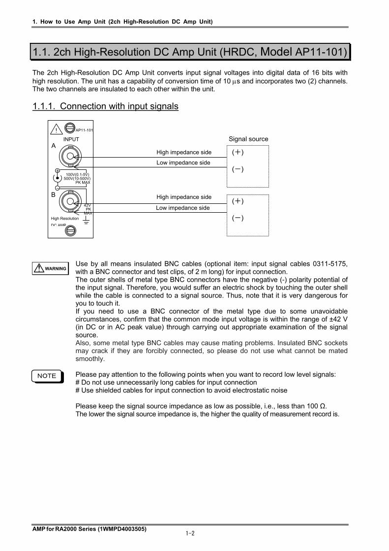
1.1. 2ch High-Resolution DC Amp Unit (HRDC, Model AP11-101) The 2ch High-Resolution DC Amp Unit converts input signal voltages into digital data of 16 bits with high resolution. The unit has a capability of conversion time of 10 s and incorporates two (2) channels. The two channels are insulated to each other within the unit.
1.1.1. Connection with input signals
Use by all means insulated BNC cables (optional item: input signal cables 0311-5175, with a BNC connector and test clips, of 2 m long) for input connection. The outer shells of metal type BNC connectors have the negative (-) polarity potential of the input signal. Therefore, you would suffer an electric shock by touching the outer shell while the cable is connected to a signal source. Thus, note that it is very dangerous for you to touch it. If you need to use a BNC connector of the metal type due to some unavoidable circumstances, confirm that the common mode input voltage is within the range of ±42 V (in DC or in AC peak value) through carrying out appropriate examination of the signal source. Also, some metal type BNC cables may cause mating problems. Insulated BNC sockets may crack if they are forcibly connected, so please do not use what cannot be mated smoothly.
Please pay attention to the following points when you want to record low level signals: # Do not use unnecessarily long cables for input connection # Use shielded cables for input connection to avoid electrostatic noise Please keep the signal source impedance as low as possible, i.e., less than 100 Ω. The lower the signal source impedance is, the higher the quality of measurement record is.
NOTE
100V(0.1-5V) 500V(10-500V) PK MAX
42V PK MAX
AP11-101
High Resolution
DC AMP
INPUT
+
-
!
A
B
(+) (-)
(+) (-)
Signal source
High impedance side
Low impedance side
High impedance side
Low impedance side
WARNING

1. How to Use Amp Unit (2ch High-Resolution DC Amp Unit)
AMP for RA2000 Series (1WMPD4003505) 1-3
Input Signals Permissible input voltages If a voltage higher than the rated voltage is input, this unit may be damaged due to internal damage such as component breakdown. Make sure that the input voltage does not exceed the following permissible input voltage for each input range. Sensitivity ranges (V in FS) 0.1, 0.2, 0.5, 1, 2, 5 10, 20, 50, 100, 200, 500 Permissible input voltages (V) 100 V 500 V
Input impedance The input impedance is approximately one (1) M. However, note that the input impedance will be lowered to approximately 15 k, when the input voltage becomes beyond 8 V for the sensitivity range of 0.1 - 5 V-FS (full-scale) in the DC coupling mode. Permissible common mode input voltages (CMV) Use the insulated BNC cable, an optional item. In this case, confirm that the permissible common mode input voltage is no more than 300 V in DC or in AC peak value.
The sample speed must be set at 10μs steps, otherwise the signal waveform cannot be obtained correctly. Example: 5 μs or 11 μs, etc. makes the waveform distort. Use cables with the insulation sheath of no less than 2 kV of withstand voltages. Do not apply voltages exceeding the permissible common mode input voltage, since application of such voltages would lead to malfunctions or failures of equipment. Also, note that recorded waveforms may involve noise components due to degradation of common mode rejection ratio (CMRR), when noise-like impulsive common mode voltages are applied. Use the equipment through keeping the input voltage within the range of -30V - +30V including the DC component, when the sensitivity range is 0.1 - 5 V-FS in the AC coupling mode. Note that correct measurement cannot be expected when the input voltage exceeds the voltage range mentioned above.
CAUTION
NOTE
CAUTION
CAUTION
NOTE
NOTE
NOTE

1. How to Use Amp Unit (2ch High-Resolution DC Amp Unit)
AMP for RA2000 Series (1WMPD4003505) 1-4
1.1.2. How to set 2ch High-Resolution DC Amp Unit (HRDC, Model AP11-101)
This section covers operations in the Amp Basic screen that appears when the Amp button on the operation panel is pressed and the Amp Details screen that appears when a channel button is pressed.
1) Basics - Channel The channel number, input Amp Unit type, and waveform color are indicated in this portion. Pressing this button displays the Amp Details screen.
2) Basics - Input Input mode can be selected. Pressing this button permits switching among ON, GND, and OFF.
3) Basics - Position This button is used to set the zero position. Pressing this button changes the button appearance. The setup can be made with the jog dial.
4) Basics - Range This button is used to set the range. Pressing this button changes the button appearance. The setup can be made with the jog dial.
5) Basics – Lo V The LED lights if the high sensitivity range can be permitted.
6) Basics - Information This portion indicates settings that are unable to be set on this screen. When changing the settings, make the settings in the Amp Details screen. Fc: Filter setting Couple: Input coupling setting
1) Channel
6) Info
4) Range 3) Position 2) Input
10) Range Indication
8) Input Coupling9) Auto Range
12) Range
13) Permission of High-sensitivity setting
11) Wide/Normal
14) Filter
7) Position
5) Lo V

1. How to Use Amp Unit (2ch High-Resolution DC Amp Unit)
AMP for RA2000 Series (1WMPD4003505) 1-5
7) Details - Position The zero position (base line) is set with a button. The zero position means the waveform display position at 0V input (input short). The base line can be set in 5% steps in reference to 100% as the full scale. Also, you can set it with the jog dial by pressing the jog button, or set it from the numeric input window by pressing the window button. And the position change is available through the setup of Physical Unit Conversion or Printing/Display Range. For more information, see Chapter 4. Physical Unit Conversion – Changing Printing/Display Range.
8) Details – Input Coupling The input coupling is set by pressing the AC coupling button or DC coupling button.
When the AC coupling button is pressed, a capacitor is connected to the input terminal. The DC component can be eliminated, which enables the measurement of alternating voltage.
9) Details - Auto range The range is automatically adjusted to the input signal.
10) Details - Range indication The value of the current display range is displayed. "#" is displayed when selecting the "Wide" range or changing "Printing / Display Range". After that, if you select the "Normal" range, the setting of "Printing / Display Range" is cleared and "#" disappears. Also, when checking "Set EU." on the ”User Conv.” Tab and setting to use physical unit conversion, the full scale converted value will be displayed with *. For more information on physical unit conversion and printing / display range setting, see Chapter 4. Physical Unit Conversion - Changing Printing / Display Range.
11) Details - Wide/Normal Wide: Entire measuring range is displayed. Normal: Half of the measuring range is displayed (Default).
12) Details - Range Range can be directly set.
When the measurement range is changed, the waveform clip range is cleared to the default value corresponding to the new range. Example: During expansion of the waveform in the waveform clip range between +40 and -40 at 100 V, if the range is set to 100 V again, the waveform clip range is set to between +50 to -50 as the default. (Enlarged display is cancelled.)
Pay attention to the permissible input voltage when setting the range. See Permissible input voltages in “Input Signals”.
13) Details - Permission of high sensitivity settings Settings of the high-sensitive range (5 V to 100 mV) can be prohibited/permitted. When using the high-sensitivity range, check the check box. When the high-sensitivity range is not used, prohibition of the high-sensitivity range without checking the box is recommended for safety.
14) Details - Filter This button is used to set the low-pass filter.
TIPS
CAUTION
TIPS
1. How to Use Amp Unit (2ch High-Resolution DC Amp Unit)
AMP for RA2000 Series (1WMPD4003505) 1-6
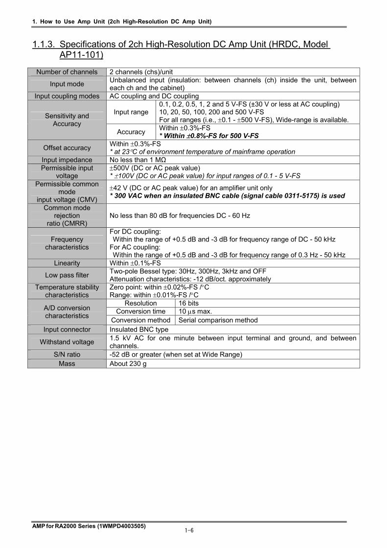
1.1.3. Specifications of 2ch High-Resolution DC Amp Unit (HRDC, Model AP11-101)
Number of channels 2 channels (chs)/unit
Input mode Unbalanced input (insulation: between channels (ch) inside the unit, between each ch and the cabinet)
Input coupling modes AC coupling and DC coupling
Input range 0.1, 0.2, 0.5, 1, 2 and 5 V-FS (±30 V or less at AC coupling) 10, 20, 50, 100, 200 and 500 V-FS For all ranges (i.e., 0.1 - 500 V-FS), Wide-range is available.
Sensitivity and Accuracy
Accuracy Within 0.3%-FS * Within 0.8%-FS for 500 V-FS
Offset accuracy Within 0.3%-FS * at 23C of environment temperature of mainframe operation
Input impedance No less than 1 MΩ Permissible input
voltage 500V (DC or AC peak value) * 100V (DC or AC peak value) for input ranges of 0.1 - 5 V-FS
Permissible common mode
input voltage (CMV)
42 V (DC or AC peak value) for an amplifier unit only * 300 VAC when an insulated BNC cable (signal cable 0311-5175) is used
Common mode rejection
ratio (CMRR) No less than 80 dB for frequencies DC - 60 Hz
Frequency characteristics
For DC coupling: Within the range of +0.5 dB and -3 dB for frequency range of DC - 50 kHz For AC coupling: Within the range of +0.5 dB and -3 dB for frequency range of 0.3 Hz - 50 kHz
Linearity Within 0.1%-FS
Low pass filter Two-pole Bessel type: 30Hz, 300Hz, 3kHz and OFF Attenuation characteristics: -12 dB/oct. approximately
Temperature stability characteristics
Zero point: within 0.02%-FS /C Range: within 0.01%-FS /C
Resolution 16 bits Conversion time 10 s max. A/D conversion
characteristics Conversion method Serial comparison method
Input connector Insulated BNC type
Withstand voltage 1.5 kV AC for one minute between input terminal and ground, and between channels.
S/N ratio -52 dB or greater (when set at Wide Range) Mass About 230 g
1. How to Use Amp Unit (2ch High-Resolution DC Amp Unit)
AMP for RA2000 Series (1WMPD4003505) 1-7
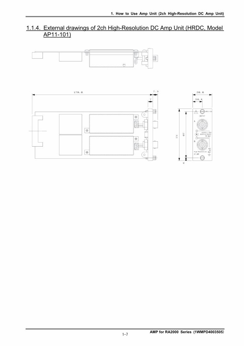
1.1.4. External drawings of 2ch High-Resolution DC Amp Unit (HRDC, Model AP11-101)
1. How to Use Amp Unit (2ch FFT Amp Unit)
AMP for RA2000 Series (1WMPD4003505) 1-8
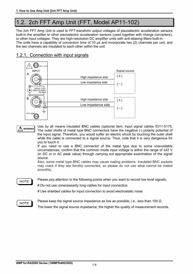
1.2. 2ch FFT Amp Unit (FFT, Model AP11-102) The 2ch FFT Amp Unit is used to FFT-transform output voltages of piezoelectric acceleration sensors built-in the amplifier or other piezoelectric acceleration sensors (used together with charge converters), or other input voltages. They are high-resolution DC amplifier units with anti-aliasing filters built-in. The units have a capability of conversion time of 10 μs and incorporate two (2) channels per unit, and the two channels are insulated to each other within the unit.
1.2.1. Connection with input signals
Use by all means insulated BNC cables (optional item: input signal cables 0311-5175, The outer shells of metal type BNC connectors have the negative (-) polarity potential of the input signal. Therefore, you would suffer an electric shock by touching the outer shell while the cable is connected to a signal source. Thus, note that it is very dangerous for you to touch it. If you need to use a BNC connector of the metal type due to some unavoidable circumstances, confirm that the common mode input voltage is within the range of ±42 V (in DC or in AC peak value) through carrying out appropriate examination of the signal source. Also, some metal type BNC cables may cause mating problems. Insulated BNC sockets may crack if they are forcibly connected, so please do not use what cannot be mated smoothly.
Please pay attention to the following points when you want to record low level signals:
# Do not use unnecessarily long cables for input connection
# Use shielded cables for input connection to avoid electrostatic noise
Please keep the signal source impedance as low as possible, i.e., less than 100 Ω.
The lower the signal source impedance, the higher the quality of measurement records.
42V PK MAX
-
Signal source
100V(0.1-5V) 500V(10-500V) PK MAX
AP11-102
FFT AMP
INPUT
+
!
A
B
(+) (-)
(+) (-)
High impedance side
Low impedance side
High impedance side
Low impedance side
NOTE
WARNING
NOTE

1. How to Use Amp Unit (2ch FFT Amp Unit)
AMP for RA2000 Series (1WMPD4003505) 1-9
Input Signals
Permissible input voltages
If a voltage higher than the rated voltage is input, this unit may be damaged due to internal damage such as component breakdown. Make sure that the input voltage does not exceed the following permissible input voltage for each input range. Sensitivity ranges (V in FS) 0.1, 0.2, 0.5, 1, 2, 5 10, 20, 50, 100, 200, 500 Permissible input voltages (V) 100 V 500 V
Input impedance The input impedance is approximately one (1) M. However, note that the input impedance will be lowered to approximately 15 k, when the input voltage becomes beyond 8 V for the sensitivity range of 0.1 - 5 V-FS (full-scale) in the DC coupling mode.
Permissible common mode input voltages (CMV) Use the insulated BNC cable, an optional item. In this case, confirm that the permissible common mode input voltage is no more than 300 V in DC or in AC peak value
When setting the sampling speed other than 10μs steps (ex. 5μs or 11μs, etc.) or setting the analyzing speed of FFT mode faster than 40 kHz, the signal waveform cannot be obtained correctly. If you execute FFT in that condition, the suspected frequency component is displayed.
In the vibration sensor mode, a constant-current of 2 mA is fed into the load from the input connector of the amplifier unit. (Voltages of more than 18 V can be exhibited at the connector.) Do not connect any sensors other than the types of sensors that are specified for the use with this amplifier. Otherwise, the sensors may be damaged.
In the vibration mode, do not input voltages. Application of voltages of 30 V or more at the input would induce amplifier failures.
Use such cables that have the insulation sheath with no less than 2 kV of withstand voltages.
Do not apply voltages exceeding the permissible common mode input voltage, since application of such voltages would lead to malfunctions or failures of equipment. Also, note that recorded waveforms may involve noise components due to degradation of common mode rejection ratio (CMRR), when noise-like impulsive common mode voltages are applied.
Use the equipment through keeping the input voltage within the range of -30V - +30V including the DC component, when the sensitivity range is 0.1 - 5 V-FS in the AC coupling mode. Note that correct measurement cannot be expected when the input voltage exceeds the voltage range mentioned above.
NOTE
CAUTION
CAUTION
CAUTION
CAUTION
NOTE
NOTE
NOTE
1. How to Use Amp Unit (2ch FFT Amp Unit)
AMP for RA2000 Series (1WMPD4003505) 1-10
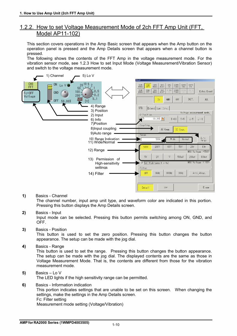
1.2.2. How to set Voltage Measurement Mode of 2ch FFT Amp Unit (FFT, Model AP11-102)
This section covers operations in the Amp Basic screen that appears when the Amp button on the operation panel is pressed and the Amp Details screen that appears when a channel button is pressed. The following shows the contents of the FFT Amp in the voltage measurement mode. For the vibration sensor mode, see 1.2.3 How to set Input Mode (Voltage Measurement/Vibration Sensor) and switch to the voltage measurement mode.
1) Basics - Channel The channel number, input amp unit type, and waveform color are indicated in this portion. Pressing this button displays the Amp Details screen.
2) Basics - Input Input mode can be selected. Pressing this button permits switching among ON, GND, and OFF.
3) Basics - Position This button is used to set the zero position. Pressing this button changes the button appearance. The setup can be made with the jog dial.
4) Basics - Range This button is used to set the range. Pressing this button changes the button appearance. The setup can be made with the jog dial. The displayed contents are the same as those in Voltage Measurement Mode. That is, the contents are different from those for the vibration measurement mode.
5) Basics – Lo V The LED lights if the high sensitivity range can be permitted.
6) Basics - Information indication This portion indicates settings that are unable to be set on this screen. When changing the settings, make the settings in the Amp Details screen. Fc: Filter setting Measurement mode setting (Voltage/Vibration)
1) Channel
6) Info
4) Range 3) Position 2) Input
8)Input coupling7)Position
9)Auto range
11) Wide/Normal10) Range Indication
12) Range
14) Filter
13) Permission ofHigh-sensitivity settings
5) Lo V
1. How to Use Amp Unit (2ch FFT Amp Unit)
AMP for RA2000 Series (1WMPD4003505) 1-11
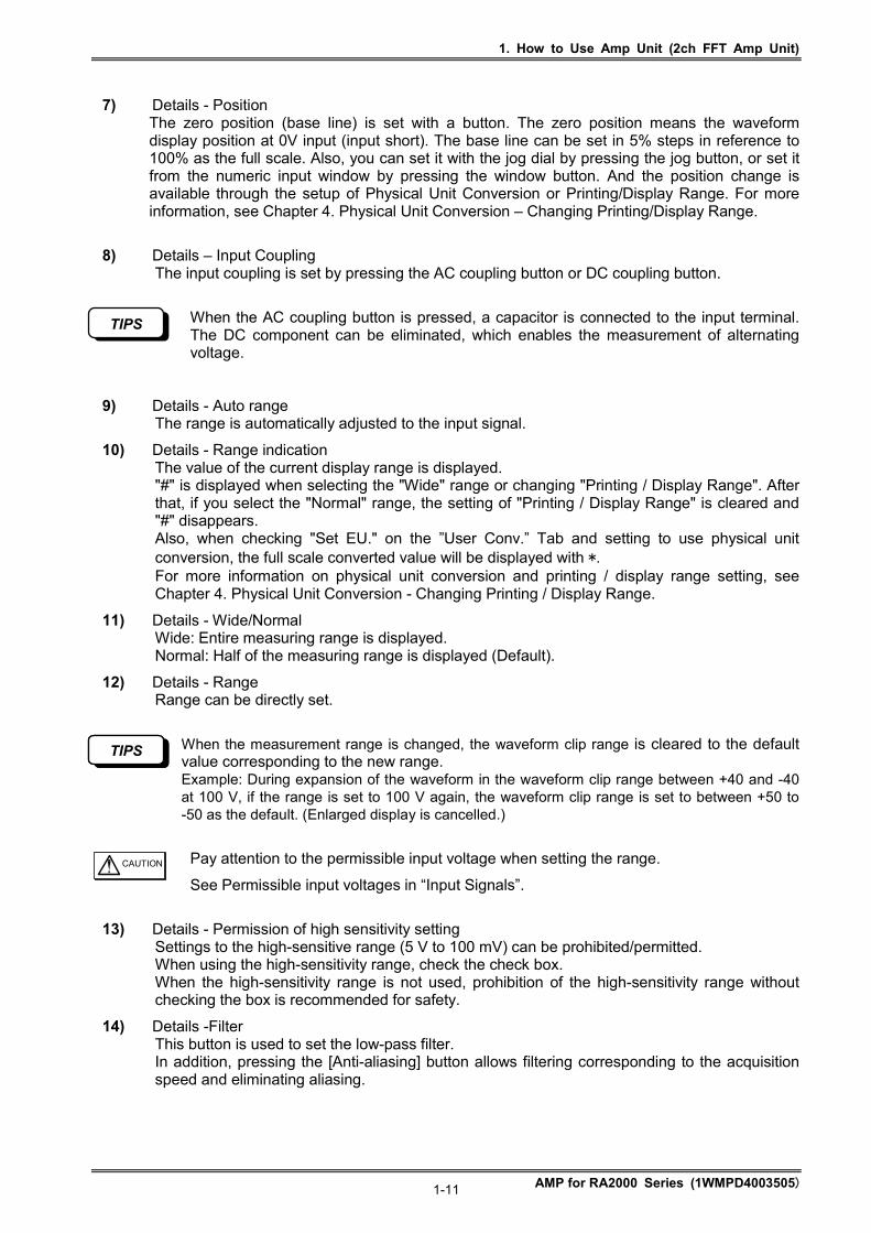
7) Details - Position The zero position (base line) is set with a button. The zero position means the waveform display position at 0V input (input short). The base line can be set in 5% steps in reference to 100% as the full scale. Also, you can set it with the jog dial by pressing the jog button, or set it from the numeric input window by pressing the window button. And the position change is available through the setup of Physical Unit Conversion or Printing/Display Range. For more information, see Chapter 4. Physical Unit Conversion – Changing Printing/Display Range.
8) Details – Input Coupling The input coupling is set by pressing the AC coupling button or DC coupling button.
When the AC coupling button is pressed, a capacitor is connected to the input terminal. The DC component can be eliminated, which enables the measurement of alternating voltage.
9) Details - Auto range The range is automatically adjusted to the input signal.
10) Details - Range indication The value of the current display range is displayed. "#" is displayed when selecting the "Wide" range or changing "Printing / Display Range". After that, if you select the "Normal" range, the setting of "Printing / Display Range" is cleared and "#" disappears. Also, when checking "Set EU." on the ”User Conv.” Tab and setting to use physical unit conversion, the full scale converted value will be displayed with *. For more information on physical unit conversion and printing / display range setting, see Chapter 4. Physical Unit Conversion - Changing Printing / Display Range.
11) Details - Wide/Normal Wide: Entire measuring range is displayed. Normal: Half of the measuring range is displayed (Default).
12) Details - Range Range can be directly set.
When the measurement range is changed, the waveform clip range is cleared to the default value corresponding to the new range. Example: During expansion of the waveform in the waveform clip range between +40 and -40 at 100 V, if the range is set to 100 V again, the waveform clip range is set to between +50 to -50 as the default. (Enlarged display is cancelled.)
Pay attention to the permissible input voltage when setting the range.
See Permissible input voltages in “Input Signals”.
13) Details - Permission of high sensitivity setting Settings to the high-sensitive range (5 V to 100 mV) can be prohibited/permitted. When using the high-sensitivity range, check the check box. When the high-sensitivity range is not used, prohibition of the high-sensitivity range without checking the box is recommended for safety.
14) Details -Filter This button is used to set the low-pass filter. In addition, pressing the [Anti-aliasing] button allows filtering corresponding to the acquisition speed and eliminating aliasing.
CAUTION
TIPS
TIPS
TIPS

1. How to Use Amp Unit (2ch FFT Amp Unit)
AMP for RA2000 Series (1WMPD4003505) 1-12
1.2.3. How to set Input Mode (Voltage measurement / Vibration sensor) The measurement target can be changed by switching the input mode of the FFT Amp. Pressing the Input Mode button in the Expansion tab in the Amp Details screen of the FFT Amp displays the following screen, which allows changing the input mode.
In the vibration sensor mode, a constant-current is required for the sensor. Therefore, if any units other than the vibration sensor are connected to the amp, the signal source may be damaged. Confirm the connection at the amp input port before switching to the vibration sensor mode.
NOTE

1. How to Use Amp Unit (2ch FFT Amp Unit)
AMP for RA2000 Series (1WMPD4003505) 1-13
1.2.4. How to set Vibration Sensor Mode of 2ch FFT Amp Unit (FFT, Model
AP11-102) This section covers operations in the Amp Basic screen that appears when the Amp button on the operation panel is pressed and the Amp Details screen that appears when a channel button is pressed. The following shows the contents of the FFT Amp in the vibration sensor mode. For the voltage measurement mode, see 1.2.3 How to set Input Mode (Voltage Measurement/Vibration Sensor) and switch to the vibration sensor mode. The procedure is the same as those in 1.2.2 How to set Voltage Measurement Mode of 2ch FFT Amp Unit (FFT, Model AP11-102). Operations of different portions are described hereafter:
4) Basics - Range The contents are different from those for the voltage measurement mode. However, the operation settings are the same.
5) Details - Range Range can be directly set. The range values are indicated after calculated with sensor sensitivity, converter sensitivity, and unit of vibration.
6) Details - Unit of vibration The unit of the vibration system can be selected between units, m/s2 and G.
The result from the changed unit is reflected to the range, sensor sensitivity and converter sensitivity. Before starting measurement, confirm the reflected parts.
TIPS
6) Info
4) Range 3) Position 2) Input
9) Range indication
7) Position
11) Range
13) Filter
1) Channel
8) Auto range
10) Wide/Normal
12) Unit of vibration
5) Lo V
1. How to Use Amp Unit (2ch FFT Amp Unit)
AMP for RA2000 Series (1WMPD4003505) 1-14
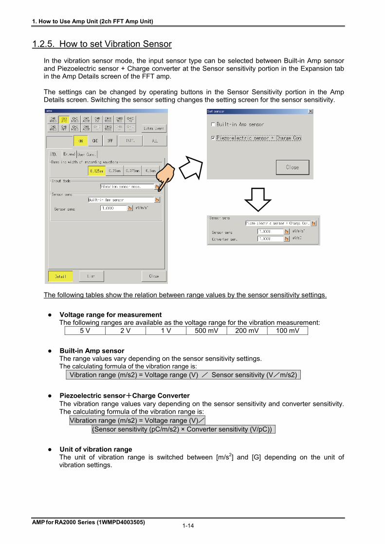
1.2.5. How to set Vibration Sensor In the vibration sensor mode, the input sensor type can be selected between Built-in Amp sensor and Piezoelectric sensor + Charge converter at the Sensor sensitivity portion in the Expansion tab in the Amp Details screen of the FFT amp. The settings can be changed by operating buttons in the Sensor Sensitivity portion in the Amp Details screen. Switching the sensor setting changes the setting screen for the sensor sensitivity. The following tables show the relation between range values by the sensor sensitivity settings.
Voltage range for measurement The following ranges are available as the voltage range for the vibration measurement:
5 V 2 V 1 V 500 mV 200 mV 100 mV
Built-in Amp sensor The range values vary depending on the sensor sensitivity settings. The calculating formula of the vibration range is: Vibration range (m/s2) = Voltage range (V) / Sensor sensitivity (V/m/s2)
Piezoelectric sensor+Charge Converter The vibration range values vary depending on the sensor sensitivity and converter sensitivity. The calculating formula of the vibration range is:
Vibration range (m/s2) = Voltage range (V)/ (Sensor sensitivity (pC/m/s2) × Converter sensitivity (V/pC))
Unit of vibration range The unit of vibration range is switched between [m/s2] and [G] depending on the unit of vibration settings.
1. How to Use Amp Unit (2ch FFT Amp Unit)
AMP for RA2000 Series (1WMPD4003505) 1-15
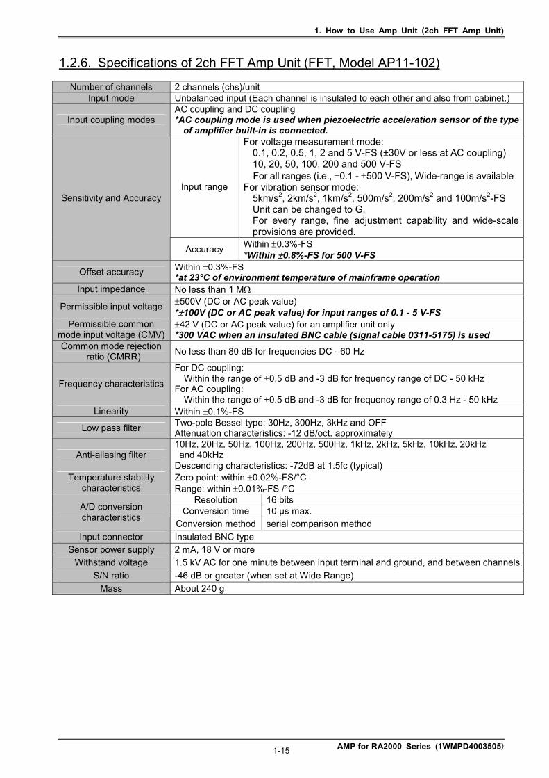
1.2.6. Specifications of 2ch FFT Amp Unit (FFT, Model AP11-102)
Number of channels 2 channels (chs)/unit Input mode Unbalanced input (Each channel is insulated to each other and also from cabinet.)
Input coupling modes AC coupling and DC coupling *AC coupling mode is used when piezoelectric acceleration sensor of the type
of amplifier built-in is connected.
Input range
For voltage measurement mode: 0.1, 0.2, 0.5, 1, 2 and 5 V-FS (±30V or less at AC coupling) 10, 20, 50, 100, 200 and 500 V-FS For all ranges (i.e., 0.1 - 500 V-FS), Wide-range is available
For vibration sensor mode: 5km/s2, 2km/s2, 1km/s2, 500m/s2, 200m/s2 and 100m/s2-FS Unit can be changed to G. For every range, fine adjustment capability and wide-scale provisions are provided.
Sensitivity and Accuracy
Accuracy Within 0.3%-FS *Within 0.8%-FS for 500 V-FS
Offset accuracy Within 0.3%-FS *at 23°C of environment temperature of mainframe operation
Input impedance No less than 1 M
Permissible input voltage 500V (DC or AC peak value) *100V (DC or AC peak value) for input ranges of 0.1 - 5 V-FS
Permissible common mode input voltage (CMV)
42 V (DC or AC peak value) for an amplifier unit only *300 VAC when an insulated BNC cable (signal cable 0311-5175) is used
Common mode rejection ratio (CMRR)
No less than 80 dB for frequencies DC - 60 Hz
Frequency characteristics
For DC coupling: Within the range of +0.5 dB and -3 dB for frequency range of DC - 50 kHz
For AC coupling: Within the range of +0.5 dB and -3 dB for frequency range of 0.3 Hz - 50 kHz
Linearity Within 0.1%-FS
Low pass filter Two-pole Bessel type: 30Hz, 300Hz, 3kHz and OFF Attenuation characteristics: -12 dB/oct. approximately
Anti-aliasing filter 10Hz, 20Hz, 50Hz, 100Hz, 200Hz, 500Hz, 1kHz, 2kHz, 5kHz, 10kHz, 20kHz and 40kHz Descending characteristics: -72dB at 1.5fc (typical)
Temperature stability characteristics
Zero point: within 0.02%-FS/°C Range: within 0.01%-FS /°C
Resolution 16 bits Conversion time 10 µs max. A/D conversion
characteristics Conversion method serial comparison method
Input connector Insulated BNC type Sensor power supply 2 mA, 18 V or more
Withstand voltage 1.5 kV AC for one minute between input terminal and ground, and between channels.
S/N ratio -46 dB or greater (when set at Wide Range)
Mass About 240 g
1. How to Use Amp Unit (2ch FFT Amp Unit)
AMP for RA2000 Series (1WMPD4003505) 1-16
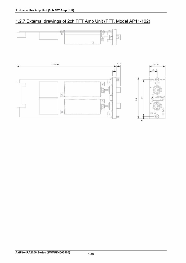
1.2.7.External drawings of 2ch FFT Amp Unit (FFT, Model AP11-102)

1. How to Use Amp Unit (2ch High-Speed DC Amp Unit)
AMP for RA2000 Series (1WMPD4003505) 1-17
1.3. 2ch High-Speed DC Amp Unit (HSDC, Model AP11-103) The 2ch High-Speed DC Amp Unit converts input analog voltages into digital signals at high speed with a sampling interval of 1s (i.e., A/D conversion) The units incorporate two (2) channels per unit and the two channels are insulated to each other within the unit.
1.3.1. Connection with input signals
Use by all means insulated BNC cables (optional item: input signal cables 0311-5175, with a BNC connector and test clips, of 2 m in length) for input connection. The outer shells of metal type BNC connectors have the negative (-) polarity potential of the input signal. Therefore, you would suffer an electric shock by touching the outer shell while the cable is connected to a signal source. Thus, note that it is very dangerous for you to touch it. If you need to use a BNC connector of the metal type due to some unavoidable circumstances, confirm that the common mode input voltage is within the range of ±42 V (in DC or in AC peak value) through carrying out appropriate examination of the signal source. Also, some metal type BNC cables may cause mating problems. Insulation BNC sockets may crack if they are forcibly connected, so please do not use what cannot be mated smoothly.
Please pay attention to the following points when you want to record low level signals: # Do not use unnecessarily long cables for input connection # Use shielded cables for input connection to avoid electrostatic noise
Please keep the signal source impedance as low as possible, i.e., less than 100 Ω. The lower the signal source impedance, the higher the quality of measurement records.
100V(0.1-5V) 500V(10-500V) PK
42V PK MAX
AP11-103
High Speed
DC AMP
INPUT
+
-
!
A
B
(+) (-)
(+) (-)
signal source
high impedance side
low impedance side
high impedance side
low impedance side
NOTE
WARNING
NOTE
1. How to Use Amp Unit (2ch High-Speed DC Amp Unit)
AMP for RA2000 Series (1WMPD4003505) 1-18
Input Signals
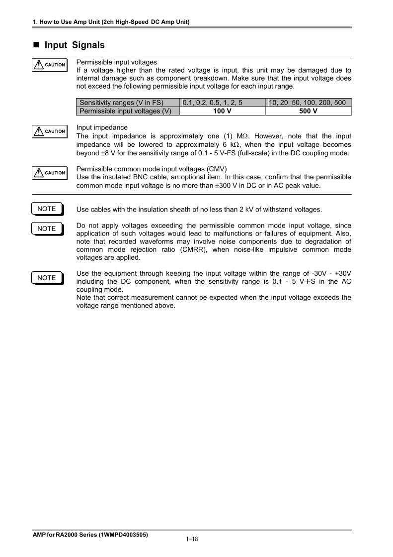
Permissible input voltages If a voltage higher than the rated voltage is input, this unit may be damaged due to internal damage such as component breakdown. Make sure that the input voltage does not exceed the following permissible input voltage for each input range. Sensitivity ranges (V in FS) 0.1, 0.2, 0.5, 1, 2, 5 10, 20, 50, 100, 200, 500 Permissible input voltages (V) 100 V 500 V
Input impedance The input impedance is approximately one (1) M. However, note that the input impedance will be lowered to approximately 6 k, when the input voltage becomes beyond 8 V for the sensitivity range of 0.1 - 5 V-FS (full-scale) in the DC coupling mode. Permissible common mode input voltages (CMV) Use the insulated BNC cable, an optional item. In this case, confirm that the permissible common mode input voltage is no more than 300 V in DC or in AC peak value. Use cables with the insulation sheath of no less than 2 kV of withstand voltages. Do not apply voltages exceeding the permissible common mode input voltage, since application of such voltages would lead to malfunctions or failures of equipment. Also, note that recorded waveforms may involve noise components due to degradation of common mode rejection ratio (CMRR), when noise-like impulsive common mode voltages are applied. Use the equipment through keeping the input voltage within the range of -30V - +30V including the DC component, when the sensitivity range is 0.1 - 5 V-FS in the AC coupling mode. Note that correct measurement cannot be expected when the input voltage exceeds the voltage range mentioned above.
CAUTION
CAUTION
CAUTION
NOTE
NOTE
NOTE

1. How to Use Amp Unit (2ch High-Speed DC Amp Unit)
AMP for RA2000 Series (1WMPD4003505) 1-19
1.3.2. How to set 2ch High-Speed DC Amp Unit (HSDC, Model AP11-103) This section covers operations in the Amp Basic screen that appears when the Amp button on the operation panel is pressed and the Amp Details screen that appears when a channel button is pressed.
1) Basics - Channel The channel number, input amp unit type, and waveform color are indicated in this portion. Pressing this button displays the Amp Details screen.
2) Basics - Input Input mode can be selected. Pressing this button permits mode switching, ON → GND → OFF → ON.
3) Basics - Position This button is used to set the zero position. Pressing this button changes the button appearance. The setup can be made with the jog dial.
4) Basics - Range This button is used to set the range. Pressing this button changes the button appearance. The setup can be made with the jog dial.
5) Basics – Lo V The LED lights if the high sensitivity range can be permitted.
6) Basics - Information indication This portion indicates settings that are unable to be set on this screen. When changing the settings, make the settings in the Amp Details screen. Fc: Filter setting Couple: Input coupling setting
1) Channel
6) Info
4) Range 3) Position 2) Input
5) Lo V
10) Range Indication
8)Input Coupling9)Auto Range
12) Range
13) Permission of High-sensitive setting
11)Wide/Normal
14) Filter
7)Position
1. How to Use Amp Unit (2ch High-Speed DC Amp Unit)
AMP for RA2000 Series (1WMPD4003505) 1-20
7) Details - Position The zero position (base line) is set with a button. The zero position means the waveform display position at 0V input (input short). The base line can be set in 5% steps in reference to 100% as the full scale. Also, you can set it with the the jog dial by pressing the jog button, or set it from the numeric input window by pressing the window button. And the position change is available through the setup of Physical Unit Conversion or Printing/Display Range. For more information, see Chapter 4. Physical Unit Conversion – Changing Printing/Display Range.
8) Details – Input Coupling The input coupling is set by pressing the AC coupling button or DC coupling button.
When the AC coupling button is pressed, a capacitor is connected to the input terminal. The DC component can be eliminated, which enables the measurement of alternating voltage.
9) Details - Auto range The range is automatically adjusted to the input signal.
10) Details - Range indication The value of the current display range is displayed. "#" is displayed when selecting the "Wide" range or changing "Printing / Display Range". After that, if you select the "Normal" range, the setting of "Printing / Display Range" is cleared and "#" disappears. Also, when checking "Set EU." on the ”User Conv.” Tab and setting to use physical unit conversion, the full scale converted value will be displayed with *. For more information on physical unit conversion and printing / display range setting, see Chapter 4. Physical Unit Conversion - Changing Printing / Display Range.
11) Details - Wide/Normal Wide: Entire measuring range is displayed. Normal: Half of the measuring range is displayed (Default).
12) Details - Range Range can be directly set.
When the measurement range is changed, the waveform clip range is cleared to the default value corresponding to the new range. Example: During expansion of the waveform in the waveform clip range between +40 and -40 at 100 V, if the range is set to 100 V again, the waveform clip range is set to between +50 to -50 as the default. (Enlarged display is cancelled.)
Pay attention to the permissible input voltage when setting the range. See Permissible input voltages in “Input Signals”.
13) Details - Permission of high sensitivity settings Settings of the high-sensitive range (5 V to 100 mV) can be prohibited/permitted. When using the high-sensitivity range, check the check box. When the high-sensitivity range is not used, prohibition of the high-sensitivity range without checking the box is recommended for safety.
14) Details - Filter This button is used to set the low-pass filter.
TIPS
CAUTION
TIPS

1. How to Use Amp Unit (2ch High-Speed DC Amp Unit)
AMP for RA2000 Series (1WMPD4003505) 1-21
1.3.3. Specifications of 2ch High-Speed DC Amp Unit (HSDC, Model AP11-103)
Number of channels 2 channels (chs)/unit
Input mode Unbalanced input (Each channel is insulated to each other and also from cabinet.) Input coupling modes AC coupling and DC coupling
Input range
0.1, 0.2, 0.5, 1, 2 and 5 V-FS (Voltages exceeding 30V shall not be applied for the ranges 0.1 - 5 V-FS in AC coupling.) 10, 20, 50, 100, 200 and 500 V-FS For every range (i.e., ±0.1 - ±500 V-FS), fine adjustment capability and wide-scale provisions are provided.
Sensitivity and Accuracy
Accuracy within ±0.5%-FS * within ±1%-FS for 500 V-FS
Offset accuracy within ±0.5%-FS * at 23 of environment temperature of mainframe operation
Input impedance No less than 1 MΩ
Permissible input voltage ±500V (DC or AC peak value) * ±100V (DC or AC peak value) for input ranges of 0.1 - 5 V-FS
Permissible common mode input voltage (CMV)
±42 V (DC or AC peak value) for an amplifier unit only * 300 VAC when an insulated BNC cable (signal cable 0311-5175) is used
Common mode rejection ratio (CMRR)
No less than 80 dB for frequencies DC - 60 Hz
Frequency characteristics
For DC coupling: Within the range of +0.5 dB and -3 dB for frequency range of DC - 400 kHz
For AC coupling: Within the range of +0.5 dB and -3 dB for frequency range of 0.3 Hz - 400 kHz
Linearity Within 0.2%-FS
Low pass filter Two-pole Bessel type: 5Hz, 50Hz, 500Hz, 5kHz, 50kHz and OFF Attenuation characteristics: -12 dB/oct. approximately
Temperature stability characteristics
Zero point: within 0.03%-FS/C Range: within 0.01%-FS/C
Resolution 12 bits Conversion time 1 µs max. A/D conversion
characteristics Conversion method serial comparison method
Input connector Insulated BNC type
Withstand voltage 1.5 kV AC for one minute between input terminal and ground, and between channels.
S/N ratio -46 dB or greater (when set at Wide Range)
Mass About 240 g

1. How to Use Amp Unit (2ch High-Speed DC Amp Unit)
AMP for RA2000 Series (1WMPD4003505) 1-22
1.3.4. External drawings of 2ch High-Speed DC Amp Unit (HSDC, Model AP11-103)
1. How to Use Amp Unit (2ch AC Strain Amp Unit)
AMP for RA2000 Series (1WMPD4003505) 1-23
1.4.2ch AC Strain Amp Unit (ACST, Model AP11-104A) The 2ch AC Strain Amp Unit is an A/D conversion unit that converts output voltages of transducers of the strain gauge type or strain gauges with bridge box connected to the input. The unit provides high accuracy and resolution measurement with low noise due to the use of AC (alternate current) bridge source. The units incorporate two (2) channels per unit and the two channels are insulated to each other within the unit.
1.4.1. Connection with input signals
The AC source unit (optional item: RA23-143) must be installed in the RA recorder unit, when the 2ch AC strain amplifier unit is used.
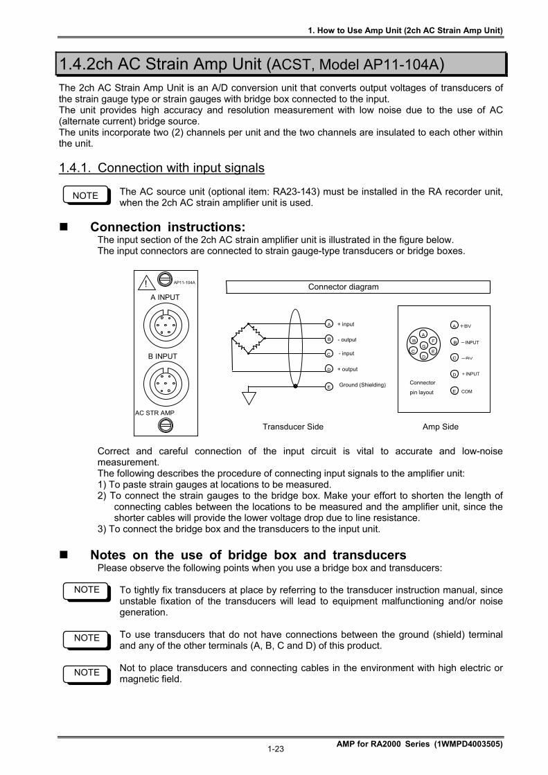
Connection instructions: The input section of the 2ch AC strain amplifier unit is illustrated in the figure below. The input connectors are connected to strain gauge-type transducers or bridge boxes. Correct and careful connection of the input circuit is vital to accurate and low-noise measurement. The following describes the procedure of connecting input signals to the amplifier unit: 1) To paste strain gauges at locations to be measured. 2) To connect the strain gauges to the bridge box. Make your effort to shorten the length of
connecting cables between the locations to be measured and the amplifier unit, since the shorter cables will provide the lower voltage drop due to line resistance.
3) To connect the bridge box and the transducers to the input unit.
Notes on the use of bridge box and transducers Please observe the following points when you use a bridge box and transducers:
To tightly fix transducers at place by referring to the transducer instruction manual, since unstable fixation of the transducers will lead to equipment malfunctioning and/or noise generation. To use transducers that do not have connections between the ground (shield) terminal and any of the other terminals (A, B, C and D) of this product. Not to place transducers and connecting cables in the environment with high electric or magnetic field.
NOTE
NOTE
NOTE
NOTE
Connector diagram
+ input
- output
- input
+ output
Ground (Shielding)E
D
C
B
A
Amp Side Transducer Side
Connector
pin layout
C
E
D
B
A +BV
-INPUT
COM
-BV
+INPUT
D
A
B
C E
FG
AC STR AMP
!
A INPUT
AP11-104A
B INPUT

1. How to Use Amp Unit (2ch AC Strain Amp Unit)
AMP for RA2000 Series (1WMPD4003505) 1-24
When the length of cables connecting this product to the bridge box or transducers is large, you will have measured values substantially lower than the actual value by the amount of voltage drop of bridge source due to line resistance. The error caused by the voltage drop can be corrected by using the following table listing bridge voltage drop factors.
Bridge Voltage Drop Rate (approximate in ) Length of cable between this product and bridge box
(Wire type: AWG20, at +20C) Bridge resistance
() 20 m 50 m 100 m 200 m 120 - 1.2 - 3.0 - 5.8 - 11.0 350 - 0.4 - 1.1 - 2.1 - 4.1 500 - 0.3 - 0.7 - 1.5 - 2.9 1000 - 0.1 - 0.4 - 0.7 - 1.5
1.4.2.How to set 2ch AC Strain Amp Unit (ACST, Model AP11-104/104A) This section covers operations in the Amp Basic Screen that appears when the Amp button on the operation panel is pressed and the Amp Details Screen that appears when a channel button is pressed.
1) Basics - Channel The channel number, input amp unit type, and waveform color are indicated in this portion. Pressing this button displays the Amp Details Screen.
2) Basics - Input Input mode can be selected. Pressing this button permits switching among ON, GND and OFF.
3) Basics - Position This button is used to set the zero position. Pressing this button changes the button appearance. The setup can be made with the job dial.
7) Range indication
6) Position
9) Range
11) Calibration
10) Filter
8) Wide/Normal
12) Balance
1) Channel
5) Info
4) Range 3) Position 2) Input
NOTE
1. How to Use Amp Unit (2ch AC Strain Amp Unit)
AMP for RA2000 Series (1WMPD4003505) 1-25
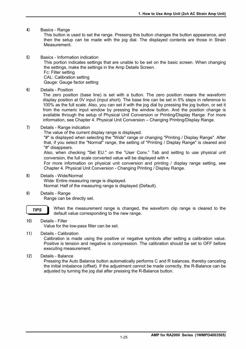
4) Basics - Range This button is used to set the range. Pressing this button changes the button appearance, and then the setup can be made with the jog dial. The displayed contents are those in Strain Measurement.
5) Basics - Information indication This portion indicates settings that are unable to be set on the basic screen. When changing the settings, make the settings in the Amp Details Screen. Fc: Filter setting CAL: Calibration setting Gauge: Gauge factor setting
6) Details - Position The zero position (base line) is set with a button. The zero position means the waveform display position at 0V input (input short). The base line can be set in 5% steps in reference to 100% as the full scale. Also, you can set it with the jog dial by pressing the jog button, or set it from the numeric input window by pressing the window button. And the position change is available through the setup of Physical Unit Conversion or Printing/Display Range. For more information, see Chapter 4. Physical Unit Conversion – Changing Printing/Display Range.
7) Details - Range indication The value of the current display range is displayed. "#" is displayed when selecting the "Wide" range or changing "Printing / Display Range". After that, if you select the "Normal" range, the setting of "Printing / Display Range" is cleared and "#" disappears. Also, when checking "Set EU." on the ”User Conv.” Tab and setting to use physical unit conversion, the full scale converted value will be displayed with *. For more information on physical unit conversion and printing / display range setting, see Chapter 4. Physical Unit Conversion - Changing Printing / Display Range.
8) Details - Wide/Normal Wide: Entire measuring range is displayed. Normal: Half of the measuring range is displayed (Default).
9) Details - Range Range can be directly set.
When the measurement range is changed, the waveform clip range is cleared to the default value corresponding to the new range.
10) Details - Filter Value for the low-pass filter can be set.
11) Details - Calibration Calibration is made using the positive or negative symbols after setting a calibration value. Positive is tension and negative is compression. The calibration should be set to OFF before executing measurement.
12) Details - Balance Pressing the Auto Balance button automatically performs C and R balances, thereby canceling the initial imbalance (offset). If the adjustment cannot be made correctly, the R-Balance can be adjusted by turning the jog dial after pressing the R-Balance button.
1. How to Use Amp Unit (2ch AC Strain Amp Unit)
AMP for RA2000 Series (1WMPD4003505) 1-26
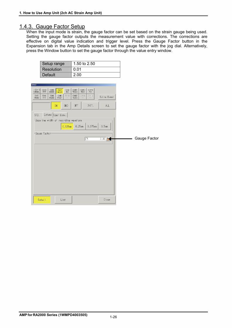
1.4.3. Gauge Factor Setup When the input mode is strain, the gauge factor can be set based on the strain gauge being used. Setting the gauge factor outputs the measurement value with corrections. The corrections are effective on digital value indication and trigger level. Press the Gauge Factor button in the Expansion tab in the Amp Details screen to set the gauge factor with the jog dial. Alternatively, press the Window button to set the gauge factor through the value entry window.
Setup range 1.50 to 2.50
Resolution 0.01 Default 2.00
Gauge Factor
1. How to Use Amp Unit (2ch AC Strain Amp Unit)
AMP for RA2000 Series (1WMPD4003505) 1-27
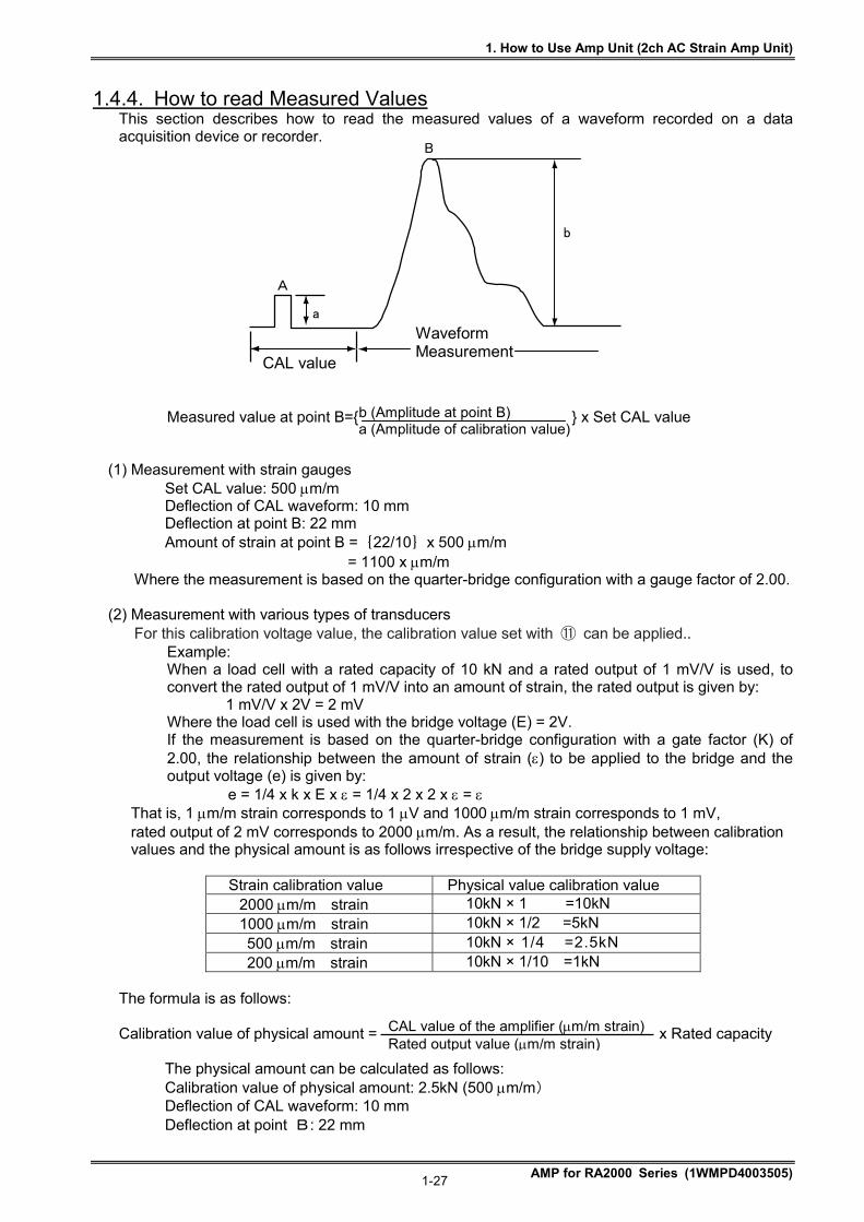
1.4.4. How to read Measured Values This section describes how to read the measured values of a waveform recorded on a data acquisition device or recorder.
Measured value at point B= x Set CAL value
(1) Measurement with strain gauges Set CAL value: 500 m/m Deflection of CAL waveform: 10 mm Deflection at point B: 22 mm Amount of strain at point B ={22/10}x 500 m/m
= 1100 x m/m Where the measurement is based on the quarter-bridge configuration with a gauge factor of 2.00.
(2) Measurement with various types of transducers
For this calibration voltage value, the calibration value set with ⑪ can be applied.. Example: When a load cell with a rated capacity of 10 kN and a rated output of 1 mV/V is used, to convert the rated output of 1 mV/V into an amount of strain, the rated output is given by:
1 mV/V x 2V = 2 mV Where the load cell is used with the bridge voltage (E) = 2V. If the measurement is based on the quarter-bridge configuration with a gate factor (K) of 2.00, the relationship between the amount of strain () to be applied to the bridge and the output voltage (e) is given by:
e = 1/4 x k x E x = 1/4 x 2 x 2 x = That is, 1 m/m strain corresponds to 1 V and 1000 m/m strain corresponds to 1 mV, rated output of 2 mV corresponds to 2000 m/m. As a result, the relationship between calibration values and the physical amount is as follows irrespective of the bridge supply voltage:
Strain calibration value Physical value calibration value 2000 m/m strain 10kN × 1 =10kN 1000 m/m strain 10kN × 1/2 =5kN 500 m/m strain 10kN × 1/4 =2.5kN 200 m/m strain 10kN × 1/10 =1kN
The formula is as follows:
Calibration value of physical amount = x Rated capacity
The physical amount can be calculated as follows: Calibration value of physical amount: 2.5kN (500 m/m) Deflection of CAL waveform: 10 mm Deflection at point B: 22 mm
b (Amplitude at point B) a (Amplitude of calibration value)
CAL value of the amplifier (m/m strain) Rated output value (m/m strain)
CAL value
a
A
B
b
Waveform Measurement
1. How to Use Amp Unit (2ch AC Strain Amp Unit)
AMP for RA2000 Series (1WMPD4003505) 1-28
The physical amount can be calculated as follows:
Load at point B = x 2.5kN = 5.5kN
(3) Correction of Calibration (CAL) Values In this amplifier unit, its gauge factor is set to 2.00, If strain gauges with a gauge factor other than 2.00 are to be used, the following formula must be used.
True CAL value = x CAL value of unit
(4) Where the distance from the bridge box to the amplifier unit is long
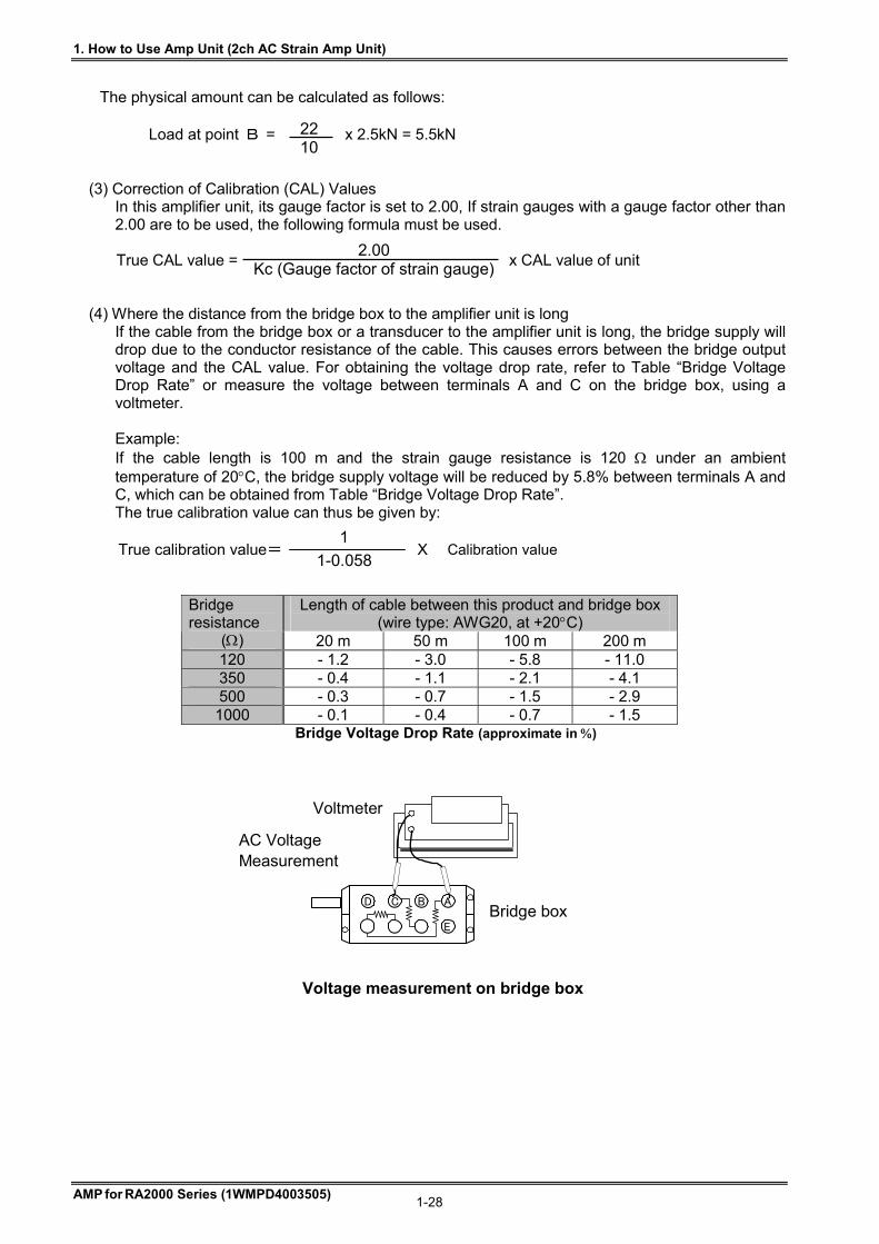
If the cable from the bridge box or a transducer to the amplifier unit is long, the bridge supply will drop due to the conductor resistance of the cable. This causes errors between the bridge output voltage and the CAL value. For obtaining the voltage drop rate, refer to Table “Bridge Voltage Drop Rate” or measure the voltage between terminals A and C on the bridge box, using a voltmeter. Example: If the cable length is 100 m and the strain gauge resistance is 120 under an ambient temperature of 20C, the bridge supply voltage will be reduced by 5.8% between terminals A and C, which can be obtained from Table “Bridge Voltage Drop Rate”. The true calibration value can thus be given by: True calibration value= X
Length of cable between this product and bridge box
(wire type: AWG20, at +20C) Bridge resistance
() 20 m 50 m 100 m 200 m 120 - 1.2 - 3.0 - 5.8 - 11.0 350 - 0.4 - 1.1 - 2.1 - 4.1 500 - 0.3 - 0.7 - 1.5 - 2.9 1000 - 0.1 - 0.4 - 0.7 - 1.5
Bridge Voltage Drop Rate (approximate in )
2.00 Kc (Gauge factor of strain gauge)
22 10
1
1-0.058 Calibration value
A
E
BCD
Voltmeter
AC Voltage Measurement
Bridge box
Voltage measurement on bridge box
1. How to Use Amp Unit (2ch AC Strain Amp Unit)
AMP for RA2000 Series (1WMPD4003505) 1-29
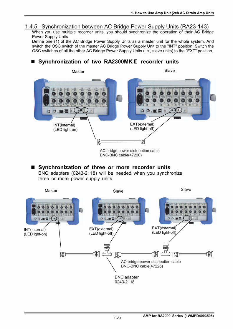
1.4.5. Synchronization between AC Bridge Power Supply Units (RA23-143) When you use multiple recorder units, you should synchronize the operation of their AC Bridge Power Supply Units. Define one (1) of the AC Bridge Power Supply Units as a master unit for the whole system. And switch the OSC switch of the master AC Bridge Power Supply Unit to the "INT" position. Switch the OSC switches of all the other AC Bridge Power Supply Units (i.e., slave units) to the "EXT" position.
Synchronization of two RA2300MKⅡ recorder units
Synchronization of three or more recorder units BNC adapters (0243-2118) will be needed when you synchronize three or more power supply units.
Master Slave
INT(internal) (LED light-on)
AC bridge power distribution cable BNC-BNC cable(47226)
EXT(external) (LED light-off)
BNC adapter 0243-2118
Master Slave
AC bridge power distribution cable BNC-BNC cable(47226)
EXT(external) (LED light-off)
INT(internal) (LED ight-on)
EXT(external) (LED light-off)
Slave
1. How to Use Amp Unit (2ch AC Strain Amp Unit)
AMP for RA2000 Series (1WMPD4003505) 1-30
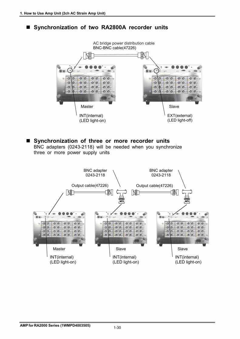
Synchronization of two RA2800A recorder units
Synchronization of three or more recorder units BNC adapters (0243-2118) will be needed when you synchronize three or more power supply units
Master Slave Slave
Output cable(47226) Output cable(47226)
BNC adapter 0243-2118
BNC adapter 0243-2118
INT(internal) (LED light-on)
INT(internal) (LED light-on)
INT(internal) (LED light-on)
AC bridge power distribution cable BNC-BNC cable(47226)
Master Slave
INT(internal) (LED light-on)
EXT(external) (LED light-off)
1. How to Use Amp Unit (2ch AC Strain Amp Unit)
AMP for RA2000 Series (1WMPD4003505) 1-31
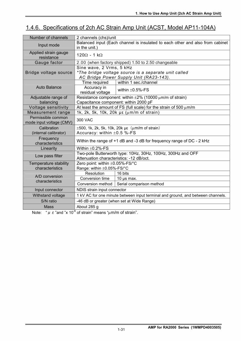
1.4.6. Specifications of 2ch AC Strain Amp Unit (ACST, Model AP11-104A)
Number of channels 2 channels (chs)/unit
Input mode Balanced input (Each channel is insulated to each other and also from cabinet in the unit.)
Applied strain gauge resistance
120 - 1 k
Gauge factor 2.00 (when factory shipped) 1.50 to 2.50 changeable
Bridge voltage source Sine wave, 2 Vrms, 5 kHz *The bridge voltage source is a separate unit called
AC Bridge Power Supply Unit (RA23-143). Time required within 1 sec./channel
Auto Balance Accuracy in residual voltage
within 0.5%-FS
Adjustable range of balancing
Resistance component: within 2% (10000 m/m of strain) Capacitance component: within 2000 pF
Voltage sensitivity At least the amount of FS (full scale) for the strain of 500 m/m Measurement range 1k, 2k, 5k, 10k, 20k με (m/m of strain)
Permissible common mode input voltage (CMV)
300 VAC
Calibration (internal calibrator)
500, 1k, 2k, 5k, 10k, 20k με(m/m of strain) Accuracy: within 0.5 %-FS
Frequency characteristics
Within the range of +1 dB and -3 dB for frequency range of DC - 2 kHz
Linearity Within 0.2%-FS
Low pass filter Two-pole Butterworth type: 10Hz, 30Hz, 100Hz, 300Hz and OFF Attenuation characteristics: -12 dB/oct.
Temperature stability characteristics
Zero point: within 0.05%-FS/°C Range: within 0.05%-FS/°C
Resolution 16 bits Conversion time 10 µs max. A/D conversion
characteristics Conversion method Serial comparison method
Input connector NDIS strain input connector
Withstand voltage 1 kV AC for one minute between input terminal and ground, and between channels.
S/N ratio -46 dB or greater (when set at Wide Range)
Mass About 285 g
Note: “με”and ”x 10-6 of strain” means “m/m of strain”.
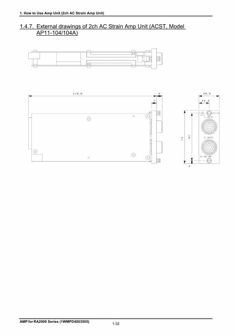
1. How to Use Amp Unit (2ch AC Strain Amp Unit)
AMP for RA2000 Series (1WMPD4003505) 1-32
1.4.7. External drawings of 2ch AC Strain Amp Unit (ACST, Model AP11-104/104A)
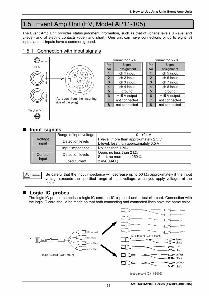
1. How to Use Amp Unit( Event Amp Unit)
AMP for RA2000 Series (1WMPD4003505) 1-33
1.5. Event Amp Unit (EV, Model AP11-105) The Event Amp Unit provides status judgment information, such as that of voltage levels (H-level and L-level) and of electric contacts (open and short). One unit can have connections of up to eight (8) inputs and all inputs have a common ground.
1.5.1. Connection with input signals
Connector 1 - 4 Connector 5 - 8 Pin No
Signal assignment
Pin No
Signal assignment
1 ch 1 input 1 ch 5 input 2 ch 2 input 2 ch 6 input 3 ch 3 input 3 ch 7 input 4 ch 4 input 4 ch 8 input 5 ground 5 ground 6 +15 V output 6 +15 V output 7 not connected 7 not connected 8 not connected 8 not connected
Input signals Range of input voltage 0 - +24 V
Detection levels H-level: more than approximately 2.5 V L-level: less than approximately 0.5 V
Voltage input
Input impedance No less than 1 M
Detection levels Open: no less than 2 k Short: no more than 250
Contact input
Load current 2 mA (MAX)
Be careful that the input impedance will decrease up to 50 k approximately if the input voltage exceeds the specified range of input voltage, when you apply voltages at the input.
Logic IC probes The logic IC probes comprise a logic IC cord, an IC clip cord and a test clip cord. Connection with the logic IC cord should be made so that both connecting and connected lines have the same color.
CAUTION
test clip cord (0311-5009)
brown
yellow
blackred
umber
black
black
black
Brown, black
Red, black
umber, black
yellow, black
brown
black
red
umber
yellow
IC clip cord (0311-5008)
logic IC cord (0311-5007)
4
8
1
2
5 3
7
6
(As seen from the insertingside of the plug)
EV AMP
INPUT
AP11-105
1
4
5
8
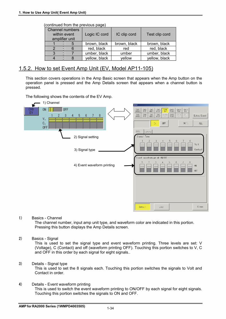
1. How to Use Amp Unit( Event Amp Unit)
AMP for RA2000 Series (1WMPD4003505) 1-34
(continued from the previous page)
Channel numbers within event amplifier unit
Logic IC cord IC clip cord Test clip cord
1 5 brown, black brown, black brown, black 2 6 red, black red red, black 3 7 umber, black umber umber, black 4 8 yellow, black yellow yellow, black
1.5.2. How to set Event Amp Unit (EV, Model AP11-105) This section covers operations in the Amp Basic screen that appears when the Amp button on the operation panel is pressed and the Amp Details screen that appears when a channel button is pressed. The following shows the contents of the EV Amp.
1) Basics - Channel The channel number, input amp unit type, and waveform color are indicated in this portion. Pressing this button displays the Amp Details screen.
2) Basics - Signal This is used to set the signal type and event waveform printing. Three levels are set: V (Voltage), C (Contact) and off (waveform printing OFF). Touching this portion switches to V, C and OFF in this order by each signal for eight signals..
3) Details - Signal type This is used to set the 8 signals each. Touching this portion switches the signals to Volt and Contact in order.
4) Details - Event waveform printing This is used to switch the event waveform printing to ON/OFF by each signal for eight signals. Touching this portion switches the signals to ON and OFF.
1) Channel
2) Signal setting
4) Event waveform printing
3) Signal type

1. How to Use Amp Unit( Event Amp Unit)
AMP for RA2000 Series (1WMPD4003505) 1-35
1.5.3. Adjustment of event waveform This section covers adjustment of the event waveform in the Expansion tab in the Amp Details screen. In the adjustment of the event waveform, settings for monitor display, waveform printing point, pitch between signals, signal amplitude and line thickness can be changed. The waveform can be adjusted to have good visibility to the measuring condition. Press the jog button of “Position”, “Sig. Pitch”, “Amplitude”, and “Line Thickness” on the Extension tab of the Amplifier Details screen and you can set each with the jog dial. Or set each from the numeric input window by pressing the window button. Touching the Auto adjust button automatically makes adjustment so that the event waveform printing is exactly positioned on the grid.
1) Printing position This value specifies the waveform position of signal 8. The signals 1 to 8 are positioned above signal 8 in the interval specified in Pitch between signals.
2) Pitch between signals This value specifies the interval between the waveform positions of all eight signals.
3) Signal amplitude This value specifies the height of the waveform amplitude (length between H and L points).
4) Line Thickness This value specifies the waveform width at the H point.
5) The event waveform printing point is automatically adjusted so as to be exactly positioned on the grid.
Extremely high setting values for Printing Portion and Pitch between Signals exceed the effective printing width, which will disable event waveform printing.
1) Printing Position 2) Pitch between Signals 3) Signal Amplitude 4) Line Thickness
5) Auto Adjust
NOTE
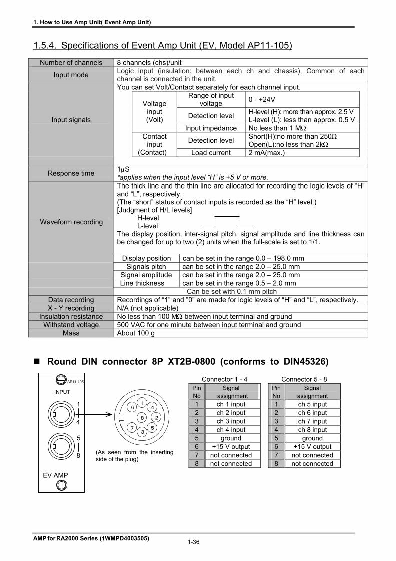
1. How to Use Amp Unit( Event Amp Unit)
AMP for RA2000 Series (1WMPD4003505) 1-36
1.5.4. Specifications of Event Amp Unit (EV, Model AP11-105)
Number of channels 8 channels (chs)/unit
Input mode Logic input (insulation: between each ch and chassis), Common of each channel is connected in the unit. You can set Volt/Contact separately for each channel input.
Range of input voltage
0 - +24V
Detection level H-level (H): more than approx. 2.5 V L-level (L): less than approx. 0.5 V
Voltage input (Volt)
Input impedance No less than 1 M
Detection level Short(H):no more than 250 Open(L):no less than 2k
Input signals
Contact input
(Contact) Load current 2 mA(max.)
Response time 1S *applies when the input level “H” is +5 V or more. The thick line and the thin line are allocated for recording the logic levels of “H” and “L”, respectively. (The “short” status of contact inputs is recorded as the “H” level.) [Judgment of H/L levels]
H-level L-level
The display position, inter-signal pitch, signal amplitude and line thickness can be changed for up to two (2) units when the full-scale is set to 1/1.
Waveform recording
Display position can be set in the range 0.0 – 198.0 mm Signals pitch can be set in the range 2.0 – 25.0 mm
Signal amplitude can be set in the range 2.0 – 25.0 mm Line thickness can be set in the range 0.5 – 2.0 mm
Can be set with 0.1 mm pitch Data recording Recordings of “1” and ”0” are made for logic levels of “H” and “L”, respectively. X - Y recording N/A (not applicable)
Insulation resistance No less than 100 M between input terminal and ground Withstand voltage 500 VAC for one minute between input terminal and ground
Mass About 100 g
Round DIN connector 8P XT2B-0800 (conforms to DIN45326)
Connector 1 - 4 Connector 5 - 8 Pin No
Signal assignment
Pin No
Signal assignment
1 ch 1 input 1 ch 5 input 2 ch 2 input 2 ch 6 input 3 ch 3 input 3 ch 7 input 4 ch 4 input 4 ch 8 input 5 ground 5 ground 6 +15 V output 6 +15 V output 7 not connected 7 not connected 8 not connected 8 not connected
EV AMP
INPUT
AP11-105
1
4
5
8
4
8
1
2
5 3
7
6
(As seen from the insertingside of the plug)

1. How to Use Amp Unit( Event Amp Unit)
AMP for RA2000 Series (1WMPD4003505) 1-37
<Logic IC probes-----accessory to Event Amp Unit>
Logic IC probes are used for connection of the event amplifier unit with electronic circuits or sequence circuits for measurement of digital signals and/or relay contact signals.
Wire color Corresponding input
channels Brown ch 1 ch 5 Red ch 2 ch 6
Umber ch 3 ch 7 Yellow ch 4 ch 8
Black ground ground
Use
Logic IC cord (0311-5007) One (1), 1.5 m long IC clip cord (0311-5008) Four (4)/sack, 15 cm long
Test clip cord (0311-5009) Four (4)/sack, 15 cm long Composition
The above comprises one (1) set of probe; two (2) are provided with each unit.
1.5.5. External drawings of Event Amp Unit (EV, Model AP11-105)
EV AMP
1
4
5
8
INPUT
AP11-105
75±0.3
28.8±0.3
179.8±0.5 (5)
7
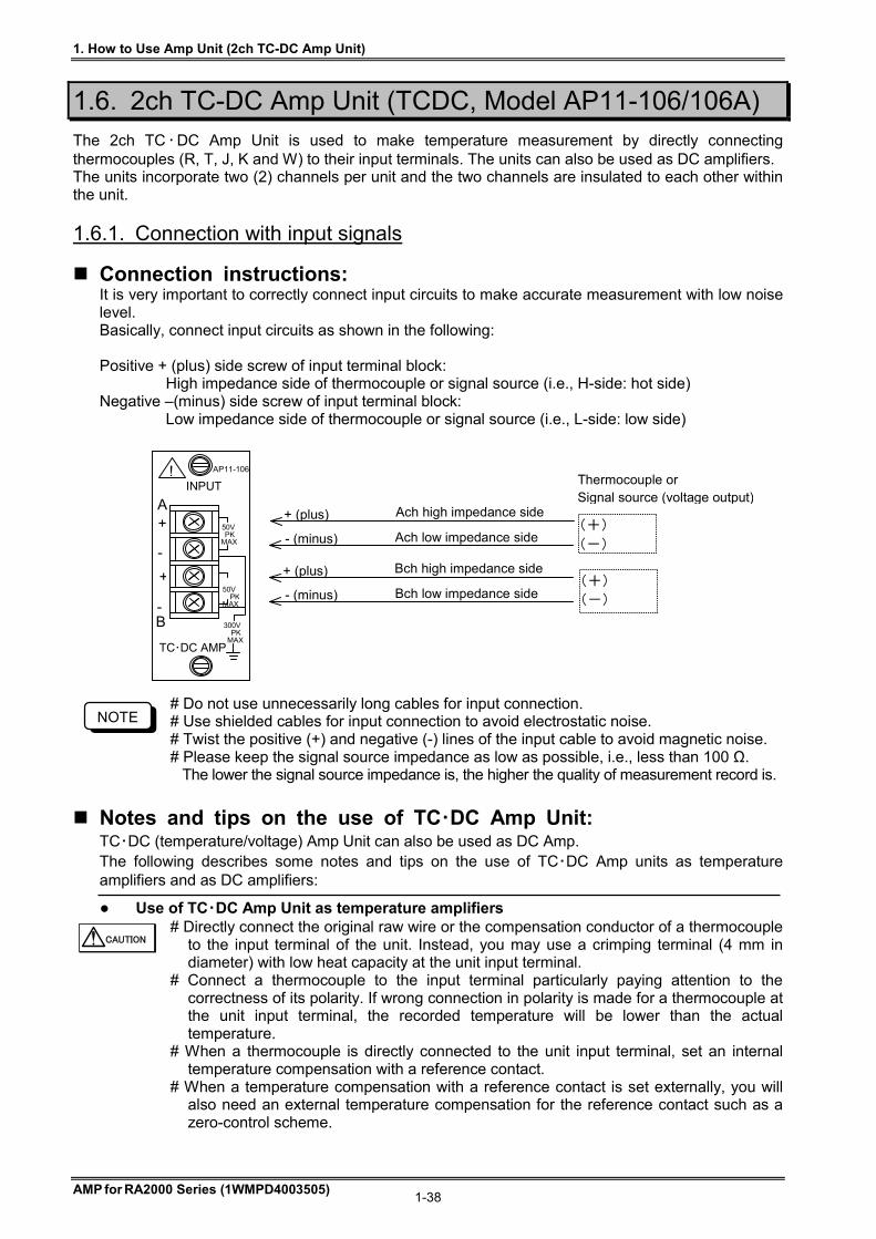
1. How to Use Amp Unit (2ch TC-DC Amp Unit)
AMP for RA2000 Series (1WMPD4003505) 1-38
1.6. 2ch TC-DC Amp Unit (TCDC, Model AP11-106/106A) The 2ch TC ・DC Amp Unit is used to make temperature measurement by directly connecting thermocouples (R, T, J, K and W) to their input terminals. The units can also be used as DC amplifiers. The units incorporate two (2) channels per unit and the two channels are insulated to each other within the unit.
1.6.1. Connection with input signals
Connection instructions: It is very important to correctly connect input circuits to make accurate measurement with low noise level. Basically, connect input circuits as shown in the following: Positive + (plus) side screw of input terminal block:
High impedance side of thermocouple or signal source (i.e., H-side: hot side) Negative –(minus) side screw of input terminal block:
Low impedance side of thermocouple or signal source (i.e., L-side: low side)
# Do not use unnecessarily long cables for input connection. # Use shielded cables for input connection to avoid electrostatic noise. # Twist the positive (+) and negative (-) lines of the input cable to avoid magnetic noise. # Please keep the signal source impedance as low as possible, i.e., less than 100 Ω.
The lower the signal source impedance is, the higher the quality of measurement record is.
Notes and tips on the use of TC・DC Amp Unit: TC・DC (temperature/voltage) Amp Unit can also be used as DC Amp. The following describes some notes and tips on the use of TC・DC Amp units as temperature amplifiers and as DC amplifiers:
Use of TC・DC Amp Unit as temperature amplifiers # Directly connect the original raw wire or the compensation conductor of a thermocouple
to the input terminal of the unit. Instead, you may use a crimping terminal (4 mm in diameter) with low heat capacity at the unit input terminal.
# Connect a thermocouple to the input terminal particularly paying attention to the correctness of its polarity. If wrong connection in polarity is made for a thermocouple at the unit input terminal, the recorded temperature will be lower than the actual temperature.
# When a thermocouple is directly connected to the unit input terminal, set an internal temperature compensation with a reference contact.
# When a temperature compensation with a reference contact is set externally, you will also need an external temperature compensation for the reference contact such as a zero-control scheme.
CAUTION
TC・DC AMP
! INPUT
AP11-106
B
A +
-
+
-
50V PK MAX
50V PKMAX
300V PK MAX
(+) (-)
Thermocouple or Signal source (voltage output)
(+) (-)
+ (plus) Ach high impedance side
- (minus) Ach low impedance side
+ (plus) Bch high impedance side
- (minus) Bch low impedance side
NOTE
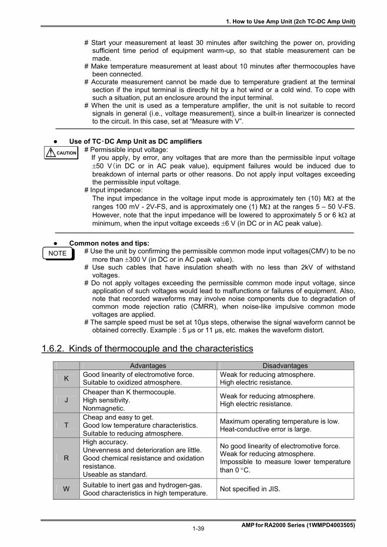
1. How to Use Amp Unit (2ch TC-DC Amp Unit)
AMP for RA2000 Series (1WMPD4003505) 1-39
# Start your measurement at least 30 minutes after switching the power on, providing
sufficient time period of equipment warm-up, so that stable measurement can be made.
# Make temperature measurement at least about 10 minutes after thermocouples have been connected.
# Accurate measurement cannot be made due to temperature gradient at the terminal section if the input terminal is directly hit by a hot wind or a cold wind. To cope with such a situation, put an enclosure around the input terminal.
# When the unit is used as a temperature amplifier, the unit is not suitable to record signals in general (i.e., voltage measurement), since a built-in linearizer is connected to the circuit. In this case, set at “Measure with V”.
Use of TC・DC Amp Unit as DC amplifiers # Permissible input voltage: If you apply, by error, any voltages that are more than the permissible input voltage
50 V(in DC or in AC peak value), equipment failures would be induced due to breakdown of internal parts or other reasons. Do not apply input voltages exceeding the permissible input voltage.
# Input impedance: The input impedance in the voltage input mode is approximately ten (10) M at the ranges 100 mV - 2V-FS, and is approximately one (1) M at the ranges 5 – 50 V-FS. However, note that the input impedance will be lowered to approximately 5 or 6 k at minimum, when the input voltage exceeds 6 V (in DC or in AC peak value).
Common notes and tips: # Use the unit by confirming the permissible common mode input voltages(CMV) to be no
more than 300 V (in DC or in AC peak value). # Use such cables that have insulation sheath with no less than 2kV of withstand
voltages. # Do not apply voltages exceeding the permissible common mode input voltage, since
application of such voltages would lead to malfunctions or failures of equipment. Also, note that recorded waveforms may involve noise components due to degradation of common mode rejection ratio (CMRR), when noise-like impulsive common mode voltages are applied.
# The sample speed must be set at 10μs steps, otherwise the signal waveform cannot be obtained correctly. Example : 5 μs or 11 μs, etc. makes the waveform distort.
1.6.2. Kinds of thermocouple and the characteristics
Advantages Disadvantages
K Good linearity of electromotive force. Suitable to oxidized atmosphere.
Weak for reducing atmosphere. High electric resistance.
J Cheaper than K thermocouple. High sensitivity. Nonmagnetic.
Weak for reducing atmosphere. High electric resistance.
T Cheap and easy to get. Good low temperature characteristics. Suitable to reducing atmosphere.
Maximum operating temperature is low. Heat-conductive error is large.
R
High accuracy. Unevenness and deterioration are little. Good chemical resistance and oxidation resistance. Useable as standard.
No good linearity of electromotive force. Weak for reducing atmosphere. Impossible to measure lower temperature than 0 C.
W Suitable to inert gas and hydrogen-gas. Good characteristics in high temperature.
Not specified in JIS.
NOTE
CAUTION
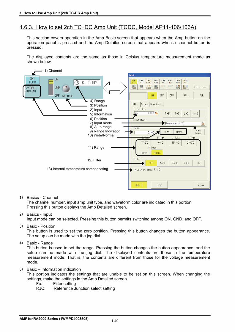
1. How to Use Amp Unit (2ch TC-DC Amp Unit)
AMP for RA2000 Series (1WMPD4003505) 1-40
1.6.3. How to set 2ch TC・DC Amp Unit (TCDC, Model AP11-106/106A) This section covers operation in the Amp Basic screen that appears when the Amp button on the operation panel is pressed and the Amp Detailed screen that appears when a channel button is pressed. The displayed contents are the same as those in Celsius temperature measurement mode as shown below.
1) Basics - Channel The channel number, input amp unit type, and waveform color are indicated in this portion. Pressing this button displays the Amp Detailed screen.
2) Basics - Input Input mode can be selected. Pressing this button permits switching among ON, GND, and OFF.
3) Basic - Position This button is used to set the zero position. Pressing this button changes the button appearance. The setup can be made with the jog dial.
4) Basic - Range This button is used to set the range. Pressing the button changes the button appearance, and the setup can be made with the jog dial. The displayed contents are those in the temperature measurement mode. That is, the contents are different from those for the voltage measurement mode.
5) Basic – Information indication This portion indicates the settings that are unable to be set on this screen. When changing the settings, make the settings in the Amp Detailed screen.
Fc: Filter setting RJC: Reference Junction select setting
6) Position 7) Input mode 8) Auto range
11) Range
13) Internal temperature compensating
12) Filter
10) Wide/Normal
2) Input
9) Range Indication
1) Channel
5) Information
4) Range 3) Position
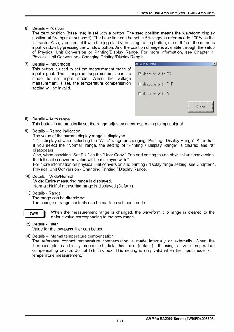
1. How to Use Amp Unit (2ch TC-DC Amp Unit)
AMP for RA2000 Series (1WMPD4003505) 1-41
6) Details – Position The zero position (base line) is set with a button. The zero position means the waveform display position at 0V input (input short). The base line can be set in 5% steps in reference to 100% as the full scale. Also, you can set it with the jog dial by pressing the jog button, or set it from the numeric input window by pressing the window button. And the position change is available through the setup of Physical Unit Conversion or Printing/Display Range. For more information, see Chapter 4. Physical Unit Conversion - Changing Printing/Display Range.
7) Details – Input mode This button is used to set the measurement mode of input signal. The change of range contents can be made to set input mode. When the voltage measurement is set, the temperature compensation setting will be invalid.
8) Details – Auto range This button is automatically set the range adjustment corresponding to input signal.
9) Details – Range indication The value of the current display range is displayed. "#" is displayed when selecting the "Wide" range or changing "Printing / Display Range". After that, if you select the "Normal" range, the setting of "Printing / Display Range" is cleared and "#" disappears. Also, when checking "Set EU." on the ”User Conv.” Tab and setting to use physical unit conversion, the full scale converted value will be displayed with *. For more information on physical unit conversion and printing / display range setting, see Chapter 4. Physical Unit Conversion - Changing Printing / Display Range.
10) Details – Wide/Normal Wide: Entire measuring range is displayed. Normal: Half of measuring range is displayed (Default).
11) Details - Range The range can be directly set. The change of range contents can be made to set input mode.
When the measurement range is changed, the waveform clip range is cleared to the default value corresponding to the new range.
12) Details - Filter Value for the low-pass filter can be set.
13) Details – Internal temperature compensation The reference contact temperature compensation is made internally or externally. When the thermocouple is directly connected, tick this box (default). If using a zero-temperature compensating device, do not tick this box. This setting is only valid when the input mode is in temperature measurement.
TIPS
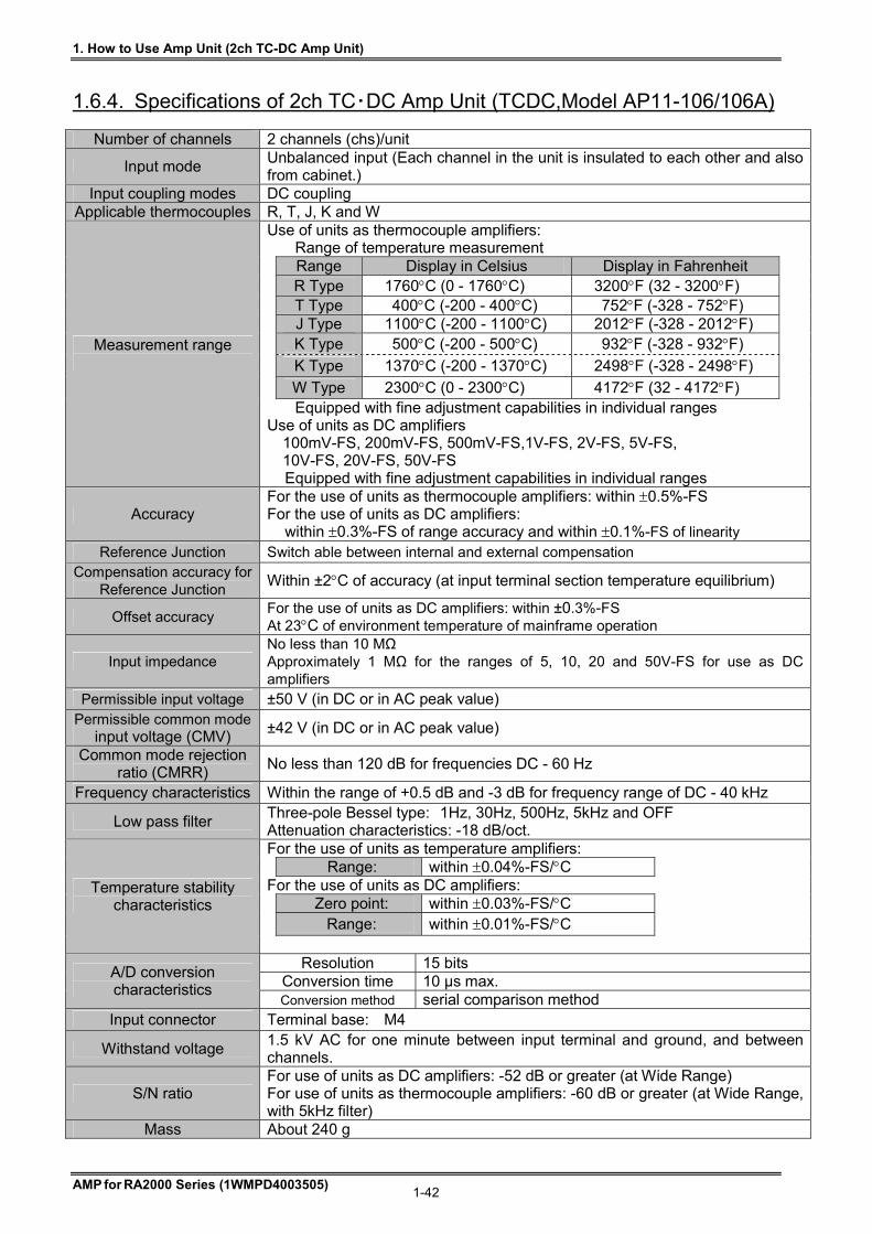
1. How to Use Amp Unit (2ch TC-DC Amp Unit)
AMP for RA2000 Series (1WMPD4003505) 1-42
1.6.4. Specifications of 2ch TC・DC Amp Unit (TCDC,Model AP11-106/106A)
Number of channels 2 channels (chs)/unit
Input mode Unbalanced input (Each channel in the unit is insulated to each other and also from cabinet.)
Input coupling modes DC coupling Applicable thermocouples R, T, J, K and W
Use of units as thermocouple amplifiers: Range of temperature measurement
Range Display in Celsius Display in Fahrenheit R Type 1760C (0 - 1760C) 3200F (32 - 3200F) T Type 400C (-200 - 400C) 752F (-328 - 752F) J Type 1100C (-200 - 1100C) 2012F (-328 - 2012F) K Type 500C (-200 - 500C) 932F (-328 - 932F)
K Type 1370C (-200 - 1370C) 2498F (-328 - 2498F)
W Type 2300C (0 - 2300C) 4172F (32 - 4172F)
Measurement range
Equipped with fine adjustment capabilities in individual ranges Use of units as DC amplifiers
100mV-FS, 200mV-FS, 500mV-FS,1V-FS, 2V-FS, 5V-FS, 10V-FS, 20V-FS, 50V-FS
Equipped with fine adjustment capabilities in individual ranges
Accuracy For the use of units as thermocouple amplifiers: within 0.5%-FS For the use of units as DC amplifiers: within 0.3%-FS of range accuracy and within 0.1%-FS of linearity
Reference Junction Switch able between internal and external compensation Compensation accuracy for
Reference Junction Within ±2C of accuracy (at input terminal section temperature equilibrium)
Offset accuracy For the use of units as DC amplifiers: within ±0.3%-FS At 23C of environment temperature of mainframe operation
Input impedance No less than 10 MΩ Approximately 1 MΩ for the ranges of 5, 10, 20 and 50V-FS for use as DC amplifiers
Permissible input voltage ±50 V (in DC or in AC peak value) Permissible common mode
input voltage (CMV) ±42 V (in DC or in AC peak value)
Common mode rejection ratio (CMRR)
No less than 120 dB for frequencies DC - 60 Hz
Frequency characteristics Within the range of +0.5 dB and -3 dB for frequency range of DC - 40 kHz
Low pass filter Three-pole Bessel type: 1Hz, 30Hz, 500Hz, 5kHz and OFF Attenuation characteristics: -18 dB/oct. For the use of units as temperature amplifiers: Range: within 0.04%-FS/C For the use of units as DC amplifiers:
Zero point: within 0.03%-FS/C
Range: within 0.01%-FS/C
Temperature stability characteristics
Resolution 15 bits
Conversion time 10 µs max. A/D conversion characteristics
Conversion method serial comparison method Input connector Terminal base: M4
Withstand voltage 1.5 kV AC for one minute between input terminal and ground, and between channels.
S/N ratio For use of units as DC amplifiers: -52 dB or greater (at Wide Range) For use of units as thermocouple amplifiers: -60 dB or greater (at Wide Range, with 5kHz filter)
Mass About 240 g
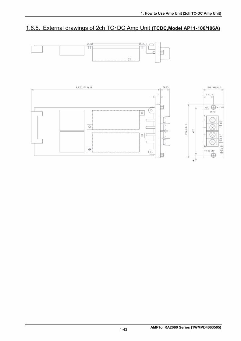
1. How to Use Amp Unit (2ch TC-DC Amp Unit)
AMP for RA2000 Series (1WMPD4003505) 1-43
1.6.5. External drawings of 2ch TC・DC Amp Unit (TCDC,Model AP11-106/106A)
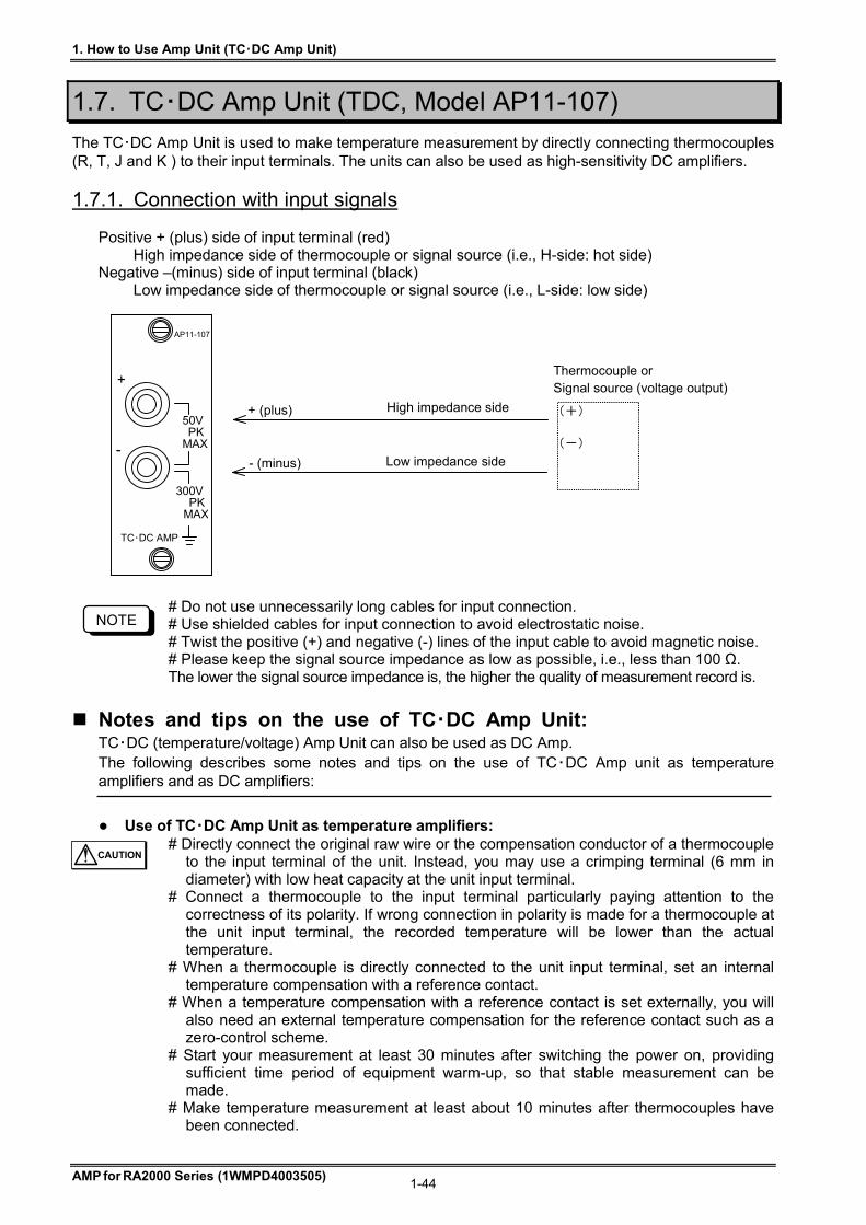
1. How to Use Amp Unit (TC・DC Amp Unit)
AMP for RA2000 Series (1WMPD4003505) 1-44
1.7. TC・DC Amp Unit (TDC, Model AP11-107)
The TC・DC Amp Unit is used to make temperature measurement by directly connecting thermocouples (R, T, J and K ) to their input terminals. The units can also be used as high-sensitivity DC amplifiers.
1.7.1. Connection with input signals Positive + (plus) side of input terminal (red)
High impedance side of thermocouple or signal source (i.e., H-side: hot side) Negative –(minus) side of input terminal (black)
Low impedance side of thermocouple or signal source (i.e., L-side: low side)
# Do not use unnecessarily long cables for input connection. # Use shielded cables for input connection to avoid electrostatic noise. # Twist the positive (+) and negative (-) lines of the input cable to avoid magnetic noise. # Please keep the signal source impedance as low as possible, i.e., less than 100 Ω. The lower the signal source impedance is, the higher the quality of measurement record is.
Notes and tips on the use of TC・DC Amp Unit: TC・DC (temperature/voltage) Amp Unit can also be used as DC Amp. The following describes some notes and tips on the use of TC・DC Amp unit as temperature amplifiers and as DC amplifiers:
Use of TC・DC Amp Unit as temperature amplifiers: # Directly connect the original raw wire or the compensation conductor of a thermocouple
to the input terminal of the unit. Instead, you may use a crimping terminal (6 mm in diameter) with low heat capacity at the unit input terminal.
# Connect a thermocouple to the input terminal particularly paying attention to the correctness of its polarity. If wrong connection in polarity is made for a thermocouple at the unit input terminal, the recorded temperature will be lower than the actual temperature.
# When a thermocouple is directly connected to the unit input terminal, set an internal temperature compensation with a reference contact.
# When a temperature compensation with a reference contact is set externally, you will also need an external temperature compensation for the reference contact such as a zero-control scheme.
# Start your measurement at least 30 minutes after switching the power on, providing sufficient time period of equipment warm-up, so that stable measurement can be made.
# Make temperature measurement at least about 10 minutes after thermocouples have been connected.
TC・DC AMP
AP11-107
+
50V PK MAX
300V PK MAX
-
+ (plus)
- (minus)
High impedance side
Low impedance side
(+) (-)
Thermocouple or Signal source (voltage output)
CAUTION
NOTE
1. How to Use Amp Unit (TC・DC Amp Unit)
AMP for RA2000 Series (1WMPD4003505) 1-45
# Accurate measurement cannot be made due to temperature gradient at the terminal
section if the input terminal is directly hit by a hot wind or a cold wind. To cope with such a situation, put an enclosure around the input terminal.
# When the unit is used as a temperature amplifier, the unit is not suitable to record signals in general (i.e., voltage measurement), since a built-in linearizer is connected to the circuit. In this case, set at “Measure with V”
Use of TC・DC Amp unit as DC amplifiers: # Permissible input voltage:
If you apply, by error, any voltages that are more than the permissible input voltage 50V(in DC or in AC peak value), equipment failures would be induced due to breakdown of internal parts or other reasons. Do not apply input voltages exceeding the permissible input voltage.
# Input impedance The input impedance in the voltage input mode is approximately ten (10) M at the ranges 100mV - 2V-FS, and is approximately one (1) M at the ranges 5 - 50V-FS. However, note that the input impedance will be lowered to approximately 5 or 6 k at minimum, when the input voltage exceeds 6 V (in DC or in AC peak value).
Common notes and tips: # Use the unit by confirming the permissible common mode input voltages (CMV) to be
no more than 300 V (in DC or in AC peak value). # Use such cables that have insulation sheath with no less than 2kV of withstand
voltages. # Do not apply voltages exceeding the permissible common mode input voltage, since
application of such voltages would lead to malfunctions or failures of equipment. Also, note that recorded waveforms may involve noise components due to degradation of common mode rejection ratio (CMRR), when noise-like impulsive common mode voltages are applied.
The sample speed must be set at 10μs steps, otherwise the signal waveform cannot be obtained correctly. Example : 5 μs or 11 μs, etc. makes the waveform distort.
1.7.2. Kinds of thermocouple and the characteristics
Advantages Disadvantages
K Good linearity of electromotive force. Suitable to oxidized atmosphere.
Weak for reducing atmosphere. High electric resistance.
J Cheaper than K thermocouple. High sensitivity. Nonmagnetic.
Weak for reducing atmosphere. High electric resistance.
T Cheap and easy to get. Good low temperature characteristics. Suitable to reducing atmosphere.
Maximum operating temperature is low. Heat-conductive error is large.
R
High accuracy. Unevenness and deterioration are little. Good chemical resistance and oxidation resistance. Useable as standard.
No good linearity of electromotive force. Weak for reducing atmosphere. Impossible to measure lower temperature than 0 C.
NOTE
CAUTION
NOTE
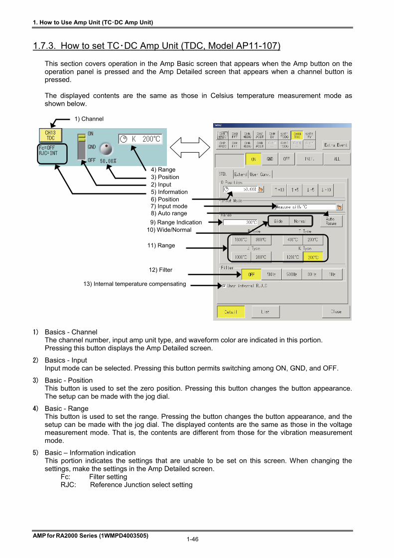
1. How to Use Amp Unit (TC・DC Amp Unit)
AMP for RA2000 Series (1WMPD4003505) 1-46
1.7.3. How to set TC・DC Amp Unit (TDC, Model AP11-107) This section covers operation in the Amp Basic screen that appears when the Amp button on the operation panel is pressed and the Amp Detailed screen that appears when a channel button is pressed. The displayed contents are the same as those in Celsius temperature measurement mode as shown below.
1) Basics - Channel The channel number, input amp unit type, and waveform color are indicated in this portion. Pressing this button displays the Amp Detailed screen.
2) Basics - Input Input mode can be selected. Pressing this button permits switching among ON, GND, and OFF.
3) Basic - Position This button is used to set the zero position. Pressing this button changes the button appearance. The setup can be made with the jog dial.
4) Basic - Range This button is used to set the range. Pressing the button changes the button appearance, and the setup can be made with the jog dial. The displayed contents are the same as those in the voltage measurement mode. That is, the contents are different from those for the vibration measurement mode.
5) Basic – Information indication This portion indicates the settings that are unable to be set on this screen. When changing the settings, make the settings in the Amp Detailed screen.
Fc: Filter setting RJC: Reference Junction select setting
1) Channel
5) Information
4) Range 3) Position 2) Input
9) Range Indication
6) Position 7) Input mode 8) Auto range
11) Range
13) Internal temperature compensating
12) Filter
10) Wide/Normal
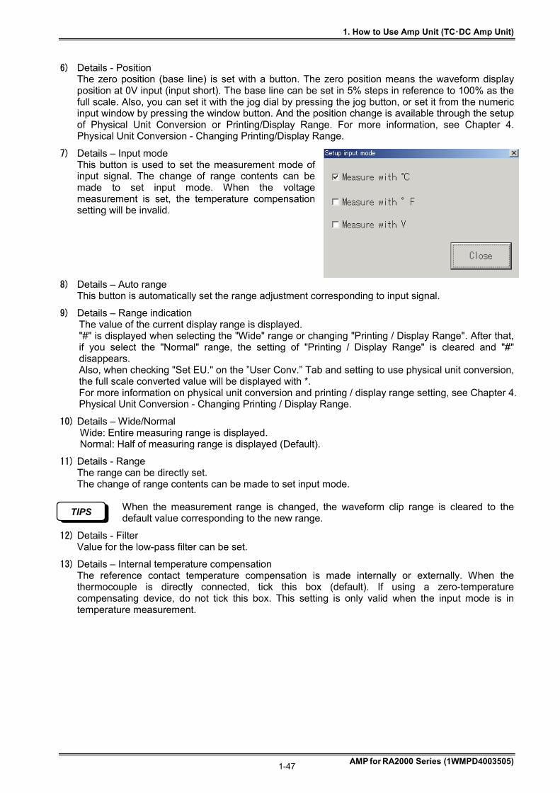
1. How to Use Amp Unit (TC・DC Amp Unit)
AMP for RA2000 Series (1WMPD4003505) 1-47
6) Details - Position The zero position (base line) is set with a button. The zero position means the waveform display position at 0V input (input short). The base line can be set in 5% steps in reference to 100% as the full scale. Also, you can set it with the jog dial by pressing the jog button, or set it from the numeric input window by pressing the window button. And the position change is available through the setup of Physical Unit Conversion or Printing/Display Range. For more information, see Chapter 4. Physical Unit Conversion - Changing Printing/Display Range.
7) Details – Input mode This button is used to set the measurement mode of input signal. The change of range contents can be made to set input mode. When the voltage measurement is set, the temperature compensation setting will be invalid.
8) Details – Auto range This button is automatically set the range adjustment corresponding to input signal.
9) Details – Range indication The value of the current display range is displayed. "#" is displayed when selecting the "Wide" range or changing "Printing / Display Range". After that, if you select the "Normal" range, the setting of "Printing / Display Range" is cleared and "#" disappears. Also, when checking "Set EU." on the ”User Conv.” Tab and setting to use physical unit conversion, the full scale converted value will be displayed with *. For more information on physical unit conversion and printing / display range setting, see Chapter 4. Physical Unit Conversion - Changing Printing / Display Range.
10) Details – Wide/Normal Wide: Entire measuring range is displayed. Normal: Half of measuring range is displayed (Default).
11) Details - Range The range can be directly set. The change of range contents can be made to set input mode.
When the measurement range is changed, the waveform clip range is cleared to the default value corresponding to the new range.
12) Details - Filter Value for the low-pass filter can be set.
13) Details – Internal temperature compensation The reference contact temperature compensation is made internally or externally. When the thermocouple is directly connected, tick this box (default). If using a zero-temperature compensating device, do not tick this box. This setting is only valid when the input mode is in temperature measurement.
TIPS
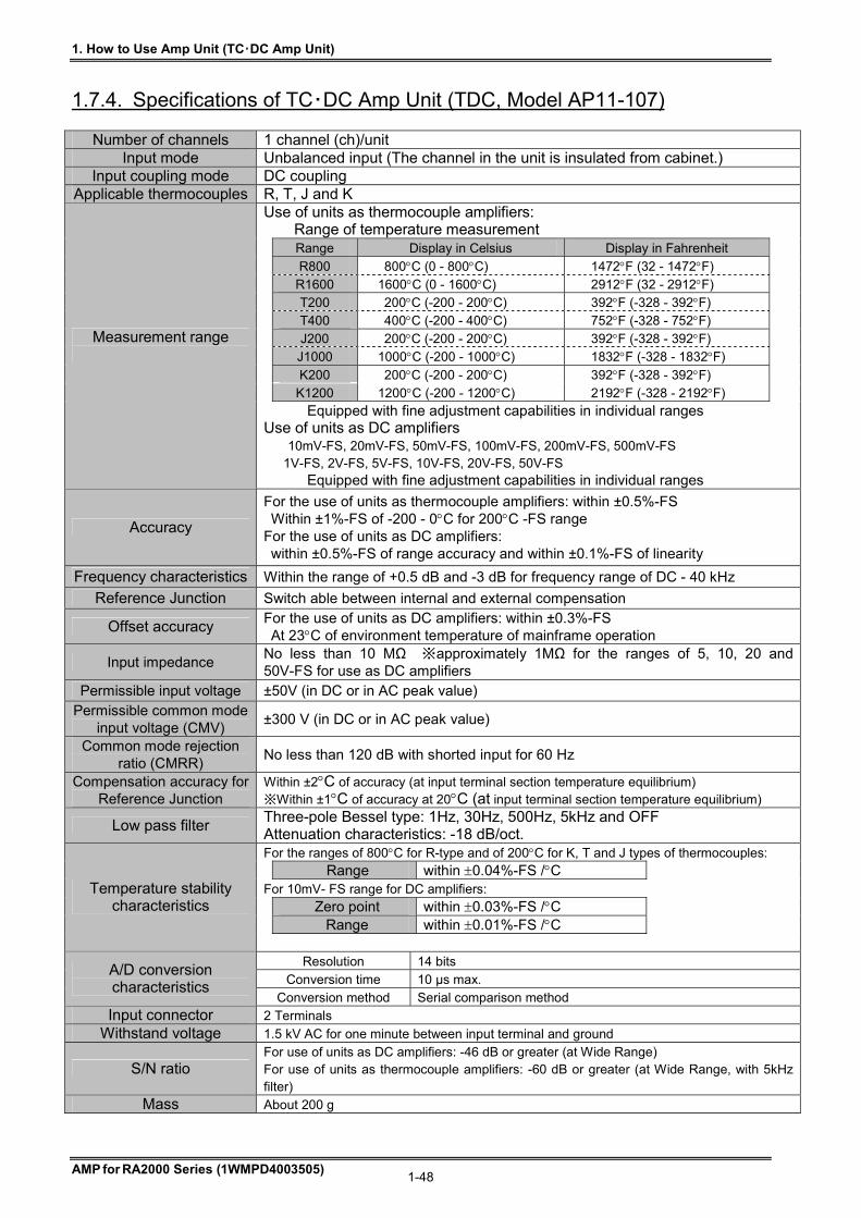
1. How to Use Amp Unit (TC・DC Amp Unit)
AMP for RA2000 Series (1WMPD4003505) 1-48
1.7.4. Specifications of TC・DC Amp Unit (TDC, Model AP11-107)
Number of channels 1 channel (ch)/unit Input mode Unbalanced input (The channel in the unit is insulated from cabinet.)
Input coupling mode DC coupling Applicable thermocouples R, T, J and K
Use of units as thermocouple amplifiers: Range of temperature measurement Range Display in Celsius Display in Fahrenheit
R800 800C (0 - 800C) 1472F (32 - 1472F) R1600 1600C (0 - 1600C) 2912F (32 - 2912F) T200 200C (-200 - 200C) 392F (-328 - 392F) T400 400C (-200 - 400C) 752F (-328 - 752F) J200 200C (-200 - 200C) 392F (-328 - 392F) J1000 1000C (-200 - 1000C) 1832F (-328 - 1832F)
K200 200C (-200 - 200C) 392F (-328 - 392F)
K1200 1200C (-200 - 1200C) 2192F (-328 - 2192F)
Measurement range
Equipped with fine adjustment capabilities in individual ranges Use of units as DC amplifiers 10mV-FS, 20mV-FS, 50mV-FS, 100mV-FS, 200mV-FS, 500mV-FS
1V-FS, 2V-FS, 5V-FS, 10V-FS, 20V-FS, 50V-FS Equipped with fine adjustment capabilities in individual ranges
Accuracy
For the use of units as thermocouple amplifiers: within ±0.5%-FS Within ±1%-FS of -200 - 0C for 200C -FS range
For the use of units as DC amplifiers: within ±0.5%-FS of range accuracy and within ±0.1%-FS of linearity
Frequency characteristics Within the range of +0.5 dB and -3 dB for frequency range of DC - 40 kHz
Reference Junction Switch able between internal and external compensation
Offset accuracy For the use of units as DC amplifiers: within ±0.3%-FS At 23C of environment temperature of mainframe operation
Input impedance No less than 10 MΩ ※approximately 1MΩ for the ranges of 5, 10, 20 and 50V-FS for use as DC amplifiers
Permissible input voltage ±50V (in DC or in AC peak value) Permissible common mode
input voltage (CMV) ±300 V (in DC or in AC peak value)
Common mode rejection ratio (CMRR)
No less than 120 dB with shorted input for 60 Hz
Compensation accuracy for Reference Junction
Within ±2C of accuracy (at input terminal section temperature equilibrium) ※Within ±1C of accuracy at 20C (at input terminal section temperature equilibrium)
Low pass filter Three-pole Bessel type: 1Hz, 30Hz, 500Hz, 5kHz and OFF Attenuation characteristics: -18 dB/oct. For the ranges of 800C for R-type and of 200C for K, T and J types of thermocouples: Range within 0.04%-FS /C For 10mV- FS range for DC amplifiers:
Zero point within 0.03%-FS /C
Range within 0.01%-FS /C
Temperature stability characteristics
Resolution 14 bits
Conversion time 10 µs max. A/D conversion characteristics
Conversion method Serial comparison method Input connector 2 Terminals
Withstand voltage 1.5 kV AC for one minute between input terminal and ground
S/N ratio For use of units as DC amplifiers: -46 dB or greater (at Wide Range) For use of units as thermocouple amplifiers: -60 dB or greater (at Wide Range, with 5kHz filter)
Mass About 200 g
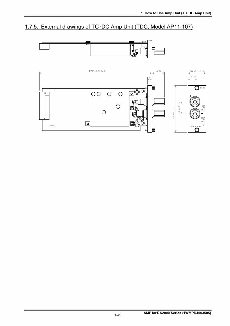
1. How to Use Amp Unit (TC・DC Amp Unit)
AMP for RA2000 Series (1WMPD4003505) 1-49
1.7.5. External drawings of TC・DC Amp Unit (TDC, Model AP11-107)
AP11-107
TC・DC AMP
MAXPK
300V
MAXPK50V
28.8±0.3
14.4
75±
0.3
19±
0.1
179.8±0.5
7
(20)
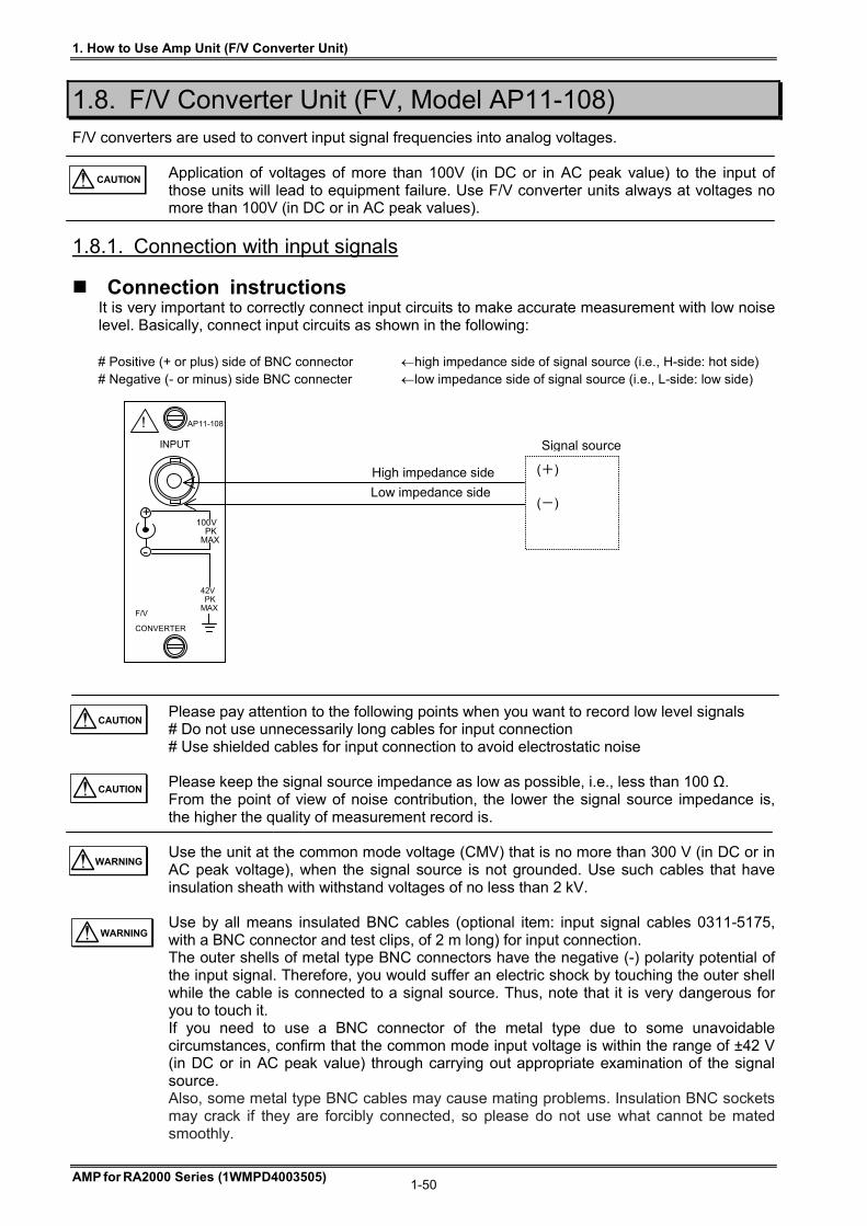
1. How to Use Amp Unit (F/V Converter Unit)
AMP for RA2000 Series (1WMPD4003505) 1-50
1.8. F/V Converter Unit (FV, Model AP11-108) F/V converters are used to convert input signal frequencies into analog voltages.
Application of voltages of more than 100V (in DC or in AC peak value) to the input of those units will lead to equipment failure. Use F/V converter units always at voltages no more than 100V (in DC or in AC peak values).
1.8.1. Connection with input signals
Connection instructions It is very important to correctly connect input circuits to make accurate measurement with low noise level. Basically, connect input circuits as shown in the following: # Positive (+ or plus) side of BNC connector high impedance side of signal source (i.e., H-side: hot side) # Negative (- or minus) side BNC connecter low impedance side of signal source (i.e., L-side: low side)
Please pay attention to the following points when you want to record low level signals # Do not use unnecessarily long cables for input connection # Use shielded cables for input connection to avoid electrostatic noise
Please keep the signal source impedance as low as possible, i.e., less than 100 Ω. From the point of view of noise contribution, the lower the signal source impedance is, the higher the quality of measurement record is.
Use the unit at the common mode voltage (CMV) that is no more than 300 V (in DC or in AC peak voltage), when the signal source is not grounded. Use such cables that have insulation sheath with withstand voltages of no less than 2 kV.
Use by all means insulated BNC cables (optional item: input signal cables 0311-5175, with a BNC connector and test clips, of 2 m long) for input connection. The outer shells of metal type BNC connectors have the negative (-) polarity potential of the input signal. Therefore, you would suffer an electric shock by touching the outer shell while the cable is connected to a signal source. Thus, note that it is very dangerous for you to touch it. If you need to use a BNC connector of the metal type due to some unavoidable circumstances, confirm that the common mode input voltage is within the range of ±42 V (in DC or in AC peak value) through carrying out appropriate examination of the signal source. Also, some metal type BNC cables may cause mating problems. Insulation BNC sockets may crack if they are forcibly connected, so please do not use what cannot be mated smoothly.
CAUTION
WARNING
CAUTION
CAUTION
WARNING
Signal source
High impedance side
Low impedance side
100V PK MAX
42V PK MAX
AP11-108
F/V
CONVERTER
INPUT
+
-
!
(+) (-)
1. How to Use Amp Unit (F/V Converter Unit)
AMP for RA2000 Series (1WMPD4003505) 1-51
Input signals
Maximum input voltage The maximum permissible input voltage is 100 V (in DC or in AC peak values). If you apply, by error, an input voltage exceeding 100 V (in DC or in AC peak value), this will lead to equipment failure caused by breakdown of parts that are used internal to the unit. Permissible common mode input voltage (CMV) Use insulated BNC cables for input connection by all means, which may be attached as an optional item. Be careful to maintain the common mode input voltage (CMV) at no more than 300V (in DC or in AC peak value). Also, note that input frequencies may not always be correctly converted to analog values due to degradation of common mode rejection ratio (CMRR), when noise-like impulsive common mode voltages are applied. Do not apply input voltages exceeding the specified permissible common mode input voltage of 300 V, peak value. This is because application of such voltages would lead to malfunctions of equipment.
Ranges of operational input voltages and frequencies Be careful that measurement results will involve errors if you apply input voltages that are outside the frequency range of 0.3 - 30 V, peak-to-peak. Also, note that the specified input frequency range is 1 Hz - 10 kHz.
Detection of the input frequency is done at the instant the input signal pass through the trigger level. Therefore, the input waveform should always to be fluctuating around the voltage level of approximately 0.1 V to perform frequency measurement.
Input impedance The input impedance is always 100 k approximately. # Maintain the input voltages within the range of -12V - +12V when using the equipment. # Normal and correct measurement cannot be expected if the input voltage exceeds the
range above.
WARNING
CAUTION
NOTE
WARNING
CAUTION
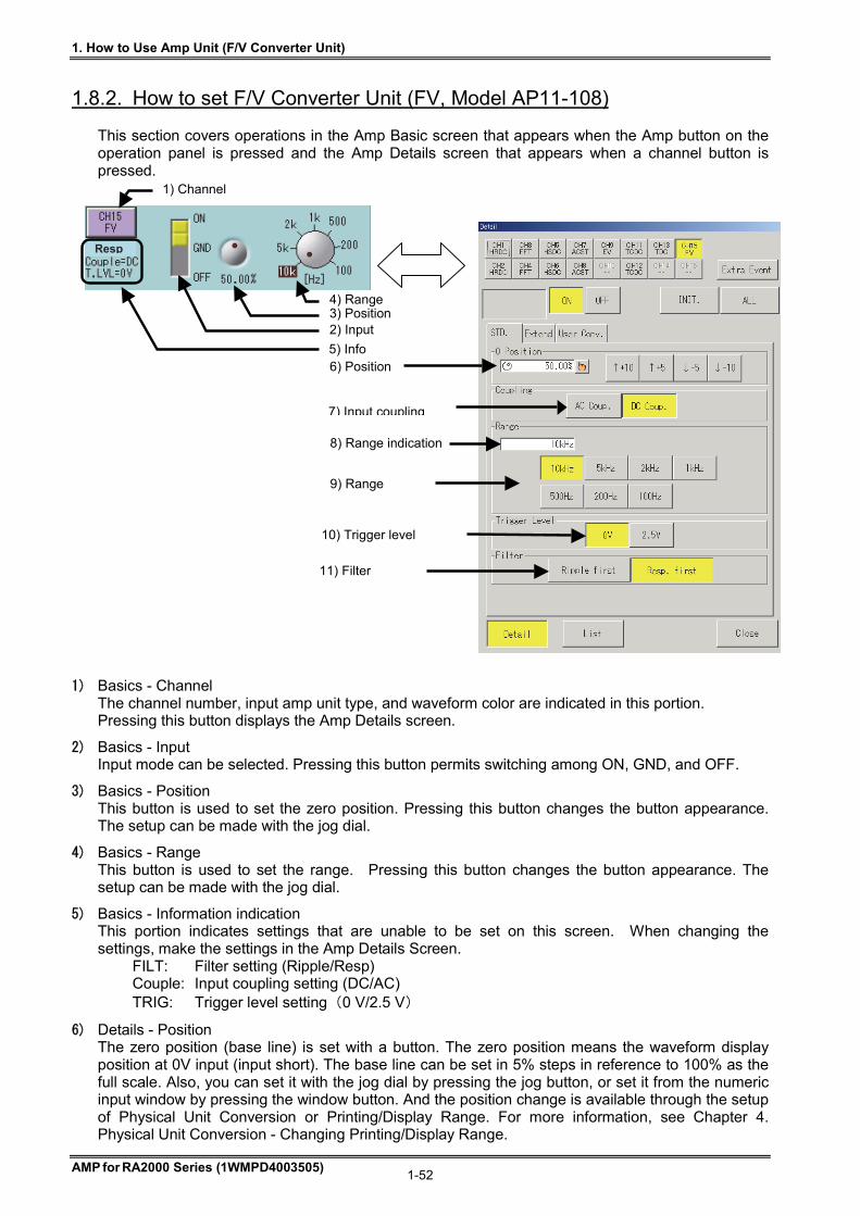
1. How to Use Amp Unit (F/V Converter Unit)
AMP for RA2000 Series (1WMPD4003505) 1-52
1.8.2. How to set F/V Converter Unit (FV, Model AP11-108) This section covers operations in the Amp Basic screen that appears when the Amp button on the operation panel is pressed and the Amp Details screen that appears when a channel button is pressed.
1) Basics - Channel The channel number, input amp unit type, and waveform color are indicated in this portion. Pressing this button displays the Amp Details screen.
2) Basics - Input Input mode can be selected. Pressing this button permits switching among ON, GND, and OFF.
3) Basics - Position This button is used to set the zero position. Pressing this button changes the button appearance. The setup can be made with the jog dial.
4) Basics - Range This button is used to set the range. Pressing this button changes the button appearance. The setup can be made with the jog dial.
5) Basics - Information indication This portion indicates settings that are unable to be set on this screen. When changing the settings, make the settings in the Amp Details Screen.
FILT: Filter setting (Ripple/Resp) Couple: Input coupling setting (DC/AC) TRIG: Trigger level setting (0 V/2.5 V)
6) Details - Position The zero position (base line) is set with a button. The zero position means the waveform display position at 0V input (input short). The base line can be set in 5% steps in reference to 100% as the full scale. Also, you can set it with the jog dial by pressing the jog button, or set it from the numeric input window by pressing the window button. And the position change is available through the setup of Physical Unit Conversion or Printing/Display Range. For more information, see Chapter 4. Physical Unit Conversion - Changing Printing/Display Range.
9) Range
8) Range indication
11) Filter
7) Input coupling
6) Position
10) Trigger level
1) Channel
4) Range 3) Position 2) Input
5) Info
Resp
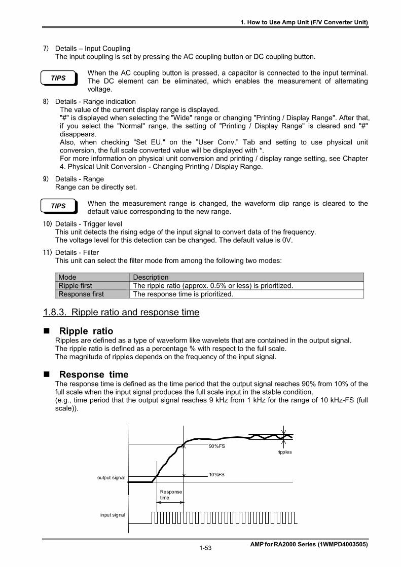
1. How to Use Amp Unit (F/V Converter Unit)
AMP for RA2000 Series (1WMPD4003505) 1-53
7) Details – Input Coupling The input coupling is set by pressing the AC coupling button or DC coupling button.
When the AC coupling button is pressed, a capacitor is connected to the input terminal. The DC element can be eliminated, which enables the measurement of alternating voltage.
8) Details - Range indication The value of the current display range is displayed. "#" is displayed when selecting the "Wide" range or changing "Printing / Display Range". After that, if you select the "Normal" range, the setting of "Printing / Display Range" is cleared and "#" disappears. Also, when checking "Set EU." on the ”User Conv.” Tab and setting to use physical unit conversion, the full scale converted value will be displayed with *. For more information on physical unit conversion and printing / display range setting, see Chapter 4. Physical Unit Conversion - Changing Printing / Display Range.
9) Details - Range Range can be directly set.
When the measurement range is changed, the waveform clip range is cleared to the default value corresponding to the new range.
10) Details - Trigger level This unit detects the rising edge of the input signal to convert data of the frequency. The voltage level for this detection can be changed. The default value is 0V.
11) Details - Filter This unit can select the filter mode from among the following two modes: Mode Description Ripple first The ripple ratio (approx. 0.5% or less) is prioritized. Response first The response time is prioritized.
1.8.3. Ripple ratio and response time
Ripple ratio Ripples are defined as a type of waveform like wavelets that are contained in the output signal. The ripple ratio is defined as a percentage % with respect to the full scale. The magnitude of ripples depends on the frequency of the input signal.
Response time The response time is defined as the time period that the output signal reaches 90% from 10% of the full scale when the input signal produces the full scale input in the stable condition. (e.g., time period that the output signal reaches 9 kHz from 1 kHz for the range of 10 kHz-FS (full scale)).
TIPS
TIPS
output signal 1 0 % F S
input signal
Response time
ripples 90 % F S
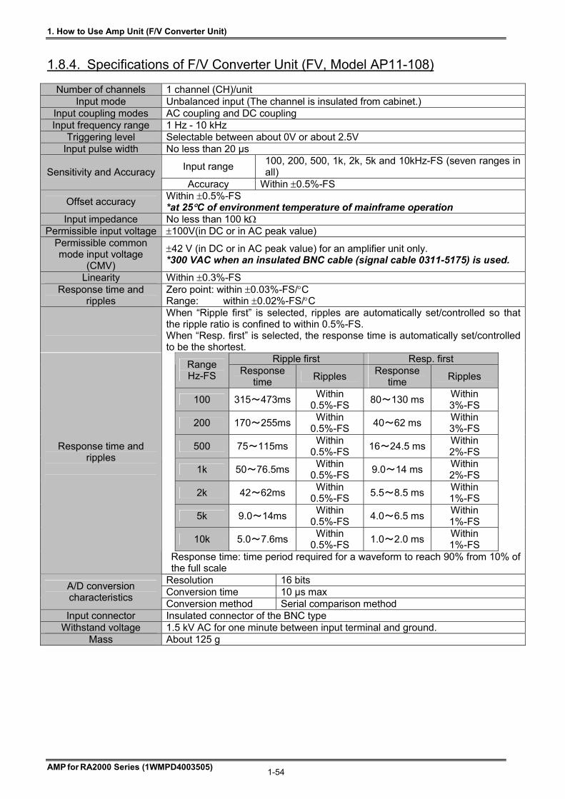
1. How to Use Amp Unit (F/V Converter Unit)
AMP for RA2000 Series (1WMPD4003505) 1-54
1.8.4. Specifications of F/V Converter Unit (FV, Model AP11-108)
Number of channels 1 channel (CH)/unit Input mode Unbalanced input (The channel is insulated from cabinet.)
Input coupling modes AC coupling and DC coupling Input frequency range 1 Hz - 10 kHz
Triggering level Selectable between about 0V or about 2.5V Input pulse width No less than 20 µs
Input range 100, 200, 500, 1k, 2k, 5k and 10kHz-FS (seven ranges in all) Sensitivity and Accuracy
Accuracy Within 0.5%-FS
Offset accuracy Within 0.5%-FS *at 25C of environment temperature of mainframe operation
Input impedance No less than 100 k Permissible input voltage 100V(in DC or in AC peak value)
Permissible common mode input voltage
(CMV)
42 V (in DC or in AC peak value) for an amplifier unit only. *300 VAC when an insulated BNC cable (signal cable 0311-5175) is used.
Linearity Within 0.3%-FS Response time and
ripples Zero point: within 0.03%-FS/C Range: within 0.02%-FS/C
When “Ripple first” is selected, ripples are automatically set/controlled so that the ripple ratio is confined to within 0.5%-FS. When “Resp. first” is selected, the response time is automatically set/controlled to be the shortest.
Ripple first Resp. first Range Hz-FS Response
time Ripples
Response time
Ripples
100 315~473ms Within
0.5%-FS 80~130 ms
Within 3%-FS
200 170~255ms Within
0.5%-FS 40~62 ms
Within 3%-FS
500 75~115ms Within
0.5%-FS 16~24.5 ms
Within 2%-FS
1k 50~76.5ms Within
0.5%-FS 9.0~14 ms
Within 2%-FS
2k 42~62ms Within
0.5%-FS 5.5~8.5 ms
Within 1%-FS
5k 9.0~14ms Within
0.5%-FS 4.0~6.5 ms
Within 1%-FS
10k 5.0~7.6ms Within
0.5%-FS 1.0~2.0 ms
Within 1%-FS
Response time and ripples
Response time: time period required for a waveform to reach 90% from 10% of the full scale
Resolution 16 bits Conversion time 10 µs max
A/D conversion characteristics
Conversion method Serial comparison method Input connector Insulated connector of the BNC type
Withstand voltage 1.5 kV AC for one minute between input terminal and ground. Mass About 125 g

1. How to Use Amp Unit (F/V Converter Unit)
AMP for RA2000 Series (1WMPD4003505) 1-55
1.8.5. External drawings of F/V Converter Unit (FV, Model AP11-108)
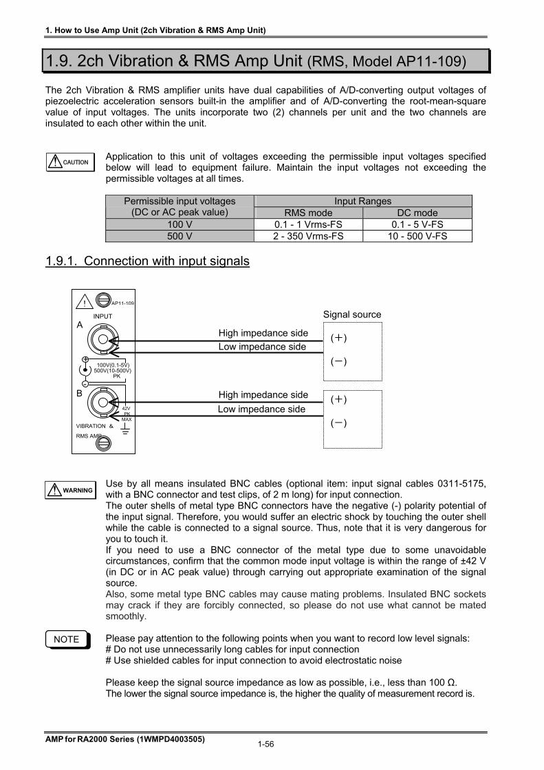
1. How to Use Amp Unit (2ch Vibration & RMS Amp Unit)
AMP for RA2000 Series (1WMPD4003505) 1-56
1.9. 2ch Vibration & RMS Amp Unit (RMS, Model AP11-109) The 2ch Vibration & RMS amplifier units have dual capabilities of A/D-converting output voltages of piezoelectric acceleration sensors built-in the amplifier and of A/D-converting the root-mean-square value of input voltages. The units incorporate two (2) channels per unit and the two channels are insulated to each other within the unit.
Application to this unit of voltages exceeding the permissible input voltages specified below will lead to equipment failure. Maintain the input voltages not exceeding the permissible voltages at all times.
Input Ranges Permissible input voltages
(DC or AC peak value) RMS mode DC mode 100 V 0.1 - 1 Vrms-FS 0.1 - 5 V-FS 500 V 2 - 350 Vrms-FS 10 - 500 V-FS
1.9.1. Connection with input signals
Use by all means insulated BNC cables (optional item: input signal cables 0311-5175, with a BNC connector and test clips, of 2 m long) for input connection. The outer shells of metal type BNC connectors have the negative (-) polarity potential of the input signal. Therefore, you would suffer an electric shock by touching the outer shell while the cable is connected to a signal source. Thus, note that it is very dangerous for you to touch it. If you need to use a BNC connector of the metal type due to some unavoidable circumstances, confirm that the common mode input voltage is within the range of ±42 V (in DC or in AC peak value) through carrying out appropriate examination of the signal source. Also, some metal type BNC cables may cause mating problems. Insulated BNC sockets may crack if they are forcibly connected, so please do not use what cannot be mated smoothly. Please pay attention to the following points when you want to record low level signals: # Do not use unnecessarily long cables for input connection # Use shielded cables for input connection to avoid electrostatic noise Please keep the signal source impedance as low as possible, i.e., less than 100 Ω. The lower the signal source impedance is, the higher the quality of measurement record is.
CAUTION
NOTE
(+) (-)
(+) (-)
Signal source
High impedance side
Low impedance side
High impedance side
Low impedance side
100V(0.1-5V) 500V(10-500V) PK
42V PK MAX
AP11-109
VIBRATION &
RMS AMP
INPUT
+
-
!
A
B
WARNING
1. How to Use Amp Unit (2ch Vibration & RMS Amp Unit)
AMP for RA2000 Series (1WMPD4003505) 1-57
CAUTION
Input Signals
Permissible input voltages If a voltage higher than the rated voltage is input, this unit may be damaged due to internal damage such as component breakdown. Make sure that the input voltage does not exceed the following permissible input voltage for each input range. Sensitivity ranges (V in FS) 0.1, 0.2, 0.5, 1, 2, 5 10, 20, 50, 100, 200, 500 Permissible input voltages (V) 100 V 500 V
Input impedance The input impedance is approximately one (1) M. However, note that the input impedance will be lowered to approximately 15 k, when the input voltage becomes 8 V or more for the input sensitivity ranges of 0.1 - 5 V-FS (full-scale) in the DC coupling mode. Permissible common mode input voltages (CMV) Use the insulated BNC cable, an optional item. In this case, confirm that the permissible common mode input voltage is no more than 300 V in DC or in AC peak value.
In the vibration mode and the vibration RMS mode, a constant-current of 2 mA is fed into the load from the input connector of the amplifier unit. (Voltages of more than 18 V can be exhibited at the connector.) Do not connect any sensors other than the types of sensors that are specified for the use with this amplifier. Otherwise, the sensors may be damaged. In the vibration mode, do not apply voltages. Application of voltages of 30 V or more at the input would induce amplifier failures. Use cables having the insulation sheath of no less than 2 kV of withstand voltages. Do not apply voltages exceeding the permissible common mode input voltage, since application of such voltages would lead to malfunctions or failures of equipment. Also, note that recordings may involve noise components due to degradation of common mode rejection ratio (CMRR), when noise-like impulsive common mode voltages are applied. Use the equipment through keeping the input voltage within the range of -30V - +30V including the DC component, when the sensitivity range is one of 0.1 - 5 V-FS in the AC coupling mode. Note that correct measurement cannot be expected when the input voltage exceeds the voltage range mentioned above. The sampling speed must be set at 10μs steps, otherwise the signal waveform cannot be obtained correctly. Example: 5 μs or 11 μs, etc. makes the waveform distort.
CAUTION
NOTE
NOTE
NOTE
CAUTION
CAUTION
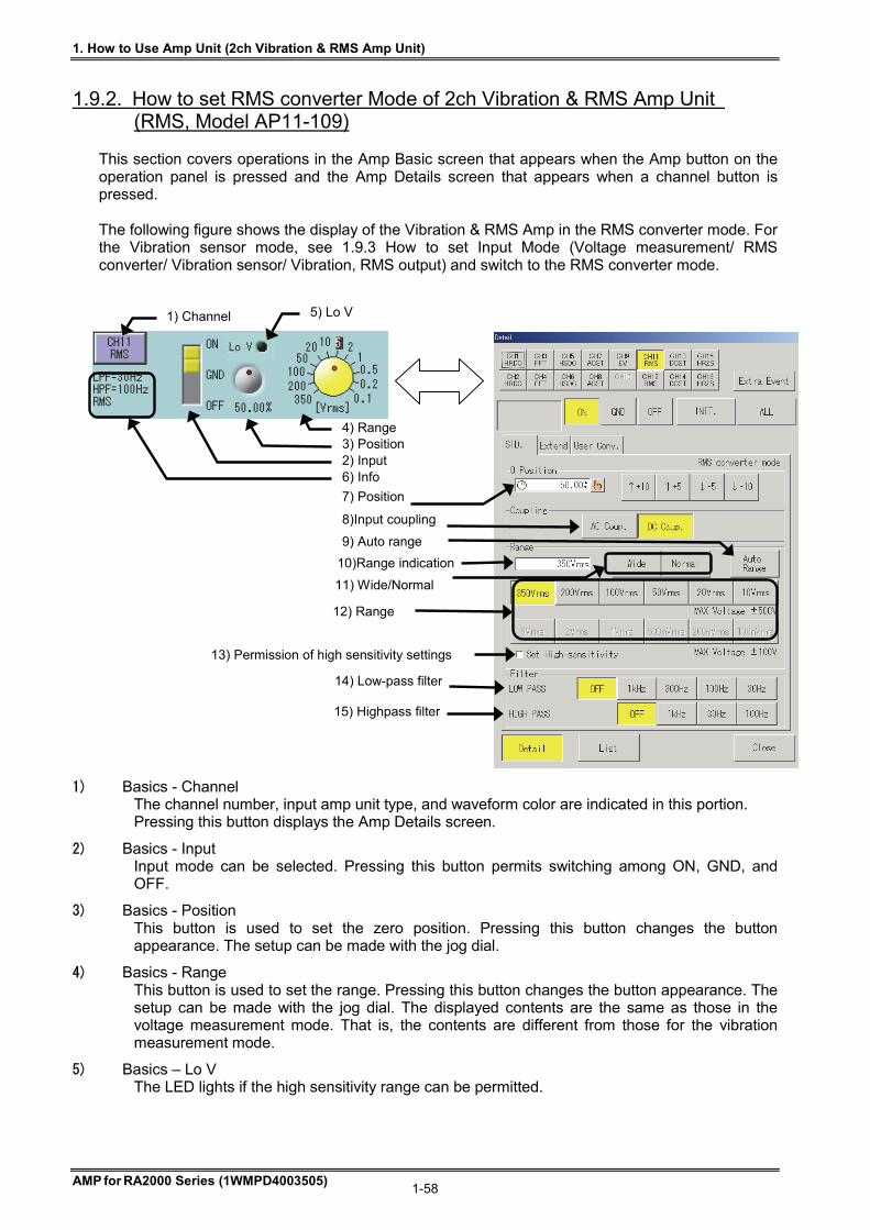
1. How to Use Amp Unit (2ch Vibration & RMS Amp Unit)
AMP for RA2000 Series (1WMPD4003505) 1-58
1.9.2. How to set RMS converter Mode of 2ch Vibration & RMS Amp Unit (RMS, Model AP11-109)
This section covers operations in the Amp Basic screen that appears when the Amp button on the operation panel is pressed and the Amp Details screen that appears when a channel button is pressed. The following figure shows the display of the Vibration & RMS Amp in the RMS converter mode. For the Vibration sensor mode, see 1.9.3 How to set Input Mode (Voltage measurement/ RMS converter/ Vibration sensor/ Vibration, RMS output) and switch to the RMS converter mode.
1) Basics - Channel The channel number, input amp unit type, and waveform color are indicated in this portion. Pressing this button displays the Amp Details screen.
2) Basics - Input Input mode can be selected. Pressing this button permits switching among ON, GND, and OFF.
3) Basics - Position This button is used to set the zero position. Pressing this button changes the button appearance. The setup can be made with the jog dial.
4) Basics - Range This button is used to set the range. Pressing this button changes the button appearance. The setup can be made with the jog dial. The displayed contents are the same as those in the voltage measurement mode. That is, the contents are different from those for the vibration measurement mode.
5) Basics – Lo V The LED lights if the high sensitivity range can be permitted.
10)Range indication
7) Position
8)Input coupling
9) Auto range
12) Range
13) Permission of high sensitivity settings
14) Low-pass filter
11) Wide/Normal
15) Highpass filter
1) Channel
6) Info
4) Range 3) Position 2) Input
5) Lo V
1. How to Use Amp Unit (2ch Vibration & RMS Amp Unit)
AMP for RA2000 Series (1WMPD4003505) 1-59
6) Basics - Information indication This portion indicates settings that are unable to be set on this screen. When changing the settings, make the settings in the Amp Details screen. LPF: Low Pass Filter setting HPF: High Pass Filter setting Input Mode setting (DC/RMS/Vibration)
7) Details - Position The zero position (base line) is set with a button. The zero position means the waveform display position at 0V input (input short). The base line can be set in 5% steps in reference to 100% as the full scale. Also, you can set it with the jog dial by pressing the jog button, or set it from the numeric input window by pressing the window button. And the position change is available through the setup of Physical Unit Conversion or Printing/Display Range. For more information, see Chapter 4. Physical Unit Conversion – Changing Printing/Display Range.
8) Details – Input coupling The input coupling is set by pressing the AC coupling button or DC coupling button.
When the AC coupling button is pressed, a capacitor is connected to the input terminal. The DC component can be eliminated, which enables the measurement of alternating voltage.
9) Details - Auto range The range is automatically adjusted to the input signal.
10) Details - Range indication The value of the current display range is displayed. "#" is displayed when selecting the "Wide" range or changing "Printing / Display Range". After that, if you select the "Normal" range, the setting of "Printing / Display Range" is cleared and "#" disappears. Also, when checking "Set EU." on the ”User Conv.” Tab and setting to use physical unit conversion, the full scale converted value will be displayed with *. For more information on physical unit conversion and printing / display range setting, see Chapter 4. Physical Unit Conversion - Changing Printing / Display Range.
11) Details - Wide/Normal Wide: Entire measuring range is displayed. Normal: Half of the measuring range is displayed (Default).
12) Details – Range Range can be directly set.
When the measurement range is changed, the waveform clip range is cleared to the default value corresponding to the new range. Example: During expansion of the waveform in the waveform clip range between +40 and -40 at 100 V, if the range is set to 100 V again, the waveform clip range is set to between +50 to -50 as the default. (Enlarged display is cancelled.)
Pay attention to the permissible input voltage when setting the range. See Permissible input voltages in “Input Signals”.
13) Details - Permission of high sensitivity settings Settings to the high-sensitivity range (5 V to 100 mV) can be prohibited/permitted. When using the high-sensitivity range, check the check box. When the high-sensitivity range is not used, prohibition of the high-sensitivity range without checking the box is recommended for safety.
14) Details - Low-pass filter This button is used to set the low-pass filter.
15) Details - High-pass filter This button is used to set the high-pass filter.
CAUTION
TIPS
TIPS
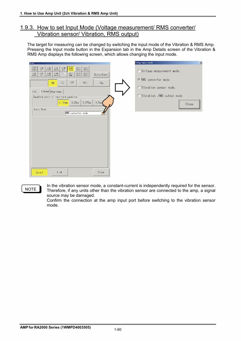
1. How to Use Amp Unit (2ch Vibration & RMS Amp Unit)
AMP for RA2000 Series (1WMPD4003505) 1-60
1.9.3. How to set Input Mode (Voltage measurement/ RMS converter/ Vibration sensor/ Vibration, RMS output)
The target for measuring can be changed by switching the input mode of the Vibration & RMS Amp. Pressing the Input mode button in the Expansion tab in the Amp Details screen of the Vibration & RMS Amp displays the following screen, which allows changing the input mode.
In the vibration sensor mode, a constant-current is independently required for the sensor. Therefore, if any units other than the vibration sensor are connected to the amp, a signal source may be damaged. Confirm the connection at the amp input port before switching to the vibration sensor mode.
NOTE
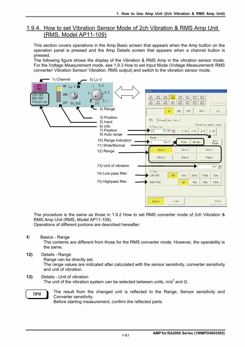
1. How to Use Amp Unit (2ch Vibration & RMS Amp Unit)
AMP for RA2000 Series (1WMPD4003505) 1-61
1.9.4. How to set Vibration Sensor Mode of 2ch Vibration & RMS Amp Unit (RMS, Model AP11-109)
This section covers operations in the Amp Basic screen that appears when the Amp button on the operation panel is pressed and the Amp Details screen that appears when a channel button is pressed. The following figure shows the display of the Vibration & RMS Amp in the vibration sensor mode. For the Voltage Measurement mode, see 1.9.3 How to set Input Mode (Voltage Measurement/ RMS converter/ Vibration Sensor/ Vibration, RMS output) and switch to the vibration sensor mode. The procedure is the same as those in 1.9.2 How to set RMS converter mode of 2ch Vibration & RMS Amp Unit (RMS, Model AP11-109). Operations of different portions are described hereafter:
4) Basics - Range The contents are different from those for the RMS converter mode. However, the operability is the same.
12) Details - Range Range can be directly set. The range values are indicated after calculated with the sensor sensitivity, converter sensitivity and unit of vibration.
13) Details - Unit of vibration The unit of the vibration system can be selected between units, m/s2 and G.
The result from the changed unit is reflected to the Range, Sensor sensitivity and Converter sensitivity. Before starting measurement, confirm the reflected parts.
TIPS
1) Channel
6) Info
4) Range
3) Position 2) Input
10) Range indication
7) Position 9) Auto range
12) Range
13) Unit of vibration
11) Wide/Normal
14) Low pass filter 15) Highpass filter
5) Lo V
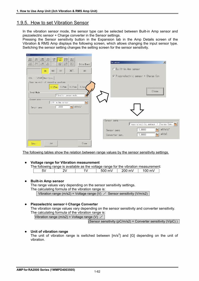
1. How to Use Amp Unit (2ch Vibration & RMS Amp Unit)
AMP for RA2000 Series (1WMPD4003505) 1-62
1.9.5. How to set Vibration Sensor In the vibration sensor mode, the sensor type can be selected between Built-in Amp sensor and piezoelectric sensor + Charge converter in the Sensor settings. Pressing the Sensor sensitivity button in the Expansion tab in the Amp Details screen of the Vibration & RMS Amp displays the following screen, which allows changing the input sensor type. Switching the sensor setting changes the setting screen for the sensor sensitivity. The following tables show the relation between range values by the sensor sensitivity settings.
Voltage range for Vibration measurement The following range is available as the voltage range for the vibration measurement:
5V 2V 1V 500 mV 200 mV 100 mV
Built-in Amp sensor The range values vary depending on the sensor sensitivity settings. The calculating formula of the vibration range is:
Vibration range (m/s2) = Voltage range (V) / Sensor sensitivity (V/m/s2)
Piezoelectric sensor+Charge Converter The vibration range values vary depending on the sensor sensitivity and converter sensitivity. The calculating formula of the vibration range is:
Vibration range (m/s2) = Voltage range (V) / (Sensor sensitivity (pC/m/s2) × Converter sensitivity (V/pC) )
Unit of vibration range The unit of vibration range is switched between [m/s2] and [G] depending on the unit of vibration.
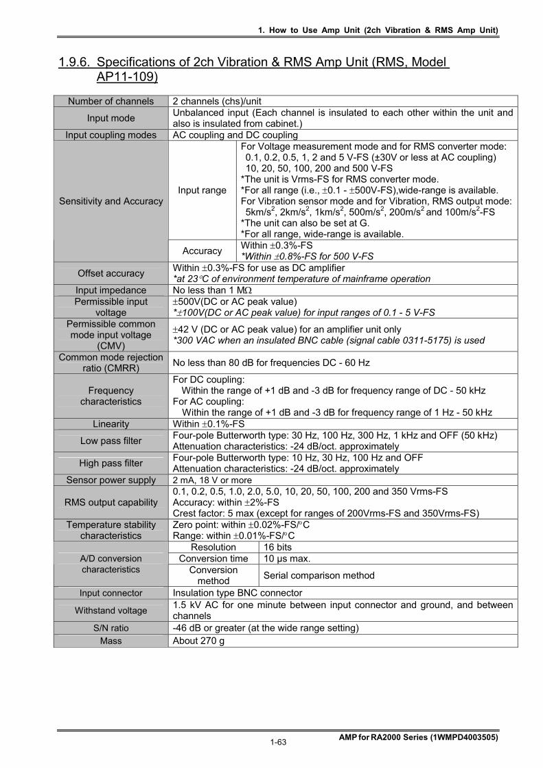
1. How to Use Amp Unit (2ch Vibration & RMS Amp Unit)
AMP for RA2000 Series (1WMPD4003505) 1-63
1.9.6. Specifications of 2ch Vibration & RMS Amp Unit (RMS, Model AP11-109)
Number of channels 2 channels (chs)/unit
Input mode Unbalanced input (Each channel is insulated to each other within the unit and also is insulated from cabinet.)
Input coupling modes AC coupling and DC coupling
Input range
For Voltage measurement mode and for RMS converter mode: 0.1, 0.2, 0.5, 1, 2 and 5 V-FS (±30V or less at AC coupling) 10, 20, 50, 100, 200 and 500 V-FS *The unit is Vrms-FS for RMS converter mode. *For all range (i.e., 0.1 - 500V-FS),wide-range is available. For Vibration sensor mode and for Vibration, RMS output mode: 5km/s2, 2km/s2, 1km/s2, 500m/s2, 200m/s2 and 100m/s2-FS *The unit can also be set at G. *For all range, wide-range is available.
Sensitivity and Accuracy
Accuracy Within 0.3%-FS *Within 0.8%-FS for 500 V-FS
Offset accuracy Within 0.3%-FS for use as DC amplifier *at 23C of environment temperature of mainframe operation
Input impedance No less than 1 M Permissible input
voltage 500V(DC or AC peak value) *100V(DC or AC peak value) for input ranges of 0.1 - 5 V-FS
Permissible common mode input voltage
(CMV)
42 V (DC or AC peak value) for an amplifier unit only *300 VAC when an insulated BNC cable (signal cable 0311-5175) is used
Common mode rejection ratio (CMRR)
No less than 80 dB for frequencies DC - 60 Hz
Frequency characteristics
For DC coupling: Within the range of +1 dB and -3 dB for frequency range of DC - 50 kHz
For AC coupling: Within the range of +1 dB and -3 dB for frequency range of 1 Hz - 50 kHz
Linearity Within 0.1%-FS
Low pass filter Four-pole Butterworth type: 30 Hz, 100 Hz, 300 Hz, 1 kHz and OFF (50 kHz) Attenuation characteristics: -24 dB/oct. approximately
High pass filter Four-pole Butterworth type: 10 Hz, 30 Hz, 100 Hz and OFF Attenuation characteristics: -24 dB/oct. approximately
Sensor power supply 2 mA, 18 V or more
RMS output capability 0.1, 0.2, 0.5, 1.0, 2.0, 5.0, 10, 20, 50, 100, 200 and 350 Vrms-FS Accuracy: within 2%-FS Crest factor: 5 max (except for ranges of 200Vrms-FS and 350Vrms-FS)
Temperature stability characteristics
Zero point: within 0.02%-FS/C Range: within 0.01%-FS/C
Resolution 16 bits Conversion time 10 µs max. A/D conversion
characteristics Conversion method
Serial comparison method
Input connector Insulation type BNC connector
Withstand voltage 1.5 kV AC for one minute between input connector and ground, and between channels
S/N ratio -46 dB or greater (at the wide range setting) Mass About 270 g

1. How to Use Amp Unit (2ch Vibration & RMS Amp Unit)
AMP for RA2000 Series (1WMPD4003505) 1-64
1.9.7. External drawings of 2ch Vibration & RMS Amp Unit (RMS, Model AP11-109)

1. How to Use Amp Unit (2ch DC Strain Amp Unit)
AMP for RA2000 Series (1WMPD4003505) 1-65
1.10. 2ch DC Strain Amp Unit (DCST, Model AP11-110) The 2ch DC Strain Amp unit connects a strain gage type transducer and a bridge box connected with a strain gauge to the input and A / D converts its minute output signal to 16-bit high resolution data. The units incorporate two (2) channels per unit and the two channels are insulated to each other within the unit.
1.10.1. Connection with input signals
Connection instructions The diagrams/figures below show the input section of the 2ch DC Strain Amp unit. Strain gauge type transducers or bridge boxes are connected to the input connector. When the unit is used as a DC amplifier, the terminals of B (- input), D (+ input) and E (shield/ground), are used. Use the cable (47228) dedicated to the connection of the unit.
Notes on the use of the transducers Observe the following when you use the transducers:
# To tightly fix transducers at place by referring to the transducers instruction manual, since unstable fixation of the transducers will lead to equipment malfunctioning and/or noise generation.
# To prevent transducers and connecting cables from rain, water, etc, while they are humidity resistant in general.
# To use transducers that do not have connections between the ground (shield) terminal (E) and any of the other terminals (A, B, C and D) of this product.
# Not to place transducers and connecting cables in the environment with high electric or magnetic field.
# When the length of cables connecting this product to the bridge box or transducers is large, you will have measured values substantially lower than the actual value by the amount of voltage drop of bridge source due to line resistance. The error caused by the voltage drop can be corrected by using the following table listing bridge voltage drop factors.
Bridge voltage drop factors (approximate in %):
Length of cable between this product and bridge box (Wire type: AWG20, at +20C)
Bridge resistance
() 20 m 50 m 100 m 200 m 120 - 1.2 - 3.0 - 5.8 - 11.0 350 - 0.4 - 1.1 - 2.1 - 4.1 500 - 0.3 - 0.7 - 1.5 - 2.9 1 k - 0.1 - 0.4 - 0.7 - 1.5
NOTE
Connector diagram
Amp Side
Connector
pin layout
C
E
D
B
A +BV
-INPUT
COM
-BV
+INPUT
D
AB
C E
FG
Transducer Side
E
D
C
B
A + input
- output
- input
+ output
Ground (Shielding)
DC STR AMP
!
A INPUT
AP11-110
B INPUT
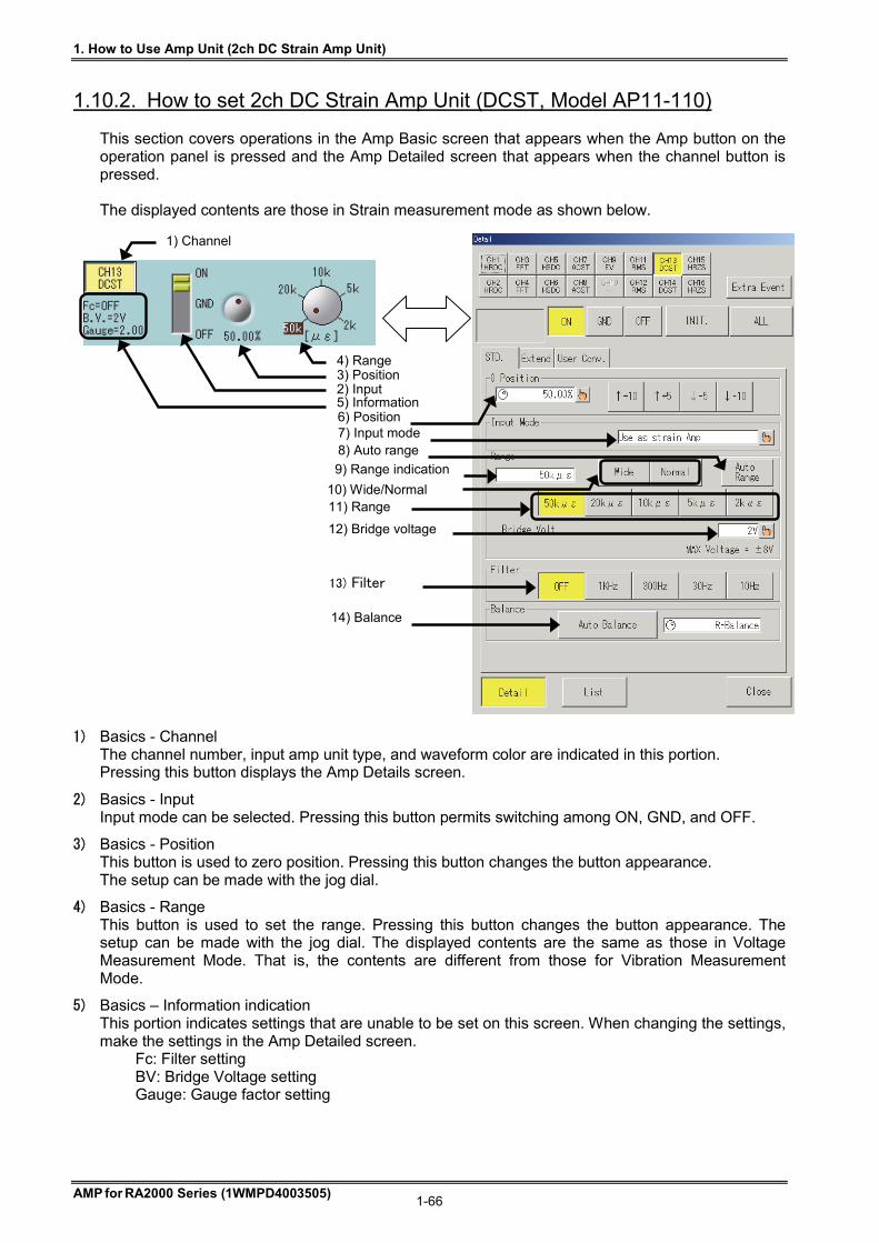
1. How to Use Amp Unit (2ch DC Strain Amp Unit)
AMP for RA2000 Series (1WMPD4003505) 1-66
1.10.2. How to set 2ch DC Strain Amp Unit (DCST, Model AP11-110) This section covers operations in the Amp Basic screen that appears when the Amp button on the operation panel is pressed and the Amp Detailed screen that appears when the channel button is pressed. The displayed contents are those in Strain measurement mode as shown below.
1) Basics - Channel The channel number, input amp unit type, and waveform color are indicated in this portion. Pressing this button displays the Amp Details screen.
2) Basics - Input Input mode can be selected. Pressing this button permits switching among ON, GND, and OFF.
3) Basics - Position This button is used to zero position. Pressing this button changes the button appearance. The setup can be made with the jog dial.
4) Basics - Range This button is used to set the range. Pressing this button changes the button appearance. The setup can be made with the jog dial. The displayed contents are the same as those in Voltage Measurement Mode. That is, the contents are different from those for Vibration Measurement Mode.
5) Basics – Information indication This portion indicates settings that are unable to be set on this screen. When changing the settings, make the settings in the Amp Detailed screen.
Fc: Filter setting BV: Bridge Voltage setting Gauge: Gauge factor setting
1) Channel
5) Information
4) Range 3) Position 2) Input
9) Range indication
6) Position7) Input mode8) Auto range
11) Range
14) Balance
13) Filter
12) Bridge voltage
10) Wide/Normal
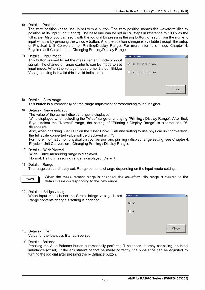
1. How to Use Amp Unit (2ch DC Strain Amp Unit)
AMP for RA2000 Series (1WMPD4003505) 1-67
6) Details - Position The zero position (base line) is set with a button. The zero position means the waveform display position at 0V input (input short). The base line can be set in 5% steps in reference to 100% as the full scale. Also, you can set it with the jog dial by pressing the jog button, or set it from the numeric input window by pressing the window button. And the position change is available through the setup of Physical Unit Conversion or Printing/Display Range. For more information, see Chapter 4. Physical Unit Conversion – Changing Printing/Display Range.
7) Details – Input mode This button is used to set the measurement mode of input signal. The change of range contents can be made to set input mode. When the voltage measurement is set, Bridge Voltage setting is invalid (No invalid indication).
8) Details – Auto range This button is automatically set the range adjustment corresponding to input signal.
9) Details - Range indication The value of the current display range is displayed. "#" is displayed when selecting the "Wide" range or changing "Printing / Display Range". After that, if you select the "Normal" range, the setting of "Printing / Display Range" is cleared and "#" disappears. Also, when checking "Set EU." on the ”User Conv.” Tab and setting to use physical unit conversion, the full scale converted value will be displayed with *. For more information on physical unit conversion and printing / display range setting, see Chapter 4. Physical Unit Conversion - Changing Printing / Display Range.
10) Details – Wide/Normal Wide: Entire measuring range is displayed. Normal: Half of measuring range is displayed (Default).
11) Details - Range The range can be directly set. Range contents change depending on the input mode settings.
When the measurement range is changed, the waveform clip range is cleared to the default value corresponding to the new range.
12) Details – Bridge voltage When input mode is set the Strain, bridge voltage is set. Range contents change if setting is changed.
13) Details - Filter Value for the low-pass filter can be set.
14) Details - Balance Pressing the Auto Balance button automatically performs R balances, thereby canceling the initial imbalance (offset). If the adjustment cannot be made correctly, the R-balance can be adjusted by turning the jog dial after pressing the R-Balance button.
TIPS
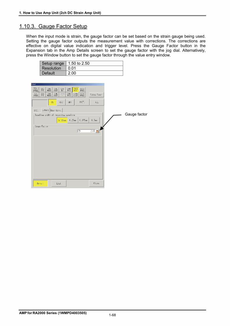
1. How to Use Amp Unit (2ch DC Strain Amp Unit)
AMP for RA2000 Series (1WMPD4003505) 1-68
1.10.3. Gauge Factor Setup When the input mode is strain, the gauge factor can be set based on the strain gauge being used. Setting the gauge factor outputs the measurement value with corrections. The corrections are effective on digital value indication and trigger level. Press the Gauge Factor button in the Expansion tab in the Amp Details screen to set the gauge factor with the jog dial. Alternatively, press the Window button to set the gauge factor through the value entry window.
Setup range 1.50 to 2.50 Resolution 0.01 Default 2.00
Gauge factor
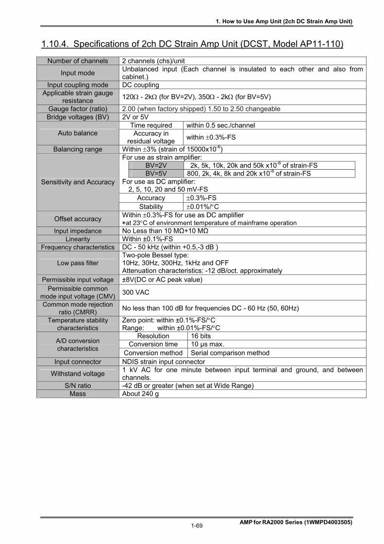
1. How to Use Amp Unit (2ch DC Strain Amp Unit)
AMP for RA2000 Series (1WMPD4003505) 1-69
1.10.4. Specifications of 2ch DC Strain Amp Unit (DCST, Model AP11-110)
Number of channels 2 channels (chs)/unit
Input mode Unbalanced input (Each channel is insulated to each other and also from cabinet.)
Input coupling mode DC coupling Applicable strain gauge
resistance 120 - 2k (for BV=2V), 350 - 2k (for BV=5V)
Gauge factor (ratio) 2.00 (when factory shipped) 1.50 to 2.50 changeable Bridge voltages (BV) 2V or 5V
Time required within 0.5 sec./channel Auto balance Accuracy in
residual voltage within 0.3%-FS
Balancing range Within 3% (strain of 15000x10-6) For use as strain amplifier:
BV=2V 2k, 5k, 10k, 20k and 50k x10-6 of strain-FS
BV=5V 800, 2k, 4k, 8k and 20k x10-6 of strain-FS
For use as DC amplifier: 2, 5, 10, 20 and 50 mV-FS
Accuracy 0.3%-FS
Sensitivity and Accuracy
Stability 0.01%/C
Offset accuracy Within 0.3%-FS for use as DC amplifier *at 23C of environment temperature of mainframe operation
Input impedance No Less than 10 MΩ+10 MΩ Linearity Within ±0.1%-FS
Frequency characteristics DC - 50 kHz (within +0.5,-3 dB )
Low pass filter Two-pole Bessel type: 10Hz, 30Hz, 300Hz, 1kHz and OFF Attenuation characteristics: -12 dB/oct. approximately
Permissible input voltage ±8V(DC or AC peak value) Permissible common
mode input voltage (CMV) 300 VAC
Common mode rejection ratio (CMRR)
No less than 100 dB for frequencies DC - 60 Hz (50, 60Hz)
Temperature stability characteristics
Zero point: within ±0.1%-FS/C Range: within ±0.01%-FS/C
Resolution 16 bits Conversion time 10 µs max. A/D conversion
characteristics Conversion method Serial comparison method
Input connector NDIS strain input connector
Withstand voltage 1 kV AC for one minute between input terminal and ground, and between channels.
S/N ratio -42 dB or greater (when set at Wide Range) Mass About 240 g
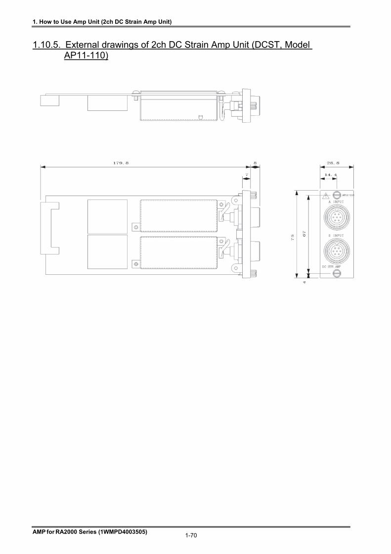
1. How to Use Amp Unit (2ch DC Strain Amp Unit)
AMP for RA2000 Series (1WMPD4003505) 1-70
1.10.5. External drawings of 2ch DC Strain Amp Unit (DCST, Model AP11-110)
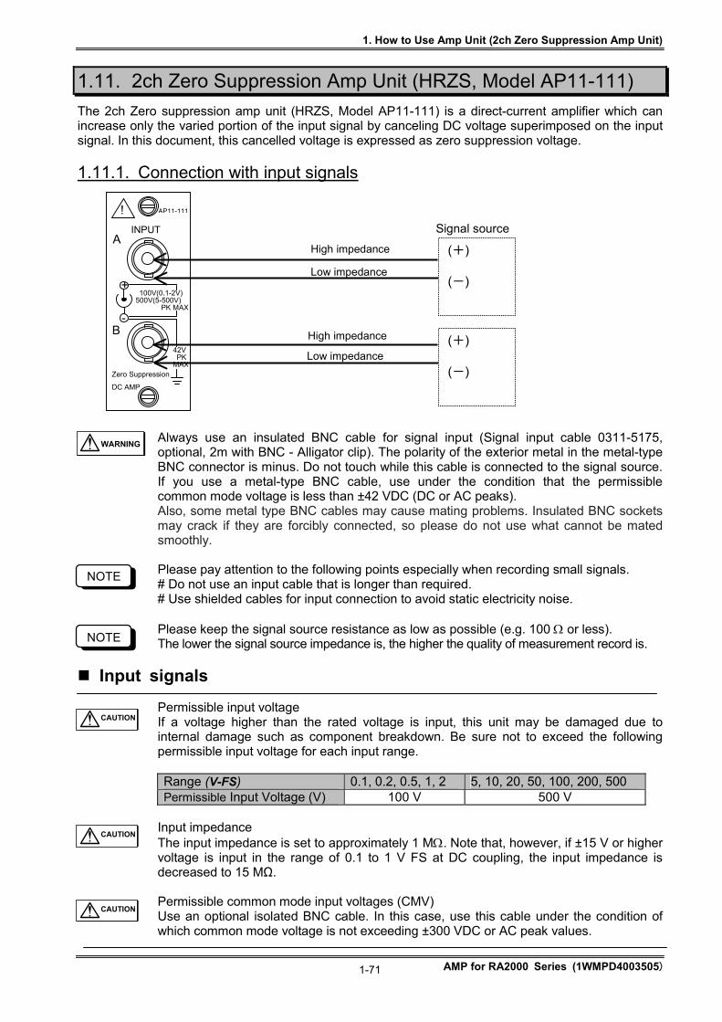
1. How to Use Amp Unit (2ch Zero Suppression Amp Unit)
AMP for RA2000 Series (1WMPD4003505)
1-71
1.11. 2ch Zero Suppression Amp Unit (HRZS, Model AP11-111)
The 2ch Zero suppression amp unit (HRZS, Model AP11-111) is a direct-current amplifier which can increase only the varied portion of the input signal by canceling DC voltage superimposed on the input signal. In this document, this cancelled voltage is expressed as zero suppression voltage.
1.11.1. Connection with input signals
Always use an insulated BNC cable for signal input (Signal input cable 0311-5175, optional, 2m with BNC - Alligator clip). The polarity of the exterior metal in the metal-type BNC connector is minus. Do not touch while this cable is connected to the signal source. If you use a metal-type BNC cable, use under the condition that the permissible common mode voltage is less than ±42 VDC (DC or AC peaks). Also, some metal type BNC cables may cause mating problems. Insulated BNC sockets may crack if they are forcibly connected, so please do not use what cannot be mated smoothly. Please pay attention to the following points especially when recording small signals. # Do not use an input cable that is longer than required. # Use shielded cables for input connection to avoid static electricity noise. Please keep the signal source resistance as low as possible (e.g. 100 or less). The lower the signal source impedance is, the higher the quality of measurement record is.
Input signals Permissible input voltage If a voltage higher than the rated voltage is input, this unit may be damaged due to internal damage such as component breakdown. Be sure not to exceed the following permissible input voltage for each input range. Range (V-FS) 0.1, 0.2, 0.5, 1, 2 5, 10, 20, 50, 100, 200, 500 Permissible Input Voltage (V) 100 V 500 V
Input impedance The input impedance is set to approximately 1 M. Note that, however, if ±15 V or higher voltage is input in the range of 0.1 to 1 V FS at DC coupling, the input impedance is decreased to 15 MΩ. Permissible common mode input voltages (CMV) Use an optional isolated BNC cable. In this case, use this cable under the condition of which common mode voltage is not exceeding ±300 VDC or AC peak values.
NOTE
CAUTION
100V(0.1-2V) 500V(5-500V) PK MAX
42V PK MAX
AP11-111
Zero Suppression
DC AMP
INPUT
+
-
!
A
B
(+) (-)
(+) (-)
Signal source
High impedance
Low impedance
High impedance
Low impedance
NOTE
WARNING
CAUTION
CAUTION

1. How to Use Amp Unit (2ch Zero Suppression Amp Unit)
AMP for RA2000 Series (1WMPD4003505)
1-72
The sample speed must be set at 10μs steps, otherwise the signal waveform cannot be obtained correctly. Example: 5 μs or 11 μs, etc. makes the waveform distort.
Use cables with the insulation sheath of no less than 2 kV of withstand voltages. Do not apply voltages exceeding the permissible common mode input voltage, since application of such voltages would lead to malfunctions or failures of equipment. Also, note that recorded waveforms may involve noise components due to degradation of common mode rejection ratio (CMRR), when noise-like impulsive common mode voltages are applied. When the range is set to 0.1 to 2.0 V FS in the AC coupling, use this amp under the condition of which the input voltage within ±30 V including the DC portion. If a signal over this voltage is input, measurement cannot be performed correctly.
1.11.2. How to set 2ch Zero Suppression Amp Unit (HRZS, Model AP11-111) This section covers operations in the Amp Basic screen that appears when the Amp button on the operation panel is pressed and the Amp Details screen that appears when a channel button is pressed.
1) Basics - Channel The channel number, input amp unit type, and waveform color are indicated in this portion. Pressing this button displays the Amp Details screen.
2) Basics - Input Input mode can be selected. Pressing this button permits switching among ON, GND, and OFF.
3) Basics - Position This button is used to set the zero position. Pressing this button changes the button appearance. The setup can be made with the jog dial.
NOTE
NOTE
NOTE
NOTE
1) Channel
6) Infomation
4) Range 3) Position 2) Input
5) Lo V
15) Zero suppression voltage
7) Position8)Input coupling
9) Auto range
12) Range
13) Permission of high sensitivity settings
14) Filter
11) Wide/Normal10) Range indication

1. How to Use Amp Unit (2ch Zero Suppression Amp Unit)
AMP for RA2000 Series (1WMPD4003505)
1-73
4) Basics - Range This button is used to set the range. Pressing this button changes the button appearance. The setup can be made with the jog dial.
5) Basics – Lo V The LED lights if the high sensitivity range can be permitted.
6) Basics - Information This portion indicates settings that are unable to be set on this screen. When changing the settings, make the settings in the Amp Details Screen. Fc: Filter setting Couple: Input coupling setting ZSV: Zero Suppression setting
7) Details - position The zero position (base line) is set with a button. The zero position means the waveform display position at 0V input (input short). The base line can be set in 5% steps in reference to 100% as the full scale. Also, you can set it with the jog dial by pressing the jog button, or set it from the numeric input window by pressing the window button. And the position change is available through the setup of Physical Unit Conversion or Printing/Display Range. For more information, see Chapter 4. Physical Unit Conversion – Changing Printing/Display Range.
8) Details - Input coupling The input coupling is set by pressing the AC coupling button or DC coupling button.
When the AC coupling button is pressed, a capacitor is connected to the input terminal. The DC component can be eliminated, which enables the measurement of alternating voltage.
9) Details - Auto range The range is automatically adjusted to the input signal.
10) Details - Range indication The value of the current display range is displayed. "#" is displayed when selecting the "Wide" range or changing "Printing / Display Range". After that, if you select the "Normal" range, the setting of "Printing / Display Range" is cleared and "#" disappears. Also, when checking "Set EU." on the ”User Conv.” Tab and setting to use physical unit conversion, the full scale converted value will be displayed with *. For more information on physical unit conversion and printing / display range setting, see Chapter 4. Physical Unit Conversion - Changing Printing / Display Range.
11) Details - Wide/Normal Wide: Entire measuring range is displayed. Normal: Half of the measuring range is displayed (Default).
12) Details - Range Range can be directly set.
When the measurement range is changed, the waveform clip range is cleared to the default value corresponding to the new range. Example: During expansion of the waveform in the waveform clip range between +40 and -40 at 100 V, if the range is set to 100 V again, the waveform clip range is set to between +50 to -50 as the default. (Enlarged display is cancelled.)
Pay attention to the permissible input voltage when setting the range. See Permissible input voltages in “Input Signals”.
13) Details - Permission of high sensitivity settings Settings to the high-sensitivity range (5 V to 100 mV) can be prohibited/permitted. When using the high-sensitivity range, check the check box. When the high-sensitivity range is not used, prohibition of the high-sensitivity range without checking the box is recommended for safety.
14) Details - Filter This button is used to set the low-pass filter.
CAUTION
TIPS
TIPS
CAUTION
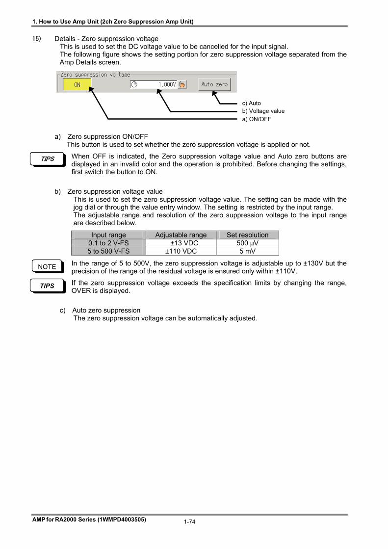
1. How to Use Amp Unit (2ch Zero Suppression Amp Unit)
AMP for RA2000 Series (1WMPD4003505)
1-74
15) Details - Zero suppression voltage This is used to set the DC voltage value to be cancelled for the input signal. The following figure shows the setting portion for zero suppression voltage separated from the Amp Details screen.
a) Zero suppression ON/OFF This button is used to set whether the zero suppression voltage is applied or not.
When OFF is indicated, the Zero suppression voltage value and Auto zero buttons are displayed in an invalid color and the operation is prohibited. Before changing the settings, first switch the button to ON.
b) Zero suppression voltage value This is used to set the zero suppression voltage value. The setting can be made with the jog dial or through the value entry window. The setting is restricted by the input range. The adjustable range and resolution of the zero suppression voltage to the input range are described below.
Input range Adjustable range Set resolution 0.1 to 2 V-FS ±13 VDC 500 μV 5 to 500 V-FS ±110 VDC 5 mV
In the range of 5 to 500V, the zero suppression voltage is adjustable up to ±130V but the precision of the range of the residual voltage is ensured only within ±110V.
If the zero suppression voltage exceeds the specification limits by changing the range, OVER is displayed.
c) Auto zero suppression The zero suppression voltage can be automatically adjusted.
a) ON/OFF
c) Auto b) Voltage value
TIPS
NOTE
TIPS
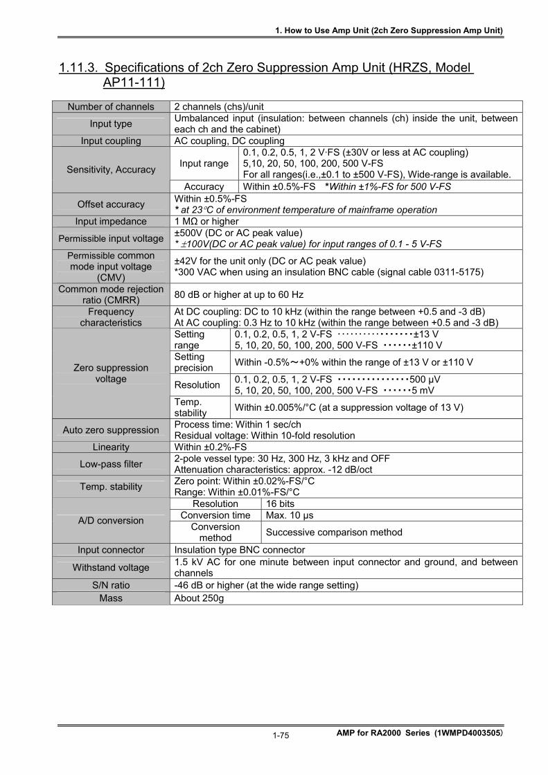
1. How to Use Amp Unit (2ch Zero Suppression Amp Unit)
AMP for RA2000 Series (1WMPD4003505)
1-75
1.11.3. Specifications of 2ch Zero Suppression Amp Unit (HRZS, Model AP11-111)
Number of channels 2 channels (chs)/unit
Input type Umbalanced input (insulation: between channels (ch) inside the unit, between each ch and the cabinet)
Input coupling AC coupling, DC coupling
Input range 0.1, 0.2, 0.5, 1, 2 V·FS (±30V or less at AC coupling) 5,10, 20, 50, 100, 200, 500 V-FS For all ranges(i.e.,±0.1 to ±500 V-FS), Wide-range is available. Sensitivity, Accuracy
Accuracy Within ±0.5%-FS *Within ±1%-FS for 500 V-FS
Offset accuracy Within ±0.5%-FS * at 23C of environment temperature of mainframe operation
Input impedance 1 MΩ or higher
Permissible input voltage ±500V (DC or AC peak value) * 100V(DC or AC peak value) for input ranges of 0.1 - 5 V-FS
Permissible common mode input voltage
(CMV)
±42V for the unit only (DC or AC peak value) *300 VAC when using an insulation BNC cable (signal cable 0311-5175)
Common mode rejection ratio (CMRR)
80 dB or higher at up to 60 Hz
Frequency characteristics
At DC coupling: DC to 10 kHz (within the range between +0.5 and -3 dB) At AC coupling: 0.3 Hz to 10 kHz (within the range between +0.5 and -3 dB) Setting range
0.1, 0.2, 0.5, 1, 2 V-FS ・・・・・・・・・・・・・・・・・±13 V 5, 10, 20, 50, 100, 200, 500 V-FS ・・・・・・±110 V
Setting precision
Within -0.5%~+0% within the range of ±13 V or ±110 V
Resolution 0.1, 0.2, 0.5, 1, 2 V-FS ・・・・・・・・・・・・・・・500 μV 5, 10, 20, 50, 100, 200, 500 V-FS ・・・・・・5 mV
Zero suppression voltage
Temp. stability
Within ±0.005%/°C (at a suppression voltage of 13 V)
Auto zero suppression Process time: Within 1 sec/ch Residual voltage: Within 10-fold resolution
Linearity Within ±0.2%-FS
Low-pass filter 2-pole vessel type: 30 Hz, 300 Hz, 3 kHz and OFF Attenuation characteristics: approx. -12 dB/oct
Temp. stability Zero point: Within ±0.02%-FS/°C Range: Within ±0.01%-FS/°C
Resolution 16 bits Conversion time Max. 10 μs A/D conversion
Conversion method
Successive comparison method
Input connector Insulation type BNC connector
Withstand voltage 1.5 kV AC for one minute between input connector and ground, and between channels
S/N ratio -46 dB or higher (at the wide range setting) Mass About 250g
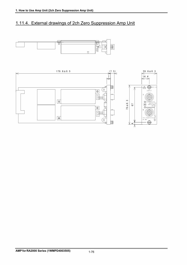
1. How to Use Amp Unit (2ch Zero Suppression Amp Unit)
AMP for RA2000 Series (1WMPD4003505)
1-76
1.11.4. External drawings of 2ch Zero Suppression Amp Unit
67
4
75±
0.3
1 4 .4
28.8±0.3
7
179.8±0.5 (7.5)
! AP11-111
INPUT
DC AMP
Zero Suppression MAX
PK
42V
B
100V(0.1-2V)
500V(5-500V)
PK MAX
A
2. Common Settings for Amp Details Screen
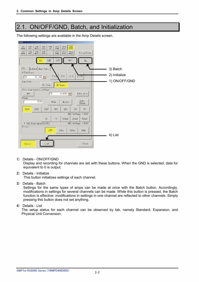
2. Common Settings in Amp Details Screen
AMP for RA2000 Series (1WMPD4003505) 2-2
2.1. ON/OFF/GND, Batch, and Initialization The following settings are available in the Amp Details screen.
1) Details - ON/OFF/GND Display and recording for channels are set with these buttons. When the GND is selected, data for equivalent to 0 is output.
2) Details - Initialize This button initializes settings of each channel.
3) Details - Batch Settings for the same types of amps can be made at once with the Batch button. Accordingly, modifications in settings for several channels can be made. While this button is pressed, the Batch function is effective: modifications in settings in one channel are reflected to other channels. Simply pressing this button does not set anything.
4) Details - List The setup status for each channel can be observed by tab, namely Standard, Expansion, and Physical Unit Conversion.
2) Initialize
3) Batch
1) ON/OFF/GND
4) List
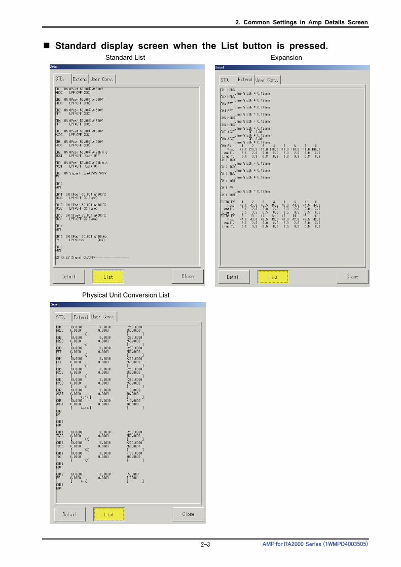
2. Common Settings in Amp Details Screen
AMP for RA2000 Series (1WMPD4003505) 2-3
Standard display screen when the List button is pressed.
Standard List Expansion
Physical Unit Conversion List
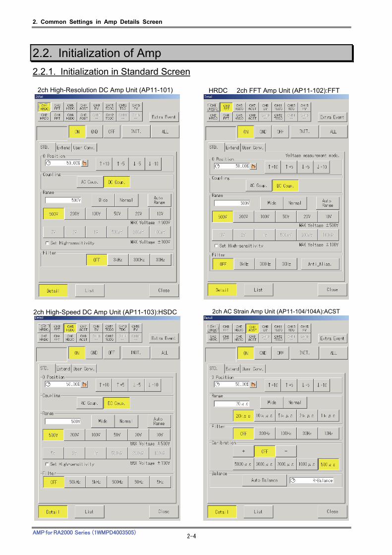
2. Common Settings in Amp Details Screen
AMP for RA2000 Series (1WMPD4003505) 2-4
2.2. Initialization of Amp
2.2.1. Initialization in Standard Screen
2ch High-Resolution DC Amp Unit (AP11-101) HRDC 2ch FFT Amp Unit (AP11-102):FFT
2ch High-Speed DC Amp Unit (AP11-103):HSDC 2ch AC Strain Amp Unit (AP11-104/104A):ACST
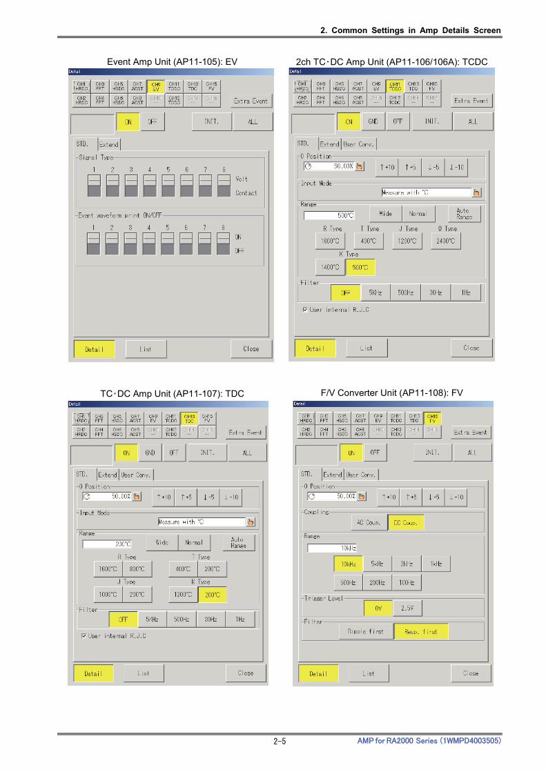
2. Common Settings in Amp Details Screen
AMP for RA2000 Series (1WMPD4003505) 2-5
Event Amp Unit (AP11-105): EV 2ch TC・DC Amp Unit (AP11-106/106A): TCDC
TC・DC Amp Unit (AP11-107): TDC F/V Converter Unit (AP11-108): FV
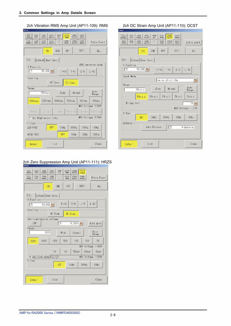
2. Common Settings in Amp Details Screen
AMP for RA2000 Series (1WMPD4003505) 2-6
2ch Zero Suppression Amp Unit (AP11-111): HRZS
2ch Vibration RMS Amp Unit (AP11-109): RMS 2ch DC Strain Amp Unit (AP11-110): DCST
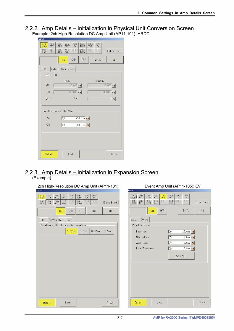
2. Common Settings in Amp Details Screen
AMP for RA2000 Series (1WMPD4003505) 2-7
2.2.2. Amp Details – Initialization in Physical Unit Conversion Screen
Example: 2ch High-Resolution DC Amp Unit (AP11-101): HRDC
2.2.3. Amp Details – Initialization in Expansion Screen (Example)
2ch High-Resolution DC Amp Unit (AP11-101): Event Amp Unit (AP11-105): EV


3. Expansion Settings

3. Expansion Settings
AMP for RA2000 Series (1WMPD4003505) 3-2
3.1. Change of Base Line Width of Printing Waveform The following settings are available in the Amp Details screen. (1) Details – Base Line Width of Printing Waveform
The line width for printing waveform can be set for each channel.
(1) Base Line Width of Printing Waveform
4. Physical Unit Conversion-Changing Printing / Display Range
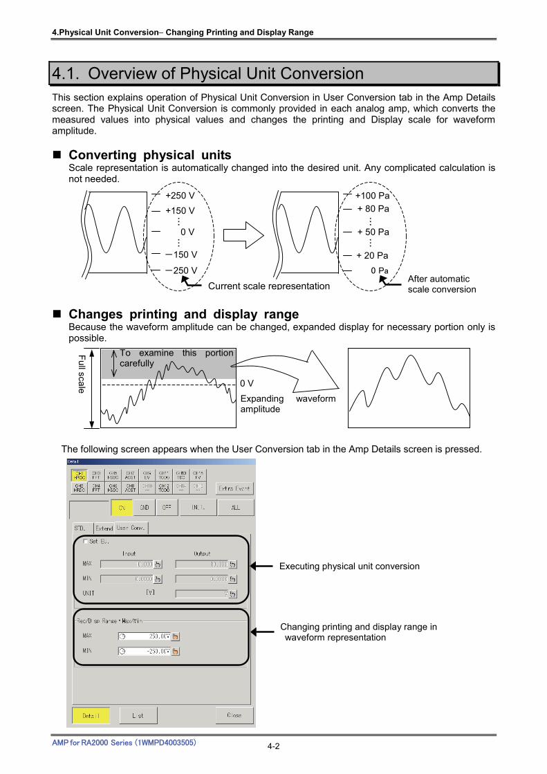
4.Physical Unit Conversion Changing Printing and Display Range
AMP for RA2000 Series (1WMPD4003505) 4-2
4.1. Overview of Physical Unit Conversion This section explains operation of Physical Unit Conversion in User Conversion tab in the Amp Details screen. The Physical Unit Conversion is commonly provided in each analog amp, which converts the measured values into physical values and changes the printing and Display scale for waveform amplitude.
Converting physical units Scale representation is automatically changed into the desired unit. Any complicated calculation is not needed.
Changes printing and display range Because the waveform amplitude can be changed, expanded display for necessary portion only is possible.
The following screen appears when the User Conversion tab in the Amp Details screen is pressed.
…
…
+100 Pa
0 Pa
+ 50 Pa
+ 80 Pa
+ 20 Pa
After automatic scale conversion
-250 V
…
…
+250 V
0 V
+150 V
-150 V
Current scale representation
0 V
Full sca
le
To examine this portioncarefully
Expanding waveformamplitude
Executing physical unit conversion
Changing printing and display range in waveform representation
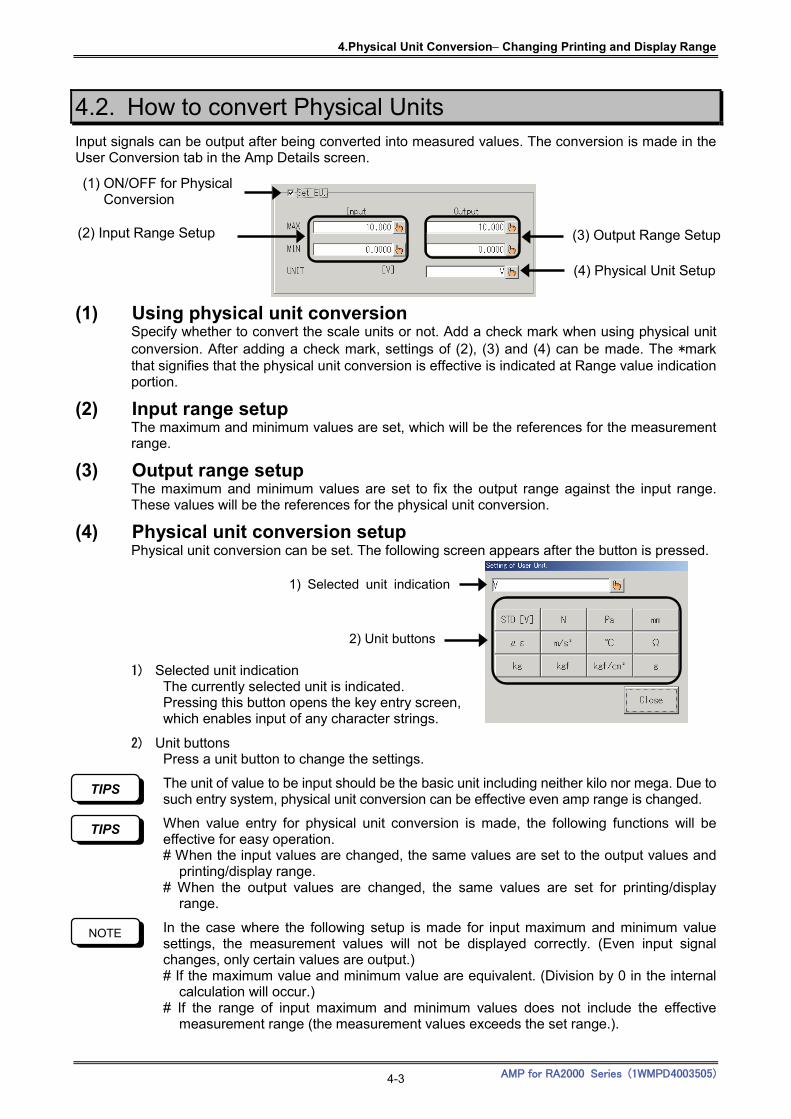
4.Physical Unit Conversion Changing Printing and Display Range
AMP for RA2000 Series (1WMPD4003505) 4-3
4.2. How to convert Physical Units Input signals can be output after being converted into measured values. The conversion is made in the User Conversion tab in the Amp Details screen.
(1) Using physical unit conversion Specify whether to convert the scale units or not. Add a check mark when using physical unit conversion. After adding a check mark, settings of (2), (3) and (4) can be made. The *mark that signifies that the physical unit conversion is effective is indicated at Range value indication portion.
(2) Input range setup The maximum and minimum values are set, which will be the references for the measurement range.
(3) Output range setup The maximum and minimum values are set to fix the output range against the input range. These values will be the references for the physical unit conversion.
(4) Physical unit conversion setup Physical unit conversion can be set. The following screen appears after the button is pressed.
1) Selected unit indication The currently selected unit is indicated. Pressing this button opens the key entry screen, which enables input of any character strings.
2) Unit buttons Press a unit button to change the settings.
The unit of value to be input should be the basic unit including neither kilo nor mega. Due to such entry system, physical unit conversion can be effective even amp range is changed.
When value entry for physical unit conversion is made, the following functions will be effective for easy operation. # When the input values are changed, the same values are set to the output values and
printing/display range. # When the output values are changed, the same values are set for printing/display
range.
In the case where the following setup is made for input maximum and minimum value settings, the measurement values will not be displayed correctly. (Even input signal changes, only certain values are output.) # If the maximum value and minimum value are equivalent. (Division by 0 in the internal
calculation will occur.) # If the range of input maximum and minimum values does not include the effective
measurement range (the measurement values exceeds the set range.).
TIPS
NOTE
TIPS
2) Unit buttons
1) Selected unit indication
(1) ON/OFF for Physical Conversion
(2) Input Range Setup
(4) Physical Unit Setup
(3) Output Range Setup
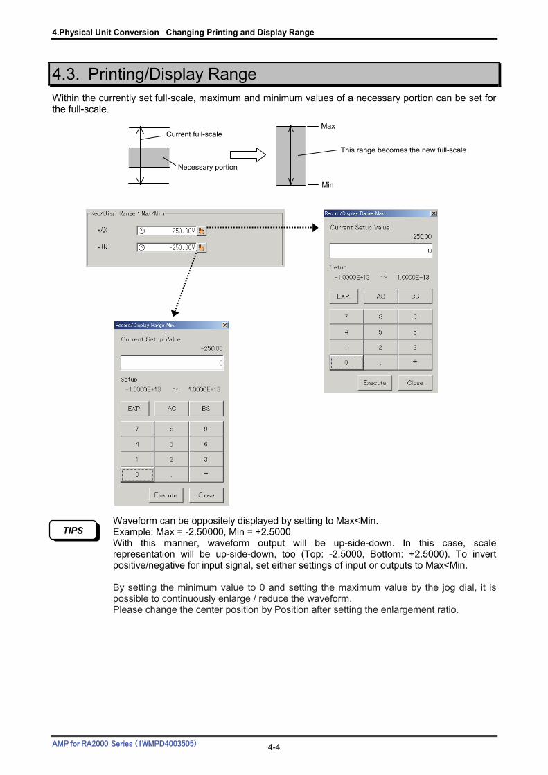
4.Physical Unit Conversion Changing Printing and Display Range
AMP for RA2000 Series (1WMPD4003505) 4-4
4.3. Printing/Display Range Within the currently set full-scale, maximum and minimum values of a necessary portion can be set for the full-scale.
Waveform can be oppositely displayed by setting to Max<Min. Example: Max = -2.50000, Min = +2.5000 With this manner, waveform output will be up-side-down. In this case, scale representation will be up-side-down, too (Top: -2.5000, Bottom: +2.5000). To invert positive/negative for input signal, set either settings of input or outputs to Max<Min. By setting the minimum value to 0 and setting the maximum value by the jog dial, it is possible to continuously enlarge / reduce the waveform. Please change the center position by Position after setting the enlargement ratio.
TIPS
Min
This range becomes the new full-scale
Max Current full-scale
Necessary portion

5. Procedure for Changing Amplifier Units
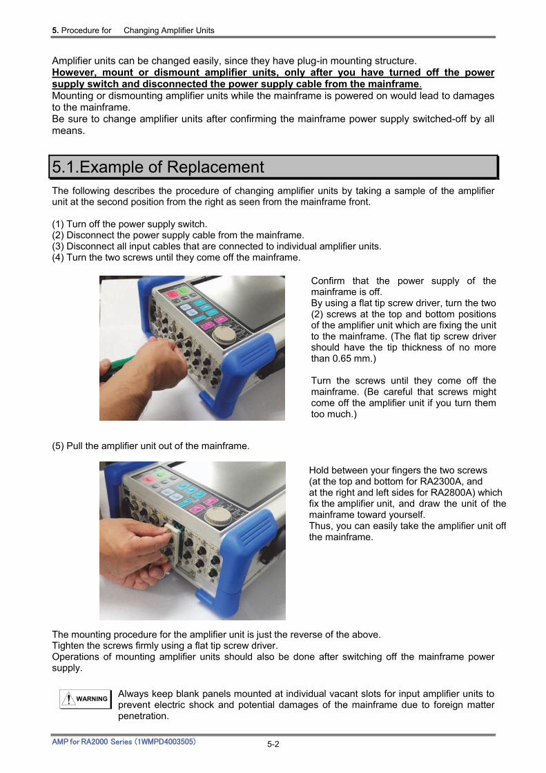
5. Procedure for Changing Amplifier Units
AMP for RA2000 Series (1WMPD4003505) 5-2
Amplifier units can be changed easily, since they have plug-in mounting structure. However, mount or dismount amplifier units, only after you have turned off the power supply switch and disconnected the power supply cable from the mainframe. Mounting or dismounting amplifier units while the mainframe is powered on would lead to damages to the mainframe. Be sure to change amplifier units after confirming the mainframe power supply switched-off by all means.
5.1.Example of Replacement The following describes the procedure of changing amplifier units by taking a sample of the amplifier unit at the second position from the right as seen from the mainframe front. (1) Turn off the power supply switch. (2) Disconnect the power supply cable from the mainframe. (3) Disconnect all input cables that are connected to individual amplifier units. (4) Turn the two screws until they come off the mainframe. (5) Pull the amplifier unit out of the mainframe.
The mounting procedure for the amplifier unit is just the reverse of the above. Tighten the screws firmly using a flat tip screw driver. Operations of mounting amplifier units should also be done after switching off the mainframe power supply.
Always keep blank panels mounted at individual vacant slots for input amplifier units to prevent electric shock and potential damages of the mainframe due to foreign matter penetration.
Confirm that the power supply of themainframe is off. By using a flat tip screw driver, turn the two(2) screws at the top and bottom positionsof the amplifier unit which are fixing the unitto the mainframe. (The flat tip screw drivershould have the tip thickness of no morethan 0.65 mm.) Turn the screws until they come off the mainframe. (Be careful that screws mightcome off the amplifier unit if you turn themtoo much.)
WARNING
Hold between your fingers the two screws (at the top and bottom for RA2300A, and at the right and left sides for RA2800A) which fix the amplifier unit, and draw the unit of themainframe toward yourself. Thus, you can easily take the amplifier unit offthe mainframe.
To be used for a long time
A&D Company,Limited. Thank you for purchasing our products. In order to use the purchased product for a long time, we offer the following maintenance service system.
1. Warranty period One year is warranted from the date of purchase and will be repaired free of charge in the event of failure. (However, it is limited to the case where the fault that occurred is our responsibility.)
2. Maintenance service when the warranty period has passed
If the warranty period has passed, the repair service will be charged. In addition, overhaul is also accepted at customer's request.
3. Maintenance agreement recommendation
At our company we also conduct periodic inspection and maintenance services so that the products you purchase can always be used with confidence.
Address inquiries to:
(1) This manual may not be reproduced to any form in whole or in part. (2) Then contents in this manual may be updated without prior notice.
The AP Amplifier series units for RA2000 Series Instruction Manual (1WMPD4003505)
1st Edition : September 2017


! " # $% &'() *+, -. /0 12) *+, -. /0+33')445556(77668'4