DL102 - Counter Loop Amplifier
16
DL102 Counter Loop Amplifier USER MANUAL MAN 234A
-
Upload
khangminh22 -
Category
Documents
-
view
2 -
download
0
Transcript of DL102 - Counter Loop Amplifier
DL102Counter Loop Amplifier
USER MANUAL
MAN 234A
2
ContentsOverview ............................................................................................................................................3
System Includes .....................................................................................................................3
Maintenance and Recycling Instructions .................................................................................3
Safety Information ...........................................................................................................................4
Quick Setup ......................................................................................................................................5
Setup ...................................................................................................................................................6
Loop Amplifier .........................................................................................................................6
Wiring a Counter ....................................................................................................................6
Connect Loop Wire to the Loop Output Terminals .....................................................6
Placing a Loop Mat ................................................................................................................6
Connect Audio Outputs to Loop Amplifier Inputs .......................................................8
Connect Power to the Amplifier ........................................................................................9
Operation ......................................................................................................................................... 10
Volume Control ..................................................................................................................... 10
Microphone ............................................................................................................................ 10
Line Inputs .............................................................................................................................. 10
Troubleshooting ..............................................................................................................................11
Specifications ................................................................................................................................. 12
Warranty ............................................................................................................................................14
3
OverviewThank you for purchasing the DL102 counter loop amplifier.
The DL102 loop amplifier provides a practical solution for a user to hear with their T-coil enabled hearing device in small areas such as counters and service desks.
Audio is wired into the DL102 amplifier via a line input or microphone. Audio is fed from the amplifier through the loop wire in the area where a T-coil hearing device can pick-up the audio.
With no direct connection between the user and service personnel, users can hear effectively when using the T-coil in their customized hearing devices.
This loop system may be supplied with a loop pad or spool of wire.
System IncludesDL102
DL102 amplifier Power supply AC line cord Loop notice stickers Set of adhesive cable clips MIC 103 - Microphone
DL102 SY1
DL102 amplifier Power supply AC line cord Loop notice stickers Set of adhesive cable clips MIC 103 - Microphone PLW 037 (120ft Spool of wire) PLM 001 - Loop Pad
Maintenance and Recycling InstructionsHelp Williams AV protect the environment. Please take the time to dispose of your equipment properly.
Product Recycling:Please do NOT dispose of your Williams AV equipment in the household trash. Take the equipment to a electronics recycling center, or return the product to the factory for proper disposal.

4
Safety InformationServicing or attempting to service this device will void the warrantyRefer servicing to qualified personnel. Servicing is required when the system has been damaged in any way: if liquid has been spilled or objects have fallen into the unit, if the unit has been exposed to moisture, if the unit does not operate normally, or if the unit has been dropped.
Do not block any ventilation openings. Install in accordance with manufacturer’s instructions.
Do not install near any heat sources such as radiators, heat registers, stoves, or other apparatus that produces heat.
Use only attachments/accessories specified by the manufacturer.
Unplug the amplifier during lightning storms or when unused for long periods of time.
Be advised that different operating voltages require the use of different types of line cord and attachment plugs. Check the voltage in your area and use the correct type.
Use only the power supply provided by Williams AV. Other power supplies may have similar specifications, but may not be equivalent in emissions ratings, in-rush current, etc. Use of an unapproved power supply may leave the device partially or completely inoperable, and will void the warranty.
CAUTION: The power cord must be disconnected BEFORE any audio connections are made to the loop amplifier. To completely disconnect the system from the power cord, please remove the line cord plug from the wall socket.
CAUTION: The surface of the amplifier may become hot when operating this sys-tem continuously. Do not touch the surface during use or block the ventilation holes.
5
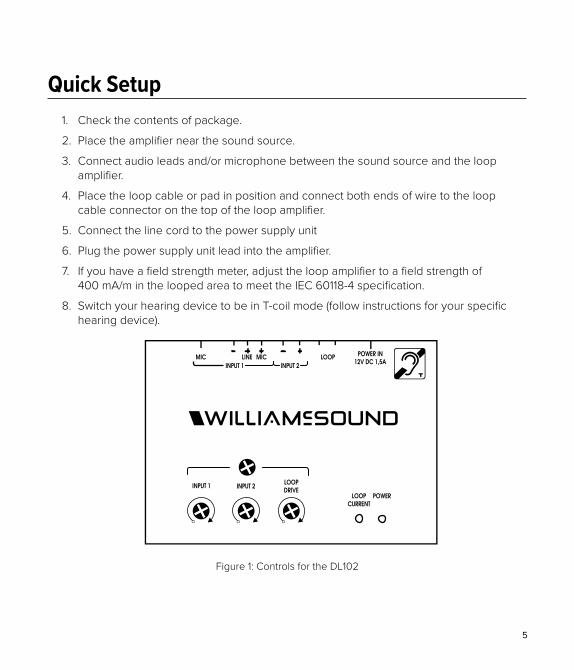
Quick Setup1. Check the contents of package.
2. Place the amplifier near the sound source.
3. Connect audio leads and/or microphone between the sound source and the loop amplifier.
4. Place the loop cable or pad in position and connect both ends of wire to the loop cable connector on the top of the loop amplifier.
5. Connect the line cord to the power supply unit
6. Plug the power supply unit lead into the amplifier.
7. If you have a field strength meter, adjust the loop amplifier to a field strength of 400 mA/m in the looped area to meet the IEC 60118-4 specification.
8. Switch your hearing device to be in T-coil mode (follow instructions for your specific hearing device).
Phoenix style connectorPhoenix style connector
Top Front
Figure 1: Controls for the DL102

6
SetupImportant: Always disconnect the unit from power before making connections.
Loop AmplifierPlace the amplifier in a convenient, well-ventilated area near the audio source so that all of the necessary connections can reach the amplifier.
Wiring a CounterThere are several configurations for wiring a loop for a counter top or similar area. We recommend the loop be placed on both the flat top and vertical face of the counter. Alternatively, the loop could also be placed only on or under the flat top of the counter, or only on the vertical face of the counter. It could also be placed on the floor where the user may be standing, if interference is not an issue. See “Figure 2: Various Counter Placements” on page 7 for examples.
Note: A loop system will not work well under or on top of a metal surface.
No matter which method is selected, the loop will need to be placed as near as possible to where the customer will be standing.
Wire LengthThe wire length must have a DCΩ no lower than 0.1Ω and may not exceed 1Ω.
Connect Loop Wire to the Loop Output TerminalsConnect the wire to the amplifier’s loop output. Ensure that only the bare wire goes into the hole and not the insulation.
Placing a Loop MatConnect the loop mat to the amplifier just as you would for loop wire. Place the mat in the area where people will need looped audio, such as at a counter or on a couch.

7
AAmplifier
Loop
Amplifier
LoopB
Loop
C
Amplifier
Loop
Amplifier
D
Figure 2: Various Counter Placements
8
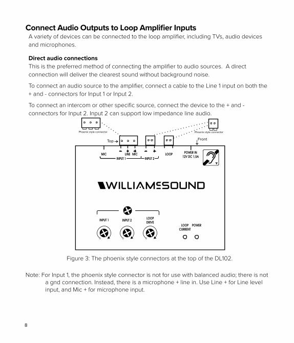
Connect Audio Outputs to Loop Amplifier Inputs A variety of devices can be connected to the loop amplifier, including TVs, audio devices and microphones.
Direct audio connectionsThis is the preferred method of connecting the amplifier to audio sources. A direct connection will deliver the clearest sound without background noise.
To connect an audio source to the amplifier, connect a cable to the Line 1 input on both the + and - connectors for Input 1 or Input 2.
To connect an intercom or other specific source, connect the device to the + and - connectors for Input 2. Input 2 can support low impedance line audio.
Phoenix style connectorPhoenix style connector
Top Front
Figure 3: The phoenix style connectors at the top of the DL102.
Note: For Input 1, the phoenix style connector is not for use with balanced audio; there is not a gnd connection. Instead, there is a microphone + line in. Use Line + for Line level input, and Mic + for microphone input.
9
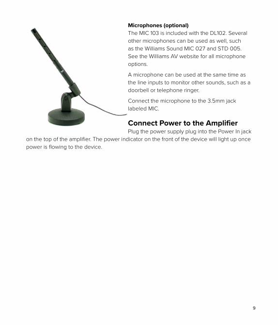
Microphones (optional)The MIC 103 is included with the DL102. Several other microphones can be used as well, such as the Williams Sound MIC 027 and STD 005. See the Williams AV website for all microphone options.
A microphone can be used at the same time as the line inputs to monitor other sounds, such as a doorbell or telephone ringer.
Connect the microphone to the 3.5mm jack labeled MIC.
Connect Power to the AmplifierPlug the power supply plug into the Power In jack
on the top of the amplifier. The power indicator on the front of the device will light up once power is flowing to the device.
10
OperationWhen connecting power to your amplifier for the first time, the power LED will illuminate green and the amplifier will be on.
1. Set the audio equipment to normal listening level for the other listeners in the room.
2. Switch your hearing aid to T-coil mode.
3. Adjust the volume to suit your listening using the Input 1, Input 2 or Loop knobs on the amplifier.
Volume ControlUse the Input 1, Input 2 and Loop knobs on the front of the amplifier to adjust the volume to the loop.
MicrophoneWhen used for speech, a microphone should be placed near the service person at the counter. A microphone can also be useful for monitoring a doorbell, or if a partner wants to talk to the hearing device wearer through the loop.
Line InputsOne or both channels can be selected (and heard) simultaneously.
11
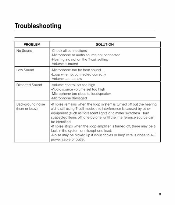
Troubleshooting
PROBLEM SOLUTION
No Sound -Check all connections-Microphone or audio source not connected-Hearing aid not on the T-coil setting-Volume is muted
Low Sound -Microphone too far from sound-Loop wire not connected correctly-Volume set too low
Distorted Sound -Volume control set too high. -Audio source volume set too high -Microphone too close to loudspeaker-Microphone damaged
Background noise (hum or buzz)
-If noise remains when the loop system is turned off but the hearing aid is still using T-coil mode, this interference is caused by other equipment (such as florescent lights or dimmer switches). Turn suspected items off, one-by-one, until the interference source can be identified.-If noise stops when the loop amplifier is turned off, there may be a fault in the system or microphone lead. -Noise may be picked up if input cables or loop wire is close to AC power cable or outlet.
12
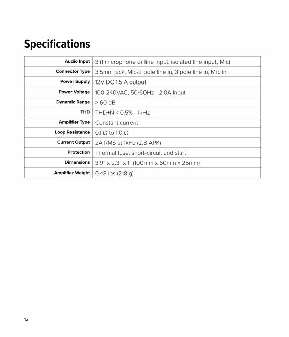
SpecificationsAudio Input 3 (1 microphone or line input, isolated line input, Mic)
Connector Type 3.5mm jack, Mic-2 pole line in, 3 pole line in, Mic inPower Supply 12V DC 1.5 A output
Power Voltage 100-240VAC, 50/60Hz - 2.0A InputDynamic Range > 60 dB
THD THD+N < 0.5% - 1kHzAmplifier Type Constant current
Loop Resistance 0.1 Ω to 1.0 ΩCurrent Output 2A RMS at 1kHz (2.8 APK)
Protection Thermal fuse, short-circuit and startDimensions 3.9” x 2.3” x 1” (100mm x 60mm x 25mm)
Amplifier Weight 0.48 lbs (218 g)

13
This page is intentionally left blank.

14
WarrantyWilliams AV products are engineered, designed and manufactured under carefully controlled conditions to provide you with many years of reliable service. Williams AV warrants the DL102 amplifier against defects in materials and workmanship for TWO (2) years. During the first two years from the purchase date, we will promptly repair or replace the product.
Power supplies, cables and other accessories are covered under a 90 day warranty.
WILLIAMS AV HAS NO CONTROL OVER THE CONDITIONS UNDER WHICH THIS PRODUCT IS USED. WILLIAMS AV, THEREFORE, DISCLAIMS ALL WARRANTIES NOT SET FORTH ABOVE, BOTH EXPRESS AND IMPLIED, WITH RESPECT TO THE DL102 SYSTEM, INCLUDING BUT NOT LIMITED TO, ANY IMPLIED WARRANTY OF MERCHANTABILITY OR FITNESS FOR A PARTICULAR PURPOSE. WILLIAMS AV SHALL NOT BE LIABLE TO ANY PERSON OR ENTITY FOR ANY MEDICAL EXPENSES OR ANY DIRECT, INCIDENTAL OR CONSEQUENTIAL DAMAGES CAUSED BY ANY USE, DEFECT, FAILURE OR MALFUNCTIONING OF THE PRODUCT, WHETHER A CLAIM FOR SUCH DAMAGES IS BASED UPON WARRANTY, CONTRACT, TORT OR OTHERWISE. THE SOLE REMEDY FOR ANY DEFECT, FAILURE OR MALFUNCTION OF THE PRODUCT IS REPLACEMENT OF THE PRODUCT. NO PERSON HAS ANY AUTHORITY TO BIND WILLIAMS AV TO ANY REPRESENTATION OR WARRANTY WITH RESPECT TO THE DL102 SYSTEM. UNAUTHORIZED REPAIRS OR MODIFICATIONS WILL VOID THE WARRANTY.
The exclusions and limitations set out above are not intended to, and should not be construed so as to contravene mandatory provisions of applicable law. If any part or term of this Disclaimer of Warranty is held to be illegal, unenforceable, or in conflict with applicable law by a court of competent jurisdiction, the validity of the remaining portions of this Disclaimer of Warranty shall not be affected, and all rights and obligations shall be construed and enforced as if this Limited Warranty did not contain the particular part or term held to be invalid.
If you experience difficulty with your system, call toll-free for customer assistance: 1-800-843-3544 (U.S.A.) or +1 952 943 2252 (outside the U.S.A.)
If it is necessary to return the system for service, your Customer Service Representative will give you a Return Authorization Number (RA) and shipping instructions.
15
Pack the system carefully and send it to:
Williams AV
Attn: Repair Dept.
10300 Valley View Road
Eden Prairie, MN 55344 USA
Your warranty becomes effective the date you purchase your system. If your sales receipt is not available, the date code on the product will determine your warranty status.

[email protected] / www.williamsav.com800-843-3544 / INTL: +1-952-943-2252
© 2018, Williams AV, LLC MAN 234A