BJT amplifier & small-signal concept
35
BJT amplifier & small-signal concept By Dr.V.Prasad Professor,ECE Department Sridevi Womens Engineering College 1
-
Upload
khangminh22 -
Category
Documents
-
view
0 -
download
0
Transcript of BJT amplifier & small-signal concept

BJT amplifier & small-signal
concept
By
Dr.V.Prasad
Professor,ECE Department
Sridevi Womens Engineering College
1

Preview
• Basic characteristics of BJT amplifiers
• DC and ac analysis & equivalent circuits
• Small-signal hybrid-π equivalent circuits
• Small-signal voltage gain, input resistance &
output resistance
• Common-emitter amplifiers
• dc & ac load lines
2

Linear analog amplifier
3

Notation
4
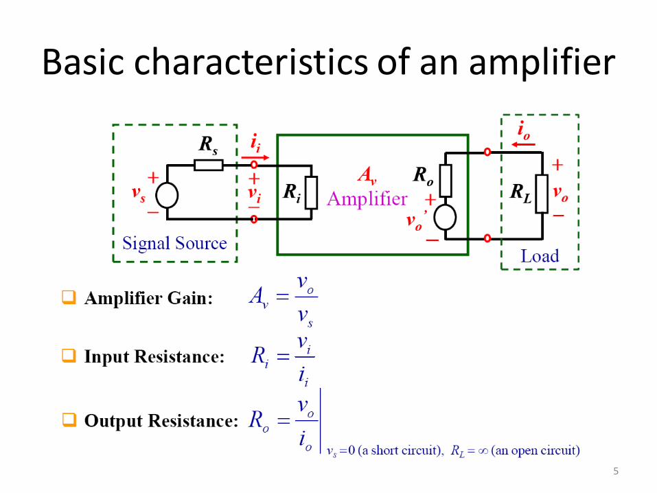
Basic characteristics of an amplifier
5

Basic characteristics of an amplifier
(cont’d)
6

Basic BJT amplifier
7
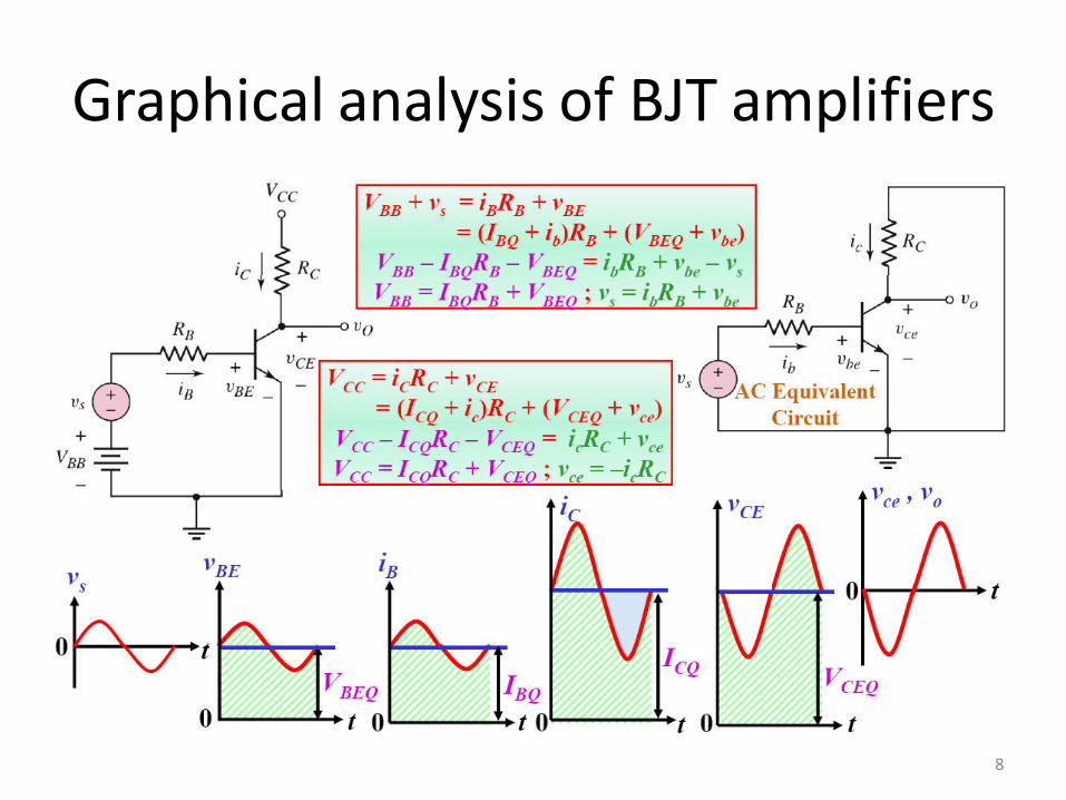
Graphical analysis of BJT amplifiers
8

Graphical analysis of BJT amplifiers
(Cont’d)
9

Analysis of BJT amplifiers
10
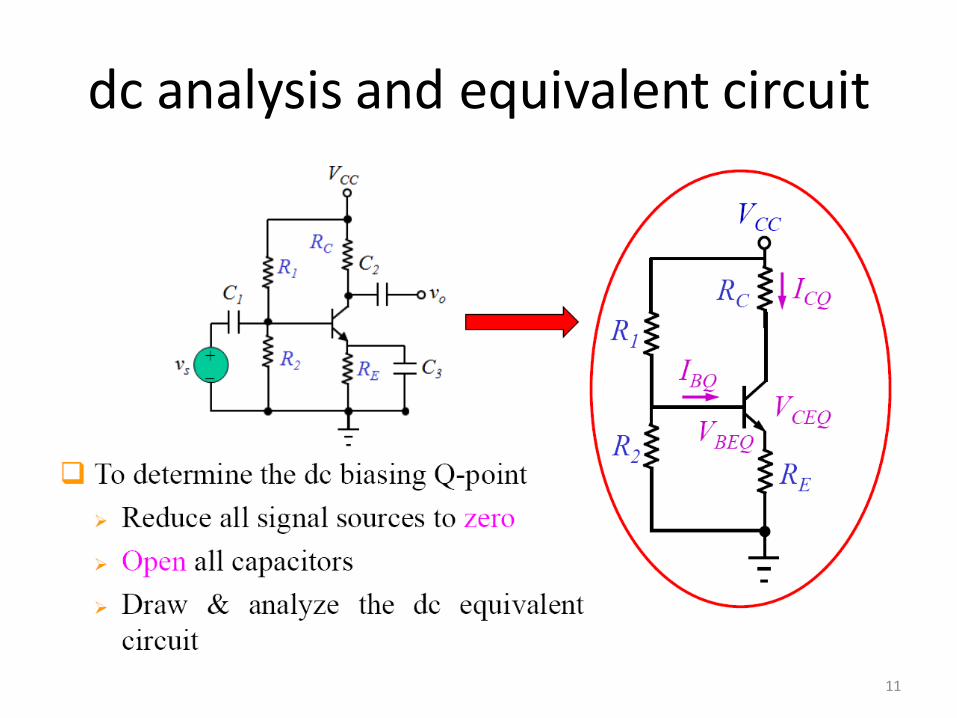
dc analysis and equivalent circuit
11

ac analysis and equivalent circuit
12

Small-signal hybrid-π equivalent circuit
13

Small-signal hybrid-π equivalent circuit
(Cont’d)
14

Small-signal voltage gain
15

Input and output resistances
16

Example: dc circuit analysis
17

Example: dc circuit analysis (Cont’d)
18
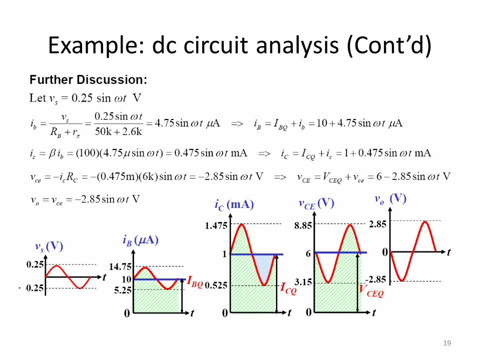
Example: dc circuit analysis (Cont’d)
19
-

Small-signal hybrid-π equivalent circuit
with Early effect
20

Example: determine BJT amplifier
parameters
• Determine the small-signal voltage gain, input resistance, and
output resistance of the BJT amplifier circuit in previous
example with the early effect. Assume that the early voltage is
50V.
21

Common-emitter amplifiers (with voltage-
divider biasing & coupling capacitor)
22
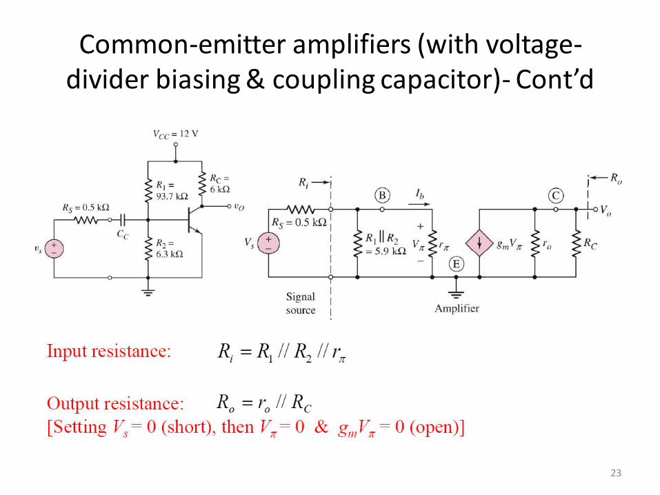
Common-emitter amplifiers (with voltage-
divider biasing & coupling capacitor)- Cont’d
23

Common-emitter amplifiers (with voltage-divider
biasing & coupling capacitor & emitter resistor)
24
dc & ac load lines
• Dc load line is used to find Q-point
• Ac load line is used to determine graphically
the operation of a BJT amplifier
• Dc and ac load lines are essentially different
since capacitors appear as an open circuit for
a de operation but a short circuit for an ac
operation
25
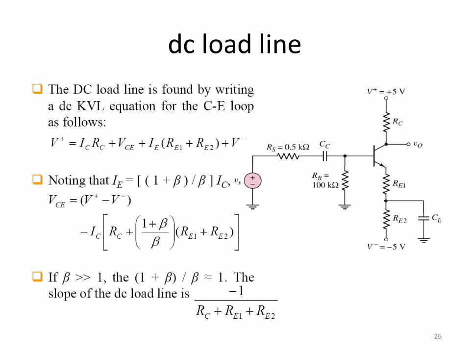
dc load line
26
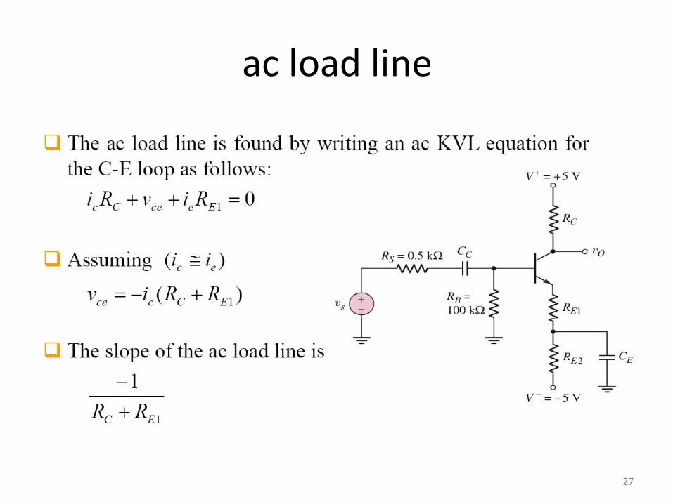
ac load line
27

Maximum output symmetrical swing
28

Saturation
29

Cutoff
30

Example: Calculate BJT circuit
parameters
• Determine the small-signal voltage gain, input
resistance, and output resistance of the circuit
shown in attached Figure. Assume the transistor
parameters are: β=100, VBE(on) =0.7V, and VA=100V
31

32
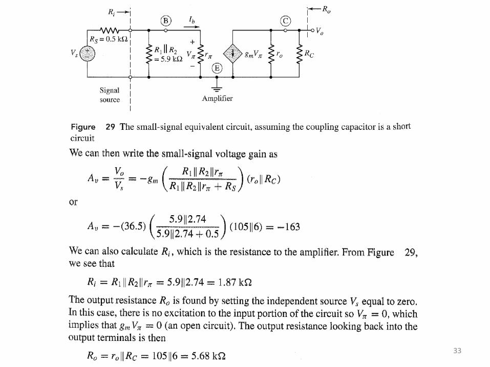
33

END
34
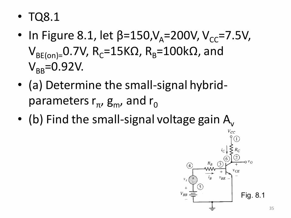
• TQ8.1
• In Figure 8.1, let β=150,VA=200V, VCC=7.5V,
VBE(on)=0.7V, RC=15KΩ, RB=100kΩ, and
VBB=0.92V.
• (a) Determine the small-signal hybrid-
parameters rπ, gm, and r0
• (b) Find the small-signal voltage gain Av
35
Fig. 8.1