Operational Amplifier II lec 9
37
Engineering and Architecture Analog Electronics Circuits EEE321 Lec 9 Operational Amplifier II Lecturer Sally Adil
-
Upload
khangminh22 -
Category
Documents
-
view
0 -
download
0
Transcript of Operational Amplifier II lec 9

Engineering and
Architecture
Analog
Electronics
Circuits
EEE321
Lec 9
Operational Amplifier II
Lecturer Sally Adil

– The output of a linear op-amp circuit has the same shape
as the input signal. At no time during the cycle does the op
amp go into saturation.
– The output of a nonlinear op-amp circuit usually has a
different shape from the input signal because the op-amp
saturates during part of the input cycle.
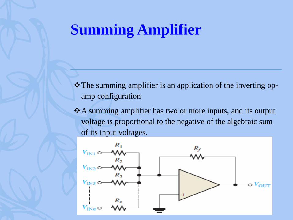
Summing Amplifier
❖The summing amplifier is an application of the inverting op-
amp configuration
❖A summing amplifier has two or more inputs, and its output
voltage is proportional to the negative of the algebraic sum
of its input voltages.

1.Summing Amplifier with
Unity Gain
– Two voltages, Vin1 and Vin2 are applied to the inputs and produce
currents I1 and I2, as shown. Using the concepts of infinite input
impedance and virtual ground, you can determine that the inverting
input of the op-amp is approximately 0 V and has no current through it.
This means that the total current IT, which goes through Rf divides into
I1 and I2 at summing point A,

1.Summing Amplifier with
Unity Gain
– for a unity-gain summing amplifier with n inputs where all
resistors are equal in value.

2. Summing Amplifier with Gain
Greater Than Unity
❖When Rf is larger than the input resistors, the amplifier has
a gain of Rf /R, where R is the value of each equal-value
input resistor. The general expression for the output is

Summing Amplifier with Gain
Greater Than Unity

3. Averaging Amplifier
– An averaging amplifier is basically a summing amplifier
with the gain set to Rf /R = 1/n (n is the number of inputs).
The output is the negative average of the inputs.


4 .Scaling Adder
❖A scaling adder has two or more inputs with each input
having a different gain. The output represents the negative
scaled sum of the inputs.
❖The weight of a particular input is set by the ratio of Rf to
the resistance, Rx.


Applications of Summing
amplifier
❖ D/A conversion is an important interface process for
converting digital signals to analog (linear) signals
❖ Method of D/A conversion
1. binary-weighted resistor DAC).
2. the R/2R ladder method

Comparator
– A comparator is a specialized nonlinear op-amp circuit that
compares two input voltages and produces an output state
that indicates which one is greater. Comparators are
designed to be fast and frequently have other capabilities to
optimize the comparison function.

Comparator
❖ Because the output is always in one of two states,
comparators are often used to interface between an analog
and digital circuit
❖ For less critical applications, an op-amp running without
negative feedback (open-loop)is often used as a comparator.
❖ In general, comparators cannot be used as op-amps, but op-
amps can be used as comparators in noncritical applications
Why? Because an op-amp without negative feedback is
essentially a comparator,

Zero-Level Detection
– the inverting input is grounded to produce a zero level and that the
input signal voltage is applied to the noninverting input.
– Because of the high open-loop voltage gain, a very small difference
voltage between the two inputs drives the amplifier into saturation,
causing the output voltage to go to its limit.
The op-amp as a zero-level detector.

Nonzero-Level Detection


Comparator with Hysteresis
– Sometimes the input signal to a comparator may vary due to noise superimposed on the input. The result can be an unstable output. To avoid this, hysteresis can be used
– Hysteresis is incorporated by adding regenerative (positive) feedback,
which creates two switching points:
the upper trigger point (UTP)
and the lower trigger point (LTP).
After one trigger point is crossed,
it becomes inactive and the other
one becomes active.

Comparator with Hysteresis
– A comparator with hysteresis is also called a Schmitt
trigger. The trigger points are found by applying the
voltage-divider rule:
( )2UTP ( )
1 2
out max
RV V
R R= +
+
( )2LTP ( )
1 2
out max
RV V
R R= −
+


Output Bounding
– Some applications require a limit to the output of the
comparator (such as a digital circuit). The output can be
limited by using one or two zener diodes in the feedback
circuit.
– The circuit shown here is bounded as a positive value equal
to the zener breakdown voltage.


Comparator Applications
– Simultaneous or flash analog-to-digital

Integrator
– The ideal integrator is an inverting amplifier that has a
capacitor in the feedback path. The output voltage is
proportional to the negative integral (running sum) of the
input voltage.
The output is the integral of the
input; i.e., proportional to the
area under the input waveform.
This circuit is useful in low-
pass filter circuits and sensor
conditioning circuits.
−= dttvRC
tvo )(1
)( 1

Integrator
– Op-amp integrating circuits must have extremely low dc
offset and bias currents, because small errors are equivalent
to a dc input. The ideal integrator tends to accumulate these
errors, which moves the output toward saturation. The
practical integrator overcomes these errors– the simplest
method is to add a relatively large feedback resistor.

Integrator
– If a constant level is the input, the current is
constant. The capacitor charges from a constant
current and produces a ramp. The slope of the
output is given by the equation:
out in
i
V V
t R C
= −


Differentiator
– The ideal differentiator is an inverting amplifier that has a
capacitor in the input path. The output voltage is
proportional to the negative rate of change of the input
voltage.
The differentiator takes
the derivative of the input.
This circuit is useful in
high-pass filter circuits.
dt
tdvRCtvo
)()( 1−=

Differentiator
– The small reactance of C at high frequencies means an ideal
differentiator circuit has very high gain for high-frequency
noise. To compensate for this, a small series resistor is often
added to the input. This practical differentiator has
reduced high frequency gain and is less prone to noise.

Differentiator
– The output voltage of a differentiator is given by
Cout f
VV R C
t
= −


Thank you