Features General Description Counter
30
PSoC® Creator™ Component Data Sheet Cypress Semiconductor Corporation • 198 Champion Court • San Jose, CA 95134-1709 • 408-943-2600 Document Number: 001-63039 Rev. *B Revised July 29, 2013 PRELIMINARY Features Supports fixed-function and UDB-based implementations 8-, 16-, 24-, or 32-bit Counter Configurable as Up, Down or Up and Down Counter Optional Compare Output Optional Capture Input Enable and reset inputs to synchronize with other components Continuous or One shot run modes General Description The Counter component provides an up, down, or up and down (up/down) counter with a programmable period. The counter is designed to provide an easy method of counting events. The Counter component can optionally capture the current count value for software use or generate a compare output for hardware signaling or synchronization. Up counters and down counters count in only one direction and require only a single count input to the Counter. The signal to be counted may be routed from an I/O pin or from other internal component outputs. Count events occur each time a rising edge is detected on the count input. Once started, the Counter operates continuously and reloads the Counter on terminal count by default. For a down Counter, the terminal count is zero and the Counter is reloaded with the Period value. For an up Counter, the terminal count is the Period value and the Counter is reloaded with zero. The up-and-down Counter functions in a similar manner to the up Counter and down Counter. Two versions of the up and down Counter are available based on application requirements: The first version provides a count input and a direction input. When active, a 1 on the up and down input forces the Counter to increment by one on a rising edge of the count input. A 0 on the up and down input causes the Counter to decrement by one on a rising edge of the count input. The second version provides an up count input and a down count input. The Counter will increment or decrement based on which respective count input had a rising edge. This version of the Counter requires an additional oversample clock input while all other versions do not. On Counter underflow and overflow, flags are set and the period reloaded allowing glitch proof counter expansion in firmware. Counter 1.50
-
Upload
khangminh22 -
Category
Documents
-
view
3 -
download
0
Transcript of Features General Description Counter

PSoC® Creator™ Component Data Sheet
Cypress Semiconductor Corporation • 198 Champion Court • San Jose, CA 95134-1709 • 408-943-2600 Document Number: 001-63039 Rev. *B Revised July 29, 2013
PRELIMINARY
Features Supports fixed-function and UDB-based implementations
8-, 16-, 24-, or 32-bit Counter
Configurable as Up, Down or Up and Down Counter
Optional Compare Output
Optional Capture Input
Enable and reset inputs to synchronize with other components
Continuous or One shot run modes
General Description The Counter component provides an up, down, or up and down (up/down) counter with a programmable period. The counter is designed to provide an easy method of counting events. The Counter component can optionally capture the current count value for software use or generate a compare output for hardware signaling or synchronization. Up counters and down counters count in only one direction and require only a single count input to the Counter. The signal to be counted may be routed from an I/O pin or from other internal component outputs. Count events occur each time a rising edge is detected on the count input. Once started, the Counter operates continuously and reloads the Counter on terminal count by default. For a down Counter, the terminal count is zero and the Counter is reloaded with the Period value. For an up Counter, the terminal count is the Period value and the Counter is reloaded with zero. The up-and-down Counter functions in a similar manner to the up Counter and down Counter. Two versions of the up and down Counter are available based on application requirements:
The first version provides a count input and a direction input. When active, a 1 on the up and down input forces the Counter to increment by one on a rising edge of the count input. A 0 on the up and down input causes the Counter to decrement by one on a rising edge of the count input.
The second version provides an up count input and a down count input. The Counter will increment or decrement based on which respective count input had a rising edge. This version of the Counter requires an additional oversample clock input while all other versions do not. On Counter underflow and overflow, flags are set and the period reloaded allowing glitch proof counter expansion in firmware.
Counter1.50

Counter PSoC® Creator™ Component Data Sheet
Page 2 of 30 Document Number: 001-63039 Rev. *B
PRELIMINARY
During each clock cycle, the optional compare output compares the current count to the compare value. The compare mode is configurable to all the standard Boolean comparison modes providing several waveform options. The compare output provides a logic level that may be routed to I/O pins and to other component inputs. An optional capture input copies the current count value into a storage location on a rising edge. Firmware may read out the capture value at any time without timing restrictions as long as the capture FIFO has room. The capture FIFO allows storage of up to 4 capture values. The enable and reset inputs allow the Counter to be synchronized with other internal or external hardware. The Counter enable signal may be generated by a software API, the hardware compare input, or the AND of both. For the hardware enable input, the Counter only counts while the enable input is high. A rising edge on the reset input causes the Counter to reset its count as if the terminal count was reached. If the reset input remains high, the Counter will remain in reset. An interrupt can be programmed to be generated under any combination of the following conditions: when the counter reaches the terminal count, the comparator output is asserted, or a capture event has occurred.
When to use a Counter The default use of the Counter is to count the number of rising edge events on the count input. However, there are several other potential uses of the Counter:
The Counter can be used as a clock divider by driving a clock into the count input and using the compare or terminal count outputs as the divided clock output.
The Counter may also be used as a frequency counter by providing a known period on the enable input of the counter while counting the signal to measure on the count input. After the enable period, the Counter will contain the number of rising edges measured during that period allowing calculation of the input frequency.
The up and down Counter may be used to measure complementary events such as the output of a quadrature decoder to measure a sensors position.
A Timer component is better used in situations focused on timing the length of events, measuring the interval of multiple rising and/or falling edges, or for multiple capture events. A PWM component is better used in situations requiring multiple compare outputs with more control features like center alignment, output kill and deadband outputs.

PSoC® Creator™ Component Data Sheet Counter
Document Number: 001-63039 Rev. *B Page 3 of 30
PRELIMINARY
Input/Output Connections This section describes the various input and output connections for the Counter. Some I/Os may be hidden on the symbol under the conditions listed in the description of that I/O. Note All signals are active high unless otherwise specified.
Input May Be Hidden
Description
clock Y The clock input defines oversample clock necessary to implement an increment on upCnt, decrement on dwnCnt, or no change on upCnt and dwnCnt. This input is only visible if the Clock Mode parameter is set to “Clock + upCnt & dwnCnt”.
count Y The count input defines the signal to count. The counter value is incremented or decremented based on the direction or pin usage chosen in the Clock Mode parameter. This input is visible in any of the clock modes except “Clock + upCnt & dwnCnt”.
reset N The reset input resets the counter to the starting value. For the "Up Counter" configuration, the starting value is zero. For "Down Counter", "Count Input and Direction" and "Clock With UpCnt &
DwnCnt" configurations, the starting value is set to the current period register value Note For PsoC3 ES2 silicon, the Terminal Count pin for the fixed function counter is held HIGH in Reset. A schematic fix for this is provided under "Reset in Fixed Function Block" in the Functional Description section of this data sheet. For PsoC3 ES3 or later silicon, Terminal Count pin for the fixed function counter is held LOW in Reset
enable Y Hardware enable of the counter. This input is visible if the functionality is required as defined by the configuration of the Enable Mode parameter. This input signal is asynchronous to the datapath clock.
up_ndown Y Defines the counting direction of the counter. This input is only available if Clock Mode is set to enable direction control (“Count + Direction Inputs”). When active a ‘1’ on this input forces the counter to increment by one on a rising edge of the count input, a ‘0’ on this input causes the counter to decrement by one on a rising edge of the count input. This input signal is asynchronous to the datapath clock.
upCnt Y Increment signal to the counter. When Clock Mode is set to “Clock + upCnt & dwnCnt” this input is used in conjunction with the dwnCnt input and the clock input to provide the ability for the Counter to be used as an encoder where a rising edge on this input increments the count value by 1.
dwnCnt Y Decrement signal to the counter. When Clock Mode of the counter is set to “Clock + upCnt & dwnCnt” this input is used in conjunction with the upCnt input and the clock input to provide the ability for the counter to be used as an encoder where a rising edge on this input decrements the count value by 1.
capture Y Captures the current count value to a storage FIFO. The FIFO for this operation is four entries deep. This input is visible if the Capture Mode parameter set to any mode other than “None”.
Counter PSoC® Creator™ Component Data Sheet
Page 4 of 30 Document Number: 001-63039 Rev. *B
PRELIMINARY
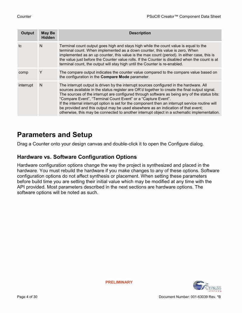
Output May Be Hidden
Description
tc N Terminal count output goes high and stays high while the count value is equal to the terminal count. When implemented as a down counter, this value is zero, When implemented as an up counter, this value is the max count (period). In either case, this is the value just before the Counter value rolls. If the Counter is disabled when the count is at terminal count, the output will stay high until the Counter is re-enabled.
comp Y The compare output indicates the counter value compared to the compare value based on the configuration in the Compare Mode parameter.
interrupt N The interrupt output is driven by the interrupt sources configured in the hardware. All sources available in the status register are OR’d together to create the final output signal. The sources of the interrupt are configured through software as being any of the status bits: “Compare Event”, “Terminal Count Event” or a “Capture Event”. If the internal interrupt option is set for the component then an interrupt service routine will be provided and this output may be used elsewhere as an indication of that event; otherwise, this may be connected to another interrupt object in a schematic implementation.
Parameters and Setup Drag a Counter onto your design canvas and double-click it to open the Configure dialog.
Hardware vs. Software Configuration Options Hardware configuration options change the way the project is synthesized and placed in the hardware. You must rebuild the hardware if you make changes to any of these options. Software configuration options do not affect synthesis or placement. When setting these parameters before build time you are setting their initial value which may be modified at any time with the API provided. Most parameters described in the next sections are hardware options. The software options will be noted as such.
PSoC® Creator™ Component Data Sheet Counter
Document Number: 001-63039 Rev. *B Page 5 of 30
PRELIMINARY
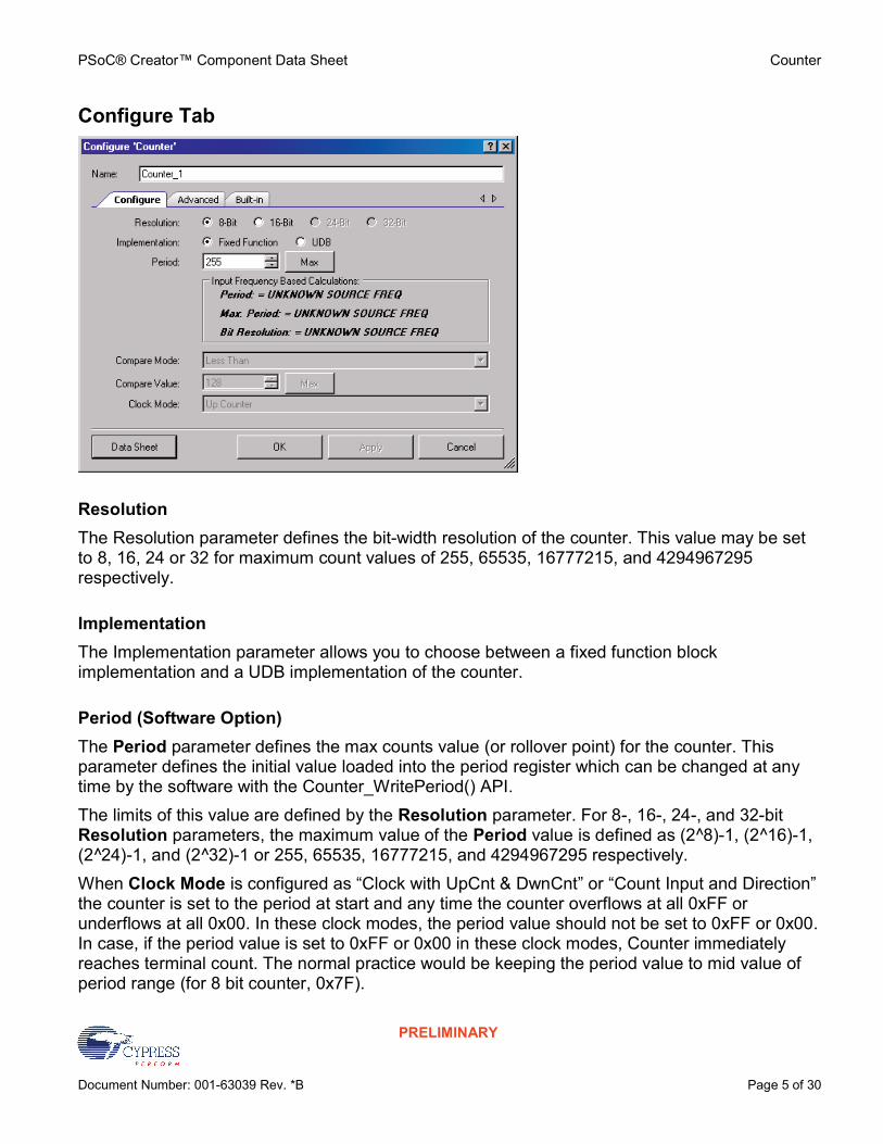
Configure Tab
Resolution The Resolution parameter defines the bit-width resolution of the counter. This value may be set to 8, 16, 24 or 32 for maximum count values of 255, 65535, 16777215, and 4294967295 respectively.
Implementation The Implementation parameter allows you to choose between a fixed function block implementation and a UDB implementation of the counter.
Period (Software Option) The Period parameter defines the max counts value (or rollover point) for the counter. This parameter defines the initial value loaded into the period register which can be changed at any time by the software with the Counter_WritePeriod() API. The limits of this value are defined by the Resolution parameter. For 8-, 16-, 24-, and 32-bit Resolution parameters, the maximum value of the Period value is defined as (2^8)-1, (2^16)-1, (2^24)-1, and (2^32)-1 or 255, 65535, 16777215, and 4294967295 respectively. When Clock Mode is configured as “Clock with UpCnt & DwnCnt” or “Count Input and Direction” the counter is set to the period at start and any time the counter overflows at all 0xFF or underflows at all 0x00. In these clock modes, the period value should not be set to 0xFF or 0x00. In case, if the period value is set to 0xFF or 0x00 in these clock modes, Counter immediately reaches terminal count. The normal practice would be keeping the period value to mid value of period range (for 8 bit counter, 0x7F).

Counter PSoC® Creator™ Component Data Sheet
Page 6 of 30 Document Number: 001-63039 Rev. *B
PRELIMINARY
The following figure shows the working of counter in Count Input and Direction Clock mode.
Compare Mode (Software Option) The Compare Mode parameter configures the operation of the Compare output signal which is the status of a compare between the compare value parameter and current counter value. This parameter defines the initial setting loaded into the control register. The control register bit-field may be updated at any time to re-configure the compare operation of the counter. This value is an enumerated type and can be set to any of the following modes:
“Less Than”: The Counter value is less than the compare value
“Less Than Or Equal To”: The Counter value is less than or equal to the compare value
“Equal To”: The Counter value is equal to the compare value
“Greater Than”: The Counter value is greater than the compare value
“Greater Than Or Equal To”: The Counter value is greater than or equal to the compare value
"Software Controlled": The compare mode can be set during runtime with the SetCompareMode() API call to any one of the 5 compare modes listed above.
Compare Value (Software Option) The Compare Value parameter defines the initial value loaded into the compare register of the counter. This value is used in conjunction with the Compare Mode parameter selected to define the operation of the compare output. This value can be any unsigned integer value from 0 to (2^Resolution-1), but it must be less than the max_counts or Period value. If the value is allowed to be larger than max_counts, the compare output would be a constant ‘0’ or ‘1’ value and is therefore not allowed.

PSoC® Creator™ Component Data Sheet Counter
Document Number: 001-63039 Rev. *B Page 7 of 30
PRELIMINARY
Clock Mode The Clock Mode parameter configures the clocking and direction control method that is desired for this instance of the counter. This value is an enumerated type and can be set to any of the following options:
"Count Input + Direction": Counter is a bi-directional counter counting up while the up_ndown input is high on each rising edge of the input clock and counting down while up_ndown is low on each rising edge of the input clock. In this mode, the Counter works asynchronously with respect to the datapath clock.
“Clock with UpCnt & DwnCnt”: Counter is a bi-directional counter incrementing the counter by 1 for each rising edge on the upCnt input and decrementing the counter by 1 for each rising edge of the dwnCnt input.
“Up Counter”: Counter is an up counter only configured to increment on any rising edge of the input clock signal while the counter is enabled.
“Down Counter”: Counter is a down counter only configured to decrement on any rising edge of the input clock signal while the counter is enabled.
Advanced Tab

Counter PSoC® Creator™ Component Data Sheet
Page 8 of 30 Document Number: 001-63039 Rev. *B
PRELIMINARY
Capture Mode The Capture Mode parameter configures the implementation of the capture input. This value is an enumerated type and can be set to any of the following values:
“None”: No capture implemented and the capture input pin is hidden
“Rising Edge”: Capture the counter value on any rising edge of the capture input
“Falling Edge”: Capture the counter value on any falling edge of the capture input
“Either Edge”: Capture the counter value on any edge of the capture input
"Software Controlled": For Software Controlled mode, set the mode at runtime by setting the Compare Mode bits in the control register Counter_CTRL_CAPMODE_MASK with the enumerated capture mode types defined in the Counter.h header file.
Note In general the capture function will not reliably work with UpCnt & DwnCnt Clock Mode, since a separate up and down signal is used. In this mode, the clock used for edge detection (clock) is different than the clock used for the datapath (clock combined with an edge detect on the up and down clocks). It depends on the exact alignment of the capture edge and an up down count edge.
Enable Mode The Enable Mode parameter configures the enable implementation of the counter. This value is an enumerated type and can be set to any of the following options:
“Software”: The Counter is enabled based on the enable bit of the control register only
“Hardware”: The Counter is enabled based on the enable input only
“Software And Hardware”: The Counter is enabled if and only if both the input and the control register bits are active
Run Mode The Run Mode parameter allows you to configure the Counter component to run continuously or in one shot mode:
“Continuous”: The Counter will run so long as the enable conditions are true
“One Shot”: The Counter will run through a single period and stop after terminal count until the Counter component is hardware reset at which point it will begin another single cycle. On stop, it reloads period into count register in case of UDB counter where as count register remains at terminal count in case of Fixed function counter.

PSoC® Creator™ Component Data Sheet Counter
Document Number: 001-63039 Rev. *B Page 9 of 30
PRELIMINARY
Reload Counter The Reload Counter parameters allow you to configure the counter value to be reloaded when one or more of the following selected events occur. The counter is reloaded with its start value (for an up counter this is reloaded to a value of “Zero”, for a down counter this is reloaded to the max counts or period value). This configuration is OR’d with all of the other Reload Counter parameters to provide the final reload trigger to the counter.
On Capture – The counter value will be reloaded when a capture event has occurred. By default this parameter is set to “false”. This parameter is only shown when "UDB" is selected for Implementation.
On Compare – The counter value will be reloaded when a compare true event has occurred. By default this parameter is set to “false”. This parameter is only shown when "UDB" is selected for Implementation.
On Reset – The counter value will be reloaded when a reset event has occurred. By default this parameter is set to “true.” This parameter is always shown, but it is only active when "UDB" is selected for Implementation.
On TC – The counter value will be reloaded when the counter has overflowed (in count up mode) or underflowed (in count down mode). By default this parameter is set to “true”. This parameter is always shown, but it is only active when "UDB" is selected for Implementation. When the clock mode is set to “Clock with UpCnt & DwnCnt” this option reloads to the period value when counter is 0x00 or all 0xFF. This configuration is OR’d with all of the other reload parameters to provide the final reload trigger to the counter.
Interrupt The Interrupt parameters allow you to configure the initial interrupt sources. These values are OR’d with any of the other Interrupt parameters to give a final group of events that can trigger an interrupt. The software can re-configure this mode at any time; this parameter simply defines an initial configuration.
On TC –This option is always available; it is set to "false" by default.
On Capture – This option is set to "false" by default. It is always shown, but it is only active when "UDB" is selected for Implementation.
On Compare – This option is set to "false" by default. It is always shown, but it is only active when "UDB" is selected for Implementation.
Counter PSoC® Creator™ Component Data Sheet
Page 10 of 30 Document Number: 001-63039 Rev. *B
PRELIMINARY
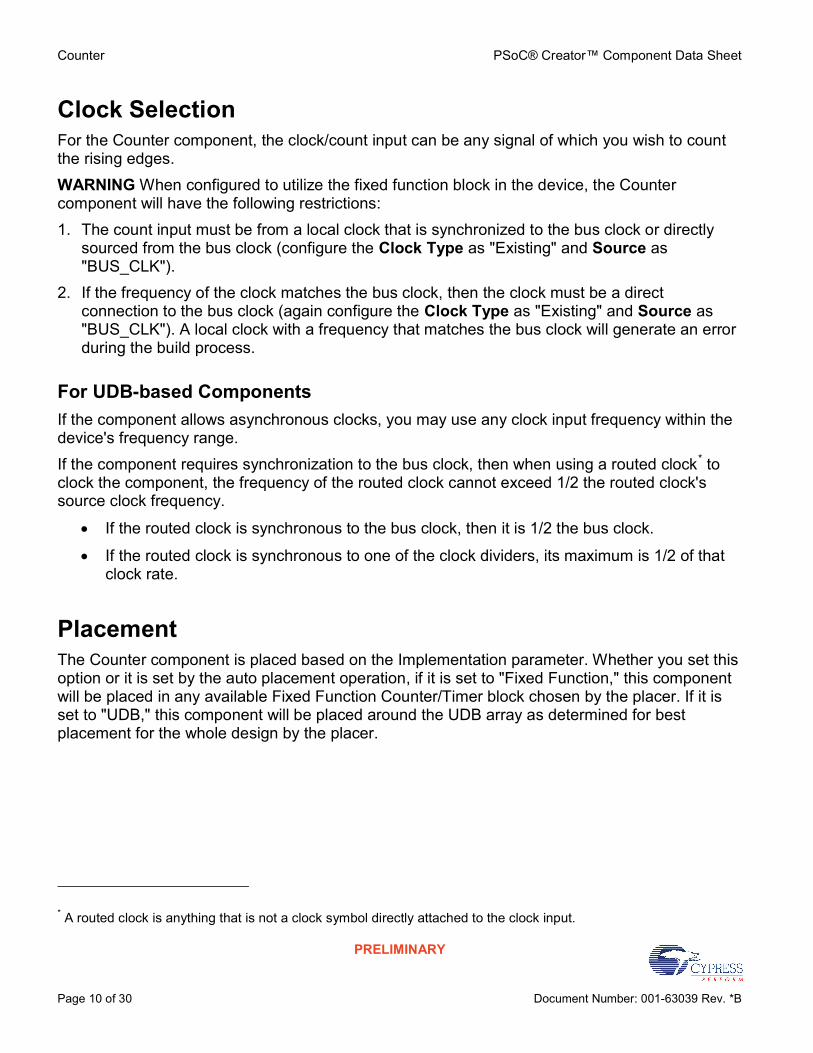
Clock Selection For the Counter component, the clock/count input can be any signal of which you wish to count the rising edges. WARNING When configured to utilize the fixed function block in the device, the Counter component will have the following restrictions: 1. The count input must be from a local clock that is synchronized to the bus clock or directly
sourced from the bus clock (configure the Clock Type as "Existing" and Source as "BUS_CLK").
2. If the frequency of the clock matches the bus clock, then the clock must be a direct connection to the bus clock (again configure the Clock Type as "Existing" and Source as "BUS_CLK"). A local clock with a frequency that matches the bus clock will generate an error during the build process.
For UDB-based Components If the component allows asynchronous clocks, you may use any clock input frequency within the device's frequency range. If the component requires synchronization to the bus clock, then when using a routed clock* to clock the component, the frequency of the routed clock cannot exceed 1/2 the routed clock's source clock frequency.
If the routed clock is synchronous to the bus clock, then it is 1/2 the bus clock.
If the routed clock is synchronous to one of the clock dividers, its maximum is 1/2 of that clock rate.
Placement The Counter component is placed based on the Implementation parameter. Whether you set this option or it is set by the auto placement operation, if it is set to "Fixed Function," this component will be placed in any available Fixed Function Counter/Timer block chosen by the placer. If it is set to "UDB," this component will be placed around the UDB array as determined for best placement for the whole design by the placer.
* A routed clock is anything that is not a clock symbol directly attached to the clock input.

PSoC® Creator™ Component Data Sheet Counter
Document Number: 001-63039 Rev. *B Page 11 of 30
PRELIMINARY
Resources Resolution Digital Blocks API Memory
(Bytes) Pins (per
External I/O)
Datapaths Macro cells
Status Registers
Control Registers
Counter7 Flash RAM
8 Bits 1 TBD 1 1 0 TBD TBD TBD
16 Bits 2 TBD 1 1 0 TBD TBD TBD
24 Bits 3 TBD 1 1 0 TBD TBD TBD
32 Bits 4 TBD 1 1 0 TBD TBD TBD
Up/Down Count
Addition
TBD TBD TBD TBD TBD TBD TBD TBD
Application Programming Interface Application Programming Interface (API) routines allow you to configure the component using software. The following table lists and describes the interface to each function. The subsequent sections cover each function in more detail. By default, PSoC Creator assigns the instance name "Counter_1" to the first instance of a component in a given design. You can the rename the instance to any unique value that follows the syntactic rules for identifiers. The instance name becomes the prefix of every global function name, variable, and constant symbol. For readability, the instance name used in the following table is "Counter."
Function Description
void Counter_Init(void) Initialize or restore default Counter configuration.
void Counter_Enable(void) Enable the Counter.
void Counter_Start(void) Initialize the Counter with default customizer values and enable the Counter.
void Counter_Stop (void) Disable the Counter operation; Clears the enable bit of the control register for either of the software controlled enable modes.
void Counter_SetInterruptMode (uint8 interruptsource)
Enables or disables the sources of the interrupt output from the optional interrupt sources defined by the bits in the status register.
uint8 Counter_GetInterruptSource (void)
Provides an interface where the firmware can query for the source of the a triggered interrupt placed on the interrupt output pin of the Timer
uint8 Counter_ReadStatusRegister (void)
Reads the status register and returns it's state. This function should use defined types for the bit-field information as the bits in this register may be permutable.

Counter PSoC® Creator™ Component Data Sheet
Page 12 of 30 Document Number: 001-63039 Rev. *B
PRELIMINARY
Function Description
uint8 Counter_ReadControlRegister (void)
Reads the control register and returns it's state. This function should use defined types for the bit-field information as the bits in this register may be permutable.
void Counter_WriteControlRegister (uint8 control)
Sets the bit-field of the control register. This function should use defined types for the bit-field information as the bits in this register may be permutable
void Counter_WriteCounter (uint8/16/32 count)
Writes a new counter value directly into the accumulator thus setting the counter and not the period to the value written
uint8/16/32 Counter_ReadCounter (void)
Reads the latest captured counter value. If no value has been captured to the FIFO then this value will be the current counter value.
uint8/16/32 Counter_ReadCapture (void)
Read the capture data from the first in first out buffer
void Counter_WritePeriod (uint8/16/32 period)
Writes the Period register with the new desired period or max counts value
uint8/16/32 Counter_ReadPeriod (void)
Reads the Period register providing the software with the current value used as the rollover value of the counter
void Counter_WriteCompare (uint8/16/32 compare)
Writes the Compare value register defining the compare output compare value (Compare Mode is set individually in the control register).
uint8/16/32 Counter_ReadCompare (void)
Reads the current Compare value register which defines the compare output compare value (Compare Mode is set individually in the control register).
void Counter_SetCompareMode (uint8 comparemode)
Set the compare mode using the enumerated types defined in the header file for the software controlled Compare mode type
void Counter_SetCaptureMode (uint8 capturemode)
Set the capture mode using the enumerated types defined in the header file for the software controlled Capture mode type
void Counter_ClearFIFO (void) Clears the capture FIFO of any previously captured data
void Counter_Sleep(void) Stops the Counter operation and saves the user configuration
void Counter_Wakeup(void) Restores and enables the user configuration
void Counter_SaveConfig(void) Save the configuration of Counter.
void Counter_RestoreConfig(void) Restore the configuration of Counter.
Global Variables Variable Description
Counter_initVar Indicates whether the Counter has been initialized. The variable is initialized to 0 and set to 1 the first time Counter_Start() is called. This allows the component to restart without reinitialization in after the first call to the Counter_Start() routine. If reinitialization of the component is required, then the Counter_Init() function can be called before the Counter_Start() or Counter_Enable() function.

PSoC® Creator™ Component Data Sheet Counter
Document Number: 001-63039 Rev. *B Page 13 of 30
PRELIMINARY
void Counter_Init(void) Description: Initialize/Restore default Counter configuration. The counter starts as the continuous run mode
as default run mode. The interrupts are chosen as the output from the status register. If the UDB mode is set then the default Compare mode and Capture mode values are set as defined per the user configuration. The FIFO is cleared in case of UDB mode.
Parameters: None Return Value: None Side Effects: All registers will be set to their initial values and FIFO is cleared. This will re-initialize the
component.
void Counter_Enable(void) Description: Enables the Counter by setting the 7th bit of the control register for either of the software
controlled enable modes. In case of Fixed function mode the chosen fixed function block is enabled.
Parameters: None Return Value: None Side Effects: If the Enable mode is set to Hardware only then this function has no effect on the operation of
the Counter.
void Counter_Start(void) Description: Initialize the Counter with default customizer values and enables the Counter. Parameters: None Return Value: None Side Effects: Sets the enable bit in the control register of the Counter. If the enable bit is set to hardware
only, this has no effect on the Counter. If the enable mode is set to hardware and software, then this will only enable the software portion of this mode and the hardware input must also be enabled to finally enable the Counter.
void Counter_Stop(void) Description: Disable the Counter operation by resetting the 7th bit of the control register for either of the
software controlled enable modes. Disables the Fixed function block which had been chosen. Parameters: None Return Value: None Side Effects: Clears the enable bit in the control register.
Counter PSoC® Creator™ Component Data Sheet
Page 14 of 30 Document Number: 001-63039 Rev. *B
PRELIMINARY
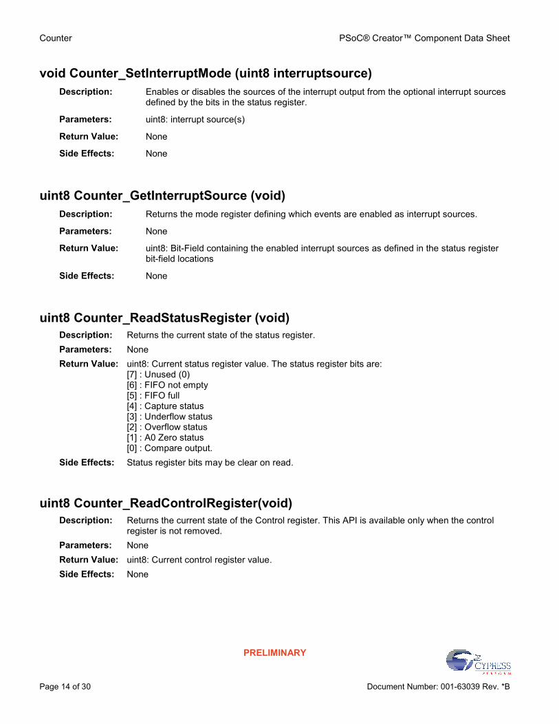
void Counter_SetInterruptMode (uint8 interruptsource) Description: Enables or disables the sources of the interrupt output from the optional interrupt sources
defined by the bits in the status register.
Parameters: uint8: interrupt source(s)
Return Value: None
Side Effects: None
uint8 Counter_GetInterruptSource (void) Description: Returns the mode register defining which events are enabled as interrupt sources.
Parameters: None
Return Value: uint8: Bit-Field containing the enabled interrupt sources as defined in the status register bit-field locations
Side Effects: None
uint8 Counter_ReadStatusRegister (void) Description: Returns the current state of the status register. Parameters: None Return Value: uint8: Current status register value. The status register bits are:
[7] : Unused (0) [6] : FIFO not empty [5] : FIFO full [4] : Capture status [3] : Underflow status [2] : Overflow status [1] : A0 Zero status [0] : Compare output.
Side Effects: Status register bits may be clear on read.
uint8 Counter_ReadControlRegister(void) Description: Returns the current state of the Control register. This API is available only when the control
register is not removed. Parameters: None Return Value: uint8: Current control register value. Side Effects: None

PSoC® Creator™ Component Data Sheet Counter
Document Number: 001-63039 Rev. *B Page 15 of 30
PRELIMINARY
void Counter_WriteControlRegister(uint8 control) Description: Sets the bit-field of the Control register. This API is available only when the control register is
not removed. Parameters: uint8: Control register Bit-Field. The control register bits are:
[7] :Counter Enable [6] :Reset [5] :Unused [4:3] : Capture Mode select [2:0] : Compare Mode select
Return Value: None Side Effects: None
void Counter_WriteCounter (uint8/16/24/32 count) Description: Writes a new counter value directly into the accumulator thus setting the counter and not the
period to the value written. In case of Fixed function mode 8/16 bit value can be written and in case of UDB mode 8/16/24/32 bit value can be written.
Parameters: (uint8/16/24/32) New Counter value Return Value: None Side Effects: Overwrites the counter value which may cause undesired affects on the compare output,
terminal count output or period width of the counter.
uint8/16/32 Counter_ReadCounter (void) Description: Reads the latest captured counter value. If no value has been captured to the FIFO then
this value will be the current counter value.
Parameters: None
Return Value: (uint8/16/32) Counter Value
Side Effects: None
uint8/16/32 Counter_ReadCapture (void) Description: Read the capture data from the first in first out buffer
Parameters: None
Return Value: (uint8/16/32) Capture Value
Side Effects: Unloads one value from the FIFO. If the FIFO was empty then the data is stale data from a previous capture. FIFO status should always be checked before calling this function.

Counter PSoC® Creator™ Component Data Sheet
Page 16 of 30 Document Number: 001-63039 Rev. *B
PRELIMINARY
void Counter_WritePeriod (uint8/16/32 period) Description: Writes the Period register with the new desired period or max counts value
Parameters: (uint8/16/32) Period Value
Return Value: None
Side Effects: None
uint8/16/32 Counter_ReadPeriod (void) Description: Reads the Period register providing the software with the current value used as the
rollover value of the counter.
Parameters: None
Return Value: (uint8/16/32) Period Value
Side Effects: None
void Counter_WriteCompare (uint8/16/24/32 compare) Description: Writes the Compare value register defining the compare output compare value (Compare
Mode is set individually in the control register). This API is available only for UDB mode of the Counter.
Parameters: (uint8/16/24/32) Compare Value Return Value: None Side Effects: None
uint8/16/32 Counter_ReadCompare (void) Description: Reads the current Compare value register which defines the compare output compare
value (Compare Mode is set individually in the control register).
Parameters: None
Return Value: (uint8/16/32) Compare Value
Side Effects: None
PSoC® Creator™ Component Data Sheet Counter
Document Number: 001-63039 Rev. *B Page 17 of 30
PRELIMINARY
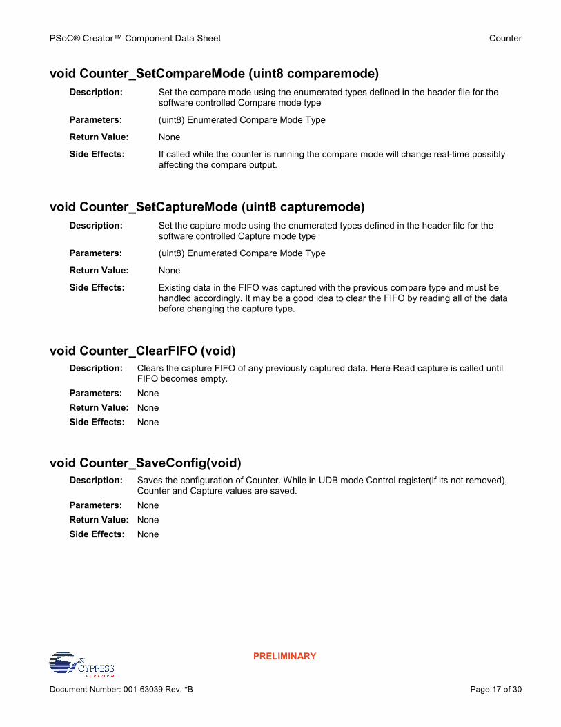
void Counter_SetCompareMode (uint8 comparemode) Description: Set the compare mode using the enumerated types defined in the header file for the
software controlled Compare mode type
Parameters: (uint8) Enumerated Compare Mode Type
Return Value: None
Side Effects: If called while the counter is running the compare mode will change real-time possibly affecting the compare output.
void Counter_SetCaptureMode (uint8 capturemode) Description: Set the capture mode using the enumerated types defined in the header file for the
software controlled Capture mode type
Parameters: (uint8) Enumerated Compare Mode Type
Return Value: None
Side Effects: Existing data in the FIFO was captured with the previous compare type and must be handled accordingly. It may be a good idea to clear the FIFO by reading all of the data before changing the capture type.
void Counter_ClearFIFO (void) Description: Clears the capture FIFO of any previously captured data. Here Read capture is called until
FIFO becomes empty. Parameters: None Return Value: None Side Effects: None
void Counter_SaveConfig(void) Description: Saves the configuration of Counter. While in UDB mode Control register(if its not removed),
Counter and Capture values are saved. Parameters: None Return Value: None Side Effects: None
Counter PSoC® Creator™ Component Data Sheet
Page 18 of 30 Document Number: 001-63039 Rev. *B
PRELIMINARY
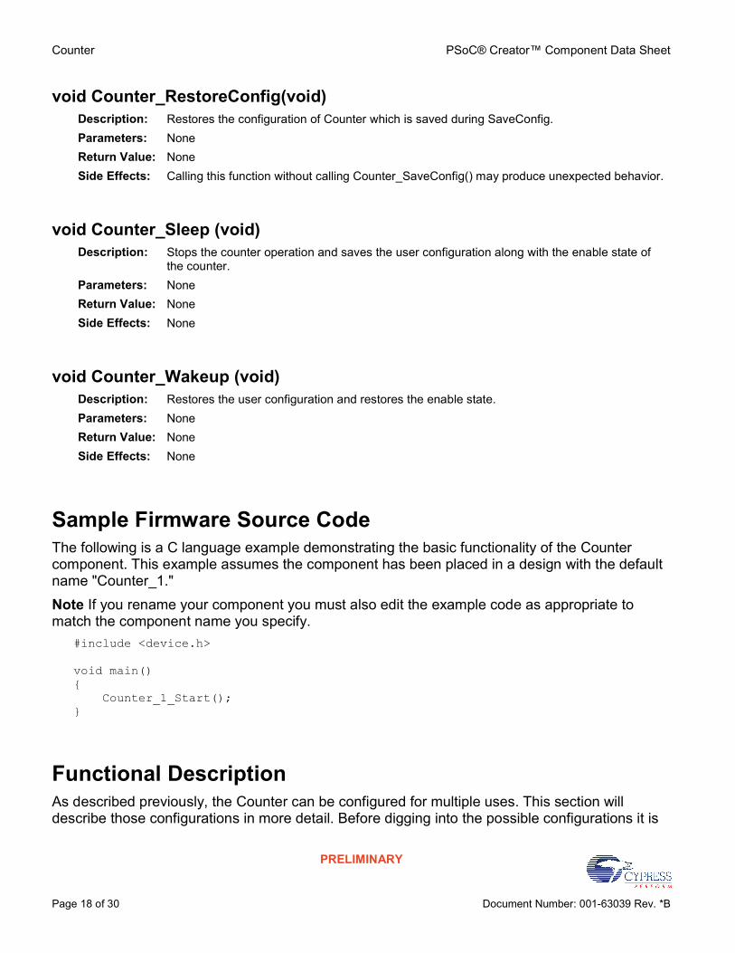
void Counter_RestoreConfig(void) Description: Restores the configuration of Counter which is saved during SaveConfig. Parameters: None Return Value: None Side Effects: Calling this function without calling Counter_SaveConfig() may produce unexpected behavior.
void Counter_Sleep (void) Description: Stops the counter operation and saves the user configuration along with the enable state of
the counter. Parameters: None Return Value: None Side Effects: None
void Counter_Wakeup (void) Description: Restores the user configuration and restores the enable state. Parameters: None Return Value: None Side Effects: None
Sample Firmware Source Code The following is a C language example demonstrating the basic functionality of the Counter component. This example assumes the component has been placed in a design with the default name "Counter_1." Note If you rename your component you must also edit the example code as appropriate to match the component name you specify.
#include <device.h>
void main() { Counter_1_Start(); }
Functional Description As described previously, the Counter can be configured for multiple uses. This section will describe those configurations in more detail. Before digging into the possible configurations it is

PSoC® Creator™ Component Data Sheet Counter
Document Number: 001-63039 Rev. *B Page 19 of 30
PRELIMINARY
important to know the limitations of using the Fixed Function Counter versus the UDB implementation.
Fixed Function Block Limitations The Counter, Timer, and PWM have very similar internal requirements that are implemented as fixed function blocks in the chip. There are a few configuration options for one of these blocks, and the limitations of this block as a counter versus the UDB implementation are listed below.
8 or 16-bits only
Down count only
Reload on Reset and Terminal Count only
Interrupt on Terminal Count only
Default Configuration The default configuration of the counter component provides the most basic counter which simply increments a count value on every rising edge of the clock input. With this configuration the component symbol will look like this:
Figure 1: Default Counter Configuration
The count input is the signal whose rising edge is counted and the reset input provides a hardware mechanism for resetting the count value. Since this is configured as an up counter by default when a reset event is seen on the reset input, the counter value will be reset to zero. Terminal count indicates in real time whether the counter value is at the terminal count (Maximum value or Period). The period is programmable to be any value from 1 to (2^Resolution)-1. The compare output is a real time indicator that the count value compares to the compare value as defined in the compare configuration. The compare configuration is set in the control register for the component and can be set by software at any time. The default Maximum Count (Period) is set to 2^Resolution-1 and the compare value is set to ½ of that number. The counter will

Counter PSoC® Creator™ Component Data Sheet
Page 20 of 30 Document Number: 001-63039 Rev. *B
PRELIMINARY
increment on any rising edge clock until the point when it will rollover at the terminal count. The following is a waveform showing the expected results.
Figure 2: Default Counter Implementation Example Waveform
Clock Divider Configuration A simple extension of the default configuration will provide a clock divider with programmable duty cycle. If a clock input where fed into the counter clock input with the default period and compare parameter settings the compare output would be a 50% duty cycle clock with 1/256th the frequency of the input clock. This is because the default compare configuration is less than or equal to which would have a high state on the compare output from 0 to 127 and a low signal from 128 to 255. Any even number period setting can have a 50% duty cycle. And duty cycle is as easy as changing the compare value or compare configuration. The following is an example waveform from a default configuration extended to divide the input clock by 6 and have a 50% duty cycle by setting the compare value to 2 (keeping the less than or equal to configuration for the compare mode).
Figure 3: Clock Divider Configuration Example Waveform

PSoC® Creator™ Component Data Sheet Counter
Document Number: 001-63039 Rev. *B Page 21 of 30
PRELIMINARY
Frequency Counter Configuration Adding hardware enable functionality to the basic counter allows the user to easily implement a frequency counter function. If the Enable input is driven by a known period signal such as a 1KHz Clock starting with a counter value of 0x00 and an up counter implementation, it is easy math to determine the frequency of an input signal as shown in the example waveform.
Figure 4: Frequency Counter Configuration Example Waveform
Fixed Function Configuration The fixed function configuration restricts the counter in placement options to one of the Fixed Function blocks on the chip. You should consider your resource needs when choosing to implement the counter in the fixed function block as an 8-bit fixed function counter wastes half of the fixed function block.
Reset in Fixed Function Block On PSoC 3 ES2 silicon, the fixed function implementation of the Counter differs from the UDB implementation in that the TC during reset goes high, whereas in the UDB implementation the TC goes low. The schematic below shows a Fixed Function Counter implementation which drives the TC low while the reset input is active, thus giving the same functionality as the UDB implementation of the same component.
Counter PSoC® Creator™ Component Data Sheet
Page 22 of 30 Document Number: 001-63039 Rev. *B
PRELIMINARY
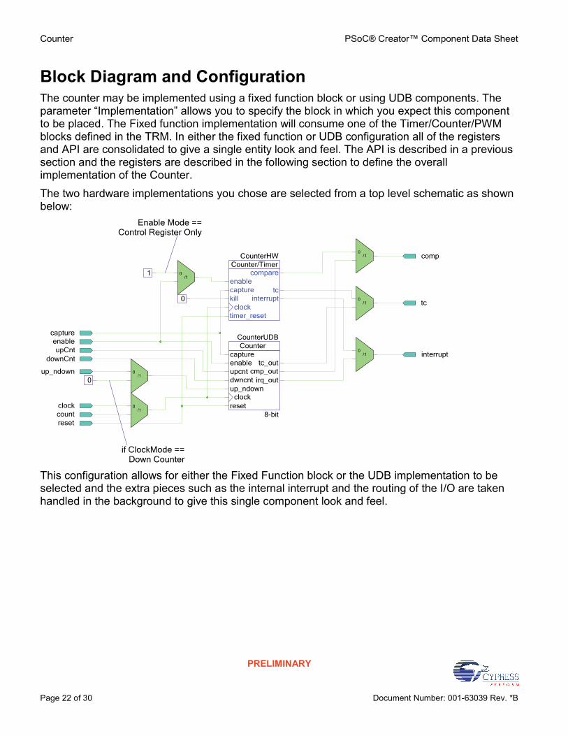
Block Diagram and Configuration The counter may be implemented using a fixed function block or using UDB components. The parameter “Implementation” allows you to specify the block in which you expect this component to be placed. The Fixed function implementation will consume one of the Timer/Counter/PWM blocks defined in the TRM. In either the fixed function or UDB configuration all of the registers and API are consolidated to give a single entity look and feel. The API is described in a previous section and the registers are described in the following section to define the overall implementation of the Counter. The two hardware implementations you chose are selected from a top level schematic as shown below:
This configuration allows for either the Fixed Function block or the UDB implementation to be selected and the extra pieces such as the internal interrupt and the routing of the I/O are taken handled in the background to give this single component look and feel.

PSoC® Creator™ Component Data Sheet Counter
Document Number: 001-63039 Rev. *B Page 23 of 30
PRELIMINARY
Registers
Status The status register is a read only register which contains the various status bits defined for the counter. The value of this register is available with the Counter_ReadStatusRegister() function call. The interrupt output signal (irq_out) is generated from an ORing of the masked bit-fields within this register. You can set the mask using the Counter_SetInterruptMode() function call and upon receiving an interrupt you can retrieve the interrupt source by reading the Status register with the Counter_GetInterruptSource() function call. The Status register is a clear on read register so the interrupt source is held until this function or the Counter_ReadStatusRegister () function is called. The Counter_GetInterruptSource() API will handle which interrupts are enabled to provide an accurate report of what the actual source of the interrupt was. All operations on the status register must use the following defines for the bit-fields as these bit-fields may be moved around within the status register during place and route. The status data is registered at the input clock edge of the counter giving all bits configured as mode=1 the timing resolution of the counter, these bits are sticky and are cleared on a read of the status register. All other bits configured as mode=0 are transparent and read directly from the inputs to the status register, they are not sticky and therefore not clear on read. All bits configured as Mode=1 are indicated with an asterisk (*) in the defines listed below. There are several bit-fields masks defined in the status register. Any of these bit-fields may be included as an interrupt source. The #defines are available in the generated header file (.h) as follows:
Counter_STATUS_CMP * Status of the Compare output. This bit goes high when the compare output is valid.
Counter_STATUS_ZERO * Status of the counter value as it relates to zero. This bit goes high when the counter value is equal to zero.
Counter_STATUS_OVERFLOW * Status of the counter value as it relates to the period. This bit will go high when the counter value is equal to the period value. This bit-field is not available when the Fixed Function block is selected for implementation.
Counter_STATUS_UNDERFLOW * Status of the counter value as it relates to the zero. This bit will go high when the counter value is equal to zero. This bit-field is not available when the Fixed Function block is selected for implementation.
Counter PSoC® Creator™ Component Data Sheet
Page 24 of 30 Document Number: 001-63039 Rev. *B
PRELIMINARY
Counter_STATUS_CAPTURE * Status of the Capture operation of the counter. This bit will go high whenever a valid capture event has been triggered. This does not include software capture as the hardware does not track the software interaction with capture.
Counter_STATUS_FIFOFULL Level status of the Capture FIFO. This bit will go high when the FIFO reaches the full state defined as 4 entries.
Counter_STATUS_FIFONEMP Level status of the Capture FIFO. This bit will go high when the FIFO contains at least one entry.
Control The Control register allows you to control the general operation of the counter. This register is written with the Counter_WriteControlRegister() function call and read with the Counter_ReadControlRegister(). When reading or writing the control register you must use the bit-field definitions as defined in the header (.h) file. The #defines for the control register are as follows:
Counter_CTRL_CMPMODE0_MASK The Compare mode control bits is a 3-bit field used to define the expected compare output operation. This bit-field will be 3 consecutive bits in the control register and all operations on this bit-field must use the #defines associated with the compare modes available. These are:
Counter__B_COUNTER__CM_LESSTHAN
Counter__B_COUNTER__CM_LESSTHANOREQUAL
Counter__B_COUNTER__CM_EQUAL
Counter__B_COUNTER__CM_GREATERTHAN
Counter__B_COUNTER__CM_GREATERTHANOREQUAL This bit-field is configured at initialization with the compare mode defined in the CompareMode parameter.
Counter_CTRL_CAPMODE_MASK The capture mode control bits is a 2-bit field used to define the expected capture input operation. This bit-field will be 2 consecutive bits in the control register and all operations on this bit-field must use the #defines associated with the capture modes available. These are:
Counter__B_COUNTER__CPTM_NONE
Counter__B_COUNTER__CPTM_RISINGEDGE
PSoC® Creator™ Component Data Sheet Counter
Document Number: 001-63039 Rev. *B Page 25 of 30
PRELIMINARY
Counter__B_COUNTER__CPTM_FALLINGEDGE
Counter__B_COUNTER__CPTM_EITHEREDGE This bit-field is configured at initialization with the capture mode defined in the CaptureMode parameter. The capture operation in the Fixed Function block is fixed as rising edge on the capture input. Therefore, since it is not programmable in the Fixed Function block this bit-field is not available in the control register in the Fixed Function implementation.
Counter_CTRL_RESET The software reset option allows you to reset the counter to a known state by setting and clearing the reset bit in the control register. When set high the Static Count register will be reloaded with the period value (if running as a down counter) or with zero (if running as an up counter). The Fixed Function block does not provide a software reset mechanism this is only possible as a hardware input. Therefore, this bit-field is not available when the counter is configured to use the Fixed Function implementation.
Counter_CTRL_ENABLE The enable bit controls software enabling of the counter operation. The counter has a configurable enable mode defined at build time. If the Enable mode parameter is set to “Input Only” then the functionality of this bit is none. However in either of the other modes the counter does not increment or decrement if this bit is not set high. Normal operation requires that this bit is set and held high during all operation of the counter.
Static Count (8, 16, 24 or 32-bit based on Resolution) The Static Count register contains the FIFO’d capture counter value. Any hardware capture event will push the current counter value onto this FIFO. The FIFO is read one entry at a time using the Counter_ReadCounter() function call. It may be useful to read the status register for the level indication of the FIFO before trying to read from the FIFO. This information is indicated in the STATUS_FIFOFULL and STATUS_FIFONEMPTY status bits.
Period (8, 16, 24 or 32-bit based on Resolution) The period register contains the period value set by the user through the Counter_WritePeriod() function call and defined by the Period parameter at initialization. The Period register has no affect on the counter until a terminal count is reached at which time the Counter register is reloaded. If the counter is configured as an UP counter, when the Counter value is equal to the Period the Counter register is reloaded (in hardware) to zero. Terminal count is defined as the Period Value for an UP Counter. However, if the counter is configured as a DOWN counter what the Counter value is equal to zero the Counter register is reloaded with the Period value. And Terminal count is defined as zero for the down counter.

Counter PSoC® Creator™ Component Data Sheet
Page 26 of 30 Document Number: 001-63039 Rev. *B
PRELIMINARY
Compare (8, 16, 24 or 32-bit based on Resolution) The compare register contains the compare value used to determine the state of the compare (comp) output. The compare output is based on how this register compares to the counter value in relation to the compare mode defined in the control register.
Counter (8, 16, 24 or 32-bit based on Resolution) The counter register contains the counter value throughout the operation of the counter. During basic operation this register is incrementing or decrementing by 1 while the counter is enabled and on each rising edge of the clock input. The contents of this register may be read at any time by the user with the Counter_ReadCounter() function call. When the terminal count is reached this register is reloaded with the period value you define in the period register through the Counter_WritePeriod() function call or during initialization with the Period parameter. The compare output is based on the relationship between the value held in this register and the value you define in the compare register through the Counter_WriteCompare() function call or during initialization with the CompareValue parameter. The Static Count register should not be written to from the CPU.
Conditional Compilation Information The counter API requires two conditional compile definitions to handle the multiple configurations it must support. It is required that the API conditionally compile on the Resolution chosen and the Implementation chosen between the Fixed Function block or the UDB blocks. The two conditions defined are based on the parameters FixedFunction and Resolution. The API should never use these parameters directly but should use the two define list below.
Counter_DataWidth The datawidth define is assigned to the Resolution value at build time. It is used throughout the API to compile in the correct data width types for the API functions relying on this information.
Counter_UsingFixedFunction The Using Fixed Function define is used mostly in the header file to make the correct register assignments as the registers provided in the fixed function block are different than those used when the counter is implemented in UDB’s. In some cases this define is also used with the DataWidth define because the Fixed Function block is limited to 16 bit’s maximum data width.
Constants There are several constants defined for the status and control registers as well as some of the enumerated types. Most of these are described above for the Control and Status Register. However there are more constants needed in the header file to make all of this happen. Each of the register definitions requires either a pointer into the register data or a register address.

PSoC® Creator™ Component Data Sheet Counter
Document Number: 001-63039 Rev. *B Page 27 of 30
PRELIMINARY
Because of multiple Endianness` of the compilers it is required that the CY_GET_REGX and CY_SET_REGX macros are used for register accesses greater than 8-bits. These macros require the use of the _PTR definition for each of the registers. It is also required that the control and status register bits be allowed to be placed and routed by the fitter engine in that we must have constants that define the placement of the bits. For each of the status and control register bits there is an associated _SHIFT value which defines the bit’s offset within the register. These are used in the header file to define the final bit mask as an _MASK definition (The _MASK extension is only added to bit-fields greater than a single bit, all single bit values drop the _MASK extension). The fixed function block has some limitations compared to the UDB implementations because it is designed with limited configurability. The UDB implementation is implemented according to the following block diagram.
Figure 5 UDB Implementation
The block diagram above shows the counter implemented as a datapath and some control logic. There is a status register and a control register that feed into and come out of the logic cloud as well. All of the logic for the counter is the same whether the datapath is 8, 16, 24, or 32 bits wide.
DC and AC Electrical Characteristics
DC Specifications Parameter Description Conditions Min Typ Max Units
Block current consumption 16-bit counter, at listed input clock frequency
- - - μA
3 MHz - 8 - μA
12 MHz - 30 - μA

Counter PSoC® Creator™ Component Data Sheet
Page 28 of 30 Document Number: 001-63039 Rev. *B
PRELIMINARY
Parameter Description Conditions Min Typ Max Units
48 MHz - 120 - μA
67 MHz - 165 - μA
AC Specifications Parameter Description Conditions Min Typ Max Units
Operating frequency DC - 67 MHz
Capture pulse 15 - - ns
Resolution 15 - - ns
Pulse width 15 - - ns
Pulse width (external) 30 ns
Enable pulse width 15 - - ns
Enable pulse width (external) 30 - - ns
Reset pulse width 15 - - ns
Reset pulse width (external) 30 - - ns
Component Changes This section lists the major changes in the component from the previous version.
Version Description of Changes Reason for Changes / Impact
1.50.b Minor datasheet edits.
1.50.a Minor datasheet edits.
1.50 Added Sleep/Wakeup and Init/Enable APIs. To support low power modes, as well as to provide common interfaces to separate control of initialization and enabling of most components.
Added Run Mode parameter to the Configure dialog, Advanced tab.
This was a requested feature to include a 'one shot' mode on the Counter just like the PWM and Timer.
Modified Verilog code to fix UDB counter reload on capture not working properly.
Capture detect signal was combinational because the edge detect signal width was too small. Now the Capture detect signal is registered using the clock block so that the edge detect pulse is available for one full block clock cycle.

PSoC® Creator™ Component Data Sheet Counter
Document Number: 001-63039 Rev. *B Page 29 of 30
PRELIMINARY
Version Description of Changes Reason for Changes / Impact
Updated the API files to add support for PSoC 3 ES3 and PSoC 5 ES2 silicon.
In PSoC 3 ES2 / PSoC 5 ES1, [3:1] bits of the CFG1 register must be used to set the run mode. In PSoC 3 ES3 / PSoC 5 ES2, [1:0] bits of CFG2 register must be used to set the run mode.
Added Keil function reentrancy support to the relevant APIs.
Add the capability for customers to specify individual generated functions as reentrant.
Changed the symbol to that a connection to the reset input is not required.
Change was made based on feedback from previous versions of the Counter.
Modified Verilog code to fix an issue with the Counter counting up.
There was issue with the Counter counting in the up direction when ClockMode is configured as 'Count Input and Direction'. Overflow and underflow signals were made dependent on 'Count Input and Direction' along with 'Clock With UpCnt & DownCnt' ClockMode.
Updated the API files to address a warning related to the usage of 'status' variable.
This warning was generating when MDK/RVDS compilers were used. Updated the ReadStatusRegister() function.
1.20.b Added information to the component that advertizes its compatibility with silicon revisions.
The tool reports an error/warning if the component is used on incompatible silicon. If this happens, update to a revision that supports your target device.
1.20.a Updated internal expression for the FixedFunction parameter; no affect on component behavior.
1.20 Updated from v1.10. Updated the component symbol to comply with corporate standard. Fixed several defects.
1.10.b Added information to the component that advertizes its compatibility with silicon revisions.
The tool reports an error/warning if the component is used on incompatible silicon. If this happens, update to a revision that supports your target device.
1.10.a Updated internal expression for the FixedFunction parameter; no affect on component behavior.
1.10 Updated from v1.0. Matched parameters with Configure Dialog. Changes to the APIs
1.0.b Added information to the component that advertizes its compatibility with silicon revisions.
The tool reports an error/warning if the component is used on incompatible silicon. If this happens, update to a revision that supports your target device.
1.0.a Updated internal expression for the FixedFunction parameter; no affect on component behavior.
1.0 Initial release.

Counter PSoC® Creator™ Component Data Sheet
Page 30 of 30 Document Number: 001-63039 Rev. *B
PRELIMINARY
© Cypress Semiconductor Corporation, 2008-2013. The information contained herein is subject to change without notice. Cypress Semiconductor Corporation assumes no responsibility for the use of any circuitry other than circuitry embodied in a Cypress product. Nor does it convey or imply any license under patent or other rights. Cypress products are not warranted nor intended to be used for medical, life support, life saving, critical control or safety applications, unless pursuant to an express written agreement with Cypress. Furthermore, Cypress does not authorize its products for use as critical components in life-support systems where a malfunction or failure may reasonably be expected to result in significant injury to the user. The inclusion of Cypress products in life-support systems application implies that the manufacturer assumes all risk of such use and in doing so indemnifies Cypress against all charges. PSoC® is a registered trademark, and PSoC Creator™ and Programmable System-on-Chip™ are trademarks of Cypress Semiconductor Corp. All other trademarks or registered trademarks referenced herein are property of the respective corporations. Any Source Code (software and/or firmware) is owned by Cypress Semiconductor Corporation (Cypress) and is protected by and subject to worldwide patent protection (United States and foreign), United States copyright laws and international treaty provisions. Cypress hereby grants to licensee a personal, non-exclusive, non-transferable license to copy, use, modify, create derivative works of, and compile the Cypress Source Code and derivative works for the sole purpose of creating custom software and or firmware in support of licensee product to be used only in conjunction with a Cypress integrated circuit as specified in the applicable agreement. Any reproduction, modification, translation, compilation, or representation of this Source Code except as specified above is prohibited without the express written permission of Cypress. Disclaimer: CYPRESS MAKES NO WARRANTY OF ANY KIND, EXPRESS OR IMPLIED, WITH REGARD TO THIS MATERIAL, INCLUDING, BUT NOT LIMITED TO, THE IMPLIED WARRANTIES OF MERCHANTABILITY AND FITNESS FOR A PARTICULAR PURPOSE. Cypress reserves the right to make changes without further notice to the materials described herein. Cypress does not assume any liability arising out of the application or use of any product or circuit described herein. Cypress does not authorize its products for use as critical components in life-support systems where a malfunction or failure may reasonably be expected to result in significant injury to the user. The inclusion of Cypress’ product in a life-support systems application implies that the manufacturer assumes all risk of such use and in doing so indemnifies Cypress against all charges. Use may be limited by and subject to the applicable Cypress software license agreement.