Feminist cinema as counter cinema: Is feminist cinema counter cinema?
Upload
khangminh22Category
view
0download
0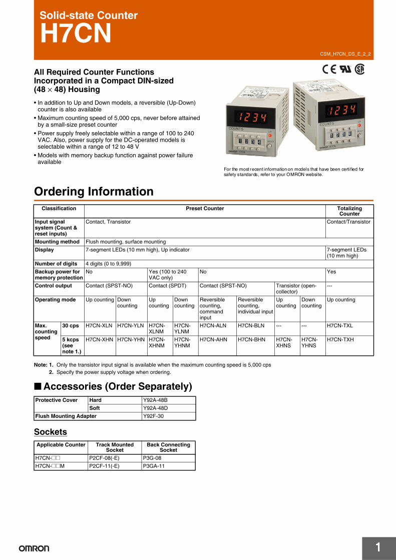
CSM_H7CN_DS_E_2_2
1
Solid-state Counter
H7CNAll Required Counter Functions Incorporated in a Compact DIN-sized (48 × 48) Housing• In addition to Up and Down models, a reversible (Up-Down)
counter is also available• Maximum counting speed of 5,000 cps, never before attained
by a small-size preset counter• Power supply freely selectable within a range of 100 to 240
VAC. Also, power supply for the DC-operated models is selectable within a range of 12 to 48 V
• Models with memory backup function against power failure available
For the most recent information on models that have been certified for safety standards, refer to your OMRON website.
Ordering Information
Note: 1. Only the transistor input signal is available when the maximum counting speed is 5,000 cps2. Specify the power supply voltage when ordering.
■ Accessories (Order Separately)
Sockets
Classification Preset Counter Totalizing Counter
Input signal system (Count & reset inputs)
Contact, Transistor Contact/Transistor
Mounting method Flush mounting, surface mountingDisplay 7-segment LEDs (10 mm high), Up indicator 7-segment LEDs
(10 mm high)Number of digits 4 digits (0 to 9,999)Backup power for memory protection
No Yes (100 to 240 VAC only)
No Yes
Control output Contact (SPST-NO) Contact (SPDT) Contact (SPST-NO) Transistor (open-collector)
---
Operating mode Up counting Down counting
Up counting
Down counting
Reversible counting, command input
Reversible counting, individual input
Up counting
Down counting
Up counting
Max. counting speed
30 cps H7CN-XLN H7CN-YLN H7CN-XLNM
H7CN-YLNM
H7CN-ALN H7CN-BLN --- --- H7CN-TXL
5 kcps (see note 1.)
H7CN-XHN H7CN-YHN H7CN-XHNM
H7CN-YHNM
H7CN-AHN H7CN-BHN H7CN-XHNS
H7CN-YHNS
H7CN-TXH
Protective Cover Hard Y92A-48BSoft Y92A-48D
Flush Mounting Adapter Y92F-30
Applicable Counter Track Mounted Socket
Back Connecting Socket
H7CN-@@ P2CF-08(-E) P3G-08H7CN-@@M P2CF-11(-E) P3GA-11

H7CN
2
Specifications
■ Ratings
Note: 1. The memory backup function is not available for this DC supply voltage range.2. On power application, an inrush current of approximately 10 times the normal current flows through the Counter.
■ Characteristics
■ Applicable Standards
Supply voltage 24, 100 to 240 VAC 50/60 Hz12 to 48 VDC (contains 20% ripple max.) (see note 1)
Operating voltage range 85% to 110% of rated voltagePower consumption (see note 2)
Approx. 12 VA/2.5 W (at 240 VAC, 50Hz)Approx. 2.5 W (at 48 VDC)
Count and reset input Impedance by short-circuiting contacts: 1 kΩ max.Residual voltage: 2 V max.Impedance by opening contacts: 100 kΩ min.
Max. counting speeds of count input
30 cps (contact and transistor inputs)Minimum pulse width: 16.7 ms (ON/OFF ratio: 1:1)
5.000 cps (transistor inputs)Minimum pulse width: 0.1 ms (ON/OFF ratio: 1:1)
Reset system Power-OFF resetReset time: 0.5 sReset time following power application 0.05 s
External reset & manual resetReset time: 0.02 sReset time following signal application: 0.05 s
Control output Contact (SPDT) output:3 A, 250 VAC, cosϕ = 1 (resistive load)
Transistor (open collector) output:30 VDC MAX. 100 mA max.
Case color Light gray (Munsell 5Y7/1)
Item Preset Counter Totalizing CounterInsulation resistance 100 MΩ min. (at 500 VDC) (between current-carrying
terminal and exposed non-current-carrying metal parts, and between non-continuous contacts)
100 MΩ min. (at 500 VDC) (between current-carrying terminal and exposed non-current-carrying metal parts)
Dielectric strength 2,000 VAC, 50/60 Hz for 1 min (between current-carrying terminal and exposed non-current carrying metal parts and between non-continuous contacts)
2,000 VAC, 50/60 Hz for 1 min (between current-carrying terminal and exposed non-current carrying metal parts)
Impulse withstand voltage 6 kV (between power terminals)6 kV (between current-carrying terminal and exposed non-current-carrying metal parts)
Noise immunity ±2 kV (between power terminals), ±500 V (between input terminals), square-wave noise by noise simulator
Static immunity Malfunction: 8 kVVibration resistance Destruction: 10 to 55 Hz, 0.75-mm single amplitude
Malfunction: 10 to 55 Hz, 0.5-mm single amplitudeShock resistance Destruction: 300 m/s2 (approx. 30G)
Malfunction: 100 m/s2 (approx. 10G)Ambient temperature Operating: –10°C to 55°C (with no icing)
Storage: –25°C to 65°C (with no icing)Ambient humidity 35% to 85%Life expectancy Mechanical: 10 million operations min.
Electrical: 100,000 operations min. (3 A at 250 VAC, resistive load)
---
Weight Approx. 110 g
Approved safety standards UL508/CSA C22.2 No. 14EN 61010-1 (IEC 61010-1): Pollution degree 2/overvoltage category II
EMC (EMI) EN61326Emission Enclosure: EN 55011 Group 1 class AEmission AC mains: EN 55011 Group 1 class A(EMS) EN61326Immunity ESD: EN 61000-4-2Immunity RF-interference: EN 61000-4-3Immunity Conducted Disturbance: EN 61000-4-6Immunity Burst: EN 61000-4-4Immunity Surge: EN 61000-4-5Immunity Voltage Dip/Interruption: EN 61000-4-11

H7CN
3
Engineering Data
Electrical Life Expectancy
Operation
■ Timing Charts
Preset Counter
(Resistive load) (Inductive load)
Load current (A) Load current (A)
Reset
Preset
0
Count-up
Reset
Preset
0
Count-up
Reset
Preset
0
Count-up
Up Type Down Type
Up/Down A, B Types
Digital display
Digital display
Digital display
Control output
Control output
Control output

H7CN
4
Totalizing Counter
Input ModeUp/Down Selectable TypeNote: (A) must be more than the minimum signal width. If (A) is set shorter than the minimum signal width, the error of count ±1 may occur.
Up/Down TypeNote: A) must be more than the minimum signal width. If (A) is set shorter than the minimum signal width, the error of count ±1 may occur.
H: Short-circuit ON-time impedance; 1 kΩ max. Residual voltage; 0.5 V max.L: Open circuit OFF-time impedance; 100 kΩ min.
Up TypeReset
*Full scale
Digital display
* Full scale: 99990
Up mode Down mode
Count input 1: Count input; Count input 2: Inhibit (gate) input
Count input 1
Count input 2
Inhibited
Count value
Note: Input to the CP2 while the CP1 is set to "L."
Count input 1
Count input 2
Inhibited
Count value
Count input 1: Count input; Count input 2: Inhibit (gate) input
Note: Input to the CP2 while the CP1 is set to "L."
Count input 1: Inhibit (gate) input; Count input 2: Count inputCount input 1
Count input 2
Inhibited
Count value
Note: Input to the CP1 while the CP2 is set to "H."
Count input 1
Count input 2
Inhibited
Count value
Count input 1: Inhibit (gate) input; Count input 2: Count input
Note: Input to the CP1 while the CP2 is set to "H."
Up/Down A command input
Count input 1
Count input 2
Count value
Up/Down B individual input
Count input 1
Count input 2
Count value

H7CN
5
Dimensions
■ Accessories
Adapter for Flush Mounting
Y90F-30
Panel CutoutThe standard panel cutout is as shown below. (Panel cutout conforms to DIN43700.)
Panel cutout for side-by-side mounting of two or more Units
When mounting n Counters in a line, dimension A can be calculated from following formula.A = (48n-2.5)
Connecting Sockets
H7CN
H7CN-@@NM
48
48 72.5(10.9)14.2
97.6
6
@44.8
Panel
P3G-08 Y92F-30 Flush Mounting Adapter
Back Connecting Socket
Radius: 0.5 max.
+10
H7CN
P2CF-08(-E)
103.7
Front Mounting
H7CN + Adapter
Y92F-30
P3G-08
95.1
Flush Mounting
Front Mounting
P2CF-11(-E)
H7CN114.6116.9
H7CN + Adapter
Y92F-30
P3GA-11
Flush Mounting

H7CN
6
■ Protective CoverThe Protective Cover shields the front panel, particularly the count value setting section from dust, dirt and water, and prevent malfunctioning of the Counter due to static electricity.
Note: 1. The Hard Protective Cover prevents the set count value from being altered due to accidental contact with the push-type thumbwheel switch.
2. The Soft Protective Cover allows the set value to be set by depressing the thumbwheel switches through it. It may be, however, difficult to make setting changes of the Counter with the Y92A-48B Protective Cover attached, which must be taken into consideration before using the Y92A-48B Protective Cover.
Installation■ Terminal Arrangement
Connections■ Power Supply Connection
Note: 1. Make sure that the fluctuation of the supply voltage is within the permissible range.2. Pay attention to the polarity of the DC power supply and do not make a wiring mistake.
Y92A-48B (Hard cover)(see note 1)
Y92A-48D (Soft cover)(see note 2)
Presetting Model (with No Backup Function)
Presetting Model (with Backup Function)
Totalizing Model (with No Backup Function)
Res
et in
put
CP
1 in
put
CP
2 in
put
Out
put c
ircui
t
Power input
Common of CP1 and CP2 reset inputs
Res
et in
put
CP
1 in
put
CP
2 in
put
Power input
Common of CP1 and CP2 reset inputs
Res
et in
put
CP
1 in
put
CP
2 in
put
Power input
Common of CP1 and CP2 reset inputs
Note: 1. Terminal 2 is a negative terminal and terminal 7 is a positive terminal if DC power is supplied.
2. Common terminal 1 is internally connected to terminal 2 if the Counter is a model that operates with DC.
Note: 1. Terminal 2 is a negative terminal and terminal 7 is a positive terminal if DC power is supplied.
2. Common terminal 1 is internally connected to terminal 2 if the Counter is a model that operates with DC.
For Models with No Backup Function For Models with Backup Function
AC Power Supply DC Power Supply
100 to 240 VAC12 to 48 VDC
100 to 240 VAC

H7CN
7
■ Input ConnectionThe CP1 and CP2 reset inputs of the H7CN will be active when input to the H7CN is short-circuited.
■ Output (Load) Connection
Delay TimeThe delay time, which is the period between the moment a pulse input signal that coincides with the preset value is ON and the moment the corresponding control output signal is ON, varies with the counting speed and type of output as shown in the following table.
Transistor Input (NPN) Contact InputSensor
CP1 (N)CP2 (N)(Reset)
Input common
*Operate with transistor ON
Sensor
CP1 (N)CP2 (N)(Reset)
Input common
*Operate with transistor ON
CP1 (N)CP2 (N)(Reset)
Input common
*Operate with contact ON
(30 V max.)
* Refer to the following for the signal levels of the transistor input.
* Sensors with voltage output can be connected to the H7CN as shown in the above circuit diagram. When transistor is OFF, make sure that the voltage between the input common and CP1 or CP2 terminals are 4 V min. for AC models and 6 V min. for DC models.
Note: 1. H level with transistor ON.Residual voltage: 2 V max.ON impedance: 1 kΩ max.
2. L level with transistor OFF.OFF impedance: 100 kΩ min.
* Make sure that the contact can switch 0.5 mA at 5 V with ease.
Control output Max. counting speed Delay timeContact output 30 Hz (cps) 12.5 to 15.0 ms
5 kHz (cps) 4.0 to 5.5 msTransistor output 5 kHz (cps) 0.05 to 0.25 ms
Contact Output
Transistor Output
Load
*Diode to absorb counter-electromotive force
250 VAC max.
Load
30 VDC max.

H7CN
8
Safety Precautions● Be sure to read the precautions for all Counters in the website at: http://www.ia.omron.com/.Warning Indications
Meaning of Product Safety Symbols
!CAUTION
• Make sure the proper product is specified for the application.• For correct use, do not subject the product to the following
conditions.• Dramatic temperature fluctuations
• High humidity or where condensation may occur
• Severe vibration and shock
• Where excessive dust, corrosive gas, or direct sunlight may be present
• This product is not waterproof or oil resistance. Do not use the product in any of the places subject to splashing liquid or oil atmosphere.
• Use and store the product within the rated ranges given for the product model you are using. If necessary, use forced cooling.If the product is stored below −10°C, allow it to warm up for three hours at room temperature before turning ON the power supply.
• Do not cover the vent holes on the products and the area around the product in order to ensure thermal dissipation.
• Wiring all terminals correctly.• Do not wire the terminals which are not used.• Use specified size crimped terminals (M3.5, thickness 7.2mm
max.) for wiring with a gage of AWG 24 to AWG 18 (equal to a cross section area of 0.205 to 0.823mm2).(The wiring stripping length is 5 to 6mm.)Up to two wires of same size and type, or two crimped terminals can be inserted into a single terminal.
• Use this product within the rated power supply voltage and control output.
• Use a switch, relay, or other contact to turn the power supply ON instantaneously. If the voltage is applied gradually, the power may not be reset or output malfunctions may occur.
• Do not apply the supply voltage directly from external to transistor output.
• Interlock the power to the product with a relay so that the product will not be left in an output on condition for long periods. Leaving the product in an output-on condition for a month or longer, especially in places with high temperatures, may result in deterioration to internal parts, such as an electrolytic capacitor.
• A constant reading system is used in the present counter, so settings can be changed while power is being supplied, but the output will turn ON if the set value is set to the current measurement value.
• When changing the set count while power is being supplied, an inadequate push of the thumb wheel switches will display two numbers in one display window, causing the operating count to drift widely. Therefore, press the thumb wheel switches surely.
• Internal circuit voltage (5 V) is output to the no-voltage input terminals, which may cause some connected devices to malfunction or fail. Check the specifications of the input device (e.g., rated output voltage or whether a power supply circuit diode is built in).To prevent power supply devices from being subjected to charging accidents, connect a diode as in the diagram figure when using a power supply voltage of 5 V or less to operate input devices that do not have a diode built into the power supply circuit.
• Check that the LED indicators are operating normally. Depending on the operating environment, the indicators and plastic parts may deteriorate faster than expected, causing the indicators to fail. Periodically perform inspections and replacements.
• Use tools when separating parts for disposal.• When disposing of the product, observer all local ordinances as
they apply.
CAUTIONIndicates a potentially hazardous situation which, if not avoided, may result in minor or moderate injury or in property damage.
Precautions for Safe Use
Supplementary comments on what to do or avoid doing, to use the product safely.
Precautions for Correct Use
Supplementary comments on what to do or avoid doing, to prevent failure to operate, malfunction or undesirable effect on product performance.
Used to warn of the risk of electric shock under specific conditions.
Used for general prohibitions for which there is no specific symbol.
Used for general mandatory action precautions for which there is no specified symbol.
Do not touch the terminals while power is being supplied. Doing so may occasionally result in minor injury due to electric shock.
Do not use the product where subject to flammable or explosive gas. Otherwise, minor injury from explosion may occasionally occur.Never disassemble, modify or repair the product or touch any of the internal parts. Minor electric shock, fire, or malfunction may occasionally occur.The life expectancy of output relays varies considerablywith the output load and switching conditions. Always consider the application conditions and use the output relays within their rated load and electrical life expectancy. If the output relays are used past their life expectancy, contact fusing or burning may occasionally occur. Also, never exceed the rated load current. When using a heater, surely use a thermo switch in the load circuit.
Tighten the screws to between 0.74 and 0.90 N⋅m. Loose screws may occasionally result in fire.
Do not allow pieces of metal, wire clippings, or fine metallic shavings from installation to enter the product. Doing so may occasionally result in electric shock, fire, or malfunction.
Precautions for Safe Use
Sensor
Input0V

H7CN
9
• Inrush current will be carried when turning on the power. If the capacity of the power for the product is insufficient, the product cannot start. Use a power supply, breakers, contacts which sufficient capacity.100 to 240 VAC specifications Approx. 0.8 A for 264 VAC12 to 48 VDC specifications Approx. 0.4 A for 52.8 VDC
• Since 50 ms after the power is turned ON is required as the raise time of the internal circuit voltage, note that the product may not operate in response to any input signal during this period.
• Since 50 ms after the power is turned OFF (or momentary power failures) is required as the fall time of the internal circuit voltage, note that the product may respond to input signals during this period.
• Models without power failure memory backup will operate as shown in the following figure if the power supply is momentarily interrupted.
Note: Use a Counter with power failure backup memory (models ending with -M) if holding the status before the power failure is required when the power is interrupted.
• All number display digits on the Counter will be OFF when the signal is input for a external or manual reset. When the reset signal is completed, the numeric display will show the reset value.
• Model H7CN 12-48 VDC specification use transformerless power supply which the power terminals and input terminals are not insulated. When use this specification, the internal parts of the product may be occasionally burnt (damaged) if the wiring is not correct. Pay attention to check the wiring before use.
Power Failure Backup Memory• The product memorizes the status just before occurring the electric
failure memory with non-volatile memory. The rewriting lifespan of the non-volatile memory is 1,000,000 or more. The non-volatile memory rewrites the setting condition into the initial setting one when the power OFF and reset input.
■ Self-diagnostic FunctionWhen an error has occurred, the bellow error codes are shown.
* Including the case when the rewriting lifespan of the nonvolatile memory is reached.
Recovery method
As an action, turn the power OFF then back ON again. If the display restored to normal, then a probable cause can be external noise affecting the system. Check for external noise. In the case of e3, if the display remains the same even when turn power ON again, input reset. After that, if it still remains the same, the product must be repaired.
■ Changes in Specifications
• When conforming to EMC standards, refer to the information provided in datasheet for cable selection and other conditions.
• This is a class A product. In residential areas it may cause radio interference, in which case the user may be required to take adequate measures to reduce interference.
• 100-240 VAC types: There is basic insulation between the power supply terminals and input terminals, and between power supply terminals and output terminals, and between input and output terminals.12-48 VDC types: No insulation is provided between the power supply and input terminals. There is basic insulation between power supply terminals and output terminals, and between input and output terminals.
• If double or reinforced insulation is required, use the double or reinforced insulation defined in IEC 60664 that is suitable for the maximum applied voltage for the clearance, solid insulation, and other factors.
Precautions for Correct Use
ON
OFF50 ms 50 ms
Power supply
Input can be received
Counting operation unstable
Input reception
Momentary power interruption
ON
OFFPower supply
Operation after power interruption
0.5 s min. Displays and outputs will be reset.
0.01 s max. The status before the power interruption will be held.
0.01 to 0.5 s Operation will be unstable, i.e., one of the above operations will be performed.
7 segment display
Count UP display
Description Output
e1 OFF CPU error OFFe2 OFF Memory error (RAM) OFFe3 OFF Memory error
(non-volatile memory)*OFF
The Counter was upgraded in November 2005. The major changes are described below.• Backup Battery Connection to Counters with Memory
BackupPreviously, an external backup battery was required for Counters with memory backup, but the Counter has been upgraded so that the external battery is no longer necessary.
Conformance to EN/IEC Standards
In the interest of product improvement, specifications are subject to change without notice.
ALL DIMENSIONS SHOWN ARE IN MILLIMETERS.
To convert millimeters into inches, multiply by 0.03937. To convert grams into ounces, multiply by 0.03527.

Terms and Conditions Agreement Read and understand this catalog. Please read and understand this catalog before purchasing the products. Please consult your OMRON representative if you have any questions or comments. Warranties. (a) Exclusive Warranty. Omron’s exclusive warranty is that the Products will be free from defects in materials and workmanship for a period of twelve months from the date of sale by Omron (or such other period expressed in writing by Omron). Omron disclaims all other warranties, express or implied. (b) Limitations. OMRON MAKES NO WARRANTY OR REPRESENTATION, EXPRESS OR IMPLIED, ABOUT NON-INFRINGEMENT, MERCHANTABILITY OR FITNESS FOR A PARTICULAR PURPOSE OF THE PRODUCTS. BUYER ACKNOWLEDGES THAT IT ALONE HAS DETERMINED THAT THE PRODUCTS WILL SUITABLY MEET THE REQUIREMENTS OF THEIR INTENDED USE. Omron further disclaims all warranties and responsibility of any type for claims or expenses based on infringement by the Products or otherwise of any intellectual property right. (c) Buyer Remedy. Omron’s sole obligation hereunder shall be, at Omron’s election, to (i) replace (in the form originally shipped with Buyer responsible for labor charges for removal or replacement thereof) the non-complying Product, (ii) repair the non-complying Product, or (iii) repay or credit Buyer an amount equal to the purchase price of the non-complying Product; provided that in no event shall Omron be responsible for warranty, repair, indemnity or any other claims or expenses regarding the Products unless Omron’s analysis confirms that the Products were properly handled, stored, installed and maintained and not subject to contamination, abuse, misuse or inappropriate modification. Return of any Products by Buyer must be approved in writing by Omron before shipment. Omron Companies shall not be liable for the suitability or unsuitability or the results from the use of Products in combination with any electrical or electronic components, circuits, system assemblies or any other materials or substances or environments. Any advice, recommendations or information given orally or in writing, are not to be construed as an amendment or addition to the above warranty. See http://www.omron.com/global/ or contact your Omron representative for published information. Limitation on Liability; Etc. OMRON COMPANIES SHALL NOT BE LIABLE FOR SPECIAL, INDIRECT, INCIDENTAL, OR CONSEQUENTIAL DAMAGES, LOSS OF PROFITS OR PRODUCTION OR COMMERCIAL LOSS IN ANY WAY CONNECTED WITH THE PRODUCTS, WHETHER SUCH CLAIM IS BASED IN CONTRACT, WARRANTY, NEGLIGENCE OR STRICT LIABILITY. Further, in no event shall liability of Omron Companies exceed the individual price of the Product on which liability is asserted. Suitability of Use. Omron Companies shall not be responsible for conformity with any standards, codes or regulations which apply to the combination of the Product in the Buyer’s application or use of the Product. At Buyer’s request, Omron will provide applicable third party certification documents identifying ratings and limitations of use which apply to the Product. This information by itself is not sufficient for a complete determination of the suitability of the Product in combination with the end product, machine, system, or other application or use. Buyer shall be solely responsible for determining appropriateness of the particular Product with respect to Buyer’s application, product or system. Buyer shall take application responsibility in all cases. NEVER USE THE PRODUCT FOR AN APPLICATION INVOLVING SERIOUS RISK TO LIFE OR PROPERTY OR IN LARGE QUANTITIES WITHOUT ENSURING THAT THE SYSTEM AS A WHOLE HAS BEEN DESIGNED TO ADDRESS THE RISKS, AND THAT THE OMRON PRODUCT(S) IS PROPERLY RATED AND INSTALLED FOR THE INTENDED USE WITHIN THE OVERALL EQUIPMENT OR SYSTEM. Programmable Products. Omron Companies shall not be responsible for the user’s programming of a programmable Product, or any consequence thereof. Performance Data. Data presented in Omron Company websites, catalogs and other materials is provided as a guide for the user in determining suitability and does not constitute a warranty. It may represent the result of Omron’s test conditions, and the user must correlate it to actual application requirements. Actual performance is subject to the Omron’s Warranty and Limitations of Liability. Change in Specifications. Product specifications and accessories may be changed at any time based on improvements and other reasons. It is our practice to change part numbers when published ratings or features are changed, or when significant construction changes are made. However, some specifications of the Product may be changed without any notice. When in doubt, special part numbers may be assigned to fix or establish key specifications for your application. Please consult with your Omron’s representative at any time to confirm actual specifications of purchased Product. Errors and Omissions. Information presented by Omron Companies has been checked and is believed to be accurate; however, no responsibility is assumed for clerical, typographical or proofreading errors or omissions.
2017.4
In the interest of product improvement, specifications are subject to change without notice.
OMRON Corporation Industrial Automation Company http://www.ia.omron.com/
(c)Copyright OMRON Corporation 2017 All Right Reserved.
Copyright © 2022 FDOKUMEN