Features General Description Clock
21
PSoC ® Creator™ Component Datasheet Cypress Semiconductor Corporation • 198 Champion Court • San Jose, CA 95134-1709 • 408-943-2600 Document Number: 001-84993 Rev. *B Revised February 15, 2013 Features Quickly defines new clocks Refers to system or design-wide clocks Configures the clock frequency tolerance General Description The Clock component provides two key features: it provides allows you to create local clocks, and it allows you to connect designs to system and design-wide clocks. All clocks are shown in the Design-Wide Resources (DWR) Clock Editor. For more information, refer to the Clock Editor section of the PSoC Creator Help. Clocks may be defined in several ways, for example: As a frequency with an automatically selected source clock As a frequency with a user-selected source clock As a divider and user-selected source clock If a frequency is specified, PSoC Creator automatically selects a divider that yields the most accurate resulting frequency. If allowed, PSoC Creator also examines all system and design- wide clocks and selects a source and divider pair that yields the most accurate resulting frequency. Appearance The color of the Clock component waveform symbol will change based on the clock's domain (as shown in the DWR Clock Editor), as follows: Digital – The waveform color is the same as a digital wire, with a black outline. Analog – The waveform color is the same as an analog wire, with a black outline. Indeterminate – The waveform color is white, with no outline. Clock 2.0
-
Upload
khangminh22 -
Category
Documents
-
view
5 -
download
0
Transcript of Features General Description Clock

PSoC® Creator™ Component Datasheet
Cypress Semiconductor Corporation • 198 Champion Court • San Jose, CA 95134-1709 • 408-943-2600 Document Number: 001-84993 Rev. *B Revised February 15, 2013
Features Quickly defines new clocks
Refers to system or design-wide clocks
Configures the clock frequency tolerance
General Description The Clock component provides two key features: it provides allows you to create local clocks, and it allows you to connect designs to system and design-wide clocks. All clocks are shown in the Design-Wide Resources (DWR) Clock Editor. For more information, refer to the Clock Editor section of the PSoC Creator Help. Clocks may be defined in several ways, for example:
As a frequency with an automatically selected source clock
As a frequency with a user-selected source clock
As a divider and user-selected source clock If a frequency is specified, PSoC Creator automatically selects a divider that yields the most accurate resulting frequency. If allowed, PSoC Creator also examines all system and design-wide clocks and selects a source and divider pair that yields the most accurate resulting frequency.
Appearance The color of the Clock component waveform symbol will change based on the clock's domain (as shown in the DWR Clock Editor), as follows:
Digital – The waveform color is the same as a digital wire, with a black outline.
Analog – The waveform color is the same as an analog wire, with a black outline.
Indeterminate – The waveform color is white, with no outline.
Clock 2.0

Clock PSoC® Creator™ Component Datasheet
Page 2 of 21 Document Number: 001-84993 Rev. *B
Input/Output Connections This section describes the various input and output connections for the Clock. An asterisk (*) in the list of I/Os indicates that the I/O may be hidden on the symbol under the conditions listed in the description of that I/O.
clock – output Clocks have a standard output terminal that provides access to the clock signal.
digital domain – output * If Force clock to be Analog Clock is selected, this optional output provides access to the digital domain output from an analog clock. Enable this output using the option on the Advanced tab of the Configure dialog.
Component Parameters Drag a Clock onto your design and double-click it to open the Configure dialog. Note For any local clock you add to your design, the DWR Clock Editor contains a "Start on Reset" option, which is enabled by default. In some cases, such as to reduce power consumption, you may wish to control the clock programmatically. In such cases, deselect the "Start on Reset" option, and insert the Clock_Start() function in your code. See the Application Programming Interface section of this datasheet and the Clock Editor section of the PSoC Creator Help, for more details.

PSoC® Creator™ Component Datasheet Clock
Document Number: 001-84993 Rev. *B Page 3 of 21
Configure Clock Tab The Configure Clock tab contains the Clock Type and Source parameters. Based on your selections, this tab will contain various other parameters as shown in the following figures:
Figure 1. Clock Type: New / Source: <Auto>
Figure 2. Clock Type: New / Source: Specific Clock
Clock PSoC® Creator™ Component Datasheet
Page 4 of 21 Document Number: 001-84993 Rev. *B
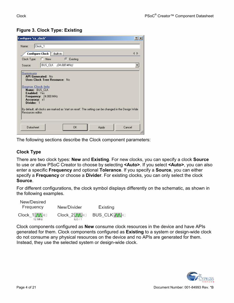
Figure 3. Clock Type: Existing
The following sections describe the Clock component parameters:
Clock Type There are two clock types: New and Existing. For new clocks, you can specify a clock Source to use or allow PSoC Creator to choose by selecting <Auto>. If you select <Auto>, you can also enter a specific Frequency and optional Tolerance. If you specify a Source, you can either specify a Frequency or choose a Divider. For existing clocks, you can only select the clock Source. For different configurations, the clock symbol displays differently on the schematic, as shown in the following examples.
Clock components configured as New consume clock resources in the device and have APIs generated for them. Clock components configured as Existing to a system or design-wide clock do not consume any physical resources on the device and no APIs are generated for them. Instead, they use the selected system or design-wide clock.

PSoC® Creator™ Component Datasheet Clock
Document Number: 001-84993 Rev. *B Page 5 of 21
Source Select <Auto> (default) if you want PSoC Creator to automatically locate an available source clock that, when divided down, provides the most accurate resulting frequency. Clocks with a source of <Auto> may only enter a desired frequency. A tolerance may also optionally be provided. Select a system or design-wide clock from the list provided to force PSoC Creator to use that clock as the source.
Frequency Enter the desired frequency and units (default = 12 MHz). PSoC Creator then calculates the divider that will create a clock signal that is as close as possible to the desired frequency. On PSoC 4, if the Source is specified as <Auto> and the desired frequency results in a divider value larger than 65536, PSoC Creator will automatically chain two 16-bit dividers in order to achieve the closest possible divider that is a product of two 16-bit numbers. In this case, the SetDivider and SetFractionalDivider APIs are not available. To be able to dynamically modify the divider of a chained-divider clock, you must specify the chaining explicitly with a Design-Wide Clock: Add a Design-Wide Clock from the Clock Editor in the DWR and specify the Source of the clock component to be the Design-Wide Clock you just created. Configure the Divider values of those two clocks such that their product achieves the intended divider value.
Tolerance If you select <Auto> as the clock source, you can enter the desired tolerance values for the clock (default is ± 5%). PSoC Creator will ensure that the accuracy of the resulting clock falls within the given tolerance range or produce a warning if the desired clock is not achievable. Clock tolerances are specified as a percentage. (Note Entering ppm will cause the value entered to be converted to the corresponding percent value.) If there is no desired tolerance range, then deselect the check box next to the tolerance and no warning will be generated for this clock.
Divider If you choose a specific Source, you can enter an explicit value for the Divider. Otherwise, if you leave the Source set to <Auto>, the Divider option is not available (default). If you select the Divider option, then the Frequency option is not available. On PSoC 4, you can select Use fractional divider to allow fractional values to be used for the divider value. If you have specified a frequency, the clock solver will use the fractional divider to try to obtain the requested frequency. If you have specified a divider, you will be able to enter a fractional divide value between 0 and 31.

Clock PSoC® Creator™ Component Datasheet
Page 6 of 21 Document Number: 001-84993 Rev. *B
Advanced Tab The Advanced tab contains two parameters.
Note: the Advanced tab does not exist on PSoC 4.
Force clock to be Analog Clock If checked (default = unchecked), this option adds a terminal for the version of the analog clock that uses the main digital sync clock as the resync clock. If used, this clock is forced into the analog domain; however, the newly added terminal is in the digital domain.
Sync with MASTER_CLK If selected (default = not selected) the clock is synchronized with the MASTER clock; otherwise, the clock is unsynchronized.
Application Programming Interface Application Programming Interface (API) routines allow you to configure the component using software. The following table lists and describes the interface to each function. The subsequent sections cover each function in more detail. By default, PSoC Creator assigns the instance name “Clock_1” to the first instance of a component in a given design. You can rename it to any unique value that follows the syntactic
PSoC® Creator™ Component Datasheet Clock
Document Number: 001-84993 Rev. *B Page 7 of 21
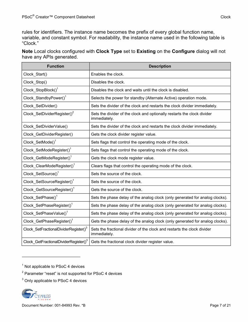
rules for identifiers. The instance name becomes the prefix of every global function name, variable, and constant symbol. For readability, the instance name used in the following table is “Clock.” Note Local clocks configured with Clock Type set to Existing on the Configure dialog will not have any APIs generated.
Function Description
Clock_Start() Enables the clock.
Clock_Stop() Disables the clock.
Clock_StopBlock()1 Disables the clock and waits until the clock is disabled.
Clock_StandbyPower()1 Selects the power for standby (Alternate Active) operation mode.
Clock_SetDivider() Sets the divider of the clock and restarts the clock divider immediately.
Clock_SetDividerRegister()2 Sets the divider of the clock and optionally restarts the clock divider immediately.
Clock_SetDividerValue() Sets the divider of the clock and restarts the clock divider immediately.
Clock_GetDividerRegister() Gets the clock divider register value.
Clock_SetMode()1 Sets flags that control the operating mode of the clock.
Clock_SetModeRegister()1 Sets flags that control the operating mode of the clock.
Clock_GetModeRegister()1 Gets the clock mode register value.
Clock_ClearModeRegister()1 Clears flags that control the operating mode of the clock.
Clock_SetSource()1 Sets the source of the clock.
Clock_SetSourceRegister()1 Sets the source of the clock.
Clock_GetSourceRegister()1 Gets the source of the clock.
Clock_SetPhase()1 Sets the phase delay of the analog clock (only generated for analog clocks).
Clock_SetPhaseRegister()1 Sets the phase delay of the analog clock (only generated for analog clocks).
Clock_SetPhaseValue()1 Sets the phase delay of the analog clock (only generated for analog clocks).
Clock_GetPhaseRegister()1 Gets the phase delay of the analog clock (only generated for analog clocks).
Clock_SetFractionalDividerRegister()3 Sets the fractional divider of the clock and restarts the clock divider immediately.
Clock_GetFractionalDividerRegister()3 Gets the fractional clock divider register value.
1 Not applicable to PSoC 4 devices 2 Parameter “reset” is not supported for PSoC 4 devices 3 Only applicable to PSoC 4 devices

Clock PSoC® Creator™ Component Datasheet
Page 8 of 21 Document Number: 001-84993 Rev. *B
void Clock_Start(void) Description: Starts the clock.
Note On startup, clocks may already be running if the “Start on Reset” option is enabled in the DWR Clock Editor.
Parameters: void
Return Value: void
Side Effects: The clock is enabled.
void Clock_Stop(void) Description: Stops the clock and returns immediately. This API does not require the source clock to be
running but may return before the hardware is actually disabled. If the settings of the clock are changed after calling this function, the clock may glitch when it is started. To avoid the clock glitch, use the Clock_StopBlock() function.
Parameters: void
Return Value: void
Side Effects: The clock is disabled. The output will be logic 0. Note When using PSoC 5 silicon, a clock with source “MASTER_CLK” and divider 1 will always be running.
void Clock_StopBlock(void) Description: Stops the clock and waits for the hardware to actually be disabled before returning. This
ensures that the clock is never truncated (high part of the cycle will terminate before the clock is disabled and the API returns). Note that the source clock must be running or this API will never return as a stopped clock cannot be disabled.
Parameters: void
Return Value: void
Side Effects: The clock is disabled. The output will be logic 0. Note The Clock_StopBlock() API is only supported on PSoC 3 and PSoC 5 LP, and will not be generated for other devices.

PSoC® Creator™ Component Datasheet Clock
Document Number: 001-84993 Rev. *B Page 9 of 21
void Clock_StandbyPower(uint8 state) Description: Selects the power for standby (Alternate Active) operation mode.
Note: The Clock_Start API enables the clock in Alternate Active Mode, and the Clock_Stop and ClockStopBlock APIs disable the clock in Alternate Active Mode. If the clock is enabled, but needs to be disabled in Alternate Active Mode, Clock_StandbyPower(0) should be called after Clock_Start(). If the clock is disabled, but needs to be enabled in Alternate Active mode, Clock_StandbyPower(1) should be called after Clock_Stop().
Parameters: uint8 state: 0 to disable clock during Alternate Active mode, nonzero to enable.
Return Value: void
Side Effects: None
void Clock_SetDivider(uint16 clkDivider) Description: Modifies the clock divider, and thus, the frequency. When the clock divider register is set to
zero or changed from zero, the clock is temporarily disabled in order to change a mode bit. If the clock is enabled when Clock_SetDivider() is called, the source clock must be running. The current clock cycle will be truncated and the new divide value will take effect immediately. The difference between this and Clock_SetDividerValue is that this API must consider the +1 factor.
Parameters: uint16 clkDivider: Divider register value (0 to 65,535). This value is NOT the divider; the clock hardware divides by clkDivider plus one. For example, to divide the clock by 2, this parameter should be set to 1.
Return Value: void
Side Effects: None
void Clock_SetDividerRegister(uint16 clkDivider, uint8 reset) Description: Modifies the clock divider, and thus, the frequency. When the clock divider register is set to
zero or changed from zero, the clock is temporarily disabled in order to change a mode bit. If the clock is enabled when Clock_SetDivider() is called, then the source clock must be running.
Parameters: uint16 clkDivider: Divider register value (0 to 65,535). This value is NOT the divider; the clock hardware divides by clkDivider plus one. For example, to divide the clock by 2, this parameter should be set to 1.
uint8 reset: If nonzero, restarts the clock divider; the current clock cycle will be truncated and the new divide value will take effect immediately. If zero, the new divide value will take effect at the end of the current clock cycle.
Return Value: void
Side Effects: None

Clock PSoC® Creator™ Component Datasheet
Page 10 of 21 Document Number: 001-84993 Rev. *B
void Clock_SetDividerValue(uint16 clkDivider) Description: Modifies the clock divider, and thus, the frequency. When the clock divider register is set to
zero or changed from zero, the clock will be temporarily disabled in order to change the SSS mode bit. If the clock is enabled when Clock_SetDivider() is called, then the source clock must be running. The current clock cycle will be truncated and the new divide value will take effect immediately.
Parameters: uint16 clkDivider: Divide value (1 to 65535) or zero. If clkDivider is zero, the clock will be divided by 65,536. The difference between this and Clock_SetDivider() is that this API does not have to consider the +1 factor.
Return Value: void
Side Effects: None
uint16 Clock_GetDividerRegister(void) Description: Gets the clock divider register value.
Parameters: void
Return Value: Divide value of the clock minus 1. For example, if the clock is set to divide by 2, the return value is 1.
Side Effects: None
void Clock_SetMode(uint8 clkMode) Description: Sets flags that control the operating mode of the clock. This function only changes flags from
0 to 1; flags that are already 1 remain unchanged. To clear flags, use the Clock_ClearModeRegister() function. The clock must be disabled before changing the mode. This API provides the same functionality as the SetModeRegister API.
Parameters: uint8 clkMode: Bit mask containing the bits to set. For PSoC 3 and PSoC 5, clkMode should be a set of the following optional bits ORed together: CYCLK_EARLY: Enable early phase mode. Rising edge of output clock will occur when
the divider counter reaches half of the divide value.
CYCLK_DUTY: Enable 50-percent duty cycle output. When enabled, the output clock is asserted for approximately half of its period. When disabled, the output clock is asserted for one period of the source clock.
CYCLK_SYNC: Enable output synchronization to master clock. This should be enabled for all synchronous clocks.
See the Technical Reference Manual for details about setting the mode of the clock. Specifically, see the CLKDIST.DCFG.CFG2 register.
Return Value: void
Side Effects: None

PSoC® Creator™ Component Datasheet Clock
Document Number: 001-84993 Rev. *B Page 11 of 21
void Clock_SetModeRegister(uint8 clkMode) Description: Same as Clock_SetMode(). Sets flags that control the operating mode of the clock. This
function only changes flags from 0 to 1; flags that are already 1 will remain unchanged. To clear flags, use the Clock_ClearModeRegister() function. The clock must be disabled before changing the mode. This API provides the same functionality as the SetMode API.
Parameters: uint8 clkMode: Bit mask containing the bits to set. It should be a set of the following optional bits ORed together: CYCLK_EARLY: Enable early phase mode. Rising edge of output clock will occur when
the divider counter reaches half of the divide value.
CYCLK_DUTY: Enable 50-percent duty cycle output. When enabled, the output clock is asserted for approximately half of its period. When disabled, the output clock is asserted for one period of the source clock.
CYCLK_SYNC: Enable output synchronization to master clock. This should be enabled for all synchronous clocks.
See the Technical Reference Manual for details about setting the mode of the clock. Specifically, see the CLKDIST.DCFG.CFG2 register.
Return Value: void
Side Effects: None
uint8 Clock_GetModeRegister(void) Description: Gets the clock mode register value.
Parameters: void
Return Value: Bit mask representing the enabled mode bits. See the Clock_SetModeRegister() and Clock_ClearModeRegister() descriptions for details about the mode bits..
Side Effects: None

Clock PSoC® Creator™ Component Datasheet
Page 12 of 21 Document Number: 001-84993 Rev. *B
void Clock_ClearModeRegister(uint8 clkMode) Description: Clears flags that control the operating mode of the clock. This function only changes flags
from 1 to 0; flags that are already 0 will remain unchanged. The clock must be disabled before changing the mode.
Parameters: uint8 clkMode: Bit mask containing the bits to clear. It should be a set of the following optional bits ORed together: CYCLK_EARLY: Enable early phase mode. Rising edge of output clock will occur when
the divider counter reaches half of the divide value.
CYCLK_DUTY: Enable 50-percent duty cycle output. When enabled, the output clock is asserted for approximately half of its period. When disabled, the output clock is asserted for one period of the source clock.
CYCLK_SYNC: Enable output synchronization to master clock. This should be enabled for all synchronous clocks.
See the Technical Reference Manual for details about setting the mode of the clock. Specifically, see the CLKDIST.DCFG.CFG2 register.
Return Value: void
Side Effects: None
void Clock_SetSource(uint8 clkSource) Description: Sets the input source of the clock. The clock must be disabled before changing the source.
The old and new clock sources must be running. This API provides the same functionality as the SetSourceRegister API.
Parameters: uint8 clkSource: Should be one of the following input sources: CYCLK_SRC_SEL_SYNC_DIG: Phase-delayed master clock
CYCLK_SRC_SEL_IMO: Internal main oscillator
CYCLK_SRC_SEL_XTALM: 4- to 33-MHz external crystal oscillator
CYCLK_SRC_SEL_ILO: Internal low-speed oscillator
CYCLK_SRC_SEL_PLL: Phase-locked loop output
CYCLK_SRC_SEL_XTALK: 32.768-kHz external crystal oscillator
CYCLK_SRC_SEL_DSI_G: DSI global input signal
CYCLK_SRC_SEL_DSI_D: DSI digital input signal
CYCLK_SRC_SEL_DSI_A: DSI analog input signal
See the Technical Reference Manual for details on clock sources.
Return Value: void
Side Effects: None
PSoC® Creator™ Component Datasheet Clock
Document Number: 001-84993 Rev. *B Page 13 of 21
void Clock_SetSourceRegister(uint8 clkSource) Description: Same as Clock_SetSource(). Sets the input source of the clock. The clock must be disabled
before changing the source. The old and new clock sources must be running. This API provides the same functionality as the SetSource API.
Parameters: uint8 clkSource: It should be one of the following input sources: CYCLK_SRC_SEL_SYNC_DIG: Phase-delayed master clock
CYCLK_SRC_SEL_IMO: Internal main oscillator
CYCLK_SRC_SEL_XTALM: 4- to 33-MHz external crystal oscillator
CYCLK_SRC_SEL_ILO: Internal low-speed oscillator
CYCLK_SRC_SEL_PLL: Phase-locked loop output
CYCLK_SRC_SEL_XTALK: 32.768-kHz external crystal oscillator
CYCLK_SRC_SEL_DSI_G: DSI global input signal
CYCLK_SRC_SEL_DSI_D/CYCLK_SRC_SEL_DSI_A: DSI input signal (Both constants map to the same value).
See the Technical Reference Manual for details on clock sources.
Return Value: void
Side Effects: None
uint8 Clock_GetSourceRegister(void) Description: Gets the input source of the clock.
Parameters: void
Return Value: The input source of the clock. See Clock_SetSourceRegister() for details.
Side Effects: None

Clock PSoC® Creator™ Component Datasheet
Page 14 of 21 Document Number: 001-84993 Rev. *B
void Clock_SetPhase(uint8 clkPhase) Description: Sets the phase delay of the analog clock. This function is only available for analog clocks.
The clock must be disabled before changing the phase delay to avoid glitches. This API provides the same functionality as the SetPhaseRegister API.
Parameters: uint8 clkPhase: Amount to delay the phase of the clock, in 1.0-ns increments. clkPhase must be from 1 to 11 inclusive. Other values, including 0, disable the clock.
clkPhase value Phase delay
0 Clock disabled
1 0.0 ns
2 1.0 ns
3 2.0 ns
4 3.0 ns
5 4.0 ns
6 5.0 ns
7 6.0 ns
8 7.0 ns
9 8.0 ns
10 9.0 ns
11 10.0 ns
12 to 15 Clock disabled
Return Value: void
Side Effects: None

PSoC® Creator™ Component Datasheet Clock
Document Number: 001-84993 Rev. *B Page 15 of 21
void Clock_SetPhaseRegister(uint8 clkPhase) Description: Same as Clock_SetPhase(). Sets the phase delay of the analog clock. This function is only
available for analog clocks. The clock must be disabled before changing the phase delay to avoid glitches. This API provides the same functionality as the SetPhase API.
Parameters: uint8 clkPhase: Amount to delay the phase of the clock, in 1.0-ns increments. clkPhase must be from 1 to 11 inclusive. Other values, including 0, disable the clock.
clkPhase value Phase delay
0 Clock disabled
1 0.0 ns
2 1.0 ns
3 2.0 ns
4 3.0 ns
5 4.0 ns
6 5.0 ns
7 6.0 ns
8 7.0 ns
9 8.0 ns
10 9.0 ns
11 10.0 ns
12 to 15 Clock disabled
Return Value: void
Side Effects: None

Clock PSoC® Creator™ Component Datasheet
Page 16 of 21 Document Number: 001-84993 Rev. *B
void Clock_SetPhaseValue(uint8 clkPhase) Description: Sets the phase delay of the analog clock. This function is only available for analog clocks.
The clock must be disabled before changing the phase delay to avoid glitches. Same as Clock_SetPhase(), except Clock_SetPhaseValue() adds one to the value and then calls Clock_SetPhaseRegister() with it.
Parameters: uint8 clkPhase: Amount to delay the phase of the clock, in 1.0-ns increments. clkPhase must be from 0 to 10 inclusive. Other values disable the clock.
clkPhase value Phase delay
0 0.0 ns
1 1.0 ns
2 2.0 ns
3 3.0 ns
4 4.0 ns
5 5.0 ns
6 6.0 ns
7 7.0 ns
8 8.0 ns
9 9.0 ns
10 10.0 ns
11 to 15 Clock disabled
Return Value: void
Side Effects: None
PSoC® Creator™ Component Datasheet Clock
Document Number: 001-84993 Rev. *B Page 17 of 21
uint8 Clock_GetPhaseRegister(void) Description: Gets the phase delay of the analog clock. This function is only available for analog clocks.
Parameters: void
Return Value: Phase of the analog clock in nanoseconds. See Clock_SetPhaseRegister() for details.
Side Effects: None
void Clock_SetFractionalDividerRegister(uint16 clkDivider, uint8 fracDivider) Description: Modifies the clock divider and the fractional clock divider, and thus, the frequency. The
fractional divider does not work with integer divider values by 1.
Parameters: uint16 clkDivider: Integer divider register value (0 to 65,535). This value is NOT the divider; the clock hardware divides by clkDivider plus one. For example, to divide the clock by 2, this parameter should be set to 1.
Uint8 fracDivider: Fractional divider register value (0 to 31). This value represents fractional clock divide values in increments of 1/32. For example, to divide the clock by 3/32, this parameter should be set to 3.
Return Value: void
Side Effects: None
uint8 Clock_GetFractionalDividerRegister (void) Description: Gets the fractional clock divider register value.
Parameters: Void
Return Value: Fractional divide value of the clock. If the fractional clock divider is not in use, the return value is 0.
Side Effects: None
MISRA Compliance This section describes the MISRA-C:2004 compliance and deviations for the component. There are two types of deviations defined: project deviations – deviations that are applicable for all PSoC Creator components
specific deviations – deviations that are applicable only for this component This section provides information on component-specific deviations. Project deviations are described in the MISRA Compliance section of the System Reference Guide along with information on the MISRA compliance verification environment. The Clock component does not have any specific deviations.

Clock PSoC® Creator™ Component Datasheet
Page 18 of 21 Document Number: 001-84993 Rev. *B
Sample Firmware Source Code PSoC Creator provides numerous example projects that include schematics and example code in the Find Example Project dialog. For component-specific examples, open the dialog from the Component Catalog or an instance of the component in a schematic. For general examples, open the dialog from the Start Page or File menu. As needed, use the Filter Options in the dialog to narrow the list of projects available to select. Refer to the “Find Example Project” topic in the PSoC Creator Help for more information.
Resources Resource use varies based on configuration and connectivity.
Clock components configured as Existing do not consume any resource on the chip.
Clock components configured as New consume a single clock resource. PSoC Creator automatically discovers whether the clock connects to digital or analog peripherals and consumes a digital clock or analog clock resource as necessary.
API Memory Usage The component memory usage varies significantly, depending on the compiler, device, number of APIs used and component configuration. The following table provides the memory usage for all APIs available in the given component configuration. The measurements have been done with the associated compiler configured in Release mode with optimization set for Size. For a specific design, the map file generated by the compiler can be analyzed to determine the memory usage.
Configuration PSoC 3 (Keil_PK51) PSoC 4 (GCC) PSoC 5LP (GCC)
Flash Bytes
SRAM Bytes
Flash Bytes
SRAM Bytes
Flash Bytes
SRAM Bytes
Digital clock 574 0 104 0 416 0
Analog clock 589 0 104 0 448 0

PSoC® Creator™ Component Datasheet Clock
Document Number: 001-84993 Rev. *B Page 19 of 21
Component Changes This section lists the major changes in the component from the previous version.
Version Description of Changes Reason for Changes / Impact
2.0.b Added a note to the Frequency parameter description describing the automatic divider chaining on PSoC 4.
Clarification of component functionality.
2.0.a Added PSoC 4 support Modified GUI and APIs to function correctly with PSoC 4
Added Clock_SetFractionalDividerRegister() and Clock_GetFractionalDividerRegister() APIs
Allows the firmware to set/get the current fractional divider value
2.0 Added MISRA Compliance section. The component does not have any specific deviations.
Updated Clock_Start, Clock_Stop, and Clock_StopBlock APIs
The APIs now start/stop the clock in both Active and Alternate Active modes. This is consistent with other PSoC Creator components. See the Clock_Standby API description for more details.
1.70 Added PSoC 5LP support
Minor datasheet edits and updates
1.60 Updated Clock_SetDivider() and Clock_SetDividerRegister() APIs
Fixed APIs to function correctly with PSoC 5
Changed wording of the “digital domain – output”
Added note to Clock_Stop() in datasheet
1.50.a Added note to Clock_StopBlock() in datasheet to note lack of silicon support
Minor datasheet edits and updates
1.50 Added Clock_StopBlock() API This function stops the clock and waits for it to be disabled. This is necessary to prevent glitches when changing settings and restarting a clock.
Added Clock_GetPhaseRegister() API (analog only)
Allows the firmware to read the current phase value.
Added Clock_SetPhaseValue() API (analog only)
This macro wraps Clock_SetPhaseRegister() and automatically adds 1 to the phase value to provide a more intuitive interface.
Renamed Clock_SetPhase() to Clock_SetPhaseRegister() (analog only)
For consistency with other names. For compatibility, SetPhase is provided as a macro and has the same effect as Clock_SetPhaseRegister().
Added Clock_GetSourceRegister() API Allows the firmware to read the current clock source.

Clock PSoC® Creator™ Component Datasheet
Page 20 of 21 Document Number: 001-84993 Rev. *B
Version Description of Changes Reason for Changes / Impact
Renamed Clock_SetSource() to Clock_SetSourceRegister()
For consistency with other names. For compatibility, SetSource is provided as a macro and has the same effect as Clock_SetSourceRegister().
Added Clock_GetModeRegister() API Allows the firmware to read the current mode flags.
Added Clock_SetModeRegister() API This function replaces Clock_SetMode(). For compatibility, SetMode is provided as a macro and has the same effect as Clock_SetModeRegister(). Clock_SetModeRegister() only changes mode flags from 0 to 1. This prevents unintended clearing of other mode bits such as SYNC.
Added Clock_ClearModeRegister() API This function is similar to Clock_SetModeRegister(), but only changes mode flags from 1 to 0.
Added Clock_GetDividerRegister() API Allows the firmware to read the current divider value.
Added Clock_SetDividerRegister() API The Clock_SetDivider() API unconditionally resets the clock divider. Clock_SetDividerRegister() allows the firmware author to control whether the divider is reset.
Added Clock_SetDividerValue() API This macro wraps Clock_SetDividerRegister() and automatically subtracts 1 from the divider to provide a more intuitive interface.
Set SSS in Clock_SetDividerRegister() When dividing by 1 (divide value of 0), the SSS bit must be set to bypass the divider. The Clock_SetDividerRegister() function will automatically set/clear SSS, temporarily disabling the clock if necessary.
Changed register definitions Updated to match component coding guidelines.
Corrected Clock_SetDivider() API documentation
The Clock_SetDivider() API documentation stated that the clkDivider parameter should be the divide value + 1. This should have been the divide value - 1. The documentation incorrectly stated that 0 was an invalid value for clkDivider.
Changed “Synch with Bus” to “Sync with Master” and associated tooltip on the Configure dialog.
Updated to match how the device works. This was just a cosmetic change.
Added parameter to enable the digital domain output from the analog clock.
A signal is available from analog clocks in the hardware that was not previously exposed on the component.

PSoC® Creator™ Component Datasheet Clock
Document Number: 001-84993 Rev. *B Page 21 of 21
Version Description of Changes Reason for Changes / Impact
Added `=ReentrantKeil($INSTANCE_NAME . "_...")` to the following functions: void Clock_Start() void Clock_Stop() void Clock_StopBlock() void Clock_StandbyPower() void Clock_SetDividerRegister() uint16 Clock_GetDividerRegister() void Clock_SetModeRegister() void Clock_ClearModeRegister() uint8 Clock_GetModeRegister() void Clock_SetSourceRegister() uint8 Clock_GetSourceRegister() void Clock_SetPhaseRegister() uint8 Clock_GetPhaseRegister()
Allows users to make these APIs reentrant if reentrancy is desired.
1.0.a Move CYCLK_ constants to cydevice.h/cydevice_trm.h.
The CYCLK_ constants for the mode and source are now generated from the selected device’s register map. This allows the clock component to be independent of device-specific register values. The cydevice.h file is already included from the clock header, so no user code changes should be necessary.
Add description of CYCLK_ constants in the datasheet.
The parameter descriptions for the Clock_SetMode() and Clock_SetSource() APIs now contain a description of each value.
© Cypress Semiconductor Corporation, 2013. The information contained herein is subject to change without notice. Cypress Semiconductor Corporation assumes no responsibility for the use of any circuitry other than circuitry embodied in a Cypress product. Nor does it convey or imply any license under patent or other rights. Cypress products are not warranted nor intended to be used for medical, life support, life saving, critical control or safety applications, unless pursuant to an express written agreement with Cypress. Furthermore, Cypress does not authorize its products for use as critical components in life-support systems where a malfunction or failure may reasonably be expected to result in significant injury to the user. The inclusion of Cypress products in life-support systems application implies that the manufacturer assumes all risk of such use and in doing so indemnifies Cypress against all charges. PSoC® is a registered trademark, and PSoC® Creator™ and Programmable System-on-Chip™ are trademarks of Cypress Semiconductor Corp. All other trademarks or registered trademarks referenced herein are property of the respective corporations. Any Source Code (software and/or firmware) is owned by Cypress Semiconductor Corporation (Cypress) and is protected by and subject to worldwide patent protection (United States and foreign), United States copyright laws and international treaty provisions. Cypress hereby grants to licensee a personal, non-exclusive, non-transferable license to copy, use, modify, create derivative works of, and compile the Cypress Source Code and derivative works for the sole purpose of creating custom software and or firmware in support of licensee product to be used only in conjunction with a Cypress integrated circuit as specified in the applicable agreement. Any reproduction, modification, translation, compilation, or representation of this Source Code except as specified above is prohibited without the express written permission of Cypress. Disclaimer: CYPRESS MAKES NO WARRANTY OF ANY KIND, EXPRESS OR IMPLIED, WITH REGARD TO THIS MATERIAL, INCLUDING, BUT NOT LIMITED TO, THE IMPLIED WARRANTIES OF MERCHANTABILITY AND FITNESS FOR A PARTICULAR PURPOSE. Cypress reserves the right to make changes without further notice to the materials described herein. Cypress does not assume any liability arising out of the application or use of any product or circuit described herein. Cypress does not authorize its products for use as critical components in life-support systems where a malfunction or failure may reasonably be expected to result in significant injury to the user. The inclusion of Cypress’ product in a life-support systems application implies that the manufacturer assumes all risk of such use and in doing so indemnifies Cypress against all charges. Use may be limited by and subject to the applicable Cypress software license agreement.