Precision Clock Synchronization Protocol - NIST Technical ...
162
Workshop on IEEE-1588, Standard for a Precision Clock Synchronization Protocol for Networked Measurement and Control Systems Lee, K. B. U. S. DEPARTMENT OF COMMERCE Technology Administration National Institute of Standards and Technology Gaithersburg, MD 20899 <QC /OO . u,5fe * 1070 9,003 NIST National Institute of Standards and Technology Technology Administration U.S. Department of Commerce
-
Upload
khangminh22 -
Category
Documents
-
view
0 -
download
0
Transcript of Precision Clock Synchronization Protocol - NIST Technical ...

Workshop on IEEE-1588, Standard for aPrecision Clock Synchronization Protocolfor Networked Measurement and Control
Systems
Lee, K. B.
U. S. DEPARTMENT OF COMMERCETechnology Administration
National Institute of Standards
and Technology
Gaithersburg, MD 20899
<QC/OO
. u,5fe
* 10709,003
NISTNational Institute of Standardsand TechnologyTechnology AdministrationU.S. Department of Commerce


Workshop on IEEE-1588, Standard for aPrecision Clock Synchronization Protocolfor Networked Measurement and Control
Systems
Lee
,
K. B.
U. S. DEPARTMENT OF COMMERCETechnology Administration
National Institute of Standards
and Technology
Gaithersburg, MD 20899
November 20, 2003
U.S. DEPARTMENT OF COMMERCEDonald L. Evans, Secretary
TECHNOLOGY ADMINISTRATIONPhillip J. Bond, Under Secretary for Technology
NATIONAL INSTITUTE OF STANDARDSAND TECHNOLOGYArden L. Bement, Jr., Director

NISTIR 7070
Workshop on IEEE-1588, Standard for a
Precision Clock Synchronization Protocol for
Networked Measurement and Control Systems
Kang Lee
National Institute of Standards and Technology
Gaithersburg, Maryland
John Eidson
Agilent Technologies
Palo Alto, California
September 24, 2003
DISCLAIMER:
This publication consists of workshop proceedings containing presentation slides, technical papers, recommendations,
and other materials contributed by participants of this workshop. This publication provides the material as presented and
discussed at the workshop in its original form, without modification by the National Institute of Standards and
Technology (NIST). Commercial equipment and software referred to in this document are identified for informational
purposes only, and does not imply recommendation of or endorsement by NIST, nor does it imply that the products so
identified are the best available for the purpose.

IV

Table of Contents
Executive Summary 4
Summary of Points Noted During the Open Discussion Section 5
Agenda 7
Time Synchronization in Switched Ethernet 13
Oyvind Holmeide, OnTime Networks ASBoundary Clock Implementation with Time Synchronization Protocol Analyzer 20
Embedded SynUTC and IEEE 1588 Clock Synchronization for
Industrial Ethernet 26
Nikolaus E. Kero, Oregano Systems, Hanncs Muhr, Georg Gaderer, Roland Holler,
Thilo Sauter, Institute of Computer Technology, Vienna University of Technology,
Horavcr Martin, Technikun Wien
PTP in Redundant Network Structures 38
Ludwig Winkel, Siemens Automation and Drives
A Solution for Fault-Tolerant IEEE-1588 (Slides) 43
A Solution for Fault-Tolerant IEEE-1588 (Paper) 56
Jeff Allan, Dongik Lee, Dependable Real-Time Systems Ltd.
PTP in Switched Networks 63
Thomas Mueller, Zurich University of Applied Science, Winterthur, Suisse,
Karl Weber, Siemens Automation and Drives
Impact of Switch Cascading on Time Accuracy 71
IEEE 1588 Network Devices 77
Dirk S. Mohl, Hirshmann Electronics
A Frequency Compensated Clock for Precision Synchronization
using IEEE 1588 Protocol and its Application to Ethernet 91
Sivaran Balasubramanian, Kendal R. Harris and Anatoly Moldovansky,
Rockwell Automation
IEEE-1588 Node Synchronization Improvement by High Stability Oscillators 95
John C. Eidson, Bruce Hamilton, Agilent Technologies
IEEE 15881 ' 1 Node Synchronization Improvement by High Stability Oscillators 102
Time Correlation on a Network Based Airborne Telemetry System 1 13
Jiwang Dai, Edward Grozalis, L3 Communications Telemetry East, Thomas DeSelms, Veridian
Engineering
Implementation of IEEE Std.-1588 in a Networked I/O Node 122
Mark E. Shepard, Douglas G. Fowley, Roy L. Jackson, Dennis B. King,
GE Drives & Controls, Inc.
Application of IEEE 1588 to a Distributed Motion Control System 133
Kendal Harris, Sivaram Balasubramanian, Anatoly Moldovansky
Rockwell Automation
IEEE 1588 Proposal for Metro Ethernet Enterprise Solutions 139
Glenn Algie, Nortel Networks
Appendix AQuestion and Answers on Workshop Papers 144
Demonstrations: 147
IEEE 1588 Prototype Demonstration, Hirshmann Set up to Show' Effects of Oscillator Quality
Electronics on Synchronization, Agilent Technologies
Demonstration for the Application of the IEEE Boundary Clock Implementation,
1588 to Distributed Motion Control, Rockwell On Time Networks (no slide provided)
Automation Extending IEEE 1588 to fault tolerant
Implementation of IEEE Std.- 1588 in a Networked synchronization with a worst-case precision in the
I/O Node, GE Drives & Controls (no slide provided) 100ns range, Oregano Systems (no slide provided)
Final Participants List 150
v

Workshop Summary
Executive Summary from the Conference Co-Chairs
The IEEE 1588 standard defines a protocol enabling precise synchronization of clocks in
measurement and control systems implemented with technologies such as network communication,
local computing, and distributed objects. The protocol enables heterogeneous systems that include
clocks of various inherent precision, resolution, and stability to synchronize. The IEEE 1588
standard was approved as ANSI/IEEE 1588-2002 in January 2003. This conference was to provide
a forum for users and implementers of the 1588 standard to exchange information and ideas about
the standard.
The conference participants represented different sectors of industry ranging from networked
instrumentation and measurement, to utility power generation and distribution, to aerospace and
avionics, to semiconductor production equipment manufacturing, to telecommunication. The
workshop opened with welcoming remarks and a presentation about the National Institute of
Standards and Technology (NIST) and the various programs of its Manufacturing Engineering
Laboratory (MEL) by the MEL Director Dr. Dale Hall. Dr. Hall pointed out that a workshop like
this is one of the many avenues for industry and NIST to work together on standards and
technology issues.
Twelve presentations on implementations based on the IEEE 1588 standard or technologies
addressing time synchronization issues were presented in three sessions. Following that, a
demonstration session was held featuring implementations based on IEEE 1588 from six
companies. The demonstrations ranged from networked time synchronization of sensor data
acquisition, to motion control, to software tools for time synchronization diagnostics. The final
session was an open forum discussion. It focused on issues about the standard identified by the
attendees. Attendees were invited to put issues on the board, or add a check mark to existing
issue(s) they wanted to discuss. The moderator chose the issues with the most check marks first.
The purpose was to get the issues aired and defined and to identify the hot items, not to solve
technical issues. At the end, all issues on the board were addressed or at least briefly discussed.
The summary of the discussion on these issues is presented below. The ideas and issues brought
out in this workshop will be the used to formulate the agenda for the next workshop to be held in
the same time frame in 2004. The proceedings for the workshop will be put on the IEEE 1588
Web site at http ://ieee i 5 8 8 . n i st. gov as soon as it is approved for publication by NIST. Plans for
the next workshop will be presented in the spring of 2004.
vi
Summary of Points Discussed During the Open Discussion Session
Market Acceptance / Requirements
IEEE 1588 is applicable to a much wider range of applications than networking sensors and
networked measurement and control systems. Because of its potentially wide application space,
many questions still need to be answered in future workshops. They are:
• Which set of markets is appropriate to use the IEEE 1588 standard?
• Once the markets are identified, we must determine for each market
o what set of requirements is appropriate?
o what level of synchronization?
o how much redundancy?
If we don't have a good set of requirements and use cases, we won't be able to make good choices.
For example, in the telecommunication space, we may be able to find customers who have
advanced technology shops and are willing to help.
Telecommunication requirements are likely to be different from most others. Ideally it would be
the same standard, just a different implementation. Applications where IEEE 1588 overlaps other
technologies, such as Network Time Protocol (NTP), will need to be examined.
Tools would help acceptance, for example, for a Field Programmable Gate Array (FPGA) core, or
for a source code for the protocol stack. It was noted that Application Specific Integrated Circuit
(ASIC)/FPGA cores tend to be very application-specific, whereas, the stack and management
message handling would be widely applicable. For the FPGA, people could publish the state
diagram. In other standards, a marketing track was formed to deal with this issue.
The standard leaves some things to the implemented. We may need more clarification or
statements of preferred implementation to assure interoperation. It was noted that the committee
keeps questions and interpretations of the standard on the IEEE 1588 Web site. Questions currently
go to the IEEE, or committee chair.
Conformance & Certification
• Minimum subset for conformance to the IEEE 1588 standard.
• Certification tools/procedures are needed.
• A test set.
• A certification body, or an accepted set of procedures.
• Part of the issues is who has liability if things do not work. The Distributed Network
Protocol (http://www.dnp.org) is a nonprofit organization, thus not willing to assume
liability. They developed a book saying, “this is how you certify.” Anyone who wants to
become a certifier pays a license fee for the logo, follows the book, and is a certifier. If
something goes wrong, liability falls to the certifier.
• A university, a company, or NIST may become a certifier for a test fee.
• A reference implementation.
• Keen interest in a Plugfest - plug-and-play tests for interoperability.
• Financial support for some of these activities.

Extensions
• Ways to update the standard were briefly discussed. Suggested modifications can be
partitioned into two categories. One category of modifications fit within the existing
standard and the other causes a dramatic modification of the core of the standard. Changes
should probably go hand-in-hand with chosen markets.
• Additional payload (in existing packets, or extension packets)
• IPv6
• 802.3 tagged frames (may be able to adopt this & Ipv6 as alternate profiles).
• “Bare” Ethernet, below Internet Protocol (IP) and Unified Data Protocol (UDP), e.g..
Ethernet-level multicast. Some embedded systems don’t use TCP or UDP. On the other
hand, it’s easier to use off-the-shelf systems when your packets have IP headers. The IP
join/leave mechanism may be useful for management.
• Redundancy. Part of this issue includes defining what it means.
• Bypass clocks.
• Networks other than LAN, e.g., physically bigger or poorer-quality links.
• Support for heterogeneous components, along the lines of Simple Network Time Protocol
(SNTP).
• What is the governing body? IEEE has rules for amending a standard, but they address only
procedures, not content. A Project Authorization Request (PAR) needs to be formulated
and submitted to IEEE-SA in order to obtain a project to update the standard.
• Task groups are needed to hold technical discussions and coordinate the work on the
standard. They will be formed shortly after the workshop. In the group discussion, we will
prioritize the tasks and get a clear view of the requirements before opening any PARbecause a PAR carries a deadline.
• Volunteers are solicited to serve in the task groups. Anyone interested to participate should
contact John Eidson and Kang Lee.
Conference Proceedings
When the conference proceedings are ready, they will be available for access on the IEEE 1588
website located at URL: h ttp : //ieee 1 5 8 8 . nis t.gov/ .
Future Workshop
The plan for future workshop was briefly discussed. Most attendees wanted to have another
workshop organized by NIST. Location is to be determined. Practically no one voted for a
workshop in six months, but the majority of the attendees preferred to have the next workshop in
about one year. Companies participated in the demonstration at this workshop and other attendees
expressed interest in showing their implementations based on IEEE 1588 in the next workshop. In
addition, participants wanted to have a tutorial session on the detail of the standard - what it is,
why is it needed, and how it can be used, etc.
The topics of the next workshop should include:
• Tutorial. There was a specific request for a session on comparing PTP with other clock
synchronization protocols.
• Technical papers.
• Reports by the task groups.
• A Plugfest.

Workshop on
IEEE-1588, Standard for a Precision Clock Synchronization Protocol for
Networked Measurement and Control Systems
Co-sponsored by
NIST and IEEE Instrumentation and Measurement Society
NISTGaithersburg, Maryland
September 24, 2003
Workshop: Lecture room ADemonstration: Lecture room B
AGENDA
• 8:00 AM: Bus leaves conference hotel for NIST facility
• 8:30-9:00 AM: Continental breakfast, meet other attendees, pick up conference badges and
material.
• 9:00-9: 15 AM: Workshop opening
Moderator: Kang Lee, NISTo Welcome from Dr. Dale Hall, Director of the NIST Manufacturing Engineering
Laboratory
o Administrative details
• 9:15 AM to 10:35 AM: Technical paper presentations session 1
Moderator: John Eidson, Agilent Technologies
o 9: 1 5-9:35 AM: Boundary Clock implementation: 0yvind Holmeide, Managing
Director, OnTime Networks AS.
o 9:35-9:55AM: Extending IEEE 1588 to fault tolerant synchronization with a
worst-case precision in the 100 ns range: Nikoaus E. Keroe, Oregano Systems,
Georg Gaderer, Roland Holler and Thilo Sauter, Institute of Computer Technology,
Vienna University of Technology
o 9:55-10: 1 5AM: Consequences of Redundant Structures PTP: Ludwig Winkel,
SIEMENS Automation and Drives
o 10: 15-10:35AM: A Solution for Fault -Tolerant IEEE-1588: Jeff Allan & Dr
Dongik Lee, Dependable Real Time Systems Ltd., Sheffield, U.K.
• 10:35 - 10:50 AM: Morning coffee break
• 10:50 AM- 12:10 PM: Technical paper presentations session 2
Moderator: Kang Lee, NIST

o 10:50-1 1:10AM: Impact of Switch Cascading on Time Accuracy: Prof. Thomas
Mueller, University Wintherthur, Suisse, Karl Weber, SIEMENS Automation and
Drives
o 11:10-11 :30AM: IEEE 1588 and Network Devices: Dirk S. Mohl, Hirschmann
Electronics
o 1
1
:30-l 1 :50AM: A Frequency Compensated Clock for Precision
Synchronization using IEEE 1588 Protocol and its Application to Ethernet:
Sivaram Balasubramanian, Kendal R. Harris and Anatoly Moldovansky, Rockwell
Automation
o 1 1:50AM-12:10PM: IEEE-1588 Node Synchronization Improvement by High
Stability Oscillators: John C Eidson & Bruce Hamilton, Agilent Laboratories
12:10-1:10 PM: Lunch at NIST cafeteria
1 : 10-2:30 PM: Technical paper presentations session 3
Moderator: Joe White, US Naval Research Laboratory
o 1 :10-1:30PM: Time Correlation using network based data acquisition on-
board a Military Test Vehicle: Jiwang Dai, Ph.D, Senior Software Engineer, L3
Communications Telemetry East, Thomas DeSelms, Senior Network Systems
Engineer, Veridian Engineering, and Edward Grozalis, Senior Engineer, L3
Communications Telemetry East
o 1 :30-l :50PM: Implementation of IEEE Std.-1588 in a Networked I/O Node:
Mark Shepard, GE Drives & Controls, Inc., Salem, VAo 1 :50-2: 10PM: Application of IEEE 1588 to Distributed Motion Control: Kendal
R. Harris, Sivaram Balasubramanian, and Anatoly Moldovansky, Rockwell
Automation
o 2:10-2:30PM: Proposal for IEEE1588 use over Metro Ethernet Layer 2 VPNs:Glenn Algie, Senior Advisor, Wireless Technology Labs, Nortel Networks
2:30-3:30 PM: Demonstration of implementations
Moderator: John Eidson, Agilent Technologies
o OnTime Networks AS, 0yvind Holmeide, Managing Director
o Oregano Systems, Nikoaus E. Keroe
o Hirschmann Electronics, Dirk Mohl & Dominik ladonisi
o Rockwell Automation, Kendal R. Harris and Sivaram Balasubramanian
o GE Drives & Controls, Inc., Salem, VA, Mark Shepard
o Agilent Laboratories, John C Eidson & Bruce Hamilton
3:30-3:45 PM: Afternoon refreshment break
3:45-4:45 PM: Open discussion session- Moderator: John Eidson, Scribe: Bruce Hamilton,
Agilent Technologies
o Topics selected by attendees
o Next steps
4:45-5 PM: Closing comments- Kang Lee & John Eidson
5:15 PM: Bus leaves NIST for conference hotel

ABSTRACTS FOR TECHNICAL SESSIONS
Session 1, 9:15 AM to 10:35 AM :
• Boundary Clock implementation: 0yvind Holmeide, Managing Director, OnTimeNetworks AS. Abstract: The presentation will cover special properties of a boundary clock
implementation. The principles for achieving the same timing accuracy on a 1588
boundary clock implementation without Follow Up packet support as with the support of
this feature will also be described.
• Extending IEEE 1588 to fault tolerant synchronization with a worst-case precision in
the 100 ns range: Nikoaus E. Keroe, Oregano Systems, Georg Gaderer, Roland Holler and
Thilo Sauter, Institute of Computer Technology, Vienna University of Technology
Abstract: We present the SynUTC paradigm, fitted into the IEEE 1588 standard for
realizing the basic functionality in terms of time distribution and accuracy. By using the
extended features provided by the SynUTC technology a worst case precision of less than
100 ns under any network load can be realized.
• Consequences of Redundant Structures PTP: Ludwig Winkel, SIEMENS Automation
and Drives Abstract: A switch over in redundant structures will result in a loss of delay
time when a link fails. A UDP based node cannot detect this failure. A method for handling
time synchronization in redundant structures will be proposed.
• A Solution for Fault -Tolerant IEEE-1588: Jeff Allan & Dr Dongik Lee, Dependable
Real Time Systems Ltd., Sheffield, U.K. Abstract: The IEEE- 1588 Standard offers a very
stable and accurate platform for distributed time-based communications. A claimed
weakness however of the current IEEE- 1588 Standard relates to a lack of fault-tolerance.
Dependable Real Time Systems Ltd (DRTS Ltd) have been developing reliable and fault-
tolerant clock synchronization techniques for CAN networks. The core technology enables
time triggered CAN communications that can be implemented in standard CAN nodes
using no extra hardware and needing no new silicon to provide a cost-effective solution for
safety-critical applications. This paper outlines how DRTS ideas previously implemented
in CAN can be applied to the IEEE- 1588 Standard and outlines a simple way in which the
current standard could be improved to include a reliable fault-tolerant capability.
Session 2, 10:50 AM-12:10 PM:
• Impact of Switch Cascading on Time Accuracy: Prof. Thomas Mueller, University
Wintherthur, Suisse, Karl Weber, SIEMENS Automation and Drives Abstract: Switches
add a non-deterministic delay to messages. They may be treated as boundary clocks but the
cascading of control loops in each node will introduce additional sources for time
inaccuracies. A method for efficient handling of switched networks based on PTP will be
proposed.
• IEEE 1588 and Network Devices: Dirk S. Mohl, Hirschmann Electronics Abstract: The
presentation will start with an overview of our IEEE 1588 implementation. It will give an
overview of the system design (software and hardware) and also show some issues of a
portable IEEE 1588 code (Linux, Windows, VxWorks). It will give some details about
precision of the implementation and show some ideas for possible improvements in the
software stack. The presentation will give some tips on how to implement IEEE 1588 and
where to get the necessary software stacks. It will then show why IEEE 1 588 is also

necessary and useful in layer 2 switches. The presentation will close with an overview of
possible enhancements for IEEE 1588 like calculation and adjusting clock drifts and using
SNMP for management.
• A Frequency Compensated Clock for Precision Synchronization using IEEE 1588
Protocol and its Application to Ethernet: Sivaram Balasubramanian, Kendal R. Elarris
and Anatoly Moldovansky, Rockwell Automation Abstract: In a distributed control system
containing multiple clocks, individual clocks tend to drift apart due to instabilities inherent
in source oscillators and environmental conditions such as temperature, mechanical, aging
etc. Hence, some kind of correction is necessary to synchronize individual clocks to
maintain the notion of global time, which is accurate to some requisite clock resolution. In
this paper, we present a frequency compensated clock to achieve precision synchronization
amongst distributed clocks using IEEE 1588 protocol to exchange timing information.
Further, we explore its application to Ethernet.
• IEEE-1588 Node Synchronization Improvement by High Stability Oscillators: John CEidson & Bruce Hamilton, Agilent Laboratories Abstract: This paper outlines work done
for the US Naval Research Laboratory to investigate the sensitivity of synchronization
accuracy with the stability of local oscillators. The results indicate the likely accuracy
obtainable in a variety of configurations.
Session 3, 1:10-2:30 PM:
• Time Correlation using network based data acquisition on-board a Military Test
Vehicle: Jiwang Dai, Ph.D, Senior Software Engineer, L3 Communications Telemetry
East, Thomas DeSelms, Senior Network Systems Engineer, Veridian Engineering, and
Edward Grozalis, Senior Engineer, L3 Communications Telemetry East Abstract: Military
avionics busses and processors are getting faster, plus data acquisition systems are
specified as needing an order of magnitude better time correlation than the System Under
Test (SUT). In combination with these is the drive to lower cost, increase capability and
use COTS equipment the test vehicle community is moving to a network based data
acquisition system. Using a network based data acquisition system presents problems
when attempting to correlate data on a asynchronous network. This paper will detail timing
correlation issues when using a network based data acquisition system on-board a military
test vehicle and propose IEEE 1588 as one of the solutions.
• Implementation of IEEE Std.-1588 in a Networked I/O Node: Mark Shepard, GEDrives & Controls, Inc., Salem, VA Abstract: IEEE Std. 1588-2002 is very specific in its
description of the Precision Time Protocol for exchanging information between clocks.
However, many of the detailed algorithms for disciplining, converging and tracking the
actual clocks are “beyond the scope” of the standard. This paper describes an
implementation of PTP with emphasis on the specification, design and performance of
these algorithms. Included are initial acquisition of a master clock, tracking of the master
clock, and rejection of outlying timestamps. Measured data from an operating system on
switched Ethernet is presented.
• Application of IEEE 1588 to Distributed Motion Control: Kendal R. Harris, Sivaram
Balasubramanian, and Anatoly Moldovansky, Rockwell Automation Abstract: This paper
discusses the application of IEEE 1588 to distributed motion control systems. Current
solutions rely on proprietary implementations to time synchronize distributed motion
control system components. With the introduction of IEEE 1588 these solutions may now
4
be implemented using open networks and standard components. Both peer to peer
controller and controller to drive systems are considered.
• Proposal for IEEE1588 use over Metro Ethernet Layer 2 VPNs: Glenn Algie, Senior
Advisor, Wireless Technology Labs, Nortel Networks Abstract: Metro edge and core
deployed timing sources, receivers and inter-working devices can be a mix of Metro
provider owned and managed vs. Enterprise owned and managed. A jitter tolerant recovery
method is proposed where fewer Boundary clocks are required in the L1/L2 switched
Metro. The presentation proposes a small set of enhancements to IEEE 1588 to enable a
suite of Metro Ethernet use cases.
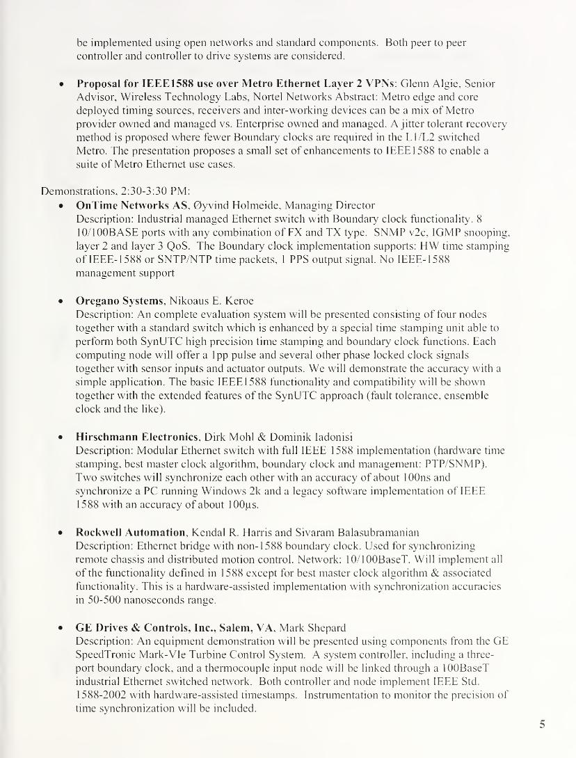
Demonstrations, 2:30-3:30 PM:
• OnTime Networks AS, 0yvind Holmeide, Managing Director
Description: Industrial managed Ethernet switch with Boundary clock functionality. 8
10/100BASE ports with any combination of FX and TX type. SNMP v2c, IGMP snooping,
layer 2 and layer 3 QoS. The Boundary clock implementation supports: HW time stamping
of IEEE- 1588 or SNTP/NTP time packets, 1 PPS output signal. No IEEE- 1588
management support
• Oregano Systems, Nikoaus E. Keroe
Description: An complete evaluation system will be presented consisting of four nodes
together with a standard switch which is enhanced by a special time stamping unit able to
perform both SynUTC high precision time stamping and boundary clock functions. Each
computing node will offer a lpp pulse and several other phase locked clock signals
together with sensor inputs and actuator outputs. We will demonstrate the accuracy with a
simple application. The basic IEEE 1588 functionality and compatibility will be shown
together with the extended features of the SynUTC approach (fault tolerance, ensemble
clock and the like).
• Hirschmann Electronics, Dirk Mohl & Dominik Iadonisi
Description: Modular Ethernet switch with full IEEE 1588 implementation (hardware time
stamping, best master clock algorithm, boundary clock and management: PTP/SNMP).
Two switches will synchronize each other with an accuracy of about 100ns and
synchronize a PC running Windows 2k and a legacy software implementation of IEEE
1588 with an accuracy of about lOOps.
• Rockwell Automation, Kendal R. Harris and Sivaram Balasubramanian
Description: Ethernet bridge with non- 1588 boundary clock. Used for synchronizing
remote chassis and distributed motion control. Network: 10/100BaseT. Will implement all
of the functionality defined in 1588 except for best master clock algorithm & associated
functionality. This is a hardware-assisted implementation with synchronization accuracies
in 50-500 nanoseconds range.
• GE Drives & Controls, Inc., Salem, VA, Mark Shepard
Description: An equipment demonstration will be presented using components from the GESpeedTronic Mark-VIe Turbine Control System. A system controller, including a three-
port boundary clock, and a thermocouple input node will be linked through a 100BaseT
industrial Ethernet switched network. Both controller and node implement IEEE Std.
1588-2002 with hardware-assisted timestamps. Instrumentation to monitor the precision of
time synchronization will be included.
5

Agilent Laboratories, John C Eidson & Bruce Hamilton
Description: Prototype implementations of an earlier version of IEEE- 1588 to demonstrate
the effects of local oscillator stability on synchronization accuracy. Hardware assist and
lOBaseT network technology is used. Internal visibility is provided by a web interface.

Time synchronization in switched Ethernet
By
0yvind Holmeide
www.ontimenet.com
OnTimenEtmorns
me synchronization in switched Ethernet
Traditional time
synchronisation: tpd
do tel
ml tsi
time client
time server
netuunrHs

me synchronization in switched Ethernet
Time stamping at application layer
Accuracy depends on
- Jitter in Tx and Rx protocol stack
GPS
SNTP/NTP/P1588 time server
Time
server/| 2 J.
TCP UDP
MAC
8023
iT3 t4
SNTP/NTP/P1588 time client
..To/r^nT
f" Ti
UDP TCP
IP
MAC
802.3
3
OnTimef"""l bni tZ. ULt G I 5E5
/ g
Time synchronization in switched Ethernet
• Time stamping at Ethernet driver level
• Accuracy depends on
- Jitter in interrupt latency of Ethernet Rx ISR()
- Jitter in Ethernet send HW
GPS
SNTP/NTP/P1588 time server
TCP
MAC tow SW driver
8023
T2 1 T3 T4
SNTP/NTP/P1588 time client
-To,
* - Ti
UDP TCP
SW driver MAC
3T
OnTimenetiiiorns
8

•onization in switched Ethernet
Time stamping at Ethernet HWAccuracy depends on
- GPS PPS rise time
- Stability of local oscillator
GPS
SNTP/NTP/P1588 time server
TCP UDP
IP
MAC low SW drive*
802.3 HW
1
t2 _ Ta T4
SNTP/NTP/P1588 time client
To,
- Ti
UDP TCP
IP
SW drive* MAC
KWtftri.estaroo
802.3
3
OnTimenetixiofKS
Time synchronization in switched Ethernet
How to achieve an accurate T3 time stamp in case
SNTP/NTP is used as the time server protocol:
GPS
TU
SNTP/NTP time server
TCP UDP
MAC low SW drive*
X02J HW T3
T3 is a future time that is generated by
the switch CPU
The SNTP/NTP reply packet is sent
from the switch when actual time is
equal to T3 which is found in the
SNTP/NTP payload
Deterministic transmission of the
SNTP/NTP reply packet can be
achieved by using:
- Flow control (FDX - IEEE 802.3x)
- Back pressure (HDX)
- Transmission of a dummy packet
OnTimenEttunrHs
Time synchronization in switched Ethernet
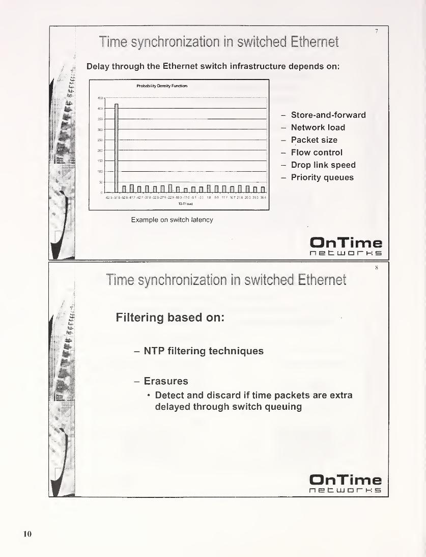
Delay through the Ethernet switch infrastructure depends on:
Probability Density Function
n n fin n n n n an n n n n n-62.5 -57 6 -52.6-47.7 -42.7 -37.8 -32.8-27 9 -22.9 -18 0 -13.0 -8.1 -3.1 1 8 6.8 11 7 16 7 21.6 26.5 31.5 36.4
T2-T1 (us)
- Store-and-forward
- Network load
- Packet size
- Flow control
- Drop link speed
- Priority queues
Example on switch latency
OnTimej |
j—« 1 1 1 i i j h 55
F
Time synchronization in switched Ethernet
Filtering based on:
- NTP filtering techniques
- Erasures
• Detect and discard if time packets are extra
delayed through switch queuing
OnTimen p l~ 1 1 1 n r j-» e;

/
Time synchronization in switched Ethernet
Boundary clock implementation:
CPU• Handles time sync
application
(SNTP/NTP/P1 588)
• Switch management• Serial NMEA protocol
vs. GPS receiver
FPGA• Local Clock
generation based onPPS from GPSreceiver
• Time stamping of
incoming andoutgoing time packets
on Mil
OnTimenEtlilDTHS
Time synchronization in switched Ethernet
Boundary clock features:
Time server/client implementation integrated in the
Ethernet switch.
- Relevant time sync protocols:
• SNTP, RFC2030
• NTP, RFC1305
• PI 588, IEEE Std 1588™-2002
OnTimenet iju i h b
11

Time synchronization in switched Ethernet
Boundary clock features cont’d:
- Accuracy independent of network load, 0,1 PPMpossible
Forwarding of time sync packets only to switch
CPU (P1588)
OnTimeIn** LjEmI ezi r*** i"****i
1 M
12
Time synchronization in switched Ethernet
Boundary clock features cont’d:
- Individual port state
• PI 588: master, slave, etc
• NTP/SNTP: server/client
Time reference:
• External GPS or
• Local clock
• Etc.
Time synchronization protocol analyzer support
OnTimenetuuor-HS

Time synchronization in switched Ethernet
Boundary clock implementation with time synchronization
protocol analyzer support:
13
OnTimer""i tzii inini Cuii r*"
1*
i"" 1
> «!!!?
Time synchronization in switched Ethernet
Boundary clock with protocol analyzer support
- All time sync packets (SNTP/NTP or PI 588) sent andreceived on any port are sent to the PC for presentation
PC with protocol analyzer support
- Directly connected to the Boundary clock
- Time sync packets are visualized
- Detailed presentation of the time sync packet content
14
Packet details
0- General Information
SNTP request packet
TO = 3270378474 390001 seconds
S MAC Header
Destination address. 0x00 0x07 0x7c 0x00 0x1 0 0x00
Source address. 0x00 0x06 0x5b 0x35 Oxcf 0x74
Type. 0x0800 (IP)
IP Header
UDP Header
MSEi
1 0x00 0x00 0x00 0x05 0x00 0x07 Ox'
j
0x08 0x00 0x45 0x00 0x00 0x4c Oxl
i
0x01 0x64 OxcO 0xa8 0x01 0xc8 Oxl
0x00 OsOQ 0x00 0x00 0x00 0x00 Oxt
0x00 0x00 0x00 0x00 0x00 0x00 Ox!
0x00 0x00 0x00 0x00 QxOQ 0x00 Ox.
OnTimenet LLi d i hi s

Boundary Clock Implementation with TimeSynchronization Protocol Analyzer
Kristin Holmeide and 0yvind Holmeide
Abstract— Variable latencies through the protocol
stacks and the Ethernet switches will degrade the timing
accuracy that can be achieved when time synchronization
is performed via a switched Ethernet infrastructure.
Time stamping of incoming and outgoing time packets
shall preferably be done as low as possible in the protocol
stacks. The Ethernet switch latency depends on the
network load and the switch architecture. This problem
can be solved if time synchronization properties are
integrated in the Ethernet switches as well as in the
Ethernet end nodes. This article describes the basic
principles of a PI 588 Boundary Clock and the well
established internet SNTP/NTP protocol and how to
implement these protocols on Ethernet switches in order
to achieve a timing accuracy in the sub-microsecond (ps)
range regardless of the network load. How a Boundary
Clock implementation can be used as a time
synchronization protocol analyzer is also described.
Index Terms—Time synchronization, switched Ethernet,
SNTP/NTP, PI 588, Time synchronization protocol
analyzer.
The timing accuracy that can be achieved at
the time clients by performing time stamping
at application layer will typically be in
milliseconds range.
Figure 1, time stamping at application layer
I. TIME STAMPING OF TIME PACKETS
Timing accuracy depends on where the time
stamping of incoming and outgoing time
packets is performed. Time stamping can be
performed at the application layer, Ethernet
driver level (software) or at the Ethernet data
link/physical layer (hardware).
A. Time stamping at application layer
Most time synchronization implementations
perform all time stamping at the application
layer, see Figure 1 for details. This means that
the timing accuracy that can be achieved at the
clients will suffer from the variable latency
through the UDP/IP protocol stack. This
latency depends on the UDP/IP
implementation, platform load and the Real
Time Operating System (RTOS)implementation. The impact of this jitter can
be reduced by using the NTP or similar
filtering techniques.
The server adds both the receive time stamp of
the time request, T2, and the transmit time
stamp of the time reply, T3, in the time reply
packets. The T3 timestamp is put into the
packet before the packet is sent.
B. Time stamping at the Ethernet driver
The timing accuracy can be significantly
improved if the time stamping is performed at
the Ethernet software driver level. The receive
time stamps, i.e. T2 and T4, are performed in
the Ethernet Interrupt Service Routine (ISR),
while the transmit time stamps of the client,
Ti, is performed in the Ethernet send routine
of the Ethernet driver. The T3 time stamp is
somewhat more tricky, since this time stamp
is already included in the reply packet that is
generated in the application layer. How to
achieve an accurate T3 time stamp is further
discussed in chapter II. This is relevant in
case SNTP or NTP are used as time
synchronization protocols.
14

It is possible to store the server clock when the
time reply was sent from the server, T.% and
send this time stamp in a second packet later.
This is one of the main properties of the
PI 588 protocol. The time reply is referred to
as a SYNC packet and the second packet is
referred to as the FOLLOW UP packet.
Transmit time stamping can be very accurate;
while the corresponding receive time stamps
may suffer from jitter in the interrupt latency.
This jitter depends on the RTOSimplementation and the platform load. Analternative software approach that can be used
in order to overcome this problem is to
implement an RTOS independent ISR that
performs the time stamping of incoming time
packets.
challenge when using this method, see chapter
II for how this can be done.)
SNTP/NTP/P1588 time server SNTP/NTP/P1588 time client
TL
TCP I UDP
uTTTi j. 4.
Figure 3, time stamping at Ethernet data
link/physical layer
Figure 2, time stamping in Ethernet level
C. Time stamping at the Ethernet data link/physical
layer
The latency through the protocol stacks can be
removed if time stamping is performed in the
data link/physical layer. The time stamping
can be implemented in HW in the Ethernet
controller, the PHY chip or in e.g. a separate
FPGA that is interfacing the Media
Independent Interface (Mil) between the
Ethernet controller and the Ethernet PHYchip. Time synchronization can be extremely
accurate if time stamping is performed in HW.The accuracy at the time clients can be better
than 1 PPM if this method is used and a direct
wire is used between the server and the client.
(Achieving an accurate T3 time stamp is also a
II. HOW TO ACHIEVE AN ACCURATE T3TIME STAMP 1
The SNTP time reply contains both the
receive time stamp of the time request packet,
T2,and the transmit time stamp, T3 , of the
time reply packet. Thus, actual time must be
equal to T3 , when the time reply packet hit the
drop link. This means that the server must
have deterministic access to the media. I.e. T3
is a future time when this time stamp is put
into the time reply, and the packet will then be
sent on a pre-determined point in time. The
following implementations can be used;
1 . The flow control feature of the Ethernet
switch, ref. IEEE802.3x, can be used in
case of full duplex connectivity in order to
hold back the reply packet until absolute
time is equal to the T3 time stamp given in
the time reply payload. The time reply
packet must be ready for transmission
when the flow control is turned off.
2. The back pressure feature of the Ethernet
switch can be used in case of half duplex
connectivity in order to hold back the
reply packet until absolute time is equal to
the T.3 time stamp given in the time reply
payload. The time reply packet must be
OnTimc patent pending
15

ready for transmission when the back
pressure signal (JAM patter) is turned off
3. Sending a dummy packet of a given length
can be used for both half and full duplex
connectivity drop links. The time reply
packet must be sent immediately after the
dummy packet (only minimum Inter
Packet Gap (IPG) between the packets).
The time reply packet is granted access to
the media at a given time, T3 , by using this
technique.
Note: the time reply packet may experience a
collision in case of half duplex connectivity,
and a re-transmission of this packet will then
contain a wrong T3 time stamp. This must be
handled either at the server (i.e. abort re-
transmissions of time reply packets) or at the
client (the client generates an erasure in case a
collision is detected prior to the reception of
the time reply packet).
III. WHY IS SWITCH LATENCY A PROBLEM?
Figure 4 shows a traditional time
synchronization implementation, where time
packets are sent through a switched Ethernet
infrastructure.
Figure 4, traditional time synchronization
The network latency depends on the network
load, drop link speed, packets sizes, the switch
architecture and the number of switches
between the server and the client. The switch
latency may vary from a few tens of
microseconds up to several milliseconds.
Most new Ethernet switch designs are
based on “store-and-forward” technology.
This means that an Ethernet packet must
be completely received on an input port
before it is checked for bit errors (the
switch calculates the Frame Check
Sequence (FCS), and compares it with
the FCS found at the end of the packet)
and forwarded to the respective output
port. Thus, the latency depends on the
drop link speed and the packet sizes.
E.g. an Ethernet packet of maximum
Ethernet packet size (1522 bytes)
received on a 10 Mbps drop link will be
delayed by 1.2 milliseconds due to the
“store-and-forward” mechanism. A
corresponding 100 Mbps drop link
represents a delay of 122 microseconds.
The packet may be further delayed if other
packets are queued for transmission on the
same output port. Protecting the time packets
by using priority does not improve the
situation, because the transmission of another
packet may already be started when the high
priority time packet enters the output port
queue. Figure 5 shows an example of the
Probability Density Function (PDF) of the
switch latency taken from actual
measurements in case other packets are sent to
the same output port as the time packets. The
measurement is based on 50% load on the
receiving drop link. The PDF has a uniform
distribution for all switch latency
measurements where extra delay is introduced
due to other packets.
Note: extra latency due to other traffic is also
a problem in case the switch is based on “cut-
through” packet forwarding.
The switch latency may also vary due to
general switch load. I.e. packets sent and
received on ports not used for time updates.
Such an unwanted switch property is only
relevant on old switch architectures.
16

RS422/RS232Probability Density Function
nllnnnnnnnnnnnnnnnnn
i MII/RMII/SMII
SmX.h core
/FPGA
&»s»n*4PKY
-62 5 -57.6 -52 6-47.7 -42.7 -37.8 -32.8-27 9 -22 9 -18 0 -13 0 -8 1 -3.1 1 8 68 11 7 16.7 21 6 26 5 31 5 364
T2-T1 (us)Figure 6, Boundary clock implementation
Figure 5, example of switch latency measurements
The NTP filtering techniques can be used to
reduce the impact of variable network latency.
However, these filtering techniques are not
optimized for typical latency density functions
relevant on a LAN based on Ethernet
switches. A better accuracy can be achieved if
knowledge about general switch latency
characteristics is utilized. Time updates
performed in a LAN network, where there is
one Ethernet switch on the path between the
time client and the time server, will suffer
from variable switch latency caused by the
switch network load as earlier described.
However, both the time client and the time
server can verify if a received time packet is
extra delayed through the switch, by another
packet being sent from the switch. The extra
delay is verified if the interval between this
preceding packet and the time packet, is equal
to the minimum Inter Packet Gap of Ethernet
or close to this interval". A convenient
implementation of this erasure technique, in
case the time synchronization implementation
is based on a software time stamping of
incoming time packets in the Ethernet ISR, is
to generate this type of erasure if the time
packet received is not the first received packet
associated to the Ethernet receive interrupt.
IV. BOUNDARY CLOCK IMPLEMENTATION
A Boundary clock implementation is shown in
Figure 6.
2 ABB patent pending
Incoming and outgoing time packets are time
stamped in hardware at the Media
Independent Interface (Mil) between the
switch core and the Ethernet PHY. Thus, an
incoming time packet is time stamped before
it is forwarded through the Ethernet switch
core and an outgoing time packet is time
stamped after the packet has been sent through
the switch core. This means that variable
latency through the switch core has no impact
on the time synchronization accuracy. The
time stamping is performed in an FPGA. The
FPGA also generates the local clock of the
Boundary clock implementation based on
either an external Pulse Per Second (PPS)
input from e.g. a GPS receiver, or only based
on a local oscillator (e.g. the switch core
oscillator). The drift and offset of the local
oscillator is adjusted based on the PPS signal
in case an external time base is used.
The CPU handles the time sync protocol.
Boundary clock configuration via e.g. SNMP,serial interface versus an external clock source
(if available) and the interface versus the
FPGA. The NMEA protocol over RS232 or
RS422 versus an external GPS is often
relevant in order to have reference to absolute
time. RS422 is the preferred interface for both
serial data and the PPS signal in order to meet
various installation requirements (distance
between GPS receiver and Boundary clock).
The most relevant time synchronization
protocols are based on SNTP/NTP(RFC2030/RFC1305) or P1588 (IEEE Std
1588™-2002). These protocols are all based
on UDP/IP.
An Ethernet network where all network
elements are based on Boundary clock

implementation should not forward time
synchronization packets from one Ethernet
port to another Ethernet port. Time
synchronization packets received on a
Boundary clock port should be forwarded to
the Boundary clock CPU only in order to
make sure that there is no network element on
the path between the time client and the time
server. This property is included in the PI 588
standard, but not in the SNTP or NTPstandards. However, a SNTP/NTP client
might be able to verify the number of network
hops (switches) between the client and a given
server based on the stratum field of the
SNTP/NTP reply from a SNTP/NTP server or
based on the propagation delay between the
client and the server. The stratum field and/or
propagation delay measurement performed by
the client are used in order to choose the best
SNTP/NTP server alternative. I.e. preferably a
SNTP/NTP Boundary clock implementation
directly connected to the SNTP/NTP client. Anetwork hop can be identified based on the
store-and-forward delay introduced by the
network element. Such a SNTP/NTP property
ought to be implemented on a SNTP/NTPBoundary clock.
The ports of a Boundary clock may have
different states. E.g. one port may act as a
time client versus a better time server, while
all the other ports act as time servers. This is
a fundamental principle of the PI 588 standard.
In PI 588 context this means that the time
client port is in SLAVE state and the other
ports on the Boundary clock are in MASTERstate.
The Boundary clock accuracy in case an
external time base is used, depends on the
quality of the PPS signal from an external
clock source (rise time of PPS and jitter
between the PPS signals) and the jitter per
second of the local oscillator. The latter
degradation factor is often depending on
temperature variation unless the local
oscillator has a temperature compensation
property. A quality parameter can be
calculated based on the jitter per second of the
local oscillator. This parameter can be
calculated for a given time interval and
associated to time updates performed within
this time interval. This parameter is referred
to as the clock variance in the PI 588 standard.
An accuracy in the order of 0,1 PPM is
possible.
V. TIME SYNCHRONZATION PROTOCOLANALYZER
A Boundary Clock implementation can also
function as a time synchronization protocol
analyzer together with a PC directly connected
to Boundary Clock. The PC is running a
program for configuration and visualization of
time synchronization packets sent and
received on any of the ports on the Boundary
Clock. Both the PI 588 and the SNTP/NTPprotocols can be supported. Such a program
for network capture and a Boundary clock
with the capability of trapping and sending
time synchronization packets to the connected
PC, can be an excellent tool during the
development of time synchronization support
based on PI 588 or SNTP/NTP of an Ethernet
enabled end node.
The multicast client part of the network
capture program connects to the
corresponding multicast server of the
Boundary Clock implementation via a pre-
defined IP multicast socket address and port
number. Multicast packets sent from the
multicast client to the Boundary Clock are
only forwarded to the Boundary Clock CPU.
No knowledge about the Boundary Clock IP
address is required since IP multicast
communication is used between the PC and
the Boundary Clock.
All PI 588 or SNTP/NTP packets sent or
received on any ports of the Boundary Clock
including the port where the PC is running the
network capture program, will be trapped on
the Boundary Clock and sent to the PC via the
established multicast socket.
The time synchronization packets are
visualized per port in the same order as they
appear in time on the Boundary Clock. The
user can select any of the trapped time
synchronization packets for a detailed packet
view. A time synchronization packet is
presented as shown in Figure 7.
18
Packe» detail:
General mlormahon
SNTP request packet
TO = 3270878474 890001 second:
& MAC Header
Destination addre: : 0x00 0x07 0x7c 0x00 0x1 0 0x00
Source addre:: 0x00 0x06 0x5b 0x35 Oxcl 0x74
Type 0x0800 |IP|
ft; IP Header
+1 UDP Header
* aaBBms
* 0x00 0x00 0x00 0x05 0x00 0x07 Ox
j0x08 0x00 0x45 0x00 0x00 0x4c Oxi
5 0x01 0x64 OxcO 0xa8 0x01 0xc8 Oxi
0*00 0x00 CxOO 0x00 0x00 0x00 Cbf
O'OG 0x00 G OG 0x00 0x00 G>00 Ox?
| U/.OG 0x00 G.'.OG OxGO 0x00 0>.0G Ox;
|
I
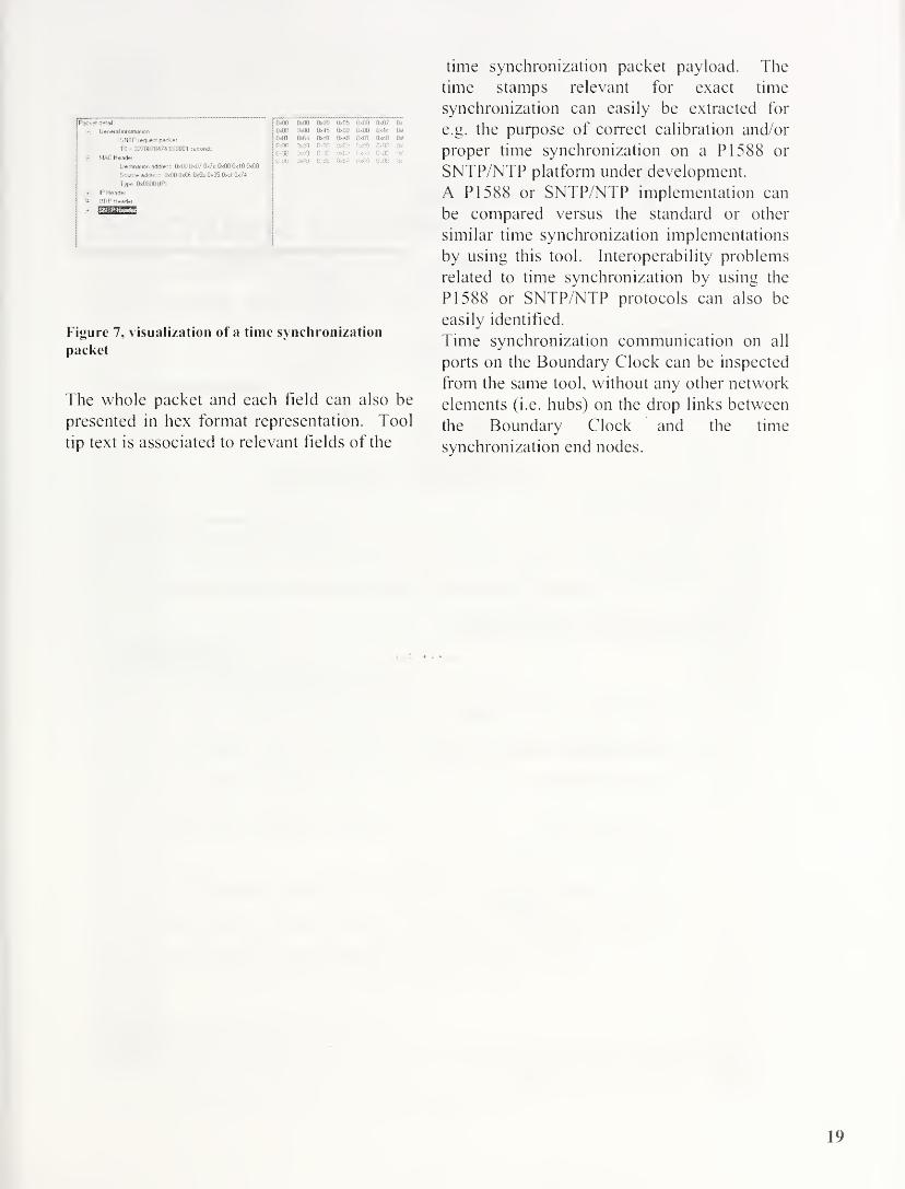
Figure 7, visualization of a time synchronization
packet
The whole packet and each field can also be
presented in hex format representation. Tool
tip text is associated to relevant fields of the
time synchronization packet payload. The
time stamps relevant for exact time
synchronization can easily be extracted for
e.g. the purpose of correct calibration and/or
proper time synchronization on a PI 588 or
SNTP/NTP platform under development.
A PI 588 or SNTP/NTP implementation can
be compared versus the standard or other
similar time synchronization implementations
by using this tool. Interoperability problems
related to time synchronization by using the
PI 588 or SNTP/NTP protocols can also be
easily identified.
Time synchronization communication on all
ports on the Boundary Clock can be inspected
from the same tool, without any other network
elements (i.e. hubs) on the drop links between
the Boundary Clock and the time
synchronization end nodes.
19

Embedded SynUTCandIEEE 1588 Clock Synchronization
for Industrial Ethernet
1st Workshop onIEEE-1588 Standard
Oregano SystemsInstitute of s
Computer Technology
Outlinemmmmmaam
System Overview
Sy/7£/mechnology
IEEE 1588
Comparison
Network Interface Card
Ethernet Switch
Future Work
Institute of Computer Technology 2

System Overview
Til Institute of Computer Technology
SynUTCTechnoloqy
Adder based clock
On-the-fly timestamping
Interval based paradigm (pos/neg accuracies)
Clock state and rate synchronization
Non master-slave principle
Covers synchronization algorithms
Covers hardware implementation issues
Strong mathematical background
sa—am
Institute of Computer Technology

SynUTCAdder Based Clock 1
TIJ Institute of Computer Technology
SynUTCAdder Based Clock 2
EE 1588 + PSynUTC Adder Based Clock Register Layout
32bit nanoseconds 32bit subnanoseconds
711 Institute of Computer Technology
WIEN22
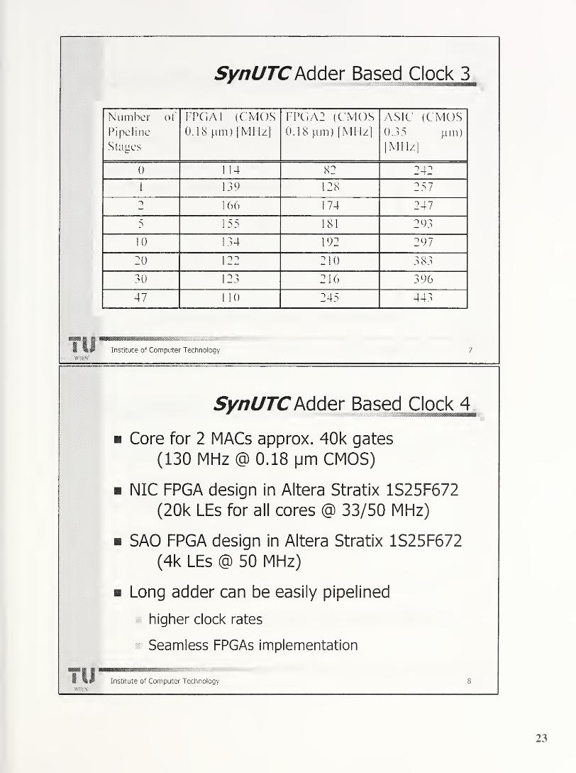
Synl/TCMder Based Clock 3mmmm
Number of
Pipeline
Stages
FPGAI (CMOS0.18 pm) [MHz]
FPGA2 (CMOS0.18 pm)
[MHz]
ASIC
0.35
[MIL
(CMOSpm)
fJ
0 1 14 82 242
1 139 128 257
n 166 174 247
5 155 181 293
10 134 192 297
20 122 210 383
30 123 216 396
47 1 1
0
245 443
Mil r
1 lbJ Institute of Computer Technology 7
Wli-S
SynUTCAdder Based Clock 4
Core for 2 MACs approx. 40k gates
(130 MHz @ 0.18 pm CMOS)
NIC FPGA design in Altera Stratix 1S25F672
(20k LEs for all cores @ 33/50 MHz)
SAO FPGA design in Altera Stratix 1S25F672
(4k LEs @ 50 MHz)
Long adder can be easily pipelined
higher clock rates
Seamless FPGAs implementation
Institute of Computer Technology
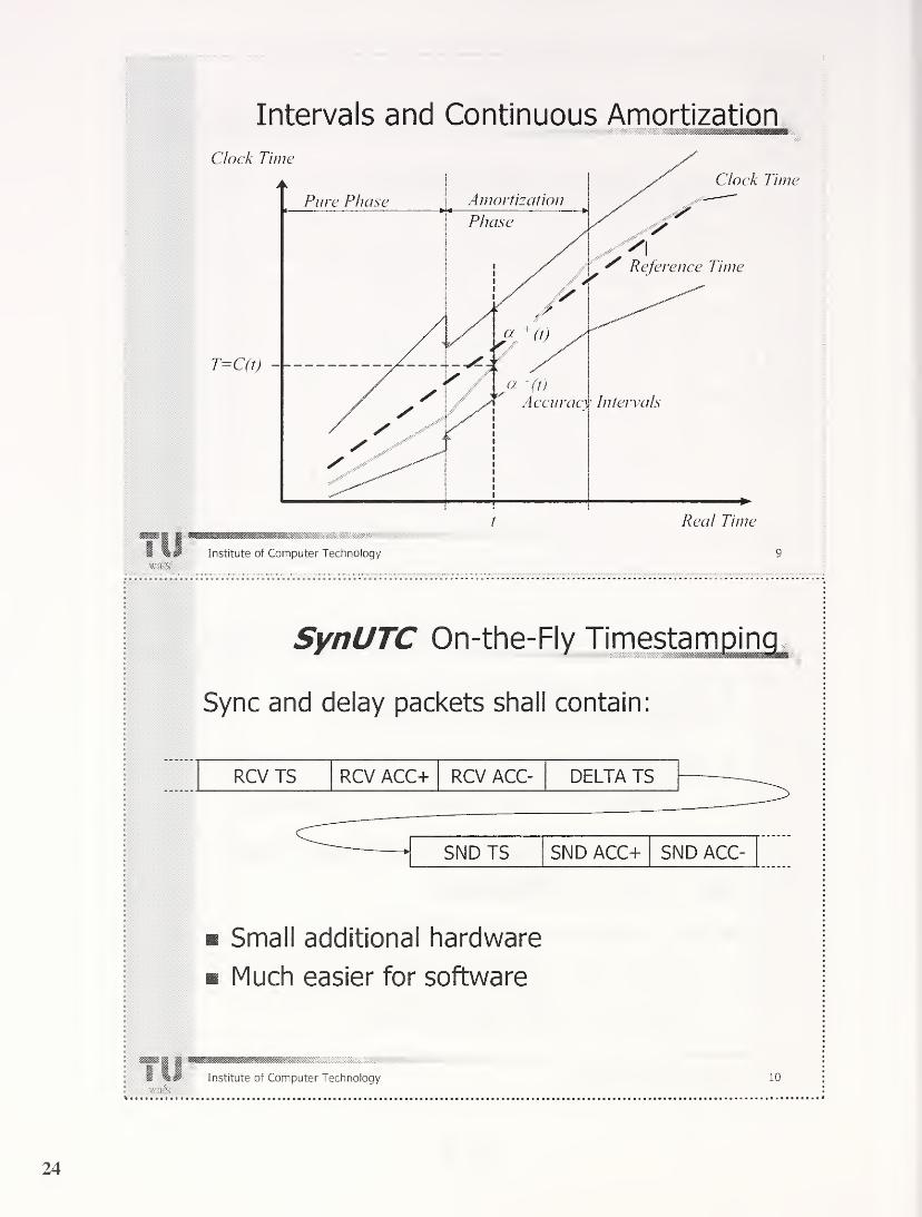
Intervals and Continuous Amortization
Til
SynUTC On-the-Fly Timestamping* 1 —B
Sync and delay packets shall contain:
RCV TS RCV ACC+ RCV ACC- DELTA TS
SNDTS SND ACC+ SND ACC-
Small additional hardware
Much easier for software
Til Institute of Computer Technology 10

IEEE 1588mm
Small networks
* Consuming small amount of resources
Small administrative overhead
Master-slave principle
Automatic network partitioning
PTP (Precision Time Protocol) clock definition
BMC (Best Master Clock algorithm)
Institute of Computer Technology 11
SynUTC vs. IEEE 1588M m m
Improved fault tolerance, due to its NONmaster-slave principle
Clock accuracy information for all clocks
(eases control loops, ...)
On the fly packet timestamping
Algorithms for state and rate synchronization
of the clocks
m Support for external clock synchronization
12Institute of Computer Technology

Network Interface Card
Institute of Computer Technology 13
Wl? \
W

Ethernet PHY Evaluation 1
'
- 400
Jitter of 100.000 clock synchronization packets for
Fast Ethernet PHY's, 99m CAT-5 cable, 100Base-TX Full Duplex Mode
Til Institute of Computer Technology 15
Til< i-'k
Ethernet PHY Evaluation 2mm
[us]
Jitter of 100.000 clock synchronization packets for
Gigabit Ethernet PHY‘s, 99m CAT-5 cable, 100Base-TX Full Duplex Modewmmsmmmmmmmb
Institute of Computer Technology 16
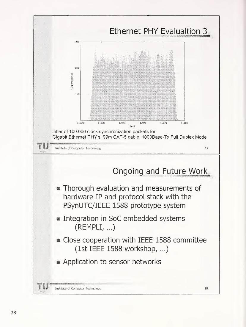
Ethernet PHY Evalua ltion 3
1.378 1.376 1.374 1.372 1.370 1.368
tus]
Jitter of 100.000 clock synchronization packets for
Gigabit Ethernet PHY‘s, 99m CAT-5 cable, lOOOBase-Tx Full Duplex Mode
TIJmmmMmmmmm*mmInstitute of Computer Technology 17
Ongoing and Future Work
m Thorough evaluation and measurements of
hardware IP and protocol stack with the
PSynUTC/IEEE 1588 prototype system
Integration in SoC embedded systems
(REMPLI, ...)
Close cooperation with IEEE 1588 committee
(1st IEEE 1588 workshop, ...)
Application to sensor networks
mm | |wmmMmmmmmmym 1
1
1 HJ Institute of Computer Technologymm
18

Clock Synchronization Constraints
How to achieve 10 ns accuracy ?
Overall accuracy n depends on
71 = C\t' + C~,G +CM + C4Pp
s ... Transmission delay uncertainty
G ... Local clock granularity
. Rate synchronization uncertaintyli
Timing error due to discrete rate adjustment (u=i'Lc)
Pp ... Clock drift during a re-synchronization
period
I P ... length of the re-synchronization period
a p ... oscillator drift
Institute of Computer Technology 19
Local Clock Granu larity
• Compensated external crystal oscillator
TCXO, MXCO, OXCOLimited frequency range: 1 MHz up to 10/20/100 MHz
PLL to decrease granularity
On-Chip module x4, x8 ...
Operating frequency of 96 bit accumulator
Pipe-lined architecture
> 200 MHz using state-of-the-art FPGA families
> 400 MHz using affordable CMOS-ASIC fabrication
processes
Generic adder based clock generator modulei Different optimization criteria
Ml | mmmmmsmmmmm1 Institute of Computer Technology 20
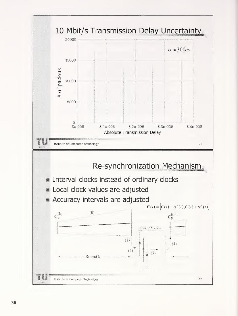
10 Mbit/s Transmission Delay Uncertainty1 mm
:oooo
15000
m
« 10000a.
onfc
5000
08e-0Q6
1
•—j
; i
CJ ~ 300/75'
\
I
1
1
1
1
1
m
!
fi
1
tjmkf
8 1e-006 8.2e-006 8.3e-006
Absolute Transmission Delay
Til Institute of Computer Technology
8.4e-QQS
21
Re-synchronization Mechanism
Interval clocks instead of ordinary clocks
Local clock values are adjusted
Accuracy intervals are adjusted
cAk) (0 )
C(0 = [c(0-«-(0,C(/)+« +
(0]
node p's view
I
(1)
i
(2)
Round k
(4)
:3 )
J888888888888888S88888833888®S8388S8383383SS^*^:->-^'' "•m%.
Institute of Computer Technology 22

100 Mbit/s Transmission Delay Uncertainty2000
Absolute Transmission Delay
Institute of Computer Technology 23

PTP in redundant network
structures
Topics
• Configurations
• Recovery
• Proposed enhancements
• Time Master Redundancy
• Secondary Master Handling
• Conclusion
Page 1 Ludwig Winkel, 2003-09-24
Configurations
• A redundant system has at least two nodes that are connected by at least two
different communication paths
• Ring structure as base for redundancy is the most common type of architecture
» delays between 2 nodes are different . . .PTP must know path
See path between 4 and 2 via 1 and via 7,8,5
Page 2 Ludwig Winkel, 2003-09-24
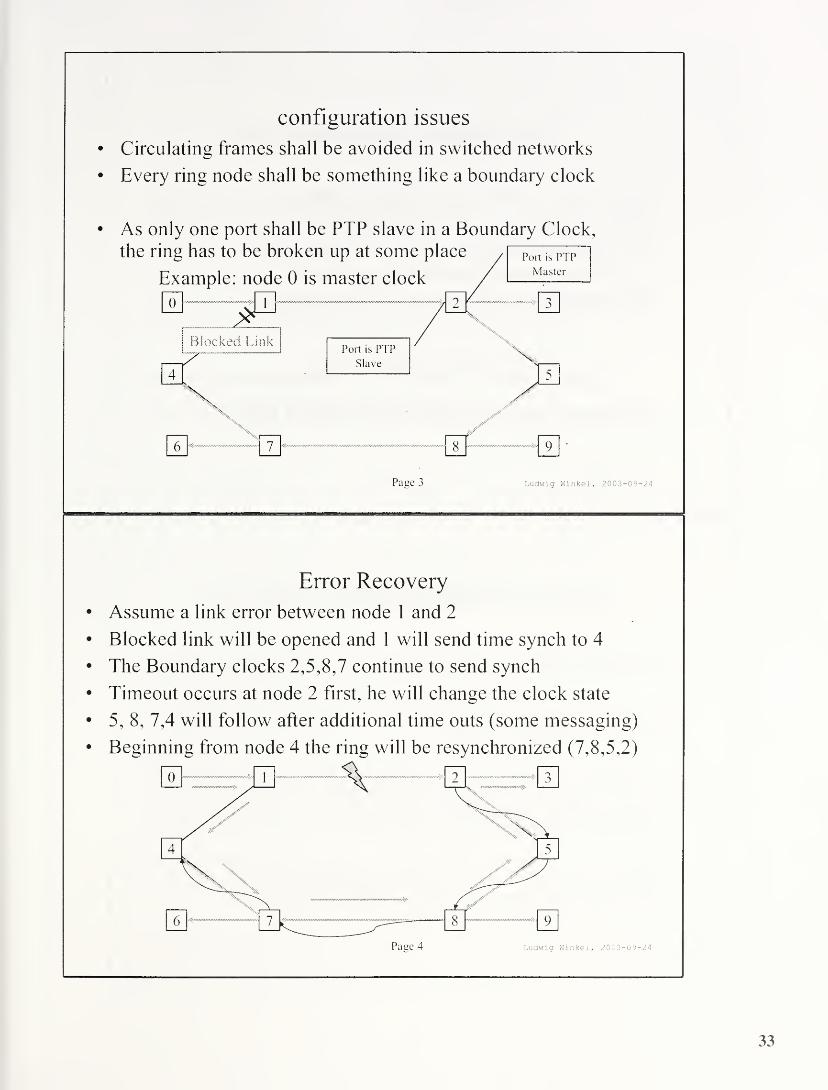
configuration issues
• Circulating frames shall be avoided in switched networks
• Every ring node shall be something like a boundary clock
As only one port shall be PTP slave in a Boundary Clock,
the ring has to be broken up at some place
Example: node 0 is master clock1
u i
Blocked Link
7
> 9 •
Page 3 Ludwig Winkel, 2003-09-24
Error Recovery
• Assume a link error between node 1 and 2
• Blocked link will be opened and 1 will send time synch to 4
• The Boundary clocks 2, 5, 8, 7 continue to send synch
• Timeout occurs at node 2 first, he will change the clock state
• 5, 8, 7,4 will follow after additional time outs (some messaging)
• Beginning from node 4 the ring will be resynchronized (7, 8, 5,2)
Page 4 Ludwig Winkel, 2003-09-24

Discussion of recovery
• Most actions will be executed sequentially
• This will lead to not acceptable delay
• Management messages may improve performance
. . . but with a lot of sophisticated protocols
• Blocking ports result in a poor recovery time
Potential enhancements
• Redundant path may improve accuracy if used
Page 5 Ludwig Winkel, 2003-09-24
Proposed enhancement in PTP
• Use both paths (red and blue)
• Use the switches that forward time with compensated delay
instead of boundary clocks
• The follow up messages require a unique transaction identifier
(stations that split messages shall produce two distinct
transaction identifier in sync and follow up)
• Option: Average timing errors in each end node
receiving from the same node on different paths
Page 6 Ludwig Winkel, 2003-09-24

Time Master Redundancy
• Time Masters in stand by will produce
the same effects as blocked ports
• Boundary clocks in switches will block a second master
• Resynchronization will lead to instable conditions
(each control loop has to adopt to new drift parameters)
• All happens sequentially which makes change slow
• Simultaneous adoption to new master clock required
• Same principles apply as shown before
Page 7 Ludwig Winkel, 2003-09-24
Secondary Master Handling
• Switch uses best master clock algorithm
• Only the best master clock will be forwarded
• Delay measurement will be done on any link and is
available on both sides
(otherwise a delay measurement cycle is needed)
• At time out of the current best master clock the switch that
has both as sources will forward the messages from the
second master clock
• The end nodes work as specified by IEEE 1588
best master clock algorithm
Page 8 Ludwig Winkel, 2003-09-24

Example: Node 0 and 4 are Master Clocks
0 is best Master Clock
• Error in Master Clock 0
• 1-5 detects timeout
• 5 will forward master clock 4
• Link 1-3 and 3-5 will forward in reverse direction
Conclusion
• We propose to enhance IEEE 1 588 for redundancy!
• The approach is in accordance with other
requirements of a switched network for sub
microsecond accuracy
• A technical proposal is under discussion within 1ECSC65C REAL TIME Ethernet
Page 10 Ludwig Winkel, 2003-09-24
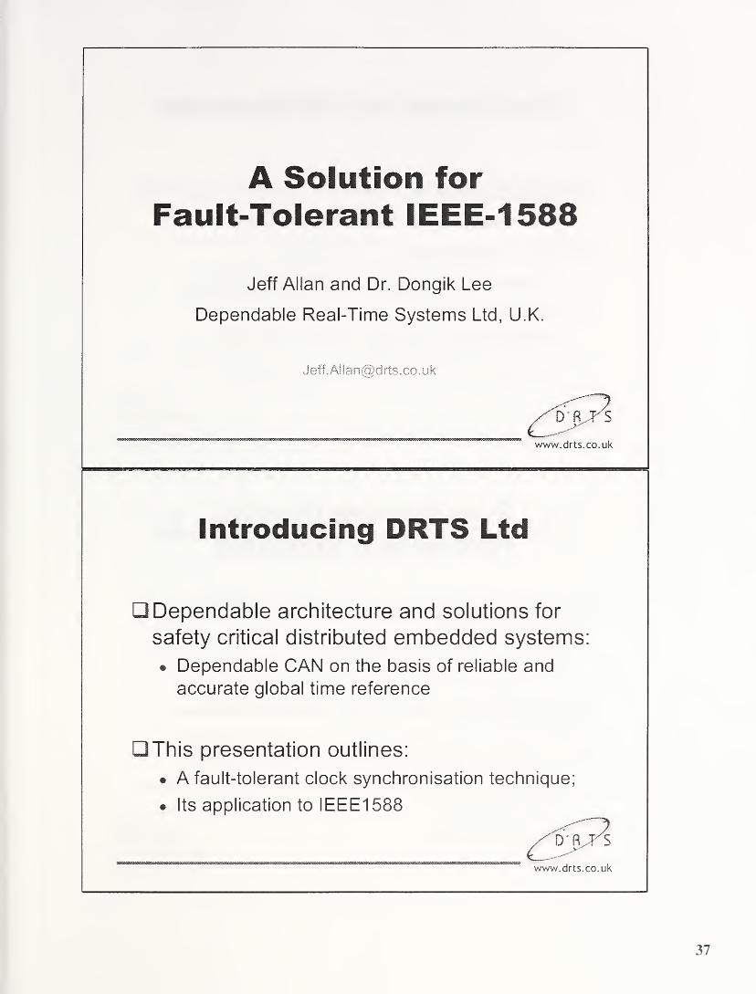
A Solution for
Fault-Tolerant IEEE-1588
Jeff Allan and Dr. Dongik Lee
Dependable Real-Time Systems Ltd, U.K.
www.drts.co.uk
Introducing DRTS Ltd
Dependable architecture and solutions for
safety critical distributed embedded systems:
* Dependable CAN on the basis of reliable and
accurate global time reference
This presentation outlines:
* A fault-tolerant clock synchronisation technique;
* Its application to IEEE1 588
www.drts.co.uk
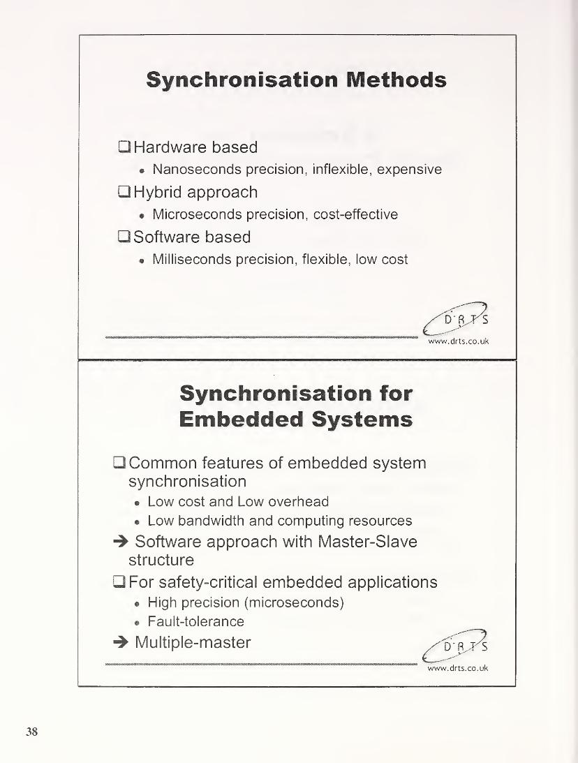
Synchronisation Methods
Hardware based
• Nanoseconds precision, inflexible, expensive
Hybrid approach
• Microseconds precision, cost-effective
Software based
• Milliseconds precision, flexible, low cost
www.drts.co.uk
Synchronisation for
Embedded Systems
Common features of embedded systemsynchronisation
• Low cost and Low overhead
• Low bandwidth and computing resources
4 Software approach with Master-Slave
structure
For safety-critical embedded applications
• High precision (microseconds)
• Fault-tolerance
4 Multiple-master
www.drts.co.uk

Software-Based Algorithms
Message latency causes the major problem
with software-based approach
Synchronisation Message Latency
Master Timestamp Queue Arbitra-
tion
Trans-mission
X.\ Local Time
Slave Reception Buffer Timestamp
Local Time
www.drts.co.uk
A Posteriori Technique (1)
A software synchronisation method with
microseconds precison for CAN network*
• To reduce the influence of message latency and
jitter
• Master and slaves take timestamps at the end of
messag transmission (or reception)
*Gergeleit & Streich (1994). “Implementing a distributed high-resolution real-time clock using the
CAN bus", Proc. 1st iCC.
www.drts.co.uk

A Posteriori Technique (2)
Round k
MasterTrans-mission
Time-stamp
Xx- k
Txk-i m
Slave ReceptionTime-stamp
tF
Round (k+r
Trans- Time-mission stamp
T k+1
N: k m
ReceptionTime-stamp
Local! Time
-p k+lLocal Time
Clock skew » 1 bit time (e.g., 1 jus at 1Mbps)
Fault-tolerance?
www.drts.co.uk
Multi-Master Techniques
A multi-master approach needs a complex voting
mechanism
Complexity and necessary bandwidth increases with
the number of master clocks
A DRTS solution to:
Minimise voting complexity, bus load, and use of
computing resources
Maximise fault-tolerance and design flexibility.
www.drts.co.uk

DRTS Technique to AchieveFault-Tolerance
Classifying the clocks into three groups
Master Candidates Substitutes
Group (MCG) Group (SUB)
Replacing Faulty Candidates
Voting takes place only in
MCGClocks in SUB replace any
faulty clocks in MCGThe size of MCG: Nm = 2fm+1 (or 3fm+1 to tolerate
Byzantine faults)
The size of SUB: Ns = 2fm
The level of fault-tolerance is mainly dependent on Ns
The voting complexity is minimised
www.drts.co.uk

Master Selection andSynchronisation
0
m.
O
Resynchronisation Round k
Stepl Message Exchangewithin MCG
Step2 Step3 Master .
Step4 Step5
Voting1
1
p/ock Estimation^[
Correction*
Ack
(Fault)
statt m
.
mi
F( Tf ,T2 ,
T
3
(Master
Selected)
m ,
F(r7,r
2,r
3
3 C4
C/34
> Jrc/3
In this example:
- Size of MCG: Nm=3 (i.e. fm-
1
- C2 is the best clock
(No Correction)
MP mack
Fc(T
2a ,T
3a
)
T a13
F (T a T'r '2 ’14
F(TS,TNa
)
Local Time
Size of SUB: Ns=
2
Ci is a new faulty clock
www.drts.co.uk
Synchronisation Messages (1)
Start Message (mstart)
• Fastest clock(s) starts a new synchronisation
round: Starting clocks are not necessarily the best
clock
Timestamps (mi) exchange within MCGclocks
www.drts.co.uk

Synchronisation Messages (2)
Two successive Sync Messages (Ma,MP)\
• Ma for the list of MCG members• MP for the master clock timestamp
• In the next round, different clock can be selected
as master
• Immediately detect a fault of ‘selected master’ andre-elect
Acknowledgement Message (mack) by a
substitute: Accept or Reject to be a newmember of MCG
www.drts.co.uk
Analysis
Synchronisation precision:
# Worst clock skew: 5=4pR+£
Where, p= drift rate, R= resynchronisation period, reading
error (including 1-bit time and interrupt processing)
Number of messages for tolerating fm faulty
candidates in a single synchronisation round :
. 2fm+4 ^ rimsg — (n+2)fm+4, (n=1,2,...)
(e.g.) Bandwidth of CAN used for synchronisation
(fm=1 ;n=2\ Ns
=2; Nm=3): <0.1% at 1Mbps, <0.4%
at 250Kbps
„ ,-
www . d xt s . co . uk

Experiments with CAN
Steer-by-wire model system and demonstrator
Steer-By-Wire Demonstrator
X-View (Steering
Wheel)
4 Slave Clocks (Node 6 - Node 9)
Node 8
(87C591
)
Node 7
(C167CR)
CAN Bus Network (Bus Speed: 250Kbit/sec)-A
Node 6
(C167CR)
Actuator 1
Node 1 Node 2 Node 3 Node 4 Node 5
(C167CR) (C167CR) (C167CR) (C167CR) (C167CR)
Actuator 2
2 Substitute Clocks
(Node 4 & 5)
3 Master Candidate Clocks (Node 1 - 3) and 2 Actuators
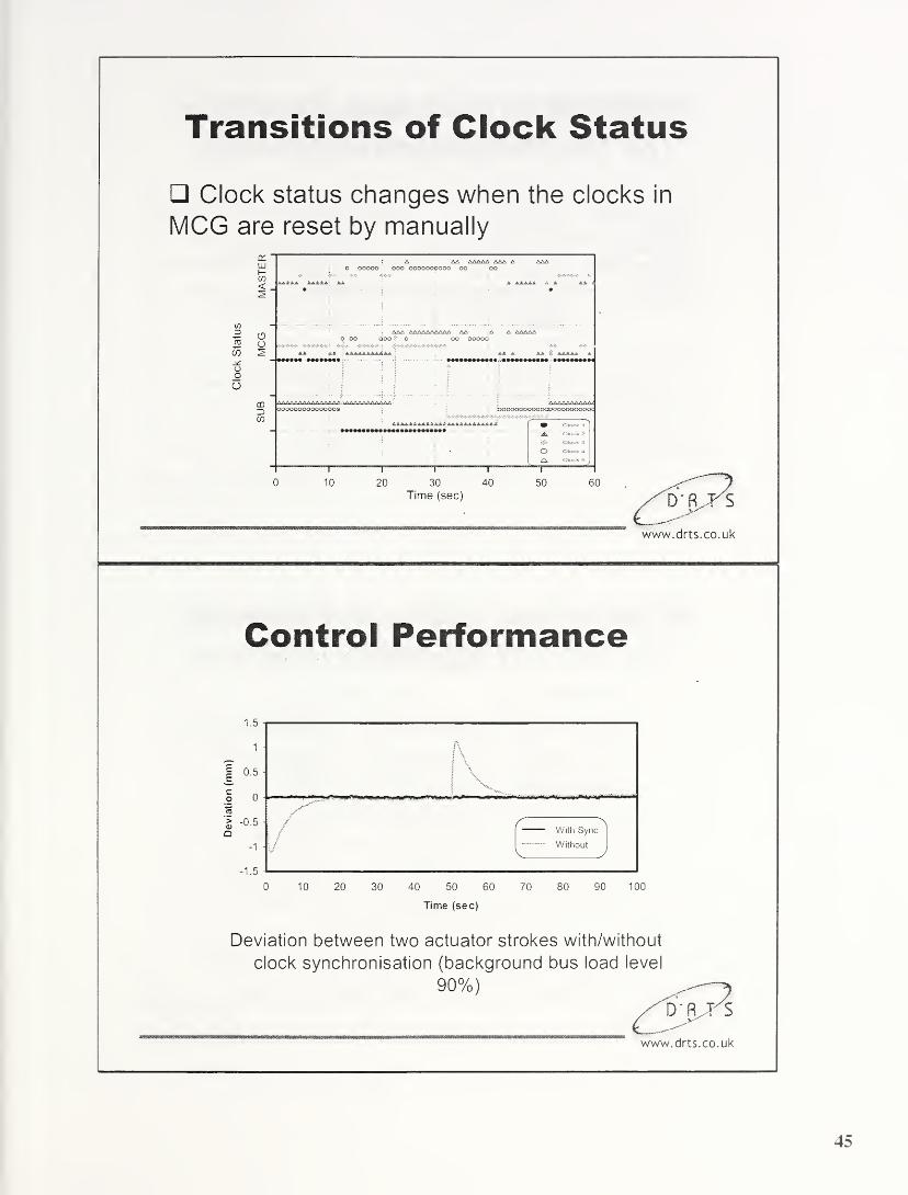
Transitions of Clock Status
Clock status changes when the clocks in
MCG are reset by manually
Control Performance
\
/
C \With Sync
WithoutV J
0 10 20 30 40 50 60 70 80 90 100
Time (sec)
Deviation between two actuator strokes with/without
clock synchronisation (background bus load level

IEEE1588: An Ideal Platformfor DRTS Synchronisation
IEEE1588 DRTS Synchronisation
Network Multicast Multicast
Optimised for Embedded systems Embedded systems
Category Hybrid Software
Structure Master-slave (Single
master)
Master-slave (Multi
master+voting)
Precision Nanoseconds Microseconds
To overcome
message latency
Special hardware +
a posteriori technique
A posteriori technique
Fault-toierance No Yes
Ideal platform <=> Fault-tolerance
www.drts.co.uk
A Solution to Fault-Tolerant
IEEE1588Substitutes Group Slave Clocks Group
DRTS S/Won Top of
1588 Clock
DRTS S/Won Top of
1588 Clock
DRTS S/Won Top of
1588 Clock
DRTS S/Won Top of
1588 Clock
DRTS S/Won Top of
1588 Clock
DRTS S/Won Top of
1588 Clock
Master Candidate Clocks Group
IFault-tolerant time reference with nanoseconds
Iprecision without hardware modification or extra —
y
|
hardware X s
www.drts.co.uk
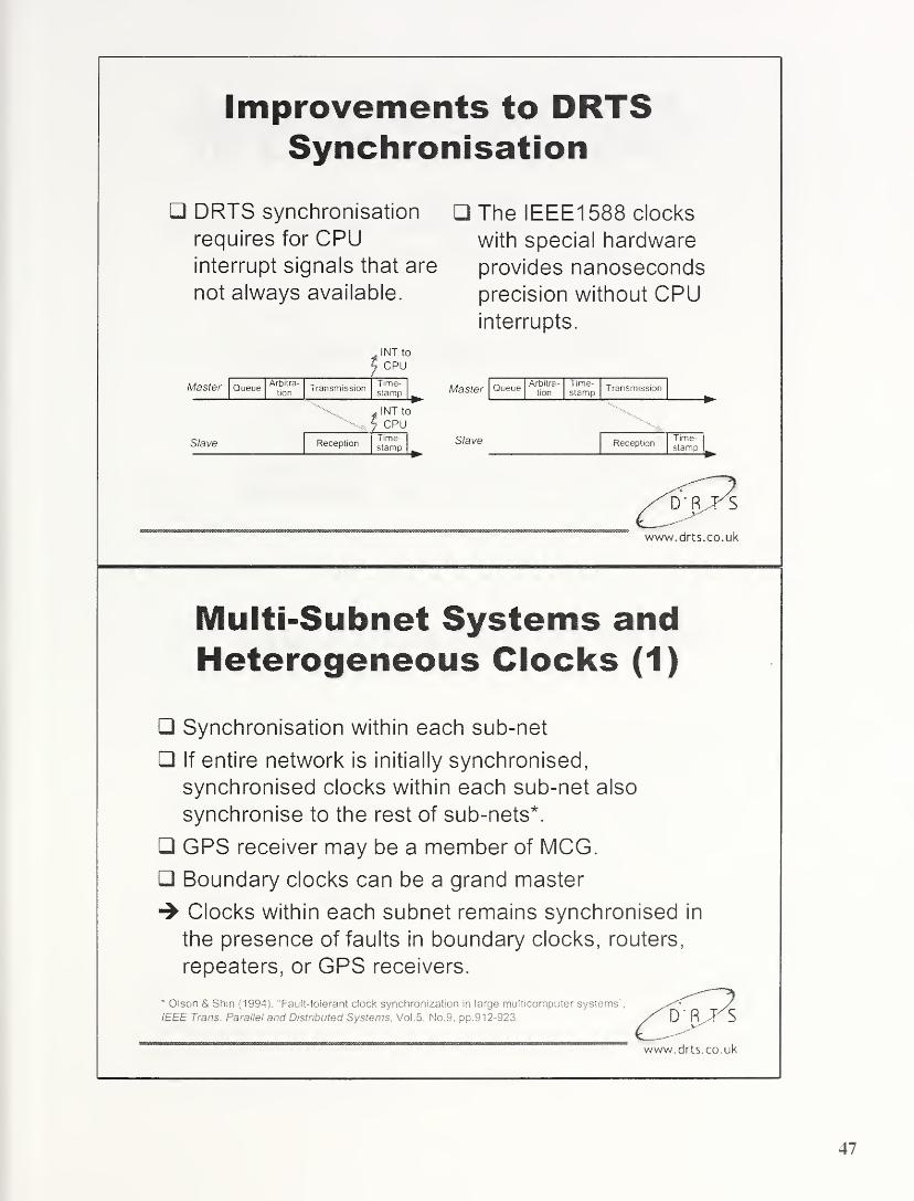
Improvements to DRTSSynchronisation
DRTS synchronisation
requires for CPUinterrupt signals that are
not always available.
The IEEE1588 clocks
with special hardware
provides nanosecondsprecision without CPUinterrupts.
INT to
CPU
MdSter Queue^r^ ra " Transmission
tion stamp
Slave
INT to
CPU
ReceptionTime-stamp
Master Queue Arbitra-
tion
Time-stamp
Transmission
Slave ReceptionTime-stamp
www.drts.co.uk
Multi-Subnet Systems andHeterogeneous Clocks (1)
Synchronisation within each sub-net
If entire network is initially synchronised,
synchronised clocks within each sub-net also
synchronise to the rest of sub-nets*.
GPS receiver may be a member of MCG.
Boundary clocks can be a grand master
Clocks within each subnet remains synchronised in
the presence of faults in boundary clocks, routers,
repeaters, or GPS receivers.
* Olson & Shin (1994). "Fault-toierant clock synchronization in large multicomputer systems ',
IEEE Trans. Parallel and Distributed Systems,Vol.5. No. 9. pp.912-923.
' """ irnnrmwrrn-Trnnrrrmmrni^'nrrmrnmirrnmrm rnrm mmr nr-™™™,WWW. dftS . CO . Uk

Multi-Subnet Systems andHeterogeneous Clocks (2)
f Repeater/ fDRTS S/W +^\
Switch J \jsJon-1588 Clocjy
DRTS + 1588 DRTS + 1588
Clock Boundary Clock
Router/1 588
Boundary Clock
www.drts.co.uk
Summary and Conclusion (1)
A unique clustering technique has been
presented:
• Software based technique—Low cost, No need for
additional hardware
• Minimise voting process—Simplicity and efficiency
• Flexibility—Ns and Ns can be chosen as design
factors
• Deterministic—Achievable fault-tolerance and
bandwidth used can be predicted
/D'fiJSwww.drts.co.uk
Summary and Conclusion (2)
DRTS technique can provide fault-tolerance
clock synchronisation with IEEE1588
• IEEE1588 provides ideal foundation for the DRTSapproach
• Software technique-^ No need for hardware
modification
www.drts.co.uk

A Solution for Fault-Tolerant IEEE 1588
Jeff Allan and Dongik Lee
Dependable Real Time Systems Limited
The Innovation Centre, 217 Portobello Road, Sheffield, SI 4DP, United KingdomPhone/Fax: +44-(0)1 14 223 2301
E-mail: [email protected]
Website: www.drts.co.uk
A software-based fault-tolerant clock synchronisation technique is presented. Theproposed algorithm aims at fault-tolerant clock synchronisation within a subnetinvolving any number of heterogeneous clocks with or without IEEE1588 clocks. Theproposed algorithm is simple, and provides predictable and reliable time references in
the presence of faults with grandmaster or network connections.
1. INTRODUCTION
Clock synchronization is a key factor for
many industrial systems. For example,
synchronised clocks are the fundamental
requirement for embedded control systems,
time-triggered communications, redundancy
management, etc. The IEEE 1588 standard
[a. or PTP (Precision Time Protocol),
provides a precise clock synchronisation
protocol for multicast networks. In contrast to
NTP (Network Time Protocol), IEEE 1588
aims at measurement and control applications
and the protocol can provide system-wide
synchronisation precision in the sub-
microsecond range. However, the potential
drawbacks of PTP are a lack of capability to
tolerate faulty master clocks and a selection
mechanism that is probably too complicated
(and expensive) to be used in low-cost
embedded applications.
This paper presents a software-based master
selection mechanism that will tolerate faulty
master clocks, and also maintain
synchronisation in any IEEE 1588 subnet,
low-cost or otherwise. The proposed
algorithm was originally developed for CAN(Controller Area Network), which is also a
multicast network. The proposed algorithm
deterministically guarantees an upper-bound
for the clock skew and the message overhead.
2. IEEE-1588 FOR LOW-COSTEMBEDDED SYSTEMS
DRTS Ltd has been developing dependable
architecture and solutions for safety-critical
embedded systems such as “x-by-wire”
applications for vehicles. The fundamental
requirement for a dependable distributed
architecture is a precision system-wide time
reference. From the point of view of
synchronisation precision, the IEEE 1588
standard may provide an ideal platform for
establishing dependable systems architecture.
However, for low-cost embedded systems
including safety-critical applications, there are
several potential drawbacks:
The mechanism for selecting the master
clock is complex and represents “overkill”
for use in low-level embedded
applications;
The behaviour of faulty clocks is assumed
as “fail-silent”—that is, a new master will
be selected when the current master does
not send a “sync” message in time.
However, if the current master is faulty, so
that it gets faster, this scenario may not be
detected by other clocks, and the healthy
slave clocks may claim themselves faulty;
and also,
The desired number of IEEE 1588 clocks
with the stratum number 1 or 2 (i.e., GPS
50

receivers or atomic clocks) may not be
available.
For example, considering an IEEE 1588 “x-
by-wire” implementation typifying a low-cost
embedded application, a single GPS receiver
would be available, and the rest of nodes in
the system would be likely to have lower
quality clocks. Most likely, many of the nodes
would not have IEEE 1588 clocks. In this
scenario, the PTP “best master clock”
algorithm would be unable to tolerate a faulty
master. In addition, because the standard
allows only a single path to each subnet, a
system could be left without synchronisation
resulting in loss of messages or a
disconnected communication.
3. THE “A POSTERIORI” TECHNIQUEFOR CAN
The communication network on which the
DRTS approach is based is standard CAN.The precision that a software-based
synchronisation method can achieve is limited
by message latency and jitter. The result
would be a typical precision in the order of a
few milliseconds.
Round k Round (k+1)
MasterTrans-mission
Time-stamp
Trans-mission
Time-stamp
Slave
T k
T^k-l mm
T k+1
nr-v
Loca Time
ReceptionTime-stamp
ReceptionTime-stamp
Local Time
Figure 1. Clock synchronisation based on the
“a posteriori“ technique.
To overcome the message latency problem,
Gergeleit and Streich [2] proposed a clock
synchronisation technique based on “c/
posteriori
"
technique (see figure 1 ). A clock
in the system is designated as the master,
which periodically broadcasts a
synchronisation message that provides a
reference time value. In this method,
timestamps are taken right after a message is
delivered, rather than before broadcasting the
message. In the synchronisation round k, the
master broadcasts a synchronisation message
m k which contains its timestamp taken at
T k
n
1 when the previous synchronisation
message m k 1 was delivered to the slaves.
Every slave in the system simultaneously
receives this message at T k
, and takes a
timestamp right after the reception. Each
slave clock then calculates a correction term
using the difference between the timestamps
T k 1
and T k 1
. The key advantage is the high
precision that does not depend on message
latency. This approach can achieve the
synchronisation precision up to 1
microsecond. However, the lack of capability
to tolerate a faulty master is the major
concern.
4. FAULT-TOLERANT CLOCKSYNCHRONISATION FOR CAN
DRTS has developed a unique mechanism to
provide the “ur posteriori technique with
fault-tolerance capability. This section
describes the fault-tolerant clock
synchronisation algorithm for CAN. The
application of this technique to any broadcast
networks having IEEE 1588 clocks will be
discussed in section 5.
The key feature of the proposed algorithm it
the use of dynamic voting within a set of
master candidate clocks. The novelty and
value of the method lies in the use of two
groups of master candidates—
'Master
Candidates Group' (MCG) and ‘Substitutes
Group' (SUB). By classifying the candidate
clocks into two groups, the complexity and
bus traffic of the voting mechanism can be
drastically reduced.
4.1. Subsets of Clocks in the System
The major drawback with a multiple-master
technique is the need for a master selection
mechanism. Selection algorithms are usually
complicated and introduce extra load on the
system in terms of bus traffic and processing
time. The number of messages required for
the selection mechanism increases with the
51

size of the multiple-master cluster. The larger
size of the multiple-master also leads to the
higher complexity in the selection
mechanism, which is not desirable.
Master Candidates Substitutes
Slaves Group (SLV)
Figure 2. Subsets of clocks in the system.
In this paper, to overcome these problems, all
clocks in the system are divided into three
subsets (figure 2). At each synchronisation
round, only clocks in the MCG take part in
voting for a master. Clocks in the SUB group
do not take part in the voting process, and are
only for replacing faulty members of the
MCG. The rest of the clocks in the system are
considered to be slaves (SLV).
Figure 3. Replacement of a faulty candidate
clock.
An example given in figure 3 explains howthe MCG and the substitutes group work in
order to update the MCG. Each node of the
MCG examines its clock value by comparing
with the current master clock time. When a
clock in the MCG is found to be faulty, a non-
faulty clock in the SUB group becomes a newmember of the MCG. In figure 3, for
example, the faulty candidate C 3 is replaced
with C4. Clock C3 takes the place of C4,
rather than being removed from the system.
The number of clocks for each group can be
chosen by the system designer to achieve the
desired level of fault-tolerance. The size of
MCG to tolerate/,, faults is given by
Nm =2fm +l (1)
If Byzantine faults are assumed, the size of
MCG group is given by Nm=3fm+1. Note that
fm denotes the maximum number of newfaulty clocks of the MCG that can arise in a
single resynchronisation round. Thus, the
complexity of the selection mechanism is not
directly proportional to the total number of
faulty clocks assumed in the system. On the
other hand, the size of the substitutes group,
Ns ,depends on the total number of faulty
clocks if) to be tolerated in the system. It
seems useful to choose Ns as a multiple of/,„
to achieve rpmodular set of redundant clocks
to substitute for faulty master candidates; that
is,
Ns =nfm > n = 0,1,2,... (2)
The minimum size of SUB group is zero in
the case that no clocks are designated to the
SUB group. Since/„«/ the proposed
algorithm can achieve a desirable degree of
fault-tolerance using a simple voting
mechanism and a lower number of message
exchanges.
4.2. State Diagram Model for the Algorithm
The state diagram in figure 4 is used to
describe how the proposed synchronisation
algorithm works. Circles and arrows represent
states and transitions, respectively. In the
resynchronisation process, clocks in the
system can be in one of the states shown.
Transitions from one state to another are
triggered either on the reception of a message
or by the expiration of a deadline. Conditions
for the state transitions are shown on the
upper part of the labels. The lower part of the
label shows the content of message, which is
52

sent at the time of the corresponding
transition. A null label represents the
condition that no message is sent or received.
RESYNCDETECTION: The
synchronisation round k begins when any
clock in the MCG reaches to kR on its logical
clock, where R is the resynchronisation
interval. In practice, the fastest clock, or even
a faulty clock, in the MCG will reach a newsynchronisation round at first, and will
generate a start message.
MCGTIMESTAMPSEXCHANGE: This
state is triggered on the reception of a start
message. Each clock in the MCG takes its
timestamp based on the "a posteriori'
technique. Each candidate clock then
broadcasts its timestamp to the other clocks,
and also waits for messages from other
candidate clocks. Either when all the
timestamps are received, or when the deadline
for the message exchanges is expired, each
clock transits to the next state for selecting a
master.
proposed algorithm.
SELECTING MASTER: Each master
candidate clock has a set of timestamps
representing other candidates’ clock values,
as well as its own timestamp. Clock values of
the nodes that failed to send their timestamps
by the deadline are replaced with zeros. Byapplying the fault-tolerant midpoint function
the clock which has the median value is
selected as the master of the corresponding
synchronisation round. On the other hand,
clocks whose time differences with the
median value are bigger than a threshold Dwill be considered as faulty.
GENERATING SYNC MSG a: In this
state, the selected master clock sends a
synchronisation message, Mu. The content of
this message is a set of identification numbers
corresponding to the substitutes, with which
the faulty candidates in the MCG identified at
the selection process will be replaced. Anempty message represents that all the current
candidate clocks are non-faulty, so that
updating the MCG will not take place.
GENERATING SYNC MSG P: The first
synchronisation message M 1’ is immediately
followed by another message, M p,which is
sent by the master too. This message contains
the timestamp taken by the master when the
first synchronisation message was delivered
to all the non-faulty clocks in the system.
SELECTING NEW MASTER: This state
is reached when any of the deadlines for
sending the synchronisation messages has
expired. In this state a new master clock is
selected. After replacing the clock value of
the faulty master with zero, the same selection
function is applied.
CLOCK CORRECTION: All clocks in the
system except the master calculate their
correction terms corresponding to the
differences from the master’s clock value
which is delivered in the follow up message
M |5
. Each clock then adjusts its logical clock
with the correction term to remove the clock
error.
ACKNOWLEDGEMENT: If any clocks in
the MCG were identified as faulty through the
master selection mechanisms, it is then
necessary to replace them with the clocks in
the SUB group. Clocks designated in the first
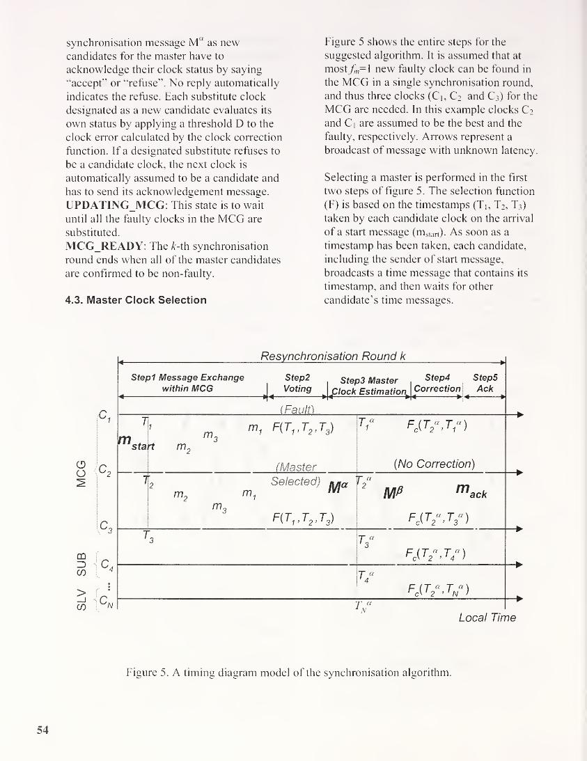
synchronisation message Muas new
candidates for the master have to
acknowledge their clock status by saying
“accept” or “refuse”. No reply automatically
indicates the refuse. Each substitute clock
designated as a new candidate evaluates its
own status by applying a threshold D to the
clock error calculated by the clock correction
function. If a designated substitute refuses to
be a candidate clock, the next clock is
automatically assumed to be a candidate and
has to send its acknowledgement message.
UPDATING_MCG: This state is to wait
until all the faulty clocks in the MCG are
substituted.
MCG_READY: The A-th synchronisation
round ends when all of the master candidates
are confirmed to be non-faulty.
4.3. Master Clock Selection
Figure 5 shows the entire steps for the
suggested algorithm. It is assumed that at
most/„=l new faulty clock can be found in
the MCG in a single synchronisation round,
and thus three clocks (Ci, C2 and C3) for the
MCG are needed. In this example clocks C2
and Ci are assumed to be the best and the
faulty, respectively. Arrows represent a
broadcast of message with unknown latency.
Selecting a master is performed in the first
two steps of figure 5 . The selection function
(F) is based on the timestamps (Tj, T2, T3)
taken by each candidate clock on the arrival
of a start message (mslart). As soon as a
timestamp has been taken, each candidate,
including the sender of start message,
broadcasts a time message that contains its
timestamp, and then waits for other
candidate’s time messages.
0Q
DO3CO
>CO
c,
IQ
Resynchronisation Round k
Stepl Message Exchange Step2 Step3 Master Step4 Step5
within MCG _ Voting jc/ock Estimation Correction] Ack
(Fault)
T
m.sta
1
m3
F(Tv T2 ,T3 )
t m2
(Master
T ° fb(t«,t°)
(No Correction)
1 n Selected) n/ia
m2
m1
MF(T1t T2t T3 )
^ MP mack
fc{t
2\t
3°)
T “
Fe(T
2°.T
4°)
T/Fc(T
2°,Tn“)
T a1 AT
Local Time
*
Figure 5 . A timing diagram model of the synchronisation algorithm.
54

Since CAN is a multicast network, all the
correct candidates will obtain an identical set
of timestamps, and thus, will vote for a
common clock as the master.
In addition to the selection of a master, the
selection mechanism also identifies any faulty
clocks in the MCG. Any candidates whose
time differences with the median value are
larger than a predefined threshold will be
considered faulty. The faulty clocks abandon
themselves as candidates for a master and
move to the SUB group, whilst the selected
master builds a list of new candidates for the
following synchronisation round.
A key advantage with the proposed voting
mechanism is its robustness. Since all the
timestamps needed for voting are taken at
once, any delays (or even missing deadlines)
in sending them do not lead to
synchronisation failure. On the start
messages, the fastest clock in the MCG maybroadcast a “start” message. However, the
selection mechanism still gives a correct
result even though the resynchronisation
round starts earlier due to the fastest clock (or
a faulty clock in the worse case), since the
selection algorithm relies on the fact that a
start message has arrived rather than the time
when it was generated.
4.4. Clock Correction
Except for the selected master, all clocks in
the system synchronise to the master clock.
Step3 and step4 in figure 5 are related to the
clock correction mechanism.
4.5. Substitution of Faulty Candidates
Each synchronisation round ends by updating
the MCG with a set of non-faulty clocks
(step5). The key to this process is the
acknowledgement messages sent by the
substitutes. Only the substitutes requested by
the current master send the
acknowledgement messages containing
binary information, i.e., “accept” or “refuse”
depending on the sender’s clock status, x 4.6.
Analysis
It is not feasible to describe in this paper the
details of analysis on the achievable
synchronisation precision and the number of
messages. To summarise, the worst case
synchronisation skew' between any two clocks
is given by:
8 - 4pR + £ (3)
where, p, R, and £, denote drift rate,
resynchronisation period, and reading error,
respectively. To toleratefm faulty candidates
in a single synchronisation round, the total
number of messages for the synchronisation
algorithm is given by:
2fm + 4 < nmg < (>/ + 2)f„ +4(4 )
where, r|=0, 1 ,2, is a parameter to be
selected by the system designer according to
the desired degree of fault-tolerance.
5. APPLICATION TO IEEE-1588
The application of the proposed
synchronisation method to a networked
system involving any number of IEEE 1588
clocks is straightforward, because the
proposed method:
is developed for a multicast network;
has a master-slave structure;
does not require any assumptions by the
clocks;
use the “a posteriori” technique which can
be easily replaced with the method used in
the PTP (i.e., “sync” and “follow-up"'
messages); and
is a software-based method;
A likely network configuration for typical
embedded applications is shown in figure 6.
Some subnets may contain 1588 clocks, and
others may not.
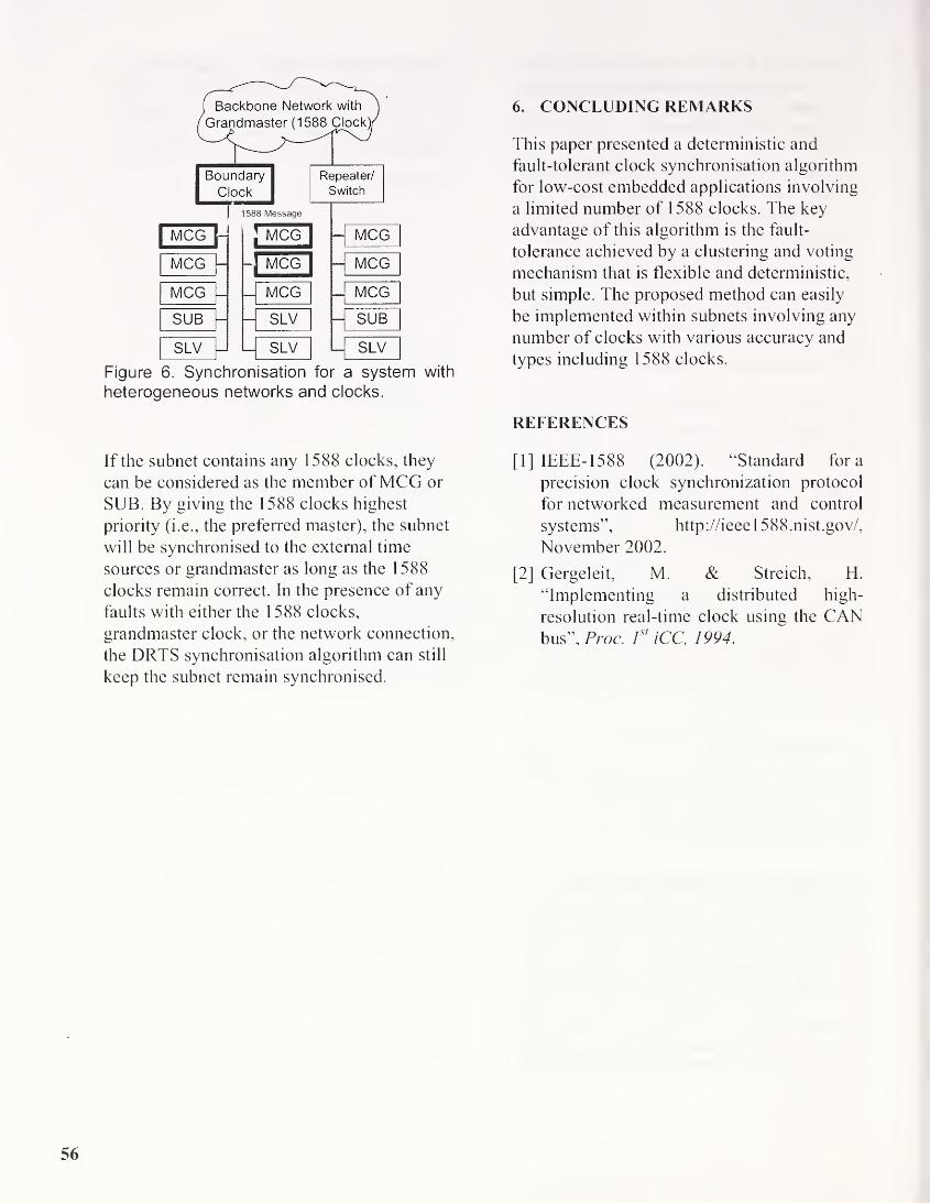
Figure 6. Synchronisation for a system with
heterogeneous networks and clocks.
If the subnet contains any 1588 clocks, they
can be considered as the member ofMCG or
SUB. By giving the 1588 clocks highest
priority (i.e., the preferred master), the subnet
will be synchronised to the external time
sources or grandmaster as long as the 1588
clocks remain correct. In the presence of any
faults with either the 1588 clocks,
grandmaster clock, or the network connection,
the DRTS synchronisation algorithm can still
keep the subnet remain synchronised.
6. CONCLUDING REMARKS
This paper presented a deterministic and
fault-tolerant clock synchronisation algorithm
for low-cost embedded applications involving
a limited number of 1588 clocks. The key
advantage of this algorithm is the fault-
tolerance achieved by a clustering and voting
mechanism that is flexible and deterministic,
but simple. The proposed method can easily
be implemented within subnets involving any
number of clocks with various accuracy and
types including 1588 clocks.
REFERENCES
[1] IEEE- 1588 (2002). “Standard fora
precision clock synchronization protocol
for networked measurement and control
systems”, http://ieee 1 588.nist.gov/,
November 2002.
[2] Gergeleit, M. & Streich, H.
“Implementing a distributed high-
resolution real-time clock using the CANbus”, Proc. 1
st
iCC, 1994.
56

PTP in switched networks
Topics
• Switch architectural issues
• Discussion of sources of synchronisation errors
• Adjustment of time in an PTP client
• Discussion of required update frequencies
• Influence of cascading
• Proposed enhancements
9/29/2003 Muller/Weber
Switch architectural issues
• Switches forward Ethernet frames based on address tables
learned on source addresses while forwarding
• Switches have storage capabilities to buffer frames in case of a
congestion
• The delay of switches is not fixed but will change with
• The load of the switch on a particular send port
• The time to find a destination address in the address table
• Other delays due to switch internal issues may occur
• Even in case of highest priority frames a delay of a full size
frame (approx. 125 ps at 100 Mb/s) can occur
(switching according to IEEE 802. ID assumed - preemptive
strategies can improve this but has some other side effects)
9/29/2003 2 Muller/Weber

Switch effects to time synchronization
Switches will produce asymmetric delays
as frames will delay time messages
Additional Delays at Delay measurement
PTP Node}
A
Switch
Olitput-
QueneX
r“1
L_
_J
t Qutpirf-
AQueue
PTP Node]
B
INode CData
Source
Trying to filter delayed frames will lead to unpredictable results
9/29/2003 3 Muller/Weber
Discussion of sources of synchronisation errors
• 3 types can be identified
• Jitter: random change of clock signals
• Delay: time offset between two clocks
• Drift: deviation due to frequency shifts of local clocks
• Jitters can be adopted by filtering (if it is of statistic nature)
• Delays are caused by non symmetrical paths between clock
receiver and clock sender (this are a few ns at physical level but
may be 100 ps or more in case of non-preemptive switches)
• Drifts can be measured at start up as a difference of the
difference of a pair of local time and received time
• Drift will change with aging (very slow) and
temperature change
(moderate with a deviation of 1 PPM per degree of Kelvin)
9/29/2003 4 Muller/Weber
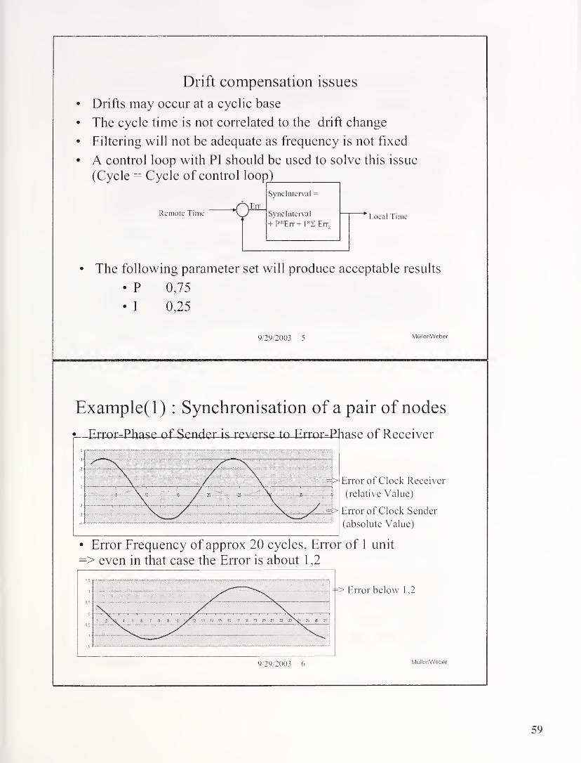
Drift compensation issues
Drifts may occur at a cyclic base
The cycle time is not correlated to the drift change
Filtering will not be adequate as frequency is not fixed
A control loop with PI should be used to solve this issue
(Cycle = Cycle of control loop)
Remote TimeiEit
Sync Interval =
Sync Interval
P*Err + I*Z Err,
Local Time
The following parameter set will produce acceptable results
• P 0,75
• I 0,25
9/29/2003 5 Muller/Weber
Example(l) : Synchronisation of a pair of nodes
? Error-Phase of Sender is reverse -to Error=J?hase of Receiver
Error of Clock Receiver
(relative Value)
Error of Clock Sender
(absolute Value)
Error Frequency of approx 20 cycles, Error of 1 unit

Example(2): Synchronisation of a pair of nodes• Error Frequency of 10 Synclntervals, Error of +/-1 unit
(at sender and receiver)
=> results in an error of approx. 1,6 units
• Error Frequency of 2 Synclntervals, Error of 1 unit
=> results in an error of approx. 1 ,8 units
9/29/2003 7 Muller/Weber
Discussion: update frequencies
• In case of a control loop cycle of 1 s:
a cyclic temperature change of 1 degree within 10s
=> results in an error of approx. 1,2 Microseconds
see Diagram of Example(l)
• IEC 60068-2-14 requires temperature changes of
1 degree K in 20s and this is not the only cause of error
• According to Example(2) a higher Error may occur in case
of higher frequencies
• Errors due to jitter (or filters) may be added
• Consider to use shorter clock synchronization cycles
• 1/2, 1/4, 1/8, 1/16, 1/32 seconds shall be used
9/29/2003 8 Muller/Weber
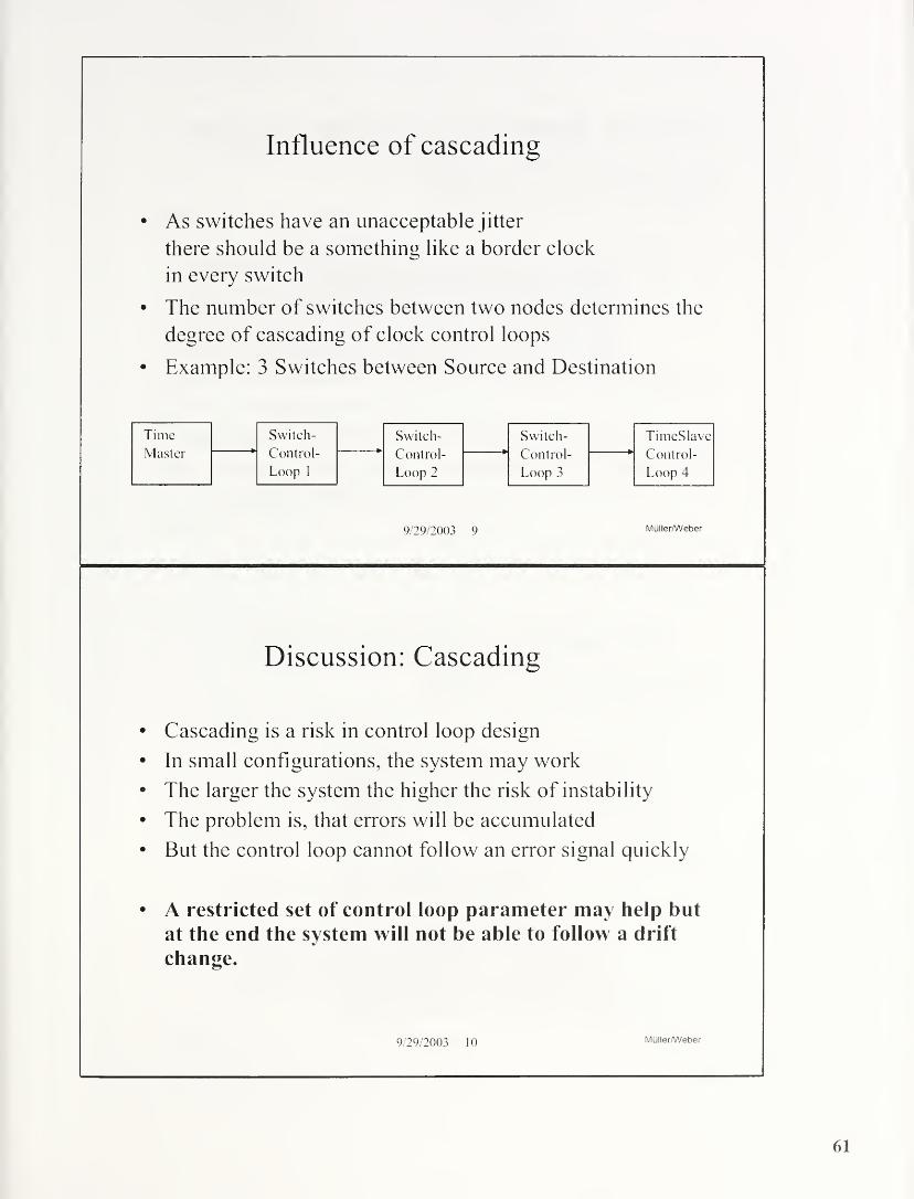
Influence of cascading
• As switches have an unacceptable jitter
there should be a something like a border clock
in every switch
• The number of switches between two nodes determines the
degree of cascading of clock control loops
• Example: 3 Switches between Source and Destination
9/29/2003 9 Muller/Weber
Discussion: Cascading
• Cascading is a risk in control loop design
• In small configurations, the system may work
• The larger the system the higher the risk of instability
• The problem is, that errors will be accumulated
• But the control loop cannot follow an error signal quickly
• A restricted set of control loop parameter may help but
at the end the system will not be able to follow a drift
change.
9/29/2003 10 Muller/Weber
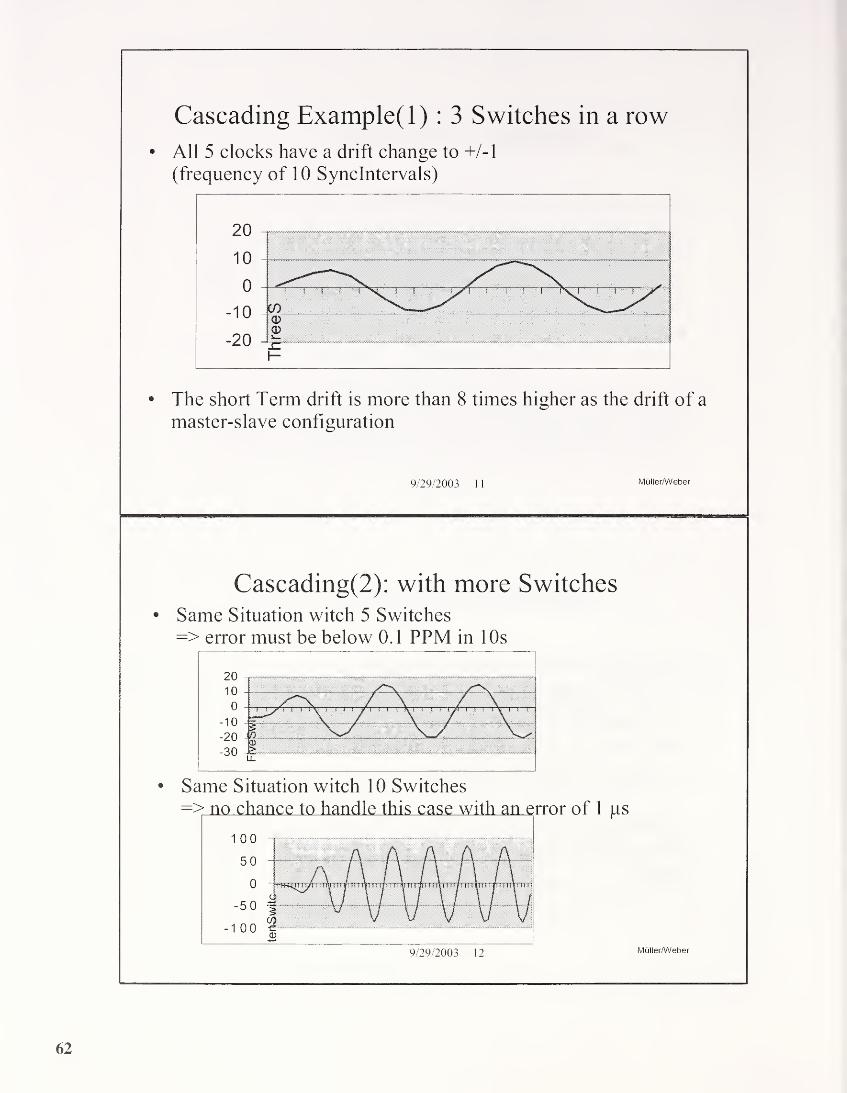
Cascading Example(l) : 3 Switches in a row
• All 5 clocks have a drift change to +/-1
(frequency of 10 Synclntervals)
• The short Term drift is more than 8 times higher as the drift of a
master-slave configuration
9/29/2003 1
1
Muller/Weber
Cascading(2): with more Switches• Same Situation witch 5 Switches=> error must be below 0. 1 PPM in 1 Os
• Same Situation witch 10 Switches

Proposed enhancement in PTP
• Introduce a new type of intermediate clock
bypass clock
• The Delay within a switch will be forwarded as extra
parameter
• Only nodes requiring time will run a control loop
• Switches may maintain a clock but its local time is not used in
the time forwarding process
• No additional hardware requirement (“just protocol”)
• The design of the control loop in that way is
much simpler and more robust
9/29/2003 13 Muller/Weber
Principles of operation
Delay A^ s = Delay S^A Delay S^ B = Delay B^ s
9/29/2003 14 Muller/Weber

Protocol considerations
• The protocol is close to link layer and shall be treated as link
layer protocol
• This protocol is should be restricted to a single link between
switches and between switch and his adjacent DTE• IEEE 802. 1 D reserved addresses that may help to resolve
compatibility problems with non bypass switches:Frames containing any of the group MAC Addresses specified in Table 7-9 in their destination address field
shall not be relayed by the Bridge. They shall be configured in the Permanent Database. Management shall
not provide the capability to modify or remove these entries from the Permanent or the Filtering Databases.
These group MAC Addresses are reserved for assignment to standard protocols, according to the criteria for
such assignments (Clause 5.5 oflSO/IEC TR 1 1802-2).
9/29/2003 15 Muller/Weber

Impact of Switch Cascading on Time AccuracyBy Prof. Thomas Muller and Karl Weber
Switches are the bases for modem Ethernet technology. Switches allow running networks with
several hundreds of nodes without configuration overhead and little delays. Hubs limit the number
of nodes for reasonable performance and routers add additional delay and limit the protocols being
used.
To use switches needs special attention for Time Synchronization, because the general paradigm of
symmetrical delay does not hold. Figure 1 shows the impact of other ports on forwarding PTPframes. Node C will add delay by filling the output queue to PTP Node B. Bridges are non-
preemptive according to the Standard IEEE 802. ID. If Node A is PTP Master the additional delay
on a delay response message to Node B will result in an error (Node B assumes a higher delay and
the local time will be ahead).
There are some ways to reduce the effect of delays; one is priority tagging according to IEEE
802.1Q(give PTP frames higher priority than other frames). But this can produce a delay of 1 22 jus
in case of 100 Mb/s Ethernet for frames with highest priority per switch. The cascading of switches
depends upon the application. Office applications will minimize the number of switches by using
stackable switches with dozens of ports. Industrial environment need systems with flexible
configurations and small switches to fit into a small cabinets. Wiring follows cabling channels that
lead to a structure of a line with some trunks. Thus, an industrial control system may have tens or
even up to hundreds of switches cascaded.
Additional Delays at Delay measurement
As local delays are not fixed, switches have to be somewhat like a boundary clock. But this requires
a time adjustment in any switch.
The sources of time errors have to be determined to discuss this adjustment. Three types can be
identified:
•Jitter: random change of clock signalsrandom change of clock signals
65

•Delay: time offset between two clocks
•Drift: deviation due to frequency shifts of clocks
Jitter can be compensated by filtering (but this will additional delays to the control loop).
Delays at the transmission channels are fixed and several hundreds of nanoseconds for maximumextension of a point-to-point network. They can be compensated if they are symmetrical. AsTransceiver/Receiver may not be symmetrical a correction value has to be added. The same applies
for non-symmetrical cables (allowed delay skew 50 ns for 100 m according to ISO/IEC 11801). Avalue of 30-50 ns should be a base to estimate delays between two adjacent nodes. This is an
absolute error, which cannot be compensated.
Drifts are mainly caused by deviation of the frequencies of the clock sender from the frequency of
the clock receiver. They are mainly caused by temperature and ageing. As temperature change mayoccur in various kinds they should be compensated by a control loop. Each PTP slave has to have
such kind of loop. The loop design is beyond the scope of PTP. But their design determines the
quality of time synchronization and should be fixed for boundary clocks. It is of less importance for
end nodes, which have no networking purpose.
Figure 2 shows the outline of a control loop. A Pi-Loop is the most popular and robust design
method for control loops with unknown behavior. The I-Factor should be about 1 Quarter of the P-
Factor and the P-Factor should be less than 1 to avoid instable conditions.
As control loops should be able to be cascaded, a P of 1 and an I of 0.25 seemed to be appropriate.
This parameter are an example to show the effects of cascading.
Remote Time oSynclnterval =
jErrSynclnterval
+ P*Err + 1*1 Errk
w
-
Local Time
Figure 2: control loop design
Time errors are accumulated i.e. a relative time error of one unit will result in an absolute error of
one in the first cycle, two in the second cycle, three in the third cycle and so on.
Note 1 the calculation was done with relative values which can be obtained by multiplying it with a time value.
Note 2 the absolute cycle time is of no importance - the maximum change and the value of an error signal have a correlation to the
worst case diagram.
Figure 3 presents the basic configuration, with 2 nodes. The blue function represents the error of the
PTP Master in correlation to absolute time. The purple function is the relative error of a PTP Slave.
This diagram shows error changes as cyclic function which may occur in areas with regulated
temperature. Other waveforms are tested with similar results.
66

Figure 3 shows an absolute error of about 3 if the error cycle is about 20 Sync Intervals. The
absolute error is of less importance but it will lead to time deviations. The numbers are selected
because a temperature change of 1 Degree Kelvin will occur within 20s in the IEC 60068-2-14. So
this figure represents a time synchronisation interval of 4s without statistical filters and about Is
with filters averaging the last 8 values.
tests. The selection of this parameter does not affect the general result. A longer cycle will reduce
the absolute error at the same amplitude if the error slope is in the same range.
Figure 4 and 5 shows results for a error cycle of 20 Sync Intervals and 10 Sync Intervals with the
same error maximum value. The resulting error in the Figure 5 is 1.8 times which is caused by the
higher slope.
Figure 6 show the result of an error cycle of 40 Sync Intervals which is smaller because of the
reduced slope.
It might be difficult to have a sub microsecond accuracy with standard clocks even in the case of no
boundary clocks between because the error due to temperature drift is even higher as the requested
mikrosecond.
In case of a Sync Interval of 4 s (or filtered with a Sync Interval of Is) and cyclic temperature
change of 1 degree within 20s will results in an error of approximately 1.7 Microseconds.
A shorter cycle time will improve the situation. The negative powers of 2 may be used without
changing protocol formats.
Figure 3: Absolute error and relative error at receiver

Figure 4: Error between sender and receiver(Error cycle = 20 Synclntervals)
Figure 5: Error between sender and receiver(Error cycle = 10 Synclntervals)
Figure 6: Error between sender and receiver(Error cycle = 40 Synclntervals)
As switches have an unacceptable jitter there should be a something like a border clock in every
switch. The number of switches between two nodes determines the degree of cascading of clock
control loops. If there are 5 Switches between PTP master and PTP slave the number of cascaded
control loops is 6. Figures 7,8 and 9 shows that the growth of the error is non linear. Therefore the
cascading may work for configurations of 3 to 5 Switches but may be completely inacceptable when
the number of switches is 10 or even higher. Even in case of small drifts in the area of less than 1
PPM over 20 Synch Intervals the result would be an error in the 50 microseconds range.
68

Figure 6: Error between sender and receiver(with 3 Switches in between)
Figure 7: Error between sender and receiver(with 5 Switches in between)
Figure 7: Error between sender and receiver(with 10 Switches in between)
The main cause of the problem is the control loop in the switches. The need to do this is because of
the dynamic internal delay of the switches. PTP itself should have all means to measure this internal
delay (= time outgoing - time incoming of the sync frame). The problem could be solved by in a
system that sends the delays in the frames. If switches will do this a very simple solution of this
69

problem can be found. Control loop design for switches may be much simpler. There is additional
jitter due to cascading, but as it is of statistical nature it can be managed by filters easily.
Switches with no need for synchronized time may not run a control loop.
There are a few additional thoughts how to handle PTP in a protocol architecture:
• The protocol is close to link layer and shall be treated as link layer protocol
• This protocol is should be restricted to a single link between switches and between
switch and his adjacent DTE• IEEE 802.1 D reserved addresses that may help to resolve compatibility problems
with non bypass switches:
70
IEEE 1588 and
Network Devices
Hirschmanri Electronics GmbH & Co, KG
Automation and Network Solutions
Dirk S. MofiS
Part I: IEEE 1588 - SW Implementation and Design Results
* System Architecture
8 Software Architecture
- Protocol Simulation
* Ideas for Improvements of Precision of Software
Stack
® Software for Linux, Windows and VxWorks

System Architecture of IEEE 1588 Implementation
necessary if no Mil- interface available
MI) Message Detector lor Sync and Delay_Request packets
Software Architecture IEEE 1588
Main Goal: Operating System Independent Design
- OS independent Protocol Stack(1EEE1588 Implementation)
- OS Abstraction Layer(Clock Interface, Timestamp Interface. Port interface (Packets)
)
- OS dependent(Tasks. Timer, Semaphore, Sockets)
- OS and Hardware dependent(Network Driver, Clock Driver, Timestamp Driver )

Basic Software Architecture
IEEE1588PTp Logic Layer,
OS independent
PTP Portltf TPTPTimestampltfTPTPCIockllf T
Call or signal
Dispatcher
OS Abstraction Layer
Interfaces
OS Layer
IEEE 1588
FTP
transmit
PTP Portltf TCall
Di-oaUnC!PTP Time
stampltl'T
RX PTPPori: 319
v event /
PTP Queue
Synchronised!
RXPTPPort: 320
\gencruiy OS abstraction
LayerTransmit frame Callf
Dispatcher fL>vcn3
Timer
Tick
Signal
(read access!
OS Layer
set
time stamp
PTP T PTP Queue
rushSynchronised T
Linux Software Architecture
Logik Layer
OS independentread
time stamp
&
c.
CO
cn
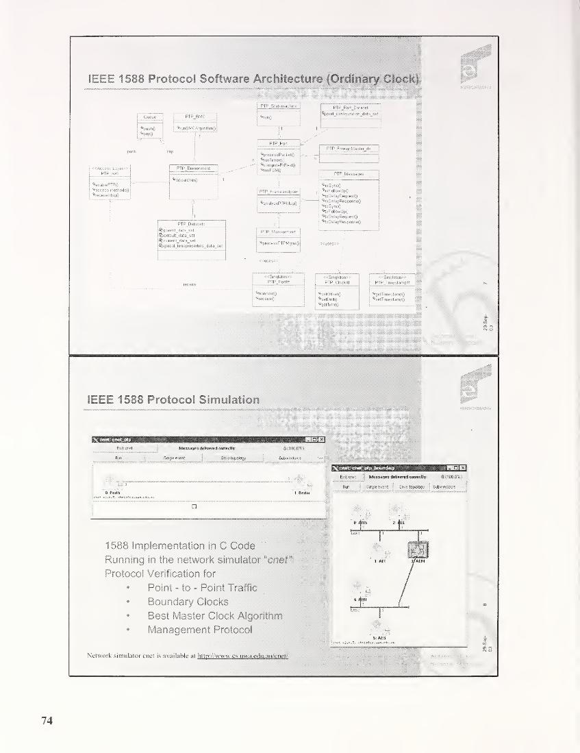
IEEE 1588 Protocol Software Architecture (Ordinary Clock)
j
^pushO
j^pop0
jPTP Stalemachine
PTP BMC ! ;vrunt)
^por1_configuration_data_set
•vrunDlVIL.HJgonthm(j : :| 1
: 1 ;
A*
pu$h
i <<Access Layer>>
PTF'API
|^enablePTPO P
! ^access methodsO
j%eceiveMsgO
PTP Environment
^processPacketO
^runTimersQ
^computeErBestO
^-runFSMO
PTP_Fo re ignMa ste r_ds
^dispatcherQ
PTP_F rameanalyse
^analysePTPMsgfj
1
PTP_Datasets
jfit-parent_data_set
!'%<iefaull_data_set
j%current_data_set
! '^globalJimeproperties_data_set
PTPManagement
^processPTPMgmtQ
PTPJvlessages
^rxSyncQ
^rsFollowUpO
^rsDelayRequestO
''•'rxDelayResponseO
^IxSyncO'hxFollowUpQ
%xDelayRequestO^xPelayResponseQ
<<Smgleton»PTP Portltf
^IransmitQ
%eceiveQ
«Singleton>>
PTP Clockltf
^setOITsetO
^set.Dnf!0
^getTimeO
«Singleton»PTP Tirnestampllf
vqetTimestampO^setTimestampO
,ill(P
IEEE 1588 Protocol Simulation'
.
cnet: cnet ptp M3E3]Exit or-et MeS3Ages delivered correctly CKioo&%y
Bun $ Single event $ Save topology Subwindows
3 --xV
0 Perth 1 Berlin
n
! Nfc cnet; cnet_ptp_boundaiy SMB ... 101*1
Exit cnet Messages drtivered correctly: 0 <100.0%)
fan Single event Save topology SiiwindOT?*
1588 Implementation in C Code
Running in the network simulatorucnef'
Protocol Verification for
* Point - to - Point Traffic
* Boundary Clocks
* Best Master Clock Algorithm
* Management Protocol
Network simulator cnet is available at http: www.cs.uwa,edu.au/enet/

Improvements of Software Stack
First Step
* Using UDP sockets / Winsock
* High task priority for FTP
* Manual drift / rate compensation for high precision counter
=> jitter typical +/- 10 .. 100 ps
Second Step
« Algorithm for throwing away sync packets which are too late
* same for delay request packets
- Automatic drift / rate compensation
=> jitter typical +/- 5 ps
Third Step
* optimized ISR: Software Timestamp for TX and RX packets,
basics research done by ZHW=> jitter expected +/- Ips
Assumption: no high Network traffic, no high CPU load (e. <
no Bus Master DMA
Software Library Conceptlii^
lib
pip
be
oc
ptptest
libraries
Linux Interface ImpL
Cnet Simulation
VxWorks Interface InrpL
OS independent
Boundary Clock specific
Ordinary Clock specific
Windows interface Impt.
PIP Test Program
Modules for Windows and Linux
Directory structure
. Linux Boundary Clock: Code from directories ptp. be. misc und ttrwx
• Linux Ordinary Clock: Code from directories pip, oc. m/sc und ttnux.
. Windows Boundary Clock: Code from directories ptp, be, misc und windows
. Windows Ordinary Clock: Code from directories ptp, oc. misc und windows.
29-Sep-

IEEE 1588 Linux and Windows Implementation
Master Clock ft
Offset
Offset correction bydrift / rate control
System Clock of Windows(approx. Ips)
Slave Clock
Eingabeauffordeiung - ptp_win
Port 1 State: PTP__SLfiUE<0f fset>—15@00</Q£fset>SetSystenTineftdjustnentC i><0f fset >-10?000</Of fset >SetSystenliraefldjustrsentC 5><Offset>87000</Offset>SetSysteinTin»efldjustnent< —4><Offset>-11808</Offset>SetSystemTimefldjustroentX 0><Offset>-6000</Offset><Offset>-18000</Offset>SetSystemTimefldjustroent< 1><0f fset >3000</Of£set >SetSystenTimefldjustmentC 0><O£fset>-34088</Offset>SetSystemTimefldjustroent< 2><Offset>22000</Offset>SetSystemTimeftdjustroent< -1><0ffset >—9000</Of fset
>
SetSystemTipneAdjustmentC 0>Current Delay: sec: 0 nsec<Offset>-63000</Offset>
+ <100145
>
+ <108145
>
+ <100145
>
<108145
>
+ <100145
>
+ <108145
>
+ <108145
>
+ <180145
>
+ <108145
>
: 242800
Summary of Software Stack
Full IEEE 1588-2002 Implementation
* synchronization, follow up, delay measurement* best master clock algorithm
* full IEEE 1588 management support
additional features
* drift / rate correction
* jitter filter for synchronization and delay measurements
* portable code
* adaptation layer for pure software or hardware based
time stamping / clock generation
* SNMP MIB (VxWorks)
* time representation of nsec : UINT32
tested underLinux* *VxWorks and Windows
Precision typically in the range of 1§ps fSW time stamp)

* Why IEEE 1588 Switches with Boundary Ci0€k
* Boundary Clock Software and Hardware Architecture
* Prototype: Modular IEEE1588 Switch
* Results of Hardware implementation
IEEE 1588 and Switches without Boundary
Latency of Layer 2 Switch - store and forward
Packet reception depending on packet length:
100 Mbits/s: 5,8ps for 64 Bytes up to 122ps for 1518 Bytes
“last bit in first bit ouf latency of a Switch:
typical hardware based, no cascaded chip: 2 .. 5 ps
Measured Jitter of switch latency:
e.g, Hirschmann Switch RS2-FX/FX: 0,4 ps
But this values are only valid under “no load" condition
2
i

gljpwmT
IEEE 1588 and Switches without Boundary Clock
The Problem:
Jitter under load condition:
Not depending of the Hardware, but depending on queued
packets = TX queue length of switch
worst case for e.g, a 20 packet queue:
jitter up to 20 x 120ps = 2,4ms
Does prioritization help ?
At least one low priority packet can still be in process of
transmission ~> jitter up to 125ps (maximum length packet)
but current available switches show that after the priority
scheduler there is another queue for 2 up to 8 packets
=> jitter 360ps up to 1ms=> available prioritization e.g. 801. D/p does not really help
IEEE 1588 Switch: Boundary Clock on Layer 2
The solution:
Use IEEE 1588 Boundary docks in switches
• only point to point connections:
=> nearly no delay jitter between master and slave
* internal queuing delay / jitter of switch not relevant
MASTER CLOCK BOUNDARY CLOCK SLAVE CLOCKS
Bill
,,1588 Switch
s = SLAVE CLOCK
nan = master clock

IEEE 1588 Hardware Architectyre - Message Detector
Desian of Sync Message Detector and Clock
Modular Industrial Ethernet Switch
® new module with 4 IEEE 1588 Ports
* full Implementation of IEEE 1588 protocol
* time stamp and clock in hardware
* SNMP management
oco
29-Sep-
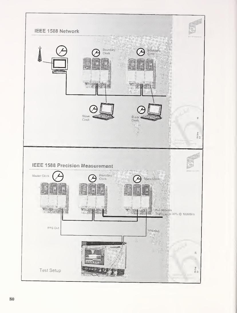
*$\0-
IEEE 1588 Network
Clock
IEEE 1588 Precision
Master Clock
lOOMB-ts
Test Setup
PPS Out
29-Sep-
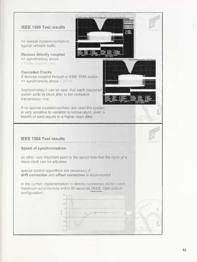
Devices directly coupled=> synchronicity about
Cascaded Clocks
2 devices coupled through a IEEE 1588 switch
=> synchronicity about ± 240ns
Approximately it can be said, that each cascaded
switch adds its clock jitter to the complete
transmission line
If no special crystals/oscillator are used the system
is very sensitive to variation in temperature, even a
breath of wind results in a higher clock jitter
IEEE 1588 Test results
Speed of synchronization
an other very' important point is the speed how fast the clock of a
slave clock can be adjusted
special control algorithms are necessary if
drift correction and offset correction is implemented
in the current implementation to directly connected clocks reach
maximum synchronicity within 80 seconds (IEEE 1588 default
configuration)
Eftl:
no special crystals/oscillatqjrs,
typical network traffic
IEEE 1588 Test results
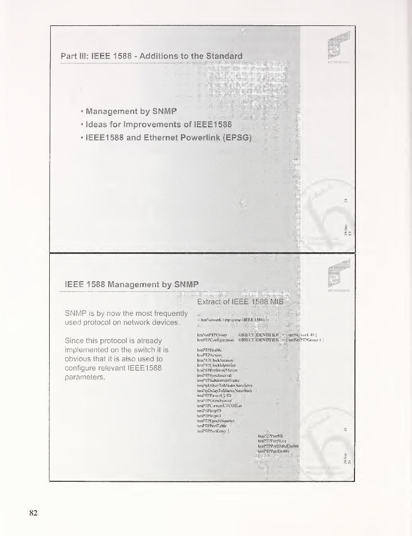
wmW
Part 111: IEEE 1588 - Additions to the Standard
Management by SNMP
Ideas for Improvements of IEEE1588
IEEE1588 and Ethernet Powerlink (EPSG)
sSillSP'”
IEEE 1588 Management by SNMP
SNMP is by now the most frequently
used protocol on network devices.
Since this protocol is ,
implemented on the switch it is
obvious that it is also used to
configure relevant 1EEE1588parameters.
Extract of IEEE 1588 MIB
hmNetwork / ptp-giottp (IF.FE 15&R) --
hmNetPTPGroup OBJECT IDENTIFIER!toiNctwork 40
|
htnPTPCon figuration OBJECT IDENTIFIER{tenNetPTPGroup
htnPTPEnable
hwPTPAttuin
braPTPCIackStratum
braPTPC loukhlenti Tier
braPIPPreferredMaster
hm PTPSync interva I
hmPTPSubdomainN'anie
hm PtpOffivetToMasterNanoSecs
hmPtpDelayTuMastei NannSeoii
hmPTPPat entlT IID
hmP Il’Gnamtmasrer
hmPTPCurrentL’JCOfEei
hmPTPIeap59
hmPTPIcapMbinPTPF.pochNumber
bmPTPPortTablc
braPTPPurtEntry j
hrnPTPPon ID
hmPTPPortState
hmPTPPortBunstEnable
hmPTPPortEnable

IEEE 1588 Enhancements
Higher Synchronization Rate (e, g. IGx)
* faster transient oscillation
* enables the use of oscillators with higher temperature drift
* suitable for small domains {bandwidth)
Adaptive delay request measurements
* faster transient oscillation
- faster reaction to network topology changes
- suitable for small domains (bandwidth)
.
IEEE 1588 Enhancements
Detection of error conditions
• Aging speed of slave ports (10 lost Sync messages)
• Handling of faulty state (e.g. due to missing FollowUp
msgs)
« PIP transparent switch / bypass clock
- idea: measuring the propagation delay of sync
messages and delay request messages and correcting
corresponding follow up messages and delay response
messages with these values
® switch is transparent for IEEE1588 clocks
* no IEEE1588 protocol modification necessary
* switch adds nearly no jitter to clock synchronization
- new protocol on this transparent switch (small)
8 does only work if FollowUp service is supported

IEEE 1588 in Automation
Initially IEEE 1588 was designed for time synchronization in test
and measurement applications.
Automation is now very interested in IEEE 1588:
CfPSync, Profinet V3, Ethernet Powerlink (EPSG),
IEC61850 (Communication networks and systems in
substations)...
Hirsclimann is active in EPSG
Etiiernet Powerlink is one solution for Ethernet in Motion Control
* 100% Ethernet 802.3 compliant
* Cyclic communication
* Profile: CANopen* Segmentation by Gateway* Time synchronization 100% compliant to IEEE1588
*#11111
pot..
'
Real Time Applications with Ethernet
ETHERNET
Dirk S. Mohl, Hirschmann Electronics GmbH & Co.KG, [email protected]
irtip
lit®;**

85

Frequency Compensated Cloc
Tx/Rx
Signals
Frequency
Compensation
Value
Message Detection &Time Stamping Logic
p-bit Clock Counter
q-bit Accumulator
^ r-bit Addend Register
Frequency Compensated
Clock
FreqDivisionRatio = FreqOscillator / FreqClock
CompensationPrecision < 1 / (Synclnterval * FreqClock)
2^ > FreqDivisionRatio / CompensationPrecision
2 r > 2V FreqDivisionRatio
2p> 2^
For example
- FreqOscillator = 50MHz, FreqClock - 40MHz,
FreqDivisionRatio = 1.25, CompensationPrecision =
1x10~9
,width of accumulator q = 32, width of addend
register r = 32, width of clock counter p = 64
86

• Fast, one sync interval settling time
• Self-correcting behavior, initial accuracy not required
• Initially, FreqCompValue0= 2 (
i / FreqDivisionRatio
• Algorithm
- MasterClockTimen= MasterSyncTime
n +
MasterToSlaveDelay
- ClockDiffCountn= MasterClockTime
n- SlaveClockTime
n
- Where,* n - Sync message count
* MasterSyncTimen
- time at which Master sends a Sync message to a Slave
* SlaveClockTimen
- time at which Slave receives the Sync message
* MasterClockTimen- computed by the Slave after the Sync message is
received
5
Frequency Compensation Algorithm (cont.
mil!m i nInHtill
FreqScaleFactorn = (MasterClockCount
n +
ClockDiffCountn )
/ SlaveClockCountn
Where,4 MasterClockCount
n= MasterClockTime
n- MasterClockTime^
* SlaveClockCountn= SlaveClockTime
n- SlaveClockTime
n .1
FreqCompValuen= FreqScaleFactor
n* FreqCompValuen^
6
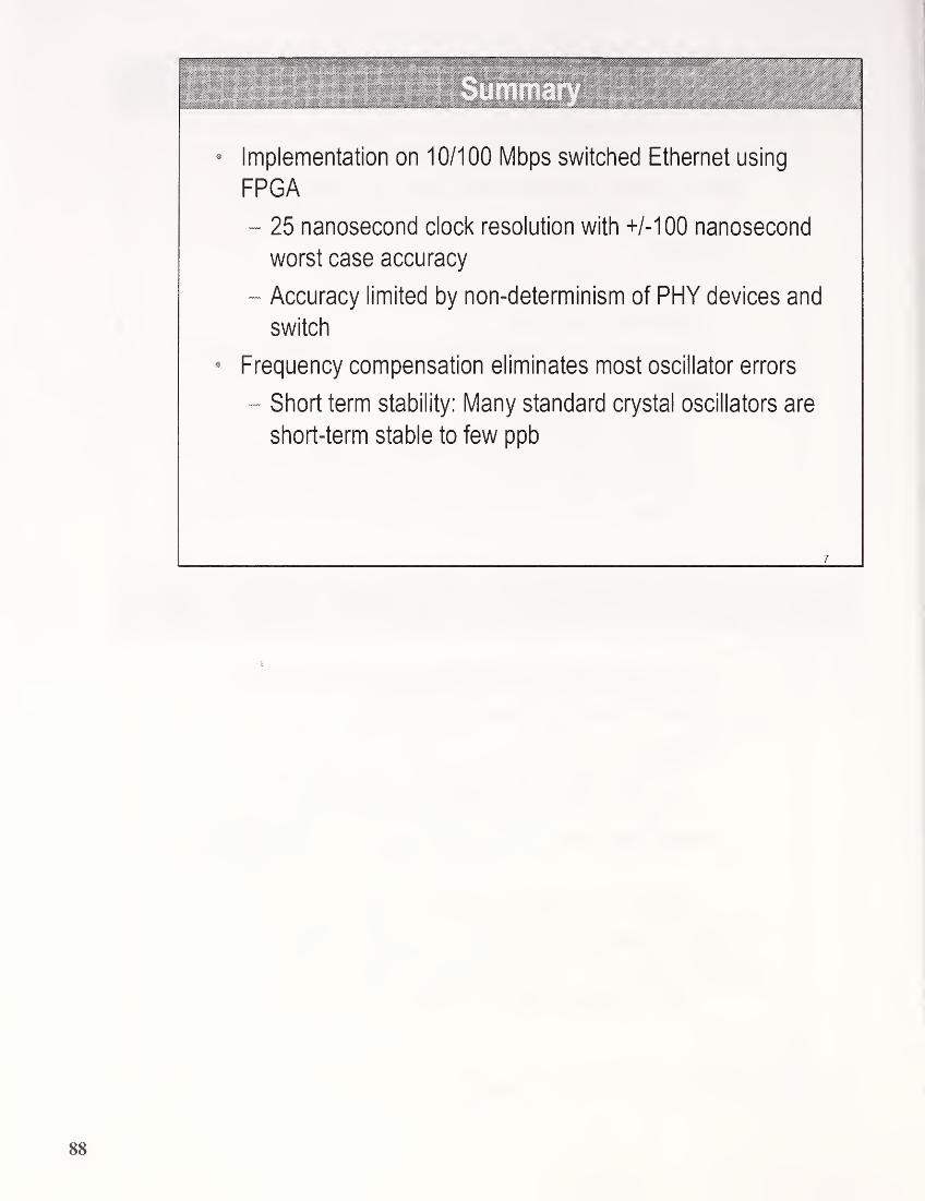
Implementation on 10/100 Mbps switched Ethernet using
FPGA
- 25 nanosecond clock resolution with +/-100 nanosecond
worst case accuracy
- Accuracy limited by non-determinism of PHY devices and
switch
Frequency compensation eliminates most oscillator errors
- Short term stability: Many standard crystal oscillators are
short-term stable to few ppb

September kuuo
John [email protected] bruce_ [email protected]
:0v Agilent Technologies
Over view
•Sources of fluctuation in an IEEE 1588 system
•Characterization of oscillators
•Measurement results
•Conclusions
Work supported by U. S. Naval Research Laboratory- Dr. Joe White
(John Eidson, Bruce Hamilton- Agilent; Mike Fischer- Fischer Consulting)
ieeei 588 workshop Agilent Technologies Page 2
September 24, 2003
89

S&urcegj of FluctuationMASTER SLAVE
ieeeisss workshop sC Agilent Technologies Page 3
September 24, 2003
Characterization of oscillators
* Long term systematic effects: aging
* Short term systematic effects:
* temperature, pressure, operating voltage
* Short term random processes: Allan variance
ieeei 588 workshop Agilent Technologies Page 4
September 24, 2003
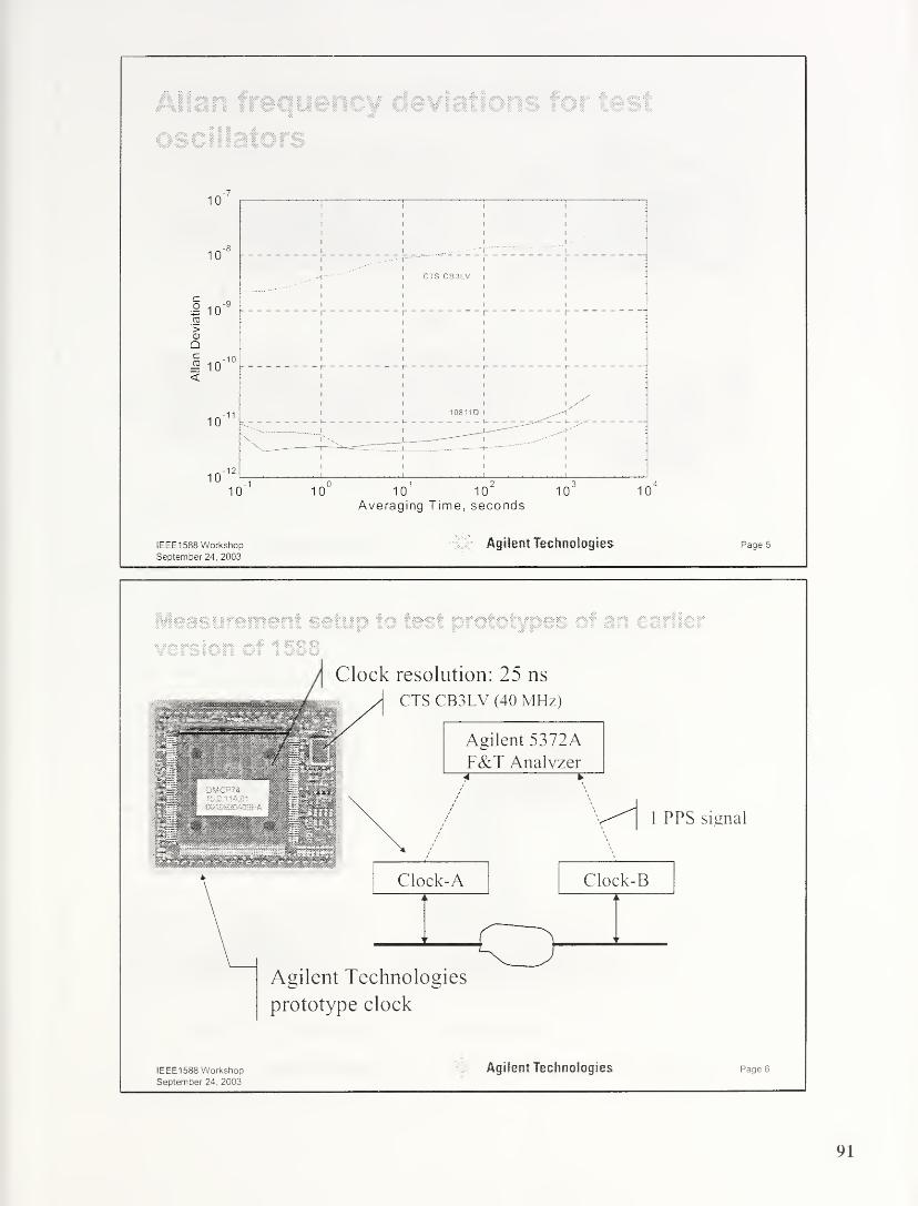
Allan frequency deviatio
oscillators
ieeei 588 workshop Or Agilent Technologies PagesSeptember 24, 2003
es of an earlier
Agilent Technologies
prototype clock
ieee 1588 workshop Agilent Technologies Page 6
September 24, 2003
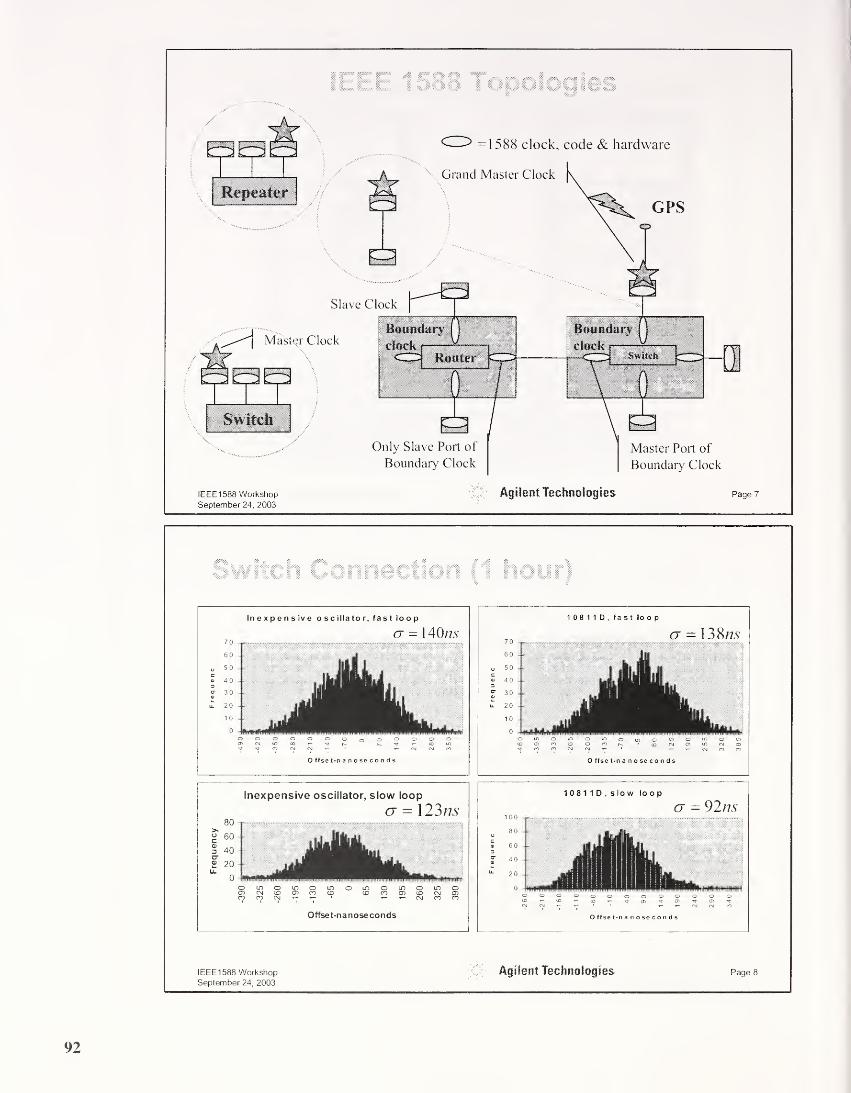
IEEE 151 8 jpol >gies
ieeei 588 workshop 55 Agilent Technologies Page 7
September 24, 2003
Switch Connection (1 hour)
10811D,slow loop
(
7
= 92ns1 00
80
o 603
O 40
^ 20
0
O ffse t-n anoseconds
IEEE1588 WorkshopSeptember 24, 2003
Page 8Agilent Technologies

Inexpensive oscillator, fast loop
cj - 15ns
inoiootnomomoioomcoocoroo^cDCNT— tnco
O ffse t-nanoseconds
1 08 1 1 D,fast loop
Offset-nanoseconds
ieeei 588 workshop ':C> Agilent Technologies page 9
September 24, 2003
Seconds tick deviations: connection via a repeater-72 hours
12000 -
10000 -
8000 -
6000
4000
2000
mean: 801 ps Std. Dev: 26.8 ns
0 50 100
nanoseconds
150-100
ieeei 588 workshop Agilent Technologies PageioSeptember 24, 2003
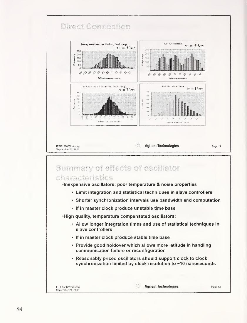
Direct Corine :t?cr
Inexpensive oscillator, fast loop
cr = 34ns250
S'200
£ 150
f 100
£ 50
0
<V> «$£ p & p p r> o 4> ^Offset-nanoseconds
10811D, fast loop ^G — 39/75
ieeei 588 workshop O' Agilent Technologies PagenSeptember 24, 2003
Sum ; nnr r cf cffec-;s c’ nsunictnr
S .;g © 35
arai snsucs•Inexpensive oscillators: poor temperature & noise properties
• Limit integration and statistical techniques in slave controllers
• Shorter synchronization intervals use bandwidth and computation
• If in master clock produce unstable time base
•High quality, temperature compensated oscillators:
• Allow longer integration times and use of statistical techniques in
slave controllers
• If in master clock produce stable time base
• Provide good holdover which allows more latitude in handling
communication failure or reconfiguration
• Reasonably priced oscillators should support clock to clock
synchronization limited by clock resolution to ~10 nanoseconds
IEEEI 588 WorkshopSeptember 24, 2003
Page 12Agilent Technologies
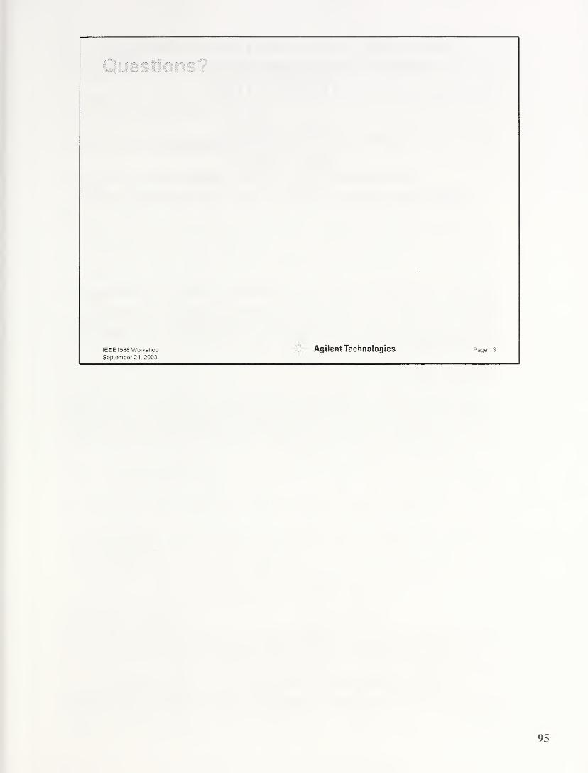
ieeei 588 workshop.0;' Agilent Technologies Page 13
September 24, 2003
IEEE-1588™ NODE SYNCHRONIZATIONIMPROVEMENT BY HIGH STABILITY
OSCILLATORS
John C. Eidson650-485-4263, john_eidsonfoia gi 1en t .com
Bruce Hamilton650-485-2818, bruce_hamilton@agj lent.com
Agilent Laboratories, 3500 Deer Creek Rd., Palo Alto, CA, 94304
Abstract
This paper outlines work donefor the US Naval Research Laboratory to investigate the
sensitivity ofsynchronization accuracy with the stability oflocal oscillators in IEEE1588 systems. Performance results ofprototype implementations ofthis standard in an
Ethernet environment will be presented. The implications ofthis work on IEEE 1588
design will be discussed.
Introduction
In most measurement and control systems execution timing is determined by the design of
electronic components and the implicit timing in computer programs. As the systems being
measured or controlled increase in size and complexity it becomes increasingly difficult to
manage timing constraints in this fashion. This is particularly true when the communication
between devices and controllers is via a network.
Recently there has been increased interest in making time explicit in such systems as a way to
improve timing performance. This has been common practice in the general computer
environment but generally with looser timing constraints than found in typical measurement and
control systems. Such networked systems are typically implemented with a real-time clock in
each node and with the suite of clocks synchronized via some protocol. In the general computing
world the dominant protocol is the Network Time Protocol, NTP [5]. IEEE- 1588-2002, ‘Standard
for a Precision Clock Synchronization Protocol for Networked Measurement and Control
Systems’ was designed to serve the clock synchronization needs of measurement and control
systems. Typical applications and their required accuracies are listed in Table 1.
Table 1: Typical application synchronization requirements
Application area Required synchronization
accuracy
Low speed sensors (e.g. pressure, temperature) Milliseconds
Common electro-mechanical devices (e.g. relays, breakers,
solenoids, valves)
Milliseconds
General automation (e.g. materials handling, chemical
processing)
Milliseconds
Precise motion control (e.g. high speed packaging, printing,
robotics)
A few microseconds

High speed electrical devices (e.g. synchrophasor
measurements)
Microseconds
Electronic ranging (e.g. fault detection, triangulation) Sub microsecond
This paper discusses some of the practical considerations in implementing IEEE 1588 needed to
meet the most demanding timing requirements.
The U. S. Naval Research Laboratory sponsored much of the work reported here. A more
complete report of this work may be found in [1].
High Accuracy Operation Of The IEEE-1588 Protocol
Within a network subnet the IEEE-1588 protocol establishes a master-slave relationship amongthe participating clocks. The master is selected as the best clock based on defined descriptors
maintained by each clock describing inherent accuracy, traceabilty to UTC, inherent variance, etc.
A properly designed IEEE 1588 system produces a self-consistent, system-wide time base closely
synchronized to the master clock. Since the slave nodes operate a servo to synchronize their local
clock to the clock of the master, the stability and noise properties of the master limit the overall
time performance of the system. If the time base of the system is to be UTC then the master clock
must maintain or be synchronized to an appropriate source of UTC time.
To obtain high accuracy the slaves synchronize their local clocks to that of their master by an
exchange of messages illustrated in Figure 1. Periodically the master clock sends a distinguished
message, a Sync message, as a multicast to all its slaves. The master implements mechanism for
detecting and time stamping the time that the Sync message is actually placed on the network
based on the master’s local clock. The master's IEEE- 1588 code sends this measured time stamp,
the actual sending time stamp, to all slaves in a second message, the Follow up message. The
slaves receive the Sync message and detect and time stamp its arrival as close to the network as
possible. Upon receiving the Follow_up message the slave’s IEEE- 1588 code uses the contained
actual sending time stamp and the local receipt time for the Sync message to correct the time of
the slave’s local clock. Periodically, but with longer period to reduce network loading, this
process is reversed. This forward and reverse path information is used to compute the one-way
network latency on the assumption that the path is symmetrical. The slaves use this measured
latency in computing the correction to their local clock. This procedure effectively removes the
latency in the communication path.
Sources Of Timing Fluctuations In A IEEE 1588 System
There are several sources of timing fluctuations in an IEEE 1588 system. These are illustrated in
Figure 2 for an Ethernet implementation. The dashed line shows the communication path taken
by the Sync messages between the IEEE 1588 code in the master and the slave. The primary
sources of fluctuation are found in network components and in the end devices themselves.
Fluctuations in the actual network media are generally negligible for the target applications of
IEEE 1588 although this may not hold if there are wireless links involved.
A major source of timing errors is network latency fluctuations introduced by network elements
such as repeaters, switches, and routers. Routers introduce fluctuations too large and inconsistent
to be reduced to the desired accuracy with statistics. IEEE- 1 588 specifies a transfer standard
mechanism, the boundary clock, for logically eliminating routers from the IEEE- 1588 protocol
communication path. Modern switches implement level 2 protocols that can further reduce
fluctuations based on the priority of Sync messages [2], It is also possible to design switches
incorporating IEEE- 1588 boundary clocks that logically remove them from the IEEE- 1588
communication paths.
97
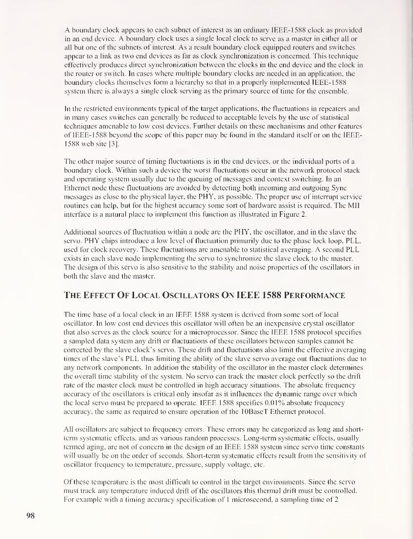
A boundary clock appears to each subnet of interest as an ordinary IEEE- 1588 clock as provided
in an end device. A boundary clock uses a single local clock to serve as a master in either all or
all but one of the subnets of interest. As a result boundary clock equipped routers and switches
appear to a link as two end devices as far as clock synchronization is concerned. This technique
effectively produces direct synchronization between the clocks in the end device and the clock in
the router or switch. In cases where multiple boundary clocks are needed in an application, the
boundary clocks themselves form a hierarchy so that in a properly implemented IEEE-1588
system there is always a single clock serving as the primary source of time for the ensemble.
In the restricted environments typical of the target applications, the fluctuations in repeaters and
in many cases switches can generally be reduced to acceptable levels by the use of statistical
techniques amenable to low cost devices. Further details on these mechanisms and other features
of IEEE- 1588 beyond the scope of this paper may be found in the standard itself or on the IEEE-
1588 web site [3].
The other major source of timing fluctuations is in the end devices, or the individual ports of a
boundary clock. Within such a device the worst fluctuations occur in the network protocol stack
and operating system usually due to the queuing of messages and context switching. In an
Ethernet node these fluctuations are avoided by detecting both incoming and outgoing Sync
messages as close to the physical layer, the PHY, as possible. The proper use of interrupt service
routines can help, but for the highest accuracy some sort of hardware assist is required. The Mil
interface is a natural place to implement this function as illustrated in Figure 2.
Additional sources of fluctuation within a node are the PHY, the oscillator, and in the slave the
servo. PHY chips introduce a low level of fluctuation primarily due to the phase lock loop, PLL,
used for clock recovery. These fluctuations are amenable to statistical averaging. A second PLLexists in each slave node implementing the servo to synchronize the slave clock to the master.
The design of this servo is also sensitive to the stability and noise properties of the oscillators in
both the slave and the master.
The Effect Of Local Oscillators On IEEE 1588 Performance
The time base of a local clock in an IEEE 1588 system is derived from some sort of local
oscillator. In low cost end devices this oscillator will often be an inexpensive crystal oscillator
that also serves as the clock source for a microprocessor. Since the IEEE 1588 protocol specifies
a sampled data system any drift or fluctuations of these oscillators between samples cannot be
corrected by the slave clock’s servo. These drift and fluctuations also limit the effective averaging
times of the slave’s PLL thus limiting the ability of the slave servo average out fluctuations due to
any network components. In addition the stability of the oscillator in the master clock determines
the overall time stability of the system. No servo can track the master clock perfectly so the drift
rate of the master clock must be controlled in high accuracy situations. The absolute frequency
accuracy of the oscillators is critical only insofar as it influences the dynamic range over which
the local servo must be prepared to operate. IEEE 1588 specifies 0.01% absolute frequency
accuracy, the same as required to ensure operation of the lOBaseT Ethernet protocol.
All oscillators are subject to frequency errors. These errors may be categorized as long and short-
term systematic effects, and as various random processes. Long-term systematic effects, usually
termed aging, are not of concern in the design of an IEEE 1588 system since servo time constants
will usually be on the order of seconds. Short-term systematic effects result from the sensitivity of
oscillator frequency to temperature, pressure, supply voltage, etc.
Of these temperature is the most difficult to control in the target environments. Since the servo
must track any temperature induced drift of the oscillators this thermal drift must be controlled.
For example with a timing accuracy specification of 1 microsecond, a sampling time of 2
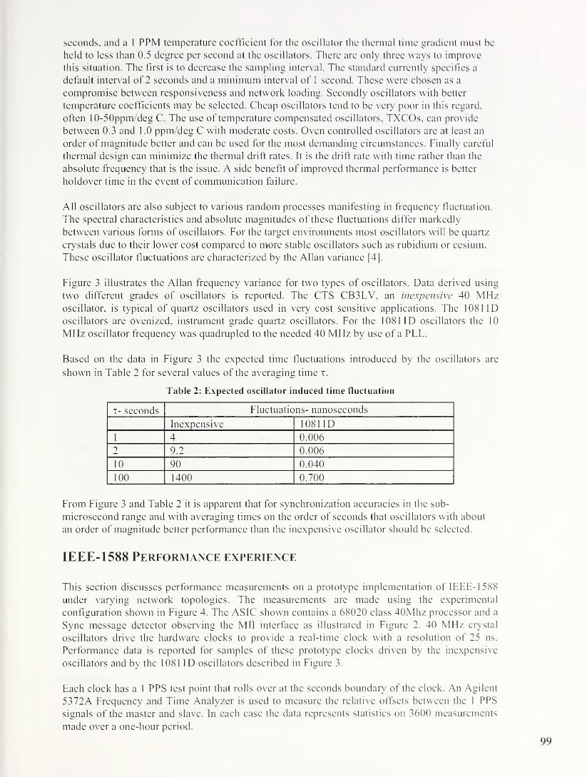
seconds, and a 1 PPM temperature coefficient for the oscillator the thermal time gradient must be
held to less than 0.5 degree per second at the oscillators. There are only three ways to improve
this situation. The first is to decrease the sampling interval. The standard currently specifics a
default interval of 2 seconds and a minimum interv al of 1 second. These were chosen as a
compromise between responsiveness and network loading. Secondly oscillators with better
temperature coefficients may be selected. Cheap oscillators tend to be very poor in this regard,
often 10-50ppm/deg C. The use of temperature compensated oscillators, TXCOs, can provide
between 0.3 and 1.0 ppm/deg C with moderate costs. Oven controlled oscillators arc at least an
order of magnitude better and can be used for the most demanding circumstances. Finally careful
thermal design can minimize the thermal drift rates. It is the drift rate with time rather than the
absolute frequency that is the issue. A side benefit of improved thermal performance is better
holdover time in the event of communication failure.
All oscillators are also subject to various random processes manifesting in frequency fluctuation.
The spectral characteristics and absolute magnitudes of these fluctuations differ markedly
between various forms of oscillators. For the target environments most oscillators will be quartz
crystals due to their lower cost compared to more stable oscillators such as rubidium or cesium.
These oscillator fluctuations are characterized by the Allan variance [4],
Figure 3 illustrates the Allan frequency variance for two types of oscillators. Data derived using
two different grades of oscillators is reported. The CTS CB3LV, an inexpensive 40 MHzoscillator, is typical of quartz oscillators used in very cost sensitive applications. The 1081 ID
oscillators are ovenized, instrument grade quartz oscillators. For the 1081 ID oscillators the 10
MHz oscillator frequency was quadrupled to the needed 40 MHz by use of a PLL.
Based on the data in Figure 3 the expected time fluctuations introduced by the oscillators arc
shown in Table 2 for several values of the averaging time i.
Table 2: Expected oscillator induced time fluctuation
i- seconds Fluctuations- nanoseconds
Inexpensive 1081 ID
1 4 0.006
2 9.2 0.006
10 90 0.040
100 1400 0.700
From Figure 3 and Table 2 it is apparent that for synchronization accuracies in the sub-
microsecond range and with averaging times on the order of seconds that oscillators with about
an order of magnitude better performance than the inexpensive oscillator should be selected.
IEEE-1588 Performance experience
This section discusses performance measurements on a prototype implementation of IEEE- 1588
under varying network topologies. The measurements are made using the experimental
configuration shown in Figure 4. The ASIC shown contains a 68020 class 40Mhz processor and a
Sync message detector observing the Mil interface as illustrated in Figure 2. 40 MHz crystal
oscillators drive the hardware clocks to provide a real-time clock with a resolution of 25 ns.
Performance data is reported for samples of these prototype clocks driven by the inexpensive
oscillators and by the 1081 ID oscillators described in Figure 3.
Each clock has a 1 PPS test point that rolls over at the seconds boundary of the clock. An Agilent
53 72A Frequency and Time Analyzer is used to measure the relative offsets between the 1 PPS
signals of the master and slave. In each case the data represents statistics on 3600 measurements
made over a one-hour period.

The prototypes use a simple PI control loop in the slave clocks to servo the local clock to that of
the master. The clock offset errors are sampled every 2 seconds as the basis for the PI loop input.
Two sets of parameters for the proportional and integral terms in the PI loop are reported. A fast
loop set with P=2 and I - 0.5, and a slow loop set with P=0.5 and 1=0.125. The fast loop has
relatively high gain, wide bandwidth and fast response time, a desirable condition during startup
to speed acquisition of lock and to drive large initial errors to small values, typically on the order
of a minute.
Synchronization results are given for several network connection topologies as illustrated in
Figure 5. IEEE- 1588 is expected to find most extensive application in topologies consisting of a
single subnet. This is illustrated in Figure 5 by the collection of three clocks communicating via a
repeater or a switch. When multiple subnets are required then for the highest accuracy routers
must implement IEEE- 1588 boundary clock specifications. Switches may also implement
boundary clocks as illustrated. When boundary clocks are used then end nodes effectively
synchronize directly to their master clock. Results follow for the three basic topologies shown
enclosed in circles in Figure 5.
Direct connection between clocks
To show the limiting characteristics of the clock implementation free from fluctuations
introduced by network components clocks were tested using a direct connection, e.g. connected
via a crossover cable rather than via a repeater or switch. This case also represents the expected
performance for topologies in which end devices interact directly with a switch, or any other
device, implementing IEEE- 1588 boundary clock functionality.
Figure 6 contains histograms of the synchronization error for two clocks directly connected via
Ethernet for both inexpensive and 1081 ID oscillators and for the slow and fast loop parameters.
No fluctuations from the 1081 ID oscillators are significant for the range of parameters used as
noted in Table 2. With the inexpensive oscillators and the fast loop (a few seconds time constant)
the clocks manage to track the oscillator induced fluctuations well enough to keep the offsets
reasonably well bounded as illustrated by the width of the histogram. However with the slow loop
the fluctuations of the inexpensive oscillators become more apparent as seen in the increased
width of the histogram. The means and standard deviations of the measurements in Figure 6 are
shown in Table 3. With the 1081 ID oscillators one would expect the standard deviations to
improve in implementations with clock resolution finer than the 25 ns, and with a true VCOrather than the digital version of the reported implementation.
Table 3: Offset error statistics for direct connection
Loop speed Oscillators Mean-ns Std.Dev-ns
Fast loop Inexpensive oscillators -28 34
1081 1 D oscillators -1 39
Slow loop Inexpensive oscillators -21 76
1081 ID oscillators 5 15
Clocks connected via a repeaterFor these measurements the clocks were connected via a single HP J4090A Ethernet repeater. Notraffic other than synchronization messages was present on the subnet.
Figure 7 contains histograms of the synchronization error for the repeater connected clocks for
both inexpensive and 1081 ID oscillators and for the slow and fast loop parameters. The means
and standard deviations of the measurements in Figure 7 are shown in Table 4.

Table 4: Offset error statistics for connection via a repeater
Loop speed Oscillators Mean-ns Std.Dev-ns
Fast loop Inexpensive oscillators -27 75
1 08 1 1 D oscillators -7 46
Slow loop Inexpensive oscillators -32 80
1081 1 D oscillators 10 42
In this case the repeater introduced measurable fluctuations for all cases resulting in the increase
in the widths of the histograms compared to the corresponding eases for the direct connection. Tofirst order repeater connections will be relatively traffic independent since synchronization
messages suffering collisions and retransmission will bear a time stamp for only the successful
transmission.
Clocks connected via a switch
For these measurements the clocks were connected via a single HP J4121A Ethernet switch. Noother traffic other than synchronization messages was present on the subnet.
Figure 8 contains histograms of the synchronization error for the switch connected clocks for both
inexpensive and 1081 ID oscillators and for the slow and fast loop parameters. The means and
standard deviations of the measurements in Figure 8 are shown in Table 5.
Table 5: Offset error statistics for connection via a switch
Loop speed Oscillators Mean-ns Std.Dev-ns
Fast loop Inexpensive oscillators -49 140
1081 ID oscillators -14 138
Slow loop Inexpensive oscillators -21 123
1081 ID oscillators 5 92
Comparing the data for the repeater and the switch, the switch clearly introduces more
fluctuations. Unlike repeaters, switches will show sensitivity to traffic although improvement is
possible using both priority features of modern switches and more sophisticated statistical
treatment of measured transit times of the synchronization messages. These techniques will only
be effective when the underlying stability of the oscillators permits statistical treatment of
synchronization messages spanning several sampling intervals.
Summary
In summary inexpensive oscillators have poor temperature and noise properties that limit the
synchronization accuracy of an IEEE- 1588 system. In particular poor oscillators limit the
allowable integration times and statistical techniques used in the phase lock loops of the slave
clock controllers. These effects may be somewhat offset by shorter sampling intervals but at
considerable cost in network traffic and computational resources.
High quality temperature compensated or controlled oscillators allow longer integration times and
more sophisticated statistical techniques to be used in the slave clocks. In addition a high quality
clock in the grandmaster clock node will produce a much more stable time base. An additional
benefit is that higher quality clocks generally will allow more design freedom in implementing
holdover strategies used in the event of communication failure or reconfiguration.
References
[1]: “Node Synchronization Improvement by High Stability Oscillators” Michael C. Fischer, John
C. Eidson, Bruce Hamilton. Agilent Laboratories Technical Report AGL-2002-13.
101
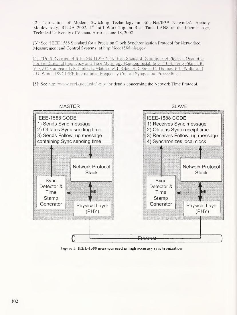
[2]
: ‘Utilization of Modern Switching Technology in EtherNet/IP™ Networks’, Anatoly
Moldovansky, RTLIA 2002, l
sl
Int’l Workshop on Real Time LANS in the Internet Age,
Technical University of Vienna, Austria, June 18, 2002[3]
: See TEEE 1588 Standard for a Precision Clock Synchronization Protocol for Networked
Measurement and Control Systems’ at http://ieec 1 588.nist.gov
[4]
: •"Draft Revision of IEEE Std 1 139-1988, IEEE Standard Definitions of Physical Quantities
For Fundamental Frequency and Time Metrology-Random Instabilities." E,S. Ferre-Fikal, J.R.
Vig, J.C. Camparo, L.S, Cutler. L. Maleki, W.J. Riley, S.R. Stein. C. Thomas, F.L. Walls, and
J.D. White, 1997 IEEE International Frequency Control Symposium Proceedings.
[5]
: See h lip: //www .eec i s . ude
1
.ed u /~ntp/ for details concerning the Network Time Protocol.
MASTER SLAVE
Figure 1: IEEE-1588 messages used in high accuracy synchronization

MASTER SLAVE
Figure 3: Allan frequency deviations for test oscillators
103

Agilent Technologies
Prototype Clock
Agilent Technologies
5372A Frequency and
Time Analyzer
7 T1 PPS signal 1 PPS signal
/ \Clock A Clock B
Ethernet
Repeaters
or
Switches
Figure 4: Measurement topology
o IEEE 1588 clock, code & hardware
Grand Master Clock
Only Slave Port of
Boundary Clock
Master Port of
Boundary Clock
Master Clock
Figure 5: Experimental network connection topologies

Inexpensive oscillator, fast loop
a = 34ns1081
1
D, fast loop ^a = 39ns
Inexpensive o s c ilia to r, s lo w loop
a = 16ns
OOOOOOOOOOOOCNf^CNh— CNf^cNICOOOncOCOCO CM CVJ t- t- 1 1 t-t-CN
O ffse t- nanoseconds
1 0 8 t 1 D, s lo w loop
a = 1 5ns
Offset- nanoseconds
Figure 6: Histogram of synchronization error for direct connection
Inexpensive o s c i I la to r, fa s t lo o p
a = 15ns
unoLOOLnomoinoLOOioCOOCOCOaicOCMT-rJ-OO-r-lOCOCM CM t- r- 1 1 ' t- t- t-
Offset-na noseconds
Figure 7: Synchronization error for connection via a repeater
105

Inexpensive o s c ilia to r, fa s t lo o p
(j = 1 40ns
OOOOOOOqoOOOOcd cnj un 00 ^ t— co lo
^ CO CM CM T- ' T— CM CM CO
O ffse t-n a n o se co n d s
1 08 1 1 D , fast loop
70(j - 138/75
60
o 50c0) 40
Lu 20
1 0
0
Offset-nanoseconds
80>oCO3CT
£ 20u.
0
60
40
Inexpensive oscillator, slow loop
a = 123ns
o to o in oCD CM CD a> coco co cm
un o m o ld oCD CO CD CD CM CD
^ ^— CM CO CO
Offset-nanoseconds
100
80
60
40
20
0
O ffse t-na noseconds
10811D,slow loop
a - 92ns
Figure 8: Synchronization error for connection via a switch
106

communicationsTelemetry-East
me Correlation on a Network BasedAirborne Telemetry System
Jiwaog Dai5LS^TE
Thomas DeSefms, Meridian
Edward Grozalis, L3-TE
Overview of L«3 Communications Telemetry-East
• >300 Employees
* 85,000 Sq. Ft.
8 Full Engineering
& Manufacturing
Facility
8 ISO 9001

1C | communicationsij|t Telemetry-East
LOB-1 At r craft Flight Test Instrumentation Telemetry Products
LOB-3 range Instrumentation Products
AM/URY-3
LOB~2 Missile/Target/ Launch Vehicle Telemetry Products
" C'sV T W&tipipill li Iflll^s ISIli m
LOB-4 Ground Instrument
vr.
Products
• Space Data
• SIGINT
• Telemetry
• TT&C
communicationsTelemetry-East
Aircraft Flight Test Instrumentation Products
Safi iiii ., '
v > fa -
'
% % ,
PCU-300Programmable
Send itionina Unit
MicroDAS 1 000
Adv anced Data
Acquisition System
MiniARMOR 700
MUXtoEMUX
mmMMSC-800
Micro Miniature Signal
Conditioner
MPC-800Min rnture Programmab 1 e
S isnal Con ditioner

communicationsTelemetry-East
Legacy Telemetry System (standalone)
PCM (Pulse Code Modulation) Stream
communicationsTelemetry-East
Legacy Telemetry System (fWaster/Remote Slave)
Recorder0master RS232
_n_TLPilot control unit
Command/response
Configure computer
Serial Interface
Remote slave
Remote slave

communicationsTelemetry-East
Advanced Legacy Telemetry System (Multiple Masters)
SSJO
communicationsTelemetry-East
Limitation of the Legacy System
• Relatively low bit rate (-5 Mbps)
Proprietary Interface
- Limited Interoperability
- Limited Usage of COTS
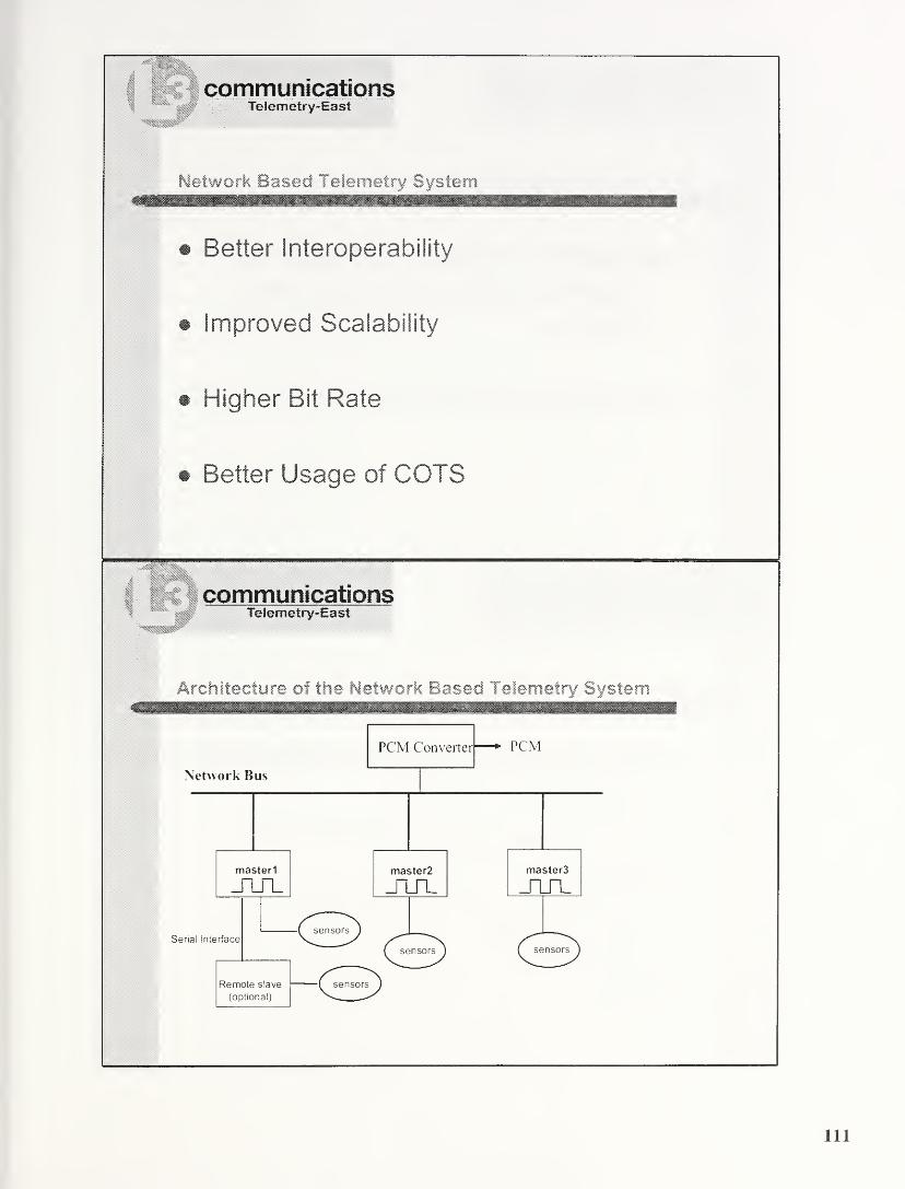
communicationsTelemetry-East
Network Based Telemetry System
• Better Interoperability
• Improved Scalability
• Higher Bit Rate
• Better Usage of COTS
communicationsTelemetry-East
Architecture of the Network Based Telemetry System

communicationsTelemetry-East
How to Synchronize the clock of Masters?
• Add Additional Interface for Clock Sync
- Proprietary Solution (e.g. External clock)
- IRIG Time
• Use the Network Bus for Clock Sync
communicationsTelemetry-East
Choices of the System Bus
• Fibre Channel Avionics Environment (FC-AE)- Embedded Time Sync Design
- Expensive
- Lack of Industrial Switches
• Ethernet- Cost Saving
- Mature Technology
- No Time Sync
• Others

(communications
Telemetry-East
Time Correlation Wlethods for the Ethernet
NTP(10’s (js)
PTP(< 1 m s
)
(Ref. IRIG-G, 20ns)
communicationsTelemetry-East
Time Sync Requirements
• IK Signal
12 Bits accuracy : 39 ns
10 Bits accuracy : 155 ns
113

communicationsTelemetry-East
A HPCUSm Unit
PCU network bus :
10/100 BT Ethernet
Fibre channel backbone
communicationsTelemetry-East
PIP Hardware Implementation
114

communicationsTelemetry-East
Implementation Details
Stable Oscillator - a Temperature Compensated Crystal
Osciilator(TXCO)
FPGA - The “glue" logic of the systemTimeStamp registers
Control logic to discipline the dock
Bus interfaces to the microprocessor and the Backplane Bus.
Microprocessor - A Motorola 860 PowerPC (Internal EthernetMAC)
Ethernet PHY
communicationsTelemetry-East
Ethernet Based Telemetry System
AnalogBuses
Wireless
Hub
Ethernet
Switch
ST-805
Y
Y7XWireless
HubPCU-800
Internet tor Remote
Oiagrcstics and Configuration
10 Wire
Interface
Micro DP. S
Interface
Rtre Channel
-—
j
Setup
\/ Calibration
GEDrives & Controls, Inc.
Implementation of IEEE Std.-1588
in a Networked I/O Node
Mark E. ShepardDouglas G. FowleyRoy L. JacksonDennis B. King
GE Drives & Controls, Inc.
Salem, VA
GE Salem Products GEDrives & Controls, Inc.
Turbine controls
- Large stationary gas turbines (10 - 200 MW)- Aeroderivative turbines for marine, oil & gas (25 - 75 MW)- Large steam turbines (20 - 1500 MW)- Hydroelectric turbines
Power conversion products
- Turbine static starters
- Excitation products
- System drives
- Rolling mill main drives
- Marine propulsion
- Converters for alternate energy - wind, fuel cell, etc.
• Drive Systems - recently spun off to a JV with Toshiba
Sept 24, 2003 IEEE-1 588 Workshop 2
116

Mark VI Turbine Control System GE Drives & Controls, Inc.
• Large central lineup
• 1000-3000 I/O points, typically
• Triple Modular Redundant(TMR)- 3 symmetric controllers
- Redundant signal conditioning
Input voting by controllers
- Output voting in hardware
- Frame-based temporal architecture
- All 3 controllers rendezvous to vote
• Terminal boards- Field wiring point
- Split inputs to 3 controllers
- Impedance isolation
- Surge suppression
• Controllers
- Monolithic VME rack
Signal conditioning on 6U modules
37-pin cables to I/O
- Custom power supply Backplaneprovides key services
• Power distribution
• Communication bandwidth
• Synchronous timing
Sept. 24, 2003 IEEE-1588 Workshop 3
Mark Vie Distributed I/O System GEDrives & Controls, Inc.
• Replace backplane by
switched Ethernet network- 2 ms in a 1 0 ms frame to gather
all I/O for voting- flood switches
- Ethernet Global Data protocol
- IEEE-1588 for time sync
- Hardware-based timestamps
• Simplified controllers
- Standard CPCI rack
- Off-the-shelf power supply
- Pentium III CPCI
- Custom PMC card for time sync
• Uses same terminal boards
• I/O packs mount to terminal
boards
• Initial pilots in central lineups
as shown here
• Developed to allow I/O
integration by skid vendors
Sept. 24. 2003 IEEE-1588 Workshop 4

Networked I/O pack GEDrives & Controls, Inc.
• CPU card common to all packsAMD Alchemy Au 1000 SoC
- 266MHz MIPS32 CPUDual 10/100 Ethernet, IrDA
100K Xilinx Spartan-ll FPGAQNX Neutrino RTOS
• Specific signal-conditioning board for
each I/O type
• Industrial-hardened
0 - 60C at full accuracy
- -40 - +70C operating
- Shock, vibration, EMI
Sept. 24, 2003 IEEE-1588 Workshop 5
PMC Ethernet with hardware-assist GEDrives & Controls, Inc.
•IEEE-1588 for Mark Vie Controller
•PCI Mezzanine Card form factor
•Dense functionality
-PCI bridge
-Bus Mastering local bus controller
-3x 10/100 MAC + PHY
-100K Xilinx Spartan-ll FPGA
-NVRAM, LEDs, etc...
•Low CPU overhead
- Only Sync & Delay_Req timestamps are kept
- Timestamps and packet info written directly to
buffer in CPU memory space using PCI Bus
Master
•3-port boundary clock
Sept. 24, 2003 IEEE-1588 Workshop 6

IEEE-1588 in the Mark Vie GEDrives & Controls, Inc.
In the Turbine control system- UTC reference is important for timestamping events for "flight-data-recorder” usage
- But - turbine operation must never be compromised by a lost or corrupt UTC reference
- Networked nodes must remain synchronized to their controllers, ignoring ambiguous or conflicting
UTC references (esp. from NTP)
So we choose to avoid
- Arbitrary autonomous selection of their time master by network nodes
Possible bidding for slaves by rogue masters
- Other unanticipated failure modes from the autonomy inherent in IEEE-1588
The Mark Vie will apply IEEE-1588 so that:
- The nodes and controllers are synchronized to a time reference with arbitrary epoch which we call
System Time, using Clockldentifier I N IT
- Only the controller which is the System Time GrandMaster is empowered to coordinate the Mark Vie
internal time reference with UTC- The epoch of System Time, expressed as UTC, must be maintained outside the PTP protocol
- The system can run without GPS/UTC- All nodes belong to CommunicationID PTP_CLOSED- Each controller R, S, T uses a distinct AlternatePTPDomain for its nodes
- The three controllers belong to DefaultPTPDomain
- The controllers maintain separate synchronization to UTC sources with additional virtual clocks in the
DefaultPTPDomain on CommunicationID PTP ETHER
Need better-defined accommodation for this in IEEE-1588?
Sept 24, 2003 IEEE-1 588 Workshop 7
Hardware PLL paradigm
sept. 24. 2003 IEEE-1588 Workshop 8
• 64-bit register (adder) with time in ns
• Locked to remote clock by PLL
• Clocked by local oscillator
• VCO - increment by clock period (in
ns)
• Latch register time at SFD on PHY• Error detector and regulator can be
closed in h/w or s/w
• Adjust VCO by 0, ±1 increment value
• Pros
- Can be self-contained
- All nodes have synchronized registers
• Cons- Fairly complex logic
- Replicated for each clock
GEDrives & Controls, Inc.
119

“Virtual” PLL - software implementation GE Drives & Controls, Inc.
Hardware free-running counter
(FRC) latched for incoming
timestamp
Piecewise-linear model of FRCvs. System Time
Slope (VCO frequency) constant
between synchronization points
Error calculated from timestampsin Sync messages
Slope is output of PI regulator
looking at error
Software functions convert
between FRC and System Time
Sept. 24. 2003 IEEE- 1588 Workshop
Visualization of logged data GE Drives & Controls, Inc.
. S0066835e-02, +1 . 4 8000000e+<
• Data written to textI
'
file on RAMdisk in3 i
node 2 £ o : t
• Use FTP to /# l-1
download, Matlab to r / '97 9 75 9.8 9 85 9.9 9
analyze and plot S-
//System T,me
x 1Q«
• Show raw timestampU.
1 / I
lC"
O !
o ‘bdata and PLL tracking jf o 50
•$ c_
5>°
• Detrend and magnify05
// §
f°
• Scale counts to usee 1—1
Sept. 24, 2003
) 7 9 75 9 8 9 85 9 9 9 95
System Time , n4
IEEE-1588 Workshop
9 75 9 8 9 85 99 9 95
iTime
10
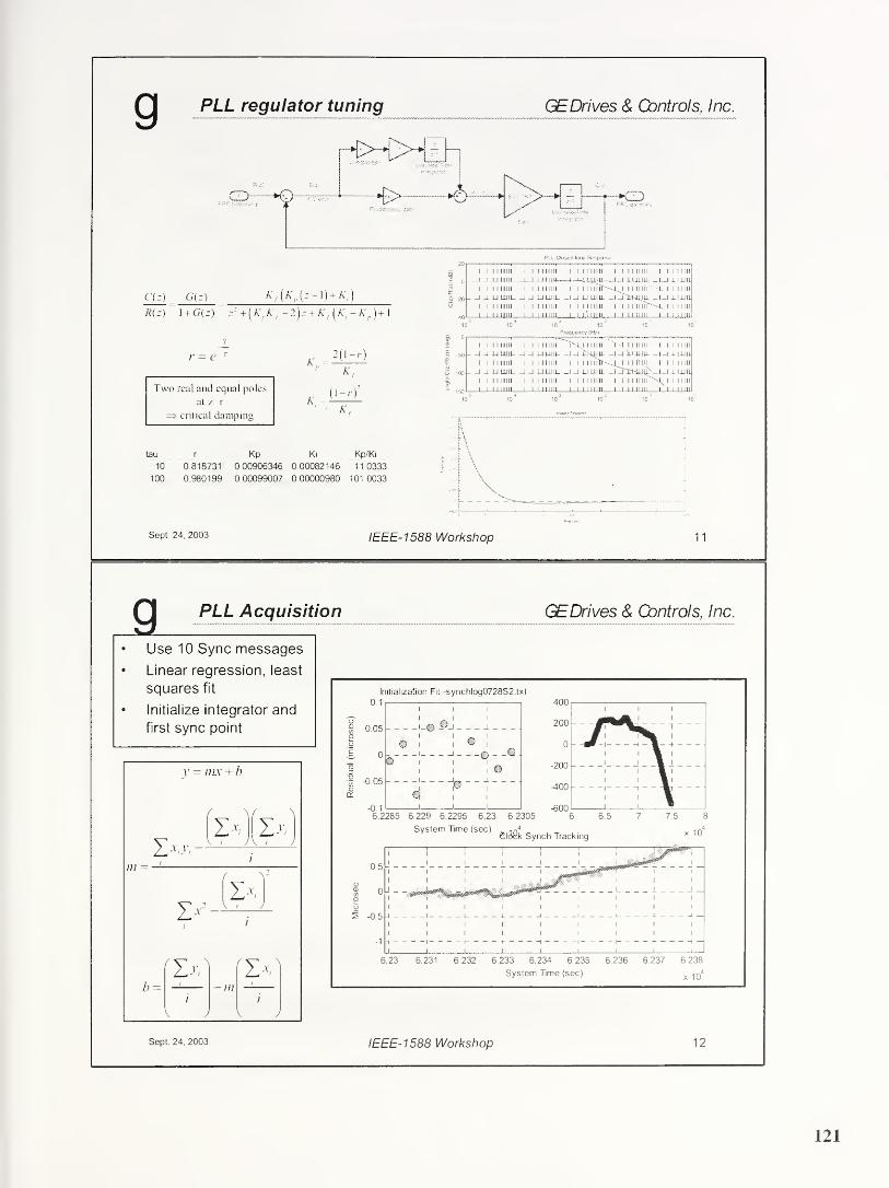
g PLL regulator tuning GEDrives & Controls,Inc.
CD—€> CD
PLL Closed-loop Response
C(r) G(z) Kf(K
f,(z-\) + K,)
R(z) I + G(z) z1 +[K
pKf-2)z + K
f{K-K
p )+\
1 1 1 IIIIII 1 1 1 1 IIIII 1 1 1 1 IIIII 1 1 1 1 IIIII 1 1 1 1 IIII
1—1-M I 111! ID-LWI-WU—4
D
_J i-LiilLi _l_| -LIJ-lll
1 1 1 1 IIIII 1 1 1 1 IIIII i i i miir-'-L i 1 1 mu' 1. 1 1 IIIII
.JJU LU II UU Lilli- _i _i j-i ui u. _i iTiiujju. _l_l _L IJJI1
1 1 1 1 IIIII 1 1 1 1 IIIII i 1 1
1
iiiii iiii imr''L. 1 1 IIIII
i 1
1
mm 1 1 l 1 IIIII 1 .1 1111111 1 1 LLLilli— i 1
1
mu
Frequency (Hz)
/• = e 1
K
Two real and equal poles
at z=r
=> critical damping
i i 1
1
mu i ii i mu-uu mil—uii wu-
i i i iiiiii i i i mill
jju mil uu mu i
i i i iiiiii mii i i iiiiii i i i iiiiii
-Li iiiiii i -i 1 1 iiiii i i i iiiii
u isqiu. _i_iT'.mu- _i_i xijju
i 1 1 iiTfr'-m i 1 1 i>n i i i i iiiii
J -LI UHL -HJHimt'-l-l J.I1III
i i iiiiii 1111 iiiii''<^ i 1 1 mii i iiiiii iiii m il i i ir
Sept. 24, 2003 IEEE-1588 Workshop 11
_a PLL Acquisition GEDrives & (Controls, Inc.
Use 10 Sync messages
Linear regression, least
squares fit
Initialize integrator and
first sync point
Initialization Fit -synchlog0728S2.txt
IEEE-1588 Workshop 12
121

Enhanced PLL acquisition
• Acquire both Sync and
Delay_Req messages
• Fit regression model that uses
both, constrains equal slopes
• Least-squares fit using SVD for
matrix inversion
• Sort by residual value
• Apply Chauvenet’s Criterion to
largest residual. If largest
residual is an outlier, discard
and repeat
• Chauvenet’s criterion: “You mayconsider rejecting the data when
the number ofmeasurements
expected this far from the mean is
less than one half “ (assuming a
normal distribution)
GEDrives & Controls, Inc.
Sf 1 0"
^ m
f
' FRCX
'
st2
0 1
r — frc2
stn 1 0, k
FRCn j
Ax = b
(A)-x = (U-W-V T)-x = b
x = V W 1 UTb
Approximation of CDF26.2.23
!
e(?));<C4.5X10
*
c9—2.51551 * j== i .432788
.80-2853 .180269
Ct**- .010328 d}= .601308
Sept. 24. 2003 IEEE-1588 Workshop 13
Simulation results for acquisition GEDrives & Gontrols, Inc.
Residual Plot - red => rejected outlier
• 100 BaseTx Ethernet 50
• 3 switches in series
• 2.1 ±0.1 us switch Of f & & tfr * $ $4-
latency
• 10% probability of '£'-50 _
queuing delay in each 0'«
switch a?
= -100 -
• Uniform queuing latency r- & #
distribution, zero-max
• 1 Sync message/sec-150
• Random distribution of
Delay Req messages per -200 “
IEEE-1588
-250 1 1 1 1)
i i i i
0 5 10 15 20 25
System Time (sec)
Sept. 24, 2003 IEEE-1588 Workshop 14
122

Tracking behavior GEDrives & Controls, Inc.
Clock Synch Tracking
System Time (sec)
Sept. 24, 2003 IEEE-1588 Workshop 15
Tracking behavior GEDrives & Gontrols, Inc.
Clock Synch Tracking
It’s all about the error estimator. .
.
Sept. 24. 2003 IEEE-1588 Workshop 16
123

Sept. 24, 2003 IEEE-1588 Workshop 17
g
25ns/div
Master-slave delay vs time GEDrives & Controls, Inc.
Sept. 24, 2003 IEEE-1588 Workshop 18
ilant 53310A
124
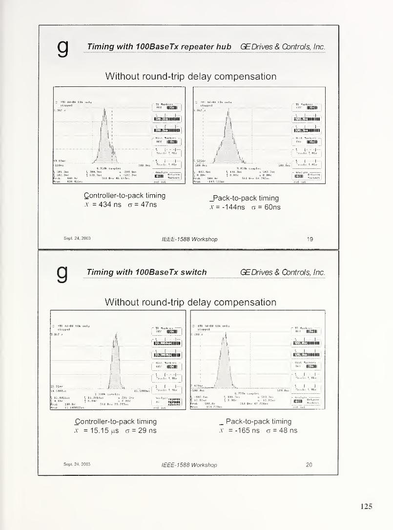
Timing with 100BaseTX repeater hub GEDrives & Controls, Inc.
Without round-trip delay compensation
Controller-to-pack timing
x = 434 ns ct = 47ns_Pack-to-pack timing
x = -144ns a = 60ns
Sept. 24, 2003 IEEE-1588 Workshop 19
g Timing with 100BaseTX switch GEDrives & Controls, Inc.
Without round-trip delay compensation
Sept. 24, 2003 IEEE-1588 Workshop 20
125
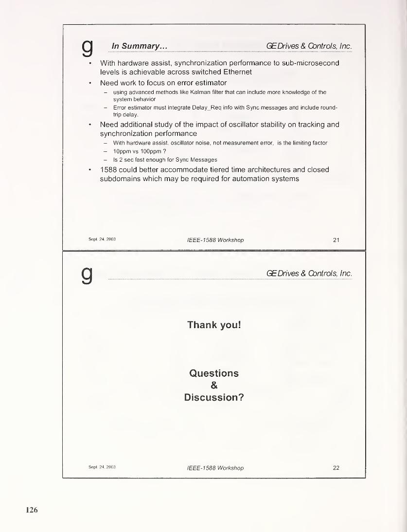
In Summary... GEDrives & Controls, Inc.
With hardware assist, synchronization performance to sub-microsecond
levels is achievable across switched Ethernet
Need work to focus on error estimator
- using advanced methods like Kalman filter that can include more knowledge of the
system behavior
- Error estimator must integrate Delay_Req info with Sync messages and include round-
trip delay.
Need additional study of the impact of oscillator stability on tracking and
synchronization performance- With hardware assist, oscillator noise, not measurement error, is the limiting factor
- lOppm vs lOOppm ?
- Is 2 sec fast enough for Sync Messages
1588 could better accommodate tiered time architectures and closed
subdomains which may be required for automation systems
Sept 24. 2003 IEEE-1588 Workshop 21
GEDrives & Controls, Inc.
Thank you!
Questions
&Discussion?
Sept 24, 2003 IEEE-1 588 Workshop 22
126
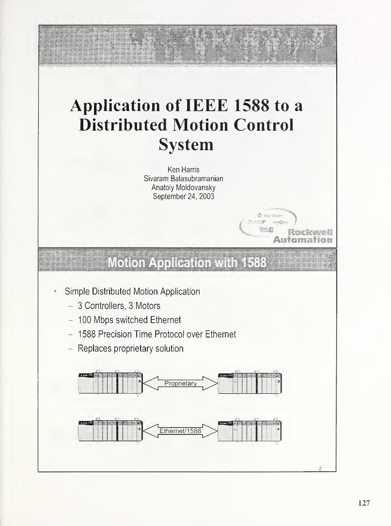
Application of IEEE 1588 to a
Distributed Motion Control
System
Ken Harris
Sivaram Balasubramanian
Anatoly Moldovansky
September 24, 2003
Alien-littaSS#
RociamliAsitomation
Motion Application with 1588
Simple Distributed Motion Application
- 3 Controllers, 3 Motors
- 100 Mbps switched Ethernet
- 1588 Precision Time Protocol over Ethernet
- Replaces proprietary solution

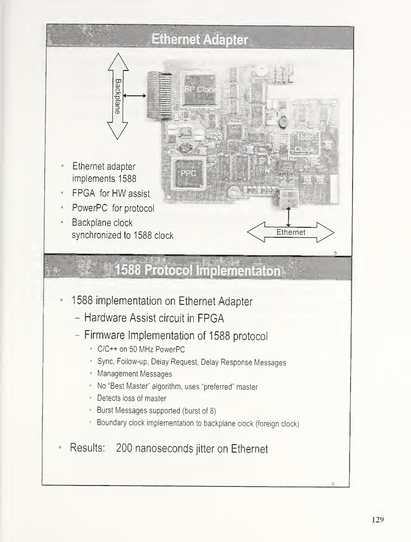
Ethernet adapter
implements 1588
FPGA for HW assist
PowerPC for protocol
Backplane clock
synchronized to 1588 clockEthernet
1588 implementation on Ethernet Adapter
- Hardware Assist circuit in FPGA
- Firmware Implementation of 1588 protocol
4 C/C++ on 50 MHz PowerPC
8 Sync, Follow-up, Delay Request, Delay Response Messages
* Management Messages
* No "Best Master" algorithm, uses “preferred” master
* Detects loss of master
* Burst Messages supported (burst of 8)
* Boundary clock implementation to backplane clock (foreign clock)
Results: 200 nanoseconds jitter on Ethernet
129
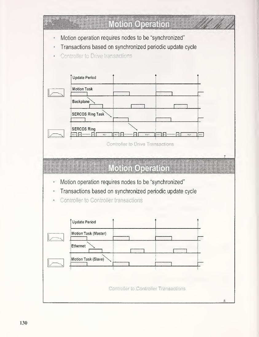
• Motion operation requires nodes to be “synchronized”
• Transactions based on synchronized periodic update cycle
• Controller to Drive transactions
Update Period
I Motion Task
r|1 1 1
i BackplaneX,1
1 l 1 l 1
jSERCOS Ring TaskN\
ri
i 1 1
SERCOS Ring \1 MST
j|at| |at|
|MOT
|MST
| M H |MOT MST
| |At] |atJ
|MOT MST
|
Controller to Drive Transactions
7
• Motion operation requires nodes to be “synchronized"
« Transactions based on synchronized periodic update cycle
• Controller to Controller transactions
Update Period
Motion Task (Master)
rEthernet
Motion Task
8
Controller to Controller ! ransactions
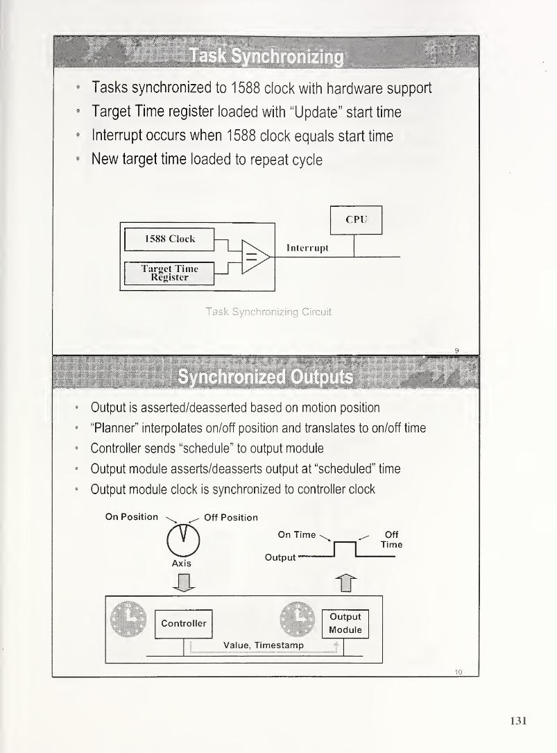
sjmpm**’ |.SI
f425
Tasks synchronized to 1588 clock with hardware support
Target Time register loaded with “Update” start time
Interrupt occurs when 1588 clock equals start time
New target time loaded to repeat cycle
Task Synchronizing Circuit
Output is asserted/deasserted based on motion position
“Planner” interpolates on/off position and translates to on/off time
Controller sends “schedule” to output module
Output module asserts/deasserts output at “scheduled" time
Output module clock is synchronized to controller clock
On Position Off Position
0Axis
On Time
Output ^
-O- nr
OffTime
10
131

Ethernet adapter modified to interface to GPS receiver
Receives Pulse-Per-Second and UTC from receiver
Local 1588 clock synchronized to GPS clock
Results: 500 nsec accumulated jitter
11
n„... Itv.. i i
.
• # • #
12
132
rW IEEE1588 proposal for
Metro Ethernet Enterprise
Solutions
IEEE1588 Sept 24 2003 workshop presentation
Glenn Algie
Nortel Networks, Wireless Technology Labs
Sept 24 2003
H&RTELNETWORKS
Why IEEE1588 Enhancements ?Problem Statement:
Transition is now occurring from Circuit to Packet in the Metro
- Ethernet edges are replacing the Traditional E1/T1 circuit demarcation (803. 3ah)
Timing sensitive services that used the Circuit/Sonet/SDH timingreferences can’t transition to Ethernet edge without a packet basedPrecision timing reference. New timing sensitive packet basedservices are also emerging.
Solution Proposed:• NORTEL NETWORKS proposes that IEEE1588 be adapted for this
need. Positioned as a Precision timing service over Metro Ethernetdemarcations into Enterprise VPN (Virtual Private Network).
• Slight enhancements to the IEEE1588 Standard are proposed here for
these Metro applications.
• 1588 timing payloads are extensible to any frame/cell transport.
• Does not replace NTP. Interworking is expected.
IEEE1588 enables timing sensitive end services onEnterprise VPNs to utilize Metro Ethernet Solutions
NortelNETWORKS NORTEL NETWORKS - Advanced Technology Labs IEEE1588 NortelNetworks
133

Typical IEEE1588 transport overlays
on Metro Ethernet ArchitectureMetro- Ent.
demarcation
/
Enterprise
premise
/
Stratum 1
References
(or traceable)
I I-
I
Enterprisej
Branch L^N
KD •
Residential
SetTopBox
NORTELNETWORKS
Device
OwnershipTiming
Servers
Timing
Adaptations
Timing Sensitive
Services/Devices
Metro
Provider
X,Y F, G, H F, G
Enterprise
User
Z C, E A, B, C, D, E
:i
Q>C
;iEnterprise
CD Owned &
UJ managed
iiequip.
NORTEL NETWORKS - Advanced Technology Labs IEEE1588 NortelNetworks 09242003
E T7Enterprise
Branch LAN
Metro Ethernet 1588 Timing Service
DimensionsPrecision Timing Service Components:• Timing Sourcing edge point(s)
• Timing Recovery/Adaptation edge points• Timing Sensitive Service edge points
Management/ownership options:• Enterprise managed endpoint• Metro Provider managed endpoint• Hosted Service provider endpoint
Variety of Metro Ethernet Network Technologies:• core distribution vs. collector edge, Ring vs Mesh deployments• L1/L2 transport technology variety has performance impact on
IEEE1588 PTP flows
• Precision Timing Service Components span management boundaries• A muitivendor timing solution requires a Standard• Variety of Metro Ethernet technologies affect end-end performance
NORTELNETWORKS NORTEL NETWORKS - Advanced Technology Labs IEEE1588 NortelNetworks
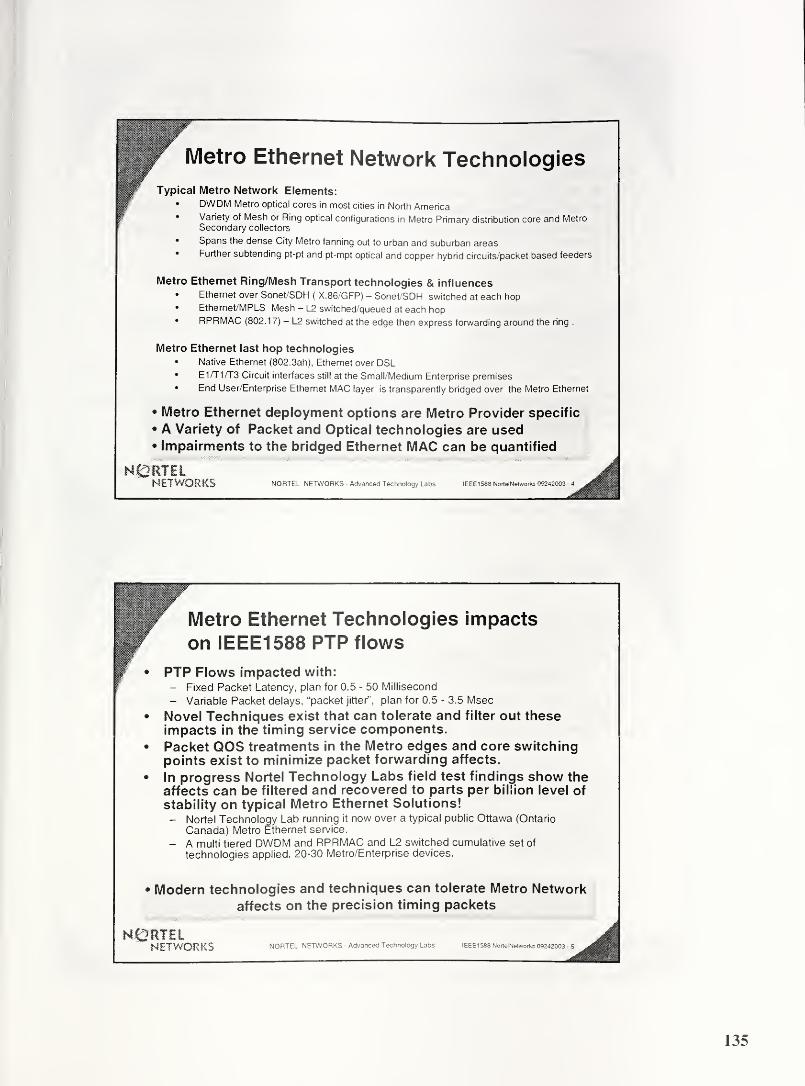
Metro Ethernet Network Technologies
Typical Metro Network Elements:• DWDM Metro optical cores in most cities in North America• Variety of Mesh or Ring optical configurations in Metro Primary distribution core and Metro
Secondary collectors
• Spans the dense City Metro fanning out to urban and suburban areas• Further subtending pt-pt and pt-mpt optical and copper hybrid circuits/packet based feeders
Metro Ethernet Ring/Mesh Transport technologies & influences• Ethernet over Sonet/SDH
( X.86/GFP) — Sonet/SDH switched at each hop• Ethernet/MPLS Mesh - L2 switched/queued at each hop• RPRMAC (802.17) - L2 switched at the edge then express forwarding around the ring .
Metro Ethernet last hop technologies• Native Ethernet (802. 3ah), Ethernet over DSL• E17T1/T3 Circuit interfaces still at the Small/Medium Enterprise premises
• End User/Enterprise Ethernet MAC layer is transparently bridged over the Metro Ethernet
• Metro Ethernet deployment options are Metro Provider specific
• A Variety of Packet and Optical technologies are used• Impairments to the bridged Ethernet MAC can be quantified
H&RTElNETWORKS NORTEL NETWORKS - Advanced Technology Labs IEEE 1588 Nortel Networks 09242003 -4
Metro Ethernet Technologies impacts
on IEEE1588 PTP flows
PTP Flows impacted with:- Fixed Packet Latency, plan for 0.5 - 50 Millisecond
- Variable Packet delays, “packet jitter”, plan for 0.5 - 3.5 Msec
• Novel Techniques exist that can tolerate and filter out theseimpacts in the timing service components.
• Packet QOS treatments in the Metro edges and core switchingpoints exist to minimize packet forwarding affects.
• In progress Nortel Technology Labs field test findings show theaffects can be filtered and recovered to parts per billion level of
stability on typical Metro Ethernet Solutions!- Nortel Technology Lab running it now over a typical public Ottawa (Ontario
Canada) Metro Ethernet service.
- A multi tiered DWDM and RPRMAC and L2 switched cumulative set of
technologies applied. 20-30 Metro/Enterprise devices.
• Modern technologies and techniques can tolerate Metro Network
affects on the precision timing packets
NORTELNETWORKS NORTEL NETWORKS - Advanced Technology Labs IEEE 1588 NortelNetworks 09242003

IEEE1588 impacts to enable a Metro
Ethernet Enterprise VPN use case.
Key revision items needed for a Metro Ethernet use of 1588:
• Capture Metro Ethernet “Boundary clock” deployment rules
• Add packet latency and packet delay variation boundary conditions.
• Allow subsecond rate granularity of the timestamps based messages.- Propose a new bit/field parameter in spare octet of Sync, Delay_req message.- Bit “0” value means existing seconds based granularity for the existing “rate” field.
- Bit “1” value means 1 0 or 1 00 millisecond based interval rate for the existing “rate” field.
Additional Standards items:• Seek necessary reserved identifiers such as Ethertype and/or Multicast from
IEEE Registration Authority for IEEE1588 payloads.- Is a unique Ethernet multicast address enough?- Some scenarios deployable where no UDP/IP stack exists!
• ITU-T SGI 5 Q13 address synchronization service needs over asynchronous(packet) transport. Packet based timing transport rules could be worked here.
• Informative presentations into MEF, ITU-T, 802..., and Telecom Industryconferences as appropriate.
NORTELNETWORKS NORTEL NETWORKS - Advanced Technology Labs IEEE1583 Nortel Networks 09242003 -6
lllll
Seek IEEE1588 and Telecom Industry user/vendor sponsorshipsfor this proposal.
• Propose to IEEE1588 Chair for a PAR revision project.- Review by Registration Authority, include new Ethertype and/or multicast address needs
in the request
• Liaisons and informative presentations as needed with IEEE802.3,802.1, 802.17, MEF and ITU-T SG15. Also other industryconferences as appropriate to spread the word.
Telecom Industry Target Objective:• Enable timing sensitive edge services to utilize the cost effective value of
Metro Ethernet solutions.
• Make the packet timing service a “no brainer” for Metro Enterprisesolutions. Make it better or equal to the network derived timingperformance of legacy EI/TI/Sonet/SDH that Metro - Enterprisedemarcations had.
NETWORKS NORTEL NETWORKS - Advanced Technology Labs IEEE1588 NortelNetworks 0S242003
136

Backup slide -
Proposed revision to “synclnterval” octets
Backward compatible enhancement to Sync and Delay Req MessagesAdd a “intervalGranularity” octet into spare octet
intervalGranularity definition:
0: second (default)
1 : 10 millisecond
2: 1 millisecond
current
proposed
SOF N Octet
NOctet
N+1
Octet
N+2Octet
N+3Type(Informative)
Field Name
Clause 8.2 and 8.3
122 80 00 00 00 HO HI Integer8 synclnterval
122 80 00 K0 K1 00 HO HI Octet| Integer8|
Octetj Integer8
intervalGranularity!
synclnterval
NORTELNETWORKS
NORTEL NETWORKS CONFIDENTIAL
137
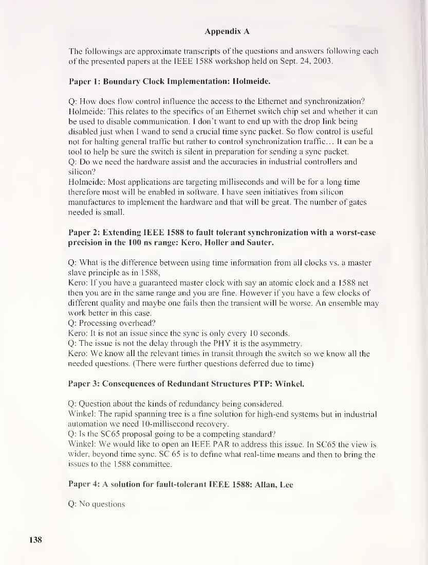
Appendix A
The followings are approximate transcripts of the questions and answers following each
of the presented papers at the IEEE 1588 workshop held on Sept. 24, 2003.
Paper 1: Boundary Clock Implementation: Holmeide.
Q: How does flow control influence the access to the Ethernet and synchronization?
Holmeide: This relates to the specifics of an Ethernet switch chip set and whether it can
be used to disable communication. I don’t want to end up with the drop link being
disabled just when I wand to send a crucial time sync packet. So flow control is useful
not for halting general traffic but rather to control synchronization traffic... It can be a
tool to help be sure the switch is silent in preparation for sending a sync packet.
Q: Do we need the hardware assist and the accuracies in industrial controllers and
silicon?
Holmeide: Most applications are targeting milliseconds and will be for a long time
therefore most will be enabled in software. I have seen initiatives from silicon
manufactures to implement the hardware and that will be great. The number of gates
needed is small.
Paper 2: Extending IEEE 1588 to fault tolerant synchronization with a worst-case
precision in the 100 ns range: Kero, Holler and Sauter.
Q: What is the difference between using time information from all clocks vs. a master
slave principle as in 1588,
Kero: If you have a guaranteed master clock with say an atomic clock and a 1 588 net
then you are in the same range and you are fine. However if you have a few clocks of
different quality and maybe one fails then the transient will be worse. An ensemble maywork better in this case.
Q: Processing overhead?
Kero: It is not an issue since the sync is only every 10 seconds.
Q: The issue is not the delay through the PHY it is the asymmetry.
Kero: We know all the relevant times in transit through the switch so we know all the
needed questions. (There were further questions deferred due to time)
Paper 3: Consequences of Redundant Structures PTP: Winkel.
Q: Question about the kinds of redundancy being considered.
Winkel: The rapid spanning tree is a fine solution for high-end systems but in industrial
automation we need 10-millisecond recovery.
Q: Is the SC65 proposal going to be a competing standard?
Winkel: We would like to open an IEEE PAR to address this issue. In SC65 the view is
wider, beyond time sync. SC 65 is to define what real-time means and then to bring the
issues to the 1588 committee.
Paper 4: A solution for fault-tolerant IEEE 1588: Allan, Lee
Q: No questions
138

Paper 5: Impact of Switch Cascading on Time Accuracy: Mueller, Weber
Q: You are proposing eliminating UDP and IP and running directly over Ethernet
Weber: Yes
Paper 6: IEEE 1588 and Network Devices: Mohl.
Q: Your SNMP proposal is it similar to the 1588 equivalent and do you implement traps?
Mohl: It covers the same information and we do not implement traps at present.
Paper 7: A frequency compensated clock for Precision synchronization using IEEE1588 protocol and its application to Ethernet: Balasubramanian, Harris,
Moldovansky.
Q: What about start up where there may be large differences?
Moldovansky: There needs to be a separate algorithm for big start up situations. We see
at most 6-7 seconds pull in for the transients we see. Rockwell has a proprietary system
that does have a fast pull in for start up. We may apply it to this environment as well.
Paper 8: IEEE-1588 Node Synchronization Improvement by High Stability
Oscillators: Eidson, Hamilton.
Q: Is there provision for a burst mode in the protocol to allow compensation for some of
the effects mentioned today?
Eidson: There is a burst mode in the standard allowing either slaves or master to increase
the rate of sync message. It was put in to allow more rapid recovery in the event of the
need to recompute parameters.
Q: In the direct case you reported 15 ns standard deviation with good oscillators. What
could be done to improve this?
Eidson: The oscillators we used had xlOOO headroom. To do better you will need a finer
resolution on the clock. I am not optimistic about reaching one or two nanoseconds.
Paper 9: Time Correlation using network based data acquisition onboard a Military
Test Vehicle: Dai, DeSelms, Grozalis.
Q: (Question could not be heard on the tape)
Dai: We have built the first prototype to bridge to existing systems. We have not
completed the time synchronization portion.
Q: We had same connector problem.
Dai: The problem is standardization on a single connector.
Paper 10: Implementation of IEEE Std.-1588 in a Networked I/O Node: Shepard.
Q: Did you tweak the standard?
Shepard: We did not tweak it but we may have used elements in odd ways.
Paper 11: Application of IEEE 1588 to Distributed Motion Control: Harris,
Balasubramanian, Moldovansky.

Q: Being a part of Rockwell are you part of the CIPSync definition
Harris: Yes
Q: How did you use burst?
Harris: We used it to speed up the clock synchronization during pull in.
Q: How much did this help?
Harris: We improved from 20-second pull in to about 4 seconds.
Paper 12: Proposal for IEEE 1588 use over Metro Ethernet Layer 2: Algie.
Q: Operating with voice packet networks that use RTP?Algie: RTP does include timestamps but only to milliseconds alignments. We use NTPderived clock now. Think 1588 will interwork with these. My concern is with video and
similar.
Q: (Question could not be heard on the tape)
Algie: For voice over IP could use derived clock from 1588 but could use NTP. For more
precise things like cell sites we think we can use 1588.
Q: Are your pictures US centric or worldwide?
Algie: It is similar everywhere.

EEE 1588 Prototype Demonstration
Hirsciimatirt Electronics GmbH & €0 * KGAutomation and Network Solutions
T. Gramann
IEEE 1588 Networkfflilfi
0
if
I
Boundary Clock
as Grandmaster
m m#
.. i t
" iiwaw> * .. ^ » -fl&N, & p.t * 3 a * i >
BoundaryClock
ns
*r
0 0m m
0-O
rtu
Network
Ordinary Clock

Demonstration for the Application of
IEEE-1588 to Distributed MotionControl
Steven A. Zuponcic
Rockwell Automation
September 24, 2003
v,.SSI1 UtectotTel!
Automation
EE-1588 Demo for Distributed Motion Contrl
5!Ethernet
Adapter—Sercos
Adapter
Ethernet
Switch
Ethernet _ .
{S ControllerAdapte
Sercos
Adapter
(y)(s) (s) Slave Axis
€Ethernet
AdapterController
(m) Time Master (p 9wwtft Slave Axis
ti * « * # *
Distributed Chassis Clocks are Synchronized to within 100ns of each
other
Motion Reference Data is Produced in the Master Chassis and
Consumed in the Slave Chassis
Task Execution in Master Chassis is Synchronized with Task Execution
in Slave Chassis to Produce Smooth, Precise, Coordination

Sc' p to show effects of oscillator quality on
synchmn Ization
Agilent Technologies
prototype clock
Clock resolution: 25 ns
IEEE1 588 Workshop Agifent Technologies PagelSeptember 24, 2003

Final Participants List
Glenn Algie
Nortel Networks
3500 Carling Ave.
Ottawa, Ontario, K2H 8E9
CANADA(613) 763-2211
Geoffrey Allan
Dependable Real Time Systems Ltd.
The Innovation Centre
Sheffield SI 4Dp,
UNITED KINGDOM(44) 1142232301
44/1142232301
Fred Balady
Intel Corporation
1515 Route Ten
Parsippany, NJ 07054
USA(973) 967-6617
Christopher Chang
Netsilicon, Inc.
400 Waverley Oaks Road
Waltham, MA 02452
USA(781) 647-1234
781/893-1338
Muhammad Saeed Chaudhry
Nortel Networks
20410 Century Blvd.
Germatown, MD 20874
USA(301) 528-3233
301/528-3298
Jiwang Dai
L-3 Communications
1515 Grundy's Lane
Bristol, PA 19007
USA(267) 545-7037
Patrick Diamond
Semtech Corp.
200 Flynn Road
Camarillo, CA 93021
USA(805)480-2188
805/498-5621
John Eidson
Agilent Technologies
3500 Deer Creek Rd.
Palo Alto, CA 94304
USA(650) 485-4263
650/485-3894
Mark Elliott
Symmetricom
3750 Westwind Blvd.
Santa Rosa, CA 95403
USA(707) 636-1931
Doug Fowley
GE Industrial Systems
1501 Roanoke Blvd.
Room 281
Salem, VA 24153
USA(540) 387-8598
540/387-8651
144

Michael Gerstenberger
KUKA Development Labs
2619 Product Drive
Suite 104
Rochester Hills, MI 48309
USA(248) 844-0561
248/853-0707
Bruce Hamilton
Agilent Technologies
Box 10350
MS 24M-APalo Alto, CA 94303
USA(650) 485-2818
650/485-4917
Grant Gilchrist
GE Energy Services
2728 Hopewell Place, NECalgary, Alberta, T1Y 1G6
CANADA(403)214-4519
403/287-7946
James Gilsinn
NIST1 00 Bureau Drive
Mail Stop 8230
Gaithersburg, MD 20899-8230
USA(301) 975-3865
301/990-9688
Barbara Goldstein
NIST100 Bureau Drive
Mail Stop 8103
Gaithersburg, MD 20899-8103
USA(301) 975-2304
301/975-4091
Chris Guo3eTI
700 King Farm Blvd.
Rockville, MD 22182
USA(301)944-1294
Ken Harris
Rockwell Automation
1 Allen-Bradley Dr.
Mayfield Hts., OH 44124
USA(440) 646-3621
440/646-3258
Oyvind Holmeide
OnTime Networks ASGladsvei 20
Oslo 0489,
NORWAY(47) 22090304
47/22090310
W. Harrell Huckeba
Symmetricom, Inc.
3750 Westwind Blvd.
Santa Rosa, CA 95403
USA(707) 636-1937
Dominic Iadonisi
Hirschmann USA55 OakmontAuburn Hill, MI 48326
USA(248) 852-0338

Roy Jackson
GE Industrial Systems
1501 Roanoke Blvd.
Salem, VA 24153
USA(540) 387-8417
Robert Johnson
Telemonitor, Inc.
9055F Guilford Road
Columbia, MD 21046
USA(410)312-6621
410/312-6653
John Kates
JXI2, Inc.
2308 Lake Omega St.
El Paso, TX 79936
USA(915) 856-0241
915/856-0245
Krishna Kaza
3e Technologies International
700 King Farm Blvd.
Suite 600
Rockville, MD 20850
USA(301) 944-1306
301/670-6989
Nikolaus Keroe
Oregano Systems Ltd.
Phorusgasse 8
Vienna A- 1040,
AUSTRIA(43) 6763126964
43/856539914
Dennis King
GE Industrial Systems
1501 Roanoke Blvd.
Salem, VA 24153
USA(540) 387-8322
540/387-8651
Kang Lee
NIST1 00 Bureau Drive
MS 8220
Gaithersburg, MD 20899-8220
USA(301)975-6604
301/990-3851
Ya-Shian Li
NIST100 Bureau Drive
Mail Stop 8114
Gaithersburg, MD 20899-81 14
USA(301) 975-5319
John MacKayProgeny Systems, Inc.
8809 Sudley Road
Suite 101
Manassas, VA 20110
USA(703) 368-6107
703/331-5651
Li Mingfu
Telecommunication Labs
No 12, Lane 55
1
Min-Tsu Rd Sec 5, Yang-Mei
Taoyuan 326,
TAIWAN(886) 34245181
886/34245474
146

Dirk MohlHirschmann Elect. GmbH & Co. KGStuttgarter Str. 45-51
Neckartenzlingen, 72654
GERMANY(49) 7127141622
49/71271400
Anatoly Moldovansky
Rockwell Automation
1 Allen-Bradley Dr.
Mayfield Hts., OH 44124
USA(440) 646-5369
440/646-3076
David Moyer
Semtech Corporation
958 Spring City Road
Phoenixville, PA 19460
USA(610) 792-9395
610/948-2945
Lee NgAgilent Technologies
3500 Deer Creek Road
Palo Alto, CA 94304
USA(650)485-5726
650/485-6522
Wanda Reiss
NetSilicon
41 1 Waverley Oaks Road
Suite 304
Waltham, MA 02452
USA(781) 398-4508
Silvana Rodrigues
Zarlink Seminconductor
400 March Road
Ottawa, Ontario, K2K 3H4CANADA(613)270-7590
613/592-1010
Martin Rostan
Beckhoff
Ostendstr 196
Nuremberg 90482,
GERMANY(49)9115405611
49-9115405629
Michael Rupert
Zarlink Semiconductor
400 March Road
Ottawa, Ontario, K2K 3H4CANADA(613)270-7347
Paul Rushton
Semtech Corp.
Units 2 & 3
Park Court, Premier WayRomsey, Hampshire, S05 1 9DNUNITED KINGDOM(44) 1794527600
441794527601
Mark Shepard
GE Drives & Controls, Inc.
1 501 Roanoke Blvd.
Salem, VA 24018
USA(540) 387-8710
147
Paul Skoog
Symmetricom
3750 Westwind Blvd.
Santa Rosa, CA 95403
USA(707) 636-1955
707/527-6640
Eugene Song
NIST100 Bureau Drive
MS 8220
Gaithersburg, MD 20899-8220
USA(301) 975-6542
301/990-3851
James St. Pierre
NIST100 Bureau Drive
Mail Stop 8111
Gaithersburg, MD 20899-8 1 1
1
USA(301)975-2403
301/948-5796
Bradley Van Eck
International SEMATECH2706 Montopolis Drive
Austin, TX 78741
USA(512) 356-3981
512/356-7848
Milan Vlajnic
Nortel Networks
20410 Century Blvd.
Germantown, MD 20874
USA(301) 528-3228
Karl WeberSiemens A&D SEWuerzburger Str 121
Fuerth 90766,
GERMANY(49) 1712307569
49/9117502100
Adam Wertheimer
Telcordia Technologies
100 North Road
Chester, NJ 07930
USA(973) 829-2635
973/829-2622
Joseph White
U.S. Naval Research Laboratory
4555 Overlook Ave., SWWashington, DC 20375
USA(202) 767-5111
202/767-4050
Ludwig Winkel
Siemens AGSiemensallee 84
Karlsruhe 76181,
GERMANY(49) 7215956098
49/7215954938
Steven Wissler
Industrial Ethernet Net. Guide
1322 Marie Ave.
Ephrata, PA 17522
USA(717) 738-2724
148

Stan WoodsAgilent Technologies
3500 Deer Creek Road
Palo Alto, CA 94304
USA(650) 485-5067
650/485-8670
Gary WorkmanGeneral Motors CCRW30300 Mound Road
M/C 480-109-267
Warren, MI 48090
USA(810) 602-9918
586/947-2268
George Zampetti
Symmetricom
2300 Orchard Parkway
San Jose, CA 95131
USA(408)428-7835
925/383-1814
Steven Zuponcic
Rockwell Automation
1 Allen-Bradley Drive
Mayfield Hts., OH 44124
USA(440) 646-5384
440/646-3076
149


A