Technologic Papers - NIST Technical Series Publications
136
DEPARTMENT OF COMMERCE Technologic Papers OF THE Bureau of Standards S. W. STRATTON, Director No. 200 AN INVESTIGATION OF OXYACETYLENE WELDING AND CUTTING BLOW- PIPES, WITH ESPECIAL REFERENCE TO THEHt DESIGN, SAFETY, AND ECONOMY IN OPERATION BY ROBERT S. JOHNSTON, Engineer Physicist Bureau of Standards DECEMBER 28, 1921 PRICE, 35 CENTS Sold only by the Superintendent of Documents, Government Printing Office Washington, D. C. WASHINGTON GOVERNMENT PRINTING OFFICE 1922
-
Upload
khangminh22 -
Category
Documents
-
view
3 -
download
0
Transcript of Technologic Papers - NIST Technical Series Publications

DEPARTMENT OF COMMERCE
Technologic PapersOF THE
Bureau of StandardsS. W. STRATTON, Director
No. 200AN INVESTIGATION OF
OXYACETYLENE WELDING AND CUTTING BLOW-PIPES, WITH ESPECIAL REFERENCE TO
THEHt DESIGN, SAFETY, ANDECONOMY IN OPERATION
BY
ROBERT S. JOHNSTON, Engineer Physicist
Bureau of Standards
DECEMBER 28, 1921
PRICE, 35 CENTS
Sold only by the Superintendent of Documents, Government Printing Office
Washington, D. C.
WASHINGTONGOVERNMENT PRINTING OFFICE
1922


AN INVESTIGATION OF OXYACETYLENE WELDINGAND CUTTING BLOWPIPES, WITH ESPECIAL REFER-ENCE TO THEIR DESIGN, SAFETY, AND ECONOMYIN OPERATION '
By Robert S. Johnston
ABSTRACT
Apparatus from 14 of the most prominent manufacturers were tested under stand-
ardized conditions, the practical work of cutting and welding being carried on by a
group of experienced welders and cutters directly under the supervision of the Bureau
representative.
None of the commercial cutting blowpipes procurable appear to be designed accord-
ing to definite theory. None of the cutting blowpipes are efficient in cutting metal
of all thicknesses. Considerable improvement can be made in economy in cutting
2-inch metal and possibly in other thicknesses. About 12 inches is probably the
maximum thickness that may be cut economically with oxyacetylene blowpipes.
None of the welding blowpipes were correctly designed, and none were free from
flash-back phenomena. Most of them are somewhat unsafe and inherent defects in
design result in unsound welds. With a properly designed welding blowpipe, it is
believed that satisfactory fusion welds may be made.
CONTENTSPage
I. Introduction 41
.
Purpose of the investigation 42
.
History of development of the tests 5
3. Stipulations governing the conduct of tests 5
4. Acknowledgments 7
II. Description of equipment used in testing the blowpipes 7
1
.
The weighing system 9(a) The balances 10
(b) The observer's table 10
(c) Methods of determining weight data 11
(d) Precision of weighings 12
2
.
The gage-board system 13
(a) Gage-board regulation 13
(b) Flow meter 14
Flow-meter theory 16
Calibration of flow meters 17
(c) Manometer and pressure-gage equipment 19
3
.
The welding table 22
4. The cutting table 23
5. The flash-back and safety apparatus 26
(a) Flash-back tanks 26
(b) Flash-back apparatus 27
1 The paper presented herewith is the result of a special investigation conducted at the Bureau of
Standards for the War Department, as represented by Maj. A. B. Quinton, jr., tank, tractor, andtrailer division, Ordnance Department, through which department the results of the investigation
have been made available for public distribution.
3

4 Technologic Papers of the Bureau of Standards
Page
III. Materials used in tests 27
1. Welding rod 27
2. Steel plates for welding and cutting 27
3. Gases 29
(a) Oxygen 29
(6) Acetylene 30
IV. Secondary studies for securing data for interpreting tests $$1
.
Correction of flow-meter readings for temperature changes ^2. Correction of blowpipe data for errors in Bourdon tube gage S3
3. Gas densities 34
(a) Oxygen 34(b) Acetylene 35
4. Pressure drop in gas supply lines 395. Loss of pressure through manifold 406. Hand versus machine cutting 40
7. Effect of the purity of oxygen on efficiency in cutting 41
8. Determination of gas volumes consumed by loss of pressure indi-
cated by tank pressure gages I 42
V. Description of the tests 441. Welding tests 452. Cutting tests 46
3 . Gas-ratio tests 48
4. Flash-back tests 495. Log sheet records of tests 50
VI. Discussion of test results 50
1. General basis of consideration 50
2. The cutting blowpipe 68
3. The welding blowpipe 83
VII. Summary 106
I. INTRODUCTION1. PURPOSE OF THE INVESTIGATION
During the war period oxyacetylene welding and cutting equip-
ment became of primary importance to the American Expedi-
tionary Forces as a means of demolition or field repair of various
engineering structures. The increased use to which this apparatus
was put necessitated the purchase by the Government of a large
number of sets of welding and cutting equipment. Investigation
showed that there were no reliable data available upon which
specifications for this equipment could be based.
After several conversations between representatives of the
War Department, members of the Bureau staff and representa-
tives of the oxyacetylene blowpipe manufacturers, the Bureau
of Standards received under date of September 14, 19 18, over the
signature of Capt. H. Carlton, miscellaneous section of the Ord-
nance Department, a letter requesting, in the name of the Chief
of Ordnance, that the Bureau of Standards make a test to deter-
mine the "efficiency, safety, and workmanship entering into the
several makes of apparatus" (oxyacetylene).
Investigation of Oxyacetylene Blowpipes 5
2. HISTORY OF DEVELOPMENT OF THE TESTS
In compliance with this request, a preliminary investigation
was inaugurated in cooperation with various divisions of the
Army and with the assistance of blowpipe manufacturers to plan
tests which should indicate the relative merits of various blow-
pipes. The investigation originally contemplated an immediate
testing of equipment and therefore would have been confined to
a short series of rough tests. The armistice removed the ur-
gency of the investigation and the rapidly changing personnel
delayed it still further. The delay, however, allowed the scope
of the investigation to be extended, and finally a thorough and
comprehensive series of tests was developed.
The tests were finally specified after consideration of all sug-
gestions from the various divisions of the Army and Navy and
from the manufacturers who submitted apparatus for test. In
planning the tests, care was taken to eliminate, as far as this waspossible, any discrepancies due to the personal equation of the
operators.
In their final form the tests were approved by a majority of the
manufacturers, but two manufacturers were dissatisfied and
withdrew the apparatus they had submitted for test. In these
cases their apparatus was purchased in the open market and
tested under the same conditions as the rest. When the schedule
of tests had been prepared, a preliminary series of tests was run
and the test procedure modified wherever it seemed advisable.
The final schedule of tests which was then sent to the manufac-
turers was adhered to throughout the whole series. The condi-
tions under which the manufacturers submitted their apparatus
are given below.
3. STIPULATIONS GOVERNING THE CONDUCT OF TESTS
The stipulations forwarded to the manufacturers were as fol-
lows:
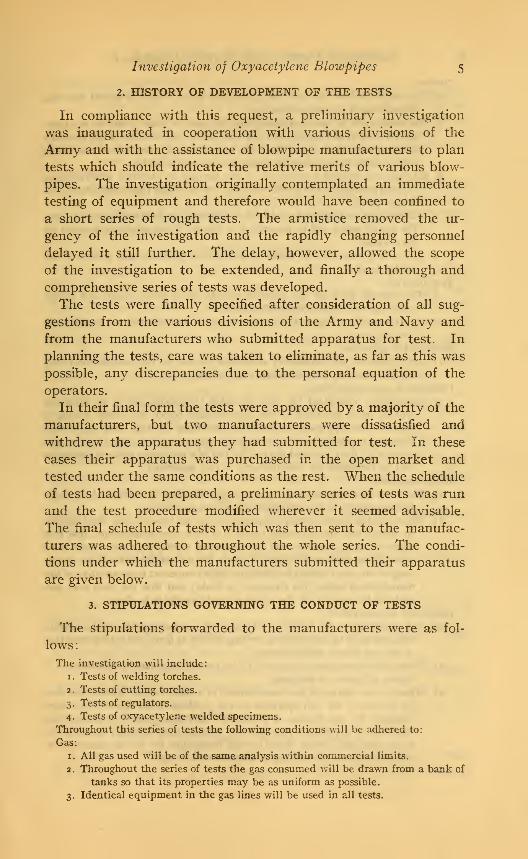
The investigation will include:
1
.
Tests of welding torches.
2
.
Tests of cutting torches.
3. Tests of regulators.
4. Tests of oxyacetylene welded specimens.
Throughout this series of tests the following conditions will be adhered to:
Gas:
1. All gas used will be of the same analysis within commercial limits.
2. Throughout the series of tests the gas consumed will be drawn from a bank of
tanks so that its properties may be as uniform as possible.
3. Identical equipment in the gas lines will be used in all tests.

Technologic Papers of the Bureau of Standards
Torches:
4. The torches will be operated throughout the series of tests in accord with the
instructions of the manufacturers.
5. The torches will be operated throughout the series of tests by one set of exper-
ienced welders and cutters who will work under the direction of the Bureau 's
representative in charge of the tests, except that a manufacturer may makea demonstration test using an operator of his own selection.
6. All makes of welding torches will be put through an identical series of tests.
The gas pressures will be controlled by one set of gas regulators selected for
this purpose.
7. All makes of cutting torches will be put through an identical series of tests.
The gas pressures will be controlled by one set of gas regulators selected for
the purpose.
8. All cutting tests will be made by mechanical guidance and control of the
cutting torch.
Test material:
9. The material used for test purposes consists of x/2 inch, 2-inch, and 6-inch
steel, each of known chemical analysis.
10. One grade of welding rod of known chemical analysis will be used for the
welding tests.
Submittal of apparatus:
11. Any apparatus not voluntarily submitted for test by the manufacturer maybe purchased in the open market and tested.
Information concerning tests:
12. Information concerning the tests to which the torches are to be subjected
will be made available to the manufacturer before the actual testing is
started. All apparatus voluntarily submitted for test must be in the
Bureau's hands before the information concerning the tests is given out.
13. A copy of all data obtained during the test of a particular make of apparatus
will be furnished the manufacturer of that apparatus.
Witnessing tests:
14. The tests on any particular make of apparatus may be witnessed by three
representatives of the manufacturer of that apparatus.
15. Whenever the manufacturer's representatives are present they shall specify
in writing that the apparatus tested is of their own manufacture, that it is
identical in all respects with the torches of similar style sold under their
name in the open market, that it was in proper working order at the begin-
ning of the test (it shall be tried out by a competent representative of the
manufacturer before this statement is made), and that the tests were car-
ried out in accord with the schedule made available to them.
Retest and demonstration:
16. Any objections to the methods and procedure in operating the torches during
the tests shall be submitted in writing within 24 hours after the completion
of the test on any make of torch.
17. When conditions seem to warrant it, the Bureau may make such retests as it
deems advisable or necessary.
18. When in the opinion of the manufacturer of a torch he can demonstrate that
by the use of his own operators he can produce better results than were
obtained by the Bureau of Standards' operators, such a demonstration
test will be permitted, provided the manufacturer supplies the material
to be used and further, holds himself responsible for all cost necessary in
connection with the making of a demonstration test.

Investigation of Oxyacetylene Blowpipes 7
Retest and demonstration—Continued.
19. If the opportunity to make a demonstration test is accepted by a manufac-
turer, such test must be made at the Bureau under the identical con-
ditions, except for operators, in which the Bureau 's test was made. Further,
the same torches and identical material are to be used for both tests.
20. The Bureau will endeavor as far as possible to assist the manufacturer to
secure material of identical composition for demonstration tests.
Decisions:
21. Final decision upon any questions which may arise in regard to these tests
will be made by a committee composed of one representative of the U. S.
Army, one representative of the U. S. Navy, and three representatives of
the Bureau of Standards.
4. ACKNOWLEDGMENTS
In connection with the development and completion of this
investigation, the general experience of a number of people was
freely drawn upon so that the question might be viewed from its
broadest aspects, and such assistance is here acknowledged with
the realization that the successful completion of the investigation
was largely due to the splendid cooperation received. In this
connection the assistance of the following is acknowledged:
The Ordnance Department of the War Department, U. S. A.;
U. S. Naval Gun Factory, Washington, D. C; Hull Division,
U. S. Navy Yard, New York; and various manufacturers of oxy-
acetylene equipment, especially the Davis-Boumonville Co. and
the Commercial Acetylene Co. Of the Bureau staff, G. M. Dent-
ing and his assistant, L. R. Sweetman, to whom the successful
design, calibration, and operation of the testing equipment are
largely due, and S. W. Miller, consulting engineer, Rochester,
N. Y.
II. DESCRIPTION OF EQUIPMENT USED IN TESTINGTHE BLOWPIPES
In general the equipment used for making the tests may be
listed as
—
1. The weighing system for determining the amount of the
gases used during the tests by loss of tank weight.
2. The gage-board system containing the necessary pressure
gages, regulators, and orifice flow meters.
3. The welding table.
4. The cutting table.
5. The flash-back and safety testing apparatus.
A general view of the entire equipment and its arrangementis shown in Fig. 1. For purposes of analysis and explanation it
8 Technologic Papers of the Bureau of Standards
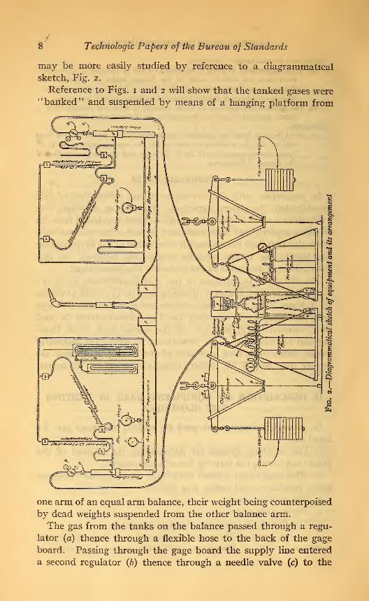
may be more easily studied by reference to a diagrammatical
sketch, Fig. 2.
Reference to Figs. 1 and 2 will show that the tanked gases were"banked" and suspended by means of a hanging platform from
one arm of an equal arm balance, their weight being counterpoised
by dead weights suspended from the other balance arm.
The gas from the tanks on the balance passed through a regu-
lator (a) thence through a flexible hose to the back of the gage
board. Passing through the gage board the supply line entered
a second regulator (b) thence through a needle valve (c) to the

^

Bureau of Standards Technologic Paper No. 200
Fig. 5.
—
Weighing apparatus showing banked gas tanks on balances and observer's table

Investigation of Oxyacetylene Blowpipes 9
top of and through an orifice flow meter (d). The gas coming
from the extreme bottom of the flow meter was then conducted
through a standardized length of flexible hose (e) containing a
safety flash-back tank (/) to the blowpipe to be tested.
1. THE WEIGHING SYSTEM
The weighing system comprised two equal-arm balances of
3000 pounds and 1000 pounds capacity, respectively, for the
oxygen and acetylene and the observer's table. (See Fig. 3.)
io Technologic Papers of the Bureau of Standards
(c) THE BALANCES
The "banked" tanked gas was set on a platform suspended
from one arm of the balance. Dead-weights were hung from the
other arm of the balance to counterweight the load of the sus-
pended platform. The weighings were always made by the
substitution method described later. The readings were secured
by the so-called "Method of swings" and were taken on a scale
(h) as it oscillated to either side of a fixed reference point (j).
The scale (h) was a centimeter scale fastened to a support hang-
ing down below the beam of the balance and rigidly fixed to the
balance beam so that it oscillated with it. The necessary fixed
point (j) was secured by a fine wire stretched taut in front of
the scale between the center knife-edge support of the beamand a stake driven in the ground beneath.
(6) THE OBSERVER'S TABLE
Between the two balances, with arms projecting horizontally
to within a short distance of and at right angles to the plane of
oscillation of the balance beams there was an observer's table.
The extreme ends of the projecting arms held a small electric
light bulb and a magnifying glass which permitted an enlarged
projection of the scales to be thrown on two mirrors set above the
desk of the observer's table and at 45 ° to the line of the projected
image of the scales. This arrangement permitted the observer,
seated at the desk, to obtain a clear view of the scale of either
balance instantaneously. Directly below the reflecting mirrors
of the observer's table, and within convenient reach of the observer,
there was placed a small tilting holder (p) carrying the ends of
soft rubber tubes connected to a constant level reservoir of water
(k) placed above and to the left of the mirrors. The flow of water
through these tubes was controlled by needle valves (/) located
to the right and left of the mirrors.
The tube ends on the tilting holder deposited the water from
the reservoir into one of two pairs of funnels (m) so arranged that
by tilting the holder either forward or backward the water could
be deposited into either pair of funnels. Flexible tubing attached
to these funnels led to bottles (n and o) placed on the balance
platforms carrying the tanked gas. It is apparent, therefore,
that water could be easily deposited in either of the two bottles
on the balance platforms by simply tilting the tube holder back-
ward or forward. Control of the rate of flow of the water wasreadily governed by the needle valves (/). An observer sitting
at the desk and watching the swing of the balance arms could by

Investigation of Oxyacetylene Blowpipes 1
1
simple adjustment of the needle valves permit water to flow into
the bottles on the balance platforms at such a rate as would
approximately compensate for any loss in weight due to the
withdrawal of gas from the tanked cylinders.
(c) METHODS OF DETERMINING WEIGHT DATA
With the necessity of using gas until the blowpipes were prop-
erly adjusted before commencing any test operation and because
there were two balances to observe as nearly simultaneously as
possible at the start of each test, it was not possible to always
start the tests with the balance scales at an exact zero. There
was a constant and regular '* drift" of the zero position as gas
was withdrawn from the tanks. Any error from this possible
source was readily and easily compensated for as follows: After
the blowpipe was properly adjusted and the gage-board observers
and practical operators were ready to begin a test, the weighing
observer was notified by signal. The latter meanwhile had been
adjusting the flow of water to such rate as would as nearly as
possible compensate for the weight of gases being withdrawn.
At the sounding of the signal he began a series of five turning-
point observations for each balance, the five for the oxygen
balance being taken first. At the completion of the fourth
turning-point observation for the oxygen balance a preliminary
warning signal was given, and at the completion of the fifth
observation the signal to begin the test was sounded. Imme-diately following this signal the weighing observer took the five
turning-point observations for the acetylene.
The mean of each consecutive three turning-point observations
for each gas gave three determinations of the zero of the balance.
From these the'
' drift'
' of the zero of the balances could be deter-
mined and the readings corrected to the actual time of starting
the test.
During a test the zero of the balances was maintained as nearly
constant as possible. The exact value could not, however, be
held for so long a period as the tests required, so that at the
completion of a test the zero usually had shifted to one side or the
other of the initial zero determination, because either too muchor not enough water had been permitted to enter the gas weight
bottles on the scale platforms. Such errors were readily corrected,
however, by the determination of the final zero.
In order to make this correction it was necessary to determine
the sensitivity of the balance. As this did not remain constant

12 Technologic Papers of the Bureau of Standards
from day to day, the sensitivity was determined each morning
before beginning the day's tests. It was desirable to release the
load on the balances each evening, but a complete release of the
load was found to cause erratic changes in the sensitivity. Toavoid this the greater portion of the load was relieved by jacks
placed under the counterweights, allowing enough weight to
remain to prevent displacement of the knife-edges. With this
procedure erratic results from the determinations for sensitivity
were very infrequent.
The sensitivity was determined by taking turning-point obser-
vations for the zero of the balance oscillations and then determining
by the same method the "drift" caused by placing a standard
10 g weight on the counterweight side of the balance. Theamount of drift in centimeters divided by the number of
grams used to cause such displacement gave the weight equivalent
value of the scale divisions in grams per centimeter. This deter-
mination was always made with the gas line leading to the gage
board "flooded" under a pressure equivalent to the average gas
pressure generally used; that is, 125 lbs./ in.2 for the oxygen line
and 20 lbs./ in.2 for the acetylene line.
During the course of the experiments it was thought desirable
also to make one other correction for error in balance determina-
tions. It is almost impossible to stop all leakage when a series
of tanks is banked as in these tests. Small leakages in tank
valves, too small to be readily detected, were found to exist.
To compensate for these the gas lines were flooded as far as the
regulator on the gage board and the zero-point determinations
made over a period approximating a half hour. The determi-
nation of the amount of drift thus found in connection with the
weight equivalent value of the scale divisions gave an index of
the rate of loss of gas by leakage. This determination allowed
all balance data to be corrected for such loss. (See Fig. 19.)
If the gas loss exceeded 0.01 to 0.02 pound per hour, actual testing
of the blowpipes was not continued until the leaks causing such
losses were located and stopped.
(d) PRECISION OF WEIGHINGS
As to the precision of readings obtained by the use of these
balances and the weighing system it would seem that, giving due
consideration to all disturbing influences, the values obtained
for gas consumption are accurate to 0.005 pound, and in mostcases are probably much closer.

Investigation of Oxyacetylene Blowpipes 1
3
2. THE GAGE-BOARD SYSTEM
(a) GAGE-BOARD REGULATION
During the preliminary investigation of the equipment to be
used for these tests it was found that none of the standard regu-
lators generally furnished with such equipment were satisfactory
for regulation purposes, if results of any considerable accuracy
were to be obtained. Due to the construction of the ordinary
regulator the readjustments for pressure distribution are inter-
mittent and spasmodic and allow of considerable variation in
the actual pressures delivered on the low-pressure side of the
regulator.
It became necessary, therefore, to devise some means by which
a more constant and reliable pressure could be delivered to the
line supplying the blowpipes. After considerable inquiry and
experimental trial the method shown in Fig. 2 and the various
photographs was adopted and as a whole proved extremely
satisfactory. The main regulation was accomplished by tworegulators used in series, one attached to the outlet of the mani-
fold of the banked tanks (a, Fig. 2), and the other placed on the
gage board just in front of the inlet to the flow meter (6). Bymeans of the regulator at the manifold the tank pressures were
reduced to an amount about 50 per cent in excess of the pressures
required for the blowpipe, the second regulator being used to
reduce still further the pressure to that desired.
The various regulators used were the best of a large group that
was on hand, their efficiency being determined by constant trials
and observations of the regulators themselves. Through this
means a set of regulators selected for their good performance
was used as a whole throughout the entire series of tests.
The regulator (6) at the gage board was changed as occasion
demanded in order to secure as sensitive a regulator as possible
contingent upon the pressure which it was required to deliver.
It was found, however, that even with the selection of regulators
from the large number on hand, too great a variation still existed
in the pressures which would have been delivered to the blowpipe
line. A part of this trouble was due to the construction of the
regulator, in that the reduction of pressures was accomplished
by intermittent and spasmodic action of the regulator. Recog-
nizing this, a set of ''rappers" was used which vibrated the bodyof the gage-board regulator (6) , the idea being that the constant
agitation and vibration of the regulator body would tend to keep
14 Technologic Papers of the Bureau of Standards
the seat of the regulator floating and therefore secure less inter-
mittent action. These "rappers" were connected in series with
a master vibrator located at some distance from the board. Theinterrupting mechanism of the two gage-board vibrators wasshort-circuited so that no sparking could be produced at the gage
board within a dangerous vicinity of possible gas leaks, etc.
Further experience indicated that the insertion of a small
hand-regulated needle valve (c) between the regulator at the
gage board (b) and the flow meter (d) secured a decidedly moreuniform regulation. The standard procedure throughout the
tests, therefore, was to have one of the gage board operators
make such adjustment by means of the needle valve (c) as from
time to time was found necessary to maintain constant pressures
in the gas line. After a blowpipe had been properly adjusted
and had been operating for a few minutes it was seldom found
necessary to make any further adjustment in the needle valve,
the pressures remaining as a whole very constant through the
tests.
By means of the above arrangement it was readily possible
to maintain under most all conditions a pressure varying not
more than o.oi or 0.02 of a pound from the desired amount. Theconstancy of the regulation obtained may be seen from Fig. 21,
which is a copy of an average log sheet, or from Fig. 3 1 , a copy of
one of the autographic pressure curves. As a general thing the
best regulation obtained was far better than that shown on these
figures, although occasionally somewhat poorer regulation resulted.
(6) FLOW METER
During the study of the methods proposed for testing the various
blowpipes it appeared desirable to secure information concerning
the amount of gas used through some independent means other
than through the loss of weight of the tanks. It seemed essential
that these data should be secured as a check upon possible errors
in tank weights and further to permit of instantaneous readings
from time to time of the relative amounts of gas being consumed
by the blowpipes.
After considerable discussion and study it was finally decided
that this information could be best secured through the use of a
flow meter. A special orifice flow meter, the general details
of which are indicated in Fig. 4, was therefore designed and
constructed for this investigation.

Investigation of Oxyacetylene Blowpipes 1
5
Referring to Fig. 4 it will be seen that the flow meter consisted
essentially of a brass tube, 45 inches in length and 2 inches inside
diameter, which was cut into two pieces at approximately the
center of its length and fastened together by a screwed coupling.
To the top and bottom ends respectively of the tube in line with
its longitudinal axis, an inlet and an outlet nipple were brazed.
Two other nipples were brazed to the side of the tube, one a short
distance above the split joint at the center of the tube, and the
other about 10 inches above the outlet nipple. These led respec-
tively to the differential manometer and to the differential and
static pressure manometers.
In order to insure uniform distribution of gas throughout the
inlet end of the flow meter there was built into the upper end
just below the inlet nipple a cross baffle and a series of four
60-mesh brass screens, as indicated in Fig. 4.
The orifices were of the thin plate, sharp-edged type, and were
held in position at approximately the mid-length of the flow-meter
tube by the adjustment of the coupling as indicated in Fig. 4.
A section showing their shape is also included in this figure.
Orifices of this type were selected as they were simple and readily
machined to exact sizes. Their continued use throughout the
series of tests has shown that they have been extremely satis-
factory. A total flow of several hundred million linear feet of
oxygen has passed through one of the orifices used on the oxygen
flow meter at an average velocity of several thousand feet per
minute, and so far as can be detected it has shown no signs of
wear or erosion. To substantiate this latter a photograph wastaken of this orifice before it was used and after it had been put
through the entire series of tests. This photograph does not
even indicate any rounding of the corners of the orifice, and the
check measurements show also that no enlargement of the opening
has taken place.
Experience showed that the number of orifices could be limited
to five without undue loss of sensitivity by using, in parallel
with the main vertical manometers, adjustable inclined mano-meters. These water manometers had a relatively high sensitiv-
ity and were therefore protected by cut-off valves against excess
pressure. (See Figs. 1 and 7.)
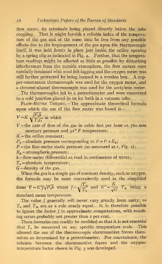
Since the rate of flow of a gas is a function of its temperatureas well as its pressure and density, it was necessary to measurethe temperature of the gas as it passed through the flow meter.
In order to accomplish this a thermocouple was built into the
1
6
Technologic Papers of the Bureau of Standards
flow meter, its terminals being placed directly below the tube
coupling. That it might furnish a reliable index of the tempera-
ture of the gas and at the same time be free from any possible
effects due to the impingement of the gas upon the thermocouple
itself, it was held firmly in place just inside the orifice opening
by a spring clip as indicated in Fig. 4. Further, that the tempera-
ture readings might be affected as little as possible by disturbing
interferences from the outside atmosphere, the flow meters were
carefully insulated with wool felt lagging and the oxygen meter wasstill further protected by being incased in a wooden box. A cop-
per-constantan thermocouple was used for the oxygen meter, anda chromel-alumel thermocouple was used for the acetylene meter.
The thermocouples led to a potentiometer and were connected
to a cold junction placed in an ice bath in a vacuum tube.
Fu)W-METER Theory.—The approximate theoretical formula
upon which the use of the flow meter was based is
—
IPJt . 'L u^r-p.» in which1 &Lr
F = the rate of flow of the gas in cubic feet per hour at 760 mmmercury pressure and 32 ° F temperature;
K = the orifice constant;
Pa = absolute pressure corresponding to P =P +Bp ;
P = the flow-meter static pressure (as measured at r, Fig. 2)
;
Bv= atmospheric pressure
;
h = flow-meter differential as read in centimeters of water
;
Ta = absolute temperature
;
G = density of the gas.
When the gas is a simple gas of constant density, such as oxygen,
the formula may be more conveniently used in the simplified
^ and K' =~fc>
Tm being a
standard mean temperature.
The value / generally will never vary greatly from unity, as
Ta and Tm are as a rule nearly equal. It is therefore possible
to ignore the factor / in approximate computations, with result-
ing errors probably not greater than 2 per cent.
These formulas can readily be modified so that it is not essential
that Ta be measured on any specific temperature scale. This
allowed the use of the thermocouple electromotive forces them-
selves as determined by a potentiometer. For convenience, the
relation between the electromotive forces and the oxygen-
temperature factor shown in Fig. 5 was developed.

Investigation of Oxyacetylene Blowpipes 17
V^m
Where the gas is a complex one of changing density such as
that drawn from compressed acetylene cylinders which contain
varying proportions of acetone, the ftmdamental flow-meter
formula may be written, for convenience, V = k'F-yJPJt, in which
k it gbeing a standard mean density, and F = + *p r*'
Gm was taken as 0.0750 lb. /ft.3
, which appeared to be the meandensity of the gas as taken from the density determinations
mentioned later. The value selected for Ta was identical with
that used for the oxy-
gen meter. In this
later form the temper-
ature density factor
F also ranges around
unity, so that, as indi-
cated above, it might
also be neglected in
approximate determi-
nations. In such cases,
however, the results
will be more liable to
error on account of
the varying density of
the acetylene. Therelations between the
density, gas tempera- Tempenrfun? factor
ture, and temperature FlG ' S'-0*W>n temperaturefactor curve
density factor F, which were used in the interpretation of the
test data, are shown in Fig. 6.
Calibration of Flow Meters.—Three independent calibra-
tions were made of the orifices of each of the flow meters to deter-
mine the value of the constant K. In the first calibration the
flow-meter readings were compared with the readings of a stand-
ardized dry gas meter. The pressure regulation was not as close
as was desired, and the values of K fluctuated more widely than
was considered satisfactory.
A second calibration was therefore made after the selected
regulators and "rappers" were installed in the form used in the
final blowpipe tests. As an additional check the dry gas meter
readings were supplemented by the weight of the gas lost as
determined by the balance. The regulation secured was excel-
58814°—21 2
MO .97.
!W .93
v 100 .39
[
\.
V)s/fO
\M0
\WI
M.zd
xlOZ
1
-71)'

18 Technologic Papers of the Bureau of Standards
lent and as a whole far better than was obtained in the blowpipe
tests themselves. The results of this calibration were very con-
sistent, as may be seen from the following table of values of Kdetermined for one orifice under three widely different pressures
and three widely different rates of flow:
Test No. Ko-i I. 171
0-2 1. 169
0-3 I. 182
0-4 1. 187
0-5 1. 1900-6 I. 187
0-7. I. 186
This second calibration was therefore at first considered satis-
factory. In computing the results of the first blowpipe tests,
there appeared an unex-
plained systematic differ-
ence between the gas con-
sumption calculated from
the balances and from the
flow meters. Investigation
showed the unexpected re-
sult that the value of K, as
determined by the mano-meters used, was lowered
by pressure fluctuations.
The theoretically exist-
ing difference between the
square root of the average
value of h and the average
of the square root of h is
far too small to account for
this difference. It must
therefore be due to an
actual higher average dif-
erential under fluctuating
ml
s^
.080 Sgr
.079\<%
F 07Se>
b 077x2?
X^076\ si >
I073
.074
s. ^N^ s
.073 % \ s
.071^0.50 .60 .70 .80 .90 JjDO /JO MO
Potenf/omefer /fcad/ngs, mvFig. 6.
—
Acetylene temperaturefactor curves
pressures, due to inertial and frictional effects in the manometers,
or to a systematic tendency of the operator to overread a fluctu-
ating manometer.
A full investigation of the cause of this systematic difference
would be very desirable, but the time required would have been
excessive in the present investigation.
A third calibration of the flow meters was therefore calculated
from the balance and flow-meter readings in the preliminary

Investigation of Oxyacetylene Blowpipes 19
series of actual blowpipe tests. The pressure regulation in these
tests was not so good as in the second calibration but better than
in the first. The magnitude of this systematic effect of pressure
fluctuation can be seen from the following table
:
Calibration Pressure regulation for orifice No. 5 K
z Very good 1.189
3 1.145
1 Poor 1.114
The effect is larger in the smaller orifices.
The flow-meter constants K, as determined from this third
calibration, were used in computing the test data. The close
check of the gas consumption calculated from the flow-meter
readings with the balance readings in the individual tests (see
for instance Figs. 22 and 23) shows that this was justified, andindicates that the same average closeness of pressure regulation
was maintained throughout the tests.
(c) MANOMETER AND PRESSURE-GAGE EQUIPMENT
As indicated above, the gas leaving the flow meters passed to
the blowpipe through the gas line e and flashback /, Fig. 2.
The static pressure of the gas passed to the blowpipe was deter-
mined by means of pressure gages and manometers on the line r,
Fig. 2, taken from the side of the flow-meter base just above the
outlet to the gas line e.
On the oxygen side of the gage board there was incorporated
in the line of static pressure r, Fig. 2 or 7, a Bourdon tube master
gage y }a recording gage, and two compound manometers z, one
of 0-44 lbs. /in.2 range, and the other 0-180 lbs. /in.
2 This static
line pressure also connected through the baffles w, Fig. 2, with
the upper ends of the differential manometers. The other ends of
the differential manometers, both vertical and inclined, were con-
nected through reservoirs w', Fig. 2, to the static pressure lines at
the inlet end of the flow meter just above the orifice opening.
On the acetylene side of the gage board the Bourdon tube gage
was replaced by a simple mercury manometer z' , which could be
connected into the line as needed, and in place of the compoundmanometer z of the oxygen side there was installed a simple
U-column mercury manometer.
The pressure gages used throughout the tests were a special
series of master test gages that were made for this investigation.
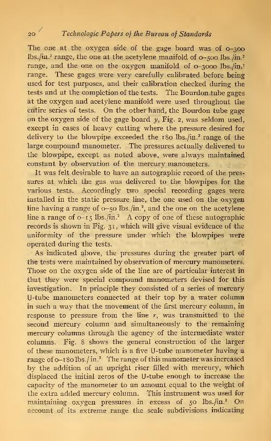
20 Technologic Papers of the Bureau of Standards
The one at the oxygen side of the gage board was of 0-300lbs./in. 2 range, the one at the acetylene manifold of 0-500 lbs. /in. 2
range, and the one on the oxygen manifold of 0-3000 lbs./in. 2
range. These gages were very carefully calibrated before being
used for test purposes, and their calibration checked during the
tests and at the completion of the tests. The Bourdon tube gages
at the oxygen and acetylene manifold were used throughout the
entire series of tests. On the other hand, the Bourdon tube gage
on the oxygen side of the gage board y yFig. 2, was seldom used,
except in cases of heavy cutting where the pressure desired for
delivery to the blowpipe exceeded the 180 lbs./in.2 range of the
large compound manometer. The pressures actually delivered to
the blowpipe, except as noted above, were always maintained
constant by observation of the mercury manometers.
It was felt desirable to have an autographic record of the pres-
sures at which the gas was delivered to the blowpipes for the
various tests. Accordingly two special recording gages were
installed in the static pressure line, the one used on the oxygen
line having a range of 0-50 lbs./in.2, and the one on the acetylene
line a range of 0-15 lbs./in.2 A copy of one of these autographic
records is shown in Fig. 3 1 , which will give visual evidence of the
uniformity of the pressure under which the blowpipes were
operated during the tests.
As indicated above, the pressures during the greater part of
the tests were maintained by observation of mercury manometers.
Those on the oxygen side of the line are of particular interest in
that they were special compound manometers devised for this
investigation. In principle they consisted of a series of mercury
U-tube manometers connected at their top by a water column
in such a way that the movement of the first mercury column, in
response to pressure from the line r, was transmitted to the
second mercury column and simultaneously to the remaining
mercury columns through the agency of the intermediate water
columns. Fig. 8 shows the general construction of the larger
of these manometers, which is a five U-tube manometer having a
range of 0-1 80 lbs./ in.2 The range of this manometer was increased
by the addition of an upright riser filled with mercury, which
displaced the initial zeros of the U-tube enough to increase the
capacity of the manometer to an amount equal to the weight of
the extra added mercury column. This instrument was used for
maintaining oxygen pressures in excess of 50 lbs./in.2 On
account of its extreme range the scale subdivisions indicating
Bureau of Standards Technologic Paper No. 200
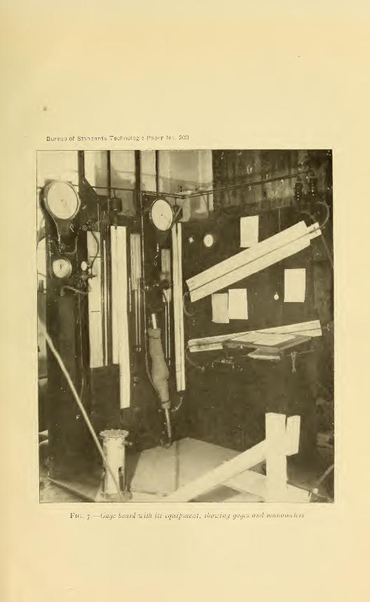
Fig. 7.
—
Gage board with its equipment, showing gages and manometer*

Buraau of Standards Technologic Paper No. 200
Fig. 8.
—
Compound manometer used in investigation

Investigation of Oxyacetylene Blowpipes 2
1
pressures lower than 50 lbs./ in.2 were too small to permit of ready
interpolation of pressures to the nearest 1/100 of a pound. There
was therefore used in connection with this a smaller compoundmanometer of two U-tube construction with a range of 0-50 lbs. /in.
2
This latter was used for all welding tests and for the larger
number of cutting tests.
These manometers gave extremely satisfactory service and
proved a valuable addition to the gage-board equipment. The
smaller compound manometer of 0-50 lbs./ in.2 range proved to be
extremely accurate and sensitive, and it was therefore selected as
the pressure standard for the entire gage-board equipment. The
remaining manometers and Bourdon tube gages, etc., were there-
fore frequently checked for accuracy against this manometer.
The greatest discrepancies in these manometers seemed to
result from inaccuracies in the zero settings of the manometer
scales. Errors due to this cause might possibly amount to \T/2
per cent of the manometer reading for values below 5 lbs./in.2
For the higher values of the manometer readings, however, the
error as a general rule ranged from 0.1 to 0.7 per cent.
Besides the Bourdon tube gages and the pressure manometersthere was installed on the gage board as mentioned above a series
of vertical and inclined differential manometers for measuring
the flow-meter differentials. For the higher values of the flow-
meter differential the vertical manometers were used, but the
line was arranged so that for the lower values the inclined differ-
ential manometers could be cut in at will. The inclined mano-meter for measuring the differentials on the acetylene flow meter
was mounted so that it could be set at either of two positions.
(See Fig. 7.) These differential manometers were mounted with
special calibration charts giving the flow-meter differential pres-
sures and a series of curves enabling the determination by rough
approximation of the rates of flow of the gas when the differential
and the static pressure were known. The charts in question were
based upon pressures above atmosphere standardized to 757 mmof mercury. The charts, however, are not fully described,
because the readings obtained were only approximate since they
did not contain corrections for temperature drop or changes in
barometric pressure, nor did they take into account the question
of the changing density of such gases as tanked acetylene. Thegeneral construction of these charts, however, is clearly indicated
in Figs. 7 and 8.

22 Technologic Papers of the Bureau of Standards
In order to maintain the correct initial zeros for the flow-meter
differential manometers, they had connected in their line at their
base a small reservoir {w f
, Fig. 2) . This reservoir was so mountedthat by means of the lever and set screw the zero of the manom-eter could be readily adjusted.
It was found necessary to protect these instruments against
accidental blowouts due to sudden back pressures caused byunforeseen gas explosions in the gas lines leading to the blowpipe.
This was done by a baffle (w, Fig. 2) installed immediately over
the top of each differential manometer, which interrupted anyliquid accidentally blown out and, upon the release of pressure
allowed the liquid to flow back into the manometer tube, per-
mitting immediate continuance of the test without serious inter-
ference.
In order to complete the records in the test data, the gage board
was also equipped with a standard calibrated thermometer, a
psychrometer, a barometer, and a stop watch. (See Fig. 7.)
3. THE WELDING TABLE
All welding during the tests was performed upon the welding
table illustrated in Fig. 9. This was a wooden frame table
approximately 3 feet square, the top of which was composed of
fire bricks. On top of the fire bricks was placed a heavy casting
channeled for a width of about 6 inches throughout its length.
This formed the base upon which all the plates for welding rested
during the welding operation. The plates were aligned centrally
along this base with the idea that the casting with its grooved
surface would permit of better heat radiation along the line of the
weld.
As indicated in Fig. 9, the line of the weld was placed directly
in front of the welder and the welding was performed from the
back toward the operator, thus giving him a full view of the work
as it progressed. The welded plates were cut so that the welds
were 1 foot in length. Where 2 feet of weld were made contin-
uously, pairs of plates were set in front of each other with a slight
space between the individual pairs and with proper allowance for
expansion so that the process could be carried from one plate to
the other without any interruption. The groove along the base
plate facilitated the preheating of the second pair of plates, so
that the start upon the second weld was made under conditions
practically identical with those which existed when the first pair
of plates was finished, a condition equivalent to welding one

Bureau of Standards Technologic Paper No. 200
Fig. 9. -The welding iabk

Bureau of Standards Technologic Paper No. 200
Fig. io.—The top and bottom view of an average weld

Investigation of Oxyacetylene Blowpipes 23
2 -foot length instead of two i-foot lengths. Particular care was
taken throughout the tests to level the plates before welding and
to set them with a proper expansion allowance so that they would
come together properly at the completion of the weld without
overlapping. Fig. 10 shows the top and bottom view of an
average weld. It will be noted that special attention was given
to securing good penetration. The micrographs given later show
further examples of the good penetration secured (Figs. 65 to 71).
4. THE CUTTING TABLE
In order to minimize as far as possible the personal equation
entering into cutting tests all tests were made by a mechanically
controlled cutting device installed upon the cutting table. (Fig.
11.) This was a wooden frame table approximately 4 by 12 feet
in size with metal bound edges and a fire-brick top. . At each end
of the table and securely fastened to it were 6 by 6 inch sticks
placed crosswise, along the top of which were fastened 1 by 2 inch
bars of metal. These latter acted as runners to carry a channel
placed with flanges down as illustrated in the figures. Thechannel held the track upon which the mechanically controlled
cutting device operated. Longitudinal motion of the blowpipe
could therefore be secured by causing the machine to move along
the track and lateral shifts were made by sliding the channel
along the runner bars screwed to the 6 by 6 inch end blocks. In
order to facilitate quick lateral movement of the channel and
insure, where such was desired, that pieces of definite width
could be cut, the runner bars had a series of holes spaced con-
veniently at 2 inches on centers and a set of metal pins which
fitted these holes. (See Fig. 1.) By inserting the pins in the
proper holes the channel could be instantly shoved over a definite
required distance.
This compound arrangement facilitated greatly the makingof continuous cuts of 10 feet or upward. The cutting machinebeing fitted with a reverse motion gear could be operated in a
forward direction for the full length of the table, reversed in
direction of travel, and at the same time the channel slid over a
definite distance and thus the blowpipe made to travel backwardfor the full length of the table for a cut on a new and adjacent
line. (See Fig. 1 1 .)
In order to furnish room for the disposition of the slag formedduring the cutting operation, the metal to be cut was supported on

24 Technologic Papers of the Bureau of Standards
a system of teeth as shown in Fig. n. These teeth proved
extremely satisfactory and made a very convenient method of
maintaining the metal in proper position for cutting. They could
be shimmed to compensate for warped plates, and due to their
tooth construction allowed the passage of slag without in anyway blocking or interfering with the cutting operation during
the test.
The mechanical guiding and controlling device proved extremely
satisfactory and reliable, giving no trouble throughout the entire
series of tests. The machine, however, was not arranged to
allow of continuous variation of speed, which was necessary for
an accurate determination of the maximum cutting speed. For
this purpose a combination of series and shunt resistances wasattached which enabled the speed to be varied continuously from
about 1.5 to 25 feet per minute. For the purposes of the tests
the blowpipe holder furnished with the machine was replaced bya special holder that would allow greater latitude in adjustment
and would at the same time permit the machine to be adapted
to hand-cutting blowpipes of all the various makes.
It was found in preliminary tests that the speed of the machine
under all conditions remained practically constant for any par-
ticular adjustment. In order to make sure of this, however,
the time was carefully noted for the various lengths of cut madeduring all tests. During the operation of the machine in the
entire series of tests there was never noted a variation in speed
that justified a rerunning of a test. (See Table 1 for a typical
speed record.)
TABLE 1.—Time Speed Record for Cutting ifa-lnch Metal, Torch No. 14
Length of
cut in feet
Length of
time to
Time to cuteach 5-foot
make cut increment
Minutes Minutes0.0 0.0
5 2.73 2.7310 5.42 2.6915 8.28 o2.8620 11.01 2.7325 13.78 a 2. 77
30 16.52 2.7435 19.28 a 2. 7640 22.03 2.7545 24.88 a 2. 8550 27.58 2.70
a It was found during the tests that from 2 to 4 seconds were consumed in reversing direction of cut at
end of each 10 feet of length.

Bureau of Standards Technologic Paper No. 200
Fig. ii.—The culling equipment

Bureau of Standards Technologic Paper No. 200
Fig. 12.
—
The flash-back apparatus
Investigation of Oxyacetylene Blowpipes 25
For convenience in handling, the material used during the
cutting tests was cut into lengths of 3 or 5 feet. This necessi-
tated the placing of two lengths of plates in order to secure the
lengths of cuts desired in making the tests.
To minimize the delay in passing from the end of one plate to
the beginning of another during the cutting operation, a method
of preheating, as indicated in Fig. 1, was devised. As the blow-
pipe approached the end of the cut on one plate a welding blow-
pipe was ignited and played upon the edge of the second plate in
line with the cut, thus preheating its edge so that the cutting
blowpipe had a warm plate to attack in passing from the first to
the second. It was found that by this method of preheating,
bringing just a small spot at the edge of the second plate to a
cherry red, the blowpipe could be operated continuously for the
full length of the cut, cutting through the junction of billets 6
inches in thickness, without changing or slowing the speed of
operation. Where the cuts were of such length as to require
several traverses back and forth through the length of the table,
such as the 50-foot cut for X_uicn plate, the same preheating with
the welding blowpipe was carried out on the ends of the plate.
(See Fig. 11.) This preheating therefore permitted the cutting
operation to proceed as one continuous operation without any
delay or interference from the fact that the test cuts were madeon relatively short lengths of plate.
The entire cutting table equipment became practically a
mechanically self-operating mechanism, inasmuch as after the
maximum speed was obtained the only adjustment required of
the operator was that necessary to keep the preheating flames of
the cutting blowpipe at a proper distance from the face of the
plate. This operation itself would have been unnecessary except
for the fact that the cutting operation invariably caused consid-
erable warping of the plate as the cutting proceeded, especially
with the thinner plates.
It was the fixed procedure in making the cutting tests to adjust
the blowpipe to neutral flame with the cutting oxygen valve
at full opening and with the gases delivered at the required
pressures. After such adjustment was satisfactorily made one
or more preliminary trial cuts were made to determine the maxi-
mum speed at which the blowpipe would cut. The trial cuts
for the major tests were always made upon a cold plate so that
the effect of the heating of the plate in the cutting operation was

26 Technologic Papers of the Bureau of Standards
made negligible. By means of the mechanical gear shifts of the
cutting machine and the resistances mentioned above, the maxi-
mum speed at which the blowpipe could operate was readily
determined, and having determined this maximum speed the
actual cutting operation required for the test was conducted.
By the use of the mechanical driving mechanism the heating of
the material during a test operation became ineffective inasmuchas the maximum speed was determined upon a cold plate, andfrom then on to the completion of the test the speed of operation
of the cutting blowpipe was maintained constant by the mechan-ically operated mechanism.
5. THE FLASH-BACK AND SAFETY APPARATUS
(c) FLASH-BACK TANKS
The testing equipment also included in the gas lines two com-mercial flash-back tanks (/, Fig. 2, and Fig. 1). These tanks were
essentially hydraulically controlled valves which were intended
to prevent the propagation of an explosion in the blowpipe or
gas line backward toward the gas supply. While it was realized
that the installation of the water seal of these flash-back tanks
might be considered detrimental, due to the absorption of moisture
by the gas, it became evident that their installation was never-
theless a prime necessity as a means of protecting the rather
expensive gage-board equipment. It was believed, further, that,
inasmuch as the oxygen in use generally came from cylinders that
contained more or less water, the passing of the gas through the
hydraulic seal of the flash-back tanks would in reality tend to
standardize the moisture content in the gas and therefore produce
similar effects for all blowpipes.
These flash-back tanks proved extremely satisfactory for the
purpose intended in that in several explosions they prevented the
propagation of the flame beyond the flash tank. They generally
ruptured by the blowing off of the head of the tank during the
explosion. As furnished the heads were of rather thick sheet
metal, fastened on with bolts. This construction proved to be
somewhat dangerous to the operators making the tests, and the
tanks were therefore modified in their construction by having a
rubber packing and a thin sheet of metal fastened to the top
with a heavy annulus. By this construction it was expected that
if an explosion developed within the flash tank the thin metal sheet
would rupture by tearing and thus minimize danger from flying
parts.

Investigation of Oxyacetylene Blowpipes 27
(b) FLASH-BACK APPARATUS
The tests for freedom from flash back and safety in operation
were conducted with the so-called flash-back apparatus. For
this series of tests a pair of flash tanks was connected into the
hose lines immediately back of the blowpipe. Between the flash
tanks and the blowpipe proper two observation boxes were
installed. These observation boxes consisted of a glass observa-
tion tube inserted in the gas lines and protected by a glass-covered
box. The box was of wooden side and back construction with
a vented back and a duplex glass face. The interior of the obser-
vation box was painted dead black to facilitate observation of the
flame propagation. (See Fig. 12.) This equipment was used
throughout the entire series of flash-back tests and for the severe
flash-back test mentioned later. One further piece of equipment
was a vertical sliding blowpipe holder constructed and operated as
shown in the figure.
HI. MATERIALS USED IN TESTS
1. WELDING ROD
The welding rod used throughout the entire series of tests wassecured from the Naval Gun Factory, Washington, D. C. This
rod was purchased in July, 191 7, under Navy Department Speci-
fication 22-W-4. A number of chemical analyses were madeto determine the composition, with the following results
:
Per cent
Carbon 0.024 to 0.03
Manganese 05 to .08
Phosphorus 01 to .015
Sulfur 023 to .024
Silicon 002 to .004
Chromium Trace
Nickel Not detected qualitatively
Vanadium Do.
2. STEEL PLATES FOR WELDING AND CUTTING
The steel plates used for welding were yi inch and J^ inch in
thickness. The material used for cutting was }4, 2, 6, and 10
inches in thickness. All the material used in both welding andcutting, except the 10-inch material, was furnished through the
Engineer Corps, War Department, and was selected with special
reference to uniform quality for any particular thickness. The^-inch material was furnished in plates 3 by 5 feet in size and wasused for both welding and cutting tests. For the welding tests

28 Technologic Papers of the Bureau of Standards
the plates were cut in sections 9 by 1 2 inches in size. The middle
section of each plate was retained as a sample for determining the
qualities of the plate. The remaining pieces were used for makingwelds. During the welding tests it was the practice to use plates
that were adjacent to each other in the main or full plate before
it was cut into weld specimens, so that as nearly as possible the
material used for any particular test would be identical.
The J^-inch material for welds was received in plates 1 2 inches
wide by 6 feet in length. These plates were cut up into sections
9 inches in length, and for the full width of the plate, that is 12
inches. All specimens for welding tests were finished with a butt
joint of the single V 90 included angle type.
For the cutting tests the 3 by 5 feet by % inch plates were cut
into strips approximately ij^ to 2 inches in width, as indicated
in the description of the cutting apparatus above. The 2-inch
material for cutting was furnished in sections 2 inches by 6 inches
by 20 feet. These were cut, for convenience in handling, into 5-
foot lengths, and in test operations were cut lengthwise into
sections of 2 -inch width. The 6-inch material was shell billet
steel furnished in 3-foot lengths and was cut lengthwise in test
operations.
Analyses of these materials indicated that they contained
approximately the following:
>^-inch mild steel plate for welding and cutting tests: per cent
Carbon 0.14
Manganese 32 to 0.36
Phosphorus 012 to .013
Sulphur 033 to .055
Silicon 006 to .012
%-inch plate for welding tests:v Per cent
Carbon o. 25 to o. 27
Manganese 4* to .48
Phosphorus on to . 013
Sulphur 041
Silicon 004
2-inch mild steel for cutting tests: Per cent
Carbon o. 19 to o. 20
Manganese J" 42 to .44
Phosphorus 025 to .027
Sulphur 055
Silicon 009 to .017
6-inch steel for cutting tests
:
Per cent
Carbon o. 46 to o. 51
Manganese 60
Phosphorus 029 to . 038
Sulphur 064 to .067
Silicon 13 to .14

Investigation of Oxyacetylene Blowpipes 29
For extra heavy cutting it was desired to determine what the
various blowpipes could do on special material approximating
armor plate in quality. For this purpose the Naval Gun Factory
supplied a cast steel billet 10 by 36 by 50 inches in dimensions.
This proved to be of the following chemical analysis:Per cent
Carbon o. 38
Manganese 1. 21 to 1. 27
Phosphorus 038 to . 043
Sulphur 019 to .027
Silicon 25 to .28
Copper 96
Nickel 2. 62 to 2. 70
Chromium less than o. 01
3. GASES
(a) OXYGEN
At the initiation of this investigation it was the intention of the
Engineer Corps to supply the gas required for making the tests.
The oxygen available at that time had been made by the liquid-
air process. Later on the question came up as to the desirability
of using gas of some other manufacture because the total amountof gas which would be required for the tests could not be secured
from the Engineer's Depot at the Washington Barracks. After
due consideration it was decided that it would be advisable to
make the tests with oxygen made by the liquid-air process, as it is
generally said that this gas as a rule did not run as pure as the
electrolytic material and, further, that the impurity was an inert
element in contradistinction to the impurity of the electrolytic
gas. The decision was based upon the knowledge that the purity
of the oxygen had considerable effect upon the cutting efficiency
although its effect upon the welding tests is thought to be of
minor importance. It was felt that if a blowpipe operated suc-
cessfully on liquid-air oxygen of lower general average purity, it
would operate at least equally as well on electrolytic oxygen of
greater purity.
During the preliminary calibrations of the test equipment a
number of tanks of oxygen were analyzed, and it was found that
the percentage of purity ranged from 97.2 to 99.3, with the
average analysis approaching very close to 98.3. Recognizing
the effect the purity of the oxygen had upon the cutting efficiency
of the blowpipe, it was necessary to establish and maintain as
closely as possible a standard oxygen purity for all cutting tests.
The average analysis of some 40 tanks of oxygen was therefore

30 Technologic Papers of the Bureau of Standards
assumed as the standard for this series of tests, this standard
being 98.3 per cent pure oxygen.
In order to maintain the standard throughout the series of
tests it was the practice to analyze each individual tank of oxygenand to determine its tank pressure. From these data the cylin-
ders were selected so as to furnish as near as possible an average
analysis agreeing with the desired standard, that is, 98.3 per cent
purity.
After a group of tanks had been thus selected and banked andthe manifold tested for leaks, a sample of the mixed gas from the
manifold was analyzed for oxygen purity. This latter analysis
is the one that is recorded on the log sheets of the various tests
as the purity of the oxygen. Throughout the entire series of
tests it was found possible to secure the standard required oxygenpurity within ±0.2 per cent.
The apparatus used for the analyses of oxygen was a modified
Orsat gas analysis apparatus. The sample was measured over
mercury and absorbed by an alkaline pyrogallol solution made upaccording to directions given by Prof. R. P. Anderson. 2
The accuracy of analyses according to this method depends
somewhat upon the size of the sample taken. When approxi-
mately 100 cm3 of oxygen was taken it was found to be ±0.1 per
cent. This was the size of the sample used in analyzing the
oxygen taken for analysis for the entire bank of cylinders. For
the analysis of the individual cylinders a smaller sample, that is
25 cm3, was taken from each cylinder. The accuracy of the
method for the smaller sample is considered to be ±0.2 per cent.
(b) ACETYLENE
In initiating these tests it was decided to use tanked acetylene in
preference to generator acetylene, as it was known that the
greater part of the War Department's field equipment would
be operated from cylinders, and it was therefore felt that the
comparison of the blowpipes should be made upon the basis of
the type of gas with which they would be used in field service.
A commercial acetylene was suggested by the War Department
and was therefore adopted as the standard and used throughout
the entire investigation. The manufacturers of this gas claim
a gas free from sulphur, phosphorus, lime, and water vapor. Onaccount of the injurious effects of sulphur and phosphorus upon
2 R. P. Anderson, " Reagents for use in gas analysis," Journal of Industrial and Engineering Chem-istry, 7, pp. 587-596, July, 1915.

Investigation of Oxyacetylene Blowpipes 31
the welding process, frequent tests were made to indicate the
presence of these elements by the use of a silver nitrate solution.
The results of this test throughout the entire investigation were
always negative.
An attempt was also made to determine the acetone content
of the gas as it was drawn off at various rates of flow from tanks
under different pressures. As far as it could be determined there
were no available data on this subject, but for the purpose of this
test it was felt that an exact investigation to determine the
acetone content of the tanked acetylene gas under the above-
mentioned conditions would be far too extensive and costly.
To secure some information on the acetone content a portable
Rayleigh type interferometer was used. This instrument is pri-
marily useful for the analysis of binary mixtures or mixtures that
can be made equivalent to binary mixtures by the removal of one
or more gases. It was thought that this instrument, in offering
a method of comparing the refractivity of two gases or gaseous
mixtures, would offer at least a comparative determination of
the acetone content of the acetylene gas as it was withdrawn
from the cylinders.
The instrument is so designed that light passes through two
tubes, one of which contains the gas mixture that is to be analyzed
and the other contains the mixture without the constituent about
which information is desired. To compensate for differences in
the refractivity in the gas in the tubes and to measure such
differences, a micrometer screw is arranged to move a thin plate
of glass in the light passing through one of the tubes. After
calibrating the scale on the screw for definite differences in refrac-
tivity it is very simple to make a calibration of the instrunent for
the gas that is to be analyzed. In the work in connection with
this investigation the refractivity of acetone vapor was taken
as 1073 by io-7 , the value determined by Prytz.
The standard gas for the use of this instrument—that is, the
one in which no acetone was to be present—was obtained byconnecting the instrument to an acetylene cylinder containing
gas at approximately 250 pound pressure (in order to minimize
as much as possible the probable acetone content), the gas thus
obtained being passed through a solution of sodium bisulfide to
remove such acetone as was present, from which it passed through
a drying tube filled with calcium chloride. From this latter tube
the pure acetylene gas entered one of the interferometer tubes.
The gas to be analyzed for its acetone vapor content was also

32 Technologic Papers of the Bureau of Standards
drawn from the cylinders, but was passed only through a tubeof calcium chloride to free it from water vapor, from which tubeit passed to the second tube of the interferometer.
The information gathered by means of this apparatus andgiven below can not be considered reliable, as it will be affected
by impurities in the acetylene or acetone, and, further, by the
fact that the refractivity for acetone has not been definitely
established, the figures of the different investigators being in
disagreement by as much as 2 per cent.
One series of analyses was made upon gas taken from a single
cylinder at 25 to 30 pounds pressure to find the effect of the rate
of withdrawal of the gas upon the acetone content. It was later
found that the flow-meter data indicating the rates of flow for
this series of tests were incorrect, so that the exact rates can not
be definitely established. For that reason the figures for this
series of analyses are not given. The series, however, did as a
whole show that the percentage of acetone vapor present increased
with the rate of withdrawal of the gas.
A second series of analyses was made on gas taken from the
same cylinder of acetylene but at different periods of its discharge
with the idea of determining the effect the total pressure hadupon the acetone content. In the figures given hi the table
below for this series of analyses the "theoretical per cent" rer>
resents the per cent of acetone vapor that should be in gas confined
over liquid acetone under the same pressure at 20° C.
Pressure in pounds Analyses"Theoreti-
cal
per cent"
250
Per cent
-1.5
+1.0
1.6
3.4
1.3
190 1.7
110 2.8
50 5.4
As is to be expected, there is a steady increase in the acetone
content with decreasing cylinder pressure, but in no case is the
percentage as high as that which might be theoretically expected.
It is interesting to note in this connection that the first value
given for this tank shows a negative acetone content. This
negative value is without doubt due to the solution in the liquid
acetone of some less refractive gas which more than counter-
balanced the refractive effect of the small amount of acetone
present. It is quite possible that this suggested phenomenon

Investigation of Oxyacetylene Blowpipes 33
is also responsible for the analysis value being consistently lower
than that theoretically expected. In this connection there wasalso the possibility that the smaller amount of acetone vapor
present is also due to the condensation effect mentioned under
the discussion of density of acetylene gas.
While it is realized that the results mentioned above can not
be considered reliable, it is believed they indicate that, with
proper care and manipulation, this method of analysis might be
used to secure accurate data concerning the purity of acetylene
gas withdrawn from compressed-gas cylinders.
IV. SECONDARY STUDIES FOR SECURING DATA FOR IN-TERPRETING TESTS
1. CORRECTION OF FLOW-METER READINGS FOR TEMPERATURECHANGES
The early calibration and experiments with the flow meters
indicated that for the very low rates of flow the temperature
effects would not be sufficient to warrant the use of a thermo-
couple on the acetylene line. When, however, the gage board
was set in its permanent position and exposed to the heat given
off during cutting, it was discovered that certain data would be
considerably in error unless thermocouples were installed for
both lines. All later and by far the greater portion of the tests
were made with the thermocouples in both meters. In order
that the few earlier tests which were made without the thermo-
couple in the acetylene meter might be made as fully as possible
comparable to the later tests, a careful study was made to deter-
mine the average relationship between room temperature and
that of the gas passing through the meters. It was learned that
a straight-line relation would probably be accurate within at
least 1 per cent, and the data secured from this study were there-
fore used in correcting the gage-board data secured without the
use of the thermocouple in the acetylene meter. Later several
check runs were made on the few blowpipes to which these cor-
rections were applied, and the legitimacy of the method of the
correction fully established.
2. CORRECTION OF BLOWPIPE DATA FOR ERRORS IN BOURDON TUBEGAGE
Once through accident the small manometer was blown out.
In order to continue the tests without awaiting the installation
of a new manometer, a Bourdon tube gage of from 0-50 lbs./ in.2
58814°—21 3
34 Technologic Papers of the Bureau of Standards
range was installed to replace the injured manometer. This
gage was put in without having been calibrated, and the tests onblowpipes of three different manufacturers were run with this
gage before the compound manometer was repaired, calibrated,
and reinstalled. A careful calibration of the Bourdon tube gage
temporarily used showed that it was somewhat in error. Cali-
bration corrections were therefore applied to the tests run with
this gage. The welding pressures specified for one of these three
blowpipes were entirely too high for the operation of the blowpipe,
and the pressures used during the tests therefore bore no relation
to the manufacturer's specified pressures. The data secured on
that blowpipe were therefore not corrected for the errors in the
Bourdon tube gage. Smaller calibration correction values applied
to the pressures maintained for the other two makes of apparatus
indicated that the pressures actually delivered to the blowpipes
during the tests in which the Bourdon tube gage was used were
practically identical with the specified pressures, the differences
being very slight. It was felt, however, that in justice to the
manufacturers the data secured should be as accurate as possible,
and therefore an extra check weld of 2-foot length in >£-inch mate-
rial was made for these blowpipes after the reinstallation of the
repaired compound manometer.
3. GAS DENSITIES
(a) OXYGEN
Due to the use, in determining the volume consumed in any
particular blowpipe test, of the method of substitution for tank
weight loss, the question of gas density became of prime impor-
tance in the interpretation of test data. The flow-meter obser-
vations were also dependent upon a correct knowledge of the
densities of the gas in use.
For the oxygen the value obtained by Morley of 1.4290 grams
per liter was considered as the most satisfactory. This value
was corrected for the average degree of purity of oxygen used
throughout the tests, approximately 98.3 per cent, with nitrogen
considered as the inert element present. Upon this basis the
density of the oxygen was taken as 0.0890 lb. /ft.3 This value
was probably very slightly in error due to the fact that most of
the tanks containing oxygen made by the liquid-air process have
more or less water in them, which permitted the oxygen to draw
over with it a certain amount of water vapor. However, the
partial pressure of this water vapor is relatively small for high

Investigation of Oxyacetylene Blowpipes 35
tank pressures, and it is not until the tank is almost exhausted
that an appreciable effect upon the density of the gas will be
noticed. It was therefore not considered necessary to correct
the value for the density assumed above for water vapor content,
and it is believed that the error involved in this procedure was
never greater than 0.5 per cent for all tank pressures above 300
lbs. /in.2 The tank pressures were seldom lowered below this value
during the test operations and in no case below 200 lbs. /in.2 At
the latter pressure the error in the density value due to the neglect
of the effect of water vapor is about 0.7 per cent. It is probable
then that the error in the interpretations of the test data on the
basis of an assumed oxygen density of 0.0890 will in the great
majority of the tests be below 0.5 per cent.
(b) ACETYLENE
The question of the density to be used for the tanked acetylene
was far more complicated. An extended search indicated that
practically no information was available concerning the density
of acetylene drawn from dissolved acetylene cylinders. It is
generally known that the density of the gas is affected by the
temperature of the tank, the internal pressures, and the rate of
withdrawal of the gas. Inasmuch as it had been decided to use
tanked acetylene for this investigation, it was felt that some
definite knowledge on this matter was necessary. Accordingly
a series of tests was made to determine the probable densities
of the gas at various tank pressures. The apparatus used in this
determination consisted of the dry gas meter used for calibrating
the flow meters with the acetylene balance system used during
the tests. The gas was withdrawn from the bank at different
rates of flow and was passed through the flow meter and the gas
meter to the air. It was passed through the flow meter for a
sufficient length of time to insure that the loss in weight of the
tanks, as determined by the balance system, would have errors
well within the generally accepted range of errors used throughout
the investigation. During these runs a thermometer was kept
at the outlet of the gas meter and observations of temperature
and atmospheric pressure recorded in order that the dry meter
volumes could be properly reduced to standard conditions.
Quite a number of runs were made to secure data for deter-
mining the density of acetylene. The gas as a rule was drawnfrom a bank of three tanks, and the principal study was madewhen it was withdrawn at the rate of approximately 30 cubic

36 Technologic Papers of the Bureau of Standards
feet per hour, which was considered to be about the average rate
of flow actually used during the blowpipe tests. Additional test
data were secured for gas withdrawn at the rate of 65 cubic feet
per hour and at 1 1 cubic feet per hour. A short study was further
made on the withdrawal of gas from a bank of two tanks at the
rate of about 30 cubic feet per hour, which was equivalent to 45cubic feet per hour for a three-tank bank.
In addition to the study made for this investigation, the Com-mercial Acetylene Co., through A. H. Ahldin, sent for comparison
some additional information from density tests made by themwith the Regnault apparatus. This latter work was based upongas withdrawn from a single cylinder with discharges at the rates
°f 37-5> 1 S-li and 9.3 cubic feet per hour. The values obtained
from the latter study have been transformed to agree with the
three-tank bank density determinations made for this investi-
gation, giving density determinations for the rates of discharge
of 112, 47, and 28 cubic feet per hour, respectively.
The entire data on density determinations thus secured are
plotted in Fig. 13, and it will be noticed that the points repre-
senting the various rates of flow are designated also with a series
of letters indicating the various gas banks from which the data
were secured. This latter distinction seemed to be necessary,
as the density studies indicated that for similar rates of flow
different gas banks gave unlike densities.
A study of the plotted data in Fig. 13 indicates that the density
is greatly affected by several conditions. First, it is apparent
that it varies decidedly with the tank pressures, increasing rather
rapidly as the tank pressure falls. Second, that the density
varies with the rate of the withdrawal of the gas and seems to be
highest for the lower discharges. Third, a marked difference
in densities is especially noticeable at low tank pressures between
different banks with the gas discharged at similar rates of flow.
The simplest assumption as to the cause for this variation in
density is that the acetylene gas withdrawn from the tank carries
with it a varying amount of acetone vapor, the amount of acetone
present being that which might be expected in the same volume
of acetylene in a system where acetone vapor and liquid acetone
are in equilibrium. This assumption, however, does not pretend
to account for the full amount of the acetone actually passing
from the tank, as the varying densities would indicate that a
greater proportion of acetone than that based upon the above
assumption passes out with the acetylene. It is probable, there-

Investigation of Oxyacetylene Blowpipes 37
fore, that a certain amount of the acetone vapor is carried out
mechanically as a fine spray in suspension in the acetylene gas.
It will be noticed in Fig. 13 that quite a number of the density
determinations where the gas was withdrawn at 30 cubic feet
per hour lie close to a definite curve from point iC to point iB.
If these points are used for a simultaneous solution of acetylene
.073 .074 .075 .076 .077 .076 .079 .080
Denj/fy /& pera/,ft
Fig. 13.
—
Average density of acetylene
density and the acetone vapor density, on the basis that both
gases are in equilibrium, a value of 0.0725 lb. /ft.3
is obtained
for the acetylene density for the mean simultaneous solution of
all of the points except the point iB. On the basis of this value
and the average value obtained for the acetone density a theoret-
ical density curve indicated by the dotted line in Fig. 13 can be
drawn. An examination of the data plotted on the curve

38 Technologic Papers of the Bureau of Standards
indicates clearly that this assumption is fairly accurate for all
tank pressures except the very low values.
As to the effect of the rate of flow upon the density of the
acetylene, it seems evident that the lower acetone content for the
higher rates of flow is to be most readily explained by the lower
temperature of the gas withdrawn from the cylinders when the
rate of flow is high. The effect of the lower temperature is to
lower the vapor pressure of the acetone and probably collect a
portion of the acetone spray within the tanks before it has entirely
passed out of the tank. From the data gathered in this investi-
gation it is evident that there is a decided increase of density with
the lower rates of flow. This condition has been somewhatcorroborated by the data supplied by the Commercial Acetylene
Co. The study of the density of the gas withdrawn from tanks at
low pressure also indicates that the previous history of the bankaffects the values obtained. The bank G and the bank H were
used only for welding and welding gas ratio tests, all of which
were run upon the upper pressure ranges of the tanks. The rates
of flow for these tests were quite high. It will be noticed that
considerably more acetone seems to be present for these banks
on the lower tank pressures than was present in other banks where
low and high rates of flow of equal duration alternated. Thedensity values determined for the higher rates of flow for bank Gseemed to indicate however that the bank itself behaved quite
differently from the others. The values obtained here seemed to
to be in close agreement at the higher rates of flow with the density
determinations furnished by the Commercial Acetylene Co. Not-
withstanding this, however, it would seem that acetylene with-
drawn from different banks at the lower pressures may vary in
acetone content by reason of the fact that more or less acetone
has been taken from the upper portion of the tank filler in the
earlier or initial discharge of the gas from the bank. It is probable
also that the unavoidable variations in the density of the filler
may retard the escape of the acetone from certain tanks. This
latter seems to be borne out by a statement of the Commercial
Acetylene Co. to the effect that their experiments seem to indicate
that different constructions of the porous fillings have a decided
influence upon the density of the gas withdrawn.
In view of the greater discrepancies in the density values at
the lower tank pressures it is quite evident that one continuous
curve representing the probable average density of the acetylene

Investigation of Oxyacetylene Blowpipes 39
withdrawn from the banks could not be used in computing the
volume flows. It was therefore decided that the best results
would be obtained from the use of the two curves, A and B,
shown on Fig. 13, curve A being used for the determination of
the densities at the higher rates of flow and curve B being used
for densities at the lower rates of flow. It is on the basis of the
latter two curves that the volume computations in this report
were made.4. PRESSURE DROP IN GAS SUPPLY LINES
The oxygen gas line (e, Fig. 2) used for all welding, gas-ratio,
and low-pressure cutting tests was a 28-foot length of X"incn
flexible hose. For the extra heavy cuts (10 inches and above,
test 9) a 2/3-inch hose of 26-foot length was substituted for the
above. The acetylene gas supply line was a 30-foot length of
f^-inch flexible hose. Throughout the entire investigation the
flash-back tank (/, Fig. 2) was always connected in the acetylene
supply line. A similar flash-back tank was used in the oxygen
gas supply line only in the welding, welding gas ratio, and flash-
back tests.
Due to the fact that the length of flexible hose used to transmit
the gas from the regulator to the blowpipes was somewhat in
excess of that in general use with such apparatus, and, further,
inasmuch as the gas lines were supplied with the flash-back
tanks, it was felt that the line drop through the hose and the
tanks should be determined so that it would be possible to specify
the actual pressure delivered at the blowpipe handle for the cor-
responding static pressure held at the gage board from line r,
Fig. 2, as the manufacturer's specified regulator pressure. Withthe lines in the actual condition in which they were to be used
and containing identical fittings and flash backs, observations
were made by the use of mercury manometers to determine the
line drops. The data secured from these observations were used
in computing the results of the tests. Due to the fact that the
differential manometers were used in several positions and that
several different sized orifices were used in the flow meter, it was
necessary to plot a number of curves to represent the particular
conditions under which the line drop was desired.
In the interpretation of test data the static pressure held at
line r, Fig. 2, as the manufacturer's specified regulator pressure,
has been designated the "mean line pressure." This value has
been corrected for the line drop furnished by the plotted data of
the above-mentioned curves, and the corrected value is reported

4-0 Technologic Papers of the Bureau of Standards
as the "mean torch pressure," which is the pressure at whichthe gas was delivered to the blowpipe for the particular test in
question.
5. LOSS OF PRESSURE THROUGH MANIFOLD
A study of the pressure drops through both the oxygen andacetylene manifolds was made to determine whether any possible
difference existed between the pressure indicated on the gage andthe mean pressures within the bank. The rates of flow of the
acetylene gas were so low that there was apparently no noticeable
loss of line drop on the acetylene bank. On the oxygen bank,
however, it was found that when the rate of discharge was in the
neighborhood of 3000 cubic feet per hour, there was a possible in-
crease of 3 pounds in the pressure as determined from the gage
observation made immediately after closing the line valve from the
regulator and immediately before closing such line valve. This
indicated that for all practical purposes the line drop within the
manifold was negligible for all pressures and rates of flow used
during the tests, and that it was only when the rate of flow exceeded
3000 cubic feet per hour, and the tanks were being discharged
while under approximately full pressure, that any noticeable pres-
sure drop was obtained. Even under these conditions the pressure
drop within the tank valves and manifolds did not exceed approxi-
mately 3 pounds.
6. HAND VERSUS MACHINE CUTTING
All cutting done during the investigation on the tests of cutting
blowpipes, with the exception of the cut for maximum thickness,
was done as described above by means of a mechanically-con-
trolled and guided holder. The decision to use this mechanical
appliance was based upon three facts. First, it would tend to
eliminate the uncertain personal equation of the operator; sec-
ond, its performance when properly adjusted would be far more
regular than could be expected of hand operation; and, third, it
was felt that with such a method of operation the maximum cut-
ting speed at which a blowpipe could be operated could be readily
fixed and held for the entire test period.
It seemed desirable, however, that some information should be
secured as to what might be expected by hand cutting, and with
this in mind several cutting tests were run under like pressure con-
ditions and on similar material with a blowpipe that had given
rather satisfactory results as used in the cutting machine. The
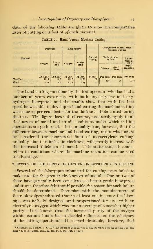
Investigation of Oxyacety ene Blowpipes 4i
data of the following table are given to show the comparative
rates of cutting on 5 feet of >£-inch material.
TABLE 2.—Hand Versus Machine Cutting
Pressure Rate of flow
Rate of
cutting
Comparison of hand withmachine cutting
Method
Oxygen Acety-lene
Oxygen Acety-lene
Ratio of ratesof flow Ratio of
rates of
cutting,
hand-machineOxygen Acety-
lene
Lbs./in.»20.0
20.0
Lbs./in.»3.0
3.0
Ft. 3/hr.
39.5
41.1
Ft.?/hr.
8.04
7.73
Ft./hr.
61
45
Per cent
}104
Per cent
96
Per cerrt
Hand73.8
The hand cutting was done by the test operator, who has had a
number of years experience with both oxyacetylene and oxy-
hydrogen blowpipes, and the results show that with the best
speed he was able to develop in hand cutting the machine cutting
was some 25 per cent faster for the thickness of plate used during
the test. This figure does not, of course, necessarily apply to all
thicknesses of metal and to all conditions under which cutting
operations are performed. It is probably true, however, that the
difference between machine and hand cutting, up to what might
be considered the commercial limit of oxyacetylene cutting,
probably about 10 inches in thickness, will greatly increase with
the increased thickness of metal. This statement, of course,
refers to conditions where the machine operation can be used
to advantage.
7. EFFECT OF THE PURITY OF OXYGEN ON EFFICIENCY IN CUTTING
Several of the blowpipes submitted for cutting tests failed to
make cuts for the greater thicknesses of metal. One or two of
these have generally been considered as better grade blowpipes,
and it was therefore felt that if possible the reason for such failure
should be determined. Discussion with the manufacturers of
these blowpipes indicated that in at least one instance the blow-
pipe was initially designed and proportioned for use with an
electrolytic oxygen which was on an average of somewhat higher
purity. It is known that the increased purity of the oxygen
within certain limits has a decided influence on the efficiency
of the cutting operation. 3It seemed desirable, therefore, that
* Alexander E. Tucker, F. I. C, " The influence of impurities in oxygen when used for cutting iron andsteel," J. of Soc. Chem. Ind., 80, No. 13, p. 779; July 15, 1911.
42 Technologic Papers of the Bureau of Standards
exact data based upon the apparatus developed for this investi-
gation should be secured with the idea of establishing the probable
differences which might be expected for oxygen of various degrees
of purity. Difficulties were encountered, however, in securing a
supply of tanked oxygen of the various degrees of purity desired.
In view of the probable delay involved in completing the investi-
gation, it was decided that no further work along this line wouldbe undertaken.
8. DETERMINATION OF GAS VOLUMES CONSUMED BY LOSS OF PRESSUREINDICATED BY TANK PRESSURE GAGES
In general welding and cutting operations it is quite a commonpractice to determine approximately the amount of gas consumedon any particular piece of work by means of the loss of tank
pressure indicated by gage readings. For oxygen the values thus
obtained have proved fairly satisfactory, but acetylene gas volumes
thus determined have never been found reliable. In general prac-
tice, therefore, the volume of acetylene used has always been
taken as equivalent to the oxygen volume thus determined. This
practice, of course, can be justified on theoretical grounds.
It was felt that a little study given to this matter might prove
of interest, and an attempt was therefore made to determine a
constant for both gases which could be considered the equivalent
in cubic feet for a loss of i pound tank pressure.
The determination of a general useful constant for acetylene
seemed to be impossible, as might be expected. As pointed out in
the discussion on the density of acetylene, the conditions under
which the gas is withdrawn greatly affect the amount of acetone
withdrawn with it. Further, it was found that, at the lower
pressures especially, there was a time interval effect which madevolume determinations from pressure gage readings quite unrelia-
ble. This latter element seems to be due to the difficulty with
which low pressure gas seeps through the porous filler. As an
example of this it was observed on one occasion that the acetylene
bank pressure gage at the completion of one day's tests read
70 lbs. /in.2 with a room temperature of 85 ° F. The following
morning with a room temperature of 84 ° F the same test gage
read 85 lbs./in.2
, the gain apparently being due to the fact that,
at the earlier reading the gas pressures in the bank had not
reached a state of equilibrium. In fact the test gage will nearly
always show, a few minutes after the completion of a test, a reading
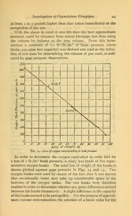
Investigation of Oxyacetylene Blowpipes 43
of from i to 3 pounds higher than that taken immediately at the
completion of the test.
With the above in mind it was felt that the best approximate
constant could be obtained from actual blowpipe test data using
the volume by balance as the true volume. From this latter
method a constant of 2.2 ft.3/lb./in.
2 of bank pressure (three
tanks, 225 cubic feet capacity) was derived and used in the reduc-
tion of test data for determining the volume of gas used, as indi-
cated by gage pressure observations.
zzoa
40 JO 60 70
Loss of weight fa60 90 I/O iZO
Fig. 14.
—
Loss of oxygen corresponding to tank pressure
In order to determine the oxygen equivalent in cubic feet for
a loss of 1 lb. /in.2 bank pressure, a study was made of two repre-
sentative oxygen banks. The total loss of weight of the banks is
shown plotted against gage pressure in Figs. 14 and 15. Twooxygen banks were used by reason of the fact that it was knownthat occasionally water may take up considerable space in the
bottoms of the oxygen tanks. The two banks were therefore
studied in order to determine whether any great differences existed
between the banks themselves. A slight difference in the capacity
of the banks seemed to be perceptible. For the purpose of approxi-
mate volume determinations the selection of a mean value for the

44 Technologic Papers of the Bureau of Standards
number of cubic feet per pound per square-inch gage pressure
seemed warranted. This value was taken as 0.68 ft.3/lb./in.
2 of
bank pressure or gage pressure for a 7-tank oxygen bank with
tanks of 200 cubic feet capacity.
V. DESCRIPTION OF THE TESTS
The investigation was started with the idea of submitting each
manufacturer's equipment to a much more extensive series of
tests. It was found, however,
that the proposed series wasexcessive from the time stand-
point. One of the most seri-
ous drawbacks as a time con-
suming element was the fact
that a very large percentage
of the blowpipes submitted
for test would not operate
with the pressures specified bythe manufacturers. This con-
dition was probably due to
the fact that it is quite a
customary practice to recom-
mend setting the regulator
pressures 3 to 5 pounds higher
than the specified blowpipe
pressures. By throttling the
gases at the blowpipe handle
valves the operator insures
having sufficient pressureavailable at all times to main-
tain the required velocity of
exit of the gases at the tip
end. He is therefore enabled
to compensate for pressure
fluctuations due to irregular
action of the regulator, thus
tending to minimize the development of flash backs. The speci-
fications for the tests distinctly stated that at least one of the
blowpipe handle valves must be maintained at full opening
during a test. It was only by such a procedure that the gas
consumption of a blowpipe could be definitely ascertained. For a
great many of the blowpipes the pressures were too high to
Fig. 15.
ZO 30 40 SO 60
loss of We/M, /6.
-Loss of acetylene corresponding to
pressure

Investigation of Oxyacetylene Blowpipes 45
enable the maintenance of a stable flame with one of the handle
valves at full opening.
Another quite serious source of trouble from the standpoint of
time consumption was that due to leakage, necessitating the dis-
mantling and repacking of the valves.
In order, therefore, that the entire investigation might not
require an undue length of time it was decided that attention
should be devoted only to the so-called primary tests, consisting
of the welding, cutting, gas ratio, and flash-back tests. Such
proposed tests as the variation of pressure within the blowpipe
head, etc., were therefore abandoned. On the basis of the above
the following schedule of tests was adopted and all blowpipes
tested during this investigation were submitted to it.
1. WELDING TESTS
All blowpipes reported upon were submitted to five welding
tests, designated respectively as tests i-a, i-b, i-c, i-d, and 2.
All the tests numbered 1 were made with J^-inch plate. Test 2
was a weld with J^-inch plate.
Tests 1-a and i-b were made with the tip sizes and pressures
specified by the manufacturer if this were possible. For both of
these tests a 2-foot length of weld was made. These tests were
identical in all respects, with the exception that an attempt was
made to evaluate the personal equation by using different oper-
ators. For tests i-c and i-d a 12-inch length of weld was made.
Both of these welds were made by the operator who made the weld
of test 1-a, the idea being to maintain as nearly constant a per-
sonal equation for this series of tests as possible. Test i-c was
run with the same size tip as i-a, but with pressures (both oxygen
and acetylene) 50 per cent in excess of the pressures used for
test i-a. Test i-d was carried out similarly to i-c except that
the pressures were 25 per cent below those used in test i-a.
As mentioned above, the pressures specified by the manufac-
turer very often gave an exit velocity to the gas too high to
permit of maintaining a stable flame at the blowpipe tip. In
such cases the manufacturer's representative was requested to
furnish a modified pressure that would enable the maintenance
of a stable welding flame. Very often the modified pressure thus
determined upon would not permit of the application of test i-c;
that is, a test with a 50 per cent increase in pressure in both gas
lines. It was customary, therefore, in such cases to modify the
test procedure and incorporate as a test in place of test i-c, test

46 Technologic Papers of the Bureau of Standards
i-e, which was run under identical conditions with the above
test, with the exception that the pressure on both gas lines wasreduced to 50 per cent of the pressure used to make test i-a.
Tests i-c, i-d, and i-e were incorporated to show the effects
of increased or decreased pressures on the operation and economyof the blowpipe. Such excess or decreased pressures are found
to be quite common in many welding operations, due to careless-
ness on the part of the operator in setting regulator pressures or
to imperfect regulator action. It was felt that a properly de-
signed blowpipe should be capable of adjustment over a consid-
erable range for any specified tip size. It was hoped in the
investigation to secure data that would either verify this assump-
tion or prove that it was absolutely essential to maintain exact
pressures for satisfactory blowpipe operation.
Test 2 was a 12 -inch length of weld of J^-inchmild steel plate.
This weld was made in all cases by the operator, who made the
weld of test i-b. This test was selected as indicating the probable
results to be obtained with a blowpipe in heavy welding, and
with test 1 it was felt that it would give a fair idea of the adapt-
ability of the blowpipe for welding purposes. The tips for weld-
ing % and % inch plate were selected as being the tips used re-
spectively for the average size weld and for the maximum size
weld and therefore the best general average for determining the
blowpipe's efficiency and safety.
2. CUTTING TESTS
The cutting blowpipes reported upon have been submitted to
eight cutting tests, four of which may be considered primary.
In each of the cutting tests a length of cut was made sufficient
to determine accurately the gas consumption of the blowpipe.
Test 6-a consisted of cutting continuously 50 linear feet of y2 -m.ohmild steel, test 7 was a continuous cut of 10 feet of 2-inch mild
steel, test 8 was a continuous cut of 6 feet of 6-inch mediumsteel, test 9 was a cut by hand for maximum thickness.
As indicated above in the description of the cutting test equip-
ment, each test cut was preceded by a preliminary trial cut to
determine the maximum speed at which the blowpipe would cut
with the tip size and pressures specified by the manufacturer for
the particular thickness of metal. It was found during these
trial cuts that the same condition existed relative to the cutting
blowpipes that was found to exist with the welding blowpipes,
that is, that a great many of the pressures specified by the manu-

Investigation of Oxyacetylene Blowpipes 47
facturers for cutting particular thicknesses of metal were not
suitable for the work intended. One of the main troubles seemed
to be that the majority of the blowpipes were operated with pre-
heating flames of too high intensity.
Throughout the entire series of cutting tests all blowpipes were
operated similarly, that is, at least one of the gas control valves
for the preheating flames was at full opening, the preheating
flames were adjusted to neutral with the oxygen cutting valve
at full opening, and all cutting operations were started with this
latter open. Some criticism of this procedure developed from
time to time, but throughout the entire series of tests it was found
that at no time were any detrimental results produced, and that
even on cuts as heavy as 16 inches no trouble was found in start-
ing with the oxygen cutting valve open. This method was adopted
to insure the maximum capacity of the blowpipe throughout the
entire test period, and, further, to enable the maintenance of
accurate pressures throughout the test and insure accurate data
as to the maximum gas consumption during the cutting operation.
Test 9, cutting for maximum thickness, was originally conducted
with the idea of submitting the blowpipe to a test for the maximumthickness specified by the manufacturer as permissible for his blow-
pipe. It was found during the course of the investigation that
the great majority of the blowpipes would not successfully cut
the so-called maximum thickness specified by the manufacturers.
Experience during the investigation seemed to indicate that the
probable maximum commercial limit for economic heavy cutting
operations when the cut is made in one direction only with an ordi-
nary stock blowpipe, lay in the neighborhood of 10 inches. It
was therefore decided that all blowpipes should be submitted to
the same maximum or heavy cut. A cut in material 10 inches in
thickness, of 12 to 18 inches in length was therefore made as a
supplementary heavy cut test for each blowpipe.
The tests for maximum thickness of cut were made by hand.
On account of the possibility of damage to the gage-board equip-
ment caused by heavy slag showers from pockets, etc., produced
during cutting, this test was conducted out of doors. The original
tests for maximum thickness were therefore made on different
days with the temperature of the metal varying from 35 to 68° F.
After the decision had been made to submit all blowpipes to
cutting tests of identical thickness, it was decided to minimize
the effects of varying temperature as much as possible on the heavy
cut by making all cuts during the course of one or two days. By

48 Technologic Papers of the Bureau of Standards
this procedure only a slight temperature change occurred. Par-
ticular care was also exercised to insure that a blowpipe was not
submitted to test on pieces of the steel ingot used for this workthat were still warm from a test of another blowpipe. The test
for heavy cutting—that is the special io-inch cut just described
—
is listed as test 9 in the data that follow.
Besides the primary tests it was thought desirable also to
determine the efficiency of the blowpipe as it was affected byvariations in the oxygen pressure supplied. For this purpose a
series of supplementary tests listed as tests 6-b, 6-c, 6-d, and 6-s
were conducted. These were made on *^-inch mild steel plate and
a cut of 10 linear feet made for each test. In this entire series of
tests the tip sizes and the conditions of cutting were identical
with test 6-a listed above, with the exception that the oxygen
pressures alone were modified. These were increased 50 and 25
per cent and decreased 25 and 50 per cent respectively for tests
6-b, 6-c, 6-d, and 6-e. No change was made in the acetylene
pressure. A slight aspirating effect for the increased oxygen
pressure was expected and was shown in the volume of the
acetylene used.3. GAS-RATIO TESTS
One of the prime essentials of a good welding blowpipe is its so-
called gas ratio—that is, the ratio of the volume of oxygen to the
volume of acetylene consumed. Theoretically a properly ad-
justed blowpipe requires equal volumes of both gases, giving a
one-to-one ratio. In order to establish the ratios of the blowpipes
under test, each one reported upon was submitted to a series of
gas-ratio tests, numbered 5-a-i and 5-b.
For these tests the blowpipe was allowed to burn freely in air
with the same tip sizes and pressures as were used in the welding
tests mentioned above. The blowpipe was supported upon a
bracket stand with the tip in horizontal position. All gas-ratio
tests were made upon the tips used for welding, and no attempt
was made to clean them before making the tests other than to blow
them out with a rather high oxygen pressure. These tests might
be expected to indicate the gas consumption of the blowpipe with
the flame burning undisturbed from accidental obstructions, such
as slag adhesions to the ends of the tips, etc., which occur in actual
welding practice. The discussion of the welding blowpipe fur-
nishes additional interesting information concerning the gas-ratio
tests.

Investigation of Oxyacetylene Blowpipes 49
4. FLASH-BACK TESTS
In order to determine the probable safety of operation of a
welding blowpipe and, further, to secure information concerning
the permanency of construction of the tip and blowpipe head, the
blowpipes reported upon were submitted to two types of flash-
back tests.
One series of tests, designated 3-a and 3-b, flash-back tests on
the tips used for welding %-moh metal and 3^-inch metal, respec-
tively, consisted of the standard series of tests used by the Under-
writers' Laboratories for determining the freedom from flash back
and the safety of the welding blowpipe. Each of these tests con-
sisted of four distinct operations. The first three of these opera-
tions were carried out as follows: After being properly adjusted to
neutral flame the blowpipe was tested for flash back by drawing the
tip at varying angles across the surface of and finally pressing the
tip end firmly against certain materials. For this test a cold steel
plate, a fire brick, and a piece of wood were used. Finally, the tip
was used to make a pool of molten metal in a cast-iron block, flux
being used to assist in maintaining the fluid condition of the metal
and the tip suddenly plunged into the pool of metal.
Another series of tests intended to determine the permanency
of construction and designated as the "severe flash-back test,"
test 4, was carried out by supporting the blowpipe on a vertical
sliding carriage in such a manner that at the proper instant the
ignited and carefully adjusted blowpipe could be lowered so that the
end of the tip was directly over the center of a hole 2 inches in diam-
eter and 2 inches deep, drilled in a heavy cast-iron block (Fig. 12).
Experiments in the development of the severe flash-back test
indicated that this procedure, by causing a reflection of the flame
up about the head of the welding blowpipe and concentrating the
entire flame about the tip and blowpipe head, not only caused the
development and propagation of a true flash back with all blow-
pipes but further caused the tip to become red hot and tended
to melt the brazed joint at the juncture of the gas tubes and the
blowpipe head. While this test might be considered rather severe,
inasmuch as it will not occur in general, ordinary practice, the
condition is nevertheless likely to occur to rather a large extent
in welding in corners, etc. Further, by being easily duplicated
as to conditions it permitted the obtaining of definite information
as to the effects of excess heat upon the blowpipe tip and head.
58814°—21 4

50 Technologic Papers of the Bureau of Standards
In all the tests for flash back the flash-back observation boxes
mentioned above in the description of the testing apparatus were
used and careful notes taken to record the behavior of the condi-
tions developed during the tests. In the case of the severe flash-
back test, test 4, particular attention was also paid to the effect
of excess heat upon the blowpipe heads and as to whether the gases
could be shut off and the blowpipe relighted after the flash back hadoccurred without the necessity of cooling the blowpipe with water.
In all the flash-back tests the blowpipe was operated under
the identical conditions at which it was supposed to be used during
the welding operations, and after the initial adjustment of the
flame no further adjustments were permitted. Following also
the procedure in the welding tests, at least one of the blowpipe
handle valves controlling the gas had to be at full opening.
In first carrying out the severe flash-back tests the investigation
indicated from time to time minor points for consideration which
had not been thought of in previous tests. It was therefore decided
to rerun the entire series of severe flash-back tests so that each
blowpipe would be submitted to identical tests and observed in
like manner. The results of the latter tests only are recorded in
this report.5. LOG SHEET RECORDS OF TESTS
It has not been thought advisable, in the light of the discussions
following, to incorporate as part of the report the complete set
of test log sheets, especially as there are over 1900 of them. In
order that an idea may be had of the amount and extent of the
data taken for each test, a few typical log sheets representing the
data taken for one manufacturer's apparatus are reproduced in
Figs. 16 to 31.
VI. DISCUSSION OF TEST RESULTS1. GENERAL BASIS OF CONSIDERATION
For convenience in analysis the results of these tests have been
summarized in a series of tables (Tables 3 to 7) and plotted
graphs, Figs. 32 to 41 and 51 to 60. In the plotted summaries
are shown the results of tests on blowpipes from 14 different
manufacturers, each represented by a designating number. Thegroup submitted to test comprises most of the better-known and
more widely advertised makes of apparatus on the American
market and includes besides those voluntarily submitted the
three makes of apparatus that were withdrawn by their manu-facturers because of disagreement over methods of test procedure.
Samples of these latter three were purchased for test purposes.

Investigation of Oxyacetylene Blowpipes 5i
D~* 3-/7- 20
S/y/e of Tbrc/r Zfttnufac/uret/ £>y
SkefM*/
Summary of
HeWny Test Mb. f~&
A/a. 7&6&
Zl7h/c/(ne3A ofP/a/e.
7!me fo f/oAe He/a* <?4
linear feef Mb/Sea* y>er //our 2.. 72C/taracfer/sf/e& of Mfe/dea* Materia/
ienff/> of Mr/a* 2*2*JF see.
L 7e/rsi/e Sfreng/A 32OOP l£>.y?er So. //?.
2. Pvc/'/'fy> Bert/ to Jhc/ae/ea' Anf/e of 4-3 Oeyrees
J. Sfac/ure of MiAf &/f/?fy cryAte/tine* at/hex*Gf?
Pressure , Ga& Cortsompficr? ao</ r?a/e of f/oiv
Oryye/7 Acetyte/re
/fea/7 Line Pressure . Ib.yrer Sa//?.
f/eay? /5rc6 fissure - I6*er Sa/r?.
h/eia^f ofjGas 6/&eef . /bora's
6, 2S a <?<P
>5-.32 7.3S
Ifo/ume is? Cufff~ flbtrr Oe/rrtr?//7ea' from
/- MfyAf of£aA l/^</
2- f/ow ffe/er 0afa
3 _ Tesf Gape rTeaaf/tas
/lean r?afe of ffo»/ fy /fa*/ A/efer
Cubic fee/ y?er //our
Vo/ume fta/io 0*yy&> fo Ace/y/ene
/- By h/e/ynf fertsffy ffef6o</
Z-By f/o»* fi/efer
By Ba/onjce
Fig. 16.
—
Log sheet No. 1, summary—welding
4f2^r 33:3/
/•?//•/&

52 Technologic Papers of the Bureau of Standards
Cam/KrAft/ by /7-tfS'
Cfiec*«/ fiy 4-*S. Steet A/a?
Sum/nary
7Z*tA/oS4
Jfecant cf 7orcfi Con6vm&/-/c>/?
TimeAfifU/tes
/fare c- Co rr/>Oxyyer?r (cefp/e/re 0yy\Acet
Tfrne
ffinute&
/fate ofCu.ftpetCxygrery Acefy/ene
lbAme/&fc
fay. '.Acef.
/ £M SZ-ff /•/*
3 SS.9 j~<?-0
6 s*r ¥£9$ S%6 </&?
/* s&f Y#7/f S&2 W¥/S £&* tf&6
*/ S#o f£6 //744 j$* SJtf.
*7 S70 VA33* *7S fsf
"
33 £Zf. &'36 £7.4 f*fi3* *?£ ¥fi7
¥2 s7-¥ ?*? /-/#
/femarfisr- ,
Fig. 17.
—
Log slieet No. 2, summary—welding

Investigation of Oxyacetylene Blowpipes 53
Oate 3-/7-20 Sheet Mo. 3
Wegh/ng Tai>M leg Sheet
Ne/c/isigTist A*> /-&
Sty/e of 7orct> £ fVo. 7136&1
tfa/xxfacturexf by
Seriat M>pfWb/a' 6-0-/ A-&-2 Operator ^AJThictrneaxofo/ate ^2 //7 len^tb 0/ tVe/a' 2ft 7T* A/o. 9Manufacturers spec'fted'pressures .-
Oxygen 6. S ft.par sj.in Acety/ene r3 tb.per sain
Pressure at */t>icagcrs was o*etiverea* to fare/? t/nf:
tTxy^rn & 2& /b.persfin Aeetytene & ib.per sain.
AA/mber ofGas 7a/?As in banA .Oxygen 7 Acetytene 3Aterage anafysisofgos in ban*.Oxygen 90.
3
Acetone ('£> 7. &}
Wegnfof Ptafes tVe'gt?toflve*/Sngt?o</
OeJbre Wefa'ing S&.S f*. ?<?/?S grants
After Vetoing 6/7.S /b. $&& &***
Gases uset/as alrter/mnea*fiy /ass in weight of tenAs :
Oxygen / 7.30. 2 grams Acefrtene //&-?' ^grams7*ne tomate wetd -4^ /77/S7 3f?&6.
tfe/nar/rs
;
FlG. i8.—Log sheet No. 3, -weighing table summary—welding

54 Technologic Papers of the Bureau of Standards
0crte 3-/7-20
O&server
Sneet/f**?
log Sfieet
Test No./-*
Sty/eawfA/o. of7brch Z- 7&£&Operator ^rAS
&££.
U&L
/rueZero-
tfeadk
/26?&f$'3Z<&d^&z &<?/
4J&.
//ZJ2JO.ta£LJ<4&/<26£.
Q/s/f/-ofZeroSens/f/wfy
VfSf/Ue of&isp/-
Lossperm/nufeT/me
fe/ue ofloss%>fa/Correction^ g
Zero
mm.2&&
£Z£
1£&lute.
ZL2.
7/0^£/*02LZu&IS.
-&3
Acefyfe/te
Zero
2£4£
Z4A\tt#P
££M.
VU4Z2&2&22I2&;
24&\
^•wfaj igk^:
2&£?L
ftep/acemenf
U/e/ght
orrecf/on
Z&k*
£39t>2Z4tfia9227<&
ZZ££L££L££L&L2./&
•*.*
/&d>
f-ae Weg/rf
Oxygen Acefy/ene
/7Z&0 //??.<?
/73&2 U&&S
FlG. 19.
—
hog sheet No. 4, weighing table—welding

Investigation of Oxyacetylene Blowpipes 55
Xecorter £>em/n9 SneetNo S
^forWe/ring TestrVo./-a
Jbrofr manufactured£>y
Ser/atA/oofWe/d A-*-/ A-ry-z Caeratbr FAS77iicAness ofP/af*. 2 /„. lengtr ofWetd 2 ff\ VoA/o* 9Afanu/ircSurerh sfect'ftedyvrea$ure% :
Oxygen 6.^ tfrfer*so.m Ace/y/ene & ffi.fOef SfJh
Pressure at wtt/c/7 Acts wasdet/veredfo tarct?t/ne.
Oxygen 6.2.*" fbo£rsa./n Acety/ene & tb.jo^sa./r>.
Tank Pressures Oxygen Acetylene
At star/ &4<r /qx
Arcnd 7 9Q /76
7emperature(Room} Barometer rtum/d/'ty
** &*» 7Q.S 7SS "*3
Atend 72. 7SJ .SO
Pos/t/bn ofManometers -tf/Qh La* Vert/ca/ f) AOrtf/ccA/e Oxygen J~ Acetytene TVTezj&eroturereadSng ofor/f/cc • Oxygen Acety/ene
At sfort . 78 m v . 7& m.*
At end _ . 7& m v . 73 m>*>
7/me requiredtomate *ve/d 4^/77/n. .^sec.
AfemarAs'-
Fig. 20.
—
Log slieet No. 5, gage board summary—welding

56 Technologic Papers of the Bureau of Standards
&r/e 3-/7-20ftecort/er Oem/no M ,CPjerver JPeminy-Swiermen.
&>eet AA>.&
• anreerrnan.
Pressure ana*Wot* Meter L&6 SAee/fir
*U/eMa&fcst M>./~£t
TbrcA mana/acfitrea4 byi____i_
Sena/ Afo. of hre/a*
6
-0-/*-a-sOjOtrafcr ^jTS Ay> A/a, -.9
Pressure aftvhicA 4a* tras c/e/'rerea' /i> forcAZ/ne:
G&gft* &2£* /b f>er&j //? Ace/y/erte. & //?. pe^ sa./ri.
a 1Pres a
Acery
r~/a*r mtdfffererOxygea
iter>//a/s
Ace/y. I I/Yes at /?ea.
Acffy.
Mow Mc///fere,&xygen
€tert?//a/sAcefy.
/ JB .630 8. OS /32.0 7X93 6 23 T.99 /26J 73.6
6 6<Zf B.O0 /2S.6 73.2
$ fa/.f 8.00 /23~2 73./
a 6.2s 8.00 /2S.8 72.0
tf 6 23 S. a? /23.Z 7/. 7
/& 6.ZS 8>.s?/ Z22.7 72.3
P 62f 7.90 JZ2& 72 3
& 6*2f 8.00 Z22.4 73.2
?7 &?3 8.02 /2/.S 7 /./>
IP f>.2£ 7.90 /2/.S 70s33 6.2S 8.0S /£/.<? 70.0
36 6.2f 8.00 AZ&3. 7ae
19 6.2<? 7.99 720.7 69.r3
4? 7t 6.2S B.OO Z20.0 S3.
7
Me 7d 6.25 0.OO '£3.4 -72.
a
Fig. 21 —Log sheet No. 6tgage board-^welding

Investigation of Oxyacetylene Blowpipes 57
P^d^E SAfefAto. 7
Compi/foffows
7esr f/o./-<T
Afoa/? line. Pressure-
Line Drop -
/feast 7areA Pressure,
rteo/r A/moaptere -
fo/t/e of f7*&A 30cA-/feacf-
Abso/ufe f/o*v /fe/er f^v&si/re^
/fea/r Pofen/Sosnefer /feao^^f-
/feon 7eny?era/c/re /ac/br~
W*/jA?' of <?*s Usetf-
PerrsJf/ of &?s _
tfo/(//r?e. of Go& £y SaAmce _
fife0/7 fTafe <pf f/onr L?y P/or/ tfefer.
£>ura/(<?/7 of 7esf .734 /fcura
L&perSafa
l£>perSo./n.
lb.perSa./n.
L£>perSf.H
Li>.perSa^//7.
Lb.per Sa.//?
//////ito/fe
rot/no's
LfiperCvPt
Ci/b/c fief
Cuff, per Ah
Oryyesr Acefy/esre
uZ2 <6tr
tf,2Z 7,3fJ4.6JZ.
/&
l£>$7JfZ.
Z2J£7ft
AGO? 7#&63t f=$/2 ^JlZJ2.Q&3Q Y17J2
3& 3U-
.6&
277.2
2JL
Vo/ame of (Pas Ay f/o»/ /fcfer- CuAJo feef &LZ£.Loss of fc/rA Pressure * Ihper Sa.f/r. —£~is"
Cvb/cfi*f~ l?er Prone/ of 7a/yA Ahesswns .
lfo/u/ne of <*er& 6y Tie/- Gaye- CuA/'c feef
Ve/urne ffaffo 6y 3a/a/?ce - L*LL.
J/o/usne P*//o Ay f/otv Afcfer. \ A /&Lerry/A ofJ/e/S *» Caff At feef- 2L.0
lJ/?earPeefper Abt/r tVe/Setf or&rt- j| 72.
tfoon ZrnA Pressure - LAper Sf//r.^ «-*-• •' '*•-- f&ZS
FlG. 22.
—
Log sheet No. 7, computations—welding test No. i-a

58 Technologic Papers of the Bureau of Standards
S/>eefM..
C0mpu/~af/0/?s
7eaf A/0-/-6
ffea/7 l/he Pressure.
line 0ro/» -
ffean 7orcA Pressure-
t/ea/7 df/nosf/hene .
ya/ue af f/asb Sac* ffeae/.
Abjo/afe f7on, f/efer Pressure-
fifear* Pafe/>//ame'fer r?eaa'//?y-
Wear? 7e/7tperafure- r^acfar-
h/e/fbf of Gas {/sea4'.
Derrsffy of Gas -
Va/u/r?e of Gas by 3afas?ce-
ffean ffafe af P/anr by r7o*r /fefer.
£>uraf/or? of fe^f 686 //<z/rs
lb.e>erSa./o.
/b.ferSp.b?.
Ib.jyerSa.M.
Ibper Sa./rf.
Ib.ferSp/o.
lb.fer SyJ/f.
ty//ivo/fs
Pot/no's
/.b>£>sr Caff
Cub/c reef
Cuff, fer Ah
Gxyaen Acefy/eae
J".J/ ~*"7.<f/.
J£. j&2.
~ZS- uSZ.
*9&2 A0&2.
3,60? Z3719
Cub/c reef
Ib.oer Sa./a.
-f#,2f
±£jB. 2*J2-
37 3/£Z£-
Vo/t/me af Gaj by f/o»/ ffefer-
/.asj- or* 7a/7/r Pressure..
Cab/'cfcet £>er /%*//? a* of 7crt7jr Press,ure
Ib/u/nc o/ Gas by 7esf Gage. Cub/'c feef
Vo/a/rpe fpaf/o by Safance -
Ya/unve Paf/'o 6y P/atv ffefer*^
/enyfb ofA&faf w Caf f/r feef-
/./rtearfeef/ter f/aur J/eA/ea' **&/
tf&a/? 7aM Pressure. /fy>er ,Sp.//?. __««_ -
Fig. 23.
—
hog sheet No. 7, computations—welding test No. i-b
3Z.7//4
LZ^.^2.
J2.9/
/6jL

Investigation of Oxyacetylene Blowpipes 59
tornpafey bu rf' <^y«
Qh*c*.s 4, ML.C Shut M*/
Summaryof
Sfyk> of 7are/r J-L Afc ^~*££_tfa/tufoctargo' f>y
frArAxsss of Cut fe in. leayffi cf Co/ &> ft
7tme ftedu/rea* fo AfaAe //>e Cut /3 ott'/f. &7 sec.
L'near feet Cvf per Hour #£-&
Type ofCut Secure*/
7o0 £ctoe Smnntfh
face of Cc// Snnn/97%
Pray :£25 mc/?
torf Vti ukbS/ay &r,1?te
:^//jAffr r7J*fo//,-r. .s/^y. CJ&fiZL
botfnm Psfgf.
Prea&ure., Cas Censtsmpf/a/? ana' fita/e of f/otv77P,
tfean Ime Pressure - £&.fer Sa.//7.
/fra/7 fcrc/rfrestore . Ibyxr Sp./r?.
Mr/j/r/ofCas 4/setf _ Pa/vats
tt/v/ne //7 Cc/ftpa jHvj Oc/br/77/Ofd'/re/7?
/. My/?/ af Cas feeS2- ffow Sfe/er Oa/a
3 . %sf Caye rTeaa/rys
ftea/7 f?afe eff/atv 6y f/o*/ ffefer
C<j6'c fee/ per /tour
0y Ba/aspce.
Oryyer? Acety/ene
3.02
2</70 JZ.9&
/0S£ 0/7&
/f.30 *V//2>2 '**
f/0.4Je
FlG. 24.
—
Log sheet No. I, summary—cutting

6o Technologic Papers o f the Bureau of Standards
Ccmpufctt by rf'/f<>*Sfieef A/a 2
Summaryof
&sf/Vo.6#
rTeeara* ef Tore/* Co/iavmofAvrr
7/me.
Oxyyerj^rAcety7erte
KoA/rrte/fclk.
0xyiAce/.
7i'me. ftafe ofCir.ffp*0x^y9*i
f~/o*tr /fourAcetjr/erre Oxy :Ac*t
/ S3.6 //-#
3 &/ /A#/7a, v& re* ^vs/&.f
S £TJ?.f /•/7 S/6 ///
fA 7/#e s*a &beesife/2 S3.</ M// S/9 7-ff
/3 S2J #7
r
<r?emar/c&
Fig. 25.
—
Log sheet No. 2, summary—cutting
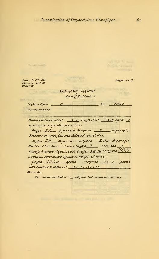
Investigation of Oxyacetylene Blowpipes 61
fiat* S-27-Z0 J/*,/- Ho:3Recorder sTatfe0/>s*rrer
We/gh/ngTb*/e Leg Sheet
Catfing 7*stHa6-a
Sty/e. ofTorch C A/*. /36j>
tfanu/acturedby
TA/ckncts. ofmateria/ Cut "£ />? lend//) ofcut Z &ff Tib tVo. /
t/a/rufacturers soec/f/ed oressures
}en ZS i&.oer so. in. Ace/ytenc 3 /baer** in.
Pressure at which 6as was oie/ivered /otorchh'n e
.
,
Oxygen ZS /£> *>er so in Acc/ytene i3. OZ /h.per spin.
Mumper of$as Panks /n banks : Oxygen 7 Aee/y/ene 3Average Ana/ysis of^asin ban* 'Oxygen 9&.3d Acetj/ene l^f'Zf
Gases as determined py/oss in weight of /a/?As -•
Oxygen 49A.4 ^fams Ace/y/ene fi9A / ^grants
Time required /b moke cut /3rr>/ \n. ^75t2£.
Remarks :
FlG. 26.
—
Log sheet No. 3, weighing table summary—cutting

62 Technologic Papers of the Bureau of Standards
s?ecosz/er Afe//&Observer
SActrAfo. *?
Log&teef7esfA//S> 6&
Sty/e arret Ato. offerer?
/1f&t>y
C-/34&Operator rT.L.ht
0xr6cr? Accfy/e/?e
Zero Zero
/£.<r? 37&tfS.J?6 /z.ee 2&f0 33</2
/&f£ /?.£? 37^ 33j/3
S>./*/ /?.SJ> ?<#.3£ 33.</£
/s.#S> 37.se
TrueZero /&£& 33.^f
\
/g.Co 3J.*7##At /&6S- 37?& 33.S0
/&3% &.e£ 30-30 33.^7
y.fz /#<37 37&? 33.S5T
/6-/2 30S0/2.tf6 33.J7
9/s/?/ofZero -./# -Y7Se/?s///Wfy- •
/V<7* /*/-7/
Va/ue of P/s/?f A</7 -££/Loss/perm/neffe -a73 .00
7/me /3'-57" /3'-0f
Ih/ue ofloss ~./J3
Tota/Correcf/on -/j-7 -&f/
/?ef>/crcemen?We/gtot
Correcf/oo
0xygen Acetylene
tf&&0 00.0-/€ -6$
True WeWt &£& -££L
FlG. 27.
—
Log sheet No. 4, weighing table—cutting
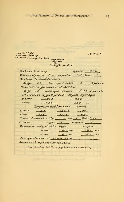
Investigation of Oxyacetylene Blowpipes 63
Gate 3~ 27-20 SAcetA/o. srRecorder Oe/77/nf
LZAShcef
Cutting 7estAfo.6 -<7
7brc/> manufactured ty Cperafor /?/ \a/
Thickness ofpiate cut 2. />>. Lengftt ofcut 2&f* 77o A/a. /
Manufacturer's sf>ec/f/edpre ssure.
0xv4en Z.-T /t?.f>er sf/a. Acety/ene JT /bper Sf/b.
Pre&aurc atwnicAgas H/as deJ/veredA? fercA//'ne.-
Oxygen ZS /b.per so- in. Acetytene. <202 ib.persa.in.
fenA Pressures .Oxygen /t>.persa.i/t. Acefytene ftxper sa/r?.
At start t04.r 2azAtend S000 2&&
7e/r?pen7fure(A?oon$fiaramefer ffumtd/ty
Atstarf, 72, t 7£$<? -0&
fbs/f/bn af/rJanoapefers : tfi£f> — Lav J Verfica/ r>
Or/f/ce A/&. Oxygen ~JT Acefy/ene TV
Temperature reading of orifice : Oxygen Acefy/ene
Atstart .&& mv. *8 2. my.
At en</ . 00 m- * - 02 m.r.
7itrte required to make cut /3 /77/n ^7sec.
Remarks 2. / faff?year. A/e ntJ/sfancc
Fig. 28.
—
Log sheet No. 5, gage board summary—cutting

64 Technologic Papers of the Bureau of Standards
Pafe S-27-Z0 Sfoe/ Afa.€Recorder Off/77/nyOteerver &e/??/>?y- Suvrftrr*/?
_, m* Pressure antf f/otv Afefer £c& Sheet
£i/,f/frtg7e#tAh.6-4
7brcn manufacture.
a
4'
/>y
7%/cAr?essoffJate euf ? /n lengtSyf cuf 2/5-SA 7u>fi/o>. • mm
rTre&sare afjt/A/c/p^as H/a&ide/ivereJfa TbfcA//'no,'
Oxygen ££" faper*f //f. Acety/ene &. <? 2 fa/>erspfa
I1 Pres.&t
Oxygen Acefy.
r~/o*s ma'/f/eres
Oxygen
>eferit/aris
Acefy 1fres en
Oxygen Acefy
How A.
a'tf/ereOfygen
fefernttafsAcefy*
/ $ >\*m .1.00 .5T*V 32 23 2^.06 '2.QO '#?.3 32.3
r^/2 •n* r*< 7t///S,s/%>•
<r Z4?.Q.* 3.^ .r.J.2. 26 6
7 Z&SQ Z..OA ,ir/.4 2r3<*
r^/am <> npaj >•>/<?,=/
r^Vsirr. t? r*(*/7& Vm*A*1
3 2^,00 3.20 :<*& /S.2
ft 2.Z0/1 3.00 3~2.0 /4.0
/,? A 'Zf.a, ,1.00 .^2./ /7.J
iff* 'n Zf.fXi 3,OZ &./ Zxf.Z
_
-
Fig. 29.
—
Log sheet No. 6, gage board—cutting
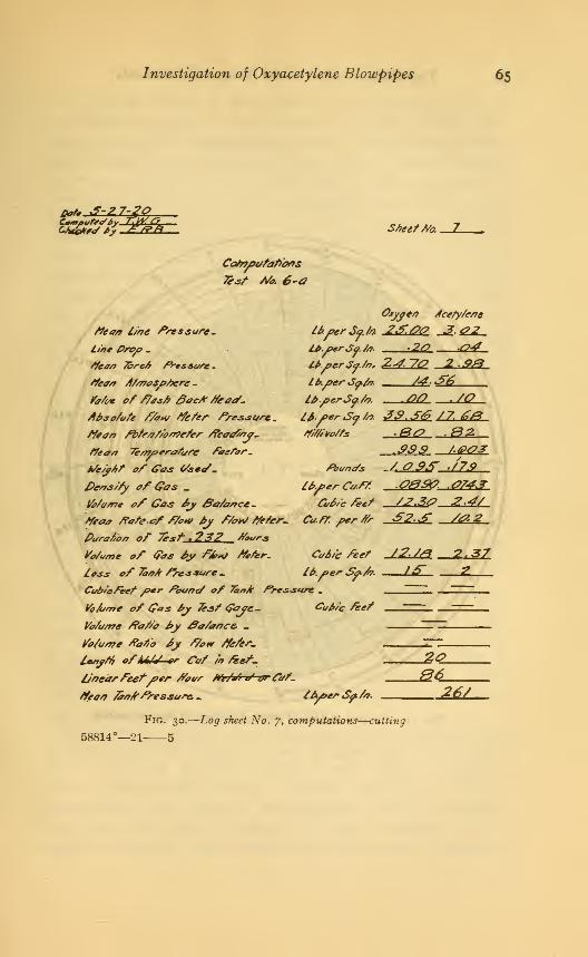
Investigation of Oxyacetylene Blowpipes 65
pare u-^i~*v, aStreet Ato. -JL
Cooifo-fatt'aos
Tesf Afo. 6-a
tfeaa line Pressure-
line Proa -
tteea 75rc6 Pressure
-
Peaa Atmosfttere
-
Vatoe of ftast? SacP tteac-
tiosotute P/on/ tfefer Pressure.
A/tort fbtraf/oa?efer Peoafajr-
tteaa 7eay?erature factor.
M/e/f/tf of Gas (/set/.
l>eos/fy of Gas .
j/otv/ne of Gas fy 3a/aaee-
tteaa Pate of ftonf 6y Pto»/ Peter-
Purat/on of 7esf .232 Pours
Votvne af (pas 6y P6»/ Peter-
loss of Taatr tressure .
Cubtefeef /?er Pounct of 7a»/r Pressure .
Vo/urrre of G*s £>j &sf Gaye- Cop/'c feet
Votume PaPo by &a/a/?c& -
Vo/u/r?e Parfo 6y P/o* tfefer-
lestftt, ofkAU-or Cat /» fkef-
l/nearPeef /?*r Poor Ae/af v' or faf-
tfea/f faajrPressure, . /bfer Sp/n-
Otyyea Acetyteae
-2<? C?4la.PerSo. /a.
lt>.aer<So.tn,
la./?er *Sp/fr.
la.perJo. to.
Ifi.per So. to.
tfttivotts
Pot/no's
la.ferCo.Pf.
CvAsc feet
Ca.ft. /?erttr
Ct/6/c feet
la.oer Sa/a.
24-7C? 2,2ftM,S£..00 ./(?
JS.SS 12L£&
.sss t.002
-A(?$& -t7>9
C74J
SZf /<?>2
/2-M 2<?7
J20.&6-2£L
Fig. 30.
—
Log sheet No. 7, computations—cutting
58814°—21-
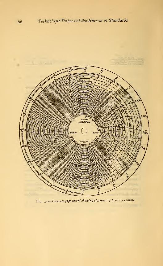
66 Technologic Papers of the Bureau of Standards
p!G 3 i.
—
Pressure gage record showing closeness of pressure control
Investigation of Oxyacetylene Blowpipes 67
For certain studies on the probable economies of operation of
the various blowpipes it was necessary to assume certain fixed
values as units of compensation and cost. While this procedure
may be open to certain criticisms due to the fact that the assigned
values are arbitrary and may not apply under conditions of
operation ordinarily met with in commercial work, still it is only
through such economy studies that certain features of blowpipe
operation can be distinctly shown. For such studies the standard
salary schedule of the United States Naval Gun Factory, Wash-
ington, D. C, for the summer of 1920 was selected as the basis
of compensation for labor costs. On this assumption the labor
costs for welding and cutting have been computed at 80 cents
per man-hour. For specifying the value of the • gas consumed
during any particular operation the prices of $1.50 per hundred
cubic feet for tanked oxygen and $2.75 per hundred cubic feet
for tanked acetylene were assumed. The prices are those at
which such gases were furnished to the Bureau and seem on the
whole to represent general average costs for such commodities,
exclusive of shipment charges. An unsuccessful attempt wasmade to secure what might be considered general average prices
from several of the larger gas manufacturers. Before definitely
settling on the above prices, cost data for several of the test
series were computed for varying ratios of cost of oxygen to
acetylene. These latter figures showed that any reasonable
change in the basis of cost caused only a few unimportant changes
in the relative rating of the blowpipes.
In the computations of cost of operation only gas and labor
costs are included. No additions have been made for main-
tenance of equipment, overhead charges, and secondary supplies.
It is felt that this procedure furnishes a satisfactory basis of
analysis, as external conditions and management will largely
control the value of secondary costs and vitiate any assumptions
made concerning the value of such items.
Certain of the plotted data mentioned above contain curves
showing the relative velocity of exit of gases from the blowpipe
tips. In order to plot these curves for the cutting blowpipes it
was assumed that the volume of oxygen consumed by the pre-
heating flames was equal to the measured volume of acetylene
consumed, and that the volume of oxygen available for the
oxygen cutting jet was therefore the total measured volume of

68 Technologic Papers of the Bureau of Standards
oxygen consumed, minus an amount equal to the measuredvolume of acetylene consumed. For the welding blowpipes the
velocity of exit was based upon total volume of both gases con-
sumed.2. THE CUTTING BLOWPIPE
The summaries of the data obtained from cutting tests madewith the various blowpipes are shown in Figs. 32 to 41 and Table
3. The curves of Figs. 32 to 35 are plotted to show, for the thick-
ness of metal used for the tests, the relations existing between the
volumes of oxygen and acetylene consumed per hour, the linear
feet of metal cut per hour, and the velocity of exit of the oxygen
cutting jet. A study of these curves shows that the rate of cut-
ting apparently increases with the volume of oxygen consumed.
In these curves the blowpipes are arranged in the order of the
oxygen consumption.
For determining the relative economy of operation the graphs
of Figs. 36 to 39 have been plotted to show the cost per linear foot
of cut for each blowpipe. In these curves the blowpipes have
been arranged in the order of the cost of operation.
The study of these data shows some rather interesting condi-
tions relative to the art of metal cutting by the oxyacetylene
process
:
1 . The very great irregularity in the shape of the various graphs
indicates quite clearly that if the individual blowpipes have been
designed according to a theory there does not exist any generally
accepted theory. It is interesting to note in this connection that
in cutting identical material under standardized conditions the
various blowpipes exhibit, as indicated by the data for cutting %inch metal (Fig. 32), variations in speed of cutting from 33 to
109 feet per hour, or 330 per cent; variations in volume of oxygen
consumed from 30 to 130 cubic feet per hour, or 430 per cent;
variations in velocity of exit of cutting jet oxygen from 530 to
1975 feet per second, or 390 per cent; and variations in volume
of acetylene consumed from 7 to 21 cubic feet per hour, or 300
per cent.

Investigation of Oxyacetylene Blowpipes 69
g i % < 4 1 '\7%
3 /3 $TorchNumbers- fn CrderofOxygenConsumpf/tr?
FlG. 32.
—
Relation of rate offlow and velocity of exit of oxygen to rate of cutting }/2-inch
metal
Torch Numbers -ArrangedAccording fo Oxygen Consumption
Fig. 33.
—
Relation of rate of flow and velocity of exit of oxygen to rate of cutting 2-inch
metal

70 Technologic Papers of the Bureau of Standards
I 3 6 .14 10 7 H 8 13 Z 5 IZ
Torch Numt>e&~ArrangedAccord/nqrfo Oxygen Conjumpf/or?
Fig. 34.
—
Relation of rate offlow and velocity of exit of oxygen to rate of cutting 6-inch
metal
IZ 8 3 / 10 J3 7 //
Torch rti/mbe&r-Arr&ngea'According fo Oxygen tConsumpfyn
Fig. 35.
—
Relation of rate offlow and velocity of exit of oxygen to rate of cutting lo-inch
meta l{seefootnote d, Table 3)

Investigation of Oxyacetylene Blowpipes 71
<
£ 04
1 0,
1
>
<l§ m
9 10 8 /Z 7 / Z S 13 tf //
Torch Ni/mbers - Arranged/n Orderoffif/c/^ncy
FlG. 36.
—
Cost of cutting y^-inch metal
5 10
A
^0tdY1 09
^ 06
.
7 d £ 3 / 10 5 13 14 II iZ dTorch tfvmbers-Arranged/nOrderofEfficiency
Fig. 37.—Cos* of cutting 2-inch metal
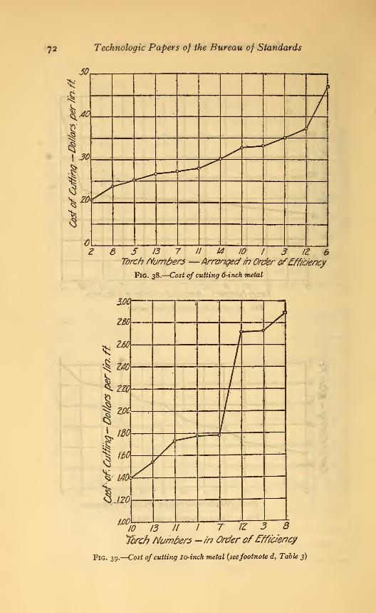
72 Technologic Papers of the Bureau of Standards
6 5 13 7 II 14 10 I 3 12 6Torch fVumfrers— Arranged /r? Order ofEfficiency
Fig. 38.
—
Cost of cutting 6-inch metal
10 13 It I 7 IZ 3 8Torch Numbers ~ in Order of Efficiency
Fig. 39.
—
Cost of cutting 10-inch metal {seefootnote d, Table 3)
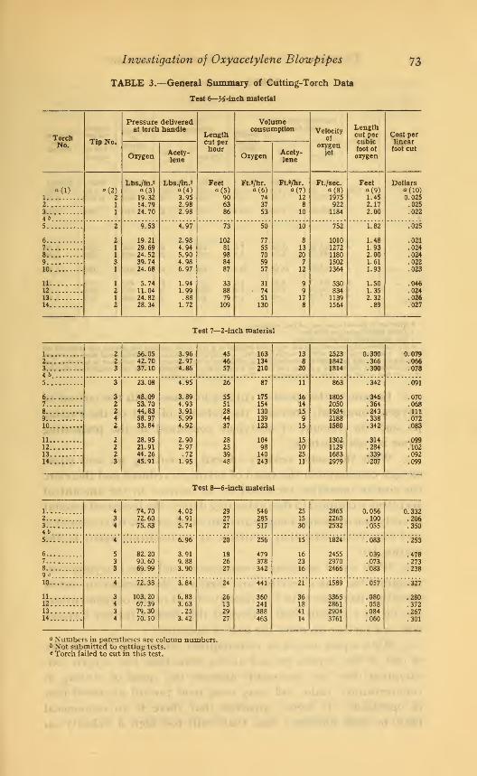
Investigation of Oxyacetylene Blowpipes 73
TABLE 3.—General Summary of Cutting-Torch Data
Test 6—J4-inch material
TorchTip No.
Pressure deliveredat torch handle
Lengthcut perhour
Volumeconsumption Velocity
of
oxygenjet
Lengthcut percubicfoot of
oxygen
Cost perlinearfoot cut
No.
Oxygen Acety-lene
Oxygen Acety-lene
•<D1
"(2)2
Lbs./in.*° (3)19.3214. 7924.70
Lbs./in.*
«(4)3.952.982.98
Feet»(»
906386
Ft.3/hr.
° (6)74
37
53
Ft.»/hr.
« (7)12
8
10
Ft./sec.
« (8)19759221184
Feeta (9)1.452.172.00
Dollarsa (10)0.025
2 .0253 .0224b5
2
9.53
19.2129.6924.5239.7424.68
5.7411.0424.8228.34
4.97
2.984.945.904.986.97
1.941.99.88
1.72
73
102
81988487
338879
109
50
77
55705957
317451
130
10
8
13
20712
99
17
8
752
10101272118015021364
53083411391564
1.82
1.481.932.001.61
1.93
1.501.352.32.89
.025
6 .0217 .0248 .0249 .02210 .023
11 .04612 .02413 .02614 .027
Test 7—2-inch material
1 2
2
3
56.0542.7037.10
3.962.974.86
454657
163134210
13
820
252318421814
0.300.366.300
0.0792 .0663 .078465 3
32242
22
23
23.08
48.0953.7044.8358.9733.84
28.9521.9144.2645.91
4.95
3.894.933.915.994.92
2.902.97.72
1.95
26
5551
284437
28
253948
87
175154130139123
10498140243
11
161415915
1510
2511
863
18052050193421881580
1302112916832979
.342
.346
.364
.243
.338
.342
.314
.284
.339
.207
.091
6 .0707 .0688 .1119.. .07210 .083
11 .09912 .10213 .09214 .099
Test 8—6-inch material
1 .. 434
74.7072.6075.83
4.024.915.74
29
2727
546285517
2515
30
286522602532
0.056.100.055
0.3322 .2063 .3504b5 4
533
6.96
3.919.883.90
20
182627
256
479378342
15
16
2316
1824
245529702466
.083
.039
.073
.083
.253
6 82.2090.6069.99
.4787
8.273238
9 c
10 4
343
4
72.38
103. 20
67.3979.3070.10
3.84
6.833.63.25
3.42
24
2613
2927
441
360241388463
21
361841
14
1589
3365286129043761
.057
.080
.058
.084
.060
.327
11 .28012 .372
.267
.301
13
14
a Numbers in parentheses are column numbers.Not submitted to cutting tests.
* Torch failed to cut in this test.

74 Technologic Papers of the Bureau of Standards
TABLE 3—ContinuedTest 9—10-inch material
TorchTip No.
Pressure deliveredat torch handle
Lengthcut perhour
Volumeconsumption Velocity
of
oxygenjet
Lengthcut percubicfoot of
oxygen
Cost perlinearfoot cut
No.
Oxygen Acety-lene
Oxygen Acety-lene
1
a (2)
Lbs./in.s
«(3)129. 80
Lbs./in.2o(4)
5.73
Feettt (5)10.0
Ft.s/hr.a (6)1050
FU/hr.a (7)
44
Ft./sec.a (8)
4012
Feeta (9)
0.0100
Dollarso(10)
1.7762b3 5 123.90 7.68 6.8 1122 33 3385 .0064 2.7254c5b
6b7 4
4153.00165. 70
11.883.79
7.66.5
8091157
2225
43504281
.0102
.00531.780
8 2 8989b10 4
464
152.90
164.17160. 24
117. 32
14.65
4.635.73-.69
10.6
7.1• 7.3
9.4
858
7011216816
43
372853
3085
456549122889
.0135
.0106
.0058
. 0117
1.400
11
1213
i:7372.7161.542
14 b d
o Number in parentheses are column numbers.b Torch failed to cut in this test.c Not submitted to cutting tests.<* By inadvertent error a No. 4 tip was used instead of a No. 8a in making the 10-inch cut reported on
above. On a previous test with an 8a tip torch No. 14 made a cut through 10-inch material using an oxygenvelocity of 7310 feet per second; consuming 1340 cubic feet of oxygen and 18.55 cubic feet of acetylene perhour; cutting at the rate of 9.23 feet per hour at a cost of $2.32 per linear foot of cut, which is at the rateof 0.0067 foot of cut per cubic foot of oxygen. The cut was of fair quality.
2. In general the speed of cutting increases with the volume of
oxygen consumed, provided the velocity of exit of the cutting
jet and the amount of acetylene consumed in the preheating
flame is kept constant.
3. With the same velocity of exit of cutting jet and equal
oxygen consumption the speed of cutting is reduced and therefore
the cost of operation increased by an increase in the amount of
acetylene consumed in the preheating flames, the increased amountof acetylene requiring a larger amount of oxygen for its combustion
and thus decreasing that available as an oxidizing agent in the
cutting jet.
4. With equal acetylene consumption and equal oxygen con-
sumption the rate of cutting and therefore the decrease in cost of
operation increases with the velocity of exit of the oxygen-cutting
jet, up to a certain limit. Beyond this limit a further increase
does not further decrease the cost of operation.
5. With equal acetylene consumption, increasing the velocity
of exit of the oxygen jet and at the same time the oxygen con-
sumption does not necessarily increase the speed of cutting in
commensurate ratio and may even tend toward increased cost
of operation. It seems apparent that there is an economical
limit to such increases, and that with too high a velocity an

Investigation of Oxyacetylene Blowpipes 75
increased oxygen volume may be wasted. This indicates that for
any thickness of metal there is a limiting velocity at which complete
utilization of the oxygen takes place and a limiting value to the
amount of oxygen required to produce the cut.
As indicated above there is a great deal of difference between
the characteristics of blowpipes of different designs. One of the
most interesting and noticeable differences is the fact that no
make is equally proficient and economical for all thicknesses of
metal. Of the six most economical cutting blowpipes on X-inch
material, two failed to cut 10-inch material, and the remainder
stand almost in the inverse order of rating. Further, two of the
most uneconomical blowpipes on yi-mch material are two of the
most economical on the heavy or 10-inch cutting. It is interesting
to note that this reversal of performance in general seems to be
progressive with the variation in thickness of metal cut. (See
Table 3 and Figs. 36 to 39.)
The reason for reversal of performance, upon examination of
the data available, seems to be quite clearly indicated. The aver-
age design of blowpipe is operated with the oxygen jet issuing
from the tip at too great a velocity. It will be noted that the most
efficient blowpipes for the metal of various thicknesses are those
operating at the lower velocities. Where there appears to be a
divergence from this fact it will be further noted that those blow-
pipes seeming in performance to be inconsistent with the above
statement are those using an excessive amount of acetylene.
A portion of the data of Table 3 replotted to show the relation
between area of metal cut per cubic foot of oxygen consumed for
the various thicknesses (See Fig. 40) is of further interest, as it sug-
gests that none of the blowpipes submitted to test are as econom-
ical in cutting 2 -inch and possibly 10-inch metal as might be ex-
pected. The data of Fig. 40 show distinctly that the amount of
metal cut per cubic foot of oxygen was greatest for the X"mcn ma_terial. Further, if the oxygen in all cases could be used with the
same economy, and the same width of kerf as obtained with the
K-inch material secured for metal ofvarious thicknesses, the relation
between square inches of metal cut per cubic foot of oxygen used
and the various thicknesses would He on a horizontal straight line
(a-a Fig. 40) through the point of maximum efficiency for the
X-inch material. The replotted data, however, lie below this
straight line.
It should be expected that in reality the width of kerf would in-
crease with the thickness being cut, and on this basis it is evident
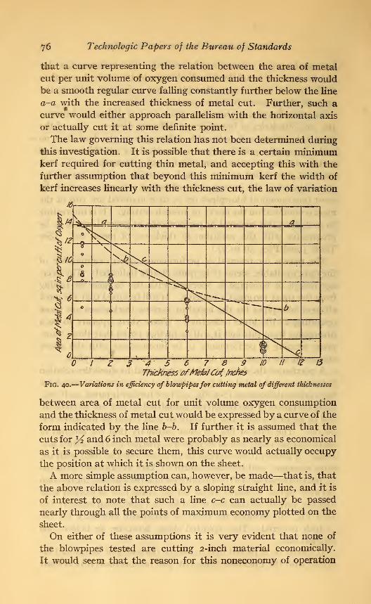
76 Technologic Papers of the Bureau of Standards
that a curve representing the relation between the area of metal
cut per unit volume of oxygen consumed and the thickness wouldbe a smooth regular curve falling constantly further below the line
a-a with the increased thickness of metal cut. Further, such acurve would either approach parallelism with the horizontal axis
or actually cut it at some definite point.
The law governing this relation has not been determined during
this investigation. It is possible that there is a certain minimumkerf required for cutting thin metal, and accepting this with the
further assumption that beyond this minimum kerf the width of
kerf increases linearly with the thickness cut, the law of variation
3 4' 5 6 7 3 P ID If 1Z 13
ThicknessofMefojCu( Inches
Fig. 40.
—
Variations in efficiency of blowpipesfor cutting metal of different thicknesses
between area of metal cut for unit volume oxygen consumption
and the thickness of metal cut would be expressed by a curve of the
form indicated by the line b-b. If further it is assumed that the
cuts for 14 and 6 inch metal were probably as nearly as economical
as it is possible to secure them, this curve would actually occupy
the position at which it is shown on the sheet.
A more simple assumption can, however, be made—that is, that
the above relation is expressed by a sloping straight line, and it is
of interest to note that such a line c-c can actually be passed
nearly through all the points of maximum economy plotted on the
sheet.
On either of these assumptions it is very evident that none of
the blowpipes tested are cutting 2-inch material economically.
It would seem that the reason for this noneconomy of operation

Investigation of Oxyacetylene Blowpipes 77
is probably due to two things. First, the use of an oxygen
cutting jet issuing at too great a velocity. If a velocity of 2200
feet per second is sufficient for cutting 6-inch material, it would
appear that a velocity of 1800 feet per second is excessive for
2-inch material. Secondly, in the blowpipes tested the preheating
flames in most cases were too large for the work required. In fact,
in a number of instances there was practically very little difference
between the size of the preheating flame used for the 2-inch plate
and that used for the 6-inch material. For the thinner material
the large-sized preheating flame would tend toward noneconomy
in operation inasmuch as it would preheat a relatively large surface,
with the resulting tendency for the oxygen to oxidize the entire
body of metal thus preheated, giving probably a wider kerf than
necessary and thus using the oxygen supply nonadvantageously.
This conclusion is further substantiated by the fact that in cutting
2-inch material practically none of the slags showed metallic char-
acteristics but were on the other hand fully oxidized metal.
A further study of the data presented in Fig. 40 indicates also
that possibly the maximum economy has not been fully secured
for the 10-inch material. It is certain, though, in this connection
that the relation between metal cut per unit volume of oxygen
consumed and metal of different thicknesses can not follow the law
suggested and represented by the curve b-b, for this curve implies
that, in addition to a possible increase in economy over that
actually obtained, far greater thicknesses could be cut with
relatively slight changes in economy. This is contrary to knownfacts and is rather forcibly contradicted by the appearance and
character of the cuts made on 10-inch material and shown in Figs.
44 to 46, inclusive. It seems probable , then , that the true economyrelation is more nearly represented by the straight line c-c. If
this is true, then a slight improvement might be expected in
cutting 10-inch material economically. On the other hand, such a
conclusion leads directly to the fact that the maximum available
cut of oxyacetylene blowpipes of present design lies in the vicinity
of 12 inches. As an interesting side light on this, Fig. 47 shows anattempted cut for maximum thickness made with the blowpipe
that exhibited maximum efficiency in heavy cutting. The cut
penetrated about 12 inches into a 16-inch block, the bottom of the
cut being practically at right angles to the direction of cut.
This immediately brings up the question as to why the limit
of depth of cut for an oxyacetylene blowpipe should apparently
be about 12 inches. It has been known that in heavy cutting the
cleaner cuts and greater depths were secured with the oxyhydro-

78 Technologic Papers of the Bureau of Standards
gen blowpipe. (See Fig. 46B.) The reason generally given for
this difference is that the oxyhydrogen preheating flame is longer
and therefore secures better preheat penetration within the cut.
It would seem, however, that a possibly more probable explana-
tion of the difference lies in the resulting products of combustionand that this is also a possible explanation of the limitation of the
oxyacetylene blowpipe in heavy cutting. Besides the iron
oxide, water vapor and carbon dioxide are formed during the cut-
ting process. With the use of acetylene instead of hydrogen a
greater proportion of carbon dioxide is formed. This gas sinking
to and being partially trapped in the lower portion of a cut andbeing a nonsupporter of combustion causes a slackening of the
oxidation process and in deep cuts it may be present in sufficient
volume to actually arrest the oxidation process. This suggestion
would seem to be verified by the experience that in deep cutting
a large increase in the kinetic energy of the issuing cutting jet
produced by increasing the pressure at which the gas is used will
often secure a cut where the blowpipe would otherwise not have
been enabled to do so. The increased pressure and resulting
energy insures that the products of combustion are blown out of
the way. Under such conditions increased depths of cuts may be
secured, but not necessarily economically.
Unfortunately these questions have not been definitely settled
by these tests and the above must therefore be looked upon
simply as indications and suggestions for further work toward
securing increased economy in cutting.
In questions of economy of operation the volume of gas used
plays an important part. Where an excessive amount of ace-
tylene is used, acetylene being the more expensive gas, the econ-
omy of operation is affected adversely. This question of ace-
tylene consumption is one that would seem to deserve attention.
The size of the preheating flames is a direct index of the acetylene
consumption. As indicated above in a great many of the blow-
pipes tested, it was found necessary to reduce the acetylene
pressure under that specified by the manufacturer (thereby re-
ducing the size of the flame or acetylene consumption) in order
to secure the flame size that did not melt too much of the top
edge of the cut and reunite the pieces cut apart by the flow of
this molten metal back into the kerf. In some instances with the
specified preheating flame the pieces were practically welded
together again along the top edge, and in others the top edge was
badly beveled.

Investigation of Oxyacetylene Blowpipes 79
Neither of the above conditions, developed by excessive sized
preheating flames, is desirable. Even though not welded to-
gether a badly beaded top edge (Fig. 43//) or a badly beveled top
edge would in most cases increase the cost of following manufac-
turing operations. The feeling of the blowpipe manufacturers
on this matter seems to be that they must have excessive preheat-
ing flames to take care of heavy scale, slag, etc., and to facilitate
rapid cutting, especially at the start of a cutting operation. Theexperience of this investigation as developed on cutting does not
indicate that a cut can be started any quicker with an excessive
flame than with one of proper size. In cases where slag or heavy
scale are met with it is doubted whether burning slag and scale
sq. in./cu. ft.
&IZ
V4S
ffiflFflhr
V1 111 11 1 1 1 1 1 111 1 1 1 1 1 11 1 1 1 1
1
II Ml 111 1 M M10 If 12 13 14< / 2 3 5 6 7 6
Torch NumberFlG. 41.
—
Relation of volume of oxygen used to area of metal cut for metals of varying
thicknesses
off at an oxygen cost of $1 .50 to $10 an hour (according to thickness
of material cut) can economically compete with unskilled handlabor (chisel and hammer) at 75 cents per hour.
The quality of cut secured is quite important. Figs. 42 and 43are included to show what may be expected from a properly
operating cutting blowpipe. Figs. 44 to 46A attempted cuts on10-inch material, in this case armor plate, speak for themselves,
and they may well be taken to indicate that none of the blowpipes
tested are suitable for working to close limits on cuts of such depths.
For comparison an oxyhydrogen cut on the same block is shownin Fig. 4.6B.
On the other hand, there is splendid evidence that some blow-
pipes can do especially nice work when properly designed for the
thickness being cut, in this case 6 inches. (Fig. 43F). A sec-

80 Technologic Papers of the Bureau of Standards
tional view through this cut is shown on the right-hand side of
Fig, 48, c. Fig. 42 B to E inclusive shows typical cuts of 2-inch
and -|-inch metal, and Fig. 4.2A is further evidence that there is
such a thing as using too much oxygen in executing a cut.
Besides the top edge and face of a cut, the bottom edge is of
interest, as its appearance is quite closely connected with the
type of slag formed. A completely oxidized slag has a greater
tendency to cling to the underside and if excess oxygen is present
there is considerable undercutting which tends to increase the
amount of slag and to make it adhere more firmly, with the result
that a rough bottom edge is produced. By the proper proportion-
ing of the oxygen volume it is apparent that a slightly metallic
slag can be secured, the metallic element being due to the fact that
in the presence of an insufficient oxygen volume some of the metal
is blown out without being oxidized. A slightly metallic slag
clings quite firmly to the bottom edge of the cut, but apparently
possesses an advantage in that it may be removed in long pieces
as shown in Fig. 43G, and leaves behind it, as seen, a very smooth
sharp under edge. The section of the 6-inch cut shown in Fig.
43F had a slightly metallic slag.
In the use of the oxyacetylene cutting blowpipe with especial
reference to manufacturing operations the question arises as to
what effect the cutting action has upon the metal body. Todetermine this a section through oxyacetylene cuts of £, 2, and
6 inch plate which will be designated hereafter as blocks A, B,
and C, respectively, were examined microscopically to determine
the nature and extent of the surface changes induced in the metal
by the oxyacetylene flame used for cutting the blocks. The
examination included a study of the macroscopic appearance of a
cross section after suitable etching, as well as of the comparative
microstructure of the central or unchanged portion of the blocks
and of the surface metal. In the following macrographs (Fig. 48)
the specimens are shown natural size, the surface having been
etched with an aqueous solution of ammonium persulphate.
The depth to which the material has been affected by the flame
is readily detected.
All of the micrographs of the material were taken at a magni-
fication of 100 diameters, after etching with 2 per cent alcoholic
nitric acid. These have been designated as A, B, and C to corre-
spond to the macrograph of the same material. The micrographs
in Fig. 49, A, Byand C show the structural condition at the
extreme edge of the section, that is, where the flame affected
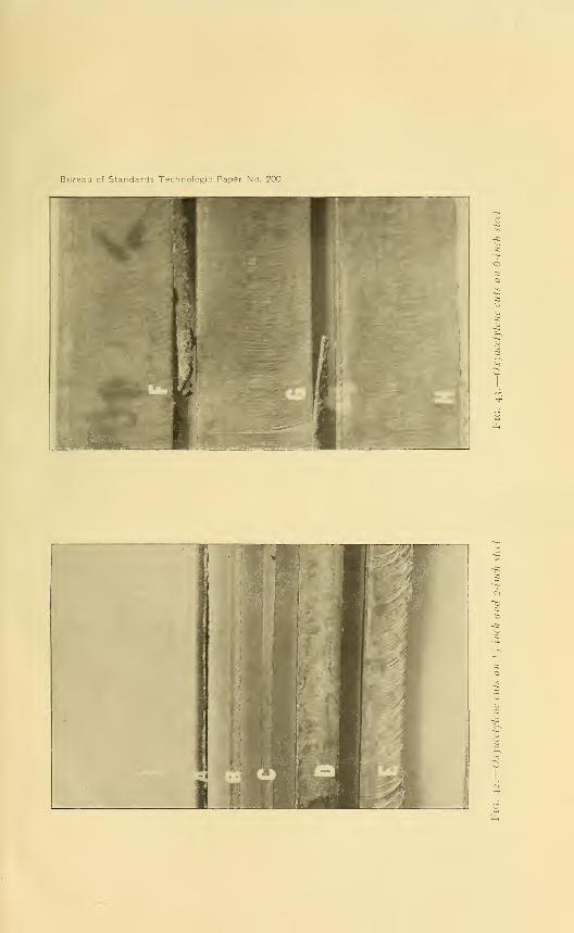
Bureau of Standards Technologic Paper No. 200

Bureau of Standards Technologic Paper No. 200
Fig. 44.
—
Oxyacetylene cuts on io-inch steel showing irregularity of cut
Fig. 45.
—
Oxyacetylene cuts on 10-inch steel showing irregularity of cut

Bureau of Standards Technolo^: Pin~r No. 200
u(Pi
9jm
>
I riG. 46A. Oxyacetylene cuts on 10-inch steel showing failure to complete cut
mm : r^j. |^ ;;
-
$ .
BkFig. 46B.
—
Oxyhydrogen cut on 10-inch steel showing relative smoothness of cut

Bureau of Standards Technologic Paoer No. 200
Fig. 47.
—
Oxyacetylene cut on 16-inch steel showing failure of cut at depth of 12 inches

Bureau of Standards Technologic Paper No. 200
X'
Fig. 48.
—
Macrographs ofl
, , -inch metal (.1), 2-inch metal (B), mid 6-inch
metal (< ) cut during tests. X and X' arc the sides exposed to the flame

Bureau of Standards Technologic Paper No. 200
A
nK^ te*
t'.|
B'
Fig. 49 A, B, C.—Surface exposed to the oxyacetylene flame
Fig. 49 A', B', Of —Unchanged or initial structure of central portion of specimen

Bureau of Standards Technologic Paper No. 203
Fig. 50.
—
Micrographs showing the structure of the outer C and central Cv portions
of the specimen which seemed to he most affected by the cutting process as shownin Fig. 49


Investigation of Oxyacetylene Blowpipes 8
1
the metal, and A', B', and C show the initial or unchanged
metal of the central part of the block. The three specimens vary
considerably in their carbon content, and the magnitude of the
change in the surface metal of the specimen of highest carbon
content (specimen C) has been much greater than in the others
which were of lower carbon content.
In order to determine whether there had been appreciable car-
burization of the surface metal, such as the micrographs suggest,
a sample of specimen C, which material was affected to the largest
extent, was annealed at approximately 760 C, that is, above its
critical temperature. Proper means were taken to avoid decar-
burization during the heating. The micrographs in Fig. 50 show
the structure of the outer (affected) layer, C, and the central
portion O, at 100 diameters.
There appears to be no appreciable difference in the carbon
content of the two parts of the annealed specimen. It may be
concluded then that the appearance of the surface layer of the
steel directly after cutting with the oxyacetylene flame is due to
the chilling action of the large mass of unheated metal upon the
hot surface after the flame has been removed. Such an effect
would, of course, be more noticeable in a steel of higher carbon
content than in one which is lower in this element. This of course
accounts for the hard surface metal that is frequently encoun-
tered in working up metal cut with the oxyacetylene blowpipe.
A very noticeable feature in cutting blowpipe performance wasthe irregularity of action and the variation in length of the pre-
heating flames and the frequency with which certain blowpipes
developed flashbacks or went out during operations. In fact one
particular and very well known blowpipe after six official test
trials on >£-inch plate failed to make more than 43 feet of the
required 50-foot test cut. As the causes back of these troubles
are identical with the action of the welding blowpipes, discussion
concerning them will be included in that on welding blowpipes.
Among the cutting tests there were included short lengths of
cuts made on %-moh plate with oxygen pressures set 50 and 25
per cent above the manufacturers' specified pressures and 25 and
50 per cent below them. As these tests, outside of a few incon-
sistencies which were attributed to the cutting operation being
carried out on warm plate, furnish only check data on the con-
clusions noted above, they are presented for what they are worth
without further discussion (Fig. 51).
58814°—21 6

82 Technologic Papers of the Bureau of Standards
1 1rv.' \ | 1 | 1
1 III 1 1
1 1 \j^'- \ 1 . . ., 1 !___ 1
_J 1 1 1J
1 1
I ^j^^J^^j^j^^JL^j^^I
._...f^ + Bit MM»o st «N m -. ^
s
fcl
1ft.
I 1
nil
vO
fn
Nj
'4&&J? '/usa-jpef. utte •0u/#n3jQ ?/?£

Investigation of Oxyacetylene Blowpipes 83
3. THE WELDING BLOWPIPE
It is universally accepted that outside of the mechanical features
of design that affect weight, balance, and convenience of operation,
the prime essentials of a strictly satisfactory piece of apparatus are
:
1
.
Safety under all operating conditions.
2. Freedom from the so-called phenomenon of flash back or
sustained back fire.
3. The quality of maintaining under all operating conditions a
welding flame that is neither oxidizing nor carbonizing, one tech-
nically known as a "neutral flame," which in the process of com-
bustion consumes, as nearly as possible, equal volumes of oxygen
and acetylene; that is, maintains as nearly as possible the theo-
retical gas volume ratio of unity.
The tests of this investigation were decided upon with the idea
of furnishing data that would enable blowpipe comparison relative
to these essentials.
A study of the data obtained at the completion of the prescribed
tests showed so many apparent inconsistencies that it was evident
that there was a governing factor that was not understood, and
that was, so far as test data were available, not in evidence. Irre-
spective of the fact that particular attention had been given to
insure identical working conditions and gas pressure control, and
that especial care was taken to secure exceedingly competent and
unbiased operators, the results obtained from the welding tests
seemed extremely unsatisfactory. Gas ratios obtained during
actual welding operations were extremely high. Those obtained
when the blowpipe was burning freely in air were also higher
than was to be expected. In tests for flash backs there seemed
to be a difference in the ease with which they could be developed
in blowpipes of different manufacture, but there appeared to be
no criterion that would enable one to say just why such phenomenacould be caused more easily in some pieces of apparatus than in
others, or why with some pieces of apparatus flash backs could be
produced at times quite readily and at other times with difficulty.
Finally, the general quality of the welds produced during test,
although executed with the greatest care and, as shown by tensile
tests, to be of a higher strength than is generally secured in most
welding shops, was far from satisfactory.
It was evident that further information was essential if a satis-
factory analysis of welding blowpipe performance was to be made.
The greatest discrepancy from what was expected appeared to be
in the high gas ratios obtained and the first attempt to answer the

84 Technologic Papers of the Bureau of Standards
problem was made by a study of gas-ratio phenomena. This
seemed particularly desirable, as it has been very firmly held byalmost all authorities that good welding can not be done with
blowpipes having a high gas ratio.
An extensive series of supplementary gas-ratio tests was ac-
cordingly carried out. The results obtained accounted partly for
the quality of the welding work secured. In some respects,
though, they added increased confusion by lack of consistency.
In further study of the data secured by the prescribed tests, it
was noticed that blowpipes that seemed especially susceptible to
the phenomenon known as flash back were those in which the
oxygen was delivered to the blowpipe at a pressure very much in
excess of that at which the acetylene was delivered. It wasfurther noticed that even among such blowpipes inconsistencies
appeared. Critical examination of tip design in these later sug-
gested a possible explanation. On this basis another series of
supplementary tests was made and from the results of these data
secured that clearly explain the cause of flash-back phenomena.
The logical continuance of the theory evolved for the cause of
the flash-back phenomenon leads directly to the question of
safety in operation and correct gas ratio and will explain, in large
part, the reason for so large a proportion of oxyacetylene welds
being of inferior grade.
The essential qualifications for a satisfactory welding blowpipe
as enumerated above are therefore very intimately connected
with the conditions governing the phenomenon of flash back.
It seems desirable then to begin the discussion of the results
obtained in the tests of the investigation by the critical analysis
of the conditions conducive to the development of so-called
flash backs in welding blowpipes.
Before taking up this discussion it will be of value to define the
term "flash back" or, as it is sometimes called, "sustained back
fire." It was very evident throughout the investigational tests
that the representatives of the manufacturers were not in agree-
ment as to what constitutes a flash back. To some the terms
flash back and " back-firing" were synonymous, others distinguished
between the blowpipe action representing these terms, and at
least one other manufacturer attempted to distinguish blowpipe
behavior by incorporating a term "preignition." There is there-
fore an apparent confusion of ideas.
For the purpose of this discussion the following definitions have
been accepted as representative of blowpipe behavior under cer-
tain operating conditions.

Investigation of Oxyacetylene Blowpipes 85
1. Back Fire or PrEignition.—Momentary retrogression of
the blowpipe flame into the blowpipe tip which may relight
immediately upon withdrawing the blowpipe away from the test
piece or necessitate the reignition of the gases by means of a
lighter. In this latter condition the flame will ignite properly
without manipulation of the blowpipe handle valves.
2. Flash Back or Sustained Back Fire.—The retrogression
of the burning flame back into the mixing chamber accompanied
by the well-known marked hissing or squealing sound and the
characteristic smoky sharp pointed flame of small volume neces-
sitating the immediate cutting off of the gas supply by means
of the blowpipe handle valves to prevent severe heating and
possible destruction of the blowpipe head, and generally neces-
sitating cooling the head before the blowpipe can be reignited.
The desirability of securing a nonflash back blowpipe has gen-
erally been considered to be due to its freedom from inconven-
ience and loss of time during welding operations and to its safety.
Probably nothing is more detrimental to the poise of an operator
and his desire to perform excellent work than an instrument
that is constantly giving trouble. But the principal detriment
in a blowpipe that flashes back, other than that of loss of time
during welding operations, is in the possibility that a flash back
may propagate itself back into the gas lines and in so doing
possibly become responsible for a violent explosion with its accom-
panying dangers.
Blowpipe designers have devoted considerable time and moneyto the problem of minimizing or possibly obviating this latter
danger and have devised a number of blowpipe designs that were
expected to eliminate flash backs. A study of a number of
letters patent indicates quite clearly that there are nearly as
many theories concerning the cause of flash backs as there are
patented designs. Necessarily considerable ingenuity has been
shown in the attempts to accomplish the desired results. Not-
withstanding the fact that some of the more recently designed
blowpipes lay claim to being safe and nonflash back, still, as will
be shown presently, none of those submitted to the tests of this
investigation have proved free from flash back under ordinary
flash-back test procedure ; nor may a great many of them be con-
sidered entirely safe pieces of apparatus. The fact is that the
theory back of the causes of flash back does not appear to have
been fully comprehended and therefore naturally not correctly
applied. Neither do any of the treatises or published articles

86 Technologic Papers of the Bureau of Standards
dealing with oxyacetylene blowpipe design or the autogenous
welding process give any statements that indicate that flash-back
phenomena have been understood. It is essential then that anexplanation of the phenomenon be offered, especially as indicated
above, as it is intimately connected with the question of soundwelds. The explanation offered is based on some very old prin-
ciples.
Sir Humphry Davy in the course of the researches that led to
the invention of the miner's safety lamp, among other things,
showed that there were certain governing principles relative to
the inflammability of gaseous mixtures. He pointed out that
there was a relation between the richness of the gaseous mixture
and the rate of propagation of flame through it, and that such
gaseous mixtures could either be enriched to the point where
they ceased to be inflammable or that they could be diluted to the
point where they would cease to be inflammable. It was also
shown that the points where inflammability ceased were very
sharply defined, but that the limits could be increased by in-
creased temperature or pressure ; and in fact that at these '\ critical
proportion mixtures," at dilution and concentration, a very
slight temperature rise will produce an inflammable mixture. It
was also shown that the maximum velocity of flame propagation
occurred with the gaseous mixture so proportioned that, at the
completion of the combustion process, stable compounds were
formed. Finally it was shown that if a gaseous mixture is ejected
through a tube into the air at a velocity greater than the velocity
of flame propagation for that mixture the mixture may be ignited
and will burn at the exit opening of the tube without striking
back into the interior of the tube. These fundamental principles
were later proved to be correct in every particular by Bunsen
and since then by a great number of other investigators.
The chemistry of the combustion process of a gaseous acety-
lene-oxygen mixture shows that the complete oxidization of one
volume of acetylene requires two and one-half volumes of oxygen.
Experience with the design and operation of oxyacetylene blow-
pipes has demonstrated the fact, however, that in reality it is
only necessary to project, with the blowpipe, equal volumes of
oxygen and acetylene, chemistry showing that it is a two-phased
process, the second phase of which can be completed by the ab-
sorption of the remaining required oxygen from the atmosphere
surrounding the flame.
The above shows that the design of the oxyacetylene welding
blowpipe is based upon the fact that equal volumes of acetylene

Investigation of Oxyacetylene Blowpipes 87
and oxygen are to be mixed and ejected through the tube of the
welding blowpipe tip at a velocity at least equal to or in excess of
the velocity of flame propagation for that mixture. Under such
conditions the flame will burn steadily and freely at the exit end
of the tube, gathering enough oxygen from the surrounding au-
to complete the oxidization of the components of the acetylene
gas.
A long experience has seemed to show, nevertheless, that the
fulfillment of the above conditions was not sufficient in itself to
maintain always the flame at the tube or tip end. It was found
that if a blowpipe tip is brought too near the surface of the weld,
is accidentally dipped into the molten metal of the weld, has the
aperture partly blocked by flying slag, or is badly overheated, the
flame will snap back into the tube, causing a so-called back fire, and
may even propagate itself still farther backward until it burns at
the mixing chamber, thus causing what is known as the flash-back
phenomenon. It is due to the fact that this detrimental phe-
nomenon can be so readily produced that so much energy and
money have been expended in the attempt to eliminate it.
Outside of the flash back produced through the severe over-
heating of the head and tip of a blowpipe, it is apparent that all
the other causes mentioned above seem to depend for their action
upon a partial or complete blockage of the gas flow. It will be
readily perceived that any sort of obstruction that checks the
volume flow of the gases also increases proportionally the velocity
of exit of the gaseous mixture at the tip end. Such being true,
it would seem that, with the velocity of exit increased above the
velocity of flame propagation, the flame could not strike back into
the tube, in other words, back fire, Yet, in spite of this, back fires
are caused, and it is known that with some blowpipes a back fire
will immediately become a flash back, while in others it causes the
extinguishing of the flame, or, if the blowpipe is withdrawn from
the work, it will be blown forward again to the exit of the tip or
tube. Why should some blowpipes be so much more susceptible
to the development of flash back than others ?
The lack of sufficient velocity of exit of the gaseous mixture has
been accredited as the principal cause for flash back in some of
the latest designed and most successful nonflash-back blowpipes.
That there is some reason of far deeper significance than this is
evident from a study of Tables 4 and 5. It is true that an ob-
struction to the flow will cause flash backs, but such obstruction
is in reality only a contributing cause.

88 Technologic Papers of the Bureau of Standards
TABLE 4.—Summary of Tests for "Flash Back," Ordinary Conditions, Test 3
[Key: F=flash back. FOO=flash back in oxygen observation tube. FAO=flash back in acetyleneobservation tube. b=backfire. r=trouble in relighting. v=flame blew away and valve had to bereadjusted.]
Tip No.a
Pressures used Action of torch in tests with—
Torch No.
Oxygen Acety-lene
Coldsteel
Firebrick
Woodof exit
Valve wide open
I
6(2)668
810
f910
3535363636
dll«15
77999
117
6(77
777
7
A899
99
7799
5<6
89
MO1212
IS
Lbs./in.2
M3)4.004.005.75
8.0010.00
6.507.50
12.0012.0014.0014.0014.00
11.0015.00
14.0014.0018.0018.0018.00
10.0012.00
12.0014.0014.0014.0014.0014.00
5.008.008.008.008.00
8.008.0014.0014.00
6.0015.0015.00
4.505.50
21.0025.0025.00
8.0012.00
Lbs./in.2
5.005.007.00
8.0010.00
8.009.00
5.005.006.006.006.00
11.0015.00
6.006.006.006.006.00
10.0012.00
6.008.008.008.008.008.00
4.008.008.008.008.00
6.006.0014.0014.00
6.006.006.00
4.505.50
1.001.001.00
8.0012.00
6(5)b, r
"(6) *(7)FOO,b,r
Ft./sec.
*(8)371371380
364397
479427
366366335335335
450332
406406375375375
413462
495558558558558558
427391391391391
568568582582
430483483
370335
323343343
353485
6(9)
SSKNmAcetylene
Do.
b, vv
v2 bb
vOxygen
Do.3 bF
FFFFF
FOO, F.
FFFFF
Do.
4 FFF,rF,rF,r
b
OxygenUt , ,
Oxygen/2 trials
Acetylene]Acetylene
J-3trials
Acetylenej
Oxygen5b Acetylene
6 bb...FF
bbFFF
b
FAO, b.FAO....FFFAO....
bb
bFbb
AcetyleneKt
, .
Oxygen /2 trials
Acetylene]Acetylenes trials
Acetylenej
7 bb
OxygenDo.
8 bF,bbbbb
bFbbF
AcetyleneOxygen]OxygenOxygen [5 trials
OxygenOxygen]
9 bbb
bb
bFFbb........
F,rbFb
b,rbb
b
AcetyleneAcetylene]AcetyleneL
trialsAcetylener trlals
bAcetylenej
10 b,v b,risgis:}*"*
b 30*4111 b
bb
b
bbb
Oxygen
12.
AcetyleneDo.
Do.b Do.
13 FFF
bb
FFF
b
FFF
b
Oxygen
14
Oxygen\2 t
, ,
Oxygen/2 m S
AcetyleneDo.
o Smaller size tips were used for welding M-inch metal and larger size for K-mch metal.6 Column numbers.e Small explosions denoting attempt at backfire in tests on brick and wood.*Two backfires in 6 trials on cold steel.
« Too hot to hold after test on wood./ Head quite hot.Half of handle too hot to hold after test on wood.
ft Tendency to flash back not sustained with brick and wood.*Monel metal tip.
/Copper tip.* Torch head very hot.1 No back flash after brick was warm.m Tendency to backfire with wood and brick.

Investigation of Oxyacetylene Blowpipes 89
TABLE 5.—Summary of Tests for Flash Back, Severe Conditions, Test 4
Torch
Minutes beforeflash back
Conditions prevailing alter flash back
No.First
trial
Secondtrial
First trial Second trial
a (l) a (2)1.6.75.43
.40
.50
.53
.86
.68
.80
.33
.80
.38
.871.07.78
«(3)1.961.13.75
.38
.50
.90
.72
.65
.68
.42
.92
.58
.68
.85
.90
a(4)Tip loose
« (5)Tip looseSlight leak at tip
Tip leaks in head when hot. Noleak when cold
Tip leaks in head when hot. Noleak when cold
Slight leak in tip
6 Had to be cooled before relighting
.
Leak in top oi tip, tip loose ...
Tip leaked at joint
Tip leaked at headFlashed back and relit, leaking
8
around tip, which was loose
Small leak in bottom section of tip
Monel metal tip
Copper tip, tip leaked around end.
.
Copper tip, tip leaked aroun d end
14 Handle too hot to hold
a Numbers in parentheses are column numbers.
Partial obstruction of the tip opening by slag, etc., or the con-
finement of the expanding products of combustion through bring-
ing the tip end too near to the metal surface causes the develop-
ment of a back pressure. This back pressure may be readily
observed by watching a pressure gage as a lighted blowpipe tip is
alternately brought in contact with or removed from a plane
surface.
This back pressure has a very detrimental effect in that it
chokes off the flow of the gas that is admitted under the lower
pressure. Reference to Figs. 52 to 59, exhibiting results of tests
in which the amount of obstruction of the exit opening was under
control, shows the development of this back pressure and the
restriction of the flow of the gas admitted under lower pressure.
If then the blowpipe design is such that the back pressure tends
to check the oxygen supply more than the acetylene an increased
richness (in acetylene) of the gaseous mixture occurs. The gas-
eous mixture in the blowpipe will therefore have a lower flame
propagation velocity due to the fact that the increased richness is
tending toward the critical proportion mixture at concentration as
defined by Davy. The velocity of flame propagation is therefore
decreasing while the velocity of exit has been increased by the
partial closure of the orifice. There is a resulting tendency there-
fore for the flame to be maintained at the tip end. If under the
same conditions the obstruction is sufficiently severe, the gaseous
mixture within the blowpipe passes the critical proportion mix-
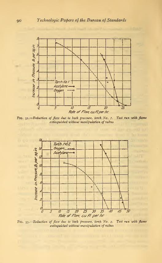
90 Technologic Papers of the Bureau of Standards
.t
.*' .7 "Ss*• X
sN*N
\, \ib ^
\s
s \\\
s Asi
^
TorchNo. 1
)cefyfene—\
\
• \(
I,ttyqen -0
sv \
4 X ;„ i
ID 15 ZO 25
Rate of How, cuffperfir
FlG. 52.
—
Reduction of fiow due to back pressure, torch No. 1. Test run with flame
extinguished without manipulation of valves
16
Torch No\zOxyo&r?-—--!<y
^V .....
Acefy/erfc»—
«
V©->-,
**>x\
l.\s \\
\
\\\\\
\i
1\
v
\T 3\V
._V- \5 10 .15 ZO Z5 30 35 40 45 50
f&fe of flow, cuff,per fir
Fig. 53.
—
Reduction of flow due to back pressure, torch No. 2. Test run with flame
extinguished without manipulation of valves

Investigation of Oxyacetylene Blowpipes 9i
5 10 15 ZO ZS 30 35 40 45 50 55 60
fafe of ffow, cu ff.perh/r
Fig. 54.
—
Reduction of flow due to back pressure, torch No. 3. Test run with flame
extinguislied without manipulation oj valves
40
36 \ Torch'Na5
V A Oxygen -0
Acefa/ene-—*
<***. \^74
'^^,
*^V» \t?20
""•n. \ \ '
>"N \
^ \X- \
4
N4\ \
*->>_
5 10 IS ZO Z5 30 35 40 45 50 55 60 65/fa/e ofF/oyv. ci/ffoerhr
Fig. 55.
—
Reduction of flow due to back pressure, torch No. 5. Test run with flat
extinguished without manipulation of valves

92 Technologic Papers of the Bureau of Standards
%
X
1/4
\
4
.?
M
\
\\
Torch Ab. $
Acetyfene-—
\
n
X
5., JO. 15. W Z5 30 35 ' 40 "45Rote ofr/ow. cuW,0er/ir
Fig. 56.
—
Reduction of flow due to back pressure, torch No. Q. Test run with flame
extinguished without manipulation of valves
36
.32
TorchNoJOOxygen—^-o-
•Stf? \V
Acetylene-
\t% 16
r It
0-^""*"""
**o""*>*
'
S a H%1
\\
^ 4
^>s3 \ •
1
1
N 1
*Q Y5 10 15 ZO Z5 30 35 40 45 SO
Rate off/on: cu ftperhr
Fig. 57.
—
Reduction of flow due to back pressure, torch No. JO. Test run with flame
extinguished without manipulation of valves

Investigation of Oxyacetylene Blowpipes 93
m
mTorch-No./!
^ 14! \
Oxyqe
Acety,
77
'ene—
-o
\- \4J
V to
^v^ \\
| 8 \ \\
\§ 4
\\
\k \
i \ \s
\5 10 15 ZO Z5 30 35 0, 45
fofe of F/ow. cu ftper hr
Fig. 58.
—
Reduction of flow due to back pressure, torch No. II. Test run with flameextinguished without manipulation of valves
31
31Tire-J? Mi 13
>%?.d XV
*V & sX^zo
I U •
%4
* \
\\XX
5 10 15 ZO Z5 30 35 40 45Fafe ofF/otr cf/kefyfene, cu ff.per frr
Fig. 59.
—
Reduction of flow, due to back pressure, torch No. ij. Test run with flameextinguished without manipulation of valves

94 Technologic Papers of the Bureau of Standards
ture at concentration, the mixture becomes noninflammable andthe flame is extinguished. With blowpipes furnishing the acetylene
under a higher pressure it is therefore evident that the tendencyto produce flash backs is minimized if not entirely suppressed.
On the other hand, if the blowpipe design is such that the backpressure tends to check the acetylene supply more than the oxy-gen, a mixture leaner in acetylene is produced. Such a mixtureis approaching the two and a half volume of oxygen to one volumeof acetylene mixture at which the maximum velocity of flame
propagation exists. A back pressure, then, that increases the
oxygen content above
that of the one-to-one
volume ratio furnished in
blowpipe design is pro-
ducing a gaseous mixture
that possesses a higher
flame propagation veloc-
ity than that possessed
by the one-to-one mix-
ture.
If the increased exit
velocity caused by the
obstruction to the gas
flow compares favorably
with the increased veloc-
ity of flame propagation,
the ignited mixture will
continue to burn at the
tip. In all blowpipes of
this type which have been examined this condition is not fulfilled,
with the result that a flash back always occurs. As experimental
evidence of the correctness of this statement the data of Fig. 60
are presented. These were obtained with a blowpipe mountedso that the amount of the obstruction to gas flow could be con-
trolled. When the oxygen content of the gas mixture had been
increased to the amount indicated by the diagram the flame
snapped back of its own accord to a true flash back.
Having snapped back to the mixing chamber the back pressure
will be destroyed and the flow becoming normal again, the flame
burns there in the volumes permitted by the blowpipe construction
with insufficient oxygen to cause complete oxidization and the
acetylene gas is broken up into its components one of which
lb
14 <—
1
lashhiotaicurred1
\
\1
Torch f\>o.6
\ Oxygen
%3
| 6
c\15 35ZO 25 50
Rate of How, cu ftper hr
Fig. 60.
—
Reduction of flow due to back pressure,
torch No. 6. Test run without extinguishing flame
or manipulating valves

Investigation of Oxyacetylene Blowpipes 95
unites with the available oxygen to form water vapor, leaving
carbon deposited on the walls of the tip tube and mixing chamber.
This explains not only the heavy carbon deposit that is always left
as the result of a flash back but the reason why it is relatively so
moist.
It is of course possible that if the oxygen content of the gaseous
mixture could be increased beyond the proportions for maximumvelocity of flame propagation, that is, beyond the two and a half
to one volume ratio, the velocity of flame propagation might be
reduced sufficiently to compare favorably with the exit velocity.
In the light of the above, however, it is evident that this condition
can not be produced, nor would it be desirable, as the flame
would be extremely oxidizing.
At how great a disadvantage the high pressure oxygen blow-
pipe designs are as compared with those operating with acetylene
delivered at excess pressure is very apparent from another con-
sideration. Eitner 4 has shown that the lower inflammable limit
by percentage volume of combustible gas in a mixture of acetylene
and air is about 3.35 per cent, and that the upper limit is about
52.3 per cent. There is no doubt that with a more active gas,
such as oxygen, the lower limit will be at least the same and
possibly the upper limit will be found to be slightly raised. Bear-
ing in mind that normally a 50 per cent mixture is being passed
to the mixing chamber, it is readily seen that the critical proportion
mixture at concentration is reached very soon, while the critical
proportion mixture at dilution is not reached until almost the
entire combustible gas supply has been shut off.
It has been known for some time that an operator could extin-
guish a flash back in a high-pressure blowpipe by suddenly increas-
ing the oxygen pressure or by crimping the acetylene supply line.
The reasons are now very apparent. In the former case the oxy-
gen volume ratio is greatly increased by the accelerated checking
of the acetylene supply until the volume ratio is diluted beyond the
maximum explosive mixture, the flame propagation velocity is
thereby reduced, and at the same time the increased pressure of
the oxygen expels the mixture at increased velocity. The flame
may therefore be pushed to the outlet opening of the tip. In the
latter case, crimping the hose line, the combustible gas is shut off
and the flame may be pushed forward as above or may go out
from the gas mixture having reached the critical proportion
* L. A. Groth, Welding and Cutting Materials by Aid of Gases or Electricity, Archibald Constable & Co.
(Ltd.), London, p. 251; 1909. See also G. A. Burrell and G. G. Oberfell, the Explosibility of Acetylene,
Bureau of Mines Technologic Paper No. 112, p. 5; 1915-

96 Technologic Papers of the Bureau of Standards
mixture at dilution; but in this case, on account of the low per-
centage mixture at which this occurs, it may as well be caused
through the entire combustible gas supply having been cut off.
Having explained the conditions necessary for, and the action
of flash-back phenomena, it is of interest to determine why someblowpipes flash back so much more readily than others of similar
design; as, for example, those in which the oxygen pressure is
higher than that of the acetylene. The rapidity of development
of the condition for producing a flash back depends entirely uponthe rapidity with which the back pressure is set up. That there
is a difference in the rate at which the back pressure is developed
is evident from an inspection of Figs. 52 to 59. The data of these
tests show that those blowpipes which were more susceptible to
flash back from obstruction of gas flow were those in which the
back pressure most rapidly diminishes the acetylene flow. A blow-
pipe operating on the injector principle or one in which the oxygen
pressure is very much in excess of the acetylene pressure will
therefore be far more susceptible to flash-back phenomena.
An investigation of the actual pressures specified by the manu-facturers, as well as a study of certain letters patent, indicates that
a few of them at least, in their experimental work, have become
cognizant of the effect a gas mixture rare in acetylene has uponthe development of a flash back. To overcome flash-back troubles,
several of the recent designs are based upon furnishing acetylene
under a higher pressure, spoken of in the letters patent as higher
velocity, than that used for the oxygen. Reference to Tables 4and 5 shows that flash backs can be caused in apparatus of that
type. The question may rightly be asked as to why flash backs
can then be developed in such blowpipes.
A critical study of the design of the blowpipe tips shows further
that the way in which one stream of gas is admitted into another
has a decided effect upon conditions resulting from the develop-
ment of a back pressure.
A back pressure caused by tube obstruction pushes back into
the tube in the most direct line (Fig. 61). An acetylene gas
passage entering the oxygen tube at right angles has its gas flow
cut off very quickly, especially when the oxygen pressure is muchhigher than the acetylene pressure and the point of admission
of the oxygen is, as it is in most of the tip designs, beyond the
point of admission of the acetylene.
In this respect a gas passage entering the oxygen passage at
a sharper angle is more advantageous, but, under certain condi-
tions, this construction may not produce results that are any

Bureau of Standards Tp hn i Paper No. 200
Fig. 6i.— Views of cross sections of tips
Fig. 62.
—
Tips after a flash hack


Investigation of Oxyacetylene Blowpipes 97
more desirable. If the velocity of the oxygen jet is relatively
high and the acetylene gas ports are placed at an angle to the
tube of the oxygen jet, an aspirator or injector action is developed
relative to the acetylene. The higher the velocity of the oxygen
the greater is the aspirating effect on the gas tube. This aspirating
effect is in reality an attempt to produce a partial vacuum within
the acetylene tube. If, then, while operating under such condi-
tions a sudden obstruction of the exit passage occurs with its
accompanying back pressure development, the sudden release of
the aspirating action causes a collapse of the partial vacuum and
the gas passage tube is therefore momentarily choked or at least
throttled by the infiltration of oxygen. This action instantly
produces the leaner mixture and conditions necessary for the
development of a flash back.
But there are also two other fundamental physical laws which
apparently have not been given proper consideration in the
designs of blowpipes, and which will probably account in a far
larger measure for the development of flash-back conditions.
These laws refer to
:
1. The variation of velocity of a fluid in a pipe of varying size.
2. The diminution of pressure in a throat.
The first law recognizes the fact that the mass discharge of a
fluid at all sections is a constant; hence for a pipe of varying size,
as shown, the following condition holds when the friction loss of
pressure is neglected
:
If a>a f, then av<a'v'', where
a and a' = areas of gas passage,
v and v' = velocities of gas.
This indicates that at various points along a tube the velocities
of the fluid increase as the section areas decrease.
The second law is based on the fact that, neglecting friction
and eddy losses, at any two sections of such a tube the total
energy per unit mass will be equal ; that is, an increased velocity
produces a decreased pressure. 5
b The relation for a gas is given by the equation
**-**= 2TCp[ 1- [f']^gp] . in which
p and p'= pressure;
"j and v'= velocities;
d= density;
T= absolute temperature;
CP= specific heat at constant pressure;
Cv= specific heat at constant volume.The decrease of pressure with increase of velocity is perhaps more clearly shown by the approximate
formula
which neglects the expansion of the gas.
58814°—21 7

98 Technologic Papers of the Bureau of Standards
From these two laws it is evident that if the area of a tube is
contracted with the idea of securing increased velocity the pres-
sure in the contracted area is reduced.
Reference to Fig. 61 shows that in practically all designs the
contracted throat is used in the acetylene passages. It will bereadily realized then that in even those blowpipes which are sup-
posed to operate with acetylene delivered at excess pressure there
exists in the fundamentals of their design an inherent tendency
for the choking off of the acetylene supply and the developmentof the leaner flash-back mixture at the first indication of backpressure.
The inherent defects in the present designs show plainly then
why it is also possible to produce a flash back almost at will in
the blowpipes that are designed on the excess acetylene pressure
basis. It is evident, therefore, that none of the blowpipes de-
signed for use with one gas delivered at a higher pressure than
that used for the other are really free from flash-back troubles
caused by obstructions to the gas flow.
There is another important consideration to be discussed rela-
tive to blowpipes using one gas at higher pressure, and that is
their safety during operation. The foregoing discussion shows
that an obstruction to the gas flow issuing from the tip sets up a
decided and effective back pressure and that the back pressure
thus set up will be sufficient not only to check the flow of the gas
admitted under the lower pressure, but also actually to push it
back into its supply tube and line. The return of one gas into
the supply line of the other instantly forms an explosive gas mix-
ture back of the mixing chamber. Reference to the exceedingly
low limit of the critical mixture at dilution as indicated by Eit-
ner's investigations shows how rapidly a dangerous mixture can
be formed by a blowpipe using acetylene under excess pressure.
A blowpipe using the oxygen under the excess pressure is about
equally as dangerous. It is simply a question of the time interval
the back pressure has available to accomplish its results.
The degree of danger from this cause is greater, the greater
the difference in pressure. A blowpipe operating with one gas
at a pressure greatly in excess of the other can force a return mix-
ture just so much more quickly than a blowpipe operating with
less difference in pressures. Also with one pressure greatly in
excess of another a larger amount of explosive mixture will be
formed back in the tube or line, as the distance the explosive mix-
ture will be forced back depends upon how quickly the equalizing

Investigation of Oxyacetylene Blowpipes 99
element, the pressure developed by the compression of the gas
in the tube, overcomes the effect of the back pressure.
In connection with this phenomenon of the creation of explosive
mixtures in tubes and lines due to back pressure, it seems desirable
at this time to call attention to the decidedly dangerous influence
leaks in the supply lines can have in cases where a dangerous
mixture is being forced backward in one tube.
With the knowledge that the back pressure set up by the obstruc-
tion of gas flow from a tip can return a dangerous explosive mix-
ture into the tubes and supply lines, and further with the realiza-
tion, now apparent at least, that none of the unequal pressure
blowpipes are free from the possibility of the development of a
flash back, it can be readily seen that no blowpipe on the market
to-day that operates under unequal or unbalanced pressures can
with assurity be declared absolutely safe. This is especially true
as it has not as yet been established how small an opening will
have to be before it will cease to propagate a flame through
an explosive mixture of oxygen and acetylene. It is known,
though, from the investigation carried on to determine the feas-
ibility of acetylene lamps for mine use, that the opening is very
small. That the return of such explosive mixtures can be caused
is evidenced by reference to Table 4.
Recognizing the dangers coincident with blowpipes operated
under dissimilar pressures, some manufacturers have attempted to
minimize the return of dangerous gas mixtures by incorporating
check valves in the blowpipe construction. While such desires
are commendable they are in their method of fulfilment of doubtful
value in that there is no assurance that the valves will always be
operative. Failure, or loss of life in springs, or pieces of dirt or
scale, or corrosion of a stem or seat may readily cause a check valve
to fail to function. Its utility then is very questionable.
Other manufacturers have sought safety in action by attempting
a design based on delivering the gases under equal pressure. Pos-
sibly also they have realized to some extent the effects of excess
oxygen or acetylene on the development of flash-back phenomena.
A very careful study of their letters patent shows, however, that
they have not completely understood the phenomenon, its cause
and effects, and the methods necessary for its suppression. It is
therefore not surprising that not one of the so-called equal pres-
sure blowpipes proves actually to be such. The data of Table
4 show this beyond a doubt. They are therefore at times subject
to the same flash-back difficulties and the same lack of safety in
ioo Technologic Papers of the Bureau of Standards
operation, their differences being only a question of relative degree
and subject to the same principles mentioned above.
In mentioning above the things that seemed to be responsible
for the flash back, specific reference was made to overheating of the
tip and head. All blowpipes can be made to flash back from such
a cause. How quickly they will do so seems to depend entirely
on their design. It is certain that water-cooled heads can assist
in restraining such flash backs. It is also apparent that a tip andhead made of metal of high thermal conductivity, pure copper, for
example, is beneficial. In fact, any construction that tends to
maintain a cool gas flow seems to be helpful, and it is probable
that in that fact lies the explanation for flash backs caused byoverheating of blowpipe parts.
It will be recalled that Davy's experiments showed that the
critical mixture proportions were affected by changes in tempera-
ture, that a slight increase in temperature may make what is
normally a noninflammable mixture inflammable. It is knownalso that the velocity of propagation of flame is increased with
increases in temperature. It is evident, then, that under the in-
fluence of a high temperature there is an increasing tendency for
even a blowpipe designed for operation with excess acetylene to
flash back on the development of back pressure.
The real cause for flash backs developed under the influence of
high temperature, where back pressure does not necessarily exist,
is probably due to the sudden heating to the ignition point of a
large volume of gaseous mixture. The tip and head become ex-
tremely hot for their entire length and subject a relatively large
volume of gas mixture to the effects of the high temperature. The
result is naturally a detonation. The suddenness arid violence
with which such flash backs occur and their destructive effects on
the tips ends, as shown in Figs. 62 and 63, are evidence that the
burning gaseous mixture has been subjected in reality to a de-
tonation.
The difference in action that takes place in the two forms of
flash back, namely, those caused by back pressuresand those caused
by detonation of the gaseous mixture, can probably be best illus-
trated by calling to mind the familiar facts concerning gun cotton,
a material that, lying loosely and open to the air, will burn harm-
lessly if ignited by flame, becomes a most violent explosive if fired
by a percussive detonator. It is a question of the rapidity with
which a large volume of the mixture is ignited.

lib > ML. ,«JIH|
Bureau of Standards Technologic Paper No. 200

Bureau of Standards Technologic Paper No. 200
Fig. 64.
—
Oxyacetylene flames
A.—Acetylene flame, no oxygenB.—Slight excess oi acetyleneC.—Neutral flame

Investigation of Oxyacetylene Blowpipes 101
If, then, the sudden firing of a relatively large volume of a gase-
ous mixture produces a detonation, it is quite evident that the rate
of flame propagation is exceedingly high. For an oxygen-hydrogen
mixture it has been reported as approximately 93 1 5 feet per sec-
ond; for a carbonic-oxide mixture, a relatively slow and inert
combination, at about 3575 feet per second. 6 Figures for acety-
lene do not seem to be available, but it is certain that they will be
nearly as high as those for hydrogen.
The futility of attempting to prevent flash backs from this cause
by ejecting the mixture at a high velocity is very apparent
Knowledge, however, of the cause of the action indicates that any-
thing that tends to keep the gaseous mixture cool tends to hinder
the development of such flash backs.
Having discovered the causes of the development of the so-called
flash-back phenomenon, and shown that the safety of a blowpipe
is dependent upon the causes back of this same phenomenon, it is
next in order to inquire as to what possible effect the causes of
flash backs may have upon the gas ratio ; that is, upon the economyof operation and upon the process of autogenous welding.
The questions are hardly proposed before their answers are
apparent. It cannot be expected that a blowpipe whose gaseous
volume mixture is constantly changing from the one-to-one
volume ratio to an excess carbon (acetylene) content or an excess
oxygen content can maintain a constant gas ratio or a truly neu-
tral flame. If this is so, it is hopeless to expect such blowpipes
to be capable of producing unoxidized or uncarbonized welds.
The controversy on the causes for unsound welds has of course
been two sided. It has been said that even experienced welders
excuse the shortcomings of their work by claiming that the blow-
pipe or the welding rod was not good. But generally up to this
time the condemnation has been placed principally upon the
welder and there is no doubt in certain cases rightly so.
In certain quarters the oxyacetylene weld has been severely
criticized. As a result of this criticism it has been suggested that
all welders should receive special training, that the quality of
their work be constantly checked by tests, and that they be li-
censed. Extensive metallurgical studies of welds, and attempts
to find nonoxidizing welding rods have also been made. All
these are good and useful expedients, but if in the first place the
operator is not furnished with a blowpipe that has been designed
«D. Clerk, The Gas, Petrol, and Oil Engine, p. 116.
102 Technologic Papers of the Bureau of Standards
with a correct interpretation and application of fundamental physi-
cal laws, it can not be expected that sound welds will be forth-
coming, no matter what other expedients are employed to increase
the efficiency of the weld.
The oscillatory motion given to the blowpipe in the process of
welding and the trembling of the operator's hand, by causing a
constantly varying back pressure as the blowpipe tip approaches
or recedes from the surface of the weld insures a constantly fluctu-
ating gaseous mixture with a predominating tendency, as indicated
above, toward an oxidizing flame.
In the more careful welding operations very great pains are usu-
ally taken to burn out oxide or slag pockets, etc., with the result
that the tip end is forced down into a confined space. Even with
such care welds are found to be oxidized. The bottom of the Vof a weld is almost always oxidized, while the upper portion mayshow more or less of the clean cast metal. It has been known for
years that a shaky-handed welder could not make sound welds.
It has also been known that certain blowpipes, as regards flash
back, were particularly susceptible to the nearness with which the
blowpipe tip approached the welding surface. Further, some at
least have known that after placing an ignited and properly ad-
justed blowpipe flat on a surface and then gradually raising the
head, keeping the tip upon the surface meanwhile, the blowpipe
would flash back after the head had been elevated to a certain
angle. These are some of the facts that indicated that there was
being developed at such times the detrimental back pressures.
All the data available as a result of the investigation bear out
the logical conclusions of the above theory—the high gas ratios
during welding, the difference in gas ratios when identical tests
are performed by different operators, the lower gas ratios when a
blowpipe burns freely in air (see Table 6), the fluctuations in
volume flows as determined by flow-meter readings taken every
few minutes with gas pressures maintained within a few hundredths
of a pound per square inch throughout the entire test period.
(See Fig. 21.) Most convincing of all is the wide variation in the
physical properties of the welds made during the investigation,
a group of welds that probably was made with greater care than
has ever been bestowed upon any other such set. (See Figs.
65 to 71.)
All past experience, including the experience gained during
these tests, points to but one convincing conclusion, namely,
that a blowpipe designed to be absolutely free from flash back

Investigation of Oxyacetylene Blowpipes 103
caused by any form of obstruction, under all working conditions,
will also be the eminently safe blowpipe and the blowpipe that will
with ordinary care produce sound welds. Such a blowpipe will
be one so designed that under all conditions of operation, even to
complete blocking of the gas exit at the tip end, there will be main-
tained a one-to-one volume delivery of each gas at identical pres-
sures. No oxyacetylene blowpipe on the market to-day fulfills
these fundamental conditions.
A few other points are of interest in connection with the welding
blowpipe investigation. It was mentioned above that one of the
most noticeable outstanding features which was the first to be
investigated in the attempt to solve the apparent discrepancies
in welding blowpipe data was the high gas ratio obtained during
welding operations. Attention has also been called to the fact
that such ratios were lower when the blowpipe burned freely in air.
The reason for this is of course now apparent. But it will be of
interest to note that even such values were relatively high, and
this notwithstanding the further fact that in a majority of gas-
ratio tests the neutral flame was set in the presence of and met the
approval of experienced blowpipe operators, representatives of
the manufacturers. Consideration of these facts led to the belief
that what is called the neutral flame is more or less masked by the
operator's personal equation, that is, what he considers a neutral
flame to be. Further, continued experience indicated that whenthe gases were issuing at a high velocity the extreme ragged edge
of the inner cone seemed to interfere with the determination of the
neutral flame. It became apparent, then, that the general tend-
ency was toward setting an oxidizing flame. This was strength-
ened by the knowledge that all treatises and books of instruction
that were available describe the neutral flame as having been se-
cured when the intensely white flame or inner cone is "sharp in
outline—symmetrical and smooth." (Fig. 64.) The trouble with
this statement lies in the emphasis given to the words '
' sharp'
'
and "smooth." In adjusting the burning gases to produce a
neutral flame it seems to have become an ingrained action uponthe part of the operator to cut the acetylene gas flow back until
the entire inner cone is "sharp" and "smooth," with the result,
as exhibited by the gas-ratio tests of this investigation, that
the flame has actually been made quite oxidizing.
Having come to this conclusion, the idea of examining the
flame spectroscopically presented itself, and for this purpose,

104 Technologic Papers of the Bureau of Standards
because of its convenience, a replica diffraction grating was used.
The use of this method suggested itself, as it was recognized that
in a carbonizing flame there must exist unburned incandescent
solid carbon particles which would superimpose their blurred
continuous spectra over the line spectra of the flame. Suchproved to be the case, and it was found, as anticipated, that proba-
bly too much attention has been paid in the past to setting the
inner cone to too sharp a contour, especially on the extreme end.
The results of a series of gas-ratio tests run with the use of the
gratings are shown also in Table 6, and it will be noticed that they
show very marked changes in values and much greater uniformity.
This table shows that practically any of the present blowpipes
can be made to produce a neutral flame and burn equal volumes
of oxygen and acetylene if the flame can burn undisturbed in the
air. But, as stated above, none of them can maintain such a flame
during the welding process.
TABLE 6.—Summary of Tests for Gas Ratios
Gas ratios for test No.—
Torch No.
1-a 1-b 2 5-a-l 5-b
With gratings
5-a-l 5-b
o(l) a (2)1.13
6(1.11)1.12
(1.11)1.21
(1. 18)
1.13
(1. 13)1.07
(1.05)1.10
(1. 10)
1.07
(1.04)1.13
(1- 12)1.15
(1. 18)
1.12
(1.11)1.19
(1. 19)1.21
(1.17)
1.02
(1.04)1.07
(1.06)
«(3)1.16(1.15)1.07(1.06)1.26(1.23)
1.09(1-09)1.05(1.04)1.11(l.U)
1.05
(1.03)1.12
(1. 12)1.18
(1.24)
1.15
(1.13)1.20(1.21)1.21
(1.20)
1.13
(1. 12)1.09
(1.08)
a (4)1.14(1.14)1.08(1.06)1.13
(1. 19)
1.41(1. 16)1.03(1.13)1.14
(1. 15)
1.03(1.02)1.18
(1.16)1.19
(1. 17)
1.19(1.06)1.26(1.23)1.13
(1.11)
1.09(1.09)1.08(1.07)
a (5)1.19
(1- 18)1.04
(1-04)1.10(1.07)
1.14(1. 15)1.02'
(1.02)1.12
(1. 12)
1.04(1.01)1.27
(1.28)1.14
(1.14)
1.10(1.09)1.27
(1. 28)1.02
(1.01)
1.09(1.08)1.08
(1.08)
«(6)1.08(1.04)1.06(1.04)1.07
(1.09)
1.29(1.10)1.04
(1. 10)1.17
(1. 16)
1.07(1.03)1.43
(1.38)1.14
(1. 15)
1.04(1.05)1.09(1.08)1.04
(1.02)
1.07
(1.06)1.10
(1. 10)
«(7)1.04(1.05)1.04(1.02)1.01
(1.01)
a(8)
1.01
2
(.981).992
3
(.996)1.04
4...
(1.09)
5 1.01(1.01)1.06
(1.03)
1.05(1.01)1.05(1.03)1.43(1.39)
1.03(.989)1.21
(1.19)1.02
(. 998)
1.02(1.01).999(.992)
.999
6
(1.03)1.08
7
(1.07)
1.02
8
(.994)1.01
9
(.986)1.19
10
(1.15)
1.01
11
(.992)1.04
12
(1.05)1.02
13
(. 979)
1.00
14
(1.00).956(.964)
a Column numbers.& Values in parentheses are computed from flow-meter data.
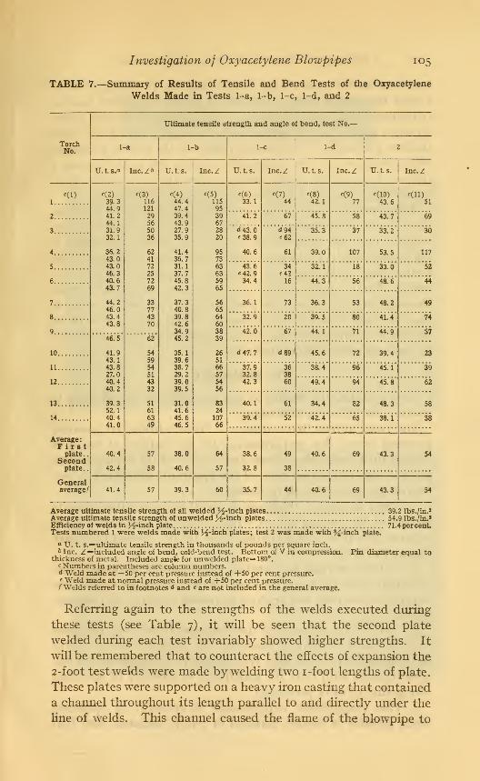
Investigation of Oxyoxetylene Blowpipes 105
TABLE 7.—Summary of Results of Tensile and Bend Tests of the Oxyacetylene
Welds Made in Tests 1-a, 1-b, 1-c, 1-d, and 2
Ultimate tensile s trength and angle of bend, test No.—
TorchNo.
1--a 1- b 1-c 1-d 2
U. L s.a Inc.Z'' TJ. t. s. Inc.Z U. t. s. Inc.Z U. t. s. Inc.Z U. t. s. Inc.Z
1
c(2)
39.344.941.244.131.932.1
36.243.043.046.340.643.7
44.246.043.443.8
«(3)
116121
29565036
62417225
7269
33774370
c(4)
44.447.439.443.927.935.9
41.436.731.137.745.842.3
37.340.839.842.634.945.2
35.139.638.729.239.039.5
31.041.645.646.5
c(5)
115
9539672820
957363635965
566564603839
2651
66575456
832410766
<(6)
33.1
c(7)
44
c(8)42.1
f(9)
77
c(10)
43.6
c(U)51
2 41.2 67 45.8 58 43.7 69
3 <M3.0«38.9
40.6
d94«62
61
35.3 37 33.2 30
4 39.0 107 53.5 117
5 43.6«42.934.4
34e4216
32.1 18 33.0 52
6 44.3 56 48.6 44
7 36.1 73 36.3 53 48.2 49
8 32.9 20 39.5 80 41.4 74
9 42.0 67 44.1 71 44.9 5746.5
41.943.143.827.040.440.2
39.352.140.441.0
62
545954514332
5161
6349
10 «U7.7 d89 45.6 72 39.4 23
11 37.932.842.3
363860
38.4 96 45.1 39
12 49.4 94 45.8 62
13 40.1 61 34.4 82 48.3 58
14 39.4 52 42.4 65 38.1 38
Average:First
plate..Secondplate..
40.4
42.4
57
58
38.0
40.6
64
57
38.6
32.8
49
38
40.6 69 43.3 54
Generalaverage/ 41.4 57 39.3 60 35.7 44 40.6 69 43.3 54
Average ultimate tensile strength of all welded H-hich plates 39.2 lbs./in.a
Average ultimate tensile strength of unwelded 3^2-inch plates 54.9 Ibs./in.1
Efficiency of welds in J4-inch plate 71.4percenLTests numbered 1 were welds made with H-inch plates; test 2 was made with %-inch plate.
U. t. s.=ultimate tensile strength in thousands of pounds per square inch.b Inc. Z=included angle of bend, cold-bend test. Bottom of V in compression. Pin diameter equal to
thickness of metal. Included angle for unwelded plate=180°.c Numbers in parentheses are column numbers.d Weld made at —50 per cent pressure instead of +50 per cent pressure.« Weld made at normal pressure instead of +50 per cent pressure./ Welds referred to in footnotes <* and < are not included in the general average.
Referring again to the strengths of the welds executed during
these tests (see Table 7), it will be seen that the second plate
welded during each test invariably showed higher strengths. It
will be remembered that to counteract the effects of expansion the
2-foot test welds were made by welding two i-foot lengths of plate.
These plates were supported on a heavy iron casting that contained
a channel throughout its length parallel to and directly under the
line of welds. This channel caused the flame of the blowpipe to

106 Technologic Papers of the Bureau of Standards
return under the plates being welded and thus preheated to someextent the second plate. Further, it caused a decided heating
of the near end of the base casting. The explanation for the higher
strength shown by the second plates probably lies in the moreuniform preheating of the second plate and the greater annealing
effect produced by the heated base casting, the latter causing a
release of the tensile strains resulting from the contraction of the
metal along the line of the weld.
The average strengths and average included angle of bend are
given in the above-mentioned table (Table 7) for what they are
worth. It is very probable in the light of present knowledge of
the requirements of blowpipe design, that some new ideas will be
forthcoming concerning the average strength of oxyacetylene
welds. Finally in Figs. 65 to 71 are exhibited microphotographs
showing the effect upon the grain structure of the material, in
this case mild steel, of the autogenous welding process, effects not
necessarily detrimental when properly performed, but, as exhibited
by the microphotographs, instructive.
VII. SUMMARY
In conclusion, the results of this investigation would seem to
warrant the following statements.
For the Cutting Blowpipes.— 1 . There is to-day no generally
accepted theory for proportioning, for the cutting of metal of
various thicknesses, the volume and velocity of the issuing cutting
jet, with the result that none of the apparatus submitted to test
proved economical for all thicknesses.
2. There is for any thickness of metal cut a limiting velocity
of exit of the cutting jet, at which complete utilization of the
oxygen takes place and a limiting value for the amount of oxygen
required to produce a cut.
3. That an increase in acetylene consumption, in oxygen con-
sumption, or in the velocity of exit of the cutting jet beyond the
limiting values does not produce increased efficiency in commen-
surate ratio.
4. That a large majority of the blowpipes tested were equipped
with excessive preheating flames for the thickness of metal the
tip is specified for, and that such excessive sized flames are dis-
advantageous both from the standpoint of economy of operation
and quality of work performed.
5. That considerable improvement in economy of operation
seems possible in cutting material of 2-inch thickness, and that

Bureau of Standards Technologic Paper No. 200
w
W^L
Wmm kSSIIkswp^s*
S*
w'^L v
rS i'Vu*.
Fig. 65.
—
Microphotographs I
a.—Welded plate, natural size. Location of n
&.—Weld metalc.—Junction of weld and plate
rf.—< iverbeated plate metal near welde.—Unaltered plate metal

Bureau of Standards Technologic Paper No. 200
Fig. 66.
—
Etched sections through welds

zzx-^=r* .wj^.
Bureau of Standards Technologic Paper No. 200
i
Fig. 67. Etched sections thruinjh welds—Continued

Bureau of Standards Technologic Paper No. 200
V
S*%as&
v'"- . ... v.-. -.
Fig. 68.
—
Etched sections through welds—Continued

Bureau of Standards Technologic Paper No. 200
T'lG. 69.
—
Etched sections through welds— Continued

Bureau of Standards Technologic Paper No. 200
ZPJ ?t>>
/O A
(M
-
f* 2~.
/%?>
V5*{
Fig. 70.
—
Etched sections through welds—Continued

Bureau of Standards Technologic Paper No. 200
Fig. 71.
—
Etched sections ihrouyh welds—Concluded


Investigation of Oxyacetylene Blowpipes 107
possibly this condition may be found to exist for metal of other
thicknesses than those used in the tests.
6. That the maximum thickness of metal that may be economi-
cally cut with an oxyacetylene blowpipe of standard design when
neither the material nor the oxygen is preheated and the cutting
is done only from one direction is about 12 inches.
7. That cutting blowpipes, due to their incorrect design, are
subject to the same flash-back troubles found in the welding
blowpipes.
For the Welding Blowpipes.— 1. That the blowpipes most
subject to the so-called flash-back phenomena are those in which
the oxygen is delivered at a pressure in excess of that at which the
acetylene is delivered.
2. That all the blowpipes tested, including those in which the
acetylene is delivered at an excess pressure as well as the so-called
equal or balanced pressure blowpipes, are subject to flash-back
phenomena on account of inherent defects in their design.
3. That the cause of the development of the conditions produc-
ing flash back is the setting up within the blowpipe tip and head
of a back pressure which retards or chokes off the flow of one of
the gases.
4. That this back pressure is the result of confining or restrict-
ing the volume flow of the issuing gases at the tip end.
5. That any cause tending to restrict the flow of the gases sets
up a back pressure, which immediately causes a change in the
amount of each gas delivered to the mixing chamber.
6. That a fluctuating gas volume ratio, due to restriction of
volume flow, from whatever cause, prevents a blowpipe from
maintaining constantly and at all times during operation the
desired "neutral flame."
7. That a blowpipe that can not maintain under all operating
conditions a neutral flame can not logically be expected to pro-
duce sound welds.
8. That all the blowpipes tested during this investigation,
either through improper gas pressures or improper interior design
or both are incapable of maintaining a neutral flame (constant
volume gas ratio) under all conditions of restricted gas flow andare therefore incapable of producing sound welds where there is
any liability of the gaseous products of combustion being momen-tarily confined, such as occurs in practically all welding operations.

108 Technologic Papers of the Bureau of Standards
9. That the ability of a blowpipe to consume an equal volume
ratio of gases when burning freely and undisturbed in air is nocriterion that it is capable of producing sound welds; that is,
that it is not subject to detrimental fluctuations in gas ratio
during a welding operation and therefore is capable of maintain-
ing a neutral flame under all operating conditions.
10. That whether blowpipes of present designs will consumeequal volume ratio of gases when burning freely and undisturbed
in air depends on how nearly correct the operator sets the so-called
neutral flame, and experience indicates that the average operator
checks the acetylene gas flow too much and actually develops an
oxidizing rather than a neutral flame.
11. That the question of the possible limiting strength andductility or the efficiency of welds made by the oxyacetylene
welding blowpipe must await the development of a more satis-
factory instrument, and that having such an instrument there is
no reason to believe that a weld of clean sound metal can not be
made with assurance during any welding operation and that such
welds will or can be made to possess the proper physical properties.
Washington, March 13, 1921.