GENERAL DESCRIPTION
36
CENTRAL WORKSHOP/MYSURU ` 1 GENERAL DESCRIPTION METAL JOINING METHODS WELDING “Welding is a process of joining two or more pieces of the same or dissimilar materials to achieve complete coalescence. This is the only method of developing monolithic structures and it is often accomplished by the use of heat and/or pressure. ADVANTAGES OF WELDING Welding is superior to other metal joining methods because it: Is a permanent pressure tight joint Occupies less space Gives more economy of material Has less weight Withstands high temperature and pressure equal to joined material Can be done quickly Gives no color change to joints. It is the strongest joint and any type of metal of any thickness can be joined. DIFFERENT METHODS OF WELDING Fusion method without pressure/ with pressure Non-fusion method Fusion welding without pressure The joint made is permanent. The common heating sources are: Arc welding Gas welding Chemical reaction (Thermit welding) Pressure welding Heat source may be blacksmith forge (forge welding) or electric resistance (resistance welding) or friction
-
Upload
khangminh22 -
Category
Documents
-
view
2 -
download
0
Transcript of GENERAL DESCRIPTION

CENTRAL WORKSHOP/MYSURU
` 1
GENERAL DESCRIPTION
METAL JOINING METHODS
WELDING “Welding is a process of joining two or more pieces of the same or dissimilar materials to achieve complete coalescence. This is the only method of developing monolithic structures and it is often accomplished by the use of heat and/or pressure. ADVANTAGES OF WELDING
Welding is superior to other metal joining methods because it:
Is a permanent pressure tight joint Occupies less space Gives more economy of material Has less weight Withstands high temperature and pressure equal to joined material Can be done quickly Gives no color change to joints.
It is the strongest joint and any type of metal of any thickness can be joined.
DIFFERENT METHODS OF WELDING
Fusion method without pressure/ with pressure Non-fusion method
Fusion welding without pressure
The joint made is permanent. The common heating sources are: Arc welding Gas welding Chemical reaction (Thermit welding)
Pressure welding
Heat source may be blacksmith forge (forge welding) or electric resistance (resistance
welding) or friction
CENTRAL WORKSHOP/MYSURU
` 2
NON-FUSION WELDING
This is a method in which similar or dissimilar metals are joined together without melting the edges of the base metal by using a low melting point filler rod but without the application of pressure.
Electric welding processes can be classified as:
Electric arc welding Electric resistance welding Laser welding Electron beam welding Induction welding
Electric arc welding can be further classified as:
Metallic arc welding Carbon arc welding Atomic hydrogen arc welding Inert gas arc welding/ TIG welding CO2 gas arc welding Flux cored arc welding Submerged arc welding Electro-slag welding Plasma arc welding Electric resistance welding can be further classified as:
Spot welding Seam welding Butt welding Flash butt welding Projection welding Gas welding processes can be classified as:
Oxy-acetylene gas welding Oxy-hydrogen gas welding Oxy-coal gas welding Oxy-liquefied petroleum gas welding Air acetylene gas welding

CENTRAL WORKSHOP/MYSURU
` 3
COMMON METALS AND ALLOYS
Metals may be ferrous, non-ferrous metals and alloys.
Ferrous metals are those which have iron as their base. They include iron and its alloys such as steel, cast iron and alloy steels such as stainless steel etc.
Non-ferrous metals do not contain iron as base. They include copper, aluminium, zinc, tin etc and non-ferrous alloys.
Alloys If two or more metals are chemically combined they form an alloy e.g. iron, chromium nickel and carbon form an alloy called chromium nickel steel (stainless), manganese, iron and carbon form an alloy called manganese steel, copper and zinc form an alloy called brass, copper and tin form an alloy called bronze, lead and tin form an alloy called soft solder. PROPERTIES OF METALS
Properties of metals can be classified mainly into: o Chemical properties o Physical properties o Mechanical properties
Chemical properties :- are those which involve chemical effect such as: o Corrosion o Oxidation o Reduction
Corrosion will spoil the metal surface due to the effect of various elements in the atmosphere and water.
Oxidation is the formation of metal oxides which occur when oxygen combines with metals.
Reduction refers to the removal of oxygen from the surrounding molten puddle to reduce the effect of atmospheric contamination. Physical properties are those, which affect metals when they are subjected to heat generated by welding such as: o melting point o thermal conductivity o thermal expansion o grain growth
CENTRAL WORKSHOP/MYSURU
` 4
Melting point is the degree of temperature, when a solid metal changes into liquid. Melting points of some metals are given below:
1. Mild steel
1500 to
1530°C
2. Cast iron 1150°C
3. Copper 1083°C
4. Aluminium 659°C
5. Brass and bronze 950°C
6. Zinc 419°C
7. Tin 232°C
8. Lead 327°C
9. Nickel 1452°C
10. Soft solder 190°C
Mechanical Properties
Mechanical properties are those which determine the behavior of metals under applied load such as: Tensile strength
Ductility Hardness
Toughness Brittleness
EFFECT OF WELDING HEAT ON THE PROPERTIES OF METALS
During welding the properties of the weld metal may be affected. Important alloying elements may be destroyed. Brittle, hard or cracked welds may be produced. There may be reduction in the corrosion resistance properties of the welds. Main properties of the base metal and weld metal will get affected
EFFECT OF ATMOSPHERIC AIR ON WELDING The atmospheric air is a gaseous mixture of mainly nitrogen and oxygen, with some other gases like hydrogen, etc. in small percentages. Since the atmospheric air contains 21% of oxygen, whenever a red hot or molten iron comes in contact with atmospheric air the metal gets oxidized.
Oxygen contamination i.e. oxidation will reduce the mechanical properties of the weld metal. In other words the tensile strength, toughness and ductility of the weld decrease with increased oxygen contamination.

CENTRAL WORKSHOP/MYSURU
` 5
ELECTRIC WELDING PROCESSES
TYPES OF ELECTRIC WELDING
ELECTRIC ARC WELDING Electric arc is formed when both the terminals of an electric circuit are brought together
and then separated by a small gap. When high current passes through an air gap from one
conductor to another, it produces very intense and concentrated heat in the form of a spark.
The temperature of this spark (or arc) is app. 3600°C, which can melt and fuse the metal very
quickly to produce a homogeneous weld. The types of electric arc welding are as follows.
Tungsten Inert Gas arc welding (TIG)
In this process the arc is formed between the tungsten electrodes (non-consumable) and
the welding job in an atmosphere of an inert gas (argon or helium). A separate filler rod is
used to add the filler metal. This process is also called gas tungsten arc welding (GTAW)
process.
CENTRAL WORKSHOP/MYSURU
` 6
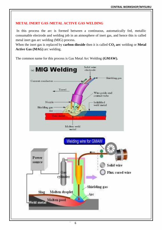
METAL INERT GAS /METAL ACTIVE GAS WELDING In this process the arc is formed between a continuous, automatically fed, metallic
consumable electrode and welding job in an atmosphere of inert gas, and hence this is called
metal inert gas arc welding (MIG) process.
When the inert gas is replaced by carbon dioxide then it is called CO2 arc welding or Metal
Active Gas (MAG) arc welding.
The common name for this process is Gas Metal Arc Welding (GMAW).
CENTRAL WORKSHOP/MYSURU
` 7
SALIENT FEATURES:-
It is an arc welding process in which the heat required for the welding comes from an electric arc.
The electric arc develops when electricity jumps across an air gap (ionization of air) between the end of the metallic electrode and the welding job surface.
The metallic electrode is generally coated with a flux which is consumable.
The arc created due to the ionization of air between the electrode tip and the base metal generates an intense arc heat having a temperature between 3600°C-4000°C.
The welding current is provided by an AC or DC machine.
The intense heat of the arc melts a small portion (molten pool) on the job directly under the arc and at the end of the electrode instantaneously.
The melted electrode fuses into the molten pool of the welding job and produces a homogeneous weld on cooling.
Shielded Metal Arc Welding (SMAW).
o The flux coating on the electrode also melts and
provides a gaseous shield around the arc which protects the molten metal from atmospheric contamination. Hence this is called Shielded Metal Arc Welding (SMAW).
o The welding speed and feed of the electrode is
controlled manually by the welder himself. So it is also called Manual Metal Arc Welding (MMAW).
o When the weld metal solidifies, the slag (of flux
coating) gets deposited on its surface as it is lighter than the metal and the weld metal is allowed to cool gradually and slowly.
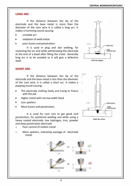
ARC LENGTH
It is the straight distance between the electrode tip and the job surface when the arc is formed. There are three types of arc lengths:
Medium or normal
Long
Short
CENTRAL WORKSHOP/MYSURU
` 8
LONG ARC
If the distance between the tip of the electrode and the base metal is more than the diameter of the core wire it is called a long arc. It makes a humming sound causing: unstable arc oxidation of weld metal poor fusion and penetration
It is used in plug and slot welding, for restarting the arc and while withdrawing the electrode at the end of a bead after filling the crater. Generally long arc is to be avoided as it will give a defective weld.
SHORT ARC
If the distance between the tip of the electrode and the base metal is less than the diameter of the core wire, it is called a short arc. It makes a popping sound causing: The electrode melting fastly and trying to freeze
with the job Higher metal with narrow width bead Less spatters More fusion and penetration.
It is used for root runs to get good root
penetration, for positional welding and while using a heavy coated electrode, low hydrogen, iron, powder and deep penetration electrode. o Poor control of molten metal
o More spatters, indicating wastage of electrode
metal.

CENTRAL WORKSHOP/MYSURU
` 9
SAFETY IN MANUAL METAL ARC WELDING
During arc welding the welder is exposed
to hazards such as injury due to harmful rays (ultra
violet and infra red rays) of the arc, burns due to
excessive heat from the arc and contact with hot
jobs, electric shock, toxic fumes, flying hot
spatters, slag particles and objects falling on the
feet.
The following safety apparels and accessories are
used to protect the welder and other persons
working near the welding area from the above
mentioned hazards.
1. Safety apparels a. Leather apron b. Leather gloves c. Leather cape with sleeves d. Industrial safety shoes 2. Hand screen a. Adjustable helmet b. Portable fire proof canvas screens 3. Chipping/ grinding goggles Respirator and exhaust ducting
RECOMMENDATION OF FILTER GLASSES FOR MANUAL METAL ARC WELDING.
Shade No. of coloured glass Range of welding current in amperes
8-9 Upto 100
10-12 100 to 250
12-14 Above 250

CENTRAL WORKSHOP/MYSURU
` 10
Plain goggles are used to protect the eyes while
chipping the slag or grinding the job. It is made of
Bakelite frame fitted with clear glasses and an
elastic band to hold it securely on the operators
head. It is designed for comfortable fit, proper
ventilation and full protection from all sides.
3. SAFETY APPARELS
The leather apron, gloves, cape with
sleeves and leg guard are used to protect the body,
hands, arms, neck and chest of the welder from
the heat radiation and hot spatters from the arc
and also from the hot slag particles flying from the
weld joint during chipping off the solidified slag.
ARC WELDING ACCESSORIES
Some very important items used by a
welder with an arc welding machine during the
welding operation, are called arc welding
accessories.
Electrode Welding cables/ leads -holder Earth Clamp

CENTRAL WORKSHOP/MYSURU
` 11
MATERIAL PREPARATION METHOD
POLARITY IN DC ARC WELDING
Importance of polarity in welding
In DC welding 2/3 of the heat liberated from the positive end and 1/3 from the negative end. To have this advantage of unequal heat distribution in the electrode and base metal, the polarity is an important factor for successful welding.
In AC, the polarity cannot be utilized as the power source changes its poles frequently.
Kinds of polarity are two: Straight polarity or electrode negative (DCEN). Reverse polarity or electrode positive (DCEP).
STRAIGHT POLARITY (DCEN)
In straight polarity the electrode is connected to
the negative and the work to the positive terminal
of the power source.
REVERSE POLARITY (DCEP)
In reverse polarity the electrode is connected to the positive and the work to the negative terminal of the power source.
Reverse polarity is used for: DC is preferred to AC for hard facing and stainless steel welding.
Choice of the polarity also depends on the instruction of the electrode manufacturers. In order to get the best results, it is essential to attach the electrode with the correct terminal of the welding machine.

CENTRAL WORKSHOP/MYSURU
` 12
FUNCTIONS OF AN ELECTRODE IN SHIELDED METAL ARC WELDING (SMAW)
There are two main functions of an electrode in shielded metal arc welding:
The core wire conducts the electric current from the electrode holder to the base metal
through the arc. It deposits weld metal across the arc onto the base metal. The flux covering melts at a slower rate than the metal core and a cup is formed at the tip of the electrode which helps to direct the molten metal to the required spot.
IDENTIFICATION OF ELECTRODES For easy identification and selection of a suitable arc welding electrode for welding mild steel plates, the electrodes are coded by Bureau of Indian Standards (B.I.S). According to the B.I.S., the electrodes to be used for welding mild steel for training a beginner is coded as ER4211.
The classification for the electrode ER4211 is given below for easy understanding: E = Flux coated or covered electrode R = Type of flux covering (Rutile) 4 = Strength of the joint (UTS = 410-510 N/nm
2 and YS = 330N/nm
2 min.
2 = Elongation and impact properties of the weld (Elongation = 22% min. and impact = 47 J min. at 0°C)
1 = Welding position (all position) welding can be done in all positions
1 = Welding current and voltage conditions. This means that for DC welding, the electrode can be connected to the +ve or –ve terminal. For AC welding, the open circuit voltage should be 50 volts.
CENTRAL WORKSHOP/MYSURU
` 13
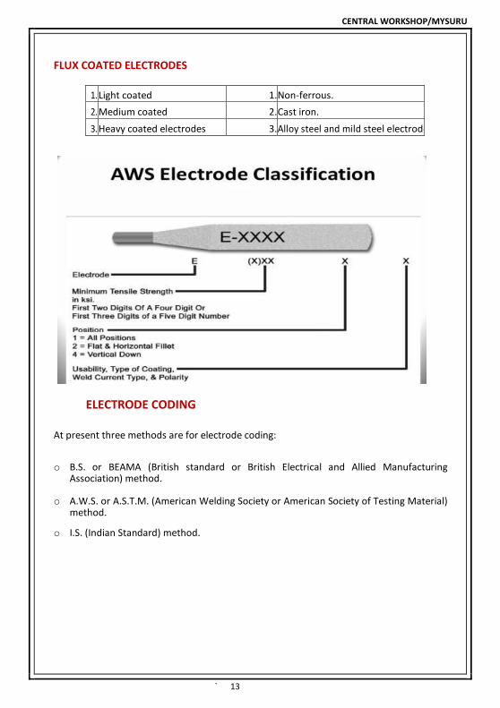
FLUX COATED ELECTRODES
1. Light coated 1. Non-ferrous.
2. Medium coated 2. Cast iron.
3. Heavy coated electrodes 3. Alloy steel and mild steel electrodes.
ELECTRODE CODING
At present three methods are for electrode coding:
o B.S. or BEAMA (British standard or British Electrical and Allied Manufacturing
Association) method. o A.W.S. or A.S.T.M. (American Welding Society or American Society of Testing Material)
method. o I.S. (Indian Standard) method.

CENTRAL WORKSHOP/MYSURU
` 14
USAGE AND STORAGE OF ELECTRODES
Usage and storage of electrodes Electrodes are costly, therefore, use and consume every bit of them.
Do not discard STUB ENDS more than 30-40 mm length.
Electrode coating can pick up moisture if exposed to atmosphere.
Store and keep the electrodes (air tight) in a dry place.
Heat the moisture affected/ prone electrodes in an electrode drying oven at 110-150°C for one hour before using.
WELDING ELECTRODE OVEN HAND OVEN
Remember a moisture affected electrode:
has rusty stub end
has white powder appearance in coating
produces porous weld. Storage of electrodes:
The efficiency of an electrode is affected if the covering becomes damp.
Keep electrodes in unopened packets in a dry store.
Place packages on a duckboard or pallet, not directly on the floor.
Store so that air can circulate around and through the stack.
CENTRAL WORKSHOP/MYSURU
` 15
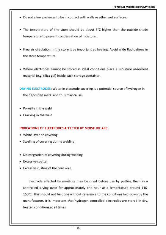
Do not allow packages to be in contact with walls or other wet surfaces.
The temperature of the store should be about 5°C higher than the outside shade
temperature to prevent condensation of moisture.
Free air circulation in the store is as important as heating. Avoid wide fluctuations in
the store temperature.
Where electrodes cannot be stored in ideal conditions place a moisture absorbent
material (e.g. silica gel) inside each storage container.
DRYING ELECTRODES: Water in electrode covering is a potential source of hydrogen in
the deposited metal and thus may cause.
Porosity in the weld
Cracking in the weld
INDICATIONS OF ELECTRODES AFFECTED BY MOISTURE ARE:
White layer on covering
Swelling of covering during welding
Disintegration of covering during welding
Excessive spatter
Excessive rusting of the core wire.
Electrode affected by moisture may be dried before use by putting them in a
controlled drying oven for approximately one hour at a temperature around 110-
150°C. This should not be done without reference to the conditions laid down by the
manufacturer. It is important that hydrogen controlled electrodes are stored in dry,
heated conditions at all times.

CENTRAL WORKSHOP/MYSURU
` 16
ISR
CLASS USE
IS/AWS
SPEC.
IS/AWS
CODE
A-1
Steel sheet joining & GR. FE 330, repairing
welding of cast steel GR.200-400W & IS:
2062-99, GR A.IS: 1875-92 class 1 & 1A or
similar IS: 814-91
ER 4112
medium coated
A-2
Fabrication of steel bridges the weld deposit
shall be of radiographic quality IS:2062-99
GR.B.IS: 1875-92 class 1 & 1A or similar IS: 814-91
ER 4112X
medium coated
A-3
Highly dynamic application made of steel
IS:2062-99 GR.C. & low temperature
impact property. The weld deposit shall be
of radiographic quality IS: 814-91
EB 5326H2X
medium coated
A-4
Highly dynamic application made of steel
IS:2062-99 GR. C & low temperature
Impact property. The weld with high
efficiency deposit shall be of radiographic
quality IS: 814-91
EB 5326H2X
heavy coated
A-5 Pipe welding or where high penetration of
arc is needed IS: 814-91
ER 4316X
medium coated
B-1
Welding of steel component as steel to IS:
8500-91 GR.4408 & 4908, IS: 2002-92 GR. 1&2, IS: 1875-92 class 2, 2A & 3 or similar
suitable for repair welding of cast steel to
IS:1030 GR. 230-450W. The weld deposit
shallbe of Radiographic quality Joining of stainless steel type 3CR 12, IRS M-44 or its
equivalent with Milo steel / low alloyed
steel/corten steel IS: 814-91
EB5426H3X
medium coated
B-2 Application same as B-1 above with high deposition efficiency IS: 814-91
EB5426H3JX
heavy coated
B-3
Fabrication of components made of steel to ASTM 516 GR. 70 or equivalent where low
temperature (AT-46oC) impact properties
are required. The weld deposit shall be of
Radiographic quality. IS: 1395-B2
E55BC126
heavy coated
B-4 Application same as B-3 above with high
deposition efficiency. IS: 1395-B2
E55BC126J
heavy coated
C-1
Fabrication of components made of steel to
IS: 8500-91 GR.5408, 5708, 590, IS: 2002- 92 GR.3, IS: 1875-92 class 3A or similar.
The weld deposit shall be of radiographic
quality. IS: 1395-B2
E63BD126
heavy coated
C-2 Application same as C1 above with high
deposition efficiency. IS: 1395-B2 E63BD126J
heavy coated
CENTRAL WORKSHOP/MYSURU
` 17
ISR
CLASS USE
IS/AWS
SPEC.
IS/AWS
CODE
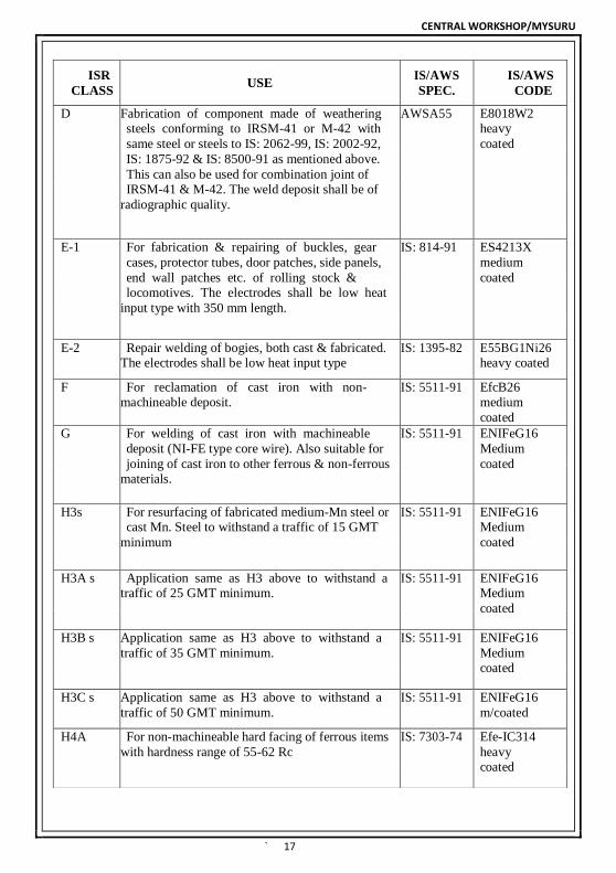
D Fabrication of component made of weathering steels conforming to IRSM-41 or M-42 with
same steel or steels to IS: 2062-99, IS: 2002-92,
IS: 1875-92 & IS: 8500-91 as mentioned above.
This can also be used for combination joint of IRSM-41 & M-42. The weld deposit shall be of
radiographic quality.
AWSA55 E8018W2 heavy
coated
E-1 For fabrication & repairing of buckles, gear
cases, protector tubes, door patches, side panels,
end wall patches etc. of rolling stock & locomotives. The electrodes shall be low heat
input type with 350 mm length.
IS: 814-91 ES4213X
medium
coated
E-2 Repair welding of bogies, both cast & fabricated. The electrodes shall be low heat input type
IS: 1395-82 E55BG1Ni26 heavy coated
F For reclamation of cast iron with non-
machineable deposit.
IS: 5511-91 EfcB26
medium
coated
G For welding of cast iron with machineable
deposit (NI-FE type core wire). Also suitable for
joining of cast iron to other ferrous & non-ferrous materials.
IS: 5511-91 ENIFeG16
Medium
coated
H3s For resurfacing of fabricated medium-Mn steel or cast Mn. Steel to withstand a traffic of 15 GMT
minimum
IS: 5511-91 ENIFeG16 Medium
coated
H3A s Application same as H3 above to withstand a traffic of 25 GMT minimum.
IS: 5511-91 ENIFeG16 Medium
coated
H3B s Application same as H3 above to withstand a
traffic of 35 GMT minimum.
IS: 5511-91 ENIFeG16
Medium coated
H3C s Application same as H3 above to withstand a
traffic of 50 GMT minimum.
IS: 5511-91 ENIFeG16
m/coated
H4A For non-machineable hard facing of ferrous items
with hardness range of 55-62 Rc
IS: 7303-74 Efe-IC314
heavy coated

CENTRAL WORKSHOP/MYSURU
` 18
ISR
CLASS USE IS/AWS SPEC.
IS/AWS
CODE
L For welding of aluminium and aluminium alloys AWS A5, 3 AL-43
medium
coated
M1 For fabrication of stainless steels type 18% Cr 8%
Ni types its equivalent.
IS: 5206-83 E19.9R26
heavy coated
M2 For fabrication of ferritic stainless steels type
3Cr12IRS M-44 or its equivalent, also suitable for
fabrication of 18% Cr 8% Ni stainless steels with
low carbon.
IS: 5206-83 E19.9R26
heavy coated
M3 For fabrication of stainless steels to ASTM grade
316 or its equivalent.
IS: 5206-83 E19.12.2R26
heavy coated
M4 For joining of dissimilar stainless steels as
mentioned in M1, M2 and M3 or their equivalent
& also suitable for joining M1, M2 and M3
stainless steels as mentioned above or their
equivalent with mild steel or low alloyed steel.
Also be used for welding of heat resisting stainless
steels 22% Cr 12% Ni type or its equivalent.
IS: 5206-83 E23.12R26
heavy coated
M5 For joining of manganese steel liners and other
austenitic manganese steel components with steel
casting to IS: 1030 Gr.230-450W/280-520W or to
IS: 2062
IS: 5206-83 E18.8MnB26
heavy coated
M6 For repair welding of cracked gas inlet casting of
diesel locomotives. Used for other repair welding
of stainless steels casting having higher percentage
of carbon and for welding of high heat resisting
stainless steels 25% Cr 20% Ni type or its
equivalent.
IS: 5206-83 E25.20R26
heavy coated
N-1 For cutting mild steel low alloy steel, stainless
steels, austentic manganese steels, cast iron cast
steel & non-ferrous alloys such as nickel alloys,
ALU, C, bronzes etc.
IS: 5206-83 E25.20R26
heavy coated
N-2 For gouging & piercing of steels and non-ferrous
alloy as described in N1.
IS: 5206-83 E25.20R26
heavy coated
N-3 For gouging of mild & low alloy steel, stainless
steels, austenitic manganese steel and cast iron &
cast steel, copper coated graphitic type electrode.
IS: 5206-83 E25.20R26
heavy coated
CENTRAL WORKSHOP/MYSURU
` 19
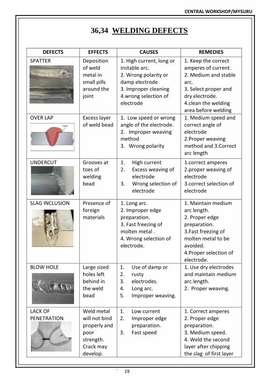
36,34 WELDING DEFECTS
DEFECTS EFFECTS CAUSES REMEDIES
SPATTER Deposition of weld metal in small pills around the joint
1. High current, long or instable arc. 2. Wrong polarity or damp electrode 3. Improper cleaning 4.wrong selection of electrode
1. Keep the correct amperes of current. 2. Medium and stable arc. 3. Select proper and dry electrode. 4.clean the welding area before welding
OVER LAP Excess layer of weld bead
1. Low speed or wrong angle of the electrode. 2. Improper weaving method 3. Wrong polarity
1. Medium speed and correct angle of electrode 2.Proper weaving method and 3.Correct arc length
UNDERCUT
Grooves at toes of welding bead
1. High current 2. Excess weaving of
electrode 3. Wrong selection of
electrode
1.correct amperes 2.proper weaving of electrode 3.correct selection of electrode
SLAG INCLUSION
Presence of foreign materials
1. Long arc. 2. Improper edge preparation. 3. Fast freezing of molten metal . 4. Wrong selection of electrode.
1. Maintain medium arc length. 2. Proper edge preparation. 3.Fast freezing of molten metal to be avoided. 4.Proper selection of electrode.
BLOW HOLE Large sized holes left behind in the weld bead
1. Use of damp or 2. rusty 3. electrodes. 4. Long arc. 5. Improper weaving.
1. Use dry electrodes and maintain medium arc length. 2. Proper weaving.
LACK OF PENETRATION
Weld metal will not bind properly and poor strength. Crack may develop.
1. Low current 2. Improper edge
preparation. 3. Fast speed
1. Correct amperes 2. Proper edge preparation. 3. Medium speed. 4. Weld the second layer after chipping the slag of first layer

CENTRAL WORKSHOP/MYSURU
` 20
CRACK Development of
crack in the weld in metal
1. Lack of penetration. 2. Improper edge preparation. 3. Sudden cooling of welded components. 4. Low current
1. Proper penetration. 2. Edge preparation. 3. Components to be cooled in atmospheric air. 4.correct amperes of current
DISTORTION Deformation of shape
1. Dissimilar metal thickness. 2. Lack of using jigs and fixtures. 3.improper tack weld
1.Use similar thickness of metal. 2. Use jigs and fixtures 3. Proper tack weld.
SPATTERS Swinging of weld metal to the weld line
1. Use of wrong electrode .
2. Wrong technique.
3. High current.
1.proper electrode 2. Proper welding technique. 3. Correct amperes of current.
CRATER
Development of a pit at the weld line end
Incomplete layer of welding bead
At end of weld line the electrode should be kept for a while.
SURFACE PORES
Formation of small holes in the weld bead
1.High current, 2.electrode damp or its flux is broken. 3.long arc
1. Correct amperes of current.2. dry electrodes with proper flux coating.3. Medium arc length.
LACK OF FUSION
Insufficient melting of both parent and weld metals
1. Improper arc length.
2. Wrong type of electrode.
3. wrong weaving method.
1.Medium arc length. 2.Proper type of electrode. 3.Proper weaving method.
CENTRAL WORKSHOP/MYSURU
` 21
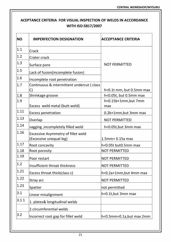
ACEPTANCE CRITERIA FOR VISUAL INSPECTION OF WELDS IN ACCORDANCE
WITH ISO:5817/2007
NO IMPERFECTION DESIGNATION ACCEPTANCE CRITERIA
1.1 Crack
NOT PERMITTED
1.2 Crater crack
1.3 Surface pore
1.5 Lack of fusion(incomplete fusion)
1.6 Incomplete root penetration
1.7 Continuous & intermittent undercut ( class C) h<0.1t mm, but 0.5mm max
1.8 Shrinkage groove h<0.05t, but 0.5mm max
1.9 Excess weld metal (butt weld)
h<0.15b+1mm,but 7mm max
1.11 Excess penetration 0.2b+1mm,but 3mm max
1.13 Overlap NOT PERMITTED
1.14 sagging ,incompletely filled weld h<0.05t,but 3mm max
1.16 Excessive Asymmetry of fillet weld (Excessive unequal leg) 1.5mm+ 0.15a max
1.17 Root concavity h<0.05t but0.5mm max
1.18 Root porosity NOT PERMITTED
1.19 Poor restart NOT PERMITTED
1.2 Insufficient throat thickness NOT PERMITTED
1.21 Excess throat thick(class c) h<0.2a+1mm,but 4mm max
1.22 Stray arc NOT PERMITTED
1.23 Spatter not permitted
3.1 Linear misalignment h<0.1t,but 3mm max
3.1 1 1. plates& longitudinal welds 2.circumferential welds 3.2 Incorrect root gap for fillet weld h<0.5mm+0.1a,but max 2mm

CENTRAL WORKSHOP/MYSURU
` 22
h - Height or depth of imperfection
b- Width of weld reinforcement
t- Thickness of job / plate (nominal size of parent metal)
S-nominal butt weld thickness
l - Length of imperfection in longitudinal direction of weld
a - nominal throat thickness of fillet weld
l - Length of imperfection in longitudinal direction of weld
CENTRAL WORKSHOP/MYSURU
` 23
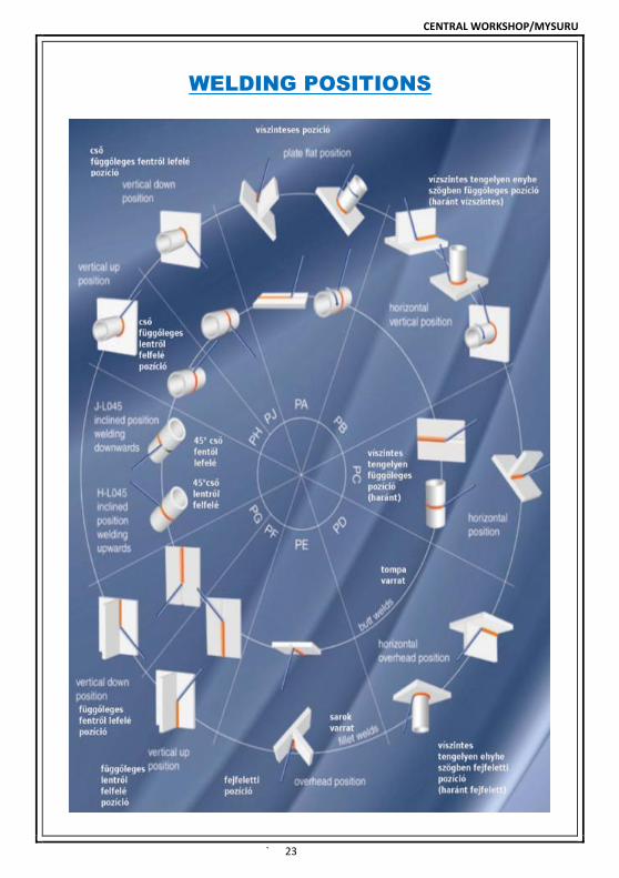
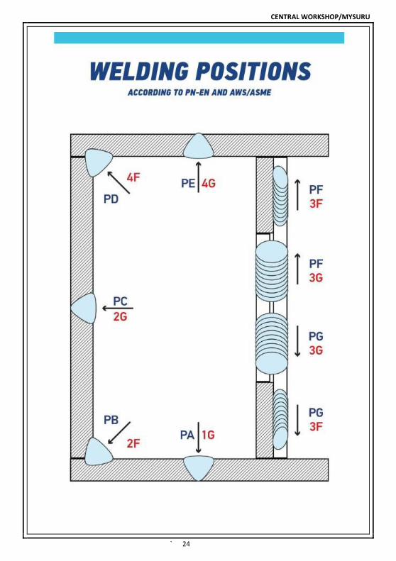
WELDING POSITIONS
CENTRAL WORKSHOP/MYSURU
` 24
CENTRAL WORKSHOP/MYSURU
` 25
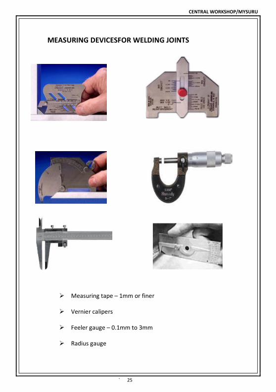
MEASURING DEVICESFOR WELDING JOINTS
Measuring tape – 1mm or finer
Vernier calipers
Feeler gauge – 0.1mm to 3mm
Radius gauge

CENTRAL WORKSHOP/MYSURU
` 26
WHAT IS ISO-3834
ISO 3834 is a Quality requirement for fusion welding of metallic materials.
It is an international standard created by the welding professional.
ISO 9001 defines overall requirements for quality management system.
ISO-3834 standard specifies the requirements relating only to the welded structure.
ISO 3834 is not a product standard, but it is often cited as a requirement of various
products to ensure good practice in the welding and to prevent premature failures.
ISO 3834 standard provides details of how to control the various welding and
welding-related operations to achieve the desired quality consistently.
CONCEPT OF ISO 3834
QUALIFICATION REQUIREMENT
Welder qualification
ISO 9606 EN 287
Welding operator
qualification
ISO 14732 EN 1418
Welding coordinator (WC + RWC)
ISO 14731 IWE, IWP, IWT, IWS
NDT personnel ISO 9712 EN 473 IWIP
Welding-procedure
specifications
ISO 15607
ISO 15609
CENTRAL WORKSHOP/MYSURU
` 27
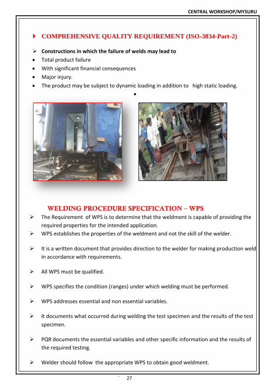
COMPREHENSIVE QUALITY REQUIREMENT (ISO-3834-Part-2)
Constructions in which the failure of welds may lead to
Total product failure
With significant financial consequences
Major injury.
The product may be subject to dynamic loading in addition to high static loading.
WELDING PROCEDURE SPECIFICATION – WPS
The Requirement of WPS is to determine that the weldment is capable of providing the
required properties for the intended application.
WPS establishes the properties of the weldment and not the skill of the welder.
It is a written document that provides direction to the welder for making production welds
in accordance with requirements.
All WPS must be qualified.
WPS specifies the condition (ranges) under which welding must be performed.
WPS addresses essential and non essential variables.
It documents what occurred during welding the test specimen and the results of the test
specimen.
PQR documents the essential variables and other specific information and the results of
the required testing.
Welder should follow the appropriate WPS to obtain good weldment.
CENTRAL WORKSHOP/MYSURU
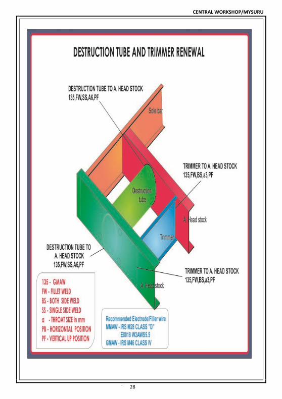
` 28

CENTRAL WORKSHOP/MYSURU
` 29
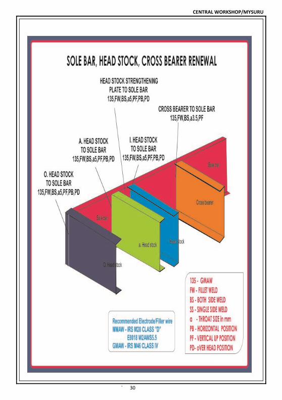
CENTRAL WORKSHOP/MYSURU
` 30

CENTRAL WORKSHOP/MYSURU
` 31
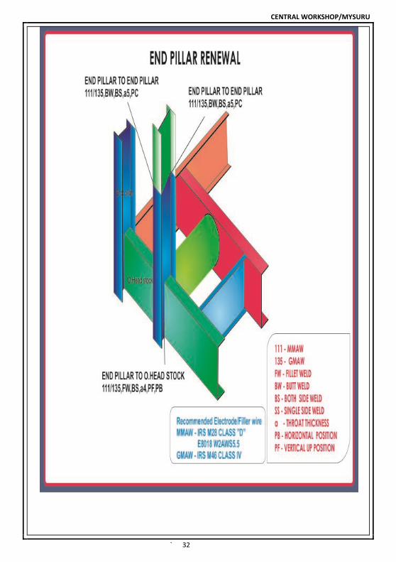
CENTRAL WORKSHOP/MYSURU
` 32
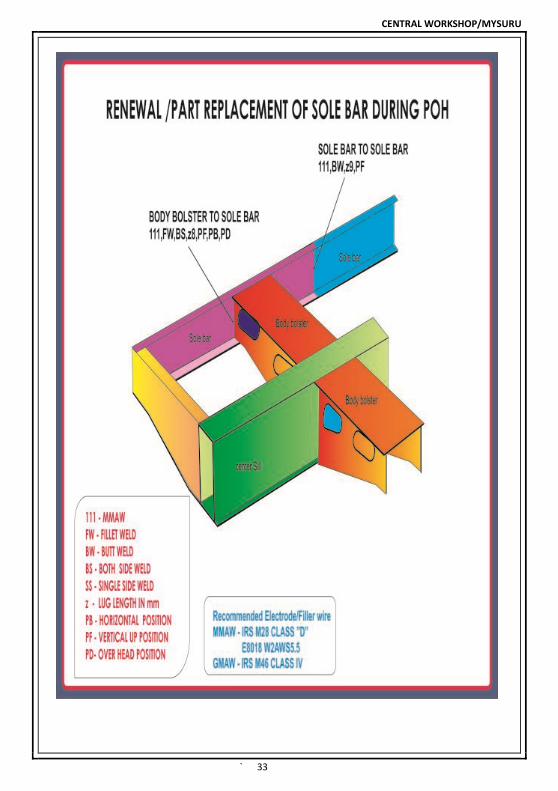
CENTRAL WORKSHOP/MYSURU
` 33

CENTRAL WORKSHOP/MYSURU
` 34
CENTRAL WORKSHOP/MYSURU
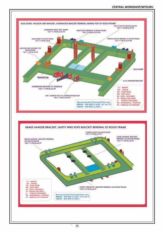
` 35

CENTRAL WORKSHOP/MYSURU
` 36