
An embedded readout for GM counter
13
228 Int. J. Instrumentation Technology, Vol. 1, No. 3, 2014 Copyright © 2014 Inderscience Enterprises Ltd. An embedded read-out for GM counter G. Prasanna* and J. Jayapandian Materials Science Group, Indira Gandhi Centre for Atomic Research, Kalpakkam 603 102, Tamil Nadu, India E-mail: [email protected] E-mail: [email protected] *Corresponding author Abstract: Cost effective embedded design for Geiger Mueller counter biasing and read-out, using a programmable system-on-chip is described in this paper. Geiger Mueller counters (GM-counters) are simple radiation detectors widely used in the area of detection of nuclear occurrences, which require read-out electronics to perform the functions of pulse counting and measurement data display. In addition to this, GM-tubes require high voltage biasing circuitry for their operation. A GM-tube based radiation counter has design requirements such as ruggedness, low power consumption and immunity against interference. These requirements are complex to achieve with conventional hardware circuit design of the read-out systems. In this paper a novel embedded design based on the cypress semiconductor’s single chip programmable-system-on-chip (PSoC), exploiting its mixed signal array of analogue and digital modules is described. Acquired data from GM counter has been communicated to a PC using UART protocol. Calibration procedures performed with the GM counter with the new read-out design is also discussed in this paper. The measurements from this design has been compared with those of existing commercial radiation measurement systems and found to be comparable with commercial off the shelf instruments. This reliable and accurate single-chip embedded design also has high-voltage biasing circuitry for the GM counter in addition to its read-out electronics. Keywords: GM counter; PSoC readout; high voltage regulation; pulse width modulator; gamma dosimetry; radiation detection; signal conditioning; single chip readout design; mixed signal array; nuclear occurrences. Reference to this paper should be made as follows: Prasanna, G. and Jayapandian, J. (2014) ‘An embedded read-out for GM counter’, Int. J. Instrumentation Technology, Vol. 1, No. 3, pp.228–240. Biographical notes: G. Prasanna is a research scholar in the Electronics and Instrumentation section, Materials Science group, IGCAR. His research work is in the area of embedded readout design for radiation detection and measurement. J. Jayapandian heads the Electronics and Instrumentation section, Materials Science group, IGCAR. He is working in the areas of nuclear electronics and embedded systems design with virtual instrument programming. He has developed many systems for laboratory automation with PSoC and LabView.
Transcript of An embedded readout for GM counter

228 Int. J. Instrumentation Technology, Vol. 1, No. 3, 2014
Copyright © 2014 Inderscience Enterprises Ltd.
An embedded read-out for GM counter
G. Prasanna* and J. Jayapandian Materials Science Group, Indira Gandhi Centre for Atomic Research, Kalpakkam 603 102, Tamil Nadu, India E-mail: [email protected] E-mail: [email protected] *Corresponding author
Abstract: Cost effective embedded design for Geiger Mueller counter biasing and read-out, using a programmable system-on-chip is described in this paper. Geiger Mueller counters (GM-counters) are simple radiation detectors widely used in the area of detection of nuclear occurrences, which require read-out electronics to perform the functions of pulse counting and measurement data display. In addition to this, GM-tubes require high voltage biasing circuitry for their operation. A GM-tube based radiation counter has design requirements such as ruggedness, low power consumption and immunity against interference. These requirements are complex to achieve with conventional hardware circuit design of the read-out systems. In this paper a novel embedded design based on the cypress semiconductor’s single chip programmable-system-on-chip (PSoC), exploiting its mixed signal array of analogue and digital modules is described. Acquired data from GM counter has been communicated to a PC using UART protocol. Calibration procedures performed with the GM counter with the new read-out design is also discussed in this paper. The measurements from this design has been compared with those of existing commercial radiation measurement systems and found to be comparable with commercial off the shelf instruments. This reliable and accurate single-chip embedded design also has high-voltage biasing circuitry for the GM counter in addition to its read-out electronics.
Keywords: GM counter; PSoC readout; high voltage regulation; pulse width modulator; gamma dosimetry; radiation detection; signal conditioning; single chip readout design; mixed signal array; nuclear occurrences.
Reference to this paper should be made as follows: Prasanna, G. and Jayapandian, J. (2014) ‘An embedded read-out for GM counter’, Int. J. Instrumentation Technology, Vol. 1, No. 3, pp.228–240.
Biographical notes: G. Prasanna is a research scholar in the Electronics and Instrumentation section, Materials Science group, IGCAR. His research work is in the area of embedded readout design for radiation detection and measurement.
J. Jayapandian heads the Electronics and Instrumentation section, Materials Science group, IGCAR. He is working in the areas of nuclear electronics and embedded systems design with virtual instrument programming. He has developed many systems for laboratory automation with PSoC and LabView.

An embedded read-out for GM counter 229
1 Introduction
GM counter is a simple particle detector that is widely used in the area of detection of nuclear occurrences (Knoll, 2009), which requires a regulated 500 V bias for its operation and counting the nuclear occurrences. A signal conditioning circuit, pulse discriminator and a digital counter are required for the practical acquisition of data using GM tube for the purpose of radiation measurement. This paper describes the sequence of functions in a general GM counter readout system and subsequently describes their implementation on a single chip mixed signal platform.
2 GM counter sequential functions
The following are the sequential functional requirements of GM counter for radiation applications
a generation of high voltage and biasing the GM tube
b acquisition of raw analogue pulses from GM-tube
c conditioning the raw pulses to form logic pulses
d counting the logic pulses with time gating
e display the counts per second or the dose information.
The following sections describe the general implementation of each of the above functions in detail.
3 General implementation procedure
3.1 Generation of high voltage and biasing the GM tube
Figure 1 shows a simple boost converter which works on the principle of fast switching of an inductor current between two different levels. In the schematic shown, the switch is initially closed for a long time and a constant current is established in the inductor. Now, when the current is suddenly switched from the established constant value to zero by opening the switch a high voltage is generated on the pole side of the switch. This momentarily generates high voltage that can be stored in a capacitor through a diode and further processed to act as a source. Since any load connected to the capacitor discharges it, the capacitor charge should be constantly replenished by repetition of the switching action. This is done by replacing the mechanical switch with a switching transistor with a pulse signal in its base terminal. There is a simple relation between the input voltage (Vin) and the output voltage (Vout) of a boost converter in terms of the duty cycle (D) which states (http://www.ti.com/download/trng/docs/seminar/Topic_3_Lynch.pdf)

230 G. Prasanna and J. Jayapandian
( )out inV V (1 D)= −
The high voltage generated depends on the duty cycle of this pulse signal. The duty cycle here is the ratio of the time for which the switch is kept closed (Ton), thereby enabling a current through the inductor to the total cycle time, (Ton + Toff), i.e., switch closed time added with that time for which switch is open) Duty Cycle D = Ton / (Ton + Toff). Thus, as the duty cycle approaches unity, output voltage (Vout) that is greater than the input (Vin) can be generated. This relation establishes that a constant high voltage source can be realized using duty cycle control of the switching transistor. High voltage fluctuations have to be corrected using a feedback system (Ghazali et al., 2013). A simple proportional integral (PI) controller can be used to implement this closed loop system. Once the high voltage of 500 V is generated and connected to the central conductor of the GM tube with respect to its chassis (which is grounded), the GM tube produces pulses for the passing nuclear occurrences (http://www.centronic.co.uk/gamma_detectors.htm).
Figure 1 A simple boost converter showing the current variation in inductor w.r.t time
Source: http://www.maxim-ic.com/an2031
Figure 2 describes the behaviour of a GM tube during its operation. It depicts two situations in a GM tube output viz., the high voltage wire condition and the grounded wire condition. Under normal circumstances, the central wire is left floating and hence the output at R1 is at a high voltage. Whenever there is an occurrence of particle interaction, ionization of the fill gas takes place thereby enabling a current between the central wire and the chassis, momentarily pulling down the voltage at the R1 resistance to ground level. Suitable translation of this voltage transition to the low operating voltage range of the counting circuitry is done to enable conversion of this GM pulse into TTL logic pulse by a comparator for further processing by intelligent digital controllers. But still, there are other issues involved in directly connecting this clamped pulse to a counter circuitry input viz.,
a high voltage isolation
b overshoots due to sudden switching (inductive effect of the central conductor).

An embedded read-out for GM counter 231
Figure 2 Pulse generation in GM tube (see online version for colours)
These issues can be solved by the implementation of a conditioning circuit as shown in Figure 3.
Figure 3 Complete clamping circuit with overshoot protection and high voltage isolation (see online version for colours)
3.2 Conditioning of the raw pulses to form logic pulses
Once clamped, the analogue pulses can be converted to logic pulses using a simple comparator. After the acquisition, the raw analogue pulses should be conditioned to form logic pulses satisfying certain voltage level and timing requirements (Jisha et al., 2012). This is done by means of a comparator. The analogue pulse waveform goes negative, whenever an event occurs in the GM tube and hence a suitable threshold reference level should be chosen for firing a comparator. The logic pulses thus generated can be used for clocking a counter to record the events.
232 G. Prasanna and J. Jayapandian
3.3 Counting the logic pulses with time gating
The parameter of interest in a GM counter is the counts per second information. This is achieved by concurrently running a timer and a counter, the timer being used as a time gating device. Whenever the timer overflows the current count value is read out and divided by the time to get the counts per unit time value.
3.4 Displaying the dose rate information
In a general implementation, communicating the dose rate information to a personal computer (PC) enables both measurement data display and availability of measurement data to other software applications; hence the measurement data is sent to a PC through a serial communication link.
The following section describes implementation of all the above functions on a single chip using the PSoC platform.
4 PSoC implementation for GM counter read-out
4.1 High voltage generation and regulation
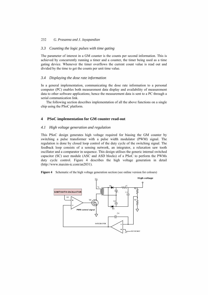
This PSoC design generates high voltage required for biasing the GM counter by switching a pulse transformer with a pulse width modulator (PWM) signal. The regulation is done by closed loop control of the duty cycle of the switching signal. The feedback loop consists of a sensing network, an integrator, a relaxation saw tooth oscillator and a comparator in sequence. This design utilises the generic internal switched capacitor (SC) user module (ASC and ASD blocks) of a PSoC to perform the PWMs duty cycle control. Figure 4 describes the high voltage generation in detail (http://www.maxim-ic.com/an2031).
Figure 4 Schematic of the high voltage generation section (see online version for colours)

An embedded read-out for GM counter 233
As shown in Figure 4, the switching transistor Q1, the transformer T1 and the voltage doubler network consisting of diodes D1, D2 and capacitors C1, C2 outside the PSoC chip generate the regulated high voltage biasing of 500 volts required for the GM-counter The regulation of this voltage is done by a feedback technique whereby the output is sampled at the voltage divider network R2 and R3. This feedback voltage is integrated by PSoC internal integrator with internal reference voltage. When the sampled voltage is less than this reference the integrator produces a positive ramp and when it is greater than the reference it produces a negative ramp signal. This ramp signal is then fed to the threshold point of a comparator whose actual input signal on the other terminal is a saw tooth waveform produced using internal PSoC op-amp configured as oscillator. The output of this setup is a Pulse width modulated signal which controls the opening and closing of the switching transistor. For one of the SC blocks which is configured as a relaxation oscillator for generating the switching control signal for the transistor, external passive components are used to fix the frequency (Van Ess, 2011).
By receiving the feedback controlled PWM output pulses from PSoC chip, utilising on-chip SC blocks, a stabilised high voltage is achieved (http://www.cypress.com/ ?id=1573&source=productshome).
4.2 Signal conditioning and counting
Biased GM tube detects particles and produces a momentary grounding of its central conductor which is normally in a high voltage condition. An external clamping network is designed to convert this high voltage -to-ground transition of the central conductor to a meaningful signal excursion for the counting circuitry. Since the fast rising pulse excursion exceeds the supply rails by a large amount (inductive effect), the external clamping network is biased at a lower value than the supply rail of the counting circuitry. The required bias voltages are derived from internal PSoC continuous time blocks (ACBs) acting as programmable gain amplifiers (PGA modules) with gain settings < 1. The clamped pulses are directly fed to a PSoC internal comparator to generate logic pulses for the internal counter module. The counting function is done by an internal counter and a timer module of the PSoC.
The counter and the timer are started on reset. The PSoC core is programmed such that the timer overflow interrupt is used to readout the current count value in the counter register and subsequently clear it and again reinitialise it.
The PSoC platform assists effectively in providing an integrated embedded solution to the functions shown in Figure 3. Figure 5 shows the required functional blocks implementation in PSoC for this specific application. In this design PSoC operating voltage is selected to +5 Volts and the clamping voltage is fixed at 2.5 V. As shown in Figure 5 the positive overshoot is handled by the diode D1 connected to the regulated clamp voltage. Even though the positive overshoot excurses to 3.2 V level it is not of major concern as this level is still well below the supply rail of the microcontroller. But the negative excursion (undershoot) could potentially damage microcontroller input.

234 G. Prasanna and J. Jayapandian
Figure 5 On-chip analogue PSoC blocks aid in integration (see online version for colours)
Hence, a compensatory voltage of 1 V which is slightly more than the 0.7 V diode drop is added in series with the diode D2. The PGA, an on-chip PSoC module, is used as a regulated voltage source, instead of discrete components in the existing circuits. An amplifier’s output is used as a regulated source for very low current loads, thus two PGAs are used to get a 2.5 V and a 1 V regulated source. For the 2.5 V source a PGA is used as an attenuator with the microcontroller power supply itself as signal input. This provides isolation between GM output and microcontroller supply rail in addition to regulation. The 1 V source is obtained by the same technique using another PGA module. For limiting the current drawn from the regulated sources the resistors R2, R3 and R4 should be very high in the order of mega ohms and have the same value (1 MΩ). The threshold voltage of the comparator in PSoC internal block, ACB00, is chosen around 2 V from its internal reference. The comparator is configured to fire whenever the pulse signal falling edge crosses this threshold. To count the TTL pulses that correspond to the occurrence, a counter and timer blocks are implemented in PSoC. The counter accumulates the pulse count until the timer overflows and causes an interrupt. The interrupt service routine reads the current count value for further processing according to user requirements.
5 PSoC design simulation and programming
PSoC Designer version 5.1 Integrated Development Environment (IDE) (http://www.cypress.com/?id=1573&source=productshome) was used for programming of the system. The IDE consists of an interconnect viewer and a C compiler. The use of this IDE is limited to the earlier version of PSoC, i.e., PSoC-1. The functional hardware testing was done using PSoC-1 in-circuit emulator (ICE) and a development board. The C language coding for the design is given in Appendix. Shown in the next figure is a screenshot of the development environment.

An embedded read-out for GM counter 235
Figure 6 PSoC digital blocks configuration for GM counter application (see online version for colours)
Figure 7 PSoC analogue blocks configuration for GM counter application (see online version for colours)

236 G. Prasanna and J. Jayapandian
6 Results
6.1 Functional test and calibration of GM counter
The system is tested for its functionality and also calibrated with a 0.1799 mCi cobalt-60 (Co-60) source in the laboratory (Table 1) for various distance. The sensitivity of the instrument is the slope of its linearly fitted graph of observed counts per second and compared with the theoretically calculated dose rates for various source-to-detector distances (Botter-Jensen and Jensen, 1992). The sensitivity is found out to be 0.01451 CPS/nSvh–1 from the plotted data. This sensitivity is found to be better than that of other commercial systems DRM 1 area monitor of ‘Laurus’ make systems (Sensitivity = 0.0017 Cps/nSvh–1) (http://www.laurussystems.com/), PRM-9000 dosimeter of Mazur instruments make (Sensitivity = 0.00583 Cps/nSvh–1) (http://www.mazurinstruments.com/PRM-9000_detail.html). The accuracy of the device is typically ±10% with a maximum of ±15% which is comparable to that of the above commercial devices. This single chip embedded design implementation, which is more compact, rugged, also ensures better reliability, sensitivity and accuracy. The long-term stability for this embedded design is excellent since the high voltage is found to be stable for long periods of operation. Table 1 Calibration data
Source to detector distance (cm)
Theoretical dose rate value (nSvh–1)
Observed counts per second (CPS)
31 23,447 344
48 9,779 180
68 4,873 96
108 1,932 40
153 962 20
216 483 11
7 Conclusions
PSoC based embedded read-out design has been successfully implemented, designed, fabricated and tested with the GM counter at Indira Gandhi Centre for Atomic Research, Kalpakkam and found to be working as per the user satisfaction. The calibration graph in Figure 8 shows the excellent linearity in measurement with the indigenous PSoC embedded design read-out and regulated high voltage biasing circuit. The functionality of the compact cost effective PSoC embedded GM counter read-out is comparable with commercial bench top models. Implementation of the required analogue, digital and digital communication blocks for the specific design in a single silicon chip is one of the major advantages in Cypress Semiconductors PSoC chip. Any specific applications can be implemented in an easy manner as well as effectively with this embedded design tool.

An embedded read-out for GM counter 237
Figure 8 Calibration graph with Co60 source of 0.1799 mCi (see online version for colours)
Note: Observed counts plotted against calculated dose rates.
Acknowledgements
One of the authors Mr. G. Prasanna thanks Director IGCAR for providing research opportunity to carry out this work in IGCAR. The authors would like to thank Director, MSG, Director, EI&RSG, Associate Director, RMG and Associate Director, RSEG of Indira Gandhi Centre for Atomic Research for their encouragement to conduct the testing and evaluation of the design in the laboratory environment.
References Botter-Jensen, L. and Jensen, P.H. (1992) ‘Determination of scattered gamma radiation in the
calibration of environmental dose rate meters’, Radiation Protection Dosimetry, Vol. 42, No. 4, pp.291–299.
Centronic ZP series GM tube specifications [online] http://www.centronic.co.uk/gamma_detectors.htm (accessed 2 April 2013).
Ghazali, A.B., Ahmad, T.S. and Abdullah, N.A. (2013) ‘Characterization of a pulsed mode high voltage power supply for nuclear detectors’, IOP Conf. Series: Earth and Environmental Science, Vol. 16, p.012137.
Jisha, N.V., Krishnakumar, D.N., Surya Prakash, G., Kumari, A., Baskaran, R. and Venkatraman, B. (2012) ‘Development of autonomous gamma dose logger for environmental monitoring’, Review of Scientific Instruments, Vol. 83, No. 3, p.035112 [online] http://link.aip.org/link/doi/10.1063/1.3697697 (accessed 29 November 2013).
Knoll, G.F. (2009) Radiation Detection and Measurement, 3rd ed., pp.201–215, Wiley India Pvt Ltd., New Delhi.
Laurus radiation detector systems product catalog [online] http://www.laurussystems.com/products/products_pdf/ LAURUS-Radiation-Product-Catalog.pdf (accessed 29 November 2013).

238 G. Prasanna and J. Jayapandian
Maxim integratedTM Application note 2031, ‘DC to DC converter tutorial’ [online] http://www.maxim-ic.com/an2031 (accessed 29 November 2013).
Mazur instruments PRM9000 specifications [online] http://www.mazurinstruments.com/ PRM-9000_detail.html (accessed 29 November 2013).
PSoC 1, Cypress semiconductor product page [online] http://www.cypress.com/?id=1573&source=productshome (accessed 1 May 2014).
Texas instruments application note on DC/DC converters by B.T. Lynch [online] http://www.ti.com/download/trng/docs/seminar/Topic_3_Lynch.pdf (accessed 29 November 2013).
Van Ess, D. (2011) PSoC Application Note, AN2223 [online] http://www.cypress.com/?docID=49232 (accessed 11 December 2012).
Appendix
Embedded ‘C’ program listing (see online version for colours)
#include <m8c.h>// part specific constants and macros #include “PSoCAPI.h”// PSoC API definitions for all User Modules #include <stdlib.h>//standard library for float to integer conversions #define GATETIME gatetime(int)// give the option of gating time for counting pulses in units of seconds here. #define SENSITIVITY sensitivity(double)//write the value of instrument sensitivity in units of (CPS/nGy perhour) obtained through calibration experiments here. #pragma interrupt_handler timer_ovf//perform interrupt service routine at the moment of timer interrupt. #pragma interrupt_handler counter_ovf//perform batch value increment for counter on ovflo interrrupt. /*===============================Start Global variables=======================================*/ int seconds; int batch; //char *dose; /*=================================End Global variables=======================================*/ //---------------------------------------------------------------------------- // C main line //---------------------------------------------------------------------------- void main(void) /*=================Start user module
intialisation=================================*/ M8C_EnableGInt; //enable all interrupts of M8C processor

An embedded read-out for GM counter 239
BUFFER_Start(BUFFER_LOWPOWER);//start integrator buffer with low power setting
Relax_Start(Relax_LOWPOWER);//start the relaxation oscillator-switched capacitor block in low power mode
Integrator_Start(Integrator_LOWPOWER);//start the switched capacitor integrator in low power
COMP_Start(COMP_LOWPOWER);//start the comparator in low power mode DigBuf_Start();//start the digital buffer module in low power mode CLAMPOUT_2_Start(CLAMPOUT_2_LOWPOWER);//start the positive
clamping source CLAMPOUT_1_Start(CLAMPOUT_1_LOWPOWER);//start the diode
compensation source Timer16_EnableInt(); //Ensure timer interrupt is enabled Timer16_Start(); /*start the timer also*/ Counter8_EnableInt();//enable the counter interrupts Counter8_Start();/* start the counter */ UART_1_Start(UART_PARITY_NONE);//start the UART module /*================End user module
initialisation====================================*/ /*================Start main function variables
declaration================================*/ /*================End main function variables
declaration==================================*/ seconds = 0; batch = 0; UART_1_PutChar(12); while(1) /*do nothing just wait for timer and counter interrupts(infinite while
loop)*/ /*============================================Start timer interrupt subroutine======================*/ void timer_ovf(void)//interrupt routine for timer 16 interrupt int totcount = 0;//declare integer variable for holding the total count. float countpersec = 0, DOSERATE = 0;//floating point variables for persecond
count and doserate. char dosebuf(25);//character array for holding formatted string for doserate
display in hyperterminal.

240 G. Prasanna and J. Jayapandian
seconds += 1;//increment the seconds value by unity upto the GATETIME value. if(seconds == GATETIME) seconds = 0;//initialise “seconds” for the next round and proceed. Counter8_Stop();//temporarily stop the counter for reading out the count
value totcount = (batch * 255) + (255 – Counter8_bReadCounter());//read the
current counter value and evaluate the total count value and store in the ivalue variable
batch = 0;//reinitialise the value of batch. countpersec = totcount/GATETIME;//evaluate counts per second. DOSERATE = countpersec/SENSITIVITY;//evaluate the actual dose
rate interms of nGy. Counter8_WritePeriod(255);//re-initialise the counter Counter8_Start();//restart the counter csprintf(dosebuf,“\n\r%fnGyph%c”,DOSERATE,‘\0’);//function to
produce formatted string equivalent(with null termination) of dose rate. UART_1_PutString(dosebuf);//send the formatted (null
terminated)string to hyperterminal. /*=========================================Start counter interrupt subroutine======================*/ void counter_ovf(void) batch+ = 1;//increment the variable batch by 1 when the 8-bit counter
overflows. /*==========================================End of program=========================================*/
System level specifications of the application board
Power supply 9V alkaline battery (500 mAh) Current consumption of board 60 mA PSoC IC used CY8C29466 GM tube Centronic ZP1221 Instrument sensitivity 0.01451 CPS/nSv/h Read-out terminal Windows-Hyper terminal using RS232/LCD