Table of Contents - GM Upfitter
882
Table of Contents General Information ........................... 1-1 General Information ............................ 1-3 Body Systems .................................. 2-1 Fixed and Moveable Windows ................. 2-3 Horns and Pedestrian Alerts ................... 2-9 Lighting ....................................... 2-12 Mirrors ........................................ 2-46 Trailering Systems ............................ 2-54 Vehicle Access ............................... 2-68 Wipers and Washers ......................... 2-86 Driver Information and Entertainment ....... 3-1 Image Display Cameras ....................... 3-3 Engine/Propulsion ............................. 4-1 12 V Starting and Charging .................... 4-3 HVAC ............................................ 5-1 HVAC - Automatic .............................. 5-3 Power and Signal Distribution ................ 6-1 Data Communications ......................... 6-3 Electrical Component and Inline Harness Connector End Views ....................... 6-30 Power Outlets ............................... 6-536 Wiring Systems and Power Management ............................... 6-546 Safety and Security ............................ 7-1 Driver Assistance Systems .................... 7-3 Immobilizer .................................... 7-23 Parking Assistance Systems ................. 7-29 Remote Functions ............................ 7-35 INDEX ................................. INDEX-1 2021 - Yukon, Yukon XL Electrical Body Builder Manual
-
Upload
khangminh22 -
Category
Documents
-
view
0 -
download
0
Transcript of Table of Contents - GM Upfitter

Table of Contents
General Information . . . . . . . . . . . . . . . . . . . . . . . . . . . 1-1General Information . . . . . . . . . . . . . . . . . . . . . . . . . . . . 1-3
Body Systems . . . . . . . . . . . . . . . . . . . . . . . . . . . . . . . . . . 2-1Fixed and Moveable Windows . . . . . . . . . . . . . . . . . 2-3Horns and Pedestrian Alerts . . . . . . . . . . . . . . . . . . . 2-9Lighting . . . . . . . . . . . . . . . . . . . . . . . . . . . . . . . . . . . . . . . 2-12Mirrors . . . . . . . . . . . . . . . . . . . . . . . . . . . . . . . . . . . . . . . . 2-46Trailering Systems . . . . . . . . . . . . . . . . . . . . . . . . . . . . 2-54Vehicle Access . . . . . . . . . . . . . . . . . . . . . . . . . . . . . . . 2-68Wipers and Washers . . . . . . . . . . . . . . . . . . . . . . . . . 2-86
Driver Information and Entertainment . . . . . . . 3-1Image Display Cameras . . . . . . . . . . . . . . . . . . . . . . . 3-3
Engine/Propulsion . . . . . . . . . . . . . . . . . . . . . . . . . . . . . 4-112 V Starting and Charging . . . . . . . . . . . . . . . . . . . . 4-3
HVAC . . . . . . . . . . . . . . . . . . . . . . . . . . . . . . . . . . . . . . . . . . . . 5-1HVAC - Automatic . . . . . . . . . . . . . . . . . . . . . . . . . . . . . . 5-3
Power and Signal Distribution . . . . . . . . . . . . . . . . 6-1Data Communications . . . . . . . . . . . . . . . . . . . . . . . . . 6-3Electrical Component and Inline HarnessConnector End Views . . . . . . . . . . . . . . . . . . . . . . . 6-30
Power Outlets . . . . . . . . . . . . . . . . . . . . . . . . . . . . . . . 6-536Wiring Systems and PowerManagement . . . . . . . . . . . . . . . . . . . . . . . . . . . . . . . 6-546
Safety and Security. . . . . . . . . . . . . . . . . . . . . . . . . . . . 7-1Driver Assistance Systems . . . . . . . . . . . . . . . . . . . . 7-3Immobilizer. . . . . . . . . . . . . . . . . . . . . . . . . . . . . . . . . . . . 7-23Parking Assistance Systems . . . . . . . . . . . . . . . . . 7-29Remote Functions . . . . . . . . . . . . . . . . . . . . . . . . . . . . 7-35
INDEX . . . . . . . . . . . . . . . . . . . . . . . . . . . . . . . . . INDEX-1
2021 - Yukon, Yukon XL Electrical Body Builder Manual

BLANK
2021 - Yukon, Yukon XL Electrical Body Builder Manual
Table of Contents 1-1
Section 1
General Information
General Information . . . . . . . . . . . . . . . . . . . . . . . . . . . 1-3Introduction . . . . . . . . . . . . . . . . . . . . . . . . . . . . . . . . . . . . . . . 1-3
Vehicle Certification, Tire Placard, Anti-Theft, andService Parts ID Label . . . . . . . . . . . . . . . . . . . . . . . . . . 1-3
2021 - Yukon, Yukon XL Electrical Body Builder Manual

1-2 Table of Contents
BLANK
2021 - Yukon, Yukon XL Electrical Body Builder Manual

General Information 1-3
General Information
IntroductionVehicle Certification, Tire Placard,Anti-Theft, and Service Parts IDLabel
4992823
Vehicle Certification LabelCallout Description
A vehicle-specific Certification label is attached to the vehicle's center pillar (B-pillar) and displays the following assessments:
1 Logo
2Final Date of Manufacture (Month and Year MM/YY)Date of manufacture is to reflect the date that the vehicle is counted as built. In those cases where a replacementlabel is needed, the replacement label should reflect the actual build date not the date of replacement.
3 Name of Manufacturer
4 Maximum Gross Vehicle Weight Rating (GVWR)
5 Maximum Gross Axle Weight Rating (GAWR) - Front
6 Maximum Gross Axle Weight Rating (GAWR) - Rear
7 Certification Statement
8 Vehicle Identification Number (VIN)
9 Engineering Model Number
10 Vehicle Class Type (Pass Car, etc.)
11 Original Equipment Rim Size
12 Original Equipment Tire Size
13 Paint Code
14
QR CodeOnce the QR code is scanned, the information will appear in this order on your smartphone or laptop: VIN, ModelYear, Model, Build Month, Year, Engineering Book, Vehicle Order Number, 3 Digit RPO Codes sortedalphanumerically and the Paint Code (same code appears the lower left of the QR code)
2021 - Yukon, Yukon XL Electrical Body Builder Manual

1-4 General Information
4962282
Tire PlacardCallout Description
A vehicle-specific Tire and Loading Information label is attached to the vehicle's center pillar (B-pillar) and displays the followingassessments:
1 Specified Occupant Seating Positions
2 Maximum Vehicle Capacity Weight
3 Original Equipment Tire Size
4 Tire Pressure, Front, Rear, and Spare (Cold)
4962289
2021 - Yukon, Yukon XL Electrical Body Builder Manual
General Information 1-5
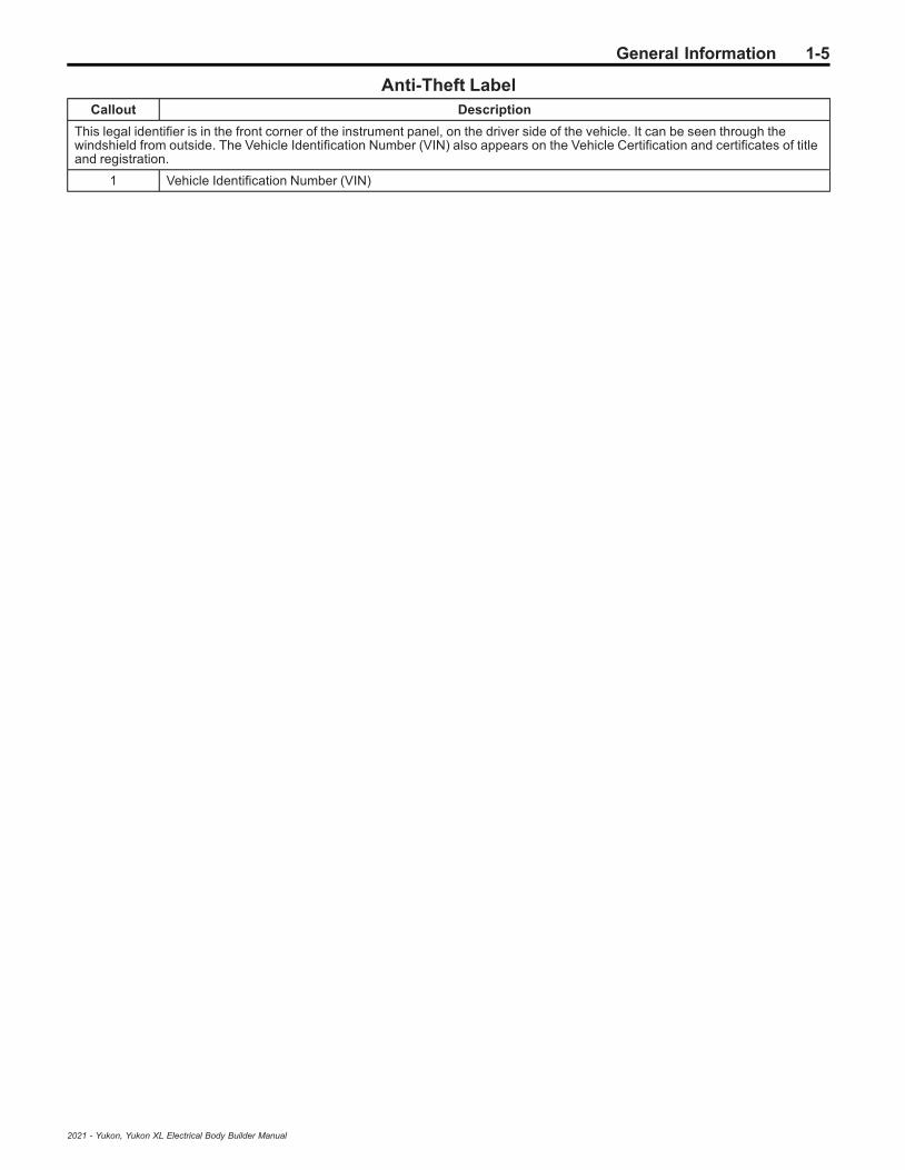
Anti-Theft LabelCallout Description
This legal identifier is in the front corner of the instrument panel, on the driver side of the vehicle. It can be seen through thewindshield from outside. The Vehicle Identification Number (VIN) also appears on the Vehicle Certification and certificates of titleand registration.
1 Vehicle Identification Number (VIN)
2021 - Yukon, Yukon XL Electrical Body Builder Manual

1-6 General Information
BLANK
2021 - Yukon, Yukon XL Electrical Body Builder Manual

Table of Contents 2-1
Section 2
Body Systems
Fixed and Moveable Windows . . . . . . . . . . . . . . . . 2-3Schematic and Routing Diagrams . . . . . . . . . . . . . . . 2-3
Moveable Window Schematics . . . . . . . . . . . . . . . . . . 2-4Defogger Schematics . . . . . . . . . . . . . . . . . . . . . . . . . . . . 2-7
Description and Operation . . . . . . . . . . . . . . . . . . . . . . . 2-8Power Windows Description and Operation . . . . . . 2-8Rear Window Defogger Description and
Operation . . . . . . . . . . . . . . . . . . . . . . . . . . . . . . . . . . . . . . . 2-8
Horns and Pedestrian Alerts . . . . . . . . . . . . . . . . . . 2-9Schematic and Routing Diagrams . . . . . . . . . . . . . . . 2-9
Horn Schematics . . . . . . . . . . . . . . . . . . . . . . . . . . . . . . . 2-10Description and Operation . . . . . . . . . . . . . . . . . . . . . . 2-11
Horns System Description and Operation . . . . . . . 2-11
Lighting . . . . . . . . . . . . . . . . . . . . . . . . . . . . . . . . . . . . . . . . 2-12Schematic and Routing Diagrams . . . . . . . . . . . . . . 2-12
Headlights/Daytime Running Lights (DRL)Schematics . . . . . . . . . . . . . . . . . . . . . . . . . . . . . . . . . . . . 2-13
Fog Lights Schematics . . . . . . . . . . . . . . . . . . . . . . . . . 2-16Exterior Lights Schematics . . . . . . . . . . . . . . . . . . . . . 2-17Interior Lights Schematics . . . . . . . . . . . . . . . . . . . . . . 2-32Interior Lights Dimming Schematics . . . . . . . . . . . . 2-37
Description and Operation . . . . . . . . . . . . . . . . . . . . . . 2-41Exterior Lighting Systems Description and
Operation . . . . . . . . . . . . . . . . . . . . . . . . . . . . . . . . . . . . . . 2-41Interior Lighting Systems Description and
Operation . . . . . . . . . . . . . . . . . . . . . . . . . . . . . . . . . . . . . . 2-44
Mirrors . . . . . . . . . . . . . . . . . . . . . . . . . . . . . . . . . . . . . . . . . 2-46Schematic and Routing Diagrams . . . . . . . . . . . . . . 2-46
Inside Rearview Mirror Schematics . . . . . . . . . . . . . 2-47Outside Rearview Mirror Schematics . . . . . . . . . . . 2-48
Description and Operation . . . . . . . . . . . . . . . . . . . . . . 2-51Automatic Day-Night Mirror Description and
Operation . . . . . . . . . . . . . . . . . . . . . . . . . . . . . . . . . . . . . . 2-51Outside Mirror Description and Operation . . . . . . 2-52
Trailering Systems . . . . . . . . . . . . . . . . . . . . . . . . . . . 2-54Schematic and Routing Diagrams . . . . . . . . . . . . . . 2-54
Trailering Systems Schematics . . . . . . . . . . . . . . . . . 2-55Description and Operation . . . . . . . . . . . . . . . . . . . . . . 2-60
Trailering Description and Operation . . . . . . . . . . . 2-60
Vehicle Access . . . . . . . . . . . . . . . . . . . . . . . . . . . . . . . 2-68Schematic and Routing Diagrams . . . . . . . . . . . . . . 2-68
Door Lock/Indicator Schematics . . . . . . . . . . . . . . . . 2-69Release Systems Schematics . . . . . . . . . . . . . . . . . . 2-75
Hood Latch Schematics . . . . . . . . . . . . . . . . . . . . . . . . 2-78Liftgate Schematics . . . . . . . . . . . . . . . . . . . . . . . . . . . . . 2-79
Description and Operation . . . . . . . . . . . . . . . . . . . . . . 2-82Door Ajar Indicator Description and
Operation . . . . . . . . . . . . . . . . . . . . . . . . . . . . . . . . . . . . . . 2-82Fuel Fill Door Description and Operation . . . . . . . 2-82Hood Ajar Indicator Description and
Operation . . . . . . . . . . . . . . . . . . . . . . . . . . . . . . . . . . . . . . 2-82Liftgate Ajar Indicator Description and
Operation . . . . . . . . . . . . . . . . . . . . . . . . . . . . . . . . . . . . . . 2-82Liftgate Description and Operation . . . . . . . . . . . . . 2-83Power Door Locks Description and
Operation . . . . . . . . . . . . . . . . . . . . . . . . . . . . . . . . . . . . . . 2-84Rear Hatch/Gate Description and Operation . . . 2-85
Wipers and Washers . . . . . . . . . . . . . . . . . . . . . . . . . 2-86Schematic and Routing Diagrams . . . . . . . . . . . . . . 2-86
Wiper/Washer Schematics . . . . . . . . . . . . . . . . . . . . . . 2-87Description and Operation . . . . . . . . . . . . . . . . . . . . . . 2-91
Wiper/Washer System Description andOperation . . . . . . . . . . . . . . . . . . . . . . . . . . . . . . . . . . . . . . 2-91
2021 - Yukon, Yukon XL Electrical Body Builder Manual

2-2 Table of Contents
BLANK
2021 - Yukon, Yukon XL Electrical Body Builder Manual

Fixed and Moveable Windows 2-3
Fixed and Moveable Windows
Schematic and Routing Diagrams
2021 - Yukon, Yukon XL Electrical Body Builder Manual

2-4 Fixed and Moveable WindowsM
ov
ea
ble
Win
do
wS
ch
em
ati
cs
(Dri
ve
r)
53
711
91
2021 - Yukon, Yukon XL Electrical Body Builder Manual

Fixed and Moveable Windows 2-5M
ov
ea
ble
Win
do
wS
ch
em
ati
cs
(Pa
ss
en
ge
r)
53
711
92
2021 - Yukon, Yukon XL Electrical Body Builder Manual

2-6 Fixed and Moveable WindowsM
ov
ea
ble
Win
do
wS
ch
em
ati
cs
(Re
ar
Win
do
ws
)
53
711
93
2021 - Yukon, Yukon XL Electrical Body Builder Manual

Fixed and Moveable Windows 2-7D
efo
gg
er
Sc
he
ma
tic
s(D
efo
gg
er)
53
71
05
9
2021 - Yukon, Yukon XL Electrical Body Builder Manual

2-8 Fixed and Moveable Windows
Description and OperationPower Windows Description andOperation
Power Windows System ComponentsThe power window system consists of the followingcomponents:
• Driver front side door window control switch• Passenger front side door window control switch• Left rear side door window switch• Right rear side door window switch• Window motors in each of the doors• Body control module (BCM)
Driver and Passenger Express Up andExpress Down Power Window MotorsThe driver and passenger doors contains a windowmotor is smart motor that will detect excessiveresistance while performing the express up functionand automatically reverse direction to prevent injury toany occupants that may become trapped between theclosing window and the door frame. The automaticreverse safety feature can be overridden by pulling andholding the window switch.The logic circuit within the window motor monitors theup, down and express signal circuits which arenormally equal to B+ voltage. When a switch is used onthe front side door window control switch, the contactsclose causing a voltage drop within the appropriatesignal circuit. The window motor will detect the voltagedrop and will command the window to move in thedirection requested.The driver front side door window control switchcommunicates to the BCM by a serial data circuit.When the driver wishes to control the passengerwindow, the driver will use the appropriate switch on thedriver front side door window control switch. When thisswitch is used, a serial data message is sent to theBCM requesting the passenger window motorcommand, the BCM will then send a serial datamessage to the passenger window motor which willthen move in the direction requested.
Left Rear, Right Rear Express DownWindow MotorsFor the right rear and left rear doors, when their windowswitch is pressed in the down position, battery positivevoltage is applied to their respective window motorcontrol circuit and ground to the other window motorcontrol circuit causing that window to open. When theindividual window switch is pulled in the up position,voltage and ground is applied to the window motor inthe opposite direction causing that window to close.The return path to ground is supplied through theinactive control circuit being normally grounded throughthe window switch.Each rear side door window switch communicates tothe BCM by a serial data circuit. When the driverwishes to control the left rear or right rear window, thedriver will use the appropriate switch on the driver frontside door window control switch. When this switch isused, a serial data message is sent to the BCM
requesting a window motor command, the BCM willthen send a serial data message to the appropriate rearside door window switch which will then command thatwindow to move in the direction requested.
Lockout Switch FeatureThe driver front side door window control switchcontains a window lockout switch, when the driverpresses the window lockout switch, a serial datamessage is sent to the BCM which will send a disablecommand to the rear side door window switches,deactivating them. The rear windows will still functionnormally from the switches on the driver front side doorwindow control switch.
Rear Window Defogger Descriptionand Operation
Rear Window Defogger SystemComponentsThe rear window defogger system consists of thefollowing components:
• Body Control Module• Front Heater and Air Conditioning User Interface
Control• Rear Body Wiring Harness Junction Block
(Contains PCB Rear Defogger Relay• Rear Defogger Grid• 40A Fuse
Rear Window Defogger OperationThe rear defog control system utilizes a single zonebacklight design, driven with a single relayconfiguration. A switch for the customer to control thesystem is provided within the front heater and airconditioning user interface control. Also included in thefront heater and air conditioning user interface controlis an indicator to inform the customer with the currentstate of the system. The system is only operationalwhen engine is running or during remote start.Pressing the heated rear window switch causes thefront heater and air conditioning user interface controlto send a serial data message to the body controlmodule requesting rear window defog operation. Thebody control module upon receipt of the serial datamessage will provide voltage to the coil side of the reardefogger relay, this will energize the relay causing therelay switch contacts to close allowing B+ voltage toflow through the rear defogger grid control circuit to therear defogger grid.When the rear heated rear window switch is pressedand the engine is running, the rear window defoggergrid will activate and will turn off automaticallydepending upon the vehicle speed (refer to owner’smanual for rear window defogger operation cycles)
2021 - Yukon, Yukon XL Electrical Body Builder Manual

Horns and Pedestrian Alerts 2-9
Horns and Pedestrian Alerts
Schematic and Routing Diagrams
2021 - Yukon, Yukon XL Electrical Body Builder Manual

2-10 Horns and Pedestrian AlertsH
orn
Sc
he
ma
tic
s(H
orn
)
53
711
55
2021 - Yukon, Yukon XL Electrical Body Builder Manual

Horns and Pedestrian Alerts 2-11
Description and OperationHorns System Description andOperation
System DescriptionThe horn system consists of the following components:
• HORN fuse• Engine wiring harness junction block (contains
horn PCB relay• Steering wheel horn contact• Horn• Body control module (BCM)
System OperationThe vehicle horn system is activated under thefollowing conditions:
• When the horn switch is depressed• The BCM commands the horns ON under any of
the following conditions:– When the content theft deterrent system detects
a vehicle intrusion—For further information referto Theft Systems Description and Operation.
– When the panic button is depressed on theremote control door lock transmitter—For furtherinformation refer to Keyless Entry SystemDescription and Operation on page 7‑41.
– When the keyless entry system is used to lockthe vehicle, a horn chirp may sound to notify thedriver that the vehicle has been locked. Thenotification feature may be enabled or disabledthrough personalization. For further informationrefer to Keyless Entry System Description andOperation on page 7‑41.
– When the OnStar® system is used to sound thehorns if equipped—For further information, referto OnStar Description and Operation .
Circuit OperationBattery positive voltage is applied at all times to thehorn relay coil and the horn relay switch. Pressingeither of the horn switches applies ground to the hornrelay control circuit. The BCM may also apply ground tothe horn relay control circuit as described above. Whenthe horn relay control circuit is grounded, the horn relayis energized and battery positive voltage is applied tothe horns through the horn control circuit. The hornssound as long as ground is applied to the horn relaycontrol circuit.
2021 - Yukon, Yukon XL Electrical Body Builder Manual
2-12 Lighting
Lighting
Schematic and Routing Diagrams
2021 - Yukon, Yukon XL Electrical Body Builder Manual

Lighting 2-13H
ea
dli
gh
ts/D
ay
tim
eR
un
nin
gL
igh
ts(D
RL
)S
ch
em
ati
cs
(Co
ntr
ols
an
dIn
dic
ato
rs)
53
711
35
2021 - Yukon, Yukon XL Electrical Body Builder Manual
2-14 LightingH
ea
dli
gh
ts/D
ay
tim
eR
un
nin
gL
igh
ts(D
RL
)S
ch
em
ati
cs
(He
ad
lam
ps
an
dD
ay
tim
eR
un
nin
gL
am
ps
-L
eft
)
53
711
36
2021 - Yukon, Yukon XL Electrical Body Builder Manual

Lighting 2-15H
ea
dli
gh
ts/D
ay
tim
eR
un
nin
gL
igh
ts(D
RL
)S
ch
em
ati
cs
(He
ad
lam
ps
an
dD
ay
tim
eR
un
nin
gL
am
ps
-R
igh
t)
53
711
37
2021 - Yukon, Yukon XL Electrical Body Builder Manual
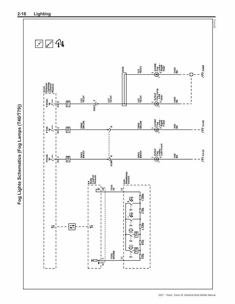
2-16 LightingF
og
Lig
hts
Sc
he
ma
tic
s(F
og
La
mp
s(T
40
/T7
9))
53
711
12
2021 - Yukon, Yukon XL Electrical Body Builder Manual

Lighting 2-17E
xte
rio
rL
igh
tsS
ch
em
ati
cs
(Lig
hti
ng
Co
ntr
olM
od
ule
Po
we
r,G
rou
nd
,an
dS
eri
alD
ata
)
53
711
40
2021 - Yukon, Yukon XL Electrical Body Builder Manual

2-18 LightingE
xte
rio
rL
igh
tsS
ch
em
ati
cs
(Lig
hti
ng
Co
ntr
olM
od
ule
Su
bs
ys
tem
Re
fere
nc
es
)
53
711
39
2021 - Yukon, Yukon XL Electrical Body Builder Manual
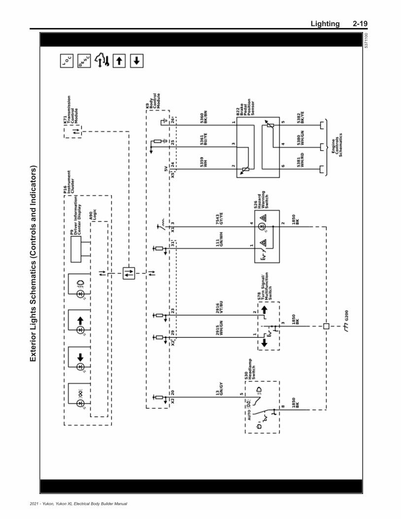
Lighting 2-19E
xte
rio
rL
igh
tsS
ch
em
ati
cs
(Co
ntr
ols
an
dIn
dic
ato
rs)
53
711
00
2021 - Yukon, Yukon XL Electrical Body Builder Manual
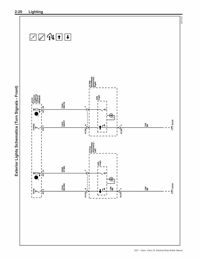
2-20 LightingE
xte
rio
rL
igh
tsS
ch
em
ati
cs
(Tu
rnS
ign
als
-F
ron
t)
53
711
10
2021 - Yukon, Yukon XL Electrical Body Builder Manual
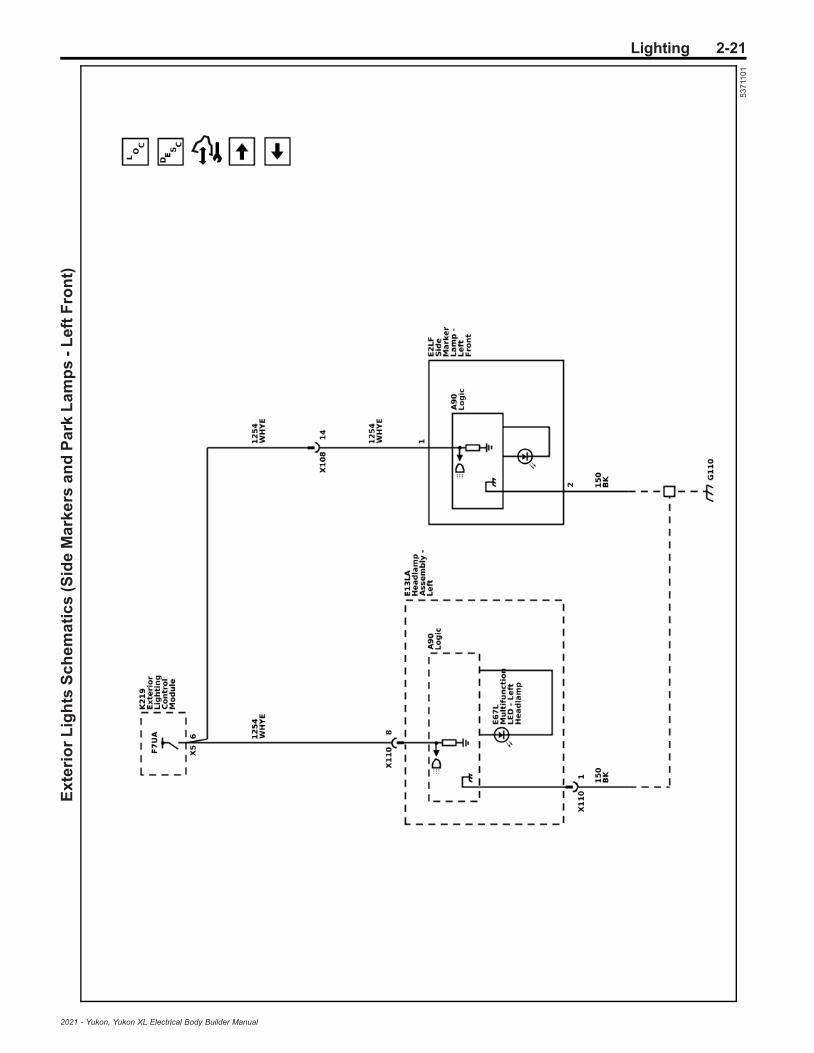
Lighting 2-21E
xte
rio
rL
igh
tsS
ch
em
ati
cs
(Sid
eM
ark
ers
an
dP
ark
La
mp
s-
Le
ftF
ron
t)
53
711
01
2021 - Yukon, Yukon XL Electrical Body Builder Manual

2-22 LightingE
xte
rio
rL
igh
tsS
ch
em
ati
cs
(Sid
eM
ark
ers
an
dP
ark
La
mp
s-
Rig
ht
Fro
nt)
53
711
02
2021 - Yukon, Yukon XL Electrical Body Builder Manual

Lighting 2-23E
xte
rio
rL
igh
tsS
ch
em
ati
cs
(Ou
tsid
eR
ea
rvie
wM
irro
rL
am
ps
(DX
R/D
W6
))
53
711
06
2021 - Yukon, Yukon XL Electrical Body Builder Manual

2-24 LightingE
xte
rio
rL
igh
tsS
ch
em
ati
cs
(Hig
hM
ou
nt
Sto
pL
am
p)
53
711
05
2021 - Yukon, Yukon XL Electrical Body Builder Manual
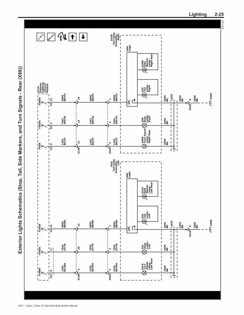
Lighting 2-25E
xte
rio
rL
igh
tsS
ch
em
ati
cs
(Sto
p,T
ail
,Sid
eM
ark
ers
,an
dTu
rnS
ign
als
-R
ea
r(X
88
))
53
711
07
2021 - Yukon, Yukon XL Electrical Body Builder Manual

2-26 LightingE
xte
rio
rL
igh
tsS
ch
em
ati
cs
(Sto
pa
nd
Turn
Sig
na
ls-
Re
ar
(Z8
8))
53
711
11
2021 - Yukon, Yukon XL Electrical Body Builder Manual

Lighting 2-27E
xte
rio
rL
igh
tsS
ch
em
ati
cs
(Sid
eM
ark
ers
an
dTa
ilL
am
ps
-L
eft
Re
ar
(Z8
8))
53
711
03
2021 - Yukon, Yukon XL Electrical Body Builder Manual
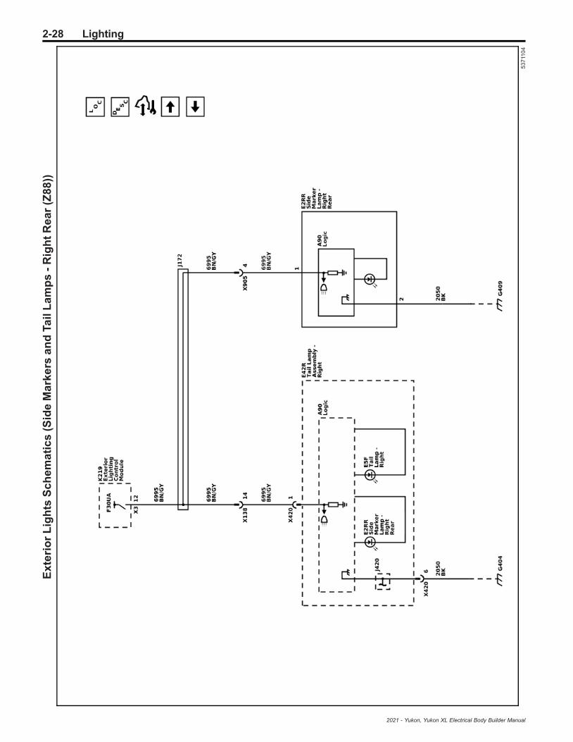
2-28 LightingE
xte
rio
rL
igh
tsS
ch
em
ati
cs
(Sid
eM
ark
ers
an
dTa
ilL
am
ps
-R
igh
tR
ea
r(Z
88
))
53
711
04
2021 - Yukon, Yukon XL Electrical Body Builder Manual

Lighting 2-29E
xte
rio
rL
igh
tsS
ch
em
ati
cs
(Ba
ck
Up
La
mp
s(X
88
))
53
711
08
2021 - Yukon, Yukon XL Electrical Body Builder Manual
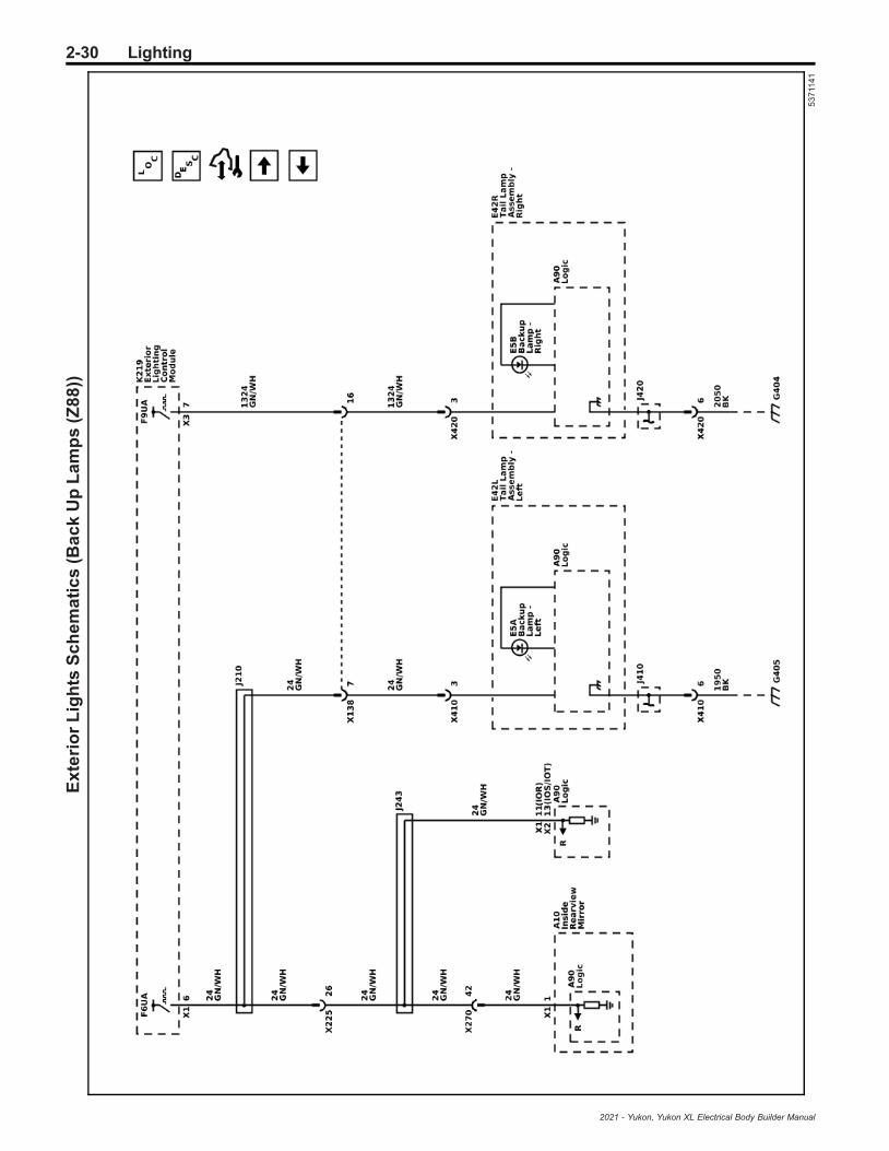
2-30 LightingE
xte
rio
rL
igh
tsS
ch
em
ati
cs
(Ba
ck
Up
La
mp
s(Z
88
))
53
711
41
2021 - Yukon, Yukon XL Electrical Body Builder Manual

Lighting 2-31E
xte
rio
rL
igh
tsS
ch
em
ati
cs
(Lic
en
se
Pla
te,H
an
ds
-Fre
eL
iftg
ate
(TC
2),
an
dR
un
nin
gB
oa
rdL
am
ps
(B3
L))
53
711
09
2021 - Yukon, Yukon XL Electrical Body Builder Manual

2-32 LightingIn
teri
or
Lig
hts
Sc
he
ma
tic
s(S
un
sh
ad
es
,Flo
or
Co
ns
ole
Co
mp
art
me
nt,
an
dC
arg
oL
am
ps
)
53
711
81
2021 - Yukon, Yukon XL Electrical Body Builder Manual

Lighting 2-33In
teri
or
Lig
hts
Sc
he
ma
tic
s(R
oo
fC
on
so
lea
nd
Re
ad
ing
an
dC
ou
rte
sy
La
mp
s(C
3U
))
54
50
12
4
2021 - Yukon, Yukon XL Electrical Body Builder Manual

2-34 LightingIn
teri
or
Lig
hts
Sc
he
ma
tic
s(R
oo
fC
on
so
lea
nd
Re
ad
ing
an
dC
ou
rte
sy
La
mp
s(-
C3
U))
53
711
85
2021 - Yukon, Yukon XL Electrical Body Builder Manual
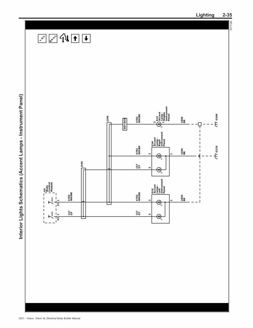
Lighting 2-35In
teri
or
Lig
hts
Sc
he
ma
tic
s(A
cc
en
tL
am
ps
-In
str
um
en
tP
an
el)
53
711
86
2021 - Yukon, Yukon XL Electrical Body Builder Manual

2-36 LightingIn
teri
or
Lig
hts
Sc
he
ma
tic
s(F
loo
dL
am
ps
an
dA
cc
en
tL
am
ps
-D
oo
rH
an
dle
sa
nd
Po
ck
ets
)
53
711
87
2021 - Yukon, Yukon XL Electrical Body Builder Manual

Lighting 2-37In
teri
or
Lig
hts
Dim
min
gS
ch
em
ati
cs
(Co
ntr
ols
an
dL
iftg
ate
Dim
min
g)
53
711
72
2021 - Yukon, Yukon XL Electrical Body Builder Manual

2-38 LightingIn
teri
or
Lig
hts
Dim
min
gS
ch
em
ati
cs
(Do
ors
an
dF
loo
rC
on
so
leD
imm
ing
)
53
711
73
2021 - Yukon, Yukon XL Electrical Body Builder Manual

Lighting 2-39In
teri
or
Lig
hts
Dim
min
gS
ch
em
ati
cs
(Se
ria
lDa
taD
imm
ing
)
53
711
74
2021 - Yukon, Yukon XL Electrical Body Builder Manual

2-40 LightingIn
teri
or
Lig
hts
Dim
min
gS
ch
em
ati
cs
(In
str
um
en
tP
an
elD
imm
ing
)
53
711
75
2021 - Yukon, Yukon XL Electrical Body Builder Manual

Lighting 2-41
Description and OperationExterior Lighting SystemsDescription and OperationThe exterior lighting system consist of the followinglamps:
• Backup lamps• Daytime running lamps (DRL)• Exterior courtesy lamps• Hazard warning lamps• Headlamps• Park, tail, license, and marker lamps• Front fog lamps (T40)• Rear fog lamps (T79)• Stop lamps• Turn signal lamps• Trailer lighting, refer to Trailering Description and
Operation on page 2‑60 for more information.
Low Beam HeadlampsThe headlamps may be turned ON in 3 different ways:
• When the headlamp switch is placed in the ONposition, for normal operation
• When the headlamp switch is placed in the AUTOposition, for automatic lamp control during lowambient light conditions
• When the headlamp switch is placed in the AUTOposition, with the windshield wipers ON in daylightconditions, after a 6 second delay
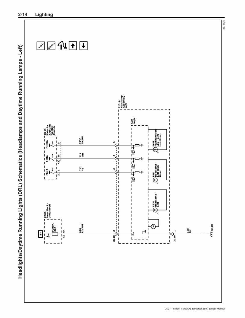
The K9 Body Control Module (BCM) monitors threesignal circuits from the S30 Headlamp Switch. Whenthe headlamp switch is in the AUTO position, the threesignal circuits are unaffected (open) and the BCM relieson the B10B Ambient Light/Sunload Sensor input todetermine if headlamps are required or if daytimerunning lamps will be activated based on outsidelighting conditions. When the headlamp switch isplaced in the headlamp OFF position, the headlampswitch headlamps OFF signal circuit is grounded,indicating to the BCM that the exterior lamps should beturned OFF. With the headlamp switch in the PARKLAMPS position, the headlamp switch park lamps ONsignal circuit is grounded, indicating that the park lampshave been requested. When the headlamp switch is inthe HEADLAMP position, both the headlamp switchpark lamps ON signal circuit and the headlamps ONsignal circuit are grounded. The BCM responds tothese inputs by sending a serial data message to theK219 Lighting Control Module. The Lighting ControlModule responds by applying pulse width modulated(PWM) voltage to both headlamp low beam controlcircuits, illuminating the low beam headlamps. Whenthe Lighting Control Module commands the low beamheadlamps ON, the operator will notice the interiorbacklighting for the instrument cluster and the variousother switches dim to the level of brightness selectedby the instrument panel dimmer switch.
High Beam HeadlampsThe high beam and flash to pass (FTP) functions arecontained within the S78 Turn Signal/MultifunctionSwitch. The K9 Body Control Module (BCM) provides
the turn signal/multifunction switch with two signalcircuits, the high beam signal circuit and the FTP signalcircuit. When the low beam headlamps are ON, and theturn signal/multifunction switch is placed in either thehigh beam position or FTP position, ground is appliedto the BCM through the high beam/FTP signal circuit.The BCM responds to the high beam request bysending a serial data message to the K219 LightingControl Module. The Lighting Control Module respondsby applying pulse width modulated (PWM) voltage toboth headlamp high beam control circuits, illuminatingthe high beam headlamps. The status of the high beamlamps is shown by a blue indicator located on theinstrument cluster. When high beams are commandedon, the indicator will be illuminated continuously. If thedriver turns the high beams off, the indicator will alsoturn off.
Flash to PassWhen the S78 Turn Signal/Multifunction Switch ismomentarily placed in the flash to pass position,ground is applied to the turn signal/multifunction switch.The turn signal/multifunction switch applies ground tothe K9 Body Control Module (BCM) through the flash topass switch signal circuit. The BCM responds to theflash to pass request by sending a serial data messageto the K219 Lighting Control Module. The LightingControl Module responds by applying pulse widthmodulated (PWM) voltage to both headlamp high beamcontrol circuits, illuminating the high beam headlamps.This causes the high beam headlamps to illuminate atfull brightness until the turn signal/multifunction switchis returned to the at rest position.
Automatic Headlamp ControlThe K9 Body Control Module (BCM) monitors threesignal circuits from the S30 Headlamp Switch. Whenthe headlamp switch is in the AUTO position, the threesignal circuits are unaffected (open) and the BCM relieson the B10B Ambient Light/Sunload Sensor input todetermine if headlamps are required or if daytimerunning lamps will be activated based on outsidelighting conditions. During automatic lamp control, theheadlamps will be off during daylight conditions but willturn on when the ambient light sensor detects lowambient light conditions. The ambient light sensor is alight sensitive transistor that varies the voltage signal tothe BCM. The BCM provides a 5 volt reference signaland a low reference ground to the ambient light sensor.During low light conditions the BCM will request the lowbeam headlamps ON by sending a serial data messageto the K219 Lighting Control Module. The LightingControl Module responds by applying pulse widthmodulated (PWM) voltage to both headlamp low beamcontrol circuits, illuminating the low beam headlamps.
Automatic High Beam Assist (TQ5)The automatic high beam assist (AHBA) systemoperates the high beam headlamps ON and OFFautomatically when the system is activated and certainconditions are met. The AHBA system consists of afront camera module that detects light and is able toidentify approaching vehicles on an even, straight roadat a distance of greater than 0.4 km (0.25 mi). The frontcamera module analyzes light color, intensity, andmovement. The AHBA system will turn OFF the high
2021 - Yukon, Yukon XL Electrical Body Builder Manual

2-42 Lighting
beam headlamps when approaching vehicleheadlamps or preceding vehicle taillights are detectedby the front camera module. AHBA can be deactivatedwhen the headlamp dimmer switch is moved from theneutral position to the high beam or flash to passpositions. AHBA can be reactivated by operating thehigh beam select switch from the neutral position to thehigh beam position twice within 2 seconds.
AHBA System Activation• Vehicle ON• Headlamp switch placed in the AUTO position• Outside lighting conditions must be dark• Vehicle speed greater than 25 mph (40 km/h)
AHBA System Operation
The following are conditions that the AHBA system willturn the high beam headlamps off during operation:
• The system detects approaching traffic headlamps• The system detects preceding traffic tail lamps• Ambient light level too high due to towns or twilight
situations• The vehicle’s speed drops below 13 mph
(22 km/h)• Delay
Note: AHBA may not operate properly if any of thefollowing conditions exist:
• Approaching and preceding vehicles lamps areundetectable due to dirt, snow, road spray, smoke,fog, or any other airborne conditions.
• The front camera module is covered with ice, dirt,snow, haze, or is obstructed.
• The vehicle is being driven on winding or hilly roadconditions which would make any on comingvehicle headlamps undetectable by the AHBA.
AHBA System Deactivation• Manually operating the headlamp switch from
neutral to high beam position• AHBA is deactivated automatically when the front
or rear fog lamps are turned ON
AHBA System Indicator
The status of the AHBA system is shown by a greenindicator located on the instrument panel cluster. WhenAHBA is active, the indicator will be illuminatedcontinuously. If the operator deactivates the AHBAsystem, the indicator will turn off.
Daytime Running LampsThe daytime running lamps (DRL) will illuminatecontinuously when the following conditions are met:
• Engine running• The headlamp switch is in the AUTO position• Ambient light conditions are daytime conditions
The B10B Ambient Light/Sunload Sensor is used tomonitor outside lighting conditions. The ambient lightsensor provides a voltage signal that will vary between0.2 and 4.9 volts depending on outside lightingconditions. The K9 Body Control Module (BCM)provides a 5 volt reference signal and a low referenceground to the ambient light sensor. The BCM monitors
the ambient light sensor signal circuit to determine ifoutside lighting conditions are correct for either daytimerunning lamps (DRL) or automatic lamp control whenthe headlamp switch is in the AUTO position. Indaylight conditions the BCM will send a serial datamessage to the K219 Lighting Control Module tocommand the DRLs ON, the Lighting Control Moduleresponds by applying pulse width modulated (PWM)voltage to both DRL control circuits, illuminating theDRLs. During low light conditions the Lighting ControlModule will command the low beam headlamps ON.
Hazard LampsThe hazard flashers may be activated in any powermode. The S26 Hazard Switch signal circuit ismomentarily grounded when the hazard switch ispressed. The K9 Body Control Module (BCM) respondsto the hazard switch signal input by sending a serialdata message to the K219 Lighting Control Module.The Lighting Control Module responds by supplyingbattery voltage to all turn signal lamps in an ON andOFF duty cycle. When the hazard switch is activated,the BCM also sends a serial data message to theinstrument cluster requesting both turn signal indicatorsto be cycled ON and OFF.
Park, Tail, and License LampsWhen the S30 Headlamp Switch is placed in the HEADor PARK position, ground is applied to the park lampswitch ON signal circuit to the K9 Body Control Module(BCM). The BCM responds to the park lamp switchsignal input by sending a serial data message to theK219 Lighting Control Module. The Lighting ControlModule responds by applying battery voltage to thepark lamps, tail lamps, and license lamps controlcircuits illuminating the park, tail, and license lamps.
Stop LampsThe B22 Brake Pedal Position Sensor is used to sensethe action of the driver application of the brake pedal.The K9 Body Control Module (BCM) provides the brakepedal position sensor with low reference, signal, and5 volt reference circuits. When the variable signalreaches a voltage threshold indicating the brakes havebeen applied, the BCM will respond by sending a serialdata message to the K219 Lighting Control Modulerequesting the stop lamps to be turned ON. TheLighting Control Module responds by applying batteryvoltage to the left and right stop lamp control circuits aswell as the center high mounted stop lamp controlcircuit illuminating the left and right stop lamps and thecenter high mounted stop lamp. If serial datacommunication is lost between the BCM and theLighting Control Module, the Lighting Control Modulewill receive a serial data message from the ElectronicBrake Control Module indicating that the brakes havebeen applied. If serial data communication is lostbetween all three modules, the Lighting Control Modulealso receives a hard wired voltage signal from the BCMto signal the brake lamps ON.
Turn Signal LampsTurn Signals
The K9 Body Control Module (BCM) provides theS78 Turn Signal/Multifunction Switch with left and rightturn signal switch signal circuits. Ground is applied at
2021 - Yukon, Yukon XL Electrical Body Builder Manual
Lighting 2-43
all times to the turn signal/multifunction switch. The turnsignal lamps may only be activated with the ignitionswitch in the ON or START positions. When the turnsignal/multifunction switch is placed in either the turnright or turn left position, ground is applied to the BCMthrough either the right turn or left turn signal switchsignal circuit. The BCM responds to the turn signalswitch input by sending a serial data message to theK219 Lighting Control Module. The Lighting ControlModule responds by applying a pulsating voltage to theturn signal lamps through there respective controlcircuits. When a turn signal request is received by theBCM, a serial data message is also sent to theinstrument cluster requesting the respective turn signalindicator be pulsed ON and OFF.
Turn Signal Outage Detection
Vehicles with LED turn signals require additional turnsignal outage detection circuits that provide turn signalfeedback to the K219 Lighting Control Module. TheLighting Control Module uses the feedback informationto send a serial data message to the instrument clusterto alert the driver anytime a turn signal fault is detected.If a fault is detected on a turn signal circuit or a turnsignal feedback circuit, the turn signals will flash in arapid manner to alert the driver of the fault.
Backup LampsWith the engine running and the transmission in thereverse position, the transmission control module(TCM) sends a serial data message to the multiplecontrol modules. The message indicates that the gearselector is in the reverse position. The K9 Body ControlModule (BCM) responds to the reverse positionmessage by sending a serial data message to theK219 Lighting Control Module to request the backuplamps on. The Lighting Control Module responds byapplying battery voltage to the backup lamps controlcircuit(s) illuminating the backup lamps. The appliedvoltage is also sent to the A11 Radio and A10 InsideRearview Mirror for rearview camera purposes. Oncethe driver moves the gear selector out of the reverseposition, a serial data message is sent by the TCM thatthe transmission is no longer in the reverse position.The BCM responds to the reverse position message bysending a serial data message to the Lighting ControlModule to request the backup lamps off. The LightingControl Module responds by removing battery voltagefrom the backup lamp circuits. The engine must berunning for the backup lamps to operate.
Exterior Courtesy LampsThe body control module (BCM) supplies batteryvoltage to each exterior door handle LED backlightingcircuit, the LED lighting located under each outsiderearview mirror for approach lighting, and both runningboard step courtesy lamps when equipped. When thekeyless entry transmitter is operated to either the lockor unlock functions the LED lighting located under eachoutside rearview mirror, exterior door handles, and bothrunning board steps are commanded ON for approachlighting.
Hands−Free Liftgate SensorLamp (TC2)If equipped with a hands-free liftgate, a vehicle logo willbe projected onto the ground near the rearbumper when:
• An RKE transmitter is detected within an area ofapproximately 2 m (6 ft) outside the liftgate
• A successful hands-free operation has occurredThe projected logo shows where the kicking motion isto take place. Once activated, the projected vehiclelogo will remain active for one minute, unless one ofthese conditions is met:
• The vehicle battery is low• The vehicle is not parked• Hands Free Liftgate Operation is set to OFF in
vehicle personalizationProjected logo will not be provided to the customer forthis RKE transmitter again for an approach until it hasnot been detected in the authentication zone for at least20 s. If an RKE transmitter is again detected withinapproximately 2 m (6 ft) of the liftgate, or anotherhands-free operation has been detected, theone-minute timer will be reset. If the vehicle remainsparked for an extended period of time with no RKEtransmitter use or Keyless Access operation, theprojected vehicle logo will be disabled. The projectedlogo will be re-enabled when:
• Any button is pressed on the RKE transmitter• One or all vehicle doors are opened and closed• The liftgate is closed when all doors are opened
The projected logo will not work for a single RKEtransmitter when a transmitter:
• Has been left within approximately 5 m (15 ft) ofthe liftgate for several minutes
• Has been left inside the vehicle and all vehicledoors are closed
• Has approached the area outside of the liftgateseveral times in a short period of time
Battery Run Down Protection/Inadvertent PowerTo provide battery run down protection, the exteriorlamps will be deactivated automatically under certainconditions. The K9 Body Control Module (BCM)monitors the state of the S30 Headlamp Switch. If theheadlamp switch is in the park or headlamp positionwhen the ignition switch is ON and then the ignitionswitch is placed in the OFF position, the BCM initiates a10 minutes timer. At the end of the 10 minutes, the BCMwill send a serial data message to the K219 LightingControl Module to deactivate the exterior lamps toprevent total battery discharge. This feature will becancelled if any power mode other than OFF becomesactive.
2021 - Yukon, Yukon XL Electrical Body Builder Manual

2-44 Lighting
The BCM will disable battery run down protection if anyof the following conditions exist:
• The park or headlamp switch is changed from theON to OFF position, and back to the ON positionduring battery run down protection.
• The BCM determined that the park or headlampswitch was not active when the ignition wasturned OFF.
Interior Lighting SystemsDescription and Operation
Interior LampsThe interior lighting system consist of two groups. Thisfirst group includes lamps that are not be dimmed.
• Dome/reading lamps• Instrument panel compartment lamp• Instrument panel courtesy lamps• Overhead console accent lamp• Rear compartment courtesy lamp• Sunshade mirror lamps
Dome Lamps
The dome lamps are controlled by door ajar inputs tothe K9 Body Control Module (BCM). When any door isopened, the door ajar switch contacts close and theBCM receives a door-open input. The BCM illuminatesthe dome lamp when any door is opened or a door lock/unlock request is activated with the key fob. After alldoors have been closed, the dome lamp will remainilluminated approximately 3 seconds after the last doorcloses. In the event that the dome lamp were to remainilluminated for more than 10 minutes with the ignitionswitch in the OFF position, the BCM will deactivate thedome lamp control circuit to prevent total batterydischarge. The dome lamps will turn OFF using thetheater dimming feature when controlled by the BCM.
Keyless Entry Interior Illumination
When the operator uses the keyless entry transmitter inorder to unlock the doors, the K9 Body Control Module(BCM) receives a door-unlock signal. The BCM mustreceive inputs from various systems that indicate thatthe ignition switch is OFF, the courtesy lamp switch isOFF, and all doors are closed before the BCM willactivate the interior lamps. After all doors have beenclosed, the courtesy lamps will turn OFF immediately ifthe ignition switch is turned to the ON position, the doorlocks are LOCKED, or approximately 20 seconds afterthe last door closes. The BCM will turn off the courtesylamps through the theater dimming feature. The BCMkeeps the courtesy lamps on for 40 seconds after analarm event is completed.
Instrument Panel Compartment Lamp
The inadvertent power supply voltage circuit from theK9 Body Control Module (BCM) provides batteryvoltage to the instrument panel compartment (glovebox) lamp. When the instrument panel compartment isopened, the instrument panel compartment lamp switchcontacts close providing a path to ground and theinstrument panel compartment lamp illuminates. If theoperator inadvertently leaves the instrument panelcompartment door open with the instrument panel
compartment lamp ON, the BCM will turn all interiorlamps OFF after 10 minutes has passed to prevent totalbattery discharge.
Reading Lamps
The inadvertent power supply voltage circuit from theK9 Body Control Module (BCM) provides batterypositive voltage to each reading lamp. When a readinglamp switch is activated, the switch contacts closeproviding a path to ground and the reading lampilluminates. If the operator inadvertently leaves areading lamp ON, the BCM will turn all interior lampsOFF after 10 minutes has passed to prevent totalbattery discharge.
Rear Compartment Courtesy Lamps
When the rear compartment is opened, the rearcompartment lid latch opens providing a rearcompartment open input signal to the K9 Body ControlModule (BCM). The BCM responds by applying batteryvoltage to the rear compartment courtesy lamp controlcircuit illuminating the rear compartment courtesylamps. If the operator inadvertently leaves the rearcompartment lid open, the BCM will turn all interiorlamps OFF after 10 minutes has passed to prevent totalbattery discharge.
Sunshade Mirror Lamp
The inadvertent power supply voltage circuit from theK9 Body Control Module (BCM) provides batteryvoltage to the passenger side sunshade mirror lamp.When the sunshade mirror cover is opened, a switchcloses providing ground and the sunshade lampilluminates. If the operator inadvertently leaves thesunshade mirror cover open with the lamp ON, theBCM will turn all interior lamps OFF after 10 minuteshas passed to prevent total battery discharge.
Interior Lamps DimmingThe second group includes lamps which may bedimmed. This group may use a combination of lightemitting diodes (LED), incandescent lamps, and pulsewidth modulation (PWM) voltage illumination.
• Audio/Video Input Adapter• Door lock switch – driver• Door lock switch – passenger• Door handle switch – driver interior• Door handle switch – passenger interior• Hazard switch• Hood/liftgate release switch• HVAC control head assembly• Ignition mode switch• Instrument panel dimmer switch• Multifunction switch – center console• Multifunction switch – instrument panel• Outside rearview mirror switch• Park brake switch• Radio• Rear compartment lid unlatch switch• Seat memory switch – driver• Seat memory switch – passenger• Steering wheel controls switch – left
2021 - Yukon, Yukon XL Electrical Body Builder Manual
Lighting 2-45
• Steering wheel controls switch – radio presets• Steering wheel controls switch – radio volume• Window switch – driver• Window switch – passenger
With the headlamp switch in the PARK or HEADposition, the park lamp switch signal circuit provides aninput to the K9 Body Control Module (BCM). The BCMresponds by applying voltage to the backlight dimmingcontrol circuits illuminating all components with interiorbacklighting. All interior backlighting turns on at thedimming level set by the dimmer buttons within theheadlamp switch. The headlamp switch is used toincrease and decrease the brightness of the interiorbacklighting components. The BCM provides a signalcircuit and a low reference circuit to the headlampswitch for backlight dimming. When a dimming button ispressed, the signal circuit becomes grounded throughthe appropriate resistor internal to the headlight switchand voltage from the BCM will decrease accordingly.The BCM interprets the signal and responds in twoways. The BCM applies a pulse width modulated(PWM) voltage through the LED dimming controlcircuits illuminating the interior backlighting to therequested level of brightness. The BCM also sends aserial data message to the appropriate control modulesrequesting all dimming components to be illuminated tothe same level of brightness.
Battery Rundown Protection/Inadvertent PowerThe K9 Body Control Module (BCM) inadvertent powersupply voltage circuit provides battery voltage to all ofthe interior courtesy lamps. In the event that any ofthese lamps were to remain illuminated for a period ofmore than 10 minutes with the ignition switch in theOFF position, the BCM will deactivate the inadvertentpower supply voltage circuit to prevent total batterydischarge. If the ignition switch is turned to any positionother than OFF, or if a lamp switch is activated duringthis 10 minute period, the timer resets for another10 minutes.
2021 - Yukon, Yukon XL Electrical Body Builder Manual
2-46 Mirrors
Mirrors
Schematic and Routing Diagrams
2021 - Yukon, Yukon XL Electrical Body Builder Manual

Mirrors 2-47In
sid
eR
ea
rvie
wM
irro
rS
ch
em
ati
cs
(In
sid
eR
ea
rvie
wM
irro
r(D
D8
/DR
Z))
53
711
65
2021 - Yukon, Yukon XL Electrical Body Builder Manual
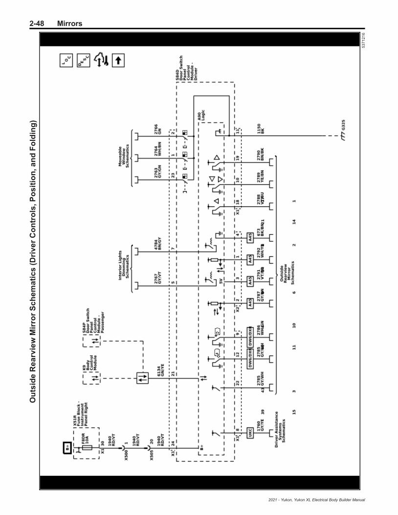
2-48 MirrorsO
uts
ide
Re
arv
iew
Mir
ror
Sc
he
ma
tic
s(D
riv
er
Co
ntr
ols
,Po
sit
ion
,an
dF
old
ing
)
53
71
21
6
2021 - Yukon, Yukon XL Electrical Body Builder Manual

Mirrors 2-49O
uts
ide
Re
arv
iew
Mir
ror
Sc
he
ma
tic
s(P
as
se
ng
er
Co
ntr
ols
,Po
sit
ion
,an
dF
old
ing
)
53
71
21
7
2021 - Yukon, Yukon XL Electrical Body Builder Manual

2-50 MirrorsO
uts
ide
Re
arv
iew
Mir
ror
Sc
he
ma
tic
s(D
imm
ing
(DD
8/D
RZ
)a
nd
He
ati
ng
)
53
71
22
0
2021 - Yukon, Yukon XL Electrical Body Builder Manual

Mirrors 2-51
Description and OperationAutomatic Day-Night MirrorDescription and Operation
Inside Rearview Mirror with theAutomatic Day-Night Feature SystemOperationThe inside rearview mirror uses 2 photocell sensors.One sensor is the headlight sensor, located on the faceside of the mirror. The headlight sensor is used todetermine light conditions present at the mirror face.The other sensor is the ambient light sensor, located onthe rear of the mirror or windshield side. The ambientlight sensor is used to determine the exterior lightconditions. With a low exterior light condition detected,and a high light condition from behind the car, at theheadlight sensor, the inside rearview mirror willautomatically darken the face of the mirror.In the daytime, the mirror is in a normal state becauseof the high exterior light condition that is indicated bythe ambient light sensor. With the gear selector lever inthe REVERSE position and the Ignition ON/Vehicle inService Mode, backup lamp supply voltage is suppliedas an input to the inside rearview mirror. The mirrormonitors this input to disable the automatic day-nightfeature. This allows the driver to see objects in themirror clearly when backing up, even during the night.
Driver Outside Rearview Mirror withAutomatic Day-Night System Operation(If Equipped)The automatic day-night feature of the driver outsiderearview mirror is controlled by the inside rearviewmirror. The inside rearview mirror supplies control andlow reference to the driver outside rearview mirror. Atnight, with the automatic day-night feature enabled, thedriver outside rearview mirror will automatically darkenwith the inside rearview mirror to reduce glare fromheadlamps behind the vehicle.
Inside Rearview Camera Full DisplayMirror System OperationThe inside rearview camera full display mirror isconnected to the outside rearview camera via ashielded coaxial cable. When the tab under the insiderearview mirror is pulled rearward, a view of the areabehind the vehicle displays on the mirror. Adjust therearview mirror for a clear view of the area behind thevehicle before turning on full display mirror. Use thebutton on the back of the mirror to adjust the brightnessof the display. Make sure the light sensor is not coveredwhen adjusting the brightness.The inside rearview camera full display mirror may notwork properly or display a clear image if:.
• It is dark.• The sun or the beam of headlamps are shining
directly into the camera lens.• Ice, snow, mud, or anything else builds up on the
camera lens. Clean the lens, rinse it with water,and wipe it with a soft cloth.
When the mirror detects that the camera is not sendinga valid video signal, it “blue screens” with a “no video”decal for 3 seconds, then reverts back to the mirror.Meanwhile, if a blue screen keeps on displayinginstead of the camera view, take the vehicle to yourdealer for service.
2021 - Yukon, Yukon XL Electrical Body Builder Manual
2-52 Mirrors
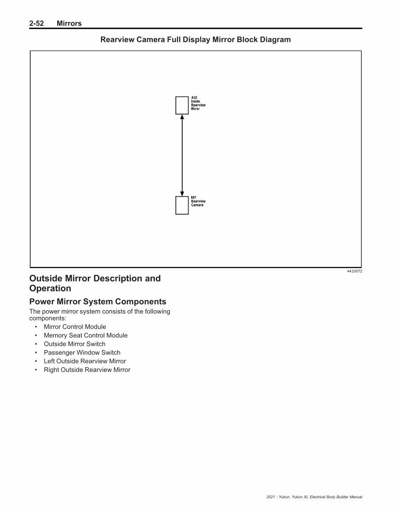
Rearview Camera Full Display Mirror Block Diagram
4433072
Outside Mirror Description andOperation
Power Mirror System ComponentsThe power mirror system consists of the followingcomponents:
• Mirror Control Module• Memory Seat Control Module• Outside Mirror Switch• Passenger Window Switch• Left Outside Rearview Mirror• Right Outside Rearview Mirror
2021 - Yukon, Yukon XL Electrical Body Builder Manual

Mirrors 2-53
Power Mirrors With A45 Block Diagram
3270439
Power Mirror System ControlsThe outside rearview mirror switch is a multiplex switchwhich signals the mirror control module which outsiderearview mirror to move (driver or passenger) andwhich direction to move it. The mirror control moduleand the passenger window switch are on a serial datacircuit with the memory seat module as the master. Themirror select and directional control switches are inputsto the mirror control module. When the memory seatmodule receives the switch inputs from the mirrorcontrol module, mirror output commands are sent to theappropriate module/switch through the serial datacircuit. The mirror control module and passengerwindow switch control the left and right outside rearview mirrors through bi-directional motor controlcircuits. The motor control circuits are floating while inan inactive state and the switches will apply power andground to the control circuits as necessary to move themirror in the commanded direction.Mirror position is determined by both horizontal andvertical position sensors in each of the power mirrors.The mirror control module and passenger windowswitch supply a 5 V reference, low reference, andhorizontal and vertical position signal circuits to thesesensors. The signal circuits are referenced from 5 V bythe switches and the signal circuit voltage levelsrepresent the mirror positions. The mirror positions aresent to the memory seat control module through theserial data circuit where they are stored for memorymirror operation. When the memory seat module
receives a memory recall command, the memory seatcontrol module will send the go to position commandsto the mirror control module and passenger windowswitch. The switches will then drive the appropriatemirror motors to the commanded position sensorsettings.
Folding MirrorsThe outside rearview mirror switch sends the mirrorselect and mirror fold/unfold inputs to the mirror controlmodule which communicates the inputs to the memoryseat control module through serial data. When thememory seat control module receives a fold/unfoldsignal it will send a fold/unfold command to the mirrorcontrol module and the passenger window switch. Theoutside mirrors will fold or unfold depending on theircurrent state. The mirror control module and thepassenger window switch control the fold/unfold motorsthrough bi-directional control circuits.
Heated MirrorsThe heated mirrors are controlled through the reardefog relay. Whenever the vehicle is running and therear window defogger is turned on battery voltage issupplied to the mirror heater elements through the leftand right mirror heater element control circuits.
2021 - Yukon, Yukon XL Electrical Body Builder Manual

2-54 Trailering Systems
Trailering Systems
Schematic and Routing Diagrams
2021 - Yukon, Yukon XL Electrical Body Builder Manual
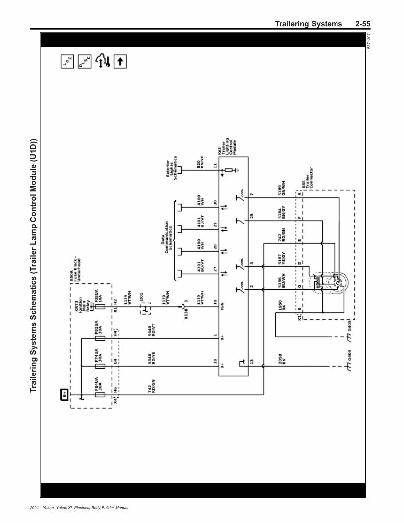
Trailering Systems 2-55T
rail
eri
ng
Sy
ste
ms
Sc
he
ma
tic
s(T
rail
er
La
mp
Co
ntr
olM
od
ule
(U1
D))
53
71
30
7
2021 - Yukon, Yukon XL Electrical Body Builder Manual

2-56 Trailering SystemsT
rail
eri
ng
Sy
ste
ms
Sc
he
ma
tic
s(T
rail
er
Co
nn
ec
tor
Pin
s:
A,B
,D,E
,F,G
(Z8
2-U
1D
))
53
71
30
5
2021 - Yukon, Yukon XL Electrical Body Builder Manual

Trailering Systems 2-57T
rail
eri
ng
Sy
ste
ms
Sc
he
ma
tic
s(T
rail
er
Bra
ke
sP
rov
isio
n(Z
82
-JL
1))
53
71
30
4
2021 - Yukon, Yukon XL Electrical Body Builder Manual
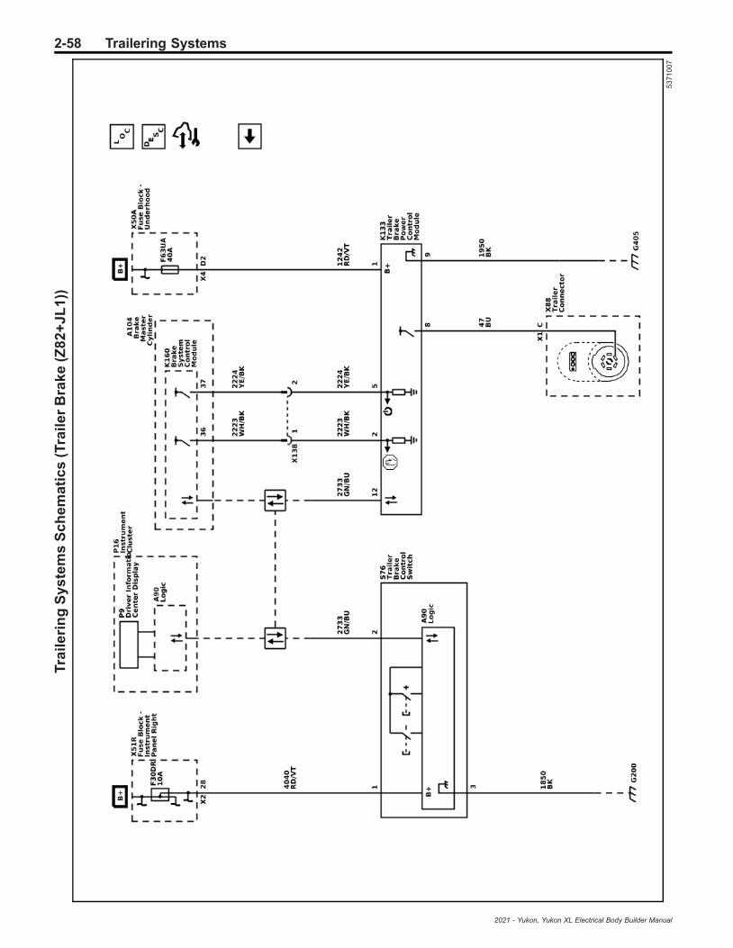
2-58 Trailering SystemsT
rail
eri
ng
Sy
ste
ms
Sc
he
ma
tic
s(T
rail
er
Bra
ke
(Z8
2+
JL
1))
53
71
00
7
2021 - Yukon, Yukon XL Electrical Body Builder Manual

Trailering Systems 2-59T
rail
eri
ng
Sy
ste
ms
Sc
he
ma
tic
s(T
rail
er
Tir
eP
res
su
re(P
TT
))
53
71
30
6
2021 - Yukon, Yukon XL Electrical Body Builder Manual

2-60 Trailering Systems
Description and OperationTrailering Description and Operation
Trailering System OverviewBegin the trailering system diagnosis with DiagnosticSystem Check - Trailering. The Diagnostic SystemCheck - Trailering will provide a complete strategy tolocate and repair a vehicle trailering electrical fault. Notfollowing this strategy may cause additional diagnostictime and/or misdiagnosis.The trailering system consists of the following:
• Trailer Lighting, refer to Trailer Lamps Malfunctionfor additional diagnostic information.
• Trailer Brakes, refer to Trailer Brake Malfunctionfor additional diagnostic information.
• Trailer Battery Charging System, refer to TrailerBattery Charging Malfunction for additionaldiagnostic information.
• Trailer Detection, refer to Trailer DetectionMalfunction for additional diagnostic information.
• Trailer Tire Pressure Monitoring System, refer toTrailer Tire Pressure Monitoring Malfunction foradditional diagnostic information.
• Trailer Theft Detection.When a trailer is detected on a vehicle equipped withside blind zone detection, rear park assist, and/or rearcross traffic alert, the vehicle will automatically turnthese features off. These features are turned off toprevent false detections due to the trailer obstructingthe view of the sensors.
7–Terminal Trailer Connector Pinout (NorthAmerica)
• Terminal A – Trailer Backup Lamp Control• Terminal B – Ground• Terminal C – Trailer Brake Control• Terminal D – Right Trailer Stop/Turn Signal Lamp
Control• Terminal E – B+• Terminal F – Trailer Park Lamp Control• Terminal G – Left Trailer Stop/Turn Signal Lamp
Control
13–Terminal Trailer Connector Pinout (Export)• Terminal 1 – Left Trailer Turn Signal Lamp Control• Terminal 2 – Trailer Fog Lamp Control• Terminal 3 – Ground• Terminal 4 – Right Trailer Turn Signal Lamp
Control• Terminal 5 – Right Trailer Park Lamps Control• Terminal 6 – Trailer Stop Lamps Control• Terminal 7 – Left Trailer Park Lamps Control• Terminal 8 – Trailer Backup Lamp Control• Terminal 9 – B+• Terminal 10 – Ignition Voltage• Terminal 11 – Ground• Terminal 12 – Trailer Connected Signal• Terminal 13 – Ground
Connecting Aftermarket Accessories• Some aftermarket accessories that connect to the
X88 Trailer Connector will be recognized by thevehicle as a trailer connected, even if theaccessory is not a trailer. As a result, side blindzone detection, rear park assist, and/or rear crosstraffic alert will be turned off anytime the vehicledetects a trailer/accessory is connected.
• Vehicles equipped with U1D have trailer theftdetection that constantly monitors trailerconnected status when enabled. This is done byperiodically pulsing the lighting circuits of thetrailer when the vehicle is parked. As a result,some aftermarket accessories may be turned ON/OFF when connected to the vehicle with theftdetection enabled.
• Vehicles equipped with U1D use pulse widthmodulation voltage (PWM) for trailer lightingfunctions. Some aftermarket accessories areincompatible with PWM and may not functioncorrectly when connected to the trailer lightingcircuits of the vehicle.
Trailer Battery Charging SystemTrailer battery charging is accomplished throughconstant battery voltage from the X50A Fuse Block –Underhood to the X88 Trailer Connector. Batteryvoltage is supplied to terminal E at the X88 TrailerConnector at all times. If equipped, the trailer batterywill constantly be charged by the vehicle’s electricalsystem anytime the trailer is connected. Some trailersrequire the B+ circuit to the X88 Trailer Connector forthe trailer brakes to function.
Trailer Lighting and Detection With U1DNote: Some trailers utilize a trailer control module tocontrol the trailer lighting of the trailer. These trailersmay require the B+ circuit to the trailer connector tocontrol trailer lighting when equipped with a separatetrailer control module. These trailers will not bedetected by the K68 Trailer Lighting Control Moduleand may require an additional trailer adaptor for thevehicle to recognize the trailer is connected.
North America (7-Terminal connector)
North American vehicles use a 7-way trailer connectorfor trailering features. The K68 Trailer Lighting ControlModule is responsible for controlling the trailer lightingon vehicles with U1D. The combined trailer stop/turnsignal lamps of the trailer must draw at least 55mA oftotal current to be detected as a trailer or the TrailerLighting Control Module will not control the lightingcircuits. The Trailer Lighting Control Module receivesserial data messages from the K9 Body Control Module(BCM) indicating what lamps have been activated onthe vehicle. The Trailer Lighting Control Moduleresponds by applying pulse width modulated voltage(PWM) to the appropriate control circuits for therequested lamps illuminating the lamps on the attachedtrailer. The Trailer Lighting Control Module constantlymonitors for trailer connection status, trailer lightingfaults, and trailer theft deterrent purposes. This isaccomplished through the lighting circuits of the trailerto determine if a trailer is connected. When a trailer isconnected, the Trailer Lighting Control Module senses
2021 - Yukon, Yukon XL Electrical Body Builder Manual

Trailering Systems 2-61
the trailer connection and alerts the driver byrequesting a trailer profile setup through the TraileringApp, which is displayed on the infotainment screen. If atrailer is disconnected with the ignition ON, the vehiclewill display multiple trailer lighting messages until atrailer is reconnected or the message is dismissed bythe user. With the key OFF, the Trailer Lighting ControlModule will periodically pulse the lighting circuits of thetrailer to verify it is still connected. The lights on thetrailer may flash at different intervals with the key OFFdepending on which type of lights the trailer is built with.If a trailer is disconnected with the key ON, the vehiclewill display a trailer disconnected message until a traileris reconnected or the ignition is cycled.
Export (13-Terminal connector)
Export vehicles use a 13-way trailer connector fortrailering features. The K68 Trailer Lighting ControlModule is responsible for controlling the trailer lightingon vehicles with U1D. The combined trailer turn signaland park lamps of the trailer must draw at least 55mA oftotal current to be detected as a trailer or the TrailerLighting Control Module will not control the lightingcircuits. The Trailer Lighting Control Module receivesserial data messages from the K9 Body Control Module(BCM) indicating what lamps have been activated onthe vehicle. The Trailer Lighting Control Moduleresponds by applying pulse width modulated voltage(PWM) to the appropriate control circuits for therequested lamps illuminating the lamps on the attachedtrailer. The Trailer Lighting Control Module constantlymonitors for trailer connection status, trailer lightingfaults, and trailer theft deterrent purposes. This isaccomplished through the lighting circuits of the trailer
to determine if a trailer is connected. With the key OFF,the Trailer Lighting Control Module will periodicallypulse the lighting circuits of the trailer to verify it is stillconnected. The lights on the trailer may flash atdifferent intervals with the key OFF depending on whichtype of lights the trailer is built with. If a trailer isdisconnected with the key ON, the vehicle will display atrailer disconnected message until a trailer isreconnected or the ignition is cycled.
Trailer Lighting Without U1DThe K219 Lighting Control Module is responsible forcontrolling the trailer lighting on vehicles without U1D.The lighting control module receives serial datamessages from the K9 Body Control Module (BCM)indicating what lamps have been activated on thevehicle. The lighting control module responds byapplying voltage to the appropriate relay control circuitsfor the requested lamps anytime the vehicle lamps arecommanded ON. With the relay coil energized, therelay contacts close and allow voltage to flow throughthe relay illuminating the appropriate lamps on theattached trailer.
Trailering MessagesThe driver information center (P16 Instrument Cluster)or infotainment screen (P17 Info Display Module) maydisplay one or more of the following messages to theuser related to trailering.
Trailering Message Description
Check Left Trailer Turn Signal Lamp The K68 Trailer Lighting Control Module detects a fault on the left trailerstop/turn lamp control circuit
Check Right Trailer Turn Signal Lamp The K68 Trailer Lighting Control Module detects a fault on the right trailerstop/turn lamp control circuit
Check Trailer Rear Lamp The K68 Trailer Lighting Control Module detects a fault on the trailer parklamp control circuit.
Check Trailer Reversing Lamp The K68 Trailer Lighting Control Module detects a fault on the trailerbackup lamp control circuit.
Check Trailer Stop Lamps The K68 Trailer Lighting Control Module detects a fault on the left or righttrailer stop/turn lamp control circuits
Check Trailer Wiring The K133 Trailer Brake Power Control Module detects a fault on the trailerbrake control circuit or the trailer was disconnected.
Lane Change Alert Off Reminder to the user that lane change alerts are turned off anytime atrailer is detected.
Rear Cross Traffic Alert Off Reminder to the user that rear cross traffic alerts are turned off anytime atrailer is detected.
Rear Park Assist Off Reminder to the user that rear park assist is turned off anytime a trailer isdetected.
Remember to turn On Tow/Haul Mode Reminder to the user to turn ON Tow/Haul Mode when towing.
Service Trailer Brake System The K133 Trailer Brake Power Control Module detects a fault on the trailerbrake control circuit.
Service Trailer Tire Monitor System The K214 Trailer Tire Pressure Indicator Module detects one or moreissues with the trailer tire pressure monitoring system.
Trailer Detected The K68 Trailer Lighting Control Module detects a trailer has beenconnected to the X88 Trailer Connector.
2021 - Yukon, Yukon XL Electrical Body Builder Manual

2-62 Trailering Systems
Trailering Message Description
Trailer Brakes Detected (With JL1) The K133 Trailer Brake Power Control Module detects a trailer with trailerbrakes has been connected to the X88 Trailer Connector.
Trailer Disconnected Check Connection The K68 Trailer Lighting Control Module detects a trailer has beendisconnected from the X88 Trailer Connector.
Trailer Tire Pressure High The K214 Trailer Tire Pressure Indicator Module detects one or more ofthe trailer tire pressures is high.
Trailer Tire Pressure Low The K214 Trailer Tire Pressure Indicator Module detects one or more ofthe trailer tire pressures is low.
Trailer Tire Sensor Fault The K214 Trailer Tire Pressure Indicator Module detects one or more ofthe trailer tire pressure sensors has a fault.
Trailer Tire Temperature High The K214 Trailer Tire Pressure Indicator Module detects one or more ofthe trailer tire temperatures is too high.
Trailer Theft Detection (With U1D Only)Trailer theft monitoring can be turned ON and OFFthrough the vehicle Trailer App. Anytime the contenttheft deterrent system is armed, the trailer lightingcircuits are constantly monitored to determine if a traileris connected for trailer theft deterrent purposes. Withthe key OFF, the K68 Trailer Lighting Control Modulewill periodically pulse the lighting circuits of the trailer toverify it is still connected by monitoring the voltage dropof the circuit. Depending on the configuration of thetrailer lights, the trailer lights may periodically flash aspart of the trailer theft deterrent function. These flashescorrespond to when the K68 Trailer Lighting ControlModule pulses the lighting circuits to ensure the traileris still connected and is considered normal. If the traileris disconnected while the content theft deterrent systemis armed, the vehicle will flash the exterior lights andcycle the horn to alert of a trailer theft event. Refer toTheft Systems Description and Operation for moreinformation on the content theft deterrent system.
Trailer BrakesA trailer brake control system is used to control theamount of trailer braking power that is made availableto trailers with brakes that require a controlled electricaloutput signal for actuation.The power output to the trailer brakes is based on boththe amount of braking being applied by the vehicle’sbrake system and on the type of trailer brakes detected.
The Trailer Brake Control System is compatible withtwo types of Trailer Brake Systems as listed below:
1. Electric Brakes A controlled electrical outputsignal energizes an electric-magnet/lever armassembly that directly actuates the brakemechanism. The GDS name for this system is“Electromagnetic Brakes”.
2. Electric Over Hydraulic Brakes A controlledelectrical output signal energizes a remote, trailermounted hydraulic pump to build brake pressure ina closed hydraulic system on the trailer. Thehydraulic fluid pressure actuates the brakemechanism. The GDS name for this system is“Electrohydraulic Brakes”.
Trailer Brake Output Versus Trailer Brake Type• The trailer brake system characterizes the trailer
brakes as either Electric Brake or Electric OverHydraulic Brake automatically. Thischaracterization may be affected by the number,type, and age of the trailer brake magnets, as wellas any other devices installed on the trailer brakes(i.e. adapters for Electric Over Hydraulic brakefunctionality).
• The trailer brake system is fully operational witheither characterization.
• Some features of the trailer brake system may bedifferent based on the trailer brake typecharacterization. An example of this is at zerospeed, where pressing the service brake pedal willproduce output when the trailer brakes arecharacterized as Electric Brakes, but not whencharacterized as Electric Over Hydraulic Brakes.
• Sliding the manual trailer brake apply lever willproduce output at zero speed for eithercharacterization.
The user gain allows the driver to adjust the amount oftrailer brake output to match the trailer load and roadsurface. The controller determines the desired trailerbrake output and provides a control signal to theK133 Trailer Brake Power Control Module (TBPM). TheK133 Trailer Brake Power Control Module amplifies thesignal and provides the output required to activate theElectric or Electric Over Hydraulic trailer brakes.The trailer brake control can support up to a maximumof four axles with electric trailer brakes (8 brakemagnets).Connecting a trailer that is not compatible with thetrailer brake system may result in reduced or completeloss of trailer braking. There may be an increase instopping distance or trailer instability which could resultin personal injury or damage to the vehicle, trailer orother property. An aftermarket controller may beavailable for use with trailers with surge or air trailerbrake systems.To determine the type of brakes on your trailer and theavailability of controllers, check with your trailermanufacturer or dealer. Do not power up an aftermarketcontroller with the factory brake controller at thesame time.
2021 - Yukon, Yukon XL Electrical Body Builder Manual

Trailering Systems 2-63
The vehicle is equipped with the following trailerbraking components:
• K160 Brake System Control Module• K133 Trailer Brake Power Control Module• S76 Trailer Brake Control Switch• Manual Trailer Brake Apply• Trailer Gain Adjustment• Trailer Brake Driver Information Center Display
Trailer Brake Control PanelThe S76 Trailer Brake Control Switch contains thetrailer gain and manual apply switches. It is located inthe vehicle center stack. Refer to the owner’s manualfor more information on the location. The control paneland switches allows you to adjust the amount of output,referred to as trailer gain, available to the Electric orElectric Over Hydraulic brakes. It also allows you tomanually apply the trailer brakes. The trailer brakecontrol switch is used along with the trailer brakedisplay page on the driver information center to adjustand display power output to the trailer brakes.
Manual Trailer Brake ApplyThe manual trailer brake apply lever is located on theS76 Trailer Brake Control Switch and is used to applythe trailer’s Electric or Electric Over Hydraulic brakesindependent of the vehicle’s brakes. This lever is usedin the trailer gain adjustment procedure to properlyadjust the power output to the trailer brakes.Sliding the lever to the left will apply only the trailerbrakes. The power output to the trailer is indicated inthe trailer brake display page in the Driver InformationCenter (DIC). If the vehicle’s service brakes are appliedwhile using the manual trailer brake apply lever, thetrailer output power will be the greater of the two.The trailer and the vehicle’s brake lamps will come onwhen either the vehicle’s braking or manual trailerbrakes are applied.
Trailer Brake Gain AdjustmentTrailer gain should be set for a specific traileringcondition and must be adjusted any time vehicleloading, trailer loading or road surface conditionschange. It is important to re-adjust trailer gain any timethe tow vehicle, trailer loading or road surfaceconditions change or it you notice trailer wheel lock-upat any time while you are towing.Setting the trailer gain properly is needed for the besttrailer stopping performance. A trailer that isover-gained may result in locked trailer brakes. A trailerthat is under-gained may result in not enough trailerbraking. Both of these conditions may result in poorstopping and stability of the vehicle and trailer.
Trailer Gain Adjustment Procedure• Adjust trailer gain in 0.5 step increments up to 10
gain setting by using the gain adjustment +/−buttons on the trailer brake control panel switch.Pressing and holding a gain button will cause thetrailer gain to continuously increment ordecrement. To turn the output to the trailer off, setthe gain to zero.
• Drive the tow vehicle and trailer combination on alevel surface representative of the towingcondition and free of traffic at approximately 32–40 km/h (20–25 mph) and fully apply the manualtrailer brake apply lever mechanism located on thetrailer brake control panel switch. Adjusting thetrailer gain at slower speeds may result in anincorrect gain setting.
• Adjust the trailer gain to just below the threshold oftrailer wheel lock-up . Trailer wheel lock-up maynot occur if towing a heavily loaded trailer. In thiscase, adjust the trailer gain to the highestallowable setting for the towing condition.
Trailer Brake Gain and Output Display
This display menu can be accessed by scrollingthrough the DIC menu, or any time the trailer gain +/−button is depressed, or the manual trailer brake applylever is actuated. The trailer output is displayed from 0to full output and indicates the output power provided tothe trailer brakes, relative to the gain setting.
After the electrical connection is made to a trailerequipped with electric brakes or electric over hydraulicbrakes, the TRAILER CONNECTED message will bedisplayed momentarily on the DIC. The Trailer BrakeDisplay Page can be selected on the DIC showingTRAILER GAIN and OUTPUT, after all vehicle relatedservice messages are acknowledged by the driver.Depending on which instrument panel cluster is in thevehicle, the DIC may display dashed lines, a greyed outdisplay, or it may be blank signifying a disconnectedtrailer or a trailer brake fault condition.
Trailer Brake Driver Information CenterIndicators and MessagesTrailer Brake Detection
The K133 Trailer Brake Power Control Moduleconstantly monitors the trailer auxiliary control circuitfrom Terminal C at the X88 Trailer connector. When atrailer is connected with trailer brakes, the K133 TrailerBrake Power Control Module senses the connectionand alerts the driver with a Trailer Connected message.If the K133 Trailer Brake Power Control Module sensesa fault, or the trailer becomes disconnected, the vehiclewill alert the driver with a Check Trailer Wiringmessage.The following indicators are used to inform the driver ofseveral different conditions:
Trailer Connected
This message will be briefly displayed when a trailerwith Electric or Electric Over Hydraulic brakes is firstconnected to the vehicle. This message willautomatically turn off in about ten seconds. The drivercan also acknowledge this message before itautomatically turns off.
2021 - Yukon, Yukon XL Electrical Body Builder Manual
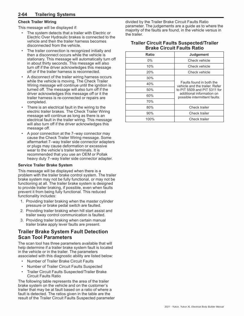
2-64 Trailering Systems
Check Trailer Wiring
This message will be displayed if:• The system detects that a trailer with Electric or
Electric Over Hydraulic brakes is connected to thevehicle and then the trailer harness becomesdisconnected from the vehicle.
• The trailer connection is recognized initially andthen a disconnect occurs while the vehicle isstationary. This message will automatically turn offin about thirty seconds. This message will alsoturn off if the driver acknowledges this messageoff or if the trailer harness is reconnected.
• A disconnect of the trailer wiring harness occurswhile the vehicle is moving. The Check TrailerWiring message will continue until the ignition isturned off. The message will also turn off if thedriver acknowledges this message off or it thetrailer harness is re-connected or repairs arecompleted.
• There is an electrical fault in the wiring to theelectric trailer brakes. The Check Trailer Wiringmessage will continue as long as there is anelectrical fault in the trailer wiring. This messagewill also turn off if the driver acknowledges thismessage off.
• A poor connection at the 7–way connector maycause the Check Trailer Wiring message. Someaftermarket 7–way trailer side connector adaptersor plugs may cause deformation or excessivewear to the vehicle’s trailer terminals. It isrecommended that you use an OEM or Pollakheavy duty 7–way trailer side connector adapter.
Service Trailer Brake System
This message will be displayed when there is aproblem with the trailer brake control system. The trailerbrake system may not be fully functional, or may not befunctioning at all. The trailer brake system is designedto provide trailer braking, if possible, even when faultsprevent it from being fully functional. This reducedfunctionality includes:
1. Providing trailer braking when the master cylinderpressure or brake pedal switch are faulted.
2. Providing trailer braking when hill start assist andtrailer sway control communication is faulted.
3. Providing trailer braking when certain manualtrailer brake apply lever faults are present.
Trailer Brake System Fault DetectionScan Tool ParametersThe scan tool has three parameters available that willhelp determine if a trailer brake system fault is locatedin the vehicle or in the trailer. The parametersassociated with this diagnostic ability are listed below:
• Number of Trailer Brake Circuit Faults• Number of Trailer Circuit Faults Suspected• Trailer Circuit Faults Suspected/Trailer Brake
Circuit Faults RatioThe following table represents the area of the trailerbrake system on the vehicle and on the customer’strailer that may be at fault based on a ratio of where afault is detected. The ratios given in the table are theresult of the Trailer Circuit Faults Suspected parameter
divided by the Trailer Brake Circuit Faults Ratioparameter. The judgements are a guide as to where themajority of the faults are found, in the vehicle versus inthe trailer.
Trailer Circuit Faults Suspected/TrailerBrake Circuit Faults RatioRatio Judgement
0% Check vehicle
10% Check vehicle
20% Check vehicle
30%Faults found in both the
vehicle and the trailer. Referto PIT 5509 and PIT 5311 for
additional information onpossible intermittent faults.
40%
50%
60%
70%
80% Check trailer
90% Check trailer
100% Check trailer
2021 - Yukon, Yukon XL Electrical Body Builder Manual

Trailering Systems 2-65
Trailer Tire Pressure Monitoring
Tire Pressure Monitoring Block Diagram
5080679
Special Tools• EL-46079/J-46079 Tire Pressure Monitor
Diagnostic Tool• EL-50448 Tire Pressure Monitor Sensor
Activation Tool• EL-52641 Trailer Presence Simulator Tool
For equivalent regional tools, refer to Special Tools.The Trailer Tire Pressure Monitor System is designedto monitor the pressure of the trailer tires, and warn thedriver when a low pressure condition exists. FourTrailer Tire Pressure Monitor System sensors areprovided in the vehicle’s glove box as an accessorywhen equipped. The system can accommodate a trailerwith up to (6) tires if additional sensors are purchasedfrom the dealership. Also, the system can be pairedwith up to (5) individual trailers. The sensors must bemounted onto each tire and wheel assembly, and thesensors must be learned by the vehicle by following the
learning procedure as shown in the Trailering Appsection of this manual. For sensor installationassistance, please contact your trailer service center ortire service center. The Trailer Tire Pressure MonitorSystem sensors monitor the air pressure in the trailertires and transmit the trailer tire pressure readings to areceiver located in the vehicle. The trailer tire pressuresensors can transmit up to 23 feet (7 meters) from thehitch receiver of the vehicle. The tire pressure valuescan be viewed in the trailering app in the vehicle’scenter stack.
Trailering Diagnostic ToolsIn some situations when diagnosing trailer tire pressuremonitoring, trailer lighting, or integrated trailer brakes, itmay be necessary to connect the vehicle to a trailer toconfirm proper operation. Performing this activity mayprove difficult in the service environment since trailersare not often available for diagnostic use, may have
2021 - Yukon, Yukon XL Electrical Body Builder Manual

2-66 Trailering Systems
existing electrical issues outside of the issues atechnician is attempting to diagnose, or simply may betoo unwieldily to connect for diagnosis.With all this in mind, it may be helpful to build or createa tool that can be plugged into the vehicle’s trailerconnector and simulate a connected trailer. This toolwould include park lamps, stop lamps, and a reverselamp for lighting and trailer tire pressure monitoringdiagnosis. It can be expanded to include trailer brakemagnets to diagnose integrated trailer brake concerns.Also, an additional lamp can be included to diagnosethe B+ circuit to the trailer.Trailer issues are NOT covered under warranty, butthese tools may be used to verify the vehicle isfunctioning properly and to help the customerunderstand and correct any trailer related issues if theyso choose.
Available Trailer PresenceSimulator Tool
Illustration Tool Number/Description
5166189
EL-52641
Trailer PresenceSimulator Tool
Simulated Trailer LightingCreating a tool to simulate a connected trailer can beused to diagnose issues with trailer lighting, trailerbrake (if equipped), the Trailering App (if equipped),and trailer tire pressure monitoring system (ifequipped).If the vehicle is equipped with a K68 Trailer LightingControl Module (U1D), the module monitors the currenton the lighting circuits to determine a trailer has beenconnected. The Trailer Lighting Control Module pulsescurrent on the trailer lighting circuits every 10–15 s tomonitor for a connected trailer. If a current draw greaterthan 55mA is detected, the Trailer Lighting ControlModule recognizes this as a connected trailer. This willenable any trailer lighting controlled by the TrailerLighting Control Module. If the vehicle is also equippedwith trailer tire pressure monitoring, the Trailer LightingControl Module will also use this trailer detection as acue to enable the Trailering App and trailer tire pressuremonitoring functions.
Creating a Simulated Trailer Lighting Tool
Parts needed:• 7-way RV trailer connector Qty: 1
Note: The combination trailer stop/turn, andbackup lamps must draw at least 55mA of totalcurrent to be detected as a trailer. Some LEDcombination lamps will not draw enough current.
If an LED combination lamp is used, make sure itdraws at least 55mA. A load resistor can be addedto the circuit if necessary to obtain the correct load.
• Combination trailer park/stop/turn lamp (greaterthan 55mA drawn when on) Qty: 2
• Reverse lamp Qty: 1• 12 gauge wire and terminals/connectors Qty: As
needed• 18 gauge wire and terminals/connectors Qty: As
needed• Mounting board Qty: 1
1. Connect a 12 gauge wire to the ground terminal ofthe 7-way trailer connector and the ground circuitof each combination trailer park/stop/turn lamp andthe reverse lamp in parallel.
2. Connect an 18 gauge wire between the park lampterminal of the 7-way trailer connector and the parklamp circuit of each combination trailer park/stop/turn lamp in parallel.
3. Connect an 18 gauge wire between the left turn/stop lamp terminal of the 7-way trailer connectorand the turn/stop lamp circuit of left trailer park/stop/turn lamp.
4. Connect an 18 gauge wire between the right turn/stop lamp terminal of the 7-way trailer connectorand the turn/stop lamp circuit of right trailer park/stop/turn lamp.
5. Connect an 18 gauge wire between the reverselamp terminal of the 7-way trailer connector andthe reverse lamp.Note: A combination trailer lighting and trailerbrake tool can be created on the same mountingboard.
6. Mount the left combination trailer park/stop/turnlamp, right combination trailer park/stop/turn lamp,and reverse lamp to the mounting board.
7. Plug the 7-way RV trailer connector to the vehicleand verify functionality.
Simulated Trailer BrakesCreating a tool to simulate trailer brakes can be used todiagnose trailer brake issues.The trailer brake control system is compatible with twotypes of trailer brake systems: electromagnetic orelectro-over hydraulic trailer brakes. The Brake SystemControl Module must determine which type of brakesthe trailer is equipped with so the system can outputcorrectly for the trailer's brake system. Because theBrake System Control Module has to determine thetype of trailer brake system that is being used, it can besensitive to a variety of trailer wiring issues.The Trailer Brake Power Control Module continuouslysends a test pulse out on the trailer brake control circuit(circuit 47) to determine if a trailer with trailer brakeshas been connected. How the pulse reacts when atrailer is connected is how the Trailer Brake PowerControl Module determines which type of brakingsystem the trailer is equipped with.Even after the system detects the trailer, Trailer BrakePower Control Module will continue to send this testpulse on the trailer brake control circuit, which now ismonitoring both the truck and trailer circuitry. The trailer
2021 - Yukon, Yukon XL Electrical Body Builder Manual
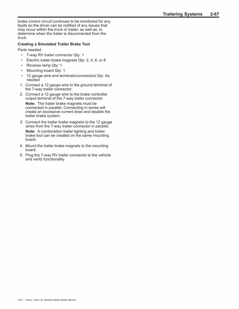
Trailering Systems 2-67
brake control circuit continues to be monitored for anyfaults so the driver can be notified of any issues thatmay occur within the truck or trailer, as well as, todetermine when the trailer is disconnected from thetruck.
Creating a Simulated Trailer Brake Tool
Parts needed:• 7-way RV trailer connector Qty: 1• Electric trailer brake magnets Qty: 2, 4, 6, or 8• Reverse lamp Qty: 1• Mounting board Qty: 1• 12 gauge wire and terminals/connectors Qty: As
needed1. Connect a 12 gauge wire to the ground terminal of
the 7-way trailer connector.2. Connect a 12 gauge wire to the brake controller
output terminal of the 7-way trailer connector.Note: The trailer brake magnets must beconnected in parallel. Connecting in series willcreate an excessive current draw and disable thetrailer brake system.
3. Connect the trailer brake magnets to the 12 gaugewires from the 7-way trailer connector in parallel.Note: A combination trailer lighting and trailerbrake tool can be created on the same mountingboard.
4. Mount the trailer brake magnets to the mountingboard.
5. Plug the 7-way RV trailer connector to the vehicleand verify functionality.
2021 - Yukon, Yukon XL Electrical Body Builder Manual

2-68 Vehicle Access
Vehicle Access
Schematic and Routing Diagrams
2021 - Yukon, Yukon XL Electrical Body Builder Manual
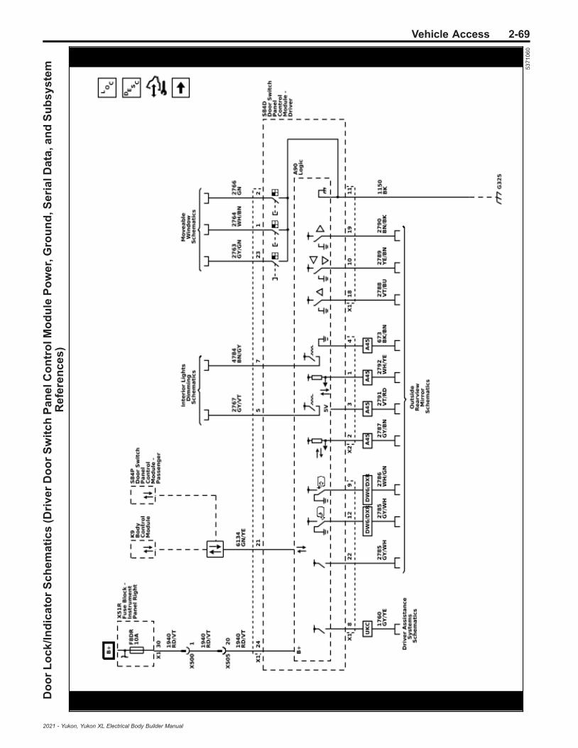
Vehicle Access 2-69D
oo
rL
oc
k/I
nd
ica
tor
Sc
he
ma
tic
s(D
riv
er
Do
or
Sw
itc
hP
an
elC
on
tro
lMo
du
leP
ow
er,
Gro
un
d,S
eri
alD
ata
,an
dS
ub
sy
ste
mR
efe
ren
ce
s)
53
71
06
0
2021 - Yukon, Yukon XL Electrical Body Builder Manual
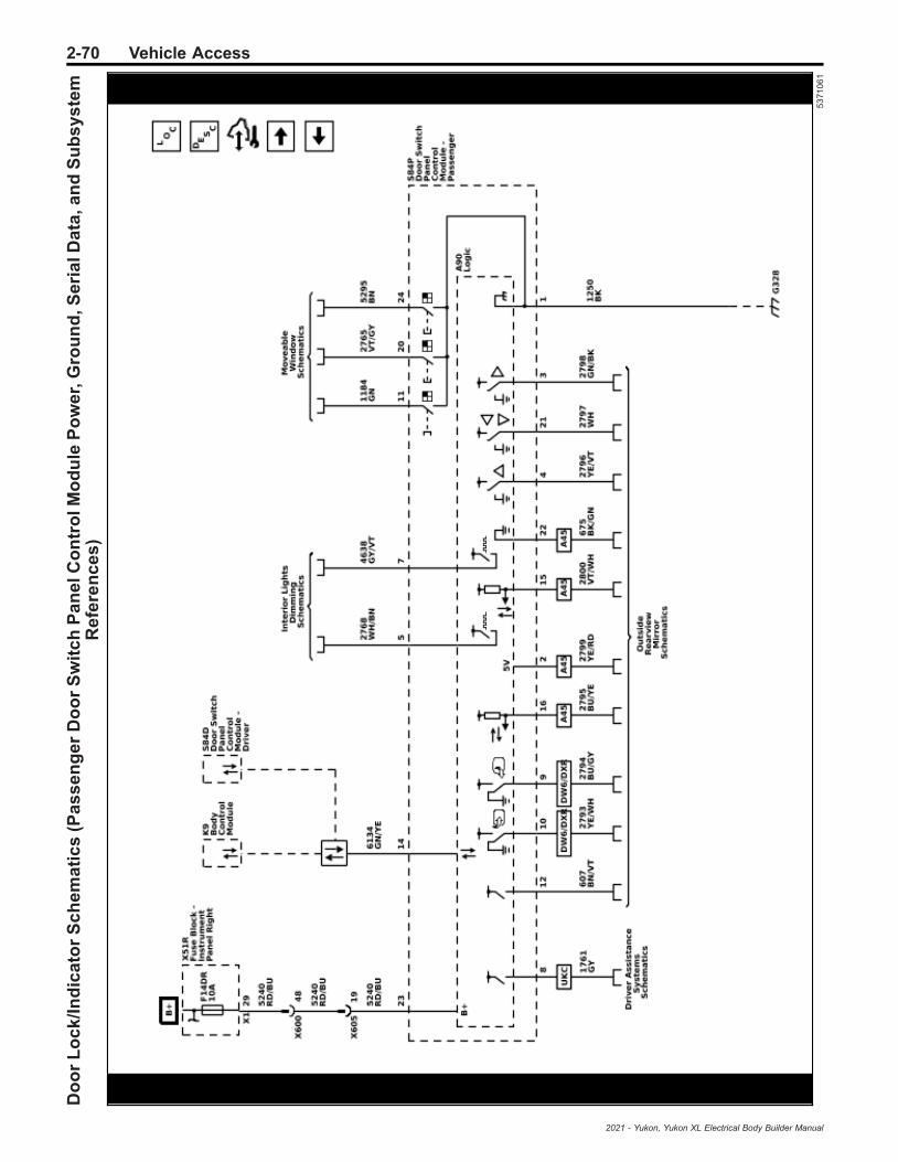
2-70 Vehicle AccessD
oo
rL
oc
k/I
nd
ica
tor
Sc
he
ma
tic
s(P
as
se
ng
er
Do
or
Sw
itc
hP
an
elC
on
tro
lMo
du
leP
ow
er,
Gro
un
d,S
eri
alD
ata
,an
dS
ub
sy
ste
mR
efe
ren
ce
s)
53
71
06
1
2021 - Yukon, Yukon XL Electrical Body Builder Manual

Vehicle Access 2-71D
oo
rL
oc
k/I
nd
ica
tor
Sc
he
ma
tic
s(D
oo
rL
oc
kS
wit
ch
es
an
dIn
dic
ato
rs)
53
71
06
4
2021 - Yukon, Yukon XL Electrical Body Builder Manual

2-72 Vehicle AccessD
oo
rL
oc
k/I
nd
ica
tor
Sc
he
ma
tic
s(A
jar
Sw
itc
he
sa
nd
Lo
ck
Ind
ica
tors
)
53
71
06
2
2021 - Yukon, Yukon XL Electrical Body Builder Manual

Vehicle Access 2-73D
oo
rL
oc
k/I
nd
ica
tor
Sc
he
ma
tic
s(A
ctu
ato
rs)
53
71
06
3
2021 - Yukon, Yukon XL Electrical Body Builder Manual

2-74 Vehicle AccessD
oo
rL
oc
k/I
nd
ica
tor
Sc
he
ma
tic
s(D
oo
rH
an
dle
Sw
itc
he
s)
53
71
06
5
2021 - Yukon, Yukon XL Electrical Body Builder Manual

Vehicle Access 2-75R
ele
as
eS
ys
tem
sS
ch
em
ati
cs
(Lif
tgla
ss
Re
lea
se
)
53
71
27
8
2021 - Yukon, Yukon XL Electrical Body Builder Manual

2-76 Vehicle AccessR
ele
as
eS
ys
tem
sS
ch
em
ati
cs
(Lif
tga
teR
ele
as
e(T
B4
))
53
71
27
9
2021 - Yukon, Yukon XL Electrical Body Builder Manual

Vehicle Access 2-77R
ele
as
eS
ys
tem
sS
ch
em
ati
cs
(Fu
elT
an
kF
ille
rD
oo
rL
oc
kA
ctu
ato
r(N
08
))
53
71
28
0
2021 - Yukon, Yukon XL Electrical Body Builder Manual

2-78 Vehicle AccessH
oo
dL
atc
hS
ch
em
ati
cs
(En
gin
eC
om
pa
rtm
en
tC
ov
er
Sw
itc
h)
53
711
54
2021 - Yukon, Yukon XL Electrical Body Builder Manual

Vehicle Access 2-79L
iftg
ate
Sc
he
ma
tic
s(R
ea
rG
ate
Mo
du
leP
ow
er,
Gro
un
d,S
eri
alD
ata
,an
dL
iftg
ate
Mo
tor
(TC
2))
53
711
88
2021 - Yukon, Yukon XL Electrical Body Builder Manual
2-80 Vehicle AccessL
iftg
ate
Sc
he
ma
tic
s(L
iftg
ate
La
tch
,Sw
itc
he
s,a
nd
Sid
eS
en
so
rs(T
C2
))
53
711
89
2021 - Yukon, Yukon XL Electrical Body Builder Manual
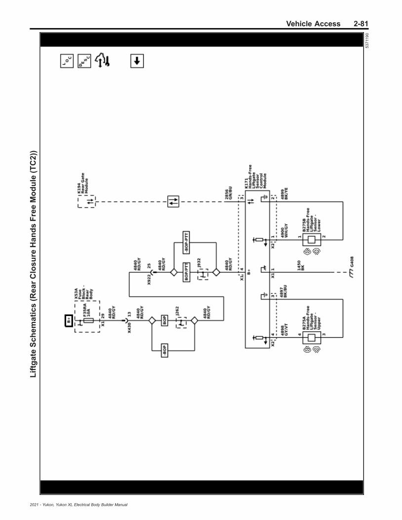
Vehicle Access 2-81L
iftg
ate
Sc
he
ma
tic
s(R
ea
rC
los
ure
Ha
nd
sF
ree
Mo
du
le(T
C2
))
53
711
90
2021 - Yukon, Yukon XL Electrical Body Builder Manual

2-82 Vehicle Access
Description and OperationDoor Ajar Indicator Description andOperation
Door Ajar Indicator SystemComponentsThe door ajar indicator system consists of the followingcomponents:
• Body control module (BCM)• Instrument cluster• Driver door latch• Passenger door latch• Left rear door latch• Right rear door latch• Driver window motor• Passenger window motor• Left rear side door window switch• Right rear side door window switch
Driver and Passenger Door AjarThe window motor supplies a 12 V signal to the doorajar switch within the door latch, when a door is openthe door ajar switch closes pulling the 12 V signal low.When the window motor detects the drop in the 12 Vsignal circuit, it will then communicate this status to theBCM via local interconnect network (LIN) bus. TheBCM communicates with the instrument cluster viaserial data message. The instrument cluster, uponreceipt of this serial data message, will illuminate thedoor ajar indicator and also send a serial data messageto the radio to activate the door ajar audible warningwhen the vehicle speed is greater then 8 km/h (5 mph).
Rear Doors AjarThe rear side door window switches each provide a12 V signal to their respective door ajar switch signalcircuits. The rear door ajar switches are integral to eachrear door latch assembly. When a rear door is opened,the normally open door ajar switch closes. With thedoor ajar switch closed, ground is provided to the doorajar switch signal circuit and the voltage within thesignal circuit drops. The rear side door windowswitches will detect the voltage drop and will send aserial data message to the body control module whichwill then send a message to the instrument cluster tocommand the door ajar message
Fuel Fill Door Description andOperation
Fuel Door Release System Components• Body control module (BCM)• Fuel door release actuator
The locking and unlocking of the fuel door is a functionof the power door lock system. The fuel door releaseactuator is supplied by the driver door lock controlcircuit and the fuel door unlock control circuit. TheBCM, upon receipt of a lock switch lock or unlocksignal, will supply battery voltage to the door lockactuator lock or fuel door unlock control circuits. Sincethe opposite side of the lock actuator is connected to
ground through the other lock actuator control circuit,the doors and fuel filler door will then lock or unlock ascommanded.
Hood Ajar Indicator Description andOperation
Hood Ajar SwitchThe body control module (BCM) applies B+ to the hoodajar signal circuit and monitors the voltage to determinethe position of the hood. When the hood is open, theswitch is open and voltage remains high. When thehood is closed, the switch is closed and the voltage ispulled low.The BCM uses the hood ajar switch as a content theftdeterrent alarm trigger.
Hood Ajar Indicator/MessageWhen the hood is ajar, a message is displayed on theDIC or the hood ajar indicator will be illuminated.
Liftgate Ajar Indicator Descriptionand Operation
Rear Access OpenManual Liftgate
The driver information center will display the RearAccess Open message when the body control module(BCM) detects that the liftgate is open. The instrumentpanel cluster receives a serial data message from theBCM requesting illumination. If the vehicle is in theforward or reverse gear position, the BCM activates anaudible warning.
Power Liftgate
The rear gate module detects the rear gate latchunlatch switch is closed to ground indicating the liftgateis open. The driver information center receives a serialdata message from the rear gate module indicating theliftgate ajar status and the driver information centerdisplay the Rear Access Open message
Rear Liftglass OpenLiftgate Window
The lighting control module will monitor the voltage onthe liftglass ajar signal circuit, when the ajar switch isopen, the voltage level within the signal circuit will begreater than 7 volts indicating the liftgate window is inthe closed position. When the liftgate window is open orajar, the ajar switch will close providing a ground pathfor the signal circuit, the lighting control module willdetect the drop in voltage and will send a serial datamessage to the driver information center to display theRear Liftglass Open message.
2021 - Yukon, Yukon XL Electrical Body Builder Manual

Vehicle Access 2-83
Liftgate Description and Operation
System DescriptionThe power liftgate system consists of the followingcomponents:
• Rear gate module• Body control module• Liftgate position sensor (part of the power assist
actuator)• Interior liftgate rotary switch• Exterior liftgate release switch• Liftgate close switch• Liftgate latch• Liftgate power assist actuator• Left and right liftgate object sensors• Rear closure hands free module• Upper and lower rear closure hands free sensors• Keyless entry transmitter
OperationThe power liftgate operations will be suspended if thevehicle not in park or if the vehicle speed isabove 3KPHThe tail lamps will then flash 3X to indicate that thebody control module has received a request to poweropen or power closeThe power liftgate can be commanded to power openand power close by the following methods:
• An open or close command from the interiorliftgate rotary switch
• An open command from the exterior liftgaterelease switch
• A close command from the liftgate close switch• An open or close request by a signal from the
keyless entry transmitter to the remote controldoor lock receiver (¾ or the MAX modes only)
• An open or closed commanded by a kickingmotion of a foot and lower leg under the rearfascia – Sensor location may vary dependingupon make and model, refer to owner’s manual forthe location of the sensors. (configured underpersonalization)
• The kick projected logo light shows where toperform the kicking motion (Diagnosed in theexterior lighting section)
The rear gate module will respond to a request bycommanding the liftgate latch to release the liftgate andactivate the liftgate motor in the liftgate power assistactuator and raise the liftgate to the open position or tolower and cinch the liftgate closed.
Power Liftgate SystemThe rear gate module continuously monitors powerliftgate operation and calculates its location anddirection of travel from an liftgate position sensor (partof the power assist actuator). One input returns theposition of the liftgate relative to the x-axis and y-axis.The rear gate module then uses these 2 inputs togetherto calculate its angle relative to the liftgate. The interiorliftgate rotary switch contains resistors which will
incrementally drop the voltage level in the signal circuitas the switch rotated from the OFF position to the ¾position or the MAX position, the front overheadconsole assembly will detect the change in voltage andwill send a serial data message to the rear gate modulewhich will monitor the x-axis and y-axis as the liftgate isin motion to stop the liftgate parallel to the vehicle roof ifthe rotary switch is in the ¾ setting or to open fully if therotary switch is in the MAX setting.The liftgate latch is a bi-directional motor and latch orunlatch operation is the result of the direction of themotor rotation. The rear gate module controls theliftgate latch through the control circuits by supplyingpower and ground in the appropriate polarity. The motorcontrol circuits are monitored by the rear gate moduleprior to activation for a high or low condition and duringmotor operation for an insufficient current flowcondition. The unlatch, primary, and neutral switchesare part of the liftgate latch and are used by the reargate module to determine the state of the latch duringthe process of latching or unlatching and will send thestatus of the latches to the body control module whichis used to determine if the liftgate is closed or ajar. Eachof the latch switch signal circuits are supplied batteryvoltage and monitored within the rear gate module. Thelatch switches share a common low reference circuitfrom the rear gate module and when the switchcontacts close the signal circuit goes low and the reargate module determines the switch to be active.The exterior liftgate release switch circuit is suppliedbattery voltage by the body control module, when theswitch is pressed the contacts close and the signalcircuit goes low, the body control module will detect thevoltage drop and will send a serial data message to therear gate module requesting the rear gate open request(vehicle unlocked).The liftgate close switch signal circuit is suppliedbattery voltage by the rear gate module. The switchshares a common low reference circuit from the reargate module and when the switch is pressed thecontacts close and the signal circuit goes low, the reargate module will detect the voltage drop and will send aserial data message to the body control modulerequesting the rear gate close request.For vehicles without the optional passive keyless entry,when the exterior liftgate release switch is pressed, thebody control module will check the status of the vehicledoor locks. If the vehicle doors are locked, the bodycontrol module will ignore the signal from the liftgatehandle switch. If the vehicle doors are unlocked, thebody control module will permit the liftgate to unlatchand power open when the exterior liftgate releaseswitch is pressed.For vehicles with the optional passive keyless entrysystem, the body control module monitors the proximityof the keyless entry transmitter. If the exterior liftgaterelease switch is pressed and the keyless entrytransmitter is within range, the body control module willsend a serial data message to the rear gate moduleand will permit the liftgate to unlatch and power open.If the doors are locked and the keyless entry transmitteris not within range, the body control module will ignorethe signal from the exterior liftgate release switch andthe liftgate will not power open.
2021 - Yukon, Yukon XL Electrical Body Builder Manual

2-84 Vehicle Access
Rear Closure Hands Free SensorThe sensors are located behind the rear fascia(location may vary depending upon make and model,refer to owner’s manual for the location of the sensors)and is designed to detect the motion of the operator ’sfoot by way of a kicking motion. When the keyless entrytransmitter is within 3 feet (1 meter) of the liftgate andthe operator kicks his or her foot under the rear fascia,the sensors will detect the motion of the foot and thelower leg and if the procedure has been performedcorrectly the rear closure hands free module will send aserial data message to the body control module. Thetail lamps will then flash 3x to indicate that thecommand has been received and the body controlmodule and will allow the liftgate to perform the poweropen or power close function. The rear closure handsfree functions can be modified within the VehiclePersonalization:
• Open and close with the kicking motion• Open only with the kicking motion• Hands free function disabled
Object DetectionThe power liftgate system uses an object detectionmethod which consists of liftgate side sensors fixed toboth sides of the liftgate near the seal area. The liftgateside sensors consist of an internal fixed resistor andnormally open switch contacts which when closed willbypass the resistor. The signal circuit is supplied 5 Vthrough a resistor and monitored within the rear gatemodule, and during normal power liftgate operation thesignal circuit should remain a fixed value. When anliftgate side sensor is presses one of the sensors thecontacts close and the resistor is bypassed causing thesignal circuit voltage at the module to go low. If theliftgate is being power closed at that time, the rear gatemodule will command the power liftgate to reversedirection. All power close liftgate operations will besuspended until the obstruction pressing on the liftgateside sensor is removedThe rear gate module continuously monitors powerliftgate operation and calculates its location anddirection of travel from an liftgate position sensor (partof the power assist actuator). One input returns theposition of the liftgate relative to the x-axis and y-axis.The rear gate module then uses these 2 inputs togetherto calculate its position and motion, if the rear gatemodule detects a current spike and motion reduction inthe liftgate position sensor during the power closeoperation, it will command the liftgate to reversedirection.
Manual Liftgate OperationNote: The interior liftgate rotary switch must be in the¾ position or the MAX position for the remote keylessentry transmitter (key fob) to command the liftgate, TheOFF setting will disable the liftgate release of theremote keyless entry transmitter (key fob)
The operator has the option to disable the powerliftgate operations by selecting the “OFF” position onthe interior liftgate rotary switch. The releasing andcinching for the liftgate latch will function normally,however, the operator must use the exterior liftgatehandle switch to activate the liftgate latch and manually
pull the liftgate open and push the liftgate closed. Allpower liftgate operations will be suspended for as longas the liftgate rotary switch is in the “OFF” position.
Power Door Locks Description andOperation
Door Lock System ComponentsThe power door lock system consists of the followingcomponents:
• Driver door lock switch• Passenger door lock switch• Left rear door lock switch• Right rear door lock switch• Driver front side door window control switch• Passenger front side door window switch• Driver front side door latch• Passenger front side door latch• Left rear side door latch• Right rear side door latch• Exterior door handle switches• Body control module• Lighting control module
Door Lock System ControlsThe power door lock system can be controlled by any ofthe following:
• Power door lock switch activation• Keyless entry lock or unlock command• Delayed locking command• Automatic door lock command
Door Lock and Unlock OperationThe driver or passenger front side door window controlswitch will monitor the voltage of their respective doorlock switches, when the driver or passenger door lockswitch is activated in the lock or unlock position thesignal voltage will be pulled low, the correspondingfront side door window control switch will detect thevoltage drop in the signal circuit and will send a serialdata message to the body control module requestingthe door lock or unlock command.The lighting control module will monitor the voltage ofthe left rear and right rear door lock switches, when theleft rear or right rear door lock switch is activated in thelock or unlock position the signal voltage will be pulledlow, the lighting control module will detect the voltagedrop in the signal circuit and will send a serial datamessage to the body control module requesting thedoor lock or unlock command.The body control module upon receipt of a lock orunlock request, will supply battery voltage to the doorlock actuator lock or unlock control circuits. Since theopposite side of the lock actuator is connected toground through the other lock actuator control circuit,the doors, and fuel filler door will then lock or unlock ascommanded.
2021 - Yukon, Yukon XL Electrical Body Builder Manual
Vehicle Access 2-85
The following control circuits are used to operate thedoor lock actuators:
• Driver door unlock only• Passenger and rear door unlock• All door lock
This sequence and be modified through thepersonalization settings
Passive Door Lock/Unlock OperationThe exterior door handle switch signal circuits provideinputs to the body control module when the exteriordoor handle switches are activated. These inputs allowthe body control module to detect a door lock or a doorunlock request. The body control module provides a 7 Vsignal to each exterior door handle switch via the doorhandle switch signal circuits. When a door handleswitch is pressed, the switch closes and the voltagesignal within the signal circuit is pulled to ground. Thebody control module will detect the voltage drop and alow frequency antenna will transmit a challenge to thekeyless entry transmitter. If the challenge is met, thekeyless entry transmitter will respond, and the bodycontrol module will command the door(s) to be lockedor unlocked
Rear Hatch/Gate Description andOperation
Liftgate/Liftgate Window ReleaseComponentsThe liftgate release system consists of the followingcomponents:
• Body control module• Lighting control module• Rear gate module• Liftgate latch assembly• Liftgate unlatch switch• Liftgate window unlatch switch• Liftgate window latch assembly• Liftgate window unlatch relay
Liftgate Latch AssemblyThe liftgate uses a system similar to the passengerdoor locking system. The liftgate contains a liftgatedoor lock/unlock actuator the shares the same lock andunlock control circuits as the passenger doors. Whenthe passenger doors and liftgate have beencommanded to lock with a door lock switch or a keylessentry transmitter, the liftgate handle will becomeinoperative the same way the passenger door handleswill become inoperative to prevent unauthorizedaccess. Also the passenger doors must be commandedto unlock to unlock the liftgate.
Liftgate Window Latch AssemblyLiftgate Window Unlatch Switch
The lighting control module (TB4) or the rear gatemodule (TB5) monitors supplies a 12 V signal to theliftgate window unlatch switch so that when the switchis pressed, the voltage within the signal circuit is pulledlow and in response, the lighting control module (TB4)or the rear gate module (TB5) will detect the voltage
drop and send a serila data message to the bodycontrol module to command the liftgate window torelease.
Liftgate Window Latch
When body control module receives a liftgate windowrelease command from the liftgate window unlatchswitch, the body control module applies voltage to theliftgate window unlatch relay control circuit, whichenergizes the coil side of the relay. The switch side ofthe liftgate window unlatch relay then momentarilycloses, supplying a brief pulse of battery positivevoltage to the liftgate window latch. The liftgate windowlatch is continuously grounded and when it receives thevoltage pulse, it will become energized and the latchwill activate releasing the liftgate window so that it maybe manually raised to an open position.
2021 - Yukon, Yukon XL Electrical Body Builder Manual

2-86 Wipers and Washers
Wipers and Washers
Schematic and Routing Diagrams
2021 - Yukon, Yukon XL Electrical Body Builder Manual

Wipers and Washers 2-87W
ipe
r/W
as
he
rS
ch
em
ati
cs
(Co
ntr
ols
)
54
30
55
3
2021 - Yukon, Yukon XL Electrical Body Builder Manual
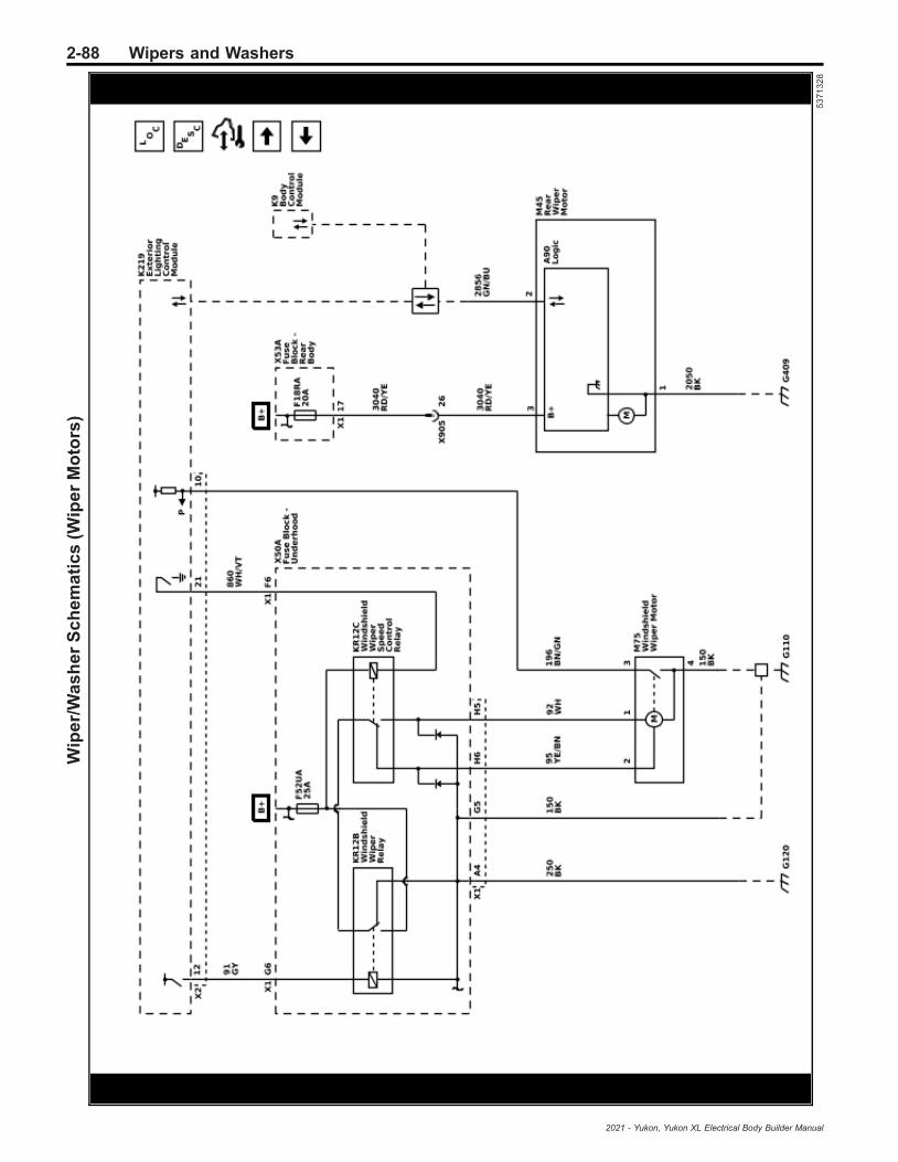
2-88 Wipers and WashersW
ipe
r/W
as
he
rS
ch
em
ati
cs
(Wip
er
Mo
tors
)
53
71
32
8
2021 - Yukon, Yukon XL Electrical Body Builder Manual

Wipers and Washers 2-89W
ipe
r/W
as
he
rS
ch
em
ati
cs
(Wa
sh
er
Pu
mp
)
53
71
32
9
2021 - Yukon, Yukon XL Electrical Body Builder Manual
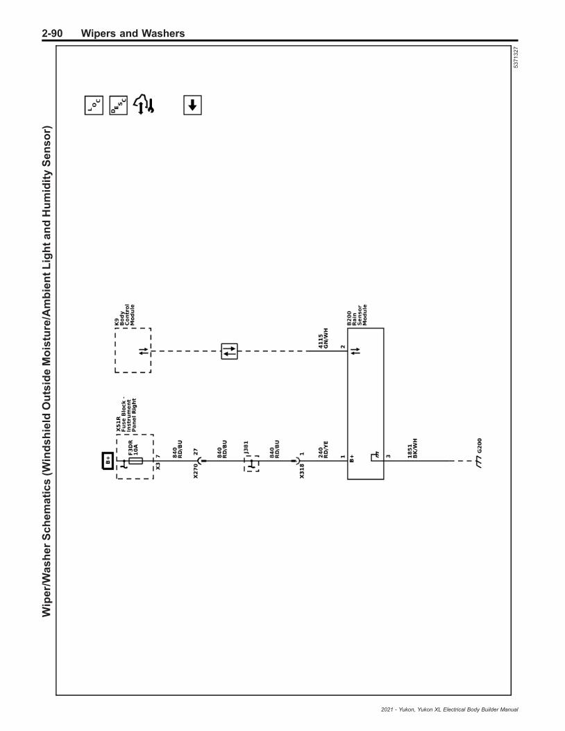
2-90 Wipers and WashersW
ipe
r/W
as
he
rS
ch
em
ati
cs
(Win
ds
hie
ldO
uts
ide
Mo
istu
re/A
mb
ien
tL
igh
ta
nd
Hu
mid
ity
Se
ns
or)
53
71
32
7
2021 - Yukon, Yukon XL Electrical Body Builder Manual

Wipers and Washers 2-91
Description and OperationWiper/Washer System Descriptionand Operation
Front Windshield Wiper OperationThe windshield wipers system allows the driver to clearthe vehicle’s windshield using a discrete switch orthrough an automatic rain sensing system. Thewindshield wiper system functions through a primarycontrol, but also allows redundant high speed-onlyoperation in the event of a system fault. The wipersystems uses the S82 Windshield Wiper/WasherSwitch as the primary means of driver control, alongwith the B117A Windshield Outside Moisture/AmbientLight and Humidity Sensor to modulate intermittentwiper operation. The S82 Windshield Wiper/WasherSwitch is a discrete input to the K9 Body ControlModule. The K9 Body Control Module communicateswith the K219 Lighting Control Module over CAN, andwith the B117A Windshield Outside Moisture/AmbientLight and Humidity Sensor over LIN, to control wiperactivation.
Low Speed Wiper Operation
With the S82 Windshield Wiper/Washer Switch in thelow speed position, the discrete signal circuit to theK9 Body Control Module is pulled down through tworesistors in a resistor ladder to a low reference providedby the K9 Body Control Module. The K9 Body ControlModule communicates with the K219 Lighting ControlModule over CAN, requesting consistent low speedwiping operation. To initiate low speed operation, theK219 Lighting Control Module energizes theKR12B Windshield Wiper Relay. This allows batteryvoltage from the wiper fuse to be applied through theswitched contacts of the KR12B Windshield WiperRelay, through the normally closed contacts of theKR12C Windshield Wiper Speed Control Relay, to thewindshield wiper low speed control circuit of theM75 Windshield Wiper Motor.
Intermittent Wiper Operation
With the S82 Windshield Wiper/Washer Switch in theintermittent position, the discrete signal circuit to theK9 Body Control Module is pulled down through anumber of resistors within a resistor ladder to a lowreference provided by the K9 Body Control Module. Thenumber of resistors the signal travels through isdependent on the intermittent selection made on theS82 Windshield Wiper/Washer Switch. The K9 BodyControl Module interprets this range of voltagepull-down as a request for intermittent wiper activation,with each pull-down voltage value equating anintermittent delay (sensitivity) level. If the rain sense isenabled the K9 Body Control Module communicateswith the B117A Windshield Outside Moisture/AmbientLight and Humidity Sensor via LIN. TheB117A Windshield Outside Moisture/Ambient Light andHumidity Sensor utilizes windshield optics to determinethe amount of water on the windshield and willcommunicate this info to the K9 Body Control Module,which will vary wiping cadence based on theintermittent sensitivity selection on the S82 WindshieldWiper/Washer Switch and the amount of water on thewindshield. If the rain sense is disabled the K9 Body
Control will vary the wiping cadence based on a presetamount of time determined by the intermittent delayselection on the S82 Windshield Wiper/Washer Switch.To initiate wiper operation, the K219 Lighting ControlModule energizes the KR12B Windshield Wiper Relay.This allows battery voltage from the wiper fuse to beapplied through the switched contacts of theKR12B Windshield Wiper Relay, through the normallyclosed contacts of the KR12C Windshield Wiper SpeedControl Relay, to the low speed control circuit of theM75 Windshield Wiper Motor.
High Speed Wiper Operation
With the S82 Windshield Wiper/Washer Switch in thehigh speed position, the discrete signal circuit to theK9 Body Control Module is pulled down through tworesistors in a resistor ladder to a low reference providedby the K9 Body Control Module. The K9 Body ControlModule interprets this specific voltage pull-down as arequest for wiper activation. In addition to this pull-downsignal, a second switch in the S82 Windshield Wiper/Washer Switch is also pulled down to low reference.This signal is a discrete input to the K219 LightingControl Module. The K219 Lighting Control Modulerequests wiping operation. To initiate high speedoperation, the K219 Lighting Control Module energizesthe KR12B Windshield Wiper Relay and grounds theKR12C Windshield Wiper Speed Control Relay. Thisallows battery voltage from the wiper fuse to be appliedthrough the switched contacts of the KR12B WindshieldWiper Relay, through the switched contacts of theKR12C Windshield Wiper Speed Control Relay, to thewindshield wiper motor high speed control circuit of theM75 Windshield Wiper Motor.
Mist (Single Wipe) Operation
The mist (single wipe) position is a momentary switchposition that will return the S82 Windshield Wiper/Washer Switch to the off position as soon as the switchis released. With the S82 Windshield Wiper/WasherSwitch in the mist (single wipe) position, the discretesignal circuit to the K9 Body Control Module is pulleddown through two resistors in a resistor ladder to a lowreference provided by the K9 Body Control Module. TheK9 Body Control Module interprets this specific voltagepull-down as a request for wiper activation. TheK9 Body Control Module communicates with theK219 Lighting Control Module via CAN, requestingconsistent low speed wiping operation as long as theS82 Windshield Wiper/Washer Switch is held in themist (single wipe) position. If the mist (single wipe)position is only briefly selected, the K9 Body ControlModule will request only a single wipe.
Wiper Park Operation
With the S82 Windshield Wiper/Washer Switch in theoff position, the discrete signal circuit to the K9 BodyControl Module is pulled down through one resistor in aresistor ladder to a low reference provided by theK9 Body Control Module. The K9 Body Control Moduleinterprets this specific voltage pull-down as a request tostop wiper activation. The K9 Body Control Modulecommunicates with the K219 Lighting Control Modulevia CAN, requesting wiper operation stop. At this time,the K219 Lighting Control Module will deactivate theKR12B Windshield Wiper Relay and KR12C WindshieldWiper Speed Control Relay. The relay contacts will
2021 - Yukon, Yukon XL Electrical Body Builder Manual
2-92 Wipers and Washers
switch back to their normally closed position and willapply ground to the wiper motor power inputs throughthe normally closed contacts of the wiper relays. Thisdeactivates and dynamically brakes the wiper motor inthe park position. When the wiper switch is turned tothe OFF position while the wiper motor is somewhere inmid-cycle, the K219 Lighting Control Module willcontinue to operate the motor until the wipers reach thepark position. If the ignition is turned OFF while thewipers are in mid-cycle, the wipers will stopimmediately, regardless of position. The K219 LightingControl Module will park the wipers next time theignition is turned ON.The windshield wiper system consists of the followingelectrical components:
• S82 Windshield Wiper/Washer Switch• K9 Body Control Module• K219 Lighting Control Module• KR12B Windshield Wiper Relay• KR12C Windshield Wiper Speed Control Relay• B117A Windshield Outside Moisture/Ambient Light
and Humidity Sensor• M75 Windshield Wiper Motor
Front Windshield Wiper ComponentsS82 Windshield Wiper/Washer Switch
The S82 Windshield Wiper/Washer Switch is theprimary input to the K9 Body Control Module for thedriver to control windshield wiper operation. TheS82 Windshield Wiper/Washer Switch also providesdiscrete input to the K219 Exterior Lighting ControlModule and M75 Windshield Wiper Motor during highspeed wiper operation.
The S82 Windshield Wiper/Washer Switch containsthree individual internal switch. One switch changesbetween mist (single wipe), off, intermittent, low speed,and high speed selection. The second switch changeswith differing intermittent sensitivity selection. The thirdswitch is only active when high speed wiper operationis selected. A resistor ladder is also used to determineswitch selection and intermittent sensitivity selection.The high speed switch does not utilize the resistorladder.
The K9 Body Control Module provides theS82 Windshield Wiper/Washer Switch with groundthrough a single low reference circuit and monitors theswitch position through a single signal circuit. Voltage isapplied by the K9 Body Control Module to this signalcircuit and voltage drop is monitored to determineswitch selection. This voltage drop will vary dependingon the number of resistors in the resistor ladder, whichchanges depending on switch position. In the offposition, current flows through a single resistor. In themist (single wipe), low speed, and high speed position,current flows through two resistors. In the intermittentposition, current flows through three or more resistors,depending on the intermittent sensitivity selected.
The S82 Windshield Wiper/Washer Switch provides adiscrete switch input to the K219 Lighting ControlModule during high speed wiper operation. Voltage isapplied by the K219 Lighting Control Module to thissignal circuit and voltage drop is monitored to
determine switch selection. When high speed operationis selected, the signal circuit is pulled to ground (lowreference).
K9 Body Control Module
The K9 Body Control Module will send a CAN messageto the K219 Lighting Control Module to request wiperoperation. The K9 Body Control Module responds toinput requests from the S82 Windshield Wiper/WasherSwitch. The K9 Body Control Module provides aconstant ground for the S82 Windshield Wiper/WasherSwitch and monitors a signal circuit to determine therequested windshield wiper position.
The K9 Body Control Module communicates with theB117A Windshield Outside Moisture/Ambient Light andHumidity Sensor via LIN. Messages are received fromthe B117A Windshield Outside Moisture/Ambient Lightand Humidity Sensor to indicate the amount of water onthe windshield.
K219 Lighting Control Module
The K219 Lighting Control Module controls the wipermotor via two PCB relays (KR12B Windshield WiperRelay and KR12C Windshield Wiper Speed ControlRelay). The K219 Lighting Control Module receives amessage from K9 Body Control Module over CAN todetermine what type of wiper operation is requested.
KR12B Windshield Wiper Relay
The KR12B Windshield Wiper Relay supplies B+ to theM75 Windshield Wiper Motor and is controlled by theK219 Lighting Control Module. The coil side of the relayreceives a constant chassis ground and the switch sidereceives a constant B+. When wiper operation isrequested, the K219 Lighting Control Module willprovide voltage to the coil side of the relay. This willenergize the relay, closing the high current contact, andsupply B+ to the M75 Windshield Wiper Motor throughthe KR12C Windshield Wiper Speed Control Relay,enabling wiper operation.
KR12C Windshield Wiper Speed Control Relay
The KR12C Windshield Wiper Speed Control Relaycontrols B+ to the M75 Windshield Wiper Motor and iscontrolled by the K219 Lighting Control Module. Thecoil side of the relay receives a ground controlled by theK219 Lighting Control Module. The switch side of therelay receives B+ through the KR12B Windshield WiperRelay. When high speed wiper operation is requested,the K219 Lighting Control Module will provide ground tothe coil side of the relay. This will energize the relay,closing the high current contact, and supply the B+ tothe M75 Windshield Wiper Motor high speed control,enabling high speed wiper operation.
B117A Windshield Outside Moisture/Ambient Lightand Humidity Sensor
The B117A Windshield Outside Moisture/Ambient Lightand Humidity Sensor utilizes an internal infrared LEDand an optic sensor to determine the amount of wateron the windshield. The infrared LED bounces infraredlight against the inside of the windshield. The opticsensor measures the amount of light returned afterbouncing off the windshield. With a dry windshield, alllight bounced off the windshield is returned to the opticsensor. As water accumulates on the windshield, thelight input to the optic sensor is diffused and reduced.
2021 - Yukon, Yukon XL Electrical Body Builder Manual

Wipers and Washers 2-93
The amount of light reduction corresponds directly tothe amount of water on the windshield. TheB117A Windshield Outside Moisture/Ambient Light andHumidity Sensor interprets the amount of light returnedand communicates this info to the K9 Body ControlModule, which will control intermittent wiper operationbased on the sensitivity selection of the S82 WindshieldWiper/Washer Switch and the amount of water on thewindshield.
M75 Windshield Wiper Motor
The M75 Windshield Wiper Motor receives a constantchassis ground. B+ is controlled by theKR12B Windshield Wiper Relay and KR12C WindshieldWiper Speed Control Relay being operated by theK219 Lighting Control Module.
The M75 Windshield Wiper Motor includes a DC motorand an internal position switch to indicate the wiperpark position. When wiper operation is requested, theDC motor spins. The spinning motor is directed to awiping motion through the windshield wipertransmission. When wiper operation is no longerrequired, the M75 Windshield Wiper Motor will continuespinning until the internal position switch indicates it isin the park position.
Rear Window Wiper OperationThe rear window wiper system allows the driver to clearthe vehicle’s rear window using a discrete switch. Therear wiper systems uses the S82 Windshield Wiper/Washer Switch as the means of control. TheS82 Windshield Wiper/Washer Switch is a discreteinput to the K9 Body Control Module. The K9 BodyControl Module communicates with the M45 RearWiper Motor via LIN to control wiper activation.
Low Speed Wiper Operation
With the S82 Windshield Wiper/Washer Switch in thelow speed position, the discrete signal circuit to theK9 Body Control Module is pulled down through oneresistor in a resistor ladder to a low reference providedby the K9 Body Control Module. The K9 Body ControlModule communicates with the M45 Rear Wiper Motorover LIN, requesting consistent low speed wipingoperation.
Intermittent Wiper Operation
With the S82 Windshield Wiper/Washer Switch in theintermittent position, the discrete signal circuit to theK9 Body Control Module is pulled down through a tworesistors in a resistor ladder to a low reference providedby the K9 Body Control Module. The K9 Body ControlModule communicates with the M45 Rear Wiper Motorover LIN, requesting consistent intermittent wipingoperation. The K9 Body Control will vary the wipingcadence based on a preset amount of time.
Mist (Single Wipe) Operation
The mist (single wipe) position is a momentary switchposition that will return the S82 Windshield Wiper/Washer Switch to the off position as soon as the switchis released. With the S82 Windshield Wiper/WasherSwitch in the mist (single wipe) position, the discretesignal circuit to the K9 Body Control Module is pulleddown through three resistors in a resistor ladder to alow reference provided by the K9 Body Control Module.The K9 Body Control Module interprets this specific
voltage pull-down as a request for wiper activation. TheK9 Body Control Module communicates with theM45 Rear Wiper Motor via LIN, requesting consistentlow speed wiping operation as long as theS82 Windshield Wiper/Washer Switch is held in themist (single wipe) position. If the mist (single wipe)position is only briefly selected, the K9 Body ControlModule will request only a single wipe.
Wiper Park Operation
With the S82 Windshield Wiper/Washer Switch in theoff position, the discrete signal circuit to the K9 BodyControl Module is opened. The K9 Body ControlModule interprets this as a request to stop wiperactivation. The K9 Body Control Module communicateswith the M45 Rear Wiper Motor via LIN, requestingwiper operation stop. The M45 Rear Wiper Motor willpark the rear window wiper in their lowest position.When the wiper switch is turned to the OFF positionwhile the wiper motor is somewhere in mid-cycle, theK9 Body Control Module will continue to operate themotor until the wiper reaches the park position. If theignition is turned OFF while the wipers are in mid-cycle,the wipers will stop immediately, regardless of position.The K9 Body Control Module will park the wipers nexttime the ignition is turned ON.The rear window wiper system consists of the followingelectrical components:
• S82 Windshield Wiper/Washer Switch• K9 Body Control Module• M45 Rear Wiper Motor
Rear Window Wiper ComponentsS82 Windshield Wiper/Washer Switch
The S82 Windshield Wiper/Washer Switch is theprimary input to the K9 Body Control Module for thedriver to control rear window wiper operation.
The S82 Windshield Wiper/Washer Switch containsone individual internal switch used to request mist(single wipe) off, intermittent, and low speed selection.
The K9 Body Control Module provides theS82 Windshield Wiper/Washer Switch with groundthrough a single low reference circuit and monitors theswitch position through a single signal circuit. Voltage isapplied by the K9 Body Control Module to this signalcircuit and voltage drop is monitored to determineswitch selection. This voltage drop will vary dependingon the number of resistors in the resistor ladder, whichchanges depending on switch position. In the offposition, current doesn’t flow. In the mist (single wipe)position current flows through three resistors, in theintermittent speed position current flows through tworesistors, and in the low speed position, current flowsthrough one resistor.
K9 Body Control Module
The K9 Body Control Module will send a LIN messageto the M45 Rear Wiper Motor to request wiperoperation. The K9 Body Control Module responds toinput requests from the S82 Windshield Wiper/WasherSwitch. The K9 Body Control Module provides aconstant ground for the S82 Windshield Wiper/WasherSwitch and monitors a signal circuit to determine therequested windshield wiper position.
2021 - Yukon, Yukon XL Electrical Body Builder Manual

2-94 Wipers and Washers
M45 Rear Wiper Motor
The M45 Rear Wiper Motor receives a constant B+ andchassis ground.
The M45 Rear Wiper Motor includes a DC motor and aninternal position switch to indicate the wiper parkposition. When wiper operation is requested, the DCmotor spins. The spinning motor is directed to a wipingmotion through the windshield wiper transmission.When wiper operation is no longer required, theM45 Rear Wiper Motor will continue spinning until theinternal position switch indicates it is in the parkposition.
Windshield Washer OperationThe windshield washer system allows the driver toclean the vehicle’s windshield or rear window using adiscrete switch. The washer system uses theS82 Windshield Wiper/Washer Switch as the primarymeans of driver control. The S82 Windshield Wiper/Washer Switch is a discrete input to the K9 BodyControl Module. The K9 Body Control Modulecommunicates with the K219 Lighting Control Moduleover CAN to control G24 Windshield Washer Pumpactivation. The K9 Body Control Module alsocommunicates with the K219 Lighting Control Moduleto control B+ to the M75 Windshield Wiper Motor duringoperation.The windshield wiper system consists of the followingelectrical components:
• S82 Windshield Wiper/Washer Switch• K9 Body Control Module• K219 Lighting Control Module• KR12B Windshield Wiper Relay• KR6 Rear Window Washer Pump Relay• KR11 Windshield Washer Pump Relay• G24 Windshield Washer Pump• M45 Rear Wiper Motor• M75 Windshield Wiper Motor• B118B Windshield Washer Fluid Level Switch
Windshield Washer ComponentsS82 Windshield Wiper/Washer Switch
The S82 Windshield Wiper/Washer Switch is theprimary input to the K9 Body Control Module for thedriver to control washer operation.
For front washers, the K9 Body Control Moduleprovides the S82 Windshield Wiper/Washer Switch withground through a single low reference circuit andmonitors the two switch positions through two signalcircuits. Voltage is applied by the K9 Body ControlModule to the signal circuits and voltage drop ismonitored to determine switch selection. For frontwashers, the S82 Windshield Wiper/Washer Switchcontains an internal switch dedicated to frontwindshield washer operation. When the switch isclosed, the signal circuit is pulled to ground, indicatingfront washer operation is requested. For rear washers,the switch is part of a resistor ladder. The voltage dropwill vary depending on the number of resistors in theresistor ladder. When the switch is closed, the signalcircuit is pulled to ground through three resistors,indicating rear washer operation is requested.
K9 Body Control Module
The K9 Body Control Module responds to inputrequests from the S82 Windshield Wiper/WasherSwitch. The K9 Body Control Module provides aconstant ground for the S82 Windshield Wiper/WasherSwitch and monitors a signal circuit to determine therequested windshield wiper position.
When front washer operation is requested, the K9 BodyControl Module will send a CAN message to theK219 Lighting Control Module to enable theG24 Windshield Washer Pump through theKR11 Windshield Washer Pump Relay, as well assupply B+ to the M75 Windshield Wiper Motor for lowspeed wiper operation.
When rear washer operation is requested, the K9 BodyControl Module will send a CAN message to theK219 Lighting Control Module to enable theG24 Windshield Washer Pump through the KR6 RearWindow Washer Pump Relay, as well as send a signalthrough LIN to the M45 Rear Wiper Motor for low speedwiper operation.
K219 Lighting Control Module
The K219 Lighting Control Module controls B+ to theG24 Windshield Washer Pump. When washeroperation is requested from a CAN message from theK9 Body Control Module, the K219 Lighting ControlModule will apply voltage via a high side driver to theKR11 Windshield Washer Pump Relay or the KR6 RearWindow Washer Pump Relay. The K219 LightingControl Module also controls B+ to the M75 WindshieldWiper Motor. When washer operation is requested, theK219 Lighting Control Module will apply voltage via ahigh side driver to the KR12B Windshield Wiper Relay.
The K219 Lighting Control Module also monitors theB118B Windshield Washer Fluid Level Switch through adiscrete signal circuit.
KR12B Windshield Wiper Relay
The KR12B Windshield Wiper Relay supplies B+ to theM75 Windshield Wiper Motor and is controlled by theK219 Lighting Control Module. The coil side of the relayreceives a constant chassis ground and the switch sidereceives a constant B+. When wiper operation isrequested, the K219 Lighting Control Module willprovide voltage to the coil side of the relay. This willenergize the relay, closing the high current contact, andsupply B+ to the M75 Windshield Wiper Motor throughthe KR12C Windshield Wiper Speed Control Relay,enabling wiper operation.
KR6 Rear Window Washer Pump Relay
The KR6 Rear Window Washer Pump Relay supplies B+ to the G24 Windshield Washer Pump and iscontrolled by the K219 Lighting Control Module. Thecoil side of the relay receives a constant chassisground and the switch side receives a constant B+.When washer operation is requested, the K219 LightingControl Module will provide voltage to the coil side ofthe relay. This will energize the relay, closing the highcurrent contact, and supply B+ to the G24 WindshieldWasher Pump, enabling washer pump operation.
2021 - Yukon, Yukon XL Electrical Body Builder Manual
Wipers and Washers 2-95
KR11 Windshield Washer Pump Relay
The KR11 Windshield Washer Pump Relay supplies B+to the G24 Windshield Washer Pump and is controlledby the K219 Lighting Control Module. The coil side ofthe relay receives a constant chassis ground and theswitch side receives a constant B+. When wiperoperation is requested, the K219 Lighting ControlModule will provide voltage to the coil side of the relay.This will energize the relay, closing the high currentcontact, and supply B+ to the G24 Windshield WasherPump, enabling washer pump operation.
G24 Windshield Washer Pump
The G24 Windshield Washer Pump is a reversiblemotor that receives a ground through the non activatedrelay. B+ is controlled by the KR11 Windshield WasherPump Relay for front washer operation, or theKR6 Rear Window Washer Pump Relay for rear washeroperation. With voltage applied, a DC motor spins,connecting and pressurizing washer fluid from thewasher fluid reservoir. The pressurized washer fluid isdeposited on the windshield or rear window through aseries of lines and nozzles.
M45 Rear Window Wiper Motor
The M45 Rear Wiper Motor communicates with theK9 Body Control Module via LIN and responds torequests to turn the rear wipers on and off. TheM45 Rear Wiper Motor receives a constant B+ andchassis ground. In operation, the M45 Rear WiperMotor monitors LIN messages to determine whenwasher operation is requested. The M45 Rear WiperMotor will wipe at low speed when washer operation isrequested.
The M45 Rear Wiper Motor includes a DC motor and aninternal position switch to indicate the wiper parkposition. When washer operation is requested, the DCmotor spins. When wiper operation is no longerrequired, the M45 Rear Wiper Motor will continuespinning until the internal position switch indicates it isin the park position.
M75 Windshield Wiper Motor
The M75 Windshield Wiper Motor receives a constantchassis ground. B+ is controlled by theKR12B Windshield Wiper Relay and KR12C WindshieldWiper Speed Control Relay being operated by theK219 Lighting Control Module. The M75 WindshieldWiper Motor will wiper at low speed when washeroperation is requested.
The M75 Windshield Wiper Motor includes a DC motorand an internal position switch to indicate the wiperpark position. When wiper operation is requested, theDC motor spins. The spinning motor is directed to awiping motion through the windshield wipertransmission. When wiper operation is no longerrequired, the M75 Windshield Wiper Motor will continuespinning until the internal position switch indicates it isin the park position.
B118B Windshield Washer Fluid Level Switch
The B118B Windshield Washer Fluid Level Switchreceives a constant chassis ground. A signal circuit ismonitored by the K219 Lighting Control Module. TheK219 Lighting Control Module applies voltage to thesignal circuit. When the B118B Windshield WasherFluid Level Switch is closed, voltage on the signalcircuit is pulled to ground, indicating fluid in the washerfluid reservoir.
2021 - Yukon, Yukon XL Electrical Body Builder Manual

2-96 Wipers and Washers
BLANK
2021 - Yukon, Yukon XL Electrical Body Builder Manual
Table of Contents 3-1
Section 3
Driver Information and Entertainment
Image Display Cameras . . . . . . . . . . . . . . . . . . . . . . . 3-3Schematic and Routing Diagrams . . . . . . . . . . . . . . . 3-3
Image Display Camera Schematics . . . . . . . . . . . . . . 3-4Description and Operation . . . . . . . . . . . . . . . . . . . . . . . 3-8
Rearview Camera Full Display Mirror Descriptionand Operation . . . . . . . . . . . . . . . . . . . . . . . . . . . . . . . . . . 3-8
Rear Vision Camera Description andOperation . . . . . . . . . . . . . . . . . . . . . . . . . . . . . . . . . . . . . . . 3-8
Surround Vision Camera Description andOperation . . . . . . . . . . . . . . . . . . . . . . . . . . . . . . . . . . . . . . . 3-8
2021 - Yukon, Yukon XL Electrical Body Builder Manual
3-2 Table of Contents
BLANK
2021 - Yukon, Yukon XL Electrical Body Builder Manual

Image Display Cameras 3-3
Image Display Cameras
Schematic and Routing Diagrams
2021 - Yukon, Yukon XL Electrical Body Builder Manual

3-4 Image Display CamerasIm
ag
eD
isp
lay
Ca
me
raS
ch
em
ati
cs
(Re
arv
iew
Dri
ve
rIn
form
ati
on
Ca
me
ra(U
VB
))
53
711
95
2021 - Yukon, Yukon XL Electrical Body Builder Manual

Image Display Cameras 3-5Im
ag
eD
isp
lay
Ca
me
raS
ch
em
ati
cs
(In
sid
eR
ea
rvie
wM
irro
rC
am
era
(DR
Z))
53
711
96
2021 - Yukon, Yukon XL Electrical Body Builder Manual
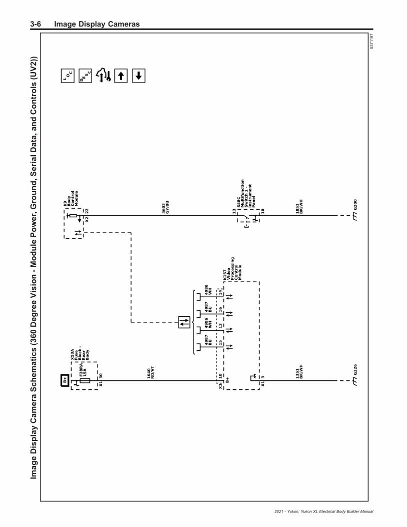
3-6 Image Display CamerasIm
ag
eD
isp
lay
Ca
me
raS
ch
em
ati
cs
(36
0D
eg
ree
Vis
ion
-M
od
ule
Po
we
r,G
rou
nd
,Se
ria
lDa
ta,a
nd
Co
ntr
ols
(UV
2))
53
711
97
2021 - Yukon, Yukon XL Electrical Body Builder Manual

Image Display Cameras 3-7Im
ag
eD
isp
lay
Ca
me
raS
ch
em
ati
cs
(36
0D
eg
ree
Vis
ion
-C
am
era
sa
nd
Dis
pla
y(U
V2
))
53
711
98
2021 - Yukon, Yukon XL Electrical Body Builder Manual

3-8 Image Display Cameras
Description and OperationRearview Camera Full Display MirrorDescription and OperationIf equipped, full display mirror provides a wider field ofview than normally seen from the inside rearview mirrorto assist when driving and changing lanes. When thetab under the inside rearview mirror is pulled rearward,a view of the area behind the vehicle displays on themirror. The inside rearview camera full display mirror isconnected to the outside rearview camera via ashielded coaxial cable.When the tab under the inside rearview mirror is pulledrearward, a view of the area behind the vehicle displayson the mirror.Adjust the rearview mirror for a clear view of the areabehind the vehicle before turning on full display mirror.Use the three buttons on the bottom of the mirror toadjust the brightness, zoom, and tilt of the display.Make sure the light sensor is not covered whenadjusting the brightness.The inside rearview camera full display mirror may notwork properly or display a clear image if:.
• It is dark.• The sun or the beam of headlamps are shining
directly into the camera lens.• Ice, snow, mud, or anything else builds up on the
camera lens. Clean the lens, rinse it with water,and wipe it with a soft cloth.
When the mirror detects that the camera is not sendinga valid video signal, it “blue screens” with a “no video”decal for 3 seconds, then reverts back to the mirror.
Rear Vision Camera Description andOperation
Rear Vision Camera System OperationThe rear vision camera system consists of a videocamera located at the rear of the vehicle and the Rado.When the transmission is placed into REVERSE, asignal is sent to the Radio indicating that cameraoperation is requested. The rearview camera sendsvideo information to the radio through a coax cable.The coax cable also provides power from the Radio tothe rearview camera.The following conditions may cause a degraded rearvision camera image:
• Ice, snow, or mud has built up on the rear visioncamera
• Dark conditions• Extreme light conditions, such as glare from the
sun or the headlights of another vehicle• Damage to the rear of the vehicle• Extreme high temperatures or extreme
temperature changesIf a malfunction is detected in the system, Service RearVision Camera may be displayed on the Info DisplayModule as an indicator to the customer that a problemexists that requires service.
Surround Vision Camera Descriptionand OperationWarning: The Surround Vision cameras have blindspots and will not display all objects near thecorners of the vehicle. Folding outside mirrors thatare out of position may not display surround viewcorrectly. Always check around the vehicle whenparking or backing.
4291164
1. View Displayed by the Surround Vision Camera2. Area Not Shown
4291749
1. View Displayed by the Surround Vision Camera2. Area Not Shown
The surround vision camera system consists of thefollowing components:
• B87 Rearview Camera• B174G Frontview Camera – Grille• K157 Video Processing Control Module
2021 - Yukon, Yukon XL Electrical Body Builder Manual

Image Display Cameras 3-9
• A11 Radio OR K74 Human Machine InterfaceModule
• B225L Sideview Camera – Left• B225R Sideview Camera – Right• X20 Memory Card Receptacle (with XVR)
When the vehicle is traveling at speeds slower than 6mph (10kph) the video processing control module willpower up the cameras and send a video signal to theradio or human machine interface module.The following conditions may cause a degradedsurround vision camera image:
• Ice, snow, or mud has built up on the rear visioncamera
• Dark conditions• Extreme light conditions, such as glare from the
sun or the headlights of another vehicle• Damage to the rear of the vehicle• Extreme high temperatures or extreme
temperature changesSurround Vision displays an overhead view of the areasurrounding the vehicle, along with the front or rearcamera views in the center stack. The front camera is inthe grille or near the front emblem, the side camerasare on the bottom of the outside rearview mirrors, andthe rear vision camera is above the license plate.Note: Images from the Sideview Cameras are onlydisplayed when both front doors are properly closed.
Features of the Surround Vision System• Rear camera (B87 Rearview Camera) view
alongside overhead view is displayed in reverse• Front camera (B174G Frontview Camera – Grille)
view alongside overhead view is displayed aftershifting out of reverse to Neutral or Drive
• Will display front view when front park assistobject is within trigger range calibration value(30 cm (12 in) in a forward gear
• Image is removed from display when vehiclespeed exceeds speed calibration (10kph/6 mph)or button press / screen touch
System Operation
The video processing control module is connected toeach camera via a shielded coaxial cable. The coaxialcable provides power for the camera and also carriesthe video image from the cameras to the videoprocessing control module for processing. The videoprocessing control module will then send the processedimage output to infotainment system via anothercoaxial cable.
The video processing control module receives CANinformation from Rear Park Assist object detectionmodule and Steering Wheel angle from body controlmodule during Reverse. A warning triangle may displayduring the 360 surround view screen if Rear ParkingAssist has detected an object during a reverse. Thistriangle changes from amber to red and increases insize the closer the object. Also a dynamic guideline isdisplayed in Reverse to show the projected path of thevehicle.
If equipped, the video processing control modulesystem may have a memory card receptacle (with XVR)located in the trunk. The memory card receptacleinterfaces with the video processing control module viaa USB cable. The memory card receptacle alsoreceives fused battery voltage and ground from thevideo processing control module. The video processingcontrol module uses the memory card as a massstorage device, similar to a USB storage device.
2021 - Yukon, Yukon XL Electrical Body Builder Manual

3-10 Image Display Cameras
BLANK
2021 - Yukon, Yukon XL Electrical Body Builder Manual

Table of Contents 4-1
Section 4
Engine/Propulsion
12 V Starting and Charging . . . . . . . . . . . . . . . . . . . 4-3Schematic and Routing Diagrams . . . . . . . . . . . . . . . 4-3
Starting and Charging Schematics . . . . . . . . . . . . . . . 4-4Auxiliary Battery Schematics . . . . . . . . . . . . . . . . . . . . . 4-8
Description and Operation . . . . . . . . . . . . . . . . . . . . . . . 4-9Battery Description and Operation . . . . . . . . . . . . . . . 4-9Charging System Description and Operation . . . . 4-9Electrical Power Management Description and
Operation . . . . . . . . . . . . . . . . . . . . . . . . . . . . . . . . . . . . . . 4-12Starting System Description and Operation . . . . 4-14Stop/Start System Description and
Operation . . . . . . . . . . . . . . . . . . . . . . . . . . . . . . . . . . . . . . 4-16
2021 - Yukon, Yukon XL Electrical Body Builder Manual

4-2 Table of Contents
BLANK
2021 - Yukon, Yukon XL Electrical Body Builder Manual

12 V Starting and Charging 4-3
12 V Starting and Charging
Schematic and Routing Diagrams
2021 - Yukon, Yukon XL Electrical Body Builder Manual

4-4 12 V Starting and ChargingS
tart
ing
an
dC
ha
rgin
gS
ch
em
ati
cs
(Sta
rtin
g(L
84
/L8
7))
53
71
29
2
2021 - Yukon, Yukon XL Electrical Body Builder Manual

12 V Starting and Charging 4-5S
tart
ing
an
dC
ha
rgin
gS
ch
em
ati
cs
(Sta
rtin
g(L
M2
))
53
71
01
3
2021 - Yukon, Yukon XL Electrical Body Builder Manual

4-6 12 V Starting and ChargingS
tart
ing
an
dC
ha
rgin
gS
ch
em
ati
cs
(Ch
arg
ing
)
53
71
29
3
2021 - Yukon, Yukon XL Electrical Body Builder Manual

12 V Starting and Charging 4-7S
tart
ing
an
dC
ha
rgin
gS
ch
em
ati
cs
(Sto
p/S
tart
Sy
ste
m)
53
71
01
2
2021 - Yukon, Yukon XL Electrical Body Builder Manual

4-8 12 V Starting and ChargingA
ux
ilia
ryB
att
ery
Sc
he
ma
tic
s(A
ux
ilia
ryB
att
ery
Re
lay
(5W
4/9
C1
))
53
71
33
0
2021 - Yukon, Yukon XL Electrical Body Builder Manual

12 V Starting and Charging 4-9
Description and OperationBattery Description and OperationWarning: Batteries produce explosive gases,contain corrosive acid, and supply levels ofelectrical current high enough to cause burns.Therefore, to reduce the risk of personal injurywhen working near a battery:
• Always shield your eyes and avoid leaning overthe battery whenever possible.
• Do not expose the battery to open flames orsparks.
• Do not allow the battery electrolyte to contactthe eyes or the skin. Flush immediately andthoroughly any contacted areas with water andget medical help.
• Follow each step of the jump startingprocedure in order.
• Treat both the booster and the dischargedbatteries carefully when using the jumpercables.
Batteries that are no longer wanted must be disposedof by an approved battery recycler and must never bethrown in the trash or sent to a landfill.Batteries that are not part of the vehicle itself, not thebattery under the hood, must only be transported onpublic streets for business purposes via approvedhazardous material transportation procedures.Battery storage, charging and testing facilities in repairshops must meet various requirements for ventilation,safety equipment, material segregation, etc.The maintenance free battery is standard. There are novent plugs in the cover. The battery is completelysealed except for 2 small vent holes in the side. Thesevent holes allow the small amount of gas that isproduced in the battery to escape.The battery has 3 functions as a major source ofenergy:
• Engine cranking• Voltage stabilizer• Alternate source of energy with generator
overload
Battery Low Start Vehicle MessageThe body control module (BCM) monitors batterypositive voltage to determine battery state of charge.If one or more of the BCM battery positive voltageterminals measure less than approximately 11.6Vcompared to the BCM ground circuits, this message willdisplay and four chimes may sound. Start the vehicleimmediately. If the vehicle is not started and the batterycontinues to discharge, the climate controls, heatedseats, and audio systems will shut off and the vehiclemay require a jump start. These systems will functionagain after the vehicle is started.
Battery RatingsA battery has 2 ratings:
• Cold cranking amperage• Amperage hours
When a battery is replaced use a battery with similarratings. See battery specification label on the originalbattery.
Amperage HoursThe amperage hour rating tells you how muchamperage is available when discharged evenly over a20 hour period. The amperage hour rating iscumulative, so in order to know how many constantamperage the battery will output for 20 h, you have todivide the amperage hour rating by 20. Example: If abattery has an amperage hour rating of 74, dividing by20 = 3.75. Such a battery can carry a 3.75 A load for20 hours before dropping to 10.5 V. (10.5 V is the fullydischarged level, at which point the battery needs to berecharged.) A battery with an amperage hour rating of55 will carry a 2.75 A load for 20 hours before droppingto 10.5 V.
Cold Cranking AmperageThe cold cranking amperage is an indication of theability of the battery to crank the engine at coldtemperatures. The cold cranking amperage rating is theminimum amperage the battery must maintain for30 seconds at −18°C (0°F) while maintaining at least7.2 V. See battery label for the cold cranking amperagerating of this battery.
Charging System Description andOperation
Electrical Power Management OverviewThe electrical power management system is designedto monitor and control the charging system and senddiagnostic messages to alert the driver of possibleproblems with the battery and generator. This electricalpower management system primarily utilizes existingon-board computer capability to maximize theeffectiveness of the generator, to manage the load,improve battery state-of-charge and life, and minimizethe system's impact on fuel economy. The electricalpower management system performs 3 functions:
• Monitor the battery voltage and estimate thebattery condition
• Take corrective actions by boosting idle speeds,and adjusting the regulated voltage
• Perform diagnostics and driver notificationThe battery condition is estimated during ignition/vehicle off and during ignition/vehicle on. Duringignition/vehicle off the state-of-charge of the battery isdetermined by measuring the open-circuit voltage. Thestate-of-charge is a function of the acid concentrationand the internal resistance of the battery, and isestimated by reading the battery open circuit voltagewhen the battery has been at rest for several hours.Any time the ignition/vehicle is on, the vehicle algorithmcontinuously estimates battery state-of-charge basedon adjusted net amp hours, battery capacity, initialstate-of-charge, and calculated temperature.While the engine is running, the battery degree ofdischarge is primarily determined by the integratedbattery current sensor, to obtain net amp hours.
2021 - Yukon, Yukon XL Electrical Body Builder Manual

4-10 12 V Starting and Charging
In addition, the electrical power management functionis designed to perform regulated voltage control toimprove battery state-of-charge, battery life, and fueleconomy. This is accomplished by using knowledge ofthe battery state-of-charge and temperature to set thecharging voltage to an optimum battery voltage level forrecharging without detriment to battery life.
Charging System ComponentsG13 Generator
The engine drive belt drives the generator. When therotor is spun, it induces an alternating current (AC) intothe stator windings. The AC voltage is then sentthrough a series of diodes for rectification. The rectifiedvoltage has been converted into a direct current (DC)for use by the vehicles electrical system to maintainelectrical loads and the battery charge. The voltageregulator integral to the generator controls the output ofthe generator; It is not serviceable. The voltageregulator controls the amount of current provided to therotor. If the generator has field control circuit fault, thegenerator defaults to an output voltage of 13.8 V.
The generator is serviced as a complete assembly.If there is a diagnosed fault in the generator, it must bereplaced as an assembly.
Generator Pulley
The pulley drives the Generator via the engine drivebelt. There are 2 types of pulleys:
1. Conventional solid Pulley which is bolted to theGenerator stator shaft. This Pulley can be servicedseparately.
2. One Way Clutch Pulley or Overrunning AlternatorDecoupler Pulley allows the Generator to spin freelywhen the engine rapidly slows down on suddendeceleration. This part is not serviceable and theGenerator needs to be replaced as an assembly.
K9 Body Control Module (BCM)
The K9 Body Control Module communicates with theK20 Engine Control Module and the instrument clusterfor electrical power management operation. The BCMdetermines the output of the generator and sends theinformation to the ECM for control of the generator turnon signal circuit. It monitors the generator field dutycycle signal circuit information sent from the ECM forcontrol of the generator. It monitors the battery currentsensor, the battery positive voltage circuit, andestimates battery temperature to determine batterystate of charge. The BCM also performs idle boost.
B110 Battery Monitor Module
The Battery Monitor Module communicates to the BCMvia LIN. The BCM shares this information with the ECM.The purpose of the battery sensor module is to transmitbattery information that the BCM/ECM can use to makedecisions regarding stop/start, battery saver mode, andload shedding.
K20 Engine Control Module (ECM)
When the engine is running, the generator turn-onsignal is sent to the generator from the ECM, turning onthe regulator. The generator's voltage regulator controlscurrent to the rotor, thereby controlling the outputvoltage. The rotor current is proportional to the
electrical pulse width supplied by the regulator. Whenthe engine is started, the regulator senses generatorrotation by detecting AC voltage at the stator throughan internal wire. Once the engine is running, theregulator varies the field current by controlling the pulsewidth. This regulates the generator output voltage forproper battery charging and electrical systemoperation. The generator field duty terminal isconnected internally to the voltage regulator andexternally to the ECM. When the voltage regulatordetects a charging system problem, it grounds thiscircuit to signal the ECM that a problem exists. TheECM monitors the generator field duty cycle signalcircuit, and receives control decisions based oninformation from the BCM.
P16 Instrument Cluster
As a means of displaying the charging systemfunctions, some vehicles may be equipped with avoltmeter gauge on the instrument cluster and/or asystem voltage display in the driver information center.These will indicate the current vehicle system voltage.
The instrument cluster also provides customernotification if there is a concern with the chargingsystem. There are two means of notification: a chargeindicator on the instrument cluster and/or a servicesystem message displayed on the Driver InformationCenter (DIC) if equipped.
Charging System OperationThe purpose of the charging system is to maintain thebattery charge and vehicle loads. There are 6 modes ofoperation and they include:
• Battery Sulfation Mode• Charge Mode• Fuel Economy Mode• Head lamp Mode• Start Up Mode• Voltage Reduction Mode
The ECM Controls the Generator through the generatorturn–on signal circuit, also known as the GeneratorL-terminal. The ECM monitors the generatorperformance though the Generator field duty cyclesignal circuit, also known as the generator F-terminal.The Generator turn–on signal (Generator L-terminal) isa Pulse Width Modulation (PWM) signal of 128 Hz witha duty cycle of 0–100%. Normal duty cycle is between5–95%. 0–5% and 95–100% are for diagnosticpurposes, with 0–5% monitoring for an open circuit and95–100% monitoring for a short to ground at a fixed13.8 V. The following table shows the commanded dutycycle and output voltage of the Generator:
Commanded Duty CycleGenerator Output Voltage
(+/- .25 V)
0–5% 13.8 V
10% 11 V
20% 11.56 V
30% 12.13 V
40% 12.69 V
50% 13.25 V
60% 13.81 V
2021 - Yukon, Yukon XL Electrical Body Builder Manual

12 V Starting and Charging 4-11
Commanded Duty CycleGenerator Output Voltage
(+/- .25 V)
70% 14.38 V
80% 14.94 V
90% 15.5 V
95–100% 13.8 V
The Generator provides a PWM feedback signal of theGenerator voltage output through the Generator fieldduty cycle signal circuit to the ECM. This information issent to the Body Control Module (BCM). The Generatorfield duty cycle signal (Generator F-terminal) is a PWMsignal of 60–460 Hz with a duty cycle of 0–100%.Normal duty cycle is between 5–100%. 0–5% isreserved for diagnostic purposes.As the charging systems works to maintain the batterycharge and manage vehicle electrical loads, it is normalfor the voltmeter gauge on the instrument cluster or thesystem voltage displayed in the DIC to fluctuate orchange. This does not indicate a malfunction.Depending on the battery state of charge and thevehicle electrical load, these values may be anywherefrom 12.5 V to 15.5 V.
Charging System ModesBattery Sulfation Mode
The BCM will enter this mode when the interpretedGenerator output voltage is less than 13.2 V for45 minutes. When this condition exists the BCM willenter Charge Mode for 2–3 minutes. The BCM will thendetermine which mode to enter depending on voltagerequirements.
Charge Mode
The BCM will enter Charge Mode when ever one of thefollowing conditions are met:
• Windshield wipers are ON for more than 3 s.• Climate Control Voltage Boost Mode Request is
true, as sensed by the HVAC control module viaserial data. High speed cooling fan, rear defogger,and HVAC high speed blower operation can causethe BCM to enter the Charge Mode.
• The estimated battery temperature is less than 0°C (32°F).
• Battery State of Charge is less than 80%.• Vehicle speed is greater than 145 km/h (90 mph)• A current sensor malfunction exists.• System voltage is determined to be below 12.56 V
When any one of these conditions is met, the systemwill set targeted generator output voltage to a chargingvoltage between 13.9–15.5 V, depending on the batterystate of charge and estimated battery temperature.
Fuel Economy Mode
The BCM will enter Fuel Economy Mode when theestimated battery temperature is at least 0°C (32°F) butless than or equal to 80°C (176°F), the calculatedbattery current is less than 15 A and greater than −8 A,and the battery state-of-charge is greater than or equalto 80%. Its targeted generator output voltage is theopen circuit voltage of the battery and can be between12.5–13.1 V. When fuel economy mode is active, the
generator is not charging, only maintaining open circuitbattery voltage. The BCM will exit this mode and enterCharge Mode when any of the conditions describedabove are present.
Headlamp Mode
The BCM will enter Headlamp Mode when ever thehead lamps are ON (high or low beams). Voltage will beregulated between 13.9–14.5 V.
Start Up Mode
When the engine is started the BCM sets a targetedgenerator output voltage of 14.5 V for 30 s.
Tow/Haul Mode (if applicable)
Pressing the Tow/Haul Mode button located on thecenter stack, the vehicle system voltage is raised andthe remote (non-vehicle) battery will be charged.Having the headlamps on will raise the system voltageand if the Tow/Haul button is applied it will not serveany purpose. The voltage is regulated between13.9-14.5 V.
Instrument Cluster OperationCharge Indicator Operation
The instrument cluster illuminates the charge indicatorand displays a warning message in the driverinformation center if equipped, when the one or more ofthe following occurs:
• The ECM detects that the generator output is lessthan 11 V or greater than 16 V. The instrumentcluster receives a serial data message from theECM requesting illumination.
• The instrument cluster determines that the systemvoltage is less than 11 V or greater than 16 V formore than 30 s. The instrument cluster receives aserial data message from the BCM indicatingthere is a system voltage range concern.
• The instrument cluster performs the displays testat the start of each ignition cycle. The indicatorilluminates for approximately 3 s.
Driver Information Center Message: BATTERY NOTCHARGING SERVICE CHARGING SYSTEM orSERVICE BATTERY CHARGING SYSTEM
The BCM and the ECM will send a serial data messageto the driver information center for the BATTERY NOTCHARGING SERVICE CHARGING SYSTEM orSERVICE BATTERY CHARGING SYSTEM messageto be displayed. It is displayed when a charging systemDTC is a current DTC. The message is turned off whenthe conditions for clearing the DTC have been met.
Voltmeter Gauge and/or System Voltage Display (ifequipped)
As a means of displaying the charging systemfunctions, some vehicles may be equipped with avoltmeter gauge on the instrument cluster and/or asystem voltage display in the driver information center.These will indicate the current vehicle system voltage.
As the charging systems works to maintain the batterycharge and manage vehicle electrical loads, it is normalfor the voltmeter gauge on the instrument cluster or thesystem voltage display in the driver information centerto fluctuate or change. This does not indicate a
2021 - Yukon, Yukon XL Electrical Body Builder Manual

4-12 12 V Starting and Charging
malfunction. Depending on the battery state of chargeand the vehicle electrical load, these values may beanywhere from 12.5 V to 15.5 V.
Electrical Power ManagementDescription and Operation
Electrical Power ManagementThe electrical power management is used to monitorand control the charging system and alert the driver ofpossible problems within the charging system. Theelectrical power management system makes the mostefficient use of the generator output, improves thebattery state-of-charge, extends battery life, andmanages system electrical loads.The load shed operation is a means of reducingelectrical loads during a low voltage or low batterystate-of-charge condition.The idle boost operation is a means of improvinggenerator performance during a low voltage or lowbattery state-of-charge condition.Each electrical power management function, either idleboost or load shed, is activated in incremental steps.For example, idle boost 1 must be active before idleboost 2 can be active. The criteria used by the bodycontrol module (BCM) to regulate electrical powermanagement are outlined below:
3621782
2021 - Yukon, Yukon XL Electrical Body Builder Manual

12 V Starting and Charging 4-13
Idle Boost and Load Shed With Current Sensor
FunctionBattery Temperature
CalculationBattery Voltage
CalculationAmp-HourCalculation Action Taken
Idle Boost 1 Start Less Than −15°C (5°F) Less Than 13 V — First level Idle boostrequested
Idle Boost 1 Start — — Battery has a net lossgreater than 0.6 Ah
First level Idle boostrequested
Idle Boost 1 Start — Less Than 11 V — First level Idle boostrequested
Idle Boost 1 End Greater Than −10°C(14°F) Greater Than 12 V Battery has a net loss
less than 0.2 AhFirst level Idle boostrequest cancelled
Idle Boost 2 Start — — Battery has a net lossgreater than 1.6 Ah
Second level Idle boostrequested
Idle Boost 2 Start — Less Than 11 V — Second level Idle boostrequested
Idle Boost 2 End — Greater Than 12 V Battery has a net lossless than 0.8 Ah
Second level Idle boostrequest cancelled
Load Shed 1 Start — — Battery has a net lossof 4 Ah
Rear Defrost, HeatedMirrors, Heated Seats,HVAC cycled OFF for
20% of their cycle
Load Shed 1 Start — Less Than 11 V —
Rear Defrost, HeatedMirrors, Heated Seats,HVAC cycled OFF for
20% of their cycle
Load Shed 1 End — Greater Than 12 V Battery has a net lossof less than 2 Ah Clear Load Shed 1
Idle Boost 3 Start — — Battery has a net lossof 10 Ah
Third level Idle boostrequested
Idle Boost 3 Start — Less Than 11 V — Third level Idle boostrequested
Idle Boost 3 End — Greater Than 12 V Battery has a net lossof less than 6.0 Ah
Third level Idle boostrequest cancelled
Load Shed 2 Start — — Battery has a net lossgreater than 12 Ah
Rear Defrost, HeatedMirrors, Heated Seats,HVAC cycled OFF for
50% of their cycle. TheBATTERY SAVER
ACTIVE message willbe displayed on
the DIC
Load Shed 2 Start — Less Than 11 V —
Rear Defrost, HeatedMirrors, Heated Seats,HVAC cycled OFF for
50% of their cycle. TheBATTERY SAVER
ACTIVE message willbe displayed on
the DIC
Load Shed 2 End — Greater Than 12 V Battery has a net lossof less than 8 Ah Clear Load Shed 2
Load Shed 3 Start — Less Than 11.9 V Battery has a net lossgreater than 20 Ah
Rear Defrost, HeatedMirrors, Heated Seats,HVAC cycled OFF for100% of their cycle.
The BATTERY SAVERACTIVE message will
be displayed onthe DIC
2021 - Yukon, Yukon XL Electrical Body Builder Manual

4-14 12 V Starting and Charging
Idle Boost and Load Shed With Current Sensor (cont'd)
FunctionBattery Temperature
CalculationBattery Voltage
CalculationAmp-HourCalculation Action Taken
Load Shed 3 Start — Less Than 11 V —
Rear Defrost, HeatedMirrors, Heated Seats,HVAC cycled OFF for100% of their cycle.
The BATTERY SAVERACTIVE message will
be displayed onthe DIC
Load Shed 3 End — Greater Than 12.6 V Battery has a net lossof less than 13 Ah Clear Load Shed 3
Idle Boost and Load Shed Without Current Sensor (based on battery voltage)
FunctionBattery Temperature
Calculation Battery Voltage Calculation Action Taken
Idle Boost 1 Start Less Than −15°C (5°F) Less Than 13 V First level Idle boostrequested
Idle Boost 1 Start — Less Than 12.6 V First level Idle boostrequested
Idle Boost 1 End Greater Than −15°C (5°F) — First level Idle boost requestcancelled
Idle Boost 1 End — Greater Than 13 V First level Idle boost requestcancelled
Idle Boost 2 Start — Less Than 12.4 V Second level Idle boostrequested
Idle Boost 2 End — Greater Than 12.5 V Second level Idle boostrequest cancelled
Load Shed 1 Start — Less Than 12.3 VRear Defrost, Heated Mirrors,Heated Seats, HVAC cycledOFF for 20% of their cycle
Load Shed 1 End — Greater Than 12.4 V Clear Load Shed 1
Idle Boost 3 Start — Less Than 10 V Third level Idle boostrequested
Idle Boost 3 End — Greater Than 12.3 V Third level Idle boost requestcancelled
Load Shed 2 Start — Less Than 12.1 V
Rear Defrost, Heated Mirrors,Heated Seats, HVAC cycledOFF for 50% of their cycle.
The BATTERY SAVERACTIVE message will be
displayed on the DIC
Load Shed 2 End — Greater Than 12.2 V Clear Load Shed 2
Load Shed 3 Start — Less Than 11.9 V
Rear Defrost, Heated Mirrors,Heated Seats, HVAC cycledOFF for 100% of their cycle.
The BATTERY SAVERACTIVE message will be
displayed on the DIC
Load Shed 3 End — Greater Than 12.0 V Clear Load Shed 3
Starting System Description andOperation
Starter Motor Operation (Without KL9)The starter motors are non-repairable. They have polepieces that are arranged around the armature. Bothsolenoid windings are energized. The pull-in windingcircuit is completed to the ground through the starter
motor. The windings work together magnetically to pulland hold in the plunger. The plunger moves the shiftlever. This action causes the starter drive assembly torotate on the armature shaft spline as it engages withthe flywheel ring gear on the engine. Moving at thesame time, the plunger also closes the solenoid switchcontacts in the starter solenoid. Full battery voltage isapplied directly to the starter motor and it cranks theengine.
2021 - Yukon, Yukon XL Electrical Body Builder Manual

12 V Starting and Charging 4-15
As soon as the solenoid switch contacts close, currentstops flowing thorough the pull-in winding becausebattery voltage is applied to both ends of the windings.The hold-in winding remains energized. Its magneticfield is strong enough to hold the plunger, shift lever,starter drive assembly, and solenoid switch contacts inplace to continue cranking the engine. When theengine starts, pinion overrun protects the armature fromexcessive speed until the switch is opened.When the crank signal is removed, the starter relayopens and battery voltage is removed from the startersolenoid S terminal. Current flows from the motorcontacts through both windings to the ground at the endof the hold-in winding. However, the direction of thecurrent flow through the pull-in winding is now oppositethe direction of the current flow when the winding wasfirst energized.The magnetic fields of the pull-in and hold-in windingsnow oppose one another. This action of the windings,along with the help of the return spring, causes thestarter drive assembly to disengage and the solenoidswitch contacts to open simultaneously. As soon as thecontacts open, the starter circuit is turned off.
Enhanced Starter MotorOperation (KL9)The Engine Stop/Start system in GM vehiclesautomatically turns off the engine when the vehiclecomes to a stop under certain driving conditions, andcan quickly restart the engine in about 0.3 secondswhen commanded to do so.In order to smoothly restart the engine as quickly aspossible while managing the greater number of enginestarts, the Stop/Start system uses an enhanced startermotor that operates differently from a conventionalstarter motor. It has a high performance electric motorand a stronger pinion engagement mechanism than aconventional starter. It also has independent control ofthe pinion and motor.The enhanced starter motor continues using the typicalpinion engagement mechanism with a starter solenoidthat drives the pinion gear to engage or disengage theflywheel of the engine. When engaged, the startermotor can rotate the engine flywheel and, in turn, thecrankshaft.On the enhanced starter of a Stop/Start system theoperation is done in two separate functions inside thesolenoid, Starter Motor and Pinion Actuator. Eachfunction controlled individually by the ECM. There aretwo separate relays to control the two separate parts ofthe enhanced solenoid:
• KR27 Starter Motor Relay• KR27C Starter Pinion Actuator Relay
The two individually-controlled relays allow for smoothengagement of the pinion gear into the flywheel withminimum noise and wear.When the vehicle is coming to a stop, just before theengine stops rotating (at approximately 50 RPM) duringstop/start operation, the ECM energizes the StarterPinion Solenoid Actuator Relay to easily push thepinion gear into the flywheel gear without gear clash.(Fig. 8) When the engine stops rotating during Stop/
Start operation (Auto Stop mode), the starter piniongear is fully engaged, ready for the starter motor tobecome energized to quickly start the engine again.A secondary need for the starter pinion to be driven intothe flywheel gear before the engine stops rotating is toaddress quickly changing demands on the engine. Forexample, when a driver is slowing nearly to a stop —and the Stop/Start system is preparing for Auto Stopmode — but suddenly decides to release the brake andaccelerateIn this situation, the engine has already stoppedrotating, or nearly so. A conventional starter cannotrestart the engine until the engine has completelystopped. However, with the enhanced starter, thestarter pinion gear is fully engaged and ready to beginrotating the engine even before it fully stops turning.Otherwise, the engine would actually have to stoprotating before the pinion can engage smoothly to begina restart.To prevent a lag in engine operation, the ECM usespredictive speed matching of the flywheel gear speedand the pinion gear speed to engage the pinion gearinto the flywheel gear without gear clash before theengine fully stops. By predicting how long it takes thestarter motor to spin up using an algorithm, the piniongear speed can be matched to the flywheel gear speed.The result is an almost instant restart that is possible atextremely low engine speeds.
Circuit DescriptionKeyless StartWhen the Ignition mode switch is placed in the crankposition, a discrete signal is supplied to the bodycontrol module (BCM) notifying it that the ignition is inthe crank position. The BCM then sends a serial datamessage to the engine control module (ECM) thatcrank has been requested. The ECM then verifies thatthe clutch is fully depressed or the automatictransmission is in Park/Neutral. If it is, the ECM thensupplies 12 V to the control circuit of the starter relay.When this occurs, battery positive voltage is suppliedthrough the switch side of the crank relay to the Sterminal of the starter solenoid.
Key StartWhen the ignition switch is placed in the Start position,a discrete signal is supplied to the body control module(BCM) notifying it that the ignition is in the Startposition. The BCM then sends a message to the enginecontrol module (ECM) notifying it that CRANK has beenrequested. The ECM verifies that the transmission is inPark or Neutral. If it is, the ECM then supplies 12 V tothe control circuit of the crank relay. When this occurs,battery positive voltage is supplied through the switchside of the crank relay to the S terminal of the startersolenoid.
2021 - Yukon, Yukon XL Electrical Body Builder Manual

4-16 12 V Starting and Charging
3603725
Stop/Start System Description andOperationThe Stop/Start System is used to improve fuelefficiency in stop/start driving. The vehicleautomatically shuts down the engine in appropriateconditions at a traffic light, for example, resulting in zerotail pipe emissions and saving fuel which otherwise isused idling the engine when stationary. The engineinstantly restarts when the driver is ready tomove away.As soon as the driver prepares to move away (byreleasing the brake pedal and/or depressing theaccelerator pedal), the engine will start; it only takes thesystem around 0.3 s to start the engine.To support the increased number of engine starts, thestarter motor is upgraded with a high performanceelectric motor and a stronger pinion engagementmechanism with reduced noise levels.Along with the upgraded starter motor, advancedbattery technology is required to ensure the vehiclesbattery can handle the frequent charge and dischargecycles common with stop/start operation. There isbattery sensor module connected to the battery whichcontinually monitors the battery charge and healthystate. The Engine Control Module (ECM) uses thisinformation from the battery sensor module todetermine if the battery charge and health is sufficientfor an Stop/Start condition.
The Stop/Start system can reduce fuel consumptionand carbon dioxide (CO2) emissions by up to 5% inmixed driving conditions. In an urban environment andin heavy traffic with frequent stops the savings mayincrease to as much as 10%.There are also sophisticated controls in place to helpensure the Stop/Start System does not compromise theneeds of either the driver or vehicle. For the engine toshutdown, the vehicle must be below 5 km/h (3 MPH),the selector lever in position D, and brake pedaldepressed. To restart, the driver simply releases thebrake pedal and the enhanced starter motor engagesthe engine. When the engine has been shut down bythe Stop/Start System, a control indicator will beilluminated in the Driver Information Center (DIC).When the engine is restarted, the control indicator inthe DIC extinguishes.To ensure neither the needs of the driver or vehicle arecompromised the engine will not shut down in thefollowing circumstances:
• Ambient and coolant temperature correlation doesnot match specified values.
• Ambient temperature is less than −10°C (14°F)• Battery temperature is less than 0°C (32°F) or
greater than 55°C (131°F)• Driver seat belt is not fastened and the drivers
door is not fully closed (not applicable to vehiclesin North America)
• HVAC system demand is high• HVAC defrost has been selected• Battery charge is low
2021 - Yukon, Yukon XL Electrical Body Builder Manual

12 V Starting and Charging 4-17
Likewise the engine will automatically restart if:• Driver door opened and driver seat belt unbuckled
(not applicable to vehicles in North America)• Engine hood opened• Battery charge is low• HVAC demand increases• Vehicle speed increases• Brake booster vacuum has been reduced• Engine coolant temperature is greater than 125°
C (257°F)• Economy mode turned OFF by driver• Autostop time exceeded 2 min
When the Stop/Start System has shut down the engine,and the ambient temperature is below 15°C (59°F), theECM will activate the Stop/Start auxiliary relay whichcontrols the electric engine coolant pump motor tocontinually circulate the engine coolant through theengine while the engine is off. This is to ensure theengine and passenger compartment temperature ismaintained while off. Once the Stop/Start System hasrestarted the engine, the ECM will turn off the electriccoolant pump motor, thus allowing the engines internalcoolant pump to circulate the engine coolant. The Stop/Start System is automatically activated each time theignition switch is turned on.Through the climate control system, the vehicle can becycled between off, comfort, and eco air conditioningmodes (if equipped). In comfort mode, the priority forStop/Start operation is on customer comfort.Depending on ambient temp, humidity, cabintemperature and cabin temperature setpoint, the leastamount of autostops occur in this mode. In eco mode,the priority is on fuel economy. There are more frequentautostops with some sacrificing of cabin temperaturecontrol. With the HVAC turned off, the maximumautostops occur since there will be no A/C compressorrequests.
Autostop CriteriaThe ECM will send an Autostop state message to thebody control module (BCM) and shut down the enginewhen all of the following criteria is met. The BCM willtransmit the Autostop state message to the instrumentcluster which will display the Autostop indicator in thetachometer display.
• Initial minimum vehicle speed during drive cyclemust be 19 km/h (12 MPH) or greater. Subsequentautostop minimum speed may vary from2-10 km/h (1-6 MPH), depending on vehicle
• Ambient and engine coolant temperaturecorrelation meets specified values.
• Ambient and transmission fluid temperaturecorrelation meets specified values.
• Hood switch status is closed• Driver door status is closed• Driver seat belt status is buckled• Brake booster vacuum is greater than
45 kPa (7 PSI)• Transmission gear selector is in the Drive position• Vehicle speed is less than 5 km/h (3 MPH)• Engine speed is below 1,500 RPM• Engine coolant temperature is less than 120°
C (248°F)• Ambient temperature is greater than −10°C (14°F)• No A/C compressor request from HVAC (A/C or
Defrost modes)• Battery voltage greater than 12 V• Battery state of charge greater than 75% (changes
with state of health)
Autostop Enable Ambient and Engine Coolant Temperature TableAmbient Temperature inimum Coolant Temperature Autostop Enable
−10°C (14°F) 60°C (140°F) Yes
0°C (32°F) 50°C (122°F) Yes
6°C (43°F) 40°C (104°F) Yes
12°C (54°F) 30°C (86°F) Yes
20°C (68°F) 18°C (64°F) Yes
30°C (86°F) 18°C (64°F) Yes
Autostart CriteriaThe ECM will send an Autostart state message to theBCM. If all of the following conditions are true the ECMand BCM will restart the vehicle.Driver Enabled Conditions that will engage Autostart:
• Driver removes pressure from the brake ordepresses the accelerator pedal while the vehicleis in the forward Drive gear
System Enabled Conditions that will engage Autostart
Note: If one or more of the following conditions occur,the system will force the engine to restart.
• Brake booster vacuum is less than 40 kPa (6 PSI)• A/C compressor request from HVAC (A/C or
Defrost modes)• Battery voltage less than 11 V,• Battery state of charge is less than 73% (changes
with state of health)• Driver door status changes to open and driver seat
belt status changes to unbuckled (not applicableto vehicles in North America)
2021 - Yukon, Yukon XL Electrical Body Builder Manual
4-18 12 V Starting and Charging
• Hood switch status changes to open• Autostop time exceeded 2 min
If the crank time exceeds 2 s, a manual ignition switchrestart will be necessary.
System ComponentsEngine Control Module (ECM)
The ECM monitors the inputs from the Engine CoolantTemperature (ECT) sensor, Vehicle SpeedSensor (VSS), Battery Sensor Module, hood ajarswitch, brake booster vacuum sensor, and enginespeed to determine Autostart and Autostop conditions.The ECM also controls the auxiliary coolant pumpmotor (if equipped).
Transmission Control Module (TCM)
The TCM monitors the inputs from the transmissionneutral safety switch to determine the driver selectedgear. This information is transmitted to the ECM viaserial data to support the Auto Stop Start algorithm.
Engine Coolant Temperature sensor (ECT)
The ECT sensor is used to determine engine operatingtemperature.
Intake Air Temperature Sensor (IAT)
The ECM uses this sensor to monitor ambient airtemperature. If too cold, the Autostop will not occur.
Inside air temperature sensor
The HVAC control module monitors the passengercompartment temperature sensor to determine thetemperature inside the passenger compartment. TheHVAC control module sends this temperature readingto the ECM on the data communication circuit. TheECM uses this temperature values to determine if arestart is requires based on the temperature inside thepassenger compartment.
Vehicle speed sensor
The vehicle speed sensor is used to determine vehiclespeed. If vehicle speed is detected above a calculatedvalue during an Autostop condition, the ECM will startthe engine.
Hood Ajar Switch
If the hood switch is in the open position, the vehiclewill not Autostop. If the hood is opened duringAutostop, the vehicle will automatically restart.
Brake Booster Vacuum Sensor
The ECM monitors vacuum in order to ensure properpower assist for the brake pedal. If the ECM determinesvacuum is too low, it will restart the engine.
Brake Pedal Position Sensor (BPPS) & AcceleratorPedal Position Sensor (APP)
The ECM monitors both the brake pedal positionsensor and the accelerator pedal position sensor todetermine the level of activation for each. While theaccelerator pedal is in it’s at rest position with nopressure applied by the operator, a partially depressedBrake pedal will cause the ECM to prepare the enginefor an Autostop event. When the vehicle is in an autostop event and the status of the brake pedal positionsensor changes from meeting the autostop criteria to
not meeting this criteria the engine will be restartedprovided all of the other conditions to allow an autostartare met. If the Accelerator pedal is moved from its atrest position the vehicle will also enter an auto startevent if all other conditions to support an autostartevent, except for the brake pedal position, are met.
Transmission Gear Shift Position Switch
The transmission gear shift position switch is used todetermine if the transmission is in the proper state toallow an auto stop/start event. The ECM will not allowAutostop until the brake is engaged, the transmission isin the forward gear position and then the vehicle slowsto below the minimum speed required to allow andautostop while meeting all of the other minimum criteriato support an autostop event.
Coolant Pump Motor
The ECM will turn on the auxiliary coolant pump motorduring Autostop to maintain engine operatingtemperature and HVAC temperature. Once the engineis running, the ECM will turn off the coolant pumpmotor.
Body Control Module (BCM)
The Body Control Module (BCM) monitors the AutostopDisable switch in order to enable or disable the system.It sends the appropriate messages to the ECM Viaserial data to enable or disable the system.
Battery Sensor Module
The Battery Sensor Module monitors the battery currentload, state of health, and state of charge, theinformation is sent to the BCM Via LIN then to the ECMVia Serial Data. If the module detects high current load,the battery is in a poor state of health or a low chargecondition, the ECM will not allow Autostop to occur.
Autostop Disable Switch
The disable switch is an input to the BCM, it allows thecustomer to disable or re-enable the Autostop system.After the vehicle is turned off the Autostop system willturn back on the next time the vehicle is started.
Power Supply Transformer
The DC to DC converter monitors battery voltage andwill maintain operating voltage to the radio, instrumentcluster and instrument panel displays. The DC to DCconverter will provide a boosted voltage to sensitiveloads during Autostart to ensure proper operation of thedriver informational displays.
Instrument Cluster
In order to differentiate between a normal engine shutdown (engine speed 0 RPM) and when the engine hasbeen shut down by the Stop/Start System, thetachometer needle will rest at the Autostop indicatoricon (500 RPM point) indicating the engine has beenshut down by the Stop/Start System. Once the engineis restarted, or the ECO button has disengagedAutostop, the tachometer will function normally.
2021 - Yukon, Yukon XL Electrical Body Builder Manual
Table of Contents 5-1
Section 5
HVAC
HVAC - Automatic . . . . . . . . . . . . . . . . . . . . . . . . . . . . . . 5-3Schematic and Routing Diagrams . . . . . . . . . . . . . . . 5-3
HVAC Schematics . . . . . . . . . . . . . . . . . . . . . . . . . . . . . . . 5-4Description and Operation . . . . . . . . . . . . . . . . . . . . . . 5-13
Automatic HVAC Description and Operation . . . . 5-13
2021 - Yukon, Yukon XL Electrical Body Builder Manual

5-2 Table of Contents
BLANK
2021 - Yukon, Yukon XL Electrical Body Builder Manual
HVAC - Automatic 5-3
HVAC - Automatic
Schematic and Routing Diagrams
2021 - Yukon, Yukon XL Electrical Body Builder Manual

5-4 HVAC - AutomaticH
VA
CS
ch
em
ati
cs
(HV
AC
Co
ntr
ols
)
53
711
57
2021 - Yukon, Yukon XL Electrical Body Builder Manual

HVAC - Automatic 5-5H
VA
CS
ch
em
ati
cs
(Ac
tua
tors
)
53
711
61
2021 - Yukon, Yukon XL Electrical Body Builder Manual

5-6 HVAC - AutomaticH
VA
CS
ch
em
ati
cs
(Blo
we
rM
oto
r)
53
711
56
2021 - Yukon, Yukon XL Electrical Body Builder Manual

HVAC - Automatic 5-7H
VA
CS
ch
em
ati
cs
(Am
bie
nt
Lig
ht/
Su
nlo
ad
Se
ns
or
an
dA
/CE
va
po
rato
rTe
mp
era
ture
Se
ns
or)
53
711
60
2021 - Yukon, Yukon XL Electrical Body Builder Manual

5-8 HVAC - AutomaticH
VA
CS
ch
em
ati
cs
(A/C
Co
mp
res
so
rC
on
tro
ls(L
84
/L8
7))
53
71
01
5
2021 - Yukon, Yukon XL Electrical Body Builder Manual

HVAC - Automatic 5-9H
VA
CS
ch
em
ati
cs
(A/C
Co
mp
res
so
rC
on
tro
ls(L
M2
))
53
711
62
2021 - Yukon, Yukon XL Electrical Body Builder Manual

5-10 HVAC - AutomaticH
VA
CS
ch
em
ati
cs
(Au
xil
iary
HV
AC
Co
ntr
ols
Po
we
r,G
rou
nd
,an
dS
eri
alD
ata
(C6
9))
53
711
58
2021 - Yukon, Yukon XL Electrical Body Builder Manual

HVAC - Automatic 5-11H
VA
CS
ch
em
ati
cs
(Au
xil
iary
HV
AC
Air
Sp
ee
d,D
eli
ve
ry,a
nd
Tem
pe
ratu
re(C
69
))
53
711
59
2021 - Yukon, Yukon XL Electrical Body Builder Manual

5-12 HVAC - AutomaticH
VA
CS
ch
em
ati
cs
(Air
He
ate
r(C
3A
))
54
31
70
0
2021 - Yukon, Yukon XL Electrical Body Builder Manual
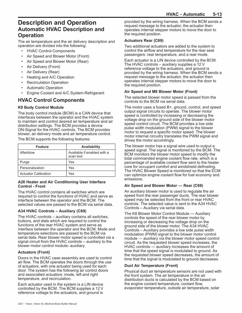
HVAC - Automatic 5-13
Description and OperationAutomatic HVAC Description andOperationThe air temperature and the air delivery description andoperation are divided into the following:
• HVAC Control Components• Air Speed and Blower Motor (Front)• Air Speed and Blower Motor (Rear)• Air Delivery (Front)• Air Delivery (Rear)• Heating and A/C Operation• Recirculation Operation• Automatic Operation• Engine Coolant and A/C System Refrigerant
HVAC Control ComponentsK9 Body Control Module
The body control module (BCM) is a CAN device thatinterfaces between the operator and the HVAC systemto maintain and control desired air temperature and airdistribution settings. The BCM provides a deviceON-Signal for the HVAC controls. The BCM providesblower, air delivery mode and air temperature control.The BCM supports the following features:
Feature Availability
Afterblow Available if enabled with ascan tool
Purge Yes
Personalization Yes
Actuator Calibration Yes
A26 Heater and Air Conditioning User InterfaceControl - Front
The HVAC control contains all switches which arerequired to control the functions of HVAC and serve asinterface between the operator and the BCM. Theselected values are passed to the BCM via serial data.
A34 HVAC Controls – Auxiliary (C69)
The HVAC controls – auxiliary contains all switches,buttons, and dials which are required to control thefunctions of the rear HVAC system and serve asinterface between the operator and the BCM. Mode andtemperature selections are passed to the BCM viaserial data. Rear blower motor speed is controlled via asignal circuit from the HVAC controls – auxiliary to theblower motor control module- auxiliary.
Actuators (Front)
Doors in the HVAC case assembly are used to controlair flow. The BCM operates the doors through the useof actuators, with one actuator being used for eachdoor. The system has the following air control doorsand associated actuators: mode, left and righttemperature, and recirculation.
Each actuator used in the system is a LIN devicecontrolled by the BCM. The BCM supplies a 12 Vreference voltage to the actuators, and ground is
provided by the wiring harness. When the BCM sends arequest message to the actuator, the actuator thenoperates internal stepper motors to move the door tothe required position.
Actuators Rear (C69)
Two additional actuators are added to the system tocontrol the airflow and temperature for the rear seatpassengers: rear temperature, and a rear mode.
Each actuator is a LIN device controlled by the BCM.The HVAC controls – auxiliary supplies a 12 Vreference voltage to the actuators, and ground isprovided by the wiring harness. When the BCM sends arequest message to the actuator, the actuator thenoperates internal stepper motors to move the door tothe required position.
Air Speed and M8 Blower Motor (Front)
The selected blower motor speed is passed from thecontrols to the BCM via serial data.
The motor uses a fused B+, ground, control, and speedoutput signal circuits to operate. The blower motorspeed is controlled by increasing or decreasing thevoltage drop on the ground side of the blower motorspeed control circuit. The BCM provides a low sidepulse width modulation (PWM) signal to the blowermotor to request a specific motor speed. The blowermotor internal circuitry translates the PWM signal anddrives the motor accordingly.
The blower motor has a signal wire used to output aspeed signal. The signal is monitored by the BCM. TheBCM monitors the blower motor speed to modify thetotal commanded engine coolant flow rate, which is apercentage of available coolant flow sent to the heatercore for occupant comfort and windshield defrosting.The HVAC Blower Speed is monitored so that the ECMcan optimize engine coolant flow for fuel economy andemissions.
Air Speed and Blower Motor — Rear (C69)
An auxiliary blower motor is used to regulate the airspeed from the rear passenger ducts. The rear blowerspeed may be selected from the front or rear HVACcontrols. The selected value is sent to the A34 HVACControls – Auxiliary via serial data.
The K8 Blower Motor Control Module — Auxiliarycontrols the speed of the rear blower motor byincreasing or decreasing the voltage drop on theground side of the blower motor. The A34 HVACControls – Auxiliary provides a low side pulse widthmodulation (PWM) signal to the blower motor controlmodule — auxiliary via the blower motor speed controlcircuit. As the requested blower speed increases, theHVAC controls — auxiliary increases the amount oftime that the speed signal is modulated to ground. Asthe requested blower speed decreases, the amount oftime that the signal is modulated to ground decreases.
Duct Air Temperature (Front)
Physical duct air temperature sensors are not used withthe front system. The air temperature in the airdistribution ducts is calculated by the BCM based onthe engine coolant temperature, coolant flow,evaporator temperature, outside air temperature, solar
2021 - Yukon, Yukon XL Electrical Body Builder Manual

5-14 HVAC - Automatic
load, blower motor speed, air inlet door position, andtemperature door position information. The BCM usesthe values to calculate actuator position.
Duct Temperature Sensors– Rear (C69)
The air temperature sensors are 2-wire negativetemperature co-efficient thermistors. The sensorsoperate within a temperature range of −40 to +85°C(−40 to +185°F). The sensors are installed in the airdistribution ducts and measure the temperature of theair that streams from the ducts. The HVAC controlmodule uses these values to calculate the mixed airdoor position.
A signal circuit to each sensor and a common lowreference circuit is provided by the A34 HVAC Controls– Auxiliary.
B39 Air Conditioning Evaporator Air TemperatureSensor
The evaporator temperature sensor is a 2-wire negativetemperature coefficient thermistor. The sensor operateswithin a temperature range of −40 to +85°C (−40 to+185°F). The sensor is installed near the evaporatorcore to measure the air temperature exiting the core.
Based on vehicle operating conditions and operatorsettings, the HVAC software algorithms will determine atarget evaporator air temperature. The operation of thecompressor solenoid will be adjusted as needed toquickly reach and maintain the targeted temperature.
B1 Air Conditioning Refrigerant Pressure Sensor
The A/C refrigerant pressure sensor is a 3-wirepiezoelectric pressure transducer. A 5 V referencevoltage, low reference, and signal circuits enable thesensor to operate. The A/C pressure signal can bebetween 0.2–4.8 V. When the A/C refrigerant pressureis low, the signal value is near 0 V. When the A/Crefrigerant pressure is high, the signal value is near 5 V.The engine control module (ECM) converts the voltagesignal to a pressure value. When pressure is too high ortoo low, the ECM will not allow the A/C compressorclutch to engage.
G1 Air Conditioning Compressor
The A/C compressor uses a conventional belt drivenmagnetic clutch to engage and mechanically turn thecompressor. When the A/C switch is pressed, the BCMsends an A/C request message to the ECM via serialdata. If specific criteria is met, the ECM then groundsthe A/C compressor clutch relay control circuit, whichwill switch the A/C compressor clutch relay. With therelay contacts closed, battery voltage is supplied to thepermanently grounded A/C compressor clutch. The A/Ccompressor clutch will then be activated.
This A/C system utilizes a variable displacementsolenoid valve to alter the amount of displacementcreated by the turning of the compressor. The BCMprovides both battery voltage and a pulse widthmodulated ground to the Q46 Air ConditioningCompressor Solenoid Valve. When the A/C switch ispressed, the BCM grounds the variable displacementsolenoid using a (PWM) signal in order to determine theamount of compressor displacement. The performanceof the A/C compressor is regulated based oncooling load.
B160 Inside Air Moisture and WindshieldTemperature Sensor
The windshield temperature and inside moisture sensorincludes the relative humidity sensor, windshieldtemperature sensor and humidity sensing elementtemperature sensor.This sensor assembly provides information about:
• Relative humidity level at windshield (passengercompartment side)
• Temperature of the windshield (passengercompartment side)
• Temperature of the humidity sensor elementThe relative humidity sensor measures the relativehumidity of the passenger compartment side of thewindshield. It also detects the temperature of thewindshield surface on the passenger compartmentside. Both values are used as control inputs for theBCM application to calculate the fog risk on windshieldcompartment side and ability to reduce fuelconsumption by decreasing A/C compressor power to aminimum without causing any fog. The sensor will alsoenable partial recirculation mode in order to improveheat-up performance of the passenger compartmentunder cold ambient temperature conditions without therisk of mist build-up on the windshield. The humiditysensor element temperature sensor supplies thetemperature of the humidity sensor element. It is onlyneeded if the thermal contact between the humiditysensing element and the inside windshield surface isnot sufficient.The sensor is part of a LIN windshield sensor array, andthe windshield temperature and humidity values aretransmitted to the BCM via serial data.
B10B Sunload, Temperature and Ambient Light andSecurity Sensor
The ambient light/sunload sensor includes the solarsensor and passenger compartment temperaturesensor.
The solar sensor is connected to a low reference and 5V supply through the BCM. As the sunload increases,the sensor signal voltage also increases and viceversa. The signal provided to the BCM varies between1.2–4.85 V.
The passenger compartment temperature sensor is anegative temperature coefficient thermistor, connectedto a low reference and 5 V supply through the BCM. Asthe air temperature increases, the sensor resistancedecreases. The signal varies between 0–5 V.
Bright or high intensity light can cause the vehiclesinterior temperature to increase. The HVAC systemuses the sensor values and compensates for theincreased temperature to maintain the system settings.
AfterblowAfterblow is a feature that dries the evaporator core byoperating the blower motor after the engine is turnedOFF. This reduces the amount of microbial growth thatcan create undesirable odors. The vehicle does notcome equipped with the afterblow feature turned ON.If the afterblow feature is desired due to an odorconcern, it must be enabled using the scan toolAfterblow Configuration function.
2021 - Yukon, Yukon XL Electrical Body Builder Manual

HVAC - Automatic 5-15
When the BCM is enabled for afterblow, the followingconditions must be met for afterblow to operate:
• The vehicle has been OFF for at least 30 minutes.• The ambient air temperature is at least 11°C
(52°F).• The A/C compressor operated for more than
5 minutes before shut down.• The system voltage is at least 12 V.
Once the above conditions have been met, the blowermotor will perform the following sequence up to 4 times.This could last up to an hour:
1. The blower motor will be OFF for 7–15 minutes.2. The blower motor will RUN for approximately
30 seconds.
Air Delivery (Front)The BCM controls the distribution of air by the use ofrecirculation and mode door actuators. The modes thatmay be selected are:
• Defrost: windshield outlet• Panel: dashboard outlets• Floor: front footwell outlets• Defog: defrost + floor• Bi-level: panel + floor• Tri-level: panel + defrost + floor• Hi-level: panel + defrost
The desired air distribution mode can be selected withthe air distribution switches at the HVAC control. TheHVAC control delivers the values to the BCM via serialdata. The BCM sends a request to the mode dooractuator to move the door to the required position.Depending on the position of the door, air is distributedthrough various ducts leading to the outlets in the dash.When defrost airflow is active, the BCM will move therecirculation actuator to outside air, to aid in reducingwindow fogging. When defrost is selected the blowermotor will be activated, regardless of the coolanttemperature. A/C is available in all modes.Refer to the owners manual for operation of the HVACcontrols and mode selection.
Recirculation Operation
The recirculation switch is integrated into the HVACcontrol. The selected recirculation setting is sent to theBCM via serial data. The BCM controls the air intakeusing the recirculation actuator. In recirculation modethe recirculation door is positioned to block outside airfrom entering and circulate the air within the vehicle. Inoutside air mode the recirculation door is positioned toroute outside air into the vehicle.
Recirculation is only available if the defrost mode is notactive. When the defrost mode is active, therecirculation actuator positions the recirculation door sothat outside air is circulated to the windshield to reducefogging.
In automatic mode the values of the sensors are usedas inputs for the BCM to calculate the fog risk on thepassenger compartment side of the windshield. The A/C compressor and the defrost mode may be activatedto prevent or remove fog on the passengercompartment side of the windshield.
In automatic mode, a partial recirculation mode may becommanded to accelerate cabin heating or cooling andreduce energy usage. The recirculation indicatorremains illuminated at all times, regardless of the actualoperating mode determined by the system.
Air Delivery — Rear (C69)The BCM control module controls the distribution of airby the mode door actuator – auxiliary. The modes thatmay be selected are:
• AUTO• Floor• Bi-Level• Vent
The desired rear air distribution mode can be selectedwith the Mode switch at the HVAC control – auxiliary.The HVAC control – auxiliary delivers the values to theBCM via serial data. The BCM controls the mode dooractuator – auxiliary via LIN bus to move the door to thecalculated position. Depending on the position of thedoor, air is distributed through various ducts.
Heating and A/C OperationThe purpose of the heating and A/C system is toprovide heated and cooled air to the interior of thevehicle. The A/C system will also remove humidity fromthe interior and reduce windshield fogging. Regardlessof the temperature setting, the following may affect therate that the HVAC system can achieve the desiredtemperature:
• Recirculation setting• Difference between inside and desired
temperature• Blower motor speed setting• Mode setting• Dashboard outlet open/closed position
When the A/C switch or the AUTO switch is pressed,the HVAC control sends a signal to the BCM via serialdata. The BCM evaluates this signal and sends an A/Crequest signal to the ECM via CAN-Bus. The ECMchecks all preconditions before releasing and if allconditions are met sends a release signal back to theBCM. The A/C compressor is activated by the BCM.The BCM supplies battery voltage to the A/Ccompressor solenoid. When the A/C switch is pressed,the BCM provides a pulse width modulation (PWM)signal to the A/C compressor solenoid in order tocommand the performance of the A/C compressor. Theperformance of the A/C compressor is regulated usingevaporator temperature and engine load.The A/C indicator does not indicate the compressor iscurrently active. The A/C indicator shows that A/C hasbeen requested and the system will activate thecompressor as needed.The following conditions must be met in order toactivate the A/C compressor:
• Battery voltage is between 9–18 V• Engine coolant temperature is less than 124°C
(255°F)• Engine speed is greater than 600 RPM• Engine speed is less than 5 500 RPM
2021 - Yukon, Yukon XL Electrical Body Builder Manual

5-16 HVAC - Automatic
• A/C high side pressure is between 269–2 929 kPa(39–425 PSI)
• Throttle position is less than 100%• Evaporator temperature is greater than 3°C (38°F)• ECM does not detect immoderate torque load• ECM does not detect insufficient idle quality• The ambient temperature is above 1°C (34°F)
The sensor information is used by the ECM todetermine the following:
• The A/C high side pressure• An A/C system load on the engine• An immoderate A/C high side pressure• The heat load at the A/C condenser
The air streams into the passenger compartmentthrough the heater core and the evaporator core. Theair temperature actuator drives the mixed air door todirect the airflow. If the interior temperature should beincreased, the mixed air door is put into the position inwhich more air streams through the heater core. If theinterior temperature should be decreased, the mixed airdoor is put into the position in which more air streamsthrough the evaporator core.
Automatic OperationIn automatic operation, the BCM maintains the comfortlevel inside of the vehicle by controlling the A/Ccompressor solenoid, the blower motor, the airtemperature actuators, mode actuator and recirculationactuator.The automatic mode indicator shows that the system isin full automatic operation. If an individual setting ischanged (excluding temperature), the automaticindicator will turn off, and that function will enter manualcontrol. All other functions will remain under automaticcontrol unless manually changed.To put the HVAC system in automatic mode, thefollowing is required:
1. The auto switch must be activated.2. The air temperature switch must not be in either
the full hot or full cold position.Once the desired temperature is reached, the blowermotor, mode, recirculation and temperature actuatorsautomatically adjust to maintain the temperatureselected. The BCM performs the following functions tomaintain the desired air temperature:
• Monitors the following:– Ambient (outside) air temperature sensor– Passenger compartment temperature sensor– Calculated front duct air temperatures– Auxiliary duct air temperature sensors (C69)– Windshield temperature and inside moisture
sensor– Evaporator temperature sensor– Ambient light/sunload sensor
• Regulate the blower motor speed• Regulate the rear blower motor speed (C69)• Position the air temperature actuators• Position the mode door actuators
• Position the recirculation actuator• Control of the A/C compressor solenoid
When the temperature setting is set to full hot, theblower speed will increase gradually as the coolantwarms to normal operating temperature. When normalengine operating temperature is reached the blowerstays on high speed and the air temperature actuatorsstays in the full heat position.When the temperature setting is set to full cold, theblower will immediately operate at high speed and theair temperature actuators move to full cold position. Themode actuator moves to the panel position and therecirculation actuator moves to the recirculationposition.Under cold ambient temperatures, the automatic HVACsystem provides heat in the most efficient manner. Theoperator can select an extreme temperature setting butthe system will not warm the vehicle any faster. Underwarm ambient temperatures, the automatic HVACsystem also provides air conditioning in the mostefficient manner. Selecting an extreme cooltemperature will not cool the vehicle any faster.In automatic mode the values of the windshieldtemperature and inside moisture sensor are used ascontrol inputs for the BCM application to calculate thefog risk on the passenger compartment side of thewindshield and ability to reduce fuel consumption bydecreasing A/C compressor power to a minimumwithout causing any fog. The A/C compressor and thedefrost mode are activated to prevent or remove fog onthe passenger compartment side of the windshield. Thesensor will also enable partial recirculation mode inorder to improve heat-up performance of the passengercompartment under cold ambient temperatureconditions without the risk of mist build-up on thewindshield.
Engine Coolant and A/C SystemRefrigerantFor information on engine coolant, coolant flow, A/Crefrigerant, and the A/C refrigerant cycle, refer toHeating and Air Conditioning System Description andOperation.
2021 - Yukon, Yukon XL Electrical Body Builder Manual

Table of Contents 6-1
Section 6
Power and Signal Distribution
Data Communications . . . . . . . . . . . . . . . . . . . . . . . . . 6-3Schematic and Routing Diagrams . . . . . . . . . . . . . . . 6-3
Data Communication Schematics . . . . . . . . . . . . . . . . 6-4Body Control System Schematics . . . . . . . . . . . . . . 6-24
Description and Operation . . . . . . . . . . . . . . . . . . . . . . 6-27Data Link Communications Description and
Operation . . . . . . . . . . . . . . . . . . . . . . . . . . . . . . . . . . . . . . 6-27
Electrical Component and Inline HarnessConnector End Views . . . . . . . . . . . . . . . . . . . . . . . 6-30Visual Identification . . . . . . . . . . . . . . . . . . . . . . . . . . . . . 6-30
Electrical Center Identification Views . . . . . . . . . . . 6-30Component Connector End Views . . . . . . . . . . . . . . 6-75Inline Harness Connector End Views . . . . . . . . . . 6-374
Power Outlets . . . . . . . . . . . . . . . . . . . . . . . . . . . . . . . 6-536Schematic and Routing Diagrams . . . . . . . . . . . . 6-536
Cigar Lighter/Power Outlet Schematics . . . . . . . 6-537Description and Operation . . . . . . . . . . . . . . . . . . . . 6-543
Mobile Device Wireless Charger Descriptionand Operation . . . . . . . . . . . . . . . . . . . . . . . . . . . . . . . . 6-543
Power Outlets Description and Operation . . . . . 6-543
Wiring Systems and PowerManagement . . . . . . . . . . . . . . . . . . . . . . . . . . . . . . . . 6-546Schematic and Routing Diagrams . . . . . . . . . . . . 6-546
Power Distribution Schematics . . . . . . . . . . . . . . . . 6-547Power Moding Schematics . . . . . . . . . . . . . . . . . . . . 6-575Ground Distribution Schematics . . . . . . . . . . . . . . . 6-577Upfitter Provision Schematics . . . . . . . . . . . . . . . . . 6-601
Component Locator . . . . . . . . . . . . . . . . . . . . . . . . . . . . 6-616Master Electrical Component List . . . . . . . . . . . . . 6-616
Description and Operation . . . . . . . . . . . . . . . . . . . . 6-685Power Mode Description and Operation . . . . . . . 6-685Retained Accessory Power Description and
Operation . . . . . . . . . . . . . . . . . . . . . . . . . . . . . . . . . . . . 6-687
2021 - Yukon, Yukon XL Electrical Body Builder Manual

6-2 Table of Contents
BLANK
2021 - Yukon, Yukon XL Electrical Body Builder Manual
Data Communications 6-3
Data Communications
Schematic and Routing Diagrams
2021 - Yukon, Yukon XL Electrical Body Builder Manual

6-4 Data CommunicationsD
ata
Co
mm
un
ica
tio
nS
ch
em
ati
cs
(Da
taL
ink
Co
nn
ec
tor
an
dS
eri
alD
ata
Ga
tew
ay
Mo
du
leP
ow
er
an
dG
rou
nd
)
53
71
04
7
2021 - Yukon, Yukon XL Electrical Body Builder Manual

Data Communications 6-5D
ata
Co
mm
un
ica
tio
nS
ch
em
ati
cs
(CA
N1
(1o
f2
))
53
71
03
8
2021 - Yukon, Yukon XL Electrical Body Builder Manual

6-6 Data CommunicationsD
ata
Co
mm
un
ica
tio
nS
ch
em
ati
cs
(CA
N1
(2o
f2
))
53
71
03
9
2021 - Yukon, Yukon XL Electrical Body Builder Manual
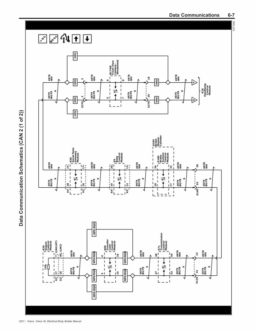
Data Communications 6-7D
ata
Co
mm
un
ica
tio
nS
ch
em
ati
cs
(CA
N2
(1o
f2
))
53
71
04
0
2021 - Yukon, Yukon XL Electrical Body Builder Manual
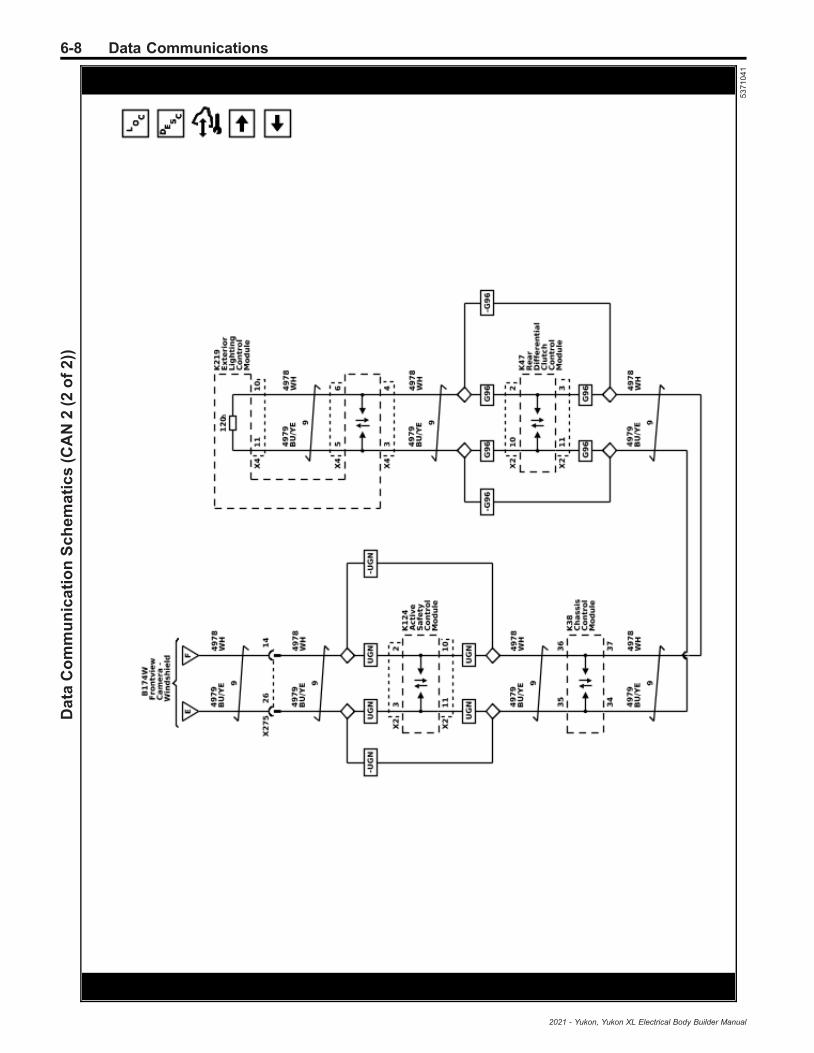
6-8 Data CommunicationsD
ata
Co
mm
un
ica
tio
nS
ch
em
ati
cs
(CA
N2
(2o
f2
))
53
71
04
1
2021 - Yukon, Yukon XL Electrical Body Builder Manual

Data Communications 6-9D
ata
Co
mm
un
ica
tio
nS
ch
em
ati
cs
(CA
N3
)
53
71
04
2
2021 - Yukon, Yukon XL Electrical Body Builder Manual

6-10 Data CommunicationsD
ata
Co
mm
un
ica
tio
nS
ch
em
ati
cs
(CA
N4
(1o
f2
))
53
71
04
3
2021 - Yukon, Yukon XL Electrical Body Builder Manual
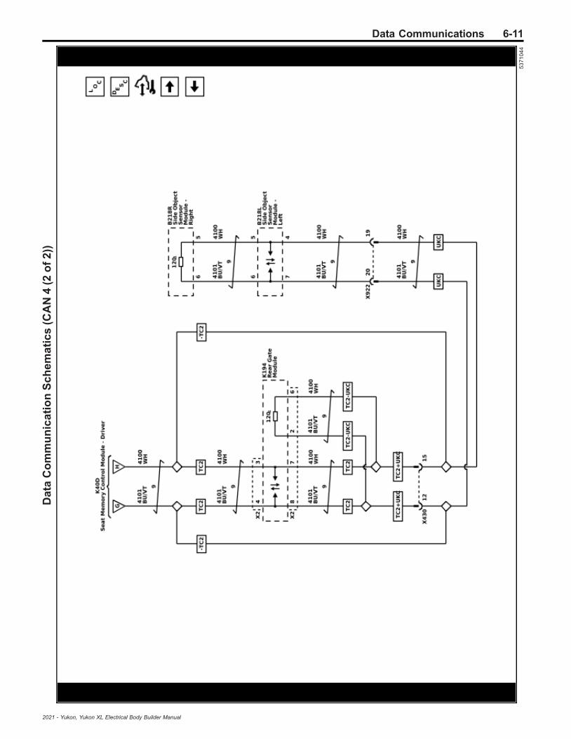
Data Communications 6-11D
ata
Co
mm
un
ica
tio
nS
ch
em
ati
cs
(CA
N4
(2o
f2
))
53
71
04
4
2021 - Yukon, Yukon XL Electrical Body Builder Manual

6-12 Data CommunicationsD
ata
Co
mm
un
ica
tio
nS
ch
em
ati
cs
(CA
N5
)
53
71
04
5
2021 - Yukon, Yukon XL Electrical Body Builder Manual
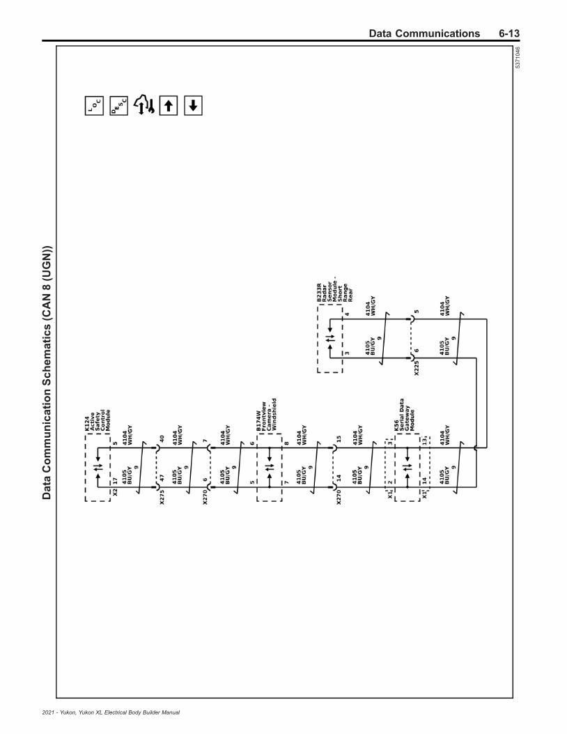
Data Communications 6-13D
ata
Co
mm
un
ica
tio
nS
ch
em
ati
cs
(CA
N8
(UG
N))
53
71
04
6
2021 - Yukon, Yukon XL Electrical Body Builder Manual

6-14 Data CommunicationsD
ata
Co
mm
un
ica
tio
nS
ch
em
ati
cs
(Po
we
rtra
inC
AN
)
53
71
04
8
2021 - Yukon, Yukon XL Electrical Body Builder Manual

Data Communications 6-15D
ata
Co
mm
un
ica
tio
nS
ch
em
ati
cs
(Po
we
rtra
inC
AN
En
ab
le)
53
71
04
9
2021 - Yukon, Yukon XL Electrical Body Builder Manual

6-16 Data CommunicationsD
ata
Co
mm
un
ica
tio
nS
ch
em
ati
cs
(Bo
dy
Co
ntr
olM
od
ule
Lo
ca
lIn
terc
on
ne
ct
Ne
two
rk(L
IN)
Bu
ss
es
2,3
,an
d4
)
53
71
05
2
2021 - Yukon, Yukon XL Electrical Body Builder Manual

Data Communications 6-17D
ata
Co
mm
un
ica
tio
nS
ch
em
ati
cs
(Bo
dy
Co
ntr
olM
od
ule
Lo
ca
lIn
terc
on
ne
ct
Ne
two
rk(L
IN)
Bu
ss
es
5,6
,7,a
nd
8)
53
71
05
3
2021 - Yukon, Yukon XL Electrical Body Builder Manual

6-18 Data CommunicationsD
ata
Co
mm
un
ica
tio
nS
ch
em
ati
cs
(Bo
dy
Co
ntr
olM
od
ule
Lo
ca
lIn
terc
on
ne
ct
Ne
two
rk(L
IN)
Bu
ss
es
9,1
0,a
nd
11)
53
71
05
4
2021 - Yukon, Yukon XL Electrical Body Builder Manual
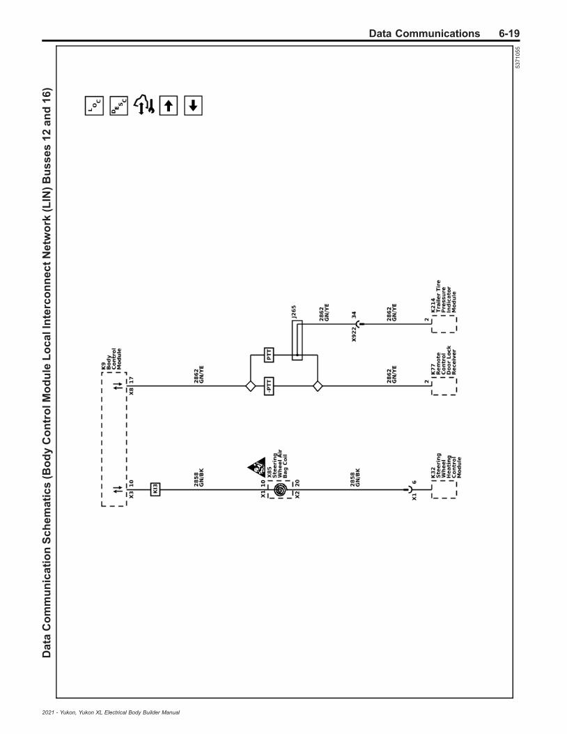
Data Communications 6-19D
ata
Co
mm
un
ica
tio
nS
ch
em
ati
cs
(Bo
dy
Co
ntr
olM
od
ule
Lo
ca
lIn
terc
on
ne
ct
Ne
two
rk(L
IN)
Bu
ss
es
12
an
d1
6)
53
71
05
5
2021 - Yukon, Yukon XL Electrical Body Builder Manual

6-20 Data CommunicationsD
ata
Co
mm
un
ica
tio
nS
ch
em
ati
cs
(Bra
ke
Sy
ste
mC
on
tro
lMo
du
leL
oc
alI
nte
rco
nn
ec
tN
etw
ork
(LIN
)B
us
se
s1
an
d2
) 53
71
05
6
2021 - Yukon, Yukon XL Electrical Body Builder Manual

Data Communications 6-21D
ata
Co
mm
un
ica
tio
nS
ch
em
ati
cs
(En
gin
eC
on
tro
lMo
du
leL
oc
alI
nte
rco
nn
ec
tN
etw
ork
(LIN
)B
us
se
s1
,2,3
,an
d4
)
53
71
05
7
2021 - Yukon, Yukon XL Electrical Body Builder Manual

6-22 Data CommunicationsD
ata
Co
mm
un
ica
tio
nS
ch
em
ati
cs
(Lo
ca
lIn
terc
on
ne
ct
Ne
two
rk(L
IN))
53
71
05
8
2021 - Yukon, Yukon XL Electrical Body Builder Manual
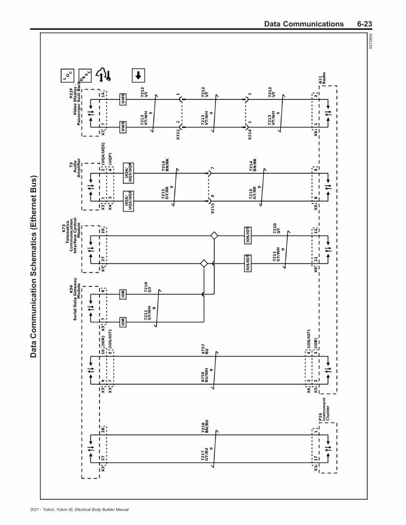
Data Communications 6-23D
ata
Co
mm
un
ica
tio
nS
ch
em
ati
cs
(Eth
ern
et
Bu
s)
54
70
85
0
2021 - Yukon, Yukon XL Electrical Body Builder Manual

6-24 Data CommunicationsB
od
yC
on
tro
lSy
ste
mS
ch
em
ati
cs
(Po
we
r,G
rou
nd
,Se
ria
lDa
ta,a
nd
Su
bs
ys
tem
Re
fere
nc
es
(1o
f3
))
53
71
02
3
2021 - Yukon, Yukon XL Electrical Body Builder Manual

Data Communications 6-25B
od
yC
on
tro
lSy
ste
mS
ch
em
ati
cs
(Su
bs
ys
tem
Re
fere
nc
es
(2o
f3
))
53
71
02
5
2021 - Yukon, Yukon XL Electrical Body Builder Manual

6-26 Data CommunicationsB
od
yC
on
tro
lSy
ste
mS
ch
em
ati
cs
(Su
bs
ys
tem
Re
fere
nc
es
(3o
f3
))
53
71
02
6
2021 - Yukon, Yukon XL Electrical Body Builder Manual

Data Communications 6-27
Description and OperationData Link CommunicationsDescription and OperationNote: This is an overview of different serial data busesused by control modules to communicate with eachothers. Use Data Communication Schematicson page 6‑4 to find out which serial data buses areconfigured for a specific vehicle.
Data Link Communications OverviewThere are many components in a vehicle that rely oninformation from other sources, transmit information toother sources, or both. Serial data communicationnetworks provide a reliable, cost effective, way forvarious components of the vehicle to “talk” to oneanother and share information.General Motors uses a number of differentcommunication buses to insure the timely and efficientexchange of information between control modules.When compared to each other, some of these busesare different in nature as far as speed, signalcharacteristics, and behavior.On the other hand, when other buses are compared toeach other they have similar characteristics and simplyoperate in parallel. In this case they are used to grouptogether components which have high interaction.Examples are the Controller Area Network (CAN),private CAN, and LIN buses. This allows them tocommunicate with each other on a bus with reducedmessage congestion insuring faster and the moretimely exchange of information than if all vehicle controlmodules were on a single bus.The majority of information that exists within a givennetwork generally stays local; however someinformation will have to be shared on other networks.Control modules designated as Gateway’s perform thefunction of transferring information between the variousbuses. A Gateway module is connected to at least 2buses and will interact with each network according toits message strategy and transmission models.CAN provides the capability for a receiving controlmodule to monitor message transmissions from othercontrol modules in order to determine if messages ofinterest are not being received. The primary purpose isto allow reasonable default values to be substituted forthe information no longer being received. Additionally, acontrol module may set a Diagnostic Trouble Code(DTC) to indicate that the control module it is expectinginformation from is no longer communicating.
K9 Body Control Module (BCM)The body control system consists of the K9 BodyControl Module, communications, and various inputand outputs. Some inputs, outputs and messagesrequire other control modules to interact with theK9 Body Control Module. The K9 Body Control Modulealso has discrete input and output terminals to controlthe vehicle's body functions. The K9 Body ControlModule is wired to CAN 2 serial data bus and multipleLocal Interconnect Network (LIN) buses and acts as agateway between them.
The various K9 Body Control Module input and outputcircuits are illustrated in the corresponding functionalareas on the K9 Body Control Module electricalschematics. Refer to the Body Control SystemSchematics on page 6‑24 for more detailed information.
K56 Serial Data Gateway ModuleThe K56 Serial Data Gateway Module gates messagesbetween the CAN networks described in the ControllerArea Network (CAN) Bus Description section below.The K56 Serial Data Gateway Module needs to knowwhat CAN control modules are present on a givenvehicle in order to enable/disable loss ofcommunication DTCs and to know what CAN controlmodules to track for their communication status. TheK56 Serial Data Gateway Module has the ability tolearn the diagnostic addresses list of CAN controlmodules to identify what CAN control modules areequipped on the vehicle and what CAN buses they areon. If the K56 Serial Data Gateway Module is replaced,this learn/verification process will have to be doneagain through K56 Serial Data Gateway Moduleprogramming and setup procedure in SPS. This learnprocess will not cause any previously learned contentsto be forgotten/overwritten. If the learn process is notdone on a new K56 Serial Data Gateway Module,DTC U1977 will be set until the learn procedure isexecuted. If the learn is invalid due to control moduleinternal malfunction or a K56 Serial Data GatewayModule swap, DTC U3000 42 or DTC U3002 56 will beset. If any of these DTCs sets, the K56 Serial DataGateway Module will enable loss of communication forall CAN control modules. This will result in loss ofcommunication DTCs being set against CAN controlmodules that are not equipped on the vehicle.A fault can be localized by monitoring the normal modemessages on a CAN bus. The K56 Serial DataGateway Module will monitor one signal per CANcontrol module per CAN bus to determine controlmodule status. When a signal times out, a loss ofcommunication event will be started.
Controller Area Network (CAN) BusDescriptionThe CAN buses are used where data needs to beexchanged at a high enough rate to minimize the delaybetween the occurrence of a change in sensor valueand the reception of this information by a control deviceusing the information to adjust vehicle systemperformance.Each CAN serial data network consists of two twistedwires. One signal circuit is identified as CAN-High andthe other signal circuit is identified as CAN-Low. Ateach end of the data bus there is a 120 Ω terminationresistor between the CAN-High and CAN-Low circuits.The data to be transmitted over a CAN bus isrepresented by the voltage difference between theCAN-High signal voltage and the CAN-Low signalvoltage. Data symbols (1’s and 0’s) are transmittedsequentially at the following rate:
• CAN 1 (circuits 4986 & 4987) = 500 Kbit/s• CAN 2 (circuits 4978 & 4979) = 2 Mbit/s• CAN 3 (circuits 4976 & 4977) = 500 Kbit/s• CAN 4 (circuits 4100 & 4101) = 500 Kbit/s
2021 - Yukon, Yukon XL Electrical Body Builder Manual
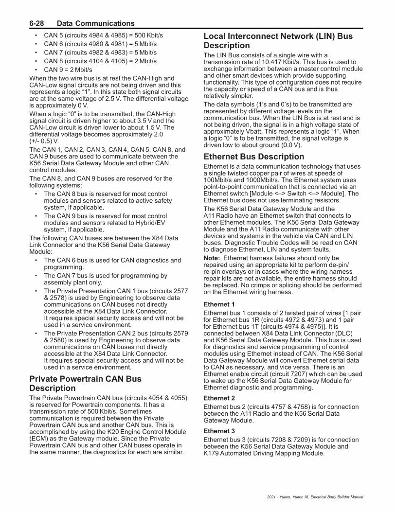
6-28 Data Communications
• CAN 5 (circuits 4984 & 4985) = 500 Kbit/s• CAN 6 (circuits 4980 & 4981) = 5 Mbit/s• CAN 7 (circuits 4982 & 4983) = 5 Mbit/s• CAN 8 (circuits 4104 & 4105) = 2 Mbit/s• CAN 9 = 2 Mbit/s
When the two wire bus is at rest the CAN-High andCAN-Low signal circuits are not being driven and thisrepresents a logic “1”. In this state both signal circuitsare at the same voltage of 2.5 V. The differential voltageis approximately 0 V.When a logic “0” is to be transmitted, the CAN-Highsignal circuit is driven higher to about 3.5 V and theCAN-Low circuit is driven lower to about 1.5 V. Thedifferential voltage becomes approximately 2.0(+/- 0.5) V.The CAN 1, CAN 2, CAN 3, CAN 4, CAN 5, CAN 8, andCAN 9 buses are used to communicate between theK56 Serial Data Gateway Module and other CANcontrol modules.The CAN 8, and CAN 9 buses are reserved for thefollowing systems:
• The CAN 8 bus is reserved for most controlmodules and sensors related to active safetysystem, if applicable.
• The CAN 9 bus is reserved for most controlmodules and sensors related to Hybrid/EVsystem, if applicable.
The following CAN buses are between the X84 DataLink Connector and the K56 Serial Data GatewayModule:
• The CAN 6 bus is used for CAN diagnostics andprogramming.
• The CAN 7 bus is used for programming byassembly plant only.
• The Private Presentation CAN 1 bus (circuits 2577& 2578) is used by Engineering to observe datacommunications on CAN buses not directlyaccessible at the X84 Data Link Connector.It requires special security access and will not beused in a service environment.
• The Private Presentation CAN 2 bus (circuits 2579& 2580) is used by Engineering to observe datacommunications on CAN buses not directlyaccessible at the X84 Data Link Connector.It requires special security access and will not beused in a service environment.
Private Powertrain CAN BusDescriptionThe Private Powertrain CAN bus (circuits 4054 & 4055)is reserved for Powertrain components. It has atransmission rate of 500 Kbit/s. Sometimescommunication is required between the PrivatePowertrain CAN bus and another CAN bus. This isaccomplished by using the K20 Engine Control Module(ECM) as the Gateway module. Since the PrivatePowertrain CAN bus and other CAN buses operate inthe same manner, the diagnostics for each are similar.
Local Interconnect Network (LIN) BusDescriptionThe LIN Bus consists of a single wire with atransmission rate of 10.417 Kbit/s. This bus is used toexchange information between a master control moduleand other smart devices which provide supportingfunctionality. This type of configuration does not requirethe capacity or speed of a CAN bus and is thusrelatively simpler.The data symbols (1’s and 0’s) to be transmitted arerepresented by different voltage levels on thecommunication bus. When the LIN Bus is at rest and isnot being driven, the signal is in a high voltage state ofapproximately Vbatt. This represents a logic “1”. Whena logic “0” is to be transmitted, the signal voltage isdriven low to about ground (0.0 V).
Ethernet Bus DescriptionEthernet is a data communication technology that usesa single twisted copper pair of wires at speeds of100Mbit/s and 1000Mbit/s. The Ethernet system usespoint-to-point communication that is connected via anEthernet switch [Module <–> Switch <–> Module]. TheEthernet bus does not use terminating resistors.The K56 Serial Data Gateway Module and theA11 Radio have an Ethernet switch that connects toother Ethernet modules. The K56 Serial Data GatewayModule and the A11 Radio communicate with otherdevices and systems in the vehicle via CAN and LINbuses. Diagnostic Trouble Codes will be read on CANto diagnose Ethernet, LIN and system faults.Note: Ethernet harness failures should only berepaired using an appropriate kit to perform de-pin/re-pin overlays or in cases where the wiring harnessrepair kits are not available, the entire harness shouldbe replaced. No crimps or splicing should be performedon the Ethernet wiring harness.
Ethernet 1Ethernet bus 1 consists of 2 twisted pair of wires [1 pairfor Ethernet bus 1R (circuits 4972 & 4973) and 1 pairfor Ethernet bus 1T (circuits 4974 & 4975)]. It isconnected between X84 Data Link Connector (DLC)and K56 Serial Data Gateway Module. This bus is usedfor diagnostics and service programming of controlmodules using Ethernet instead of CAN. The K56 SerialData Gateway Module will convert Ethernet serial datato CAN as necessary, and vice versa. There is anEthernet enable circuit (circuit 7207) which can be usedto wake up the K56 Serial Data Gateway Module forEthernet diagnostic and programming.
Ethernet 2Ethernet bus 2 (circuits 4757 & 4758) is for connectionbetween the A11 Radio and the K56 Serial DataGateway Module.
Ethernet 3Ethernet bus 3 (circuits 7208 & 7209) is for connectionbetween the K56 Serial Data Gateway Module andK179 Automated Driving Mapping Module.
2021 - Yukon, Yukon XL Electrical Body Builder Manual
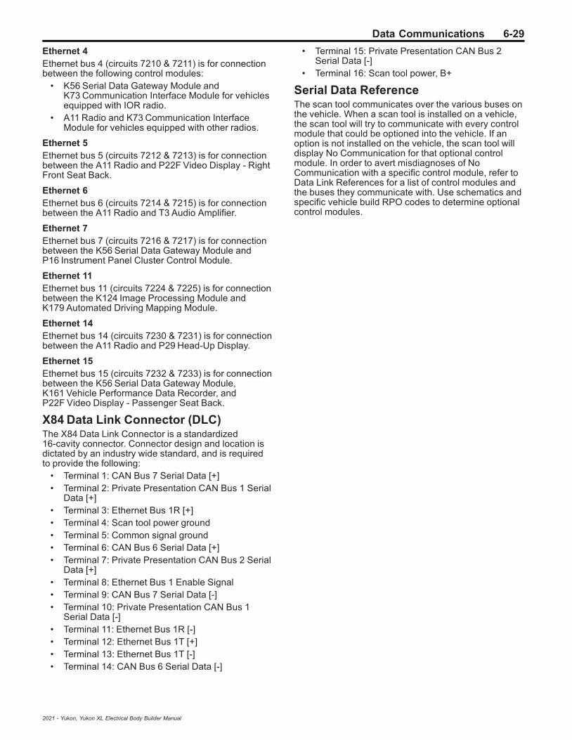
Data Communications 6-29
Ethernet 4Ethernet bus 4 (circuits 7210 & 7211) is for connectionbetween the following control modules:
• K56 Serial Data Gateway Module andK73 Communication Interface Module for vehiclesequipped with IOR radio.
• A11 Radio and K73 Communication InterfaceModule for vehicles equipped with other radios.
Ethernet 5Ethernet bus 5 (circuits 7212 & 7213) is for connectionbetween the A11 Radio and P22F Video Display - RightFront Seat Back.
Ethernet 6Ethernet bus 6 (circuits 7214 & 7215) is for connectionbetween the A11 Radio and T3 Audio Amplifier.
Ethernet 7Ethernet bus 7 (circuits 7216 & 7217) is for connectionbetween the K56 Serial Data Gateway Module andP16 Instrument Panel Cluster Control Module.
Ethernet 11Ethernet bus 11 (circuits 7224 & 7225) is for connectionbetween the K124 Image Processing Module andK179 Automated Driving Mapping Module.
Ethernet 14Ethernet bus 14 (circuits 7230 & 7231) is for connectionbetween the A11 Radio and P29 Head-Up Display.
Ethernet 15Ethernet bus 15 (circuits 7232 & 7233) is for connectionbetween the K56 Serial Data Gateway Module,K161 Vehicle Performance Data Recorder, andP22F Video Display - Passenger Seat Back.
X84 Data Link Connector (DLC)The X84 Data Link Connector is a standardized16-cavity connector. Connector design and location isdictated by an industry wide standard, and is requiredto provide the following:
• Terminal 1: CAN Bus 7 Serial Data [+]• Terminal 2: Private Presentation CAN Bus 1 Serial
Data [+]• Terminal 3: Ethernet Bus 1R [+]• Terminal 4: Scan tool power ground• Terminal 5: Common signal ground• Terminal 6: CAN Bus 6 Serial Data [+]• Terminal 7: Private Presentation CAN Bus 2 Serial
Data [+]• Terminal 8: Ethernet Bus 1 Enable Signal• Terminal 9: CAN Bus 7 Serial Data [-]• Terminal 10: Private Presentation CAN Bus 1
Serial Data [-]• Terminal 11: Ethernet Bus 1R [-]• Terminal 12: Ethernet Bus 1T [+]• Terminal 13: Ethernet Bus 1T [-]• Terminal 14: CAN Bus 6 Serial Data [-]
• Terminal 15: Private Presentation CAN Bus 2Serial Data [-]
• Terminal 16: Scan tool power, B+
Serial Data ReferenceThe scan tool communicates over the various buses onthe vehicle. When a scan tool is installed on a vehicle,the scan tool will try to communicate with every controlmodule that could be optioned into the vehicle. If anoption is not installed on the vehicle, the scan tool willdisplay No Communication for that optional controlmodule. In order to avert misdiagnoses of NoCommunication with a specific control module, refer toData Link References for a list of control modules andthe buses they communicate with. Use schematics andspecific vehicle build RPO codes to determine optionalcontrol modules.
2021 - Yukon, Yukon XL Electrical Body Builder Manual

6-30 Electrical Component and Inline Harness Connector End Views
Electrical Component and Inline Harness Connector EndViews
Visual Identification
Electrical Center Identification Views
X50D Fuse Block - Battery Top View
5070128
Usage Table
No.Device
Label NameDevice
Assigned Name Rating Description
Fuses
F1 — F1BA250A (L84/
L87)275A (LM2)
• G13 Generator• X50A Fuse Block - Underhood
F2 — F2BA 175A • K43 Power Steering Control Module
F3 — F3BA 400A • M64 Starter Motor
F4 — F4BA 150A • E40 Electrical Auxiliary Heater (C3A)
F5 — F5BA 100A • K20 Engine Control Module (LM2)
F6 — F6BA 80A • G10R Cooling Fan Motor - Right (LM2)
F7 — F7BA 60A • X51R Fuse Block - Instrument Panel Right
F8 — F8BA 60A • K160 Brake System Control Module
F9 — F9BA 5A • B110 Battery Sensor Module
2021 - Yukon, Yukon XL Electrical Body Builder Manual

Electrical Component and Inline Harness Connector End Views 6-31
X50D Fuse Block - Battery X1 (C3A)
5194789
Connector Part InformationHarness Type: BodyOEM Connector: 35085117Service Connector: Service by Cable Assembly — See Part CatalogDescription: 1-Way Ring Terminal
Terminal Part InformationTerminal Type ID Terminated Lead Diagnostic Test Probe Terminal Removal Tool
I Not Required No Tool Required No Tool Required
X50D Fuse Block - Battery X1 (C3A)Pin Size Color Circuit Function Terminal
Type IDOption
A 16 RD/GY 642 Primary Fused Battery Positive Voltage 6 I —
X50D Fuse Block - Battery X3 (LM2)
4994507
Connector Part InformationHarness Type: EngineOEM Connector: 35085183Service Connector: Service by Cable Assembly — See Part CatalogDescription: 1-Way Ring Terminal
2021 - Yukon, Yukon XL Electrical Body Builder Manual

6-32 Electrical Component and Inline Harness Connector End Views
Terminal Part InformationTerminal Type ID Terminated Lead Diagnostic Test Probe Terminal Removal Tool
I Not Required No Tool Required No Tool Required
X50D Fuse Block - Battery X3 (LM2)Pin Size Color Circuit Function Terminal
Type IDOption
A 10 RD/YE 1442 Primary Fused Battery Positive Voltage 14 I —
X50D Fuse Block - Battery X5
4994183
Connector Part InformationHarness Type: BodyOEM Connector: 33297578Service Connector: Service by Harness - See Part CatalogDescription: 1-Way F 6.3 Series (BK)
Terminal Part InformationTerminal Type ID Terminated Lead Diagnostic Test Probe Terminal Removal Tool
I Not Required J-35616-42 (RD) No Tool Required
X50D Fuse Block - Battery X5Pin Size Color Circuit Function Terminal
Type IDOption
A 5 RD/YE 1442 Primary Fused Battery Positive Voltage 14 I —
2021 - Yukon, Yukon XL Electrical Body Builder Manual

Electrical Component and Inline Harness Connector End Views 6-33
X50D Fuse Block - Battery X6
4994171
Connector Part InformationHarness Type: BodyOEM Connector: 33297579Service Connector: Service by Harness - See Part CatalogDescription: 1-Way F 6.3 Series (BU)
Terminal Part InformationTerminal Type ID Terminated Lead Diagnostic Test Probe Terminal Removal Tool
I Not Required J-35616-42 (RD) No Tool Required
X50D Fuse Block - Battery X6Pin Size Color Circuit Function Terminal
Type IDOption
A 6 RD/WH 1642 Primary Fused Battery Positive Voltage 16 I —
X50D Fuse Block - Battery X9 (LM2)
5373306
Connector Part InformationHarness Type: EngineOEM Connector: 35169508Service Connector: Service by Cable Assembly — See Part CatalogDescription: 1-Way Ring Terminal
2021 - Yukon, Yukon XL Electrical Body Builder Manual

6-34 Electrical Component and Inline Harness Connector End Views
Terminal Part InformationTerminal Type ID Terminated Lead Diagnostic Test Probe Terminal Removal Tool
I Not Required No Tool Required No Tool Required
X50D Fuse Block - Battery X9 (LM2)Pin Size Color Circuit Function Terminal
Type IDOption
A 6 BN/D-BU 104 Glow Plug Control I —
X50D Fuse Block - Battery X11
2474713
Connector Part InformationHarness Type: BodyOEM Connector: 13782480Service Connector: 13577534Description: 2-Way F 150 MX Series, Sealed (BK)
Terminal Part InformationTerminal Type ID Terminated Lead Diagnostic Test Probe Terminal Removal Tool
I Not Required J-35616-2A (GY) No Tool Required
X50D Fuse Block - Battery X11Pin Size Color Circuit Function Terminal
Type IDOption
1 0.75 RD/YE 2340 Secondary Fused Battery Positive Voltage 23 I —
2 — — — Not Occupied — —
2021 - Yukon, Yukon XL Electrical Body Builder Manual

Electrical Component and Inline Harness Connector End Views 6-35
X50A Fuse Block - Underhood Label
5441141
2021 - Yukon, Yukon XL Electrical Body Builder Manual

6-36 Electrical Component and Inline Harness Connector End Views
X50A Fuse Block - Underhood Top View
5041384
Usage Table
No.Device
Label NameDevice
Assigned Name Rating Description
Fuses
F1 NOT USED F1UA 10A • Not Used
F2 NOT USED F2UA 10A • Not Used
F3 NOT USED F3UA 20A • Not Used
F4 NOT USED F4UA 20A • Not Used
F6 ELM 7 F6UA 20A • K219 Exterior Lighting Control Module
F7 ELM 4 F7UA 20A • K219 Exterior Lighting Control Module
F8 NOT USED F8UA 15A • Not Used
F9 ELM 5 F9UA 20A • K219 Exterior Lighting Control Module
F10 ELM 6 F10UA 20A • K219 Exterior Lighting Control Module
F11 POLICE UPFTR F11UA 15A • Not Used
F12 NOT USED F12UA 30A • Not Used
F13 WSHR FRT F13UA 15A • KR11 Windshield Washer Pump Relay
F14 WSHR RR F14UA 15A • KR6 Rear Window Washer Pump Relay
F15 REC 2 F15UA 60A • X53A Fuse Block - Rear Body
F16 PWR SNDR F16UA 10A • P25 Power Sounder Content Theft Deterrent AlarmModule
F17 IECL 1 F17UA 60A • Not Used
2021 - Yukon, Yukon XL Electrical Body Builder Manual
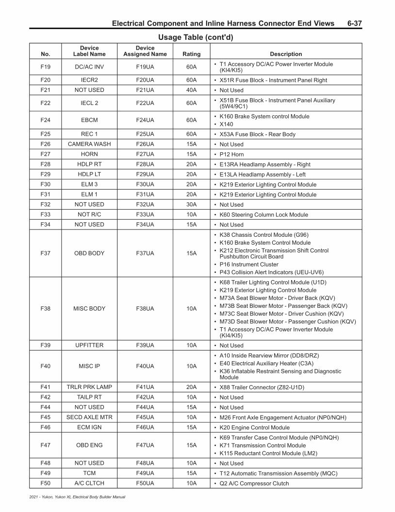
Electrical Component and Inline Harness Connector End Views 6-37
Usage Table (cont'd)
No.Device
Label NameDevice
Assigned Name Rating Description
F19 DC/AC INV F19UA 60A • T1 Accessory DC/AC Power Inverter Module(KI4/KI5)
F20 IECR2 F20UA 60A • X51R Fuse Block - Instrument Panel Right
F21 NOT USED F21UA 40A • Not Used
F22 IECL 2 F22UA 60A • X51B Fuse Block - Instrument Panel Auxiliary(5W4/9C1)
F24 EBCM F24UA 60A• K160 Brake System control Module• X140
F25 REC 1 F25UA 60A • X53A Fuse Block - Rear Body
F26 CAMERA WASH F26UA 15A • Not Used
F27 HORN F27UA 15A • P12 Horn
F28 HDLP RT F28UA 20A • E13RA Headlamp Assembly - Right
F29 HDLP LT F29UA 20A • E13LA Headlamp Assembly - Left
F30 ELM 3 F30UA 20A • K219 Exterior Lighting Control Module
F31 ELM 1 F31UA 20A • K219 Exterior Lighting Control Module
F32 NOT USED F32UA 30A • Not Used
F33 NOT R/C F33UA 10A • K60 Steering Column Lock Module
F34 NOT USED F34UA 15A • Not Used
F37 OBD BODY F37UA 15A
• K38 Chassis Control Module (G96)• K160 Brake System Control Module• K212 Electronic Transmission Shift Control
Pushbutton Circuit Board• P16 Instrument Cluster• P43 Collision Alert Indicators (UEU-UV6)
F38 MISC BODY F38UA 10A
• K68 Trailer Lighting Control Module (U1D)• K219 Exterior Lighting Control Module• M73A Seat Blower Motor - Driver Back (KQV)• M73B Seat Blower Motor - Passenger Back (KQV)• M73C Seat Blower Motor - Driver Cushion (KQV)• M73D Seat Blower Motor - Passenger Cushion (KQV)• T1 Accessory DC/AC Power Inverter Module
(KI4/KI5)
F39 UPFITTER F39UA 10A • Not Used
F40 MISC IP F40UA 10A
• A10 Inside Rearview Mirror (DD8/DRZ)• E40 Electrical Auxiliary Heater (C3A)• K36 Inflatable Restraint Sensing and Diagnostic
Module
F41 TRLR PRK LAMP F41UA 20A • X88 Trailer Connector (Z82-U1D)
F42 TAILP RT F42UA 10A • Not Used
F44 NOT USED F44UA 15A • Not Used
F45 SECD AXLE MTR F45UA 10A • M26 Front Axle Engagement Actuator (NP0/NQH)
F46 ECM IGN F46UA 15A • K20 Engine Control Module
F47 OBD ENG F47UA 15A• K69 Transfer Case Control Module (NP0/NQH)• K71 Transmission Control Module• K115 Reductant Control Module (LM2)
F48 NOT USED F48UA 10A • Not Used
F49 TCM F49UA 15A • T12 Automatic Transmission Assembly (MQC)
F50 A/C CLTCH F50UA 10A • Q2 A/C Compressor Clutch
2021 - Yukon, Yukon XL Electrical Body Builder Manual

6-38 Electrical Component and Inline Harness Connector End Views
Usage Table (cont'd)
No.Device
Label NameDevice
Assigned Name Rating Description
F51 TCCM F51UA 30A • K69 Transfer Case Control Module (NP0/NQH)
F52 FRT WPR F52UA 25A• KR12B Windshield Wiper Relay• KR12C Windshield Wiper Speed Control Relay
F53 NOT USED F53UA 10A • Not Used
F54 TAILLP LT F54UA 10A • Not Used
F55 TRLR BCK/UP LAMP F55UA 10A • X88 Trailer Connector (Z82-U1D)
F56 SADS F56UA 15A • K19 Suspension Control Module (Z95)
F57 TTPM F57UA 10A • Not Used
F58 STRTR MTR F58UA 30A • KR27 Starter Relay
F60 AFM1 F60UA 10A • Not Used
F61 ALC MAIN F61UA 15A • K3 Air Suspension Control Module (F47)
F62 ICCM/CVS/DEF F62UA 10A• K115 Reductant Control Module (LM2)• Q13 Evaporative Emission Vent Solenoid Valve
(-L84/L87)
F63 TRLR BRK F63UA 40A• K133 Trailer Brake Power Control Module (JL1)• W24 Blunt Cut - Trailer Brakes Provision (Z82-JL1)
F65 AUX UEC F65UA 60A • X50B Fuse Block - Underhood Auxiliary (LM2)
F66 COOL FANMTR LT F66UA 50A • G10L Cooling Fan Motor - Left
F67 AFM2 F67UA 10A • Not Used
F68 ALC MTR F68UA 40A • K3 Air Suspension Control Module (F47)
F69 STRTR PINION LD F69UA 40A • KR27C Starter Pinion Solenoid Actuator Relay
F71 COOL FANMTR LWR F71UA 50A • G10LW Cooling Fan Motor - Right (LM2)
F72 COOL FAN MTRRT/LWR F72UA 50A • G10R Cooling Fan Motor - Right (L84/L87)
F73 TRLR STP/TRNLAMP LT F73UA 10A • X88 Trailer Connector (Z82-U1D)
F74 TIM 2 F74UA 30A • K68 Trailer Lighting Control Module (U1D)
F75 DEFC F75UA 30A • K115 Reductant Control Module (LM2)
F76 ELEC RNG BDS F76UA 30A • K4 Assist Step Control Module (B3L)
F78 ECM F78UA 15A • K20 Engine Control Module
F79 NOT USED F79UA 10A • Not Used
F80 CABIN COOLPUMP 17W F80UA 10A • Not Used
F81 TRLR STP/TRNLAMP RT F81UA 10A • X88 Trailer Connector (Z82-U1D)
F82 TIM 1 F82UA 30A • K68 Trailer Lighting Control Module (U1D)
F83 FTZM F83UA 30A • K111 Fuel Pump Driver Control Module
F84 TRLR BATT F84UA 30A • X88 Trailer Connector (Z82)
F85 ENG F85UA 15A • X50B Fuse Block - Underhood Auxiliary (LM2)
F86 ECM F86UA 30A • K20 Engine Control Module
2021 - Yukon, Yukon XL Electrical Body Builder Manual

Electrical Component and Inline Harness Connector End Views 6-39
Usage Table (cont'd)
No.Device
Label NameDevice
Assigned Name Rating Description
F87 INJ B EVEN F87UA 20A
• K20 Engine Control Module (L84/L87)• T8B Ignition Coil 2 (L84/L87)• T8D Ignition Coil 4 (L84/L87)• T8F Ignition Coil 6 (L84/L87)• T8H Ignition Coil 8 (L84/L87)
F88 O2 B SNSR F88UA 15A
• B52D Heated Oxygen Sensor - Bank 1 Sensor 2(L84/L87)
• B52F Heated Oxygen Sensor - Bank 2 Sensor 2(L84/L87)
• B75C Multifunction Intake Air Sensor• K20 Engine Control Module (L84/L87)• M10 Charge Air Cooler Coolant Pump (LM2)• Q97B Engine Flow Control Valve - Block (LM2)
F89 O2 A SNSR F89UA 15A
• B52C Heated Oxygen Sensor - Bank 1 Sensor 1(L84/L87)
• B52E Heated Oxygen Sensor - Bank 2 Sensor 1(L84/L87)
• Q12 Evaporative Emission Purge Solenoid Valve(L84/L87)
• Q44 Engine Oil Pressure Control Solenoid Valve(L84/L87)
F90 INJ A ODD F90UA 20A
• K20 Engine Control Module• T8A Ignition Coil 1 (L84/L87)• T8C Ignition Coil 3 (L84/L87)• T8E Ignition Coil 5 (L84/L87)• T8G Ignition Coil 7 (L84/L87)
F91 ECMTHROT CONT F91UA 15A • Not Used
F92COOL FAN
CLUTCH/AEROSHUTTER
F92UA 10A• M96A Active Grille Air Shutter 1 Actuator (VTI/WMI)• M96B Active Grille Air Shutter 2 Actuator (WMI)
Relays
K5 NOT USED KR50 HeadlampRelay —
• F3UA• F4UA
K18 DC/AC INV KR80 AccessoryRelay — • F19UA
K23 NOT USED KR5 RearDefogger Relay —
• F32UA• F33UA
K35 PRK LAMP KR125 Trailer ParkLamps Relay — • F41UA
K36 RUN/CRNK KR73 Ignition MainRelay —
• F33UA• F37UA• F38UA• F39UA• F40UA• F44UA• F46UA• F47UA• F48UA
K43 SECD AXLE MTR — — • Not Used
K59 A/C CLTCHKR29 A/C
Compressor ClutchRelay
— • F50UA
2021 - Yukon, Yukon XL Electrical Body Builder Manual

6-40 Electrical Component and Inline Harness Connector End Views
Usage Table (cont'd)
No.Device
Label NameDevice
Assigned Name Rating Description
K64 STRTR MTR KR27 Starter Motor — • M64 Starter Motor
K70 STRTR PINIONKR27C StarterPinion SolenoidActuator Relay
— • M64 Starter Motor
K77 PWR/TRNKR75 Engine
Controls IgnitionRelay
—
• F60UA• F67UA• F80UA• F85UA• F86UA• F87UA• F88UA• F89UA• F90UA• F91UA• F92UA• KR29 A/C Compressor Clutch Relay• KR33 Auxiliary Heater Coolant Pump Relay
— — — — • Not Used
— — — — • Not Used
— —KR6 Rear Window
Washer PumpRelay
— • G24 Windshield Washer Pump
— —KR11 Windshield
Washer PumpRelay
— • G24 Windshield Washer Pump
— — KR12B WindshieldWiper Relay — • M75 Windshield Wiper Motor
— —KR12C Windshield
Wiper SpeedControl Relay
— • M75 Windshield Wiper Motor
— —KR33 Auxiliary
HeaterCoolant Pump
— • G17 Heater Coolant Pump (L84/L87)
— —KR61 Trailer
Backup LampsRelay
— • F55UA
— —KR63L Trailer
Stop/Turn SignalLamp Relay - Left
— • F73UA
— —KR63R Trailer
Stop/Turn SignalLamp Relay - Right
— • F81UA
2021 - Yukon, Yukon XL Electrical Body Builder Manual
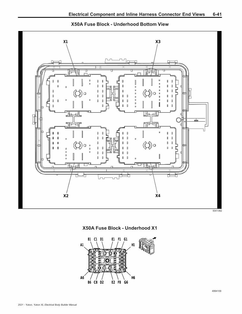
Electrical Component and Inline Harness Connector End Views 6-41
X50A Fuse Block - Underhood Bottom View
5041382
X50A Fuse Block - Underhood X1
4994109
2021 - Yukon, Yukon XL Electrical Body Builder Manual

6-42 Electrical Component and Inline Harness Connector End Views
Connector Part InformationHarness Type: BodyOEM Connector: 33384590Service Connector: 19370824Description: 44-Way F 1.5, 2.8, 6.3 CTS, 9.5 MCON-LL Series (BU)
Terminal Part InformationTerminal Type ID Terminated Lead Diagnostic Test Probe Terminal Removal Tool
I 13582286 J-35616-35 (VT) J-38125-557
II 19332365 J-35616-14 (GN) J-38125-560A
III 19332366 J-35616-35 (VT) J-38125-212
IV 84764079 J-35616-22 (RD) J-38125-11A
V Not Required J-35616-22 (RD) No Tool Required
X50A Fuse Block - Underhood X1Pin Size Color Circuit Function Terminal
Type IDOption
A1 1 RD/VT 7140 Secondary Fused Battery Positive Voltage 71 III —
A20.5
0.75RD/D-BURD/D-BU
540540
Secondary Fused Battery Positive Voltage 5Secondary Fused Battery Positive Voltage 5
IIIIII
——
A3 — — — Not Occupied — —
A4 1 BK 250 Ground 2 III —
A5 0.75 GY/VT 228 Windshield Washer Pump Control III —
A6 0.75 D-BU/VT 392 Rear Window Washer Pump Control III —
B1 - C2 — — — Not Occupied — —
C3 0.5 WH/L-GN 4628 DC/AC Inverter Relay Control II —
C4 0.35 BN/GY 2268 Windshield Washer Relay Control II —
C5 - C6 — — — Not Occupied — —
C7 0.35 L-GN/WH 2270 Rear Window Washer Relay Control II —
C8 — — — Not Occupied — —
D1 5 BN/BK 4629 DC/AC Inverter Control IV —
D2 10 RD/WH 342 Primary Fused Battery Positive Voltage 3 V —
E1 10 RD/YE 442 Primary Fused Battery Positive Voltage 4 V —
E2 10 RD/L-GN 1942 Primary Fused Battery Positive Voltage 19 V —
F1 - F5 — — — Not Occupied — —
F6 0.35 WH/VT 860 Windshield Wiper Switch High Signal II —
F7 - G2 — — — Not Occupied — —
G3 0.35 D-BU/VT 807 Ignition Off/Accessory Ignition Voltage III —
G4 0.5 L-GN/VT 5199 Run/Crank Relay Coil Control III —
G522
BKBK
150150
Ground 1Ground 1
IIII
——
G6 0.35 GY 91 Windshield Wiper Motor Relay Coil Control III —
H1 0.5 VT/WH 639 Run/Crank Ignition 1 Voltage 6 III —
H2 0.5 VT/WH 1139 Run/Crank Ignition 1 Voltage 11 III —
H3 0.75 VT/WH 4939 Run/Crank Ignition 1 Voltage 49 III —
H4 0.5 VT/WH 239 Run/Crank Ignition 1 Voltage 2 III —
H5 2 WH 92 Windshield Wiper Motor High Speed Control III —
H6 2 YE/BN 95 Windshield Wiper Motor Low Speed Control III —
2021 - Yukon, Yukon XL Electrical Body Builder Manual
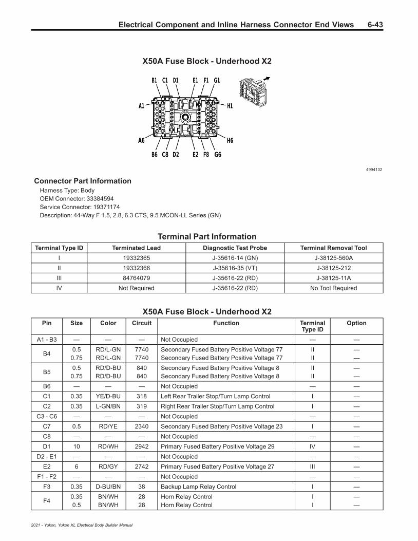
Electrical Component and Inline Harness Connector End Views 6-43
X50A Fuse Block - Underhood X2
4994132
Connector Part InformationHarness Type: BodyOEM Connector: 33384594Service Connector: 19371174Description: 44-Way F 1.5, 2.8, 6.3 CTS, 9.5 MCON-LL Series (GN)
Terminal Part InformationTerminal Type ID Terminated Lead Diagnostic Test Probe Terminal Removal Tool
I 19332365 J-35616-14 (GN) J-38125-560A
II 19332366 J-35616-35 (VT) J-38125-212
III 84764079 J-35616-22 (RD) J-38125-11A
IV Not Required J-35616-22 (RD) No Tool Required
X50A Fuse Block - Underhood X2Pin Size Color Circuit Function Terminal
Type IDOption
A1 - B3 — — — Not Occupied — —
B40.5
0.75RD/L-GNRD/L-GN
77407740
Secondary Fused Battery Positive Voltage 77Secondary Fused Battery Positive Voltage 77
IIII
——
B50.5
0.75RD/D-BURD/D-BU
840840
Secondary Fused Battery Positive Voltage 8Secondary Fused Battery Positive Voltage 8
IIII
——
B6 — — — Not Occupied — —
C1 0.35 YE/D-BU 318 Left Rear Trailer Stop/Turn Lamp Control I —
C2 0.35 L-GN/BN 319 Right Rear Trailer Stop/Turn Lamp Control I —
C3 - C6 — — — Not Occupied — —
C7 0.5 RD/YE 2340 Secondary Fused Battery Positive Voltage 23 I —
C8 — — — Not Occupied — —
D1 10 RD/WH 2942 Primary Fused Battery Positive Voltage 29 IV —
D2 - E1 — — — Not Occupied — —
E2 6 RD/GY 2742 Primary Fused Battery Positive Voltage 27 III —
F1 - F2 — — — Not Occupied — —
F3 0.35 D-BU/BN 38 Backup Lamp Relay Control I —
F40.350.5
BN/WHBN/WH
2828
Horn Relay ControlHorn Relay Control
II
——
2021 - Yukon, Yukon XL Electrical Body Builder Manual

6-44 Electrical Component and Inline Harness Connector End Views
X50A Fuse Block - Underhood X2 (cont'd)Pin Size Color Circuit Function Terminal
Type IDOption
F5 - F8 — — — Not Occupied — —
G1 0.75 BN/GY 29 Horn Control II —
G2 — — — Not Occupied — —
G3 0.75 RD/YE 740 Secondary Fused Battery Positive Voltage 7 II —
G4 0.75 RD/WH 640 Secondary Fused Battery Positive Voltage 6 II —
G50.5
0.75RD/BNRD/BN
14401440
Secondary Fused Battery Positive Voltage 14Secondary Fused Battery Positive Voltage 14
IIII
——
G60.5
0.75RD/BNRD/BN
11401140
Secondary Fused Battery Positive Voltage 11Secondary Fused Battery Positive Voltage 11
IIII
——
H1 - H5 — — — Not Occupied — —
H6 0.35 WH/BN 7055 Auxiliary Park Lamp Relay Control II —
X50A Fuse Block - Underhood X3
4992608
Connector Part InformationHarness Type: EngineOEM Connector: 33384584Service Connector: 19371176Description: 44-Way F 1.5, 2.8, 6.3 CTS, 9.5 MCON-LL Series (GY)
Terminal Part InformationTerminal Type ID Terminated Lead Diagnostic Test Probe Terminal Removal Tool
I 13582285 J-35616-35 (VT) J-38125-557
II 19332365 J-35616-14 (GN) J-38125-560A
III 19332366 J-35616-35 (VT) J-38125-212
IV 19371228 J-35616-42 (RD) J-38125-215A
V 84764079 J-35616-22 (RD) J-38125-11A
VI Not Required J-35616-22 (RD) No Tool Required
X50A Fuse Block - Underhood X3Pin Size Color Circuit Function Terminal
Type IDOption
A1 0.75 VT/L-GN 439 Run/Crank Ignition 1 Voltage 4 III —
2021 - Yukon, Yukon XL Electrical Body Builder Manual

Electrical Component and Inline Harness Connector End Views 6-45
X50A Fuse Block - Underhood X3 (cont'd)Pin Size Color Circuit Function Terminal
Type IDOption
A2 0.5 VT/BK 2139 Run/Crank Ignition 1 Voltage 21 III —
A3 — — — Not Occupied — —
A4 0.75 BN/L-GN 59 A/C Compressor Clutch Control III —
A5 0.75 RD/VT 7940 Secondary Fused Battery Positive Voltage 79 III —
A6 0.5 L-GN 8016 Secondary Axle Motor Control III —
B1 2.5 YE 6 Starter Solenoid Actuator Crank Ignition Voltage III —
B2 0.5 YE/BK 625 Starter Enable Relay Control III —
B3 0.5 VT/GY 8017 Secondary Axle Motor Relay Control III —
B4 - B5 — — — Not Occupied — —
B6 2.5 RD/GY 1342 Primary Fused Battery Positive Voltage 13 III —
C1 - C2 — — — Not Occupied — —
C30.750.5
BKBK
4506550
Ground 4Propulsion Propulsion System
IIII
—LM2
C4 0.5 WH/GY 459 A/C Compressor Clutch Relay Control II —
C5 - C8 — — — Not Occupied — —
D1 10 RD/GY 7040 Secondary Fused Battery Positive Voltage 70 VI —
D2 5 RD/D-BU 1842 Primary Fused Battery Positive Voltage 18 V —
E1 5 RD/D-BU 1542 Primary Fused Battery Positive Voltage 15 V —
E2 5 RD/BN 1742 Primary Fused Battery Positive Voltage 17 V —
F1 2.5 YE/L-GN 4358 Starter Pinion Solenoid Actuator Voltage IV —
F2 0.5 YE/VT 4325 Starter Pinion Solenoid Actuator Relay Control II —
F3 0.5 RD/BN 440 Secondary Fused Battery Positive Voltage 4 II —
F4 0.5 YE 5991 Powertrain Relay Coil Control II —
F5 — — — Not Occupied — —
F6 0.5 RD/BN 5940 Secondary Fused Battery Positive Voltage 59 II —
F7 0.5 VT/D-BU 5705 Powertrain Main Relay Fused Supply 6 II —
F8 — — — Not Occupied — —
G1 0.5 VT/D-BU 7078 Powertrain Main Relay Fused Supply Voltage 7 III —
G2 - G5 — — — Not Occupied — —
G60.750.75
VT/D-BUVT/D-BU
52915291
Powertrain Main Relay Fused Supply 2Powertrain Main Relay Fused Supply 2
IIII
——
H1 2 VT/D-BU 5290 Powertrain Main Relay Fused Supply 1 III —
H2 0.75 VT/D-BU 5292 Powertrain Main Relay Fused Supply 3 III —
H3 0.75 VT/D-BU 5294 Powertrain Main Relay Fused Supply 5 III —
H4 0.75 VT/D-BU 5293 Powertrain Main Relay Fused Supply 4 III —
H5 1 VT/D-BU 5291 Powertrain Main Relay Fused Supply 2 III —
H6 — — — Not Occupied — —
2021 - Yukon, Yukon XL Electrical Body Builder Manual

6-46 Electrical Component and Inline Harness Connector End Views
X50A Fuse Block - Underhood X4
4993031
Connector Part InformationHarness Type: ChassisOEM Connector: 33384574Service Connector: 19371188Description: 44-Way F 1.5, 2.8, 6.3 CTS, 9.5 MCON-LL Series (BK)
Terminal Part InformationTerminal Type ID Terminated Lead Diagnostic Test Probe Terminal Removal Tool
I 13582286 J-35616-35 (VT) J-38125-557
II 19332365 J-35616-14 (GN) J-38125-560A
III 19332366 J-35616-35 (VT) J-38125-212
IV 19367600 J-35616-40 (BU) J-38125-556
V 19371228 J-35616-42 (RD) J-38125-215A
VI 84764079 J-35616-22 (RD) J-38125-11A
VII 84779405 J-35616-35 (VT) J-38125-215A
X50A Fuse Block - Underhood X4Pin Size Color Circuit Function Terminal
Type IDOption
A1 - A2 — — — Not Occupied — —
A3 0.75 GY/BN 2109 Trailer Park Lamp Control III —
A4 - B1 — — — Not Occupied — —
B2 0.75 WH/L-GN 1624 Trailer Backup Lamp Control III —
B3 0.75 RD/L-GN 2440 Secondary Fused Battery Positive Voltage 24 III —
B4 0.5 RD/L-GN 6940 Secondary Fused Battery Positive Voltage 69 III —
B5 - B6 — — — Not Occupied — —
C1 0.75 RD/BN 2940 Secondary Fused Battery Positive Voltage 29 II —
C2 - C6 — — — Not Occupied — —
C7 0.5 RD/WH 2040 Secondary Fused Battery Positive Voltage 20 II —
C8 - D1 — — — Not Occupied — —
D2 6 RD/VT 1242 Primary Fused Battery Positive Voltage 12 VI —
E1 - E2 — — — Not Occupied — —
F133
RD/D-BURD/D-BU
76407640
Secondary Fused Battery Positive Voltage 76Secondary Fused Battery Positive Voltage 76
IVV
——
F2 - G2 — — — Not Occupied — —
2021 - Yukon, Yukon XL Electrical Body Builder Manual

Electrical Component and Inline Harness Connector End Views 6-47
X50A Fuse Block - Underhood X4 (cont'd)Pin Size Color Circuit Function Terminal
Type IDOption
G3 0.75 YE/GY 1618 Left Rear Trailer Stop/Turn Lamp Control III —
G422
RD/YERD/YE
58405840
Secondary Fused Battery Positive Voltage 58Secondary Fused Battery Positive Voltage 58
IIII
——
G5 2.5 RD/WH 3440 Secondary Fused Battery Positive Voltage 34 III —
G6 2.5 RD/YE 1142 Primary Fused Battery Positive Voltage 11 III —
H1 - H2 — — — Not Occupied — —
H3 0.75 L-GN/VT 1619 Right Rear Trailer Stop/Turn Lamp Control III —
H4 3 RD/VT 5640 Secondary Fused Battery Positive Voltage 56 VII —
H5 2.5 RD/VT 1940 Secondary Fused Battery Positive Voltage 19 III —
H6 4 RD/L-GN 742 Primary Fused Battery Positive Voltage 7 VII —
X50B Fuse Block - Underhood Auxiliary Label (LM2)
5118008
2021 - Yukon, Yukon XL Electrical Body Builder Manual

6-48 Electrical Component and Inline Harness Connector End Views
X50B Fuse Block - Underhood Auxiliary Top View (LM2)
5118010
Usage Table
No.Device
Label NameDevice
Assigned Name Rating Description
Fuses
7 SPARE F7UB — • KR121B Reductant Control Module Relay 2
8 DEF HTR F8UB 25A • Not Used
9 STARTER F9UB 40A• KR121A Reductant Control Module Relay 1• F13UB
10 FUEL HTR F10UB 40A • KR22 Fuel Heater Relay
11 SMARTSENSORS F11UB 10A
• B136 Exhaust Particulate Sensor• B195A Nitrogen Oxides Sensor 1• B195B Nitrogen Oxides Sensor 2• B195C Nitrogen Oxides Sensor 3
12 SCRPM F12UB 10A• K111 Fuel Pump Driver Control Module• K115 Reductant Control Module
13 SPARE F13UB — • KR18 Charge Air Cooler Coolant Pump Relay
Relays
1 STARTERKR121A Reductant
Control ModuleRelay 1
— • K115 Reductant Control Module
2 FUEL HTR KR22 Fuel HeaterRelay — • E11A Fuel Heater/Water in Fuel Sensor
2021 - Yukon, Yukon XL Electrical Body Builder Manual

Electrical Component and Inline Harness Connector End Views 6-49
Usage Table (cont'd)
No.Device
Label NameDevice
Assigned Name Rating Description
3 SCR CTRLKR18 Charge AirCooler Coolant
Pump Relay— • M10 Charge Air Cooler Coolant Pump
4 FUEL PUMPKR121B Reductant
Control ModuleRelay 2
—• F11UB• F12UB
5 FAN DRIVER — — • Not Used
6 PWRTRN SNSR — — • Not Used
2021 - Yukon, Yukon XL Electrical Body Builder Manual
6-50 Electrical Component and Inline Harness Connector End Views
X50B Fuse Block - Underhood Auxiliary Wire Entry (LM2)
—
Connector Part InformationHarness Type: EngineOEM Connector: 35096237Service Connector: Service by Component Assembly - See Part CatalogDescription: —
Terminal Part InformationTerminal Type ID Terminated Lead Diagnostic Test Probe Terminal Removal Tool
I 13327158 J-35616-42 (RD) J-38125-215A
II 13327178 J-35616-43 (RD) J-38125-215A
III 13575574 J-35616-5 (PU) J-38125-36
IV 13582244 J-35616-42 (RD) J-38125-215A
V Not Required J-35616-22 (RD) No Tool Required
X50B Fuse Block - Underhood Auxiliary Wire Entry (LM2)Pin Size Color Circuit Function Terminal
Type IDOption
4 0.5 L-GN/D-BU 3889 Powertrain Sensor Bus Relay Control III —
5 1 VT/L-GN 4320 Selective Catalytic Reduction Power ModuleWake-Up Signal III —
6 0.5 D-BU 3017 Fuel Heater Relay 1 Control I —
7 0.5 VT/D-BU 7078 Powertrain Main Relay Fused Supply Voltage 7 I —
15 2.5 BN/YE 2996 Fuel Heater Control 1 IV —
19 1 VT/D-BU 3674 NOx Sensor 1 Control III —
20 0.5 BK 6550 Propulsion Propulsion System III —
21 2.5 RD/WH 5440 Secondary Fused Battery Positive Voltage 54 IV —
26 10 RD/GY 7040 Secondary Fused Battery Positive Voltage 70 V —
31 2.5 RD/WH 5440 Secondary Fused Battery Positive Voltage 54 II —
33 1.5 RD/BN 5940 Secondary Fused Battery Positive Voltage 59 III —
34 1 VT/D-BU 3674 NOx Sensor 1 Control III —
2021 - Yukon, Yukon XL Electrical Body Builder Manual

Electrical Component and Inline Harness Connector End Views 6-51
X51B Fuse Block - Auxiliary Instrument Panel Label (5W4/9C1)
5573254
2021 - Yukon, Yukon XL Electrical Body Builder Manual

6-52 Electrical Component and Inline Harness Connector End Views
X51B Fuse Block - Auxiliary Instrument Panel Top View (5W4/9C1)
5245414
Usage Table
No.Device
Label NameDevice
Assigned Name Rating Description
Fuses
F160 SW 1-2 RC F160DA 5A• KR161A Configurable Provision Relay 1• KR161B Configurable Provision Relay 2
F161 SW 1-2 BATT F161DA 5A• KR161A Configurable Provision Relay 1• KR161B Configurable Provision Relay 2
F162 UPFIT1 F162DA 25A • W12FC Blunt Cut - Front Seat/Center Console
F163 UPFIT2 F163DA 20A • W12FC Blunt Cut - Front Seat/Center Console
F164 SW 3-4 RC F164DA 5A• KR161C Configurable Provision Relay 3• KR161D Configurable Provision Relay 4
F165 SW 3-4 BATT F165DA 5A• KR161C Configurable Provision Relay 3• KR161D Configurable Provision Relay 4
F166 UPFIT3 F166DA 20A • W12RCL Blunt Cut - Left Rear Cargo Trim
F167 UPFIT4 F167DA 25A • W12RCL Blunt Cut - Left Rear Cargo Trim
Relays
K124 UPFIT1KR161A
ConfigurableProvision Relay 1
— • F162DA
K125 UPFIT2KR161B
ConfigurableProvision Relay 2
— • F163DA
2021 - Yukon, Yukon XL Electrical Body Builder Manual

Electrical Component and Inline Harness Connector End Views 6-53
Usage Table (cont'd)
No.Device
Label NameDevice
Assigned Name Rating Description
K126 UPFIT3KR161C
ConfigurableProvision Relay 3
— • F166DA
K127 UPFIT4KR161D
ConfigurableProvision Relay 4
— • F167DA
K128 ROOF BEACON — — • Not Used
2021 - Yukon, Yukon XL Electrical Body Builder Manual

6-54 Electrical Component and Inline Harness Connector End Views
X51B Fuse Block - Auxiliary Instrument Panel Wire Entry (5W4/9C1)
—
Connector Part InformationHarness Type: Instrument PanelOEM Connector: 33323307Service Connector: Service by Component Assembly - See Part CatalogDescription: —
Terminal Part InformationTerminal Type ID Terminated Lead Diagnostic Test Probe Terminal Removal Tool
I 13575574 J-35616-5 (PU) J-38125-36
II 84779405 J-35616-35 (VT) J-38125-215A
X51B Fuse Block - Auxiliary Instrument Panel Wire Entry (5W4/9C1)Pin Size Color Circuit Function Terminal
Type IDOption
1 5 RD/GY 2742 Primary Fused Battery Positive Voltage 27 II —
2 0.75 D-BU/YE 8895 Police Relay 1 Control I —
3 0.75 L-GN/YE 8896 Police Relay 2 Control I —
4 0.75 GY/YE 8897 Police Relay 3 Control I —
5 0.75 VT/YE 8898 Police Relay 4 Control I —
6 0.75 RD/L-GN 8911 — I —
7 0.75 RD/GY 8912 — I —
8 0.75 RD/WH 8913 — I —
9 0.75 RD/YE 8914 — I —
2021 - Yukon, Yukon XL Electrical Body Builder Manual

Electrical Component and Inline Harness Connector End Views 6-55
X51R Fuse Block - Instrument Panel Right Label
5441144
2021 - Yukon, Yukon XL Electrical Body Builder Manual

6-56 Electrical Component and Inline Harness Connector End Views
X51R Fuse Block - Instrument Panel Right Top View
5041376
Usage Table
No.Device
Label NameDevice
Assigned Name Rating Description
Fuses
F1 RT DR F1DR 30A• M74P Window Motor - Passenger• S79RR Window Switch - Right Rear
F2 LT DR F2DR 30A• M74D Window Motor - Driver• S79LR Window Switch - Left Rear
F3 UGDO/OHC/CAMERA F3DR 10A
• A98 Front Overhead Console Assembly• B174W Frontview Camera - Windshield (UEU)• B200 Rain Sensor Module• W9 Blunt Cut - Police Provision (5W4/9C1)
F4 BCM 2 F4DR 20A • K9 Body Control Module
2021 - Yukon, Yukon XL Electrical Body Builder Manual

Electrical Component and Inline Harness Connector End Views 6-57
Usage Table (cont'd)
No.Device
Label NameDevice
Assigned Name Rating Description
F5 DISPLAYS F5DR 20A
• A26 HVAC Controls• P16 Instrument Cluster• P17 Info Display Module• P29 Head-Up Display (UV6)
F6 FRT BLWR F6DR 40A • M8 Blower Motor
F8 LT DR PNL F8DR 15A • S84D Door Switch Panel Control Module - Driver
F10 TILT/COL LOCK F10DR 15A• K60 Steering Colmn Lock Module• K99 Steering Column Position Control Module
F11 USB/DLC F11DR 10A • X84 Data Link Connector
F12 CGM/ONSTAR F12DR 15A• K56 Serial Data Gateway Module• K73 Telematics Communication Interface Control
Module
F14 RT DR PNL F14DR 10A • S84P Door Switch Panel Control Module - Passenger
F17 STR WHL CNTRL F17DR 2A• S70L Steering Wheel Controls Switch - Left (KI3)• S70R Steering Wheel Controls Switch - Right (KI3)
F18 AVM 1 F18DR 10A• Q80L Engine Mount Solenoid Valve - Left (LM2)• Q80R Engine Mount Solenoid Valve - Right (LM2)
F19 NOT USED F19DR 2A • Not Used
F20 NOT USED F20DR 5A • Not Used
F21 NOT USED F21DR 10A • Not Used
F22 HTD WHL F22DR 7.5A • K32 Steering Wheel Heating Control Module (KI3)
F23 NOT USED F23DR 10A • Not Used
F24 NOT USED F24DR 10A • Not Used
F25 SEO/UPFITTER F25DR 15A • W9 Blunt Cut - Police Provision (5W4/9C1)
F26 USB/SEO RAP F26DR 10A
• W9 Blunt Cut - Police Provision (5W4/9C1)• X92BCL USB Receptacle - 3rd Row Seat Left• X92BCR USB Receptacle - 3rd Row Seat Right• X92C USB Receptacle - Center Console Rear
F27 APO/RAP F27DR 50A • CB1DR
F28 APO/BATT F28DR 50A • CB1DR
F30 SDM AOS F30DR 10A
• K36 Inflatable Restraint Sensing and DiagnosticModule
• K85 Passenger Presence Module• S76 Trailer Brake Control Switch (JL1)
F31 BCM 3 F31DR 20A • K9 Body Control Module
F32 CSM USB F32DR 15A
• Auxiliary Audio/Video Input Adapter - 1 (AZ3/D07/DCK/DCH)
• Auxiliary Audio/ Video Input Adapter - 2 (D07/DCK/UW9)
• A11 Radio
F33 BCM 4 F33DR 30A • K9 Body Control Module
F34 OUT OF PARK F34DR 5A • KR87 Transmission Park Position Relay
F40 NOT USED F40DR 10A • Not Used
F41 NOT USED F41DR 10A • Not Used
F42 ELEC PRK/BRK SW F42DR 10A
• B80 Park Brake Switch• K212 Electronic Transmission Shift Control
Pushbutton Circuit Board
F43 NOT USED F43DR 10A • Not Used
2021 - Yukon, Yukon XL Electrical Body Builder Manual
6-58 Electrical Component and Inline Harness Connector End Views
Usage Table (cont'd)
No.Device
Label NameDevice
Assigned Name Rating Description
F44 AVM 2 F44DR 10A • Not Used
F45 RADIO MDL F45DR 15A • A11 Radio (IOR)
F46 BCM 1A F46DR 10A • K9 Body Control Module (IOS/IOT)
F47 NOT USED F47DR 10A • Not Used
F48 TCM F48DR 20A • K71 Transmission Control Module
F49 BCM 1 F49DR 15A • K9 Body Control Module
F50 DMS F50DR 10A • Not Used
F51 NOT USED F51DR 40A • Not Used
F52 NOT USED F52DR 40A • Not Used
F53 NOT USED F53DR 10A • Not Used
F54 SUNROOF F54DR 40A • K61 Sunroof Control Module (C3U)
F55 NOT USED F55DR 30A • Not Used
F56 DC/DC CNVBATT1 F56DR 40A • T19 Power Supply Transformer
F57 DC/DC CNVBATT2 F57DR 40A • T19 Power Supply Transformer
F58 SPARE F58DR 15A • Not Used
F59 APO 3 F59DR 15A • Not Used
Circuit Breakers
CB1 APO 1 CB1DR 15A• X80G Accessory Power Receptacle - Instrument
Panel• X80H Accessory Power Receptacle - Center Console
CB2 APO 2 CB2DR 15A • Not Used
Relays
K1 NOT USED — — • Not Used
K2 RAP/ACCY 1KR76A RetainedAccessory Power
Relay 1—
• F26DR• CB1DR
K4 RAP/ACCY 2 — — • Not Used
K5 NOT USED — — • Not Used
Note: Relays listed below are non-serviceable Printed Circuit Board (PCB) relays and are internal to the block.
— —KR87
Transmission ParkPosition Relay
—
• S143L Folding Seat Control Switch - 2nd Row Left(ATN/ATT)
• S143R Folding Seat Control Switch - 2nd Row Right(ATN/ATT)
• S144A Folding Seat Control Switch - RearCompartment 2nd Row (ATN/ATT)
2021 - Yukon, Yukon XL Electrical Body Builder Manual
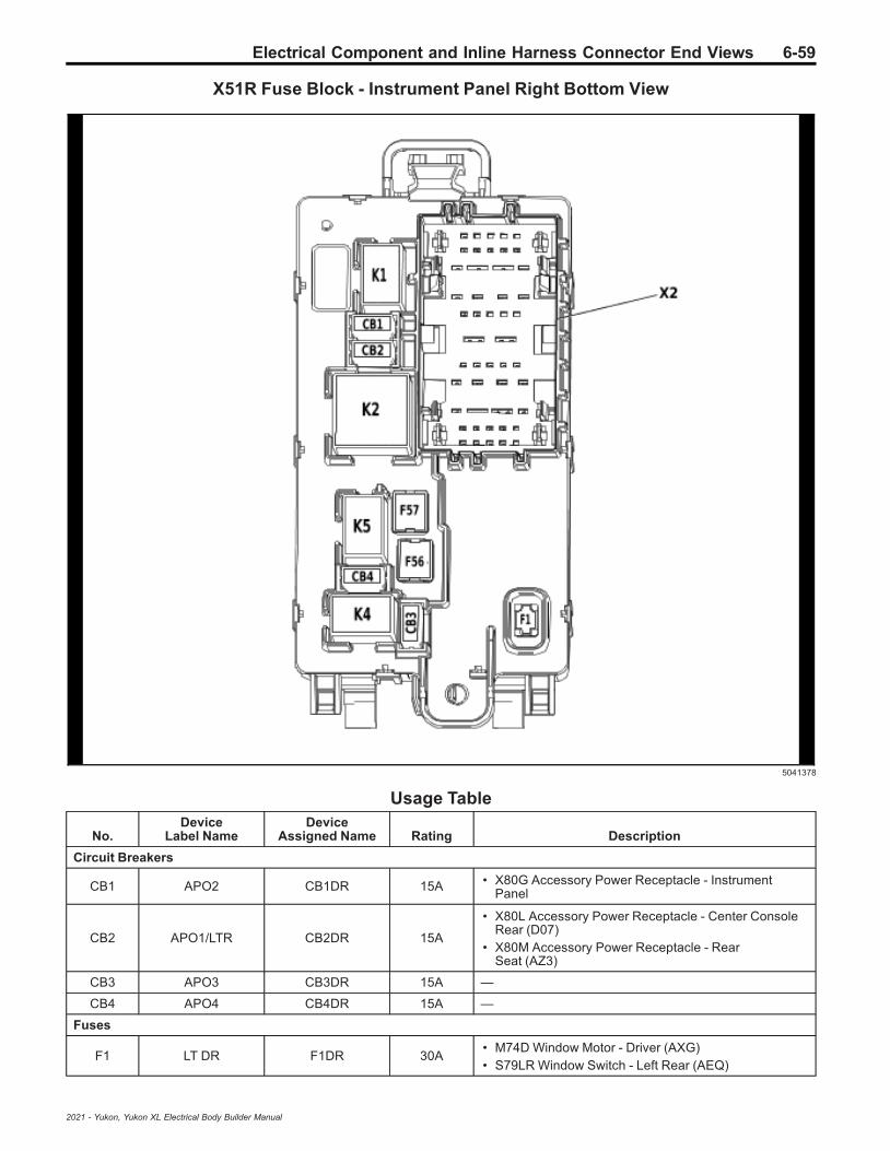
Electrical Component and Inline Harness Connector End Views 6-59
X51R Fuse Block - Instrument Panel Right Bottom View
5041378
Usage Table
No.Device
Label NameDevice
Assigned Name Rating Description
Circuit Breakers
CB1 APO2 CB1DR 15A • X80G Accessory Power Receptacle - InstrumentPanel
CB2 APO1/LTR CB2DR 15A
• X80L Accessory Power Receptacle - Center ConsoleRear (D07)
• X80M Accessory Power Receptacle - RearSeat (AZ3)
CB3 APO3 CB3DR 15A —
CB4 APO4 CB4DR 15A —
Fuses
F1 LT DR F1DR 30A• M74D Window Motor - Driver (AXG)• S79LR Window Switch - Left Rear (AEQ)
2021 - Yukon, Yukon XL Electrical Body Builder Manual

6-60 Electrical Component and Inline Harness Connector End Views
Usage Table (cont'd)
No.Device
Label NameDevice
Assigned Name Rating Description
F56 DC DC TRANS1 F56DR 40A • T19 Power Supply Transformer (KL9)
F57 DC DC TRANS2 F57DR 40A • T19 Power Supply Transformer (KL9)
Relays
K1 RUN CRANK KR73 Ignition MainRelay —
• F20DR• F21DR• F22DR• F23DR• F24DR• F25DR
K2 RAP/ACCY1KR76A RetainedAccessory Power
Relay 1—
• F26DR• F27DR
K4 RAP/ACCY2KR76B RetainedAccessory Power
Relay 2—
• CB3DR• CB4DR
K5 NOT USED — — —
X51R Fuse Block - Instrument Panel Right X1
4994712
Connector Part InformationHarness Type: BodyOEM Connector: 33371909Service Connector: 19371181Description: 38-Way F 1.5, 2.8, 6.3 CTS Series (BU)
Terminal Part InformationTerminal Type ID Terminated Lead Diagnostic Test Probe Terminal Removal Tool
I 13579915 J-35616-40 (BU) J-38125-556
II 19332366 J-35616-35 (VT) J-38125-212
III 19371175 J-35616-2A (GY) J-38125-11A
IV 84764079 J-35616-22 (RD) J-38125-11A
V Not Required J-35616-22 (RD) No Tool Required
2021 - Yukon, Yukon XL Electrical Body Builder Manual

Electrical Component and Inline Harness Connector End Views 6-61
X51R Fuse Block - Instrument Panel Right X1Pin Size Color Circuit Function Terminal
Type IDOption
1 - 2 — — — Not Occupied — —
3 0.75 RD/L-GN 1840 Secondary Fused Battery Positive Voltage 18 II —
4 0.35 RD/WH 7240 Secondary Fused Battery Positive Voltage 72 III —
5 0.5 RD/L-GN 4440 Secondary Fused Battery Positive Voltage 44 III —
6 0.5 VT 4701 Retained Accessory Power Control 11 III —
7 — — — Not Occupied — —
8 0.5 VT 4701 Retained Accessory Power Control 11 III —
9 — — — Not Occupied — —
10 0.35 GY/L-GN 4083 Retained Accessory Power Relay 2 Coil Control III —
11 0.5 RD/VT 340 Secondary Fused Battery Positive Voltage 3 III —
12 — — — Not Occupied — —
13 0.35 YE/BK 5813 Park Enable Control III —
14 - 16 — — — Not Occupied — —
17 2.5 RD/YE 2172 12 Volt Regulated Supply Voltage 1 I —
18 2.5 RD/YE 8140 Secondary Fused Battery Positive Voltage 81 I —
19 5 RD/YE 1442 Primary Fused Battery Positive Voltage 14 IV —
20 10 RD/WH 342 Primary Fused Battery Positive Voltage 3 V —
21 2.5 RD/L-GN 2173 12 Volt Regulated Supply Voltage 2 I —
22 2.5 RD/WH 8040 Secondary Fused Battery Positive Voltage 80 I —
23 2.5 RD/BN 4240 Secondary Fused Battery Positive Voltage 42 II —
24 2.5 RD/BN 4240 Secondary Fused Battery Positive Voltage 42 II —
25 2.5 RD/GY 3540 Secondary Fused Battery Positive Voltage 35 II —
26 — — — Not Occupied — —
27 0.5 RD/VT 340 Secondary Fused Battery Positive Voltage 3 III —
28 — — — Not Occupied — —
29 0.5 RD/D-BU 5240 Secondary Fused Battery Positive Voltage 52 III —
30 0.5 RD/VT 1940 Secondary Fused Battery Positive Voltage 19 III —
31 — — — Not Occupied — —
32 0.5 YE 6812 Out of Park Signal III —
33 0.35 GY/L-GN 4083 Retained Accessory Power Relay 2 Coil Control III —
34 - 35 — — — Not Occupied — —
36 1.5 VT 1701 Retained Accessory Power Control 4 II —
37 2.5 RD/GY 3540 Secondary Fused Battery Positive Voltage 35 II —
38 — — — Not Occupied — —
2021 - Yukon, Yukon XL Electrical Body Builder Manual

6-62 Electrical Component and Inline Harness Connector End Views
X51R Fuse Block - Instrument Panel Right X2
4997272
Connector Part InformationHarness Type: Instrument PanelOEM Connector: 33371910Service Connector: 19371180Description: 48-Way F 1.5, 2.8, 6.3 CTS Series (GN)
Terminal Part InformationTerminal Type ID Terminated Lead Diagnostic Test Probe Terminal Removal Tool
I 19332366 J-35616-35 (VT) J-38125-212
II 19370816 J-35616-42 (RD) J-38125-11A
III 19371175 J-35616-2A (GY) J-38125-11A
IV 84764078 J-35616-42 (RD) J-38125-11A
X51R Fuse Block - Instrument Panel Right X2Pin Size Color Circuit Function Terminal
Type IDOption
1 0.5 BK 1050 Ground 10 III —
2 - 7 — — — Not Occupied — —
8 0.35 RD/GY 4140 Secondary Fused Battery Positive Voltage 41 III —
9 0.5 RD/YE 6540 Secondary Fused Battery Positive Voltage 65 III —
10 — — — Not Occupied — —
11 0.75 RD/L-GN 10240 Secondary Fused Battery Positive Voltage 102Police I —
12 - 13 — — — Not Occupied — —
14 0.5 RD/D-BU 3240 Secondary Fused Battery Positive Voltage 32 I —
15 0.35 RD/BN 10040 Secondary Fused Battery Positive Voltage 100 I —
16 1.5 RD/VT 4640 Secondary Fused Battery Positive Voltage 46 I —
17 — — — Not Occupied — —
18 0.35 RD/VT 3340 Secondary Fused Battery Positive Voltage 33 I —
19 — — — Not Occupied — —
20 0.75 RD/GY 10340 Secondary Fused Battery Positive Voltage 103Police III —
21 - 23 — — — Not Occupied — —
24 5 RD/GY 2042 Primary Fused Battery Positive Voltage 20 IV —
25 2.5 RD/D-BU 4540 Secondary Fused Battery Positive Voltage 45 II —
26 — — — Not Occupied — —
2021 - Yukon, Yukon XL Electrical Body Builder Manual

Electrical Component and Inline Harness Connector End Views 6-63
X51R Fuse Block - Instrument Panel Right X2 (cont'd)Pin Size Color Circuit Function Terminal
Type IDOption
270.350.50.5
RD/YERD/YERD/YE
234023402340
Secondary Fused Battery Positive Voltage 23Secondary Fused Battery Positive Voltage 23Secondary Fused Battery Positive Voltage 23
IIIIIIIII
—D07-D07
28 0.35 RD/VT 4040 Secondary Fused Battery Positive Voltage 40 III —
29 - 30 — — — Not Occupied — —
31 1.5 VT 1001 Retained Accessory Power Control 2 I —
32 0.75 RD/D-BU 2540 Secondary Fused Battery Positive Voltage 25 I —
33 0.75 RD/WH 1340 Secondary Fused Battery Positive Voltage 13 I —
34 0.75 RD/GY 2140 Secondary Fused Battery Positive Voltage 21 I —
35 1 RD/GY 2840 Secondary Fused Battery Positive Voltage 28 I —
36 — — — Not Occupied — —
37 0.75 RD/YE 2340 Secondary Fused Battery Positive Voltage 23 IV —
38 - 39 — — — Not Occupied — —
40 0.5 VT 2801 Retained Accessory Power Control 8 III —
41 0.75 RD/L-GN 5140 Secondary Fused Battery Positive Voltage 51 III —
42 0.35 RD/L-GN 5140 Secondary Fused Battery Positive Voltage 51 III —
43 - 44 — — — Not Occupied — —
45 0.5 RD/WH 2740 Secondary Fused Battery Positive Voltage 27 III —
46 - 48 — — — Not Occupied — —
X51R Fuse Block - Instrument Panel Right X3
5190115
Connector Part InformationHarness Type: Instrument PanelOEM Connector: 33377074Service Connector: 13525315Description: 14-Way F 1.5, 2.8 MCP Series (GY)
Terminal Part InformationTerminal Type ID Terminated Lead Diagnostic Test Probe Terminal Removal Tool
I 19332366 J-35616-35 (VT) J-38125-212
2021 - Yukon, Yukon XL Electrical Body Builder Manual

6-64 Electrical Component and Inline Harness Connector End Views
X51R Fuse Block - Instrument Panel Right X3Pin Size Color Circuit Function Terminal
Type IDOption
1 - 6 — — — Not Occupied — —
7 1 RD/YE 240 Secondary Fused Battery Positive Voltage 2 I —
8 - 14 — — — Not Occupied — —
X50E Fuse Block - Battery Auxiliary Top View (5W4/9C1)
5573251
Usage Table
No.Device
Label NameDevice
Assigned Name Rating Description
Fuses
— — F1BB 100A • X50D Fuse Block - Battery
— — F2BB 100A • W12RCL Blunt Cut - Left Rear Cargo Trim
— — F3BB 50A • W12RCL Blunt Cut - Left Rear Cargo Trim
Relays
— — KR81 AuxiliaryBattery Relay — • F1BB
2021 - Yukon, Yukon XL Electrical Body Builder Manual

Electrical Component and Inline Harness Connector End Views 6-65
X50E Fuse Block - Battery Auxiliary Wire Entry (5W4/9C1)
4649903
Connector Part InformationHarness Type: BodyOEM Connector: 33327048Service Connector: 19366858Description: 2-Way F 1.2 MCON Series, Sealed (BK)
Terminal Part InformationTerminal Type ID Terminated Lead Diagnostic Test Probe Terminal Removal Tool
I Not Required J-35616-16 (LT GN) No Tool Required
X50E Fuse Block - Battery Auxiliary Wire Entry (5W4/9C1)Pin Size Color Circuit Function Terminal
Type IDOption
1 0.5 BN/D-BU 4892 Auxiliary Battery Relay Control I —
2 0.5 BK 7650 Police Ground 76 I —
X50E Fuse Block - Battery Auxiliary X1 (5W4/9C1)
3273653
Connector Part InformationHarness Type: BodyOEM Connector: 13516384Service Connector: Service by Cable Assembly — See Part CatalogDescription: 1-Way Ring Terminal
2021 - Yukon, Yukon XL Electrical Body Builder Manual

6-66 Electrical Component and Inline Harness Connector End Views
Terminal Part InformationTerminal Type ID Terminated Lead Diagnostic Test Probe Terminal Removal Tool
I Not Required No Tool Required No Tool Required
X50E Fuse Block - Battery Auxiliary X1 (5W4/9C1)Pin Size Color Circuit Function Terminal
Type IDOption
1 16 RD/GY 642 Primary Fused Battery Positive Voltage 6 I —
X50E Fuse Block - Battery Auxiliary X2 (5W4/9C1)
4050490
Connector Part InformationHarness Type: BodyOEM Connector: 13516383Service Connector: Service by Cable Assembly — See Part CatalogDescription: 1-Way Ring Terminal
Terminal Part InformationTerminal Type ID Terminated Lead Diagnostic Test Probe Terminal Removal Tool
I Not Required No Tool Required No Tool Required
X50E Fuse Block - Battery Auxiliary X2 (5W4/9C1)Pin Size Color Circuit Function Terminal
Type IDOption
1 10 RD/VT 842 Primary Fused Battery Positive Voltage 8 I —
2021 - Yukon, Yukon XL Electrical Body Builder Manual
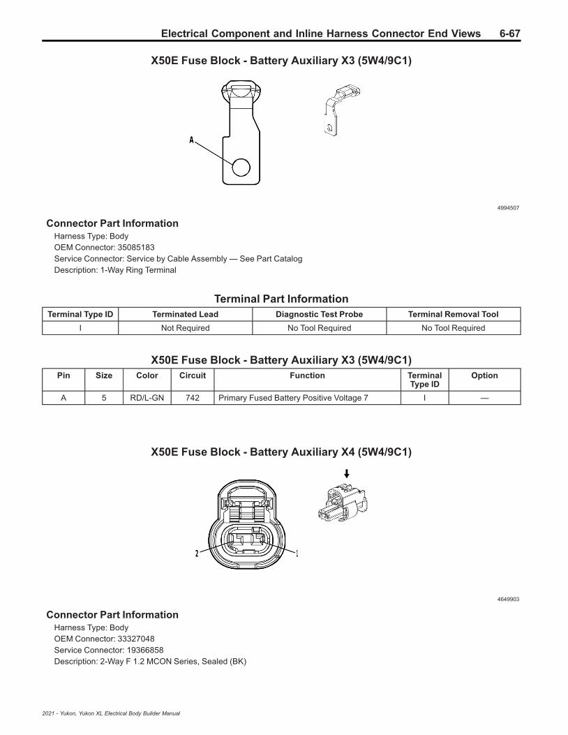
Electrical Component and Inline Harness Connector End Views 6-67
X50E Fuse Block - Battery Auxiliary X3 (5W4/9C1)
4994507
Connector Part InformationHarness Type: BodyOEM Connector: 35085183Service Connector: Service by Cable Assembly — See Part CatalogDescription: 1-Way Ring Terminal
Terminal Part InformationTerminal Type ID Terminated Lead Diagnostic Test Probe Terminal Removal Tool
I Not Required No Tool Required No Tool Required
X50E Fuse Block - Battery Auxiliary X3 (5W4/9C1)Pin Size Color Circuit Function Terminal
Type IDOption
A 5 RD/L-GN 742 Primary Fused Battery Positive Voltage 7 I —
X50E Fuse Block - Battery Auxiliary X4 (5W4/9C1)
4649903
Connector Part InformationHarness Type: BodyOEM Connector: 33327048Service Connector: 19366858Description: 2-Way F 1.2 MCON Series, Sealed (BK)
2021 - Yukon, Yukon XL Electrical Body Builder Manual

6-68 Electrical Component and Inline Harness Connector End Views
Terminal Part InformationTerminalType ID
TerminatedLead
DiagnosticTest Probe
TerminalRemoval Tool
Service Terminal TrayName
CoreCrimp
InsulationCrimp
I NotRequired
J-35616-16(LT GN) No Tool Required Not Required Not
RequiredNot
RequiredNot
Required
X50E Fuse Block - Battery Auxiliary X4 (5W4/9C1)Pin Size Color Circuit Function Terminal
Type IDOption
1 0.5 BN/D-BU 4892 Auxiliary Battery Relay Control I —
2 0.5 BK 7650 Police Ground 76 I —
X53A Fuse Block - Rear Body Label
5441152
2021 - Yukon, Yukon XL Electrical Body Builder Manual

Electrical Component and Inline Harness Connector End Views 6-69
X53A Fuse Block - Rear Body Top View
5331356
Usage Table
No.Device
Label NameDevice
Assigned Name Rating Description
Fuses
F01 RFA F1RA 10A • K77 Remote Function Actuator Module
F02 ECM F2RA 10A • K20 Engine Control Module
F03 DRVR HTD/SEAT F3RA 15A • K29FV Front Seat Heater Vent Control Module
F04 FTZM F4RA 20A • K111 Fuel Pump Power Control Module
F05 Not Used F5RA — • Not Used
F06 Not Used F6RA — • Not Used
F07 Not Used F7RA — • Not Used
F08 Not Used F8RA — • Not Used
F09 Not Used F9RA — • Not Used
F10 MTR ST BLT PASS F10RA 30A • M101R Front Seat Belt Retractor Motor - Right
2021 - Yukon, Yukon XL Electrical Body Builder Manual

6-70 Electrical Component and Inline Harness Connector End Views
Usage Table (cont'd)
No.Device
Label NameDevice
Assigned Name Rating Description
F11 CNSTRVENT SOL F11RA 10A • Q13 Evaporative Emission Canister Vent Valve
Solenoid
F12 S/ROOF F12RA 30A • K61 Sunroof Control Module
F13 Not Used F13RA — • Not Used
F14 Not Used F14RA — • Not Used
F15 PASS HTD/SEAT F15RA 15A • K29FV Front Seat Heater Vent Control Module
F16 ACDCINV F16RA 30A • Not Used
F17 ESC F17RA 25A • K19 Suspension Control Module (F55)
F18 Not Used F18RA — • Not Used
F19 MTR STBLT DRVR F19RA 30A • M101L Front Seat Belt Retractor Motor - Left
F20 RR DEFOG F20RA 40A • R14L Radio Antenna Ground Coil - Left
F21 DC DC TRANS F21RA 40A • T19 Multifunction Power Supply Converter
F22 DRVR WINDWDR/LCK SW F22RA 10A
• A24D Front Side Door Outside Handle - Left• S79D Front Side Door Window Control Switch - Driver
F23 EOCM F23RA 10A• B174W Front View Camera - Windshield• B233R Short Range Radar Sensor - Rear (UGN)• K124 Image Processing Module (UGN)
F24PASS DRVRWINDW DR/
LCK SWF24RA 10A
• A24P Front Side Door Outside Handle - Right• S79P Front Side Door Window Switch - Passenger
F25 Not Used F25RA — • Not Used
F26 TRLR F26RA 40A • Not Used
F27 RDCM F27RA 40A • K164 Differential Control Module
F28 REAR HTD/SEAT 2 F28RA 15A • Not Used
F29 Not Used F29RA — • Not Used
F30 Not Used F30RA 10A • Not Used
F31 DC DC TRANS F31RA 40A • T19 Multifunction Power Supply Converter
F32 TREC F32RA 15A • K69 Transfer Case Control Module (F46)
F33 CGM/SBZA F33RA 10A
• B218L Side Obstacle Detection Control Module -Left (UKC)
• B218R Side Obstacle Detection Control Module -Right (UKC)
• K56 Serial Data Gateway Module
F34 REAR HTD/SEAT1/VPM F34RA 15A • K157 Video Processing Module (UV2)
F35 HFCR F35RA 10A• K171 Rear Closure Hands Free Module (TL3)• W23 Blunt Cut - Body Provision (-TL3)
F36 ELM 2 F36RA 20A • K219 Lighting Control Module
F37 MSM PASS F37RA 10A
• K40P Passenger Seat Adjuster MemoryModule (AVU)
• K104P Front Seat Bladder Control Module -Passenger (AVU-AHH/AKE)
• K134P Front Seat Bolster Memory Module -Passenger (AHH)
• S64P Front Seat Adjuster Switch - Passenger(A7K+AHH)
• S65P Front Seat Lumbar Switch - Passenger (A7J)
2021 - Yukon, Yukon XL Electrical Body Builder Manual
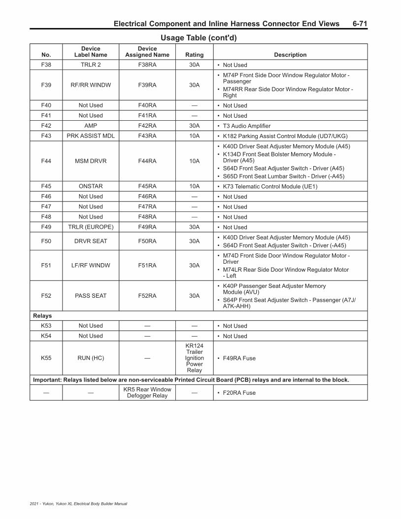
Electrical Component and Inline Harness Connector End Views 6-71
Usage Table (cont'd)
No.Device
Label NameDevice
Assigned Name Rating Description
F38 TRLR 2 F38RA 30A • Not Used
F39 RF/RR WINDW F39RA 30A
• M74P Front Side Door Window Regulator Motor -Passenger
• M74RR Rear Side Door Window Regulator Motor -Right
F40 Not Used F40RA — • Not Used
F41 Not Used F41RA — • Not Used
F42 AMP F42RA 30A • T3 Audio Amplifier
F43 PRK ASSIST MDL F43RA 10A • K182 Parking Assist Control Module (UD7/UKG)
F44 MSM DRVR F44RA 10A
• K40D Driver Seat Adjuster Memory Module (A45)• K134D Front Seat Bolster Memory Module -
Driver (A45)• S64D Front Seat Adjuster Switch - Driver (A45)• S65D Front Seat Lumbar Switch - Driver (-A45)
F45 ONSTAR F45RA 10A • K73 Telematic Control Module (UE1)
F46 Not Used F46RA — • Not Used
F47 Not Used F47RA — • Not Used
F48 Not Used F48RA — • Not Used
F49 TRLR (EUROPE) F49RA 30A • Not Used
F50 DRVR SEAT F50RA 30A• K40D Driver Seat Adjuster Memory Module (A45)• S64D Front Seat Adjuster Switch - Driver (-A45)
F51 LF/RF WINDW F51RA 30A
• M74D Front Side Door Window Regulator Motor -Driver
• M74LR Rear Side Door Window Regulator Motor- Left
F52 PASS SEAT F52RA 30A
• K40P Passenger Seat Adjuster MemoryModule (AVU)
• S64P Front Seat Adjuster Switch - Passenger (A7J/A7K-AHH)
Relays
K53 Not Used — — • Not Used
K54 Not Used — — • Not Used
K55 RUN (HC) —
KR124TrailerIgnitionPowerRelay
• F49RA Fuse
Important: Relays listed below are non-serviceable Printed Circuit Board (PCB) relays and are internal to the block.
— — KR5 Rear WindowDefogger Relay — • F20RA Fuse
2021 - Yukon, Yukon XL Electrical Body Builder Manual

6-72 Electrical Component and Inline Harness Connector End Views
X53A Fuse Block - Rear Body Bottom View
5331358
X53A Fuse Block - Rear Body X1
4997272
2021 - Yukon, Yukon XL Electrical Body Builder Manual
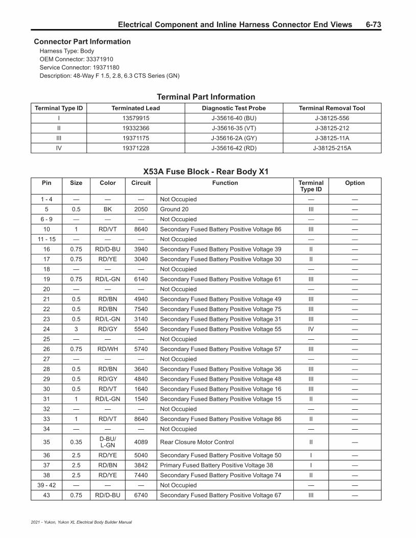
Electrical Component and Inline Harness Connector End Views 6-73
Connector Part InformationHarness Type: BodyOEM Connector: 33371910Service Connector: 19371180Description: 48-Way F 1.5, 2.8, 6.3 CTS Series (GN)
Terminal Part InformationTerminal Type ID Terminated Lead Diagnostic Test Probe Terminal Removal Tool
I 13579915 J-35616-40 (BU) J-38125-556
II 19332366 J-35616-35 (VT) J-38125-212
III 19371175 J-35616-2A (GY) J-38125-11A
IV 19371228 J-35616-42 (RD) J-38125-215A
X53A Fuse Block - Rear Body X1Pin Size Color Circuit Function Terminal
Type IDOption
1 - 4 — — — Not Occupied — —
5 0.5 BK 2050 Ground 20 III —
6 - 9 — — — Not Occupied — —
10 1 RD/VT 8640 Secondary Fused Battery Positive Voltage 86 III —
11 - 15 — — — Not Occupied — —
16 0.75 RD/D-BU 3940 Secondary Fused Battery Positive Voltage 39 II —
17 0.75 RD/YE 3040 Secondary Fused Battery Positive Voltage 30 II —
18 — — — Not Occupied — —
19 0.75 RD/L-GN 6140 Secondary Fused Battery Positive Voltage 61 III —
20 — — — Not Occupied — —
21 0.5 RD/BN 4940 Secondary Fused Battery Positive Voltage 49 III —
22 0.5 RD/BN 7540 Secondary Fused Battery Positive Voltage 75 III —
23 0.5 RD/L-GN 3140 Secondary Fused Battery Positive Voltage 31 III —
24 3 RD/GY 5540 Secondary Fused Battery Positive Voltage 55 IV —
25 — — — Not Occupied — —
26 0.75 RD/WH 5740 Secondary Fused Battery Positive Voltage 57 III —
27 — — — Not Occupied — —
28 0.5 RD/BN 3640 Secondary Fused Battery Positive Voltage 36 III —
29 0.5 RD/GY 4840 Secondary Fused Battery Positive Voltage 48 III —
30 0.5 RD/VT 1640 Secondary Fused Battery Positive Voltage 16 III —
31 1 RD/L-GN 1540 Secondary Fused Battery Positive Voltage 15 II —
32 — — — Not Occupied — —
33 1 RD/VT 8640 Secondary Fused Battery Positive Voltage 86 II —
34 — — — Not Occupied — —
35 0.35 D-BU/L-GN 4089 Rear Closure Motor Control II —
36 2.5 RD/YE 5040 Secondary Fused Battery Positive Voltage 50 I —
37 2.5 RD/BN 3842 Primary Fused Battery Positive Voltage 38 I —
38 2.5 RD/YE 7440 Secondary Fused Battery Positive Voltage 74 II —
39 - 42 — — — Not Occupied — —
43 0.75 RD/D-BU 6740 Secondary Fused Battery Positive Voltage 67 III —
2021 - Yukon, Yukon XL Electrical Body Builder Manual

6-74 Electrical Component and Inline Harness Connector End Views
X53A Fuse Block - Rear Body X1 (cont'd)Pin Size Color Circuit Function Terminal
Type IDOption
44 0.35 GY/YE 6188 Liftgate Window/Rear Compartment Lid MotorUnlatch Control III —
45 — — — Not Occupied — —
46 0.5 RD/L-GN 2642 Primary Fused Battery Positive Voltage 26 III —
47 - 48 — — — Not Occupied — —
X53A Fuse Block - Rear Body X2
4994712
Connector Part InformationHarness Type: BodyOEM Connector: 33371909Service Connector: 19371181Description: 38-Way F 1.5, 2.8, 6.3 CTS Series (BU)
Terminal Part InformationTerminal Type ID Terminated Lead Diagnostic Test Probe Terminal Removal Tool
I 13579915 J-35616-40 (BU) J-38125-556
II 19332366 J-35616-35 (VT) J-38125-212
III 19367600 J-35616-40 (BU) J-38125-556
IV 19371175 J-35616-2A (GY) J-38125-11A
V Not Required J-35616-22 (RD) No Tool Required
X53A Fuse Block - Rear Body X2Pin Size Color Circuit Function Terminal
Type IDOption
1 0.75 RD/BN 2240 Secondary Fused Battery Positive Voltage 22 II —
2 - 3 — — — Not Occupied — —
4 0.75 RD/BN 6640 Secondary Fused Battery Positive Voltage 66 IV —
5 0.5 RD/VT 2640 Secondary Fused Battery Positive Voltage 26 IV —
6 0.5 RD/VT 6340 Secondary Fused Battery Positive Voltage 63 IV —
7 0.35 BN/VT 193 Rear Defogger Relay Control IV —
8 - 13 — — — Not Occupied — —
14 0.75 RD/GY 6240 Secondary Fused Battery Positive Voltage 62 II —
2021 - Yukon, Yukon XL Electrical Body Builder Manual
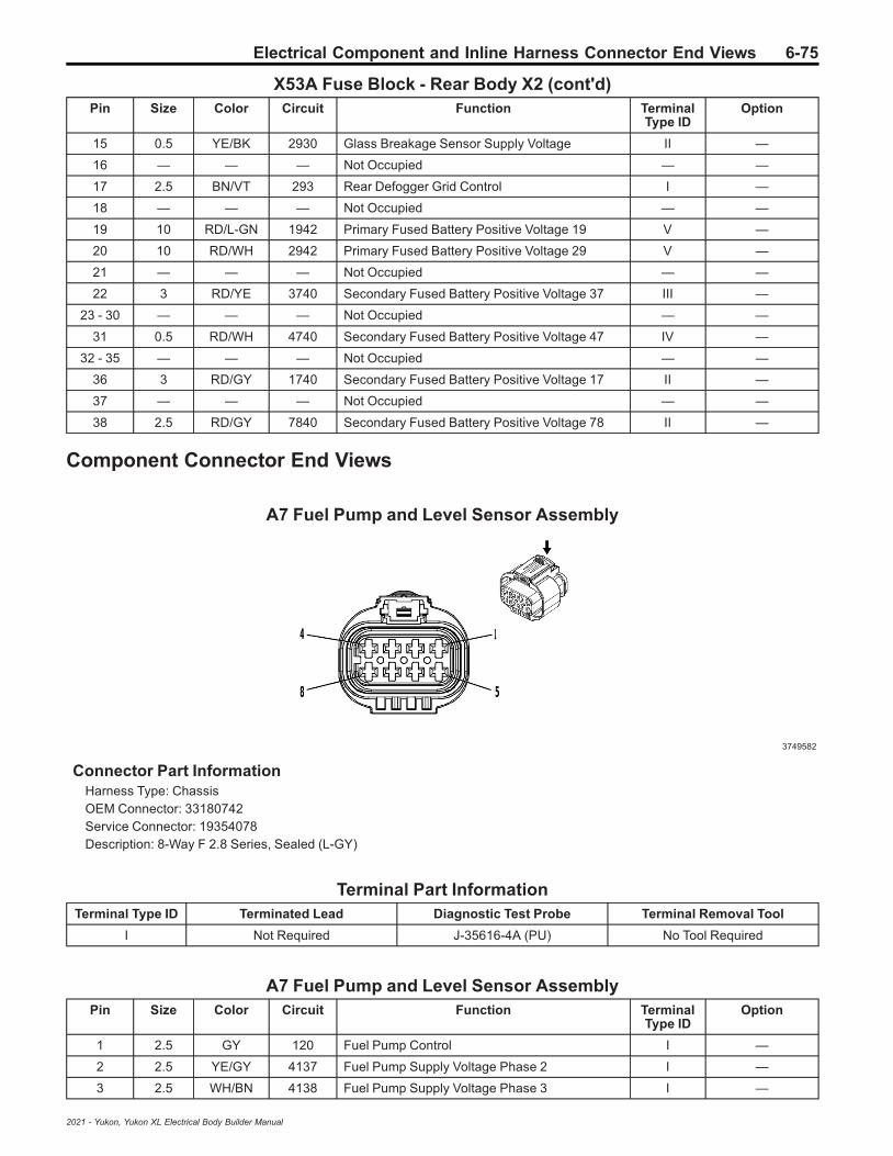
Electrical Component and Inline Harness Connector End Views 6-75
X53A Fuse Block - Rear Body X2 (cont'd)Pin Size Color Circuit Function Terminal
Type IDOption
15 0.5 YE/BK 2930 Glass Breakage Sensor Supply Voltage II —
16 — — — Not Occupied — —
17 2.5 BN/VT 293 Rear Defogger Grid Control I —
18 — — — Not Occupied — —
19 10 RD/L-GN 1942 Primary Fused Battery Positive Voltage 19 V —
20 10 RD/WH 2942 Primary Fused Battery Positive Voltage 29 V —
21 — — — Not Occupied — —
22 3 RD/YE 3740 Secondary Fused Battery Positive Voltage 37 III —
23 - 30 — — — Not Occupied — —
31 0.5 RD/WH 4740 Secondary Fused Battery Positive Voltage 47 IV —
32 - 35 — — — Not Occupied — —
36 3 RD/GY 1740 Secondary Fused Battery Positive Voltage 17 II —
37 — — — Not Occupied — —
38 2.5 RD/GY 7840 Secondary Fused Battery Positive Voltage 78 II —
Component Connector End Views
A7 Fuel Pump and Level Sensor Assembly
3749582
Connector Part InformationHarness Type: ChassisOEM Connector: 33180742Service Connector: 19354078Description: 8-Way F 2.8 Series, Sealed (L-GY)
Terminal Part InformationTerminal Type ID Terminated Lead Diagnostic Test Probe Terminal Removal Tool
I Not Required J-35616-4A (PU) No Tool Required
A7 Fuel Pump and Level Sensor AssemblyPin Size Color Circuit Function Terminal
Type IDOption
1 2.5 GY 120 Fuel Pump Control I —
2 2.5 YE/GY 4137 Fuel Pump Supply Voltage Phase 2 I —
3 2.5 WH/BN 4138 Fuel Pump Supply Voltage Phase 3 I —
2021 - Yukon, Yukon XL Electrical Body Builder Manual
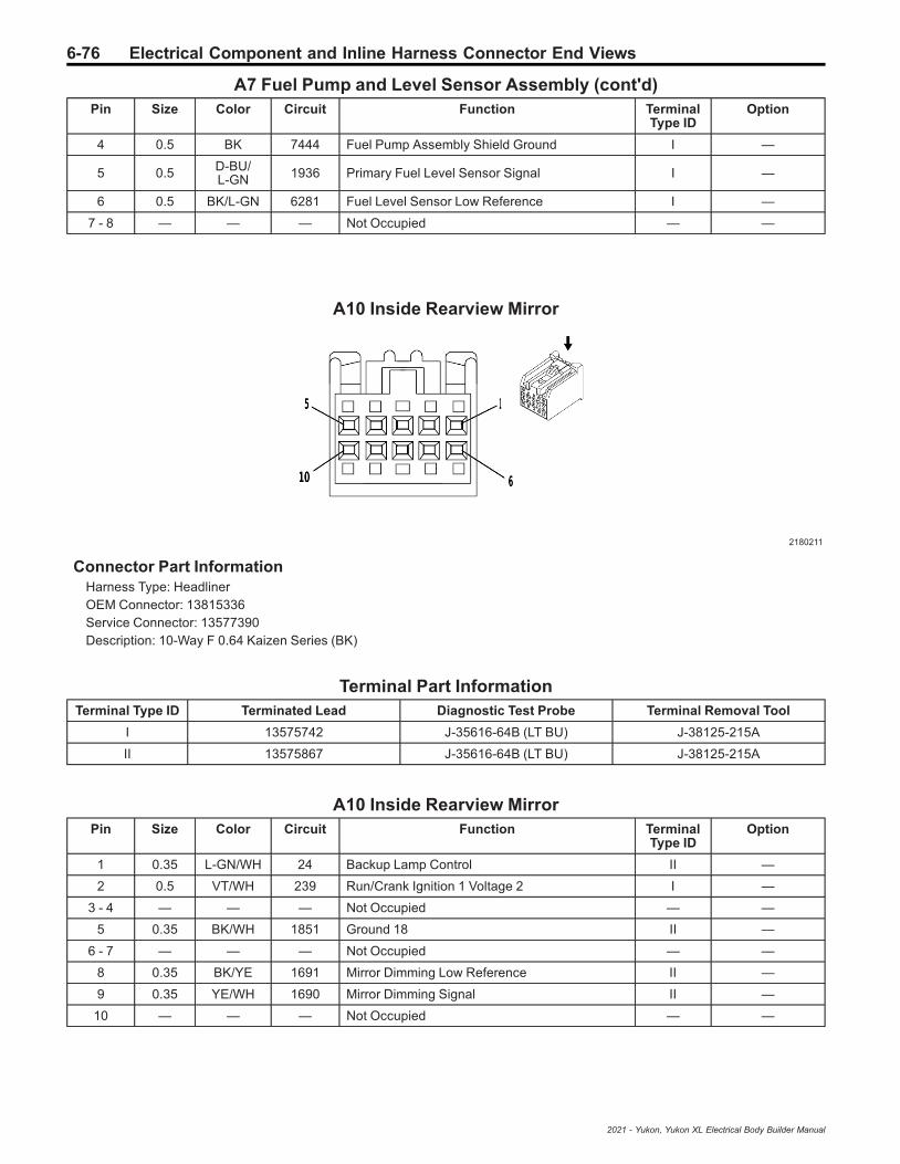
6-76 Electrical Component and Inline Harness Connector End Views
A7 Fuel Pump and Level Sensor Assembly (cont'd)Pin Size Color Circuit Function Terminal
Type IDOption
4 0.5 BK 7444 Fuel Pump Assembly Shield Ground I —
5 0.5 D-BU/L-GN 1936 Primary Fuel Level Sensor Signal I —
6 0.5 BK/L-GN 6281 Fuel Level Sensor Low Reference I —
7 - 8 — — — Not Occupied — —
A10 Inside Rearview Mirror
2180211
Connector Part InformationHarness Type: HeadlinerOEM Connector: 13815336Service Connector: 13577390Description: 10-Way F 0.64 Kaizen Series (BK)
Terminal Part InformationTerminal Type ID Terminated Lead Diagnostic Test Probe Terminal Removal Tool
I 13575742 J-35616-64B (LT BU) J-38125-215A
II 13575867 J-35616-64B (LT BU) J-38125-215A
A10 Inside Rearview MirrorPin Size Color Circuit Function Terminal
Type IDOption
1 0.35 L-GN/WH 24 Backup Lamp Control II —
2 0.5 VT/WH 239 Run/Crank Ignition 1 Voltage 2 I —
3 - 4 — — — Not Occupied — —
5 0.35 BK/WH 1851 Ground 18 II —
6 - 7 — — — Not Occupied — —
8 0.35 BK/YE 1691 Mirror Dimming Low Reference II —
9 0.35 YE/WH 1690 Mirror Dimming Signal II —
10 — — — Not Occupied — —
2021 - Yukon, Yukon XL Electrical Body Builder Manual
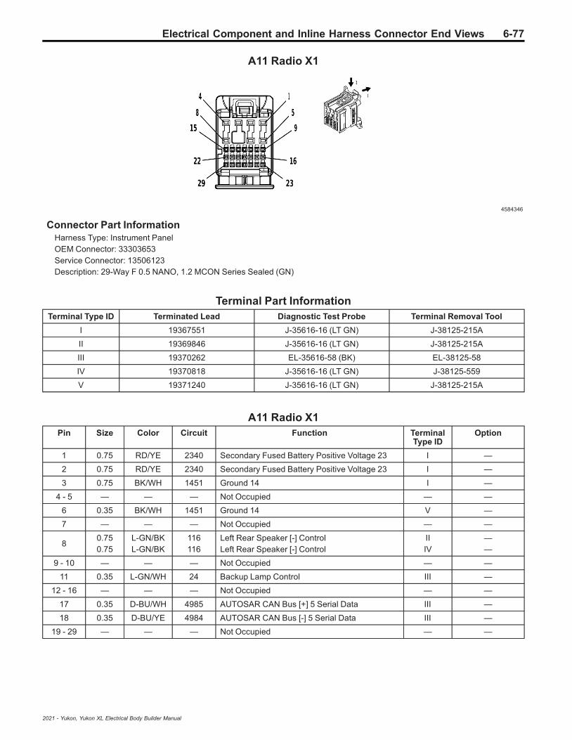
Electrical Component and Inline Harness Connector End Views 6-77
A11 Radio X1
4584346
Connector Part InformationHarness Type: Instrument PanelOEM Connector: 33303653Service Connector: 13506123Description: 29-Way F 0.5 NANO, 1.2 MCON Series Sealed (GN)
Terminal Part InformationTerminal Type ID Terminated Lead Diagnostic Test Probe Terminal Removal Tool
I 19367551 J-35616-16 (LT GN) J-38125-215A
II 19369846 J-35616-16 (LT GN) J-38125-215A
III 19370262 EL-35616-58 (BK) EL-38125-58
IV 19370818 J-35616-16 (LT GN) J-38125-559
V 19371240 J-35616-16 (LT GN) J-38125-215A
A11 Radio X1Pin Size Color Circuit Function Terminal
Type IDOption
1 0.75 RD/YE 2340 Secondary Fused Battery Positive Voltage 23 I —
2 0.75 RD/YE 2340 Secondary Fused Battery Positive Voltage 23 I —
3 0.75 BK/WH 1451 Ground 14 I —
4 - 5 — — — Not Occupied — —
6 0.35 BK/WH 1451 Ground 14 V —
7 — — — Not Occupied — —
80.750.75
L-GN/BKL-GN/BK
116116
Left Rear Speaker [-] ControlLeft Rear Speaker [-] Control
IIIV
——
9 - 10 — — — Not Occupied — —
11 0.35 L-GN/WH 24 Backup Lamp Control III —
12 - 16 — — — Not Occupied — —
17 0.35 D-BU/WH 4985 AUTOSAR CAN Bus [+] 5 Serial Data III —
18 0.35 D-BU/YE 4984 AUTOSAR CAN Bus [-] 5 Serial Data III —
19 - 29 — — — Not Occupied — —
2021 - Yukon, Yukon XL Electrical Body Builder Manual

6-78 Electrical Component and Inline Harness Connector End Views
A11 Radio X2
4584398
Connector Part InformationHarness Type: Instrument PanelOEM Connector: 33303654Service Connector: 13506123Description: 29-Way F 0.5 NANO, 1.2 MCON Series Sealed (GY)
Terminal Part InformationTerminal Type ID Terminated Lead Diagnostic Test Probe Terminal Removal Tool
I 19367551 J-35616-16 (LT GN) J-38125-215A
II 19369846 J-35616-16 (LT GN) J-38125-215A
III 19370262 EL-35616-58 (BK) EL-38125-58
IV 19370818 J-35616-16 (LT GN) J-38125-559
A11 Radio X2Pin Size Color Circuit Function Terminal
Type IDOption
10.750.75
L-GNL-GN
199199
Left Rear Speaker [+] ControlLeft Rear Speaker [+] Control
IIIV
——
2 0.5 D-BU 201 Left Front Speaker 1 [+] Control I —
3 0.5 YE 200 Right Front Speaker 1 [+] Control I —
40.750.75
D-BU/BKD-BU/BK
115115
Right Rear Speaker [-] ControlRight Rear Speaker [-] Control
IIIV
——
5 0.5 BN/D-BU 118 Left Front Speaker [-] Control 1 I —
6 0.5 YE/BK 117 Right Front Speaker [-] Control 1 I —
7 — — — Not Occupied — —
80.750.75
WHWH
4646
Right Rear Speaker [+] ControlRight Rear Speaker [+] Control
III
——
90.350.35
BK/GYBK/BN
5152654
Voice Recognition Audio [-] ControlCellular Telephone Microphone Low Reference
IIIIII
——
100.350.35
GY/YED-BU
5149655
Voice Recognition Audio SignalCellular Telephone Microphone Signal
IIIIII
——
11 - 29 — — — Not Occupied — —
2021 - Yukon, Yukon XL Electrical Body Builder Manual

Electrical Component and Inline Harness Connector End Views 6-79
A11 Radio X3
4215060
Connector Part InformationHarness Type: Instrument PanelOEM Connector: 33228283Service Connector: 19354840Description: 4-Way F Mini 50 Series (BK)
Terminal Part InformationTerminal Type ID Terminated Lead Diagnostic Test Probe Terminal Removal Tool
I Not Required EL-35616-58 (BK) No Tool Required
A11 Radio X3Pin Size Color Circuit Function Terminal
Type IDOption
1 — — — Not Occupied — —
2 0.35 D-BU/WH 4758 Ethernet Bus 2 [+] I —
3 0.35 D-BU 4757 Ethernet Bus 2 [-] I —
4 — — — Not Occupied — —
A16 Transfer Case Motor (NP0/NQH)
646372
Connector Part InformationHarness Type: EngineOEM Connector: 13538370
2021 - Yukon, Yukon XL Electrical Body Builder Manual

6-80 Electrical Component and Inline Harness Connector End Views
Service Connector: 19369184Description: 8-Way F 280 GT Series, Sealed (BK)
Terminal Part InformationTerminal Type ID Terminated Lead Diagnostic Test Probe Terminal Removal Tool
I Not Required J-35616-4A (PU) No Tool Required
A16 Transfer Case Motor (NP0/NQH)Pin Size Color Circuit Function Terminal
Type IDOption
A 2.5 YE/GY 1552 Transfer Case Motor Clockwise Control I —
B 0.5 D-BU 8013 Transfer Case Lock Solenoid Control 2 I —
C 0.5 YE/BN 1569 Transfer Case Lock Solenoid Valve Control I —
D 2.5 YE/VT 1553 Transfer Case Motor Counter Clockwise Control I —
E 0.5 YE 7474 Incremental Encoder Direction Signal I —
F 0.5 D-BU/GY 7473 Incremental Encoder Impulse Signal I —
G 0.5 WH/L-GN 7475 Incremental Encoder Sensor 8V Reference I —
H 0.5 VT 7476 Incremental Encoder Sensor Low Reference I —
A22 Radio Controls X3
4578560
Connector Part InformationHarness Type: Instrument PanelOEM Connector: 33303967Service Connector: 84655160Description: 29-Way F 0.5 NANO, 1.2 MCON Series Sealed (GY)
Terminal Part InformationTerminal Type ID Terminated Lead Diagnostic Test Probe Terminal Removal Tool
I 19367551 J-35616-16 (LT GN) J-38125-215A
II 19370262 EL-35616-58 (BK) EL-38125-58
III 19370818 J-35616-16 (LT GN) J-38125-559
2021 - Yukon, Yukon XL Electrical Body Builder Manual

Electrical Component and Inline Harness Connector End Views 6-81
A22 Radio Controls X3Pin Size Color Circuit Function Terminal
Type IDOption
1 0.75 L-GN 199 Left Rear Speaker [+] Control III —
2 0.5 D-BU 201 Left Front Speaker 1 [+] Control I —
3 0.5 YE/BK 117 Right Front Speaker [-] Control 1 I —
4 0.75 D-BU/BK 115 Right Rear Speaker [-] Control III —
5 0.5 BN/D-BU 118 Left Front Speaker [-] Control 1 I —
6 0.5 YE 200 Right Front Speaker 1 [+] Control I —
7 — — — Not Occupied — —
8 0.75 WH 46 Right Rear Speaker [+] Control I —
9 0.35 D-BU/WH 4985 AUTOSAR CAN Bus [+] 5 Serial Data II —
10 0.35 D-BU/YE 4984 AUTOSAR CAN Bus [-] 5 Serial Data II —
11 - 12 — — — Not Occupied — —
13 0.35 L-GN/WH 24 Backup Lamp Control II —
14 0.35 L-GN/YE 7066 Entertainment Remote Enable Signal II —
15 - 29 — — — Not Occupied — —
A22 Radio Controls X6
3824362
Connector Part InformationHarness Type: Instrument PanelOEM Connector: 33235297Service Connector: 13507121Description: 12-Way F Mini 50 Series (BK)
Terminal Part InformationTerminal Type ID Terminated Lead Diagnostic Test Probe Terminal Removal Tool
I 19333221 EL-35616-58 (BK) EL-38125-58
A22 Radio Controls X6Pin Size Color Circuit Function Terminal
Type IDOption
1 0.35 VT/WH 7213 Ethernet Bus 5 [+] I —
2 0.35 VT 7212 Ethernet Bus 5 [-] I —
3 0.35 D-BU/WH 4758 Ethernet Bus 2 [+] I —
2021 - Yukon, Yukon XL Electrical Body Builder Manual

6-82 Electrical Component and Inline Harness Connector End Views
A22 Radio Controls X6 (cont'd)Pin Size Color Circuit Function Terminal
Type IDOption
4 0.35 D-BU 4757 Ethernet Bus 2 [-] I —
5 - 7 — — — Not Occupied — —
8 0.35 GY/BK 7215 Ethernet Bus 6 [+] I —
9 0.35 BN/BK 7214 Ethernet Bus 6 [-] I —
10 — — — Not Occupied — —
11 0.35 GY/WH 7211 Ethernet Bus 4 [+] I —
12 0.35 GY 7210 Ethernet Bus 4 [-] I —
A22 Radio Controls X2 (UQF)
4496253
Connector Part InformationHarness Type: Instrument PanelOEM Connector: 33303954Service Connector: 13506123Description: 29-Way F 0.5 NANO, 1.2 MCON Series Sealed (BK)
Terminal Part InformationTerminal Type ID Terminated Lead Diagnostic Test Probe Terminal Removal Tool
I 19367551 J-35616-16 (LT GN) J-38125-215A
II 19370262 EL-35616-58 (BK) EL-38125-58
III 19370818 J-35616-16 (LT GN) J-38125-559
A22 Radio Controls X2 (UQF)Pin Size Color Circuit Function Terminal
Type IDOption
1 0.5 RD/YE 2340 Secondary Fused Battery Positive Voltage 23 I —
2 — — — Not Occupied — —
3 0.5 BK/WH 1451 Ground 14 I —
4 - 7 — — — Not Occupied — —
8 0.75 L-GN/BK 116 Left Rear Speaker [-] Control III —
90.350.35
GY/YED-BU
5149655
Voice Recognition Audio SignalCellular Telephone Microphone Signal
IIII
IOS+UDA+UE1IOS-UDA-UE1
10 0.35 BK/GY 5152 Voice Recognition Audio [-] Control II IOS+UDA+UE1
2021 - Yukon, Yukon XL Electrical Body Builder Manual

Electrical Component and Inline Harness Connector End Views 6-83
A22 Radio Controls X2 (UQF) (cont'd)Pin Size Color Circuit Function Terminal
Type IDOption
0.35 BK/BN 654 Cellular Telephone Microphone Low Reference II IOS-UDA-UE1
11 0.35 VT/YE 7043 Microphone [+] Signal II —
12 0.35 D-BU/BK 7044 Microphone [-] II —
13 - 29 — — — Not Occupied — —
A23C Liftgate Latch Assembly (TB4)
5137287
Connector Part InformationHarness Type: LiftgateOEM Connector: 15509333Service Connector: Service by Harness - See Part CatalogDescription: 4-Way F 1.5 YESC Series (BK)
Terminal Part InformationTerminal Type ID Terminated Lead Diagnostic Test Probe Terminal Removal Tool
I Not Required J-35616-2A (GY) No Tool Required
A23C Liftgate Latch Assembly (TB4)Pin Size Color Circuit Function Terminal
Type IDOption
1 0.35 VT/GY 1303 Liftgate Ajar Switch Signal 1 I —
2 0.5 BK 2050 Ground 20 I —
3 0.5 D-BU/WH 6128 Rear Closure Unlatch Actuator Unlatch Control I —
4 0.5 GY/BK 2680 Lock Actuators Unlock Control 2 I —
2021 - Yukon, Yukon XL Electrical Body Builder Manual
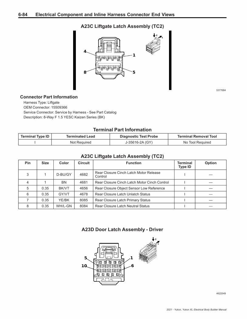
6-84 Electrical Component and Inline Harness Connector End Views
A23C Liftgate Latch Assembly (TC2)
5377684
Connector Part InformationHarness Type: LiftgateOEM Connector: 15509366Service Connector: Service by Harness - See Part CatalogDescription: 8-Way F 1.5 YESC Kaizen Series (BK)
Terminal Part InformationTerminal Type ID Terminated Lead Diagnostic Test Probe Terminal Removal Tool
I Not Required J-35616-2A (GY) No Tool Required
A23C Liftgate Latch Assembly (TC2)Pin Size Color Circuit Function Terminal
Type IDOption
3 1 D-BU/GY 4682 Rear Closure Cinch Latch Motor ReleaseControl I —
4 1 BN 4681 Rear Closure Cinch Latch Motor Cinch Control I —
5 0.35 BK/VT 4656 Rear Closure Object Sensor Low Reference I —
6 0.35 GY/VT 4678 Rear Closure Latch Unlatch Status I —
7 0.35 YE/BK 8085 Rear Closure Latch Primary Status I —
8 0.35 WH/L-GN 8084 Rear Closure Latch Neutral Status I —
A23D Door Latch Assembly - Driver
4622549
2021 - Yukon, Yukon XL Electrical Body Builder Manual
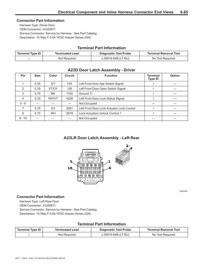
Electrical Component and Inline Harness Connector End Views 6-85
Connector Part InformationHarness Type: Driver DoorOEM Connector: 33320811Service Connector: Service by Harness - See Part CatalogDescription: 10-Way F 0.64 YESC Kaizen Series (GN)
Terminal Part InformationTerminal Type ID Terminated Lead Diagnostic Test Probe Terminal Removal Tool
I Not Required J-35616-64B (LT BU) No Tool Required
A23D Door Latch Assembly - DriverPin Size Color Circuit Function Terminal
Type IDOption
1 0.35 GY 745 Left Front Door Ajar Switch Signal I —
2 0.35 VT/GY 126 Left Front Door Open Switch Signal I —
3 0.75 BK 1150 Ground 11 I —
4 0.35 WH/VT 4258 Left Front Door Lock Status Signal I —
5 - 6 — — — Not Occupied — —
7 0.75 GY 2681 Left Front Door Lock Actuator Lock Control I —
8 0.75 WH 2679 Lock Actuators Unlock Control 1 I —
9 - 10 — — — Not Occupied — —
A23LR Door Latch Assembly - Left Rear
4622549
Connector Part InformationHarness Type: Left Rear DoorOEM Connector: 33320811Service Connector: Service by Harness - See Part CatalogDescription: 10-Way F 0.64 YESC Kaizen Series (GN)
Terminal Part InformationTerminal Type ID Terminated Lead Diagnostic Test Probe Terminal Removal Tool
I Not Required J-35616-64B (LT BU) No Tool Required
2021 - Yukon, Yukon XL Electrical Body Builder Manual

6-86 Electrical Component and Inline Harness Connector End Views
A23LR Door Latch Assembly - Left RearPin Size Color Circuit Function Terminal
Type IDOption
1 0.35 GY 747 Left Rear Door Ajar Switch Signal I —
2 — — — Not Occupied — —
3 0.75 BK 1150 Ground 11 I —
4 0.35 L-GN/D-BU 4648 Left Rear Door Lock Status Signal I —
5 — — — Not Occupied — —
6 0.75 VT/BN 2754 Door Double Lock Actuator Lock Control 2 I —
7 0.75 D-BU/YE 1091 Left Rear Door Lock Actuator Lock Control I —
8 0.75 WH 2679 Lock Actuators Unlock Control 1 I —
9 - 10 — — — Not Occupied — —
A23P Door Latch Assembly - Passenger
4622549
Connector Part InformationHarness Type: Passenger DoorOEM Connector: 33320811Service Connector: Service by Harness - See Part CatalogDescription: 10-Way F 0.64 YESC Kaizen Series (GN)
Terminal Part InformationTerminal Type ID Terminated Lead Diagnostic Test Probe Terminal Removal Tool
I Not Required J-35616-64B (LT BU) No Tool Required
A23P Door Latch Assembly - PassengerPin Size Color Circuit Function Terminal
Type IDOption
1 — — — Not Occupied — —
2 0.35 VT 4259 Right Front Door Lock Status Signal I —
3 0.75 BK 1250 Ground 12 I —
4 — — — Not Occupied — —
5 0.35 GY 746 Right Front Door Ajar Switch Signal I —
6 - 7 — — — Not Occupied — —
8 0.75 GY/BK 2680 Lock Actuators Unlock Control 2 I —
2021 - Yukon, Yukon XL Electrical Body Builder Manual

Electrical Component and Inline Harness Connector End Views 6-87
A23P Door Latch Assembly - Passenger (cont'd)Pin Size Color Circuit Function Terminal
Type IDOption
9 0.75 YE/L-GN 2682 Right Front Door Lock Actuator Lock Control I —
10 — — — Not Occupied — —
A23RR Door Latch Assembly - Right Rear
4622549
Connector Part InformationHarness Type: Right Rear DoorOEM Connector: 33320811Service Connector: Service by Harness - See Part CatalogDescription: 10-Way F 0.64 YESC Kaizen Series (GN)
Terminal Part InformationTerminal Type ID Terminated Lead Diagnostic Test Probe Terminal Removal Tool
I Not Required J-35616-64B (LT BU) No Tool Required
A23RR Door Latch Assembly - Right RearPin Size Color Circuit Function Terminal
Type IDOption
1 — — — Not Occupied — —
2 0.35 WH/GY 4649 Right Rear Door Lock Status Signal I —
3 0.5 BK 1250 Ground 12 I —
4 — — — Not Occupied — —
5 0.35 GY 748 Right Rear Door Ajar Switch Signal I —
6 - 7 — — — Not Occupied — —
8 0.75 GY/BK 2680 Lock Actuators Unlock Control 2 I —
9 0.75 VT/WH 1094 Right Rear Door Lock Actuator Lock Control I —
10 0.75 VT/BN 2754 Door Double Lock Actuator Lock Control 2 I —
2021 - Yukon, Yukon XL Electrical Body Builder Manual

6-88 Electrical Component and Inline Harness Connector End Views
A24D Door Handle Assembly - Driver Exterior
4808325
Connector Part InformationHarness Type: Driver DoorOEM Connector: 35028907Service Connector: Service by Harness - See Part CatalogDescription: 5-Way M 1.2 Series, Sealed (BK)
Terminal Part InformationTerminal Type ID Terminated Lead Diagnostic Test Probe Terminal Removal Tool
I Not Required J-35616-17 (LT GN) No Tool Required
A24D Door Handle Assembly - Driver ExteriorPin Size Color Circuit Function Terminal
Type IDOption
1 0.5 D-BU 2675 Left Front Exterior Door Handle Switch UnlockSignal I —
2 - 4 — — — Not Occupied — —
5 0.75 BK 1150 Ground 11 I —
A24LR Door Handle Assembly - Left Rear Exterior
4808325
Connector Part InformationHarness Type: Left Rear DoorOEM Connector: 35028907
2021 - Yukon, Yukon XL Electrical Body Builder Manual

Electrical Component and Inline Harness Connector End Views 6-89
Service Connector: Service by Harness - See Part CatalogDescription: 5-Way M 1.2 Series, Sealed (BK)
Terminal Part InformationTerminal Type ID Terminated Lead Diagnostic Test Probe Terminal Removal Tool
I Not Required J-35616-13 (BU) No Tool Required
II Not Required J-35616-17 (LT GN) No Tool Required
A24LR Door Handle Assembly - Left Rear ExteriorPin Size Color Circuit Function Terminal
Type IDOption
1 0.35 WH/VT 4994 Left Rear Door Exterior Switch Unlock Signal I —
2 - 4 — — — Not Occupied — —
5 0.5 BK 1150 Ground 11 II —
A24P Door Handle Assembly - Passenger Exterior
4808325
Connector Part InformationHarness Type: Passenger DoorOEM Connector: 35028907Service Connector: Service by Harness - See Part CatalogDescription: 5-Way M 1.2 Series, Sealed (BK)
Terminal Part InformationTerminal Type ID Terminated Lead Diagnostic Test Probe Terminal Removal Tool
I Not Required J-35616-13 (BU) No Tool Required
II Not Required J-35616-17 (LT GN) No Tool Required
A24P Door Handle Assembly - Passenger ExteriorPin Size Color Circuit Function Terminal
Type IDOption
1 0.35 GY/VT 2676 Right Front Door Exterior Switch Unlock Signal I —
2 - 4 — — — Not Occupied — —
5 0.5 BK/WH 1251 Ground 12 II —
2021 - Yukon, Yukon XL Electrical Body Builder Manual
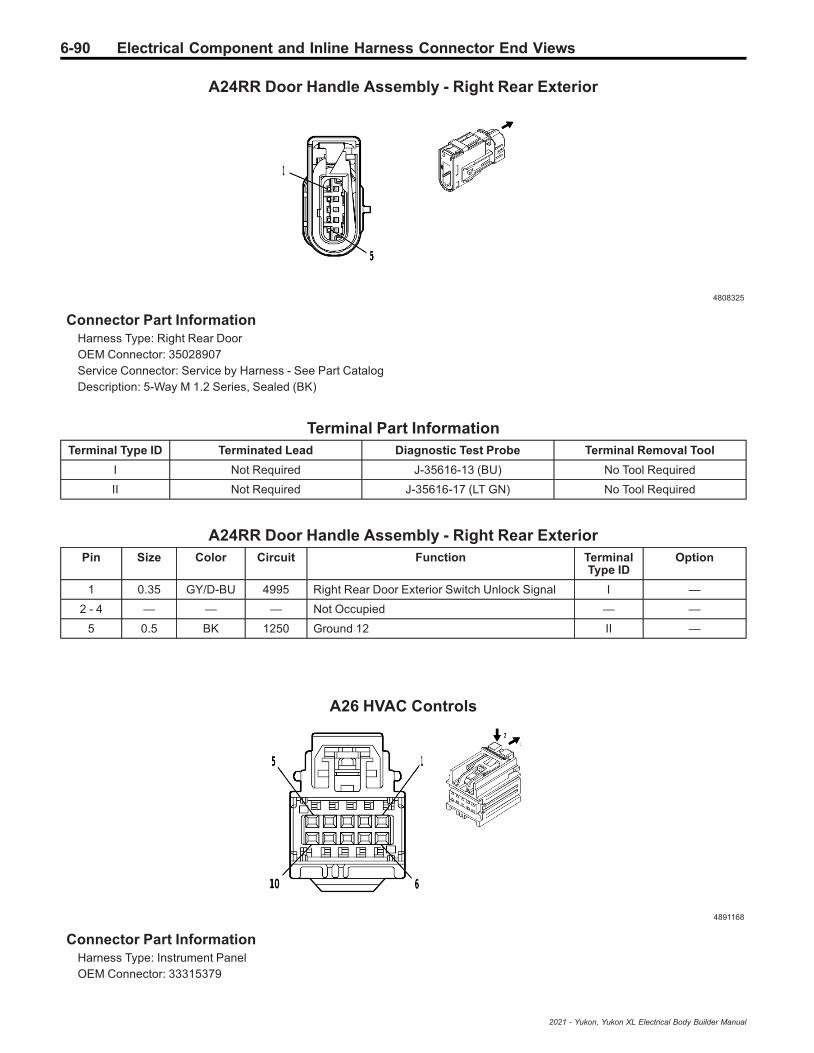
6-90 Electrical Component and Inline Harness Connector End Views
A24RR Door Handle Assembly - Right Rear Exterior
4808325
Connector Part InformationHarness Type: Right Rear DoorOEM Connector: 35028907Service Connector: Service by Harness - See Part CatalogDescription: 5-Way M 1.2 Series, Sealed (BK)
Terminal Part InformationTerminal Type ID Terminated Lead Diagnostic Test Probe Terminal Removal Tool
I Not Required J-35616-13 (BU) No Tool Required
II Not Required J-35616-17 (LT GN) No Tool Required
A24RR Door Handle Assembly - Right Rear ExteriorPin Size Color Circuit Function Terminal
Type IDOption
1 0.35 GY/D-BU 4995 Right Rear Door Exterior Switch Unlock Signal I —
2 - 4 — — — Not Occupied — —
5 0.5 BK 1250 Ground 12 II —
A26 HVAC Controls
4891168
Connector Part InformationHarness Type: Instrument PanelOEM Connector: 33315379
2021 - Yukon, Yukon XL Electrical Body Builder Manual

Electrical Component and Inline Harness Connector End Views 6-91
Service Connector: 13509649Description: 10-Way F 0.64 YESC Kaizen Series (NA)
Terminal Part InformationTerminal Type ID Terminated Lead Diagnostic Test Probe Terminal Removal Tool
I 13575742 J-35616-64B (LT BU) J-38125-215A
II 13575867 J-35616-64B (LT BU) J-38125-215A
A26 HVAC ControlsPin Size Color Circuit Function Terminal
Type IDOption
1 0.5 RD/WH 1340 Secondary Fused Battery Positive Voltage 13 I —
2 — — — Not Occupied — —
3 0.35 D-BU/WH 4985 AUTOSAR CAN Bus [+] 5 Serial Data II —
4 0.35 D-BU/WH 4985 AUTOSAR CAN Bus [+] 5 Serial Data II —
5 — — — Not Occupied — —
6 0.35 GY/L-GN 4636 HVAC System Enable Signal II —
7 — — — Not Occupied — —
8 0.35 D-BU/YE 4984 AUTOSAR CAN Bus [-] 5 Serial Data II —
9 0.35 D-BU/YE 4984 AUTOSAR CAN Bus [-] 5 Serial Data II —
10 0.5 BK/WH 1851 Ground 18 I —
A34 HVAC Controls - Auxiliary (BOP)
4873243
Connector Part InformationHarness Type: Floor ConsoleOEM Connector: 35016343Service Connector: Service by Harness - See Part CatalogDescription: 16-Way F 0.64 OCS Series (BK)
Terminal Part InformationTerminal Type ID Terminated Lead Diagnostic Test Probe Terminal Removal Tool
I Not Required J-35616-64B (LT BU) No Tool Required
2021 - Yukon, Yukon XL Electrical Body Builder Manual

6-92 Electrical Component and Inline Harness Connector End Views
A34 HVAC Controls - Auxiliary (BOP)Pin Size Color Circuit Function Terminal
Type IDOption
1 — — — Not Occupied — —
2 0.35 BN/BK 405 Lower Duct Air Temperature Sensor Signal I —
3 0.75 BK/VT 470 Sensor Low Reference 3 I —
4 0.35 BN 404 Upper Duct Air Temperature Sensor Signal I —
5 — — — Not Occupied — —
6 0.75 YE/WH 4635 HVAC Remote Enable 2 Signal I —
7 0.5 L-GN/BK 2211 Rear Blower Motor Speed Control I —
8 0.35 D-BU/YE 4984 AUTOSAR CAN Bus [-] 5 Serial Data I —
9 0.35 D-BU/WH 4985 AUTOSAR CAN Bus [+] 5 Serial Data I —
10 0.5 RD/BN 7540 Secondary Fused Battery Positive Voltage 75 I —
11 0.5 BK/WH 1351 Ground 13 I —
12 0.35 D-BU/YE 4984 AUTOSAR CAN Bus [-] 5 Serial Data I —
13 0.35 D-BU/WH 4985 AUTOSAR CAN Bus [+] 5 Serial Data I —
14 — — — Not Occupied — —
15 0.35 D-BU/YE 4984 AUTOSAR CAN Bus [-] 5 Serial Data I —
16 0.35 D-BU/WH 4985 AUTOSAR CAN Bus [+] 5 Serial Data I —
A34 HVAC Controls - Auxiliary (C69)
4873243
Connector Part InformationHarness Type: Floor ConsoleOEM Connector: 35016343Service Connector: Service by Harness - See Part CatalogDescription: 16-Way F 0.64 OCS Series (BK)
Terminal Part InformationTerminal Type ID Terminated Lead Diagnostic Test Probe Terminal Removal Tool
I Not Required J-35616-64B (LT BU) No Tool Required
A34 HVAC Controls - Auxiliary (C69)Pin Size Color Circuit Function Terminal
Type IDOption
1 — — — Not Occupied — —
2021 - Yukon, Yukon XL Electrical Body Builder Manual
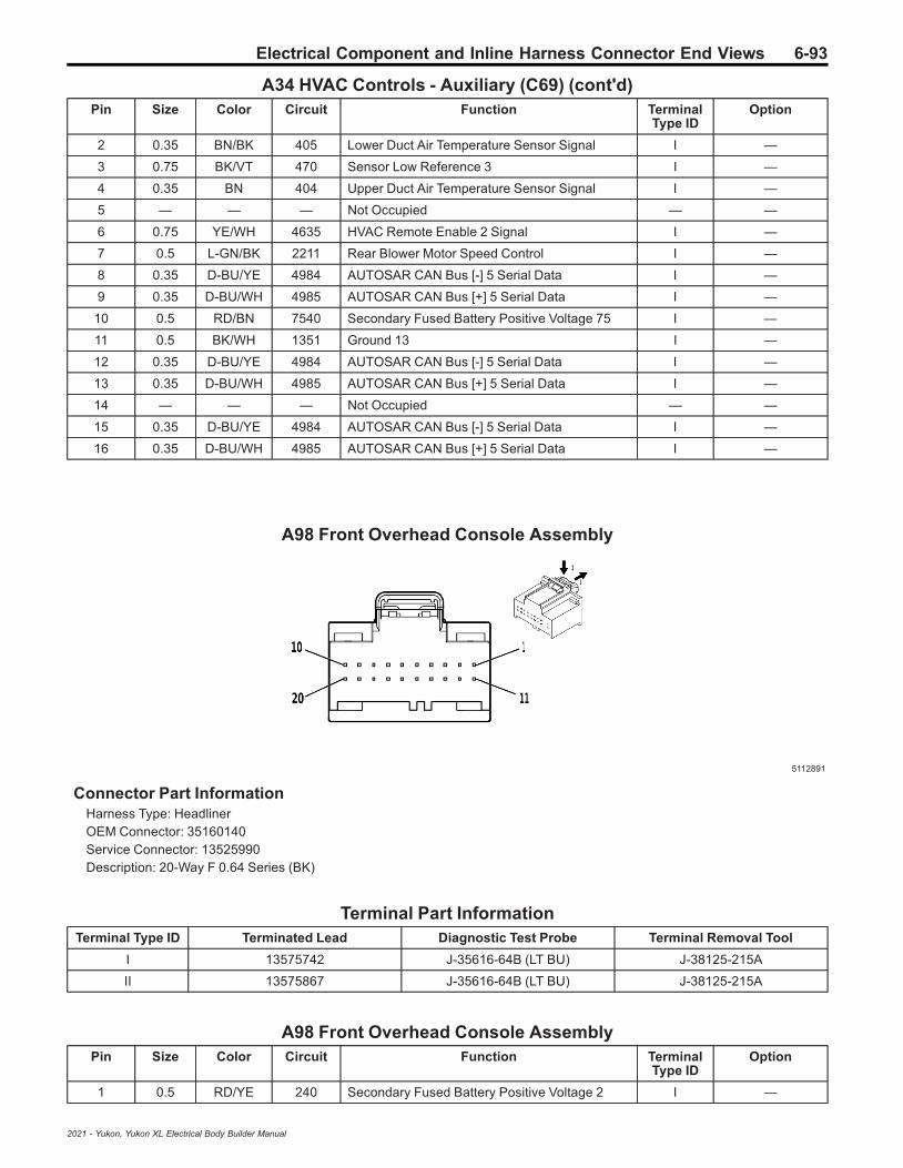
Electrical Component and Inline Harness Connector End Views 6-93
A34 HVAC Controls - Auxiliary (C69) (cont'd)Pin Size Color Circuit Function Terminal
Type IDOption
2 0.35 BN/BK 405 Lower Duct Air Temperature Sensor Signal I —
3 0.75 BK/VT 470 Sensor Low Reference 3 I —
4 0.35 BN 404 Upper Duct Air Temperature Sensor Signal I —
5 — — — Not Occupied — —
6 0.75 YE/WH 4635 HVAC Remote Enable 2 Signal I —
7 0.5 L-GN/BK 2211 Rear Blower Motor Speed Control I —
8 0.35 D-BU/YE 4984 AUTOSAR CAN Bus [-] 5 Serial Data I —
9 0.35 D-BU/WH 4985 AUTOSAR CAN Bus [+] 5 Serial Data I —
10 0.5 RD/BN 7540 Secondary Fused Battery Positive Voltage 75 I —
11 0.5 BK/WH 1351 Ground 13 I —
12 0.35 D-BU/YE 4984 AUTOSAR CAN Bus [-] 5 Serial Data I —
13 0.35 D-BU/WH 4985 AUTOSAR CAN Bus [+] 5 Serial Data I —
14 — — — Not Occupied — —
15 0.35 D-BU/YE 4984 AUTOSAR CAN Bus [-] 5 Serial Data I —
16 0.35 D-BU/WH 4985 AUTOSAR CAN Bus [+] 5 Serial Data I —
A98 Front Overhead Console Assembly
5112891
Connector Part InformationHarness Type: HeadlinerOEM Connector: 35160140Service Connector: 13525990Description: 20-Way F 0.64 Series (BK)
Terminal Part InformationTerminal Type ID Terminated Lead Diagnostic Test Probe Terminal Removal Tool
I 13575742 J-35616-64B (LT BU) J-38125-215A
II 13575867 J-35616-64B (LT BU) J-38125-215A
A98 Front Overhead Console AssemblyPin Size Color Circuit Function Terminal
Type IDOption
1 0.5 RD/YE 240 Secondary Fused Battery Positive Voltage 2 I —
2021 - Yukon, Yukon XL Electrical Body Builder Manual

6-94 Electrical Component and Inline Harness Connector End Views
A98 Front Overhead Console Assembly (cont'd)Pin Size Color Circuit Function Terminal
Type IDOption
2 0.5 D-BU/L-GN 4785 Interior Lamp Overhead Enable Signal I —
3 0.5 GY/WH 2369 Interior Lamp Overhead 2 Enable Signal I —
4 0.35 L-GN/YE 2903 Row 2 Dome Reading Lamp Interior LampControl II —
5 0.35 BN/D-BU 2905 Row 2 Dome Reading Lamp 2 Interior LampControl II —
6 0.35 WH/BN 2904 Row 2 Dome Reading Lamp Switch Signal II —
7 0.35 VT/GY 2906 Row 2 Dome Reading Lamp 2 Switch Signal II —
8 0.35 VT/YE 2908 Row 3 Dome Reading Lamp Switch Signal II —
9 0.35 YE/GY 2910 Row 3 Dome Reading Lamp 2 Switch Signal II —
10 0.35 L-GN/WH 2854 Body Control Module LIN Bus 8 II —
11 0.35 D-BU/WH 2907 Row 3 Dome Reading Lamp Interior LampControl II —
12 0.5 BN/VT 2909 Row 3 Dome Reading Lamp 2 Interior LampControl I —
13 0.5 BK/BN 654 Cellular Telephone Microphone Low Reference I —
14 0.5 D-BU 655 Cellular Telephone Microphone Signal I —
15 0.35 L-GN/BK 2515 Keypad Control II —
16 0.35 L-GN/WH 2514 Keypad Signal II —
17 0.35 YE/VT 2516 Keypad Green LED Control II —
18 0.35 BN/WH 2517 Keypad Red LED Control II —
19 — — — Not Occupied — —
20 0.35 BK 1850 Ground 18 II —
B1 A/C Refrigerant Pressure Sensor
4581126
Connector Part InformationHarness Type: EngineOEM Connector: 33358800Service Connector: 19366844Description: 3-Way F 1.2 MCON-CB Series, Sealed (BK)
2021 - Yukon, Yukon XL Electrical Body Builder Manual

Electrical Component and Inline Harness Connector End Views 6-95
Terminal Part InformationTerminal Type ID Terminated Lead Diagnostic Test Probe Terminal Removal Tool
I Not Required J-35616-16 (LT GN) No Tool Required
B1 A/C Refrigerant Pressure SensorPin Size Color Circuit Function Terminal
Type IDOption
1 0.5 WH/RD 480 Engine Control Vehicle Sensors 5 VoltReference 1 I —
2 0.5 L-GN 380 A/C Refrigerant Pressure Sensor Signal I —
30.50.5
BK/YEBK/GY
548626
Engine Control Sensors Low Reference 1Engine Control Vehicle Sensors LowReference 1
II
L84LM2
B5LF Wheel Speed Sensor - Left Front
2900396
Connector Part InformationHarness Type: ChassisOEM Connector: 15503634Service Connector: 19366856Description: 2-Way F 1.5 Series (L-GY)
Terminal Part InformationTerminal Type ID Terminated Lead Diagnostic Test Probe Terminal Removal Tool
I Not Required J-35616-14 (GN) No Tool Required
B5LF Wheel Speed Sensor - Left FrontPin Size Color Circuit Function Terminal
Type IDOption
1 0.5 GY/WH 7064 Left Front Wheel Speed Sensor Control I —
2 0.5 GY 830 Left Front Wheel Speed Sensor Signal I —
2021 - Yukon, Yukon XL Electrical Body Builder Manual

6-96 Electrical Component and Inline Harness Connector End Views
B5LR Wheel Speed Sensor - Left Rear
2900396
Connector Part InformationHarness Type: ChassisOEM Connector: 15503634Service Connector: 19366856Description: 2-Way F 1.5 Series (L-GY)
Terminal Part InformationTerminal Type ID Terminated Lead Diagnostic Test Probe Terminal Removal Tool
I Not Required J-35616-14 (GN) No Tool Required
B5LR Wheel Speed Sensor - Left RearPin Size Color Circuit Function Terminal
Type IDOption
1 0.5 GY/BK 7127 Left Rear Wheel Speed Sensor Control I —
2 0.5 D-BU 884 Left Rear Wheel Speed Sensor Signal I —
B5RF Wheel Speed Sensor - Right Front
2900396
Connector Part InformationHarness Type: ChassisOEM Connector: 15503634Service Connector: 19366856Description: 2-Way F 1.5 Series (L-GY)
2021 - Yukon, Yukon XL Electrical Body Builder Manual

Electrical Component and Inline Harness Connector End Views 6-97
Terminal Part InformationTerminal Type ID Terminated Lead Diagnostic Test Probe Terminal Removal Tool
I Not Required J-35616-14 (GN) No Tool Required
B5RF Wheel Speed Sensor - Right FrontPin Size Color Circuit Function Terminal
Type IDOption
1 0.5 GY/BN 7065 Right Front Wheel Speed Sensor Control I —
2 0.5 YE 872 Right Front Wheel Speed Sensor Signal I —
B5RR Wheel Speed Sensor - Right Rear
4115616
Connector Part InformationHarness Type: ChassisOEM Connector: 33122852Service Connector: 19366860Description: 2-Way F 1.5 Series, Sealed (BK)
Terminal Part InformationTerminal Type ID Terminated Lead Diagnostic Test Probe Terminal Removal Tool
I Not Required J-35616-14 (GN) No Tool Required
B5RR Wheel Speed Sensor - Right RearPin Size Color Circuit Function Terminal
Type IDOption
1 0.5 GY/YE 7128 Right Rear Wheel Speed Sensor Control I —
2 0.5 VT 882 Right Rear Wheel Speed Sensor Signal I —
2021 - Yukon, Yukon XL Electrical Body Builder Manual

6-98 Electrical Component and Inline Harness Connector End Views
B10B Ambient Light/Sunload Sensor
2282896
Connector Part InformationHarness Type: Instrument PanelOEM Connector: 15338980Service Connector: 19333315Description: 6-Way F 0.64 Micro-Quadlock Series (BK)
Terminal Part InformationTerminal Type ID Terminated Lead Diagnostic Test Probe Terminal Removal Tool
I Not Required J-35616-64B (LT BU) No Tool Required
B10B Ambient Light/Sunload SensorPin Size Color Circuit Function Terminal
Type IDOption
1 0.35 GY 590 Driver Solar Sensor Signal I —
2 — — — Not Occupied — —
3 0.35 WH/D-BU 278 Ambient Light Sensor Signal I —
4 0.35 D-BU/WH 734 Inside Air Temperature Sensor Signal I —
5 — — — Not Occupied — —
6 0.35 BK/YE 407 Sensor Low Reference I —
B20 Brake Fluid Level Switch
2717066
2021 - Yukon, Yukon XL Electrical Body Builder Manual

Electrical Component and Inline Harness Connector End Views 6-99
Connector Part InformationHarness Type: BodyOEM Connector: 13735326Service Connector: 13587326Description: 2-Way F 1.2 Multilock Series, Sealed (BK)
Terminal Part InformationTerminal Type ID Terminated Lead Diagnostic Test Probe Terminal Removal Tool
I Not Required J-35616-16 (LT GN) No Tool Required
B20 Brake Fluid Level SwitchPin Size Color Circuit Function Terminal
Type IDOption
1 0.5 L-GN/GY 333 Brake Fluid Level Switch Signal I —
2 0.5 BK/WH 1151 Ground 11 I —
B22 Brake Pedal Position Sensor
4773396
Connector Part InformationHarness Type: BodyOEM Connector: 35199160Service Connector: 84683650Description: 6-Way F 64 Series, Sealed (NA)
Terminal Part InformationTerminal Type ID Terminated Lead Diagnostic Test Probe Terminal Removal Tool
I Not Required J-35616-64B (LT BU) No Tool Required
B22 Brake Pedal Position SensorPin Size Color Circuit Function Terminal
Type IDOption
1 0.35 BK/BN 5360 Brake Apply Sensor Low Reference I —
2 0.35 WH 5359 Brake Apply Sensor Voltage Reference I —
3 0.35 D-BU/YE 5361 Brake Apply Sensor Signal I —
4 0.5 WH/L-GN 5380 Brake Position Sensor Signal I —
5 0.5 BK/YE 5382 Brake Position Sensor Low Reference I —
2021 - Yukon, Yukon XL Electrical Body Builder Manual

6-100 Electrical Component and Inline Harness Connector End Views
B22 Brake Pedal Position Sensor (cont'd)Pin Size Color Circuit Function Terminal
Type IDOption
6 0.5 WH/RD 5381 Brake Position Sensor 5V Reference I —
B23 Camshaft Position Sensor (L84/L87)
2717069
Connector Part InformationHarness Type: Camshaft Position Sensor JumperOEM Connector: 13763990Service Connector: Service by Harness - See Part CatalogDescription: 3-Way F 1.2 Multilock Series, Sealed (BK)
Terminal Part InformationTerminal Type ID Terminated Lead Diagnostic Test Probe Terminal Removal Tool
I Not Required J-35616-16 (LT GN) No Tool Required
B23 Camshaft Position Sensor (L84/L87)Pin Size Color Circuit Function Terminal
Type IDOption
1 0.5 GY/D-BU 5300 Intake Camshaft Position Sensor 1 VoltageReference I —
2 0.5 BK/L-GN 5301 Intake Camshaft Position Sensor LowReference 1 I —
3 0.5 YE/VT 5275 Intake Camshaft Position Sensor 1 I —
2021 - Yukon, Yukon XL Electrical Body Builder Manual

Electrical Component and Inline Harness Connector End Views 6-101
B23 Camshaft Position Sensor (LM2)
4581126
Connector Part InformationHarness Type: EngineOEM Connector: 33358800Service Connector: 19366844Description: 3-Way F 1.2 MCON-CB Series, Sealed (BK)
Terminal Part InformationTerminal Type ID Terminated Lead Diagnostic Test Probe Terminal Removal Tool
I Not Required J-35616-16 (LT GN) No Tool Required
B23 Camshaft Position Sensor (LM2)Pin Size Color Circuit Function Terminal
Type IDOption
1 0.5 GY/YE 5297 Exhaust Camshaft Position Sensor 1 VoltageReference I —
2 0.5 BK/GY 5296 Exhaust Camshaft Position Sensor LowReference 1 I —
3 0.5 VT/BK 5273 Exhaust Camshaft Position Sensor 1 I —
B24D Mobile Telephone Microphone - Driver
4115691
Connector Part InformationHarness Type: HeadlinerOEM Connector: 35311666
2021 - Yukon, Yukon XL Electrical Body Builder Manual
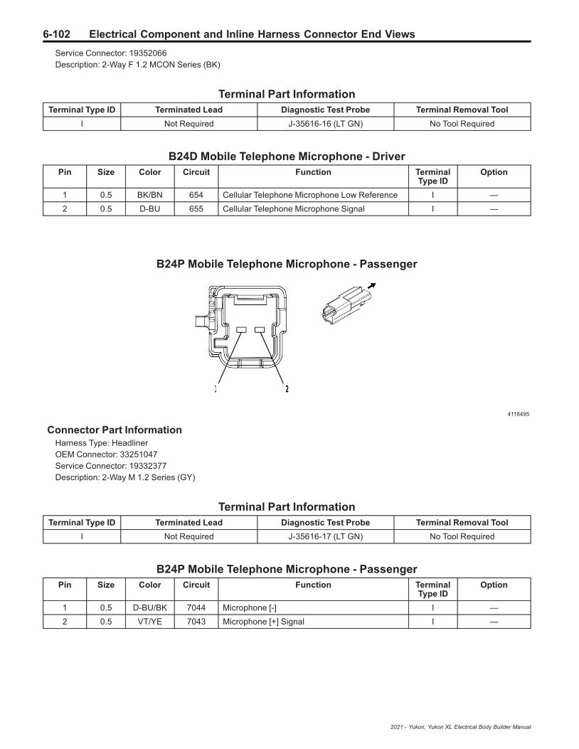
6-102 Electrical Component and Inline Harness Connector End Views
Service Connector: 19352066Description: 2-Way F 1.2 MCON Series (BK)
Terminal Part InformationTerminal Type ID Terminated Lead Diagnostic Test Probe Terminal Removal Tool
I Not Required J-35616-16 (LT GN) No Tool Required
B24D Mobile Telephone Microphone - DriverPin Size Color Circuit Function Terminal
Type IDOption
1 0.5 BK/BN 654 Cellular Telephone Microphone Low Reference I —
2 0.5 D-BU 655 Cellular Telephone Microphone Signal I —
B24P Mobile Telephone Microphone - Passenger
4116495
Connector Part InformationHarness Type: HeadlinerOEM Connector: 33251047Service Connector: 19332377Description: 2-Way M 1.2 Series (GY)
Terminal Part InformationTerminal Type ID Terminated Lead Diagnostic Test Probe Terminal Removal Tool
I Not Required J-35616-17 (LT GN) No Tool Required
B24P Mobile Telephone Microphone - PassengerPin Size Color Circuit Function Terminal
Type IDOption
1 0.5 D-BU/BK 7044 Microphone [-] I —
2 0.5 VT/YE 7043 Microphone [+] Signal I —
2021 - Yukon, Yukon XL Electrical Body Builder Manual

Electrical Component and Inline Harness Connector End Views 6-103
B26 Crankshaft Position Sensor
4581126
Connector Part InformationHarness Type: EngineOEM Connector: 33358800Service Connector: 19366844Description: 3-Way F 1.2 MCON-CB Series, Sealed (BK)
Terminal Part InformationTerminal Type ID Terminated Lead Diagnostic Test Probe Terminal Removal Tool
I Not Required J-35616-16 (LT GN) No Tool Required
B26 Crankshaft Position SensorPin Size Color Circuit Function Terminal
Type IDOption
10.50.5
L-GNVT/D-BU
62716270
Crankshaft Position Sensor SignalCrankshaft Position Sensor Voltage
II
L84/L87LM2
2 0.5 BK/VT 6272 Crankshaft Position Sensor Low Reference I —
30.50.5
VT/D-BUL-GN
62706271
Crankshaft Position Sensor VoltageCrankshaft Position Sensor Signal
II
L84/L87LM2
B34A Engine Coolant Temperature Sensor 1 (LM2)
2830969
Connector Part InformationHarness Type: EngineOEM Connector: 13840071
2021 - Yukon, Yukon XL Electrical Body Builder Manual

6-104 Electrical Component and Inline Harness Connector End Views
Service Connector: 13587321Description: 2-Way F 1.2 Multilock Series, Sealed (D-GY)
Terminal Part InformationTerminal Type ID Terminated Lead Diagnostic Test Probe Terminal Removal Tool
I Not Required J-35616-16 (LT GN) No Tool Required
B34A Engine Coolant Temperature Sensor 1 (LM2)Pin Size Color Circuit Function Terminal
Type IDOption
1 0.5 YE/D-BU 2408 Engine Inlet Coolant Temperature Signal I —
2 0.5 BK/YE 548 Engine Control Sensors Low Reference 1 I —
B34B Engine Coolant Temperature Sensor 2 (LM2)
2830969
Connector Part InformationHarness Type: Engine Coolant Temperature JumperOEM Connector: 10010339Service Connector: Service by Harness - See Part CatalogDescription: 2-Way F 1.2 Multilock Series, Sealed (D-GY)
Terminal Part InformationTerminal Type ID Terminated Lead Diagnostic Test Probe Terminal Removal Tool
I Not Required J-35616-16 (LT GN) No Tool Required
B34B Engine Coolant Temperature Sensor 2 (LM2)Pin Size Color Circuit Function Terminal
Type IDOption
1 0.5 VT 2988 Engine Outlet Coolant Temperature Signal I —
2 0.5 BK/GY 626 Engine Control Vehicle Sensors LowReference 1 I —
2021 - Yukon, Yukon XL Electrical Body Builder Manual

Electrical Component and Inline Harness Connector End Views 6-105
B34E Engine Coolant Temperature Sensor 5 (LM2)
2717066
Connector Part InformationHarness Type: EngineOEM Connector: 13735326Service Connector: 13587326Description: 2-Way F 1.2 Multilock Series, Sealed (BK)
Terminal Part InformationTerminal Type ID Terminated Lead Diagnostic Test Probe Terminal Removal Tool
I Not Required J-35616-16 (LT GN) No Tool Required
B34E Engine Coolant Temperature Sensor 5 (LM2)Pin Size Color Circuit Function Terminal
Type IDOption
1 0.5 D-BU/BK 1422 Engine Water Charge Air Coolant TemperatureSignal I —
2 0.5 BK/GY 626 Engine Control Vehicle Sensors LowReference 1 I —
B34F Engine Coolant Temperature Sensor 6 (LM2)
2830969
Connector Part InformationHarness Type: Engine Coolant Temperature JumperOEM Connector: 10010339Service Connector: Service by Harness - See Part CatalogDescription: 2-Way F 1.2 Multilock Series, Sealed (D-GY)
2021 - Yukon, Yukon XL Electrical Body Builder Manual
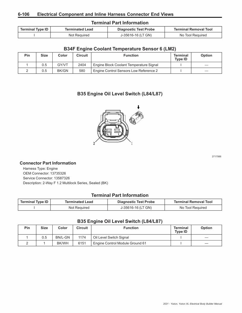
6-106 Electrical Component and Inline Harness Connector End Views
Terminal Part InformationTerminal Type ID Terminated Lead Diagnostic Test Probe Terminal Removal Tool
I Not Required J-35616-16 (LT GN) No Tool Required
B34F Engine Coolant Temperature Sensor 6 (LM2)Pin Size Color Circuit Function Terminal
Type IDOption
1 0.5 GY/VT 2404 Engine Block Coolant Temperature Signal I —
2 0.5 BK/GN 580 Engine Control Sensors Low Reference 2 I —
B35 Engine Oil Level Switch (L84/L87)
2717066
Connector Part InformationHarness Type: EngineOEM Connector: 13735326Service Connector: 13587326Description: 2-Way F 1.2 Multilock Series, Sealed (BK)
Terminal Part InformationTerminal Type ID Terminated Lead Diagnostic Test Probe Terminal Removal Tool
I Not Required J-35616-16 (LT GN) No Tool Required
B35 Engine Oil Level Switch (L84/L87)Pin Size Color Circuit Function Terminal
Type IDOption
1 0.5 BN/L-GN 1174 Oil Level Switch Signal I —
2 1 BK/WH 6151 Engine Control Module Ground 61 I —
2021 - Yukon, Yukon XL Electrical Body Builder Manual
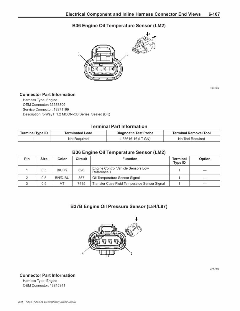
Electrical Component and Inline Harness Connector End Views 6-107
B36 Engine Oil Temperature Sensor (LM2)
4994602
Connector Part InformationHarness Type: EngineOEM Connector: 33358809Service Connector: 19371199Description: 3-Way F 1.2 MCON-CB Series, Sealed (BK)
Terminal Part InformationTerminal Type ID Terminated Lead Diagnostic Test Probe Terminal Removal Tool
I Not Required J-35616-16 (LT GN) No Tool Required
B36 Engine Oil Temperature Sensor (LM2)Pin Size Color Circuit Function Terminal
Type IDOption
1 0.5 BK/GY 626 Engine Control Vehicle Sensors LowReference 1 I —
2 0.5 BN/D-BU 357 Oil Temperature Sensor Signal I —
3 0.5 VT 7485 Transfer Case Fluid Temperatue Sensor Signal I —
B37B Engine Oil Pressure Sensor (L84/L87)
2717079
Connector Part InformationHarness Type: EngineOEM Connector: 13815341
2021 - Yukon, Yukon XL Electrical Body Builder Manual

6-108 Electrical Component and Inline Harness Connector End Views
Service Connector: 13587299Description: 4-Way F 1.2 Multilock Series, Sealed (BK)
Terminal Part InformationTerminal Type ID Terminated Lead Diagnostic Test Probe Terminal Removal Tool
I Not Required J-35616-16 (LT GN) No Tool Required
B37B Engine Oil Pressure Sensor (L84/L87)Pin Size Color Circuit Function Terminal
Type IDOption
1 0.5 BK/YE 548 Engine Control Sensors Low Reference 1 I —
2 0.5 YE/BN 331 Oil Pressure Sensor Signal I —
3 0.5 WH/RD 480 Engine Control Vehicle Sensors 5 VoltReference 1 I —
4 0.5 BN/D-BU 357 Oil Temperature Sensor Signal I —
B37B Engine Oil Pressure Sensor (LM2)
3240107
Connector Part InformationHarness Type: EngineOEM Connector: 13889776Service Connector: 19301717Description: 3-Way F 1.2 Multilock Series, Sealed (BK)
Terminal Part InformationTerminal Type ID Terminated Lead Diagnostic Test Probe Terminal Removal Tool
I Not Required J-35616-16 (LT GN) No Tool Required
B37B Engine Oil Pressure Sensor (LM2)Pin Size Color Circuit Function Terminal
Type IDOption
1 0.5 YE/BN 331 Oil Pressure Sensor Signal I —
2 0.5 BK/YE 548 Engine Control Sensors Low Reference 1 I —
3 0.5 WH/RD 480 Engine Control Vehicle Sensors 5 VoltReference 1 I —
2021 - Yukon, Yukon XL Electrical Body Builder Manual
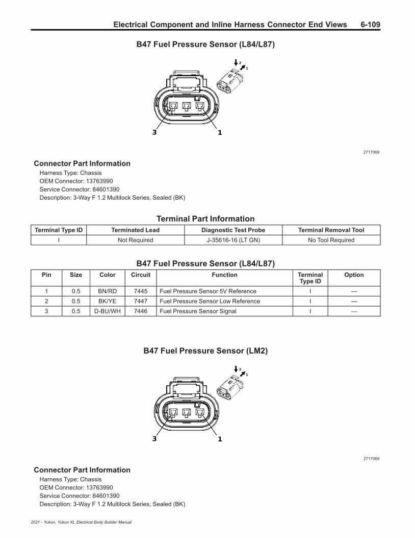
Electrical Component and Inline Harness Connector End Views 6-109
B47 Fuel Pressure Sensor (L84/L87)
2717069
Connector Part InformationHarness Type: ChassisOEM Connector: 13763990Service Connector: 84601390Description: 3-Way F 1.2 Multilock Series, Sealed (BK)
Terminal Part InformationTerminal Type ID Terminated Lead Diagnostic Test Probe Terminal Removal Tool
I Not Required J-35616-16 (LT GN) No Tool Required
B47 Fuel Pressure Sensor (L84/L87)Pin Size Color Circuit Function Terminal
Type IDOption
1 0.5 BN/RD 7445 Fuel Pressure Sensor 5V Reference I —
2 0.5 BK/YE 7447 Fuel Pressure Sensor Low Reference I —
3 0.5 D-BU/WH 7446 Fuel Pressure Sensor Signal I —
B47 Fuel Pressure Sensor (LM2)
2717069
Connector Part InformationHarness Type: ChassisOEM Connector: 13763990Service Connector: 84601390Description: 3-Way F 1.2 Multilock Series, Sealed (BK)
2021 - Yukon, Yukon XL Electrical Body Builder Manual

6-110 Electrical Component and Inline Harness Connector End Views
Terminal Part InformationTerminal Type ID Terminated Lead Diagnostic Test Probe Terminal Removal Tool
I Not Required J-35616-16 (LT GN) No Tool Required
B47 Fuel Pressure Sensor (LM2)Pin Size Color Circuit Function Terminal
Type IDOption
1 0.5 BN/RD 7445 Fuel Pressure Sensor 5V Reference I —
2 0.5 BK/YE 7447 Fuel Pressure Sensor Low Reference I —
3 0.5 D-BU/WH 7446 Fuel Pressure Sensor Signal I —
B51F Suspension Height Sensor - Front (TR7-F47)
4569745
Connector Part InformationHarness Type: ChassisOEM Connector: 33343869Service Connector: 19179750Description: 3-Way F 150 MX Series, Sealed (BK)
Terminal Part InformationTerminal Type ID Terminated Lead Diagnostic Test Probe Terminal Removal Tool
I Not Required J-35616-14 (GN) No Tool Required
B51F Suspension Height Sensor - Front (TR7-F47)Pin Size Color Circuit Function Terminal
Type IDOption
1 0.75 WH/RD 7524 Front Vehicle Level Sensor 5V Reference I —
2 0.5 BK/GY 7526 Front Vehicle Level Sensor Low Reference I —
3 0.5 BN/WH 7525 Front Vehicle Level Sensor Signal I —
2021 - Yukon, Yukon XL Electrical Body Builder Manual

Electrical Component and Inline Harness Connector End Views 6-111
B51R Suspension Height Sensor - Rear (TR7-F47)
4569745
Connector Part InformationHarness Type: ChassisOEM Connector: 33343869Service Connector: 19179750Description: 3-Way F 150 MX Series, Sealed (BK)
Terminal Part InformationTerminal Type ID Terminated Lead Diagnostic Test Probe Terminal Removal Tool
I Not Required J-35616-14 (GN) No Tool Required
B51R Suspension Height Sensor - Rear (TR7-F47)Pin Size Color Circuit Function Terminal
Type IDOption
1 0.5 WH/RD 2165 Vehicle Level Control Position Sensor 5VReference I —
2 0.5 BK/BN 2185 Vehicle Level Control Position Sensor LowReference I —
3 0.5 BN 2184 Vehicle Level Control Position Sensor Signal I —
B52C Heated Oxygen Sensor - Bank 1 Sensor 1 (L84/L87)
4381050
Connector Part InformationHarness Type: EngineOEM Connector: 33253021
2021 - Yukon, Yukon XL Electrical Body Builder Manual

6-112 Electrical Component and Inline Harness Connector End Views
Service Connector: 19354075Description: 4-Way F 1.2 Multilock Series, Sealed (BK)
Terminal Part InformationTerminal Type ID Terminated Lead Diagnostic Test Probe Terminal Removal Tool
I Not Required J-35616-16 (LT GN) No Tool Required
B52C Heated Oxygen Sensor - Bank 1 Sensor 1 (L84/L87)Pin Size Color Circuit Function Terminal
Type IDOption
1 0.5 GY/WH 3113 HO2S Heater Low Control Bank 1 Sensor 1 I —
2 0.75 VT/D-BU 5293 Powertrain Main Relay Fused Supply 4 I —
3 0.5 WH/BK 3111 HO2S Low Signal Bank 1 Sensor 1 (3) I —
4 0.5 VT/GY 3110 HO2S High Signal Bank 1 Sensor 1 I —
B52D Heated Oxygen Sensor - Bank 1 Sensor 2 (L84/L87)
4036370
Connector Part InformationHarness Type: EngineOEM Connector: 15532690Service Connector: 19330920Description: 4-Way F 1.2 Multilock Series, Sealed (GY)
Terminal Part InformationTerminal Type ID Terminated Lead Diagnostic Test Probe Terminal Removal Tool
I Not Required J-35616-16 (LT GN) No Tool Required
B52D Heated Oxygen Sensor - Bank 1 Sensor 2 (L84/L87)Pin Size Color Circuit Function Terminal
Type IDOption
10.750.75
WH/BNGY/WH
32233122
HO2S Heater Low Control Bank 2 Sensor 2HO2S Heater Low Control Bank 1 Sensor 2
II
—L84/L87
2 0.75 VT/D-BU 5294 Powertrain Main Relay Fused Supply 5 I —
30.50.5
YE/D-BUWH/YE
32213121
HO2S Low Signal Bank 2 Sensor 2HO2S Low Signal Bank 1 Sensor 2
II
—L84/L87
2021 - Yukon, Yukon XL Electrical Body Builder Manual
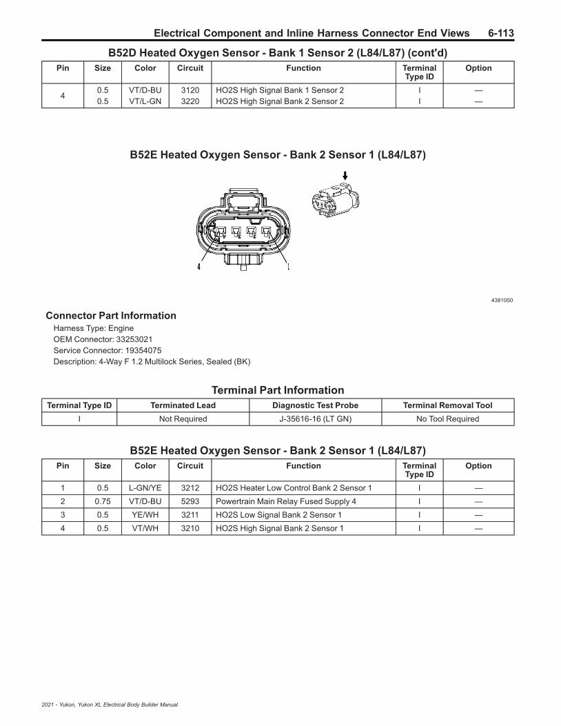
Electrical Component and Inline Harness Connector End Views 6-113
B52D Heated Oxygen Sensor - Bank 1 Sensor 2 (L84/L87) (cont'd)Pin Size Color Circuit Function Terminal
Type IDOption
40.50.5
VT/D-BUVT/L-GN
31203220
HO2S High Signal Bank 1 Sensor 2HO2S High Signal Bank 2 Sensor 2
II
——
B52E Heated Oxygen Sensor - Bank 2 Sensor 1 (L84/L87)
4381050
Connector Part InformationHarness Type: EngineOEM Connector: 33253021Service Connector: 19354075Description: 4-Way F 1.2 Multilock Series, Sealed (BK)
Terminal Part InformationTerminal Type ID Terminated Lead Diagnostic Test Probe Terminal Removal Tool
I Not Required J-35616-16 (LT GN) No Tool Required
B52E Heated Oxygen Sensor - Bank 2 Sensor 1 (L84/L87)Pin Size Color Circuit Function Terminal
Type IDOption
1 0.5 L-GN/YE 3212 HO2S Heater Low Control Bank 2 Sensor 1 I —
2 0.75 VT/D-BU 5293 Powertrain Main Relay Fused Supply 4 I —
3 0.5 YE/WH 3211 HO2S Low Signal Bank 2 Sensor 1 I —
4 0.5 VT/WH 3210 HO2S High Signal Bank 2 Sensor 1 I —
2021 - Yukon, Yukon XL Electrical Body Builder Manual

6-114 Electrical Component and Inline Harness Connector End Views
B52F Heated Oxygen Sensor - Bank 2 Sensor 2 (L84/L87)
4036370
Connector Part InformationHarness Type: EngineOEM Connector: 15532690Service Connector: 19330920Description: 4-Way F 1.2 Multilock Series, Sealed (GY)
Terminal Part InformationTerminal Type ID Terminated Lead Diagnostic Test Probe Terminal Removal Tool
I Not Required J-35616-16 (LT GN) No Tool Required
B52F Heated Oxygen Sensor - Bank 2 Sensor 2 (L84/L87)Pin Size Color Circuit Function Terminal
Type IDOption
1 0.75 WH/BN 3223 HO2S Heater Low Control Bank 2 Sensor 2 I —
2 0.75 VT/D-BU 5294 Powertrain Main Relay Fused Supply 5 I —
3 0.5 YE/D-BU 3221 HO2S Low Signal Bank 2 Sensor 2 I —
4 0.5 VT/L-GN 3220 HO2S High Signal Bank 2 Sensor 2 I —
B55 Engine Hood Switch
4421568
Connector Part InformationHarness Type: BodyOEM Connector: 33320864
2021 - Yukon, Yukon XL Electrical Body Builder Manual

Electrical Component and Inline Harness Connector End Views 6-115
Service Connector: 19368220Description: 3-Way F 1.2 MCON-LL Series, Sealed (BK)
Terminal Part InformationTerminal Type ID Terminated Lead Diagnostic Test Probe Terminal Removal Tool
I Not Required J-35616-16 (LT GN) No Tool Required
B55 Engine Hood SwitchPin Size Color Circuit Function Terminal
Type IDOption
1 0.5 YE 4063 Hood Status A Signal I —
2 0.35 BN/L-GN 4064 Hood Status B Signal I —
3 0.75 BK 150 Ground 1 I —
B59L Front Impact Sensor - Left
4649903
Connector Part InformationHarness Type: BodyOEM Connector: 33327048Service Connector: 19366858Description: 2-Way F 1.2 MCON Series, Sealed (BK)
Terminal Part InformationTerminal Type ID Terminated Lead Diagnostic Test Probe Terminal Removal Tool
I Not Required J-35616-16 (LT GN) No Tool Required
B59L Front Impact Sensor - LeftPin Size Color Circuit Function Terminal
Type IDOption
1 0.5 OG/YE 354 Left Front Impact Discriminating Sensor Signal I —
2 0.5 BK/OG 5045 Left Front Impact Discriminating Sensor LowReference I —
2021 - Yukon, Yukon XL Electrical Body Builder Manual

6-116 Electrical Component and Inline Harness Connector End Views
B59R Front Impact Sensor - Right
4649903
Connector Part InformationHarness Type: BodyOEM Connector: 33327048Service Connector: 19366858Description: 2-Way F 1.2 MCON Series, Sealed (BK)
Terminal Part InformationTerminal Type ID Terminated Lead Diagnostic Test Probe Terminal Removal Tool
I Not Required J-35616-16 (LT GN) No Tool Required
B59R Front Impact Sensor - RightPin Size Color Circuit Function Terminal
Type IDOption
1 0.5 OG/L-GN 1409 Right Front Impact Discriminating Sensor Signal I —
2 0.5 BK/OG 5600 Right Front Impact Discriminating Sensor LowReference I —
B61P Seat Belt Tension Sensor - Passenger
4115691
Connector Part InformationHarness Type: BodyOEM Connector: 35026312Service Connector: 19352066Description: 2-Way F 1.2 Series (BK)
2021 - Yukon, Yukon XL Electrical Body Builder Manual

Electrical Component and Inline Harness Connector End Views 6-117
Terminal Part InformationTerminal Type ID Terminated Lead Diagnostic Test Probe Terminal Removal Tool
I Not Required J-35616-16 (LT GN) No Tool Required
B61P Seat Belt Tension Sensor - PassengerPin Size Color Circuit Function Terminal
Type IDOption
1 0.5 GY/OG 3946 Passenger Automatic Locking Retractor SwitchLow Reference I —
2 0.5 OG/BN 3947 Passenger Automatic Locking Retractor SwitchSignal I —
B63LF Side Impact Sensor - Left Front
2179777
Connector Part InformationHarness Type: Driver DoorOEM Connector: 13610095Service Connector: Service by Harness - See Part CatalogDescription: 2-Way F 0.64 Series, Sealed (D-GY)
Terminal Part InformationTerminal Type ID Terminated Lead Diagnostic Test Probe Terminal Removal Tool
I Not Required J-35616-64B (LT BU) No Tool Required
B63LF Side Impact Sensor - Left FrontPin Size Color Circuit Function Terminal
Type IDOption
1 0.5 OG/L-GN 2132 Left Front Side Impact Sensor Signal I —
2 0.5 BK/OG 6628 Left Front Side Impact Sensor Low Reference I —
2021 - Yukon, Yukon XL Electrical Body Builder Manual

6-118 Electrical Component and Inline Harness Connector End Views
B63LR Side Impact Sensor - Left Rear
4335931
Connector Part InformationHarness Type: BodyOEM Connector: 33371691Service Connector: 19366843Description: 2-Way F 1.2 MCON Series, Sealed (BK)
Terminal Part InformationTerminal Type ID Terminated Lead Diagnostic Test Probe Terminal Removal Tool
I Not Required J-35616-16 (LT GN) No Tool Required
B63LR Side Impact Sensor - Left RearPin Size Color Circuit Function Terminal
Type IDOption
1 0.5 OG/D-BU 6622 Left Rear Side Impact Sensor Signal I —
2 0.5 BK/OG 6623 Left Rear Side Impact Sensor Low Reference I —
B63RF Side Impact Sensor - Right Front
2179777
Connector Part InformationHarness Type: Passenger DoorOEM Connector: 13610095Service Connector: Service by Harness - See Part CatalogDescription: 2-Way F 0.64 Series, Sealed (D-GY)
2021 - Yukon, Yukon XL Electrical Body Builder Manual

Electrical Component and Inline Harness Connector End Views 6-119
Terminal Part InformationTerminal Type ID Terminated Lead Diagnostic Test Probe Terminal Removal Tool
I Not Required J-35616-64B (LT BU) No Tool Required
B63RF Side Impact Sensor - Right FrontPin Size Color Circuit Function Terminal
Type IDOption
1 0.5 BN/OG 2134 Right Front Side Impact Sensor Signal I —
2 0.5 BK/OG 6629 Right Front Side Impact Sensor Low Reference I —
B63RR Side Impact Sensor - Right Rear
4335931
Connector Part InformationHarness Type: BodyOEM Connector: 33371691Service Connector: 19366843Description: 2-Way F 1.2 MCON Series, Sealed (BK)
Terminal Part InformationTerminal Type ID Terminated Lead Diagnostic Test Probe Terminal Removal Tool
I Not Required J-35616-16 (LT GN) No Tool Required
B63RR Side Impact Sensor - Right RearPin Size Color Circuit Function Terminal
Type IDOption
1 0.5 OG/WH 6626 Right Rear Side Impact Sensor Signal I —
2 0.5 BK/OG 6627 Right Rear Side Impact Sensor Low Reference I —
2021 - Yukon, Yukon XL Electrical Body Builder Manual
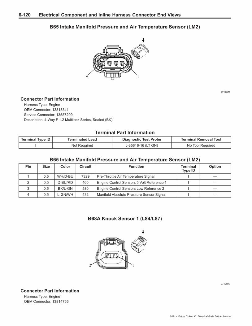
6-120 Electrical Component and Inline Harness Connector End Views
B65 Intake Manifold Pressure and Air Temperature Sensor (LM2)
2717079
Connector Part InformationHarness Type: EngineOEM Connector: 13815341Service Connector: 13587299Description: 4-Way F 1.2 Multilock Series, Sealed (BK)
Terminal Part InformationTerminal Type ID Terminated Lead Diagnostic Test Probe Terminal Removal Tool
I Not Required J-35616-16 (LT GN) No Tool Required
B65 Intake Manifold Pressure and Air Temperature Sensor (LM2)Pin Size Color Circuit Function Terminal
Type IDOption
1 0.5 WH/D-BU 7329 Pre-Throttle Air Temperature Signal I —
2 0.5 D-BU/RD 460 Engine Control Sensors 5 Volt Reference 1 I —
3 0.5 BK/L-GN 580 Engine Control Sensors Low Reference 2 I —
4 0.5 L-GN/WH 432 Manifold Absolute Pressure Sensor Signal I —
B68A Knock Sensor 1 (L84/L87)
2717073
Connector Part InformationHarness Type: EngineOEM Connector: 13814755
2021 - Yukon, Yukon XL Electrical Body Builder Manual
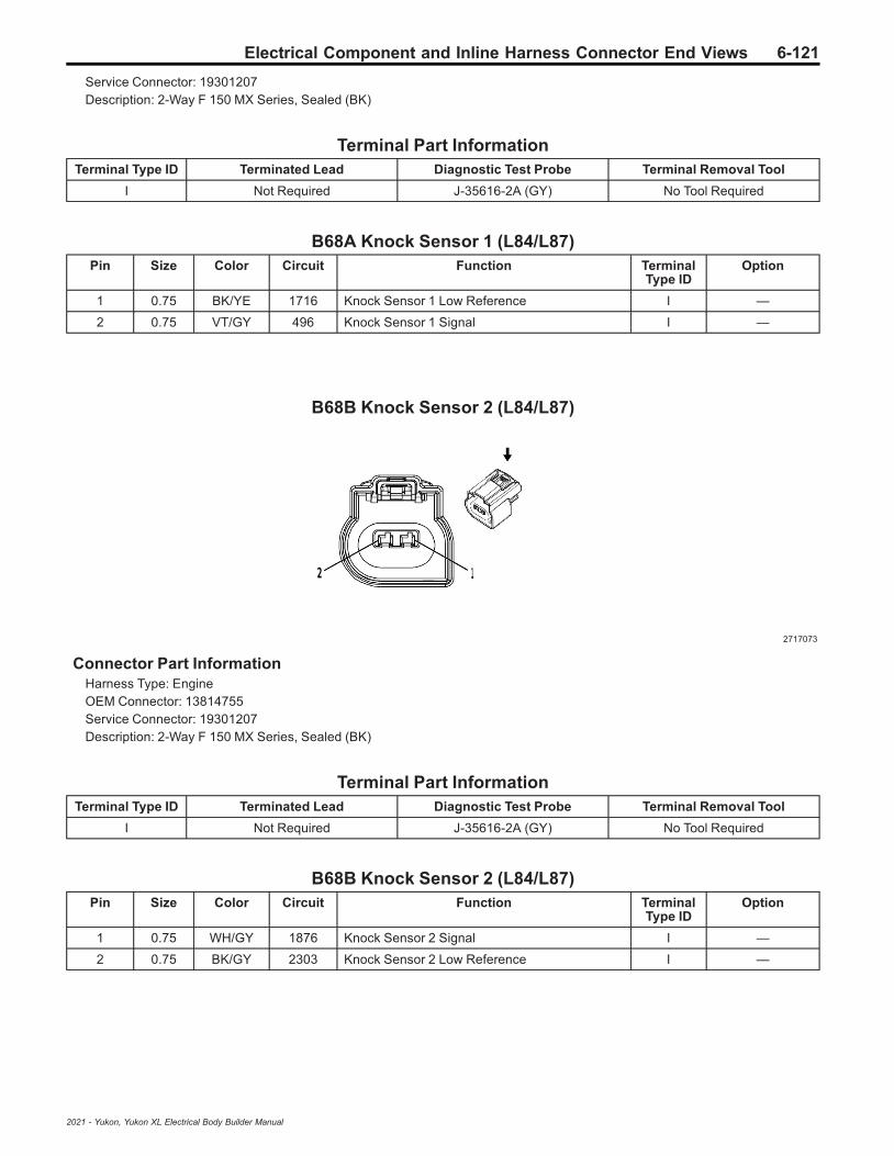
Electrical Component and Inline Harness Connector End Views 6-121
Service Connector: 19301207Description: 2-Way F 150 MX Series, Sealed (BK)
Terminal Part InformationTerminal Type ID Terminated Lead Diagnostic Test Probe Terminal Removal Tool
I Not Required J-35616-2A (GY) No Tool Required
B68A Knock Sensor 1 (L84/L87)Pin Size Color Circuit Function Terminal
Type IDOption
1 0.75 BK/YE 1716 Knock Sensor 1 Low Reference I —
2 0.75 VT/GY 496 Knock Sensor 1 Signal I —
B68B Knock Sensor 2 (L84/L87)
2717073
Connector Part InformationHarness Type: EngineOEM Connector: 13814755Service Connector: 19301207Description: 2-Way F 150 MX Series, Sealed (BK)
Terminal Part InformationTerminal Type ID Terminated Lead Diagnostic Test Probe Terminal Removal Tool
I Not Required J-35616-2A (GY) No Tool Required
B68B Knock Sensor 2 (L84/L87)Pin Size Color Circuit Function Terminal
Type IDOption
1 0.75 WH/GY 1876 Knock Sensor 2 Signal I —
2 0.75 BK/GY 2303 Knock Sensor 2 Low Reference I —
2021 - Yukon, Yukon XL Electrical Body Builder Manual

6-122 Electrical Component and Inline Harness Connector End Views
B70 Liftgate Close Switch (TC2)
2173574
Connector Part InformationHarness Type: LiftgateOEM Connector: 13679454Service Connector: Service by Harness - See Part CatalogDescription: 4-Way F 0.64 Micro-Quadlock Series, Sealed (BK)
Terminal Part InformationTerminal Type ID Terminated Lead Diagnostic Test Probe Terminal Removal Tool
I Not Required J-35616-64B (LT BU) No Tool Required
B70 Liftgate Close Switch (TC2)Pin Size Color Circuit Function Terminal
Type IDOption
1 0.35 BK/VT 4656 Rear Closure Object Sensor Low Reference I —
2 0.35 GY/WH 4658 Rear Closure Switch LED Control I —
3 0.35 L-GN 4657 Rear Closure Switch Signal I —
4 — — — Not Occupied — —
B71L Liftgate Object Sensor - Left (TC2)
5355341
Connector Part InformationHarness Type: LiftgateOEM Connector: 35258943
2021 - Yukon, Yukon XL Electrical Body Builder Manual
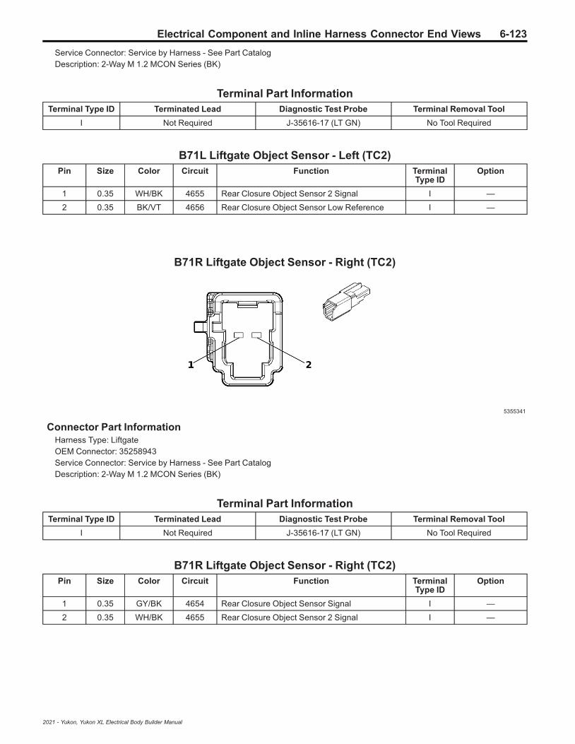
Electrical Component and Inline Harness Connector End Views 6-123
Service Connector: Service by Harness - See Part CatalogDescription: 2-Way M 1.2 MCON Series (BK)
Terminal Part InformationTerminal Type ID Terminated Lead Diagnostic Test Probe Terminal Removal Tool
I Not Required J-35616-17 (LT GN) No Tool Required
B71L Liftgate Object Sensor - Left (TC2)Pin Size Color Circuit Function Terminal
Type IDOption
1 0.35 WH/BK 4655 Rear Closure Object Sensor 2 Signal I —
2 0.35 BK/VT 4656 Rear Closure Object Sensor Low Reference I —
B71R Liftgate Object Sensor - Right (TC2)
5355341
Connector Part InformationHarness Type: LiftgateOEM Connector: 35258943Service Connector: Service by Harness - See Part CatalogDescription: 2-Way M 1.2 MCON Series (BK)
Terminal Part InformationTerminal Type ID Terminated Lead Diagnostic Test Probe Terminal Removal Tool
I Not Required J-35616-17 (LT GN) No Tool Required
B71R Liftgate Object Sensor - Right (TC2)Pin Size Color Circuit Function Terminal
Type IDOption
1 0.35 GY/BK 4654 Rear Closure Object Sensor Signal I —
2 0.35 WH/BK 4655 Rear Closure Object Sensor 2 Signal I —
2021 - Yukon, Yukon XL Electrical Body Builder Manual
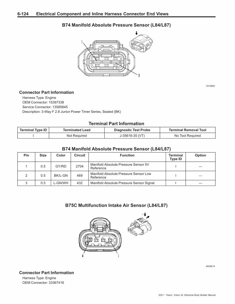
6-124 Electrical Component and Inline Harness Connector End Views
B74 Manifold Absolute Pressure Sensor (L84/L87)
1914850
Connector Part InformationHarness Type: EngineOEM Connector: 15397338Service Connector: 13585845Description: 3-Way F 2.8 Junior Power Timer Series, Sealed (BK)
Terminal Part InformationTerminal Type ID Terminated Lead Diagnostic Test Probe Terminal Removal Tool
I Not Required J-35616-35 (VT) No Tool Required
B74 Manifold Absolute Pressure Sensor (L84/L87)Pin Size Color Circuit Function Terminal
Type IDOption
1 0.5 GY/RD 2704 Manifold Absolute Pressure Sensor 5VReference I —
2 0.5 BK/L-GN 469 Manifold Absolute Pressure Sensor LowReference I —
3 0.5 L-GN/WH 432 Manifold Absolute Pressure Sensor Signal I —
B75C Multifunction Intake Air Sensor (L84/L87)
4934614
Connector Part InformationHarness Type: EngineOEM Connector: 33367416
2021 - Yukon, Yukon XL Electrical Body Builder Manual
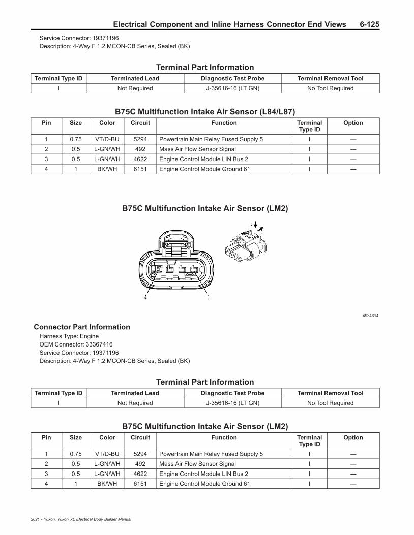
Electrical Component and Inline Harness Connector End Views 6-125
Service Connector: 19371196Description: 4-Way F 1.2 MCON-CB Series, Sealed (BK)
Terminal Part InformationTerminal Type ID Terminated Lead Diagnostic Test Probe Terminal Removal Tool
I Not Required J-35616-16 (LT GN) No Tool Required
B75C Multifunction Intake Air Sensor (L84/L87)Pin Size Color Circuit Function Terminal
Type IDOption
1 0.75 VT/D-BU 5294 Powertrain Main Relay Fused Supply 5 I —
2 0.5 L-GN/WH 492 Mass Air Flow Sensor Signal I —
3 0.5 L-GN/WH 4622 Engine Control Module LIN Bus 2 I —
4 1 BK/WH 6151 Engine Control Module Ground 61 I —
B75C Multifunction Intake Air Sensor (LM2)
4934614
Connector Part InformationHarness Type: EngineOEM Connector: 33367416Service Connector: 19371196Description: 4-Way F 1.2 MCON-CB Series, Sealed (BK)
Terminal Part InformationTerminal Type ID Terminated Lead Diagnostic Test Probe Terminal Removal Tool
I Not Required J-35616-16 (LT GN) No Tool Required
B75C Multifunction Intake Air Sensor (LM2)Pin Size Color Circuit Function Terminal
Type IDOption
1 0.75 VT/D-BU 5294 Powertrain Main Relay Fused Supply 5 I —
2 0.5 L-GN/WH 492 Mass Air Flow Sensor Signal I —
3 0.5 L-GN/WH 4622 Engine Control Module LIN Bus 2 I —
4 1 BK/WH 6151 Engine Control Module Ground 61 I —
2021 - Yukon, Yukon XL Electrical Body Builder Manual
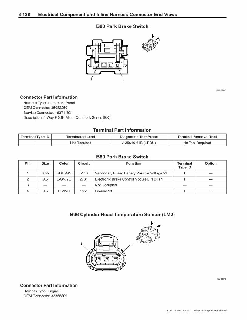
6-126 Electrical Component and Inline Harness Connector End Views
B80 Park Brake Switch
4997407
Connector Part InformationHarness Type: Instrument PanelOEM Connector: 35082250Service Connector: 19371192Description: 4-Way F 0.64 Micro-Quadlock Series (BK)
Terminal Part InformationTerminal Type ID Terminated Lead Diagnostic Test Probe Terminal Removal Tool
I Not Required J-35616-64B (LT BU) No Tool Required
B80 Park Brake SwitchPin Size Color Circuit Function Terminal
Type IDOption
1 0.35 RD/L-GN 5140 Secondary Fused Battery Positive Voltage 51 I —
2 0.5 L-GN/YE 2731 Electronic Brake Control Module LIN Bus 1 I —
3 — — — Not Occupied — —
4 0.5 BK/WH 1851 Ground 18 I —
B96 Cylinder Head Temperature Sensor (LM2)
4994602
Connector Part InformationHarness Type: EngineOEM Connector: 33358809
2021 - Yukon, Yukon XL Electrical Body Builder Manual

Electrical Component and Inline Harness Connector End Views 6-127
Service Connector: 19371199Description: 3-Way F 1.2 MCON-CB Series, Sealed (BK)
Terminal Part InformationTerminal Type ID Terminated Lead Diagnostic Test Probe Terminal Removal Tool
I Not Required J-35616-16 (LT GN) No Tool Required
B96 Cylinder Head Temperature Sensor (LM2)Pin Size Color Circuit Function Terminal
Type IDOption
1 0.5 BK/GY 626 Engine Control Vehicle Sensors LowReference 1 I —
2 0.5 L-GN/YE 37 Engine Block Temperature Sensor Signal I —
3 0.5 BN/YE 1372 Engine Metal Temperature Sensor Signal 2 I —
B101 Immobilizer Antenna
4115691
Connector Part InformationHarness Type: Instrument PanelOEM Connector: 35026312Service Connector: 19352066Description: 2-Way F 1.2 Series (BK)
Terminal Part InformationTerminal Type ID Terminated Lead Diagnostic Test Probe Terminal Removal Tool
I Not Required J-35616-16 (LT GN) No Tool Required
B101 Immobilizer AntennaPin Size Color Circuit Function Terminal
Type IDOption
1 0.35 BN/BK 4996 Immobilizer Antenna Signal [+] I —
2 0.35 WH/GY 4997 Immobilizer Antenna Low Signal I —
2021 - Yukon, Yukon XL Electrical Body Builder Manual

6-128 Electrical Component and Inline Harness Connector End Views
B107 Accelerator Pedal Position Sensor
5157678
Connector Part InformationHarness Type: BodyOEM Connector: 35199156Service Connector: 84773558Description: 6-Way F 64 Series, Sealed (BK)
Terminal Part InformationTerminal Type ID Terminated Lead Diagnostic Test Probe Terminal Removal Tool
I Not Required J-35616-64B (LT BU) No Tool Required
B107 Accelerator Pedal Position SensorPin Size Color Circuit Function Terminal
Type IDOption
1 0.5 WH/RD 1164 Accelerator Pedal Position 5 Volt Reference 1 I —
2 0.5 YE/WH 1161 Accelerator Pedal Position Signal 1 I —
3 0.5 BK/D-BU 1271 Accelerator Pedal Position Low Reference 1 I —
4 0.5 BK/VT 1272 Accelerator Pedal Position Low Reference 2 I —
5 0.5 L-GN/WH 1162 Accelerator Pedal Position Signal 2 I —
6 0.5 BN/RD 1274 Accelerator Pedal Position 5V Reference 2 I —
B110 Battery Sensor Module
4649903
2021 - Yukon, Yukon XL Electrical Body Builder Manual
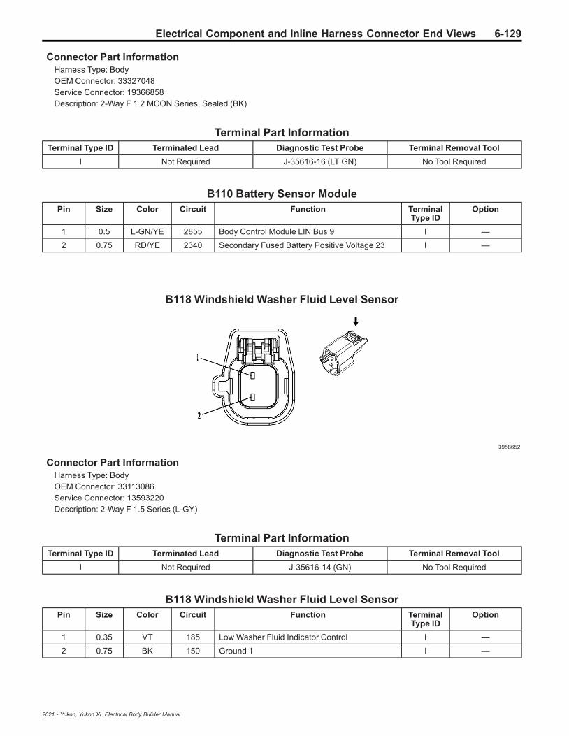
Electrical Component and Inline Harness Connector End Views 6-129
Connector Part InformationHarness Type: BodyOEM Connector: 33327048Service Connector: 19366858Description: 2-Way F 1.2 MCON Series, Sealed (BK)
Terminal Part InformationTerminal Type ID Terminated Lead Diagnostic Test Probe Terminal Removal Tool
I Not Required J-35616-16 (LT GN) No Tool Required
B110 Battery Sensor ModulePin Size Color Circuit Function Terminal
Type IDOption
1 0.5 L-GN/YE 2855 Body Control Module LIN Bus 9 I —
2 0.75 RD/YE 2340 Secondary Fused Battery Positive Voltage 23 I —
B118 Windshield Washer Fluid Level Sensor
3958652
Connector Part InformationHarness Type: BodyOEM Connector: 33113086Service Connector: 13593220Description: 2-Way F 1.5 Series (L-GY)
Terminal Part InformationTerminal Type ID Terminated Lead Diagnostic Test Probe Terminal Removal Tool
I Not Required J-35616-14 (GN) No Tool Required
B118 Windshield Washer Fluid Level SensorPin Size Color Circuit Function Terminal
Type IDOption
1 0.35 VT 185 Low Washer Fluid Indicator Control I —
2 0.75 BK 150 Ground 1 I —
2021 - Yukon, Yukon XL Electrical Body Builder Manual
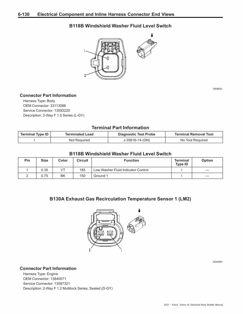
6-130 Electrical Component and Inline Harness Connector End Views
B118B Windshield Washer Fluid Level Switch
3958652
Connector Part InformationHarness Type: BodyOEM Connector: 33113086Service Connector: 13593220Description: 2-Way F 1.5 Series (L-GY)
Terminal Part InformationTerminal Type ID Terminated Lead Diagnostic Test Probe Terminal Removal Tool
I Not Required J-35616-14 (GN) No Tool Required
B118B Windshield Washer Fluid Level SwitchPin Size Color Circuit Function Terminal
Type IDOption
1 0.35 VT 185 Low Washer Fluid Indicator Control I —
2 0.75 BK 150 Ground 1 I —
B130A Exhaust Gas Recirculation Temperature Sensor 1 (LM2)
2830969
Connector Part InformationHarness Type: EngineOEM Connector: 13840071Service Connector: 13587321Description: 2-Way F 1.2 Multilock Series, Sealed (D-GY)
2021 - Yukon, Yukon XL Electrical Body Builder Manual
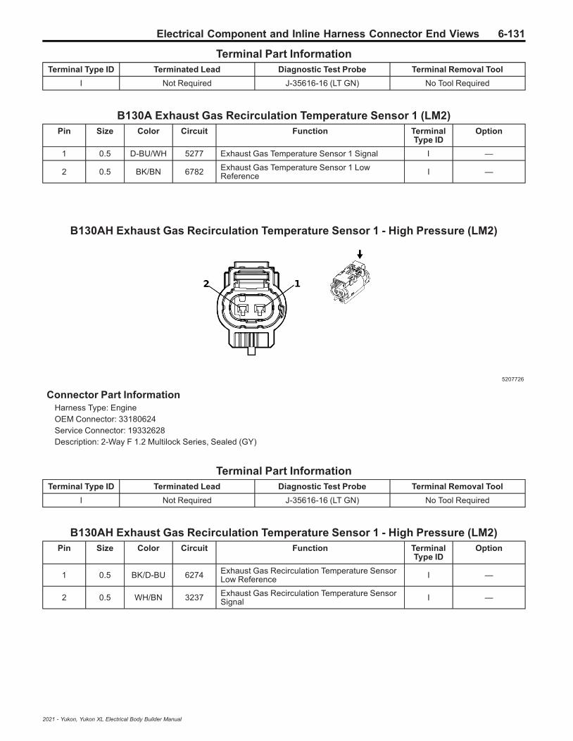
Electrical Component and Inline Harness Connector End Views 6-131
Terminal Part InformationTerminal Type ID Terminated Lead Diagnostic Test Probe Terminal Removal Tool
I Not Required J-35616-16 (LT GN) No Tool Required
B130A Exhaust Gas Recirculation Temperature Sensor 1 (LM2)Pin Size Color Circuit Function Terminal
Type IDOption
1 0.5 D-BU/WH 5277 Exhaust Gas Temperature Sensor 1 Signal I —
2 0.5 BK/BN 6782 Exhaust Gas Temperature Sensor 1 LowReference I —
B130AH Exhaust Gas Recirculation Temperature Sensor 1 - High Pressure (LM2)
5207726
Connector Part InformationHarness Type: EngineOEM Connector: 33180624Service Connector: 19332628Description: 2-Way F 1.2 Multilock Series, Sealed (GY)
Terminal Part InformationTerminal Type ID Terminated Lead Diagnostic Test Probe Terminal Removal Tool
I Not Required J-35616-16 (LT GN) No Tool Required
B130AH Exhaust Gas Recirculation Temperature Sensor 1 - High Pressure (LM2)Pin Size Color Circuit Function Terminal
Type IDOption
1 0.5 BK/D-BU 6274 Exhaust Gas Recirculation Temperature SensorLow Reference I —
2 0.5 WH/BN 3237 Exhaust Gas Recirculation Temperature SensorSignal I —
2021 - Yukon, Yukon XL Electrical Body Builder Manual
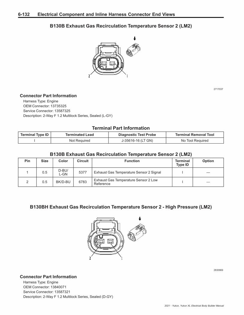
6-132 Electrical Component and Inline Harness Connector End Views
B130B Exhaust Gas Recirculation Temperature Sensor 2 (LM2)
2717037
Connector Part InformationHarness Type: EngineOEM Connector: 13735325Service Connector: 13587325Description: 2-Way F 1.2 Multilock Series, Sealed (L-GY)
Terminal Part InformationTerminal Type ID Terminated Lead Diagnostic Test Probe Terminal Removal Tool
I Not Required J-35616-16 (LT GN) No Tool Required
B130B Exhaust Gas Recirculation Temperature Sensor 2 (LM2)Pin Size Color Circuit Function Terminal
Type IDOption
1 0.5 D-BU/L-GN 5377 Exhaust Gas Temperature Sensor 2 Signal I —
2 0.5 BK/D-BU 6783 Exhaust Gas Temperature Sensor 2 LowReference I —
B130BH Exhaust Gas Recirculation Temperature Sensor 2 - High Pressure (LM2)
2830969
Connector Part InformationHarness Type: EngineOEM Connector: 13840071Service Connector: 13587321Description: 2-Way F 1.2 Multilock Series, Sealed (D-GY)
2021 - Yukon, Yukon XL Electrical Body Builder Manual
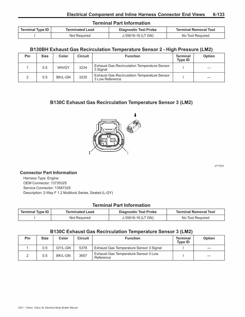
Electrical Component and Inline Harness Connector End Views 6-133
Terminal Part InformationTerminal Type ID Terminated Lead Diagnostic Test Probe Terminal Removal Tool
I Not Required J-35616-16 (LT GN) No Tool Required
B130BH Exhaust Gas Recirculation Temperature Sensor 2 - High Pressure (LM2)Pin Size Color Circuit Function Terminal
Type IDOption
1 0.5 WH/GY 3234 Exhaust Gas Recirculation Temperature Sensor3 Signal I —
2 0.5 BK/L-GN 3235 Exhaust Gas Recirculation Temperature Sensor3 Low Reference I —
B130C Exhaust Gas Recirculation Temperature Sensor 3 (LM2)
2717037
Connector Part InformationHarness Type: EngineOEM Connector: 13735325Service Connector: 13587325Description: 2-Way F 1.2 Multilock Series, Sealed (L-GY)
Terminal Part InformationTerminal Type ID Terminated Lead Diagnostic Test Probe Terminal Removal Tool
I Not Required J-35616-16 (LT GN) No Tool Required
B130C Exhaust Gas Recirculation Temperature Sensor 3 (LM2)Pin Size Color Circuit Function Terminal
Type IDOption
1 0.5 GY/L-GN 5378 Exhaust Gas Temperature Sensor 3 Signal I —
2 0.5 BK/L-GN 3657 Exhaust Gas Temperature Sensor 3 LowReference I —
2021 - Yukon, Yukon XL Electrical Body Builder Manual

6-134 Electrical Component and Inline Harness Connector End Views
B136 Exhaust Particulate Matter Sensor (LM2)
2717096
Connector Part InformationHarness Type: ChassisOEM Connector: 13815348Service Connector: 13587298Description: 4-Way F 1.2 Multilock Series, Sealed (L-GY)
Terminal Part InformationTerminal Type ID Terminated Lead Diagnostic Test Probe Terminal Removal Tool
I Not Required J-35616-16 (LT GN) No Tool Required
B136 Exhaust Particulate Matter Sensor (LM2)Pin Size Color Circuit Function Terminal
Type IDOption
111
BK/WHVT/L-GN
61514320
Engine Control Module Ground 61Selective Catalytic Reduction Power ModuleWake-Up Signal
II
LWBSWB
20.50.5
D-BU/GYWH
40544055
Private Serial Data Powertrain CAN Bus [-]Serial DataPrivate Serial Data Powertrain CAN Bus [+]Serial Data
II
LWBSWB
30.50.5
WHD-BU/GY
40554054
Private Serial Data Powertrain CAN Bus [+]Serial DataPrivate Serial Data Powertrain CAN Bus [-]Serial Data
II
LWBSWB
411
VT/L-GNBK/WH
43206151
Selective Catalytic Reduction Power ModuleWake-Up SignalEngine Control Module Ground 61
II
LWBSWB
2021 - Yukon, Yukon XL Electrical Body Builder Manual

Electrical Component and Inline Harness Connector End Views 6-135
B150 Fuel Tank Pressure Sensor
4589538
Connector Part InformationHarness Type: ChassisOEM Connector: 33343864Service Connector: 84569854Description: 3-Way F 150 MX Series, Sealed (GY)
Terminal Part InformationTerminal Type ID Terminated Lead Diagnostic Test Probe Terminal Removal Tool
I Not Required J-35616-14 (GN) No Tool Required
B150 Fuel Tank Pressure SensorPin Size Color Circuit Function Terminal
Type IDOption
1 0.5 D-BU/WH 890 Fuel Tank Pressure Sensor Signal I —
2 0.5 BK/BN 6284 Fuel Tank Pressure Sensor Low Reference I —
3 0.5 YE/RD 2709 Fuel Tank Pressure Sensor 5V Reference I —
B152LF Suspension Position Sensor - Left Front (F47)
4569745
Connector Part InformationHarness Type: ChassisOEM Connector: 33343869Service Connector: 19179750Description: 3-Way F 150 MX Series, Sealed (BK)
2021 - Yukon, Yukon XL Electrical Body Builder Manual
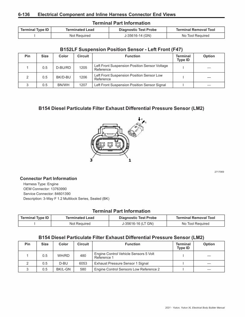
6-136 Electrical Component and Inline Harness Connector End Views
Terminal Part InformationTerminal Type ID Terminated Lead Diagnostic Test Probe Terminal Removal Tool
I Not Required J-35616-14 (GN) No Tool Required
B152LF Suspension Position Sensor - Left Front (F47)Pin Size Color Circuit Function Terminal
Type IDOption
1 0.5 D-BU/RD 1205 Left Front Suspension Position Sensor VoltageReference I —
2 0.5 BK/D-BU 1206 Left Front Suspension Position Sensor LowReference I —
3 0.5 BN/WH 1207 Left Front Suspension Position Sensor Signal I —
B154 Diesel Particulate Filter Exhaust Differential Pressure Sensor (LM2)
2717069
Connector Part InformationHarness Type: EngineOEM Connector: 13763990Service Connector: 84601390Description: 3-Way F 1.2 Multilock Series, Sealed (BK)
Terminal Part InformationTerminal Type ID Terminated Lead Diagnostic Test Probe Terminal Removal Tool
I Not Required J-35616-16 (LT GN) No Tool Required
B154 Diesel Particulate Filter Exhaust Differential Pressure Sensor (LM2)Pin Size Color Circuit Function Terminal
Type IDOption
1 0.5 WH/RD 480 Engine Control Vehicle Sensors 5 VoltReference 1 I —
2 0.5 D-BU 6053 Exhaust Pressure Sensor 1 Signal I —
3 0.5 BK/L-GN 580 Engine Control Sensors Low Reference 2 I —
2021 - Yukon, Yukon XL Electrical Body Builder Manual

Electrical Component and Inline Harness Connector End Views 6-137
B159L Glass Breakage Sensor - Left (UTJ)
2339593
Connector Part InformationHarness Type: BodyOEM Connector: 13670097Service Connector: 13580951Description: 2-Way F 1.6 Timer Series (BK)
Terminal Part InformationTerminal Type ID Terminated Lead Diagnostic Test Probe Terminal Removal Tool
I Not Required J-35616-14 (GN) No Tool Required
B159L Glass Breakage Sensor - Left (UTJ)Pin Size Color Circuit Function Terminal
Type IDOption
1 0.5 D-BU/VT 7597 Glass Breakage Sensor Signal I —
2 0.35 VT/D-BU 7598 Glass Breakage Sensor 2 Signal I —
B159R Glass Breakage Sensor - Right (UTJ)
2339593
Connector Part InformationHarness Type: BodyOEM Connector: 13670097Service Connector: 13580951Description: 2-Way F 1.6 Timer Series (BK)
2021 - Yukon, Yukon XL Electrical Body Builder Manual
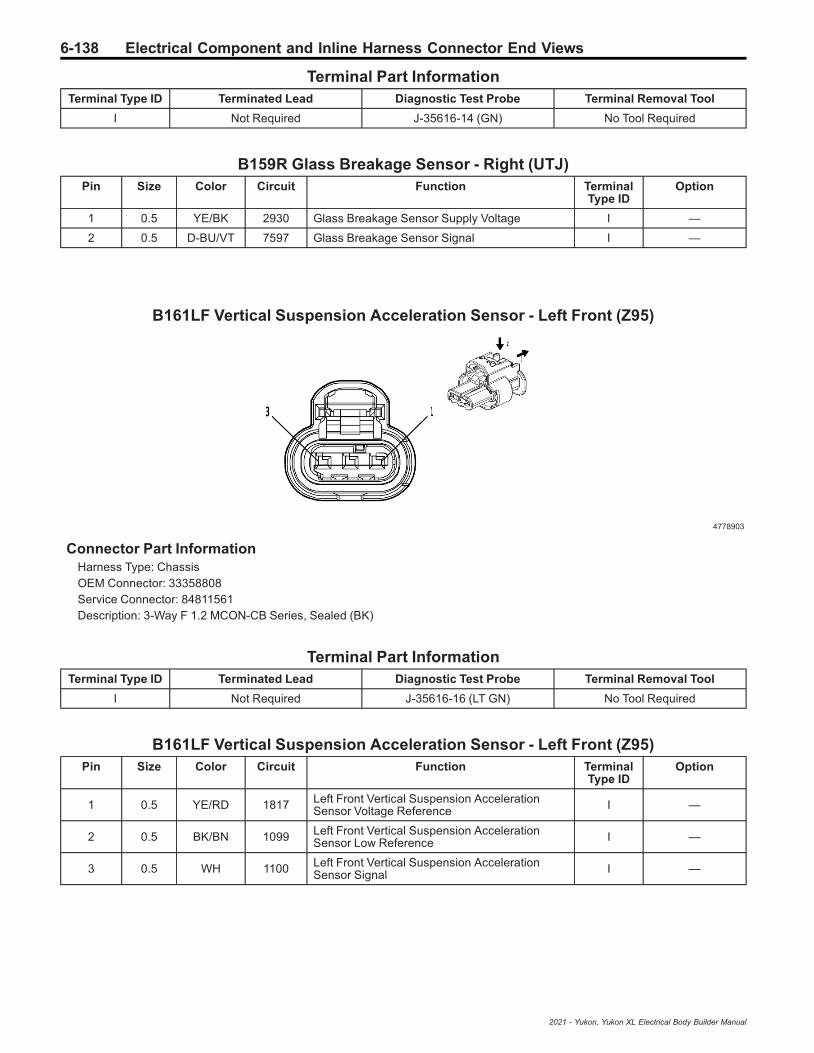
6-138 Electrical Component and Inline Harness Connector End Views
Terminal Part InformationTerminal Type ID Terminated Lead Diagnostic Test Probe Terminal Removal Tool
I Not Required J-35616-14 (GN) No Tool Required
B159R Glass Breakage Sensor - Right (UTJ)Pin Size Color Circuit Function Terminal
Type IDOption
1 0.5 YE/BK 2930 Glass Breakage Sensor Supply Voltage I —
2 0.5 D-BU/VT 7597 Glass Breakage Sensor Signal I —
B161LF Vertical Suspension Acceleration Sensor - Left Front (Z95)
4778903
Connector Part InformationHarness Type: ChassisOEM Connector: 33358808Service Connector: 84811561Description: 3-Way F 1.2 MCON-CB Series, Sealed (BK)
Terminal Part InformationTerminal Type ID Terminated Lead Diagnostic Test Probe Terminal Removal Tool
I Not Required J-35616-16 (LT GN) No Tool Required
B161LF Vertical Suspension Acceleration Sensor - Left Front (Z95)Pin Size Color Circuit Function Terminal
Type IDOption
1 0.5 YE/RD 1817 Left Front Vertical Suspension AccelerationSensor Voltage Reference I —
2 0.5 BK/BN 1099 Left Front Vertical Suspension AccelerationSensor Low Reference I —
3 0.5 WH 1100 Left Front Vertical Suspension AccelerationSensor Signal I —
2021 - Yukon, Yukon XL Electrical Body Builder Manual

Electrical Component and Inline Harness Connector End Views 6-139
B161LR Vertical Suspension Acceleration Sensor - Left Rear (Z95)
—
Connector Part InformationHarness Type: Chassis Rear ExtensionOEM Connector: 84237878Service Connector: Service by Harness - See Part CatalogDescription: —
Terminal Part InformationTerminal Type ID Terminated Lead Diagnostic Test Probe Terminal Removal Tool
I Not Required No Tool Required No Tool Required
B161LR Vertical Suspension Acceleration Sensor - Left Rear (Z95)Pin Size Color Circuit Function Terminal
Type IDOption
1 0.75 VT/RD 1818 Left Rear Vertical Suspension AccelerationSensor Voltage Reference I —
2 0.75 BK/VT 1833 Left Rear Vertical Suspension AccelerationSensor Low Reference I —
3 0.75 YE/BN 1103 Left Rear Vertical Suspension AccelerationSensor Signal I —
B161RF Vertical Suspension Acceleration Sensor - Right Front (Z95)
4778903
Connector Part InformationHarness Type: ChassisOEM Connector: 33358808Service Connector: 84811561Description: 3-Way F 1.2 MCON-CB Series, Sealed (BK)
Terminal Part InformationTerminal Type ID Terminated Lead Diagnostic Test Probe Terminal Removal Tool
I Not Required J-35616-16 (LT GN) No Tool Required
2021 - Yukon, Yukon XL Electrical Body Builder Manual

6-140 Electrical Component and Inline Harness Connector End Views
B161RF Vertical Suspension Acceleration Sensor - Right Front (Z95)Pin Size Color Circuit Function Terminal
Type IDOption
1 0.5 BN/RD 1819 Right Front Vertical Suspension AccelerationSensor Voltage Reference I —
2 0.5 BK/L-GN 1105 Right Front Vertical Suspension AccelerationSensor Low Reference I —
3 0.5 WH 1106 Right Front Vertical Suspension AccelerationSensor Signal I —
2021 - Yukon, Yukon XL Electrical Body Builder Manual
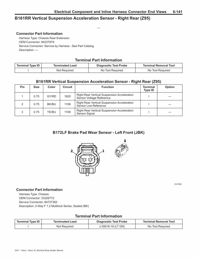
Electrical Component and Inline Harness Connector End Views 6-141
B161RR Vertical Suspension Acceleration Sensor - Right Rear (Z95)
—
Connector Part InformationHarness Type: Chassis Rear ExtensionOEM Connector: 84237879Service Connector: Service by Harness - See Part CatalogDescription: —
Terminal Part InformationTerminal Type ID Terminated Lead Diagnostic Test Probe Terminal Removal Tool
I Not Required No Tool Required No Tool Required
B161RR Vertical Suspension Acceleration Sensor - Right Rear (Z95)Pin Size Color Circuit Function Terminal
Type IDOption
1 0.75 GY/RD 1820 Right Rear Vertical Suspension AccelerationSensor Voltage Reference I —
2 0.75 BK/BU 1108 Right Rear Vertical Suspension AccelerationSensor Low Reference I —
3 0.75 YE/BU 1109 Right Rear Vertical Suspension AccelerationSensor Signal I —
B172LF Brake Pad Wear Sensor - Left Front (JBK)
3747581
Connector Part InformationHarness Type: ChassisOEM Connector: 33226772Service Connector: 84727362Description: 2-Way F 1.2 Multilock Series, Sealed (BK)
Terminal Part InformationTerminal Type ID Terminated Lead Diagnostic Test Probe Terminal Removal Tool
I Not Required J-35616-16 (LT GN) No Tool Required
2021 - Yukon, Yukon XL Electrical Body Builder Manual

6-142 Electrical Component and Inline Harness Connector End Views
B172LF Brake Pad Wear Sensor - Left Front (JBK)Pin Size Color Circuit Function Terminal
Type IDOption
1 0.75 BN/D-BU 1602 Front Brake Pad Wear Sensor Signal I —
2 0.5 BK 2050 Ground 20 I —
B172LR Brake Pad Wear Sensor - Left Rear (JBK)
3747581
Connector Part InformationHarness Type: Chassis Rear ExtensionOEM Connector: 13583195Service Connector: Service by Harness - See Part CatalogDescription: 2-Way F 1.2 Multilock Series, Sealed (BK)
Terminal Part InformationTerminal Type ID Terminated Lead Diagnostic Test Probe Terminal Removal Tool
I Not Required J-35616-16 (LT GN) No Tool Required
B172LR Brake Pad Wear Sensor - Left Rear (JBK)Pin Size Color Circuit Function Terminal
Type IDOption
1 0.75 GN/YE 1616 Rear Brake Pad Wear Sensor Signal I —
2 0.75 BK 2050 Ground 20 I —
2021 - Yukon, Yukon XL Electrical Body Builder Manual

Electrical Component and Inline Harness Connector End Views 6-143
B174W Frontview Camera - Windshield (UEU/UHY/UGN)
3824362
Connector Part InformationHarness Type: HeadlinerOEM Connector: 33235297Service Connector: 13507121Description: 12-Way F Mini 50 Series (BK)
Terminal Part InformationTerminal Type ID Terminated Lead Diagnostic Test Probe Terminal Removal Tool
I 19333221 EL-35616-58 (BK) EL-38125-58
II 19369210 EL-35616-58 (BK) EL-38125-58
B174W Frontview Camera - Windshield (UEU/UHY/UGN)Pin Size Color Circuit Function Terminal
Type IDOption
1 0.5 BK/WH 1851 Ground 18 II —
2 — — — Not Occupied — —
3 0.5 RD/YE 240 Secondary Fused Battery Positive Voltage 2 II —
4 — — — Not Occupied — —
50.50.5
D-BU/GYD-BU/YE
41054979
AUTOSAR Serial Data CAN Bus [+] 8Serial DataAUTOSAR CAN Bus [+] 2 Serial Data
IIII
UEU+UGNUEU+UHY
60.50.5
WH/GYWH
41044978
AUTOSAR Serial Data CAN Bus [-] 8Serial DataAUTOSAR CAN Bus [-] 2 Serial Data
IIII
UEU+UGNUEU+UHY
70.350.5
D-BU/GYD-BU/YE
41054979
AUTOSAR Serial Data CAN Bus [+] 8Serial DataAUTOSAR CAN Bus [+] 2 Serial Data
III
UEU+UGNUEU+UHY
80.350.5
WH/GYWH
41044978
AUTOSAR Serial Data CAN Bus [-] 8Serial DataAUTOSAR CAN Bus [-] 2 Serial Data
III
UEU+UGNUEU+UHY
9 - 12 — — — Not Occupied — —
2021 - Yukon, Yukon XL Electrical Body Builder Manual

6-144 Electrical Component and Inline Harness Connector End Views
B193A Charge Air Cooler Inlet Temperature Sensor (LM2)
3747581
Connector Part InformationHarness Type: EngineOEM Connector: 33226772Service Connector: 84727362Description: 2-Way F 1.2 Multilock Series, Sealed (BK)
Terminal Part InformationTerminal Type ID Terminated Lead Diagnostic Test Probe Terminal Removal Tool
I Not Required J-35616-16 (LT GN) No Tool Required
B193A Charge Air Cooler Inlet Temperature Sensor (LM2)Pin Size Color Circuit Function Terminal
Type IDOption
1 0.5 YE/BK 3682 Charge Air Cooler Inlet Temperature SensorLow Reference I —
2 0.5 L-GN 3683 Charge Air Cooler Inlet Temperature SensorSignal I —
B193B Charge Air Cooler Outlet Temperature Sensor (LM2)
3747581
Connector Part InformationHarness Type: EngineOEM Connector: 33226772Service Connector: 84727362Description: 2-Way F 1.2 Multilock Series, Sealed (BK)
2021 - Yukon, Yukon XL Electrical Body Builder Manual

Electrical Component and Inline Harness Connector End Views 6-145
Terminal Part InformationTerminal Type ID Terminated Lead Diagnostic Test Probe Terminal Removal Tool
I Not Required J-35616-16 (LT GN) No Tool Required
B193B Charge Air Cooler Outlet Temperature Sensor (LM2)Pin Size Color Circuit Function Terminal
Type IDOption
1 0.5 YE/D-BU 3680 Charge Air Cooler Outlet Temperature SensorLow Reference I —
2 0.5 BN 3681 Charge Air Cooler Outlet Temperature SensorSignal I —
B195A Nitrogen Oxides Sensor 1 (LM2)
2717079
Connector Part InformationHarness Type: EngineOEM Connector: 13815341Service Connector: 13587299Description: 4-Way F 1.2 Multilock Series, Sealed (BK)
Terminal Part InformationTerminal Type ID Terminated Lead Diagnostic Test Probe Terminal Removal Tool
I Not Required J-35616-16 (LT GN) No Tool Required
B195A Nitrogen Oxides Sensor 1 (LM2)Pin Size Color Circuit Function Terminal
Type IDOption
1 1 VT/L-GN 4320 Selective Catalytic Reduction Power ModuleWake-Up Signal I —
2 0.5 WH 4055 Private Serial Data Powertrain CAN Bus [+]Serial Data I —
3 0.5 D-BU/GY 4054 Private Serial Data Powertrain CAN Bus [-]Serial Data I —
4 1 BK/WH 6151 Engine Control Module Ground 61 I —
2021 - Yukon, Yukon XL Electrical Body Builder Manual

6-146 Electrical Component and Inline Harness Connector End Views
B195B Nitrogen Oxides Sensor 2 (LM2)
2717096
Connector Part InformationHarness Type: ChassisOEM Connector: 13815348Service Connector: 13587298Description: 4-Way F 1.2 Multilock Series, Sealed (L-GY)
Terminal Part InformationTerminal Type ID Terminated Lead Diagnostic Test Probe Terminal Removal Tool
I Not Required J-35616-16 (LT GN) No Tool Required
B195B Nitrogen Oxides Sensor 2 (LM2)Pin Size Color Circuit Function Terminal
Type IDOption
1 1 VT/L-GN 4320 Selective Catalytic Reduction Power ModuleWake-Up Signal I —
2 0.5 WH 4055 Private Serial Data Powertrain CAN Bus [+]Serial Data I —
3 0.5 D-BU/GY 4054 Private Serial Data Powertrain CAN Bus [-]Serial Data I —
4 1 BK/WH 6151 Engine Control Module Ground 61 I —
B195C Nitrogen Oxides Sensor 3 (LM2)
2717079
2021 - Yukon, Yukon XL Electrical Body Builder Manual

Electrical Component and Inline Harness Connector End Views 6-147
Connector Part InformationHarness Type: ChassisOEM Connector: 13815341Service Connector: 13587299Description: 4-Way F 1.2 Multilock Series, Sealed (BK)
Terminal Part InformationTerminal Type ID Terminated Lead Diagnostic Test Probe Terminal Removal Tool
I Not Required J-35616-16 (LT GN) No Tool Required
B195C Nitrogen Oxides Sensor 3 (LM2)Pin Size Color Circuit Function Terminal
Type IDOption
1 1 VT/L-GN 4320 Selective Catalytic Reduction Power ModuleWake-Up Signal I —
2 0.5 WH 4055 Private Serial Data Powertrain CAN Bus [+]Serial Data I —
3 0.5 D-BU/GY 4054 Private Serial Data Powertrain CAN Bus [-]Serial Data I —
4 1 BK/WH 6151 Engine Control Module Ground 61 I —
B203 Radiator Coolant Temperature Sensor (LM2)
2717066
Connector Part InformationHarness Type: EngineOEM Connector: 13735326Service Connector: 13587326Description: 2-Way F 1.2 Multilock Series, Sealed (BK)
Terminal Part InformationTerminal Type ID Terminated Lead Diagnostic Test Probe Terminal Removal Tool
I Not Required J-35616-16 (LT GN) No Tool Required
B203 Radiator Coolant Temperature Sensor (LM2)Pin Size Color Circuit Function Terminal
Type IDOption
1 0.5 YE/BK 3000 Coolant Temperature Sensor 2 Signal I —
2021 - Yukon, Yukon XL Electrical Body Builder Manual

6-148 Electrical Component and Inline Harness Connector End Views
B203 Radiator Coolant Temperature Sensor (LM2) (cont'd)Pin Size Color Circuit Function Terminal
Type IDOption
2 0.5 BK/L-GN 580 Engine Control Sensors Low Reference 2 I —
B218L Side Object Sensor Module - Left (UKC/UKV)
4708234
Connector Part InformationHarness Type: Rear FasciaOEM Connector: 35192853Service Connector: Service by Harness - See Part CatalogDescription: 8-Way F 64 Series, Sealed (BK)
Terminal Part InformationTerminal Type ID Terminated Lead Diagnostic Test Probe Terminal Removal Tool
I Not Required J-35616-64B (LT BU) No Tool Required
B218L Side Object Sensor Module - Left (UKC/UKV)Pin Size Color Circuit Function Terminal
Type IDOption
1 0.5 WH 4087 Private Serial Data Side Obstacle DetectionCAN Bus [-] Serial Data I —
2 0.5 D-BU/VT 4088 Private Serial Data Side Obstacle DetectionCAN Bus [+] Serial Data I —
3 0.5 BK 1450 Ground 14 I —
4 0.35 WH 4100 AUTOSAR Serial Data CAN Bus [-] 4Serial Data I —
5 0.5 WH 4100 AUTOSAR Serial Data CAN Bus [-] 4Serial Data I —
6 0.5 D-BU/VT 4101 AUTOSAR Serial Data CAN Bus [+] 4Serial Data I —
7 0.35 D-BU/VT 4101 AUTOSAR Serial Data CAN Bus [+] 4Serial Data I —
8 0.5 RD/BN 4940 Secondary Fused Battery Positive Voltage 49 I —
2021 - Yukon, Yukon XL Electrical Body Builder Manual

Electrical Component and Inline Harness Connector End Views 6-149
B218R Side Object Sensor Module - Right (UKC/UKV)
4708234
Connector Part InformationHarness Type: Rear FasciaOEM Connector: 35200888Service Connector: Service by Harness - See Part CatalogDescription: 8-Way F 64 Series, Sealed (BK)
Terminal Part InformationTerminal Type ID Terminated Lead Diagnostic Test Probe Terminal Removal Tool
I Not Required J-35616-64B (LT BU) No Tool Required
B218R Side Object Sensor Module - Right (UKC/UKV)Pin Size Color Circuit Function Terminal
Type IDOption
1 0.5 WH 4087 Private Serial Data Side Obstacle DetectionCAN Bus [-] Serial Data I —
2 0.5 D-BU/VT 4088 Private Serial Data Side Obstacle DetectionCAN Bus [+] Serial Data I —
3 0.5 BK 1450 Ground 14 I —
4 — — — Not Occupied — —
5 0.5 WH 4100 AUTOSAR Serial Data CAN Bus [-] 4Serial Data I —
6 0.5 D-BU/VT 4101 AUTOSAR Serial Data CAN Bus [+] 4Serial Data I —
7 — — — Not Occupied — —
8 0.5 RD/BN 4940 Secondary Fused Battery Positive Voltage 49 I —
2021 - Yukon, Yukon XL Electrical Body Builder Manual

6-150 Electrical Component and Inline Harness Connector End Views
B227 Gear Position Sensor (NP0/NQH)
4569745
Connector Part InformationHarness Type: EngineOEM Connector: 33343869Service Connector: 19179750Description: 3-Way F 150 MX Series, Sealed (BK)
Terminal Part InformationTerminal Type ID Terminated Lead Diagnostic Test Probe Terminal Removal Tool
I Not Required J-35616-14 (GN) No Tool Required
II Not Required J-35616-2A (GY) No Tool Required
B227 Gear Position Sensor (NP0/NQH)Pin Size Color Circuit Function Terminal
Type IDOption
10.50.5
WH/RDWH/RD
74777477
Gear Position Sensor 5V ReferenceGear Position Sensor 5V Reference
III
——
20.50.5
WH/L-GNWH/L-GN
74797479
Rotary Position Sensor SignalRotary Position Sensor Signal
III
——
30.50.5
YE/BKYE/BK
74787478
Gear Position Sensor Low ReferenceGear Position Sensor Low Reference
III
——
B233B Radar Sensor Module - Long Range (UGN/UVZ)
4708234
2021 - Yukon, Yukon XL Electrical Body Builder Manual
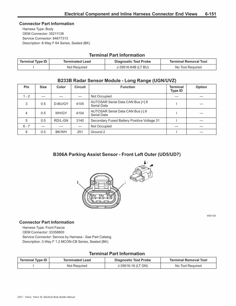
Electrical Component and Inline Harness Connector End Views 6-151
Connector Part InformationHarness Type: BodyOEM Connector: 35211138Service Connector: 84677313Description: 8-Way F 64 Series, Sealed (BK)
Terminal Part InformationTerminal Type ID Terminated Lead Diagnostic Test Probe Terminal Removal Tool
I Not Required J-35616-64B (LT BU) No Tool Required
B233B Radar Sensor Module - Long Range (UGN/UVZ)Pin Size Color Circuit Function Terminal
Type IDOption
1 - 2 — — — Not Occupied — —
3 0.5 D-BU/GY 4105 AUTOSAR Serial Data CAN Bus [+] 8Serial Data I —
4 0.5 WH/GY 4104 AUTOSAR Serial Data CAN Bus [-] 8Serial Data I —
5 0.5 RD/L-GN 3140 Secondary Fused Battery Positive Voltage 31 I —
6 - 7 — — — Not Occupied — —
8 0.5 BK/WH 251 Ground 2 I —
B306A Parking Assist Sensor - Front Left Outer (UD5/UD7)
4581126
Connector Part InformationHarness Type: Front FasciaOEM Connector: 33358800Service Connector: Service by Harness - See Part CatalogDescription: 3-Way F 1.2 MCON-CB Series, Sealed (BK)
Terminal Part InformationTerminal Type ID Terminated Lead Diagnostic Test Probe Terminal Removal Tool
I Not Required J-35616-16 (LT GN) No Tool Required
2021 - Yukon, Yukon XL Electrical Body Builder Manual

6-152 Electrical Component and Inline Harness Connector End Views
B306A Parking Assist Sensor - Front Left Outer (UD5/UD7)Pin Size Color Circuit Function Terminal
Type IDOption
1 0.5 BN 6581 Front Parking Assist Display Control I —
2 0.5 VT/WH 5215 Left Front Outer Parking Assist Sensor I —
3 0.5 BK/D-BU 5214 Front Parking Assist Sensor Low Reference I —
B306B Parking Assist Sensor - Front Left Middle (UD5/UD7)
4581126
Connector Part InformationHarness Type: Front FasciaOEM Connector: 33358800Service Connector: Service by Harness - See Part CatalogDescription: 3-Way F 1.2 MCON-CB Series, Sealed (BK)
Terminal Part InformationTerminal Type ID Terminated Lead Diagnostic Test Probe Terminal Removal Tool
I Not Required J-35616-16 (LT GN) No Tool Required
B306B Parking Assist Sensor - Front Left Middle (UD5/UD7)Pin Size Color Circuit Function Terminal
Type IDOption
1 0.5 BN 6581 Front Parking Assist Display Control I —
2 0.5 YE/GY 5216 Left Front Middle Parking Assist Sensor I —
3 0.5 BK/D-BU 5214 Front Parking Assist Sensor Low Reference I —
2021 - Yukon, Yukon XL Electrical Body Builder Manual

Electrical Component and Inline Harness Connector End Views 6-153
B306C Parking Assist Sensor - Front Right Middle (UD5/UD7)
4581126
Connector Part InformationHarness Type: Front FasciaOEM Connector: 33358800Service Connector: Service by Harness - See Part CatalogDescription: 3-Way F 1.2 MCON-CB Series, Sealed (BK)
Terminal Part InformationTerminal Type ID Terminated Lead Diagnostic Test Probe Terminal Removal Tool
I Not Required J-35616-16 (LT GN) No Tool Required
B306C Parking Assist Sensor - Front Right Middle (UD5/UD7)Pin Size Color Circuit Function Terminal
Type IDOption
1 0.5 BN 6581 Front Parking Assist Display Control I —
2 0.5 VT/GY 5218 Right Front Middle Parking Assist Sensor I —
3 0.5 BK/D-BU 5214 Front Parking Assist Sensor Low Reference I —
B306D Parking Assist Sensor - Front Right Outer (UD5/UD7)
4581126
Connector Part InformationHarness Type: Front FasciaOEM Connector: 33358800Service Connector: Service by Harness - See Part CatalogDescription: 3-Way F 1.2 MCON-CB Series, Sealed (BK)
2021 - Yukon, Yukon XL Electrical Body Builder Manual
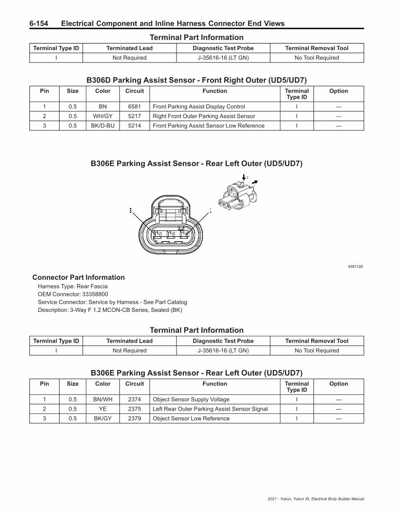
6-154 Electrical Component and Inline Harness Connector End Views
Terminal Part InformationTerminal Type ID Terminated Lead Diagnostic Test Probe Terminal Removal Tool
I Not Required J-35616-16 (LT GN) No Tool Required
B306D Parking Assist Sensor - Front Right Outer (UD5/UD7)Pin Size Color Circuit Function Terminal
Type IDOption
1 0.5 BN 6581 Front Parking Assist Display Control I —
2 0.5 WH/GY 5217 Right Front Outer Parking Assist Sensor I —
3 0.5 BK/D-BU 5214 Front Parking Assist Sensor Low Reference I —
B306E Parking Assist Sensor - Rear Left Outer (UD5/UD7)
4581126
Connector Part InformationHarness Type: Rear FasciaOEM Connector: 33358800Service Connector: Service by Harness - See Part CatalogDescription: 3-Way F 1.2 MCON-CB Series, Sealed (BK)
Terminal Part InformationTerminal Type ID Terminated Lead Diagnostic Test Probe Terminal Removal Tool
I Not Required J-35616-16 (LT GN) No Tool Required
B306E Parking Assist Sensor - Rear Left Outer (UD5/UD7)Pin Size Color Circuit Function Terminal
Type IDOption
1 0.5 BN/WH 2374 Object Sensor Supply Voltage I —
2 0.5 YE 2375 Left Rear Outer Parking Assist Sensor Signal I —
3 0.5 BK/GY 2379 Object Sensor Low Reference I —
2021 - Yukon, Yukon XL Electrical Body Builder Manual

Electrical Component and Inline Harness Connector End Views 6-155
B306F Parking Assist Sensor - Rear Left Middle (UD5/UD7)
4581126
Connector Part InformationHarness Type: Rear FasciaOEM Connector: 33358800Service Connector: Service by Harness - See Part CatalogDescription: 3-Way F 1.2 MCON-CB Series, Sealed (BK)
Terminal Part InformationTerminal Type ID Terminated Lead Diagnostic Test Probe Terminal Removal Tool
I Not Required J-35616-16 (LT GN) No Tool Required
B306F Parking Assist Sensor - Rear Left Middle (UD5/UD7)Pin Size Color Circuit Function Terminal
Type IDOption
1 0.5 BN/WH 2374 Object Sensor Supply Voltage I —
2 0.5 YE/D-BU 2376 Left Rear Middle Parking Assist Sensor Signal I —
3 0.5 BK/GY 2379 Object Sensor Low Reference I —
B306G Parking Assist Sensor - Rear Right Middle (UD5/UD7)
4581126
Connector Part InformationHarness Type: Rear FasciaOEM Connector: 33358800Service Connector: Service by Harness - See Part CatalogDescription: 3-Way F 1.2 MCON-CB Series, Sealed (BK)
2021 - Yukon, Yukon XL Electrical Body Builder Manual
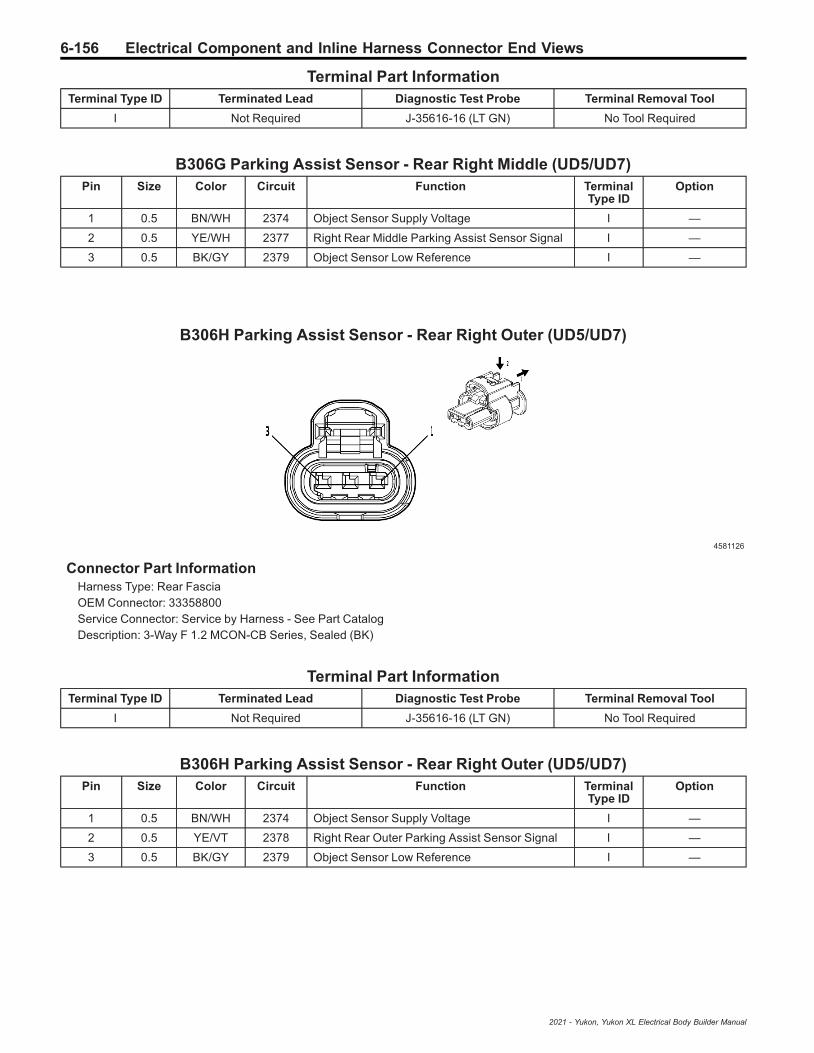
6-156 Electrical Component and Inline Harness Connector End Views
Terminal Part InformationTerminal Type ID Terminated Lead Diagnostic Test Probe Terminal Removal Tool
I Not Required J-35616-16 (LT GN) No Tool Required
B306G Parking Assist Sensor - Rear Right Middle (UD5/UD7)Pin Size Color Circuit Function Terminal
Type IDOption
1 0.5 BN/WH 2374 Object Sensor Supply Voltage I —
2 0.5 YE/WH 2377 Right Rear Middle Parking Assist Sensor Signal I —
3 0.5 BK/GY 2379 Object Sensor Low Reference I —
B306H Parking Assist Sensor - Rear Right Outer (UD5/UD7)
4581126
Connector Part InformationHarness Type: Rear FasciaOEM Connector: 33358800Service Connector: Service by Harness - See Part CatalogDescription: 3-Way F 1.2 MCON-CB Series, Sealed (BK)
Terminal Part InformationTerminal Type ID Terminated Lead Diagnostic Test Probe Terminal Removal Tool
I Not Required J-35616-16 (LT GN) No Tool Required
B306H Parking Assist Sensor - Rear Right Outer (UD5/UD7)Pin Size Color Circuit Function Terminal
Type IDOption
1 0.5 BN/WH 2374 Object Sensor Supply Voltage I —
2 0.5 YE/VT 2378 Right Rear Outer Parking Assist Sensor Signal I —
3 0.5 BK/GY 2379 Object Sensor Low Reference I —
2021 - Yukon, Yukon XL Electrical Body Builder Manual

Electrical Component and Inline Harness Connector End Views 6-157
B310 Fuel Pressure/Temperature Sensor (LM2)
2717079
Connector Part InformationHarness Type: EngineOEM Connector: 13815341Service Connector: 13587299Description: 4-Way F 1.2 Multilock Series, Sealed (BK)
Terminal Part InformationTerminal Type ID Terminated Lead Diagnostic Test Probe Terminal Removal Tool
I Not Required J-35616-16 (LT GN) No Tool Required
B310 Fuel Pressure/Temperature Sensor (LM2)Pin Size Color Circuit Function Terminal
Type IDOption
1 0.5 BN/RD 2917 Fuel Rail Pressure Sensor 5V Reference I —
2 0.5 BN/YE 2161 Fuel Rail Pressure Sensor 2 Signal I —
3 0.5 BK/L-GN 2919 Fuel Rail Pressure Sensor Low Reference I —
4 0.5 D-BU/WH 2918 Fuel Rail Pressure Sensor Signal I —
B312LF Active Noise Cancellation Microphone - Left Front
4116496
Connector Part InformationHarness Type: HeadlinerOEM Connector: 33189233
2021 - Yukon, Yukon XL Electrical Body Builder Manual

6-158 Electrical Component and Inline Harness Connector End Views
Service Connector: 19332376Description: 2-Way M 1.2 Series (BK)
Terminal Part InformationTerminal Type ID Terminated Lead Diagnostic Test Probe Terminal Removal Tool
I Not Required J-35616-17 (LT GN) No Tool Required
B312LF Active Noise Cancellation Microphone - Left FrontPin Size Color Circuit Function Terminal
Type IDOption
1 0.5 L-GN/BK 3008 Active Noise Cancellation Microphone 1Feedback Signal I —
2 0.5 L-GN/BN 3005 Active Noise Cancellation Microphone 1 Signal I —
B321 Crankcase Pressure Sensor (LM2)
4778903
Connector Part InformationHarness Type: EngineOEM Connector: 33358808Service Connector: 84811561Description: 3-Way F 1.2 MCON-CB Series, Sealed (BK)
Terminal Part InformationTerminal Type ID Terminated Lead Diagnostic Test Probe Terminal Removal Tool
I Not Required J-35616-16 (LT GN) No Tool Required
B321 Crankcase Pressure Sensor (LM2)Pin Size Color Circuit Function Terminal
Type IDOption
1 0.5 WH/RD 480 Engine Control Vehicle Sensors 5 VoltReference 1 I —
2 0.5 YE/GY 3926 Crankcase Differential Pressure Sensor Signal I —
3 0.5 BK/YE 548 Engine Control Sensors Low Reference 1 I —
2021 - Yukon, Yukon XL Electrical Body Builder Manual
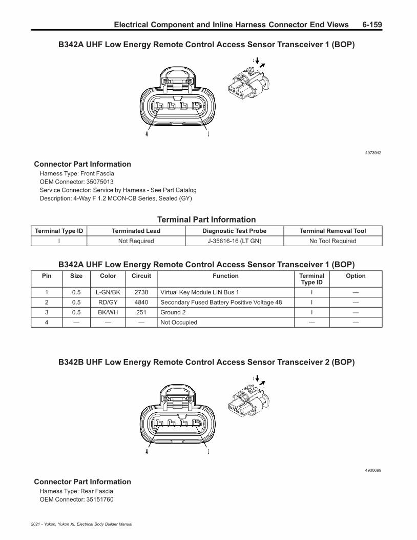
Electrical Component and Inline Harness Connector End Views 6-159
B342A UHF Low Energy Remote Control Access Sensor Transceiver 1 (BOP)
4973942
Connector Part InformationHarness Type: Front FasciaOEM Connector: 35075013Service Connector: Service by Harness - See Part CatalogDescription: 4-Way F 1.2 MCON-CB Series, Sealed (GY)
Terminal Part InformationTerminal Type ID Terminated Lead Diagnostic Test Probe Terminal Removal Tool
I Not Required J-35616-16 (LT GN) No Tool Required
B342A UHF Low Energy Remote Control Access Sensor Transceiver 1 (BOP)Pin Size Color Circuit Function Terminal
Type IDOption
1 0.5 L-GN/BK 2738 Virtual Key Module LIN Bus 1 I —
2 0.5 RD/GY 4840 Secondary Fused Battery Positive Voltage 48 I —
3 0.5 BK/WH 251 Ground 2 I —
4 — — — Not Occupied — —
B342B UHF Low Energy Remote Control Access Sensor Transceiver 2 (BOP)
4900699
Connector Part InformationHarness Type: Rear FasciaOEM Connector: 35151760
2021 - Yukon, Yukon XL Electrical Body Builder Manual

6-160 Electrical Component and Inline Harness Connector End Views
Service Connector: Service by Harness - See Part CatalogDescription: 4-Way F 1.2 MCON-CB Series, Sealed (BK)
Terminal Part InformationTerminal Type ID Terminated Lead Diagnostic Test Probe Terminal Removal Tool
I Not Required J-35616-16 (LT GN) No Tool Required
B342B UHF Low Energy Remote Control Access Sensor Transceiver 2 (BOP)Pin Size Color Circuit Function Terminal
Type IDOption
1 0.5 L-GN/BK 2738 Virtual Key Module LIN Bus 1 I —
2 0.5 RD/GY 4840 Secondary Fused Battery Positive Voltage 48 I —
3 0.5 BK 1450 Ground 14 I —
4 — — — Not Occupied — —
B342C UHF Low Energy Remote Control Access Sensor Transceiver 3 (BOP)
4210809
Connector Part InformationHarness Type: Front FasciaOEM Connector: 33390897Service Connector: Service by Harness - See Part CatalogDescription: 4-Way F 1.2 MCON-CB Series, Sealed (BK)
Terminal Part InformationTerminal Type ID Terminated Lead Diagnostic Test Probe Terminal Removal Tool
I Not Required J-35616-16 (LT GN) No Tool Required
B342C UHF Low Energy Remote Control Access Sensor Transceiver 3 (BOP)Pin Size Color Circuit Function Terminal
Type IDOption
1 0.5 L-GN/BK 2738 Virtual Key Module LIN Bus 1 I —
2 0.5 RD/GY 4840 Secondary Fused Battery Positive Voltage 48 I —
3 0.5 BK/WH 251 Ground 2 I —
4 — — — Not Occupied — —
2021 - Yukon, Yukon XL Electrical Body Builder Manual

Electrical Component and Inline Harness Connector End Views 6-161
B342D UHF Low Energy Remote Control Access Sensor Transceiver 4 (BOP)
4934614
Connector Part InformationHarness Type: Rear FasciaOEM Connector: 33367416Service Connector: Service by Harness - See Part CatalogDescription: 4-Way F 1.2 MCON-CB Series, Sealed (BK)
Terminal Part InformationTerminal Type ID Terminated Lead Diagnostic Test Probe Terminal Removal Tool
I Not Required J-35616-16 (LT GN) No Tool Required
B342D UHF Low Energy Remote Control Access Sensor Transceiver 4 (BOP)Pin Size Color Circuit Function Terminal
Type IDOption
1 0.5 L-GN/BK 2738 Virtual Key Module LIN Bus 1 I —
2 0.5 RD/GY 4840 Secondary Fused Battery Positive Voltage 48 I —
3 0.5 BK 1450 Ground 14 I —
4 — — — Not Occupied — —
B345R Exhaust Pressure Differential Sensor - Exhaust Gas Recirculation (LM2)
4778903
Connector Part InformationHarness Type: EngineOEM Connector: 33358808
2021 - Yukon, Yukon XL Electrical Body Builder Manual
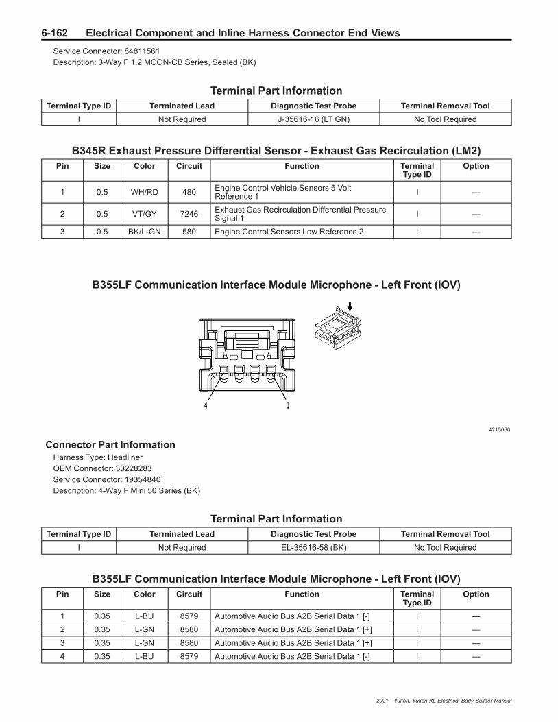
6-162 Electrical Component and Inline Harness Connector End Views
Service Connector: 84811561Description: 3-Way F 1.2 MCON-CB Series, Sealed (BK)
Terminal Part InformationTerminal Type ID Terminated Lead Diagnostic Test Probe Terminal Removal Tool
I Not Required J-35616-16 (LT GN) No Tool Required
B345R Exhaust Pressure Differential Sensor - Exhaust Gas Recirculation (LM2)Pin Size Color Circuit Function Terminal
Type IDOption
1 0.5 WH/RD 480 Engine Control Vehicle Sensors 5 VoltReference 1 I —
2 0.5 VT/GY 7246 Exhaust Gas Recirculation Differential PressureSignal 1 I —
3 0.5 BK/L-GN 580 Engine Control Sensors Low Reference 2 I —
B355LF Communication Interface Module Microphone - Left Front (IOV)
4215060
Connector Part InformationHarness Type: HeadlinerOEM Connector: 33228283Service Connector: 19354840Description: 4-Way F Mini 50 Series (BK)
Terminal Part InformationTerminal Type ID Terminated Lead Diagnostic Test Probe Terminal Removal Tool
I Not Required EL-35616-58 (BK) No Tool Required
B355LF Communication Interface Module Microphone - Left Front (IOV)Pin Size Color Circuit Function Terminal
Type IDOption
1 0.35 L-BU 8579 Automotive Audio Bus A2B Serial Data 1 [-] I —
2 0.35 L-GN 8580 Automotive Audio Bus A2B Serial Data 1 [+] I —
3 0.35 L-GN 8580 Automotive Audio Bus A2B Serial Data 1 [+] I —
4 0.35 L-BU 8579 Automotive Audio Bus A2B Serial Data 1 [-] I —
2021 - Yukon, Yukon XL Electrical Body Builder Manual

Electrical Component and Inline Harness Connector End Views 6-163
B355LR Communication Interface Module Microphone - Left Rear (IOV)
4215060
Connector Part InformationHarness Type: HeadlinerOEM Connector: 33228283Service Connector: 19354840Description: 4-Way F Mini 50 Series (BK)
Terminal Part InformationTerminal Type ID Terminated Lead Diagnostic Test Probe Terminal Removal Tool
I Not Required EL-35616-58 (BK) No Tool Required
B355LR Communication Interface Module Microphone - Left Rear (IOV)Pin Size Color Circuit Function Terminal
Type IDOption
1 0.35 L-BU 8579 Automotive Audio Bus A2B Serial Data 1 [-] I —
2 0.35 L-GN 8580 Automotive Audio Bus A2B Serial Data 1 [+] I —
3 0.35 L-GN 8580 Automotive Audio Bus A2B Serial Data 1 [+] I —
4 0.35 L-BU 8579 Automotive Audio Bus A2B Serial Data 1 [-] I —
B355RF Communication Interface Module Microphone - Right Front (IOV)
4215060
Connector Part InformationHarness Type: HeadlinerOEM Connector: 33228283
2021 - Yukon, Yukon XL Electrical Body Builder Manual

6-164 Electrical Component and Inline Harness Connector End Views
Service Connector: 19354840Description: 4-Way F Mini 50 Series (BK)
Terminal Part InformationTerminal Type ID Terminated Lead Diagnostic Test Probe Terminal Removal Tool
I Not Required EL-35616-58 (BK) No Tool Required
B355RF Communication Interface Module Microphone - Right Front (IOV)Pin Size Color Circuit Function Terminal
Type IDOption
1 0.35 L-BU 8579 Automotive Audio Bus A2B Serial Data 1 [-] I —
2 0.35 L-GN 8580 Automotive Audio Bus A2B Serial Data 1 [+] I —
3 0.35 L-GN 8580 Automotive Audio Bus A2B Serial Data 1 [+] I —
4 0.35 L-BU 8579 Automotive Audio Bus A2B Serial Data 1 [-] I —
E1C Accent Lamp - Driver Door Handle
4115691
Connector Part InformationHarness Type: Driver Door TrimOEM Connector: 35311666Service Connector: Service by Harness - See Part CatalogDescription: 2-Way F 1.2 MCON Series (BK)
Terminal Part InformationTerminal Type ID Terminated Lead Diagnostic Test Probe Terminal Removal Tool
I Not Required J-35616-16 (LT GN) No Tool Required
E1C Accent Lamp - Driver Door HandlePin Size Color Circuit Function Terminal
Type IDOption
1 0.35 GY/VT 2767 LED Ambient Lighting Control Left Front Door I —
2 0.35 BK 1150 Ground 11 I —
2021 - Yukon, Yukon XL Electrical Body Builder Manual
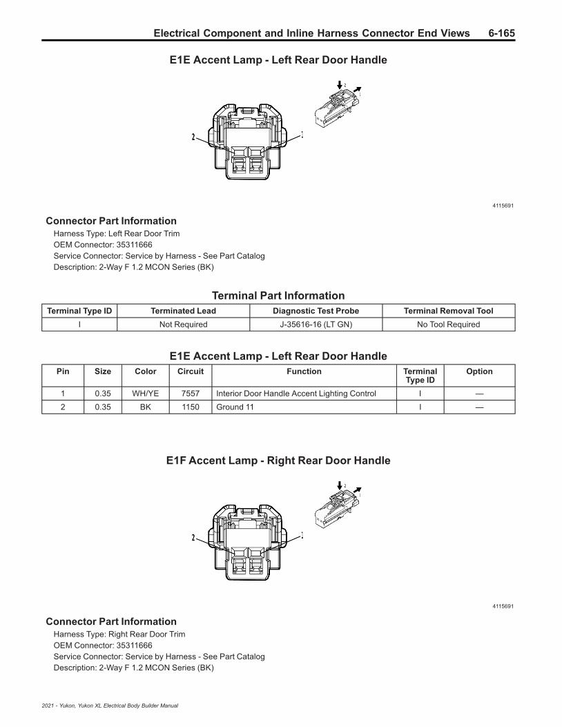
Electrical Component and Inline Harness Connector End Views 6-165
E1E Accent Lamp - Left Rear Door Handle
4115691
Connector Part InformationHarness Type: Left Rear Door TrimOEM Connector: 35311666Service Connector: Service by Harness - See Part CatalogDescription: 2-Way F 1.2 MCON Series (BK)
Terminal Part InformationTerminal Type ID Terminated Lead Diagnostic Test Probe Terminal Removal Tool
I Not Required J-35616-16 (LT GN) No Tool Required
E1E Accent Lamp - Left Rear Door HandlePin Size Color Circuit Function Terminal
Type IDOption
1 0.35 WH/YE 7557 Interior Door Handle Accent Lighting Control I —
2 0.35 BK 1150 Ground 11 I —
E1F Accent Lamp - Right Rear Door Handle
4115691
Connector Part InformationHarness Type: Right Rear Door TrimOEM Connector: 35311666Service Connector: Service by Harness - See Part CatalogDescription: 2-Way F 1.2 MCON Series (BK)
2021 - Yukon, Yukon XL Electrical Body Builder Manual
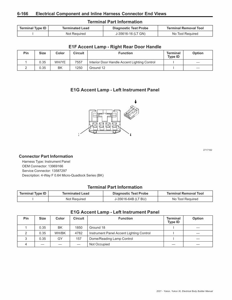
6-166 Electrical Component and Inline Harness Connector End Views
Terminal Part InformationTerminal Type ID Terminated Lead Diagnostic Test Probe Terminal Removal Tool
I Not Required J-35616-16 (LT GN) No Tool Required
E1F Accent Lamp - Right Rear Door HandlePin Size Color Circuit Function Terminal
Type IDOption
1 0.35 WH/YE 7557 Interior Door Handle Accent Lighting Control I —
2 0.35 BK 1250 Ground 12 I —
E1G Accent Lamp - Left Instrument Panel
2717162
Connector Part InformationHarness Type: Instrument PanelOEM Connector: 13969166Service Connector: 13587297Description: 4-Way F 0.64 Micro-Quadlock Series (BK)
Terminal Part InformationTerminal Type ID Terminated Lead Diagnostic Test Probe Terminal Removal Tool
I Not Required J-35616-64B (LT BU) No Tool Required
E1G Accent Lamp - Left Instrument PanelPin Size Color Circuit Function Terminal
Type IDOption
1 0.35 BK 1850 Ground 18 I —
2 0.35 WH/BK 4782 Instrument Panel Accent Lighting Control I —
3 0.35 GY 157 Dome/Reading Lamp Control I —
4 — — — Not Occupied — —
2021 - Yukon, Yukon XL Electrical Body Builder Manual

Electrical Component and Inline Harness Connector End Views 6-167
E1H Accent Lamp - Right Instrument Panel
4115691
Connector Part InformationHarness Type: Instrument PanelOEM Connector: 35311666Service Connector: 19352066Description: 2-Way F 1.2 MCON Series (BK)
Terminal Part InformationTerminal Type ID Terminated Lead Diagnostic Test Probe Terminal Removal Tool
I Not Required J-35616-16 (LT GN) No Tool Required
E1H Accent Lamp - Right Instrument PanelPin Size Color Circuit Function Terminal
Type IDOption
1 0.35 BK 1850 Ground 18 I —
2 0.35 WH/BK 4782 Instrument Panel Accent Lighting Control I —
E1M Accent Lamp - Passenger Door Handle
4115691
Connector Part InformationHarness Type: Passenger Door TrimOEM Connector: 35311666Service Connector: Service by Harness - See Part CatalogDescription: 2-Way F 1.2 MCON Series (BK)
2021 - Yukon, Yukon XL Electrical Body Builder Manual

6-168 Electrical Component and Inline Harness Connector End Views
Terminal Part InformationTerminal Type ID Terminated Lead Diagnostic Test Probe Terminal Removal Tool
I Not Required J-35616-16 (LT GN) No Tool Required
E1M Accent Lamp - Passenger Door HandlePin Size Color Circuit Function Terminal
Type IDOption
1 0.35 WH/BN 2768 LED Ambient Lighting Control Right Front Door I —
2 0.35 BK 1250 Ground 12 I —
E1Z Accent Lamp - Middle Instrument Panel
2717162
Connector Part InformationHarness Type: Instrument PanelOEM Connector: 13969166Service Connector: 13587297Description: 4-Way F 0.64 Micro-Quadlock Series (BK)
Terminal Part InformationTerminal Type ID Terminated Lead Diagnostic Test Probe Terminal Removal Tool
I Not Required J-35616-64B (LT BU) No Tool Required
E1Z Accent Lamp - Middle Instrument PanelPin Size Color Circuit Function Terminal
Type IDOption
1 0.35 BK 1050 Ground 10 I —
2 0.35 WH/BK 4782 Instrument Panel Accent Lighting Control I —
3 0.35 GY 157 Dome/Reading Lamp Control I —
4 — — — Not Occupied — —
2021 - Yukon, Yukon XL Electrical Body Builder Manual

Electrical Component and Inline Harness Connector End Views 6-169
E2LF Side Marker Lamp - Left Front
4649903
Connector Part InformationHarness Type: Front FasciaOEM Connector: 33327048Service Connector: Service by Harness - See Part CatalogDescription: 2-Way F 1.2 MCON Series, Sealed (BK)
Terminal Part InformationTerminal Type ID Terminated Lead Diagnostic Test Probe Terminal Removal Tool
I Not Required J-35616-16 (LT GN) No Tool Required
E2LF Side Marker Lamp - Left FrontPin Size Color Circuit Function Terminal
Type IDOption
1 0.5 WH/YE 1254 Left Front Park Lamp Control I —
2 0.5 BK 150 Ground 1 I —
E2LR Side Marker Lamp - Left Rear (Z88)
5360948
Connector Part InformationHarness Type: LiftgateOEM Connector: 35264701Service Connector: Service by Harness - See Part CatalogDescription: 2-Way M 1.2 MCON Series (GY)
2021 - Yukon, Yukon XL Electrical Body Builder Manual

6-170 Electrical Component and Inline Harness Connector End Views
Terminal Part InformationTerminal Type ID Terminated Lead Diagnostic Test Probe Terminal Removal Tool
I Not Required J-35616-17 (LT GN) No Tool Required
E2LR Side Marker Lamp - Left Rear (Z88)Pin Size Color Circuit Function Terminal
Type IDOption
1 0.35 BN/D-BU 6993 Left Rear Park Lamp Control I —
2 0.35 BK 2050 Ground 20 I —
E2RF Side Marker Lamp - Right Front
4649903
Connector Part InformationHarness Type: Front FasciaOEM Connector: 33327048Service Connector: Service by Harness - See Part CatalogDescription: 2-Way F 1.2 MCON Series, Sealed (BK)
Terminal Part InformationTerminal Type ID Terminated Lead Diagnostic Test Probe Terminal Removal Tool
I Not Required J-35616-16 (LT GN) No Tool Required
E2RF Side Marker Lamp - Right FrontPin Size Color Circuit Function Terminal
Type IDOption
1 0.5 D-BU/L-GN 1253 Right Front Park Lamp Control I —
2 0.5 BK 250 Ground 2 I —
2021 - Yukon, Yukon XL Electrical Body Builder Manual
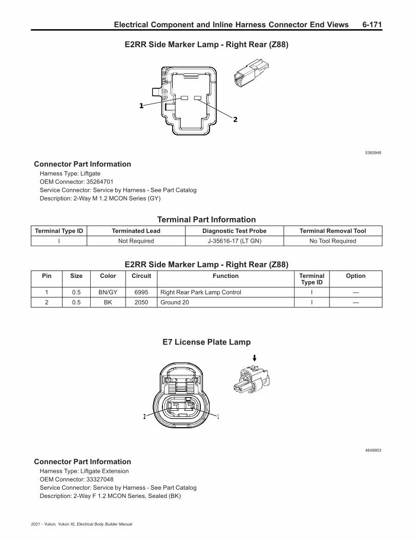
Electrical Component and Inline Harness Connector End Views 6-171
E2RR Side Marker Lamp - Right Rear (Z88)
5360948
Connector Part InformationHarness Type: LiftgateOEM Connector: 35264701Service Connector: Service by Harness - See Part CatalogDescription: 2-Way M 1.2 MCON Series (GY)
Terminal Part InformationTerminal Type ID Terminated Lead Diagnostic Test Probe Terminal Removal Tool
I Not Required J-35616-17 (LT GN) No Tool Required
E2RR Side Marker Lamp - Right Rear (Z88)Pin Size Color Circuit Function Terminal
Type IDOption
1 0.5 BN/GY 6995 Right Rear Park Lamp Control I —
2 0.5 BK 2050 Ground 20 I —
E7 License Plate Lamp
4649903
Connector Part InformationHarness Type: Liftgate ExtensionOEM Connector: 33327048Service Connector: Service by Harness - See Part CatalogDescription: 2-Way F 1.2 MCON Series, Sealed (BK)
2021 - Yukon, Yukon XL Electrical Body Builder Manual

6-172 Electrical Component and Inline Harness Connector End Views
Terminal Part InformationTerminal Type ID Terminated Lead Diagnostic Test Probe Terminal Removal Tool
I Not Required J-35616-16 (LT GN) No Tool Required
E7 License Plate LampPin Size Color Circuit Function Terminal
Type IDOption
1 0.35 BK 2050 Ground 20 I —
2 0.35 L-GN/YE 6846 Rear License Plate Lamp Control I —
E11A Fuel Heater/Water in Fuel Sensor (LM2)
2537256
Connector Part InformationHarness Type: ChassisOEM Connector: 10774827Service Connector: 19354080Description: 7-Way F 2.8 Junior Power Timer Series, Sealed (BK)
Terminal Part InformationTerminal Type ID Terminated Lead Diagnostic Test Probe Terminal Removal Tool
I Not Required J-35616-35 (VT) No Tool Required
I Not Required J-35616-35 (VT) No Tool Required
II Not Required J-35616-4A (PU) No Tool Required
E11A Fuel Heater/Water in Fuel Sensor (LM2)Pin Size Color Circuit Function Terminal
Type IDOption
1 2.5 BK 1950 Ground 19 I —
2 2.5 BN/YE 2996 Fuel Heater Control 1 I —
30.50.5
VT/L-GNVT/L-GN
43204320
Selective Catalytic Reduction Power ModuleWake-Up SignalSelective Catalytic Reduction Power ModuleWake-Up Signal
III
FHXFJW
4 0.5 BK/D-BU 6863 Water In Fuel Sensor Low Reference II —
5 0.5 D-BU/YE 6861 Water In Fuel Sensor Signal II —
6 0.5 BN/GY 7072 Fuel Temperature Sensor 1 Signal II —
2021 - Yukon, Yukon XL Electrical Body Builder Manual

Electrical Component and Inline Harness Connector End Views 6-173
E11A Fuel Heater/Water in Fuel Sensor (LM2) (cont'd)Pin Size Color Circuit Function Terminal
Type IDOption
7 0.5 BN/WH 7073 Fuel Temperature Sensor 1 Low Reference II —
E12A Glow Plug 1 (LM2)
2231591
Connector Part InformationHarness Type: Glow Plug JumperOEM Connector: 284818-1Service Connector: Service by Cable Assembly - See Part CatalogDescription: 1-Way F 4.0 Series (BK)
Terminal Part InformationTerminal Type ID Terminated Lead Diagnostic Test Probe Terminal Removal Tool
I Not Required No Tool Required No Tool Required
E12A Glow Plug 1 (LM2)Pin Size Color Circuit Function Terminal
Type IDOption
1 2.5 GY/RD 1581 Glow Plug 1 Control I —
E12B Glow Plug 2 (LM2)
2231591
2021 - Yukon, Yukon XL Electrical Body Builder Manual

6-174 Electrical Component and Inline Harness Connector End Views
Connector Part InformationHarness Type: Glow Plug JumperOEM Connector: 284818-1Service Connector: Service by Cable Assembly - See Part CatalogDescription: 1-Way F 4.0 Series (BK)
Terminal Part InformationTerminal Type ID Terminated Lead Diagnostic Test Probe Terminal Removal Tool
I Not Required No Tool Required No Tool Required
E12B Glow Plug 2 (LM2)Pin Size Color Circuit Function Terminal
Type IDOption
1 2.5 GY/BK 1582 Glow Plug 2 Control I —
E12C Glow Plug 3 (LM2)
2231591
Connector Part InformationHarness Type: Glow Plug JumperOEM Connector: 284818-1Service Connector: Service by Cable Assembly - See Part CatalogDescription: 1-Way F 4.0 Series (BK)
Terminal Part InformationTerminal Type ID Terminated Lead Diagnostic Test Probe Terminal Removal Tool
I Not Required No Tool Required No Tool Required
E12C Glow Plug 3 (LM2)Pin Size Color Circuit Function Terminal
Type IDOption
1 2.5 GY/GN 1583 Glow Plug 3 Control I —
2021 - Yukon, Yukon XL Electrical Body Builder Manual
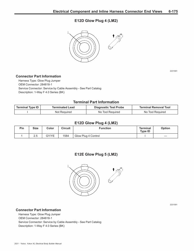
Electrical Component and Inline Harness Connector End Views 6-175
E12D Glow Plug 4 (LM2)
2231591
Connector Part InformationHarness Type: Glow Plug JumperOEM Connector: 284818-1Service Connector: Service by Cable Assembly - See Part CatalogDescription: 1-Way F 4.0 Series (BK)
Terminal Part InformationTerminal Type ID Terminated Lead Diagnostic Test Probe Terminal Removal Tool
I Not Required No Tool Required No Tool Required
E12D Glow Plug 4 (LM2)Pin Size Color Circuit Function Terminal
Type IDOption
1 2.5 GY/YE 1584 Glow Plug 4 Control I —
E12E Glow Plug 5 (LM2)
2231591
Connector Part InformationHarness Type: Glow Plug JumperOEM Connector: 284818-1Service Connector: Service by Cable Assembly - See Part CatalogDescription: 1-Way F 4.0 Series (BK)
2021 - Yukon, Yukon XL Electrical Body Builder Manual

6-176 Electrical Component and Inline Harness Connector End Views
Terminal Part InformationTerminal Type ID Terminated Lead Diagnostic Test Probe Terminal Removal Tool
I Not Required No Tool Required No Tool Required
E12E Glow Plug 5 (LM2)Pin Size Color Circuit Function Terminal
Type IDOption
1 2.5 GY/WH 1585 Glow Plug 5 Control I —
E12F Glow Plug 6 (LM2)
2231591
Connector Part InformationHarness Type: Glow Plug JumperOEM Connector: 284818-1Service Connector: Service by Cable Assembly - See Part CatalogDescription: 1-Way F 4.0 Series (BK)
Terminal Part InformationTerminal Type ID Terminated Lead Diagnostic Test Probe Terminal Removal Tool
I Not Required No Tool Required No Tool Required
E12F Glow Plug 6 (LM2)Pin Size Color Circuit Function Terminal
Type IDOption
1 2.5 GY 1586 Glow Plug 6 Control I —
2021 - Yukon, Yukon XL Electrical Body Builder Manual
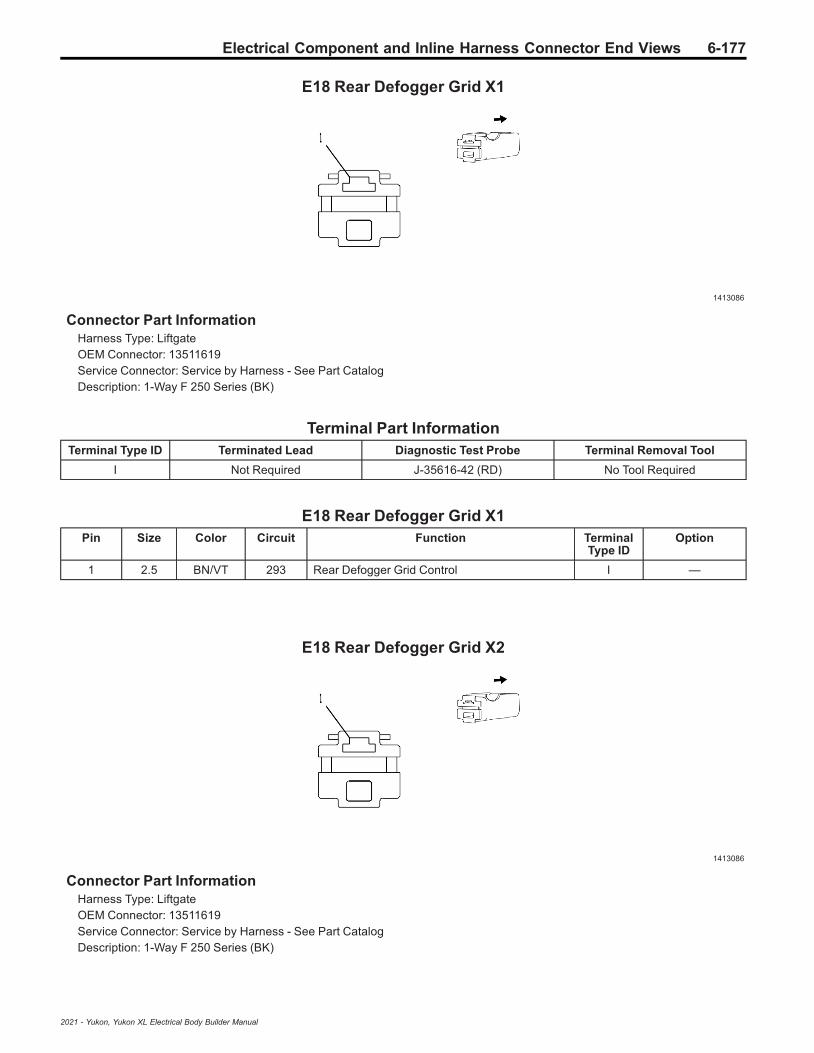
Electrical Component and Inline Harness Connector End Views 6-177
E18 Rear Defogger Grid X1
1413086
Connector Part InformationHarness Type: LiftgateOEM Connector: 13511619Service Connector: Service by Harness - See Part CatalogDescription: 1-Way F 250 Series (BK)
Terminal Part InformationTerminal Type ID Terminated Lead Diagnostic Test Probe Terminal Removal Tool
I Not Required J-35616-42 (RD) No Tool Required
E18 Rear Defogger Grid X1Pin Size Color Circuit Function Terminal
Type IDOption
1 2.5 BN/VT 293 Rear Defogger Grid Control I —
E18 Rear Defogger Grid X2
1413086
Connector Part InformationHarness Type: LiftgateOEM Connector: 13511619Service Connector: Service by Harness - See Part CatalogDescription: 1-Way F 250 Series (BK)
2021 - Yukon, Yukon XL Electrical Body Builder Manual
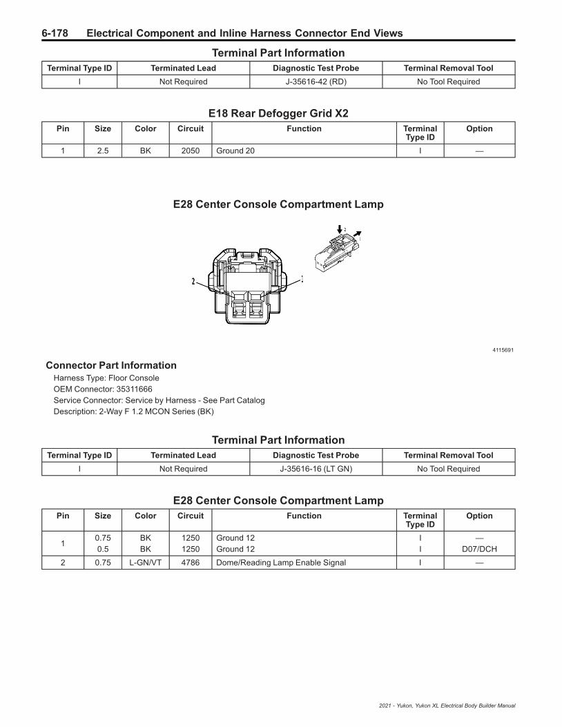
6-178 Electrical Component and Inline Harness Connector End Views
Terminal Part InformationTerminal Type ID Terminated Lead Diagnostic Test Probe Terminal Removal Tool
I Not Required J-35616-42 (RD) No Tool Required
E18 Rear Defogger Grid X2Pin Size Color Circuit Function Terminal
Type IDOption
1 2.5 BK 2050 Ground 20 I —
E28 Center Console Compartment Lamp
4115691
Connector Part InformationHarness Type: Floor ConsoleOEM Connector: 35311666Service Connector: Service by Harness - See Part CatalogDescription: 2-Way F 1.2 MCON Series (BK)
Terminal Part InformationTerminal Type ID Terminated Lead Diagnostic Test Probe Terminal Removal Tool
I Not Required J-35616-16 (LT GN) No Tool Required
E28 Center Console Compartment LampPin Size Color Circuit Function Terminal
Type IDOption
10.750.5
BKBK
12501250
Ground 12Ground 12
II
—D07/DCH
2 0.75 L-GN/VT 4786 Dome/Reading Lamp Enable Signal I —
2021 - Yukon, Yukon XL Electrical Body Builder Manual

Electrical Component and Inline Harness Connector End Views 6-179
E29LF Fog Lamp - Left Front (T40)
3404058
Connector Part InformationHarness Type: Front FasciaOEM Connector: 13930730Service Connector: Service by Harness - See Part CatalogDescription: 2-Way F 2.8 APEX Series, Sealed (BK)
Terminal Part InformationTerminal Type ID Terminated Lead Diagnostic Test Probe Terminal Removal Tool
I Not Required J-35616-4A (PU) No Tool Required
E29LF Fog Lamp - Left Front (T40)Pin Size Color Circuit Function Terminal
Type IDOption
1 0.5 BN/GY 5061 Left Front Fog Lamp Control I —
2 0.5 BK 150 Ground 1 I —
E29LF Fog Lamp - Left Front (T79)
2179777
Connector Part InformationHarness Type: Rear FasciaOEM Connector: 13610095Service Connector: Service by Harness - See Part CatalogDescription: 2-Way F 0.64 Series, Sealed (D-GY)
2021 - Yukon, Yukon XL Electrical Body Builder Manual

6-180 Electrical Component and Inline Harness Connector End Views
Terminal Part InformationTerminal Type ID Terminated Lead Diagnostic Test Probe Terminal Removal Tool
I Not Required J-35616-64B (LT BU) No Tool Required
E29LF Fog Lamp - Left Front (T79)Pin Size Color Circuit Function Terminal
Type IDOption
1 0.5 YE/GY 122 Rear Fog Lamp Control I —
2 0.5 BK 1450 Ground 14 I —
E29RF Fog Lamp - Right Front (T40)
3404058
Connector Part InformationHarness Type: Front FasciaOEM Connector: 13930730Service Connector: Service by Harness - See Part CatalogDescription: 2-Way F 2.8 APEX Series, Sealed (BK)
Terminal Part InformationTerminal Type ID Terminated Lead Diagnostic Test Probe Terminal Removal Tool
I Not Required J-35616-4A (PU) No Tool Required
E29RF Fog Lamp - Right Front (T40)Pin Size Color Circuit Function Terminal
Type IDOption
1 0.5 BN/L-GN 5062 Right Front Fog Lamp Control I —
2 0.5 BK 250 Ground 2 I —
2021 - Yukon, Yukon XL Electrical Body Builder Manual

Electrical Component and Inline Harness Connector End Views 6-181
E29RR Fog Lamp - Right Rear (T79)
2179777
Connector Part InformationHarness Type: Rear FasciaOEM Connector: 13610095Service Connector: Service by Harness - See Part CatalogDescription: 2-Way F 0.64 Series, Sealed (D-GY)
Terminal Part InformationTerminal Type ID Terminated Lead Diagnostic Test Probe Terminal Removal Tool
I Not Required J-35616-64B (LT BU) No Tool Required
E29RR Fog Lamp - Right Rear (T79)Pin Size Color Circuit Function Terminal
Type IDOption
1 0.5 YE/GY 122 Rear Fog Lamp Control I —
2 0.5 BK 1450 Ground 14 I —
E31L Sunshade Mirror Lamp - Left
5377746
Connector Part InformationHarness Type: HeadlinerOEM Connector: 35327306Service Connector: Service by Harness - See Part CatalogDescription: 2-Way F 1.2 MCON Series (BN)
2021 - Yukon, Yukon XL Electrical Body Builder Manual
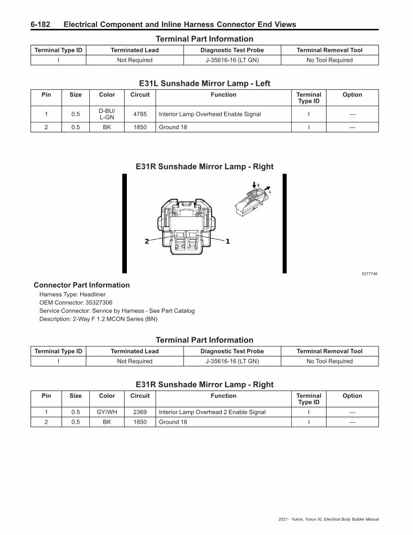
6-182 Electrical Component and Inline Harness Connector End Views
Terminal Part InformationTerminal Type ID Terminated Lead Diagnostic Test Probe Terminal Removal Tool
I Not Required J-35616-16 (LT GN) No Tool Required
E31L Sunshade Mirror Lamp - LeftPin Size Color Circuit Function Terminal
Type IDOption
1 0.5 D-BU/L-GN 4785 Interior Lamp Overhead Enable Signal I —
2 0.5 BK 1850 Ground 18 I —
E31R Sunshade Mirror Lamp - Right
5377746
Connector Part InformationHarness Type: HeadlinerOEM Connector: 35327306Service Connector: Service by Harness - See Part CatalogDescription: 2-Way F 1.2 MCON Series (BN)
Terminal Part InformationTerminal Type ID Terminated Lead Diagnostic Test Probe Terminal Removal Tool
I Not Required J-35616-16 (LT GN) No Tool Required
E31R Sunshade Mirror Lamp - RightPin Size Color Circuit Function Terminal
Type IDOption
1 0.5 GY/WH 2369 Interior Lamp Overhead 2 Enable Signal I —
2 0.5 BK 1850 Ground 18 I —
2021 - Yukon, Yukon XL Electrical Body Builder Manual
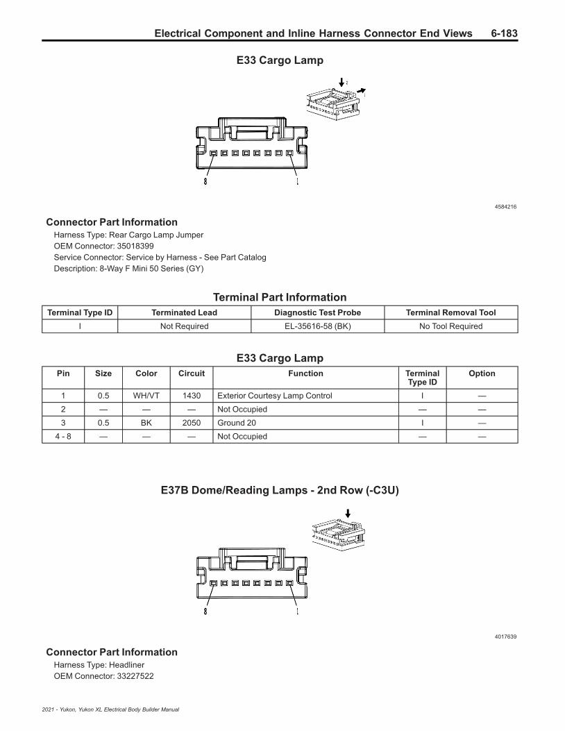
Electrical Component and Inline Harness Connector End Views 6-183
E33 Cargo Lamp
4584216
Connector Part InformationHarness Type: Rear Cargo Lamp JumperOEM Connector: 35018399Service Connector: Service by Harness - See Part CatalogDescription: 8-Way F Mini 50 Series (GY)
Terminal Part InformationTerminal Type ID Terminated Lead Diagnostic Test Probe Terminal Removal Tool
I Not Required EL-35616-58 (BK) No Tool Required
E33 Cargo LampPin Size Color Circuit Function Terminal
Type IDOption
1 0.5 WH/VT 1430 Exterior Courtesy Lamp Control I —
2 — — — Not Occupied — —
3 0.5 BK 2050 Ground 20 I —
4 - 8 — — — Not Occupied — —
E37B Dome/Reading Lamps - 2nd Row (-C3U)
4017639
Connector Part InformationHarness Type: HeadlinerOEM Connector: 33227522
2021 - Yukon, Yukon XL Electrical Body Builder Manual

6-184 Electrical Component and Inline Harness Connector End Views
Service Connector: 19354223Description: 8-Way F Mini 50 Series (BK)
Terminal Part InformationTerminal Type ID Terminated Lead Diagnostic Test Probe Terminal Removal Tool
I Not Required EL-35616-58 (BK) No Tool Required
E37B Dome/Reading Lamps - 2nd Row (-C3U)Pin Size Color Circuit Function Terminal
Type IDOption
1 0.35 L-GN/YE 2903 Row 2 Dome Reading Lamp Interior LampControl I —
2 0.35 BN/D-BU 2905 Row 2 Dome Reading Lamp 2 Interior LampControl I —
3 0.35 BK 1850 Ground 18 I —
4 0.35 WH/BN 2904 Row 2 Dome Reading Lamp Switch Signal I —
5 0.35 VT/GY 2906 Row 2 Dome Reading Lamp 2 Switch Signal I —
6 - 8 — — — Not Occupied — —
E37C Dome/Reading Lamps - 3rd Row
4017639
Connector Part InformationHarness Type: HeadlinerOEM Connector: 33227522Service Connector: 19354223Description: 8-Way F Mini 50 Series (BK)
Terminal Part InformationTerminal Type ID Terminated Lead Diagnostic Test Probe Terminal Removal Tool
I Not Required EL-35616-58 (BK) No Tool Required
E37C Dome/Reading Lamps - 3rd RowPin Size Color Circuit Function Terminal
Type IDOption
1 0.35 D-BU/WH 2907 Row 3 Dome Reading Lamp Interior LampControl I —
2021 - Yukon, Yukon XL Electrical Body Builder Manual

Electrical Component and Inline Harness Connector End Views 6-185
E37C Dome/Reading Lamps - 3rd Row (cont'd)Pin Size Color Circuit Function Terminal
Type IDOption
2 0.5 BN/VT 2909 Row 3 Dome Reading Lamp 2 Interior LampControl I —
3 0.35 BK 1850 Ground 18 I —
4 0.35 VT/YE 2908 Row 3 Dome Reading Lamp Switch Signal I —
5 0.35 YE/GY 2910 Row 3 Dome Reading Lamp 2 Switch Signal I —
6 - 8 — — — Not Occupied — —
E37SL Dome/Reading Lamps - 2nd Row Left (C3U)
4215060
Connector Part InformationHarness Type: HeadlinerOEM Connector: 33228283Service Connector: 19354840Description: 4-Way F Mini 50 Series (BK)
Terminal Part InformationTerminal Type ID Terminated Lead Diagnostic Test Probe Terminal Removal Tool
I Not Required EL-35616-58 (BK) No Tool Required
E37SL Dome/Reading Lamps - 2nd Row Left (C3U)Pin Size Color Circuit Function Terminal
Type IDOption
1 0.35 L-GN/YE 2903 Row 2 Dome Reading Lamp Interior LampControl I —
2 — — — Not Occupied — —
3 0.35 BK 1850 Ground 18 I —
4 0.35 WH/BN 2904 Row 2 Dome Reading Lamp Switch Signal I —
2021 - Yukon, Yukon XL Electrical Body Builder Manual

6-186 Electrical Component and Inline Harness Connector End Views
E37SR Dome/Reading Lamps - 2nd Row Right (C3U)
4215060
Connector Part InformationHarness Type: HeadlinerOEM Connector: 33228283Service Connector: 19354840Description: 4-Way F Mini 50 Series (BK)
Terminal Part InformationTerminal Type ID Terminated Lead Diagnostic Test Probe Terminal Removal Tool
I Not Required EL-35616-58 (BK) No Tool Required
E37SR Dome/Reading Lamps - 2nd Row Right (C3U)Pin Size Color Circuit Function Terminal
Type IDOption
1 0.35 BN/D-BU 2905 Row 2 Dome Reading Lamp 2 Interior LampControl I —
2 — — — Not Occupied — —
3 0.35 BK 1850 Ground 18 I —
4 0.35 VT/GY 2906 Row 2 Dome Reading Lamp 2 Switch Signal I —
E42L Tail Lamp Assembly - Left
1986159
Connector Part InformationHarness Type: ChassisOEM Connector: 35014074
2021 - Yukon, Yukon XL Electrical Body Builder Manual

Electrical Component and Inline Harness Connector End Views 6-187
Service Connector: 19367742Description: 6-Way M 150 MX Series, Sealed (BK)
Terminal Part InformationTerminal Type ID Terminated Lead Diagnostic Test Probe Terminal Removal Tool
I Not Required J-35616-3 (GY) No Tool Required
E42L Tail Lamp Assembly - LeftPin Size Color Circuit Function Terminal
Type IDOption
1 0.5 BN/D-BU 6993 Left Rear Park Lamp Control I —
20.50.5
GY/YED-BU/WH
75421334
Left Rear Stop Lamp ControlLeft Rear Turn Signal Lamp Control 2
II
Z75Z88
3 0.5 L-GN/WH 24 Backup Lamp Control I —
4 0.5 D-BU/WH 1334 Left Rear Turn Signal Lamp Control 2 I —
5 0.5 WH/VT 6567 Rear Turn Signal Lamp Feedback Signal I —
6 1.5 BK 1950 Ground 19 I —
E42R Tail Lamp Assembly - Right
1986159
Connector Part InformationHarness Type: ChassisOEM Connector: 35014074Service Connector: 19367742Description: 6-Way M 150 MX Series, Sealed (BK)
Terminal Part InformationTerminal Type ID Terminated Lead Diagnostic Test Probe Terminal Removal Tool
I Not Required J-35616-3 (GY) No Tool Required
E42R Tail Lamp Assembly - RightPin Size Color Circuit Function Terminal
Type IDOption
1 0.5 BN/GY 6995 Right Rear Park Lamp Control I —
20.50.5
WH/YED-BU/VT
75411335
Right Rear Stop Lamp ControlRight Rear Turn Signal Lamp Control 2
II
Z75Z88
2021 - Yukon, Yukon XL Electrical Body Builder Manual
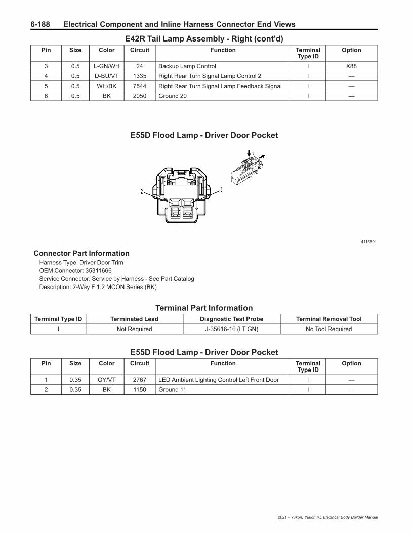
6-188 Electrical Component and Inline Harness Connector End Views
E42R Tail Lamp Assembly - Right (cont'd)Pin Size Color Circuit Function Terminal
Type IDOption
3 0.5 L-GN/WH 24 Backup Lamp Control I X88
4 0.5 D-BU/VT 1335 Right Rear Turn Signal Lamp Control 2 I —
5 0.5 WH/BK 7544 Right Rear Turn Signal Lamp Feedback Signal I —
6 0.5 BK 2050 Ground 20 I —
E55D Flood Lamp - Driver Door Pocket
4115691
Connector Part InformationHarness Type: Driver Door TrimOEM Connector: 35311666Service Connector: Service by Harness - See Part CatalogDescription: 2-Way F 1.2 MCON Series (BK)
Terminal Part InformationTerminal Type ID Terminated Lead Diagnostic Test Probe Terminal Removal Tool
I Not Required J-35616-16 (LT GN) No Tool Required
E55D Flood Lamp - Driver Door PocketPin Size Color Circuit Function Terminal
Type IDOption
1 0.35 GY/VT 2767 LED Ambient Lighting Control Left Front Door I —
2 0.35 BK 1150 Ground 11 I —
2021 - Yukon, Yukon XL Electrical Body Builder Manual

Electrical Component and Inline Harness Connector End Views 6-189
E55LR Flood Lamp - Left Rear Door Pocket
4115691
Connector Part InformationHarness Type: Left Rear Door TrimOEM Connector: 35311666Service Connector: Service by Harness - See Part CatalogDescription: 2-Way F 1.2 MCON Series (BK)
Terminal Part InformationTerminal Type ID Terminated Lead Diagnostic Test Probe Terminal Removal Tool
I Not Required J-35616-16 (LT GN) No Tool Required
E55LR Flood Lamp - Left Rear Door PocketPin Size Color Circuit Function Terminal
Type IDOption
1 0.35 WH/YE 7557 Interior Door Handle Accent Lighting Control I —
2 0.35 BK 1150 Ground 11 I —
E55P Flood Lamp - Passenger Door Pocket
4115691
Connector Part InformationHarness Type: Passenger Door TrimOEM Connector: 35311666Service Connector: Service by Harness - See Part CatalogDescription: 2-Way F 1.2 MCON Series (BK)
2021 - Yukon, Yukon XL Electrical Body Builder Manual

6-190 Electrical Component and Inline Harness Connector End Views
Terminal Part InformationTerminal Type ID Terminated Lead Diagnostic Test Probe Terminal Removal Tool
I Not Required J-35616-16 (LT GN) No Tool Required
E55P Flood Lamp - Passenger Door PocketPin Size Color Circuit Function Terminal
Type IDOption
1 0.35 WH/BN 2768 LED Ambient Lighting Control Right Front Door I —
2 0.35 BK 1250 Ground 12 I —
E55RR Flood Lamp - Right Rear Door Pocket
4115691
Connector Part InformationHarness Type: Right Rear Door TrimOEM Connector: 35311666Service Connector: Service by Harness - See Part CatalogDescription: 2-Way F 1.2 MCON Series (BK)
Terminal Part InformationTerminal Type ID Terminated Lead Diagnostic Test Probe Terminal Removal Tool
I Not Required J-35616-16 (LT GN) No Tool Required
E55RR Flood Lamp - Right Rear Door PocketPin Size Color Circuit Function Terminal
Type IDOption
1 0.35 WH/YE 7557 Interior Door Handle Accent Lighting Control I —
2 0.35 BK 1250 Ground 12 I —
2021 - Yukon, Yukon XL Electrical Body Builder Manual

Electrical Component and Inline Harness Connector End Views 6-191
E72 Hands-Free Liftgate Sensor Lamp (QT6)
4649903
Connector Part InformationHarness Type: Rear FasciaOEM Connector: 33327048Service Connector: Service by Harness - See Part CatalogDescription: 2-Way F 1.2 MCON Series, Sealed (BK)
Terminal Part InformationTerminal Type ID Terminated Lead Diagnostic Test Probe Terminal Removal Tool
I Not Required J-35616-16 (LT GN) No Tool Required
E72 Hands-Free Liftgate Sensor Lamp (QT6)Pin Size Color Circuit Function Terminal
Type IDOption
1 0.5 GY 2066 Hands-Free Liftgate Sensor Lamp Control I —
2 0.5 BK 1450 Ground 14 I —
F105L Roof Rail Air Bag - Left
4036662
Connector Part InformationHarness Type: BodyOEM Connector: 33386204Service Connector: 19369032Description: 2-Way F 1.2 MCON-CB Series, Sealed (BK)
2021 - Yukon, Yukon XL Electrical Body Builder Manual

6-192 Electrical Component and Inline Harness Connector End Views
Terminal Part InformationTerminal Type ID Terminated Lead Diagnostic Test Probe Terminal Removal Tool
I Not Required J-35616-16 (LT GN) No Tool Required
F105L Roof Rail Air Bag - LeftPin Size Color Circuit Function Terminal
Type IDOption
1 0.5 OG/L-GN 5019 Left Front Roof Rail Air Bag High Control I —
2 0.5 VT/OG 5020 Left Front Roof Rail Air Bag Low Control I —
F105R Roof Rail Air Bag - Right
4036662
Connector Part InformationHarness Type: BodyOEM Connector: 33386204Service Connector: 19369032Description: 2-Way F 1.2 MCON-CB Series, Sealed (BK)
Terminal Part InformationTerminal Type ID Terminated Lead Diagnostic Test Probe Terminal Removal Tool
I Not Required J-35616-16 (LT GN) No Tool Required
F105R Roof Rail Air Bag - RightPin Size Color Circuit Function Terminal
Type IDOption
1 0.5 OG/GY 5021 Right Front Roof Rail Air Bag High Control I —
2 0.5 WH/OG 5022 Right Front Roof Rail Air Bag Low Control I —
2021 - Yukon, Yukon XL Electrical Body Builder Manual

Electrical Component and Inline Harness Connector End Views 6-193
F112D Seat Belt Retractor Pretensioner - Driver
4679778
Connector Part InformationHarness Type: BodyOEM Connector: 33345783Service Connector: 19355491Description: 2-Way F ABX-5 Series (GY with YE Cover)
Terminal Part InformationTerminal Type ID Terminated Lead Diagnostic Test Probe Terminal Removal Tool
I Not Required J-35616-64B (LT BU) No Tool Required
F112D Seat Belt Retractor Pretensioner - DriverPin Size Color Circuit Function Terminal
Type IDOption
1 0.5 OG/WH 3477 Driver Seat Belt Retractor Pretensioner HighControl I —
2 0.5 VT/OG 3478 Driver Seat Belt Retractor Pretensioner LowControl I —
F112P Seat Belt Retractor Pretensioner - Passenger
4241364
Connector Part InformationHarness Type: BodyOEM Connector: 33345778Service Connector: 19355490Description: 2-Way F ABX-5 Series (PU with YE Cover)
2021 - Yukon, Yukon XL Electrical Body Builder Manual

6-194 Electrical Component and Inline Harness Connector End Views
Terminal Part InformationTerminal Type ID Terminated Lead Diagnostic Test Probe Terminal Removal Tool
I Not Required J-35616-64B (LT BU) No Tool Required
F112P Seat Belt Retractor Pretensioner - PassengerPin Size Color Circuit Function Terminal
Type IDOption
1 0.5 OG/L-GN 3475 Passenger Seat Belt Retractor PretensionerHigh Control I —
2 0.5 WH/OG 3476 Passenger Seat Belt Retractor PretensionerLow Control I —
F113D Seat Belt Anchor Pretensioner - Driver
4823732
Connector Part InformationHarness Type: BodyOEM Connector: 1-1801930-1Service Connector: 13598467Description: 2-Way F 1.0 Series (PK with YE Cover)
Terminal Part InformationTerminal Type ID Terminated Lead Diagnostic Test Probe Terminal Removal Tool
I Not Required J-35616-64B (LT BU) No Tool Required
F113D Seat Belt Anchor Pretensioner - DriverPin Size Color Circuit Function Terminal
Type IDOption
1 0.5 OG/YE 3481 Driver Seat Belt Anchor Pretensioner HighControl I —
2 0.5 VT/OG 3482 Driver Seat Belt Anchor Pretensioner LowControl I —
2021 - Yukon, Yukon XL Electrical Body Builder Manual

Electrical Component and Inline Harness Connector End Views 6-195
F113P Seat Belt Anchor Pretensioner - Passenger
4823732
Connector Part InformationHarness Type: BodyOEM Connector: 1-1801930-1Service Connector: 13598467Description: 2-Way F 1.0 Series (PK with YE Cover)
Terminal Part InformationTerminal Type ID Terminated Lead Diagnostic Test Probe Terminal Removal Tool
I Not Required J-35616-64B (LT BU) No Tool Required
F113P Seat Belt Anchor Pretensioner - PassengerPin Size Color Circuit Function Terminal
Type IDOption
1 0.5 OG/BN 3479 Passenger Seat Belt Anchor Pretensioner HighControl I —
2 0.5 GY/OG 3480 Passenger Seat Belt Anchor Pretensioner LowControl I —
G3 Air Suspension Compressor (F47)
4584202
Connector Part InformationHarness Type: ChassisOEM Connector: 13888959Service Connector: 19355452Description: 2-Way F 6.3 Series, Sealed (D-GY)
2021 - Yukon, Yukon XL Electrical Body Builder Manual

6-196 Electrical Component and Inline Harness Connector End Views
Terminal Part InformationTerminal Type ID Terminated Lead Diagnostic Test Probe Terminal Removal Tool
I Not Required J-35616-42 (RD) No Tool Required
G3 Air Suspension Compressor (F47)Pin Size Color Circuit Function Terminal
Type IDOption
1 2.5 L-GN/BN 2357 Vehicle Level Control Compressor Motor Control I —
2 2.5 GY/BN 2693 Leveling Compressor Motor Low Reference I —
G8 Coolant Pump - Auxiliary (L84/L87)
4581126
Connector Part InformationHarness Type: EngineOEM Connector: 33358800Service Connector: 19366844Description: 3-Way F 1.2 MCON-CB Series, Sealed (BK)
Terminal Part InformationTerminal Type ID Terminated Lead Diagnostic Test Probe Terminal Removal Tool
I Not Required J-35616-16 (LT GN) No Tool Required
G8 Coolant Pump - Auxiliary (L84/L87)Pin Size Color Circuit Function Terminal
Type IDOption
1 0.75 BK 450 Ground 4 I —
2 0.5 RD/BN 5940 Secondary Fused Battery Positive Voltage 59 I —
3 0.5 L-GN/VT 4621 Engine Control Module LIN Bus 1 I —
2021 - Yukon, Yukon XL Electrical Body Builder Manual

Electrical Component and Inline Harness Connector End Views 6-197
G8 Coolant Pump - Auxiliary (LM2)
4249125
Connector Part InformationHarness Type: EngineOEM Connector: 33176362Service Connector: 19366844Description: 3-Way F 1.2 MCP Series, Sealed (BN)
Terminal Part InformationTerminal Type ID Terminated Lead Diagnostic Test Probe Terminal Removal Tool
I Not Required J-35616-16 (LT GN) No Tool Required
G8 Coolant Pump - Auxiliary (LM2)Pin Size Color Circuit Function Terminal
Type IDOption
1 0.5 BK 6550 Propulsion Propulsion System I —
2 1.5 RD/BN 5940 Secondary Fused Battery Positive Voltage 59 I —
3 0.5 L-GN/VT 4621 Engine Control Module LIN Bus 1 I —
G10L Cooling Fan Motor - Left (L84/L87)
4732789
Connector Part InformationHarness Type: EngineOEM Connector: 33234243Service Connector: 84625007Description: 4-Way F 2.8 APEX Series, Sealed (BK)
2021 - Yukon, Yukon XL Electrical Body Builder Manual
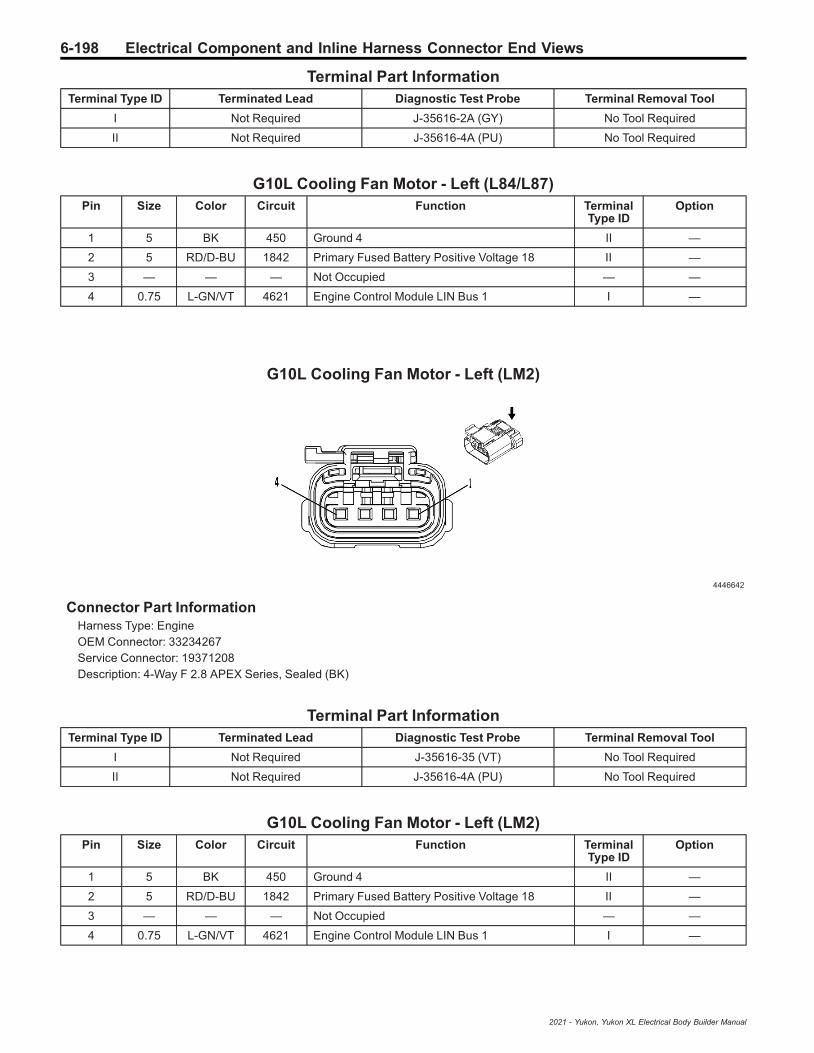
6-198 Electrical Component and Inline Harness Connector End Views
Terminal Part InformationTerminal Type ID Terminated Lead Diagnostic Test Probe Terminal Removal Tool
I Not Required J-35616-2A (GY) No Tool Required
II Not Required J-35616-4A (PU) No Tool Required
G10L Cooling Fan Motor - Left (L84/L87)Pin Size Color Circuit Function Terminal
Type IDOption
1 5 BK 450 Ground 4 II —
2 5 RD/D-BU 1842 Primary Fused Battery Positive Voltage 18 II —
3 — — — Not Occupied — —
4 0.75 L-GN/VT 4621 Engine Control Module LIN Bus 1 I —
G10L Cooling Fan Motor - Left (LM2)
4446642
Connector Part InformationHarness Type: EngineOEM Connector: 33234267Service Connector: 19371208Description: 4-Way F 2.8 APEX Series, Sealed (BK)
Terminal Part InformationTerminal Type ID Terminated Lead Diagnostic Test Probe Terminal Removal Tool
I Not Required J-35616-35 (VT) No Tool Required
II Not Required J-35616-4A (PU) No Tool Required
G10L Cooling Fan Motor - Left (LM2)Pin Size Color Circuit Function Terminal
Type IDOption
1 5 BK 450 Ground 4 II —
2 5 RD/D-BU 1842 Primary Fused Battery Positive Voltage 18 II —
3 — — — Not Occupied — —
4 0.75 L-GN/VT 4621 Engine Control Module LIN Bus 1 I —
2021 - Yukon, Yukon XL Electrical Body Builder Manual

Electrical Component and Inline Harness Connector End Views 6-199
G10LW Cooling Fan Motor - Lower (LM2)
4847569
Connector Part InformationHarness Type: EngineOEM Connector: 33376654Service Connector: Service by Harness - See Part CatalogDescription: 4-Way F 1.2, 9.5 MCON Series (BK)
Terminal Part InformationTerminal Type ID Terminated Lead Diagnostic Test Probe Terminal Removal Tool
I Not Required J-35616-16 (LT GN) No Tool Required
II Not Required J-35616-22 (RD) No Tool Required
G10LW Cooling Fan Motor - Lower (LM2)Pin Size Color Circuit Function Terminal
Type IDOption
1 5 RD/D-BU 1542 Primary Fused Battery Positive Voltage 15 II —
2 5 BK 450 Ground 4 II —
3 0.5 L-GN/YE 4623 Engine Control Module LIN Bus 3 I —
4 — — — Not Occupied — —
G10R Cooling Fan Motor - Right (L84/L87)
4732789
Connector Part InformationHarness Type: EngineOEM Connector: 33234243
2021 - Yukon, Yukon XL Electrical Body Builder Manual

6-200 Electrical Component and Inline Harness Connector End Views
Service Connector: 84625007Description: 4-Way F 2.8 APEX Series, Sealed (BK)
Terminal Part InformationTerminal Type ID Terminated Lead Diagnostic Test Probe Terminal Removal Tool
I Not Required J-35616-2A (GY) No Tool Required
II Not Required J-35616-4A (PU) No Tool Required
G10R Cooling Fan Motor - Right (L84/L87)Pin Size Color Circuit Function Terminal
Type IDOption
1 5 BK 450 Ground 4 II —
2 5 RD/BN 1742 Primary Fused Battery Positive Voltage 17 II —
3 — — — Not Occupied — —
4 0.75 L-GN/VT 4621 Engine Control Module LIN Bus 1 I —
G10R Cooling Fan Motor - Right (LM2)
5187743
Connector Part InformationHarness Type: EngineOEM Connector: 35194180Service Connector: Service by Harness - See Part CatalogDescription: 4-Way F 1.2, 9.5 MCON Series (GY)
Terminal Part InformationTerminal Type ID Terminated Lead Diagnostic Test Probe Terminal Removal Tool
I Not Required J-35616-16 (LT GN) No Tool Required
II Not Required J-35616-22 (RD) No Tool Required
G10R Cooling Fan Motor - Right (LM2)Pin Size Color Circuit Function Terminal
Type IDOption
1 10 RD/YE 1442 Primary Fused Battery Positive Voltage 14 II —
2 8 BK 450 Ground 4 II —
3 0.5 L-GN/VT 4621 Engine Control Module LIN Bus 1 I —
4 — — — Not Occupied — —
2021 - Yukon, Yukon XL Electrical Body Builder Manual

Electrical Component and Inline Harness Connector End Views 6-201
G13 Generator
2577394
Connector Part InformationHarness Type: EngineOEM Connector: 13930085Service Connector: 13384371Description: 2-Way F 2.8 Series, Sealed (BK)
Terminal Part InformationTerminal Type ID Terminated Lead Diagnostic Test Probe Terminal Removal Tool
I Not Required J-35616-35 (VT) No Tool Required
G13 GeneratorPin Size Color Circuit Function Terminal
Type IDOption
1 0.5 BN 25 Charge Indicator Control I —
2 0.5 GY 23 Generator Field Duty Cycle Signal I —
G24 Windshield Washer Pump
2474738
Connector Part InformationHarness Type: BodyOEM Connector: 10863916
2021 - Yukon, Yukon XL Electrical Body Builder Manual

6-202 Electrical Component and Inline Harness Connector End Views
Service Connector: 19368727Description: 2-Way F 2.8 MDK5 Series, Sealed (BK)
Terminal Part InformationTerminal Type ID Terminated Lead Diagnostic Test Probe Terminal Removal Tool
I Not Required J-35616-4A (PU) No Tool Required
G24 Windshield Washer PumpPin Size Color Circuit Function Terminal
Type IDOption
1 0.75 D-BU/VT 392 Rear Window Washer Pump Control I —
2 0.75 GY/VT 228 Windshield Washer Pump Control I —
K3 Air Suspension Control Module (F47)
4162046
Connector Part InformationHarness Type: ChassisOEM Connector: 33222138Service Connector: 19333026Description: 46-Way F 1.2 OCS, 2.8, 4.8 CTS Series, Sealed (GY)
Terminal Part InformationTerminal Type ID Terminated Lead Diagnostic Test Probe Terminal Removal Tool
I 19119560 J-35616-40 (BU) J-38125-556
II 19332900 J-35616-42 (RD) J-38125-215A
III 19333088 J-35616-35 (VT) J-38125-215A
IV 19371240 J-35616-16 (LT GN) J-38125-215A
K3 Air Suspension Control Module (F47)Pin Size Color Circuit Function Terminal
Type IDOption
1 3 RD/D-BU 7640 Secondary Fused Battery Positive Voltage 76 II —
2 0.75 RD/BN 2940 Secondary Fused Battery Positive Voltage 29 III —
3 - 6 — — — Not Occupied — —
7 0.5 WH/L-GN 320 Vehicle Level Control Exhaust Solenoid ValveControl IV —
2021 - Yukon, Yukon XL Electrical Body Builder Manual

Electrical Component and Inline Harness Connector End Views 6-203
K3 Air Suspension Control Module (F47) (cont'd)Pin Size Color Circuit Function Terminal
Type IDOption
8 — — — Not Occupied — —
9 0.5 WH/D-BU 3261 Vehicle Level Control Exhaust Solenoid ValveControl IV —
10 0.5 D-BU 4987 AUTOSAR CAN Bus [+] 1 Serial Data IV —
11 0.5 WH 4986 AUTOSAR CAN Bus [-] 1 Serial Data IV —
12 — — — Not Occupied — —
13 0.75 BK 2150 Ground 21 III —
14 3 BK 2150 Ground 21 II —
15 - 17 — — — Not Occupied — —
18 0.5 BK/D-BU 1206 Left Front Suspension Position Sensor LowReference IV —
19 0.5 BN/WH 1207 Left Front Suspension Position Sensor Signal IV —
20 0.5 D-BU/RD 1205 Left Front Suspension Position Sensor VoltageReference IV —
21 0.5 YE/RD 1208 Left Rear Suspension Position Sensor VoltageReference IV —
22 0.5 L-GN/WH 1210 Left Rear Suspension Position Sensor Signal IV —
23 0.5 BK/L-GN 1209 Left Rear Suspension Position Sensor LowReference IV —
24 0.5 D-BU 4987 AUTOSAR CAN Bus [+] 1 Serial Data IV —
25 0.5 WH 4986 AUTOSAR CAN Bus [-] 1 Serial Data IV —
26 - 29 — — — Not Occupied — —
302.52.5
L-GN/BNL-GN/BN
23572357
Vehicle Level Control Compressor Motor ControlVehicle Level Control Compressor Motor Control
III
——
31 - 33 — — — Not Occupied — —
34 0.5 BK/GY 1212 Right Front Suspension Position Sensor LowReference IV —
35 0.5 YE/WH 1213 Right Front Suspension Position Sensor Signal IV —
36 0.5 BN/RD 1211 Right Front Suspension Position Sensor VoltageReference IV —
37 0.5 L-GN/RD 1214 Right Rear Suspension Position Sensor VoltageReference IV —
38 0.5 L-GN/GY 1216 Right Rear Suspension Position Sensor Signal IV —
39 0.5 BK/YE 1215 Right Rear Suspension Position Sensor LowReference IV —
40 - 45 — — — Not Occupied — —
462.52.5
GY/BNGY/BN
26932693
Leveling Compressor Motor Low ReferenceLeveling Compressor Motor Low Reference
III
——
2021 - Yukon, Yukon XL Electrical Body Builder Manual
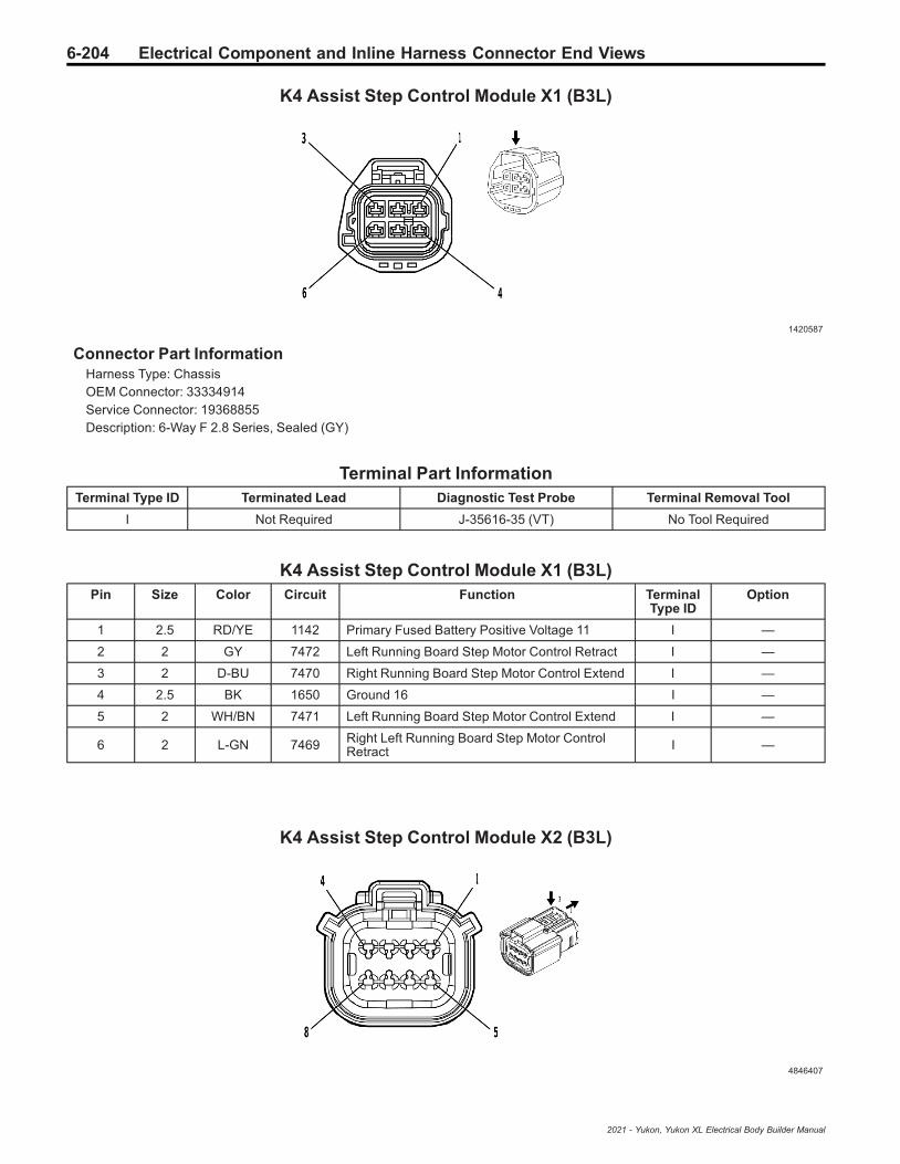
6-204 Electrical Component and Inline Harness Connector End Views
K4 Assist Step Control Module X1 (B3L)
1420587
Connector Part InformationHarness Type: ChassisOEM Connector: 33334914Service Connector: 19368855Description: 6-Way F 2.8 Series, Sealed (GY)
Terminal Part InformationTerminal Type ID Terminated Lead Diagnostic Test Probe Terminal Removal Tool
I Not Required J-35616-35 (VT) No Tool Required
K4 Assist Step Control Module X1 (B3L)Pin Size Color Circuit Function Terminal
Type IDOption
1 2.5 RD/YE 1142 Primary Fused Battery Positive Voltage 11 I —
2 2 GY 7472 Left Running Board Step Motor Control Retract I —
3 2 D-BU 7470 Right Running Board Step Motor Control Extend I —
4 2.5 BK 1650 Ground 16 I —
5 2 WH/BN 7471 Left Running Board Step Motor Control Extend I —
6 2 L-GN 7469 Right Left Running Board Step Motor ControlRetract I —
K4 Assist Step Control Module X2 (B3L)
4846407
2021 - Yukon, Yukon XL Electrical Body Builder Manual

Electrical Component and Inline Harness Connector End Views 6-205
Connector Part InformationHarness Type: ChassisOEM Connector: 35037827Service Connector: 19366859Description: 8-Way F 150 MX Series, Sealed (BK)
Terminal Part InformationTerminal Type ID Terminated Lead Diagnostic Test Probe Terminal Removal Tool
I Not Required J-35616-2A (GY) No Tool Required
K4 Assist Step Control Module X2 (B3L)Pin Size Color Circuit Function Terminal
Type IDOption
1 — — — Not Occupied — —
2 0.5 WH 4986 AUTOSAR CAN Bus [-] 1 Serial Data I —
3 0.5 D-BU 4987 AUTOSAR CAN Bus [+] 1 Serial Data I —
4 - 5 — — — Not Occupied — —
6 0.5 WH 4986 AUTOSAR CAN Bus [-] 1 Serial Data I —
7 0.5 D-BU 4987 AUTOSAR CAN Bus [+] 1 Serial Data I —
8 — — — Not Occupied — —
K4 Assist Step Control Module X3 (B3L)
1825165
Connector Part InformationHarness Type: ChassisOEM Connector: 13653762Service Connector: 19352907Description: 12-Way F 1.5 Series, Sealed (BK)
Terminal Part InformationTerminal Type ID Terminated Lead Diagnostic Test Probe Terminal Removal Tool
I 19300432 J-35616-2A (GY) J-38125-217
2021 - Yukon, Yukon XL Electrical Body Builder Manual
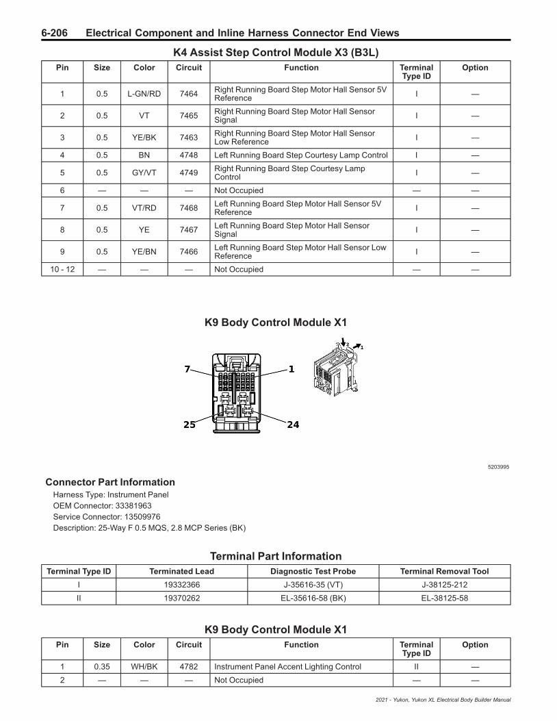
6-206 Electrical Component and Inline Harness Connector End Views
K4 Assist Step Control Module X3 (B3L)Pin Size Color Circuit Function Terminal
Type IDOption
1 0.5 L-GN/RD 7464 Right Running Board Step Motor Hall Sensor 5VReference I —
2 0.5 VT 7465 Right Running Board Step Motor Hall SensorSignal I —
3 0.5 YE/BK 7463 Right Running Board Step Motor Hall SensorLow Reference I —
4 0.5 BN 4748 Left Running Board Step Courtesy Lamp Control I —
5 0.5 GY/VT 4749 Right Running Board Step Courtesy LampControl I —
6 — — — Not Occupied — —
7 0.5 VT/RD 7468 Left Running Board Step Motor Hall Sensor 5VReference I —
8 0.5 YE 7467 Left Running Board Step Motor Hall SensorSignal I —
9 0.5 YE/BN 7466 Left Running Board Step Motor Hall Sensor LowReference I —
10 - 12 — — — Not Occupied — —
K9 Body Control Module X1
5203995
Connector Part InformationHarness Type: Instrument PanelOEM Connector: 33381963Service Connector: 13509976Description: 25-Way F 0.5 MQS, 2.8 MCP Series (BK)
Terminal Part InformationTerminal Type ID Terminated Lead Diagnostic Test Probe Terminal Removal Tool
I 19332366 J-35616-35 (VT) J-38125-212
II 19370262 EL-35616-58 (BK) EL-38125-58
K9 Body Control Module X1Pin Size Color Circuit Function Terminal
Type IDOption
1 0.35 WH/BK 4782 Instrument Panel Accent Lighting Control II —
2 — — — Not Occupied — —
2021 - Yukon, Yukon XL Electrical Body Builder Manual
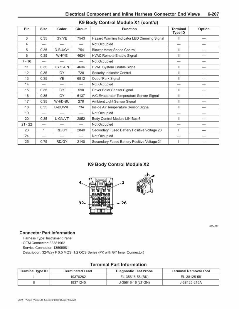
Electrical Component and Inline Harness Connector End Views 6-207
K9 Body Control Module X1 (cont'd)Pin Size Color Circuit Function Terminal
Type IDOption
3 0.35 GY/YE 7543 Hazard Warning Indicator LED Dimming Signal II —
4 — — — Not Occupied — —
5 0.35 D-BU/GY 754 Blower Motor Speed Control II —
6 0.35 WH/YE 4634 HVAC Remote Enable Signal II —
7 - 10 — — — Not Occupied — —
11 0.35 GY/L-GN 4636 HVAC System Enable Signal II —
12 0.35 GY 728 Security Indicator Control II —
13 0.35 YE 6812 Out of Park Signal II —
14 — — — Not Occupied — —
15 0.35 GY 590 Driver Solar Sensor Signal II —
16 0.35 GY 6137 A/C Evaporator Temperature Sensor Signal II —
17 0.35 WH/D-BU 278 Ambient Light Sensor Signal II —
18 0.35 D-BU/WH 734 Inside Air Temperature Sensor Signal II —
19 — — — Not Occupied — —
20 0.35 L-GN/VT 2852 Body Control Module LIN Bus 6 II —
21 - 22 — — — Not Occupied — —
23 1 RD/GY 2840 Secondary Fused Battery Positive Voltage 28 I —
24 — — — Not Occupied — —
25 0.75 RD/GY 2140 Secondary Fused Battery Positive Voltage 21 I —
K9 Body Control Module X2
5204222
Connector Part InformationHarness Type: Instrument PanelOEM Connector: 33381962Service Connector: 13509981Description: 32-Way F 0.5 MQS, 1.2 OCS Series (PK with GY Inner Connector)
Terminal Part InformationTerminal Type ID Terminated Lead Diagnostic Test Probe Terminal Removal Tool
I 19370262 EL-35616-58 (BK) EL-38125-58
II 19371240 J-35616-16 (LT GN) J-38125-215A
2021 - Yukon, Yukon XL Electrical Body Builder Manual
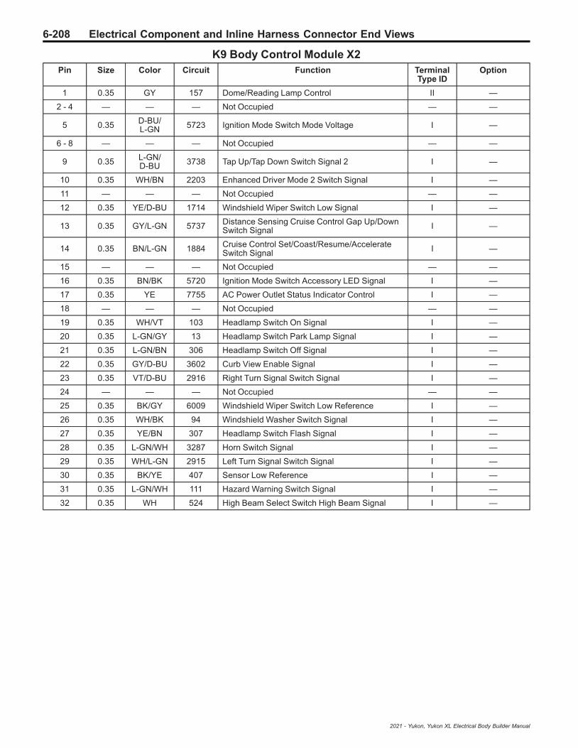
6-208 Electrical Component and Inline Harness Connector End Views
K9 Body Control Module X2Pin Size Color Circuit Function Terminal
Type IDOption
1 0.35 GY 157 Dome/Reading Lamp Control II —
2 - 4 — — — Not Occupied — —
5 0.35 D-BU/L-GN 5723 Ignition Mode Switch Mode Voltage I —
6 - 8 — — — Not Occupied — —
9 0.35 L-GN/D-BU 3738 Tap Up/Tap Down Switch Signal 2 I —
10 0.35 WH/BN 2203 Enhanced Driver Mode 2 Switch Signal I —
11 — — — Not Occupied — —
12 0.35 YE/D-BU 1714 Windshield Wiper Switch Low Signal I —
13 0.35 GY/L-GN 5737 Distance Sensing Cruise Control Gap Up/DownSwitch Signal I —
14 0.35 BN/L-GN 1884 Cruise Control Set/Coast/Resume/AccelerateSwitch Signal I —
15 — — — Not Occupied — —
16 0.35 BN/BK 5720 Ignition Mode Switch Accessory LED Signal I —
17 0.35 YE 7755 AC Power Outlet Status Indicator Control I —
18 — — — Not Occupied — —
19 0.35 WH/VT 103 Headlamp Switch On Signal I —
20 0.35 L-GN/GY 13 Headlamp Switch Park Lamp Signal I —
21 0.35 L-GN/BN 306 Headlamp Switch Off Signal I —
22 0.35 GY/D-BU 3602 Curb View Enable Signal I —
23 0.35 VT/D-BU 2916 Right Turn Signal Switch Signal I —
24 — — — Not Occupied — —
25 0.35 BK/GY 6009 Windshield Wiper Switch Low Reference I —
26 0.35 WH/BK 94 Windshield Washer Switch Signal I —
27 0.35 YE/BN 307 Headlamp Switch Flash Signal I —
28 0.35 L-GN/WH 3287 Horn Switch Signal I —
29 0.35 WH/L-GN 2915 Left Turn Signal Switch Signal I —
30 0.35 BK/YE 407 Sensor Low Reference I —
31 0.35 L-GN/WH 111 Hazard Warning Switch Signal I —
32 0.35 WH 524 High Beam Select Switch High Beam Signal I —
2021 - Yukon, Yukon XL Electrical Body Builder Manual

Electrical Component and Inline Harness Connector End Views 6-209
K9 Body Control Module X3
5203925
Connector Part InformationHarness Type: Instrument PanelOEM Connector: 33381956Service Connector: 13509979Description: 32-Way F 0.5 MQS, 1.2 OCS Series (BU with GY Inner Connector)
Terminal Part InformationTerminal Type ID Terminated Lead Diagnostic Test Probe Terminal Removal Tool
I 19367551 J-35616-16 (LT GN) J-38125-215A
II 19370262 EL-35616-58 (BK) EL-38125-58
K9 Body Control Module X3Pin Size Color Circuit Function Terminal
Type IDOption
1 — — — Not Occupied — —
2 0.5 BN/D-BU 4892 Auxiliary Battery Relay Control I —
3 - 4 — — — Not Occupied — —
5 0.35 L-GN/BN 2853 Body Control Module LIN Bus 7 II —
6 0.35 BN/D-BU 391 Rear Window Wiper Switch Signal II —
7 0.35 WH/BN 7555 Headlamp Switch Signal II —
8 - 9 — — — Not Occupied — —
10 0.35 L-GN/BK 2858 Body Control Module LIN Bus 12 II —
11 - 12 — — — Not Occupied — —
13 0.35 WH 3152 Lane Departure Warning Indicator Control II —
14 0.35 L-GN/BN 5852 Rear Parking Assist Disable LED Signal II —
15 0.35 L-GN 1110 Stop/Start Indicator Control II —
16 0.35 L-GN/D-BU 761 Blower Speed Feedback Signal II —
17 — — — Not Occupied — —
18 0.35 YE 7556 Headlamp Switch Reference II —
19 0.35 D-BU/BK 5719 Ignition Mode Switch Start LED Signal II —
20 0.35 WH/VT 6821 Surveillance Switch Signal II —
21 — — — Not Occupied — —
22 0.35 BN/GY 8021 Police Microphone Enable Signal II —
23 0.35 D-BU 1111 Stop/Start Switch Signal II —
24 0.35 WH/D-BU 3691 Trailer Brake Apply Signal II —
2021 - Yukon, Yukon XL Electrical Body Builder Manual

6-210 Electrical Component and Inline Harness Connector End Views
K9 Body Control Module X3 (cont'd)Pin Size Color Circuit Function Terminal
Type IDOption
25 - 26 — — — Not Occupied — —
27 0.35 GY/WH 3153 Lane Departure Warning Disable Switch Signal II —
28 — — — Not Occupied — —
29 0.35 GY/VT 8022 Police Roof Lamp Control II —
30 0.35 D-BU/YE 6844 ABS/Traction Control Hill Descent ControlSwitch Signal II —
31 0.35 GY/L-GN 2555 Rear Parking Assist Disable Signal II —
32 — — — Not Occupied — —
K9 Body Control Module X4
5203893
Connector Part InformationHarness Type: Instrument PanelOEM Connector: 33381959Service Connector: 13509978Description: 25-Way F 0.5 MQS, 2.8 MCP Series (GY)
Terminal Part InformationTerminal Type ID Terminated Lead Diagnostic Test Probe Terminal Removal Tool
I 19119592 J-35616-4A (PU) J-38125-557
II 19332366 J-35616-35 (VT) J-38125-212
III 19370262 EL-35616-58 (BK) EL-38125-58
K9 Body Control Module X4Pin Size Color Circuit Function Terminal
Type IDOption
1 0.35 BN/BK 3552 Interior Keyless Entry Antenna 1 High Signal III —
2 0.35 WH 3553 Interior Keyless Entry Antenna 1 Low Signal III —
3 0.35 BK/VT 1449 Steering Wheel Resistor Ladder Low Reference III —
4 — — — Not Occupied — —
5 0.35 L-GN/VT 5199 Run/Crank Relay Coil Control III —
6 — — — Not Occupied — —
7 0.35 BN/BK 4996 Immobilizer Antenna Signal [+] III —
2021 - Yukon, Yukon XL Electrical Body Builder Manual

Electrical Component and Inline Harness Connector End Views 6-211
K9 Body Control Module X4 (cont'd)Pin Size Color Circuit Function Terminal
Type IDOption
8 - 9 — — — Not Occupied — —
10 0.35 GY/L-GN 4083 Retained Accessory Power Relay 2 Coil Control III —
11 - 13 — — — Not Occupied — —
14 0.35 WH/GY 4997 Immobilizer Antenna Low Signal III —
15 0.35 D-BU/VT 1788 Traction Control Switch Signal 1 III —
16 0.35 L-GN/WH 4115 Body Control Module LIN Bus 5 III —
17 - 18 — — — Not Occupied — —
19 0.35 D-BU/YE 4979 AUTOSAR CAN Bus [+] 2 Serial Data III —
20 0.35 WH 4978 AUTOSAR CAN Bus [-] 2 Serial Data III —
21 — — — Not Occupied — —
22 0.5 RD/WH 2740 Secondary Fused Battery Positive Voltage 27 I —
23 0.75 RD/D-BU 2540 Secondary Fused Battery Positive Voltage 25 II —
24 2.5 BK/WH 1851 Ground 18 I —
25 2.5 BK 1850 Ground 18 I —
K9 Body Control Module X5
4584346
Connector Part InformationHarness Type: BodyOEM Connector: 33303653Service Connector: 13506123Description: 29-Way F 0.5 NANO, 1.2 MCON Series (GN)
Terminal Part InformationTerminalType ID
TerminatedLead
DiagnosticTest Probe
TerminalRemoval Tool
Service Terminal TrayName
CoreCrimp
InsulationCrimp
I 19367551 J-35616-16(LT GN) J-38125-215A Not Available Not
AvailableNot
AvailableNot
Available
II 19370262 EL-35616-58 (BK) EL-38125-58 Not Available Not
AvailableNot
AvailableNot
Available
III 19370818 J-35616-16(LT GN) J-38125-559 Not Available Not
AvailableNot
AvailableNot
Available
IV 19371240 J-35616-16(LT GN) J-38125-215A Not Available Not
AvailableNot
AvailableNot
Available
2021 - Yukon, Yukon XL Electrical Body Builder Manual

6-212 Electrical Component and Inline Harness Connector End Views
K9 Body Control Module X5Pin Size Color Circuit Function Terminal
Type IDOption
1 0.75 GN/VT 4786 Dome/Reading Lamp Enable Signal III —
2 0.5 BU/BN 7573 A/C Compressor Solenoid Valve Control I —
3 0.5 BU/YE 7574 A/C Compressor Solenoid Valve Control I —
4 0.75 WH 2679 Lock Actuators Unlock Control 1 I —
5 0.5 GY 157 Dome/Reading Lamp Control IV —
6 0.5 YE 6817 LED Backlight Dimming Control 1 I —
7 — — — Not Occupied — —
8 0.75 GY 2681 Left Front Door Lock Actuator Lock Control I —
9 - 10 — — — Not Occupied — —
11 0.35 BN/WH 28 Horn Relay Control II —
12 0.35 WH 4978 AUTOSAR CAN Bus [-] 2 Serial Data II —
13 0.35 BU/YE 4979 AUTOSAR CAN Bus [+] 2 Serial Data II —
14 — — — Not Occupied — —
15 0.35 WH/YE 7557 Interior Door Handle Accent Lighting Control II —
16 0.35 VT 4301 Passive Entry Left Front Antenna Signal High II —
17 0.35 GN/YE 2855 Body Control Module LIN Bus 9 II —
18 0.35 VT/GY 126 Left Front Door Open Switch Signal II —
19 0.35 GN/YE 6134 Body Control Module LIN Bus 3 II —
20 — — — Not Occupied — —
21 0.35 WH/BU 6311 Cruise/ETC/TCC Brake Signal II —
22 0.35 BN/VT 193 Rear Defogger Relay Control II —
23 0.35 VT/GY 4302 Passive Entry Left Front Antenna Signal Low II —
24 0.35 WH 5359 Brake Apply Sensor Voltage Reference II —
25 0.35 BU/YE 5361 Brake Apply Sensor Signal II —
26 0.35 BK/BN 5360 Brake Apply Sensor Low Reference II —
27 - 29 — — — Not Occupied — —
K9 Body Control Module X6
5202291
Connector Part InformationHarness Type: BodyOEM Connector: 33381954
2021 - Yukon, Yukon XL Electrical Body Builder Manual

Electrical Component and Inline Harness Connector End Views 6-213
Service Connector: 13509982Description: 32-Way F 0.5 MQS, 1.2 OCS Series (BN with GY Inner Connector)
Terminal Part InformationTerminal Type ID Terminated Lead Diagnostic Test Probe Terminal Removal Tool
I 19367551 J-35616-16 (LT GN) J-38125-215A
II 19370262 EL-35616-58 (BK) EL-38125-58
III 19370818 J-35616-16 (LT GN) J-38125-559
K9 Body Control Module X6Pin Size Color Circuit Function Terminal
Type IDOption
1 — — — Not Occupied — —
20.750.75
VT/WHVT/WH
10941094
Right Rear Door Lock Actuator Lock ControlRight Rear Door Lock Actuator Lock Control
IIII
——
30.750.75
GY/BKGY/BK
26802680
Lock Actuators Unlock Control 2Lock Actuators Unlock Control 2
IIII
——
4 — — — Not Occupied — —
5 0.35 YE/D-BU 5797 Rear Closure Handle Switch Open Signal II —
6 — — — Not Occupied — —
7 0.35 BN/L-GN 3568 Rear Closure Keyless Entry Antenna HighSignal II —
8 0.35 L-GN/GY 3569 Rear Closure Keyless Entry Antenna Low Signal II —
9 - 10 — — — Not Occupied — —
11 0.35 L-GN/D-BU 6133 Body Control Module LIN Bus 2 II —
12 — — — Not Occupied — —
13 0.35 L-GN/BN 6132 Body Control Module LIN Bus 1 II —
14 0.35 L-GN/VT 4786 Dome/Reading Lamp Enable Signal II —
15 - 16 — — — Not Occupied — —
17 0.35 D-BU/BN 8917 Left Front Door Ajar Switch Signal 2 II —
18 - 21 — — — Not Occupied — —
22 0.35 BN/L-GN 4064 Hood Status B Signal II —
23 - 27 — — — Not Occupied — —
28 0.35 D-BU 2675 Left Front Exterior Door Handle Switch UnlockSignal II —
29 - 30 — — — Not Occupied — —
31 0.35 GY/D-BU 4995 Right Rear Door Exterior Switch Unlock Signal II —
32 — — — Not Occupied — —
2021 - Yukon, Yukon XL Electrical Body Builder Manual
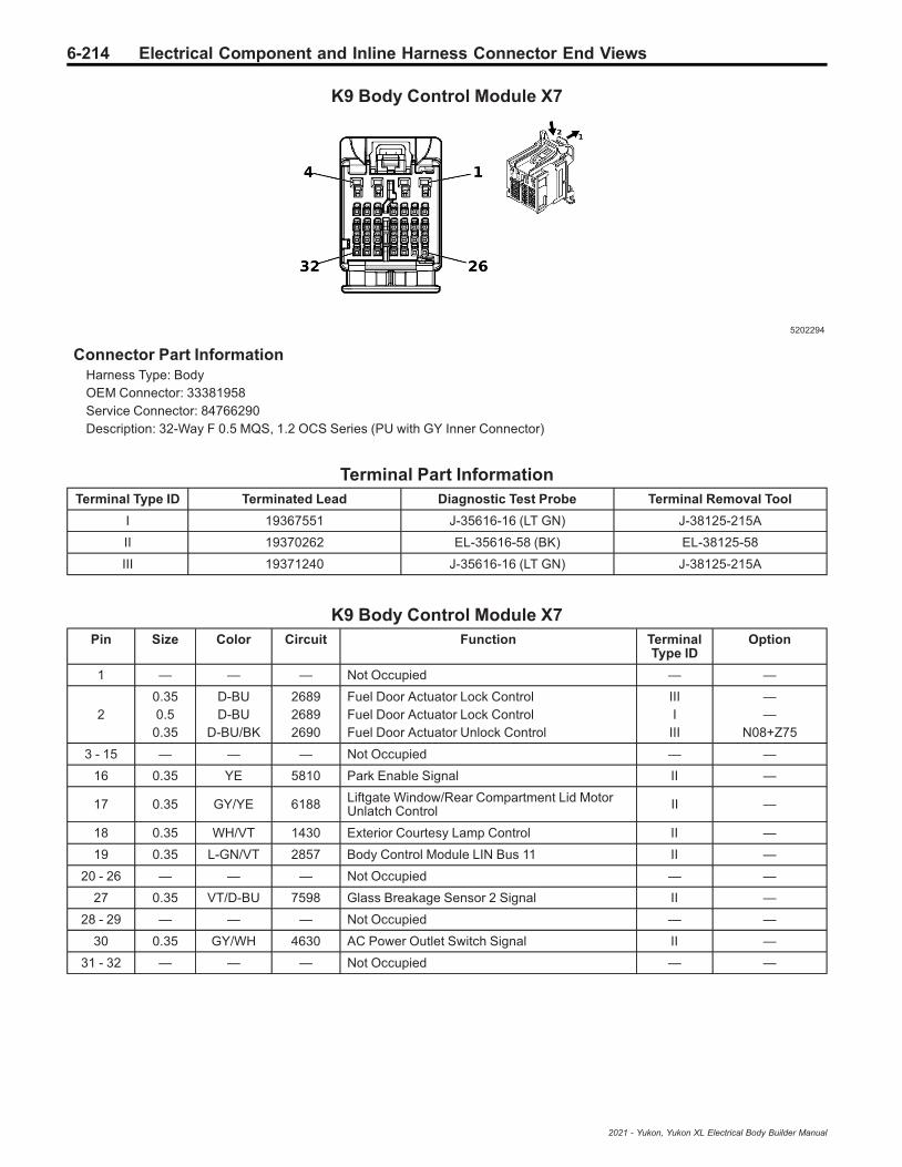
6-214 Electrical Component and Inline Harness Connector End Views
K9 Body Control Module X7
5202294
Connector Part InformationHarness Type: BodyOEM Connector: 33381958Service Connector: 84766290Description: 32-Way F 0.5 MQS, 1.2 OCS Series (PU with GY Inner Connector)
Terminal Part InformationTerminal Type ID Terminated Lead Diagnostic Test Probe Terminal Removal Tool
I 19367551 J-35616-16 (LT GN) J-38125-215A
II 19370262 EL-35616-58 (BK) EL-38125-58
III 19371240 J-35616-16 (LT GN) J-38125-215A
K9 Body Control Module X7Pin Size Color Circuit Function Terminal
Type IDOption
1 — — — Not Occupied — —
20.350.5
0.35
D-BUD-BU
D-BU/BK
268926892690
Fuel Door Actuator Lock ControlFuel Door Actuator Lock ControlFuel Door Actuator Unlock Control
IIII
III
——
N08+Z75
3 - 15 — — — Not Occupied — —
16 0.35 YE 5810 Park Enable Signal II —
17 0.35 GY/YE 6188 Liftgate Window/Rear Compartment Lid MotorUnlatch Control II —
18 0.35 WH/VT 1430 Exterior Courtesy Lamp Control II —
19 0.35 L-GN/VT 2857 Body Control Module LIN Bus 11 II —
20 - 26 — — — Not Occupied — —
27 0.35 VT/D-BU 7598 Glass Breakage Sensor 2 Signal II —
28 - 29 — — — Not Occupied — —
30 0.35 GY/WH 4630 AC Power Outlet Switch Signal II —
31 - 32 — — — Not Occupied — —
2021 - Yukon, Yukon XL Electrical Body Builder Manual

Electrical Component and Inline Harness Connector End Views 6-215
K9 Body Control Module X8
4578560
Connector Part InformationHarness Type: BodyOEM Connector: 33303967Service Connector: 84655160Description: 29-Way F 0.5 NANO, 1.2 MCON Series Sealed (GY)
Terminal Part InformationTerminal Type ID Terminated Lead Diagnostic Test Probe Terminal Removal Tool
I 19333323 J-35616-16 (LT GN) J-38125-215A
II 19367551 J-35616-16 (LT GN) J-38125-215A
III 19370262 EL-35616-58 (BK) EL-38125-58
IV 19370818 J-35616-16 (LT GN) J-38125-559
V 19371240 J-35616-16 (LT GN) J-38125-215A
K9 Body Control Module X8Pin Size Color Circuit Function Terminal
Type IDOption
10.50.5
D-BU/WHD-BU/WH
61286128
Rear Closure Unlatch Actuator Unlatch ControlRear Closure Unlatch Actuator Unlatch Control
IIV
——
2 — — — Not Occupied — —
30.750.75
D-BU/YED-BU/YE
10911091
Left Rear Door Lock Actuator Lock ControlLeft Rear Door Lock Actuator Lock Control
IIIV
——
40.750.75
YE/L-GNYE/L-GN
26822682
Right Front Door Lock Actuator Lock ControlRight Front Door Lock Actuator Lock Control
IVII
——
50.350.35
GYGY
20662066
Hands-Free Liftgate Sensor Lamp ControlHands-Free Liftgate Sensor Lamp Control
IV
——
6 - 8 — — — Not Occupied — —
9 0.35 L-GN/BK 4304 Passive Entry Right Front Door AntennaSignal Low III —
10 0.35 L-GN/YE 4303 Passive Entry Right Front Door AntennaSignal High III —
11 0.35 D-BU 3554 Interior Keyless Entry Antenna 2 High Signal III —
12 0.35 GY/BK 3555 Interior Keyless Entry Antenna 2 Low Signal III —
13 - 15 — — — Not Occupied — —
16 0.35 WH/VT 4994 Left Rear Door Exterior Switch Unlock Signal III —
17 0.35 L-GN/YE 2862 Body Control Module LIN Bus 16 III —
18 0.35 L-GN/WH 2854 Body Control Module LIN Bus 8 III —
2021 - Yukon, Yukon XL Electrical Body Builder Manual

6-216 Electrical Component and Inline Harness Connector End Views
K9 Body Control Module X8 (cont'd)Pin Size Color Circuit Function Terminal
Type IDOption
19 — — — Not Occupied — —
20 0.35 L-GN/D-BU 2856 Body Control Module LIN Bus 10 III —
21 0.35 VT/WH 6675 Left Rear Door Lock Indicator Control III —
22 0.35 YE/BK 6677 Right Rear Door Lock Indicator Control III —
23 - 27 — — — Not Occupied — —
28 0.35 GY/VT 2676 Right Front Door Exterior Switch Unlock Signal III —
29 0.35 L-GN/GY 6135 Body Control Module LIN Bus 4 III —
K19 Suspension Control Module (Z95)
4162046
Connector Part InformationHarness Type: ChassisOEM Connector: 33222138Service Connector: 19333026Description: 46-Way F 1.2 OCS, 2.8, 4.8 CTS Series, Sealed (GY)
Terminal Part InformationTerminal Type ID Terminated Lead Diagnostic Test Probe Terminal Removal Tool
I 19332900 J-35616-43 (RD) J-38125-215A
II 19371240 J-35616-16 (LT GN) J-38125-215A
K19 Suspension Control Module (Z95)Pin Size Color Circuit Function Terminal
Type IDOption
1 0.75 RD/L-GN 2440 Secondary Fused Battery Positive Voltage 24 I —
2 - 4 — — — Not Occupied — —
5 0.5 D-BU 4987 AUTOSAR CAN Bus [+] 1 Serial Data II —
6 0.5 D-BU 4987 AUTOSAR CAN Bus [+] 1 Serial Data II —
7 0.5 WH 4986 AUTOSAR CAN Bus [-] 1 Serial Data II —
8 0.5 WH 4986 AUTOSAR CAN Bus [-] 1 Serial Data II —
9 — — — Not Occupied — —
10 0.5 BN/D-BU 1116 Right Front Shock Absorber Actuator Control II —
2021 - Yukon, Yukon XL Electrical Body Builder Manual

Electrical Component and Inline Harness Connector End Views 6-217
K19 Suspension Control Module (Z95) (cont'd)Pin Size Color Circuit Function Terminal
Type IDOption
11 0.5 GY/WH 1117 Right Front Shock Absorber Actuator Control II —
12 - 13 — — — Not Occupied — —
14 0.75 BK 2150 Ground 21 I —
15 0.5 BN/WH 1107 Left Front Shock Absorber Actuator Control II —
16 - 21 — — — Not Occupied — —
22 0.5 D-BU/GY 1114 Left Rear Shock Absorber Actuator Control II —
23 0.5 BK/BN 1099 Left Front Vertical Suspension AccelerationSensor Low Reference II —
24 0.5 WH 1100 Left Front Vertical Suspension AccelerationSensor Signal II —
25 0.5 YE/RD 1817 Left Front Vertical Suspension AccelerationSensor Voltage Reference II —
26 0.5 VT/RD 1818 Left Rear Vertical Suspension AccelerationSensor Voltage Reference II —
27 0.5 YE/BN 1103 Left Rear Vertical Suspension AccelerationSensor Signal II —
28 0.5 BK/VT 1833 Left Rear Vertical Suspension AccelerationSensor Low Reference II —
29 0.5 BN/L-GN 1118 Right Rear Shock Absorber Actuator Control II —
30 — — — Not Occupied — —
31 0.5 GY/D-BU 1113 Left Front Shock Absorber Actuator Control II —
32 - 37 — — — Not Occupied — —
38 0.5 L-GN/VT 1115 Left Rear Shock Absorber Actuator Control II —
39 0.5 BK/L-GN 1105 Right Front Vertical Suspension AccelerationSensor Low Reference II —
40 0.5 WH 1106 Right Front Vertical Suspension AccelerationSensor Signal II —
41 0.5 BN/RD 1819 Right Front Vertical Suspension AccelerationSensor Voltage Reference II —
42 0.5 GY/RD 1820 Right Rear Vertical Suspension AccelerationSensor Voltage Reference II —
43 0.5 YE/D-BU 1109 Right Rear Vertical Suspension AccelerationSensor Signal II —
44 0.5 BK/D-BU 1108 Right Rear Vertical Suspension AccelerationSensor Low Reference II —
45 0.5 L-GN/GY 1119 Right Rear Shock Absorber Actuator Control II —
46 — — — Not Occupied — —
2021 - Yukon, Yukon XL Electrical Body Builder Manual

6-218 Electrical Component and Inline Harness Connector End Views
K20 Engine Control Module X1 (L84/L87)
4596458
Connector Part InformationHarness Type: EngineOEM Connector: 33315785Service Connector: 19368142Description: 49-Way F 0.64, 2.8 Series, Sealed (BK with BU Terminal Position Assurance)
Terminal Part InformationTerminal Type ID Terminated Lead Diagnostic Test Probe Terminal Removal Tool
I 13576377 J-35616-35 (VT) J-38125-12A
II 19355819 J-35616-64B (LT BU) J-38125-215A
K20 Engine Control Module X1 (L84/L87)Pin Size Color Circuit Function Terminal
Type IDOption
1 0.5 L-GN/WH 492 Mass Air Flow Sensor Signal II —
2 — — — Not Occupied — —
3 0.5 D-BU/GY 4054 Private Serial Data Powertrain CAN Bus [-]Serial Data II —
4 — — — Not Occupied — —
5 0.5 WH 4976 AUTOSAR CAN Bus [-] 3 Serial Data II —
6 0.5 WH/D-BU 6311 Cruise/ETC/TCC Brake Signal II —
7 0.5 WH 4978 AUTOSAR CAN Bus [-] 2 Serial Data II —
8 — — — Not Occupied — —
9 0.5 YE 5991 Powertrain Relay Coil Control II —
10 — — — Not Occupied — —
11 0.5 YE 4063 Hood Status A Signal II —
12 0.5 D-BU/GY 636 Ambient Air Temperature Sensor Signal II —
13 0.5 WH 4055 Private Serial Data Powertrain CAN Bus [+]Serial Data II —
14 0.5 WH/L-GN 5380 Brake Position Sensor Signal II —
15 0.5 D-BU/BK 4977 AUTOSAR CAN Bus [+] 3 Serial Data II —
16 — — — Not Occupied — —
17 0.5 D-BU/YE 4979 AUTOSAR CAN Bus [+] 2 Serial Data II —
18 0.5 WH/GY 459 A/C Compressor Clutch Relay Control II —
19 - 20 — — — Not Occupied — —
2021 - Yukon, Yukon XL Electrical Body Builder Manual

Electrical Component and Inline Harness Connector End Views 6-219
K20 Engine Control Module X1 (L84/L87) (cont'd)Pin Size Color Circuit Function Terminal
Type IDOption
21 0.75 L-GN/D-BU 428 EVAP Purge Solenoid Valve Control II —
22 - 23 — — — Not Occupied — —
24 0.5 BK/D-BU 1271 Accelerator Pedal Position Low Reference 1 II —
25 - 27 — — — Not Occupied — —
28 0.5 BN/L-GN 1174 Oil Level Switch Signal II —
29 — — — Not Occupied — —
30 0.5 BK/VT 1272 Accelerator Pedal Position Low Reference 2 II —
31 — — — Not Occupied — —
32 0.75 VT/D-BU 5291 Powertrain Main Relay Fused Supply 2 II —
33 — — — Not Occupied — —
34 0.5 RD/BN 440 Secondary Fused Battery Positive Voltage 4 II —
35 — — — Not Occupied — —
36 0.5 YE/BK 625 Starter Enable Relay Control II —
37 0.5 L-GN/GY 465 Fuel Pump Primary Relay Control II —
38 0.5 WH/RD 1164 Accelerator Pedal Position 5 Volt Reference 1 II —
39 0.5 YE/WH 1161 Accelerator Pedal Position Signal 1 II —
40 0.5 YE/BN 331 Oil Pressure Sensor Signal II —
41 0.5 L-GN 380 A/C Refrigerant Pressure Sensor Signal II —
42 - 43 — — — Not Occupied — —
44 0.5 L-GN/WH 1162 Accelerator Pedal Position Signal 2 II —
45 0.5 BN/RD 1274 Accelerator Pedal Position 5V Reference 2 II —
46 — — — Not Occupied — —
47 0.75 VT/L-GN 439 Run/Crank Ignition 1 Voltage 4 II —
48 0.75 VT/D-BU 5290 Powertrain Main Relay Fused Supply 1 II —
49 2 VT/D-BU 5290 Powertrain Main Relay Fused Supply 1 I —
K20 Engine Control Module X2 (L84/L87)
1590596
Connector Part InformationHarness Type: EngineOEM Connector: 15499466Service Connector: 19333090Description: 73-Way F 0.64, 2.8 Series, Sealed (BK with BK Terminal Position Assurance)
2021 - Yukon, Yukon XL Electrical Body Builder Manual

6-220 Electrical Component and Inline Harness Connector End Views
Terminal Part InformationTerminal Type ID Terminated Lead Diagnostic Test Probe Terminal Removal Tool
I 19355819 J-35616-64B (LT BU) J-38125-215A
II Not Required No Tool Required No Tool Required
K20 Engine Control Module X2 (L84/L87)Pin Size Color Circuit Function Terminal
Type IDOption
1 0.5 L-GN/YE 3212 HO2S Heater Low Control Bank 2 Sensor 1 I —
2 0.5 GY 5493 Cylinder Deactivation Solenoid Valve Control 3 I —
3 0.5 BK/YE 548 Engine Control Sensors Low Reference 1 I —
4 - 6 — — — Not Occupied — —
7 0.5 L-GN/WH 4622 Engine Control Module LIN Bus 2 I —
8 0.75 L-GN/VT 4621 Engine Control Module LIN Bus 1 I —
9 — — — Not Occupied — —
10 0.5 VT/GY 3110 HO2S High Signal Bank 1 Sensor 1 I —
11 0.5 WH/BK 3111 HO2S Low Signal Bank 1 Sensor 1 (3) I —
12 0.5 YE/D-BU 2124 Ignition Control 4 I —
13 0.5 BN/D-BU 2126 Ignition Control 6 I —
14 0.5 VT/D-BU 5294 Powertrain Main Relay Fused Supply 5 I —
15 0.5 VT/D-BU 5294 Powertrain Main Relay Fused Supply 5 I —
16 0.5 VT/D-BU 5294 Powertrain Main Relay Fused Supply 5 I —
17 0.5 GY/WH 3113 HO2S Heater Low Control Bank 1 Sensor 1 I —
18 0.5 YE/GY 2493 Cylinder Shutoff Solenoid Enable Signal 3 I —
19 - 25 — — — Not Occupied — —
26 0.5 VT/WH 3210 HO2S High Signal Bank 2 Sensor 1 I —
27 0.5 YE/WH 3211 HO2S Low Signal Bank 2 Sensor 1 I —
28 0.5 L-GN/D-BU 2123 Ignition Control 3 I —
29 0.5 D-BU/GY 2125 Ignition Control 5 I —
30 0.75 BK/GY 2130 Ignition Control Low Reference Bank 2 I —
31 0.5 BN 5496 Cylinder Deactivation Solenoid Valve Control 6 I —
32 0.5 YE/BN 2496 Cylinder Shutoff Solenoid Enable Signal 6 I —
33 0.75 WH/BN 3223 HO2S Heater Low Control Bank 2 Sensor 2 I —
34 — — — Not Occupied — —
35 0.5 D-BU 179 Engine Oil Pump Control I —
36 0.5 YE/L-GN 2494 Cylinder Shutoff Solenoid Enable Signal 4 I —
37 0.75 VT/D-BU 5294 Powertrain Main Relay Fused Supply 5 I —
38 — — — Not Occupied — —
39 0.5 WH/RD 480 Engine Control Vehicle Sensors 5 VoltReference 1 I —
40 - 45 — — — Not Occupied — —
46 0.5 YE/D-BU 3221 HO2S Low Signal Bank 2 Sensor 2 I —
47 0.5 VT/L-GN 3220 HO2S High Signal Bank 2 Sensor 2 I —
48 - 49 — — — Not Occupied — —
50 0.75 BK/GY 2303 Knock Sensor 2 Low Reference I —
51 0.75 BK/YE 1716 Knock Sensor 1 Low Reference I —
52 0.5 BN/WH 582 Throttle Actuator Close Control I —
2021 - Yukon, Yukon XL Electrical Body Builder Manual

Electrical Component and Inline Harness Connector End Views 6-221
K20 Engine Control Module X2 (L84/L87) (cont'd)Pin Size Color Circuit Function Terminal
Type IDOption
53 0.75 GY/WH 3122 HO2S Heater Low Control Bank 1 Sensor 2 I —
54 0.5 VT 5495 Cylinder Deactivation Solenoid Valve Control 5 I —
55 0.5 WH/VT 2495 Cylinder Shutoff Solenoid Enable Signal 5 I —
56 0.5 YE/D-BU 5494 Cylinder Deactivation Solenoid Valve Control 4 I —
57 0.5 L-GN 5492 Cylinder Deactivation Solenoid Valve Control 2 I —
58 0.5 WH/L-GN 2492 Cylinder Shutoff Solenoid Enable Signal 2 I —
59 - 65 — — — Not Occupied — —
66 0.5 WH/YE 3121 HO2S Low Signal Bank 1 Sensor 2 I —
67 0.5 VT/D-BU 3120 HO2S High Signal Bank 1 Sensor 2 I —
68 - 69 — — — Not Occupied — —
70 0.75 WH/GY 1876 Knock Sensor 2 Signal I —
71 0.75 VT/GY 496 Knock Sensor 1 Signal I —
72 0.5 YE 581 Throttle Actuator Open Control I —
73 2.5 BK/WH 6151 Engine Control Module Ground 61 II —
K20 Engine Control Module X3 (L84/L87)
1590596
Connector Part InformationHarness Type: EngineOEM Connector: 15497996Service Connector: 19333091Description: 73-Way F 0.64, 2.8 Series, Sealed (BK with GY Terminal Position Assurance)
Terminal Part InformationTerminal Type ID Terminated Lead Diagnostic Test Probe Terminal Removal Tool
I 19355819 J-35616-64B (LT BU) J-38125-215A
II Not Required No Tool Required No Tool Required
K20 Engine Control Module X3 (L84/L87)Pin Size Color Circuit Function Terminal
Type IDOption
1 0.5 WH 5497 Cylinder Deactivation Solenoid Valve Control 7 I —
2 0.5 L-GN/GY 2497 Cylinder Shutoff Solenoid Enable Signal 7 I —
2021 - Yukon, Yukon XL Electrical Body Builder Manual

6-222 Electrical Component and Inline Harness Connector End Views
K20 Engine Control Module X3 (L84/L87) (cont'd)Pin Size Color Circuit Function Terminal
Type IDOption
3 - 4 — — — Not Occupied — —
5 0.5 VT/BN 5284 Intake Camshaft Position Actuator SolenoidValve 1 I —
6 0.5 VT/L-GN 4320 Selective Catalytic Reduction Power ModuleWake-Up Signal I —
7 — — — Not Occupied — —
8 0.5 YE/VT 5275 Intake Camshaft Position Sensor 1 I —
9 0.5 GY/D-BU 5300 Intake Camshaft Position Sensor 1 VoltageReference I —
10 0.5 L-GN 6271 Crankshaft Position Sensor Signal I —
11 — — — Not Occupied — —
12 0.75 D-BU/WH 2122 Ignition Control 2 I —
13 0.5 VT/WH 2128 Ignition Control 8 I —
14 0.5 BN 25 Charge Indicator Control I —
15 — — — Not Occupied — —
16 0.75 YE 7301 High Pressure Fuel Pump High Control I —
17 - 20 — — — Not Occupied — —
21 0.5 BK/BN 6753 Camshaft Position Actuator Solenoid Valve WLow Reference I —
22 - 23 — — — Not Occupied — —
24 0.5 BK/L-GN 5301 Intake Camshaft Position Sensor LowReference 1 I —
25 0.5 VT/D-BU 6270 Crankshaft Position Sensor Voltage I —
26 0.5 BK/VT 6272 Crankshaft Position Sensor Low Reference I —
27 — — — Not Occupied — —
28 0.5 L-GN/GY 2127 Ignition Control 7 I —
29 0.5 D-BU/VT 2121 Ignition Control 1 I —
30 0.5 BK/D-BU 2129 Ignition Control Low Reference Bank 1 I —
31 — — — Not Occupied — —
32 0.75 VT/BK 7300 High Pressure Fuel Pump Low Control I —
33 0.5 YE/VT 4325 Starter Pinion Solenoid Actuator Relay Control I —
34 0.5 WH/D-BU 2491 Cylinder Shutoff Solenoid Enable Signal 1 I —
35 0.5 WH/YE 2498 Cylinder Shutoff Solenoid Enable Signal 8 I —
36 0.5 BK/BN 2752 Throttle Position Sensor Low Reference I —
37 0.5 BK/L-GN 469 Manifold Absolute Pressure Sensor LowReference I —
38 - 39 — — — Not Occupied — —
40 0.5 BN/D-BU 357 Oil Temperature Sensor Signal I —
41 - 43 — — — Not Occupied — —
44 0.75 VT/D-BU 5292 Powertrain Main Relay Fused Supply 3 I —
45 0.75 L-GN 4803 Direct Fuel Injector High Voltage ControlCylinder 3 I —
46 0.75 GY/D-BU 4804 Direct Fuel Injector High Voltage ControlCylinder 4 I —
47 0.75 WH/L-GN 4805 Direct Fuel Injector High Voltage ControlCylinder 5 I —
48 0.75 VT/L-GN 4806 Direct Fuel Injector High Voltage ControlCylinder 6 I —
2021 - Yukon, Yukon XL Electrical Body Builder Manual

Electrical Component and Inline Harness Connector End Views 6-223
K20 Engine Control Module X3 (L84/L87) (cont'd)Pin Size Color Circuit Function Terminal
Type IDOption
49 0.75 D-BU 4802 Direct Fuel Injector High Voltage ControlCylinder 2 I —
50 0.75 YE/GY 4807 Direct Fuel Injector High Voltage ControlCylinder 7 I —
51 0.75 GY 4808 Direct Fuel Injector High Voltage ControlCylinder 8 I —
52 0.75 BN 4801 Direct Fuel Injector High Voltage ControlCylinder 1 I —
53 0.5 D-BU 5491 Cylinder Deactivation Solenoid Valve Control 1 I —
54 0.5 YE 5498 Cylinder Deactivation Solenoid Valve Control 8 I —
55 0.5 BN/RD 2701 Throttle Position Sensor 5V Reference 2 I —
56 0.5 D-BU/WH 3630 Throttle Position Sensor SENT 1 Signal I —
57 0.5 GY/RD 2704 Manifold Absolute Pressure Sensor 5VReference I —
58 0.5 L-GN/WH 432 Manifold Absolute Pressure Sensor Signal I —
59 - 60 — — — Not Occupied — —
61 0.5 D-BU 410 Engine Coolant Temperature Sensor Signal I —
62 — — — Not Occupied — —
63 0.5 D-BU/WH 2918 Fuel Rail Pressure Sensor Signal I —
64 0.5 GY 23 Generator Field Duty Cycle Signal I —
65 0.75 L-GN/GY 4903 Direct Fuel Injector High Voltage SupplyCylinder 3 I —
66 0.75 D-BU/WH 4904 Direct Fuel Injector High Voltage SupplyCylinder 4 I —
67 0.75 L-GN/WH 4905 Direct Fuel Injector High Voltage SupplyCylinder 5 I —
68 0.75 VT/GY 4906 Direct Fuel Injector High Voltage SupplyCylinder 6 I —
69 0.75 D-BU/GY 4902 Direct Fuel Injector High Voltage SupplyCylinder 2 I —
70 0.75 WH/YE 4907 Direct Fuel Injector High Voltage SupplyCylinder 7 I —
71 0.75 GY/WH 4908 Direct Fuel Injector High Voltage SupplyCylinder 8 I —
72 0.75 BN/WH 4901 Direct Fuel Injector High Voltage SupplyCylinder 1 I —
73 2.5 BK/WH 6151 Engine Control Module Ground 61 II —
2021 - Yukon, Yukon XL Electrical Body Builder Manual

6-224 Electrical Component and Inline Harness Connector End Views
K20 Engine Control Module X1 (LM2)
4997706
Connector Part InformationHarness Type: EngineOEM Connector: 35021651Service Connector: 84628960Description: 90-Way F 0.64 GEN-Y, 2.8, 6.3 MCP Series, Sealed (BU)
Terminal Part InformationTerminal Type ID Terminated Lead Diagnostic Test Probe Terminal Removal Tool
I 19367373 J-35616-64B (LT BU) J-38125-215A
II 19368490 J-35616-64B (LT BU) J-38125-215A
III 19371214 J-35616-35 (VT) J-38125-557
IV 19371240 J-35616-35 (VT) J-38125-557
V 84616649 J-35616-40 (BU) J-38125-556
K20 Engine Control Module X1 (LM2)Pin Size Color Circuit Function Terminal
Type IDOption
1 6 BN/D-BU 104 Glow Plug Control V —
2 2.5 GY/VT 1586 Glow Plug 6 Control III —
3 - 5 — — — Not Occupied — —
6 0.5 WH/GY 459 A/C Compressor Clutch Relay Control II —
7 0.5 RD/BN 440 Secondary Fused Battery Positive Voltage 4 II —
8 0.5 L-GN/WH 492 Mass Air Flow Sensor Signal II —
9 — — — Not Occupied — —
10 0.5 WH/D-BU 6311 Cruise/ETC/TCC Brake Signal II —
11 0.5 GY 2973 Coolant Flow Control Valve Position Signal II —
12 0.5 L-GN/GY 7316 Intake Manifold Runner Valve Actuator Control II —
13 - 14 — — — Not Occupied — —
15 0.5 BN/L-GN 4305 Exhaust Flow Control Valve 1 II —
16 0.5 WH 4055 Private Serial Data Powertrain CAN Bus [+]Serial Data II —
17 0.5 D-BU/BK 4977 AUTOSAR CAN Bus [+] 3 Serial Data II —
18 0.5 D-BU/YE 4979 AUTOSAR CAN Bus [+] 2 Serial Data II —
19 0.5 BK/L-GN 580 Engine Control Sensors Low Reference 2 II —
20 — — — Not Occupied — —
2021 - Yukon, Yukon XL Electrical Body Builder Manual

Electrical Component and Inline Harness Connector End Views 6-225
K20 Engine Control Module X1 (LM2) (cont'd)Pin Size Color Circuit Function Terminal
Type IDOption
21 0.75 GY/BK 1330 Variable Geometry Turbocharger PositionSensor Motor Close Control II —
22 0.75 WH/BN 1313 Variable Geometry Turbocharger PositionSensor Motor Open Control II —
23 2.5 GY/L-GN 1583 Glow Plug 3 Control III —
24 2.5 GY/WH 1585 Glow Plug 5 Control III —
25 0.75 VT/L-GN 439 Run/Crank Ignition 1 Voltage 4 II —
26 0.5 YE 5991 Powertrain Relay Coil Control II —
27 — — — Not Occupied — —
28 0.35 L-GN/BN 507 Wait To Start Indicator Control I —
29 — — — Not Occupied — —
30 0.5 BK/GY 626 Engine Control Vehicle Sensors LowReference 1 II —
31 - 33 — — — Not Occupied — —
34 0.5 VT/YE 5947 Turbocharger Vane Position Sensor Signal II —
35 0.5 BN/WH 5763 Exhaust Gas Recirculation Position Signal II —
36 0.5 D-BU/GY 2978 Coolant Diverter Valve Position Signal II —
37 — — — Not Occupied — —
38 0.5 D-BU/GY 4054 Private Serial Data Powertrain CAN Bus [-]Serial Data II —
39 0.5 WH 4976 AUTOSAR CAN Bus [-] 3 Serial Data II —
40 0.5 WH 4978 AUTOSAR CAN Bus [-] 2 Serial Data II —
41 0.5 BN/D-BU 4065 Driveline Mount Actuator 1 Control II —
42 0.5 YE/BK 625 Starter Enable Relay Control II —
43 0.5 VT/BK 5746 Exhaust Gas Recirculation Valve Low Control II —
44 0.5 WH/VT 5764 Exhaust Gas Recirculation Valve High Control II —
45 2.5 GY/BN 1582 Glow Plug 2 Control III —
46 1 BK/WH 6151 Engine Control Module Ground 61 V —
47 2.5 GY/YE 1584 Glow Plug 4 Control III —
48 0.5 WH/RD 480 Engine Control Vehicle Sensors 5 VoltReference 1 II —
49 0.5 L-GN/WH 1162 Accelerator Pedal Position Signal 2 II —
50 0.5 BK/VT 1272 Accelerator Pedal Position Low Reference 2 II —
51 0.5 BK/D-BU 1271 Accelerator Pedal Position Low Reference 1 II —
52 0.5 WH/L-GN 5380 Brake Position Sensor Signal II —
53 - 54 — — — Not Occupied — —
55 0.5 YE 4063 Hood Status A Signal II —
56 - 58 — — — Not Occupied — —
59 0.5 L-GN 380 A/C Refrigerant Pressure Sensor Signal II —
60 0.5 YE/BN 331 Oil Pressure Sensor Signal II —
61 0.5 YE/GY 3926 Crankcase Differential Pressure Sensor Signal II —
62 - 63 — — — Not Occupied — —
64 0.5 L-GN/D-BU 3889 Powertrain Sensor Bus Relay Control II —
65 — — — Not Occupied — —
66 0.5 BN 1421 Exhaust Restrictor Motor Closed Control II —
67 0.5 YE/BN 1420 Exhaust Restrictor Motor Open Control II —
2021 - Yukon, Yukon XL Electrical Body Builder Manual

6-226 Electrical Component and Inline Harness Connector End Views
K20 Engine Control Module X1 (LM2) (cont'd)Pin Size Color Circuit Function Terminal
Type IDOption
68 2.5 GY/D-BU 1581 Glow Plug 1 Control III —
69 0.75 VT/D-BU 5291 Powertrain Main Relay Fused Supply 2 IV —
70 0.5 D-BU/RD 460 Engine Control Sensors 5 Volt Reference 1 II —
71 0.5 BN/RD 1274 Accelerator Pedal Position 5V Reference 2 II —
72 0.5 WH/RD 1164 Accelerator Pedal Position 5 Volt Reference 1 II —
73 0.5 YE/WH 1161 Accelerator Pedal Position Signal 1 II —
74 0.5 D-BU/GY 636 Ambient Air Temperature Sensor Signal II —
75 0.5 VT 7485 Transfer Case Fluid Temperatue Sensor Signal II —
76 - 77 — — — Not Occupied — —
78 0.5 GY/VT 2404 Engine Block Coolant Temperature Signal II —
79 - 83 — — — Not Occupied — —
84 0.5 VT/GY 7246 Exhaust Gas Recirculation Differential PressureSignal 1 II —
85 — — — Not Occupied — —
86 0.5 L-GN/GY 465 Fuel Pump Primary Relay Control II —
87 0.75 VT/D-BU 5294 Powertrain Main Relay Fused Supply 5 II —
88 0.75 GY/BN 2972 Coolant Flow Control Actuator Control Close II —
89 0.75 GY/D-BU 2971 Coolant Flow Control Actuator Control Open II —
90 2 VT/D-BU 5290 Powertrain Main Relay Fused Supply 1 III —
K20 Engine Control Module X2 (LM2)
4997563
Connector Part InformationHarness Type: EngineOEM Connector: 35021652Service Connector: 84628959Description: 112-Way F 0.64 GEN-Y, 1.2 MCON Series, Sealed (BK)
Terminal Part InformationTerminal Type ID Terminated Lead Diagnostic Test Probe Terminal Removal Tool
I 13582289 J-35616-16 (LT GN) J-38125-215A
II 19331733 J-35616-16 (LT GN) J-38125-215A
III 19368490 J-35616-64B (LT BU) J-38125-215A
2021 - Yukon, Yukon XL Electrical Body Builder Manual

Electrical Component and Inline Harness Connector End Views 6-227
K20 Engine Control Module X2 (LM2)Pin Size Color Circuit Function Terminal
Type IDOption
1 1.5 L-GN 4803 Direct Fuel Injector High Voltage ControlCylinder 3 I —
2 1.5 GY/D-BU 4804 Direct Fuel Injector High Voltage ControlCylinder 4 I —
3 0.75 YE/VT 2420 Fuel High Pressure Pump Low Enable Signal II —
4 0.75 YE/VT 7245 High Pressure Fuel Pump Low Enable Signal II —
5 0.5 GY/YE 5297 Exhaust Camshaft Position Sensor 1 VoltageReference III —
6 0.5 L-GN 6271 Crankshaft Position Sensor Signal III —
7 0.5 VT/D-BU 6270 Crankshaft Position Sensor Voltage III —
8 — — — Not Occupied — —
9 0.5 BN 25 Charge Indicator Control III —
10 — — — Not Occupied — —
11 0.5 BK/L-GN 3235 Exhaust Gas Recirculation Temperature Sensor3 Low Reference III —
12 0.5 YE/D-BU 3680 Charge Air Cooler Outlet Temperature SensorLow Reference III —
13 0.5 YE/BK 3682 Charge Air Cooler Inlet Temperature SensorLow Reference III —
14 0.5 BK/D-BU 6274 Exhaust Gas Recirculation Temperature SensorLow Reference III —
15 — — — Not Occupied — —
16 0.5 BK/L-GN 3657 Exhaust Gas Temperature Sensor 3 LowReference III —
17 — — — Not Occupied — —
18 0.5 BK/D-BU 6783 Exhaust Gas Temperature Sensor 2 LowReference III —
19 — — — Not Occupied — —
20 0.5 BK/BN 6782 Exhaust Gas Temperature Sensor 1 LowReference III —
21 - 22 — — — Not Occupied — —
23 0.75 BN/WH 3100 Diesel Exhaust Fluid Dosing Valve Low Control III —
24 0.5 BK/YE 2834 Fuel Rail Pressure Solenoid Valve LowReference III —
25 0.5 D-BU 179 Engine Oil Pump Control III —
26 0.5 BN/YE 4066 Driveline Mount Actuator 2 Control III —
27 0.5 BN/WH 582 Throttle Actuator Close Control III —
28 0.5 YE 581 Throttle Actuator Open Control III —
29 1.5 L-GN/GY 4903 Direct Fuel Injector High Voltage SupplyCylinder 3 I —
30 1.5 D-BU/WH 4904 Direct Fuel Injector High Voltage SupplyCylinder 4 I —
31 0.75 GY/BN 2419 — II —
32 0.75 GY/BN 7244 High Pressure Fuel Pump High Side Control II —
33 0.5 BK/GY 5296 Exhaust Camshaft Position Sensor LowReference 1 III —
34 0.5 VT/BK 5273 Exhaust Camshaft Position Sensor 1 III —
35 0.5 BK/VT 6272 Crankshaft Position Sensor Low Reference III —
36 — — — Not Occupied — —
37 0.5 D-BU 3017 Fuel Heater Relay 1 Control III —
2021 - Yukon, Yukon XL Electrical Body Builder Manual

6-228 Electrical Component and Inline Harness Connector End Views
K20 Engine Control Module X2 (LM2) (cont'd)Pin Size Color Circuit Function Terminal
Type IDOption
38 — — — Not Occupied — —
39 0.5 WH/GY 3234 Exhaust Gas Recirculation Temperature Sensor3 Signal III —
40 0.5 BN 3681 Charge Air Cooler Outlet Temperature SensorSignal III —
41 0.5 L-GN 3683 Charge Air Cooler Inlet Temperature SensorSignal III —
42 0.5 WH/BN 3237 Exhaust Gas Recirculation Temperature SensorSignal III —
43 — — — Not Occupied — —
44 0.5 GY/L-GN 5378 Exhaust Gas Temperature Sensor 3 Signal III —
45 — — — Not Occupied — —
46 0.5 D-BU/L-GN 5377 Exhaust Gas Temperature Sensor 2 Signal III —
47 — — — Not Occupied — —
48 0.5 D-BU/WH 5277 Exhaust Gas Temperature Sensor 1 Signal III —
49 - 50 — — — Not Occupied — —
51 0.75 BN 3099 Diesel Exhaust Fluid Dosing Valve High Control III —
52 0.5 D-BU/WH 2530 Fuel Rail Pressure Solenoid Valve Control III —
53 0.5 YE/BN 106 Oil Pump Motor Control III —
54 — — — Not Occupied — —
55 0.75 BK/D-BU 1408 Variable Swirl Valve Close Control III —
56 0.75 BK/L-GN 1389 Variable Swirl Valve Open Control III —
57 1.5 VT/GY 4906 Direct Fuel Injector High Voltage SupplyCylinder 6 I —
58 1.5 BN/WH 4901 Direct Fuel Injector High Voltage SupplyCylinder 1 I —
59 1.5 L-GN/WH 4905 Direct Fuel Injector High Voltage SupplyCylinder 5 I —
60 1.5 D-BU/GY 4902 Direct Fuel Injector High Voltage SupplyCylinder 2 I —
61 - 65 — — — Not Occupied — —
66 0.5 BN/RD 2917 Fuel Rail Pressure Sensor 5V Reference III —
67 0.5 BK/L-GN 2919 Fuel Rail Pressure Sensor Low Reference III —
68 — — — Not Occupied — —
69 0.5 BN/D-BU 357 Oil Temperature Sensor Signal III —
70 0.5 YE/BK 3000 Coolant Temperature Sensor 2 Signal III —
71 — — — Not Occupied — —
72 0.5 BN/YE 1372 Engine Metal Temperature Sensor Signal 2 III —
73 0.5 WH/D-BU 7329 Pre-Throttle Air Temperature Signal III —
74 0.5 D-BU 6053 Exhaust Pressure Sensor 1 Signal III —
75 0.5 BK/YE 548 Engine Control Sensors Low Reference 1 III —
76 0.75 L-GN/VT 4621 Engine Control Module LIN Bus 1 III —
77 0.5 L-GN/WH 4622 Engine Control Module LIN Bus 2 III —
78 0.5 L-GN/YE 4623 Engine Control Module LIN Bus 3 III —
79 - 82 — — — Not Occupied — —
83 0.75 D-BU/BN 2977 Coolant Diverter Valve Actuator Control Close III —
84 0.75 D-BU 2976 Coolant Diverter Valve Actuator Control Open III —
2021 - Yukon, Yukon XL Electrical Body Builder Manual

Electrical Component and Inline Harness Connector End Views 6-229
K20 Engine Control Module X2 (LM2) (cont'd)Pin Size Color Circuit Function Terminal
Type IDOption
85 1.5 VT/L-GN 4806 Direct Fuel Injector High Voltage ControlCylinder 6 I —
86 1.5 BN 4801 Direct Fuel Injector High Voltage ControlCylinder 1 I —
87 1.5 D-BU 4802 Direct Fuel Injector High Voltage ControlCylinder 2 I —
88 1.5 WH/L-GN 4805 Direct Fuel Injector High Voltage ControlCylinder 5 I —
89 — — — Not Occupied — —
90 0.5 D-BU/WH 3630 Throttle Position Sensor SENT 1 Signal III —
91 0.5 D-BU/L-GN 4012 Exhaust Gas Recirculation 2 Valve Position
Sensor Signal III —
92 0.5 GY 23 Generator Field Duty Cycle Signal III —
93 — — — Not Occupied — —
94 0.5 D-BU/WH 2918 Fuel Rail Pressure Sensor Signal III —
95 0.5 YE/D-BU 2408 Engine Inlet Coolant Temperature Signal III —
96 0.5 BN/YE 2161 Fuel Rail Pressure Sensor 2 Signal III —
97 0.5 VT 2988 Engine Outlet Coolant Temperature Signal III —
98 - 100 — — — Not Occupied — —
101 0.5 L-GN/WH 432 Manifold Absolute Pressure Sensor Signal III —
102 0.5 L-GN/YE 37 Engine Block Temperature Sensor Signal III —
103 0.5 D-BU/BK 1422 Engine Water Charge Air Coolant TemperatureSignal III —
104 — — — Not Occupied — —
105 0.5 L-GN/BN 2732 Engine Control Module LIN Bus 4 III —
106- 110 — — — Not Occupied — —
111 0.5 D-BU/BN 4013 Exhaust Gas Recirculation 2 Valve CloseControl III —
112 0.5 D-BU/WH 4014 Exhaust Gas Recirculation 2 Valve Open Control III —
K36 Inflatable Restraint Sensing and Diagnostic Module X1
5377109
Connector Part InformationHarness Type: BodyOEM Connector: 35280988
2021 - Yukon, Yukon XL Electrical Body Builder Manual
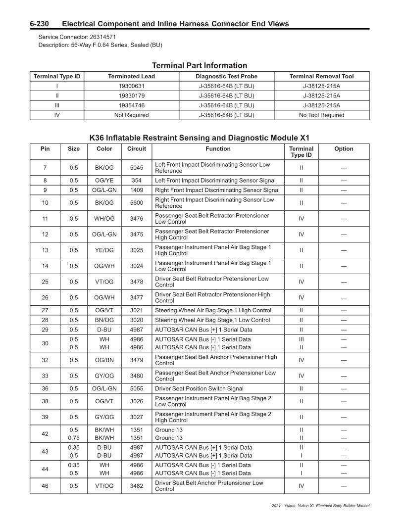
6-230 Electrical Component and Inline Harness Connector End Views
Service Connector: 26314571Description: 56-Way F 0.64 Series, Sealed (BU)
Terminal Part InformationTerminal Type ID Terminated Lead Diagnostic Test Probe Terminal Removal Tool
I 19300631 J-35616-64B (LT BU) J-38125-215A
II 19330179 J-35616-64B (LT BU) J-38125-215A
III 19354746 J-35616-64B (LT BU) J-38125-215A
IV Not Required J-35616-64B (LT BU) No Tool Required
K36 Inflatable Restraint Sensing and Diagnostic Module X1Pin Size Color Circuit Function Terminal
Type IDOption
7 0.5 BK/OG 5045 Left Front Impact Discriminating Sensor LowReference II —
8 0.5 OG/YE 354 Left Front Impact Discriminating Sensor Signal II —
9 0.5 OG/L-GN 1409 Right Front Impact Discriminating Sensor Signal II —
10 0.5 BK/OG 5600 Right Front Impact Discriminating Sensor LowReference II —
11 0.5 WH/OG 3476 Passenger Seat Belt Retractor PretensionerLow Control IV —
12 0.5 OG/L-GN 3475 Passenger Seat Belt Retractor PretensionerHigh Control IV —
13 0.5 YE/OG 3025 Passenger Instrument Panel Air Bag Stage 1High Control II —
14 0.5 OG/WH 3024 Passenger Instrument Panel Air Bag Stage 1Low Control II —
25 0.5 VT/OG 3478 Driver Seat Belt Retractor Pretensioner LowControl IV —
26 0.5 OG/WH 3477 Driver Seat Belt Retractor Pretensioner HighControl IV —
27 0.5 OG/VT 3021 Steering Wheel Air Bag Stage 1 High Control II —
28 0.5 BN/OG 3020 Steering Wheel Air Bag Stage 1 Low Control II —
29 0.5 D-BU 4987 AUTOSAR CAN Bus [+] 1 Serial Data II —
300.50.5
WHWH
49864986
AUTOSAR CAN Bus [-] 1 Serial DataAUTOSAR CAN Bus [-] 1 Serial Data
IIIII
——
32 0.5 OG/BN 3479 Passenger Seat Belt Anchor Pretensioner HighControl IV —
33 0.5 GY/OG 3480 Passenger Seat Belt Anchor Pretensioner LowControl IV —
36 0.5 OG/L-GN 5055 Driver Seat Position Switch Signal II —
38 0.5 OG/VT 3026 Passenger Instrument Panel Air Bag Stage 2Low Control II —
39 0.5 GY/OG 3027 Passenger Instrument Panel Air Bag Stage 2High Control II —
420.5
0.75BK/WHBK/WH
13511351
Ground 13Ground 13
IIII
——
430.350.5
D-BUD-BU
49874987
AUTOSAR CAN Bus [+] 1 Serial DataAUTOSAR CAN Bus [+] 1 Serial Data
III
——
440.350.5
WHWH
49864986
AUTOSAR CAN Bus [-] 1 Serial DataAUTOSAR CAN Bus [-] 1 Serial Data
III
——
46 0.5 VT/OG 3482 Driver Seat Belt Anchor Pretensioner LowControl IV —
2021 - Yukon, Yukon XL Electrical Body Builder Manual

Electrical Component and Inline Harness Connector End Views 6-231
K36 Inflatable Restraint Sensing and Diagnostic Module X1 (cont'd)Pin Size Color Circuit Function Terminal
Type IDOption
47 0.5 OG/YE 3481 Driver Seat Belt Anchor Pretensioner HighControl IV —
50 0.5 BN/WH 3895 Roof Rail Air Bag Disable Switch Low Reference II —
51 0.5 D-BU/WH 3119 Roof Rail Air Bag Disable Switch Signal II —
53 0.5 WH/OG 3022 Steering Wheel Air Bag Stage 2 Low Control II —
54 0.5 OG/L-GN 3023 Steering Wheel Air Bag Stage 2 High Control II —
55 0.5 VT/WH 239 Run/Crank Ignition 1 Voltage 2 II —
56 0.5 RD/L-GN 4440 Secondary Fused Battery Positive Voltage 44 II —
K36 Inflatable Restraint Sensing and Diagnostic Module X2
5377124
Connector Part InformationHarness Type: BodyOEM Connector: 35280986Service Connector: Service by Harness - See Part CatalogDescription: 56-Way F 0.64 Series, Sealed (BK)
Terminal Part InformationTerminal Type ID Terminated Lead Diagnostic Test Probe Terminal Removal Tool
I 19330179 J-35616-64B (LT BU) J-38125-215A
K36 Inflatable Restraint Sensing and Diagnostic Module X2Pin Size Color Circuit Function Terminal
Type IDOption
9 0.5 VT/OG 3517 3rd Row Right Seat Belt Switch Signal I —
10 0.5 D-BU/OG 5163 Rear Center Seat Belt Switch Signal I —
11 0.5 YE/OG 5161 Left Rear Seat Belt Switch Signal I —
120.50.5
OG/BNOG/GY
2382652
Driver Seat Belt Switch SignalDriver Seat Belt Sensor Signal
II
——
13 0.5 BK/OG 6627 Right Rear Side Impact Sensor Low Reference I —
14 0.5 OG/WH 6626 Right Rear Side Impact Sensor Signal I —
21 0.5 OG/L-GN 3700 3rd Row Center Seat Belt Switch Signal I —
22 0.5 L-GN/OG 3516 3rd Row Left Seat Belt Switch Signal I —
23 0.5 BK/OG 1363 Driver Seat Belt Switch Low Reference I —
2021 - Yukon, Yukon XL Electrical Body Builder Manual

6-232 Electrical Component and Inline Harness Connector End Views
K36 Inflatable Restraint Sensing and Diagnostic Module X2 (cont'd)Pin Size Color Circuit Function Terminal
Type IDOption
24 0.5 BN/OG 5162 Right Rear Seat Belt Switch Signal I —
25 0.5 OG/VT 1362 Passenger Seat Belt Switch Signal I —
27 0.5 BK/OG 6628 Left Front Side Impact Sensor Low Reference I —
28 0.5 OG/L-GN 2132 Left Front Side Impact Sensor Signal I —
37 0.5 OG/GY 5021 Right Front Roof Rail Air Bag High Control I —
38 0.5 WH/OG 5022 Right Front Roof Rail Air Bag Low Control I —
39 0.5 D-BU/OG 4957 Passenger Seat Back Air Bag Low Control I —
40 0.5 OG/GY 4956 Passenger Seat Back Air Bag High Control I —
41 0.5 BK/OG 6629 Right Front Side Impact Sensor Low Reference I —
42 0.5 BN/OG 2134 Right Front Side Impact Sensor Signal I —
45 0.5 GY/OG 4208 Driver Inboard Seat Side Air Bag Low Control I —
46 0.5 OG/BN 4207 Driver Inboard Seat Side Air Bag High Control I —
51 0.5 OG/L-GN 5019 Left Front Roof Rail Air Bag High Control I —
52 0.5 VT/OG 5020 Left Front Roof Rail Air Bag Low Control I —
53 0.5 BK/OG 4963 Driver Seat Back Air Bag Low Control I —
54 0.5 OG/D-BU 4962 Driver Seat Back Air Bag High Control I —
55 0.5 BK/OG 6623 Left Rear Side Impact Sensor Low Reference I —
56 0.5 OG/D-BU 6622 Left Rear Side Impact Sensor Signal I —
K38 Chassis Control Module
3621452
Connector Part InformationHarness Type: BodyOEM Connector: 13965710Service Connector: 19329822Description: 66-Way F 0.64, 2.8 Series, Sealed (BK with BK Terminal Position Assurance)
Terminal Part InformationTerminal Type ID Terminated Lead Diagnostic Test Probe Terminal Removal Tool
I 13575796 J-35616-35 (VT) J-38125-11A
II 13579769 J-35616-4A (PU) J-38125-11A
III 19355819 J-35616-64B (LT BU) J-38125-215A
2021 - Yukon, Yukon XL Electrical Body Builder Manual

Electrical Component and Inline Harness Connector End Views 6-233
K38 Chassis Control ModulePin Size Color Circuit Function Terminal
Type IDOption
1 - 5 — — — Not Occupied — —
6 0.5 VT/WH 639 Run/Crank Ignition 1 Voltage 6 III —
7 - 33 — — — Not Occupied — —
34 0.35 D-BU/YE 4979 AUTOSAR CAN Bus [+] 2 Serial Data III —
35 0.35 D-BU/YE 4979 AUTOSAR CAN Bus [+] 2 Serial Data III —
36 0.35 WH 4978 AUTOSAR CAN Bus [-] 2 Serial Data III —
37 0.35 WH 4978 AUTOSAR CAN Bus [-] 2 Serial Data III —
38 - 64 — — — Not Occupied — —
650.50.5
BKBK
20502050
Ground 20Ground 20
III
——
660.50.5
RD/L-GNRD/L-GN
26422642
Primary Fused Battery Positive Voltage 26Primary Fused Battery Positive Voltage 26
III
——
K47 Rear Differential Clutch Control Module X1 (G96)
3787366
Connector Part InformationHarness Type: BodyOEM Connector: 10846813Service Connector: 84766433Description: 4-Way F 6.3 Series (L-GY)
Terminal Part InformationTerminal Type ID Terminated Lead Diagnostic Test Probe Terminal Removal Tool
I Not Required J-35616-42 (RD) No Tool Required
K47 Rear Differential Clutch Control Module X1 (G96)Pin Size Color Circuit Function Terminal
Type IDOption
1 4 GY/BN 7968 Axle Differential Lock Control High I —
2 3 BK 2050 Ground 20 I —
3 3 RD/GY 5540 Secondary Fused Battery Positive Voltage 55 I —
4 4 YE/WH 7969 Axle Differential Lock Control Low I —
2021 - Yukon, Yukon XL Electrical Body Builder Manual

6-234 Electrical Component and Inline Harness Connector End Views
K47 Rear Differential Clutch Control Module X2 (G96)
4873243
Connector Part InformationHarness Type: BodyOEM Connector: 35016343Service Connector: 13519738Description: 16-Way F 0.64 OCS Series (BK)
Terminal Part InformationTerminal Type ID Terminated Lead Diagnostic Test Probe Terminal Removal Tool
I 19300660 J-35616-64B (LT BU) J-38125-12A
II 84619127 J-35616-64B (LT BU) J-38125-215A
K47 Rear Differential Clutch Control Module X2 (G96)Pin Size Color Circuit Function Terminal
Type IDOption
1 — — — Not Occupied — —
2 0.35 WH 4978 AUTOSAR CAN Bus [-] 2 Serial Data I —
3 0.35 WH 4978 AUTOSAR CAN Bus [-] 2 Serial Data I —
4 0.35 D-BU/WH 7978 Axle Differential Lock Motor Temperature SensorSignal I —
5 0.35 GY 7976 Axle Differential Lock Motor Position SensorSignal 2 I —
6 0.35 L-GN/BN 7975 Axle Differential Lock Motor Position SensorSignal 1 I —
7 0.35 VT/BK 7972 Axle Differential Lock Motor Brake Control Low I —
8 0.5 Bare 7970 Axle Differential Lock Control Shield I —
9 — — — Not Occupied — —
10 0.35 D-BU/YE 4979 AUTOSAR CAN Bus [+] 2 Serial Data I —
11 0.35 D-BU/YE 4979 AUTOSAR CAN Bus [+] 2 Serial Data I —
12 0.35 BK/YE 7977 Axle Differential Lock Motor Temperature SensorLow Reference I —
13 0.35 BK/VT 7974 Axle Differential Lock Motor Position SensorLow Reference I —
14 0.75 WH/RD 7973 Axle Differential Lock Motor Position SensorHigh Reference II —
15 — — — Not Occupied — —
16 0.35 WH 7971 Axle Differential Lock Motor Brake Control High I —
2021 - Yukon, Yukon XL Electrical Body Builder Manual
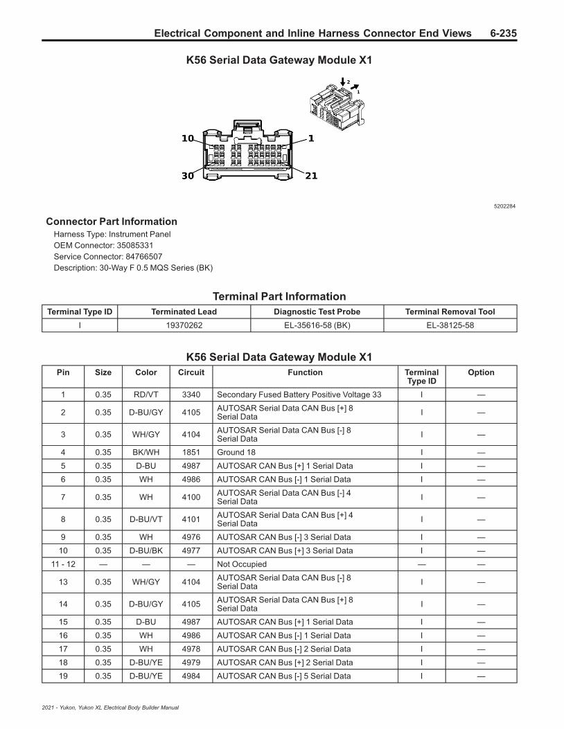
Electrical Component and Inline Harness Connector End Views 6-235
K56 Serial Data Gateway Module X1
5202284
Connector Part InformationHarness Type: Instrument PanelOEM Connector: 35085331Service Connector: 84766507Description: 30-Way F 0.5 MQS Series (BK)
Terminal Part InformationTerminal Type ID Terminated Lead Diagnostic Test Probe Terminal Removal Tool
I 19370262 EL-35616-58 (BK) EL-38125-58
K56 Serial Data Gateway Module X1Pin Size Color Circuit Function Terminal
Type IDOption
1 0.35 RD/VT 3340 Secondary Fused Battery Positive Voltage 33 I —
2 0.35 D-BU/GY 4105 AUTOSAR Serial Data CAN Bus [+] 8Serial Data I —
3 0.35 WH/GY 4104 AUTOSAR Serial Data CAN Bus [-] 8Serial Data I —
4 0.35 BK/WH 1851 Ground 18 I —
5 0.35 D-BU 4987 AUTOSAR CAN Bus [+] 1 Serial Data I —
6 0.35 WH 4986 AUTOSAR CAN Bus [-] 1 Serial Data I —
7 0.35 WH 4100 AUTOSAR Serial Data CAN Bus [-] 4Serial Data I —
8 0.35 D-BU/VT 4101 AUTOSAR Serial Data CAN Bus [+] 4Serial Data I —
9 0.35 WH 4976 AUTOSAR CAN Bus [-] 3 Serial Data I —
10 0.35 D-BU/BK 4977 AUTOSAR CAN Bus [+] 3 Serial Data I —
11 - 12 — — — Not Occupied — —
13 0.35 WH/GY 4104 AUTOSAR Serial Data CAN Bus [-] 8Serial Data I —
14 0.35 D-BU/GY 4105 AUTOSAR Serial Data CAN Bus [+] 8Serial Data I —
15 0.35 D-BU 4987 AUTOSAR CAN Bus [+] 1 Serial Data I —
16 0.35 WH 4986 AUTOSAR CAN Bus [-] 1 Serial Data I —
17 0.35 WH 4978 AUTOSAR CAN Bus [-] 2 Serial Data I —
18 0.35 D-BU/YE 4979 AUTOSAR CAN Bus [+] 2 Serial Data I —
19 0.35 D-BU/YE 4984 AUTOSAR CAN Bus [-] 5 Serial Data I —
2021 - Yukon, Yukon XL Electrical Body Builder Manual

6-236 Electrical Component and Inline Harness Connector End Views
K56 Serial Data Gateway Module X1 (cont'd)Pin Size Color Circuit Function Terminal
Type IDOption
20 0.35 D-BU/WH 4985 AUTOSAR CAN Bus [+] 5 Serial Data I —
21 - 26 — — — Not Occupied — —
27 0.35 WH 4978 AUTOSAR CAN Bus [-] 2 Serial Data I —
28 0.35 D-BU/YE 4979 AUTOSAR CAN Bus [+] 2 Serial Data I —
29 - 30 — — — Not Occupied — —
K56 Serial Data Gateway Module X2
5203942
Connector Part InformationHarness Type: Instrument PanelOEM Connector: 35094158Service Connector: 84766509Description: 30-Way F 0.5 MQS Series (BK with GY Terminal Position Assurance)
Terminal Part InformationTerminal Type ID Terminated Lead Diagnostic Test Probe Terminal Removal Tool
I 19370262 EL-35616-58 (BK) EL-38125-58
K56 Serial Data Gateway Module X2Pin Size Color Circuit Function Terminal
Type IDOption
1 - 4 — — — Not Occupied — —
5 0.35 BK/GY 3559 Passive Start Switch 2 Low Reference I —
6 — — — Not Occupied — —
7 0.35 L-GN/VT 5199 Run/Crank Relay Coil Control I —
8 — — — Not Occupied — —
9 0.35 YE/WH 4973 Ethernet Bus 1R [+] I —
10 0.35 YE 4972 Ethernet Bus 1R [-] I —
11 - 12 — — — Not Occupied — —
13 0.35 D-BU/BN 4983 AUTOSAR CAN Bus [+] 7 Serial Data I —
14 0.35 WH 4982 AUTOSAR CAN Bus [-] 7 Serial Data I —
15 0.35 L-GN/BK 3558 Ignition Mode Switch Signal 2 I —
16 0.35 WH 4980 AUTOSAR CAN Bus [-] 6 Serial Data I —
2021 - Yukon, Yukon XL Electrical Body Builder Manual

Electrical Component and Inline Harness Connector End Views 6-237
K56 Serial Data Gateway Module X2 (cont'd)Pin Size Color Circuit Function Terminal
Type IDOption
17 0.35 L-GN 2578 Private Serial Data Presentation CAN Bus [+] 1Serial Data I —
18 0.35 BN 2577 Private Serial Data Presentation CAN Bus [-] 1Serial Data I —
19 0.35 WH 7207 Ethernet Bus 1 Enable Signal I —
20 - 22 — — — Not Occupied — —
23 0.35 D-BU/WH 4985 AUTOSAR CAN Bus [+] 5 Serial Data I —
24 0.35 D-BU/YE 4984 AUTOSAR CAN Bus [-] 5 Serial Data I —
25 — — — Not Occupied — —
26 0.35 YE 4981 AUTOSAR CAN Bus [+] 6 Serial Data I —
27 0.35 VT 2580 Private Serial Data Presentation CAN Bus [+] 2Serial Data I —
28 0.35 GY 2579 Private Serial Data Presentation CAN Bus [-] 2Serial Data I —
29 0.35 L-GN/WH 4975 Ethernet Bus 1T [+] I —
30 0.35 L-GN 4974 Ethernet Bus 1T [-] I —
K56 Serial Data Gateway Module X3
4900333
Connector Part InformationHarness Type: Instrument PanelOEM Connector: 35077574Service Connector: 13519319Description: 30-Way F 0.5 MQS Series (BK with GY Terminal Position Assurance)
Terminal Part InformationTerminal Type ID Terminated Lead Diagnostic Test Probe Terminal Removal Tool
I 19370262 EL-35616-58 (BK) EL-38125-58
K56 Serial Data Gateway Module X3Pin Size Color Circuit Function Terminal
Type IDOption
1 - 6 — — — Not Occupied — —
2021 - Yukon, Yukon XL Electrical Body Builder Manual

6-238 Electrical Component and Inline Harness Connector End Views
K56 Serial Data Gateway Module X3 (cont'd)Pin Size Color Circuit Function Terminal
Type IDOption
70.350.35
D-BU/WHGY/WH
47587211
Ethernet Bus 2 [+]Ethernet Bus 4 [+]
II
(IOS/IOT/IOV)+IOV
IOR+UDA/IOR+UE1/IOR+UI3
80.350.35
D-BUGY
47577210
Ethernet Bus 2 [-]Ethernet Bus 4 [-]
II
(IOS/IOT/IOV)+IOV
IOR+UDA/IOR+UE1/IOR+UI3
9 0.35 D-BU/WH 4758 Ethernet Bus 2 [+] I —
10 0.35 D-BU 4757 Ethernet Bus 2 [-] I —
11 - 26 — — — Not Occupied — —
27 0.35 GY/D-BU 7217 Ethernet Bus 7 [+] I —
28 0.35 BN/D-BU 7216 Ethernet Bus 7 [-] I —
29 - 30 — — — Not Occupied — —
K60 Steering Column Lock Module
4017639
Connector Part InformationHarness Type: Instrument PanelOEM Connector: 33227522Service Connector: 19354223Description: 8-Way F Mini 50 Series (BK)
Terminal Part InformationTerminal Type ID Terminated Lead Diagnostic Test Probe Terminal Removal Tool
I Not Required EL-35616-58 (BK) No Tool Required
K60 Steering Column Lock ModulePin Size Color Circuit Function Terminal
Type IDOption
1 0.35 RD/GY 4140 Secondary Fused Battery Positive Voltage 41 I —
2 — — — Not Occupied — —
3 0.35 BK 1850 Ground 18 I —
4 0.35 D-BU 4987 AUTOSAR CAN Bus [+] 1 Serial Data I —
5 0.35 D-BU 4987 AUTOSAR CAN Bus [+] 1 Serial Data I —
2021 - Yukon, Yukon XL Electrical Body Builder Manual

Electrical Component and Inline Harness Connector End Views 6-239
K60 Steering Column Lock Module (cont'd)Pin Size Color Circuit Function Terminal
Type IDOption
6 0.35 WH 4986 AUTOSAR CAN Bus [-] 1 Serial Data I —
7 0.35 WH 4986 AUTOSAR CAN Bus [-] 1 Serial Data I —
8 0.35 D-BU/VT 807 Ignition Off/Accessory Ignition Voltage I —
K68 Trailer Lighting Control Module (U1D)
3638282
Connector Part InformationHarness Type: ChassisOEM Connector: 13655518Service Connector: 19303771Description: 38-Way F 1.5 CTS, 2.8 MCP, 4.8 MCP Series, Sealed (BK with BN Inner Connector)
Terminal Part InformationTerminal Type ID Terminated Lead Diagnostic Test Probe Terminal Removal Tool
I 13576374 J-35616-35 (VT) J-38125-557
II 19119560 J-35616-40 (BU) J-38125-556
III 19119560 J-35616-40 (BU) J-38125-556
IV 19301776 J-35616-14 (GN) J-38125-215A
K68 Trailer Lighting Control Module (U1D)Pin Size Color Circuit Function Terminal
Type IDOption
1 3 RD/VT 5640 Secondary Fused Battery Positive Voltage 56 III —
2 0.75 D-BU/WH 5186 Left Trailer Turn Signal Lamp Control IV —
3 0.75 YE/GY 5187 Right Trailer Turn Signal Lamp Control IV —
4 — — — Not Occupied — —
5 0.75 BN/GY 5184 Left Trailer Park Lamp Control IV —
6 — — — Not Occupied — —
7 0.75 L-GN/WH 5189 Trailer Backup Lamp Control IV —
8 - 9 — — — Not Occupied — —
10 0.5 VT/WH 1139 Run/Crank Ignition 1 Voltage 11 IV —
11 0.5 BN/YE 820 Center High Mounted Stop Lamp Supply Voltage IV —
12 — — — Not Occupied — —
2021 - Yukon, Yukon XL Electrical Body Builder Manual

6-240 Electrical Component and Inline Harness Connector End Views
K68 Trailer Lighting Control Module (U1D) (cont'd)Pin Size Color Circuit Function Terminal
Type IDOption
13 2.5 BK 2050 Ground 20 II —
14 - 26 — — — Not Occupied — —
27 0.5 D-BU/VT 4101 AUTOSAR Serial Data CAN Bus [+] 4Serial Data IV —
28 0.5 WH 4100 AUTOSAR Serial Data CAN Bus [-] 4Serial Data IV —
29 0.5 D-BU/VT 4101 AUTOSAR Serial Data CAN Bus [+] 4Serial Data IV —
30 0.5 WH 4100 AUTOSAR Serial Data CAN Bus [-] 4Serial Data IV —
31 - 37 — — — Not Occupied — —
38 2 RD/YE 5840 Secondary Fused Battery Positive Voltage 58 I —
K69 Transfer Case Control Module (NP0/NQH)
5199340
Connector Part InformationHarness Type: EngineOEM Connector: 33235465Service Connector: 84769286Description: 38-Way F 1.5, 2.8, 4.8 MCP Series, Sealed (BK with BN Inner Connector)
Terminal Part InformationTerminal Type ID Terminated Lead Diagnostic Test Probe Terminal Removal Tool
I 13576374 J-35616-35 (VT) J-38125-557
II 13582180 J-35616-14 (GN) J-38125-557
III 19119560 J-35616-40 (BU) J-38125-556
IV 19301776 J-35616-14 (GN) J-38125-215A
K69 Transfer Case Control Module (NP0/NQH)Pin Size Color Circuit Function Terminal
Type IDOption
1 2.5 RD/GY 1342 Primary Fused Battery Positive Voltage 13 III —
2 — — — Not Occupied — —
30.50.5
D-BU/YED-BU/YE
49794979
AUTOSAR CAN Bus [+] 2 Serial DataAUTOSAR CAN Bus [+] 2 Serial Data
IIIV
——
2021 - Yukon, Yukon XL Electrical Body Builder Manual

Electrical Component and Inline Harness Connector End Views 6-241
K69 Transfer Case Control Module (NP0/NQH) (cont'd)Pin Size Color Circuit Function Terminal
Type IDOption
40.50.5
WHWH
49784978
AUTOSAR CAN Bus [-] 2 Serial DataAUTOSAR CAN Bus [-] 2 Serial Data
IIIV
——
50.50.5
WH/L-GNWH/L-GN
74797479
Rotary Position Sensor SignalRotary Position Sensor Signal
IIIV
——
6 — — — Not Occupied — —
70.50.5
YEYE
74747474
Incremental Encoder Direction SignalIncremental Encoder Direction Signal
IVII
——
8 — — — Not Occupied — —
90.50.5
YE/WHYE/WH
16951695
4WD Locked Range Indicator Control4WD Locked Range Indicator Control
IVII
——
10 — — — Not Occupied — —
110.50.5
VT/GYVT/GY
80178017
Secondary Axle Motor Relay ControlSecondary Axle Motor Relay Control
IVII
——
120.50.5
GY/BKGY/BK
15701570
Front Axle Actuator ControlFront Axle Actuator Control
IIIV
——
13 2.5 YE/VT 1553 Transfer Case Motor Counter Clockwise Control III —
14 — — — Not Occupied — —
150.50.5
D-BU/YED-BU/YE
49794979
AUTOSAR CAN Bus [+] 2 Serial DataAUTOSAR CAN Bus [+] 2 Serial Data
IVII
——
160.50.5
WHWH
49784978
AUTOSAR CAN Bus [-] 2 Serial DataAUTOSAR CAN Bus [-] 2 Serial Data
IVII
——
17 — — — Not Occupied — —
180.50.5
VT/BKVT/BK
21392139
Run/Crank Ignition 1 Voltage 21Run/Crank Ignition 1 Voltage 21
IIIV
——
190.50.5
D-BU/GYD-BU/GY
74737473
Incremental Encoder Impulse SignalIncremental Encoder Impulse Signal
IIIV
——
200.50.5
WH/RDWH/RD
74777477
Gear Position Sensor 5V ReferenceGear Position Sensor 5V Reference
IIIV
——
21 - 23 — — — Not Occupied — —
240.50.5
BKBK
80158015
Transfer Case Motor Low ReferenceTransfer Case Motor Low Reference
IIIV
——
252.52.5
BKBK
4506550
Ground 4Propulsion Propulsion System
II
——
26 — — — Not Occupied — —
270.50.5
BKBK
80148014
Transfer Case Lock Solenoid Low ReferenceTransfer Case Lock Solenoid Low Reference
IIIV
——
28 - 29 — — — Not Occupied — —
300.50.5
YE/BKYE/BK
74787478
Gear Position Sensor Low ReferenceGear Position Sensor Low Reference
IVII
——
310.50.5
WH/L-GNWH/L-GN
74757475
Incremental Encoder Sensor 8V ReferenceIncremental Encoder Sensor 8V Reference
IVII
——
32 — — — Not Occupied — —
330.50.5
D-BUD-BU
80138013
Transfer Case Lock Solenoid Control 2Transfer Case Lock Solenoid Control 2
IVII
——
340.50.5
YE/BNYE/BN
15691569
Transfer Case Lock Solenoid Valve ControlTransfer Case Lock Solenoid Valve Control
IVII
——
35 — — — Not Occupied — —
2021 - Yukon, Yukon XL Electrical Body Builder Manual

6-242 Electrical Component and Inline Harness Connector End Views
K69 Transfer Case Control Module (NP0/NQH) (cont'd)Pin Size Color Circuit Function Terminal
Type IDOption
360.50.5
VTVT
74767476
Incremental Encoder Sensor Low ReferenceIncremental Encoder Sensor Low Reference
IVII
——
37 — — — Not Occupied — —
38 2.5 YE/GY 1552 Transfer Case Motor Clockwise Control I —
K71 Transmission Control Module
4024881
Connector Part InformationHarness Type: EngineOEM Connector: 33344977Service Connector: 19330900Description: 66-Way F 0.64, 2.8 Series, Sealed (BK with BK Terminal Position Assurance)
Terminal Part InformationTerminal Type ID Terminated Lead Diagnostic Test Probe Terminal Removal Tool
I 13575796 J-35616-35 (VT) J-38125-11A
II 19355819 J-35616-64B (LT BU) J-38125-215A
K71 Transmission Control ModulePin Size Color Circuit Function Terminal
Type IDOption
1 0.5 VT/WH 422 Torque Converter Clutch Solenoid Valve Control II —
2 0.5 GY/L-GN 6403 Clutch Solenoid Valve D Control II —
3 0.5 WH/D-BU 4507 Transmission Clutch H Control II —
4 0.5 WH 4508 Transmission Clutch G Control II —
5 - 6 — — — Not Occupied — —
7 0.5 YE/L-GN 4170 Transmission Output Shaft Speed Sensor Circuit9V Reference II —
8 0.5 YE/D-BU 4171 Transmission Input Shaft Speed Sensor Circuit9V Reference II —
9 - 11 — — — Not Occupied — —
12 0.5 L-GN/YE 6353 Input Speed Signal II —
13 0.5 L-GN/VT 4510 Transmission Intermediate Speed Signal II —
14 0.5 GY/D-BU 6358 Output Speed Signal II —
2021 - Yukon, Yukon XL Electrical Body Builder Manual
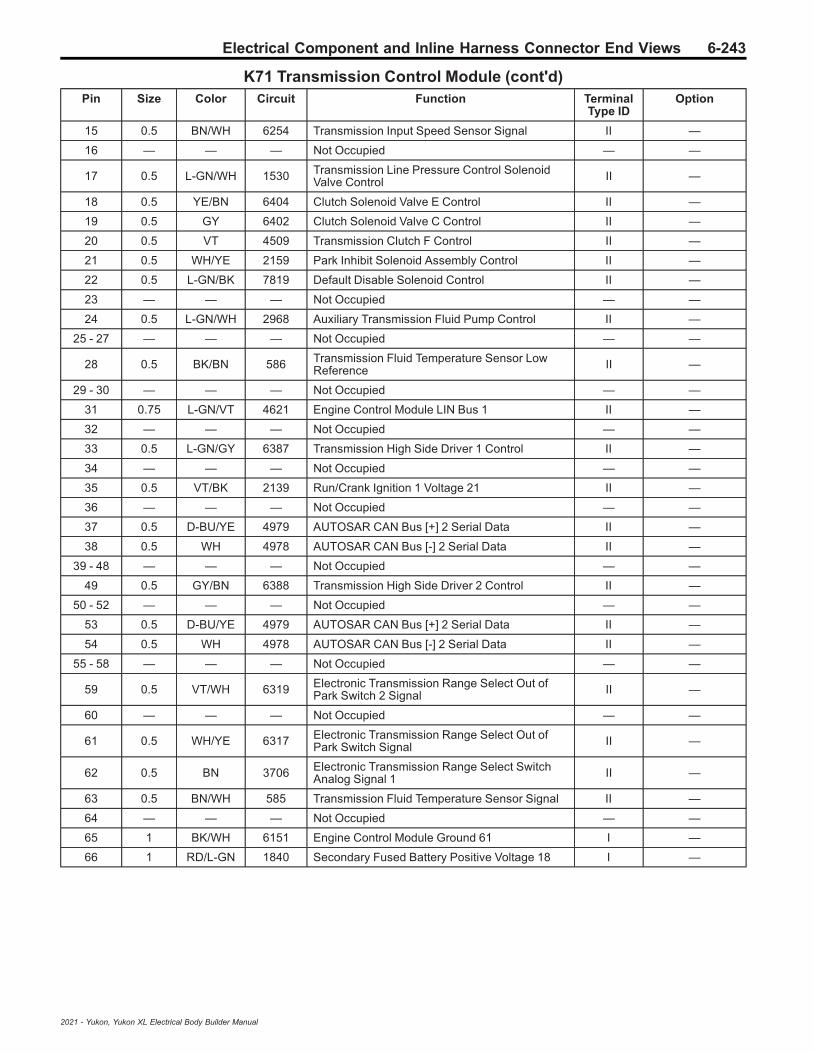
Electrical Component and Inline Harness Connector End Views 6-243
K71 Transmission Control Module (cont'd)Pin Size Color Circuit Function Terminal
Type IDOption
15 0.5 BN/WH 6254 Transmission Input Speed Sensor Signal II —
16 — — — Not Occupied — —
17 0.5 L-GN/WH 1530 Transmission Line Pressure Control SolenoidValve Control II —
18 0.5 YE/BN 6404 Clutch Solenoid Valve E Control II —
19 0.5 GY 6402 Clutch Solenoid Valve C Control II —
20 0.5 VT 4509 Transmission Clutch F Control II —
21 0.5 WH/YE 2159 Park Inhibit Solenoid Assembly Control II —
22 0.5 L-GN/BK 7819 Default Disable Solenoid Control II —
23 — — — Not Occupied — —
24 0.5 L-GN/WH 2968 Auxiliary Transmission Fluid Pump Control II —
25 - 27 — — — Not Occupied — —
28 0.5 BK/BN 586 Transmission Fluid Temperature Sensor LowReference II —
29 - 30 — — — Not Occupied — —
31 0.75 L-GN/VT 4621 Engine Control Module LIN Bus 1 II —
32 — — — Not Occupied — —
33 0.5 L-GN/GY 6387 Transmission High Side Driver 1 Control II —
34 — — — Not Occupied — —
35 0.5 VT/BK 2139 Run/Crank Ignition 1 Voltage 21 II —
36 — — — Not Occupied — —
37 0.5 D-BU/YE 4979 AUTOSAR CAN Bus [+] 2 Serial Data II —
38 0.5 WH 4978 AUTOSAR CAN Bus [-] 2 Serial Data II —
39 - 48 — — — Not Occupied — —
49 0.5 GY/BN 6388 Transmission High Side Driver 2 Control II —
50 - 52 — — — Not Occupied — —
53 0.5 D-BU/YE 4979 AUTOSAR CAN Bus [+] 2 Serial Data II —
54 0.5 WH 4978 AUTOSAR CAN Bus [-] 2 Serial Data II —
55 - 58 — — — Not Occupied — —
59 0.5 VT/WH 6319 Electronic Transmission Range Select Out ofPark Switch 2 Signal II —
60 — — — Not Occupied — —
61 0.5 WH/YE 6317 Electronic Transmission Range Select Out ofPark Switch Signal II —
62 0.5 BN 3706 Electronic Transmission Range Select SwitchAnalog Signal 1 II —
63 0.5 BN/WH 585 Transmission Fluid Temperature Sensor Signal II —
64 — — — Not Occupied — —
65 1 BK/WH 6151 Engine Control Module Ground 61 I —
66 1 RD/L-GN 1840 Secondary Fused Battery Positive Voltage 18 I —
2021 - Yukon, Yukon XL Electrical Body Builder Manual

6-244 Electrical Component and Inline Harness Connector End Views
K73 Telematics Communication Interface Control Module (UE1)
4496253
Connector Part InformationHarness Type: Instrument PanelOEM Connector: 33303954Service Connector: 13506123Description: 29-Way F 0.5 NANO, 1.2 MCON Series Sealed (BK)
Terminal Part InformationTerminal Type ID Terminated Lead Diagnostic Test Probe Terminal Removal Tool
I 19367551 J-35616-16 (LT GN) J-38125-215A
II 19370262 EL-35616-58 (BK) EL-38125-58
III 19371240 J-35616-16 (LT GN) J-38125-215A
K73 Telematics Communication Interface Control Module (UE1)Pin Size Color Circuit Function Terminal
Type IDOption
1 0.5 RD/D-BU 3240 Secondary Fused Battery Positive Voltage 32 I —
2 - 3 — — — Not Occupied — —
4 0.35 BK/WH 1451 Ground 14 III —
5 — — — Not Occupied — —
6 0.35 L-GN/BK 2515 Keypad Control III —
7 - 8 — — — Not Occupied — —
9 0.35 D-BU/YE 4984 AUTOSAR CAN Bus [-] 5 Serial Data II —
10 0.35 D-BU/WH 4985 AUTOSAR CAN Bus [+] 5 Serial Data II —
11 0.35 L-GN/WH 2514 Keypad Signal II —
12 — — — Not Occupied — —
13 0.35 Bare 1792 Low Reference 7 II —
14 0.35 BK/GY 5152 Voice Recognition Audio [-] Control II —
15 0.35 GY/YE 5149 Voice Recognition Audio Signal II —
16 0.35 D-BU/YE 4984 AUTOSAR CAN Bus [-] 5 Serial Data II —
17 0.35 D-BU/WH 4985 AUTOSAR CAN Bus [+] 5 Serial Data II —
18 0.35 WH/BK 4769 Emergency Call Backup Speaker [-] Control II —
19 0.35 YE/VT 2516 Keypad Green LED Control II —
20 — — — Not Occupied — —
21 0.35 BK/BN 654 Cellular Telephone Microphone Low Reference II —
22 0.35 D-BU 655 Cellular Telephone Microphone Signal II —
2021 - Yukon, Yukon XL Electrical Body Builder Manual

Electrical Component and Inline Harness Connector End Views 6-245
K73 Telematics Communication Interface Control Module (UE1) (cont'd)Pin Size Color Circuit Function Terminal
Type IDOption
23 - 24 — — — Not Occupied — —
25 0.35 GY/L-GN 4770 Emergency Call Backup Speaker [+] Control II —
26 0.35 BN/WH 2517 Keypad Red LED Control II —
27 0.35 GY 7210 Ethernet Bus 4 [-] II —
28 0.35 GY/WH 7211 Ethernet Bus 4 [+] II —
29 — — — Not Occupied — —
K77 Remote Control Door Lock Receiver (ATH)
2717162
Connector Part InformationHarness Type: BodyOEM Connector: 13969166Service Connector: 13587297Description: 4-Way F 0.64 Micro-Quadlock Series (BK)
Terminal Part InformationTerminal Type ID Terminated Lead Diagnostic Test Probe Terminal Removal Tool
I Not Required J-35616-64B (LT BU) No Tool Required
K77 Remote Control Door Lock Receiver (ATH)Pin Size Color Circuit Function Terminal
Type IDOption
1 0.5 RD/VT 2640 Secondary Fused Battery Positive Voltage 26 I —
2 0.5 L-GN/YE 2862 Body Control Module LIN Bus 16 I —
3 — — — Not Occupied — —
4 0.5 BK/WH 1351 Ground 13 I —
2021 - Yukon, Yukon XL Electrical Body Builder Manual
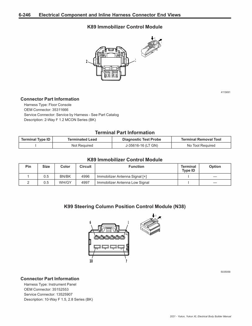
6-246 Electrical Component and Inline Harness Connector End Views
K89 Immobilizer Control Module
4115691
Connector Part InformationHarness Type: Floor ConsoleOEM Connector: 35311666Service Connector: Service by Harness - See Part CatalogDescription: 2-Way F 1.2 MCON Series (BK)
Terminal Part InformationTerminal Type ID Terminated Lead Diagnostic Test Probe Terminal Removal Tool
I Not Required J-35616-16 (LT GN) No Tool Required
K89 Immobilizer Control ModulePin Size Color Circuit Function Terminal
Type IDOption
1 0.5 BN/BK 4996 Immobilizer Antenna Signal [+] I —
2 0.5 WH/GY 4997 Immobilizer Antenna Low Signal I —
K99 Steering Column Position Control Module (N38)
5035058
Connector Part InformationHarness Type: Instrument PanelOEM Connector: 35152553Service Connector: 13525907Description: 10-Way F 1.5, 2.8 Series (BK)
2021 - Yukon, Yukon XL Electrical Body Builder Manual
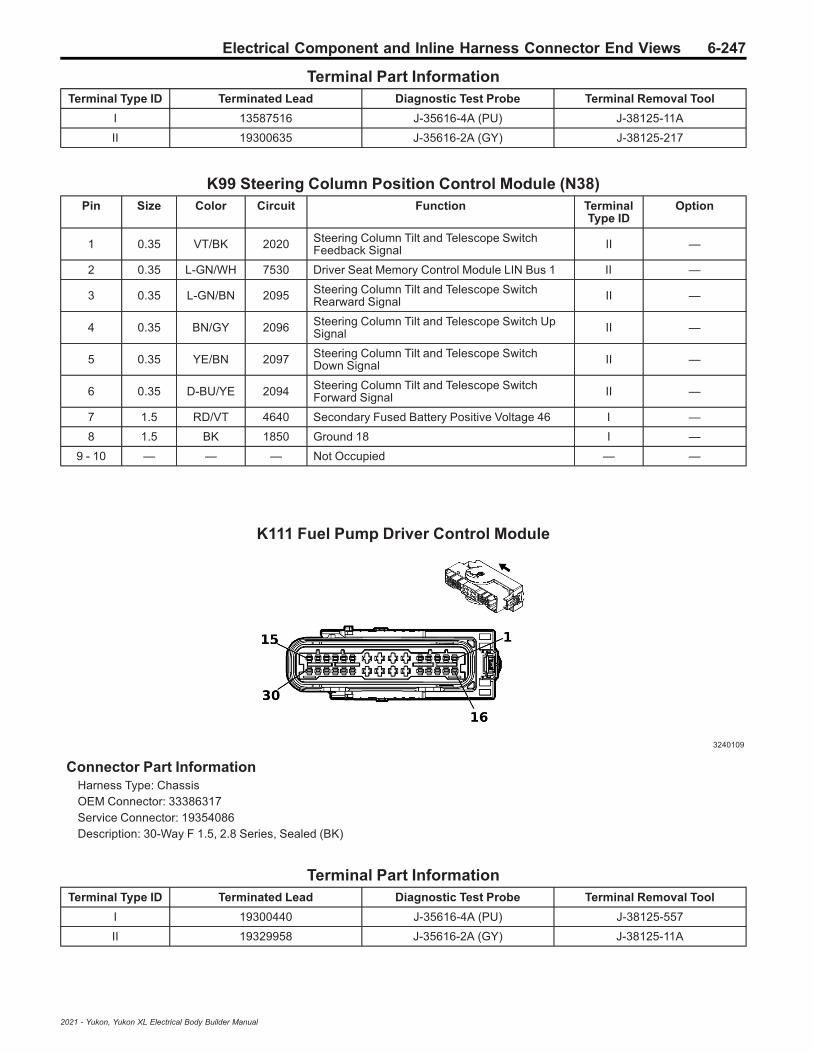
Electrical Component and Inline Harness Connector End Views 6-247
Terminal Part InformationTerminal Type ID Terminated Lead Diagnostic Test Probe Terminal Removal Tool
I 13587516 J-35616-4A (PU) J-38125-11A
II 19300635 J-35616-2A (GY) J-38125-217
K99 Steering Column Position Control Module (N38)Pin Size Color Circuit Function Terminal
Type IDOption
1 0.35 VT/BK 2020 Steering Column Tilt and Telescope SwitchFeedback Signal II —
2 0.35 L-GN/WH 7530 Driver Seat Memory Control Module LIN Bus 1 II —
3 0.35 L-GN/BN 2095 Steering Column Tilt and Telescope SwitchRearward Signal II —
4 0.35 BN/GY 2096 Steering Column Tilt and Telescope Switch UpSignal II —
5 0.35 YE/BN 2097 Steering Column Tilt and Telescope SwitchDown Signal II —
6 0.35 D-BU/YE 2094 Steering Column Tilt and Telescope SwitchForward Signal II —
7 1.5 RD/VT 4640 Secondary Fused Battery Positive Voltage 46 I —
8 1.5 BK 1850 Ground 18 I —
9 - 10 — — — Not Occupied — —
K111 Fuel Pump Driver Control Module
3240109
Connector Part InformationHarness Type: ChassisOEM Connector: 33386317Service Connector: 19354086Description: 30-Way F 1.5, 2.8 Series, Sealed (BK)
Terminal Part InformationTerminal Type ID Terminated Lead Diagnostic Test Probe Terminal Removal Tool
I 19300440 J-35616-4A (PU) J-38125-557
II 19329958 J-35616-2A (GY) J-38125-11A
2021 - Yukon, Yukon XL Electrical Body Builder Manual
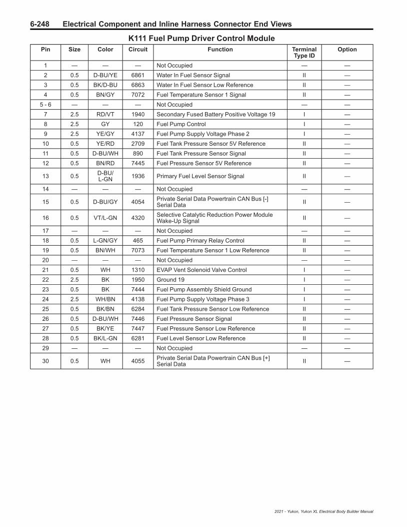
6-248 Electrical Component and Inline Harness Connector End Views
K111 Fuel Pump Driver Control ModulePin Size Color Circuit Function Terminal
Type IDOption
1 — — — Not Occupied — —
2 0.5 D-BU/YE 6861 Water In Fuel Sensor Signal II —
3 0.5 BK/D-BU 6863 Water In Fuel Sensor Low Reference II —
4 0.5 BN/GY 7072 Fuel Temperature Sensor 1 Signal II —
5 - 6 — — — Not Occupied — —
7 2.5 RD/VT 1940 Secondary Fused Battery Positive Voltage 19 I —
8 2.5 GY 120 Fuel Pump Control I —
9 2.5 YE/GY 4137 Fuel Pump Supply Voltage Phase 2 I —
10 0.5 YE/RD 2709 Fuel Tank Pressure Sensor 5V Reference II —
11 0.5 D-BU/WH 890 Fuel Tank Pressure Sensor Signal II —
12 0.5 BN/RD 7445 Fuel Pressure Sensor 5V Reference II —
13 0.5 D-BU/L-GN 1936 Primary Fuel Level Sensor Signal II —
14 — — — Not Occupied — —
15 0.5 D-BU/GY 4054 Private Serial Data Powertrain CAN Bus [-]Serial Data II —
16 0.5 VT/L-GN 4320 Selective Catalytic Reduction Power ModuleWake-Up Signal II —
17 — — — Not Occupied — —
18 0.5 L-GN/GY 465 Fuel Pump Primary Relay Control II —
19 0.5 BN/WH 7073 Fuel Temperature Sensor 1 Low Reference II —
20 — — — Not Occupied — —
21 0.5 WH 1310 EVAP Vent Solenoid Valve Control I —
22 2.5 BK 1950 Ground 19 I —
23 0.5 BK 7444 Fuel Pump Assembly Shield Ground I —
24 2.5 WH/BN 4138 Fuel Pump Supply Voltage Phase 3 I —
25 0.5 BK/BN 6284 Fuel Tank Pressure Sensor Low Reference II —
26 0.5 D-BU/WH 7446 Fuel Pressure Sensor Signal II —
27 0.5 BK/YE 7447 Fuel Pressure Sensor Low Reference II —
28 0.5 BK/L-GN 6281 Fuel Level Sensor Low Reference II —
29 — — — Not Occupied — —
30 0.5 WH 4055 Private Serial Data Powertrain CAN Bus [+]Serial Data II —
2021 - Yukon, Yukon XL Electrical Body Builder Manual

Electrical Component and Inline Harness Connector End Views 6-249
K115 Reductant Control Module (LM2)
3240110
Connector Part InformationHarness Type: DEF JumperOEM Connector: 13582126Service Connector: Service by Harness - See Part CatalogDescription: 38-Way F 1.5 CTS, 2.8 MCP, 4.8 MCP Series, Sealed (BK with BK Inner Connector)
Terminal Part InformationTerminalType ID
TerminatedLead
DiagnosticTest Probe
TerminalRemoval Tool
Service Terminal TrayName
CoreCrimp
InsulationCrimp
I NotRequired Not Available No Tool Required Not Required Not
RequiredNot
RequiredNot
Required
I NotRequired Not Available No Tool Required Not Required Not
RequiredNot
RequiredNot
Required
K115 Reductant Control Module (LM2)Pin Size Color Circuit Function Terminal
Type IDOption
1 2.5 RD/WH 2040 Secondary Fused Battery Positive Voltage 20 I —
2 0.5 VT/WH 3676 Diesel Exhaust Fluid Heating Tank 2 HeaterControl I —
3 — — — Not Occupied — —
4 0.5 WH/BN 3677 Diesel Exhaust Fluid Reservoir Heater Control I —
5 — — — Not Occupied — —
6 0.5 YE 3244 Diesel Exhaust Fluid Tank Temperature SensorSignal I —
7 0.5 VT 7290 Diesel Exhaust Fluid Sensor VoltageReference 1 I —
8 0.5 YE/GN 7284 Diesel Exhaust Fluid Liquid Quality TemperatureSignal I —
9 0.5 BK/YE 8434 Diesel Exhaust Fluid Sensor Low Reference I —
10 — — — Not Occupied — —
11 0.5 VT/WH 3876 Diesel Exhaust Fluid Smart Pump SupplyVoltage Phase 3 I —
12 — — — Not Occupied — —
13 0.75 BK 1650 Ground 16 I —
14 0.5 BN/GY 2936 Diesel Exhaust Fluid Heating Tank 2 HeaterControl Low I —
15 — — — Not Occupied — —
16 0.5 BU/BK 4318 Diesel Exhaust Fluid Tank Heater Low Control I —
2021 - Yukon, Yukon XL Electrical Body Builder Manual

6-250 Electrical Component and Inline Harness Connector End Views
K115 Reductant Control Module (LM2) (cont'd)Pin Size Color Circuit Function Terminal
Type IDOption
17 — — — Not Occupied — —
18 0.5 YE/GN 3245 Diesel Exhaust Fluid Tank Temperature SensorFeedback Signal I —
19 0.5 YE/RD 3106 Diesel Exhaust Fluid Pressure Sensor 5 VoltReference I —
20 0.5 BN/YE 3108 Diesel Exhaust Fluid Pressure Sensor Signal I —
21 0.5 BK/GN 3107 Diesel Exhaust Fluid Pressure Sensor LowReference I —
22 - 23 — — — Not Occupied — —
24 0.5 VT 3875 Diesel Exhaust Fluid Smart Pump SupplyVoltage Phase 2 I —
25 2.5 BK 1650 Ground 16 I —
26 0.5 YE/GY 3199 Diesel Exhaust Fluid Pressure Line HeaterControl I —
27 — — — Not Occupied — —
28 0.5 GN/BK 4319 Diesel Exhaust Fluid Line Heater Low Control I —
29 — — — Not Occupied — —
30 0.5 VT/BK 2139 Run/Crank Ignition 1 Voltage 21 I —
31 0.35 BU/BK 4977 AUTOSAR CAN Bus [+] 3 Serial Data I —
32 0.5 BU/BK 4977 AUTOSAR CAN Bus [+] 3 Serial Data I —
33 0.5 WH 4976 AUTOSAR CAN Bus [-] 3 Serial Data I —
34 0.5 WH 4976 AUTOSAR CAN Bus [-] 3 Serial Data I —
35 — — — Not Occupied — —
36 0.5 GY/BK 2937 Diesel Exhaust Fluid Pump Motor Stator LowReference I —
37 0.5 GY 3103 Diesel Exhaust Fluid Smart Pump Control I —
38 0.5 RD/WH 3440 Secondary Fused Battery Positive Voltage 34 I —
K133 Trailer Brake Power Control Module (JL1)
4624589
Connector Part InformationHarness Type: ChassisOEM Connector: 33297568Service Connector: 13599889Description: 16-Way F 1.5, 2.8 Series, Sealed (GY)
2021 - Yukon, Yukon XL Electrical Body Builder Manual
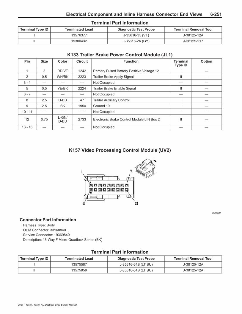
Electrical Component and Inline Harness Connector End Views 6-251
Terminal Part InformationTerminal Type ID Terminated Lead Diagnostic Test Probe Terminal Removal Tool
I 13576377 J-35616-35 (VT) J-38125-12A
II 19300432 J-35616-2A (GY) J-38125-217
K133 Trailer Brake Power Control Module (JL1)Pin Size Color Circuit Function Terminal
Type IDOption
1 3 RD/VT 1242 Primary Fused Battery Positive Voltage 12 I —
2 0.5 WH/BK 2223 Trailer Brake Apply Signal II —
3 - 4 — — — Not Occupied — —
5 0.5 YE/BK 2224 Trailer Brake Enable Signal II —
6 - 7 — — — Not Occupied — —
8 2.5 D-BU 47 Trailer Auxiliary Control I —
9 2.5 BK 1950 Ground 19 I —
10 - 11 — — — Not Occupied — —
12 0.75 L-GN/D-BU 2733 Electronic Brake Control Module LIN Bus 2 II —
13 - 16 — — — Not Occupied — —
K157 Video Processing Control Module (UV2)
4329088
Connector Part InformationHarness Type: BodyOEM Connector: 33168840Service Connector: 19369840Description: 18-Way F Micro-Quadlock Series (BK)
Terminal Part InformationTerminal Type ID Terminated Lead Diagnostic Test Probe Terminal Removal Tool
I 13575587 J-35616-64B (LT BU) J-38125-12A
II 13575859 J-35616-64B (LT BU) J-38125-12A
2021 - Yukon, Yukon XL Electrical Body Builder Manual

6-252 Electrical Component and Inline Harness Connector End Views
K157 Video Processing Control Module (UV2)Pin Size Color Circuit Function Terminal
Type IDOption
1 - 2 — — — Not Occupied — —
3 0.5 BK/WH 1351 Ground 13 II —
4 - 9 — — — Not Occupied — —
10 0.5 RD/VT 1640 Secondary Fused Battery Positive Voltage 16 II —
11 - 12 — — — Not Occupied — —
13 0.5 WH 4986 AUTOSAR CAN Bus [-] 1 Serial Data II —
14 0.35 WH 4986 AUTOSAR CAN Bus [-] 1 Serial Data I —
15 0.5 D-BU 4987 AUTOSAR CAN Bus [+] 1 Serial Data II —
16 0.35 D-BU 4987 AUTOSAR CAN Bus [+] 1 Serial Data I —
17 - 18 — — — Not Occupied — —
K160 Brake System Control Module
4162046
Connector Part InformationHarness Type: BodyOEM Connector: 33222138Service Connector: 19333026Description: 46-Way F 1.2 OCS, 2.8, 4.8 CTS Series, Sealed (GY)
Terminal Part InformationTerminal Type ID Terminated Lead Diagnostic Test Probe Terminal Removal Tool
I 19333088 J-35616-35 (VT) J-38125-212
II 19370818 J-35616-16 (LT GN) J-38125-559
III 19371240 J-35616-16 (LT GN) J-38125-215A
IV 84634921 J-35616-42 (RD) J-38125-215A
K160 Brake System Control ModulePin Size Color Circuit Function Terminal
Type IDOption
1 6 BK 150 Ground 1 IV —
2 2.5 WH 2001 Left Park Brake Motor Apply Control I —
3 2.5 GY/BK 4369 Left Park Brake Motor Low Reference I —
4 0.5 GY/WH 7064 Left Front Wheel Speed Sensor Control III —
2021 - Yukon, Yukon XL Electrical Body Builder Manual

Electrical Component and Inline Harness Connector End Views 6-253
K160 Brake System Control Module (cont'd)Pin Size Color Circuit Function Terminal
Type IDOption
5 0.5 GY 830 Left Front Wheel Speed Sensor Signal III —
6 - 8 — — — Not Occupied — —
9 0.5 VT/WH 639 Run/Crank Ignition 1 Voltage 6 III —
10 0.5 GY/BN 7065 Right Front Wheel Speed Sensor Control III —
11 0.5 YE 872 Right Front Wheel Speed Sensor Signal III —
12 2.5 L-GN/VT 1988 Right Park Brake Motor Apply Control I —
13 2.5 GY 4368 Right Park Brake Motor Low Reference I —
14 6 RD/YE 442 Primary Fused Battery Positive Voltage 4 IV —
15 0.5 GY/BK 7127 Left Rear Wheel Speed Sensor Control III —
16 0.5 D-BU 884 Left Rear Wheel Speed Sensor Signal III —
17 0.35 D-BU/YE 4979 AUTOSAR CAN Bus [+] 2 Serial Data III —
18 0.35 D-BU/YE 4979 AUTOSAR CAN Bus [+] 2 Serial Data III —
19 0.5 L-GN/GY 817 Vehicle Speed Signal 4 III —
20 - 22 — — — Not Occupied — —
23 0.5 L-GN/YE 2731 Electronic Brake Control Module LIN Bus 1 III —
24 — — — Not Occupied — —
25 0.35 WH 4986 AUTOSAR CAN Bus [-] 1 Serial Data III —
26 0.35 WH 4986 AUTOSAR CAN Bus [-] 1 Serial Data III —
27 — — — Not Occupied — —
28 0.5 GY/YE 7128 Right Rear Wheel Speed Sensor Control III —
29 0.5 VT 882 Right Rear Wheel Speed Sensor Signal III —
30 6 BK 150 Ground 1 IV —
31 - 32 — — — Not Occupied — —
33 0.35 WH 4978 AUTOSAR CAN Bus [-] 2 Serial Data III —
34 0.35 WH 4978 AUTOSAR CAN Bus [-] 2 Serial Data III —
35 0.75 L-GN/D-BU 2733 Electronic Brake Control Module LIN Bus 2 II —
36 0.5 WH/BK 2223 Trailer Brake Apply Signal III —
37 0.5 YE/BK 2224 Trailer Brake Enable Signal III —
38 0.5 L-GN/GY 333 Brake Fluid Level Switch Signal III —
39 0.75 BN/D-BU 1602 Front Brake Pad Wear Sensor Signal II —
40 — — — Not Occupied — —
41 0.35 D-BU 4987 AUTOSAR CAN Bus [+] 1 Serial Data III —
42 0.35 D-BU 4987 AUTOSAR CAN Bus [+] 1 Serial Data III —
43 — — — Not Occupied — —
44 0.75 L-GN/YE 1616 Rear Brake Pad Wear Sensor Signal II —
45 — — — Not Occupied — —
46 6 RD/WH 1642 Primary Fused Battery Positive Voltage 16 IV —
2021 - Yukon, Yukon XL Electrical Body Builder Manual

6-254 Electrical Component and Inline Harness Connector End Views
K171 Hands-Free Liftgate Sensor Control Module (QT8)
4210809
Connector Part InformationHarness Type: Rear FasciaOEM Connector: 33390897Service Connector: Service by Harness - See Part CatalogDescription: 4-Way F 1.2 MCON-CB Series, Sealed (BK)
Terminal Part InformationTerminal Type ID Terminated Lead Diagnostic Test Probe Terminal Removal Tool
I Not Required J-35616-16 (LT GN) No Tool Required
K171 Hands-Free Liftgate Sensor Control Module (QT8)Pin Size Color Circuit Function Terminal
Type IDOption
1 0.5 BK 1450 Ground 14 I —
2 — — — Not Occupied — —
3 0.5 L-GN/D-BU 2856 Body Control Module LIN Bus 10 I —
4 0.5 RD/GY 4840 Secondary Fused Battery Positive Voltage 48 I —
K175 Center Console Compartment Cooler Control Module (DCK)
4862126
Connector Part InformationHarness Type: Floor ConsoleOEM Connector: 35327305
2021 - Yukon, Yukon XL Electrical Body Builder Manual
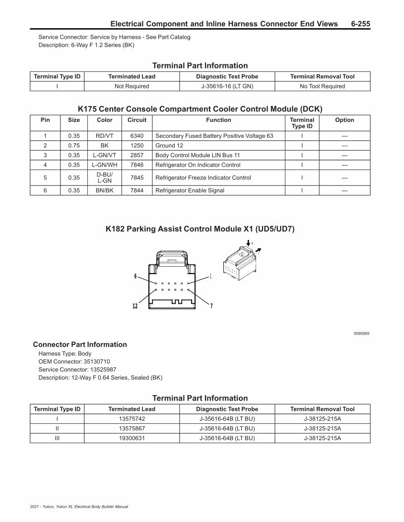
Electrical Component and Inline Harness Connector End Views 6-255
Service Connector: Service by Harness - See Part CatalogDescription: 6-Way F 1.2 Series (BK)
Terminal Part InformationTerminal Type ID Terminated Lead Diagnostic Test Probe Terminal Removal Tool
I Not Required J-35616-16 (LT GN) No Tool Required
K175 Center Console Compartment Cooler Control Module (DCK)Pin Size Color Circuit Function Terminal
Type IDOption
1 0.35 RD/VT 6340 Secondary Fused Battery Positive Voltage 63 I —
2 0.75 BK 1250 Ground 12 I —
3 0.35 L-GN/VT 2857 Body Control Module LIN Bus 11 I —
4 0.35 L-GN/WH 7846 Refrigerator On Indicator Control I —
5 0.35 D-BU/L-GN 7845 Refrigerator Freeze Indicator Control I —
6 0.35 BN/BK 7844 Refrigerator Enable Signal I —
K182 Parking Assist Control Module X1 (UD5/UD7)
5095565
Connector Part InformationHarness Type: BodyOEM Connector: 35130710Service Connector: 13525987Description: 12-Way F 0.64 Series, Sealed (BK)
Terminal Part InformationTerminal Type ID Terminated Lead Diagnostic Test Probe Terminal Removal Tool
I 13575742 J-35616-64B (LT BU) J-38125-215A
II 13575867 J-35616-64B (LT BU) J-38125-215A
III 19300631 J-35616-64B (LT BU) J-38125-215A
2021 - Yukon, Yukon XL Electrical Body Builder Manual
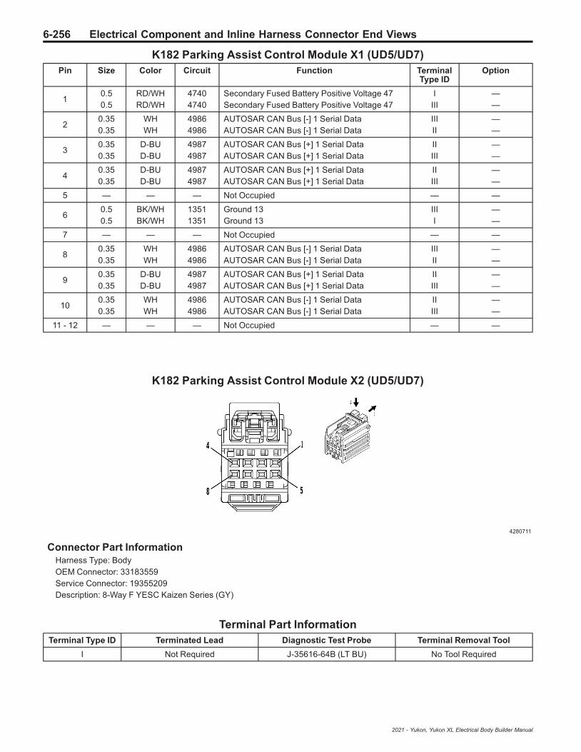
6-256 Electrical Component and Inline Harness Connector End Views
K182 Parking Assist Control Module X1 (UD5/UD7)Pin Size Color Circuit Function Terminal
Type IDOption
10.50.5
RD/WHRD/WH
47404740
Secondary Fused Battery Positive Voltage 47Secondary Fused Battery Positive Voltage 47
IIII
——
20.350.35
WHWH
49864986
AUTOSAR CAN Bus [-] 1 Serial DataAUTOSAR CAN Bus [-] 1 Serial Data
IIIII
——
30.350.35
D-BUD-BU
49874987
AUTOSAR CAN Bus [+] 1 Serial DataAUTOSAR CAN Bus [+] 1 Serial Data
IIIII
——
40.350.35
D-BUD-BU
49874987
AUTOSAR CAN Bus [+] 1 Serial DataAUTOSAR CAN Bus [+] 1 Serial Data
IIIII
——
5 — — — Not Occupied — —
60.50.5
BK/WHBK/WH
13511351
Ground 13Ground 13
IIII
——
7 — — — Not Occupied — —
80.350.35
WHWH
49864986
AUTOSAR CAN Bus [-] 1 Serial DataAUTOSAR CAN Bus [-] 1 Serial Data
IIIII
——
90.350.35
D-BUD-BU
49874987
AUTOSAR CAN Bus [+] 1 Serial DataAUTOSAR CAN Bus [+] 1 Serial Data
IIIII
——
100.350.35
WHWH
49864986
AUTOSAR CAN Bus [-] 1 Serial DataAUTOSAR CAN Bus [-] 1 Serial Data
IIIII
——
11 - 12 — — — Not Occupied — —
K182 Parking Assist Control Module X2 (UD5/UD7)
4280711
Connector Part InformationHarness Type: BodyOEM Connector: 33183559Service Connector: 19355209Description: 8-Way F YESC Kaizen Series (GY)
Terminal Part InformationTerminal Type ID Terminated Lead Diagnostic Test Probe Terminal Removal Tool
I Not Required J-35616-64B (LT BU) No Tool Required
2021 - Yukon, Yukon XL Electrical Body Builder Manual

Electrical Component and Inline Harness Connector End Views 6-257
K182 Parking Assist Control Module X2 (UD5/UD7)Pin Size Color Circuit Function Terminal
Type IDOption
1 — — — Not Occupied — —
2 0.5 YE/WH 2377 Right Rear Middle Parking Assist Sensor Signal I —
3 0.5 YE 2375 Left Rear Outer Parking Assist Sensor Signal I —
4 0.5 BN/WH 2374 Object Sensor Supply Voltage I —
5 0.5 YE/VT 2378 Right Rear Outer Parking Assist Sensor Signal I —
6 0.5 YE/D-BU 2376 Left Rear Middle Parking Assist Sensor Signal I —
7 — — — Not Occupied — —
8 0.5 BK/GY 2379 Object Sensor Low Reference I —
K182 Parking Assist Control Module X3 (UD5/UD7)
4547098
Connector Part InformationHarness Type: BodyOEM Connector: 35014564Service Connector: 19354933Description: 14-Way F 0.64 Kaizen Series (BU)
Terminal Part InformationTerminal Type ID Terminated Lead Diagnostic Test Probe Terminal Removal Tool
I 19300631 J-35616-64B (LT BU) J-38125-215A
K182 Parking Assist Control Module X3 (UD5/UD7)Pin Size Color Circuit Function Terminal
Type IDOption
1 - 4 — — — Not Occupied — —
5 0.5 YE/GY 5216 Left Front Middle Parking Assist Sensor I —
6 0.5 WH/GY 5217 Right Front Outer Parking Assist Sensor I —
7 0.5 BN 6581 Front Parking Assist Display Control I —
8 - 10 — — — Not Occupied — —
11 0.5 VT/WH 5215 Left Front Outer Parking Assist Sensor I —
12 0.5 VT/GY 5218 Right Front Middle Parking Assist Sensor I —
13 — — — Not Occupied — —
14 0.5 BK/D-BU 5214 Front Parking Assist Sensor Low Reference I —
2021 - Yukon, Yukon XL Electrical Body Builder Manual
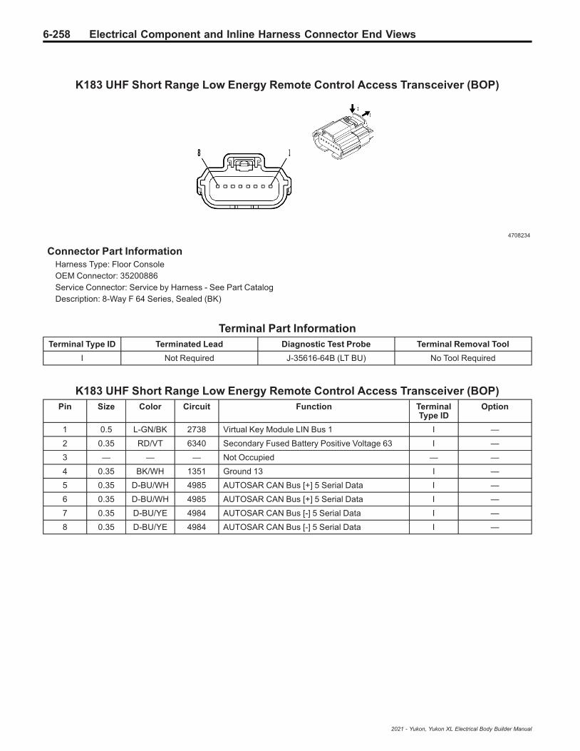
6-258 Electrical Component and Inline Harness Connector End Views
K183 UHF Short Range Low Energy Remote Control Access Transceiver (BOP)
4708234
Connector Part InformationHarness Type: Floor ConsoleOEM Connector: 35200886Service Connector: Service by Harness - See Part CatalogDescription: 8-Way F 64 Series, Sealed (BK)
Terminal Part InformationTerminal Type ID Terminated Lead Diagnostic Test Probe Terminal Removal Tool
I Not Required J-35616-64B (LT BU) No Tool Required
K183 UHF Short Range Low Energy Remote Control Access Transceiver (BOP)Pin Size Color Circuit Function Terminal
Type IDOption
1 0.5 L-GN/BK 2738 Virtual Key Module LIN Bus 1 I —
2 0.35 RD/VT 6340 Secondary Fused Battery Positive Voltage 63 I —
3 — — — Not Occupied — —
4 0.35 BK/WH 1351 Ground 13 I —
5 0.35 D-BU/WH 4985 AUTOSAR CAN Bus [+] 5 Serial Data I —
6 0.35 D-BU/WH 4985 AUTOSAR CAN Bus [+] 5 Serial Data I —
7 0.35 D-BU/YE 4984 AUTOSAR CAN Bus [-] 5 Serial Data I —
8 0.35 D-BU/YE 4984 AUTOSAR CAN Bus [-] 5 Serial Data I —
2021 - Yukon, Yukon XL Electrical Body Builder Manual
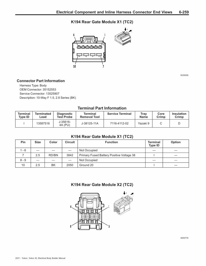
Electrical Component and Inline Harness Connector End Views 6-259
K194 Rear Gate Module X1 (TC2)
5035058
Connector Part InformationHarness Type: BodyOEM Connector: 35152553Service Connector: 13525907Description: 10-Way F 1.5, 2.8 Series (BK)
Terminal Part InformationTerminalType ID
TerminatedLead
DiagnosticTest Probe
TerminalRemoval Tool
Service Terminal TrayName
CoreCrimp
InsulationCrimp
I 13587516 J-35616-4A (PU) J-38125-11A 7116-4112-02 Yazaki 9 C D
K194 Rear Gate Module X1 (TC2)Pin Size Color Circuit Function Terminal
Type IDOption
1 - 6 — — — Not Occupied — —
7 2.5 RD/BN 3842 Primary Fused Battery Positive Voltage 38 I —
8 - 9 — — — Not Occupied — —
10 2.5 BK 2050 Ground 20 I —
K194 Rear Gate Module X2 (TC2)
4935776
2021 - Yukon, Yukon XL Electrical Body Builder Manual

6-260 Electrical Component and Inline Harness Connector End Views
Connector Part InformationHarness Type: BodyOEM Connector: 15526972Service Connector: 19370429Description: 8-Way F 0.64 OCS Series (BK)
Terminal Part InformationTerminalType ID
TerminatedLead
DiagnosticTest Probe
TerminalRemoval Tool
Service Terminal TrayName
CoreCrimp
InsulationCrimp
I NotRequired
J-35616-64B(LT BU) No Tool Required Not Required Not
RequiredNot
RequiredNot
Required
K194 Rear Gate Module X2 (TC2)Pin Size Color Circuit Function Terminal
Type IDOption
1 — — — Not Occupied — —
2 0.35 WH 4100 AUTOSAR Serial Data CAN Bus [-] 4Serial Data I —
3 0.35 WH 4100 AUTOSAR Serial Data CAN Bus [-] 4Serial Data I —
4 0.35 D-BU/VT 4101 AUTOSAR Serial Data CAN Bus [+] 4Serial Data I —
5 — — — Not Occupied — —
6 0.35 D-BU/VT 4101 AUTOSAR Serial Data CAN Bus [+] 4Serial Data I —
7 0.35 WH 4100 AUTOSAR Serial Data CAN Bus [-] 4Serial Data I —
8 0.35 D-BU/VT 4101 AUTOSAR Serial Data CAN Bus [+] 4Serial Data I —
K194 Rear Gate Module X4 (TC2)
4115730
Connector Part InformationHarness Type: BodyOEM Connector: 35029309Service Connector: 13533121Description: 16-Way F 1.2 Series (BK)
2021 - Yukon, Yukon XL Electrical Body Builder Manual

Electrical Component and Inline Harness Connector End Views 6-261
Terminal Part InformationTerminalType ID
TerminatedLead
DiagnosticTest Probe
TerminalRemoval Tool
Service Terminal TrayName
CoreCrimp
InsulationCrimp
I 19371240 J-35616-16(LT GN) J-38125-215A Not Available Not
AvailableNot
AvailableNot
Available
II - J-35616-13 (BU) - Not Available Not
AvailableNot
AvailableNot
Available
K194 Rear Gate Module X4 (TC2)Pin Size Color Circuit Function Terminal
Type IDOption
1 1 BN 4681 Rear Closure Cinch Latch Motor Cinch Control I —
2 - 3 — — — Not Occupied — —
4 0.35 GY/VT 4678 Rear Closure Latch Unlatch Status II —
5 — — — Not Occupied — —
6 0.35 WH/L-GN 8084 Rear Closure Latch Neutral Status II —
7 0.5 GY/BK 4654 Rear Closure Object Sensor Signal II —
8 0.35 GY/WH 4658 Rear Closure Switch LED Control II —
9 1 D-BU/GY 4682 Rear Closure Cinch Latch Motor ReleaseControl I —
10 0.35 BK/VT 4656 Rear Closure Object Sensor Low Reference II —
11 - 12 — — — Not Occupied — —
13 0.35 YE/BK 8085 Rear Closure Latch Primary Status II —
14 0.35 GY/L-GN 6190 Liftgate Window/Rear Compartment Lid, ExteriorUnlatch Signal II —
15 — — — Not Occupied — —
16 0.35 L-GN 4657 Rear Closure Switch Signal II —
K212 Electronic Transmission Shift Control Pushbutton Circuit Board
4231339
Connector Part InformationHarness Type: Instrument PanelOEM Connector: 33167777Service Connector: 13596105Description: 20-Way F Mini 50 Series (BK)
2021 - Yukon, Yukon XL Electrical Body Builder Manual

6-262 Electrical Component and Inline Harness Connector End Views
Terminal Part InformationTerminal Type ID Terminated Lead Diagnostic Test Probe Terminal Removal Tool
I 19333221 EL-35616-58 (BK) EL-38125-58
K212 Electronic Transmission Shift Control Pushbutton Circuit BoardPin Size Color Circuit Function Terminal
Type IDOption
1 0.35 D-BU/BK 4977 AUTOSAR CAN Bus [+] 3 Serial Data I —
2 0.35 D-BU/BK 4977 AUTOSAR CAN Bus [+] 3 Serial Data I —
3 0.35 WH 4976 AUTOSAR CAN Bus [-] 3 Serial Data I —
4 0.35 WH 4976 AUTOSAR CAN Bus [-] 3 Serial Data I —
5 0.35 WH 4055 Private Serial Data Powertrain CAN Bus [+]Serial Data I —
6 0.35 WH 4055 Private Serial Data Powertrain CAN Bus [+]Serial Data I —
7 0.35 D-BU/GY 4054 Private Serial Data Powertrain CAN Bus [-]Serial Data I —
8 0.35 D-BU/GY 4054 Private Serial Data Powertrain CAN Bus [-]Serial Data I —
9 0.35 RD/L-GN 5140 Secondary Fused Battery Positive Voltage 51 I —
10 — — — Not Occupied — —
11 0.35 L-GN/D-BU 3738 Tap Up/Tap Down Switch Signal 2 I —
12 0.35 BK 1050 Ground 10 I —
13 - 15 — — — Not Occupied — —
16 0.35 VT/L-GN 4320 Selective Catalytic Reduction Power ModuleWake-Up Signal I —
17 0.35 VT/WH 639 Run/Crank Ignition 1 Voltage 6 I —
18 - 19 — — — Not Occupied — —
20 0.35 BK 1050 Ground 10 I —
K214 Trailer Tire Pressure Indicator Module (PTT)
2173574
Connector Part InformationHarness Type: Rear FasciaOEM Connector: 13679454Service Connector: Service by Harness - See Part CatalogDescription: 4-Way F 0.64 Micro-Quadlock Series, Sealed (BK)
2021 - Yukon, Yukon XL Electrical Body Builder Manual
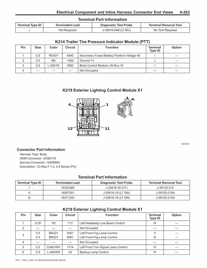
Electrical Component and Inline Harness Connector End Views 6-263
Terminal Part InformationTerminal Type ID Terminated Lead Diagnostic Test Probe Terminal Removal Tool
I Not Required J-35616-64B (LT BU) No Tool Required
K214 Trailer Tire Pressure Indicator Module (PTT)Pin Size Color Circuit Function Terminal
Type IDOption
1 0.5 RD/GY 4840 Secondary Fused Battery Positive Voltage 48 I —
2 0.5 BK 1450 Ground 14 I —
3 0.5 L-GN/YE 2862 Body Control Module LIN Bus 16 I —
4 — — — Not Occupied — —
K219 Exterior Lighting Control Module X1
5203784
Connector Part InformationHarness Type: BodyOEM Connector: 33382115Service Connector: 13509990Description: 12-Way F 1.2, 2.8 Series (PU)
Terminal Part InformationTerminal Type ID Terminated Lead Diagnostic Test Probe Terminal Removal Tool
I 19332366 J-35616-35 (VT) J-38125-212
II 19367551 J-35616-16 (LT GN) J-38125-215A
III 19371240 J-35616-16 (LT GN) J-38125-215A
K219 Exterior Lighting Control Module X1Pin Size Color Circuit Function Terminal
Type IDOption
1 0.35 YE 712 Left Headlamp Low Beam Control III —
2 — — — Not Occupied — —
30.50.5
BN/GYBN/GY
50615061
Left Front Fog Lamp ControlLeft Front Fog Lamp Control
IIIII
——
4 — — — Not Occupied — —
5 0.5 D-BU/WH 1314 Left Front Turn Signal Lamp Control III —
6 0.5 L-GN/WH 24 Backup Lamp Control III —
2021 - Yukon, Yukon XL Electrical Body Builder Manual

6-264 Electrical Component and Inline Harness Connector End Views
K219 Exterior Lighting Control Module X1 (cont'd)Pin Size Color Circuit Function Terminal
Type IDOption
7 0.5 WH/L-GN 5966 Approach Lamp Control III —
8 0.5 YE/GY 122 Rear Fog Lamp Control III —
9 1 RD/VT 7140 Secondary Fused Battery Positive Voltage 71 I —
10 0.5 BN/D-BU 6993 Left Rear Park Lamp Control I —
11 - 12 — — — Not Occupied — —
K219 Exterior Lighting Control Module X2
5203807
Connector Part InformationHarness Type: BodyOEM Connector: 33382136Service Connector: 84766289Description: 25-Way F 0.5 MQS, 2.8 MCP Series (GY)
Terminal Part InformationTerminal Type ID Terminated Lead Diagnostic Test Probe Terminal Removal Tool
I 19332366 J-35616-35 (VT) J-38125-212
II 19370262 EL-35616-58 (BK) EL-38125-58
K219 Exterior Lighting Control Module X2Pin Size Color Circuit Function Terminal
Type IDOption
1 0.35 L-GN/YE 6846 Rear License Plate Lamp Control II —
2 0.35 L-GN/WH 2270 Rear Window Washer Relay Control II —
3 0.35 BN/GY 2268 Windshield Washer Relay Control II —
4 0.35 D-BU/BN 38 Backup Lamp Relay Control II —
5 - 8 — — — Not Occupied — —
9 0.35 VT/L-GN 10130 Auxiliary Center Stack Display BacklightDimming Control II —
10 0.35 BN/L-GN 196 Windshield Wiper Motor Park Switch Signal II —
11 0.35 VT/BK 6568 Front Turn Signal Lamp Feedback Signal II —
12 0.35 GY 91 Windshield Wiper Motor Relay Coil Control II —
13 — — — Not Occupied — —
2021 - Yukon, Yukon XL Electrical Body Builder Manual

Electrical Component and Inline Harness Connector End Views 6-265
K219 Exterior Lighting Control Module X2 (cont'd)Pin Size Color Circuit Function Terminal
Type IDOption
14 0.35 VT 185 Low Washer Fluid Indicator Control II —
15 - 18 — — — Not Occupied — —
19 0.35 WH/BN 7055 Auxiliary Park Lamp Relay Control II —
20 0.35 WH/YE 7545 Right Front Turn Signal Lamp Feedback Signal II —
21 0.35 WH/VT 860 Windshield Wiper Switch High Signal II —
220.5
0.75RD/L-GNRD/L-GN
77407740
Secondary Fused Battery Positive Voltage 77Secondary Fused Battery Positive Voltage 77
II
——
230.5
0.75RD/D-BURD/D-BU
840840
Secondary Fused Battery Positive Voltage 8Secondary Fused Battery Positive Voltage 8
II
——
24 - 25 — — — Not Occupied — —
K219 Exterior Lighting Control Module X3
5203797
Connector Part InformationHarness Type: BodyOEM Connector: 33382116Service Connector: 13509989Description: 12-Way F 1.2, 2.8 Series (GN)
Terminal Part InformationTerminal Type ID Terminated Lead Diagnostic Test Probe Terminal Removal Tool
I 19332366 J-35616-35 (VT) J-38125-212
II 19371240 J-35616-16 (LT GN) J-38125-215A
K219 Exterior Lighting Control Module X3Pin Size Color Circuit Function Terminal
Type IDOption
1 0.5 VT 8866 Police Liftgate Strobe Control II —
2 0.5 BN/L-GN 5062 Right Front Fog Lamp Control II —
3 — — — Not Occupied — —
4 0.5 YE 312 Right Headlamp Low Beam Control II —
5 — — — Not Occupied — —
6 0.5 D-BU/VT 1335 Right Rear Turn Signal Lamp Control 2 II —
2021 - Yukon, Yukon XL Electrical Body Builder Manual

6-266 Electrical Component and Inline Harness Connector End Views
K219 Exterior Lighting Control Module X3 (cont'd)Pin Size Color Circuit Function Terminal
Type IDOption
7 0.5 L-GN/WH 1324 Backup Lamp Control 2 II —
8 — — — Not Occupied — —
90.5
0.75RD/D-BURD/D-BU
540540
Secondary Fused Battery Positive Voltage 5Secondary Fused Battery Positive Voltage 5
II
——
100.5
0.75RD/BNRD/BN
14401440
Secondary Fused Battery Positive Voltage 14Secondary Fused Battery Positive Voltage 14
II
——
11 — — — Not Occupied — —
12 0.5 BN/GY 6995 Right Rear Park Lamp Control I —
K219 Exterior Lighting Control Module X4
5203416
Connector Part InformationHarness Type: BodyOEM Connector: 33381951Service Connector: 13509977Description: 25-Way F 0.5 MQS, 2.8 MCP Series (PU)
Terminal Part InformationTerminal Type ID Terminated Lead Diagnostic Test Probe Terminal Removal Tool
I 19332366 J-35616-35 (VT) J-38125-212
II 19370262 EL-35616-58 (BK) EL-38125-58
K219 Exterior Lighting Control Module X4Pin Size Color Circuit Function Terminal
Type IDOption
1 - 2 — — — Not Occupied — —
3 0.35 D-BU/YE 4979 AUTOSAR CAN Bus [+] 2 Serial Data II —
4 0.35 WH 4978 AUTOSAR CAN Bus [-] 2 Serial Data II —
5 0.35 D-BU/YE 4979 AUTOSAR CAN Bus [+] 2 Serial Data II —
6 0.35 WH 4978 AUTOSAR CAN Bus [-] 2 Serial Data II —
7 0.35 WH/D-BU 6311 Cruise/ETC/TCC Brake Signal II —
8 0.35 VT/YE 8868 Police Liftgate Strobe Enable 1 Signal II —
9 0.35 VT/L-GN 8869 Police Liftgate Strobe Rear On OFF Control II —
2021 - Yukon, Yukon XL Electrical Body Builder Manual

Electrical Component and Inline Harness Connector End Views 6-267
K219 Exterior Lighting Control Module X4 (cont'd)Pin Size Color Circuit Function Terminal
Type IDOption
10 0.35 WH 4978 AUTOSAR CAN Bus [-] 2 Serial Data II —
11 0.35 D-BU/YE 4979 AUTOSAR CAN Bus [+] 2 Serial Data II —
12 0.35 D-BU/L-GN 8864 Police Tail Lamp Red/Red Alternate Flash
Enable Signal II —
13 0.35 GY/L-GN 8865 Police Tail Lamp Red/White Alternate FlashEnable Signal II —
14 0.35 L-GN 8863 Police High Beam Alternate Flash Enable Signal II —
15 0.35 VT/D-BU 4001 Left Rear Door Lock Switch Lock Control II —
16 0.35 WH/YE 4002 Left Rear Door Lock Switch Unlock Control II —
17 0.35 L-GN/BN 4003 Right Rear Door Lock Switch Lock Control II —
18 0.35 D-BU/GY 4004 Right Rear Door Lock Switch Unlock Control II —
19 0.35 GY/WH 10137 Radio Audio Mute Police Signal II —
20 0.35 D-BU/YE 2279 Liftgate Window Ajar Switch Signal II —
21 0.35 VT/GY 1303 Liftgate Ajar Switch Signal 1 II —
220.5
0.75RD/BNRD/BN
11401140
Secondary Fused Battery Positive Voltage 11Secondary Fused Battery Positive Voltage 11
II
——
23 1 BK/WH 1151 Ground 11 I —
24 1 RD/L-GN 1540 Secondary Fused Battery Positive Voltage 15 I —
25 1 BK/WH 1151 Ground 11 I —
K219 Exterior Lighting Control Module X5
5203373
Connector Part InformationHarness Type: BodyOEM Connector: 33381952Service Connector: 13509983Description: 29-Way F 0.5 NANO, 1.2 MCON Series Sealed (BU)
Terminal Part InformationTerminal Type ID Terminated Lead Diagnostic Test Probe Terminal Removal Tool
I 19367551 J-35616-16 (LT GN) J-38125-215A
II 19369846 J-35616-16 (LT GN) J-38125-215A
III 19370262 EL-35616-58 (BK) EL-38125-58
IV 19371240 J-35616-16 (LT GN) J-38125-215A
2021 - Yukon, Yukon XL Electrical Body Builder Manual

6-268 Electrical Component and Inline Harness Connector End Views
K219 Exterior Lighting Control Module X5Pin Size Color Circuit Function Terminal
Type IDOption
10.50.5
GY/D-BUGY/D-BU
75387538
Left Front DRL ControlLeft Front DRL Control
IIV
——
20.50.5
D-BU/L-GND-BU/L-GN
12531253
Right Front Park Lamp ControlRight Front Park Lamp Control
IVII
——
30.50.5
GY/YEGY/YE
75427542
Left Rear Stop Lamp ControlLeft Rear Stop Lamp Control
IVI
——
40.50.5
WH/YEWH/YE
75417541
Right Rear Stop Lamp ControlRight Rear Stop Lamp Control
IIV
——
50.50.5
D-BU/BND-BU/BN
75397539
Right Front DRL ControlRight Front DRL Control
IIV
——
60.50.5
WH/YEWH/YE
12541254
Left Front Park Lamp ControlLeft Front Park Lamp Control
IVII
——
70.50.5
L-GN/VTL-GN/VT
13151315
Right Front Turn Signal Lamp ControlRight Front Turn Signal Lamp Control
IVI
——
80.50.5
D-BU/WHD-BU/WH
13341334
Left Rear Turn Signal Lamp Control 2Left Rear Turn Signal Lamp Control 2
IVI
——
9 0.35 L-GN/GY 2115 Right Turn Signal Lamp Control 2 III —
10 0.35 WH/GY 2114 Left Turn Signal Lamp Control 2 III —
11 0.35 GY 1715 Windshield Wiper Switch High Signal III —
13 0.35 L-GN/BN 319 Right Rear Trailer Stop/Turn Lamp Control III —
14 — — — Not Occupied — —
15 0.35 GY/L-GN 6190 Liftgate Window/Rear Compartment Lid, ExteriorUnlatch Signal III —
16 0.35 WH 311 Right Headlamp High Beam Control III —
17 — — — Not Occupied — —
18 0.35 VT/WH 1139 Run/Crank Ignition 1 Voltage 11 III —
20 - 22 — — — Not Occupied — —
23 0.35 WH/VT 6567 Rear Turn Signal Lamp Feedback Signal III —
24 0.35 WH/BK 7544 Right Rear Turn Signal Lamp Feedback Signal III —
25 0.35 BN/YE 820 Center High Mounted Stop Lamp Supply Voltage III —
26 - 27 — — — Not Occupied — —
28 0.35 WH 711 Left Headlamp High Beam Control III —
29 0.35 YE/D-BU 318 Left Rear Trailer Stop/Turn Lamp Control III —
2021 - Yukon, Yukon XL Electrical Body Builder Manual

Electrical Component and Inline Harness Connector End Views 6-269
M8 Blower Motor
4650258
Connector Part InformationHarness Type: Instrument PanelOEM Connector: 33395154Service Connector: 19356432Description: 6-Way F 0.64, 6.3 Series (BK)
Terminal Part InformationTerminal Type ID Terminated Lead Diagnostic Test Probe Terminal Removal Tool
I Not Required J-35616-42 (RD) No Tool Required
II Not Required J-35616-64B (LT BU) No Tool Required
M8 Blower MotorPin Size Color Circuit Function Terminal
Type IDOption
1 5 RD/GY 2042 Primary Fused Battery Positive Voltage 20 I —
2 0.35 D-BU/GY 754 Blower Motor Speed Control II —
3 0.35 L-GN/D-BU 761 Blower Speed Feedback Signal II —
4 - 5 — — — Not Occupied — —
6 5 BK 1050 Ground 10 I —
M10 Charge Air Cooler Coolant Pump (LM2)
4997613
2021 - Yukon, Yukon XL Electrical Body Builder Manual

6-270 Electrical Component and Inline Harness Connector End Views
Connector Part InformationHarness Type: EngineOEM Connector: 33230781Service Connector: 19371209Description: 4-Way F 2.8 CTS Series, Sealed (BK)
Terminal Part InformationTerminal Type ID Terminated Lead Diagnostic Test Probe Terminal Removal Tool
I Not Required J-35616-35 (VT) No Tool Required
M10 Charge Air Cooler Coolant Pump (LM2)Pin Size Color Circuit Function Terminal
Type IDOption
1 0.75 BK 6550 Propulsion Propulsion System I —
2 0.75 BK 9000 — I —
3 0.75 L-GN/VT 4621 Engine Control Module LIN Bus 1 I —
4 0.75 VT/D-BU 5294 Powertrain Main Relay Fused Supply 5 I —
M26 Front Axle Engagement Actuator (NP0/NQH)
4210809
Connector Part InformationHarness Type: Front AxleOEM Connector: 33390897Service Connector: Service by Harness - See Part CatalogDescription: 4-Way F 1.2 MCON-CB Series, Sealed (BK)
Terminal Part InformationTerminal Type ID Terminated Lead Diagnostic Test Probe Terminal Removal Tool
I Not Required J-35616-16 (LT GN) No Tool Required
M26 Front Axle Engagement Actuator (NP0/NQH)Pin Size Color Circuit Function Terminal
Type IDOption
1 0.5 VT/BK 2139 Run/Crank Ignition 1 Voltage 21 I —
2 0.5 GY/BK 1570 Front Axle Actuator Control I —
3 0.5 YE/WH 1695 4WD Locked Range Indicator Control I —
2021 - Yukon, Yukon XL Electrical Body Builder Manual

Electrical Component and Inline Harness Connector End Views 6-271
M26 Front Axle Engagement Actuator (NP0/NQH) (cont'd)Pin Size Color Circuit Function Terminal
Type IDOption
4 0.5 BK 4450 Ground 44 I —
M32 Differential Clutch Pump (G96)
5202126
Connector Part InformationHarness Type: Differential Lock JumperOEM Connector: 33131692Service Connector: Service by Harness - See Part CatalogDescription: 11-Way F 1.2 Multilock, 2.8 SLK Series, Sealed (BK)
Terminal Part InformationTerminal Type ID Terminated Lead Diagnostic Test Probe Terminal Removal Tool
I Not Required J-35616-16 (LT GN) No Tool Required
II Not Required J-35616-4A (PU) No Tool Required
M32 Differential Clutch Pump (G96)Pin Size Color Circuit Function Terminal
Type IDOption
1 — — — Not Occupied — —
2 2.5 YE/WH 7969 Axle Differential Lock Control Low II —
3 2.5 GY/BN 7968 Axle Differential Lock Control High II —
4 0.5 WH/RD 7973 Axle Differential Lock Motor Position SensorHigh Reference I —
5 0.5 D-BU/WH 7978 Axle Differential Lock Motor Temperature SensorSignal I —
6 0.5 L-GN/BN 7975 Axle Differential Lock Motor Position SensorSignal 1 I —
7 0.5 WH 7971 Axle Differential Lock Motor Brake Control High I —
8 0.5 BK/YE 7977 Axle Differential Lock Motor Temperature SensorLow Reference I —
9 0.5 BK/VT 7974 Axle Differential Lock Motor Position SensorLow Reference I —
10 0.5 GY 7976 Axle Differential Lock Motor Position SensorSignal 2 I —
11 0.5 VT/BK 7972 Axle Differential Lock Motor Brake Control Low I —
2021 - Yukon, Yukon XL Electrical Body Builder Manual

6-272 Electrical Component and Inline Harness Connector End Views
M45 Rear Wiper Motor
5215435
Connector Part InformationHarness Type: LiftgateOEM Connector: 35340169Service Connector: Service by Harness - See Part CatalogDescription: 3-Way F 2.8 YESC Series (GY)
Terminal Part InformationTerminal Type ID Terminated Lead Diagnostic Test Probe Terminal Removal Tool
I Not Required J-35616-4A (PU) No Tool Required
M45 Rear Wiper MotorPin Size Color Circuit Function Terminal
Type IDOption
1 0.75 BK 2050 Ground 20 I —
2 0.35 L-GN/D-BU 2856 Body Control Module LIN Bus 10 I —
3 0.75 RD/YE 3040 Secondary Fused Battery Positive Voltage 30 I —
M64 Starter Motor X1 (L84/L87)
4992524
2021 - Yukon, Yukon XL Electrical Body Builder Manual
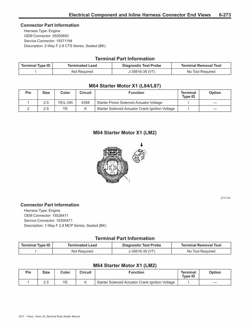
Electrical Component and Inline Harness Connector End Views 6-273
Connector Part InformationHarness Type: EngineOEM Connector: 35050650Service Connector: 19371194Description: 2-Way F 2.8 CTS Series, Sealed (BK)
Terminal Part InformationTerminal Type ID Terminated Lead Diagnostic Test Probe Terminal Removal Tool
I Not Required J-35616-35 (VT) No Tool Required
M64 Starter Motor X1 (L84/L87)Pin Size Color Circuit Function Terminal
Type IDOption
1 2.5 YE/L-GN 4358 Starter Pinion Solenoid Actuator Voltage I —
2 2.5 YE 6 Starter Solenoid Actuator Crank Ignition Voltage I —
M64 Starter Motor X1 (LM2)
2717134
Connector Part InformationHarness Type: EngineOEM Connector: 15526411Service Connector: 19300471Description: 1-Way F 2.8 MCP Series, Sealed (BK)
Terminal Part InformationTerminal Type ID Terminated Lead Diagnostic Test Probe Terminal Removal Tool
I Not Required J-35616-35 (VT) No Tool Required
M64 Starter Motor X1 (LM2)Pin Size Color Circuit Function Terminal
Type IDOption
1 2.5 YE 6 Starter Solenoid Actuator Crank Ignition Voltage I —
2021 - Yukon, Yukon XL Electrical Body Builder Manual

6-274 Electrical Component and Inline Harness Connector End Views
M74D Window Motor - Driver
2282932
Connector Part InformationHarness Type: Driver DoorOEM Connector: 15504732Service Connector: Service by Harness - See Part CatalogDescription: 7-Way F 0.64, 2.8 Kaizen Timer Series, Sealed (GY)
Terminal Part InformationTerminal Type ID Terminated Lead Diagnostic Test Probe Terminal Removal Tool
I Not Required J-35616-4A (PU) No Tool Required
II Not Required J-35616-64B (LT BU) No Tool Required
M74D Window Motor - DriverPin Size Color Circuit Function Terminal
Type IDOption
1 2.5 BK 1150 Ground 11 I —
2 2.5 RD/GY 3540 Secondary Fused Battery Positive Voltage 35 I —
3 0.35 GY/L-GN 2763 Window Switch Left Front Up Signal II —
4 0.35 L-GN/YE 6134 Body Control Module LIN Bus 3 II —
5 0.35 L-GN 2766 Power Window Switch Left Front Express Signal II —
6 0.35 GY 745 Left Front Door Ajar Switch Signal II —
7 0.35 WH/BN 2764 Window Switch Left Front Down Signal II —
M74LR Window Motor - Left Rear
2716333
2021 - Yukon, Yukon XL Electrical Body Builder Manual

Electrical Component and Inline Harness Connector End Views 6-275
Connector Part InformationHarness Type: Left Rear DoorOEM Connector: 13863838Service Connector: Service by Harness - See Part CatalogDescription: 2-Way F 2.8 Series, Sealed (BK)
Terminal Part InformationTerminal Type ID Terminated Lead Diagnostic Test Probe Terminal Removal Tool
I Not Required J-35616-35 (VT) No Tool Required
M74LR Window Motor - Left RearPin Size Color Circuit Function Terminal
Type IDOption
1 2 D-BU/VT 668 Left Rear Window Motor Up Control I —
2 2 YE/D-BU 669 Left Rear Window Motor Down Control I —
M74P Window Motor - Passenger
2282932
Connector Part InformationHarness Type: Passenger DoorOEM Connector: 15504732Service Connector: Service by Harness - See Part CatalogDescription: 7-Way F 0.64, 2.8 Kaizen Timer Series, Sealed (GY)
Terminal Part InformationTerminal Type ID Terminated Lead Diagnostic Test Probe Terminal Removal Tool
I Not Required J-35616-4A (PU) No Tool Required
II Not Required J-35616-64B (LT BU) No Tool Required
M74P Window Motor - PassengerPin Size Color Circuit Function Terminal
Type IDOption
1 2.5 BK 1250 Ground 12 I —
2 2.5 RD/BN 4240 Secondary Fused Battery Positive Voltage 42 I —
3 0.35 L-GN 1184 Window Switch Right Front Up Signal II —
4 0.35 L-GN/YE 6134 Body Control Module LIN Bus 3 II —
2021 - Yukon, Yukon XL Electrical Body Builder Manual
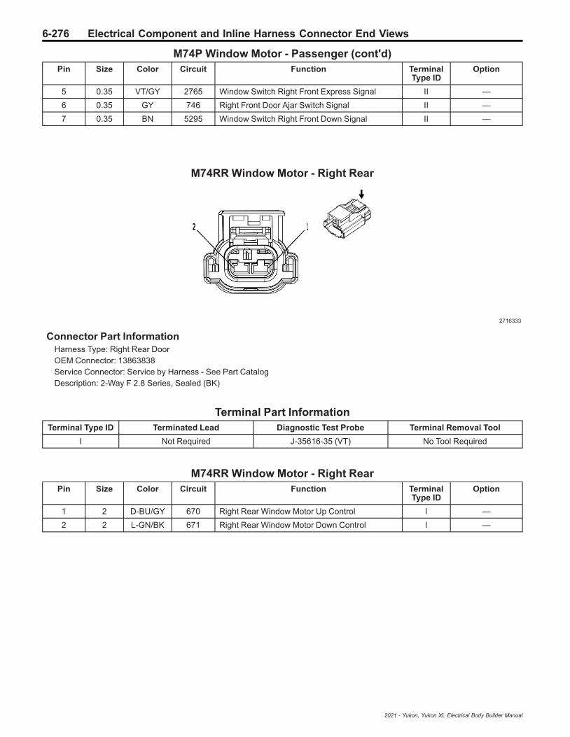
6-276 Electrical Component and Inline Harness Connector End Views
M74P Window Motor - Passenger (cont'd)Pin Size Color Circuit Function Terminal
Type IDOption
5 0.35 VT/GY 2765 Window Switch Right Front Express Signal II —
6 0.35 GY 746 Right Front Door Ajar Switch Signal II —
7 0.35 BN 5295 Window Switch Right Front Down Signal II —
M74RR Window Motor - Right Rear
2716333
Connector Part InformationHarness Type: Right Rear DoorOEM Connector: 13863838Service Connector: Service by Harness - See Part CatalogDescription: 2-Way F 2.8 Series, Sealed (BK)
Terminal Part InformationTerminal Type ID Terminated Lead Diagnostic Test Probe Terminal Removal Tool
I Not Required J-35616-35 (VT) No Tool Required
M74RR Window Motor - Right RearPin Size Color Circuit Function Terminal
Type IDOption
1 2 D-BU/GY 670 Right Rear Window Motor Up Control I —
2 2 L-GN/BK 671 Right Rear Window Motor Down Control I —
2021 - Yukon, Yukon XL Electrical Body Builder Manual

Electrical Component and Inline Harness Connector End Views 6-277
M75 Windshield Wiper Motor
2474722
Connector Part InformationHarness Type: BodyOEM Connector: 13941663Service Connector: 19367598Description: 4-Way F Junior Power Timer Series (BK)
Terminal Part InformationTerminal Type ID Terminated Lead Diagnostic Test Probe Terminal Removal Tool
I Not Required J-35616-4A (PU) No Tool Required
M75 Windshield Wiper MotorPin Size Color Circuit Function Terminal
Type IDOption
1 2 WH 92 Windshield Wiper Motor High Speed Control I —
2 2 YE/BN 95 Windshield Wiper Motor Low Speed Control I —
3 0.35 BN/L-GN 196 Windshield Wiper Motor Park Switch Signal I —
4 2 BK 150 Ground 1 I —
M103 Turbocharger Vane Position Actuator
3338689
Connector Part InformationHarness Type: EngineOEM Connector: 13943325
2021 - Yukon, Yukon XL Electrical Body Builder Manual

6-278 Electrical Component and Inline Harness Connector End Views
Service Connector: 19119351Description: 5-Way F 1.2 MCON-LL Series, Sealed (BK)
Terminal Part InformationTerminal Type ID Terminated Lead Diagnostic Test Probe Terminal Removal Tool
I Not Required J-35616-16 (LT GN) No Tool Required
M103 Turbocharger Vane Position ActuatorPin Size Color Circuit Function Terminal
Type IDOption
1 0.75 WH/BN 1313 Variable Geometry Turbocharger PositionSensor Motor Open Control I —
2 0.5 VT/YE 5947 Turbocharger Vane Position Sensor Signal I —
3 0.5 BK/L-GN 580 Engine Control Sensors Low Reference 2 I —
4 0.5 D-BU/RD 460 Engine Control Sensors 5 Volt Reference 1 I —
5 0.75 GY/BK 1330 Variable Geometry Turbocharger PositionSensor Motor Close Control I —
M104L Park Brake Actuator - Left
4992524
Connector Part InformationHarness Type: Chassis Rear ExtensionOEM Connector: 13532979Service Connector: Service by Harness - See Part CatalogDescription: 2-Way F 2.8 CTS Series, Sealed (BK)
Terminal Part InformationTerminal Type ID Terminated Lead Diagnostic Test Probe Terminal Removal Tool
I Not Required J-35616-35 (VT) No Tool Required
M104L Park Brake Actuator - LeftPin Size Color Circuit Function Terminal
Type IDOption
1 2.5 WH 2001 Left Park Brake Motor Apply Control I —
2 2.5 GY/BK 4369 Left Park Brake Motor Low Reference I —
2021 - Yukon, Yukon XL Electrical Body Builder Manual

Electrical Component and Inline Harness Connector End Views 6-279
M104R Park Brake Actuator - Right
4992524
Connector Part InformationHarness Type: Chassis Rear ExtensionOEM Connector: 13532979Service Connector: Service by Harness - See Part CatalogDescription: 2-Way F 2.8 CTS Series, Sealed (BK)
Terminal Part InformationTerminal Type ID Terminated Lead Diagnostic Test Probe Terminal Removal Tool
I Not Required J-35616-35 (VT) No Tool Required
M104R Park Brake Actuator - RightPin Size Color Circuit Function Terminal
Type IDOption
1 2.5 GN/VT 1988 Right Park Brake Motor Apply Control I —
2 2.5 GY 4368 Right Park Brake Motor Low Reference I —
M106 Exhaust Flow Control Valve Actuator (LM2)
4997783
Connector Part InformationHarness Type: EngineOEM Connector: 35026727Service Connector: 19371195Description: 5-Way F 1.2 MCON-CB Series, Sealed (BK)
2021 - Yukon, Yukon XL Electrical Body Builder Manual

6-280 Electrical Component and Inline Harness Connector End Views
Terminal Part InformationTerminal Type ID Terminated Lead Diagnostic Test Probe Terminal Removal Tool
I Not Required J-35616-16 (LT GN) No Tool Required
M106 Exhaust Flow Control Valve Actuator (LM2)Pin Size Color Circuit Function Terminal
Type IDOption
1 0.5 BK/YE 548 Engine Control Sensors Low Reference 1 I —
2 0.5 BN/L-GN 4305 Exhaust Flow Control Valve 1 I —
3 0.5 D-BU/RD 460 Engine Control Sensors 5 Volt Reference 1 I —
4 0.5 BN 1421 Exhaust Restrictor Motor Closed Control I —
5 0.5 YE/BN 1420 Exhaust Restrictor Motor Open Control I —
P12 Horn
2792100
Connector Part InformationHarness Type: BodyOEM Connector: 13828712Service Connector: 19352068Description: 2-Way F 1.5 Series, Sealed (BK)
Terminal Part InformationTerminal Type ID Terminated Lead Diagnostic Test Probe Terminal Removal Tool
I Not Required J-35616-14 (GN) No Tool Required
P12 HornPin Size Color Circuit Function Terminal
Type IDOption
1 0.75 BK 250 Ground 2 I —
2 0.75 BN/GY 29 Horn Control I —
2021 - Yukon, Yukon XL Electrical Body Builder Manual
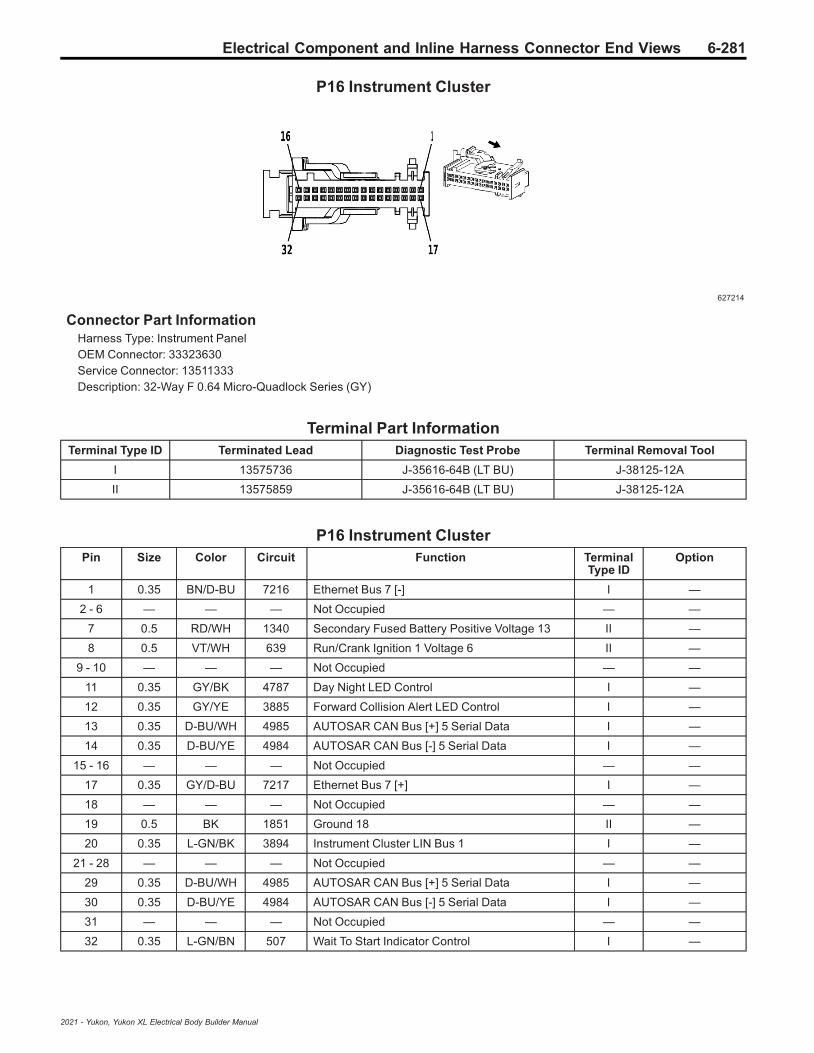
Electrical Component and Inline Harness Connector End Views 6-281
P16 Instrument Cluster
627214
Connector Part InformationHarness Type: Instrument PanelOEM Connector: 33323630Service Connector: 13511333Description: 32-Way F 0.64 Micro-Quadlock Series (GY)
Terminal Part InformationTerminal Type ID Terminated Lead Diagnostic Test Probe Terminal Removal Tool
I 13575736 J-35616-64B (LT BU) J-38125-12A
II 13575859 J-35616-64B (LT BU) J-38125-12A
P16 Instrument ClusterPin Size Color Circuit Function Terminal
Type IDOption
1 0.35 BN/D-BU 7216 Ethernet Bus 7 [-] I —
2 - 6 — — — Not Occupied — —
7 0.5 RD/WH 1340 Secondary Fused Battery Positive Voltage 13 II —
8 0.5 VT/WH 639 Run/Crank Ignition 1 Voltage 6 II —
9 - 10 — — — Not Occupied — —
11 0.35 GY/BK 4787 Day Night LED Control I —
12 0.35 GY/YE 3885 Forward Collision Alert LED Control I —
13 0.35 D-BU/WH 4985 AUTOSAR CAN Bus [+] 5 Serial Data I —
14 0.35 D-BU/YE 4984 AUTOSAR CAN Bus [-] 5 Serial Data I —
15 - 16 — — — Not Occupied — —
17 0.35 GY/D-BU 7217 Ethernet Bus 7 [+] I —
18 — — — Not Occupied — —
19 0.5 BK 1851 Ground 18 II —
20 0.35 L-GN/BK 3894 Instrument Cluster LIN Bus 1 I —
21 - 28 — — — Not Occupied — —
29 0.35 D-BU/WH 4985 AUTOSAR CAN Bus [+] 5 Serial Data I —
30 0.35 D-BU/YE 4984 AUTOSAR CAN Bus [-] 5 Serial Data I —
31 — — — Not Occupied — —
32 0.35 L-GN/BN 507 Wait To Start Indicator Control I —
2021 - Yukon, Yukon XL Electrical Body Builder Manual
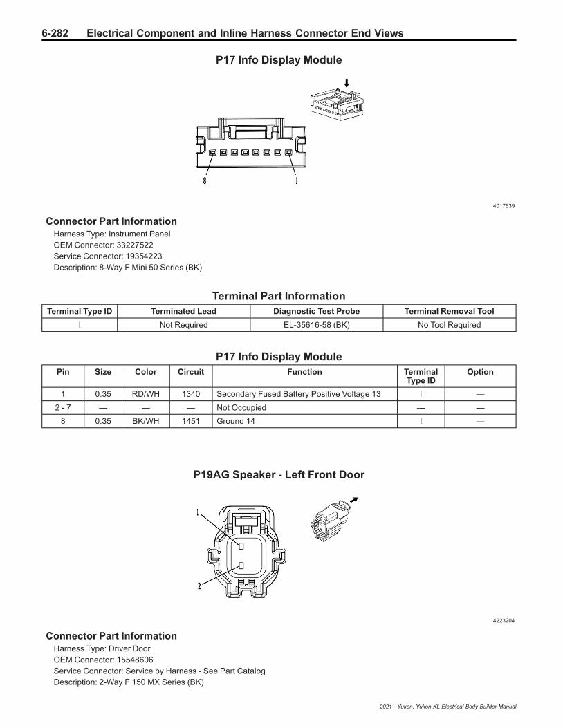
6-282 Electrical Component and Inline Harness Connector End Views
P17 Info Display Module
4017639
Connector Part InformationHarness Type: Instrument PanelOEM Connector: 33227522Service Connector: 19354223Description: 8-Way F Mini 50 Series (BK)
Terminal Part InformationTerminal Type ID Terminated Lead Diagnostic Test Probe Terminal Removal Tool
I Not Required EL-35616-58 (BK) No Tool Required
P17 Info Display ModulePin Size Color Circuit Function Terminal
Type IDOption
1 0.35 RD/WH 1340 Secondary Fused Battery Positive Voltage 13 I —
2 - 7 — — — Not Occupied — —
8 0.35 BK/WH 1451 Ground 14 I —
P19AG Speaker - Left Front Door
4223204
Connector Part InformationHarness Type: Driver DoorOEM Connector: 15548606Service Connector: Service by Harness - See Part CatalogDescription: 2-Way F 150 MX Series (BK)
2021 - Yukon, Yukon XL Electrical Body Builder Manual

Electrical Component and Inline Harness Connector End Views 6-283
Terminal Part InformationTerminal Type ID Terminated Lead Diagnostic Test Probe Terminal Removal Tool
I Not Required J-35616-14 (GN) No Tool Required
P19AG Speaker - Left Front DoorPin Size Color Circuit Function Terminal
Type IDOption
1 0.75 BN/D-BU 118 Left Front Speaker [-] Control 1 I —
2 0.75 D-BU 201 Left Front Speaker 1 [+] Control I —
P19AH Speaker - Right Front Door
4223204
Connector Part InformationHarness Type: Passenger DoorOEM Connector: 15548606Service Connector: Service by Harness - See Part CatalogDescription: 2-Way F 150 MX Series (BK)
Terminal Part InformationTerminal Type ID Terminated Lead Diagnostic Test Probe Terminal Removal Tool
I Not Required J-35616-14 (GN) No Tool Required
P19AH Speaker - Right Front DoorPin Size Color Circuit Function Terminal
Type IDOption
1 0.75 YE/BK 117 Right Front Speaker [-] Control 1 I —
2 0.75 YE 200 Right Front Speaker 1 [+] Control I —
2021 - Yukon, Yukon XL Electrical Body Builder Manual

6-284 Electrical Component and Inline Harness Connector End Views
P19AL Speaker - Left Rear Door
4223204
Connector Part InformationHarness Type: Left Rear DoorOEM Connector: 15548606Service Connector: Service by Harness - See Part CatalogDescription: 2-Way F 150 MX Series (BK)
Terminal Part InformationTerminal Type ID Terminated Lead Diagnostic Test Probe Terminal Removal Tool
I Not Required J-35616-14 (GN) No Tool Required
P19AL Speaker - Left Rear DoorPin Size Color Circuit Function Terminal
Type IDOption
1 0.75 L-GN/BK 116 Left Rear Speaker [-] Control I —
2 0.75 L-GN 199 Left Rear Speaker [+] Control I —
P19AM Speaker - Right Rear Door (UQA/UQF/UQS)
4223204
Connector Part InformationHarness Type: Right Rear DoorOEM Connector: 15548606Service Connector: Service by Harness - See Part CatalogDescription: 2-Way F 150 MX Series (BK)
2021 - Yukon, Yukon XL Electrical Body Builder Manual

Electrical Component and Inline Harness Connector End Views 6-285
Terminal Part InformationTerminal Type ID Terminated Lead Diagnostic Test Probe Terminal Removal Tool
I Not Required J-35616-14 (GN) No Tool Required
P19AM Speaker - Right Rear Door (UQA/UQF/UQS)Pin Size Color Circuit Function Terminal
Type IDOption
1 0.75 D-BU/BK 115 Right Rear Speaker [-] Control I —
2 0.75 WH 46 Right Rear Speaker [+] Control I —
P19AM Speaker - Right Rear Door (UQP)
4373379
Connector Part InformationHarness Type: Right Rear Door TrimOEM Connector: 35311601Service Connector: Service by Harness - See Part CatalogDescription: 2-Way F 1.2 MCON Series (GY)
Terminal Part InformationTerminal Type ID Terminated Lead Diagnostic Test Probe Terminal Removal Tool
I Not Required J-35616-16 (LT GN) No Tool Required
P19AM Speaker - Right Rear Door (UQP)Pin Size Color Circuit Function Terminal
Type IDOption
1 0.75 D-BU/BK 115 Right Rear Speaker [-] Control I —
2 0.75 WH 46 Right Rear Speaker [+] Control I —
2021 - Yukon, Yukon XL Electrical Body Builder Manual

6-286 Electrical Component and Inline Harness Connector End Views
P19AN Speaker - Left Rear Trim Panel (UQA)
4373379
Connector Part InformationHarness Type: BodyOEM Connector: 35034269Service Connector: 19369632Description: 2-Way F 1.2 Series (GY)
Terminal Part InformationTerminal Type ID Terminated Lead Diagnostic Test Probe Terminal Removal Tool
I Not Required J-35616-16 (LT GN) No Tool Required
P19AN Speaker - Left Rear Trim Panel (UQA)Pin Size Color Circuit Function Terminal
Type IDOption
1 0.75 L-GN/BK 116 Left Rear Speaker [-] Control I —
2 0.75 L-GN 199 Left Rear Speaker [+] Control I —
P19AN Speaker - Left Rear Trim Panel (UQP)
4373379
Connector Part InformationHarness Type: BodyOEM Connector: 35034269Service Connector: 19369632Description: 2-Way F 1.2 Series (GY)
2021 - Yukon, Yukon XL Electrical Body Builder Manual

Electrical Component and Inline Harness Connector End Views 6-287
Terminal Part InformationTerminal Type ID Terminated Lead Diagnostic Test Probe Terminal Removal Tool
I Not Required J-35616-16 (LT GN) No Tool Required
P19AN Speaker - Left Rear Trim Panel (UQP)Pin Size Color Circuit Function Terminal
Type IDOption
1 0.75 BN/WH 8575 Left Rear D-Pillar Speaker [-] Control I —
2 0.75 WH/L-GN 8576 Left Rear D-Pillar Speaker [+] Control I —
P19AN Speaker - Left Rear Trim Panel (UQS)
4373379
Connector Part InformationHarness Type: BodyOEM Connector: 35034269Service Connector: 19369632Description: 2-Way F 1.2 Series (GY)
Terminal Part InformationTerminal Type ID Terminated Lead Diagnostic Test Probe Terminal Removal Tool
I Not Required J-35616-16 (LT GN) No Tool Required
P19AN Speaker - Left Rear Trim Panel (UQS)Pin Size Color Circuit Function Terminal
Type IDOption
1 0.75 WH/BN 1891 Rear/Left Rear Surround Speaker [-] Control I —
2 0.75 GY 8365 Rear Surround Speaker Series [+] to [-] I —
2021 - Yukon, Yukon XL Electrical Body Builder Manual

6-288 Electrical Component and Inline Harness Connector End Views
P19AP Speaker - Right Rear Trim Panel (UQA)
4373379
Connector Part InformationHarness Type: BodyOEM Connector: 35034269Service Connector: 19369632Description: 2-Way F 1.2 Series (GY)
Terminal Part InformationTerminal Type ID Terminated Lead Diagnostic Test Probe Terminal Removal Tool
I Not Required J-35616-16 (LT GN) No Tool Required
P19AP Speaker - Right Rear Trim Panel (UQA)Pin Size Color Circuit Function Terminal
Type IDOption
1 0.75 D-BU/BK 115 Right Rear Speaker [-] Control I —
2 0.75 WH 46 Right Rear Speaker [+] Control I —
P19AP Speaker - Right Rear Trim Panel (UQP)
4373379
Connector Part InformationHarness Type: BodyOEM Connector: 35034269Service Connector: 19369632Description: 2-Way F 1.2 Series (GY)
2021 - Yukon, Yukon XL Electrical Body Builder Manual

Electrical Component and Inline Harness Connector End Views 6-289
Terminal Part InformationTerminal Type ID Terminated Lead Diagnostic Test Probe Terminal Removal Tool
I Not Required J-35616-16 (LT GN) No Tool Required
P19AP Speaker - Right Rear Trim Panel (UQP)Pin Size Color Circuit Function Terminal
Type IDOption
1 0.75 GY/WH 8577 Right Rear D-Pillar Speaker [-] Control I —
2 0.75 VT 8578 Right Rear D-Pillar Speaker [+] Control I —
P19AP Speaker - Right Rear Trim Panel (UQS)
4373379
Connector Part InformationHarness Type: BodyOEM Connector: 35034269Service Connector: 19369632Description: 2-Way F 1.2 Series (GY)
Terminal Part InformationTerminal Type ID Terminated Lead Diagnostic Test Probe Terminal Removal Tool
I Not Required J-35616-16 (LT GN) No Tool Required
P19AP Speaker - Right Rear Trim Panel (UQS)Pin Size Color Circuit Function Terminal
Type IDOption
1 0.75 GY 8365 Rear Surround Speaker Series [+] to [-] I —
2 0.75 VT/D-BU 1889 Rear/Left Rear Surround Speaker [+] Control I —
2021 - Yukon, Yukon XL Electrical Body Builder Manual
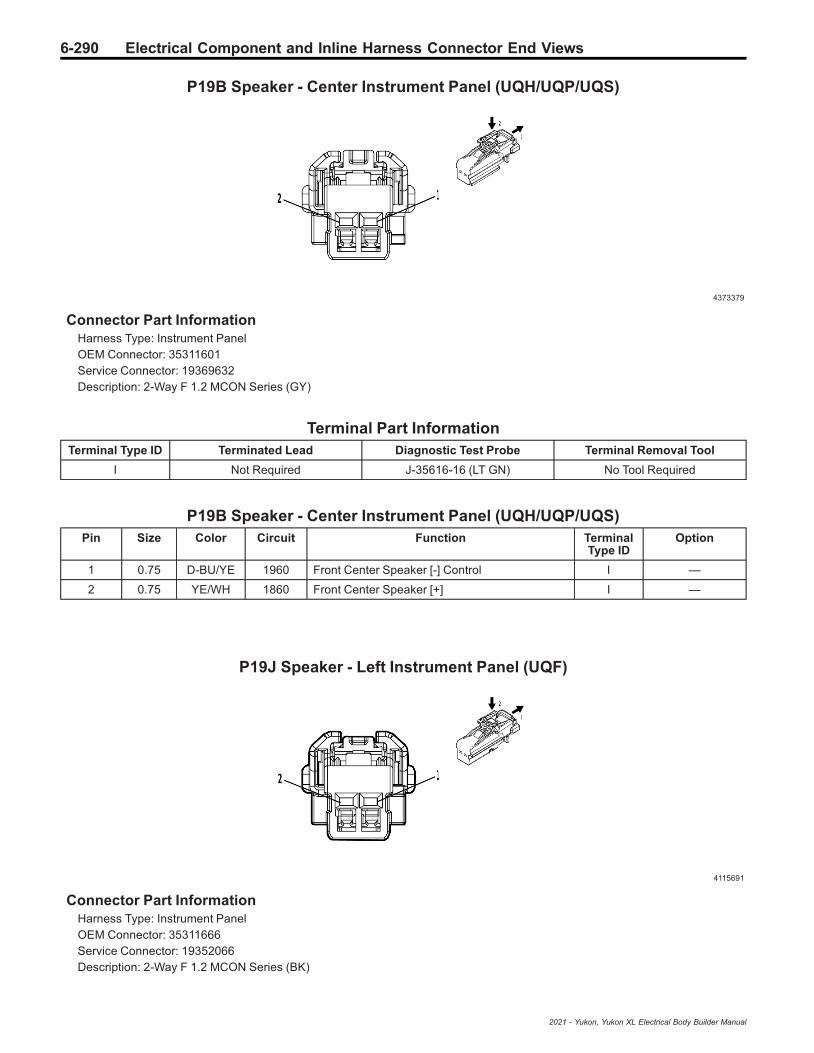
6-290 Electrical Component and Inline Harness Connector End Views
P19B Speaker - Center Instrument Panel (UQH/UQP/UQS)
4373379
Connector Part InformationHarness Type: Instrument PanelOEM Connector: 35311601Service Connector: 19369632Description: 2-Way F 1.2 MCON Series (GY)
Terminal Part InformationTerminal Type ID Terminated Lead Diagnostic Test Probe Terminal Removal Tool
I Not Required J-35616-16 (LT GN) No Tool Required
P19B Speaker - Center Instrument Panel (UQH/UQP/UQS)Pin Size Color Circuit Function Terminal
Type IDOption
1 0.75 D-BU/YE 1960 Front Center Speaker [-] Control I —
2 0.75 YE/WH 1860 Front Center Speaker [+] I —
P19J Speaker - Left Instrument Panel (UQF)
4115691
Connector Part InformationHarness Type: Instrument PanelOEM Connector: 35311666Service Connector: 19352066Description: 2-Way F 1.2 MCON Series (BK)
2021 - Yukon, Yukon XL Electrical Body Builder Manual
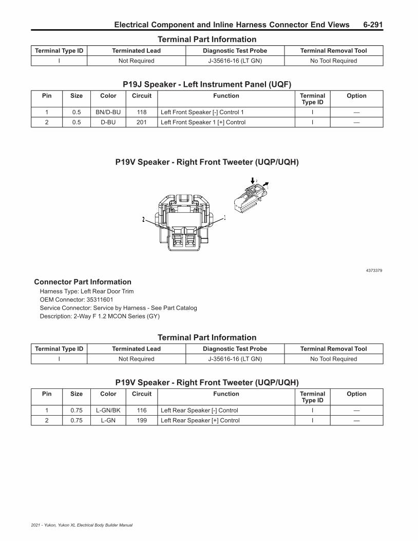
Electrical Component and Inline Harness Connector End Views 6-291
Terminal Part InformationTerminal Type ID Terminated Lead Diagnostic Test Probe Terminal Removal Tool
I Not Required J-35616-16 (LT GN) No Tool Required
P19J Speaker - Left Instrument Panel (UQF)Pin Size Color Circuit Function Terminal
Type IDOption
1 0.5 BN/D-BU 118 Left Front Speaker [-] Control 1 I —
2 0.5 D-BU 201 Left Front Speaker 1 [+] Control I —
P19V Speaker - Right Front Tweeter (UQP/UQH)
4373379
Connector Part InformationHarness Type: Left Rear Door TrimOEM Connector: 35311601Service Connector: Service by Harness - See Part CatalogDescription: 2-Way F 1.2 MCON Series (GY)
Terminal Part InformationTerminal Type ID Terminated Lead Diagnostic Test Probe Terminal Removal Tool
I Not Required J-35616-16 (LT GN) No Tool Required
P19V Speaker - Right Front Tweeter (UQP/UQH)Pin Size Color Circuit Function Terminal
Type IDOption
1 0.75 L-GN/BK 116 Left Rear Speaker [-] Control I —
2 0.75 L-GN 199 Left Rear Speaker [+] Control I —
2021 - Yukon, Yukon XL Electrical Body Builder Manual

6-292 Electrical Component and Inline Harness Connector End Views
P19W Speaker - Right Instrument Panel (UQF)
4115691
Connector Part InformationHarness Type: Instrument PanelOEM Connector: 35311666Service Connector: 19352066Description: 2-Way F 1.2 MCON Series (BK)
Terminal Part InformationTerminal Type ID Terminated Lead Diagnostic Test Probe Terminal Removal Tool
I Not Required J-35616-16 (LT GN) No Tool Required
P19W Speaker - Right Instrument Panel (UQF)Pin Size Color Circuit Function Terminal
Type IDOption
1 0.5 YE/BK 117 Right Front Speaker [-] Control 1 I —
2 0.5 YE 200 Right Front Speaker 1 [+] Control I —
P25 Power Sounder Content Theft Deterrent Alarm Module (UTJ)
655785
Connector Part InformationHarness Type: BodyOEM Connector: 15324398Service Connector: 13580107Description: 3-Way F 0.64 Micro-Quadlock Series, Sealed (BK)
2021 - Yukon, Yukon XL Electrical Body Builder Manual

Electrical Component and Inline Harness Connector End Views 6-293
Terminal Part InformationTerminal Type ID Terminated Lead Diagnostic Test Probe Terminal Removal Tool
I Not Required J-35616-64B (LT BU) No Tool Required
P25 Power Sounder Content Theft Deterrent Alarm Module (UTJ)Pin Size Color Circuit Function Terminal
Type IDOption
1 0.75 BK 150 Ground 1 I —
2 0.5 L-GN/D-BU 6133 Body Control Module LIN Bus 2 I —
3 0.5 RD/YE 2340 Secondary Fused Battery Positive Voltage 23 I —
P27 Mobile Telephone Speaker
4115691
Connector Part InformationHarness Type: Instrument PanelOEM Connector: 35311666Service Connector: 19352066Description: 2-Way F 1.2 MCON Series (BK)
Terminal Part InformationTerminal Type ID Terminated Lead Diagnostic Test Probe Terminal Removal Tool
I Not Required J-35616-16 (LT GN) No Tool Required
P27 Mobile Telephone SpeakerPin Size Color Circuit Function Terminal
Type IDOption
1 0.35 WH/BK 4769 Emergency Call Backup Speaker [-] Control I —
2 0.35 GY/L-GN 4770 Emergency Call Backup Speaker [+] Control I —
2021 - Yukon, Yukon XL Electrical Body Builder Manual
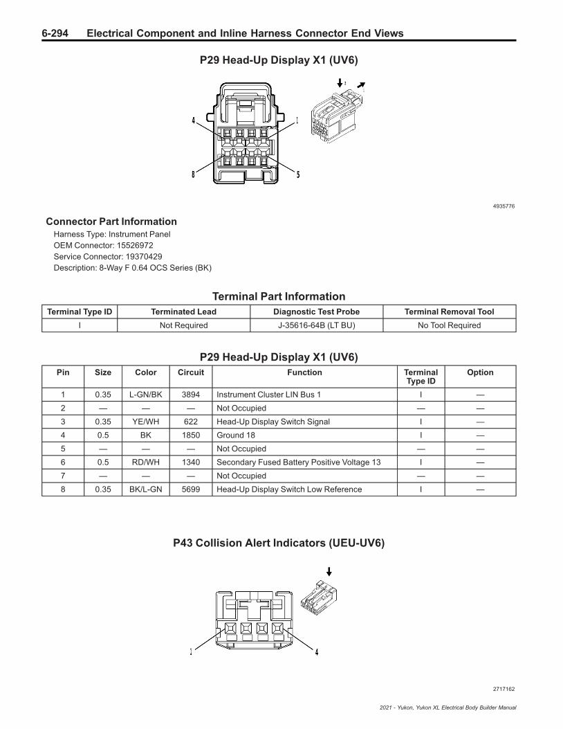
6-294 Electrical Component and Inline Harness Connector End Views
P29 Head-Up Display X1 (UV6)
4935776
Connector Part InformationHarness Type: Instrument PanelOEM Connector: 15526972Service Connector: 19370429Description: 8-Way F 0.64 OCS Series (BK)
Terminal Part InformationTerminal Type ID Terminated Lead Diagnostic Test Probe Terminal Removal Tool
I Not Required J-35616-64B (LT BU) No Tool Required
P29 Head-Up Display X1 (UV6)Pin Size Color Circuit Function Terminal
Type IDOption
1 0.35 L-GN/BK 3894 Instrument Cluster LIN Bus 1 I —
2 — — — Not Occupied — —
3 0.35 YE/WH 622 Head-Up Display Switch Signal I —
4 0.5 BK 1850 Ground 18 I —
5 — — — Not Occupied — —
6 0.5 RD/WH 1340 Secondary Fused Battery Positive Voltage 13 I —
7 — — — Not Occupied — —
8 0.35 BK/L-GN 5699 Head-Up Display Switch Low Reference I —
P43 Collision Alert Indicators (UEU-UV6)
2717162
2021 - Yukon, Yukon XL Electrical Body Builder Manual
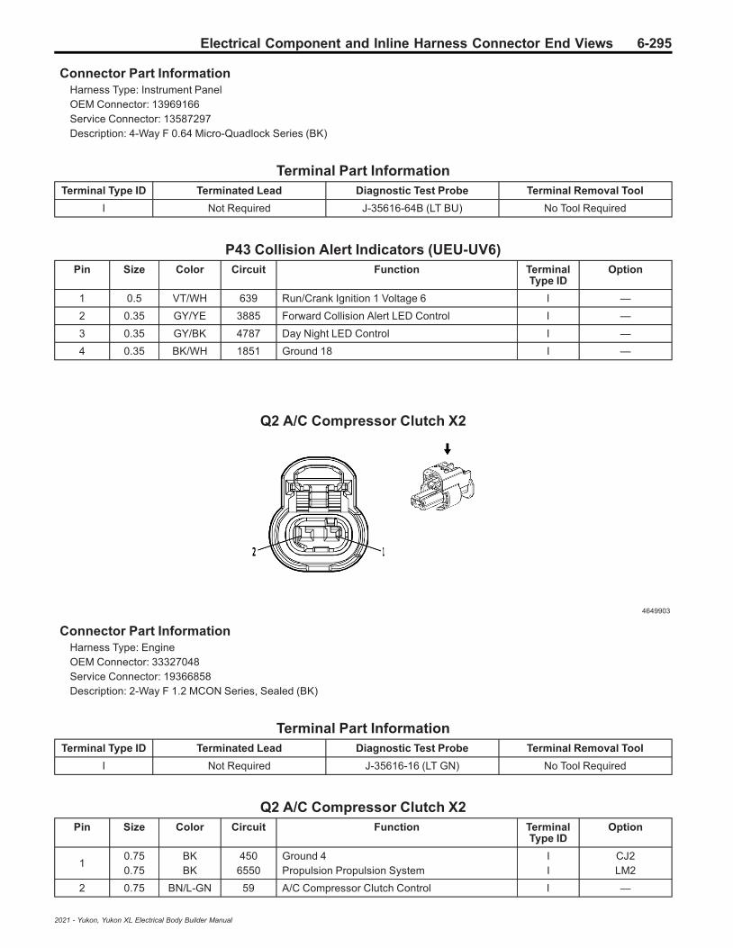
Electrical Component and Inline Harness Connector End Views 6-295
Connector Part InformationHarness Type: Instrument PanelOEM Connector: 13969166Service Connector: 13587297Description: 4-Way F 0.64 Micro-Quadlock Series (BK)
Terminal Part InformationTerminal Type ID Terminated Lead Diagnostic Test Probe Terminal Removal Tool
I Not Required J-35616-64B (LT BU) No Tool Required
P43 Collision Alert Indicators (UEU-UV6)Pin Size Color Circuit Function Terminal
Type IDOption
1 0.5 VT/WH 639 Run/Crank Ignition 1 Voltage 6 I —
2 0.35 GY/YE 3885 Forward Collision Alert LED Control I —
3 0.35 GY/BK 4787 Day Night LED Control I —
4 0.35 BK/WH 1851 Ground 18 I —
Q2 A/C Compressor Clutch X2
4649903
Connector Part InformationHarness Type: EngineOEM Connector: 33327048Service Connector: 19366858Description: 2-Way F 1.2 MCON Series, Sealed (BK)
Terminal Part InformationTerminal Type ID Terminated Lead Diagnostic Test Probe Terminal Removal Tool
I Not Required J-35616-16 (LT GN) No Tool Required
Q2 A/C Compressor Clutch X2Pin Size Color Circuit Function Terminal
Type IDOption
10.750.75
BKBK
4506550
Ground 4Propulsion Propulsion System
II
CJ2LM2
2 0.75 BN/L-GN 59 A/C Compressor Clutch Control I —
2021 - Yukon, Yukon XL Electrical Body Builder Manual
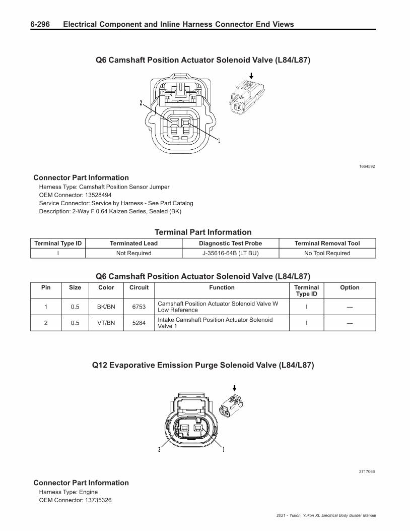
6-296 Electrical Component and Inline Harness Connector End Views
Q6 Camshaft Position Actuator Solenoid Valve (L84/L87)
1664592
Connector Part InformationHarness Type: Camshaft Position Sensor JumperOEM Connector: 13528494Service Connector: Service by Harness - See Part CatalogDescription: 2-Way F 0.64 Kaizen Series, Sealed (BK)
Terminal Part InformationTerminal Type ID Terminated Lead Diagnostic Test Probe Terminal Removal Tool
I Not Required J-35616-64B (LT BU) No Tool Required
Q6 Camshaft Position Actuator Solenoid Valve (L84/L87)Pin Size Color Circuit Function Terminal
Type IDOption
1 0.5 BK/BN 6753 Camshaft Position Actuator Solenoid Valve WLow Reference I —
2 0.5 VT/BN 5284 Intake Camshaft Position Actuator SolenoidValve 1 I —
Q12 Evaporative Emission Purge Solenoid Valve (L84/L87)
2717066
Connector Part InformationHarness Type: EngineOEM Connector: 13735326
2021 - Yukon, Yukon XL Electrical Body Builder Manual

Electrical Component and Inline Harness Connector End Views 6-297
Service Connector: 13587326Description: 2-Way F 1.2 Multilock Series, Sealed (BK)
Terminal Part InformationTerminal Type ID Terminated Lead Diagnostic Test Probe Terminal Removal Tool
I Not Required J-35616-16 (LT GN) No Tool Required
Q12 Evaporative Emission Purge Solenoid Valve (L84/L87)Pin Size Color Circuit Function Terminal
Type IDOption
1 0.75 VT/D-BU 5293 Powertrain Main Relay Fused Supply 4 I —
2 0.75 L-GN/D-BU 428 EVAP Purge Solenoid Valve Control I —
Q13 Evaporative Emission Vent Solenoid Valve (L84/L87)
2422378
Connector Part InformationHarness Type: ChassisOEM Connector: 13771883Service Connector: 13579002Description: 2-Way F 1.5 Series, Sealed (BK)
Terminal Part InformationTerminal Type ID Terminated Lead Diagnostic Test Probe Terminal Removal Tool
I Not Required J-35616-14 (GN) No Tool Required
Q13 Evaporative Emission Vent Solenoid Valve (L84/L87)Pin Size Color Circuit Function Terminal
Type IDOption
1 0.5 WH 1310 EVAP Vent Solenoid Valve Control I —
2 0.5 RD/WH 2040 Secondary Fused Battery Positive Voltage 20 I —
2021 - Yukon, Yukon XL Electrical Body Builder Manual

6-298 Electrical Component and Inline Harness Connector End Views
Q14A Exhaust Gas Recirculation Valve 1 (LM2)
4997783
Connector Part InformationHarness Type: EngineOEM Connector: 35026727Service Connector: 19371195Description: 5-Way F 1.2 MCON-CB Series, Sealed (BK)
Terminal Part InformationTerminal Type ID Terminated Lead Diagnostic Test Probe Terminal Removal Tool
I Not Required J-35616-16 (LT GN) No Tool Required
Q14A Exhaust Gas Recirculation Valve 1 (LM2)Pin Size Color Circuit Function Terminal
Type IDOption
1 0.5 D-BU/RD 460 Engine Control Sensors 5 Volt Reference 1 I —
2 0.5 BN/WH 5763 Exhaust Gas Recirculation Position Signal I —
3 0.5 BK/YE 548 Engine Control Sensors Low Reference 1 I —
4 0.5 WH/VT 5764 Exhaust Gas Recirculation Valve High Control I —
5 0.5 VT/BK 5746 Exhaust Gas Recirculation Valve Low Control I —
Q14B Exhaust Gas Recirculation Valve 2 (LM2)
4997783
Connector Part InformationHarness Type: EngineOEM Connector: 35026727
2021 - Yukon, Yukon XL Electrical Body Builder Manual

Electrical Component and Inline Harness Connector End Views 6-299
Service Connector: 19371195Description: 5-Way F 1.2 MCON-CB Series, Sealed (BK)
Terminal Part InformationTerminal Type ID Terminated Lead Diagnostic Test Probe Terminal Removal Tool
I Not Required J-35616-16 (LT GN) No Tool Required
Q14B Exhaust Gas Recirculation Valve 2 (LM2)Pin Size Color Circuit Function Terminal
Type IDOption
1 0.5 BK/YE 548 Engine Control Sensors Low Reference 1 I —
2 0.5 D-BU/L-GN 4012 Exhaust Gas Recirculation 2 Valve Position
Sensor Signal I —
3 0.5 D-BU/RD 460 Engine Control Sensors 5 Volt Reference 1 I —
4 0.5 D-BU/WH 4014 Exhaust Gas Recirculation 2 Valve Open Control I —
5 0.5 D-BU/BN 4013 Exhaust Gas Recirculation 2 Valve CloseControl I —
Q17A Fuel Injector 1 (LM2)
2845578
Connector Part InformationHarness Type: Fuel InjectorOEM Connector: 1928405715Service Connector: Service by Harness - See Part CatalogDescription: 2-Way F 2.8 Series, Sealed (BK)
Terminal Part InformationTerminal Type ID Terminated Lead Diagnostic Test Probe Terminal Removal Tool
I Not Required J-35616-35 (VT) No Tool Required
Q17A Fuel Injector 1 (LM2)Pin Size Color Circuit Function Terminal
Type IDOption
1 1.5 BN/WH 4901 Direct Fuel Injector High Voltage SupplyCylinder 1 I —
2 1.5 BN 4801 Direct Fuel Injector High Voltage ControlCylinder 1 I —
2021 - Yukon, Yukon XL Electrical Body Builder Manual

6-300 Electrical Component and Inline Harness Connector End Views
Q17B Fuel Injector 2 (LM2)
2845578
Connector Part InformationHarness Type: Fuel InjectorOEM Connector: 1928405715Service Connector: Service by Harness - See Part CatalogDescription: 2-Way F 2.8 Series, Sealed (BK)
Terminal Part InformationTerminal Type ID Terminated Lead Diagnostic Test Probe Terminal Removal Tool
I Not Required J-35616-35 (VT) No Tool Required
Q17B Fuel Injector 2 (LM2)Pin Size Color Circuit Function Terminal
Type IDOption
1 1.5 BU/GY 4902 Direct Fuel Injector High Voltage SupplyCylinder 2 I —
2 1.5 BU 4802 Direct Fuel Injector High Voltage ControlCylinder 2 I —
Q17C Fuel Injector 3 (LM2)
2845578
Connector Part InformationHarness Type: Fuel InjectorOEM Connector: 1928405715
2021 - Yukon, Yukon XL Electrical Body Builder Manual

Electrical Component and Inline Harness Connector End Views 6-301
Service Connector: Service by Harness - See Part CatalogDescription: 2-Way F 2.8 Series, Sealed (BK)
Terminal Part InformationTerminal Type ID Terminated Lead Diagnostic Test Probe Terminal Removal Tool
I Not Required J-35616-35 (VT) No Tool Required
Q17C Fuel Injector 3 (LM2)Pin Size Color Circuit Function Terminal
Type IDOption
1 1.5 GN/GY 4903 Direct Fuel Injector High Voltage SupplyCylinder 3 I —
2 1.5 GN 4803 Direct Fuel Injector High Voltage ControlCylinder 3 I —
Q17D Fuel Injector 4 (LM2)
2845578
Connector Part InformationHarness Type: Fuel InjectorOEM Connector: 1928405715Service Connector: Service by Harness - See Part CatalogDescription: 2-Way F 2.8 Series, Sealed (BK)
Terminal Part InformationTerminal Type ID Terminated Lead Diagnostic Test Probe Terminal Removal Tool
I Not Required J-35616-35 (VT) No Tool Required
Q17D Fuel Injector 4 (LM2)Pin Size Color Circuit Function Terminal
Type IDOption
1 1.5 BU/WH 4904 Direct Fuel Injector High Voltage SupplyCylinder 4 I —
2 1.5 GY/BU 4804 Direct Fuel Injector High Voltage ControlCylinder 4 I —
2021 - Yukon, Yukon XL Electrical Body Builder Manual

6-302 Electrical Component and Inline Harness Connector End Views
Q17E Fuel Injector 5 (LM2)
2845578
Connector Part InformationHarness Type: Fuel InjectorOEM Connector: 1928405715Service Connector: Service by Harness - See Part CatalogDescription: 2-Way F 2.8 Series, Sealed (BK)
Terminal Part InformationTerminal Type ID Terminated Lead Diagnostic Test Probe Terminal Removal Tool
I Not Required J-35616-35 (VT) No Tool Required
Q17E Fuel Injector 5 (LM2)Pin Size Color Circuit Function Terminal
Type IDOption
1 1.5 GN/WH 4905 Direct Fuel Injector High Voltage SupplyCylinder 5 I —
2 1.5 WH/GN 4805 Direct Fuel Injector High Voltage ControlCylinder 5 I —
Q17F Fuel Injector 6 (LM2)
2845578
Connector Part InformationHarness Type: Fuel InjectorOEM Connector: 1928405715Service Connector: Service by Harness - See Part CatalogDescription: 2-Way F 2.8 Series, Sealed (BK)
2021 - Yukon, Yukon XL Electrical Body Builder Manual

Electrical Component and Inline Harness Connector End Views 6-303
Terminal Part InformationTerminal Type ID Terminated Lead Diagnostic Test Probe Terminal Removal Tool
I Not Required J-35616-35 (VT) No Tool Required
Q17F Fuel Injector 6 (LM2)Pin Size Color Circuit Function Terminal
Type IDOption
1 1.5 VT/GY 4906 Direct Fuel Injector High Voltage SupplyCylinder 6 I —
2 1.5 VT/GN 4806 Direct Fuel Injector High Voltage ControlCylinder 6 I —
Q18A Fuel Pressure Regulator 1 (LM2)
2577394
Connector Part InformationHarness Type: EngineOEM Connector: 13930085Service Connector: 13384371Description: 2-Way F 2.8 Series, Sealed (BK)
Terminal Part InformationTerminal Type ID Terminated Lead Diagnostic Test Probe Terminal Removal Tool
I Not Required J-35616-35 (VT) No Tool Required
Q18A Fuel Pressure Regulator 1 (LM2)Pin Size Color Circuit Function Terminal
Type IDOption
1 0.75 YE/VT 7245 High Pressure Fuel Pump Low Enable Signal I —
2 0.75 GY/BN 7244 High Pressure Fuel Pump High Side Control I —
2021 - Yukon, Yukon XL Electrical Body Builder Manual

6-304 Electrical Component and Inline Harness Connector End Views
Q18B Fuel Pressure Regulator 2 (LM2)
5095463
Connector Part InformationHarness Type: EngineOEM Connector: 33163309Service Connector: 84616656Description: 2-Way F 2.8 Series, Sealed (BK)
Terminal Part InformationTerminal Type ID Terminated Lead Diagnostic Test Probe Terminal Removal Tool
I Not Required J-35616-4A (PU) No Tool Required
Q18B Fuel Pressure Regulator 2 (LM2)Pin Size Color Circuit Function Terminal
Type IDOption
1 0.5 BK/YE 2834 Fuel Rail Pressure Solenoid Valve LowReference I —
2 0.5 D-BU/WH 2530 Fuel Rail Pressure Solenoid Valve Control I —
Q18C Fuel Pressure Regulator 3 (LM2)
2577394
Connector Part InformationHarness Type: EngineOEM Connector: 13930085Service Connector: 13384371Description: 2-Way F 2.8 Series, Sealed (BK)
2021 - Yukon, Yukon XL Electrical Body Builder Manual

Electrical Component and Inline Harness Connector End Views 6-305
Terminal Part InformationTerminal Type ID Terminated Lead Diagnostic Test Probe Terminal Removal Tool
I Not Required J-35616-35 (VT) No Tool Required
Q18C Fuel Pressure Regulator 3 (LM2)Pin Size Color Circuit Function Terminal
Type IDOption
1 0.75 YE/VT 2420 Fuel High Pressure Pump Low Enable Signal I —
2 0.75 GY/BN 2419 — I —
Q22 Intake Manifold Tuning Solenoid Valve (LM2)
3338689
Connector Part InformationHarness Type: EngineOEM Connector: 13943325Service Connector: 19119351Description: 5-Way F 1.2 MCON-LL Series, Sealed (BK)
Terminal Part InformationTerminal Type ID Terminated Lead Diagnostic Test Probe Terminal Removal Tool
I Not Required J-35616-16 (LT GN) No Tool Required
Q22 Intake Manifold Tuning Solenoid Valve (LM2)Pin Size Color Circuit Function Terminal
Type IDOption
1 0.5 BK/L-GN 580 Engine Control Sensors Low Reference 2 I —
2 0.5 L-GN/GY 7316 Intake Manifold Runner Valve Actuator Control I —
3 0.5 WH/RD 480 Engine Control Vehicle Sensors 5 VoltReference 1 I —
4 0.75 BK/D-BU 1408 Variable Swirl Valve Close Control I —
5 0.75 BK/L-GN 1389 Variable Swirl Valve Open Control I —
2021 - Yukon, Yukon XL Electrical Body Builder Manual
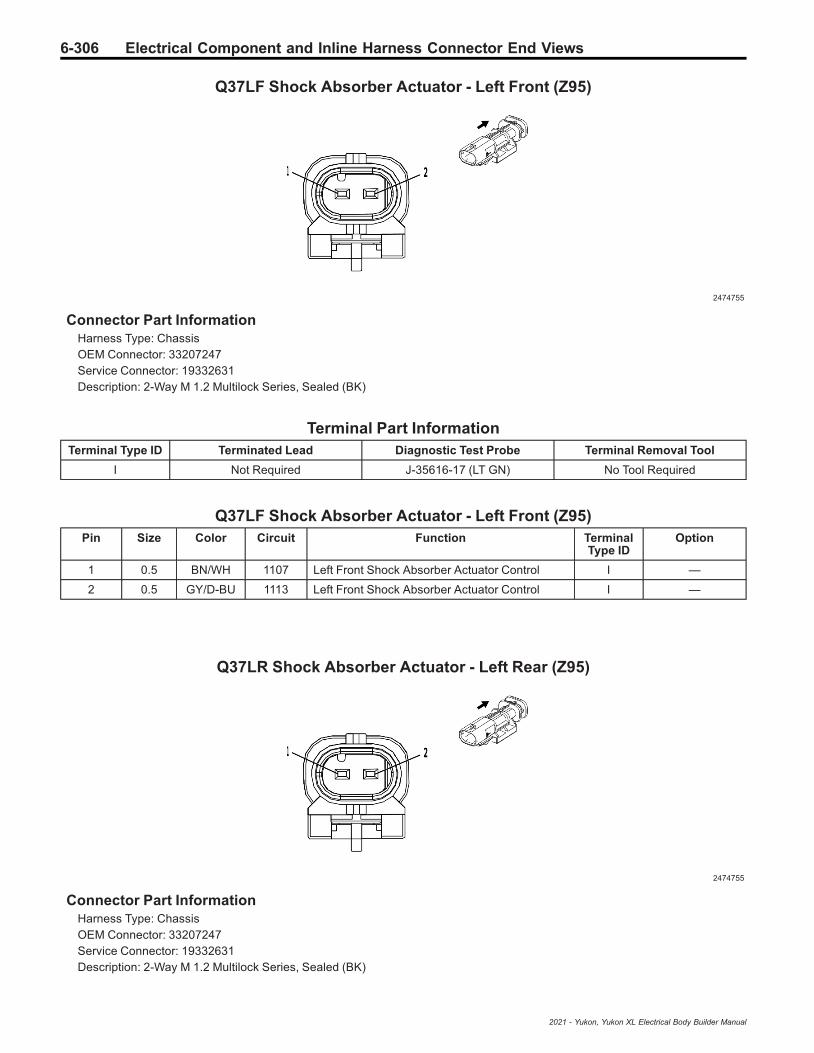
6-306 Electrical Component and Inline Harness Connector End Views
Q37LF Shock Absorber Actuator - Left Front (Z95)
2474755
Connector Part InformationHarness Type: ChassisOEM Connector: 33207247Service Connector: 19332631Description: 2-Way M 1.2 Multilock Series, Sealed (BK)
Terminal Part InformationTerminal Type ID Terminated Lead Diagnostic Test Probe Terminal Removal Tool
I Not Required J-35616-17 (LT GN) No Tool Required
Q37LF Shock Absorber Actuator - Left Front (Z95)Pin Size Color Circuit Function Terminal
Type IDOption
1 0.5 BN/WH 1107 Left Front Shock Absorber Actuator Control I —
2 0.5 GY/D-BU 1113 Left Front Shock Absorber Actuator Control I —
Q37LR Shock Absorber Actuator - Left Rear (Z95)
2474755
Connector Part InformationHarness Type: ChassisOEM Connector: 33207247Service Connector: 19332631Description: 2-Way M 1.2 Multilock Series, Sealed (BK)
2021 - Yukon, Yukon XL Electrical Body Builder Manual

Electrical Component and Inline Harness Connector End Views 6-307
Terminal Part InformationTerminal Type ID Terminated Lead Diagnostic Test Probe Terminal Removal Tool
I Not Required J-35616-17 (LT GN) No Tool Required
Q37LR Shock Absorber Actuator - Left Rear (Z95)Pin Size Color Circuit Function Terminal
Type IDOption
1 0.5 D-BU/GY 1114 Left Rear Shock Absorber Actuator Control I —
2 0.5 L-GN/VT 1115 Left Rear Shock Absorber Actuator Control I —
Q37RF Shock Absorber Actuator - Right Front (Z95)
2474755
Connector Part InformationHarness Type: ChassisOEM Connector: 33207247Service Connector: 19332631Description: 2-Way M 1.2 Multilock Series, Sealed (BK)
Terminal Part InformationTerminal Type ID Terminated Lead Diagnostic Test Probe Terminal Removal Tool
I Not Required J-35616-17 (LT GN) No Tool Required
Q37RF Shock Absorber Actuator - Right Front (Z95)Pin Size Color Circuit Function Terminal
Type IDOption
1 0.5 BN/D-BU 1116 Right Front Shock Absorber Actuator Control I —
2 0.5 GY/WH 1117 Right Front Shock Absorber Actuator Control I —
2021 - Yukon, Yukon XL Electrical Body Builder Manual

6-308 Electrical Component and Inline Harness Connector End Views
Q37RR Shock Absorber Actuator - Right Rear (Z95)
2474755
Connector Part InformationHarness Type: ChassisOEM Connector: 33207247Service Connector: 19332631Description: 2-Way M 1.2 Multilock Series, Sealed (BK)
Terminal Part InformationTerminal Type ID Terminated Lead Diagnostic Test Probe Terminal Removal Tool
I Not Required J-35616-17 (LT GN) No Tool Required
Q37RR Shock Absorber Actuator - Right Rear (Z95)Pin Size Color Circuit Function Terminal
Type IDOption
1 0.5 BN/L-GN 1118 Right Rear Shock Absorber Actuator Control I —
2 0.5 L-GN/GY 1119 Right Rear Shock Absorber Actuator Control I —
Q38 Throttle Body (L84/L87)
3747579
Connector Part InformationHarness Type: EngineOEM Connector: 33220833Service Connector: 19352911Description: 6-Way F 1.2 MCON Series, Sealed (BK)
2021 - Yukon, Yukon XL Electrical Body Builder Manual
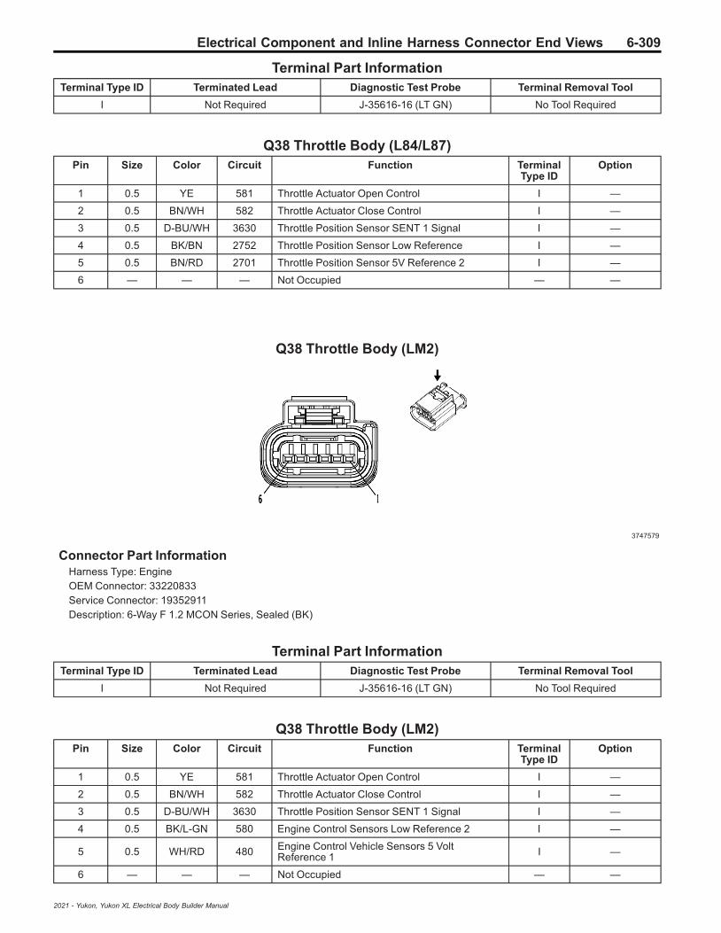
Electrical Component and Inline Harness Connector End Views 6-309
Terminal Part InformationTerminal Type ID Terminated Lead Diagnostic Test Probe Terminal Removal Tool
I Not Required J-35616-16 (LT GN) No Tool Required
Q38 Throttle Body (L84/L87)Pin Size Color Circuit Function Terminal
Type IDOption
1 0.5 YE 581 Throttle Actuator Open Control I —
2 0.5 BN/WH 582 Throttle Actuator Close Control I —
3 0.5 D-BU/WH 3630 Throttle Position Sensor SENT 1 Signal I —
4 0.5 BK/BN 2752 Throttle Position Sensor Low Reference I —
5 0.5 BN/RD 2701 Throttle Position Sensor 5V Reference 2 I —
6 — — — Not Occupied — —
Q38 Throttle Body (LM2)
3747579
Connector Part InformationHarness Type: EngineOEM Connector: 33220833Service Connector: 19352911Description: 6-Way F 1.2 MCON Series, Sealed (BK)
Terminal Part InformationTerminal Type ID Terminated Lead Diagnostic Test Probe Terminal Removal Tool
I Not Required J-35616-16 (LT GN) No Tool Required
Q38 Throttle Body (LM2)Pin Size Color Circuit Function Terminal
Type IDOption
1 0.5 YE 581 Throttle Actuator Open Control I —
2 0.5 BN/WH 582 Throttle Actuator Close Control I —
3 0.5 D-BU/WH 3630 Throttle Position Sensor SENT 1 Signal I —
4 0.5 BK/L-GN 580 Engine Control Sensors Low Reference 2 I —
5 0.5 WH/RD 480 Engine Control Vehicle Sensors 5 VoltReference 1 I —
6 — — — Not Occupied — —
2021 - Yukon, Yukon XL Electrical Body Builder Manual
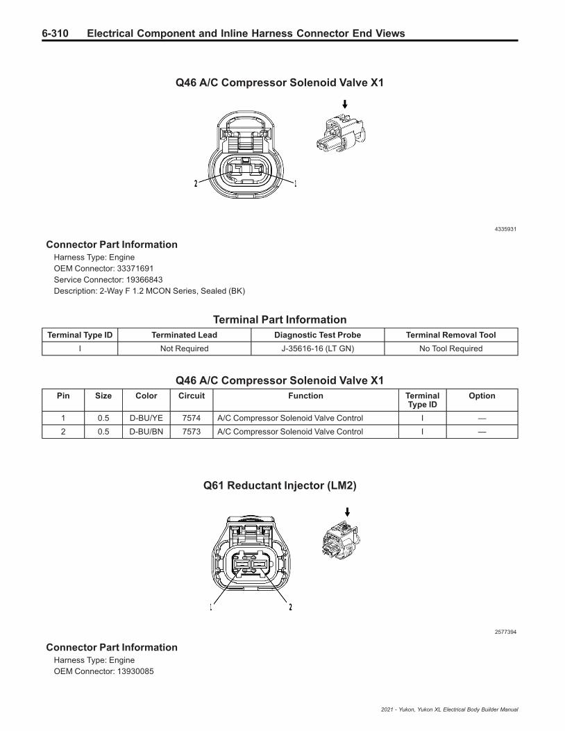
6-310 Electrical Component and Inline Harness Connector End Views
Q46 A/C Compressor Solenoid Valve X1
4335931
Connector Part InformationHarness Type: EngineOEM Connector: 33371691Service Connector: 19366843Description: 2-Way F 1.2 MCON Series, Sealed (BK)
Terminal Part InformationTerminal Type ID Terminated Lead Diagnostic Test Probe Terminal Removal Tool
I Not Required J-35616-16 (LT GN) No Tool Required
Q46 A/C Compressor Solenoid Valve X1Pin Size Color Circuit Function Terminal
Type IDOption
1 0.5 D-BU/YE 7574 A/C Compressor Solenoid Valve Control I —
2 0.5 D-BU/BN 7573 A/C Compressor Solenoid Valve Control I —
Q61 Reductant Injector (LM2)
2577394
Connector Part InformationHarness Type: EngineOEM Connector: 13930085
2021 - Yukon, Yukon XL Electrical Body Builder Manual

Electrical Component and Inline Harness Connector End Views 6-311
Service Connector: 13384371Description: 2-Way F 2.8 Series, Sealed (BK)
Terminal Part InformationTerminal Type ID Terminated Lead Diagnostic Test Probe Terminal Removal Tool
I Not Required J-35616-35 (VT) No Tool Required
Q61 Reductant Injector (LM2)Pin Size Color Circuit Function Terminal
Type IDOption
1 0.75 BN/WH 3100 Diesel Exhaust Fluid Dosing Valve Low Control I —
2 0.75 BN 3099 Diesel Exhaust Fluid Dosing Valve High Control I —
Q74 Engine Coolant Bypass Valve (LM2)
4994456
Connector Part InformationHarness Type: EngineOEM Connector: 35110578Service Connector: 19371191Description: 5-Way F 1.2 MCON-LL Series, Sealed (NA)
Terminal Part InformationTerminal Type ID Terminated Lead Diagnostic Test Probe Terminal Removal Tool
I Not Required J-35616-16 (LT GN) No Tool Required
Q74 Engine Coolant Bypass Valve (LM2)Pin Size Color Circuit Function Terminal
Type IDOption
1 0.75 D-BU 2976 Coolant Diverter Valve Actuator Control Open I —
2 0.75 D-BU/BN 2977 Coolant Diverter Valve Actuator Control Close I —
3 0.5 WH/RD 480 Engine Control Vehicle Sensors 5 VoltReference 1 I —
4 0.5 D-BU/GY 2978 Coolant Diverter Valve Position Signal I —
5 0.5 BK/L-GN 580 Engine Control Sensors Low Reference 2 I —
2021 - Yukon, Yukon XL Electrical Body Builder Manual

6-312 Electrical Component and Inline Harness Connector End Views
Q78 Air Suspension Reservoir Solenoid Valve (F47)
4649903
Connector Part InformationHarness Type: ChassisOEM Connector: 33327048Service Connector: 19366858Description: 2-Way F 1.2 MCON Series, Sealed (BK)
Terminal Part InformationTerminal Type ID Terminated Lead Diagnostic Test Probe Terminal Removal Tool
I Not Required J-35616-16 (LT GN) No Tool Required
Q78 Air Suspension Reservoir Solenoid Valve (F47)Pin Size Color Circuit Function Terminal
Type IDOption
1 0.5 WH/D-BU 3261 Vehicle Level Control Exhaust Solenoid ValveControl I —
2 0.5 WH/L-GN 320 Vehicle Level Control Exhaust Solenoid ValveControl I —
Q80L Engine Mount Solenoid Valve - Left (LM2)
4690744
Connector Part InformationHarness Type: EngineOEM Connector: 33375932Service Connector: 19366871Description: 2-Way F 1.2 MCON Series, Sealed (BK)
2021 - Yukon, Yukon XL Electrical Body Builder Manual

Electrical Component and Inline Harness Connector End Views 6-313
Terminal Part InformationTerminal Type ID Terminated Lead Diagnostic Test Probe Terminal Removal Tool
I Not Required J-35616-16 (LT GN) No Tool Required
Q80L Engine Mount Solenoid Valve - Left (LM2)Pin Size Color Circuit Function Terminal
Type IDOption
1 0.5 RD/VT 340 Secondary Fused Battery Positive Voltage 3 I —
2 0.5 BN/D-BU 4065 Driveline Mount Actuator 1 Control I —
Q80R Engine Mount Solenoid Valve - Right (LM2)
4690744
Connector Part InformationHarness Type: EngineOEM Connector: 33375932Service Connector: 19366871Description: 2-Way F 1.2 MCON Series, Sealed (BK)
Terminal Part InformationTerminal Type ID Terminated Lead Diagnostic Test Probe Terminal Removal Tool
I Not Required J-35616-16 (LT GN) No Tool Required
Q80R Engine Mount Solenoid Valve - Right (LM2)Pin Size Color Circuit Function Terminal
Type IDOption
1 0.5 RD/VT 340 Secondary Fused Battery Positive Voltage 3 I —
2 0.5 BN/YE 4066 Driveline Mount Actuator 2 Control I —
2021 - Yukon, Yukon XL Electrical Body Builder Manual

6-314 Electrical Component and Inline Harness Connector End Views
Q97M Engine Coolant Flow Control Valve - Main (LM2)
4994456
Connector Part InformationHarness Type: EngineOEM Connector: 35110578Service Connector: 19371191Description: 5-Way F 1.2 MCON-LL Series, Sealed (NA)
Terminal Part InformationTerminal Type ID Terminated Lead Diagnostic Test Probe Terminal Removal Tool
I Not Required J-35616-16 (LT GN) No Tool Required
Q97M Engine Coolant Flow Control Valve - Main (LM2)Pin Size Color Circuit Function Terminal
Type IDOption
1 0.75 GY/BN 2972 Coolant Flow Control Actuator Control Close I —
2 0.75 GY/D-BU 2971 Coolant Flow Control Actuator Control Open I —
3 0.5 WH/RD 480 Engine Control Vehicle Sensors 5 VoltReference 1 I —
4 0.5 GY 2973 Coolant Flow Control Valve Position Signal I —
5 0.5 BK/L-GN 580 Engine Control Sensors Low Reference 2 I —
S13D Door Lock Switch - Driver
4650256
2021 - Yukon, Yukon XL Electrical Body Builder Manual

Electrical Component and Inline Harness Connector End Views 6-315
Connector Part InformationHarness Type: Driver Door TrimOEM Connector: 33315784Service Connector: Service by Harness - See Part CatalogDescription: 6-Way F 0.64 HCM Series (BK)
Terminal Part InformationTerminal Type ID Terminated Lead Diagnostic Test Probe Terminal Removal Tool
I Not Required J-35616-64B (LT BU) No Tool Required
S13D Door Lock Switch - DriverPin Size Color Circuit Function Terminal
Type IDOption
1 0.35 BN/GY 4784 Left Front Door LED Backlight Dimming Control I —
2 0.35 BN/YE 2771 Left Front Door Lock Switch Lock Signal I —
3 0.35 BN/WH 2772 Left Front Door Lock Switch Unlock Signal I —
4 0.35 BK 1150 Ground 11 I —
5 0.35 VT/YE 4244 Left Front Door Lock Indicator Control I —
6 — — — Not Occupied — —
S13LR Door Lock Switch - Left Rear
4650256
Connector Part InformationHarness Type: Left Rear Door TrimOEM Connector: 33315784Service Connector: Service by Harness - See Part CatalogDescription: 6-Way F 0.64 HCM Series (BK)
Terminal Part InformationTerminal Type ID Terminated Lead Diagnostic Test Probe Terminal Removal Tool
I Not Required J-35616-64B (LT BU) No Tool Required
S13LR Door Lock Switch - Left RearPin Size Color Circuit Function Terminal
Type IDOption
1 0.35 YE 6817 LED Backlight Dimming Control 1 I —
2021 - Yukon, Yukon XL Electrical Body Builder Manual

6-316 Electrical Component and Inline Harness Connector End Views
S13LR Door Lock Switch - Left Rear (cont'd)Pin Size Color Circuit Function Terminal
Type IDOption
2 0.35 VT/D-BU 4001 Left Rear Door Lock Switch Lock Control I —
3 0.35 WH/YE 4002 Left Rear Door Lock Switch Unlock Control I —
4 0.35 BK 1150 Ground 11 I —
5 0.35 VT/WH 6675 Left Rear Door Lock Indicator Control I —
6 — — — Not Occupied — —
S13P Door Lock Switch - Passenger
4650256
Connector Part InformationHarness Type: Passenger Door TrimOEM Connector: 33315784Service Connector: Service by Harness - See Part CatalogDescription: 6-Way F 0.64 HCM Series (BK)
Terminal Part InformationTerminal Type ID Terminated Lead Diagnostic Test Probe Terminal Removal Tool
I Not Required J-35616-64B (LT BU) No Tool Required
S13P Door Lock Switch - PassengerPin Size Color Circuit Function Terminal
Type IDOption
1 0.35 GY/VT 4638 LED Backlight Dimming Control RightFront Door I —
2 0.35 YE/VT 2773 Right Front Door Lock Switch Lock Control I —
3 0.35 BN/VT 2774 Right Front Door Lock Switch Unlock Control I —
4 0.35 BK 1250 Ground 12 I —
5 0.35 YE/D-BU 4245 Right Front Door Lock Indicator Control I —
6 — — — Not Occupied — —
2021 - Yukon, Yukon XL Electrical Body Builder Manual

Electrical Component and Inline Harness Connector End Views 6-317
S13RR Door Lock Switch - Right Rear
4650256
Connector Part InformationHarness Type: Right Rear Door TrimOEM Connector: 33315784Service Connector: Service by Harness - See Part CatalogDescription: 6-Way F 0.64 HCM Series (BK)
Terminal Part InformationTerminal Type ID Terminated Lead Diagnostic Test Probe Terminal Removal Tool
I Not Required J-35616-64B (LT BU) No Tool Required
S13RR Door Lock Switch - Right RearPin Size Color Circuit Function Terminal
Type IDOption
1 0.5 YE 6817 LED Backlight Dimming Control 1 I —
2 0.35 L-GN/BN 4003 Right Rear Door Lock Switch Lock Control I —
3 0.35 D-BU/GY 4004 Right Rear Door Lock Switch Unlock Control I —
4 0.35 BK 1250 Ground 12 I —
5 0.5 YE/BK 6677 Right Rear Door Lock Indicator Control I —
6 — — — Not Occupied — —
S26 Hazard Warning Switch
2717162
2021 - Yukon, Yukon XL Electrical Body Builder Manual
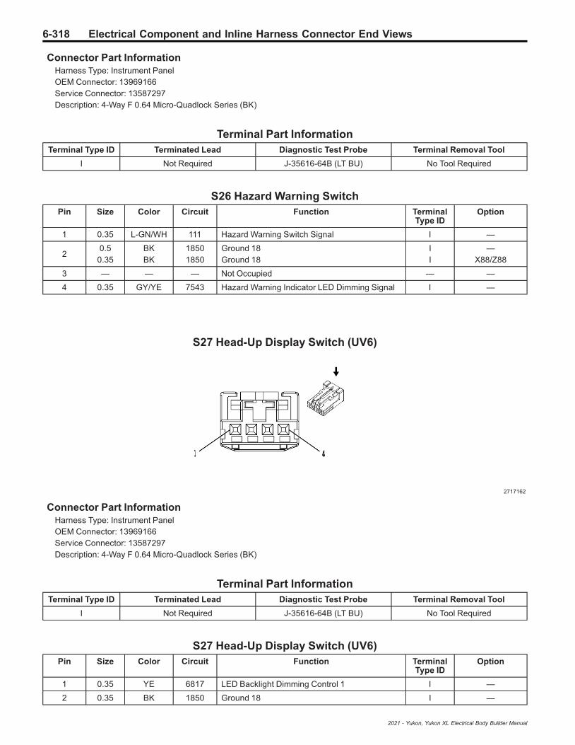
6-318 Electrical Component and Inline Harness Connector End Views
Connector Part InformationHarness Type: Instrument PanelOEM Connector: 13969166Service Connector: 13587297Description: 4-Way F 0.64 Micro-Quadlock Series (BK)
Terminal Part InformationTerminal Type ID Terminated Lead Diagnostic Test Probe Terminal Removal Tool
I Not Required J-35616-64B (LT BU) No Tool Required
S26 Hazard Warning SwitchPin Size Color Circuit Function Terminal
Type IDOption
1 0.35 L-GN/WH 111 Hazard Warning Switch Signal I —
20.5
0.35BKBK
18501850
Ground 18Ground 18
II
—X88/Z88
3 — — — Not Occupied — —
4 0.35 GY/YE 7543 Hazard Warning Indicator LED Dimming Signal I —
S27 Head-Up Display Switch (UV6)
2717162
Connector Part InformationHarness Type: Instrument PanelOEM Connector: 13969166Service Connector: 13587297Description: 4-Way F 0.64 Micro-Quadlock Series (BK)
Terminal Part InformationTerminal Type ID Terminated Lead Diagnostic Test Probe Terminal Removal Tool
I Not Required J-35616-64B (LT BU) No Tool Required
S27 Head-Up Display Switch (UV6)Pin Size Color Circuit Function Terminal
Type IDOption
1 0.35 YE 6817 LED Backlight Dimming Control 1 I —
2 0.35 BK 1850 Ground 18 I —
2021 - Yukon, Yukon XL Electrical Body Builder Manual
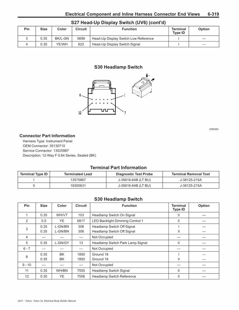
Electrical Component and Inline Harness Connector End Views 6-319
S27 Head-Up Display Switch (UV6) (cont'd)Pin Size Color Circuit Function Terminal
Type IDOption
3 0.35 BK/L-GN 5699 Head-Up Display Switch Low Reference I —
4 0.35 YE/WH 622 Head-Up Display Switch Signal I —
S30 Headlamp Switch
5095565
Connector Part InformationHarness Type: Instrument PanelOEM Connector: 35130710Service Connector: 13525987Description: 12-Way F 0.64 Series, Sealed (BK)
Terminal Part InformationTerminal Type ID Terminated Lead Diagnostic Test Probe Terminal Removal Tool
I 13575867 J-35616-64B (LT BU) J-38125-215A
II 19300631 J-35616-64B (LT BU) J-38125-215A
S30 Headlamp SwitchPin Size Color Circuit Function Terminal
Type IDOption
1 0.35 WH/VT 103 Headlamp Switch On Signal II —
2 0.5 YE 6817 LED Backlight Dimming Control 1 II —
30.350.35
L-GN/BNL-GN/BN
306306
Headlamp Switch Off SignalHeadlamp Switch Off Signal
III
——
4 — — — Not Occupied — —
5 0.35 L-GN/GY 13 Headlamp Switch Park Lamp Signal II —
6 - 7 — — — Not Occupied — —
80.350.35
BKBK
18501850
Ground 18Ground 18
III
——
9 - 10 — — — Not Occupied — —
11 0.35 WH/BN 7555 Headlamp Switch Signal II —
12 0.35 YE 7556 Headlamp Switch Reference II —
2021 - Yukon, Yukon XL Electrical Body Builder Manual

6-320 Electrical Component and Inline Harness Connector End Views
S38 Ignition Mode Switch
4232228
Connector Part InformationHarness Type: Instrument PanelOEM Connector: 15526973Service Connector: 19353873Description: 8-Way F 0.64 OCS Series (GY)
Terminal Part InformationTerminal Type ID Terminated Lead Diagnostic Test Probe Terminal Removal Tool
I Not Required J-35616-64B (LT BU) No Tool Required
S38 Ignition Mode SwitchPin Size Color Circuit Function Terminal
Type IDOption
1 0.35 D-BU/BK 5719 Ignition Mode Switch Start LED Signal I —
2 0.35 BN/BK 5720 Ignition Mode Switch Accessory LED Signal I —
3 0.5 BK/WH 1851 Ground 18 I —
4 0.35 D-BU/L-GN 5723 Ignition Mode Switch Mode Voltage I —
5 0.35 YE 6817 LED Backlight Dimming Control 1 I —
6 — — — Not Occupied — —
7 0.35 BK/GY 3559 Passive Start Switch 2 Low Reference I —
8 0.35 L-GN/BK 3558 Ignition Mode Switch Signal 2 I —
2021 - Yukon, Yukon XL Electrical Body Builder Manual

Electrical Component and Inline Harness Connector End Views 6-321
S47D Seat Memory Switch - Driver (A45/AUN)
2717162
Connector Part InformationHarness Type: Driver Door TrimOEM Connector: 13969166Service Connector: Service by Harness - See Part CatalogDescription: 4-Way F 0.64 Micro-Quadlock Series (BK)
Terminal Part InformationTerminal Type ID Terminated Lead Diagnostic Test Probe Terminal Removal Tool
I Not Required J-35616-64B (LT BU) No Tool Required
S47D Seat Memory Switch - Driver (A45/AUN)Pin Size Color Circuit Function Terminal
Type IDOption
1 0.35 BN/GY 4784 Left Front Door LED Backlight Dimming Control I —
2 0.35 BK/WH 1151 Ground 11 I —
3 0.35 WH 615 Seat Memory Switch Signal 1 I —
4 0.35 D-BU/L-GN 614 Seat Memory Switch Set Signal I —
S48C Multifunction Switch 1 - Instrument Panel
4329088
Connector Part InformationHarness Type: Instrument PanelOEM Connector: 33168840
2021 - Yukon, Yukon XL Electrical Body Builder Manual

6-322 Electrical Component and Inline Harness Connector End Views
Service Connector: 19369840Description: 18-Way F Micro-Quadlock Series (BK)
Terminal Part InformationTerminal Type ID Terminated Lead Diagnostic Test Probe Terminal Removal Tool
I 13575587 J-35616-64B (LT BU) J-38125-12A
II 13575859 J-35616-64B (LT BU) J-38125-12A
S48C Multifunction Switch 1 - Instrument PanelPin Size Color Circuit Function Terminal
Type IDOption
1 0.35 D-BU/VT 1788 Traction Control Switch Signal 1 I —
2 0.35 GY/WH 4630 AC Power Outlet Switch Signal I —
3 0.35 YE 7755 AC Power Outlet Status Indicator Control I —
4 0.35 GY/WH 3153 Lane Departure Warning Disable Switch Signal I —
5 0.35 WH 3152 Lane Departure Warning Indicator Control I —
6 0.35 GY/L-GN 2555 Rear Parking Assist Disable Signal I —
7 0.35 L-GN/BN 5852 Rear Parking Assist Disable LED Signal I —
8 0.5 D-BU/WH 3119 Roof Rail Air Bag Disable Switch Signal II —
9 0.35 D-BU/YE 6844 ABS/Traction Control Hill Descent ControlSwitch Signal I —
10 0.35 BK/WH 1851 Ground 18 I —
11 0.5 YE 6817 LED Backlight Dimming Control 1 II —
12 — — — Not Occupied — —
13 0.35 GY/D-BU 3602 Curb View Enable Signal I —
14 0.5 BN/WH 3895 Roof Rail Air Bag Disable Switch Low Reference II —
15 - 16 — — — Not Occupied — —
17 0.35 L-GN 1110 Stop/Start Indicator Control I —
18 0.35 D-BU 1111 Stop/Start Switch Signal I —
S71 Steering Column Tilt and Telescope Switch (N38)
73146
Connector Part InformationHarness Type: Instrument PanelOEM Connector: 12052854
2021 - Yukon, Yukon XL Electrical Body Builder Manual

Electrical Component and Inline Harness Connector End Views 6-323
Service Connector: 15862656Description: 7-Way F 280 Metri-Pack Series (BK)
Terminal Part InformationTerminal Type ID Terminated Lead Diagnostic Test Probe Terminal Removal Tool
I Not Required J-35616-4A (PU) No Tool Required
S71 Steering Column Tilt and Telescope Switch (N38)Pin Size Color Circuit Function Terminal
Type IDOption
A 0.35 D-BU/YE 2094 Steering Column Tilt and Telescope SwitchForward Signal I —
B 0.35 YE/BN 2097 Steering Column Tilt and Telescope SwitchDown Signal I —
C 0.35 BN/GY 2096 Steering Column Tilt and Telescope Switch UpSignal I —
D - E — — — Not Occupied — —
F 0.35 L-GN/BN 2095 Steering Column Tilt and Telescope SwitchRearward Signal I —
G 0.35 VT/BK 2020 Steering Column Tilt and Telescope SwitchFeedback Signal I —
S76 Trailer Brake Control Switch (JL1)
2717162
Connector Part InformationHarness Type: Instrument PanelOEM Connector: 13599500Service Connector: Service by Harness - See Part CatalogDescription: 4-Way F 0.64 Micro-Quadlock Series (YE)
Terminal Part InformationTerminal Type ID Terminated Lead Diagnostic Test Probe Terminal Removal Tool
I Not Required J-35616-64B (LT BU) No Tool Required
S76 Trailer Brake Control Switch (JL1)Pin Size Color Circuit Function Terminal
Type IDOption
1 0.35 RD/VT 4040 Secondary Fused Battery Positive Voltage 40 I —
2021 - Yukon, Yukon XL Electrical Body Builder Manual

6-324 Electrical Component and Inline Harness Connector End Views
S76 Trailer Brake Control Switch (JL1) (cont'd)Pin Size Color Circuit Function Terminal
Type IDOption
2 0.35 L-GN/D-BU 2733 Electronic Brake Control Module LIN Bus 2 I —
3 0.35 BK 1850 Ground 18 I —
4 — — — Not Occupied — —
S78 Turn Signal/Multifunction Switch
2830955
Connector Part InformationHarness Type: Instrument PanelOEM Connector: 13650061Service Connector: 19299776Description: 10-Way F 0.64 Micro-Quadlock Series (BK)
Terminal Part InformationTerminal Type ID Terminated Lead Diagnostic Test Probe Terminal Removal Tool
I 13575736 J-35616-64B (LT BU) J-38125-12A
II 13579993 J-35616-64B (LT BU) J-38125-12A
S78 Turn Signal/Multifunction SwitchPin Size Color Circuit Function Terminal
Type IDOption
1 0.35 WH/L-GN 2915 Left Turn Signal Switch Signal I —
2 0.35 VT/D-BU 2916 Right Turn Signal Switch Signal I —
3 0.35 BK 1850 Ground 18 I —
4 0.35 BN/D-BU 391 Rear Window Wiper Switch Signal I —
5 0.35 WH/BK 94 Windshield Washer Switch Signal I —
60.350.35
YE/BNYE/BN
307307
Headlamp Switch Flash SignalHeadlamp Switch Flash Signal
III
——
7 0.35 WH 524 High Beam Select Switch High Beam Signal I —
8 0.35 BK/GY 6009 Windshield Wiper Switch Low Reference I —
9 0.35 GY 1715 Windshield Wiper Switch High Signal I —
10 0.35 YE/D-BU 1714 Windshield Wiper Switch Low Signal I —
2021 - Yukon, Yukon XL Electrical Body Builder Manual

Electrical Component and Inline Harness Connector End Views 6-325
S79D Window Switch - Driver X1
2871905
Connector Part InformationHarness Type: Driver Door TrimOEM Connector: 13706537Service Connector: Service by Harness - See Part CatalogDescription: 24-Way F 0.64, 1.5, 2.8 Series (BK)
Terminal Part InformationTerminal Type ID Terminated Lead Diagnostic Test Probe Terminal Removal Tool
I Not Required J-35616-2A (GY) No Tool Required
II Not Required J-35616-4A (PU) No Tool Required
III Not Required J-35616-64B (LT BU) No Tool Required
S79D Window Switch - Driver X1Pin Size Color Circuit Function Terminal
Type IDOption
1 0.35 WH/BN 2764 Window Switch Left Front Down Signal II —
2 0.35 L-GN 2766 Power Window Switch Left Front Express Signal III —
3 0.35 BN/YE 2771 Left Front Door Lock Switch Lock Signal III —
4 0.35 BN/WH 2772 Left Front Door Lock Switch Unlock Signal III —
5 0.35 GY/VT 2767 LED Ambient Lighting Control Left Front Door III —
6 0.35 VT/YE 4244 Left Front Door Lock Indicator Control III —
7 0.35 BN/GY 4784 Left Front Door LED Backlight Dimming Control III —
8 0.35 GY/YE 1760 Left Side Object Detection LED Control III —
9 0.35 WH/L-GN 2786 Left Front Mirror Motor Fold In Control III —
10 0.35 YE/BN 2789 Left Front Mirror Motor Common Control III —
11 0.5 BK 1150 Ground 11 II —
12 0.35 GY/WH 2785 Left Front Mirror Motor Fold Out Control I —
13 - 16 — — — Not Occupied — —
17 0.35 WH/VT 4258 Left Front Door Lock Status Signal III —
18 0.35 VT/D-BU 2788 Left Front Mirror Motor Up [+] Down [-] Control III —
19 0.35 BN/BK 2790 Left Front Mirror Motor Right [+] Left [-] Control III —
20 — — — Not Occupied — —
21 0.35 L-GN/YE 6134 Body Control Module LIN Bus 3 III —
22 0.35 WH 606 Left Outside Rearview Mirror Heater Control I —
23 0.35 GY/L-GN 2763 Window Switch Left Front Up Signal II —
2021 - Yukon, Yukon XL Electrical Body Builder Manual

6-326 Electrical Component and Inline Harness Connector End Views
S79D Window Switch - Driver X1 (cont'd)Pin Size Color Circuit Function Terminal
Type IDOption
24 0.5 RD/VT 1940 Secondary Fused Battery Positive Voltage 19 II —
S79D Window Switch - Driver X2
4145138
Connector Part InformationHarness Type: Driver Door TrimOEM Connector: 33251915Service Connector: Service by Harness - See Part CatalogDescription: 6-Way F 0.64 Generation Y Series (BK)
Terminal Part InformationTerminal Type ID Terminated Lead Diagnostic Test Probe Terminal Removal Tool
I Not Required J-35616-64B (LT BU) No Tool Required
S79D Window Switch - Driver X2Pin Size Color Circuit Function Terminal
Type IDOption
1 0.35 WH/YE 2792 Left Front Mirror Position Sensor Left [-] Right [+]Signal I —
2 0.35 GY/BN 2787 Left Front Mirror Position Sensor Up [+] Down [-]Signal I —
3 0.35 VT/RD 2791 Left Front Mirror Position Sensor HighReference I —
4 0.35 BK/BN 673 Left Outside Rearview Mirror Position SensorLow Reference I —
5 - 6 — — — Not Occupied — —
2021 - Yukon, Yukon XL Electrical Body Builder Manual

Electrical Component and Inline Harness Connector End Views 6-327
S79LR Window Switch - Left Rear
5035058
Connector Part InformationHarness Type: Left Rear Door TrimOEM Connector: 35152553Service Connector: Service by Harness - See Part CatalogDescription: 10-Way F 1.5, 2.8 Series (BK)
Terminal Part InformationTerminal Type ID Terminated Lead Diagnostic Test Probe Terminal Removal Tool
I Not Required J-35616-2A (GY) No Tool Required
II Not Required J-35616-4A (PU) No Tool Required
S79LR Window Switch - Left RearPin Size Color Circuit Function Terminal
Type IDOption
1 0.35 L-GN/GY 6135 Body Control Module LIN Bus 4 I —
2 0.35 GY 747 Left Rear Door Ajar Switch Signal I —
3 0.5 BK 1150 Ground 11 I —
4 0.35 L-GN/D-BU 4648 Left Rear Door Lock Status Signal I —
5 - 6 — — — Not Occupied — —
7 2.5 BK 1150 Ground 11 II —
8 2.5 RD/GY 3540 Secondary Fused Battery Positive Voltage 35 II —
9 2 D-BU/VT 668 Left Rear Window Motor Up Control II —
10 2 YE/D-BU 669 Left Rear Window Motor Down Control II —
2021 - Yukon, Yukon XL Electrical Body Builder Manual

6-328 Electrical Component and Inline Harness Connector End Views
S79P Window Switch - Passenger
2871905
Connector Part InformationHarness Type: Passenger Door TrimOEM Connector: 13706537Service Connector: Service by Harness - See Part CatalogDescription: 24-Way F 0.64, 1.5, 2.8 Series (BK)
Terminal Part InformationTerminal Type ID Terminated Lead Diagnostic Test Probe Terminal Removal Tool
I Not Required J-35616-2A (GY) No Tool Required
II Not Required J-35616-4A (PU) No Tool Required
III Not Required J-35616-64B (LT BU) No Tool Required
S79P Window Switch - PassengerPin Size Color Circuit Function Terminal
Type IDOption
1 0.5 BK 1250 Ground 12 II —
2 0.35 YE/RD 2799 Right Front Mirror Position Sensor HighReference III —
3 0.35 L-GN/BK 2798 Right Front Mirror Motor Right [+] Left [-] Control III —
4 0.35 YE/VT 2796 Right Front Mirror Motor Up [+] Down [-] Control III —
5 0.35 WH/BN 2768 LED Ambient Lighting Control Right Front Door III —
6 0.35 YE/D-BU 4245 Right Front Door Lock Indicator Control III —
7 0.35 GY/VT 4638 LED Backlight Dimming Control RightFront Door III —
8 0.35 GY 1761 Right Side Object Detection LED Control III —
9 0.35 D-BU/GY 2794 Right Front Mirror Motor Fold In Control III —
10 0.35 YE/WH 2793 Right Front Mirror Motor Fold Out Control III —
11 0.35 L-GN 1184 Window Switch Right Front Up Signal II —
12 0.35 BN/VT 607 Right Outside Rearview Mirror Heater Control I —
13 — — — Not Occupied — —
14 0.35 L-GN/YE 6134 Body Control Module LIN Bus 3 III —
15 0.35 VT/WH 2800 Right Front Mirror Position Sensor Left [-] Right[+] Signal III —
16 0.35 D-BU/YE 2795 Right Front Mirror Position Sensor Up [+] Down[-] Signal III —
17 0.35 YE/VT 2773 Right Front Door Lock Switch Lock Control III —
18 0.35 BN/VT 2774 Right Front Door Lock Switch Unlock Control III —
2021 - Yukon, Yukon XL Electrical Body Builder Manual

Electrical Component and Inline Harness Connector End Views 6-329
S79P Window Switch - Passenger (cont'd)Pin Size Color Circuit Function Terminal
Type IDOption
19 0.35 VT 4259 Right Front Door Lock Status Signal III —
20 0.35 VT/GY 2765 Window Switch Right Front Express Signal III —
21 0.35 WH 2797 Right Front Mirror Motor Common Control III —
22 0.35 BK/L-GN 675 Right Outside Rearview Mirror Position SensorLow Reference I —
23 0.5 RD/D-BU 5240 Secondary Fused Battery Positive Voltage 52 II —
24 0.35 BN 5295 Window Switch Right Front Down Signal II —
S79RR Window Switch - Right Rear
5035058
Connector Part InformationHarness Type: Right Rear Door TrimOEM Connector: 35152553Service Connector: Service by Harness - See Part CatalogDescription: 10-Way F 1.5, 2.8 Series (BK)
Terminal Part InformationTerminal Type ID Terminated Lead Diagnostic Test Probe Terminal Removal Tool
I Not Required J-35616-2A (GY) No Tool Required
II Not Required J-35616-4A (PU) No Tool Required
S79RR Window Switch - Right RearPin Size Color Circuit Function Terminal
Type IDOption
1 0.35 L-GN/GY 6135 Body Control Module LIN Bus 4 I —
2 0.35 GY 748 Right Rear Door Ajar Switch Signal I —
3 — — — Not Occupied — —
4 0.35 WH/GY 4649 Right Rear Door Lock Status Signal I —
5 - 6 — — — Not Occupied — —
7 2.5 BK 1250 Ground 12 II —
8 2.5 RD/BN 4240 Secondary Fused Battery Positive Voltage 42 II —
9 2 D-BU/GY 670 Right Rear Window Motor Up Control II —
10 2 L-GN/BK 671 Right Rear Window Motor Down Control II —
2021 - Yukon, Yukon XL Electrical Body Builder Manual

6-330 Electrical Component and Inline Harness Connector End Views
S126 Drive Mode Select Switch
4232228
Connector Part InformationHarness Type: Instrument PanelOEM Connector: 15526973Service Connector: 19353873Description: 8-Way F 0.64 OCS Series (GY)
Terminal Part InformationTerminal Type ID Terminated Lead Diagnostic Test Probe Terminal Removal Tool
I Not Required J-35616-64B (LT BU) No Tool Required
S126 Drive Mode Select SwitchPin Size Color Circuit Function Terminal
Type IDOption
1 0.35 WH/BN 2203 Enhanced Driver Mode 2 Switch Signal I —
2 — — — Not Occupied — —
30.350.35
BK/GYBK/VT
14491449
Steering Wheel Resistor Ladder Low ReferenceSteering Wheel Resistor Ladder Low Reference
II
—X88/Z88
4 0.35 YE 6817 LED Backlight Dimming Control 1 I —
5 0.35 BK 1850 Ground 18 I —
6 - 8 — — — Not Occupied — —
2021 - Yukon, Yukon XL Electrical Body Builder Manual

Electrical Component and Inline Harness Connector End Views 6-331
S141 Liftgate Window Unlatch Switch
4649903
Connector Part InformationHarness Type: Liftgate ExtensionOEM Connector: 33327048Service Connector: Service by Harness - See Part CatalogDescription: 2-Way F 1.2 MCON Series, Sealed (BK)
Terminal Part InformationTerminal Type ID Terminated Lead Diagnostic Test Probe Terminal Removal Tool
I Not Required J-35616-16 (LT GN) No Tool Required
S141 Liftgate Window Unlatch SwitchPin Size Color Circuit Function Terminal
Type IDOption
1 0.35 GY/L-GN 6190 Liftgate Window/Rear Compartment Lid, ExteriorUnlatch Signal I —
2 0.35 BK 2050 Ground 20 I —
S143L Folding Seat Control Switch - 2nd Row Left (ATN/ATT)
1376712
Connector Part InformationHarness Type: BodyOEM Connector: 15417063Service Connector: 88987857Description: 3-Way F 0.64 Micro-Pack Series (BK)
2021 - Yukon, Yukon XL Electrical Body Builder Manual

6-332 Electrical Component and Inline Harness Connector End Views
Terminal Part InformationTerminal Type ID Terminated Lead Diagnostic Test Probe Terminal Removal Tool
I Not Required J-35616-64B (LT BU) No Tool Required
S143L Folding Seat Control Switch - 2nd Row Left (ATN/ATT)Pin Size Color Circuit Function Terminal
Type IDOption
A 0.35 YE/BK 5813 Park Enable Control I —
B — — — Not Occupied — —
C 0.5 L-GN 6808 Left Rear Folding Seat Motor Control I —
S143R Folding Seat Control Switch - 2nd Row Right (ATN/ATT)
1376712
Connector Part InformationHarness Type: BodyOEM Connector: 15417063Service Connector: 88987857Description: 3-Way F 0.64 Micro-Pack Series (BK)
Terminal Part InformationTerminal Type ID Terminated Lead Diagnostic Test Probe Terminal Removal Tool
I Not Required J-35616-64B (LT BU) No Tool Required
S143R Folding Seat Control Switch - 2nd Row Right (ATN/ATT)Pin Size Color Circuit Function Terminal
Type IDOption
A 0.35 YE/BK 5813 Park Enable Control I —
B — — — Not Occupied — —
C 0.5 BN/WH 6809 Right Rear Folding Seat Motor Control I —
2021 - Yukon, Yukon XL Electrical Body Builder Manual

Electrical Component and Inline Harness Connector End Views 6-333
S144A Folding Seat Control Switch - Rear Compartment 2nd Row (ATN/ATT)
4808677
Connector Part InformationHarness Type: BodyOEM Connector: 35015626Service Connector: 19368548Description: 8-Way F 0.64 YESC Series (BK)
Terminal Part InformationTerminal Type ID Terminated Lead Diagnostic Test Probe Terminal Removal Tool
I Not Required J-35616-64B (LT BU) No Tool Required
S144A Folding Seat Control Switch - Rear Compartment 2nd Row (ATN/ATT)Pin Size Color Circuit Function Terminal
Type IDOption
1 — — — Not Occupied — —
2 0.35 YE/BK 5813 Park Enable Control I —
3 — — — Not Occupied — —
4 0.5 L-GN 6808 Left Rear Folding Seat Motor Control I —
5 0.75 BN/WH 6809 Right Rear Folding Seat Motor Control I —
6 - 8 — — — Not Occupied — —
S145 Center Console Compartment Cooler Switch (DCK)
3960313
2021 - Yukon, Yukon XL Electrical Body Builder Manual
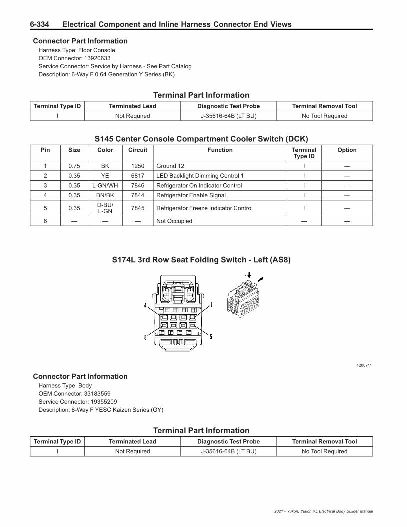
6-334 Electrical Component and Inline Harness Connector End Views
Connector Part InformationHarness Type: Floor ConsoleOEM Connector: 13920633Service Connector: Service by Harness - See Part CatalogDescription: 6-Way F 0.64 Generation Y Series (BK)
Terminal Part InformationTerminal Type ID Terminated Lead Diagnostic Test Probe Terminal Removal Tool
I Not Required J-35616-64B (LT BU) No Tool Required
S145 Center Console Compartment Cooler Switch (DCK)Pin Size Color Circuit Function Terminal
Type IDOption
1 0.75 BK 1250 Ground 12 I —
2 0.35 YE 6817 LED Backlight Dimming Control 1 I —
3 0.35 L-GN/WH 7846 Refrigerator On Indicator Control I —
4 0.35 BN/BK 7844 Refrigerator Enable Signal I —
5 0.35 D-BU/L-GN 7845 Refrigerator Freeze Indicator Control I —
6 — — — Not Occupied — —
S174L 3rd Row Seat Folding Switch - Left (AS8)
4280711
Connector Part InformationHarness Type: BodyOEM Connector: 33183559Service Connector: 19355209Description: 8-Way F YESC Kaizen Series (GY)
Terminal Part InformationTerminal Type ID Terminated Lead Diagnostic Test Probe Terminal Removal Tool
I Not Required J-35616-64B (LT BU) No Tool Required
2021 - Yukon, Yukon XL Electrical Body Builder Manual

Electrical Component and Inline Harness Connector End Views 6-335
S174L 3rd Row Seat Folding Switch - Left (AS8)Pin Size Color Circuit Function Terminal
Type IDOption
1 0.5 YE/D-BU 2698 Left 3rd Row Seat Recline Switch Signal I —
2 - 3 — — — Not Occupied — —
4 0.5 BK/D-BU 5474 3rd Row Seat Sensor Low Reference I —
5 — — — Not Occupied — —
6 0.5 L-GN/GY 2699 Right 3rd Row Seat Recline Switch Signal I —
7 - 8 — — — Not Occupied — —
T1 Accessory DC/AC Power Inverter Module X1 (KI4/KI5)
2453116
Connector Part InformationHarness Type: BodyOEM Connector: 13581928Service Connector: Service by Harness - See Part CatalogDescription: 2-Way F 9.5 Series (BK)
Terminal Part InformationTerminal Type ID Terminated Lead Diagnostic Test Probe Terminal Removal Tool
I Not Required J-35616-22 (RD) No Tool Required
T1 Accessory DC/AC Power Inverter Module X1 (KI4/KI5)Pin Size Color Circuit Function Terminal
Type IDOption
1 5 BN/BK 4629 DC/AC Inverter Control I —
2 5 BK 1450 Ground 14 I —
2021 - Yukon, Yukon XL Electrical Body Builder Manual

6-336 Electrical Component and Inline Harness Connector End Views
T1 Accessory DC/AC Power Inverter Module X2 (KI4/KI5)
1540775
Connector Part InformationHarness Type: Power Inverter Module JumperOEM Connector: 33356826Service Connector: Service by Harness - See Part CatalogDescription: 14-Way F 1.5, 2.8 Series (BU)
Terminal Part InformationTerminal Type ID Terminated Lead Diagnostic Test Probe Terminal Removal Tool
I Not Required J-35616-2A (GY) No Tool Required
II Not Required J-35616-4A (PU) No Tool Required
T1 Accessory DC/AC Power Inverter Module X2 (KI4/KI5)Pin Size Color Circuit Function Terminal
Type IDOption
1 — — — Not Occupied — —
2 0.5 VT/RD 4049 AC Power Outlet Sensor High Reference I —
3 0.5 VT/WH 1139 Run/Crank Ignition 1 Voltage 11 I —
4 0.5 WH/L-GN 4628 DC/AC Inverter Relay Control I —
5 0.5 D-BU/BN 6807 DC/AC Inverter Control I —
6 — — — Not Occupied — —
7 0.75 BN/WH 2262 230V AC Phase A 2 II —
8 - 9 — — — Not Occupied — —
10 0.5 L-GN/D-BU 6133 Body Control Module LIN Bus 2 I —
11 — — — Not Occupied — —
12 0.5 L-GN/BN 2266 DC/AC Inverter Control 2 I —
13 0.5 Bare 2544 230V AC Outlet 2 Low Reference I —
14 0.75 D-BU/WH 2263 230V AC Phase B 2 II —
2021 - Yukon, Yukon XL Electrical Body Builder Manual

Electrical Component and Inline Harness Connector End Views 6-337
T3 Audio Amplifier X1 (UQA/UQF/UQS/UQP)
4875738
Connector Part InformationHarness Type: BodyOEM Connector: 33223792Service Connector: 19369366Description: 8-Way F 2.8 OCS Series (BK)
Terminal Part InformationTerminal Type ID Terminated Lead Diagnostic Test Probe Terminal Removal Tool
I Not Required J-35616-4A (PU) No Tool Required
T3 Audio Amplifier X1 (UQA/UQF/UQS/UQP)Pin Size Color Circuit Function Terminal
Type IDOption
12.52.5
D-BU/GYL-GN/VT
3461795
Left/Rear Subwoofer Control [+]Right Subwoofer Control [+]
II
UQA-UQH/(-UQH+UQS)
-UQH+UQP+Z75
2 0.75 YE 200 Right Front Speaker 1 [+] Control I —
3 0.75 D-BU 201 Left Front Speaker 1 [+] Control I —
4 3 RD/YE 3740 Secondary Fused Battery Positive Voltage 37 I —
52.52.5
L-GN/BKGY/BK
1794315
Left/Rear Subwoofer Control [-]Right Subwoofer Control [-]
II
UQA-UQH/(-UQH+UQS)
-UQH+UQP+Z88
6 0.75 YE/BK 117 Right Front Speaker [-] Control 1 I —
7 0.75 BN/D-BU 118 Left Front Speaker [-] Control 1 I —
8 2.5 BK/WH 1451 Ground 14 I —
2021 - Yukon, Yukon XL Electrical Body Builder Manual
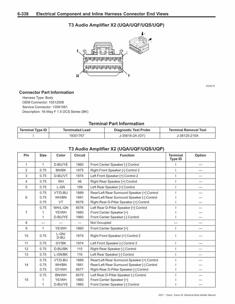
6-338 Electrical Component and Inline Harness Connector End Views
T3 Audio Amplifier X2 (UQA/UQF/UQS/UQP)
4332214
Connector Part InformationHarness Type: BodyOEM Connector: 15512506Service Connector: 13591061Description: 16-Way F 1.5 OCS Series (BK)
Terminal Part InformationTerminal Type ID Terminated Lead Diagnostic Test Probe Terminal Removal Tool
I 19301767 J-35616-2A (GY) J-38125-215A
T3 Audio Amplifier X2 (UQA/UQF/UQS/UQP)Pin Size Color Circuit Function Terminal
Type IDOption
1 1 D-BU/YE 1960 Front Center Speaker [-] Control I —
2 0.75 BN/BK 1975 Right Front Speaker [-] Control 2 I —
3 0.75 D-BU/VT 1874 Left Front Speaker [+] Control 2 I —
4 0.75 WH 46 Right Rear Speaker [+] Control I —
5 0.75 L-GN 199 Left Rear Speaker [+] Control I —
60.750.750.75
VT/D-BUWH/BN
VT
188918918578
Rear/Left Rear Surround Speaker [+] ControlRear/Left Rear Surround Speaker [-] ControlRight Rear D-Pillar Speaker [+] Control
III
———
70.75
11
WH/L-GNYE/WH
D-BU/YE
857618601960
Left Rear D-Pillar Speaker [+] ControlFront Center Speaker [+]Front Center Speaker [-] Control
III
———
8 — — — Not Occupied — —
9 1 YE/WH 1860 Front Center Speaker [+] I —
10 0.75 L-GN/D-BU 1875 Right Front Speaker [+] Control 2 I —
11 0.75 GY/BK 1974 Left Front Speaker [-] Control 2 I —
12 0.75 D-BU/BK 115 Right Rear Speaker [-] Control I —
13 0.75 L-GN/BK 116 Left Rear Speaker [-] Control I —
140.750.750.75
VT/D-BUWH/BNGY/WH
188918918577
Rear/Left Rear Surround Speaker [+] ControlRear/Left Rear Surround Speaker [-] ControlRight Rear D-Pillar Speaker [-] Control
III
———
150.75
11
BN/WHYE/WH
D-BU/YE
857518601960
Left Rear D-Pillar Speaker [-] ControlFront Center Speaker [+]Front Center Speaker [-] Control
III
———
2021 - Yukon, Yukon XL Electrical Body Builder Manual

Electrical Component and Inline Harness Connector End Views 6-339
T3 Audio Amplifier X2 (UQA/UQF/UQS/UQP) (cont'd)Pin Size Color Circuit Function Terminal
Type IDOption
16 — — — Not Occupied — —
T3 Audio Amplifier X3 (UQA/UQF/UQS/UQP)
4873243
Connector Part InformationHarness Type: BodyOEM Connector: 35016343Service Connector: 13519738Description: 16-Way F 0.64 OCS Series (BK)
Terminal Part InformationTerminal Type ID Terminated Lead Diagnostic Test Probe Terminal Removal Tool
I 19300660 J-35616-64B (LT BU) J-38125-12A
T3 Audio Amplifier X3 (UQA/UQF/UQS/UQP)Pin Size Color Circuit Function Terminal
Type IDOption
1 0.35 GY/BK 7215 Ethernet Bus 6 [+] I —
2 0.35 BN/BK 7214 Ethernet Bus 6 [-] I —
3 — — — Not Occupied — —
4 0.5 L-GN/BN 3005 Active Noise Cancellation Microphone 1 Signal I —
5 0.5 L-GN/BN 3005 Active Noise Cancellation Microphone 1 Signal I —
6 - 10 — — — Not Occupied — —
11 0.5 D-BU/WH 4985 AUTOSAR CAN Bus [+] 5 Serial Data I —
120.50.5
D-BU/YEL-GN/BK
49843008
AUTOSAR CAN Bus [-] 5 Serial DataActive Noise Cancellation Microphone 1Feedback Signal
II
UQA/UQSUQP+Z88
13 0.5 L-GN/BK 3008 Active Noise Cancellation Microphone 1Feedback Signal I —
14 - 16 — — — Not Occupied — —
2021 - Yukon, Yukon XL Electrical Body Builder Manual
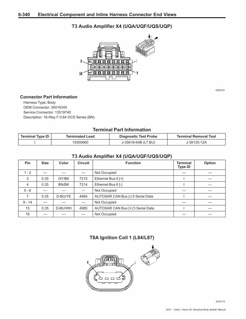
6-340 Electrical Component and Inline Harness Connector End Views
T3 Audio Amplifier X4 (UQA/UQF/UQS/UQP)
4256181
Connector Part InformationHarness Type: BodyOEM Connector: 35016345Service Connector: 13519740Description: 16-Way F 0.64 OCS Series (BN)
Terminal Part InformationTerminal Type ID Terminated Lead Diagnostic Test Probe Terminal Removal Tool
I 19300660 J-35616-64B (LT BU) J-38125-12A
T3 Audio Amplifier X4 (UQA/UQF/UQS/UQP)Pin Size Color Circuit Function Terminal
Type IDOption
1 - 2 — — — Not Occupied — —
3 0.35 GY/BK 7215 Ethernet Bus 6 [+] I —
4 0.35 BN/BK 7214 Ethernet Bus 6 [-] I —
5 - 6 — — — Not Occupied — —
7 0.35 D-BU/YE 4984 AUTOSAR CAN Bus [-] 5 Serial Data I —
8 - 14 — — — Not Occupied — —
15 0.35 D-BU/WH 4985 AUTOSAR CAN Bus [+] 5 Serial Data I —
16 — — — Not Occupied — —
T8A Ignition Coil 1 (L84/L87)
3240115
2021 - Yukon, Yukon XL Electrical Body Builder Manual

Electrical Component and Inline Harness Connector End Views 6-341
Connector Part InformationHarness Type: EngineOEM Connector: 13863211Service Connector: 19367596Description: 4-Way F 150 MX Series, Sealed (BK)
Terminal Part InformationTerminal Type ID Terminated Lead Diagnostic Test Probe Terminal Removal Tool
I Not Required J-35616-14 (GN) No Tool Required
T8A Ignition Coil 1 (L84/L87)Pin Size Color Circuit Function Terminal
Type IDOption
1 0.75 BK 6150 Engine Odd Bank Ground 61 I —
2 0.5 BK/D-BU 2129 Ignition Control Low Reference Bank 1 I —
3 0.5 D-BU/VT 2121 Ignition Control 1 I —
4 0.75 VT/D-BU 5291 Powertrain Main Relay Fused Supply 2 I —
T8B Ignition Coil 2 (L84/L87)
3240115
Connector Part InformationHarness Type: EngineOEM Connector: 13863211Service Connector: 19367596Description: 4-Way F 150 MX Series, Sealed (BK)
Terminal Part InformationTerminal Type ID Terminated Lead Diagnostic Test Probe Terminal Removal Tool
I Not Required J-35616-14 (GN) No Tool Required
T8B Ignition Coil 2 (L84/L87)Pin Size Color Circuit Function Terminal
Type IDOption
1 0.75 BK 6450 Engine Even Bank Ground 64 I —
2 0.75 BK/GY 2130 Ignition Control Low Reference Bank 2 I —
3 0.75 D-BU/WH 2122 Ignition Control 2 I —
2021 - Yukon, Yukon XL Electrical Body Builder Manual

6-342 Electrical Component and Inline Harness Connector End Views
T8B Ignition Coil 2 (L84/L87) (cont'd)Pin Size Color Circuit Function Terminal
Type IDOption
4 0.75 VT/D-BU 5292 Powertrain Main Relay Fused Supply 3 I —
T8C Ignition Coil 3 (L84/L87)
3240115
Connector Part InformationHarness Type: EngineOEM Connector: 13863211Service Connector: 19367596Description: 4-Way F 150 MX Series, Sealed (BK)
Terminal Part InformationTerminal Type ID Terminated Lead Diagnostic Test Probe Terminal Removal Tool
I Not Required J-35616-14 (GN) No Tool Required
T8C Ignition Coil 3 (L84/L87)Pin Size Color Circuit Function Terminal
Type IDOption
1 0.75 BK 6150 Engine Odd Bank Ground 61 I —
2 0.5 BK/D-BU 2129 Ignition Control Low Reference Bank 1 I —
3 0.5 L-GN/D-BU 2123 Ignition Control 3 I —
4 0.75 VT/D-BU 5291 Powertrain Main Relay Fused Supply 2 I —
2021 - Yukon, Yukon XL Electrical Body Builder Manual

Electrical Component and Inline Harness Connector End Views 6-343
T8D Ignition Coil 4 (L84/L87)
3240115
Connector Part InformationHarness Type: EngineOEM Connector: 13863211Service Connector: 19367596Description: 4-Way F 150 MX Series, Sealed (BK)
Terminal Part InformationTerminal Type ID Terminated Lead Diagnostic Test Probe Terminal Removal Tool
I Not Required J-35616-14 (GN) No Tool Required
T8D Ignition Coil 4 (L84/L87)Pin Size Color Circuit Function Terminal
Type IDOption
1 0.75 BK 6450 Engine Even Bank Ground 64 I —
2 0.75 BK/GY 2130 Ignition Control Low Reference Bank 2 I —
3 0.5 YE/D-BU 2124 Ignition Control 4 I —
4 0.75 VT/D-BU 5292 Powertrain Main Relay Fused Supply 3 I —
T8E Ignition Coil 5 (L84/L87)
3240115
Connector Part InformationHarness Type: EngineOEM Connector: 13863211
2021 - Yukon, Yukon XL Electrical Body Builder Manual

6-344 Electrical Component and Inline Harness Connector End Views
Service Connector: 19367596Description: 4-Way F 150 MX Series, Sealed (BK)
Terminal Part InformationTerminal Type ID Terminated Lead Diagnostic Test Probe Terminal Removal Tool
I Not Required J-35616-14 (GN) No Tool Required
T8E Ignition Coil 5 (L84/L87)Pin Size Color Circuit Function Terminal
Type IDOption
1 0.75 BK 6150 Engine Odd Bank Ground 61 I —
2 0.5 BK/D-BU 2129 Ignition Control Low Reference Bank 1 I —
3 0.5 D-BU/GY 2125 Ignition Control 5 I —
4 0.75 VT/D-BU 5291 Powertrain Main Relay Fused Supply 2 I —
T8F Ignition Coil 6 (L84/L87)
3240115
Connector Part InformationHarness Type: EngineOEM Connector: 13863211Service Connector: 19367596Description: 4-Way F 150 MX Series, Sealed (BK)
Terminal Part InformationTerminal Type ID Terminated Lead Diagnostic Test Probe Terminal Removal Tool
I Not Required J-35616-14 (GN) No Tool Required
T8F Ignition Coil 6 (L84/L87)Pin Size Color Circuit Function Terminal
Type IDOption
1 0.75 BK 6450 Engine Even Bank Ground 64 I —
2 0.75 BK/GY 2130 Ignition Control Low Reference Bank 2 I —
3 0.5 BN/D-BU 2126 Ignition Control 6 I —
4 0.75 VT/D-BU 5292 Powertrain Main Relay Fused Supply 3 I —
2021 - Yukon, Yukon XL Electrical Body Builder Manual
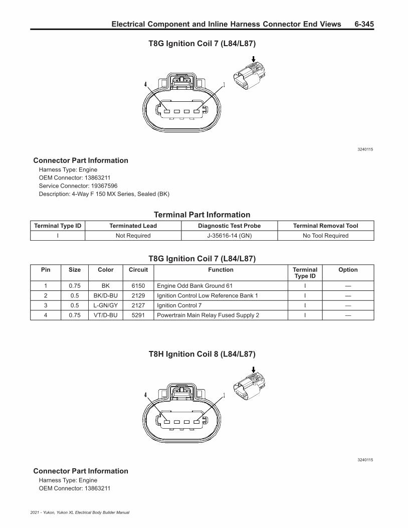
Electrical Component and Inline Harness Connector End Views 6-345
T8G Ignition Coil 7 (L84/L87)
3240115
Connector Part InformationHarness Type: EngineOEM Connector: 13863211Service Connector: 19367596Description: 4-Way F 150 MX Series, Sealed (BK)
Terminal Part InformationTerminal Type ID Terminated Lead Diagnostic Test Probe Terminal Removal Tool
I Not Required J-35616-14 (GN) No Tool Required
T8G Ignition Coil 7 (L84/L87)Pin Size Color Circuit Function Terminal
Type IDOption
1 0.75 BK 6150 Engine Odd Bank Ground 61 I —
2 0.5 BK/D-BU 2129 Ignition Control Low Reference Bank 1 I —
3 0.5 L-GN/GY 2127 Ignition Control 7 I —
4 0.75 VT/D-BU 5291 Powertrain Main Relay Fused Supply 2 I —
T8H Ignition Coil 8 (L84/L87)
3240115
Connector Part InformationHarness Type: EngineOEM Connector: 13863211
2021 - Yukon, Yukon XL Electrical Body Builder Manual
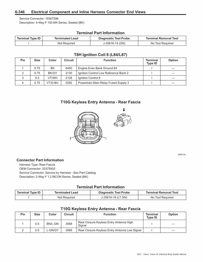
6-346 Electrical Component and Inline Harness Connector End Views
Service Connector: 19367596Description: 4-Way F 150 MX Series, Sealed (BK)
Terminal Part InformationTerminal Type ID Terminated Lead Diagnostic Test Probe Terminal Removal Tool
I Not Required J-35616-14 (GN) No Tool Required
T8H Ignition Coil 8 (L84/L87)Pin Size Color Circuit Function Terminal
Type IDOption
1 0.75 BK 6450 Engine Even Bank Ground 64 I —
2 0.75 BK/GY 2130 Ignition Control Low Reference Bank 2 I —
3 0.5 VT/WH 2128 Ignition Control 8 I —
4 0.75 VT/D-BU 5292 Powertrain Main Relay Fused Supply 3 I —
T10G Keyless Entry Antenna - Rear Fascia
4690744
Connector Part InformationHarness Type: Rear FasciaOEM Connector: 33375932Service Connector: Service by Harness - See Part CatalogDescription: 2-Way F 1.2 MCON Series, Sealed (BK)
Terminal Part InformationTerminal Type ID Terminated Lead Diagnostic Test Probe Terminal Removal Tool
I Not Required J-35616-16 (LT GN) No Tool Required
T10G Keyless Entry Antenna - Rear FasciaPin Size Color Circuit Function Terminal
Type IDOption
1 0.5 BN/L-GN 3568 Rear Closure Keyless Entry Antenna HighSignal I —
2 0.5 L-GN/GY 3569 Rear Closure Keyless Entry Antenna Low Signal I —
2021 - Yukon, Yukon XL Electrical Body Builder Manual

Electrical Component and Inline Harness Connector End Views 6-347
T10J Keyless Entry Antenna - Center Console Front (5W4/9C1/AZ3)
4690744
Connector Part InformationHarness Type: Instrument PanelOEM Connector: 33375932Service Connector: 19366871Description: 2-Way F 1.2 MCON Series, Sealed (BK)
Terminal Part InformationTerminal Type ID Terminated Lead Diagnostic Test Probe Terminal Removal Tool
I Not Required J-35616-16 (LT GN) No Tool Required
T10J Keyless Entry Antenna - Center Console Front (5W4/9C1/AZ3)Pin Size Color Circuit Function Terminal
Type IDOption
1 0.35 BN/BK 3552 Interior Keyless Entry Antenna 1 High Signal I —
2 0.35 WH 3553 Interior Keyless Entry Antenna 1 Low Signal I —
T10J Keyless Entry Antenna - Center Console Front (D07/DCH/DCK)
4690744
Connector Part InformationHarness Type: Floor ConsoleOEM Connector: 33375932Service Connector: Service by Harness - See Part CatalogDescription: 2-Way F 1.2 MCON Series, Sealed (BK)
2021 - Yukon, Yukon XL Electrical Body Builder Manual
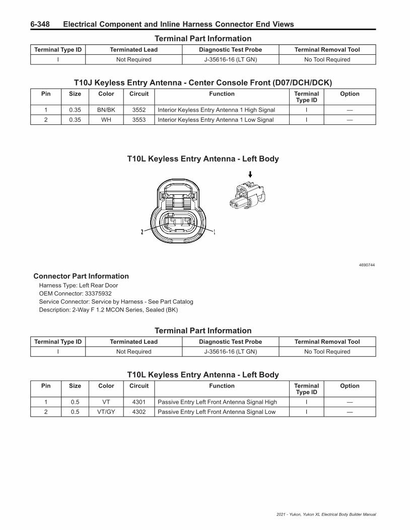
6-348 Electrical Component and Inline Harness Connector End Views
Terminal Part InformationTerminal Type ID Terminated Lead Diagnostic Test Probe Terminal Removal Tool
I Not Required J-35616-16 (LT GN) No Tool Required
T10J Keyless Entry Antenna - Center Console Front (D07/DCH/DCK)Pin Size Color Circuit Function Terminal
Type IDOption
1 0.35 BN/BK 3552 Interior Keyless Entry Antenna 1 High Signal I —
2 0.35 WH 3553 Interior Keyless Entry Antenna 1 Low Signal I —
T10L Keyless Entry Antenna - Left Body
4690744
Connector Part InformationHarness Type: Left Rear DoorOEM Connector: 33375932Service Connector: Service by Harness - See Part CatalogDescription: 2-Way F 1.2 MCON Series, Sealed (BK)
Terminal Part InformationTerminal Type ID Terminated Lead Diagnostic Test Probe Terminal Removal Tool
I Not Required J-35616-16 (LT GN) No Tool Required
T10L Keyless Entry Antenna - Left BodyPin Size Color Circuit Function Terminal
Type IDOption
1 0.5 VT 4301 Passive Entry Left Front Antenna Signal High I —
2 0.5 VT/GY 4302 Passive Entry Left Front Antenna Signal Low I —
2021 - Yukon, Yukon XL Electrical Body Builder Manual

Electrical Component and Inline Harness Connector End Views 6-349
T10R Keyless Entry Antenna - Right Body
4690744
Connector Part InformationHarness Type: Right Rear DoorOEM Connector: 33375932Service Connector: Service by Harness - See Part CatalogDescription: 2-Way F 1.2 MCON Series, Sealed (BK)
Terminal Part InformationTerminal Type ID Terminated Lead Diagnostic Test Probe Terminal Removal Tool
I Not Required J-35616-16 (LT GN) No Tool Required
T10R Keyless Entry Antenna - Right BodyPin Size Color Circuit Function Terminal
Type IDOption
1 0.5 L-GN/YE 4303 Passive Entry Right Front Door AntennaSignal High I —
2 0.5 L-GN/BK 4304 Passive Entry Right Front Door AntennaSignal Low I —
T12 Automatic Transmission Assembly
4420489
Connector Part InformationHarness Type: EngineOEM Connector: 33178413Service Connector: 13596549Description: 26-Way F 1.2 MCON-CB Series, Sealed (BK)
2021 - Yukon, Yukon XL Electrical Body Builder Manual
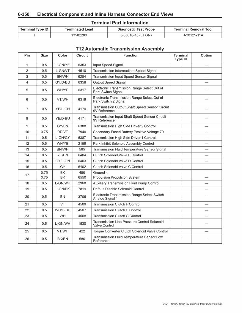
6-350 Electrical Component and Inline Harness Connector End Views
Terminal Part InformationTerminal Type ID Terminated Lead Diagnostic Test Probe Terminal Removal Tool
I 13582289 J-35616-16 (LT GN) J-38125-11A
T12 Automatic Transmission AssemblyPin Size Color Circuit Function Terminal
Type IDOption
1 0.5 L-GN/YE 6353 Input Speed Signal I —
2 0.5 L-GN/VT 4510 Transmission Intermediate Speed Signal I —
3 0.5 BN/WH 6254 Transmission Input Speed Sensor Signal I —
4 0.5 GY/D-BU 6358 Output Speed Signal I —
5 0.5 WH/YE 6317 Electronic Transmission Range Select Out ofPark Switch Signal I —
6 0.5 VT/WH 6319 Electronic Transmission Range Select Out ofPark Switch 2 Signal I —
7 0.5 YE/L-GN 4170 Transmission Output Shaft Speed Sensor Circuit9V Reference I —
8 0.5 YE/D-BU 4171 Transmission Input Shaft Speed Sensor Circuit9V Reference I —
9 0.5 GY/BN 6388 Transmission High Side Driver 2 Control I —
10 0.75 RD/VT 7940 Secondary Fused Battery Positive Voltage 79 I —
11 0.5 L-GN/GY 6387 Transmission High Side Driver 1 Control I —
12 0.5 WH/YE 2159 Park Inhibit Solenoid Assembly Control I —
13 0.5 BN/WH 585 Transmission Fluid Temperature Sensor Signal I —
14 0.5 YE/BN 6404 Clutch Solenoid Valve E Control I —
15 0.5 GY/L-GN 6403 Clutch Solenoid Valve D Control I —
16 0.5 GY 6402 Clutch Solenoid Valve C Control I —
170.750.75
BKBK
4506550
Ground 4Propulsion Propulsion System
II
——
18 0.5 L-GN/WH 2968 Auxiliary Transmission Fluid Pump Control I —
19 0.5 L-GN/BK 7819 Default Disable Solenoid Control I —
20 0.5 BN 3706 Electronic Transmission Range Select SwitchAnalog Signal 1 I —
21 0.5 VT 4509 Transmission Clutch F Control I —
22 0.5 WH/D-BU 4507 Transmission Clutch H Control I —
23 0.5 WH 4508 Transmission Clutch G Control I —
24 0.5 L-GN/WH 1530 Transmission Line Pressure Control SolenoidValve Control I —
25 0.5 VT/WH 422 Torque Converter Clutch Solenoid Valve Control I —
26 0.5 BK/BN 586 Transmission Fluid Temperature Sensor LowReference I —
2021 - Yukon, Yukon XL Electrical Body Builder Manual
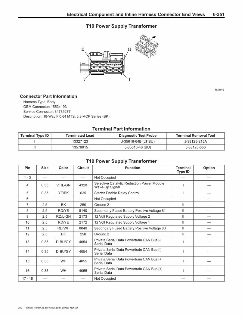
Electrical Component and Inline Harness Connector End Views 6-351
T19 Power Supply Transformer
3825662
Connector Part InformationHarness Type: BodyOEM Connector: 15534193Service Connector: 84789277Description: 18-Way F 0.64 MTS, 6.3 MCP Series (BK)
Terminal Part InformationTerminal Type ID Terminated Lead Diagnostic Test Probe Terminal Removal Tool
I 13327123 J-35616-64B (LT BU) J-38125-215A
II 13579915 J-35616-40 (BU) J-38125-556
T19 Power Supply TransformerPin Size Color Circuit Function Terminal
Type IDOption
1 - 3 — — — Not Occupied — —
4 0.35 VT/L-GN 4320 Selective Catalytic Reduction Power ModuleWake-Up Signal I —
5 0.35 YE/BK 625 Starter Enable Relay Control I —
6 — — — Not Occupied — —
7 2.5 BK 250 Ground 2 II —
8 2.5 RD/YE 8140 Secondary Fused Battery Positive Voltage 81 II —
9 2.5 RD/L-GN 2173 12 Volt Regulated Supply Voltage 2 II —
10 2.5 RD/YE 2172 12 Volt Regulated Supply Voltage 1 II —
11 2.5 RD/WH 8040 Secondary Fused Battery Positive Voltage 80 II —
12 2.5 BK 250 Ground 2 II —
13 0.35 D-BU/GY 4054 Private Serial Data Powertrain CAN Bus [-]Serial Data I —
14 0.35 D-BU/GY 4054 Private Serial Data Powertrain CAN Bus [-]Serial Data I —
15 0.35 WH 4055 Private Serial Data Powertrain CAN Bus [+]Serial Data I —
16 0.35 WH 4055 Private Serial Data Powertrain CAN Bus [+]Serial Data I —
17 - 18 — — — Not Occupied — —
2021 - Yukon, Yukon XL Electrical Body Builder Manual

6-352 Electrical Component and Inline Harness Connector End Views
T22 Mobile Device Wireless Charger Module (K4C)
5020940
Connector Part InformationHarness Type: Floor ConsoleOEM Connector: 13920634Service Connector: Service by Harness - See Part CatalogDescription: 6-Way F 0.64 Generation Y Series (BK)
Terminal Part InformationTerminal Type ID Terminated Lead Diagnostic Test Probe Terminal Removal Tool
I Not Required J-35616-64B (LT BU) No Tool Required
T22 Mobile Device Wireless Charger Module (K4C)Pin Size Color Circuit Function Terminal
Type IDOption
10.5
0.35RD/VTRD/VT
63406340
Secondary Fused Battery Positive Voltage 63Secondary Fused Battery Positive Voltage 63
II
BOP-BOP
20.750.5
BKBK
12501250
Ground 12Ground 12
II
—K4C
3 0.35 D-BU/YE 4984 AUTOSAR CAN Bus [-] 5 Serial Data I —
4 0.35 D-BU/WH 4985 AUTOSAR CAN Bus [+] 5 Serial Data I —
5 0.35 D-BU/YE 4984 AUTOSAR CAN Bus [-] 5 Serial Data I —
6 0.35 D-BU/WH 4985 AUTOSAR CAN Bus [+] 5 Serial Data I —
TBD1 Speaker - Right Instrument Panel 2 (UQP)
4373379
2021 - Yukon, Yukon XL Electrical Body Builder Manual

Electrical Component and Inline Harness Connector End Views 6-353
Connector Part InformationHarness Type: Instrument PanelOEM Connector: 35311601Service Connector: 19369632Description: 2-Way F 1.2 MCON Series (GY)
Terminal Part InformationTerminal Type ID Terminated Lead Diagnostic Test Probe Terminal Removal Tool
I Not Required J-35616-16 (LT GN) No Tool Required
TBD1 Speaker - Right Instrument Panel 2 (UQP)Pin Size Color Circuit Function Terminal
Type IDOption
1 0.75 BN/BK 1975 Right Front Speaker [-] Control 2 I —
2 0.75 L-GN/D-BU 1875 Right Front Speaker [+] Control 2 I —
TBD2 Speaker - Left Instrument Panel 2 (UQP)
4373379
Connector Part InformationHarness Type: Instrument PanelOEM Connector: 35311601Service Connector: 19369632Description: 2-Way F 1.2 MCON Series (GY)
Terminal Part InformationTerminal Type ID Terminated Lead Diagnostic Test Probe Terminal Removal Tool
I Not Required J-35616-16 (LT GN) No Tool Required
TBD2 Speaker - Left Instrument Panel 2 (UQP)Pin Size Color Circuit Function Terminal
Type IDOption
1 0.75 GY/BK 1974 Left Front Speaker [-] Control 2 I —
2 0.75 D-BU/VT 1874 Left Front Speaker [+] Control 2 I —
2021 - Yukon, Yukon XL Electrical Body Builder Manual

6-354 Electrical Component and Inline Harness Connector End Views
TBD3 Auxiliary Audio Input 2 (UW9)
3960313
Connector Part InformationHarness Type: Floor ConsoleOEM Connector: 13920633Service Connector: Service by Harness - See Part CatalogDescription: 6-Way F 0.64 Generation Y Series (BK)
Terminal Part InformationTerminal Type ID Terminated Lead Diagnostic Test Probe Terminal Removal Tool
I Not Required J-35616-64B (LT BU) No Tool Required
TBD3 Auxiliary Audio Input 2 (UW9)Pin Size Color Circuit Function Terminal
Type IDOption
1 0.35 RD/WH 7240 Secondary Fused Battery Positive Voltage 72 I —
2 0.35 YE 6817 LED Backlight Dimming Control 1 I —
3 0.35 BK/WH 1451 Ground 14 I —
4 - 6 — — — Not Occupied — —
TBD4 Accessory Power Preceptacle - Rear Compartmednt 110V AC
5086387
Connector Part InformationHarness Type: BodyOEM Connector: 35029311
2021 - Yukon, Yukon XL Electrical Body Builder Manual
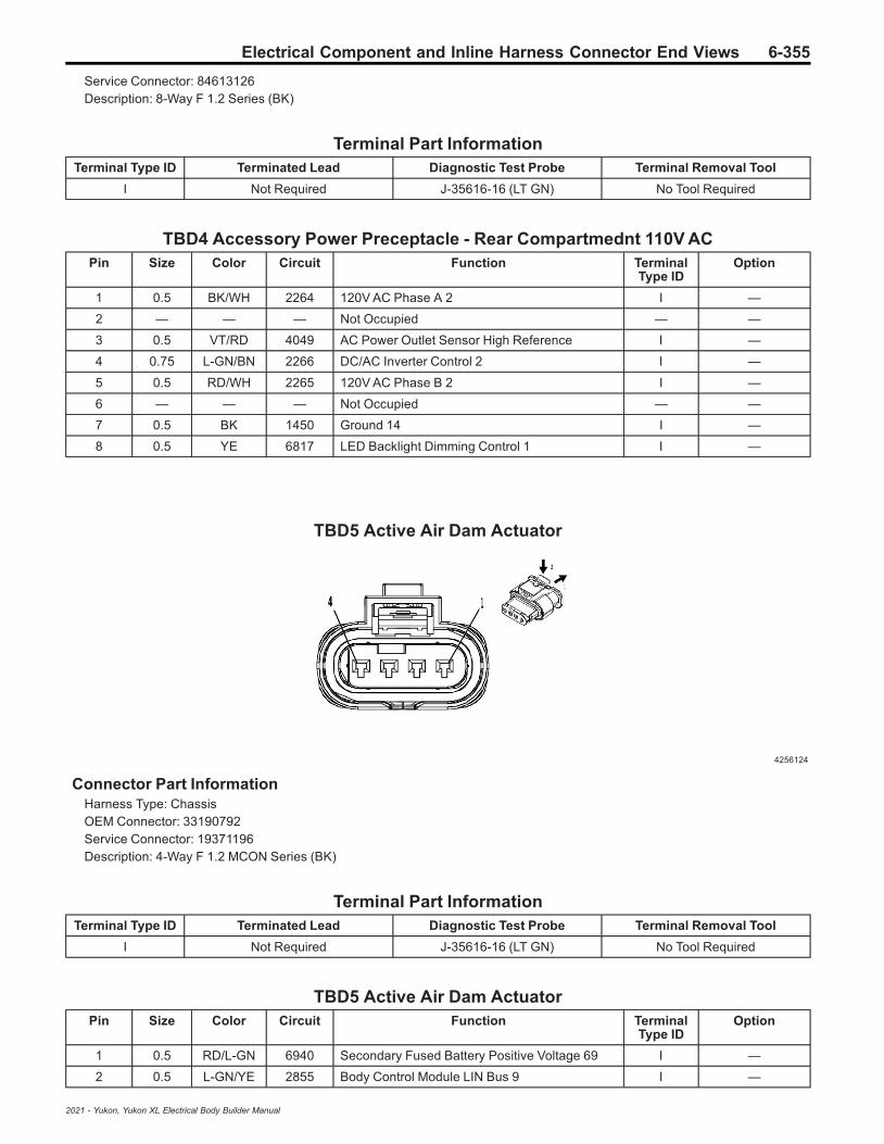
Electrical Component and Inline Harness Connector End Views 6-355
Service Connector: 84613126Description: 8-Way F 1.2 Series (BK)
Terminal Part InformationTerminal Type ID Terminated Lead Diagnostic Test Probe Terminal Removal Tool
I Not Required J-35616-16 (LT GN) No Tool Required
TBD4 Accessory Power Preceptacle - Rear Compartmednt 110V ACPin Size Color Circuit Function Terminal
Type IDOption
1 0.5 BK/WH 2264 120V AC Phase A 2 I —
2 — — — Not Occupied — —
3 0.5 VT/RD 4049 AC Power Outlet Sensor High Reference I —
4 0.75 L-GN/BN 2266 DC/AC Inverter Control 2 I —
5 0.5 RD/WH 2265 120V AC Phase B 2 I —
6 — — — Not Occupied — —
7 0.5 BK 1450 Ground 14 I —
8 0.5 YE 6817 LED Backlight Dimming Control 1 I —
TBD5 Active Air Dam Actuator
4256124
Connector Part InformationHarness Type: ChassisOEM Connector: 33190792Service Connector: 19371196Description: 4-Way F 1.2 MCON Series (BK)
Terminal Part InformationTerminal Type ID Terminated Lead Diagnostic Test Probe Terminal Removal Tool
I Not Required J-35616-16 (LT GN) No Tool Required
TBD5 Active Air Dam ActuatorPin Size Color Circuit Function Terminal
Type IDOption
1 0.5 RD/L-GN 6940 Secondary Fused Battery Positive Voltage 69 I —
2 0.5 L-GN/YE 2855 Body Control Module LIN Bus 9 I —
2021 - Yukon, Yukon XL Electrical Body Builder Manual

6-356 Electrical Component and Inline Harness Connector End Views
TBD5 Active Air Dam Actuator (cont'd)Pin Size Color Circuit Function Terminal
Type IDOption
3 — — — Not Occupied — —
4 1.5 BK 1950 Ground 19 I —
TBD6 Auxiliary Audio Input 1 X1 (USR)
3960313
Connector Part InformationHarness Type: Instrument PanelOEM Connector: 13920633Service Connector: 19332786Description: 6-Way F 0.64 Generation Y Series (BK)
Terminal Part InformationTerminal Type ID Terminated Lead Diagnostic Test Probe Terminal Removal Tool
I Not Required J-35616-64B (LT BU) No Tool Required
TBD6 Auxiliary Audio Input 1 X1 (USR)Pin Size Color Circuit Function Terminal
Type IDOption
1 0.5 RD/YE 2340 Secondary Fused Battery Positive Voltage 23 I —
2 0.5 YE 6817 LED Backlight Dimming Control 1 I —
30.350.5
BK/WHBK/WH
14511451
Ground 14Ground 14
II
——
4 - 6 — — — Not Occupied — —
2021 - Yukon, Yukon XL Electrical Body Builder Manual

Electrical Component and Inline Harness Connector End Views 6-357
TBD6 Auxiliary Audio Input 1 X1 (UW9+DCH)
3960313
Connector Part InformationHarness Type: Floor ConsoleOEM Connector: 13920633Service Connector: Service by Harness - See Part CatalogDescription: 6-Way F 0.64 Generation Y Series (BK)
Terminal Part InformationTerminal Type ID Terminated Lead Diagnostic Test Probe Terminal Removal Tool
I Not Required J-35616-64B (LT BU) No Tool Required
TBD6 Auxiliary Audio Input 1 X1 (UW9+DCH)Pin Size Color Circuit Function Terminal
Type IDOption
1 0.5 RD/YE 2340 Secondary Fused Battery Positive Voltage 23 I —
2 0.5 YE 6817 LED Backlight Dimming Control 1 I —
30.350.75
BK/WHBK/WH
14511451
Ground 14Ground 14
II
——
4 - 6 — — — Not Occupied — —
TBD7 Content Theft Deterrent Indicator
4115691
Connector Part InformationHarness Type: Driver Door TrimOEM Connector: 35311666
2021 - Yukon, Yukon XL Electrical Body Builder Manual

6-358 Electrical Component and Inline Harness Connector End Views
Service Connector: Service by Harness - See Part CatalogDescription: 2-Way F 1.2 MCON Series (BK)
Terminal Part InformationTerminal Type ID Terminated Lead Diagnostic Test Probe Terminal Removal Tool
I Not Required J-35616-16 (LT GN) No Tool Required
TBD7 Content Theft Deterrent IndicatorPin Size Color Circuit Function Terminal
Type IDOption
1 0.35 GY 728 Security Indicator Control I —
2 0.35 BK 1150 Ground 11 I —
TBD8 Keyless Entry Antenna - Passenger Comartment Rear
4690744
Connector Part InformationHarness Type: BodyOEM Connector: 33375932Service Connector: 19366871Description: 2-Way F 1.2 MCON Series, Sealed (BK)
Terminal Part InformationTerminal Type ID Terminated Lead Diagnostic Test Probe Terminal Removal Tool
I Not Required J-35616-16 (LT GN) No Tool Required
TBD8 Keyless Entry Antenna - Passenger Comartment RearPin Size Color Circuit Function Terminal
Type IDOption
1 0.35 D-BU 3554 Interior Keyless Entry Antenna 2 High Signal I —
2 0.35 GY/BK 3555 Interior Keyless Entry Antenna 2 Low Signal I —
2021 - Yukon, Yukon XL Electrical Body Builder Manual
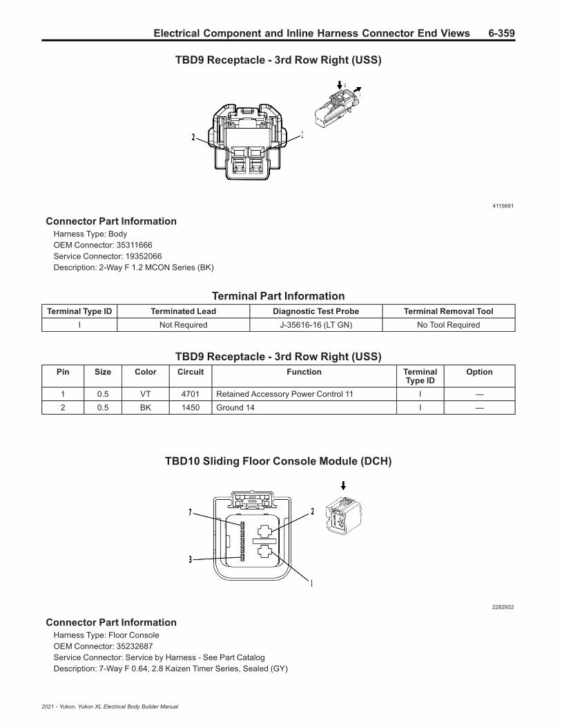
Electrical Component and Inline Harness Connector End Views 6-359
TBD9 Receptacle - 3rd Row Right (USS)
4115691
Connector Part InformationHarness Type: BodyOEM Connector: 35311666Service Connector: 19352066Description: 2-Way F 1.2 MCON Series (BK)
Terminal Part InformationTerminal Type ID Terminated Lead Diagnostic Test Probe Terminal Removal Tool
I Not Required J-35616-16 (LT GN) No Tool Required
TBD9 Receptacle - 3rd Row Right (USS)Pin Size Color Circuit Function Terminal
Type IDOption
1 0.5 VT 4701 Retained Accessory Power Control 11 I —
2 0.5 BK 1450 Ground 14 I —
TBD10 Sliding Floor Console Module (DCH)
2282932
Connector Part InformationHarness Type: Floor ConsoleOEM Connector: 35232687Service Connector: Service by Harness - See Part CatalogDescription: 7-Way F 0.64, 2.8 Kaizen Timer Series, Sealed (GY)
2021 - Yukon, Yukon XL Electrical Body Builder Manual

6-360 Electrical Component and Inline Harness Connector End Views
Terminal Part InformationTerminal Type ID Terminated Lead Diagnostic Test Probe Terminal Removal Tool
I Not Required J-35616-4A (PU) No Tool Required
II Not Required J-35616-64B (LT BU) No Tool Required
TBD10 Sliding Floor Console Module (DCH)Pin Size Color Circuit Function Terminal
Type IDOption
1 1 BK 1250 Ground 12 I —
2 1 RD/VT 8640 Secondary Fused Battery Positive Voltage 86 I —
3 — — — Not Occupied — —
4 0.5 L-GN/VT 2857 Body Control Module LIN Bus 11 II —
5 - 7 — — — Not Occupied — —
TBD11 Speaker - Subwoofer Front (UQA/UQS)
5219859
Connector Part InformationHarness Type: BodyOEM Connector: 33512070Service Connector: Service by Harness - See Part CatalogDescription: 2-Way F 2.8 APEX Series, Sealed (BK)
Terminal Part InformationTerminal Type ID Terminated Lead Diagnostic Test Probe Terminal Removal Tool
I Not Required J-35616-35 (VT) No Tool Required
TBD11 Speaker - Subwoofer Front (UQA/UQS)Pin Size Color Circuit Function Terminal
Type IDOption
1 2.5 L-GN/BK 1794 Left/Rear Subwoofer Control [-] I —
2 2.5 D-BU/GY 346 Left/Rear Subwoofer Control [+] I —
2021 - Yukon, Yukon XL Electrical Body Builder Manual
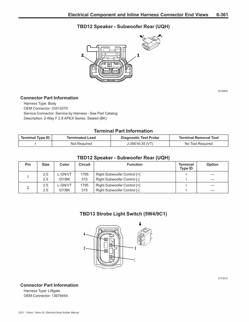
Electrical Component and Inline Harness Connector End Views 6-361
TBD12 Speaker - Subwoofer Rear (UQH)
5219859
Connector Part InformationHarness Type: BodyOEM Connector: 33512070Service Connector: Service by Harness - See Part CatalogDescription: 2-Way F 2.8 APEX Series, Sealed (BK)
Terminal Part InformationTerminal Type ID Terminated Lead Diagnostic Test Probe Terminal Removal Tool
I Not Required J-35616-35 (VT) No Tool Required
TBD12 Speaker - Subwoofer Rear (UQH)Pin Size Color Circuit Function Terminal
Type IDOption
12.52.5
L-GN/VTGY/BK
1795315
Right Subwoofer Control [+]Right Subwoofer Control [-]
II
——
22.52.5
L-GN/VTGY/BK
1795315
Right Subwoofer Control [+]Right Subwoofer Control [-]
II
——
TBD13 Strobe Light Switch (5W4/9C1)
2173574
Connector Part InformationHarness Type: LiftgateOEM Connector: 13679454
2021 - Yukon, Yukon XL Electrical Body Builder Manual

6-362 Electrical Component and Inline Harness Connector End Views
Service Connector: Service by Harness - See Part CatalogDescription: 4-Way F 0.64 Micro-Quadlock Series, Sealed (BK)
Terminal Part InformationTerminal Type ID Terminated Lead Diagnostic Test Probe Terminal Removal Tool
I Not Required J-35616-64B (LT BU) No Tool Required
TBD13 Strobe Light Switch (5W4/9C1)Pin Size Color Circuit Function Terminal
Type IDOption
1 0.75 BK 2050 Ground 20 I —
2 — — — Not Occupied — —
3 0.75 VT/L-GN 8869 Police Liftgate Strobe Rear On OFF Control I —
4 — — — Not Occupied — —
TBD14 Suspension Height Sensor - Left Front (F47)
4569745
Connector Part InformationHarness Type: ChassisOEM Connector: 33343869Service Connector: 19179750Description: 3-Way F 150 MX Series, Sealed (BK)
Terminal Part InformationTerminal Type ID Terminated Lead Diagnostic Test Probe Terminal Removal Tool
I Not Required J-35616-14 (GN) No Tool Required
TBD14 Suspension Height Sensor - Left Front (F47)Pin Size Color Circuit Function Terminal
Type IDOption
10.5
0.75D-BU/RDWH/RD
12057524
Left Front Suspension Position Sensor VoltageReferenceFront Vehicle Level Sensor 5V Reference
II
——
20.50.5
BK/D-BUBK/GY
12067526
Left Front Suspension Position Sensor LowReferenceFront Vehicle Level Sensor Low Reference
II
——
2021 - Yukon, Yukon XL Electrical Body Builder Manual

Electrical Component and Inline Harness Connector End Views 6-363
TBD14 Suspension Height Sensor - Left Front (F47) (cont'd)Pin Size Color Circuit Function Terminal
Type IDOption
30.50.5
BN/WHBN/WH
12077525
Left Front Suspension Position Sensor SignalFront Vehicle Level Sensor Signal
II
——
TBD15 Suspension Height Sensor - Left Rear (F47)
4569745
Connector Part InformationHarness Type: ChassisOEM Connector: 33343869Service Connector: 19179750Description: 3-Way F 150 MX Series, Sealed (BK)
Terminal Part InformationTerminal Type ID Terminated Lead Diagnostic Test Probe Terminal Removal Tool
I Not Required J-35616-14 (GN) No Tool Required
TBD15 Suspension Height Sensor - Left Rear (F47)Pin Size Color Circuit Function Terminal
Type IDOption
1 0.5 YE/RD 1208 Left Rear Suspension Position Sensor VoltageReference I —
2 0.5 BK/L-GN 1209 Left Rear Suspension Position Sensor LowReference I —
3 0.5 L-GN/WH 1210 Left Rear Suspension Position Sensor Signal I —
2021 - Yukon, Yukon XL Electrical Body Builder Manual

6-364 Electrical Component and Inline Harness Connector End Views
TBD16 Suspension Height Sensor - Right Front (F47)
4569745
Connector Part InformationHarness Type: ChassisOEM Connector: 33343869Service Connector: 19179750Description: 3-Way F 150 MX Series, Sealed (BK)
Terminal Part InformationTerminal Type ID Terminated Lead Diagnostic Test Probe Terminal Removal Tool
I Not Required J-35616-14 (GN) No Tool Required
TBD16 Suspension Height Sensor - Right Front (F47)Pin Size Color Circuit Function Terminal
Type IDOption
1 0.5 BN/RD 1211 Right Front Suspension Position Sensor VoltageReference I —
2 0.5 BK/GY 1212 Right Front Suspension Position Sensor LowReference I —
3 0.5 YE/WH 1213 Right Front Suspension Position Sensor Signal I —
TBD17 Suspension Height Sensor - Right Rear (F47)
4569745
Connector Part InformationHarness Type: ChassisOEM Connector: 33343869
2021 - Yukon, Yukon XL Electrical Body Builder Manual

Electrical Component and Inline Harness Connector End Views 6-365
Service Connector: 19179750Description: 3-Way F 150 MX Series, Sealed (BK)
Terminal Part InformationTerminal Type ID Terminated Lead Diagnostic Test Probe Terminal Removal Tool
I Not Required J-35616-14 (GN) No Tool Required
TBD17 Suspension Height Sensor - Right Rear (F47)Pin Size Color Circuit Function Terminal
Type IDOption
1 0.5 L-GN/RD 1214 Right Rear Suspension Position Sensor VoltageReference I —
2 0.5 BK/YE 1215 Right Rear Suspension Position Sensor LowReference I —
3 0.5 L-GN/GY 1216 Right Rear Suspension Position Sensor Signal I —
TBD18 USB Receptacle - 3rd Row Left (USS)
4115691
Connector Part InformationHarness Type: BodyOEM Connector: 35026312Service Connector: 19352066Description: 2-Way F 1.2 Series (BK)
Terminal Part InformationTerminal Type ID Terminated Lead Diagnostic Test Probe Terminal Removal Tool
I Not Required J-35616-16 (LT GN) No Tool Required
TBD18 USB Receptacle - 3rd Row Left (USS)Pin Size Color Circuit Function Terminal
Type IDOption
1 0.5 VT 4701 Retained Accessory Power Control 11 I —
2 0.5 BK 1150 Ground 11 I —
2021 - Yukon, Yukon XL Electrical Body Builder Manual

6-366 Electrical Component and Inline Harness Connector End Views
TBD19 USB Receptacle - 3rd Row Right (USS)
4115691
Connector Part InformationHarness Type: BodyOEM Connector: 35026312Service Connector: 19352066Description: 2-Way F 1.2 Series (BK)
Terminal Part InformationTerminal Type ID Terminated Lead Diagnostic Test Probe Terminal Removal Tool
I Not Required J-35616-16 (LT GN) No Tool Required
TBD19 USB Receptacle - 3rd Row Right (USS)Pin Size Color Circuit Function Terminal
Type IDOption
1 0.5 VT 4701 Retained Accessory Power Control 11 I —
2 0.5 BK 1450 Ground 14 I —
TBD20 Accessory Power Receptacle - Center Console 110V AC (KI4/KI5)
5086387
Connector Part InformationHarness Type: Floor ConsoleOEM Connector: 35029311Service Connector: Service by Harness - See Part CatalogDescription: 8-Way F 1.2 Series (BK)
2021 - Yukon, Yukon XL Electrical Body Builder Manual

Electrical Component and Inline Harness Connector End Views 6-367
Terminal Part InformationTerminal Type ID Terminated Lead Diagnostic Test Probe Terminal Removal Tool
I Not Required J-35616-16 (LT GN) No Tool Required
TBD20 Accessory Power Receptacle - Center Console 110V AC (KI4/KI5)Pin Size Color Circuit Function Terminal
Type IDOption
1 0.75 BK 5683 120V AC Phase A I —
2 — — — Not Occupied — —
3 0.5 VT/RD 4049 AC Power Outlet Sensor High Reference I —
4 0.75 D-BU/BN 6807 DC/AC Inverter Control I —
5 0.75 RD 5684 120V AC Phase B I —
6 — — — Not Occupied — —
7 0.75 BK 1250 Ground 12 I —
8 0.5 YE 6817 LED Backlight Dimming Control 1 I —
W28 Engine Coolant Heater Cable
5204301
Connector Part InformationHarness Type: Heater Cable JumperOEM Connector: 676-3AService Connector: Service by Harness - See Part CatalogDescription: 3-Way M THB HV
Terminal Part InformationTerminal Type ID Terminated Lead Diagnostic Test Probe Terminal Removal Tool
I Not Required No Tool Required No Tool Required
W28 Engine Coolant Heater CablePin Size Color Circuit Function Terminal
Type IDOption
1 0.8 GN 5686 120V AC Ground I —
2 0.8 PRINT 5685 120V AC Neutral I —
3 0.8 — 5683 120V AC Phase A I —
2021 - Yukon, Yukon XL Electrical Body Builder Manual

6-368 Electrical Component and Inline Harness Connector End Views
X80G Accessory Power Receptacle - Instrument Panel (KC5)
4872413
Connector Part InformationHarness Type: Instrument PanelOEM Connector: 33386302Service Connector: 19369281Description: 3-Way F 2.8 APEX Series (GY)
Terminal Part InformationTerminal Type ID Terminated Lead Diagnostic Test Probe Terminal Removal Tool
I Not Required J-35616-2A (GY) No Tool Required
II Not Required J-35616-35 (VT) No Tool Required
X80G Accessory Power Receptacle - Instrument Panel (KC5)Pin Size Color Circuit Function Terminal
Type IDOption
A 1.5 VT 1001 Retained Accessory Power Control 2 II —
B 0.5 YE 6817 LED Backlight Dimming Control 1 I —
C 1.5 BK 1850 Ground 18 II —
X80H Accessory Power Receptacle - Center Console (D07/DCH/DCK)
4872413
Connector Part InformationHarness Type: Floor ConsoleOEM Connector: 33386302
2021 - Yukon, Yukon XL Electrical Body Builder Manual

Electrical Component and Inline Harness Connector End Views 6-369
Service Connector: Service by Harness - See Part CatalogDescription: 3-Way F 2.8 APEX Series (GY)
Terminal Part InformationTerminal Type ID Terminated Lead Diagnostic Test Probe Terminal Removal Tool
I Not Required J-35616-2A (GY) No Tool Required
II Not Required J-35616-35 (VT) No Tool Required
X80H Accessory Power Receptacle - Center Console (D07/DCH/DCK)Pin Size Color Circuit Function Terminal
Type IDOption
A 1.5 VT 1001 Retained Accessory Power Control 2 II —
B0.50.5
YEYE
68176817
LED Backlight Dimming Control 1LED Backlight Dimming Control 1
III
——
C1
1.5BKBK
12501250
Ground 12Ground 12
III
——
X82 Audio/Video Input Adapter (UW9)
1862240
Connector Part InformationHarness Type: Floor ConsoleOEM Connector: 13595476Service Connector: Service by Harness - See Part CatalogDescription: 6-Way F 0.64 Kaizen Series (BK)
Terminal Part InformationTerminal Type ID Terminated Lead Diagnostic Test Probe Terminal Removal Tool
I Not Required J-35616-64B (LT BU) No Tool Required
X82 Audio/Video Input Adapter (UW9)Pin Size Color Circuit Function Terminal
Type IDOption
1 — — — Not Occupied — —
2 0.5 YE 6817 LED Backlight Dimming Control 1 I —
3 — — — Not Occupied — —
4 0.35 BK/WH 1451 Ground 14 I —
2021 - Yukon, Yukon XL Electrical Body Builder Manual
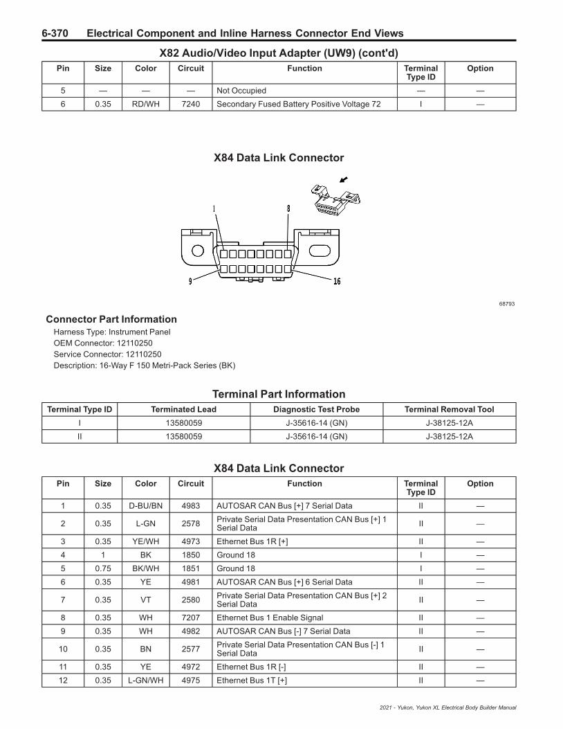
6-370 Electrical Component and Inline Harness Connector End Views
X82 Audio/Video Input Adapter (UW9) (cont'd)Pin Size Color Circuit Function Terminal
Type IDOption
5 — — — Not Occupied — —
6 0.35 RD/WH 7240 Secondary Fused Battery Positive Voltage 72 I —
X84 Data Link Connector
68793
Connector Part InformationHarness Type: Instrument PanelOEM Connector: 12110250Service Connector: 12110250Description: 16-Way F 150 Metri-Pack Series (BK)
Terminal Part InformationTerminal Type ID Terminated Lead Diagnostic Test Probe Terminal Removal Tool
I 13580059 J-35616-14 (GN) J-38125-12A
II 13580059 J-35616-14 (GN) J-38125-12A
X84 Data Link ConnectorPin Size Color Circuit Function Terminal
Type IDOption
1 0.35 D-BU/BN 4983 AUTOSAR CAN Bus [+] 7 Serial Data II —
2 0.35 L-GN 2578 Private Serial Data Presentation CAN Bus [+] 1Serial Data II —
3 0.35 YE/WH 4973 Ethernet Bus 1R [+] II —
4 1 BK 1850 Ground 18 I —
5 0.75 BK/WH 1851 Ground 18 I —
6 0.35 YE 4981 AUTOSAR CAN Bus [+] 6 Serial Data II —
7 0.35 VT 2580 Private Serial Data Presentation CAN Bus [+] 2Serial Data II —
8 0.35 WH 7207 Ethernet Bus 1 Enable Signal II —
9 0.35 WH 4982 AUTOSAR CAN Bus [-] 7 Serial Data II —
10 0.35 BN 2577 Private Serial Data Presentation CAN Bus [-] 1Serial Data II —
11 0.35 YE 4972 Ethernet Bus 1R [-] II —
12 0.35 L-GN/WH 4975 Ethernet Bus 1T [+] II —
2021 - Yukon, Yukon XL Electrical Body Builder Manual

Electrical Component and Inline Harness Connector End Views 6-371
X84 Data Link Connector (cont'd)Pin Size Color Circuit Function Terminal
Type IDOption
13 0.35 L-GN 4974 Ethernet Bus 1T [-] II —
14 0.35 WH 4980 AUTOSAR CAN Bus [-] 6 Serial Data II —
15 0.35 GY 2579 Private Serial Data Presentation CAN Bus [-] 2Serial Data II —
16 0.5 RD/YE 6540 Secondary Fused Battery Positive Voltage 65 II —
X85 Steering Wheel Air Bag Coil
3960237
Connector Part InformationHarness Type: Instrument PanelOEM Connector: 33291416Service Connector: 13510218Description: 21-Way F 0.64 Series, Sealed (YE)
Terminal Part InformationTerminal Type ID Terminated Lead Diagnostic Test Probe Terminal Removal Tool
I 13575742 J-35616-64B (LT BU) J-38125-215A
II 13575867 J-35616-64B (LT BU) J-38125-215A
X85 Steering Wheel Air Bag CoilPin Size Color Circuit Function Terminal
Type IDOption
1 0.75 BK/WH 1851 Ground 18 I —
2 0.35 L-GN/WH 3287 Horn Switch Signal II —
3 - 4 — — — Not Occupied — —
5 0.5 OG/L-GN 3023 Steering Wheel Air Bag Stage 2 High Control I —
6 0.5 WH/OG 3022 Steering Wheel Air Bag Stage 2 Low Control I —
7 0.5 BN/OG 3020 Steering Wheel Air Bag Stage 1 Low Control I —
8 0.5 OG/VT 3021 Steering Wheel Air Bag Stage 1 High Control I —
9 0.35 L-GN/BK 3894 Instrument Cluster LIN Bus 1 II —
10 0.35 L-GN/BK 2858 Body Control Module LIN Bus 12 II —
11 0.35 BN/L-GN 1884 Cruise Control Set/Coast/Resume/AccelerateSwitch Signal II —
12 0.35 BK/VT 1449 Steering Wheel Resistor Ladder Low Reference II —
2021 - Yukon, Yukon XL Electrical Body Builder Manual

6-372 Electrical Component and Inline Harness Connector End Views
X85 Steering Wheel Air Bag Coil (cont'd)Pin Size Color Circuit Function Terminal
Type IDOption
13 — — — Not Occupied — —
14 0.75 RD/L-GN 5140 Secondary Fused Battery Positive Voltage 51 I —
15 0.35 GY/L-GN 5737 Distance Sensing Cruise Control Gap Up/DownSwitch Signal II —
16 - 19 — — — Not Occupied — —
20 0.5 BK 1850 Ground 18 I —
21 0.35 RD/BN 10040 Secondary Fused Battery Positive Voltage 100 II —
X88 Trailer Connector X1
2056936
Connector Part InformationHarness Type: ChassisOEM Connector: 13857223Service Connector: 15306164Description: 7-Way F 280, 630 Metri-Pack Series, Sealed (BK)
Terminal Part InformationTerminal Type ID Terminated Lead Diagnostic Test Probe Terminal Removal Tool
I Not Required J-35616-42 (RD) No Tool Required
II Not Required J-35616-4A (PU) No Tool Required
X88 Trailer Connector X1Pin Size Color Circuit Function Terminal
Type IDOption
A0.750.75
L-GN/WHWH/L-GN
51891624
Trailer Backup Lamp ControlTrailer Backup Lamp Control
IIII
MBM+U1D+Z82-U1D+Z82
B 3 BK 1950 Ground 19 I —
C 2.5 D-BU 47 Trailer Auxiliary Control II —
D0.750.75
YE/GYL-GN/VT
51871619
Right Trailer Turn Signal Lamp ControlRight Rear Trailer Stop/Turn Lamp Control
IIII
MBM+U1D+Z82-U1D+Z82
E 4 RD/L-GN 742 Primary Fused Battery Positive Voltage 7 II —
F0.750.75
BN/GYGY/BN
51842109
Left Trailer Park Lamp ControlTrailer Park Lamp Control
IIII
MBM+U1D+Z82-U1D+Z82
2021 - Yukon, Yukon XL Electrical Body Builder Manual

Electrical Component and Inline Harness Connector End Views 6-373
X88 Trailer Connector X1 (cont'd)Pin Size Color Circuit Function Terminal
Type IDOption
G0.750.75
D-BU/WHYE/GY
51861618
Left Trailer Turn Signal Lamp ControlLeft Rear Trailer Stop/Turn Lamp Control
IIII
MBM+U1D+Z82-U1D+Z82
X92D USB Receptacle - Center Console
1862240
Connector Part InformationHarness Type: Floor ConsoleOEM Connector: 13595476Service Connector: Service by Harness - See Part CatalogDescription: 6-Way F 0.64 Kaizen Series (BK)
Terminal Part InformationTerminal Type ID Terminated Lead Diagnostic Test Probe Terminal Removal Tool
I Not Required J-35616-64B (LT BU) No Tool Required
X92D USB Receptacle - Center ConsolePin Size Color Circuit Function Terminal
Type IDOption
1 — — — Not Occupied — —
2 0.5 YE 6817 LED Backlight Dimming Control 1 I —
3 — — — Not Occupied — —
40.350.750.5
BK/WHBKBK
145112501250
Ground 14Ground 12Ground 12
III
——
USS-UW9
5 — — — Not Occupied — —
60.350.5
RD/WHVT
72404701
Secondary Fused Battery Positive Voltage 72Retained Accessory Power Control 11
II
—USS-UW9
2021 - Yukon, Yukon XL Electrical Body Builder Manual

6-374 Electrical Component and Inline Harness Connector End Views
Inline Harness Connector End Views
X102 Body Harness to Left Police Provisional Harness (5W4/9C1)
4994577
—
Connector Part InformationHarness Type: BodyOEM Connector: 33351631Service Connector: 19371202Description: 4-Way F 1.2 MCON-CB Series, Sealed (BK)
Connector Part InformationHarness Type: Left Police ProvisionalOEM Connector: Not AvailableService Connector: Service by Harness - See Part CatalogDescription: 4-Way M
Terminal Part InformationTerminal Type ID Terminated Lead Diagnostic Test Probe Terminal Removal Tool
I Not Required J-35616-16 (LT GN) No Tool Required
II Not Required J-35616-17 (LT GN) No Tool Required
X102 Body Harness to Left Police Provisional Harness (5W4/9C1)Pin Size Color Circuit Terminal
Type IDOption Function Pin Size Color Circuit Terminal
Type IDOption
1 0.75 D-BU 8890 I —Police FrontCorner LightControl
1 0.75 D-BU 8890 II —
2 0.75 BK 2050 I — Ground 20 2 0.75 BK 2050 II —
3 0.75D-
BU/WH
8891 I —
PoliceCornerStrobeSynchron-ization Signal
3 0.75D-
BU/WH
8891 II —
4 0.75 VT 8893 I —
Police FrontCornerStrobeControl
4 0.75 VT 8893 II —
2021 - Yukon, Yukon XL Electrical Body Builder Manual

Electrical Component and Inline Harness Connector End Views 6-375
X108 Front Fascia Harness to Body Harness
4650150 4817393
Connector Part InformationHarness Type: Front FasciaOEM Connector: 33378383Service Connector: Service by Harness - See Part CatalogDescription: 30-Way F 1.2 MCON, 2.8, 6.3 MCP Series (BK)
Connector Part InformationHarness Type: BodyOEM Connector: 33363373Service Connector: 19371177Description: 30-Way M 1.2 MCON, 2.8, 6.3 MCP Series (BK)
Terminal Part InformationTerminal Type ID Terminated Lead Diagnostic Test Probe Terminal Removal Tool
I Not Required J-35616-16 (LT GN) No Tool Required
II Not Required J-35616-40 (BU) No Tool Required
III Not Required J-35616-4A (PU) No Tool Required
IV 13575350 J-35616-5 (PU) J-38125-36
V 13575376 J-35616-43 (RD) J-38125-557
VI 19330703 J-35616-13 (BU) J-38125-215A
VII 19330704 J-35616-17 (LT GN) J-38125-215A
X108 Front Fascia Harness to Body HarnessPin Size Color Circuit Terminal
Type IDOption Function Pin Size Color Circuit Terminal
Type IDOption
1 0.5D-
BU/L-GN
1253 II —Right FrontPark LampControl
1 0.5D-
BU/L-GN
1253 V —
2 0.5 VT/GY 5218 III —
Right FrontMiddleParkingAssistSensor
2 0.5 VT/GY 5218 IV —
3 0.5L-
GN/BK
2738 III —Virtual KeyModule LINBus 1
3 0.5L-
GN/BK
2738 IV —
4 0.5 BK/WH 251 III — Ground 2 4 0.5 BK/
WH 251 IV —
5 — — — — — NotOccupied 5 — — — — —
6 0.5 BN/GY 5061 III —
Left FrontFog LampControl
6 0.5 BN/GY 5061 IV —
7 — — — — — NotOccupied 7 — — — — —
2021 - Yukon, Yukon XL Electrical Body Builder Manual

6-376 Electrical Component and Inline Harness Connector End Views
X108 Front Fascia Harness to Body Harness (cont'd)Pin Size Color Circuit Terminal
Type IDOption Function Pin Size Color Circuit Terminal
Type IDOption
8 0.5 BN/L-GN 5062 II —
Right FrontFog LampControl
8 0.5 BN/L-GN 5062 V —
9-
10— — — — — Not
Occupied9
- 10 — — — — —
11 0.5 WH/GY 5217 I —
Right FrontOuterParkingAssistSensor
11 0.5 WH/GY 5217 VII —
12 0.5 BK/D-BU 5214 I —
FrontParkingAssistSensor LowReference
12 0.5 BK/D-BU 5214 VII —
13 — — — — — NotOccupied 13 — — — — —
14 0.5 WH/YE 1254 I —
Left FrontPark LampControl
14 0.5 WH/YE 1254 VII —
15 0.5 BN 6581 I —
FrontParkingAssistDisplayControl
15 0.5 BN 6581 VII —
16 0.5 YE/GY 5216 I —
Left FrontMiddleParkingAssistSensor
16 0.5 YE/GY 5216 VII —
17-
18— — — — — Not
Occupied17
- 18 — — — — —
19 0.5 RD/GY 4840 I —
SecondaryFusedBatteryPositiveVoltage 48
19 0.5 RD/GY 4840 VII —
20 0.5 VT/WH 5215 I —
Left FrontOuterParkingAssistSensor
20 0.5 VT/WH 5215 VII —
21-
22— — — — — Not
Occupied21
- 22 — — — — —
230.750.5
BKBK
250250
II
T40/Z75-T40+X88
Ground 2Ground 2
23 0.35 BK 250 VI —
24-
27— — — — — Not
Occupied24
- 27 — — — — —
280.5
0.75BKBK
150150
II
T40/Z75-T40+X88
Ground 1Ground 1
28 0.75 BK 150 VII —
29-
30— — — — — Not
Occupied29
- 30 — — — — —
2021 - Yukon, Yukon XL Electrical Body Builder Manual

Electrical Component and Inline Harness Connector End Views 6-377
X110 Body Harness to Left Headlamp Harness
4846407 2667653
Connector Part InformationHarness Type: BodyOEM Connector: 35037827Service Connector: 19366859Description: 8-Way F 150 MX Series, Sealed (BK)
Connector Part InformationHarness Type: Left HeadlampOEM Connector: Not AvailableService Connector: Service by Harness - See Part CatalogDescription: 8-Way M
Terminal Part InformationTerminal Type ID Terminated Lead Diagnostic Test Probe Terminal Removal Tool
I Not Required J-35616-2A (GY) No Tool Required
II Not Required J-35616-3 (GY) No Tool Required
X110 Body Harness to Left Headlamp HarnessPin Size Color Circuit Terminal
Type IDOption Function Pin Size Color Circuit Terminal
Type IDOption
1 0.75 BK 150 I — Ground 1 1 0.75 BK 150 II —
2 0.75 RD/WH 640 I —
SecondaryFusedBatteryPositiveVoltage 6
2 0.75 RD/WH 640 II —
3 0.35 YE 712 I —
LeftHeadlampLow BeamControl
3 0.35 YE 712 II —
4 0.35 WH 711 I —
LeftHeadlampHigh BeamControl
4 0.35 WH 711 II —
5 0.5 GY/D-BU 7538 I — Left Front
DRL Control 5 0.5 GY/D-BU 7538 II —
6 0.5D-
BU/WH
1314 I —Left FrontTurn SignalLamp Control
6 0.5D-
BU/WH
1314 II —
7 0.35 VT/BK 6568 I —
Front TurnSignal LampFeedbackSignal
7 0.35 VT/BK 6568 II —
8 0.5 WH/YE 1254 I —
Left FrontPark LampControl
8 0.5 WH/YE 1254 II —
2021 - Yukon, Yukon XL Electrical Body Builder Manual

6-378 Electrical Component and Inline Harness Connector End Views
X111 Body Harness to Off-Road Grille Lamp Provisional Harness (5W4/9C1)
4846407 2667653
Connector Part InformationHarness Type: BodyOEM Connector: 35037827Service Connector: 19366859Description: 8-Way F 150 MX Series, Sealed (BK)
Connector Part InformationHarness Type: Off-Road Grille Lamp ProvisionalOEM Connector: Not AvailableService Connector: Service by Harness - See Part CatalogDescription: 8-Way M
Terminal Part InformationTerminal Type ID Terminated Lead Diagnostic Test Probe Terminal Removal Tool
I Not Required J-35616-2A (GY) No Tool Required
II Not Required J-35616-3 (GY) No Tool Required
X111 Body Harness to Off-Road Grille Lamp Provisional Harness (5W4/9C1)Pin Size Color Circuit Terminal
Type IDOption Function Pin Size Color Circuit Terminal
Type IDOption
1 0.5 BN 8855 I —Police FrontGrille Light 1Control
1 0.5 BN 8855 II —
2 0.5 BN/D-BU 8856 I —
Police FrontGrille Light 2Control
2 0.5 BN/D-BU 8856 II —
3 0.5 BK/BN 8857 I —
Police FrontGrille LightLowReference
3 0.5 BK/BN 8857 II —
4 0.5 WH 8858 I —
Police FrontGrille LightSynchroni-zation Signal
4 0.5 WH 8858 II —
5 0.5 BN/YE 8859 I —
Police FrontGrille LightSteady BurnControl
5 0.5 BN/YE 8859 II —
6 0.5 WH/BK 8860 I —
Police FrontGrille Spare1 Signal
6 0.5 WH/BK 8860 II —
7 0.5L-
GN/WH
8861 I —
Police FrontGrilleSpeaker [+]Control
7 0.5L-
GN/WH
8861 II —
2021 - Yukon, Yukon XL Electrical Body Builder Manual

Electrical Component and Inline Harness Connector End Views 6-379
X111 Body Harness to Off-Road Grille Lamp Provisional Harness (5W4/9C1) (cont'd)Pin Size Color Circuit Terminal
Type IDOption Function Pin Size Color Circuit Terminal
Type IDOption
8 0.5D-
BU/WH
8862 I —
Police FrontGrilleSpeaker [-]Control
8 0.5D-
BU/WH
8862 II —
2021 - Yukon, Yukon XL Electrical Body Builder Manual

6-380 Electrical Component and Inline Harness Connector End Views
X114 Engine Harness to Active Grille Air Shutter Harness (VTI+(L84/L87))
1986157 1986159
Connector Part InformationHarness Type: EngineOEM Connector: 13609714Service Connector: 13578533Description: 6-Way F 150 MX Series, Sealed (BK)
Connector Part InformationHarness Type: Active Grille Air ShutterOEM Connector: Not AvailableService Connector: Service by Harness - See Part CatalogDescription: 6-Way M
Terminal Part InformationTerminal Type ID Terminated Lead Diagnostic Test Probe Terminal Removal Tool
I Not Required J-35616-2A (GY) No Tool Required
II Not Required J-35616-3 (GY) No Tool Required
X114 Engine Harness to Active Grille Air Shutter Harness (VTI+(L84/L87))Pin Size Color Circuit Terminal
Type IDOption Function Pin Size Color Circuit Terminal
Type IDOption
1 0.5L-
GN/VT
4621 I —
EngineControlModule LINBus 1
1 0.5L-
GN/VT
4621 II —
2 0.75 BK 450 I — Ground 4 2 0.75 BK 450 II —
3 0.5 VT/D-BU 5705 I —
PowertrainMain RelayFusedSupply 6
3 0.5 VT/D-BU 5705 II —
4 — — — — — NotOccupied 4 — — — — —
5 0.5D-
BU/GY
636 I —
Ambient AirTemperatureSensorSignal
5 0.5D-
BU/GY
636 II —
6 0.5 BK/YE 548 I —
EngineControlSensors LowReference 1
6 0.5 BK/YE 548 II —
2021 - Yukon, Yukon XL Electrical Body Builder Manual

Electrical Component and Inline Harness Connector End Views 6-381
X114 Engine Harness to Active Grille Air Shutter Harness (VTI+LM2)
3225042 3225221
Connector Part InformationHarness Type: EngineOEM Connector: 33141414Service Connector: 19301527Description: 6-Way F 150 MX Series, Sealed (GY)
Connector Part InformationHarness Type: Active Grille Air ShutterOEM Connector: Not AvailableService Connector: Service by Harness - See Part CatalogDescription: 6-Way M
Terminal Part InformationTerminal Type ID Terminated Lead Diagnostic Test Probe Terminal Removal Tool
I Not Required J-35616-2A (GY) No Tool Required
II Not Required J-35616-3 (GY) No Tool Required
X114 Engine Harness to Active Grille Air Shutter Harness (VTI+LM2)Pin Size Color Circuit Terminal
Type IDOption Function Pin Size Color Circuit Terminal
Type IDOption
1 0.5L-
GN/VT
4621 I —
EngineControlModule LINBus 1
1 0.5L-
GN/VT
4621 II —
2 0.5 BK 6550 I —PropulsionPropulsionSystem
2 0.5 BK 6550 II —
3 0.5 VT/D-BU 5705 I —
PowertrainMain RelayFusedSupply 6
3 0.5 VT/D-BU 5705 II —
4 — — — — — NotOccupied 4 — — — — —
5 0.5D-
BU/GY
636 I —
Ambient AirTemperatureSensorSignal
5 0.5D-
BU/GY
636 II —
6 0.5 BK/GY 626 I —
EngineControlVehicleSensors LowReference 1
6 0.5 BK/GY 626 II —
2021 - Yukon, Yukon XL Electrical Body Builder Manual

6-382 Electrical Component and Inline Harness Connector End Views
X115 Engine Harness to Body Harness (L84/L87)
4992329 4994369
Connector Part InformationHarness Type: EngineOEM Connector: 35016653Service Connector: 19371184Description: 55-Way F 1.2 OCS, 2.8, 6.3 CTS Series,Sealed (GY)
Connector Part InformationHarness Type: BodyOEM Connector: 35205174Service Connector: 84727363Description: 55-Way M 1.2 OCS, 2.8, 6.3 CTS Series,Sealed (GY)
Terminal Part InformationTerminalType ID
TerminatedLead
DiagnosticTest Probe
TerminalRemoval Tool
Service Terminal TrayName
CoreCrimp
InsulationCrimp
I 19332900 J-35616-42 (RD) J-38125-215A Not Available Not
AvailableNot
AvailableNot
Available
II 19371240 J-35616-16(LT GN) J-38125-215A Not Available Not
AvailableNot
AvailableNot
Available
III 19301750 J-35616-32 (OR) J-38125-36 Not Available Not
AvailableNot
AvailableNot
Available
IV 19370818 J-35616-17(LT GN) J-38125-215A Not Available Not
AvailableNot
AvailableNot
Available
V 84616651 J-35616-17(LT GN) J-38125-215A Not Available Not
AvailableNot
AvailableNot
Available
X115 Engine Harness to Body Harness (L84/L87)Pin Size Color Circuit Terminal
Type IDOption Function Pin Size Color Circuit Terminal
Type IDOption
1- 2 — — — — — Not
Occupied1
- 2 — — — — —
3 0.5 BK/BU 1271 II —
AcceleratorPedalPosition LowReference 1
3 0.5 BK/BU 1271 V —
4 — — — — — NotOccupied 4 — — — — —
5 0.5 GN/WH 1162 II —
AcceleratorPedalPositionSignal 2
5 0.5 GN/WH 1162 V —
6-
14— — — — — Not
Occupied6
- 14 — — — — —
15 0.5 YE 4063 II — Hood StatusA Signal 15 0.5 YE 4063 V —
2021 - Yukon, Yukon XL Electrical Body Builder Manual

Electrical Component and Inline Harness Connector End Views 6-383
X115 Engine Harness to Body Harness (L84/L87) (cont'd)Pin Size Color Circuit Terminal
Type IDOption Function Pin Size Color Circuit Terminal
Type IDOption
16-
23— — — — — Not
Occupied16
- 23 — — — — —
24 0.5 BU/GY 4054 II —
Private SerialDataPowertrainCAN Bus [-]Serial Data
24 0.35 BU/GY 4054 V —
25 0.5 WH 4055 II —
Private SerialDataPowertrainCAN Bus [+]Serial Data
25 0.35 WH 4055 V —
26-
30— — — — — Not
Occupied26
- 30 — — — — —
31 0.5 WH/BU 6311 II —
Cruise/ETC/TCC BrakeSignal
31 0.5 WH/BU 6311 V —
32-
34— — — — — Not
Occupied32
- 34 — — — — —
35 0.5 BK/YE 548 II —
EngineControlSensors LowReference 1
35 0.5 BK/YE 5382 V —
36 0.5 WH/GN 5380 II —
BrakePositionSensorSignal
36 0.5 WH/GN 5380 V —
37 0.5 WH/RD 480 II —
EngineControlVehicleSensors 5VoltReference 1
37 0.5 WH/RD 5381 V —
38-
39— — — — — Not
Occupied38
- 39 — — — — —
40 0.5 BK/VT 1272 II —
AcceleratorPedalPosition LowReference 2
40 0.5 BK/VT 1272 V —
41 — — — — — NotOccupied 41 — — — — —
42 0.5 YE/BK 625 II —
StarterEnable RelayControl
42 0.35 YE/BK 625 V —
43 4 BK/WH 6151 I —
EngineControlModuleGround 61
43 4 BK/WH 6151 III —
44 1 RD/GN 1840 II —
SecondaryFusedBatteryPositiveVoltage 18
44 0.75 RD/GN 1840 IV —
45-
46— — — — — Not
Occupied45
- 46 — — — — —
2021 - Yukon, Yukon XL Electrical Body Builder Manual

6-384 Electrical Component and Inline Harness Connector End Views
X115 Engine Harness to Body Harness (L84/L87) (cont'd)Pin Size Color Circuit Terminal
Type IDOption Function Pin Size Color Circuit Terminal
Type IDOption
47 0.5 BU/BN 7573 II —
A/CCompressorSolenoidValve Control
47 0.5 BU/BN 7573 V —
48 — — — — — NotOccupied 48 — — — — —
49 0.5 YE/WH 1161 II —
AcceleratorPedalPositionSignal 1
49 0.5 YE/WH 1161 V —
50 0.5 WH/RD 1164 II —
AcceleratorPedalPosition 5VoltReference 1
50 0.5 WH/RD 1164 V —
51 0.5 BN/RD 1274 II —
AcceleratorPedalPosition 5VReference 2
51 0.5 BN/RD 1274 V —
52 — — — — — NotOccupied 52 — — — — —
53 0.5 BU/YE 7574 II —
A/CCompressorSolenoidValve Control
53 0.5 BU/YE 7574 V —
54-
55— — — — — Not
Occupied54
- 55 — — — — —
2021 - Yukon, Yukon XL Electrical Body Builder Manual

Electrical Component and Inline Harness Connector End Views 6-385
X115 Engine Harness to Body Harness (LM2)
4992329 4994369
Connector Part InformationHarness Type: EngineOEM Connector: 35016653Service Connector: 19371184Description: 55-Way F 1.2 OCS, 2.8, 6.3 CTS Series,Sealed (GY)
Connector Part InformationHarness Type: BodyOEM Connector: 35205174Service Connector: 84727363Description: 55-Way M 1.2 OCS, 2.8, 6.3 CTS Series,Sealed (GY)
Terminal Part InformationTerminalType ID
TerminatedLead
DiagnosticTest Probe
TerminalRemoval Tool
Service Terminal TrayName
CoreCrimp
InsulationCrimp
I 19332900 J-35616-42 (RD) J-38125-215A Not Available Not
AvailableNot
AvailableNot
Available
II 19332900 J-35616-43 (RD) J-38125-215A Not Available Not
AvailableNot
AvailableNot
Available
III 19333088 J-35616-35 (VT) J-38125-215A Not Available Not
AvailableNot
AvailableNot
Available
IV 19371240 J-35616-16(LT GN) J-38125-215A Not Available Not
AvailableNot
AvailableNot
Available
V 13505800 J-35616-5 (PU) J-38125-215A Not Available Not
AvailableNot
AvailableNot
Available
VI 19301750 J-35616-32 (OR) J-38125-36 Not Available Not
AvailableNot
AvailableNot
Available
VII 84616651 J-35616-17(LT GN) J-38125-215A Not Available Not
AvailableNot
AvailableNot
Available
X115 Engine Harness to Body Harness (LM2)Pin Size Color Circuit Terminal
Type IDOption Function Pin Size Color Circuit Terminal
Type IDOption
1 1 RD/GN 1840 II —
SecondaryFusedBatteryPositiveVoltage 18
1 0.75 RD/GN 1840 VI —
2- 4 — — — — — Not
Occupied2
- 4 — — — — —
5 0.5 WH/RD 480 IV —
EngineControlVehicleSensors 5VoltReference 1
5 0.5 WH/RD 5381 VII —
2021 - Yukon, Yukon XL Electrical Body Builder Manual

6-386 Electrical Component and Inline Harness Connector End Views
X115 Engine Harness to Body Harness (LM2) (cont'd)Pin Size Color Circuit Terminal
Type IDOption Function Pin Size Color Circuit Terminal
Type IDOption
6 0.5 WH/GN 5380 IV —
BrakePositionSensorSignal
6 0.5 WH/GN 5380 VII —
7 0.5 BK/GY 626 IV —
EngineControlVehicleSensors LowReference 1
7 0.5 BK/YE 5382 VII —
8 0.5 WH/RD 1164 IV —
AcceleratorPedalPosition 5VoltReference 1
8 0.5 WH/RD 1164 VII —
9 — — — — — NotOccupied 9 — — — — —
10 0.5 BK/VT 1272 IV —
AcceleratorPedalPosition LowReference 2
10 0.5 BK/VT 1272 VII —
11-
13— — — — — Not
Occupied11
- 13 — — — — —
14 0.5 RD/VT 340 III —
SecondaryFusedBatteryPositiveVoltage 3
14 0.5 RD/VT 340 V —
15 — — — — — NotOccupied 15 — — — — —
16 0.5 WH/BU 6311 IV —
Cruise/ETC/TCC BrakeSignal
16 0.5 WH/BU 6311 VII —
17 — — — — — NotOccupied 17 — — — — —
18 0.5 BU/GY 4054 IV —
Private SerialDataPowertrainCAN Bus [-]Serial Data
18 0.35 BU/GY 4054 VII —
19 0.5 WH 4055 IV —
Private SerialDataPowertrainCAN Bus [+]Serial Data
19 0.35 WH 4055 VII —
20-
31— — — — — Not
Occupied20
- 31 — — — — —
32 0.5 YE/BK 625 IV —
StarterEnable RelayControl
32 0.35 YE/BK 625 VII —
33 0.5 BK/BU 1271 IV —
AcceleratorPedalPosition LowReference 1
33 0.5 BK/BU 1271 VII —
34 0.5 YE 4063 IV — Hood StatusA Signal 34 0.5 YE 4063 VII —
35 — — — — — NotOccupied 35 — — — — —
2021 - Yukon, Yukon XL Electrical Body Builder Manual

Electrical Component and Inline Harness Connector End Views 6-387
X115 Engine Harness to Body Harness (LM2) (cont'd)Pin Size Color Circuit Terminal
Type IDOption Function Pin Size Color Circuit Terminal
Type IDOption
36 0.5 BN/RD 1274 IV —
AcceleratorPedalPosition 5VReference 2
36 0.5 BN/RD 1274 VII —
37 0.5 GN/WH 1162 IV —
AcceleratorPedalPositionSignal 2
37 0.5 GN/WH 1162 VII —
38 0.5 BU/BN 7573 IV —
A/CCompressorSolenoidValve Control
38 0.5 BU/BN 7573 VII —
39 0.5 BU/YE 7574 IV —
A/CCompressorSolenoidValve Control
39 0.5 BU/YE 7574 VII —
40-
48— — — — — Not
Occupied40
- 48 — — — — —
49 0.5 YE/WH 1161 IV —
AcceleratorPedalPositionSignal 1
49 0.5 YE/WH 1161 VII —
50 0.35 GN/BN 507 IV —
Wait To StartIndicatorControl
50 0.35 GN/BN 507 VII —
51-
54— — — — — Not
Occupied51
- 54 — — — — —
55 4 BK/WH 6151 I —
EngineControlModuleGround 61
55 4 BK/WH 6151 VI —
2021 - Yukon, Yukon XL Electrical Body Builder Manual

6-388 Electrical Component and Inline Harness Connector End Views
X116 Front Axle Harness to Engine Harness (NP0/NQH)
1960031 2368875
Connector Part InformationHarness Type: Front AxleOEM Connector: 33346391Service Connector: Service by Harness - See Part CatalogDescription: 4-Way F 150 MX Series, Sealed (BK)
Connector Part InformationHarness Type: EngineOEM Connector: 33344515Service Connector: 19330396Description: 4-Way M 150 MX Series, Sealed (BK)
Terminal Part InformationTerminal Type ID Terminated Lead Diagnostic Test Probe Terminal Removal Tool
I Not Required J-35616-2A (GY) No Tool Required
II Not Required J-35616-3 (GY) No Tool Required
X116 Front Axle Harness to Engine Harness (NP0/NQH)Pin Size Color Circuit Terminal
Type IDOption Function Pin Size Color Circuit Terminal
Type IDOption
1 0.5 BK 4450 I —
PropulsionPropulsionSystemGround 44
10.5
0.75BKBK
6550450
IIII
LM2+NP0/LM2+NQHL84+NP0
2 0.5 YE/WH 1695 I —
SecondaryAxle MotorControl4WD LockedRangeIndicatorControl
20.50.5
L-GNYE/WH
80161695
IIII
NP0/NQH—
3 0.5 VT/BK 2139 I —
Front AxleActuatorControlRun/CrankIgnition 1Voltage 21
30.50.5
GY/BK
L-GN
15708016
IIII
NP0/NQH—
4 0.5 GY/BK 1570 I —
4WD LockedRangeIndicatorControlFront AxleActuatorControl
40.50.5
YE/WHGY/BK
16951570
IIII
NP0/NQH—
2021 - Yukon, Yukon XL Electrical Body Builder Manual

Electrical Component and Inline Harness Connector End Views 6-389
X118 Heater Cable Jumper Harness to Engine Harness (K05)
5204318
—
Connector Part InformationHarness Type: Heater Cable JumperOEM Connector: 676-4AService Connector: Service by Harness - See Part CatalogDescription: 3-Way F THB HV
Connector Part InformationHarness Type: EngineOEM Connector: Not AvailableService Connector: Service by Harness - See Part CatalogDescription: 3-Way M
Terminal Part InformationTerminal Type ID Terminated Lead Diagnostic Test Probe Terminal Removal Tool
I Not Required No Tool Required No Tool Required
II Not Required No Tool Required No Tool Required
X118 Heater Cable Jumper Harness to Engine Harness (K05)Pin Size Color Circuit Terminal
Type IDOption Function Pin Size Color Circuit Terminal
Type IDOption
1 0.8 GN 5686 I — 120V ACGround 1 0.8 GN 5686 II —
2 0.8 PRINT 5685 I — 120V ACNeutral 2 0.8 PRINT 5685 II —
3 0.8 — 5683 I — 120V ACPhase A 3 0.8 — 5683 II —
2021 - Yukon, Yukon XL Electrical Body Builder Manual

6-390 Electrical Component and Inline Harness Connector End Views
X120 Body Harness to Right Headlamp Harness
4846407 2667653
Connector Part InformationHarness Type: BodyOEM Connector: 35037827Service Connector: 19366859Description: 8-Way F 150 MX Series, Sealed (BK)
Connector Part InformationHarness Type: Right HeadlampOEM Connector: Not AvailableService Connector: Service by Harness - See Part CatalogDescription: 8-Way M
Terminal Part InformationTerminal Type ID Terminated Lead Diagnostic Test Probe Terminal Removal Tool
I Not Required J-35616-2A (GY) No Tool Required
II Not Required J-35616-3 (GY) No Tool Required
X120 Body Harness to Right Headlamp HarnessPin Size Color Circuit Terminal
Type IDOption Function Pin Size Color Circuit Terminal
Type IDOption
1 0.75 BK 250 I — Ground 2 1 0.75 BK 250 II —
2 0.75 RD/YE 740 I —
SecondaryFusedBatteryPositiveVoltage 7
2 0.75 RD/YE 740 II —
3 0.5 YE 312 I —
RightHeadlampLow BeamControl
3 0.5 YE 312 II —
4 0.35 WH 311 I —
RightHeadlampHigh BeamControl
4 0.35 WH 311 II —
5 0.5D-
BU/BN
7539 I — Right FrontDRL Control 5 0.5
D-BU/BN
7539 II —
6 0.5L-
GN/VT
1315 I —Right FrontTurn SignalLamp Control
6 0.5L-
GN/VT
1315 II —
7 0.35 WH/YE 7545 I —
Right FrontTurn SignalLampFeedbackSignal
7 0.35 WH/YE 7545 II —
8 0.5D-
BU/L-GN
1253 I —Right FrontPark LampControl
8 0.5D-
BU/L-GN
1253 II —
2021 - Yukon, Yukon XL Electrical Body Builder Manual

Electrical Component and Inline Harness Connector End Views 6-391
X122 Body Harness to Right Police Provisional Harness (5W4/9C1)
4994577
—
Connector Part InformationHarness Type: BodyOEM Connector: 33351631Service Connector: 19371202Description: 4-Way F 1.2 MCON-CB Series, Sealed (BK)
Connector Part InformationHarness Type: Right Police ProvisionalOEM Connector: Not AvailableService Connector: Service by Harness - See Part CatalogDescription: 4-Way M
Terminal Part InformationTerminal Type ID Terminated Lead Diagnostic Test Probe Terminal Removal Tool
I Not Required J-35616-16 (LT GN) No Tool Required
II Not Required J-35616-17 (LT GN) No Tool Required
X122 Body Harness to Right Police Provisional Harness (5W4/9C1)Pin Size Color Circuit Terminal
Type IDOption Function Pin Size Color Circuit Terminal
Type IDOption
1 0.75 D-BU 8890 I —Police FrontCorner LightControl
1 0.75 D-BU 8890 II —
2 0.75 BK 2050 I — Ground 20 2 0.75 BK 2050 II —
3 0.75D-
BU/WH
8891 I —
PoliceCornerStrobeSynchroni-zation Signal
3 0.75D-
BU/WH
8891 II —
4 0.75 VT 8893 I —
Police FrontCornerStrobeControl
4 0.75 VT 8893 II —
2021 - Yukon, Yukon XL Electrical Body Builder Manual

6-392 Electrical Component and Inline Harness Connector End Views
X126 Engine Harness to Chassis Harness
3684497 2373686
Connector Part InformationHarness Type: EngineOEM Connector: 33218250Service Connector: 19352906Description: 16-Way F 1.5, 2.8 Series, Sealed (BK)
Connector Part InformationHarness Type: ChassisOEM Connector: 33129084Service Connector: 19331031Description: 16-Way M 1.5, 2.8 Series, Sealed (BK)
Terminal Part InformationTerminal Type ID Terminated Lead Diagnostic Test Probe Terminal Removal Tool
I 13576376 J-35616-35 (VT) J-38125-12A
II 13576376 J-35616-35 (VT) J-38125-12A
III 13576377 J-35616-35 (VT) J-38125-12A
IV 13576377 J-35616-35 (VT) J-38125-12A
V 19300432 J-35616-2A (GY) J-38125-217
VI 13584530 J-35616-5 (PU) J-38125-215A
VII 19119395 J-35616-3 (GY) J-38125-217
VIII 19119440 J-35616-3 (GY) J-38125-217
IX 19328632 J-35616-5 (PU) J-38125-215A
X 19329833 J-35616-5 (PU) J-38125-12A
XI 19332835 J-35616-5 (PU) J-38125-12A
X126 Engine Harness to Chassis HarnessPin Size Color Circuit Terminal
Type IDOption Function Pin Size Color Circuit Terminal
Type IDOption
1 1.5 BK/WH 6151 IV —
EngineControlModuleGround 61
1 1.5 BK/WH 6151 VI —
2 — — — — — NotOccupied 2 — — — — —
3 0.5L-
GN/GY
465 V —
Fuel PumpPrimaryRelayControlFuel PumpPrimaryRelayControl
30.50.5
L-GN/GYL-
GN/GY
465465
VIIVIII
——
4 — — — — — NotOccupied 4 — — — — —
2021 - Yukon, Yukon XL Electrical Body Builder Manual

Electrical Component and Inline Harness Connector End Views 6-393
X126 Engine Harness to Chassis Harness (cont'd)Pin Size Color Circuit Terminal
Type IDOption Function Pin Size Color Circuit Terminal
Type IDOption
5 0.5 WH 4976 V —
AUTOSARCAN Bus [-]3 Serial DataAUTOSARCAN Bus [-]3 Serial Data
50.50.5
WHWH
49764976
VIIVIII
——
6 0.5D-
BU/BK
4977 V —
AUTOSARCAN Bus [+]3 Serial DataAUTOSARCAN Bus [+]3 Serial Data
60.50.5
D-BU/BKD-
BU/BK
49774977
VIIVIII
——
7 — — — — — NotOccupied 7 — — — — —
8 2.5 BN/YE 2996 III —
Fuel HeaterControl 1Fuel HeaterControl 1
82.52.5
BN/YEBN/YE
29962996
XIVI
——
9 0.5 VT/BK 2139 II —
Run/CrankIgnition 1Voltage 21Run/CrankIgnition 1Voltage 21
90.50.5
VT/BKVT/BK
21392139
XIX
——
10 — — — — — NotOccupied 10 — — — — —
11 0.5 VT/L-GN 4320 V —
SelectiveCatalyticReductionPowerModuleWake-UpSignal
11 1 VT/L-GN 4320 VIII —
12 — — — — — NotOccupied 12 — — — — —
13 0.5 WH 4978 V —
AUTOSARCAN Bus [-]2 Serial DataAUTOSARCAN Bus [-]2 Serial Data
130.50.5
WHWH
49784978
VIIVIII
——
14 0.5D-
BU/YE
4979 V —
AUTOSARCAN Bus [+]2 Serial DataAUTOSARCAN Bus [+]2 Serial Data
140.50.5
D-BU/YED-
BU/YE
49794979
VIIVIII
——
15 — — — — — NotOccupied 15 — — — — —
16 1 VT/L-GN 4320 I —
SelectiveCatalyticReductionPowerModuleWake-UpSignal
16 0.5 VT/L-GN 4320 X —
2021 - Yukon, Yukon XL Electrical Body Builder Manual

6-394 Electrical Component and Inline Harness Connector End Views
X138 Body Harness to Chassis Harness
2871898 2871861
Connector Part InformationHarness Type: BodyOEM Connector: 13650143Service Connector: 19300557Description: 20-Way F 1.5 Series, Sealed (BK)
Connector Part InformationHarness Type: ChassisOEM Connector: 33181044Service Connector: 19351705Description: 20-Way M 1.5 Series, Sealed (BK)
Terminal Part InformationTerminal Type ID Terminated Lead Diagnostic Test Probe Terminal Removal Tool
I 19300432 J-35616-14 (GN) J-38125-557
II 19300432 J-35616-2A (GY) J-38125-217
III 19300635 J-35616-2A (GY) J-38125-217
IV 19119395 J-35616-3 (GY) J-38125-217
V 19119440 J-35616-3 (GY) J-38125-217
VI 19119842 J-35616-3 (GY) J-38125-217
X138 Body Harness to Chassis HarnessPin Size Color Circuit Terminal
Type IDOption Function Pin Size Color Circuit Terminal
Type IDOption
1 0.5 WH/BK 2223 II —
Trailer BrakeApply SignalTrailer BrakeApply Signal
1 0.5 WH/BK 2223 IV —
2 0.5 YE/BK 2224 II —
Trailer BrakeEnableSignalTrailer BrakeEnableSignal
2 0.5 YE/BK 2224 IV —
3 0.5 VT/WH 1139 II —
Run/CrankIgnition 1Voltage 11Run/CrankIgnition 1Voltage 11
3 0.5 VT/WH 1139 IV —
2021 - Yukon, Yukon XL Electrical Body Builder Manual

Electrical Component and Inline Harness Connector End Views 6-395
X138 Body Harness to Chassis Harness (cont'd)Pin Size Color Circuit Terminal
Type IDOption Function Pin Size Color Circuit Terminal
Type IDOption
4 0.5D-
BU/WH
1334 II —
Left RearTurn SignalLampControl 2Left RearTurn SignalLampControl 2
4 0.5D-
BU/WH
1334 IV —
5 0.35 WH 4986 III —
AUTOSARCAN Bus [-]1 Serial DataAUTOSARCAN Bus [-]1 Serial Data
5 0.5 WH 4986 IV —
6 0.5L-
GN/YE
2855 II —
Body ControlModule LINBus 9Body ControlModule LINBus 9
6 0.5L-
GN/YE
2855 IV —
7 0.5L-
GN/WH
24 II —
BackupLamp ControlBackupLamp Control
7 0.5L-
GN/WH
24 IV —
8 — — — — —
SecondaryFusedBatteryPositiveVoltage 6
8 0.75 RD/WH 640 V —
9 — — — — —
SecondaryFusedBatteryPositiveVoltage 7
9 0.75 RD/YE 740 V —
10AnimationLightingControl
10 0.5 YE/L-GN 2024 IV —
11 0.35 VT/L-GN 4320 III —
SelectiveCatalyticReductionPowerModuleWake-UpSignalSelectiveCatalyticReductionPowerModuleWake-UpSignal
11 0.5 VT/L-GN 4320 IV —
12 0.5D-
BU/VT
1335 II —
Right RearTurn SignalLampControl 2Right RearTurn SignalLampControl 2
12 0.5D-
BU/VT
1335 IV —
13 — — — — — Ground 19 13 1.5 BK 1950 VI —
2021 - Yukon, Yukon XL Electrical Body Builder Manual

6-396 Electrical Component and Inline Harness Connector End Views
X138 Body Harness to Chassis Harness (cont'd)Pin Size Color Circuit Terminal
Type IDOption Function Pin Size Color Circuit Terminal
Type IDOption
14 0.5 BN/GY 6995 II —
Right RearPark LampControlRight RearPark LampControl
14 0.5 BN/GY 6995 IV —
15 0.35 D-BU 4987 III —
AUTOSARCAN Bus [+]1 Serial DataAUTOSARCAN Bus [+]1 Serial Data
15 0.5 D-BU 4987 IV —
16 0.5L-
GN/WH
1324 II —
BackupLampControl 2BackupLampControl 2
16 0.5L-
GN/WH
1324 IV —
17 0.5 BN/D-BU 6993 II —
Left RearPark LampControlLeft RearPark LampControl
17 0.5 BN/D-BU 6993 IV —
18 2 RD/VT 1242 I —
PrimaryFusedBatteryPositiveVoltage 12
18 2 RD/VT 1242 VI —
19 0.5 WH/YE 7541 II —
Right RearStop LampControlRight RearStop LampControl
19 0.5 WH/YE 7541 IV —
20 0.5 GY/YE 7542 II —
Left RearStop LampControlLeft RearStop LampControl
20 0.5 GY/YE 7542 IV —
2021 - Yukon, Yukon XL Electrical Body Builder Manual

Electrical Component and Inline Harness Connector End Views 6-397
X140 Chassis Harness to Body Harness
4992168 4993301
Connector Part InformationHarness Type: ChassisOEM Connector: 35016652Service Connector: 19371185Description: 55-Way F 1.2 OCS, 2.8, 6.3 CTS Series,Sealed (BK)
Connector Part InformationHarness Type: BodyOEM Connector: 35205173Service Connector: 84727364Description: 55-Way M 1.2 OCS, 2.8, 6.3 CTS Series,Sealed (BK)
Terminal Part InformationTerminal Type ID Terminated Lead Diagnostic Test Probe Terminal Removal Tool
I 19119560 J-35616-40 (BU) J-38125-556
II 19119560 J-35616-40 (BU) J-38125-556
III 19332900 J-35616-42 (RD) J-38125-215A
IV 19333088 J-35616-35 (VT) J-38125-212
V 19370818 J-35616-16 (LT GN) J-38125-559
VI 19371240 J-35616-16 (LT GN) J-38125-215A
VII 84729890 J-35616-16 (LT GN) J-38125-215A
VIII 19301750 J-35616-32 (OR) J-38125-36
IX 19368968 J-35616-5 (PU) J-38125-215A
X 19369843 J-35616-17 (LT GN) J-38125-215A
XI 19370818 J-35616-17 (LT GN) J-38125-215A
XII 84616651 J-35616-17 (LT GN) J-38125-215A
X140 Chassis Harness to Body HarnessPin Size Color Circuit Terminal
Type IDOption Function Pin Size Color Circuit Terminal
Type IDOption
144
L-GN/VTL-
GN/VT
19881988
IIIII
——
Right ParkBrake MotorApplyControlRight ParkBrake MotorApplyControl
1 2.5L-
GN/VT
1988 VIII —
20.751.5
L-GN/D-BU
BK
27335050
VVII
——
ElectronicBrakeControlModule LINBus 2Ground 50
2 0.75 L-GN/D-BU 2733 XI —
2021 - Yukon, Yukon XL Electrical Body Builder Manual
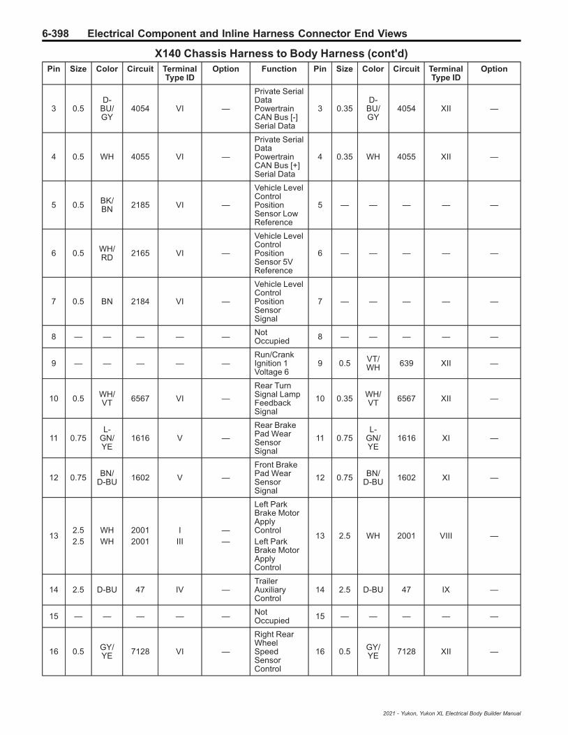
6-398 Electrical Component and Inline Harness Connector End Views
X140 Chassis Harness to Body Harness (cont'd)Pin Size Color Circuit Terminal
Type IDOption Function Pin Size Color Circuit Terminal
Type IDOption
3 0.5D-
BU/GY
4054 VI —
Private SerialDataPowertrainCAN Bus [-]Serial Data
3 0.35D-
BU/GY
4054 XII —
4 0.5 WH 4055 VI —
Private SerialDataPowertrainCAN Bus [+]Serial Data
4 0.35 WH 4055 XII —
5 0.5 BK/BN 2185 VI —
Vehicle LevelControlPositionSensor LowReference
5 — — — — —
6 0.5 WH/RD 2165 VI —
Vehicle LevelControlPositionSensor 5VReference
6 — — — — —
7 0.5 BN 2184 VI —
Vehicle LevelControlPositionSensorSignal
7 — — — — —
8 — — — — — NotOccupied 8 — — — — —
9 — — — — —Run/CrankIgnition 1Voltage 6
9 0.5 VT/WH 639 XII —
10 0.5 WH/VT 6567 VI —
Rear TurnSignal LampFeedbackSignal
10 0.35 WH/VT 6567 XII —
11 0.75L-
GN/YE
1616 V —
Rear BrakePad WearSensorSignal
11 0.75L-
GN/YE
1616 XI —
12 0.75 BN/D-BU 1602 V —
Front BrakePad WearSensorSignal
12 0.75 BN/D-BU 1602 XI —
132.52.5
WHWH
20012001
IIII
——
Left ParkBrake MotorApplyControlLeft ParkBrake MotorApplyControl
13 2.5 WH 2001 VIII —
14 2.5 D-BU 47 IV —TrailerAuxiliaryControl
14 2.5 D-BU 47 IX —
15 — — — — — NotOccupied 15 — — — — —
16 0.5 GY/YE 7128 VI —
Right RearWheelSpeedSensorControl
16 0.5 GY/YE 7128 XII —
2021 - Yukon, Yukon XL Electrical Body Builder Manual

Electrical Component and Inline Harness Connector End Views 6-399
X140 Chassis Harness to Body Harness (cont'd)Pin Size Color Circuit Terminal
Type IDOption Function Pin Size Color Circuit Terminal
Type IDOption
17 0.5 VT 882 VI —
Right RearWheelSpeedSensorSignal
17 0.5 VT 882 XII —
18 0.75 WH/RD 7524 V —
Front VehicleLevel Sensor5VReference
18 — — — — —
190.50.5
BK/GYBK/GY
75267526
VVI
——
Front VehicleLevel SensorLowReferenceFront VehicleLevel SensorLowReference
19
200.50.5
BN/WHBN/WH
75257525
VVI
——
Front VehicleLevel SensorSignalFront VehicleLevel SensorSignal
20
21 0.5 WH 4976 VI —AUTOSARCAN Bus [-]3 Serial Data
21 0.35 WH 4976 XII —
22 0.5D-
BU/BK
4977 VI —AUTOSARCAN Bus [+]3 Serial Data
22 0.35D-
BU/BK
4977 XII —
23 0.5 WH/BK 7544 VI —
Right RearTurn SignalLampFeedbackSignal
23 0.35 WH/BK 7544 XII —
24 0.5D-
BU/VT
4101 VI —
AUTOSARSerial DataCAN Bus [+]4 Serial Data
24 0.35D-
BU/VT
4101 XII —
25 0.5 WH 4100 VI —
AUTOSARSerial DataCAN Bus [-]4 Serial Data
25 0.35 WH 4100 XII —
26 0.5 BK 7970 VI —
AxleDifferentialLock ControlShield
26 0.5 BK 7970 XII —
27 — — — — — Ground 1 27 2.5 BK 150 IX —
28 2.5 GY/BN 7968 IV —
AxleDifferentialLockControl High
28 2.5 GY/BN 7968 IX —
29 4 GY/BK 4369 III —
Left ParkBrake MotorLowReference
29 2.5 GY/BK 4369 VIII —
30 2.5 YE/WH 7969 IV —
AxleDifferentialLockControl Low
30 2.5 YE/WH 7969 IX —
2021 - Yukon, Yukon XL Electrical Body Builder Manual
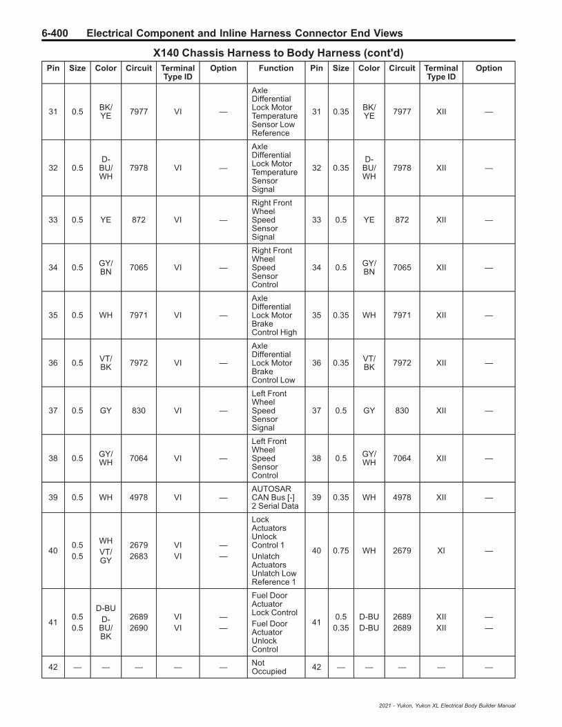
6-400 Electrical Component and Inline Harness Connector End Views
X140 Chassis Harness to Body Harness (cont'd)Pin Size Color Circuit Terminal
Type IDOption Function Pin Size Color Circuit Terminal
Type IDOption
31 0.5 BK/YE 7977 VI —
AxleDifferentialLock MotorTemperatureSensor LowReference
31 0.35 BK/YE 7977 XII —
32 0.5D-
BU/WH
7978 VI —
AxleDifferentialLock MotorTemperatureSensorSignal
32 0.35D-
BU/WH
7978 XII —
33 0.5 YE 872 VI —
Right FrontWheelSpeedSensorSignal
33 0.5 YE 872 XII —
34 0.5 GY/BN 7065 VI —
Right FrontWheelSpeedSensorControl
34 0.5 GY/BN 7065 XII —
35 0.5 WH 7971 VI —
AxleDifferentialLock MotorBrakeControl High
35 0.35 WH 7971 XII —
36 0.5 VT/BK 7972 VI —
AxleDifferentialLock MotorBrakeControl Low
36 0.35 VT/BK 7972 XII —
37 0.5 GY 830 VI —
Left FrontWheelSpeedSensorSignal
37 0.5 GY 830 XII —
38 0.5 GY/WH 7064 VI —
Left FrontWheelSpeedSensorControl
38 0.5 GY/WH 7064 XII —
39 0.5 WH 4978 VI —AUTOSARCAN Bus [-]2 Serial Data
39 0.35 WH 4978 XII —
400.50.5
WHVT/GY
26792683
VIVI
——
LockActuatorsUnlockControl 1UnlatchActuatorsUnlatch LowReference 1
40 0.75 WH 2679 XI —
410.50.5
D-BUD-
BU/BK
26892690
VIVI
——
Fuel DoorActuatorLock ControlFuel DoorActuatorUnlockControl
410.5
0.35D-BUD-BU
26892689
XIIXII
——
42 — — — — — NotOccupied 42 — — — — —
2021 - Yukon, Yukon XL Electrical Body Builder Manual

Electrical Component and Inline Harness Connector End Views 6-401
X140 Chassis Harness to Body Harness (cont'd)Pin Size Color Circuit Terminal
Type IDOption Function Pin Size Color Circuit Terminal
Type IDOption
4344
GYGY
43684368
IIIII
——
Right ParkBrake MotorLowReferenceRight ParkBrake MotorLowReference
43 2.5 GY 4368 VIII —
44 1.5 BK 5051 VII — — 44 1.5 BK 9000 X —
45 0.5 BN/YE 820 VI —
Center HighMountedStop LampSupplyVoltage
45 0.5 BN/YE 820 XII —
46 0.5 GY/BK 7127 VI —
Left RearWheelSpeedSensorControl
46 0.5 GY/BK 7127 XII —
47 0.5 D-BU 884 VI —
Left RearWheelSpeedSensorSignal
47 0.5 D-BU 884 XII —
48 0.5 WH 4100 VI —
AUTOSARSerial DataCAN Bus [-]4 Serial Data
48 0.35 WH 4100 XII —
49 0.5D-
BU/VT
4101 VI —
Fuel DoorActuatorUnlockControlAUTOSARSerial DataCAN Bus [+]4 Serial Data
490.350.35
D-BU/BKD-
BU/VT
26904101
XIIXII
——
50 0.5 GY 7976 VI —
AxleDifferentialLock MotorPositionSensorSignal 2
50 0.35 GY 7976 XII —
51 0.5 BK/VT 7974 VI —
AxleDifferentialLock MotorPositionSensor LowReference
51 0.35 BK/VT 7974 XII —
52 0.5L-
GN/BN
7975 VI —
AxleDifferentialLock MotorPositionSensorSignal 1
52 0.35L-
GN/BN
7975 XII —
53 0.5D-
BU/YE
4979 VI —AUTOSARCAN Bus [+]2 Serial Data
53 0.35D-
BU/YE
4979 XII —
2021 - Yukon, Yukon XL Electrical Body Builder Manual

6-402 Electrical Component and Inline Harness Connector End Views
X140 Chassis Harness to Body Harness (cont'd)Pin Size Color Circuit Terminal
Type IDOption Function Pin Size Color Circuit Terminal
Type IDOption
540.751.5
WH/RDBK
79735052
VVII
——
AxleDifferentialLock MotorPositionSensor HighReferenceHeadlampWasher LowReference
540.751.5
WH/RDBK
79739000
XIX
——
55 — — — — —
PrimaryFusedBatteryPositiveVoltage 4
55 4 RD/YE 442 VIII —
2021 - Yukon, Yukon XL Electrical Body Builder Manual

Electrical Component and Inline Harness Connector End Views 6-403
X143 Chassis Harness to Chassis Harness (LM2)
—
5377298
Connector Part InformationHarness Type: ChassisOEM Connector: Not AvailableService Connector: Service by Harness - See Part CatalogDescription: 30-Way F
Connector Part InformationHarness Type: ChassisOEM Connector: 35101472Service Connector: Service by Harness - See Part CatalogDescription: 30-Way M 1.2 MCON-CB, 2.8 MCP Series,Sealed (GY)
Terminal Part InformationTerminal Type ID Terminated Lead Diagnostic Test Probe Terminal Removal Tool
I Not Required J-35616-16 (LT GN) No Tool Required
II 13575350 J-35616-5 (PU) J-38125-36
III 13575376 J-35616-43 (RD) J-38125-557
IV 13578827 J-35616-5 (PU) J-38125-36
V 19330704 J-35616-17 (LT GN) J-38125-215A
X143 Chassis Harness to Chassis Harness (LM2)Pin Size Color Circuit Terminal
Type IDOption Function Pin Size Color Circuit Terminal
Type IDOption
10.52.5
RD/WHRD/WH
20403440
II
——
SecondaryFusedBatteryPositiveVoltage 20SecondaryFusedBatteryPositiveVoltage 34
10.52.5
RD/WHRD/WH
20403440
IIIIII
——
20.52.5
RD/WHRD/WH
20403440
II
——
SecondaryFusedBatteryPositiveVoltage 20SecondaryFusedBatteryPositiveVoltage 34
20.52.5
RD/WHRD/WH
20403440
IIIV
——
7 0.75 BK 1650 I — Ground 16 7 0.75 BK 1650 II —
8 2.5 BK 1650 I — Ground 16 8 2.5 BK 1650 III —
2021 - Yukon, Yukon XL Electrical Body Builder Manual

6-404 Electrical Component and Inline Harness Connector End Views
X143 Chassis Harness to Chassis Harness (LM2) (cont'd)Pin Size Color Circuit Terminal
Type IDOption Function Pin Size Color Circuit Terminal
Type IDOption
11 0.5D-
BU/BK
4977 I —AUTOSARCAN Bus [+]3 Serial Data
11 0.5D-
BU/BK
4977 V —
12 0.5 WH 4976 I —AUTOSARCAN Bus [-]3 Serial Data
12 0.5 WH 4976 V —
22 0.5D-
BU/BK
4977 I —AUTOSARCAN Bus [+]3 Serial Data
22 0.5D-
BU/BK
4977 V —
23 0.5 WH 4976 I —AUTOSARCAN Bus [-]3 Serial Data
23 0.5 WH 4976 V —
25 0.5 VT/BK 2139 I —
Run/CrankIgnition 1Voltage 21
25 0.5 VT/BK 2139 V —
2021 - Yukon, Yukon XL Electrical Body Builder Manual

Electrical Component and Inline Harness Connector End Views 6-405
X153 Engine Harness to Engine Coolant Temperature Jumper Harness (LM2)
2717079 4560843
Connector Part InformationHarness Type: EngineOEM Connector: 13815341Service Connector: 13587299Description: 4-Way F 1.2 Multilock Series, Sealed (BK)
Connector Part InformationHarness Type: Engine Coolant Temperature JumperOEM Connector: 10013906Service Connector: Service by Harness - See Part CatalogDescription: 4-Way M 1.2 Multilock Series (GY)
Terminal Part InformationTerminal Type ID Terminated Lead Diagnostic Test Probe Terminal Removal Tool
I Not Required J-35616-16 (LT GN) No Tool Required
II Not Required J-35616-17 (LT GN) No Tool Required
X153 Engine Harness to Engine Coolant Temperature Jumper Harness (LM2)Pin Size Color Circuit Terminal
Type IDOption Function Pin Size Color Circuit Terminal
Type IDOption
1 0.5 GY/VT 2404 I —
Engine BlockCoolantTemperatureSignal
1 0.5 GY/VT 2404 II —
2 0.5 BK/GY 626 I —
EngineControlVehicleSensors LowReference 1
2 0.5 BK/GN 580 II —
3 0.5 VT 2988 I —
EngineOutletCoolantTemperatureSignal
3 0.5 VT 2988 II —
4 0.5 BK/YE 548 I —
EngineControlSensors LowReference 1
4 0.5 BK/GY 626 II —
2021 - Yukon, Yukon XL Electrical Body Builder Manual

6-406 Electrical Component and Inline Harness Connector End Views
X154 Engine Harness to Camshaft Position Sensor Jumper Harness (L84/L87)
4846407 2667653
Connector Part InformationHarness Type: EngineOEM Connector: 35063116Service Connector: 19366859Description: 8-Way F 150 MX Series, Sealed (BK)
Connector Part InformationHarness Type: Camshaft Position Sensor JumperOEM Connector: 35021067Service Connector: Service by Harness - See Part CatalogDescription: 8-Way M 150 MX Series, Sealed (BK)
Terminal Part InformationTerminal Type ID Terminated Lead Diagnostic Test Probe Terminal Removal Tool
I Not Required J-35616-2A (GY) No Tool Required
II Not Required J-35616-3 (GY) No Tool Required
X154 Engine Harness to Camshaft Position Sensor Jumper Harness (L84/L87)Pin Size Color Circuit Terminal
Type IDOption Function Pin Size Color Circuit Terminal
Type IDOption
1 0.5 GY/D-BU 5300 I —
IntakeCamshaftPositionSensor 1VoltageReference
1 0.5 GY/D-BU 5300 II —
2 0.5 BK/L-GN 5301 I —
IntakeCamshaftPositionSensor LowReference 1
2 0.5 BK/L-GN 5301 II —
3 0.5 YE/VT 5275 I —
IntakeCamshaftPositionSensor 1
3 0.5 YE/VT 5275 II —
4 0.5 D-BU 179 I —Engine OilPumpControl
4 0.5 D-BU 179 II —
5 0.5 VT/BN 5284 I —
IntakeCamshaftPositionActuatorSolenoidValve 1
5 0.5 VT/BN 5284 II —
6 0.5 BK/BN 6753 I —
CamshaftPositionActuatorSolenoidValve W LowReference
6 0.5 BK/BN 6753 II —
2021 - Yukon, Yukon XL Electrical Body Builder Manual

Electrical Component and Inline Harness Connector End Views 6-407
X154 Engine Harness to Camshaft Position Sensor Jumper Harness (L84/L87) (cont'd)Pin Size Color Circuit Terminal
Type IDOption Function Pin Size Color Circuit Terminal
Type IDOption
7 0.75 VT/D-BU 5293 I —
PowertrainMain RelayFusedSupply 4
7 0.5 VT/D-BU 5293 II —
8 — — — — — NotOccupied 8 — — — — —
2021 - Yukon, Yukon XL Electrical Body Builder Manual

6-408 Electrical Component and Inline Harness Connector End Views
X155 Engine Harness to Active Fuel Management Solenoid Jumper Harness(L84/L87)
4846407 2667653
Connector Part InformationHarness Type: EngineOEM Connector: 35037827Service Connector: 19366859Description: 8-Way F 150 MX Series, Sealed (BK)
Connector Part InformationHarness Type: Active Fuel Management Solenoid JumperOEM Connector: Not AvailableService Connector: Service by Harness - See Part CatalogDescription: 8-Way M
Terminal Part InformationTerminal Type ID Terminated Lead Diagnostic Test Probe Terminal Removal Tool
I Not Required J-35616-14 (GN) No Tool Required
II Not Required No Tool Required
X155 Engine Harness to Active Fuel Management Solenoid Jumper Harness (L84/L87)Pin Size Color Circuit Terminal
Type IDOption Function Pin Size Color Circuit Terminal
Type IDOption
1 0.5 WH/L-GN 2492 I —
CylinderShutoffSolenoidEnableSignal 2
1 0.5 WH/L-GN 2492 II —
2 0.5 L-GN 5492 I —
CylinderDeactivationSolenoidValveControl 2
2 0.5 L-GN 5492 II —
3 0.5 YE/GY 2493 I —
CylinderShutoffSolenoidEnableSignal 3
3 0.5 YE/GY 2493 II —
4 0.5 GY 5493 I —
CylinderDeactivationSolenoidValveControl 3
4 0.5 GY 5493 II —
5 0.5 WH/VT 2495 I —
CylinderShutoffSolenoidEnableSignal 5
5 0.5 WH/VT 2495 II —
2021 - Yukon, Yukon XL Electrical Body Builder Manual
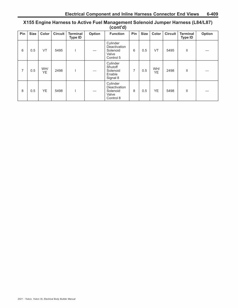
Electrical Component and Inline Harness Connector End Views 6-409
X155 Engine Harness to Active Fuel Management Solenoid Jumper Harness (L84/L87)(cont'd)
Pin Size Color Circuit TerminalType ID
Option Function Pin Size Color Circuit TerminalType ID
Option
6 0.5 VT 5495 I —
CylinderDeactivationSolenoidValveControl 5
6 0.5 VT 5495 II —
7 0.5 WH/YE 2498 I —
CylinderShutoffSolenoidEnableSignal 8
7 0.5 WH/YE 2498 II —
8 0.5 YE 5498 I —
CylinderDeactivationSolenoidValveControl 8
8 0.5 YE 5498 II —
2021 - Yukon, Yukon XL Electrical Body Builder Manual

6-410 Electrical Component and Inline Harness Connector End Views
X156 Engine Harness to Active Fuel Management Solenoid Jumper Harness(L84/L87)
2871860 3238775
Connector Part InformationHarness Type: EngineOEM Connector: 33362189Service Connector: 19352907Description: 12-Way F 150 MX Series, Sealed (BK)
Connector Part InformationHarness Type: Active Fuel Management Solenoid JumperOEM Connector: Not AvailableService Connector: Service by Harness - See Part CatalogDescription: 12-Way M
Terminal Part InformationTerminal Type ID Terminated Lead Diagnostic Test Probe Terminal Removal Tool
I 13578813 J-35616-14 (GN) J-38125-217
II Not Required No Tool Required
X156 Engine Harness to Active Fuel Management Solenoid Jumper Harness (L84/L87)Pin Size Color Circuit Terminal
Type IDOption Function Pin Size Color Circuit Terminal
Type IDOption
1 0.5 WH/D-BU 2491 I —
CylinderShutoffSolenoidEnableSignal 1
1 0.5 WH/D-BU 2491 II —
2 0.5 D-BU 5491 I —
CylinderDeactivationSolenoidValveControl 1
2 0.5 D-BU 5491 II —
3 0.5 YE/L-GN 2494 I —
CylinderShutoffSolenoidEnableSignal 4
3 0.5 YE/L-GN 2494 II —
4 0.5 YE/D-BU 5494 I —
CylinderDeactivationSolenoidValveControl 4
4 0.5 YE/D-BU 5494 II —
5 0.5 YE/BN 2496 I —
CylinderShutoffSolenoidEnableSignal 6
5 0.5 YE/BN 2496 II —
2021 - Yukon, Yukon XL Electrical Body Builder Manual
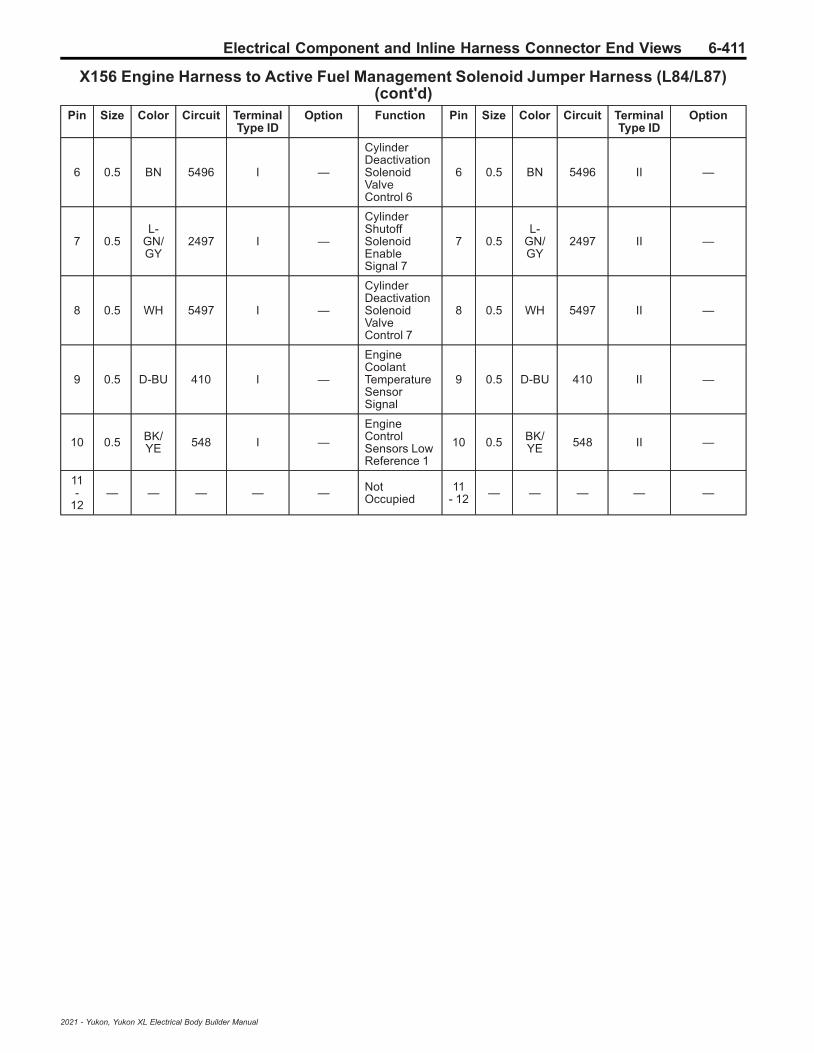
Electrical Component and Inline Harness Connector End Views 6-411
X156 Engine Harness to Active Fuel Management Solenoid Jumper Harness (L84/L87)(cont'd)
Pin Size Color Circuit TerminalType ID
Option Function Pin Size Color Circuit TerminalType ID
Option
6 0.5 BN 5496 I —
CylinderDeactivationSolenoidValveControl 6
6 0.5 BN 5496 II —
7 0.5L-
GN/GY
2497 I —
CylinderShutoffSolenoidEnableSignal 7
7 0.5L-
GN/GY
2497 II —
8 0.5 WH 5497 I —
CylinderDeactivationSolenoidValveControl 7
8 0.5 WH 5497 II —
9 0.5 D-BU 410 I —
EngineCoolantTemperatureSensorSignal
9 0.5 D-BU 410 II —
10 0.5 BK/YE 548 I —
EngineControlSensors LowReference 1
10 0.5 BK/YE 548 II —
11-
12— — — — — Not
Occupied11
- 12 — — — — —
2021 - Yukon, Yukon XL Electrical Body Builder Manual

6-412 Electrical Component and Inline Harness Connector End Views
X158 Camshaft Position Sensor Jumper Harness to Engine Harness (L84/L87)
2717066 4649903
Connector Part InformationHarness Type: Camshaft Position Sensor JumperOEM Connector: 13735326Service Connector: Service by Harness - See Part CatalogDescription: 2-Way F 1.2 Multilock Series, Sealed (BK)
Connector Part InformationHarness Type: EngineOEM Connector: Not AvailableService Connector: Service by Harness - See Part CatalogDescription: 2-Way M
Terminal Part InformationTerminal Type ID Terminated Lead Diagnostic Test Probe Terminal Removal Tool
I Not Required J-35616-16 (LT GN) No Tool Required
II Not Required J-35616-17 (LT GN) No Tool Required
X158 Camshaft Position Sensor Jumper Harness to Engine Harness (L84/L87)Pin Size Color Circuit Terminal
Type IDOption Function Pin Size Color Circuit Terminal
Type IDOption
1 0.5 VT/D-BU 5293 I —
PowertrainMain RelayFusedSupply 4
1 0.5 VT/D-BU 5293 II —
2 0.5 D-BU 179 I —Engine OilPumpControl
2 0.5 D-BU 179 II —
2021 - Yukon, Yukon XL Electrical Body Builder Manual

Electrical Component and Inline Harness Connector End Views 6-413
X158 Engine Harness to Engine Oil Pressure Control Solenoid Valve JumperHarness (LM2)
2717066 2684367
Connector Part InformationHarness Type: EngineOEM Connector: 13735326Service Connector: 13587326Description: 2-Way F 1.2 Multilock Series, Sealed (BK)
Connector Part InformationHarness Type: Engine Oil Pressure Control Solenoid ValveJumperOEM Connector: Not AvailableService Connector: Service by Harness - See Part CatalogDescription: 2-Way M
Terminal Part InformationTerminal Type ID Terminated Lead Diagnostic Test Probe Terminal Removal Tool
I Not Required J-35616-16 (LT GN) No Tool Required
II Not Required J-35616-17 (LT GN) No Tool Required
X158 Engine Harness to Engine Oil Pressure Control Solenoid Valve JumperHarness (LM2)
Pin Size Color Circuit TerminalType ID
Option Function Pin Size Color Circuit TerminalType ID
Option
1 0.5 YE/BN 106 I —
Oil PumpMotorControl
1 0.5 YE/BN 106 II —
2 0.5 D-BU 179 I —Engine OilPumpControl
2 0.5 D-BU 179 II —
2021 - Yukon, Yukon XL Electrical Body Builder Manual

6-414 Electrical Component and Inline Harness Connector End Views
X160 Engine Harness to Bank 1 Fuel Rail Harness (L84/L87)
1825165 2687960
Connector Part InformationHarness Type: EngineOEM Connector: 13595088Service Connector: 19352907Description: 12-Way F 1.5 Series, Sealed (BK)
Connector Part InformationHarness Type: Bank 1 Fuel RailOEM Connector: Not AvailableService Connector: Service by Harness - See Part CatalogDescription: 12-Way M
Terminal Part InformationTerminal Type ID Terminated Lead Diagnostic Test Probe Terminal Removal Tool
I 19300432 J-35616-2A (GY) J-38125-217
II Not Required J-35616-3 (GY) No Tool Required
X160 Engine Harness to Bank 1 Fuel Rail Harness (L84/L87)Pin Size Color Circuit Terminal
Type IDOption Function Pin Size Color Circuit Terminal
Type IDOption
1 0.75 BN/WH 4901 I —
Direct FuelInjector HighVoltageSupplyCylinder 1
1 0.75 BN/WH 4901 II —
2 0.75L-
GN/GY
4903 I —
Direct FuelInjector HighVoltageSupplyCylinder 3
2 0.75L-
GN/GY
4903 II —
3 0.75L-
GN/WH
4905 I —
Direct FuelInjector HighVoltageSupplyCylinder 5
3 0.75L-
GN/WH
4905 II —
4 0.75 WH/YE 4907 I —
Direct FuelInjector HighVoltageSupplyCylinder 7
4 0.75 WH/YE 4907 II —
5 0.75 BN 4801 I —
Direct FuelInjector HighVoltageControlCylinder 1
5 0.75 BN 4801 II —
6 — — — — — NotOccupied 6 — — — — —
2021 - Yukon, Yukon XL Electrical Body Builder Manual
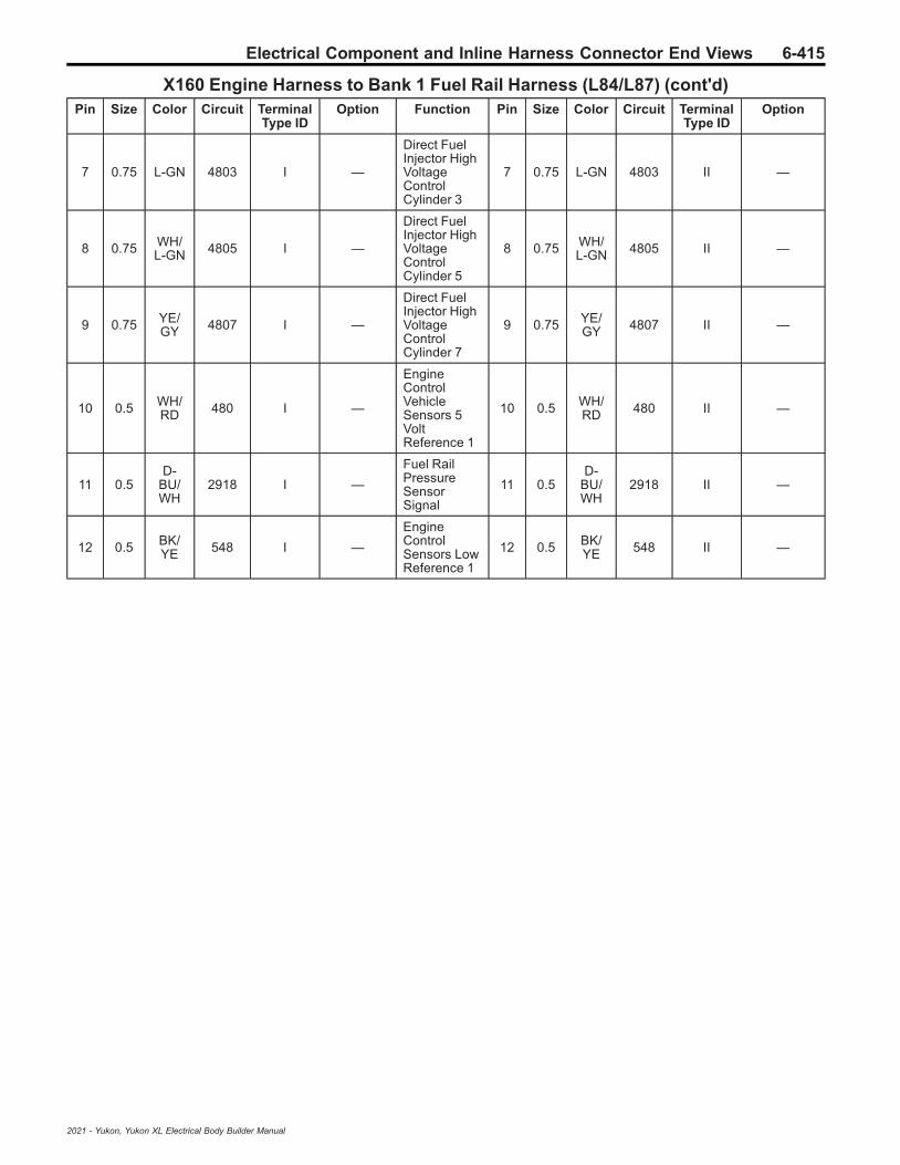
Electrical Component and Inline Harness Connector End Views 6-415
X160 Engine Harness to Bank 1 Fuel Rail Harness (L84/L87) (cont'd)Pin Size Color Circuit Terminal
Type IDOption Function Pin Size Color Circuit Terminal
Type IDOption
7 0.75 L-GN 4803 I —
Direct FuelInjector HighVoltageControlCylinder 3
7 0.75 L-GN 4803 II —
8 0.75 WH/L-GN 4805 I —
Direct FuelInjector HighVoltageControlCylinder 5
8 0.75 WH/L-GN 4805 II —
9 0.75 YE/GY 4807 I —
Direct FuelInjector HighVoltageControlCylinder 7
9 0.75 YE/GY 4807 II —
10 0.5 WH/RD 480 I —
EngineControlVehicleSensors 5VoltReference 1
10 0.5 WH/RD 480 II —
11 0.5D-
BU/WH
2918 I —
Fuel RailPressureSensorSignal
11 0.5D-
BU/WH
2918 II —
12 0.5 BK/YE 548 I —
EngineControlSensors LowReference 1
12 0.5 BK/YE 548 II —
2021 - Yukon, Yukon XL Electrical Body Builder Manual

6-416 Electrical Component and Inline Harness Connector End Views
X160 Engine Harness to Fuel Injector Harness (LM2)
2871866 5187933
Connector Part InformationHarness Type: EngineOEM Connector: 33221171Service Connector: 19333239Description: 12-Way F 150 MX Series, Sealed (D-GY)
Connector Part InformationHarness Type: Fuel InjectorOEM Connector: 33482-6261Service Connector: Service by Harness - See Part CatalogDescription: 12-Way M 150 MX Series, Sealed (GY)
Terminal Part InformationTerminal Type ID Terminated Lead Diagnostic Test Probe Terminal Removal Tool
I 13578813 J-35616-14 (GN) J-38125-217
II Not Required J-35616-3 (GY) No Tool Required
X160 Engine Harness to Fuel Injector Harness (LM2)Pin Size Color Circuit Terminal
Type IDOption Function Pin Size Color Circuit Terminal
Type IDOption
1 1.5 BN/WH 4901 I —
Direct FuelInjector HighVoltageSupplyCylinder 1
1 1.5 BN/WH 4901 II —
2 1.5 BN 4801 I —
Direct FuelInjector HighVoltageControlCylinder 1
2 1.5 BN 4801 II —
3 1.5D-
BU/GY
4902 I —
Direct FuelInjector HighVoltageSupplyCylinder 2
3 1.5 BU/GY 4902 II —
4 1.5 D-BU 4802 I —
Direct FuelInjector HighVoltageControlCylinder 2
4 1.5 BU 4802 II —
5 1.5L-
GN/GY
4903 I —
Direct FuelInjector HighVoltageSupplyCylinder 3
5 1.5 GN/GY 4903 II —
6 1.5 L-GN 4803 I —
Direct FuelInjector HighVoltageControlCylinder 3
6 1.5 GN 4803 II —
2021 - Yukon, Yukon XL Electrical Body Builder Manual
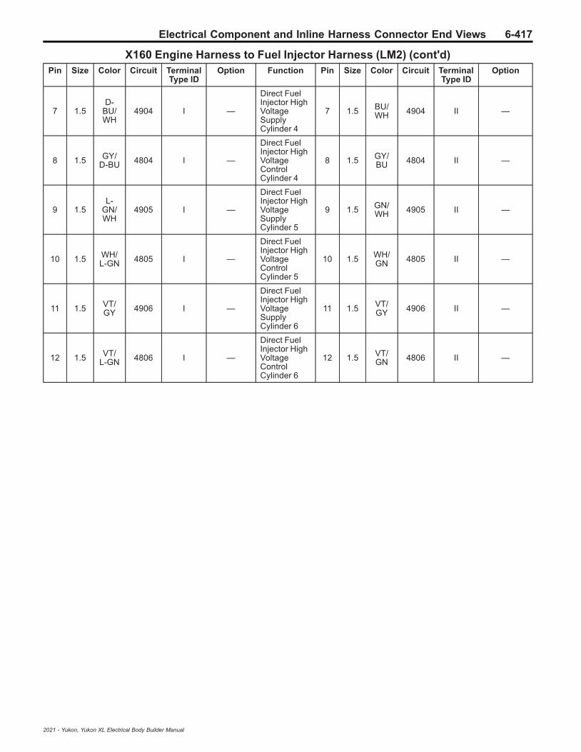
Electrical Component and Inline Harness Connector End Views 6-417
X160 Engine Harness to Fuel Injector Harness (LM2) (cont'd)Pin Size Color Circuit Terminal
Type IDOption Function Pin Size Color Circuit Terminal
Type IDOption
7 1.5D-
BU/WH
4904 I —
Direct FuelInjector HighVoltageSupplyCylinder 4
7 1.5 BU/WH 4904 II —
8 1.5 GY/D-BU 4804 I —
Direct FuelInjector HighVoltageControlCylinder 4
8 1.5 GY/BU 4804 II —
9 1.5L-
GN/WH
4905 I —
Direct FuelInjector HighVoltageSupplyCylinder 5
9 1.5 GN/WH 4905 II —
10 1.5 WH/L-GN 4805 I —
Direct FuelInjector HighVoltageControlCylinder 5
10 1.5 WH/GN 4805 II —
11 1.5 VT/GY 4906 I —
Direct FuelInjector HighVoltageSupplyCylinder 6
11 1.5 VT/GY 4906 II —
12 1.5 VT/L-GN 4806 I —
Direct FuelInjector HighVoltageControlCylinder 6
12 1.5 VT/GN 4806 II —
2021 - Yukon, Yukon XL Electrical Body Builder Manual

6-418 Electrical Component and Inline Harness Connector End Views
X161 Engine Harness to Bank 2 Fuel Rail Harness (L84/L87)
1825165 2687960
Connector Part InformationHarness Type: EngineOEM Connector: 13922706Service Connector: 19352907Description: 12-Way F 1.5 Series, Sealed (BK)
Connector Part InformationHarness Type: Bank 2 Fuel RailOEM Connector: Not AvailableService Connector: Service by Harness - See Part CatalogDescription: 12-Way M
Terminal Part InformationTerminal Type ID Terminated Lead Diagnostic Test Probe Terminal Removal Tool
I 19300432 J-35616-2A (GY) J-38125-217
II Not Required J-35616-3 (GY) No Tool Required
X161 Engine Harness to Bank 2 Fuel Rail Harness (L84/L87)Pin Size Color Circuit Terminal
Type IDOption Function Pin Size Color Circuit Terminal
Type IDOption
1 0.75D-
BU/GY
4902 I —
Direct FuelInjector HighVoltageSupplyCylinder 2
1 0.75D-
BU/GY
4902 II —
2 0.75D-
BU/WH
4904 I —
Direct FuelInjector HighVoltageSupplyCylinder 4
2 0.75D-
BU/WH
4904 II —
3 0.75 VT/GY 4906 I —
Direct FuelInjector HighVoltageSupplyCylinder 6
3 0.75 VT/GY 4906 II —
4 0.75 GY/WH 4908 I —
Direct FuelInjector HighVoltageSupplyCylinder 8
4 0.75 GY/WH 4908 II —
5 0.75 D-BU 4802 I —
Direct FuelInjector HighVoltageControlCylinder 2
5 0.75 D-BU 4802 II —
6- 7 — — — — — Not
Occupied6
- 7 — — — — —
2021 - Yukon, Yukon XL Electrical Body Builder Manual

Electrical Component and Inline Harness Connector End Views 6-419
X161 Engine Harness to Bank 2 Fuel Rail Harness (L84/L87) (cont'd)Pin Size Color Circuit Terminal
Type IDOption Function Pin Size Color Circuit Terminal
Type IDOption
8 0.75 GY/D-BU 4804 I —
Direct FuelInjector HighVoltageControlCylinder 4
8 0.75 GY/D-BU 4804 II —
9 0.75 VT/L-GN 4806 I —
Direct FuelInjector HighVoltageControlCylinder 6
9 0.75 VT/L-GN 4806 II —
10 0.75 GY 4808 I —
Direct FuelInjector HighVoltageControlCylinder 8
10 0.75 GY 4808 II —
11 0.75 VT/BK 7300 I —
HighPressureFuel PumpLow Control
11 0.75 VT/BK 7300 II —
12 0.75 YE 7301 I —
HighPressureFuel PumpHigh Control
12 0.75 YE 7301 II —
2021 - Yukon, Yukon XL Electrical Body Builder Manual

6-420 Electrical Component and Inline Harness Connector End Views
X165 Engine Harness to Engine Coolant Flow Control Valve Jumper Harness (LM2)
4778903
—
Connector Part InformationHarness Type: EngineOEM Connector: 33277161Service Connector: 19371206Description: 3-Way F 1.2 MCON-CB Series, Sealed (BK)
Connector Part InformationHarness Type: Engine Coolant Flow Control Valve JumperOEM Connector: Not AvailableService Connector: Service by Harness - See Part CatalogDescription: 3-Way M
Terminal Part InformationTerminal Type ID Terminated Lead Diagnostic Test Probe Terminal Removal Tool
I Not Required J-35616-16 (LT GN) No Tool Required
II Not Required J-35616-17 (LT GN) No Tool Required
X165 Engine Harness to Engine Coolant Flow Control Valve Jumper Harness (LM2)Pin Size Color Circuit Terminal
Type IDOption Function Pin Size Color Circuit Terminal
Type IDOption
1 0.5L-
GN/BN
2732 I —
EngineControlModule LINBus 4
1 0.5L-
GN/BN
2732 II —
2 0.5 BK 6550 I —PropulsionPropulsionSystem
2 0.5 BK 6550 II —
3 0.5 VT/D-BU 5294 I —
PowertrainMain RelayFusedSupply 5
3 0.5 VT/D-BU 5294 II —
2021 - Yukon, Yukon XL Electrical Body Builder Manual
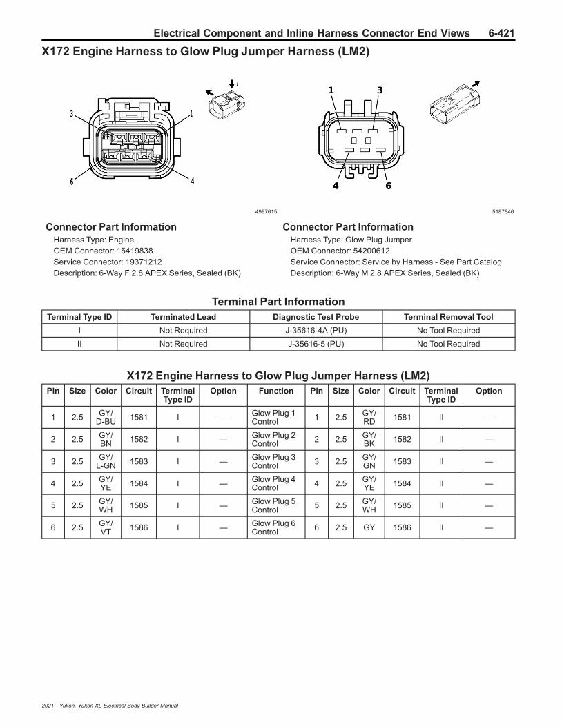
Electrical Component and Inline Harness Connector End Views 6-421
X172 Engine Harness to Glow Plug Jumper Harness (LM2)
4997615 5187846
Connector Part InformationHarness Type: EngineOEM Connector: 15419838Service Connector: 19371212Description: 6-Way F 2.8 APEX Series, Sealed (BK)
Connector Part InformationHarness Type: Glow Plug JumperOEM Connector: 54200612Service Connector: Service by Harness - See Part CatalogDescription: 6-Way M 2.8 APEX Series, Sealed (BK)
Terminal Part InformationTerminal Type ID Terminated Lead Diagnostic Test Probe Terminal Removal Tool
I Not Required J-35616-4A (PU) No Tool Required
II Not Required J-35616-5 (PU) No Tool Required
X172 Engine Harness to Glow Plug Jumper Harness (LM2)Pin Size Color Circuit Terminal
Type IDOption Function Pin Size Color Circuit Terminal
Type IDOption
1 2.5 GY/D-BU 1581 I — Glow Plug 1
Control 1 2.5 GY/RD 1581 II —
2 2.5 GY/BN 1582 I — Glow Plug 2
Control 2 2.5 GY/BK 1582 II —
3 2.5 GY/L-GN 1583 I — Glow Plug 3
Control 3 2.5 GY/GN 1583 II —
4 2.5 GY/YE 1584 I — Glow Plug 4
Control 4 2.5 GY/YE 1584 II —
5 2.5 GY/WH 1585 I — Glow Plug 5
Control 5 2.5 GY/WH 1585 II —
6 2.5 GY/VT 1586 I — Glow Plug 6
Control 6 2.5 GY 1586 II —
2021 - Yukon, Yukon XL Electrical Body Builder Manual

6-422 Electrical Component and Inline Harness Connector End Views
X182 Chassis Harness to Power Steering Harness
4574736
—
Connector Part InformationHarness Type: ChassisOEM Connector: 35147566Service Connector: 13578533Description: 6-Way F 150 MX Series, Sealed (BK)
Connector Part InformationHarness Type: Power SteeringOEM Connector: Not AvailableService Connector: Service by Harness - See Part CatalogDescription: 6-Way M
Terminal Part InformationTerminal Type ID Terminated Lead Diagnostic Test Probe Terminal Removal Tool
I Not Required J-35616-2A (GY) No Tool Required
II Not Required J-35616-3 (GY) No Tool Required
X182 Chassis Harness to Power Steering HarnessPin Size Color Circuit Terminal
Type IDOption Function Pin Size Color Circuit Terminal
Type IDOption
1 0.5 D-BU 4987 I —AUTOSARCAN Bus [+]1 Serial Data
1 0.5 D-BU 4987 II —
2- 5 — — — — — Not
Occupied2
- 5 — — — — —
6 0.5 WH 4986 I —AUTOSARCAN Bus [-]1 Serial Data
6 0.5 WH 4986 II —
2021 - Yukon, Yukon XL Electrical Body Builder Manual

Electrical Component and Inline Harness Connector End Views 6-423
X211 Body Harness to Body Harness
439818 611495
Connector Part InformationHarness Type: BodyOEM Connector: 12047682Service Connector: 12101850Description: 1-Way F 150 Metri-Pack Series (BK)
Connector Part InformationHarness Type: BodyOEM Connector: 12047683Service Connector: 12101828Description: 1-Way M 150 Metri-Pack Series (BK)
Terminal Part InformationTerminal Type ID Terminated Lead Diagnostic Test Probe Terminal Removal Tool
I Not Required J-35616-14 (GN) No Tool Required
II Not Required J-35616-3 (GY) No Tool Required
X211 Body Harness to Body HarnessPin Size Color Circuit Terminal
Type IDOption Function Pin Size Color Circuit Terminal
Type IDOption
A 0.5 BN/WH 28 I — Horn Relay
Control A 0.35 BN/WH 28 II —
2021 - Yukon, Yukon XL Electrical Body Builder Manual

6-424 Electrical Component and Inline Harness Connector End Views
X214 Instrument Panel Harness to Body Harness
4254030 4249317
Connector Part InformationHarness Type: Instrument PanelOEM Connector: 35327186Service Connector: 13517411Description: 10-Way F 1.2 Series (BK)
Connector Part InformationHarness Type: BodyOEM Connector: 33174126Service Connector: 13530136Description: 10-Way M 1.2 Series (BK)
Terminal Part InformationTerminal Type ID Terminated Lead Diagnostic Test Probe Terminal Removal Tool
I 19333323 J-35616-16 (LT GN) J-38125-215A
II 84616651 J-35616-17 (LT GN) J-38125-215A
X214 Instrument Panel Harness to Body HarnessPin Size Color Circuit Terminal
Type IDOption Function Pin Size Color Circuit Terminal
Type IDOption
1 0.35 VT/WH 7213 I — Ethernet Bus
5 [+] 1 0.35 VT/WH 7213 II —
2 0.35 VT 7212 I — Ethernet Bus5 [-] 2 0.35 VT 7212 II —
3- 6 — — — — — Not
Occupied3
- 6 — — — — —
7 0.35 BN/BK 7214 I — Ethernet Bus
6 [-] 7 0.35 BN/BK 7214 II —
8 0.35 GY/BK 7215 I — Ethernet Bus
6 [+] 8 0.35 GY/BK 7215 II —
9-
10— — — — — Not
Occupied9
- 10 — — — — —
2021 - Yukon, Yukon XL Electrical Body Builder Manual

Electrical Component and Inline Harness Connector End Views 6-425
X215 Police Provisional Harness to Instrument Panel Harness (5W4/9C1)
82383 35441
Connector Part InformationHarness Type: Police ProvisionalOEM Connector: Not AvailableService Connector: Service by Harness - See Part CatalogDescription: 2-Way F
Connector Part InformationHarness Type: Instrument PanelOEM Connector: 13649649Service Connector: 13395383Description: 2-Way M 150 Metri-Pack Series (BK)
Terminal Part InformationTerminal Type ID Terminated Lead Diagnostic Test Probe Terminal Removal Tool
I Not Required J-35616-2A (GY) No Tool Required
II Not Required J-35616-3 (GY) No Tool Required
X215 Police Provisional Harness to Instrument Panel Harness (5W4/9C1)Pin Size Color Circuit Terminal
Type IDOption Function Pin Size Color Circuit Terminal
Type IDOption
B 0.5 BK 1850 I — Ground 18 B 0.5 BK 1850 II —
A 0.75 RD/L-GN 10240 I —
SecondaryFusedBatteryPositiveVoltage 102Police
A 0.75 RD/L-GN 10240 II —
2021 - Yukon, Yukon XL Electrical Body Builder Manual

6-426 Electrical Component and Inline Harness Connector End Views
X218 Body Harness to Body Harness (C3A)
—
5375411
Connector Part InformationHarness Type: BodyOEM Connector: Not AvailableService Connector: Service by Harness - See Part CatalogDescription: 2-Way F
Connector Part InformationHarness Type: BodyOEM Connector: 35013203Service Connector: Service by Harness - See Part CatalogDescription: 2-Way M 9.5 Y-Type Series (BK)
Terminal Part InformationTerminal Type ID Terminated Lead Diagnostic Test Probe Terminal Removal Tool
I Not Required J-35616-22 (RD) No Tool Required
II Not Required J-35616-21 (RD) No Tool Required
X218 Body Harness to Body Harness (C3A)Pin Size Color Circuit Terminal
Type IDOption Function Pin Size Color Circuit Terminal
Type IDOption
2 16 RD/GY 642 I —
PrimaryFusedBatteryPositiveVoltage 6
2 16 RD/GY 642 II —
2021 - Yukon, Yukon XL Electrical Body Builder Manual
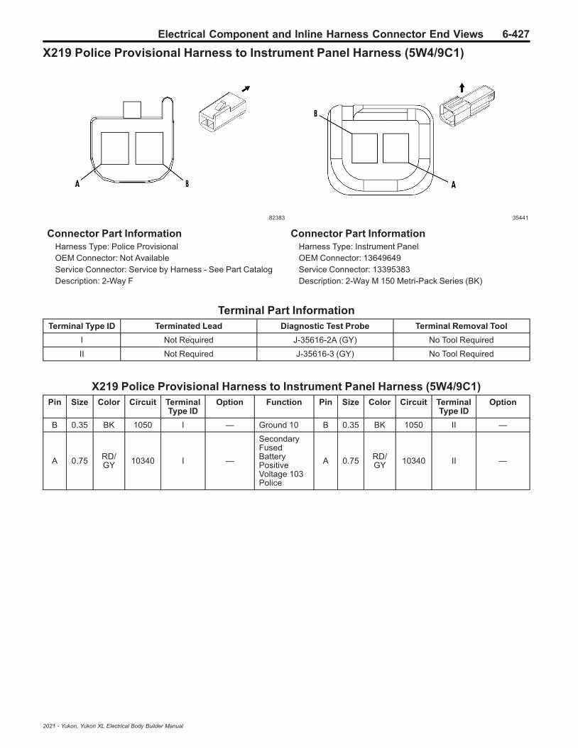
Electrical Component and Inline Harness Connector End Views 6-427
X219 Police Provisional Harness to Instrument Panel Harness (5W4/9C1)
82383 35441
Connector Part InformationHarness Type: Police ProvisionalOEM Connector: Not AvailableService Connector: Service by Harness - See Part CatalogDescription: 2-Way F
Connector Part InformationHarness Type: Instrument PanelOEM Connector: 13649649Service Connector: 13395383Description: 2-Way M 150 Metri-Pack Series (BK)
Terminal Part InformationTerminal Type ID Terminated Lead Diagnostic Test Probe Terminal Removal Tool
I Not Required J-35616-2A (GY) No Tool Required
II Not Required J-35616-3 (GY) No Tool Required
X219 Police Provisional Harness to Instrument Panel Harness (5W4/9C1)Pin Size Color Circuit Terminal
Type IDOption Function Pin Size Color Circuit Terminal
Type IDOption
B 0.35 BK 1050 I — Ground 10 B 0.35 BK 1050 II —
A 0.75 RD/GY 10340 I —
SecondaryFusedBatteryPositiveVoltage 103Police
A 0.75 RD/GY 10340 II —
2021 - Yukon, Yukon XL Electrical Body Builder Manual

6-428 Electrical Component and Inline Harness Connector End Views
X220 Instrument Panel Harness to Body Harness (5W4/9C1)
5187955 4891120
Connector Part InformationHarness Type: Instrument PanelOEM Connector: 35134698Service Connector: Service by Harness - See Part CatalogDescription: 2-Way F 9.5 MCON-LL Series (BK)
Connector Part InformationHarness Type: BodyOEM Connector: 35134697Service Connector: Service by Harness - See Part CatalogDescription: 2-Way M 9.5 MCON-LL Series (BK)
Terminal Part InformationTerminal Type ID Terminated Lead Diagnostic Test Probe Terminal Removal Tool
I Not Required J-35616-22 (RD) No Tool Required
II Not Required J-35616-21 (RD) No Tool Required
X220 Instrument Panel Harness to Body Harness (5W4/9C1)Pin Size Color Circuit Terminal
Type IDOption Function Pin Size Color Circuit Terminal
Type IDOption
1 5 RD/GY 2742 I —
PrimaryFusedBatteryPositiveVoltage 27
1 6 RD/GY 2742 II —
2 — — — — — NotOccupied 2 — — — — —
2021 - Yukon, Yukon XL Electrical Body Builder Manual

Electrical Component and Inline Harness Connector End Views 6-429
X225 Instrument Panel Harness to Body Harness
3960183 3960526
Connector Part InformationHarness Type: Instrument PanelOEM Connector: 35142991Service Connector: 84581287Description: 76-Way F 1.2, 1.5, 2.8 YESC Series (BK)
Connector Part InformationHarness Type: BodyOEM Connector: 33303580Service Connector: 19369989Description: 76-Way M 1.2 MCON-CB, 1.5, 2.8 YESCSeries (BK)
Terminal Part InformationTerminal Type ID Terminated Lead Diagnostic Test Probe Terminal Removal Tool
I 13578891 J-35616-2A (GY) J-38125-11A
II 13580025 J-35616-4A (PU) J-38125-11A
III 13582322 J-35616-4A (PU) J-38125-11A
IV 13587516 J-35616-4A (PU) J-38125-11A
V 19300649 J-35616-4A (PU) J-38125-215A
VI 19301752 J-35616-4A (PU) J-38125-215A
VII 19301761 J-35616-4A (PU) J-38125-215A
VIII 19301767 J-35616-2A (GY) J-38125-215A
IX 19333323 J-35616-16 (LT GN) J-38125-215A
X 19367551 J-35616-16 (LT GN) J-38125-215A
XI 19371240 J-35616-16 (LT GN) J-38125-215A
XII 13575818 J-35616-3 (GY) J-38125-553
XIII 13575821 J-35616-5 (PU) J-38125-11A
XIV 13575824 J-35616-5 (PU) J-38125-11A
XV 13575824 J-35616-5 (PU) J-38125-11A
XVI 13575824 J-35616-5 (PU) J-38125-11A
XVII 13575824 J-35616-5 (PU) J-38125-11A
XVIII 19330704 J-35616-17 (LT GN) J-38125-215A
XIX 19354072 J-35616-5 (PU) J-38125-215A
XX 19355729 J-35616-5 (PU) J-38125-215A
XXI 19370818 J-35616-17 (LT GN) J-38125-215A
XXII 84616651 J-35616-17 (LT GN) J-38125-215A
2021 - Yukon, Yukon XL Electrical Body Builder Manual

6-430 Electrical Component and Inline Harness Connector End Views
X225 Instrument Panel Harness to Body HarnessPin Size Color Circuit Terminal
Type IDOption Function Pin Size Color Circuit Terminal
Type IDOption
1 0.5D-
BU/VT
8900 X —
ImmobilizerAntennaSignal [+]PoliceMicrophoneInput Signal
10.50.5
BN/BKD-
BU/VT
49968900
XXIIXXII
——
2 0.35 BN/GY 8021 IX —
ImmobilizerAntenna LowSignalPoliceMicrophoneEnableSignal
20.5
0.35
WH/GYBN/GY
49978021
XXIIXXII
——
3 0.35 BN 7952 IX — E-Stop Relay1 Control 3 0.5 BN 7952 XXII —
4 0.5 BN/WH 3895 XI —
Roof Rail AirBag DisableSwitch LowReference
4 0.5 BN/WH 3895 XXII —
5 0.35 WH/GY 4104 XI —
AUTOSARSerial DataCAN Bus [-]8 Serial Data
5 0.5 WH/GY 4104 XXII —
6 0.35D-
BU/GY
4105 XI —
AUTOSARSerial DataCAN Bus [+]8 Serial Data
6 0.5D-
BU/GY
4105 XXII —
70.350.35
GYGY
17151715
XIIX
——
WindshieldWiper SwitchHigh SignalWindshieldWiper SwitchHigh Signal
7 0.35 GY 1715 XXII —
8 — — — — — Park EnableSignal 8 0.35 YE 5810 XXII —
9 0.75L-
GN/YE
8896 X — Police Relay2 Control 9 0.75
L-GN/YE
8896 XXI —
10 0.75D-
BU/YE
8895 X — Police Relay1 Control 10 0.75
D-BU/YE
8895 XXI —
11-
13— — — — — Not
Occupied11
- 13 — — — — —
140.50.5
L-GN/YEL-
GN/YE
27312731
XIX
——
ElectronicBrakeControlModule LINBus 1ElectronicBrakeControlModule LINBus 1
14 0.5L-
GN/YE
2731 XXII —
15 0.35L-
GN/VT
5199 XI —Run/CrankRelay CoilControl
15 0.5L-
GN/VT
5199 XXII —
2021 - Yukon, Yukon XL Electrical Body Builder Manual
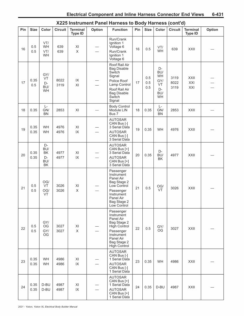
Electrical Component and Inline Harness Connector End Views 6-431
X225 Instrument Panel Harness to Body Harness (cont'd)Pin Size Color Circuit Terminal
Type IDOption Function Pin Size Color Circuit Terminal
Type IDOption
160.50.5
VT/WHVT/WH
639639
XIX
——
Run/CrankIgnition 1Voltage 6Run/CrankIgnition 1Voltage 6
16 0.5 VT/WH 639 XXII —
170.350.5
GY/VTD-
BU/WH
80223119
IXXI
——
Roof Rail AirBag DisableSwitchSignalPolice RoofLamp ControlRoof Rail AirBag DisableSwitchSignal
170.50.50.5
D-BU/WHGY/VTD-
BU/WH
311980223119
XXIIXXIXXI
———
18 0.35L-
GN/BN
2853 XI —Body ControlModule LINBus 7
18 0.35L-
GN/BN
2853 XXII —
190.350.35
WHWH
49764976
XIIX
——
AUTOSARCAN Bus [-]3 Serial DataAUTOSARCAN Bus [-]3 Serial Data
19 0.35 WH 4976 XXII —
200.350.35
D-BU/BKD-
BU/BK
49774977
XIIX
——
AUTOSARCAN Bus [+]3 Serial DataAUTOSARCAN Bus [+]3 Serial Data
20 0.35D-
BU/BK
4977 XXII —
210.50.5
OG/VTOG/VT
30263026
XIX
——
PassengerInstrumentPanel AirBag Stage 2Low ControlPassengerInstrumentPanel AirBag Stage 2Low Control
21 0.5 OG/VT 3026 XXII —
220.50.5
GY/OGGY/OG
30273027
XIX
——
PassengerInstrumentPanel AirBag Stage 2High ControlPassengerInstrumentPanel AirBag Stage 2High Control
22 0.5 GY/OG 3027 XXII —
230.350.35
WHWH
49864986
XIIX
——
AUTOSARCAN Bus [-]1 Serial DataAUTOSARCAN Bus [-]1 Serial Data
23 0.35 WH 4986 XXII —
240.350.35
D-BUD-BU
49874987
XIIX
——
AUTOSARCAN Bus [+]1 Serial DataAUTOSARCAN Bus [+]1 Serial Data
24 0.35 D-BU 4987 XXII —
2021 - Yukon, Yukon XL Electrical Body Builder Manual

6-432 Electrical Component and Inline Harness Connector End Views
X225 Instrument Panel Harness to Body Harness (cont'd)Pin Size Color Circuit Terminal
Type IDOption Function Pin Size Color Circuit Terminal
Type IDOption
25 — — — — — NotOccupied 25 — — — — —
260.50.5
L-GN/WHL-
GN/WH
2424
XIX
——
BackupLamp ControlBackupLamp Control
26 0.5L-
GN/WH
24 XXII —
27-
28— — — — — Not
Occupied27
- 28 — — — — —
292.52.5
BKBK
19501950
VIIV
——
Ground 19Ground 19
29
300.750.75
BK/WHBK/WH
14511451
VIIII
——
Ground 14Ground 14
30 0.75 BK/WH 1451 XVII —
310.350.35
D-BU/WHD-
BU/WH
49854985
VIIII
——
AUTOSARCAN Bus [+]5 Serial DataAUTOSARCAN Bus [+]5 Serial Data
31 0.35D-
BU/WH
4985 XII —
320.350.35
D-BU/YED-
BU/YE
49844984
VIIII
——
AUTOSARCAN Bus [-]5 Serial DataAUTOSARCAN Bus [-]5 Serial Data
32 0.35D-
BU/YE
4984 XII —
33 0.5 BN/D-BU 4892 III —
AuxiliaryBatteryRelayControl
33 0.5 BN/D-BU 4892 XIV —
342.52.5
RD/VTRD/VT
12421242
VIIV
——
PrimaryFusedBatteryPositiveVoltage 12PrimaryFusedBatteryPositiveVoltage 12
34 2 RD/VT 1242 XVI —
35 0.35 YE 5991 I —PowertrainRelay CoilControl
35 0.35 YE 5991 XII —
36 0.35L-
GN/WH
7530 VIII —
Driver SeatMemoryControlModule LINBus 1
36 0.5L-
GN/WH
7530 XII —
37 — — — — —Front CenterSpeaker [-]Control
37 1D-
BU/YE
1960 XII —
38 0.35 WH/VT 6821 I —
SurveillanceSwitchSignal
38 0.75 WH/VT 6821 XII —
39 — — — — — NotOccupied 39 — — — — —
2021 - Yukon, Yukon XL Electrical Body Builder Manual
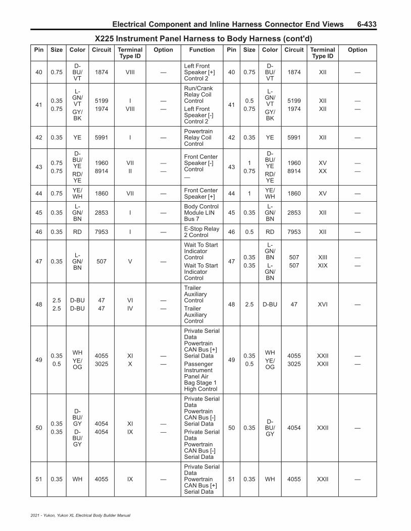
Electrical Component and Inline Harness Connector End Views 6-433
X225 Instrument Panel Harness to Body Harness (cont'd)Pin Size Color Circuit Terminal
Type IDOption Function Pin Size Color Circuit Terminal
Type IDOption
40 0.75D-
BU/VT
1874 VIII —Left FrontSpeaker [+]Control 2
40 0.75D-
BU/VT
1874 XII —
410.350.75
L-GN/VTGY/BK
51991974
IVIII
——
Run/CrankRelay CoilControlLeft FrontSpeaker [-]Control 2
410.5
0.75
L-GN/VTGY/BK
51991974
XIIXII
——
42 0.35 YE 5991 I —PowertrainRelay CoilControl
42 0.35 YE 5991 XII —
430.750.75
D-BU/YERD/YE
19608914
VIIII
——
Front CenterSpeaker [-]Control—
431
0.75
D-BU/YERD/YE
19608914
XVXX
——
44 0.75 YE/WH 1860 VII — Front Center
Speaker [+] 44 1 YE/WH 1860 XV —
45 0.35L-
GN/BN
2853 I —Body ControlModule LINBus 7
45 0.35L-
GN/BN
2853 XII —
46 0.35 RD 7953 I — E-Stop Relay2 Control 46 0.5 RD 7953 XII —
47 0.35L-
GN/BN
507 V —
Wait To StartIndicatorControlWait To StartIndicatorControl
470.350.35
L-GN/BNL-
GN/BN
507507
XIIIXIX
——
482.52.5
D-BUD-BU
4747
VIIV
——
TrailerAuxiliaryControlTrailerAuxiliaryControl
48 2.5 D-BU 47 XVI —
490.350.5
WHYE/OG
40553025
XIX
——
Private SerialDataPowertrainCAN Bus [+]Serial DataPassengerInstrumentPanel AirBag Stage 1High Control
490.350.5
WHYE/OG
40553025
XXIIXXII
——
500.350.35
D-BU/GYD-
BU/GY
40544054
XIIX
——
Private SerialDataPowertrainCAN Bus [-]Serial DataPrivate SerialDataPowertrainCAN Bus [-]Serial Data
50 0.35D-
BU/GY
4054 XXII —
51 0.35 WH 4055 IX —
Private SerialDataPowertrainCAN Bus [+]Serial Data
51 0.35 WH 4055 XXII —
2021 - Yukon, Yukon XL Electrical Body Builder Manual
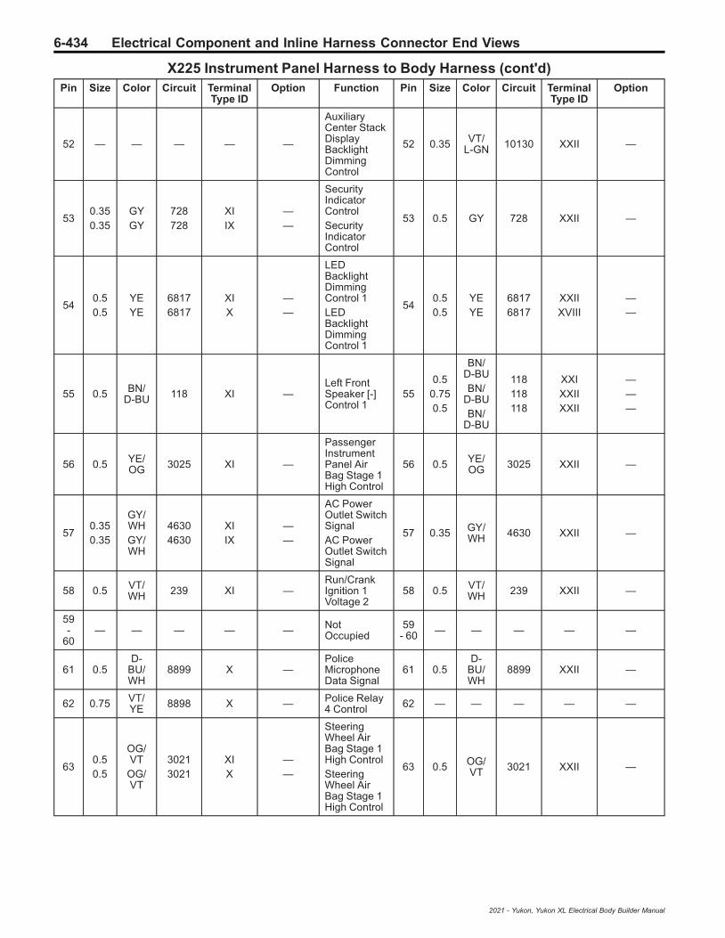
6-434 Electrical Component and Inline Harness Connector End Views
X225 Instrument Panel Harness to Body Harness (cont'd)Pin Size Color Circuit Terminal
Type IDOption Function Pin Size Color Circuit Terminal
Type IDOption
52 — — — — —
AuxiliaryCenter StackDisplayBacklightDimmingControl
52 0.35 VT/L-GN 10130 XXII —
530.350.35
GYGY
728728
XIIX
——
SecurityIndicatorControlSecurityIndicatorControl
53 0.5 GY 728 XXII —
540.50.5
YEYE
68176817
XIX
——
LEDBacklightDimmingControl 1LEDBacklightDimmingControl 1
540.50.5
YEYE
68176817
XXIIXVIII
——
55 0.5 BN/D-BU 118 XI —
Left FrontSpeaker [-]Control 1
550.5
0.750.5
BN/D-BUBN/
D-BUBN/
D-BU
118118118
XXIXXIIXXII
———
56 0.5 YE/OG 3025 XI —
PassengerInstrumentPanel AirBag Stage 1High Control
56 0.5 YE/OG 3025 XXII —
570.350.35
GY/WHGY/WH
46304630
XIIX
——
AC PowerOutlet SwitchSignalAC PowerOutlet SwitchSignal
57 0.35 GY/WH 4630 XXII —
58 0.5 VT/WH 239 XI —
Run/CrankIgnition 1Voltage 2
58 0.5 VT/WH 239 XXII —
59-
60— — — — — Not
Occupied59
- 60 — — — — —
61 0.5D-
BU/WH
8899 X —PoliceMicrophoneData Signal
61 0.5D-
BU/WH
8899 XXII —
62 0.75 VT/YE 8898 X — Police Relay
4 Control 62 — — — — —
630.50.5
OG/VTOG/VT
30213021
XIX
——
SteeringWheel AirBag Stage 1High ControlSteeringWheel AirBag Stage 1High Control
63 0.5 OG/VT 3021 XXII —
2021 - Yukon, Yukon XL Electrical Body Builder Manual

Electrical Component and Inline Harness Connector End Views 6-435
X225 Instrument Panel Harness to Body Harness (cont'd)Pin Size Color Circuit Terminal
Type IDOption Function Pin Size Color Circuit Terminal
Type IDOption
640.50.5
BN/OGBN/OG
30203020
XIX
——
SteeringWheel AirBag Stage 1Low ControlSteeringWheel AirBag Stage 1Low Control
64 0.5 BN/OG 3020 XXII —
650.50.5
OG/L-GNOG/
L-GN
30233023
XIX
——
SteeringWheel AirBag Stage 2High ControlSteeringWheel AirBag Stage 2High Control
65 0.5 OG/L-GN 3023 XXII —
660.50.5
WH/OGWH/OG
30223022
XIX
——
SteeringWheel AirBag Stage 2Low ControlSteeringWheel AirBag Stage 2Low Control
66 0.5 WH/OG 3022 XXII —
67 0.5 D-BU 201 XI —Left FrontSpeaker 1 [+]Control
670.5
0.750.5
D-BUD-BUD-BU
201201201
XXIXXIIXXII
———
680.50.5
OG/WHOG/WH
30243024
XIX
——
PassengerInstrumentPanel AirBag Stage 1Low ControlPassengerInstrumentPanel AirBag Stage 1Low Control
68 0.5 OG/WH 3024 XXII —
69 0.75 RD/L-GN 8911 X — — 69 0.75 RD/
L-GN 8911 XXI —
70 — — — — —Body ControlModule LINBus 1
70 0.35L-
GN/BN
6132 XXII —
710.350.35
WHWH
41004100
XIIX
——
AUTOSARSerial DataCAN Bus [-]4 Serial DataAUTOSARSerial DataCAN Bus [-]4 Serial Data
71 0.35 WH 4100 XXII —
720.350.35
D-BU/VTD-
BU/VT
41014101
XIIX
——
AUTOSARSerial DataCAN Bus [+]4 Serial DataAUTOSARSerial DataCAN Bus [+]4 Serial Data
72 0.35D-
BU/VT
4101 XXII —
73 — — — — — NotOccupied 73 — — — — —
2021 - Yukon, Yukon XL Electrical Body Builder Manual

6-436 Electrical Component and Inline Harness Connector End Views
X225 Instrument Panel Harness to Body Harness (cont'd)Pin Size Color Circuit Terminal
Type IDOption Function Pin Size Color Circuit Terminal
Type IDOption
740.350.35
L-GN/D-BUL-GN/D-BU
27332733
XIIX
——
ElectronicBrakeControlModule LINBus 2ElectronicBrakeControlModule LINBus 2
74 0.75 L-GN/D-BU 2733 XXI —
75 0.75 RD/GY 8912 X — — 75 0.75 RD/
GY 8912 XXI —
76 0.75 RD/WH 8913 X — — 76 0.75 RD/
WH 8913 XXI —
2021 - Yukon, Yukon XL Electrical Body Builder Manual

Electrical Component and Inline Harness Connector End Views 6-437
X250 Trailer Harness to Instrument Panel Harness
823290 1283905
Connector Part InformationHarness Type: TrailerOEM Connector: 10847017Service Connector: Service by Harness - See Part CatalogDescription: 14-Way F 1.5, 2.8 Series (L-GY)
Connector Part InformationHarness Type: Instrument PanelOEM Connector: 10846900Service Connector: 88956523Description: 14-Way M 1.5, 2.8 Series (L-GY)
Terminal Part InformationTerminal Type ID Terminated Lead Diagnostic Test Probe Terminal Removal Tool
I Not Required J-35616-2A (GY) No Tool Required
II Not Required J-35616-4A (PU) No Tool Required
III 13575818 J-35616-3 (GY) J-38125-553
IV 13575824 J-35616-5 (PU) J-38125-11A
X250 Trailer Harness to Instrument Panel HarnessPin Size Color Circuit Terminal
Type IDOption Function Pin Size Color Circuit Terminal
Type IDOption
1 2 BK 1250 II — Ground 12 1 2.5 BK 1950 IV —
2- 4 — — — — — Not
Occupied2
- 4 — — — — —
5 0.5 WH/D-BU 3691 I — Trailer Brake
Apply Signal 5 0.35 WH/D-BU 3691 III —
6 — — — — — NotOccupied 6 — — — — —
7 2 RD/VT 1242 II —
PrimaryFusedBatteryPositiveVoltage 12
7 2.5 RD/VT 1242 IV —
8-
13— — — — — Not
Occupied8
- 13 — — — — —
14 2 D-BU 47 II —TrailerAuxiliaryControl
14 2.5 D-BU 47 IV —
2021 - Yukon, Yukon XL Electrical Body Builder Manual
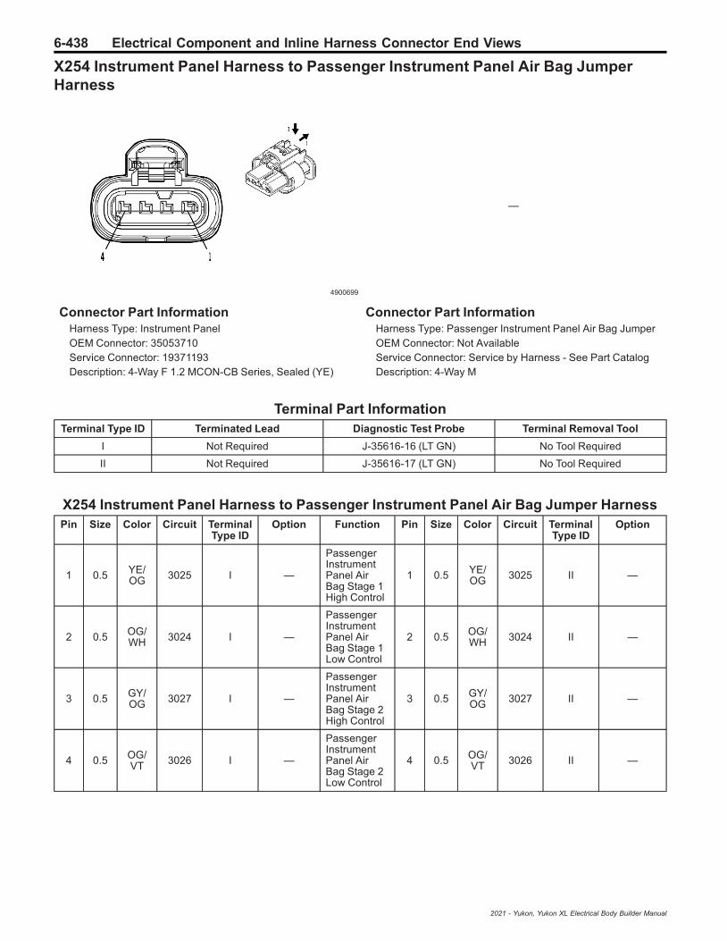
6-438 Electrical Component and Inline Harness Connector End Views
X254 Instrument Panel Harness to Passenger Instrument Panel Air Bag JumperHarness
4900699
—
Connector Part InformationHarness Type: Instrument PanelOEM Connector: 35053710Service Connector: 19371193Description: 4-Way F 1.2 MCON-CB Series, Sealed (YE)
Connector Part InformationHarness Type: Passenger Instrument Panel Air Bag JumperOEM Connector: Not AvailableService Connector: Service by Harness - See Part CatalogDescription: 4-Way M
Terminal Part InformationTerminal Type ID Terminated Lead Diagnostic Test Probe Terminal Removal Tool
I Not Required J-35616-16 (LT GN) No Tool Required
II Not Required J-35616-17 (LT GN) No Tool Required
X254 Instrument Panel Harness to Passenger Instrument Panel Air Bag Jumper HarnessPin Size Color Circuit Terminal
Type IDOption Function Pin Size Color Circuit Terminal
Type IDOption
1 0.5 YE/OG 3025 I —
PassengerInstrumentPanel AirBag Stage 1High Control
1 0.5 YE/OG 3025 II —
2 0.5 OG/WH 3024 I —
PassengerInstrumentPanel AirBag Stage 1Low Control
2 0.5 OG/WH 3024 II —
3 0.5 GY/OG 3027 I —
PassengerInstrumentPanel AirBag Stage 2High Control
3 0.5 GY/OG 3027 II —
4 0.5 OG/VT 3026 I —
PassengerInstrumentPanel AirBag Stage 2Low Control
4 0.5 OG/VT 3026 II —
2021 - Yukon, Yukon XL Electrical Body Builder Manual

Electrical Component and Inline Harness Connector End Views 6-439
X256 Instrument Panel Harness to Floor Console Harness (D07/DCK)
5020939 1851890
Connector Part InformationHarness Type: Instrument PanelOEM Connector: 35061724Service Connector: 13518747Description: 10-Way F 1.5, 2.8 Kaizen Series (L-GY)
Connector Part InformationHarness Type: Floor ConsoleOEM Connector: 13506926Service Connector: Service by Harness - See Part CatalogDescription: 10-Way M YESC Kaizen Series (L-GY)
Terminal Part InformationTerminal Type ID Terminated Lead Diagnostic Test Probe Terminal Removal Tool
I 13575850 J-35616-2A (GY) J-38125-11A
II 13587516 J-35616-4A (PU) J-38125-11A
III Not Required J-35616-3 (GY) No Tool Required
IV Not Required J-35616-5 (PU) No Tool Required
X256 Instrument Panel Harness to Floor Console Harness (D07/DCK)Pin Size Color Circuit Terminal
Type IDOption Function Pin Size Color Circuit Terminal
Type IDOption
1 1.5 VT 1001 II —
RetainedAccessoryPowerControl 2
1 1.5 VT 1001 IV —
20.350.5
RD/YERD/YE
23402340
II
——
SecondaryFusedBatteryPositiveVoltage 23SecondaryFusedBatteryPositiveVoltage 23
2 0.5 RD/YE 2340 III —
3 0.35 BN/BK 4996 I —
ImmobilizerAntennaSignal [+]
3 0.5 BN/BK 4996 III —
4 0.35 WH/GY 4997 I —
ImmobilizerAntenna LowSignal
4 0.5 WH/GY 4997 III —
5- 7 — — — — — Not
Occupied5
- 7 — — — — —
2021 - Yukon, Yukon XL Electrical Body Builder Manual
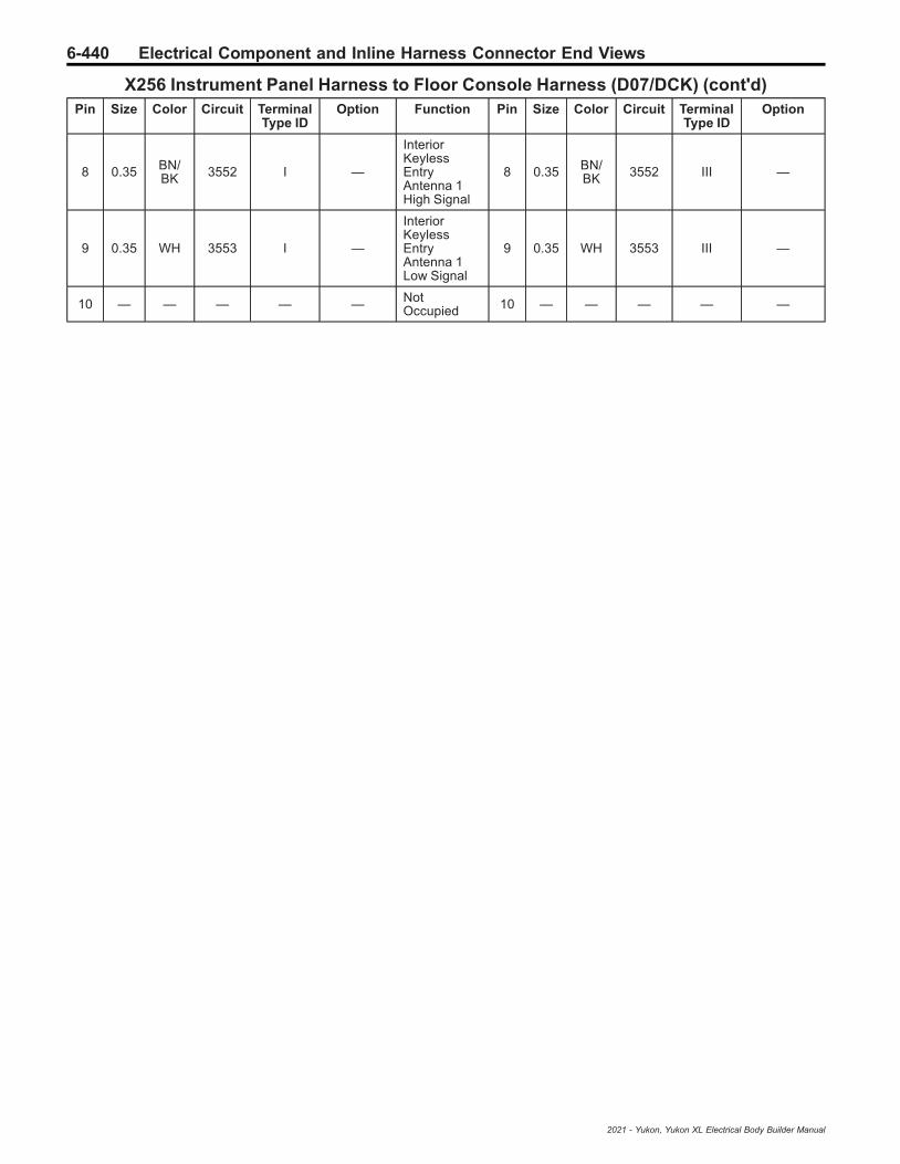
6-440 Electrical Component and Inline Harness Connector End Views
X256 Instrument Panel Harness to Floor Console Harness (D07/DCK) (cont'd)Pin Size Color Circuit Terminal
Type IDOption Function Pin Size Color Circuit Terminal
Type IDOption
8 0.35 BN/BK 3552 I —
InteriorKeylessEntryAntenna 1High Signal
8 0.35 BN/BK 3552 III —
9 0.35 WH 3553 I —
InteriorKeylessEntryAntenna 1Low Signal
9 0.35 WH 3553 III —
10 — — — — — NotOccupied 10 — — — — —
2021 - Yukon, Yukon XL Electrical Body Builder Manual
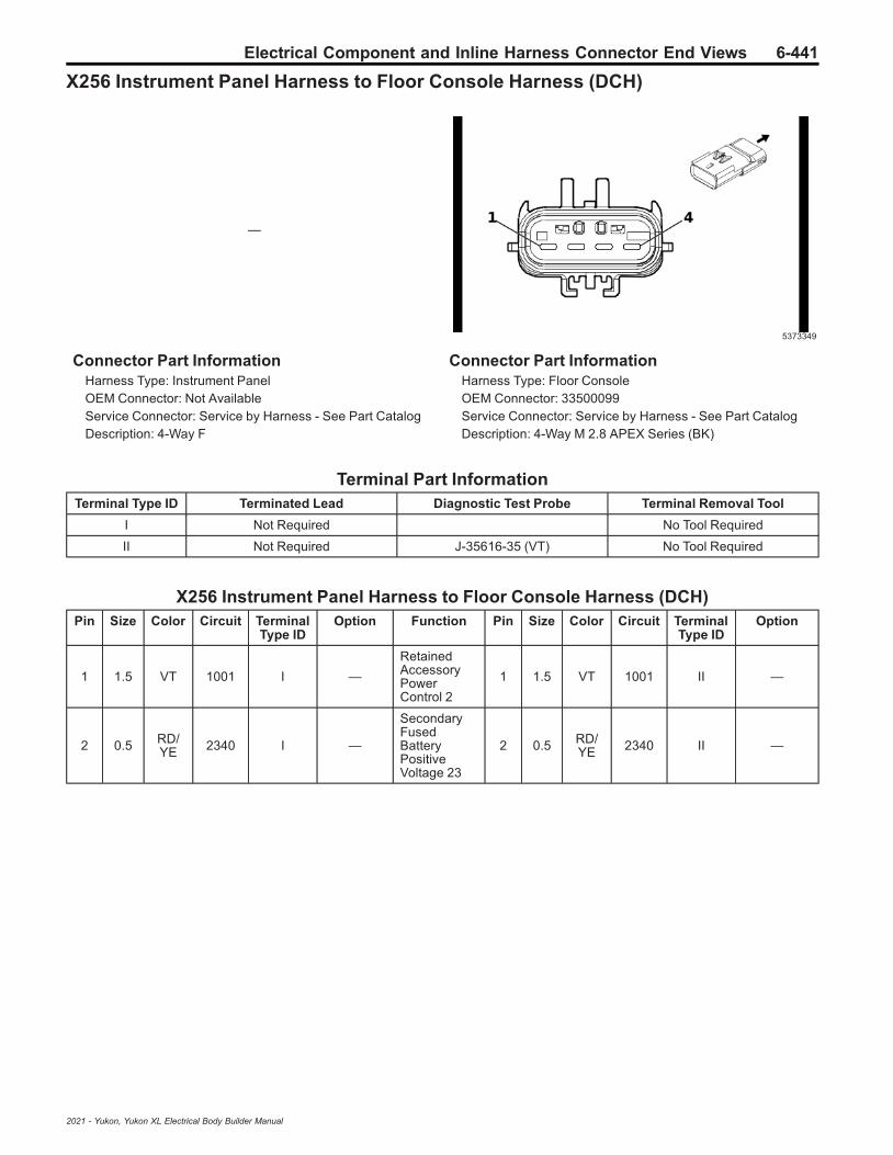
Electrical Component and Inline Harness Connector End Views 6-441
X256 Instrument Panel Harness to Floor Console Harness (DCH)
—
5373349
Connector Part InformationHarness Type: Instrument PanelOEM Connector: Not AvailableService Connector: Service by Harness - See Part CatalogDescription: 4-Way F
Connector Part InformationHarness Type: Floor ConsoleOEM Connector: 33500099Service Connector: Service by Harness - See Part CatalogDescription: 4-Way M 2.8 APEX Series (BK)
Terminal Part InformationTerminal Type ID Terminated Lead Diagnostic Test Probe Terminal Removal Tool
I Not Required No Tool Required
II Not Required J-35616-35 (VT) No Tool Required
X256 Instrument Panel Harness to Floor Console Harness (DCH)Pin Size Color Circuit Terminal
Type IDOption Function Pin Size Color Circuit Terminal
Type IDOption
1 1.5 VT 1001 I —
RetainedAccessoryPowerControl 2
1 1.5 VT 1001 II —
2 0.5 RD/YE 2340 I —
SecondaryFusedBatteryPositiveVoltage 23
2 0.5 RD/YE 2340 II —
2021 - Yukon, Yukon XL Electrical Body Builder Manual
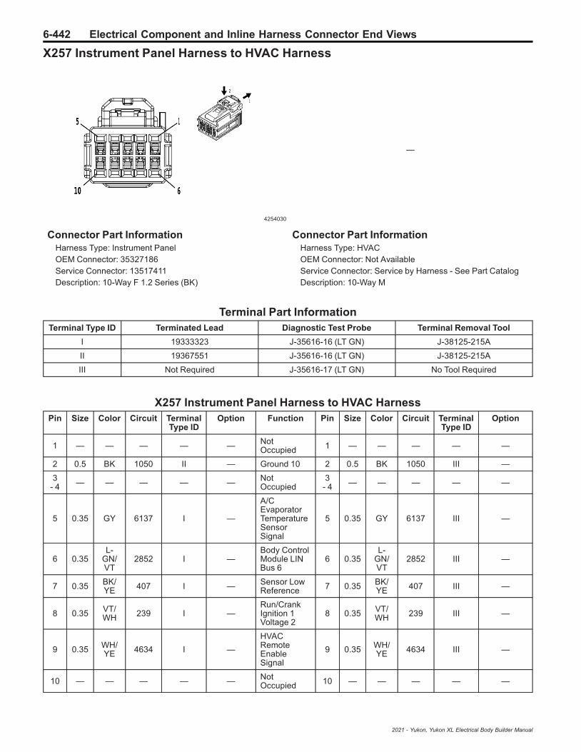
6-442 Electrical Component and Inline Harness Connector End Views
X257 Instrument Panel Harness to HVAC Harness
4254030
—
Connector Part InformationHarness Type: Instrument PanelOEM Connector: 35327186Service Connector: 13517411Description: 10-Way F 1.2 Series (BK)
Connector Part InformationHarness Type: HVACOEM Connector: Not AvailableService Connector: Service by Harness - See Part CatalogDescription: 10-Way M
Terminal Part InformationTerminal Type ID Terminated Lead Diagnostic Test Probe Terminal Removal Tool
I 19333323 J-35616-16 (LT GN) J-38125-215A
II 19367551 J-35616-16 (LT GN) J-38125-215A
III Not Required J-35616-17 (LT GN) No Tool Required
X257 Instrument Panel Harness to HVAC HarnessPin Size Color Circuit Terminal
Type IDOption Function Pin Size Color Circuit Terminal
Type IDOption
1 — — — — — NotOccupied 1 — — — — —
2 0.5 BK 1050 II — Ground 10 2 0.5 BK 1050 III —
3- 4 — — — — — Not
Occupied3
- 4 — — — — —
5 0.35 GY 6137 I —
A/CEvaporatorTemperatureSensorSignal
5 0.35 GY 6137 III —
6 0.35L-
GN/VT
2852 I —Body ControlModule LINBus 6
6 0.35L-
GN/VT
2852 III —
7 0.35 BK/YE 407 I — Sensor Low
Reference 7 0.35 BK/YE 407 III —
8 0.35 VT/WH 239 I —
Run/CrankIgnition 1Voltage 2
8 0.35 VT/WH 239 III —
9 0.35 WH/YE 4634 I —
HVACRemoteEnableSignal
9 0.35 WH/YE 4634 III —
10 — — — — — NotOccupied 10 — — — — —
2021 - Yukon, Yukon XL Electrical Body Builder Manual

Electrical Component and Inline Harness Connector End Views 6-443
X258 Instrument Panel Harness to Instrument Panel Harness
1849808 1849807
Connector Part InformationHarness Type: Instrument PanelOEM Connector: 10846802Service Connector: 19153166Description: 8-Way F 1.5 YESC Kaizen Series (L-GY)
Connector Part InformationHarness Type: Instrument PanelOEM Connector: 10847035Service Connector: 19153162Description: 8-Way M 1.5 YESC Kaizen Series (L-GY)
Terminal Part InformationTerminal Type ID Terminated Lead Diagnostic Test Probe Terminal Removal Tool
I Not Required J-35616-14 (GN) No Tool Required
II Not Required J-35616-2A (GY) No Tool Required
III Not Required J-35616-3 (GY) No Tool Required
X258 Instrument Panel Harness to Instrument Panel HarnessPin Size Color Circuit Terminal
Type IDOption Function Pin Size Color Circuit Terminal
Type IDOption
1 0.5 D-BU 201 II —Left FrontSpeaker 1 [+]Control
1 0.5 D-BU 201 III —
2 0.5 YE 200 II —Right FrontSpeaker 1 [+]Control
2 0.5 YE 200 III —
3 0.75 L-GN 199 I —Left RearSpeaker [+]Control
3 0.75 L-GN 199 III —
4 0.75 WH 46 I —Right RearSpeaker [+]Control
4 0.75 WH 46 III —
5 0.5 BN/D-BU 118 II —
Left FrontSpeaker [-]Control 1
5 0.5 BN/D-BU 118 III —
6 0.5 YE/BK 117 II —
Right FrontSpeaker [-]Control 1
6 0.5 YE/BK 117 III —
7 0.75L-
GN/BK
116 I —Left RearSpeaker [-]Control
7 0.75L-
GN/BK
116 III —
8 0.75D-
BU/BK
115 I —Right RearSpeaker [-]Control
8 0.75D-
BU/BK
115 III —
2021 - Yukon, Yukon XL Electrical Body Builder Manual

6-444 Electrical Component and Inline Harness Connector End Views
X270 Headliner Harness to Instrument Panel Harness
3277913 3277901
Connector Part InformationHarness Type: HeadlinerOEM Connector: 13889713Service Connector: 19329739Description: 48-Way F 1.2 MCON, 2.8 MCP Series (BK)
Connector Part InformationHarness Type: Instrument PanelOEM Connector: 15512031Service Connector: 19329740Description: 48-Way M 1.2 MCON, 2.8 MCP Series (BK)
Terminal Part InformationTerminal Type ID Terminated Lead Diagnostic Test Probe Terminal Removal Tool
I 19119592 J-35616-4A (PU) J-38125-557
II 19329758 J-35616-16 (LT GN) J-38125-215A
III 13575529 J-35616-5 (PU) J-38125-215A
IV 13575574 J-35616-5 (PU) J-38125-215A
V 19329749 J-35616-17 (LT GN) J-38125-215A
X270 Headliner Harness to Instrument Panel HarnessPin Size Color Circuit Terminal
Type IDOption Function Pin Size Color Circuit Terminal
Type IDOption
1 2.5 RD/D-BU 4540 I —
SecondaryFusedBatteryPositiveVoltage 45
1 2.5 RD/D-BU 4540 IV —
2 0.5D-
BU/YE
4979 I —AUTOSARCAN Bus [+]2 Serial Data
2 0.35D-
BU/YE
4979 III —
3 0.5 WH 4978 I —AUTOSARCAN Bus [-]2 Serial Data
3 0.35 WH 4978 III —
4 0.5L-
GN/BK
3008 II —
Active NoiseCancellationMicrophone1 FeedbackSignal
4 0.5L-
GN/BK
3008 V —
5 0.5L-
GN/BN
3005 II —
Active NoiseCancellationMicrophone1 Signal
5 0.5L-
GN/BN
3005 V —
6 0.5D-
BU/GY
4105 II —
AUTOSARSerial DataCAN Bus [+]8 Serial Data
6 0.35D-
BU/GY
4105 V —
2021 - Yukon, Yukon XL Electrical Body Builder Manual
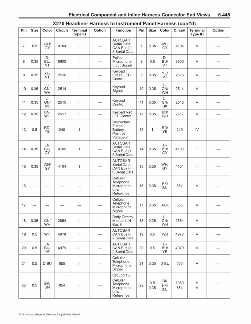
Electrical Component and Inline Harness Connector End Views 6-445
X270 Headliner Harness to Instrument Panel Harness (cont'd)Pin Size Color Circuit Terminal
Type IDOption Function Pin Size Color Circuit Terminal
Type IDOption
7 0.5 WH/GY 4104 II —
AUTOSARSerial DataCAN Bus [-]8 Serial Data
7 0.35 WH/GY 4104 V —
8 0.35D-
BU/VT
8900 II —PoliceMicrophoneInput Signal
8 0.5D-
BU/VT
8900 V —
9 0.35 YE/VT 2516 II —
KeypadGreen LEDControl
9 0.35 YE/VT 2516 V —
10 0.35L-
GN/WH
2514 II — KeypadSignal 10 0.35
L-GN/WH
2514 V —
11 0.35L-
GN/BK
2515 II — KeypadControl 11 0.35
L-GN/BK
2515 V —
12 0.35 BN/WH 2517 II — Keypad Red
LED Control 12 0.35 BN/WH 2517 V —
13 0.5 RD/YE 240 I —
SecondaryFusedBatteryPositiveVoltage 2
13 1 RD/YE 240 IV —
14 0.35D-
BU/GY
4105 I —
AUTOSARSerial DataCAN Bus [+]8 Serial Data
14 0.35D-
BU/GY
4105 III —
15 0.35 WH/GY 4104 I —
AUTOSARSerial DataCAN Bus [-]8 Serial Data
15 0.35 WH/GY 4104 III —
16 — — — — —
CellularTelephoneMicrophoneLowReference
16 0.35 BK/BN 654 V —
17 — — — — —
CellularTelephoneMicrophoneSignal
17 0.35 D-BU 655 V —
18 0.35L-
GN/WH
2854 II —Body ControlModule LINBus 8
18 0.35L-
GN/WH
2854 V —
19 0.5 WH 4978 II —AUTOSARCAN Bus [-]2 Serial Data
19 0.5 WH 4978 V —
20 0.5D-
BU/YE
4979 II —AUTOSARCAN Bus [+]2 Serial Data
20 0.5D-
BU/YE
4979 V —
21 0.5 D-BU 655 II —
CellularTelephoneMicrophoneSignal
21 0.35 D-BU 655 V —
22 0.5 BK/BN 654 II —
Ground 10CellularTelephoneMicrophoneLowReference
220.5
0.35
BKBK/BN
1050654
VV
——
2021 - Yukon, Yukon XL Electrical Body Builder Manual

6-446 Electrical Component and Inline Harness Connector End Views
X270 Headliner Harness to Instrument Panel Harness (cont'd)Pin Size Color Circuit Terminal
Type IDOption Function Pin Size Color Circuit Terminal
Type IDOption
23 0.35L-
GN/WH
24 II — BackupLamp Control 23 0.5
L-GN/WH
24 V —
24 — — — — —ExteriorCourtesyLamp Control
24 0.5 WH/VT 1430 V —
25 0.5 BK 1850 I — Ground 18 25 0.5 BK 1050 IV —
26 0.5 VT/WH 239 I —
Run/CrankIgnition 1Voltage 2
26 0.5 VT/WH 239 IV —
27 — — — — —
SecondaryFusedBatteryPositiveVoltage 2
27 1 RD/YE 240 IV —
28 0.35 L-BU 8579 II —
AutomotiveAudio BusA2B SerialData 1 [-]
28 0.35 BK/WH 1851 V —
29 0.35 L-GN 8580 II —
AutomotiveAudio BusA2B SerialData 1 [+]
29 — — — — —
30 0.5 VT/YE 7043 II — Microphone
[+] Signal 30 0.35 VT/YE 7043 V —
31 0.35 BK/WH 1851 II — Ground 18 31 0.35 BK/
WH 1851 V —
32 0.35 BK/YE 1691 II —
MirrorDimmingLowReference
32 0.35 BK/YE 1691 V —
33 0.35 YE/WH 1690 II —
MirrorDimmingSignal
33 0.35 YE/WH 1690 V —
34 0.35D-
BU/WH
8899 II —PoliceMicrophoneData Signal
34 0.5D-
BU/WH
8899 V —
35 0.75 BN 8569 II —
Right RearHeadlinerSpeaker [-]Control
35 — — — — —
36 0.75 VT/GY 8570 II —
Right RearHeadlinerSpeaker [+]Control
36 0.35L-
GN/WH
4115 V —
37 2.5 BK 1850 I — Ground 18 37 2.5 BK 1050 IV —
38 0.5L-
GN/WH
4115 I —Body ControlModule LINBus 5
38 0.35L-
GN/WH
4115 III —
39 — — — — — NotOccupied 39 — — — — —
40 0.35 L-GN 8580 II —
AutomotiveAudio BusA2B SerialData 1 [+]
40 — — — — —
41 0.35 L-BU 8579 II —
AutomotiveAudio BusA2B SerialData 1 [-]
41 — — — — —
2021 - Yukon, Yukon XL Electrical Body Builder Manual

Electrical Component and Inline Harness Connector End Views 6-447
X270 Headliner Harness to Instrument Panel Harness (cont'd)Pin Size Color Circuit Terminal
Type IDOption Function Pin Size Color Circuit Terminal
Type IDOption
42 0.5D-
BU/BK
7044 II —
BackupLamp ControlMicrophone[-]
420.5
0.35
L-GN/WHD-
BU/BK
247044
VV
——
43 0.75D-
BU/WH
8571 II —
Left FrontHeadlinerSpeaker [-]Control
43 — — — — —
44 0.75L-
GN/BN
8572 II —
Left FrontHeadlinerSpeaker [+]Control
44 — — — — —
45 0.75 GY/L-GN 8574 II —
Right FrontHeadlinerSpeaker [+]Control
45 — — — — —
46 0.75 BN/VT 8573 II —
Right FrontHeadlinerSpeaker [-]Control
46 — — — — —
47 0.75L-
GN/WH
8567 II —
Left RearHeadlinerSpeaker [-]Control
47 0.5 VT/WH 239 V —
48 0.75 GY/BN 8568 II —
Left RearHeadlinerSpeaker [+]Control
48 — — — — —
2021 - Yukon, Yukon XL Electrical Body Builder Manual

6-448 Electrical Component and Inline Harness Connector End Views
X275 Instrument Panel Harness to Body Harness
3960183 3960526
Connector Part InformationHarness Type: Instrument PanelOEM Connector: 35142991Service Connector: 84581287Description: 76-Way F 1.2, 1.5, 2.8 YESC Series (BK)
Connector Part InformationHarness Type: BodyOEM Connector: 33303580Service Connector: 19369989Description: 76-Way M 1.2 MCON-CB, 1.5, 2.8 YESCSeries (BK)
Terminal Part InformationTerminal Type ID Terminated Lead Diagnostic Test Probe Terminal Removal Tool
I 19300649 J-35616-4A (PU) J-38125-215A
II 19301767 J-35616-2A (GY) J-38125-215A
III 19333323 J-35616-16 (LT GN) J-38125-215A
IV 19367551 J-35616-16 (LT GN) J-38125-215A
V 19369846 J-35616-16 (LT GN) J-38125-215A
VI 19370817 J-35616-14 (GN) J-38125-215A
VII 19370818 J-35616-16 (LT GN) J-38125-559
VIII 19371240 J-35616-16 (LT GN) J-38125-215A
IX 13575818 J-35616-3 (GY) J-38125-553
X 13575821 J-35616-5 (PU) J-38125-11A
XI 19370818 J-35616-17 (LT GN) J-38125-215A
XII 84616651 J-35616-17 (LT GN) J-38125-215A
X275 Instrument Panel Harness to Body HarnessPin Size Color Circuit Terminal
Type IDOption Function Pin Size Color Circuit Terminal
Type IDOption
1- 7 — — — — — Not
Occupied1
- 7 — — — — —
8 0.5 WH/VT 1430 IV —
ExteriorCourtesyLamp Control
8 0.35 WH/VT 1430 XII —
9 0.75 L-GN/D-BU 1875 VII —
Right FrontSpeaker [+]Control 2
9 0.75 L-GN/D-BU 1875 XI —
10 0.75 BN/BK 1975 VII —
Right FrontSpeaker [-]Control 2
10 0.75 BN/BK 1975 XI —
2021 - Yukon, Yukon XL Electrical Body Builder Manual

Electrical Component and Inline Harness Connector End Views 6-449
X275 Instrument Panel Harness to Body Harness (cont'd)Pin Size Color Circuit Terminal
Type IDOption Function Pin Size Color Circuit Terminal
Type IDOption
11 0.5L-
GN/BN
3005 VIII —
Active NoiseCancellationMicrophone1 Signal
11 0.5L-
GN/BN
3005 XII —
12 0.5L-
GN/BK
3008 VIII —
Active NoiseCancellationMicrophone1 FeedbackSignal
12 0.5L-
GN/BK
3008 XII —
13 0.5 VT 2801 IV —
RetainedAccessoryPowerControl 8
13 0.5 VT 2801 XII —
140.350.50.5
WHWHWH
497849784978
VIIIIV
VIII
———
AUTOSARCAN Bus [-]2 Serial DataAUTOSARCAN Bus [-]2 Serial DataAUTOSARCAN Bus [-]2 Serial Data
14 0.35 WH 4978 XII —
150.50.5
YE/BKYE/BK
117117
IVVIII
——
Right FrontSpeaker [-]Control 1Right FrontSpeaker [-]Control 1
150.50.5
0.75
YE/BKYE/BKYE/BK
117117117
XIIXIXII
———
16 0.5 YE 200 VIII —
Right FrontSpeaker 1 [+]ControlRight FrontSpeaker 1 [+]Control
160.750.5
YEYE
200200
XIIXI
——
17 0.35 YE 6812 VIII — Out of ParkSignal 17 0.5 YE 6812 XII —
18 0.5 YE 200 IV —
Right FrontSpeaker 1 [+]ControlRight FrontSpeaker 1 [+]Control
180.5
0.750.5
YEYEYE
200200200
XIXIIXII
———
19 — — — — —
Active NoiseCancellationMicrophone1 Signal
19 0.5L-
GN/BN
3005 XII —
20 0.75L-
GN/BK
116 VII —
Left FrontSpeaker [+]Control 2Left RearSpeaker [-]Control
200.750.75
D-BU/VTL-
GN/BK
1874116
XIXI
——
210.750.75
L-GNL-GN
199199
VIIV
——
Left RearSpeaker [+]ControlLeft RearSpeaker [+]Control
21 0.75 L-GN 199 XI —
2021 - Yukon, Yukon XL Electrical Body Builder Manual

6-450 Electrical Component and Inline Harness Connector End Views
X275 Instrument Panel Harness to Body Harness (cont'd)Pin Size Color Circuit Terminal
Type IDOption Function Pin Size Color Circuit Terminal
Type IDOption
220.350.35
WHWH
49864986
VIIIIII
——
AUTOSARCAN Bus [-]1 Serial DataAUTOSARCAN Bus [-]1 Serial Data
22 0.35 WH 4986 XII —
230.350.35
D-BUD-BU
49874987
VIIIIII
——
AUTOSARCAN Bus [+]1 Serial DataAUTOSARCAN Bus [+]1 Serial Data
23 0.35 D-BU 4987 XII —
240.350.35
D-BU/GYD-
BU/GY
40544054
VIIIIII
——
Private SerialDataPowertrainCAN Bus [-]Serial DataPrivate SerialDataPowertrainCAN Bus [-]Serial Data
24 0.35D-
BU/GY
4054 XII —
250.350.75
WHL-
GN/BK
4055116
VIIIV
——
Private SerialDataPowertrainCAN Bus [+]Serial DataLeft RearSpeaker [-]Control
250.350.75
WHL-
GN/BK
4055116
XIIXI
——
260.350.50.5
D-BU/YED-
BU/YED-
BU/YE
497949794979
VIIIIV
VIII
———
AUTOSARCAN Bus [+]2 Serial DataAUTOSARCAN Bus [+]2 Serial DataAUTOSARCAN Bus [+]2 Serial Data
26 0.35D-
BU/YE
4979 XII —
270.350.35
L-GN/WHL-
GN/WH
28542854
VIIIIII
——
Body ControlModule LINBus 8Body ControlModule LINBus 8
27 0.35L-
GN/WH
2854 XII —
28-
31— — — — — Not
Occupied28
- 31 — — — — —
320.750.75
WHWH
4646
IIVI
——
Right RearSpeaker [+]ControlRight RearSpeaker [+]Control
32 0.75 WH 46 IX —
33-
39— — — — — Not
Occupied33
- 39 — — — — —
40 0.35 WH/GY 4104 II —
AUTOSARSerial DataCAN Bus [-]8 Serial Data
40 0.35 WH/GY 4104 IX —
2021 - Yukon, Yukon XL Electrical Body Builder Manual
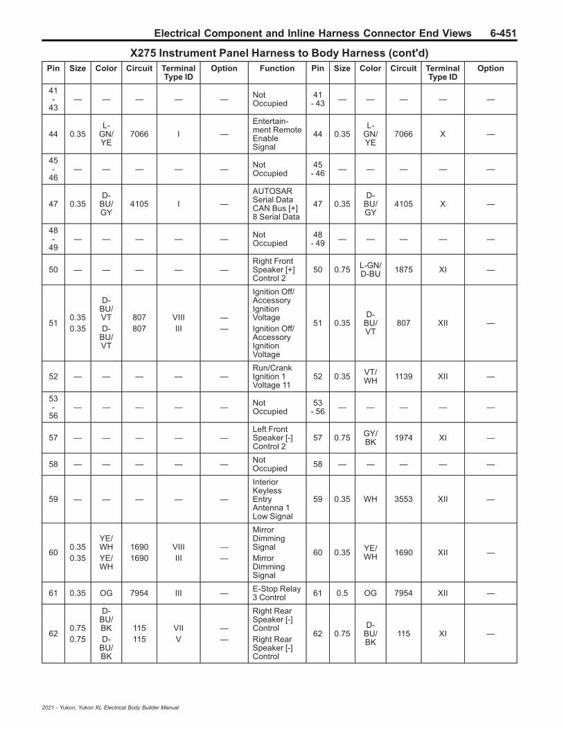
Electrical Component and Inline Harness Connector End Views 6-451
X275 Instrument Panel Harness to Body Harness (cont'd)Pin Size Color Circuit Terminal
Type IDOption Function Pin Size Color Circuit Terminal
Type IDOption
41-
43— — — — — Not
Occupied41
- 43 — — — — —
44 0.35L-
GN/YE
7066 I —
Entertain-ment RemoteEnableSignal
44 0.35L-
GN/YE
7066 X —
45-
46— — — — — Not
Occupied45
- 46 — — — — —
47 0.35D-
BU/GY
4105 I —
AUTOSARSerial DataCAN Bus [+]8 Serial Data
47 0.35D-
BU/GY
4105 X —
48-
49— — — — — Not
Occupied48
- 49 — — — — —
50 — — — — —Right FrontSpeaker [+]Control 2
50 0.75 L-GN/D-BU 1875 XI —
510.350.35
D-BU/VTD-
BU/VT
807807
VIIIIII
——
Ignition Off/AccessoryIgnitionVoltageIgnition Off/AccessoryIgnitionVoltage
51 0.35D-
BU/VT
807 XII —
52 — — — — —Run/CrankIgnition 1Voltage 11
52 0.35 VT/WH 1139 XII —
53-
56— — — — — Not
Occupied53
- 56 — — — — —
57 — — — — —Left FrontSpeaker [-]Control 2
57 0.75 GY/BK 1974 XI —
58 — — — — — NotOccupied 58 — — — — —
59 — — — — —
InteriorKeylessEntryAntenna 1Low Signal
59 0.35 WH 3553 XII —
600.350.35
YE/WHYE/WH
16901690
VIIIIII
——
MirrorDimmingSignalMirrorDimmingSignal
60 0.35 YE/WH 1690 XII —
61 0.35 OG 7954 III — E-Stop Relay3 Control 61 0.5 OG 7954 XII —
620.750.75
D-BU/BKD-
BU/BK
115115
VIIV
——
Right RearSpeaker [-]ControlRight RearSpeaker [-]Control
62 0.75D-
BU/BK
115 XI —
2021 - Yukon, Yukon XL Electrical Body Builder Manual

6-452 Electrical Component and Inline Harness Connector End Views
X275 Instrument Panel Harness to Body Harness (cont'd)Pin Size Color Circuit Terminal
Type IDOption Function Pin Size Color Circuit Terminal
Type IDOption
630.350.35
BK/YEBK/YE
16911691
VIIIIII
——
MirrorDimmingLowReferenceMirrorDimmingLowReference
63 0.35 BK/YE 1691 XII —
64 0.35 WH 4055 III —
Private SerialDataPowertrainCAN Bus [+]Serial Data
64 0.35 WH 4055 XII —
65-
67— — — — — Not
Occupied65
- 67 — — — — —
68 0.75 GY/YE 8897 IV — Police Relay
3 Control 68 0.75 GY/YE 8897 XI —
69-
70— — — — — Not
Occupied69
- 70 — — — — —
710.350.35
VT/L-GNVT/
L-GN
43204320
VIIIIII
——
SelectiveCatalyticReductionPowerModuleWake-UpSignalSelectiveCatalyticReductionPowerModuleWake-UpSignal
71 0.35 VT/L-GN 4320 XII —
72-
74— — — — — Not
Occupied72
- 74 — — — — —
75 — — — — —
InteriorKeylessEntryAntenna 1High Signal
75 0.35 BN/BK 3552 XII —
760.350.35
GY/L-GNGY/
L-GN
40834083
VIIIIII
——
RetainedAccessoryPower Relay2 CoilControlRetainedAccessoryPower Relay2 CoilControl
76 0.35 GY/L-GN 4083 XII —
2021 - Yukon, Yukon XL Electrical Body Builder Manual
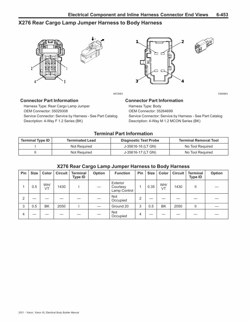
Electrical Component and Inline Harness Connector End Views 6-453
X276 Rear Cargo Lamp Jumper Harness to Body Harness
4872683 5360963
Connector Part InformationHarness Type: Rear Cargo Lamp JumperOEM Connector: 35029308Service Connector: Service by Harness - See Part CatalogDescription: 4-Way F 1.2 Series (BK)
Connector Part InformationHarness Type: BodyOEM Connector: 35264699Service Connector: Service by Harness - See Part CatalogDescription: 4-Way M 1.2 MCON Series (BK)
Terminal Part InformationTerminal Type ID Terminated Lead Diagnostic Test Probe Terminal Removal Tool
I Not Required J-35616-16 (LT GN) No Tool Required
II Not Required J-35616-17 (LT GN) No Tool Required
X276 Rear Cargo Lamp Jumper Harness to Body HarnessPin Size Color Circuit Terminal
Type IDOption Function Pin Size Color Circuit Terminal
Type IDOption
1 0.5 WH/VT 1430 I —
ExteriorCourtesyLamp Control
1 0.35 WH/VT 1430 II —
2 — — — — — NotOccupied 2 — — — — —
3 0.5 BK 2050 I — Ground 20 3 0.5 BK 2050 II —
4 — — — — — NotOccupied 4 — — — — —
2021 - Yukon, Yukon XL Electrical Body Builder Manual

6-454 Electrical Component and Inline Harness Connector End Views
X300 Floor Console Harness to Body Harness
4992168 4993301
Connector Part InformationHarness Type: Floor ConsoleOEM Connector: 35016652Service Connector: Service by Harness - See Part CatalogDescription: 55-Way F 1.2 OCS, 2.8, 6.3 CTS Series,Sealed (BK)
Connector Part InformationHarness Type: BodyOEM Connector: 35205173Service Connector: 84727364Description: 55-Way M 1.2 OCS, 2.8, 6.3 CTS Series,Sealed (BK)
Terminal Part InformationTerminal Type ID Terminated Lead Diagnostic Test Probe Terminal Removal Tool
I Not Required J-35616-16 (LT GN) No Tool Required
II Not Required J-35616-35 (VT) No Tool Required
III Not Required J-35616-42 (RD) No Tool Required
IV Not Required J-35616-43 (RD) No Tool Required
V 13505800 J-35616-5 (PU) J-38125-215A
VI 19301750 J-35616-31 (OR) J-38125-215A
VII 19301750 J-35616-32 (OR) J-38125-36
VIII 19368968 J-35616-5 (PU) J-38125-215A
IX 19369843 J-35616-17 (LT GN) J-38125-215A
X 19370818 J-35616-17 (LT GN) J-38125-215A
XI 84616651 J-35616-17 (LT GN) J-38125-215A
X300 Floor Console Harness to Body HarnessPin Size Color Circuit Terminal
Type IDOption Function Pin Size Color Circuit Terminal
Type IDOption
10.350.50.5
BK/WHBK/WHBK/WH
135113511351
IVIIIIV
———
Ground 13Ground 13Ground 13
1 0.5 BK/WH 1351 VII —
2 0.75 BK/WH 1451 I —
—Ground 14
21.5
0.75
BKBK/WH
90001451
IXX
——
3 0.5 VT/RD 4049 I —
AC PowerOutletSensor HighReference
3 0.5 VT/RD 4049 XI —
2021 - Yukon, Yukon XL Electrical Body Builder Manual

Electrical Component and Inline Harness Connector End Views 6-455
X300 Floor Console Harness to Body Harness (cont'd)Pin Size Color Circuit Terminal
Type IDOption Function Pin Size Color Circuit Terminal
Type IDOption
40.5
0.35
RD/VTRD/VT
63406340
II
BOP-BOP
SecondaryFusedBatteryPositiveVoltage 63SecondaryFusedBatteryPositiveVoltage 63
4 0.5 RD/VT 6340 XI —
5 0.35 BN/BK 405 I —
Lower DuctAirTemperatureSensorSignal
5 0.5 BN/BK 405 XI —
6 — — — — — NotOccupied 6 — — — — —
7 0.35 RD/WH 7240 I —
SecondaryFusedBatteryPositiveVoltage 72
7 0.35 RD/WH 7240 XI —
8 — — — — — NotOccupied 8 — — — — —
9 0.75 YE/WH 4635 I —
HVACRemoteEnable 2Signal
9 0.5 YE/WH 4635 XI —
10 0.5L-
GN/BK
2738 I —Virtual KeyModule LINBus 1
10 0.5L-
GN/BK
2738 XI —
11 — — — — — NotOccupied 11 — — — — —
12 1.5 BK 9001 I — — 12 1.5 BK 9000 IX —
13 — — — — — NotOccupied 13 — — — — —
14 0.5 VT 4701 II —
RetainedAccessoryPowerControl 11
14 0.5 VT 4701 V —
15 0.5L-
GN/BK
2211 I —Rear BlowerMotor SpeedControl
15 0.5L-
GN/BK
2211 XI —
16 0.5 RD/BN 7540 I —
SecondaryFusedBatteryPositiveVoltage 75
16 0.5 RD/BN 7540 XI —
17-
18— — — — — Not
Occupied17
- 18 — — — — —
19 0.75 BK/VT 470 I — Sensor Low
Reference 3 19 0.5 BK/VT 470 XI —
20 0.35 BN 404 I —
Upper DuctAirTemperatureSensorSignal
20 0.5 BN 404 XI —
2021 - Yukon, Yukon XL Electrical Body Builder Manual

6-456 Electrical Component and Inline Harness Connector End Views
X300 Floor Console Harness to Body Harness (cont'd)Pin Size Color Circuit Terminal
Type IDOption Function Pin Size Color Circuit Terminal
Type IDOption
21 0.5 VT/RD 4049 I —
AC PowerOutletSensor HighReference
21 0.5 VT/RD 4049 XI —
22 0.35 BK/WH 1451 I — Ground 14 22 0.75 BK/
WH 1451 X —
230.5
0.35
L-GN/VTL-
GN/VT
28572857
II
DCH-DCH
Body ControlModule LINBus 11Body ControlModule LINBus 11
230.5
0.35
L-GN/VTL-
GN/VT
28572857
XIXI
DCH-DCH
24-
25— — — — — Not
Occupied24
- 25 — — — — —
26 0.75 BK 5683 I — 120V ACPhase A 26 0.75 BK 5683 X —
27 — — — — —
RetainedAccessoryPowerControl 4
27 1.5 VT 1701 VIII —
28 1 RD/VT 8640 II —
SecondaryFusedBatteryPositiveVoltage 86
28 1 RD/VT 8640 V —
29-
32— — — — — Not
Occupied29
- 32 — — — — —
33 0.5 BN/BK 4996 I —
ImmobilizerAntennaSignal [+]
33 0.5 BN/BK 4996 XI —
34 0.5 WH/GY 4997 I —
ImmobilizerAntenna LowSignal
34 0.5 WH/GY 4997 XI —
35 0.75D-
BU/BN
6807 I —DC/ACInverterControl
35 0.75D-
BU/BN
6807 X —
36-
37— — — — — Not
Occupied36
- 37 — — — — —
38 0.35D-
BU/YE
4984 I —
AUTOSARCAN Bus [-]5 Serial DataAUTOSARCAN Bus [-]5 Serial Data
380.5
0.35
D-BU/YED-
BU/YE
49844984
XIXI
UQA/UQSBOP
39 0.35D-
BU/WH
4985 I —
AUTOSARCAN Bus [+]5 Serial DataAUTOSARCAN Bus [+]5 Serial Data
390.5
0.35
D-BU/WHD-
BU/WH
49854985
XIXI
UQA/UQSBOP
40 0.5 YE 6817 I —
LEDBacklightDimmingControl 1
40 0.5 YE 6817 XI —
41 — — — — — NotOccupied 41 — — — — —
2021 - Yukon, Yukon XL Electrical Body Builder Manual

Electrical Component and Inline Harness Connector End Views 6-457
X300 Floor Console Harness to Body Harness (cont'd)Pin Size Color Circuit Terminal
Type IDOption Function Pin Size Color Circuit Terminal
Type IDOption
42 0.75 RD 5684 I — 120V ACPhase B 42 0.75 RD 5684 X —
43 — — — — — NotOccupied 43 — — — — —
441.5
0.75
BKL-
GN/VT
90014786
II
—D07
—Dome/ReadingLamp EnableSignal
440.350.75
L-GN/VTL-
GN/VT
47864786
XIX
-D07D07
45-
47— — — — — Not
Occupied45
- 47 — — — — —
48 0.35 WH 3553 I —
InteriorKeylessEntryAntenna 1Low Signal
48 0.35 WH 3553 XI —
49 0.35 BN/BK 3552 I —
InteriorKeylessEntryAntenna 1High Signal
49 0.35 BN/BK 3552 XI —
50 0.35D-
BU/YE
4984 I —AUTOSARCAN Bus [-]5 Serial Data
50 0.35D-
BU/YE
4984 XI —
51 0.35D-
BU/WH
4985 I —AUTOSARCAN Bus [+]5 Serial Data
51 0.35D-
BU/WH
4985 XI —
52-
53— — — — — Not
Occupied52
- 53 — — — — —
54 1 BK 2519 I —120V ACOutlet LowReference
54 1 BK 2519 X —
55 2 BK 1250 III — Ground 12 55 2 BK 1250 VI —
2021 - Yukon, Yukon XL Electrical Body Builder Manual

6-458 Electrical Component and Inline Harness Connector End Views
X308 Body Harness to Left Second Row Seat Harness
2871860 3238775
Connector Part InformationHarness Type: BodyOEM Connector: 33362189Service Connector: 19352907Description: 12-Way F 150 MX Series, Sealed (BK)
Connector Part InformationHarness Type: Left Second Row SeatOEM Connector: Not AvailableService Connector: Service by Harness - See Part CatalogDescription: 12-Way M
Terminal Part InformationTerminal Type ID Terminated Lead Diagnostic Test Probe Terminal Removal Tool
I 19300432 J-35616-2A (GY) J-38125-217
II Not Required J-35616-3 (GY) No Tool Required
X308 Body Harness to Left Second Row Seat HarnessPin Size Color Circuit Terminal
Type IDOption Function Pin Size Color Circuit Terminal
Type IDOption
1 0.75 RD/GY 6240 I —
SecondaryFusedBatteryPositiveVoltage 62
1 0.75 RD/GY 6240 II —
2 0.75 GY 2294 I —
Left RearSeatCushionHeatingElementControl
2 0.75 GY 2294 II —
3 0.75D-
BU/BK
2446 I —
Left RearSeat HeatingElement LowReference
3 0.75D-
BU/BK
2446 II —
4 0.5 WH/D-BU 7047 I —
Left RearSeatCushionTemperatureSensorSignal
4 0.5 WH/D-BU 7047 II —
5 0.5D-
BU/WH
7048 I —
Left RearCushionThermistorFeedbackSignal
5 0.5D-
BU/WH
7048 II —
6 0.5 L-GN 6808 I —
Left RearFolding SeatMotorControl
6 0.5 L-GN 6808 II —
2021 - Yukon, Yukon XL Electrical Body Builder Manual

Electrical Component and Inline Harness Connector End Views 6-459
X308 Body Harness to Left Second Row Seat Harness (cont'd)Pin Size Color Circuit Terminal
Type IDOption Function Pin Size Color Circuit Terminal
Type IDOption
7 0.75 BK 2050 I — Ground 20 7 0.75 BK 2050 II —
8 0.5 YE/OG 5161 I —
Left RearSeat BeltSwitchSignal
8 0.5 YE/OG 5161 II —
9 0.5 BK/OG 1363 I —
Driver SeatBelt SwitchLowReference
9 0.5 BK/OG 1363 II —
10 0.5D-
BU/OG
5163 I —
Rear CenterSeat BeltSwitchSignal
10 0.5D-
BU/OG
5163 II —
11-
12— — — — — Not
Occupied11
- 12 — — — — —
2021 - Yukon, Yukon XL Electrical Body Builder Manual
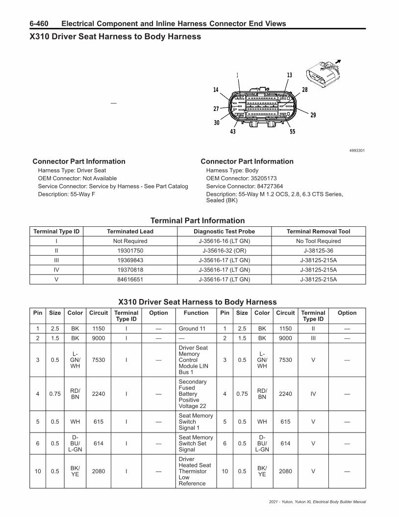
6-460 Electrical Component and Inline Harness Connector End Views
X310 Driver Seat Harness to Body Harness
—
4993301
Connector Part InformationHarness Type: Driver SeatOEM Connector: Not AvailableService Connector: Service by Harness - See Part CatalogDescription: 55-Way F
Connector Part InformationHarness Type: BodyOEM Connector: 35205173Service Connector: 84727364Description: 55-Way M 1.2 OCS, 2.8, 6.3 CTS Series,Sealed (BK)
Terminal Part InformationTerminal Type ID Terminated Lead Diagnostic Test Probe Terminal Removal Tool
I Not Required J-35616-16 (LT GN) No Tool Required
II 19301750 J-35616-32 (OR) J-38125-36
III 19369843 J-35616-17 (LT GN) J-38125-215A
IV 19370818 J-35616-17 (LT GN) J-38125-215A
V 84616651 J-35616-17 (LT GN) J-38125-215A
X310 Driver Seat Harness to Body HarnessPin Size Color Circuit Terminal
Type IDOption Function Pin Size Color Circuit Terminal
Type IDOption
1 2.5 BK 1150 I — Ground 11 1 2.5 BK 1150 II —
2 1.5 BK 9000 I — — 2 1.5 BK 9000 III —
3 0.5L-
GN/WH
7530 I —
Driver SeatMemoryControlModule LINBus 1
3 0.5L-
GN/WH
7530 V —
4 0.75 RD/BN 2240 I —
SecondaryFusedBatteryPositiveVoltage 22
4 0.75 RD/BN 2240 IV —
5 0.5 WH 615 I —Seat MemorySwitchSignal 1
5 0.5 WH 615 V —
6 0.5D-
BU/L-GN
614 I —Seat MemorySwitch SetSignal
6 0.5D-
BU/L-GN
614 V —
10 0.5 BK/YE 2080 I —
DriverHeated SeatThermistorLowReference
10 0.5 BK/YE 2080 V —
2021 - Yukon, Yukon XL Electrical Body Builder Manual
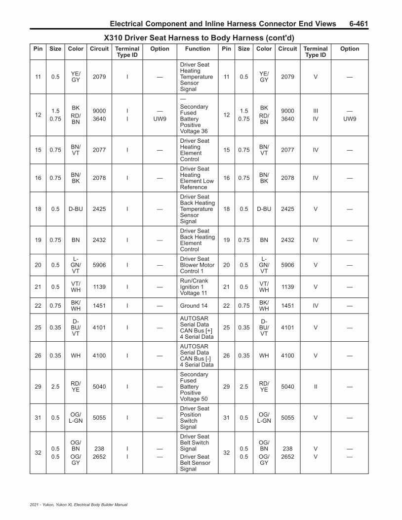
Electrical Component and Inline Harness Connector End Views 6-461
X310 Driver Seat Harness to Body Harness (cont'd)Pin Size Color Circuit Terminal
Type IDOption Function Pin Size Color Circuit Terminal
Type IDOption
11 0.5 YE/GY 2079 I —
Driver SeatHeatingTemperatureSensorSignal
11 0.5 YE/GY 2079 V —
121.5
0.75
BKRD/BN
90003640
II
—UW9
—SecondaryFusedBatteryPositiveVoltage 36
121.5
0.75
BKRD/BN
90003640
IIIIV
—UW9
15 0.75 BN/VT 2077 I —
Driver SeatHeatingElementControl
15 0.75 BN/VT 2077 IV —
16 0.75 BN/BK 2078 I —
Driver SeatHeatingElement LowReference
16 0.75 BN/BK 2078 IV —
18 0.5 D-BU 2425 I —
Driver SeatBack HeatingTemperatureSensorSignal
18 0.5 D-BU 2425 V —
19 0.75 BN 2432 I —
Driver SeatBack HeatingElementControl
19 0.75 BN 2432 IV —
20 0.5L-
GN/VT
5906 I —Driver SeatBlower MotorControl 1
20 0.5L-
GN/VT
5906 V —
21 0.5 VT/WH 1139 I —
Run/CrankIgnition 1Voltage 11
21 0.5 VT/WH 1139 V —
22 0.75 BK/WH 1451 I — Ground 14 22 0.75 BK/
WH 1451 IV —
25 0.35D-
BU/VT
4101 I —
AUTOSARSerial DataCAN Bus [+]4 Serial Data
25 0.35D-
BU/VT
4101 V —
26 0.35 WH 4100 I —
AUTOSARSerial DataCAN Bus [-]4 Serial Data
26 0.35 WH 4100 V —
29 2.5 RD/YE 5040 I —
SecondaryFusedBatteryPositiveVoltage 50
29 2.5 RD/YE 5040 II —
31 0.5 OG/L-GN 5055 I —
Driver SeatPositionSwitchSignal
31 0.5 OG/L-GN 5055 V —
320.50.5
OG/BNOG/GY
2382652
II
——
Driver SeatBelt SwitchSignalDriver SeatBelt SensorSignal
320.50.5
OG/BNOG/GY
2382652
VV
——
2021 - Yukon, Yukon XL Electrical Body Builder Manual

6-462 Electrical Component and Inline Harness Connector End Views
X310 Driver Seat Harness to Body Harness (cont'd)Pin Size Color Circuit Terminal
Type IDOption Function Pin Size Color Circuit Terminal
Type IDOption
33 0.5 BK/OG 1363 I —
Driver SeatBelt SwitchLowReference
33 0.5 BK/OG 1363 V —
35 0.5 OG/D-BU 4962 I —
Driver SeatBack Air BagHigh Control
35 0.5 OG/D-BU 4962 V —
36 0.5 BK/OG 4963 I —
Driver SeatBack Air BagLow Control
36 0.5 BK/OG 4963 V —
37 0.35L-
GN/YE
7066 I —
Entertain-ment RemoteEnableSignal
37 0.35L-
GN/YE
7066 V —
44 1.5 BK 9000 I — — 44 1.5 BK 9000 III —
50 0.35D-
BU/VT
4101 I —
AUTOSARSerial DataCAN Bus [+]4 Serial Data
50 0.35D-
BU/VT
4101 V —
51 0.35 WH 4100 I —
AUTOSARSerial DataCAN Bus [-]4 Serial Data
51 0.35 WH 4100 V —
52 0.5 OG/BN 4207 I —
DriverInboard SeatSide Air BagHigh Control
52 0.5 OG/BN 4207 V —
53 0.5 GY/OG 4208 I —
DriverInboard SeatSide Air BagLow Control
53 0.5 GY/OG 4208 V —
54 1.5 BK 9000 I — — 54 1.5 BK 9000 III —
2021 - Yukon, Yukon XL Electrical Body Builder Manual

Electrical Component and Inline Harness Connector End Views 6-463
X313 Headliner Harness to Microphone Provisional Harness (5W4/9C1)
4872683 4210503
Connector Part InformationHarness Type: HeadlinerOEM Connector: 35029308Service Connector: 19369633Description: 4-Way F 1.2 Series (BK)
Connector Part InformationHarness Type: Microphone ProvisionalOEM Connector: Not AvailableService Connector: Service by Harness - See Part CatalogDescription: 4-Way M
Terminal Part InformationTerminal Type ID Terminated Lead Diagnostic Test Probe Terminal Removal Tool
I Not Required J-35616-16 (LT GN) No Tool Required
II Not Required J-35616-17 (LT GN) No Tool Required
X313 Headliner Harness to Microphone Provisional Harness (5W4/9C1)Pin Size Color Circuit Terminal
Type IDOption Function Pin Size Color Circuit Terminal
Type IDOption
1 0.35 BK 1850 I — Ground 18 1 0.35 BK 1850 II —
2 0.35D-
BU/WH
8899 I —PoliceMicrophoneData Signal
2 0.35D-
BU/WH
8899 II —
3 0.35D-
BU/VT
8900 I —PoliceMicrophoneInput Signal
3 0.35D-
BU/VT
8900 II —
4 — — — — — NotOccupied 4 — — — — —
2021 - Yukon, Yukon XL Electrical Body Builder Manual

6-464 Electrical Component and Inline Harness Connector End Views
X315 Headliner Harness to Microphone Provisional Harness (5W4/9C1)
4115691 4065460
Connector Part InformationHarness Type: HeadlinerOEM Connector: 35311666Service Connector: 19352066Description: 2-Way F 1.2 MCON Series (BK)
Connector Part InformationHarness Type: Microphone ProvisionalOEM Connector: Not AvailableService Connector: Service by Harness - See Part CatalogDescription: 2-Way M
Terminal Part InformationTerminal Type ID Terminated Lead Diagnostic Test Probe Terminal Removal Tool
I Not Required J-35616-16 (LT GN) No Tool Required
II Not Required J-35616-17 (LT GN) No Tool Required
X315 Headliner Harness to Microphone Provisional Harness (5W4/9C1)Pin Size Color Circuit Terminal
Type IDOption Function Pin Size Color Circuit Terminal
Type IDOption
1 0.5 BK 1850 I — Ground 18 1 0.5 BK 1850 II —
2 0.5 RD/YE 240 I —
SecondaryFusedBatteryPositiveVoltage 2
2 0.5 RD/YE 240 II —
2021 - Yukon, Yukon XL Electrical Body Builder Manual
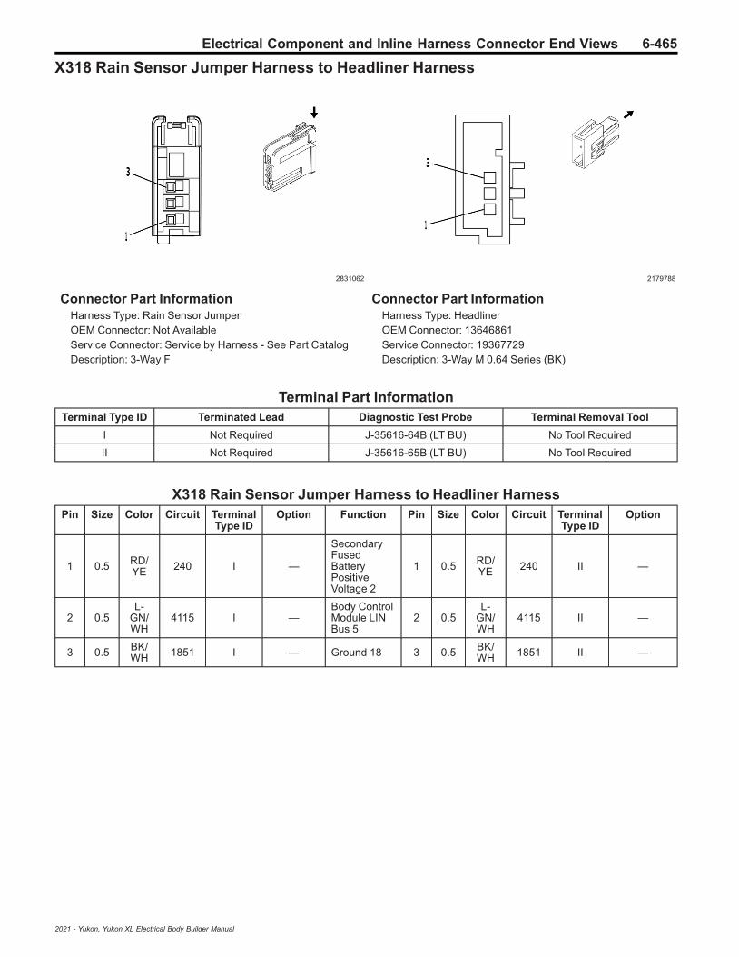
Electrical Component and Inline Harness Connector End Views 6-465
X318 Rain Sensor Jumper Harness to Headliner Harness
2831062 2179788
Connector Part InformationHarness Type: Rain Sensor JumperOEM Connector: Not AvailableService Connector: Service by Harness - See Part CatalogDescription: 3-Way F
Connector Part InformationHarness Type: HeadlinerOEM Connector: 13646861Service Connector: 19367729Description: 3-Way M 0.64 Series (BK)
Terminal Part InformationTerminal Type ID Terminated Lead Diagnostic Test Probe Terminal Removal Tool
I Not Required J-35616-64B (LT BU) No Tool Required
II Not Required J-35616-65B (LT BU) No Tool Required
X318 Rain Sensor Jumper Harness to Headliner HarnessPin Size Color Circuit Terminal
Type IDOption Function Pin Size Color Circuit Terminal
Type IDOption
1 0.5 RD/YE 240 I —
SecondaryFusedBatteryPositiveVoltage 2
1 0.5 RD/YE 240 II —
2 0.5L-
GN/WH
4115 I —Body ControlModule LINBus 5
2 0.5L-
GN/WH
4115 II —
3 0.5 BK/WH 1851 I — Ground 18 3 0.5 BK/
WH 1851 II —
2021 - Yukon, Yukon XL Electrical Body Builder Manual

6-466 Electrical Component and Inline Harness Connector End Views
X320 Body Harness to Body Harness
—
4993301
Connector Part InformationHarness Type: BodyOEM Connector: Not AvailableService Connector: Service by Harness - See Part CatalogDescription: 55-Way F
Connector Part InformationHarness Type: BodyOEM Connector: 35205173Service Connector: 84727364Description: 55-Way M 1.2 OCS, 2.8, 6.3 CTS Series,Sealed (BK)
Terminal Part InformationTerminal Type ID Terminated Lead Diagnostic Test Probe Terminal Removal Tool
I Not Required J-35616-16 (LT GN) No Tool Required
I Not Required J-35616-16 (LT GN) No Tool Required
II 13505800 J-35616-5 (PU) J-38125-215A
III 19301750 J-35616-32 (OR) J-38125-36
III 19301750 J-35616-32 (OR) J-38125-36
IV 19369843 J-35616-17 (LT GN) J-38125-215A
V 19370818 J-35616-17 (LT GN) J-38125-215A
VI 84616651 J-35616-17 (LT GN) J-38125-215A
VI 84616651 J-35616-17 (LT GN) J-38125-215A
X320 Body Harness to Body HarnessPin Size Color Circuit Terminal
Type IDOption Function Pin Size Color Circuit Terminal
Type IDOption
1 2.5 BK 1250 I — Ground 12 1 2.5 BK 1250 III —
2 1.5 BK 9000 I — — 2 1.5 BK 9000 IV —
4 0.75 RD/D-BU 3940 I —
SecondaryFusedBatteryPositiveVoltage 39
4 0.75 RD/D-BU 3940 V —
7 0.35 D-BU 4987 I —AUTOSARCAN Bus [+]1 Serial Data
7 0.35 D-BU 4987 VI —
8 0.35 WH 4986 I —AUTOSARCAN Bus [-]1 Serial Data
8 0.35 WH 4986 VI —
2021 - Yukon, Yukon XL Electrical Body Builder Manual
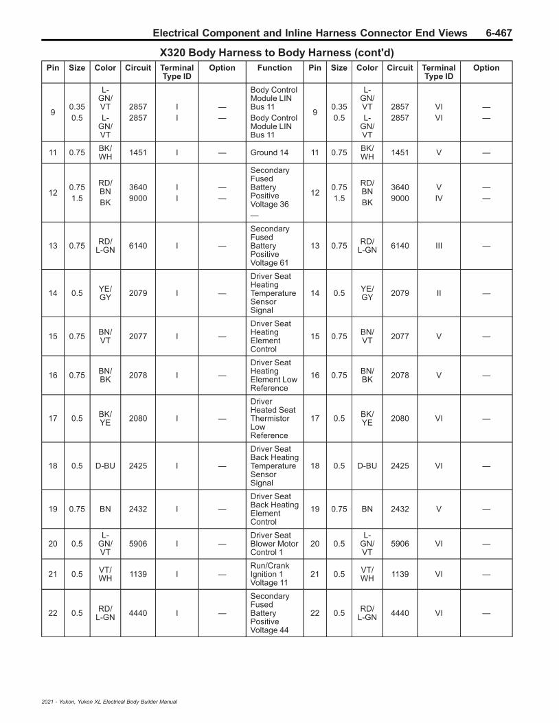
Electrical Component and Inline Harness Connector End Views 6-467
X320 Body Harness to Body Harness (cont'd)Pin Size Color Circuit Terminal
Type IDOption Function Pin Size Color Circuit Terminal
Type IDOption
90.350.5
L-GN/VTL-
GN/VT
28572857
II
——
Body ControlModule LINBus 11Body ControlModule LINBus 11
90.350.5
L-GN/VTL-
GN/VT
28572857
VIVI
——
11 0.75 BK/WH 1451 I — Ground 14 11 0.75 BK/
WH 1451 V —
120.751.5
RD/BNBK
36409000
II
——
SecondaryFusedBatteryPositiveVoltage 36—
120.751.5
RD/BNBK
36409000
VIV
——
13 0.75 RD/L-GN 6140 I —
SecondaryFusedBatteryPositiveVoltage 61
13 0.75 RD/L-GN 6140 III —
14 0.5 YE/GY 2079 I —
Driver SeatHeatingTemperatureSensorSignal
14 0.5 YE/GY 2079 II —
15 0.75 BN/VT 2077 I —
Driver SeatHeatingElementControl
15 0.75 BN/VT 2077 V —
16 0.75 BN/BK 2078 I —
Driver SeatHeatingElement LowReference
16 0.75 BN/BK 2078 V —
17 0.5 BK/YE 2080 I —
DriverHeated SeatThermistorLowReference
17 0.5 BK/YE 2080 VI —
18 0.5 D-BU 2425 I —
Driver SeatBack HeatingTemperatureSensorSignal
18 0.5 D-BU 2425 VI —
19 0.75 BN 2432 I —
Driver SeatBack HeatingElementControl
19 0.75 BN 2432 V —
20 0.5L-
GN/VT
5906 I —Driver SeatBlower MotorControl 1
20 0.5L-
GN/VT
5906 VI —
21 0.5 VT/WH 1139 I —
Run/CrankIgnition 1Voltage 11
21 0.5 VT/WH 1139 VI —
22 0.5 RD/L-GN 4440 I —
SecondaryFusedBatteryPositiveVoltage 44
22 0.5 RD/L-GN 4440 VI —
2021 - Yukon, Yukon XL Electrical Body Builder Manual
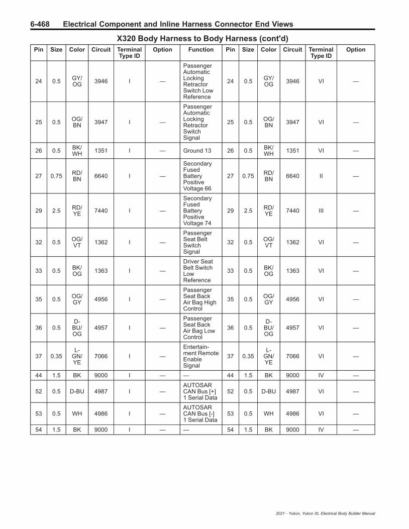
6-468 Electrical Component and Inline Harness Connector End Views
X320 Body Harness to Body Harness (cont'd)Pin Size Color Circuit Terminal
Type IDOption Function Pin Size Color Circuit Terminal
Type IDOption
24 0.5 GY/OG 3946 I —
PassengerAutomaticLockingRetractorSwitch LowReference
24 0.5 GY/OG 3946 VI —
25 0.5 OG/BN 3947 I —
PassengerAutomaticLockingRetractorSwitchSignal
25 0.5 OG/BN 3947 VI —
26 0.5 BK/WH 1351 I — Ground 13 26 0.5 BK/
WH 1351 VI —
27 0.75 RD/BN 6640 I —
SecondaryFusedBatteryPositiveVoltage 66
27 0.75 RD/BN 6640 II —
29 2.5 RD/YE 7440 I —
SecondaryFusedBatteryPositiveVoltage 74
29 2.5 RD/YE 7440 III —
32 0.5 OG/VT 1362 I —
PassengerSeat BeltSwitchSignal
32 0.5 OG/VT 1362 VI —
33 0.5 BK/OG 1363 I —
Driver SeatBelt SwitchLowReference
33 0.5 BK/OG 1363 VI —
35 0.5 OG/GY 4956 I —
PassengerSeat BackAir Bag HighControl
35 0.5 OG/GY 4956 VI —
36 0.5D-
BU/OG
4957 I —
PassengerSeat BackAir Bag LowControl
36 0.5D-
BU/OG
4957 VI —
37 0.35L-
GN/YE
7066 I —
Entertain-ment RemoteEnableSignal
37 0.35L-
GN/YE
7066 VI —
44 1.5 BK 9000 I — — 44 1.5 BK 9000 IV —
52 0.5 D-BU 4987 I —AUTOSARCAN Bus [+]1 Serial Data
52 0.5 D-BU 4987 VI —
53 0.5 WH 4986 I —AUTOSARCAN Bus [-]1 Serial Data
53 0.5 WH 4986 VI —
54 1.5 BK 9000 I — — 54 1.5 BK 9000 IV —
2021 - Yukon, Yukon XL Electrical Body Builder Manual

Electrical Component and Inline Harness Connector End Views 6-469
X322 Video Display Ethernet Jumper Harness to Body Harness (UW9)
2474713 3338703
Connector Part InformationHarness Type: Video Display Ethernet JumperOEM Connector: Not AvailableService Connector: Service by Harness - See Part CatalogDescription: 2-Way F
Connector Part InformationHarness Type: BodyOEM Connector: 35198959Service Connector: Service by Harness - See Part CatalogDescription: 2-Way M 1.5 MX Series, Sealed (BK)
Terminal Part InformationTerminal Type ID Terminated Lead Diagnostic Test Probe Terminal Removal Tool
I Not Required J-35616-2A (GY) No Tool Required
II Not Required J-35616-3 (GY) No Tool Required
X322 Video Display Ethernet Jumper Harness to Body Harness (UW9)Pin Size Color Circuit Terminal
Type IDOption Function Pin Size Color Circuit Terminal
Type IDOption
1 0.35 VT 7212 I — Ethernet Bus5 [-] 1 0.35 VT 7212 II —
2 0.35 VT/WH 7213 I — Ethernet Bus
5 [+] 2 0.35 VT/WH 7213 II —
2021 - Yukon, Yukon XL Electrical Body Builder Manual

6-470 Electrical Component and Inline Harness Connector End Views
X324 Sunroof Harness to Headliner Harness (C3U)
1851891 1851890
Connector Part InformationHarness Type: SunroofOEM Connector: Not AvailableService Connector: Service by Harness - See Part CatalogDescription: 10-Way F
Connector Part InformationHarness Type: HeadlinerOEM Connector: 13506926Service Connector: 89047070Description: 10-Way M YESC Kaizen Series (L-GY)
Terminal Part InformationTerminal Type ID Terminated Lead Diagnostic Test Probe Terminal Removal Tool
I Not Required J-35616-4A (PU) No Tool Required
II 13575824 J-35616-5 (PU) J-38125-11A
III 19301755 J-35616-3 (GY) J-38125-215A
IV 19355732 J-35616-5 (PU) J-38125-215A
X324 Sunroof Harness to Headliner Harness (C3U)Pin Size Color Circuit Terminal
Type IDOption Function Pin Size Color Circuit Terminal
Type IDOption
1 2.5 RD/D-BU 4540 I —
SecondaryFusedBatteryPositiveVoltage 45
1 2.5 RD/D-BU 4540 IV —
2- 4 — — — — — Not
Occupied2
- 4 — — — — —
5 2.5 BK 1850 I — Ground 18 5 2.5 BK 1850 II —
6 — — — — — NotOccupied 6 — — — — —
7 0.35L-
GN/WH
2854 I —Body ControlModule LINBus 8
7 0.35L-
GN/WH
2854 III —
8-
10— — — — — Not
Occupied8
- 10 — — — — —
2021 - Yukon, Yukon XL Electrical Body Builder Manual

Electrical Component and Inline Harness Connector End Views 6-471
X327 Left Assist Step Harness to Chassis Harness (B3L)
1401778 1856785
Connector Part InformationHarness Type: Left Assist StepOEM Connector: Not AvailableService Connector: Service by Harness - See Part CatalogDescription: 8-Way F
Connector Part InformationHarness Type: ChassisOEM Connector: 15419459Service Connector: 19367561Description: 8-Way M 2.8 Series, Sealed (D-GY)
Terminal Part InformationTerminal Type ID Terminated Lead Diagnostic Test Probe Terminal Removal Tool
I Not Required J-35616-4A (PU) No Tool Required
II Not Required J-35616-3 (GY) No Tool Required
III Not Required J-35616-5 (PU) No Tool Required
X327 Left Assist Step Harness to Chassis Harness (B3L)Pin Size Color Circuit Terminal
Type IDOption Function Pin Size Color Circuit Terminal
Type IDOption
1 2 WH/BN 7471 I —
Left RunningBoard StepMotorControlExtendLeft RunningBoard StepMotorControlExtend
1 2 WH/BN 7471 III —
1 2 WH/BN 7471 I —
Left RunningBoard StepMotorControlExtendLeft RunningBoard StepMotorControlExtend
1 2 WH/BN 7471 III —
2021 - Yukon, Yukon XL Electrical Body Builder Manual

6-472 Electrical Component and Inline Harness Connector End Views
X327 Left Assist Step Harness to Chassis Harness (B3L) (cont'd)Pin Size Color Circuit Terminal
Type IDOption Function Pin Size Color Circuit Terminal
Type IDOption
2 0.5 VT/RD 7468 I —
Left RunningBoard StepMotor HallSensor 5VReferenceLeft RunningBoard StepMotor HallSensor 5VReference
2 0.5 VT/RD 7468 III —
2 0.5 VT/RD 7468 I —
Left RunningBoard StepMotor HallSensor 5VReferenceLeft RunningBoard StepMotor HallSensor 5VReference
2 0.5 VT/RD 7468 III —
3 0.5 YE 7467 I —
Left RunningBoard StepMotor HallSensorSignalLeft RunningBoard StepMotor HallSensorSignal
3 0.5 YE 7467 III —
3 0.5 YE 7467 I —
Left RunningBoard StepMotor HallSensorSignalLeft RunningBoard StepMotor HallSensorSignal
3 0.5 YE 7467 III —
4 0.5 YE/BN 7466 I —
Left RunningBoard StepMotor HallSensor LowReferenceLeft RunningBoard StepMotor HallSensor LowReference
4 0.5 YE/BN 7466 III —
4 0.5 YE/BN 7466 I —
Left RunningBoard StepMotor HallSensor LowReferenceLeft RunningBoard StepMotor HallSensor LowReference
4 0.5 YE/BN 7466 III —
2021 - Yukon, Yukon XL Electrical Body Builder Manual

Electrical Component and Inline Harness Connector End Views 6-473
X327 Left Assist Step Harness to Chassis Harness (B3L) (cont'd)Pin Size Color Circuit Terminal
Type IDOption Function Pin Size Color Circuit Terminal
Type IDOption
5 2 GY 7472 I —
Left RunningBoard StepMotorControlRetractLeft RunningBoard StepMotorControlRetract
5 2 GY 7472 III —
5 2 GY 7472 I —
Left RunningBoard StepMotorControlRetractLeft RunningBoard StepMotorControlRetract
5 2 GY 7472 III —
6 0.75 BK 1650 I — Ground 16 6 0.75 BK 1650 II —
7 0.5 BN 4748 I —
Left RunningBoard StepCourtesyLamp ControlLeft RunningBoard StepCourtesyLamp Control
7 0.5 BN 4748 III —
7 0.5 BN 4748 I —
Left RunningBoard StepCourtesyLamp ControlLeft RunningBoard StepCourtesyLamp Control
7 0.5 BN 4748 III —
8 — — — — — NotOccupied 8 — — — — —
2021 - Yukon, Yukon XL Electrical Body Builder Manual

6-474 Electrical Component and Inline Harness Connector End Views
X337 Left Assist Step Harness to Chassis Harness (B3L)
1401778 1856785
Connector Part InformationHarness Type: Left Assist StepOEM Connector: Not AvailableService Connector: Service by Harness - See Part CatalogDescription: 8-Way F
Connector Part InformationHarness Type: ChassisOEM Connector: 15419459Service Connector: 19367561Description: 8-Way M 2.8 Series, Sealed (D-GY)
Terminal Part InformationTerminal Type ID Terminated Lead Diagnostic Test Probe Terminal Removal Tool
I Not Required J-35616-4A (PU) No Tool Required
II Not Required J-35616-3 (GY) No Tool Required
III Not Required J-35616-5 (PU) No Tool Required
X337 Left Assist Step Harness to Chassis Harness (B3L)Pin Size Color Circuit Terminal
Type IDOption Function Pin Size Color Circuit Terminal
Type IDOption
1 2 D-BU 7470 I —
RightRunningBoard StepMotorControlExtendRightRunningBoard StepMotorControlExtend
1 2 D-BU 7470 III —
1 2 D-BU 7470 I —
RightRunningBoard StepMotorControlExtendRightRunningBoard StepMotorControlExtend
1 2 D-BU 7470 III —
2021 - Yukon, Yukon XL Electrical Body Builder Manual

Electrical Component and Inline Harness Connector End Views 6-475
X337 Left Assist Step Harness to Chassis Harness (B3L) (cont'd)Pin Size Color Circuit Terminal
Type IDOption Function Pin Size Color Circuit Terminal
Type IDOption
2 0.5L-
GN/RD
7464 I —
RightRunningBoard StepMotor HallSensor 5VReferenceRightRunningBoard StepMotor HallSensor 5VReference
2 0.5L-
GN/RD
7464 III —
2 0.5L-
GN/RD
7464 I —
RightRunningBoard StepMotor HallSensor 5VReferenceRightRunningBoard StepMotor HallSensor 5VReference
2 0.5L-
GN/RD
7464 III —
3 0.5 VT 7465 I —
RightRunningBoard StepMotor HallSensorSignalRightRunningBoard StepMotor HallSensorSignal
3 0.5 VT 7465 III —
3 0.5 VT 7465 I —
RightRunningBoard StepMotor HallSensorSignalRightRunningBoard StepMotor HallSensorSignal
3 0.5 VT 7465 III —
4 0.5 YE/BK 7463 I —
RightRunningBoard StepMotor HallSensor LowReferenceRightRunningBoard StepMotor HallSensor LowReference
4 0.5 YE/BK 7463 III —
2021 - Yukon, Yukon XL Electrical Body Builder Manual

6-476 Electrical Component and Inline Harness Connector End Views
X337 Left Assist Step Harness to Chassis Harness (B3L) (cont'd)Pin Size Color Circuit Terminal
Type IDOption Function Pin Size Color Circuit Terminal
Type IDOption
4 0.5 YE/BK 7463 I —
RightRunningBoard StepMotor HallSensor LowReferenceRightRunningBoard StepMotor HallSensor LowReference
4 0.5 YE/BK 7463 III —
5 2 L-GN 7469 I —
Right LeftRunningBoard StepMotorControlRetractRight LeftRunningBoard StepMotorControlRetract
5 2 L-GN 7469 III —
5 2 L-GN 7469 I —
Right LeftRunningBoard StepMotorControlRetractRight LeftRunningBoard StepMotorControlRetract
5 2 L-GN 7469 III —
6 — — — — — NotOccupied 6 — — — — —
7 0.5 GY/VT 4749 I —
RightRunningBoard StepCourtesyLamp ControlRightRunningBoard StepCourtesyLamp Control
7 0.5 GY/VT 4749 III —
7 0.5 GY/VT 4749 I —
RightRunningBoard StepCourtesyLamp ControlRightRunningBoard StepCourtesyLamp Control
7 0.5 GY/VT 4749 III —
8 0.75 BK 1650 I — Ground 16 8 0.75 BK 1650 II —
2021 - Yukon, Yukon XL Electrical Body Builder Manual
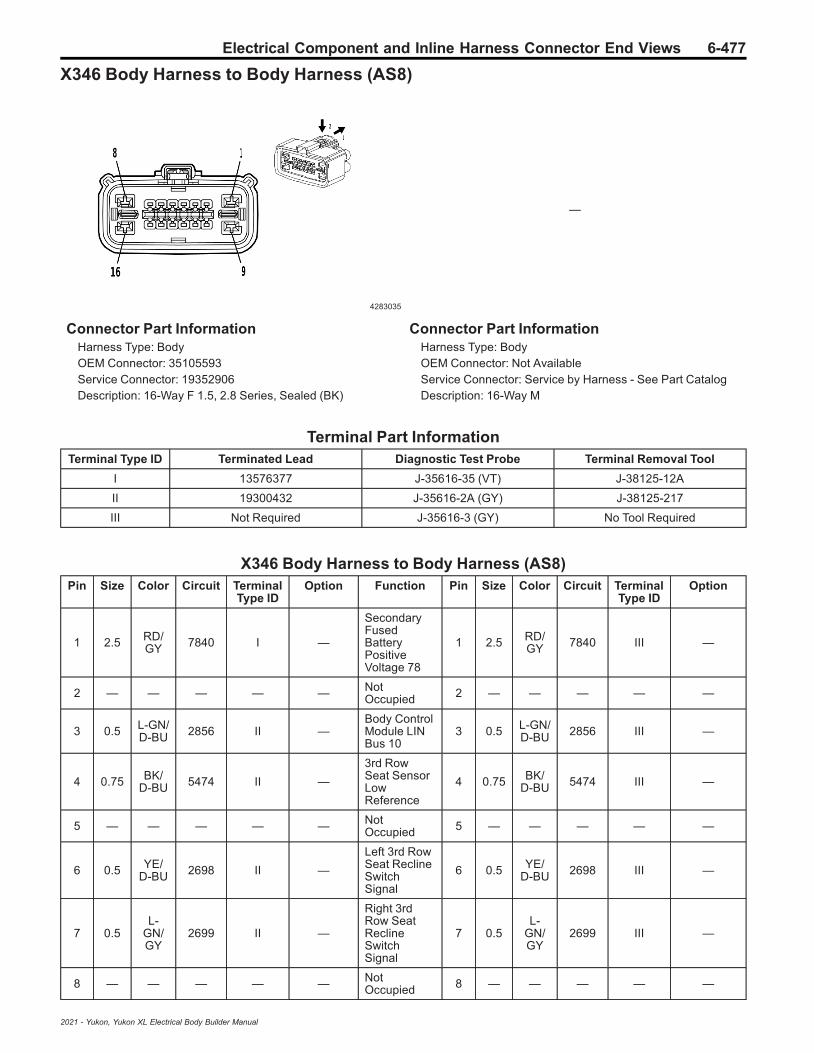
Electrical Component and Inline Harness Connector End Views 6-477
X346 Body Harness to Body Harness (AS8)
4283035
—
Connector Part InformationHarness Type: BodyOEM Connector: 35105593Service Connector: 19352906Description: 16-Way F 1.5, 2.8 Series, Sealed (BK)
Connector Part InformationHarness Type: BodyOEM Connector: Not AvailableService Connector: Service by Harness - See Part CatalogDescription: 16-Way M
Terminal Part InformationTerminal Type ID Terminated Lead Diagnostic Test Probe Terminal Removal Tool
I 13576377 J-35616-35 (VT) J-38125-12A
II 19300432 J-35616-2A (GY) J-38125-217
III Not Required J-35616-3 (GY) No Tool Required
X346 Body Harness to Body Harness (AS8)Pin Size Color Circuit Terminal
Type IDOption Function Pin Size Color Circuit Terminal
Type IDOption
1 2.5 RD/GY 7840 I —
SecondaryFusedBatteryPositiveVoltage 78
1 2.5 RD/GY 7840 III —
2 — — — — — NotOccupied 2 — — — — —
3 0.5 L-GN/D-BU 2856 II —
Body ControlModule LINBus 10
3 0.5 L-GN/D-BU 2856 III —
4 0.75 BK/D-BU 5474 II —
3rd RowSeat SensorLowReference
4 0.75 BK/D-BU 5474 III —
5 — — — — — NotOccupied 5 — — — — —
6 0.5 YE/D-BU 2698 II —
Left 3rd RowSeat ReclineSwitchSignal
6 0.5 YE/D-BU 2698 III —
7 0.5L-
GN/GY
2699 II —
Right 3rdRow SeatReclineSwitchSignal
7 0.5L-
GN/GY
2699 III —
8 — — — — — NotOccupied 8 — — — — —
2021 - Yukon, Yukon XL Electrical Body Builder Manual

6-478 Electrical Component and Inline Harness Connector End Views
X346 Body Harness to Body Harness (AS8) (cont'd)Pin Size Color Circuit Terminal
Type IDOption Function Pin Size Color Circuit Terminal
Type IDOption
9 2.5 BK 2050 I — Ground 20 9 2.5 BK 2050 III —
10 — — — — — NotOccupied 10 — — — — —
11 0.5L-
GN/OG
3516 II —
3rd Row LeftSeat BeltSwitchSignal
11 0.5L-
GN/OG
3516 III —
12 0.5 VT/OG 3517 II —
3rd RowRight SeatBelt SwitchSignal
12 0.5 VT/OG 3517 III —
13 0.5 OG/L-GN 3700 II —
3rd RowCenter SeatBelt SwitchSignal
13 0.5 OG/L-GN 3700 III —
14 — — — — — NotOccupied 14 — — — — —
15 0.5 BK/OG 1363 II —
Driver SeatBelt SwitchLowReference
15 0.5 BK/OG 1363 III —
16 — — — — — NotOccupied 16 — — — — —
2021 - Yukon, Yukon XL Electrical Body Builder Manual

Electrical Component and Inline Harness Connector End Views 6-479
X378 Body Harness to Right 2nd Row Seat Harness
2871866 3610369
Connector Part InformationHarness Type: BodyOEM Connector: 33221171Service Connector: 19333239Description: 12-Way F 150 MX Series, Sealed (D-GY)
Connector Part InformationHarness Type: Right 2nd Row SeatOEM Connector: Not AvailableService Connector: Service by Harness - See Part CatalogDescription: 12-Way M
Terminal Part InformationTerminal Type ID Terminated Lead Diagnostic Test Probe Terminal Removal Tool
I 19300432 J-35616-2A (GY) J-38125-217
II Not Required J-35616-3 (GY) No Tool Required
X378 Body Harness to Right 2nd Row Seat HarnessPin Size Color Circuit Terminal
Type IDOption Function Pin Size Color Circuit Terminal
Type IDOption
1 0.75 RD/WH 5740 I —
SecondaryFusedBatteryPositiveVoltage 57
1 0.75 RD/WH 5740 II —
2 0.75 RD/D-BU 6740 I —
SecondaryFusedBatteryPositiveVoltage 67
2 0.75 RD/D-BU 6740 II —
3 0.75 GY 2294 I —
Left RearSeatCushionHeatingElementControl
3 0.75 GY 2294 II —
4 0.5L-
GN/VT
2857 I —Body ControlModule LINBus 11
4 0.5L-
GN/VT
2857 II —
5 0.75 RD/GY 6240 I —
SecondaryFusedBatteryPositiveVoltage 62
5 0.75 RD/GY 6240 II —
6 0.5 BN/WH 6809 I —
Right RearFolding SeatMotorControl
6 0.5 BN/WH 6809 II —
2021 - Yukon, Yukon XL Electrical Body Builder Manual
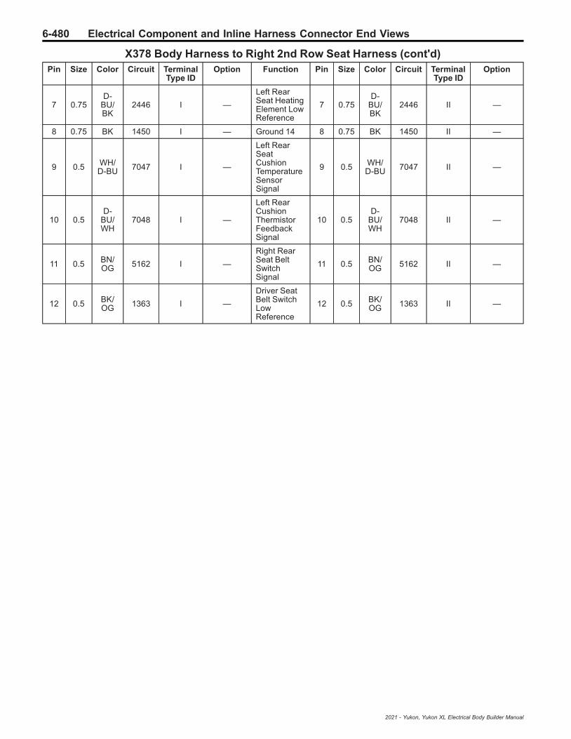
6-480 Electrical Component and Inline Harness Connector End Views
X378 Body Harness to Right 2nd Row Seat Harness (cont'd)Pin Size Color Circuit Terminal
Type IDOption Function Pin Size Color Circuit Terminal
Type IDOption
7 0.75D-
BU/BK
2446 I —
Left RearSeat HeatingElement LowReference
7 0.75D-
BU/BK
2446 II —
8 0.75 BK 1450 I — Ground 14 8 0.75 BK 1450 II —
9 0.5 WH/D-BU 7047 I —
Left RearSeatCushionTemperatureSensorSignal
9 0.5 WH/D-BU 7047 II —
10 0.5D-
BU/WH
7048 I —
Left RearCushionThermistorFeedbackSignal
10 0.5D-
BU/WH
7048 II —
11 0.5 BN/OG 5162 I —
Right RearSeat BeltSwitchSignal
11 0.5 BN/OG 5162 II —
12 0.5 BK/OG 1363 I —
Driver SeatBelt SwitchLowReference
12 0.5 BK/OG 1363 II —
2021 - Yukon, Yukon XL Electrical Body Builder Manual

Electrical Component and Inline Harness Connector End Views 6-481
X403 Chassis Harness to Chassis Rear Extension Harness (Z95)
4778903
—
Connector Part InformationHarness Type: ChassisOEM Connector: 33358808Service Connector: 84811561Description: 3-Way F 1.2 MCON-CB Series, Sealed (BK)
Connector Part InformationHarness Type: Chassis Rear ExtensionOEM Connector: 84237878Service Connector: Service by Harness - See Part CatalogDescription: 3-Way M
Terminal Part InformationTerminal Type ID Terminated Lead Diagnostic Test Probe Terminal Removal Tool
I Not Required J-35616-16 (LT GN) No Tool Required
II Not Required No Tool Required No Tool Required
X403 Chassis Harness to Chassis Rear Extension Harness (Z95)Pin Size Color Circuit Terminal
Type IDOption Function Pin Size Color Circuit Terminal
Type IDOption
1 0.5 VT/RD 1818 I —
Left RearVerticalSuspensionAccelerationSensorVoltageReference
1 0.75 VT/RD 1818 II —
2 0.5 BK/VT 1833 I —
Left RearVerticalSuspensionAccelerationSensor LowReference
2 0.75 BK/VT 1833 II —
3 0.5 YE/BN 1103 I —
Left RearVerticalSuspensionAccelerationSensorSignal
3 0.75 YE/BN 1103 II —
2021 - Yukon, Yukon XL Electrical Body Builder Manual

6-482 Electrical Component and Inline Harness Connector End Views
X406 Chassis Harness to Chassis Rear Extension Harness
5377329 5246651
Connector Part InformationHarness Type: ChassisOEM Connector: 15324787Service Connector: 15306349Description: 4-Way F 2.8 APEX Series, Sealed (GY)
Connector Part InformationHarness Type: Chassis Rear ExtensionOEM Connector: 13518460Service Connector: Service by Harness - See Part CatalogDescription: 4-Way M 2.8 APEX Series, Sealed (GY)
Terminal Part InformationTerminal Type ID Terminated Lead Diagnostic Test Probe Terminal Removal Tool
I Not Required J-35616-2A (GY) No Tool Required
II Not Required J-35616-35 (VT) No Tool Required
III Not Required J-35616-35 (VT) No Tool Required
IV Not Required J-35616-5 (PU) No Tool Required
X406 Chassis Harness to Chassis Rear Extension HarnessPin Size Color Circuit Terminal
Type IDOption Function Pin Size Color Circuit Terminal
Type IDOption
10.750.75
L-GN/YEL-
GN/YE
16161616
III
——
Rear BrakePad WearSensorSignalRear BrakePad WearSensorSignal
1 0.75 GN/YE 1616 III —
20.750.75
BKBK
20502050
III
——
Ground 20Ground 20
2 0.75 BK 2050 III —
3 4 GY/BK 4369 II —
Left ParkBrake MotorLowReference
3 2.5 GY/BK 4369 IV —
4 2.5 WH 2001 II —
Left ParkBrake MotorApplyControl
4 2.5 WH 2001 IV —
2021 - Yukon, Yukon XL Electrical Body Builder Manual

Electrical Component and Inline Harness Connector End Views 6-483
X407 Fuel Door Jumper Harness to Chassis Harness
4649903 2474755
Connector Part InformationHarness Type: Fuel Door JumperOEM Connector: 33327048Service Connector: Service by Harness - See Part CatalogDescription: 2-Way F 1.2 MCON Series, Sealed (BK)
Connector Part InformationHarness Type: ChassisOEM Connector: 33207247Service Connector: 19332631Description: 2-Way M 1.2 Multilock Series, Sealed (BK)
Terminal Part InformationTerminal Type ID Terminated Lead Diagnostic Test Probe Terminal Removal Tool
I Not Required J-35616-16 (LT GN) No Tool Required
II Not Required J-35616-17 (LT GN) No Tool Required
X407 Fuel Door Jumper Harness to Chassis HarnessPin Size Color Circuit Terminal
Type IDOption Function Pin Size Color Circuit Terminal
Type IDOption
1 0.5D-
BU/BK
2690 I —
LockActuatorsUnlockControl 1Fuel DoorActuatorUnlockControl
10.50.5
WHD-
BU/BK
26792690
IIII
——
2 0.5 VT/GY 2683 I —
Fuel DoorActuatorLock ControlUnlatchActuatorsUnlatch LowReference 1
20.50.5
D-BUVT/GY
26892683
IIII
——
2021 - Yukon, Yukon XL Electrical Body Builder Manual

6-484 Electrical Component and Inline Harness Connector End Views
X413 Chassis Harness to Chassis Rear Extension Harness (Z95)
4778903
—
Connector Part InformationHarness Type: ChassisOEM Connector: 33358808Service Connector: 84811561Description: 3-Way F 1.2 MCON-CB Series, Sealed (BK)
Connector Part InformationHarness Type: Chassis Rear ExtensionOEM Connector: 84237879Service Connector: Service by Harness - See Part CatalogDescription: 3-Way M
Terminal Part InformationTerminal Type ID Terminated Lead Diagnostic Test Probe Terminal Removal Tool
I Not Required J-35616-16 (LT GN) No Tool Required
II Not Required No Tool Required No Tool Required
X413 Chassis Harness to Chassis Rear Extension Harness (Z95)Pin Size Color Circuit Terminal
Type IDOption Function Pin Size Color Circuit Terminal
Type IDOption
1 0.5 GY/RD 1820 I —
Right RearVerticalSuspensionAccelerationSensorVoltageReference
1 0.75 GY/RD 1820 II —
2 0.5 BK/D-BU 1108 I —
Right RearVerticalSuspensionAccelerationSensor LowReference
2 0.75 BK/BU 1108 II —
3 0.5 YE/D-BU 1109 I —
Right RearVerticalSuspensionAccelerationSensorSignal
3 0.75 YE/BU 1109 II —
2021 - Yukon, Yukon XL Electrical Body Builder Manual

Electrical Component and Inline Harness Connector End Views 6-485
X415 Chassis Harness to Differential Lock Jumper Harness (G96)
3684497 2373686
Connector Part InformationHarness Type: ChassisOEM Connector: 33218250Service Connector: 19352906Description: 16-Way F 1.5, 2.8 Series, Sealed (BK)
Connector Part InformationHarness Type: Differential Lock JumperOEM Connector: 33129084Service Connector: Service by Harness - See Part CatalogDescription: 16-Way M 1.5, 2.8 Series, Sealed (BK)
Terminal Part InformationTerminal Type ID Terminated Lead Diagnostic Test Probe Terminal Removal Tool
I 13576377 J-35616-35 (VT) J-38125-12A
II 19300432 J-35616-2A (GY) J-38125-217
III Not Required J-35616-3 (GY) No Tool Required
IV Not Required J-35616-5 (PU) No Tool Required
X415 Chassis Harness to Differential Lock Jumper Harness (G96)Pin Size Color Circuit Terminal
Type IDOption Function Pin Size Color Circuit Terminal
Type IDOption
1 2.5 GY/BN 7968 I —
AxleDifferentialLockControl High
1 2.5 GY/BN 7968 IV —
2 0.5 WH 7971 II —
AxleDifferentialLock MotorBrakeControl High
2 0.5 WH 7971 III —
3 0.5L-
GN/BN
7975 II —
AxleDifferentialLock MotorPositionSensorSignal 1
3 0.5L-
GN/BN
7975 III —
4 0.5 BK/VT 7974 II —
AxleDifferentialLock MotorPositionSensor LowReference
4 0.5 BK/VT 7974 III —
5 0.5 VT/BK 7972 II —
AxleDifferentialLock MotorBrakeControl Low
5 0.5 VT/BK 7972 III —
2021 - Yukon, Yukon XL Electrical Body Builder Manual

6-486 Electrical Component and Inline Harness Connector End Views
X415 Chassis Harness to Differential Lock Jumper Harness (G96) (cont'd)Pin Size Color Circuit Terminal
Type IDOption Function Pin Size Color Circuit Terminal
Type IDOption
6 0.75 WH/RD 7973 II —
AxleDifferentialLock MotorPositionSensor HighReference
6 0.5 WH/RD 7973 III —
7 0.5 BK/YE 7977 II —
AxleDifferentialLock MotorTemperatureSensor LowReference
7 0.5 BK/YE 7977 III —
8 — — — — — NotOccupied 8 — — — — —
9 2.5 YE/WH 7969 I —
AxleDifferentialLockControl Low
9 2.5 YE/WH 7969 IV —
10 0.5 BK 7970 II —
AxleDifferentialLock ControlShield
10 0.5 BK 7970 III —
11 0.5 GY 7976 II —
AxleDifferentialLock MotorPositionSensorSignal 2
11 0.5 GY 7976 III —
12 0.5D-
BU/WH
7978 II —
AxleDifferentialLock MotorTemperatureSensorSignal
12 0.5D-
BU/WH
7978 III —
13-
16— — — — — Not
Occupied13
- 16 — — — — —
2021 - Yukon, Yukon XL Electrical Body Builder Manual
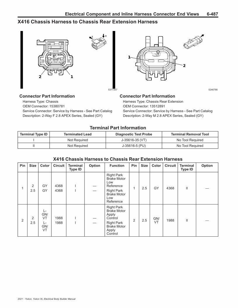
Electrical Component and Inline Harness Connector End Views 6-487
X416 Chassis Harness to Chassis Rear Extension Harness
5377357 5246766
Connector Part InformationHarness Type: ChassisOEM Connector: 15380781Service Connector: Service by Harness - See Part CatalogDescription: 2-Way F 2.8 APEX Series, Sealed (GY)
Connector Part InformationHarness Type: Chassis Rear ExtensionOEM Connector: 13512891Service Connector: Service by Harness - See Part CatalogDescription: 2-Way M 2.8 APEX Series, Sealed (GY)
Terminal Part InformationTerminal Type ID Terminated Lead Diagnostic Test Probe Terminal Removal Tool
I Not Required J-35616-35 (VT) No Tool Required
II Not Required J-35616-5 (PU) No Tool Required
X416 Chassis Harness to Chassis Rear Extension HarnessPin Size Color Circuit Terminal
Type IDOption Function Pin Size Color Circuit Terminal
Type IDOption
12
2.5GYGY
43684368
II
——
Right ParkBrake MotorLowReferenceRight ParkBrake MotorLowReference
1 2.5 GY 4368 II —
22
2.5
L-GN/VTL-
GN/VT
19881988
II
——
Right ParkBrake MotorApplyControlRight ParkBrake MotorApplyControl
2 2.5 GN/VT 1988 II —
2021 - Yukon, Yukon XL Electrical Body Builder Manual

6-488 Electrical Component and Inline Harness Connector End Views
X418 Body Harness to HVAC Harness (C69)
4934172
—
Connector Part InformationHarness Type: BodyOEM Connector: 33366376Service Connector: 13513605Description: 14-Way F 1.5, 2.8 Series (GY)
Connector Part InformationHarness Type: HVACOEM Connector: Not AvailableService Connector: Service by Harness - See Part CatalogDescription: 14-Way M
Terminal Part InformationTerminal Type ID Terminated Lead Diagnostic Test Probe Terminal Removal Tool
I 13575708 J-35616-2A (GY) J-38125-11A
II 13575832 J-35616-4A (PU) J-38125-11A
III 13578891 J-35616-2A (GY) J-38125-11A
IV Not Required J-35616-3 (GY) No Tool Required
X418 Body Harness to HVAC Harness (C69)Pin Size Color Circuit Terminal
Type IDOption Function Pin Size Color Circuit Terminal
Type IDOption
1 3 RD/GY 1740 II —
SecondaryFusedBatteryPositiveVoltage 17
1 3 RD/GY 1740 IV —
2 — — — — — NotOccupied 2 — — — — —
3 0.5 YE/WH 4635 I —
HVACRemoteEnable 2Signal
3 0.5 YE/WH 4635 IV —
40.50.5
BK/WHBK
12511450
II
——
Ground 12Ground 14
40.50.5
BK/WHBK
12511450
IVIV
——
5 0.35L-
GN/BN
2853 III —Body ControlModule LINBus 7
5 0.35L-
GN/BN
2853 IV —
6 0.5 BN 404 I —
Upper DuctAirTemperatureSensorSignal
6 0.5 BN 404 IV —
7- 8 — — — — — Not
Occupied7
- 8 — — — — —
2021 - Yukon, Yukon XL Electrical Body Builder Manual

Electrical Component and Inline Harness Connector End Views 6-489
X418 Body Harness to HVAC Harness (C69) (cont'd)Pin Size Color Circuit Terminal
Type IDOption Function Pin Size Color Circuit Terminal
Type IDOption
9 0.5L-
GN/BK
2211 I —Rear BlowerMotor SpeedControl
9 0.5L-
GN/BK
2211 IV —
10 0.5 BN/BK 405 I —
Lower DuctAirTemperatureSensorSignal
10 0.5 BN/BK 405 IV —
11 0.5 BK/VT 470 I — Sensor Low
Reference 3 11 0.5 BK/VT 470 IV —
12-
13— — — — — Not
Occupied12
- 13 — — — — —
14 3 BK 1450 II — Ground 14 14 3 BK 1450 IV —
2021 - Yukon, Yukon XL Electrical Body Builder Manual

6-490 Electrical Component and Inline Harness Connector End Views
X419 Body Harness to Power Inverter Module Jumper Harness
4934172 1283905
Connector Part InformationHarness Type: BodyOEM Connector: 35105595Service Connector: 13513604Description: 14-Way F 1.5, 2.8 Series (BK)
Connector Part InformationHarness Type: Power Inverter Module JumperOEM Connector: 10846900Service Connector: Service by Harness - See Part CatalogDescription: 14-Way M 1.5, 2.8 Series (L-GY)
Terminal Part InformationTerminal Type ID Terminated Lead Diagnostic Test Probe Terminal Removal Tool
I 13575839 J-35616-35 (VT) J-38125-11A
II 13575839 J-35616-35 (VT) J-38125-11A
III 13575850 J-35616-14 (GN) J-38125-557
IV 13575850 J-35616-2A (GY) J-38125-11A
V Not Required J-35616-3 (GY) No Tool Required
VI Not Required J-35616-5 (PU) No Tool Required
X419 Body Harness to Power Inverter Module Jumper HarnessPin Size Color Circuit Terminal
Type IDOption Function Pin Size Color Circuit Terminal
Type IDOption
1 0.75 BK 5683 I — 120V ACPhase A 1 — — — — —
2 0.5 VT/RD 4049 IV —
AC PowerOutletSensor HighReference
2 0.5 VT/RD 4049 V —
3 0.5 VT/WH 1139 IV —
Run/CrankIgnition 1Voltage 11
3 0.5 VT/WH 1139 V —
4 0.5 WH/L-GN 4628 IV —
DC/ACInverterRelayControl
4 0.5 WH/L-GN 4628 V —
5 0.75D-
BU/BN
6807 III —DC/ACInverterControl
5 0.5D-
BU/BN
6807 V —
6 — — — — — NotOccupied 6 — — — — —
7 0.5 BK/WH 2264 II — 120V AC
Phase A 2 7 0.75 BN/WH 2262 VI —
8 0.75 RD 5684 I — 120V ACPhase B 8 — — — — —
2021 - Yukon, Yukon XL Electrical Body Builder Manual

Electrical Component and Inline Harness Connector End Views 6-491
X419 Body Harness to Power Inverter Module Jumper Harness (cont'd)Pin Size Color Circuit Terminal
Type IDOption Function Pin Size Color Circuit Terminal
Type IDOption
9 0.5 Bare 2519 IV —120V ACOutlet LowReference
9 — — — — —
100.350.5
L-GN/D-BUL-GN/D-BU
61336133
IVIV
-UTJ/-UTR
UTJ+UTR
Body ControlModule LINBus 2Body ControlModule LINBus 2
10 0.5 L-GN/D-BU 6133 V —
11 — — — — — NotOccupied 11 — — — — —
12 0.75L-
GN/BN
2266 III —DC/ACInverterControl 2
12 0.5L-
GN/BN
2266 V —
13 0.5 Bare 2521 IV —120V ACOutlet 2 LowReference
13 0.5 Bare 2544 V —
14 0.5 RD/WH 2265 II — 120V AC
Phase B 2 14 0.75D-
BU/WH
2263 VI —
2021 - Yukon, Yukon XL Electrical Body Builder Manual

6-492 Electrical Component and Inline Harness Connector End Views
X421 Body Harness to Police Strobe Light Provisional Harness (5W4/9C1)
4846407 2667653
Connector Part InformationHarness Type: BodyOEM Connector: 35037827Service Connector: 19366859Description: 8-Way F 150 MX Series, Sealed (BK)
Connector Part InformationHarness Type: Police Strobe Light ProvisionalOEM Connector: Not AvailableService Connector: Service by Harness - See Part CatalogDescription: 8-Way M
Terminal Part InformationTerminal Type ID Terminated Lead Diagnostic Test Probe Terminal Removal Tool
I Not Required J-35616-2A (GY) No Tool Required
II Not Required J-35616-3 (GY) No Tool Required
X421 Body Harness to Police Strobe Light Provisional Harness (5W4/9C1)Pin Size Color Circuit Terminal
Type IDOption Function Pin Size Color Circuit Terminal
Type IDOption
1 0.75 L-GN 8892 I —Police RearCorner LightControl
1 0.75 L-GN 8892 II —
2 0.75 BK 2050 I — Ground 20 2 0.75 BK 2050 II —
3 0.75D-
BU/WH
8891 I —
PoliceCornerStrobeSynchroni-zation Signal
3 0.75D-
BU/WH
8891 II —
4 0.75 YE 8894 I —
Police RearCornerStrobeControl
4 0.75 YE 8894 II —
5 0.75 L-GN 8892 I —Police RearCorner LightControl
5 0.75 L-GN 8892 II —
6 0.75D-
BU/WH
8891 I —
PoliceCornerStrobeSynchroni-zation Signal
6 0.75D-
BU/WH
8891 II —
7 0.75 BK 2050 I — Ground 20 7 0.75 BK 2050 II —
8 0.75 YE 8894 I —
Police RearCornerStrobeControl
8 0.75 YE 8894 II —
2021 - Yukon, Yukon XL Electrical Body Builder Manual

Electrical Component and Inline Harness Connector End Views 6-493
X430 Body Harness to Body Harness
5124963 4879946
Connector Part InformationHarness Type: BodyOEM Connector: 35196009Service Connector: 13526847Description: 19-Way F 1.2, 6.3 Series (BK)
Connector Part InformationHarness Type: BodyOEM Connector: 33351246Service Connector: 13597288Description: 19-Way M 1.2, 6.3 Series (BK)
Terminal Part InformationTerminal Type ID Terminated Lead Diagnostic Test Probe Terminal Removal Tool
I 13575833 J-35616-42 (RD) J-38125-11A
II 19370818 J-35616-16 (LT GN) J-38125-559
III 19371240 J-35616-16 (LT GN) J-38125-215A
IV 13575825 J-35616-43 (RD) J-38125-11A
V 19370818 J-35616-17 (LT GN) J-38125-215A
VI 84616651 J-35616-17 (LT GN) J-38125-215A
X430 Body Harness to Body HarnessPin Size Color Circuit Terminal
Type IDOption Function Pin Size Color Circuit Terminal
Type IDOption
1 0.5 YE 2375 I —
Left RearOuterParkingAssistSensorSignal
1 0.5 YE 2375 IV —
2 0.5 BK/GY 2379 III —
ObjectSensor LowReference
2 0.5 BK/GY 2379 VI —
3 0.5 YE/VT 2378 III —
Right RearOuterParkingAssistSensorSignal
3 0.5 YE/VT 2378 VI —
4 0.5 BN/WH 2374 III —
ObjectSensorSupplyVoltage
4 0.5 BN/WH 2374 VI —
5 — — — — — NotOccupied 5 — — — — —
2021 - Yukon, Yukon XL Electrical Body Builder Manual

6-494 Electrical Component and Inline Harness Connector End Views
X430 Body Harness to Body Harness (cont'd)Pin Size Color Circuit Terminal
Type IDOption Function Pin Size Color Circuit Terminal
Type IDOption
6 0.5 YE/D-BU 2698 III —
Left 3rd RowSeat ReclineSwitchSignal
6 0.5 YE/D-BU 2698 VI —
7 0.5 YE/D-BU 2376 III —
Left RearMiddleParkingAssistSensorSignal
7 0.5 YE/D-BU 2376 VI —
8 0.5 YE/WH 2377 I —
Right RearMiddleParkingAssistSensorSignal
8 0.5 YE/WH 2377 IV —
9- 11 — — — — — Not
Occupied9
- 11 — — — — —
12 0.35D-
BU/VT
4101 III —
AUTOSARSerial DataCAN Bus [+]4 Serial Data
12 0.35D-
BU/VT
4101 VI —
13 0.5 RD/GY 4840 III —
SecondaryFusedBatteryPositiveVoltage 48SecondaryFusedBatteryPositiveVoltage 48
130.50.5
RD/GYRD/GY
48404840
VIV
——
14 0.75 GY/WH 8577 II —
Right RearD-PillarSpeaker [-]Control
14 0.75 GY/WH 8577 V —
15 0.35 WH 4100 III —
AUTOSARSerial DataCAN Bus [-]4 Serial Data
15 0.35 WH 4100 VI —
16 0.5 L-GN/D-BU 2856 III —
Body ControlModule LINBus 10Body ControlModule LINBus 10
160.350.5
L-GN/D-BUL-GN/D-BU
28562856
VIVI
AS8C25
17 0.75 BK/D-BU 5474 II —
3rd RowSeat SensorLowReference
17 0.5 BK/D-BU 5474 VI —
18 — — — — — NotOccupied 18 — — — — —
19 0.75 VT 8578 II —
Right RearD-PillarSpeaker [+]Control
19 0.75 VT 8578 V —
2021 - Yukon, Yukon XL Electrical Body Builder Manual

Electrical Component and Inline Harness Connector End Views 6-495
X500 Driver Door Harness to Body Harness
4992530 4993484
Connector Part InformationHarness Type: Driver DoorOEM Connector: 35077349Service Connector: Service by Harness - See Part CatalogDescription: 52-Way F 1.2, 2.8, 6.3, Coaxial Series,Sealed (BK)
Connector Part InformationHarness Type: BodyOEM Connector: 35190453Service Connector: 13527236Description: 52-Way M 1.2, 2.8, 6.3, Coaxial Series,Sealed (BK)
Terminal Part InformationTerminal Type ID Terminated Lead Diagnostic Test Probe Terminal Removal Tool
I Not Required J-35616-16 (LT GN) No Tool Required
II Not Required J-35616-42 (RD) No Tool Required
III Service by Cable No Tool Required No Tool Required
IV 19301536 J-35616-43 (RD) J-38125-11A
V 19370818 J-35616-17 (LT GN) J-38125-215A
VI 84616651 J-35616-17 (LT GN) J-38125-215A
VII Service by Cable No Tool Required No Tool Required
X500 Driver Door Harness to Body HarnessPin Size Color Circuit Terminal
Type IDOption Function Pin Size Color Circuit Terminal
Type IDOption
1 0.5 RD/VT 1940 I —
SecondaryFusedBatteryPositiveVoltage 19
1 0.5 RD/VT 1940 VI —
2 0.75 GY 2681 I —
Left FrontDoor LockActuatorLock Control
2 0.75 GY 2681 V —
3- 4 — — — — — Not
Occupied3
- 4 — — — — —
5 0.5 BK/WH 1151 I — Ground 11 5 0.5 BK/
WH 1151 VI —
6 — — — — — NotOccupied 6 — — — — —
7 0.75 BK/VT 8871 I —
Police LeftMirror LightLowReference
7 0.75 BK/VT 8871 V —
2021 - Yukon, Yukon XL Electrical Body Builder Manual

6-496 Electrical Component and Inline Harness Connector End Views
X500 Driver Door Harness to Body Harness (cont'd)Pin Size Color Circuit Terminal
Type IDOption Function Pin Size Color Circuit Terminal
Type IDOption
8 0.75 VT 8870 I —Police LeftMirror LightControl
8 0.75 VT 8870 V —
9Left FrontSpeaker 1 [+]Control
90.50.5
0.75
D-BUD-BUD-BU
201201201
VVIVI
———
10 0.75 BN/D-BU 118 I —
Left FrontSpeaker [-]Control 1Left FrontSpeaker [-]Control 1
100.50.5
0.75
BN/D-BUBN/
D-BUBN/
D-BU
118118118
VVIVI
———
11 0.35L-
GN/YE
6134 I —Body ControlModule LINBus 3
11 0.5L-
GN/YE
6134 VI —
12 0.35 VT/GY 126 I —
Left FrontDoor OpenSwitchSignal
12 0.35 VT/GY 126 VI —
13 0.75 D-BU 201 I —
Left FrontSpeaker 1 [+]ControlLeft FrontSpeaker 1 [+]Control
130.5
0.75D-BUD-BU
201201
VVI
——
14 0.5 D-BU 2675 I —
Left FrontExterior DoorHandleSwitchUnlockSignal
14 0.35 D-BU 2675 VI —
15 — — — — — NotOccupied 15 — — — — —
16 0.35 YE/WH 1690 I —
MirrorDimmingSignal
16 0.35 YE/WH 1690 VI —
17 0.35 BK/YE 1691 I —
MirrorDimmingLowReference
17 0.35 BK/YE 1691 VI —
18 — — — — — NotOccupied 18 — — — — —
19 0.75 WH 2679 I —
LockActuatorsUnlockControl 1
19 0.75 WH 2679 V —
20-
21— — — — — Not
Occupied20
- 21 — — — — —
22 0.75 YE/L-GN 8879 I —
Police LeftRear WindowLight FlashEnableSignal
22 — — — — —
23 0.75D-
BU/VT
8873 I —
Police LeftMirror LightSteady BurnControl
23 0.75D-
BU/VT
8873 V —
2021 - Yukon, Yukon XL Electrical Body Builder Manual
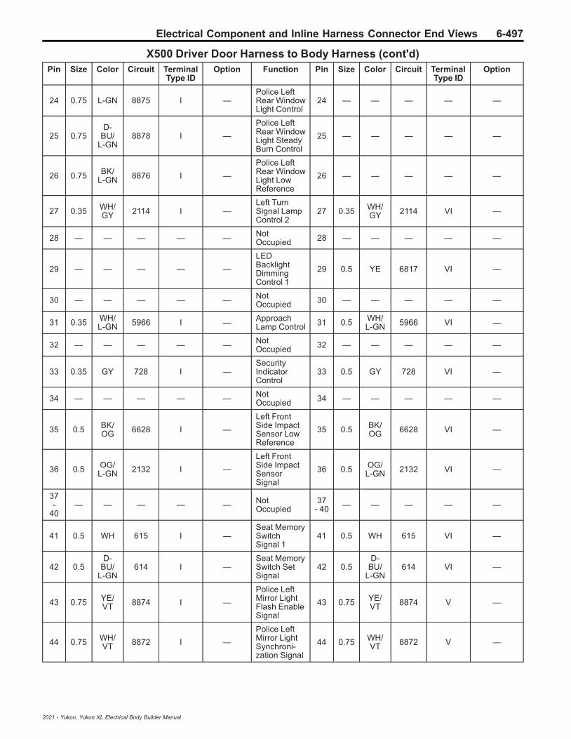
Electrical Component and Inline Harness Connector End Views 6-497
X500 Driver Door Harness to Body Harness (cont'd)Pin Size Color Circuit Terminal
Type IDOption Function Pin Size Color Circuit Terminal
Type IDOption
24 0.75 L-GN 8875 I —Police LeftRear WindowLight Control
24 — — — — —
25 0.75D-
BU/L-GN
8878 I —
Police LeftRear WindowLight SteadyBurn Control
25 — — — — —
26 0.75 BK/L-GN 8876 I —
Police LeftRear WindowLight LowReference
26 — — — — —
27 0.35 WH/GY 2114 I —
Left TurnSignal LampControl 2
27 0.35 WH/GY 2114 VI —
28 — — — — — NotOccupied 28 — — — — —
29 — — — — —
LEDBacklightDimmingControl 1
29 0.5 YE 6817 VI —
30 — — — — — NotOccupied 30 — — — — —
31 0.35 WH/L-GN 5966 I — Approach
Lamp Control 31 0.5 WH/L-GN 5966 VI —
32 — — — — — NotOccupied 32 — — — — —
33 0.35 GY 728 I —SecurityIndicatorControl
33 0.5 GY 728 VI —
34 — — — — — NotOccupied 34 — — — — —
35 0.5 BK/OG 6628 I —
Left FrontSide ImpactSensor LowReference
35 0.5 BK/OG 6628 VI —
36 0.5 OG/L-GN 2132 I —
Left FrontSide ImpactSensorSignal
36 0.5 OG/L-GN 2132 VI —
37-
40— — — — — Not
Occupied37
- 40 — — — — —
41 0.5 WH 615 I —Seat MemorySwitchSignal 1
41 0.5 WH 615 VI —
42 0.5D-
BU/L-GN
614 I —Seat MemorySwitch SetSignal
42 0.5D-
BU/L-GN
614 VI —
43 0.75 YE/VT 8874 I —
Police LeftMirror LightFlash EnableSignal
43 0.75 YE/VT 8874 V —
44 0.75 WH/VT 8872 I —
Police LeftMirror LightSynchroni-zation Signal
44 0.75 WH/VT 8872 V —
2021 - Yukon, Yukon XL Electrical Body Builder Manual

6-498 Electrical Component and Inline Harness Connector End Views
X500 Driver Door Harness to Body Harness (cont'd)Pin Size Color Circuit Terminal
Type IDOption Function Pin Size Color Circuit Terminal
Type IDOption
45 0.75 WH/L-GN 8877 I —
Police LeftRear WindowLightSynchroni-zation Signal
45 — — — — —
46 2.5 RD/GY 3540 II —
SecondaryFusedBatteryPositiveVoltage 35
46 2.5 RD/GY 3540 IV —
47 2.5 BK 1150 II — Ground 11 47 2.5 BK 1150 IV —
48-
51— — — — — Not
Occupied48
- 51 — — — — —
52 0 — 4725 III —
Left SideviewCameraLVDS (LowVoltageDifferentialSignaling)CoaxialSignal
52 0 — 5088 VII —
2021 - Yukon, Yukon XL Electrical Body Builder Manual

Electrical Component and Inline Harness Connector End Views 6-499
X505 Driver Door Harness to Driver Door Trim Harness
4997556 5022037
Connector Part InformationHarness Type: Driver DoorOEM Connector: 33390107Service Connector: Service by Harness - See Part CatalogDescription: 50-Way F 1.2, 2.8 OCS Series (BK)
Connector Part InformationHarness Type: Driver Door TrimOEM Connector: 33390111Service Connector: Service by Harness - See Part CatalogDescription: 50-Way M 1.2, 2.8 OCS Series (BK)
Terminal Part InformationTerminal Type ID Terminated Lead Diagnostic Test Probe Terminal Removal Tool
I Not Required J-35616-16 (LT GN) No Tool Required
II Not Required J-35616-4A (PU) No Tool Required
III Not Required J-35616-17 (LT GN) No Tool Required
IV Not Required J-35616-5 (PU) No Tool Required
X505 Driver Door Harness to Driver Door Trim HarnessPin Size Color Circuit Terminal
Type IDOption Function Pin Size Color Circuit Terminal
Type IDOption
1- 2 — — — — — Not
Occupied1
- 2 — — — — —
3 0.35 VT/D-BU 2788 II —
Left FrontMirror MotorUp [+] Down[-] Control
3 0.35 VT/D-BU 2788 IV —
4 0.35 VT/RD 2791 II —
Left FrontMirrorPositionSensor HighReference
4 0.35 VT/RD 2791 IV —
5 — — — — — NotOccupied 5 — — — — —
6 0.35 GY 728 II —SecurityIndicatorControl
6 0.35 GY 728 IV —
7- 8 — — — — — Not
Occupied7
- 8 — — — — —
9 0.35 WH/YE 2792 II —
Left FrontMirrorPositionSensor Left[-] Right [+]Signal
9 0.35 WH/YE 2792 IV —
2021 - Yukon, Yukon XL Electrical Body Builder Manual

6-500 Electrical Component and Inline Harness Connector End Views
X505 Driver Door Harness to Driver Door Trim Harness (cont'd)Pin Size Color Circuit Terminal
Type IDOption Function Pin Size Color Circuit Terminal
Type IDOption
10 0.35 WH/BN 2764 II —
WindowSwitch LeftFront DownSignal
10 0.35 WH/BN 2764 IV —
11-
14— — — — — Not
Occupied11
- 14 — — — — —
15 0.5 WH 615 I —Seat MemorySwitchSignal 1
15 0.35 WH 615 III —
16 0.75 BK 1150 I — Ground 11 16 0.35 BK 1150 III —
17 0.35L-
GN/YE
6134 I —Body ControlModule LINBus 3
17 0.35L-
GN/YE
6134 III —
18 0.35 L-GN 2766 I —
PowerWindowSwitch LeftFrontExpressSignal
18 0.35 L-GN 2766 III —
19 — — — — — NotOccupied 19 — — — — —
20 0.5 RD/VT 1940 I —
SecondaryFusedBatteryPositiveVoltage 19
20 0.5 RD/VT 1940 III —
21 0.35 YE/BN 2789 I —
Left FrontMirror MotorCommonControl
21 0.35 YE/BN 2789 III —
22 — — — — — NotOccupied 22 — — — — —
23 0.35 WH/VT 4258 I —
Left FrontDoor LockStatus Signal
23 0.35 WH/VT 4258 III —
24 0.35 BK/BN 673 I —
Left OutsideRearviewMirrorPositionSensor LowReference
24 0.35 BK/BN 673 III —
25 0.35 GY/L-GN 2763 I —
WindowSwitch LeftFront UpSignal
25 0.35 GY/L-GN 2763 III —
26 — — — — — NotOccupied 26 — — — — —
27 0.35 BN/BK 2790 I —
Left FrontMirror MotorRight [+] Left[-] Control
27 0.35 BN/BK 2790 III —
28-
30— — — — — Not
Occupied28
- 30 — — — — —
31 0.35 GY/YE 1760 I —
Left SideObjectDetectionLED Control
31 0.35 GY/YE 1760 III —
2021 - Yukon, Yukon XL Electrical Body Builder Manual

Electrical Component and Inline Harness Connector End Views 6-501
X505 Driver Door Harness to Driver Door Trim Harness (cont'd)Pin Size Color Circuit Terminal
Type IDOption Function Pin Size Color Circuit Terminal
Type IDOption
32-
35— — — — — Not
Occupied32
- 35 — — — — —
36 0.5 BK/WH 1151 I — Ground 11 36 0.35 BK/
WH 1151 III —
37 — — — — — NotOccupied 37 — — — — —
38 0.35 WH 606 I —
Left OutsideRearviewMirror HeaterControl
38 0.35 WH 606 III —
39 0.35 GY/WH 2785 I —
Left FrontMirror MotorFold OutControl
39 0.35 GY/WH 2785 III —
40-
42— — — — — Not
Occupied40
- 42 — — — — —
43 0.35 WH/L-GN 2786 I —
Left FrontMirror MotorFold InControl
43 0.35 WH/L-GN 2786 III —
44 — — — — — NotOccupied 44 — — — — —
45 0.5D-
BU/L-GN
614 I —Seat MemorySwitch SetSignal
45 0.35D-
BU/L-GN
614 III —
46 0.35 GY/BN 2787 I —
Left FrontMirrorPositionSensor Up[+] Down [-]Signal
46 0.35 GY/BN 2787 III —
47-
50— — — — — Not
Occupied47
- 50 — — — — —
2021 - Yukon, Yukon XL Electrical Body Builder Manual

6-502 Electrical Component and Inline Harness Connector End Views
X510 Driver Door Harness to Driver Outside Rearview Mirror Harness
5253439
—
Connector Part InformationHarness Type: Driver DoorOEM Connector: 35165322Service Connector: Service by Harness - See Part CatalogDescription: 19-Way F 1.2 MCON, Coaxial Series,Sealed (BK)
Connector Part InformationHarness Type: Driver Outside Rearview MirrorOEM Connector: Not AvailableService Connector: Service by Harness - See Part CatalogDescription: 19-Way M
Terminal Part InformationTerminal Type ID Terminated Lead Diagnostic Test Probe Terminal Removal Tool
I Not Required J-35616-13 (BU) No Tool Required
II Not Required J-35616-16 (LT GN) No Tool Required
III Not Required J-35616-64B (LT BU) No Tool Required
IV Not Required Not Available No Tool Required
X510 Driver Door Harness to Driver Outside Rearview Mirror HarnessPin Size Color Circuit Terminal
Type IDOption Function Pin Size Color Circuit Terminal
Type IDOption
1 0.35 BN/BK 2790 I —
Left FrontMirror MotorRight [+] Left[-] Control
1 0.35 BN/BK 2790 IV —
2 0.35 VT/D-BU 2788 I —
Left FrontMirror MotorUp [+] Down[-] Control
2 0.35 VT/D-BU 2788 IV —
3 0.35 WH/L-GN 2786 I —
Left FrontMirror MotorFold InControl
3 0.35 WH/L-GN 2786 IV —
4 0.35 GY/YE 1760 I —
Left SideObjectDetectionLED Control
4 0.35 GY/YE 1760 IV —
5 0.35 WH/L-GN 5966 I — Approach
Lamp Control 5 0.35 WH/L-GN 5966 IV —
6 0.35 WH/YE 2792 I —
Left FrontMirrorPositionSensor Left[-] Right [+]Signal
6 0.35 WH/YE 2792 IV —
2021 - Yukon, Yukon XL Electrical Body Builder Manual

Electrical Component and Inline Harness Connector End Views 6-503
X510 Driver Door Harness to Driver Outside Rearview Mirror Harness (cont'd)Pin Size Color Circuit Terminal
Type IDOption Function Pin Size Color Circuit Terminal
Type IDOption
7 0.35 WH 606 I —
Left OutsideRearviewMirror HeaterControl
7 0.35 WH 606 IV —
8 0.35 WH/GY 2114 I —
Left TurnSignal LampControl 2
8 0.35 WH/GY 2114 IV —
9 0.75 BK 1150 II — Ground 11 9 0.75 BK 1150 IV —
10 0.35 VT/RD 2791 I —
Left FrontMirrorPositionSensor HighReference
10 0.35 VT/RD 2791 IV —
11 0.35 GY/BN 2787 I —
Left FrontMirrorPositionSensor Up[+] Down [-]Signal
11 0.35 GY/BN 2787 IV —
12 0.35 BK/YE 1691 I —
MirrorDimmingLowReference
12 0.35 BK/YE 1691 IV —
13 — — — — — NotOccupied 13 — — — — —
14 0.35 YE/BN 2789 I —
Left FrontMirror MotorCommonControl
14 0.35 YE/BN 2789 IV —
15 0.35 GY/WH 2785 I —
Left FrontMirror MotorFold OutControl
15 0.35 GY/WH 2785 IV —
16 — — — — — NotOccupied 16 — — — — —
17 0.35 YE/WH 1690 I —
MirrorDimmingSignal
17 0.35 YE/WH 1690 IV —
18 0.35 BK/BN 673 I —
Left OutsideRearviewMirrorPositionSensor LowReference
18 0.35 BK/BN 673 IV —
19 — — 4725 III —
Left SideviewCameraLVDS (LowVoltageDifferentialSignaling)CoaxialSignal
19 — — 4725 IV —
2021 - Yukon, Yukon XL Electrical Body Builder Manual

6-504 Electrical Component and Inline Harness Connector End Views
X600 Passenger Door Harness to Body Harness
4992530 4993484
Connector Part InformationHarness Type: Passenger DoorOEM Connector: 35077349Service Connector: Service by Harness - See Part CatalogDescription: 52-Way F 1.2, 2.8, 6.3, Coaxial Series,Sealed (BK)
Connector Part InformationHarness Type: BodyOEM Connector: 35190453Service Connector: 13527236Description: 52-Way M 1.2, 2.8, 6.3, Coaxial Series,Sealed (BK)
Terminal Part InformationTerminal Type ID Terminated Lead Diagnostic Test Probe Terminal Removal Tool
I Not Required J-35616-16 (LT GN) No Tool Required
II Not Required J-35616-42 (RD) No Tool Required
III Not Required J-35616-4A (PU) No Tool Required
IV Service by Cable No Tool Required No Tool Required
V 13575824 J-35616-5 (PU) J-38125-11A
VI 19301536 J-35616-43 (RD) J-38125-11A
VII 19370818 J-35616-17 (LT GN) J-38125-215A
VIII 84616651 J-35616-17 (LT GN) J-38125-215A
IX Service by Cable No Tool Required No Tool Required
X600 Passenger Door Harness to Body HarnessPin Size Color Circuit Terminal
Type IDOption Function Pin Size Color Circuit Terminal
Type IDOption
1- 3 — — — — — Not
Occupied1
- 3 — — — — —
4 0.35L-
GN/GY
2115 I —Right TurnSignal LampControl 2
4 0.35L-
GN/GY
2115 VIII —
5 0.5 BK/WH 1251 I — Ground 12 5 0.5 BK/
WH 1251 VIII —
6 — — — — — NotOccupied 6 — — — — —
7 0.75 BK/BN 8886 I —
Police RightRear WindowLight LowReference
7 — — — — —
8 0.75 BK/GY 8881 I —
Police RightMirror LightLowReference
8 0.75 BK/GY 8881 VII —
2021 - Yukon, Yukon XL Electrical Body Builder Manual

Electrical Component and Inline Harness Connector End Views 6-505
X600 Passenger Door Harness to Body Harness (cont'd)Pin Size Color Circuit Terminal
Type IDOption Function Pin Size Color Circuit Terminal
Type IDOption
9Right FrontSpeaker 1 [+]Control
90.50.5
0.75
YEYEYE
200200200
VIIVIIIVIII
———
10 0.75 YE/BK 117 I —
Right FrontSpeaker [-]Control 1Right FrontSpeaker [-]Control 1
100.50.5
0.75
YE/BKYE/BKYE/BK
117117117
VIIVIIIVIII
———
11 0.75 GY 8880 I —Police RightMirror LightControl
11 0.75 GY 8880 VII —
12 0.75 YE/BN 8889 I —
Police RightRear WindowLight FlashEnableSignal
12 — — — — —
13 0.75 YE 200 I —
Right FrontSpeaker 1 [+]ControlRight FrontSpeaker 1 [+]Control
130.5
0.750.75
YEYE/
L-GNYE
2002682200
VIIVIIVIII
———
14-
17— — — — — Not
Occupied14
- 17 — — — — —
18 0.75 YE/GY 8884 I —
Police RightMirror LightFlash EnableSignal
18 0.75 YE/GY 8884 VII —
19 0.75 GY/BK 2680 I —
LockActuatorsUnlockControl 2
19 0.75 GY/BK 2680 VII —
20 0.5 BN/OG 2134 I —
Right FrontSide ImpactSensorSignal
20 0.5 BN/OG 2134 VIII —
21 0.5 BK/OG 6629 I —
Right FrontSide ImpactSensor LowReference
21 0.5 BK/OG 6629 VIII —
22 0.75 YE/L-GN 2682 I —
Right FrontSide ImpactSensorSignalRight FrontDoor LockActuatorLock Control
220.5
0.75
BN/OGYE/
L-GN
21342682
VIIIVII
——
23-
28— — — — — Not
Occupied23
- 28 — — — — —
29 0.35L-
GN/YE
6134 I —Body ControlModule LINBus 3
29 0.5L-
GN/YE
6134 VIII —
30 0.35 WH/L-GN 5966 I — Approach
Lamp Control 30 0.5 WH/L-GN 5966 VIII —
2021 - Yukon, Yukon XL Electrical Body Builder Manual
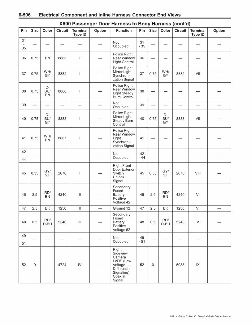
6-506 Electrical Component and Inline Harness Connector End Views
X600 Passenger Door Harness to Body Harness (cont'd)Pin Size Color Circuit Terminal
Type IDOption Function Pin Size Color Circuit Terminal
Type IDOption
31-
35— — — — — Not
Occupied31
- 35 — — — — —
36 0.75 BN 8885 I —Police RightRear WindowLight Control
36 — — — — —
37 0.75 WH/GY 8882 I —
Police RightMirror LightSynchroni-zation Signal
37 0.75 WH/GY 8882 VII —
38 0.75D-
BU/BN
8888 I —
Police RightRear WindowLight SteadyBurn Control
38 — — — — —
39 — — — — — NotOccupied 39 — — — — —
40 0.75D-
BU/GY
8883 I —
Police RightMirror LightSteady BurnControl
40 0.75D-
BU/GY
8883 VII —
41 0.75 WH/BN 8887 I —
Police RightRear WindowLightSynchroni-zation Signal
41 — — — — —
42-
44— — — — — Not
Occupied42
- 44 — — — — —
45 0.35 GY/VT 2676 I —
Right FrontDoor ExteriorSwitchUnlockSignal
45 0.35 GY/VT 2676 VIII —
46 2.5 RD/BN 4240 II —
SecondaryFusedBatteryPositiveVoltage 42
46 2.5 RD/BN 4240 VI —
47 2.5 BK 1250 II — Ground 12 47 2.5 BK 1250 VI —
48 0.5 RD/D-BU 5240 III —
SecondaryFusedBatteryPositiveVoltage 52
48 0.5 RD/D-BU 5240 V —
49-
51— — — — — Not
Occupied49
- 51 — — — — —
52 0 — 4724 IV —
RightSideviewCameraLVDS (LowVoltageDifferentialSignaling)CoaxialSignal
52 0 — 5088 IX —
2021 - Yukon, Yukon XL Electrical Body Builder Manual

Electrical Component and Inline Harness Connector End Views 6-507
X605 Passenger Door Harness to Passenger Door Trim Harness
4997556 5022037
Connector Part InformationHarness Type: Passenger DoorOEM Connector: 33390107Service Connector: Service by Harness - See Part CatalogDescription: 50-Way F 1.2, 2.8 OCS Series (BK)
Connector Part InformationHarness Type: Passenger Door TrimOEM Connector: 33390111Service Connector: Service by Harness - See Part CatalogDescription: 50-Way M 1.2, 2.8 OCS Series (BK)
Terminal Part InformationTerminal Type ID Terminated Lead Diagnostic Test Probe Terminal Removal Tool
I Not Required J-35616-16 (LT GN) No Tool Required
II Not Required J-35616-4A (PU) No Tool Required
III Not Required J-35616-17 (LT GN) No Tool Required
IV Not Required J-35616-5 (PU) No Tool Required
X605 Passenger Door Harness to Passenger Door Trim HarnessPin Size Color Circuit Terminal
Type IDOption Function Pin Size Color Circuit Terminal
Type IDOption
1- 2 — — — — — Not
Occupied1
- 2 — — — — —
3 0.35 BN/VT 607 II —
RightOutsideRearviewMirror HeaterControl
3 0.35 BN/VT 607 IV —
4 0.35 BK/L-GN 675 II —
RightOutsideRearviewMirrorPositionSensor LowReference
4 0.35 BK/L-GN 675 IV —
5 0.35 L-GN 1184 II —
WindowSwitch RightFront UpSignal
5 0.35 L-GN 1184 IV —
6 0.35 GY 1761 II —
Right SideObjectDetectionLED Control
6 0.35 GY 1761 IV —
2021 - Yukon, Yukon XL Electrical Body Builder Manual

6-508 Electrical Component and Inline Harness Connector End Views
X605 Passenger Door Harness to Passenger Door Trim Harness (cont'd)Pin Size Color Circuit Terminal
Type IDOption Function Pin Size Color Circuit Terminal
Type IDOption
7 0.35 VT/GY 2765 II —
WindowSwitch RightFrontExpressSignal
7 0.35 VT/GY 2765 IV —
8 0.35 YE/WH 2793 II —
Right FrontMirror MotorFold OutControl
8 0.35 YE/WH 2793 IV —
9 0.35D-
BU/GY
2794 II —
Right FrontMirror MotorFold InControl
9 0.35D-
BU/GY
2794 IV —
10 0.35D-
BU/YE
2795 II —
Right FrontMirrorPositionSensor Up[+] Down [-]Signal
10 0.35D-
BU/YE
2795 IV —
11 0.35 YE/VT 2796 II —
Right FrontMirror MotorUp [+] Down[-] Control
11 0.35 YE/VT 2796 IV —
12 0.35 WH 2797 II —
Right FrontMirror MotorCommonControl
12 0.35 WH 2797 IV —
13 0.35L-
GN/BK
2798 I —
Right FrontMirror MotorRight [+] Left[-] Control
13 0.35L-
GN/BK
2798 III —
14 0.35 YE/RD 2799 I —
Right FrontMirrorPositionSensor HighReference
14 0.35 YE/RD 2799 III —
15 0.35 VT/WH 2800 I —
Right FrontMirrorPositionSensor Left[-] Right [+]Signal
15 0.35 VT/WH 2800 III —
16 — — — — — NotOccupied 16 — — — — —
17 0.35 VT 4259 I —Right FrontDoor LockStatus Signal
17 0.35 VT 4259 III —
18 0.5 BK 1250 I — Ground 12 18 0.35 BK 1250 III —
19 0.5 RD/D-BU 5240 I —
SecondaryFusedBatteryPositiveVoltage 52
19 0.5 RD/D-BU 5240 III —
20 0.35 BN 5295 I —
WindowSwitch RightFront DownSignal
20 0.35 BN 5295 III —
21 0.35L-
GN/YE
6134 I —Body ControlModule LINBus 3
21 0.35L-
GN/YE
6134 III —
2021 - Yukon, Yukon XL Electrical Body Builder Manual

Electrical Component and Inline Harness Connector End Views 6-509
X605 Passenger Door Harness to Passenger Door Trim Harness (cont'd)Pin Size Color Circuit Terminal
Type IDOption Function Pin Size Color Circuit Terminal
Type IDOption
22-
50— — — — — Not
Occupied22
- 50 — — — — —
2021 - Yukon, Yukon XL Electrical Body Builder Manual

6-510 Electrical Component and Inline Harness Connector End Views
X610 Passenger Door Harness to Passenger Outside Rearview Mirror Harness
5253439
—
Connector Part InformationHarness Type: Passenger DoorOEM Connector: 35165322Service Connector: Service by Harness - See Part CatalogDescription: 19-Way F 1.2 MCON, Coaxial Series,Sealed (BK)
Connector Part InformationHarness Type: Passenger Outside Rearview MirrorOEM Connector: Not AvailableService Connector: Service by Harness - See Part CatalogDescription: 19-Way M
Terminal Part InformationTerminal Type ID Terminated Lead Diagnostic Test Probe Terminal Removal Tool
I Not Required J-35616-13 (BU) No Tool Required
II Not Required J-35616-64B (LT BU) No Tool Required
III Not Required Not Available No Tool Required
X610 Passenger Door Harness to Passenger Outside Rearview Mirror HarnessPin Size Color Circuit Terminal
Type IDOption Function Pin Size Color Circuit Terminal
Type IDOption
1 0.35L-
GN/BK
2798 I —
Right FrontMirror MotorRight [+] Left[-] Control
1 0.35L-
GN/BK
2798 III —
2 0.35 YE/VT 2796 I —
Right FrontMirror MotorUp [+] Down[-] Control
2 0.35 YE/VT 2796 III —
3 0.35D-
BU/GY
2794 I —
Right FrontMirror MotorFold InControl
3 0.35D-
BU/GY
2794 III —
4 0.35 GY 1761 I —
Right SideObjectDetectionLED Control
4 0.35 GY 1761 III —
5 0.35 WH/L-GN 5966 I — Approach
Lamp Control 5 0.35 WH/L-GN 5966 III —
6 0.35 VT/WH 2800 I —
Right FrontMirrorPositionSensor Left[-] Right [+]Signal
6 0.35 VT/WH 2800 III —
2021 - Yukon, Yukon XL Electrical Body Builder Manual
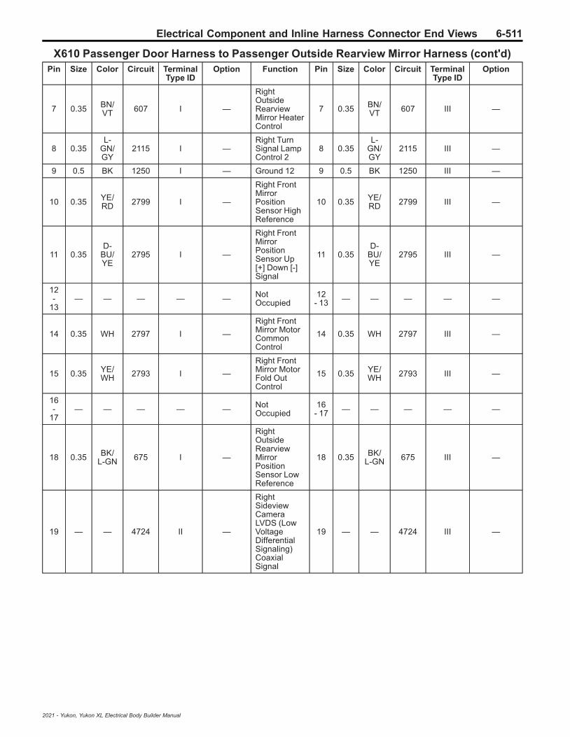
Electrical Component and Inline Harness Connector End Views 6-511
X610 Passenger Door Harness to Passenger Outside Rearview Mirror Harness (cont'd)Pin Size Color Circuit Terminal
Type IDOption Function Pin Size Color Circuit Terminal
Type IDOption
7 0.35 BN/VT 607 I —
RightOutsideRearviewMirror HeaterControl
7 0.35 BN/VT 607 III —
8 0.35L-
GN/GY
2115 I —Right TurnSignal LampControl 2
8 0.35L-
GN/GY
2115 III —
9 0.5 BK 1250 I — Ground 12 9 0.5 BK 1250 III —
10 0.35 YE/RD 2799 I —
Right FrontMirrorPositionSensor HighReference
10 0.35 YE/RD 2799 III —
11 0.35D-
BU/YE
2795 I —
Right FrontMirrorPositionSensor Up[+] Down [-]Signal
11 0.35D-
BU/YE
2795 III —
12-
13— — — — — Not
Occupied12
- 13 — — — — —
14 0.35 WH 2797 I —
Right FrontMirror MotorCommonControl
14 0.35 WH 2797 III —
15 0.35 YE/WH 2793 I —
Right FrontMirror MotorFold OutControl
15 0.35 YE/WH 2793 III —
16-
17— — — — — Not
Occupied16
- 17 — — — — —
18 0.35 BK/L-GN 675 I —
RightOutsideRearviewMirrorPositionSensor LowReference
18 0.35 BK/L-GN 675 III —
19 — — 4724 II —
RightSideviewCameraLVDS (LowVoltageDifferentialSignaling)CoaxialSignal
19 — — 4724 III —
2021 - Yukon, Yukon XL Electrical Body Builder Manual

6-512 Electrical Component and Inline Harness Connector End Views
X700 Left Rear Door Harness to Body Harness
3530739 3530694
Connector Part InformationHarness Type: Left Rear DoorOEM Connector: 13981046Service Connector: Service by Harness - See Part CatalogDescription: 26-Way F 1.2, 2.8 OCS Series (L-GY)
Connector Part InformationHarness Type: BodyOEM Connector: 15531019Service Connector: 13591678Description: 26-Way M 1.2, 2.8 OCS Series (GY)
Terminal Part InformationTerminal Type ID Terminated Lead Diagnostic Test Probe Terminal Removal Tool
I Not Required J-35616-16 (LT GN) No Tool Required
II Not Required J-35616-4A (PU) No Tool Required
III 13575824 J-35616-5 (PU) J-38125-11A
IV 13575824 J-35616-5 (PU) J-38125-11A
V 13575824 J-35616-5 (PU) J-38125-11A
VI 19333310 J-35616-65B (LT BU) J-38125-215A
VII 19369190 J-35616-65B (LT BU) J-38125-215A
X700 Left Rear Door Harness to Body HarnessPin Size Color Circuit Terminal
Type IDOption Function Pin Size Color Circuit Terminal
Type IDOption
1 2.5 RD/GY 3540 II —
SecondaryFusedBatteryPositiveVoltage 35
1 2.5 RD/GY 3540 IV —
2 — — — — —Police LeftRear WindowLight Control
2 0.75 L-GN 8875 V —
3 0.75 VT/BN 2754 I —
Door DoubleLockActuatorLockControl 2
3 0.75 VT/BN 2754 VII —
4 — — — — —
Police LeftRear WindowLight LowReference
4 0.75 BK/L-GN 8876 VII —
5 0.75 WH 2679 I —
LockActuatorsUnlockControl 1
5 0.75 WH 2679 VII —
2021 - Yukon, Yukon XL Electrical Body Builder Manual

Electrical Component and Inline Harness Connector End Views 6-513
X700 Left Rear Door Harness to Body Harness (cont'd)Pin Size Color Circuit Terminal
Type IDOption Function Pin Size Color Circuit Terminal
Type IDOption
6 0.75D-
BU/YE
1091 I —
Left RearDoor LockActuatorLock Control
6 0.75D-
BU/YE
1091 VII —
7 0.35 VT/D-BU 4001 I —
Left RearDoor LockSwitch LockControl
7 0.35 VT/D-BU 4001 VI —
8 0.35 WH/YE 4002 I —
Left RearDoor LockSwitchUnlockControl
8 0.35 WH/YE 4002 VI —
9 — — — — —
Police LeftRear WindowLightSynchroni-zation Signal
9 0.75 WH/L-GN 8877 VII —
10 — — — — —
Police LeftRear WindowLight SteadyBurn Control
10 0.75D-
BU/L-GN
8878 VII —
11 — — — — — NotOccupied 11 — — — — —
12 0.35 WH/VT 4994 I —
Left RearDoor ExteriorSwitchUnlockSignal
12 0.35 WH/VT 4994 VI —
13 0.35 VT/WH 6675 I —
Left RearDoor LockIndicatorControl
13 0.35 VT/WH 6675 VI —
14 0.35 YE 6817 II —
LEDBacklightDimmingControl 1
14 0.5 YE 6817 III —
15 2.5 BK 1150 II — Ground 11 15 2.5 BK 1150 IV —
16 — — — — — NotOccupied 16 — — — — —
17 0.35L-
GN/GY
6135 I —Body ControlModule LINBus 4
17 0.35L-
GN/GY
6135 VI —
18 0.35 WH/YE 7557 I —
Interior DoorHandleAccentLightingControl
18 0.35 WH/YE 7557 VI —
19 — — — — —
Police LeftRear WindowLight FlashEnableSignal
19 0.75 YE/L-GN 8879 VII —
20-
22— — — — — Not
Occupied20
- 22 — — — — —
23 0.75L-
GN/BK
116 I —Left RearSpeaker [-]Control
23 0.75L-
GN/BK
116 VII —
2021 - Yukon, Yukon XL Electrical Body Builder Manual

6-514 Electrical Component and Inline Harness Connector End Views
X700 Left Rear Door Harness to Body Harness (cont'd)Pin Size Color Circuit Terminal
Type IDOption Function Pin Size Color Circuit Terminal
Type IDOption
24 0.75 L-GN 199 I —Left RearSpeaker [+]Control
24 0.75 L-GN 199 VII —
25 0.5 VT 4301 I —
PassiveEntry LeftFrontAntennaSignal High
25 0.35 VT 4301 VI —
26 0.5 VT/GY 4302 I —
PassiveEntry LeftFrontAntennaSignal Low
26 0.35 VT/GY 4302 VI —
2021 - Yukon, Yukon XL Electrical Body Builder Manual

Electrical Component and Inline Harness Connector End Views 6-515
X705 Left Rear Door Harness to Left Rear Door Trim Harness
4115730 4223086
Connector Part InformationHarness Type: Left Rear DoorOEM Connector: 35029309Service Connector: Service by Harness - See Part CatalogDescription: 16-Way F 1.2 Series (BK)
Connector Part InformationHarness Type: Left Rear Door TrimOEM Connector: 35225462Service Connector: Service by Harness - See Part CatalogDescription: 16-Way M 1.2 Series (BK)
Terminal Part InformationTerminal Type ID Terminated Lead Diagnostic Test Probe Terminal Removal Tool
I Not Required J-35616-16 (LT GN) No Tool Required
II Not Required J-35616-13 (BU) No Tool Required
X705 Left Rear Door Harness to Left Rear Door Trim HarnessPin Size Color Circuit Terminal
Type IDOption Function Pin Size Color Circuit Terminal
Type IDOption
1- 2 — — — — — Not
Occupied1
- 2 — — — — —
3 0.35 VT/WH 6675 I —
Left RearDoor LockIndicatorControl
3 0.35 VT/WH 6675 II —
4 0.35 VT/D-BU 4001 I —
Left RearDoor LockSwitch LockControl
4 0.35 VT/D-BU 4001 II —
5 0.35 WH/YE 4002 I —
Left RearDoor LockSwitchUnlockControl
5 0.35 WH/YE 4002 II —
6 0.35 WH/YE 7557 I —
Interior DoorHandleAccentLightingControl
6 0.35 WH/YE 7557 II —
7 — — — — — NotOccupied 7 — — — — —
8 0.75L-
GN/BK
116 I —Left RearSpeaker [-]Control
8 0.75L-
GN/BK
116 II —
9 0.75 L-GN 199 I —Left RearSpeaker [+]Control
9 0.75 L-GN 199 II —
2021 - Yukon, Yukon XL Electrical Body Builder Manual

6-516 Electrical Component and Inline Harness Connector End Views
X705 Left Rear Door Harness to Left Rear Door Trim Harness (cont'd)Pin Size Color Circuit Terminal
Type IDOption Function Pin Size Color Circuit Terminal
Type IDOption
10 0.35 YE 6817 I —
LEDBacklightDimmingControl 1
10 0.35 YE 6817 II —
11-
15— — — — — Not
Occupied11
- 15 — — — — —
16 0.5 BK 1150 I — Ground 11 16 0.35 BK 1150 II —
2021 - Yukon, Yukon XL Electrical Body Builder Manual

Electrical Component and Inline Harness Connector End Views 6-517
X706 Left Rear Door Harness to Left Rear Door Trim Harness
5020939 1851890
Connector Part InformationHarness Type: Left Rear DoorOEM Connector: 35061724Service Connector: Service by Harness - See Part CatalogDescription: 10-Way F 1.5, 2.8 Kaizen Series (L-GY)
Connector Part InformationHarness Type: Left Rear Door TrimOEM Connector: 13506926Service Connector: Service by Harness - See Part CatalogDescription: 10-Way M YESC Kaizen Series (L-GY)
Terminal Part InformationTerminal Type ID Terminated Lead Diagnostic Test Probe Terminal Removal Tool
I Not Required J-35616-2A (GY) No Tool Required
II Not Required J-35616-4A (PU) No Tool Required
III Not Required J-35616-3 (GY) No Tool Required
IV Not Required J-35616-5 (PU) No Tool Required
X706 Left Rear Door Harness to Left Rear Door Trim HarnessPin Size Color Circuit Terminal
Type IDOption Function Pin Size Color Circuit Terminal
Type IDOption
1 2.5 RD/GY 3540 II —
SecondaryFusedBatteryPositiveVoltage 35
1 2.5 RD/GY 3540 IV —
2 — — — — — NotOccupied 2 — — — — —
3 0.35L-
GN/GY
6135 I —Body ControlModule LINBus 4
3 0.35L-
GN/GY
6135 III —
4 0.35 GY 747 I —
Left RearDoor AjarSwitchSignal
4 0.35 GY 747 III —
5 2D-
BU/VT
668 II —
Left RearWindowMotor UpControl
5 2D-
BU/VT
668 IV —
6 2.5 BK 1150 II — Ground 11 6 2.5 BK 1150 IV —
7 — — — — — NotOccupied 7 — — — — —
8 0.35 L-GN/D-BU 4648 I —
Left RearDoor LockStatus Signal
8 0.35 L-GN/D-BU 4648 III —
2021 - Yukon, Yukon XL Electrical Body Builder Manual

6-518 Electrical Component and Inline Harness Connector End Views
X706 Left Rear Door Harness to Left Rear Door Trim Harness (cont'd)Pin Size Color Circuit Terminal
Type IDOption Function Pin Size Color Circuit Terminal
Type IDOption
9 — — — — — NotOccupied 9 — — — — —
10 2 YE/D-BU 669 II —
Left RearWindowMotor DownControl
10 2 YE/D-BU 669 IV —
2021 - Yukon, Yukon XL Electrical Body Builder Manual

Electrical Component and Inline Harness Connector End Views 6-519
X800 Right Rear Door Harness to Body Harness
3530739 3530694
Connector Part InformationHarness Type: Right Rear DoorOEM Connector: 13981046Service Connector: Service by Harness - See Part CatalogDescription: 26-Way F 1.2, 2.8 OCS Series (L-GY)
Connector Part InformationHarness Type: BodyOEM Connector: 15531019Service Connector: 13591678Description: 26-Way M 1.2, 2.8 OCS Series (GY)
Terminal Part InformationTerminal Type ID Terminated Lead Diagnostic Test Probe Terminal Removal Tool
I Not Required J-35616-16 (LT GN) No Tool Required
II Not Required J-35616-4A (PU) No Tool Required
III 13575824 J-35616-5 (PU) J-38125-11A
IV 13575824 J-35616-5 (PU) J-38125-11A
V 13575824 J-35616-5 (PU) J-38125-11A
VI 19333310 J-35616-65B (LT BU) J-38125-215A
VII 19369190 J-35616-65B (LT BU) J-38125-215A
X800 Right Rear Door Harness to Body HarnessPin Size Color Circuit Terminal
Type IDOption Function Pin Size Color Circuit Terminal
Type IDOption
1 2.5 RD/BN 4240 II —
SecondaryFusedBatteryPositiveVoltage 42
1 2.5 RD/BN 4240 IV —
2 — — — — —Police RightRear WindowLight Control
2 0.75 BN 8885 V —
3 0.75 VT/BN 2754 I —
Door DoubleLockActuatorLockControl 2
3 0.75 VT/BN 2754 VII —
4 — — — — —
Police RightRear WindowLight LowReference
4 0.75 BK/BN 8886 VII —
5 0.75 GY/BK 2680 I —
LockActuatorsUnlockControl 2
5 0.75 GY/BK 2680 VII —
2021 - Yukon, Yukon XL Electrical Body Builder Manual
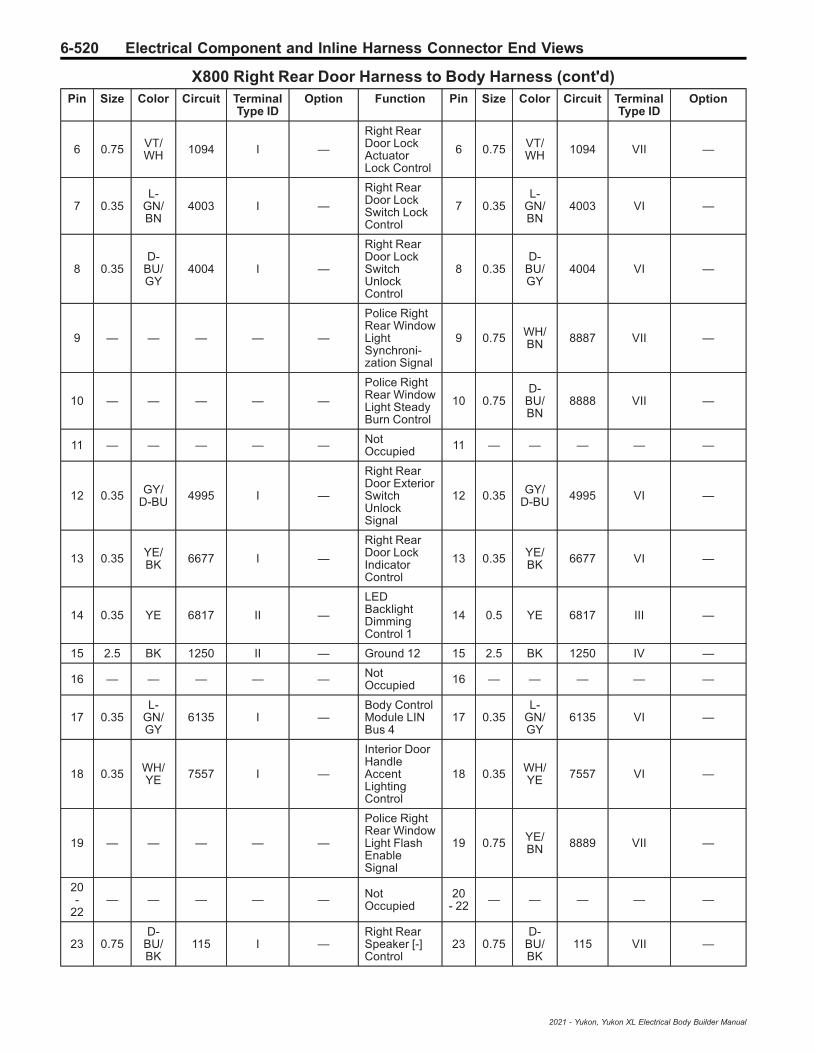
6-520 Electrical Component and Inline Harness Connector End Views
X800 Right Rear Door Harness to Body Harness (cont'd)Pin Size Color Circuit Terminal
Type IDOption Function Pin Size Color Circuit Terminal
Type IDOption
6 0.75 VT/WH 1094 I —
Right RearDoor LockActuatorLock Control
6 0.75 VT/WH 1094 VII —
7 0.35L-
GN/BN
4003 I —
Right RearDoor LockSwitch LockControl
7 0.35L-
GN/BN
4003 VI —
8 0.35D-
BU/GY
4004 I —
Right RearDoor LockSwitchUnlockControl
8 0.35D-
BU/GY
4004 VI —
9 — — — — —
Police RightRear WindowLightSynchroni-zation Signal
9 0.75 WH/BN 8887 VII —
10 — — — — —
Police RightRear WindowLight SteadyBurn Control
10 0.75D-
BU/BN
8888 VII —
11 — — — — — NotOccupied 11 — — — — —
12 0.35 GY/D-BU 4995 I —
Right RearDoor ExteriorSwitchUnlockSignal
12 0.35 GY/D-BU 4995 VI —
13 0.35 YE/BK 6677 I —
Right RearDoor LockIndicatorControl
13 0.35 YE/BK 6677 VI —
14 0.35 YE 6817 II —
LEDBacklightDimmingControl 1
14 0.5 YE 6817 III —
15 2.5 BK 1250 II — Ground 12 15 2.5 BK 1250 IV —
16 — — — — — NotOccupied 16 — — — — —
17 0.35L-
GN/GY
6135 I —Body ControlModule LINBus 4
17 0.35L-
GN/GY
6135 VI —
18 0.35 WH/YE 7557 I —
Interior DoorHandleAccentLightingControl
18 0.35 WH/YE 7557 VI —
19 — — — — —
Police RightRear WindowLight FlashEnableSignal
19 0.75 YE/BN 8889 VII —
20-
22— — — — — Not
Occupied20
- 22 — — — — —
23 0.75D-
BU/BK
115 I —Right RearSpeaker [-]Control
23 0.75D-
BU/BK
115 VII —
2021 - Yukon, Yukon XL Electrical Body Builder Manual

Electrical Component and Inline Harness Connector End Views 6-521
X800 Right Rear Door Harness to Body Harness (cont'd)Pin Size Color Circuit Terminal
Type IDOption Function Pin Size Color Circuit Terminal
Type IDOption
24 0.75 WH 46 I —Right RearSpeaker [+]Control
24 0.75 WH 46 VII —
25 0.5L-
GN/YE
4303 I —
PassiveEntry RightFront DoorAntennaSignal High
25 0.35L-
GN/YE
4303 VI —
26 0.5L-
GN/BK
4304 I —
PassiveEntry RightFront DoorAntennaSignal Low
26 0.35L-
GN/BK
4304 VI —
2021 - Yukon, Yukon XL Electrical Body Builder Manual

6-522 Electrical Component and Inline Harness Connector End Views
X805 Right Rear Door Harness to Right Rear Door Trim Harness
4115730 4223086
Connector Part InformationHarness Type: Right Rear DoorOEM Connector: 35029309Service Connector: Service by Harness - See Part CatalogDescription: 16-Way F 1.2 Series (BK)
Connector Part InformationHarness Type: Right Rear Door TrimOEM Connector: 35225462Service Connector: Service by Harness - See Part CatalogDescription: 16-Way M 1.2 Series (BK)
Terminal Part InformationTerminal Type ID Terminated Lead Diagnostic Test Probe Terminal Removal Tool
I Not Required J-35616-16 (LT GN) No Tool Required
II Not Required J-35616-13 (BU) No Tool Required
X805 Right Rear Door Harness to Right Rear Door Trim HarnessPin Size Color Circuit Terminal
Type IDOption Function Pin Size Color Circuit Terminal
Type IDOption
1- 2 — — — — — Not
Occupied1
- 2 — — — — —
3 0.35 YE/BK 6677 I —
Right RearDoor LockIndicatorControl
3 0.5 YE/BK 6677 II —
4 0.35L-
GN/BN
4003 I —
Right RearDoor LockSwitch LockControl
4 0.35L-
GN/BN
4003 II —
5 0.35D-
BU/GY
4004 I —
Right RearDoor LockSwitchUnlockControl
5 0.35D-
BU/GY
4004 II —
6 0.35 WH/YE 7557 I —
Interior DoorHandleAccentLightingControl
6 0.35 WH/YE 7557 II —
7 — — — — — NotOccupied 7 — — — — —
8 0.75D-
BU/BK
115 I —Right RearSpeaker [-]Control
8 0.75D-
BU/BK
115 II —
9 0.75 WH 46 I —Right RearSpeaker [+]Control
9 0.75 WH 46 II —
2021 - Yukon, Yukon XL Electrical Body Builder Manual

Electrical Component and Inline Harness Connector End Views 6-523
X805 Right Rear Door Harness to Right Rear Door Trim Harness (cont'd)Pin Size Color Circuit Terminal
Type IDOption Function Pin Size Color Circuit Terminal
Type IDOption
10 0.35 YE 6817 I —
LEDBacklightDimmingControl 1
10 0.5 YE 6817 II —
11-
15— — — — — Not
Occupied11
- 15 — — — — —
16 0.5 BK 1250 I — Ground 12 16 0.35 BK 1250 II —
2021 - Yukon, Yukon XL Electrical Body Builder Manual
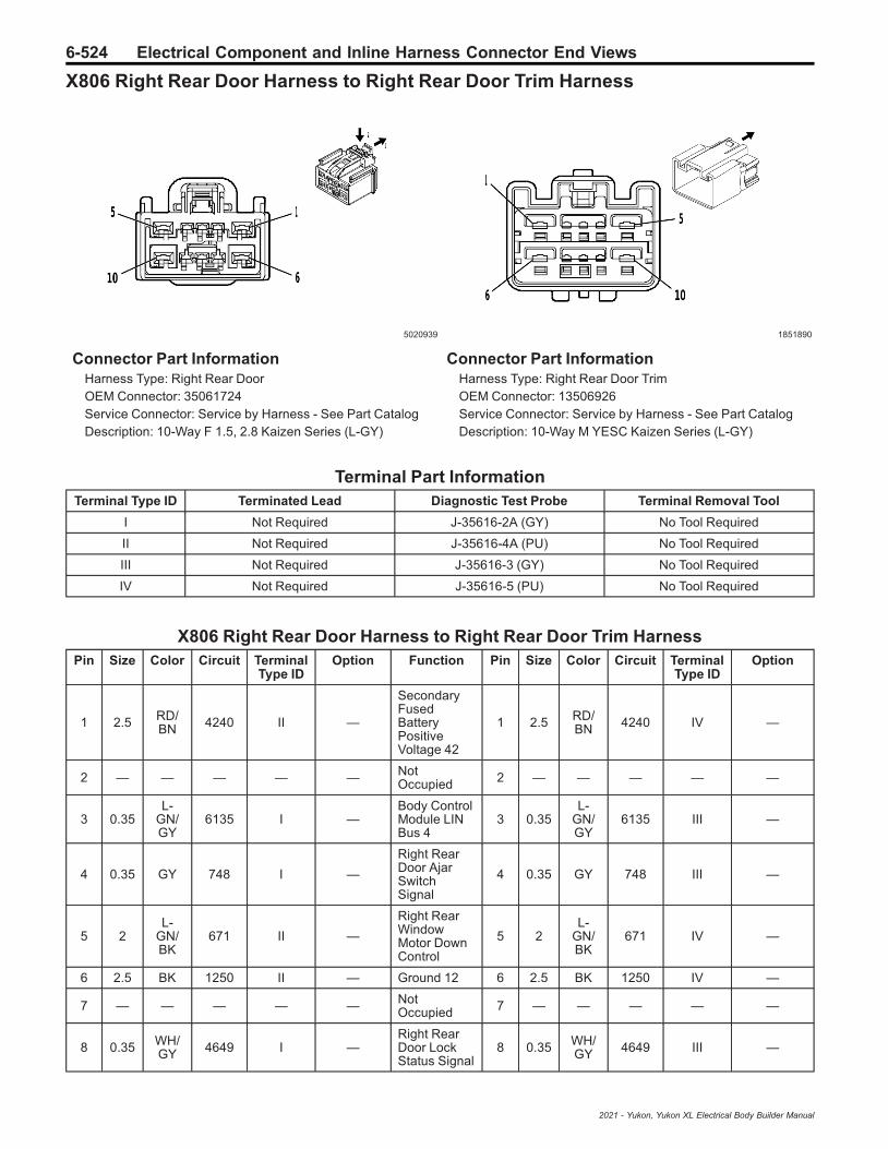
6-524 Electrical Component and Inline Harness Connector End Views
X806 Right Rear Door Harness to Right Rear Door Trim Harness
5020939 1851890
Connector Part InformationHarness Type: Right Rear DoorOEM Connector: 35061724Service Connector: Service by Harness - See Part CatalogDescription: 10-Way F 1.5, 2.8 Kaizen Series (L-GY)
Connector Part InformationHarness Type: Right Rear Door TrimOEM Connector: 13506926Service Connector: Service by Harness - See Part CatalogDescription: 10-Way M YESC Kaizen Series (L-GY)
Terminal Part InformationTerminal Type ID Terminated Lead Diagnostic Test Probe Terminal Removal Tool
I Not Required J-35616-2A (GY) No Tool Required
II Not Required J-35616-4A (PU) No Tool Required
III Not Required J-35616-3 (GY) No Tool Required
IV Not Required J-35616-5 (PU) No Tool Required
X806 Right Rear Door Harness to Right Rear Door Trim HarnessPin Size Color Circuit Terminal
Type IDOption Function Pin Size Color Circuit Terminal
Type IDOption
1 2.5 RD/BN 4240 II —
SecondaryFusedBatteryPositiveVoltage 42
1 2.5 RD/BN 4240 IV —
2 — — — — — NotOccupied 2 — — — — —
3 0.35L-
GN/GY
6135 I —Body ControlModule LINBus 4
3 0.35L-
GN/GY
6135 III —
4 0.35 GY 748 I —
Right RearDoor AjarSwitchSignal
4 0.35 GY 748 III —
5 2L-
GN/BK
671 II —
Right RearWindowMotor DownControl
5 2L-
GN/BK
671 IV —
6 2.5 BK 1250 II — Ground 12 6 2.5 BK 1250 IV —
7 — — — — — NotOccupied 7 — — — — —
8 0.35 WH/GY 4649 I —
Right RearDoor LockStatus Signal
8 0.35 WH/GY 4649 III —
2021 - Yukon, Yukon XL Electrical Body Builder Manual

Electrical Component and Inline Harness Connector End Views 6-525
X806 Right Rear Door Harness to Right Rear Door Trim Harness (cont'd)Pin Size Color Circuit Terminal
Type IDOption Function Pin Size Color Circuit Terminal
Type IDOption
9 — — — — — NotOccupied 9 — — — — —
10 2D-
BU/GY
670 II —
Right RearWindowMotor UpControl
10 2D-
BU/GY
670 IV —
2021 - Yukon, Yukon XL Electrical Body Builder Manual

6-526 Electrical Component and Inline Harness Connector End Views
X904 Center High Mounted Stop Lamp Jumper Harness to Body Harness
—
4116496
Connector Part InformationHarness Type: Center High Mounted Stop Lamp JumperOEM Connector: Not AvailableService Connector: Service by Harness - See Part CatalogDescription: 2-Way F
Connector Part InformationHarness Type: BodyOEM Connector: 33189233Service Connector: 19332376Description: 2-Way M 1.2 Series (BK)
Terminal Part InformationTerminal Type ID Terminated Lead Diagnostic Test Probe Terminal Removal Tool
I Not Required J-35616-16 (LT GN) No Tool Required
II Not Required J-35616-17 (LT GN) No Tool Required
X904 Center High Mounted Stop Lamp Jumper Harness to Body HarnessPin Size Color Circuit Terminal
Type IDOption Function Pin Size Color Circuit Terminal
Type IDOption
10.50.5
BKBN/YE
2050820
II
——
Ground 20Center HighMountedStop LampSupplyVoltage
10.50.5
BKBN/YE
2050820
IIII
——
20.50.5
BKBN/YE
2050820
II
—MBM+Z82
Ground 20Center HighMountedStop LampSupplyVoltage
20.50.5
BKBN/YE
2050820
IIII
—MBM+Z82
2021 - Yukon, Yukon XL Electrical Body Builder Manual

Electrical Component and Inline Harness Connector End Views 6-527
X905 Liftgate Harness to Body Harness
4253192 4249201
Connector Part InformationHarness Type: LiftgateOEM Connector: 33198155Service Connector: Service by Harness - See Part CatalogDescription: 30-Way F 1.2 MCON, 2.8, 6.3 YESC Series (BK)
Connector Part InformationHarness Type: BodyOEM Connector: 35056785Service Connector: 13518087Description: 30-Way M 1.2 MCON, 2.8, 6.3 YESC Series (BK)
Terminal Part InformationTerminal Type ID Terminated Lead Diagnostic Test Probe Terminal Removal Tool
I Not Required J-35616-16 (LT GN) No Tool Required
II Not Required J-35616-42 (RD) No Tool Required
III Not Required J-35616-4A (PU) No Tool Required
IV 13575824 J-35616-5 (PU) J-38125-11A
V 13575824 J-35616-5 (PU) J-38125-11A
VI 13575824 J-35616-5 (PU) J-38125-11A
VII 19301536 J-35616-43 (RD) J-38125-11A
VIII 19330704 J-35616-17 (LT GN) J-38125-215A
IX 84616651 J-35616-17 (LT GN) J-38125-215A
X905 Liftgate Harness to Body HarnessPin Size Color Circuit Terminal
Type IDOption Function Pin Size Color Circuit Terminal
Type IDOption
1 — — — — — NotOccupied 1 — — — — —
2 0.35L-
GN/YE
6846 I —Rear LicensePlate LampControl
2 0.35L-
GN/YE
6846 IX —
3 0.35D-
BU/L-GN
4089 I —Rear ClosureMotorControl
3 0.35D-
BU/L-GN
4089 IX —
4 0.5 BN/GY 6995 I —
Right RearPark LampControl
4 0.5 BN/GY 6995 IX —
5 0.35 L-GN/D-BU 2856 I —
Body ControlModule LINBus 10
5 0.5 L-GN/D-BU 2856 IX —
6 0.35 VT/GY 1303 I —
Liftgate AjarSwitchSignal 1
6 0.35 VT/GY 1303 IX —
2021 - Yukon, Yukon XL Electrical Body Builder Manual

6-528 Electrical Component and Inline Harness Connector End Views
X905 Liftgate Harness to Body Harness (cont'd)Pin Size Color Circuit Terminal
Type IDOption Function Pin Size Color Circuit Terminal
Type IDOption
7 0.35 GY/BK 4654 I —
Rear ClosureObjectSensorSignal
7 0.5 GY/BK 4654 IX —
8 — — — — — NotOccupied 8 — — — — —
9 0.5 GY/BK 2680 I —
LockActuatorsUnlockControl 2
9 0.75 GY/BK 2680 VIII —
10 0.35 BK/VT 4656 I —
Rear ClosureObjectSensor LowReference
10 0.35 BK/VT 4656 IX —
11 — — — — —Body ControlModule LINBus 4
11 0.35L-
GN/GY
6135 IX —
12 0.75 VT/L-GN 8869 I —
PoliceLiftgateStrobe RearOn OFFControl
12 0.35 VT/L-GN 8869 IX —
13 0.35D-
BU/YE
2279 I —
LiftgateWindow AjarSwitchSignal
13 0.35D-
BU/YE
2279 IX —
14 0.35 GY/WH 4658 I —
Rear ClosureSwitch LEDControl
14 0.35 GY/WH 4658 IX —
15 — — — — — NotOccupied 15 — — — — —
16 0.35 YE/D-BU 5797 I —
Rear ClosureHandleSwitch OpenSignal
16 0.35 YE/D-BU 5797 IX —
17 0.35 GY/L-GN 6190 I —
LiftgateWindow/RearCompart-ment Lid,ExteriorUnlatchSignal
17 0.35 GY/L-GN 6190 IX —
18 0.35 BN/D-BU 6993 I —
Left RearPark LampControl
18 0.5 BN/D-BU 6993 IX —
19 0.35 YE/BK 8085 I —
Rear ClosureLatchPrimaryStatus
19 0.35 YE/BK 8085 IX —
20 — — — — — NotOccupied 20 — — — — —
21 0.35 GY/VT 4678 I —
Rear ClosureLatchUnlatchStatus
21 0.35 GY/VT 4678 IX —
22 0.35 WH/L-GN 8084 I —
Rear ClosureLatch NeutralStatus
22 0.35 WH/L-GN 8084 IX —
2021 - Yukon, Yukon XL Electrical Body Builder Manual
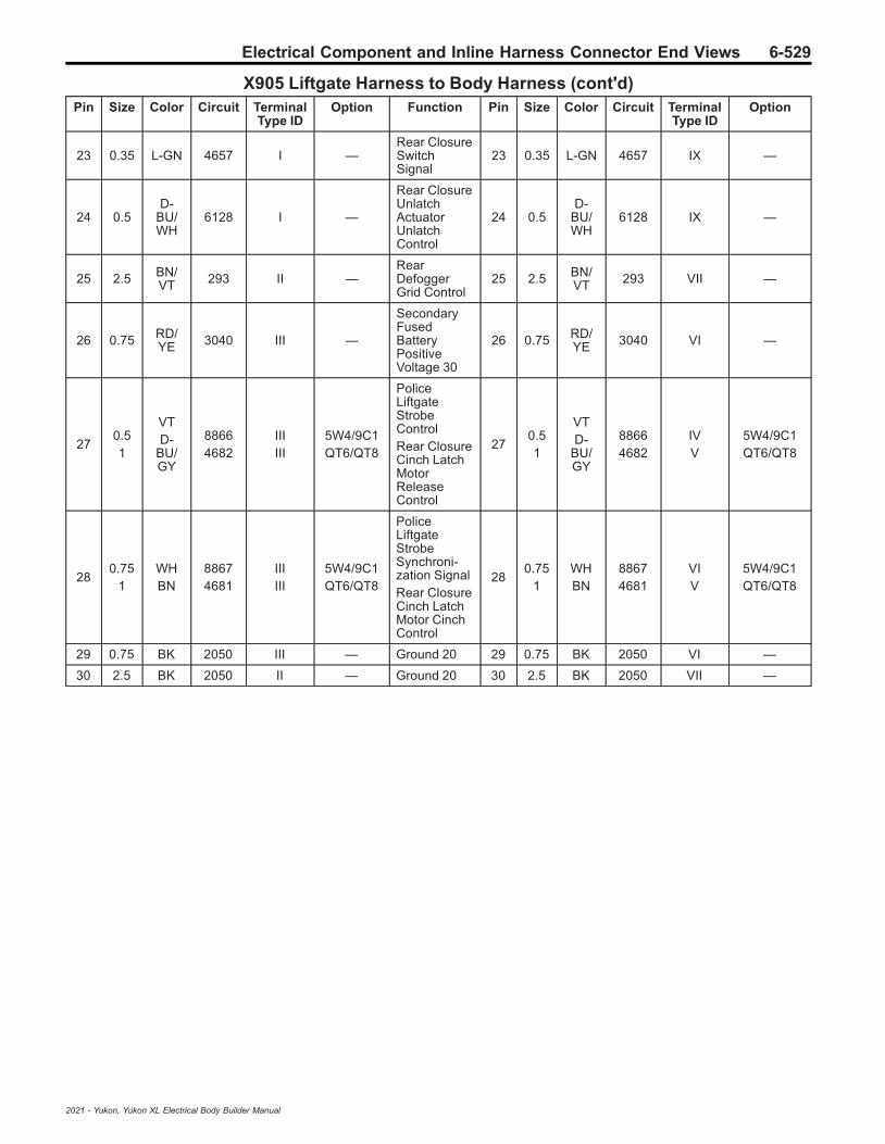
Electrical Component and Inline Harness Connector End Views 6-529
X905 Liftgate Harness to Body Harness (cont'd)Pin Size Color Circuit Terminal
Type IDOption Function Pin Size Color Circuit Terminal
Type IDOption
23 0.35 L-GN 4657 I —Rear ClosureSwitchSignal
23 0.35 L-GN 4657 IX —
24 0.5D-
BU/WH
6128 I —
Rear ClosureUnlatchActuatorUnlatchControl
24 0.5D-
BU/WH
6128 IX —
25 2.5 BN/VT 293 II —
RearDefoggerGrid Control
25 2.5 BN/VT 293 VII —
26 0.75 RD/YE 3040 III —
SecondaryFusedBatteryPositiveVoltage 30
26 0.75 RD/YE 3040 VI —
270.51
VTD-
BU/GY
88664682
IIIIII
5W4/9C1QT6/QT8
PoliceLiftgateStrobeControlRear ClosureCinch LatchMotorReleaseControl
270.51
VTD-
BU/GY
88664682
IVV
5W4/9C1QT6/QT8
280.75
1WHBN
88674681
IIIIII
5W4/9C1QT6/QT8
PoliceLiftgateStrobeSynchroni-zation SignalRear ClosureCinch LatchMotor CinchControl
280.75
1WHBN
88674681
VIV
5W4/9C1QT6/QT8
29 0.75 BK 2050 III — Ground 20 29 0.75 BK 2050 VI —
30 2.5 BK 2050 II — Ground 20 30 2.5 BK 2050 VII —
2021 - Yukon, Yukon XL Electrical Body Builder Manual

6-530 Electrical Component and Inline Harness Connector End Views
X907 Liftgate Extension Harness to Liftgate Harness
5086387 4331672
Connector Part InformationHarness Type: Liftgate ExtensionOEM Connector: 35029311Service Connector: Service by Harness - See Part CatalogDescription: 8-Way F 1.2 Series (BK)
Connector Part InformationHarness Type: LiftgateOEM Connector: 33226445Service Connector: Service by Harness - See Part CatalogDescription: 8-Way M 1.2 Series (BK)
Terminal Part InformationTerminal Type ID Terminated Lead Diagnostic Test Probe Terminal Removal Tool
I Not Required J-35616-16 (LT GN) No Tool Required
II Not Required J-35616-17 (LT GN) No Tool Required
X907 Liftgate Extension Harness to Liftgate HarnessPin Size Color Circuit Terminal
Type IDOption Function Pin Size Color Circuit Terminal
Type IDOption
1 0.35 YE/D-BU 5797 I —
Rear ClosureHandleSwitch OpenSignal
1 0.35 YE/D-BU 5797 II —
2 0.35L-
GN/YE
6846 I —Rear LicensePlate LampControl
2 0.35L-
GN/YE
6846 II —
3- 4 — — — — — Not
Occupied3
- 4 — — — — —
5 0.35 GY/L-GN 6190 I —
LiftgateWindow/RearCompart-ment Lid,ExteriorUnlatchSignal
5 0.35 GY/L-GN 6190 II —
6 — — — — — NotOccupied 6 — — — — —
7 0.35 BK 2050 I — Ground 20 7 0.35 BK 2050 II —
8 — — — — — NotOccupied 8 — — — — —
2021 - Yukon, Yukon XL Electrical Body Builder Manual

Electrical Component and Inline Harness Connector End Views 6-531
X917 Liftgate Harness to Left Strobe Light Blunt Harness
4994577
—
Connector Part InformationHarness Type: LiftgateOEM Connector: 33351631Service Connector: Service by Harness - See Part CatalogDescription: 4-Way F 1.2 MCON-CB Series, Sealed (BK)
Connector Part InformationHarness Type: Left Strobe Light BluntOEM Connector: Not AvailableService Connector: Service by Harness - See Part CatalogDescription: 4-Way M
Terminal Part InformationTerminal Type ID Terminated Lead Diagnostic Test Probe Terminal Removal Tool
I Not Required J-35616-16 (LT GN) No Tool Required
II Not Required J-35616-17 (LT GN) No Tool Required
X917 Liftgate Harness to Left Strobe Light Blunt HarnessPin Size Color Circuit Terminal
Type IDOption Function Pin Size Color Circuit Terminal
Type IDOption
1 0.75 VT 8866 I —
PoliceLiftgateStrobeControl
1 0.75 VT 8866 II —
2 0.75 BK 2050 I — Ground 20 2 0.75 BK 2050 II —
3 0.75 WH 8867 I —
PoliceLiftgateStrobeSynchroni-zation Signal
3 0.75 WH 8867 II —
4 — — — — — NotOccupied 4 — — — — —
2021 - Yukon, Yukon XL Electrical Body Builder Manual

6-532 Electrical Component and Inline Harness Connector End Views
X918 Liftgate Harness to Right Strobe Light Blunt Cut Harness
4994577
—
Connector Part InformationHarness Type: LiftgateOEM Connector: 33351631Service Connector: Service by Harness - See Part CatalogDescription: 4-Way F 1.2 MCON-CB Series, Sealed (BK)
Connector Part InformationHarness Type: Right Strobe Light Blunt CutOEM Connector: Not AvailableService Connector: Service by Harness - See Part CatalogDescription: 4-Way M
Terminal Part InformationTerminal Type ID Terminated Lead Diagnostic Test Probe Terminal Removal Tool
I Not Required J-35616-16 (LT GN) No Tool Required
II Not Required J-35616-17 (LT GN) No Tool Required
X918 Liftgate Harness to Right Strobe Light Blunt Cut HarnessPin Size Color Circuit Terminal
Type IDOption Function Pin Size Color Circuit Terminal
Type IDOption
1 0.75 VT 8866 I —
PoliceLiftgateStrobeControl
1 0.75 VT 8866 II —
2 0.75 BK 2050 I — Ground 20 2 0.75 BK 2050 II —
3 0.75 WH 8867 I —
PoliceLiftgateStrobeSynchroni-zation Signal
3 0.75 WH 8867 II —
4 — — — — — NotOccupied 4 — — — — —
2021 - Yukon, Yukon XL Electrical Body Builder Manual

Electrical Component and Inline Harness Connector End Views 6-533
X922 Body Harness to Rear Fascia Harness
2220548 2339640
Connector Part InformationHarness Type: BodyOEM Connector: 13603185Service Connector: 13576549Description: 40-Way F 1.5, 2.8 Series, Sealed (BK)
Connector Part InformationHarness Type: Rear FasciaOEM Connector: 13603208Service Connector: Service by Harness - See Part CatalogDescription: 40-Way M 1.5 DSQ, 2.8 ATS Series, Sealed (BK)
Terminal Part InformationTerminal Type ID Terminated Lead Diagnostic Test Probe Terminal Removal Tool
I 13575384 J-35616-14 (GN) J-38125-560
II 13576369 J-35616-14 (GN) J-38125-560
III 13580830 J-35616-4A (PU) J-38125-36
IV 13582248 J-35616-14 (GN) J-38125-560
V Not Required J-35616-3 (GY) No Tool Required
VI Not Required J-35616-5 (PU) No Tool Required
X922 Body Harness to Rear Fascia HarnessPin Size Color Circuit Terminal
Type IDOption Function Pin Size Color Circuit Terminal
Type IDOption
1 — — — — — NotOccupied 1 — — — — —
2 0.5 BN/WH 2374 II —
ObjectSensorSupplyVoltage
2 0.5 BN/WH 2374 V —
3 0.5 YE/GY 122 II — Rear Fog
Lamp Control 3 0.5 YE/GY 122 V —
4- 6 — — — — — Not
Occupied4
- 6 — — — — —
7 0.5 YE 2375 II —
Left RearOuterParkingAssistSensorSignal
7 0.5 YE 2375 V —
8- 9 — — — — — Not
Occupied8
- 9 — — — — —
10 0.35 L-GN/D-BU 2856 I —
Body ControlModule LINBus 10
10 0.5 L-GN/D-BU 2856 V —
2021 - Yukon, Yukon XL Electrical Body Builder Manual

6-534 Electrical Component and Inline Harness Connector End Views
X922 Body Harness to Rear Fascia Harness (cont'd)Pin Size Color Circuit Terminal
Type IDOption Function Pin Size Color Circuit Terminal
Type IDOption
11-
14— — — — — Not
Occupied11
- 14 — — — — —
15 0.35 BN/L-GN 3568 I —
Rear ClosureKeylessEntryAntennaHigh Signal
15 0.5 BN/L-GN 3568 V —
16 — — — — — NotOccupied 16 — — — — —
17 0.5 BK 1450 III — Ground 14 17 0.5 BK 1450 VI —
18 0.5 YE/D-BU 2376 II —
Left RearMiddleParkingAssistSensorSignal
18 0.5 YE/D-BU 2376 V —
19 0.35 WH 4100 I —
AUTOSARSerial DataCAN Bus [-]4 Serial Data
19 0.35 WH 4100 V —
20 0.35D-
BU/VT
4101 I —
AUTOSARSerial DataCAN Bus [+]4 Serial Data
20 0.35D-
BU/VT
4101 V —
21 0.5 BK/GY 2379 II —
ObjectSensor LowReference
21 0.5 BK/GY 2379 V —
22-
24— — — — — Not
Occupied22
- 24 — — — — —
250.50.5
RD/GYRD/GY
48404840
IIIV
——
SecondaryFusedBatteryPositiveVoltage 48SecondaryFusedBatteryPositiveVoltage 48
25 0.5 RD/GY 4840 V —
26 — — — — — NotOccupied 26 — — — — —
27 0.5 RD/BN 4940 II —
SecondaryFusedBatteryPositiveVoltage 49
27 0.5 RD/BN 4940 V —
28 0.5L-
GN/BK
2738 II —Virtual KeyModule LINBus 1
28 0.5L-
GN/BK
2738 V —
29 0.35 GY 2066 I —
Hands-FreeLiftgateSensor LampControl
29 0.5 GY 2066 V —
30-
31— — — — — Not
Occupied30
- 31 — — — — —
2021 - Yukon, Yukon XL Electrical Body Builder Manual

Electrical Component and Inline Harness Connector End Views 6-535
X922 Body Harness to Rear Fascia Harness (cont'd)Pin Size Color Circuit Terminal
Type IDOption Function Pin Size Color Circuit Terminal
Type IDOption
32 0.5 YE/WH 2377 III —
Right RearMiddleParkingAssistSensorSignal
32 0.5 YE/WH 2377 VI —
33 — — — — — NotOccupied 33 — — — — —
340.350.5
L-GN/YEL-
GN/YE
28622862
III
ATH/PTTPTT
Body ControlModule LINBus 16Body ControlModule LINBus 16
34 0.5L-
GN/YE
2862 V —
35 0.35L-
GN/GY
3569 I —
Rear ClosureKeylessEntryAntenna LowSignal
35 0.5L-
GN/GY
3569 V —
36 0.5 YE/VT 2378 II —
Right RearOuterParkingAssistSensorSignal
36 0.5 YE/VT 2378 V —
37-
40— — — — — Not
Occupied37
- 40 — — — — —
2021 - Yukon, Yukon XL Electrical Body Builder Manual

6-536 Power Outlets
Power Outlets
Schematic and Routing Diagrams
2021 - Yukon, Yukon XL Electrical Body Builder Manual

Power Outlets 6-537C
iga
rL
igh
ter/
Po
we
rO
utl
et
Sc
he
ma
tic
s(U
SB
Re
ce
pta
cle
s(-
UW
9))
54
30
55
4
2021 - Yukon, Yukon XL Electrical Body Builder Manual

6-538 Power OutletsC
iga
rL
igh
ter/
Po
we
rO
utl
et
Sc
he
ma
tic
s(P
ow
er
Re
ce
pta
cle
s)
53
71
02
8
2021 - Yukon, Yukon XL Electrical Body Builder Manual
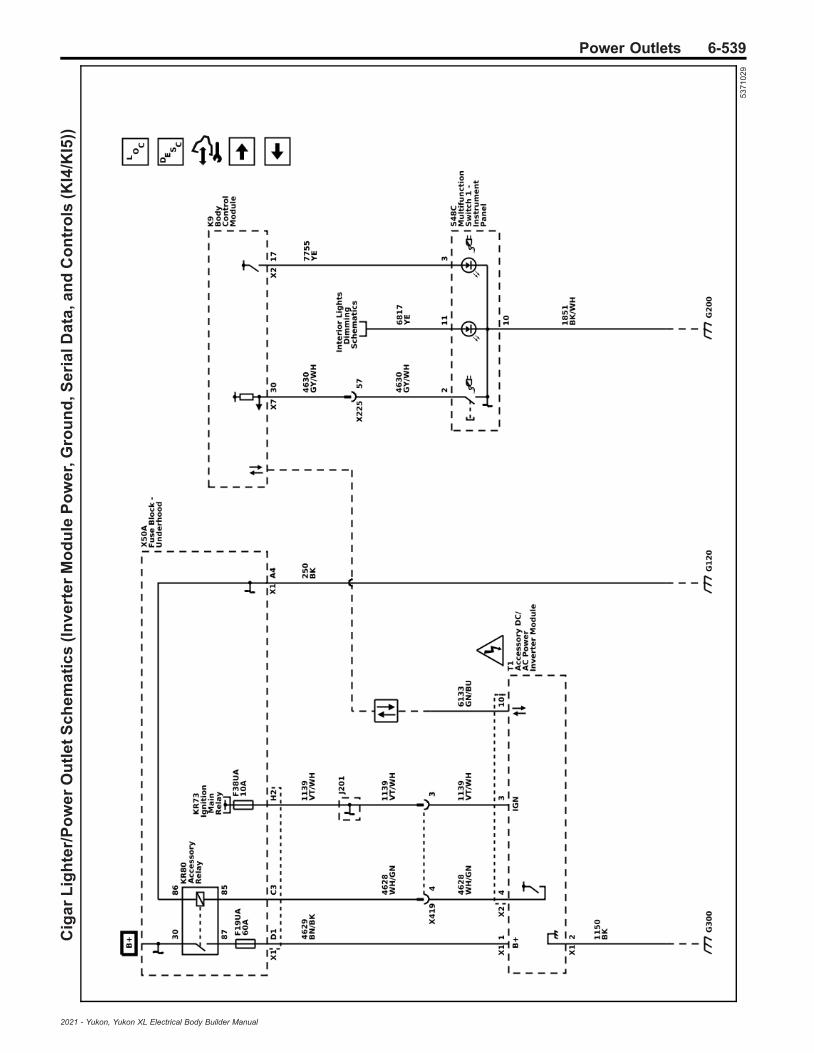
Power Outlets 6-539C
iga
rL
igh
ter/
Po
we
rO
utl
et
Sc
he
ma
tic
s(I
nv
ert
er
Mo
du
leP
ow
er,
Gro
un
d,S
eri
alD
ata
,an
dC
on
tro
ls(K
I4/K
I5))
53
71
02
9
2021 - Yukon, Yukon XL Electrical Body Builder Manual
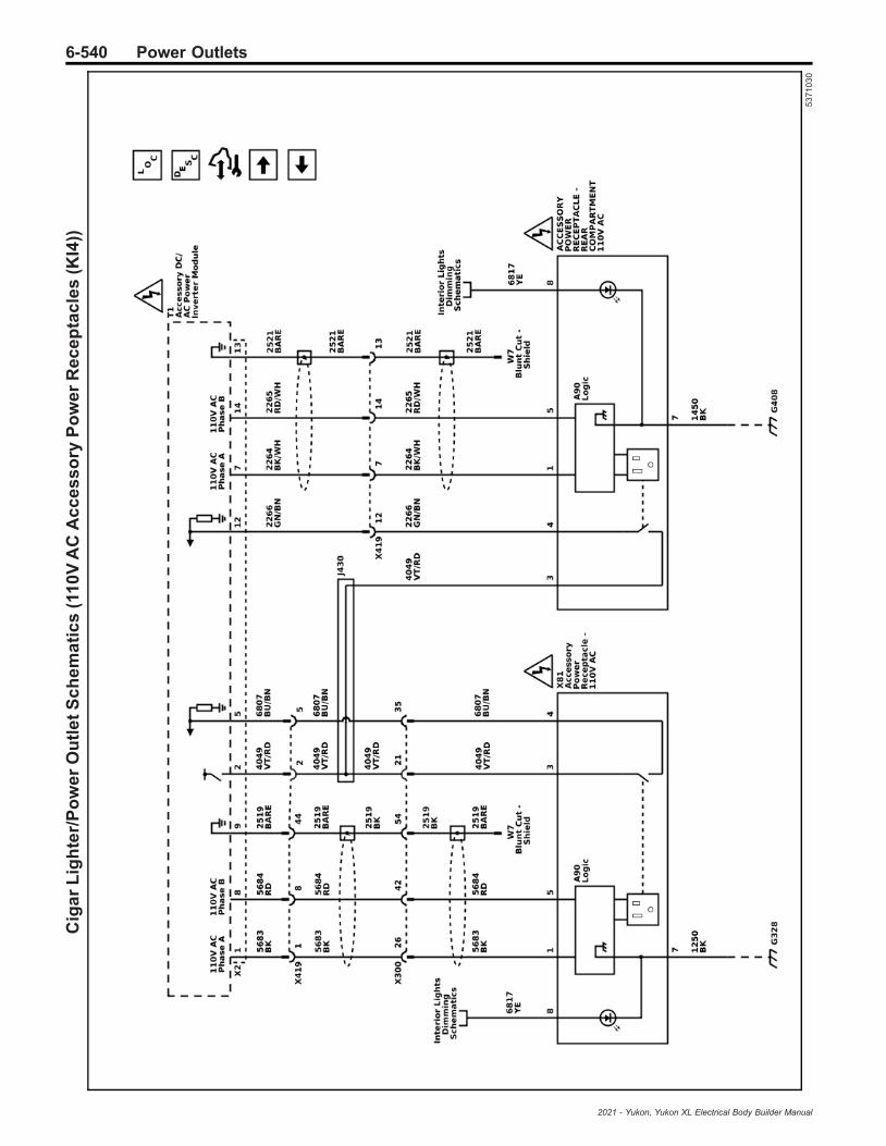
6-540 Power OutletsC
iga
rL
igh
ter/
Po
we
rO
utl
et
Sc
he
ma
tic
s(1
10
VA
CA
cc
es
so
ryP
ow
er
Re
ce
pta
cle
s(K
I4))
53
71
03
0
2021 - Yukon, Yukon XL Electrical Body Builder Manual

Power Outlets 6-541C
iga
rL
igh
ter/
Po
we
rO
utl
et
Sc
he
ma
tic
s(2
30
VA
CA
cc
es
so
ryP
ow
er
Re
ce
pta
cle
s(K
I5))
53
71
03
1
2021 - Yukon, Yukon XL Electrical Body Builder Manual

6-542 Power OutletsC
iga
rL
igh
ter/
Po
we
rO
utl
et
Sc
he
ma
tic
s(W
ire
les
sC
ha
rgin
g(K
4C
))
53
71
03
4
2021 - Yukon, Yukon XL Electrical Body Builder Manual

Power Outlets 6-543
Description and OperationMobile Device Wireless ChargerDescription and Operation
Mobile Device Wireless ChargingSystemThe Mobile Device Wireless Charging System (WCS) isan system for wirelessly charging mobile devices. It iscapable of charging the batteries of compatible mobiledevices. A compatible device is one that is compliantwith Power Matters Alliance (PMA), Wireless PowerConsortium (WPC) Standard, or Alliance for WirelessPower (A4WP), meaning that it is equipped with a PMA,WPC, or A4WP wireless charge “receiver” that will workwith the charge “transmitter” installed in the vehicle.The devices may utilize built-in charging circuitry or anadapter (external plug-in device which contains thecharging circuitry). To check for phone or other devicecompatibility, refer to GM Total Connect.
Warning: Remove all objects from the chargingpad before charging your mobile device. Objects,such as coins, keys, rings, paper clips, or cards,between the phone and charging pad will becomevery hot. On the rare occasion that the chargingsystem does not detect an object, and the objectgets wedged between the phone and charger,remove the phone and allow the object to coolbefore removing it from the charging pad, toprevent burns.
ChargingTo charge a device, place it on the charging surface inthe vehicle. There is a charging coil located in thecenter of the charging surface. The device has acharging coil typically near the center of the device.These coils must be lined up in order for charging toproceed. When the interruptible retained accessorypower (IRAP) relay is closed (this is true typically whenvehicle ignition is in Run or Accessory position), theWCS will detect the device, establish communicationswith the device to confirm it is a compatible device, andthen deliver charging power to the device via wirelessinterface. The WCS will be able to deliver 5W to 15W ofpower as requested by the compatible device. It shallonly enter a charging state if communication isestablished and a compatible device is identified.The WCS shall not enter a charging state if there is nocommunication established with a compatible device.Due to differences in objects, a foreign object detectionprotocol is employed to detect a non-compliant deviceand hold power transfer initiation until thenon-compliant object has been removed and acompliant object has been detected. The chargermonitors its internal temperature and will shut down ifthe charger temperature exceeds 185F (85C).
IndicatorThe body control module will detect the device batteryis charging and send a serial data message on theGMLAN bus to the radio display. The radio display willindicate a device is currently charging by displaying alightning bolt over the phone icon. When the indicator is
toggling on and off this indicates a thermal limit hasbeen reached and the device will not charge. For moreinformation refer to the owners manual.
CoolingThe wireless charger is kept cool using the HVACsystem. There is a dedicated HVAC duct that connectsto the Wireless Charging Module bracket (which holdsthe module and the mat).
Power Outlets Description andOperation
12 Volt Power Outlet ReceptacleDescription and OperationThe 12 V accessory power receptacles are suppliedwith power by the accessory relay.The vehicle is fitted with a cigarette lighter and/or with a12 V accessory power receptacle. The cigarette lighterand accessory power outlets are controlled by anignition operated relay. The accessory powerreceptacle and cigarette lighter are operational whenthe ignition is turned to either the On or the Accessoriespositions. To operate the cigarette lighter, press in thelighter knob. When the element is hot, the lighterautomatically pops out and is ready for use.
2021 - Yukon, Yukon XL Electrical Body Builder Manual
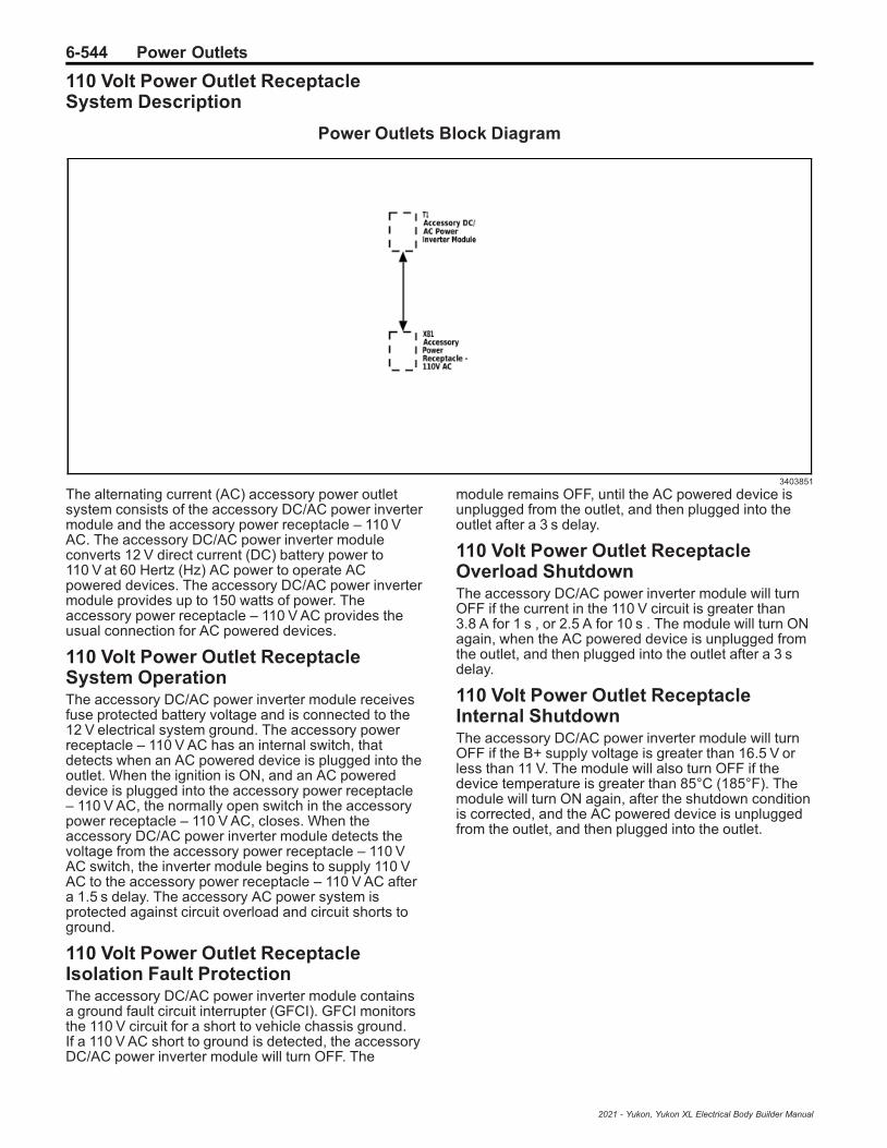
6-544 Power Outlets
110 Volt Power Outlet ReceptacleSystem Description
Power Outlets Block Diagram
3403851
The alternating current (AC) accessory power outletsystem consists of the accessory DC/AC power invertermodule and the accessory power receptacle – 110 VAC. The accessory DC/AC power inverter moduleconverts 12 V direct current (DC) battery power to110 V at 60 Hertz (Hz) AC power to operate ACpowered devices. The accessory DC/AC power invertermodule provides up to 150 watts of power. Theaccessory power receptacle – 110 V AC provides theusual connection for AC powered devices.
110 Volt Power Outlet ReceptacleSystem OperationThe accessory DC/AC power inverter module receivesfuse protected battery voltage and is connected to the12 V electrical system ground. The accessory powerreceptacle – 110 V AC has an internal switch, thatdetects when an AC powered device is plugged into theoutlet. When the ignition is ON, and an AC powereddevice is plugged into the accessory power receptacle– 110 V AC, the normally open switch in the accessorypower receptacle – 110 V AC, closes. When theaccessory DC/AC power inverter module detects thevoltage from the accessory power receptacle – 110 VAC switch, the inverter module begins to supply 110 VAC to the accessory power receptacle – 110 V AC aftera 1.5 s delay. The accessory AC power system isprotected against circuit overload and circuit shorts toground.
110 Volt Power Outlet ReceptacleIsolation Fault ProtectionThe accessory DC/AC power inverter module containsa ground fault circuit interrupter (GFCI). GFCI monitorsthe 110 V circuit for a short to vehicle chassis ground.If a 110 V AC short to ground is detected, the accessoryDC/AC power inverter module will turn OFF. The
module remains OFF, until the AC powered device isunplugged from the outlet, and then plugged into theoutlet after a 3 s delay.
110 Volt Power Outlet ReceptacleOverload ShutdownThe accessory DC/AC power inverter module will turnOFF if the current in the 110 V circuit is greater than3.8 A for 1 s , or 2.5 A for 10 s . The module will turn ONagain, when the AC powered device is unplugged fromthe outlet, and then plugged into the outlet after a 3 sdelay.
110 Volt Power Outlet ReceptacleInternal ShutdownThe accessory DC/AC power inverter module will turnOFF if the B+ supply voltage is greater than 16.5 V orless than 11 V. The module will also turn OFF if thedevice temperature is greater than 85°C (185°F). Themodule will turn ON again, after the shutdown conditionis corrected, and the AC powered device is unpluggedfrom the outlet, and then plugged into the outlet.
2021 - Yukon, Yukon XL Electrical Body Builder Manual

Power Outlets 6-545
230 Volt Power Outlet ReceptacleSystem Description
Power Outlets Block Diagram
3403853
The alternating current (AC) accessory power outletsystem consists of the accessory DC/AC power invertermodule and the accessory power receptacle – 220VAC. The accessory DC/AC power inverter moduleconverts 12 V direct current (DC) battery power to 220–230 V at 50 Hertz (Hz) AC power to operate ACpowered devices. The accessory DC/AC power invertermodule provides up to 150 watts of power. Theaccessory power receptacle – 220V AC provides theusual connection for AC powered devices.
230 Volt Power Outlet ReceptacleSystem OperationThe accessory DC/AC power inverter module receivesfuse protected battery voltage and is connected to the12 V electrical system ground. The accessory powerreceptacle – 220V AC has an internal switch, thatdetects when an AC powered device is plugged into theoutlet. When the ignition is ON, and an AC powereddevice is plugged into the accessory power receptacle– 220V AC, the normally open switch in the accessorypower receptacle – 220V AC, closes. When theaccessory DC/AC power inverter module detects thevoltage from the accessory power receptacle – 220VAC switch, the inverter module begins to supply 220–230 V AC to the accessory power receptacle – 220V ACafter a 1.5 second delay. The accessory AC powersystem is protected against circuit overload and circuitshorts to ground.
230 Volt Power Outlet ReceptacleIsolation Fault ProtectionThe accessory DC/AC power inverter module containsa ground fault circuit interrupter (GFCI). GFCI monitorsthe 230 V circuit for a short to vehicle chassis ground.If a 230 V AC short to ground is detected, the accessoryDC/AC power inverter module will turn OFF. The
module remains OFF, until the AC powered device isunplugged from the outlet, and then plugged into theoutlet after a 3 s delay.
230 Volt Power Outlet ReceptacleOverload ShutdownThe accessory AC/DC power control module will turnOFF if the current in the 230 V circuit is greater than3.8 A for 1 second, or 2.5 A for 10 seconds. The modulewill turn ON again, when the AC powered device isunplugged from the outlet, and then plugged into theoutlet after a 3 second delay.
230 Volt Power Outlet ReceptacleInternal ShutdownThe accessory DC/AC power inverter module will turnOFF if the B+ supply voltage is greater than 16.5 V orless than 11 V. The module will also turn OFF if thedevice temperature is greater than 85°C (185°F). Themodule will turn ON again, after the shutdown conditionis corrected, and the AC powered device is unpluggedfrom the accessory power receptacle – 220V AC, andthen plugged into the accessory power receptacle –220V AC.
USB Receptacle Description andOperation (USS)The vehicle is fitted with USB charge port receptaclesat the rear of the floor console. These USB receptaclesare for charging devices only. The USB receptacles arecontrolled by an ignition operated relay and areoperational when the ignition is turned to either the Onor the Accessories positions.
2021 - Yukon, Yukon XL Electrical Body Builder Manual

6-546 Wiring Systems and Power Management
Wiring Systems and Power Management
Schematic and Routing Diagrams
2021 - Yukon, Yukon XL Electrical Body Builder Manual

Wiring Systems and Power Management 6-547P
ow
er
Dis
trib
uti
on
Sc
he
ma
tic
s(X
50
DB
att
ery
Dis
trib
uti
on
Fu
se
Blo
ck
)
53
71
22
6
2021 - Yukon, Yukon XL Electrical Body Builder Manual
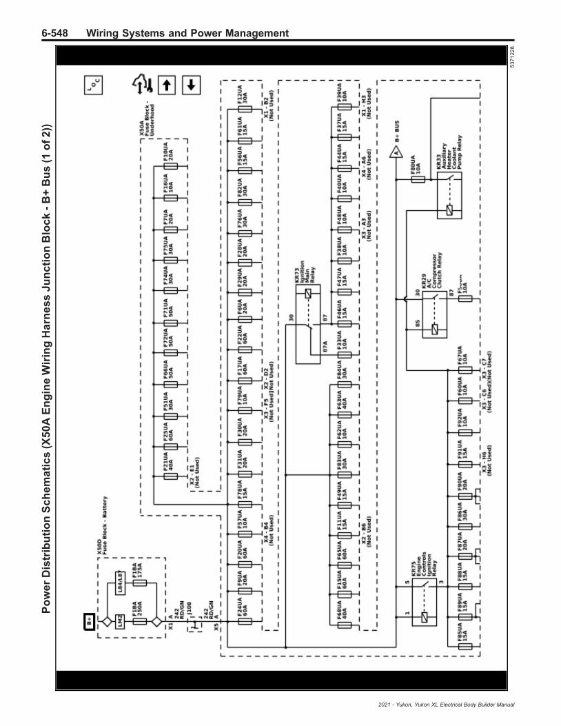
6-548 Wiring Systems and Power ManagementP
ow
er
Dis
trib
uti
on
Sc
he
ma
tic
s(X
50
AE
ng
ine
Wir
ing
Ha
rne
ss
Ju
nc
tio
nB
loc
k-
B+
Bu
s(1
of
2))
53
71
22
8
2021 - Yukon, Yukon XL Electrical Body Builder Manual

Wiring Systems and Power Management 6-549P
ow
er
Dis
trib
uti
on
Sc
he
ma
tic
s(X
50
AE
ng
ine
Wir
ing
Ha
rne
ss
Ju
nc
tio
nB
loc
k-
B+
Bu
s(2
of
2))
53
71
22
9
2021 - Yukon, Yukon XL Electrical Body Builder Manual
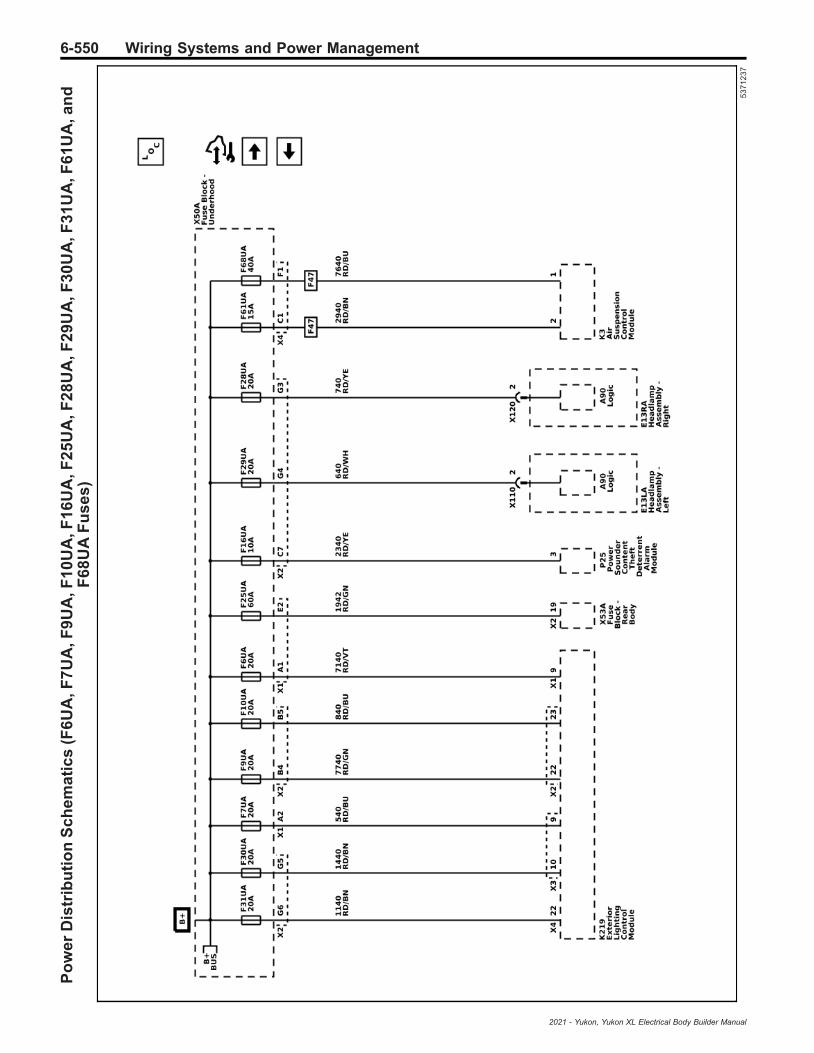
6-550 Wiring Systems and Power ManagementP
ow
er
Dis
trib
uti
on
Sc
he
ma
tic
s(F
6U
A,F
7U
A,F
9U
A,F
10
UA
,F1
6U
A,F
25
UA
,F2
8U
A,F
29
UA
,F3
0U
A,F
31
UA
,F6
1U
A,a
nd
F6
8U
AF
us
es
)
53
71
23
7
2021 - Yukon, Yukon XL Electrical Body Builder Manual

Wiring Systems and Power Management 6-551P
ow
er
Dis
trib
uti
on
Sc
he
ma
tic
s(F
13
UA
,F5
0U
A,F
55
UA
,F5
8U
A,F
69
UA
,an
dF
80
UA
Fu
se
s)
53
71
23
3
2021 - Yukon, Yukon XL Electrical Body Builder Manual

6-552 Wiring Systems and Power ManagementP
ow
er
Dis
trib
uti
on
Sc
he
ma
tic
s(F
14
UA
,F1
5U
A,F
27
UA
,F7
3U
A,a
nd
F8
1U
AF
us
es
)
53
71
23
0
2021 - Yukon, Yukon XL Electrical Body Builder Manual

Wiring Systems and Power Management 6-553P
ow
er
Dis
trib
uti
on
Sc
he
ma
tic
s(F
19
UA
,F2
2U
A,F
49
UA
,F5
6U
A,F
62
UA
,F6
3U
A,F
65
UA
,F7
6U
A,F
82
UA
,F8
3U
A,a
nd
F8
4U
AF
us
es
)
53
71
23
1
2021 - Yukon, Yukon XL Electrical Body Builder Manual

6-554 Wiring Systems and Power ManagementP
ow
er
Dis
trib
uti
on
Sc
he
ma
tic
s(F
20
UA
,F2
4U
A,F
51
UA
,F6
6U
A,F
71
UA
,F7
2U
A,F
74
UA
,F7
5U
A,a
nd
F7
8U
AF
us
es
)
53
71
23
2
2021 - Yukon, Yukon XL Electrical Body Builder Manual

Wiring Systems and Power Management 6-555P
ow
er
Dis
trib
uti
on
Sc
he
ma
tic
s(F
33
UA
,F3
8U
A,F
46
UA
,an
dF
47
UA
Fu
se
s)
53
71
23
8
2021 - Yukon, Yukon XL Electrical Body Builder Manual
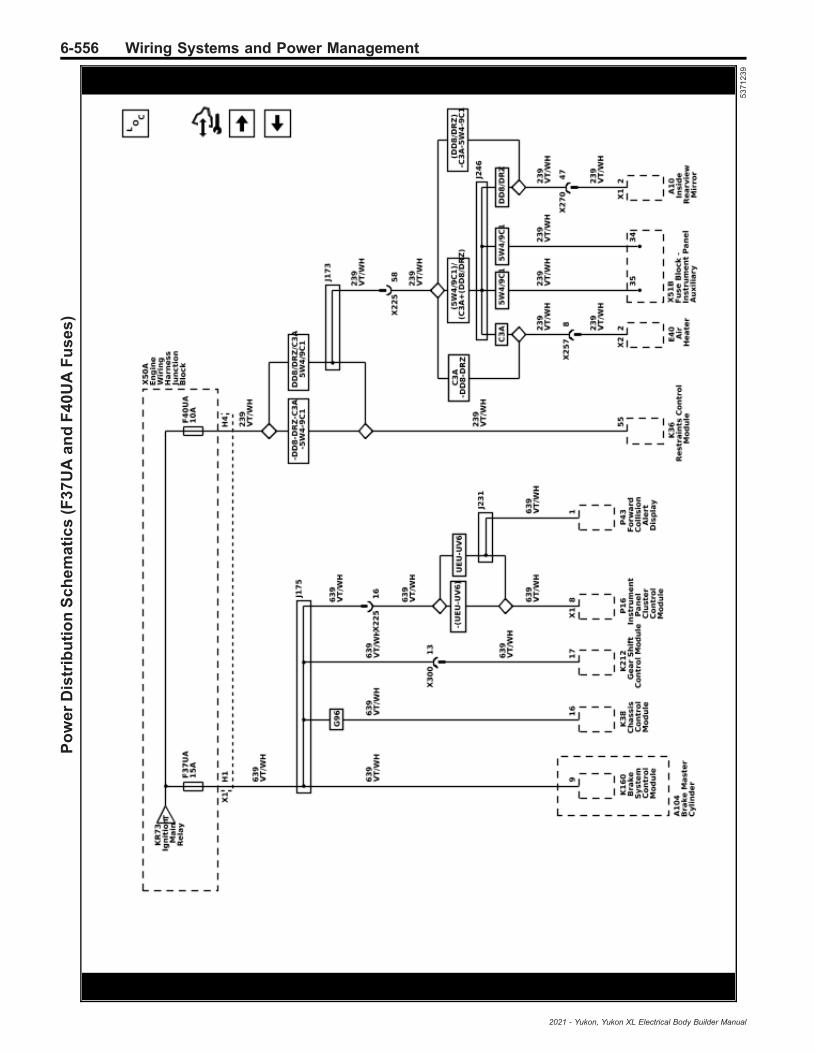
6-556 Wiring Systems and Power ManagementP
ow
er
Dis
trib
uti
on
Sc
he
ma
tic
s(F
37
UA
an
dF
40
UA
Fu
se
s)
53
71
23
9
2021 - Yukon, Yukon XL Electrical Body Builder Manual

Wiring Systems and Power Management 6-557P
ow
er
Dis
trib
uti
on
Sc
he
ma
tic
s(F
41
UA
,F4
5U
A,a
nd
F8
9U
AF
us
es
)
53
71
23
6
2021 - Yukon, Yukon XL Electrical Body Builder Manual

6-558 Wiring Systems and Power ManagementP
ow
er
Dis
trib
uti
on
Sc
he
ma
tic
s(F
85
UA
,F8
6U
A,a
nd
F8
8U
AF
us
es
)
53
71
23
4
2021 - Yukon, Yukon XL Electrical Body Builder Manual

Wiring Systems and Power Management 6-559P
ow
er
Dis
trib
uti
on
Sc
he
ma
tic
s(F
87
UA
,F9
0U
A,a
nd
F9
2U
AF
us
es
)
53
71
23
5
2021 - Yukon, Yukon XL Electrical Body Builder Manual

6-560 Wiring Systems and Power ManagementP
ow
er
Dis
trib
uti
on
Sc
he
ma
tic
s(X
50
UA
Ac
ce
ss
ory
Wir
ing
Ju
nc
tio
nB
loc
k-
Un
de
rho
od
(LM
2))
55
73
26
8
2021 - Yukon, Yukon XL Electrical Body Builder Manual

Wiring Systems and Power Management 6-561P
ow
er
Dis
trib
uti
on
Sc
he
ma
tic
s(X
51
AX
Ins
tru
me
nt
Pa
ne
lWir
ing
Ha
rne
ss
Ju
nc
tio
nB
loc
k-
Au
xil
iary
(5W
4/9
C1
))
53
71
24
2
2021 - Yukon, Yukon XL Electrical Body Builder Manual

6-562 Wiring Systems and Power ManagementP
ow
er
Dis
trib
uti
on
Sc
he
ma
tic
s(X
51
RIn
str
um
en
tP
an
elW
irin
gH
arn
es
sJ
un
cti
on
Blo
ck
-R
igh
t-
B+
Bu
s(1
of
2))
53
71
24
8
2021 - Yukon, Yukon XL Electrical Body Builder Manual

Wiring Systems and Power Management 6-563P
ow
er
Dis
trib
uti
on
Sc
he
ma
tic
s(X
51
RIn
str
um
en
tP
an
elW
irin
gH
arn
es
sJ
un
cti
on
Blo
ck
-R
igh
t-
B+
Bu
s(2
of
2))
53
71
24
9
2021 - Yukon, Yukon XL Electrical Body Builder Manual

6-564 Wiring Systems and Power ManagementP
ow
er
Dis
trib
uti
on
Sc
he
ma
tic
s(C
B1
DR
Cir
cu
itB
rea
ke
r,F
26
DR
,F2
7D
R,F
28
DR
,F3
0D
R,a
nd
F3
2D
RF
us
es
)
53
71
25
1
2021 - Yukon, Yukon XL Electrical Body Builder Manual

Wiring Systems and Power Management 6-565P
ow
er
Dis
trib
uti
on
Sc
he
ma
tic
s(F
1D
R,F
2D
R,F
3D
R,F
6D
R,F
8D
R,F
24
DR
,F3
1D
R,a
nd
F3
3D
RF
us
es
)
53
71
25
0
2021 - Yukon, Yukon XL Electrical Body Builder Manual

6-566 Wiring Systems and Power ManagementP
ow
er
Dis
trib
uti
on
Sc
he
ma
tic
s(F
4D
R,F
5D
R,F
10
DR
,F11
DR
,F1
2D
R,F
14
DR
,an
dF
54
DR
Fu
se
s)
53
71
25
4
2021 - Yukon, Yukon XL Electrical Body Builder Manual

Wiring Systems and Power Management 6-567P
ow
er
Dis
trib
uti
on
Sc
he
ma
tic
s(F
17
DR
,F2
2D
R,F
42
DR
,F4
5D
R,F
46
DR
,an
dF
57
DR
Fu
se
s)
53
71
25
2
2021 - Yukon, Yukon XL Electrical Body Builder Manual

6-568 Wiring Systems and Power ManagementP
ow
er
Dis
trib
uti
on
Sc
he
ma
tic
s(F
18
DR
,F3
4D
R,F
48
DR
,F4
9D
R,a
nd
F5
6D
RF
us
es
)
53
71
25
3
2021 - Yukon, Yukon XL Electrical Body Builder Manual
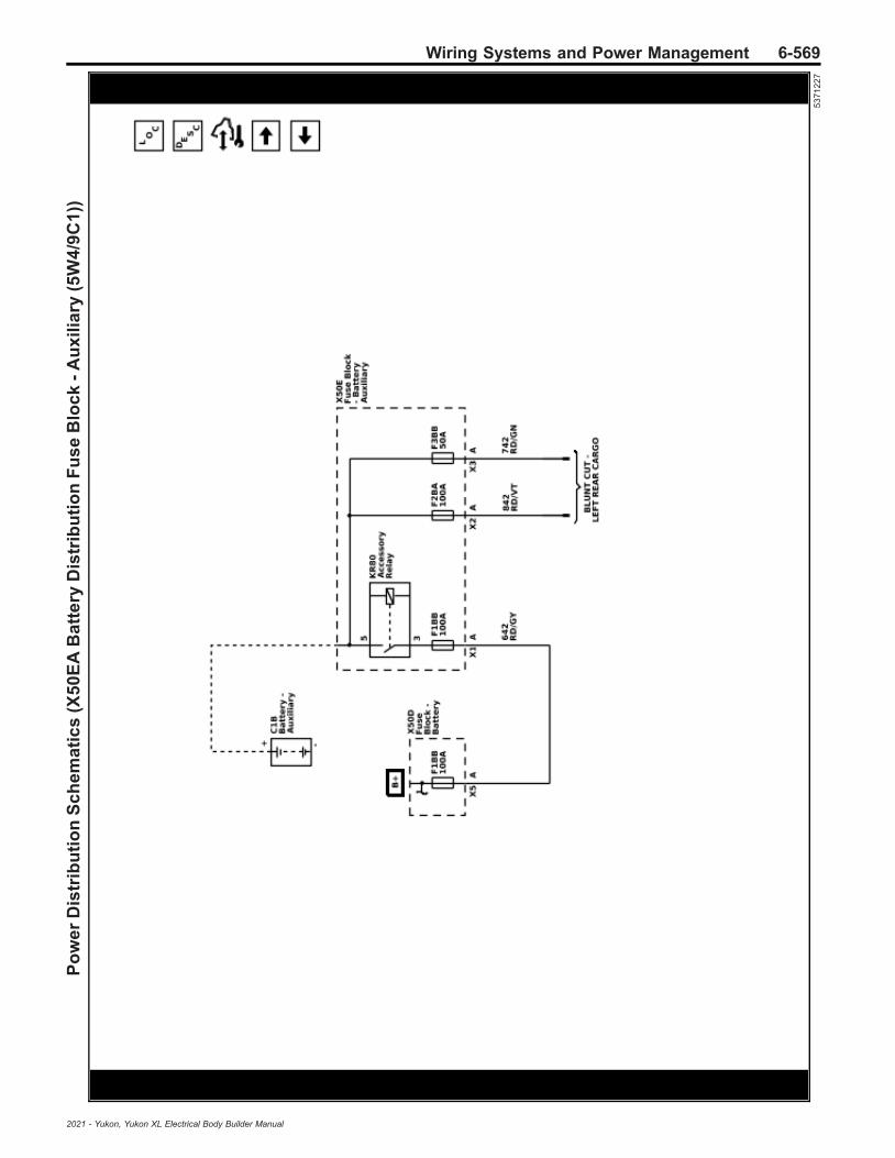
Wiring Systems and Power Management 6-569P
ow
er
Dis
trib
uti
on
Sc
he
ma
tic
s(X
50
EA
Ba
tte
ryD
istr
ibu
tio
nF
us
eB
loc
k-
Au
xil
iary
(5W
4/9
C1
))
53
71
22
7
2021 - Yukon, Yukon XL Electrical Body Builder Manual

6-570 Wiring Systems and Power ManagementP
ow
er
Dis
trib
uti
on
Sc
he
ma
tic
s(X
53
AB
od
yW
irin
gH
arn
es
sJ
un
cti
on
Blo
ck
-R
ea
r-
B+
Bu
s)
53
71
25
5
2021 - Yukon, Yukon XL Electrical Body Builder Manual
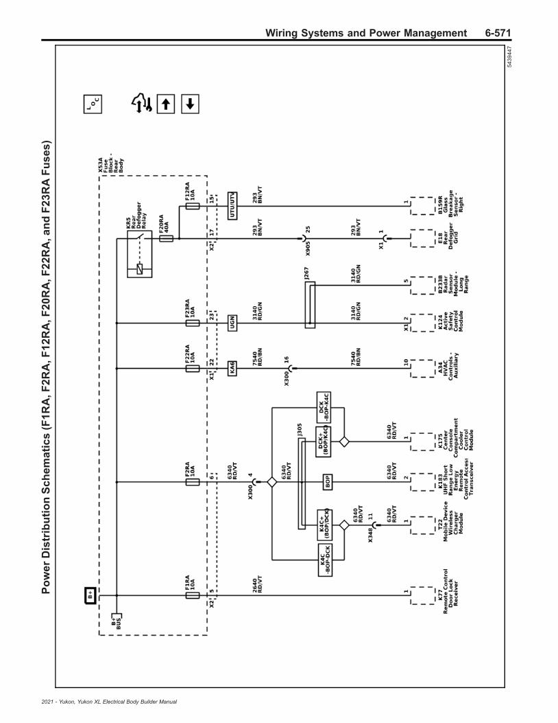
Wiring Systems and Power Management 6-571P
ow
er
Dis
trib
uti
on
Sc
he
ma
tic
s(F
1R
A,F
2R
A,F
12
RA
,F2
0R
A,F
22
RA
,an
dF
23
RA
Fu
se
s)
54
39
44
7
2021 - Yukon, Yukon XL Electrical Body Builder Manual

6-572 Wiring Systems and Power ManagementP
ow
er
Dis
trib
uti
on
Sc
he
ma
tic
s(F
3R
A,F
4R
A,F
17
RA
,F1
8R
A,F
25
RA
,an
dF
26
RA
Fu
se
s)
54
39
45
0
2021 - Yukon, Yukon XL Electrical Body Builder Manual

Wiring Systems and Power Management 6-573P
ow
er
Dis
trib
uti
on
Sc
he
ma
tic
s(F
11R
A,F
28
RA
,F3
4R
A,F
35
RA
,F4
3R
A,F
46
RA
,an
dF
48
RA
Fu
se
s)
54
39
45
2
2021 - Yukon, Yukon XL Electrical Body Builder Manual
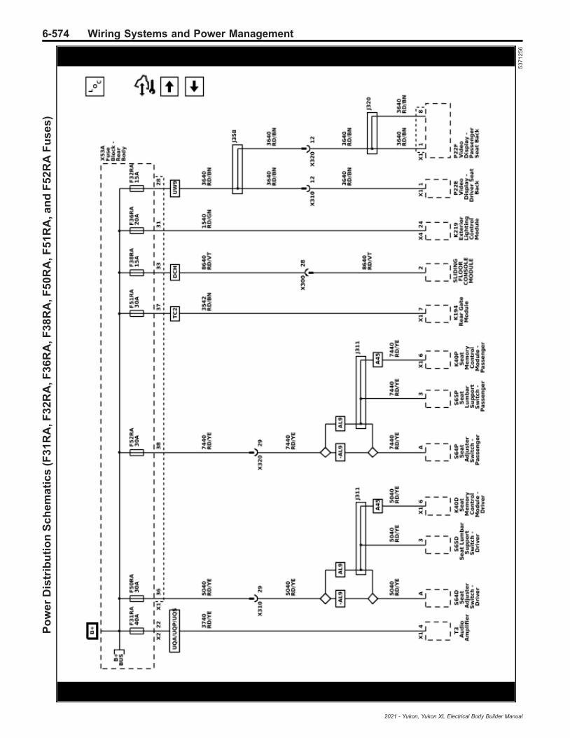
6-574 Wiring Systems and Power ManagementP
ow
er
Dis
trib
uti
on
Sc
he
ma
tic
s(F
31
RA
,F3
2R
A,F
36
RA
,F3
8R
A,F
50
RA
,F5
1R
A,a
nd
F5
2R
AF
us
es
)
53
71
25
6
2021 - Yukon, Yukon XL Electrical Body Builder Manual
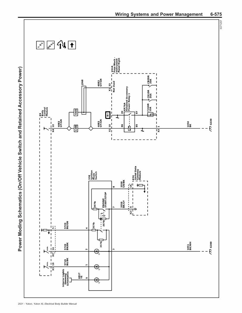
Wiring Systems and Power Management 6-575P
ow
er
Mo
din
gS
ch
em
ati
cs
(On
/Off
Ve
hic
leS
wit
ch
an
dR
eta
ine
dA
cc
es
so
ryP
ow
er)
53
71
25
7
2021 - Yukon, Yukon XL Electrical Body Builder Manual

6-576 Wiring Systems and Power ManagementP
ow
er
Mo
din
gS
ch
em
ati
cs
(Ig
nit
ion
Ma
inR
ela
y)
53
71
25
9
2021 - Yukon, Yukon XL Electrical Body Builder Manual

Wiring Systems and Power Management 6-577G
rou
nd
Dis
trib
uti
on
Sc
he
ma
tic
s(G
10
4)
53
711
29
2021 - Yukon, Yukon XL Electrical Body Builder Manual

6-578 Wiring Systems and Power ManagementG
rou
nd
Dis
trib
uti
on
Sc
he
ma
tic
s(G
110
,G1
25
,an
dG
13
0)
53
711
13
2021 - Yukon, Yukon XL Electrical Body Builder Manual

Wiring Systems and Power Management 6-579G
rou
nd
Dis
trib
uti
on
Sc
he
ma
tic
s(G
117
(L8
4/L
87
))
53
711
15
2021 - Yukon, Yukon XL Electrical Body Builder Manual
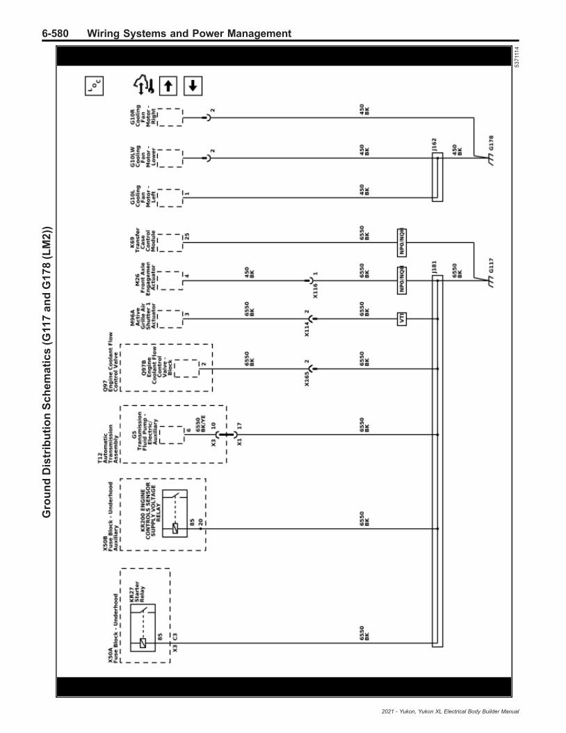
6-580 Wiring Systems and Power ManagementG
rou
nd
Dis
trib
uti
on
Sc
he
ma
tic
s(G
117
an
dG
17
8(L
M2
))
53
711
14
2021 - Yukon, Yukon XL Electrical Body Builder Manual

Wiring Systems and Power Management 6-581G
rou
nd
Dis
trib
uti
on
Sc
he
ma
tic
s(G
12
0)
53
711
16
2021 - Yukon, Yukon XL Electrical Body Builder Manual

6-582 Wiring Systems and Power ManagementG
rou
nd
Dis
trib
uti
on
Sc
he
ma
tic
s(G
13
1,G
13
2,G
13
3,G
13
4,a
nd
G3
95
)
53
711
28
2021 - Yukon, Yukon XL Electrical Body Builder Manual

Wiring Systems and Power Management 6-583G
rou
nd
Dis
trib
uti
on
Sc
he
ma
tic
s(G
17
5a
nd
G1
79
(L8
4/L
87
))
53
711
30
2021 - Yukon, Yukon XL Electrical Body Builder Manual

6-584 Wiring Systems and Power ManagementG
rou
nd
Dis
trib
uti
on
Sc
he
ma
tic
s(G
20
0(-
5W
4-9
C1
)(1
of
2))
53
711
17
2021 - Yukon, Yukon XL Electrical Body Builder Manual

Wiring Systems and Power Management 6-585G
rou
nd
Dis
trib
uti
on
Sc
he
ma
tic
s(G
20
0(-
5W
4-9
C1
)(2
of
2))
55
17
16
3
2021 - Yukon, Yukon XL Electrical Body Builder Manual

6-586 Wiring Systems and Power ManagementG
rou
nd
Dis
trib
uti
on
Sc
he
ma
tic
s(G
20
0(5
W4
/9C
1)
(1o
f2
))
53
711
20
2021 - Yukon, Yukon XL Electrical Body Builder Manual

Wiring Systems and Power Management 6-587G
rou
nd
Dis
trib
uti
on
Sc
he
ma
tic
s(G
20
0(5
W4
/9C
1)
(2o
f2
))
55
17
16
6
2021 - Yukon, Yukon XL Electrical Body Builder Manual

6-588 Wiring Systems and Power ManagementG
rou
nd
Dis
trib
uti
on
Sc
he
ma
tic
s(G
22
0(1
of
2))
53
711
18
2021 - Yukon, Yukon XL Electrical Body Builder Manual

Wiring Systems and Power Management 6-589G
rou
nd
Dis
trib
uti
on
Sc
he
ma
tic
s(G
22
0(2
of
2))
53
711
19
2021 - Yukon, Yukon XL Electrical Body Builder Manual

6-590 Wiring Systems and Power ManagementG
rou
nd
Dis
trib
uti
on
Sc
he
ma
tic
s(G
32
5(1
of
2))
53
711
31
2021 - Yukon, Yukon XL Electrical Body Builder Manual

Wiring Systems and Power Management 6-591G
rou
nd
Dis
trib
uti
on
Sc
he
ma
tic
s(G
32
5(2
of
2))
53
711
26
2021 - Yukon, Yukon XL Electrical Body Builder Manual

6-592 Wiring Systems and Power ManagementG
rou
nd
Dis
trib
uti
on
Sc
he
ma
tic
s(G
32
6a
nd
G4
06
)
53
711
27
2021 - Yukon, Yukon XL Electrical Body Builder Manual

Wiring Systems and Power Management 6-593G
rou
nd
Dis
trib
uti
on
Sc
he
ma
tic
s(G
32
7)
53
711
33
2021 - Yukon, Yukon XL Electrical Body Builder Manual

6-594 Wiring Systems and Power ManagementG
rou
nd
Dis
trib
uti
on
Sc
he
ma
tic
s(G
32
8(1
of
2))
53
711
21
2021 - Yukon, Yukon XL Electrical Body Builder Manual

Wiring Systems and Power Management 6-595G
rou
nd
Dis
trib
uti
on
Sc
he
ma
tic
s(G
32
8(2
of
2))
53
711
24
2021 - Yukon, Yukon XL Electrical Body Builder Manual

6-596 Wiring Systems and Power ManagementG
rou
nd
Dis
trib
uti
on
Sc
he
ma
tic
s(G
33
0(B
3L
/LM
2))
53
711
22
2021 - Yukon, Yukon XL Electrical Body Builder Manual
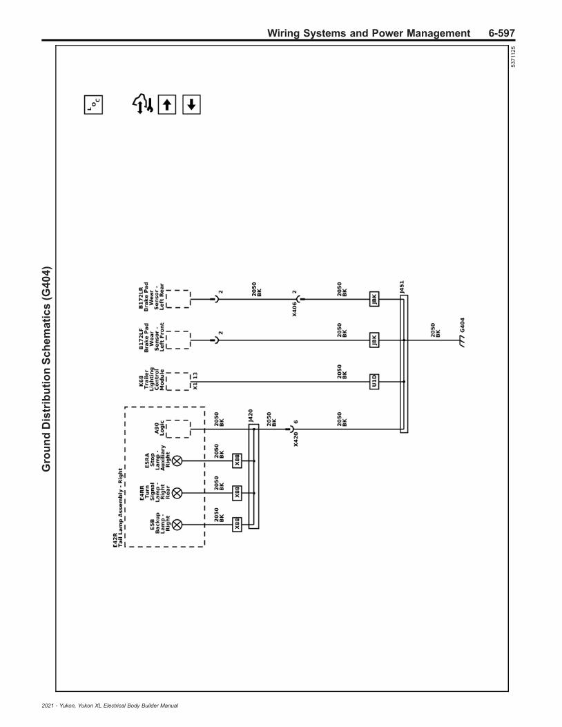
Wiring Systems and Power Management 6-597G
rou
nd
Dis
trib
uti
on
Sc
he
ma
tic
s(G
40
4)
53
711
25
2021 - Yukon, Yukon XL Electrical Body Builder Manual
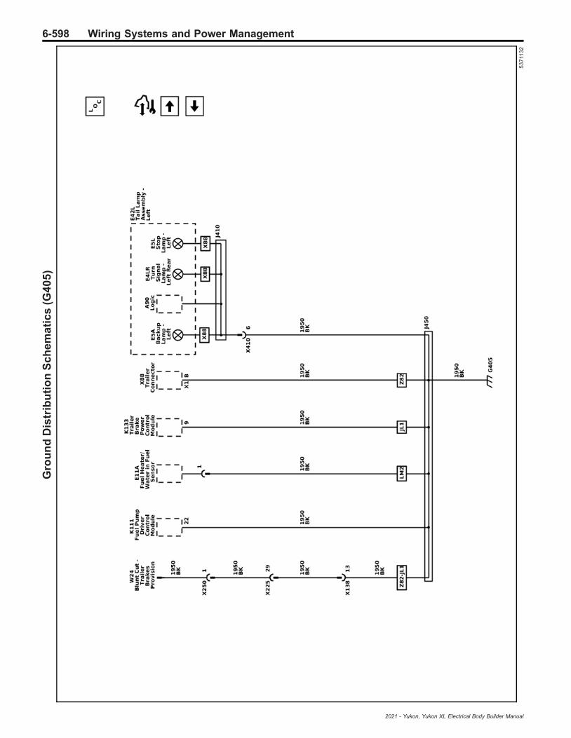
6-598 Wiring Systems and Power ManagementG
rou
nd
Dis
trib
uti
on
Sc
he
ma
tic
s(G
40
5)
53
711
32
2021 - Yukon, Yukon XL Electrical Body Builder Manual

Wiring Systems and Power Management 6-599G
rou
nd
Dis
trib
uti
on
Sc
he
ma
tic
s(G
40
8)
53
711
23
2021 - Yukon, Yukon XL Electrical Body Builder Manual
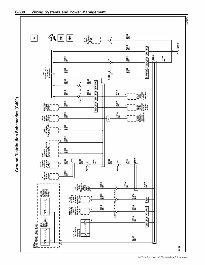
6-600 Wiring Systems and Power ManagementG
rou
nd
Dis
trib
uti
on
Sc
he
ma
tic
s(G
40
9)
53
711
34
2021 - Yukon, Yukon XL Electrical Body Builder Manual

Wiring Systems and Power Management 6-601U
pfi
tte
rP
rov
isio
nS
ch
em
ati
cs
(X5
0E
AB
att
ery
Dis
trib
uti
on
Fu
se
Blo
ck
-A
ux
ilia
ry)
54
30
58
4
2021 - Yukon, Yukon XL Electrical Body Builder Manual

6-602 Wiring Systems and Power ManagementU
pfi
tte
rP
rov
isio
nS
ch
em
ati
cs
(X5
1A
XIn
str
um
en
tP
an
elW
irin
gH
arn
es
sJ
un
cti
on
Blo
ck
-A
ux
ilia
ry)
53
71
32
0
2021 - Yukon, Yukon XL Electrical Body Builder Manual

Wiring Systems and Power Management 6-603U
pfi
tte
rP
rov
isio
nS
ch
em
ati
cs
(Ve
hic
leS
ys
tem
sS
ign
als
(1o
f2
))
55
42
57
4
2021 - Yukon, Yukon XL Electrical Body Builder Manual

6-604 Wiring Systems and Power ManagementU
pfi
tte
rP
rov
isio
nS
ch
em
ati
cs
(Ve
hic
leS
ys
tem
sS
ign
als
(2o
f2
))
54
30
58
5
2021 - Yukon, Yukon XL Electrical Body Builder Manual

Wiring Systems and Power Management 6-605U
pfi
tte
rP
rov
isio
nS
ch
em
ati
cs
(Ste
eri
ng
Wh
ee
lSw
itc
he
s)
54
30
58
6
2021 - Yukon, Yukon XL Electrical Body Builder Manual
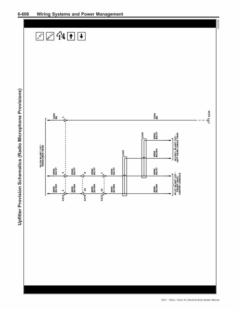
6-606 Wiring Systems and Power ManagementU
pfi
tte
rP
rov
isio
nS
ch
em
ati
cs
(Ra
dio
Mic
rop
ho
ne
Pro
vis
ion
s)
54
30
58
8
2021 - Yukon, Yukon XL Electrical Body Builder Manual

Wiring Systems and Power Management 6-607U
pfi
tte
rP
rov
isio
nS
ch
em
ati
cs
(Gri
lle
La
mp
an
dS
ire
nS
pe
ak
er
Pro
vis
ion
s)
53
71
31
6
2021 - Yukon, Yukon XL Electrical Body Builder Manual
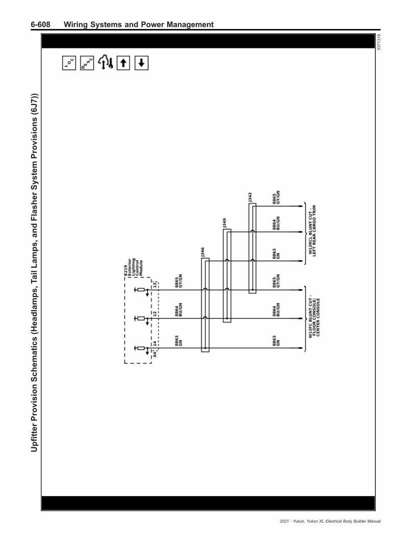
6-608 Wiring Systems and Power ManagementU
pfi
tte
rP
rov
isio
nS
ch
em
ati
cs
(He
ad
lam
ps
,Ta
ilL
am
ps
,an
dF
las
he
rS
ys
tem
Pro
vis
ion
s(6
J7
))
53
71
31
8
2021 - Yukon, Yukon XL Electrical Body Builder Manual
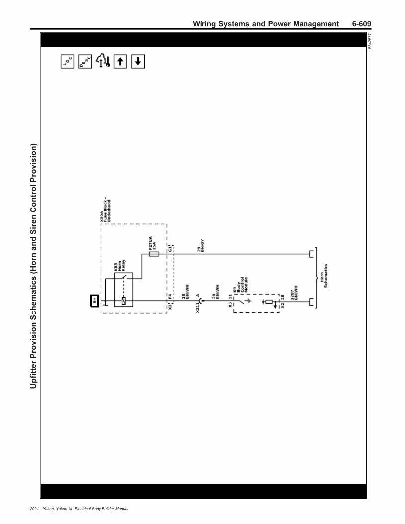
Wiring Systems and Power Management 6-609U
pfi
tte
rP
rov
isio
nS
ch
em
ati
cs
(Ho
rna
nd
Sir
en
Co
ntr
olP
rov
isio
n)
55
42
57
7
2021 - Yukon, Yukon XL Electrical Body Builder Manual
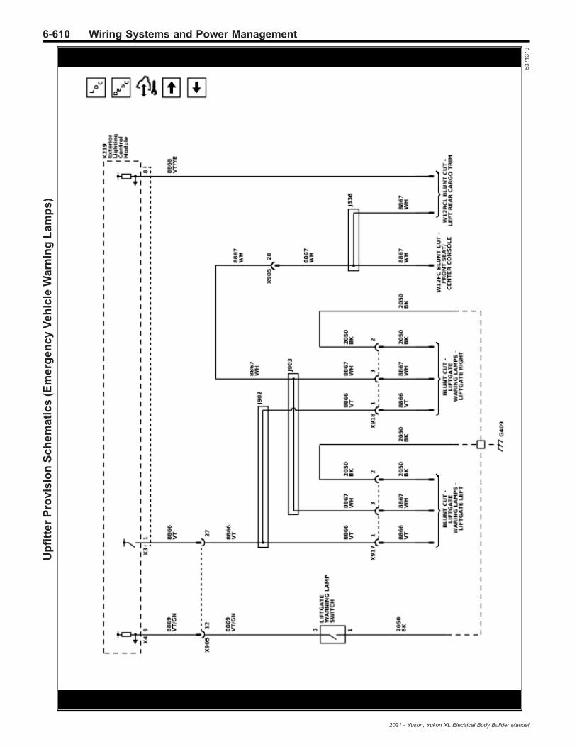
6-610 Wiring Systems and Power ManagementU
pfi
tte
rP
rov
isio
nS
ch
em
ati
cs
(Em
erg
en
cy
Ve
hic
leW
arn
ing
La
mp
s)
53
71
31
9
2021 - Yukon, Yukon XL Electrical Body Builder Manual
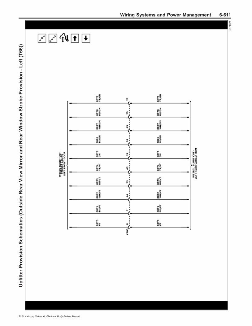
Wiring Systems and Power Management 6-611U
pfi
tte
rP
rov
isio
nS
ch
em
ati
cs
(Ou
tsid
eR
ea
rV
iew
Mir
ror
an
dR
ea
rW
ind
ow
Str
ob
eP
rov
isio
n-
Le
ft(T
66
))
53
71
32
1
2021 - Yukon, Yukon XL Electrical Body Builder Manual

6-612 Wiring Systems and Power ManagementU
pfi
tte
rP
rov
isio
nS
ch
em
ati
cs
(Ou
tsid
eR
ea
rV
iew
Mir
ror
an
dR
ea
rW
ind
ow
Str
ob
eP
rov
isio
ns
-R
igh
t(T
66
))
53
71
32
2
2021 - Yukon, Yukon XL Electrical Body Builder Manual
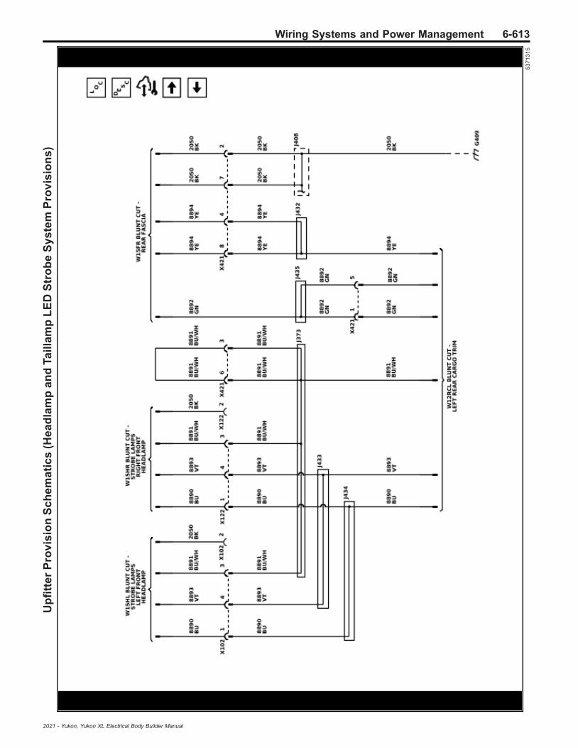
Wiring Systems and Power Management 6-613U
pfi
tte
rP
rov
isio
nS
ch
em
ati
cs
(He
ad
lam
pa
nd
Tail
lam
pL
ED
Str
ob
eS
ys
tem
Pro
vis
ion
s)
53
71
31
5
2021 - Yukon, Yukon XL Electrical Body Builder Manual

6-614 Wiring Systems and Power ManagementU
pfi
tte
rP
rov
isio
nS
ch
em
ati
cs
(LE
DS
po
tL
am
ps
)
54
30
58
7
2021 - Yukon, Yukon XL Electrical Body Builder Manual

Wiring Systems and Power Management 6-615U
pfi
tte
rP
rov
isio
nS
ch
em
ati
cs
(Em
erg
en
cy
Ve
hic
leR
ea
din
gL
am
ps
)
53
71
31
7
2021 - Yukon, Yukon XL Electrical Body Builder Manual

6-616 Wiring Systems and Power Management
Component Locator
Master Electrical Component List
Code Name Option Location Locator ViewConnector End
View
A3L Sunshade - Left —In the passenger compart-ment, at the front of theheadliner, left side
— —
A3R Sunshade - Right —In the passenger compart-ment, at the front of theheadliner, right side
— —
A5 Driver InformationCenter — — — —
A7Fuel Pump andLevel Sensor As-sembly
—Under the vehicle, left side,in front of rear axle,mounted in the fuel tank
—A7 Fuel Pump and
Level Sensor Assem-bly
A9A Outside RearviewMirror - Driver — Outside the vehicle, at the
front of the driver door
• Front of VehicleComponents(X88)
• Front of VehicleComponents(Z88)
—
A9BOutside RearviewMirror - Passen-ger
— Outside the vehicle, at thefront of the passenger door
• Front of VehicleComponents(X88)
• Front of VehicleComponents(Z88)
—
A10 Inside RearviewMirror —
In the passenger compart-ment, at the top center ofthe windshield
— A10 Inside RearviewMirror
A11 Radio —
In the passenger compart-ment, right front, belowpassenger a-pillar, betweenthe instrument panel andbulkhead
Instrument PanelComponents - Right
• A11 Radio X1
• A11 Radio X2
• A11 Radio X3
A16 Transfer CaseMotor NP0/NQH
Under the vehicle, mountedto the rear of the transfercase
Transfer Case Com-ponents (NP0/NQH)
A16 Transfer CaseMotor (NP0/NQH)
A22 Radio Controls UIR
In the passenger compart-ment, at the center of theInstrument Panel, part ofthe Info Display Module
—
• A22 Radio Con-trols X2 (UQF)
• A22 Radio Con-trols X3
• A22 Radio Con-trols X6
A23C Liftgate Latch As-sembly — — —
• A23C LiftgateLatch Assembly(TB4)
• A23C LiftgateLatch Assembly(TC2)
A23D Door Latch As-sembly - Driver — In the driver door, at the
rear center — A23D Door Latch As-sembly - Driver
A23LR Door Latch As-sembly - Left Rear — In the left rear door, at the
rear center — A23LR Door LatchAssembly - Left Rear
A23PDoor Latch As-sembly - Passen-ger
— In the passenger door, atthe rear center — A23P Door Latch As-
sembly - Passenger
A23RRDoor Latch As-sembly - RightRear
— In the right rear door, at therear center —
A23RR Door LatchAssembly - Right
Rear
2021 - Yukon, Yukon XL Electrical Body Builder Manual

Wiring Systems and Power Management 6-617
Master Electrical Component List (cont'd)
Code Name Option Location Locator ViewConnector End
View
A24DDoor Handle As-sembly - DriverExterior
— Outside of the vehicle, atthe rear of the driver door —
A24D Door HandleAssembly - Driver Ex-
terior
A24LRDoor Handle As-sembly - Left RearExterior
— Outside of the vehicle, atthe rear of the left rear door —
A24LR Door HandleAssembly - Left Rear
Exterior
A24PDoor Handle As-sembly - Passen-ger Exterior
—Outside of the vehicle, atthe rear of the passengerdoor
—A24P Door Handle
Assembly - Passen-ger Exterior
A24RRDoor Handle As-sembly - RightRear Exterior
—Outside of the vehicle, atthe rear of the right reardoor
—A24RR Door Handle
Assembly - RightRear Exterior
A26 HVAC Controls IOR
In the passenger compart-ment, at the center of theinstrument panel, beneathP17 Info Display Module
Instrument PanelComponents - Right A26 HVAC Controls
A34 HVAC Controls -Auxiliary — — —
• A34 HVAC Con-trols - Auxiliary(BOP)
• A34 HVAC Con-trols - Auxiliary(C69)
A38Reductant Pumpand Sensor As-sembly
LM2
Under the vehicle, mountedto the outboard side of theframe, below the passen-ger side of the cab
— —
A98Front OverheadConsole Assem-bly
—In the passenger compart-ment, front center, mountedto headliner
— A98 Front OverheadConsole Assembly
A104 Brake Master Cyl-inder —
In the engine compartment,left rear, bolted to the bulk-head
— —
B1 A/C RefrigerantPressure Sensor — — — B1 A/C Refrigerant
Pressure Sensor
B5LFWheel SpeedSensor - LeftFront
—Outside the vehicle, part ofthe left front wheel hub as-sembly
— B5LF Wheel SpeedSensor - Left Front
B5LR Wheel SpeedSensor - Left Rear —
Outside the vehicle,mounted to the outboardend of the left axle tube
— B5LR Wheel SpeedSensor - Left Rear
B5RFWheel SpeedSensor - RightFront
—Outside the vehicle, part ofthe right front wheel hubassembly
Engine Components- Right Front (L84/
L87)
B5RF Wheel SpeedSensor - Right Front
B5RRWheel SpeedSensor - RightRear
—Outside the vehicle,mounted to the outboardend of the right axle tube
— B5RR Wheel SpeedSensor - Right Rear
B7CAir TemperatureSensor - DuctLower Auxiliary
— — — —
B7GAir TemperatureSensor - DuctUpper Auxiliary
— — — —
B9 Ambient Air Tem-perature Sensor —
Outside of the vehicle, atthe bottom of A9B OutsideRearview Mirror - Passen-ger
— —
B10B Ambient Light/Sunload Sensor —
In the passenger compart-ment, at the top middle ofthe instrument panel
Instrument PanelComponents - Right
B10B Ambient Light/Sunload Sensor
2021 - Yukon, Yukon XL Electrical Body Builder Manual
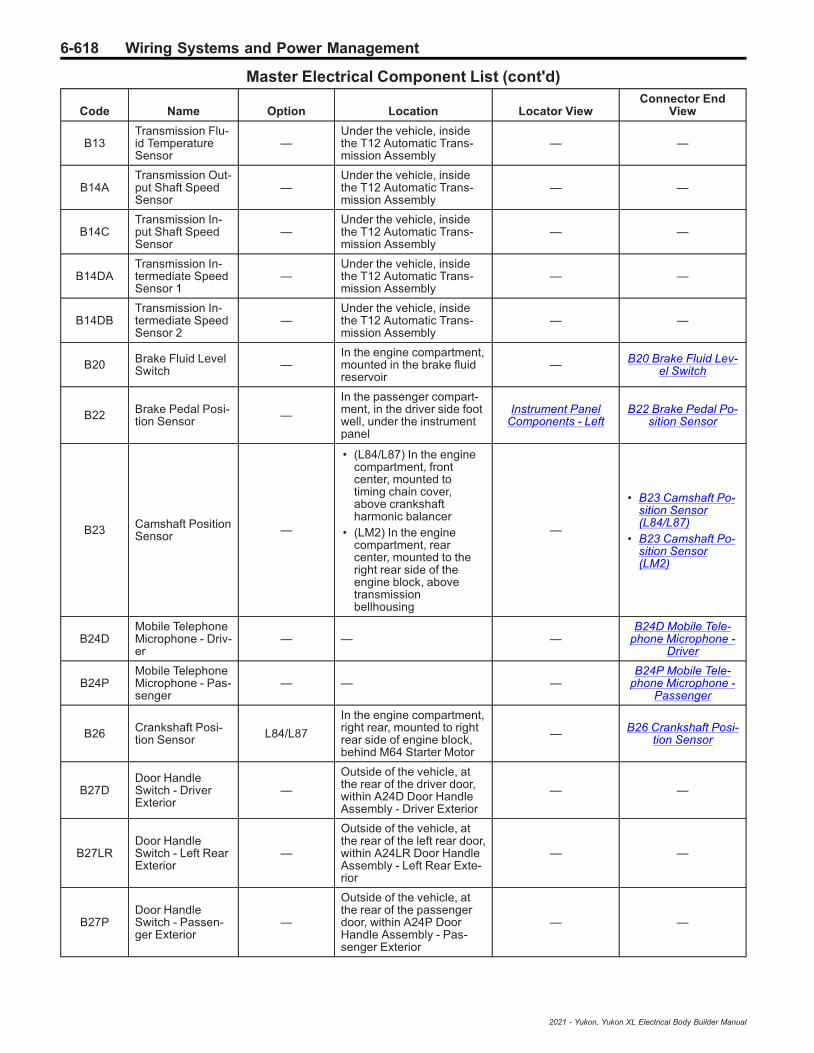
6-618 Wiring Systems and Power Management
Master Electrical Component List (cont'd)
Code Name Option Location Locator ViewConnector End
View
B13Transmission Flu-id TemperatureSensor
—Under the vehicle, insidethe T12 Automatic Trans-mission Assembly
— —
B14ATransmission Out-put Shaft SpeedSensor
—Under the vehicle, insidethe T12 Automatic Trans-mission Assembly
— —
B14CTransmission In-put Shaft SpeedSensor
—Under the vehicle, insidethe T12 Automatic Trans-mission Assembly
— —
B14DATransmission In-termediate SpeedSensor 1
—Under the vehicle, insidethe T12 Automatic Trans-mission Assembly
— —
B14DBTransmission In-termediate SpeedSensor 2
—Under the vehicle, insidethe T12 Automatic Trans-mission Assembly
— —
B20 Brake Fluid LevelSwitch —
In the engine compartment,mounted in the brake fluidreservoir
— B20 Brake Fluid Lev-el Switch
B22 Brake Pedal Posi-tion Sensor —
In the passenger compart-ment, in the driver side footwell, under the instrumentpanel
Instrument PanelComponents - Left
B22 Brake Pedal Po-sition Sensor
B23 Camshaft PositionSensor —
• (L84/L87) In the enginecompartment, frontcenter, mounted totiming chain cover,above crankshaftharmonic balancer
• (LM2) In the enginecompartment, rearcenter, mounted to theright rear side of theengine block, abovetransmissionbellhousing
—
• B23 Camshaft Po-sition Sensor(L84/L87)
• B23 Camshaft Po-sition Sensor(LM2)
B24DMobile TelephoneMicrophone - Driv-er
— — —B24D Mobile Tele-
phone Microphone -Driver
B24PMobile TelephoneMicrophone - Pas-senger
— — —B24P Mobile Tele-
phone Microphone -Passenger
B26 Crankshaft Posi-tion Sensor L84/L87
In the engine compartment,right rear, mounted to rightrear side of engine block,behind M64 Starter Motor
— B26 Crankshaft Posi-tion Sensor
B27DDoor HandleSwitch - DriverExterior
—
Outside of the vehicle, atthe rear of the driver door,within A24D Door HandleAssembly - Driver Exterior
— —
B27LRDoor HandleSwitch - Left RearExterior
—
Outside of the vehicle, atthe rear of the left rear door,within A24LR Door HandleAssembly - Left Rear Exte-rior
— —
B27PDoor HandleSwitch - Passen-ger Exterior
—
Outside of the vehicle, atthe rear of the passengerdoor, within A24P DoorHandle Assembly - Pas-senger Exterior
— —
2021 - Yukon, Yukon XL Electrical Body Builder Manual
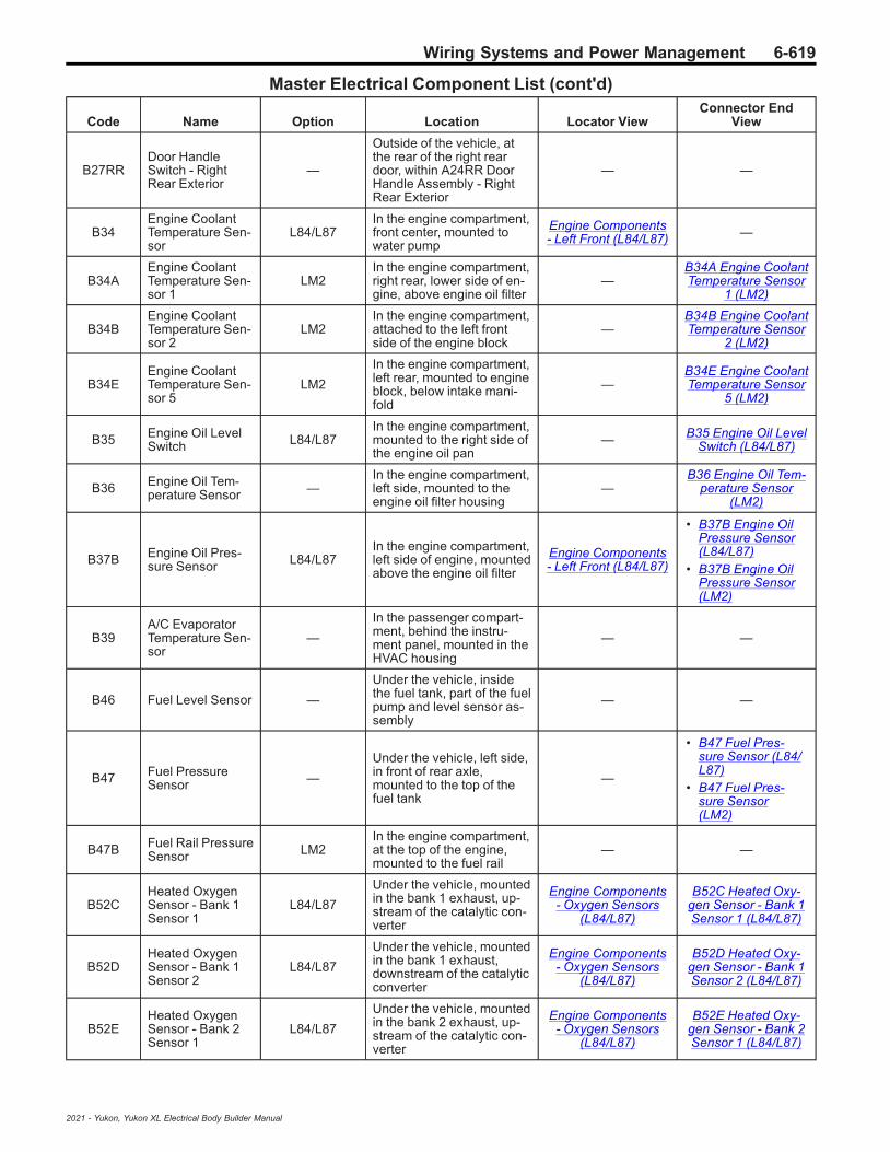
Wiring Systems and Power Management 6-619
Master Electrical Component List (cont'd)
Code Name Option Location Locator ViewConnector End
View
B27RRDoor HandleSwitch - RightRear Exterior
—
Outside of the vehicle, atthe rear of the right reardoor, within A24RR DoorHandle Assembly - RightRear Exterior
— —
B34Engine CoolantTemperature Sen-sor
L84/L87In the engine compartment,front center, mounted towater pump
Engine Components- Left Front (L84/L87) —
B34AEngine CoolantTemperature Sen-sor 1
LM2In the engine compartment,right rear, lower side of en-gine, above engine oil filter
—B34A Engine CoolantTemperature Sensor
1 (LM2)
B34BEngine CoolantTemperature Sen-sor 2
LM2In the engine compartment,attached to the left frontside of the engine block
—B34B Engine CoolantTemperature Sensor
2 (LM2)
B34EEngine CoolantTemperature Sen-sor 5
LM2
In the engine compartment,left rear, mounted to engineblock, below intake mani-fold
—B34E Engine CoolantTemperature Sensor
5 (LM2)
B35 Engine Oil LevelSwitch L84/L87
In the engine compartment,mounted to the right side ofthe engine oil pan
— B35 Engine Oil LevelSwitch (L84/L87)
B36 Engine Oil Tem-perature Sensor —
In the engine compartment,left side, mounted to theengine oil filter housing
—B36 Engine Oil Tem-
perature Sensor(LM2)
B37B Engine Oil Pres-sure Sensor L84/L87
In the engine compartment,left side of engine, mountedabove the engine oil filter
Engine Components- Left Front (L84/L87)
• B37B Engine OilPressure Sensor(L84/L87)
• B37B Engine OilPressure Sensor(LM2)
B39A/C EvaporatorTemperature Sen-sor
—
In the passenger compart-ment, behind the instru-ment panel, mounted in theHVAC housing
— —
B46 Fuel Level Sensor —
Under the vehicle, insidethe fuel tank, part of the fuelpump and level sensor as-sembly
— —
B47 Fuel PressureSensor —
Under the vehicle, left side,in front of rear axle,mounted to the top of thefuel tank
—
• B47 Fuel Pres-sure Sensor (L84/L87)
• B47 Fuel Pres-sure Sensor(LM2)
B47B Fuel Rail PressureSensor LM2
In the engine compartment,at the top of the engine,mounted to the fuel rail
— —
B52CHeated OxygenSensor - Bank 1Sensor 1
L84/L87
Under the vehicle, mountedin the bank 1 exhaust, up-stream of the catalytic con-verter
Engine Components- Oxygen Sensors
(L84/L87)
B52C Heated Oxy-gen Sensor - Bank 1Sensor 1 (L84/L87)
B52DHeated OxygenSensor - Bank 1Sensor 2
L84/L87
Under the vehicle, mountedin the bank 1 exhaust,downstream of the catalyticconverter
Engine Components- Oxygen Sensors
(L84/L87)
B52D Heated Oxy-gen Sensor - Bank 1Sensor 2 (L84/L87)
B52EHeated OxygenSensor - Bank 2Sensor 1
L84/L87
Under the vehicle, mountedin the bank 2 exhaust, up-stream of the catalytic con-verter
Engine Components- Oxygen Sensors
(L84/L87)
B52E Heated Oxy-gen Sensor - Bank 2Sensor 1 (L84/L87)
2021 - Yukon, Yukon XL Electrical Body Builder Manual

6-620 Wiring Systems and Power Management
Master Electrical Component List (cont'd)
Code Name Option Location Locator ViewConnector End
View
B52FHeated OxygenSensor - Bank 2Sensor 2
L84/L87
Under the vehicle, mountedin the bank 2 exhaust,downstream of the catalyticconverter
Engine Components- Oxygen Sensors
(L84/L87)
B52F Heated OxygenSensor - Bank 2 Sen-
sor 2 (L84/L87)
B55 Engine HoodSwitch —
Outside the vehicle, at thefront center of the hood,part of the hood latch as-sembly
— B55 Engine HoodSwitch
B59L Front Impact Sen-sor - Left —
In the engine compartment,left front, at the bottom ofthe radiator core support
— B59L Front ImpactSensor - Left
B59R Front Impact Sen-sor - Right —
In the engine compartment,right front, at the bottom ofthe radiator core support
— B59R Front ImpactSensor - Right
B61PSeat Belt TensionSensor - Passen-ger
—
In the passenger compart-ment, at the base of the B-pillar, part of the passengerseat belt retractor preten-sioner
—B61P Seat Belt Ten-sion Sensor - Pas-
senger
B63LF Side Impact Sen-sor - Left Front —
At the left front of the pas-senger compartment,mounted inside the leftfront door, at the bottom
— B63LF Side ImpactSensor - Left Front
B63LR Side Impact Sen-sor - Left Rear —
At the left rear of the pas-senger compartment,mounted inside the left reardoor, at the bottom
— B63LR Side ImpactSensor - Left Rear
B63RF Side Impact Sen-sor - Right Front —
At the right front of the pas-senger compartment,mounted inside the rightfront door, at the bottom
— B63RF Side ImpactSensor - Right Front
B63RR Side Impact Sen-sor - Right Rear —
At the right rear of the pas-senger compartment,mounted inside the rightrear door, at the bottom
— B63RR Side ImpactSensor - Right Rear
B65
Intake ManifoldPressure and AirTemperature Sen-sor
LM2
In the engine compartment,left side of engine, mountedto the intake manifold, nearQ18A Fuel Pressure Regu-lator 1
—
B65 Intake ManifoldPressure and Air
Temperature Sensor(LM2)
B68A Knock Sensor 1 L84/L87
In the engine compartment,left side of engine, mountedto the rear of the engineblock, below exhaust mani-fold
Engine Components- Left Front (L84/L87)
B68A Knock Sensor1 (L84/L87)
B68B Knock Sensor 2 L84/L87
In the engine compartment,right rear, mounted to rightrear side of engine block,behind M64 Starter Motor
— B68B Knock Sensor2 (L84/L87)
B70 Liftgate CloseSwitch — — — B70 Liftgate Close
Switch (TC2)
B71L Liftgate ObjectSensor - Left — — — B71L Liftgate Object
Sensor - Left (TC2)
B71R Liftgate ObjectSensor - Right — — — B71R Liftgate Object
Sensor - Right (TC2)
B74 Manifold AbsolutePressure Sensor L84/L87
In the engine compartment,front center, mounted to in-take manifold, to the left ofQ38 Throttle Body
Engine Components- Left Front (L84/L87)
B74 Manifold Abso-lute Pressure Sensor
(L84/L87)
2021 - Yukon, Yukon XL Electrical Body Builder Manual

Wiring Systems and Power Management 6-621
Master Electrical Component List (cont'd)
Code Name Option Location Locator ViewConnector End
View
B75C Multifunction In-take Air Sensor —
Right front of the enginecompartment, mounted inthe air cleaner assembly
Engine CompartmentComponents - Top
• B75C Multifunc-tion Intake AirSensor (L84/L87)
• B75C Multifunc-tion Intake AirSensor (LM2)
B77LF
Radio VolumeCompensator In-terior Noise Micro-phone - Left Front
— — — —
B80 Park Brake Switch —In the passenger compart-ment, at the left lower sideof the instrument panel
Instrument PanelComponents - Left
B80 Park BrakeSwitch
B87 Rearview Camera UVB/UVC/UV2/UVI
Outside the vehicle, at thetop middle of the tailgate,mounted in the tailgatehandle
— —
B88CL Seat Belt Switch -3rd Row Left — — — —
B88CR Seat Belt Switch -3rd Row Right — — — —
B88D Seat Belt Switch -Driver —
In the passenger compart-ment, at the inboard side ofthe driver seat, part of theseat belt buckle
— —
B88P Seat Belt Switch -Passenger —
In the passenger compart-ment, at the inboard side ofthe passenger seat, part ofthe seat belt buckle
— —
B96Cylinder HeadTemperature Sen-sor
LM2
In the engine compartment,center, above the drive belt,near inline connector X160Engine Harness to Fuel In-jector Harness
—B96 Cylinder Head
Temperature Sensor(LM2)
B101 Immobilizer An-tenna — — — B101 Immobilizer An-
tenna
B107 Accelerator PedalPosition Sensor —
In the passenger compart-ment, in the driver side footwell, under the instrumentpanel
Instrument PanelComponents - Left
B107 AcceleratorPedal Position Sen-
sor
B110 Battery SensorModule KL9
In the engine compartment,right side, near C1 Batterynegative cable
— B110 Battery SensorModule
B118BWindshield Wash-er Fluid LevelSwitch
—
In the engine compartment,attached to the washer fluidreservoir, behind E13LAHeadlamp Assembly - Left
—B118B WindshieldWasher Fluid Level
Switch
B130AH
Exhaust Gas Re-circulation Tem-perature Sensor 1- High Pressure
LM2
In the engine compartment,right side, beneath M103Turbocharger Vane Posi-tion Actuator
—
B130AH ExhaustGas Recirculation
Temperature Sensor1 - High Pressure
(LM2)
B130BH
Exhaust Gas Re-circulation Tem-perature Sensor 2- High Pressure
LM2 In the engine compartment,left rear side of engine —
B130BH ExhaustGas Recirculation
Temperature Sensor2 - High Pressure
(LM2)
2021 - Yukon, Yukon XL Electrical Body Builder Manual

6-622 Wiring Systems and Power Management
Master Electrical Component List (cont'd)
Code Name Option Location Locator ViewConnector End
View
B131A Exhaust Tempera-ture Sensor 1 LM2
In the engine compartment,right front, mounted in ex-haust, in front of B154 Die-sel Particulate FilterExhaust Differential Pres-sure Sensor
— —
B131B Exhaust Tempera-ture Sensor 2 LM2
In the engine compartment,right front, mounted in ex-haust, near Q61 ReductantInjector
— —
B131C Exhaust Tempera-ture Sensor 3 LM2
In the engine compartment,mounted in exhaust, nearM64 Starter Motor
— —
B136 Exhaust Particu-late Matter Sensor LM2
On the underbody,mounted to the inboardside of the right frame rail,forward of the right rearshock
—B136 Exhaust Partic-ulate Matter Sensor
(LM2)
B137BPower SteeringShaft Torque/Po-sition Sensor
—
Under the vehicle, in theengine compartment, leftfront, behind the left side ofthe power steering rack.
— —
B139
Transfer Case2WD/4WD Actua-tor Position Sen-sor
NP0/NQH Under the vehicle, mountedto the transfer case — —
B150 Fuel Tank Pres-sure Sensor L84/L87 Under the vehicle, at the
top of the fuel tank — B150 Fuel Tank Pres-sure Sensor
B152LFSuspension Posi-tion Sensor - LeftFront
Z45 Under the vehicle, at theleft front corner of the frame —
B152LF SuspensionPosition Sensor - Left
Front (F47)
B152LRSuspension Posi-tion Sensor - LeftRear
— — — —
B152RFSuspension Posi-tion Sensor -Right Front
Z45Under the vehicle, at theright front corner of theframe
Engine Components- Right Front (L84/
L87)—
B152RRSuspension Posi-tion Sensor -Right Rear
— — — —
B153D Seat Belt Buckle -Driver —
In the passenger compart-ment, at the inboard side ofthe drive seat
— —
B153P Seat Belt Buckle -Passenger —
In the passenger compart-ment, at the inboard side ofthe passenger seat
— —
B154
Diesel ParticulateFilter Exhaust Dif-ferential PressureSensor
LM2
In the engine compartment,right side, mounted in theexhaust, in front of M103Turbocharger Vane Posi-tion Actuator
—
B154 Diesel Particu-late Filter Exhaust
Differential PressureSensor (LM2)
B159L Glass BreakageSensor - Left — — —
B159L Glass Break-age Sensor - Left
(UTJ)
B159R Glass BreakageSensor - Right — — —
B159R Glass Break-age Sensor - Right
(UTJ)
B161LF
Vertical Suspen-sion AccelerationSensor - LeftFront
— — —
B161LF Vertical Sus-pension AccelerationSensor - Left Front
(Z95)
2021 - Yukon, Yukon XL Electrical Body Builder Manual

Wiring Systems and Power Management 6-623
Master Electrical Component List (cont'd)
Code Name Option Location Locator ViewConnector End
View
B161RF
Vertical Suspen-sion AccelerationSensor - RightFront
— —Engine Components- Right Front (L84/
L87)
B161RF Vertical Sus-pension AccelerationSensor - Right Front
(Z95)
B172LFBrake Pad WearSensor - LeftFront
— Under the vehicle, at leftfront caliper —
B172LF Brake PadWear Sensor - Left
Front (JBK)
B172LR Brake Pad WearSensor - Left Rear — Under the vehicle, at left
rear caliper —B172LR Brake PadWear Sensor - Left
Rear (JBK)
B174G Frontview Camera- Grille UVS At the front of the vehicle,
front center, near the grille
• Front FasciaComponents
• Front of VehicleComponents(X88)
—
B174W Frontview Camera- Windshield ASV
In the passenger compart-ment, at the top middle ofthe windshield
—B174W Frontview
Camera - Windshield(UEU/UHY/UGN)
B193ACharge Air CoolerInlet TemperatureSensor
LM2In the engine compartment,mounted to the left side ofthe air charge cooler
—B193A Charge Air
Cooler Inlet Tempera-ture Sensor (LM2)
B193BCharge Air CoolerOutlet Tempera-ture Sensor
LM2In the engine compartment,mounted to the front of theair charge cooler
—
B193B Charge AirCooler Outlet Tem-
perature Sensor(LM2)
B194 Reductant Pres-sure Sensor LM2
Under the vehicle, rightside, forward of rear axle,within reductant tank, partof A38 Reductant Pumpand Sensor Assembly
— —
B195A Nitrogen OxidesSensor 1 LM2
In the engine compartment,attached to the exhaustpipe, on the top left rearside of the engine
— B195A Nitrogen Ox-ides Sensor 1 (LM2)
B195B Nitrogen OxidesSensor 2 LM2
Under the vehicle, attachedto the exhaust pipe, at themiddle of the diesel particu-late filter
— B195B Nitrogen Ox-ides Sensor 2 (LM2)
B195C Nitrogen OxidesSensor 3 LM2 Under the vehicle, attached
to the exhaust pipe — B195C Nitrogen Ox-ides Sensor 3 (LM2)
B200 Rain Sensor Mod-ule — — — —
B203Radiator CoolantTemperature Sen-sor
LM2In the engine compartment,right front, attached to theright side of the radiator
—B203 Radiator Cool-
ant Temperature Sen-sor (LM2)
B212 Reductant SensorModule LM2 Under the vehicle, right
side, attached to DEF tank — —
B214 Reductant Tem-perature Sensor LM2
Under the vehicle, rightside, forward of rear axle,within reductant tank, partof A38 Reductant Pumpand Sensor Assembly
— —
B218L Side Object Sen-sor Module - Left UKC
Outside of the vehicle, leftrear corner, mounted to theinside of the rear bumper
—B218L Side Object
Sensor Module - Left(UKC/UKV)
B218R Side Object Sen-sor Module - Right UKC
Outside of the vehicle, rightrear corner, mounted to theinside of the rear bumper
—B218R Side Object
Sensor Module -Right (UKC/UKV)
2021 - Yukon, Yukon XL Electrical Body Builder Manual
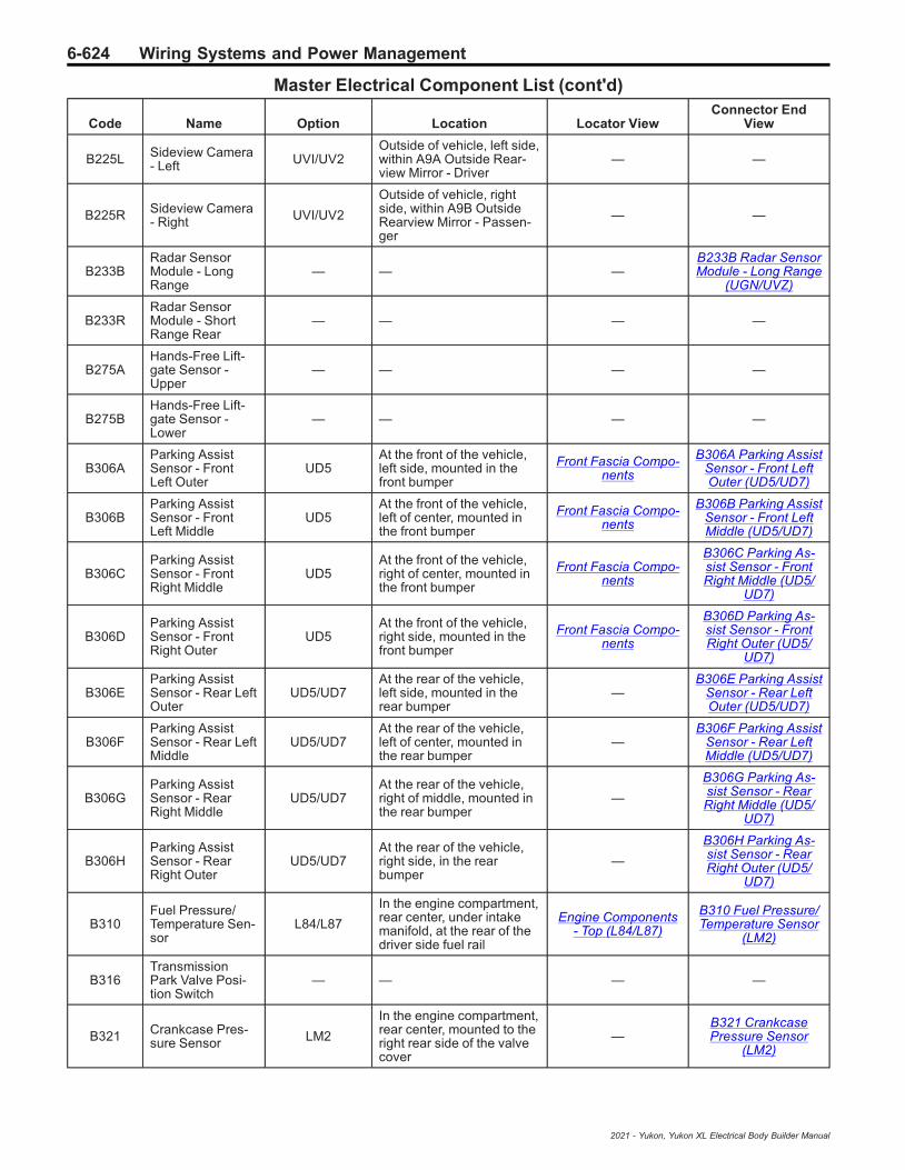
6-624 Wiring Systems and Power Management
Master Electrical Component List (cont'd)
Code Name Option Location Locator ViewConnector End
View
B225L Sideview Camera- Left UVI/UV2
Outside of vehicle, left side,within A9A Outside Rear-view Mirror - Driver
— —
B225R Sideview Camera- Right UVI/UV2
Outside of vehicle, rightside, within A9B OutsideRearview Mirror - Passen-ger
— —
B233BRadar SensorModule - LongRange
— — —B233B Radar SensorModule - Long Range
(UGN/UVZ)
B233RRadar SensorModule - ShortRange Rear
— — — —
B275AHands-Free Lift-gate Sensor -Upper
— — — —
B275BHands-Free Lift-gate Sensor -Lower
— — — —
B306AParking AssistSensor - FrontLeft Outer
UD5At the front of the vehicle,left side, mounted in thefront bumper
Front Fascia Compo-nents
B306A Parking AssistSensor - Front LeftOuter (UD5/UD7)
B306BParking AssistSensor - FrontLeft Middle
UD5At the front of the vehicle,left of center, mounted inthe front bumper
Front Fascia Compo-nents
B306B Parking AssistSensor - Front LeftMiddle (UD5/UD7)
B306CParking AssistSensor - FrontRight Middle
UD5At the front of the vehicle,right of center, mounted inthe front bumper
Front Fascia Compo-nents
B306C Parking As-sist Sensor - FrontRight Middle (UD5/
UD7)
B306DParking AssistSensor - FrontRight Outer
UD5At the front of the vehicle,right side, mounted in thefront bumper
Front Fascia Compo-nents
B306D Parking As-sist Sensor - FrontRight Outer (UD5/
UD7)
B306EParking AssistSensor - Rear LeftOuter
UD5/UD7At the rear of the vehicle,left side, mounted in therear bumper
—B306E Parking Assist
Sensor - Rear LeftOuter (UD5/UD7)
B306FParking AssistSensor - Rear LeftMiddle
UD5/UD7At the rear of the vehicle,left of center, mounted inthe rear bumper
—B306F Parking Assist
Sensor - Rear LeftMiddle (UD5/UD7)
B306GParking AssistSensor - RearRight Middle
UD5/UD7At the rear of the vehicle,right of middle, mounted inthe rear bumper
—
B306G Parking As-sist Sensor - RearRight Middle (UD5/
UD7)
B306HParking AssistSensor - RearRight Outer
UD5/UD7At the rear of the vehicle,right side, in the rearbumper
—
B306H Parking As-sist Sensor - RearRight Outer (UD5/
UD7)
B310Fuel Pressure/Temperature Sen-sor
L84/L87
In the engine compartment,rear center, under intakemanifold, at the rear of thedriver side fuel rail
Engine Components- Top (L84/L87)
B310 Fuel Pressure/Temperature Sensor
(LM2)
B316TransmissionPark Valve Posi-tion Switch
— — — —
B321 Crankcase Pres-sure Sensor LM2
In the engine compartment,rear center, mounted to theright rear side of the valvecover
—B321 CrankcasePressure Sensor
(LM2)
2021 - Yukon, Yukon XL Electrical Body Builder Manual
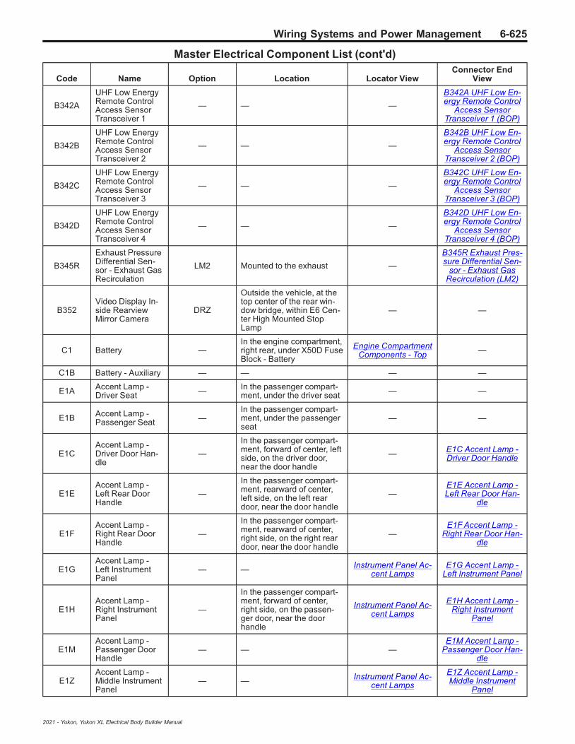
Wiring Systems and Power Management 6-625
Master Electrical Component List (cont'd)
Code Name Option Location Locator ViewConnector End
View
B342A
UHF Low EnergyRemote ControlAccess SensorTransceiver 1
— — —
B342A UHF Low En-ergy Remote Control
Access SensorTransceiver 1 (BOP)
B342B
UHF Low EnergyRemote ControlAccess SensorTransceiver 2
— — —
B342B UHF Low En-ergy Remote Control
Access SensorTransceiver 2 (BOP)
B342C
UHF Low EnergyRemote ControlAccess SensorTransceiver 3
— — —
B342C UHF Low En-ergy Remote Control
Access SensorTransceiver 3 (BOP)
B342D
UHF Low EnergyRemote ControlAccess SensorTransceiver 4
— — —
B342D UHF Low En-ergy Remote Control
Access SensorTransceiver 4 (BOP)
B345R
Exhaust PressureDifferential Sen-sor - Exhaust GasRecirculation
LM2 Mounted to the exhaust —
B345R Exhaust Pres-sure Differential Sen-
sor - Exhaust GasRecirculation (LM2)
B352Video Display In-side RearviewMirror Camera
DRZ
Outside the vehicle, at thetop center of the rear win-dow bridge, within E6 Cen-ter High Mounted StopLamp
— —
C1 Battery —In the engine compartment,right rear, under X50D FuseBlock - Battery
Engine CompartmentComponents - Top —
C1B Battery - Auxiliary — — — —
E1A Accent Lamp -Driver Seat — In the passenger compart-
ment, under the driver seat — —
E1B Accent Lamp -Passenger Seat —
In the passenger compart-ment, under the passengerseat
— —
E1CAccent Lamp -Driver Door Han-dle
—
In the passenger compart-ment, forward of center, leftside, on the driver door,near the door handle
— E1C Accent Lamp -Driver Door Handle
E1EAccent Lamp -Left Rear DoorHandle
—
In the passenger compart-ment, rearward of center,left side, on the left reardoor, near the door handle
—E1E Accent Lamp -Left Rear Door Han-
dle
E1FAccent Lamp -Right Rear DoorHandle
—
In the passenger compart-ment, rearward of center,right side, on the right reardoor, near the door handle
—E1F Accent Lamp -
Right Rear Door Han-dle
E1GAccent Lamp -Left InstrumentPanel
— — Instrument Panel Ac-cent Lamps
E1G Accent Lamp -Left Instrument Panel
E1HAccent Lamp -Right InstrumentPanel
—
In the passenger compart-ment, forward of center,right side, on the passen-ger door, near the doorhandle
Instrument Panel Ac-cent Lamps
E1H Accent Lamp -Right Instrument
Panel
E1MAccent Lamp -Passenger DoorHandle
— — —E1M Accent Lamp -
Passenger Door Han-dle
E1ZAccent Lamp -Middle InstrumentPanel
— — Instrument Panel Ac-cent Lamps
E1Z Accent Lamp -Middle Instrument
Panel
2021 - Yukon, Yukon XL Electrical Body Builder Manual

6-626 Wiring Systems and Power Management
Master Electrical Component List (cont'd)
Code Name Option Location Locator ViewConnector End
View
E2LF Side Marker Lamp- Left Front —
At the left front of vehicle,within E13LA HeadlampAssembly - Left
• Front of VehicleComponents(X88)
• Front of VehicleComponents(Z88)
E2LF Side MarkerLamp - Left Front
E2LR Side Marker Lamp- Left Rear —
At the left rear of vehicle,within E42L Tail Lamp As-sembly - Left
—E2LR Side MarkerLamp - Left Rear
(Z88)
E2RF Side Marker Lamp- Right Front —
At the right front of vehicle,within E13RA HeadlampAssembly - Right
• Front of VehicleComponents(X88)
• Front of VehicleComponents(Z88)
E2RF Side MarkerLamp - Right Front
E2RR Side Marker Lamp- Right Rear —
At the right rear of vehicle,within E42R Tail Lamp As-sembly - Right
—E2RR Side MarkerLamp - Right Rear
(Z88)
E4E Headlamp - LeftHigh Beam X88+Base
At the left front of vehicle,within E13LA HeadlampAssembly - Left
— —
E4F Headlamp - RightHigh Beam X88+Base
At the right front of vehicle,within E13RA HeadlampAssembly - Right
— —
E4LR Turn Signal Lamp- Left Rear —
At the left rear corner of thevehicle, inside the tail lampassembly
— —
E4RR Turn Signal Lamp- Right Rear —
At the right rear corner ofthe vehicle, inside the taillamp assembly
— —
E4Y Turn Signal Re-peater Lamp - Left —
At the front of the Left frontdoor, part of the OutsideRearview Mirror, part of themirror glass
— —
E4ZTurn Signal Re-peater Lamp -Right
—
At the front of the Rightfront door, part of the Out-side Rearview Mirror, partof the mirror glass
— —
E5A Backup Lamp -Left —
At the rear of vehicle, leftrear corner, within E42L Taillamp Assembly - Left
— —
E5AM Stop/Turn SignalLamp - Left —
At the rear of vehicle, leftrear corner, within E42L Taillamp Assembly - Left
— —
E5AN Stop/Turn SignalLamp - Right —
At the rear of vehicle, rightrear corner, within E42RTail lamp Assembly - Right
— —
E5B Backup Lamp -Right —
At the rear of vehicle, rightrear corner, within E42RTail lamp Assembly - Right
— —
E5E Tail Lamp - Left —At the rear of vehicle, leftrear corner, within E42L Taillamp Assembly - Left
— —
E5F Tail Lamp - Right —At the rear of vehicle, rightrear corner, within E42RTail lamp Assembly - Right
— —
E5L Stop Lamp - Left —At the left rear corner of thevehicle, inside the tail lampassembly
— —
2021 - Yukon, Yukon XL Electrical Body Builder Manual

Wiring Systems and Power Management 6-627
Master Electrical Component List (cont'd)
Code Name Option Location Locator ViewConnector End
View
E5R Stop Lamp - Right —At the right rear corner ofthe vehicle, inside the taillamp assembly
— —
E5RA Stop Lamp - Auxil-iary Right — — — —
E6Center HighMounted StopLamp
—Outside the vehicle, at thetop center of the rear win-dow bridge
— —
E7 License PlateLamp ZW9
At the rear of the vehicle,mounted in the middle ofthe rear bumper
— E7 License PlateLamp
E8ZLRunning BoardStep CourtesyLamp - Left
BRS
Under the vehicle, alongthe left frame rail, under thedriver door part of thepower assist step
— —
E8ZRRunning BoardStep CourtesyLamp - Right
BRS
Under the vehicle, alongthe right frame rail, underthe passenger door part ofthe power assist step
— —
E11A Fuel Heater/Waterin Fuel Sensor LM2
Under the vehicle, mountedto the bracket above thespare tire
—E11A Fuel Heater/
Water in Fuel Sensor(LM2)
E12A Glow Plug 1 LM2In the engine compartment,In the cylinder head at cyl-inder 1
— E12A Glow Plug 1(LM2)
E12B Glow Plug 2 LM2In the engine compartment,In the cylinder head at cyl-inder 2
— E12B Glow Plug 2(LM2)
E12C Glow Plug 3 LM2In the engine compartment,In the cylinder head at cyl-inder 3
— E12C Glow Plug 3(LM2)
E12D Glow Plug 4 LM2In the engine compartment,In the cylinder head at cyl-inder 4
— E12D Glow Plug 4(LM2)
E12E Glow Plug 5 LM2In the engine compartment,In the cylinder head at cyl-inder 5
— E12E Glow Plug 5(LM2)
E12F Glow Plug 6 LM2In the engine compartment,In the cylinder head at cyl-inder 6
— E12F Glow Plug 6(LM2)
E13L Headlamp - Left —At the front of the vehicle,within E13LA HeadlampAssembly - Left
— —
E13LA Headlamp As-sembly - Left — Outside the vehicle, at the
left front corner
• Front of VehicleComponents(X88)
• Front of VehicleComponents(Z88)
—
E13R Headlamp - Right —At the front of vehicle, with-in E13RA Headlamp As-sembly - Right
— —
E13RA Headlamp As-sembly - Right — Outside the vehicle, at the
right front corner
• Front of VehicleComponents(X88)
• Front of VehicleComponents(Z88)
—
2021 - Yukon, Yukon XL Electrical Body Builder Manual

6-628 Wiring Systems and Power Management
Master Electrical Component List (cont'd)
Code Name Option Location Locator ViewConnector End
View
E14ASeat Heating Ele-ment - DriverBack
KA1In the passenger compart-ment, in the driver seatback
— —
E14BSeat Heating Ele-ment - DriverCushion
KA1In the passenger compart-ment, in the driver seatcushion
— —
E14CSeat Heating Ele-ment - PassengerBack
KA1In the passenger compart-ment, in the passengerseat back
— —
E14DSeat Heating Ele-ment - PassengerCushion
KA1In the passenger compart-ment, in the passengerseat cushion
— —
E14FSeat Heating Ele-ment - Left RearCushion
KA6In the passenger compart-ment, in the left rear seatcushion
— —
E14HSeat Heating Ele-ment - Right RearCushion
KA6In the passenger compart-ment, in the right rear seatcushion
— —
E15 Steering WheelHeater KI3
In the passenger compart-ment, part of the steeringwheel
— —
E17DOutside RearviewMirror Glass -Driver
DEZ/DLF/UKC
Outside the vehicle, at thefront of the driver door, partof A9A Outside RearviewMirror - Driver
— —
E17POutside RearviewMirror Glass -Passenger
DEZ/DLF/UKC
Outside the vehicle, at thefront of the passenger door,part of A9B Outside Rear-view Mirror - Passenger
— —
E18 Rear DefoggerGrid —
At the rear of the passen-ger compartment, part ofthe rear window glass
—
• E18 Rear Defog-ger Grid X1
• E18 Rear Defog-ger Grid X2
E28Center ConsoleCompartmentLamp
D07
In the passenger compart-ment, between the frontseats, inside the floor con-sole storage bin
— E28 Center ConsoleCompartment Lamp
E29LF Fog Lamp - LeftFront T3U
Outside the vehicle, at theleft front corner, in the frontbumper, below E13LAHeadlight Assembly - Left
Front of Vehicle Com-ponents (Z88)
• E29LF Fog Lamp- Left Front (T40)
• E29LF Fog Lamp- Left Front (T79)
E29LR Fog Lamp - LeftRear — At the left rear corner of the
vehicle, in the rear fascia — —
E29RF Fog Lamp - RightFront T3U
Outside the vehicle, at theright front corner, in thefront bumper, below E13RAHeadlamp Assembly -Right
Front of Vehicle Com-ponents (Z88)
E29RF Fog Lamp -Right Front (T40)
E29RR Fog Lamp - RightRear —
At the right rear corner ofthe vehicle, in the rear fas-cia
— E29RR Fog Lamp -Right Rear (T79)
E31L Sunshade MirrorLamp - Left DH6
In the passenger compart-ment, at the left front of theheadliner, part of A3L Sun-shade - Left
— E31L Sunshade Mir-ror Lamp - Left
E31R Sunshade MirrorLamp - Right DH6
In the passenger compart-ment, at the right front ofthe headliner, part of A3RSunshade - Right
— E31R Sunshade Mir-ror Lamp - Right
E33 Cargo Lamp — — — E33 Cargo Lamp
2021 - Yukon, Yukon XL Electrical Body Builder Manual
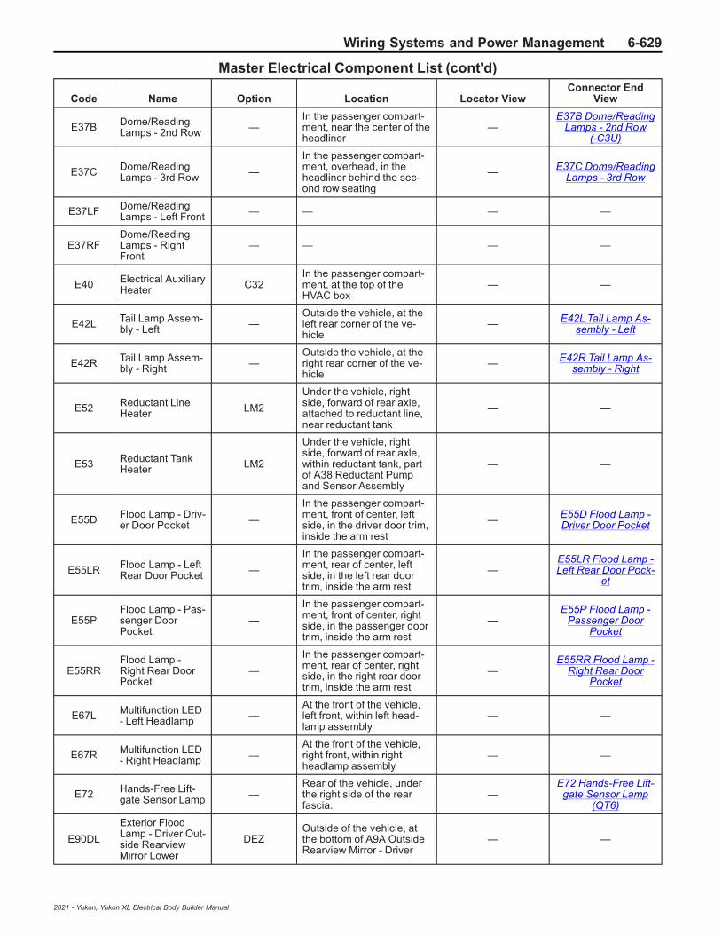
Wiring Systems and Power Management 6-629
Master Electrical Component List (cont'd)
Code Name Option Location Locator ViewConnector End
View
E37B Dome/ReadingLamps - 2nd Row —
In the passenger compart-ment, near the center of theheadliner
—E37B Dome/Reading
Lamps - 2nd Row(-C3U)
E37C Dome/ReadingLamps - 3rd Row —
In the passenger compart-ment, overhead, in theheadliner behind the sec-ond row seating
— E37C Dome/ReadingLamps - 3rd Row
E37LF Dome/ReadingLamps - Left Front — — — —
E37RFDome/ReadingLamps - RightFront
— — — —
E40 Electrical AuxiliaryHeater C32
In the passenger compart-ment, at the top of theHVAC box
— —
E42L Tail Lamp Assem-bly - Left —
Outside the vehicle, at theleft rear corner of the ve-hicle
— E42L Tail Lamp As-sembly - Left
E42R Tail Lamp Assem-bly - Right —
Outside the vehicle, at theright rear corner of the ve-hicle
— E42R Tail Lamp As-sembly - Right
E52 Reductant LineHeater LM2
Under the vehicle, rightside, forward of rear axle,attached to reductant line,near reductant tank
— —
E53 Reductant TankHeater LM2
Under the vehicle, rightside, forward of rear axle,within reductant tank, partof A38 Reductant Pumpand Sensor Assembly
— —
E55D Flood Lamp - Driv-er Door Pocket —
In the passenger compart-ment, front of center, leftside, in the driver door trim,inside the arm rest
— E55D Flood Lamp -Driver Door Pocket
E55LR Flood Lamp - LeftRear Door Pocket —
In the passenger compart-ment, rear of center, leftside, in the left rear doortrim, inside the arm rest
—E55LR Flood Lamp -Left Rear Door Pock-
et
E55PFlood Lamp - Pas-senger DoorPocket
—
In the passenger compart-ment, front of center, rightside, in the passenger doortrim, inside the arm rest
—E55P Flood Lamp -
Passenger DoorPocket
E55RRFlood Lamp -Right Rear DoorPocket
—
In the passenger compart-ment, rear of center, rightside, in the right rear doortrim, inside the arm rest
—E55RR Flood Lamp -
Right Rear DoorPocket
E67L Multifunction LED- Left Headlamp —
At the front of the vehicle,left front, within left head-lamp assembly
— —
E67R Multifunction LED- Right Headlamp —
At the front of the vehicle,right front, within rightheadlamp assembly
— —
E72 Hands-Free Lift-gate Sensor Lamp —
Rear of the vehicle, underthe right side of the rearfascia.
—E72 Hands-Free Lift-
gate Sensor Lamp(QT6)
E90DL
Exterior FloodLamp - Driver Out-side RearviewMirror Lower
DEZOutside of the vehicle, atthe bottom of A9A OutsideRearview Mirror - Driver
— —
2021 - Yukon, Yukon XL Electrical Body Builder Manual

6-630 Wiring Systems and Power Management
Master Electrical Component List (cont'd)
Code Name Option Location Locator ViewConnector End
View
E90PL
Exterior FloodLamp - PassengerOutside RearviewMirror Lower
DEZ
Outside of the vehicle, atthe bottom of A9B OutsideRearview Mirror - Passen-ger
— —
F101Passenger Instru-ment Panel AirBag
—
In the passenger compart-ment, behind the instru-ment panel upper glovebox
— —
F105L Roof Rail Air Bag- Left —
In the passenger compart-ment, along the left side ofthe headliner
— F105L Roof Rail AirBag - Left
F105R Roof Rail Air Bag- Right —
In the passenger compart-ment, along the right sideof the headliner
— F105R Roof Rail AirBag - Right
F106D Seat Side Air Bag- Driver —
In the passenger compart-ment, in the outboard sideof the driver seat back
— —
F106DA Seat Side Air Bag- Driver Inboard —
In the passenger compart-ment, on the right side ofthe left front seat back
— —
F106P Seat Side Air Bag- Passenger —
In the passenger compart-ment, in the outboard sideof the passenger seat back
— —
F107 Steering WheelAir Bag —
In the passenger compart-ment, mounted to the mid-dle of the steeing wheel
— —
F109GSeat Belt BucklePretensioner - 3rdRow Left
— — — —
F109JSeat Belt BucklePretensioner - 3rdRow Right
— — — —
F112DSeat Belt Retrac-tor Pretensioner -Driver
—In the passenger compart-ment, at the base of thedriver side B-pillar
—F112D Seat Belt Re-tractor Pretensioner -
Driver
F112PSeat Belt Retrac-tor Pretensioner -Passenger
—In the passenger compart-ment, at the base of thepassenger side B-pillar
—F112P Seat Belt Re-tractor Pretensioner -
Passenger
F113DSeat Belt AnchorPretensioner -Driver
—In the passenger compart-ment, mounted to the out-board driver seat track
—F113D Seat Belt An-chor Pretensioner -
Driver
F113PSeat Belt AnchorPretensioner -Passenger
—In the passenger compart-ment, mounted to the out-board passenger seat track
—F113P Seat Belt An-chor Pretensioner -
Passenger
G1 A/C Compressor —In the engine compartment,left front, mounted to theleft lower side of the engine
— —
G3 Air SuspensionCompressor — under the vehicle, at the left
rear, behind left rear tire — G3 Air SuspensionCompressor (F47)
G5Transmission Flu-id Pump - Electric/Auxiliary
MQBUnder the vehicle, withinT12 Automatic Transmis-sion Assembly
— —
G8 Coolant Pump -Auxiliary — — Radiator Compo-
nents (L84/L87)
• G8 Coolant Pump- Auxiliary (L84/L87)
• G8 Coolant Pump- Auxiliary (LM2)
2021 - Yukon, Yukon XL Electrical Body Builder Manual
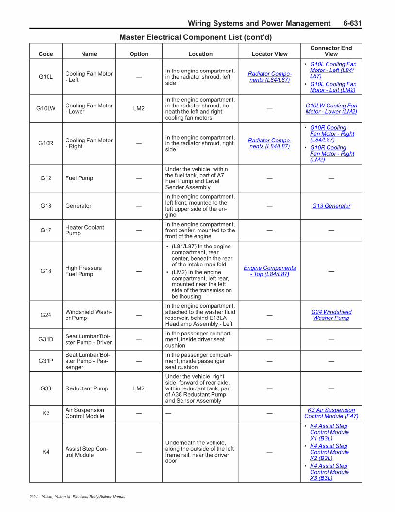
Wiring Systems and Power Management 6-631
Master Electrical Component List (cont'd)
Code Name Option Location Locator ViewConnector End
View
G10L Cooling Fan Motor- Left —
In the engine compartment,in the radiator shroud, leftside
Radiator Compo-nents (L84/L87)
• G10L Cooling FanMotor - Left (L84/L87)
• G10L Cooling FanMotor - Left (LM2)
G10LW Cooling Fan Motor- Lower LM2
In the engine compartment,in the radiator shroud, be-neath the left and rightcooling fan motors
— G10LW Cooling FanMotor - Lower (LM2)
G10R Cooling Fan Motor- Right —
In the engine compartment,in the radiator shroud, rightside
Radiator Compo-nents (L84/L87)
• G10R CoolingFan Motor - Right(L84/L87)
• G10R CoolingFan Motor - Right(LM2)
G12 Fuel Pump —
Under the vehicle, withinthe fuel tank, part of A7Fuel Pump and LevelSender Assembly
— —
G13 Generator —
In the engine compartment,left front, mounted to theleft upper side of the en-gine
— G13 Generator
G17 Heater CoolantPump —
In the engine compartment,front center, mounted to thefront of the engine
— —
G18 High PressureFuel Pump —
• (L84/L87) In the enginecompartment, rearcenter, beneath the rearof the intake manifold
• (LM2) In the enginecompartment, left rear,mounted near the leftside of the transmissionbellhousing
Engine Components- Top (L84/L87) —
G24 Windshield Wash-er Pump —
In the engine compartment,attached to the washer fluidreservoir, behind E13LAHeadlamp Assembly - Left
— G24 WindshieldWasher Pump
G31D Seat Lumbar/Bol-ster Pump - Driver —
In the passenger compart-ment, inside driver seatcushion
— —
G31PSeat Lumbar/Bol-ster Pump - Pas-senger
—In the passenger compart-ment, inside passengerseat cushion
— —
G33 Reductant Pump LM2
Under the vehicle, rightside, forward of rear axle,within reductant tank, partof A38 Reductant Pumpand Sensor Assembly
— —
K3 Air SuspensionControl Module — — — K3 Air Suspension
Control Module (F47)
K4 Assist Step Con-trol Module —
Underneath the vehicle,along the outside of the leftframe rail, near the driverdoor
—
• K4 Assist StepControl ModuleX1 (B3L)
• K4 Assist StepControl ModuleX2 (B3L)
• K4 Assist StepControl ModuleX3 (B3L)
2021 - Yukon, Yukon XL Electrical Body Builder Manual
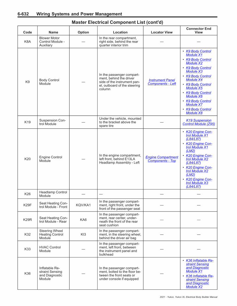
6-632 Wiring Systems and Power Management
Master Electrical Component List (cont'd)
Code Name Option Location Locator ViewConnector End
View
K8ABlower MotorControl Module -Auxiliary
—In the rear compartment,right side, behind the rearquarter interior trim
— —
K9 Body ControlModule —
In the passenger compart-ment, behind the driverside of the instrument pan-el, outboard of the steeringcolumn
Instrument PanelComponents - Left
• K9 Body ControlModule X1
• K9 Body ControlModule X2
• K9 Body ControlModule X3
• K9 Body ControlModule X4
• K9 Body ControlModule X5
• K9 Body ControlModule X6
• K9 Body ControlModule X7
• K9 Body ControlModule X8
K19 Suspension Con-trol Module —
Under the vehicle, mountedto the bracket above thespare tire
— K19 SuspensionControl Module (Z95)
K20 Engine ControlModule —
In the engine compartment,left front, behind E13LAHeadlamp Assembly - Left
Engine CompartmentComponents - Top
• K20 Engine Con-trol Module X1(L84/L87)
• K20 Engine Con-trol Module X1(LM2)
• K20 Engine Con-trol Module X2(L84/L87)
• K20 Engine Con-trol Module X2(LM2)
• K20 Engine Con-trol Module X3(L84/L87)
K26 Headlamp ControlModule — — — —
K29F Seat Heating Con-trol Module - Front KQV/KA1
In the passenger compart-ment, right front, under thefront of the passenger seat
— —
K29R Seat Heating Con-trol Module - Rear KA6
In the passenger compart-ment, rear center, under-neath the front of the rearseat cushion
— —
K32Steering WheelHeating ControlModule
KI3In the passenger compart-ment, in the steering wheel,behind the driver air bag
— —
K33 HVAC ControlModule —
In the passenger compart-ment, left front, betweenthe instrument panel andbulkhead
— —
K36
Inflatable Re-straint Sensingand DiagnosticModule
—
In the passenger compart-ment, bolted to the floor be-tween the front seats orunder console if equipped
—
• K36 Inflatable Re-straint Sensingand DiagnosticModule X1
• K36 Inflatable Re-straint Sensingand DiagnosticModule X2
2021 - Yukon, Yukon XL Electrical Body Builder Manual
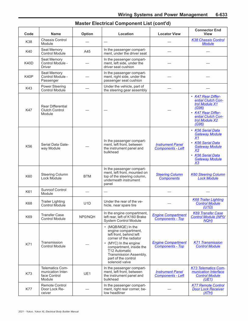
Wiring Systems and Power Management 6-633
Master Electrical Component List (cont'd)
Code Name Option Location Locator ViewConnector End
View
K38 Chassis ControlModule — — — K38 Chassis Control
Module
K40 Seat MemoryControl Module A45 In the passenger compart-
ment, under the driver seat — —
K40DSeat MemoryControl Module -Driver
—In the passenger compart-ment, left side, under thedriver seat cushion
— —
K40PSeat MemoryControl Module -Passenger
—In the passenger compart-ment, right side, under thepassenger seat cushion
— —
K43 Power SteeringControl Module — Under the vehicle, part of
the steering gear assembly — —
K47Rear DifferentialClutch ControlModule
— — —
• K47 Rear Differ-ential Clutch Con-trol Module X1(G96)
• K47 Rear Differ-ential Clutch Con-trol Module X2(G96)
K56 Serial Data Gate-way Module —
In the passenger compart-ment, left front, betweenthe instrument panel andbulkhead
Instrument PanelComponents - Left
• K56 Serial DataGateway ModuleX1
• K56 Serial DataGateway ModuleX2
• K56 Serial DataGateway ModuleX3
K60 Steering ColumnLock Module BTM
In the passenger compart-ment, left front, mounted ontop of the steering column,underneath instrumentpanel
Steering ColumnComponents
K60 Steering ColumnLock Module
K61 Sunroof ControlModule — — — —
K68 Trailer LightingControl Module U1D Under the rear of the ve-
hicle, near spare tire —K68 Trailer Lighting
Control Module(U1D)
K69 Transfer CaseControl Module NP0/NQH
In the engine compartment,left rear, left of K160 BrakeSystem Control Module
Engine CompartmentComponents - Top
K69 Transfer CaseControl Module (NP0/
NQH)
K71 TransmissionControl Module —
• (MQB/MQE) In theengine compartment,left front, behind leftcorner of the radiator
• (MYC) In the enginecompartment, inside theT12 AutomaticTransmission Assembly,part of the controlsolenoid valve
Engine CompartmentComponents - Top
K71 TransmissionControl Module
K73
Telematics Com-munication Inter-face ControlModule
UE1
In the passenger compart-ment, left front, betweenthe instrument panel andbulkhead
Instrument PanelComponents - Left
K73 Telematics Com-munication Interface
Control Module(UE1)
K77Remote ControlDoor Lock Re-ceiver
—In the passenger compart-ment, right rear corner, be-low headliner
—K77 Remote ControlDoor Lock Receiver
(ATH)
2021 - Yukon, Yukon XL Electrical Body Builder Manual

6-634 Wiring Systems and Power Management
Master Electrical Component List (cont'd)
Code Name Option Location Locator ViewConnector End
View
K84 Keyless EntryControl Module BTM
In the passenger compart-ment, left front, betweenthe instrument panel andbulkhead
— —
K85 Passenger Pres-ence Module —
In the passenger compart-ment, in the passengerseat cushion
— —
K99Steering ColumnPosition ControlModule
—
In the passenger compart-ment, forward, left side,mounted to the bottom ofthe steering column
Steering ColumnComponents
K99 Steering ColumnPosition Control Mod-
ule (N38)
K111 Fuel Pump DriverControl Module —
Under the vehicle, mountedto the bracket above thespare tire
— K111 Fuel Pump Driv-er Control Module
K115 Reductant ControlModule LM2
Under the vehicle, mountedto the outboard side of theframe, below the passen-ger side of the cab
— K115 Reductant Con-trol Module (LM2)
K124 Active SafetyControl Module —
In the rear compartment,left side, underneath rearquarter glass window, be-hind trim
— —
K133Trailer BrakePower ControlModule
JL1Under the vehicle, mountedto the bracket above thespare tire
—K133 Trailer Brake
Power Control Mod-ule (JL1)
K134DSeat BolsterMemory ControlModule - Driver
—In the passenger compart-ment, inside driver seatcushion
— —
K134P
Seat BolsterMemory ControlModule - Passen-ger
—In the passenger compart-ment, inside passengerseat cushion
— —
K157 Video ProcessingControl Module UVI/UV2
In the passenger compart-ment, right rear, mountedbehind the rear seat, belowthe rear window
—K157 Video Process-ing Control Module
(UV2)
K160 Brake SystemControl Module —
In the engine compartment,left rear corner, near brakemaster cylinder
— K160 Brake SystemControl Module
K169Folding Seat Con-trol Module - 3rdRow
—
In the passenger compart-ment, in the 3rd row seat,left side, inside seat back inthe lower left corner
— —
K171Hands-Free Lift-gate Sensor Con-trol Module
—
At the rear of the vehicle,center, mounted to theunderside of the rearbumper
—K171 Hands-Free
Liftgate Sensor Con-trol Module (QT8)
K175
Center ConsoleCompartmentCooler ControlModule
—In the passenger compart-ment, center, inside centerconsole at the floor
—
K175 Center ConsoleCompartment Cooler
Control Module(DCK)
K182 Parking AssistControl Module UD5/UD7
In the passenger compart-ment, mounted to the driverside of the rear wall
—
• K182 Parking As-sist Control Mod-ule X1 (UD5/UD7)
• K182 Parking As-sist Control Mod-ule X2 (UD5/UD7)
• K182 Parking As-sist Control Mod-ule X3 (UD5/UD7)
2021 - Yukon, Yukon XL Electrical Body Builder Manual

Wiring Systems and Power Management 6-635
Master Electrical Component List (cont'd)
Code Name Option Location Locator ViewConnector End
View
K183
UHF Short RangeLow Energy Re-mote Control Ac-cess Transceiver
— — —
K183 UHF ShortRange Low EnergyRemote Control Ac-
cess Transceiver(BOP)
K194 Rear Gate Module TC2In the rear compartment,left side of the tailgate, be-hind the trim.
—
• K194 Rear GateModule X1 (TC2)
• K194 Rear GateModule X2 (TC2)
• K194 Rear GateModule X4 (TC2)
K212
Electronic Trans-mission Shift Con-trol PushbuttonCircuit Board
— — Instrument PanelComponents - Right
K212 ElectronicTransmission ShiftControl Pushbutton
Circuit Board
K214Trailer Tire Pres-sure IndicatorModule
PTT
At the rear of the vehicle,mounted to the center ofthe rear bumper, near X88Trailer Connector
—K214 Trailer Tire
Pressure IndicatorModule (PTT)
K219 Exterior LightingControl Module — — Instrument Panel
Components - Left
• K219 ExteriorLighting ControlModule X1
• K219 ExteriorLighting ControlModule X2
• K219 ExteriorLighting ControlModule X3
• K219 ExteriorLighting ControlModule X4
• K219 ExteriorLighting ControlModule X5
M4 Air Inlet Door Ac-tuator —
In the passenger compart-ment, behind the instru-ment panel glove box
— —
M6 Air TemperatureDoor Actuator — — — —
M6BAir TemperatureDoor Actuator -Auxiliary
—
In the rear compartment,under the right rear quarterwindow, forward of the rearblower under trim.
— —
M8 Blower Motor —
In the passenger compart-ment, under the right sideof the instrument panel,above the hush panel
Instrument PanelComponents - Right M8 Blower Motor
M8B Blower Motor -Auxiliary —
In the passenger compart-ment, behind the passen-ger side of the instrumentpanel
— —
M10 Charge Air CoolerCoolant Pump LM2
In the engine compartment,left front, attached to brack-et near the front of the leftlower control arm
—M10 Charge Air Cool-
er Coolant Pump(LM2)
M17 Liftgate Motor As-sembly — — — —
M26Front Axle En-gagement Actua-tor
NP0/NQH Under the vehicle, mountedto the front axle —
M26 Front Axle En-gagement Actuator
(NP0/NQH)
2021 - Yukon, Yukon XL Electrical Body Builder Manual

6-636 Wiring Systems and Power Management
Master Electrical Component List (cont'd)
Code Name Option Location Locator ViewConnector End
View
M27 Fuel Fill Door Un-latch Actuator —
Underside of the vehicle,near the back, left side,under rear quarter glasswindow, in rear quarterpanel
— —
M33 Liftgate WindowLatch Assembly — — — —
M37 Mode Door Actua-tor —
In the passenger compart-ment, right front, within in-strument panel, attached toHVAC assembly
— —
M37B Mode Door Actua-tor - Auxiliary —
In the passenger compart-ment, forward, internal tothe instrument panel
— —
M38 Power SteeringMotor — Under the vehicle, part of
the steering gear assembly — —
M45 Rear Wiper Motor — At rear of vehicle, in the lift-gate — M45 Rear Wiper Mo-
tor
M50D Seat Front VerticalMotor - Driver — In the passenger compart-
ment, under the driver seat — —
M50PSeat Front VerticalMotor - Passen-ger
—In the passenger compart-ment, under the passengerseat
— —
M51D Seat HorizontalMotor - Driver — In the passenger compart-
ment, under the driver seat — —
M51PSeat HorizontalMotor - Passen-ger
—In the passenger compart-ment, under the passengerseat
— —
M53D Seat Lumbar Sup-port Motor - Driver — — — —
M53PSeat Lumbar Sup-port Motor - Pas-senger
— — — —
M55D Seat Rear VerticalMotor - Driver — In the passenger compart-
ment, under the driver seat — —
M55PSeat Rear VerticalMotor - Passen-ger
—In the passenger compart-ment, under the passengerseat
— —
M56D Seat Recline Mo-tor - Driver —
In the passenger compart-ment, in the driver seatback
— —
M56P Seat Recline Mo-tor - Passenger —
In the passenger compart-ment, in the passengerseat back
— —
M64 Starter Motor —In the engine compartment,left rear, mounted to rear ofengine block
—
• M64 Starter MotorX1 (L84/L87)
• M64 Starter MotorX1 (LM2)
M65 Steering ColumnTelescope Motor —
In the passenger compart-ment, forward, left of cen-ter, on the steering column
— —
M68 Steering ColumnTilt Motor —
In the passenger compart-ment, forward, left of cen-ter, on the steering column
— —
M73A Seat Blower Motor- Driver Back KQV
In the passenger compart-ment, in the driver seatback
— —
2021 - Yukon, Yukon XL Electrical Body Builder Manual

Wiring Systems and Power Management 6-637
Master Electrical Component List (cont'd)
Code Name Option Location Locator ViewConnector End
View
M73B Seat Blower Motor- Passenger Back KQV
In the passenger compart-ment, in the passengerseat cback
— —
M73C Seat Blower Motor- Driver Cushion KQV
In the passenger compart-ment, in the driver seatcushion
— —
M73DSeat Blower Motor- PassengerCushion
KQVIn the passenger compart-ment, in the passengerseat cushion
— —
M74D Window Motor -Driver — In the passenger compart-
ment, in the driver door — M74D Window Motor- Driver
M74LR Window Motor -Left Rear — In the passenger compart-
ment, in the left rear door — M74LR Window Mo-tor - Left Rear
M74P Window Motor -Passenger —
In the passenger compart-ment, in the passengerdoor
— M74P Window Motor- Passenger
M74RR Window Motor -Right Rear — In the passenger compart-
ment, in the right rear door — M74RR Window Mo-tor - Right Rear
M75 Windshield WiperMotor —
Outside the vehicle, at theleft rear of the engine com-partment, below the leftlower corner of the wind-shield
— M75 WindshieldWiper Motor
M77DOutside RearviewMirror Motor -Driver
—
Outside the vehicle, at thefront of the driver door,within the A9A OutsideRearview Mirror - Driver
— —
M77POutside RearviewMirror Motor -Passenger
—
Outside the vehicle, at thefront of the passenger door,within the A9B OutsideRearview Mirror - Passen-ger
— —
M78DOutside RearviewMirror Folding Mo-tor - Driver
A45
Outside the vehicle, at thefront of the driver door,within the A9A OutsideRearview Mirror - Driver
— —
M78POutside RearviewMirror Folding Mo-tor - Passenger
A45
Outside the vehicle, at thefront of the passenger door,within the A9B OutsideRearview Mirror - Passen-ger
— —
M81 Sunroof Sun-shade Motor — — — —
M95L Assist Step - Left BRSUnder the vehicle, alongthe left frame rail, under thedriver door
— —
M95R Assist Step -Right BRS
Under the vehicle, alongthe right frame rail, underthe passenger door
— —
M96A Active Grille AirShutter 1 Actuator VTI/WMI
At the front of the vehicle,center, attached to the in-side of the front grille
— —
M96B Active Grille AirShutter 2 Actuator WMI
At the front of the vehicle,center, attached to the in-side of the front grille
— —
M101LSeat Belt Retrac-tor Motor Module -Left
—
In the passenger compart-ment, left side, at the baseof the B-Pillar, part of theseat belt retractor
— —
2021 - Yukon, Yukon XL Electrical Body Builder Manual

6-638 Wiring Systems and Power Management
Master Electrical Component List (cont'd)
Code Name Option Location Locator ViewConnector End
View
M101RSeat Belt Retrac-tor Motor Module -Right
—
In the passenger compart-ment, right side, at the baseof the B-Pillar, part of theseat belt retractor
— —
M103TurbochargerVane Position Ac-tuator
LM2In the engine compartment,right side, mounted to tur-bocharger
—M103 Turbocharger
Vane Position Actua-tor
M104L Park Brake Actua-tor - Left —
Under the vehicle, left rear,attached to the left rearbrake caliper
— M104L Park BrakeActuator - Left
M104R Park Brake Actua-tor - Right —
Under the vehicle, rightrear, attached to the rightrear brake caliper
— M104R Park BrakeActuator - Right
M106Exhaust FlowControl Valve Ac-tuator
LM2
In the engine compartment,right rear, mounted to theexhaust, near the lowerright side of the transmis-sion bellhousing
—M106 Exhaust FlowControl Valve Actua-
tor (LM2)
M107LR Folding Seat Mo-tor - 2nd Row Left —
In the passenger compart-ment, left side, under 2ndrow seat cushion
— —
M107RRFolding Seat Mo-tor - 2nd RowRight
—In the passenger compart-ment, right side, under 2ndrow seat cushion
— —
M108LR Folding Seat Mo-tor - 3rd Row Left —
In the passenger compart-ment, left side, at the bot-tom of the 3rd row seatback
— —
M108RRFolding Seat Mo-tor - 3rd RowRight
—
In the passenger compart-ment, right side, at the bot-tom of the 3rd row seatback
— —
M109LRFolding Seat BackUnlatch Motor -3rd Row Left
—In the passenger compart-ment, left side, at the mid-dle of the 3rd row seat back
— —
M109RRFolding Seat BackUnlatch Motor -3rd Row Right
—In the passenger compart-ment, right side, at the mid-dle of the 3rd row seat back
— —
M123TransmissionPark Valve LockSolenoid Actuator
— — — —
P12 Horn —In the engine compartment,right front, at the bottom ofthe radiator core support
— P12 Horn
P16 Instrument Cluster —In the passenger compart-ment, in the driver side ofthe instrument panel
Instrument PanelComponents - Left
P16 Instrument Clus-ter
P17 Info Display Mod-ule —
In the passenger compart-ment, at the center of theinstrument panel
Instrument PanelComponents - Right
P17 Info DisplayModule
P19AC Speaker - Sub-woofer UQA
In the passenger compart-ment, under the instrumentpanel, at the front of thecenter console
— —
P19AG Speaker - LeftFront Door — In the passenger compart-
ment, in the driver door — P19AG Speaker -Left Front Door
P19AH Speaker - RightFront Door —
In the passenger compart-ment, in the passengerdoor
— P19AH Speaker -Right Front Door
2021 - Yukon, Yukon XL Electrical Body Builder Manual

Wiring Systems and Power Management 6-639
Master Electrical Component List (cont'd)
Code Name Option Location Locator ViewConnector End
View
P19AL Speaker - LeftRear Door — In the passenger compart-
ment, in the left rear door — P19AL Speaker - LeftRear Door
P19AM Speaker - RightRear Door — In the passenger compart-
ment, in the right rear door —
• P19AM Speaker -Right Rear Door(UQA/UQF/UQS)
• P19AM Speaker -Right Rear Door(UQP)
P19AN Speaker - LeftRear Trim Panel —
In the rear compartment, atthe back, left side at the topof the D-Pillar
—
• P19AN Speaker -Left Rear TrimPanel (UQA)
• P19AN Speaker -Left Rear TrimPanel (UQP)
• P19AN Speaker -Left Rear TrimPanel (UQS)
P19AP Speaker - RightRear Trim Panel — — —
• P19AP Speaker -Right Rear TrimPanel (UQA)
• P19AP Speaker -Right Rear TrimPanel (UQP)
• P19AP Speaker -Right Rear TrimPanel (UQS)
P19B Speaker - CenterInstrument Panel — — Instrument Panel
Components - Right
P19B Speaker - Cen-ter Instrument Panel
(UQH/UQP/UQS)
P19J Speaker - Left In-strument Panel —
In the passenger compart-ment, in the top of the leftside of the instrument panel
Instrument PanelComponents - Left
P19J Speaker - LeftInstrument Panel
(UQF)
P19M Speaker - LeftRear Tweeter — — — —
P19W Speaker - RightInstrument Panel —
In the passenger compart-ment, in the top of the rightside of the instrument panel
Instrument PanelComponents - Right
P19W Speaker -Right Instrument
Panel (UQF)
P19Z Speaker - RightRear Tweeter — — — —
P22E Video Display -Driver Seat Back — — — —
P22FVideo Display -Passenger SeatBack
— — — —
P25
Power SounderContent Theft De-terrent AlarmModule
— — —
P25 Power SounderContent Theft Deter-rent Alarm Module
(UTJ)
P27 Mobile TelephoneSpeaker — — — P27 Mobile Tele-
phone Speaker
P29 Head-Up Display UV6
In the passenger compart-ment, at the left side of theinstrument panel, near thewindshield
— P29 Head-Up DisplayX1 (UV6)
P34DSide Object De-tection Indicator -Driver
UKC
Outside of the vehicle, leftside, part of E17D OutsideRearview Mirror Glass -Driver, within A9A OutsideRearview Mirror - Driver
— —
2021 - Yukon, Yukon XL Electrical Body Builder Manual
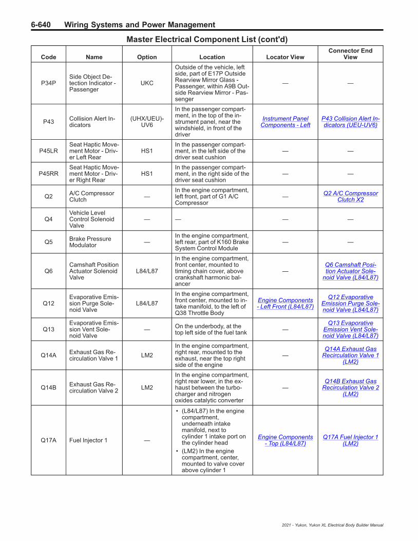
6-640 Wiring Systems and Power Management
Master Electrical Component List (cont'd)
Code Name Option Location Locator ViewConnector End
View
P34PSide Object De-tection Indicator -Passenger
UKC
Outside of the vehicle, leftside, part of E17P OutsideRearview Mirror Glass -Passenger, within A9B Out-side Rearview Mirror - Pas-senger
— —
P43 Collision Alert In-dicators
(UHX/UEU)-UV6
In the passenger compart-ment, in the top of the in-strument panel, near thewindshield, in front of thedriver
Instrument PanelComponents - Left
P43 Collision Alert In-dicators (UEU-UV6)
P45LRSeat Haptic Move-ment Motor - Driv-er Left Rear
HS1In the passenger compart-ment, in the left side of thedriver seat cushion
— —
P45RRSeat Haptic Move-ment Motor - Driv-er Right Rear
HS1In the passenger compart-ment, in the right side of thedriver seat cushion
— —
Q2 A/C CompressorClutch —
In the engine compartment,left front, part of G1 A/CCompressor
— Q2 A/C CompressorClutch X2
Q4Vehicle LevelControl SolenoidValve
— — — —
Q5 Brake PressureModulator —
In the engine compartment,left rear, part of K160 BrakeSystem Control Module
— —
Q6Camshaft PositionActuator SolenoidValve
L84/L87
In the engine compartment,front center, mounted totiming chain cover, abovecrankshaft harmonic bal-ancer
—Q6 Camshaft Posi-tion Actuator Sole-
noid Valve (L84/L87)
Q12Evaporative Emis-sion Purge Sole-noid Valve
L84/L87
In the engine compartment,front center, mounted to in-take manifold, to the left ofQ38 Throttle Body
Engine Components- Left Front (L84/L87)
Q12 EvaporativeEmission Purge Sole-noid Valve (L84/L87)
Q13Evaporative Emis-sion Vent Sole-noid Valve
— On the underbody, at thetop left side of the fuel tank —
Q13 EvaporativeEmission Vent Sole-noid Valve (L84/L87)
Q14A Exhaust Gas Re-circulation Valve 1 LM2
In the engine compartment,right rear, mounted to theexhaust, near the top rightside of the engine
—Q14A Exhaust Gas
Recirculation Valve 1(LM2)
Q14B Exhaust Gas Re-circulation Valve 2 LM2
In the engine compartment,right rear lower, in the ex-haust between the turbo-charger and nitrogenoxides catalytic converter
—Q14B Exhaust Gas
Recirculation Valve 2(LM2)
Q17A Fuel Injector 1 —
• (L84/L87) In the enginecompartment,underneath intakemanifold, next tocylinder 1 intake port onthe cylinder head
• (LM2) In the enginecompartment, center,mounted to valve coverabove cylinder 1
Engine Components- Top (L84/L87)
Q17A Fuel Injector 1(LM2)
2021 - Yukon, Yukon XL Electrical Body Builder Manual

Wiring Systems and Power Management 6-641
Master Electrical Component List (cont'd)
Code Name Option Location Locator ViewConnector End
View
Q17B Fuel Injector 2 —
• (L84/L87) In the enginecompartment,underneath intakemanifold, next tocylinder 2 intake port onthe cylinder head
• (LM2) In the enginecompartment, center,mounted to valve coverabove cylinder 2
Engine Components- Top (L84/L87)
Q17B Fuel Injector 2(LM2)
Q17C Fuel Injector 3 —
• (L84/L87) In the enginecompartment,underneath intakemanifold, next tocylinder 3 intake port onthe cylinder head
• (LM2) In the enginecompartment, center,mounted to valve coverabove cylinder 3
Engine Components- Top (L84/L87)
Q17C Fuel Injector 3(LM2)
Q17D Fuel Injector 4 —
• (L84/L87) In the enginecompartment,underneath intakemanifold, next tocylinder 4 intake port onthe cylinder head
• (LM2) In the enginecompartment, center,mounted to valve coverabove cylinder 4
Engine Components- Top (L84/L87)
Q17D Fuel Injector 4(LM2)
Q17E Fuel Injector 5 —
• (L84/L87) In the enginecompartment,underneath intakemanifold, next tocylinder 5 intake port onthe cylinder head
• (LM2) In the enginecompartment, center,mounted to valve coverabove cylinder 5
Engine Components- Top (L84/L87)
Q17E Fuel Injector 5(LM2)
Q17F Fuel Injector 6 —
• (L84/L87) In the enginecompartment,underneath intakemanifold, next tocylinder 6 intake port onthe cylinder head
• (LM2) In the enginecompartment, center,mounted to valve coverabove cylinder 6
Engine Components- Top (L84/L87)
Q17F Fuel Injector 6(LM2)
Q17G Fuel Injector 7 L84/L87
In the engine compartment,underneath intake mani-fold, next to cylinder 7 in-take port on the cylinderhead
Engine Components- Top (L84/L87) —
Q17H Fuel Injector 8 L84/L87
In the engine compartment,underneath intake mani-fold, next to cylinder 8 in-take port on the cylinderhead
Engine Components- Top (L84/L87) —
2021 - Yukon, Yukon XL Electrical Body Builder Manual

6-642 Wiring Systems and Power Management
Master Electrical Component List (cont'd)
Code Name Option Location Locator ViewConnector End
View
Q18A Fuel PressureRegulator 1 LM2
In the engine compartment,left rear side of engine, be-low Q18C Fuel PressureRegulator 3, attached toG18 High Pressure FuelPump
— Q18A Fuel PressureRegulator 1 (LM2)
Q18B Fuel PressureRegulator 2 LM2
In the engine compartment,left side of engine, mountedto the left rear side of thevalve cover
— Q18B Fuel PressureRegulator 2 (LM2)
Q18C Fuel PressureRegulator 3 LM2
In the engine compartment,left rear side of engine,above Q18A Fuel PressureRegulator 1, attached toG18 High Pressure FuelPump
— Q18C Fuel PressureRegulator 3 (LM2)
Q22Intake ManifoldTuning SolenoidValve
LM2In the engine compartment,front center, attached to thefront of the intake manifold
—Q22 Intake Manifold
Tuning SolenoidValve (LM2)
Q37LFShock AbsorberActuator - LeftFront
Z45Under the vehicle, left front,part of the left front shockabsorber
—Q37LF Shock Ab-
sorber Actuator - LeftFront (Z95)
Q37LRShock AbsorberActuator - LeftRear
Z45Under the vehicle, left rear,part of the left rear shockabsorber
—Q37LR Shock Ab-
sorber Actuator - LeftRear (Z95)
Q37RFShock AbsorberActuator - RightFront
Z45Under the vehicle, rightfront, part of the right frontshock absorber
—Q37RF Shock Ab-sorber Actuator -Right Front (Z95)
Q37RRShock AbsorberActuator - RightRear
Z45Under the vehicle, rightrear, part of the right rearshock absorber
—Q37RR Shock Ab-sorber Actuator -Right Rear (Z95)
Q38 Throttle Body —
• (L84/L87) In the enginecompartment, at thefront of the engine,mounted to the intakemanifold inlet
• (LM2) In the enginecompartment, left front,to the left of the valvecover
Engine Components- Left Front (L84/L87)
• Q38 Throttle Body(L84/L87)
• Q38 Throttle Body(LM2)
Q44Engine Oil Pres-sure Control Sole-noid Valve
—In the engine compartment,at the front of the engine,behind the front cover
— —
Q46 A/C CompressorSolenoid Valve —
In the engine compartment,left front, part of G1 A/CCompressor
— Q46 A/C CompressorSolenoid Valve X1
Q61 Reductant Injector LM2
In the engine compartment,right front, mounted to theexhaust, in front of dieselparticulate filter
— Q61 Reductant Injec-tor (LM2)
Q74 Engine CoolantBypass Valve LM2
In the engine compartment,left rear, attached to thebottom rear of Q97 EngineCoolant Flow Control Valve
— Q74 Engine CoolantBypass Valve (LM2)
Q77ATransmissionControl SolenoidValve 1
MQB/MQEUnder the vehicle, insidethe T12 Automatic Trans-mission Assembly
— —
Q77BTransmissionControl SolenoidValve 2
MQB/MQEUnder the vehicle, insidethe T12 Automatic Trans-mission Assembly
— —
2021 - Yukon, Yukon XL Electrical Body Builder Manual

Wiring Systems and Power Management 6-643
Master Electrical Component List (cont'd)
Code Name Option Location Locator ViewConnector End
View
Q77CTransmissionControl SolenoidValve 3
MQB/MQEUnder the vehicle, insidethe T12 Automatic Trans-mission Assembly
— —
Q77DTransmissionControl SolenoidValve 4
MQB/MQEUnder the vehicle, insidethe T12 Automatic Trans-mission Assembly
— —
Q77ETransmissionControl SolenoidValve 5
MQB/MQEUnder the vehicle, insidethe T12 Automatic Trans-mission Assembly
— —
Q77FTransmissionControl SolenoidValve 6
MQB/MQEUnder the vehicle, insidethe T12 Automatic Trans-mission Assembly
— —
Q77GTransmissionControl SolenoidValve 7
MQB/MQEUnder the vehicle, insidethe T12 Automatic Trans-mission Assembly
— —
Q77HTransmissionControl SolenoidValve 8
MQB/MQEUnder the vehicle, insidethe T12 Automatic Trans-mission Assembly
— —
Q77JTransmissionControl SolenoidValve 9
MQB/MQEUnder the vehicle, insidethe T12 Automatic Trans-mission Assembly
— —
Q80L Engine Mount Sol-enoid Valve - Left LM2
In the engine compartment,front center, mounted to leftside of the upper oil pan
—Q80L Engine MountSolenoid Valve - Left
(LM2)
Q80REngine Mount Sol-enoid Valve -Right
LM2
In the engine compartment,front center, mounted toright side of the upper oilpan
—Q80R Engine Mount
Solenoid Valve -Right (LM2)
Q83AAValve Lifter OilSolenoid Valve -Cylinder 1
L84/L87
In the engine compartment,mounted to the engine, be-neath the engine block val-ley cover, next to cylinder 1
— —
Q83ABValve Lifter OilSolenoid Valve -Cylinder 2
L84/L87
In the engine compartment,mounted to the engine, be-neath the engine block val-ley cover, next to cylinder 2
— —
Q83ACValve Lifter OilSolenoid Valve -Cylinder 3
L84/L87
In the engine compartment,mounted to the engine, be-neath the engine block val-ley cover, next to cylinder 3
— —
Q83ADValve Lifter OilSolenoid Valve -Cylinder 4
L84/L87
In the engine compartment,mounted to the engine, be-neath the engine block val-ley cover, next to cylinder 4
— —
Q83AEValve Lifter OilSolenoid Valve -Cylinder 5
L84/L87
In the engine compartment,mounted to the engine, be-neath the engine block val-ley cover, next to cylinder 5
— —
Q83AFValve Lifter OilSolenoid Valve -Cylinder 6
L84/L87
In the engine compartment,mounted to the engine, be-neath the engine block val-ley cover, next to cylinder 6
— —
Q83AGValve Lifter OilSolenoid Valve -Cylinder 7
L84/L87
In the engine compartment,mounted to the engine, be-neath the engine block val-ley cover, next to cylinder 7
— —
Q83AHValve Lifter OilSolenoid Valve -Cylinder 8
L84/L87
In the engine compartment,mounted to the engine, be-neath the engine block val-ley cover, next to cylinder 8
— —
2021 - Yukon, Yukon XL Electrical Body Builder Manual

6-644 Wiring Systems and Power Management
Master Electrical Component List (cont'd)
Code Name Option Location Locator ViewConnector End
View
Q97Engine CoolantFlow ControlValve
—
In the engine compartment,left, attached to the front ofQ97 Engine Coolant FlowControl Valve
— —
Q97BEngine CoolantFlow ControlValve - Block
LM2
In the engine compartment,left front, attached the frontof Q97 Engine CoolantFlow Control Valve, at thetop
— —
Q97MEngine CoolantFlow ControlValve - Main
LM2
In the engine compartment,left front, attached to thefront of Q97 Engine Cool-ant Flow Control Valve, be-hind the G13 Generator
—Q97M Engine Cool-
ant Flow ControlValve - Main (LM2)
S2TransmissionManual ShiftSwitch
—In the passenger compart-ment, part of the transmis-sion shift lever
— —
S13D Door Lock Switch- Driver —
In the passenger compart-ment, in the driver doorhandle trim panel
— S13D Door LockSwitch - Driver
S13LR Door Lock Switch- Left Rear — — — S13LR Door Lock
Switch - Left Rear
S13P Door Lock Switch- Passenger —
In the passenger compart-ment, in the passengerdoor handle trim panel
— S13P Door LockSwitch - Passenger
S13RR Door Lock Switch- Right Rear — — — S13RR Door Lock
Switch - Right Rear
S26 Hazard WarningSwitch — — Instrument Panel
Components - RightS26 Hazard Warning
Switch
S27 Head-Up DisplaySwitch UV6
In the passenger compart-ment, left front, left of thesteering column, in the in-strument panel
Instrument PanelComponents - Left
S27 Head-Up DisplaySwitch (UV6)
S30 Headlamp Switch —
In the passenger compart-ment, left of the steeringcolumn, in the instrumentpanel
Instrument PanelComponents - Left
S30 HeadlampSwitch
S33 Horn Switch —
In the passenger compart-ment, in the center of thesteering wheel, behind thedriver side air bag
— —
S38 Ignition ModeSwitch BTM
In the passenger compart-ment, right of the steeringcolumn, in the instrumentpanel
Instrument PanelComponents - Right
S38 Ignition ModeSwitch
S46 Liftgate HandleSwitch — — — —
S46B Liftgate UnlatchSwitch — — — —
S47D Seat MemorySwitch - Driver —
In the passenger compart-ment, on the driver doorpanel above the driver doorswitch assembly
—S47D Seat MemorySwitch - Driver (A45/
AUN)
S48CMultifunctionSwitch 1 - Instru-ment Panel
— — Instrument PanelComponents - Left
S48C MultifunctionSwitch 1 - Instrument
Panel
S51 Telematics ButtonAssembly UE1
In the passenger compart-ment, part of the insiderearview mirror
— —
2021 - Yukon, Yukon XL Electrical Body Builder Manual

Wiring Systems and Power Management 6-645
Master Electrical Component List (cont'd)
Code Name Option Location Locator ViewConnector End
View
S64D Seat AdjusterSwitch - Driver —
In the passenger compart-ment, mounted to the out-board side of the driverseat cushion
— —
S64PSeat AdjusterSwitch - Passen-ger
—
In the passenger compart-ment, mounted to the out-board side of thepassenger seat cushion
— —
S65DSeat Lumbar Sup-port Switch - Driv-er
A2X
In the passenger compart-ment, mounted to the out-board side of the driverseat cushion
— —
S65PSeat Lumbar Sup-port Switch - Pas-senger
A7K
In the passenger compart-ment, mounted to the out-board side of thepassenger seat cushion
— —
S70ESteering WheelControls Switch -Radio Presets
—In the passenger compart-ment, on the left rear sideof the steering wheel
Steering Wheel Com-ponents —
S70FSteering WheelControls Switch -Radio Volume
—In the passenger compart-ment, on the right rear sideof the steering wheel
Steering Wheel Com-ponents —
S70LSteering WheelControls Switch -Left
—In the passenger compart-ment, on the left side of thesteering wheel
Steering Wheel Com-ponents —
S70RSteering WheelControls Switch -Right
—In the passenger compart-ment, on the right side ofthe steering wheel
Steering Wheel Com-ponents —
S71Steering ColumnTilt and TelescopeSwitch
— — Instrument PanelComponents - Left
S71 Steering ColumnTilt and Telescope
Switch (N38)
S76 Trailer Brake Con-trol Switch —
In the passenger compart-ment, center of the instru-ment panel, below S48CMultifunction Switch 1 - In-strument Panel
Instrument PanelComponents - Left
S76 Trailer BrakeControl Switch (JL1)
S78 Turn Signal/Multi-function Switch —
In the passenger compart-ment, on the left side of thesteering column
Instrument PanelComponents - Left
S78 Turn Signal/Mul-tifunction Switch
S79LR Window Switch -Left Rear —
In the passenger compart-ment, at the center of theleft rear door, on the doortrim panel
— S79LR WindowSwitch - Left Rear
S79RR Window Switch -Right Rear —
In the passenger compart-ment, on the right rear doortrim panel, center of thedoor
— S79RR WindowSwitch - Right Rear
S84DDoor Switch PanelControl Module -Driver
— — — —
S84PDoor Switch PanelControl Module -Passenger
— — — —
S126 Drive Mode SelectSwitch URC
In the passenger compart-ment, left front, left side ofthe instrument panel,above S30 HeadlampSwitch
Instrument PanelComponents - Left
S126 Drive Mode Se-lect Switch
S141 Liftgate WindowUnlatch Switch — — — S141 Liftgate Win-
dow Unlatch Switch
2021 - Yukon, Yukon XL Electrical Body Builder Manual
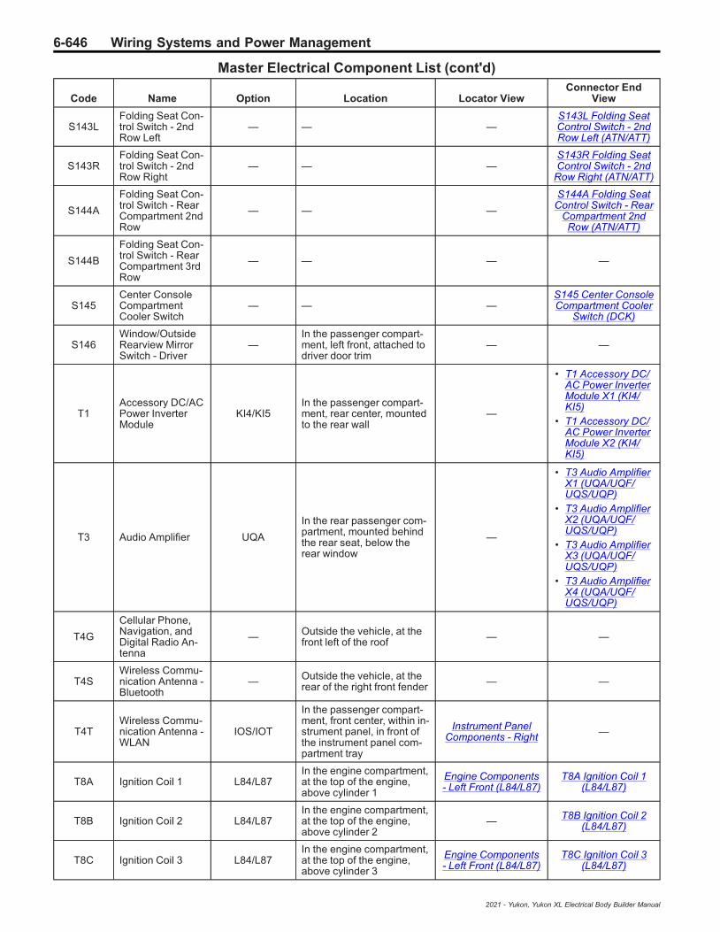
6-646 Wiring Systems and Power Management
Master Electrical Component List (cont'd)
Code Name Option Location Locator ViewConnector End
View
S143LFolding Seat Con-trol Switch - 2ndRow Left
— — —S143L Folding SeatControl Switch - 2ndRow Left (ATN/ATT)
S143RFolding Seat Con-trol Switch - 2ndRow Right
— — —S143R Folding SeatControl Switch - 2nd
Row Right (ATN/ATT)
S144A
Folding Seat Con-trol Switch - RearCompartment 2ndRow
— — —
S144A Folding SeatControl Switch - Rear
Compartment 2ndRow (ATN/ATT)
S144B
Folding Seat Con-trol Switch - RearCompartment 3rdRow
— — — —
S145Center ConsoleCompartmentCooler Switch
— — —S145 Center ConsoleCompartment Cooler
Switch (DCK)
S146Window/OutsideRearview MirrorSwitch - Driver
—In the passenger compart-ment, left front, attached todriver door trim
— —
T1Accessory DC/ACPower InverterModule
KI4/KI5In the passenger compart-ment, rear center, mountedto the rear wall
—
• T1 Accessory DC/AC Power InverterModule X1 (KI4/KI5)
• T1 Accessory DC/AC Power InverterModule X2 (KI4/KI5)
T3 Audio Amplifier UQA
In the rear passenger com-partment, mounted behindthe rear seat, below therear window
—
• T3 Audio AmplifierX1 (UQA/UQF/UQS/UQP)
• T3 Audio AmplifierX2 (UQA/UQF/UQS/UQP)
• T3 Audio AmplifierX3 (UQA/UQF/UQS/UQP)
• T3 Audio AmplifierX4 (UQA/UQF/UQS/UQP)
T4G
Cellular Phone,Navigation, andDigital Radio An-tenna
— Outside the vehicle, at thefront left of the roof — —
T4SWireless Commu-nication Antenna -Bluetooth
— Outside the vehicle, at therear of the right front fender — —
T4TWireless Commu-nication Antenna -WLAN
IOS/IOT
In the passenger compart-ment, front center, within in-strument panel, in front ofthe instrument panel com-partment tray
Instrument PanelComponents - Right —
T8A Ignition Coil 1 L84/L87In the engine compartment,at the top of the engine,above cylinder 1
Engine Components- Left Front (L84/L87)
T8A Ignition Coil 1(L84/L87)
T8B Ignition Coil 2 L84/L87In the engine compartment,at the top of the engine,above cylinder 2
— T8B Ignition Coil 2(L84/L87)
T8C Ignition Coil 3 L84/L87In the engine compartment,at the top of the engine,above cylinder 3
Engine Components- Left Front (L84/L87)
T8C Ignition Coil 3(L84/L87)
2021 - Yukon, Yukon XL Electrical Body Builder Manual

Wiring Systems and Power Management 6-647
Master Electrical Component List (cont'd)
Code Name Option Location Locator ViewConnector End
View
T8D Ignition Coil 4 L84/L87In the engine compartment,at the top of the engine,above cylinder 4
— T8D Ignition Coil 4(L84/L87)
T8E Ignition Coil 5 L84/L87In the engine compartment,at the top of the engine,above cylinder 5
Engine Components- Left Front (L84/L87)
T8E Ignition Coil 5(L84/L87)
T8F Ignition Coil 6 L84/L87In the engine compartment,at the top of the engine,above cylinder 6
— T8F Ignition Coil 6(L84/L87)
T8G Ignition Coil 7 L84/L87In the engine compartment,at the top of the engine,above cylinder 7
Engine Components- Left Front (L84/L87)
T8G Ignition Coil 7(L84/L87)
T8H Ignition Coil 8 L84/L87In the engine compartment,at the top of the engine,above cylinder 8
— T8H Ignition Coil 8(L84/L87)
T10FKeyless Entry An-tenna - Rear Win-dow
— — — —
T10GKeyless Entry An-tenna - Rear Fas-cia
— — —T10G Keyless EntryAntenna - Rear Fas-
cia
T10JKeyless Entry An-tenna - CenterConsole Front
—
In the passenger compart-ment, front center, beneathfloor console or centerseat.
—
• T10J Keyless En-try Antenna - Cen-ter Console Front(5W4/9C1/AZ3)
• T10J Keyless En-try Antenna - Cen-ter Console Front(D07/DCH/DCK)
T10L Keyless Entry An-tenna - Left Body — — — T10L Keyless Entry
Antenna - Left Body
T10RKeyless Entry An-tenna - RightBody
— — — T10R Keyless EntryAntenna - Right Body
T12 Automatic Trans-mission Assembly — Under the vehicle, mounted
to the rear of the engine — T12 Automatic Trans-mission Assembly
T19 Power SupplyTransformer KL9
In the passenger compart-ment, right front, betweenthe instrument panel andbulkhead
— T19 Power SupplyTransformer
T22Mobile DeviceWireless ChargerModule
K4CIn the passenger compart-ment, forward of center, inthe floor console bin lid.
—T22 Mobile DeviceWireless Charger
Module (K4C)
W4Blunt Cut - Off-Road Grille LampProvision
— — — —
W9 Blunt Cut - PoliceProvision — — — —
W24 Blunt Cut - TrailerBrakes Provision Z82-JL1
In the passenger compart-ment, under left side of theinstrument panel
— —
X50A Fuse Block -Underhood —
In the engine compartment,right front, in front of C1Battery
Engine CompartmentComponents - Top
Electrical CenterIdentification Views
on page 6‑30
X50BFuse Block -Underhood Auxili-ary
LM2 In the engine compartment —Electrical Center
Identification Viewson page 6‑30
2021 - Yukon, Yukon XL Electrical Body Builder Manual
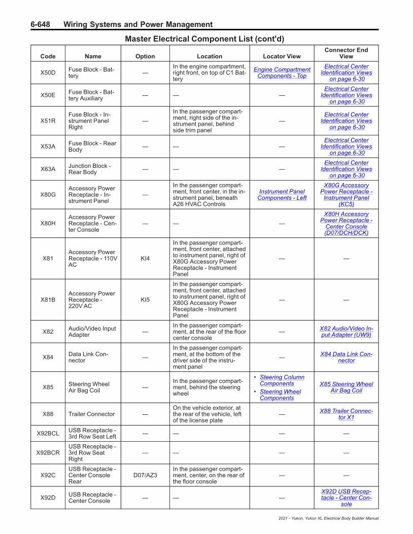
6-648 Wiring Systems and Power Management
Master Electrical Component List (cont'd)
Code Name Option Location Locator ViewConnector End
View
X50D Fuse Block - Bat-tery —
In the engine compartment,right front, on top of C1 Bat-tery
Engine CompartmentComponents - Top
Electrical CenterIdentification Views
on page 6‑30
X50E Fuse Block - Bat-tery Auxiliary — — —
Electrical CenterIdentification Views
on page 6‑30
X51RFuse Block - In-strument PanelRight
—
In the passenger compart-ment, right side of the in-strument panel, behindside trim panel
—Electrical Center
Identification Viewson page 6‑30
X53A Fuse Block - RearBody — — —
Electrical CenterIdentification Views
on page 6‑30
X63A Junction Block -Rear Body — — —
Electrical CenterIdentification Views
on page 6‑30
X80GAccessory PowerReceptacle - In-strument Panel
—
In the passenger compart-ment, front center, in the in-strument panel, beneathA26 HVAC Controls
Instrument PanelComponents - Left
X80G AccessoryPower Receptacle -
Instrument Panel(KC5)
X80HAccessory PowerReceptacle - Cen-ter Console
— — —
X80H AccessoryPower Receptacle -
Center Console(D07/DCH/DCK)
X81Accessory PowerReceptacle - 110VAC
KI4
In the passenger compart-ment, front center, attachedto instrument panel, right ofX80G Accessory PowerReceptacle - InstrumentPanel
— —
X81BAccessory PowerReceptacle -220V AC
KI5
In the passenger compart-ment, front center, attachedto instrument panel, right ofX80G Accessory PowerReceptacle - InstrumentPanel
— —
X82 Audio/Video InputAdapter —
In the passenger compart-ment, at the rear of the floorcenter console
— X82 Audio/Video In-put Adapter (UW9)
X84 Data Link Con-nector —
In the passenger compart-ment, at the bottom of thedriver side of the instru-ment panel
— X84 Data Link Con-nector
X85 Steering WheelAir Bag Coil —
In the passenger compart-ment, behind the steeringwheel
• Steering ColumnComponents
• Steering WheelComponents
X85 Steering WheelAir Bag Coil
X88 Trailer Connector —On the vehicle exterior, atthe rear of the vehicle, leftof the license plate
— X88 Trailer Connec-tor X1
X92BCL USB Receptacle -3rd Row Seat Left — — — —
X92BCRUSB Receptacle -3rd Row SeatRight
— — — —
X92CUSB Receptacle -Center ConsoleRear
D07/AZ3In the passenger compart-ment, center, on the rear ofthe floor console
— —
X92D USB Receptacle -Center Console — — —
X92D USB Recep-tacle - Center Con-
sole
2021 - Yukon, Yukon XL Electrical Body Builder Manual
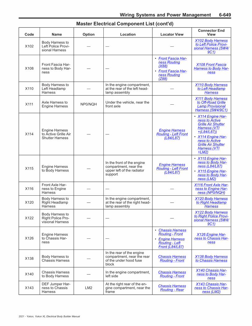
Wiring Systems and Power Management 6-649
Master Electrical Component List (cont'd)
Code Name Option Location Locator ViewConnector End
View
X102Body Harness toLeft Police Provi-sional Harness
— — —
X102 Body Harnessto Left Police Provi-
sional Harness (5W4/9C1)
X108Front Fascia Har-ness to Body Har-ness
— —
• Front Fascia Har-ness Routing(X88)
• Front Fascia Har-ness Routing(Z88)
X108 Front FasciaHarness to Body Har-
ness
X110Body Harness toLeft HeadlampHarness
—In the engine compartment,at the rear of the left head-lamp assembly
—X110 Body Harness
to Left HeadlampHarness
X111 Axle Harness toEngine Harness NP0/NQH Under the vehicle, near the
front axle —
X111 Body Harnessto Off-Road GrilleLamp Provisional
Harness (5W4/9C1)
X114Engine Harnessto Active Grille AirShutter Harness
— —Engine Harness
Routing - Left Front(L84/L87)
• X114 Engine Har-ness to ActiveGrille Air ShutterHarness (VTI+(L84/L87))
• X114 Engine Har-ness to ActiveGrille Air ShutterHarness (VTI+LM2)
X115 Engine Harnessto Body Harness —
In the front of the enginecompartment, near theupper left of the radiatorsupport
Engine HarnessRouting - Left Front
(L84/L87)
• X115 Engine Har-ness to Body Har-ness (L84/L87)
• X115 Engine Har-ness to Body Har-ness (LM2)
X116Front Axle Har-ness to EngineHarness
— — —X116 Front Axle Har-ness to Engine Har-
ness (NP0/NQH)
X120Body Harness toRight HeadlampHarness
—In the engine compartment,at the rear of the right head-lamp assembly
—X120 Body Harnessto Right Headlamp
Harness
X122Body Harness toRight Police Pro-visional Harness
— — —
X122 Body Harnessto Right Police Provi-sional Harness (5W4/
9C1)
X126Engine Harnessto Chassis Har-ness
— —
• Chassis HarnessRouting - Front
• Engine HarnessRouting - LeftFront (L84/L87)
X126 Engine Har-ness to Chassis Har-
ness
X138 Body Harness toChassis Harness —
In the rear of the enginecompartment, near the rearof the under hood fuseblock
Chassis HarnessRouting - Front
X138 Body Harnessto Chassis Harness
X140 Chassis Harnessto Body Harness — In the engine compartment,
left sideChassis HarnessRouting - Front
X140 Chassis Har-ness to Body Har-
ness
X143DEF Jumper Har-ness to ChassisHarness
LM2At the right rear of the en-gine compartment, near theframe
Chassis HarnessRouting - Rear
X143 Chassis Har-ness to Chassis Har-
ness (LM2)
2021 - Yukon, Yukon XL Electrical Body Builder Manual

6-650 Wiring Systems and Power Management
Master Electrical Component List (cont'd)
Code Name Option Location Locator ViewConnector End
View
X153
Engine Harnessto Coolant Tem-perature JumperHarness
LM2In the engine compartment,near coolant temperaturesensor
—
X153 Engine Har-ness to Engine Cool-
ant TemperatureJumper Harness
(LM2)
X154
Engine Harnessto Camshaft Posi-tion Sensor Jump-er Harness
L84/L87 In the engine compartment,near the fuel rail
Engine HarnessRouting - Left Rear
(L84/L87)
X154 Engine Har-ness to Camshaft Po-sition Sensor JumperHarness (L84/L87)
X155
Engine Harnessto Active FuelManagement Sol-enoid JumperHarness
L84/L87 In the engine compartment,at the intake manifold
Engine HarnessRouting - Left Rear
(L84/L87)
X155 Engine Har-ness to Active FuelManagement Sole-
noid Jumper Harness(L84/L87)
X156
Engine Harnessto Active FuelManagement Sol-enoid JumperHarness
L84/L87 In the engine compartment,at the intake manifold
Engine HarnessRouting - Left Rear
(L84/L87)
X156 Engine Har-ness to Active FuelManagement Sole-
noid Jumper Harness(L84/L87)
X157
Active Fuel Man-agement SolenoidJumper Harnessto Active FuelManagement Sol-enoid Harness
L84/L87 In the engine compartment,at the intake manifold — —
X158
Camshaft PositionSensor JumperHarness to EngineOil Control Sole-noid Jumper Har-ness (L82/L84/L87/LV3)| EngineHarness to EngineOil Pressure Con-trol SolenoidValve JumperHarness (L3B/LM2)
— At the left front of the en-gine compartment —
• X158 CamshaftPosition SensorJumper Harnessto Engine Harness(L84/L87)
• X158 Engine Har-ness to Engine OilPressure ControlSolenoid ValveJumper Harness(LM2)
X160
Engine Harnessto Bank 1 FuelRail Harness(L82/L84/L87/LV3)| Engine Har-ness to Fuel Injec-tor Harness(LM2)| EngineHarness to FuelRail Harness(L3B)
—
• (L84/L87) In the enginecompartment, rear ofthe engine near the topcenter
• (LM2) In the enginecompartment, rear ofthe engine near the topcenter
•
Engine HarnessRouting - Left Rear
(L84/L87)
• X160 Engine Har-ness to Bank 1Fuel Rail Harness(L84/L87)
• X160 Engine Har-ness to Fuel Injec-tor Harness (LM2)
X161Engine Harnessto Bank 2 FuelRail Harness
L84/L87In the engine compartment,rear of the engine near thetop right
Engine HarnessRouting - Left Rear
(L84/L87)
X161 Engine Har-ness to Bank 2 FuelRail Harness (L84/
L87)
X165
Engine Harnessto Engine CoolantFlow ControlValve JumperHarness
— — —
X165 Engine Har-ness to Engine Cool-
ant Flow ControlValve Jumper Har-
ness (LM2)
X172Engine Harnessto Glow PlugJumper Harness
LM2In the engine compartment,left front, above the G13Generator
—
X172 Engine Har-ness to Glow PlugJumper Harness
(LM2)
2021 - Yukon, Yukon XL Electrical Body Builder Manual
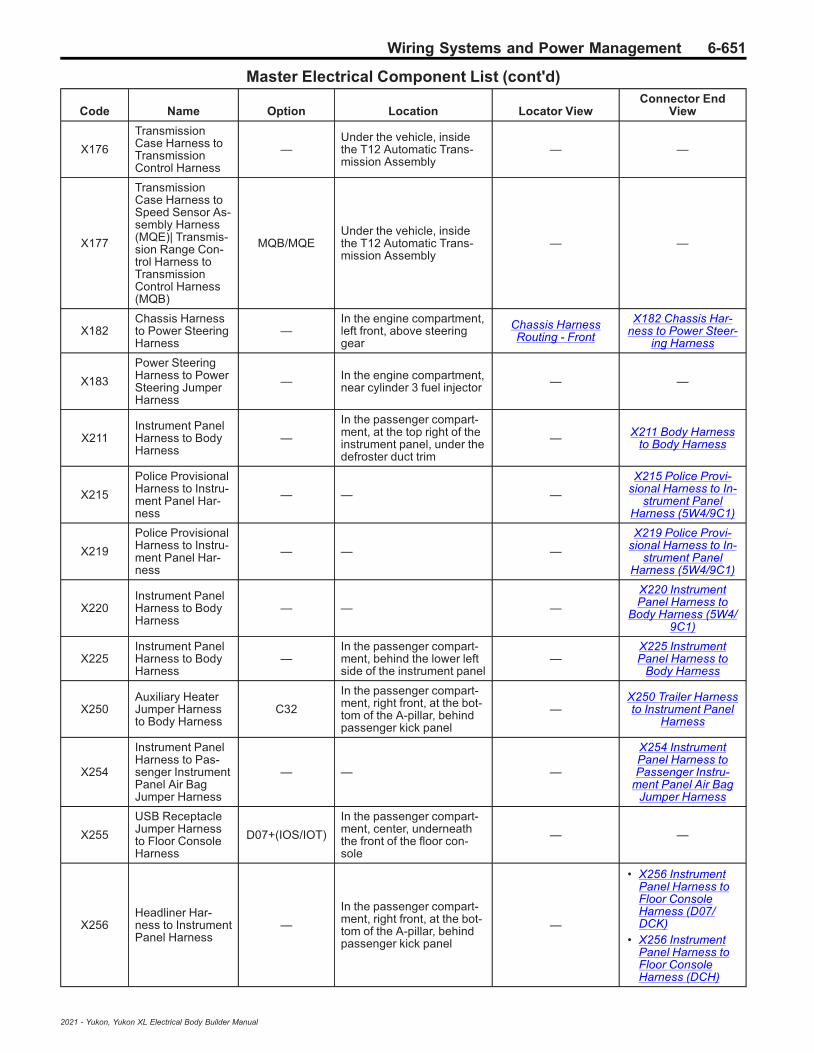
Wiring Systems and Power Management 6-651
Master Electrical Component List (cont'd)
Code Name Option Location Locator ViewConnector End
View
X176
TransmissionCase Harness toTransmissionControl Harness
—Under the vehicle, insidethe T12 Automatic Trans-mission Assembly
— —
X177
TransmissionCase Harness toSpeed Sensor As-sembly Harness(MQE)| Transmis-sion Range Con-trol Harness toTransmissionControl Harness(MQB)
MQB/MQEUnder the vehicle, insidethe T12 Automatic Trans-mission Assembly
— —
X182Chassis Harnessto Power SteeringHarness
—In the engine compartment,left front, above steeringgear
Chassis HarnessRouting - Front
X182 Chassis Har-ness to Power Steer-
ing Harness
X183
Power SteeringHarness to PowerSteering JumperHarness
— In the engine compartment,near cylinder 3 fuel injector — —
X211Instrument PanelHarness to BodyHarness
—
In the passenger compart-ment, at the top right of theinstrument panel, under thedefroster duct trim
— X211 Body Harnessto Body Harness
X215
Police ProvisionalHarness to Instru-ment Panel Har-ness
— — —
X215 Police Provi-sional Harness to In-
strument PanelHarness (5W4/9C1)
X219
Police ProvisionalHarness to Instru-ment Panel Har-ness
— — —
X219 Police Provi-sional Harness to In-
strument PanelHarness (5W4/9C1)
X220Instrument PanelHarness to BodyHarness
— — —
X220 InstrumentPanel Harness to
Body Harness (5W4/9C1)
X225Instrument PanelHarness to BodyHarness
—In the passenger compart-ment, behind the lower leftside of the instrument panel
—X225 InstrumentPanel Harness to
Body Harness
X250Auxiliary HeaterJumper Harnessto Body Harness
C32
In the passenger compart-ment, right front, at the bot-tom of the A-pillar, behindpassenger kick panel
—X250 Trailer Harnessto Instrument Panel
Harness
X254
Instrument PanelHarness to Pas-senger InstrumentPanel Air BagJumper Harness
— — —
X254 InstrumentPanel Harness toPassenger Instru-
ment Panel Air BagJumper Harness
X255
USB ReceptacleJumper Harnessto Floor ConsoleHarness
D07+(IOS/IOT)
In the passenger compart-ment, center, underneaththe front of the floor con-sole
— —
X256Headliner Har-ness to InstrumentPanel Harness
—
In the passenger compart-ment, right front, at the bot-tom of the A-pillar, behindpassenger kick panel
—
• X256 InstrumentPanel Harness toFloor ConsoleHarness (D07/DCK)
• X256 InstrumentPanel Harness toFloor ConsoleHarness (DCH)
2021 - Yukon, Yukon XL Electrical Body Builder Manual
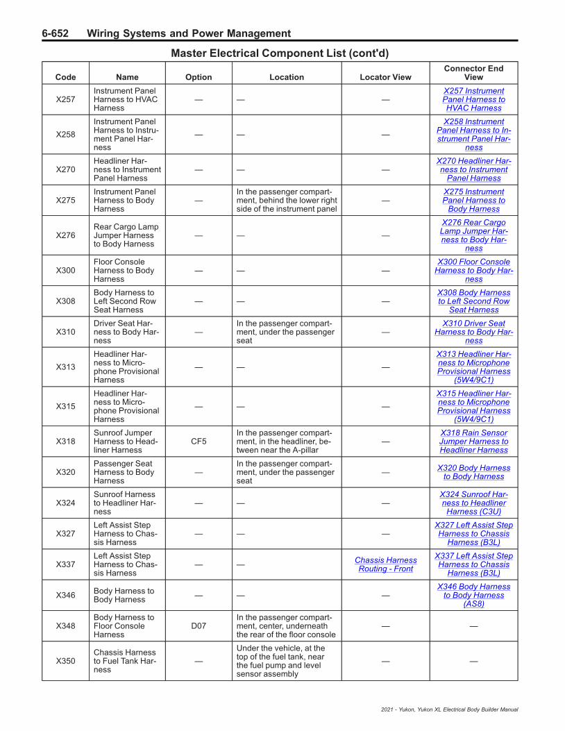
6-652 Wiring Systems and Power Management
Master Electrical Component List (cont'd)
Code Name Option Location Locator ViewConnector End
View
X257Instrument PanelHarness to HVACHarness
— — —X257 InstrumentPanel Harness toHVAC Harness
X258
Instrument PanelHarness to Instru-ment Panel Har-ness
— — —
X258 InstrumentPanel Harness to In-strument Panel Har-
ness
X270Headliner Har-ness to InstrumentPanel Harness
— — —X270 Headliner Har-ness to Instrument
Panel Harness
X275Instrument PanelHarness to BodyHarness
—In the passenger compart-ment, behind the lower rightside of the instrument panel
—X275 InstrumentPanel Harness to
Body Harness
X276Rear Cargo LampJumper Harnessto Body Harness
— — —
X276 Rear CargoLamp Jumper Har-ness to Body Har-
ness
X300Floor ConsoleHarness to BodyHarness
— — —X300 Floor Console
Harness to Body Har-ness
X308Body Harness toLeft Second RowSeat Harness
— — —X308 Body Harnessto Left Second Row
Seat Harness
X310Driver Seat Har-ness to Body Har-ness
—In the passenger compart-ment, under the passengerseat
—X310 Driver Seat
Harness to Body Har-ness
X313
Headliner Har-ness to Micro-phone ProvisionalHarness
— — —
X313 Headliner Har-ness to MicrophoneProvisional Harness
(5W4/9C1)
X315
Headliner Har-ness to Micro-phone ProvisionalHarness
— — —
X315 Headliner Har-ness to MicrophoneProvisional Harness
(5W4/9C1)
X318Sunroof JumperHarness to Head-liner Harness
CF5In the passenger compart-ment, in the headliner, be-tween near the A-pillar
—X318 Rain SensorJumper Harness toHeadliner Harness
X320Passenger SeatHarness to BodyHarness
—In the passenger compart-ment, under the passengerseat
— X320 Body Harnessto Body Harness
X324Sunroof Harnessto Headliner Har-ness
— — —X324 Sunroof Har-ness to Headliner
Harness (C3U)
X327Left Assist StepHarness to Chas-sis Harness
— — —X327 Left Assist StepHarness to Chassis
Harness (B3L)
X337Left Assist StepHarness to Chas-sis Harness
— — Chassis HarnessRouting - Front
X337 Left Assist StepHarness to Chassis
Harness (B3L)
X346 Body Harness toBody Harness — — —
X346 Body Harnessto Body Harness
(AS8)
X348Body Harness toFloor ConsoleHarness
D07In the passenger compart-ment, center, underneaththe rear of the floor console
— —
X350Chassis Harnessto Fuel Tank Har-ness
—
Under the vehicle, at thetop of the fuel tank, nearthe fuel pump and levelsensor assembly
— —
2021 - Yukon, Yukon XL Electrical Body Builder Manual
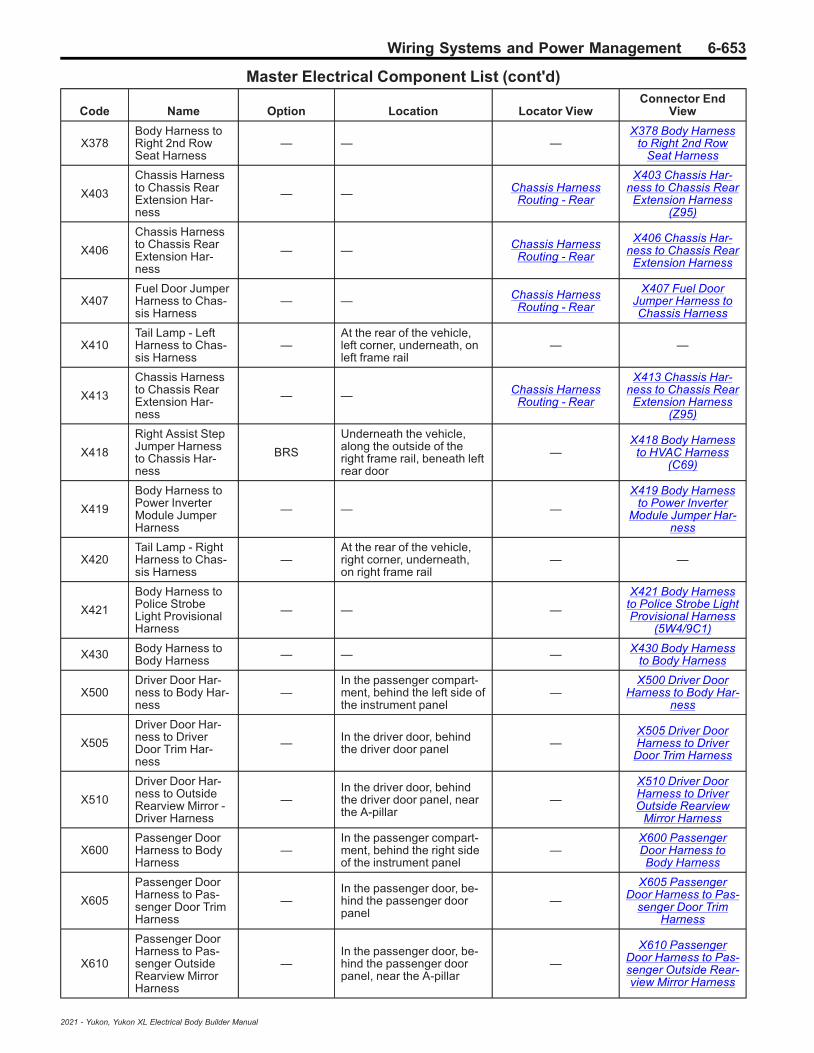
Wiring Systems and Power Management 6-653
Master Electrical Component List (cont'd)
Code Name Option Location Locator ViewConnector End
View
X378Body Harness toRight 2nd RowSeat Harness
— — —X378 Body Harness
to Right 2nd RowSeat Harness
X403
Chassis Harnessto Chassis RearExtension Har-ness
— — Chassis HarnessRouting - Rear
X403 Chassis Har-ness to Chassis RearExtension Harness
(Z95)
X406
Chassis Harnessto Chassis RearExtension Har-ness
— — Chassis HarnessRouting - Rear
X406 Chassis Har-ness to Chassis RearExtension Harness
X407Fuel Door JumperHarness to Chas-sis Harness
— — Chassis HarnessRouting - Rear
X407 Fuel DoorJumper Harness toChassis Harness
X410Tail Lamp - LeftHarness to Chas-sis Harness
—At the rear of the vehicle,left corner, underneath, onleft frame rail
— —
X413
Chassis Harnessto Chassis RearExtension Har-ness
— — Chassis HarnessRouting - Rear
X413 Chassis Har-ness to Chassis RearExtension Harness
(Z95)
X418
Right Assist StepJumper Harnessto Chassis Har-ness
BRS
Underneath the vehicle,along the outside of theright frame rail, beneath leftrear door
—X418 Body Harnessto HVAC Harness
(C69)
X419
Body Harness toPower InverterModule JumperHarness
— — —
X419 Body Harnessto Power Inverter
Module Jumper Har-ness
X420Tail Lamp - RightHarness to Chas-sis Harness
—At the rear of the vehicle,right corner, underneath,on right frame rail
— —
X421
Body Harness toPolice StrobeLight ProvisionalHarness
— — —
X421 Body Harnessto Police Strobe LightProvisional Harness
(5W4/9C1)
X430 Body Harness toBody Harness — — — X430 Body Harness
to Body Harness
X500Driver Door Har-ness to Body Har-ness
—In the passenger compart-ment, behind the left side ofthe instrument panel
—X500 Driver Door
Harness to Body Har-ness
X505
Driver Door Har-ness to DriverDoor Trim Har-ness
— In the driver door, behindthe driver door panel —
X505 Driver DoorHarness to Driver
Door Trim Harness
X510
Driver Door Har-ness to OutsideRearview Mirror -Driver Harness
—In the driver door, behindthe driver door panel, nearthe A-pillar
—
X510 Driver DoorHarness to DriverOutside Rearview
Mirror Harness
X600Passenger DoorHarness to BodyHarness
—In the passenger compart-ment, behind the right sideof the instrument panel
—X600 PassengerDoor Harness toBody Harness
X605
Passenger DoorHarness to Pas-senger Door TrimHarness
—In the passenger door, be-hind the passenger doorpanel
—
X605 PassengerDoor Harness to Pas-
senger Door TrimHarness
X610
Passenger DoorHarness to Pas-senger OutsideRearview MirrorHarness
—In the passenger door, be-hind the passenger doorpanel, near the A-pillar
—
X610 PassengerDoor Harness to Pas-senger Outside Rear-view Mirror Harness
2021 - Yukon, Yukon XL Electrical Body Builder Manual

6-654 Wiring Systems and Power Management
Master Electrical Component List (cont'd)
Code Name Option Location Locator ViewConnector End
View
X700Left Rear DoorHarness to BodyHarness
—In the passenger compart-ment, behind the left B-pil-lar, near the middle
—X700 Left Rear DoorHarness to Body Har-
ness
X705
Left Rear DoorHarness to LeftRear Door TrimHarness
— — —X705 Left Rear DoorHarness to Left RearDoor Trim Harness
X706
Left Rear DoorHarness to LeftRear Door TrimHarness
— — —X706 Left Rear DoorHarness to Left RearDoor Trim Harness
X800Right Rear DoorHarness to BodyHarness
—In the passenger compart-ment, behind the right B-pil-lar, near the middle
—X800 Right RearDoor Harness toBody Harness
X805
Right Rear DoorHarness to RightRear Door TrimHarness
— — —
X805 Right RearDoor Harness to
Right Rear Door TrimHarness
X806
Right Rear DoorHarness to RightRear Door TrimHarness
— — —
X806 Right RearDoor Harness to
Right Rear Door TrimHarness
X904
Chassis Harnessto Rear ChassisExtension Har-ness
—
• (Z45) Under the vehicle,rear center, above therear differential
• (-Z45) Under thevehicle, rear center,above the reardifferential
—
X904 Center HighMounted Stop LampJumper Harness to
Body Harness
X905 Liftgate Harnessto Body Harness — — —
X905 Liftgate Har-ness to Body Har-
ness
X907Liftgate ExtensionHarness to Lift-gate Harness
— — —X907 Liftgate Exten-sion Harness to Lift-
gate Harness
X909Endgate Harnessto Chassis Har-ness
UV2/UVB/UVI Under the vehicle, rear, leftof the spare tire — —
X917
Liftgate Harnessto Left StrobeLight Blunt Har-ness
— — —X917 Liftgate Har-ness to Left StrobeLight Blunt Harness
X918
Liftgate Harnessto Right StrobeLight Blunt CutHarness
— — —
X918 Liftgate Har-ness to Right StrobeLight Blunt Cut Har-
ness
X922Body Harness toRear Fascia Har-ness
— — —X922 Body Harnessto Rear Fascia Har-
ness
G104 Body Harness — — — —
G110 Body Harness — In the engine compartment,left side, attached to body — —
2021 - Yukon, Yukon XL Electrical Body Builder Manual

Wiring Systems and Power Management 6-655
Master Electrical Component List (cont'd)
Code Name Option Location Locator ViewConnector End
View
G117 Engine Harness —
• (L84/L87) In the enginecompartment, attachedto the left side of theengine block, below theexhaust manifold
• (LM2) In the enginecompartment, right rear,attached to the rightrear side of the engineblock, above engine oilfilter housing
— —
G120 Body Harness —In the engine compartment,right side, right of C1 Bat-tery
— —
G125 Power SteeringJumper Harness — — — —
G130 Negative BatteryCable Harness — In the engine compartment,
right rear corner — —
G131 Frame GroundStrap —
Under the vehicle, rightfront wheel well, behind in-ner fender, rearward ofupper control arm
— —
G132 Engine GroundStrap —
Under the vehicle, rightfront wheel well, behind in-ner fender, rearward of low-er control arm
— —
G133 Frame GroundStrap —
Under the vehicle, rightfront wheel well, behind in-ner fender, rearward ofupper control arm
— —
G134 Engine GroundStrap —
Under the vehicle, rightfront wheel well, behind in-ner fender, rearward of low-er control arm
— —
G175 Engine Harness — — — —
G178 Engine Harness — — — —
G179 Engine Harness — — — —
G200 Instrument PanelHarness —
In the passenger compart-ment, left front, below A-pil-lar, behind driver side kickpanel
— —
G220 Instrument PanelHarness —
In the passenger compart-ment, right front, below A-pillar, behind passengerside kick panel
— —
G300 Body Harness —In the passenger compart-ment, left side, at the bot-tom of the B-pillar
— —
G312 Body Harness —In the passenger compart-ment, right side, beneaththe passenger seat
— —
G405 Chassis Harness —
Under the rear of the ve-hicle, in front of the towhitch, mounted to the cen-ter of the frame
— —
2021 - Yukon, Yukon XL Electrical Body Builder Manual

6-656 Wiring Systems and Power Management
Master Electrical Component List (cont'd)
Code Name Option Location Locator ViewConnector End
View
J100 Front Fascia BOP
At the front of the vehicle,front center, in front of theradiator core support, at-tached to front fascia, be-tween breakout to B306AParking Assist Sensor -Front Left Outer and B306BParking Assist Sensor -Front Left Middle andbreakout to B174G Front-view Camera - Grille
— —
J101 Front Fascia BOP
At the front of the vehicle,front center, in front of theradiator core support, at-tached to front fascia, be-tween breakout to B306AParking Assist Sensor -Front Left Outer and B306BParking Assist Sensor -Front Left Middle andbreakout to B174G Front-view Camera - Grille
— —
J102 Front Fascia UD5
At the front of the vehicle,front center, in front of theradiator core support, at-tached to front fascia, be-tween breakout to B306AParking Assist Sensor -Front Left Outer and B306BParking Assist Sensor -Front Left Middle andbreakout to B174G Front-view Camera - Grille
• Front Fascia Har-ness Routing(X88)
• Front Fascia Har-ness Routing(Z88)
—
J103 Front Fascia UD5
At the front of the vehicle,front center, in front of theradiator core support, at-tached to front fascia, be-tween breakout to B306AParking Assist Sensor -Front Left Outer and B306BParking Assist Sensor -Front Left Middle andbreakout to B174G Front-view Camera - Grille
• Front Fascia Har-ness Routing(X88)
• Front Fascia Har-ness Routing(Z88)
—
J104 Front Fascia BOP
At the front of the vehicle,front center, in front of theradiator core support, at-tached to front fascia, be-tween breakout to B306AParking Assist Sensor -Front Left Outer and B306BParking Assist Sensor -Front Left Middle andbreakout to B174G Front-view Camera - Grille
Front Fascia HarnessRouting (X88) —
J105 Front Fascia T40
At the front of the vehicle,front center, in front of theradiator core support, at-tached to front fascia, be-tween breakout to B306AParking Assist Sensor -Front Left Outer and B306BParking Assist Sensor -Front Left Middle andbreakout to B174G Front-view Camera - Grille
Front Fascia HarnessRouting (Z88) —
2021 - Yukon, Yukon XL Electrical Body Builder Manual
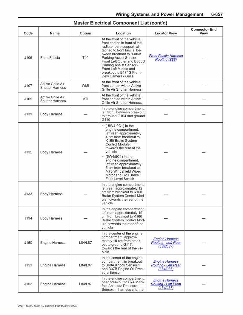
Wiring Systems and Power Management 6-657
Master Electrical Component List (cont'd)
Code Name Option Location Locator ViewConnector End
View
J106 Front Fascia T40
At the front of the vehicle,front center, in front of theradiator core support, at-tached to front fascia, be-tween breakout to B306AParking Assist Sensor -Front Left Outer and B306BParking Assist Sensor -Front Left Middle andbreakout to B174G Front-view Camera - Grille
Front Fascia HarnessRouting (Z88) —
J107 Active Grille AirShutter Harness WMI
At the front of the vehicle,front center, within ActiveGrille Air Shutter Harness
— —
J109 Active Grille AirShutter Harness VTI
At the front of the vehicle,front center, within ActiveGrille Air Shutter Harness
— —
J131 Body Harness —
In the engine compartment,left front, between breakoutto ground G104 and groundG110
— —
J132 Body Harness —
• (-5W4-9C1) In theengine compartment,left rear, approximately4 cm from breakout toK160 Brake SystemControl Module,towards the rear of thevehicle
• (5W4/9C1) In theengine compartment,left rear, approximately5 cm from breakout toM75 Windshield WiperMotor and B20 BrakeFluid Level Switch
— —
J133 Body Harness —
In the engine compartment,left rear, approximately 12cm from breakout to K160Brake System Control Mod-ule, towards the rear of thevehicle
— —
J134 Body Harness —
In the engine compartment,left rear, approximately 19cm from breakout to K160Brake System Control Mod-ule, towards the rear of thevehicle
— —
J150 Engine Harness L84/L87
In the center of the enginecompartment, approxi-mately 10 cm from break-out to ground G117,towards the rear of the ve-hicle
Engine HarnessRouting - Left Rear
(L84/L87)—
J151 Engine Harness L84/L87
In the center of the enginecompartment, in breakoutto B68A Knock Sensor 1and B37B Engine Oil Pres-sure Sensor
Engine HarnessRouting - Left Rear
(L84/L87)—
J152 Engine Harness L84/L87
In the engine compartment,near breakout to B74 Mani-fold Absolute PressureSensor, in harness channel
Engine HarnessRouting - Left Front
(L84/L87)—
2021 - Yukon, Yukon XL Electrical Body Builder Manual

6-658 Wiring Systems and Power Management
Master Electrical Component List (cont'd)
Code Name Option Location Locator ViewConnector End
View
J153 Engine Harness —
• (L84/L87) In the enginecompartment, nearbreakout to B74Manifold AbsolutePressure Sensor, inharness channel
• (LM2) In the enginecompartment, rightfront, approximately 25cm from breakout toB34J Engine CoolantTemperature Sensor 7
Engine HarnessRouting - Left Front
(L84/L87)—
J154 Engine Harness —
• (L84/L87) In the enginecompartment, nearbreakout to B74Manifold AbsolutePressure Sensor, inharness channel
• (LM2) In the enginecompartment, left front,approximately 9 cmfrom breakout to B1 A/CRefrigerant PressureSensor
Engine HarnessRouting - Left Front
(L84/L87)—
J155 Engine Harness L84/L87
In the engine compartment,near breakout to B74 Mani-fold Absolute PressureSensor, in harness channel
Engine HarnessRouting - Left Front
(L84/L87)—
J156 Engine Harness L84/L87
In the engine compartment,near breakout to B74 Mani-fold Absolute PressureSensor, in harness channel
Engine HarnessRouting - Left Front
(L84/L87)—
J157 Engine Harness L84/L87
In the engine compartment,near breakout to B74 Mani-fold Absolute PressureSensor, in harness channel
Engine HarnessRouting - Left Front
(L84/L87)—
J158 Engine Harness —
• (L84/L87) In the enginecompartment, frontcenter, betweenbreakout to Q38 ThrottleBody and breakout toT8A Ignition Coil 1
• (LM2) In the enginecompartment, left front,approximately 12 cmfrom breakout to B1 A/CRefrigerant PressureSensor
— —
J159 Engine Harness —
• (L84/L87) In the enginecompartment, frontcenter, betweenbreakout to Q38 ThrottleBody and breakout toT8A Ignition Coil 1
• (LM2) In the enginecompartment, rightfront, approximately 15cm from breakout toB34J Engine CoolantTemperature Sensor 7
Engine HarnessRouting - Left Front
(L84/L87)—
J161 Engine Harness L84/L87
In the engine compartment,front center, betweenbreakout to Q38 ThrottleBody and breakout to T8AIgnition Coil 1
Engine HarnessRouting - Left Front
(L84/L87)—
2021 - Yukon, Yukon XL Electrical Body Builder Manual

Wiring Systems and Power Management 6-659
Master Electrical Component List (cont'd)
Code Name Option Location Locator ViewConnector End
View
J162 Engine Harness —
• (L84/L87) In the enginecompartment, frontcenter, betweenbreakout to Q38 ThrottleBody and breakout toT8A Ignition Coil 1
• (LM2) In the enginecompartment, frontcenter, approximately 5cm from breakouttowards B195ANitrogen Oxides Sensor1, Q38 Throttle Body,and B193A Charge AirCoooler InletTemperature Sensor
Engine HarnessRouting - Left Front
(L84/L87)—
J163 Engine Harness L84/L87
In the engine compartment,front right, between break-out to G13 Generator andbreakout to G10R CoolingFan Motor - Right
Engine HarnessRouting - Left Front
(L84/L87)—
J164 Engine Harness L84/L87
In the engine compartment,rear of the engine, near thetop, approximately 6 cmfrom breakout to groundG175
— —
J165 Engine Harness L84/L87
In the engine compartment,rear of the engine, near thetop, between breakout toground G179 and cablechannel
Engine HarnessRouting - Left Rear
(L84/L87)—
J166 Engine Harness L84/L87
In the engine compartmentrear center, in harnesschannel, approximately 8cm from breakout towardseven bank 2 ignition coils
Engine HarnessRouting - Left Rear
(L84/L87)—
J167 Engine Harness L84/L87
In the engine compartmentrear center, in harnesschannel, in breakout to-wards bank 2 ignition coils
Engine HarnessRouting - Left Rear
(L84/L87)—
J168 Engine Harness —
• (L84/L87) In the enginecompartment, rearcenter, approximately10 cm from breakout toinline connectors X160and X161
• (LM2) In the enginecompartment, left front,approximately 5 cmfrom breakout to B1 A/CRefrigerant PressureSensor
Engine HarnessRouting - Left Rear
(L84/L87)—
J169 Engine Harness LM2
In the engine compartment,front, approximately 5 cmfrom breakout to inline con-nector X172
— —
J170 Engine Harness LM2
In the engine compartment,left rear, in harness chan-nel, attached to the left rearside of the engine
— —
2021 - Yukon, Yukon XL Electrical Body Builder Manual

6-660 Wiring Systems and Power Management
Master Electrical Component List (cont'd)
Code Name Option Location Locator ViewConnector End
View
J171 Body Harness —
In the engine compartment,right front, approximately 4cm from breakout to P12Horn, towards the rear ofthe vehicle
— —
J172 Body Harness —
• (SWB-5W4-9C1) In thepassengercompartment, leftmiddle, approximately 5cm from breakout toground G325, towardsthe rear of the vehicle
• (5W4/9C1/LWB) In thepassengercompartment, left rear,between breakout toground G325 andbreakout to F113D SeatBelt AnchorPretensioner - Driver
— —
J173 Body Harness —
In the engine compartment,right front, between break-out to X50A Fuse Block -Underhood X1 and break-out to X50A Fuse Block -Underhood X2
— —
J174 Body Harness —
• (SWB-5W4-9C1) In thepassengercompartment, leftmiddle, approximately10 cm from breakout toground G325, towardsthe rear of the vehicle
• (5W4/9C1/LWB) In thepassengercompartment, left rear,between breakout toground G325 andbreakout to F113D SeatBelt AnchorPretensioner - Driver
— —
J175 Body Harness —
In the engine compartment,right rear, between break-out to X50D Fuse Block -Battery and body harnessgrommet at the bulkhead
— —
J176 Chassis Harness —
• (SWB) In the enginecompartment, rightfront, in harnesschannel, approximately7 cm from breakout toX50A Fuse Block -Underhood X4, towardsthe rear of the vehicle
• (LWB) Under thevehicle, right side,approximately 5 cmfrom breakout towardsB195C Nitrogen OxidesSensor 3/B195BNitrogen Oxides Sensor2/ B136 ExhaustParticulate MatterSensor, towards thefront of the vehicle
— —
2021 - Yukon, Yukon XL Electrical Body Builder Manual
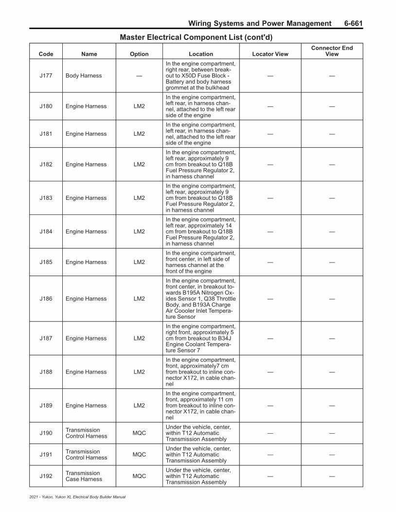
Wiring Systems and Power Management 6-661
Master Electrical Component List (cont'd)
Code Name Option Location Locator ViewConnector End
View
J177 Body Harness —
In the engine compartment,right rear, between break-out to X50D Fuse Block -Battery and body harnessgrommet at the bulkhead
— —
J180 Engine Harness LM2
In the engine compartment,left rear, in harness chan-nel, attached to the left rearside of the engine
— —
J181 Engine Harness LM2
In the engine compartment,left rear, in harness chan-nel, attached to the left rearside of the engine
— —
J182 Engine Harness LM2
In the engine compartment,left rear, approximately 9cm from breakout to Q18BFuel Pressure Regulator 2,in harness channel
— —
J183 Engine Harness LM2
In the engine compartment,left rear, approximately 9cm from breakout to Q18BFuel Pressure Regulator 2,in harness channel
— —
J184 Engine Harness LM2
In the engine compartment,left rear, approximately 14cm from breakout to Q18BFuel Pressure Regulator 2,in harness channel
— —
J185 Engine Harness LM2
In the engine compartment,front center, in left side ofharness channel at thefront of the engine
— —
J186 Engine Harness LM2
In the engine compartment,front center, in breakout to-wards B195A Nitrogen Ox-ides Sensor 1, Q38 ThrottleBody, and B193A ChargeAir Coooler Inlet Tempera-ture Sensor
— —
J187 Engine Harness LM2
In the engine compartment,right front, approximately 5cm from breakout to B34JEngine Coolant Tempera-ture Sensor 7
— —
J188 Engine Harness LM2
In the engine compartment,front, approximately7 cmfrom breakout to inline con-nector X172, in cable chan-nel
— —
J189 Engine Harness LM2
In the engine compartment,front, approximately 11 cmfrom breakout to inline con-nector X172, in cable chan-nel
— —
J190 TransmissionControl Harness MQC
Under the vehicle, center,within T12 AutomaticTransmission Assembly
— —
J191 TransmissionControl Harness MQC
Under the vehicle, center,within T12 AutomaticTransmission Assembly
— —
J192 TransmissionCase Harness MQC
Under the vehicle, center,within T12 AutomaticTransmission Assembly
— —
2021 - Yukon, Yukon XL Electrical Body Builder Manual

6-662 Wiring Systems and Power Management
Master Electrical Component List (cont'd)
Code Name Option Location Locator ViewConnector End
View
J193TransmissionRange ControlHarness
MQCUnder the vehicle, center,within T12 AutomaticTransmission Assembly
— —
J194 TransmissionCase Harness MQC
Under the vehicle, center,within T12 AutomaticTransmission Assembly
— —
J195 TransmissionCase Harness MQC
Under the vehicle, center,within T12 AutomaticTransmission Assembly
— —
J196 TransmissionCase Harness MQC
Under the vehicle, center,within T12 AutomaticTransmission Assembly
— —
J200 Body Harness —
In the passenger compart-ment, right middle, approxi-mately 10 cm frombreakout to F113P SeatBelt Anchor Prentesioner -Passenger, towards therear of othe vehicle
— —
J201 Body Harness —
In the passenger compart-ment, left front, within in-strument panel,approximately 4 cm frombreakout to B107 Accelera-tor Pedal Position Sensor,towards the right side of thevehicle
— —
J202 Body Harness —
In the passenger compart-ment, left front, within in-strument panel,approximately 14 cm frombreakout to B107 Accelera-tor Pedal Position Sensor,towards the right side of thevehicle
— —
J203 Body Harness —
In the passenger compart-ment, left front, within in-strument panel,approximately 19 cm frombreakout to B107 Accelera-tor Pedal Position Sensor,towards the right side of thevehicle
— —
J204 Body Harness —
In the passenger compart-ment, left front, within in-strument panel,approximately 24 cm frombreakout to B107 Accelera-tor Pedal Position Sensor,towards the right side of thevehicle
— —
J205 Body Harness —
In the passenger compart-ment, left front, within in-strument panel,approximately 30 cm frombreakout to B107 Accelera-tor Pedal Position Sensor,towards the right side of thevehicle
— —
2021 - Yukon, Yukon XL Electrical Body Builder Manual
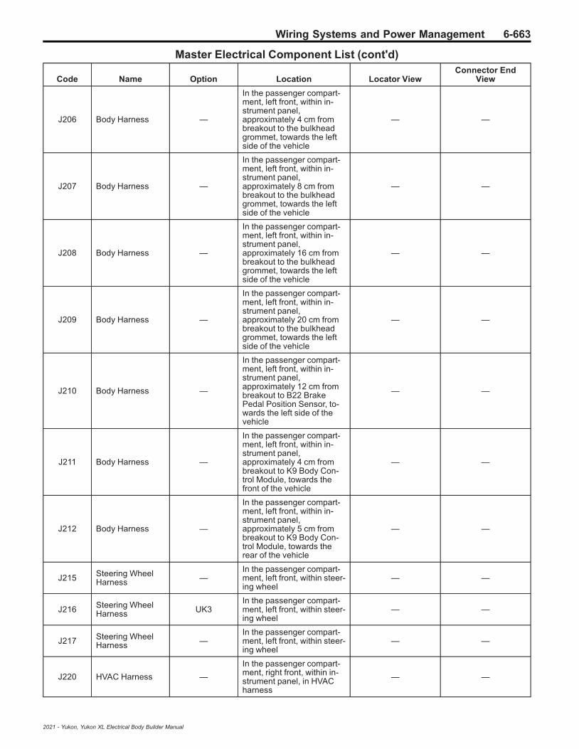
Wiring Systems and Power Management 6-663
Master Electrical Component List (cont'd)
Code Name Option Location Locator ViewConnector End
View
J206 Body Harness —
In the passenger compart-ment, left front, within in-strument panel,approximately 4 cm frombreakout to the bulkheadgrommet, towards the leftside of the vehicle
— —
J207 Body Harness —
In the passenger compart-ment, left front, within in-strument panel,approximately 8 cm frombreakout to the bulkheadgrommet, towards the leftside of the vehicle
— —
J208 Body Harness —
In the passenger compart-ment, left front, within in-strument panel,approximately 16 cm frombreakout to the bulkheadgrommet, towards the leftside of the vehicle
— —
J209 Body Harness —
In the passenger compart-ment, left front, within in-strument panel,approximately 20 cm frombreakout to the bulkheadgrommet, towards the leftside of the vehicle
— —
J210 Body Harness —
In the passenger compart-ment, left front, within in-strument panel,approximately 12 cm frombreakout to B22 BrakePedal Position Sensor, to-wards the left side of thevehicle
— —
J211 Body Harness —
In the passenger compart-ment, left front, within in-strument panel,approximately 4 cm frombreakout to K9 Body Con-trol Module, towards thefront of the vehicle
— —
J212 Body Harness —
In the passenger compart-ment, left front, within in-strument panel,approximately 5 cm frombreakout to K9 Body Con-trol Module, towards therear of the vehicle
— —
J215 Steering WheelHarness —
In the passenger compart-ment, left front, within steer-ing wheel
— —
J216 Steering WheelHarness UK3
In the passenger compart-ment, left front, within steer-ing wheel
— —
J217 Steering WheelHarness —
In the passenger compart-ment, left front, within steer-ing wheel
— —
J220 HVAC Harness —
In the passenger compart-ment, right front, within in-strument panel, in HVACharness
— —
2021 - Yukon, Yukon XL Electrical Body Builder Manual

6-664 Wiring Systems and Power Management
Master Electrical Component List (cont'd)
Code Name Option Location Locator ViewConnector End
View
J221 HVAC Harness —
In the passenger compart-ment, right front, within in-strument panel, in HVACharness
— —
J222 HVAC Harness —
In the passenger compart-ment, right front, within in-strument panel, in HVACharness
— —
J231 Instrument PanelHarness —
• (-GFW) In thepassengercompartment, left front,within instrument panel,approximately 14 cmfrom breakout to X84Data Link Connectorand K9 Body ControlModule
• (GFW) In the passengercompartment, left front,within instrument panel,approximately 10 cmfrom breakout to P16Instrument Cluster
— —
J233 Instrument PanelHarness —
In the passenger compart-ment, left front, within in-strument panel, in breakoutto X84 Data Link Connectorand K9 Body Control Mod-ule
— —
J234 Instrument PanelHarness —
• (5W4/9C1) In thepassengercompartment, left front,within instrument panel,approximately 5 cmfrom breakout to X84Data Link Connectorand K9 Body ControlModule
• (-5W4-9C1) In thepassengercompartment, left front,within instrument panel,in breakout to X84 DataLink Connector and K9Body Control Module
— —
J235 Instrument PanelHarness —
In the passenger compart-ment, left front, within in-strument panel,approximately 15 cm frombreakout to P16 InstrumentCluster
— —
J236 Instrument PanelHarness —
In the passenger compart-ment, left front, within in-strument panel,approximately 14 cm frombreakout to P16 InstrumentCluster
— —
J237 Instrument PanelHarness —
In the passenger compart-ment, left front, within in-strument panel,approximately 11 cm frombreakout to P16 InstrumentCluster
— —
2021 - Yukon, Yukon XL Electrical Body Builder Manual
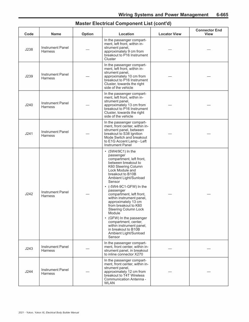
Wiring Systems and Power Management 6-665
Master Electrical Component List (cont'd)
Code Name Option Location Locator ViewConnector End
View
J238 Instrument PanelHarness —
In the passenger compart-ment, left front, within in-strument panel,approximately 9 cm frombreakout to P16 InstrumentCluster
— —
J239 Instrument PanelHarness —
In the passenger compart-ment, left front, within in-strument panel,approximately 10 cm frombreakout to P16 InstrumentCluster, towards the rightside of the vehicle
— —
J240 Instrument PanelHarness —
In the passenger compart-ment, left front, within in-strument panel,approximately 13 cm frombreakout to P16 InstrumentCluster, towards the rightside of the vehicle
— —
J241 Instrument PanelHarness —
In the passenger compart-ment, front center, within in-strument panel, betweenbreakout to S38 IgnitionMode Switch and breakoutto E1G Accent Lamp - LeftInstrument Panel
— —
J242 Instrument PanelHarness —
• (5W4/9C1) In thepassengercompartment, left front,between breakout toK60 Steering ColumnLock Module andbreakout to B10BAmbient Light/SunloadSensor
• (-5W4-9C1-GFW) In thepassengercompartment, left front,within instrument panel,approximately 13 cmfrom breakout to K60Steering Column LockModule
• (GFW) In the passengercompartment, center,within instrument panel,in breakout to B10BAmbient Light/SunloadSensor
— —
J243 Instrument PanelHarness —
In the passenger compart-ment, front center, within in-strument panel, in breakoutto inline connector X270
— —
J244 Instrument PanelHarness —
In the passenger compart-ment, front center, within in-strument panel,approximately 12 cm frombreakout to T4T WirelessCommunication Antenna -WLAN
— —
2021 - Yukon, Yukon XL Electrical Body Builder Manual

6-666 Wiring Systems and Power Management
Master Electrical Component List (cont'd)
Code Name Option Location Locator ViewConnector End
View
J245 Instrument PanelHarness —
In the passenger compart-ment, front center, within in-strument panel,approximately 5 cm frombreakout to S26 HazardWarning Switch
— —
J246 Instrument PanelHarness —
• (5W4/9C1/GFW) In thepassengercompartment, left front,between breakout toK60 Steering ColumnLock Module andbreakout to B10BAmbient Light/SunloadSensor
• (5W4-9C1-GFW) In thepassengercompartment, frontcenter, within instrumentpanel, betweenbreakout to S38 IgnitionMode Switch andbreakout to E1G AccentLamp - Left InstrumentPanel
— —
J247 Instrument PanelHarness —
In the passenger compart-ment, front center, within in-strument panel, betweenbreakout to X51R FuseBlock - Instrument Panel -Right X3 and breakout toinline connectors X256 andX255
— —
J248 Instrument PanelHarness —
In the passenger compart-ment, front right, within in-strument panel, betweenbreakout to B10B AmbientLight/Sunload Sensor andbreakout to inline connectorX270
— —
J249 Instrument PanelHarness —
In the passenger compart-ment, front right, within in-strument panel, betweenbreakout to B10B AmbientLight/Sunload Sensor andbreakout to inline connectorX270
— —
J250 Instrument PanelHarness —
• (-GFW) In thepassengercompartment, frontright, within instrumentpanel, betweenbreakout to X51R FuseBlock - InstrumentPanel Right X2 andbreakout to inlineconnector X270
• (GFW) In the passengercompartment, right ofcenter, within instrumentpanel, betweenbreakout to P19WSpeaker - RightInstrument Panel andbreakout to inlineconnector X270
— —
2021 - Yukon, Yukon XL Electrical Body Builder Manual
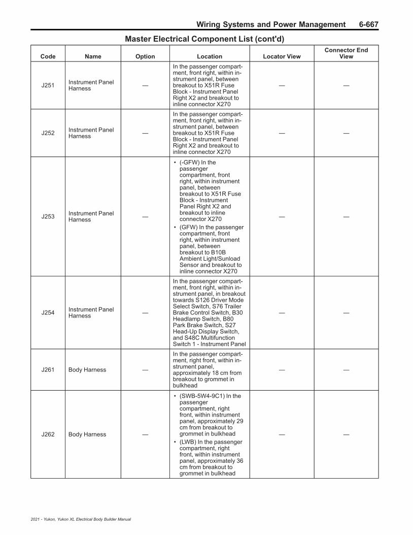
Wiring Systems and Power Management 6-667
Master Electrical Component List (cont'd)
Code Name Option Location Locator ViewConnector End
View
J251 Instrument PanelHarness —
In the passenger compart-ment, front right, within in-strument panel, betweenbreakout to X51R FuseBlock - Instrument PanelRight X2 and breakout toinline connector X270
— —
J252 Instrument PanelHarness —
In the passenger compart-ment, front right, within in-strument panel, betweenbreakout to X51R FuseBlock - Instrument PanelRight X2 and breakout toinline connector X270
— —
J253 Instrument PanelHarness —
• (-GFW) In thepassengercompartment, frontright, within instrumentpanel, betweenbreakout to X51R FuseBlock - InstrumentPanel Right X2 andbreakout to inlineconnector X270
• (GFW) In the passengercompartment, frontright, within instrumentpanel, betweenbreakout to B10BAmbient Light/SunloadSensor and breakout toinline connector X270
— —
J254 Instrument PanelHarness —
In the passenger compart-ment, front right, within in-strument panel, in breakouttowards S126 Driver ModeSelect Switch, S76 TrailerBrake Control Switch, B30Headlamp Switch, B80Park Brake Switch, S27Head-Up Display Switch,and S48C MultifunctionSwitch 1 - Instrument Panel
— —
J261 Body Harness —
In the passenger compart-ment, right front, within in-strument panel,approximately 18 cm frombreakout to grommet inbulkhead
— —
J262 Body Harness —
• (SWB-5W4-9C1) In thepassengercompartment, rightfront, within instrumentpanel, approximately 29cm from breakout togrommet in bulkhead
• (LWB) In the passengercompartment, rightfront, within instrumentpanel, approximately 36cm from breakout togrommet in bulkhead
— —
2021 - Yukon, Yukon XL Electrical Body Builder Manual

6-668 Wiring Systems and Power Management
Master Electrical Component List (cont'd)
Code Name Option Location Locator ViewConnector End
View
J263 Body Harness —
• (SWB-5W4-9C1) In thepassengercompartment, rightfront, within instrumentpanel, approximately 36cm from breakout togrommet in bulkhead
• (5W4/9C1/LWB) In thepassengercompartment, rightfront, within instrumentpanel, approximately 29cm from breakout togrommet in bulkhead
— —
J264 Body Harness —
• (GMC SWB) In thepassengercompartment, rightfront, within instrumentpanel, approximately 51cm from breakout togrommet in bulkhead
• (SWB-5W4-9C1) In thepassengercompartment, rightcenter, in harnesschannel near rightB-pillar, approximately 5cm from breakouttowards the passengerseat, towards the rear ofthe vehicle
• (LWB) In the passengercompartment, right side,approximately 13 cmfrom breakout to groundG328, towards the frontof the vehicle
— —
J265 Body Harness —
In the passenger compart-ment, right front, within in-strument panel,approximately 57 cm frombreakout to grommet inbulkhead
— —
J266 Body Harness —
In the passenger compart-ment, right front, within in-strument panel,approximately 6 cm frombreakout to X51R FuseBlock - Instrument PanelRight X1, towards the rearof the vehicle
— —
J267 Body Harness —
In the passenger compart-ment, right front, approxi-mately 19 cm frombreakout to X51R FuseBlock - Instrument PanelRight
— —
2021 - Yukon, Yukon XL Electrical Body Builder Manual

Wiring Systems and Power Management 6-669
Master Electrical Component List (cont'd)
Code Name Option Location Locator ViewConnector End
View
J268 Body Harness —
• (SWB-5W4-9C1) In thepassengercompartment, rightfront, within instrumentpanel, approximately 3cm from breakout toinline connector X218,towards the rear of thevehicle
• (LWB) In the passengercompartment, rightfront, approximately 19cm from breakout toX51R Fuse Block -Instrument Panel Right
— —
J300 Floor Console —
• (DCH) In the passengercompartment, frontcenter, beneath floorconsole, approximately5 cm from breakout toinline connector X300
• (D07) In the passengercompartment, frontcenter, beneath floorconsole, approximately18 cm from breakout toinline connector X300
• (DCK) In the passengercompartment, frontcenter, beneath floorconsole, betweenbreakout towards S15Center ConsoleCompartment CoolerSwitch and AuxiliaryAudio Input 2 andbreakout to inlineconnectors X255and X256
— —
J301 Floor Console —
• (DCH) In the passengercompartment, frontcenter, beneath floorconsole, approximately18 cm from breakout toSliding Floor ConsoleModule
• (D07) In the passengercompartment, frontcenter, beneath floorconsole, approximately20 cm from breakout toinline connector X300
• (DCK) In the passengercompartment, frontcenter, beneath floorconsole, approximately20 cm from breakout toinline connector X300
— —
2021 - Yukon, Yukon XL Electrical Body Builder Manual

6-670 Wiring Systems and Power Management
Master Electrical Component List (cont'd)
Code Name Option Location Locator ViewConnector End
View
J302 Floor Console —
• (DCH) In the passengercompartment, frontcenter, beneath floorconsole, approximately14 cm from breakout toB101 ImmobilizerAntenna
• (D07) In the passengercompartment, frontcenter, beneath floorconsole, approximately5 cm from breakout toauxiliary audio input 2
• (DCK) In the passengercompartment, frontcenter, beneath floorconsole, approximately14 cm from breakout toinline connector X301
— —
J303 Floor Console D07
• (D07) In the passengercompartment, frontcenter, beneath floorconsole, approximately29 cm from breakout toinline connector X300
• (DCK) In the passengercompartment, frontcenter, beneath floorconsole, approximately30 cm from breakout toinline connector X301
— —
J304 Floor Console D07
In the passenger compart-ment, front center, beneathfloor console, approxi-mately 48 cm from break-out to inline connectorX300
— —
J305 Floor Console —
• (D07) In the passengercompartment, frontcenter, beneath floorconsole, approximately50 cm from breakout toinline connector X300
• (DCK) In the passengercompartment, frontcenter, beneath floorconsole, betweenbreakout towards S15Center ConsoleCompartment CoolerSwitch and AuxiliaryAudio Input 2 andbreakout to inlineconnectors X255and X256
— —
J306 Auxiliary HVACHarness —
In the passenger compart-ment, front center, beneathfloor console, within Auxili-ary HVAC harness
— —
J307 Auxiliary HVACHarness —
In the passenger compart-ment, front center, beneathfloor console, within Auxili-ary HVAC harness
— —
2021 - Yukon, Yukon XL Electrical Body Builder Manual

Wiring Systems and Power Management 6-671
Master Electrical Component List (cont'd)
Code Name Option Location Locator ViewConnector End
View
J308 Auxiliary HVACHarness —
In the passenger compart-ment, front center, beneathfloor console, within Auxili-ary HVAC harness
— —
J309 Auxiliary HVACHarness —
In the passenger compart-ment, front center, beneathfloor console, within Auxili-ary HVAC harness
— —
J310 Driver Seat Har-ness A45/AUN
In the passenger compart-ment, left front, within driverseat
— —
J311 Driver Seat Har-ness A45/AVU
In the passenger compart-ment, left front, within driverseat
— —
J312 Driver Seat Har-ness AVK
In the passenger compart-ment, left front, within driverseat
— —
J313 Driver Seat Har-ness —
In the passenger compart-ment, left front, within driverseat
— —
J314 Driver Seat Har-ness —
In the passenger compart-ment, left front, within driverseat
— —
J320 Passenger SeatHarness UW9
In the passenger compart-ment, right front, within pas-senger seat
— —
J321 Passenger SeatHarness UW9
In the passenger compart-ment, right front, within pas-senger seat
— —
J329 Body Harness LWB
In the passenger compart-ment, left middle, in har-ness channel near left B-pillar, in breakout towardsinline connector X310
— —
J331 Body Harness —
In the passenger compart-ment, front center, beneathfloor console, approxi-mately 10 cm from break-out to ground G326,towards the right side of thevehicle
— —
2021 - Yukon, Yukon XL Electrical Body Builder Manual
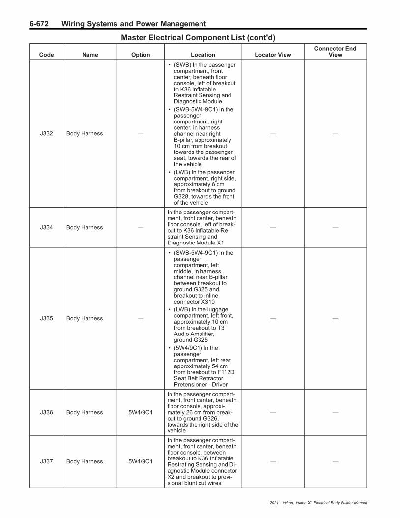
6-672 Wiring Systems and Power Management
Master Electrical Component List (cont'd)
Code Name Option Location Locator ViewConnector End
View
J332 Body Harness —
• (SWB) In the passengercompartment, frontcenter, beneath floorconsole, left of breakoutto K36 InflatableRestraint Sensing andDiagnostic Module
• (SWB-5W4-9C1) In thepassengercompartment, rightcenter, in harnesschannel near rightB-pillar, approximately10 cm from breakouttowards the passengerseat, towards the rear ofthe vehicle
• (LWB) In the passengercompartment, right side,approximately 8 cmfrom breakout to groundG328, towards the frontof the vehicle
— —
J334 Body Harness —
In the passenger compart-ment, front center, beneathfloor console, left of break-out to K36 Inflatable Re-straint Sensing andDiagnostic Module X1
— —
J335 Body Harness —
• (SWB-5W4-9C1) In thepassengercompartment, leftmiddle, in harnesschannel near B-pillar,between breakout toground G325 andbreakout to inlineconnector X310
• (LWB) In the luggagecompartment, left front,approximately 10 cmfrom breakout to T3Audio Amplifier,ground G325
• (5W4/9C1) In thepassengercompartment, left rear,approximately 54 cmfrom breakout to F112DSeat Belt RetractorPretensioner - Driver
— —
J336 Body Harness 5W4/9C1
In the passenger compart-ment, front center, beneathfloor console, approxi-mately 26 cm from break-out to ground G326,towards the right side of thevehicle
— —
J337 Body Harness 5W4/9C1
In the passenger compart-ment, front center, beneathfloor console, betweenbreakout to K36 InflatableRestrating Sensing and Di-agnostic Module connectorX2 and breakout to provi-sional blunt cut wires
— —
2021 - Yukon, Yukon XL Electrical Body Builder Manual

Wiring Systems and Power Management 6-673
Master Electrical Component List (cont'd)
Code Name Option Location Locator ViewConnector End
View
J338 Body Harness 5W4/9C1
In the passenger compart-ment, left front, in harnesschannel near left B-pillar,between breakout towardsdriver seat and breakout toground G325
— —
J339 Body Harness 5W4/9C1
In the passenger compart-ment, left front, in harnesschannel near left B-pillar,between breakout towardsdriver seat and breakout toground G325
— —
J340 Body Harness 5W4/9C1
In the passenger compart-ment, left front, in harnesschannel near left B-pillar,between breakout towardsdriver seat and breakout toground G325
— —
J341 Body Harness 5W4/9C1
In the passenger compart-ment, left rear, betweenbreakout to ground G325and breakout to F113DSeat Belt Anchor Preten-sioner - Driver
— —
J342 Body Harness 5W4/9C1
In the passenger compart-ment, left rear, betweenbreakout to ground G325and breakout to F113DSeat Belt Anchor Preten-sioner - Driver
— —
J343 Body Harness 5W4/9C1
In the passenger compart-ment, left rear, betweenbreakout to ground G325and breakout to F113DSeat Belt Anchor Preten-sioner - Driver
— —
J344 Body Harness 5W4/9C1
In the passenger compart-ment, left rear, approxi-mately 3 cm from breakoutto F113D Seat Belt AnchorPretensioner - Driver, to-wards the rear of the ve-hicle
— —
J345 Body Harness 5W4/9C1
In the passenger compart-ment, left rear, approxi-mately 7 cm from breakoutto F113D Seat Belt AnchorPretensioner - Driver, to-wards the rear of the ve-hicle
— —
J346 Body Harness 5W4/9C1
In the passenger compart-ment, left rear, approxi-mately 10 cm frombreakout to F113D SeatBelt Anchor Pretensioner -Driver, towards the rear ofthe vehicle
— —
J347 Body Harness 5W4/9C1
In the passenger compart-ment, left rear, approxi-mately 4 cm from breakoutto F112D Seat Belt Retrac-tor Pretensioner - Driver, to-wards the rear of thevehicle
— —
2021 - Yukon, Yukon XL Electrical Body Builder Manual

6-674 Wiring Systems and Power Management
Master Electrical Component List (cont'd)
Code Name Option Location Locator ViewConnector End
View
J348 Body Harness 5W4/9C1
In the passenger compart-ment, left rear, approxi-mately 7 cm from breakoutto F112D Seat Belt Retrac-tor Pretensioner - Driver, to-wards the rear of thevehicle
— —
J349 Body Harness 5W4/9C1
In the passenger compart-ment, left rear, approxi-mately 10 cm frombreakout to F112D SeatBelt Retractor Pretensioner- Driver, towards the rear ofthe vehicle
— —
J350 Body Harness 5W4/9C1
In the passenger compart-ment, left rear, approxi-mately 14 cm frombreakout to F112D SeatBelt Retractor Pretensioner- Driver, towards the rear ofthe vehicle
— —
J351 Body Harness —
In the passenger compart-ment, left side, approxi-mately 10 cm frombreakout to inline connectorX320
— —
J352 Body Harness 5W4/9C1
In the passenger compart-ment, left rear, approxi-mately 17 cm frombreakout to F112D SeatBelt Retractor Pretensioner- Driver, towards the rear ofthe vehicle
— —
J357 Body Harness —
• (SWB) In the passengercompartment, frontcenter, beneath floorconsole, approximately5 cm from breakout toSpeaker - SubwooferFront
• (LWB) In the passengercompartment, rightfront, approximately 9cm from breakout toinline connector X300,towards the right side ofthe vehicle
— —
J358 Body Harness —
• (SWB-5W4-9C1) In thepassengercompartment, frontcenter, beneath floorconsole, approximately5 cm from breakout toSpeaker - SubwooferFront
• (LWB) In the passengercompartment, rightfront, approximately 16cm from breakout toinline connector X300,towards the right side ofthe vehicle
— —
2021 - Yukon, Yukon XL Electrical Body Builder Manual
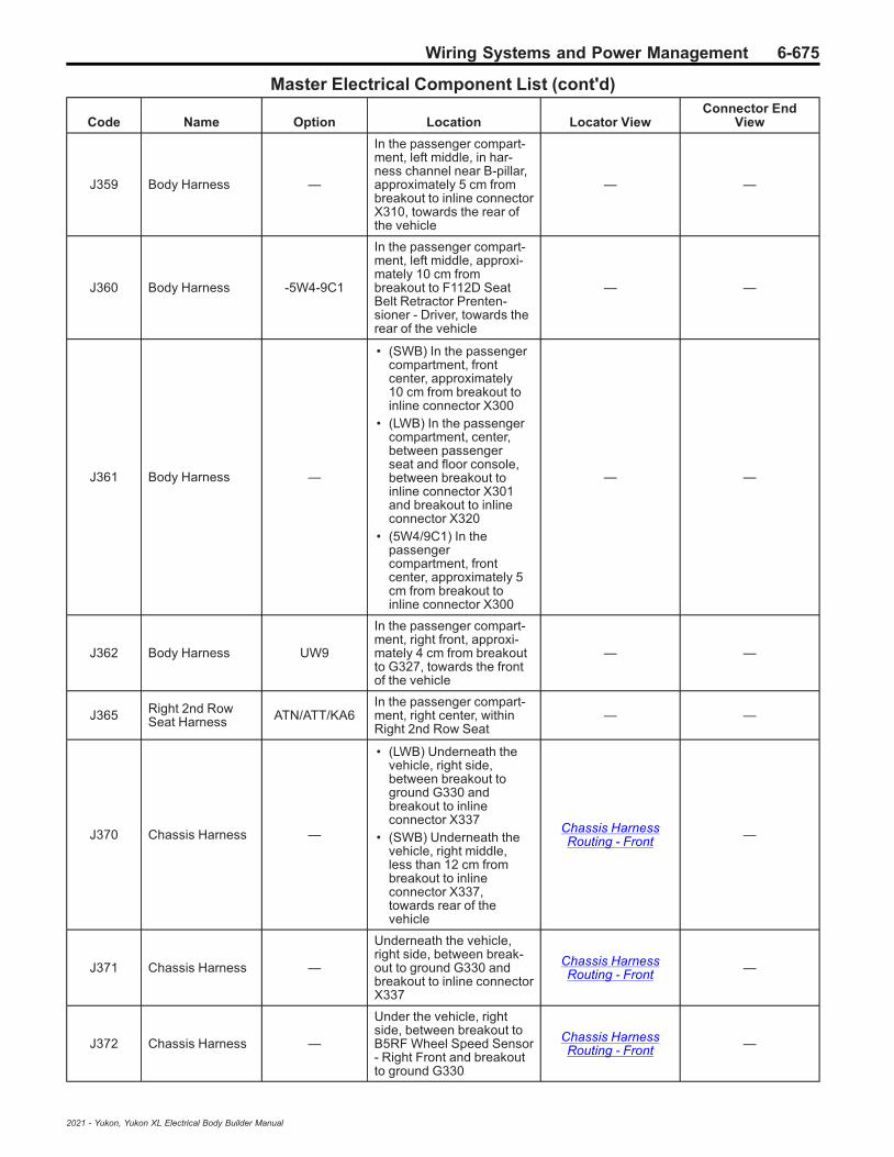
Wiring Systems and Power Management 6-675
Master Electrical Component List (cont'd)
Code Name Option Location Locator ViewConnector End
View
J359 Body Harness —
In the passenger compart-ment, left middle, in har-ness channel near B-pillar,approximately 5 cm frombreakout to inline connectorX310, towards the rear ofthe vehicle
— —
J360 Body Harness -5W4-9C1
In the passenger compart-ment, left middle, approxi-mately 10 cm frombreakout to F112D SeatBelt Retractor Prenten-sioner - Driver, towards therear of the vehicle
— —
J361 Body Harness —
• (SWB) In the passengercompartment, frontcenter, approximately10 cm from breakout toinline connector X300
• (LWB) In the passengercompartment, center,between passengerseat and floor console,between breakout toinline connector X301and breakout to inlineconnector X320
• (5W4/9C1) In thepassengercompartment, frontcenter, approximately 5cm from breakout toinline connector X300
— —
J362 Body Harness UW9
In the passenger compart-ment, right front, approxi-mately 4 cm from breakoutto G327, towards the frontof the vehicle
— —
J365 Right 2nd RowSeat Harness ATN/ATT/KA6
In the passenger compart-ment, right center, withinRight 2nd Row Seat
— —
J370 Chassis Harness —
• (LWB) Underneath thevehicle, right side,between breakout toground G330 andbreakout to inlineconnector X337
• (SWB) Underneath thevehicle, right middle,less than 12 cm frombreakout to inlineconnector X337,towards rear of thevehicle
Chassis HarnessRouting - Front —
J371 Chassis Harness —
Underneath the vehicle,right side, between break-out to ground G330 andbreakout to inline connectorX337
Chassis HarnessRouting - Front —
J372 Chassis Harness —
Under the vehicle, rightside, between breakout toB5RF Wheel Speed Sensor- Right Front and breakoutto ground G330
Chassis HarnessRouting - Front —
2021 - Yukon, Yukon XL Electrical Body Builder Manual

6-676 Wiring Systems and Power Management
Master Electrical Component List (cont'd)
Code Name Option Location Locator ViewConnector End
View
J373 Chassis Harness LM2
Underneath the vehicle,right middle, approximately22 cm from breakout to K4Assist Step Control Mod-ule, towards the front of thevehicle
— —
J374 Chassis Harness LM2
Underneath the vehicle,right middle, approximately17 cm from breakout to K4Assist Step Control Mod-ule, towards the front of thevehicle
— —
J380 Headliner Har-ness —
• (C3U) In the passengercompartment, rightfront, behind passengerA-pillar trim,approximately 15 cmabove harness channel
• (-C3U) In the passengercompartment, left front,above headliner,between breakout toA10 Inside RearviewMirror and breakout toE31L Sunshade MirrorLamp - Left
— —
J381 Headliner Har-ness —
In the passenger compart-ment, front center, aboveheadliner, between break-out to A98 Front OverheadConsole and breakout toE31R Sunshade MirrorLamp - Right
— —
J382 Headliner Har-ness C3U
In the passenger compart-ment, front center, aboveheadliner, between break-out to A98 Front OverheadConsole and breakout toE31R Sunshade MirrorLamp - Right
— —
J383 Headliner Har-ness —
• (C3U) In the passengercompartment, frontcenter, above headliner,approximately 6 cmfrom breakout to A10Inside Rearview Mirror
• In the passengercompartment, rightfront, behind passengerA-pillar trim, near theright front corner of theheadliner (-C3U)
— —
2021 - Yukon, Yukon XL Electrical Body Builder Manual

Wiring Systems and Power Management 6-677
Master Electrical Component List (cont'd)
Code Name Option Location Locator ViewConnector End
View
J400 Body Harness —
• (SWB-5W4-9C1) In theluggage compartment,left front, approximately21 cm from the breakoutto S143L Folding SeatControl Switch - 2ndRow Left, towards therear of the vehicle
• (LWB) In the luggagecompartment, left side,approximately 4 cmfrom breakout to K38Chassis Control Module
• (5W4/9C1) In theluggage compartment,left rear, approximately8 cm from breakout toX63A Junction Block -Rear Body
— —
J401 Body Harness —
In the passenger compart-ment, left middle, approxi-mately 5 cm from breakoutto F112D Seat Belt Retrac-tor Prentensioner - Driver,towards the rear of the ve-hicle
— —
J402 Body Harness —
• (SWB) In the luggagecompartment, left side,in breakout of harnessgoing towards T3 Audioamplifier and/or K157Video ProcessingControl Module
• (LWB) In the luggagecompartment, left side,approximately 68 cmfrom breakout to T3Audio Amplifier, towardsthe rear of the vehicle
— —
J403 Body Harness —
• (SWB-5W4-9C1) In theluggage compartment,left side, approximately8 cm from breakout toK77 Remote ControlDoor Lock Receiver,towards the rear of thevehicle
• (LWB) In the luggagecompartment, rightfront, approximately 10cm from breakout toX92BCR USBReceptacle - 3rd RowSeat Right, towards therear of the vehicle
— —
2021 - Yukon, Yukon XL Electrical Body Builder Manual
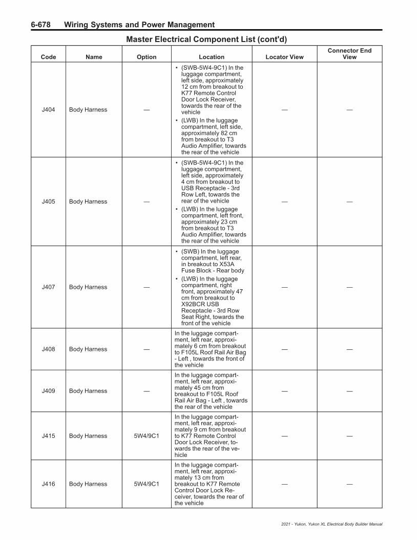
6-678 Wiring Systems and Power Management
Master Electrical Component List (cont'd)
Code Name Option Location Locator ViewConnector End
View
J404 Body Harness —
• (SWB-5W4-9C1) In theluggage compartment,left side, approximately12 cm from breakout toK77 Remote ControlDoor Lock Receiver,towards the rear of thevehicle
• (LWB) In the luggagecompartment, left side,approximately 82 cmfrom breakout to T3Audio Amplifier, towardsthe rear of the vehicle
— —
J405 Body Harness —
• (SWB-5W4-9C1) In theluggage compartment,left side, approximately4 cm from breakout toUSB Receptacle - 3rdRow Left, towards therear of the vehicle
• (LWB) In the luggagecompartment, left front,approximately 23 cmfrom breakout to T3Audio Amplifier, towardsthe rear of the vehicle
— —
J407 Body Harness —
• (SWB) In the luggagecompartment, left rear,in breakout to X53AFuse Block - Rear body
• (LWB) In the luggagecompartment, rightfront, approximately 47cm from breakout toX92BCR USBReceptacle - 3rd RowSeat Right, towards thefront of the vehicle
— —
J408 Body Harness —
In the luggage compart-ment, left rear, approxi-mately 6 cm from breakoutto F105L Roof Rail Air Bag- Left , towards the front ofthe vehicle
— —
J409 Body Harness —
In the luggage compart-ment, left rear, approxi-mately 45 cm frombreakout to F105L RoofRail Air Bag - Left , towardsthe rear of the vehicle
— —
J415 Body Harness 5W4/9C1
In the luggage compart-ment, left rear, approxi-mately 9 cm from breakoutto K77 Remote ControlDoor Lock Receiver, to-wards the rear of the ve-hicle
— —
J416 Body Harness 5W4/9C1
In the luggage compart-ment, left rear, approxi-mately 13 cm frombreakout to K77 RemoteControl Door Lock Re-ceiver, towards the rear ofthe vehicle
— —
2021 - Yukon, Yukon XL Electrical Body Builder Manual

Wiring Systems and Power Management 6-679
Master Electrical Component List (cont'd)
Code Name Option Location Locator ViewConnector End
View
J417 Body Harness 5W4/9C1
In the luggage compart-ment, left rear, approxi-mately 4 cm from breakoutto USB Receptacle - 3rdRow Left, towards the rearof the vehicle
— —
J425 Body Harness —
• (SWB-5W4-9C1) In theluggage compartment,right front,approximately 44 cmfrom breakout toX92BCR USBReceptacle - 3rd RowSeat Right, towards thefront of the vehicle
• (LWB) In the luggagecompartment, rightfront, approximately 12cm from breakout toS143R Folding SeatControl Switch - 2ndRow, towards the rear ofthe vehicle
— —
J426 Body Harness -5W4-9C1
In the luggage compart-ment, right front, approxi-mately 35 cm frombreakout to X92BCR USBReceptacle - 3rd Row SeatRight, towards the front ofthe vehicle
— —
J427 Body Harness —
• (SWB-5W4-9C1) In theluggage compartment,right front,approximately 23 cmfrom breakout toX92BCR USBReceptacle - 3rd RowSeat Right, towards thefront of the vehicle
• (LWB) In the luggagecompartment, rightfront, approximately 22cm from breakout toS143R Folding SeatControl Switch - 2ndRow, towards the rear ofthe vehicle
— —
J428 Body Harness —
In the passenger compart-ment, right middle, approxi-mately 5 cm from breakoutto F113P Seat Belt AnchorPrentesioner - Passenger,towards the rear of othe ve-hicle
— —
J429 Body Harness —
In the luggage compart-ment, right front, approxi-mately 11 cm from breakoutto X92BCR USB Recep-tacle - 3rd Row Seat Right,towards the rear of the ve-hicle
— —
2021 - Yukon, Yukon XL Electrical Body Builder Manual
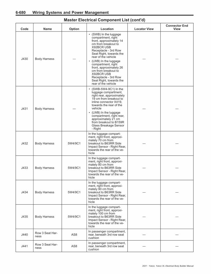
6-680 Wiring Systems and Power Management
Master Electrical Component List (cont'd)
Code Name Option Location Locator ViewConnector End
View
J430 Body Harness —
• (SWB) In the luggagecompartment, rightfront, approximately 14cm from breakout toX92BCR USBReceptacle - 3rd RowSeat Right, towards therear of the vehicle
• (LWB) In the luggagecompartment, rightfront, approximately 26cm from breakout toX92BCR USBReceptacle - 3rd RowSeat Right, towards therear of the vehicle
— —
J431 Body Harness —
• (SWB-5W4-9C1) In theluggage compartment,right rear, approximately19 cm from breakout toinline connector X419,towards the rear of thevehicle
• (LWB) In the luggagecompartment, right rear,approximately 21 cmfrom breakout to B159RGlass Breakage Sensor- Right
— —
J432 Body Harness 5W4/9C1
In the luggage compart-ment, right front, approxi-mately 70 cm frombreakout to B63RR SideImpact Sensor - Right Rear,towards the rear of the ve-hicle
— —
J433 Body Harness 5W4/9C1
In the luggage compart-ment, right front, approxi-mately 80 cm frombreakout to B63RR SideImpact Sensor - Right Rear,towards the rear of the ve-hicle
— —
J434 Body Harness 5W4/9C1
In the luggage compart-ment, right front, approxi-mately 90 cm frombreakout to B63RR SideImpact Sensor - Right Rear,towards the rear of the ve-hicle
— —
J435 Body Harness 5W4/9C1
In the luggage compart-ment, right front, approxi-mately 100 cm frombreakout to B63RR SideImpact Sensor - Right Rear,towards the rear of the ve-hicle
— —
J440 Row 3 Seat Har-ness AS8
In passenger compartment,rear, beneath 3rd row seatcushion
— —
J441 Row 3 Seat Har-ness AS8
In passenger compartment,rear, beneath 3rd row seatcushion
— —
2021 - Yukon, Yukon XL Electrical Body Builder Manual

Wiring Systems and Power Management 6-681
Master Electrical Component List (cont'd)
Code Name Option Location Locator ViewConnector End
View
J450 Chassis Harness —
Under the vehicle, rightrear, approximately 5 cmfrom breakout to groundG404
— —
J451 Chassis Harness —
Under the vehicle, rear mid-dle, approximately 41 cmfrom harness channelbreakout at the right rearside of the vehicle, towardsthe left side of the vehicle
Chassis HarnessRouting - Rear —
J452 Chassis Harness —
Under the vehicle, rightrear, approximately 23 cmfrom breakout to E42R TailLamp Assembly - Right
Chassis HarnessRouting - Rear —
J453 Chassis Harness —
Under the vehicle, rightrear, approximately 23 cmfrom breakout to E42R TailLamp Assembly - Right
— —
J454 Chassis Harness —
Under the vehicle, rightrear, approximately 19 cmfrom breakout to E42R TailLamp Assembly - Right
Chassis HarnessRouting - Rear —
J500 Driver Door Har-ness —
Left side of the vehicle,within driver door, in har-ness channel at the front ofthe door
— —
J501 Driver Door Har-ness —
Left side of the vehicle,within driver door, approxi-mately 11 cm from breakoutto M74D Window Motor -Driver
— —
J505 Driver Door TrimHarness —
left side of the vehicle, with-in driver door, approxi-mately 5 cm from breakoutto inline connector X500,towards the rear of the ve-hicle
— —
J506 Driver Door TrimHarness —
Left side of the vehicle,within driver door, approxi-mately 7 cm from breakoutto S47D Seat MemorySwitch - Driver, towards therear of the vehicle
— —
J507 Driver Door TrimHarness —
Left side of the vehicle,within driver door, approxi-mately 8 cm from breakoutto S47D Seat MemorySwitch - Driver, towards therear of the vehicle
— —
J510Driver OutsideRearview MirrorHarness
—
Left side of the vehicle,within driver outside rear-view mirror, within driveroutside rearview mirror har-ness
— —
J600 Passenger DoorHarness —
Right side of the vehicle,within passenger door, frontof door, in breakout to inlineconnector X600
— —
J601 Passenger DoorHarness —
Right side of the vehicle,within passenger door, ap-proximately 11 cm frombreakout to P19AH Speak-er - Right Front Door
— —
2021 - Yukon, Yukon XL Electrical Body Builder Manual

6-682 Wiring Systems and Power Management
Master Electrical Component List (cont'd)
Code Name Option Location Locator ViewConnector End
View
J605 Passenger DoorTrim Harness —
Right side of the vehicle,within the passenger door,approximately 5 cm frombreakout to inline connectorX605
— —
J606 Passenger DoorTrim Harness —
Right side of the vehicle,within the passenger door,in breakout to S79P Win-dow Switch - Passenger
— —
J610Passenger Out-side RearviewMirror Harness
—
Right side of the vehicle,within passenger outsiderearview mirror, within pas-senger outside rearviewmirror harness
— —
J700 Left Rear DoorHarness —
• Left side of the vehicle,within left rear door,approximately 10 cmfrom breakout to inlineconnector X700 (SWB)
• Left side of the vehicle,within left rear door,between breakout toM74LR Window Motor -Left Rear and breakoutA23LR Door LatchAssembly - LeftRear (LWB)
— —
J701 Left Rear DoorHarness —
• Left side of the vehicle,within left rear door,approximately 10 cmfrom breakout to P19ALSpeaker - Left RearDoor (SWB)
• Left side of the vehicle,within left rear door, inbreakout to A23LR DoorLatch Assembly - LeftRear (LWB)
— —
J702 Left Rear DoorHarness —
• Left side of the vehicle,within left rear door,approximately 14 cmfrom breakout to M74LRWindow Motor - LeftRear (SWB)
• Left side of the vehicle,within left rear door,approximately 10 cmfrom breakout to inlineconnector X700 (LWB)
— —
J705 Left Rear DoorTrim Harness —
Left side of the vehicle,within left rear door, inbreakout to E55LR FloodLamp - Left Rear DoorPocket
— —
J706 Left Rear DoorTrim Harness —
Left side of the vehicle,within left rear door, inbreakout to E55LR FloodLamp - Left Rear DoorPocket
— —
2021 - Yukon, Yukon XL Electrical Body Builder Manual

Wiring Systems and Power Management 6-683
Master Electrical Component List (cont'd)
Code Name Option Location Locator ViewConnector End
View
J800 Right Rear DoorHarness —
• Right side of thevehicle, within right reardoor, approximately 10cm from breakout toinline connector X800,in harnesschannel (LWB)
• Right side of thevehicle, within right reardoor, approximately 10cm from breakout toP19AM Speaker - RightRear Door (SWB)
— —
J801 Right Rear DoorHarness —
• Right side of thevehicle, within right reardoor, approximately 15cm from breakout toM74RR Window Motor -Right Rear (LWB)
• Right side of thevehicle, within right reardoor, approximately 10cm from breakout toinline connector X800,in harnesschannel (SWB)
— —
J802 Right Rear DoorHarness —
• Right side of thevehicle, within right reardoor, approximately 14cm from breakout toA24RR Door HandleAssembly - Right RearExterior (LWB)
• Right side of thevehicle, within right reardoor, approximately 14cm from breakout toM74RR Window Motor -Right Rear (SWB)
— —
J805 Right Rear DoorTrim Harness —
Right side of the vehicle,within right rear door, ap-proximately 8 cm frombreakout to S79RR Win-dow Switch - Right Rear
— —
J806 Right Rear DoorTrim Harness —
Right side of the vehicle,within right rear door, ap-proximately 9 cm frombreakout to S79RR Win-dow Switch - Right Rear
— —
J901 Liftgate Harness —
At the rear of the vehicle,within the liftgate, leftupper, approximately 16cm from breakout to E18Rear Defogger Grid X2
— —
J902 Liftgate Harness —
At the rear of the vehicle,within the liftgate, leftupper, approximately 23cm from breakout to E18Rear Defogger Grid X2
— —
J903 Liftgate Harness —
At the rear of the vehicle,within the liftgate, leftupper, approximately 43cm from breakout to E18Rear Defogger Grid X2
— —
2021 - Yukon, Yukon XL Electrical Body Builder Manual

6-684 Wiring Systems and Power Management
Master Electrical Component List (cont'd)
Code Name Option Location Locator ViewConnector End
View
J904 Liftgate Harness —
At the rear of the vehicle,within the liftgate, leftupper, approximately 11 cmfrom breakout to E18 RearDefogger Grid X2
— —
J910 Liftgate ExtensionHarness —
At the rear of the vehicle,within the liftgate, in break-out to S141 Liftgate Win-dow Unlatch Switch
— —
J925 Rear Fascia Har-ness —
At the rear of the vehicle,attached to the inside of therear fascia, right side, be-tween breakout to B306HParking Assist Sensor -Rear Right Outer andbreakout to B306G ParkingAssist Sensor - Rear RightMiddle
— —
J926 Rear Fascia Har-ness —
At the rear of the vehicle,attached to the inside of therear fascia, right side, be-tween breakout to B306HParking Assist Sensor -Rear Right Outer andbreakout to B306G ParkingAssist Sensor - Rear RightMiddle
— —
J927 Rear Fascia Har-ness —
At the rear of the vehicle,attached to the inside of therear fascia, right side, be-tween breakout to B306HParking Assist Sensor -Rear Right Outer andbreakout to B306G ParkingAssist Sensor - Rear RightMiddle
— —
J928 Rear Fascia Har-ness —
At the rear of the vehicle,attached to the inside of therear fascia, center, betweenbreakout to B306G ParkingAssist Sensor - Rear RightMiddle and breakout toB306F Parking Assist Sen-sor - Rear Left Middle
— —
J931 Rear Fascia Har-ness —
At the rear of the vehicle,attached to the inside of therear fascia, right side, be-tween breakout to B306FParking Assist Sensor -Rear Left Middle andbreakout to B306E ParkingAssist Sensor - Rear LeftOuter
— —
J932 Rear Fascia Har-ness —
At the rear of the vehicle,attached to the inside of therear fascia, right side, be-tween breakout to B306FParking Assist Sensor -Rear Left Middle andbreakout to B306E ParkingAssist Sensor - Rear LeftOuter
— —
2021 - Yukon, Yukon XL Electrical Body Builder Manual

Wiring Systems and Power Management 6-685
Description and OperationPower Mode Description andOperation
Serial Data Power Mode MasterThe K9 Body Control Module (BCM) is the Power ModeMaster (PMM) and the K56 Serial Data GatewayModule (CGM) is the Back-Up Power ModeMaster (BPMM).The Power Mode Master uses various vehicle statusconditions and inputs to determine the desired vehiclepower mode state. The Power Mode (Off, Accessory,Run, Propulsion, Start) is communicated to othermodules via Serial Data and other electrical signals inorder to provide the proper feature operation for theappropriate power mode.If the Power Mode Master cannot control or determinethe correct Power Mode, the Backup Power ModeMaster (BPMM) will take over and become the vehicle
Power Mode Master and place the vehicle into theproper Power Mode by communicating with othermodules via Serial Data to provide the proper electricalsignals to provide the proper feature operation for theappropriate power mode.
S38 On/Off Vehicle SwitchThere are 5 power modes to convey driver intent:
• OFF – A low power mode that allows maximumstand time until next start
• ACCY – Allows use of certain features that requireoperator authorization (Power windows forexample). Propulsion is specifically disallowed.
• RUN – All features enabled except propulsion(motive force)
• PROPULSION – All features enabled• START - This will transition to PROPULSION,
including turning off non-essential loads to provideadditional power for starting.
Power Mode States
Customer Action
Expected VehiclePower Mode
S38 Vehicle On/OffSwitch BCM Scan
Tool Parameter
S38 Vehicle On/OffSwitch Voltages
Vehicle OFF, S38 On/Off Vehicle Switch notpressed, Transmitter in Range Vehicle Off Mode Inactive
1.4 – 3.0 V (SwitchPressed)
3.35 – 4.26 V (SwitchReleased)
4.5 — 5.0 V (SwitchDisconnected)
Vehicle OFF, S38 On/Off Vehicle Switch notpressed, Transmitter out of Range/Away from
vehicleVehicle Off Mode Inactive
Vehicle in any Power Mode EXCEPT OFF, thenPress the S38 On/Off Vehicle Switch Foot On or Off
the Brake Pedal, Transmitter in VehicleVehicle Off Mode Active (pushed) /
Inactive (not pushed)
Vehicle in Propulsion Mode, momentarily Pressand release the S38 On/Off Vehicle Switch Foot Onor Off the Brake Pedal, Transmitter out of Range/
Away from vehicle
Run Mode, With DICMessage No RemoteDetected Press Brake
to Restart
Active (pushed)Inactive (not pushed)
Vehicle Off Power Mode, then Press the S38 On/Off Vehicle Switch for less than 5 s with foot Off the
Brake Pedal; Transmitter in Vehicle
VehicleAccessory Mode
Active (pushed) /Inactive (not pushed)
Vehicle Off Power Mode, then S38 On/Off VehicleSwitch with foot On the Brake Pedal; Transmitter in
Vehicle
Vehicle Start/Propulsion Mode
(vehicle cranks thenengine running) power
mode timeout isenabled
Active (pushed) /Inactive (not pushed)
Vehicle OFF Power Mode, then Press and Hold theS38 On/Off Vehicle Switch for 5 s with foot Off the
Brake Pedal; Transmitter in Vehicle
Vehicle Run Mode(Ignition ON withoutthe engine running)
Active (pushed) /Inactive (not pushed)
Vehicle OFF Power Mode, then Press and Hold theS38 On/Off Vehicle Switch for 5 s with foot Off the
Brake Pedal; Transmitter in Vehicle
Vehicle Start/Propulsion Mode
(vehicle cranks thenengine running) power
mode timeout isdisabled
Active (pushed) /Inactive (not pushed)
Vehicle Propulsion Mode with vehicle speeddetected above 4 km/h (2.5 MPH) press and hold
S38 On/Off Vehicle Switch for 2 s or press andrelease it 2 times within 5 S.
Vehicle will transitionfrom Propulsion Modeto Run Mode (Ignition
On Engine Off).
Active (pushed) /Inactive (not pushed)
NOTE: If the transmitter is not moved for more than 1 hour it will become inactive.
2021 - Yukon, Yukon XL Electrical Body Builder Manual

6-686 Wiring Systems and Power Management
Service ModeService Mode is the Run Power Mode with power modetimeout disabled. This can only be done with theService Tool.
Automatic Power Mode TimeoutsNote: If the Transmitter/Fob remains stationary and isnot moved for one hour, it will go to sleep and maycreate a fob not in range condition.
This system is designed to prevent batteries from goingdead in the event the ignition is left on whileunattended, it is also designed to shut the vehicle off ifleft running unattended. After a Power Mode timeout,the Power Mode Master is responsible for shuttingdown the engine or transitioning the vehicle into the lowparasitic sleep state “OFF” Power Mode. This PowerMode timeout strategy uses Vehicle Speed, VehiclePower Mode, Parked Status and other VehicleConditions to make the timeout determination.
Accessory Power Mode
The Accessory Power Mode will timeout afterapproximately 5 minutes. The timer will Start once thesystem has determined it is in the Accessory PowerMode status. After the timer expires the Power Modewill change to the OFF Power Mode.
Run Power Mode
if the conditions listed below are met the Run PowerMode will timeout after approximately 40 minutes if thetransmitter is in range, or 20 minutes if the transmitter isout of range. The timer will Start once the system hasdetermined it is in the Run Power Mode status and allof the following conditions are met. After the timerexpires the Power mode will change to OFFPower Mode.
• Vehicle in Run Mode (Vehicle powered up S38 On/Off Vehicle Switch Green indicator on Engine Off)
• Propulsion is Inactive• Vehicle in Park.• Vehicle Speed is 0 KM/MPH.• Fast Idle is Inactive (If Equipped).• PTO Remote Start Status is inactive (If Equipped).• Particulate Filter Cleaning Status is Inactive (if
Equipped)If any of the above conditions are not met and/or ifthere is a change in the Brake Pedal or Clutch Pedalstatus, the Run Mode timeout timer will be disabled,and the timer will restart after all of the conditions aremet again.
Propulsion Power Mode
If the following conditions listed below are met thePropulsion Power Mode will timeout after approximately30 minutes if the transmitter is in range, or 15 minutes ifthe transmitter is out of range. The timer will Start oncethe system has determined it is in the Propulsion PowerMode status and all of the following conditions are met.After he timer expires the Power mode will change tothe OFF Power Mode.
• Vehicle in Propulsion Mode (Engine Running orPropulsion Active).
• Vehicle in Park.
• Vehicle Speed is 0 KM/MPH.• Fast Idle is Inactive (If Equipped).• PTO Remote Start Status is inactive (If Equipped).• Particulate Filter Cleaning Status is Inactive (if
Equipped)If any of the above conditions are not met and/or ifthere is a change in the Brake Pedal or Clutch Pedalstatus, the Propulsion Mode timeout timer will bedisabled, and the timer will restart after all of theconditions are met again.
Relay Controlled Power ModeThe BCM uses discrete push button switch inputs,transmitter in range status, current power mode state,and brake pedal position state to distinguish the correctpower mode (Off, Accessory Mode, Run Mode, Start/Propulsion Mode). The BCM, after determining thedesired power mode, will activate the appropriaterelays for that power mode.The retained accessory power relay remains on for atimed period after the Ignition Mode is OFF. Refer toRetained Accessory Power Description and Operationon page 6‑687 for more information on the retainedaccessory power function.
Push Button StartThe ignition mode switch has 2 LEDs that indicate thevehicle power mode Amber for Accessory Mode andGreen for Run or Start/Propulsion Modes. When thevehicle is in the OFF mode, both LED’s will be OFF.Momentarily pressing the S38 On/Off Vehicle Switchbutton once, brake pedal not applied, the vehicle willenter into the Accessory Mode and the Amber LED willilluminate. The Accessory Mode will timeout afterapproximately 5 min to help reduce battery drain. Withthe ignition OFF, brake pedal not pressed, thenpressing and holding the S38 On/Off Vehicle Switch for5 s will place the vehicle in Run Mode (Ignition ONwithout the engine running). The vehicle will staypowered up for approximately 40 minutes if thetransmitter is in range, or 20 minutes if the transmitter isout of range, and the Green LED will illuminate.With the ignition OFF brake pedal pressed, then pressand release the iS38 On/Off Vehicle Switch, the vehiclewill enter Start/Propulsion Mode and the Green LED willilluminate, the engine will crank and the engine will berunning. The Propulsion Mode will timeout afterapproximately 30 minutes if the transmitter is in range,or 15 minutes if the transmitter is out of range. Thetimer will stop when the vehicle is shifted out of PARKor the brake pedal is pressed and released, the timerwill reset after the vehicle is placed back in PARK withthe engine running.Both LED’s have the voltage supplied from the bodycontrol module (BCM). The ignition mode switch sendsthe ignition mode switch status to the passive entrypassive start module (PEPS) and to the BCM. ThePEPS module sends a redundant signal to the BCMwith the ignition mode switch status.
Transport ModeTransport Mode is designed to reduce the parasitic loadof some modules during shipping and/or during vehiclestorage. Some features may be disabled or havereduced functionality while Transport Mode is ON.
2021 - Yukon, Yukon XL Electrical Body Builder Manual

Wiring Systems and Power Management 6-687
Transport Mode is enabled and disabled by Turning thehazard flashers ON, apply and hold the brake pedal,then press and hold the ignition mode switch for greaterthan 15 s. For vehicles equipped with a DIC a messageTransport Mode On when it is enabled and TransportMode Off when it is disabled will be displayed for apredetermined amount of time. For vehicles equippedwithout a DIC, the battery indicator light will constantlyflash on the Instrument Cluster when Transport Mode isenabled.
Battery Saver ModeThere are 7 different Battery Saver Modes. BatterySaver Modes 1 to 3 occur in Accessory and Run PowerModes (vehicle on engine off) if the battery voltagedrops below approximately 11.5 V. Battery SaverModes 4 to 7 occur in the Off Power Mode only. BatterySaver Modes 4 to 7 may set DTC’s.
• Battery Saver Mode 1: DIC message “Battery Low,Start Vehicle”, 4 chimes
• Battery Saver Mode 2: DIC message “Battery Low,Start Vehicle”, Load Shed Level 3 is activated
• Battery Saver Mode 3: DIC message “Battery Low,Start Vehicle”, Radio/Infotainment shut off, LoadShed Level 3 active
• Battery Saver Mode 4: Battery Saver ModeIgnition Off – Parasitic Current draw of 100 mA orgreater
• Battery Saver Mode 5: Battery Saver ModeIgnition Off – Parasitic Current draw of 1 A orgreater
• Battery Saver Mode 6: Battery Saver ModeIgnition Off – Battery Voltage less than 12.0 V
• Battery Saver Mode 7: Battery Saver ModeIgnition Off – Battery Voltage less than 11.6 V
Load SheddingPrior to Load shedding Idle Boost will occur, the idlespeeds will be increased by 25 to 300 RPM to helpmaintain a normal battery voltage. Idle Boost may benoticeable to the driver. If the battery voltage continuesto drop below a normal state then load shedding will goactive and it will start to reduce electric loads forcomponents that will not impact the safe operation ofvehicle. At load shed levels 2 and 3 a DIC message willbe displayed “Reducing Features To Save Battery”.When load shedding is active the customer may beginto notice features starting to have reduced functions ormay become inoperative. Examples of affected loadsare radio, HVAC blower(s) front and rear (if equipped),heated/ventilated seats, heated mirrors, rear defoggerand other devices with heavy electrical draws. IdleBoost and load shed levels can be observed with thescan tool.
Idle Boost 1
Idle is increased by 25-100 RPM and generally is notnoticeable to most drivers.
Idle Boost 2
Idle is increased by 50–200 RPM and generally is notnoticeable to most drivers.
Idle Boost 3
Idle is increased by 100–300 RPM and may benoticeable to most drivers.
Load Shed Level 1
Reduces load current by 25%.
Load Shed Level 2
Reduces load current by 50%.
Load Shed Level 3
Electric loads for components that will not impact thesafe operation of vehicle will be turned Off.
BCM Awake/Sleep StatesThe BCM is able to control or perform all of the BCMfunctions in the awake state. The BCM enters the sleepstate when active control or normal monitoring ofsystem functions has stopped and a time limit haspassed. The BCM must detect certain wake-up inputsbefore entering the awake state. The BCM monitors forthese inputs during the sleep state.The BCM will enter the awake state if any of thefollowing wake-up inputs are detected:
• Activity on the serial data line• Detection of a battery reconnect• Any door open signal• Headlamps ON• Ignition ON• Park lamps ON• Keyless entry or remote start message
The BCM will enter a sleep state when all of thefollowing conditions exist:
• Ignition OFF, transmitter is out of range• No activity exists on the serial data line.• No outputs are commanded.• No delay timers are actively counting.• No wake-up inputs are present.
If all these conditions are met, the BCM will enter a lowpower or sleep condition.
Retained Accessory PowerDescription and Operation
Retained Accessory PowerThe Retained Accessory Power (RAP) & InterruptibleRAP (IRAP) Circuits are controlled by the K9 BodyControl Module (BCM). The BCM is the Power ModeMaster, it utilizes various Vehicle inputs to determinethe Vehicle Power Mode and sends this information viaSerial Data and providing associated electrical signalsto the entire vehicle for proper feature operation.The BCM monitors the vehicles power modes, and doorajar/open switch status to determine whether theretained accessory power should be initiated andremain active or be terminated. The RAP output isoptional based on the vehicles option contents. Whenutilized, the RAP Output control can be used to controla RAP Relay, it may provide direct power, or s serialdata message to vehicle devices/modules fromthe BCM.
2021 - Yukon, Yukon XL Electrical Body Builder Manual

6-688 Wiring Systems and Power Management
Retained Accessory Power Relay CoilControl Circuit (If Equipped)The BCM keeps the device or relay (if equipped)energized during all power modes, except Off-Awakeand Crank. The device(s) remain active forapproximately 10 min after the Vehicle is placed intothe OFF Power Mode, provided none of the doors areopened.Retained accessory power will end when one of thefollowing conditions are met:
• The BCM receives an input from any door ajarswitch indicating the opening of the door after theOFF Power Mode is achieved.
Note: If the BCM is receives a door open/ajaractive signal when the vehicle is placed into theOFF Power Mode, the retained accessory powerwill not initiate.
• The BCM internal timer for the retained accessorypower expires after approximately 10 min.
Systems powered by the retained accessory powercontrol circuit during the retained accessory powermode are as follows:
Note: The vehicle may not be equipped with allcomponents as listed below.
• 12 V Accessory Power Receptacle• Cigarette Lighter Receptacle• Window Switches• Sunroof Control Module (If Equipped)• Sunroof Switch (If Equipped)• Mobile Device Wireless Charger Module• Mobile Telephone Control Module (If Equipped)• Traffic Data Receiver (If Equipped)• Transmission Shift Lever Position Indicator (w/
floor mounted console gear shift)
Serial Data Controlled RetainedAccessory PowerRetained accessory power systems controlled by serialdata are as follows:
Radio
Radio retained accessory power activation/terminationis the same as relay operation with one exception; theonly door that will turn the radio off during retainedaccessory power is the driver door open/ajar switch.The USB Ports will function the same as the radio.
Vehicle Communication Interface Module(VCIM) (Onstar®) (If Equipped)
VCIM RAP activation/termination is the same as radiooperation with 1 exception; if there is an active call andthe vehicle is placed in the OFF Power Mode, the VCIMwill remain in RAP mode, and keep the radio in RAPmode until the call is terminated.
Interruptible Retained Accessory PowerThe Power Mode Master (PMM) Controls componentsas needed If Equipped with a RAP relay the BCMcontrols the retained accessory power with anexception; interruptible retained accessory power is
deactivated during transmitter authentication. The PMMwill deactivate components that may cause radiofrequency (RF) interference when the ignition modeswitch is pressed which may result in “NO REMOTEDETECTED” displayed on the information center.
2021 - Yukon, Yukon XL Electrical Body Builder Manual
Table of Contents 7-1
Section 7
Safety and Security
Driver Assistance Systems . . . . . . . . . . . . . . . . . . . 7-3Schematic and Routing Diagrams . . . . . . . . . . . . . . . 7-3
Driver Assistance Systems Schematics . . . . . . . . . . 7-4Description and Operation . . . . . . . . . . . . . . . . . . . . . . . 7-9
Active Safety System Description and Operation(with UGN) . . . . . . . . . . . . . . . . . . . . . . . . . . . . . . . . . . . . . . 7-9
Adaptive Cruise Control Description andOperation (with UGN) . . . . . . . . . . . . . . . . . . . . . . . . . . 7-11
Forward Collision Alert Description andOperation (with UGN) . . . . . . . . . . . . . . . . . . . . . . . . . 7-16
Forward Collision Alert Description andOperation (without UGN) . . . . . . . . . . . . . . . . . . . . . . 7-16
Lane Keep Assist Description and Operation . . . 7-18Safety Alert Seat Description and Operation . . . 7-19Side Blind Zone Alert Description and
Operation . . . . . . . . . . . . . . . . . . . . . . . . . . . . . . . . . . . . . . 7-20
Immobilizer . . . . . . . . . . . . . . . . . . . . . . . . . . . . . . . . . . . . 7-23Schematic and Routing Diagrams . . . . . . . . . . . . . . 7-23
Immobilizer Schematics . . . . . . . . . . . . . . . . . . . . . . . . 7-24Repair Instructions . . . . . . . . . . . . . . . . . . . . . . . . . . . . . . 7-25
Immobilizer System ComponentProgramming . . . . . . . . . . . . . . . . . . . . . . . . . . . . . . . . . . 7-25
Description and Operation . . . . . . . . . . . . . . . . . . . . . . 7-27Immobilizer Description and Operation . . . . . . . . . 7-27
Parking Assistance Systems . . . . . . . . . . . . . . . . 7-29Schematic and Routing Diagrams . . . . . . . . . . . . . . 7-29
Parking Assistance Systems Schematics . . . . . . 7-30Description and Operation . . . . . . . . . . . . . . . . . . . . . . 7-33
Parking Assist Description andOperation (UD5) . . . . . . . . . . . . . . . . . . . . . . . . . . . . . . . 7-33
Remote Functions . . . . . . . . . . . . . . . . . . . . . . . . . . . . 7-35Schematic and Routing Diagrams . . . . . . . . . . . . . . 7-35
Remote Function Schematics . . . . . . . . . . . . . . . . . . 7-36Description and Operation . . . . . . . . . . . . . . . . . . . . . . 7-41
Garage Door Opener Description andOperation . . . . . . . . . . . . . . . . . . . . . . . . . . . . . . . . . . . . . . 7-41
Keyless Entry System Description andOperation . . . . . . . . . . . . . . . . . . . . . . . . . . . . . . . . . . . . . . 7-41
2021 - Yukon, Yukon XL Electrical Body Builder Manual
7-2 Table of Contents
BLANK
2021 - Yukon, Yukon XL Electrical Body Builder Manual

Driver Assistance Systems 7-3
Driver Assistance Systems
Schematic and Routing Diagrams
2021 - Yukon, Yukon XL Electrical Body Builder Manual

7-4 Driver Assistance SystemsD
riv
er
As
sis
tan
ce
Sy
ste
ms
Sc
he
ma
tic
s(L
an
eK
ee
pA
ss
ist
an
dF
orw
ard
Co
llis
ion
-M
od
ule
Po
we
r,G
rou
nd
,an
dS
eri
al
Da
ta(U
EU
))
53
71
20
2
2021 - Yukon, Yukon XL Electrical Body Builder Manual

Driver Assistance Systems 7-5D
riv
er
As
sis
tan
ce
Sy
ste
ms
Sc
he
ma
tic
s(L
an
eK
ee
pA
ss
ist
an
dF
orw
ard
Co
llis
ion
-C
on
tro
ls(U
EU
))
53
71
20
3
2021 - Yukon, Yukon XL Electrical Body Builder Manual

7-6 Driver Assistance SystemsD
riv
er
As
sis
tan
ce
Sy
ste
ms
Sc
he
ma
tic
s(R
ea
rC
ros
sT
raff
icA
lert
(UF
G)
an
dS
ide
Ob
jec
tD
ete
cti
on
(UK
C))
53
71
20
1
2021 - Yukon, Yukon XL Electrical Body Builder Manual
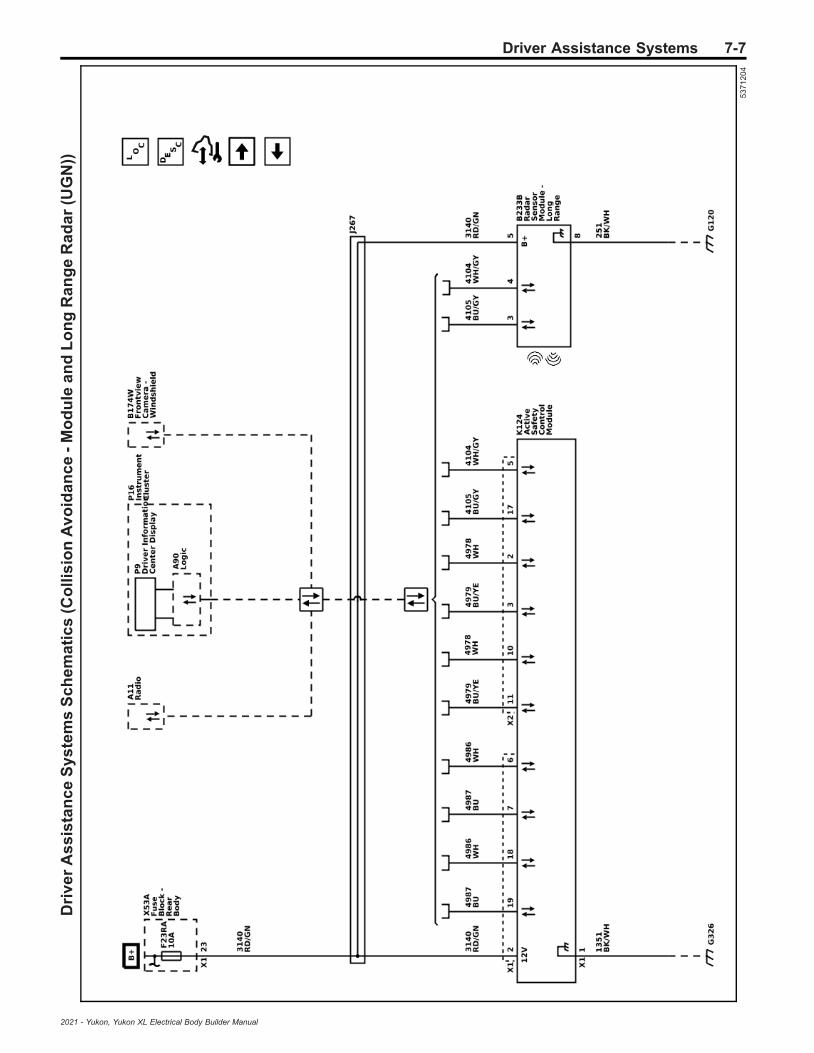
Driver Assistance Systems 7-7D
riv
er
As
sis
tan
ce
Sy
ste
ms
Sc
he
ma
tic
s(C
oll
isio
nA
vo
ida
nc
e-
Mo
du
lea
nd
Lo
ng
Ra
ng
eR
ad
ar
(UG
N))
53
71
20
4
2021 - Yukon, Yukon XL Electrical Body Builder Manual

7-8 Driver Assistance SystemsD
riv
er
As
sis
tan
ce
Sy
ste
ms
Sc
he
ma
tic
s(C
oll
isio
nA
lert
Ind
ica
tors
)
53
71
20
8
2021 - Yukon, Yukon XL Electrical Body Builder Manual
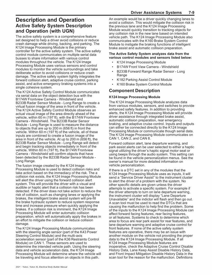
Driver Assistance Systems 7-9
Description and OperationActive Safety System Descriptionand Operation (with UGN)The active safety system is a comprehensive featureset designed to help a driver avoid collisions or reducecrash damage while driving, backing, and parking. TheK124 Image Processing Module is the primarycontroller for the active safety system. The active safetycontrol module communicates on multiple serial databusses to share information with various controlmodules throughout the vehicle. The K124 ImageProcessing Module uses various sensors and controlmodules to monitor the vehicle surroundings and takedeliberate action to avoid collisions or reduce crashdamage. The active safety system tightly integrates theforward collision alert, adaptive cruise control, parkingassist, and active emergency braking systems into asingle cohesive system.The K124 Active Safety Control Module communicatesvia serial data on the object detection bus with theB174W Frontview Camera - Windshield andB233B Radar Sensor Module - Long Range to create avirtual fusion image of the area in front of the vehicle.The K124 Active Safety Control Module observes anactual visual image of the area directly ahead of thevehicle, within 60 m (197 ft), with the B174W FrontviewCamera - Windshield. The B233B Radar SensorModule - Long Range is used to measure the distanceto objects that are up to 200 m (656 ft) in front thevehicle. Within 60 m (197 ft) of the vehicle, all of theseinputs are combined to create a fusion image of thearea in front of the vehicle. At up to 200 m (656 ft), theB233B Radar Sensor Module - Long Range will detectand begin tracking objects immediately in front of thevehicle. Within 60 m (197 ft), the B174W FrontviewCamera - Windshield will confirm objects that havebeen detected by the B233B Radar Sensor Module -Long Range.The fusion image created by the K124 ImageProcessing Module is used to detect collision risks andtake action based on the immediacy of the risk. The acollision risk exists, the K124 Image Processing Modulewill alert the driver using the forward collision alertsystem. This will provide the driver with a visual andaudible or haptic alert that a collision risk has beendetected. If the driver does not take action to reduce therisk of collision, such as changing lanes or applying thebrakes, the intelligent brake assist system will pre-fillthe brake hydraulic system to reduce system responsetime and increase pressure when quickly applying thebrakes. If a collision risk is imminent, the K124 ImageProcessing Module will enter automatic collisionpreparation, which will automatically apply the brakes inan effort to mitigate the collision or reduce collisiondamage.The K124 Image Processing Module communicateswith the steering angle sensor (part of the K43 PowerSteering Control Module) and the multi-axisacceleration sensor (part of the K36 Restraints ControlModule) on CAN 1. These sensors are used todetermine the intended vehicle path. Using the steeringdata and vehicle acceleration data, the K124 ImageProcessing Module will determine where the vehicle willbe traveling and focus attention on objects in this path.
An example would be a driver quickly changing lanes toavoid a collision. This would mitigate the collision risk inthe previous lane and the K124 Image ProcessingModule would quickly transition to tracking objects forany collision risk in the new lane based on intendedvehicle path. The K124 Image Processing Module alsocommunicates with the K160 Brake System ControlModule to instigate the braking functions of intelligentbrake assist and automatic collision preparation.
The Active Safety System analyzes data from thevarious control modules and sensors listed below:
• K124 Image Processing Module• B174W Front View Camera - Windshield• B233B Forward Range Radar Sensor - Long
Range• K182 Parking Assist Control Module• K160 Brake System Control Module
Component DescriptionK124 Image Processing Module
The K124 Image Processing Module analyzes datafrom various modules, sensors, and switches to provideenhanced safety features. In addition to providingalerts, the K124 Image Processing Module will providedriver assistance through integrated brake assist,automatic collision preparation, rear emergencybraking, and adaptive cruise control. Inputs and outputscan either be connected directly to the K124 ImageProcessing Module or communicate though serial data.The K124 Image Processing Module communicates onCAN 1, CAN 2, and CAN 8.
Forward collision alert, lane departure warning, andpark assist alerts can be user selected to either a hapticsignal utilizing the driver’s haptic signal motor seat orusing beeps through the audio system. This setting canbe found in the vehicle personalization menus. See theowner’s manual for more detailed information onvehicle personalization.
If there is a DTC set in any of the modules that theK124 Image Processing Module uses as inputs, it willsend a “Service Driver Assist” to the instrument clusterto alert the driver of a problem with the system. Noother specific details are given unless the driverattempts to activate a specific system. For example ifthe driver attempts to turn on lane departure warning,the instrument cluster will display “Lane DepartureUnavailable” and the indictor will flash and then go out.A scan tool must be used to read the DTCs that arecausing the malfunction to help find the problem. Someof the inputs to the K124 Image Processing Module canaffect forward facing features, rear facing features,or all features. Systems to check to determine whicharea to focus are rear park assist for rear features, andlane departure warning and adaptive cruise control forfront features. If none of the active safety systemfeatures are operative, there may be an issue withanother module on the vehicle not providing the properdata to the K124 Image Processing Module. If allK124 Image Processing Module features areinoperative, check the Adaptive Cruise Control DisableHistory Data, Lane Keep Assist Disable History Data,and Front Impact Mitigation Disable History Data in thescan tool for the reason for the malfunction. Definitions
2021 - Yukon, Yukon XL Electrical Body Builder Manual

7-10 Driver Assistance Systems
of parameters and suggestions on what to look for canbe found in K124 Image Processing Module: Scan ToolInformation .
• K124 Image Processing Module inputs:– B174W Front View Camera - Windshield– B233B Forward Range Radar Sensor - Long
Range– K182 Parking Assist Control Module– Multi-axis acceleration sensor– Steering wheel angle sensor– Wheel speed sensors– Forward collision alert switch– Lane departure warning switch– Parking assist switch
• K124 Image Processing Module outputs:– K9 Body Control Module– K160 Brake System Control Module– K20 Engine Control Module– P16 Instrument Panel Cluster Control Module– P29 Head-Up Display– K40D Driver Seat Adjuster Memory Module– Lane keep assist switch indicator– Parking assist switch indicator– Infotainment system
B174W Front View Camera - Windshield
The B174W Front View Camera - Windshield is locatedbehind the windshield, looking out at the road aheadand detects lane markings and objects directly ahead,within a distance of approximately 60 meters (197 ft).The B174W Front View Camera - Windshield is usedfor lane keep assist and forward collision alert systems.The B174W Front View Camera - Windshieldcommunicates with the K124 Image Processing Moduleon CAN 8.
Using information from the B174W Front View Camera -Windshield, the K124 Image Processing Module willprovide forward collision alert and lane keep assist tothe driver when appropriate. The alerts and warningscan be user-selected to be audible through the audiosystem or haptic using the active safety seat.
B233B Forward Range Radar Sensor - Long Range
The B233B Forward Range Radar Sensor - LongRange is located behind the front grille emblem and isused in the 30–200 m (98–656 ft) range. TheB233B Forward Range Radar Sensor - Long Rangecommunicates with the K124 Image Processing Moduleon CAN 8. In addition to the wiring harness ground, themodule is grounded through the mounting bracket.
K182 Parking Assist Control Module
The K182 Parking Assist Control Module usesultrasonic object sensors located in the fascias toprovide distance measurements to nearby objects. TheK182 Parking Assist Control Module communicateswith the K124 Image Processing Module on CAN 1.
K160 Brake System Control Module
The K160 Brake System Control Module performs thebraking activities of the active safety system. Whenrequested by the K124 Image Processing Module, theK160 Brake System Control Module will prepare orapply the brakes as necessary in response to animminent collision.
Active Safety System OperationForward Collision Alert
The forward collision alert system is a conveniencefeature of the K124 Image Processing Module,B174W Front View Camera - Windshield, andB233B Forward Range Radar Sensor - Long Rangethat issues a warning to the driver when a potentialcollision risk exists. When the system detects a vehiclein the path ahead, the green vehicle ahead indicator isilluminated on the P16 Instrument Panel Cluster ControlModule. If the vehicle ahead is being followed tooclosely, the vehicle ahead indicator will be amber.When approaching another vehicle too rapidly, theP43 Forward Collision Alert Display (without UV6) orcollision alert symbol in the P29 Head-Up Display (withUV6) will flash. An audible alert sound willsimultaneously sound or the safety alert seat willprovide haptic feedback. The visual alert cannot bechanged, but the driver can select between audible orhaptic alerts in the vehicle personalization menus.Refer to the vehicle owner manual for more detailedinformation on vehicle personalization.
Forward collision alert does not provide a warning tohelp avoid a crash unless it detects a vehicle. Forwardcollision alert may not detect a vehicle ahead if theB174W Front View Camera - Windshield is blocked bydirt, snow, or ice, or if the windshield is damaged.It may also not detect a vehicle on winding or hillyroads, or in conditions that can limit visibility such asfog, rain, or snow, or if the headlamps or windshield arenot cleaned or in proper condition. Keep the windshield,headlamps, and B174W Front View Camera -Windshield area clean and in good repair.
Forward collision alert may provide unnecessary alertsfor turning vehicles, vehicles in other lanes, objects thatare not vehicles, or shadows. These alerts are normaloperation and the vehicle does not need service.
Automatic Emergency Braking
Automatic emergency braking system uses theK124 Image Processing Module, B174W Front ViewCamera - Windshield, and B233B Forward RangeRadar Sensor - Long Range to determine if animminent collision risk exists. If the brakes have notbeen applied, the system will automatically apply thebrakes in an effort to mitigate the collision or reducecollision damage. The system has a detection range ofapproximately 60 m (197 ft) and will only function whena vehicle is detected, as indicated by the green vehicleahead indicator is illuminated on the instrument cluster.
Automatic emergency braking is not a substitute fornormal vehicle braking and should not be relied on tobrake the vehicle. Automatic emergency braking maynot detect a vehicle ahead if the B174W Front ViewCamera - Windshield is blocked by dirt, snow, or ice,or if the windshield is damaged. It may also not detect avehicle on winding or hilly roads, or in conditions that
2021 - Yukon, Yukon XL Electrical Body Builder Manual

Driver Assistance Systems 7-11
can limit visibility such as fog, rain, or snow, or if theheadlamps or windshield are not cleaned or in propercondition. Keep the windshield, headlamps, andB174W Front View Camera - Windshield area cleanand in good repair.
Front Pedestrian Braking
Front pedestrian braking system uses the K124 ImageProcessing Module, B174W Front View Camera -Windshield, and B233B Forward Range Radar Sensor -Long Range to determine if an imminent collision riskexists with a nearby pedestrian. If the brakes have notbeen applied, the system will automatically apply thebrakes in an effort to avoid or reduce the harm causedby front-end crashes with nearby pedestrians. Thesystem has a detection range of approximately 40 m(131 ft) and will only function when a pedestrian isdetected, as indicated by the amber pedestriandetected indicator illuminated on the instrument cluster.
Front pedestrian braking is not a substitute for normalvehicle braking and should not be relied on to brake thevehicle. Front pedestrian braking may not detect apedestrian if the B174W Front View Camera -Windshield is blocked by dirt, snow, or ice, or if thewindshield is damaged. It may also not detect apedestrian on winding or hilly roads, or in conditionsthat can limit visibility such as fog, rain, or snow, or ifthe headlamps or windshield are not cleaned or inproper condition. Keep the windshield, headlamps, andB174W Front View Camera - Windshield area cleanand in good repair.
Backing Warning
The backing warning system utilized the K124 ImageProcessing Module and the K182 Parking AssistControl Module to warn of rear objects when backingup at speeds greater than 8 km/h (5 mph). Utilizing theultrasonic rear object sensors, the K182 Parking AssistControl Module can only detect object at seeps up to8 km/h (5 mph). By utilizing the K124 Image ProcessingModule and B233CR Short Range Radar Sensor - RearMiddle, along with the K182 Parking Assist ControlModule and the rear object sensors, object can bedetected at speeds greater than 8 km/h (5 mph).
While reversing at speeds greater than 8 km/h (5 mph),the backing warning system will alert the driver with anaudible alert or through haptic feedback from the safetyalert seat when an object is first detected. If the systemdetects a potential collision risk, a series of audiblebeeps or haptic feedback pulses will be provided, aswell as a quick pulse of the brakes.
Reverse Automatic Braking
The rear automatic braking system is designed to helpavoid or reduce the harm caused by backing crashes.If the system detects the vehicle is backing too fast toavoid a collision, it may automatically brake hard toa stop.
Utilizing the K124 Image Processing Module and theK182 Parking Assist Control Module, rear automaticbraking attempts to avoid imminent collision byautomatically braking the vehicle when traveling inreverse. In conjunction with the backing warningsystem, if the driver does not respond to the audibleand haptic alerts while reversing, the system willautomatically brake the vehicle to a stop.
Rear automatic braking also prevents the vehicle frombacking into an object if the vehicle is stopped andshifted to R. If the system detects an objectimmediately behind the vehicle while attempting toreverse from a stop, the brakes will be applied.
Pressing the brake pedal after the vehicle comes to astop will release the rear automatic braking. It may benecessary to release the electronic parking brake.When it is safe to do so, pressing the accelerator pedalfirmly at any time will override the rear automaticbraking. If rear automatic braking is active and there isno object behind the vehicle, make sure there is nosnow, ice, or debris on the rear object sensors.
Lane Keep Assist
The lane keep assist system is a convenience featurethat utilizes the B174W Front View Camera -Windshield and K124 Image Processing Module todetermine if the vehicle has unintentionally crossed alane marking and issue a warning. The B174W FrontView Camera - Windshield is located behind thewindshield, looking out at the road ahead and detectingany lane markings. When the vehicle unintentionallyleaves a detected lane, visual and audible or hapticalerts are given to the driver. The visual alert cannot bechanged, but the driver can select between audible orhaptic alerts in the vehicle personalization menus.
Refer to Lane Keep Assist Description and Operationon page 7‑18 for more information about the LaneKeep Assist function.
Adaptive Cruise Control Descriptionand Operation (with UGN)The adaptive cruise control system is an enhancedcruise control system with the ability to sense and reactto forward traffic. Compared to the common cruisecontrol system found on many vehicles, the mainfunctional enhancement of the adaptive cruise controlsystem is the ability to detect the presence of a vehiclein the path of the adaptive cruise control vehicle.Adaptive cruise control retains the existing cruisecontrol feature that controls the vehicle speed to thedriver selected speed. However, adaptive cruise controlallows a driver to set and maintain a following distanceto the preceding nearest vehicle in the path ahead. TheK124 Image Processing Module controller calculates afollow speed limit to ensure an acceptable distance ismaintained to the preceding vehicle in front, should onebe present. The adaptive cruise control systemautomatically adjusts the speed when the vehiclecomes up behind a slower travelling vehicle in front.The system applies limited automatic braking andthrottle control without driver input when necessary tomaintain the set following distance. The precedingvehicle's speed and acceleration along with the activecruise control vehicle speed and acceleration and thedistance between the two vehicles are factors used bythe K124 Image Processing Module controller todetermine the follow speed limit. The vehicle speeds upto the original driver selected set speed when thepathway becomes clear without driver input.The adaptive cruise control functionality depends onvarious modules on the vehicle to function and eachmodule performs a function that is critical to the properoperation of the adaptive cruise control system.Adaptive cruise control will not operate if any
2021 - Yukon, Yukon XL Electrical Body Builder Manual

7-12 Driver Assistance Systems
components fail. Communication between modules isvia serial data. The following is a functional descriptionof the K124 Image Processing Module and the otherassociated components:
• K124 Image Processing Module• B233B Forward Radar Sensor Module - Long
Range• K9 Body Control Module• K20 Engine Control Module• K160 Brake System Control Module• K71 Transmission Control Module• P16 Instrument Panel Cluster Control Module• Cruise Control Switch• Gap Switch
K124 Image Processing Module
The K124 Image Processing Module analyzes datafrom various modules, sensors, and switches to provideenhanced safety features. In addition to enhancedsafety features, the K124 Image Processing Moduleprovides the adaptive cruise control systemfunctionality. The K124 Image Processing Moduleanalyzes data from the B233B Forward Radar SensorModule - Long Range to identify and classify objects inthe road environment. The system scans the roadenvironment to detect targets within its specified field ofview. The K124 Image Processing Module then sendsthrottle and/or brake commands to the K20 EngineControl Module and K160 Brake System ControlModule via serial data in order to control the vehicleacceleration/deceleration based on the data from themodules. The K20 Engine Control Module andK160 Brake System Control Module provide throttlecontrol and automatic braking needed for proper cruisespeed adjustment. The following is a list of theK124 Image Processing Module functions pertaining tothe adaptive cruise control functionality:
• The K124 Image Processing Module processesthe road environment to get data concerning anyvehicle ahead of the adaptive cruise controlvehicle. Detection, parameter estimation, tracking,object classification and diagnostics are theprimary functions. When an object is detected, thecontroller calculates the object range, range rate,acceleration and azimuth angle parameters.
• The K124 Image Processing Module performsadaptive cruise control state processingautomatically – distance control or speed control.The adaptive cruise control operates in twopossible states – cruise or follow. The normaloperating state is cruise, whereby the vehiclespeed is controlled to match the driver selectedset speed. When a preceding forward target isidentified, the adaptive cruise control system willautomatically transition into the follow speed stateto provide proper lane spacing behind the targetvehicle in front. The preceding vehicle's speedand acceleration, with the adaptive cruise controlvehicle speed, acceleration and distance betweenthe two vehicles will be used to determine theadaptive cruise control follow speed limit. Theadaptive cruise control follow speed limit willensure that an acceptable distance is maintainedto the preceding vehicle.
• The K124 Image Processing Module determinesthe follow speed limit for throttle control by theK20 Engine Control Module .
• The K124 Image Processing Module arbitrates theadaptive cruise control system brake and throttlecontrol between the K160 Brake System ControlModule and the K20 Engine Control Module .
• The K124 Image Processing Module requestsbrake light activation during automatic braking.
• The K124 Image Processing Module providesoperational feedback to the vehicle driver. TheK124 Image Processing Module sends signals fortelltales and messages to be displayed on theP16 Instrument Panel Cluster Control Module ordriver information center.
B233B Forward Radar Sensor Module - Long Range
The B233B Forward Radar Sensor Module - LongRange is located behind the front fascia and is used inthe 30–200 m (98–656 ft) range. The B233B ForwardRadar Sensor Module - Long Range communicateswith the K124 Image Processing Module via serial dataon CAN 8. In addition to the wiring harness ground, themodule is grounded through the mounting bracket.
K9 Body Control Module
The following are the adaptive cruise control systemfunctions provided by the K9 Body Control Module:
• The K9 Body Control Module reads all cruisecontrol switches and the gap switch. TheK124 Image Processing Module monitors a varietyof user operated switches from the K9 BodyControl Module switch status information sentvia CAN.
• The K9 Body Control Module illuminates the brakelight based on a CAN message from theK124 Image Processing Module during automaticbraking.
• The K9 Body Control Module measures the brakepedal position and sends brake pedal travel statusvia CAN to the K20 Engine Control Module . TheK20 Engine Control Module disengages theadaptive cruise control system when the brake isapplied by the driver pressing the brake pedal.
K20 Engine Control Module
The following are the adaptive cruise control systemfunctions performed by the K20 Engine Control Module:
• The K20 Engine Control Module provides theelectronic throttle control to the adaptive cruisecontrol System. The K20 Engine Control Module isalso responsible for determining when a driver isoverriding the adaptive cruise control throttleposition by pressing the accelerator pedal.
• The K20 Engine Control Module processes thecruise control switch requests received via CANfrom the K9 Body Control Module. Engaging anddisengaging the adaptive cruise control systemare functions performed by the K20 EngineControl Module .
2021 - Yukon, Yukon XL Electrical Body Builder Manual

Driver Assistance Systems 7-13
• The K20 Engine Control Module determines thedriver selected vehicle speed. Unless the adaptivecruise control module requests a lower vehiclespeed, the K20 Engine Control Module will controlthe vehicle speed to the driver selected set speed.
• The K20 Engine Control Module allows automaticbraking without disengaging the adaptive cruisecontrol.
K160 Brake System Control Module
The following are the adaptive cruise control Systemfunctions performed by the K160 Brake System ControlModule:
• The K160 Brake System Control Module controlsthe operation of the Antilock Brake System.
• The K160 Brake System Control Module providesautomatic braking for the adaptive cruise controlsystem. The K124 Image Processing Module willrequest vehicle deceleration via high speedGMLAN serial data circuit.
• The K160 Brake System Control Moduledetermines when the driver–applied brakepressure is active. The K160 Brake SystemControl Module will communicate this status viaCAN to the K9 Body Control Module.
• The K160 Brake System Control Module releasesvehicle automatic braking when there is a throttleoverride by the driver pressing the accelerator.
• The K160 Brake System Control Module predictsbrake temperatures. Due to automatic braking, thebrake system may overheat. When the brakes areoverheated, the K160 Brake System ControlModule requests the adaptive cruise controlSystem to be temporarily shut down by theK20 Engine Control Module until the brakes coolto a normal operating temperature.
K71 Transmission Control Module
The K71 Transmission Control Module provides a downshift to protect the brakes. When the K71 TransmissionControl Module detects some driver braking activity oradaptive cruise control automatic braking activity, theK71 Transmission Control Module down shifts thevehicle transmission to increase engine braking. Thishelps reduce braking activity, extend brake pad life andreduce brake system overheating.
P16 Instrument Panel Cluster Control Module
The driver information center is a part of theP16 Instrument Panel Cluster Control Module anddisplays the adaptive cruise control system warningmessages. The K124 Image Processing Modulerequests messages to be displayed on the driverinformation center by sending a CAN request to theP16 Instrument Panel Cluster Control Modulerequesting the display of the warning message. Whenthe message is acknowledged by the driver and thecause of the message resolved, the driver informationcenter turns the message off. The adaptive cruisecontrol system will not operate if the driver informationcenter fails.
Cruise Control Switch
The cruise control switch, functionally is a commonfeature that is shared between the adaptive cruisecontrol system and the regular cruise control system.The adaptive cruise control system will not operate ifany cruise switch fails. The cruise control switchcomprises the following cruise control functionswitches:
• On/Off switch• Set/decrease switch• Resume/increase switch
The cruise control function switches are arranged in aresistive ladder design whereby each switch function isset up with different resistance values. The K9 BodyControl Module through the cruise control switch signalcircuit detects a predetermined voltage value when anycruise control switch function is activated. Theassociated cruise control function signal detected bythe K9 Body Control Module is then sent to theK20 Engine Control Module as a CAN message. TheK20 Engine Control Module on receiving the messageprovides the cruise control function requested by theK9 Body Control Module. The K20 Engine ControlModule is responsible for recognizing and respondingto cruise control switch requests sent by the K9 BodyControl Module. The cruise control function switchesare used by the K20 Engine Control Module tocommunicate to the K124 Image Processing Modulethe driver selected vehicle speed. The driver selectedvehicle speed is communicated through GMLAN serialdata circuit to the K124 Image Processing Module andthe K9 Body Control Module. The adaptive cruisecontrol system engages and adjusts vehicle speedsbased on the activation of the following cruise controlfunction switches:
Cruise Control On/Off Switch
The K9 Body Control Module monitors the switch signalcircuit in order to determine when the On/Off switch isdisabled or activated. The K9 Body Control Moduledetects a predetermined voltage value on the switchsignal circuit. The On/Off switch state is then relayed tothe K20 Engine Control Module via CAN. TheK20 Engine Control Module sends the On/Off switchinput status to the K124 Image Processing Module .When the On/Off switch is turned ON, the adaptivecruise control system enters either a standby enabledor a standby disabled mode. The standby enabledmode indicates that every condition required for theadaptive cruise control system to function has beenmet, but the adaptive cruise control is not engaged.When the adaptive cruise control is in the standbydisabled mode, the conditions necessary for theadaptive cruise control system to function has not beenmet. When the On/Off switch is turned OFF, theadaptive cruise control will enter the disabled mode.The adaptive cruise control will not activate in thedisabled mode.
Cruise Control Set/Decrease Switch
The adaptive cruise control system is engaged whenthe adaptive cruise control On/Off switch is turned ONand the set/decrease switch is momentarily pressedand released . When the set/decrease switch ispressed, the selected vehicle speed is set to the currentvehicle speed by the K20 Engine Control Module . The
2021 - Yukon, Yukon XL Electrical Body Builder Manual
7-14 Driver Assistance Systems
vehicle speed must be at or greater than 40 km/h(25 MPH). The selected vehicle speed is displayed bythe driver information center. While in the engagedstate, the selected vehicle speed and the followingdistance can be adjusted. Pressing and holding the set/decrease switch, when the adaptive cruise controlsystem is engaged, will decrease the selected vehiclespeed without deactivating the adaptive cruise control.Momentarily pressing and releasing the set/decreaseswitch, when the adaptive cruise control is engaged,decreased the selected vehicle speed by 1.6 km/h(1 MPH) for each time that the set/decrease switch ispressed.
Cruise Control Resume/Increase Switch
The resume/increase switch is used in order toincrease the selected vehicle speed when adaptivecruise control is active. The amount selected vehiclespeed can be increased from the resume/increaseswitch depends on how long the switch is pressed. Thepresence of a slower moving vehicle in the path of theadaptive cruise control vehicle will limit the extent towhich the selected vehicle speed can be achieved.If there is no preceding vehicle in front, limiting theadaptive cruise control vehicle acceleration, then thevehicle speed that is attained is the new selectedvehicle speed. The current selected vehicle speed isdisplayed by the driver information center. Accelerationis terminated when the resume/increase switch isreleased. Momentarily pressing and releasing theresume/increase switch will allow the selected vehicleto accelerate in at 1.6 km/h (1 MPH) increments foreach time that the resume/increase switch ismomentarily pressed.
Gap Switch
The gap switch allows the driver to determine howclosely the adaptive cruise control vehicle follows atarget vehicle while adaptive cruise control is engaged.When the adaptive cruise control vehicle speed isbeing limited due to a slower travelling vehicle, theadaptive cruise control vehicle speed is automaticallycontrolled to the follow speed limit. The gap switch has3 following distance selections that range from 1–2 s.The gap switch following distance between theadaptive cruise control vehicle and the target vehicle isexpressed in time as opposed to actual distance. Thedistance maintained for a selected gap will vary basedon vehicle speed. The faster the vehicle speed, thefurther back you will follow. The gap setting can only beadjusted when the adaptive cruise control system isengaged. The gap switch is hard-wired to the K9 BodyControl Module. Based on voltage variations, theK9 Body Control Module is able to read the gap switchselection and communicates the switch status via CANto the K124 Image Processing Module . The gap switchis a momentary switch.
The initial push of the gap switch recalls the currentsetting and activates the display. Subsequent pushes ofthe gap switch will change the gap setting.
Driver Information MessagesAdaptive Cruise Control Temporarily Unavailable
The K124 Image Processing Module will send thismessage if the adaptive cruise control has beendisengage or disabled. There are many reasons that
can cause this, some will also set DTCs. Check vehiclefor DTCs and also check the adaptive cruise controlenable and disengage scan tool data. Definitions ofparameters can be found in K124 Image ProcessingModule scan tool information.
Service Driver Assist System
This message can be set by either the K124 ImageProcessing Module if there is a problem with the driverassist system or by the memory seat module if there isa problem with the haptic seat circuits. Check vehiclefor DTCs.
Service Adaptive Cruise Control and Service FrontCamera
The message is set if the K124 Image ProcessingModule is not communicating to the P16 InstrumentCluster . Check vehicle for DTCs.
Set Speed
The adaptive cruise control vehicle set speed isdisplayed at all times in the driver information centerwhen adaptive cruise control is engaged. TheK124 Image Processing Module set speed displayrequest is sent to the P16 Instrument Cluster via theGMLAN serial data circuit.
Follow Distance
The driver information center displays the driverselected following distance when adaptive cruisecontrol is engaged and the gap switch is active. Thecurrent follow distance setting is displayed in the driverinformation center for a few seconds after the gapswitch is pressed to increase or decrease the followingdistance. The K124 Image Processing Module followdistance display request is sent to the P16 InstrumentCluster via the GMLAN serial data circuit.
Vehicle Ahead Indicator
The vehicle ahead indicator is displayed in theP16 Instrument Cluster hen the radar identifies anin-path vehicle. The vehicle ahead indicator is awarning to the driver that a vehicle is ahead. Theindicator also serves as a feedback to the driver thatthe radar is functioning properly. The K124 ImageProcessing Module commands the display of thevehicle ahead indicator via a GMLAN serial datamessage to the P16 Instrument Cluster . The vehicleahead indicator only displays with the adaptive cruisecontrol active and may sometimes display for stationaryroad objects.
Adaptive Cruise Control OperationAdaptive cruise control uses the K124 ImageProcessing Module and B233B Forward Radar SensorModule - Long Range, which looks directly ahead tomonitor vehicles that a driver is following. Adaptivecruise control helps drivers follow a vehicle ahead atthe following gap they select — Far, Medium or Near —while they steer. This reduces the driver’s need tofrequently brake and accelerate.If the system does not detect a vehicle ahead, adaptivecruise control will resort to traditional cruise controloperation. When the system detects a vehicle ahead inthe driving lane, the vehicle ahead icon will appear ingreen on the P16 Instrument Panel Cluster ControlModule. When the vehicle detected ahead is within the
2021 - Yukon, Yukon XL Electrical Body Builder Manual
Driver Assistance Systems 7-15
selected following gap setting, adaptive cruise controlcan automatically slow the vehicle down and adjustvehicle speed to follow the vehicle ahead at theselected following gap. Like regular cruise control,adaptive cruise control uses ON/OFF, CANCEL, SETand RESUME buttons on the steering wheel.Getting started:
• To turn adaptive cruise control on, the drivershould press the cruise control ON/OFF button.
• When the system is turned on, the driverinformation center in the P16 Instrument PanelCluster Control Module will show a white adaptivecruise control icon.
• To choose a cruise speed, the driver should pressthe SET button while driving at the desired speed.The white adaptive cruise control icon will changeto green, indicating that adaptive cruise control isengaged.
• The adaptive cruise control gap switch on thesteering wheel lets drivers select a Far, Medium orNear following gap between their vehicle and thevehicle ahead. Both adaptive cruise control i andforward collision alert are set at the same setting.
Adaptive cruise control can follow a vehicle ahead to astop. When the vehicle ahead starts moving again, thedriver should check that it is safe to proceed, thencontinue to automatically follow the vehicle ahead bypressing the accelerator or resume button. If the driverdoesn’t respond soon after the stop, the vehicle aheadicon will flash. In addition, an audible notification willsound, or if equipped, the safety alert seat will pulse toremind the driver to check traffic ahead beforeproceeding.If the adaptive cruise control is controlling speed anddetects that the vehicle is approaching a vehicle aheadtoo quickly and adaptive cruise control cannot applysufficient braking, such as when vehicles aheadsuddenly slow or stop, drivers will receive a forwardcollision alert to warn them to quickly take action. Thisalert includes a red flashing visual alert, an audiblenotification, or, if equipped, the safety alert seat willpulse.If the driver uses the accelerator pedal while adaptivecruise control is active, a driver information centerwarning message will indicate that automatic brakingwill not occur. In some vehicles, instead of themessage, the green adaptive cruise control icon willchange to blue.Switching between cruise control modes (if available):
• The driver should press and hold the cruisecontrol CANCEL button.
• The driver will see either the adaptive cruisecontrol icon or the regular cruise control icon onthe driver information center. This icon indicateswhich cruise control mode has been selected.
• Drivers should check which cruise control icon isdisplayed before setting their cruise control speed.
The driver can end adaptive cruise control by doing anyof the following:
• Stepping lightly on the brake pedal• Pressing the cruise control CANCEL button• Pressing the cruise control ON/OFF button
Adaptive Cruise Control OperationalChecksSafety Considerations
• The system can only apply limited braking. Thedriver’s complete attention is always requiredwhile driving
• The system may not react to parked, stopped orslow-moving vehicles; the driver should always beready to take action and apply the brakes
• Driver should not use adaptive cruise control onwinding or hilly roads, on freeway exit or entranceramps or when trailering. In these drivingconditions, the system may not detect the vehicleahead
• The system cannot detect traffic lights or trafficsigns, so the driver needs to safely brakeaccordingly whenever approaching an intersectionwith a traffic light or stop sign
• If no vehicle ahead is detected, adaptive cruisecontrol will work like regular cruise control
• When using adaptive cruise control, the drivershould keep in mind that the system is designed tofollow detected vehicles ahead at a longerdistance when traveling at higher speeds than atlower speeds
• To avoid using adaptive cruise control by accident,advise customers to keep the cruise control buttonoff when they don’t need it. They should press theON/OFF button and verify that the adaptive cruisecontrol icon is not lit
Adaptive cruise control may have difficulty detecting thefollowing objects:
• Vehicles in front of the driver’s vehicle that have arear aspect that is low, small or irregular
• A truck or trailer that has no cargo in the cargo bed• Vehicles with cargo extending from the back end• Non-standard shaped vehicles, such as vehicle
transport, vehicles with a sidecar or horsecarriages
• Vehicles that are low to the road surface• Objects that are close to the front of the driver ’s
vehicleWeather conditions can affect adaptive cruise control:
• If the vehicle’s interior temperature is extremelyhigh, the P16 Instrument Panel Cluster ControlModule may indicate that adaptive cruise controlis temporarily unavailable. This can be caused byextreme hot weather conditions. Adaptive cruisecontrol will return to normal operation once theambient is cooler
• Conditions that are associated with low visibility,such as rain, snow or road spray, may limit theperformance of adaptive cruise control.
2021 - Yukon, Yukon XL Electrical Body Builder Manual

7-16 Driver Assistance Systems
Forward Collision Alert Descriptionand Operation (with UGN)On vehicles equipped with RPO UGN, forward collisionalert is an integrated of the active safety system. Referto Active Safety System Description and Operation(with UGN) on page 7‑9.
Forward Collision Alert Descriptionand Operation (without UGN)Forward Collision Alert (UEU)
The forward collision alert system is a conveniencefeature of the B174W Front View Camera - Windshieldthat can warn drivers of a possible front-end collisionsituation with a vehicle they are following. TheB174W Front View Camera - Windshield is locatedbehind the windshield, looking out at the road aheadand detecting vehicles directly ahead. When a vehicleis detected ahead, a green icon is displayed. Thisindicator will turn amber if the driver is following tooclosely. If the system detects that the driver is secondsaway from a possible front-end collision, it sends analert. The P43 Forward Collision Alert Display, whichincludes a series of red collision alert LEDs, will flash.An audible alert sound will simultaneously sound. If thevehicle is equipped with safety alert seat (HS1), bothsides of the seat will pulse. The forward collision alertsystem can be set to "far," "medium," or "near" timingusing the forward collision alert switch and can beturned off using this control or through the vehiclepersonalization.
Forward collision alert does not provide a warning tohelp avoid a crash unless it detects a vehicle. Forwardcollision alert may not detect a vehicle ahead if theB174W Front View Camera - Windshield is blocked bydirt, snow, or ice, or if the windshield is damaged.It may also not detect a vehicle on winding or hillyroads, or in conditions that can limit visibility such asfog, rain, or snow, or if the headlamps or windshield arenot cleaned or in proper condition. Keep the windshield,headlamps, and B174W Front View Camera -Windshield area clean and in good repair.
Forward collision alert may provide unnecessary alertsfor turning vehicles, vehicles in other lanes, objects thatare not vehicles, or shadows. These alerts are normaloperation and the vehicle does not need service.
Forward Automatic Braking (UHY)
Forward automatic braking detects vehicles ahead inyour path that are traveling in the same direction andmay help reduce crash severity or avoid the crashaltogether by applying the brakes automatically orenhancing the driver’s braking in some emergencyfront-end collision situations . It can provide brakingassist, such as brake system pre-fill, or automaticallybrake the vehicle if an imminent collision is determined.This can help avoid or lessen the severity of crasheswhen driving in a forward gear. Depending on thesituation, the vehicle may automatically brakemoderately or hard. Forward automatic braking canonly occur if a vehicle is detected. When a vehicle isdetected ahead, a green icon is displayed. The forwardautomatic braking system works when driving in a
forward gear between 8 km/h (5 mph) and 60 km/h (37mph). It can detect vehicles up to approximately 60 m(197 ft) away.
If the system detects that the driver is seconds awayfrom a possible front-end collision with the vehicle it isfollowing, it will first send an alert. If the driver doesn’trespond quickly or the situation happens suddenly,forward automatic braking enhances the driver ’sbraking or automatically applies the brakes. Drivers canoverride automatic braking at any time by pressing theaccelerator or by braking. If the system slows a vehicleto a complete stop, the electronic parking brake willapply. The electronic parking brake can be release intypical fashion by pressing the electronic parking brakeswitch.
Through vehicle personalization, the forward automaticbraking can be been set to the ALERT setting or turnedcompletely off. This setting disables most automaticbraking functions. The driver information center willdisplay FORWARD COLLISION SYSTEM REDUCEDor AUTOMATIC COLLISION PREP REDUCED. This isnormal operation when the forward automatic brakingor forward collision alert system is set to OFF orALERT. This message is not present when the forwardautomatic braking or forward collision alert system areset to ALERT and BRAKE.
Forward Collision Alert/ForwardAutomatic Braking Components
• B174W Front View Camera - Windshield• P16 Instrument Panel Cluster Control Module• P43 Forward Collision Alert Display (without UV6)• P29 Head-Up Display (with UV6)• Forward Collision Alert Switch• Infotainment System• Safety Alert Seat (with HS1)
B174W Front View Camera - Windshield
The B174W Front View Camera - Windshield detectsvehicles in front of the vehicle. The B174W Front ViewCamera - Windshield communicates with theP16 Instrument Cluster via serial data to illuminate theappropriate amber or green vehicle ahead indicator orP43 Forward Collision Alert Display. The B174W FrontView Camera - Windshield also communicates viaserial data with the infotainment system to requestaudible alerts.
P16 Instrument Panel Cluster Control Module
The P16 Instrument Panel Cluster Control Modulecommunicates via serial data with the B174W FrontView Camera - Windshield and will illuminate the amberor green vehicle ahead indicator as requested by theB174W Front View Camera - Windshield. TheP16 Instrument Panel Cluster Control Module alsocontrols the P43 Forward Collision Alert Display.
P43 Forward Collision Alert Display (without UV6)
The P43 Forward Collision Alert Display are a series ofred LEDs that will flash when approaching anothervehicle too rapidly. The P43 Forward Collision AlertDisplay are located in the upper instrument panel areaand reflect off the windshield when illuminated.
2021 - Yukon, Yukon XL Electrical Body Builder Manual

Driver Assistance Systems 7-17
The P43 Forward Collision Alert Display receive powerand ground and are discretely controlled by theP16 Instrument Cluster through a pair of low controlcircuits. When requested by the B174W Front ViewCamera - Windshield, the P16 Instrument Cluster willpulse the low control circuits, flashing the LEDs as avisual alert that another vehicle is being approachedtoo rapidly.
P29 Head-Up Display (with UV6)
The P16 Instrument Cluster controls the P29 Head-UpDisplay via serial data. The P16 Instrument Cluster willcommand the P29 Head-Up Display to flash thecollision alert indicator as a visual alert whenapproaching another vehicle too rapidly as requestedby the B174W Front View Camera - Windshield.
Forward Collision Alert Switch
The forward collision alert switch provides an input tothe B174W Front View Camera - Windshield to selectthe alert timing sensitivity when approaching anothervehicle too rapidly. The forward collision alert switch ispart of the S70L Cruise Control Switch and providesinputs to the K9 Body Control Module, which thencommunicates with the B174W Front View Camera -Windshield via serial data.
The K9 Body Control Module applies voltage andmonitors a low signal voltage from the normally openswitch. When the switch is pressed, the signal circuit ispulled low through a specific series of resistors,indicating that the system has been requested tochange the alert timing sensitivity. The first button presswill show the current alert timing setting on the driverinformation center. With every subsequent buttonpress, the alert timing sensitivity is changed.
Infotainment System
The infotainment system controls the audible alerts forthe forward collision alert system. If the vehicle isapproaching another vehicle too rapidly, theB174W Front View Camera - Windshield will commandthe infotainment system issue an audible alert to thedriver.
Safety Alert Seat (with HS1)
The K9 Body Control Module (without A45) orK40D Driver Seat Adjuster Memory Module (with A45)controls the haptic alert provided by the seats. If thevehicle is approaching another vehicle too quickly, theB174W Front View Camera - Windshield will commandthe control module to pulse both sides of the seat.
Forward Collision Alert and ForwardAutomatic Braking Operational ChecksIf the forward collision alert system is off, inoperative,or not functioning, check the following:
• Verify there are no active driver information centermessages and that no DTCs are set.
• Verify that the system is enabled through vehiclepersonalization. Vehicle personalization allows thesystem to be set to “Off,” “Beeps,” ”Alert,” “SafetyAlert Seat,” or “Alert & Brake”.
• Attempt to replicate the customer concern. Whiledriving, if the vehicle-ahead telltale displayilluminates green when following a vehicle above8 km/h (5 mph) , forward collision alert is operatingproperly.
If the driver is receiving false forward collision alerts,check the following:
• Verify the B174W Front View Camera - Windshieldis not blocked by dirt, snow, or ice, and thewindshield is not damaged.
• The system may be identifying vehicles fartherahead than the customer is expecting. Forwardcollision alert detects vehicles within a distance ofapproximately 60 m (197 ft) and operates atspeeds above 8 km/h (5 mph).
• Forward collision alert may provide unnecessaryalerts to turning vehicles, vehicles in other lanes,objects that are not vehicles, or shadows. Thesealerts are normal operation and the vehicle doesnot need service.
If forward collision alert beeps, but the seat does notvibrate, check the following:
• Verify the vehicle is equipped with safety alert seat(RPO HS1).
• Verify there are no active driver information centermessages and that no DTCs are set.
• Verify that the system is enabled through vehiclepersonalization: It may be set to “Beeps” or “AlertOnly” instead of “Safety Alert Seat” or “Alert &Brake”.
2021 - Yukon, Yukon XL Electrical Body Builder Manual
7-18 Driver Assistance Systems
If FORWARD COLLISION SYSTEM REDUCED orAUTOMATIC COLLISION PRE REDUCED is displayedon the driver information center, check the following:
• Verify that the system is enabled through vehiclepersonalization: It may be set to “Alert Only”instead of ”Off” or Alert & Brake”.
If SERVICE FRONT CAMERA is displayed on thedriver information center, check the following:
• Verify there are no active driver information centermessages and that no DTCs are set.
• If the message is only displayed upon startup,check the following:– Verify the B174W Front View Camera -
Windshield is not blocked by dirt, snow, or ice,and the windshield is not damaged.
– Verify the vehicle is not parked closed to a wallor the B174W Front View Camera - Windshieldis not in an over-temperature condition, such assitting for long periods in high ambienttemperatures and direct sun.
• If the message is displayed beyond startup, checkthe following:– Verify there are no active driver information
center messages and that no DTCs are set.If FRONT CAMERA IS BLOCKED is displayed on thedriver information center, check the following:
• Check for any other driver information centerservice messages.
• Verify the B174W Front View Camera - Windshieldis not blocked by dirt, snow, or ice, and thewindshield is not damaged.
If SERVICE DRIVER ASSIST is displayed on the driverinformation center, check the following:
• Check for any other driver information centerservice messages.
• Verify there are no active driver information centermessages and that no DTCs are set.
Lane Keep Assist Description andOperationThe lane keep assist system is a convenience featurethat utilizes the B174W Front View Camera -Windshield maintain the vehicle location betweenidentified lane markings. The B174W Front ViewCamera - Windshield is located behind the windshield,looking out at the road ahead and detecting any lanemarkings. If the vehicle begins to approach anidentified lane marking, automatic correction will beapplied by the electric power steering to move thevehicle back toward the center the lane. An integratedfunction of lane keep assist is lane departure warning.When the vehicle unintentionally leaves a detectedlane, visual and audible or haptic (if equipped) alertsare given to the driver. The visual alert cannot bechanged, but the driver can select between audible orhaptic alerts in the vehicle personalization menus.
Lane Keep Assist System ComponentsThe lane keep assist system is made up of thefollowing components:
• B174W Front View Camera - Windshield• P16 Instrument Panel Cluster Control Module
• Multi-axis acceleration sensor (part of theK36 Restraints Control Module)
• Steering wheel angle sensor (part of theK43 Power Steering Control Module)
• K43 Power Steering Control Module• Lane keep assist switch• Infotainment system• Safety alert seat (with HS1)
B174W Front View Camera - Windshield
The B174W Front View Camera - Windshield detectsvisual queues such as lane markings. When it isdetermined that the vehicle is approach an identifiedlane marking, automatic correction will be applied bythe electric power steering to move the vehicle backtoward the center the lane. Using the multi-axisacceleration sensor and steering wheel angle sensor,the B174W Front View Camera - Windshielddetermines the vehicles path and compares this to it’sown intended path based on lane markings. TheB174W Front View Camera - Windshield will thenrequest the K43 Power Steering Control Module toperform the appropriate steering correction. TheB174W Front View Camera - Windshield receives aninput from the lane keep assist switch and controls thelane keep assist switch indicator output.
P16 Instrument Panel Cluster Control Module
The P16 Instrument Panel Cluster Control Modulecontains green and amber lane keep assist indicators.These indicate to the driver the current status of thelane keep assist system and are controlled via serialdata by the B174W Front View Camera - Windshield.When the vehicle speed is above 56 km/h (35 MPH)and the system has detected the required lanemarkings and is ready to assist, the green indicator willbe illuminated on the P16 Instrument Panel ClusterControl Module. If the vehicle has unintentionally leftthe lane, the amber indicator will flash.
Multi-axis Acceleration Sensor
The steering intervention is based on the forwardlooking sensor outputs, such as lateral offset of thevehicle, relative yaw angle and time to line crossing.Over that, other vehicle dynamics signals are needed,e.g. velocity, steering angle, yaw rate for the purpose ofa driver suppression. The multi-axis accelerationsensor measures vehicle dynamics signals such asvelocity and yaw rate for the purpose of determining thevehicles path. The multi-axis acceleration sensor is anintegrated part of the K36 Restraints Control Module.
Steering Wheel Angle Sensor
The steering intervention is based on the forwardlooking sensor outputs, such as lateral offset of thevehicle, relative yaw angle and time to line crossing.Over that, other vehicle dynamics signals are needed,e.g. velocity, steering angle, yaw rate for the purpose ofa driver suppression. The steering wheel angle sensormeasures vehicle dynamics signals such as steeringangle for the purpose of determining the vehicles path.The steering wheel angle sensor is an integrated part ofthe steering gear and K43 Power Steering ControlModule.
2021 - Yukon, Yukon XL Electrical Body Builder Manual
Driver Assistance Systems 7-19
K43 Power Steering Control Module
The K43 Power Steering Control Module uses a torquesensor to detect driver inputs and relays thatinformation to the B174W Front View Camera -Windshield. The electric power steering is used tomaintain lane centering.
Lane Keep Assist Switch
The lane keep assist switch provides an input to theB174W Front View Camera - Windshield to turn thelane keep assist system on and off. The B174W FrontView Camera - Windshield provides a signal voltage tothe normally open momentary switch. When the switchis pressed, the signal circuit is pulled to ground,indicating to the B174W Front View Camera -Windshield that the system has been requested to turnON or OFF. The lane keep assist switch also containsthe lane keep assist switch indicator, which is controlledby the B174W Front View Camera - Windshield toindicate the ON and OFF status of the lane keep assistsystem. When the system has been enabled by thelane keep assist switch, the B174W Front View Camera- Windshield applies ground to the switch indicator andilluminates the LED. The location of the lane keepassist switch can vary with different vehicles. For theexact location please refer to the vehicle owner ’smanual.
Infotainment system
The radio controls the audible alert for the lane keepassist. If the vehicle has unintentionally left the lane,the radio will command three beeps as an audible alertto the driver.
Safety Alert Seat (with HS1)
The K9 Body Control Module (without A45) orK40D Driver Seat Adjuster Memory Module (with A45)controls the haptic alert provided by the seats. If thevehicle has unintentionally left the lane and theK43 Power Steering Control Module determines thecorrective action requires an above threshold amountof effort, three pulses to the left or right side of the seatwill be commanded, depending on the lane departuredirection.
Lane Keep Assist OperationLane keep assist with lane departure warning providesgentle steering wheel input and alerts to help preventdrivers from unintentionally drifting out of theirintended lane.There is two stages of warning/intervention for thedriver: The first stage is the steering push back, if thelane keep assist system detects that the vehicle willcross the lane marking despite it is intervening, asecond stage warning shall be issued. The secondstage warning is a chime or a haptic alert through thesafety alert seat (if equipped). If a haptic seat vibrationis used as stage 2 warning, the vibration will occur onthe side of the seat, where the lane departure occurred.
System operation can be described by the followingmodes:
• Off State: The system has been turned off by thedriver using the lane keep assist switch. The lanekeep assist indicator will not be illuminated.
• Not Ready To Assist: The system is enabled andthe lane keep assist indicator is illuminated, butnot ready to assist when any of the followingconditions is true:– Vehicle speed is less than 37 MPH (60 km/h) .
The system is designed to function at speedsgreater than 37 MPH (60 km/h).
– The system cannot detect lane markings. Thismay be because there are no lane markings, ason a country road or that the lane markingscannot be determined due to snow, rain, or otherdriving conditions.
– The windshield area in front of the camera or thecamera lens is blocked by fog, dirt, damage tothe windshield or other elements that mayprevent the camera from detecting lanemarkings.
• Ready To Assist: The system is enabled andready to warn of the unintentional lane crossing.The system is ready to assist when the green lanekeep assist indicator is illuminated on theP16 Instrument Cluster.
Lane Crossing Alerts• When one of the following conditions are met, the
system will not give alerts:– The correct turn signal is activated. An activated
turn signal is interpreted as an intentional lanecrossing.
– The operator makes an intentional steeringmaneuver.
– The operator makes an intentional acceleratingmaneuver.
– The operator makes an intentional brakingmaneuver.
• Lane crossing alert consists of the following:– The amber lane keep assist indicator will flash.– “push-back” steering torque input (or nudge)
from electric power steering to help prevent alane departure
– Three chimes are activated through the radio orthree pulses to the left or right side of the activesafety seat (if equipped).
Safety Alert Seat Description andOperationThe safety alert seat uses pulsing driver seat vibrationsto intuitively communicate the direction of a possiblecrash threat. Two P45 Front Seat Lane DepartureWarning Actuators are utilized to create the vibrationand are located on the left and right sides of the seatcushion. Utilizing two motors allows the vibration to belocalized to the left or right side of the seat, dependingon the side of the vehicle generating the alert, or tovibrate both simultaneously.Note: The following systems may not be available onall vehicles.
2021 - Yukon, Yukon XL Electrical Body Builder Manual

7-20 Driver Assistance Systems
The following systems utilize the safety alert seat:• Lane Departure Warning and Lane Keep Assist –
Utilizes left or right-side pulses to alert drivers ifthey unintentionally drift out of their lane
• Rear Cross Traffic Alert – Utilizes left or right-sidepulses to the direction of an approaching vehicle
• Forward Collision Alert – Simultaneously pulseson both sides to warn drivers of a possiblecollision with the vehicle that they’re following
• Front Pedestrian Braking – Simultaneously pulseson both sides to warn drivers of a possiblecollision with a pedestrian
• Front Parking Assist, Rear Parking Assist, andBacking Warning (part of the Rear AutomaticBraking system) – Simultaneously pulses on bothsides to warn drivers of a possible low-speedcollision
Safety Alert Seat ComponentsThe active safety seat utilizes the followingcomponents:
• K9 Body Control Module (without A45)• K40D Driver Seat Adjuster Memory Module
(with A45)• P45LR Front Seat Lane Departure Warning
Actuator - Left Rear• P45RR Front Seat Lane Departure Warning
Actuator - Right Rear
K9 Body Control Module (without A45)
The K9 Body Control Module receives serial datamessages from other modules and provides voltage tocontrol the P45 Front Seat Lane Departure WarningActuators. The K9 Body Control Module will pulse theleft, right, or both P45 Front Seat Lane DepartureWarning Actuators with the number of pulses requestedover serial data. The K9 Body Control Module monitorsthe control circuits for open, short to ground, and shortto voltage conditions and will set DTCs if a circuit faultis detected.
K40D Driver Seat Adjuster Memory Module(with A45)
The K40D Driver Seat Adjuster Memory Modulereceives serial data messages from other modules andprovides voltage to control the P45 Front Seat LaneDeparture Warning Actuators. The K40D Driver SeatAdjuster Memory Module will pulse the left, right,or both P45 Front Seat Lane Departure WarningActuators with the number of pulses requested overserial data. The K40D Driver Seat Adjuster MemoryModule monitors the control circuits for open, short toground, and short to voltage conditions and will setDTCs if a circuit fault is detected.
P45 Front Seat Lane Departure Warning Actuator
The P45 Front Seat Lane Departure Warning Actuatoris DC motor located in the driver’s seat bottom cushion.Two P45 Front Seat Lane Departure Warning Actuatorsare used in the seat bottom cushion, positioned on theleft and right side. An offset weight is attached to themotor. When activated, the spinning offset weightcreates a vibration felt by the driver through the seatcushion.
Each P45 Front Seat Lane Departure Warning Actuatorreceives a constant chassis ground. The motor iscontrolled by the K9 Body Control Module (without A45)or K40D Driver Seat Adjuster Memory Module (withA45) by providing voltage through a dedicated controlcircuit. When an alert is required, the control modulewill apply voltage, activating the P45 Front Seat LaneDeparture Warning Actuator
Side Blind Zone Alert Descriptionand OperationThe side blind zone alert system detects and reports“objects of interest" on either side of the vehicle, withina specified “blind spot” zone. The system is designed toalert the driver, with a visual display placed on the sideview mirror, to the presence of objects of interest thatmay not be visible in the inside rearview mirror andoutside rear view mirrors. Although this system isintended to help drivers avoid lane change collisions, itdoes not replace driver vision and therefore should beconsidered a lane change aid. Even with the side blindzone alert system, the driver must check carefully forobjects outside of the reporting zone (e.g., a fastapproaching vehicle) before changing lanes. In theevent that the system senses a malfunction through itsdiagnostic routines, the system will be disabled and thedriver will be visually notified.When the system detects a vehicle in the side blindzone while driving forward, an amber warning symbolwill light up in the appropriate outside mirror. Thisindicates that it may be unsafe to change lanes. If thedriver then activates the turn signal, the amber warningsymbol starts flashing as an extra warning not tochange lanes.Side blind zone alert is active when the vehicle is out ofpark, or the parking brake is off on manual transmissionvehicles, and at speeds up to approximately 140 km/h(87 MPH). If a vehicle is detected in the blind zone, thewarning symbols will illuminate on the appropriate side.When the vehicle is started, both outside mirrorindicators will briefly illuminate to indicate that thesystem is operating. The warning symbols will varybrightness based on the ambient light conditions.
Side Blind Zone Alert Components• B218L Side Obstacle Detection Control Module
- Left• B218R Side Obstacle Detection Control Module -
Right• K9 Body Control Module• S79D Front Side Door Window Control Switch -
Driver• S79P Front Side Door Window Switch -
Passenger• A9A Outside Rearview Mirror – Driver• A9B Outside Rearview Mirror – Passenger• Safety Alert Seat (HS1)
B218 Side Obstacle Detection Control Module
The B218L Side Obstacle Detection Control Module -Left and B218R Side Obstacle Detection ControlModule - Right are located on each side of the vehiclebehind the rear fascia and are not directly visible fromoutside the vehicle. The B218 Side Obstacle Detection
2021 - Yukon, Yukon XL Electrical Body Builder Manual

Driver Assistance Systems 7-21
Control Modules use radar to determine the presenceof objects nearby. Both B218 Side Obstacle DetectionControl Modules communicates with the vehicle viaserial data. The B218L Side Obstacle Detection ControlModule - Left and B218R Side Obstacle DetectionControl Module - Right also communicate with oneanother on a private CAN serial data bus. When anobject is detected in the side blind zone, theB218L Side Obstacle Detection Control Module - Leftand B218R Side Obstacle Detection Control Module -Right will send a CAN message to the K9 Body ControlModule to illuminate the appropriate side blind zonealert indicator.
K9 Body Control Module
The B218L Side Obstacle Detection Control Module -Left and the B218R Side Obstacle Detection ControlModule - Right will send a CAN message to theK9 Body Control Module when requesting the driver orpassenger indicator be illuminated. The K9 BodyControl Module then sends a LIN message to theS79D Front Side Door Window Control Switch - Driveror S79P Front Side Door Window Switch - Passengerwith the indicator request.
S79 Front Side Door Window Control Switch
The B218L Side Obstacle Detection Control Module –Left and the B218R Side Obstacle Detection ControlModule – Right will send a CAN message to theK9 Body Control Module when requesting the driver orpassenger indicator be illuminated. The K9 BodyControl Module then sends a LIN message to theS79D Front Side Door Window Control Switch - Driveror S79P Front Side Door Window Switch - Passengerwith the indicator request. The S79D Front Side DoorWindow Control Switch - Driver or S79P Front SideDoor Window Switch - Passenger will apply voltage tothe indicator control circuit to illuminate the appropriateindicator.
A9 Outside Rearview Mirror
The A9A Outside Rearview Mirror – Driver andA9B Outside Rearview Mirror – Passenger eachcontain an icon that is backlit with high intensity,amber-colored LED’s located on the mirror surface. Thedisplay brightness adapts to day/night conditions. TheP43D Side Object Detection Indicator – Driver andP43P Side Object Detection Indicator – Passenger inthe appropriate A9 Outside Rearview Mirror isilluminated if the specific B218 Side Obstacle DetectionControl Module detects a vehicle in the side blind zoneto inform the driver that there is a vehicle driving in theblind spot zone.
Safety Alert Seat (HS1)
The K40 Seat Memory Control Module (with A45) orK9 Body Control Module (without A45) controls theP45 Front Seat Lane Departure Warning Actuators. TheP45 Front Seat Lane Departure Warning Actuatorsprovide haptic alert to the driver. If an object isdetected, the system will command pulses to theP45LR Seat Haptic Movement Motor – Driver Left Rearor P45RR Seat Haptic Movement Motor – Driver RightRear, depending on the location of the object, as analert to the driver.
Side Blind Zone Alert OperationWhen the vehicle is started, both A9 Outside RearviewMirror indicators will briefly illuminate to indicate thatthe system is operating. The system is designed todetect objects of interest as small as a 125ccmotorcycle with rider. The detection zone starts at theoutside rearview mirror and extends out to 3.5 m (11 ft)at the back corner of the vehicle and 3 m (10 ft) behindthe vehicle at a height of 0.5 m (1.5 ft) and 2.0 m (6 ft)above the ground. The system may illuminate anindicator due to guardrails, signs, trees, shrubs, andother non-moving objects. This is normal systemoperation; the vehicle does not need service.When the system detects a vehicle in the side blindzone or lane change alert area while driving forward,independent if passing a vehicle or being passed, anamber warning symbol will illuminate in the appropriateA9 Outside Rearview Mirror. This indicates that it maybe unsafe to change lanes. If the driver then activatesthe turn signal, the amber warning symbol startsflashing as an extra warning not to change lanes.Foul weather may affect the operation of the side blindzone and lane change alert systems. Occasionalmissed alerts can occur under normal circumstancesand will increase in wet conditions. The number ofmissed alerts will increase with increased rainfall orroad spray. Heavy rainfall, as well as mud, dirt, snow,ice, or slush build-up on the rear fascia, can completelydisable the system.If the vehicle is towing a trailer or has an object such asa bicycle rack attached to the rear of the vehicle, theside blind zone and lane change alert systems may notfunction properly and the indicators may illuminateintermittently or remain illuminated all the time.
Lane Change Alert OperationAn integrated function of the side blind zone alertsystem is lane change alert. Lane change alertsupplements the side blind zone alert system bydetecting approaching vehicles on either side of thevehicle that may not yet be in the side blind zone alertarea. The detection zone for lane change alert starts atthe outside rearview mirror and extends out to 3.5 m(11 ft) at the back corner of the vehicle and up to 70 m(230 ft) behind the vehicle at a height between 0.5 m(1.5 ft) and 2.0 m (6 ft) above the ground. The systemdetermines when the indicator will illuminate based onthe rate of closure, or approach speed, of anapproaching vehicle. As the rate of closure becomefaster, the indicator will illuminate sooner.
Rear Cross Traffic Alert OperationRear cross traffic alert displays a red warning trianglewith a left or right pointing arrow on the infotainmentdisplay to warn of traffic coming from the left or right.This system detects objects coming from up to 20 m(65 ft) from the left or right side of the vehicle. When anobject is detected, either three beeps sound from theleft or right or three safety alert seat pulses occur on theleft or right side, depending on the direction of thedetected vehicle.
2021 - Yukon, Yukon XL Electrical Body Builder Manual
7-22 Driver Assistance Systems
Driver Information Center MessagesSIDE BLIND ZONE ALERT OFF or LANE CHANGEALERT OFFThis message indicates that the system has beendisabled through the driver information center. Refer tothe vehicle owner’s manual for instructions on how toset personalization options on the driver informationcenter.
SERVICE SIDE DETECTION SYSTEMThis message indicates that the system requiresservice. When the message is displayed, the indicatorswill remain illuminated at all times, notifying the driverthat the side blind zone system should not be reliedupon when changing lanes. Since the sensors are alsoused for rear cross traffic alert, this feature will also beinoperative.
SIDE DETECTION SYSTEM UNAVAILABLEThis message indicates that the system has beentemporarily disabled because the sensor is blocked orcan otherwise not accurately detect vehicles or objects.Such instances may be mud, dirt, snow, ice, or slushbuild-up on the rear fascia, heavy rainfall, excessiveroad spray, fascia damage or stickers. An over orunder-voltage condition or over-temperaure will alsocause the message to display.The rear cross traffic alert system will read the GPSlatitude and longitude on the serial data bus andcalculate if the vehicle is within a Radio Astronomyzone. These zones are located in Europe and Japanand require the sensors to be turned off. The “SideDetection System Unavailable” message will bedisplayed to the driver when this occurs.The system is continuously fine tuning the radaralignment. If the B218 Side Obstacle Detection ControlModule is removed or significantly disturbed, such asremoving the rear fascia or sensor bracket, an initialalignment is automatically performed by the system toenable system operation. However, the SIDEDETECTION SYSTEM UNAVAILABLE may remain forseveral hours of driving as the system fine tunes theradar alignment to ensure satisfactory alertperformance.
2021 - Yukon, Yukon XL Electrical Body Builder Manual

Immobilizer 7-23
Immobilizer
Schematic and Routing Diagrams
2021 - Yukon, Yukon XL Electrical Body Builder Manual
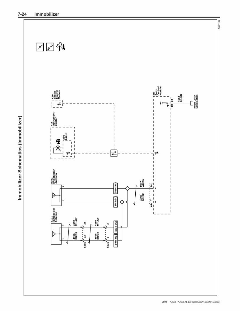
7-24 ImmobilizerIm
mo
bil
ize
rS
ch
em
ati
cs
(Im
mo
bil
ize
r)
53
711
64
2021 - Yukon, Yukon XL Electrical Body Builder Manual

Immobilizer 7-25
Repair InstructionsImmobilizer System ComponentProgrammingThis procedure will learn the immobilizer function. If thebattery voltage is low, charge the battery beforeproceeding with the learn. If the body control module(BCM) or engine control module (ECM) have beenreplaced, they must be programmed before performingthis learn procedure.Depending on the immobilizer function being learned orthe component replaced, different learn functions arerequired to be performed. These learn functions are asfollows:
Immobilizer System Component Programming
Function name on SPS tool: Function description:When the function should
be used: Notes:
Body Control Module IMMOFunction with Existing
Transponder or Remote Key
The BCM will relearn theimmobilizer passwords and
data while reusing the existingvehicle keys
The BCM has been replacedand the existing vehicle keys
are being reused or adiagnostic has instructed to
perform the learn
—
Body Control Module IMMOFunction with New
Transponder or Remote Key
The BCM will relearn theimmobilizer passwords and
data while using newvehicle keys
The BCM has been replacedand new vehicle keys are
being reused—
Engine Control Module IMMOLearn
The ECM will relearn theimmobilizer passwords
and data
The ECM has been replacedor a diagnostic has instructed
to perform the learn—
Engine Control Module andBody Control Module IMMO
Learn
The ECM and BCM will learnnew immobilizer passwords
and data
Both the ECM and BCM havebeen replaced (this selectionwill REQUIRE new vehicle
keys be used)
Because both the ECM andBCM have been replaced andare learning new immobilizer
passwords and data, allvehicle keys must also be
replaced
Program Transponder orRemote Key (Add)
A new vehicle key will learnthe immobilizer passwords
and data
A new vehicle key is beingadded (does not affect other
vehicle keys)
This function may not beavailable in all sales regions
Program Transponder orRemote Key (Delete)
All existing vehicle keys willbe invalidated and any
desired keys are relearned
All vehicle keys are desired tobe invalidated and certain
keys relearned or a diagnostichas instructed to perform the
learn
This procedure may be used ifa customer has had their keys
lost or stolen and wishes toinvalidate the keys, making
them unable to start thevehicle
1. Connect a scan tool to the vehicle andaccess SPS.
2. Turn ON the ignition, with the engine OFF.3. Ensure that all power consuming devices are
turned OFF on the vehicle.4. Select SPS application and follow the on-screen
instructions.5. Select Reprogram ECU.6. Select IMMO Immobilizer Learn.7. Select the appropriate programming function
based on the component that was replaced or isbeing programmed. Refer to the table at the top ofthis document for assistance in choosing thecorrect programming function.
Note:
• At multiple times during the learn procedure,SPS will instruct you to turn the ignition to therun position. Make sure the vehicle is actually inthe run mode before continuing on the SPSterminal. If the igniting is not in the run mode,the learn procedure will fail. To verify the vehicleis in Run mode, verify the green LED isilluminated on the ignition mode switch.
• The key pocket is located inside the centerconsole at the rear. Place the key into the slotfor the key pocket.
8. Follow the on-screen instructions.9. When the SPS procedure has completed, press
and hold the ignition mode switch for 15 seconds.10. With a scan tool, clear any DTCs.
2021 - Yukon, Yukon XL Electrical Body Builder Manual

7-26 Immobilizer
Unable to Complete ProgrammingWhen attempting to program immobilizer components,various conditions may prevent the programmingoperation from completing. These conditions may becaused by normal system operation, a systemmalfunction, or an external influence. Commonsymptoms of a incomplete programming is receiving anerror message during the attempt or having the SPSapplication become unresponsive.
• DTCs are set in the body control module (BCM)The immobilizer system is a function of the BCMsoftware. If immobilizer DTCs are set in the BCM,such as DTC B2955, a fault has been identified inthe immobilizer system. If this is not correctedbefore attempting to program components, theprogramming may not complete. Correct allimmobilizer DTCs before attempting to programany immobilizer components.
• The key has been programmed to another vehicleor is not the correct type for the vehicleA key can only be programmed to a single vehicle.Once a key is programming to a vehicle, it ispaired for the life of the key. The key can belearned to the same vehicle again and again, but itis not able to be programmed to a differentvehicle.Many vehicle are available with both a basekeyless entry system and an optional passiveentry system. These keys typically look identicalbut cannot be substituted for one another. Toverify the key is correct, compare the part numberthat is etched on the key to the part numberidentified in the parts catalog. The key should becorrect for the system installed in the vehicle.
• The theft deterrent module is not properly securedor the key is not properly positioned in thepocket/slot.
A theft deterrent module that is not fully seated oris otherwise not properly secured may prevent acoupling between the transponder located in thekey and the theft deterrent module. Being out ofplace by as little as 1 mm may preventprogramming from completing. Make sure the theftdeterrent module is properly installed and fullyseated in it’s clip.The key shank must be fully extended so that theentire key shank fits into the programming slot.To determine if the theft deterrent module isproperly secured, remove the battery from the keyand place the key into the pocket/slot. Attempt tochange the vehicle mode by pressing the vehicleON/OFF switch. The vehicle should changemodes. If the NO REMOTE DETECTED messageis displayed on the DIC, the theft deterrent modulemay not be properly secured.
• External interference is interrupting theprogramming operationExternal RF interference and EMI may interruptthe low frequency coupling between the key andtheft deterrent module. This interference maycome from many different locations. Devicesplugged into the vehicle power outlets such as cellphone chargers, laptop computers, GPS devices,etc. may cause interference. Vehicle location mayalso cause interference. Locations near airportsand military installations may causer interference.Remove all customer installed devices and,if necessary, move the vehicle if interference issuspected.
2021 - Yukon, Yukon XL Electrical Body Builder Manual

Immobilizer 7-27
Description and Operation
Immobilizer Description and Operation
3535457
The immobilizer system functions are provided by theRemote Control Door Lock Receiver, the SteeringColumn Lock Module, the Body Control Module (BCM),and the Engine Control Module (ECM), as well as anycontrol modules which store and report theenvironment identifier. The Body Control Module useslow frequency antennas in three different locations onthe vehicle to determine the location of the transmitter.Multiple transmitting antennas are used to ensurecomplete coverage of the vehicle interior and rearcompartment. These antennas transmit to the keylessentry transmitter.When the vehicle Stop/Start switch is pressed, the lowfrequency antennas emit a challenge to the keylessentry transmitter. The transmitter receives thischallenge and emits it's response as an RF message.The transmitter transmits a signal that contains itsunique value, which is received by the BCM through the
Remote Control Door Lock Receiver. The BCM thencompares this value to a value stored in memory. TheBCM also monitors various control modules todetermine if the stored environment identifiers match.If the correct transponder is detected, the electricsteering column is unlocked, and there is no startdisable from OnStar the BCM will send the prereleaseallowed message via serial data to the ECM. Thevehicle will be allowed up to 3 seconds run time. If thetheft check is incorrect, the environment identifier checkfails, the incorrect transponder is detected, the electricsteering column is locked, or there is a start disablefrom OnStar, the BCM will send a negative responseand the ECM will not start the vehicle or willimmediately shut off the vehicle if prerelease allowedthe vehicle to start.
2021 - Yukon, Yukon XL Electrical Body Builder Manual

7-28 Immobilizer
If RF communication is interrupted, a "No RemoteDetected" message will be displayed on the DIC. Inthese cases, the transmitter can be placed in thetransmitter pocket. The immobilizer coil antenna islocated in the immediate vicinity of the transmitterpocket. Placing the transmitter in the pocket/slot willcreate a low powered coupling between the transmitterand immobilizer coil antenna, allowing communicationsto occur and enabling vehicle starting.The components of the immobilizer system are asfollows:
• BCM• ECM• Remote Control Door Lock Receiver• Immobilizer coil antenna• Low frequency antenna• Ignition key/Keyless entry transmitter• Security indicator• Various control modules which store and report
the environment identifier
Body Control Module (BCM)The immobilizer system is an integral part of the BCMand is controlled internally within the BCM. The BCMcan learn up to 8 keys (transponder values). The BCMuses low frequency antennas in three differentlocations on the vehicle to determine the location of thetransmitter. Multiple antennas are used to ensurecomplete coverage of the vehicle interior and rearcompartment. The BCM monitors the ignition modeswitch. When the ignition mode is changed, the BCMwill command, or “ping”, the low frequency antenna.The BCM uses the following inputs:
• Environment identifier exchange with variousmodules
• Encrypted code from the vehicle key, received bythe immobilizer coil antenna if the keyless entrytransmitter signal isn’t detected as indicated bythe “No Remote Detected” message
• Encrypted code from the vehicle key, received bythe Remote Control Door Lock Receiver
The BCM uses the following outputs:• Prerelease Allowed signal communication
with ECM• Challenge/Response with ECM
When a transponder value is received by the BCM, theBCM will compare this value to the learned key codestored in memory. The BCM then performs one of thefollowing functions:
• If the encrypted code value matches the valuesstored in the BCM memory, the BCM will send thePrerelease Allowed signal to the ECM viaserial data.
• If the encrypted code unique value does not matchthe value stored in the BCM, the BCM will sendthe start disable message to the ECM viaserial data.
• If the BCM is unable to receive the vehicle keyencrypted code value, the BCM will not send anymessages to the ECM.
Engine Control Module (ECM)The ECM receives the BCM Prerelease Allowed signaland simultaneously the ECM sends a challenge to theBCM via the serial data circuit upon seeing the vehicletransition from OFF to any other power mode. Both theECM and BCM perform a calculation on this challenge.If the calculated response from the BCM equals thecalculation performed by the ECM, the ECM will allowvehicle starting.
Low Frequency AntennaWhen commanded, or “pinged”, the low frequencyantenna broadcast a challenge to the keyless entrytransmitter. Because of the low power of the antenna,this challenge is only broadcast in an approximatethree meter range of the antenna. Multiple antenna areused to ensure complete coverage of the vehicleinterior and rear compartment.
Remote Control Door Lock ReceiverWhen the keyless entry transmitter is challenged by alow frequency antenna, it responds by emitting aresponse as an RF message. The transmitter transmitsa signal that contains its unique value, which isreceived by the Remote Control Door Lock Receiver.The Remote Control Door Lock Receiver relays thisinformation to the BCM via a discreet serial data circuit.
Keyless Entry TransmitterEach keyless entry transmitter contains a transponderwith a unique encrypted value. The transponder'sencrypted value is fixed and unable to be changed. Theimmobilizer system uses the keyless entry transmittertransponder value to determine if a valid keyless entrytransmitter is being used to start the vehicle.
Security IndicatorThe BCM will command the Instrument Cluster toilluminate the security indicator when the vehicle is ONto indicate a fault has occurred within the immobilizersystem.
2021 - Yukon, Yukon XL Electrical Body Builder Manual

Parking Assistance Systems 7-29
Parking Assistance Systems
Schematic and Routing Diagrams
2021 - Yukon, Yukon XL Electrical Body Builder Manual

7-30 Parking Assistance SystemsP
ark
ing
As
sis
tan
ce
Sy
ste
ms
Sc
he
ma
tic
s(P
ark
As
sis
t-
Po
we
r,G
rou
nd
,an
dS
eri
alD
ata
(UD
5/U
D7
))
53
71
20
9
2021 - Yukon, Yukon XL Electrical Body Builder Manual

Parking Assistance Systems 7-31P
ark
ing
As
sis
tan
ce
Sy
ste
ms
Sc
he
ma
tic
s(P
ark
As
sis
t-
Re
ar
Se
ns
ors
(UD
5/U
D7
))
53
71
21
0
2021 - Yukon, Yukon XL Electrical Body Builder Manual

7-32 Parking Assistance SystemsP
ark
ing
As
sis
tan
ce
Sy
ste
ms
Sc
he
ma
tic
s(P
ark
As
sis
t-
Fro
nt
Se
ns
ors
(UD
5))
53
71
211
2021 - Yukon, Yukon XL Electrical Body Builder Manual

Parking Assistance Systems 7-33
Description and OperationParking Assist Description andOperation (UD5)The parking assist system can help drivers avoidcertain objects in their path during low-speed parking.The distance and location of the object is determinedby four object sensors located in the rear fascia. Theparking assist system may not detect all children,pedestrians, bicyclists, animals or objects below thebumper. Drivers should remember to always check thearea around the vehicle before shifting into REVERSE.The parking assist system will not stop or slow down avehicle. It does not engage a vehicle’s throttle orbraking. No safety system can take the place of an alertand engaged driver.The parking assist system is made up of the followingcomponents:
• K182 Parking Assist Control Module• B306 Parking Assist Alarm Sensors• Infotainment system
K182 Parking Assist Control Module
The K182 Parking Assist Control Module provides areference voltage and a low reference to theB306 Parking Assist Alarm Sensors. The K182 ParkingAssist Control Module receives individual signals fromeach of the four B306 Parking Assist Alarm Sensorsand determines the location and distance of an objectbased on these inputs. When an object is detected, theK182 Parking Assist Control Module will send a serialdata message to the infotainment system requesting anaudible alert.
B306 Parking Assist Alarm Sensors
The B306 Parking Assist Alarm Sensors are located inthe rear fascia of the vehicle. The sensors are used todetermine the distance between an object and thebumper. Each sensor emits an ultrasonic frequencywhich is reflected off any object located behind thevehicle. These reflections are received by the sensors.The time difference between the emission of thefrequency and when the reflection is received is knownas sensor echo time; it is used to determine thedistance to the object. The sensors report thisinformation to the K182 Parking Assist Control Module.
Infotainment System
The infotainment system controls the audible alert forthe parking assist system. If the an object is detectedthe infotainment system will command beeps as anaudible alert to the driver.
Rear Parking Assist OperationThe rear parking assist system uses four B306 ParkingAssist Alarm Sensors located on the rear fascia andfunctions when the transmission is in REVERSE. Whena driver is backing up at a low speed, up to about11 km/h (7 mph), the B306 Parking Assist AlarmSensors may detect objects up to 1.8 m (6 ft) behind thevehicle. When an object is within the measuring rangeof the B306 Parking Assist Alarm Sensors, theultrasonic pulse is reflected and is received by thesending or a neighboring sensor. The sensor convertsthis signal into a voltage signal and sends this signal to
the K182 Parking Assist Control Module. TheK182 Parking Assist Control Module evaluates thereceived sensor signals.When an object is within 0.6 m (2 ft) of the rear bumper,5 repeating low-pitched beeps are played from the rearspeakers, followed by a continuous tone. If the vehicleis equipped with the Safety Alert Seat (HS1), it willpulse 5 times on both sides.Some vehicles may have a park assist display on theP16 Instrument Panel Cluster Module with bars thatshow "distance to object," driving direction, and objectlocation information for the parking assist system. Asthe vehicle gets closer to the detected object,distance-to-object information and caution trianglesmay be displayed that changes from yellow to amberto red.The parking assist system can be turned on and offusing the parking assist switch.The K182 Parking Assist Control Module carries out aself test and monitors the sensors for electrical andmechanical faults. Monitored is the power supply ofeach sensor and the sensor signals. Mud, ice and snowmay cause obstruction of the function of the sensors.The K182 Parking Assist Control Module alsodetermines if the correct type of sensor is installed.If any of these tests fails, a DTC with correspondingsymptom is set and the parking assist system isdeactivated.
Parking Assist System MessagesSERVICE PARKING ASSIST or SERVICE DRIVERASSIST
The driver information center displays SERVICEPARKING ASSIST or SERVICE DRIVER ASSIST whenthe K182 Parking Assist Control Module detects amalfunction in the parking assist system and thesystem is disabled.
PARK ASSIST OFF
The PARK ASSIST OFF message is displayed in thedriver information center when the parking assistsystem is disabled due to conditions that disable orinhibit the system. The K182 Parking Assist ControlModule requests the driver information center displayPARK ASSIST OFF when it detects such a condition.
Parking Assist System OperationalChecksThe scan tool Parking Assist Disable History 1–8 datacan be used to diagnose a malfunction within theparking assist system or an intermittent concern. Thefollowing is a brief description of potential causes whichmay aid in diagnosis. For each potential issue, performan appropriate inspect of the component or system andrefer to the specific service information subsectionrelated to that system for further diagnosis:
• Disable by Switch – The parking assist systemhas been disabled through the parking assistswitch.
• Disabled by Customization Menu – The parkingassist system has been disabled through thevehicle personalization menu.
2021 - Yukon, Yukon XL Electrical Body Builder Manual

7-34 Parking Assistance Systems
• Vehicle Speed Too High – The vehicle is travellingtoo fast in reverse at speeds of greater than8 km/h (5 mph).
• Vehicle Speed Invalid – The vehicle is unable todetermine the vehicle speed.
• Steering Angle Signal Invalid – The vehicle isunable to determine the steering angle.
• Front Attached Object Detected – An object hasbeen determined to be attached to the front of thevehicle. Common items such as a brush guards,light bars, and license plates may cause thisconcern. Additionally, damage to the front of thevehicle or a misaligned sensor may cause thisconcern. If the vehicle is damaged in a mannerthat causes the sensor to detect the bumper itself,the parking assist control module will interpret thisas an attached object and disable the system.Carefully inspect the bumper, bumper mountingsurface, and sensor retainers before continuingwith normal diagnosis. After the detected causehas been addressed the vehicle must be driven atspeed greater than 40 km/h (25 MPH).
• Rear Attached Object Detected – An object hasbeen determined to be attached to the rear of thevehicle. Common items such as a hitch receiver,trailer, or a bicycle rack may cause this concern.Additionally, damage to the rear of the vehicle or amisaligned sensor may cause this concern. If thevehicle is damaged in a manner that causes thesensor to detect the bumper itself, the parkingassist control module will interpret this as anattached object and disable the system. Carefullyinspect the bumper, bumper mounting surface,and sensor retainers before continuing withnormal diagnosis. After the detected cause hasbeen addressed the vehicle must be driven atspeed greater than 40 km/h (25 MPH).
• Front And Rear Attached Object Detected – Anobject has been determined to be attached to thefront and rear of vehicle.
• Parking Assist Alarm Sensor Blocked – One of thefollowing conditions may be present:– One or more of the sensors may be blocked by
snow, mud, ice, or other debris. This mighthappen after going through a car wash in coldweather.
– Silicone insulator surrounding sensor maybemissing, cut, or twisted.
– Improperly installed sensor, sensor maybe becrooked due to a tight wire harness.
– One or more of the sensors may be scratched orthe paint maybe chipped.
– Excessive paint thickness on a sensor maycause an excessive sensor ring time. Whenreplacing or refinishing a sensor, do not apply anexcessive amount of paint or clear coat.
• Haptic Seat Malfunction – A fault exists with thesafety alert seat. Check for DTCs.
• Chime Malfunction – A fault exists with the vehiclechime. Check for DTCs.
• Parking Assist Switch Malfunction – A fault existswith the parking assist switch. Check for DTCs.
• Invalid Gear – The vehicle has determine aplausibility fault exists with the transmissionrange.
• Incorrect Power Mode – The vehicle is in anincorrect power mode for parking assist operation.
2021 - Yukon, Yukon XL Electrical Body Builder Manual

Remote Functions 7-35
Remote Functions
Schematic and Routing Diagrams
2021 - Yukon, Yukon XL Electrical Body Builder Manual

7-36 Remote FunctionsR
em
ote
Fu
nc
tio
nS
ch
em
ati
cs
(Ke
yle
ss
En
try
-A
cti
ve
)
53
71
28
1
2021 - Yukon, Yukon XL Electrical Body Builder Manual
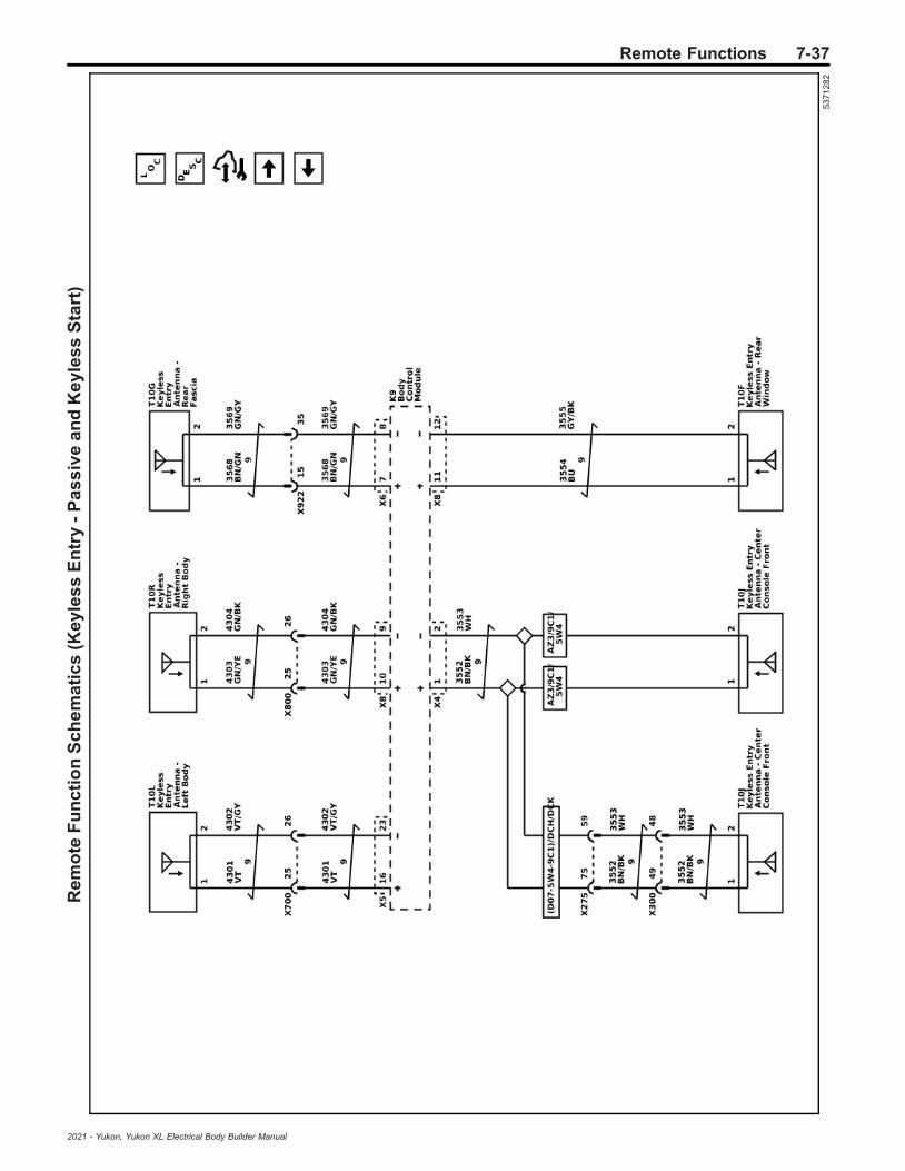
Remote Functions 7-37R
em
ote
Fu
nc
tio
nS
ch
em
ati
cs
(Ke
yle
ss
En
try
-P
as
siv
ea
nd
Ke
yle
ss
Sta
rt)
53
71
28
2
2021 - Yukon, Yukon XL Electrical Body Builder Manual

7-38 Remote FunctionsR
em
ote
Fu
nc
tio
nS
ch
em
ati
cs
(Ke
yle
ss
En
try
-V
irtu
alK
ey
Mo
du
le(B
OP
))
53
71
28
3
2021 - Yukon, Yukon XL Electrical Body Builder Manual

Remote Functions 7-39R
em
ote
Fu
nc
tio
nS
ch
em
ati
cs
(Ke
yle
ss
En
try
-V
irtu
alK
ey
Se
ns
ors
(BO
P))
54
30
58
2
2021 - Yukon, Yukon XL Electrical Body Builder Manual

7-40 Remote FunctionsR
em
ote
Fu
nc
tio
nS
ch
em
ati
cs
(Ga
rag
eD
oo
rO
pe
ne
r(U
G1
))
53
71
28
4
2021 - Yukon, Yukon XL Electrical Body Builder Manual

Remote Functions 7-41
Description and OperationGarage Door Opener Description andOperationThe garage door opener is fixed and rolling codecapable. Rolling code is a system that allows the codethat the customers receiver receives from the garagedoor opener to change every time the garage dooropener is used within operating range of the receiver.Rolling code programming requires the customer topush a learn/program button on the garage door openerreceiver at their home. This button is usually located onthe receiver unit under a cover (light cover) on one endof the unit. The customer must follow the garage dooropener manufacturers instructions to program/learn thereceiver to accept the Universal Home Remote Systemas an authorized opener for their unit . When thereceiver and the garage door opener are initiallyprogrammed together, a code is established and a newcode is created for every new transmission. Thesoftware in the receiver recognizes the garage dooropener and accepts the new code.The garage door opener is compatible with most, butnot all types and brands of transmitters.The garage door opener is a transmitter operatingbetween 288–434 MHz. The power and range of thetransmitter is limited to comply with laws governing thegeneration of radio frequency interference. Thetransmitter is programmed by the user to accept thesignal generated by the user's transmitters.The garage door opener has 3 buttons that may beprogrammed for individual transmitter/receivercombinations to control up to 3 garage door openers,security gates, lighting systems, etc. Each buttonrepresents a transmitter code section of the transmitter,which operates separately from any other button, andmay be considered a separate transmitter. Operationconsists of simply pressing a button to activate thecorresponding transmitter.Note: Do not use the garage door opener (GDO) withany garage door opener that does not have the stopand reverse safety feature. This includes any garagedoor opener model manufactured before April 1, 1982.
Keyless Entry System Descriptionand OperationKeyless Entry System Description and Operation –Active
The keyless entry system is a vehicle entry device. Thekeyless entry system is used in conjunction with thedoor locks to unlock the vehicle. Keyless entry will lock/unlock a door or open the rear compartment lid when acorresponding button on the keyless entry transmitter ispressed. This is accomplished by the transmittersending a radio frequency to the remote control doorlock receiver that has a direct link to the body controlmodule (BCM). The BCM interprets the signal andactivates the requested function or requests theappropriate ECU to activate the function via a serialdata message. A low transmitter battery or radiofrequency interference from aftermarket devices, suchas 2-way radios, power inverters, computers, etc., maycause a system malfunction. High radio frequencytraffic areas, such as gas stations that use
pay-at-the-pump radio frequency transponders, mayalso cause interference that could lead to amalfunction. Keyless entry allows you to operate thefollowing features:
• Door lock/unlock• Rear compartment lid release• Illuminated entry lamps• Panic alarm/vehicle locator• Remote vehicle start• Passive keyless entry able/disable• Automatic window express down, if equipped• Automatic window express up, if equipped• Automatic power mirror folding/unfolding,
if equipped
Keyless Entry System Description and Operation –Passive
Passive keyless entry allows entry to a locked vehiclewithout pressing any buttons on the keyless entrytransmitter. The passive entry system uses lowfrequency antennas in several different areas on thevehicle to determine the location of the transmitter.When passively opening a locked door or the rearcompartment, you must have a programmed transmitterwith you in your pocket, purse, or briefcase within a onemeter range.When an exterior door handle button is pressed or therear compartment touch pad is pressed, the bodycontrol module activates the low frequency antennawhich sends out a challenge to the keyless entrytransmitter. Because of the low frequency,communication range is limited. The antenna will emitthe challenge in a one meter range. The transmittermust be within this range to receive the challenge. Thetransmitter receives this challenge and emits it'sresponse as an RF message, which is received by theremote control door lock receiver. If the response iscorrect, entry into the vehicle will be allowed.As a customer convenience feature, the keyless entrysystem will notify the driver if the transmitter has beenleft in the vehicle after exiting by chirping the vehiclehorn three times and displaying a message on the DIC.This may be turned off using vehicle personalization.Also, if the transmitter is left in the vehicle after thecentral door lock switch has been used to lock thevehicle, the driver door will remain unlocked afterexiting the vehicle. This is intended to prevent lockingthe transmitter in the vehicle and being unable toaccess it.
Keyless Entry System Description and Operation –Keyless Start
The keyless start portion of the keyless entry systemallows vehicle starting, having only the transmitter asyour key. The keyless start system uses low frequencyantennas in three different locations on the vehicle todetermine the location of the transmitter. Multipleantenna are used to ensure complete coverage of thevehicle interior and rear compartment. When using thekeyless start system, a programmed transmitter mustbe in the vehicle's interior, in the driver's pocket, purse,or briefcase.
2021 - Yukon, Yukon XL Electrical Body Builder Manual

7-42 Remote Functions
When the ignition mode switch is pressed, the lowfrequency antennas emit a challenge to the keylessentry transmitter. The transmitter receives thischallenge and emits it's response as an RF message,which is received by the remote control door lockreceiver. If the response is correct, vehicle starting willbe allowed. If RF communication is interrupted, a “NoRemote Detected” message will be displayed on theDIC. In these cases, the transmitter can be placed inthe transmitter pocket located in the center console.The immobilizer antenna coil is located directly beneaththe transmitter pocket. Placing the transmitter in thepocket will create a low powered coupling between thetransmitter and immobilizer antenna, allowingcommunications to occur and enabling vehicle starting.If the key has been idle the DIC may display “Key InSleep Mode, Move Key, Then Start”. In this case movethe vehicle key to start the vehicle.The keyless entry system has the followingcomponents:
• Keyless entry integrated key/transmitter• Driver and passenger side antennas• Driver and passenger door handle switches (part
of the door handle assembly)• Rear fascia antenna• Immobilizer antenna coil (front console antenna
function)• Rear console antenna• Trunk antenna (rear compartment)• Body control module (BCM)• Remote control door lock receiver
Keyless Entry TransmittersBy operating any of the exterior door handle buttons orthe start/stop switch, a nearby transmitter is challengedby a keyless entry antenna. The transmitter will send anRF response to the remote control door lock receiver,which communicates with the BCM. The BCM willinterpret this communication and either allow or denyvehicle entry or starting.
Side AntennasThe keyless entry side antennas are used to transmitlow frequency communications to the keyless entrytransmitters.The keyless entry side antennas are located in thedriver and passenger body sides. The antennas arecontrolled by the body control module. When theexterior door handle button is pressed, the respectiveantenna will send out a challenge to the keyless entrytransmitter, which begins the passive entrycommunications.
Rear Fascia AntennaThe rear fascia antenna is used to transmit lowfrequency communication to the keyless entrytransmitters for entry to rear compartment.The rear fascia antenna is located behind the rearfascia. The antenna is controlled by the body controlmodule. When the rear compartment touch pad ispressed, the antenna sends out a challenge to thekeyless entry transmitter, which begins the passiveentry communications.
Immobilizer Coil AntennaThis antenna is located in the front of the centerconsole.The Immobilizer antenna coil is used for vehicle startingfunctions and for learning vehicle keys. When theignition mode switch is pressed, the antenna isenergized or "pinged". This emits a low frequencychallenge signal that is received by the keyless entrytransmitter. The transmitter will then reply to thischallenge with a response and, if correct, vehiclestarting will occur. If the transmitter battery is dead,weak, or the RF signal is being interrupted, thetransmitter may be placed in the pocket to create a lowpowered coupling between the transmitter andimmobilizer coil antenna, allowing communications tooccur and enabling vehicle starting.
Rear Console AntennaThis antenna is located in the rear of the centerconsole.The rear console antenna is used for vehicle startingfunctions. When the ignition mode switch is pressed,the antenna is energized or "pinged". This emits a lowfrequency challenge signal that is received by thekeyless entry transmitter. The transmitter will then replyto this challenge with a response and, if correct, vehiclestarting will occur.
Rear Compartment AntennaThis antenna is located near the center of the rearcompartment area.The rear compartment antenna is used for vehiclestarting functions. When the ignition mode switch ispressed, the antenna is energized or "pinged". Thisemits a low frequency challenge signal that is receivedby the keyless entry transmitter. The transmitter willthen reply to this challenge with a response and,if correct, vehicle starting will occur.
OnStar® Remote LinkA vehicle operator may have the ability to perform someof the keyless entry functions using applications onpersonal devices such as smart phones. Refer toOnStar Description and Operation.
Body Control Module (BCM)The BCM is a multi-function module that performs thefollowing functions:
• Receive and authenticate active transmitter andkeyless start/entry signals from the remote controldoor lock receiver
• Determines the function requested by thetransmitter signal
• Performs the function requested by the transmittersignal
• Activating vehicle antennas for passive keylessentry functions
• Activating vehicle antennas for keyless startfunctions
• Backup control for the ECM accessory wakeupand the run/crank relay
• If equipped, controls the electronic steeringcolumn lock
2021 - Yukon, Yukon XL Electrical Body Builder Manual
Remote Functions 7-43
• Receiver of the exterior door handle switch inputsand door open switch (not the door ajar switch)
• Ignition mode switch monitoring
Unlock Driver Door Only – ActiveMomentarily press the transmitter UNLOCK button inorder to perform the following functions:
• Unlock only the driver door or all doors, if enabledthrough personalization
• Illuminate the interior lamps for a determinedlength of time, or until the ignition is turned ON
• Flash the exterior lights, if enabled throughpersonalization
• Disarm the Content Theft Deterrent (CTD) system• Deactivate the CTD system when in the
alarm mode
Unlock All Doors – Second Operation –ActiveMomentarily press the transmitter UNLOCK button asecond time, within 5 seconds of the first press, toperform the following function:Unlock the remaining doors
Unlock Driver Door Only – PassiveIf enabled through personalization, approach the driverdoor with a valid keyless entry transmitter and press thedoor handle button to perform the following functions:
• Unlock and open only the driver door• Disarm the CTD system, if equipped• Deactivate the CTD system when in the
alarm mode
Unlock All Doors – PassiveApproach any non driver door (front or rear) or,if enabled through personalization, the driver door witha valid keyless entry transmitter and press the doorhandle button to perform the following functions:
• Unlock all vehicle doors• Disarm the CTD system, if equipped• Deactivate the CTD system when in the
alarm mode
Lock All Doors – ActivePress the transmitter LOCK button to perform thefollowing functions:
• Lock all vehicle doors• Immediately turn off the interior lamps• Flash the exterior lights, if enabled through
personalization• Chirp the horn, if enabled through personalization• Arm the CTD system
Lock All Doors – PassiveExit the vehicle (with ignition off) with the keyless entrytransmitter to automatically perform the followingfunctions, if equipped.
• Lock all vehicle doors after a delay• Flash the exterior lights, if enabled through
personalization
• Chirp horn, if enabled through personalization• Arm the CTD system
When all doors are closed, they can also be lockedfrom the exterior by operating a front door handlebutton or touch pad while having a valid transmitterwithin range. Vehicles equipped with a rear door buttoncan also lock all doors from the rear doors.
Rear Compartment Lid Release – ActiveIf the vehicle transaxle is in PARK or NEUTRAL, adouble press of the transmitter rear compartmentrelease button will open the rear compartment lid.
Rear Compartment Lid Release –PassiveApproach the rear of a locked vehicle with a validkeyless entry transmitter. Press the rear compartmentlid release touch pad. The rear compartment lidwill open.
Vehicle Locator/Panic Alarm/ActiveA single press of the panic button performs thefollowing functions. Some functions may be dependenton personalization settings:
• Pulses the horn three times• Flashes the exterior lamps three times
A press and hold of the panic button performs thefollowing functions:
• Pulses the horn and flashes the parking lamps for30 second or until the following conditions occur:– The panic button is pressed– The ignition switch is turned to the RUN position
with a valid key
Remote Vehicle Start/ActiveThe remote vehicle start function allows engine startingwhile not in the vehicle. It also allows the vehicle HVACsystem and other vehicle systems to enable, providinga comfortable vehicle upon entry. The remote vehiclestart sequence begins by pressing and releasing theremote vehicle start button on the keyless entrytransmitter twice. The turn signal lamps will illuminate toindicate the vehicle has received the remote startrequest. Each time a remote vehicle start is performed,the vehicle doors are locked, however they may thenbe unlocked/locked with the transmitter at any time.Once activated, the engine is allowed to run for15 minutes. The remote start operation can berepeated as many times as desired up to a total runtime of 30 minutes. The remote vehicle start event maybe cancelled at any time by pressing only the remotevehicle start button on the transmitter or by entering thevehicle and turning ON the hazard lamps.
Hood Ajar Switch/ActiveThe hood switch provides status of the hood to theBCM for remote vehicle start purposes. The switch isintegrated into the hood latch assembly. The hood ajarswitch provides 2 separate inputs to the BCM. Theseseparate inputs allow the BCM to actively monitor for ahood ajar switch fault.
2021 - Yukon, Yukon XL Electrical Body Builder Manual

7-44 Remote Functions
Remote Vehicle Start CircuitDescription/ActiveThe BCM receives a signal from the keyless entrytransmitter indicating a remote vehicle start request.The BCM and ECM use the following inputs to verifythe system is ready to enable a remote vehicle startevent:
• Vehicle is not in valet mode• Vehicle is in park• Keyless entry transmitter is not in the vehicle• The hood is closed• The hazard switch is OFF• Vehicle power mode is OFF• The malfunction indicator lamp (MIL) is not
commanded ON by the ECM• Remote start timer does not equal 0 (the
30 minute maximum time has not been used)When the BCM determines all conditions meet thoserequired for a remote vehicle start event, a message issent via serial data to the ECM. While the ECM is inremote vehicle start mode it will cut fuel to the engine ifany of the following monitored conditions occur:
• Vehicle speed is greater than 0• Transmission is not in P• Excessive engine coolant temperature• Low oil pressure• Engine crank time is greater than 30 seconds• Excessive engine speed• Accelerator pedal position too high• Immobilizer system indicates a theft attempt
If any conditions prevent a remote start or cause aremote start operation to be cancelled there is a recordof the cause in the scan tool.
Keyless Entry PersonalizationVehicle lock/unlock functions and remote vehicle startsettings may be personalized for the vehicle. Thisincludes the capability of turning the passive entrysystem completely off. For functional descriptions andprogramming instructions, refer to the vehicle ownersmanual.
2021 - Yukon, Yukon XL Electrical Body Builder Manual

1
AActive Safety System
Description and Operation . . . . . . . . . . . . . . . . . . . . . . . . 7-9Adaptive Cruise Control
Description and Operation . . . . . . . . . . . . . . . . . . . . . . . 7-11Automatic Day-Night Mirror
Description and Operation . . . . . . . . . . . . . . . . . . . . . . . 2-51Automatic HVAC Description and
Operation . . . . . . . . . . . . . . . . . . . . . . . . . . . . . . . . . . . . . . . . 5-13
BBattery
Description and Operation . . . . . . . . . . . . . . . . . . . . . . . . 4-9
CCharging System
Description and Operation . . . . . . . . . . . . . . . . . . . . . . . . 4-9Component Connector End Views . . . . . . . . . . . . . . . . 6-75
DData Link Communications
Description and Operation . . . . . . . . . . . . . . . . . . . . . . . 6-27Door Ajar Indicator
Description and Operation . . . . . . . . . . . . . . . . . . . . . . . 2-82
EElectrical Center Identification Views . . . . . . . . . . . . . 6-30Electrical Power Management Description and
Operation . . . . . . . . . . . . . . . . . . . . . . . . . . . . . . . . . . . . . . . . 4-12Exterior Lighting Systems
Description and Operation . . . . . . . . . . . . . . . . . . . . . . . 2-41
FForward Collision Alert
Description and Operation . . . . . . . . . . . . . . . . . . . . . . . 7-16Fuel Fill Door
Description and Operation . . . . . . . . . . . . . . . . . . . . . . . 2-82
GGarage Door Opener
Description and Operation . . . . . . . . . . . . . . . . . . . . . . . 7-41
HHood Ajar Indicator
Description and Operation . . . . . . . . . . . . . . . . . . . . . . . 2-82Horn
System Description and Operation . . . . . . . . . . . . . . 2-11
IImmobilizer
Description and Operation . . . . . . . . . . . . . . . . . . . . . . . 7-27Inline Harness Connector End Views . . . . . . . . . . . . 6-374Interior Lighting System
Description and Operation . . . . . . . . . . . . . . . . . . . . . . . 2-44
KKeyless Entry
System Description and Operation . . . . . . . . . . . . . . 7-41
LLane Keep Assist
Description and Operation . . . . . . . . . . . . . . . . . . . . . . . 7-18Liftgate
Ajar Indicator Description and Operation . . . . . . . . 2-82Description and Operation . . . . . . . . . . . . . . . . . . . . . . . 2-83
MMaster Electrical Component List . . . . . . . . . . . . . . . 6-625Mobile Device Wireless Charger
Description and Operation . . . . . . . . . . . . . . . . . . . . . . 6-552
OOutside Mirror
Description and Operation . . . . . . . . . . . . . . . . . . . . . . . 2-52
PParking Assist
Description and Operation . . . . . . . . . . . . . . . . . . . . . . . 7-33Power Door Locks
Description and Operation . . . . . . . . . . . . . . . . . . . . . . . 2-84Power Mode Description and Operation . . . . . . . . . 6-693Power Outlets
Description and Operation . . . . . . . . . . . . . . . . . . . . . . 6-552Power Windows
Description and Operation . . . . . . . . . . . . . . . . . . . . . . . . 2-8
RRear Hatch/Gate Description and
Operation . . . . . . . . . . . . . . . . . . . . . . . . . . . . . . . . . . . . . . . . 2-85Rear Vision Camera
Description and Operation . . . . . . . . . . . . . . . . . . . . . . . . 3-8Rear Window Defogger
Description and Operation . . . . . . . . . . . . . . . . . . . . . . . . 2-8Rearview Camera
Camera Full Display Mirror Description andOperation . . . . . . . . . . . . . . . . . . . . . . . . . . . . . . . . . . . . . . . . 3-8
Retained Accessory PowerDescription and Operation . . . . . . . . . . . . . . . . . . . . . . 6-696
SSafety Alert Seat
Description and Operation . . . . . . . . . . . . . . . . . . . . . . . 7-19Schematics
Auxiliary Battery . . . . . . . . . . . . . . . . . . . . . . . . . . . . . . . . . . . 4-8Body Control Systems . . . . . . . . . . . . . . . . . . . . . . . . . . . 6-24Cigar Lighter/Power Outlet . . . . . . . . . . . . . . . . . . . . . 6-546Data Communications . . . . . . . . . . . . . . . . . . . . . . . . . . . . 6-4Defogger . . . . . . . . . . . . . . . . . . . . . . . . . . . . . . . . . . . . . . . . . . 2-7Door Lock/Indicator . . . . . . . . . . . . . . . . . . . . . . . . . . . . . . 2-69Driver Assistance Systems . . . . . . . . . . . . . . . . . . . . . . . 7-4Exterior Lamps . . . . . . . . . . . . . . . . . . . . . . . . . . . . . . . . . . . 2-17Fog Lamps . . . . . . . . . . . . . . . . . . . . . . . . . . . . . . . . . . . . . . . 2-16Ground Distribution . . . . . . . . . . . . . . . . . . . . . . . . . . . . . 6-586
2021 - Yukon, Yukon XL Electrical Body Builder Manual

2
Schematics (cont'd)Headlamps/Daytime Running Lamps . . . . . . . . . . . . 2-13Hood Latch . . . . . . . . . . . . . . . . . . . . . . . . . . . . . . . . . . . . . . 2-78Horns . . . . . . . . . . . . . . . . . . . . . . . . . . . . . . . . . . . . . . . . . . . . 2-10HVAC Systems - Automatic . . . . . . . . . . . . . . . . . . . . . . . 5-4Image Display Cameras . . . . . . . . . . . . . . . . . . . . . . . . . . 3-4Immobilizer . . . . . . . . . . . . . . . . . . . . . . . . . . . . . . . . . . . . . . 7-24Inside Rearview Mirror . . . . . . . . . . . . . . . . . . . . . . . . . . . 2-47Interior Lamps . . . . . . . . . . . . . . . . . . . . . . . . . . . . . . . . . . . 2-32Interior Lamps Dimming . . . . . . . . . . . . . . . . . . . . . . . . . 2-37Liftgate . . . . . . . . . . . . . . . . . . . . . . . . . . . . . . . . . . . . . . . . . . . 2-79Moveable Window . . . . . . . . . . . . . . . . . . . . . . . . . . . . . . . . . 2-4Outside Rearview Mirror . . . . . . . . . . . . . . . . . . . . . . . . . 2-48Parking Assistance Systems . . . . . . . . . . . . . . . . . . . . 7-30Power Distribution . . . . . . . . . . . . . . . . . . . . . . . . . . . . . . 6-556Power Moding . . . . . . . . . . . . . . . . . . . . . . . . . . . . . . . . . . 6-584Release Systems . . . . . . . . . . . . . . . . . . . . . . . . . . . . . . . . 2-75Remote Function . . . . . . . . . . . . . . . . . . . . . . . . . . . . . . . . 7-36Starting and Charging . . . . . . . . . . . . . . . . . . . . . . . . . . . . . 4-4Trailering Systems . . . . . . . . . . . . . . . . . . . . . . . . . . . . . . . 2-55Upfitter Provision . . . . . . . . . . . . . . . . . . . . . . . . . . . . . . . 6-610Wiper and Washer Systems . . . . . . . . . . . . . . . . . . . . . 2-87
Side Blind Zone AlertDescription and Operation . . . . . . . . . . . . . . . . . . . . . . . 7-20
Starting SystemDescription and Operation . . . . . . . . . . . . . . . . . . . . . . . 4-14
Stop/Start SystemDescription and Operation . . . . . . . . . . . . . . . . . . . . . . . 4-16
Surround Vision CameraDescription and Operation . . . . . . . . . . . . . . . . . . . . . . . . 3-8
System ComponentsProgramming Immobilizer System . . . . . . . . . . . . . . . 7-25
TTrailering Description and Operation . . . . . . . . . . . . . 2-60Trailering Systems Schematics . . . . . . . . . . . . . . . . . . . 2-55
VVehicle Certification, Tire Placard, Anti-Theft,
and Service Parts ID Label . . . . . . . . . . . . . . . . . . . . . . . 1-3
WWiper/Washer
System Description and Operation . . . . . . . . . . . . . . 2-91
2021 - Yukon, Yukon XL Electrical Body Builder Manual