GM-A6704 GM-A4704
32
English Español BRIDGEABLE FOUR-CHANNEL POWER AMPLIFIER AMPLIFICADOR DE POTENCIA DE CUATRO CANALES EN PUENTE GM-A6704 GM-A4704 Owner’s Manual Manual de instrucciones
-
Upload
khangminh22 -
Category
Documents
-
view
0 -
download
0
Transcript of GM-A6704 GM-A4704

EnglishEspañol
BRIDGEABLE FOUR-CHANNEL POWER AMPLIFIERAMPLIFICADOR DE POTENCIA DE CUATRO CANALES EN PUENTE
GM-A6704GM-A4704
Owner’s ManualManual de instrucciones
5707000011300V <1>

PIONEER CORPORATION28-8, Honkomagome 2-chome, Bunkyo-ku,Tokyo 113-0021, JAPAN
PIONEER ELECTRONICS (USA) INC.P.O. Box 1540, Long Beach, California 90801-1540, U.S.A.TEL: (800) 421-1404
PIONEER EUROPE NVHaven 1087, Keetberglaan 1, B-9120 Melsele, Belgium/BelgiqueTEL: (0) 3/570.05.11
PIONEER ELECTRONICS ASIACENTRE PTE. LTD.2 Jalan Kilang Barat, #07-01, Singapore 159346TEL: 65-6378-7888
PIONEER ELECTRONICS AUSTRALIA PTY. LTD.5 Arco Lane, Heatherton, Victoria, 3202 AustraliaTEL: (03) 9586-6300
PIONEER ELECTRONICS OF CANADA, INC.340 Ferrier Street, Unit 2, Markham, Ontario L3R 2Z5, CanadaTEL: 1-877-283-5901TEL: 905-479-4411
PIONEER ELECTRONICS DE MÉXICO S.A. de C.V.Blvd.Manuel Ávila Camacho 138, 10 pisoCol.Lomas de Chapultepec, México, D.F. 11000TEL: 52-55-9178-4270FAX: 52-55-5202-3714
先鋒股份有限公司台北市內湖區瑞光路407號8樓電話: 886-(0)2-2657-3588
先鋒電子(香港)有限公司香港九龍長沙灣道909號5樓電話: 852-2848-6488
© 2016 PIONEERCORPORATION.All rights reserved.
© 2016 PIONEERCORPORATION.Todos los derechos reservados.
<5707000011300V> ES
http://pioneer.jp/en/info/globalnetwork/
<KOKZ16D>
5707000011300V <2>
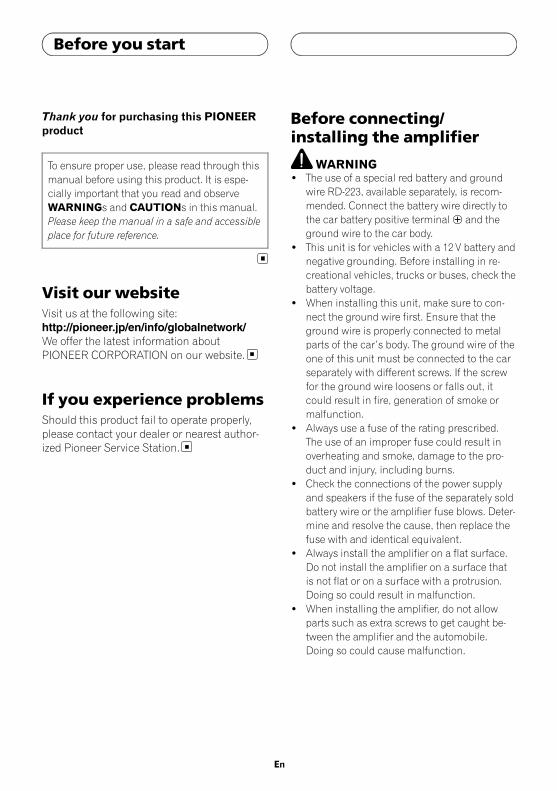
Thank you for purchasing this PIONEERproduct
To ensure proper use, please read through thismanual before using this product. It is espe-cially important that you read and observeWARNINGs and CAUTIONs in this manual.Please keep the manual in a safe and accessibleplace for future reference.
Visit our websiteVisit us at the following site:http://pioneer.jp/en/info/globalnetwork/We offer the latest information aboutPIONEER CORPORATION on our website.
If you experience problemsShould this product fail to operate properly,please contact your dealer or nearest author-ized Pioneer Service Station.
Before connecting/installing the amplifier
WARNING! The use of a special red battery and ground
wire RD-223, available separately, is recom-mended. Connect the battery wire directly tothe car battery positive terminal+ and theground wire to the car body.
! This unit is for vehicles with a 12 V battery andnegative grounding. Before installing in re-creational vehicles, trucks or buses, check thebattery voltage.
! When installing this unit, make sure to con-nect the ground wire first. Ensure that theground wire is properly connected to metalparts of the car’s body. The ground wire of theone of this unit must be connected to the carseparately with different screws. If the screwfor the ground wire loosens or falls out, itcould result in fire, generation of smoke ormalfunction.
! Always use a fuse of the rating prescribed.The use of an improper fuse could result inoverheating and smoke, damage to the pro-duct and injury, including burns.
! Check the connections of the power supplyand speakers if the fuse of the separately soldbattery wire or the amplifier fuse blows. Deter-mine and resolve the cause, then replace thefuse with and identical equivalent.
! Always install the amplifier on a flat surface.Do not install the amplifier on a surface thatis not flat or on a surface with a protrusion.Doing so could result in malfunction.
! When installing the amplifier, do not allowparts such as extra screws to get caught be-tween the amplifier and the automobile.Doing so could cause malfunction.
En
Before you start
5707000011300V <3>
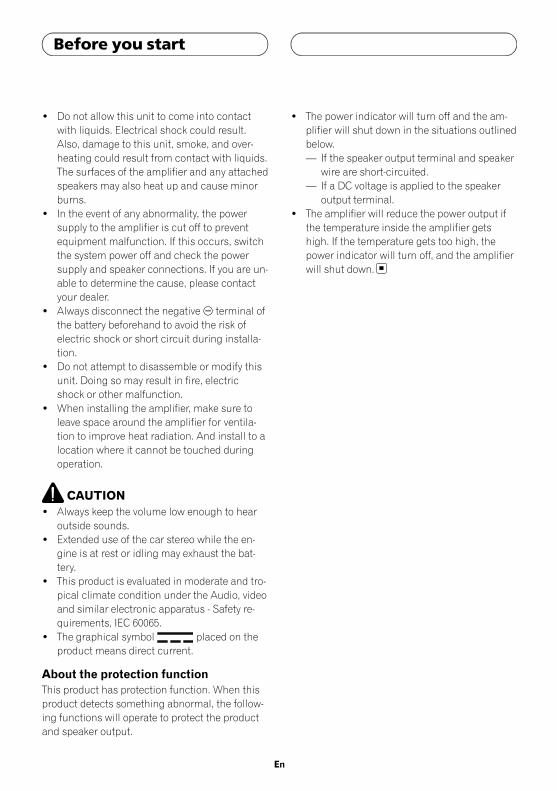
! Do not allow this unit to come into contactwith liquids. Electrical shock could result.Also, damage to this unit, smoke, and over-heating could result from contact with liquids.The surfaces of the amplifier and any attachedspeakers may also heat up and cause minorburns.
! In the event of any abnormality, the powersupply to the amplifier is cut off to preventequipment malfunction. If this occurs, switchthe system power off and check the powersupply and speaker connections. If you are un-able to determine the cause, please contactyour dealer.
! Always disconnect the negative* terminal ofthe battery beforehand to avoid the risk ofelectric shock or short circuit during installa-tion.
! Do not attempt to disassemble or modify thisunit. Doing so may result in fire, electricshock or other malfunction.
! When installing the amplifier, make sure toleave space around the amplifier for ventila-tion to improve heat radiation. And install to alocation where it cannot be touched duringoperation.
CAUTION! Always keep the volume low enough to hear
outside sounds.! Extended use of the car stereo while the en-
gine is at rest or idling may exhaust the bat-tery.
! This product is evaluated in moderate and tro-pical climate condition under the Audio, videoand similar electronic apparatus - Safety re-quirements, IEC 60065.
! The graphical symbol placed on theproduct means direct current.
About the protection functionThis product has protection function. When thisproduct detects something abnormal, the follow-ing functions will operate to protect the productand speaker output.
! The power indicator will turn off and the am-plifier will shut down in the situations outlinedbelow.— If the speaker output terminal and speaker
wire are short-circuited.— If a DC voltage is applied to the speaker
output terminal.! The amplifier will reduce the power output if
the temperature inside the amplifier getshigh. If the temperature gets too high, thepower indicator will turn off, and the amplifierwill shut down.
En
Before you start
5707000011300V <4>

What’s whatGM-A6704
Front side
Rear side
GM-A4704
Front side
Rear side
To adjust the switch, use a flathead screwdri-ver if needed.
1 FREQ (cut off frequency) controlCut off frequency selectable from 40 Hz to500 Hz if the HPF select switch is set to HPF.! You can select cut off frequency only for
CHANNEL A.
2 LPF (low-pass filter)/HPF (high-pass fil-ter) select switch
Switch the settings based on the connectedspeaker.! When the Subwoofer is connected:
Select LPF. This eliminates high rangefrequency and outputs low range fre-quency.
! When the full range speaker is con-nected:Select HPF or OFF. HPF eliminates lowrange frequency and output high rangefrequency. OFF outputs the entire fre-quency range.
3 GAIN (gain) controlAdjusting gain controls CHANNEL A (chan-nel A) and CHANNEL B (channel B) helpsalign the car stereo output to the Pioneeramplifier. Default setting is the NORMALposition.If the output remains low, even when the carstereo volume is turned up, turn the con-trols to a lower level. If distortion occurswhen the car stereo volume is turned up,turn these controls to a higher level.! If using only one input plug, set the gain
controls for speaker outputs A and B tothe same position.
! For use with an RCA equipped car stereo(standard output of 500mV), set to theNORMAL position. For use with an RCAequipped Pioneer car stereo, with maxi-mum output of 4 V or more, adjust levelto match that of the car stereo output.
! For use with an RCA equipped car stereowith output of 4 V, set to the HIGH posi-tion.
4 INPUT SELECT (input select) switchSelect 2CH for two-channel input and 4CHfor four–channel input.! You can select input select only for con-
nections when using the RCA input jack.For connections when using the speakerinput wire, 4CH will be used automati-cally no matter which switch setting isselected.
En
Setting the unit
5707000011300V <5>

5 BASS BOOST (bass boost level control)switch
You can select a bass boost level from 0 dB,6 dB and 12 dB.! Bass boost level setting applies only to
CHANNEL B (channel B) output.
6 Power indicatorThe power indicator lights up to indicatepower ON.
Setting gain properly! Protective function included to prevent
malfunction of the unit and/or speakersdue to excessive output, improper use orimproper connection.
! When outputting high volume sound etc.,this function cuts off the output for a fewseconds as a normal function, but outputis restored when the volume of the headunit is turned down.
! A cut in sound output may indicate impro-per setting of the gain control. To ensurecontinuous sound output with the headunit at a high volume, set amplifier gaincontrol to a level appropriate for the preoutmaximum output level of the head unit, sothat volume can remain unchanged and tocontrol excess output.
! Despite correct volume and gain settings,the unit sound still cuts out periodically. Insuch cases, please contact the nearestauthorized Pioneer Service Station.
Gain control of this unit
Preout level: 4 V
Preout level: 2 V (Standard: 500 mV)
Above illustration shows NORMAL gain set-ting.
Relationship between amplifier gainand head unit output power
If amplifier gain is raised improperly, this willsimply increase distortion, with little increasein power.
Signal waveform when outputting athigh volume using amplifier gaincontrol
If the signal waveform is distorted due to highoutput, even if the amplifier gain is raised, theoutput power will change only slightly.
En
Setting the unit
5707000011300V <6>
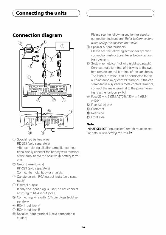
Connection diagram
1 Special red battery wireRD-223 (sold separately)After completing all other amplifier connec-tions, finally connect the battery wire terminalof the amplifier to the positive+ battery term-inal.
2 Ground wire (Black)RD-223 (sold separately)Connect to metal body or chassis.
3 Car stereo with RCA output jacks (sold sepa-rately)
4 External outputIf only one input plug is used, do not connectanything to RCA input jack B.
5 Connecting wire with RCA pin plugs (sold se-parately)
6 RCA input jack A7 RCA input jack B8 Speaker input terminal (use a connector in-
cluded)
Please see the following section for speakerconnection instructions. Refer to Connectionswhen using the speaker input wire.
9 Speaker output terminalsPlease see the following section for speakerconnection instructions. Refer to Connectingthe speakers.
a System remote control wire (sold separately)Connect male terminal of this wire to the sys-tem remote control terminal of the car stereo.The female terminal can be connected to theauto-antenna relay control terminal. If the carstereo lacks a system remote control terminal,connect the male terminal to the power term-inal via the ignition switch.
b Fuse 25A×2 (GM-A6704) / 30A×1 (GM-A4704)
c Fuse (30 A) × 2d Grommete Rear sidef Front side
NoteINPUT SELECT (input select) switch must be set.For details, see Setting the unit.
En
Connecting the units
5707000011300V <7>
Before connecting theamplifier
WARNING! Secure the wiring with cable clamps or adhe-
sive tape. To protect the wiring, wrap sectionsin contact with metal parts in adhesive tape.
! Never cut the insulation of the power supplyto feed power to other equipment. Current ca-pacity of the wire is limited.
CAUTION! Never shorten any wires, the protection circuit
may malfunction.! Never wire the speaker negative cable directly
to ground.! Never band together multiple speaker’s nega-
tive cables.! If the system remote control wire of the ampli-
fier is connected to the power terminal via theignition switch (12 VDC), the amplifier will re-main on with the ignition whether the carstereo is on or off, which may exhaust batteryif the engine is at rest or idling.
! Install and route the separately sold batterywire as far as possible from the speaker wires.Install and route the separately sold batterywire, ground wire, speaker wires and the am-plifier as far away as possible from the anten-na, antenna cable and tuner.
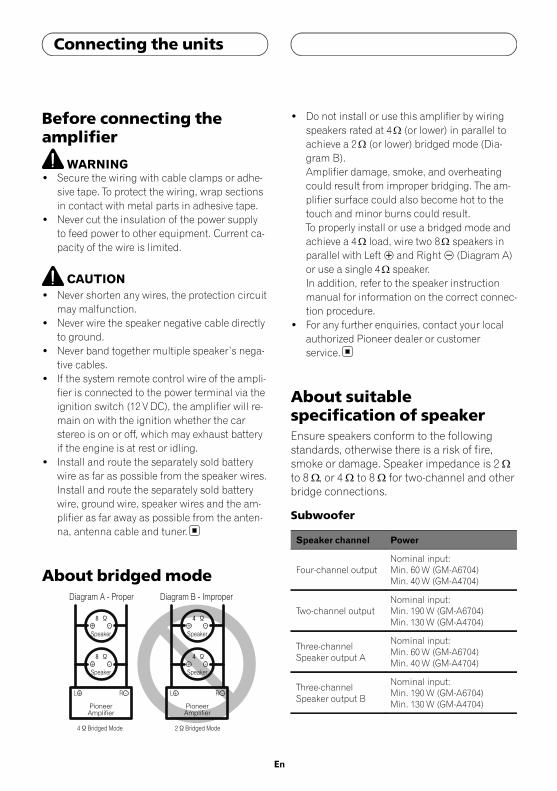
About bridged mode
! Do not install or use this amplifier by wiringspeakers rated at 4W (or lower) in parallel toachieve a 2W (or lower) bridged mode (Dia-gram B).Amplifier damage, smoke, and overheatingcould result from improper bridging. The am-plifier surface could also become hot to thetouch and minor burns could result.To properly install or use a bridged mode andachieve a 4W load, wire two 8W speakers inparallel with Left + and Right* (Diagram A)or use a single 4W speaker.In addition, refer to the speaker instructionmanual for information on the correct connec-tion procedure.
! For any further enquiries, contact your localauthorized Pioneer dealer or customerservice.
About suitablespecification of speakerEnsure speakers conform to the followingstandards, otherwise there is a risk of fire,smoke or damage. Speaker impedance is 2 Wto 8 W, or 4 W to 8 W for two-channel and otherbridge connections.
Subwoofer
Speaker channel Power
Four-channel outputNominal input:Min. 60W (GM-A6704)Min. 40W (GM-A4704)
Two-channel outputNominal input:Min. 190W (GM-A6704)Min. 130W (GM-A4704)
Three-channelSpeaker output A
Nominal input:Min. 60W (GM-A6704)Min. 40W (GM-A4704)
Three-channelSpeaker output B
Nominal input:Min. 190W (GM-A6704)Min. 130W (GM-A4704)
En
Connecting the units
5707000011300V <8>
Other than subwoofer
Speaker channel Power
Four-channel outputMax. input:Min. 170W (GM-A6704)Min. 80W (GM-A4704)
Two-channel outputMax. input:Min. 500W (GM-A6704)Min. 260W (GM-A4704)
Three-channelSpeaker output A
Max. input:Min. 170W (GM-A6704)Min. 80W (GM-A4704)
Three-channelSpeaker output B
Max. input:Min. 500W (GM-A6704)Min. 260W (GM-A4704)
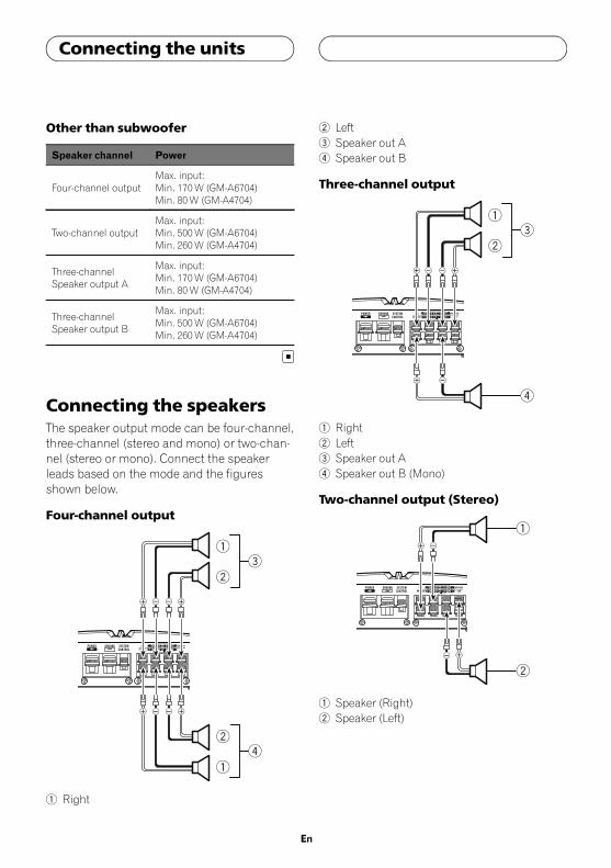
Connecting the speakersThe speaker output mode can be four-channel,three-channel (stereo and mono) or two-chan-nel (stereo or mono). Connect the speakerleads based on the mode and the figuresshown below.
Four-channel output
32
1
1
24
1 Right
2 Left3 Speaker out A4 Speaker out B
Three-channel output
4
32
1
1 Right2 Left3 Speaker out A4 Speaker out B (Mono)
Two-channel output (Stereo)
2
1 Speaker (Right)2 Speaker (Left)
En
Connecting the units
5707000011300V <9>

Two-channel output (Mono)
1
1 Speaker (Mono)
Connections when usingthe RCA input jackConnect the car stereo RCA output jack andthe RCA input jack of the amplifier.
Four-channel / Three-channel output! Slide INPUT SELECT (input select) switch
to 4CH position.
1 2
4
3
1 RCA input jack A2 RCA input jack B3 Connecting wires with RCA plugs (sold sepa-
rately)4 From car stereo (RCA output)
If only one input plug is used, e.g. when thecar stereo has only one output (RCA output),connect the plug to RCA input jack A ratherthan B.
Two-channel output (Stereo) / (Mono)! Slide INPUT SELECT (input select) switch
to 2CH position.
2
3
1
En
Connecting the units
5707000011300V <10>
1 RCA input jack AFor two-channel output, connect the RCAplugs to the RCA input jack A.
2 Connecting wire with RCA pin plugs (sold se-parately)
3 From car stereo (RCA output)
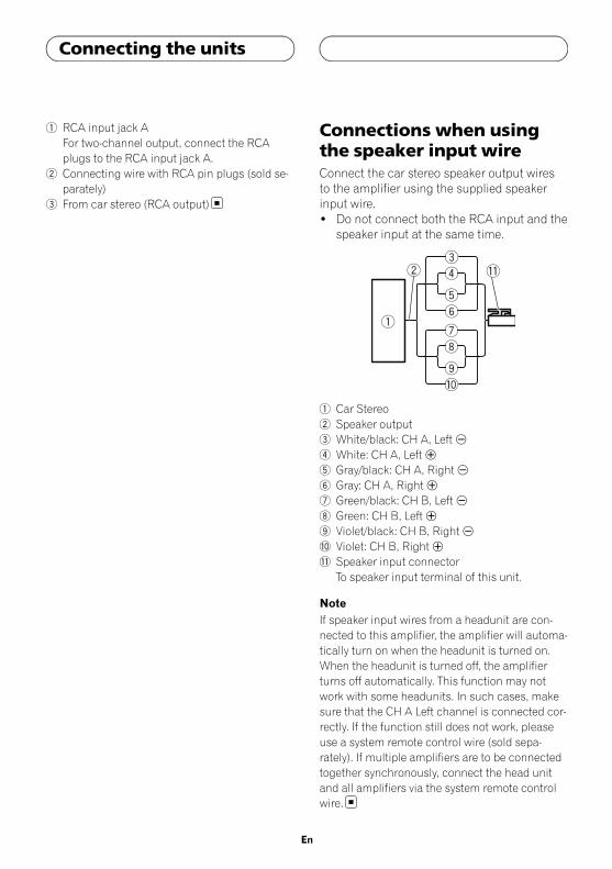
Connections when usingthe speaker input wireConnect the car stereo speaker output wiresto the amplifier using the supplied speakerinput wire.! Do not connect both the RCA input and the
speaker input at the same time.
1 Car Stereo2 Speaker output3 White/black: CH A, Left *4 White: CH A, Left +5 Gray/black: CH A, Right*6 Gray: CH A, Right+7 Green/black: CH B, Left *8 Green: CH B, Left +9 Violet/black: CH B, Right*a Violet: CH B, Right+b Speaker input connector
To speaker input terminal of this unit.
NoteIf speaker input wires from a headunit are con-nected to this amplifier, the amplifier will automa-tically turn on when the headunit is turned on.When the headunit is turned off, the amplifierturns off automatically. This function may notwork with some headunits. In such cases, makesure that the CH A Left channel is connected cor-rectly. If the function still does not work, pleaseuse a system remote control wire (sold sepa-rately). If multiple amplifiers are to be connectedtogether synchronously, connect the head unitand all amplifiers via the system remote controlwire.
En
Connecting the units
5707000011300V <11>
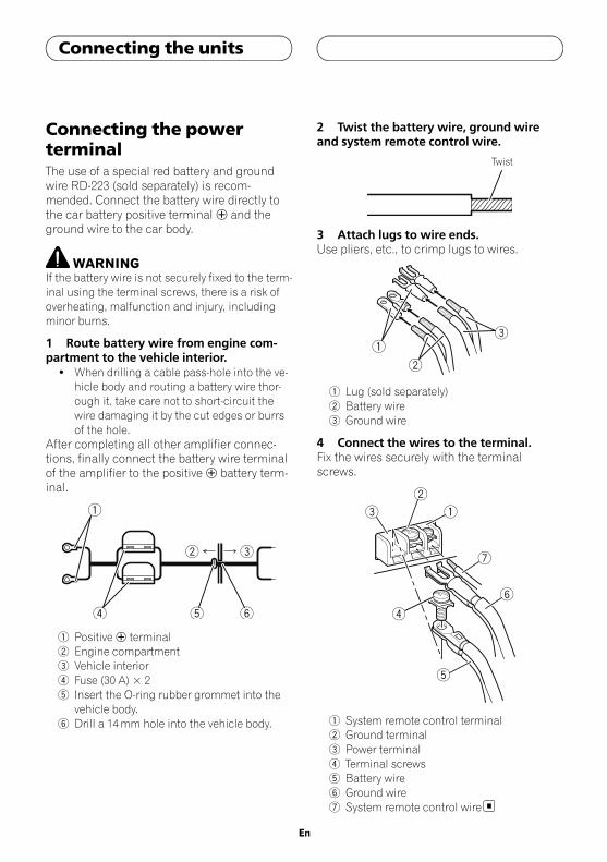
Connecting the powerterminalThe use of a special red battery and groundwire RD-223 (sold separately) is recom-mended. Connect the battery wire directly tothe car battery positive terminal + and theground wire to the car body.
WARNINGIf the battery wire is not securely fixed to the term-inal using the terminal screws, there is a risk ofoverheating, malfunction and injury, includingminor burns.
1 Route battery wire from engine com-partment to the vehicle interior.
! When drilling a cable pass-hole into the ve-hicle body and routing a battery wire thor-ough it, take care not to short-circuit thewire damaging it by the cut edges or burrsof the hole.
After completing all other amplifier connec-tions, finally connect the battery wire terminalof the amplifier to the positive+ battery term-inal.
1 Positive+ terminal2 Engine compartment3 Vehicle interior4 Fuse (30 A) × 25 Insert the O-ring rubber grommet into the
vehicle body.6 Drill a 14mm hole into the vehicle body.
2 Twist the battery wire, ground wireand system remote control wire.
Twist
3 Attach lugs to wire ends.Use pliers, etc., to crimp lugs to wires.
1 Lug (sold separately)2 Battery wire3 Ground wire
4 Connect the wires to the terminal.Fix the wires securely with the terminalscrews.
1 System remote control terminal2 Ground terminal3 Power terminal4 Terminal screws5 Battery wire6 Ground wire7 System remote control wire
En
Connecting the units
5707000011300V <12>

Connecting the speakeroutput terminals1 Use wire cutters or a utility knife tostrip the end of the speaker wires to ex-pose about 10mm of wire and then twistthe wire.
Twist
2 Attach lugs to wire ends.Use pliers, etc., to crimp lugs to wires.
1 Lug (sold separately)2 Speaker wire
3 Connect the speaker wires to thespeaker output terminals.Fix the speaker wires securely with the term-inal screws.
1 Terminal screws2 Speaker wires3 Speaker output terminals
Before installing the amplifier
WARNING! To ensure proper installation, use the supplied
parts in the manner specified. If any partsother than those supplied are used, they maydamage internal parts of the amplifier, or be-come loose causing the amplifier to shutdown.
! Do not install in:— Places where it could injure the driver or
passengers if the vehicle stops suddenly.— Places where it may interfere with the dri-
ver, such as on the floor in front of the dri-ver’s seat.
! Install tapping screws in such a way that thescrew tip does not touch any wire. This is im-portant to prevent wires from being cut by vi-bration of the car, which can result in fire.
! Make sure that wires do not get caught in thesliding mechanism of the seats or touch thelegs of a person in the vehicle as short-circuitmay result.
! When drilling to install the amplifier, alwaysconfirm no parts are behind the panel andprotect all cables and important equipment(e.g. fuel/brake lines, wiring) from damage.
CAUTION! To ensure proper heat dissipation of the ampli-
fier, ensure the following during installation:— Allow adequate space above the amplifier
for proper ventilation.— Do not cover the amplifier with a floor mat
or carpet.! Protection function may activate to protect the
amplifier against overheating due to installa-tion in locations where sufficient heat cannotbe dissipated, continuous use under high-vo-lume conditions, etc. In such cases, the am-plifier reduces the power output or shutsdown until it has cooled to a certain desig-nated temperature.
! Place all cables away from hot places, suchas near the heater outlet.
En
Connecting the units Installation
5707000011300V <13>
! The optimal installation location differs de-pending on the car model. Secure the ampli-fier at a sufficiently rigid location.
! Check all connections and systems beforefinal installation.
! After installing the amplifier, confirm that thespare tire, jack and tools can be easily re-moved.
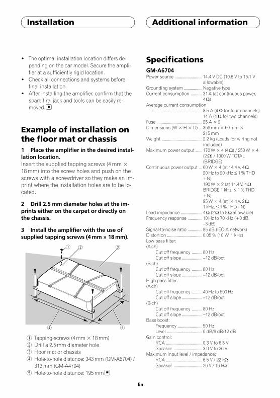
Example of installation onthe floor mat or chassis1 Place the amplifier in the desired instal-lation location.Insert the supplied tapping screws (4mm ×18mm) into the screw holes and push on thescrews with a screwdriver so they make an im-print where the installation holes are to be lo-cated.
2 Drill 2.5 mm diameter holes at the im-prints either on the carpet or directly onthe chassis.
3 Install the amplifier with the use ofsupplied tapping screws (4mm × 18mm).
4 5
1 2 3
1 Tapping-screws (4mm × 18mm)2 Drill a 2.5mm diameter hole3 Floor mat or chassis4 Hole-to-hole distance: 343mm (GM-A6704) /
313mm (GM-A4704)5 Hole-to-hole distance: 195mm
SpecificationsGM-A6704Power source ............................. 14.4 V DC (10.8 V to 15.1 V
allowable)Grounding system ................... Negative typeCurrent consumption ............ 31 A (at continuous power,
4W)Average current consumption
..................................................... 8.5 A (4 W for four channels)14 A (4 W for two channels)
Fuse ................................................ 25 A × 2Dimensions (W × H × D) ... 356mm × 60mm ×
215mmWeight .......................................... 2.2 kg (Leads for wiring not
included)Maximum power output ....... 170W × 4 (4W) / 250W × 4
(2W) / 1000W TOTAL(BRIDGE)
Continuous power output ... 60W × 4 (at 14.4 V, 4W,20Hz to 20 kHz ≦ 1% THD+N)190W × 2 (at 14.4 V, 4WBRIDGE 1 kHz, ≦ 1% THD+N)95W × 4 (at 14.4 V, 2W,1 kHz, ≦ 1% THD+N)
Load impedance ...................... 4W (2W to 8W allowable)Frequency response ............... 10Hz to 70 kHz (+0dB,
–3 dB)Signal-to-noise ratio ............... 95 dB (IEC-A network)Distortion ..................................... 0.05 % (10 W, 1 kHz)Low pass filter:(A ch)
Cut off frequency ........... 80 HzCut off slope ..................... –12 dB/oct
(B ch)Cut off frequency ........... 80 HzCut off slope ..................... –12 dB/oct
High pass filter:(A ch)
Cut off frequency ........... 40Hz to 500HzCut off slope ..................... –12 dB/oct
(B ch)Cut off frequency ........... 80 HzCut off slope ..................... –12 dB/oct
Bass boost:Frequency .......................... 50 HzLevel ..................................... 0 dB/6 dB/12 dB
Gain control:RCA ...................................... 0.3 V to 6.5 VSpeaker .............................. 3.0 V to 26 V
Maximum input level / impedance:RCA ...................................... 6.5 V / 22 kWSpeaker .............................. 26 V / 16 kW
En
Installation Additional information
5707000011300V <14>
GM-A4704Power source ............................. 14.4 V DC (10.8 V to 15.1 V
allowable)Grounding system ................... Negative typeCurrent consumption ............ 20.5 A (at continuous power,
4W)Average current consumption
..................................................... 5.5 A (4W for four channels)8.5 A (4W for two channels)
Fuse ................................................ 30 A × 1Dimensions (W × H × D) ... 326mm × 60mm ×
215mmWeight .......................................... 2.0 kg (Leads for wiring not
included)Maximum power output ....... 80W × 4 (4W) / 130W × 4
(2W) / 520W TOTAL(BRIDGE)
Continuous power output ... 40W × 4 (at 14.4 V, 4W,20Hz to 20 kHz ≦ 1% THD+N)130W × 2 (at 14.4 V, 4WBRIDGE 1 kHz, ≦ 1% THD+N)65W × 4 (at 14.4 V, 2W,1 kHz, ≦ 1% THD+N)
Load impedance ...................... 4W (2W to 8W allowable)Frequency response ............... 10Hz to 70Hz (+0 dB,
–3 dB)Signal-to-noise ratio ............... 94 dB (IEC-A network)Distortion ..................................... 0.05 % (10 W, 1 kHz)Low pass filter:(A ch)
Cut off frequency ........... 80 HzCut off slope ..................... –12 dB/oct
(B ch)Cut off frequency ........... 80 HzCut off slope ..................... –12 dB/oct
High pass filter:(A ch)
Cut off frequency ........... 40Hz to 500HzCut off slope ..................... –12 dB/oct
(B ch)Cut off frequency ........... 80 HzCut off slope ..................... –12 dB/oct
Gain control:RCA ...................................... 0.3 V to 6.5 VSpeaker .............................. 3.0 V to 26 V
Maximum input level / impedance:RCA ...................................... 6.5 V / 22 kWSpeaker .............................. 26 V / 16 kW
Notes! Specifications and the design are subject to
modifications without notice.
! The average current consumption is nearlythe maximum current consumption by thisunit when an audio signal is input. Use thisvalue when working out total current con-sumption by multiple power amplifiers.
En
Additional information
5707000011300V <15>

5707000011300V <16>

Gracias por haber adquirido este productoPIONEER
Lea con detenimiento este manual antes deutilizar el producto por primera vez para quepueda darle el mejor uso posible. Es muy im-portante que lea y cumpla con la informaciónque aparece bajo los mensajes de ADVER-TENCIA y PRECAUCIÓN de este manual.Una vez leído, guarde el manual en un lugar se-guro y a mano para poder consultarlo en el futu-ro.
Visite nuestro sitio WebVisítenos en la siguiente dirección:http://pioneer.jp/en/info/globalnetwork/En nuestro sitio Web ofrecemos la informa-ción más reciente acerca de PIONEERCORPORATION.
En caso de problemas conel dispositivoEn caso de que este producto no funcione co-rrectamente, contacte con su distribuidor ocon el servicio técnico oficial Pioneer más pró-ximo a su domicilio.
Antes de conectar/instalarel amplificador
ADVERTENCIA! Se recomienda el uso de un cable de batería
rojo especial y uno de toma a tierra RD-223,disponibles por separado. Conecte el cable dela batería directamente al terminal positivo+
y el cable de toma a tierra a la carrocería delautomóvil.
! Esta unidad es para vehículos con una bateríade 12 V y conexión a tierra negativa. Antes deinstalarla en una caravana, un camión o unautobús, compruebe el voltaje de la batería.
! Siempre conecte primero el cable a tierracuando instale esta unidad. Dicho cable debeestar conectado adecuadamente a las partesmetálicas de la carrocería del automóvil. Elcable a tierra del amplificador de esta unidaddebe conectarse al automóvil por separadousando tornillos diferentes. Si el tornillo parael cable a tierra se afloja o se cae, puede pro-vocar incendios, humo o averías.
! Utilice siempre un fusible de la corriente no-minal indicada. El uso de un fusible inadecua-do podría provocar sobrecalentamiento yhumo, daños personales y materiales, lesio-nes e incluso quemaduras.
! Compruebe las conexiones de la fuente de ali-mentación y los altavoces si se funde el fusi-ble del cable de la batería vendido porseparado o el fusible del amplificador. Deter-mine y solucione el problema y después reem-place el fusible por otro de característicasidénticas.
! El amplificador debe instalarse en una super-ficie plana. Instalarlo en una superficie queno sea plana o con protuberancias puede re-sultar en un funcionamiento defectuoso.
! Cuando instale el amplificador, no deje queninguna pieza o tornillo extra quede atrapadaentre el amplificador y el automóvil. De lo con-trario, puede producirse un fallo en su funcio-namiento.
Es
Antes de comenzar
5707000011300V <17>

! No permita que esta unidad entre en contactocon líquidos, ya que puede producir una des-carga eléctrica. Además, el contacto con líqui-dos puede causar daños en la unidad, humo yrecalentamiento.Las superficies del amplificador y cualquier al-tavoz acoplado pueden calentarse y ocasionarquemaduras.
! Ante cualquier anomalía, la fuente de alimen-tación del amplificador se desconecta paraevitar averías en el equipo. Si esto ocurre, des-conecte el sistema y compruebe las conexio-nes de la fuente de alimentación y del altavoz.Si no consigue determinar el problema, con-tacte con su distribuidor.
! Desconecte siempre primero el terminal nega-tivo* de la batería para evitar riesgos de des-carga eléctrica o un cortocircuito durante lainstalación.
! No intente desarmar ni modificar esta unidad,de lo contrario, podría provocar un incendio,una descarga eléctrico u otros fallos en el fun-cionamiento.
! Cuando instale el amplificador, asegúrese deque deja suficiente espacio alrededor del am-plificador para la ventilación para disiparmejor la radiación térmica. Instale el amplifi-cador en un lugar donde no pueda ser tocadodurante su funcionamiento.
PRECAUCIÓN! Mantenga siempre el volumen lo suficiente-
mente bajo como para poder escuchar los so-nidos que provienen del exterior.
! El uso prolongado del estéreo del vehículomientras el motor permanece inactivo o enmarcha al ralentí puede agotar la batería.
! Este producto ha sido evaluado en condicio-nes climáticas moderadas y tropicales deacuerdo con la norma IEC 60065: Aparatos deaudio, vídeo y aparatos electrónicos análogos- Requisitos de seguridad.
! El símbolo gráfico colocado en el pro-ducto significa corriente continua.
Acerca de la función de protecciónEste producto incluye una función de protección.Si el producto detecta alguna anomalía, se activa-rán las siguientes funciones para proteger el pro-ducto y la salida de los altavoces.! El indicador de encendido se desconectará y
el amplificador se apagará en las situacionesindicadas a continuación.— Si se encuentran cortocircuitados el termi-
nal de salida del altavoz y el cable del alta-voz.
— Si se aplica un voltaje CC al terminal de sa-lida del altavoz.
! El amplificador reducirá la potencia de salidasi aumenta la temperatura en el interior delamplificador. Si la temperatura aumenta de-masiado, se desconectará el indicador de en-cendido y se apagará el amplificador.
Es
Antes de comenzar
5707000011300V <18>

Qué es cada cosaGM-A6704
Parte delantera
Parte trasera
GM-A4704
Parte delantera
Parte trasera
Para ajustar el interruptor, si es preciso utiliceun destornillador de cabeza plana.
1 Control FREQ (frecuencia de corte)La frecuencia de corte que se puede selec-cionar es de 40 Hz a 500 Hz si el conmu-tador de selección HPF está en HPF.! Se puede seleccionar la frecuencia de
corte sólo para CHANNEL A.
2 Interruptor de selección de LPF (filtrode paso bajo)/HPF (filtro de paso alto)
Cambia los ajustes según el altavoz conec-tado.
! Cuando el altavoz de subgraves esté co-nectado:Seleccione LPF. Esta opción elimina lasfrecuencias altas y reproduce las bajas.
! Cuando el altavoz de toda la gama estéconectado:Seleccione HPF o OFF. HPF elimina lasfrecuencias bajas y reproduce las altas.OFF reproduce la gama completa de fre-cuencias.
3 Control de GAIN (ganancia)Mediante el ajuste de los controles de ga-nancia CHANNEL A (canal A) yCHANNEL B (canal B) se puede regular lasalida de estéreo del vehículo al amplifica-dor Pioneer. La posición predefinida esNORMAL.Si la salida sigue siendo baja, incluso alsubir el volumen del estéreo del vehículo,posicione los controles en un nivel másbajo. Si se escucha cierta distorsión al subirel volumen del vehículo, posicione estoscontroles en un nivel superior.! Si sólo utiliza un conector de entrada,
configure los controles de ganancia enlas salidas del altavoz A y B en la mismaposición.
! Para el uso con un estéreo de vehículoprovisto de RCA (salida estándar de500mV), posiciónese en NORMAL. Parael uso con un estéreo de vehículoPioneer provisto de RCA, con una salidamáxima de 4 V o superior, ajuste el nivelpara que coincida con la salida de esté-reo del vehículo.
! Para el uso con un estéreo de vehículoprovisto de RCA con salida de 4 V, posi-ciónese en HIGH.
4 Interruptor de INPUT SELECT (selecciónde entrada)
Seleccione 2CH para la entrada de dos ca-nales y 4CH para la entrada de cuatro cana-les.
Es
Configuración de launidad
5707000011300V <19>
! Sólo es posible seleccionar la selecciónde entrada cuando se utiliza la toma deentrada RCA. Para las conexiones en lasque se utiliza el cable de entrada del alta-voz, se utilizará 4CH de forma automáti-ca independientemente del ajuste delselector que haya sido seleccionado.
5 Interruptor del BASS BOOST (control denivel de intensificación de graves)
Se puede seleccionar el nivel de intensifica-ción de graves entre 0 dB, 6 dB y 12 dB.! El ajuste del nivel de intensificación de
graves se aplica sólo a la salidaCHANNEL B (canal B).
6 Indicador de encendidoEl indicador de encendido se ilumina paraindicar que está activado (ON).
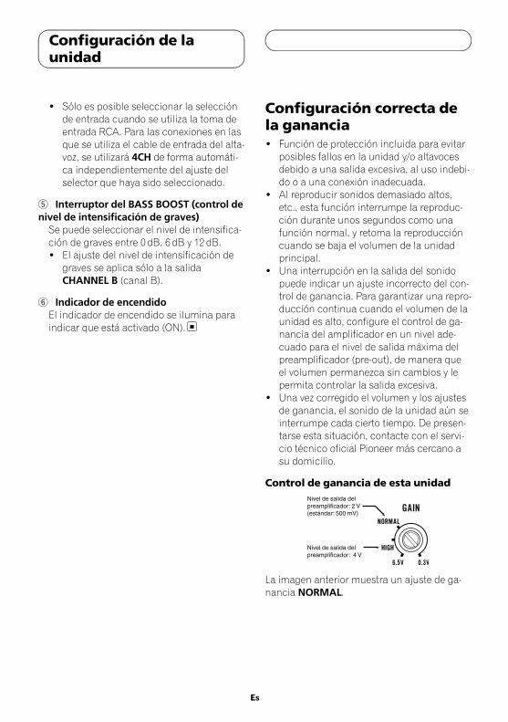
Configuración correcta dela ganancia! Función de protección incluida para evitar
posibles fallos en la unidad y/o altavocesdebido a una salida excesiva, al uso indebi-do o a una conexión inadecuada.
! Al reproducir sonidos demasiado altos,etc., esta función interrumpe la reproduc-ción durante unos segundos como unafunción normal, y retoma la reproduccióncuando se baja el volumen de la unidadprincipal.
! Una interrupción en la salida del sonidopuede indicar un ajuste incorrecto del con-trol de ganancia. Para garantizar una repro-ducción continua cuando el volumen de launidad es alto, configure el control de ga-nancia del amplificador en un nivel ade-cuado para el nivel de salida máxima delpreamplificador (pre-out), de manera queel volumen permanezca sin cambios y lepermita controlar la salida excesiva.
! Una vez corregido el volumen y los ajustesde ganancia, el sonido de la unidad aún seinterrumpe cada cierto tiempo. De presen-tarse esta situación, contacte con el servi-cio técnico oficial Pioneer más cercano asu domicilio.
Control de ganancia de esta unidad
La imagen anterior muestra un ajuste de ga-nancia NORMAL.
Es
Configuración de launidad
5707000011300V <20>
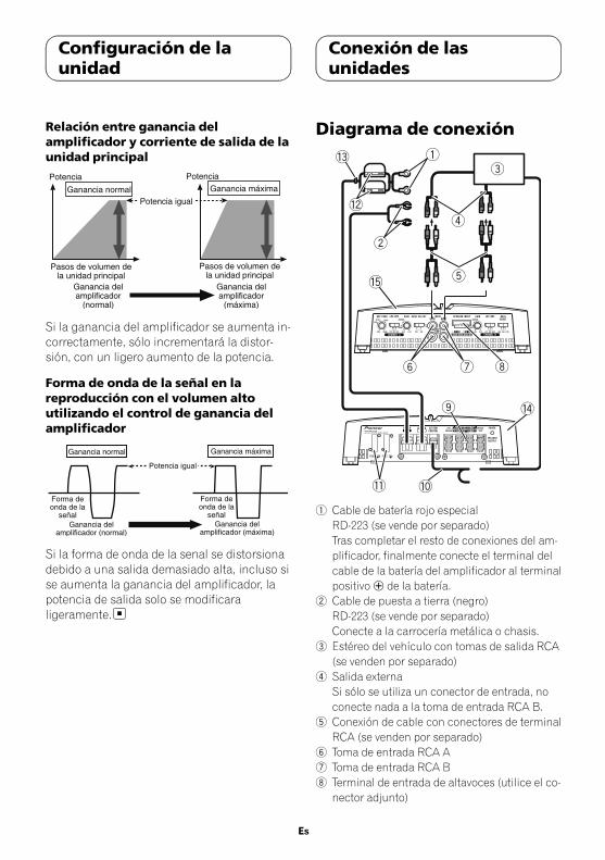
Relación entre ganancia delamplificador y corriente de salida de launidad principal
Si la ganancia del amplificador se aumenta in-correctamente, sólo incrementará la distor-sión, con un ligero aumento de la potencia.
Forma de onda de la señal en lareproducción con el volumen altoutilizando el control de ganancia delamplificador
Si la forma de onda de la senal se distorsionadebido a una salida demasiado alta, incluso sise aumenta la ganancia del amplificador, lapotencia de salida solo se modificaraligeramente.
Diagrama de conexión
1 Cable de batería rojo especialRD-223 (se vende por separado)Tras completar el resto de conexiones del am-plificador, finalmente conecte el terminal delcable de la batería del amplificador al terminalpositivo+ de la batería.
2 Cable de puesta a tierra (negro)RD-223 (se vende por separado)Conecte a la carrocería metálica o chasis.
3 Estéreo del vehículo con tomas de salida RCA(se venden por separado)
4 Salida externaSi sólo se utiliza un conector de entrada, noconecte nada a la toma de entrada RCA B.
5 Conexión de cable con conectores de terminalRCA (se venden por separado)
6 Toma de entrada RCA A7 Toma de entrada RCA B8 Terminal de entrada de altavoces (utilice el co-
nector adjunto)
Es
Configuración de launidad
Conexión de lasunidades
5707000011300V <21>

Consulte la siguiente sección para instruccio-nes sobre la conexión del altavoz. ConsulteConexiones al utilizar el cable de entrada del al-tavoz.
9 Terminales de salida del altavozConsulte la siguiente sección para instruccio-nes sobre la conexión del altavoz. ConsulteConexión de altavoces.
a Cable de control a distancia del sistema (sevende por separado)Conecte el terminal macho de este cable alterminal del control a distancia del sistema enel estéreo del vehículo. El terminal hembra sepuede conectar al terminal del control de reléde la antena del automóvil. Si el estéreo delvehículo no dispone de un terminal para elcontrol a distancia del sistema, conecte el ter-minal macho al terminal de potencia a travésde la llave de encendido.
b Fusible 25A×2 (GM-A6704) / 30A×1 (GM-A4704)
c Fusible (30 A) × 2d Ojale Parte traseraf Parte delantera
NotaEl interruptor de INPUT SELECT (selección de en-trada) debe estar configurado. Para más informa-ción, consulte Configuración de la unidad.
Antes de conectar elamplificador
ADVERTENCIA! Asegure el cableado con pinzas para cables o
cinta adhesiva. Para proteger el cableado, en-vuelva con cinta adhesiva las partes que esténen contacto con piezas metálicas.
! Nunca corte el aislamiento de la fuente de ali-mentación para suministrar energía otrosequipos. La capacidad de corriente del cablees limitada.
PRECAUCIÓN! Nunca acorte ningún cable, ya que el circuito
de protección podría no funcionar correcta-mente.
! Nunca conecte el cable negativo de los altavo-ces directamente a tierra.
! Nunca empalme los cables negativos de va-rios altavoces.
! Si el cable de control a distancia del sistemadel amplificador está conectado a un terminalde potencia a través de la llave de encendido(12 V cc), el amplificador permanecerá activotanto si el estéreo del vehículo está apagadocomo encendido, lo que puede agotar la bate-ría si el motor permanece inactivo o en mar-cha al ralentí.
! Instale y pase el cable de la batería (adquiridopor separado) lo más lejos posible de los ca-bles del altavoz.Instale y pase el cable de la batería (adquiridopor separado), junto con el cable de puesta atierra, los cables del altavoz y el amplificadorlo más lejos posible de la antena, del cable dela antena y del sintonizador.
Es
Conexión de lasunidades
5707000011300V <22>
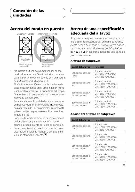
Acerca del modo en puente
! No instale o utilice este amplificador conec-tando altavoces de 4W (o inferior) en paralelopara lograr un modo en puente con una cargade 2W (o inferior) (diagrama B).El efectuar una unión en puente inadecuadapuede causar daños en el amplificador, humoy sobrecalentamiento. La superficie del ampli-ficador también puede calentarse y ocasionarquemaduras menores.Para instalar o utilizar debidamente un modoen puente y lograr una carga de 4W, conectedos altavoces de 8W en paralelo, izquierdo+
y derecho* (diagrama A) o utilice un únicoaltavoz de 4W.Consulte también el manual de instruccionesde los altavoces para obtener informaciónsobre el procedimiento correcto de conexión.
! Para cualquier otra consulta, contacte con eldistribuidor oficial de Pioneer o diríjase al ser-vicio de atención al cliente.
Acerca de una especificaciónadecuada del altavozAsegúrese de que los altavoces cumplen conlos siguientes estándares; en caso contrario,existe riesgo de incendio, humo y otros daños.La impedancia del altavoz es de 2 W a 8 W, ode 4 W a 8 W en las conexiones de dos canalesy otras en puente.
Altavoz de subgraves
Canal del altavoz Potencia
Salida de cuatro ca-nales
Entrada nominal:Mín. 60W (GM-A6704)Mín. 40W (GM-A4704)
Salida de dos cana-les
Entrada nominal:Mín. 190W (GM-A6704)Mín. 130W (GM-A4704)
Salida de altavoz Ade tres canales
Entrada nominal:Mín. 60W (GM-A6704)Mín. 40W (GM-A4704)
Salida de altavoz Bde tres canales
Entrada nominal:Mín. 190W (GM-A6704)Mín. 130W (GM-A4704)
Aparte del altavoz de subgraves
Canal del altavoz Potencia
Salida de cuatro ca-nales
Entrada máx.:Mín. 170W (GM-A6704)Mín. 80W (GM-A4704)
Salida de dos cana-les
Entrada máx.:Mín. 500W (GM-A6704)Mín. 260W (GM-A4704)
Salida de altavoz Ade tres canales
Entrada máx.:Mín. 170W (GM-A6704)Mín. 80W (GM-A4704)
Salida de altavoz Bde tres canales
Entrada máx.:Mín. 500W (GM-A6704)Mín. 260W (GM-A4704)
Es
Conexión de lasunidades
5707000011300V <23>

Conexión de altavocesEl modo de salida del altavoz puede ser decuatro, tres (estéreo y monoaural) o dos cana-les (estéreo o monoaural). Conecte los conec-tores del altavoz según el modo y las figurasdetalladas a continuación.
Salida de cuatro canales
32
1
1
24
1 Derecha2 Izquierda3 Salida de altavoz A4 Salida de altavoz B
Salida de tres canales
4
32
1
1 Derecha2 Izquierda3 Salida de altavoz A4 Salida de altavoz B (monoaural)
Salida de dos canales (estéreo)
2
1 Altavoz (derecho)2 Altavoz (izquierdo)
Es
Conexión de lasunidades
5707000011300V <24>

Salida de dos canales (monoaural)
1
1 Altavoz (monoaural)
Conexiones al utilizar unatoma de entrada RCAConecte la toma de salida RCA del estéreo delvehículo y la toma de entrada RCA del amplifi-cador.
Salida de cuatro canales / tres canales! Deslice el interruptor INPUT SELECT (selec-
tor de entrada) a la posición 4CH.
1 2
4
3
1 Toma de entrada RCA A2 Toma de entrada RCA B3 Conexión de los cables con conectores RCA
(se venden por separado)4 Desde el estéreo del vehículo (salida RCA)
Si sólo se utiliza un conector de entrada, porejemplo, cuando el estéreo del vehículo sólotiene una salida (salida RCA), conecte el co-nector a la toma de entrada RCA A en vez deB.
Salida de dos canales (estéreo) /(monoaural)! Deslice el interruptor INPUT SELECT (selec-
tor de entrada) a la posición 2CH.
Es
Conexión de lasunidades
5707000011300V <25>
2
3
1
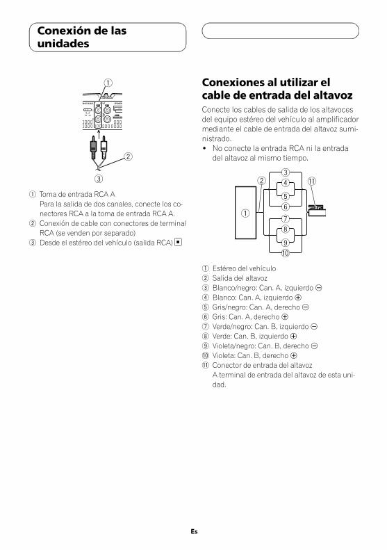
1 Toma de entrada RCA APara la salida de dos canales, conecte los co-nectores RCA a la toma de entrada RCA A.
2 Conexión de cable con conectores de terminalRCA (se venden por separado)
3 Desde el estéreo del vehículo (salida RCA)
Conexiones al utilizar elcable de entrada del altavozConecte los cables de salida de los altavocesdel equipo estéreo del vehículo al amplificadormediante el cable de entrada del altavoz sumi-nistrado.! No conecte la entrada RCA ni la entrada
del altavoz al mismo tiempo.
1 Estéreo del vehículo2 Salida del altavoz3 Blanco/negro: Can. A, izquierdo*
4 Blanco: Can. A, izquierdo+
5 Gris/negro: Can. A, derecho*
6 Gris: Can. A, derecho+
7 Verde/negro: Can. B, izquierdo*
8 Verde: Can. B, izquierdo+
9 Violeta/negro: Can. B, derecho*
a Violeta: Can. B, derecho+
b Conector de entrada del altavozA terminal de entrada del altavoz de esta uni-dad.
Es
Conexión de lasunidades
5707000011300V <26>

NotaSi los cables de entrada del altavoz de una uni-dad central están conectados a este amplificador,el amplificador se encenderá automáticamentecuando se encienda la unidad central. Cuando seapague la unidad central, el amplificador se apa-gará automáticamente. Es posible que esta fun-ción no funcione con algunas unidadescentrales. En esos casos, asegúrese de que elcanal CH A izquierdo esté conectado correcta-mente. Si la función sigue sin funcionar, utiliceun cable de control a distancia del sistema (sevende por separado). Si se deben conectar variosamplificadores juntos de forma sincronizada, co-necte la unidad central con todos los amplifica-dores mediante el cable de control a distanciadel sistema.
Conexión del terminal depotenciaSe recomienda el uso del cable de batería rojoespecial y el de toma a tierra RD-223 (disponi-bles por separado). Conecte el cable de la ba-tería directamente al terminal positivo + y elcable de toma a tierra a la carrocería del auto-móvil.
ADVERTENCIASi el cable de la batería no está correctamente fi-jado al terminal mediante los tornillos para termi-nales, existe cierto riesgo de sobrecalentamiento,funcionamiento defectuoso y daños, incluyendopequeñas quemaduras.
1 Pase el cable de la batería desde el com-partimento del motor hasta el interior delvehículo.
! Al hacer un agujero para el paso del cableen la carrocería del vehículo y tender uncable de batería por él, tenga cuidado de nocortocircuitear el cable dañándolo con can-tos afilados o las rebabas del agujero.
Tras completar el resto de conexiones del am-plificador, finalmente conecte el terminal delcable de la batería del amplificador al terminalpositivo + de la batería.
1 Terminal positivo +
2 Compartimento del motor3 Interior del vehículo4 Fusible (30 A) × 25 Inserte el ojal elástico de la junta tórica en
la carrocería.6 Perfore un agujero de 14mm en la carroce-
ría del vehículo.
2 Introduzca el cable de la batería, el depuesta a tierra y el del control a distanciadel sistema.
Gírelos
3 Acople las lengüetas a los extremos delcable.Utilice alicates, etc. para fijar las lengüetas alos cables.
1 Lengüeta (se vende por separado)2 Cable de batería3 Cable de puesta a tierra
Es
Conexión de lasunidades
5707000011300V <27>
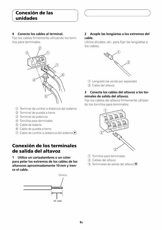
4 Conecte los cables al terminal.Fije los cables firmemente utilizando los torni-llos para terminales.
1 Terminal de control a distancia del sistema2 Terminal de puesta a tierra3 Terminal de potencia4 Tornillos para terminales5 Cable de batería6 Cable de puesta a tierra7 Cable de control a distancia del sistema
Conexión de los terminalesde salida del altavoz1 Utilice un cortaalambres o un cúterpara pelar los extremos de los cables de losaltavoces aproximadamente 10mm y tren-ce el cable.
Gírelos
2 Acople las lengüetas a los extremos delcable.Utilice alicates, etc. para fijar las lengüetas alos cables.
1 Lengüeta (se vende por separado)2 Cable del altavoz
3 Conecte los cables del altavoz a los ter-minales de salida del altavoz.Fije los cables del altavoz firmemente utilizan-do los tornillos para terminales.
1 Tornillos para terminales2 Cables del altavoz3 Terminales de salida del altavoz
Es
Conexión de lasunidades
5707000011300V <28>

Antes de instalar elamplificador
ADVERTENCIA! Para garantizar una instalación correcta, utili-
ce las piezas facilitadas del modo indicado. Eluso de otras piezas diferentes a las facilitadas,puede dañar las partes internas del amplifica-dor o aflojarse haciendo que éste se apague.
! No instalar en:— Lugares donde pueda lesionar al conduc-
tor o a los pasajeros en caso de detener elvehículo de repente.
— Lugares donde pueda interferir con la con-ducción, como es la zona situada en frentedel asiento del conductor.
! Coloque tornillos de rosca cortante de tal ma-nera que el extremo del tornillo no toque nin-gún cable. Esto es muy importante para evitarque los cables terminen cortándose por la vi-bración del vehículo, lo que podría ocasionarun incendio.
! Asegúrese de que los cables no quedan atra-pados en el mecanismo de deslizamiento delos asientos o toquen las piernas de los pasa-jeros en un vehículo ya que esto podría produ-cir un cortocircuito.
! Cuando realice un agujero para instalar el am-plificador, asegúrese siempre de que no hayaninguna pieza detrás del panel y proteja todoslos cables y equipos importantes (p. ej. líneasde freno/combustible, cableado eléctrico)para evitar daños.
PRECAUCIÓN! Para garantizar una disipación térmica ade-
cuada del amplificador, asegúrese de lo si-guiente durante la instalación:— Deje suficiente espacio sobre el amplifica-
dor para que la ventilación sea adecuada.— No cubra el amplificador con una alfombra
o moqueta.! La función de protección puede activarse para
proteger el amplificador contra un sobrecalen-tamiento debido a la instalación en lugares
donde no se puede disipar suficiente calor, eluso continuo bajo condiciones de volumenalto, etc. En tales casos, el amplificador redu-ce la potencia de salida o se apaga hasta quese ha enfriado hasta alcanzar la temperaturadesignada.
! Coloque todos los cables alejados de lugarescalientes, como cerca de la salida del calefac-tor.
! El lugar idóneo para la instalación difieresegún el modelo del vehículo. Fije el amplifi-cador a un lugar lo suficientemente rígido.
! Compruebe todas las conexiones y sistemasantes de la instalación final.
! Después de instalar el amplificador, confirmeque la rueda de repuesto, las tomas y demásherramientas pueden retirarse fácilmente.
Ejemplo de instalación enla alfombra o chasis1 Coloque el amplificador en el lugar deinstalación deseado.Inserte los tornillos de rosca cortante facilita-dos (4mm x 18mm) en los orificios correspon-dientes y apriételos con un destornillador demanera que dejen una marca donde se vayana perforar los orificios de instalación.
2 Perfore agujeros de 2,5 mm de diáme-tro en las marcas, sobre la alfombra o direc-tamente en el chasis.
Es
Instalación
5707000011300V <29>
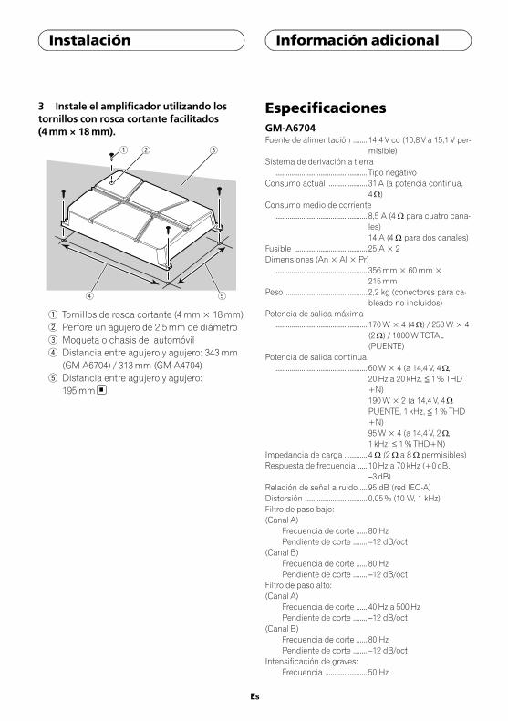
3 Instale el amplificador utilizando lostornillos con rosca cortante facilitados(4mm × 18mm).
4 5
1 2 3
1 Tornillos de rosca cortante (4mm × 18mm)2 Perfore un agujero de 2,5mm de diámetro3 Moqueta o chasis del automóvil4 Distancia entre agujero y agujero: 343mm
(GM-A6704) / 313mm (GM-A4704)5 Distancia entre agujero y agujero:
195mm
EspecificacionesGM-A6704Fuente de alimentación ........ 14,4 V cc (10,8 V a 15,1 V per-
misible)Sistema de derivación a tierra
..................................................... Tipo negativoConsumo actual ...................... 31 A (a potencia continua,
4W)Consumo medio de corriente
..................................................... 8,5 A (4 W para cuatro cana-les)14 A (4 W para dos canales)
Fusible .......................................... 25 A × 2Dimensiones (An × Al × Pr)
..................................................... 356mm × 60mm ×215mm
Peso ............................................... 2,2 kg (conectores para ca-bleado no incluidos)
Potencia de salida máxima..................................................... 170W × 4 (4W) / 250W × 4
(2W) / 1000W TOTAL(PUENTE)
Potencia de salida continua..................................................... 60W × 4 (a 14,4 V, 4W,
20Hz a 20 kHz, ≦ 1% THD+N)190W × 2 (a 14,4 V, 4WPUENTE, 1 kHz, ≦ 1% THD+N)95W × 4 (a 14,4 V, 2W,1 kHz, ≦ 1% THD+N)
Impedancia de carga ............. 4 W (2 W a 8 W permisibles)Respuesta de frecuencia ..... 10Hz a 70 kHz (+0 dB,
–3 dB)Relación de señal a ruido .... 95 dB (red IEC-A)Distorsión .................................... 0,05% (10 W, 1 kHz)Filtro de paso bajo:(Canal A)
Frecuencia de corte ...... 80 HzPendiente de corte ........ –12 dB/oct
(Canal B)Frecuencia de corte ...... 80 HzPendiente de corte ........ –12 dB/oct
Filtro de paso alto:(Canal A)
Frecuencia de corte ...... 40Hz a 500HzPendiente de corte ........ –12 dB/oct
(Canal B)Frecuencia de corte ...... 80 HzPendiente de corte ........ –12 dB/oct
Intensificación de graves:Frecuencia ........................ 50 Hz
Es
Instalación Información adicional
5707000011300V <30>
Nivel ..................................... 0 dB/6 dB/12 dBControl de ganancia:
RCA ...................................... 0,3 V a 6,5 VAltavoz ................................ 3,0 V a 26 V
Nivel de entrada máximo / impedancia:RCA ...................................... 6,5 V / 22 kWAltavoz ................................ 26 V / 16 kW
GM-A4704Fuente de alimentación ........ 14,4 V cc (10,8 V a 15,1 V per-
misible)Sistema de derivación a tierra
..................................................... Tipo negativoConsumo actual ...................... 20,5 A (a potencia continua,
4W)Consumo medio de corriente
..................................................... 5,5 A (4W para cuatro cana-les)8,5 A (4W para dos canales)
Fusible .......................................... 30 A × 1Dimensiones (An × Al × Pr)
..................................................... 326mm × 60mm ×215mm
Peso ............................................... 2,0 kg (conectores para ca-bleado no incluidos)
Potencia de salida máxima..................................................... 80W × 4 (4W) / 130W × 4
(2W) / 520W TOTAL (PUEN-TE)
Potencia de salida continua..................................................... 40W × 4 (a 14,4 V, 4W,
20Hz a 20 kHz ≦ 1% THD+N)130W × 2 (a 14,4 V, 4WPUENTE 1 kHz, ≦ 1% THD+N)65W × 4 (a 14,4 V, 2W,1 kHz, ≦ 1% THD+N)
Impedancia de carga ............. 4 W (2 W a 8 W permisibles)Respuesta de frecuencia ..... 10Hz a 70Hz (+0 dB, –3 dB)Relación de señal a ruido .... 94 dB (red IEC-A)Distorsión .................................... 0,05% (10 W, 1 kHz)Filtro de paso bajo:(Canal A)
Frecuencia de corte ...... 80 HzPendiente de corte ........ –12 dB/oct
(Canal B)Frecuencia de corte ...... 80 HzPendiente de corte ........ –12 dB/oct
Filtro de paso alto:(Canal A)
Frecuencia de corte ...... 40Hz a 500HzPendiente de corte ........ –12 dB/oct
(Canal B)Frecuencia de corte ...... 80 HzPendiente de corte ........ –12 dB/oct
Control de ganancia:RCA ...................................... 0,3 V a 6,5 VAltavoz ................................ 3,0 V a 26 V
Nivel de entrada máximo / impedancia:RCA ...................................... 6,5 V / 22 kWAltavoz ................................ 26 V / 16 kW
Notas! Las especificaciones y el diseño están sujetos
a modificaciones sin previo aviso.! El consumo medio de corriente es casi el con-
sumo de corriente máximo de esta unidad,cuando recibe una señal de audio. Utilice estevalor cuando tenga que trabajar con la co-rriente total consumida por varios amplifica-dores de potencia.
Es
Información adicional
5707000011300V <31>

5707000011300V <32>