GM Owner Manuals - Dealer E Process
462
Seats and Restraint Systems ........................... 1-1 Head Restraints ......................................... 1-2 Front Seats ............................................... 1-4 Rear Seats .............................................. 1-11 Safety Belts ............................................. 1-12 Child Restraints ....................................... 1-32 Airbag System ......................................... 1-55 Restraint System Check ............................ 1-70 Features and Controls ..................................... 2-1 Keys ........................................................ 2-3 Doors and Locks ...................................... 2-17 Windows ................................................. 2-23 Theft-Deterrent Systems ............................ 2-27 Starting and Operating Your Vehicle ........... 2-31 Mirrors .................................................... 2-49 Object Detection Systems .......................... 2-51 OnStar ® System ...................................... 2-53 Universal Home Remote System ................ 2-56 Storage Areas ......................................... 2-61 Sunroof .................................................. 2-62 Instrument Panel ............................................. 3-1 Instrument Panel Overview .......................... 3-4 Climate Controls ...................................... 3-23 Warning Lights, Gages, and Indicators ........ 3-29 Driver Information Center (DIC) .................. 3-47 Audio System(s) ....................................... 3-79 Driving Your Vehicle ....................................... 4-1 Your Driving, the Road, and Your Vehicle ..... 4-2 Towing ................................................... 4-27 Service and Appearance Care .......................... 5-1 Service ..................................................... 5-3 Fuel ......................................................... 5-5 Checking Things Under the Hood ............... 5-12 All-Wheel Drive ........................................ 5-49 Rear Axle ............................................... 5-50 Headlamp Aiming ..................................... 5-51 Bulb Replacement .................................... 5-55 Windshield Wiper Blade Replacement ......... 5-57 Tires ...................................................... 5-59 Appearance Care ................................... 5-111 Vehicle Identification ............................... 5-120 Electrical System .................................... 5-121 Capacities and Specifications ................... 5-128 Maintenance Schedule ..................................... 6-1 Maintenance Schedule ................................ 6-2 Customer Assistance Information .................... 7-1 Customer Assistance and Information ........... 7-2 Reporting Safety Defects ........................... 7-14 Vehicle Data Recording and Privacy ........... 7-16 Index ................................................................ 1 2008 Cadillac CTS Owner Manual M
-
Upload
khangminh22 -
Category
Documents
-
view
0 -
download
0
Transcript of GM Owner Manuals - Dealer E Process

Seats and Restraint Systems ........................... 1-1Head Restraints ......................................... 1-2Front Seats ............................................... 1-4Rear Seats .............................................. 1-11Safety Belts ............................................. 1-12Child Restraints ....................................... 1-32Airbag System ......................................... 1-55Restraint System Check ............................ 1-70
Features and Controls ..................................... 2-1Keys ........................................................ 2-3Doors and Locks ...................................... 2-17Windows ................................................. 2-23Theft-Deterrent Systems ............................ 2-27Starting and Operating Your Vehicle ........... 2-31Mirrors .................................................... 2-49Object Detection Systems .......................... 2-51OnStar® System ...................................... 2-53Universal Home Remote System ................ 2-56Storage Areas ......................................... 2-61Sunroof .................................................. 2-62
Instrument Panel ............................................. 3-1Instrument Panel Overview .......................... 3-4Climate Controls ...................................... 3-23Warning Lights, Gages, and Indicators ........ 3-29Driver Information Center (DIC) .................. 3-47Audio System(s) ....................................... 3-79
Driving Your Vehicle ....................................... 4-1Your Driving, the Road, and Your Vehicle ..... 4-2Towing ................................................... 4-27
Service and Appearance Care .......................... 5-1Service ..................................................... 5-3Fuel ......................................................... 5-5Checking Things Under the Hood ............... 5-12All-Wheel Drive ........................................ 5-49Rear Axle ............................................... 5-50Headlamp Aiming ..................................... 5-51Bulb Replacement .................................... 5-55Windshield Wiper Blade Replacement ......... 5-57Tires ...................................................... 5-59Appearance Care ................................... 5-111Vehicle Identification ............................... 5-120Electrical System .................................... 5-121Capacities and Specifications ................... 5-128
Maintenance Schedule ..................................... 6-1Maintenance Schedule ................................ 6-2
Customer Assistance Information .................... 7-1Customer Assistance and Information ........... 7-2Reporting Safety Defects ........................... 7-14Vehicle Data Recording and Privacy ........... 7-16
Index ................................................................ 1
2008 Cadillac CTS Owner Manual M
Information Provided by:

GENERAL MOTORS, GM, the GM Emblem, CADILLAC,the CADILLAC Crest & Wreath, and the name CTSare registered trademarks of General MotorsCorporation.
Music recognition technology and related data areprovided by Gracenote®. Gracenote is the industrystandard in music recognition technology and relatedcontent delivery. For more information, visitwww.gracenote.com.
DTS AND DTS Digital Surround are registeredtrademarks of Digital Theater Systems, Inc.
Dolby® is manufactured under license from Dolby®
Laboratories. Dolby® and the double-D symbolare trademarks of Dolby® Laboratories.
Litho in U.S.A.Part No. 15864564 A First Printing ©2007 General Motors Corporation. All Rights Reserved.
iiInformation Provided by:

This manual includes the latest information at the time itwas printed. We reserve the right to make changesafter that time without notice. For vehicles first sold inCanada, substitute the name “General Motors of CanadaLimited” for Cadillac Motor Car Division whenever itappears in this manual.
This manual describes features that may be available inthis model, but your vehicle may not have all of them.For example, more than one entertainment system maybe offered or your vehicle may have been orderedwithout a front passenger or rear seats.
Keep this manual in the vehicle for quick reference.
Canadian OwnersA French language copy of this manual can be obtainedfrom your dealer/retailer or from:
Helm, IncorporatedP.O. Box 07130Detroit, MI 48207
1-800-551-4123www.helminc.com
Propriétaires CanadiensOn peut obtenir un exemplaire de ce guide en françaisauprès de concessionnaire ou à l’adresse suivante:
Helm IncorporatedP.O. Box 07130Detroit, MI 48207
1-800-551-4123www.helminc.com
Using this ManualMany people read the owner manual from beginning toend when they first receive their new vehicle to learnabout the vehicle’s features and controls. Picturesand words work together to explain things.
IndexA good place to quickly locate information about thevehicle is the Index in the back of the manual. It is analphabetical list of what is in the manual and thepage number where it can be found.
iiiInformation Provided by:

Safety Warnings and SymbolsThere are a number of safety cautions in this book. Abox with the word CAUTION is used to tell about thingsthat could hurt you or others if you were to ignore thewarning.
{CAUTION:
These mean there is something that could hurtyou or other people.
We tell you what the hazard is and what to do to helpavoid or reduce the hazard. Please read these cautions.If you do not, you or others could be hurt.
A circle with a slashthrough it is a safetysymbol which means “DoNot,” “Do Not do this”or “Do Not let this happen.”
Vehicle Damage WarningsYou will also find notices in this manual.
Notice: These mean there is something that coulddamage your vehicle.
A notice tells about something that can damage thevehicle. Many times, this damage would not be coveredby your vehicle’s warranty, and it could be costly.The notice tells what to do to help avoid the damage.
When you read other manuals, you might seeCAUTION and NOTICE warnings in different colorsor in different words.
There are also warning labels on the vehicle which usethe same words, CAUTION or NOTICE.
Vehicle SymbolsThe vehicle has components and labels that usesymbols instead of text. Symbols are shown along withthe text describing the operation or informationrelating to a specific component, control, message,gage, or indicator.
ivInformation Provided by:

Head Restraints ...............................................1-2Front Seats ......................................................1-4
Manual Seats ................................................1-4Power Seats ..................................................1-5Power Lumbar ...............................................1-5Heated and Ventilated Seats ............................1-6Memory Seat and Mirrors ................................1-6Reclining Seatbacks ........................................1-8
Rear Seats .....................................................1-11Split Folding Rear Seat .................................1-11
Safety Belts ...................................................1-12Safety Belts: They Are for Everyone ................1-12How to Wear Safety Belts Properly .................1-17Lap-Shoulder Belt .........................................1-25Safety Belt Use During Pregnancy ..................1-30Safety Belt Extender .....................................1-31
Child Restraints .............................................1-32Older Children ..............................................1-32Infants and Young Children ............................1-35Child Restraint Systems .................................1-39
Where to Put the Restraint .............................1-42Lower Anchors and Tethers for
Children (LATCH) ......................................1-43Securing a Child Restraint in a Rear Seat
Position ...................................................1-49Securing a Child Restraint in the Right Front
Seat Position ............................................1-51Airbag System ...............................................1-55
Where Are the Airbags? ................................1-58When Should an Airbag Inflate? .....................1-60What Makes an Airbag Inflate? .......................1-62How Does an Airbag Restrain? .......................1-62What Will You See After an Airbag Inflates? .....1-62Passenger Sensing System ............................1-64Servicing Your Airbag-Equipped Vehicle ...........1-68Adding Equipment to Your Airbag-Equipped
Vehicle ....................................................1-69Restraint System Check ..................................1-70
Checking the Restraint Systems ......................1-70Replacing Restraint System Parts After
a Crash ...................................................1-71
Section 1 Seats and Restraint Systems
1-1Information Provided by:

Head RestraintsThe vehicle’s front seats have adjustable head restraintsin the outboard seating positions.
The vehicle’s rear seats have head restraints in theoutboard seating positions, but they are not adjustable.
{CAUTION:
With head restraints that are not installed andadjusted properly, there is a greater chancethat occupants will suffer a neck/spinal injuryin a crash. Do not drive until the headrestraints for all occupants are installed andadjusted properly.
Adjust the head restraint so that the top of the restraintis at the same height as the top of the occupant’shead. This position reduces the chance of a neck injuryin a crash.
1-2Information Provided by:

Pull the head restraint up toraise it. To lower the headrestraint, press the button,located on the top of theseatback, and push therestraint down.
Push down on the head restraint after the button isreleased to make sure that it is locked in place.
The vehicle’s head restraints are not designed tobe removed.
Active Head Restraint SystemOn vehicles with an active head restraint system in thefront outboard seating positions. These automaticallytilt forward to reduce the risk of neck injury if the vehicleis hit from behind.
1-3Information Provided by:

Front Seats
Manual Seats
{CAUTION:
You can lose control of the vehicle if you try toadjust a manual driver’s seat while the vehicleis moving. The sudden movement could startleand confuse you, or make you push a pedalwhen you do not want to. Adjust the driver’sseat only when the vehicle is not moving.
To move a manual seat forward or rearward:
1. Lift the bar to unlockthe seat.
2. Slide the seat to thedesired position andrelease the bar.
Try to move the seat with your body to be sure the seatis locked in place.
1-4Information Provided by:

Power Seats
If the vehicle has power seats, the controls used tooperate them are located on the outboard side ofthe seats.
• Move the seat forward or rearward by sliding thehorizontal control forward or rearward.
• Raise or lower the front part of the seat cushion bymoving the front of the horizontal control up or down.
• Raise or lower the rear part of the seat cushion bymoving the rear of the horizontal control up or down.
• Raise or lower the entire seat by moving the entirehorizontal control up or down.
The vertical control is used for reclining your seatback.See “Power Reclining Seatbacks” under RecliningSeatbacks on page 1-8 for more information.
Power Lumbar
Your vehicle may have thisfeature. The driver’s andpassenger’s seatbacklumbar support canbe adjusted by moving thecontrol located on theoutboard side of the seatcushions.
To increase or decrease support, hold the controlforward or rearward. Keep in mind that as your seatingposition changes, as it may during long trips, soshould the position of your lumbar support. Adjust theseat as needed.
1-5Information Provided by:

Heated and Ventilated SeatsOn vehicles with this feature, the buttons are located onthe climate control panel.
z (Heated Seat and Seatback): Press for the heatedseat and seatback.
{ (Ventilated Seat): Press for the ventilated seat.
A light bar in the climate control display shows thesetting; high, medium or low.
Press either button to start that feature at the highestsetting. Each press of the button, decreases the setting.
To turn the feature off, press the button until the lightturns off.
The heated or ventilated seats shut off when the vehicleis turned off.
Memory Seat and MirrorsThe buttons for this feature are located on thedriver’s door.
1: Saves the seating position for driver 1.
2: Saves the seating position for driver 2.
S: Recalls the easy exit position.
To program the buttons:
1. Adjust the driver’s seat including the seatbackrecliner and both outside mirrors.
2. Press and hold button 1 for at least three seconds.Two beeps sound to confirm that the seat andmirror positions have been saved.
3. Repeat the procedure for a second driver usingbutton 2.
1-6Information Provided by:

With an automatic transmission, the vehicle must be inPARK (P) to recall the stored driving positions.
With a manual transmission and the engine is running,the parking brake must be set to recall the memoryseat driving positions. The stored driving positions canbe recalled without setting the parking brake if thevehicle is off.
Press one of the numbered memory buttons to recallthe stored setting. Each time a memory button ispressed, a single beep will sound.
Three chimes sound and the setting is not recalled ifyou press button 1 or 2 when the vehicle is not inPARK (P) on an automatic transmission or the parkingbrake is not set on a manual transmission.
To recall the stored driving positions when unlocking thevehicle with the transmitter or after the key is placedin the ignition, see DIC Vehicle Customization onpage 3-68.
To stop recall movement of the memory feature at anytime, press one of the power seat or mirror controls.
Two personalized exit positions can also beprogrammed. Use the following steps to program exitpositions:
1. Press memory seat button 1, or the unlock buttonon the transmitter, to recall the driving position.
2. Adjust the driver’s seat to the desired exit position.
3. Press and hold the exit button located abovebuttons 1 and 2 on the driver’s door armrestfor at least three seconds.Two beeps sound to confirm that the exit positionhas been saved.
4. Repeat the procedure for a second driver usingmemory seat button 2 or the transmitter.
To recall the stored exit positions, press and release theexit button. One beep sounds, and the seat moves tothe stored exit position for that driver. If an exit positionhas not been stored for this driver, the seat movesall the way back. The position of the outside mirrorsdoes not change for the exit position.
If your vehicle has an automatic transmission, thevehicle must be in PARK (P) to recall the exit positions.If your vehicle has a manual transmission and theengine is running, the parking brake must be set to recallthe stored exit positions.
Three chimes sound and the exit setting is not recalledif the exit button is pressed when the vehicle is notin PARK (P) on an automatic transmission or the parkingbrake is not set on a manual transmission.
To recall your stored exit positions when unlocking thevehicle with the transmitter, or when the ignition isturned off and the driver’s door is opened, see DICVehicle Customization on page 3-68.
1-7Information Provided by:

Reclining Seatbacks
Manual Reclining Seatbacks
{CAUTION:
You can lose control of the vehicle if you try toadjust a manual driver’s seat while the vehicleis moving. The sudden movement could startleand confuse you, or make you push a pedalwhen you do not want to. Adjust the driver’sseat only when the vehicle is not moving.
{CAUTION:
If the seatback is not locked, it could moveforward in a sudden stop or crash. That couldcause injury to the person sitting there. Alwayspush and pull on the seatback to be sure it islocked.
If the front passenger’s seat has a manual recliningseatback, the lever used to operate it is located on theoutboard side of the seat.
To recline the seatback, do the following:
1. Lift the recline lever.
2. Move the seatback to the desired position, thenrelease the lever to lock the seatback in place.
3. Push and pull on the seatback to make sure itis locked.
1-8Information Provided by:

To return the seatback to an upright position, do thefollowing:
1. Lift the lever fully without applying pressure to theseatback and the seatback will return to the uprightposition.
2. Push and pull on the seatback to make sure it islocked.
Power Reclining Seatbacks
If your seats have power reclining seatbacks, use thevertical power seat control located on the outboard sideof each seat.
• To recline the seatback, press the control towardthe rear of the vehicle.
• To raise the seatback, press the control toward thefront of the vehicle.
1-9Information Provided by:

{CAUTION:
Sitting in a reclined position when your vehicleis in motion can be dangerous. Even if youbuckle up, your safety belts cannot do theirjob when you are reclined like this.
The shoulder belt cannot do its job. In a crash,you could go into it, receiving neck or otherinjuries.
The lap belt cannot do its job either. In a crashthe belt could go up over your abdomen. Thebelt forces would be there, not at your pelvicbones. This could cause serious internalinjuries.
For proper protection when the vehicle is inmotion, have the seatback upright. Then sitwell back in the seat and wear your safety beltproperly.
Do not have a seatback reclined if your vehicle ismoving.
1-10Information Provided by:

Rear Seats
Split Folding Rear SeatYour vehicle may have a split folding rear seat.
To lower one or both of the rear seatbacks:
1. Pull forward on the tab,located on the outboardside of the seatback,to unlock the seatback.
Notice: Folding a rear seat with the safety beltsstill fastened may cause damage to the seat or thesafety belts. Always unbuckle the safety beltsand return them to their normal stowed positionbefore folding a rear seat.
2. Fold the seatback down. This allows direct accessto the trunk.
See Trunk on page 2-20 for more information.
To return the seatback to the upright position:
{CAUTION:
If the seatback is not locked, it could moveforward in a sudden stop or crash. That couldcause injury to the person sitting there. Alwayspush and pull on the seatback to be sure it islocked.
1. Lift the seatback up and push it back into place.
2. Make sure the seatback is locked into placeby pushing and pulling on it.
3. Repeat Steps 1 and 3 for the other seatback.
When the seatback is not in use, it should be kept inthe upright, locked position.
1-11Information Provided by:

Safety Belts
Safety Belts: They Are for EveryoneThis part of the manual tells you how to use safetybelts properly. It also tells you some things you shouldnot do with safety belts.
{CAUTION:
Do not let anyone ride where he or she cannotwear a safety belt properly. If you are in acrash and you are not wearing a safety belt,your injuries can be much worse. You can hitthings inside the vehicle harder or be ejectedfrom it and be seriously injured or killed. In thesame crash, you might not be, if you arebuckled up. Always fasten your safety belt,and check that your passenger(s) arerestrained properly too.
{CAUTION:
It is extremely dangerous to ride in a cargoarea, inside or outside of a vehicle. In acollision, people riding in these areas are morelikely to be seriously injured or killed. Do notallow people to ride in any area of your vehiclethat is not equipped with seats and safetybelts. Be sure everyone in your vehicle is in aseat and using a safety belt properly.
Your vehicle has indicators as a reminder to buckle yoursafety belts. See Safety Belt Reminders on page 3-32.In most states and in all Canadian provinces, thelaw requires wearing safety belts. Here is why:You never know if you will be in a crash. If you do havea crash, you do not know if it will be a serious one.A few crashes are mild, and some crashes can be soserious that even buckled up, a person would notsurvive. But most crashes are in between. In many ofthem, people who buckle up can survive and sometimeswalk away. Without belts they could have been badlyhurt or killed.After more than 40 years of safety belts in vehicles, thefacts are clear. In most crashes buckling up doesmatter... a lot!
1-12Information Provided by:
Why Safety Belts WorkWhen you ride in or on anything, you go as fast asit goes.
Take the simplest vehicle. Suppose it is just a seat onwheels.
Put someone on it.
1-13Information Provided by:

Get it up to speed. Then stop the vehicle. The riderdoes not stop.
The person keeps going until stopped by something. Ina real vehicle, it could be the windshield...
1-14Information Provided by:

or the instrument panel... or the safety belts!
With safety belts, you slow down as the vehicle does.You get more time to stop. You stop over more distance,and your strongest bones take the forces. That is whysafety belts make such good sense.
1-15Information Provided by:

Questions and Answers AboutSafety Belts
Q: Will I be trapped in the vehicle after a crash if Iam wearing a safety belt?
A: You could be — whether you are wearing a safetybelt or not. But your chance of being consciousduring and after an accident, so you can unbuckleand get out, is much greater if you are belted.And you can unbuckle a safety belt, even if you areupside down.
Q: If my vehicle has airbags, why should I have towear safety belts?
A: Airbags are supplemental systems only; so theywork with safety belts — not instead of them.Whether or not an airbag is provided, all occupantsstill have to buckle up to get the most protection.That is true not only in frontal collisions, butespecially in side and other collisions.
Q: If I am a good driver, and I never drive far fromhome, why should I wear safety belts?
A: You may be an excellent driver, but if you are in acrash — even one that is not your fault — you andyour passenger(s) can be hurt. Being a gooddriver does not protect you from things beyond yourcontrol, such as bad drivers.
Most accidents occur within 25 miles (40 km) ofhome. And the greatest number of serious injuriesand deaths occur at speeds of less than 40 mph(65 km/h).
Safety belts are for everyone.
1-16Information Provided by:

How to Wear Safety Belts ProperlyThis section is only for people of adult size.
Be aware that there are special things to know aboutsafety belts and children. And there are differentrules for smaller children and babies. If a child will beriding in your vehicle, see Older Children on page 1-32or Infants and Young Children on page 1-35. Followthose rules for everyone’s protection.
It is very important for all occupants to buckle up.Statistics show that unbelted people are hurt more oftenin crashes than those who are wearing safety belts.
Occupants who are not buckled up can be thrown out ofthe vehicle in a crash. And they can strike others inthe vehicle who are wearing safety belts.
First, before you or your passenger(s) wear a safetybelt, there is important information you should know. Sit up straight and always keep your feet on the floor in
front of you. The lap part of the belt should be wornlow and snug on the hips, just touching the thighs. In acrash, this applies force to the strong pelvic bonesand you would be less likely to slide under the lap belt.If you slid under it, the belt would apply force onyour abdomen. This could cause serious or even fatalinjuries. The shoulder belt should go over the shoulderand across the chest. These parts of the body arebest able to take belt restraining forces.
The shoulder belt locks if there is a sudden stop or crash.
1-17Information Provided by:

Q: What is wrong with this?
A: The shoulder belt is too loose. It will not give asmuch protection this way.
{CAUTION:
You can be seriously hurt if your shoulder beltis too loose. In a crash, you would moveforward too much, which could increase injury.The shoulder belt should fit snugly againstyour body.
1-18Information Provided by:
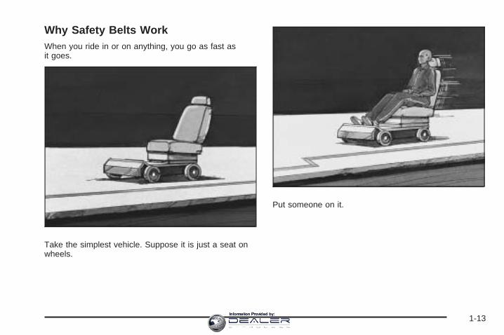
Q: What is wrong with this?
A: The lap belt is too loose. It will not give nearly asmuch protection this way.
{CAUTION:
You can be seriously hurt if your lap belt is tooloose. In a crash, you could slide under the lapbelt and apply force on your abdomen. Thiscould cause serious or even fatal injuries. Thelap belt should be worn low and snug on thehips, just touching the thighs.
1-19Information Provided by:

Q: What is wrong with this?
A: The belt is buckled in the wrong place.
{CAUTION:
You can be seriously injured if your belt isbuckled in the wrong place like this. In a crash,the belt would go up over your abdomen. Thebelt forces would be there, not on the pelvicbones. This could cause serious internalinjuries. Always buckle your belt into thebuckle nearest you.
1-20Information Provided by:
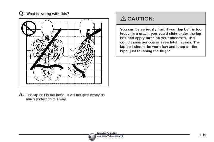
Q: What is wrong with this?
A: The belt is over an armrest.
{CAUTION:
You can be seriously injured if your belt goesover an armrest like this. The belt would bemuch too high. In a crash, you can slide underthe belt. The belt force would then be appliedon the abdomen, not on the pelvic bones, andthat could cause serious or fatal injuries. Besure the belt goes under the armrests.
1-21Information Provided by:

Q: What is wrong with this?
A: The shoulder belt is worn under the arm. It shouldbe worn over the shoulder at all times.
{CAUTION:
You can be seriously injured if you wear theshoulder belt under your arm. In a crash, yourbody would move too far forward, which wouldincrease the chance of head and neck injury.Also, the belt would apply too much force tothe ribs, which are not as strong as shoulderbones. You could also severely injure internalorgans like your liver or spleen. The shoulderbelt should go over the shoulder and acrossthe chest.
1-22Information Provided by:
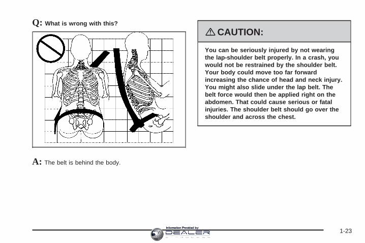
Q: What is wrong with this?
A: The belt is behind the body.
{CAUTION:
You can be seriously injured by not wearingthe lap-shoulder belt properly. In a crash, youwould not be restrained by the shoulder belt.Your body could move too far forwardincreasing the chance of head and neck injury.You might also slide under the lap belt. Thebelt force would then be applied right on theabdomen. That could cause serious or fatalinjuries. The shoulder belt should go over theshoulder and across the chest.
1-23Information Provided by:

Q: What is wrong with this?
A: The belt is twisted across the body.
{CAUTION:
You can be seriously injured by a twisted belt.In a crash, you would not have the full width ofthe belt to spread impact forces. If a belt istwisted, make it straight so it can workproperly, or ask your dealer/retailer to fix it.
1-24Information Provided by:

Lap-Shoulder BeltAll seating positions in your vehicle have alap-shoulder belt.
Here is how to wear a lap-shoulder belt properly.
1. Adjust the seat, if the seat is adjustable, so you cansit up straight. To see how, see “Seats” in the Index.
2. Pick up the latch plate and pull the belt across you.Do not let it get twisted.The lap-shoulder belt may lock if you pull the beltacross you very quickly. If this happens, let the beltgo back slightly to unlock it. Then pull the beltacross you more slowly.If you ever pull the shoulder portion of a passengerbelt out all the way, you may engage the childrestraint locking feature. If this happens, just let thebelt go back all the way and start again.
3. Push the latch plate into the buckle until it clicks.Pull up on the latch plate to make sure it is secure.If the belt is not long enough, see Safety BeltExtender on page 1-31.Make sure the release button on the buckle ispositioned so you would be able to unbuckle thesafety belt quickly if necessary.
4. If equipped with a shoulder belt height adjuster,move it to the height that is right for you. Impropershoulder belt height adjustment could reducethe effectiveness of the safety belt in a crash.See “Shoulder Belt Height Adjustment” later inthis section.
1-25Information Provided by:

5. To make the lap part tight, pull up on theshoulder belt.It may be necessary to pull stitching on the safetybelt through the latch plate to fully tighten thelap belt on smaller occupants.
To unlatch the belt, just push the button on the buckle.The belt should go back out of the way.
Before you close a door, be sure the belt is out of theway. If you slam the door on it, you can damageboth the belt and your vehicle.
1-26Information Provided by:

Shoulder Belt Height AdjusterYour vehicle has a shoulder belt height adjuster for thedriver and right front passenger position.
Adjust the height so that the shoulder portion of thebelt is centered on your shoulder. The belt shouldbe away from your face and neck, but not falling offyour shoulder. Improper shoulder belt height adjustmentcould reduce the effectiveness of the safety belt ina crash.
To move it down, pressthe release button (A) andmove the height adjusterto the desired position.You can move the heightadjuster up just bypushing up on the shoulderbelt guide.
After you move the height adjuster to where you want it,try to move it down without pressing the releasebutton to make sure it has locked into position.
Safety Belt PretensionersYour vehicle has safety belt pretensioners for frontoutboard occupants. Although you cannot see them,they are part of the safety belt assembly. They can helptighten the safety belts during the early stages of amoderate to severe frontal and near frontal crash if thethreshold conditions for pretensioner activation aremet. And, if your vehicle has side impact airbags, safetybelt pretensioners can help tighten the safety belts ina side crash.
Pretensioners work only once. If they activate in acrash, you will need to get new ones, and probably othernew parts for your safety belt system. See ReplacingRestraint System Parts After a Crash on page 1-71.
1-27Information Provided by:

Rear Safety Belt Comfort GuidesRear shoulder belt comfort guides may provide addedsafety belt comfort for older children who have outgrownbooster seats and for some adults. When installed ona shoulder belt, the comfort guide positions the beltaway from the neck and head.
There is one guide for each outboard passengerposition in the rear seat. Here is how to install a comfortguide to the safety belt:
1. Pull the elastic cord out from between the edge ofthe seatback and the interior body to remove theguide from its storage clip.
1-28Information Provided by:

2. Place the guide over the belt and insert thetwo edges of the belt into the slots of the guide.
3. Be sure that the belt is not twisted and it lies flat.The elastic cord must be under the belt and theguide on top.
1-29Information Provided by:

{CAUTION:
A safety belt that is not properly worn may notprovide the protection needed in a crash. Theperson wearing the belt could be seriouslyinjured. The shoulder belt should go over theshoulder and across the chest. These parts ofthe body are best able to take belt restrainingforces.
4. Buckle, position, and release the safety belt asdescribed previously in this section. Make surethat the shoulder belt crosses the shoulder.
To remove and store the comfort guide, squeeze thebelt edges together so that you can take them out of theguide. Pull the guide upward to expose its storageclip, and then slide the guide onto the clip. Turnthe guide and clip inward and slide them in between theseatback and the interior body, leaving only the loopof the elastic cord exposed.
Safety Belt Use During PregnancySafety belts work for everyone, including pregnantwomen. Like all occupants, they are more likely to beseriously injured if they do not wear safety belts.
1-30Information Provided by:

A pregnant woman should wear a lap-shoulder belt, andthe lap portion should be worn as low as possible,below the rounding, throughout the pregnancy.
The best way to protect the fetus is to protect themother. When a safety belt is worn properly, it is morelikely that the fetus will not be hurt in a crash. Forpregnant women, as for anyone, the key to makingsafety belts effective is wearing them properly.
Safety Belt ExtenderIf the vehicle’s safety belt will fasten around you, youshould use it.
But if a safety belt is not long enough, yourdealer/retailer will order you an extender. When you goin to order it, take the heaviest coat you will wear,so the extender will be long enough for you. To helpavoid personal injury, do not let someone else useit, and use it only for the seat it is made to fit. Theextender has been designed for adults. Never use it forsecuring child seats. To wear it, attach it to theregular safety belt. For more information, see theinstruction sheet that comes with the extender.
1-31Information Provided by:

Child Restraints
Older Children
Older children who have outgrown booster seats shouldwear the vehicle’s safety belts.
The manufacturer’s instructions that come with thebooster seat state the weight and height limitations forthat booster. Use a booster seat with a lap-shoulder beltuntil the child passes the below fit test:
• Sit all the way back on the seat. Do the knees bendat the seat edge? If yes, continue. If no, return tothe booster seat.
• Buckle the lap-shoulder belt. Does the shoulder beltrest on the shoulder? If yes, continue. If no, tryusing the rear safety belt comfort guide. See “RearSafety Belt Comfort Guides” under Lap-ShoulderBelt on page 1-25 for more information. If theshoulder belt still does not rest on the shoulder,then return to the booster seat.
• Does the lap belt fit low and snug on the hips,touching the thighs? If yes, continue. If no, return tothe booster seat.
• Can proper safety belt fit be maintained for thelength of the trip? If yes, continue. If no, returnto the booster seat.
1-32Information Provided by:

Q: What is the proper way to wear safety belts?
A: An older child should wear a lap-shoulder belt andget the additional restraint a shoulder belt canprovide. The shoulder belt should not cross the faceor neck. The lap belt should fit snugly below thehips, just touching the top of the thighs. This appliesbelt force to the child’s pelvic bones in a crash. Itshould never be worn over the abdomen, whichcould cause severe or even fatal internal injuries ina crash.
Also see “Rear Safety Belt Comfort Guides” underLap-Shoulder Belt on page 1-25.
According to accident statistics, children and infants aresafer when properly restrained in the rear seatingpositions than in the front seating positions.
In a crash, children who are not buckled up can strikeother people who are buckled up, or can be thrownout of the vehicle. Older children need to use safetybelts properly.
{CAUTION:
Never do this.
Here two children are wearing the same belt.The belt cannot properly spread the impactforces. In a crash, the two children can becrushed together and seriously injured. A beltmust be used by only one person at a time.
1-33Information Provided by:

{CAUTION:
Never do this.
Here a child is sitting in a seat that has alap-shoulder belt, but the shoulder part isbehind the child. In a crash, the child wouldnot be restrained by the shoulder belt. Thechild might slide under the lap belt. The beltforce would then be applied right on theabdomen. That could cause serious or fatalinjuries. The child could also move too farforward increasing the chance of head andneck injury. The shoulder belt should go overthe shoulder and across the chest.
1-34Information Provided by:

Infants and Young ChildrenEveryone in a vehicle needs protection! This includesinfants and all other children. Neither the distancetraveled nor the age and size of the traveler changesthe need, for everyone, to use safety restraints. In fact,the law in every state in the United States and inevery Canadian province says children up to some agemust be restrained while in a vehicle.
{CAUTION:
Children can be seriously injured or strangled ifa shoulder belt is wrapped around their neckand the safety belt continues to tighten. Neverleave children unattended in a vehicle and neverallow children to play with the safety belts.
Every time infants and young children ride in vehicles,they should have the protection provided by appropriaterestraints. Children who are not restrained properlycan strike other people, or can be thrown out ofthe vehicle. In addition, young children should not usethe vehicle’s adult safety belts alone; they need to use achild restraint.
1-35Information Provided by:

{CAUTION:
People should never hold an infant in theirarms while riding in a vehicle. An infant doesnot weigh much — until a crash. During acrash an infant will become so heavy it is notpossible to hold it. For example, in a crash atonly 25 mph (40 km/h), a 12 lb (5.5 kg) infantwill suddenly become a 240 lb (110 kg) forceon a person’s arms. An infant should besecured in an appropriate restraint.
1-36Information Provided by:

{CAUTION:
Children who are up against, or very close to,any airbag when it inflates can be seriouslyinjured or killed. Airbags plus lap-shoulderbelts offer protection for adults and olderchildren, but not for young children andinfants. Neither the vehicle’s safety belt systemnor its airbag system is designed for them.Young children and infants need the protectionthat a child restraint system can provide.
1-37Information Provided by:

Q: What are the different types of add-on childrestraints?
A: Add-on child restraints, which are purchased by thevehicle’s owner, are available in four basic types.Selection of a particular restraint should takeinto consideration not only the child’s weight, height,and age but also whether or not the restraint willbe compatible with the motor vehicle in which it willbe used.
For most basic types of child restraints, there aremany different models available. When purchasing achild restraint, be sure it is designed to be usedin a motor vehicle. If it is, the restraint will have alabel saying that it meets federal motor vehiclesafety standards.
The restraint manufacturer’s instructions that comewith the restraint state the weight and heightlimitations for a particular child restraint. In addition,there are many kinds of restraints available forchildren with special needs.
{CAUTION:
Newborn infants need complete support,including support for the head and neck. Thisis necessary because a newborn infant’s neckis weak and its head weighs so muchcompared with the rest of its body. In a crash,an infant in a rear-facing seat settles into therestraint, so the crash forces can bedistributed across the strongest part of aninfant’s body, the back and shoulders. Infantsshould always be secured in appropriate infantrestraints.
1-38Information Provided by:

{CAUTION:
The body structure of a young child is quiteunlike that of an adult or older child, for whomthe safety belts are designed. A young child’ship bones are still so small that the vehicle’sregular safety belt may not remain low on thehip bones, as it should. Instead, it may settleup around the child’s abdomen. In a crash, thebelt would apply force on a body area that isunprotected by any bony structure. This alonecould cause serious or fatal injuries. Youngchildren should always be secured inappropriate child restraints.
Child Restraint Systems
A rear-facing infantseat (A) provides restraintwith the seating surfaceagainst the back ofthe infant.
The harness system holds the infant in place and, in acrash, acts to keep the infant positioned in therestraint.
A forward-facing childseat (B) provides restraintfor the child’s bodywith the harness.
1-39Information Provided by:

A booster seat (C-D) is a child restraint designed toimprove the fit of the vehicle’s safety belt system.A booster seat can also help a child to see out thewindow.
Securing an Add-On Child Restraint inthe Vehicle
{CAUTION:
A child can be seriously injured or killed in acrash if the child restraint is not properlysecured in the vehicle. Make sure the childrestraint is properly installed in the vehicleusing the vehicle’s safety belt or LATCHsystem, following the instructions that camewith that restraint, and also the instructions inthis manual.
To help reduce the chance of injury, the child restraintmust be secured in the vehicle. Child restraint systemsmust be secured in vehicle seats by lap belts or thelap belt portion of a lap-shoulder belt, or by the LATCHsystem. See Lower Anchors and Tethers for Children(LATCH) on page 1-43 for more information. A child canbe endangered in a crash if the child restraint is notproperly secured in the vehicle.
1-40Information Provided by:

When securing an add-on child restraint, refer to theinstructions that come with the restraint which may be onthe restraint itself or in a booklet, or both, and to thismanual. The child restraint instructions are important, soif they are not available, obtain a replacement copyfrom the manufacturer.
Keep in mind that an unsecured child restraint canmove around in a collision or sudden stop and injurepeople in the vehicle. Be sure to properly secureany child restraint in your vehicle — even when no childis in it.
Securing the Child Within the ChildRestraint
{CAUTION:
A child can be seriously injured or killed in acrash if the child is not properly secured in thechild restraint. Because there are differentsystems, it is important to refer to theinstructions that come with the restraint. Makesure the child is properly secured, followingthe instructions that came with that restraint.
1-41Information Provided by:

Where to Put the RestraintAccident statistics show that children are safer if theyare restrained in the rear rather than the front seat.We recommend that children and child restraintsbe secured in a rear seat, including: an infant or a childriding in a rear-facing child restraint; a child riding ina forward-facing child seat; an older child riding ina booster seat; and children, who are large enough,using safety belts.A label on your sun visor says, “Never put a rear-facingchild seat in the front.” This is because the risk to therear-facing child is so great, if the airbag deploys.
{CAUTION:
A child in a rear-facing child restraint can beseriously injured or killed if the right frontpassenger’s airbag inflates. This is becausethe back of the rear-facing child restraintwould be very close to the inflating airbag.
Even though the passenger sensing system isdesigned to turn off the right front passenger’sfrontal airbag if the system detects a
CAUTION: (Continued)
CAUTION: (Continued)
rear-facing child restraint, no system isfail-safe, and no one can guarantee that anairbag will not deploy under some unusualcircumstance, even though it is turned off. Werecommend that rear-facing child restraints besecured in a rear seat, even if the airbag is off.
If you secure a forward-facing child restraint inthe right front seat, always move the frontpassenger seat as far back as it will go. It isbetter to secure the child restraint in a rear seat.
See Passenger Sensing System on page 1-64for additional information.
When securing a child restraint in a rear seatingposition, study the instructions that came with your childrestraint to make sure it is compatible with this vehicle.
Wherever you install a child restraint, be sure tosecure the child restraint properly.
Keep in mind that an unsecured child restraint can movearound in a collision or sudden stop and injure people inthe vehicle. Be sure to properly secure any child restraintin your vehicle — even when no child is in it.
1-42Information Provided by:

Lower Anchors and Tethers forChildren (LATCH)The LATCH system holds a child restraint during drivingor in a crash. This system is designed to makeinstallation of a child restraint easier. The LATCHsystem uses anchors in the vehicle and attachments onthe child restraint that are made for use with theLATCH system.
Make sure that a LATCH-compatible child restraint isproperly installed using the anchors, or use the vehicle’ssafety belts to secure the restraint, following theinstructions that came with that restraint, and also theinstructions in this manual. When installing a childrestraint with a top tether, you must also use either thelower anchors or the safety belts to properly securethe child restraint. A child restraint must never beinstalled using only the top tether and anchor.
In order to use the LATCH system in your vehicle, youneed a child restraint that has LATCH attachments.The child restraint manufacturer will provide youwith instructions on how to use the child restraint and itsattachments. The following explains how to attach achild restraint with these attachments in your vehicle.
Not all vehicle seating positions or child restraints havelower anchors and attachments or top tether anchorsand attachments.
Lower Anchors
Lower anchors (A) are metal bars built into the vehicle.There are two lower anchors for each LATCH seatingposition that will accommodate a child restraint withlower attachments (B).
1-43Information Provided by:

Top Tether Anchor
A top tether (A, C) anchors the top of the child restraintto the vehicle. A top tether anchor is built into thevehicle. The top tether attachment (B) on the childrestraint connects to the top tether anchor in the vehiclein order to reduce the forward movement and rotationof the child restraint during driving or in a crash.
Your child restraint may have a single tether (A) or adual tether (C). Either will have a single attachment (B)to secure the top tether to the anchor.
Some child restraints with top tethers are designed foruse with or without the top tether being attached. Othersrequire the top tether always to be attached. InCanada, the law requires that forward-facing childrestraints have a top tether, and that the tether beattached. Be sure to read and follow the instructions foryour child restraint.
If the child restraint does not have a top tether, one canbe obtained, in kit form, for many child restraints. Askthe child restraint manufacturer whether or not a kitis available.
Lower Anchor and Top Tether AnchorLocations
i (Top Tether Anchor):Seating positions with toptether anchors.
j (Lower Anchor):Seating positions withtwo lower anchors.
Rear Seat
1-44Information Provided by:

To assist you in locatingthe lower anchors, eachseating position with loweranchors has two labels,near the crease betweenthe seatback and theseat cushion.
To assist you in locatingthe top tether anchors, thetop tether anchor symbolis located on the cover.
The top tether anchors are located under the covers onthe rear seatback filler panel. Be sure to use ananchor located on the same side of the vehicle as theseating position where the child restraint will be placed.
Do not secure a child restraint in a position without atop tether anchor if a national or local law requires thatthe top tether be attached, or if the instructions thatcome with the child restraint say that the top tether mustbe attached.
Accident statistics show that children are safer if theyare restrained in the rear rather than the front seat. SeeWhere to Put the Restraint on page 1-42 for additionalinformation.
1-45Information Provided by:

Securing a Child Restraint Designed forthe LATCH System
{CAUTION:
If a LATCH-type child restraint is not attachedto anchors, the restraint will not be able toprotect the child correctly. In a crash, the childcould be seriously injured or killed. Make surethat a LATCH-type child restraint is properlyinstalled using the anchors, or use the vehicle’ssafety belts to secure the restraint, following theinstructions that came with that restraint, andalso the instructions in this manual.
{CAUTION:
Each top tether anchor and lower anchor in thevehicle is designed to hold only one childrestraint. Attaching more than one childrestraint to a single anchor could cause theanchor or attachment to come loose or evenbreak during a crash. A child or others couldbe injured if this happens. To help preventinjury to people and damage to your vehicle,attach only one child restraint per anchor.
1-46Information Provided by:

{CAUTION:
Children can be seriously injured or strangledif a shoulder belt is wrapped around their neckand the safety belt continues to tighten.Secure any unused safety belts behind thechild restraint so children cannot reach them.Pull the shoulder belt all the way out of theretractor to set the lock, if your vehicle hasone, after the child restraint has been installed.Be sure to follow the instructions of the childrestraint manufacturer.
Notice: Contact between the child restraint LATCHattachment parts and the vehicle’s safety beltassembly may cause damage to these parts. Makesure when securing unused safety belts behindthe child restraint that there is no contact betweenthe child restraint LATCH attachment parts andthe vehicle’s safety belt assembly.
Folding an empty rear seat with the safety beltssecured may cause damage to the safety belt or theseat. When removing the child restraint, alwaysremember to return the safety belts to their normal,stowed position before folding the rear seat.
1. Attach and tighten the lower attachments to thelower anchors. If the child restraint does not havelower attachments or the desired seating positiondoes not have lower anchors, secure the childrestraint with the top tether and the safety belts.Refer to your child restraint manufacturerinstructions and the instructions in this manual.
1.1. Find the lower anchors for the desiredseating position.
1.2. Put the child restraint on the seat.1.3. Attach and tighten the lower attachments on
the child restraint to the lower anchors.
2. If the child restraint manufacturer recommends thatthe top tether be attached, attach and tighten thetop tether to the top tether anchor, if equipped.Refer to the child restraint instructions andthe following steps:
2.1. Find the top tether anchor.2.2. Press the ribbed area of the cover to open
the cover and expose the anchor.2.3. If you have an adjustable head restraint,
raise the head restraint.
1-47Information Provided by:
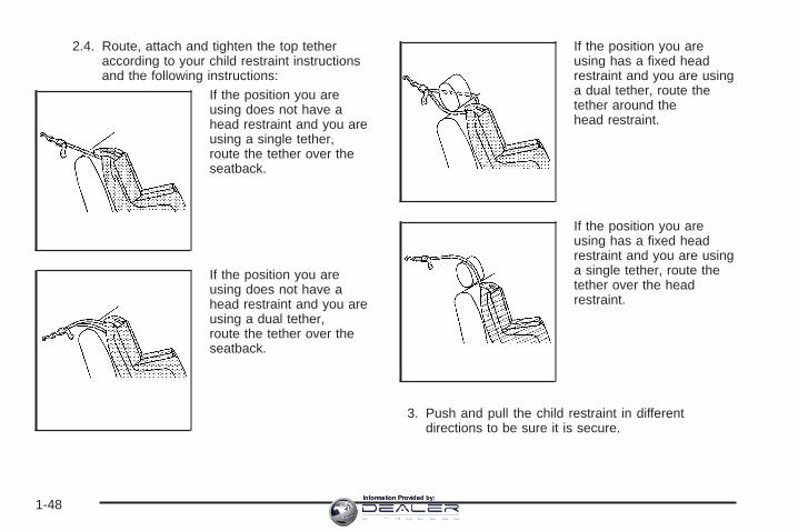
2.4. Route, attach and tighten the top tetheraccording to your child restraint instructionsand the following instructions:
If the position you areusing does not have ahead restraint and you areusing a single tether,route the tether over theseatback.
If the position you areusing does not have ahead restraint and you areusing a dual tether,route the tether over theseatback.
If the position you areusing has a fixed headrestraint and you are usinga dual tether, route thetether around thehead restraint.
If the position you areusing has a fixed headrestraint and you are usinga single tether, route thetether over the headrestraint.
3. Push and pull the child restraint in differentdirections to be sure it is secure.
1-48Information Provided by:

Securing a Child Restraint in a RearSeat PositionWhen securing a child restraint in a rear seatingposition, study the instructions that came with your childrestraint to make sure it is compatible with this vehicle.
If your child restraint has the LATCH system, see LowerAnchors and Tethers for Children (LATCH) onpage 1-43 for how to install your child restraint usingLATCH. If you secure a child restraint using a safety beltand it uses a top tether, see Lower Anchors andTethers for Children (LATCH) on page 1-43 for toptether anchor locations.
Do not secure a child restraint in a position without atop tether anchor if a national or local law requires thatthe top tether be anchored, or if the instructions thatcome with the child restraint say that the top strap mustbe anchored.
In Canada, the law requires that forward-facing childrestraints have a top tether, and that the tether beattached.
If your child restraint does not have the LATCH system,you will be using the safety belt to secure the childrestraint in this position. Be sure to follow theinstructions that came with the child restraint. Securethe child in the child restraint when and as theinstructions say.
If you need to install more than one child restraint in therear seat, be sure to read Where to Put the Restrainton page 1-42.
1. Put the child restraint on the seat.
2. Pick up the latch plate, and run the lap and shoulderportions of the vehicle’s safety belt through oraround the restraint. The child restraint instructionswill show you how.
1-49Information Provided by:

3. Push the latch plate into the buckle until it clicks.Make sure the release button is positioned so youwould be able to unbuckle the safety belt quicklyif necessary.
4. Pull the rest of the shoulder belt all the way out ofthe retractor to set the lock.
1-50Information Provided by:

5. To tighten the belt, push down on the child restraint,pull the shoulder portion of the belt to tighten thelap portion of the belt, and feed the shoulderbelt back into the retractor. If you are using aforward-facing child restraint, you may find it helpfulto use your knee to push down on the childrestraint as you tighten the belt.
6. If your child restraint has a top tether, follow thechild restraint manufacturer’s instructions regardingthe use of the top tether. See Lower Anchorsand Tethers for Children (LATCH) on page 1-43 formore information.
7. Push and pull the child restraint in differentdirections to be sure it is secure.
To remove the child restraint, unbuckle the vehicle’ssafety belt and let it go back all the way. If the top tetheris attached to a top tether anchor, disconnect it.
Securing a Child Restraint in theRight Front Seat PositionYour vehicle has airbags. A rear seat is a safer place tosecure a forward-facing child restraint. See Where toPut the Restraint on page 1-42.
In addition, your vehicle has a passenger sensingsystem which is designed to turn off the right frontpassenger’s frontal airbag and seat-mounted side impactairbag under certain conditions. See PassengerSensing System on page 1-64 and Passenger AirbagStatus Indicator on page 3-34 for more informationon this, including important safety information.
1-51Information Provided by:

A label on your sun visor says, “Never put a rear-facingchild seat in the front.” This is because the risk to therear-facing child is so great, if the airbag deploys.
{CAUTION:
A child in a rear-facing child restraint can beseriously injured or killed if the right frontpassenger’s airbag inflates. This is becausethe back of the rear-facing child restraintwould be very close to the inflating airbag.
Even though the passenger sensing system isdesigned to turn off the right front passenger’sfrontal airbag if the system detects arear-facing child restraint, no system isfail-safe, and no one can guarantee that anairbag will not deploy under some unusualcircumstance, even though it is turned off. Werecommend that rear-facing child restraints besecured in a rear seat, even if the airbag is off.
CAUTION: (Continued)
CAUTION: (Continued)
If you secure a forward-facing child restraint inthe right front seat, always move the frontpassenger seat as far back as it will go. It isbetter to secure the child restraint in a rear seat.
See Passenger Sensing System on page 1-64for additional information.
If your child restraint has the LATCH system, see LowerAnchors and Tethers for Children (LATCH) onpage 1-43 for how to install your child restraint usingLATCH. If you secure a child restraint using a safety beltand it uses a top tether, see Lower Anchors andTethers for Children (LATCH) on page 1-43 for toptether anchor locations.
Do not secure a child seat in a position without a toptether anchor if a national or local law requires that thetop tether be anchored, or if the instructions thatcome with the child restraint say that the top strap mustbe anchored.
In Canada, the law requires that forward-facing childrestraints have a top tether, and that the tether beattached.
1-52Information Provided by:

You will be using the lap-shoulder belt to secure thechild restraint in this position. Follow the instructions thatcame with the child restraint.
1. Move the seat as far back as it will go beforesecuring the forward-facing child restraint.When the passenger sensing system has turned offthe right front passenger’s frontal airbag andseat-mounted side impact airbag, the off indicatoron the passenger airbag status indicator should lightand stay lit when you start the vehicle. SeePassenger Airbag Status Indicator on page 3-34.
2. Put the child restraint on the seat.
3. Pick up the latch plate, and run the lap and shoulderportions of the vehicle’s safety belt through oraround the restraint. The child restraint instructionswill show you how.
4. Push the latch plate into the buckle until it clicks.Make sure the release button is positioned so youwould be able to unbuckle the safety belt quicklyif necessary.
1-53Information Provided by:

5. Pull the rest of the shoulder belt all the way out ofthe retractor to set the lock.
6. To tighten the belt, push down on the child restraint,pull the shoulder portion of the belt to tighten thelap portion of the belt and feed the shoulderbelt back into the retractor. If you are using aforward-facing child restraint, you may find it helpfulto use your knee to push down on the childrestraint as you tighten the belt.
7. Push and pull the child restraint in differentdirections to be sure it is secure.
1-54Information Provided by:

If the airbags are off, the off indicator in the passengerairbag status indicator will come on and stay onwhen the vehicle is started.
If a child restraint has been installed and the onindicator is lit, turn the vehicle off. Remove the childrestraint from the vehicle and reinstall the child restraint.
If, after reinstalling the child restraint and restartingthe vehicle, the on indicator is still lit, check to makesure that the vehicle’s seatback is not pressing the childrestraint into the seat cushion. If this happens, slightlyrecline the vehicle’s seatback and adjust the seatcushion if possible. Also make sure the child restraint isnot trapped under the vehicle head restraint. If thishappens, adjust the head restraint.
Remove any additional material from the seat such asblankets, cushions, seat covers, seat heaters orseat massagers before reinstalling or securing the childrestraint.
If the on indicator is still lit, secure the child in the childrestraint in a rear seat position in the vehicle andcheck with your dealer/retailer.
To remove the child restraint, unbuckle the vehicle’ssafety belt and let it go back all the way.
Airbag SystemYour vehicle has the following airbags:
• A frontal airbag for the driver.
• A frontal airbag for the right front passenger.
• A seat-mounted side impact airbag for the driver.
• A seat-mounted side impact airbag for the right frontpassenger.
• A roof-rail airbag for the driver and the passengerseated directly behind the driver.
• A roof-rail airbag for the right front passenger andthe passenger seated directly behind the rightfront passenger.
All of the airbags in your vehicle will have the wordAIRBAG embossed in the trim or on an attached labelnear the deployment opening.
For frontal airbags, the word AIRBAG will appear on themiddle part of the steering wheel for the driver andon the instrument panel for the right front passenger.
With seat-mounted side impact airbags, the wordAIRBAG will appear on the side of the seatback closestto the door.
1-55Information Provided by:

With roof-rail airbags, the word AIRBAG will appearalong the headliner or trim.
Airbags are designed to supplement the protectionprovided by safety belts. Even though today’s airbagsare also designed to help reduce the risk of injuryfrom the force of an inflating bag, all airbags must inflatevery quickly to do their job.
Here are the most important things to know about theairbag system:
{CAUTION:
You can be severely injured or killed in a crashif you are not wearing your safety belt — evenif you have airbags. Wearing your safety beltduring a crash helps reduce your chance ofhitting things inside the vehicle or beingejected from it. Airbags are “supplementalrestraints” to the safety belts. All airbags aredesigned to work with safety belts, but do notreplace them.
{CAUTION:
Frontal airbags are designed to deploy inmoderate to severe frontal and near frontalcrashes. They are not designed to inflate inrollover, rear crashes, or in many side crashes.
Seat-mounted side impact airbags aredesigned to inflate in moderate to severecrashes where something hits the side of yourvehicle. They are not designed to inflate infrontal, in rollover, or in rear crashes.
Roof-rail airbags are designed to inflate inmoderate to severe crashes where somethinghits the side of your vehicle or in a severefrontal impact. They are not designed to inflatein rollover or rear crashes.
Everyone in your vehicle should wear a safetybelt properly — whether or not there is anairbag for that person.
1-56Information Provided by:

{CAUTION:
Airbags inflate with great force, faster than theblink of an eye. Anyone who is up against, orvery close to, any airbag when it inflates canbe seriously injured or killed. Do not situnnecessarily close to the airbag, as you wouldbe if you were sitting on the edge of your seat orleaning forward. Safety belts help keep you inposition before and during a crash. Always wearyour safety belt, even with airbags. The drivershould sit as far back as possible while stillmaintaining control of the vehicle.
Occupants should not lean on or sleep againstthe door or side windows in seating positionswith seat-mounted side impact airbags and/orroof-rail airbags.
{CAUTION:
Airbags plus lap-shoulder belts offer the bestprotection for adults, but not for youngchildren and infants. Neither the vehicle’ssafety belt system nor its airbag system isdesigned for them. Young children and infantsneed the protection that a child restraintsystem can provide. Always secure childrenproperly in your vehicle. To read how, seeOlder Children on page 1-32 or Infants andYoung Children on page 1-35.
There is an airbagreadiness light on theinstrument panel cluster,which shows the airbagsymbol.
The system checks the airbag electrical system formalfunctions. The light tells you if there is an electricalproblem. See Airbag Readiness Light on page 3-33for more information.
1-57Information Provided by:
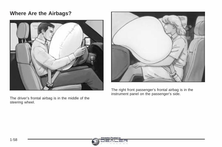
Where Are the Airbags?
The driver’s frontal airbag is in the middle of thesteering wheel.
The right front passenger’s frontal airbag is in theinstrument panel on the passenger’s side.
1-58Information Provided by:

The seat-mounted side impact airbags for the driver andright front passenger are in the side of the seatbacksclosest to the door.
The roof-rail airbags for the driver, right front passenger,and second row outboard passengers are in theceiling above the side windows.
Driver Side shown, Passenger Side similar Driver Side shown, Passenger Side similar
1-59Information Provided by:

{CAUTION:
If something is between an occupant and anairbag, the airbag might not inflate properly orit might force the object into that personcausing severe injury or even death. The pathof an inflating airbag must be kept clear. Donot put anything between an occupant and anairbag, and do not attach or put anything onthe steering wheel hub or on or near any otherairbag covering.
Do not use seat accessories that block theinflation path of a seat-mounted side impactairbag.
If your vehicle has roof-rail airbags, neversecure anything to the roof of your vehicle byrouting the rope or tie down through any dooror window opening. If you do, the path of aninflating roof-rail airbag will be blocked.
When Should an Airbag Inflate?Frontal airbags are designed to inflate in moderate tosevere frontal or near-frontal crashes to help reduce thepotential for severe injuries mainly to the driver’s orright front passenger’s head and chest. However, theyare only designed to inflate if the impact exceeds apredetermined deployment threshold. Deploymentthresholds are used to predict how severe a crash islikely to be in time for the airbags to inflate andhelp restrain the occupants.Whether your frontal airbags will or should deploy is notbased on how fast your vehicle is traveling. It dependslargely on what you hit, the direction of the impact,and how quickly your vehicle slows down.Frontal airbags may inflate at different crash speeds.For example:• If the vehicle hits a stationary object, the airbags
could inflate at a different crash speed than if thevehicle hits a moving object.
• If the vehicle hits an object that deforms, theairbags could inflate at a different crash speed thanif the vehicle hits an object that does not deform.
• If the vehicle hits a narrow object (like a pole), theairbags could inflate at a different crash speedthan if the vehicle hits a wide object (like a wall).
• If the vehicle goes into an object at an angle, theairbags could inflate at a different crash speedthan if the vehicle goes straight into the object.
1-60Information Provided by:

Thresholds can also vary with specific vehicle design.
Frontal airbags are not intended to inflate during vehiclerollovers, rear impacts, or in many side impacts.
In addition, your vehicle has a dual-stage driver airbag.Dual-stage airbags adjust the restraint according tocrash severity. Your vehicle has electronic frontalsensors, which help the sensing system distinguishbetween a moderate frontal impact and a more severefrontal impact. For moderate frontal impacts, dual-stageairbags inflate at a level less than full deployment.For more severe frontal impacts, full deployment occurs.
Your vehicle also has a dual-depth passenger airbagthat adjusts the restraint according to crash severity,seat location, and safety belt status using electronicfrontal sensors and other special sensors which enablethe sensing system to monitor the position of thefront passenger seat. The passenger airbag inflates to areduced depth when the passenger seat is in aforward position. For more rearward front seatingpositions, the passenger airbag may inflate to anincreased depth (a full deployment), based on the crashseverity measured early in the event. (Always wearyour safety belt, even with frontal airbags.)
Your vehicle has seat position sensors which enablesthe sensing system to monitor the position of the driver’sand right front passenger’s seat. Seat position sensors
provide information that is used to determine if theairbags should deploy at a reduced level or at fulldeployment.
Your vehicle has seat-mounted side impact and roof-railairbags. See Airbag System on page 1-55. Seat-mountedside impact and roof-rail airbags are intended to inflate inmoderate to severe side crashes. In addition, theseroof-rail airbags are intended to inflate in a severe frontalimpact. Seat-mounted side impact and roof-rail airbagswill inflate if the crash severity is above the system’sdesigned threshold level. The threshold level can varywith specific vehicle design.
Seat-mounted side impact airbags are not intended toinflate in frontal impacts, near-frontal impacts, rollovers,or rear impacts. Roof-rail airbags are not intended toinflate in rollovers or rear impacts. A seat-mounted sideimpact airbag is intended to deploy on the side ofthe vehicle that is struck. Both roof-rail airbags willdeploy when either side of the vehicle is struck or in asevere frontal impact.
In any particular crash, no one can say whether an airbagshould have inflated simply because of the damage to avehicle or because of what the repair costs were. Forfrontal airbags, inflation is determined by what the vehiclehits, the angle of the impact, and how quickly the vehicleslows down. For seat-mounted side impact and roof-railairbags, deployment is determined by the location andseverity of the side impact.
1-61Information Provided by:

What Makes an Airbag Inflate?In a deployment event, the sensing system sends anelectrical signal triggering a release of gas fromthe inflator. Gas from the inflator fills the airbag causingthe bag to break out of the cover and deploy. Theinflator, the airbag, and related hardware are all part ofthe airbag module.
Frontal airbag modules are located inside the steeringwheel and instrument panel. For vehicles withseat-mounted side impact airbags, there are airbagmodules in the side of the front seatbacks closest to thedoor. For vehicles with roof-rail airbags, there areairbag modules in the ceiling of the vehicle, near theside windows that have occupant seating positions.
How Does an Airbag Restrain?In moderate to severe frontal or near frontal collisions,even belted occupants can contact the steering wheel orthe instrument panel. In moderate to severe sidecollisions, even belted occupants can contact the insideof the vehicle.
Airbags supplement the protection provided by safetybelts. Frontal airbags distribute the force of theimpact more evenly over the occupant’s upper body,stopping the occupant more gradually. Seat-mounted
side impact and roof-rail airbags distribute the force ofthe impact more evenly over the occupant’s upper body.
But airbags would not help in many types of collisions,primarily because the occupant’s motion is nottoward those airbags. See When Should an AirbagInflate? on page 1-60 for more information.
Airbags should never be regarded as anything morethan a supplement to safety belts.
What Will You See After an AirbagInflates?After the frontal airbags and seat-mounted side impactairbags inflate, they quickly deflate, so quickly thatsome people may not even realize an airbag inflated.Roof-rail airbags may still be at least partially inflated forsome time after they deploy. Some components ofthe airbag module may be hot for several minutes. Forlocation of the airbag modules, see What Makes anAirbag Inflate? on page 1-62.
The parts of the airbag that come into contact with youmay be warm, but not too hot to touch. There maybe some smoke and dust coming from the vents in thedeflated airbags. Airbag inflation does not preventthe driver from seeing out of the windshield or beingable to steer the vehicle, nor does it prevent people fromleaving the vehicle.
1-62Information Provided by:

{CAUTION:
When an airbag inflates, there may be dust inthe air. This dust could cause breathingproblems for people with a history of asthmaor other breathing trouble. To avoid this,everyone in the vehicle should get out as soonas it is safe to do so. If you have breathingproblems but cannot get out of the vehicleafter an airbag inflates, then get fresh air byopening a window or a door. If you experiencebreathing problems following an airbagdeployment, you should seek medicalattention.
Your vehicle has a feature that may automaticallyunlock the doors, turn the interior lamps on, and turnthe hazard warning flashers on when the airbags inflate.You can lock the doors, turn the interior lamps off,and turn the hazard warning flashers off by using thecontrols for those features.
In many crashes severe enough to inflate the airbag,windshields are broken by vehicle deformation.Additional windshield breakage may also occur from theright front passenger airbag.
• Airbags are designed to inflate only once. After anairbag inflates, you will need some new parts forthe airbag system. If you do not get them, the airbagsystem will not be there to help protect you inanother crash. A new system will include airbagmodules and possibly other parts. The servicemanual for your vehicle covers the need to replaceother parts.
• Your vehicle has a crash sensing and diagnosticmodule which records information after a crash.See Vehicle Data Recording and Privacy onpage 7-16 and Event Data Recorders on page 7-17.
• Let only qualified technicians work on the airbagsystems. Improper service can mean that anairbag system will not work properly. See yourdealer/retailer for service.
1-63Information Provided by:

Passenger Sensing SystemYour vehicle has a passenger sensing system for theright front passenger’s position. The passengerairbag status indicator will be visible on the instrumentpanel when you start your vehicle.
The words ON and OFF, or the symbol for on and off,will be visible during the system check. If you areusing remote start to start your vehicle from a distance,if equipped, you may not see the system check.When the system check is complete, either the wordON or the word OFF, or the symbol for on or the symbolfor off, will be visible. See Passenger Airbag StatusIndicator on page 3-34.
The passenger sensing system will turn off the rightfront passenger’s frontal airbag and seat-mounted sideimpact airbag under certain conditions. The driver’sairbags are not part of the passenger sensing system.
The passenger sensing system works with sensors thatare part of the right front passenger’s seat. Thesensors are designed to detect the presence of aproperly-seated occupant and determine if the right frontpassenger’s frontal airbag and seat-mounted sideimpact airbag should be enabled (may inflate) or not.Accident statistics show that children are safer ifthey are restrained in the rear rather than the front seat.We recommend that children be secured in a rearseat, including: an infant or a child riding in a rear-facingchild restraint; a child riding in a forward-facing childseat; an older child riding in a booster seat; and children,who are large enough, using safety belts.A label on your sun visor says, “Never put a rear-facingchild seat in the front.” This is because the risk to therear-facing child is so great, if the airbag deploys.
{CAUTION:
A child in a rear-facing child restraint can beseriously injured or killed if the right frontpassenger’s airbag inflates. This is becausethe back of the rear-facing child restraintwould be very close to the inflating airbag.
CAUTION: (Continued)
United States Canada
1-64Information Provided by:

CAUTION: (Continued)
Even though the passenger sensing system isdesigned to turn off the right front passenger’sfrontal and seat-mounted side impact airbag (ifequipped) if the system detects a rear-facingchild restraint, no system is fail-safe, and noone can guarantee that an airbag will notdeploy under some unusual circumstance,even though it is turned off. We recommendthat rear-facing child restraints be secured in arear seat, even if the airbag(s) are off.
If you secure a forward-facing child restraint inthe right front seat, always move the frontpassenger seat as far back as it will go. It isbetter to secure the child restraint in a rear seat.
The passenger sensing system is designed to turn offthe right front passenger’s frontal airbag andseat-mounted side impact airbag if:
• The right front passenger seat is unoccupied.
• The system determines that an infant is present ina rear-facing infant seat.
• The system determines that a small child is presentin a child restraint.
• The system determines that a small child is presentin a booster seat.
• A right front passenger takes his/her weight off ofthe seat for a period of time.
• The right front passenger seat is occupied by asmaller person, such as a child who has outgrownchild restraints.
• Or, if there is a critical problem with the airbagsystem or the passenger sensing system.
When the passenger sensing system has turned off theright front passenger’s frontal airbag and seat-mountedside impact airbag, the off indicator will light andstay lit to remind you that the airbags are off. SeePassenger Airbag Status Indicator on page 3-34.
If a child restraint has been installed and the on indicatoris lit, turn the vehicle off. Remove the child restraintfrom the vehicle and reinstall the child restraint followingthe child restraint manufacturer’s directions and referto Securing a Child Restraint in the Right FrontSeat Position on page 1-51.
1-65Information Provided by:

If, after reinstalling the child restraint and restarting thevehicle, the on indicator is still lit, check to makesure that the vehicle’s seatback is not pressing the childrestraint into the seat cushion. If this happens, slightlyrecline the vehicle’s seatback and adjust the seatcushion if possible. Also make sure the child restraint isnot trapped under the vehicle head restraint. If thishappens, adjust the head restraint. See Head Restraintson page 1-2.
Remove any additional material from the seat such asblankets, cushions, seat covers, seat heaters, orseat massagers before reinstalling or securing the childrestraint.
If the on indicator is still lit, secure the child in the childrestraint in a rear seat position in the vehicle, andcheck with your dealer/retailer.
The passenger sensing system is designed to enable(may inflate) the right front passenger’s frontalairbag and seat-mounted side impact airbag anytime thesystem senses that a person of adult size is sittingproperly in the right front passenger’s seat. When thepassenger sensing system has allowed the airbags to beenabled, the on indicator will light and stay lit toremind you that the airbags are active.
For some children who have outgrown child restraintsand for very small adults, the passenger sensing systemmay or may not turn off the right front passenger’s frontalairbag and seat-mounted side impact airbag, dependingupon the person’s seating posture and body build.Everyone in your vehicle who has outgrown childrestraints should wear a safety belt properly — whetheror not there is an airbag for that person.
If a person of adult-size is sitting in the right frontpassenger’s seat, but the off indicator is lit, it could bebecause that person is not sitting properly in the seat. Ifthis happens, turn the vehicle off, remove any additionalmaterial from the seat, such as blankets, cushions,seat covers, seat heaters or seat massagers and askthe person to place the seatback in the fully uprightposition, then sit upright in the seat, centered on the seatcushion, with the person’s legs comfortably extended.Restart the vehicle and have the person remain inthis position for two to three minutes. This will allow thesystem to detect that person and then enable theright front passenger’s frontal airbag and seat-mountedside impact airbag.
1-66Information Provided by:

Safety belts help keep the passenger in position on theseat during vehicle maneuvers and braking, whichhelps the passenger sensing system maintain thepassenger airbag status. See “Safety Belts” and “ChildRestraints” in the Index for additional informationabout the importance of proper restraint use.
{CAUTION:
If the airbag readiness light in the instrumentpanel cluster ever comes on and stays on, itmeans that something may be wrong with theairbag system. If this ever happens, have thevehicle serviced promptly, because anadult-size person sitting in the right frontpassenger’s seat may not have the protectionof the airbag(s). See Airbag Readiness Lighton page 3-33 for more on this, includingimportant safety information.
1-67Information Provided by:

A thick layer of additional material, such as a blanket orcushion, or aftermarket equipment such as seatcovers, seat heaters, and seat massagers can affecthow well the passenger sensing system operates.We recommend that you not use seat covers or otheraftermarket equipment other than any that GM hasapproved for your specific vehicle. See AddingEquipment to Your Airbag-Equipped Vehicle onpage 1-69 for more information about modifications thatcan affect how the system operates.
{CAUTION:
Stowing of articles under the passenger’s seator between the passenger’s seat cushion andseatback may interfere with the properoperation of the passenger sensing system.
Servicing Your Airbag-EquippedVehicleAirbags affect how your vehicle should be serviced.There are parts of the airbag system in several placesaround your vehicle. Your dealer/retailer and the servicemanual have information about servicing your vehicleand the airbag system. To purchase a service manual,see Service Publications Ordering Information onpage 7-15.
{CAUTION:
For up to 10 seconds after the ignition isturned off and the battery is disconnected, anairbag can still inflate during improper service.You can be injured if you are close to anairbag when it inflates. Avoid yellowconnectors. They are probably part of theairbag system. Be sure to follow properservice procedures, and make sure the personperforming work for you is qualified to do so.
1-68Information Provided by:

Adding Equipment to YourAirbag-Equipped Vehicle
Q: Is there anything I might add to or changeabout the vehicle that could keep the airbagsfrom working properly?
A: Yes. If you add things that change your vehicle’sframe, bumper system, height, front end or sidesheet metal, they may keep the airbag system fromworking properly. Changing or moving any partsof the front seats, safety belts, the airbag sensingand diagnostic module, steering wheel, instrumentpanel, roof-rail airbag modules, ceiling headlineror pillar garnish trim, front sensors, or airbag wiringcan affect the operation of the airbag system.
In addition, your vehicle has a passenger sensingsystem for the right front passenger’s position,which includes sensors that are part of thepassenger’s seat. The passenger sensing systemmay not operate properly if the original seattrim is replaced with non-GM covers, upholstery ortrim, or with GM covers, upholstery or trimdesigned for a different vehicle. Any object, such asan aftermarket seat heater or a comfort enhancingpad or device, installed under or on top of the
seat fabric, could also interfere with the operation ofthe passenger sensing system. This could eitherprevent proper deployment of the passengerairbag(s) or prevent the passenger sensing systemfrom properly turning off the passenger airbag(s).See Passenger Sensing System on page 1-64.
If you have any questions about this, you shouldcontact Customer Assistance before you modifyyour vehicle. The phone numbers and addresses forCustomer Assistance are in Step Two of theCustomer Satisfaction Procedure in this manual.See Customer Satisfaction Procedure on page 7-2.
Q: Because I have a disability, I have to getmy vehicle modified. How can I find out whetherthis will affect my airbag system?
A: If you have questions, call Customer Assistance.The phone numbers and addresses for CustomerAssistance are in Step Two of the CustomerSatisfaction Procedure in this manual. SeeCustomer Satisfaction Procedure on page 7-2.
In addition, your dealer/retailer and the service manualhave information about the location of the airbagsensors, sensing and diagnostic module and airbagwiring.
1-69Information Provided by:

Restraint System Check
Checking the Restraint Systems
Safety BeltsNow and then, make sure the safety belt reminder lightand all your belts, buckles, latch plates, retractorsand anchorages are working properly.
Look for any other loose or damaged safety belt systemparts. If you see anything that might keep a safetybelt system from doing its job, have it repaired. Torn orfrayed safety belts may not protect you in a crash.They can rip apart under impact forces. If a belt is tornor frayed, get a new one right away.
Make sure the safety belt reminder light is working. SeeSafety Belt Reminders on page 3-32 for moreinformation.
Keep safety belts clean and dry. See Care of SafetyBelts on page 5-114.
AirbagsThe airbag system does not need regularly scheduledmaintenance or replacement. Make sure the airbagreadiness light is working. See Airbag Readiness Lighton page 3-33 for more information.
Notice: If an airbag covering is damaged, opened,or broken, the airbag may not work properly. Donot open or break the airbag coverings. If there areany opened or broken airbag covers, have theairbag covering and/or airbag module replaced. Forthe location of the airbag modules, see WhatMakes an Airbag Inflate? on page 1-62. See yourdealer/retailer for service.
1-70Information Provided by:

Replacing Restraint System PartsAfter a Crash
{CAUTION:
A crash can damage the restraint systems inyour vehicle. A damaged restraint system maynot properly protect the person using it,resulting in serious injury or even death in acrash. To help make sure your restraintsystems are working properly after a crash,have them inspected and any necessaryreplacements made as soon as possible.
If you have had a crash, do you need new belts orLATCH system (if equipped) parts?
After a very minor crash, nothing may be necessary.But the belt assemblies that were used during any crashmay have been stressed or damaged. See yourdealer/retailer to have your safety belt assembliesinspected or replaced.
If your vehicle has the LATCH system and it was beingused during a crash, you may need new LATCHsystem parts.
New parts and repairs may be necessary even if thebelt or LATCH system (if equipped), was not being usedat the time of the crash.
If an airbag inflates, you will need to replace airbagsystem parts. See the part on the airbag system earlierin this section.
Have your safety belt pretensioners checked if yourvehicle has been in a crash, if your airbag readinesslight stays on after you start your vehicle, or while youare driving. See Airbag Readiness Light on page 3-33.
1-71Information Provided by:

✍ NOTES
1-72Information Provided by:

Keys ...............................................................2-3Remote Keyless Entry (RKE) System ................2-5Keyless Access System ...................................2-6Remote Keyless Entry (RKE) System
Operation ...................................................2-7Keyless Access System Operation ....................2-9Remote Vehicle Start ....................................2-14
Doors and Locks ............................................2-17Door Locks ..................................................2-17Central Door Unlocking System ......................2-17Power Door Locks ........................................2-18Delayed Locking ...........................................2-18Programmable Automatic Door Locks ..............2-18Rear Door Security Locks ..............................2-19Lockout Protection ........................................2-20Trunk ..........................................................2-20
Windows ........................................................2-23Power Windows ............................................2-24Sun Visors ...................................................2-26
Theft-Deterrent Systems ..................................2-27Theft-Deterrent System ..................................2-27Immobilizer ..................................................2-28Immobilizer Operation (Key Access) ................2-28Immobilizer Operation (Keyless Access) ...........2-30
Starting and Operating Your Vehicle ................2-31New Vehicle Break-In ....................................2-31Ignition Positions (Key Access) .......................2-31Ignition Positions (Keyless Access) ..................2-33Retained Accessory Power (RAP) ...................2-34Starting the Engine .......................................2-34Engine Coolant Heater ..................................2-36Automatic Transmission Operation ...................2-37Manual Transmission Operation ......................2-41Parking Brake ..............................................2-43Shifting Into PARK (P) (Automatic
Transmission) ...........................................2-44Shifting Out of PARK (P) ...............................2-45Parking Your Vehicle (Manual Transmission) .....2-46Parking Over Things That Burn .......................2-47Engine Exhaust ............................................2-47Running the Vehicle While Parked ..................2-48
Mirrors ...........................................................2-49Automatic Dimming Rearview Mirror with
OnStar® ...................................................2-49Outside Power Mirrors ...................................2-49Park Tilt Mirrors ............................................2-50Outside Convex Mirror ...................................2-50Outside Heated Mirrors ..................................2-50
Section 2 Features and Controls
2-1Information Provided by:

Object Detection Systems ...............................2-51Ultrasonic Rear Parking Assist (URPA) ............2-51
OnStar ® System .............................................2-53Universal Home Remote System ......................2-56
Universal Home Remote System .....................2-56Universal Home Remote System Operation
(With One Triangular LED) .........................2-57
Storage Areas ................................................2-61Glove Box ...................................................2-61Cupholder(s) ................................................2-61Instrument Panel Storage ...............................2-61Center Console Storage .................................2-61Convenience Net ..........................................2-62
Sunroof .........................................................2-62
Section 2 Features and Controls
2-2Information Provided by:

Keys
{CAUTION:
Leaving children in a vehicle with the ignitionkey is dangerous for many reasons, children orothers could be badly injured or even killed.They could operate the power windows or othercontrols or even make the vehicle move. Thewindows will function with the keys in theignition and they could be seriously injured orkilled if caught in the path of a closing window.Do not leave the keys in a vehicle with children.
{CAUTION:
Leaving children in a vehicle with the keylessaccess transmitter is dangerous for manyreasons, children or others could be badlyinjured or even killed. They could operate thepower windows or other controls or even make
CAUTION: (Continued)
CAUTION: (Continued)
the vehicle move. The windows will functionwith the keyless access transmitter in thevehicle and they could be seriously injured orkilled if caught in the path of a closingwindow. Do not leave the keyless accesstransmitter in a vehicle with children.
2-3Information Provided by:

You will have either of the following keys.This key can be used forthe driver’s door, ignition,and glove box.
This key, located insidethe keyless accesstransmitter, can be usedfor the driver’s door, glovebox, and rear seatpass-through door. See“Rear Seat Pass-ThroughDoor” under Trunk onpage 2-20 for moreinformation.
To remove the key, pressthe button (A) near thebottom of the keylessaccess transmitter, andpull the key out. Never pullthe key out withoutpressing the button.
Your vehicle may have the Keyless Access System.See Ignition Positions (Key Access) on page 2-31or Ignition Positions (Keyless Access) on page 2-33 forinformation on starting the vehicle.
Notice: If you ever lock your keys in your vehicle,you may have to damage the vehicle to get in.Be sure you have spare keys.
In an emergency, contact Roadside Assistance.See Roadside Service on page 7-6.
2-4Information Provided by:

Remote Keyless Entry (RKE)SystemIf the vehicle has the Remote Keyless Entry (RKE)system, it operates on a radio frequency subjectto Federal Communications Commission (FCC) Rulesand with Industry Canada.
This device complies with Part 15 of the FCC Rules.Operation is subject to the following two conditions:
1. This device may not cause interference.
2. This device must accept any interference received,including interference that may cause undesiredoperation of the device.
This device complies with RSS-210 of Industry Canada.Operation is subject to the following two conditions:
1. This device may not cause interference.
2. This device must accept any interference received,including interference that may cause undesiredoperation of the device.
Changes or modifications to this system by other thanan authorized service facility could void authorization touse this equipment.
At times you may notice a decrease in range. This isnormal for any RKE system. If the transmitter does notwork or if you have to stand closer to your vehiclefor the transmitter to work, try this:
• Check the distance. You may be too far from yourvehicle. You may need to stand closer duringrainy or snowy weather.
• Check the location. Other vehicles or objects maybe blocking the signal. Take a few steps to theleft or right, hold the transmitter higher, andtry again.
• Check to determine if battery replacement isnecessary. See “Battery Replacement” later in thissection.
• If you are still having trouble, see your dealer/retaileror a qualified technician for service.
2-5Information Provided by:

Keyless Access SystemYour vehicle may have a Keyless Access System thatoperates on a radio frequency subject to FederalCommunications Commission (FCC) Rules and withIndustry Canada.
This device complies with Part 15 of the FCC Rules.Operation is subject to the following two conditions:
1. This device may not cause harmful interference.
2. This device must accept any interference received,including interference that may cause undesiredoperation.
This device complies with RSS-210 of Industry Canada.Operation is subject to the following two conditions:
1. This device may not cause interference.
2. This device must accept any interference received,including interference that may cause undesiredoperation of the device.
Changes or modifications to this system by other thanan authorized service facility could void authorization touse this equipment.
If you ever notice a decrease in the keyless accesstransmitter range, try doing one of the following:
• Check the distance. You may be too far from yourvehicle. You may need to stand closer duringrainy or snowy weather.
• Check the location. Other vehicles or objects maybe blocking the signal. Take a few steps to theleft or right, hold the transmitter higher, andtry again.
• Check to determine if battery replacement isnecessary. See “Battery Replacement” underKeyless Access System Operation on page 2-9.
• Check to make sure that an electronic device suchas a cellular phone or lap top computer is notcausing interference.
• If you are still having trouble, see your dealer/retaileror a qualified technician for service.
2-6Information Provided by:

Remote Keyless Entry (RKE)System OperationThe Remote Keyless Entry (RKE) transmitter functions,including lock, unlock, remote trunk release and vehiclelocator/panic alarm will work up to 65 feet (20 m) away.
There are other conditions which can affect theperformance of the transmitter. See Remote KeylessEntry (RKE) System on page 2-5.
Q (Lock): Press Q to lock all the doors. If enabledthrough the Driver Information Center (DIC), the parkinglamps may flash once to indicate locking has occurred,or the horn may chirp when Q is pressed again
within five seconds from the previous press of the lockbutton. See DIC Vehicle Customization on page 3-68for additional information.
" (Unlock): Press " to unlock the driver’s door. If " ispressed again within five seconds, all remainingdoors will unlock. The interior lamps will come on andstay on for 20 seconds or until the ignition is turned on.If enabled through the DIC, the parking lamps willflash twice to indicate unlocking has occurred. See DICVehicle Customization on page 3-68.
V (Remote Trunk Release): Press and hold Vfor about one second to release the trunk lid. Thetransmission must be in PARK (P) for this feature tooperate.
L (Vehicle Locator/Panic Alarm): Press and releaseLto locate your vehicle. The turn signal lamps willflash and the horn will sound three times.
Press and hold Lfor more than two seconds toactivate the panic alarm. The turn signal lamps will flashand the horn will sound repeatedly for 30 seconds.The alarm will turn off when the ignition is movedto START or Lis pressed again. The ignition must bein LOCK/OFF for the panic alarm to work.
2-7Information Provided by:

Matching Transmitter(s) to YourVehicleEach RKE transmitter is coded to prevent anothertransmitter from unlocking your vehicle. If a transmitteris lost or stolen, a replacement can be purchasedthrough your dealer/retailer. All transmitters need to bere-coded to match the new transmitter.
The lost transmitter will no longer work after the newtransmitters are re-coded. The vehicle can have amaximum of eight transmitters matched to it. See“Relearn Remote Key” under DIC Operation andDisplays on page 3-48.
Battery ReplacementReplace the battery if the Replace Battery In RemoteKey message displays in the DIC. See “Replace BatteryIn Remote Key” under DIC Warnings and Messageson page 3-54 for additional information.
Notice: When replacing the battery, use care not totouch any of the circuitry. Static from your bodytransferred to these surfaces may damage thetransmitter.
To replace the battery in the RKE transmitter:
1. Separate the halves of the transmitter with a flat,thin object inserted into the notch, located abovethe metal base.
2. Remove the old battery. Do not use a metal object.
3. Insert the new battery, positive side facing up.Replace with a CR2032 or equivalent battery.
4. Put the transmitter back together tightly.
2-8Information Provided by:

Keyless Access System OperationYour vehicle may have a Keyless Access Systemthat lets you lock and unlock your vehicle’s doors, openthe trunk lid, remotely start the engine, and locateyour vehicle or sound your vehicle’s alarm from adistance as much as 195 feet (60 m) away.
The Keyless Access System also lets you lock andunlock the vehicle’s doors and access the trunk withoutremoving the remote transmitter from your pocket,purse, briefcase, etc. The system operates when a frontdoor handle is pulled or the remote trunk releasebutton is pressed. You must have the keyless accesstransmitter with you and within 3 feet (1 m) of the door ortrunk you are opening. See “Keyless Locking” and“Keyless Unlock” under DIC Vehicle Customization onpage 3-68.
There are other conditions which can affect theperformance of the transmitter. See Keyless AccessSystem on page 2-6.
Your vehicle comes withtwo transmitters.
Q (Lock): Press Qto lock the doors. The turn signalindicators will flash. If Qis pressed twice, the doorswill lock, the turn signal indicators will flash twice, andthe horn will sound once.
You can program your vehicle so the turn signalindicators will not flash and the horn will not soundwhen pressing Qon the keyless access transmitter.For more information see “Remote Door Lock”under DIC Vehicle Customization on page 3-68.
With Remote StartShown, Without Similar
2-9Information Provided by:

" (Unlock): Press " once to unlock the driver’s door.The turn signal indicators will flash twice.
Press " twice within five seconds to unlock all thedoors. If it is dark enough outside, your interior lampswill come on.
You can program your vehicle so the turn signalindicators will not flash and the fog lamps and reverselamps remain on steady for about 20 seconds when thekeyless access transmitter is used to unlock thevehicle. See “Remote Door Unlock” under DIC VehicleCustomization on page 3-68.
If your vehicle has the memory feature you can programand recall memory settings when you press " on thekeyless access transmitter. See Memory Seat andMirrors on page 1-6 for more information.
/ (Remote Start): If your vehicle has this feature,press / after pressing Q to operate the remote startfeature. See Remote Vehicle Start on page 2-14 foradditional information.
G (Trunk): Press and hold G for aboutone second to open the trunk while the engine isturned off or the shift lever is in PARK (P).
L (Vehicle Locator/Panic Alarm): Press andrelease Lto locate your vehicle. The horn will chirpthree times and the turn signal lamps will flashthree times.
Press and hold Lfor three seconds to sound the panicalarm. The horn will chirp and the turn signal lampswill flash for 30 seconds. Press and release L againto cancel the panic alarm.
2-10Information Provided by:
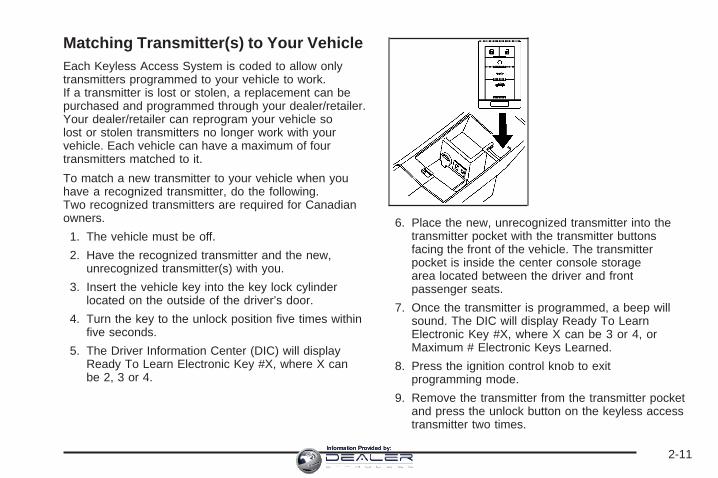
Matching Transmitter(s) to Your VehicleEach Keyless Access System is coded to allow onlytransmitters programmed to your vehicle to work.If a transmitter is lost or stolen, a replacement can bepurchased and programmed through your dealer/retailer.Your dealer/retailer can reprogram your vehicle solost or stolen transmitters no longer work with yourvehicle. Each vehicle can have a maximum of fourtransmitters matched to it.
To match a new transmitter to your vehicle when youhave a recognized transmitter, do the following.Two recognized transmitters are required for Canadianowners.
1. The vehicle must be off.
2. Have the recognized transmitter and the new,unrecognized transmitter(s) with you.
3. Insert the vehicle key into the key lock cylinderlocated on the outside of the driver’s door.
4. Turn the key to the unlock position five times withinfive seconds.
5. The Driver Information Center (DIC) will displayReady To Learn Electronic Key #X, where X canbe 2, 3 or 4.
6. Place the new, unrecognized transmitter into thetransmitter pocket with the transmitter buttonsfacing the front of the vehicle. The transmitterpocket is inside the center console storagearea located between the driver and frontpassenger seats.
7. Once the transmitter is programmed, a beep willsound. The DIC will display Ready To LearnElectronic Key #X, where X can be 3 or 4, orMaximum # Electronic Keys Learned.
8. Press the ignition control knob to exitprogramming mode.
9. Remove the transmitter from the transmitter pocketand press the unlock button on the keyless accesstransmitter two times.
2-11Information Provided by:

The Canadian immobilizer standard requires Canadianowners to see their dealer/retailer for matching newtransmitters when two recognized transmitters are notavailable. United States owners are permitted to match anew transmitter to their vehicle when a recognizedtransmitter is not available.
The procedure will require three, ten minute cycles tocomplete the matching process.
1. The vehicle must be off.
2. Place the new, unrecognized transmitter into thetransmitter pocket with the transmitter buttons facingthe front of the vehicle. The transmitter pocket isinside the center console storage area locatedbetween the driver and front passenger seats.
3. Insert the vehicle key into the key lock cylinderlocated on the driver’s door.
4. Turn the key to the unlock position five timeswithin five seconds.
5. The DIC will display Press Start Control ToLearn Keys.
6. Press the ignition switch in.
7. The DIC will read Learn Delay Active Wait XX Minand will count down to zero, one minute at a time.
8. The DIC will display Press Start Control To LearnKeys again.
9. Press the ignition switch in again.
10. The DIC will again read Learn Delay Active WaitXX Min and will count down to zero, one minuteat a time.The DIC will display Press Start Control To LearnKeys again.
11. Press the ignition switch in again.
12. The DIC will again read Learn Delay Active WaitXX Min and will count down to zero, one minuteat a time.
2-12Information Provided by:
14. A beep will sound and the DIC will read Ready ToLearn Electronic Key # X. At this time, all previouslyknown transmitters have been erased.
15. Once the transmitter is recognized andprogrammed, a beep will sound and the DIC willdisplay Ready To Learn Electronic Key # X.
16. To program additional transmitters, insert eachtransmitter in the pocket until you hear a beepand the DIC advances to the next electronic keynumber.
17. When complete, press the ignition control knob.
18. Press the unlock button on each transmitterprogrammed to complete programming.
Up to four transmitters can be programmed to thevehicle. The DIC will display Maximum # ElectronicKeys Learned and will exit the programming mode.
After performing this process, transmitters previouslyprogrammed will no longer work with your vehicleand must be reprogrammed.
Battery ReplacementReplace the battery if the Replace Battery In RemoteKey message displays in the DIC. See “REPLACEBATTERY IN REMOTE KEY” under DIC Warnings andMessages on page 3-54 for additional information.
A weak battery may also cause the DIC to displayElectronic Key Not Detected when you try to start thevehicle. If this happens, place the transmitter in thecenter console storage area transmitter pocket with thebuttons facing to the front of the vehicle. Then, withthe vehicle in PARK (P) or NEUTRAL (N), pressthe brake pedal and the ignition control knob.See Starting the Engine on page 2-34, for additionalinformation about your vehicle’s electronic keylessignition with push start. Although this will start thevehicle, it is recommended that you replace thetransmitter battery as soon as possible.
2-13Information Provided by:

Notice: When replacing the battery, use care not totouch any of the circuitry. Static from your bodytransferred to these surfaces may damage thetransmitter.
To replace the battery:
1. Separate the halves of the transmitter with a flat,thin object inserted into the slot on the side orback of the transmitter.
2. Remove the old battery. Do not use a metal object.
3. Insert the new battery, positive side facing down.Replace with a CR2032 or equivalent battery.
4. Put the transmitter back together tightly.
Remote Vehicle StartIf your vehicle has this feature, it allows you to start theengine from outside of the vehicle. It may also startthe vehicle’s automatic climate control system. When theremote start system is active, the climate controlsystem will heat and cool the inside of the vehicleaccording to the previous settings of the system beforeturning the vehicle off. The windshield defroster orrear window defogger will be turned on by the climatecontrol system when it is cold outside. If the vehicle hasheated seats, they will also turn on. See Heated andVentilated Seats on page 1-6 for additional information.Normal operation of the climate control system willreturn after the ignition is turned to ON/RUN. See DualClimate Control System on page 3-23.
Laws in some communities may restrict the use ofremote starters. For example, some laws may require aperson using remote start to have the vehicle in viewwhen doing so. Check local regulations for anyrequirements on remote starting of vehicles.
Do not use the remote start feature if your vehicle is lowon fuel. Your vehicle may run out of fuel.
Your transmitter, with the remote start button, providesan increased range of operation. However, the rangemay be less while the vehicle is running. As a result, youmay need to be closer to your vehicle to turn it off,than you were to turn it on.
2-14Information Provided by:

There are other conditions which can affect theperformance of the transmitter, see Remote KeylessEntry (RKE) System on page 2-5 or Keyless AccessSystem on page 2-6 for additional information.
/ (Remote Start): Press and release the lock buttonand then press and hold this button to use theremote start feature.
To start the vehicle using the remote start feature:
1. Aim the transmitter at the vehicle.
2. Press and release the transmitter’s lock button,then immediately press and hold the transmitter’sremote start button until the turn signal lightsflash or if the vehicle’s lights are not visible, pressand hold the remote start button for at leastfour seconds. The vehicle’s doors will lock. Pressingthe remote start button again after the vehiclehas started will turn off the ignition.When the vehicle starts, the parking lamps will turnon and remain on while the vehicle is running.
3. If it is the first remote start since the vehicle hasbeen driven, repeat these steps, while the engineis still running, to extend the engine running timeby 10 minutes. Remote start can be extendedone time.
After entering the vehicle during a remote start, pressthe brake pedal and turn the ignition to ON/RUN to drivethe vehicle.
If the vehicle is left running it will automatically shut offafter 10 minutes unless a time extension has been done.
To manually shut off a remote start:
• Aim the transmitter at the vehicle and pressthe remote start button until the parking lampsturn off.
• Turn on the hazard warning flashers.
• Turn the ignition switch on and then off.
The remote vehicle start feature provides two separatestarts, each with 10 minutes of engine running, or itprovides one start with 10 minutes of engine running thatmay be extended 10 more minutes. If you press andrelease the transmitter lock button and then press andhold the remote start button on the transmitter againbefore the first 10 minutes of engine running timehas expired, 10 minutes are added to the remainingminutes. For example, if the lock button and thenthe remote start buttons are pressed again afterfive minutes of the engine run time, 10 minutes areadded and you now have 15 minutes of engine running.The added ten minutes are considered a secondremote vehicle start.
2-15Information Provided by:
Once two remote starts or a single start with a timeextension have been used, the vehicle must be startedwith the keyless access ignition control knob beforeyou can use the remote start feature again.
The remote start feature will not operate if any of thefollowing occur:
• The ignition is in any position other than LOCK/OFF.
• A keyless access transmitter is inside the vehicle.
• The hood is open.
• There is an emission control system malfunction.
• The remote start feature is not enabled. See“Remote Start” under DIC Vehicle Customization onpage 3-68.
The engine will turn off during a remote vehicle start ifthe coolant temperature gets too high, or the oil pressureis too low.
Your vehicle was shipped from the factory with theremote vehicle start system enabled. The system maybe disabled through the Driver Information Center (DIC).See “Remote Start” under DIC Vehicle Customizationon page 3-68 for additional information.
See Engine Exhaust on page 2-47 for important safetyinformation when using remote start in a closedgarage.
Remote Start ReadyIf your vehicle does not have the remote vehicle startfeature, it may have the remote start ready feature. Thisfeature allows your dealer/retailer to add themanufacturer’s remote vehicle start feature. See yourdealer/retailer if you would like to add the manufacturer’sremote vehicle start feature to your vehicle.
2-16Information Provided by:

Doors and Locks
Door Locks
{CAUTION:
Unlocked doors can be dangerous.• Passengers, especially children, can easily
open the doors and fall out of a movingvehicle. When a door is locked, the handlewill not open it. You increase the chanceof being thrown out of the vehicle in acrash if the doors are not locked. So, wearsafety belts properly and lock the doorswhenever you drive.
• Young children who get into unlockedvehicles may be unable to get out. A childcan be overcome by extreme heat and cansuffer permanent injuries or even deathfrom heat stroke. Always lock your vehiclewhenever you leave it.
• Outsiders can easily enter through anunlocked door when you slow down orstop your vehicle. Locking your doors canhelp prevent this from happening.
There are several ways to lock and unlock your vehicle.
From the inside, use the manual lock levers locatedon the door panels near the windows.
Push down on the manual lock lever to lock the door.To unlock the door, pull up on the lever.
If the windows are down and the doors are locked, donot reach in to manually unlock the vehicle because youwill set off the alarm.
From the outside, use the key, or press the lock orunlock button on the Remote Keyless Entry (RKE)transmitter. See Remote Keyless Entry (RKE) SystemOperation on page 2-7 for more information.
On vehicles with the Remote Keyless Access system,the door unlocks by pulling the door handle whenyou have the transmitter with you. See Keyless AccessSystem Operation on page 2-9 for more information.
Central Door Unlocking SystemYour vehicle has a central door unlocking feature. Whenunlocking the driver’s door, you can unlock the otherdoors by holding the key in the turned position fora few seconds or by quickly turning the key twice in thelock cylinder.
2-17Information Provided by:

Power Door LocksThe power door lock switches are located on thefront doors.
K (Unlock): Press to unlock the doors.
Q (Lock): Remove the key from the ignition andpress to lock the doors.
Delayed LockingWith this feature, you can delay the actual locking ofthe doors.
When the power door lock switch is pressed when thekey is not in the ignition and the driver’s door is opened,a chime will sound three times indicating that delayedlocking is active.When all the doors are closed, the doors will lockautomatically after five seconds. If a door is reopenedbefore five seconds have elapsed, the five second timerwill reset itself once all the doors are closed again.
You can press the door lock switch again or the lockbutton on the RKE transmitter to override this featureand lock the doors immediately.You can turn this feature off using the Driver InformationCenter (DIC). When delayed locking is off, the doorswill lock immediately when you press the power
door lock switch or the lock button on the RKEtransmitter. See DIC Vehicle Customization onpage 3-68 for more information.
Programmable Automatic DoorLocksIf your vehicle has an automatic transmission, thevehicle is programmed so that the doors will lockautomatically when all doors are closed, the ignition ison, and the shift lever is moved out of PARK (P).The doors will automatically unlock when you stop thevehicle and move the shift lever back into PARK (P).If your vehicle has a manual transmission, the vehicle isprogrammed so that the doors will lock automaticallyafter the vehicle speed reaches 5 mph (8 km). The doorswill automatically unlock when the ignition is turnedoff and the key is removed from the ignition.If someone needs to exit the vehicle once the doors arelocked, have that person use the manual lever orpower door lock switch. When the door is closed again,it will not lock automatically. Use the manual lever orthe power door lock switch to lock the door.The power door locks can be programmed throughprompts displayed on the Driver InformationCenter (DIC). These prompts allow you to choosevarious lock and unlock settings. For more informationon programming, see DIC Vehicle Customization onpage 3-68.
2-18Information Provided by:

Rear Door Security LocksYour vehicle has rear door security locks. Theseprevent passengers from opening the rear doors fromthe inside.
The rear door securitylocks are located on theinside edge of eachrear door. The rear doorsmust be open to accessthem. The label showinglock and unlock positions islocated near the lock.
To set the locks, do the following:
1. Insert the key into the security lock slot and turn itso the slot is in the horizontal position.
2. Close the door.
When you want to open a rear door when the securitylock is on, do the following:
1. Unlock the door using the Remote Keyless Entry(RKE) or Keyless Access System transmitter, ifthe vehicle has one, the power door lock switch, orthe rear door manual lock.
2. Open the door from the outside.
To cancel the rear door security lock, do the following:
1. Unlock the door and open it from the outside.
2. Insert the key into the security lock slot and turn itso the slot is in the vertical position.
Lock Label shown
2-19Information Provided by:

Lockout ProtectionIf the power door lock switch is pressed when the key isin the ignition and a door is open, all the doors willlock and only the driver’s door will unlock. If you closethe doors, they can be locked by using the RemoteKeyless Entry (RKE) transmitter. Be sure to remove thekey from the ignition when locking your vehicle.
This feature can be overridden by pressing the lockbutton on the RKE transmitter or by pressing the powerlock switch a second time.
On vehicles with a Keyless Access System, the systemcan be programmed to alert you when all the doorsare closed and a transmitter has been left inside of thevehicle. See DIC Vehicle Customization on page 3-68for more information.
Trunk
{CAUTION:
It can be dangerous to drive with the trunk lidopen because carbon monoxide (CO) gas cancome into your vehicle. You cannot see orsmell CO. It can cause unconsciousness andeven death. If you must drive with the trunk lidopen or if electrical wiring or other cableconnections must pass through the sealbetween the body and the trunk lid:
• Make sure all other windows are shut.• Turn the fan on your heating or cooling
system to its highest speed and select thecontrol setting that will force outside airinto your vehicle. See Climate ControlSystem.
• If you have air outlets on or under theinstrument panel, open them all the way.
See Engine Exhaust on page 2-47.
2-20Information Provided by:
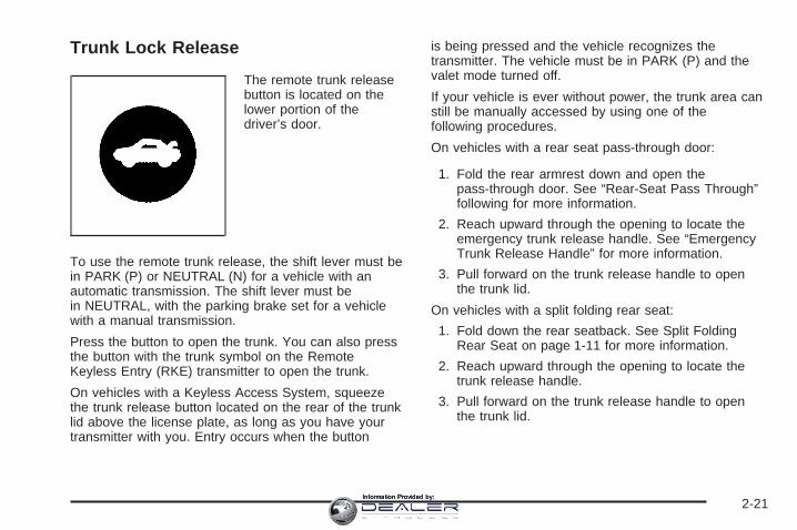
Trunk Lock Release
The remote trunk releasebutton is located on thelower portion of thedriver’s door.
To use the remote trunk release, the shift lever must bein PARK (P) or NEUTRAL (N) for a vehicle with anautomatic transmission. The shift lever must bein NEUTRAL, with the parking brake set for a vehiclewith a manual transmission.
Press the button to open the trunk. You can also pressthe button with the trunk symbol on the RemoteKeyless Entry (RKE) transmitter to open the trunk.
On vehicles with a Keyless Access System, squeezethe trunk release button located on the rear of the trunklid above the license plate, as long as you have yourtransmitter with you. Entry occurs when the button
is being pressed and the vehicle recognizes thetransmitter. The vehicle must be in PARK (P) and thevalet mode turned off.
If your vehicle is ever without power, the trunk area canstill be manually accessed by using one of thefollowing procedures.
On vehicles with a rear seat pass-through door:
1. Fold the rear armrest down and open thepass-through door. See “Rear-Seat Pass Through”following for more information.
2. Reach upward through the opening to locate theemergency trunk release handle. See “EmergencyTrunk Release Handle” for more information.
3. Pull forward on the trunk release handle to openthe trunk lid.
On vehicles with a split folding rear seat:
1. Fold down the rear seatback. See Split FoldingRear Seat on page 1-11 for more information.
2. Reach upward through the opening to locate thetrunk release handle.
3. Pull forward on the trunk release handle to openthe trunk lid.
2-21Information Provided by:

Close the trunk by pulling on the handle. Do not use thehandle as a tie-down.
Rear-Seat Pass ThroughIf your vehicle has the rear seat-pass through door, youcan access the trunk without opening the trunk lid.This is especially useful when transporting long items.
To open the door, pull down the rear seat armrest. Thenpull the lever all the way down to release the door.
To close the door, push it up and back into place. Thentry to open the door without pulling up on the lever tomake sure it is locked into place.
Emergency Trunk Release Handle
Notice: Do not use the emergency trunk releasehandle as a tie-down or anchor point when securingitems in the trunk as it could damage the handle.The emergency trunk release handle is onlyintended to aid a person trapped in a latched trunk,enabling them to open the trunk from the inside.
There is a glow-in-the-dark emergency trunk releasehandle located on the back wall of the trunk. This handlewill glow following exposure to light. Pull the releasehandle toward the front of the vehicle to open the trunkfrom the inside.
2-22Information Provided by:

Windows
{CAUTION:
Leaving children, helpless adults, or pets in avehicle with the windows closed is dangerous.They can be overcome by the extreme heatand suffer permanent injuries or even deathfrom heat stroke. Never leave a child, ahelpless adult, or a pet alone in a vehicle,especially with the windows closed in warm orhot weather.
2-23Information Provided by:

Power Windows
{CAUTION:
Leaving children, helpless adults, or pets in avehicle with the windows closed is dangerous.They can be overcome from extreme heat inwarm or hot weather and suffer permanentinjuries or even death from heat stroke.
Leaving children in a vehicle with the ignitionkey is dangerous for many reasons, childrenor others could be badly injured or even killed.They could operate the power windows orother controls or even make the vehicle move.The windows will function with the keys in theignition and they could be seriously injured orkilled if caught in the path of a closingwindow. Do not leave keys in a vehicle withchildren.
When there are children in the rear seat usethe window lockout button to preventunintentional operation of the windows.
The power windowswitches are located onthe driver’s door.
In addition, each door has a switch for its own window.The front power window switch operates with twopositions for both up and down movement and the rearpower window switch operates with one position forup and two positions for down movement. Pressthe switch to the first position to lower the window to thedesired level. Pull the switch up to raise the window.Your vehicle has Retained Accessory Power (RAP) thatallows you to use the power windows once theignition has been turned off. For more information, seeRetained Accessory Power (RAP) on page 2-34.
2-24Information Provided by:

Express-Down WindowThis feature is on all windows. Press the switch to thesecond position and release the switch to activatethe express-down feature. To stop the window as it islowering, pull up briefly on the switch again.
Express-Up WindowThis feature is on the front windows. Pull the switch upto the second position and release the switch toactivate the express-up feature. To stop the window asit is raising, pull up or press down briefly on theswitch again.
Programming the Power WindowsIf the battery on your vehicle has been recharged,disconnected, or is not working, you will need toreprogram each front power window for the express-upfeature to work. Before reprogramming, you will needto replace or recharge your vehicle’s battery.
To program each front window, follow these steps:
1. With the ignition in ACC/ACCESSORY, ON/RUN, orwhen Retained Accessory Power (RAP) is active,close all doors.
2. Press and hold the power window switch until thewindow is fully open.
3. Pull the power window switch up until the window isfully closed.
4. Continue holding the switch up for approximatelytwo seconds after the window is completelyclosed.
The window is now reprogrammed. Repeat the processfor the other windows.
Express Window Anti-Pinch FeatureIf any object is in the path of the window whenthe express-up is active, the window will stop at theobstruction and auto-reverse to a preset factory position.Weather conditions such as severe icing may alsocause the window to auto-reverse. The windowwill return to normal operation once the obstruction orcondition is removed.
2-25Information Provided by:

Express Window Anti-Pinch Override
{CAUTION:
If express override is activated, the windowwill not reverse automatically. You or otherscould be injured and the window could bedamaged. Before you use express override,make sure that all people and obstructions areclear of the window path.
In an emergency, the anti-pinch feature can beoverridden in a supervised mode. Hold the windowswitch all the way up to the second position. The windowwill rise for as long as the switch is held. Once theswitch is released, the express mode is re-activated.
In this mode, the window can still close on an object inits path. Use care when using the override mode.
Window Lockout
o (Window Lockout): The rear window lockoutbutton is located on the driver’s door near the windowswitches.
Press the right side of the button to disable the rearwindow controls. The light on the button will illuminate,indicating the feature is in use. The rear windowsstill can be raised or lowered using the driver’s windowswitches when the lockout feature is active.
To restore power to the rear windows, press the buttonagain. The light on the button will go out.
Sun VisorsSwing down the primary visor to block out glare. It canalso be detached from the center mount and movedto the side to block glare from that direction.
The driver’s visor may also have buttons for a built-ingarage door opener. See Universal Home RemoteSystem on page 2-56 for more information.
Lighted Visor Vanity MirrorPull the visor down and lift the cover to access themirror. A light comes on when the cover is lifted andgoes out when it is closed.
2-26Information Provided by:

Theft-Deterrent SystemsVehicle theft is big business, especially in some cities.Although your vehicle has a number of theft-deterrentfeatures, we know that nothing we put on it can make itimpossible to steal.
Theft-Deterrent SystemIf your vehicle has thisfeature, the security light islocated on the instrumentpanel cluster.
To activate the theft-deterrent system:
1. Open the door.
2. Lock the door with the transmitter. The security lightshould come on and stay on.
3. Close all doors. The security light should go offafter about 30 seconds. The alarm is not armeduntil the security light goes off.
If a locked door or trunk is opened without using the keyin the driver’s door key cylinder or the transmitter, aten second pre-alarm will occur. The horn will chirp andthe lights will flash. If the ignition is turned to STARTor the door is not unlocked by pressing the unlock buttonon the transmitter during the ten second pre-alarm,the alarm will go off. Your vehicle’s headlamps will flashand the horn will sound for about 30 seconds, then willturn off to save the battery power.
The theft-deterrent system will not activate if the doorsare locked with the vehicle’s key or the manual doorlock. It activates only if the power door lock switchis used while the door is open or with the transmitter.You should also remember that you can start yourvehicle with the correct ignition key if the alarm has beenset off.
To avoid setting off the alarm by accident:
• Lock the vehicle with the door key after the doorsare closed.
• Always unlock a door with the transmitter. Unlockinga door any other way will set off the alarm.
If you set off the alarm by accident, turn off the alarm bypressing the unlock button on the transmitter. The alarmwill not stop if you try to unlock a door any other way.
2-27Information Provided by:

Testing the AlarmThe alarm can be tested by following these steps:
1. From inside the vehicle, lower the driver’s windowand open the driver’s door.
2. Activate the system by locking the doors with thetransmitter.
3. Get out of the vehicle, close the door and wait forthe security light to go out.
4. Then reach in through the window, unlock the doorwith the manual door lock and open the door. Thisshould set off the alarm.
While the alarm is set, the power door unlock switch willnot work.
If the alarm does not sound when it should but theheadlamps flash, check to see if the horn works. Thehorn fuse may be blown. To replace the fuse, see Fusesand Circuit Breakers on page 5-122 Fuses and CircuitBreakers.
If the alarm does not sound or the headlamps do notflash, the vehicle should be serviced by yourdealer/retailer.
ImmobilizerThis device complies with Part 15 of the FCC Rules.Operation is subject to the following two conditions:
1. This device may not cause interference.
2. This device must accept any interference received,including interference that may cause undesiredoperation.
This device complies with RSS-210 of Industry Canada.Operation is subject to the following two conditions:
1. This device may not cause interference.
2. This device must accept any interference received,including interference that may cause undesiredoperation of the device.
Changes or modifications to this system by other thanan authorized service facility could void authorization touse this equipment.
Immobilizer Operation (Key Access)Your vehicle has a passive theft-deterrent system.
The system is automatically armed when the keyis removed from the ignition.
The theft-deterrent system is disarmed when the key isturned to ON/RUN.
You do not have to manually arm or disarm the system.
2-28Information Provided by:

The security light will come on if there is a problem witharming or disarming the theft-deterrent system.
The key uses a transponder that matches an immobilizercontrol unit in your vehicle and automatically disarmsthe system. Only the correct key will start the vehicle. Ifthe key is ever damaged, you may not be able tostart your vehicle.
When trying to start the vehicle, if the engine does notstart and the security light comes on, there may bea problem with your theft-deterrent system. Turnthe ignition off and try again.
If the engine still does not start, and the key appears tobe undamaged, try another ignition key. At this time,you may also want to check the fuse. See Fusesand Circuit Breakers on page 5-122. If the engine stilldoes not start with the other key, your vehicle needsservice. If your vehicle does start, the first key may befaulty. See your dealer/retailer who can service thetheft-deterrent system and have a new key made.
It is possible for the theft-deterrent system decoder tolearn the transponder value of a new or replacementkey. Up to 10 keys can be programmed for the vehicle.The following procedure is for programming additionalkeys only.
To program a new key do the following:
1. Verify that the new key has 1 stamped on it.
2. Insert the current driver’s key in the ignition andstart the engine. If the engine will not start seeyour dealer/retailer for service.
3. After the engine has started, turn the key toLOCK/OFF, and remove the key.
4. Insert the key to be programmed and turn it toON/RUN within five seconds of the ignition beingturned to LOCK/OFF in Step 3.
5. The security light will turn off once the key hasbeen programmed. It may not be apparent thatthe security light went on due to how quickly thekey is programmed.
6. Repeat the Steps 1 through 4 if additional keys areto be programmed.
In an emergency, contact Cadillac Roadside Service®.See Roadside Service on page 7-6.
Do not leave the key or device that disarms ordeactivates the theft deterrent system in the vehicle.
2-29Information Provided by:

Immobilizer Operation(Keyless Access)Your vehicle has a passive theft-deterrent system.
The system is automatically armed when the ignitioncontrol knob is turned to LOCK/OFF.
The immobilization system is disarmed when the ignitioncontrol knob is pushed in and a valid transmitter isfound in the vehicle.
You do not have to manually arm or disarm the system.
The security light will come on if there is a problemwith arming or disarming the theft-deterrent system.
The system has one or more keyless accesstransmitters that are matched to an immobilizer controlunit in your vehicle. Only a correctly matched keylessaccess transmitter will start the vehicle. If the keylessaccess transmitter is ever damaged, you may notbe able to start your vehicle.
When trying to start the vehicle, if the engine does notstart and the security light comes on, there may bea problem with your immobilizer system. Turn theignition control knob off and try again.
If the ignition control knob does not rotate, and thekeyless access transmitter appears to be undamaged,try another keyless access transmitter. Or, you maytry placing the transmitter in the transmitter pocketlocated in the center console. See “Electronic Key NotDetected” under DIC Warnings and Messages onpage 3-54. At this time, you may also want to check thefuse. See Fuses and Circuit Breakers on page 5-122.If the ignition control knob still does not rotate withthe other transmitter, your vehicle needs service. If theignition control knob does rotate, the first transmittermay be faulty. See your dealer/retailer who can servicethe theft-deterrent system and have a new keylessaccess transmitter programmed to the vehicle.
It is possible for the immobilizer system to learn new orreplacement keyless access transmitters. Up to4 keyless access transmitters can be programmed forthe vehicle. To program additional transmitters, see“Matching transmitter(s) to Your Vehicle” under KeylessAccess System Operation on page 2-9.
Do not leave the key or device that disarms ordeactivates the theft deterrent system in the vehicle.
2-30Information Provided by:

Starting and Operating YourVehicle
New Vehicle Break-InNotice: Your vehicle does not need an elaboratebreak-in. But it will perform better in the longrun if you follow these guidelines for the first500 miles (805 km):
• Do not drive at any one constant speed, fastor slow.
• Do not exceed 70 mph (113 km/h).
• Do not make full-throttle starts; also refrainfrom using the full throttle while driving.Avoid downshifting to brake or slow the vehicle.
If these procedures are not followed, the engine,axle, or other parts could be damaged.
Avoid making hard stops for the first 200 miles(322 km) or so. During this time the new brakelinings are not yet broken in. Hard stops with newlinings can mean premature wear and earlierreplacement. Follow this break-in guideline everytime you get new linings.
Do not tow a trailer during break-in. See Towing aTrailer on page 4-29 for the trailer towing capabilitiesof your vehicle and more information.
Following break-in, engine speed and load can begradually increased.
Ignition Positions (Key Access)
The key can be turned to four different positions.
To shift out of PARK (P), ignition must be in theON/RUN or ACC/ACCESSORY and the regular brakepedal must be applied.
2-31Information Provided by:

Notice: Using a tool to force the key from itscylinder could cause damage or break the key. Usethe correct key and turn the key only with yourhand. Make sure the key is all the way in. If it is andyou have a manual transmission vehicle, turn thesteering wheel left and right while you turn the keyhard. If none of this works, then your vehicleneeds service.
A (LOCK/OFF): This is the only position in which thekey can be inserted or removed. This position locks theignition and shifter on automatic transmission vehicles,and the ignition and steering wheel on manualtransmission vehicles.
B (ACC/ACCESSORY): This position lets you usethings like the radio and the windshield wipers whenthe engine is off. This position allows you to turn offthe engine.
C (ON/RUN): This position is for driving. It is theposition the ignition switch returns to after the enginestarts, and the key is released.
To shift the transmission out of PARK (P), the ignitionkey has to be in ACC/ACCESSORY or ON/RUN.
The battery could be drained if the key is left in theACC/ACCESSORY or ON/RUN position with the engineoff. The vehicle might not start if the battery is allowedto drain for an extended period of time.
D (START): This position starts the engine.
Key In the IgnitionNever leave your vehicle with the keys inside, as it is aneasy target for joy riders or thieves. A chime soundswhen the driver’s door is opened while the vehicleis parked and the key is left in the ignition. Alwaysremember to remove the key from the ignition and takeit with you. This will lock the ignition and transmission.Also, always remember to lock the doors.
The battery could be drained if the key is left in theignition while your vehicle is parked. The vehicle mightnot start after it has been parked for an extendedperiod of time.
2-32Information Provided by:

Ignition Positions (Keyless Access)You can turn the ignition control knob to four differentpositions.
To shift out of PARK (P), ignition must be in theON/RUN or ACC/ACCESSORY and the regular brakepedal must be applied.
Using a tool to force the knob from its cylinder couldcause damage or break the knob.
Make sure the keyless access transmitter is inside thevehicle when trying to turn the ignition control knob.
A (LOCK/OFF): The ignition control knob cannot beremoved from the vehicle. The keyless accesstransmitter must be inside the vehicle to start theengine. This position locks the ignition and shifter onautomatic transmission vehicles, and the ignitionand steering wheel on manual transmission vehicles.
B (ACC/ACCESSORY): This position allows you to usethings like the radio and the windshield wipers whenthe engine is off. This position will allow you to turn offthe engine.
C (ON/RUN): This position is for driving. It is theposition the ignition switch returns to after the enginestarts, and the control knob is released.
If you need to shift the transmission out of PARK (P),the ignition control knob has to be in ACC/ACCESSORYor ON/RUN.
The battery could be drained if you leave the key in theACC/ACCESSORY or ON/RUN position with theengine off. You may not be able to start your vehicle ifthe battery is allowed to drain for an extended periodof time.
D (START): This position starts the engine.
2-33Information Provided by:

Retained Accessory Power (RAP)These vehicle accessories can be used for up to10 minutes after the engine is turned off:
• Audio System
• Power Windows
• Sunroof
Power to the audio system will work up to 10 minutes oruntil the driver’s door is opened. Power to the windowsor sunroof will work up to 10 minutes or until anydoor is opened. For an additional 10 minutes ofoperation, close all the doors and turn the key toON/RUN and then back to LOCK/OFF.
Starting the EnginePlace the transmission in the proper gear.
Automatic TransmissionMove the shift lever to PARK (P) or NEUTRAL (N). Theengine will not start in any other position -- this is asafety feature. To restart when you are already moving,use NEUTRAL (N) only.
If your vehicle has the keyless access system, put yourfoot on the brake pedal and turn the ignition controlknob to the START position. When the engine beginscranking, let go of the ignition control knob, it will returnto the ON/RUN position.
If the transmitter is not in the vehicle or something isinterfering with the transmitter, the Driver InformationCenter (DIC) will display Electronic Key Not Detected.See DIC Warnings and Messages on page 3-54 formore information.
If the battery in the keyless access transmitter needsreplacing, the DIC displays Replace Battery In RemoteKey. The vehicle can still be driven. See “BatteryReplacement” under Keyless Access System Operationon page 2-9 for more information.
Notice: Do not try to shift to PARK (P) if yourvehicle is moving. If you do, you could damage thetransmission. Shift to PARK (P) only when yourvehicle is stopped.
Manual TransmissionThe shift lever should be in neutral position and theparking brake engaged. Hold the clutch pedal down tothe floor and start the engine. Your vehicle will notstart if the clutch pedal is not all the way down. That isa safety feature.
2-34Information Provided by:

Starting Procedure1. With your foot off the accelerator pedal, turn the
ignition key to START. If your vehicle has thekeyless access system, make sure there is akeyless access transmitter in the vehicle. When theengine starts, let go of the ignition. The idlespeed will go down as your engine gets warm. Donot race the engine immediately after starting it.Operate the engine and transmission gently to allowthe oil to warm up and lubricate all moving parts.Your vehicle has a Computer-Controlled CrankingSystem. This feature assists in starting theengine and protects components. If the ignition keyis turned to the START position, and thenreleased when the engine begins cranking, theengine will continue cranking for a few seconds oruntil the vehicle starts. If the engine does notstart and the key is held in START for manyseconds, cranking will be stopped after 15 secondsto prevent cranking motor damage. To preventgear damage, this system also prevents cranking ifthe engine is already running. Engine crankingcan be stopped by turning the ignition switchto ACC/ACCESSORY or LOCK/OFF.
Notice: Cranking the engine for long periods oftime, by returning the key to the START positionimmediately after cranking has ended, can overheat
and damage the cranking motor, and drain thebattery. Wait at least 15 seconds between each try,to let the cranking motor cool down.
2. If the engine does not start after 5-10 seconds,especially in very cold weather (below 0°F or−18°C), it could be flooded with too much gasoline.Try pushing the accelerator pedal all the way tothe floor and holding it there as you hold the key inSTART for up to a maximum of 15 seconds.Wait at least 15 seconds between each try, to allowthe cranking motor to cool down. When theengine starts, let go of the key and accelerator. Ifthe vehicle starts briefly but then stops again, do thesame thing. This clears the extra gasoline fromthe engine. Do not race the engine immediatelyafter starting it. Operate the engine andtransmission gently until the oil warms up andlubricates all moving parts.
Notice: The engine is designed to work with theelectronics in your vehicle. If you add electricalparts or accessories, you could change the way theengine operates. Before adding electrical equipment,check with your dealer/retailer. If you do not, yourengine might not perform properly. Any resultingdamage would not be covered by your vehicle’swarranty.
2-35Information Provided by:

Engine Coolant HeaterThe engine coolant heater, if available, can help in coldweather conditions at or below 0°F (−18°C) for easierstarting and better fuel economy during engine warm-up.Plug in the coolant heater at least four hours beforestarting your vehicle. An internal thermostat in theplug-end of the cord may exist which will preventengine coolant heater operation at temperaturesabove 0°F (−18°C).
To Use the Engine Coolant Heater1. Turn off the engine.
2. Open the hood and unwrap the electrical cord. Thecord is located in the engine compartment on thepassenger side of the vehicle in front of thefuse block.Remove the plastic cap to access the plug.
3. Plug it into a normal, grounded 110-volt AC outlet.
{CAUTION:
Plugging the cord into an ungrounded outletcould cause an electrical shock. Also, thewrong kind of extension cord could overheatand cause a fire. You could be seriouslyinjured. Plug the cord into a properly groundedthree-prong 110-volt AC outlet. If the cord willnot reach, use a heavy-duty three-prongextension cord rated for at least 15 amps.
4. Before starting the engine, be sure to unplug andstore the cord as it was before to keep it awayfrom moving engine parts. If you do not, it could bedamaged.
How long should you keep the coolant heater pluggedin? The answer depends on the outside temperature, thekind of oil you have, and some other things. Insteadof trying to list everything here, we ask that you contactyour dealer/retailer in the area where you will beparking your vehicle. The dealer/retailer can give youthe best advice for that particular area.
2-36Information Provided by:

Automatic Transmission OperationThe shift lever is located on the center console betweenthe front seats.
There are several differentpositions for the shift lever.
PARK (P): This position locks the rear wheels. It is thebest position to use when you start the enginebecause your vehicle cannot move easily.
{CAUTION:
It is dangerous to get out of your vehicle if theshift lever is not fully in PARK (P) with the
CAUTION: (Continued)
CAUTION: (Continued)
parking brake firmly set. Your vehicle can roll.Do not leave your vehicle when the engine isrunning unless you have to. If you have left theengine running, the vehicle can movesuddenly. You or others could be injured. Tobe sure your vehicle will not move, even whenyou are on fairly level ground, always set yourparking brake and move the shift lever toPARK (P). See Shifting Into PARK (P)(Automatic Transmission) on page 2-44. If youare pulling a trailer, see Towing a Trailer onpage 4-29.
Make sure the shift lever is fully in PARK (P) beforestarting the engine. Your vehicle has an automatictransmission shift lock control system. You must fullyapply your regular brakes first and then press theshift lever button before you can shift from PARK (P)when the ignition key is in ON. If you cannot shift out ofPARK (P), ease pressure on the shift lever and pushthe shift lever all the way into PARK (P) as you maintainbrake application. Then press the shift lever buttonand move the shift lever into another gear. See ShiftingOut of PARK (P) on page 2-45.
2-37Information Provided by:

Notice: Shifting to REVERSE (R) while your vehicleis moving forward could damage the transmission.The repairs would not be covered by your warranty.Shift to REVERSE (R) only after your vehicle isstopped.
REVERSE (R): Use this gear to back up.
At low vehicle speeds, you can also use REVERSE (R)to rock your vehicle back and forth to get out ofsnow, ice, or sand without damaging your transmission.See If Your Vehicle is Stuck in Sand, Mud, Ice, orSnow on page 4-21 for additional information.
NEUTRAL (N): In this position, the engine does notconnect with the wheels. To restart when you arealready moving, use NEUTRAL (N) only. You can alsouse NEUTRAL (N) when your vehicle is being towed.
{CAUTION:
Shifting into a drive gear while the engine isrunning at high speed is dangerous. Unlessyour foot is firmly on the brake pedal, yourvehicle could move very rapidly. You couldlose control and hit people or objects. Do notshift into a drive gear while your engine isrunning at high speed.
Notice: Shifting out of PARK (P) or NEUTRAL (N)with the engine running at high speed may damagethe transmission. The repairs would not becovered by your warranty. Be sure the engine is notrunning at high speed when shifting your vehicle.
2-38Information Provided by:

DRIVE (D): This position is for normal driving. Itprovides the best fuel economy for your vehicle. If youneed more power for passing, and you are:
• Going less than 35 mph (55 km/h), push theaccelerator pedal about halfway down.
• Going about 35 mph (55 km/h) or more, push theaccelerator all the way down.
The transmission will shift down to a lower gear andhave more power.
Downshifting the transmission in slippery road conditionscould result in skidding, see Skidding under Loss ofControl on page 4-13
MANUAL MODE (M): This position lets drivers selectthe range of gears appropriate for current drivingconditions. If your vehicle has this feature, see DriverShift Control (DSC) later in this section.
Notice: Spinning the tires or holding the vehicle inone place on a hill using only the acceleratorpedal may damage the transmission. If you arestuck, do not spin the tires. When stopping on a hill,use the brakes to hold the vehicle in place.
Driver Shift Control (DSC)
Notice: If you drive your vehicle at high RPMswithout upshifting while using Driver Shift Control(DSC), you could damage your vehicle. Alwaysupshift when necessary while using DSC.
Your automatic transmission has a Driver ShiftControl (DSC) feature that allows you to changegears similar to a manual transmission. To usethe DSC feature:
1. Slide the shift lever over from DRIVE (D) to theright to MANUAL MODE (M).If you do not move the shift lever forward orrearward, the vehicle will be in sport mode. Whenyou are in the sport mode the vehicle will stillshift automatically. While driving in sport mode, thetransmission may remain in a gear longer than itwould in the normal driving mode based on braking,throttle input, and vehicle lateral acceleration.The SPORT MODE will be displayed in the DIC
2. To enter the DSC mode, press the shift leverforward to upshift or rearward to downshift.
2-39Information Provided by:

The tachometer display on the instrument panel clusterwill show which gear the vehicle is in and a numberindicating the requested gear range when movingthe shift lever forward or rearward. See Speedometerand Odometer on page 3-31 for more information on theodometer.
While using the DSC feature, the vehicle will havefirmer shifting and increased performance. You can usethis for sport driving or when climbing or descendinghills, to stay in gear longer, or to down shift formore power or engine braking.
The transmission will only allow you to shift into gearsappropriate for the vehicle speed and engineRevolutions Per Minute (RPM). The transmission willnot automatically shift to the next lower gear if theengine RPM is too high.
If shifting is prevented for any reason, the currentlyselected gear will flash multiple times, indicating thatthe transmission has not shifted gears.
While in the DSC mode, the transmission willautomatically downshift when the vehicle comes to astop and while quickly applying the accelerator toincrease speed. This will allow for more power duringtake-off.
When accelerating your vehicle from a stop in snowyand icy conditions, you may want to shift into secondgear. A higher gear ratio allows you to gain more tractionon slippery surfaces.
2-40Information Provided by:

Manual Transmission OperationIf your vehicle has a manual transmission, the shift leveris located on the center console between the frontseats. The following explains how to operate the manualtransmission.
FIRST (1): Press the clutch pedal and shift intoFIRST (1). Then slowly let up on the clutch pedal asyou press the accelerator pedal.
Shift into FIRST (1) when you are going less than25 mph (40 km/h). If you come to a complete stop and itis hard to shift into FIRST (1), put the shift lever inNEUTRAL and let up on the clutch. Press the clutchpedal back down. Then shift into FIRST (1).
SECOND (2): Press the clutch pedal as you let up onthe accelerator pedal and shift into SECOND (2).Then, slowly let up on the clutch pedal as you press theaccelerator pedal.
THIRD (3), FOURTH (4), FIFTH (5) andSIXTH (6): Shift into THIRD (3), FOURTH (4), FIFTH (5)and SIXTH (6) the same way you do for SECOND (2).Slowly let up on the clutch pedal as you press theaccelerator pedal.
To stop, let up on the accelerator pedal and press thebrake pedal. Just before the vehicle stops, pressthe clutch pedal and the brake pedal, and shift toNEUTRAL.
NEUTRAL: Use this position when you start or idleyour engine. Your shift lever is in NEUTRAL when it iscentered in the shift pattern, not in any gear.
REVERSE (R): To back up, press down the clutchpedal, completely stop the vehicle, and shift intoREVERSE (R). Let up on the clutch pedal slowly whilepressing the accelerator pedal.
2-41Information Provided by:

Shift Speeds (Manual Transmission)
{CAUTION:
If you skip a gear when you downshift, youcould lose control of your vehicle. You couldinjure yourself or others. Do not shift downmore than one gear at a time when youdownshift.
Notice: If you skip more than one gear when youdownshift, or if you race the engine when yourelease the clutch pedal while downshifting, youcould damage the engine, clutch, driveshaft or thetransmission. Do not skip gears or race theengine when downshifting.
If the vehicle speed drops below 20 mph (32 km/h), or ifthe engine is not running smoothly, you shoulddownshift to the next lower gear. You may have todownshift two or more gears to keep the engine runningsmoothly or for good performance.
Up-Shift Light
Vehicles with a manualtransmission may have anup-shift light on theinstrument panel. This lightwill show you when toshift to the next higher gearfor the best fuel economy.
When this light comes on, you can shift to the nexthigher gear if weather, road, and traffic conditions allow.For the best fuel economy, accelerate slowly andshift when the light comes on.
While you accelerate, it is normal for the light to go onand off if you quickly change the position of theaccelerator. Ignore the light when you downshift.
2-42Information Provided by:

Parking Brake
The parking brake pedal islocated on the lowerportion of the instrumentpanel to the left of thesteering wheel.
To set the parking brake, hold the regular brake pedaldown with your right foot and push the parking brakepedal down with your left foot.
If the ignition is on, the brake system warning light onthe instrument panel cluster should come on. If itdoes not, you need to have your vehicle serviced. SeeBrake System Warning Light on page 3-37 for moreinformation.
To release the parking brake, pull the release leverlocated to the left of the steering wheel on the instrumentpanel.
Notice: Driving with the parking brake on canoverheat the brake system and cause prematurewear or damage to brake system parts. Make surethat the parking brake is fully released and the brakewarning light is off before driving.A warning chime will sound if the parking brake is set,the ignition is on, and the vehicle begins to move.To stop the chime, fully release the parking brake.If you are towing a trailer and parking on a hill,see Towing a Trailer on page 4-29 for more information.
2-43Information Provided by:

Shifting Into PARK (P)(Automatic Transmission)
{CAUTION:
It can be dangerous to get out of your vehicle ifthe shift lever is not fully in PARK (P) with theparking brake firmly set. Your vehicle can roll.If you have left the engine running, the vehiclecan move suddenly. You or others could beinjured. To be sure your vehicle will not move,even when you are on fairly level ground, usethe steps that follow. If you are pulling a trailer,see Towing a Trailer on page 4-29.
Use this procedure to shift into PARK (P):
1. Hold the brake pedal down with your right foot andset the parking brake.See Parking Brake on page 2-43 for moreinformation.
2. Move the shift lever into PARK (P) by holding in thebutton on the shift lever and pushing the lever allthe way toward the front of the vehicle.
3. Turn the ignition to LOCK/OFF.
4. For vehicles with key access, remove the key andtake it with you. If you can leave your vehicle withthe ignition key in your hand, your vehicle is inPARK (P). Vehicles with the keyless access system,take the keyless access transmitter with you.
Leaving Your Vehicle With the EngineRunning (Automatic Transmission)
{CAUTION:
It can be dangerous to leave your vehicle withthe engine running. Your vehicle could movesuddenly if the shift lever is not fully inPARK (P) with the parking brake firmly set.And, if you leave the vehicle with the enginerunning, it could overheat and even catch fire.You or others could be injured. Do not leaveyour vehicle with the engine running.
If you have to leave your automatic transmission vehiclewith the engine running, be sure your vehicle is inPARK (P) and your parking brake is firmly set beforeyou leave it. After you have moved the shift lever
2-44Information Provided by:

into PARK (P), hold the regular brake pedal down.Then, see if you can move the shift lever away fromPARK (P) without first pushing the button.
If you can, it means that the shift lever was not fullylocked into PARK (P).
Torque Lock (Automatic Transmission)If you are parking on a hill and you do not shift theautomatic transmission into PARK (P) properly,the weight of the vehicle may put too much force on theparking pawl in the transmission. You may find itdifficult to pull the shift lever out of PARK (P). This iscalled torque lock. To prevent torque lock, set theparking brake and then shift into PARK (P) properlybefore you leave the driver’s seat. To find out how, see“Shifting Into Park (P)” previously in the section.
When you are ready to drive, move the shift lever out ofPARK (P) before releasing the parking brake.
If torque lock does occur, you may need to haveanother vehicle push yours a little uphill to take some ofthe pressure from the parking pawl in the transmission,so you can pull the shift lever out of PARK (P).
Shifting Out of PARK (P)This vehicle is equipped with an electronic shift lockrelease system. The shift lock release is designed to:
• Prevent ignition key, Key Access, removal unlessthe shift lever is in PARK (P) with the shift leverbutton fully released, and
• Prevent movement of the shift lever out ofPARK (P), unless the ignition is in ON/RUN orACC/ACCESSORY and the regular brake pedalis applied.
The shift lock release is always functional except inthe case of an uncharged or low voltage (less than9 volt) battery.
If your vehicle has an uncharged battery or a batterywith low voltage, try charging or jump starting thebattery. See Jump Starting on page 5-44 for moreinformation.
To shift out of PARK (P) use the following:
1. Apply the brake pedal.
2. Then press the shift lever button.
3. Move the shift lever to the desired position.
2-45Information Provided by:

If you still are unable to shift out of PARK (P):
1. Fully release the shift lever button.
2. While holding down the brake pedal, press the shiftlever button again.
3. Move the shift lever to the desired position.
If you still cannot move the shift lever from PARK (P),consult your dealer/retailer or a professional towingservice.
Parking Your Vehicle (ManualTransmission)Before you get out of your vehicle, place the shift leverin REVERSE (R) and firmly apply the parking brake.For the base ignition, turn the ignition key to OFF/LOCK,press the release button and remove the key. See“Key Release Button” under Ignition Positions (KeyAccess) on page 2-31 or Ignition Positions (KeylessAccess) on page 2-33 for more information.
For the keyless access ignition, turn the ignition toLOCK/OFF and remove the keyless access transmitter.
If you are towing a trailer, see Towing a Trailer onpage 4-29.
2-46Information Provided by:

Parking Over Things That Burn
{CAUTION:
Things that can burn could touch hot exhaustparts under your vehicle and ignite. Do notpark over papers, leaves, dry grass, or otherthings that can burn.
Engine Exhaust
{CAUTION:
Engine exhaust can kill. It contains the gascarbon monoxide (CO), which you cannot seeor smell. It can cause unconsciousness anddeath.
CAUTION: (Continued)
CAUTION: (Continued)
You might have exhaust coming in if:• The exhaust system sounds strange or
different.• Your vehicle gets rusty underneath.• Your vehicle was damaged in a collision.• Your vehicle was damaged when driving
over high points on the road or over roaddebris.
• Repairs were not done correctly.• Your vehicle or the exhaust system has
been modified improperly.
If you ever suspect exhaust is coming intoyour vehicle:
• Drive it only with all the windows down toblow out any CO; and
• Have your vehicle fixed immediately.
2-47Information Provided by:

Running the Vehicle While ParkedIt is better not to park with the engine running. But if youever have to, here are some things to know.
{CAUTION:
Idling the engine with the climate controlsystem off could allow dangerous exhaust intoyour vehicle. See the earlier caution underEngine Exhaust on page 2-47.
Also, idling in a closed-in place can let deadlycarbon monoxide (CO) into your vehicle even ifthe climate control fan is at the highest setting.One place this can happen is a garage.Exhaust — with CO — can come in easily.NEVER park in a garage with the enginerunning.
Another closed-in place can be a blizzard. SeeWinter Driving on page 4-18.
{CAUTION:
It can be dangerous to get out of your vehicleif the automatic transmission shift lever is notfully in PARK (P) with the parking brake firmlyset. Your vehicle can roll. Do not leave yourvehicle when the engine is running unless youhave to. If you have left the engine running,the vehicle can move suddenly. You or otherscould be injured. To be sure your vehicle willnot move, even when it is on fairly levelground, always set the parking brake andmove the automatic transmission shift lever toPARK (P), or the manual transmission shiftlever to NEUTRAL.
Follow the proper steps to be sure your vehicle will notmove. See Shifting Into PARK (P) (AutomaticTransmission) on page 2-44 and Parking Your Vehicle(Manual Transmission) on page 2-46.
If you are parking on a hill and if you are pulling atrailer, see Towing a Trailer on page 4-29.
2-48Information Provided by:

Mirrors
Automatic Dimming Rearview Mirrorwith OnStar ®
The vehicle may have an automatic dimming insiderearview mirror with OnStar® controls. For moreinformation about OnStar®, see OnStar® System onpage 2-53.
O (On/Off): The on/off button on the lower left side ofthe mirror, is used for the automatic dimming functionsof the rearview mirror.
Mirror OperationThe automatic dimming feature comes on each time thevehicle is started. Automatic dimming reduces theglare of lights from behind the vehicle.
To turn the automatic dimming feature on or off, pressand release the AUTO/( (off) button. The indicatorlight will come on when this feature is on.
Cleaning the MirrorWhen cleaning the mirror, use a paper towel or similarmaterial dampened with glass cleaner. Do not sprayglass cleaner directly on the mirror as that may causethe liquid cleaner to enter the mirror housing.
Outside Power Mirrors
The control on the driverside door operates bothoutside rearview mirrors.
Press the left or right mirror symbol on the selectorswitch to choose the driver side or passenger side mirror.
Once a mirror is selected, use the arrows on the controlpad to move the mirror to the correct direction. Adjusteach mirror so you can see the side of your vehicle andthe area behind your vehicle.
The mirrors can be manually folded inward to preventdamage when going through an automatic car wash. Tofold, push the mirror toward the vehicle. To return themirror to its original position, push outward. Be sure toreturn both mirrors to their original unfolded positionbefore driving.
If the vehicle has the memory package, the mirrors canbe programmed for personalization and curb view assist.
2-49Information Provided by:

Park Tilt MirrorsIf the vehicle has the memory seat and mirrors, themirrors can be tilted to a preselected position when thevehicle is shifted into REVERSE (R). Use this parktilt feature to view the curb when parallel parking.
When the vehicle is shifted out of REVERSE (R) andafter a five-second delay, the mirrors will return to theiroriginal position.
The park tilt can be turned on or off through the DriverInformation Center (DIC). See DIC VehicleCustomization on page 3-68 for more information.
Outside Convex Mirror
{CAUTION:
A convex mirror can make things (like othervehicles) look farther away than they really are.If you cut too sharply into the right lane, youcould hit a vehicle on your right. Check yourinside mirror or glance over your shoulderbefore changing lanes.
The passenger side mirror is convex. A convex mirror’ssurface is curved so more can be seen from thedriver’s seat. This mirror does not have a dimmingfeature.
Outside Heated MirrorsWhen the rear window defogger is turned on, it alsowarms both outside rearview mirrors to help clear themof fog or ice. See “Rear Window Defogger” underDual Climate Control System on page 3-23 for moreinformation.
2-50Information Provided by:

Object Detection Systems
Ultrasonic Rear ParkingAssist (URPA)If your vehicle has the Ultrasonic Rear Parking Assist(URPA) system, it helps you park easier and avoid othervehicles while in REVERSE (R). It operates at speedsless than 5 mph (8 km/h). It can determine howclose objects are to the rear bumper, up to 8 feet (2.5 m)behind your vehicle. The distance sensors are locatedon the rear bumper.
{CAUTION:
The Ultrasonic Rear Parking Assist (URPA)system does not replace driver vision. Itcannot detect:
• objects that are below the bumper,underneath the vehicle, or if they are tooclose or far from the vehicle
• children, pedestrians, bicyclists, or pets.
CAUTION: (Continued)
CAUTION: (Continued)
If you do not use proper care before and whilebacking; vehicle damage, injury, or deathcould occur. Even with URPA, always checkbehind your vehicle before backing up. Whilebacking, be sure to look for objects and checkyour vehicle’s mirrors.
The display is locatedabove the rear window andcan be seen by lookingover your right shoulder.
URPA uses three color-coded lights to provide distanceand system information.
2-51Information Provided by:

How the System WorksURPA comes on automatically when the shift lever ismoved into REVERSE (R). The rear display willthen briefly illuminate to let you know the system isworking.
URPA operates only at speeds less than 5 mph(8 km/h). If you are above this speed, the red light onthe rear display will flash.
To be detected, objects must be at least 10 inches(25.4 cm) off the ground and below trunk level. Objectsmust also be within 8 feet (2.5 m) from your rearbumper. This distance may be less during warmer orhumid weather.
A single beep will sound the first time an object isdetected between 20 inches (0.5 m) and 8 feet (2.5 m)away. Beeping will occur for three seconds whenyou are closer than 1 foot (0.3 m) from the object.
The following describes what will occur with the URPAdisplay as you get closer to a detected object:
Description English Metricamber light 8 ft 2.5 m
amber/amber lights 40 in 1.0 mamber/amber/red lights 23 in 0.6 mamber/amber/red lightsflashing and beep for
three seconds1 ft 0.3 m
The system can be disabled through the DriverInformation Center (DIC). See “Park Assist” under DICOperation and Displays on page 3-48 for moreinformation.
2-52Information Provided by:

When the System Does Not Seem toWork Properly• The driver disables the system.
• The parking brake pedal is depressed.
• The ultrasonic sensors are not clean. Keep yourvehicle’s rear bumper free of mud, dirt, snow,ice and slush. For cleaning instructions, seeWashing Your Vehicle on page 5-115.
• A trailer was attached to your vehicle, or a bicycleor an object was hanging out of your trunk duringyour last drive cycle, the red light may illuminate inthe rear display. Once the attached object isremoved, URPA will return to normal operation.
• A tow bar is attached to your vehicle.
• The vehicle’s bumper is damaged. Take the vehicleto your dealer/retailer to repair the system.
• Other conditions may affect system performance,such as vibrations from a jackhammer or thecompression of air brakes on a very large truck.
If the system is still disabled, after driving forward atleast 15 mph (25 km/h), take your vehicle to yourdealer/retailer.
OnStar ® System
OnStar uses several innovative technologies and liveadvisors to provide you with a wide range of safety,security, information, and convenience services. If yourairbags deploy, the system is designed to make anautomatic call to OnStar Emergency advisors who canrequest emergency services be sent to your location.If you lock your keys in the vehicle, call OnStar at1-888-4-ONSTAR and they can send a signal to unlockyour doors. If you need roadside assistance, pressthe OnStar button and they can contact RoadsideService for you.
2-53Information Provided by:
OnStar service is provided to you subject to the OnStarTerms and Conditions. You may cancel your OnStarservice at any time by contacting OnStar. A completeOnStar Owner’s Guide and the OnStar Terms andConditions are included in the vehicle’s OnStarSubscriber glove box literature. For more information,visit onstar.com or onstar.ca, contact OnStar at1-888-4-ONSTAR (1-888-466-7827) or TTY1-877-248-2080, or press the OnStar button to speakwith an OnStar advisor 24 hours a day, 7 days a week.
Not all OnStar features are available on all vehicles.To check if your vehicle is equipped to provide theservices described below, or for a full description ofOnStar services and system limitations, see the OnStarOwner’s Guide in your glove box or visit onstar.com.
OnStar ServicesFor new vehicles with OnStar, the Safe & Sound Plan,or the Directions & Connections Plan is included forone year from the date of purchase. You can extend thisplan beyond the first year, or upgrade to the Directions& Connections Plan. For more information, pressthe OnStar button to speak with an advisor. SomeOnStar services (such as Remote Door Unlock or StolenVehicle Location Assistance) may not be availableuntil you register with OnStar.
Available Services with Safe & Sound Plan• Automatic Notification of Airbag Deployment
• Advanced Automatic Crash Notification (AACN)(If equipped)
• Link to Emergency Services
• Roadside Assistance
• Stolen Vehicle Location Assistance
• AccidentAssist
• Remote Door Unlock/Vehicle Alert
• OnStar Vehicle Diagnostics
• GM Goodwrench® On Demand Diagnostics
• OnStar Hands-Free Calling with 30 complimentaryminutes
• OnStar Virtual Advisor (U.S. Only)
Available Services included with Directions& Connections Plan• All Safe and Sound Plan Services
• Driving Directions - Advisor delivered or OnStarTurn-by-Turn Navigation (If equipped)
• RideAssist
• Information and Convenience Services
2-54Information Provided by:

OnStar Hands-Free CallingOnStar Hands-Free Calling allows eligible OnStarsubscribers to make and receive calls using voicecommands. Hands-Free Calling is fully integrated intothe vehicle, and can be used with OnStar Pre-PaidMinute Packages. Hands-Free Calling may alsobe linked to a Verizon Wireless service plan in the U.S.or a Bell Mobility service plan in Canada, dependingon eligibility. To find out more, refer to the OnStarOwner’s Guide in the vehicle’s glove box, visitwww.onstar.com or www.onstar.ca, or speak withan OnStar advisor by pressing the OnStar button orcalling 1-888-4-ONSTAR (1-888-466-7827).
OnStar Virtual AdvisorOnStar Virtual Advisor is a feature of OnStarHands-Free Calling that uses your minutes to accesslocation-based weather, local traffic reports, andstock quotes. By pressing the phone button and givinga few simple voice commands, you can browsethrough the various topics. See the OnStar Owner’sGuide for more information (Only available in thecontinental U.S.).
OnStar Steering Wheel ControlsYour vehicle may have a Talk/Mute button that can beused to interact with OnStar Hands-Free Calling.See Audio Steering Wheel Controls on page 3-106 formore information.
On some vehicles, you may have to hold the button fora few seconds and give the command “ONSTAR” toactivate the OnStar Hands-Free Calling.
On some vehicles, the mute button can be used to dialnumbers into voicemail systems, or to dial phoneextensions. See the OnStar Owner’s Guide for moreinformation.
How OnStar Service WorksYour vehicle’s OnStar system has the capability ofrecording and transmitting vehicle information. Thisinformation is automatically sent to an OnStar CallCenter at the time of an OnStar button press,Emergency button press or if your airbags or AACNsystem deploys. The vehicle information usually includesyour GPS location and, in the event of a crash,additional information regarding the accident that yourvehicle has been involved in (e.g. the direction fromwhich your vehicle was hit). When you use the VirtualAdvisor feature of OnStar Hands-Free Calling, yourvehicle also sends OnStar your GPS location so that wecan provide you with location-based services.
2-55Information Provided by:

OnStar service cannot work unless your vehicle is in aplace where OnStar has an agreement with a wirelessservice provider for service in that area. OnStarservice also cannot work unless you are in a placewhere the wireless service provider OnStar has hired forthat area has coverage, network capacity and receptionwhen the service is needed, and technology that iscompatible with the OnStar service. Not all services areavailable everywhere, particularly in remote orenclosed areas, or at all times.
Location information about your vehicle is only availableif the GPS satellite signals are unobstructed andavailable.
Your vehicle must have a working electrical system(including adequate battery power) for the OnStarequipment to operate. There are other problems OnStarcannot control that may prevent OnStar from providingOnStar service to you at any particular time or place.Some examples are damage to important parts of yourvehicle in an accident, hills, tall buildings, tunnels,weather or wireless phone network congestion.
Your ResponsibilityIncrease the radio volume if you cannot hear the OnStaradvisor. If the light next to the OnStar buttons is red,this means that your system is not functioning properlyand should be checked by your dealer/retailer. If thelight appears clear (no light is appearing), your OnStar
subscription has expired. You can always press theOnStar button to confirm that your OnStar equipmentis active.
Universal Home RemoteSystem
Universal Home Remote SystemThe Universal Home Remote System provides a way toreplace up to three hand-held Radio-Frequency (RF)transmitters used to activate devices such as garagedoor openers, security systems, and home lighting.
This device complies with Part 15 of the FCC Rules.Operation is subject to the following two conditions:
1. This device may not cause harmful interference.
2. This device must accept any interference received,including interference that may cause undesiredoperation.
This device complies with RSS-210 of Industry Canada.Operation is subject to the following two conditions:
1. This device may not cause interference.
2. This device must accept any interference received,including interference that may cause undesiredoperation of the device.
2-56Information Provided by:

Changes or modifications to this system by other thanan authorized service facility could void authorization touse this equipment.
Universal Home RemoteSystem Operation (WithOne Triangular LED)
If there is one triangular Light Emitting Diode (LED)indicator light above the Universal Home Remotebuttons, follow the instructions below.
This system provides a way to replace up tothree remote control transmitters used to activatedevices such as garage door openers, security systems,and home automation devices.
Do not use the Universal Home Remote with anygarage door opener that does not have the stop andreverse feature. This includes any garage door openermodel manufactured before April 1, 1982.
Read the instructions completely before attempting toprogram the Universal Home Remote. Because ofthe steps involved, it may be helpful to have anotherperson available to assist you in the programmingthe Universal Home Remote.
Keep the original hand-held transmitter for use in othervehicles as well as for future Universal Home Remoteprogramming. It is also recommended that upon the saleof the vehicle, the programmed Universal HomeRemote buttons should be erased for security purposes.See “Erasing Universal Home Remote Buttons” laterin this section.
When programming a garage door, park outside ofthe garage. Park directly in line with and facingthe garage door opener motor-head or gate motor-head.Be sure that people and objects are clear of thegarage door or gate you are programming.
It is recommended that a new battery be installed inyour hand-held transmitter for quicker and moreaccurate transmission of the radio-frequency signal.
2-57Information Provided by:

Programming the Universal HomeRemote SystemIf you have questions or need help programming theUniversal Home Remote System, call 1-800-355-3515or go to www.homelink.com.
Programming a garage door opener involvestime-sensitive actions, so read the entire procedurebefore you begin. If you do not follow these actions, thedevice will time out and you will have to repeat theprocedure.
To program up to three devices:
1. From inside the vehicle, press and hold down thetwo outside buttons at the same time, releasingonly when the Universal Home Remote indicatorlight begins to flash, after 20 seconds. This step willerase the factory settings or all previouslyprogrammed buttons.
Do not hold down the buttons for longer than30 seconds and do not repeat this step to programthe remaining two Universal Home Remote buttons.
2. Hold the end of your hand-held transmitterabout 1 to 3 inches (3 to 8 cm) away fromthe Universal Home Remote buttons while keepingthe indicator light in view. The hand-heldtransmitter was supplied by the manufacturer ofyour garage door opener receiver (motor head unit).
3. At the same time, press and hold both the UniversalHome Remote button that you would like to use tocontrol the garage door and the hand-heldtransmitter button. Do not release the UniversalHome Remote button or the hand-held transmitterbutton until Step 4 has been completed.Some entry gates and garage door openers mayrequire you to substitute Step 3 with the procedurenoted in “Gate Operator and CanadianProgramming” later in this section.
4. The indicator light on the Universal Home Remotewill flash slowly at first and then rapidly afterUniversal Home Remote successfully receives thefrequency signal from the hand-held transmitter.Release both buttons.
2-58Information Provided by:

5. Press and hold the newly-trained Universal HomeRemote button and observe the indicator light.If the indicator light stays on continuously,the programming is complete and your garage doorshould move when the Universal Home Remotebutton is pressed and released. You do not need tocontinue the programming Steps 6 through 8 andcan stop here.If the Universal Home Remote indicator light blinksrapidly for two seconds and then turns to aconstant light, continue with the programmingSteps 6 through 8.It may be helpful to have another person availableto assist with the remaining steps.
6. After Steps 1 through 5 have been completed,locate inside the garage the garage door openerreceiver (motor-head unit). Locate the “Learn”or “Smart” button. The name and color of the buttonmay vary by manufacturer.
7. Firmly press and release the “Learn” or “Smart”button. After you press this button, you will have30 seconds to complete Step 8.
2-59Information Provided by:

8. Immediately return to the vehicle. Firmly press andhold the Universal Home Remote button, chosen inStep 3 to control the garage door, for two seconds,and then release it. If the garage door does notmove, press and hold the same button asecond time for two seconds, and then release it.Again, if the door does not move, press and hold thesame button a third time for two seconds, andthen release.The Universal Home Remote should now activatethe garage door.
To program the remaining two Universal Home Remotebuttons, begin with Step 2 of “Programming theUniversal Home Remote System.” Do not repeat Step 1,as this will erase all previous programming from theUniversal Home Remote buttons.
Gate Operator and CanadianProgrammingIf you have questions or need help programming theUniversal Home Remote System, call 1-800-355-3515or go to www.homelink.com.
Canadian radio-frequency laws require transmittersignals to time out or quit after several seconds oftransmission. This may not be long enough for UniversalHome Remote to pick up the signal during programming.
Similarly, some U.S. gate operators are manufactured totime out in the same manner.
If you live in Canada, or you are having difficultyprogramming a gate operator or garage door opener byusing the “Programming Universal Home Remote”procedures, regardless of where you live, replaceStep 3 under “Programming Universal Home Remote”with the following:
Continue to press and hold the Universal Home Remotebutton while you press and release every two seconds(cycle) the hand-held transmitter button until thefrequency signal has been successfully accepted by theUniversal Home Remote. The Universal Home Remoteindicator light will flash slowly at first and then rapidly.Proceed with Step 4 under “Programming UniversalHome Remote” to complete.
Using Universal Home RemotePress and hold the appropriate Universal Home Remotebutton for at least half of a second. The indicator lightwill come on while the signal is being transmitted.
Erasing Universal Home RemoteButtonsErase the programmed buttons when you sell orterminate your lease.
2-60Information Provided by:

To erase all programmed buttons on the UniversalHome Remote device:
1. Press and hold down the two outside buttons untilthe indicator light begins to flash, after 20 seconds.
2. Release both buttons.
Reprogramming a Single UniversalHome Remote ButtonTo reprogram any of the three Universal Home Remotebuttons, repeat the programming instructions earlierin this section, beginning with Step 2.
For help or information on the Universal Home RemoteSystem, call the customer assistance phone numberunder Customer Assistance Offices on page 7-5.
Storage Areas
Glove BoxTo open, press the button. Use the key to lockand unlock.
Cupholder(s)Your vehicle has cupholders located in front of thecenter console. Push down on the lid to open.
Instrument Panel StorageYour vehicle has a storage area located below theclimate control systems. To access, push on the lid.
Center Console StorageYour vehicle has a center console with an upper andlower storage area. To access the upper storage area,push the button on the front of the console and lift thecover. To access the lower storage area, pull up on thecenter console. There is an additional storage areabehind the center console. To access, push the cover in.
2-61Information Provided by:

Convenience NetYour vehicle may have a convenience net in the rear ofthe vehicle. Put small loads behind the net. It canalso be positioned into an envelope style to hold smalleritems. The net is not for heavier loads. Store them asfar forward as you can.
SunroofIf your vehicle has a power sunroof it will only operatewhen the ignition is turned on, or in ACC/ACCESSORY,or when Retained Accessory Power (RAP) is active.See Retained Accessory Power (RAP) on page 2-34.
The sunroof switches are located on the overheadconsole.
The driver side switchoperates the sunshade.
Press and hold the rear of the switch to open thesunshade. Press and hold the front of the switch toclose the sunshade.
The passenger side switchoperates the sunroof.
Vent Feature: Press and hold the front of the switch tovent the sunroof. Press and hold the rear of theswitch to close the vent.
Sunroof Feature: Press the rear of the switch to openthe sunroof, and the front of the switch to close it.
Anti-Pinch FeatureIf an object is in the path of the sunroof when it isclosing, the anti-pinch feature will detect the object andstop the sunroof from closing at the point of theobstruction. The sunroof will then return to the full-openor vent position. To close the sunroof once it hasre-opened press and hold the front of the passenger’sside switch.
2-62Information Provided by:

Instrument Panel Overview ...............................3-4Hazard Warning Flashers ................................3-6Horn .............................................................3-6Tilt and Telescopic Steering Wheel ...................3-6Power Tilt Wheel and Telescopic Steering
Column ......................................................3-7Turn Signal/Multifunction Lever .........................3-7Turn and Lane-Change Signals ........................3-8Headlamp High/Low-Beam Changer ..................3-8Flash-to-Pass .................................................3-9Windshield Wipers ..........................................3-9Rainsense™ Wipers ......................................3-10Windshield Washer .......................................3-11Headlamp Washer ........................................3-13Cruise Control ..............................................3-13Headlamps ..................................................3-16Wiper Activated Headlamps ............................3-17Headlamps on Reminder ................................3-17Daytime Running Lamps (DRL) .......................3-17Adaptive Forward Lighting System ...................3-18Fog Lamps ..................................................3-18Exterior Lighting Battery Saver ........................3-19Instrument Panel Brightness ...........................3-19Entry Lighting ...............................................3-19
Parade Dimming ...........................................3-19Reading Lamps ............................................3-20Electric Power Management ...........................3-20Battery Run-Down Protection ..........................3-21Accessory Power Outlet(s) .............................3-21Ashtray(s) and Cigarette Lighter ......................3-22Analog Clock ...............................................3-22
Climate Controls ............................................3-23Dual Climate Control System ..........................3-23Outlet Adjustment .........................................3-27Passenger Compartment Air Filter ...................3-28
Warning Lights, Gages, and Indicators ............3-29Instrument Panel Cluster ................................3-30Speedometer and Odometer ...........................3-31Trip Odometers ............................................3-31Tachometer .................................................3-31Engine Speed Limiter ....................................3-32Safety Belt Reminders ...................................3-32Airbag Readiness Light ..................................3-33Passenger Airbag Status Indicator ...................3-34Charging System Light ..................................3-36Up-Shift Light ...............................................3-36Brake System Warning Light ..........................3-37
Section 3 Instrument Panel
3-1Information Provided by:

Antilock Brake System Warning Light ...............3-38Traction Control System (TCS)/ StabiliTrak®
Warning Light ...........................................3-38Engine Coolant Temperature Warning Light ......3-39Engine Coolant Temperature Gage ..................3-39Tire Pressure Light .......................................3-40Malfunction Indicator Lamp .............................3-40Oil Pressure Light .........................................3-43Engine Oil Pressure Gage .............................3-44Security Light ...............................................3-45Fog Lamp Light ............................................3-45Lights On Reminder ......................................3-46Cruise Control Light ......................................3-46Highbeam On Light .......................................3-46Fuel Gage ...................................................3-46
Driver Information Center (DIC) .......................3-47DIC Operation and Displays ...........................3-48DIC Compass ..............................................3-52DIC Warnings and Messages .........................3-54DIC Vehicle Customization .............................3-68
Audio System(s) .............................................3-79Radio(s) ......................................................3-80Using an MP3 ............................................3-101XM Radio Messages ...................................3-105Navigation/Radio System ..............................3-106Theft-Deterrent Feature ................................3-106Audio Steering Wheel Controls ......................3-106Radio Reception .........................................3-107Backglass Antenna ......................................3-108XM™ Satellite Radio Antenna System ............3-108
Section 3 Instrument Panel
3-2Information Provided by:

✍ NOTES
3-3Information Provided by:

Instrument Panel Overview
3-4Information Provided by:

The main components of the instrument panel are the following:
A. Air Outlets. See Outlet Adjustment on page 3-27.B. Driver Information Center (DIC) Buttons. See Driver
Information Center (DIC) on page 3-47.C. Instrument Panel Brightness Control. See Instrument
Panel Brightness on page 3-19.D. Turn Signal/Multifunction Lever. See Turn
Signal/ Multifunction Lever on page 3-7.E. Instrument Panel Cluster. See Instrument Panel
Cluster on page 3-30.F. Windshield Wiper Lever. See Windshield Wipers
on page 3-9.G. Traction Control System (TCS) Disable Button.
See Traction Control System (TCS) on page 4-6.H. Analog Clock. See Analog Clock on page 3-22.I. Hazard Warning Flasher Button. See Hazard
Warning Flashers on page 3-6.J. Audio (Base Audio System) or Audio/Navigation
System (If Equipped). See Audio System(s) onpage 3-79 or Navigation/Radio System onpage 3-106.
K. Parking Brake Release. See Parking Brake onpage 2-43.
L. Hood Release. See Hood Release on page 5-13.M. Cruise Control Buttons. See Cruise Control on
page 3-13.N. Tilt Wheel Lever. See Tilt and Telescopic Steering
Wheel on page 3-6 or Power Tilt Wheel andTelescopic Steering Column on page 3-7.
O. Horn. See Horn on page 3-6.P. Audio Steering Wheel Controls. See Audio Steering
Wheel Controls on page 3-106.Q. Heated and Ventilated Seats. See Heated and
Ventilated Seats on page 1-6.R. Dual Climate Control System. See Dual Climate
Control System on page 3-23.S. Shift Lever. See Automatic Transmission Operation
on page 2-37 or Manual Transmission Operationon page 2-41.
T. Storage Compartment. See Instrument PanelStorage on page 2-61. Accessory Power Outlet.See Accessory Power Outlet(s) on page 3-21.
U. Glove Box. See Glove Box on page 2-61.
3-5Information Provided by:

Hazard Warning FlashersThe hazard warning flashers let you warn the police andothers that you have a problem. The front and rearturn signal lamps will flash on and off.
The hazard warningflasher button is on theinstrument panel.
Press the button to make the front and rear turn signallamps flash on and off. Press again to turn theflashers completely off.
The hazard warning flashers work even if the key is notin the ignition switch.
HornPress near or on the horn symbols on the steeringwheel pad to sound the horn.
Tilt and Telescopic Steering WheelA tilt and telescope wheel lets you adjust the steeringwheel before you drive. The steering wheel can beraised to the highest level to give your legs more roomwhen entering and exiting the vehicle.
The tilt and telescope lever is located on the left side ofthe steering column.
To tilt and telescope the steering wheel, pull the leverdown. Then move the steering wheel up or downor backward or forward into a comfortable position. Pullthe lever up to lock the steering wheel in place.
3-6Information Provided by:

Power Tilt Wheel and TelescopicSteering Column
If your vehicle has thisfeature, the power tiltwheel control is located onthe left side of thesteering column.
To operate the power tilt feature, push the control upand the steering wheel tilts up. Push the controldown and the steering wheel goes down.
Push the control forward and the steering wheel movestoward the front of the vehicle. Push the controlrearward and the steering wheel moves toward the rearof the vehicle.
Turn Signal/Multifunction Lever
The lever on the left side of the steering columnincludes the following:
• G Turn and Lane-Change Signals. See Turn andLane-Change Signals on page 3-8.
• P Exterior Lamp Control. See Headlamps onpage 3-16.
• 3 Headlamp High/Low-Beam Changer. SeeHeadlamp High/Low-Beam Changer on page 3-8.
• Flash-To-Pass Feature. See Flash-to-Passon page 3-9.
• - Fog Lamps. See Fog Lamps on page 3-18.
3-7Information Provided by:

Turn and Lane-Change SignalsTo signal a turn, move the lever all the way up or down.The lever returns automatically when the turn iscomplete.
An arrow on the instrumentpanel cluster flashes in thedirection of the turn orlane change.
Raise or lower the lever until the arrow starts to flash tosignal a lane change. Hold it briefly until the lanechange is complete. The arrow will automatically flashthree times The lever returns to its original position whenit is released.
Rapid flashing of arrows when signaling for a turn orlane change can be caused by a burned-out signal bulb.Other drivers will not see the signal.
Replace burned-out bulbs to help avoid possibleaccidents. Check the fuse for burned-out bulbs if thearrow fails to work when signaling a turn. See Fuses andCircuit Breakers on page 5-122 for more information.
Turn Signal On ChimeIf the turn signal is left on for about 1 mile (1.6 km), awarning chime will sound and the TURN SIGNALON message will appear on the Driver InformationCenter (DIC) display. See “Turn Signal On” under DICWarnings and Messages on page 3-54 for moreinformation.
Headlamp High/Low-Beam ChangerPush forward on the turn signal/multifunction leverto change the headlamps from low to high beam. Pullthe lever back and then release it to change from high tolow beam.
If the vehicle is turned off while the high beams are on,they will come on the next time the vehicle is started.
The highbeam light on theinstrument panel cluster,comes on while thehigh-beam headlampsare on.
3-8Information Provided by:

Flash-to-PassThis feature allows you to use the high-beam headlampsto signal the driver in front of you that you want to pass.
Pull and hold the turn signal/multifunction lever towardyou to use this feature. When this is done the followingwill occur:
• If the headlamps are off, in low-beam or in DaytimeRunning Lamps (DRL) mode, the high-beamheadlamps will turn on. They will stay on as long asthe lever is held there. Release the lever to turnthem off.
• For vehicles with High Intensity Discharge (HID)headlamps, the low-beam headlamps must beon to activate the high-beam headlamps. See HighIntensity Discharge (HID) Lighting on page 5-55.
• If the headlamps are already in high-beam mode,they will remain on high-beam.
Windshield Wipers
The lever on the right side of the steering columnoperates the windshield wipers.
7 (Mist): Pull the lever down and release it for asingle wiping cycle. The lever will return to its originalposition. For more cycles, hold the lever downbefore releasing it.
& (Delay): Move the lever to this position to set adelay between wipes. Turn the delay adjustment bandto set the length of the delay.
6 (Delay Adjustment): Use this band to set the lengthof the delay between wipes when using the delayfeature. The closer the band is moved towards 7,the longer the delay. The windshield wiper lever must bein delay for this feature to work.
3-9Information Provided by:

1 (Low Speed): Move the lever to this position forslow, steady wiping cycles.
2 (High Speed): Move the lever to this position forrapid wiping cycles.
If the windshield wipers are in use for about six secondswhile you are driving, the exterior lamps come onautomatically if the exterior lamp control is in AUTO.See Wiper Activated Headlamps on page 3-17 for moreinformation.
Be sure to clear ice and snow from the wiper bladesbefore using them. If they are frozen to the windshield,gently loosen or thaw them. If the blades do becomedamaged, install new blades. For more information, seeWindshield Wiper Blade Replacement on page 5-57.
Heavy snow or ice can overload the wiper motor.A circuit breaker will stop the motor until it cools down.Clear away snow or ice to prevent an overload.
Rainsense™ WipersVehicles with Rainsense™ windshield wipers, have amoisture sensor for this feature mounted on the interiorside of the windshield behind the rearview mirror.This sensor automatically operates the wipers bymonitoring the amount of moisture build-up on thewindshield. Wipes occur as needed to clear thewindshield depending on driving conditions and thesensitivity setting. In light rain or snow, fewer wipes willoccur. In heavy rain or snow, wipes occur morefrequently. If the system is left on for long periods oftime, occasional wipes may occur without any moistureon the windshield. This is normal and indicates thatthe Rainsense™ system is activated.
The wiper control should be left in the off position,unless the wiper is needed.
The Rainsense™ system is sensitive to vibration andcan activate if something hits the windshield or ifthe vehicle hits a bump.
Rainsense™ windshield wipers operate in a delaymode, as well as a continuous low or high speed asneeded. Move the wiper lever up to the delay positionand turn the band to one of five settings.
3-10Information Provided by:

The level one or lowest setting is at the bottom of theband. This setting lets more rain or snow collect on thewindshield between wipes. Turn the delay bandforward to a higher setting to let less rain or snow collecton the windshield between wipes.
The top position is the highest setting. A single wipeoccurs each time the delay band is turned to a highersetting to indicate that the Rainsense™ ® level has beenincreased.
Notice: Going through an automatic car wash withthe wipers on can damage them. Turn the wipersoff when going through an automatic car wash.
The mist and wash cycles operate as normal and arenot affected by the Rainsense™ function. TheRainsense™ system can be overridden at any time bymanually changing the wiper control to low or highspeed. The system will default to normal time delayoperation if the Rainsensor detects something that wouldaffect Rainsense™ operation.
When Rainsense™ is active, the headlamps turn onautomatically. If it is dark, they remain on. See“Wiper-Activated Headlamps” under Wiper ActivatedHeadlamps on page 3-17 for more information.
Notice: Do not place stickers or other items onthe exterior glass surface directly in front ofthe moisture sensor. Doing this could cause themoisture sensor to malfunction.
Windshield Washer
{CAUTION:
In freezing weather, do not use your washeruntil the windshield is warmed. Otherwise thewasher fluid can form ice on the windshield,blocking your vision.
K (Washer Fluid): Press the button with thissymbol, located at the end of the windshield washerlever, to wash the windshield. The washer fluid spraysonto the windshield and the wipers run for a fewcycles to clear the windshield. Press and hold the buttonfor more wash cycles.
Washer Fluid Low Add Fluid displays on the DriverInformation Center (DIC) when the washer fluid is low.See DIC Warnings and Messages on page 3-54.
If the headlamps are on while the windshield is beingwashed, the headlamp washers, if the vehicle has them,will also turn on. See “Headlamp Washer” followingfor more information.
3-11Information Provided by:

Heated Windshield WasherIf your vehicle has the heated windshield washer fluidsystem it can be used to help clear ice, snow, tree sap,or bugs from the windshield.
The button is locatedon the climate controlsystem panel.
Push the heated washer fluid button to begin fourheated wipe cycles. Heating Washer Fluid Wash WipesPending displays on the DIC. See DIC Warnings andMessages on page 3-54. The first heated wipe cycle cantake up to 40 seconds to occur, depending on theoutside temperature. After the first wipe cycle, it cantake up to 20 seconds for each of the remaining cycles.
Press the button again to turn off the heated windshieldwasher fluid system. Heated Washer Fluid SystemOff displays on the DIC. See DIC Warnings andMessages on page 3-54. It automatically turns off afterfour wipe cycles have been completed.
When the heated windshield washer fluid system isactivated under certain outside temperature conditions,steam might flow out of the washer nozzles for ashort period of time before washer fluid is sprayed. Thisis a normal condition.
Washer Fluid Low Add Fluid displays on the DIC whenthe washer fluid is low. See DIC Warnings andMessages on page 3-54.
3-12Information Provided by:

Headlamp WasherYour vehicle may have headlamp washers. Theheadlamp washers clear debris from the headlamplenses.
The headlamp washersare located beneath theheadlamps.
Press the washer button located at the end of thewindshield wiper lever, to wash the headlamps. Both theheadlamps and the windshield will be washed. Afterthe first wash, the headlamps will not be washed untilthe fifth press of the windshield washer button.
The headlamps must be on to be washed. If theheadlamps are off, only the windshield will be washedwhen the washer button is pressed. If the washer fluid islow, the headlamp washers will not work.
See Windshield Washer on page 3-11 for moreinformation.
Cruise Control
{CAUTION:
Cruise control can be dangerous where youcannot drive safely at a steady speed. So, donot use your cruise control on winding roadsor in heavy traffic.
Cruise control can be dangerous on slipperyroads. On such roads, fast changes in tiretraction can cause excessive wheel slip, andyou could lose control. Do not use cruisecontrol on slippery roads.
With cruise control, a speed of about 25 mph (40 km/h)or more can be maintained without keeping your footon the accelerator. This can really help on longtrips. Cruise control does not work at speeds belowabout 25 mph (40 km/h).
When the brakes are applied, the cruise controlturns off.
3-13Information Provided by:

If your vehicle has the StabiliTrak® system and beginsto limit wheel spin while you are using cruise control, thecruise control will automatically disengage. SeeStabiliTrak® System on page 4-8. When road conditionsallow you to safely use it again, the cruise controlcan be turned back on.
The cruise control buttonsare located on the left sideof the steering wheel.
I (On/Off): Press button to activate and turn off thesystem. The indicator light on the button turns onwhen cruise control is on.
+ RES (Resume/Accelerate): Press this button tomake the vehicle accelerate or resume to a previouslyset speed.
SET − (Set/Coast): Press this button to set the speedor make the vehicle decelerate.
[ (Cancel): Press this button to cancel cruise controlwithout erasing the set speed from memory.
Setting Cruise ControlCruise control will not work if the parking brake is set, orif the master cylinder brake fluid level is low.
The cruise control light on the instrument panel clustercomes on after the cruise control has been set tothe desired speed.
{CAUTION:
If you leave your cruise control on when youare not using cruise, you might hit a buttonand go into cruise when you do not want to.You could be startled and even lose control.Keep the cruise control switch off until youwant to use cruise control.
1. Press the cruise control On/Off button.
2. Get up to the desired speed.
3. Press the SET− button located on the steeringwheel and release it.
4. Take your foot off the accelerator.
3-14Information Provided by:

Resuming a Set SpeedSuppose the cruise control is set at a desired speedand then the brake is applied. This shuts off the cruisecontrol. But it does not need to be reset.
Once the vehicle is driving at about 25 mph (40 km/h)or more, press the +RES button on the steeringwheel. The vehicle will go back to the previous setspeed and stay there.
Increasing Speed While Using CruiseControlTo increase the cruise speed while using cruise control:
• Press and hold the +RES button on the steeringwheel until the new desired speed is reached,then release it.
• To increase vehicle speed in small increments,press the +RES button. Each time this is done,the vehicle goes about 1 mph (1.6 km/h) faster.
Reducing Speed While Using CruiseControlTo reduce the vehicle’s speed while using cruisecontrol:
• Press and hold the SET– button on the steeringwheel until the desired lower speed is reached,then release it.
• To slow down in very small amounts, press theSET– button on the steering wheel briefly. Eachtime this is done, the vehicle goes about 1 mph(1.6 km/h) slower.
Passing Another Vehicle While UsingCruise ControlUse the accelerator pedal to increase the vehicle’sspeed. When you take your foot off the pedal, thevehicle will slow down to the previous set cruise speed.
3-15Information Provided by:
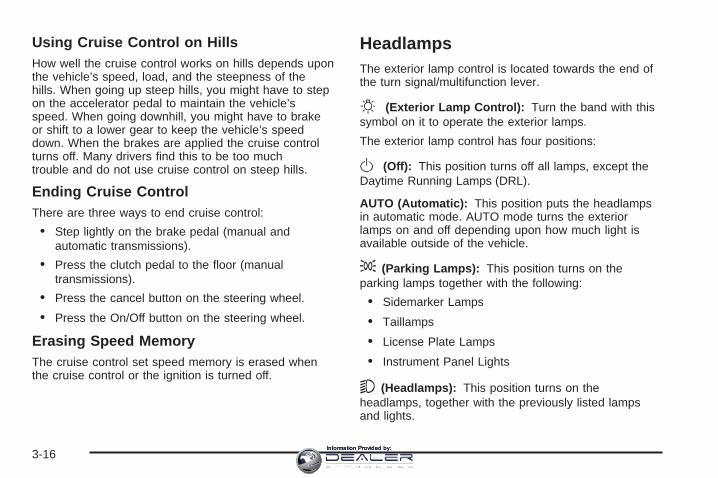
Using Cruise Control on HillsHow well the cruise control works on hills depends uponthe vehicle’s speed, load, and the steepness of thehills. When going up steep hills, you might have to stepon the accelerator pedal to maintain the vehicle’sspeed. When going downhill, you might have to brakeor shift to a lower gear to keep the vehicle’s speeddown. When the brakes are applied the cruise controlturns off. Many drivers find this to be too muchtrouble and do not use cruise control on steep hills.
Ending Cruise ControlThere are three ways to end cruise control:
• Step lightly on the brake pedal (manual andautomatic transmissions).
• Press the clutch pedal to the floor (manualtransmissions).
• Press the cancel button on the steering wheel.
• Press the On/Off button on the steering wheel.
Erasing Speed MemoryThe cruise control set speed memory is erased whenthe cruise control or the ignition is turned off.
HeadlampsThe exterior lamp control is located towards the end ofthe turn signal/multifunction lever.
O (Exterior Lamp Control): Turn the band with thissymbol on it to operate the exterior lamps.
The exterior lamp control has four positions:
O (Off): This position turns off all lamps, except theDaytime Running Lamps (DRL).
AUTO (Automatic): This position puts the headlampsin automatic mode. AUTO mode turns the exteriorlamps on and off depending upon how much light isavailable outside of the vehicle.
; (Parking Lamps): This position turns on theparking lamps together with the following:
• Sidemarker Lamps
• Taillamps
• License Plate Lamps
• Instrument Panel Lights
5 (Headlamps): This position turns on theheadlamps, together with the previously listed lampsand lights.
3-16Information Provided by:

Wiper Activated HeadlampsThis feature activates the headlamps and parking lampsafter the windshield wipers have been in use forabout six seconds. For this feature to work, the exteriorlamp control must be in AUTO.
The wiper-activated headlamps immediately turn off,when the ignition is turned to LOCK/OFF or thewindshield wiper control is turned off.
Headlamps on ReminderA warning chime will sound if the exterior lamp controlis left on in either the headlamp or parking lamp positionand the driver’s door is opened with the ignition off.See Lights On Reminder on page 3-46 for additionalinformation.
Daytime Running Lamps (DRL)Daytime Running Lamps (DRL) can make it easier forothers to see the front of your vehicle during theday. DRL can be helpful in many different drivingconditions, but they can be especially helpful in the shortperiods after dawn and before sunset. Fully functionaldaytime running lamps are required on all vehiclesfirst sold in Canada.
The DRL system will make either the reduced intensitylow-beam headlamps or dedicated DRL’s come onwhen the following conditions are met:
• It is still daylight and the ignition is in ON/RUNor START.
• The exterior lamp control is in off or AUTO and theheadlamps are off.
• The automatic transmission is not in PARK (P).
When DRL’s are on, only the reduced intensitylow-beam headlamps or dedicated DRL’s will be on. Noother exterior lamps will be on. The instrument panelcluster will not be lit up either.
When the exterior lamp control is in AUTO and it is darkenough outside, the DRL turns off and the low-beamheadlamps will turn on. When it is bright enough outside,the low-beam headlamps will go off, and the DRL willturn back on. If the vehicle is started in a dark garage,the automatic headlamp system comes on immediately.Once the vehicle leaves the garage, it takes aboutone minute for the automatic headlamp systemto change to DRL if it is light outside. During that delay,the instrument panel cluster may not be as bright asusual. Make sure the instrument panel brightness leveris in the full bright position. See Instrument PanelBrightness on page 3-19.
3-17Information Provided by:

Turning the exterior lamp control to off or to thelow-beam headlamp position will turn off the DRL. If theparking lamps or the fog lamps were turned oninstead, the DRL will still turn off.
This will work regardless of gear position and whetheror not the parking brake is set.
Light Sensor
The light sensor for the DRL and AUTO headlampfeature is located on top of the instrument panel. If thesensor is covered, it will prevent it from sensinglight, and the exterior lamps or the HeadlampsSuggested message will appear on the DIC wheneverthe ignition is on.
Adaptive Forward Lighting SystemThe Adaptive Forward Lighting System (AFL) swivelsthe headlamps horizontally to provide greater roadillumination while turning. AFL will operate whenthe vehicle speed is greater than 2 mph (3 km/h).AFL will not operate when the transmission is inREVERSE (R). AFL is not immediately operable afterstarting the vehicle; driving a short distance is requiredto calibrate the AFL. To enable AFL, set the exteriorlamp switch on the multifunction lever to the AUTOposition. Moving the switch out of the AUTO position willdeactivate the system. See Headlamps on page 3-16.
Fog LampsUse the fog lamps for better vision in foggy or mistyconditions.The fog lamp control is located on the turnsignal/multifunction lever.
- (Fog Lamps): Turn the fog lamp band on the leverup to - and release it, to turn the fog lamps on oroff. The band will return to its original position.The parking lamps must be on for the fog lamps to work.If the high-beam headlamps are turned on, the foglamps will also turn off. They will turn back on againwhen you switch back to low-beam headlamps.Some localities have laws that require the headlamps tobe on along with the fog lamps.
3-18Information Provided by:

Exterior Lighting Battery SaverThe exterior lamps turn off about 10 minutes after theignition is turned to LOCK/OFF, if the parking lampsor headlamps have been left on. This protects againstdraining the battery. The battery saver does notwork if the headlamps are turned on after the ignitionis turned to LOCK/OFF.
To keep the lamps on for more than 10 minutes, turnthe lamps back on with the exterior lamp control.
Instrument Panel Brightness
The knob with this symbolon it is located on theinstrument panel to the leftof the steering column.
Turn the knob clockwise to brighten the lights orcounterclockwise to dim them.
Turn the knob completely clockwise to turn on theinterior lamps.
Entry LightingThe entry lighting system turns on the reading anddome lamps and the backlighting to the exterior lampcontrol, when a door is opened or if the transmitterunlock button is pressed. If activated by the transmitter,the lighting stays on for about 25 seconds. The entrylighting system uses the light sensor on the instrumentpanel; so it must be dark outside in order for thelamps to turn on. The lamps turn off about 25 secondsafter the last door is closed. They dim then turn offif the ignition key is turned to ON/RUN. Theyimmediately turn off if the power locks are used.
Parade DimmingThis feature does not let the instrument panel backlightdim during daylight hours while the key is in theignition and the headlamps are on. Parade dimmingautomatically works with the light sensor, located on topof the dashboard. If it is dark enough outside and theparking lamps are on, the backlight on the instrumentpanel can be adjusted by turning the instrumentpanel brightness knob clockwise or counterclockwise tobrighten or dim the lighting. See Instrument PanelBrightness on page 3-19.
3-19Information Provided by:
Reading LampsThe reading lamps are located on the overhead console.These lamps come on automatically when any door isopened.
For manual operation, press the button next to eachlamp to turn it on or off.
If the reading lamps are left on, they automatically shutoff 10 minutes after the ignition has been turned off.
Electric Power ManagementThe vehicle has Electric Power Management (EPM) thatestimates the battery’s temperature and state ofcharge. It then adjusts the voltage for best performanceand extended life of the battery.
When the battery’s state of charge is low, the voltage israised slightly to quickly put the charge back in. Whenthe state of charge is high, the voltage is lowered slightlyto prevent overcharging. If the vehicle has a voltmetergage or a voltage display on the Driver InformationCenter (DIC), you may see the voltage move upor down. This is normal. If there is a problem, an alertwill be displayed.
The battery can be discharged at idle if the electricalloads are very high. This is true for all vehicles. This isbecause the generator (alternator) may not bespinning fast enough at idle to produce all the powerthat is needed for very high electrical loads.
A high electrical load occurs when several of thefollowing loads are on: headlamps, high beams, foglamps, rear window defogger, climate control fan at highspeed, heated seats, engine cooling fans, trailerloads, and loads plugged into accessory power outlets.
EPM works to prevent excessive discharge of thebattery. It does this by balancing the generator’s outputand the vehicle’s electrical needs. It can increaseengine idle speed to generate more power, wheneverneeded. It can temporarily reduce the power demands ofsome accessories.
Normally, these actions occur in steps or levels, withoutbeing noticeable. In rare cases at the highest levelsof corrective action, this action may be noticeable to thedriver. If so, a Driver Information Center (DIC)message might be displayed, such as Battery SaverActive or Service Battery Charging System. If thismessage is displayed, it is recommended that the driverreduce the electrical loads as much as possible. SeeDIC Warnings and Messages on page 3-54.
3-20Information Provided by:

Battery Run-Down ProtectionYour vehicle has a feature to help prevent battery drainif accessory lamps are left on or something is leftplugged into the accessory power outlet or cigarettelighter, if the vehicle has one. If accessory lamps suchas the vanity mirror, cargo, reading, console, orglove box are left on, they automatically time-out afterabout 20 minutes. To reset the battery protection,all of the above lamps must be turned off or the ignitionmust be in the ACC/ACCESSORY position.
Accessory Power Outlet(s)Accessory power outlets can be used to connectauxiliary electrical equipment, such as a cellulartelephone or CB radio.
There are three accessory power outlets. There is anoutlet located in the front storage area below the climatecontrol system, one inside the center console storagebin, and one on the rear of the center console.
To use an outlet, remove the protective cap. When not inuse, always cover the outlet with the protective cap. Theaccessory power outlet is operational at all times.
Notice: If electrical devices are left plugged into apower outlet, the battery may drain causing yourvehicle not to start or damage to the battery.This would not be covered by the warranty. Alwaysunplug all electrical devices when turning offyour vehicle.
Certain electrical accessories may not be compatiblewith the accessory power outlet and could resultin blown vehicle or adapter fuses. If you experience aproblem see your dealer/retailer for additionalinformation on accessory power outlets.
Notice: Adding any electrical equipment to yourvehicle may damage it or keep other componentsfrom working as they should. The repairs would notbe covered by your warranty. Do not use equipmentexceeding maximum amperage rating of 20 amperes.Check with your dealer/retailer before addingelectrical equipment.
Notice: Improper use of the power outlet can causedamage not covered by your warranty. Do nothang any type of accessory or accessory bracketfrom the plug because the power outlets aredesigned for accessory power plugs only.
3-21Information Provided by:

Ashtray(s) and Cigarette LighterYour vehicle may have two removable ashtrays andcigarette lighters. One ashtray can be placed intothe instrument panel storage compartment and the otherinto the center console rear compartment. To use thelighter, push it in all the way and let go. When it is ready,it will pop back out by itself.
To empty the ashtrays, grip the edges of the bin andpull it straight out of the housing. To reinstall, push thetray back into place.
Notice: Holding a cigarette lighter in while it isheating does not let the lighter back away from theheating element when it is hot. Damage fromoverheating can occur to the lighter or heatingelement, or a fuse could be blown. Do not hold acigarette lighter in while it is heating.
Notice: If you put papers, pins, or other flammableitems in the ashtray, hot cigarettes or othersmoking materials could ignite them and possiblydamage your vehicle. Never put flammable items inthe ashtray.
Analog ClockThe analog clock is located on the instrument panelabove the radio. The clock is not connected withany other vehicle system and runs by itself. To adjustthe clock:
1. Locate the adjustment buttons directly below theclock face.
2. Push and hold the right adjustment button to movethe clock hands forward or the left adjustmentbutton to make the clock hands go backward.Holding either button down will cause the clock toadvance faster. Release the button before thedesired time is reached.
3. Push and release either button to adjust the time byone minute increments until the desired time isreached.
3-22Information Provided by:

Climate Controls
Dual Climate Control SystemThe heating, cooling, and ventilation for the vehicle canbe controlled with this system.
O (Power): Press this button to turn the climatecontrol system on or off. When the climate controlsystem is turned off the air inlet defaults to outside air.
Automatic Operation
AUTO (Automatic): When this button is pressed andthe temperature is set, the system automatically controlsthe inside temperature, the air delivery mode, the airconditioning compressor, and the fan speed. When theindicator light is on, the system is in full automaticoperation. If the air delivery mode or fan setting ismanually adjusted, the auto indicator turns off anddisplays will show the selected settings.
1. Press the AUTO button.
2. Adjust the temperature to a comfortable settingbetween 60°F (15.5°C) and 90°F (32.2°C).Choosing the coldest or warmest temperature settingwill not cause the system to heat or cool any faster. Ifthe system is set at the warmest temperature setting,it remains in manual mode at that temperature and itwill not go into automatic mode.In cold weather, the system starts at reduced fanspeeds to avoid blowing cold air into the vehicle untilwarmer air is available. The system beginsblowing air at the floor but may change modesautomatically as the vehicle warms up to maintainthe chosen temperature setting. The length oftime the system needs to warm up depends on theoutside temperature and the length of time thathas elapsed since the vehicle was last driven.
3-23Information Provided by:

3. Wait for the system to regulate. This may take from10 to 30 minutes. Then adjust the temperature, ifnecessary.
You can switch from English to metric units through theDriver Information Center (DIC). See DIC VehicleCustomization on page 3-68.
The air-conditioning system removes moisture from theair, so a small amount of water might drip underneaththe vehicle while it is idling or after the engine is turnedoff is normal.
Do not cover the solar sensor located in the center ofthe instrument panel, near the windshield. For moreinformation on the solar sensor, see “Sensors” later inthis section.
PASS (Passenger Climate Control): Press this buttonto set a different temperature for the passenger.Then press the passenger temperature adjustmentbuttons to select a comfortable setting.
Pressing the PASS button again automatically sets thepassenger’s temperature to the driver’s setting.
Turning the passenger’s temperature display off doesnot shut the climate control system for the passenger off.
Q / R (Temperature Adjustment): The temperaturecan be adjusted separately for the driver and thepassenger. Press the up or down arrow buttons toincrease or decrease the automatic temperature settings.
Manual Operation
HG (Mode): Press the H or G buttons to change thecurrent airflow mode. The current mode selectionappears in the display screen. Changing the modecancels the automatic operation and the system goesinto manual mode. Press AUTO to return to automaticoperation.
The outboard air outlets always receive some airflow inevery mode, except defrost. See Outlet Adjustmenton page 3-27 to change this airflow from the outboardoutlets.
Y (Vent): This mode directs air to the instrumentpanel outlets.
\ (Bi-Level): This mode splits the air between theinstrument panel outlets and the floor outlets. Inautomatic operation, cooler air is directed to the upperoutlets and warmer air to the floor outlets.
[ (Floor): This mode directs most of the air to thefloor outlets with some air directed to the outboardoutlets and a little air directed to the windshield.
The mode buttons can also be used to select the defogand defrost modes. Information on defogging anddefrosting can be found later in this section.
3-24Information Provided by:

DC (Fan): Press the D or C buttons to increase ordecrease the fan speed. Pressing either button cancelsautomatic operation and the system goes into manualmode. Press AUTO to return to automatic operation. Theblower may reduce during an Onstar® session to limitbackground noise.
If the airflow seems low when the fan speed is at thehighest setting, the passenger compartment airfilter might need to be replaced. For more information,see Passenger Compartment Air Filter on page 3-28 andScheduled Maintenance on page 6-4.
# (Air Conditioning): Press this button to overridethe automatic system and turn the air conditioningsystem on or off. When in AUTO, the air conditioningcompressor will come on automatically, as necessary.
The air conditioning system removes moisture fromthe air, so a small amount of water might dripunderneath the vehicle while idling or after turning offthe engine. This is normal.
M / F (Recirculation/Outside Air): Press thisbutton to switch between recirculation and outside air.Whenever the button is pressed, the indicator light comeson for the mode being used. The recirculation moderecirculates air inside the vehicle. It can be used toprevent outside air and odors from entering the vehicle orto help cool the air inside the vehicle more quickly. Pressthe auto button to have the system select the best airdelivery mode for your temperature setting.
Recirculation is not available in the defrost mode andautomatically turns off 10 minutes after defog is selected.This helps to limit window fogging in the vehicle.
Using recirculation for long periods of time could causethe air inside the vehicle to become too dry or stuffy. Toprevent this from happening, after the air in the vehiclehas cooled, select outside air or press the auto button.
The outside air mode pulls fresh air from outside thevehicle. Outside air is always selected in defrost mode toprevent fogging.
_ (Heated Windshield Washer, If Equipped): Formore information, see Windshield Washer on page 3-11.
3-25Information Provided by:

Defogging and DefrostingFog on the inside of windows is a result of high humidity(moisture) condensing on the cool window glass. Thiscan be minimized if the climate control system isused properly. There are two modes to clear fog fromthe windshield. Use the defog mode to clear thewindows of fog or moisture and warm the passengers.Use the defrost mode to remove fog or frost fromthe windshield more quickly.
H G (Mode): Press the mode buttons until defogappears on the display.
- (Defog): This mode directs the air between thewindshield, floor outlets and side windows. Whenthis mode is selected, the system turns off recirculationand runs the air-conditioning compressor unless theoutside temperature is at or below freezing. Ifrecirculation mode is selected while in defog mode, itwill be cancelled after 10 minutes.
0 (Defrost): Pressing defrost directs most of the air tothe windshield, with some air directed to the sidewindows. In this mode, the system automatically turns offrecirculation and runs the air-conditioning compressor,unless the outside temperature is at or below freezing.
This mode may also cause the fan speed and airtemperature to increase.
Rear Window DefoggerThe rear window defogger uses a warming grid toremove fog or frost from the rear window.
The rear window defogger will only work when theignition is in ON/RUN.
= (Rear Window Defogger): Press this button toturn the rear window defogger on or off. Be sure to clearas much snow from the rear window as possible.
The rear window defogger turns off about 15 minutesafter the button is first pressed if the vehicle is moving atslower speeds. At higher speeds, the rear windowdefogger may stay on continuously. With each additionalpress, the defogger runs for about 10 minutes. Thedefogger can also be turned off by pressing the buttonagain or by turning off the engine.
The heated outside rearview mirrors will heat to helpclear fog or frost from the surface of the mirror when therear window defogger button is on. See OutsideHeated Mirrors on page 2-50.
Notice: Do not try to clear frost or other materialfrom the inside of the front windshield and rearwindow with a razor blade or anything else that issharp. This may damage the rear window defoggergrid and affect your radio’s ability to pick upstations clearly. The repairs wouldn’t be covered byyour warranty.
3-26Information Provided by:

Sensors
There is a solar sensor, located on the instrumentpanel, near the windshield.
There is also an interiortemperature sensor,located to the right of thesteering wheel, on theinstrument panel.
By monitoring the solar radiation and the air inside thevehicle, these sensors help maintain the selectedtemperature by adjusting the fan speed, and the airdelivery system. In order to do this, the system can alsosupply cooler air to the side of the vehicle facing thesun. The recirculation mode will also be activated,as necessary. Do not cover the sensors or the automaticclimate control system will not work properly.
Outlet AdjustmentUse the air outlets located in the center and on the sideof the instrument panel to direct the airflow. Use thethumbwheels near the air outlets to open or close off theairflow.
Operation Tips• Clear away any ice, snow, or leaves from air inlets
at the base of the windshield that could block theflow of air into the vehicle.
• Keep the path under the front seats clear of objectsto help circulate the air inside of the vehicle moreeffectively.
• Use of non-GM approved hood deflectors canadversely affect the performance of the system.Check with your dealer/retailer before addingequipment to the outside of your vehicle.
3-27Information Provided by:

Passenger Compartment Air FilterThe passenger compartment air filter traps most of thedust and pollen from the air entering the vehicle.The filter will need to be changed periodically. SeeScheduled Maintenance on page 6-4.
Using the climate control system without the passengerair filter installed could let water or other debris enter thesystem. This could cause a water leak or noises. Makesure to install a new air filter after removing the old one.
The passenger compartment air filter is locatedunderneath the hood below the windshield wiper armand the screen on the passenger side of the vehicle.See Engine Compartment Overview on page 5-14for more information on location.
To replace the passenger compartment air filter:
1. Turn the ignition to ON/RUN with the engine off.
2. Turn on the windshield wipers and turn themoff again when the wipers are straight up onthe windshield.This allows access to the leaf screen. Thepassenger compartment air filter is located underthe screen.
3. Open the hood to access the engine compartment.See Hood Release on page 5-13 for moreinformation.
4. Remove the three screws that hold the screen inplace and lift off the screen by lifting and sliding ittoward the center of the vehicle.
5. Pull out on the two tabs located on each end of thefilter cover.
6. Lift the filter cover off by pulling it straight up.
7. Remove the old filter and insert a new one.See Maintenance Replacement Parts on page 6-13for the correct part number for the filter.
8. Reverse Steps 1 through 6 to reinstall the cover.
3-28Information Provided by:

Warning Lights, Gages, andIndicatorsThis part describes the warning lights and gages thatmay be on your vehicle. The pictures will help youlocate them.
Warning lights and gages can signal that something iswrong before it becomes serious enough to causean expensive repair or replacement. Paying attention tothe warning lights and gages could also save you orothers from injury.
Warning lights come on when there may be or is aproblem with one of your vehicle’s functions. As you willsee in the details on the next few pages, somewarning lights come on briefly when you start theengine just to let you know they are working. If you arefamiliar with this section, you should not be alarmedwhen this happens.
Gages can indicate when there may be or is a problemwith one of your vehicle’s functions. Often gagesand warning lights work together to let you know whenthere is a problem with your vehicle.
When one of the warning lights comes on and stays onwhile you are driving, or when one of the gages showsthere may be a problem, check the section that tellsyou what to do about it. Waiting to do repairs can becostly – and even dangerous. So please get to know yourwarning lights and gages. They are a big help.
Your vehicle also has a Driver Information Center (DIC)that works along with the warning lights and gages.See Driver Information Center (DIC) on page 3-47 formore information.
3-29Information Provided by:

Instrument Panel ClusterThe instrument panel cluster is designed to let you know at a glance how your vehicle is running. You will know howfast you are going, how much fuel you are using and many of the other things you will need to know to drive safelyand economically.
United States Automatic Cluster shown, Canada similar
3-30Information Provided by:

Speedometer and OdometerThe speedometer lets you see your speed in eithermiles per hour (mph) or kilometers per hour (km/h). Theodometer shows how far your vehicle has beendriven, in either miles (used in the United States) orkilometers (used in Canada).
If your vehicle has to have a new odometer installed,the new one may read the correct mileage. This isbecause your vehicle’s computer has stored the mileagein memory.
While the Driver Shift Control (DSC) feature is active,the odometer will change to show the gear range.See Automatic Transmission Operation on page 2-37 formore information.
Trip OdometersThe trip odometer can record the number of miles orkilometers traveled for up to two trips.
The trip odometer is part of the Driver InformationCenter (DIC), for more information see DIC Operationand Displays on page 3-48.
For vehicles that have the navigation system, see yourNavigation System manual for more information.
Tachometer
The tachometerdisplays the enginespeed in revolutionsper minute (rpm).
Notice: If you operate the engine with thetachometer in the shaded warning area, your vehiclecould be damaged, and the damages would notbe covered by your warranty. Do not operatethe engine with the tachometer in the shadedwarning area.
3-31Information Provided by:

Engine Speed LimiterThis feature prevents the engine from operating at toomany revolutions per minute (rpm). When the engine’srpms are too high, the throttle is closed to reducespeed. If this is not sufficient, then the fuel supply to theengine will be limited. When the rpms return tonormal, the fuel supply will return to normal. This helpsprevent damage to the engine.
Safety Belt Reminders
Safety Belt Reminder LightWhen the engine is started, a chime will come on forseveral seconds to remind people to fasten their safetybelts, unless the driver’s safety belt is already buckled.
The safety belt light willalso come on and stay onfor several seconds, then itwill flash for several more.
This chime and light is repeated if the driver remainsunbuckled and the vehicle is in motion. If the driver’s beltis already buckled, neither the chime nor the light willcome on.
Passenger Safety Belt Reminder LightSeveral seconds after the engine is started, a chimewill sound for several seconds to remind the frontpassenger to buckle their safety belt. This would onlyoccur if the passenger airbag is enabled. See PassengerSensing System on page 1-64 for more information.The passenger safety belt light, located on theinstrument panel, will come on and stay on for severalseconds and then flash for several more.
This chime and light arerepeated if the passengerremains unbuckled andthe vehicle is in motion.
If the passenger’s safety belt is buckled, neither thechime nor the light will come on.
3-32Information Provided by:

Airbag Readiness LightThere is an airbag readiness light on the instrumentpanel cluster, which shows the airbag symbol. Thesystem checks the airbag’s electrical system formalfunctions. The light tells you if there is an electricalproblem. The system check includes the airbagsensor, the pretensioners, the airbag modules, thewiring and the crash sensing and diagnostic module.For more information on the airbag system, see AirbagSystem on page 1-55.
This light will come onwhen you start yourvehicle, and it will flash fora few seconds. Thelight should go out and thesystem is ready.
If the airbag readiness light stays on after you start thevehicle or comes on when you are driving, yourairbag system may not work properly. Have your vehicleserviced right away.
{CAUTION:
If the airbag readiness light stays on after youstart your vehicle, it means the airbag systemmay not be working properly. The airbags inyour vehicle may not inflate in a crash, or theycould even inflate without a crash. To helpavoid injury to yourself or others, have yourvehicle serviced right away if the airbagreadiness light stays on after you start yourvehicle.
The airbag readiness light should flash for afew seconds when you start the engine. If the light doesnot come on then, have it fixed immediately. If thereis a problem with the airbag system, an airbag DriverInformation Center (DIC) message may also comeon. See DIC Warnings and Messages on page 3-54 formore information.
3-33Information Provided by:

Passenger Airbag Status IndicatorYour vehicle has the passenger sensing system.Your instrument panel has a passenger airbag statusindicator.
When you start the vehicle, the passenger airbag statusindicator will light ON and OFF, or the symbol for onand off, for several seconds as a system check. If youuse remote start to start your vehicle from a distance,if equipped, you may not see the system check.Then, after several more seconds, the status indicatorwill light either ON or OFF, or either the on or off symbolto let you know the status of the right front passenger’sfrontal and seat-mounted side impact airbags.
If the word ON or the on symbol is lit on the passengerairbag status indicator, it means that the right frontpassenger’s frontal airbag and seat-mounted side impactairbag are enabled (may inflate).
{CAUTION:
If the on indicator comes on when you have arear-facing child restraint installed in the rightfront passenger’s seat, it means that thepassenger sensing system has not turned offthe passenger’s frontal airbag andseat-mounted side impact airbag (if equipped).A child in a rear-facing child restraint can beseriously injured or killed if the right frontpassenger’s airbag inflates. This is because theback of the rear-facing child restraint would bevery close to the inflating airbag. Do not use arear-facing child restraint in the right frontpassenger’s seat if the airbag is turned on.
United States Canada
3-34Information Provided by:

{CAUTION:
Even though the passenger sensing system isdesigned to turn off the right front passenger’sfrontal airbag and seat-mounted side impactairbag (if equipped) if the system detects arear-facing child restraint, no system isfail-safe, and no one can guarantee that anairbag will not deploy under some unusualcircumstance, even though it is turned off. Werecommend that rear-facing child restraints besecured in a rear seat, even if the airbag is orairbags are off.
If the word OFF or the off symbol is lit on the passengerairbag status indicator, it means that the passengersensing system has turned off the right front passenger’sfrontal airbag and seat-mounted side impact airbag.See Passenger Sensing System on page 1-64 for moreon this, including important safety information.
If, after several seconds, both status indicator lightsremain on, or if there are no lights at all, there may be aproblem with the lights or the passenger sensingsystem. See your dealer/retailer for service.
{CAUTION:
If the airbag readiness light in the instrumentpanel cluster ever comes on and stays on, itmeans that something may be wrong with theairbag system. If this ever happens, have thevehicle serviced promptly, because anadult-size person sitting in the right frontpassenger’s seat may not have the protectionof the airbag(s). See Airbag Readiness Lighton page 3-33 for more on this, includingimportant safety information.
3-35Information Provided by:
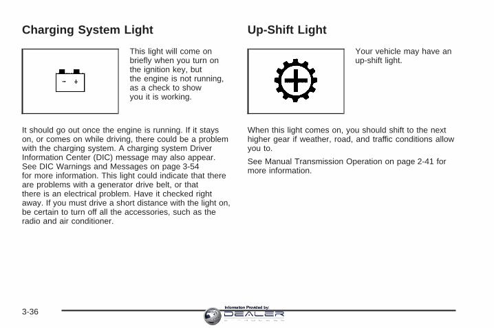
Charging System Light
This light will come onbriefly when you turn onthe ignition key, butthe engine is not running,as a check to showyou it is working.
It should go out once the engine is running. If it stayson, or comes on while driving, there could be a problemwith the charging system. A charging system DriverInformation Center (DIC) message may also appear.See DIC Warnings and Messages on page 3-54for more information. This light could indicate that thereare problems with a generator drive belt, or thatthere is an electrical problem. Have it checked rightaway. If you must drive a short distance with the light on,be certain to turn off all the accessories, such as theradio and air conditioner.
Up-Shift Light
Your vehicle may have anup-shift light.
When this light comes on, you should shift to the nexthigher gear if weather, road, and traffic conditions allowyou to.
See Manual Transmission Operation on page 2-41 formore information.
3-36Information Provided by:

Brake System Warning LightYour vehicle’s hydraulic brake system is divided intotwo parts. If one part is not working, the other part canstill work and stop you. For good braking, though,you need both parts working well.
If the warning light comes on, there is a brake problem.Have your brake system inspected right away.
This light should come on briefly when you turn theignition to ON/RUN. If it does not come on then, have itfixed so it will be ready to warn you if there is aproblem.
When the ignition is on, the brake system warning lightwill also come on when you set your parking brake.The light will stay on if your parking brake doesnot release fully. If it stays on after your parking brake isfully released, it means you have a brake problem.
If the light comes on while you are driving, pull off theroad and stop carefully. You may notice that the pedal isharder to push, or the pedal may go closer to thefloor. It may take longer to stop. If the light is still on,have the vehicle towed for service. See TowingYour Vehicle on page 4-27.
{CAUTION:
Your brake system may not be workingproperly if the brake system warning light ison. Driving with the brake system warning lighton can lead to an accident. If the light is stillon after you have pulled off the road andstopped carefully, have the vehicle towed forservice.
United States Canada
3-37Information Provided by:

Antilock Brake SystemWarning Light
For vehicles with theAntilock Brake System(ABS), this light comes onbriefly when the engineis started.
That is normal. If the light does not come on then, haveit fixed so it will be ready to warn you if there is aproblem.
If the ABS light stays on, turn the ignition off, if the lightcomes on when you are driving, stop as soon as it issafely possible and turn the ignition off. Then start theengine again to reset the system. If the ABS light stillstays on, or comes on again while you are driving, yourvehicle needs service. If the regular brake systemwarning light is not on, your vehicle still has brakes, butnot antilock brakes. If the regular brake system warninglight is also on, your vehicle does not have antilockbrakes and there is a problem with the regular brakes.See Brake System Warning Light on page 3-37.
For vehicles with a Driver Information Center (DIC), seeDIC Warnings and Messages on page 3-54 for allbrake related DIC messages.
Traction Control System (TCS)/StabiliTrak ® Warning Light
The Traction ControlSystem/StabiliTrak®
warning light should comeon briefly when theengine is started.
If the warning light does not come on then, have it fixedso it will be ready to warn you if there is a problem. Ifit stays on, or comes on when you are driving, there maybe a problem with your Traction Control System(TCS)/StabiliTrak® and your vehicle may need service.When this warning light is on, the system will notlimit wheel spin. Adjust your driving accordingly.
If the traction control system warning light comes onand stays on for an extended period of time when thesystem is turned on, your vehicle needs service.See Traction Control System (TCS) on page 4-6 andStabiliTrak® System on page 4-8 for more information.
3-38Information Provided by:

Engine Coolant TemperatureWarning Light
This light will come onwhen you first start thevehicle as a checkto let you know that thelight is working.
It will go out after a few seconds. If the light does notcome on, see your dealer/retailer.
If the light does not go out or if the light comes on andstays on while you are driving, your vehicle mayhave a problem with the cooling system. You shouldstop the vehicle and turn off the engine as soonas possible to avoid damage to the engine. A warningchime will also sound when this light is on.
See Engine Overheating on page 5-30 for moreinformation.
Engine Coolant Temperature Gage
This gage shows the engine coolant temperature. If theengine coolant overheats the engine coolanttemperature warning light will come on. See EngineOverheating on page 5-30 and Engine CoolantTemperature Warning Light on page 3-39 for moreinformation.
United States Canada
3-39Information Provided by:

Tire Pressure Light
Your vehicle has a tirepressure light.
This light comes on briefly when the engine is startedand provides information about tire pressures andthe Tire Pressure Monitoring System.
When the Light is SolidThis indicates that one or more of your tires aresignificantly underinflated.
A tire pressure message in the Driver InformationCenter (DIC), may accompany the light. See DICWarnings and Messages on page 3-54 for moreinformation. Stop and check your tires as soon as it issafe to do so. If underinflated, inflate to the properpressure. See Tires on page 5-59 for more information.
When the Light Flashes First and Then isSolidThis indicates that there may be a problem with the TirePressure Monitor System. The light flashes for abouta minute and stays on solid for the remainder ofthe ignition cycle. This sequence will repeat with everyignition cycle. See Tire Pressure Monitor System onpage 5-70 for more information.
Malfunction Indicator Lamp
Check Engine LightA computer system called OBD II (On-BoardDiagnostics-Second Generation) monitors operation ofthe fuel, ignition, and emission control systems. It makessure that emissions are at acceptable levels for thelife of the vehicle, helping to produce a cleanerenvironment.
The check engine lightcomes on to indicate thatthere is an OBD IIproblem and service isrequired.
3-40Information Provided by:

Malfunctions often are indicated by the system beforeany problem is apparent. This can prevent more seriousdamage to your vehicle. This system is also designedto assist your service technician in correctly diagnosingany malfunction.
Notice: If you keep driving your vehicle with thislight on, after a while, the emission controlsmight not work as well, your vehicle’s fuel economymight not be as good, and the engine might notrun as smoothly. This could lead to costly repairsthat might not be covered by your warranty.
Notice: Modifications made to the engine,transmission, exhaust, intake, or fuel system ofyour vehicle or the replacement of the original tireswith other than those of the same Tire PerformanceCriteria (TPC) can affect your vehicle’s emissioncontrols and can cause this light to come on.Modifications to these systems could lead to costlyrepairs not covered by your warranty. This couldalso result in a failure to pass a required EmissionInspection/Maintenance test. See Accessoriesand Modifications on page 5-3.
This light comes on, as a check to show it is working,when the ignition is turned ON/RUN but the engine is notrunning. If the light does not come on, have it repaired.This light also comes on during a malfunction inone of two ways:
• Light Flashing — A misfire condition has beendetected. A misfire increases vehicle emissionsand could damage the emission control system onyour vehicle. Diagnosis and service might berequired.
• Light On Steady — An emission control systemmalfunction has been detected on your vehicle.Diagnosis and service might be required.
3-41Information Provided by:

If the Light is FlashingThe following can prevent more serious damage to yourvehicle:
• Reduce vehicle speed.
• Avoid hard accelerations.
• Avoid steep uphill grades.
• If you are towing a trailer, reduce the amount ofcargo being hauled as soon as it is possible.
If the light stops flashing and remains on steady, see “Ifthe Light Is On Steady” following.
If the light continues to flash, when it is safe to do so,stop the vehicle. Find a safe place to park the vehicle.Turn the ignition off, wait at least 10 seconds, and restartthe engine. If the light remains on steady, see “If theLight Is On Steady” following. If the light is still flashing,follow the previous steps and see your dealer/retailerfor service as soon as possible.
If the Light Is On SteadyYou might be able to correct the emission systemmalfunction by considering the following:
Did you recently put fuel into your vehicle?
If so, reinstall the fuel cap, making sure to fully installthe cap. See Filling the Tank on page 5-8. Thediagnostic system can determine if the fuel cap has
been left off or improperly installed. A loose or missingfuel cap allows fuel to evaporate into the atmosphere.A few driving trips with the cap properly installed shouldturn the light off.
Did you just drive through a deep puddle of water?
If so, your vehicle’s electrical system might be wet. Thecondition is usually corrected when the electrical systemdries out. A few driving trips should turn the light off.
Have you recently changed brands of fuel?
If so, be sure to fuel your vehicle with quality fuel. SeeGasoline Octane on page 5-5. Poor fuel quality causesthe engine not to run as efficiently as designed. Youmight notice this as stalling after start-up, stalling whenyou put the vehicle into gear, misfiring, hesitation onacceleration, or stumbling on acceleration — theseconditions might go away once the engine is warmed up.This will be detected by the system and cause the light toturn on.
If you experience one or more of these conditions,change the fuel brand you use. It will require at leastone full tank of the proper fuel to turn the light off.
If none of the above steps have made the light turn off,your dealer/retailer can check the vehicle. Yourdealer/retailer has the proper test equipment anddiagnostic tools to fix any mechanical or electricalproblems that might have developed.
3-42Information Provided by:

Emissions Inspection and MaintenanceProgramsSome state/provincial and local governments have ormight begin programs to inspect the emission controlequipment on your vehicle. Failure to pass thisinspection could prevent you from getting a vehicleregistration.
Here are some things you need to know to help yourvehicle pass an inspection:
Your vehicle will not pass this inspection if the checkengine light is on or not working properly.
Your vehicle will not pass this inspection if the OBD(on-board diagnostic) system determines that criticalemission control systems have not been completelydiagnosed by the system. The vehicle would beconsidered not ready for inspection. This can happen ifyou have recently replaced the battery or if thebattery has run down. The diagnostic system isdesigned to evaluate critical emission control systemsduring normal driving. This can take several daysof routine driving. If you have done this and your vehiclestill does not pass the inspection for lack of OBDsystem readiness, your dealer/retailer can prepare thevehicle for inspection.
Oil Pressure Light
Your vehicle may have thisfeature.
If the vehicle has an oil problem, this light may stay onafter the engine is started, or come on while you aredriving.
This light indicates that oil is not going through theengine quickly enough to keep it lubricated. The enginecould be low on oil or could have some other oilproblem. Have it fixed right away.
3-43Information Provided by:

The oil light could also come on in the followingsituations:
• The light will come on briefly when the ignition isturned on to show that it is working properly. If itdoes not come on with the ignition on, there may bea problem with the fuse or bulb. Have it fixedright away.
• Sometimes when the engine is idling at a stop, achime will sound and the light may blink on andoff. This is normal.
{CAUTION:
Do not keep driving if the oil pressure is low. Ifyou do, your engine can become so hot that itcatches fire. You or others could be burned.Check your oil as soon as possible and haveyour vehicle serviced.
Notice: Lack of proper engine oil maintenance maydamage the engine. The repairs would not becovered by your warranty. Always follow themaintenance schedule in this manual for changingengine oil.
Engine Oil Pressure Gage
Your vehicle may have an engine oil pressure gage. Itshows the engine oil pressure in psi (pounds per squareinch) when the engine is running. Canadian vehiclesindicate pressure in kPa (kilopascals).
Oil pressure may vary with engine speed, outsidetemperature and oil viscosity, but if readings are outsidethe normal operating range, the oil pressure light willcome on. See Oil Pressure Light on page 3-43 for moreinformation.
United States Canada
3-44Information Provided by:

A reading outside the normal operating range may becaused by a dangerously low oil level or some otherproblem causing low oil pressure. Check your oilas soon as possible. See Oil pressure Low Stop Engineunder DIC Warnings and Messages on page 3-54and Engine Oil on page 5-16.
{CAUTION:
Do not keep driving if the oil pressure is low. Ifyou do, your engine can become so hot that itcatches fire. You or others could be burned.Check your oil as soon as possible and haveyour vehicle serviced.
Notice: Lack of proper engine oil maintenance maydamage the engine. The repairs would not becovered by your warranty. Always follow themaintenance schedule in this manual for changingengine oil.
Security Light
For information regardingthis light and the vehicle’ssecurity system, seeTheft-Deterrent System onpage 2-27.
Fog Lamp Light
The fog lamp light willcome on when the foglamps are in use.
The light will go out when the fog lamps are turned off.See Fog Lamps on page 3-18 for more information.
3-45Information Provided by:

Lights On Reminder
This light comes onwhenever the parkinglamps are on.
See Headlamps on Reminder on page 3-17 for moreinformation.
Cruise Control Light
This light comes onwhenever you set thecruise control.
The light goes out when the cruise control is turned off.See Cruise Control on page 3-13 for more information.
Highbeam On Light
This light comes on whenthe high-beam headlampsare in use.
See Headlamp High/Low-Beam Changer on page 3-8for more information.
Fuel Gage
The fuel gage showsapproximately how muchfuel is in the fuel tank.It works only whenthe ignition is in theON/RUN position.
3-46Information Provided by:

If the fuel supply gets low, the Fuel Level Low messagewill appear on the Driver Information Center (DIC)and a single chime will sound. See DIC Warnings andMessages on page 3-54 for more information.
Here are a few concerns some owners have had aboutthe fuel gage. All of these situations are normal anddo not indicate that anything is wrong with the fuel gage:
• At the gas station the gas pump shuts off beforethe gage reads full.
• The gage may change when you turn, stop quicklyor accelerate quickly.
• It takes a little more or less fuel to fill the tank thanthe gage indicated. For example, the gage mayhave indicated that the tank was half full, butit actually took a little more or less than half thetank’s capacity to fill the tank.
Driver Information Center (DIC)The Driver Information Center (DIC) gives you thestatus of many of your vehicle’s systems. The DIC isalso used to display warning/status messages. Allmessages appear in the DIC display located at thebottom of the instrument panel cluster. The DIC buttonsare located on the instrument panel, next to thesteering wheel.
The DIC comes on when the ignition is on. After a shortdelay, the DIC displays the information that was lastdisplayed before the engine was turned off.
The top line of the DIC display shows the DICinformation. The bottom line of the DIC display showsthe compass. The compass displays in the trip/fuelmenus and in some vehicle information menus.
If a problem is detected, a warning message appearson the display. Take any message that appears onthe display seriously and remember that clearingthe message only makes the message disappear, anddoes not correct the problem.
3-47Information Provided by:

DIC Operation and Displays
The Driver InformationCenter (DIC) has differentdisplays which can beaccessed by pressing theDIC buttons located onthe instrument panel, nextto the steering wheel.
3 Trip/Fuel: Press this button to scroll through thetrip and fuel displays. See “Trip/Fuel Display MenuItems” following for more information on these displays.
T Vehicle Information: Press this button to scrollthrough the vehicle information displays. See “VehicleInformation Display Menu Items” following for moreinformation on these displays.
U Customization: Press this button to scroll througheach of the customization features. See DIC VehicleCustomization on page 3-68 for more information on thecustomization features.
V Set/Reset: Press this button to reset certain DICfeatures and to acknowledge DIC warning messagesand clear them from the DIC display.
yz Menu Up/Down: Press this button to scroll upand down the menu items.
Trip/Fuel Display Menu Items
3 (Trip/Fuel): The following display menu itemscan be displayed by pressing the trip/fuel button:
OdometerThis display shows the distance the vehicle has beendriven in either miles (mi) or kilometers (km).
Trip A or Trip BThese displays show the current distance traveled sincethe last reset for each trip odometer in either miles (mi)or kilometers (km). Both odometers can be used atthe same time. Each trip odometer can be reset to zeroseparately by pressing and holding the set/resetbutton for a few seconds while the desired trip odometeris displayed.
3-48Information Provided by:

Fuel RangeThis display shows the approximate number ofremaining miles (mi) or kilometers (km) you can drivewithout refilling the fuel tank. This estimate is based onthe current driving conditions and changes if thedriving conditions change. For example, if you aredriving in traffic and making frequent stops, the displaymay read one number, but if you enter the freeway,the number may change even though you still have thesame amount of fuel in the fuel tank. This is becausedifferent driving conditions produce different fueleconomies. Generally, freeway driving produces betterfuel economy than city driving.
Once the range drops below about 30 miles (48 km)remaining, the display shows Low Range.
If your vehicle is low on fuel, the Fuel Level Lowmessage displays. See “Fuel Level Low” under DICWarnings and Messages on page 3-54 for moreinformation.
AVG (Average) EconomyThis display shows the approximate average miles pergallon (mpg) or liters per 100 kilometers (L/100 km).This number is calculated based on the numberof mpg (L/100 km) recorded since the last time thisdisplay was reset. To reset this display to zero, pressthe set/reset button.
TimerThis display can be used like a stopwatch. You canrecord the time it takes to travel from one point toanother. To access the timer, press the trip/fuel buttonuntil Timer 00:00:00 displays.
To turn on the timer, press the set/reset button until thetimer starts.
To turn off the timer, press the set/reset button again.The timer stops and displays the end timing value.
To reset the timer to zero, press and hold the set/resetbutton after the timer has been stopped.
Inst (Instantaneous) EconomyThis display shows the current fuel economy in eithermiles per gallon (mpg) or liters per 100 kilometers(L/100 km). This number reflects only the fuel economythat the vehicle has right now and changes frequentlyas driving conditions change. Unlike average economy,this display cannot be reset.
AVG (Average) SpeedThis display shows the average speed of the vehiclein either miles per hour (mph) or kilometers perhour (km/h). This average is calculated based on thevarious vehicle speeds recorded since the last reset ofthis display. To reset this display to zero, press theset/reset button.
3-49Information Provided by:
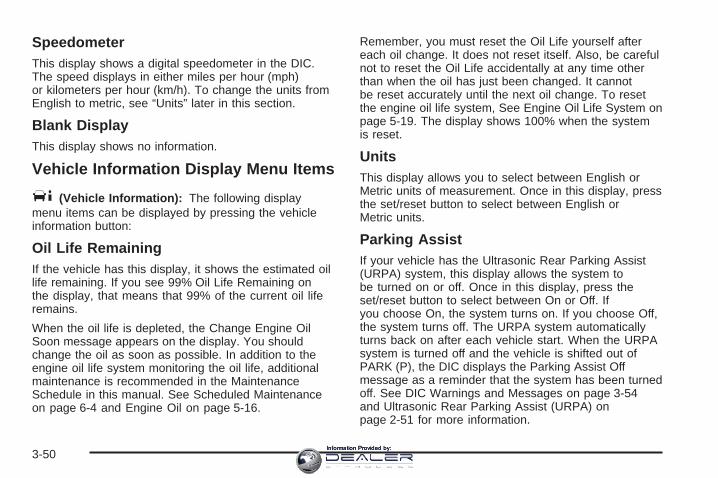
SpeedometerThis display shows a digital speedometer in the DIC.The speed displays in either miles per hour (mph)or kilometers per hour (km/h). To change the units fromEnglish to metric, see “Units” later in this section.
Blank DisplayThis display shows no information.
Vehicle Information Display Menu Items
T (Vehicle Information): The following displaymenu items can be displayed by pressing the vehicleinformation button:
Oil Life RemainingIf the vehicle has this display, it shows the estimated oillife remaining. If you see 99% Oil Life Remaining onthe display, that means that 99% of the current oil liferemains.
When the oil life is depleted, the Change Engine OilSoon message appears on the display. You shouldchange the oil as soon as possible. In addition to theengine oil life system monitoring the oil life, additionalmaintenance is recommended in the MaintenanceSchedule in this manual. See Scheduled Maintenanceon page 6-4 and Engine Oil on page 5-16.
Remember, you must reset the Oil Life yourself aftereach oil change. It does not reset itself. Also, be carefulnot to reset the Oil Life accidentally at any time otherthan when the oil has just been changed. It cannotbe reset accurately until the next oil change. To resetthe engine oil life system, See Engine Oil Life System onpage 5-19. The display shows 100% when the systemis reset.
UnitsThis display allows you to select between English orMetric units of measurement. Once in this display, pressthe set/reset button to select between English orMetric units.
Parking AssistIf your vehicle has the Ultrasonic Rear Parking Assist(URPA) system, this display allows the system tobe turned on or off. Once in this display, press theset/reset button to select between On or Off. Ifyou choose On, the system turns on. If you choose Off,the system turns off. The URPA system automaticallyturns back on after each vehicle start. When the URPAsystem is turned off and the vehicle is shifted out ofPARK (P), the DIC displays the Parking Assist Offmessage as a reminder that the system has been turnedoff. See DIC Warnings and Messages on page 3-54and Ultrasonic Rear Parking Assist (URPA) onpage 2-51 for more information.
3-50Information Provided by:

Tire PressureThe pressure for each tire can be viewed in the DIC.The tire pressure is shown in either pounds per squareinch (psi) or kilopascals (kPa). Press the vehicleinformation button until the DIC displays Front Tire PSI(kPa) Left ## Right ##. Press the vehicle informationbutton again until the DIC displays Rear Tire PSI (kPa)Left ## Right ##
If a low or high tire pressure condition is detected by thesystem while driving, a message advising you tocheck the pressure in a specific tire appears in thedisplay. See Inflation - Tire Pressure on page 5-67 andDIC Warnings and Messages on page 3-54 for moreinformation.
Battery VoltageThis display shows the current battery voltage. Yourvehicle’s charging system regulates voltage basedon the state of the battery. The battery voltage mayfluctuate when viewing this information on the DIC. Thisis normal.
If there is a problem with the battery charging system,the charging system light illuminates and/or the DICdisplays a message. See Charging System Lighton page 3-36, DIC Warnings and Messages onpage 3-54 and Electric Power Management onpage 3-20 for more information.
Calibrate CompassYour vehicle may have this feature. The compass canbe manually calibrated. To calibrate the compassthrough the DIC, see DIC Compass on page 3-52.
Change Compass ZoneYour vehicle may have this feature. To change thecompass zone through the DIC, see DIC Compass onpage 3-52.
Relearn Remote KeyIf your vehicle has the Remote Keyless Entry (RKE)system, this display allows you to match the transmitterto your vehicle. If your vehicle has the keyless accesssystem, see Keyless Access System Operation onpage 2-9 for instructions on matching a keyless accesstransmitter to your vehicle. To match an RKEtransmitter to your vehicle:
1. Press the vehicle information button until Press VTo Relearn Remote Key displays.
2. Press the set/reset button until Remote KeyLearning Active is displayed.
3-51Information Provided by:

3. Press and hold the lock and unlock buttons on thefirst transmitter at the same time for about15 seconds.On vehicles with memory recall seats, the firsttransmitter learned will match driver 1 andthe second will match driver 2.A chime sounds indicating that the transmitter ismatched.
4. To match additional transmitters at this time, repeatStep 3.Each vehicle can have a maximum of eighttransmitters matched to it.
5. To exit the programming mode, you must cycle thekey to LOCK/OFF.
Blank DisplayThis display shows no information.
DIC CompassYour vehicle may have a compass in the DriverInformation Center (DIC).
Compass ZoneThe zone is set to zone eight upon leaving the factory.Your dealer/retailer will set the correct zone for yourlocation.
Under certain circumstances, such as during a longdistance cross-country trip or moving to a new state orprovince, it will be necessary to compensate forcompass variance by resetting the zone through theDIC if the zone is not set correctly.
Compass variance is the difference between the earth’smagnetic north and true geographic north. If thecompass is not set to the zone where you live, thecompass may give false readings. The compass mustbe set to the variance zone in which the vehicle istraveling.
To adjust for compass variance, use the followingprocedure:
Compass Variance (Zone) Procedure1. Do not set the compass zone when the vehicle is
moving. On an automatic transmission vehicle, onlyset it when the vehicle is in PARK (P). On amanual transmission vehicle, only set it when thevehicle is stopped.
Press the vehicle information button until Press VTo Change Compass Zone displays.
3-52Information Provided by:

2. Find the vehicle’s current location and variancezone number on the map.Zones 1 through 15 are available.
3. Press the set/reset button to scroll through andselect the appropriate variance zone.
4. Press the trip/fuel button until the vehicle heading,for example, N for North, is displayed in the DIC.
5. Calibrate the compass. See “Compass CalibrationProcedure” following.
Compass CalibrationThe compass can be manually calibrated. Only calibratethe compass in a magnetically clean and safe location,such as an open parking lot, where driving the vehicle incircles is not a danger. It is suggested to calibrateaway from tall buildings, utility wires, manhole covers, orother industrial structures, if possible.
If CAL should ever appear in the DIC display, thecompass should be calibrated.
If the DIC display does not show a heading, for example,N for North, or the heading does not change aftermaking turns, there may be a strong magnetic fieldinterfering with the compass. Such interference may becaused by a magnetic CB or cell phone antennamount, a magnetic emergency light, magnetic note padholder, or any other magnetic item. Turn off thevehicle, move the magnetic item, then turn on thevehicle and calibrate the compass.
3-53Information Provided by:
To calibrate the compass, use the following procedure:
Compass Calibration Procedure1. Before calibrating the compass, make sure the
compass zone is set to the variance zone inwhich the vehicle is located. See “CompassVariance (Zone) Procedure” earlier in this section.Do not operate any switches such as window,sunroof, climate controls, seats, etc. duringthe calibration procedure.
2. Press the vehicle information button until Press VTo Calibrate Compass displays.
3. Press the set/reset button to start the compasscalibration.
4. The DIC will display Calibrating Drive In Circles.Drive the vehicle in tight circles at less than5 mph (8 km/h) to complete the calibration. The DICwill display Calibration Complete for a few secondswhen the calibration is complete. The DIC displaywill then return to Press V To Calibrate Compass.
DIC Warnings and MessagesMessages are displayed on the DIC to notify the driverthat the status of the vehicle has changed and thatsome action may be needed by the driver to correct thecondition. Multiple messages may appear one afteranother.
Some messages may not require immediate action, butyou can press any of the DIC buttons on the instrumentpanel to acknowledge that you received the messagesand to clear them from the display.
Some messages cannot be cleared from the DICdisplay because they are more urgent. These messagesrequire action before they can be cleared. You shouldtake any messages that appear on the display seriouslyand remember that clearing the messages will onlymake the messages disappear, not correct the problem.
The following are the possible messages that can bedisplayed and some information about them.
Accessory Mode ActiveIf your vehicle has the keyless access system, thismessage displays when the accessory mode is active.See Ignition Positions (Key Access) on page 2-31or Ignition Positions (Keyless Access) on page 2-33 formore information.
3-54Information Provided by:

AFL (Adaptive Forward Lighting)Lamps Need ServiceThis message displays when the Adaptive ForwardLighting (AFL) system is disabled and needs service.See your dealer/retailer. See Adaptive Forward LightingSystem on page 3-18 for more information.
All Wheel Drive OffIf your vehicle has the All-Wheel Drive (AWD) system,this message displays when there is a temporarycondition making the AWD system unavailable. Yourvehicle will run in 2WD. This could be caused by:
• Loss of wheel or vehicle speed
• AWD system overheat
• Certain vehicle electrical conditions
This message turns off when the above conditions areno longer present and by resetting the warningmessage.
To reset the warning message, turn the ignition off andthen back on again after 30 seconds. If the messagestays on, see your dealer/retailer right away. SeeAll-Wheel Drive (AWD) System on page 4-9 for moreinformation.
Automatic Light Control OffThis message displays when the automatic headlampsare turned off.
Automatic Light Control OnThis message displays when the automatic headlampsare turned on.
Battery Saver ActiveThis message displays when the system detects thatthe battery voltage is dropping below expectedlevels. The battery saver system starts reducing certainfeatures of the vehicle that you may be able to notice.At the point that the features are disabled, this messageis displayed. It means that the vehicle is trying tosave the charge in the battery.
Turn off all unnecessary accessories to allow the batteryto recharge.
The normal battery voltage range is 11.5 to 15.5 volts.You can monitor battery voltage on the DIC by pressingthe vehicle information button until Battery Voltage isdisplayed.
3-55Information Provided by:

Battery Volts LowThis message displays when the electrical system ischarging less than 10 volts or the battery has beendrained.
If this message appears immediately after starting theengine, it is possible that the generator can still rechargethe battery. The battery should recharge while driving,but may take a few hours to do so. Consider usingan auxiliary charger to boost the battery after returninghome or to a final destination. Make sure you followthe manufacturer’s instructions.
If this message appears while driving or after startingyour vehicle and stays on, have it checked immediatelyto determine the cause of this problem.
To help the generator recharge the battery quickly, youcan reduce the load on the electrical system byturning off the accessories.
The normal battery voltage range is 11.5 to 15.5 volts.You can monitor battery voltage on the DIC by pressingthe vehicle information button until Battery Voltage isdisplayed.
Calibrating Drive In CirclesThis message displays when calibrating the compass.Drive the vehicle in circles at less than 5 mph (8 km/h) tocomplete the calibration. See DIC Compass onpage 3-52 for more information.
Calibration CompleteThis message displays when the compass calibration iscomplete. See DIC Compass on page 3-52 for moreinformation.
Change Engine Oil SoonWhen this message displays, it means that service isrequired for your vehicle. See your dealer/retailer.See Engine Oil on page 5-16 and ScheduledMaintenance on page 6-4 for more information.
When you reset the Change Engine Oil Soon messageby clearing it from the display, you still must resetthe engine oil life system separately. For moreinformation on resetting the engine oil life system, seeEngine Oil Life System on page 5-19.
3-56Information Provided by:

Check Tire PressureThis message displays when the pressure in one or moreof the vehicle’s tires needs to be checked. This messagealso displays Left Front, Right Front, Left Rear, or RightRear to indicate which tire needs to be checked. You canreceive more than one tire pressure message at a time.To read the other messages that may have been sent atthe same time, press the set/reset button. If a tirepressure message appears on the DIC, stop as soon asyou can. Have the tire pressures checked and set tothose shown on the Tire Loading Information label. SeeTires on page 5-59, Loading Your Vehicle on page 4-22,and Inflation - Tire Pressure on page 5-67. The DICdisplay also shows the tire pressure values. See DICOperation and Displays on page 3-48. If the tire pressureis low, the low tire pressure warning light comes on. SeeTire Pressure Light on page 3-40.
Cruise Set To XXX MPH (km/h)This message displays whenever the cruise control isset. See Cruise Control on page 3-13 for moreinformation.
Driver Door OpenThis message displays when the driver door is notclosed completely. Make sure that the door is closedcompletely.
Electronic Key Already KnownIf your vehicle has the keyless access system, thismessage displays if you try to match a transmitter thathas already been learned. See Keyless AccessSystem Operation on page 2-9 for more information.
3-57Information Provided by:

Electronic Key Not DetectedIf your vehicle has the keyless access system, thismessage displays if the vehicle does not detectthe presence of a transmitter when you have attemptedto start the vehicle or a vehicle door has just closed.The following conditions may cause this messageto appear:
• Driver-added equipment plugged into the accessorypower outlet on the center console is causinginterference. Examples of these devices are cellphones and cell phone chargers, two-way radios,power inverters, or similar items. Try movingthe keyless access transmitter away from thesedevices when starting the vehicle. In addition, PDAdevices and remote garage and gate openersmay also generate Electromagnetic Interference(EMI) that may interfere with the keyless accesstransmitter. Do not carry the keyless accesstransmitter in the same pocket or bag as thesedevices.
• The vehicle is experiencing ElectromagneticInterference (EMI). Some locations, such asairports, automatic toll booths, and some gasstations have EMI fields which may interfere withthe keyless access transmitter.
If moving the transmitter todifferent locations withinthe vehicle does nothelp, place the transmitterin the center consoletransmitter pocket with thebuttons facing to theright and then press theSTART button.
• The vehicle’s battery voltage is low. The batteryvoltage must be above 10 volts for the keylessaccess transmitter to be detected properly.
3-58Information Provided by:

Electronic Key Not Detected RestartAllowedIf your vehicle has the keyless access system, thismessage displays when the keyless access transmitteris not detected inside the vehicle while you are tryingto turn the ignition off. Your vehicle may be near a strongradio antenna signal causing the keyless accesssystem to be jammed. The vehicle will remain inACC/ACCESSORY until the vehicle is turned off or isstarted, or five minutes has expired. If you turn theignition off and you cannot find the keyless accesstransmitter, you will not be able to restart the vehicle.The keyless access transmitter needs to be inside of thevehicle in order for the vehicle to start. See Startingthe Engine on page 2-34 for more information.
Engine Hot A/C (Air Conditioning) OffThis message displays when the engine coolantbecomes hotter than the normal operating temperature.See Engine Coolant Temperature Gage on page 3-39.To avoid added strain on a hot engine, the airconditioning compressor automatically turns off. Whenthe coolant temperature returns to normal, the airconditioning compressor turns back on. You cancontinue to drive your vehicle.
If this message continues to appear, have the systemrepaired by your dealer/retailer as soon as possibleto avoid damage to the engine.
Engine Oil Low Add OilIf your vehicle has an oil level sensor, this messagedisplays if the oil level in the vehicle is low. Check the oillevel and correct it as necessary. You may need to letthe vehicle cool or warm up and cycle the ignitionto be sure this message clears.
This message clears itself after 10 seconds, until thenext ignition cycle. See Engine Oil on page 5-16for additional information.
Engine Overheated Idle Engine
Notice: If you drive your vehicle while the engine isoverheating, severe engine damage may occur. Ifan overheat warning appears on the instrumentpanel cluster and/or DIC, stop the vehicle as soonas possible. Do not increase the engine speed abovenormal idling speed. See Engine Overheating onpage 5-30 for more information.
This message displays when the engine coolanttemperature is too hot. Stop and allow the vehicle toidle until it cools down. See Engine CoolantTemperature Warning Light on page 3-39.
See Overheated Engine Protection Operating Mode onpage 5-32 for information on driving to a safe placein an emergency.
3-59Information Provided by:

Engine Power Is ReducedThis message displays when the engine power is beingreduced to protect the engine from damage. Therecould be several malfunctions that might causethis message. Reduced engine power can affect thevehicle’s ability to accelerate. If this message is on, butthere is no reduction in performance, proceed toyour destination. The performance may be reduced thenext time the vehicle is driven. The vehicle may bedriven at a reduced speed while this message is on, butacceleration and speed may be reduced. Anytime thismessage stays on, the vehicle should be taken toyour dealer/retailer for service as soon as possible.
Fuel Level LowThis message displays when your vehicle is low on fuel.Refill the fuel tank as soon as possible. A chime maysound when this message displays. See Filling the Tankon page 5-8.
Heated Washer Fluid Wash (Washer)Wipes PendingIf your vehicle has this feature, this message displayswhen you turn on the heated windshield washerfluid system. See “Heated Windshield Washer” underWindshield Washer on page 3-11 for more information.
Heated Washer Fluid System OffIf your vehicle has this feature, this message displayswhen you manually turn off the heated windshieldwasher fluid system or when the system automaticallyturns off. See “Heated Windshield Washer” underWindshield Washer on page 3-11 for more information.This message clears itself after 10 seconds.
Hood OpenThis message displays when the hood is not closedcompletely. Make sure that the hood is closedcompletely.
Ice Possible Drive With CareThis message displays when the outside temperature iscold enough to create icy road conditions. Adjustyour driving accordingly.
Learn Delay Active Wait XX Min(Minutes)If your vehicle has the keyless access system, thismessage displays when matching new transmitters tothe vehicle. See Keyless Access System Operationon page 2-9 for more information.
3-60Information Provided by:
Left Rear Door OpenThis message displays when the driver side rear door isnot closed completely. Make sure that the door isclosed completely.
Maximum # Electronic Keys LearnedIf your vehicle has the keyless access system, thismessage displays when the maximum number oftransmitters have been learned. See Keyless AccessSystem Operation on page 2-9 for more information.
Oil Pressure Low Stop EngineNotice: If you drive your vehicle while the engineoil pressure is low, severe engine damage mayoccur. If a low oil pressure warning appears on theinstrument panel cluster and/or DIC, stop thevehicle as soon as possible. Do not drive the vehicleuntil the cause of the low oil pressure is corrected.See Engine Oil on page 5-16 for more information.
This message displays when the vehicle’s engineoil pressure is low. The oil pressure light may alsoappear on the instrument panel cluster. See OilPressure Light on page 3-43. See Engine Oil onpage 5-16 for more information.
Stop the vehicle immediately, as engine damage canresult from driving a vehicle with low oil pressure. Havethe vehicle serviced by your dealer/retailer as soonas possible when this message is displayed.
Parking Assist OffIf your vehicle has the Ultrasonic Rear Parking Assist(URPA) system, after the vehicle has been started, thismessage displays to remind the driver that the URPAsystem has been turned off. Press the set/reset button toacknowledge this message and clear it from the DICdisplay. To turn the URPA system back on, see “ParkingAssist” under DIC Operation and Displays on page 3-48.See Ultrasonic Rear Parking Assist (URPA) onpage 2-51 for more information.
Passenger Door OpenThis message displays when the passenger side frontdoor is not closed completely. Make sure that the door isclosed completely.
Press Brake To Start Engine(Automatic Transmission Only)If your vehicle has the keyless access system, thismessage displays if you try to start the engine withouthaving the brake pressed. The brake needs to bepressed when starting the engine. See Ignition Positions(Key Access) on page 2-31 or Ignition Positions(Keyless Access) on page 2-33 for more information.
3-61Information Provided by:

Press Start Control To Learn KeysIf your vehicle has the keyless access system, thismessage displays when matching new transmitters tothe vehicle. See Keyless Access System Operationon page 2-9 for more information.
Rainsense™ Wipers ActiveIf your vehicle has this feature, this message displayswhile the Rainsense™ wipers are active. SeeRainsense™ Wipers on page 3-10 for more information.
Ready To Learn Electronic Key # XIf your vehicle has the keyless access system, thismessage displays while matching new transmitters tothe vehicle. See Keyless Access System Operationon page 2-9 for more information.
Remote Key Learning ActiveIf your vehicle has the Remote Keyless Entry (RKE)system, this message displays while matching newtransmitters to the vehicle. See “Matching Transmitter(s)to Your Vehicle” under Remote Keyless Entry (RKE)System Operation on page 2-7 and DIC Operation andDisplays on page 3-48 for more information.
Replace Battery In Remote KeyThis message displays when the battery in the RemoteKeyless Entry (RKE) or keyless access transmitterneeds to be replaced. To replace the battery, see“Battery Replacement” under Remote Keyless Entry(RKE) System Operation on page 2-7 or Keyless AccessSystem Operation on page 2-9.
Right Rear Door OpenThis message displays when the passenger side reardoor is not closed completely. Make sure that the door isclosed completely.
Rotate Control To Off PositionIf your vehicle has the keyless access system,this message displays when the ignition is inACC/ACCESSORY and the shift lever has just beenmoved to PARK (P). The message displays as areminder to turn the ignition off. To avoid draining thebattery, make sure the ignition is turned off beforeleaving the vehicle.
Service Air BagThis message displays when there is a problem with theairbag system. Have your vehicle serviced by yourdealer/retailer immediately. See Airbag Readiness Lighton page 3-33 for more information.
3-62Information Provided by:

Service A/C SystemThis message displays when the electronic sensors thatcontrol the air conditioning and heating systems areno longer working. Have the climate control systemserviced by your dealer/retailer if you notice a drop inheating and air conditioning efficiency.
Service All Wheel DriveThis message displays if a problem occurs with theAll-Wheel Drive (AWD) system. Your vehicle will run in2WD. This could be caused by:
• An electronics problem
• An AWD system oil overheat
• Worn out or overheated clutch plates
• Various electrical issues
If this message appears, stop as soon as possible andturn off the ignition for 30 seconds. Restart thevehicle and check for the message on the DIC display.If the message is still displayed or appears againwhen you begin driving, the system needs service. Seeyour dealer/retailer right away.
Service Battery Charging SystemThis message displays when there is a problem with thegenerator and battery charging systems. Driving withthis problem could drain the battery. Turn off allunnecessary accessories. Stop and turn off the vehicleas soon as it is safe to do so. Have the electricalsystem checked by your dealer/retailer. Under certainconditions, the charging system light may also turn on inthe instrument panel cluster. See Charging SystemLight on page 3-36 for more information.
Service Brake AssistThis message displays if there is a problem with thebrake system. The brake system warning light and theantilock brake system (ABS) warning light may alsodisplay on the instrument panel cluster. See BrakeSystem Warning Light on page 3-37 and Antilock BrakeSystem Warning Light on page 3-38 for moreinformation. If this happens, stop as soon as possibleand turn off the vehicle. Restart the vehicle andcheck for the message on the DIC display. If themessage displays or appears again when you begindriving, the brake system needs service. See yourdealer/retailer as soon as possible. See Brakeson page 5-40 for more information.
3-63Information Provided by:

Service Brake SystemThis message displays, while the ignition is on, whenthe brake fluid level is low. The brake system warninglight on the instrument panel cluster also comes on. SeeBrake System Warning Light on page 3-37 for moreinformation. Have the brake system serviced byyour dealer/retailer as soon as possible.
Service Keyless Start SystemIf your vehicle has the keyless access system, thismessage displays when there is a problem withthis feature. See your dealer/retailer.
Service Parking AssistIf your vehicle has the Ultrasonic Rear Parking Assist(URPA) system, this message displays if there is aproblem with the URPA system. Do not use this systemto help you park. See Ultrasonic Rear Parking Assist(URPA) on page 2-51 for more information. Seeyour dealer/retailer for service.
Service Power SteeringYour vehicle may have a speed variable assist steeringsystem. See Steering on page 4-9.
This message displays if a problem is detected with thespeed variable assist steering system. When thismessage is displayed, you may notice that the effortrequired to steer the vehicle increases or feels heavier,but you will still be able to steer the vehicle.
Service StabiliTrak ®
This message displays if there has been a problemdetected with the StabiliTrak® system.
If this message comes on while you are driving, pull offthe road as soon as possible and stop carefully. Tryresetting the system by turning the ignition off then backon. If this message still stays on or comes back onagain while you are driving, your vehicle needs service.Have the StabiliTrak® system inspected by yourdealer/retailer as soon as possible. See StabiliTrak®
System on page 4-8 for more information.
Service Theft Deterrent SystemThis message displays when there is a problem with thetheft-deterrent system programmed in the key. A faulthas been detected in the system which means thatthe system is disabled and it is not protecting thevehicle. The vehicle usually restarts; however, you maywant to take the vehicle to your dealer/retailer beforeturning off the engine. See Immobilizer Operation (KeyAccess) on page 2-28 or Immobilizer Operation(Keyless Access) on page 2-30 for more information.
3-64Information Provided by:

Service Tire Monitor SystemThis message displays if a part on the Tire PressureMonitor System (TPMS) is not working properly. The tirepressure light also flashes and then remains on duringthe same ignition cycle. See Tire Pressure Light onpage 3-40. Several conditions may cause this messageto appear. See Tire Pressure Monitor Operation onpage 5-71 for more information. If the warning comes onand stays on, there may be a problem with the TPMS.See your dealer/retailer.
Service Traction ControlThis message displays when there is a problem with theTraction Control System (TCS). When this messagedisplays, the system will not limit wheel spin. Adjust yourdriving accordingly. See your dealer/retailer for service.See Traction Control System (TCS) on page 4-6 formore information.
Service TransmissionThis message displays when there is a problem with thevehicle’s transmission. Have your vehicle serviced byyour dealer/retailer.
Service Vehicle SoonThis message displays when a non-emissions relatedmalfunction occurs. Have your vehicle serviced by yourdealer/retailer as soon as possible.
Shift To Park (AutomaticTransmission Only)If your vehicle has the keyless access system, thismessage displays if the vehicle is not in PARK (P) whilethe engine is being turned off. The vehicle will be inACC/ACCESSORY. Once the shift lever is moved toPARK (P), the ignition needs to be turned off. If theignition is not turned off, the vehicle will remain inACC/ACCESSORY. To avoid draining the battery, makesure the ignition is turned off before leaving the vehicle.
Speed Limited To XXX MPH (km/h)This message displays when your vehicle speed islimited to 80 mph (128 km/h) because the vehicledetects a problem in the speed variable assist steering,magnetic ride control, or automatic leveling controlsystems. Have your vehicle serviced by yourdealer/retailer.
Sport ModeThis message displays when the vehicle is in sportmode. See “Driver Shift Control (DSC)” under AutomaticTransmission Operation on page 2-37 for moreinformation.
3-65Information Provided by:

StabiliTrak ® Competitive ModeThis message displays when the Competitive Drivingmode is selected. When in this mode, the TractionControl System (TCS) will not be operating and the TCSwarning light will turn on. Adjust your driving accordingly.See “Competitive Driving Mode” under TractionControl System (TCS) on page 4-6 for more information.
StabiliTrak ® Not ReadyThis message may display after first driving the vehicleand exceeding 19 mph (30 km/h) for 30 seconds.The StabiliTrak® system is not functional until themessage has turned off. See StabiliTrak® System onpage 4-8 for more information.
StabiliTrak ® OffThis message displays when you turn off StabiliTrak®,or when the stability control has been automaticallydisabled. To limit wheel spin and realize the full benefitsof the stability enhancement system, you shouldnormally leave StabiliTrak® on. However, you shouldturn StabiliTrak® off if your vehicle gets stuck insand, mud, ice, or snow and you want to rock yourvehicle to attempt to free it, or if you are drivingin extreme off-road conditions and require more wheelspin. See If Your Vehicle is Stuck in Sand, Mud,Ice, or Snow on page 4-21. To turn the StabiliTrak®
system on or off, see StabiliTrak® System on page 4-8.
There are several conditions that can cause thismessage to appear.
• One condition is overheating, which could occur ifStabiliTrak® activates continuously for an extendedperiod of time.
• The message also displays if the brake systemwarning light is on. See Brake System WarningLight on page 3-37.
• The message could display if the stability systemtakes longer than usual to complete its diagnosticchecks due to driving conditions.
• The message displays if an engine or vehiclerelated problem has been detected and the vehicleneeds service. See your dealer/retailer.
The message turns off as soon as the conditions thatcaused the message to be displayed are no longerpresent.
Start Aborted By Theft DeterrentThis message displays if there is a communicationproblem between the keyless access system and thevehicle. The vehicle cannot be started when thismessage displays. See your dealer/retailer for service.
3-66Information Provided by:

Theft AttemptedThis message displays if the theft-deterrent system hasdetected a break-in attempt while you were awayfrom your vehicle. See Theft-Deterrent System onpage 2-27 for more information.
Tighten Gas CapThis message displays when the fuel cap has not beenfully tightened. Recheck the fuel cap to ensure that itis on and tightened properly.
Tire Learning ActiveThis message displays when the Tire Pressure MonitorSystem (TPMS) is re-learning the tire positions onyour vehicle. The tire positions must be re-learned afterrotating the tires or after replacing a tire or sensor.See Tire Inspection and Rotation on page 5-75,Tire Pressure Monitor System on page 5-70, andInflation - Tire Pressure on page 5-67 for moreinformation.
Transmission Hot Idle EngineThis message displays when the transmission fluid inyour vehicle is too hot. Stop the vehicle and allowit to idle until the transmission cools down or until thismessage is removed.
Trunk OpenThis message displays when the trunk is not closedcompletely. Make sure that the trunk is closedcompletely.
Turn Signal OnThis message displays as a reminder to turn off the turnsignal if you drive your vehicle for more than about1 mile (1.6 km) with a turn signal on. A multiple chimesounds when this message displays.
Washer Fluid Low Add FluidThis message displays when your vehicle is low onwindshield washer fluid. Refill the windshield washerfluid reservoir as soon as possible. See WindshieldWasher Fluid on page 5-39 for more information.
3-67Information Provided by:

DIC Vehicle CustomizationYour vehicle has customization capabilities that allowyou to program certain features to one preferred setting.Customization features can only be programmed toone setting on the vehicle and cannot be programmedto a preferred setting for two different drivers.
All of the customization options may not be available onyour vehicle. Only the options available will bedisplayed on the DIC.
The default settings for the customization features wereset when your vehicle left the factory, but may havebeen changed from their default state since then.
The customization preferences are automaticallyrecalled.
To change customization preferences, use the followingprocedure.
Entering the Feature Settings Menu1. Turn the ignition on.
To avoid excessive drain on the battery, it isrecommended that the headlamps are turned off.
2. Press the customization button to enter the featuresettings menu.
Feature Settings Menu ItemsThe following are customization features that allow youto program settings to the vehicle:
Display In EnglishThis feature will only display if a language other thanEnglish has been set. This feature allows you to changethe language in which the DIC messages appearback to English.
Press the customization button until the Press V ToDisplay In English screen appears on the DIC display.Press the set/reset button once to select English asthe language in which all DIC messages will appear.
Display LanguageThis feature allows you to select the language in whichthe DIC messages will appear.
Press the customization button until the DisplayLanguage screen appears on the DIC display. Press theset/reset button once to access the settings for thisfeature. Then press the menu up/down button to scrollthrough the following settings:
English (default): All messages will appear in English.
Deutsch: All messages will appear in German.
Italiano: All messages will appear in Italian.
3-68Information Provided by:

Francais: All messages will appear in French.
Espanol: All messages will appear in Spanish.
Portugese: All messages will appear in Portugese.
Arabic: All messages will appear in Arabic.
Chinese: All messages will appear in Chinese.
Japanese: All messages will appear in Japanese.
No Change: No change will be made to this feature.The current setting will remain.
To select a setting, press the set/reset button while thedesired setting is displayed on the DIC.
Auto Door LockThis feature allows you to select when the vehicle’s doorswill automatically lock. See Programmable AutomaticDoor Locks on page 2-18 for more information.
Press the customization button until Auto Door Lockappears on the DIC display. Press the set/reset buttononce to access the settings for this feature. Thenpress the menu up/down button to scroll through thefollowing settings:
Shift Out Of Park (default on AutomaticTransmission) (Automatic Transmission Only): Thevehicle’s doors automatically lock when the doorsare closed and the vehicle is shifted out of PARK (P).
At Vehicle Speed (default on ManualTransmission): The vehicle’s doors automatically lockwhen the vehicle speed is above 5 mph (8 km/h) forthree seconds.
No Change: No change will be made to this feature.The current setting will remain.
To select a setting, press the set/reset button while thedesired setting is displayed on the DIC.
Auto Door UnlockThis feature allows you to select whether or not thedoor(s) will automatically unlock. It also allows you toselect which doors and when they will automaticallyunlock. See Programmable Automatic Door Locks onpage 2-18 for more information.
Press the customization button until Auto Door Unlockappears on the DIC display. Press the set/resetbutton once to access the settings for this feature. Thenpress the menu up/down button to scroll through thefollowing settings:
Off: None of the doors will automatically unlock.
Driver At Off: Only the driver’s door will unlock whenthe ignition is turned off.
Driver In Park (Automatic Transmission Only): Onlythe driver’s door will unlock when the vehicle isshifted into PARK (P).
3-69Information Provided by:

All At Off (default on Manual Transmission): All ofthe doors will unlock when the ignition is turned off.
All In Park (default on Automatic Transmission)(Automatic Transmission Only): All of the doors willunlock when the vehicle is shifted into PARK (P).
No Change: No change will be made to this feature.The current setting will remain.To select a setting, press the set/reset button while thedesired setting is displayed on the DIC.
Remote Door LockThis feature allows you to select the type of feedbackyou will receive when locking the vehicle with theRemote Keyless Entry (RKE) or keyless accesstransmitter, or when the vehicle is automatically lockedusing the Keyless Locking feature. You will notreceive feedback when locking the vehicle with thetransmitter if the doors are open. See Remote KeylessEntry (RKE) System Operation on page 2-7, KeylessAccess System Operation on page 2-9, or “KeylessLocking” later in this section for more information.Press the customization button until Remote Door Lockappears on the DIC display. Press the set/resetbutton once to access the settings for this feature. Thenpress the menu up/down button to scroll through thefollowing settings:
Off: There will be no feedback when you press the lockbutton on the transmitter.
Lights Only: The exterior lamps will flash when youpress the lock button on the transmitter.
Horn Only: The horn will sound on the second press ofthe lock button on the transmitter.
Horn & Lights (default): The exterior lamps will flashwhen you press the lock button on the transmitter,and the horn will sound when the lock button is pressedagain within five seconds of the previous command.
No Change: No change will be made to this feature.The current setting will remain.
To select a setting, press the set/reset button while thedesired setting is displayed on the DIC.
Remote Door UnlockThis feature allows you to select the type of feedbackyou will receive when unlocking the vehicle withthe Remote Keyless Entry (RKE) or keyless accesstransmitter, or when the vehicle is automaticallyunlocked using the Keyless Unlock feature. You will notreceive feedback when unlocking the vehicle with thetransmitter if the doors are open. See Remote KeylessEntry (RKE) System Operation on page 2-7, KeylessAccess System Operation on page 2-9, or “KeylessUnlock” later in this section for more information.
3-70Information Provided by:

Press the customization button until Remote DoorUnlock appears on the DIC display. Press the set/resetbutton once to access the settings for this feature.Then press the menu up/down button to scroll throughthe following settings:
Lights Off: The exterior lamps will not flash when youpress the unlock button on the transmitter.
Lights On (default): The exterior lamps will flash whenyou press the unlock button on the transmitter.
No Change: No change will be made to this feature.The current setting will remain.
To select a setting, press the set/reset button while thedesired setting is displayed on the DIC.
Delay Door LockThis feature allows you to select whether or not thelocking of the vehicle’s doors will be delayed. Whenlocking the doors with the power door lock switch and adoor is open, this feature will delay locking the doorsuntil five seconds after the last door is closed. You willhear three chimes to signal that the delayed lockingfeature is in use. On vehicles with the Remote KeylessEntry (RKE) system, the key must be out of the
ignition for this feature to work. On vehicles with theKeyless Access System, the vehicle must be off and thekeyless access transmitter must be removed from thevehicle for this feature to work. You can temporarilyoverride delayed locking by pressing the powerdoor lock switch twice or the lock button on thetransmitter twice. See Delayed Locking on page 2-18 formore information.
Press the customization button until Delay Door Lockappears on the DIC display. Press the set/resetbutton once to access the settings for this feature. Thenpress the menu up/down button to scroll through thefollowing settings:
Off: There will be no delayed locking of thevehicle’s doors.
On (default): The doors will not lock until five secondsafter the last door is closed.
No Change: No change will be made to this feature.The current setting will remain.
To select a setting, press the set/reset button while thedesired setting is displayed on the DIC.
3-71Information Provided by:

Exit LightingThis feature allows you to select the amount of time youwant the exterior lamps to remain on when it is darkenough outside. This happens after the key is turnedfrom ON/RUN to LOCK/OFF.
Press the customization button until Exit Lightingappears on the DIC display. Press the set/reset buttononce to access the settings for this feature. Thenpress the menu up/down button to scroll through thefollowing settings:
Off: The exterior lamps will not turn on.
30 Seconds (default): The exterior lamps will stay onfor 30 seconds.
1 Minute: The exterior lamps will stay on forone minute.
2 Minutes: The exterior lamps will stay on fortwo minutes.
No Change: No change will be made to this feature.The current setting will remain.
To select a setting, press the set/reset button while thedesired setting is displayed on the DIC.
Approach LightingThis feature allows you to select whether or not to havethe exterior lights turn on briefly during low lightperiods after unlocking the vehicle using the RemoteKeyless Entry (RKE) or keyless access transmitter.
Press the customization button until Approach Lightingappears on the DIC display. Press the set/resetbutton once to access the settings for this feature. Thenpress the menu up/down button to scroll through thefollowing settings:
Off: The exterior lights will not turn on when you unlockthe vehicle with the transmitter.
On (default): If it is dark enough outside, the exteriorlights will turn on briefly when you unlock the vehiclewith the transmitter.
The lights will remain on for 20 seconds or until the lockbutton on the transmitter is pressed, or the vehicle isno longer off. See Remote Keyless Entry (RKE) SystemOperation on page 2-7 and Keyless Access SystemOperation on page 2-9 for more information.
No Change: No change will be made to this feature.The current setting will remain.
To select a setting, press the set/reset button while thedesired setting is displayed on the DIC.
3-72Information Provided by:

Factory SettingsThis feature allows you to set all of the customizationfeatures back to their factory default settings.
Press the customization button until Factory Settingsappears on the DIC display. Press the set/reset buttononce to access the settings for this feature. Thenpress the menu up/down button to scroll through thefollowing settings:
Restore All (default): The customization features willbe set to their factory default settings.
Do Not Restore: The customization features will not beset to their factory default settings.
To select a setting, press the set/reset button while thedesired setting is displayed on the DIC.
Advanced FeaturesIf your vehicle has this feature, it allows you to enter theadvanced features menu.
Press the customization button until Advanced FeaturesPress V To Enter appears on the DIC display. Pressthe set/reset button once to access the advancedfeature menu. See “Advanced Features Menu Items”later in this section for more information.
If you do not press the set/reset button, FeatureSettings Press V To Exit appears on the DIC display.See “Feature Settings Exit” below for more information.
Feature Settings ExitThis feature allows you to exit the feature settings menu.
Press the customization button until Feature SettingsPress V To Exit appears in the DIC display. Press theset/reset button once to exit the menu.
If you do not exit, pressing the customization buttonagain will return you to the beginning of the featuresettings menu.
Advanced Features Menu ItemsKeyless LockingIf your vehicle has the keyless access system, thisfeature allows you to select whether the doorsautomatically lock during normal vehicle exit. When theignition is turned off and all doors become closed,the vehicle will determine how many keyless accesstransmitters remain in the vehicle interior. If at leastone keyless access transmitter has been removed fromthe interior of the vehicle, the doors will lock afterseveral seconds.
3-73Information Provided by:

For example, if there are two keyless accesstransmitters in the vehicle and one is removed, theother will be locked in. The keyless access transmitterlocked in the vehicle can still be used to start the vehicleor unlock the doors, if needed. A person approachingthe outside of the locked vehicle without an authorizedkeyless access transmitter, however, will not be ableto open the door, even with a transmitter in the vehicle.See Keyless Access System Operation on page 2-9for more information.
You may temporarily disable the keyless locking featureby pressing the door unlock switch for three secondson an open door. Keyless locking will then remaindisabled until a door lock switch is pressed or until thepower mode transitions from the off power mode.
To select whether the horn sounds or the lights flashwhen the vehicle is locked, see “Remote DoorLock” earlier in this section.
Press the customization button until Keyless Lockingappears on the DIC display. Press the set/reset buttononce to access the settings for this feature. Thenpress the menu up/down button to scroll through thefollowing settings:
Off (default): The keyless locking feature will bedisabled.
On: The keyless locking feature will be enabled.
The doors will automatically lock several seconds afteryou turn the ignition off, remove a keyless accesstransmitter from the interior of the vehicle, and close allof the doors.
No Change: No change will be made to this feature.The current setting will remain.
To select a setting, press the set/reset button while thedesired setting is displayed on the DIC.
Keyless UnlockIf your vehicle has the keyless access system, thisfeature allows you to select which doors willautomatically unlock when you approach the vehiclewith the keyless access transmitter and open the driver’sdoor. See Keyless Access System Operation onpage 2-9 for more information.
To select whether the lights flash when the vehicle isunlocked, see “Remote Door Unlock” earlier in thissection.
Press the customization button until Keyless Unlockappears on the DIC display. Press the set/reset buttononce to access the settings for this feature. Thenpress the menu up/down button to scroll through thefollowing settings:
Off: None of the doors will automatically unlock.
3-74Information Provided by:

Entry Door Only: Only the driver’s door willautomatically unlock when you approach the vehicle withthe keyless access transmitter and open the driver’s door.
All Doors (default): All doors will automatically unlockwhen you approach the vehicle with the keylessaccess transmitter and open the driver or frontpassenger door.
No Change: No change will be made to this feature.The current setting will remain.
To select a setting, press the set/reset button while thedesired setting is displayed on the DIC.
Electronic Key ReminderIf your vehicle has the keyless access system, thisfeature allows you to select whether or not the hornchirps when the driver’s door is closed and there is akeyless access transmitter inside the interior of thevehicle. This will only occur when the vehicle is off.
Press the customization button until ElectronicKey Reminder appears on the DIC display. Press theset/reset button once to access the settings for thisfeature. Then press the menu up/down button to scrollthrough the following settings:
Electronic Key Reminder Off: The horn will not chirpwhen a keyless access transmitter is inside of thevehicle while the ignition is turned off and the driver’sdoor is closed.
Electronic Key Reminder On (default): The horn willchirp three times when a keyless access transmitteris inside of the vehicle while the ignition is turned off andthe driver’s door is closed.
No Change: No change will be made to this feature.The current setting will remain.
To select a setting, press the set/reset button while thedesired setting is displayed on the DIC.
Chime VolumeThis feature allows you to select the volume level ofthe chime.
Press the customization button until Chime Volumeappears on the DIC display. Press the set/reset buttononce to access the settings for this feature. Thenpress the menu up/down button to scroll through thefollowing settings:
Normal: The chime volume will be set to anormal level.
Loud: The chime volume will be set to a loud level.
No Change: No change will be made to this feature.The current setting will remain.
There is no default for chime volume. The volume willstay at the last known setting.
To select a setting, press the set/reset button while thedesired setting is displayed on the DIC.
3-75Information Provided by:

Park Tilt MirrorsIf your vehicle has this feature, it allows you to selectwhether or not the outside mirror(s) will automatically tiltdown when the vehicle is shifted into REVERSE (R).See Park Tilt Mirrors on page 2-50 for more information.
Press the customization button until Park Tilt Mirrorsappears on the DIC display. Press the set/reset buttononce to access the settings for this feature. Thenpress the menu up/down button to scroll through thefollowing settings:
Off (default): Neither outside mirror will be tilted downwhen the vehicle is shifted into REVERSE (R).
Driver Mirror: The driver’s outside mirror will be tilteddown when the vehicle is shifted into REVERSE (R).
Passenger Mirror: The passenger’s outside mirror willbe tilted down when the vehicle is shifted intoREVERSE (R).
Both Mirrors: The driver’s and passenger’s outsidemirrors will be tilted down when the vehicle is shifted intoREVERSE (R).
No Change: No change will be made to this feature.The current setting will remain.
To select a setting, press the set/reset button while thedesired setting is displayed on the DIC.
Easy Exit RecallIf your vehicle has this feature, it allows you to selectyour preference for the automatic easy exit seat feature.See Memory Seat and Mirrors on page 1-6 for moreinformation.
Press the customization button until Easy Exit Recallappears on the DIC display. Press the set/reset buttononce to access the settings for this feature. Thenpress the menu up/down button to scroll through thefollowing settings:
Door Button Only: No automatic seat exit recall willoccur. The recall will only occur after pressing the easyexit seat button.
Button And Automatic (Keyless Access default): Ifthe features are enabled though the Easy Exit Setupmenu, the driver’s seat will move back, and if the vehiclehas the power tilt wheel and telescopic steering feature,the power steering column will move up and forwardwhen the vehicle is parked and the driver door is opened,or after pressing the easy exit seat button.
The automatic easy exit seat movement will only occurone time after the driver door is opened. If the automaticmovement has already occurred, and you close and thenopen the driver door, the seat and steering column willstay in the original exit position, unless a memory recalltook place prior to opening the driver door again.
3-76Information Provided by:

Button And Automatic (Key Access default): If thefeatures are enabled though the Easy Exit Setup menu,the driver’s seat will move back, and if the vehiclehas the power tilt wheel and telescopic steering feature,the power steering column will move up and forwardwhen the key is removed from the ignition or afterpressing the easy exit seat button. The automatic easyexit seat movement will only occur one time afterthe key is removed from the ignition. If the automaticmovement has already occurred, and you put thekey back in the ignition and remove it again, the seatand steering column will stay in the original exit position,unless a memory recall took place prior to removingthe key again.
No Change: No change will be made to this feature.The current setting will remain.
To select a setting, press the set/reset button while thedesired setting is displayed on the DIC.
Easy Exit SetupIf your vehicle has this feature, it allows you to selectwhich areas will recall with the automatic easy exit seatfeature. It also allows you to turn off the automaticeasy exit feature. See Memory Seat and Mirrorson page 1-6 and “Easy Exit Recall” earlier for moreinformation.
Press the customization button until Easy Exit Setupappears on the DIC display. Press the set/reset buttononce to access the settings for this feature. Thenpress the menu up/down button to scroll through thefollowing settings:
Off: No automatic seat exit will recall.
Seat Only: The driver’s seat will recall.
Tilt Only: The steering wheel tilt feature will recall.
Telescope Only: The steering column telescopefeature will recall.
Seat/Tilt: The driver’s seat and the steering wheel tiltfeature will recall.
Seat/Telescope: The driver’s seat and the steeringcolumn telescope feature will recall.
Tilt/Telescope: The steering wheel tilt and steeringcolumn telescope features will recall.
All (default): The driver’s seat and the steering wheeltilt and steering column telescope features will recall,if your vehicle has this option.
No Change: No change will be made to this feature.The current setting will remain.
To select a setting, press the set/reset button while thedesired setting is displayed on the DIC.
3-77Information Provided by:

Memory Seat RecallIf your vehicle has this feature, it allows you to selectyour preference for the remote memory seat recallfeature. See Memory Seat and Mirrors on page 1-6 formore information.
Press the customization button until Memory SeatRecall appears on the DIC display. Press the set/resetbutton once to access the settings for this feature.Then press the menu up/down button to scroll throughthe following settings:
Off (default): No remote memory seat recall will occur.
On: The driver’s seat and outside mirrors willautomatically move to the stored driving position whenthe unlock button on the Remote Keyless Entry(RKE) or keyless access transmitter is pressed. Thesteering column will also move on vehicles withthe power tilt and telescopic steering feature. See PowerTilt Wheel and Telescopic Steering Column onpage 3-7 for more information. See “Relearn RemoteKey” under DIC Operation and Displays on page 3-48for more information on matching transmitters todriver ID numbers.
No Change: No change will be made to this feature.The current setting will remain.
To select a setting, press the set/reset button while thedesired setting is displayed on the DIC.
Remote StartIf the vehicle has this feature, it allows you to turn theremote start feature off or on. The remote startfeature allows you to start the engine from outside ofthe vehicle using the Remote Keyless Entry (RKE)or keyless access transmitter. See Remote Vehicle Starton page 2-14 for more information.
Press the customization button until Remote Startappears in the DIC display. Press the set/reset buttononce to access the settings for this feature. Thenpress the menu up/down button to scroll through thefollowing settings:
Off: The remote start feature will be disabled.
On (default): The remote start feature will be enabled.
No Change: No change will be made to this feature.The current setting will remain.
To select a setting, press the set/reset button while thedesired setting is displayed on the DIC.
3-78Information Provided by:

Advanced Features ExitThis feature allows you to exit the advancedfeatures menu.
Press the customization button until Advanced FeaturesPress V To Exit appears in the DIC display. Pressthe set/reset button once to exit the menu. FeatureSettings Press V To Exit will appear. Press the set/resetbutton to exit the menu.
If you do not exit, pressing the customization buttonagain will return you to the beginning of the menu.
Exiting the Feature Settings/AdvancedFeatures MenuThe feature settings/advanced features menus will beexited when any of the following occurs:
• The vehicle is no longer in ON/RUN.
• The trip/fuel or vehicle information DIC buttons arepressed.
• The end of the feature settings menu is reachedand exited.
• A 40 second time period has elapsed with noselection made.
Audio System(s)Determine which radio your vehicle has and then readthe pages following to familiarize yourself with itsfeatures.
{CAUTION:
This system provides you with far greateraccess to audio stations and song listings.Giving extended attention to entertainmenttasks while driving can cause a crash and youor others can be injured or killed. Always keepyour eyes on the road and your mind on thedrive — avoid engaging in extended searchingwhile driving.
Keeping your mind on the drive is important for safedriving. See Defensive Driving on page 4-2. Hereare some ways in which you can help avoid distractionwhile driving.
3-79Information Provided by:

While your vehicle is parked:
• Familiarize yourself with all of its controls.
• Familiarize yourself with its operation.
• Set up your audio system by presetting yourfavorite radio stations, setting the tone, andadjusting the speakers. Then, when drivingconditions permit, you can tune to your favoriteradio stations using the presets and steering wheelcontrols if the vehicle has them.
Notice: Before adding any sound equipment toyour vehicle, such as an audio system, CD player,CB radio, mobile telephone, or two-way radio, makesure that it can be added by checking with yourdealer/retailer. Also, check federal rules coveringmobile radio and telephone units. If soundequipment can be added, it is very important to doit properly. Added sound equipment may interferewith the operation of your vehicle’s engine, radio, orother systems, and even damage them. Yourvehicle’s systems may interfere with the operationof sound equipment that has been added.
Your vehicle has a feature called Retained AccessoryPower (RAP). With RAP, the audio system can beplayed even after the ignition is turned off. See RetainedAccessory Power (RAP) on page 2-34 for moreinformation.
Radio(s)
Full View of Radio with CD shown, Radio withSix-Disc CD similar
3-80Information Provided by:

Your vehicle may have one of these radios as its audiosystem.
If your vehicle does not have one of these radiosystems, it may have a navigation radio system. Seethe Navigation System manual for more information onthe navigation audio system.
If your vehicle has one of these radios, it has either aBose® sound system or a Bose® 5.1 Cabin Surround®
sound system. See “Digital Signal Processing (DSP)”later in this section for more information on theBose® 5.1 Cabin Surround® sound system.
The radio with DVD Audio, HDD, and USB utilizesGracenote® technology to provide Song, Artist, Album,and Genre information for many CD audio discsand is capable of playing DVD-A and DTS encodeddiscs, (DTS and DTS Digital Surround are registeredtrademarks of Digital Theater Systems, Inc.).
Manufactured under license from Dolby® Laboratories.Dolby® and the double-D symbol are trademarks ofDolby® Laboratories.
Radio Data System (RDS)The audio system has a Radio Data System (RDS)feature. RDS is available for use only on FM stationsthat broadcast RDS information. This system relies uponreceiving specific information from these stations andonly works when the information is available. While theradio is tuned to an FM-RDS station, the stationname or call letters display. In rare cases, a radio stationcan broadcast incorrect information that causes theradio features to work improperly. If this happens,contact the radio station.
Partial View of Radio with DVD Audio, Hard DiscDrive (HDD), and USB
3-81Information Provided by:

Playing the Radio
VOL P (Volume/Power): The power knob is part ofthe VOL (volume) knob and is located above theradio, at the left side of the clock. Press to turn thesystem on and off.
Turn the VOL knob clockwise or counterclockwise toincrease or decrease the volume.
Speed Compensated Volume (SCV): A Radio withSpeed Compensated Volume (SCV) automaticallyadjusts the sound to compensate for road and windnoise as the vehicle speeds up or slows down, so thatthe volume is consistent while driving. That way,the volume level should sound about the same as youdrive. To activate SCV:
1. Set the radio volume to the desired level.
2. Press the CONFIG button to display the radiosetup menu.
3. Press the pushbutton under the AUTO VOL(automatic volume) label on the radio display.
4. Press the pushbutton under the desired SpeedCompensated Volume setting (OFF, Low, Med,or High) to select the level of radio volumecompensation. The display times out afterapproximately 10 seconds. Each higher settingallows for more radio volume compensation at fastervehicle speeds.
Noise Compensation Technology: If your vehicle hasthe Radio with DVD Audio, HDD, and USB, it includesBose AudioPilot® noise compensation technology.
When turned on, AudioPilot® continuously adjusts theaudio system equalization, to compensate forbackground noise.
This feature is most effective at lower radio volumesettings where background noise can affect how wellyou hear the music being played through your vehicle’saudio system. At higher volume settings, where themusic is much louder than the background noise, theremight be little or no adjustments by AudioPilot®. Foradditional information on AudioPilot®, visitwww.bose.com/audiopilot.
To activate AudioPilot®:
1. Press the CONFIG button to display the radiosetup menu.
2. Press the pushbutton under the AUTO VOL labelon the radio display.
3. Press either the On or Off label located under theAUTO VOL display to turn this feature on or off.The display times out after approximately10 seconds.
3-82Information Provided by:
Finding a Station
TUNE/TONE: Turn to select different radio stationswithin a selected band.
FM/AM: Press to switch between FM and AMradio bands.
© SEEK ¨: Press the arrows to go to the previousor to the next radio station and stay there.
The radio only tunes into stations with a strong signalthat are in the selected band.
INFO (Information) (FM-RDS, XM™ Satellite RadioService, CD-Text, CD Gracenote Database, HDD,MP3/WMA, and iPod): Press to display additional textinformation related to the currently playing content.
When information is not available, No Informationdisplays.
MENU/SELECT: For FM/AM stations, the MENU/SELECT displays a list of available radio stations. Underthis menu, there is a refresh list selection that allowsthe user to update the list for all available stations thatthe radio is able to receive at the current location.
For XM™ stations, the music guide displays a Categorylist. This list displays all of the Categories availableand the number of XM™ stations available under each.
Turn the MENU/SELECT knob clockwise orcounterclockwise to scroll through the list. Press thisknob to select the desired item. The selected itemdisplays a speaker symbol to indicate it is the currentactive source.
Finding a XM™ Station
m: Press to switch to XM™ mode. Turn the TUNE/TONE knob to select from a list of available XM stations.Turn the TUNE/TONE knob until the desired station ishighlighted. Press the TUNE/TONE knob to selectthe highlighted station. The highlighted station will alsoautomatically be selected if the TUNE/TONE isreleased and no longer turned.
Storing a Radio Station as a FavoriteDrivers are encouraged to set up their radio stationfavorites while the vehicle is stopped. Tune to yourfavorite stations using the presets, favorites button, andsteering wheel controls, if the vehicle has this feature.See Defensive Driving on page 4-2.
3-83Information Provided by:

FAV (Favorites): A maximum of 36 stations can beprogrammed as favorites using the six pushbuttonspositioned below the radio station frequency labels onthe display and by using the radio favorites page button(FAV button). Press the FAV button to go through upto six pages of favorites, each having six favoritestations available per page. Each page of favoritescan contain any combination of AM, FM, or XM™(if equipped) stations.
To store a station as a favorite, perform thefollowing steps:
1. Tune to the desired radio station.
2. Press the FAV button to display the page where thestation is to be stored.
3. Press and hold one of the six pushbuttons until abeep sounds. When that pushbutton is pressed andreleased, the radio recalls the station that was set.
4. Repeat the steps for each pushbutton radio stationto be stored as a favorite.
The number of favorites pages can be setup using theCONFIG button. To setup the number of favoritespages, perform the following steps:
1. Press the CONFIG button to display the radiosetup menu.
2. Press the pushbutton located below the FAV label.
3. Select the desired number of favorites pages bypressing the pushbutton located below thedisplayed page numbers.
4. Press the FAV button, or let the menu time out, toreturn to the original main radio screen showing theradio station frequency labels and to begin theprocess of programming your favorites for thechosen number of pages.
Setting the Tone(Bass/Midrange/Treble)
BASS/MID/TREB (Bass, Midrange, or Treble): Toadjust bass, midrange, or treble, press the TUNE/TONEknob until the tone control labels display. Continuepressing to highlight the desired label, or pressthe pushbutton positioned under the desired label. Turnthe TUNE/TONE knob clockwise or counterclockwiseto adjust the highlighted setting. The highlighted settingcan also be adjusted by pressing either SEEK arrow,\ FWD, or s REV button until the desiredlevels are obtained. If a station’s frequency is weak orhas static, decrease the treble.
To quickly adjust bass, midrange, or treble to the middleposition, press the pushbutton positioned under theBASS, MID, or TREB label for more than two seconds.A beep may sound and the level adjusts to themiddle position.
3-84Information Provided by:

To quickly adjust all tone and speaker controls to themiddle position, press the TUNE/TONE knob formore than two seconds.
Adjusting the Speakers (Balance/Fade)
BAL/FADE (Balance/Fade): To adjust balance orfade, press the TUNE/TONE knob until the speakercontrol labels display. Continue pressing to highlight thedesired label, or press the pushbutton positionedunder the desired label. Turn the TUNE/TONE knobclockwise or counterclockwise to adjust the highlightedsetting. The highlighted setting can be adjusted bypressing either SEEK arrow, \ FWD, or s REVbuttons until the desired levels are obtained.
To quickly adjust balance or fade to the middle position,press the pushbutton positioned under the BAL orFADE label for more than two seconds. A beep maysound and the level adjusts to the middle position.
To quickly adjust all speaker and tone controls to themiddle position, press the TUNE/TONE knob formore than two seconds.
Digital Signal Processing (DSP)If your radio has this feature, it is used to provide achoice of different listening experiences. To choose aDSP setting, perform the following steps:
1. Press the TUNE/TONE knob to display thetone/speaker, and DSP labels.
2. Press the pushbutton located under the DSP label.
3. Press the Back button to exit the display. Toreturn to the original display, repeatedly pressthe Back button or wait for the display to time out.
The DSP settings available are:
• Normal: Select for normal mode, this provides thebest sound quality for all seating positions.
• Driver: Select to adjust the audio for the driver toreceive the best possible sound quality.
• Rear: Select to adjust the audio for the rear seatpassengers to receive the best possible soundquality.
• Centerpoint ®: Select to enable Bose®
Centerpoint®. Centerpoint® produces a full vehiclesurround sound listening experience from CD,non-5.1 surround sound DVD-A, MP3/WMA, AUX(auxiliary) input, or XM™ digital audio sourceand will deliver five independent audio channelsfrom conventional two channel stereo recording.
3-85Information Provided by:

This feature is not available in AM/FM radio mode.If your vehicle is equipped with the Bose® 5.1 CabinSurround® sound system, your radio can supportthe playback of 5.1 Surround Sound DVD-A discs orDTS 5.1 Surround Sound CD discs. When a 5.1Surround Sound formatted disc is playing, DSPoptions available are:
− 5.1 Surround + Normal: Best for all seatingpositions.
− 5.1 Surround + Rear: Best for the rear seatingposition.
Configuring Radio Functions
CONFIG: Press to display FAV, AUTO VOL, XM (ifequipped), or HDD (if available), and Back. Seethe information provided in this radio section to learnmore options about the FAV, AUTO VOL, XM, and HDD(if available) label functions. See “Speed CompensatedVolume (SCV)” or “Noise Compensation Technology”earlier for information on the AUTO VOL label. Press thepushbutton located under the Back label to go back tothe previous display.
Radio Message
Locked: Displays when the THEFTLOCK® system haslocked up the radio. Take the vehicle to your dealer/retailer for service.
If any error occurs repeatedly or if an error cannot becorrected, contact your dealer/retailer.
XM™ Satellite Radio ServiceXM™ is a satellite radio service that is based in the48 contiguous United States and 10 Canadianprovinces. XM™ Satellite Radio has a wide variety ofprogramming and commercial-free music,coast-to-coast, and in digital-quality sound. During yourtrial or when you subscribe, you will get unlimitedaccess to XM™ Radio Online for when you are not inyour vehicle. A service fee is required to receivethe XM™ service. For more information, contact XM™at www.xmradio.com or call 1-800-929-2100 in theU.S. and www.xmradio.ca or call 1-877-438-9677 inCanada.
Radio Messages for XM™ OnlySee XM Radio Messages on page 3-105 later in thissection for further detail.
3-86Information Provided by:

Playing a CD (Single Disc Player)Insert a CD partway into the slot, label side up. Theplayer pulls it in. The CD track number and a Shufflelabel displays. The CD begins playback.
Shuffle: Press the pushbutton located below theShuffle label to play the tracks of a CD in random order.Press again to turn Shuffle off. Shuffle Off displays.
Playing a CD(s) (Six-Disc CD Player)
^ (Load): Press to load CDs into the CD player. ThisCD player holds up to six CDs.
To insert one CD:
1. Press and release the load button.
2. Wait for the message to insert the disc.
3. Load a CD. Insert the CD partway into the slot,label side up. The player pulls the CD in. AShuffle label and the DISC icon displays.
4. Press the pushbutton located below the Shufflelabel to play the tracks of a current disc in randomorder. Press the pushbutton again to turn Shuffle off.Shuffle Off displays.
5. The CD resumes normal playback.
To insert multiple CDs, do the following:
1. Press and hold this button for five seconds. A beepsounds and Load All Discs displays.
2. Follow the displayed instruction on when to insertthe discs. The CD player takes up to six CDs.
3. Press the Load button again to cancel loadingmore CDs.
If the ignition or radio is turned off while a CD in theplayer, it stays in the player. When the ignition or radiois turned on, the CD starts playing where it stopped,if it was the last selected audio source.
When a CD is inserted, the disc number displays on theupper right side of the screen and the track numberdisplays at the left and center of the screen. The Shuffleand Disc labels appear below. Press the pushbuttonslocated under the Disc label to change to anotherdisc. The CD begins playback of the first track on theselected disc. As each new track starts to play the tracknumber displays in the left and center of the screen.
Shuffle: Press the pushbutton located below the Shufflelabel to play the tracks of a CD in random order.Press again to turn Shuffle off. Shuffle Off displays
3-87Information Provided by:

Z (Eject): To eject the disc that is currently playing,press and release. Ejecting Disc displays and a beepsounds. Once the disc is ejected, Remove Disc displays.The disc can be removed. If the disc is not removed,after several seconds, the disc automatically pulls backinto the player and begins playing.
For the Six-Disc CD player, press and hold fortwo seconds to eject all discs.
© SEEK ¨: Press the left arrow to go to the start ofthe current track, if more than five seconds haveplayed. Press the right arrow to go to the next track. Ifeither arrow is held, or pressed multiple times, the playercontinues moving backward or forward through thetracks on the CD.
s REV (Fast Reverse): Press and hold to reverseplayback quickly within a track. Sound is heard at areduced volume and the elapsed time of the trackdisplays. Release to resume playing the track.
\ FWD (Fast Forward): Press and hold to advanceplayback quickly within a track. Sound is heard at areduced volume and the elapsed time of the trackdisplays. Release to resume playing the track.
FM/AM: Press to listen to the radio when a CD isplaying. The CD remains inside the radio for futurelistening.
CD: Press to play a CD when listening to the radio.The disc and/or track number displays when a CD is inthe player.
AUX (Auxiliary): Press to automatically search foran auxiliary input device, such as a portable audioplayer. If a portable audio player is not connected,“No Aux Input Device Found” displays.
Playing a DVD-A (Audio) DiscThe radio with DVD Audio, HDD, and USB is capable ofplaying DVD audio discs in the Bose® 5.1 Cabinsurround sound system.
Insert the DVD audio disc into the CD/DVD-A player.DVD AUDIO displays and playback begins. The Groupand track number displays during playback.
This type of radio does not support the playback of DVDvideo discs. If you attempt to play a DVD video disc,the radio displays “Read Error Please Check Disc” andejects the disc.
CD/AUX (CD/Auxiliary): Press to switch betweenCD/DVD-A, auxiliary input, and USB devices.
3-88Information Provided by:

s REV (Fast Reverse): Press to reverse playbackquickly within a track. Sound is heard at a reducedvolume. Press once to change playback to a speedof 2X. Each successive press changes playbackto a speed of 4X, 10X, or 21X. Press r / j(play/pause) to resume normal playback. The elapsedtime of the track displays.
While recording a disc to HDD, the fast reverse doesnot function.
\ FWD (Fast Forward): Press to advance playbackquickly within a track. Sound is heard at a reducedvolume. Press once to change playback to a speedof 2X. Each successive press changes playbackto a speed of 4X, 10X, or 21X. Press r / j to resumenormal playback. The elapsed time of the trackdisplays.
While recording a disc to HDD, the fast forward doesnot function.
Stopping DVD Audio Playback
Press the pushbutton located under the c (stop) labelto stop playback of the DVD audio disc. “DVD PreStop”displays. Press r / j to resume playback fromwhere it was stopped.
Press the pushbutton located under the c label againwhile in DVDPreStop, “DVDStop” displays. Press r/ j while in DVDStop to begin playback from thebeginning of the DVD audio disc.
Press r / j during DVD audio playback to pause orresume playback.
Finding Songs on DVD Audio
TUNE/TONE: Turn this knob to display a list of alltracks in all groups on the DVD audio disc. Stop turningthis knob or press the TUNE/TONE knob to startplayback of a particular track.
© SEEK ¨: Press the left arrow to go to the start ofthe current track, if more than five seconds haveplayed. Press the right arrow to go to the next track. Ifeither arrow is held, or pressed multiple times, the playercontinues moving backward or forward through thetracks within the current Group.
MENU/SELECT: To change Groups, press thepushbutton located under the Menu label to display alist of all Groups. Turn the MENU/SELECT knob tohighlight the desired Group. Press the MENU/SELECTknob to select it. Playback begins from track 1 ofthe selected Group.
3-89Information Provided by:

Shuffle on DVD AudioPress the pushbutton located under the Shuffle label tobegin random playback of all songs in the currentGroup. Press again to turn off random playback.
Selecting DVD Audio StreamsEach DVD audio Group may contain audio content thatis encoded in one or two formats. For example, aparticular Group may have both a 5.1 surround audiostream and a 2.0 stereo audio stream available.
Press the pushbutton located under the Audio label todisplay the current audio stream playing. “AudioStream 1” or “Audio Stream 2” briefly displays. Pressthe pushbutton located under the Audio label againto toggle between Audio Stream 1 or Audio Stream 2(if available).
Check the DSP settings to determine if a 5.1 surroundsound Audio Stream is playing. See “Digital SignalProcessing (DSP)” earlier in this section. Press the DSPlabel to see if the 5.1 + Normal or 5.1 + Rear settingsare available for selection. If these settings are available,Audio Stream 1 is playing.
Care of Your CD and DVD-A DiscsIf playing a CD or DVD-A disc, the sound quality can bereduced due to disc quality, the method of recording,the quality of the music that has been recorded, and theway the disc has been handled. Handle them carefully.Store disc(s) in their original cases or other protectivecases and away from direct sunlight and dust. TheCD/DVD-A player scans the bottom surface of the disc.If the surface of a disc is damaged, such as cracked,broken, or scratched, the disc may not play properly ornot at all. Do not touch the bottom side of a discwhile handling it; this could damage the surface. Pick updiscs by grasping the outer edges or the edge of thehole and the outer edge.
If the surface of a disc is soiled, take a soft, lint free clothor dampen a clean, soft cloth in a mild, neutral detergentsolution mixed with water, and clean it. Make sure thewiping process starts from the center to the edge.
3-90Information Provided by:

Care of Your CD or DVD-A PlayerDo not add any label to a disc, it could get caught in theCD/DVD-A player. If a disc is recorded on a personalcomputer and a description label is needed, label the topof the recorded disc with a marking pen.
The use of disc lens cleaners for discs is not advised,due to the risk of contaminating the lens of the discoptics with lubricants internal to the CD/DVD-A playermechanism.
Notice: If a label is added to a CD, or more thanone CD is inserted into the slot at a time, or anattempt is made to play scratched or damaged CDs,the CD player could be damaged. While using theCD player, use only CDs in good condition withoutany label, load one CD at a time, and keep theCD player and the loading slot free of foreignmaterials, liquids, and debris.
If an error displays, see “Disc Messages” later in thissection.
Playing an MP3/WMA DiscRadios with the MP3 feature are capable of playing anMP3/WMA CD-R or CD-RW disc. Radios with theDVD Audio feature, are capable of playing MP3/WMAon DVD+/-R discs. For more information, see Usingan MP3 on page 3-101 later in this section.
Disc Messages
DISC ERROR: If this message displays and/or the discejects, it could be for one of the following reasons:
• The radio system does not support the playlistformat, the compressed audio format, or the data fileformat.
• It is very hot. When the temperature returns tonormal, the disc should play.
• You are driving on a very rough road. When theroad becomes smoother, the disc should play.
• The disc is dirty, scratched, wet, or upside down.
• The air is very humid. If so, wait about an hour andtry again.
• There could have been a problem while burningthe disc.
• The label could be caught in the CD/DVD-A player.
If the disc is not playing correctly, for any otherreason, try a known good disc.
If any error occurs repeatedly or if an error cannot becorrected, contact your dealer/retailer. If the radiodisplays an error message, write it down and provide itto your dealer/retailer when reporting the problem.
3-91Information Provided by:
Hard Disk Drive (HDD)Radios with a hard disk drive are able to record songsfrom Audio CDs, MP3/WMA discs, and USB massstorage devices. This type of radio has a 40 GB(gigabyte) HDD. A portion of the HDD is used for thestorage of radio system files. The remainder of the HDDcapacity is available for the storage of media files.
Recording From Audio CDs
REC (Record): While listening to an audio CD, press tostart recording songs from the disc. The radio has theoption to record the current song playing or all songsfrom the CD. Press the pushbutton located underthe desired record option.
A status bar appears on the top of the display when therecording process starts. The status bar disappearswhen the process has ended. The recorded songs arenow available.
Copy Protected CD(s)Make sure the disc is not copy-protected. The radiodoes not copy a copy-protected CD to the HDD.
Stopping the RecordingWhile recording from the audio CD, press the RECbutton to display the stop recording option. Press thepushbutton located under this option to confirm theselection.
Ejecting a CD or Turning Off Your VehicleWhile RecordingIf the CD is ejected or the vehicle is turned off beforethe recording process has completed, tracks thathave been completely recorded are stored to the HDD.Incomplete tracks are discarded.
Re-recording Audio CDsIf a CD has already been recorded, the radio systemwill not record the contents again. If a partially recordedCD is selected for recording, only those songs whichare not already on the HDD will be recorded.
Audio CD Song, Artist, Album and GenreInformationRadios with HDD, contain a Gracenote® Database thatthe radio uses to determine the song, artist, albumand genre information. The Gracenote® Database allowsthe radio to record an audio CD to the HDD and storethe content using song, artist, album and genreinformation.
3-92Information Provided by:

Newly released audio CDs as well as some lesscommon audio CDs may not be found in the Gracenote®
Database stored on the HDD. If these audio CDscontain CD-text, the radio will use the CD-textinformation when recording the content to the HDD. Ifan audio CD is not found in the Gracenote® Databaseand it does not have CD-text information, the radiowill record the audio CD with all song, artist, album andgenre names as “NO INFO”.
Songs recorded with “NO INFO” to the HDD will be hardto sort, identify, and select. For better HDD navigation,CDs with “NO INFO” can first be converted to MP3format with Tag information on a home computer andthen recorded to the HDD from an MP3 disc orUSB device.
Occasionally, the radio may find more than one matchin Gracenote® Database for an audio CD that hasbeen recorded. If this happens, the radio will display“MultiHit” for the name information when the songs areselected from the HDD. With a “MuliHit” song playing,press the button below the EDIT label to bring up the listof multiple names found in the Gracenote® Database.Use the Menu/Select knob to highlight and selectthe correct name for the “MultiHit” recorded CD.
The Gracenote® Database stored on your HDD can beupdated so that it includes name information formore recently released audio CDs. See yourdealer/retailer for more information on Gracenote®
Database updates for your HDD radio.
Gracenote ® DatabaseGracenote Music Recognition Service, Music recognitiontechnology, and related data are provided byGracenote®. Gracenote is the industry standard inmusic recognition technology and related contentdelivery. For more information, visit www.gracenote.com.
CD and music-related data from Gracenote, Inc.,copyright © 2000-2007 Gracenote. Gracenote Software,copyright © 2000-2007 Gracenote. This product andservice may practice one or more of the followingU.S. Patents: #5,987,525; #6,061,680; #6,154,773,#6,161,132, #6,230,192, #6,230,207, #6,240,459,#6,330,593, and other patents issued or pending. Someservices supplied under license from Open Globe,Inc. for U.S. Patent: #6,304,523.
Gracenote and CDDB are registered trademarks ofGracenote. The Gracenote logo and logotype, and the“Powered by Gracenote” logo are trademarks ofGracenote.
If you require more information regarding the use of theGracenote Service, visit: www.gracenote.com/corporate
For the data provided by Gracenote® MusicRecognition Service, the content is not necessarilyguaranteed 100%.
Regarding the use of Gracenote Music RecognitionService. When this product is used, it is necessary toagree to the following articles.
3-93Information Provided by:

This application or device contains software fromGracenote, Inc. of Emeryville, California (“Gracenote”).
The software from Gracenote (the “GracenoteSoftware”) enables this application to perform discand/or file identification and obtain music-relatedinformation, including name, artist, track, and titleinformation (“Gracenote Data”) from online servers orembedded databases (collectively, “Gracenote Servers”)and to perform other functions.
You may use Gracenote Data only by means of theintended End-User functions of this application ordevice. You agree that you will use Gracenote Data, theGracenote Software, and Gracenote Servers for yourown personal non-commercial use only. You agree notto assign, copy, transfer or transmit the GracenoteSoftware or any Gracenote Data to any third party.
YOU AGREE NOT TO USE OR EXPLOITGRACENOTE DATA, THE GRACENOTE SOFTWARE,OR GRACENOTE SERVERS, EXCEPT ASEXPRESSLY PERMITTED HEREIN. You agree thatyour non-exclusive license to use the Gracenote Data,the Gracenote Software, and Gracenote Servers willterminate if you violate these restrictions. If your licenseterminates, you agree to cease any and all use ofthe Gracenote Data, the Gracenote Software, andGracenote Servers.
Gracenote reserves all rights in Gracenote Data, theGracenote Software, and the Gracenote Servers,including all ownership rights.
Under no circumstances will Gracenote become liablefor any payment to you for any information that youprovide. You agree that Gracenote, Inc. may enforce itsrights under this Agreement against you directly in itsown name.
The Gracenote service uses a unique identifier to trackqueries for statistical purposes.
The purpose of a randomly assigned numeric identifieris to allow the Gracenote service to count querieswithout knowing anything about who you are. For moreinformation, see the web page for the GracenotePrivacy Policy for the Gracenote service.
The Gracenote Software and each item of GracenoteData are licensed to you “AS IS.” Gracenote makes norepresentations or warranties, express or implied,regarding the accuracy of any Gracenote Data from inthe Gracenote Servers.
Gracenote reserves the right to delete data from theGracenote Servers or to change data categories for anycause that Gracenote deems sufficient.
No warranty is made that the Gracenote Software orGracenote Servers are error-free or that functioning ofGracenote Software or Gracenote Servers will beuninterrupted.
3-94Information Provided by:

Gracenote is not obligated to provide you with newenhanced or additional data types or categoriesthat Gracenote may provide in the future and is free todiscontinue its services at any time.
GRACENOTE DISCLAIMS ALL WARRANTIESEXPRESS OR IMPLIED, INCLUDING, BUT NOTLIMITED TO, IMPLIED WARRANTIES OFMERCHANTABILITY, FITNESS FOR A PARTICULARPURPOSE, TITLE, AND NON-INFRINGEMENT.GRACENOTE DOES NOT WARRANT THE RESULTSTHAT WILL BE OBTAINED BY YOUR USE OF THEGRACENOTE SOFTWARE OR ANY GRACENOTESERVER. IN NO CASE WILL GRACENOTE BE LIABLEFOR ANY CONSEQUENTIAL OR INCIDENTALDAMAGES OR FOR ANY LOST PROFITS OR LOSTREVENUES.
Recording From MP3/WMA Discsor USB
REC (Record): While listening to a MP3/WMA disc or aUSB device (excluding iPod), press to start recordingsongs from the disc. The radio has the option to recordthe current song playing or all songs from the disc.Press the pushbutton located under the desired recordoption.
A status bar appears on the top of the display when therecording process starts. The status bar disappearswhen the process has ended. The recorded songs arenow available.
AAC and OGG Vorbis file types are not fully supported.These file types may or may not play and may beshown without Tag information. Without Tag informationavailable, these file types may be identified only byfilename.
Audiobooks from www.audible.com can also betransferred to the HDD using the record function. SeeAudiobooks later in this section for more information.
USB Host SupportThe USB connector uses the USB standards, 1.1 and2.0. This type of connector supports rates for low speed(1.5 Mb/s), full speed (12 Mb/s), and high speed(480 Mb/s).
USB Supported Devices• USB Flash Drives
• Portable USB Hard Drives
Playing From the Hard Disc Drive
HDD (Hard Disc Drive): Press the HDD button to startthe HDD mode. HDD displays and playback resumesfrom where it was last stopped.
3-95Information Provided by:

HDD Playback ModeThis radio system displays the current hard driveplayback mode. See the following table showing thedisplay mode options and what happens as the mode isdisplayed:
Mode When Displayed
Shuffle System is randomly playing backall HDD content.
ArtistSystem is playing back contentby a selected Artist inalphabetical order.
AlbumSystem is playing back contentfrom a selected album in trackorder.
Genre System is playing back content ina selected Genre in alphabeticalorder.
Song System is playing back all songsin alphabetical order.
Playlist System is playing back all songsfrom the selected playlist in theorder they were added.
AudioBook System is playing back audiobook content.
HDD Menu1. Press the MENU/SELECT knob to display the
HDD Menu.
2. Turn this knob to highlight an option from the HDDMenu. The available options are:
• Shuffle Songs
• Playlist
• Artists
• Albums
• Song Titles
• Genres
• Recently Saved
• Audiobook
3. Press the MENU/SELECT knob to select thedesired option.
Shuffle SongsSelect this option from the HDD Menu to randomly playback HDD content.
3-96Information Provided by:

PlaylistSelect this option from the HDD Menu to display allsix favorite Playlists, then select one of the six playlist todisplay a list of songs that have been added to thatfavorite playlist. Select a song from the list to beginplayback of that song and to put the HDD into thePlaylist mode. See “Saving HDD Favorites” later in thissection for more information.
HDD CategoriesThe HDD category mode can be used to select a song bya particular artist, album, or genre for playback. As anexample, the HDD Menu displays a layout such as:
— Artists (5)— Albums (6)— Song Titles (77)— Genres (3)
The radio system displays the number of available itemsin each individual category as shown on the sampledisplay. For example, the sample display shows there iscontent on the hard drive from five individual artists.
Select the HDD Menu category to display the availableitems in each individual category, then select anitem from one of these submenus to display a list ofsongs related to that menu item. Select a song to beginplayback of that song and to put the HDD in theplayback mode.
Recently SavedSelect this option from the HDD Menu to display the last50 songs added since the vehicle was last turned on.The songs are categorized into songs recordedfrom CDs or USB devices.
AudiblebookThe radio is able to play back audio-book contentdownloaded from www.audible.com®. This content canbe transferred into the HDD by either burning it to aCD or copying it to a USB storage device and thenrecording it to the HDD.
The audible.com® playback requires activation of thevehicle as a player for downloaded content. Theradio system activates the audible.com® system wheninformation is found on either a CD inserted intothe CD/DVD-A player or if a USB storage device isconnected. The Vehicle Identification Number (VIN)number is a required in order to activate your vehicle.
3-97Information Provided by:

Saving HDD FavoritesDuring HDD playback, press the FAV button to changebetween favorite modes. The following favorite modesare supported:
• Playlists
• Artists
• Albums
• Genres
Favorites can be saved by pressing and holding thepushbutton located under the favorites selection. Storeyour favorites according to the following table:
FavoritesDisplay Mode Action on Press-and-Hold
Playlist Adds currently playing track tothe playlist selected.
ArtistSaves the artist associated withthe currently playing track in theindicated favorites position.
AlbumSaves the album associated withthe currently playing track in theindicated favorites position.
GenreSaves the genre associated withthe currently playing track in theindicated favorites position.
Configuring HDD FavoritesPress the CONFIG button to display the radioconfiguration options. Press the pushbutton under theHDD label to display the available favorite modes. Pressthe pushbutton under the favorite label to set theavailable favorite modes. Available favorite modes arehighlighted.
Time-shifting — Pause and Rewind LiveFM/AM and XM™ (if equipped)The Radio with DVD Audio, HDD, and USB has theability to rewind 60 minutes of FM/AM and XM(if equipped) content. While listening to the radio, thecontent from the current station is always being bufferedto the HDD.
Press r / j (play/pause) To pause the radio. Theradio display will show the Time Shift buffer status bar.The status bar shows the amount of content that isstored in the buffer and the current pause point.
To resume playback from the current pause point, pressr / j again. The radio will no longer be playing“live” radio. Instead, time shifted content is being playedfrom the buffer. When the radio is playing time shiftedcontent from the buffer, a buffer status bar shows belowthe station number on the left side of screen.
3-98Information Provided by:

Press and hold the REV or FWD buttons to rewind orfast forward through the time shift buffer. Hold FWD untilthe end of the currently recorded buffer to resume“live” radio playback. With “live” radio playing, the radiodisplay will no longer show the buffer bar below thestation number.
On AM/FM, press the REV or FWD button multipletimes to rewind or fast forward. Each press will rewindor fast forward 30 seconds of content. On XM, press theREV or FWD button multiple time to jump to theprevious or next song or commercial.
When the radio station is changed, the buffer is clearedand automatically restarted for the current station.You cannot rewind to content from a previously tunedstation.
Time shifting of AM/FM or XM is not available whilerecording or while other sources of playback areselected.
Pausing AM/FM or XM™ (if equipped) withthe Vehicle Turned OffIf AM/FM or XM is paused when the vehicle is turnedoff, the radio will continue to buffer the current radiostation for up to one hour. If the vehicle is turned backon within one hour, the radio will automaticallyresume playback from the pause point.
Using the Auxiliary Input JackThe radio system has an auxiliary input jack. It is in thecenter console bin. This is not an audio output; donot plug the headphone set into the front auxiliary inputjack. An external audio device such as an iPod,laptop computer, MP3 player, etc. can be connected tothe auxiliary input jack for use as another source foraudio listening.
Set up any auxiliary device while the vehicle is stopped.See Defensive Driving on page 4-2 for more informationon driver distraction.
To use a portable audio player, connect a 3.5 mm(1/8 inch) cable to the radio’s front auxiliary input jack.The radio automatically detects the device and “AuxInput Device” displays. The device begins playing overthe vehicle speakers. If an auxiliary device hasalready been connected, press the radio’s AUX orCD/AUX button.
VOL/ O (Volume/Power): Turn clockwise orcounterclockwise to increase or decrease the volume ofthe portable player. Use the portable device to makeadditional volume adjustments.
FM/AM: Press to listen to the radio when a portableaudio device is playing. The portable audio devicecontinues playing, until you stop it.
3-99Information Provided by:
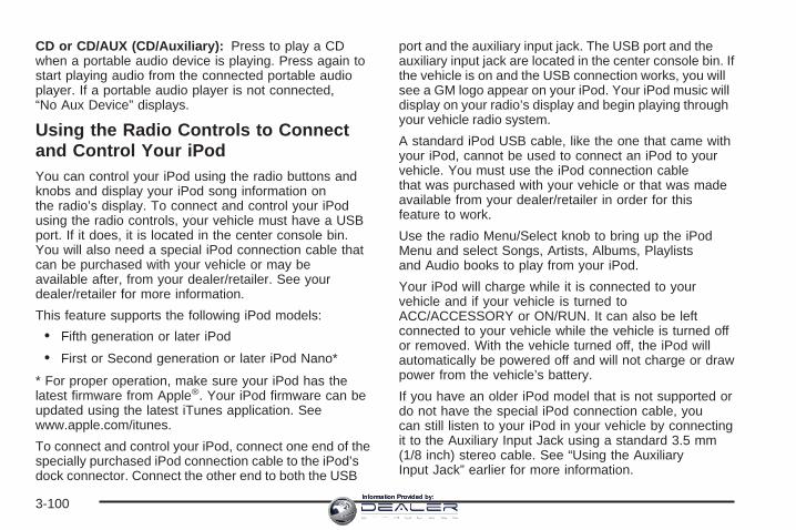
CD or CD/AUX (CD/Auxiliary): Press to play a CDwhen a portable audio device is playing. Press again tostart playing audio from the connected portable audioplayer. If a portable audio player is not connected,“No Aux Device” displays.
Using the Radio Controls to Connectand Control Your iPodYou can control your iPod using the radio buttons andknobs and display your iPod song information onthe radio’s display. To connect and control your iPodusing the radio controls, your vehicle must have a USBport. If it does, it is located in the center console bin.You will also need a special iPod connection cable thatcan be purchased with your vehicle or may beavailable after, from your dealer/retailer. See yourdealer/retailer for more information.
This feature supports the following iPod models:
• Fifth generation or later iPod
• First or Second generation or later iPod Nano*
* For proper operation, make sure your iPod has thelatest firmware from Apple®. Your iPod firmware can beupdated using the latest iTunes application. Seewww.apple.com/itunes.
To connect and control your iPod, connect one end of thespecially purchased iPod connection cable to the iPod’sdock connector. Connect the other end to both the USB
port and the auxiliary input jack. The USB port and theauxiliary input jack are located in the center console bin. Ifthe vehicle is on and the USB connection works, you willsee a GM logo appear on your iPod. Your iPod music willdisplay on your radio’s display and begin playing throughyour vehicle radio system.
A standard iPod USB cable, like the one that came withyour iPod, cannot be used to connect an iPod to yourvehicle. You must use the iPod connection cablethat was purchased with your vehicle or that was madeavailable from your dealer/retailer in order for thisfeature to work.
Use the radio Menu/Select knob to bring up the iPodMenu and select Songs, Artists, Albums, Playlistsand Audio books to play from your iPod.
Your iPod will charge while it is connected to yourvehicle and if your vehicle is turned toACC/ACCESSORY or ON/RUN. It can also be leftconnected to your vehicle while the vehicle is turned offor removed. With the vehicle turned off, the iPod willautomatically be powered off and will not charge or drawpower from the vehicle’s battery.
If you have an older iPod model that is not supported ordo not have the special iPod connection cable, youcan still listen to your iPod in your vehicle by connectingit to the Auxiliary Input Jack using a standard 3.5 mm(1/8 inch) stereo cable. See “Using the AuxiliaryInput Jack” earlier for more information.
3-100Information Provided by:
Press the AM/FM, XM or HDD buttons to listen to oneof these sources while an iPod is connected. If a disc isinserted, press the CD/AUX button to listen to a CDor DVD-A disc. Press the CD/AUX button again to startplaying and controlling the connected iPod.
To properly dismount the iPod USB device beforedisconnecting from the vehicle, press the button directlyunder the EJECT label found on the iPod playbackscreen.
Using an MP3
MP3/WMA FormatThe Single CD and the Six-Disc CD Radio will playMP3/WMA files that were recorded on a CD-R orCD-RW disc. The HDD Radio is similar and can alsoplay MP3/WMA files recorded on DVD +/− R discs or aUSB storage device.
The files can be recorded with the following fixed bitrates: 32 kbps, 40 kbps, 56 kbps, 64 kbps, 80 kbps,96 kbps, 112 kbps, 128 kbps, 160 kbps, 192 kbps,224 kbps, 256 kbps, and 320 kbps or a variable bit rate.Song title, artist name, and album can display whenfiles are recorded using ID3 tags version 1 and 2.
Creating an MP3/WMA DiscIf you burn your own MP3/WMA disc on a personalcomputer:
• Make sure the MP3/WMA files are recorded on aCD-R or CD-RW disc.
• Do not mix standard audio and MP3/WMA files onone disc.
• Make sure the CD does not have more than amaximum of 50 folders and playlists, and 255 files toread and play.
• Create a folder structure that makes it easy to findsongs while driving. Organize songs by albumsusing one folder for each album. Each folderor album should contain 18 songs or less.
• Avoid subfolders. The system can support up to8 subfolders deep, keep the total number offolders to a minimum to reduce the complexity andconfusion during playback.
• Make sure playlists have a .mp3 or .wpl extension(other file extensions may not work).
3-101Information Provided by:

• Minimize the length of the file, folder or playlistnames. Long file, folder, or playlist names, or acombination of a large number of files and folders,or playlists can cause the player to be unable toplay up to the maximum number of files, folders,playlists, or sessions.
• Finalize the audio disc before burning it. Addingmusic to an existing disc can cause the disc notto function.
Playlists can be selected by using the previous and nextfolder buttons, the SEEK arrows, \ FWD, or sREV buttons. An MP3/WMA CD-R or CD-RW that wasrecorded using no file folders can also be played. Ifa CD-R or CD-RW contains more than the maximum of50 folders and playlists, and 255 files, the player letsyou access and navigate up to the maximum, butall items over the maximum are not accessible.
The HDD Radio can support more than 255 files on anMP3/WMA disc.
The HDD Radio does not support playlists on a disc orUSB storage device.
Root DirectoryThe root directory of the CD-R or CD-RW is treated asa folder. If the root directory has compressed audiofiles, the directory displays as F1 DISC. All files
contained directly under the root directory are accessedprior to any root directory folders. Playlists (Px) arealways accessed after root folders or files.
The HDD Radio displays the root directory of anMP3/WMA disc as F1 MP3 and the root directory of aUSB storage device as F1 USB.
Empty Directory or FolderIf a root directory or a folder exists somewhere in thefile structure that contains only folders/subfolders and nocompressed files directly beneath them, the playeradvances to the next folder in the file structurethat contains compressed audio files.
No FolderWhen the CD contains only compressed files, the filesare located under the root folder. The next and previousfolder functions do not display on a CD that wasrecorded without folders or playlists. The radio displaysF1 DISC for the root directory.
When the CD contains only playlists and compressedaudio files, but no folders, all files are located under theroot folder. The folder down and the folder up buttonssearch playlists (Px) first and then goes to the rootfolder. The radio displays F1 DISC for the root directory.
3-102Information Provided by:

Order of PlayTracks recorded to the CD-R or CD-RW play in thefollowing order:
• Play begins from the first track in the first folder andcontinues sequentially through all tracks in eachfolder. When the last track of the last folderhas played, play continues from the first track of thefirst playlist.
− Playlists can be changed by pressing the nextand previous folder button.
• Play begins from the first track in the first playlistand continues sequentially through all tracks ineach playlist. When the last track of the last playlisthas played, play continues from the first track ofthe first folder.
When play enters a new folder, the display does notautomatically show the new folder name unlessthe folder mode has been chosen as the default display.The new track name displays.
File System and NamingThe song name displays the song name that iscontained in the ID3 tag. If the song name is not in theID3 tag, the radio displays the file name without theextension.
Track names longer than 32 characters are shortened.Parts of words on the last page of text and theextension of the filename is not displayed.
The HDD Radio will display file names with theextension.
Preprogrammed PlaylistsPreprogrammed playlists that were created usingWinAmp™, MusicMatch™, or Real Jukebox™ softwarecan be accessed, however they cannot be editedusing the radio. These playlists are special folderscontaining compressed audio song files. Playlists musthave a file extension of PLS or M3U.
Playlists can be selected using the previous and nextfolder buttons. Tracks can be changed by pressingthe seek buttons or turning the tune knob. Songs areplayed sequentially; press the s REV or \ FWD toreverse or advance through the playing song.
The HDD Radio does not support preprogrammedplaylists. To create a playlist on the HDD radio fromsongs recorded to the HDD, see “Saving HDD Favorites”earlier in this section.
3-103Information Provided by:

Playing an MP3/WMAInsert a CD partway into the slot (Single CD Player), orpress the load button and wait for the message toinsert disc (Six-Disc CD Player), label side up. Theplayer pulls in the CD and should begin playing.
For the Single CD Player, the track number displays atthe left and center of the screen. A Shuffle labelappears below. Press the pushbutton located under theShuffle label to play the MP3/WMA files of the CD inrandom order.
For the Six-Disc CD Player, the disc number displays atthe upper right side of the screen. The track numberdisplays at the left and center of the screen. The Shuffle,Disc, and Folder labels appear below. Press thepushbutton located under the Shuffle label to play theMP3/WMA files of the currently selected CD in randomorder. Press the pushbuttons located under the Discor Folder labels to change to another disc or folder.
As each new track starts to play, the track number andsong title displays.
Z (Eject): Press to eject a CD. If the CD is notremoved, after several seconds, the CD automaticallypulls back into the player and begins playing.
For the Six-Disc CD player, press and hold this buttonfor two seconds to eject all discs.
TUNE/TONE: Turn to select MP3/WMA files on theCD playing.
© SEEK ¨: Press the left arrow to go to the start ofthe current MP3/WMA file, if more than five secondshave played. Press the right arrow to go to thenext MP3/WMA file. If either arrow is held or pressedmultiple times, the player continues moving backward orforward through MP3/WMA files on the CD.
Sc (Previous Folder): Press the pushbuttonunder the Folder label to go to the first track inthe previous folder.
cT (Next Folder): Press the pushbutton under theFolder label to go to the first track in the next folder.
s REV (Reverse): Press and hold to reverseplayback quickly within an MP3/WMA file. Sound isheard at a reduced volume. The elapsed time of the filedisplays. Release to resume playing the file.
\ FWD (Fast Forward): Press and hold to advanceplayback quickly within an MP3/WMA file. Sound isheard at a reduced volume. The elapsed time of the filedisplays. Release to resume playing the file.
3-104Information Provided by:

Shuffle: With the shuffle setting, MP3/WMA files on theCD can be played in random, rather than sequentialorder, on the CD currently playing. To use shuffle:
• To play MP3/WMA files from the CD in randomorder, press the pushbutton under the Shufflelabel until Shuffle On displays. Press again to turnshuffle off.
XM Radio Messages
xL (Explicit Language Channels): These channels, orany others, can be blocked at a customer’s request,by calling 1-800-852-XMXM (9696).
XM Updating: The encryption code in the receiver isbeing updated, and no action is required. This processshould take no longer than 30 seconds.
No XM Signal: The system is functioning correctly, butthe vehicle is in a location that is blocking the XM™signal. When the vehicle is moved into an open area, thesignal should return.
Loading XM: The audio system is acquiring andprocessing audio and text data. No action is needed.This message should disappear shortly.
Channel Off Air: This channel is not currently inservice. Tune in to another channel.
Channel Unavail: This previously assigned channel isno longer assigned. Tune to another station. If thisstation was one of the presets, choose another stationfor that preset button.
No Info: No artist, song title, category, or textinformation is available at this time on this channel.The system is working properly.
NotFound: There are no channels available for theselected category. The system is working properly.
Radio ID: If tuned to channel 0, this messagewill alternate with the XM Radio 8 digit radio ID label.This label is needed to activate the service.
Unknown: If this message is received when tuned tochannel 0, there may be a receiver fault. Consultwith your dealer/retailer.
Check XM: If this message does not clear within ashort period of time, the receiver may have a fault.Consult with your dealer/retailer.
3-105Information Provided by:

Navigation/Radio SystemYour vehicle may have a navigation radio system.
The navigation system has built-in features intended tominimize driver distraction. Technology alone, nomatter how advanced, can never replace your ownjudgment. See the Navigation System manual for sometips to help you reduce distractions while driving.
Theft-Deterrent FeatureTHEFTLOCK® is designed to discourage theft of yourvehicle’s radio. The feature works automatically bylearning a portion of the Vehicle Identification Number(VIN). If the radio is moved to a different vehicle, it doesnot operate and LOC, LOCK, or LOCKED coulddisplay.
With THEFTLOCK® activated, the radio does notoperate if stolen.
Audio Steering Wheel Controls
Some audio controls can be adjusted at the steeringwheel. They include the following:
SRCE (Source): Press this button to switch betweenthe radio AM, FM, XM™ (if equipped), CD, HDD (ifavailable), auxiliary input jack (if connected), USB andiPod (if available and connected).
yz (Previous/Next): Press the previous or the nextarrow to go to the previous or to the next radiostation stored as a favorite.
When a CD is playing, press either arrow to go to theprevious or to the next track.
Left-Side SteeringWheel Controls
Right-Side SteeringWheel Controls
3-106Information Provided by:

+ e − e (Volume): Press the plus or minus volumebutton to increase or to decrease the volume.
g (Mute/Speech Recognition): Press and releasethis button to silence the vehicle speakers only.The audio of the wireless and wired headphones, if yourvehicle has these features, does not mute. Press andrelease this button again, to turn the sound on.
If your vehicle has the navigation system, press andhold this button for longer than one second to initiatespeech recognition. See “Speech Recognition” inthe Navigation System manual for more information.
If your vehicle has OnStar®, press and hold this buttonfor longer than one second to interact with the OnStar®
system. If your vehicle also has the navigation system,press and hold this button for longer than one secondto initiate speech recognition and say “OnStar” to enterOnStar® mode. See the OnStar® System on page 2-53in this manual for more information.
Radio ReceptionFrequency interference and static can occur duringnormal radio reception if items such as cell phonechargers, vehicle convenience accessories, and externalelectronic devices are plugged into the accessory poweroutlet. If there is interference or static, unplug the itemfrom the accessory power outlet.
AMThe range for most AM stations is greater than for FM,especially at night. The longer range can cause stationfrequencies to interfere with each other. For better radioreception, most AM radio stations boost the power levelsduring the day, and then reduce these levels during thenight. Static can also occur when things like storms andpower lines interfere with radio reception. When thishappens, try reducing the treble on your radio.
FM StereoFM stereo gives the best sound, but FM signals reachonly about 10 to 40 miles (16 to 65 km). Tall buildings orhills can interfere with FM signals, causing the soundto fade in and out.
XM™ Satellite Radio ServiceXM™ Satellite Radio Service gives digital radioreception from coast-to-coast in the 48 contiguousUnited States, and in Canada. Just as with FM,tall buildings or hills can interfere with satellite radiosignals, causing the sound to fade in and out. Inaddition, traveling or standing under heavy foliage,bridges, garages, or tunnels may cause loss ofXM signal for a period of time. The radio maydisplay No XM Signal to indicate interference.
3-107Information Provided by:

Cellular Phone UsageCellular phone usage may cause interference with yourvehicle’s radio. This interference may occur whenmaking or receiving phone calls, charging the phone’sbattery, or simply having the phone on. This interferencecauses an increased level of static while listening tothe radio. If static is received while listening to the radio,unplug the cellular phone and turn it off.
Backglass AntennaThe AM-FM antenna is integrated with the rear windowdefogger, located in the rear window. Make sure thatthe inside surface of the rear window is not scratchedand that the grid lines on the glass are not damaged. Ifthe inside surface is damaged, it could interfere withradio reception.
Notice: Using a razor blade or sharp object to clearthe inside rear window may damage the rearwindow antenna and/or the rear window defogger.Repairs would not be covered by your warranty. Donot clear the inside rear window with sharpobjects.
Notice: Do not apply aftermarket glass tinting withmetallic film. The metallic film in some tintingmaterials will interfere with or distort the incomingradio reception. Any damage caused to yourbackglass antenna due to metallic tinting materialswill not be covered by your warranty.
Because this antenna is built into the rear window, thereis a reduced risk of damage caused by car washesand vandals.
XM™ Satellite Radio AntennaSystemThe XM™ Satellite Radio antenna is located on the roofof your vehicle. Keep this antenna clear of snow andice build up for clear radio reception.
If your vehicle has a sunroof, the performance of theXM™ system may be affected if the sunroof is open.
Loading items onto the roof of your vehicle can interferewith the performance of the XM™ system. Make surethe XM™ Satellite Radio antenna is not obstructed.
3-108Information Provided by:

Your Driving, the Road, and Your Vehicle ..........4-2Defensive Driving ...........................................4-2Drunk Driving .................................................4-2Control of a Vehicle ........................................4-3Braking .........................................................4-3Antilock Brake System (ABS) ...........................4-4Braking in Emergencies ...................................4-5Traction Control System (TCS) .........................4-6Limited-Slip Rear Axle .....................................4-8StabiliTrak® System ........................................4-8Panic Brake Assist .........................................4-9All-Wheel Drive (AWD) System .........................4-9Steering ........................................................4-9Off-Road Recovery .......................................4-12Passing .......................................................4-12Loss of Control .............................................4-13
Competitive Driving .......................................4-14Driving at Night ............................................4-14Driving in Rain and on Wet Roads ..................4-15Before Leaving on a Long Trip .......................4-16Highway Hypnosis ........................................4-16Hill and Mountain Roads ................................4-17Winter Driving ..............................................4-18If Your Vehicle is Stuck in Sand, Mud, Ice,
or Snow ...................................................4-21Rocking Your Vehicle to Get It Out .................4-22Loading Your Vehicle ....................................4-22
Towing ..........................................................4-27Towing Your Vehicle .....................................4-27Recreational Vehicle Towing ...........................4-27Towing a Trailer ...........................................4-29
Section 4 Driving Your Vehicle
4-1Information Provided by:

Your Driving, the Road, andYour Vehicle
Defensive DrivingDefensive driving means “always expect theunexpected.” The first step in driving defensively is towear your safety belt — See Safety Belts: They Are forEveryone on page 1-12.
{CAUTION:
Assume that other road users (pedestrians,bicyclists, and other drivers) are going to becareless and make mistakes. Anticipate whatthey might do and be ready. In addition:
• Allow enough following distance betweenyou and the driver in front of you.
• Focus on the task of driving.
Driver distraction can cause collisionsresulting in injury or possible death. Thesesimple defensive driving techniques couldsave your life.
Drunk Driving
{CAUTION:
Drinking and then driving is very dangerous.Your reflexes, perceptions, attentiveness, andjudgment can be affected by even a smallamount of alcohol. You can have a serious — oreven fatal — collision if you drive after drinking.Do not drink and drive or ride with a driver whohas been drinking. Ride home in a cab; or if youare with a group, designate a driver who willnot drink.
Death and injury associated with drinking and driving isa global tragedy.
Alcohol affects four things that anyone needs to drive avehicle: judgment, muscular coordination, vision, andattentiveness.
4-2Information Provided by:

Police records show that almost 40 percent of all motorvehicle-related deaths involve alcohol. In most cases,these deaths are the result of someone who was drinkingand driving. In recent years, more than 17,000 annualmotor vehicle-related deaths have been associated withthe use of alcohol, with about 250,000 people injured.
For persons under 21, it is against the law in everyU.S. state to drink alcohol. There are good medical,psychological, and developmental reasons forthese laws.
The obvious way to eliminate the leading highwaysafety problem is for people never to drink alcohol andthen drive.
Medical research shows that alcohol in a person’ssystem can make crash injuries worse, especiallyinjuries to the brain, spinal cord, or heart. This meansthat when anyone who has been drinking — driveror passenger — is in a crash, that person’s chance ofbeing killed or permanently disabled is higher than if theperson had not been drinking.
Control of a VehicleThe following three systems help to control your vehiclewhile driving — brakes, steering, and accelerator. Attimes, as when driving on snow or ice, it is easy to askmore of those control systems than the tires and road canprovide. Meaning, you can lose control of your vehicle.See Traction Control System (TCS) on page 4-6.
Adding non-dealer/non-retailer accessories can affectyour vehicle’s performance. See Accessories andModifications on page 5-3.
BrakingSee Brake System Warning Light on page 3-37.
Braking action involves perception time and reactiontime. First, you have to decide to push on the brakepedal. That is perception time. Then you have to bringup your foot and do it. That is reaction time.
4-3Information Provided by:

Average reaction time is about three-fourths of asecond. But that is only an average. It might be lesswith one driver and as long as two or three seconds ormore with another. Age, physical condition, alertness,coordination, and eyesight all play a part. So do alcohol,drugs, and frustration. But even in three-fourths of asecond, a vehicle moving at 60 mph (100 km/h) travels66 feet (20 m). That could be a lot of distance in anemergency, so keeping enough space betweenyour vehicle and others is important.
And, of course, actual stopping distances vary greatlywith the surface of the road, whether it is pavement orgravel; the condition of the road, whether it is wet, dry, oricy; tire tread; the condition of the brakes; the weight ofthe vehicle; and the amount of brake force applied.
Avoid needless heavy braking. Some people drive inspurts — heavy acceleration followed by heavybraking — rather than keeping pace with traffic. This isa mistake. The brakes might not have time to coolbetween hard stops. The brakes will wear out muchfaster if you do a lot of heavy braking. If you keep pacewith the traffic and allow realistic following distances,you will eliminate a lot of unnecessary braking.That means better braking and longer brake life.
If your vehicle’s engine ever stops while you are driving,brake normally but do not pump the brakes. If you do,the pedal could get harder to push down. If theengine stops, you will still have some power brakeassist. But you will use it when you brake. Once thepower assist is used up, it can take longer to stop andthe brake pedal will be harder to push.
Adding non-dealer/non-retailer accessories can affectyour vehicle’s performance. See Accessories andModifications on page 5-3.
Antilock Brake System (ABS)Your vehicle has the Antilock Brake System (ABS), anadvanced electronic braking system that will helpprevent a braking skid.
When you start the engine and begin to drive away,ABS will check itself. You might hear a momentarymotor or clicking noise while this test is going on, andyou might even notice that the brake pedal movesa little. This is normal.
4-4Information Provided by:

If there is a problem withABS, this warning light willstay on. See AntilockBrake System WarningLight on page 3-38.
Let us say the road is wet and you are driving safely.Suddenly, an animal jumps out in front of you. You slamon the brakes and continue braking. Here is whathappens with ABS:
A computer senses that wheels are slowing down. Ifone of the wheels is about to stop rolling, the computerwill separately work the brakes at each wheel.
ABS can change the brake pressure faster than anydriver could. The computer is programmed to make themost of available tire and road conditions. This canhelp you steer around the obstacle while braking hard.
As you brake, the computer keeps receiving updates onwheel speed and controls braking pressure accordingly.
Remember: ABS does not change the time you needto get your foot up to the brake pedal or alwaysdecrease stopping distance. If you get too close to thevehicle in front of you, you will not have time toapply the brakes if that vehicle suddenly slows or stops.Always leave enough room up ahead to stop, eventhough you have ABS.
Using ABSDo not pump the brakes. Just hold the brake pedaldown firmly and let antilock work for you. You might hearthe antilock pump or motor operate, and feel thebrake pedal pulsate, but this is normal.
Braking in EmergenciesWith ABS, you can steer and brake at the same time.In many emergencies, steering can help you more thaneven the very best braking.
4-5Information Provided by:

Traction Control System (TCS)Your vehicle has a Traction Control System (TCS) thatlimits wheel spin. This is especially useful in slippery roadconditions. It will activate and the TCS/StabiliTrak® lightwill flash if it senses that any of the wheels are spinning orbeginning to lose traction while driving. When thishappens, the system applies the brake to the spinningwheel(s) and/or reduces engine power to limit wheel spin.The TCS/StabiliTrak® warning light will flash when thetraction control system is limiting wheel spin.
You may feel or hear the system working, but this isnormal.
This warning light will flashif there is a problem withthe traction control system.
See Traction Control System (TCS)/StabiliTrak®
Warning Light on page 3-38 and StabiliTrak® System onpage 4-8. When the TCS/StabiliTrak® warning light ison, the system will not limit wheel spin. Adjust yourdriving accordingly.
TCS automatically comes on whenever vehicle isstarted. To limit wheel spin, especially in slippery roadconditions, you should always leave the system on.But the TCS should be turned off if your vehicleever gets stuck in sand, mud or snow and rocking thevehicle is required. Also, turn the TCS off while indeep snow or on loose gravel, to assist vehicle motionat lower speeds. See Rocking Your Vehicle to GetIt Out on page 4-22 for more information. See alsoWinter Driving on page 4-18 for information on usingTCS when driving in snowy or icy conditions.
4-6Information Provided by:

Press the TC (TractionControl) button, located onthe instrument panel, toturn the system off.
If you press the TC button once, the tractioncontrol system will turn off and the Traction ControlSystem (TCS) Warning Light will flash. Press theTC button again to turn the system back on. Press andhold the TC button for five seconds or longer, to turnthe StabiliTrak® system off. The TCS/StabiliTrak®
warning light will flash. Press the TC button again toturn StabiliTrak® back on. For more information,see StabiliTrak® System on page 4-8.
Adding non-dealer/non-retailer accessories can affectyour vehicle’s performance. See Accessories andModifications on page 5-3 for more information.
Competitive Driving ModePress the TC button quickly two times to select thisoptional handling mode. The StabiliTrak® CompetitiveMode message displays in the Driver InformationCenter (DIC). While in the StabiliTrak® CompetitiveMode, TCS does not operate, and the TCS warning lightcomes on. Adjust your driving accordingly.
Press the TC button again, or turn the ignition toACC/ACCESSORY, to turn the TCS back on and theTCS warning light off.
Notice: When traction control is turned off, orCompetitive Driving Mode is active, it is possible tolose traction. If you attempt to shift with the rearwheels spinning with a loss of traction, it is possibleto cause damage to the transmission. Do notattempt to shift when the rear wheels do not havetraction. Damage caused by misuse of the vehicle isnot covered. See your warranty book for additionalinformation.
4-7Information Provided by:

Limited-Slip Rear AxleYour vehicle may have this feature. A limited-slip rearaxle can give you additional traction on snow, mud, ice,sand or gravel. It works like a standard axle most ofthe time, but when one of the rear wheels has notraction and the other does, this feature will allow thewheel with traction to move the vehicle.
StabiliTrak ® SystemYour vehicle has an electronic stability control systemcalled StabiliTrak®. It is an advanced computercontrolled system that assists with directional control ofthe vehicle in difficult driving conditions.
StabiliTrak® activates when the computer senses adiscrepancy between your intended path and thedirection the vehicle is actually traveling. StabiliTrak®
selectively applies braking pressure at any one ofthe vehicle’s brakes to help steer the vehicle in thedirection which you are steering.
When the system activates, the Traction ControlSystem (TCS)/StabiliTrak® warning light on theinstrument panel cluster flashes. You may also hear anoise or feel vibration in the brake pedal. This is normal.Continue to steer the vehicle in the direction you wantit to go.
If there is a problem detected with StabiliTrak®, aService Stability System message displays on the DriverInformation Center (DIC) and the TCS/StabiliTrak®
warning light flashes on the instrument panel cluster.When this message and warning light displays, thesystem is not operational. Driving should be adjustedaccordingly. See DIC Warnings and Messages onpage 3-54 and Warning Lights, Gages, and Indicatorson page 3-29 for more information.
StabiliTrak® comes on automatically whenever thevehicle is started. The system should be left on to helpassist with directional control of the vehicle. IfStabiliTrak® needs to be turned off, press the TC(traction control) on/off button. See Traction ControlSystem (TCS) on page 4-6.
If cruise control is being used when the StabiliTrak®
activates, the cruise control will automatically disengage.When road conditions allow, reengage the cruise control.See Cruise Control on page 3-13 for more information.
4-8Information Provided by:

Panic Brake AssistYour vehicle has a panic brake assist system thatmonitors the intention of the driver while braking. If thesystem senses that the driver has applied hard/fastpressure to the brake pedal, the system will generateadditional pressure, making it easier for the driverto maintain brake application. When this happens thebrake pedal will feel easier to push. Just hold the brakepedal down firmly and let the system work for you.You may feel the brakes vibrate, or you may noticesome noise but this is normal. The brakes will return tonormal operation after the brake pedal has beenreleased.
All-Wheel Drive (AWD) SystemIf your vehicle has this feature, engine power is sent toall four wheels when needed. During normal drivingconditions the vehicle will operate in 2WD mode. Whenthe system senses a loss of traction the vehicle willautomatically change to AWD mode.
If you have the spare tire on the vehicle, there may be areduction in performance of the AWD system.
Steering
Power SteeringIf you lose power steering assist because the enginestops or the system is not functioning, you can steer butit will take much more effort.
Speed Variable Assist SteeringYour vehicle has a steering system that varies theamount of effort required to steer the vehicle in relationto the speed of the vehicle.
The amount of steering effort required is less at slowerspeeds to make the vehicle more maneuverableand easier to park. At faster speeds, the steering effortincreases to provide a sport-like feel to the steering.This provides maximum control and stability.
If your vehicle seems harder to steer than normal whenparking or driving slowly, there may be a problemwith the system. You will still have power steering, butsteering will be stiffer than normal at slow speeds.See your dealer/retailer for service.
4-9Information Provided by:

Steering TipsIt is important to take curves at a reasonable speed.
A lot of the “driver lost control” accidents mentioned onthe news happen on curves. Here is why:
Experienced driver or beginner, each of us is subject tothe same laws of physics when driving on curves.The traction of the tires against the road surface makesit possible for the vehicle to change its path whenyou turn the front wheels. If there is no traction, inertiawill keep the vehicle going in the same direction. Ifyou have ever tried to steer a vehicle on wet ice, youwill understand this.
The traction you can get in a curve depends on thecondition of the tires and the road surface, the angle atwhich the curve is banked, and your speed. While you arein a curve, speed is the one factor you can control.
Suppose you are steering through a sharp curve.Then you suddenly accelerate. Both controlsystems — steering and acceleration — have to dotheir work where the tires meet the road. Addingthe sudden acceleration can demand too much of thoseplaces. You can lose control. See Traction ControlSystem (TCS) on page 4-6.
What should you do if this ever happens? Ease up onthe accelerator pedal, steer the vehicle the way youwant it to go, and slow down.
Speed limit signs near curves warn that you shouldadjust your speed. Of course, the posted speedsare based on good weather and road conditions. Underless favorable conditions you will want to go slower.
If you need to reduce your speed as you approacha curve, do it before you enter the curve, while the frontwheels are straight ahead.
Try to adjust your speed so you can drive through thecurve. Maintain a reasonable, steady speed. Waitto accelerate until you are out of the curve, and thenaccelerate gently into the straightaway.
Adding non-dealer/non-retailer accessories can affectyour vehicle’s performance. See Accessories andModifications on page 5-3.
4-10Information Provided by:

Steering in EmergenciesThere are times when steering can be more effective thanbraking. For example, you come over a hill and find atruck stopped in your lane, or a car suddenly pulls outfrom nowhere, or a child darts out from between parkedcars and stops right in front of you. You can avoid theseproblems by braking — if you can stop in time. Butsometimes you cannot; there is not room. That is the timefor evasive action — steering around the problem.
Your vehicle can perform very well in emergencies likethese. First apply the brakes. See Braking on page 4-3.It is better to remove as much speed as you can from apossible collision. Then steer around the problem, to theleft or right depending on the space available.
An emergency like this requires close attention and aquick decision. If you are holding the steering wheel atthe recommended 9 and 3 o’clock positions, youcan turn it a full 180 degrees very quickly withoutremoving either hand. But you have to act fast, steerquickly, and just as quickly straighten the wheelonce you have avoided the object.
The fact that such emergency situations are alwayspossible is a good reason to practice defensive drivingat all times and wear safety belts properly.
4-11Information Provided by:

Off-Road RecoveryYou may find that your vehicle’s right wheels havedropped off the edge of a road onto the shoulder whileyou are driving.
If the level of the shoulder is only slightly below thepavement, recovery should be fairly easy. Ease off theaccelerator and then, if there is nothing in the way,steer so that your vehicle straddles the edge ofthe pavement. You can turn the steering wheel up toone-quarter turn until the right front tire contactsthe pavement edge. Then turn the steering wheel to gostraight down the roadway.
PassingPassing another vehicle on a two-lane road can bedangerous. To reduce the risk of danger while passing,we suggest the following tips:
• Look down the road, to the sides, and to crossroadsfor situations that might affect a successful pass. Ifin doubt, wait.
• Watch for traffic signs, pavement markings, andlines that could indicate a turn or an intersection.Never cross a solid or double-solid line on your sideof the lane.
• Do not get too close to the vehicle you want topass. Doing so can reduce your visibility.
• Wait your turn to pass a slow vehicle.
• When you are being passed, ease to the right.
4-12Information Provided by:
Loss of ControlLet us review what driving experts say about whathappens when the three control systems — brakes,steering, and acceleration — do not have enough frictionwhere the tires meet the road to do what the driver hasasked.
In any emergency, do not give up. Keep trying to steerand constantly seek an escape route or area of lessdanger.
SkiddingIn a skid, a driver can lose control of the vehicle.Defensive drivers avoid most skids by taking reasonablecare suited to existing conditions, and by not overdrivingthose conditions. But skids are always possible.
The three types of skids correspond to your vehicle’sthree control systems. In the braking skid, the wheels arenot rolling. In the steering or cornering skid, too muchspeed or steering in a curve causes tires to slip and losecornering force. And in the acceleration skid, too muchthrottle causes the driving wheels to spin.
A cornering skid is best handled by easing your foot offthe accelerator pedal.
Remember: Any traction control system helps avoid onlythe acceleration skid. If your traction control system isoff, then an acceleration skid is also best handledby easing your foot off the accelerator pedal.
If your vehicle starts to slide, ease your foot off theaccelerator pedal and quickly steer the way you wantthe vehicle to go. If you start steering quickly enough,your vehicle may straighten out. Always be readyfor a second skid if it occurs.
Of course, traction is reduced when water, snow, ice,gravel, or other material is on the road. For safety, youwill want to slow down and adjust your driving tothese conditions. It is important to slow down on slipperysurfaces because stopping distance will be longer andvehicle control more limited.
While driving on a surface with reduced traction, try yourbest to avoid sudden steering, acceleration, or braking,including reducing vehicle speed by shifting to a lowergear. Any sudden changes could cause the tires toslide. You may not realize the surface is slippery untilyour vehicle is skidding. Learn to recognize warningclues — such as enough water, ice, or packed snow onthe road to make a mirrored surface — and slow downwhen you have any doubt.
Remember: Any Antilock Brake System (ABS) helpsavoid only the braking skid.
4-13Information Provided by:

Competitive DrivingSee your warranty book before using your vehicle forcompetitive driving.
Notice: If you use your vehicle for competitivedriving, the engine may use more oil than it wouldwith normal use. Low oil levels can damage theengine. Be sure to check the oil level often duringcompetitive driving and keep the level at or near theupper mark that shows the proper operating rangeon the engine oil dipstick. For information on how toadd oil, see Engine Oil on page 5-16.
Driving at NightNight driving is more dangerous than day drivingbecause some drivers are likely to be impaired — byalcohol or drugs, with night vision problems, or byfatigue.
Night driving tips include:
• Drive defensively.
• Do not drink and drive.
• Reduce headlamp glare by adjusting the insiderearview mirror.
• Slow down and keep more space between you andother vehicles because your headlamps can onlylight up so much road ahead.
• Watch for animals.
• When tired, pull off the road.
• Do not wear sunglasses.
• Avoid staring directly into approaching headlamps.
• Keep the windshield and all glass on your vehicleclean — inside and out.
• Keep your eyes moving, especially during turns orcurves.
No one can see as well at night as in the daytime.But, as we get older, these differences increase.A 50-year-old driver might need at least twice as muchlight to see the same thing at night as a 20-year-old.
4-14Information Provided by:

Driving in Rain and on Wet RoadsRain and wet roads can reduce vehicle tractionand affect your ability to stop and accelerate. Alwaysdrive slower in these types of driving conditionsand avoid driving through large puddles anddeep-standing or flowing water.
{CAUTION:
Wet brakes can cause crashes. They might notwork as well in a quick stop and could causepulling to one side. You could lose control ofthe vehicle.
After driving through a large puddle of wateror a car/vehicle wash, lightly apply the brakepedal until the brakes work normally.
CAUTION: (Continued)
CAUTION: (Continued)
Flowing or rushing water creates strongforces. Driving through flowing water couldcause your vehicle to be carried away. If thishappens, you and other vehicle occupantscould drown. Do not ignore police warningsand be very cautious about trying to drivethrough flowing water.
HydroplaningHydroplaning is dangerous. Water can build up underyour vehicle’s tires so they actually ride on thewater. This can happen if the road is wet enough andyou are going fast enough. When your vehicle ishydroplaning, it has little or no contact with the road.
There is no hard and fast rule about hydroplaning. Thebest advice is to slow down when the road is wet.
4-15Information Provided by:

Other Rainy Weather TipsBesides slowing down, other wet weather driving tipsinclude:
• Allow extra following distance.
• Pass with caution.
• Keep windshield wiping equipment in good shape.
• Keep the windshield washer fluid reservoir filled.
• Have good tires with proper tread depth. See Tireson page 5-59.
Before Leaving on a Long TripTo prepare your vehicle for a long trip, consider havingit serviced by your dealer/retailer before departing.
Things to check on your own include:
• Windshield Washer Fluid: Reservoir full? Windowsclean — inside and outside?
• Wiper Blades: In good shape?
• Fuel, Engine Oil, Other Fluids: All levels checked?
• Lamps: Do they all work and are lenses clean?
• Tires: Are treads good? Are tires inflated torecommended pressure?
• Weather and Maps: Safe to travel? Haveup-to-date maps?
Highway HypnosisAlways be alert and pay attention to your surroundingswhile driving. If you become tired or sleepy, find asafe place to park your vehicle and rest.
Other driving tips include:
• Keep the vehicle well ventilated.
• Keep interior temperature cool.
• Keep your eyes moving — scan the road aheadand to the sides.
• Check the rearview mirror and vehicleinstruments often.
4-16Information Provided by:

Hill and Mountain RoadsDriving on steep hills or through mountains is differentthan driving on flat or rolling terrain. Tips for drivingin these conditions include:
• Keep your vehicle serviced and in good shape.
• Check all fluid levels and brakes, tires, coolingsystem, and transmission.
• Going down steep or long hills, shift to alower gear.
{CAUTION:
If you do not shift down, the brakes could getso hot that they would not work well. Youwould then have poor braking or even nonegoing down a hill. You could crash. Shift downto let the engine assist the brakes on a steepdownhill slope.
{CAUTION:
Coasting downhill in NEUTRAL (N) or with theignition off is dangerous. The brakes will haveto do all the work of slowing down and theycould get so hot that they would not work well.You would then have poor braking or evennone going down a hill. You could crash.Always have the engine running and yourvehicle in gear when you go downhill.
• Stay in your own lane. Do not swing wide or cutacross the center of the road. Drive at speedsthat let you stay in your own lane.
• Top of hills: Be alert — something could be in yourlane (stalled car, accident).
• Pay attention to special road signs (falling rocksarea, winding roads, long grades, passing orno-passing zones) and take appropriate action.
4-17Information Provided by:

Winter DrivingHere are some tips for winter driving:
• Have your vehicle in good shape for winter.
• You might want to put winter emergency supplies inyour trunk.
Include an ice scraper, a small brush or broom, asupply of windshield washer fluid, a rag, some winterouter clothing, a small shovel, a flashlight, a redcloth, and a couple of reflective warning triangles. And,if you will be driving under severe conditions, includea small bag of sand, a piece of old carpet, or a couple ofburlap bags to help provide traction. Be sure youproperly secure these items in your vehicle.
Also see Tires on page 5-59.
Driving on Snow or IceMost of the time, those places where the tires meet theroad probably have good traction.
However, if there is snow or ice between the tires and theroad, you can have a very slippery situation. You have alot less traction, or grip, and need to be very careful.
What is the worst time for this? Wet ice. Very cold snowor ice can be slick and hard to drive on. But wet icecan be even more trouble because it can offer the leasttraction of all. You can get wet ice when it is aboutfreezing, 32°F (0°C), and freezing rain begins to fall. Tryto avoid driving on wet ice until salt and sand crewscan get there.
Whatever the condition — smooth ice, packed, blowing,or loose snow — drive with caution.
4-18Information Provided by:

The Traction Control System (TCS) improves yourability to accelerate when driving on a slippery road.Even though you have TCS, slow down and adjust yourdriving to the road conditions. Under certain conditions,you might want to turn the TCS off, such as whendriving through deep snow and loose gravel, to helpmaintain vehicle motion at lower speeds. See TractionControl System (TCS) on page 4-6. Also seeStabiliTrak® System on page 4-8, If Your Vehicle isStuck in Sand, Mud, Ice, or Snow on page 4-21, and“Winter Tires” under Tires on page 5-59.
The Antilock Brake System (ABS) improves yourvehicle’s stability when you make a hard stop on aslippery road. Even though you have ABS, beginstopping sooner than you would on dry pavement.See Antilock Brake System (ABS) on page 4-4.
• Allow greater following distance on any slippery road.
• Watch for slippery spots. The road might be fine untilyou hit a spot that is covered with ice. On anotherwise clear road, ice patches can appear inshaded areas where the sun cannot reach, such asaround clumps of trees, behind buildings, or underbridges. Sometimes the surface of a curve or anoverpass can remain icy when the surrounding roadsare clear. If you see a patch of ice ahead of you,brake before you are on it. Try not to brake while youare actually on the ice, and avoid sudden steeringmaneuvers.
If You Are Caught in a BlizzardIf you are stopped by heavy snow, you could be in aserious situation. You should probably stay withyour vehicle unless you know for sure that you are nearhelp and you can hike through the snow. Here aresome things to do to summon help and keep yourselfand your passengers safe:
• Turn on the hazard warning flashers.
• Tie a red cloth to your vehicle to alert police thatyou have been stopped by the snow.
• Put on extra clothing or wrap a blanket around you.If you do not have blankets or extra clothing, makebody insulators from newspapers, burlap bags,rags, floor mats — anything you can wrap aroundyourself or tuck under your clothing to keep warm.
4-19Information Provided by:

You can run the engine to keep warm, but be careful.
{CAUTION:
Snow can trap exhaust gases under yourvehicle. This can cause deadly CO (carbonmonoxide) gas to get inside. CO couldovercome you and kill you. You cannot see itor smell it, so you might not know it is in yourvehicle. Clear away snow from around thebase of your vehicle, especially any that isblocking the exhaust pipe. And check aroundagain from time to time to be sure snow doesnot collect there.
Open a window just a little on the side of thevehicle that is away from the wind. This willhelp keep CO out.
4-20Information Provided by:
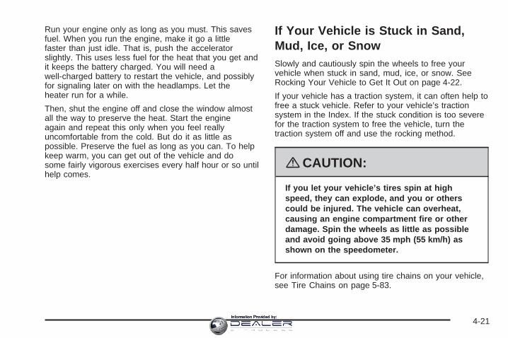
Run your engine only as long as you must. This savesfuel. When you run the engine, make it go a littlefaster than just idle. That is, push the acceleratorslightly. This uses less fuel for the heat that you get andit keeps the battery charged. You will need awell-charged battery to restart the vehicle, and possiblyfor signaling later on with the headlamps. Let theheater run for a while.
Then, shut the engine off and close the window almostall the way to preserve the heat. Start the engineagain and repeat this only when you feel reallyuncomfortable from the cold. But do it as little aspossible. Preserve the fuel as long as you can. To helpkeep warm, you can get out of the vehicle and dosome fairly vigorous exercises every half hour or so untilhelp comes.
If Your Vehicle is Stuck in Sand,Mud, Ice, or SnowSlowly and cautiously spin the wheels to free yourvehicle when stuck in sand, mud, ice, or snow. SeeRocking Your Vehicle to Get It Out on page 4-22.
If your vehicle has a traction system, it can often help tofree a stuck vehicle. Refer to your vehicle’s tractionsystem in the Index. If the stuck condition is too severefor the traction system to free the vehicle, turn thetraction system off and use the rocking method.
{CAUTION:
If you let your vehicle’s tires spin at highspeed, they can explode, and you or otherscould be injured. The vehicle can overheat,causing an engine compartment fire or otherdamage. Spin the wheels as little as possibleand avoid going above 35 mph (55 km/h) asshown on the speedometer.
For information about using tire chains on your vehicle,see Tire Chains on page 5-83.
4-21Information Provided by:
Rocking Your Vehicle to Get It OutFirst, turn the steering wheel left and right toclear the area around the front wheels. Turn offany traction or stability system. See Traction ControlSystem (TCS) on page 4-6 and StabiliTrak® System onpage 4-8. Then shift back and forth betweenREVERSE (R) and a forward gear, or with a manualtransmission, between FIRST (1) or SECOND (2)and REVERSE (R), spinning the wheels as little aspossible. To prevent transmission wear, wait until thewheels stop spinning before shifting gears. Release theaccelerator pedal while you shift, and press lightly onthe accelerator pedal when the transmission is in gear.By slowly spinning the wheels in the forward andreverse directions, you will cause a rocking motion thatcould free your vehicle. If that does not get yourvehicle out after a few tries, it might need to be towedout. If your vehicle does need to be towed out, seeTowing Your Vehicle on page 4-27.
Loading Your VehicleIt is very important to know how much weight yourvehicle can carry. This weight is called the vehiclecapacity weight and includes the weight of alloccupants, cargo, and all nonfactory-installedoptions. Two labels on your vehicle show how muchweight it may properly carry, the Tire and LoadingInformation label, and the Certification label.
{CAUTION:
Do not load your vehicle any heavier thanthe Gross Vehicle Weight Rating (GVWR),or either the maximum front or rear GrossAxle Weight Rating (GAWR). If you do,parts on your vehicle can break, and itcan change the way your vehicle handles.These could cause you to lose controland crash. Also, overloading can shortenthe life of your vehicle.
4-22Information Provided by:

Tire and Loading Information Label
A vehicle specific Tire and Loading Informationlabel is attached to the vehicle’s center pillar(B-pillar). With the driver’s door open, you will findthe label attached below the door lock post (striker).The Tire and Loading Information label shows thenumber of occupant seating positions (A), and themaximum vehicle capacity weight (B) in kilogramsand pounds.
The Tire and Loading Information label also showsthe tire size of the original equipment tires (C) andthe recommended cold tire inflation pressures (D).For more information on tires and inflation see Tireson page 5-59 and Inflation - Tire Pressure onpage 5-67.
There is also important loading information on theCertification label. It tells you the Gross VehicleWeight Rating (GVWR) and the Gross Axle WeightRating (GAWR) for the front and rear axle; see“Certification Label” later in this section.
Steps for Determining CorrectLoad Limit
1. Locate the statement “The combined weight ofoccupants and cargo should never exceedXXX kg or XXX lbs” on your vehicle’s placard.
2. Determine the combined weight of the driverand passengers that will be riding in yourvehicle.
3. Subtract the combined weight of the driverand passengers from XXX kg or XXX lbs.
Example Label
4-23Information Provided by:

4. The resulting figure equals the availableamount of cargo and luggage load capacity.For example, if the “XXX” amount equals1400 lbs and there will be five 150 lbpassengers in your vehicle, the amount ofavailable cargo and luggage load capacity is650 lbs (1400 − 750 (5 x 150) = 650 lbs).
5. Determine the combined weight of luggageand cargo being loaded on the vehicle. Thatweight may not safely exceed the availablecargo and luggage load capacity calculated inStep 4.
6. If your vehicle will be towing a trailer, the loadfrom your trailer will be transferred to yourvehicle. Consult this manual to determine howthis reduces the available cargo and luggageload capacity of your vehicle.See Towing a Trailer on page 4-29 forimportant information on towing a trailer,towing safety rules, and trailering tips.
Item Description Total
AVehicle CapacityWeight forExample 1 =
1,000 lbs(453 kg)
BSubtract OccupantWeight 150 lbs(68 kg) × 2 =
300 lbs (136 kg)
C Available Occupantand Cargo Weight = 700 lbs (317 kg)
Example 1
4-24Information Provided by:

Item Description Total
AVehicle CapacityWeight forExample 2 =
1,000 lbs(453 kg)
BSubtract OccupantWeight 150 lbs(68 kg) × 5 =
750 lbs (340 kg)
C Available CargoWeight = 250 lbs (113 kg)
Item Description Total
AVehicle CapacityWeight forExample 3 =
1,000 lbs(453 kg)
BSubtract OccupantWeight 200 lbs(91 kg) × 5 =
1,000 lbs(453 kg)
C Available CargoWeight = 0 lbs (0 kg)
Refer to your vehicle’s Tire and LoadingInformation label for specific information aboutyour vehicle’s capacity weight and seatingpositions. The combined weight of the driver,passengers, and cargo should never exceed yourvehicle’s capacity weight.
Example 2 Example 3
4-25Information Provided by:

Certification Label
A vehicle specific Certification label is attached toeither the driver’s door edge or the lower centerpillar on the driver’s side of the vehicle. This labelshows the gross weight capacity of your vehicle,called the Gross Vehicle Weight Rating (GVWR).The GVWR includes the weight of the vehicle,all occupants, fuel, and cargo.
The Certification label also shows the maximumweights for the front and rear axles, calledthe Gross Axle Weight Rating (GAWR). Neverexceed the GVWR or the GAWR for eitherthe front or rear axle.
{CAUTION:
Do not load your vehicle any heavier thanthe Gross Vehicle Weight Rating (GVWR),or either the maximum front or rear GrossAxle Weight Rating (GAWR). If you do,parts on your vehicle can break, and itcan change the way your vehicle handles.These could cause you to lose controland crash. Also, overloading can shortenthe life of your vehicle.
Notice: Overloading your vehicle may causedamage. Repairs would not be covered by yourwarranty. Do not overload your vehicle.
4-26Information Provided by:

If you put things inside your vehicle, like suitcases,tools, packages, or anything else, they will go asfast as the vehicle goes. If you have to stop or turnquickly, or if there is a crash, they will keep going.
{CAUTION:
Things you put inside your vehicle canstrike and injure people in a sudden stopor turn, or in a crash.
• Put things in the trunk of your vehicle.In a trunk, put them as far forward asyou can. Try to spread the weightevenly.
• Never stack heavier things, likesuitcases, inside the vehicle so thatsome of them are above the tops ofthe seats.
• Do not leave an unsecured childrestraint in your vehicle.
• When you carry something inside thevehicle, secure it whenever you can.
• Do not leave a seat folded downunless you need to.
Towing
Towing Your VehicleConsult your dealer/retailer or a professional towingservice if you need to have your disabled vehicle towed.See Roadside Service on page 7-6.
If you want to tow your vehicle behind another vehiclefor recreational purposes (such as behind a motorhome),see Recreational Vehicle Towing following.
Recreational Vehicle TowingRecreational vehicle towing means towing your vehiclebehind another vehicle – such as behind a motorhome.The two most common types of recreational vehicletowing are known as “dinghy towing” (towing your vehiclewith all four wheels on the ground) and “dolly towing”(towing your vehicle with two wheels on the ground andtwo wheels up on a device known as a “dolly”).
With the proper preparation and equipment, manyvehicles can be towed in these ways. See “DinghyTowing” and “Dolly Towing,” following.
4-27Information Provided by:

Here are some important things to consider before youdo recreational vehicle towing:
• What is the towing capacity of the towing vehicle?Be sure you read the tow vehicle manufacturer’srecommendations.
• How far will you tow? Some vehicles haverestrictions on how far and how long they can tow.
• Do you have the proper towing equipment?See your dealer/retailer or trailering professional foradditional advice and equipment recommendations.
• Is your vehicle ready to be towed? Just as youwould prepare your vehicle for a long trip, you’llwant to make sure your vehicle is prepared to betowed. See Before Leaving on a Long Trip onpage 4-16.
Dinghy Towing
Notice: If you tow your vehicle with all four wheelson the ground, the drivetrain components couldbe damaged. The repairs would not be covered byyour warranty. Do not tow your vehicle with allfour wheels on the ground.
Your vehicle was not designed to be towed with all fourwheels on the ground. If your vehicle must be towed,you should use a dolly. See “Dolly Towing” following formore information.
Dolly Towing
Your vehicle can be towed using a dolly. To tow yourvehicle using a dolly:
1. Put the rear wheels on the dolly.
2. Securely attach the vehicle being towed to the towvehicle.
4-28Information Provided by:

3. Put the vehicle in PARK (P) for an automatictransmission or in NEUTRAL for a manualtransmission.
4. Set the parking brake and then remove the key.
5. Clamp the steering wheel in a straight-aheadposition with a clamping device designed fortowing.
6. Release the parking brake.
Dolly Towing (All-Wheel-Drive Vehicles)
Notice: Towing an all-wheel-drive vehicle with allfour wheels on the ground, or even with only two ofits wheels on the ground, will damage drivetraincomponents. Do not tow an all-wheel-drive vehicle ifany of its wheels will be on the ground.
If you have an All-Wheel-Drive vehicle, it can only betowed on a flat-bed trailer.
Towing a Trailer
{CAUTION:
If you do not use the correct equipment anddrive properly, you can lose control when youpull a trailer. For example, if the trailer is tooheavy, the brakes may not work well — or evenat all. You and your passengers could beseriously injured. You may also damage yourvehicle; the resulting repairs would not becovered by your warranty. Pull a trailer only ifyou have followed all the steps in this section.Ask your dealer/retailer for advice andinformation about towing a trailer withyour vehicle.
Your vehicle can tow a trailer if it is equipped with theproper trailer towing equipment. To identify the traileringcapacity of your vehicle, you should read the informationin “Weight of the Trailer” that appears later in thissection. Trailering is different than just driving yourvehicle by itself. Trailering means changes in handling,acceleration, braking, durability and fuel economy.Successful, safe trailering takes correct equipment, andit has to be used properly.
4-29Information Provided by:

That is the reason for this part. In it are manytime-tested, important trailering tips and safety rules.Many of these are important for your safety and that ofyour passengers. So please read this section carefullybefore you pull a trailer.
Load-pulling components such as the engine,transmission, wheel assemblies and tires are forced towork harder against the drag of the added weight.The engine is required to operate at relatively higherspeeds and under greater loads, generating extra heat.Also, the trailer adds considerably to wind resistance,increasing the pulling requirements.
If You Do Decide To Pull A TrailerIf you do, here are some important points:
• There are many different laws, including speed limitrestrictions, having to do with trailering. Make sureyour rig will be legal, not only where you livebut also where you will be driving. A good sourcefor this information can be state or provincial police.
• Consider using a sway control. You can ask a hitchdealer/retailer about sway controls.
• Do not tow a trailer at all during the first 1,000 miles(1 600 km) your new vehicle is driven. Your engine,axle or other parts could be damaged.
• Then, during the first 500 miles (800 km) that youtow a trailer, do not drive over 50 mph (80 km/h)and do not make starts at full throttle. Thishelps your engine and other parts of your vehiclewear in at the heavier loads.
• Obey speed limit restrictions when towing a trailer.Do not drive faster than the maximum posted speedfor trailers, or no more than 55 mph (90 km/h), tosave wear on your vehicle’s parts.
Three important considerations have to do with weight:
• The weight of the trailer.
• The weight of the trailer tongue.
• The total weight on your vehicle’s tires.
Weight of the TrailerHow heavy can a trailer safely be?
It should never weigh more than 1,000 lbs (450 kg). Buteven that can be too heavy.
It depends on how you plan to use your rig. Forexample, speed, altitude, road grades, outsidetemperature and how much your vehicle is used to pulla trailer are all important. It can also depend on anyspecial equipment that you have on your vehicle,and the amount of tongue weight the vehicle can carry.See “Weight of the Trailer Tongue” later in thissection for more information.
4-30Information Provided by:
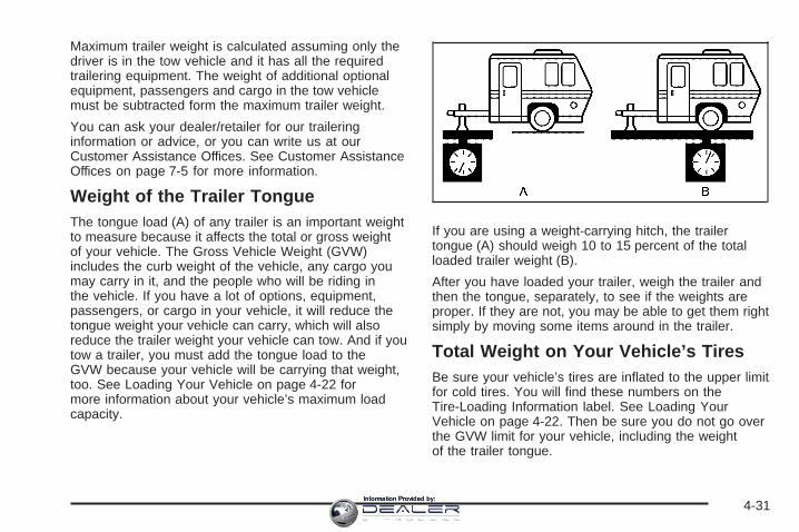
Maximum trailer weight is calculated assuming only thedriver is in the tow vehicle and it has all the requiredtrailering equipment. The weight of additional optionalequipment, passengers and cargo in the tow vehiclemust be subtracted form the maximum trailer weight.
You can ask your dealer/retailer for our traileringinformation or advice, or you can write us at ourCustomer Assistance Offices. See Customer AssistanceOffices on page 7-5 for more information.
Weight of the Trailer TongueThe tongue load (A) of any trailer is an important weightto measure because it affects the total or gross weightof your vehicle. The Gross Vehicle Weight (GVW)includes the curb weight of the vehicle, any cargo youmay carry in it, and the people who will be riding inthe vehicle. If you have a lot of options, equipment,passengers, or cargo in your vehicle, it will reduce thetongue weight your vehicle can carry, which will alsoreduce the trailer weight your vehicle can tow. And if youtow a trailer, you must add the tongue load to theGVW because your vehicle will be carrying that weight,too. See Loading Your Vehicle on page 4-22 formore information about your vehicle’s maximum loadcapacity.
If you are using a weight-carrying hitch, the trailertongue (A) should weigh 10 to 15 percent of the totalloaded trailer weight (B).
After you have loaded your trailer, weigh the trailer andthen the tongue, separately, to see if the weights areproper. If they are not, you may be able to get them rightsimply by moving some items around in the trailer.
Total Weight on Your Vehicle’s TiresBe sure your vehicle’s tires are inflated to the upper limitfor cold tires. You will find these numbers on theTire-Loading Information label. See Loading YourVehicle on page 4-22. Then be sure you do not go overthe GVW limit for your vehicle, including the weightof the trailer tongue.
4-31Information Provided by:

HitchesIt is important to have the correct hitch equipment.Crosswinds, large trucks going by and rough roads area few reasons why you will need the right hitch. Hereare some rules to follow:
• The rear bumper on your vehicle is not intended forhitches. Do not attach rental hitches or otherbumper-type hitches to it. Use only a frame-mountedhitch that does not attach to the bumper.
• Will you have to make any holes in the body of yourvehicle when you install a trailer hitch? If you do, thenbe sure to seal the holes later when you remove thehitch. If you do not seal them, deadly carbonmonoxide (CO) from your exhaust can get into yourvehicle. See Engine Exhaust on page 2-47. Dirt andwater can also enter the vehicle.
Safety ChainsYou should always attach chains between your vehicleand your trailer. Cross the safety chains under the tongueof the trailer so that the tongue will not drop to the road ifit becomes separated from the hitch. Instructions aboutsafety chains may be provided by the hitch manufactureror by the trailer manufacturer. Follow the manufacturer’srecommendation for attaching safety chains and do notattach them to the bumper. Always leave just enoughslack so you can turn with your rig. And, never allowsafety chains to drag on the ground.
Trailer BrakesDoes your trailer have its own brakes? Be sure to readand follow the instructions for the trailer brakes so you willbe able to install, adjust and maintain them properly.
Because you have anti-lock brakes, do not try to tap intoyour vehicle’s brake system. If you do, both brakesystems will not work well, or at all.
Trailer Wiring HarnessAll of the electrical circuits required for your trailerlighting system can be accessed at the driver’s side rearlamp connector. This connector is located under thecarpet on the rear corner of the trunk compartment.
4-32Information Provided by:

Driving with a TrailerTowing a trailer requires a certain amount of experience.Before setting out for the open road, you will want toget to know your rig. Acquaint yourself with the feel ofhandling and braking with the added weight of the trailer.And always keep in mind that the vehicle you aredriving is now a good deal longer and not nearly asresponsive as your vehicle is by itself.
Before you start, check all trailer hitch parts andattachments, safety chains, electrical connector, lamps,tires and mirror adjustment. If the trailer has electricbrakes, start your vehicle and trailer moving and thenapply the trailer brake controller by hand to be surethe brakes are working. This lets you check yourelectrical connection at the same time.
During your trip, check occasionally to be sure that theload is secure, and that the lamps and any trailerbrakes are still working.
Following DistanceStay at least twice as far behind the vehicle ahead asyou would when driving your vehicle without a trailer.This can help you avoid situations that requireheavy braking and sudden turns.
PassingYou will need more passing distance up ahead when youare towing a trailer. And, because the vehicle is a gooddeal longer, you will need to go much farther beyond thepassed vehicle before you can return to your lane.
Backing UpHold the bottom of the steering wheel with one hand.Then, to move the trailer to the left, just move that handto the left. To move the trailer to the right, move yourhand to the right. Always back up slowly and, if possible,have someone guide you.
Making Turns
Notice: Making very sharp turns while traileringcould cause the trailer to come in contact with thevehicle. Your vehicle could be damaged. Avoidmaking very sharp turns while trailering.
When you are turning with a trailer, make wider turns thannormal. Do this so your trailer will not strike softshoulders, curbs, road signs, trees or other objects. Avoidjerky or sudden maneuvers. Signal well in advance.
4-33Information Provided by:

Turn Signals When Towing a TrailerWhen you tow a trailer, your vehicle may need adifferent turn signal flasher and/or extra wiring. Checkwith your dealer/retailer. The arrows on your instrumentpanel will flash whenever you signal a turn or lanechange. Properly hooked up, the trailer lamps will alsoflash, telling other drivers you are about to turn,change lanes or stop.
When towing a trailer, the arrows on your instrumentpanel will flash for turns even if the bulbs on the trailerare burned out. Thus, you may think drivers behindyou are seeing your signal when they are not. Itis important to check occasionally to be sure the trailerbulbs are still working.
Your vehicle has bulb warning lights. When you plug atrailer lighting system into your vehicle’s lightingsystem, its bulb warning lights may not let you know ifone of your lamps goes out. So, when you have a trailerlighting system plugged in, be sure to check yourvehicle and trailer lamps from time to time to be surethey are all working. Once you disconnect the trailerlamps, the bulb warning lights again can tell you if oneof your vehicle lamps is out.
Driving On GradesReduce speed and shift to a lower gear before you startdown a long or steep downgrade. If you do not shiftdown, you might have to use your brakes so much thatthey would get hot and no longer work well.
On a long uphill grade, shift down to a lower gear andreduce your speed to around 45 mph (70 km/h) to reducethe possibility of engine and transmission overheating.
Parking on Hills
{CAUTION:
You really should not park your vehicle, with atrailer attached, on a hill. If something goeswrong, your rig could start to move. Peoplecan be injured, and both your vehicle and thetrailer can be damaged.
But if you ever have to park your rig on a hill, here ishow to do it:
1. Apply your regular brakes, but do not shift intoPARK (P) yet.
2. Have someone place chocks under the trailerwheels.
4-34Information Provided by:

3. When the wheel chocks are in place, release theregular brakes until the chocks absorb the load.
4. Reapply the regular brakes. Then apply yourparking brake, and then shift to PARK (P).
5. Release the regular brakes.
When You Are Ready to Leave AfterParking on a Hill
1. Apply your regular brakes and hold the pedal downwhile you:
• Start your engine.
• Shift into a gear.
• Release the parking brake.
2. Let up on the brake pedal.
3. Drive slowly until the trailer is clear of the chocks.
4. Stop and have someone pick up and store thechocks.
Maintenance When Trailer TowingYour vehicle will need service more often when you’repulling a trailer. See the Maintenance Schedule for moreon this. Things that are especially important in traileroperation are automatic transmission fluid (don’t overfill),engine oil, drive belt, cooling system and brakesystem. Each of these is covered in this manual, andthe Index will help you find them quickly. If you’retrailering, it’s a good idea to review this informationbefore you start your trip.
Check periodically to see that all hitch nuts and boltsare tight.
Engine Cooling When Trailer TowingYour cooling system may temporarily overheat duringsevere operating conditions. See Engine Overheating onpage 5-30.
4-35Information Provided by:

✍ NOTES
4-36Information Provided by:

Service ............................................................5-3Accessories and Modifications ..........................5-3California Proposition 65 Warning .....................5-4California Perchlorate Materials Requirements .....5-4Doing Your Own Service Work .........................5-4Adding Equipment to the Outside
of Your Vehicle ...........................................5-5Fuel ................................................................5-5
Gasoline Octane ............................................5-5Gasoline Specifications ....................................5-6California Fuel ...............................................5-6Additives .......................................................5-6Fuels in Foreign Countries ...............................5-7Filling the Tank ..............................................5-8Filling a Portable Fuel Container .....................5-11
Checking Things Under the Hood ....................5-12Hood Release ..............................................5-13Engine Compartment Overview .......................5-14Engine Oil ...................................................5-16Engine Oil Life System ..................................5-19Engine Air Cleaner/Filter ................................5-21Automatic Transmission Fluid .........................5-25Manual Transmission Fluid .............................5-25Hydraulic Clutch ...........................................5-26Engine Coolant .............................................5-27Coolant Surge Tank Pressure Cap ..................5-30Engine Overheating .......................................5-30
Overheated Engine Protection Operating Mode ...5-32Cooling System ............................................5-33Power Steering Fluid .....................................5-38Windshield Washer Fluid ................................5-39Brakes ........................................................5-40Battery ........................................................5-43Jump Starting ...............................................5-44
All-Wheel Drive ..............................................5-49Rear Axle .......................................................5-50Headlamp Aiming ...........................................5-51Bulb Replacement ..........................................5-55
High Intensity Discharge (HID) Lighting ............5-55Halogen Bulbs ..............................................5-55Front Turn Signal and Fog Lamps ...................5-56License Plate Lamp ......................................5-56Replacement Bulbs .......................................5-57
Windshield Wiper Blade Replacement ..............5-57Tires ..............................................................5-59
Winter Tires .................................................5-60Tire Sidewall Labeling ...................................5-61Tire Terminology and Definitions .....................5-64Inflation - Tire Pressure .................................5-67High-Speed Operation ...................................5-69Tire Pressure Monitor System .........................5-70Tire Pressure Monitor Operation .....................5-71Tire Inspection and Rotation ...........................5-75
Section 5 Service and Appearance Care
5-1Information Provided by:

When It Is Time for New Tires .......................5-76Buying New Tires .........................................5-77Different Size Tires and Wheels ......................5-79Uniform Tire Quality Grading ..........................5-80Wheel Alignment and Tire Balance ..................5-81Wheel Replacement ......................................5-81Tire Chains ..................................................5-83If a Tire Goes Flat ........................................5-83Tire Sealant and Compressor Kit
(With Sealant Selector Switch) ....................5-85Tire Sealant and Compressor Kit
(Without Sealant Selector Switch) ................5-93Changing a Flat Tire ...................................5-102Removing the Spare Tire and Tools ..............5-104Removing the Flat Tire and Installing
the Spare Tire .........................................5-105Storing a Flat or Spare Tire and Tools ...........5-110Compact Spare Tire ....................................5-111
Appearance Care ..........................................5-111Interior Cleaning .........................................5-111Fabric/Carpet ..............................................5-113Leather ......................................................5-113Instrument Panel, Vinyl, and Other
Plastic Surfaces .......................................5-114Wood Panels ..............................................5-114Speaker Covers ..........................................5-114
Care of Safety Belts ....................................5-114Weatherstrips .............................................5-115Washing Your Vehicle ..................................5-115Cleaning Exterior Lamps/Lenses ....................5-116Finish Care ................................................5-116Windshield and Wiper Blades .......................5-117Aluminum or Chrome-Plated Wheels
and Trim ................................................5-117Tires .........................................................5-118Sheet Metal Damage ...................................5-118Finish Damage ...........................................5-118Underbody Maintenance ...............................5-119Chemical Paint Spotting ...............................5-119Vehicle Care/Appearance Materials ................5-119
Vehicle Identification .....................................5-120Vehicle Identification Number (VIN) ................5-120Service Parts Identification Label ...................5-121
Electrical System ..........................................5-121Add-On Electrical Equipment .........................5-121Windshield Wiper Fuses ...............................5-121Power Windows and Other Power Options ......5-122Fuses and Circuit Breakers ..........................5-122Underhood Fuse Block ................................5-122Rear Compartment Fuse Block .....................5-126
Capacities and Specifications ........................5-128
Section 5 Service and Appearance Care
5-2Information Provided by:

ServiceFor service and parts needs, visit your dealer/retailer.You will receive genuine GM parts and GM-trained andsupported service people.
Genuine GM parts have one of these marks:
Accessories and ModificationsWhen non-dealer/non-retailer accessories are added toyour vehicle they can affect your vehicle’s performanceand safety, including such things as, airbags, braking,stability, ride and handling, emissions systems,aerodynamics, durability, and electronic systems likeantilock brakes, traction control and stability control.Some of these accessories could even causemalfunction or damage not covered by warranty.
GM Accessories are designed to complement andfunction with other systems on your vehicle. YourGM dealer/retailer can accessorize your vehicle usinggenuine GM Accessories. When you go to yourGM dealer/retailer and ask for GM Accessories,you will know that GM-trained and supported servicetechnicians will perform the work using genuineGM Accessories.
Also, see Adding Equipment to Your Airbag-EquippedVehicle on page 1-69.
5-3Information Provided by:

California Proposition 65 WarningMost motor vehicles, including this one, contain and/oremit chemicals known to the State of California tocause cancer and birth defects or other reproductiveharm. Engine exhaust, many parts and systems(including some inside the vehicle), many fluids,and some component wear by-products containand/or emit these chemicals.
California Perchlorate MaterialsRequirementsCertain types of automotive applications, such asairbag initiators, seat belt pretensioners, and lithiumbatteries contained in remote keyless entry transmitters,may contain perchlorate materials. Special handlingmay be necessary. For additional information, seewww.dtsc.ca.gov/hazardouswaste/perchlorate.
Doing Your Own Service Work
{CAUTION:
You can be injured and your vehicle could bedamaged if you try to do service work on avehicle without knowing enough about it.
• Be sure you have sufficient knowledge,experience, the proper replacement parts,and tools before you attempt any vehiclemaintenance task.
• Be sure to use the proper nuts, bolts,and other fasteners. English and metricfasteners can be easily confused. If youuse the wrong fasteners, parts can laterbreak or fall off. You could be hurt.
If you want to do some of your own service work, youshould use the proper service manual. It tells you muchmore about how to service your vehicle than thismanual can. To order the proper service manual, seeService Publications Ordering Information on page 7-15.
Your vehicle has an airbag system. Before attemptingto do your own service work, see Servicing YourAirbag-Equipped Vehicle on page 1-68.
5-4Information Provided by:

You should keep a record with all parts receipts and listthe mileage and the date of any service work youperform. See Maintenance Record on page 6-15.
Adding Equipment to the Outsideof Your VehicleThings you might add to the outside of your vehicle canaffect the airflow around it. This can cause windnoise and can affect fuel economy and windshieldwasher performance. Check with your dealer/retailerbefore adding equipment to the outside of your vehicle.
FuelUse of the recommended fuel is an important partof the proper maintenance of your vehicle. To helpkeep the engine clean and maintain optimum vehicleperformance, we recommend the use of gasolineadvertised as TOP TIER Detergent Gasoline.
The 8th digit of the Vehicle Identification Number (VIN)shows the code letter or number that identifies yourvehicle’s engine. The VIN is at the top left of theinstrument panel. See Vehicle IdentificationNumber (VIN) on page 5-120.
Gasoline OctaneIf your vehicle has the 3.6L V6 engine (VIN Code V),use regular unleaded gasoline with a posted octanerating of 87 or higher. If the octane rating is less than 87,you might notice an audible knocking noise when youdrive, commonly referred to as spark knock. If thisoccurs, use a gasoline rated at 87 octane or higher assoon as possible. If you are using gasoline rated at87 octane or higher and you hear heavy knocking, theengine needs service.
If your vehicle has the 3.6L V6 engine (VIN Code 7),use regular unleaded gasoline with a posted octanerating of 87 or higher. For best performance or trailertowing, you could choose to use middle grade 89 octaneunleaded gasoline. If the octane rating is less than87, you might notice an audible knocking noise whenyou drive, commonly referred to as spark knock.If this occurs, use a gasoline rated at 87 octane orhigher as soon as possible. If you are using gasolinerated at 87 octane or higher and you hear heavyknocking, the engine needs service.
5-5Information Provided by:

Gasoline SpecificationsAt a minimum, gasoline should meet ASTMspecification D 4814 in the United States orCAN/CGSB-3.5 or 3.511 in Canada. Some gasolinescontain an octane-enhancing additive calledmethylcyclopentadienyl manganese tricarbonyl (MMT).We recommend against the use of gasolinescontaining MMT. See Additives on page 5-6 foradditional information.
California FuelIf your vehicle is certified to meet California EmissionsStandards, it is designed to operate on fuels thatmeet California specifications. See the underhoodemission control label. If this fuel is not availablein states adopting California emissions standards,your vehicle will operate satisfactorily on fuels meetingfederal specifications, but emission control systemperformance might be affected. The malfunctionindicator lamp could turn on and your vehicle mightfail a smog-check test. See Malfunction Indicator Lampon page 3-40. If this occurs, return to your authorizeddealer/retailer for diagnosis. If it is determined thatthe condition is caused by the type of fuel used,repairs might not be covered by your warranty.
AdditivesTo provide cleaner air, all gasolines in the United Statesare now required to contain additives that help preventengine and fuel system deposits from forming, allowingthe emission control system to work properly. In mostcases, you should not have to add anything to the fuel.However, some gasolines contain only the minimumamount of additive required to meet U.S. EnvironmentalProtection Agency regulations. To help keep fuel injectorsand intake valves clean, or if your vehicle experiencesproblems due to dirty injectors or valves, look for gasolinethat is advertised as TOP TIER Detergent Gasoline. Also,your dealer/retailer has additives that will help correct andprevent most deposit-related problems.
Gasolines containing oxygenates, such as ethers andethanol, and reformulated gasolines might be available inyour area. We recommend that you use these gasolines,if they comply with the specifications described earlier.However, E85 (85% ethanol) and other fuels containingmore than 10% ethanol must not be used in vehicles thatwere not designed for those fuels.
5-6Information Provided by:
Notice: Your vehicle was not designed for fuel thatcontains methanol. Do not use fuel containingmethanol. It can corrode metal parts in the fuelsystem and also damage plastic and rubber parts.That damage would not be covered under yourwarranty.
Some gasolines that are not reformulated for lowemissions can contain an octane-enhancing additivecalled methylcyclopentadienyl manganese tricarbonyl(MMT); ask the attendant where you buy gasolinewhether the fuel contains MMT. We recommend againstthe use of such gasolines. Fuels containing MMT canreduce the life of spark plugs and the performanceof the emission control system could be affected.The malfunction indicator lamp might turn on. If thisoccurs, return to your dealer/retailer for service.
Fuels in Foreign CountriesIf you plan on driving in another country outside theUnited States or Canada, the proper fuel might behard to find. Never use leaded gasoline or any otherfuel not recommended in the previous text on fuel.Costly repairs caused by use of improper fuel wouldnot be covered by your warranty.
To check the fuel availability, ask an auto club, orcontact a major oil company that does business inthe country where you will be driving.
5-7Information Provided by:

Filling the Tank
{CAUTION:
Fuel vapor burns violently and a fuel fire cancause bad injuries. To help avoid injuries toyou and others, read and follow all theinstructions on the pump island. Turn off yourengine when you are refueling. Do not smokeif you are near fuel or refueling your vehicle.Do not use cellular phones. Keep sparks,flames, and smoking materials away from fuel.Do not leave the fuel pump unattended whenrefueling your vehicle. This is against the lawin some places. Do not re-enter the vehiclewhile pumping fuel. Keep children away fromthe fuel pump; never let children pump fuel.
The fuel cap is behind a hinged fuel door on thepassenger’s side of the vehicle. The fuel door is openedby pushing in on the rear edge until the door pops out.
5-8Information Provided by:

To remove the fuel cap, turn it slowly counterclockwise.The fuel cap has a spring in it; if the cap is releasedtoo soon, it will spring back to the right.
While refueling, hang the tethered fuel cap from thehook on the fuel door.
{CAUTION:
Fuel can spray out on you if you open thefuel cap too quickly. If you spill fuel and thensomething ignites it, you could be badly burned.This spray can happen if your tank is nearly full,and is more likely in hot weather. Open the fuelcap slowly and wait for any hiss noise to stop.Then unscrew the cap all the way.
Be careful not to spill fuel. Do not top off or overfillthe tank and wait a few seconds after you have finishedpumping before removing the nozzle. Clean fuel frompainted surfaces as soon as possible. See WashingYour Vehicle on page 5-115.
5-9Information Provided by:

When replacing the fuel cap, turn it clockwise until itclicks. Make sure the cap is fully installed. Thediagnostic system can determine if the fuel cap hasbeen left off or improperly installed. This would allow fuelto evaporate into the atmosphere. See MalfunctionIndicator Lamp on page 3-40.
The Tighten Gas Cap message in the Driver InformationCenter (DIC) will be displayed if the fuel cap is notproperly installed. See DIC Warnings and Messageson page 3-54 for more information.
{CAUTION:
If a fire starts while you are refueling, do notremove the nozzle. Shut off the flow of fuel byshutting off the pump or by notifying thestation attendant. Leave the area immediately.
Notice: If you need a new fuel cap, be sure to getthe right type. Your dealer/retailer can get onefor you. If you get the wrong type, it may not fitproperly. This may cause your malfunction indicatorlamp to light and may damage your fuel tank andemissions system. See Malfunction Indicator Lampon page 3-40.
5-10Information Provided by:

Filling a Portable Fuel Container
{CAUTION:
Never fill a portable fuel container while it isin your vehicle. Static electricity dischargefrom the container can ignite the fuel vapor.You can be badly burned and your vehicledamaged if this occurs. To help avoid injuryto you and others:
• Dispense fuel only into approvedcontainers.
• Do not fill a container while it is inside avehicle, in a vehicle’s trunk, pickup bed,or on any surface other than the ground.
CAUTION: (Continued)
CAUTION: (Continued)
• Bring the fill nozzle in contact with theinside of the fill opening before operatingthe nozzle. Contact should be maintaineduntil the filling is complete.
• Do not smoke while pumping fuel.
• Do not use a cellular phone whilepumping fuel.
5-11Information Provided by:
Checking Things Underthe Hood
{CAUTION:
An electric fan under the hood can start upand injure you even when the engine is notrunning. Keep hands, clothing, and tools awayfrom any underhood electric fan.
{CAUTION:
Things that burn can get on hot engine partsand start a fire. These include liquids like fuel,oil, coolant, brake fluid, windshield washer andother fluids, and plastic or rubber. You orothers could be burned. Be careful not to dropor spill things that will burn onto a hot engine.
5-12Information Provided by:

Hood ReleaseTo open the hood, do the following:
1. Pull the hood releaselever with this symbolon it. It is located insidethe vehicle on the lowerleft side of theinstrument panel.
2. Then go to the front of the vehicle and find thesecondary hood release lever. The lever is locatedunder the front edge of the grille near the center.Push the release lever up and raise the hood.
Before closing the hood, be sure all the filler caps areon properly. Then pull the hood down and close it firmly.
5-13Information Provided by:

Engine Compartment OverviewWhen you open the hood, here is what you will see:
5-14Information Provided by:

A. Windshield Washer Fluid Reservoir. See “AddingWasher Fluid” under Windshield Washer Fluidon page 5-39.
B. Underhood Fuse Block. See Underhood Fuse Blockon page 5-122.
C. Remote Positive (+) Terminal. See Jump Startingon page 5-44.
D. Remote Negative (+) Terminal. See Jump Startingon page 5-44.
E. Passenger Compartment Air Filter. See PassengerCompartment Air Filter on page 3-28.
F. Engine Cooling Fan. See Cooling Systemon page 5-33.
G. Power Steering Fluid Reservoir (Under EngineCover). See Power Steering Fluid on page 5-38.
H. Engine Oil Fill Cap. See “When to Add Engine Oil”under Engine Oil on page 5-16.
I. Engine Oil Dipstick (Out of View). See “CheckingEngine Oil” under Engine Oil on page 5-16.
J. Hydraulic Clutch Reservoir (If Equipped) (NotShown). See “When to Check and What to Use”under Hydraulic Clutch on page 5-26.
K. Brake Master Cylinder Reservoir (Out of View).See “Brake Fluid” under Brakes on page 5-40.
L. Engine Coolant Surge Tank and Pressure Cap.See Coolant Surge Tank Pressure Cap on page 5-30and Cooling System on page 5-33.
M. Engine Air Cleaner/Filter. See Engine AirCleaner/Filter on page 5-21.
5-15Information Provided by:

Engine Oil
There is an oil pressurelight in the instrumentcluster and an Oil PressureLow Stop Enginemessage on the DriverInformation Center (DIC).
If the light and/or message appear, check the engine oillevel right away. For more information, see “OilPressure Low Stop Engine” under DIC Warnings andMessages on page 3-54 and Oil Pressure Light onpage 3-43. You should check the engine oil levelregularly; this is an added reminder.
Checking Engine OilIt is a good idea to check the engine oil every time youget fuel. In order to get an accurate reading, the oilmust be warm and the vehicle must be on level ground.
The engine oil dipstick handle is a yellow loop. SeeEngine Compartment Overview on page 5-14 forthe location of the engine oil dipstick.
1. Turn off the engine and give the oil several minutesto drain back into the oil pan. If you do not do this,the oil dipstick might not show the actual level.
2. Pull out the dipstick and clean it with a paper towelor cloth, then push it back in all the way. Remove itagain, keeping the tip down, and check the level.
5-16Information Provided by:

When to Add Engine Oil
If the oil level is within the add cross-hatched area atthe tip of the dipstick, add at least one quart/liter of therecommended oil. This section explains what kind ofoil to use. For engine oil crankcase capacity, seeCapacities and Specifications on page 5-128.
Notice: Do not add too much oil. If the enginehas so much oil that the oil level gets above theproper operating range and into the uppercross-hatched area on the dipstick, the enginecould be damaged.
See Engine CompartmentOverview on page 5-14for the location of theengine oil fill cap.
Be sure to add enough oil to put the level somewherein the proper operating range. Push the dipstick allthe way back in when you are through.
5-17Information Provided by:

What Kind of Engine Oil to Use
Look for three things:
• GM4718M
Your vehicle’s engine requires a special oil meetingGM Standard GM4718M. Oils meeting this standardmay be identified as synthetic. However, not allsynthetic oils will meet this GM standard. Look for anduse only an oil that meets GM Standard GM4718M.
Notice: If you use oils that do not have theGM4718M Standard designation, you can causeengine damage not covered by your warranty.
• SAE 5W-30
As shown in the viscosity chart, SAE 5W-30 is bestfor your vehicle.These numbers on an oil container show itsviscosity, or thickness. Do not use other viscosityoils such as SAE 20W-50.
• Oils meeting theserequirements shouldhave the starburstsymbol on the container.This symbol indicatesthat the oil hasbeen certified by theAmerican PetroleumInstitute (API).
Look for this on the oil container, and use only thoseoils that are identified as meeting GM StandardGM4718M and have the starburst symbol on the front ofthe oil container.
Your vehicle’s engine is filled at the factory with aMobil 1® synthetic oil, which meets all requirements foryour vehicle.
5-18Information Provided by:

Substitute Engine Oil: When adding oil to maintainengine oil level, oil meeting GM Standard GM4718Mmay not be available. You can add substitute oildesignated SAE 5W-30 with the starburst symbol at alltemperatures. Substitute oil not meeting GM StandardGM4718M should not be used for an oil change.
Engine Oil AdditivesDo not add anything to the oil. The recommended oilswith the starburst symbol that meet GM standards are allyou need for good performance and engine protection.
Engine Oil Life System
When to Change Engine OilYour vehicle has a computer system that lets you knowwhen to change the engine oil and filter. This is based onengine revolutions and engine temperature, and not onmileage. Based on driving conditions, the mileage atwhich an oil change will be indicated can varyconsiderably. For the oil life system to work properly, youmust reset the system every time the oil is changed.
When the system has calculated that oil life has beendiminished, it will indicate that an oil change isnecessary. A Change Engine Oil Soon message willcome on. See DIC Warnings and Messages onpage 3-54. Change the oil as soon as possible withinthe next 600 miles (1 000 km). It is possible that, if youare driving under the best conditions, the oil lifesystem might not indicate that an oil change isnecessary for over a year. However, the engine oil andfilter must be changed at least once a year and atthis time the system must be reset. Your dealer/retailerhas trained service people who will perform this workusing genuine parts and reset the system. It is alsoimportant to check the oil regularly and keep it at theproper level.
If the system is ever reset accidentally, you mustchange the oil at 3,000 miles (5 000 km) since your lastoil change. Remember to reset the oil life systemwhenever the oil is changed.
5-19Information Provided by:

How to Reset the Engine Oil LifeSystemThe Engine Oil Life System calculates when to changethe engine oil and filter based on vehicle use.Whenever the oil is changed, reset the system so it cancalculate when the next oil change is required. If asituation occurs where you change the oil priorto a Change Engine Oil Soon message being turned on,reset the system.
Always reset the engine oil life to 100% after every oilchange. It will not reset itself. To reset the EngineOil Life System:
1. Display the OIL LIFE REMAINING on the DIC.
2. Press and hold the SET/RESET button on the DICfor more than five seconds. The oil life will changeto 100%.
If the Change Engine Oil Soon message comes back onwhen you start your vehicle, the Engine Oil LifeSystem has not reset. Repeat the procedure.
What to Do with Used OilUsed engine oil contains certain elements that can beunhealthy for your skin and could even cause cancer.Do not let used oil stay on your skin for very long. Cleanyour skin and nails with soap and water, or a goodhand cleaner. Wash or properly dispose of clothing orrags containing used engine oil. See the manufacturer’swarnings about the use and disposal of oil products.
Used oil can be a threat to the environment. If youchange your own oil, be sure to drain all the oil from thefilter before disposal. Never dispose of oil by putting itin the trash, pouring it on the ground, into sewers, or intostreams or bodies of water. Instead, recycle it bytaking it to a place that collects used oil. If you have aproblem properly disposing of used oil, ask yourdealer/retailer, a service station, or a local recyclingcenter for help.
5-20Information Provided by:
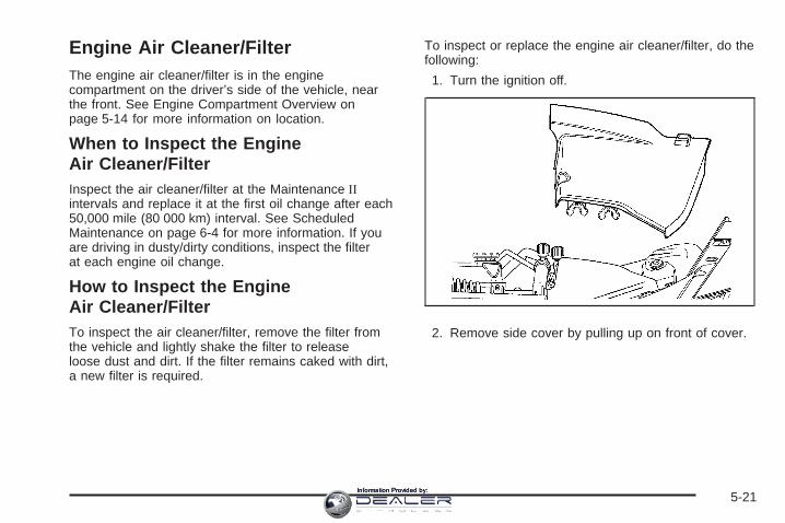
Engine Air Cleaner/FilterThe engine air cleaner/filter is in the enginecompartment on the driver’s side of the vehicle, nearthe front. See Engine Compartment Overview onpage 5-14 for more information on location.
When to Inspect the EngineAir Cleaner/FilterInspect the air cleaner/filter at the Maintenance IIintervals and replace it at the first oil change after each50,000 mile (80 000 km) interval. See ScheduledMaintenance on page 6-4 for more information. If youare driving in dusty/dirty conditions, inspect the filterat each engine oil change.
How to Inspect the EngineAir Cleaner/FilterTo inspect the air cleaner/filter, remove the filter fromthe vehicle and lightly shake the filter to releaseloose dust and dirt. If the filter remains caked with dirt,a new filter is required.
To inspect or replace the engine air cleaner/filter, do thefollowing:
1. Turn the ignition off.
2. Remove side cover by pulling up on front of cover.
5-21Information Provided by:

3. Disconnect electrical connector from air box.
4. Loosen the screw on the clamp holding the air outletduct in place. Do not pry the clamp off. position theduct aside.
5. Remove the rubber hose from the air cleanerhousing mounting arm. Position the rubber hoseaside.
6. Remove the three air cleaner housing coverscrews.
5-22Information Provided by:

7. Pivot the air cleaner housing cover and remove thecover from the air cleaner housing.
8. Remove the air cleaner element from the aircleaner housing.
5-23Information Provided by:

How to Reinstall EngineAir Cleaner/Filter
1. Install the air cleaner element to the air cleanerhousing. Ensure that the air cleaner elementperimeter seal is installed correctly to the air cleanerhousing.
2. Align the air cleaner housing cover tabs to the aircleaner housing.
3. Install the air cleaner housing cover.
4. Install the air cleaner housing cover screws.
5. Install the surge tank hose to the air cleaner housingmounting arm. Ensure that the hose is routedcorrectly.
6. Install the air cleaner outlet duct to the air cleanerhousing.
7. Tighten the air cleaner outlet duct screw clamp.
8. Attach electrical connector to airbox.
9. Reinstall side cover.
{CAUTION:
Operating the engine with the air cleaner/filteroff can cause you or others to be burned.The air cleaner not only cleans the air; it helpsto stop flames if the engine backfires. If it isnot there and the engine backfires, you couldbe burned. Do not drive with it off, and becareful working on the engine with the aircleaner/filter off.
Notice: If the air cleaner/filter is off, a backfire cancause a damaging engine fire. And, dirt caneasily get into your engine, which will damage it.Always have the air cleaner/filter in place when youare driving.
5-24Information Provided by:

Automatic Transmission Fluid
How to Check AutomaticTransmission FluidIt is not necessary to check the transmission fluid level.A transmission fluid leak is the only reason for fluidloss. If a leak occurs, take the vehicle to thedealer/retailer service department and have it repairedas soon as possible.
There is a special procedure for checking and changingthe transmission fluid. Because this procedure isdifficult, you should have this done at the dealer/retailerservice department. Contact your dealer/retailer foradditional information or the procedure can be found inthe service manual. To purchase a service manual,see Service Publications Ordering Information onpage 7-15.
Notice: Use of the incorrect automatic transmissionfluid may damage your vehicle, and the damagesmay not be covered by your warranty. Alwaysuse the automatic transmission fluid listed inRecommended Fluids and Lubricants on page 6-11.
Change the fluid and filter at the intervals listed inAdditional Required Services on page 6-5, and be sureto use the fluid listed in Recommended Fluids andLubricants on page 6-11.
Manual Transmission Fluid
When to Check ManualTransmission FluidIt is not necessary to check the manual transmissionfluid level. A transmission fluid leak is the only reason forfluid loss. If a leak occurs, take the vehicle to yourdealer/retailer service department and have it repairedas soon as possible.
How to Check ManualTransmission FluidBecause this operation can be difficult, you may chooseto have this done at your dealer/retailer servicedepartment.
If you do it yourself, be sure to follow all the instructionshere, or you could get a false reading.
Notice: Too much or too little fluid can damageyour transmission. Too much can mean that someof the fluid could come out and fall on hot engineparts or exhaust system parts, starting a fire.Too little fluid could cause the transmission tooverheat. Be sure to get an accurate reading if youcheck your transmission fluid.
5-25Information Provided by:

Check the fluid level only when your engine is off, thevehicle is parked on a level place and the transmissionis cool enough for you to rest your fingers on thetransmission case.
To check the fluid level, do the following:
1. Remove the filler plug.
2. Check that the lubricant level is up to the bottom ofthe filler plug hole.
3. If the fluid level is good, replace the gasket andreinstall the filler plug.With either vehicle, be sure the plug is fully seated.If the fluid level is low, add more fluid as describedin the next steps.
How to Add Manual Transmission FluidHere is how to add fluid. See Recommended Fluidsand Lubricants on page 6-11 to determine which type offluid to use.
1. Remove the filler plug.
2. Add fluid at the filler plug hole. Add only enoughfluid to bring the fluid level up to the bottom of thefiller plug hole.
3. Replace the gasket and reinstall the filler plug.Be sure the plug is fully seated.
Hydraulic ClutchIt is not necessary to regularly check clutch fluid unlessyou suspect there is a leak in the system. Addingfluid will not correct a leak.
A fluid loss in this system could indicate a problem.Have the system inspected and repaired.
When to Check and What to Use
The hydraulic clutch fluidreservoir cap has thissymbol on it. See EngineCompartment Overviewon page 5-14 for reservoirlocation.
Refer to the Maintenance Schedule to determine howoften you should check the fluid level in your clutchmaster cylinder reservoir and for the proper fluid to use.See Owner Checks and Services on page 6-8 andRecommended Fluids and Lubricants on page 6-11.
5-26Information Provided by:

How to Check and Add FluidMake sure the fluid level is at the MIN (Minimum) lineon the side of the reservoir. If it is not, remove thecap and add the proper fluid until the level reaches theMIN line.
Engine CoolantThe cooling system in your vehicle is filled withDEX-COOL® engine coolant. This coolant is designedto remain in your vehicle for five years or 150,000 miles(240 000 km), whichever occurs first, if you add onlyDEX-COOL® extended life coolant.
The following explains the cooling system and how toadd coolant when it is low. If the engine overheats, seeEngine Overheating on page 5-30.
A 50/50 mixture of clean, drinkable water andDEX-COOL® coolant will:
• Give freezing protection down to −34°F (−37°C).
• Give boiling protection up to 265°F (129°C).
• Protect against rust and corrosion.
• Help keep the proper engine temperature.
• Allow the warning lights and gages to work asthey should.
Notice: Using coolant other than DEX-COOL ® maycause premature engine, heater core, or radiatorcorrosion. In addition, the engine coolant mayrequire changing sooner, at the first maintenanceservice after each 30,000 miles (50 000 km) or24 months, whichever occurs first. Any repairswould not be covered by your warranty. Always useDEX-COOL® (silicate-free) coolant in your vehicle.
5-27Information Provided by:

What to UseUse a mixture of one-half clean, drinkable water andone-half DEX-COOL® coolant which will not damagealuminum parts. If you use this coolant mixture, you donot need to add anything else.
{CAUTION:
Adding only plain water to your coolingsystem can be dangerous. Plain water, orsome other liquid such as alcohol, can boilbefore the proper coolant mixture will. Yourvehicle’s coolant warning system is set for theproper coolant mixture. With plain water or thewrong mixture, your engine could get too hotbut you would not get the overheat warning.Your engine could catch fire and you or otherscould be burned. Use a 50/50 mixture of clean,drinkable water and DEX-COOL ® coolant.
Notice: If you use an improper coolant mixture,your engine could overheat and be badly damaged.The repair cost would not be covered by yourwarranty. Too much water in the mixture can freezeand crack the engine, radiator, heater core, andother parts.
If you have to add coolant more than once or twice ayear, have your dealer/retailer check your coolingsystem.
Notice: If you use extra inhibitors and/or additivesin your vehicle’s cooling system, you coulddamage your vehicle. Use only the proper mixtureof the engine coolant listed in this manual forthe cooling system. See Recommended Fluids andLubricants on page 6-11 for more information.
5-28Information Provided by:

Checking Coolant
The coolant surge tank and pressure cap are located onthe driver’s side of the vehicle, toward the rear of theengine compartment. See Engine CompartmentOverview on page 5-14 for more information on location.
{CAUTION:
Turning the surge tank pressure cap when theengine and radiator are hot can allow steamand scalding liquids to blow out and burn youbadly. Never turn the surge tank pressurecap — even a little — when the engine andradiator are hot.
The vehicle must be on a level surface. When yourengine is cold, the coolant level should be at theFROID/FULL COLD line on the side of the surge tank.Follow the arrow from the top of the tank down theside to the horizontal mark.
5-29Information Provided by:

Adding CoolantIf more coolant is needed, add the proper DEX-COOL®
coolant mixture at the surge tank, but only when theengine is cool.
{CAUTION:
You can be burned if you spill coolant on hotengine parts. Coolant contains ethylene glycol,and it will burn if the engine parts are hotenough. Do not spill coolant on a hot engine.
When replacing the pressure cap, make sure it ishand-tight and fully seated.
Coolant Surge Tank Pressure CapNotice: If the pressure cap is not tightly installed,coolant loss and possible engine damage may occur.Be sure the cap is properly and tightly secured.
The coolant surge tank pressure cap must be fullyinstalled on the coolant surge tank. See EngineCompartment Overview on page 5-14 for moreinformation on location.
Engine OverheatingThere are two engine hot messages that may bedisplayed in the Driver Information Center (DIC).See DIC Warnings and Messages on page 3-54 formore information.
5-30Information Provided by:

If Steam Is Coming From Your Engine
{CAUTION:
Steam from an overheated engine can burnyou badly, even if you just open the hood. Stayaway from the engine if you see or hear steamcoming from it. Turn it off and get everyoneaway from the vehicle until it cools down. Waituntil there is no sign of steam or coolantbefore you open the hood.
If you keep driving when the vehicles engine isoverheated, the liquids in it can catch fire. Youor others could be badly burned. Stop yourengine if it overheats, and get out of thevehicle until the engine is cool.
See Overheated Engine Protection OperatingMode on page 5-32 for information on drivingto a safe place in an emergency.
Notice: If your engine catches fire because youkeep driving with no coolant, your vehicle canbe badly damaged. The costly repairs would not becovered by your warranty. See Overheated EngineProtection Operating Mode on page 5-32 forinformation on driving to a safe place in anemergency.
If No Steam Is Coming FromYour EngineAn Engine Overheated Idle Engine warning, along withlow coolant, can indicate a serious problem.
If you get an Engine Overheated Idle Engine warning,but see or hear no steam, the problem may not betoo serious. Sometimes the engine can get a little toohot when you:
• Climb a long hill on a hot day.
• Stop after high-speed driving.
• Idle for long periods in traffic.
• Tow a trailer.
5-31Information Provided by:

If you get the Engine Overheated Idle Engine warningwith no sign of steam, try this for a minute or so:
1. In heavy traffic, let the engine idle in NEUTRAL (N)while stopped. If it is safe to do so, pull off the road,shift to PARK (P) or NEUTRAL (N) and let theengine idle.
2. Set the climate controls to the highest heat settingand fan speed and open the windows, asnecessary.
If you no longer have the Engine Overheated IdleEngine warning, you can drive. Just to be safe, driveslower for about 10 minutes. If the warning doesnot come back on, you can drive normally.
If the warning continues and you have not stopped, pullover, stop, and park your vehicle right away.
If there is still no sign of steam, you can idle the enginefor three minutes while you are parked. If you stillhave the warning, turn off the engine and get everyoneout of the vehicle until it cools down.
You may decide not to lift the hood but to get servicehelp right away.
Overheated Engine ProtectionOperating ModeThis operating mode allows your vehicle to be driven toa safe place in an emergency. Should a hot enginecondition exist, an overheat protection mode whichalternates firing groups of cylinders helps prevent enginedamage. In this mode, there is a loss in power andengine performance. Driving extended miles (km) and/ortowing a trailer in the overheat protection mode shouldbe avoided.
Notice: After driving in the overheated engineprotection operating mode, to avoid engine damage,allow the engine to cool before attempting anyrepair. The engine oil will be severely degraded.Repair the cause of coolant loss and change the oil.See Engine Oil on page 5-16.
5-32Information Provided by:

Cooling SystemWhen you decide it is safe to lift the hood, here is whatyou will see:
A. Electric Engine Cooling Fans (Out of View)B. Coolant Surge Tank and Pressure Cap
{CAUTION:
An electric engine cooling fan under the hoodcan start up even when the engine is notrunning and can injure you. Keep hands,clothing, and tools away from any underhoodelectric fan.
If the coolant inside the coolant surge tank is boiling,do not do anything else until it cools down. The vehicleshould be parked on a level surface.
5-33Information Provided by:

If the engine is warm or hot, the coolant level should beat or above the FROID/FULL COLD line on the sideof the coolant surge tank. If the engine is cold, thecoolant level should be near the FROID/FULL COLDline on the side of the coolant surge tank. If it is not,you could have a leak at the pressure cap or inthe radiator hoses, heater hoses, radiator, water pump,or somewhere else in the cooling system.
{CAUTION:
Heater and radiator hoses, and other engineparts, can be very hot. Do not touch them.If you do, you can be burned.
Do not run the engine if there is a leak. If yourun the engine, it could lose all coolant. Thatcould cause an engine fire, and you could beburned. Get any leak fixed before you drivethe vehicle.
If there seems to be no leak, with the engine on, checkto see if the electric engine cooling fans are running.If the engine hot light is on, both fans should be running.If they are not, your vehicle needs service.
Notice: Engine damage from running your enginewithout coolant is not covered by your warranty. SeeOverheated Engine Protection Operating Mode onpage 5-32 for information on driving to a safe placein an emergency.
Notice: Using coolant other than DEX-COOL ® maycause premature engine, heater core, or radiatorcorrosion. In addition, the engine coolant couldrequire changing sooner, at 30,000 miles (50 000 km)or 24 months, whichever occurs first. Any repairswould not be covered by the warranty. Alwaysuse DEX-COOL ® (silicate-free) coolant in the vehicle.
5-34Information Provided by:

How to Add Coolant to the CoolantSurge TankIf you have not found a problem yet, check to see ifcoolant is visible in the surge tank. If coolant is visiblebut the coolant level is not at the FROID/FULLCOLD line on the side of the coolant surge tank, add a50/50 mixture of clean, drinkable water and DEX-COOL®
coolant at the coolant surge tank, but be sure thecooling system, including the coolant surge tankpressure cap, is cool before you do it. See EngineCoolant on page 5-27 for more information.
{CAUTION:
Steam and scalding liquids from a hot coolingsystem can blow out and burn you badly. Theyare under pressure, and if you turn the coolantsurge tank pressure cap — even a little — theycan come out at high speed. Never turn thecap when the cooling system, including thecoolant surge tank pressure cap, is hot. Waitfor the cooling system and coolant surge tankpressure cap to cool if you ever have to turnthe pressure cap.
{CAUTION:
Adding only plain water to the cooling systemcan be dangerous. Plain water, or some otherliquid such as alcohol, can boil before theproper coolant mixture will. The vehicle’scoolant warning system is set for the propercoolant mixture. With plain water or the wrongmixture, the engine could get too hot but youwould not get the overheat warning. Theengine could catch fire and you or otherscould be burned. Use a 50/50 mixture of clean,drinkable water and DEX-COOL ® coolant.
Notice: In cold weather, water can freeze and crackthe engine, radiator, heater core and other parts.Use the recommended coolant and the propercoolant mixture.
5-35Information Provided by:

{CAUTION:
You can be burned if you spill coolant on hotengine parts. Coolant contains ethylene glycoland it will burn if the engine parts are hotenough. Do not spill coolant on a hot engine.
If no coolant is visible in the surge tank, add coolantas follows:
1. Remove the coolant surge tank pressure capwhen the cooling system, including the coolantsurge tank pressure cap and upper radiator hose,is no longer hot. Turn the pressure cap slowlycounterclockwise about one-quarter turn andthen stop.If you hear a hiss, wait for that to stop. A hissmeans there is still some pressure left.
2. Then keep turning the pressure cap slowly, andremove it.
5-36Information Provided by:

3. Fill the coolant surge tank with the proper mixture,to slightly above the FROID/FULL COLD line on theside of the coolant surge tank.
4. With the coolant surge tank pressure cap off, startthe engine and let it run until you can feel the upperradiator hose getting hot. The upper radiatorhose is the top hose coming out of the radiator, onthe passenger’s side of the vehicle. Watch outfor the engine cooling fans.By this time, the coolant level inside the coolantsurge tank may be lower. If the level is lower, addmore of the proper mixture to the coolant surge tankuntil the level reaches the FROID/FULL COLDline on the side of the coolant surge tank.
5. Then replace the pressure cap. Be sure thepressure cap is hand-tight and fully seated.
Recheck the coolant level in the bottle next time youuse your vehicle to insure the system is full when cold.See Engine Coolant on page 5-27.
5-37Information Provided by:

Power Steering Fluid
See Engine CompartmentOverview on page 5-14 forthe location of the powersteering fluid reservoir.
When to Check Power Steering FluidIt is not necessary to regularly check power steering fluidunless you suspect there is a leak in the system oryou hear an unusual noise. A fluid loss in this systemcould indicate a problem. Have the system inspectedand repaired.
How to Check Power Steering FluidTo check the power steering fluid, do the following:
1. Turn the key off and let the engine compartmentcool down.
2. Wipe the cap and the top of the reservoir clean.
3. Unscrew the cap and wipe the dipstick with aclean rag.
4. Replace the cap and completely tighten it.
5. Remove the cap again and look at the fluid levelon the dipstick.
The level should be at the FULL COLD mark.If necessary, add only enough fluid to bring thelevel up to the mark.
What to UseTo determine what kind of fluid to use, seeRecommended Fluids and Lubricants on page 6-11.Always use the proper fluid.
Notice: Use of the incorrect fluid may damage yourvehicle and the damages may not be covered byyour warranty. Always use the correct fluid listed inRecommended Fluids and Lubricants on page 6-11.
5-38Information Provided by:

Windshield Washer Fluid
What to UseWhen you need windshield washer fluid, be sure toread the manufacturer’s instructions before use. If youwill be operating your vehicle in an area where thetemperature may fall below freezing, use a fluid thathas sufficient protection against freezing.
Adding Washer FluidThe Washer Fluid Low Add Fluid message will appearon the Driver Information Center (DIC) when thefluid level is low. See DIC Warnings and Messageson page 3-54 for more information.
Open the cap with thewasher symbol on it.Add washer fluid until thetank is full. See EngineCompartment Overviewon page 5-14 for reservoirlocation.
Notice:
• When using concentrated washer fluid,follow the manufacturer’s instructions foradding water.
• Do not mix water with ready-to-use washer fluid.Water can cause the solution to freeze anddamage your washer fluid tank and other partsof the washer system. Also, water does notclean as well as washer fluid.
• Fill the washer fluid tank only three-quarters fullwhen it is very cold. This allows for fluidexpansion if freezing occurs, which coulddamage the tank if it is completely full.
• Do not use engine coolant (antifreeze) in yourwindshield washer. It can damage the vehicle’swindshield washer system and paint.
5-39Information Provided by:

Brakes
Brake Fluid
The brake master cylinderreservoir is filled withDOT-3 brake fluid. SeeEngine CompartmentOverview on page 5-14 forthe location of thereservoir.
There are only two reasons why the brake fluid levelin the reservoir might go down. The first is that the brakefluid goes down to an acceptable level during normalbrake lining wear. When new linings are put in, the fluidlevel goes back up. The other reason is that fluid isleaking out of the brake hydraulic system. If it is, youshould have the brake hydraulic system fixed, sincea leak means that sooner or later the brakes willnot work well.
It is not a good idea to top off the brake fluid. Addingbrake fluid will not correct a leak. If fluid is added whenthe linings are worn, there will be too much fluidwhen new brake linings are installed. Add or removebrake fluid, as necessary, only when work is done on thebrake hydraulic system.
{CAUTION:
If your vehicle has too much brake fluid, it canspill on the engine. The fluid will burn if theengine is hot enough. You or others could beburned, and your vehicle could be damaged.Add brake fluid only when work is done on thebrake hydraulic system.
If the ignition is in ON/RUN and the brake fluid is low, theService Brake System message will be displayed in theDIC. See DIC Warnings and Messages on page 3-54.
When the brake fluid falls to a low level, the brakewarning light will come on. See Brake System WarningLight on page 3-37.
5-40Information Provided by:

What to AddWhen you do need brake fluid, DOT-3 brake fluid isrecommended for use. DOT-4 brake fluid is alsocompatible with your vehicle’s brake system parts.However, if you choose to use DOT-4 fluid, it isrecommended that you flush the brake hydraulicsystem and refill it with new DOT-4 fluid at a regularmaintenance service every two years. See AdditionalRequired Services on page 6-5. Use new brakefluid from a sealed container only. See RecommendedFluids and Lubricants on page 6-11.
Always clean the brake fluid reservoir cap and the areaaround the cap before removing it. This helps keepdirt from entering the reservoir.
{CAUTION:
With the wrong kind of fluid in the brakehydraulic system, the brakes might not workwell. This could cause a crash. Always usethe proper brake fluid.
Notice:
• Using the wrong fluid can badly damage brakehydraulic system parts. For example, just afew drops of mineral-based oil, such as engineoil, in the brake hydraulic system can damagebrake hydraulic system parts so badly that theywill have to be replaced. Do not let someoneput in the wrong kind of fluid.
• If you spill brake fluid on your vehicle’s paintedsurfaces, the paint finish can be damaged. Becareful not to spill brake fluid on your vehicle.If you do, wash it off immediately. See WashingYour Vehicle on page 5-115.
5-41Information Provided by:

Brake WearYour vehicle has disc brakes. Disc brake pads havebuilt-in wear indicators that make a high-pitched warningsound when the brake pads are worn and new padsare needed. The sound can come and go or be heard allthe time your vehicle is moving, except when you arepushing on the brake pedal firmly.
{CAUTION:
The brake wear warning sound means thatsoon the brakes will not work well. That couldlead to an accident. When you hear the brakewear warning sound, have your vehicleserviced.
Notice: Continuing to drive with worn-out brakepads could result in costly brake repair.
Some driving conditions or climates can cause a brakesqueal when the brakes are first applied or lightlyapplied. This does not mean something is wrong withthe brakes.
Properly torqued wheel nuts are necessary to helpprevent brake pulsation. When tires are rotated, inspectbrake pads for wear and evenly tighten wheel nuts inthe proper sequence to torque specifications inCapacities and Specifications on page 5-128.
Brake linings should always be replaced as completeaxle sets.
Brake Pedal TravelSee your dealer/retailer if the brake pedal does notreturn to normal height, or if there is a rapid increase inpedal travel. This could be a sign that brake servicemight be required.
Brake AdjustmentEvery time you apply the brakes, with or without thevehicle moving, the brakes adjust for wear.
5-42Information Provided by:

Replacing Brake System PartsThe braking system on a vehicle is complex. Its manyparts have to be of top quality and work well together ifthe vehicle is to have really good braking. Your vehiclewas designed and tested with top-quality brake parts.When you replace parts of the braking system — forexample, when the brake linings wear down and youneed new ones put in — be sure you get new approvedreplacement parts. If you do not, the brakes might notwork properly. For example, if someone puts in brakelinings that are wrong for your vehicle, the balancebetween the front and rear brakes can change — for theworse. The braking performance you have come toexpect can change in many other ways if someone putsin the wrong replacement brake parts.
BatteryYour vehicle has a maintenance free battery. It is locatedin the trunk, behind the trim panel, on the passenger sideof the vehicle. When it is time for a new battery, see yourdealer/retailer for one that has the replacement numbershown on the original battery’s label.
Warning: Battery posts, terminals, and relatedaccessories contain lead and lead compounds,chemicals known to the State of California to causecancer and reproductive harm. Wash hands afterhandling.
After a power loss, such as disconnecting the battery orremoving the maxi fuses in the power distributionfuse block, the following steps must be performed tocalibrate the electronic throttle control. If this is not done,the engine will not run properly.
1. Turn the ignition to ON/RUN. Do not start theengine.
2. Leave the ignition in ON/RUN for at least threeminutes so that the electronic throttle control willcycle and re-learn its home position.
3. Turn the ignition to LOCK/OFF.
4. Start and run the engine for at least 30 seconds.
5-43Information Provided by:

Vehicle Storage
{CAUTION:
Batteries have acid that can burn you andgas that can explode. You can be badly hurtif you are not careful. See Jump Starting onpage 5-44 for tips on working around a batterywithout getting hurt.
Infrequent Usage: If you drive your vehicle infrequently,remove the black, negative (−) cable from the battery.This will help keep the battery from running down.
Extended Storage: For extended storage of your vehicle,remove the black, negative (−) cable from the batteryor use a battery trickle charger. This will help maintainthe charge of the battery over an extended periodof time.
Jump StartingIf your vehicle’s battery has run down, you may want touse another vehicle and some jumper cables to start yourvehicle. Be sure to use the following steps to do it safely.
{CAUTION:
Batteries can hurt you. They can be dangerousbecause:
• They contain acid that can burn you.• They contain gas that can explode or
ignite.• They contain enough electricity to
burn you.
If you do not follow these steps exactly,some or all of these things can hurt you.
5-44Information Provided by:

Notice: Ignoring these steps could result in costlydamage to your vehicle that would not be coveredby your warranty.
Trying to start your vehicle by pushing or pulling itwill not work, and it could damage your vehicle.
1. Check the other vehicle. It must have a 12-voltbattery with a negative ground system.
Notice: If the other vehicle’s system is not a 12-voltsystem with a negative ground, both vehicles canbe damaged. Only use vehicles with 12-volt systemswith negative grounds to jump start your vehicle.
2. Get the vehicles close enough so the jumper cablescan reach, but be sure the vehicles are not touchingeach other. If they are, it could cause a groundconnection you do not want. You would not be ableto start your vehicle and the bad grounding coulddamage the electrical systems.To avoid the possibility of the vehicles rolling, setthe parking brake firmly on both vehicles involved inthe jump start procedure. Put an automatictransmission in PARK (P) or a manual transmissionin NEUTRAL before setting the parking brake.
Notice: If you leave your radio or other accessorieson during the jump starting procedure, they couldbe damaged. The repairs would not be coveredby your warranty. Always turn off your radio andother accessories when jump starting your vehicle.
3. Turn off the ignition on both vehicles. Unplugunnecessary accessories plugged into the cigarettelighter or the accessory power outlets. Turn offthe radio and all lamps that are not needed. Thiswill avoid sparks and help save both batteries. Andit could save the radio!
4. Open the hoods and locate the positive (+) andnegative (−) terminal locations or the remotepositive (+) and remote negative (−) terminals of theother vehicle. Then locate the remote positive (+)location on your vehicle. See Engine CompartmentOverview on page 5-14 for more information onlocations the terminals.
5-45Information Provided by:

Your vehicle has a remote negative (−) groundlocation, as shown in the illustration. It is located onthe rear passenger side of the vehicle. SeeEngine Compartment Overview on page 5-14. Youshould always use this remote ground location,instead of the terminal on the battery.
Notice: If you connect a negative cable to theEngine Control Module (ECM), ECM mountingbracket, or any cables that attach to the ECMbracket, you may damage the ECM. Always attachthe negative cable to your vehicle’s remote negativeground location, instead of the ECM, ECM bracket,or any cables attached to the ECM bracket.
{CAUTION:
An electric fan can start up even when theengine is not running and can injure you.Keep hands, clothing and tools away from anyunderhood electric fan.
5-46Information Provided by:

{CAUTION:
Using a match near a battery can cause batterygas to explode. People have been hurt doingthis, and some have been blinded. Use aflashlight if you need more light.
Be sure the battery has enough water. You donot need to add water to the battery installedin your new vehicle. But if a battery has fillercaps, be sure the right amount of fluid is there.If it is low, add water to take care of that first.If you do not, explosive gas could be present.
Battery fluid contains acid that can burn you.Do not get it on you. If you accidentally get itin your eyes or on your skin, flush the placewith water and get medical help immediately.
{CAUTION:
Fans or other moving engine parts can injureyou badly. Keep your hands away from movingparts once the engine is running.
5. Check that the jumper cables do not have loose ormissing insulation. If they do, you could get ashock. The vehicles could be damaged too.Before you connect the cables, here are somebasic things you should know. Positive (+) will go topositive (+) or to a remote positive (+) terminal ifthe vehicle has one. Negative (−) will go to a heavy,unpainted metal engine part or to a remotenegative (−) terminal if the vehicle has one.Do not connect positive (+) to negative (−) or youwill get a short that would damage the batteryand maybe other parts too. And do not connect thenegative (−) cable to the negative (−) terminal onthe dead battery because this can cause sparks.
5-47Information Provided by:

6. Connect the red positive (+) cable to the positive (+)terminal of the dead battery. Use a remotepositive (+) terminal if the vehicle has one.
7. Do not let the other end touch metal. Connect it tothe positive (+) terminal of the good battery. Use aremote positive (+) terminal if the vehicle has one.
8. Now connect the black negative (−) cable to thenegative terminal of the good battery. Use aremote negative (−) terminal if the vehicle has one.Do not let the other end touch anything until thenext step. The other end of the negative (−) cabledoes not go to the dead battery. It goes to aheavy, unpainted metal engine part or to a remotenegative (−) terminal on the vehicle with thedead battery.
9. Connect the other end of the negative (−) cable atleast 18 inches (45 cm) away from the dead battery,but not near engine parts that move. The electricalconnection is just as good there, and the chanceof sparks getting back to the battery is much less.Use a remote negative (−) terminal if the vehicle hasone. Your vehicle’s remote negative (−) groundlocation is for this purpose.
10. Now start the vehicle with the good battery and runthe engine for a while.
11. Try to start the vehicle that had the dead battery.If it will not start after a few tries, it probably needsservice.
5-48Information Provided by:

Notice: If the jumper cables are connected orremoved in the wrong order, electrical shorting mayoccur and damage the vehicle. The repairs wouldnot be covered by your warranty. Always connectand remove the jumper cables in the correctorder, making sure that the cables do not toucheach other or other metal.
A. Heavy, Unpainted Metal Engine Part or RemoteNegative (−) Terminal
B. Good Battery or Remote Positive (+) and RemoteNegative (−) Terminals
C. Dead Battery or Remote Positive (+) Terminal
To disconnect the jumper cables from both vehicles,do the following:
1. Disconnect the black negative (−) cable from thevehicle that had the dead battery.
2. Disconnect the black negative (−) cable from thevehicle with the good battery.
3. Disconnect the red positive (+) cable from thevehicle with the good battery.
4. Disconnect the red positive (+) cable from theother vehicle.
All-Wheel DriveIf your vehicle is equipped with all-wheel-drive, this is anadditional system that needs lubrication.
Transfer CaseWhen to Check LubricantIt is not necessary to regularly check the transfer casefluid unless you suspect there is a leak or you hearan unusual noise. A fluid loss could indicate a problem.Have it inspected and repaired.
Jumper Cable Removal
5-49Information Provided by:

How to Check Lubricant
A. Drain PlugB. Fill Plug
To get an accurate reading, the vehicle should be on alevel surface.
If the level is below the bottom of the filler plug hole,located on the transfer case, you’ll need to addsome lubricant. Add enough lubricant to raise the levelto the bottom of the filler plug hole. Use care not toovertighten the plug.
What to UseRefer to the Maintenance Schedule to determine whatkind of lubricant to use. See Recommended Fluidsand Lubricants on page 6-11.
Rear AxleWhen to Check LubricantIt is not necessary to regularly check rear axle fluidunless you suspect there is a leak or you hear anunusual noise. A fluid loss could indicate a problem.Have it inspected and repaired.
5-50Information Provided by:

How to Check Lubricant
To get an accurate reading, the vehicle should be on alevel surface.
If the level is below the bottom of the filler plug hole,located on the rear axle, you’ll need to add somelubricant. Add enough lubricant to raise the level to thebottom of the filler plug hole.
What to UseRefer to the Maintenance Schedule to determine whatkind of lubricant to use. See Recommended Fluidsand Lubricants on page 6-11.
Headlamp AimingThe vehicle has a visual optical headlamp aimingsystem. The aim has been preset at the factory andshould need no further adjustment.
However, if the vehicle is damaged in a crash, theheadlamp aim may be affected and adjustment may benecessary.
If oncoming vehicles flash their high beams at you, thismay also mean the vertical aim needs to be adjusted.
It is recommended that the vehicle is taken to yourdealer/retailer for service if the headlamps need to bere-aimed. It is possible however, to re-aim theheadlamps as described.
5-51Information Provided by:

The vehicle should:
• Be placed so the headlamps are 25 ft. (7.6 m) froma light colored wall.
• Have all four tires on a level surface which is levelall the way to the wall.
• Be placed so it is perpendicular to the wall.
• Not have any snow, ice, or mud on it.
• Be fully assembled and all other work stopped whileheadlamp aiming is being performed.
• Normally loaded with a full tank of fuel and oneperson or 160 lbs (75 kg) sitting on the driver seat.
• Have all tires properly inflated.
• Have the spare tire is in its original location inthe vehicle.
Headlamp aiming is done with the vehicle’s low-beamheadlamps. The high-beam headlamps will be correctlyaimed if the low-beam headlamps are aimed properly.
To adjust the vertical aim:
1. Open the hood. See Hood Release on page 5-13for more information.
Base Level
5-52Information Provided by:

2. Locate the aim dot on the lens of the low-beamheadlamp.
3. Record the distance from the ground to the aim doton the low-beam headlamp.
4. At a wall, measure from the ground upward (A) tothe recorded distance from Step 3 and mark it.
5. Draw or tape a horizontal line (B) the width of thevehicle at the wall where it was marked it Step 4.
Notice: Do not cover a headlamp to improve beamcut-off when aiming. Covering a headlamp maycause excessive heat build-up which may causedamage to the headlamp.
6. Turn on the low-beam headlamps and place apiece of cardboard or equivalent in front of theheadlamp not being aimed. This should allow onlythe beam of light from the headlamp beingaimed to be seen on the flat surface.
Uplevel
5-53Information Provided by:

7. Locate the vertical headlamp aiming screws, whichare under the hood near each headlamp assembly.The adjustment screw can be turned with a 6 mm hexsocket.
8. Turn the vertical aiming screw until the headlampbeam is aimed to the horizontal tape line. Turn itclockwise or counterclockwise to raise or lower theangle of the beam.The top edge of the cut-off should be positioned atthe bottom edge of the horizontal tape line.
9. Make sure that the light from the headlamp ispositioned at the bottom edge of the horizontal tapeline. The lamp on the left (A) shows the correctheadlamp aim. The lamp on the right (B) shows theincorrect headlamp aim.
10. Repeat Steps 7 through 9 for the oppositeheadlamp.
Passenger’s Side Shown
5-54Information Provided by:

Bulb ReplacementFor the proper type of replacement bulbs, seeReplacement Bulbs on page 5-57.
For any bulb changing procedure not listed in thissection, contact your dealer/retailer.
High Intensity Discharge (HID)Lighting
{CAUTION:
The low beam high intensity discharge lightingsystem operates at a very high voltage. If youtry to service any of the system components,you could be seriously injured. Have yourdealer/retailer or a qualified technicianservice them.
Your vehicle has HID headlamps. After your vehicle’sHID headlamp bulb has been replaced, you may noticethat the beam is a slightly different shade than it wasoriginally. This is normal.
Halogen Bulbs
{CAUTION:
Halogen bulbs have pressurized gas inside andcan burst if you drop or scratch the bulb. You orothers could be injured. Be sure to read andfollow the instructions on the bulb package.
5-55Information Provided by:

Front Turn Signal and Fog Lamps
To replace fog lamp bulb:1. Pull out the push-pins located on the underside of
the protection shield to remove the shield.2. Reach up behind the front bumper area from under
the vehicle to access the lamp housing.3. Remove the bulb socket from the housing by
turning the bulb socket one-quarter turncounterclockwise.
4. Remove the electrical connector from the bulb bylifting the two plastic clips.
5. Pull the old bulb from the bulb socket keeping thebulb straight as you pull it out.
6. Install a new bulb.7. Reverse the steps to reinstall the lamp assembly.
License Plate LampTo replace one of these bulbs, do the following:
1. Push tabs to remove the license plate lamp.2. Turn the license plate lamp assembly down to
remove it.3. Turn the socket counterclockwise and remove it.4. Pull the bulb straight out to remove it.5. Push the new bulb straight into the socket.6. Reverse Steps 1 through 3 to reinstall the license
plate lamp assembly.
5-56Information Provided by:

Replacement Bulbs
Exterior Lamp Bulb Number
Front Turn Signal 3157K
Fog Lamp (Uplevel Only) H11LL
License Plate Lamp W5WLL
For replacement bulbs not listed here, contact yourdealer/retailer.
Windshield Wiper BladeReplacementWindshield wiper blades should be inspected for wearor cracking. See Owner Checks and Services onpage 6-8.
It is a good idea to clean or replace the wiper bladeassembly on a regular basis or when worn. For properwindshield wiper blade length and type, seeMaintenance Replacement Parts on page 6-13.
To replace the wiper blade assembly:
1. Turn the ignition to ON/RUN with the engine off.
2. Turn on the windshield wipers and turn themoff again when the wipers are in the out-wipeposition. The driver side blade will be straight upand down on the windshield.
3. Pull the windshield wiper assembly away from thewindshield.
5-57Information Provided by:

4. Lift up the wiper blade assembly cap.
5. Pull the wiper blade assembly down far enough torelease it from the J-hooked end of the wiper arm.Slide the assembly away from the arm.Allowing the wiper blade arm to touch the windshieldwhen no wiper blade is installed could damagethe windshield. Any damage that occurs would notbe covered by your warranty. Do not allow thewiper blade arm to touch the windshield.
6. Replace the blade with a new one.
7. Reinstall the wiper blade assembly by sliding it overthe wiper arm to engage the J-hooked end. Pull upon the assembly to lock it into place.
8. Repeat the steps for the other wiper.
5-58Information Provided by:

TiresYour new vehicle comes with high-quality tiresmade by a leading tire manufacturer. If you everhave questions about your tire warranty and whereto obtain service, see your vehicle Warrantybooklet for details.
{CAUTION:
• Poorly maintained and improperlyused tires are dangerous.
• Overloading your tires can causeoverheating as a result of too muchflexing. You could have an air-out anda serious accident. See Loading YourVehicle on page 4-22.
CAUTION: (Continued)
CAUTION: (Continued)
• Underinflated tires pose the samedanger as overloaded tires. Theresulting accident could cause seriousinjury. Check all tires frequently tomaintain the recommended pressure.Tire pressure should be checked whenyour tires are cold. See Inflation - TirePressure on page 5-67.
• Overinflated tires are more likely to becut, punctured, or broken by a suddenimpact — such as when you hit apothole. Keep tires at therecommended pressure.
• Worn, old tires can cause accidents. Ifyour tread is badly worn, or if your tireshave been damaged, replace them.
See High-Speed Operation on page 5-69for inflation pressure adjustment for highspeed driving.
5-59Information Provided by:
Low-Profile TiresIf your vehicle has 235/50ZR18 or P235/50R18size tires, they are classified as low-profile tires.These tires are designed for very responsivedriving on wet or dry pavement. You may alsonotice more road noise with low-profile performancetires and that they tend to wear faster.
Notice: If your vehicle has low-profile tires,they are more susceptible to damage from roadhazards or curb impact than standard profiletires. Tire and/or wheel assembly damagecan occur when coming into contact with roadhazards like, potholes, or sharp edgedobjects, or when sliding into a curb. Yourvehicle warranty does not cover this type ofdamage. Keep tires set to the correct inflationpressure and, when possible avoid contactwith curbs, potholes, and other road hazards.
Winter TiresIf you expect to drive on snow or ice covered roadsoften, you may want to get winter tires for your vehicle.All season tires provide good overall performance onmost surfaces but they may not offer the tractionyou would like or the same level of performance aswinter tires on snow or ice covered roads.
Winter tires, in general, are designed for increasedtraction on snow and ice covered roads. With wintertires, there may be decreased dry road traction,increased road noise, and shorter tread life. Afterswitching to winter tires, be alert for changes in vehiclehandling and braking.
See your dealer/retailer for details regarding winter tireavailability and proper tire selection. Also, see BuyingNew Tires on page 5-77.
If you choose to use winter tires:• Use tires of the same brand and tread type on all
four wheel positions.• Use only radial ply tires of the same size, load range,
and speed rating as the original equipment tires.
Winter tires with the same speed rating as your originalequipment tires may not be available for H, V, W, Y,and ZR speed rated tires. If you choose winter tires witha lower speed rating, never exceed the tire’s maximumspeed capability.
5-60Information Provided by:

Tire Sidewall LabelingUseful information about a tire is molded into itssidewall. The examples below show a typicalpassenger vehicle tire and a compact spare tiresidewall.
(A) Tire Size : The tire size is a combination ofletters and numbers used to define a particulartire’s width, height, aspect ratio, construction type,and service description. See the “Tire Size”illustration later in this section for more detail.
(B) TPC Spec (Tire Performance CriteriaSpecification) : Original equipment tires designedto GM’s specific tire performance criteria havea TPC specification code molded onto the sidewall.GM’s TPC specifications meet or exceed allfederal safety guidelines.
(C) DOT (Department of Transportation) :The Department of Transportation (DOT) codeindicates that the tire is in compliance with theU.S. Department of Transportation Motor VehicleSafety Standards.
(D) Tire Identification Number (TIN) : The lettersand numbers following DOT (Department ofTransportation) code is the Tire IdentificationNumber (TIN). The TIN shows the manufacturerand plant code, tire size, and date the tirewas manufactured. The TIN is molded onto bothsides of the tire, although only one side may havethe date of manufacture.
Passenger (P-Metric) Tire Example
5-61Information Provided by:
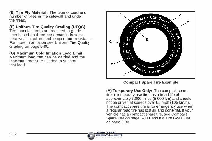
(E) Tire Ply Material : The type of cord andnumber of plies in the sidewall and underthe tread.
(F) Uniform Tire Quality Grading (UTQG) :Tire manufacturers are required to gradetires based on three performance factors:treadwear, traction, and temperature resistance.For more information see Uniform Tire QualityGrading on page 5-80.
(G) Maximum Cold Inflation Load Limit :Maximum load that can be carried and themaximum pressure needed to supportthat load.
(A) Temporary Use Only : The compact sparetire or temporary use tire has a tread life ofapproximately 3,000 miles (5 000 km) and shouldnot be driven at speeds over 65 mph (105 km/h).The compact spare tire is for emergency use whena regular road tire has lost air and gone flat. If yourvehicle has a compact spare tire, see CompactSpare Tire on page 5-111 and If a Tire Goes Flaton page 5-83.
Compact Spare Tire Example
5-62Information Provided by:

(B) Tire Ply Material : The type of cord andnumber of plies in the sidewall and underthe tread.
(C) Tire Identification Number (TIN) : The lettersand numbers following the DOT (Department ofTransportation) code is the Tire IdentificationNumber (TIN). The TIN shows the manufacturerand plant code, tire size, and date the tirewas manufactured. The TIN is molded onto bothsides of the tire, although only one side mayhave the date of manufacture.
(D) Maximum Cold Inflation Load Limit :Maximum load that can be carried and themaximum pressure needed to support that load.
(E) Tire Inflation : The temporary use tire orcompact spare tire should be inflated to 60 psi(420 kPa). For more information on tire pressureand inflation see Inflation - Tire Pressure onpage 5-67.
(F) Tire Size : A combination of letters andnumbers define a tire’s width, height, aspect ratio,construction type, and service description. Theletter T as the first character in the tire size meansthe tire is for temporary use only.
(G) TPC Spec (Tire Performance CriteriaSpecification) : Original equipment tires designedto GM’s specific tire performance criteria havea TPC specification code molded onto the sidewall.GM’s TPC specifications meet or exceed allfederal safety guidelines.
Tire SizeThe following illustration shows an example of atypical passenger vehicle tire size.
(A) Passenger (P-Metric) Tire : The United Statesversion of a metric tire sizing system. The letterP as the first character in the tire size meansa passenger vehicle tire engineered to standardsset by the U.S. Tire and Rim Association.
(B) Tire Width : The three-digit number indicatesthe tire section width in millimeters from sidewallto sidewall.
5-63Information Provided by:

(C) Aspect Ratio : A two-digit number thatindicates the tire height-to-width measurements.For example, if the tire size aspect ratio is 60,as shown in item C of the illustration, it wouldmean that the tire’s sidewall is 60 percent ashigh as it is wide.
(D) Construction Code : A letter code is used toindicate the type of ply construction in the tire.The letter R means radial ply construction;the letter D means diagonal or bias plyconstruction; and the letter B means belted-biasply construction.
(E) Rim Diameter : Diameter of the wheel ininches.
(F) Service Description : These charactersrepresent the load range and speed rating of thetire. The load index represents the load carrycapacity a tire is certified to carry. The load indexcan range from 1 to 279. The speed rating isthe maximum speed a tire is certified to carry aload. Speed ratings range from A to Z.
Tire Terminology and Definitions
Air Pressure : The amount of air inside thetire pressing outward on each square inch of thetire. Air pressure is expressed in pounds persquare inch (psi) or kilopascal (kPa).
Accessory Weight : This means the combinedweight of optional accessories. Some examples ofoptional accessories are, automatic transmission,power steering, power brakes, power windows,power seats, and air conditioning.
Aspect Ratio : The relationship of a tire’s heightto its width.
Belt : A rubber coated layer of cords that islocated between the plies and the tread. Cordsmay be made from steel or other reinforcingmaterials.
Bead: The tire bead contains steel wires wrappedby steel cords that hold the tire onto the rim.
Bias Ply Tire : A pneumatic tire in which the pliesare laid at alternate angles less than 90 degreesto the centerline of the tread.
5-64Information Provided by:

Cold Tire Pressure : The amount of air pressurein a tire, measured in pounds per square inch(psi) or kilopascals (kPa) before a tire has builtup heat from driving. See Inflation - Tire Pressureon page 5-67.
Curb Weight : The weight of a motor vehiclewith standard and optional equipment includingthe maximum capacity of fuel, oil, and coolant,but without passengers and cargo.
DOT Markings : A code molded into the sidewallof a tire signifying that the tire is in compliancewith the U.S. Department of Transportation (DOT)motor vehicle safety standards. The DOT codeincludes the Tire Identification Number (TIN),an alphanumeric designator which can also identifythe tire manufacturer, production plant, brand,and date of production.
GVWR: Gross Vehicle Weight Rating.See Loading Your Vehicle on page 4-22.
GAWR FRT: Gross Axle Weight Rating forthe front axle. See Loading Your Vehicle onpage 4-22.
GAWR RR: Gross Axle Weight Rating for the rearaxle. See Loading Your Vehicle on page 4-22.
Intended Outboard Sidewall : The side of anasymmetrical tire, that must always face outwardwhen mounted on a vehicle.
Kilopascal (kPa) : The metric unit for air pressure.
Light Truck (LT-Metric) Tire : A tire used onlight duty trucks and some multipurpose passengervehicles.
Load Index : An assigned number ranging from1 to 279 that corresponds to the load carryingcapacity of a tire.
Maximum Inflation Pressure : The maximumair pressure to which a cold tire can be inflated.The maximum air pressure is molded onto thesidewall.
Maximum Load Rating : The load rating for atire at the maximum permissible inflation pressurefor that tire.
Maximum Loaded Vehicle Weight : The sum ofcurb weight, accessory weight, vehicle capacityweight, and production options weight.
Normal Occupant Weight : The number ofoccupants a vehicle is designed to seat multipliedby 150 lbs (68 kg). See Loading Your Vehicleon page 4-22.
5-65Information Provided by:
Occupant Distribution : Designated seatingpositions.
Outward Facing Sidewall : The side of anasymmetrical tire that has a particular side thatfaces outward when mounted on a vehicle.The side of the tire that contains a whitewall, bearswhite lettering, or bears manufacturer, brand,and/or model name molding that is higheror deeper than the same moldings on the othersidewall of the tire.
Passenger (P-Metric) Tire : A tire used onpassenger cars and some light duty trucks andmultipurpose vehicles.
Recommended Inflation Pressure : Vehiclemanufacturer’s recommended tire inflationpressure as shown on the tire placard. SeeInflation - Tire Pressure on page 5-67 andLoading Your Vehicle on page 4-22.
Radial Ply Tire : A pneumatic tire in which theply cords that extend to the beads are laid at90 degrees to the centerline of the tread.
Rim: A metal support for a tire and upon whichthe tire beads are seated.
Sidewall : The portion of a tire between thetread and the bead.
Speed Rating : An alphanumeric code assigned toa tire indicating the maximum speed at which atire can operate.
Traction : The friction between the tire and theroad surface. The amount of grip provided.
Tread: The portion of a tire that comes intocontact with the road.
Treadwear Indicators : Narrow bands, sometimescalled wear bars, that show across the tread ofa tire when only 1/16 inch (1.6 mm) of treadremains. See When It Is Time for New Tireson page 5-76.
UTQGS (Uniform Tire Quality GradingStandards) : A tire information system thatprovides consumers with ratings for a tire’straction, temperature, and treadwear. Ratingsare determined by tire manufacturers usinggovernment testing procedures. The ratings aremolded into the sidewall of the tire. See UniformTire Quality Grading on page 5-80.
Vehicle Capacity Weight : The number ofdesignated seating positions multiplied by150 lbs (68 kg) plus the rated cargo load.See Loading Your Vehicle on page 4-22.
5-66Information Provided by:

Vehicle Maximum Load on the Tire : Load onan individual tire due to curb weight, accessoryweight, occupant weight, and cargo weight.
Vehicle Placard : A label permanently attachedto a vehicle showing the vehicle’s capacityweight and the original equipment tire size andrecommended inflation pressure. See “Tireand Loading Information Label” under LoadingYour Vehicle on page 4-22.
Inflation - Tire PressureTires need the correct amount of air pressureto operate effectively.
Notice: Do not let anyone tell you thatunder-inflation or over-inflation is all right.It is not. If your tires do not have enough air(under-inflation), you can get the following:• Too much flexing• Too much heat• Tire overloading• Premature or irregular wear• Poor handling• Reduced fuel economy
If your tires have too much air (over-inflation),you can get the following:• Unusual wear• Poor handling• Rough ride• Needless damage from road hazards
A vehicle specific Tire and Loading Informationlabel is attached to your vehicle. This label lists yourvehicle’s original equipment tires and shows thecorrect inflation pressures for your tires when theyare cold. The recommended cold tire inflationpressure, shown on the label, is the minimumamount of air pressure needed to support yourvehicle’s maximum load carrying capacity.
For additional information regarding how muchweight your vehicle can carry, and an example ofthe tire and loading information label, see LoadingYour Vehicle on page 4-22. How you load yourvehicle affects vehicle handling and ride comfort.Never load your vehicle with more weight than itwas designed to carry.
5-67Information Provided by:

When to CheckCheck your tires once a month or more. Do notforget to check the compact spare tire, if yourvehicle has one. The compact spare should beat 60 psi (420 kPa). For additional informationregarding the compact spare tire, see CompactSpare Tire on page 5-111.
How to CheckUse a good quality pocket-type gage to checktire pressure. You cannot tell if your tires areproperly inflated simply by looking at them.Radial tires may look properly inflated even whenthey are underinflated. Check the tire’s inflationpressure when the tires are cold. Cold means yourvehicle has been sitting for at least three hoursor driven no more than 1 mile (1.6 km).
Remove the valve cap from the tire valve stem.Press the tire gage firmly onto the valve toget a pressure measurement. If the cold tireinflation pressure matches the recommendedpressure on the Tire and Loading Informationlabel, no further adjustment is necessary. If theinflation pressure is low, add air until you reachthe recommended amount.
If you overfill the tire, release air by pushing onthe metal stem in the center of the tire valve.Re-check the tire pressure with the tire gage.
Be sure to put the valve caps back on the valvestems. They help prevent leaks by keeping outdirt and moisture.
5-68Information Provided by:

High-Speed Operation
{CAUTION:
Driving at high speeds, 100 mph (160 km/h)or higher, puts an additional strain on tires.Sustained high-speed driving causesexcessive heat build up and can cause suddentire failure. You could have a crash and you orothers could be killed. Some high-speed ratedtires require inflation pressure adjustment forhigh speed operation. When speed limits androad conditions are such that a vehicle canbe driven at high speeds, make sure the tiresare rated for high speed operation, in excellentcondition, and set to the correct cold tireinflation pressure for the vehicle load.
If your vehicle has 235/50ZR18 size tires, they willrequire inflation pressure adjustment when driving yourvehicle at speeds of 100 mph (160 km/h) or higher. Set the cold inflation pressure to the maximum inflationpressure shown on the tire sidewall, or 44 psi (300 kPa),whichever is lower. See the example following. Whenyou end this high-speed driving, return the tires to thecold tire inflation pressure shown on the Tire andLoading Information label. See Loading Your Vehicleon page 4-22 and Inflation - Tire Pressure on page 5-67.
Example:
You will find the maximum load and inflation pressuremolded on the tire’s sidewall, in small letters, nearthe rim flange. It will read something like this: Maximumload 690 kg (1521 lbs) 300 kPa (44 psi) Max. Press.
For this example, you would set the inflation pressurefor high-speed driving at 44 psi (300 kPa).
5-69Information Provided by:

Tire Pressure Monitor SystemThe Tire Pressure Monitor System (TPMS) uses radioand sensor technology to check tire pressure levels.The TPMS sensors monitor the air pressure inyour vehicle’s tires and transmit tire pressure readingsto a receiver located in the vehicle.
Each tire, including the spare (if provided), should bechecked monthly when cold and inflated to the inflationpressure recommended by the vehicle manufactureron the vehicle placard or tire inflation pressure label.(If your vehicle has tires of a different size than thesize indicated on the vehicle placard or tire inflationpressure label, you should determine the propertire inflation pressure for those tires.)
As an added safety feature, your vehicle has beenequipped with a tire pressure monitoring system (TPMS)that illuminates a low tire pressure telltale when oneor more of your tires is significantly under-inflated.
Accordingly, when the low tire pressure telltaleilluminates, you should stop and check your tires assoon as possible, and inflate them to the properpressure. Driving on a significantly under-inflated tirecauses the tire to overheat and can lead to tire failure.Under-inflation also reduces fuel efficiency and tiretread life, and may affect the vehicle’s handlingand stopping ability.
Please note that the TPMS is not a substitute for propertire maintenance, and it is the driver’s responsibility tomaintain correct tire pressure, even if under-inflation hasnot reached the level to trigger illumination of theTPMS low tire pressure telltale.
Your vehicle has also been equipped with a TPMSmalfunction indicator to indicate when the system is notoperating properly. The TPMS malfunction indicatoris combined with the low tire pressure telltale. When thesystem detects a malfunction, the telltale will flash forapproximately one minute and then remain continuouslyilluminated. This sequence will continue uponsubsequent vehicle start-ups as long as the malfunctionexists.
When the malfunction indicator is illuminated, thesystem may not be able to detect or signal low tirepressure as intended. TPMS malfunctions may occurfor a variety of reasons, including the installationof replacement or alternate tires or wheels on the vehiclethat prevent the TPMS from functioning properly.Always check the TPMS malfunction telltale afterreplacing one or more tires or wheels on your vehicle toensure that the replacement or alternate tires andwheels allow the TPMS to continue to function properly.
See Tire Pressure Monitor Operation on page 5-71for additional information.
5-70Information Provided by:

Federal CommunicationsCommission (FCC) and Industryand Science CanadaThe Tire Pressure Monitor System (TPMS) operateson a radio frequency and complies with Part 15 ofthe FCC Rules. Operation is subject to the followingtwo conditions:
1. This device may not cause harmful interference.
2. This device must accept any interference received,including interference that may cause undesiredoperation.
The Tire Pressure Monitor System (TPMS) operateson a radio frequency and complies with RSS-210of Industry and Science Canada. Operation is subjectto the following two conditions:
1. This device may not cause interference.
2. This device must accept any interference received,including interference that may cause undesiredoperation of the device.
Changes or modifications to this system by other thanan authorized service facility could void authorizationto use this equipment.
Tire Pressure Monitor OperationThe Tire Pressure Monitor System (TPMS) is designedto warn the driver when a low tire pressure conditionexists. TPMS sensors are mounted onto each tireand wheel assembly, excluding the spare tire and wheelassembly. The TPMS sensors monitor the air pressurein the vehicle’s tires and transmits the tire pressurereadings to a receiver located in the vehicle.
Using the Driver Information Center (DIC), the drivercan also check tire pressure levels using the DIC.For additional information and details about the DICoperation and displays see DIC Operation and Displayson page 3-48 and DIC Warnings and Messages onpage 3-54.
5-71Information Provided by:

When a low tire pressurecondition is detected, theTPMS illuminates thelow tire pressure warninglight located on theinstrument panel cluster.
A DIC warning message to check the pressure in aspecific tire is also shown on the DIC display screen.The low tire pressure warning light and the DIC warningmessage come at each ignition cycle until the tiresare inflated to the correct inflation pressure.
The low tire pressure warning light may come on in coolweather when the vehicle is first started, and thenturn off as you start to drive. This could be an earlyindicator that the air pressure in the tire(s) are gettinglow and need to be inflated to the proper pressure.
The Tire and Loading Information label, attached to yourvehicle, shows the size of your vehicle’s originalequipment tires and the correct inflation pressure for thetires when they are cold. See Loading Your Vehicleon page 4-22, for an example of the Tire and LoadingInformation label and its location on your vehicle.Also see Inflation - Tire Pressure on page 5-67.
Your vehicle’s TPMS can warn you about a low tirepressure condition but it does not replace normaltire maintenance. See Tire Inspection and Rotation onpage 5-75 and Tires on page 5-59.
Notice: Using non-approved tire sealants coulddamage the Tire Pressure Monitor System (TPMS)sensors. TPMS sensor damage caused by usingan incorrect tire sealant is not covered by thevehicle warranty. Always use the GM approved tiresealant available through your dealer/retailer.
Your vehicle, when new, may have included afactory-installed Tire Sealant and Compressor Kit. Thiskit uses a GM approved liquid tire sealant. See TireSealant and Compressor Kit (With Sealant SelectorSwitch) on page 5-85 or Tire Sealant and CompressorKit (Without Sealant Selector Switch) on page 5-93.
5-72Information Provided by:

TPMS Malfunction Light and MessageThe TPMS will not function properly if one or more of theTPMS sensors are missing or inoperable. When thesystem detects a malfunction, the low tire warning lightflashes for about one minute and then stays on forthe remainder of the ignition cycle. A DIC warningmessage is also displayed. The low tire warning lightand DIC warning message come on at each ignitioncycle until the problem is corrected. Some of theconditions that can cause the malfunction light andDIC message to come on are:
• One of the road tires has been replaced with thespare tire. The spare tire does not have a TPMSsensor. The DIC message should go off once youre-install the road tire containing the TPMS sensor.
• The TPMS sensor matching process was not doneor not completed successfully after rotating thevehicle’s tires. The DIC message should go off aftersuccessfully completing the sensor matchingprocess. See “TPMS Sensor Matching Process”later in this section.
• One or more TPMS sensors are missing ordamaged. The DIC message and the TPMSmalfunction light should go off when the TPMSsensors are installed and the sensor matchingprocess is performed successfully. See yourdealer/retailer for service.
• Replacement tires or wheels do not match yourvehicle’s original equipment tires or wheels. Tiresand wheels other than those recommended for yourvehicle could prevent the TPMS from functioningproperly. See Buying New Tires on page 5-77.
• Operating electronic devices or being near facilitiesusing radio wave frequencies similar to the TPMScould cause the TPMS sensors to malfunction.
If the TPMS is not functioning it cannot detect orsignal a low tire condition. See your dealer/retailer forservice if the TPMS malfunction light and DIC messagecomes on and stays on.
TPMS Sensor Matching ProcessEach TPMS sensor has a unique identification code.Any time you replace one or more of the TPMS sensorsor rotate your vehicle’s tires, the identification codesneed to be matched to the new tire/wheel position.The sensors are matched to the tire/wheel positions inthe following order: driver side front tire, passengerside front tire, passenger side rear tire, and driver siderear tire using a TPMS diagnostic tool. See yourdealer/retailer for service.
5-73Information Provided by:

The TPMS sensors can also be matched to eachtire/wheel position by increasing or decreasing the tire’sair pressure. If increasing the tire’s air pressure, donot exceed the maximum inflation pressure indicated onthe tire’s sidewall. To decrease the tire’s air-pressureuse the pointed end of the valve cap, a pencil-styleair pressure gage, or a key.
You have two minutes to match the first tire/wheelposition, and five minutes overall, to match all fourtire/wheel positions. If it takes longer than two minutes,to match the first tire and wheel, or more thanfive minutes to match all four tire and wheel positions,the matching process stops and you need to start over.
The TPMS matching process is outlined below:
1. Set the parking brake.
2. Turn the ignition switch to ON/RUN with theengine off.
3. Press the Remote Keyless Entry (RKE) transmitter’slock and unlock buttons at the same time forapproximately five seconds. The horn soundstwice to signal the receiver is in relearn modeand Tire Learning Active message displays on theDIC screen.
4. Start with the driver side front tire.
5. Remove the valve cap from the valve stem.Activate the TPMS sensor by increasing ordecreasing the tire’s air pressure for 10 seconds,or until a horn chirp sounds. The horn chirp, whichcan take up to 30 seconds to sound, confirmsthat the TPMS sensor identification code hasbeen matched to this tire position.
6. Proceed to the passenger side front tire, and repeatthe procedure in Step 5.
7. Proceed to the passenger side rear tire, and repeatthe procedure in Step 5.
8. Proceed to the driver side rear tire, and repeat theprocedure in Step 5.
9. After hearing the confirming horn chirp, for thedriver side rear tire, the horn sounds two moretimes to signal the tire learning mode is no longeractive. Turn the ignition switch to LOCK/OFF.
10. Set all four tires to the recommended airpressure level as indicated on the tire andloading information label.
11. Put the valve caps back on the valve stems.
5-74Information Provided by:

Tire Inspection and RotationWe recommend that you regularly inspect yourvehicle’s tires, including the spare tire, for signs ofwear or damage. See When It Is Time for NewTires on page 5-76 for more information.
Tires should be rotated every 5,000 to 8,000 miles(8 000 to 13 000 km). See Scheduled Maintenanceon page 6-4.
The purpose of a regular tire rotation is to achievea uniform wear for all tires on the vehicle. Thiswill ensure that your vehicle continues to performmost like it did when the tires were new.
If your vehicle has 235/50ZR18 size tires, GMrecommends rotating these tires at 3,000 mile(4 800 km) intervals. These tires are optimized fordry traction and handling performance. Tread lifemay be 15,000 miles (24 140 km) or less for thesetires, depending on how and where you drive.
Any time you notice unusual wear, rotate yourvehicle’s tires as soon as possible and checkwheel alignment. Also check for damaged tires orwheels. See When It Is Time for New Tires onpage 5-76 and Wheel Replacement on page 5-81for more information.
When rotating your vehicle’s tires, always use thecorrect rotation pattern shown here.
If your vehicle has a compact spare tire, do notinclude it in the tire rotation.
After the tires have been rotated, adjust the frontand rear inflation pressures as shown on the Tireand Loading Information label. See Inflation - TirePressure on page 5-67 and Loading Your Vehicleon page 4-22.
Reset the Tire Pressure Monitor System. SeeTire Pressure Monitor Operation on page 5-71.
5-75Information Provided by:

Make certain that all wheel nuts are properlytightened. See “Wheel Nut Torque” underCapacities and Specifications on page 5-128.
{CAUTION:
Rust or dirt on a wheel, or on the parts towhich it is fastened, can make wheel nutsbecome loose after time. The wheel couldcome off and cause an accident. When youchange a wheel, remove any rust or dirtfrom places where the wheel attaches tothe vehicle. In an emergency, you can usea cloth or a paper towel to do this; but besure to use a scraper or wire brush later,if needed, to get all the rust or dirt off.See Changing a Flat Tire on page 5-102.
When It Is Time for New TiresVarious factors, such as maintenance, temperatures,driving speeds, vehicle loading, and road conditionsinfluence when you need new tires.
One way to tell when it istime for new tires is tocheck the treadwearindicators, which willappear when your tireshave only 1/16 inch(1.6 mm) or less of treadremaining.
5-76Information Provided by:

You need new tires if any of the following statementsare true:
• You can see the indicators at three or more placesaround the tire.
• You can see cord or fabric showing through thetire’s rubber.
• The tread or sidewall is cracked, cut, or snaggeddeep enough to show cord or fabric.
• The tire has a bump, bulge, or split.
• The tire has a puncture, cut, or other damage thatcannot be repaired well because of the size orlocation of the damage.
The rubber in tires degrades over time, even if theyare not being used. This is also true for the spare tire,if your vehicle has one. Multiple conditions affecthow fast this aging takes place, including temperatures,loading conditions, and inflation pressure maintenance.With proper care and maintenance tires will typicallywear out before they degrade due to age. If youare unsure about the need to replace your tires as theyget older, consult the tire manufacturer for moreinformation.
Buying New TiresGM has developed and matched specific tires for yourvehicle. The original equipment tires installed onyour vehicle, when it was new, were designed to meetGeneral Motors Tire Performance Criteria Specification(TPC Spec) system rating. If you need replacementtires, GM strongly recommends that you get tires withthe same TPC Spec rating. This way, your vehiclewill continue to have tires that are designed to give thesame performance and vehicle safety, during normaluse, as the original tires.
GM’s exclusive TPC Spec system considers over adozen critical specifications that impact the overallperformance of your vehicle, including brake systemperformance, ride and handling, traction control, and tirepressure monitoring performance. GM’s TPC Specnumber is molded onto the tire’s sidewall near the tiresize. If the tires have an all-season tread design,the TPC Spec number will be followed by an MS formud and snow. See Tire Sidewall Labeling on page 5-61for additional information.
5-77Information Provided by:

GM recommends replacing tires in sets of four. This isbecause uniform tread depth on all tires will helpkeep your vehicle performing most like it did when thetires were new. Replacing less than a full set of tires canaffect the braking and handling performance of yourvehicle. See Tire Inspection and Rotation on page 5-75for information on proper tire rotation.
Winter tires with the same speed rating as your vehicle’soriginal equipment tires may not be available for H, V,W, Y, and ZR speed rated tires. If you choose snow tireswith a lower speed rating, never exceed the tire’smaximum speed capability.
{CAUTION:
Mixing tires could cause you to losecontrol while driving. If you mix tires ofdifferent sizes, brands, or types (radialand bias-belted tires), the vehicle may nothandle properly, and you could have acrash. Using tires of different sizes,brands, or types may also cause damageto your vehicle. Be sure to use the correctsize, brand, and type of tires on all wheels.It is all right to drive with your compactspare temporarily, as it was developed foruse on your vehicle. See Compact SpareTire on page 5-111.
5-78Information Provided by:

{CAUTION:
If you use bias-ply tires on your vehicle,the wheel rim flanges could developcracks after many miles of driving. A tireand/or wheel could fail suddenly, causinga crash. Use only radial-ply tires with thewheels on your vehicle.
If you must replace your vehicle’s tires with those thatdo not have a TPC Spec number, make sure theyare the same size, load range, speed rating, andconstruction type (radial and bias-belted tires) as yourvehicle’s original tires.
Vehicles that have a tire pressure monitoring systemcould give an inaccurate low-pressure warning ifnon-TPC Spec rated tires are installed on your vehicle.Non-TPC Spec rated tires may give a low-pressurewarning that is higher or lower than the proper warninglevel you would get with TPC Spec rated tires. SeeTire Pressure Monitor System on page 5-70.
Your vehicle’s original equipment tires are listed onthe Tire and Loading Information Label. See LoadingYour Vehicle on page 4-22, for more informationabout the Tire and Loading Information Label and itslocation on your vehicle.
Different Size Tires and WheelsIf you add wheels or tires that are a different size thanyour original equipment wheels and tires, this mayaffect the way your vehicle performs, including itsbraking, ride and handling characteristics, stability, andresistance to rollover. Additionally, if your vehiclehas electronic systems such as, anti-lock brakes,traction control, and electronic stability control, theperformance of these systems can be affected.
{CAUTION:
If you add different sized wheels, your vehiclemay not provide an acceptable level ofperformance and safety if tires notrecommended for those wheels are selected.You may increase the chance that you willcrash and suffer serious injury. Only use GMspecific wheel and tire systems developed foryour vehicle, and have them properly installedby a GM certified technician.
See Buying New Tires on page 5-77 and Accessoriesand Modifications on page 5-3 for additional information.
5-79Information Provided by:

Uniform Tire Quality GradingQuality grades can be found where applicable onthe tire sidewall between tread shoulder andmaximum section width. For example:
Treadwear 200 Traction AA Temperature AThe following information relates to the systemdeveloped by the United States National HighwayTraffic Safety Administration (NHTSA), whichgrades tires by treadwear, traction, andtemperature performance. This applies only tovehicles sold in the United States. The grades aremolded on the sidewalls of most passenger cartires. The Uniform Tire Quality Grading (UTQG)system does not apply to deep tread, winter-typesnow tires, space-saver, or temporary usespare tires, tires with nominal rim diameters of10 to 12 inches (25 to 30 cm), or to somelimited-production tires.
While the tires available on General Motorspassenger cars and light trucks may vary withrespect to these grades, they must also conformto federal safety requirements and additionalGeneral Motors Tire Performance Criteria (TPC)standards.
TreadwearThe treadwear grade is a comparative ratingbased on the wear rate of the tire when testedunder controlled conditions on a specifiedgovernment test course. For example, a tiregraded 150 would wear one and a half (1.5) timesas well on the government course as a tiregraded 100. The relative performance of tiresdepends upon the actual conditions of their use,however, and may depart significantly fromthe norm due to variations in driving habits, servicepractices, and differences in road characteristicsand climate.
Traction – AA, A, B, CThe traction grades, from highest to lowest, areAA, A, B, and C. Those grades represent thetire’s ability to stop on wet pavement as measuredunder controlled conditions on specifiedgovernment test surfaces of asphalt and concrete.A tire marked C may have poor tractionperformance.
Warning: The traction grade assigned tothis tire is based on straight-ahead brakingtraction tests, and does not includeacceleration, cornering, hydroplaning,or peak traction characteristics.
5-80Information Provided by:

Temperature – A, B, CThe temperature grades are A (the highest), B,and C, representing the tire’s resistance tothe generation of heat and its ability to dissipateheat when tested under controlled conditions on aspecified indoor laboratory test wheel. Sustainedhigh temperature can cause the material of the tireto degenerate and reduce tire life, and excessivetemperature can lead to sudden tire failure.The grade C corresponds to a level of performancewhich all passenger car tires must meet underthe Federal Motor Vehicle Safety StandardNo. 109. Grades B and A represent higher levelsof performance on the laboratory test wheelthan the minimum required by law.
Warning: The temperature grade for this tireis established for a tire that is properly inflatedand not overloaded. Excessive speed,underinflation, or excessive loading, eitherseparately or in combination, can cause heatbuildup and possible tire failure.
Wheel Alignment and Tire BalanceThe tires and wheels on your vehicle were alignedand balanced carefully at the factory to give youthe longest tire life and best overall performance.Adjustments to wheel alignment and tire balancing willnot be necessary on a regular basis. However, ifyou notice unusual tire wear or your vehicle pulling toone side or the other, the alignment might need tobe checked. If you notice your vehicle vibrating whendriving on a smooth road, the tires and wheelsmight need to be rebalanced. See your dealer/retailerfor proper diagnosis.
Wheel ReplacementReplace any wheel that is bent, cracked, or badly rustedor corroded. If wheel nuts keep coming loose, thewheel, wheel bolts, and wheel nuts should be replaced.If the wheel leaks air, replace it (except somealuminum wheels, which can sometimes be repaired).See your dealer/retailer if any of these conditions exist.
Your dealer/retailer will know the kind of wheel you need.
5-81Information Provided by:

Each new wheel should have the same load-carryingcapacity, diameter, width, offset, and be mountedthe same way as the one it replaces.
If you need to replace any of your wheels, wheel bolts,wheel nuts, or Tire Pressure Monitor System (TPMS)sensors, replace them only with new GM originalequipment parts. This way, you will be sure to have theright wheel, wheel bolts, wheel nuts, and TPMSsensors for your vehicle.
{CAUTION:
Using the wrong replacement wheels, wheelbolts, or wheel nuts on your vehicle can bedangerous. It could affect the braking andhandling of your vehicle, make your tires loseair and make you lose control. You could havea collision in which you or others could beinjured. Always use the correct wheel, wheelbolts, and wheel nuts for replacement.
Notice: The wrong wheel can also cause problemswith bearing life, brake cooling, speedometer orodometer calibration, headlamp aim, bumper height,vehicle ground clearance, and tire or tire chainclearance to the body and chassis.
See Changing a Flat Tire on page 5-102 for moreinformation.
Used Replacement Wheels
{CAUTION:
Putting a used wheel on your vehicle isdangerous. You cannot know how it has beenused or how far it has been driven. It could failsuddenly and cause a crash. If you have toreplace a wheel, use a new GM originalequipment wheel.
5-82Information Provided by:

Tire Chains
{CAUTION:
Do not use tire chains. There is not enoughclearance. Tire chains used on a vehiclewithout the proper amount of clearance cancause damage to the brakes, suspension,or other vehicle parts. The area damagedby the tire chains could cause you to losecontrol of your vehicle and you or othersmay be injured in a crash. Use another typeof traction device only if its manufacturerrecommends it for use on your vehicle andtire size combination and road conditions.Follow that manufacturer’s instructions.To help avoid damage to your vehicle, driveslowly, re-adjust or remove the device if itis contacting your vehicle, and do not spinyour wheels. If you do find traction devicesthat will fit, install them on the rear tires.
If a Tire Goes FlatIt is unusual for a tire to blowout while you are driving,especially if you maintain your tires properly. SeeTires on page 5-59. If air goes out of a tire, It is muchmore likely to leak out slowly. But if you should everhave a blowout, here are a few tips about what to expectand what to do:
If a front tire fails, the flat tire will create a drag thatpulls the vehicle toward that side. Take your foot off theaccelerator pedal and grip the steering wheel firmly.Steer to maintain lane position, and then gently brake toa stop well out of the traffic lane.
A rear blowout, particularly on a curve, acts much like askid and may require the same correction you woulduse in a skid. In any rear blowout, remove your foot fromthe accelerator pedal. Get the vehicle under controlby steering the way you want the vehicle to go. It maybe very bumpy and noisy, but you can still steer.Gently brake to a stop, well off the road if possible.
5-83Information Provided by:

If a tire goes flat, and your vehicle has a compact sparetire, see Changing a Flat Tire on page 5-102. Thisinformation shows you how to use your vehicle’s tirechanging equipment and how to change a flat tire safely.
{CAUTION:
Lifting a vehicle and getting under it to domaintenance or repairs is dangerous withoutthe appropriate safety equipment and training.The jack provided with your vehicle isdesigned only for changing a flat tire. If it isused for anything else, you or others could bebadly injured or killed if the vehicle slips offthe jack. Use the jack provided with yourvehicle only for changing a flat tire.
Tire Sealant and Compressor KitIf your vehicle has a factory installed tire sealant andcompressor kit, there is no spare tire, no tire changingequipment and no place to store a tire.
If a tire goes flat, avoid further tire and wheel damageby driving slowly to a level place and stopping.
1. Turn on the hazard warning flashers. See HazardWarning Flashers on page 3-6.
2. Park your vehicle. If your vehicle has an automatictransmission, set the parking brake firmly andput the shift lever in PARK (P). See Shifting IntoPARK (P) (Automatic Transmission) on page 2-44.If your vehicle has a manual transmission, movethe shift lever to REVERSE (R) and set the parkingbrake firmly. See Parking Your Vehicle (ManualTransmission) on page 2-46 for additionalinformation.
3. Turn off the engine.
4. Inspect the flat tire.
If the tire has been separated from the wheel, hasdamaged sidewalls, or has a puncture larger than a1⁄4 inch (6 mm), the tire is too severely damaged forthe tire sealant and compressor kit to be effective.See Roadside Service on page 7-6.
If the tire has a puncture less than a 1⁄4 inch (6 mm)in the tread area of the tire, see Tire Sealant andCompressor Kit (With Sealant Selector Switch) onpage 5-85 or Tire Sealant and Compressor Kit(Without Sealant Selector Switch) on page 5-93.
5-84Information Provided by:

Tire Sealant and Compressor Kit(With Sealant Selector Switch)Your vehicle has a tire sealant and compressor kitthat is capable of temporarily sealing a puncture up to1⁄4 inch (6mm) in the tread area of the tire. There isno jack or spare tire. The kit inflates the tire with liquidsealant and air. The tire sealant and compressor kitcan also be used to inflate an underinflated tire. After thetire is inflated to the recommended inflation pressure,see Inflation - Tire Pressure on page 5-67 for moreinformation, the vehicle must be driven for five miles todistribute the sealant in the tire and seal the puncture.After driving five miles the tire pressure must berechecked and adjusted as needed. See “Using theTire Sealant and Compressor Kit to Temporarily Seala Punctured Tire” later in this section. Be sure toread and follow all of the tire sealant and compressorkit instructions. The kit includes:
A. Selector SwitchB. On/Off ButtonC. Air Pressure GageD. Tire Sealant
Canister
E. Air CompressorAccessory Plug
F. Sealant/Air Hose(Clear)
G. Air Only Hose
After temporarily sealing the tire sealant and compressorkit, it is recommended to take your vehicle to anauthorized dealer/retailer as soon as possible. If thesealant is removed within 100 miles (161 kilometers)of driving, then it is easier to clean from the tire and youare less likely to require a replacement tire.
5-85Information Provided by:

Accessing the Tire Sealant andCompressor Kit
A. Tire Sealant and Compressor KitB. Foam ContainerC. Wing Nut
To access the tire sealant and compressor kit:
1. Open the trunk. See Trunk on page 2-20 formore information.
2. Locate the tire sealant and compressor kit (A)in the center of the cargo area.
3. Remove the tire sealant and compressor kit byturning the wing nut (C counterclockwise).
4. Remove the sealant and compressor kit from itsfoam container (B).
Tire SealantRead and follow the safe handling instructions on thesealant canister.
The sealant can temporarily seal small punctures in thetread area of the tire. The sealant cannot seal sidewalldamage, large punctures, or a tire that has unseatedfrom the wheel. See Roadside Service on page 7-6 ifyou need assistance.
The sealant can only be used to seal one tire. Afterusage, the sealant canister and sealant filling hoseassembly must be replaced at a dealer/retailer.See “Removal and Installation of Sealant Canister”later in this section.
Check the tire sealant expiration date on the sealantcanister. The sealant might not be effective beyond theexpiration date. If needed, see your dealer/retailerfor a replacement canister.
5-86Information Provided by:

Using the Tire Sealant and CompressorKit to Temporarily Seal a Punctured TireFollow these directions closely for correct sealant usage.
1. Do a safety check before proceeding. See If aTire Goes Flat on page 5-83.
2. Inspect the damaged tire.The sealant cannot seal sidewall damage, largepunctures, or a tire that has unseated fromthe wheel. See Roadside Service on page 7-6.Do not remove any objects that have penetratedthe tire.
3. Place the sealant and compressor kit on the groundand unwrap the sealant/air hose (F) hose from thecompressor.The sealant/air hose (F) is the top, clear hose.
4. Remove the valve stem cap from the flat tire byturning it counterclockwise.
5. Attach the sealant filling hose (F) onto the tire valvestem. Turn it clockwise until it is tight.
6. Unwrap and plug the air compressor accessoryplug (E) into an accessory power outlet in thevehicle. See Accessory Power Outlet(s) onpage 3-21 for more information.Do not slam the door or close the window on thecompressor accessory plug cord.
{CAUTION:
Idling the engine in a closed-in place or withthe climate control system off can causedeadly carbon monoxide (CO). See EngineExhaust on page 2-47.
7. Start the vehicle. See Starting the Engine onpage 2-34 for more information. The vehicle mustbe running while using the air compressor.
5-87Information Provided by:

{CAUTION:
Inflating something too much can make itexplode, and you or others could be injured.Be sure to read the inflator instructions, andinflate the tire to its recommended pressure.Do not exceed 36 psi (248 kPa).
8. Turn the selector switch (A) counterclockwise tothe sealant and air position.
9. Push the On/Off button (B).The sealant and compressor kit will inject sealant andair into the tire. Sealant may leak from the punctureuntil the vehicle is driven and the hole has sealed.The pressure gage (C) will initially show a highpressure while the compressor pushes the sealantinto the tire. Once the sealant is completelydispersed into the tire, the pressure will quickly dropand start to rise again as the tire inflates with air.
10. Inflate the tire to the recommended inflationpressure, found on the Tire and Loading Informationlabel. See Inflation - Tire Pressure on page 5-67.The pressure gage reads high while the compressoris running. Turn the compressor off to get anaccurate pressure reading.
Notice: If the recommended pressure cannot bereached after 15 minutes, the vehicle should not bedriven farther. Damage to the tire is severe andthe sealant will not be effective. Remove theair compressor plug from the accessory poweroutlet and unscrew the inflating hose from the tirevalve. See Roadside Service on page 7-6.
11. Turn the compressor off by pushing the On/Offbutton (B).
12. The tire is not sealed and will continue to leak airuntil the vehicle is driven and the sealant isdistributed in the tire.Steps 11 through 18 must be done right afterStep 10.
5-88Information Provided by:

13. Unplug the air compressor accessory plug (F) fromthe accessory power outlet in the vehicle.
14. Disconnect the sealant/air hose from the tire valvestem or tire pressure monitoring sensor cap, byturning it counterclockwise, and replace thetire valve stem cap.Be careful when handling the tire inflatorcomponents as they may be hot after usage.
15. Wrap the sealant/air hose around the aircompressor channel to stow it in its original location.
16. Wrap the air compressor accessory plug (E)back into place.
17. If the flat tire was ableto inflate to therecommended inflationpressure, removethe maximum speedlabel from the sealantcanister.
Place it in a highly visible location such as theinside of the upper left corner of the windshield orto the face of the radio/clock.The maximum speed label reminds you to drivecautiously and not to exceed 55 mph (90 km/h) untilyou have the damaged tire inspected and repaired.
{CAUTION:
Storing the tire sealant and compressorkit or other equipment in the passengercompartment of the vehicle could cause injury.In a sudden stop or collision, loose equipmentcould strike someone. Store the tire sealantand compressor kit in the proper place.
18. Return the equipment to the proper storage locationin the trunk of your vehicle.
5-89Information Provided by:

19. Immediately drive the vehicle 5 miles (8 km) todistribute the sealant evenly in the tire. Stop at asafe location and check the tire pressure, referto Steps 1 through 8 under “Using the AirCompressor without Sealant” next in this section.
20. If the tire pressure has fallen more then 10 psi(68 kPa), below the recommended inflation pressure,stop driving the vehicle. The tire is too severelydamaged and the tire sealant and compressor kitcannot seal the tire. See Roadside Service onpage 7-6 for more information.If the tire pressure has not dropped more than10 psi (68 kPa) from the recommended inflationpressure, you can inflate the tire back up tothe recommended inflation pressure.
21. Wipe off any sealant from the wheel, tire, andvehicle with a rag.
22. Dispose of the sealant canister at a local dealer/retailer or in accordance with your local state codesand practices.After using the sealant canister, replace it with anew canister from your dealer/retailer.
23. After temporarily sealing a tire with the tire sealantand compressor kit, take your vehicle to yourdealer/retailer to have the tire inspected andrepaired.
Using the Air Compressor withoutSealant to Inflate an Underinflated Tire(Not Punctured)To use the air compressor to inflate a tire with air onlyand not sealant:
Your tire sealant and compressor kit has an accessoryadapter located in a compartment on the bottom ofits housing that may be used to inflate air mattresses,balls, etc.
5-90Information Provided by:

1. Do a safety check before proceeding. See If aTire Goes Flat on page 5-83.
2. Unwrap the air only hose (G) from the bottom ofthe air compressor.
3. Attach the air only hose (G) onto the valve stemto secure into place.
4. Plug the air compressor accessory plug (E) intoan accessory power outlet in the vehicle. SeeAccessory Power Outlet(s) on page 3-21 for moreinformation.
{CAUTION:
Idling the engine in a closed-in place or withthe climate control system off can causedeadly carbon monoxide (CO). See EngineExhaust on page 2-47.
5. Start the vehicle. See Starting the Engine onpage 2-34 for more information. The vehicle mustbe running while using the air compressor.
{CAUTION:
Inflating something too much can make itexplode, and you or others could be injured.Be sure to read the inflator instructions, andinflate the tire to its recommended pressure.Do not exceed 36 psi (248 kPa).
6. Turn the selector switch (A) clockwise to theair only position.
7. Push the On/Off button (B).
5-91Information Provided by:

8. Inflate the tire up to the recommended inflationpressure using the air pressure gage (C) on thetop of the unit.The pressure gage read high while the compressoris running. Turn the compressor off to get anaccurate reading.
9. Turn off the air compressor by pushing the On/Offbutton (B).
10. Unplug the air compressor accessory plug (E) andwrap it back into place.
{CAUTION:
Storing the tire sealant and compressor kit orother equipment in the passengercompartment of the vehicle could cause injury.In a sudden stop or collision, loose equipmentcould strike someone. Store the tire sealantand compressor kit in the proper place.
11. Disconnect the air only hose (G) and wrap the hosein the bottom of the sealant and compressor kit.
12. Place the equipment in the original location in thetrunk of your vehicle.
Removal and Installation of theSealant CanisterTo remove the sealant canister:
1. Unwrap the sealant and air hose.
2. Push the canister release button.
3. Pull up and remove the canister.
4. Replace with a new canister. See yourdealer/retailer for the new canister.
5. Push the new canister into place.
5-92Information Provided by:

Tire Sealant and Compressor Kit(Without Sealant Selector Switch)Your vehicle has a tire sealant and compressor kitthat is capable of temporarily sealing a small punctureup to 1⁄4 inch (6 mm) in the tread. There is no jackor spare tire. The kit inflates the tire with liquid sealantand air. The tire sealant and compressor kit canalso be used to inflate an underinflated tire. After thetire is inflated to the recommended inflation pressure,see Inflation - Tire Pressure on page 5-67 for moreinformation, the vehicle must be driven for five miles todistribute the sealant in the tire and seal the puncture.After driving five miles the tire pressure must berechecked and adjusted as needed. See “Using theTire Sealant and Compressor Kit” later in this section.Be sure to read and follow all of the tire sealant andcompressor kit instructions. The kit includes: A. Air Compressor
B. Tire Sealant CanisterC. Air Compressor
Accessory Plug
D. On/Off SwitchE. Air Pressure GageF. Air Only HoseG. Sealant/Air Hose
After temporarily sealing and inflating the with the tiresealant and compressor kit, it is recommended to takeyour vehicle to an authorized dealer/retailer as soon aspossible for tire repair or replacement. If the sealant isremoved within 100 miles (161 kilometers) of driving,then it is easier to clean from the tire and you are lesslikely to require a replacement tire.
5-93Information Provided by:

Accessing the Tire Sealant andCompressor KitTo access the tire sealant and compressor kit:
1. Open the trunk. See Trunk on page 2-20 formore information.
2. Locate the tire sealant and compressor kit on thedriver side of the vehicle, near the back corner ofthe trunk.
3. Remove the tire sealantand compressor kitstrap by squeezing thetwo tabs of the quickrelease buckle.
4. Remove the sealant and compressor kit from itsfoam container.
Tire SealantRead and follow the safe handling instructions on thesealant canister.
The sealant can temporarily seal a puncture up to1⁄4 inch (6 mm) in the tread area of the tire. The sealantcannot seal sidewall damage, large punctures, or atire that has unseated from the wheel. See RoadsideService on page 7-6 if you need assistance.
5-94Information Provided by:

The sealant can only be used to seal one tire. Afterusage, the sealant canister and sealant/air hoseassembly must be replaced at a dealer/retailer.See “Removal and Installation of Sealant Canister”later in this section.
Check the tire sealant expiration date on the sealantcanister, if it has expired, see your dealer/retailer fora replacement.
Using the Tire Sealant and CompressorKit to Temporarily Seal a Punctured TireFollow these directions closely for correct sealant usage.
1. Do a safety check before proceeding. See If a TireGoes Flat on page 5-83.
2. Inspect the damaged tire. The sealant cannot sealsidewall damage, large punctures, or a tire that hasunseated from the wheel. See Roadside Serviceon page 7-6.
3. If an object, such as a nail, has penetrated the tire,do not remove it.
4. Place the sealant and compressor kit on the groundand unwrap the sealant/air hose (G) from thecompressor.
5. Remove the valve stem cap from the flat tire byturning it counterclockwise.
5-95Information Provided by:

6. Attach the sealant filling hose (G) onto the tire valvestem. Turn it clockwise until it is tight.Make sure the sealant and compressor kit on/offswitch (D) is in the O (off) position.
7. Remove the air compressor accessory plug (C)from the unit.
8. Plug the air compressor accessory plug (C) intoan accessory power outlet in the vehicle. SeeAccessory Power Outlet(s) on page 3-21 for moreinformation.Do not slam the door or close the window on theair compressor accessory plug.
{CAUTION:
Idling the engine in a closed-in place or withthe climate control system off can causedeadly carbon monoxide (CO). See EngineExhaust on page 2-47.
9. Start the vehicle. See Starting the Engine onpage 2-34 for more information. The vehicle mustbe running while using the air compressor.
{CAUTION:
Inflating something too much can make itexplode, and you or others could be injured.Be sure to read the inflator instructions, andinflate the tire to its recommended pressure.Do not exceed 36 psi (248 kPa).
10. Push the On/Off switch to the I (on) position.The sealant and compressor kit will inject sealantand air into the tire. Sealant may leak from thepuncture until the vehicle is driven and the hole hassealed.The pressure gage will initially show a high pressurewhile the compressor pushes the sealant into thetire. Once the sealant is completely dispersedinto the tire, the pressure will quickly drop and startto rise again as the tire inflates with air.
5-96Information Provided by:

11. Inflate the tire to the recommended inflationpressure, found on the Tire and Loading Informationlabel using the air pressure gage on the top ofthe unit. See Inflation - Tire Pressure on page 5-67.The pressure gage reads high while the compressoris running. Turn the compressor off to get anaccurate pressure reading.
Notice: If the recommended pressure cannot bereached after 15 minutes, the vehicle should not bedriven farther. Damage to the tire is severe andthe sealant will not be effective. Remove theair compressor plug from the accessory poweroutlet and unscrew the inflating hose from the tirevalve. See Roadside Service on page 7-6.
12. Push the on/off switch (D) to the O (off) position.
13. The tire is not sealed and will continue to leakair until the vehicle is driven and the sealant isdistributed in the tire.Steps 13 through 20 must be done right afterStep 11.
14. Unplug the air compressor accessory plug (C) fromthe accessory power outlet in the vehicle.
15. Disconnect the sealant/air hose from the tire valvestem, by turning it counterclockwise, and replacethe tire valve stem cap.Be careful when handling the tire inflatorcomponents as they may be hot after usage.
16. Wrap the sealant/air hose around the aircompressor channel to stow it in its original location.
17. Stow the air compressor accessory plug back in theair compressor. To do this, wrap the air compressoraccessory plug, snap in the plug, and then pushin the bottom and then the top of the wrappedair compressor accessory plug.
5-97Information Provided by:

18. If the flat tire was ableto inflate to therecommended inflationpressure, removethe maximum speedlabel from the sealantcanister.
Place it in a highly visible location such as theinside of the upper left corner of the windshield orto the face of the radio/clock.The maximum speed label reminds you to drivecautiously and not to exceed 55 mph (90 km/h) untilyou have the damaged tire inspected and repaired.
{CAUTION:
Storing the tire sealant and compressorkit or other equipment in the passengercompartment of the vehicle could cause injury.In a sudden stop or collision, loose equipmentcould strike someone. Store the tire sealantand compressor kit in the proper place.
19. Return the equipment to its original storagelocation in the trunk of your vehicle.
20. Immediately drive the vehicle 5 miles (8 km) todistribute the sealant evenly in the tire. Stop ata safe location and check the tire pressure, refer toSteps 1 through 8 under “Using the Air Compressorwithout Sealant to Inflate an Underinflated Tire(Not Punctured)” next in this section.
5-98Information Provided by:

21. If the tire pressure has fallen more then 10 psi(68 kPa), below the recommended inflationpressure, stop driving the vehicle. The tire is tooseverely damaged and the tire sealant andcompressor kit cannot seal the tire. See RoadsideService on page 7-6 for more information.If the tire pressure has not dropped more than10 psi (68 kPa) from the recommended inflationpressure, you can inflate the tire back up tothe recommended inflation pressure.
22. Wipe off any sealant from the wheel, tire, andvehicle.
23. Dispose of the sealant canister (B) and sealant/airhose (G) at a local dealer/retailer or in accordancewith your local state codes and practices.After using the sealant canister, replace it with anew canister from your dealer/retailer.
24. After temporarily sealing a tire with the tire sealantand compressor kit, take your vehicle to yourdealer/retailer to have the tire inspected andrepaired or replaced.
Using the Air Compressor withoutSealant to Inflate an Underinflated Tire(Not Punctured)To use the air compressor to inflate a tire with air onlyand not sealant:
1. Do a safety check before proceeding. See If a TireGoes Flat on page 5-83.
2. Inspect the damaged tire. The sealant cannot sealsidewall damage, large punctures, or a tire that hasunseated from the wheel. See Roadside Serviceon page 7-6.
3. If an object, such as a nail, has penetrated the tire,do not remove it.
4. Unlock the air compressor hose from the sealantcanister by pulling up on the lever.
5-99Information Provided by:

5. Pull the air only hose (F) from the sealantcanister (B).
6. Push the air only hose (F) onto the tire valve stemand push the lever down to secure in place.
7. Plug the air compressor accessory plug (C) intoan accessory power outlet in the vehicle. SeeAccessory Power Outlet(s) on page 3-21 for moreinformation.
{CAUTION:
Idling the engine in a closed-in place or withthe climate control system off can causedeadly carbon monoxide (CO). See EngineExhaust on page 2-47.
8. Start the vehicle. See Starting the Engine onpage 2-34 for more information. The vehicle mustbe running while using the air compressor.
{CAUTION:
Inflating something too much can make itexplode, and you or others could be injured.Be sure to read the inflator instructions, andinflate the tire to its recommended pressure.Do not exceed 36 psi (248 kPa).
9. Push the sealant and compressor kit switch tothe I (on) position.
5-100Information Provided by:

10. Inflate the tire up to the recommended inflationpressure using the air pressure gage on the topof the unit.The pressure gage read high while the compressoris running. Turn the compressor off to get anaccurate reading.
11. Turn off the air compressor by pushing the switchto the O (off) position.
{CAUTION:
Storing the tire sealant and compressorkit or other equipment in the passengercompartment of the vehicle could cause injury.In a sudden stop or collision, loose equipmentcould strike someone. Store the tire sealantand compressor kit in the proper place.
12. Disconnect the compressor inflator hose and wrapthe hose in the bottom of the sealant andcompressor kit.
13. Place the equipment in the original location ofyour vehicle.
Removal and Installation of theSealant CanisterTo remove the sealant canister:
1. Unlock the air compressor hose from the sealantcanister by pulling up on the lever.
2. Pull the air only hose (F) from the sealantcanister (B).
3. Unwrap the sealant/air hose from the compressor.
5-101Information Provided by:

4. Turn the sealant canister so the inflator filling hoseis aligned with the slot in the compressor.
5. Lift the sealant canister from the compressor andreplace with a new sealant canister. See yourdealer/retailer for more information.
To install a new sealant canister:
1. Align the sealant/air hose with the slot in theair compressor.
2. Push the sealant canister down and turn itclockwise.
3. Wrap the sealant/air hose around the aircompressor channel to stow it in its original location.
4. Push the air only hose onto the sealant canister inletand push the lever down to secure.
Changing a Flat TireIf a tire goes flat, avoid further tire and wheel damageby driving slowly to a level place. Turn on your vehicle’shazard warning flashers. See Hazard Warning Flasherson page 3-6 for more information.
5-102Information Provided by:

{CAUTION:
Changing a tire can be dangerous. The vehiclecan slip off the jack and roll over or fall on youor other people. You and they could be badlyinjured or even killed. Find a level place tochange your tire. To help prevent the vehiclefrom moving:
1. Set the parking brake firmly.
2. Put the shift lever in PARK (P).
3. Turn off the engine and do not restartwhile the vehicle is raised.
4. Do not allow passengers to remain inthe vehicle.
To be even more certain the vehicle will notmove, you should put blocks at the front andrear of the tire farthest away from the onebeing changed. That would be the tire, on theother side, at the opposite end of the vehicle.
When your vehicle has a flat tire, use the followingexample as a guide to assist you in the placement ofwheel blocks.
The following information tells you how to use the jackand change a tire.
5-103Information Provided by:

Removing the Spare Tire and Tools
A. Wing NutB. Spare TireC. Jack
D. Wheel WrenchE. ExtensionF. Strap
The equipment you will need is in the trunk.
To gain access to the spare tire and jacking equipment,do the following:
1. Remove the spare tire cover.
2. Remove the stow rod cap by pulling it straight upoff of the rod.
3. Turn the wing nut (A) on the compact spare tire (B)counterclockwise to remove it.
4. Remove the spare tire and place it next to theflat tire.
5. The tools you will be using next include the jack (C),wheel wrench (D), and extension (E).
5-104Information Provided by:

Removing the Flat Tire andInstalling the Spare Tire
1. Do a safety check before proceeding. See Changinga Flat Tire on page 5-102 for more information.
2. Loosen the wheel nuts, but do not remove themyet, using the wheel wrench. Turn the handleabout 180 degrees, then return the handle back tothe starting position. This avoids taking thewrench off the lug nut for each turn.
3. Find the jacking location using the diagram aboveand corresponding V-shaped locating notcheslocated in the plastic molding.
5-105Information Provided by:

4. Insert the hooked end of the extension handlethrough the jack and the flat end through thewheel wrench.
{CAUTION:
Getting under a vehicle when it is jacked up isdangerous. If the vehicle slips off the jack, youcould be badly injured or killed. Never get undera vehicle when it is supported only by a jack.
{CAUTION:
Lifting a vehicle and getting under it to domaintenance or repairs is dangerous withoutthe appropriate safety equipment and training.The jack provided with your vehicle is designedonly for changing a flat tire. If it is used foranything else, you or others could be badlyinjured or killed if the vehicle slips off the jack.Use the jack provided with your vehicle only forchanging a flat tire.
5-106Information Provided by:

{CAUTION:
Raising your vehicle with the jack improperlypositioned can damage the vehicle and evenmake the vehicle fall. To help avoid personalinjury and vehicle damage, be sure to fit thejack lift head into the proper location beforeraising the vehicle.
Notice: If you position the jack under the rockermolding and attempt to raise the vehicle, you couldbreak the molding and/or cause other damage toyour vehicle. Always position the jack so that whenthe jack head is raised, it will fit firmly in thenotch located inboard from the rocker molding.
5. Turn the wheel wrench counterclockwise to lowerthe jack lift head until the jack fits under thevehicle.
6. Raise the jack by turning the wheel wrench clockwiseuntil the slots in the jack head fit into the metalflange located behind the V–shaped locating notcheson the plastic molding as shown.
7. Put the compact spare tire near you.
8. Raise the vehicle by turning the wheel wrenchclockwise. Raise the vehicle far enough off theground for the compact spare tire to fit under thevehicle.
5-107Information Provided by:
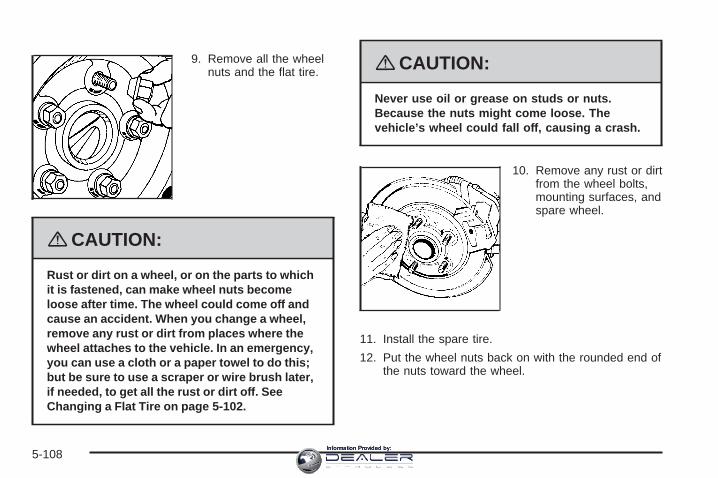
9. Remove all the wheelnuts and the flat tire.
{CAUTION:
Rust or dirt on a wheel, or on the parts to whichit is fastened, can make wheel nuts becomeloose after time. The wheel could come off andcause an accident. When you change a wheel,remove any rust or dirt from places where thewheel attaches to the vehicle. In an emergency,you can use a cloth or a paper towel to do this;but be sure to use a scraper or wire brush later,if needed, to get all the rust or dirt off. SeeChanging a Flat Tire on page 5-102.
{CAUTION:
Never use oil or grease on studs or nuts.Because the nuts might come loose. Thevehicle’s wheel could fall off, causing a crash.
10. Remove any rust or dirtfrom the wheel bolts,mounting surfaces, andspare wheel.
11. Install the spare tire.
12. Put the wheel nuts back on with the rounded end ofthe nuts toward the wheel.
5-108Information Provided by:
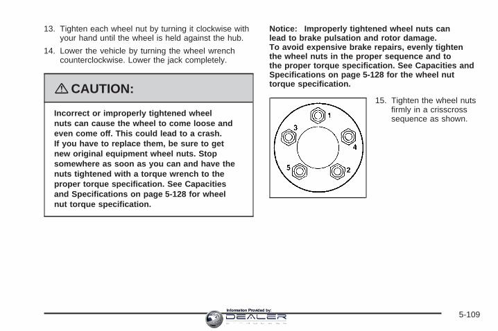
13. Tighten each wheel nut by turning it clockwise withyour hand until the wheel is held against the hub.
14. Lower the vehicle by turning the wheel wrenchcounterclockwise. Lower the jack completely.
{CAUTION:
Incorrect or improperly tightened wheelnuts can cause the wheel to come loose andeven come off. This could lead to a crash.If you have to replace them, be sure to getnew original equipment wheel nuts. Stopsomewhere as soon as you can and have thenuts tightened with a torque wrench to theproper torque specification. See Capacitiesand Specifications on page 5-128 for wheelnut torque specification.
Notice: Improperly tightened wheel nuts canlead to brake pulsation and rotor damage.To avoid expensive brake repairs, evenly tightenthe wheel nuts in the proper sequence and tothe proper torque specification. See Capacities andSpecifications on page 5-128 for the wheel nuttorque specification.
15. Tighten the wheel nutsfirmly in a crisscrosssequence as shown.
5-109Information Provided by:

Storing a Flat or Spare Tireand Tools
{CAUTION:
Storing a jack, a tire, or other equipment in thepassenger compartment of the vehicle couldcause injury. In a sudden stop or collision,loose equipment could strike someone.Store all these in the proper place.
After you have put the compact spare tire on yourvehicle, you will need to store the flat tire in your trunk.
The compact spare is for temporary use only. Replacethe compact spare tire with a full-size tire as soonas you can.
Use the following diagram as a guide for storing thecompact spare tire in the trunk:
A. Wing NutB. Compact Spare
Tire or Flat Tire(valve stem down)
C. JackD. Wheel WrenchE. ExtensionF. Strap
5-110Information Provided by:
Compact Spare TireIf your vehicle is equipped with a compact spare tire itwas fully inflated when the vehicle was new, it canlose air after a time. Check the inflation pressureregularly. It should be 60 psi (420 kPa).
After installing the compact spare on the vehicle, stopas soon as possible and make sure the spare tireis correctly inflated. The compact spare is made toperform well at speeds up to 65 mph (105 km/h)for distances up to 3,000 miles (5 000 km), so you canfinish your trip and have the full-size tire repaired orreplaced at your convenience. Of course, it is bestto replace the spare with a full-size tire as soon aspossible. The spare tire will last longer and be in goodshape in case it is needed again.
Notice: When the compact spare is installed, donot take your vehicle through an automatic car washwith guide rails. The compact spare can getcaught on the rails. That can damage the tire andwheel, and maybe other parts of your vehicle.
Do not use the compact spare on other vehicles.
And do not mix the compact spare tire or wheel withother wheels or tires. They will not fit. Keep thespare tire and its wheel together.
Notice: Tire chains will not fit your compact spare.Using them can damage your vehicle and candamage the chains too. Do not use tire chains onyour compact spare.
Appearance Care
Interior CleaningYour vehicle’s interior will continue to look its best if it iscleaned often. Although not always visible, dust anddirt can accumulate on your upholstery. Dirt can damagecarpet, fabric, leather, and plastic surfaces. Regularvacuuming is recommended to remove particlesfrom your upholstery. It is important to keep yourupholstery from becoming and remaining heavily soiled.Soils should be removed as quickly as possible. Yourvehicle’s interior may experience extremes of heatthat could cause stains to set rapidly.
5-111Information Provided by:

Lighter colored interiors may require more frequentcleaning. Use care because newspapers and garmentsthat transfer color to your home furnishings may alsotransfer color to your vehicle’s interior.
When cleaning your vehicle’s interior, only use cleanersspecifically designed for the surfaces being cleaned.Permanent damage may result from using cleaners onsurfaces for which they were not intended. Use glasscleaner only on glass. Remove any accidental over-sprayfrom other surfaces immediately. To prevent over-spray,apply cleaner directly to the cleaning cloth.
Notice: If you use abrasive cleaners when cleaningglass surfaces on your vehicle, you could scratchthe glass and/or cause damage to the rear windowdefogger. When cleaning the glass on yourvehicle, use only a soft cloth and glass cleaner.
Many cleaners contain solvents that may becomeconcentrated in your vehicle’s breathing space. Beforeusing cleaners, read and adhere to all safetyinstructions on the label. While cleaning your vehicle’sinterior, maintain adequate ventilation by openingyour vehicle’s doors and windows.
Dust may be removed from small buttons and knobsusing a small brush with soft bristles.
Your dealer/retailer has a product for cleaning yourvehicle’s glass. Should it become necessary, you canalso obtain a product from your dealer/retailer to removeodors from your vehicle’s upholstery.
Do not clean your vehicle using:
• A knife or any other sharp object to remove a soilfrom any interior surface.
• A stiff brush. It can cause damage to your vehicle’sinterior surfaces.
• Heavy pressure or aggressive rubbing with acleaning cloth. Use of heavy pressure can damageyour interior and does not improve the effectivenessof soil removal.
• Laundry detergents or dishwashing soaps withdegreasers can leave residue that streaks andattracts dirt. For liquid cleaners, about 20 drops pergallon (3.78 L) of water is a good guide. Useonly mild, neutral-pH soaps.
• Too much cleaner that saturates the upholstery.
• Organic solvents such as naptha, alcohol, etc. thatcan damage your vehicle’s interior.
5-112Information Provided by:

Fabric/CarpetUse a vacuum cleaner with a soft brush attachmentfrequently to remove dust and loose dirt. A canistervacuum with a beater bar in the nozzle may only be usedon floor carpet and carpeted floor mats. For any soil,always try to remove it first with plain water or club soda.Before cleaning, gently remove as much of the soil aspossible using one of the following techniques:• For liquids: gently blot the remaining soil with a paper
towel. Allow the soil to absorb into the paper toweluntil no more can be removed.
• For solid dry soils: remove as much as possible andthen vacuum.
To clean:1. Saturate a lint-free, clean white cloth with water or
club soda.
2. Wring the cloth to remove excess moisture.
3. Start on the outside edge of the soil and gently rubtoward the center. Continue cleaning, using a cleanarea of the cloth each time it becomes soiled.
4. Continue to gently rub the soiled area until thecleaning cloth remains clean.
5. If the soil is not completely removed, use a mildsoap solution and repeat the cleaning processthat was used with plain water.
If any of the soil remains, a commercial fabric cleaner orspot lifter may be necessary. When a commercialupholstery cleaner or spot lifter is to be used, test asmall hidden area for colorfastness first. If the locallycleaned area gives any impression that a ring formationmay result, clean the entire surface.
After the cleaning process has been completed, a papertowel can be used to blot excess moisture from thefabric or carpet.
LeatherA soft cloth dampened with water can be used toremove dust. If a more thorough cleaning is necessary,a soft cloth dampened with a mild soap solution canbe used. Allow the leather to dry naturally. Do not useheat to dry. Never use steam to clean leather. Neveruse spot lifters or spot removers on leather. Manycommercial leather cleaners and coatings that are soldto preserve and protect leather may permanentlychange the appearance and feel of your leather and arenot recommended. Do not use silicone or wax-basedproducts, or those containing organic solvents to cleanyour vehicle’s interior because they can alter theappearance by increasing the gloss in a non-uniformmanner. Never use shoe polish on leather.
5-113Information Provided by:

Instrument Panel, Vinyl, and OtherPlastic SurfacesA soft cloth dampened with water may be used toremove dust. If a more thorough cleaning is necessary,a clean soft cloth dampened with a mild soap solutioncan be used to gently remove dust and dirt. Never usespot lifters or removers on plastic surfaces. Manycommercial cleaners and coatings that are sold topreserve and protect soft plastic surfaces maypermanently change the appearance and feel of yourinterior and are not recommended. Do not use siliconeor wax-based products, or those containing organicsolvents to clean your vehicle’s interior becausethey can alter the appearance by increasing the gloss ina non-uniform manner.
Some commercial products may increase gloss on yourinstrument panel. The increase in gloss may causeannoying reflections in the windshield and even make itdifficult to see through the windshield under certainconditions.
Wood PanelsUse a clean cloth moistened in warm, soapy water(use mild dish washing soap). Dry the wood immediatelywith a clean cloth.
Speaker CoversVacuum around a speaker cover gently, so thatthe speaker will not be damaged. Clean spots with justwater and mild soap.
Care of Safety BeltsKeep belts clean and dry.
{CAUTION:
Do not bleach or dye safety belts. If you do,it may severely weaken them. In a crash,they might not be able to provide adequateprotection. Clean safety belts only with mildsoap and lukewarm water.
5-114Information Provided by:

WeatherstripsSilicone grease on weatherstrips will make them lastlonger, seal better, and not stick or squeak. Applysilicone grease with a clean cloth. During very cold,damp weather frequent application may be required. SeeRecommended Fluids and Lubricants on page 6-11.
Washing Your VehicleThe best way to preserve your vehicle’s finish is to keepit clean by washing it often.
Notice: Certain cleaners contain chemicals that candamage the emblems or nameplates on yourvehicle. Check the cleaning product label. If it statesthat it should not be used on plastic parts, do notuse it on your vehicle or damage may occurand it would not be covered by the warranty.
Do not wash the vehicle in direct sunlight. Use a carwashing soap. Do not use cleaning agents thatare petroleum based or that contain acid or abrasives,as they can damage the paint, metal or plastic onyour vehicle. Approved cleaning products can beobtained from your dealer/retailer. See VehicleCare/Appearance Materials on page 5-119. Follow allmanufacturers’ directions regarding correct productusage, necessary safety precautions and appropriatedisposal of any vehicle care product.
Rinse the vehicle well, before washing and after toremove all cleaning agents completely. If they areallowed to dry on the surface, they could stain.
Dry the finish with a soft, clean chamois or an all-cottontowel to avoid surface scratches and water spotting
High pressure car washes may cause water to enter thevehicle. Avoid using high pressure washes closerthan 12 inches (30 cm) to the surface of the vehicle.Use of power washers exceeding 1,200 psi (8 274 kPa)can result in damage or removal of paint and decals.
5-115Information Provided by:

Cleaning Exterior Lamps/LensesUse only lukewarm or cold water, a soft cloth and a carwashing soap to clean exterior lamps and lenses.Follow instructions under Washing Your Vehicleon page 5-115.
Finish CareOccasional waxing or mild polishing of your vehicle byhand may be necessary to remove residue from thepaint finish. You can get approved cleaning productsfrom your dealer/retailer. See Vehicle Care/AppearanceMaterials on page 5-119.
If your vehicle has a basecoat/clearcoat paint finish, theclearcoat gives more depth and gloss to the coloredbasecoat. Always use waxes and polishes that arenon-abrasive and made for a basecoat/clearcoat paintfinish.
Notice: Machine compounding or aggressivepolishing on a basecoat/clearcoat paint finish maydamage it. Use only non-abrasive waxes andpolishes that are made for a basecoat/clearcoatpaint finish on your vehicle.
Foreign materials such as calcium chloride and othersalts, ice melting agents, road oil and tar, tree sap, birddroppings, chemicals from industrial chimneys, etc.,can damage your vehicle’s finish if they remainon painted surfaces. Wash the vehicle as soon aspossible. If necessary, use non-abrasive cleaners thatare marked safe for painted surfaces to removeforeign matter.
Exterior painted surfaces are subject to aging, weatherand chemical fallout that can take their toll over aperiod of years. You can help to keep the paint finishlooking new by keeping your vehicle garaged or coveredwhenever possible.
Protecting Exterior Bright Metal PartsBright metal parts should be cleaned regularly to keeptheir luster. Washing with water is all that is usuallyneeded. However, you may use chrome polish onchrome or stainless steel trim, if necessary.
Use special care with aluminum trim. To avoid damagingprotective trim, never use auto or chrome polish,steam or caustic soap to clean aluminum. A coating ofwax, rubbed to high polish, is recommended for allbright metal parts.
5-116Information Provided by:

Windshield and Wiper BladesClean the outside of the windshield with glass cleaner.
Clean the rubber blades using a lint free cloth or papertowel soaked with windshield washer fluid or a milddetergent. Wash the windshield thoroughly whencleaning the blades. Bugs, road grime, sap, and abuildup of vehicle wash/wax treatments may cause wiperstreaking. Replace the wiper blades if they are worn ordamaged.
Wipers can be damaged by:• Extreme dusty conditions• Sand and salt• Heat and sun• Snow and ice, without proper removal
Aluminum or Chrome-Plated Wheelsand TrimYour vehicle may have either aluminum orchrome-plated wheels.
Keep the wheels clean using a soft clean cloth with mildsoap and water. Rinse with clean water. After rinsingthoroughly, dry with a soft clean towel. A wax may thenbe applied.
Notice: Chrome wheels and other chrome trim maybe damaged if you do not wash your vehicle afterdriving on roads that have been sprayed withmagnesium, calcium or sodium chloride. Thesechlorides are used on roads for conditions such asice and dust. Always wash your vehicle’s chromewith soap and water after exposure.
Notice: If you use strong soaps, chemicals,abrasive polishes, cleaners, brushes, or cleanersthat contain acid on aluminum or chrome-platedwheels, you could damage the surface of thewheel(s). The repairs would not be covered by yourwarranty. Use only approved cleaners on aluminumor chrome-plated wheels.
The surface of these wheels is similar to the paintedsurface of your vehicle. Do not use strong soaps,chemicals, abrasive polishes, abrasive cleaners,cleaners with acid, or abrasive cleaning brushes onthem because you could damage the surface. Do notuse chrome polish on aluminum wheels.
5-117Information Provided by:

Notice: Using chrome polish on aluminum wheelscould damage the wheels. The repairs would notbe covered by your warranty. Use chrome polish onchrome wheels only.
Use chrome polish only on chrome-plated wheels, butavoid any painted surface of the wheel, and buff offimmediately after application.
Notice: If you drive your vehicle through anautomatic car wash that has silicone carbide tirecleaning brushes, you could damage the aluminumor chrome-plated wheels. The repairs would notbe covered by your warranty. Never drive a vehicleequipped with aluminum or chrome-plated wheelsthrough an automatic car wash that uses siliconecarbide tire cleaning brushes.
TiresTo clean the tires, use a stiff brush with tire cleaner.
Notice: Using petroleum-based tire dressingproducts on your vehicle may damage the paintfinish and/or tires. When applying a tire dressing,always wipe off any overspray from all paintedsurfaces on your vehicle.
Sheet Metal DamageIf the vehicle is damaged and requires sheet metalrepair or replacement, make sure the body repair shopapplies anti-corrosion material to parts repaired orreplaced to restore corrosion protection.
Original manufacturer replacement parts will provide thecorrosion protection while maintaining the warranty.
Finish DamageAny stone chips, fractures or deep scratches in thefinish should be repaired right away. Bare metalwill corrode quickly and may develop into major repairexpense.
Minor chips and scratches can be repaired with touch-upmaterials available from your dealer/retailer. Largerareas of finish damage can be corrected in yourdealer’s/retailer’s body and paint shop.
5-118Information Provided by:
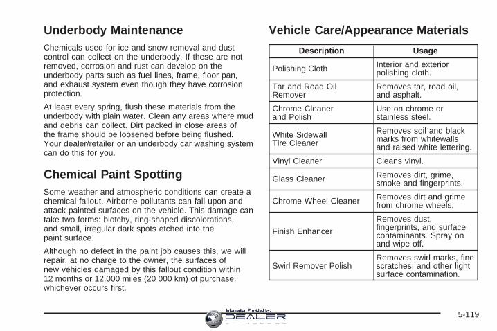
Underbody MaintenanceChemicals used for ice and snow removal and dustcontrol can collect on the underbody. If these are notremoved, corrosion and rust can develop on theunderbody parts such as fuel lines, frame, floor pan,and exhaust system even though they have corrosionprotection.
At least every spring, flush these materials from theunderbody with plain water. Clean any areas where mudand debris can collect. Dirt packed in close areas ofthe frame should be loosened before being flushed.Your dealer/retailer or an underbody car washing systemcan do this for you.
Chemical Paint SpottingSome weather and atmospheric conditions can create achemical fallout. Airborne pollutants can fall upon andattack painted surfaces on the vehicle. This damage cantake two forms: blotchy, ring-shaped discolorations,and small, irregular dark spots etched into thepaint surface.
Although no defect in the paint job causes this, we willrepair, at no charge to the owner, the surfaces ofnew vehicles damaged by this fallout condition within12 months or 12,000 miles (20 000 km) of purchase,whichever occurs first.
Vehicle Care/Appearance Materials
Description Usage
Polishing Cloth Interior and exteriorpolishing cloth.
Tar and Road OilRemover
Removes tar, road oil,and asphalt.
Chrome Cleanerand Polish
Use on chrome orstainless steel.
White SidewallTire Cleaner
Removes soil and blackmarks from whitewallsand raised white lettering.
Vinyl Cleaner Cleans vinyl.
Glass Cleaner Removes dirt, grime,smoke and fingerprints.
Chrome Wheel Cleaner Removes dirt and grimefrom chrome wheels.
Finish Enhancer
Removes dust,fingerprints, and surfacecontaminants. Spray onand wipe off.
Swirl Remover PolishRemoves swirl marks, finescratches, and other lightsurface contamination.
5-119Information Provided by:

Description Usage
Cleaner Wax Removes light scratchesand protects finish.
Foaming Tire ShineLow Gloss
Cleans, shines, andprotects tires. No wipingnecessary.
Wash Wax Concentrate
Medium foamingshampoo. Cleansand lightly waxes.Biodegradable andphosphate free.
Spot Lifter
Quickly removes spotsand stains from carpets,vinyl, and clothupholstery.
Odor EliminatorOdorless spray odoreliminator used on fabrics,vinyl, leather and carpet.
Vehicle Identification
Vehicle Identification Number (VIN)
This is the legal identifier for your vehicle. It appearson a plate in the front corner of the instrument panel,on the driver side. You can see it if you look throughthe windshield from outside your vehicle. The VINalso appears on the Vehicle Certification and ServiceParts labels and the certificates of title and registration.
5-120Information Provided by:

Engine IdentificationThe eighth character in the VIN is the engine code.This code helps you identify your vehicle’s engine,specifications, and replacement parts. See Capacitiesand Specifications on page 5-128 for your vehicle’sengine code.
Service Parts Identification LabelThis label is on the spare tire cover. It is very helpfulif you ever need to order parts. The label has thefollowing information:
• Vehicle Identification Number (VIN)
• Model designation
• Paint information
• Production options and special equipment
Do not remove this label from the vehicle.
Electrical System
Add-On Electrical EquipmentNotice: Do not add anything electrical to yourvehicle unless you check with your dealer/retailerfirst. Some electrical equipment can damageyour vehicle and the damage would not be coveredby your warranty. Some add-on electrical equipmentcan keep other components from working as theyshould.
Add-on equipment can drain your vehicle’s battery, evenif your vehicle is not operating.
Your vehicle has an airbag system. Before attempting toadd anything electrical to your vehicle, see ServicingYour Airbag-Equipped Vehicle on page 1-68.
Windshield Wiper FusesThe windshield wiper motor is protected by an internalcircuit breaker. If the wiper motor overheats due toheavy snow, the wipers will stop until the motor coolsand will then restart.
5-121Information Provided by:

Power Windows and OtherPower OptionsCircuit breakers in the fuse block protect the powerwindows and other power accessories. When thecurrent load is too heavy, the circuit breaker opensand closes, protecting the circuit until the problem isfixed or goes away.
Fuses and Circuit BreakersThe wiring circuits in your vehicle are protected fromshort circuits by a combination of fuses and circuitbreakers. This greatly reduces the chance of firescaused by electrical problems.
Look at the silver-colored band inside the fuse. If theband is broken or melted, replace the fuse. Be sure youreplace a bad fuse with a new one of the identicalsize and rating.
If you ever have a problem on the road and don’t havea spare fuse, you can borrow one that has the sameamperage. Just pick some feature of your vehiclethat you can get along without — like the radio orcigarette lighter — and use its fuse, if it is the correctamperage. Replace it as soon as you can.
Underhood Fuse BlockThe underhood fuse block is located on the passengerside of the engine compartment.
Lift the fuse block cover to access the fuses.
Notice: Spilling liquid on any electrical componentson your vehicle may damage it. Always keep thecovers on any electrical component.
5-122Information Provided by:

Fuses UsageLT LO BEAM Left Low-Beam HeadlampRT LO BEAM Right Low-Beam Headlamp
LO BEAM DRL Low-Beam Daytime RunningLamp (DRL)
Fuses UsageAIRBAG IGN Airbag Switch
SPARE SpareBCM 7 Body Control Module 7
PED PROT Not Used
5-123Information Provided by:

Fuses Usage
ECM/TCM IGN
Engine Control Module (ECM),Transmission Control Module (TCM),IPC (Instrument Panel Cluster),PASS-Key® III+ Module
MISC IGN IgnitionEMIS 1 Emission 1DISPLY DisplayBCM 3 Body Control Module 3
EVEN COILS Even CoilsBCM 6 Body Control Module 6BCM 2 Body Control Module 2
ODD COILS Odd CoilsBCM 1 Body Control Module 1
LT HI BEAM Left High-Beam Headlamp
PWR MODING PassKey Module, Body ControlModule
STR/WHL/ILLUM Steering Wheel Illumination
EMIS 2 Emission 2AFS Adaptive Forward Lighting System
RT HI BEAM Right High-Beam HeadlampNAV MTR Navigation MotorFRT FOG Front Fog Lamps
ECM Engine Control ModuleBCM 5 Body Control Module 5
Fuses UsageWPR Windshield Wiper
TRANSOIL RLY Transmission Oil Relay
BCM 4 Body Control Module 4RT LO BEAM Right Low-Beam Headlamp
AWD All-Wheel DriveLT LO BEAM Left Low-Beam Headlamp
TCM BATT Transmission Control ModuleBattery
DRL RT Right Daytime Running Lamp (DRL)SPARE Spare
ABS Antilock Brake SystemHORN Horn
WSW PUMP Windshield Washer PumpA/C CLTCH Air Conditioning Compressor ClutchDRL/ENG
PUMP Daytime Running Lamps (DRL)
HDM WASH Headlamp Driver Module Washer
J-Case Fuses UsageFAN 2 Cooling Fan 2
SPARE SpareFAN 1 Cooling Fan 2
SPARE Spare
5-124Information Provided by:

J-Case Fuses UsageSTRTR Starter
TRANS PUMP Transmission PumpWSW/HTR Windshield Washer HeaterBRK VAC
PUMP Brake Vacuum Pump
BLWR BlowerABS MTR Antilock Brake System Motor
REAR DEFOG Rear DefoggerSPARE Spare
Relays UsageFAN 2 Cooling Fan 2
FAN S/P Cooling Fan Series/ParallelLO BEAM(W/O HID)
LT DRL (HID)
Low-Beam (without High IntensityDischarge), Left Daytime RunningLamp (High Intensity Discharge)
FAN 1 Cooling Fan 1FOG LAMP Fog Lamps
SPARE Spare
Relays UsageIGN 1 Ignition 1
STRTR StarterPWR/TRN Powertrain
REAR DEFOG Rear DefoggerHI BEAM High-Beam Headlamp
DRL (W/O HID)LO BEAM (HID)
Daytime Running Lamps(without High Intensity Discharge),Low Beam Headlamps (HighIntensity Discharge)
WPR Windshield WiperWPR HI Windshield Wiper High Speed
HEAD LAMPWASH Headlamp Washer
HORN HornWSW PUMP Windshield Washer Pump
A/C CMPRSR Air Conditioning CompressorENG PUMP Engine Pump
RT DRL (HID) Right Daytime Running Lamp(High Intensity Discharge)
5-125Information Provided by:

Rear Compartment Fuse BlockThe rear compartment fuse block is located on top of the battery, on the right side of the trunk. The battery accessdoor must be removed to access the fuse block.
5-126Information Provided by:

Relays UsageLF FRT/
PWR/SEAT Left Front Power Seat
RT FRT/PWR/SEAT Right Front Power Seat
PWR/WNDW PowerPWR/CLMN Power Steering Column
TRUNK/RELSE Trunk ReleaseLCK Lock
FUEL/PUMP Fuel PumpUNLCK Unlock
STOP/LP StoplampSPARE Spare
RT/POS/LP Right Position LampREAR/FOG Not UsedLT/POS/LP Left Position Lamp
Fuses UsageLT/POS/LP Left Position LampREAR/FOG Not Used
SPARE SpareRT/POS/LP Right Position LampRVC/SNSR Regulated Voltage Control SensorLT/REAR/
WNDW Left Rear Window
Fuses UsageDR/LCK Door Lock
RDO Audio SystemTRUNK/RELSE Trunk Release
FUEL/PUMP Fuel PumpAIRBAG Airbag System
THEFT/UGDO Theft Deterrent System,Universal Home Remote System
SPARE SpareRKE/
PASS-Key®/MDL
Remote Keyless Entry System,PASS-Key® Theft DeterrentFeature Module
MSM Memory Seat ModuleSTOP/LP Stoplamp
RDO/SPKR Audio SpeakersPDM Passenger Door Module
RT/POS/LP Right Position LampONSTAR OnStar® System
REAR/WNDW Rear WindowS/ROOF Sunroof
ECM Engine Control Module (ECM)AUX/OUTLET Auxiliary Power OutletCNSTR/VENT Canister Vent
AMP Amplifier
5-127Information Provided by:

Capacities and SpecificationsThe following approximate capacities are given in English and metric conversions. See Recommended Fluids andLubricants on page 6-11 for more information.
ApplicationCapacities
English Metric
Air Conditioning Refrigerant R134a
For the air conditioning system refrigerantcharge amount, see the refrigerant caution
label located under the hood. See yourdealer/retailer for more information.
Cooling System
3.6L HFV6 Engine (LY7) 10.3 qt 9.7 L
3.6L HFV6 Engine (LLT) 10.6 qt 10.0 L
Engine Oil with Filter
3.6L HFV6 Engine 6.0 qt 5.7 L
Fuel Tank 18.0 gal 68.1 L
Transmission (Pan Removal and Replacement)
6-Speed Automatic 6.7 qt 6.3 L
6-Speed Manual 1.9 qt 1.8 L
Wheel Nut Torque 100 lb ft (140 Y)
All capacities are approximate. When adding, be sure to fill to the approximate level, as recommended in thismanual. Recheck fluid level after filling.
5-128Information Provided by:

Engine SpecificationsEngine VIN Code Transmission Spark Plug Gap
3.6L HFV6 7 AutomaticManual 0.043 inches (1.1 mm)
3.6L HFV6 V AutomaticManual 0.043 inches (1.1 mm)
5-129Information Provided by:

✍ NOTES
5-130Information Provided by:

Maintenance Schedule ......................................6-2Introduction ...................................................6-2Maintenance Requirements ..............................6-2Your Vehicle and the Environment ....................6-2Using the Maintenance Schedule ......................6-2Scheduled Maintenance ...................................6-4Additional Required Services ............................6-5Maintenance Footnotes ...................................6-6
Owner Checks and Services ............................6-8At Each Fuel Fill ............................................6-8At Least Once a Month ...................................6-8At Least Once a Year .....................................6-9Recommended Fluids and Lubricants ...............6-11Maintenance Replacement Parts .....................6-13Engine Drive Belt Routing ..............................6-14Maintenance Record .....................................6-15
Section 6 Maintenance Schedule
6-1Information Provided by:

Maintenance Schedule
IntroductionImportant: Keep engine oil at the proper level andchange as recommended.
Have you purchased the GM Protection Plan? The Plansupplements your new vehicle warranties. See yourWarranty and Owner Assistance booklet or yourdealer/retailer for details.
Maintenance RequirementsNotice: Maintenance intervals, checks, inspections,replacement parts, and recommended fluids andlubricants as prescribed in this manual are necessaryto keep your vehicle in good working condition.Any damage caused by failure to follow scheduledmaintenance might not be covered by warranty.
Your Vehicle and the EnvironmentProper vehicle maintenance not only helps to keepyour vehicle in good working condition, but also helpsthe environment. All recommended maintenance isimportant. Improper vehicle maintenance can even affectthe quality of the air we breathe. Improper fluid levels orthe wrong tire inflation can increase the level of emissionsfrom your vehicle. To help protect our environment, andto keep your vehicle in good condition, be sure tomaintain your vehicle properly.
Using the Maintenance ScheduleWe want to help you keep your vehicle in good workingcondition. But we do not know exactly how you willdrive it. You might drive very short distances only a fewtimes a week. Or you might drive long distances allthe time in very hot, dusty weather. You might use yourvehicle in making deliveries. Or you might drive it towork, to do errands, or in many other ways.
Because of all the different ways people use theirvehicles, maintenance needs vary. You might needmore frequent checks and replacements. So please readthe following and note how you drive. If you have anyquestions on how to keep your vehicle in good condition,see your dealer/retailer.
6-2Information Provided by:

This schedule is for vehicles that:• carry passengers and cargo within recommended
limits. You will find these limits on the Tire andLoading Information label. See Loading YourVehicle on page 4-22.
• are driven on reasonable road surfaces within legaldriving limits.
• use the recommended fuel. See Gasoline Octaneon page 5-5.
The services in Scheduled Maintenance on page 6-4should be performed when indicated. See AdditionalRequired Services on page 6-5 and MaintenanceFootnotes on page 6-6 for further information.
{CAUTION:
Performing maintenance work on a vehiclecan be dangerous. In trying to do some jobs,you can be seriously injured. Do your ownmaintenance work only if you have the requiredknow-how and the proper tools and equipmentfor the job. If you have any doubt, see yourdealer/retailer to have a qualified technician dothe work. See Doing Your Own Service Work onpage 5-4.
Some maintenance services can be complex.So, unless you are technically qualified and havethe necessary equipment, you should have yourdealer/retailer do these jobs.
When you go to your dealer/retailer for your serviceneeds, you will know that trained and supported servicetechnicians will perform the work using genuine parts.
If you want to purchase service information, see ServicePublications Ordering Information on page 7-15.
Owner Checks and Services on page 6-8 tells you whatshould be checked, when to check it, and what you caneasily do to help keep your vehicle in good condition.
The proper replacement parts, fluids, and lubricants touse are listed in Recommended Fluids and Lubricantson page 6-11 and Maintenance Replacement Parts onpage 6-13. When your vehicle is serviced, make surethese are used. All parts should be replaced and allnecessary repairs done before you or anyone elsedrives the vehicle. We recommend the use of genuineparts from your dealer/retailer.
6-3Information Provided by:

Scheduled MaintenanceTo maintain the ride, handling, and performance of yourvehicle, it is important that the first tire rotation servicebe performed when the vehicle has 5,000 to 8,000 miles(8 000 to 13 000 km). Check tires for inflation pressuresand wear. See Tires on page 5-59. Rotate tires. See TireInspection and Rotation on page 5-75 and “Tire WearInspection” in At Least Once a Month on page 6-8.
When the Change Engine Oil Soon message in the DriverInformation Center (DIC) comes on, it means that serviceis required for your vehicle. Have your vehicle serviced assoon as possible within the next 600 miles (1 000 km).It is possible that, if you are driving under the bestconditions, the engine oil life system may not indicatethat vehicle service is necessary for over a year.However, your engine oil and filter must be changed atleast once a year and at this time the system must bereset. Your dealer/retailer has trained service technicianswho will perform this work using genuine parts and resetthe system.
If the engine oil life system is ever reset accidentally,you must service your vehicle within 3,000 miles(5 000 km) since your last service. Remember toreset the oil life system whenever the oil is changed.See Engine Oil Life System on page 5-19 forinformation on the Engine Oil Life System andresetting the system.
When the Change Engine Oil Soon message appears,the following services, checks, and inspections arerequired:❑ Change engine oil and filter. See Engine Oil on
page 5-16. Reset oil life system. See Engine Oil LifeSystem on page 5-19. An Emission Control Service.
❑ Visually check for any leaks or damage.See footnote (k).
❑ Inspect engine air cleaner filter. If necessary, replacefilter. See Engine Air Cleaner/Filter on page 5-21.See footnote (l).
❑ Rotate tires and check inflation pressures and wear.See Tire Inspection and Rotation on page 5-75 and“Tire Wear Inspection” in At Least Once a Month onpage 6-8.
❑ Inspect brake system. See footnote (a).❑ Check engine coolant and windshield washer fluid
levels and add fluid as needed.❑ Perform any needed additional services.
See “Additional Required Services” in this section.❑ Inspect suspension and steering components.
See footnote (b).❑ Inspect engine cooling system. See footnote (c).❑ Inspect wiper blades. See footnote (d).❑ Inspect restraint system components.
See footnote (e).❑ Lubricate body components. See footnote (f).
6-4Information Provided by:

Additional Required ServicesThe following services should be performed at the first maintenance service after the indicated miles (kilometers)shown for each item.
Additional Required Services
Service and Miles (Kilometers) 25,000(40 000)
50,000(80 000)
75,000(120 000)
100,000(160 000)
125,000(200 000)
150,000(240 000)
Inspect fuel system for damageor leaks. • • • • • •
Inspect exhaust system for loose ordamaged components. • • • • • •
Replace engine air cleaner filter. SeeEngine Air Cleaner/Filter on page 5-21. • • •
Replace passenger compartment airfilter. See footnote (g). • • • • • •
Change automatic transmission fluidand filter (severe service).See footnote (h).
• • •
Change automatic transmission fluidand filter (normal service). •
Replace spark plugs. An EmissionControl Service. •
6-5Information Provided by:

Additional Required Services (cont’d)
Service and Miles (Kilometers) 25,000(40 000)
50,000(80 000)
75,000(120 000)
100,000(160 000)
125,000(200 000)
150,000(240 000)
Engine cooling system service (or everyfive years, whichever occurs first).An Emission Control Service.See footnote (i).
•
Inspect engine accessory drive belt.An Emission Control Service.See footnote (m).
•
If using DOT-4 brake fluid, changebrake fluid at a regular maintenanceservice every two years.See footnote (j).
Maintenance Footnotes(a) Visually inspect brake lines and hoses for properhook-up, binding, leaks, cracks, chafing, etc. Inspectdisc brake pads for wear and rotors for surfacecondition. Inspect other brake parts, including calipers,parking brake, etc.
(b) Visually inspect front and rear suspension andsteering system for damaged, loose, or missing parts orsigns of wear. Inspect power steering lines and hosesfor proper hook-up, binding, leaks, cracks, chafing, etc.
(c) Visually inspect hoses and have them replaced ifthey are cracked, swollen, or deteriorated. Inspect allpipes, fittings and clamps; replace with genuine parts asneeded. To help ensure proper operation, a pressure testof the cooling system and pressure cap and cleaning theoutside of the radiator and air conditioning condenser isrecommended at least once a year.(d) Inspect wiper blades for wear, cracking, orcontamination. Clean the windshield and wiper blades,if contaminated. Replace wiper blades that are wornor damaged. See Windshield Wiper Blade Replacementon page 5-57 and Windshield and Wiper Blades onpage 5-117 for more information.
6-6Information Provided by:
(e) Make sure the safety belt reminder light and safetybelt assemblies are working properly. Look for any otherloose or damaged safety belt system parts. If you seeanything that might keep a safety belt system from doingits job, have it repaired. Have any torn or frayed safetybelts replaced. Also see Checking the Restraint Systemson page 1-70.
(f) Lubricate all key lock cylinders. Lubricate all bodydoor hinges. Lubricate all hinges and latches, includingthose for the hood, rear compartment, console door, andany folding seat hardware. More frequent lubrication maybe required when exposed to a corrosive environment.Applying silicone grease on weatherstrips with a cleancloth will make them last longer, seal better, and not stickor squeak.
(g) If you drive regularly under dusty conditions, thefilter may require replacement more often.
(h) Change automatic transmission fluid and filter if thevehicle is mainly driven under one or more of theseconditions:
− In heavy city traffic where the outside temperatureregularly reaches 90°F (32°C) or higher.
− In hilly or mountainous terrain.− When doing frequent trailer towing.− Uses such as high performance operation.
(i) Drain, flush, and refill cooling system. This service canbe complex; you should have your dealer/retailer performthis service. See Engine Coolant on page 5-27 for what touse. Inspect hoses. Clean radiator, condenser, pressurecap, and filler neck. Pressure test the cooling system andpressure cap.
(j) If using DOT-4 brake fluid only: Drain, flush, andrefill brake hydraulic system at a regular maintenanceservice every two years. This service can be complex;you should have your dealer/retailer perform this service.See Brakes on page 5-40.
(k) A fluid loss in any vehicle system could indicate aproblem. Have the system inspected and repairedand the fluid level checked. Add fluid if needed.
(l) If you drive regularly under dusty conditions, inspectthe filter at each engine oil change.
(m) Visually inspect belt for fraying, excessive cracks, orobvious damage. Replace belt if necessary.
6-7Information Provided by:

Owner Checks and ServicesThese owner checks and services should be performedat the intervals specified to help ensure the safety,dependability, and emission control performance of yourvehicle. Your dealer/retailer can assist you with thesechecks and services.
Be sure any necessary repairs are completed at once.Whenever any fluids or lubricants are added to yourvehicle, make sure they are the proper ones, as shownin Recommended Fluids and Lubricants on page 6-11.
At Each Fuel FillIt is important to perform these underhood checks ateach fuel fill.
Engine Oil Level Check
Notice: It is important to check the engine oilregularly and keep it at the proper level. Failure tokeep the engine oil at the proper level can causedamage to the engine not covered by your warranty.
Check the engine oil level and add the proper oil ifnecessary. See Engine Oil on page 5-16.
Engine Coolant Level CheckCheck the engine coolant level and add DEX-COOL®
coolant mixture if necessary. See Engine Coolanton page 5-27.
Windshield Washer Fluid Level CheckCheck the windshield washer fluid level in the windshieldwasher fluid reservoir and add the proper fluid ifnecessary.
At Least Once a Month
Tire Inflation CheckInspect your vehicle’s tires and make sure they areinflated to the correct pressures. Do not forget to checkthe spare tire. See Inflation - Tire Pressure on page 5-67.Check to make sure the spare tire is stored securely.See Changing a Flat Tire on page 5-102.
Tire Wear InspectionTire rotation may be required for high mileage highwaydrivers prior to the Engine Oil Life System servicenotification. Check the tires for wear and, if necessary,rotate the tires. See Tire Inspection and Rotation onpage 5-75.
6-8Information Provided by:

At Least Once a YearStarter Switch Check
{CAUTION:
When you are doing this inspection, thevehicle could move suddenly. If the vehiclemoves, you or others could be injured.
1. Before you start, be sure you have enough roomaround the vehicle.
2. Firmly apply both the parking brake and the regularbrake. See Parking Brake on page 2-43.Do not use the accelerator pedal, and be ready toturn off the engine immediately if it starts.
3. On automatic transmission vehicles, try to start theengine in each gear. The vehicle should start only inPARK (P) or NEUTRAL (N). If the vehicle starts inany other position, contact your dealer/retailer forservice.On manual transmission vehicles, put the shift leverin NEUTRAL, push the clutch pedal down halfway,and try to start the engine. The vehicle should startonly when the clutch pedal is pushed down all theway to the floor. If the vehicle starts when the clutchpedal is not pushed all the way down, contact yourdealer/retailer for service.
Automatic Transmission Shift LockControl System Check
{CAUTION:
When you are doing this inspection, thevehicle could move suddenly. If the vehiclemoves, you or others could be injured.
1. Before you start, be sure you have enough roomaround the vehicle. It should be parked on a levelsurface.
2. Firmly apply the parking brake. See Parking Brakeon page 2-43.Be ready to apply the regular brake immediately ifthe vehicle begins to move.
3. With the engine off, turn the ignition to ON/RUN,but do not start the engine. Without applying theregular brake, try to move the shift lever outof PARK (P) with normal effort. If the shift levermoves out of PARK (P), contact your dealer/retailerfor service.
6-9Information Provided by:

Ignition Transmission Lock CheckWhile parked, and with the parking brake set, try to turnthe ignition to LOCK/OFF in each shift lever position.
• With an automatic transmission, the ignitionshould turn to LOCK/OFF only when the shiftlever is in PARK (P).
• With the key access ignition system, the ignitionkey should come out only in LOCK/OFF. Withkeyless access ignition, the ignition key does notcome out. See Ignition Positions (Key Access)on page 2-31 or Ignition Positions (Keyless Access)on page 2-33.
Contact your dealer/retailer if service is required.
Parking Brake and AutomaticTransmission Park (P) Mechanism Check
{CAUTION:
When you are doing this check, your vehiclecould begin to move. You or others could beinjured and property could be damaged.
CAUTION: (Continued)
CAUTION: (Continued)
Make sure there is room in front of yourvehicle in case it begins to roll. Be ready toapply the regular brake at once should thevehicle begin to move.
Park on a fairly steep hill, with the vehicle facingdownhill. Keeping your foot on the regular brake,set the parking brake.
• To check the parking brake’s holding ability: With theengine running and transmission in NEUTRAL (N),slowly remove foot pressure from the regular brakepedal. Do this until the vehicle is held by the parkingbrake only.
• To check the PARK (P) mechanism’s holding ability:With the engine running, shift to PARK (P). Thenrelease the parking brake followed by the regularbrake.
Contact your dealer/retailer if service is required.
Underbody Flushing ServiceAt least every spring, use plain water to flush anycorrosive materials from the underbody. Take care toclean thoroughly any areas where mud and other debriscan collect.
6-10Information Provided by:

Tire Sealant and Compressor KitCheck the sealant expiration date printed on theinstruction label of the Tire Sealant and CompressorKit (if equipped) at least once a year. See yourdealer/retailer for a replacement canister.
Recommended Fluids andLubricantsFluids and lubricants identified below by name, partnumber, or specification can be obtained from yourdealer/retailer.
Usage Fluid/Lubricant
Engine Oil
The engine requires a specialengine oil meeting GM StandardGM4718M. Oils meeting thisstandard can be identified assynthetic, and should also beidentified with the AmericanPetroleum Institute (API) Certifiedfor Gasoline Engines starburstsymbol. However, not all syntheticAPI oils with the starburst symbolwill meet this GM standard. Lookfor and use only an oil that meetsGM Standard GM4718M. For theproper viscosity, see Engine Oilon page 5-16.
Usage Fluid/Lubricant
Engine Coolant
50/50 mixture of clean, drinkablewater and use only DEX-COOL®
Coolant. See Engine Coolant onpage 5-27.
Hydraulic BrakeSystem
Delco® Supreme 11 Brake Fluid orequivalent DOT-3 brake fluid.
WindshieldWasher Optikleen® Washer Solvent.
HydraulicClutch System
Hydraulic Clutch Fluid. Use onlyGM Part No. U.S. 88958860, inCanada 88901244, Super DOT-4brake fluid.
Parking BrakeCable Guides
Chassis Lubricant(GM Part No. U.S. 12377985, inCanada 88901242) or lubricantmeeting requirements of NLGI #2,Category LB or GC-LB.
Power SteeringSystem
GM Power Steering Fluid(GM Part No. U.S. 89021184,in Canada 89021186).
ManualTransmission
SAE 75W-90 GL5 Gear Oil(GM Part No. U.S. 88862475,in Canada 88862476).
AutomaticTransmission
DEXRON®-VI AutomaticTransmission Fluid.
6-11Information Provided by:

Usage Fluid/Lubricant
Transfer Case(All-Wheel
Drive)
Transfer Case Fluid(GM Part No. U.S. 88861950,in Canada 88861951).
Key LockCylinders
Multi-Purpose Lubricant, Superlube(GM Part No. U.S. 12346241,in Canada 10953474).
Floor ShiftLinkage
Lubriplate Lubricant Aerosol(GM Part No. U.S. 12346293,in Canada 992723) or lubricantmeeting requirements of NLGI #2,Category LB or GC-LB.
Rear Axle
SAE 75W-90 SyntheticAxle Lubricant(GM Part No. U.S. 89021677,in Canada 89021678) meetingGM Specification 9986115.
Rear Axle(Limited-SlipDifferential)
SAE 75W-90 SyntheticAxle Lubricant(GM Part No. U.S. 89021677,in Canada 89021678) meetingGM Specification 9986115.With a complete drain andrefill add 4 ounces (118 ml) ofLimited-Slip Axle Lubricant Additive(GM Part No. U.S. 1052358, inCanada 992694) where required.See Rear Axle on page 5-50
Usage Fluid/Lubricant
Hood LatchAssembly,Secondary
Latch, Pivots,Spring Anchor,and Release
Pawl
Lubriplate Lubricant Aerosol(GM Part No. U.S. 12346293,in Canada 992723) or lubricantmeeting requirements of NLGI #2,Category LB or GC-LB.
Hood and DoorHinges
Multi-Purpose Lubricant, Superlube(GM Part No. U.S. 12346241,in Canada 10953474).
WeatherstripConditioning
Weatherstrip Lubricant(GM Part No. U.S. 3634770,in Canada 10953518) orDielectric Silicone Grease(GM Part No. U.S. 12345579,in Canada 992887).
6-12Information Provided by:

Maintenance Replacement PartsReplacement parts identified below by name, part number or specification can be obtained from your dealer/retailer.
Part GM Part Numbers ACDelco ® PartNumbers
Engine Air Cleaner/Filter 15875795 —
Engine Oil Filter 25177917 PF2129
Passenger Compartment Air Filter Element 19130403 —
Spark Plugs 12597464 41-990
Wiper Blades (Hook Type)
Driver’s Side – 22 inches (56.5 cm) 12487636 —
Passenger’s Side – 21 inches (53.3 cm) 12487638 —
6-13Information Provided by:

Engine Drive Belt Routing
6-14Information Provided by:

Maintenance RecordAfter the scheduled services are performed, record the date, odometer reading, who performed the service, and thetype of services performed in the boxes provided. See Maintenance Requirements on page 6-2. Any additionalinformation from Owner Checks and Services on page 6-8 can be added on the following record pages. You shouldretain all maintenance receipts.
Maintenance Record
Date OdometerReading Serviced By Maintenance Stamp Services Performed
6-15Information Provided by:

Maintenance Record (cont’d)
Date OdometerReading Serviced By Maintenance Stamp Services Performed
6-16Information Provided by:

Maintenance Record (cont’d)
Date OdometerReading Serviced By Maintenance Stamp Services Performed
6-17Information Provided by:

Maintenance Record (cont’d)
Date OdometerReading Serviced By Maintenance Stamp Services Performed
6-18Information Provided by:

Customer Assistance and Information ...............7-2Customer Satisfaction Procedure ......................7-2Online Owner Center ......................................7-4Customer Assistance for Text
Telephone (TTY) Users ................................7-5Customer Assistance Offices ............................7-5GM Mobility Reimbursement Program ................7-6Roadside Service ...........................................7-6Scheduling Service Appointments .....................7-9Courtesy Transportation ...................................7-9Collision Damage Repair ................................7-11
Reporting Safety Defects ................................7-14Reporting Safety Defects to the United States
Government ..............................................7-14Reporting Safety Defects to the Canadian
Government ..............................................7-14Reporting Safety Defects to General Motors .....7-15Service Publications Ordering Information .........7-15
Vehicle Data Recording and Privacy ................7-16Event Data Recorders ...................................7-17OnStar® ......................................................7-18Navigation System ........................................7-18Radio Frequency Identification (RFID) ..............7-18
Section 7 Customer Assistance Information
7-1Information Provided by:

Customer Assistance andInformation
Customer Satisfaction ProcedureYour satisfaction and goodwill are important toyour dealer and to Cadillac. Normally, any concernswith the sales transaction or the operation of yourvehicle will be resolved by your dealer’s sales or servicedepartments. Sometimes, however, despite the bestintentions of all concerned, misunderstandings canoccur. If your concern has not been resolved to yoursatisfaction, the following steps should be taken:
STEP ONE: Discuss your concern with a member ofdealership management. Normally, concerns canbe quickly resolved at that level. If the matter hasalready been reviewed with the sales, service or partsmanager, contact the owner of the dealership orthe general manager.
STEP TWO: If after contacting a member of dealershipmanagement, it appears your concern cannot beresolved by the dealership without further help, in theUnited States, contact the Cadillac Customer AssistanceCenter, 24 hours a day, by calling 1-800-458-8006. InCanada, contact the Canadian Cadillac CustomerCommunication Centre by calling 1-888-446-2000.
We encourage you to call the toll-free number in orderto give your inquiry prompt attention. Please havethe following information available to give the CustomerAssistance Representative:
• Vehicle Identification Number (VIN). This isavailable from the vehicle registration or title, or theplate at the top left of the instrument panel andvisible through the windshield.
• Dealership name and location.
• Vehicle delivery date and present mileage.
When contacting Cadillac, please remember that yourconcern will likely be resolved at a dealer’s facility. Thatis why we suggest you follow Step One first if youhave a concern.
7-2Information Provided by:

STEP THREE (United States Owners): Both GeneralMotors and your dealer are committed to makingsure you are completely satisfied with your new vehicle.However, if you continue to remain unsatisfied afterfollowing the procedure outlined in Steps One and Two,you should file with the Better Business Bureau (BBB)Auto Line Program to enforce your rights.
The BBB Auto Line Program is an out of court programadministered by the Council of Better BusinessBureaus to settle automotive disputes regarding vehiclerepairs or the interpretation of the New VehicleLimited Warranty. Although you may be required toresort to this informal dispute resolution program prior tofiling a court action, use of the program is free ofcharge and your case will generally be heard within40 days. If you do not agree with the decision given inyour case, you may reject it and proceed with any othervenue for relief available to you.
You may contact the BBB Auto Line Program using thetoll-free telephone number or write them at thefollowing address:
BBB Auto Line ProgramCouncil of Better Business Bureaus, Inc.4200 Wilson BoulevardSuite 800Arlington, VA 22203-1838
Telephone: 1-800-955-5100
This program is available in all 50 states and the Districtof Columbia. Eligibility is limited by vehicle age,mileage and other factors. General Motors reserves theright to change eligibility limitations and/or discontinueits participation in this program.
STEP THREE (Canadian Owners):
General Motors Participation in theMediation/Arbitration Program
In the event that you do not feel your concerns have beenaddressed after the following the procedure outlined inSteps One and Two. General Motors of Canada Limitedwants you to be aware of its participation in a no-chargemediation/Arbitration program. General Motors ofCanada Limited has committed to binding arbitration ofowner disputes involving factory-related vehicle serviceclaims. The program provides for the review of the factsinvolved by an impartial third party arbiter, and mayinclude an informal hearing before the arbiter. Theprogram is designed so that the entire dispute settlementprocess, from the time you file your complaint to the finaldecision, should be completed in approximately 70 days.We believe our impartial program offers advantages overcourts in most jurisdictions because it is informal, quick,and free of charge.
7-3Information Provided by:

For further information concerning eligibility in theCanadian Motor Vehicle Arbitration Plan (CAMVAP), calltoll-free 1-800-207-0685. Alternatively you may call theGeneral Motors Customer Communication Centre,1-800-263-3777 (English), 1-800-263-7854 (French), oryou may write to the Mediation/Arbitration Program at thefollowing address. Your inquiry should be accompaniedby your Vehicle Identification Number (VIN).
Mediation/Arbitration Programc/o Customer Communication CentreGeneral Motors of Canada LimitedMail Code: CA1–163–0051908 Colonel Sam DriveOshawa, Ontario L1H 8P7
Online Owner Center(United States only)The Owner Center is a resource for your GM ownershipneeds. Specific vehicle information can be found inone place.
The Online Owner Center allows you to:
• Get e-mail service reminders.• Access information about your specific vehicle,
including tips and videos and an electronicversion of this owner manual.
• Keep track of your vehicle’s service history andmaintenance schedule.
• Find GM dealers/retailers for service nationwide.• Receive special promotions and privileges only
available to members.
Refer to www.MyGMLink.com on the web for updatedinformation and to register your vehicle.
My GM Canada (Canada only)My GM Canada is a password-protected section ofgmcanada.com where you can save information on GMvehicles, get personalized offers, and use handy toolsand forms with greater ease.Here are a few of the valuable tools and services youwill have access to:
− My Showroom: Find and save information onvehicles and current offers in your area.
− My Dealers/Retailers: Save details such asaddress and phone number for each of yourpreferred GM Dealers or Retailers.
− My Driveway: Receive service reminders andhelpful advice on owning and maintainingyour vehicle.
− My Preferences: Manage your profile, subscribe toE-News and use tools and forms with greater ease.
To sign up to My GM Canada, visit the My GM Canadasection within www.gmcanada.com.
7-4Information Provided by:

Customer Assistance for TextTelephone (TTY) UsersTo assist customers who are deaf, hard of hearing, orspeech-impaired and who use Text Telephones (TTYs),Cadillac has TTY equipment available at its CustomerAssistance Center. Any TTY user can communicate withCadillac by dialing: 1-800-833-CMCC (2622). (TTYusers in Canada can dial 1-800-263-3830.)
Customer Assistance OfficesCadillac encourages customers to call the toll-freenumber for assistance. However, if a customer wishesto write or e-mail Cadillac, the letter should beaddressed to:
United States — Customer AssistanceCadillac Customer Assistance CenterCadillac Motor Car DivisionP.O. Box 33169Detroit, MI 48232-5169
www.Cadillac.com1-800-458-80061-800-833-2622 (For Text Telephone devices (TTYs))Roadside Assistance: 1-800-882-1112Fax Number: 313-381-0022
From Puerto Rico:1-800-496-9992 (English)1-800-496-9993 (Spanish)Fax Number: 313-381-0022
From U.S. Virgin Islands:1-800-496-9994Fax Number: 313-381-0022
Canada — Customer AssistanceGeneral Motors of Canada LimitedCanadian Cadillac Customer Communication Centre,CA1-163-0051908 Colonel Sam DriveOshawa, Ontario L1H 8P7
www.gmcanada.com1-888-446-20001-800-263-3830 (For Text Telephone devices (TTYs))Roadside Assistance: 1-800-882-1112
Overseas — Customer AssistancePlease contact the local General Motors Business Unit.
7-5Information Provided by:

Mexico, Central America andCaribbean Islands/Countries(Except Puerto Rico and U.S. VirginIslands) — Customer Assistance
General Motors de Mexico, S. de R.L. de C.V.Customer Assistance CenterPaseo de la Reforma # 2740Col. Lomas de BezaresC.P. 11910, Mexico, D.F.01-800-508-0000Long Distance: 011-52-53 29 0 800
GM Mobility ReimbursementProgram
This program, available to qualified applicants, canreimburse you up to $1,000 of the cost of eligibleaftermarket adaptive equipment required for your vehicle,such as hand controls or a wheelchair/scooter lift.
The offer is available for a very limited period of timefrom the date of vehicle purchase/lease. For moredetails, or to determine your vehicle’s eligibility, visitgmmobility.com or call the GM Mobility AssistanceCenter at 1-800-323-9935. Text telephone (TTY) users,call 1-800-833-9935.
General Motors of Canada also has a Mobility Program.Call 1-800-GM-DRIVE (463-7483) for details. TTYusers call 1-800-263-3830.
Roadside ServiceIn the United States or Canada, call 1-800-882-1112.
Text Telephone (TTY), U.S. only, call 1-888-889-2438.
Service is available 24 hours a day, 365 days a year.
As the owner of a new Cadillac vehicle, you areautomatically enrolled in the Cadillac RoadsideService® program.
Who Is Covered?Roadside Service coverage is for the vehicle operator,regardless of ownership. In Canada, a person drivingthis vehicle without the consent of the owner is noteligible for coverage.
7-6Information Provided by:
Cadillac Owner Privileges™The following services are provided in the U.S. andCanada up to 5 years/100,000 miles (160 000 km),whichever occurs first, and, in Canada only, upto a maximum coverage of $100. These services areprovided at a nominal charge if the vehicle is no longerwithin the Powertrain warranty.
Roadside Service provides several Cadillac OwnerPrivileges™ at “no charge,” throughout your CadillacPowertrain Warranty — 5 years/100,000 miles(160 000 km).
Emergency Road Service is performed on site for thefollowing situations:
• Fuel Delivery: Delivery of enough fuel for thevehicle to get to the nearest service station(approximately $5 in Canada). In Canada, for safetyreasons, propane and other alternative fuels willnot be provided through this service.
• Lock-out Service: Lock-out service will be coveredat no charge if you are unable to gain entry intoyour vehicle. A remote unlock may be available ifyou have an active OnStar® subscription. To ensuresecurity, the driver must present personalidentification before lock-out service is provided. InCanada, the vehicle registration is also required.
• Emergency Tow From a Public Roadway orHighway: Tow to the nearest dealership for warrantyservice or in the event of a vehicle-disabling crash.Winch-out assistance is provided when the vehicle ismired in sand, mud, or snow.
• Flat Tire Change: Installation of a spare tire in goodcondition, when equipped and properly inflated, iscovered at no charge. The customer is responsiblefor the repair or replacement of the tire if not coveredby a warrantable failure.
• Jump Start: A battery jump start is covered at nocharge if the vehicle does not start.
• Trip Routing Service: Upon request, CadillacRoadside Service will send you detailed, computerpersonalized maps, highlighting your choice of eitherthe most direct route or the most scenic route to yourdestination, anywhere in North America, along withhelpful travel information pertaining to your trip.
Please allow three weeks before your planneddeparture date. In Canada, trip routing requests willbe limited to six per calendar year.
7-7Information Provided by:

• Trip Interruption Benefits and Assistance: If yourtrip is interrupted due to a warranty failure, incidentalexpenses may be reimbursed during the 60 months/100,000 miles (160 000 km) warranty period. Itemscovered are hotel, meals, and rental car.
• Alternative Service (Canada only): There may betimes when Roadside Service cannot provide timelyassistance. Your advisor may authorize you tosecure local emergency road service, and you will bereimbursed up to $100 upon submission of theoriginal receipt to Cadillac Roadside Service®.
Cadillac and General Motors of Canada Limited reservethe right to limit services or reimbursement to anowner or driver when, in their sole discretion, the claimsbecome excessive in frequency or type of occurrence.
Cadillac Technician RoadsideService (U.S. only)Cadillac’s exceptional Roadside Service is more than anauto club or towing service. It provides every Cadillacowner in the United States with the advantage ofcontacting a Cadillac advisor and, where available, aCadillac trained dealer technician who can provideon-site service.
A dealer technician will travel to your location within a30 mile radius of a participating Cadillac dealership.If beyond this radius, we will arrange to have your cartowed to the nearest Cadillac dealership. Eachtechnician travels with a specially equipped servicevehicle complete with the necessary Cadillac parts andtools required to handle most roadside repairs.
Calling for AssistanceFor prompt and efficient assistance when calling, pleaseprovide the following to the Roadside ServiceRepresentative:
• Your name, home address, and home telephonenumber
• Telephone number of your location
• Location of the vehicle
• Model, year, color, and license plate number of thevehicle
• Odometer reading, Vehicle Identification Number(VIN), and delivery date of the vehicle
• Description of the problem
7-8Information Provided by:

Towing and Road Service ExclusionsSpecifically excluded from Roadside Service coverageare towing or services for vehicles operated on anon-public roadway or highway, fines, impound towingcaused by a violation of local, Municipal, State, Provincialor Federal law, and mounting, dismounting or changing ofsnow tires, chains, or other traction devices.
Roadside Service is not part of or included in thecoverage provided by the New Vehicle Limited Warranty.Cadillac and General Motors of Canada Limitedreserve the right to make any changes or discontinuethe Roadside Service program at any time withoutnotification.
Scheduling Service AppointmentsWhen your vehicle requires warranty service, contactyour dealer/retailer and request an appointment.By scheduling a service appointment and advising yourservice consultant of your transportation needs, yourdealer/retailer can help minimize your inconvenience.
If your vehicle cannot be scheduled into the servicedepartment immediately, keep driving it until it can bescheduled for service, unless, of course, the problem issafety-related. If it is, please call your dealership/retailer,let them know this, and ask for instructions.
If the dealer/retailer requests that you simply drop thevehicle off for service, you are urged to do so as early inthe work day as possible to allow for the same day repair.
Courtesy TransportationTo enhance your ownership experience, we and ourparticipating dealers are proud to offer CourtesyTransportation, a customer support program for vehicleswith the Bumper to Bumper (Base Warranty Coverageperiod in Canada) and extended powertrain warrantyin both the U.S. and Canada.
Several courtesy transportation options are available toassist in reducing your inconvenience when warrantyrepairs are required.
Courtesy Transportation is not a part of the New VehicleLimited Warranty. A separate booklet entitled “Warrantyand Owner Assistance Information” furnished witheach new vehicle provides detailed warranty coverageinformation.
7-9Information Provided by:

Transportation OptionsWarranty service can generally be completed while youwait. However, if you are unable to wait, GM helpsto minimize your inconvenience by providing severaltransportation options. Depending on the circumstances,your dealer can offer you one of the following:
Shuttle ServiceParticipating dealers can provide shuttle service to getyou to your destination with minimal interruption ofyour daily schedule. This includes one-way or round tripshuttle service to a destination up to 10 miles (16 km)from the dealership.
Public Transportation or FuelReimbursementIf your vehicle requires warranty repairs, and publictransportation is used instead of the dealer’s shuttleservice, the expense must be supported by originalreceipts and can only be up to the maximum amountallowed by GM for shuttle service. In addition, forU.S. customers, should you arrange transportationthrough a friend or relative, limited reimbursement forreasonable fuel expenses may be available. Claimamounts should reflect actual costs and be supportedby original receipts. See your dealer for informationregarding the allowance amounts for reimbursement offuel or other transportation costs.
Courtesy Rental VehicleYour dealer may arrange to provide you with a courtesyrental vehicle or reimburse you for a rental vehiclethat you obtain if your vehicle is kept for a warrantyrepair. If you obtain a rental vehicle on your own, pleasesee your dealer for the maximum number of daysallowed and the allowance per rental day. Rentalreimbursement must be supported by original receipts.This requires that you sign and complete a rentalagreement and meet state, local, and rental vehicleprovider requirements. Requirements vary andmay include minimum age requirements, insurancecoverage, credit card, etc. You are responsible for fuelusage charges and may also be responsible fortaxes, levies, usage fees, excessive mileage, or rentalusage beyond the completion of the repair.
It may not be possible to provide a like-vehicle as acourtesy rental.
Additional Program InformationAll program options, such as shuttle service, may not beavailable at every dealer. Please contact your dealerfor specific information about availability. All CourtesyTransportation arrangements will be administeredby appropriate dealer personnel.
7-10Information Provided by:

General Motors reserves the right to unilaterally modify,change, or discontinue Courtesy Transportation atany time and to resolve all questions of claim eligibilitypursuant to the terms and conditions describedherein at its sole discretion.
Collision Damage RepairIf your vehicle is involved in a collision and it isdamaged, have the damage repaired by a qualifiedtechnician using the proper equipment and qualityreplacement parts. Poorly performed collision repairswill diminish your vehicle’s resale value, and safetyperformance can be compromised in subsequentcollisions.
Collision PartsGenuine GM Collision parts are new parts made with thesame materials and construction methods as the partswith which your vehicle was originally built. Genuine GMCollision parts are your best choice to ensure that yourvehicle’s designed appearance, durability and safety arepreserved. The use of Genuine GM parts can helpmaintain your GM New Vehicle Warranty.
Recycled original equipment parts may also be used forrepair. These parts are typically removed from vehiclesthat were total losses in prior crashes. In most cases,the parts being recycled are from undamaged sectionsof the vehicle. A recycled original equipment GM
part, may be an acceptable choice to maintain yourvehicle’s originally designed appearance and safetyperformance, however, the history of these parts is notknown. Such parts are not covered by your GM NewVehicle Limited Warranty, and any related failuresare not covered by that warranty.
Aftermarket collision parts are also available. These aremade by companies other than GM and may nothave been tested for your vehicle. As a result, theseparts may fit poorly, exhibit prematuredurability/corrosion problems, and may not performproperly in subsequent collisions. Aftermarket parts arenot covered by your GM New Vehicle LimitedWarranty, and any vehicle failure related to such partsare not covered by that warranty.
Repair FacilityGM also recommends that you choose a collision repairfacility that meets your needs before you ever needcollision repairs. Your GM dealer/retailer may have acollision repair center with GM-trained techniciansand state of the art equipment, or be able to recommenda collision repair center that has GM-trained techniciansand comparable equipment.
7-11Information Provided by:

Insuring Your VehicleProtect your investment in your GM vehicle withcomprehensive and collision insurance coverage. Thereare significant differences in the quality of coverageafforded by various insurance policy terms. Manyinsurance policies provide reduced protection to yourGM vehicle by limiting compensation for damage repairsby using aftermarket collision parts. Some insurancecompanies will not specify aftermarket collisionparts. When purchasing insurance, we recommend thatyou assure your vehicle will be repaired with GMoriginal equipment collision parts. If such insurancecoverage is not available from your current insurancecarrier, consider switching to another insurance carrier.
If your vehicle is leased, the leasing company mayrequire you to have insurance that assures repairs withGenuine GM Original Equipment Manufacturer (OEM)parts or Genuine Manufacturer replacement parts. Readyour lease carefully, as you may be charged at theend of your lease for poor quality repairs.
If a Crash OccursHere is what to do if you are involved in a crash.
• Try to relax and then check to make sure you areall right. If you are uninjured, make sure that noone else in your vehicle, or the other vehicle,is injured.
• If there has been an injury, call emergency servicesfor help. Do not leave the scene of a crash until allmatters have been taken care of. Move yourvehicle only if its position puts you in danger or youare instructed to move it by a police officer.
• Give only the necessary and requested informationto police and other parties involved in the crash.Do not discuss your personal condition, mentalframe of mind, or anything unrelated to the crash.This will help guard against post-crash legal action.
• If you need roadside assistance, call GM RoadsideAssistance. See Roadside Service on page 7-6 formore information.
• If your vehicle cannot be driven, know where thetowing service will be taking it. Get a card fromthe tow truck operator or write down the driver’sname, the service’s name, and the phone number.
7-12Information Provided by:

• Remove any valuables from your vehicle before it istowed away. Make sure this includes your insuranceinformation and registration if you keep theseitems in your vehicle.
• Gather the important information you will need fromthe other driver. Things like name, address, phonenumber, driver’s license number, vehicle licenseplate, vehicle make, model and model year, VehicleIdentification Number (VIN), insurance companyand policy number, and a general description of thedamage to the other vehicle.
• If possible, call your insurance company from thescene of the crash. They will walk you throughthe information they will need. If they ask fora police report, phone or go to the policedepartment headquarters the next day and you canget a copy of the report for a nominal fee. Insome states/provinces with “no fault” insurancelaws, a report may not be necessary. This isespecially true if there are no injuries and bothvehicles are driveable.
• Choose a reputable collision repair facility for yourvehicle. Whether you select a GM dealer/retaileror a private collision repair facility to fix the damage,make sure you are comfortable with them.Remember, you will have to feel comfortable withtheir work for a long time.
• Once you have an estimate, read it carefully andmake sure you understand what work will beperformed on your vehicle. If you have a question,ask for an explanation. Reputable shops welcomethis opportunity.
Managing the Vehicle Damage RepairProcessIn the event that your vehicle requires damage repairs,GM recommends that you take an active role in itsrepair. If you have a pre-determined repair facility ofchoice, take your vehicle there, or have it towed there.Specify to the facility that any required replacementcollision parts be original equipment parts, either newGenuine GM parts or recycled original GM parts.Remember, recycled parts will not be covered by yourGM vehicle warranty.
Insurance pays the bill for the repair, but you must livewith the repair. Depending on your policy limits, yourinsurance company may initially value the repair usingaftermarket parts. Discuss this with your repairprofessional, and insist on Genuine GM parts.Remember if your vehicle is leased you may beobligated to have the vehicle repaired with Genuine GMparts, even if your insurance coverage does not paythe full cost.
7-13Information Provided by:

If another party’s insurance company is paying for therepairs, you are not obligated to accept a repairvaluation based on that insurance company’s collisionpolicy repair limits, as you have no contractual limits withthat company. In such cases, you can have control ofthe repair and parts choices as long as cost stays withinreasonable limits.
Reporting Safety Defects
Reporting Safety Defects to theUnited States GovernmentIf you believe that your vehicle has a defect whichcould cause a crash or could cause injury ordeath, you should immediately inform the NationalHighway Traffic Safety Administration (NHTSA)in addition to notifying General Motors.
If NHTSA receives similar complaints, it may openan investigation, and if it finds that a safety defectexists in a group of vehicles, it may order a recalland remedy campaign. However, NHTSA cannotbecome involved in individual problems betweenyou, your dealer/retailer, or General Motors.
To contact NHTSA, you may call the VehicleSafety Hotline toll-free at 1-888-327-4236 (TTY:1-800-424-9153); go to http://www.safercar.gov; orwrite to:
Administrator, NHTSA400 Seventh Street, SW.Washington D.C., 20590
You can also obtain other information about motorvehicle safety from http://www.safercar.gov.
Reporting Safety Defects tothe Canadian GovernmentIf you live in Canada, and you believe that your vehiclehas a safety defect, notify Transport Canadaimmediately, in addition to notifying General Motors ofCanada Limited. Call them at 1-800-333-0510 orwrite to:
Transport CanadaRoad Safety Branch2780 Sheffield RoadOttawa, Ontario K1B 3V9
7-14Information Provided by:

Reporting Safety Defects to GeneralMotorsIn addition to notifying NHTSA (or Transport Canada) ina situation like this, please notify General Motors.
Call 1-800-458-8006, or write:
Cadillac Customer Assistance CenterCadillac Motor Car DivisionP.O. Box 33169Detroit, MI 48232-5169
In Canada, call 1-888-446-2000, or write:
Canadian Cadillac Customer Communication Centre,CA1-163-005General Motors of Canada Limited1908 Colonel Sam DriveOshawa, Ontario L1H 8P7
Service Publications OrderingInformation
Service ManualsService Manuals have the diagnosis and repairinformation on engines, transmission, axle suspension,brakes, electrical, steering, body, etc.
Service BulletinsService Bulletins’ give additional technical serviceinformation needed to knowledgeably service GeneralMotors cars and trucks. Each bulletin containsinstructions to assist in the diagnosis and service ofyour vehicle.
Owner InformationOwner publications are written specifically for ownersand intended to provide basic operational informationabout the vehicle. The owner manual includes theMaintenance Schedule for all models.
In-Portfolio: Includes a Portfolio, Owner Manual, andWarranty Booklet.
RETAIL SELL PRICE: $35.00 (U.S.) plus processing fee
Without Portfolio: Owner Manual only.
RETAIL SELL PRICE: $25.00 (U.S.) plus processing fee
7-15Information Provided by:

Current and Past Model Order FormsTechnical Service Bulletins and Manuals are availablefor current and past model GM vehicles. To requestan order form, specify year and model name ofthe vehicle.
ORDER TOLL FREE: 1-800-551-4123Monday-Friday 8:00 AM - 6:00 PMEastern TimeFor Credit Card Orders Only(VISA-MasterCard-Discover), visit Helm, Inc. on theWorld Wide Web at: www.helminc.com
Or you can write to:
Helm, IncorporatedP.O. Box 07130Detroit, MI 48207
Prices are subject to change without notice and withoutincurring obligation. Allow ample time for delivery.
Note to Canadian Customers: All listed prices arequoted in U.S. funds. Canadian residents are to makechecks payable in U.S. funds.
Vehicle Data Recording andPrivacyYour GM vehicle has a number of sophisticatedcomputers that record information about the vehicle’sperformance and how it is driven. For example,your vehicle uses computer modules to monitor andcontrol engine and transmission performance, to monitorthe conditions for airbag deployment and deployairbags in a crash and, if so equipped, to provideantilock braking to help the driver control the vehicle.These modules may store data to help yourdealer/retailer technician service your vehicle. Somemodules may also store data about how you operate thevehicle, such as rate of fuel consumption or averagespeed. These modules may also retain the owner’spersonal preferences, such as radio pre-sets, seatpositions, and temperature settings.
7-16Information Provided by:

Event Data RecordersThis vehicle has an Event Data Recorder (EDR). Themain purpose of an EDR is to record, in certain crash ornear crash-like situations, such as an airbag deploymentor hitting a road obstacle, data that will assist inunderstanding how a vehicle’s systems performed. TheEDR is designed to record data related to vehicledynamics and safety systems for a short period of time,typically 30 seconds or less. The EDR in this vehicleis designed to record such data as:
• How various systems in your vehicle were operating
• Whether or not the driver and passenger safetybelts were buckled/fastened
• How far, if at all, the driver was pressing theaccelerator and/or brake pedal
• How fast the vehicle was traveling
This data can help provide a better understanding of thecircumstances in which crashes and injuries occur.Important: EDR data is recorded by your vehicle onlyif a non-trivial crash situation occurs; no data isrecorded by the EDR under normal driving conditionsand no personal data (e.g., name, gender, age,and crash location) is recorded. However, other parties,such as law enforcement, could combine the EDRdata with the type of personally identifying data routinelyacquired during a crash investigation.
To read data recorded by an EDR, special equipment isrequired, and access to the vehicle or the EDR isneeded. In addition to the vehicle manufacturer, otherparties, such as law enforcement, that have the specialequipment, can read the information if they haveaccess to the vehicle or the EDR.
GM will not access this data or share it with othersexcept: with the consent of the vehicle owner or, if thevehicle is leased, with the consent of the lessee; inresponse to an official request of police or similargovernment office; as part of GM’s defense of litigationthrough the discovery process; or, as required bylaw. Data that GM collects or receives may also be usedfor GM research needs or may be made available toothers for research purposes, where a need is shownand the data is not tied to a specific vehicle orvehicle owner.
7-17Information Provided by:

OnStar ®
If your vehicle has OnStar and you subscribe to theOnStar services, please refer to the OnStar Terms andConditions for information on data collection anduse. See also OnStar® System on page 2-53 in thismanual for more information.
Navigation SystemIf your vehicle has a navigation system, use of thesystem may result in the storage of destinations,addresses, telephone numbers, and other tripinformation. Refer to the navigation system operatingmanual for information on stored data and for deletioninstructions.
Radio FrequencyIdentification (RFID)RFID technology is used in some vehicles for functionssuch as tire pressure monitoring and ignition systemsecurity, as well as in connection with conveniencessuch as key fobs for remote door locking/unlocking andstarting, and in-vehicle transmitters for garage dooropeners. RFID technology in GM vehicles does not useor record personal information or link with any otherGM system containing personal information.
7-18Information Provided by:

AAccessories and Modifications ............................ 5-3Adaptive Forward Lighting System ..................... 3-18Adding Equipment to Your Airbag-Equipped
Vehicle ....................................................... 1-69Additives, Fuel ................................................. 5-6Add-On Electrical Equipment ........................... 5-121Air Cleaner/Filter, Engine ................................. 5-21Air Conditioning .............................................. 3-23Airbag
Passenger Status Indicator ........................... 3-34Readiness Light .......................................... 3-33
Airbag System ................................................ 1-55What Will You See After an Airbag Inflates? .... 1-62When Should an Airbag Inflate? .................... 1-60Where Are the Airbags? ............................... 1-58
Airbag SystemsAdding Equipment to Your Airbag-Equipped
Vehicle ................................................... 1-69How Does an Airbag Restrain? ...................... 1-62Passenger Sensing System ........................... 1-64Servicing Your Airbag-Equipped Vehicle .......... 1-68What Makes an Airbag Inflate? ...................... 1-62
All-Wheel Drive ............................................... 5-49All-Wheel-Drive (AWD) System ........................... 4-9Analog Clock .................................................. 3-22Antenna, Backglass ....................................... 3-108
Antenna, XM™ Satellite Radio AntennaSystem ..................................................... 3-108
Antilock Brake System (ABS) ............................. 4-4Antilock Brake, System Warning Light ................ 3-38Appearance Care
Aluminum or Chrome-Plated Wheels ............. 5-117Care of Safety Belts ................................... 5-114Chemical Paint Spotting .............................. 5-119Cleaning Exterior Lamps/Lenses .................. 5-116Fabric/Carpet ............................................ 5-113Finish Care ............................................... 5-116Finish Damage .......................................... 5-118Instrument Panel, Vinyl, and Other
Plastic Surfaces ..................................... 5-114Interior Cleaning ........................................ 5-111Leather .................................................... 5-113Sheet Metal Damage .................................. 5-118Speaker Covers ......................................... 5-114Tires ........................................................ 5-118Underbody Maintenance ............................. 5-119Vehicle Care/Appearance Materials ............... 5-119Washing Your Vehicle ................................. 5-115Weatherstrips ............................................ 5-115Windshield and Wiper Blades ...................... 5-117Wood Panels ............................................ 5-114
Appointments, Scheduling Service ....................... 7-9Ashtray ......................................................... 3-22
1Information Provided by:

Audio System ................................................. 3-79Audio Steering Wheel Controls .................... 3-106Backglass Antenna ..................................... 3-108Navigation/Radio System, see Navigation
Manual ................................................. 3-106Radio Reception ........................................ 3-107Theft-Deterrent Feature ............................... 3-106XM™ Satellite Radio Antenna System ........... 3-108
Audio System(s) ............................................. 3-80Automatic Transmission
Fluid .......................................................... 5-25Operation ................................................... 2-37
BBackglass Antenna ........................................ 3-108Battery .......................................................... 5-43
Electric Power Management .......................... 3-20Exterior Lighting Battery Saver ...................... 3-19Run-Down Protection ................................... 3-21
BrakeEmergencies ................................................ 4-5
Brakes .......................................................... 5-40Panic Assist ................................................. 4-9System Warning Light .................................. 3-37
Braking ........................................................... 4-3Braking in Emergencies ..................................... 4-5Break-In, New Vehicle ..................................... 2-31
Bulb Replacement ........................................... 5-55Front Turn Signal and Fog Lamps .................. 5-56Halogen Bulbs ............................................ 5-55Headlamp Aiming ........................................ 5-51High Intensity Discharge (HID) Lighting ........... 5-55License Plate Lamps .................................... 5-56Replacement Bulbs ...................................... 5-57
Buying New Tires ........................................... 5-77
CCalibration ..................................................... 3-52California Fuel .................................................. 5-6California Perchlorate Materials Requirements ....... 5-4California Proposition 65 Warning ....................... 5-4Canadian Owners ............................................... iiiCapacities and Specifications .......................... 5-128Carbon Monoxide ................... 2-20, 2-47, 4-18, 4-29Care of
Safety Belts .............................................. 5-114CD, MP3 ..................................................... 3-101Center Console Storage Area ........................... 2-61Chains, Tire ................................................... 5-83Charging System Light .................................... 3-36Check
Engine Light ............................................... 3-40Checking Things Under the Hood ...................... 5-12Chemical Paint Spotting ................................. 5-119
2Information Provided by:

Child RestraintsChild Restraint Systems ............................... 1-39Infants and Young Children ........................... 1-35Lower Anchors and Tethers for Children .......... 1-43Older Children ............................................. 1-32Securing a Child Restraint in a Rear
Seat Position ........................................... 1-49Securing a Child Restraint in the
Right Front Seat Position .......................... 1-51Where to Put the Restraint ........................... 1-42
Cigarette Lighter ............................................. 3-22Cleaning
Aluminum or Chrome-Plated Wheels ............. 5-117Exterior Lamps/Lenses ................................ 5-116Fabric/Carpet ............................................ 5-113Finish Care ............................................... 5-116Instrument Panel, Vinyl, and Other
Plastic Surfaces ..................................... 5-114Interior ..................................................... 5-111Leather .................................................... 5-113Speaker Covers ......................................... 5-114Tires ........................................................ 5-118Underbody Maintenance ............................. 5-119Washing Your Vehicle ................................. 5-115Weatherstrips ............................................ 5-115Windshield and Wiper Blades ...................... 5-117Wood Panels ............................................ 5-114
Climate Control SystemAir Filter, Passenger Compartment ................. 3-28Dual .......................................................... 3-23Outlet Adjustment ........................................ 3-27
Clock ............................................................ 3-22Clutch, Hydraulic ............................................. 5-26Collision Damage Repair .................................. 7-11Compact Spare Tire ...................................... 5-111Compass ....................................................... 3-52Competitive Driving ......................................... 4-14Compressor Kit, Tire Sealant .................... 5-85, 5-93Control of a Vehicle .......................................... 4-3Convenience Net ............................................ 2-62Coolant
Engine Temperature Gage ............................ 3-39Engine Temperature Warning Light ................. 3-39Heater, Engine ............................................ 2-36Surge Tank Pressure Cap ............................. 5-30
Cooling System .............................................. 5-33Cruise Control ................................................ 3-13Cruise Control Light ........................................ 3-46Cupholder(s) .................................................. 2-61Customer Assistance Information
Courtesy Transportation .................................. 7-9Customer Assistance for Text
Telephone (TTY) Users ............................... 7-5Customer Assistance Offices ........................... 7-5
3Information Provided by:

Customer Assistance Information (cont.)Customer Satisfaction Procedure ..................... 7-2GM Mobility Reimbursement Program ............... 7-6Reporting Safety Defects to General Motors .... 7-15Reporting Safety Defects to the
Canadian Government .............................. 7-14Reporting Safety Defects to the
United States Government ......................... 7-14Roadside Service .......................................... 7-6Service Publications Ordering Information ........ 7-15
DDaytime Running Lamps .................................. 3-17Defensive Driving ............................................. 4-2Delayed Locking ............................................. 2-18DIC Compass ................................................. 3-52Diesel
Running Out of Fuel .................................... 2-48Disc, MP3 .................................................... 3-101Doing Your Own Service Work ........................... 5-4Door
Central Door Unlocking System ..................... 2-17Delayed Locking .......................................... 2-18Locks ........................................................ 2-17Power Door Locks ....................................... 2-18Programmable Automatic Door Locks ............. 2-18Rear Door Security Locks ............................. 2-19
Driver Information Center (DIC) ......................... 3-47DIC Operation and Displays .......................... 3-48DIC Vehicle Customization ............................ 3-68DIC Warnings and Messages ........................ 3-54
DrivingAt Night ..................................................... 4-14Before a Long Trip ...................................... 4-16Defensive ..................................................... 4-2Drunken ....................................................... 4-2Highway Hypnosis ....................................... 4-16Hill and Mountain Roads .............................. 4-17In Rain and on Wet Roads ........................... 4-15Rocking Your Vehicle to Get it Out ................. 4-22Winter ........................................................ 4-18
Dual Climate Control System ............................ 3-23
EEDR ............................................................. 7-16Electrical System
Add-On Equipment ..................................... 5-121Fuses and Circuit Breakers ......................... 5-122Power Windows and Other Power Options .... 5-122Rear Compartment Fuse Block .................... 5-126Underhood Fuse Block ............................... 5-122Windshield Wiper Fuses ............................. 5-121
4Information Provided by:

EngineAir Cleaner/Filter ......................................... 5-21Check and Service Engine Soon Light ............ 3-40Coolant ...................................................... 5-27Coolant Heater ............................................ 2-36Coolant Temperature Gage ........................... 3-39Coolant Temperature Warning Light ................ 3-39Drive Belt Routing ....................................... 6-14Engine Compartment Overview ...................... 5-14Exhaust ..................................................... 2-47Oil ............................................................. 5-16Oil Life System ........................................... 5-19Oil Pressure Gage ....................................... 3-44Overheated Protection Operating Mode ........... 5-32Overheating ................................................ 5-30Speed Limiter ............................................. 3-32Starting ...................................................... 2-34
Entry Lighting ................................................. 3-19Event Data Recorders ..................................... 7-17Extender, Safety Belt ....................................... 1-31Exterior Lighting Battery Saver .......................... 3-19
FFilter
Engine Air Cleaner ...................................... 5-21Finish Damage ............................................. 5-118Flashers, Hazard Warning .................................. 3-6
Flash-to-Pass ................................................... 3-9Flat Tire ........................................................ 5-83Flat Tire, Changing ........................................ 5-102Flat Tire, Storing ........................................... 5-110Fluid ............................................................. 5-25
Automatic Transmission ................................ 5-25Power Steering ........................................... 5-38Windshield Washer ...................................... 5-39
Fog LampFog ........................................................... 3-18
Fog Lamp Light .............................................. 3-45Folding Rear Seat ........................................... 1-11Fuel ............................................................... 5-5
Additives ...................................................... 5-6California Fuel .............................................. 5-6Filling a Portable Fuel Container .................... 5-11Filling the Tank ............................................. 5-8Fuels in Foreign Countries .............................. 5-7Gage ......................................................... 3-46Gasoline Octane ........................................... 5-5Gasoline Specifications .................................. 5-6Running Out of ........................................... 2-48
FusesFuses and Circuit Breakers ......................... 5-122Rear Compartment Fuse Block .................... 5-126Underhood Fuse Block ............................... 5-122Windshield Wiper ....................................... 5-121
5Information Provided by:

GGage
Engine Coolant Temperature ......................... 3-39Engine Oil Pressure ..................................... 3-44Fuel .......................................................... 3-46Speedometer .............................................. 3-31Tachometer ................................................. 3-31
Garage Door Opener ....................................... 2-56Gasoline
Octane ........................................................ 5-5Specifications ............................................... 5-6
Glove Box ..................................................... 2-61GM Mobility Reimbursement Program .................. 7-6
HHazard Warning Flashers ................................... 3-6Head Restraints ............................................... 1-2Headlamp
Aiming ....................................................... 5-51Headlamps .................................................... 3-16
Adaptive Forward Lighting System ................. 3-18Bulb Replacement ....................................... 5-55Daytime Running Lamps ............................... 3-17Flash-to-Pass ............................................... 3-9Front Turn Signal and Fog Lamps .................. 5-56
Headlamps (cont.)Halogen Bulbs ............................................ 5-55High Intensity Discharge (HID) Lighting ........... 5-55High/Low Beam Changer ................................ 3-8On Reminder .............................................. 3-17Washer ...................................................... 3-13Wiper Activated ........................................... 3-17
Heated Seats ................................................... 1-6Heater ........................................................... 3-23Highbeam On Light ......................................... 3-46High-Speed Operation, Tires ............................. 5-69Highway Hypnosis ........................................... 4-16Hill and Mountain Roads .................................. 4-17Hood
Checking Things Under ................................ 5-12Release ..................................................... 5-13
Horn ............................................................... 3-6How to Wear Safety Belts Properly ................... 1-17Hydraulic Clutch ............................................. 5-26
IIgnition Positions .................................... 2-31, 2-33Immobilizer .................................................... 2-28Immobilizer Operation .............................. 2-28, 2-30Infants and Young Children, Restraints ............... 1-35Inflation - Tire Pressure ................................... 5-67Inflator Kit, Tire ....................................... 5-85, 5-93
6Information Provided by:

Instrument PanelOverview ..................................................... 3-4Storage Area .............................................. 2-61
Instrument Panel (I/P)Brightness .................................................. 3-19Cluster ....................................................... 3-30
JJump Starting ................................................. 5-44
KKeyless Access System ..................................... 2-6Keyless Access System, Operation ...................... 2-9Keyless Entry System ....................................... 2-5Keys ............................................................... 2-3
LLabeling, Tire Sidewall ..................................... 5-61Lamps
Exterior Lighting Battery Saver ...................... 3-19Reading ..................................................... 3-20
Lap-Shoulder Belt ........................................... 1-25LATCH System
Child Restraints ........................................... 1-43License Plate Lamps ....................................... 5-56
LightAirbag Readiness ........................................ 3-33Antilock Brake System Warning ..................... 3-38Brake System Warning ................................. 3-37Charging System ......................................... 3-36Cruise Control ............................................. 3-46Engine Coolant Temperature Warning ............. 3-39Fog Lamp .................................................. 3-45Highbeam On ............................................. 3-46Lights On Reminder ..................................... 3-46Malfunction Indicator .................................... 3-40Oil Pressure ............................................... 3-43Passenger Airbag Status Indicator .................. 3-34Safety Belt Reminders .................................. 3-32Security ..................................................... 3-45Tire Pressure .............................................. 3-40Traction Control System (TCS)/StabiliTrak® ...... 3-38Up-Shift ..................................................... 3-36
LightingEntry ......................................................... 3-19Parade Dimming .......................................... 3-19
Lights ............................................................ 3-16Flash-to-Pass ............................................... 3-9High/Low Beam Changer ................................ 3-8On Reminder .............................................. 3-17
Limited-Slip Rear Axle ....................................... 4-8Loading Your Vehicle ....................................... 4-22Lockout Protection .......................................... 2-20
7Information Provided by:

LocksCentral Door Unlocking System ..................... 2-17Delayed Locking .......................................... 2-18Door .......................................................... 2-17Lockout Protection ....................................... 2-20Power Door ................................................ 2-18Programmable Automatic Door Locks ............. 2-18Rear Door Security Locks ............................. 2-19
Loss of Control ............................................... 4-13Lumbar
Power Controls ............................................. 1-5
MMaintenance Schedule
Additional Required Services ........................... 6-5At Each Fuel Fill ........................................... 6-8At Least Once a Month .................................. 6-8At Least Once a Year .................................... 6-9Introduction .................................................. 6-2Maintenance Footnotes .................................. 6-6Maintenance Record .................................... 6-15Maintenance Replacement Parts .................... 6-13Maintenance Requirements ............................. 6-2Owner Checks and Services ........................... 6-8Recommended Fluids and Lubricants ............. 6-11Scheduled Maintenance ................................. 6-4Using .......................................................... 6-2Your Vehicle and the Environment ................... 6-2
Malfunction Indicator Light ................................ 3-40
Manual Seats ................................................... 1-4Manual Transmission
Fluid .......................................................... 5-25Operation ................................................... 2-41
Manual, Using .................................................... iiiMemory Seat and Mirrors .................................. 1-6Message
DIC Warnings and Messages ........................ 3-54Mirrors
Automatic Dimming Rearview with OnStar® ..... 2-49Outside Convex Mirror ................................. 2-50Outside Heated Mirrors ................................ 2-50Outside Power Mirrors .................................. 2-49Park Tilt ..................................................... 2-50
MP3 ............................................................ 3-101MyGMLink.com ................................................ 7-4
NNavigation System, Privacy .............................. 7-18Navigation/Radio System, see Navigation
Manual ..................................................... 3-106New Vehicle Break-In ...................................... 2-31
OOdometer ...................................................... 3-31Odometers, Trip .............................................. 3-31Off-Road Recovery .......................................... 4-12
8Information Provided by:

OilEngine ....................................................... 5-16Engine Oil Pressure Gage ............................ 3-44Pressure Light ............................................. 3-43
Oil, Engine Oil Life System .............................. 5-19Older Children, Restraints ................................ 1-32Online Owner Center ........................................ 7-4OnStar, Privacy .............................................. 7-18OnStar® System, see OnStar® Manual ............... 2-53Operation, Universal Home Remote System ........ 2-57Outlet Adjustment ............................................ 3-27Outlets
Accessory Power ......................................... 3-21Outside
Convex Mirror ............................................. 2-50Heated Mirrors ............................................ 2-50Power Mirrors ............................................. 2-49
Overheated Engine Protection Operating Mode ... 5-32Owner Checks and Services .............................. 6-8Owners, Canadian .............................................. iii
PPaint, Damage .............................................. 5-118Panic Brake Assist ............................................ 4-9Parade Dimming ............................................. 3-19Park Aid ........................................................ 2-51Park Brake .................................................... 2-43
Park (P)Shifting Into ................................................ 2-44Shifting Out of ............................................ 2-45
Park Tilt Mirrors .............................................. 2-50Parking
Assist ........................................................ 2-51Over Things That Burn ................................. 2-47
Parking Your Vehicle ....................................... 2-46Passenger Airbag Status Indicator ..................... 3-34Passenger Compartment Air Filter ..................... 3-28Passenger Sensing System .............................. 1-64Passing ......................................................... 4-12Perchlorate Materials Requirements, California ...... 5-4Power
Door Locks ................................................. 2-18Electrical System ....................................... 5-122Lumbar Controls ........................................... 1-5Retained Accessory (RAP) ............................ 2-34Seat ............................................................ 1-5Steering Fluid ............................................. 5-38Tilt Wheel and Telescopic Steering Column ....... 3-7Windows .................................................... 2-24
Privacy .......................................................... 7-16Event Data Recorders .................................. 7-17Navigation System ....................................... 7-18OnStar ....................................................... 7-18Radio Frequency Identification ....................... 7-18
Programmable Automatic Door Locks ................. 2-18
9Information Provided by:

RRadio Frequency Identification (RFID), Privacy .... 7-18Radios .......................................................... 3-79Radio(s) ........................................................ 3-80Radios
Navigation/Radio System, see NavigationManual ................................................. 3-106
Reception ................................................. 3-107Theft-Deterrent .......................................... 3-106
Rainsense™ Wipers ........................................ 3-10Reading Lamps .............................................. 3-20Rear Axle ...................................................... 5-50
Limited-Slip .................................................. 4-8Rear Door Security Locks ................................ 2-19Rearview Mirror, Automatic Dimming
with OnStar® .............................................. 2-49Reclining Seatbacks .......................................... 1-8Recommended Fluids and Lubricants ................. 6-11Recreational Vehicle Towing ............................. 4-27Remote, Keyless Access System ........................ 2-6Remote Keyless Entry (RKE) System .................. 2-5Remote Keyless Entry (RKE) System,
Operation ..................................................... 2-7Remote Vehicle Start ....................................... 2-14Removing the Flat Tire and Installing
the Spare Tire ........................................... 5-105Removing the Spare Tire and Tools ................. 5-104Replacement Bulbs ......................................... 5-57Replacement Parts, Maintenance ...................... 6-13
Reporting Safety DefectsCanadian Government .................................. 7-14General Motors ........................................... 7-15United States Government ............................ 7-14
Restraint System CheckChecking the Restraint Systems .................... 1-70Replacing Restraint System Parts
After a Crash .......................................... 1-71Retained Accessory Power (RAP) ...................... 2-34Roadside
Service ........................................................ 7-6Rocking Your Vehicle to Get it Out .................... 4-22Routing, Engine Drive Belt ............................... 6-14Running Out of Fuel ........................................ 2-48
SSafety Belt
Reminder Light ............................................ 3-32Safety Belts
Care of .................................................... 5-114How to Wear Safety Belts Properly ................ 1-17Lap-Shoulder Belt ........................................ 1-25Safety Belt Extender .................................... 1-31Safety Belt Use During Pregnancy ................. 1-30Safety Belts Are for Everyone ....................... 1-12
Safety Warnings and Symbols .............................. ivScheduled Maintenance ..................................... 6-4
10Information Provided by:

SeatsHeated and Ventilated Seats ........................... 1-6Memory, Mirrors ............................................ 1-6Power Lumbar .............................................. 1-5Power Seats ................................................. 1-5Reclining Seatbacks ...................................... 1-8Split Folding Rear Seat ................................ 1-11
Securing a Child RestraintRear Seat Position ...................................... 1-49Right Front Seat Position .............................. 1-51
Security Light ................................................. 3-45Service ........................................................... 5-3
Accessories and Modifications ......................... 5-3Adding Equipment to the Outside
of Your Vehicle .......................................... 5-5California Perchlorate Materials Requirements ... 5-4California Proposition 65 Warning .................... 5-4Doing Your Own Work ................................... 5-4Engine Soon Light ....................................... 3-40Publications Ordering Information ................... 7-15
Service, Scheduling Appointments ....................... 7-9Servicing Your Airbag-Equipped Vehicle .............. 1-68Sheet Metal Damage ..................................... 5-118Shifting Into Park (P) ....................................... 2-44Shifting Out of Park (P) ................................... 2-45Signals, Turn and Lane-Change .......................... 3-8
Spare TireCompact ................................................... 5-111Installing ................................................... 5-105Removing ................................................. 5-104Storing ..................................................... 5-110
Specifications, Capacities ............................... 5-128Speedometer .................................................. 3-31Split Folding Rear Seat .................................... 1-11StabiliTrak® System .......................................... 4-8StabiliTrak®/TCS Warning Light ......................... 3-38Start Vehicle, Remote ...................................... 2-14Starting the Engine ......................................... 2-34Steering .......................................................... 4-9Steering Wheel Controls, Audio ....................... 3-106Steering Wheel, Power Tilt Wheel and
Telescopic Steering Column ............................ 3-7Steering Wheel, Tilt and Telescopic ..................... 3-6Storage Areas
Center Console Storage Area ........................ 2-61Convenience Net ......................................... 2-62Cupholder(s) ............................................... 2-61Glove Box .................................................. 2-61Instrument Panel Storage Area ...................... 2-61
Stuck in Sand, Mud, Ice, or Snow ..................... 4-21Sun Visors ..................................................... 2-26Sunroof ......................................................... 2-62
11Information Provided by:

TTachometer .................................................... 3-31Telescopic Steering Column, Power Tilt Wheel ...... 3-7Telescopic Wheel .............................................. 3-6Theft-Deterrent, Radio .................................... 3-106Theft-Deterrent System .................................... 2-27Theft-Deterrent Systems ................................... 2-27
Immobilizer ................................................. 2-28Immobilizer Operation .......................... 2-28, 2-30
Tilt Wheel ........................................................ 3-6Tire
Pressure Light ............................................. 3-40Tires ............................................................. 5-59
Aluminum or Chrome-Plated Wheels,Cleaning ............................................... 5-117
Buying New Tires ........................................ 5-77Chains ....................................................... 5-83Changing a Flat Tire .................................. 5-102Cleaning ................................................... 5-118Compact Spare Tire ................................... 5-111Different Size .............................................. 5-79High-Speed Operation .................................. 5-69If a Tire Goes Flat ....................................... 5-83Inflation - Tire Pressure ................................ 5-67Inspection and Rotation ................................ 5-75Installing the Spare Tire .............................. 5-105Pressure Monitor Operation ........................... 5-71
Tires (cont.)Pressure Monitor System .............................. 5-70Removing the Flat Tire ............................... 5-105Removing the Spare Tire and Tools .............. 5-104Storing a Flat or Spare Tire and Tools .......... 5-110Tire Sealant and Compressor Kit ........... 5-85, 5-93Tire Sidewall Labeling .................................. 5-61Tire Terminology and Definitions .................... 5-64Uniform Tire Quality Grading ......................... 5-80Wheel Alignment and Tire Balance ................. 5-81Wheel Replacement ..................................... 5-81When It Is Time for New Tires ...................... 5-76Winter Tires ................................................ 5-60
TowingRecreational Vehicle ..................................... 4-27Towing a Trailer .......................................... 4-29Your Vehicle ............................................... 4-27
TractionControl System (TCS) .................................... 4-6Control System (TCS)/StabiliTrak® Warning
Light ...................................................... 3-38Limited-Slip Rear Axle .................................... 4-8StabiliTrak® System ....................................... 4-8
TransmissionFluid, Automatic ........................................... 5-25Fluid, Manual .............................................. 5-25Up-Shift Light .............................................. 3-36
Transmission Operation, Automatic .................... 2-37
12Information Provided by:

Transmission Operation, Manual ........................ 2-41Trip Odometers .............................................. 3-31Trunk ............................................................ 2-20Turn and Lane-Change Signals .......................... 3-8Turn Signal/Multifunction Lever ........................... 3-7
UUltrasonic Rear Parking Assist (URPA) ............... 2-51Uniform Tire Quality Grading ............................ 5-80Universal Home Remote System ....................... 2-56
Operation ................................................... 2-57Up-Shift Light ................................................. 3-36Using this Manual ............................................... iii
VVehicle
Control ........................................................ 4-3Damage Warnings ........................................... ivLoading ...................................................... 4-22Parking Your ............................................... 2-46Symbols ......................................................... iv
Vehicle Customization, DIC .............................. 3-68Vehicle Data Recording and Privacy .................. 7-16
Vehicle IdentificationNumber (VIN) ............................................ 5-120Service Parts Identification Label .................. 5-121
Vehicle, Remote Start ...................................... 2-14Ventilated Seats ............................................... 1-6Ventilation Adjustment ...................................... 3-27Visors ........................................................... 2-26
WWarning Lights, Gages and Indicators ................ 3-29Warnings
DIC Warnings and Messages ........................ 3-54Hazard Warning Flashers ............................... 3-6Safety and Symbols ......................................... ivVehicle Damage .............................................. iv
Washer, Headlamps ........................................ 3-13Wheels
Alignment and Tire Balance .......................... 5-81Different Size .............................................. 5-79Replacement ............................................... 5-81
Where to Put the Restraint ............................... 1-42Windows ....................................................... 2-23
Power ........................................................ 2-24
13Information Provided by:

WindshieldRainsense™ Wipers ..................................... 3-10Washer ...................................................... 3-11Washer Fluid .............................................. 5-39Wiper Blade Replacement ............................. 5-57Wiper Blades, Cleaning .............................. 5-117Wiper Fuses ............................................. 5-121Wipers ......................................................... 3-9
Winter Driving ................................................ 4-18Winter Tires ................................................... 5-60Wiper Activated Headlamps .............................. 3-17
XXM Radio Messages ..................................... 3-105XM™ Satellite Radio Antenna System .............. 3-108
YYour Vehicle and the Environment ....................... 6-2
14Information Provided by: