AP Sensing DTS Linear Heat Series
27
AP Sensing DTS Linear Heat Series System Introduction and Installation Recommendations Intelligent Solutions
-
Upload
khangminh22 -
Category
Documents
-
view
0 -
download
0
Transcript of AP Sensing DTS Linear Heat Series

AP Sensing DTS Linear Heat Series System Introduction and Installation Recommendations
Intelligent Solutions

AP Sensing DTS – Linear Heat Series 2
Notices © 2009 AP Sensing GmbH
No part of this manual may be reproduced in any form or by any means (including electronic storage and retrieval or translation into a foreign language) without prior agreement and written consent from AP Sensing GmbH as governed by European and international copyright laws.
AP Sensing GmbH Herrenberger Straße 130 71034 Böblingen, Germany.
Manual Part Number N4387-90031
Edition 4th edition, May 2009
Subject Matter The material in this document is subject to change without notice.
AP Sensing makes no warranty of any kind with regard to this printed material, including, but not limited to, the implied warranties of merchantability and fitness for a particular purpose.
AP Sensing shall not be liable for errors contained herein or for incidental or consequential damages in connection with the furnishing, performance, or use of this material.
Printing History New editions are complete revisions of the guide reflecting alterations in the functionality of the instrument. Updates are occasionally made to the guide between editions. The date on the title page changes when an updated guide is published. To find out the current revision of the guide, or to purchase an updated guide, contact your AP Sensing representative.
Warranty This AP Sensing instrument product is warranted against defects in material and workmanship for a period of one year from date of
shipment. During the warranty period, AP Sensing will, at its option, either repair or replace products that prove to be defective.
For warranty service or repair, this product must be returned to a service facility designated by AP Sensing. Buyer shall prepay shipping charges to AP Sensing and AP Sensing shall pay shipping charges to return the product to Buyer. However, Buyer shall pay all shipping charges, duties, and taxes for products returned to AP Sensing from another country.
AP Sensing warrants that its software and firmware designated by AP Sensing for use with an instrument will execute its programming instructions when properly installed on that instrument. AP Sensing does not warrant that the operation of the instrument, software, or firmware will be uninterrupted or error free.
Limitation of Warranty The foregoing warranty shall not apply to defects resulting from improper or inadequate maintenance by Buyer, Buyer-supplied software or interfacing, unauthorized modification or misuse, operation outside of the environmental specifications for the product, or improper site preparation or maintenance.
No other warranty is expressed or implied. AP Sensing specifically disclaims the implied warranties of Merchantability and Fitness for a Particular Purpose.
Exclusive Remedies The remedies provided herein are Buyer’s sole and exclusive remedies. AP Sensing shall not be liable for any direct, indirect, special, incidental or consequential damages whether based on contract, tort, or any other legal theory.
Assistance Product maintenance agreements and other customer assistance agreements are available for AP Sensing products. For any assistance contact AP Sensing.
Certification AP Sensing GmbH certifies that this product met its published specifications at the time of shipment from the factory.
AP Sensing further certifies that its calibration measurements are traceable to the United States National Institute of Standards and Technology, NIST (formerly the United States National Bureau of Standards, NBS) to the extent allowed by the Institutes’ calibration facility, and to the calibration facilities of other International Standards Organization members.
ISO 9001 Certification Produced to ISO 9001 international quality system standard as part of our objective of continually increasing customer satisfaction through improved process control.

AP Sensing DTS – Linear Heat Series 3
Table of contents Table of contents .............................................................................................................................. 3 1 General safety information ....................................................................................................... 4
1.1 Commissioning and inspection ......................................................................................... 4 1.2 Railway tunnels ................................................................................................................. 4
2 Introduction............................................................................................................................... 5 2.1 What the system reports to the control center ................................................................... 5 2.2 Monitoring at a primary control center ............................................................................. 5 2.3 Applications ...................................................................................................................... 6 2.4 Key data of DTS ............................................................................................................... 6 2.5 Key data of sensor cable ................................................................................................... 7
3 System architecture ................................................................................................................... 8 3.1 System configuration ........................................................................................................ 8 3.2 Outputs .............................................................................................................................. 9 3.3 Inputs ................................................................................................................................. 9
4 Instrument parameterization according to EN54-5 ................................................................. 10 4.1 Adaptive alarm criterion ................................................................................................. 12
5 Zones and alarms .................................................................................................................... 13 5.1 Zones ............................................................................................................................... 13 5.2 Zone to indicate fiber breaks ........................................................................................... 13 5.3 Alarm triggering .............................................................................................................. 13 5.4 Alarm indications ............................................................................................................ 15 5.5 Failure reports ................................................................................................................. 15 5.6 Fire size ........................................................................................................................... 15 5.7 Fire propagation direction ............................................................................................... 16 5.8 Alarm resetting ................................................................................................................ 16
6 General installation information ............................................................................................. 17 6.1 Awarding the installation contract ................................................................................... 17 6.2 Cable layout .................................................................................................................... 17 6.3 Routing the sensor cable ................................................................................................. 17 6.4 Termination at the end of the sensor cable ...................................................................... 20 6.5 Connecting the sensor cable to the DTS instrument ....................................................... 20 6.6 Splicing the sensor cable ................................................................................................. 21 6.7 Repairing the sensor cable .............................................................................................. 21 6.8 Testing the sensor cable .................................................................................................. 22 6.9 Sensor cable replacement after fire ................................................................................. 23
7 DTS instrument cabinet assembly .......................................................................................... 23 8 Final examination and performance test ................................................................................. 24
8.1 Checklist installation sensor cable .................................................................................. 24 8.2 Checklist zone / alarm (relay parameterization) ............................................................. 25 8.3 Checklist instrument & power supply ............................................................................. 25 8.4 Checklist fire control panel (FCP) .................................................................................. 25 8.5 Zone Table ....................................................................................................................... 26
AP Sensing DTS – Linear Heat Series 4
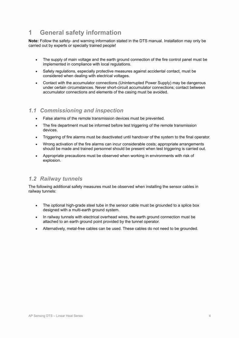
1 General safety information Note: Follow the safety- and warning information stated in the DTS manual. Installation may only be carried out by experts or specially trained people!
• The supply of main voltage and the earth ground connection of the fire control panel must be implemented in compliance with local regulations.
• Safety regulations, especially protective measures against accidental contact, must be considered when dealing with electrical voltages.
• Contact with the accumulator connections (Uninterrupted Power Supply) may be dangerous under certain circumstances. Never short-circuit accumulator connections; contact between accumulator connections and elements of the casing must be avoided.
1.1 Commissioning and inspection • False alarms of the remote transmission devices must be prevented.
• The fire department must be informed before test triggering of the remote transmission devices.
• Triggering of fire alarms must be deactivated until handover of the system to the final operator.
• Wrong activation of the fire alarms can incur considerable costs; appropriate arrangements should be made and trained personnel should be present when test triggering is carried out.
• Appropriate precautions must be observed when working in environments with risk of explosion.
1.2 Railway tunnels The following additional safety measures must be observed when installing the sensor cables in railway tunnels:
• The optional high-grade steel tube in the sensor cable must be grounded to a splice box designed with a multi-earth ground system.
• In railway tunnels with electrical overhead wires, the earth ground connection must be attached to an earth ground point provided by the tunnel operator.
• Alternatively, metal-free cables can be used. These cables do not need to be grounded.

AP Sensing DTS – Linear Heat Series 5
2 Introduction Fiber-optic linear heat detectors, also called DTS (Distributed Temperature Sensing), offer many advantages over conventional methods.
• The regulation of the alarm criteria / triggering parameters is highly customizable and can be
defined by each zone. Hot gases (smoke) and radiant heat are detectable.
• The sensor cable is fitted with two optical fibers. The cable is very sturdy and resistant to environmental influences such as temperature, pressure, humidity, dirt, dust and exhaust fumes/corrosive gases. The cable is designed to last for approximately thirty years.
• The fiber is immune to electromagnetic influences, a great advantage in applications with high electromagnetic radiation.
• Assembly and maintenance of the sensor cable is very simple. Defective areas can be repaired (spliced) by trained personnel.
Note: The system has been certified for certain cable and parameter settings by the VdS certifying body.
2.1 What the system reports to the control center • Triggering of the fire control panel (FCP) via relay contacts.
• Exact coordinates of the fire location or hotspots, as well as the size of the associated alarm zone.
• Propagation direction of the fire, i.e. of the alarm zone (at a standstill, in the direction of the device or away from the device).
• Triggering of pre-programmed control processes, e.g. traffic signaling, ventilation activation, video systems, fire suppression system, etc..
2.2 Monitoring at a primary control center Displaying of temperature curves, zones, alarms, alarm location, fire size and propagation etc. and live monitoring via USB and / or Ethernet is not part of the certification. It offers further information for the primary control center, the device works nevertheless independently of higher systems and their availability. For certified operation of the linear heat detection system at least two relay output shall be connected to the fire control panel (FCP) for triggering “alarm”, “fault” and “fiber break”.
AP Sensing DTS – Linear Heat Series 6
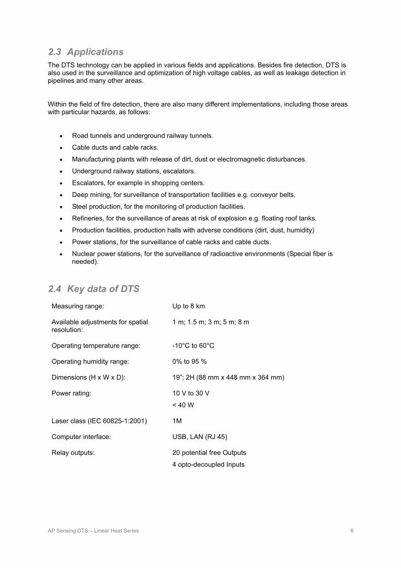
2.3 Applications The DTS technology can be applied in various fields and applications. Besides fire detection, DTS is also used in the surveillance and optimization of high voltage cables, as well as leakage detection in pipelines and many other areas.
Within the field of fire detection, there are also many different implementations, including those areas with particular hazards, as follows:
• Road tunnels and underground railway tunnels.
• Cable ducts and cable racks.
• Manufacturing plants with release of dirt, dust or electromagnetic disturbances.
• Underground railway stations, escalators.
• Escalators, for example in shopping centers.
• Deep mining, for surveillance of transportation facilities e.g. conveyor belts.
• Steel production, for the monitoring of production facilities.
• Refineries, for the surveillance of areas at risk of explosion e.g. floating roof tanks.
• Production facilities, production halls with adverse conditions (dirt, dust, humidity)
• Power stations, for the surveillance of cable racks and cable ducts.
• Nuclear power stations, for the surveillance of radioactive environments (Special fiber is needed).
2.4 Key data of DTS
Measuring range: Up to 8 km
Available adjustments for spatial resolution:
1 m; 1.5 m; 3 m; 5 m; 8 m
Operating temperature range: -10°C to 60°C
Operating humidity range: 0% to 95 %
Dimensions (H x W x D): 19”; 2H (88 mm x 448 mm x 364 mm)
Power rating: 10 V to 30 V
< 40 W
Laser class (IEC 60825-1:2001) 1M
Computer interface: USB, LAN (RJ 45)
Relay outputs: 20 potential free Outputs
4 opto-decoupled Inputs
AP Sensing DTS – Linear Heat Series 7
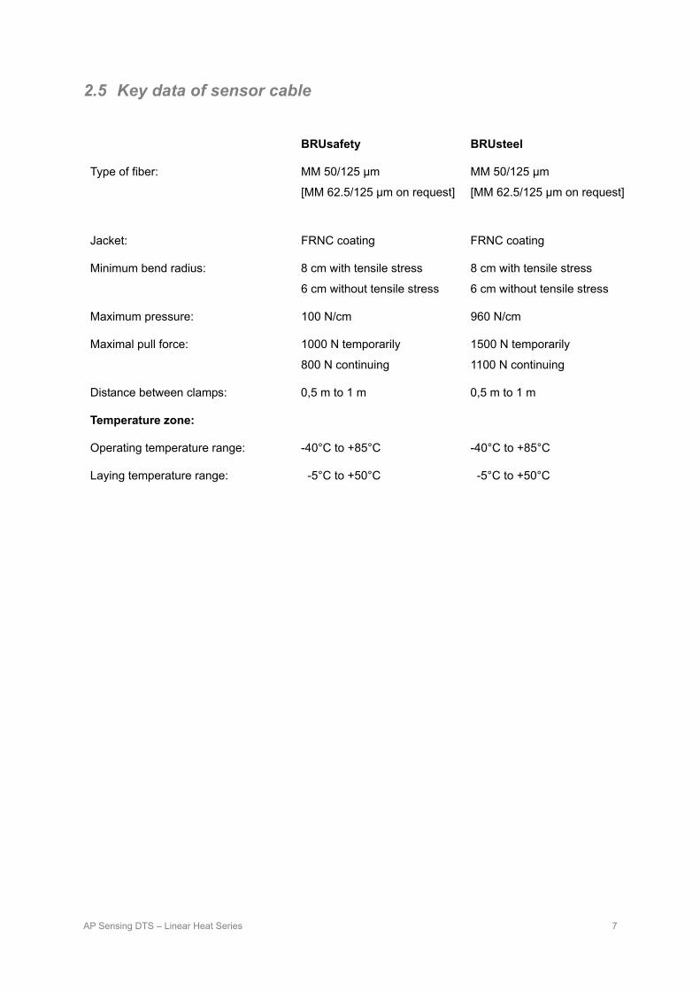
2.5 Key data of sensor cable
BRUsafety BRUsteel
Type of fiber: MM 50/125 μm
[MM 62.5/125 μm on request]
MM 50/125 μm
[MM 62.5/125 μm on request]
Jacket: FRNC coating FRNC coating
Minimum bend radius: 8 cm with tensile stress
6 cm without tensile stress
8 cm with tensile stress
6 cm without tensile stress
Maximum pressure: 100 N/cm 960 N/cm
Maximal pull force: 1000 N temporarily
800 N continuing
1500 N temporarily
1100 N continuing
Distance between clamps: 0,5 m to 1 m 0,5 m to 1 m
Temperature zone:
Operating temperature range: -40°C to +85°C -40°C to +85°C
Laying temperature range: -5°C to +50°C -5°C to +50°C

AP Sensing DTS – Linear Heat Series 8
3 System architecture
PC = Personal Computer with DTS Configurator
FP = Fire Panel or SCADA System
UPS = Uninterruptable Power Supply or Battery Package
3.1 System configuration • Power supply with a power source in compliance with EN54-4 (10 to 30V DC).
• The power supply offered by AP Sensing is not qualified for this application and is not certified in compliance with EN54-4
• The linear heat detector shall be connected to the fire control panel (FCP) through up to 20 potential free controller contact outputs. Alarm and failure reports are conveyed by this medium (19 alarms, 1 common fault).
• Alarm confirmation of the fire control panel (FCP) occurs by means of up to 4 opto-decoupled controller inputs. Alternatively, this can also take place by means of a key switch or a computer (if connected).
• The controller can be connected to a PC by USB and LAN. This allows parameterization to be carried out and measurement information to be read.

AP Sensing DTS – Linear Heat Series 9
3.2 Outputs The DTS provides 20 relay outputs (potential free contacts) that are capable of notifying the user of alarm conditions. The first of the 20 relays is the fault relay. It is normally closed but in situations of fault condition (for example power failure, instrument problems, fiber break) it will be opened. The other 19 relays are normally open and in the event of an alarm condition the contacts will be closed. Reverse logic can also be programmed. The resulting ability to switch between these two states provides several options for the user. For example, the output can be used to operate external audible alarms or warning lamps.
Notice: The first relay output is reserved for monitoring the operating conditions.
Pin assignment “Output I” Error Output Pin 1, 14 Output 2 Pin 2, 15 Output 3 Pin 3, 16 Output 4 Pin 4, 17 Output 5 Pin 5, 18 Output 6 Pin 6, 19 Output 7 Pin 7, 20 Output 8 Pin 8, 21 Output 9 Pin 9, 22 Output 10 Pin 10, 23 Not connected Pin 11, 12, 13, 24, 25 Pin assignment ”Output II” Output 11 Pin 1, 14 Output 12 Pin 2, 15 Output 13 Pin 3, 16 Output 14 Pin 4, 17 Output 15 Pin 5, 18 Output 16 Pin 6, 19 Output 17 Pin 7, 20 Output 18 Pin 8, 21 Output 19 Pin 9, 22 Output 20 Pin 10, 23 Not connected Pin 11, 12, 13, 24, 25
3.3 Inputs The DTS also provides 4 opto-decoupled inputs. The inputs are edge-sensitive and their polarity (rising or falling edge) is selectable / programmable by the user. The inputs can be configured to reset detected alarms.
Pin assignment connector Input 1 Pin 1 Input 2 Pin 2 Input 3 Pin 3 Input 4 Pin 4 GND (earth) Pin 5, 6, 7, 8, 9,
Pin assignment connector

AP Sensing DTS – Linear Heat Series 10
4 Instrument parameterization according to EN54-5 The configuration of the DTS instrument consists of measurement parameters (measurement time, spatial resolution) and alarming parameters (triggering limits). The configuration can be set using the supplied “DTS Configurator” software.
Parameters for EN54-5 class A1/A2
The following sets of parameters are in compliance with the VdS certification. Corresponding to the classification, in class A1 the detector (i.e. the sensor cable) is suitable for installation heights of up to 7.5 m and in class A2 up to installation heights of 6.0 m.
• Alarm: Activated
• Alarm confirmation cycle: 1
• Sampling Interval 1 m
Per zone:
• Maximum any point temperature: 60°C
• Maximum temperature difference to the zone average: Deactivated
• Temperature gradient 1 for 1-channel, 2-channel and dual-ended Delta = 13°C @ 40 s
• Temperature gradient 2: Delta = 17°C @ 120 s
• Temperature gradient 3: Delta = 28°C @ 360 s
This alarm parameter set in conjunction with the following measurement parameter sets and sensor cable lengths let expect a response behavior in accordance with EN54-5 detection class A1 and class A2. Example configuration files for use with the DTS Configurator can be found on the instrument’s support CD.
Single-ended 1 channel sensor cable configuration for sensor cable types BRUsafety and BRUsteel.
Class Sensor length
Measurement time
Spatial resolution VdS configuration name
A1 ≤ 2 km 10 s
1m 1.5m 3m 5m
VdS BRUsafety* 2km - 10s -1m VdS BRUsafety* 2km - 10s -1.5m VdS BRUsafety* 2km - 10s -3m VdS BRUsafety* 2km - 10s -5m
A1 ≤ 4 km 10 s 1.5m 3m 5m
VdS BRUsafety* 4km - 10s -1.5m VdS BRUsafety* 4km - 10s -3m VdS BRUsafety* 4km - 10s -5m
A1 ≤ 6 km 10 s 3m 5m
VdS BRUsafety* 6km - 10s -3m VdS BRUsafety* 6km - 10s -5m
A2 ≤ 8 km
20 s 3 m VdS BRUsafety* 8km - 20s -3m
A1 10 s 5 m VdS BRUsafety* 8km - 10s -5m

AP Sensing DTS – Linear Heat Series 11
Dual-ended sensor cable configuration for sensor cable types BRUsafety and BRUsteel.
Class Sensor length
Measurement time
Spatial resolution VdS configuration name
A2 ≤ 2km 10s 1m 1.5m 3m 5m
VdS BRUsafety* 2km - 10s -1m -d1 VdS BRUsafety* 2km - 10s -1.5m -d1 VdS BRUsafety* 2km - 10s -3m -d1 VdS BRUsafety* 2km - 10s -5m -d1
A2 ≤ 4km 10s 1.5m 3m 5m
VdS BRUsafety* 4km - 10s -1.5m -d1 VdS BRUsafety* 4km - 10s -3m -d1 VdS BRUsafety* 4km - 10s -5m -d1
A2 ≤ 6km 10s 3m 5m
VdS BRUsafety* 6km - 10s -3m -d1 VdS BRUsafety* 6km - 10s -5m -d1
A2 ≤ 8km 10s 5m VdS BRUsafety* 8km - 10s -5m -d1 Single-ended 2-channel sensor cable configuration, sensor cable types BRUsafety and BRUsteel.
Class Sensor length
Measurement time
Spatial resolution VdS configuration name
A2 ≤ 2km 10s 1m
1.5m
3m
5m
VdS BRUsafety* 2km - 10s -1m -2ch VdS BRUsafety* 2km - 10s -1m VdS BRUsafety* 2km - 10s -1.5m -2ch VdS BRUsafety* 2km - 10s -1.5m VdS BRUsafety* 2km - 10s -3m -2ch VdS BRUsafety* 2km - 10s -3m VdS BRUsafety* 2km - 10s -5m -2ch VdS BRUsafety* 2km - 10s -5m
A2 ≤ 4km 10s 1.5m
3m
5m
VdS BRUsafety* 4km - 10s -1.5m -2ch VdS BRUsafety* 4km - 10s -1.5m VdS BRUsafety* 4km - 10s -3m -2ch VdS BRUsafety* 4km - 10s -3m - VdS BRUsafety* 4km - 10s -5m -2ch VdS BRUsafety* 4km - 10s -5m
A2 ≤ 6km 10s 3m
5m
VdS BRUsafety* 6km - 10s -3m -2ch VdS BRUsafety* 6km - 10s -3m VdS BRUsafety* 6km - 10s -5m -2ch VdS BRUsafety* 6km - 10s -5m
A2 ≤ 8km 10s 5m VdS BRUsafety* 8km - 10s -5m -2ch VdS BRUsafety* 8km - 10s -5m
(*)The same values apply for cable type “BRUsteel”, the configuration names then changes from BRUsafety to BRUsteel.

AP Sensing DTS – Linear Heat Series 12
Measuring accuracy /noise response
An accurate measurement (temperature resolution) depends on several factors. The table below shows the “noise response” (+/- tolerance) for 1-channel of the respective measurement. Figures in white cells are results obtained with VdS approved measurement parameters.
Monitoring range:
1 km 2 km 4km 6km 8km
Spatial R. \ M. Time
10s 20s 10s 20s 10s 20s 10s 20s 10s 20s
1 m 0.51 0.36 0.71 0.50 1.54 1.09 3.79 2.68 7.31 5.17
1,5 m 0.34 0.24 0.41 0.29 0.71 0.50 1.59 1.13 2.85 2.01
3 m 0.17 0.12 0.20 0.14 0.36 0.25 0.79 0.56 1.40 0.99
5 m 0.08 0.05 0.09 0.06 0.17 0.12 0.36 0.25 0.64 0.45
8 m 0.04 0.03 0.05 0.04 0.09 0.07 0.20 0.14 0.36 0.25
Apparently a short measurement time and a low spatial resolution may qualify the EN54-5 criterions. Nevertheless the settings should be chose in accordance to the requirement of the application to balance alarm sensitivity and false alarm safety.
A 2 channel instrument has an intrinsic slightly higher optical loss which results in a higher noise. This effect is comparable with a 300m or 600m longer measurement distance
4.1 Adaptive alarm criterion The DTS instrument offers the capability to trigger an alarm if the temperature rises above a certain level compared to the average temperature within an alarm zone.
This capability is not part of the VdS certification, but offers the possibility to dynamically adapt the temperature level required to trigger an alarm in reference to the average temperature within an alarm zone. This can be particularly useful if the normal temperature is expected to change over time (day/night or summer/winter differences).
In zones with rather constant and slow changing temperature levels (e.g. within a tunnel) it is recommended to set this parameter as the following:
• Maximum temperature difference to the zone average 15°C
In zones where larger and more rapid temperature fluctuations are expected (e.g. at the portal areas of a tunnel) it is recommended to set this parameter as the following:
• Maximum temperature difference to the zone average 25°C

AP Sensing DTS – Linear Heat Series 13
5 Zones and alarms
5.1 Zones The sensor cable can be sub-divided into various zones for different alarming conditions (i.e. sprinkler, video, ventilation, lighting zones). An (alarm) zone is a continuous part of the sensor cable. Zones can be defined as required and may overlap each other. Up to 256 zones can be configured. Each zone can have up to 7 independent alarm criterions in addition to a unique output relay combination.
Notice: Generally the VdS-Parameter should be useful for most applications. If the VdS parameters doesn’t suit the application requirements (e.g. leading to false alarms in specific alarm zones) you might change the parameter accordingly.
5.2 Zone to indicate fiber breaks It is recommended to define a dedicated zone over the entire length of the cable (zone from 0m up to the cable end -20m) do detect fiber breaks. In order to activate the alarm handling for the zone it is required to define at least one alarm criterion. Set the Minimum Check to True and the Minimum Value [°C] to -200. This extreme low value will avoid other alarms then the fiber break alarm in this dedicated zone.
5.3 Alarm triggering Generally an alarm is triggered if one of the following 5 alarm criteria in a zone is met (and confirmed, see below). An alarm is triggered at the end of a complete measurement cycle.
a) Maximum temperature in °C
Zone parameters of a zone with 5 of 7 different alarm parameters

AP Sensing DTS – Linear Heat Series 14
b) Positive Delta to the zone average in °C
c) Temperature Gradient 1 (temperature rise over time)
d) Temperature Gradient 2 (temperature rise over time)
e) Temperature Gradient 3 (temperature rise over time)
To prevent false alarms, a comparison is made between the measurement cycle that has detected an alarm condition first and the following measurement cycle (Confirmation Cycle). The alarm is triggered after confirmation. This confirmation cycle can also be set individually. 0 = instant triggering (at first detection of the alarm condition); 1 = one confirmation cycle and 2 = two confirmation cycles.
The specific alarm criterion which hasdetected an alarm condition must be confirmed in the confirmation cycle before triggering an alarm. In other words, if the same alarm criterion is not valid within the confirmation cycle, no alarm will be triggered. This means the DTS instrument will continue to acquire data until the next alarm condition is found and confirmed.
Limit
Alarm criterion met 2nd time Alarm criterion
met 1st time
Time
AP Sensing DTS – Linear Heat Series 15
Notice: If the detection of a temperature below a minimum value is desired (e.g. warning of black ice), a dedicated zone should be defined (which may overlap with a fire detection zone) that is not connected to a fire control panel (FCP). Otherwise a cold spot would trigger a fire alarm.
5.4 Alarm indications Alarms will be indicated as follows:
• Red shiny LED on the front panel (“Alarm”). The alarm is assigned to the respective sensor channel/cable.
• Activated relay contacts to the fire control panel.
• Alarm and zone view in the visualization software.
5.5 Failure reports The system permanently monitors its own operation as well as the integrity of the sensor cable. A malfunction will be indicated as follows:
• Yellow shiny LED on the front panel („Fault“)
• Activated relay contact (Relay 1)
• A failure resp. cable/fiber break is indicated in the visualization software
Note: To prevent false alarms, in case of a cable/fiber break the temperature data in a range of ±20m from the break will be masked out so that no alarm check is performed there. The cable/fiber break will be indicated as a failure to the fire control panel (FCP).
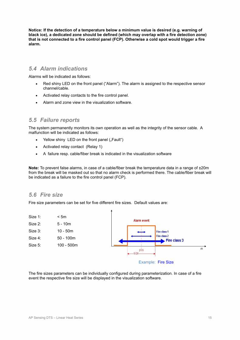
5.6 Fire size Fire size parameters can be set for five different fire sizes. Default values are:
Size 1: < 5m
Size 2: 5 - 10m
Size 3: 10 - 50m
Size 4: 50 - 100m
Size 5: 100 - 500m
The fire sizes parameters can be individually configured during parameterization. In case of a fire event the respective fire size will be displayed in the visualization software.
Example: Fire Size

AP Sensing DTS – Linear Heat Series 16
5.7 Fire propagation direction Most fires have a main propagation direction caused by the (tunnel-) air current. By knowing this propagation direction, the counter action of the emergency services (fire brigade, ambulance, etc.) can be directed to the less hazardous side of the fire or to keep fire and smoke where it is by using special ventilation programs. There are three possible propagation directions:
• No direction
• In direction to the evaluation unit
• In direction away from the evaluation unit
In case of a sensor cable loop set up (i.e. sensor cable is installed along one tunnel side and then returns on the other tunnel side) the “Point of Return” needs to be set to ensure that the propagation direction is displayed correctly.
5.8 Alarm resetting This is done by either using one of the four input contacts or the key switch on the front of the device, or the DTS configurator software. See also section 3.3
two Alarms with direction

AP Sensing DTS – Linear Heat Series 17
6 General installation information
6.1 Awarding the installation contract The installation of the cable should be delegated to an appropriately specialized company with necessary resources and tools (mobile assembly platforms, unrolling stand for the cable, fusion splice device, etc.) and experience of dealing with fiber optic cables.
6.2 Cable layout The cable layout plan shows the rough courses the sensor cable will run especially the beginning and end of the sensor cable installation. During installation, relevant meter markings of the cable has to be recorded in the respective zone list as crucial points, such as zone boundaries, object start, splicing, etc. This will be necessary to define an accurate zone definition during the commissioning.
Cable drum The sensor cable is supplied on a cable drum. The case should only be removed shortly before the installation. The cable drum must always stand upright to avoid damage during handling and storing. The maximum pull force and the minimum bending radius must never be exceeded throughout the installation. • Do not go below the minimum cable bend radius of 8 cm. • Maximum (long-term) pull force on BRUsafety cable: 800 N, BRUsteel
cable 1100 N. • Exceeding rated loads can break the fibers, which may then fail
immediately or later during operation. Such damage is not necessarily visible from the outside.
A Cable Drum
6.3 Routing the sensor cable At the beginning of the cable stretch, a surplus length of approx. 3 m to 5 m shall be remaining in the cabinet so that the pigtail can be spliced with the sensor cable.
A surplus length of minimum 20 m. must be left at the end of the total measured section as a non-active measured section. This prevents any negative effects on the measurement result caused by fiber-end reflex. The fiber end should be spliced with an E2000 8° angled connector or carefully terminated (see also section 6.4).
Assembly sequence
The sensor cable shall be installed with a suitable cable clamp e.g. to a tunnel ceiling.
1. Fit a cable clamp
2. Lay the cable
3. Fix the cable to the cable clamp
4. Record the meter marking in the zone chart (see attachment at the end of this manual)
If possible, the installation of the sensor cable can be carried out alongside the progress of the building work, otherwise it can be installed using a mobile roller block or spool trestle. To avoid cable twists it is strongly recommended to use a roller block or spool trestle to roll off the sensor cable.

AP Sensing DTS – Linear Heat Series 18
Markings on the cable
The sensor cable is labeled with cable brand, product number and a meter marking. Small meter values are to be found at the outside of the cable roll but it will not be necessarily “0 m”. It is recommended to note the cable meters of zone boundaries in the zone table (see attachment at end of this manual) to facilitate the zone setup during commissioning.
For further information please see chapter 6.4.

AP Sensing DTS – Linear Heat Series 19
Cable installation in tunnels
The figures show the areas (marked green), where the cables have to be fixed. Depending on the number of lanes (resp. width of the tunnel) more than one cable has to be laid out/may be required. Generally it is indicated to use 2 cable lines if the tunnel has more than 3 lanes or has a width of more than 12 m. But this depends on the countries regulation and specification given by the contractor / planner. In case of doubt it is recommended to follow the specification.
To ensure an appropriate response characteristic, a cable distance between 15 mm and 50 mm from the ceiling is recommended. Furthermore it has to be avoided to install the sensor cable or sections of the sensor cable behind barriers like cable trays, ventilators, lamps, cable conduits and other obstacles like protrusions.
General remarks concerning mounting of the sensor cable In straight-line assembly, a distance of 0.5 m to 1 m between the cable clamps is recommended. The cable has to be stretched between the cable clamps by hand. It is recommended that the sensor cable shall be easy accessible for system tests. Obstacles often arise in form of pipes, cables racks, protrusions etc. To overcome these, the pipe clamps should be mounted on both sides of the obstacle at a distance of approximately 20 cm. The passage over the obstacle must be softly bended and the cable must not touch the obstacle.
Overcome obstacles
Note! Keep in mind the minimum bend radius of 8 cm. A flexible open seam tube should be used to protect the sensor cable if sharp-cornered obstacles are by-passed during installation.

AP Sensing DTS – Linear Heat Series 20
Mounting to a tensioning wire The sensor cable can also be mounted to a tensioning wire by means of cable straps, which must be resistant to all occurring environmental influences. A distance of 0.5 m to 1 m is recommended.
6.4 Termination at the end of the sensor cable The last 20 m of the installed sensor cables is rolled up in a splice box or laid in a raceway. The fiber end must be terminated accurately prior to commissioning.
The recommended termination of the fiber end is to splice a pigtail with E2000, 8° angle polish connector to the end of the fiber. For easy handling in field, preconfigured sensor cables with connector are available. Alternatively, the fiber end can be winded at least 5 times with a diameter smaller than 5 mm. The fiber loops have to be fixed with gluing tape and deposit the loop inside a (splice-) box.
These measures will reduce the end reflection to a minimum. An end reflection value of less than -25 dB has to be achieved in order to prevent measurement fluctuations possibly resulting in false alarms. Otherwise the termination has to be done again. The end reflection value shall be obtained from the attenuation curve measured by the linear heat detector during commissioning.
6.5 Connecting the sensor cable to the DTS instrument The back of the DTS instrument is equipped with E2000, 8° angle polish connector(s). The connection of the sensor cable to the evaluation unit is done via a splice box (junction box) or alternatively inside the device directly (see User’s Guide). As option, the sensor cable can be shipped with a pre-assembled pigtail connection with an E2000 connector.
The splice has to be placed in the splice cartridge that is situated in a splice box. The pigtail and the splice box must be installed and fixed in such a way that any mechanical effects on the pigtail are avoided (e.g. high pulling power as a result of a overly short feed or wrongly placed splice box / danger of crushing through sliding controller cabinet doors or swing gates because of the too generally dimensioned feeder / cable straps done up too tightly).
The splice box shall be fixed next to the controller.
When a connector is plugged into the DTS instrument, it is essential to realize a dust and damage free connection.
Optical E2000 connectors can be cleaned using the E2000 Serviceadapter included in the DTS shipment. The fiber end face must be cleaned carefully ─ first wet (lint-free, soft cloth + laboratory alcohol) and then dry (lint-free, soft cloth). Appropriate fiber inspection set and cleaning tools are available from AP Sensing.

AP Sensing DTS – Linear Heat Series 21
E2000 – Serviceadapter put on connector
Note: Apart from the connector of the device, no further connections are allowed in order to prevent false alarms due to connection problems.
6.6 Splicing the sensor cable Only the fusion splicing process should be considered for a good splice connection. This requires a special splicing device and corresponding preparation tools. The actual splicing of the fiber requires expert knowledge. Therefore it is recommended to leave the splicing to a specialized telecommunication company.
Notice: The maximum permitted splice loss is 0.1 dB.
Number of splices
In general, splices should be avoided where possible. In compliance with the above mentioned maximum splice loss, a total of ten splices along the fiber is allowed.
Splice box assembly instructions
1. Clean dirt from the cable ends.
2. Use a cable feed to feed the cable into the splice box.
3. Prepare the cable.
• Sensor cable: Remove 2 m of insulation (outer casing) and, if available, the high-grade steel tube up to a remainder of 5 cm, which, if necessary, is grounded in the multi-contact cylinder.
• Pigtail: Remove 2 m of insulation.
The above lengths assume that a reserve length is inserted in both the splice box and in the splice cartridge. The fiber bend radius should be taken as large as possible (min. bend radius 60 mm).
4. Put the cable and the pigtail into the splice box.
5. Leave cable and pigtail to about 5 cm in the splice box and relieve the stress in the intended support
points with cable straps. Avoid high tensile forces to fix the cable straps.
6. Splice.
7. Stabilize the splice points with a splice protection.
8. Place the glass fiber in the splice cartridge and fix the splice protector in the intended holder.
9. Carefully close the splice cartridge.
10. Finally place the lockable cover and screw it on the splice box on.
6.7 Repairing the sensor cable In the unusual case of a sensor cable damage the part of the cable with the corresponding point of damage has to be removed and replaced with a new piece. Two splice boxes has to be used to insert the new piece of sensor cable (see figure below). It is advisable to make the replacement cable approximately 3 meters longer at both ends than the removed one for easy handling of the splice works. At both ends the splice boxes are set in the middle of the overlap so that sufficient fiber length is available for splicing.

AP Sensing DTS – Linear Heat Series 22
After repairing the sensor cable please ensure that the zone information is updated with respect to the zone stretch. Therefore it is necessary to re-configure the zone start- and end-point within the evaluation unit.
Splice box fixing
6.8 Testing the sensor cable After splicing, the cable must be re-calibrated and the corresponding results must be logged.
To check the integrity of the sensor cable, an optical backscatter measurement has to be carried out which gives information about possible mechanical damages of the sensor cable
This can be performed with either the DTS measuring instrument itself (“Loss” Trace) or an OTDR (Optical Time Domain Reflectometer, multimode 850 nm or 1310nm version with E2000 8° angle polish connector or adapter). It is essential that the same connector type (i.e. 8° angle polish) is used. Connecting a different connector type (e.g. a straight polish connector) may damage the optical connectors.
Maximum loss:
DTS loss trace (1064nm) OTDR 850nm OTDR 1310nm
Optical connector ≤ 0.3 dB ≤ 0.3 dB ≤ 0.3 dB
Splice ≤ 0.1 dB ≤ 0.1 dB ≤ 0.1 dB
Fiber ≤ 1.1 dB / km ≤ 2.7 dB / km ≤ 0.9 dB / km
Fiber end reflection n/a ≤ - 25 dB ≤ - 25 dB

AP Sensing DTS – Linear Heat Series 23
6.9 Sensor cable replacement after fire
If the cable has been exposed to real emergency / fire with temperatures exceeding 85 °C for more the 60 minutes or exceeding 150 °C it is strongly recommended to replace the sensor cable and to configurate the system with the new sensor cable
7 DTS instrument cabinet assembly Prior to the cabinet assembly the service technician must check that all the necessary hardware components are available.
Checklist:
1. DTS instrument
2. Pigtail with E2000, 8° angle polish connector
3. Splice box including splice cartridge, with earth ground connection if applicable
4. Power supply cable 10 VDC to 30 VDC
5. USB / LAN cable
6. Relays – input cable
7. Relays – output cable (2)
The DTS unit shall be firmly mounted with 4 screws to the cabinet rack.
The sensor cable and the connector pigtail have to be placed in the cabinet.
The splice box must be fixed in an appropriate position inside the cabinet. This position should be selected in such a way that:
• both the sensor cable and the connector pigtail can be put into the splice box / splice cartridge without falling below the minimum bend radius of 8 cm and
• it is ensured to place the fibers in the splice cartridge without damaging them.
If the grounding connection is used, the yellow/green grounding wire enclosed to the splicing box must be firmly screwed onto the intended external connector. The other end of the grounding wire has to be connected to the grounding point provided by the operator.
During the cabinet assembly, all connections between the DTS unit and external peripheral devices needed to configure and to operate the DTS unit (power supply, relays – inputs and outputs, data transfer via USB or LAN) has to be installed and tested. See also the User Guide.
Afterwards the system can be started up.
AP Sensing DTS – Linear Heat Series 24
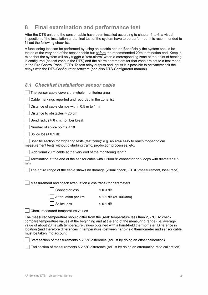
8 Final examination and performance test After the DTS unit and the sensor cable have been installed according to chapter 1 to 6, a visual inspection of the installation and a final test of the system have to be performed. It is recommended to fill out the following checklists.
A functioning test can be performed by using an electric heater. Beneficially the system should be tested at the very end of the sensor cable but before the recommended 20m termination end. Keep in mind that the system will only trigger a “test-alarm” when a corresponding zone at the point of heating is configured (as test zone in the DTS) and the alarm parameters for that zone are set to a test mode in the Fire Control Panel (FCP). To test relay outputs and inputs it is possible to activate/check the relays with the DTS-Configurator software (see also DTS-Configurator manual).
8.1 Checklist installation sensor cable The sensor cable covers the whole monitoring area
Cable markings reported and recorded in the zone list
Distance of cable clamps within 0.5 m to 1 m
Distance to obstacles > 20 cm
Bend radius ≥ 8 cm, no fiber break
Number of splice points < 10
Splice loss< 0.1 dB
Specific section for triggering tests (test zone): e.g. an area easy to reach for periodical measurement tests without disturbing traffic, production processes, etc.
Additional 20 m cable at the very end of the monitoring length.
Termination at the end of the sensor cable with E2000 8° connector or 5 loops with diameter < 5 mm
The entire range of the cable shows no damage (visual check, OTDR-measurement, loss-trace)
Measurement and check attenuation (Loss trace) for parameters
Connector loss ≤ 0.3 dB
Attenuation per km ≤ 1.1 dB (at 1064nm)
Splice loss ≤ 0.1 dB
Check measured temperature values
The measured temperature should differ from the „real“ temperature less than 2,5 °C. To check, compare temperature values at the beginning and at the end of the measuring range (i.e. average value of about 20m) with temperature values obtained with a hand-held thermometer. Difference in location (and therefore differences in temperature) between hand-held thermometer and sensor cable must be taken into account.
Start section of measurements ≤ 2,5°C difference (adjust by doing an offset calibration)
End section of measurements ≤ 2,5°C difference (adjust by doing an attenuation ratio calibration)

AP Sensing DTS – Linear Heat Series 25
8.2 Checklist zone / alarm (relay parameterization) The entire area is covered with relays controlled zones and each zone is assigned to a relay.
”Negative“ alarm criteria (like ice warning) are not switched on the relays for the fire control panel (FCP) and are not applied for fire zones.
Cable (fiber) break is indicated by the default “fault” relay 1. Additionally verify, that the selected relay indicates only the fault to the fire control panel (FCP) and not an alarm.
(It is recommended to define a dedicated zone spanning the entire cable length)
Alarm criteria set on „true“.
8.3 Checklist instrument & power supply Device is fixed properly.
Date and time are configured.
Environmental conditions correspond with the tolerated requirements.
USV in accordance with EN54-4 connected.
PC is connected (if applicable).
Software is protected by a password so ”unauthorized individuals“ cannot change device- / measuring parameter.
“Restart Measurement Automatically after Power On” is configured on the DTS instrument.
8.4 Checklist fire control panel (FCP) Relay outputs and inputs are wired up with fire control panel (FCP).
Test the relays (use the PC-Software).
Logic of the relays (sensor break relays and alarm relays) corresponds to the project specification.

AP Sensing DTS – Linear Heat Series 26

AP Sensing DTS – Linear Heat Series 27
© AP Sensing GmbH 4th edition, May 2009
Intelligent Solutions AP Sensing GmbH Herrenberger Str. 130 71034 Boeblingen, Germany Tel: + 49 7031 435 5910 Fax: + 49 7031 435 5911 www.apsensing.com