
AP´ENDICES - UPCommons
259
AP ´ ENDICES T ´ ITULO DEL TFG: Estudio y dise ˜ no de dos placas de intercambio de datos de inclinaci ´ on y posici ´ on entre dos cubesats TITULACI ´ ON: Grado en Ingenier´ ıa en Tecnolog´ ıas Aeroespaciales AUTOR: Juan Palomares Moyano DIRECTORES: Javier Gago Barrio Juanjo Alins Delgado FECHA: 10 de junio de 2019
-
Upload
khangminh22 -
Category
Documents
-
view
0 -
download
0
Transcript of AP´ENDICES - UPCommons

APENDICES
TITULO DEL TFG: Estudio y diseno de dos placas de intercambio de datos deinclinacion y posicion entre dos cubesats
TITULACION: Grado en Ingenierıa en Tecnologıas Aeroespaciales
AUTOR: Juan Palomares Moyano
DIRECTORES: Javier Gago BarrioJuanjo Alins Delgado
FECHA: 10 de junio de 2019


APENDICE A. CODIGOS ARDUINO
Sensores.ino1 /*JUAN PALOMARES MOYANO - 2019*/23 /*˜˜˜˜˜˜˜˜˜˜˜˜˜˜˜˜˜˜˜˜˜˜˜˜˜˜˜˜˜*/4 /*˜˜˜˜˜˜˜˜˜˜ LIBRERIAS ˜˜˜˜˜˜˜˜˜˜*/5 /*˜˜˜˜˜˜˜˜˜˜˜˜˜˜˜˜˜˜˜˜˜˜˜˜˜˜˜˜˜*/67 //Conexionados UART e I2C8 #include "Wire.h"9 #include "SoftwareSerial.h"
1011 //IMU12 #include "MPU6050_6Axis_MotionApps20.h" //Mediante esta biblioteca se pueden obtener
datos del DMP (Digital Motion Processor) de la IMU13 #include "I2Cdev.h" //Mediante esta biblioteca se pueden obtener datos del DMP de la IMU14 #include "helper_3dmath.h" //Mediante esta biblioteca se pueden realizar operaciones de
cuaterniones1516 //GPS17 #include "NMEAGPS.h"1819 /*˜˜˜˜˜˜˜˜˜˜˜˜˜˜˜˜˜˜˜˜˜˜˜˜˜˜˜˜˜˜*/20 /*˜˜˜DEFINICION DE VARIABLES ,˜˜˜*/21 /*˜˜˜˜˜ OBJETOS Y CONSTANTES ˜˜˜˜˜*/22 /*˜˜˜˜˜˜˜˜˜˜˜˜˜˜˜˜˜˜˜˜˜˜˜˜˜˜˜˜˜˜*/2324 const float pi = 3.141592653;2526 //IMU27 const int mpuAddress = 0x68; // Se define la direccion de la IMU , puede ser 0x68 o 0x6928 MPU6050 mpu(mpuAddress); //Se crea un objeto MPU6050 para poder extraer datos de la DMP29 int fifoCount = 0, packetSize; //Se crea un contador de valores en el FIFO de la MPU y
el tamano del paquete que obtendremos30 byte fifoBuffer [42]; //Se crea el buffer que se utilizara para obtener los datos roll ,
pitch y yaw.31 float roll=0, pitch=0, yaw=0, sqx, sqy, sqz, sqw, test; //Se crea tanto las variables de
roll , pitch y yaw como las variables "float"32 //intermedias necesarias para
obtenerlas33 Quaternion q; //Se crea el cuaternion necesario para obtener los valores de pitch , yaw y
roll3435 //GPS36 NMEAGPS GPSobject; //Se define un objeto NMEAGPS para poder acceder a los datos del GPS37 gps_fix GPSdata; //Se define el "struct" donde se guardaran los datos del GPS38 #define GPSerial Serial //Como los datos del GPS se obtendran mediante el serial , se
renombra el serial.39 float LatLon[2],Vel,Alt,Sat; //Se definen las variables float donde se guardaran los
datos obtenidos de GPSdata.4041 //Bluetooth42 const int tx = 4; //Se define el pin digital 4 como el TX del Arduino en la conexion
UART con el modulo Bluetooth43 const int rx = 3; //Se define el pin digital 3 como el RX del Arduino en la conexion
UART con el modulo Bluetooth44 SoftwareSerial BT(rx, tx); //Se crea el puerto sere mediante software que utilizara el
modulo Bluetooth para conectarse con el Arduino4546 //RADIO47 //Se crea una union para pasar los datos "float" a "array de bytes" y asi poderlos
enviar por transmision de radio48 union 49 byte array[4];50 float FloatNumber;51 FloatByteTX;52 //Se crea una union para pasar los datos provenientes del buffer de recepcion ("array de
bytes") de la radio a float53 union
1

54 byte array[4];55 float FloatNumber;56 FloatByteRX;57 byte bufferRX[60], bufferTX [60];58 float DatosOtroSat [8]; //Se define un array con todos los datos que se obtendran del
otro satelite.596061 /*˜˜˜˜˜˜˜˜˜˜˜˜˜˜˜˜˜˜˜˜˜˜˜˜˜˜˜˜˜*/62 /*˜˜˜˜˜˜˜˜˜˜˜˜ SETUP ˜˜˜˜˜˜˜˜˜˜˜˜*/63 /*˜˜˜˜˜˜˜˜˜˜˜˜˜˜˜˜˜˜˜˜˜˜˜˜˜˜˜˜˜*/6465 void setup()66 6768 //PUERTOS SERIE69 BT.begin (115200); //Se inicializa el puerto serie del bluetooth70 while (!BT); //Se espera hasta que el puerto del Bluetooth esta inicializado71 GPSerial.begin(9600); //Se inicializa el puerto serie del GPS72 while (!GPSerial); //Se espera hasta que el puerto del GPS esta inicializado73 Wire.begin(); //Se inicializa la libreria Wire.h7475 //IMU76 mpu.initialize(); //Inicializacion de la imu77 mpu.dmpInitialize(); //Inicializacion del DMP78 mpu.setDMPEnabled(true); //Habilitacion del DMP79 packetSize = mpu.dmpGetFIFOPacketSize(); //Se obtiene el tamano del paquete que
obtendremos del DMP (42)8081 //Se introducen los offsets calculados mediante MPU6050_calibration82 mpu.setXAccelOffset (-2538);83 mpu.setYAccelOffset (-1997);84 mpu.setZAccelOffset (1888);85 mpu.setXGyroOffset (95);86 mpu.setYGyroOffset (34);87 mpu.setZGyroOffset(-45);8889 //Se define el cuaternion inicial de actitud90 q.w = 1;91 q.x = 0;92 q.y = 0;93 q.z = 0;9495 delay(100); //Se da un margen de tiempo para que todos los procesos se completen96 9798 /*˜˜˜˜˜˜˜˜˜˜˜˜˜˜˜˜˜˜˜˜˜˜˜˜˜˜˜˜˜*/99 /*˜˜˜˜˜˜˜˜˜˜˜˜ LOOP ˜˜˜˜˜˜˜˜˜˜˜˜˜*/
100 /*˜˜˜˜˜˜˜˜˜˜˜˜˜˜˜˜˜˜˜˜˜˜˜˜˜˜˜˜˜*/101102 void loop()103 104 IMU();105 GPS();106 RadioTX();107 RadioRX();108 Printer();109 delay(10); //Tiempo para relajar las conexiones entre componentes110
01 IMU.ino1 /* ESTA FUNCION DEVUELVE LOS DATOS QUE SE QUIEREN OBTENER DEL MPU6050 (PITCH , YAW Y ROLL
)*/2 void IMU() 3 fifoCount = mpu.getFIFOCount(); //Se obtiene el numero de bytes del DMP4 if (fifoCount >= 42) //Si el numero de datos en el DMP es mayor a 42 bytes (mayor
que el packetSize)5 mpu.resetFIFO(); //Se resetea el FIFO6 fifoCount = mpu.getFIFOCount(); //Se vuelven a obtener el numero de bytes en el FIFO
del DMP7 8 while (fifoCount < packetSize) //Mientras el numero de datos es menor al paquete

9 fifoCount = mpu.getFIFOCount(); //Se vuelven a obtener el numero de bytes en el FIFOdel DMP
10 delay(1); //El delay es necesario para controlar el fifoCount.11 if (fifoCount > packetSize) //Si el numero de datos en el DMP es mayor a 42 bytes12 //(mayor que el packetSize)13 mpu.resetFIFO(); //Se resetea el FIFO14 fifoCount = mpu.getFIFOCount(); //Se vuelven a obtener el numero de bytes en el
FIFO del DMP15 16 17 fifoCount = fifoCount - packetSize; //Se resta al fifoCount el packetSize (el
resultado deberia18 //ser siempre 0)19 mpu.getFIFOBytes(fifoBuffer , packetSize); //Se obtienen los datos del sensor en forma
de bytes20 mpu.dmpGetQuaternion(&q, fifoBuffer); //Se obtiene el cuaternion de actitud mediante
el DMP21 QuatToEuler(q, yaw, pitch , roll); //Se hace el paso del cuaternion de actitud a los
angulos de Euler22
02 QUAT TO EULER.ino1 /* ESTA FUNCION DEVUELVE LOS DATOS QUE SE QUIEREN OBTENER DEL MPU6050 (PITCH , YAW Y ROLL
) UNA VEZ SE2 LE HAN DADO EL VALOR DEL CUATERNION DE ACTITUD*/3 void QuatToEuler(Quaternion q, float &yaw, float &pitch , float &roll) 4 //El proceso que seguidamente se muestra es completamente algebraico ,5 //en la memoria del trabajo se encuentra explicado el proceso.6 test = q.x * q.z - q.w * q.y;7 sqx = q.x * q.x;8 sqy = q.y * q.y;9 sqz = q.z * q.z;
10 sqw = q.w * q.w;11 roll = (180 / pi) * atan2(2 * q.y * q.z + 2 * q.w * q.x, sqz - sqy - sqx + sqw);12 pitch = -(180 / pi) * asin(2 * test);13 yaw = (180 / pi) * atan2(2 * q.x * q.y + 2 * q.w * q.z, sqx + sqw - sqz - sqy);14 //Se asegura que en caso de gimbal lock , el resultado este definido15 if (pitch >= 89.5) 16 pitch = 90;17 yaw = (180 / pi) * 2 * atan2(q.z, q.w);18 roll = 0;19 else if (pitch <= -89.5) 20 pitch = -90;21 yaw = (180 / pi) * 2 * atan2(q.z, q.w);22 roll = 0;23 24
03 GPS.ino1 /* ESTA FUNCION DEVUELVE LOS DATOS QUE SE QUIEREN OBTENER DEL GPS (LAT. LON. VELOCIDAD ,
ALTITUD Y NUMERO DE SATELITES DE LOS QUE SE OBTIENEN DATOS)*/2 void GPS() 3 if (GPSobject.available(GPSerial)) //Si hay valores para leer en el puerto serie del
GPS4 GPSdata = GPSobject.read(); //Se leen los valores en el puerto serie del GPS5 //Se guardan los datos del struct que devuelve el GPS a "floats" manejables6 Sat=GPSdata.satellites;7 LatLon[0]=GPSdata.latitude();8 LatLon[1]=GPSdata.longitude();9 Vel=GPSdata.speed_mph()* 0.44704; //Conversion de "mph" a "m/s"
10 Alt=GPSdata.altitude()* 0.3048; //Conversion de "ft" a "m"11 12
04 RADIO TX.ino1 /* ESTA FUNCION CODIFICA Y ENVIA LOS DATOS QUE SE QUIEREN ENVIAR POR ANTENA AL ARDUINO
ESCLAVO*/23 void RadioTX() 4 int j = 0; //Se inicializa un contador para que el buffer no se vaya sobreescribiendo
conforme se codifican nuevos valores

5 //Codificacion del "roll"6 FloatByteTX.FloatNumber = roll; //El valor float de la union de transmision ahora sera
el "roll"7 for (int i = 0; i < sizeof(float); i++) //Se guardan todos los bytes que codifican
el "roll" en el buffer de transmision8 bufferTX[j] = (FloatByteTX.array[i]); //Se escriben los bytes que codifican el "roll
" en el buffer de transmision9 j += 1; //El siguiente byte se guardara en la siguiente posicion del "array" del "
bufferTX"10 1112 //Codificacion del "pitch"13 FloatByteTX.FloatNumber = pitch;14 for (int i = 0; i < sizeof(float); i++) 15 bufferTX[j] = (FloatByteTX.array[i]);16 j += 1;17 1819 //Codificacion del "yaw"20 FloatByteTX.FloatNumber = yaw;21 for (int i = 0; i < sizeof(float); i++) 22 bufferTX[j] = (FloatByteTX.array[i]);23 j += 1;24 2526 //Codificacion del numero de satelites que aportan datos al modulo GPS27 FloatByteTX.FloatNumber = float(Sat);28 for (int i = 0; i < sizeof(float); i++) 29 bufferTX[j] = (FloatByteTX.array[i]);30 j += 1;31 3233 //Codificacion de la latitud34 FloatByteTX.FloatNumber = LatLon[0];35 for (int i = 0; i < sizeof(float); i++) 36 bufferTX[j] = (FloatByteTX.array[i]);37 j += 1;38 3940 //Codificacion de la longitud41 FloatByteTX.FloatNumber = LatLon[1];42 for (int i = 0; i < sizeof(float); i++) 43 bufferTX[j] = (FloatByteTX.array[i]);44 j += 1;45 4647 //Codificacion de la velocidad48 FloatByteTX.FloatNumber = Vel;49 for (int i = 0; i < sizeof(float); i++) 50 bufferTX[j] = (FloatByteTX.array[i]);51 j += 1;52 5354 //Codificacion de la altitud55 FloatByteTX.FloatNumber = Alt;56 for (int i = 0; i < sizeof(float); i++) 57 bufferTX[j] = (FloatByteTX.array[i]);58 j += 1;59 6061 //Transmision de los datos al Arduino esclavo62 Wire.beginTransmission (8); //Inicio de la transmision con el Arduino esclavo con
direccion 0x0863 for (int i = 0; i < j; i++) //Este for recorre todo el buffer de transmision desde
la primera posicion hasta la ultima con valor64 Wire.write(bufferTX[i]); //Se envia el byte en cuestion65 66 Wire.endTransmission (); //Finalizacion de la transmision67
05 RADIO RX.ino1 /* ESTA FUNCION RECIBE Y DECODIFICA LOS DATOS QUE SE HAN ENVIADO POR ANTENA AL ARDUINO

ESCLAVO*/2 void RadioRX()3 Wire.requestFrom(8, 32); //Se piden 32 bytes al Arduino esclavo con direccion 0x084 int i = 0; //contador para cada byte que llega5 while (Wire.available()) //Este while acaba cuando se acaban los datos a recibir.6 bufferRX[i] = Wire.read(); //Los bytes que se obtienen se guardan en el buffer de
recepcion7 i = i + 1;8 9 //Decodificacion de los datos recibidos
10 for (int j = 0; j < 8; j++) //Mediante este "for" se reciben los 8 "floats" que seesperan obtener
11 for (int i = 0; i < sizeof(float); i++) 12 FloatByteRX.array[i] = bufferRX[i + j * 4]; //Los 4 bytes que representan 1 float
se guardan en la union de recepcion13 14 DatosOtroSat[j] = FloatByteRX.FloatNumber; //Se convierten los 4 bytes a "float" y
se guarda el valor15 16
06 PRINTER.ino1 /* ESTA FUNCION IMPRIME LOS VALORES FINALES EN EL PUERTO SERIE DEL BLUETOOTH CON FORMATO
APTO PARA PROCESSING*/2 void Printer() 3 //Datos de la IMU4 BT.print(roll);5 BT.print(",");6 BT.print(pitch);7 BT.print(",");8 BT.print(yaw);9 BT.print(",");
10 //Datos del GPS11 BT.print(Sat);12 BT.print(",");13 BT.print(LatLon[0],6);14 BT.print(",");15 BT.print(LatLon[1],6);16 BT.print(",");17 BT.print(Vel);18 BT.print(",");19 BT.print(Alt);20 BT.print(",");21 //Datos del otro cubesat22 for(int i=0;i<8;i++)23 if(i==4 || i==5)24 BT.print(DatosOtroSat[i],6);25 BT.print(",");26 else27 BT.print(DatosOtroSat[i]);28 BT.print(",");29 30 31 BT.print("\n");32
Antena.ino1 /*JUAN PALOMARES MOYANO - 2019*/23 /*˜˜˜˜˜˜˜˜˜˜˜˜˜˜˜˜˜˜˜˜˜˜˜˜˜˜˜˜˜*/4 /*˜˜˜˜˜˜˜˜˜˜ LIBRERIAS ˜˜˜˜˜˜˜˜˜˜*/5 /*˜˜˜˜˜˜˜˜˜˜˜˜˜˜˜˜˜˜˜˜˜˜˜˜˜˜˜˜˜*/67 //Radio8 #include <cc1100_arduino.h>9 #include <EnableInterrupt.h>
1011 //Conexionado I2C con el Arduino maestro12 #include <Wire.h>1314

15 /*˜˜˜˜˜˜˜˜˜˜˜˜˜˜˜˜˜˜˜˜˜˜˜˜˜˜˜˜˜*/16 /*˜˜˜DEFINICION DE VARIABLES˜˜˜*/17 /*˜˜˜˜˜˜˜Y CONSTANTES ˜˜˜˜˜˜˜˜˜˜*/18 /*˜˜˜˜˜˜˜˜˜˜˜˜˜˜˜˜˜˜˜˜˜˜˜˜˜˜˜˜˜*/1920 CC1100 cc1100; //Se define una variable de la clase CC1101 para poder recibir y enviar
informacion21 byte Tx_fifo[FIFOBUFFER]=, Rx_fifo[FIFOBUFFER ]=; //Se definen los buffers de
transmision y recepcion y se inicializan con 0 en cada componente22 byte My_addr , Rx_addr , Pktlen; //Se definen las variables de transmision.23 //Se define la direccion de la propia antena , la de la
antena receptora24 //y la longitud del paquete de informacion.25 byte rx_addr , sender , lqi, pktlen; //Se definen las variables de recepcion.26 //Se define la direccion de la antena receptora (que27 //debera ser la misma que "My_addr"), la direccion de28 //la antena emisora , la calidad de la senal y la
longitud del paquete.29 int8_t rssi_dbm; //Se define el indicador de fuerza de la senal recibida.30 volatile uint8_t cc1101_packet_available; //Se define la variable que indicara si
existen datos recibidos legibles.3132 /*˜˜˜˜˜˜˜˜˜˜˜˜˜˜˜˜˜˜˜˜˜˜˜˜˜˜˜˜˜*/33 /*˜˜˜˜˜˜˜˜˜˜˜˜ SETUP ˜˜˜˜˜˜˜˜˜˜˜˜*/34 /*˜˜˜˜˜˜˜˜˜˜˜˜˜˜˜˜˜˜˜˜˜˜˜˜˜˜˜˜˜*/3536 void setup()37 3839 Serial.begin (115200); //Se inicializa el puerto serie con el ordenador40 while(!Serial); //Se espera hasta que el puerto serie esta inicializado41 Wire.begin(8); //Se inicia la libreria Wire.h. Se define el actual Arduino como el
esclavo con42 //direccion 0x08.43 Wire.onRequest(requestEvent); //Cuando el maestro le pida datos a este Arduino ,
saltara la funcion44 //"requestEvent"45 Wire.onReceive(receiveEvent); //Cuando el maestro le de datos a este Arduino , saltara
la funcion "receiveEvent"4647 // init CC1101 RF-module and get My_address from EEPROM48 cc1100.begin(My_addr); //Inicializacion de la radio4950 cc1100.sidle(); //Se deja en reposo la radio51 cc1100.set_mode(0x04); //Se escoge la modulacion: mode 1 =
GFSK_1_2_kb;52 //2 = GFSK_38_4_kb; 3 = GFSK_100_kb; 4 =
MSK_250_kb;53 //5 = MSK_500_kb; 6 = OOK_4_8_kb54 cc1100.set_ISM(0x02); //Se escoge la frecuencia: 1=315MHz; 2=433MHz
; 3=868MHz;55 //4=915MHz56 cc1100.set_channel(0x01); //Se escoge el canal de comunicacion57 cc1100.set_output_power_level (0); //Se escoge la potencia del amplificador de
transmision58 cc1100.set_myaddr(0x03); //Se define la propia direccion de la antena5960 cc1100.spi_write_register(IOCFG2 , 0x06); //Se define la antena en modo de deteccion
sincrona61 //cc1100.set_modulation_type(7); //Se puede definir un segundo modo de
modulacion62 //FSK=0; GFSK=1; ASK/OOK=3; 4-FSK=4; MSK=763 //cc1100.set_datarate(0x8b, 0xf8, 0x44); //Se pueden definir los parametros de "
datarate"646566 //cc1100.show_main_settings(); //Muestra mensajes de debug67 //cc1100.show_register_settings(); //Muestra los valores de registro actuales
del CC110168 cc1100.receive(); //Se activa el modo recepcon.697071 enableInterrupt(GDO2 , rf_available_int , RISING); //Se crea una interrupcion que se

activara cuando72 //llegue un dato a la antena73747576 7778 /*˜˜˜˜˜˜˜˜˜˜˜˜˜˜˜˜˜˜˜˜˜˜˜˜˜˜˜˜˜*/79 /*˜˜˜˜˜˜˜˜˜˜˜˜ LOOP ˜˜˜˜˜˜˜˜˜˜˜˜˜*/80 /*˜˜˜˜˜˜˜˜˜˜˜˜˜˜˜˜˜˜˜˜˜˜˜˜˜˜˜˜˜*/8182 void loop()83 84 Rx_addr = 0x01; //Se define la direccion
del receptor85 Pktlen = 0x23; //Se define la longitud
del paquete a enviar86 detachPinChangeInterrupt(GDO2); //Se deshabilitan cambios
en el pin de interrupcion GDO287 cc1100.sent_packet(My_addr , Rx_addr , Tx_fifo , Pktlen , 40); //Se envia el paquete de
informacion. Se recibe un ACK.88 attachPinChangeInterrupt(GDO2 , rf_available_int , RISING); //Se habilitan cambios en
el pin de interrupcion GDO289 delay(300);90 919293 /*˜˜˜˜˜˜˜˜˜˜˜˜˜˜˜˜˜˜˜˜˜˜˜˜˜˜˜˜˜*/94 /*˜˜Interrupcion de recepcion˜˜*/95 /*˜˜˜˜˜˜˜˜˜˜˜˜˜˜˜˜˜˜˜˜˜˜˜˜˜˜˜˜˜*/9697 void rf_available_int(void)98 99 disableInterrupt(GDO2); //Se deshabilitan interrupciones
100 if (cc1100.packet_available() == TRUE) 101 if(cc1100.get_payload(Rx_fifo , pktlen , rx_addr , sender , rssi_dbm , lqi) == TRUE) //Si
llegan datos legibles , se guardan102 103 cc1101_packet_available = TRUE; //Se indican que los datos eran legibles104 105 else106 107 cc1101_packet_available = FALSE; //Se indica que los datos estaban corruptos108 109 110 enableInterrupt(GDO2 , rf_available_int , RISING); //Se habilitan interrupciones111 112113 /*˜˜˜˜˜˜˜˜˜˜˜˜˜˜˜˜˜˜˜˜˜˜˜˜˜˜˜˜˜*/114 /*˜˜Comunicacion con maestro˜˜˜*/115 /*˜˜˜˜˜˜˜˜˜˜˜˜˜˜˜˜˜˜˜˜˜˜˜˜˜˜˜˜˜*/116117 void requestEvent() 118 for (int i = 0; i < 32; i++) //Se esperan recibir 32 bytes (8 "floats") del otro
cubesat119 Wire.write(Rx_fifo[3 + i]); //Se envian los datos del buffer de recepcion que
contienen los datos120 //del otro cubesat.121 122 123124 void receiveEvent(int howMany)125 126 for (int i = 0; i < howMany; i++) //Hasta que se ha leido el ultimo dato enviado127 Tx_fifo[3 + i] = Wire.read(); //Se leen todos los datos que ha enviado el Arduino
maestro128 129
MPU6050 calibration.ino1 // Arduino sketch that returns calibration offsets for MPU6050 // Version 1.1 (31th
January 2014)

2 // Done by Luis Rodenas <[email protected]>3 // Based on the I2Cdev library and previous work by Jeff Rowberg <[email protected]>4 // Updates (of the library) should (hopefully) always be available at https://github.com
/jrowberg/i2cdevlib56 // These offsets were meant to calibrate MPU6050’s internal DMP, but can be also useful
for reading sensors.7 // The effect of temperature has not been taken into account so I can’t promise that it
will work if you8 // calibrate indoors and then use it outdoors. Best is to calibrate and use at the same
room temperature.9
10 /* ========== LICENSE ==================================11 I2Cdev device library code is placed under the MIT license12 Copyright (c) 2011 Jeff Rowberg1314 Permission is hereby granted , free of charge , to any person obtaining a copy15 of this software and associated documentation files (the "Software"), to deal16 in the Software without restriction , including without limitation the rights17 to use, copy , modify , merge , publish , distribute , sublicense , and/or sell18 copies of the Software , and to permit persons to whom the Software is19 furnished to do so, subject to the following conditions:2021 The above copyright notice and this permission notice shall be included in22 all copies or substantial portions of the Software.2324 THE SOFTWARE IS PROVIDED "AS IS", WITHOUT WARRANTY OF ANY KIND , EXPRESS OR25 IMPLIED , INCLUDING BUT NOT LIMITED TO THE WARRANTIES OF MERCHANTABILITY ,26 FITNESS FOR A PARTICULAR PURPOSE AND NONINFRINGEMENT. IN NO EVENT SHALL THE27 AUTHORS OR COPYRIGHT HOLDERS BE LIABLE FOR ANY CLAIM , DAMAGES OR OTHER28 LIABILITY , WHETHER IN AN ACTION OF CONTRACT , TORT OR OTHERWISE , ARISING FROM ,29 OUT OF OR IN CONNECTION WITH THE SOFTWARE OR THE USE OR OTHER DEALINGS IN30 THE SOFTWARE.31 =========================================================32 */3334 // I2Cdev and MPU6050 must be installed as libraries35 #include "I2Cdev.h"36 #include "MPU6050.h"37 #include "Wire.h"3839 /////////////////////////////////// CONFIGURATION /////////////////////////////40 //Change this 3 variables if you want to fine tune the skecth to your needs.41 int buffersize =1000; //Amount of readings used to average , make it higher to get
more precision but sketch will be slower (default :1000)42 int acel_deadzone=8; //Acelerometer error allowed , make it lower to get more
precision , but sketch may not converge (default:8)43 int giro_deadzone=1; //Giro error allowed , make it lower to get more precision , but
sketch may not converge (default:1)4445 // default I2C address is 0x6846 // specific I2C addresses may be passed as a parameter here47 // AD0 low = 0x68 (default for InvenSense evaluation board)48 // AD0 high = 0x6949 //MPU6050 accelgyro;50 MPU6050 accelgyro(0x68); // <-- use for AD0 high5152 int16_t ax, ay, az,gx, gy, gz;5354 int mean_ax ,mean_ay ,mean_az ,mean_gx ,mean_gy ,mean_gz ,state=0;55 int ax_offset ,ay_offset ,az_offset ,gx_offset ,gy_offset ,gz_offset;5657 /////////////////////////////////// SETUP ////////////////////////////////////58 void setup() 59 // join I2C bus (I2Cdev library doesn’t do this automatically)60 Wire.begin();61 // COMMENT NEXT LINE IF YOU ARE USING ARDUINO DUE62 TWBR = 24; // 400kHz I2C clock (200kHz if CPU is 8MHz). Leonardo measured 250kHz.6364 // initialize serial communication65 Serial.begin (115200);6667 // initialize device

68 accelgyro.initialize();6970 // wait for ready71 while (Serial.available() && Serial.read()); // empty buffer72 while (!Serial.available())73 Serial.println(F("Send any character to start sketch.\n"));74 delay(1500);75 76 while (Serial.available() && Serial.read()); // empty buffer again7778 // start message79 Serial.println("\nMPU6050 Calibration Sketch");80 delay(2000);81 Serial.println("\nYour MPU6050 should be placed in horizontal position , with package
letters facing up. \nDon’t touch it until you see a finish message.\n");82 delay(3000);83 // verify connection84 Serial.println(accelgyro.testConnection() ? "MPU6050 connection successful" : "MPU6050
connection failed");85 delay(1000);86 // reset offsets87 accelgyro.setXAccelOffset(0);88 accelgyro.setYAccelOffset(0);89 accelgyro.setZAccelOffset(0);90 accelgyro.setXGyroOffset(0);91 accelgyro.setYGyroOffset(0);92 accelgyro.setZGyroOffset(0);93 9495 /////////////////////////////////// LOOP ////////////////////////////////////96 void loop() 97 if (state==0)98 Serial.println("\nReading sensors for first time...");99 meansensors();
100 state++;101 delay(1000);102 103104 if (state==1) 105 Serial.println("\nCalculating offsets...");106 calibration();107 state++;108 delay(1000);109 110111 if (state==2) 112 meansensors();113 Serial.println("\nFINISHED!");114 Serial.print("\nSensor readings with offsets:\t");115 Serial.print(mean_ax);116 Serial.print("\t");117 Serial.print(mean_ay);118 Serial.print("\t");119 Serial.print(mean_az);120 Serial.print("\t");121 Serial.print(mean_gx);122 Serial.print("\t");123 Serial.print(mean_gy);124 Serial.print("\t");125 Serial.println(mean_gz);126 Serial.print("Your offsets:\t");127 Serial.print(ax_offset);128 Serial.print("\t");129 Serial.print(ay_offset);130 Serial.print("\t");131 Serial.print(az_offset);132 Serial.print("\t");133 Serial.print(gx_offset);134 Serial.print("\t");135 Serial.print(gy_offset);136 Serial.print("\t");137 Serial.println(gz_offset);138 Serial.println("\nData is printed as: acelX acelY acelZ giroX giroY giroZ");

139 Serial.println("Check that your sensor readings are close to 0 0 16384 0 0 0");140 Serial.println("If calibration was succesful write down your offsets so you can set
them in your projects using something similar to mpu.setXAccelOffset(youroffset)");
141 while (1);142 143 144145 /////////////////////////////////// FUNCTIONS ////////////////////////////////////146 void meansensors()147 long i=0,buff_ax=0,buff_ay=0,buff_az=0,buff_gx=0,buff_gy=0,buff_gz=0;148149 while (i<(buffersize +101))150 // read raw accel/gyro measurements from device151 accelgyro.getMotion6(&ax, &ay, &az, &gx, &gy, &gz);152153 if (i>100 && i<=(buffersize +100)) //First 100 measures are discarded154 buff_ax=buff_ax+ax;155 buff_ay=buff_ay+ay;156 buff_az=buff_az+az;157 buff_gx=buff_gx+gx;158 buff_gy=buff_gy+gy;159 buff_gz=buff_gz+gz;160 161 if (i==(buffersize +100))162 mean_ax=buff_ax/buffersize;163 mean_ay=buff_ay/buffersize;164 mean_az=buff_az/buffersize;165 mean_gx=buff_gx/buffersize;166 mean_gy=buff_gy/buffersize;167 mean_gz=buff_gz/buffersize;168 169 i++;170 delay(2); //Needed so we don’t get repeated measures171 172 173174 void calibration()175 ax_offset=-mean_ax/8;176 ay_offset=-mean_ay/8;177 az_offset=(16384-mean_az)/8;178179 gx_offset=-mean_gx/4;180 gy_offset=-mean_gy/4;181 gz_offset=-mean_gz/4;182 while (1)183 int ready=0;184 accelgyro.setXAccelOffset(ax_offset);185 accelgyro.setYAccelOffset(ay_offset);186 accelgyro.setZAccelOffset(az_offset);187188 accelgyro.setXGyroOffset(gx_offset);189 accelgyro.setYGyroOffset(gy_offset);190 accelgyro.setZGyroOffset(gz_offset);191192 meansensors();193 Serial.println("...");194195 if (abs(mean_ax)<=acel_deadzone) ready++;196 else ax_offset=ax_offset -mean_ax/acel_deadzone;197198 if (abs(mean_ay)<=acel_deadzone) ready++;199 else ay_offset=ay_offset -mean_ay/acel_deadzone;200201 if (abs(16384-mean_az)<=acel_deadzone) ready++;202 else az_offset=az_offset+(16384-mean_az)/acel_deadzone;203204 if (abs(mean_gx)<=giro_deadzone) ready++;205 else gx_offset=gx_offset -mean_gx/(giro_deadzone+1);206207 if (abs(mean_gy)<=giro_deadzone) ready++;208 else gy_offset=gy_offset -mean_gy/(giro_deadzone+1);209

210 if (abs(mean_gz)<=giro_deadzone) ready++;211 else gz_offset=gz_offset -mean_gz/(giro_deadzone+1);212213 if (ready==6) break;214 215
eeprom write.ino
1 // Arduino sketch that returns calibration offsets for MPU6050 // Version 1.1 (31thJanuary 2014)
2 // Done by Luis Rodenas <[email protected]>3 // Based on the I2Cdev library and previous work by Jeff Rowberg <[email protected]>4 // Updates (of the library) should (hopefully) always be available at https://github.com
/jrowberg/i2cdevlib56 // These offsets were meant to calibrate MPU6050’s internal DMP, but can be also useful
for reading sensors.7 // The effect of temperature has not been taken into account so I can’t promise that it
will work if you8 // calibrate indoors and then use it outdoors. Best is to calibrate and use at the same
room temperature.9
10 /* ========== LICENSE ==================================11 I2Cdev device library code is placed under the MIT license12 Copyright (c) 2011 Jeff Rowberg1314 Permission is hereby granted , free of charge , to any person obtaining a copy15 of this software and associated documentation files (the "Software"), to deal16 in the Software without restriction , including without limitation the rights17 to use, copy , modify , merge , publish , distribute , sublicense , and/or sell18 copies of the Software , and to permit persons to whom the Software is19 furnished to do so, subject to the following conditions:2021 The above copyright notice and this permission notice shall be included in22 all copies or substantial portions of the Software.2324 THE SOFTWARE IS PROVIDED "AS IS", WITHOUT WARRANTY OF ANY KIND , EXPRESS OR25 IMPLIED , INCLUDING BUT NOT LIMITED TO THE WARRANTIES OF MERCHANTABILITY ,26 FITNESS FOR A PARTICULAR PURPOSE AND NONINFRINGEMENT. IN NO EVENT SHALL THE27 AUTHORS OR COPYRIGHT HOLDERS BE LIABLE FOR ANY CLAIM , DAMAGES OR OTHER28 LIABILITY , WHETHER IN AN ACTION OF CONTRACT , TORT OR OTHERWISE , ARISING FROM ,29 OUT OF OR IN CONNECTION WITH THE SOFTWARE OR THE USE OR OTHER DEALINGS IN30 THE SOFTWARE.31 =========================================================32 */3334 // I2Cdev and MPU6050 must be installed as libraries35 #include "I2Cdev.h"36 #include "MPU6050.h"37 #include "Wire.h"3839 /////////////////////////////////// CONFIGURATION /////////////////////////////40 //Change this 3 variables if you want to fine tune the skecth to your needs.41 int buffersize =1000; //Amount of readings used to average , make it higher to get
more precision but sketch will be slower (default :1000)42 int acel_deadzone=8; //Acelerometer error allowed , make it lower to get more
precision , but sketch may not converge (default:8)43 int giro_deadzone=1; //Giro error allowed , make it lower to get more precision , but
sketch may not converge (default:1)4445 // default I2C address is 0x6846 // specific I2C addresses may be passed as a parameter here47 // AD0 low = 0x68 (default for InvenSense evaluation board)48 // AD0 high = 0x6949 //MPU6050 accelgyro;50 MPU6050 accelgyro(0x68); // <-- use for AD0 high5152 int16_t ax, ay, az,gx, gy, gz;5354 int mean_ax ,mean_ay ,mean_az ,mean_gx ,mean_gy ,mean_gz ,state=0;55 int ax_offset ,ay_offset ,az_offset ,gx_offset ,gy_offset ,gz_offset;56

57 /////////////////////////////////// SETUP ////////////////////////////////////58 void setup() 59 // join I2C bus (I2Cdev library doesn’t do this automatically)60 Wire.begin();61 // COMMENT NEXT LINE IF YOU ARE USING ARDUINO DUE62 TWBR = 24; // 400kHz I2C clock (200kHz if CPU is 8MHz). Leonardo measured 250kHz.6364 // initialize serial communication65 Serial.begin (115200);6667 // initialize device68 accelgyro.initialize();6970 // wait for ready71 while (Serial.available() && Serial.read()); // empty buffer72 while (!Serial.available())73 Serial.println(F("Send any character to start sketch.\n"));74 delay(1500);75 76 while (Serial.available() && Serial.read()); // empty buffer again7778 // start message79 Serial.println("\nMPU6050 Calibration Sketch");80 delay(2000);81 Serial.println("\nYour MPU6050 should be placed in horizontal position , with package
letters facing up. \nDon’t touch it until you see a finish message.\n");82 delay(3000);83 // verify connection84 Serial.println(accelgyro.testConnection() ? "MPU6050 connection successful" : "MPU6050
connection failed");85 delay(1000);86 // reset offsets87 accelgyro.setXAccelOffset(0);88 accelgyro.setYAccelOffset(0);89 accelgyro.setZAccelOffset(0);90 accelgyro.setXGyroOffset(0);91 accelgyro.setYGyroOffset(0);92 accelgyro.setZGyroOffset(0);93 9495 /////////////////////////////////// LOOP ////////////////////////////////////96 void loop() 97 if (state==0)98 Serial.println("\nReading sensors for first time...");99 meansensors();
100 state++;101 delay(1000);102 103104 if (state==1) 105 Serial.println("\nCalculating offsets...");106 calibration();107 state++;108 delay(1000);109 110111 if (state==2) 112 meansensors();113 Serial.println("\nFINISHED!");114 Serial.print("\nSensor readings with offsets:\t");115 Serial.print(mean_ax);116 Serial.print("\t");117 Serial.print(mean_ay);118 Serial.print("\t");119 Serial.print(mean_az);120 Serial.print("\t");121 Serial.print(mean_gx);122 Serial.print("\t");123 Serial.print(mean_gy);124 Serial.print("\t");125 Serial.println(mean_gz);126 Serial.print("Your offsets:\t");127 Serial.print(ax_offset);

128 Serial.print("\t");129 Serial.print(ay_offset);130 Serial.print("\t");131 Serial.print(az_offset);132 Serial.print("\t");133 Serial.print(gx_offset);134 Serial.print("\t");135 Serial.print(gy_offset);136 Serial.print("\t");137 Serial.println(gz_offset);138 Serial.println("\nData is printed as: acelX acelY acelZ giroX giroY giroZ");139 Serial.println("Check that your sensor readings are close to 0 0 16384 0 0 0");140 Serial.println("If calibration was succesful write down your offsets so you can set
them in your projects using something similar to mpu.setXAccelOffset(youroffset)");
141 while (1);142 143 144145 /////////////////////////////////// FUNCTIONS ////////////////////////////////////146 void meansensors()147 long i=0,buff_ax=0,buff_ay=0,buff_az=0,buff_gx=0,buff_gy=0,buff_gz=0;148149 while (i<(buffersize +101))150 // read raw accel/gyro measurements from device151 accelgyro.getMotion6(&ax, &ay, &az, &gx, &gy, &gz);152153 if (i>100 && i<=(buffersize +100)) //First 100 measures are discarded154 buff_ax=buff_ax+ax;155 buff_ay=buff_ay+ay;156 buff_az=buff_az+az;157 buff_gx=buff_gx+gx;158 buff_gy=buff_gy+gy;159 buff_gz=buff_gz+gz;160 161 if (i==(buffersize +100))162 mean_ax=buff_ax/buffersize;163 mean_ay=buff_ay/buffersize;164 mean_az=buff_az/buffersize;165 mean_gx=buff_gx/buffersize;166 mean_gy=buff_gy/buffersize;167 mean_gz=buff_gz/buffersize;168 169 i++;170 delay(2); //Needed so we don’t get repeated measures171 172 173174 void calibration()175 ax_offset=-mean_ax/8;176 ay_offset=-mean_ay/8;177 az_offset=(16384-mean_az)/8;178179 gx_offset=-mean_gx/4;180 gy_offset=-mean_gy/4;181 gz_offset=-mean_gz/4;182 while (1)183 int ready=0;184 accelgyro.setXAccelOffset(ax_offset);185 accelgyro.setYAccelOffset(ay_offset);186 accelgyro.setZAccelOffset(az_offset);187188 accelgyro.setXGyroOffset(gx_offset);189 accelgyro.setYGyroOffset(gy_offset);190 accelgyro.setZGyroOffset(gz_offset);191192 meansensors();193 Serial.println("...");194195 if (abs(mean_ax)<=acel_deadzone) ready++;196 else ax_offset=ax_offset -mean_ax/acel_deadzone;197198 if (abs(mean_ay)<=acel_deadzone) ready++;

199 else ay_offset=ay_offset -mean_ay/acel_deadzone;200201 if (abs(16384-mean_az)<=acel_deadzone) ready++;202 else az_offset=az_offset+(16384-mean_az)/acel_deadzone;203204 if (abs(mean_gx)<=giro_deadzone) ready++;205 else gx_offset=gx_offset -mean_gx/(giro_deadzone+1);206207 if (abs(mean_gy)<=giro_deadzone) ready++;208 else gy_offset=gy_offset -mean_gy/(giro_deadzone+1);209210 if (abs(mean_gz)<=giro_deadzone) ready++;211 else gz_offset=gz_offset -mean_gz/(giro_deadzone+1);212213 if (ready==6) break;214 215

APENDICE B. CODIGOS PROCESSING
TFG.pde
1 /*JUAN PALOMARES MOYANO - 2019*/23 /*˜˜˜˜˜˜˜˜˜˜˜˜˜˜˜˜˜˜˜˜˜˜˜˜˜˜˜˜˜*/4 /*˜˜˜˜˜˜˜˜˜˜ LIBRERIAS ˜˜˜˜˜˜˜˜˜˜*/5 /*˜˜˜˜˜˜˜˜˜˜˜˜˜˜˜˜˜˜˜˜˜˜˜˜˜˜˜˜˜*/67 import processing.opengl.*; //Para utilizar el motor OPENGL8 import processing.serial.*; //Para renderizar en 2D y 3D9
10 /*˜˜˜˜˜˜˜˜˜˜˜˜˜˜˜˜˜˜˜˜˜˜˜˜˜˜˜˜˜˜*/11 /*˜˜˜DEFINICION DE VARIABLES ,˜˜˜*/12 /*˜˜˜˜˜ OBJETOS Y CONSTANTES ˜˜˜˜˜*/13 /*˜˜˜˜˜˜˜˜˜˜˜˜˜˜˜˜˜˜˜˜˜˜˜˜˜˜˜˜˜˜*/1415 Serial port; //Se define el puerto serie del cual se obtendran los datos.16 String roll1 = "0.0", pitch1 = "0.0", yaw1 = "0.0", latitude1 = "0.0", longitude1 = "0.0
",vel1 = "0.0", alt1 = "0.0",numSat1="0.0"; //Se define las variables "string" queadoptaran el "string" que llegue por el serial (Satelite 1)
17 Float Roll1 = 0.0, Pitch1 = 0.0, Yaw1 = 0.0, Latitude1 = 0.0, Longitude1 = 0.0,Vel1 =0.0, Alt1 = 0.0,NumSat1 =0.0; //Estas variables guardaran el valor transformado a "float" de los "string" que lleguen por el serial (Satelite 1)
18 String roll2 = "0.0", pitch2 = "0.0", yaw2 = "0.0", latitude2 = "0.0", longitude2 = "0.0",vel2 = "0.0", alt2 = "0.0",numSat2="0.0"; //Se define las variables "string" queadoptaran el "string" que llegue por el serial (Satelite 2)
19 Float Roll2 = 0.0, Pitch2 = 0.0, Yaw2 = 0.0, Latitude2 = 0.0, Longitude2 = 0.0,Vel2 =0.0, Alt2 = 0.0,NumSat2 =0.0; //Estas variables guardaran el valor transformado a "float" de los "string" que lleguen por el serial (Satelite 2)
20 int tab=1; //Inicia la variable que guardara la informacion de la pestana en la que nosencontramos
21 PImage map; //Crea el datatipo que guardara la imagen del mapa mundi22 PImage tab1 ,tab2 ,tab3; //Se guardan las figuras de las pestanas23 float t=1; //Variable para probar la funcion GPS sin necesidad de habilitar el puerto
serie2425 /*˜˜˜˜˜˜˜˜˜˜˜˜˜˜˜˜˜˜˜˜˜˜˜˜˜˜˜˜˜*/26 /*˜˜˜˜˜˜˜˜˜˜˜˜ SETUP ˜˜˜˜˜˜˜˜˜˜˜˜*/27 /*˜˜˜˜˜˜˜˜˜˜˜˜˜˜˜˜˜˜˜˜˜˜˜˜˜˜˜˜˜*/2829 void setup() 30 map=loadImage("Equirectangular_projection_SW.jpg"); //Se carga el mapa mundi31 tab1=loadImage("1IMU.png"); //Se carga la primera pestana32 tab2=loadImage("2Paneles.png"); //Se carga la segunda pestana33 tab3=loadImage("3GPS.png"); //Se carga la tercera pestana34 size(1600, 1000, OPENGL); //Se define el tamano de la ventana35 ortho(); //Establece una proyeccion ortogonal36 textSize(20); //Establece un valor concreto al tamano del texto37 port = new Serial(this , "COM8", 115200); //Se configura la variable del puerto serie38 port.bufferUntil(’\n’); //Con esto se asegura que se leeran datos hasta que se llegue
a un salto de linea3940 4142 /*˜˜˜˜˜˜˜˜˜˜˜˜˜˜˜˜˜˜˜˜˜˜˜˜˜˜˜˜˜˜*/43 /*˜˜˜˜˜˜˜˜˜˜˜˜˜ DRAW ˜˜˜˜˜˜˜˜˜˜˜˜˜*/44 /*˜˜˜˜˜˜˜˜˜˜˜˜˜˜˜˜˜˜˜˜˜˜˜˜˜˜˜˜˜˜*/4546 void draw() 47 background (198); //Establece un fondo gris.4849 if(tab==1)50 image(tab1 ,0,0); //Se muestra la primera pestana51 IMU(); //Llama a la funcion IMU52 else if(tab==2)53 image(tab2 ,0,0); //Se muestra la segunda pestana54 else if(tab==3)55 image(tab3 ,0,0); //Se muestra la tercera pestana56 GPS(); //Llama a la funcion GPS
15

57 58
GPS.pde
1 void GPS()2 // ESTA FUNCION MUESTRA LA INFORMACION RELATIVA AL GPS MEDIANTE EL DISPLAY DEL MAPA
MUNDI //3 float resMap =87.03/15; //Se define la resolucion pixel/grados del mapa original4 float scal=1.3; //Factor de escalado5 float widthMap =2058; //Ancho del mapa (en pixels)6 float heightMap =1036; //Altura del mapa (en pixels)7 float Longitude1_Esc=0.0, Longitude2_Esc =0.0; //Longitudes escaladas8 float Latitude1_Esc=0.0, Latitude2_Esc =0.0; //Latitudes escaladas9
10 //Pruebas11 /*Latitude1 = -34.3580555;12 Longitude1 =18.4719444;13 Latitude2=-55.98;14 Longitude2 = -67.289166;15 t+=0.01;16 Latitude1=45*cos(1*t);17 Longitude1 =45*sin(1*t);18 Latitude2=(5)*cos(2*t)-Longitude1;19 Longitude2 =(5)*sin(2*t)-Latitude1;*/2021 pushMatrix(); //Se guarda el sistema de coordenadas actual en el stack22 translate(width/2,height/2,0); //Se translada el sistema coordenado al centro de la
imagen23 scale(1/scal ,1/scal ,1/scal); //Se realiza el escalado del sistema coordenado24 image(map,-widthMap/2,-heightMap/2); //Se muestra la imagen "map" con su centro
centrado al de la ventana25 popMatrix(); //Se reestablece el sistema de coordenadas al que estaba guardado en el
stack2627 //Referido a la posicion del satelite 128 pushMatrix(); //Se guarda el sistema de coordenadas actual en el stack29 translate(width/2,height/2,0); //Se translada el sistema coordenado al centro de la
imagen30 scale(1/scal ,1/scal ,1/scal); //Se realiza el escalado del sistema coordenado31 stroke(0); //Se visualizara el borde de lo que se dibuje32 fill(0,255,0); //Lo siguiente que se dibuje se hara en verde33 Latitude1_Esc=Latitude1*(resMap -0.125); //Se escala la latitud34 Longitude1_Esc=Longitude1*(resMap -0.125); //Se escala la longitud35 ellipse(Longitude1_Esc ,-Latitude1_Esc ,10,10); //Se muestra la posicion del satelite36 popMatrix(); //Se reestablece el sistema de coordenadas al que estaba guardado en el
stack3738 //Referido a la posicion del satelite 239 pushMatrix(); //Se guarda el sistema de coordenadas actual en el stack40 translate(width/2,height/2,0); //Se translada el sistema coordenado al centro de la
imagen41 scale(1/scal ,1/scal ,1/scal); //Se realiza el escalado del sistema coordenado42 stroke(0); //Se visualizara el borde de lo que se dibuje43 fill(255,0,0); //Lo siguiente que se dibuje se hara en rojo44 Latitude2_Esc=Latitude2*(resMap -0.125); //Se escala la latitud45 Longitude2_Esc=Longitude2*(resMap -0.125); //Se escala la longitud46 ellipse(Longitude2_Esc ,-Latitude2_Esc ,10,10); //Se muestra la posicion del satelite47 popMatrix(); //Se reestablece el sistema de coordenadas al que estaba guardado en el
stack4849 pushMatrix();//Se guarda el sistema de coordenadas actual en el stack5051 translate(width/8,0,0); //Se translada ligeramente el origen de coordenadas52 fill(0,180,0); //Lo siguiente que se dibuje se hara en verde53 text("SATELITE 1|", 8, height/2+heightMap/(2*scal)+(height/2-heightMap/(2*scal))/2+8);
//Se muestran los datos del satelite54 text("Latitud: "+Latitude1+"grados", 128, height/2+heightMap/(2*scal)+(height/2-
heightMap/(2*scal))/2+8-40); //Se muestran los datos del satelite55 text("Longitud: "+Longitude1+"grados", 128, height/2+heightMap/(2*scal)+(height/2-
heightMap/(2*scal))/2+8-15); //Se muestran los datos del satelite56 text("Velocidad: "+Vel1+"m/s", 128, height/2+heightMap/(2*scal)+(height/2-heightMap
/(2*scal))/2+8+10); //Se muestran los datos del satelite
57 text("Altitud: "+Alt1+"m", 128, height/2+heightMap/(2*scal)+(height/2-heightMap/(2*scal))/2+8+35); //Se muestran los datos del satelite
5859 translate(width/2,0,0); //Se translada el origen de coordenadas60 fill(200,0,0); //Lo siguiente que se dibuje se hara en verde61 text("SATELITE 2|", 8, height/2+heightMap/(2*scal)+(height/2-heightMap/(2*scal))/2+8);
//Se muestran los datos del satelite62 text("Latitud: "+Latitude2+"grados", 128, height/2+heightMap/(2*scal)+(height/2-
heightMap/(2*scal))/2+8-40); //Se muestran los datos del satelite63 text("Longitud: "+Longitude2+"grados", 128, height/2+heightMap/(2*scal)+(height/2-
heightMap/(2*scal))/2+8-15); //Se muestran los datos del satelite64 text("Velocidad: "+Vel2+"m/s", 128, height/2+heightMap/(2*scal)+(height/2-heightMap
/(2*scal))/2+8+10); //Se muestran los datos del satelite65 text("Altitud: "+Alt2+"m", 128, height/2+heightMap/(2*scal)+(height/2-heightMap/(2*
scal))/2+8+35); //Se muestran los datos del satelite6667 popMatrix(); //Se reestablece el sistema de coordenadas al que estaba guardado en el
stack68
IMU.pde
1 void IMU() 2 // ESTA FUNCION MUESTRA LA INFORMACION RELATIVA A LA ORIENTACION OBTENIDA MEDIANTE EL
MPU6050 //3 lights(); //Se muestra iluminacion45 //Pruebas6 /*Pitch1 += 1;7 Yaw1 += 1;8 Roll1 += 1;9 Pitch2 += 1;
10 Yaw2 += 3;11 Roll2 += -2;*/1213 // Creacion del primer satelite14 pushMatrix(); //Se guarda el sistema de coordenadas actual en el stack15 translate(width/4, height/2, 0); //Se translada el origen de coordenadas al centro del
que sera el satelite16 fill(0); //Lo siguiente que se dibuje se hara en negro17 text("SATELITE 1", -55, -225); //Se muestran los datos del satelite18 text("Roll: "+Roll1+"grados", -55, 245); //Se muestran los datos del satelite19 text("Pitch: "+Pitch1+"grados", -55, 295); //Se muestran los datos del satelite20 text("Yaw: "+Yaw1+"grados", -55, 345); //Se muestran los datos del satelite21 scale(5, 5, 5); //Se escala el sistema coordenado22 rotateY(radians(180)); //Para que sea mas simple el visionado del comportamiento del
sistema23 rotateY(radians(Yaw1)); //Se realiza la primera rotacion. Los ejes de rotacion no son
los que correspondrian en los ejes fisicos de la IMU, partiendo que se utilizanejes left -handed (https://processing.org/tutorials/p3d/)
24 rotateX(radians(Pitch1)); //Se realiza la segunda rotacion.25 rotateZ(radians(Roll1)); //Se realiza la tercera rotacion26 noStroke(); //Lo siguiente que se dibuje no tendra bordes27 beginShape(QUADS); //El satelite se define como un cubo que ha su vez se define por
las caras cuadradas que lo forman28 //Cara delantera29 fill(0, 255, 0); //Se seleecciona el color de los siguiente que se dibujara30 vertex(-20, -20, 20); //Se definen los vertices que daran forma a una cara31 vertex(20, -20, 20);32 vertex(20, 20, 20);33 vertex(-20, 20, 20);34 //Cara trasera35 fill(0, 0, 255);36 vertex(-20, -20, -20);37 vertex(20, -20, -20);38 vertex(20, 20, -20);39 vertex(-20, 20, -20);40 //Cara lateral izquierda41 fill(255, 0, 0);42 vertex(-20, -20, -20);43 vertex(-20, -20, 20);44 vertex(-20, 20, 20);45 vertex(-20, 20, -20);

46 //Cara lateral derecha47 fill(255, 255, 0);48 vertex(20, -20, -20);49 vertex(20, -20, 20);50 vertex(20, 20, 20);51 vertex(20, 20, -20);52 //cara superior53 fill(255, 0, 255);54 vertex(-20, -20, -20);55 vertex(20, -20, -20);56 vertex(20, -20, 20);57 vertex(-20, -20, 20);58 //Cara inferior59 fill(0, 255, 255);60 vertex(-20, 20, -20);61 vertex(20, 20, -20);62 vertex(20, 20, 20);63 vertex(-20, 20, 20);64 endShape(); // Ya no se dibujaran mas cuadrados65 popMatrix(); //Se reestablece el sistema de coordenadas al que estaba guardado en el
stack6667 // Creacion del segundo satelite68 pushMatrix(); //Se guarda el sistema de coordenadas actual en el stack69 translate(3*width/4, height/2, 0); //Se translada el origen de coordenadas al centro
del que sera el satelite70 fill(0); //Lo siguiente que se dibuje se hara en negro71 text("SATELITE 2", -55, -225); //Se muestran los datos del satelite72 text("Roll: "+Roll2+"grados", -55, 245); //Se muestran los datos del satelite73 text("Pitch: "+Pitch2+"grados", -55, 295); //Se muestran los datos del satelite74 text("Yaw: "+Yaw2+"grados", -55, 345); //Se muestran los datos del satelite75 scale(5, 5, 5); //Se escala el sistema coordenado76 rotateY(radians(180)); //Para que sea mas simple el visionado del comportamiento del
sistema77 rotateY(radians(Yaw2)); //Se realiza la primera rotacion. Los ejes de rotacion no son
los que correspondrian en los ejes fisicos de la IMU, partiendo que se utilizanejes left -handed (https://processing.org/tutorials/p3d/)
78 rotateX(radians(Pitch2)); //Se realiza la segunda rotacion79 rotateZ(radians(Roll2)); //Se realiza la tercera rotacion80 noStroke(); //Lo siguiente que se dibuje no tendra bordes81 beginShape(QUADS); //El satelite se define como un cubo que ha su vez se define por
las caras cuadradas que lo forman82 //Cara delantera83 fill(0, 255, 0); //Se seleecciona el color de los siguiente que se dibujara84 vertex(-20, -20, 20); //Se definen los vertices que daran forma a una cara85 vertex(20, -20, 20);86 vertex(20, 20, 20);87 vertex(-20, 20, 20);88 //Cara trasera89 fill(0, 0, 255);90 vertex(-20, -20, -20);91 vertex(20, -20, -20);92 vertex(20, 20, -20);93 vertex(-20, 20, -20);94 //Cara lateral izquierda95 fill(255, 0, 0);96 vertex(-20, -20, -20);97 vertex(-20, -20, 20);98 vertex(-20, 20, 20);99 vertex(-20, 20, -20);
100 //Cara lateral derecha101 fill(255, 255, 0);102 vertex(20, -20, -20);103 vertex(20, -20, 20);104 vertex(20, 20, 20);105 vertex(20, 20, -20);106 //cara superior107 fill(255, 0, 255);108 vertex(-20, -20, -20);109 vertex(20, -20, -20);110 vertex(20, -20, 20);111 vertex(-20, -20, 20);112 //Cara inferior

113 fill(0, 255, 255);114 vertex(-20, 20, -20);115 vertex(20, 20, -20);116 vertex(20, 20, 20);117 vertex(-20, 20, 20);118 endShape(); //Ya no se dibujaran mas cuadrados119 popMatrix(); //Se reestablece el sistema de coordenadas al que estaba guardado en el
stack120
keyPressed.pde
1 void keyPressed()2 // ESTA FUNCION MODIFICA EL ESTADO DE LA VARIABLE QUE GUARDA LA INFORMACION DE EN QUE
PESTANA NOS ENCONTRAMOS //3 //SE ACTIVA CUANDO SE APRETA UNA TECLA//4 if (key==49) //Si la tecla que se aprieta es "1" (49 en ASCII)5 tab=1;6 else if(key==50) //Si la tecla que se aprieta es "2" (50 en ASCII)7 tab=2;8 else if(key==51) //Si la tecla que se aprieta es "3" (51 en ASCII)9 tab=3;
10 11
serialEvent.pde
1 void serialEvent (Serial p) 2 // ESTA FUNCION PROCESA LA INFORMACION QUE LE LLEGA POR EL SERIAL. SE ACTIVA CUANDO
LLEGA ALGO. //3 try 4 String data = p.readStringUntil(’\n’); //Se leera el string que llegue hasta el5 if (data != null) 6 data = data.substring(0, data.length() -1);7 String[] dataList = split(data , ’,’);8 // Accedemos a cada uno de los parametros enviados.9 roll1 = dataList[0];
10 pitch1 = dataList[1];11 yaw1 = dataList[2];12 numSat1=dataList[3];13 latitude1=dataList[4];14 longitude1=dataList[5];15 vel1=dataList[6];16 alt1=dataList[7];17 roll2 = dataList[8];18 pitch2 = dataList[9];19 yaw2 = dataList [10];20 numSat2=dataList [11];21 latitude2=dataList [12];22 longitude2=dataList [13];23 vel2=dataList [14];24 alt2=dataList [15];25 // Convertimos los datos recibidos en valores numericos.26 Roll1 = Float.parseFloat(roll1);27 Pitch1 = Float.parseFloat(pitch1);28 Yaw1 = Float.parseFloat(yaw1);29 NumSat1=Float.parseFloat(numSat1);30 Latitude1=Float.parseFloat(latitude1);31 Longitude1=Float.parseFloat(longitude1);32 Vel1=Float.parseFloat(vel1);33 Alt1=Float.parseFloat(alt1);34 Roll2 = Float.parseFloat(roll2);35 Pitch2 = Float.parseFloat(pitch2);36 Yaw2 = Float.parseFloat(yaw2);37 NumSat2=Float.parseFloat(numSat2);38 Latitude2=Float.parseFloat(latitude2);39 Longitude2=Float.parseFloat(longitude2);40 Vel2=Float.parseFloat(vel2);41 Alt2=Float.parseFloat(alt2);42 43 44 catch(RuntimeException e) 45

46

APENDICE C. CODIGOS DE LAS TAREAS
• Org-Cal: Asegurar en cada sesion de trabajo de que se esta siguiendo el programadisenado.
• Est-Des: Definicion del subsistema a disenar.
• Est-Elec: Eleccion los componentes electronicos idoneos para el trabajo.
• Est-Comp: Busqueda de proveedores de los componentes que se deban comprar.
• Est-Proto: Diseno inicial del subsistema. Se anaden progresivamente diferentesmodulos a una Protoboard y se elabora un programa en Arduino para comprobarque el sistema evoluciona hacia el resultado deseado.
• Est-Esq: Croquis del conexionado del hardware con todos los modulos necesarios.
• PCB-Dis: Proceso de transformacion del esquematico del subsistema a un docu-mento Gerber, requerido para la elaboracion de las PCB. Acaba con el envıo deldocumento a fabricacion.
• PCB-Dep: Retoque del programa Arduino, eliminando los pequenos fallos que pue-da tener.
• PCB-Mon: Soldaje de los diferentes modulos a las placas. Comienza cuando sereciben las placas.
• PCB-Pr: Prueba del subsistema final.
• Pro-P: Diseno de un programa en Processing que permita la visualizacion de losdatos que se obtienen del subsistema.
• E-C: Redaccion y revision del charter siguiendo el formato que se nos proporcionoen la presentacion del TFG.
• E-M: Redaccion y revision de la memoria del trabajo siguiendo el formato que senos proporciono en la presentacion del TFG.
• E-B: Redaccion y revision del presupuesto del trabajo siguiendo el formato que senos proporciono en la presentacion del TFG.
• E-A: Redaccion del auto-informe de calidad siguiendo el formato que se nos pro-porciono en la presentacion del TFG.
• E-H: Redaccion de la declaracion de honor siguiendo el formato que se nos propor-ciono en la presentacion del TFG.
• E-P: Elaboracion del guion de la presentacion y del material de apoyo, y ensayo dela exposicion.
21


APENDICE D. RECOMENDACIONES Y MINIMOSEN LA ELABORACION DE LA PCB
23

PARTE TÉCNICA
El servicio de elaboración de circuitos impresos, consiste en el fresado de las
pistas, corte del contorno y taladrado de los pads y vías a partir de archivos de
diseño.
Opcionalmente y de forma independiente, se ofrece el servicio de metalizado de
placas mediante el cual se comunican por los taladros ambas capas del circuito.
El circuito final, se entrega con una capa de barniz soldable antioxidante.
Debido a las limitaciones del sistema, las placas vírgenes sobre las que se
fresarán los circuitos son las disponibles en el mismo laboratorio de circuitos
impresos a tal efecto (suministradas expresamente por el distribuidor del
equipo).
Para poder realizar el proceso de fresado, son necesarios los siguientes archivos
provenientes del programa CAD de diseño de circuito impreso:
o Archivos en formato GerberX de la(s) capa(s) del diseño.
o Capa de contorno de placa (habitualmente denominada board o brd).
o Archivo de taladros “Drills”.
Tan solo se garantiza que se puedan importar los archivos de los siguientes
programas y versiones:
o Protel, version DXP o superior.
o Orcad, versión 9 o superior.
o Ultiboard, versión 8 o superior.
Mediante el sistema de fresado, es posible la realización de placas de circuito
impreso de una o dos caras de tamaño máximo efectivo 270x210 mm.
Salvo casos excepcionales, las zonas que no estén ocupadas por pistas, vías o
pads deberán quedar cubiertas por cobre. Se recomienda el uso de planos de
masa y/o alimentación.
Los requerimientos de diseño para la elaboración de los Circuitos Impresos son:
o Medidas de la placa en sistema métrico, para que los archivos se puedan
importar correctamente.
o Mínimo grosor de pistas o planos: Se recomienda grosor no inferior a
0.25mm con un mínimo absoluto de 0.15mm. Para diseños sin exigencias
especiales de frecuencia o corriente se recomienda 0.6mm.

o Mínima distancia entre pistas o entre planos y pistas: 0.3mm.
Recomendado: 0.3mm.
o Taladros recomendados: 0.6mm para vías, 1 mm para circuitos
integrados formato DIL y componentes discretos, 1.2 mm para
conectores tipo regleta y 3 mm para patas de sujeción. Hay que tener en
cuenta que al metalizar los taladros (si es el caso), el grosor de las
paredes interiores se reduce.
El número máximo de brocas a utilizar para un mismo diseño es 5.
o Se recomienda dejar el mayor grosor posible en los pads (existe la
posibilidad de realizarlos ovalados) siempre respetando la distancia entre
ellos (la misma que entre pistas).
No se puede realizar serigrafiado (capa topsilk), a cambio, se puede grabar en la
capa TOP sobre el plano de cobre. El grosor mínimo es el mismo que para las
pistas.
Ejemplo de diseño de placa de circuito impreso. Izqda capa Top, dcha capa Bottom.


APENDICE E. MODULO MAGNETOMETRO
Al no implementarse en el diseno final, este apendice tan solo tiene como objetivo mos-trar cual fue el conexionado, el codigo y los resultados obtenidos para el magnetometroestudiado con el fin de justificar su no implementacion.
El magnetometro seleccionado fue el HMC5883L debido a sus pequenas dimensiones,su conexionado I2C (pudiendo compartir cableado con el modulo GY-521) [56] y su am-plio uso en la comunidad Arduino. No obstante, en el momento de recibir el modulo, sedescubrio que este estaba formado por el sensor QMC5883L, una copia del deseado. Detodas formas se realizo el estudio con este magnetometro. En la figura E.1 se muestrael conexionado del modulo al Arduino, notese que el modulo se denomina HMC5883L envez de QMC5883L, esto es indiferente debido a que en la copia las conexiones son lasmismas. A su vez, y para clarificar, el cable ocre muestra la lınea SDA y la azul, la SCL.
Figura E.1: Conexionado del modulo QMC5883L
La librerıa utilizada para implementar el modulo fue la ’DFRobot QMC5883.h’ elaboradapor Dexian Huang. El codigo utilizado para hacer las pruebas fue el codigo de ejemplo dela librerıa, el denominado ’QMC5883 compass.ino’. No obstante, hay que indicar que fuenecesario anadir la librerıa ’SoftwareSerial.h’ para poder recibir los datos mediante Blue-tooth al movil, ya que era necesario para eliminar las posibles interferencias que pudieracrear el ordenador. La implementacion del Bluetooth se encuentra explicado de formadetallada en la seccion 1.4.1..
Los resultados que se obtuvieron fueron los siguientes:
27

Figura E.2: Datos del sensor QMC5883L para 10o reales
Figura E.3: Datos del sensor QMC5883L para 211o reales
Las figuras E.2 y E.3 estan formadas por dos imagenes: La de la izquierda muestra laorientacion obtenida mediante la aplicacion Compass Galaxy de Android, y la de la de-recha muestra los valores obtenidos mediante el sensor. Tal como se puede observar,los resultados obtenidos no fueron consistentes y, debido a las largas fluctuaciones queexperimentaban, no era factible realizar un filtrado de los datos. Debido a esto, el mag-netometro no fue implementado en el diseno.

APENDICE F. MANUAL ARDUINO NANO
29

Arduino Nano (V2.3)
User Manual
Released under the Creative Commons Attribution Share-Alike 2.5 License
http://creativecommons.org/licenses/by-sa/2.5/
More information:
www.arduino.cc Rev. 2.3

Arduino Nano Pin Layout
!
D1/TX (1) (30) VIN D0/RX (2) (29) GND RESET (3) (28) RESET GND (4) (27) +5V D2 (5) (26) A0 D3 (6) (25) A1 D4 (7) (24) A2 D5 (8) (23) A3 D6 (9) (22) A4 D7 (10) (21) A5 D8 (11) (20) A6 D9 (12) (19) A7 D10 (13) (18) AREF D11 (14) (17) 3V3 D12 (15) (16) D13
Pin No. Name Type Description 1-2, 5-16 D0-D13 I/O Digital input/output port 0 to 13
3, 28 RESET Input Reset (active low) 4, 29 GND PWR Supply ground
17 3V3 Output +3.3V output (from FTDI) 18 AREF Input ADC reference
19-26 A7-A0 Input Analog input channel 0 to 7 27 +5V Output or
Input +5V output (from on-board regulator) or +5V (input from external power supply)
30 VIN PWR Supply voltage
!!!!!!

Arduino Nano Mechanical Drawing
!

Arduino Nano Bill of Material Item!Number! Qty.! Ref.!Dest.! Description! Mfg.!P/N! MFG! Vendor!P/N! Vendor!
1! 5! C1,C3,C4,C7,C9!Capacitor,!0.1uF!50V!10%!Ceramic!X7R!0805! C0805C104K5RACTU! Kemet! 80"C0805C104K5R! Mouser!
2! 3! C2,C8,C10!Capacitor,!4.7uF!10V!10%!Tantalum!Case!A! T491A475K010AT! Kemet! 80"T491A475K010! Mouser!
3! 2! C5,C6!Capacitor,!18pF!50V!5%!Ceramic!NOP/COG!0805! C0805C180J5GACTU! Kemet! 80"C0805C180J5G! Mouser!
4! 1! D1! Diode,!Schottky!0.5A!20V! MBR0520LT1G! ONSemi! 863"MBR0520LT1G! Mouser!5! 1! J1,J2! Headers,!36PS!1!Row! 68000"136HLF! FCI! 649"68000"136HLF! Mouser!
6! 1! J4!Connector,!Mini"B!Recept!Rt.!Angle! 67503"1020! Molex! 538"67503"1020! Mouser!
7! 1! J5! Headers,!72PS!2!Rows! 67996"272HLF! FCI! 649"67996"272HLF! Mouser!
8! 1! LD1!
LED,!Super!Bright!RED!100mcd!640nm!120degree!0805! APT2012SRCPRV! Kingbright! 604"APT2012SRCPRV! Mouser!
9! 1! LD2!
LED,!Super!Bright!GREEN!50mcd!570nm!110degree!0805! APHCM2012CGCK"F01! Kingbright! 604"APHCM2012CGCK! Mouser!
10! 1! LD3!
LED,!Super!Bright!ORANGE!160mcd!601nm!110degree!0805! APHCM2012SECK"F01! Kingbright! 04"APHCM2012SECK! Mouser!
11! 1! LD4!
LED,!Super!Bright!BLUE!80mcd!470nm!110degree!0805! LTST"C170TBKT! Lite"On!Inc! 160"1579"1"ND! Digikey!
12! 1! R1!Resistor!Pack,!1K!+/"5%!62.5mW!4RES!SMD! YC164"JR"071KL! Yageo! YC164J"1.0KCT"ND! Digikey!
13! 1! R2!Resistor!Pack,!680!+/"5%!62.5mW!4RES!SMD! YC164"JR"07680RL! Yageo! YC164J"680CT"ND! Digikey!
14! 1! SW1!Switch,!Momentary!Tact!SPST!150gf!3.0x2.5mm! B3U"1000P! Omron! SW1020CT"ND! Digikey!
15! 1! U1!
IC,!Microcontroller!RISC!16kB!Flash,!0.5kB!EEPROM,!23!I/O!Pins! ATmega168"20AU! Atmel! 556"ATMEGA168"20AU! Mouser!
16! 1! U2!IC,!USB!to!SERIAL!UART!28!Pins!SSOP! FT232RL! FTDI! 895"FT232RL! Mouser!
17! 1! U3!IC,!Voltage!regulator!5V,!500mA!SOT"223! UA78M05CDCYRG3! TI! 595"UA78M05CDCYRG3! Mouser!
18! 1! Y1!Cystal,!16MHz!+/"20ppm!HC"49/US!Low!Profile! ABL"16.000MHZ"B2! Abracon! 815"ABL"16"B2! Mouser!


APENDICE G. DATASHEET MPU-6050
35

InvenSense Inc.
1197 Borregas Ave, Sunnyvale, CA 94089 U.S.A.
Tel: +1 (408) 988-7339 Fax: +1 (408) 988-8104
Website: www.invensense.com
Document Number: PS-MPU-6000A-00 Revision: 3.3
Release Date: 5/16/2012
1 of 54
MPU-6000 and MPU-6050
Product Specification
Revision 3.3

MPU-6000/MPU-6050 Product Specification
Document Number: PS-MPU-6000A-00 Revision: 3.3 Release Date: 5/16/2012
2 of 54
CONTENTS
1 REVISION HISTORY ................................................................................................................................... 5
2 PURPOSE AND SCOPE ............................................................................................................................. 6
3 PRODUCT OVERVIEW ............................................................................................................................... 7
3.1 MPU-60X0 OVERVIEW ........................................................................................................................ 7
4 APPLICATIONS ........................................................................................................................................... 9
5 FEATURES ................................................................................................................................................ 10
5.1 GYROSCOPE FEATURES ..................................................................................................................... 10
5.2 ACCELEROMETER FEATURES ............................................................................................................. 10
5.3 ADDITIONAL FEATURES ...................................................................................................................... 10
5.4 MOTIONPROCESSING ......................................................................................................................... 11
5.5 CLOCKING ......................................................................................................................................... 11
6 ELECTRICAL CHARACTERISTICS ......................................................................................................... 12
6.1 GYROSCOPE SPECIFICATIONS ............................................................................................................ 12
6.2 ACCELEROMETER SPECIFICATIONS ..................................................................................................... 13
6.3 ELECTRICAL AND OTHER COMMON SPECIFICATIONS ............................................................................ 14
6.4 ELECTRICAL SPECIFICATIONS, CONTINUED ......................................................................................... 15
6.5 ELECTRICAL SPECIFICATIONS, CONTINUED ......................................................................................... 16
6.6 ELECTRICAL SPECIFICATIONS, CONTINUED ......................................................................................... 17
6.7 I2C TIMING CHARACTERIZATION.......................................................................................................... 18
6.8 SPI TIMING CHARACTERIZATION (MPU-6000 ONLY) ........................................................................... 19
6.9 ABSOLUTE MAXIMUM RATINGS ........................................................................................................... 20
7 APPLICATIONS INFORMATION .............................................................................................................. 21
7.1 PIN OUT AND SIGNAL DESCRIPTION .................................................................................................... 21
7.2 TYPICAL OPERATING CIRCUIT ............................................................................................................. 22
7.3 BILL OF MATERIALS FOR EXTERNAL COMPONENTS .............................................................................. 22
7.4 RECOMMENDED POWER-ON PROCEDURE ........................................................................................... 23
7.5 BLOCK DIAGRAM ............................................................................................................................... 24
7.6 OVERVIEW ........................................................................................................................................ 24
7.7 THREE-AXIS MEMS GYROSCOPE WITH 16-BIT ADCS AND SIGNAL CONDITIONING ................................ 25
7.8 THREE-AXIS MEMS ACCELEROMETER WITH 16-BIT ADCS AND SIGNAL CONDITIONING ........................ 25
7.9 DIGITAL MOTION PROCESSOR ............................................................................................................ 25
7.10 PRIMARY I2C AND SPI SERIAL COMMUNICATIONS INTERFACES ............................................................ 25
7.11 AUXILIARY I2C SERIAL INTERFACE ...................................................................................................... 26

MPU-6000/MPU-6050 Product Specification
Document Number: PS-MPU-6000A-00 Revision: 3.3 Release Date: 5/16/2012
3 of 54
7.12 SELF-TEST ........................................................................................................................................ 27
7.13 MPU-60X0 SOLUTION FOR 9-AXIS SENSOR FUSION USING I2C INTERFACE .......................................... 28
7.14 MPU-6000 USING SPI INTERFACE ..................................................................................................... 29
7.15 INTERNAL CLOCK GENERATION .......................................................................................................... 30
7.16 SENSOR DATA REGISTERS ................................................................................................................. 30
7.17 FIFO ................................................................................................................................................ 30
7.18 INTERRUPTS ...................................................................................................................................... 30
7.19 DIGITAL-OUTPUT TEMPERATURE SENSOR .......................................................................................... 31
7.20 BIAS AND LDO .................................................................................................................................. 31
7.21 CHARGE PUMP .................................................................................................................................. 31
8 PROGRAMMABLE INTERRUPTS ............................................................................................................ 32
8.1 MOTION INTERRUPT ........................................................................................................................... 33
9 DIGITAL INTERFACE ............................................................................................................................... 34
9.1 I2C AND SPI (MPU-6000 ONLY) SERIAL INTERFACES .......................................................................... 34
9.2 I2C INTERFACE .................................................................................................................................. 34
9.3 I2C COMMUNICATIONS PROTOCOL ...................................................................................................... 34
9.4 I2C TERMS ........................................................................................................................................ 37
9.5 SPI INTERFACE (MPU-6000 ONLY) .................................................................................................... 38
10 SERIAL INTERFACE CONSIDERATIONS (MPU-6050) .......................................................................... 39
10.1 MPU-6050 SUPPORTED INTERFACES ................................................................................................. 39
10.2 LOGIC LEVELS ................................................................................................................................... 39
10.3 LOGIC LEVELS DIAGRAM FOR AUX_VDDIO = 0 .................................................................................. 40
10.4 LOGIC LEVELS DIAGRAM FOR AUX_VDDIO = 1 .................................................................................. 41
11 ASSEMBLY ............................................................................................................................................... 42
11.1 ORIENTATION OF AXES ...................................................................................................................... 42
11.2 PACKAGE DIMENSIONS ...................................................................................................................... 43
11.3 PCB DESIGN GUIDELINES .................................................................................................................. 44
11.4 ASSEMBLY PRECAUTIONS .................................................................................................................. 45
11.5 STORAGE SPECIFICATIONS ................................................................................................................. 48
11.6 PACKAGE MARKING SPECIFICATION .................................................................................................... 48
11.7 TAPE & REEL SPECIFICATION ............................................................................................................. 49
11.8 LABEL ............................................................................................................................................... 50
11.9 PACKAGING ....................................................................................................................................... 51
11.10 REPRESENTATIVE SHIPPING CARTON LABEL ................................................................................... 52

MPU-6000/MPU-6050 Product Specification
Document Number: PS-MPU-6000A-00 Revision: 3.3 Release Date: 5/16/2012
4 of 54
12 RELIABILITY ............................................................................................................................................. 53
12.1 QUALIFICATION TEST POLICY ............................................................................................................. 53
12.2 QUALIFICATION TEST PLAN ................................................................................................................ 53
13 ENVIRONMENTAL COMPLIANCE ........................................................................................................... 54

MPU-6000/MPU-6050 Product Specification
Document Number: PS-MPU-6000A-00 Revision: 3.3 Release Date: 5/16/2012
5 of 54
1 Revision History
Revision Date
Revision Description
11/24/2010 1.0 Initial Release
05/19/2011 2.0 For Rev C parts. Clarified wording in sections (3.2, 5.1, 5.2, 6.1-6.4, 6.6, 6.9, 7, 7.1-7.6, 7.11, 7.12, 7.14, 8, 8.2-8.4, 10.3, 10.4, 11, 12.2)
07/28/2011 2.1 Edited supply current numbers for different modes (section 6.4)
08/05/2011 2.2 Unit of measure for accelerometer sensitivity changed from LSB/mg to LSB/g
10/12/2011 2.3 Updated accelerometer self test specifications in Table 6.2. Updated package dimensions (section 11.2). Updated PCB design guidelines (section 11.3)
10/18/2011 3.0 For Rev D parts. Updated accelerometer specifications in Table 6.2. Updated accelerometer specification note (sections 8.2, 8.3, & 8.4). Updated qualification test plan (section 12.2).
10/24/2011 3.1
Edits for clarity
Changed operating voltage range to 2.375V-3.46V
Added accelerometer Intelligence Function increment value of 1mg/LSB
(Section 6.2)
Updated absolute maximum rating for acceleration (any axis, unpowered) from 0.3ms to 0.2ms (Section 6.9)
Modified absolute maximum rating for Latch-up to Level A and ±100mA (Section 6.9, 12.2)
11/16/2011 3.2
Updated self-test response specifications for Revision D parts dated with date code 1147 (YYWW) or later.
Edits for clarity
Added Gyro self-test (sections 5.1, 6.1, 7.6, 7.12)
Added Min/Max limits to Accel self-test response (section 6.2)
Updated Accelerometer low power mode operating currents (Section 6.3)
Added gyro self test to block diagram (section 7.5)
Updated packaging labels and descriptions (sections 11.8 & 11.9)
5/16/2012 3.3
Updated Gyro and Accelerometer self test information (sections 6.1, 6.2, 7.12)
Updated latch-up information (Section 6.9)
Updated programmable interrupts information (Section 8)
Changed shipment information from maximum of 3 reels (15K units) per shipper box to 5 reels (25K units) per shipper box (Section 11.7)
Updated packing shipping and label information (Sections 11.8, 11.9)
Updated reliability references (Section 12.2)

MPU-6000/MPU-6050 Product Specification
Document Number: PS-MPU-6000A-00 Revision: 3.3 Release Date: 5/16/2012
6 of 54
2 Purpose and Scope
This product specification provides advanced information regarding the electrical specification and design related information for the MPU-6000™ and MPU-6050™ MotionTracking™ devices, collectively called the MPU-60X0™ or MPU™.
Electrical characteristics are based upon design analysis and simulation results only. Specifications are subject to change without notice. Final specifications will be updated based upon characterization of production silicon. For references to register map and descriptions of individual registers, please refer to the MPU-6000/MPU-6050 Register Map and Register Descriptions document.
The self-test response specifications provided in this document pertain to Revision D parts with date codes of 1147 (YYWW) or later. Please see Section 11.6 for package marking description details.

MPU-6000/MPU-6050 Product Specification
Document Number: PS-MPU-6000A-00 Revision: 3.3 Release Date: 5/16/2012
7 of 54
3 Product Overview
3.1 MPU-60X0 Overview MotionInterface™ is becoming a “must-have” function being adopted by smartphone and tablet manufacturers due to the enormous value it adds to the end user experience. In smartphones, it finds use in applications such as gesture commands for applications and phone control, enhanced gaming, augmented reality, panoramic photo capture and viewing, and pedestrian and vehicle navigation. With its ability to precisely and accurately track user motions, MotionTracking technology can convert handsets and tablets into powerful 3D intelligent devices that can be used in applications ranging from health and fitness monitoring to location-based services. Key requirements for MotionInterface enabled devices are small package size, low power consumption, high accuracy and repeatability, high shock tolerance, and application specific performance programmability – all at a low consumer price point.
The MPU-60X0 is the world’s first integrated 6-axis MotionTracking device that combines a 3-axis gyroscope, 3-axis accelerometer, and a Digital Motion Processor™ (DMP) all in a small 4x4x0.9mm package. With its dedicated I
2C sensor bus, it directly accepts inputs from an external 3-axis compass to
provide a complete 9-axis MotionFusion™ output. The MPU-60X0 MotionTracking device, with its 6-axis integration, on-board MotionFusion™, and run-time calibration firmware, enables manufacturers to eliminate the costly and complex selection, qualification, and system level integration of discrete devices, guaranteeing optimal motion performance for consumers. The MPU-60X0 is also designed to interface with multiple non-inertial digital sensors, such as pressure sensors, on its auxiliary I
2C port. The MPU-60X0 is footprint
compatible with the MPU-30X0 family.
The MPU-60X0 features three 16-bit analog-to-digital converters (ADCs) for digitizing the gyroscope outputs and three 16-bit ADCs for digitizing the accelerometer outputs. For precision tracking of both fast and slow motions, the parts feature a user-programmable gyroscope full-scale range of ±250, ±500, ±1000, and ±2000°/sec (dps) and a user-programmable accelerometer full-scale range of ±2g, ±4g, ±8g, and ±16g.
An on-chip 1024 Byte FIFO buffer helps lower system power consumption by allowing the system processor to read the sensor data in bursts and then enter a low-power mode as the MPU collects more data. With all the necessary on-chip processing and sensor components required to support many motion-based use cases, the MPU-60X0 uniquely enables low-power MotionInterface applications in portable applications with reduced processing requirements for the system processor. By providing an integrated MotionFusion output, the DMP in the MPU-60X0 offloads the intensive MotionProcessing computation requirements from the system processor, minimizing the need for frequent polling of the motion sensor output.
Communication with all registers of the device is performed using either I2C at 400kHz or SPI at 1MHz
(MPU-6000 only). For applications requiring faster communications, the sensor and interrupt registers may be read using SPI at 20MHz (MPU-6000 only). Additional features include an embedded temperature sensor and an on-chip oscillator with ±1% variation over the operating temperature range.
By leveraging its patented and volume-proven Nasiri-Fabrication platform, which integrates MEMS wafers with companion CMOS electronics through wafer-level bonding, InvenSense has driven the MPU-60X0 package size down to a revolutionary footprint of 4x4x0.9mm (QFN), while providing the highest performance, lowest noise, and the lowest cost semiconductor packaging required for handheld consumer electronic devices. The part features a robust 10,000g shock tolerance, and has programmable low-pass filters for the gyroscopes, accelerometers, and the on-chip temperature sensor.
For power supply flexibility, the MPU-60X0 operates from VDD power supply voltage range of 2.375V-3.46V. Additionally, the MPU-6050 provides a VLOGIC reference pin (in addition to its analog supply pin: VDD), which sets the logic levels of its I
2C interface. The VLOGIC voltage may be 1.8V±5% or VDD.
The MPU-6000 and MPU-6050 are identical, except that the MPU-6050 supports the I2C serial interface only,
and has a separate VLOGIC reference pin. The MPU-6000 supports both I2C and SPI interfaces and has a
single supply pin, VDD, which is both the device’s logic reference supply and the analog supply for the part. The table below outlines these differences:

MPU-6000/MPU-6050 Product Specification
Document Number: PS-MPU-6000A-00 Revision: 3.3 Release Date: 5/16/2012
8 of 54
Primary Differences between MPU-6000 and MPU-6050
Part / Item MPU-6000 MPU-6050
VDD 2.375V-3.46V 2.375V-3.46V
VLOGIC n/a 1.71V to VDD
Serial Interfaces Supported I2C, SPI I
2C
Pin 8 /CS VLOGIC
Pin 9 AD0/SDO AD0
Pin 23 SCL/SCLK SCL
Pin 24 SDA/SDI SDA

MPU-6000/MPU-6050 Product Specification
Document Number: PS-MPU-6000A-00 Revision: 3.3 Release Date: 5/16/2012
9 of 54
4 Applications
BlurFree™ technology (for Video/Still Image Stabilization)
AirSign™ technology (for Security/Authentication)
TouchAnywhere™ technology (for “no touch” UI Application Control/Navigation)
MotionCommand™ technology (for Gesture Short-cuts)
Motion-enabled game and application framework
InstantGesture™ iG™
gesture recognition
Location based services, points of interest, and dead reckoning
Handset and portable gaming
Motion-based game controllers
3D remote controls for Internet connected DTVs and set top boxes, 3D mice
Wearable sensors for health, fitness and sports
Toys

MPU-6000/MPU-6050 Product Specification
Document Number: PS-MPU-6000A-00 Revision: 3.3 Release Date: 5/16/2012
10 of 54
5 Features
5.1 Gyroscope Features The triple-axis MEMS gyroscope in the MPU-60X0 includes a wide range of features:
Digital-output X-, Y-, and Z-Axis angular rate sensors (gyroscopes) with a user-programmable full-scale range of ±250, ±500, ±1000, and ±2000°/sec
External sync signal connected to the FSYNC pin supports image, video and GPS synchronization
Integrated 16-bit ADCs enable simultaneous sampling of gyros
Enhanced bias and sensitivity temperature stability reduces the need for user calibration
Improved low-frequency noise performance
Digitally-programmable low-pass filter
Gyroscope operating current: 3.6mA
Standby current: 5µA
Factory calibrated sensitivity scale factor
User self-test
5.2 Accelerometer Features The triple-axis MEMS accelerometer in MPU-60X0 includes a wide range of features:
Digital-output triple-axis accelerometer with a programmable full scale range of ±2g, ±4g, ±8g and ±16g
Integrated 16-bit ADCs enable simultaneous sampling of accelerometers while requiring no external multiplexer
Accelerometer normal operating current: 500µA
Low power accelerometer mode current: 10µA at 1.25Hz, 20µA at 5Hz, 60µA at 20Hz, 110µA at 40Hz
Orientation detection and signaling
Tap detection
User-programmable interrupts
High-G interrupt
User self-test
5.3 Additional Features The MPU-60X0 includes the following additional features:
9-Axis MotionFusion by the on-chip Digital Motion Processor (DMP)
Auxiliary master I2C bus for reading data from external sensors (e.g., magnetometer)
3.9mA operating current when all 6 motion sensing axes and the DMP are enabled
VDD supply voltage range of 2.375V-3.46V
Flexible VLOGIC reference voltage supports multiple I2C interface voltages (MPU-6050 only)
Smallest and thinnest QFN package for portable devices: 4x4x0.9mm
Minimal cross-axis sensitivity between the accelerometer and gyroscope axes
1024 byte FIFO buffer reduces power consumption by allowing host processor to read the data in bursts and then go into a low-power mode as the MPU collects more data
Digital-output temperature sensor
User-programmable digital filters for gyroscope, accelerometer, and temp sensor
10,000 g shock tolerant
400kHz Fast Mode I2C for communicating with all registers
1MHz SPI serial interface for communicating with all registers (MPU-6000 only)
20MHz SPI serial interface for reading sensor and interrupt registers (MPU-6000 only)

MPU-6000/MPU-6050 Product Specification
Document Number: PS-MPU-6000A-00 Revision: 3.3 Release Date: 5/16/2012
11 of 54
MEMS structure hermetically sealed and bonded at wafer level
RoHS and Green compliant
5.4 MotionProcessing
Internal Digital Motion Processing™ (DMP™) engine supports 3D MotionProcessing and gesture recognition algorithms
The MPU-60X0 collects gyroscope and accelerometer data while synchronizing data sampling at a user defined rate. The total dataset obtained by the MPU-60X0 includes 3-Axis gyroscope data, 3-Axis accelerometer data, and temperature data. The MPU’s calculated output to the system processor can also include heading data from a digital 3-axis third party magnetometer.
The FIFO buffers the complete data set, reducing timing requirements on the system processor by allowing the processor burst read the FIFO data. After burst reading the FIFO data, the system processor can save power by entering a low-power sleep mode while the MPU collects more data.
Programmable interrupt supports features such as gesture recognition, panning, zooming, scrolling, zero-motion detection, tap detection, and shake detection
Digitally-programmable low-pass filters
Low-power pedometer functionality allows the host processor to sleep while the DMP maintains the step count.
5.5 Clocking
On-chip timing generator ±1% frequency variation over full temperature range
Optional external clock inputs of 32.768kHz or 19.2MHz

MPU-6000/MPU-6050 Product Specification
Document Number: PS-MPU-6000A-00 Revision: 3.3 Release Date: 5/16/2012
12 of 54
6 Electrical Characteristics
6.1 Gyroscope Specifications VDD = 2.375V-3.46V, VLOGIC (MPU-6050 only) = 1.8V±5% or VDD, TA = 25°C
PARAMETER CONDITIONS MIN TYP MAX UNITS NOTES
GYROSCOPE SENSITIVITY
Full-Scale Range FS_SEL=0 ±250 º/s
FS_SEL=1 ±500 º/s
FS_SEL=2 ±1000 º/s
FS_SEL=3 ±2000 º/s
Gyroscope ADC Word Length 16 bits
Sensitivity Scale Factor FS_SEL=0 131 LSB/(º/s)
FS_SEL=1 65.5 LSB/(º/s)
FS_SEL=2 32.8 LSB/(º/s)
FS_SEL=3 16.4 LSB/(º/s)
Sensitivity Scale Factor Tolerance 25°C -3 +3 %
Sensitivity Scale Factor Variation Over Temperature
±2 %
Nonlinearity Best fit straight line; 25°C 0.2 %
Cross-Axis Sensitivity ±2 %
GYROSCOPE ZERO-RATE OUTPUT (ZRO)
Initial ZRO Tolerance 25°C ±20 º/s
ZRO Variation Over Temperature -40°C to +85°C ±20 º/s
Power-Supply Sensitivity (1-10Hz) Sine wave, 100mVpp; VDD=2.5V 0.2 º/s
Power-Supply Sensitivity (10 - 250Hz) Sine wave, 100mVpp; VDD=2.5V 0.2 º/s
Power-Supply Sensitivity (250Hz - 100kHz) Sine wave, 100mVpp; VDD=2.5V 4 º/s
Linear Acceleration Sensitivity Static 0.1 º/s/g
SELF-TEST RESPONSE
Relative
Change from factory trim
-14
14
%
1
GYROSCOPE NOISE PERFORMANCE FS_SEL=0
Total RMS Noise DLPFCFG=2 (100Hz) 0.05 º/s-rms
Low-frequency RMS noise Bandwidth 1Hz to10Hz 0.033 º/s-rms
Rate Noise Spectral Density At 10Hz 0.005 º/s/√Hz
GYROSCOPE MECHANICAL FREQUENCIES
X-Axis 30 33 36 kHz
Y-Axis 27 30 33 kHz
Z-Axis 24 27 30 kHz
LOW PASS FILTER RESPONSE
Programmable Range 5 256 Hz
OUTPUT DATA RATE
Programmable 4 8,000 Hz
GYROSCOPE START-UP TIME DLPFCFG=0
ZRO Settling (from power-on) to ±1º/s of Final 30 ms
1. Please refer to the following document for further information on Self-Test: MPU-6000/MPU-6050 Register Map and Descriptions
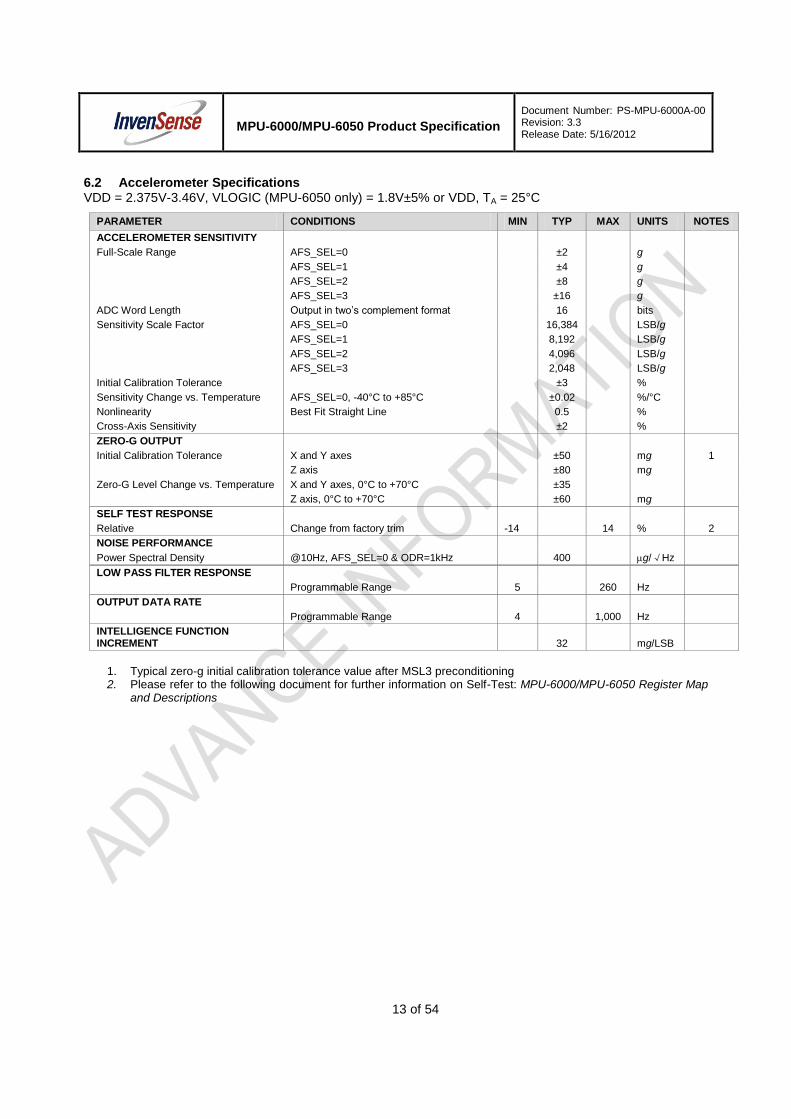
MPU-6000/MPU-6050 Product Specification
Document Number: PS-MPU-6000A-00 Revision: 3.3 Release Date: 5/16/2012
13 of 54
6.2 Accelerometer Specifications VDD = 2.375V-3.46V, VLOGIC (MPU-6050 only) = 1.8V±5% or VDD, TA = 25°C
PARAMETER CONDITIONS MIN TYP MAX UNITS NOTES
ACCELEROMETER SENSITIVITY
Full-Scale Range AFS_SEL=0 ±2 g
AFS_SEL=1 ±4 g
AFS_SEL=2 ±8 g
AFS_SEL=3 ±16 g
ADC Word Length Output in two’s complement format 16 bits
Sensitivity Scale Factor AFS_SEL=0 16,384 LSB/g
AFS_SEL=1 8,192 LSB/g
AFS_SEL=2 4,096 LSB/g
AFS_SEL=3 2,048 LSB/g
Initial Calibration Tolerance
±3 %
Sensitivity Change vs. Temperature AFS_SEL=0, -40°C to +85°C ±0.02 %/°C
Nonlinearity Best Fit Straight Line 0.5 %
Cross-Axis Sensitivity ±2 %
ZERO-G OUTPUT
Initial Calibration Tolerance X and Y axes ±50 mg 1
Z axis ±80 mg
Zero-G Level Change vs. Temperature X and Y axes, 0°C to +70°C ±35
Z axis, 0°C to +70°C ±60 mg
SELF TEST RESPONSE
Relative Change from factory trim -14 14 % 2
NOISE PERFORMANCE
Power Spectral Density @10Hz, AFS_SEL=0 & ODR=1kHz 400 g/√Hz
LOW PASS FILTER RESPONSE
Programmable Range 5 260 Hz
OUTPUT DATA RATE
Programmable Range 4 1,000 Hz
INTELLIGENCE FUNCTION INCREMENT
32 mg/LSB
1. Typical zero-g initial calibration tolerance value after MSL3 preconditioning 2. Please refer to the following document for further information on Self-Test: MPU-6000/MPU-6050 Register Map
and Descriptions

MPU-6000/MPU-6050 Product Specification
Document Number: PS-MPU-6000A-00 Revision: 3.3 Release Date: 5/16/2012
14 of 54
6.3 Electrical and Other Common Specifications VDD = 2.375V-3.46V, VLOGIC (MPU-6050 only) = 1.8V±5% or VDD, TA = 25°C
PARAMETER CONDITIONS MIN TYP MAX Units Notes
TEMPERATURE SENSOR
Range -40 to +85 °C
Sensitivity Untrimmed 340 LSB/ºC
Temperature Offset 35oC -521 LSB
Linearity Best fit straight line (-40°C to +85°C)
±1 °C
VDD POWER SUPPLY
Operating Voltages 2.375 3.46 V
Normal Operating Current Gyroscope + Accelerometer + DMP 3.9 mA
Gyroscope + Accelerometer
(DMP disabled) 3.8 mA
Gyroscope + DMP
(Accelerometer disabled) 3.7 mA
Gyroscope only
(DMP & Accelerometer disabled) 3.6 mA
Accelerometer only
(DMP & Gyroscope disabled) 500 µA
Accelerometer Low Power Mode Current
1.25 Hz update rate 10 µA
5 Hz update rate 20 µA
20 Hz update rate 70 µA
40 Hz update rate 140 µA
Full-Chip Idle Mode Supply Current 5 µA
Power Supply Ramp Rate Monotonic ramp. Ramp rate is 10% to 90% of the final value
100 ms
VLOGIC REFERENCE VOLTAGE MPU-6050 only
Voltage Range VLOGIC must be ≤VDD at all times 1.71 VDD V
Power Supply Ramp Rate Monotonic ramp. Ramp rate is 10% to 90% of the final value
3 ms
Normal Operating Current 100 µA
TEMPERATURE RANGE
Specified Temperature Range Performance parameters are not applicable beyond Specified Temperature Range
-40 +85 °C

MPU-6000/MPU-6050 Product Specification
Document Number: PS-MPU-6000A-00 Revision: 3.3 Release Date: 5/16/2012
15 of 54
6.4 Electrical Specifications, Continued VDD = 2.375V-3.46V, VLOGIC (MPU-6050 only) = 1.8V±5% or VDD, TA = 25°C
PARAMETER CONDITIONS MIN TYP MAX Units Notes
SERIAL INTERFACE
SPI Operating Frequency, All Registers Read/Write
MPU-6000 only, Low Speed Characterization
100 ±10% kHz
MPU-6000 only, High Speed Characterization
1 ±10% MHz
SPI Operating Frequency, Sensor and Interrupt Registers Read Only
MPU-6000 only 20 ±10% MHz
I2C Operating Frequency All registers, Fast-mode 400 kHz
All registers, Standard-mode 100 kHz
I2C ADDRESS AD0 = 0 1101000
AD0 = 1 1101001
DIGITAL INPUTS (SDI/SDA, AD0, SCLK/SCL, FSYNC, /CS, CLKIN)
VIH, High Level Input Voltage MPU-6000 0.7*VDD V
MPU-6050 0.7*VLOGIC V
VIL, Low Level Input Voltage MPU-6000 0.3*VDD V
MPU-6050 0.3*VLOGIC V
CI, Input Capacitance < 5 pF
DIGITAL OUTPUT (SDO, INT)
VOH, High Level Output Voltage RLOAD=1MΩ; MPU-6000 0.9*VDD V
RLOAD=1MΩ; MPU-6050 0.9*VLOGIC V
VOL1, LOW-Level Output Voltage RLOAD=1MΩ; MPU-6000 0.1*VDD V
RLOAD=1MΩ; MPU-6050 0.1*VLOGIC V
VOL.INT1, INT Low-Level Output Voltage
OPEN=1, 0.3mA sink
Current
0.1 V
Output Leakage Current OPEN=1 100 nA
tINT, INT Pulse Width LATCH_INT_EN=0 50 µs
DIGITAL OUTPUT (CLKOUT)
VOH, High Level Output Voltage
VOL1, LOW-Level Output Voltage
RLOAD=1MΩ
RLOAD=1MΩ
0.9*VDD
0.1*VDD
V
V

MPU-6000/MPU-6050 Product Specification
Document Number: PS-MPU-6000A-00 Revision: 3.3 Release Date: 5/16/2012
16 of 54
6.5 Electrical Specifications, Continued Typical Operating Circuit of Section 7.2, VDD = 2.375V-3.46V, VLOGIC (MPU-6050 only) = 1.8V±5% or VDD, TA = 25°C
Parameters Conditions Typical Units Notes
Primary I2C I/O (SCL, SDA)
VIL, LOW-Level Input Voltage MPU-6000 -0.5 to 0.3*VDD V
VIH, HIGH-Level Input Voltage MPU-6000 0.7*VDD to VDD + 0.5V V
Vhys, Hysteresis MPU-6000 0.1*VDD V
VIL, LOW Level Input Voltage MPU-6050 -0.5V to 0.3*VLOGIC V
VIH, HIGH-Level Input Voltage MPU-6050 0.7*VLOGIC to VLOGIC + 0.5V V
Vhys, Hysteresis MPU-6050 0.1*VLOGIC V
VOL1, LOW-Level Output Voltage 3mA sink current 0 to 0.4 V
IOL, LOW-Level Output Current VOL = 0.4V 3 mA
VOL = 0.6V 5 mA
Output Leakage Current 100 nA
tof, Output Fall Time from VIHmax to VILmax Cb bus capacitance in pF 20+0.1Cb to 250 ns
CI, Capacitance for Each I/O pin < 10 pF
Auxiliary I2C I/O (AUX_CL, AUX_DA) MPU-6050: AUX_VDDIO=0
VIL, LOW-Level Input Voltage -0.5V to 0.3*VLOGIC V
VIH, HIGH-Level Input Voltage 0.7*VLOGIC to VLOGIC + 0.5V
V
Vhys, Hysteresis 0.1*VLOGIC V
VOL1, LOW-Level Output Voltage VLOGIC > 2V; 1mA sink current 0 to 0.4 V
VOL3, LOW-Level Output Voltage VLOGIC < 2V; 1mA sink current 0 to 0.2*VLOGIC V
IOL, LOW-Level Output Current VOL = 0.4V VOL = 0.6V
1 1
mA mA
Output Leakage Current 100 nA
tof, Output Fall Time from VIHmax to VILmax Cb bus capacitance in pF 20+0.1Cb to 250 ns
CI, Capacitance for Each I/O pin < 10 pF
Auxiliary I2C I/O (AUX_CL, AUX_DA) MPU-6050: AUX_VDDIO=1;
MPU-6000
VIL, LOW-Level Input Voltage -0.5 to 0.3*VDD V
VIH, HIGH-Level Input Voltage 0.7*VDD to VDD+0.5V V
Vhys, Hysteresis 0.1*VDD V
VOL1, LOW-Level Output Voltage 1mA sink current 0 to 0.4 V
IOL, LOW-Level Output Current VOL = 0.4V VOL = 0.6V
1 1
mA mA
Output Leakage Current 100 nA
tof, Output Fall Time from VIHmax to VILmax Cb bus cap. in pF 20+0.1Cb to 250 ns
CI, Capacitance for Each I/O pin < 10 pF

MPU-6000/MPU-6050 Product Specification
Document Number: PS-MPU-6000A-00 Revision: 3.3 Release Date: 5/16/2012
17 of 54
6.6 Electrical Specifications, Continued Typical Operating Circuit of Section 7.2, VDD = 2.375V-3.46V, VLOGIC (MPU-6050 only) = 1.8V±5% or VDD, TA = 25°C
Parameters Conditions Min Typical Max Units Notes
INTERNAL CLOCK SOURCE CLK_SEL=0,1,2,3
Gyroscope Sample Rate, Fast DLPFCFG=0 SAMPLERATEDIV = 0
8 kHz
Gyroscope Sample Rate, Slow DLPFCFG=1,2,3,4,5, or 6 SAMPLERATEDIV = 0
1 kHz
Accelerometer Sample Rate 1 kHz
Reference Clock Output CLKOUTEN = 1 1.024 MHz
Clock Frequency Initial Tolerance CLK_SEL=0, 25°C -5 +5 %
CLK_SEL=1,2,3; 25°C -1 +1 %
Frequency Variation over Temperature CLK_SEL=0 -15 to +10 %
CLK_SEL=1,2,3 ±1 %
PLL Settling Time CLK_SEL=1,2,3 1 10 ms
EXTERNAL 32.768kHz CLOCK CLK_SEL=4
External Clock Frequency 32.768 kHz
External Clock Allowable Jitter Cycle-to-cycle rms 1 to 2 µs
Gyroscope Sample Rate, Fast DLPFCFG=0 SAMPLERATEDIV = 0
8.192 kHz
Gyroscope Sample Rate, Slow DLPFCFG=1,2,3,4,5, or 6 SAMPLERATEDIV = 0
1.024 kHz
Accelerometer Sample Rate 1.024 kHz
Reference Clock Output CLKOUTEN = 1 1.0486 MHz
PLL Settling Time 1 10 ms
EXTERNAL 19.2MHz CLOCK CLK_SEL=5
External Clock Frequency 19.2 MHz
Gyroscope Sample Rate Full programmable range 3.9 8000 Hz
Gyroscope Sample Rate, Fast Mode DLPFCFG=0 SAMPLERATEDIV = 0
8 kHz
Gyroscope Sample Rate, Slow Mode DLPFCFG=1,2,3,4,5, or 6 SAMPLERATEDIV = 0
1 kHz
Accelerometer Sample Rate 1 kHz
Reference Clock Output CLKOUTEN = 1 1.024 MHz
PLL Settling Time 1 10 ms

MPU-6000/MPU-6050 Product Specification
Document Number: PS-MPU-6000A-00 Revision: 3.3 Release Date: 5/16/2012
18 of 54
6.7 I2C Timing Characterization
Typical Operating Circuit of Section 7.2, VDD = 2.375V-3.46V, VLOGIC (MPU-6050 only) = 1.8V±5% or VDD, TA = 25°C
Parameters Conditions Min Typical Max Units Notes
I2C TIMING I
2C FAST-MODE
fSCL, SCL Clock Frequency 400 kHz
tHD.STA, (Repeated) START Condition Hold Time
0.6 µs
tLOW, SCL Low Period 1.3 µs
tHIGH, SCL High Period 0.6 µs
tSU.STA, Repeated START Condition Setup Time
0.6 µs
tHD.DAT, SDA Data Hold Time 0 µs
tSU.DAT, SDA Data Setup Time 100 ns
tr, SDA and SCL Rise Time Cb bus cap. from 10 to 400pF 20+0.1Cb 300 ns
tf, SDA and SCL Fall Time Cb bus cap. from 10 to 400pF 20+0.1Cb 300 ns
tSU.STO, STOP Condition Setup Time 0.6 µs
tBUF, Bus Free Time Between STOP and START Condition
1.3 µs
Cb, Capacitive Load for each Bus Line < 400 pF
tVD.DAT, Data Valid Time 0.9 µs
tVD.ACK, Data Valid Acknowledge Time 0.9 µs
Note: Timing Characteristics apply to both Primary and Auxiliary I2C Bus
I2C Bus Timing Diagram

MPU-6000/MPU-6050 Product Specification
Document Number: PS-MPU-6000A-00 Revision: 3.3 Release Date: 5/16/2012
19 of 54
6.8 SPI Timing Characterization (MPU-6000 only) Typical Operating Circuit of Section 7.2, VDD = 2.375V-3.46V, VLOGIC (MPU-6050 only) = 1.8V±5% or VDD,TA = 25°C, unless otherwise noted.
Parameters Conditions Min Typical Max Units Notes
SPI TIMING
fSCLK, SCLK Clock Frequency
1 MHz
tLOW, SCLK Low Period
400
ns
tHIGH, SCLK High Period
400
ns
tSU.CS, CS Setup Time
8
ns
tHD.CS, CS Hold Time
500
ns
tSU.SDI, SDI Setup Time
11
ns
tHD.SDI, SDI Hold Time
7
ns
tVD.SDO, SDO Valid Time Cload = 20pF
100 ns
tHD.SDO, SDO Hold Time Cload = 20pF 4
ns
tDIS.SDO, SDO Output Disable Time
10 ns
SPI Bus Timing Diagram

MPU-6000/MPU-6050 Product Specification
Document Number: PS-MPU-6000A-00 Revision: 3.3 Release Date: 5/16/2012
20 of 54
6.9 Absolute Maximum Ratings Stress above those listed as “Absolute Maximum Ratings” may cause permanent damage to the device. These are stress ratings only and functional operation of the device at these conditions is not implied. Exposure to the absolute maximum ratings conditions for extended periods may affect device reliability.
Parameter Rating
Supply Voltage, VDD -0.5V to +6V
VLOGIC Input Voltage Level (MPU-6050) -0.5V to VDD + 0.5V
REGOUT -0.5V to 2V
Input Voltage Level (CLKIN, AUX_DA, AD0, FSYNC, INT, SCL, SDA)
-0.5V to VDD + 0.5V
CPOUT (2.5V ≤ VDD ≤ 3.6V ) -0.5V to 30V
Acceleration (Any Axis, unpowered) 10,000g for 0.2ms
Operating Temperature Range -40°C to +105°C
Storage Temperature Range -40°C to +125°C
Electrostatic Discharge (ESD) Protection 2kV (HBM);
200V (MM)
Latch-up JEDEC Class II (2),125°C
±100mA

MPU-6000/MPU-6050 Product Specification
Document Number: PS-MPU-6000A-00 Revision: 3.3 Release Date: 5/16/2012
21 of 54
7 Applications Information
7.1 Pin Out and Signal Description
Pin Number MPU- 6000
MPU- 6050
Pin Name Pin Description
1 Y Y CLKIN Optional external reference clock input. Connect to GND if unused.
6 Y Y AUX_DA I2C master serial data, for connecting to external sensors
7 Y Y AUX_CL I2C Master serial clock, for connecting to external sensors
8 Y /CS SPI chip select (0=SPI mode)
8 Y VLOGIC Digital I/O supply voltage
9 Y AD0 / SDO I2C Slave Address LSB (AD0); SPI serial data output (SDO)
9 Y AD0 I2C Slave Address LSB (AD0)
10 Y Y REGOUT Regulator filter capacitor connection
11 Y Y FSYNC Frame synchronization digital input. Connect to GND if unused.
12 Y Y INT Interrupt digital output (totem pole or open-drain)
13 Y Y VDD Power supply voltage and Digital I/O supply voltage
18 Y Y GND Power supply ground
19, 21 Y Y RESV Reserved. Do not connect.
20 Y Y CPOUT Charge pump capacitor connection
22 Y Y CLKOUT System clock output
23 Y SCL / SCLK I2C serial clock (SCL); SPI serial clock (SCLK)
23 Y SCL I2C serial clock (SCL)
24 Y SDA / SDI I2C serial data (SDA); SPI serial data input (SDI)
24 Y SDA I2C serial data (SDA)
2, 3, 4, 5, 14, 15, 16, 17
Y Y NC Not internally connected. May be used for PCB trace routing.
MPU-6000
MPU-6050
+Z
+X
+Y
7 8 9 10 11 12
AU
X_
CL
VL
OG
IC
AD
0
RE
GO
UT
FS
YN
C
INT
13
18
17
16
15
14
NC
NC
NC
VDD
NC
GND
6
1
2
3
4
5
NC
NC
NC
AUX_DA
NC
CLKIN
24 23 22 21 20 19
RE
SV
CP
OU
T
RE
SV
CL
KO
UT
SC
L
SD
A
MPU-6050
QFN Package
24-pin, 4mm x 4mm x 0.9mm
Orientation of Axes of Sensitivity and
Polarity of Rotation
Top View
+Z
+Y
+X
7 8 9 10 11 12
AU
X_
CL
/CS
AD
0/S
DO
RE
GO
UT
FS
YN
C
INT
13
18
17
16
15
14
NC
NC
NC
VDD
NC
GND
6
1
2
3
4
5
NC
NC
NC
AUX_DA
NC
CLKIN
24 23 22 21 20 19
RE
SV
CP
OU
T
RE
SV
CL
KO
UT
SC
L/S
CL
K
SD
A/S
DI
MPU-6000
QFN Package
24-pin, 4mm x 4mm x 0.9mm
Top View

MPU-6000/MPU-6050 Product Specification
Document Number: PS-MPU-6000A-00 Revision: 3.3 Release Date: 5/16/2012
22 of 54
7.2 Typical Operating Circuit
AD
0 / S
DO
Typical Operating Circuits
7 8 9 10 11 12
13
18
17
16
15
14
6
1
2
3
4
5
24 23 22 21 20 19
MPU-6000
CLKIN
/CS
GND
GND
GND
FS
YN
C
INT
GND
VDD
SC
L / S
CL
K
SD
A / S
DI
C3
2.2nF
C1
0.1µF
C2
0.1µF
AD
0
7 8 9 10 11 12
13
18
17
16
15
14
6
1
2
3
4
5
24 23 22 21 20 19
MPU-6050
CLKIN
GND
GND
GND
FS
YN
C
INT
GND
VDD
SC
L
SD
A
C3
2.2nF
C1
0.1µF
C2
0.1µF
GND
VLOGIC
C4
10nF
AUX_CL
AUX_DA
AUX_CL
AUX_DA
CL
KO
UT
CL
KO
UT
7.3 Bill of Materials for External Components
Component Label Specification Quantity
Regulator Filter Capacitor (Pin 10) C1 Ceramic, X7R, 0.1µF ±10%, 2V 1
VDD Bypass Capacitor (Pin 13) C2 Ceramic, X7R, 0.1µF ±10%, 4V 1
Charge Pump Capacitor (Pin 20) C3 Ceramic, X7R, 2.2nF ±10%, 50V 1
VLOGIC Bypass Capacitor (Pin 8) C4* Ceramic, X7R, 10nF ±10%, 4V 1
* MPU-6050 Only.

MPU-6000/MPU-6050 Product Specification
Document Number: PS-MPU-6000A-00 Revision: 3.3 Release Date: 5/16/2012
23 of 54
7.4 Recommended Power-on Procedure
TVLGR
VLOGIC
VDD
TVDDR
All
Vo
lta
ge
s a
t 0
V
Power-Up Sequencing
1. VLOGIC amplitude must always be ≤VDD
amplitude
2. TVDDR is VDD rise time: Time for VDD to rise
from 10% to 90% of its final value
3. TVDDR is ≤100ms
4. TVLGR is VLOGIC rise time: Time for
VLOGIC to rise from 10% to 90% of its final
value
5. TVLGR is ≤3ms
6. TVLG-VDD is the delay from the start of VDD
ramp to the start of VLOGIC rise
7. TVLG-VDD is ≥0
8. VDD and VLOGIC must be monotonic
ramps
90%
10%
90%
10%
TVLG - VDD

MPU-6000/MPU-6050 Product Specification
Document Number: PS-MPU-6000A-00 Revision: 3.3 Release Date: 5/16/2012
24 of 54
7.5 Block Diagram
CLOCK MPU-60X0
Charge
Pump
(/CS)
AD0 / (SDO)
SCL / (SCLK)
SDA / (SDI)
Temp Sensor ADC
ADCZ Gyro
ADCY Gyro
Digital Motion
Processor
(DMP)
FSYNC
22
1
8
9
23
24
11
Slave I2C and
SPI Serial
Interface
Master I2C
Serial
Interface
Clock
CPOUT
Serial
Interface
Bypass
Mux
7
6
AUX_CL
AUX_DA
INT12
20
Factory
Calibration
Interrupt
Status
Register
VDD
Bias & LDO
GND REGOUT
13 18 10
Note: Pin names in round brackets ( ) apply only to MPU-6000
Pin names in square brackets [ ] apply only to MPU-6050
Z Accel
Y Accel
X Accel ADC
ADC
ADC
CLKIN
CLKOUT
ADCX Gyro
Sig
na
l Co
nd
ition
ing
FIFO
Config
Registers
Sensor
Registers
Self
test
[VLOGIC]
8
Self
test
Self
test
Self
test
Self
test
Self
test
7.6 Overview The MPU-60X0 is comprised of the following key blocks and functions:
Three-axis MEMS rate gyroscope sensor with 16-bit ADCs and signal conditioning
Three-axis MEMS accelerometer sensor with 16-bit ADCs and signal conditioning
Digital Motion Processor (DMP) engine
Primary I2C and SPI (MPU-6000 only) serial communications interfaces
Auxiliary I2C serial interface for 3
rd party magnetometer & other sensors
Clocking
Sensor Data Registers
FIFO
Interrupts
Digital-Output Temperature Sensor
Gyroscope & Accelerometer Self-test
Bias and LDO
Charge Pump

MPU-6000/MPU-6050 Product Specification
Document Number: PS-MPU-6000A-00 Revision: 3.3 Release Date: 5/16/2012
25 of 54
7.7 Three-Axis MEMS Gyroscope with 16-bit ADCs and Signal Conditioning The MPU-60X0 consists of three independent vibratory MEMS rate gyroscopes, which detect rotation about the X-, Y-, and Z- Axes. When the gyros are rotated about any of the sense axes, the Coriolis Effect causes a vibration that is detected by a capacitive pickoff. The resulting signal is amplified, demodulated, and filtered to produce a voltage that is proportional to the angular rate. This voltage is digitized using individual on-chip 16-bit Analog-to-Digital Converters (ADCs) to sample each axis. The full-scale range of the gyro sensors may be digitally programmed to ±250, ±500, ±1000, or ±2000 degrees per second (dps). The ADC sample rate is programmable from 8,000 samples per second, down to 3.9 samples per second, and user-selectable low-pass filters enable a wide range of cut-off frequencies.
7.8 Three-Axis MEMS Accelerometer with 16-bit ADCs and Signal Conditioning The MPU-60X0’s 3-Axis accelerometer uses separate proof masses for each axis. Acceleration along a particular axis induces displacement on the corresponding proof mass, and capacitive sensors detect the displacement differentially. The MPU-60X0’s architecture reduces the accelerometers’ susceptibility to fabrication variations as well as to thermal drift. When the device is placed on a flat surface, it will measure 0g on the X- and Y-axes and +1g on the Z-axis. The accelerometers’ scale factor is calibrated at the factory and is nominally independent of supply voltage. Each sensor has a dedicated sigma-delta ADC for providing digital outputs. The full scale range of the digital output can be adjusted to ±2g, ±4g, ±8g, or ±16g.
7.9 Digital Motion Processor The embedded Digital Motion Processor (DMP) is located within the MPU-60X0 and offloads computation of motion processing algorithms from the host processor. The DMP acquires data from accelerometers, gyroscopes, and additional 3
rd party sensors such as magnetometers, and processes the data. The resulting
data can be read from the DMP’s registers, or can be buffered in a FIFO. The DMP has access to one of the MPU’s external pins, which can be used for generating interrupts.
The purpose of the DMP is to offload both timing requirements and processing power from the host processor. Typically, motion processing algorithms should be run at a high rate, often around 200Hz, in order to provide accurate results with low latency. This is required even if the application updates at a much lower rate; for example, a low power user interface may update as slowly as 5Hz, but the motion processing should still run at 200Hz. The DMP can be used as a tool in order to minimize power, simplify timing, simplify the software architecture, and save valuable MIPS on the host processor for use in the application.
7.10 Primary I2C and SPI Serial Communications Interfaces
The MPU-60X0 communicates to a system processor using either a SPI (MPU-6000 only) or an I2C serial
interface. The MPU-60X0 always acts as a slave when communicating to the system processor. The LSB of the of the I
2C slave address is set by pin 9 (AD0).
The logic levels for communications between the MPU-60X0 and its master are as follows:
MPU-6000: The logic level for communications with the master is set by the voltage on VDD
MPU-6050: The logic level for communications with the master is set by the voltage on VLOGIC
For further information regarding the logic levels of the MPU-6050, please refer to Section 10.

MPU-6000/MPU-6050 Product Specification
Document Number: PS-MPU-6000A-00 Revision: 3.3 Release Date: 5/16/2012
26 of 54
7.11 Auxiliary I2C Serial Interface
The MPU-60X0 has an auxiliary I2C bus for communicating to an off-chip 3-Axis digital output magnetometer
or other sensors. This bus has two operating modes:
I2C Master Mode: The MPU-60X0 acts as a master to any external sensors connected to the
auxiliary I2C bus
Pass-Through Mode: The MPU-60X0 directly connects the primary and auxiliary I2C buses together,
allowing the system processor to directly communicate with any external sensors.
Auxiliary I2C Bus Modes of Operation:
I2C Master Mode: Allows the MPU-60X0 to directly access the data registers of external digital
sensors, such as a magnetometer. In this mode, the MPU-60X0 directly obtains data from auxiliary sensors, allowing the on-chip DMP to generate sensor fusion data without intervention from the system applications processor.
For example, In I2C Master mode, the MPU-60X0 can be configured to perform burst reads,
returning the following data from a magnetometer:
X magnetometer data (2 bytes) Y magnetometer data (2 bytes) Z magnetometer data (2 bytes)
The I
2C Master can be configured to read up to 24 bytes from up to 4 auxiliary sensors. A fifth sensor
can be configured to work single byte read/write mode.
Pass-Through Mode: Allows an external system processor to act as master and directly communicate to the external sensors connected to the auxiliary I
2C bus pins (AUX_DA and
AUX_CL). In this mode, the auxiliary I2C bus control logic (3
rd party sensor interface block) of the
MPU-60X0 is disabled, and the auxiliary I2C pins AUX_DA and AUX_CL (Pins 6 and 7) are
connected to the main I2C bus (Pins 23 and 24) through analog switches.
Pass-Through Mode is useful for configuring the external sensors, or for keeping the MPU-60X0 in a low-power mode when only the external sensors are used. In Pass-Through Mode the system processor can still access MPU-60X0 data through the I
2C
interface.
Auxiliary I2C Bus IO Logic Levels
MPU-6000: The logic level of the auxiliary I2C bus is VDD
MPU-6050: The logic level of the auxiliary I2C bus can be programmed to be either VDD or VLOGIC
For further information regarding the MPU-6050’s logic levels, please refer to Section 10.2.

MPU-6000/MPU-6050 Product Specification
Document Number: PS-MPU-6000A-00 Revision: 3.3 Release Date: 5/16/2012
27 of 54
7.12 Self-Test Please refer to the MPU-6000/MPU-6050 Register Map and Register Descriptions document for more details on self test.
Self-test allows for the testing of the mechanical and electrical portions of the sensors. The self-test for each measurement axis can be activated by means of the gyroscope and accelerometer self-test registers (registers 13 to 16).
When self-test is activated, the electronics cause the sensors to be actuated and produce an output signal. The output signal is used to observe the self-test response.
The self-test response is defined as follows:
Self-test response = Sensor output with self-test enabled – Sensor output without self-test enabled
The self-test response for each accelerometer axis is defined in the accelerometer specification table (Section 6.2), while that for each gyroscope axis is defined in the gyroscope specification table (Section 6.1).
When the value of the self-test response is within the min/max limits of the product specification, the part has passed self test. When the self-test response exceeds the min/max values, the part is deemed to have failed self-test. Code for operating self test code is included within the MotionApps software provided by InvenSense.

MPU-6000/MPU-6050 Product Specification
Document Number: PS-MPU-6000A-00 Revision: 3.3 Release Date: 5/16/2012
28 of 54
7.13 MPU-60X0 Solution for 9-axis Sensor Fusion Using I2C Interface
In the figure below, the system processor is an I2C master to the MPU-60X0. In addition, the MPU-60X0 is an
I2C master to the optional external compass sensor. The MPU-60X0 has limited capabilities as an I
2C
Master, and depends on the system processor to manage the initial configuration of any auxiliary sensors. The MPU-60X0 has an interface bypass multiplexer, which connects the system processor I
2C bus pins 23
and 24 (SDA and SCL) directly to the auxiliary sensor I2C bus pins 6 and 7 (AUX_DA and AUX_CL).
Once the auxiliary sensors have been configured by the system processor, the interface bypass multiplexer should be disabled so that the MPU-60X0 auxiliary I
2C master can take control of the sensor I
2C bus and
gather data from the auxiliary sensors.
For further information regarding I2C master control, please refer to Section 10.
MPU-60X0 AD0/SDO
SCL/SCLK
SDA/SDI
Digital
Motion
Processor
(DMP)
9
23
24
Sensor
Master I2C
Serial
Interface
7
6
AUX_CL
AUX_DA
Interrupt
Status
Register
INT12
VDD
Bias & LDO
GND REGOUT
13 18 10
FIFO
Config
Register
Sensor
Register
Factory
Calibration
/CS8
Slave I2C
or SPI
Serial
Interface
Compass
SCL
SDA
System
Processor
Interface
Bypass
Mux
SCL
SDA
VDD
VDD or GND
I2C Processor Bus: for reading all
sensor data from MPU and for
configuring external sensors (i.e.
compass in this example)
Interface bypass mux allows
direct configuration of
compass by system processor
Optional
Sensor I2C Bus: for
configuring and reading
from external sensors

MPU-6000/MPU-6050 Product Specification
Document Number: PS-MPU-6000A-00 Revision: 3.3 Release Date: 5/16/2012
29 of 54
7.14 MPU-6000 Using SPI Interface In the figure below, the system processor is an SPI master to the MPU-6000. Pins 8, 9, 23, and 24 are used to support the /CS, SDO, SCLK, and SDI signals for SPI communications. Because these SPI pins are shared with the I
2C slave pins (9, 23 and 24), the system processor cannot access the auxiliary I
2C bus
through the interface bypass multiplexer, which connects the processor I2C interface pins to the sensor I
2C
interface pins.
Since the MPU-6000 has limited capabilities as an I2C Master, and depends on the system processor to
manage the initial configuration of any auxiliary sensors, another method must be used for programming the sensors on the auxiliary sensor I
2C bus pins 6 and 7 (AUX_DA and AUX_CL).
When using SPI communications between the MPU-6000 and the system processor, configuration of devices on the auxiliary I
2C sensor bus can be achieved by using I
2C Slaves 0-4 to perform read and write
transactions on any device and register on the auxiliary I2C bus. The I
2C Slave 4 interface can be used to
perform only single byte read and write transactions.
Once the external sensors have been configured, the MPU-6000 can perform single or multi-byte reads using the sensor I
2C bus. The read results from the Slave 0-3 controllers can be written to the FIFO buffer as
well as to the external sensor registers.
For further information regarding the control of the MPU-60X0’s auxiliary I2C interface, please refer to the
MPU-6000/MPU-6050 Register Map and Register Descriptions document.
MPU-6000AD0/SDO
SCL/SCLK
SDA/SDI
Digital
Motion
Processor
(DMP)
9
23
24
Sensor
Master I2C
Serial
Interface
Interrupt
Status
Register
INT12
VDD
Bias & LDO
GND REGOUT
13 18 10
FIFO
Config
Register
Sensor
Register
Factory
Calibration
/CS8
Slave I2C
or SPI
Serial
Interface
System
Processor
Interface
Bypass
Mux
SDI
SCLK
SDO
/CS
Processor SPI Bus: for reading all
data from MPU and for configuring
MPU and external sensors
7
6
AUX_CL
AUX_DACompass
SCL
SDA
Optional
I2C Master performs
read and write
transactions on
Sensor I2C bus.
Sensor I2C Bus: for
configuring and
reading data from
external sensors

MPU-6000/MPU-6050 Product Specification
Document Number: PS-MPU-6000A-00 Revision: 3.3 Release Date: 5/16/2012
30 of 54
7.15 Internal Clock Generation The MPU-60X0 has a flexible clocking scheme, allowing a variety of internal or external clock sources to be used for the internal synchronous circuitry. This synchronous circuitry includes the signal conditioning and ADCs, the DMP, and various control circuits and registers. An on-chip PLL provides flexibility in the allowable inputs for generating this clock.
Allowable internal sources for generating the internal clock are:
An internal relaxation oscillator
Any of the X, Y, or Z gyros (MEMS oscillators with a variation of ±1% over temperature)
Allowable external clocking sources are:
32.768kHz square wave
19.2MHz square wave
Selection of the source for generating the internal synchronous clock depends on the availability of external sources and the requirements for power consumption and clock accuracy. These requirements will most likely vary by mode of operation. For example, in one mode, where the biggest concern is power consumption, the user may wish to operate the Digital Motion Processor of the MPU-60X0 to process accelerometer data, while keeping the gyros off. In this case, the internal relaxation oscillator is a good clock choice. However, in another mode, where the gyros are active, selecting the gyros as the clock source provides for a more accurate clock source.
Clock accuracy is important, since timing errors directly affect the distance and angle calculations performed by the Digital Motion Processor (and by extension, by any processor).
There are also start-up conditions to consider. When the MPU-60X0 first starts up, the device uses its internal clock until programmed to operate from another source. This allows the user, for example, to wait for the MEMS oscillators to stabilize before they are selected as the clock source.
7.16 Sensor Data Registers The sensor data registers contain the latest gyro, accelerometer, auxiliary sensor, and temperature measurement data. They are read-only registers, and are accessed via the serial interface. Data from these registers may be read anytime. However, the interrupt function may be used to determine when new data is available.
For a table of interrupt sources please refer to Section 8.
7.17 FIFO The MPU-60X0 contains a 1024-byte FIFO register that is accessible via the Serial Interface. The FIFO configuration register determines which data is written into the FIFO. Possible choices include gyro data, accelerometer data, temperature readings, auxiliary sensor readings, and FSYNC input. A FIFO counter keeps track of how many bytes of valid data are contained in the FIFO. The FIFO register supports burst reads. The interrupt function may be used to determine when new data is available.
For further information regarding the FIFO, please refer to the MPU-6000/MPU-6050 Register Map and Register Descriptions document.
7.18 Interrupts Interrupt functionality is configured via the Interrupt Configuration register. Items that are configurable include the INT pin configuration, the interrupt latching and clearing method, and triggers for the interrupt. Items that can trigger an interrupt are (1) Clock generator locked to new reference oscillator (used when switching clock

MPU-6000/MPU-6050 Product Specification
Document Number: PS-MPU-6000A-00 Revision: 3.3 Release Date: 5/16/2012
31 of 54
sources); (2) new data is available to be read (from the FIFO and Data registers); (3) accelerometer event interrupts; and (4) the MPU-60X0 did not receive an acknowledge from an auxiliary sensor on the secondary I2C bus. The interrupt status can be read from the Interrupt Status register.
For further information regarding interrupts, please refer to the MPU-60X0 Register Map and Register Descriptions document.
For information regarding the MPU-60X0’s accelerometer event interrupts, please refer to Section 8.
7.19 Digital-Output Temperature Sensor An on-chip temperature sensor and ADC are used to measure the MPU-60X0 die temperature. The readings from the ADC can be read from the FIFO or the Sensor Data registers.
7.20 Bias and LDO The bias and LDO section generates the internal supply and the reference voltages and currents required by the MPU-60X0. Its two inputs are an unregulated VDD of 2.375 to 3.46V and a VLOGIC logic reference supply voltage of 1.71V to VDD (MPU-6050 only). The LDO output is bypassed by a capacitor at REGOUT. For further details on the capacitor, please refer to the Bill of Materials for External Components (Section 7.3).
7.21 Charge Pump An on-board charge pump generates the high voltage required for the MEMS oscillators. Its output is bypassed by a capacitor at CPOUT. For further details on the capacitor, please refer to the Bill of Materials for External Components (Section 7.3).

MPU-6000/MPU-6050 Product Specification
Document Number: PS-MPU-6000A-00 Revision: 3.3 Release Date: 5/16/2012
32 of 54
8 Programmable Interrupts
The MPU-60X0 has a programmable interrupt system which can generate an interrupt signal on the INT pin. Status flags indicate the source of an interrupt. Interrupt sources may be enabled and disabled individually.
Table of Interrupt Sources
Interrupt Name Module
Motion Detection Motion
FIFO Overflow FIFO
Data Ready Sensor Registers
I2C Master errors: Lost Arbitration, NACKs I
2C Master
I2C Slave 4 I
2C Master
For information regarding the interrupt enable/disable registers and flag registers, please refer to the MPU-6000/MPU-6050 Register Map and Register Descriptions document. Some interrupt sources are explained below.

MPU-6000/MPU-6050 Product Specification
Document Number: PS-MPU-6000A-00 Revision: 3.3 Release Date: 5/16/2012
33 of 54
8.1 Motion Interrupt The MPU-60X0 provides Motion detection capability. Accelerometer measurements are passed through a configurable digital high pass filter (DHPF) in order to eliminate bias due to gravity. A qualifying motion sample is one where the high passed sample from any axis has an absolute value exceeding a user-programmable threshold. A counter increments for each qualifying sample, and decrements for each non-qualifying sample. Once the counter reaches a user-programmable counter threshold, a motion interrupt is triggered. The axis and polarity which caused the interrupt to be triggered is flagged in the MOT_DETECT_STATUS register.
Motion detection has a configurable acceleration threshold MOT_THR specified in 1 mg increments. The counter threshold MOT_DUR is specified in 1 ms increments. The decrement rate for non-qualifying samples is also configurable. The MOT_DETECT_CTRL register allows the user to specify whether a non-qualifying sample makes the counter reset to zero, or decrement in steps of 1, 2, or 4.
The flow chart below explains how the motion interrupt should be used. Please refer to the MPU-6000/MPU-6050 Register Map and Register Descriptions document for descriptions of the registers referenced in the flow chart.

MPU-6000/MPU-6050 Product Specification
Document Number: PS-MPU-6000A-00 Revision: 3.3 Release Date: 5/16/2012
34 of 54
9 Digital Interface
9.1 I2C and SPI (MPU-6000 only) Serial Interfaces
The internal registers and memory of the MPU-6000/MPU-6050 can be accessed using either I2C at 400 kHz
or SPI at 1MHz (MPU-6000 only). SPI operates in four-wire mode.
Serial Interface
Pin Number MPU-6000 MPU-6050 Pin Name Pin Description
8 Y /CS SPI chip select (0=SPI enable)
8 Y VLOGIC Digital I/O supply voltage. VLOGIC must be ≤ VDD at all times.
9 Y AD0 / SDO I2C Slave Address LSB (AD0); SPI serial data output (SDO)
9 Y AD0 I2C Slave Address LSB
23 Y SCL / SCLK I2C serial clock (SCL); SPI serial clock (SCLK)
23 Y SCL I2C serial clock
24 Y SDA / SDI I2C serial data (SDA); SPI serial data input (SDI)
24 Y SDA I2C serial data
Note:
To prevent switching into I2C mode when using SPI (MPU-6000), the I
2C interface should be disabled by
setting the I2C_IF_DIS configuration bit. Setting this bit should be performed immediately after waiting for the time specified by the “Start-Up Time for Register Read/Write” in Section 6.3.
For further information regarding the I2C_IF_DIS bit, please refer to the MPU-6000/MPU-6050 Register Map and Register Descriptions document.
9.2 I2C Interface
I2C is a two-wire interface comprised of the signals serial data (SDA) and serial clock (SCL). In general, the
lines are open-drain and bi-directional. In a generalized I2C interface implementation, attached devices can
be a master or a slave. The master device puts the slave address on the bus, and the slave device with the matching address acknowledges the master.
The MPU-60X0 always operates as a slave device when communicating to the system processor, which thus acts as the master. SDA and SCL lines typically need pull-up resistors to VDD. The maximum bus speed is 400 kHz.
The slave address of the MPU-60X0 is b110100X which is 7 bits long. The LSB bit of the 7 bit address is determined by the logic level on pin AD0. This allows two MPU-60X0s to be connected to the same I
2C bus.
When used in this configuration, the address of the one of the devices should be b1101000 (pin AD0 is logic low) and the address of the other should be b1101001 (pin AD0 is logic high).
9.3 I2C Communications Protocol
START (S) and STOP (P) Conditions
Communication on the I2C bus starts when the master puts the START condition (S) on the bus, which is
defined as a HIGH-to-LOW transition of the SDA line while SCL line is HIGH (see figure below). The bus is considered to be busy until the master puts a STOP condition (P) on the bus, which is defined as a LOW to HIGH transition on the SDA line while SCL is HIGH (see figure below).

MPU-6000/MPU-6050 Product Specification
Document Number: PS-MPU-6000A-00 Revision: 3.3 Release Date: 5/16/2012
35 of 54
Additionally, the bus remains busy if a repeated START (Sr) is generated instead of a STOP condition.
SDA
SCL
S
START condition STOP condition
P
START and STOP Conditions
Data Format / Acknowledge
I2C data bytes are defined to be 8-bits long. There is no restriction to the number of bytes transmitted per
data transfer. Each byte transferred must be followed by an acknowledge (ACK) signal. The clock for the acknowledge signal is generated by the master, while the receiver generates the actual acknowledge signal by pulling down SDA and holding it low during the HIGH portion of the acknowledge clock pulse.
If a slave is busy and cannot transmit or receive another byte of data until some other task has been performed, it can hold SCL LOW, thus forcing the master into a wait state. Normal data transfer resumes when the slave is ready, and releases the clock line (refer to the following figure).
DATA OUTPUT BY
TRANSMITTER (SDA)
DATA OUTPUT BY
RECEIVER (SDA)
SCL FROM
MASTER
START
condition
clock pulse for
acknowledgement
acknowledge
not acknowledge
1 2 8 9
Acknowledge on the I2C Bus

MPU-6000/MPU-6050 Product Specification
Document Number: PS-MPU-6000A-00 Revision: 3.3 Release Date: 5/16/2012
36 of 54
Communications
After beginning communications with the START condition (S), the master sends a 7-bit slave address followed by an 8
th bit, the read/write bit. The read/write bit indicates whether the master is receiving data from
or is writing to the slave device. Then, the master releases the SDA line and waits for the acknowledge signal (ACK) from the slave device. Each byte transferred must be followed by an acknowledge bit. To acknowledge, the slave device pulls the SDA line LOW and keeps it LOW for the high period of the SCL line. Data transmission is always terminated by the master with a STOP condition (P), thus freeing the communications line. However, the master can generate a repeated START condition (Sr), and address another slave without first generating a STOP condition (P). A LOW to HIGH transition on the SDA line while SCL is HIGH defines the stop condition. All SDA changes should take place when SCL is low, with the exception of start and stop conditions.
SDA
START
condition
SCL
ADDRESS R/W ACK DATA ACK DATA ACK STOP
condition
S P
1 – 7 8 9 1 – 7 8 9 1 – 7 8 9
Complete I2C Data Transfer
To write the internal MPU-60X0 registers, the master transmits the start condition (S), followed by the I2C
address and the write bit (0). At the 9th clock cycle (when the clock is high), the MPU-60X0 acknowledges the
transfer. Then the master puts the register address (RA) on the bus. After the MPU-60X0 acknowledges the reception of the register address, the master puts the register data onto the bus. This is followed by the ACK signal, and data transfer may be concluded by the stop condition (P). To write multiple bytes after the last ACK signal, the master can continue outputting data rather than transmitting a stop signal. In this case, the MPU-60X0 automatically increments the register address and loads the data to the appropriate register. The following figures show single and two-byte write sequences.
Single-Byte Write Sequence
Burst Write Sequence
Master S AD+W RA DATA P
Slave ACK ACK ACK
Master S AD+W RA DATA DATA P
Slave ACK ACK ACK ACK

MPU-6000/MPU-6050 Product Specification
Document Number: PS-MPU-6000A-00 Revision: 3.3 Release Date: 5/16/2012
37 of 54
To read the internal MPU-60X0 registers, the master sends a start condition, followed by the I2C address and
a write bit, and then the register address that is going to be read. Upon receiving the ACK signal from the MPU-60X0, the master transmits a start signal followed by the slave address and read bit. As a result, the MPU-60X0 sends an ACK signal and the data. The communication ends with a not acknowledge (NACK) signal and a stop bit from master. The NACK condition is defined such that the SDA line remains high at the 9
th clock cycle. The following figures show single and two-byte read sequences.
Single-Byte Read Sequence
Burst Read Sequence
9.4 I2C Terms
Signal Description
S Start Condition: SDA goes from high to low while SCL is high
AD Slave I2C address
W Write bit (0)
R Read bit (1)
ACK Acknowledge: SDA line is low while the SCL line is high at the 9
th clock cycle
NACK Not-Acknowledge: SDA line stays high at the 9th clock cycle
RA MPU-60X0 internal register address
DATA Transmit or received data
P Stop condition: SDA going from low to high while SCL is high
Master S AD+W RA S AD+R NACK P
Slave ACK ACK ACK DATA
Master S AD+W RA S AD+R ACK NACK P
Slave ACK ACK ACK DATA DATA

MPU-6000/MPU-6050 Product Specification
Document Number: PS-MPU-6000A-00 Revision: 3.3 Release Date: 5/16/2012
38 of 54
9.5 SPI Interface (MPU-6000 only) SPI is a 4-wire synchronous serial interface that uses two control lines and two data lines. The MPU-6000 always operates as a Slave device during standard Master-Slave SPI operation.
With respect to the Master, the Serial Clock output (SCLK), the Serial Data Output (SDO) and the Serial Data Input (SDI) are shared among the Slave devices. Each SPI slave device requires its own Chip Select (/CS) line from the master.
/CS goes low (active) at the start of transmission and goes back high (inactive) at the end. Only one /CS line is active at a time, ensuring that only one slave is selected at any given time. The /CS lines of the non-selected slave devices are held high, causing their SDO lines to remain in a high-impedance (high-z) state so that they do not interfere with any active devices.
SPI Operational Features
1. Data is delivered MSB first and LSB last 2. Data is latched on the rising edge of SCLK 3. Data should be transitioned on the falling edge of SCLK 4. The maximum frequency of SCLK is 1MHz 5. SPI read and write operations are completed in 16 or more clock cycles (two or more bytes). The
first byte contains the SPI Address, and the following byte(s) contain(s) the SPI data. The first bit of the first byte contains the Read/Write bit and indicates the Read (1) or Write (0) operation. The following 7 bits contain the Register Address. In cases of multiple-byte Read/Writes, data is two or more bytes:
SPI Address format
MSB LSB
R/W A6 A5 A4 A3 A2 A1 A0
SPI Data format
MSB LSB
D7 D6 D5 D4 D3 D2 D1 D0
6. Supports Single or Burst Read/Writes.
Typical SPI Master / Slave Configuration
SPI Master SPI Slave 1
SPI Slave 2
/CS1
/CS2
SCLK
SDI
SDO
/CS
SCLK
SDI
SDO
/CS

MPU-6000/MPU-6050 Product Specification
Document Number: PS-MPU-6000A-00 Revision: 3.3 Release Date: 5/16/2012
39 of 54
10 Serial Interface Considerations (MPU-6050)
10.1 MPU-6050 Supported Interfaces The MPU-6050 supports I
2C communications on both its primary (microprocessor) serial interface and its
auxiliary interface.
10.2 Logic Levels The MPU-6050’s I/O logic levels are set to be either VDD or VLOGIC, as shown in the table below.
I/O Logic Levels vs. AUX_VDDIO
AUX_VDDIO MICROPROCESSOR LOGIC LEVELS
(Pins: SDA, SCL, AD0, CLKIN, INT) AUXILLARY LOGIC LEVELS
(Pins: AUX_DA, AUX_CL)
0 VLOGIC VLOGIC
1 VLOGIC VDD
Note: The power-on-reset value for AUX_VDDIO is 0.
VLOGIC may be set to be equal to VDD or to another voltage. However, VLOGIC must be ≤ VDD at all times. When AUX_VDDIO is set to 0 (its power-on-reset value), VLOGIC is the power supply voltage for both the microprocessor system bus and the auxiliary I
2C bus, as shown in the figure of Section 10.3. When
AUX_VDDIO is set to 1, VLOGIC is the power supply voltage for the microprocessor system bus and VDD is the supply for the auxiliary I
2C bus, as shown in the figure of Section 10.4.

MPU-6000/MPU-6050 Product Specification
Document Number: PS-MPU-6000A-00 Revision: 3.3 Release Date: 5/16/2012
40 of 54
10.3 Logic Levels Diagram for AUX_VDDIO = 0 The figure below depicts a sample circuit with a third party magnetometer attached to the auxiliary I
2C bus. It
shows logic levels and voltage connections for AUX_VDDIO = 0. Note: Actual configuration will depend on the auxiliary sensors used.
MPU-6050
3rd PartyMagnetometer
SDA
AUX_CL SCL
AUX_DA
VDD_IO
VDD
SA0
INT 2
INT 1
System Processor IO
CLKIN
SYSTEM BUS
VLOGIC
VLOGIC
VLOGIC
VDD
VLOGIC
(0V - VLOGIC)
SCL
SDA
INT
FSYNC
VLOGIC
AD0(0V - VLOGIC)
(0V - VLOGIC)
(0V - VLOGIC)(0V - VLOGIC)
(0V - VLOGIC)
(0V - VLOGIC)
(0V - VLOGIC)
(0V - VLOGIC)
(0V - VLOGIC)
(0V, VLOGIC)
(0V, VLOGIC)
CS(0V, VLOGIC)
VDD_IO
I/O Levels and Connections for AUX_VDDIO = 0
Notes:
1. AUX_VDDIO determines the IO voltage levels of AUX_DA and AUX_CL
(0 = set output levels relative to VLOGIC)
2. CLKOUT is referenced to VDD.
3. All other MPU-6050 logic IOs are referenced to VLOGIC.

MPU-6000/MPU-6050 Product Specification
Document Number: PS-MPU-6000A-00 Revision: 3.3 Release Date: 5/16/2012
41 of 54
10.4 Logic Levels Diagram for AUX_VDDIO = 1 The figure below depicts a sample circuit with a 3
rd party magnetometer attached to the auxiliary I
2C bus. It
shows logic levels and voltage connections for AUX_VDDIO = 1. This configuration is useful when the auxiliary sensor has only one supply for logic and power. Note: Actual configuration will depend on the auxiliary sensors used.
VLOGIC
VDD
Configuration 1 Configuration 2
1.8V±5%
2.5V±5% 3.0V±5%
3.0V±5%
Voltage/
Configuration
AUX_VDDIO 1 1
MPU-6050
3rd PartyMagnetometer
SDA
AUX_CL SCL
AUX_DA
VDD
VDD
ADDR
INT 2
INT 1
System Processor IO
CLKIN
SYSTEM BUS
VLOGIC
VLOGIC
VDD
VDD
VLOGIC
SCL
SDA
INT
FSYNC
VLOGIC
AD0
(0V - VLOGIC)
(0V - VLOGIC)(0V - VLOGIC)
(0V - VLOGIC)
(0V - VLOGIC)
(0V - VLOGIC)
0V - VDD
0V - VDD(0V, VLOGIC)
0V - VDD
VLOGIC
(0V – VLOGIC)
(0V – VLOGIC)
VDD_IO
I/O Levels and Connections for Two Example Power Configurations (AUX_VDDIO = 1)
Notes:
1. AUX_VDDIO determines the IO voltage levels of AUX_DA and AUX_CL. AUX_VDDIO = 1 sets output levels relative to VDD.
2. 3rd
-party auxiliary device logic levels are referenced to VDD. Setting INT1 and INT2 to open drain configuration provides voltage compatibility when VDD ≠ VLOGIC. When VDD = VLOGIC, INT1 and INT2 may be set to push-pull outputs, and external pull-up resistors are not needed.
3. CLKOUT is referenced to VDD. 4. All other MPU-6050 logic IOs are referenced to VLOGIC.

MPU-6000/MPU-6050 Product Specification
Document Number: PS-MPU-6000A-00 Revision: 3.3 Release Date: 5/16/2012
42 of 54
11 Assembly
This section provides general guidelines for assembling InvenSense Micro Electro-Mechanical Systems (MEMS) gyros packaged in Quad Flat No leads package (QFN) surface mount integrated circuits.
11.1 Orientation of Axes The diagram below shows the orientation of the axes of sensitivity and the polarity of rotation. Note the pin 1 identifier (•) in the figure.
MPU-6000
MPU-6050
+Z
+X
+Y
Orientation of Axes of Sensitivity and
Polarity of Rotation
+Z
+Y
+X

MPU-6000/MPU-6050 Product Specification
Document Number: PS-MPU-6000A-00 Revision: 3.3 Release Date: 5/16/2012
43 of 54
11.2 Package Dimensions
24 Lead QFN (4x4x0.9) mm NiPdAu Lead-frame finish
SYMBOLS DIMENSIONS IN MILLIMETERS
MIN NOM MAX
A 0.85 0.90 0.95
A1 0.00 0.02 0.05
b 0.18 0.25 0.30
c --- 0.20 REF ---
D 3.90 4.00 4.10
D2 2.65 2.70 2.75
E 3.90 4.00 4.10
E2 2.55 2.60 2.65
e --- 0.50 ---
f (e-b) --- 0.25 ---
K 0.25 0.30 0.35
L 0.30 0.35 0.40
L1 0.35 0.40 0.45
s 0.05 --- 0.15
CO.3
DD2
1
6
7
18
13
12
E
PIN 1 IDENTIFIER IS A LASER
MARKED FEATURE ON TOP
24 19
e
b
c
A1
A
On 4 corners -lead dimensions
s
s
L
E2
L1
f

MPU-6000/MPU-6050 Product Specification
Document Number: PS-MPU-6000A-00 Revision: 3.3 Release Date: 5/16/2012
44 of 54
11.3 PCB Design Guidelines The Pad Diagram using a JEDEC type extension with solder rising on the outer edge is shown below. The Pad Dimensions Table shows pad sizing (mean dimensions) recommended for the MPU-60X0 product.
JEDEC type extension with solder rising on outer edge
PCB Layout Diagram
SYMBOLS DIMENSIONS IN MILLIMETERS NOM
Nominal Package I/O Pad Dimensions
e Pad Pitch 0.50
b Pad Width 0.25
L Pad Length 0.35
L1 Pad Length 0.40
D Package Width 4.00
E Package Length 4.00
D2 Exposed Pad Width 2.70
E2 Exposed Pad Length 2.60
I/O Land Design Dimensions (Guidelines )
D3 I/O Pad Extent Width 4.80
E3 I/O Pad Extent Length 4.80
c Land Width 0.35
Tout Outward Extension 0.40
Tin Inward Extension 0.05
L2 Land Length 0.80
L3 Land Length 0.85
PCB Dimensions Table (for PCB Lay-out Diagram)

MPU-6000/MPU-6050 Product Specification
Document Number: PS-MPU-6000A-00 Revision: 3.3 Release Date: 5/16/2012
45 of 54
11.4 Assembly Precautions
11.4.1 Gyroscope Surface Mount Guidelines
InvenSense MEMS Gyros sense rate of rotation. In addition, gyroscopes sense mechanical stress coming from the printed circuit board (PCB). This PCB stress can be minimized by adhering to certain design rules:
When using MEMS gyroscope components in plastic packages, PCB mounting and assembly can cause package stress. This package stress in turn can affect the output offset and its value over a wide range of temperatures. This stress is caused by the mismatch between the Coefficient of Linear Thermal Expansion (CTE) of the package material and the PCB. Care must be taken to avoid package stress due to mounting.
Traces connected to pads should be as symmetric as possible. Maximizing symmetry and balance for pad connection will help component self alignment and will lead to better control of solder paste reduction after reflow.
Any material used in the surface mount assembly process of the MEMS gyroscope should be free of restricted RoHS elements or compounds. Pb-free solders should be used for assembly.
11.4.2 Exposed Die Pad Precautions
The MPU-60X0 has very low active and standby current consumption. The exposed die pad is not required for heat sinking, and should not be soldered to the PCB. Failure to adhere to this rule can induce performance changes due to package thermo-mechanical stress. There is no electrical connection between the pad and the CMOS.
11.4.3 Trace Routing
Routing traces or vias under the gyro package such that they run under the exposed die pad is prohibited. Routed active signals may harmonically couple with the gyro MEMS devices, compromising gyro response. These devices are designed with the drive frequencies as follows: X = 33±3Khz, Y = 30±3Khz, and Z=27±3Khz. To avoid harmonic coupling don’t route active signals in non-shielded signal planes directly below, or above the gyro package. Note: For best performance, design a ground plane under the e-pad to reduce PCB signal noise from the board on which the gyro device is mounted. If the gyro device is stacked under an adjacent PCB board, design a ground plane directly above the gyro device to shield active signals from the adjacent PCB board.
11.4.4 Component Placement
Do not place large insertion components such as keyboard or similar buttons, connectors, or shielding boxes at a distance of less than 6 mm from the MEMS gyro. Maintain generally accepted industry design practices for component placement near the MPU-60X0 to prevent noise coupling and thermo-mechanical stress.
11.4.5 PCB Mounting and Cross-Axis Sensitivity
Orientation errors of the gyroscope and accelerometer mounted to the printed circuit board can cause cross-axis sensitivity in which one gyro or accel responds to rotation or acceleration about another axis, respectively. For example, the X-axis gyroscope may respond to rotation about the Y or Z axes. The orientation mounting errors are illustrated in the figure below.

MPU-6000/MPU-6050 Product Specification
Document Number: PS-MPU-6000A-00 Revision: 3.3 Release Date: 5/16/2012
46 of 54
Package Gyro & Accel Axes ( ) Relative to PCB Axes ( ) with Orientation Errors (Θ and Φ)
MPU-6000
MPU-6050
Φ
Θ X
Y
Z
The table below shows the cross-axis sensitivity as a percentage of the gyroscope or accelerometer’s sensitivity for a given orientation error, respectively.
Cross-Axis Sensitivity vs. Orientation Error
Orientation Error (θ or Φ)
Cross-Axis Sensitivity (sinθ or sinΦ)
0º 0%
0.5º 0.87%
1º 1.75%
The specifications for cross-axis sensitivity in Section 6.1 and Section 6.2 include the effect of the die orientation error with respect to the package.
11.4.6 MEMS Handling Instructions
MEMS (Micro Electro-Mechanical Systems) are a time-proven, robust technology used in hundreds of millions of consumer, automotive and industrial products. MEMS devices consist of microscopic moving mechanical structures. They differ from conventional IC products, even though they can be found in similar packages. Therefore, MEMS devices require different handling precautions than conventional ICs prior to mounting onto printed circuit boards (PCBs).
The MPU-60X0 has been qualified to a shock tolerance of 10,000g. InvenSense packages its gyroscopes as
it deems proper for protection against normal handling and shipping. It recommends the following handling precautions to prevent potential damage.
Do not drop individually packaged gyroscopes, or trays of gyroscopes onto hard surfaces. Components placed in trays could be subject to g-forces in excess of 10,000g if dropped.
Printed circuit boards that incorporate mounted gyroscopes should not be separated by manually snapping apart. This could also create g-forces in excess of 10,000g.
Do not clean MEMS gyroscopes in ultrasonic baths. Ultrasonic baths can induce MEMS damage if the bath energy causes excessive drive motion through resonant frequency coupling.
11.4.7 ESD Considerations
Establish and use ESD-safe handling precautions when unpacking and handling ESD-sensitive devices.

MPU-6000/MPU-6050 Product Specification
Document Number: PS-MPU-6000A-00 Revision: 3.3 Release Date: 5/16/2012
47 of 54
Store ESD sensitive devices in ESD safe containers until ready for use. The Tape-and-Reel moisture-sealed bag is an ESD approved barrier. The best practice is to keep the units in the original moisture sealed bags until ready for assembly.
Restrict all device handling to ESD protected work areas that measure less than 200V static charge. Ensure that all workstations and personnel are properly grounded to prevent ESD.
11.4.8 Reflow Specification
Qualification Reflow: The MPU-60X0 was qualified in accordance with IPC/JEDEC J-STD-020D.01. This standard classifies proper packaging, storage and handling in order to avoid subsequent thermal and mechanical damage during the solder reflow attachment phase of PCB assembly.
The qualification preconditioning process specifies a sequence consisting of a bake cycle, a moisture soak cycle (in a temperature humidity oven), and three consecutive solder reflow cycles, followed by functional device testing.
The peak solder reflow classification temperature requirement for package qualification is (260 +5/-0°C) for lead-free soldering of components measuring less than 1.6 mm in thickness. The qualification profile and a table explaining the set-points are shown below:
Tem
pera
ture
[°C
]
Time [Seconds]
SOLDER REFLOW PROFILE FOR QUALIFICATIONLEAD-FREE IR/CONVECTION
Preheat60-120sec
Tsmax
Tsmin
TLiquidus
TPmin
TPmax
Liquidus60-120sec
10-30sec
Tramp-up
( < 3 C/sec)Tramp-down
( < 4 C/sec)
Troom-Pmax
(< 480sec)A
B
CD
E
F
G
H
I

MPU-6000/MPU-6050 Product Specification
Document Number: PS-MPU-6000A-00 Revision: 3.3 Release Date: 5/16/2012
48 of 54
Temperature Set Points Corresponding to Reflow Profile Above
Step Setting CONSTRAINTS
Temp (°C) Time (sec) Max. Rate (°C/sec)
A Troom 25
B TSmin 150
C TSmax 200 60 < tBC < 120
D TLiquidus 217 r(TLiquidus-TPmax) < 3
E TPmin [255°C, 260°C] 255 r(TLiquidus-TPmax) < 3
F TPmax [ 260°C, 265°C] 260 tAF < 480 r(TLiquidus-TPmax) < 3
G TPmin [255°C, 260°C] 255 10< tEG < 30 r(TPmax-TLiquidus) < 4
H TLiquidus 217 60 < tDH < 120
I Troom 25
Notes: Customers must never exceed the Classification temperature (TPmax = 260°C). All temperatures refer to the topside of the QFN package, as measured on the package body surface.
Production Reflow: Check the recommendations of your solder manufacturer. For optimum results, use lead-free solders that have lower specified temperature profiles (Tpmax ~ 235°C). Also use lower ramp-up and ramp-down rates than those used in the qualification profile. Never exceed the maximum conditions that we used for qualification, as these represent the maximum tolerable ratings for the device.
11.5 Storage Specifications The storage specification of the MPU-60X0 conforms to IPC/JEDEC J-STD-020D.01 Moisture Sensitivity Level (MSL) 3.
Calculated shelf-life in moisture-sealed bag 12 months -- Storage conditions: <40°C and <90% RH
After opening moisture-sealed bag 168 hours -- Storage conditions: ambient ≤30°C at 60%RH
11.6 Package Marking Specification
INVENSENSE
MPU6000
X X X X X X-X X
X X Y Y W W X
Lot traceability code
Foundry code
Package Vendor Code
Rev Code
Y Y = Year Code
W W = Work Week
TOP VIEW
Part number
INVENSENSE
MPU6050
X X X X X X-X X
X X Y Y W W X
TOP VIEW
Package Marking Specification

MPU-6000/MPU-6050 Product Specification
Document Number: PS-MPU-6000A-00 Revision: 3.3 Release Date: 5/16/2012
49 of 54
11.7 Tape & Reel Specification
Tape Dimensions
Reel Outline Drawing
Reel Dimensions and Package Size
PACKAGE
SIZE
REEL (mm)
L V W Z
4x4 330 100 13.2 2.2

MPU-6000/MPU-6050 Product Specification
Document Number: PS-MPU-6000A-00 Revision: 3.3 Release Date: 5/16/2012
50 of 54
Tape and Reel Specification
Reel Specifications
Quantity Per Reel 5,000
Reels per Box 1
Boxes Per Carton (max) 5
Pcs/Carton (max) 25,000
11.8 Label
Barcode Label Location of Label on Reel
Label
Reel
Cover Tape
(Anti-Static)
Carrier Tape
(Anti-Static)
Terminal Tape
User Direction
of Feed
INVENSENSE INVENSENSEINVENSENSE INVENSENSE
Pin 1
Package Orientation
InvenSense
P b -f r e e
ca t e g o r y ( e4 )HF
D E VIC E (1P ): M P U-605 0P O : H UB
RE EL Q T Y (Q ): 500 0
L O T 1 (1 T ): Q 2R784 -F1
D /C(D ): 111 8
Q T Y (Q ): 300 0
L O T 2 (1 T ): Q 3V 215 -G1
D /C(D
): 110 7
Q T Y (Q): 200 0
Ree l D a te : 18 /05 /11
Q C S T AM P :

MPU-6000/MPU-6050 Product Specification
Document Number: PS-MPU-6000A-00 Revision: 3.3 Release Date: 5/16/2012
51 of 54
11.9 Packaging
REEL – with Barcode & Vacuum-Sealed Moisture MSL3 Label
Caution labels Barrier Bag with ESD, MSL3,
Caution, and Barcode Labels
Caution Label ESD Label Inner Bubble Wrap
Pizza Box Pizza Boxes Placed in Foam- Outer Shipper Label
Lined Shipper Box

MPU-6000/MPU-6050 Product Specification
Document Number: PS-MPU-6000A-00 Revision: 3.3 Release Date: 5/16/2012
52 of 54
11.10 Representative Shipping Carton Label

MPU-6000/MPU-6050 Product Specification
Document Number: PS-MPU-6000A-00 Revision: 3.3 Release Date: 5/16/2012
53 of 54
12 Reliability
12.1 Qualification Test Policy
InvenSense’s products complete a Qualification Test Plan before being released to production. The Qualification Test Plan for the MPU-60X0 followed the JESD 47H.01 Standards, “Stress-Test-Driven Qualification of Integrated Circuits,” with the individual tests described below.
12.2 Qualification Test Plan
Accelerated Life Tests
TEST Method/Condition
Lot Quantity
Sample / Lot
Acc / Reject Criteria
(HTOL/LFR) High Temperature Operating Life
JEDEC JESD22-A108D, Dynamic, 3.63V biased, Tj>125°C [read-points 168, 500, 1000 hours]
3 77 (0/1)
(HAST) Highly Accelerated Stress Test
(1)
JEDEC JESD22-A118A Condition A, 130°C, 85%RH, 33.3 psia., unbiased, [read-point 96 hours]
3 77 (0/1)
(HTS) High Temperature Storage Life
JEDEC JESD22-A103D, Cond. A, 125°C Non-Bias Bake [read-points 168, 500, 1000 hours]
3
77 (0/1)
Device Component Level Tests
TEST Method/Condition
Lot Quantity
Sample / Lot
Acc / Reject Criteria
(ESD-HBM) ESD-Human Body Model
JEDEC JS-001-2010, (1.5KV) 1 3 (0/1)
(ESD-MM) ESD-Machine Model
JEDEC JESD22-A115C, (200V) 1 3 (0/1)
(LU) Latch Up
JEDEC JESD-78D Class II (2), 125°C; ±100mA 1 6 (0/1)
(MS) Mechanical Shock
JEDEC JESD22-B104C, Mil-Std-883, Method 2002.5, Cond. E, 10,000g’s, 0.2ms, ±X, Y, Z – 6 directions, 5 times/direction
3
5
(0/1)
(VIB) Vibration
JEDEC JESD22-B103B, Variable Frequency (random), Cond. B, 5-500Hz, X, Y, Z – 4 times/direction
3 5 (0/1)
(TC) Temperature Cycling
(1)
JEDEC JESD22-A104D Condition N [-40°C to +85°C], Soak Mode 2 [5’], 100 cycles
3 77 (0/1)
Board Level Tests
TEST Method/Condition
Lot Quantity
Sample / Lot
Acc / Reject Criteria
(BMS) Board Mechanical Shock
JEDEC JESD22-B104C,Mil-Std-883, Method 2002.5, Cond. E, 10000g’s, 0.2ms, +-X, Y, Z – 6 directions, 5 times/direction
1
5
(0/1)
(BTC) Board Temperature Cycling
(1)
JEDEC JESD22-A104D Condition N [ -40°C to +85°C], Soak mode 2 [5’], 100 cycles
1 40 (0/1)
(1) Tests are preceded by MSL3 Preconditioning in accordance with JEDEC JESD22-A113F

MPU-6000/MPU-6050 Product Specification
Document Number: PS-MPU-6000A-00 Revision: 3.3 Release Date: 5/16/2012
54 of 54
13 Environmental Compliance The MPU-6000/MPU-6050 is RoHS and Green compliant.
The MPU-6000/MPU-6050 is in full environmental compliance as evidenced in report HS-MPU-6000, Materials Declaration Data Sheet.
Environmental Declaration Disclaimer:
InvenSense believes this environmental information to be correct but cannot guarantee accuracy or completeness. Conformity documents for the above component constitutes are on file. InvenSense subcontracts manufacturing and the information contained herein is based on data received from vendors and suppliers, which has not been validated by InvenSense.
This information furnished by InvenSense is believed to be accurate and reliable. However, no responsibility is assumed by InvenSense for its use, or for any infringements of patents or other rights of third parties that may result from its use. Specifications are subject to change without notice. InvenSense reserves the right to make changes to this product, including its circuits and software, in order to improve its design and/or performance, without prior notice. InvenSense makes no warranties, neither expressed nor implied, regarding the information and specifications contained in this document. InvenSense assumes no responsibility for any claims or damages arising from information contained in this document, or from the use of products and services detailed therein. This includes, but is not limited to, claims or damages based on the infringement of patents, copyrights, mask work and/or other intellectual property rights.
Certain intellectual property owned by InvenSense and described in this document is patent protected. No license is granted by implication or otherwise under any patent or patent rights of InvenSense. This publication supersedes and replaces all information previously supplied. Trademarks that are registered trademarks are the property of their respective companies. InvenSense sensors should not be used or sold in the development, storage, production or utilization of any conventional or mass-destructive weapons or for any other weapons or life threatening applications, as well as in any other life critical applications such as medical equipment, transportation, aerospace and nuclear instruments, undersea equipment, power plant equipment, disaster prevention and crime prevention equipment.
InvenSense® is a registered trademark of InvenSense, Inc. MPUTM
, MPU-6000TM
, MPU-6050TM
, MPU-60X0TM
, Digital Motion Processor
™, DMP
™, Motion Processing Unit™, MotionFusion™, MotionInterface™, MotionTracking™, and MotionApps™ are
trademarks of InvenSense, Inc.
©2011 InvenSense, Inc. All rights reserved.


APENDICE H. DATASHEET NEO-6
91

NEO-6 u-blox 6 GPS Modules Data Sheet
Abstract
Technical data sheet describing the cost effective, high-performance
u-blox 6 based NEO-6 series of GPS modules, that brings the high
performance of the u-blox 6 positioning engine to the miniature NEO form factor.
These receivers combine a high level of integration capability with
flexible connectivity options in a small package. This makes them perfectly suited for mass-market end products with strict size and
cost requirements.
16.0 x 12.2 x 2.4 mm
loca
te,
com
mu
nic
ate
, acc
ele
rate
www.u-blox.com

NEO-6 - Data Sheet
GPS.G6-HW-09005-E Page 2 of 25
Document Information
Title NEO-6
Subtitle u-blox 6 GPS Modules
Document type Data Sheet
Document number GPS.G6-HW-09005-E
Document status
Document status information
Objective
Specification
This document contains target values. Revised and supplementary data will be published
later.
Advance
Information
This document contains data based on early testing. Revised and supplementary data will
be published later.
Preliminary This document contains data from product verification. Revised and supplementary data
may be published later.
Released This document contains the final product specification.
This document applies to the following products:
Name Type number ROM/FLASH version PCN reference
NEO-6G NEO-6G-0-001 ROM7.03 UBX-TN-11047-1
NEO-6Q NEO-6Q-0-001 ROM7.03 UBX-TN-11047-1
NEO-6M NEO-6M-0-001 ROM7.03 UBX-TN-11047-1
NEO-6P NEO-6P-0-000 ROM6.02 N/A
NEO-6V NEO-6V-0-000 ROM7.03 N/A
NEO-6T NEO-6T-0-000 ROM7.03 N/A
This document and the use of any information contained therein, is subject to the acceptance of the u-blox terms and conditions. They can be downloaded from www.u-blox.com.
u-blox makes no warranties based on the accuracy or completeness of the contents of this document and reserves the right to make changes to specifications and product descriptions at any time without notice. Reproduction, use or disclosure to third parties without
express permission is strictly prohibited. Copyright © 2011, u-blox AG.
u-blox® is a registered trademark of u-blox Holding AG in the EU and other countries. ARM
® is the registered trademark of ARM Limited in
the EU and other countries.

NEO-6 - Data Sheet
GPS.G6-HW-09005-E Page 3 of 25
Contents
Contents .............................................................................................................................. 3
1 Functional description .................................................................................................. 5
1.1 Overview .............................................................................................................................................. 5
1.2 Product features ................................................................................................................................... 5
1.3 GPS performance .................................................................................................................................. 6
1.4 Block diagram ....................................................................................................................................... 7
1.5 Assisted GPS (A-GPS) ............................................................................................................................ 7
1.6 AssistNow Autonomous ....................................................................................................................... 7
1.7 Precision Timing .................................................................................................................................... 8
1.7.1 Time mode .................................................................................................................................... 8
1.7.2 Timepulse and frequency reference ............................................................................................... 8
1.7.3 Time mark ..................................................................................................................................... 8
1.8 Raw data .............................................................................................................................................. 8
1.9 Automotive Dead Reckoning ................................................................................................................ 8
1.10 Precise Point Positioning .................................................................................................................... 9
1.11 Oscillators ......................................................................................................................................... 9
1.12 Protocols and interfaces .................................................................................................................... 9
1.12.1 UART ............................................................................................................................................. 9
1.12.2 USB ............................................................................................................................................... 9
1.12.3 Serial Peripheral Interface (SPI) ....................................................................................................... 9
1.12.4 Display Data Channel (DDC) ........................................................................................................ 10
1.13 Antenna .......................................................................................................................................... 10
1.14 Power Management ....................................................................................................................... 10
1.14.1 Maximum Performance Mode ..................................................................................................... 10
1.14.2 Eco Mode .................................................................................................................................... 10
1.14.3 Power Save Mode ....................................................................................................................... 11
1.15 Configuration ................................................................................................................................. 11
1.15.1 Boot-time configuration .............................................................................................................. 11
1.16 Design-in ........................................................................................................................................ 11
2 Pin Definition .............................................................................................................. 12
2.1 Pin assignment ................................................................................................................................... 12
3 Electrical specifications .............................................................................................. 14
3.1 Absolute maximum ratings ................................................................................................................. 14
3.2 Operating conditions .......................................................................................................................... 15
3.3 Indicative power requirements ............................................................................................................ 15
3.4 SPI timing diagrams ............................................................................................................................ 16
3.4.1 Timing recommendations ............................................................................................................ 16
4 Mechanical specifications .......................................................................................... 17

NEO-6 - Data Sheet
GPS.G6-HW-09005-E Page 4 of 25
5 Qualification and certification ................................................................................... 18
5.1 Reliability tests .................................................................................................................................... 18
5.2 Approvals ........................................................................................................................................... 18
6 Product handling & soldering .................................................................................... 19
6.1 Packaging ........................................................................................................................................... 19
6.1.1 Reels ........................................................................................................................................... 19
6.1.1 Tapes .......................................................................................................................................... 20
6.2 Moisture Sensitivity Levels ................................................................................................................... 21
6.3 Reflow soldering ................................................................................................................................. 21
6.4 ESD handling precautions ................................................................................................................... 21
7 Default settings .......................................................................................................... 22
8 Labeling and ordering information ........................................................................... 23
8.1 Product labeling .................................................................................................................................. 23
8.2 Explanation of codes........................................................................................................................... 23
8.3 Ordering information .......................................................................................................................... 24
Related documents........................................................................................................... 24
Revision history ................................................................................................................ 24
Contact .............................................................................................................................. 25

NEO-6 - Data Sheet
GPS.G6-HW-09005-E Page 5 of 25
1 Functional description
1.1 Overview
The NEO-6 module series is a family of stand-alone GPS receivers featuring the high performance u-blox 6
positioning engine. These flexible and cost effective receivers offer numerous connectivity options in a miniature
16 x 12.2 x 2.4 mm package. Their compact architecture and power and memory options make NEO-6 modules ideal for battery operated mobile devices with very strict cost and space constraints.
The 50-channel u-blox 6 positioning engine boasts a Time-To-First-Fix (TTFF) of under 1 second. The dedicated
acquisition engine, with 2 million correlators, is capable of massive parallel time/frequency space searches, enabling it to find satellites instantly. Innovative design and technology suppresses jamming sources and
mitigates multipath effects, giving NEO-6 GPS receivers excellent navigation performance even in the most
challenging environments.
1.2 Product features
Table 1: Features of the NEO-6 Series
All NEO-6 modules are based on GPS chips qualified according to AEC-Q100. See Chapter 5.1 for further
information.

NEO-6 - Data Sheet
GPS.G6-HW-09005-E Page 6 of 25
1.3 GPS performance
Parameter Specification
Receiver type 50 Channels
GPS L1 frequency, C/A Code
SBAS: WAAS, EGNOS, MSAS
Time-To-First-Fix1 NEO-6G/Q/T NEO-6M/V NEO-6P
Cold Start2 26 s 27 s 32 s
Warm Start2 26 s 27 s 32 s
Hot Start2 1 s 1 s 1 s
Aided Starts3 1 s <3 s <3 s
Sensitivity4 NEO-6G/Q/T NEO-6M/V NEO-6P
Tracking & Navigation -162 dBm -161 dBm -160 dBm
Reacquisition5 -160 dBm -160 dBm -160 dBm
Cold Start (without aiding) -148 dBm -147 dBm -146 dBm
Hot Start -157 dBm -156 dBm -155 dBm
Maximum Navigation update rate NEO-6G/Q/M/T NEO-6P/V
5Hz 1 Hz
Horizontal position accuracy6 GPS 2.5 m
SBAS 2.0 m
SBAS + PPP7 < 1 m (2D, R50)
8)
SBAS + PPP7 < 2 m (3D, R50)
8
Configurable Timepulse frequency range NEO-6G/Q/M/P/V NEO-6T
0.25 Hz to 1 kHz 0.25 Hz to 10 MHz
Accuracy for Timepulse signal RMS 30 ns
99% <60 ns
Granularity 21 ns
Compensated9 15 ns
Velocity accuracy6 0.1m/s
Heading accuracy6 0.5 degrees
Operational Limits Dynamics 4 g
Altitude10 50,000 m
Velocity10 500 m/s
Table 2: NEO-6 GPS performance
1 All satellites at -130 dBm
2 Without aiding
3 Dependent on aiding data connection speed and latency
4 Demonstrated with a good active antenna
5 For an outage duration 10s
6 CEP, 50%, 24 hours static, -130dBm, SEP: <3.5m
7 NEO-6P only
8 Demonstrated under following conditions: 24 hours, stationary, first 600 seconds of data discarded. HDOP < 1.5 during measurement period, strong signals. Continuous availability of valid SBAS correction data during full test period.
9 Quantization error information can be used with NEO-6T to compensate the granularity related error of the timepulse signal
10 Assuming Airborne <4g platform

NEO-6 - Data Sheet
GPS.G6-HW-09005-E Page 7 of 25
1.4 Block diagram
Figure 1: Block diagram (For available options refer to the product features table in section 1.2).
1.5 Assisted GPS (A-GPS)
Supply of aiding information like ephemeris, almanac, rough last position and time and satellite status and an
optional time synchronization signal will reduce time to first fix significantly and improve the acquisition
sensitivity. All NEO-6 modules support the u-blox AssistNow Online and AssistNow Offline
A-GPS services
11 and
are OMA SUPL compliant.
1.6 AssistNow Autonomous
AssistNow Autonomous provides functionality similar to Assisted-GPS without the need for a host or external network connection. Based on previously broadcast satellite ephemeris data downloaded to and stored by the
GPS receiver, AssistNow Autonomous automatically generates accurate satellite orbital data (“AssistNow
Autonomous data”) that is usable for future GPS position fixes. AssistNow Autonomous data is reliable for up to 3 days after initial capture.
u-blox’ AssistNow Autonomous benefits are:
Faster position fix
No connectivity required
Complementary with AssistNow Online and Offline services
No integration effort, calculations are done in the background
For more details see the u-blox 6 Receiver Description including Protocol Specification [2].
11 AssistNow Offline requires external memory.

NEO-6 - Data Sheet
GPS.G6-HW-09005-E Page 8 of 25
1.7 Precision Timing
1.7.1 Time mode
NEO-6T provides a special Time Mode to provide higher timing accuracy. The NEO-6T is designed for use with stationary antenna setups. The Time Mode features three different settings described in Table 3: Disabled,
Survey-In and Fixed Mode. For optimal performance entering the position of the antenna (when known) is
recommended as potential source of errors will be reduced.
Time Mode Settings Description
Disabled Standard PVT operation
Survey-In The GPS receiver computes the average position over an extended time period until a predefined maximum standard deviation has been reached. Afterwards the receiver will be automatically set to
Fixed Mode and the timing features will be activated.
Fixed Mode In this mode, a fixed 3D position and known standard deviation is assumed and the timing features are activated. Fixed Mode can either be activated directly by feeding pre-defined position coordinates (ECEF
- Earth Center Earth Fixed format) or by performing a Survey-In.
In Fixed mode, the timing errors in the TIMEPULSE signal which otherwise result from positioning errors are eliminated. Single-satellite operation is supported. For details, please refer to the u-blox 6 Receiver
Description including Protocol Specification [2].
Table 3: Time mode settings
1.7.2 Timepulse and frequency reference
NEO-6T comes with a timepulse output which can be configured from 0.25 Hz up to 10 MHz. The timepulse can
either be used for time synchronization (i.e. 1 pulse per second) or as a reference frequency in the MHz range. A timepulse in the MHz range provides excellent long-term frequency accuracy and stability.
1.7.3 Time mark
NEO-6T can be used for precise time measurements with sub-microsecond resolution using the external interrupt (EXTINT0). Rising and falling edges of these signals are time-stamped to the GPS or UTC time and counted. The
Time Mark functionality can be enabled with the UBX-CFG-TM2 message
For details, please refer to the u-blox 6 Receiver Description including Protocol Specification [2].
1.8 Raw data
Raw data output is supported at an update rate of 5 Hz on the NEO-6T and NEO-6P. The UBX-RXM-RAW
message includes carrier phase with half-cycle ambiguity resolved, code phase and Doppler measurements, which can be used in external applications that offer precision positioning, real-time kinematics (RTK) and
attitude sensing.
1.9 Automotive Dead Reckoning
Automotive Dead Reckoning (ADR) is u-blox’ industry proven off-the-shelf Dead Reckoning solution for tier-one
automotive customers. u-blox’ ADR solution combines GPS and sensor digital data using a tightly coupled Kalman filter. This improves position accuracy during periods of no or degraded GPS signal.
The NEO-6V provides ADR functionality over its software sensor interface. A variety of sensors (such as wheel ticks and gyroscope) are supported, with the sensor data received via UBX messages from the application
processor. This allows for easy integration and a simple hardware interface, lowering costs. By using digital
sensor data available on the vehicle bus, hardware costs are minimized since no extra sensors are required for Dead Reckoning functionality. ADR is designed for simple integration and easy configuration of different sensor
options (e.g. with or without gyroscope) and vehicle variants, and is completely self-calibrating.

NEO-6 - Data Sheet
GPS.G6-HW-09005-E Page 9 of 25
For more details contact the u-blox support representative nearest you to receive dedicated u-blox 6 Receiver Description Including Protocol Specification [3].
1.10 Precise Point Positioning
u-blox’ industry proven PPP algorithm provides extremely high levels of position accuracy in static and slow
moving applications, and makes the NEO-6P an ideal solution for a variety of high precision applications such as
surveying, mapping, marine, agriculture or leisure activities.
Ionospheric corrections such as those received from local SBAS12 geostationary satellites (WAAS, EGNOS, MSAS)
or from GPS enable the highest positioning accuracy with the PPP algorithm. The maximum improvement of
positioning accuracy is reached with PPP+SBAS and can only be expected in an environment with unobstructed sky view during a period in the order of minutes.
1.11 Oscillators
NEO-6 GPS modules are available in Crystal and TCXO versions. The TCXO allows accelerated weak signal acquisition, enabling faster start and reacquisition times.
1.12 Protocols and interfaces
Protocol Type
NMEA Input/output, ASCII, 0183, 2.3 (compatible to 3.0)
UBX Input/output, binary, u-blox proprietary
RTCM Input, 2.3
Table 4: Available protocols
All listed protocols are available on UART, USB, and DDC. For specification of the various protocols see the u-
blox 6 Receiver Description including Protocol Specification [2].
1.12.1 UART
NEO-6 modules include one configurable UART interface for serial communication (for information about configuration see section 1.15).
1.12.2 USB
NEO-6 modules provide a USB version 2.0 FS (Full Speed, 12Mbit/s) interface as an alternative to the UART. The pull-up resistor on USB_DP is integrated to signal a full-speed device to the host. The VDDUSB pin supplies the
USB interface. u-blox provides a Microsoft® certified USB driver for Windows XP, Windows Vista and Windows 7
operating systems.
1.12.3 Serial Peripheral Interface (SPI)
The SPI interface allows for the connection of external devices with a serial interface, e.g. serial flash to save
configuration and AssistNow Offline A-GPS data or to interface to a host CPU. The interface can be operated in master or slave mode. In master mode, one chip select signal is available to select external slaves. In slave mode a
single chip select signal enables communication with the host.
The maximum bandwidth is 100kbit/s.
12 Satellite Based Augmentation System

NEO-6 - Data Sheet
GPS.G6-HW-09005-E Page 10 of 25
1.12.4 Display Data Channel (DDC)
The I2C compatible DDC interface can be used either to access external devices with a serial interface EEPROM or
to interface with a host CPU. It is capable of master and slave operation. The DDC interface is I2C Standard Mode
compliant. For timing parameters consult the I2C standard.
The DDC Interface supports serial communication with u-blox wireless modules. See the specification of the applicable wireless module to confirm compatibility.
The maximum bandwidth is 100kbit/s.
1.12.4.1 External serial EEPROM
NEO-6 modules allow an optional external serial EEPROM to be connected to the DDC interface. This can be
used to store Configurations permanently.
For more information see the LEA-6/NEO-6/MAX-6 Hardware Integration Manual [1].
Use caution when implementing since forward compatibility is not guaranteed.
1.13 Antenna
NEO-6 modules are designed for use with passive and active13
antennas.
Parameter Specification
Antenna Type Passive and active antenna
Active Antenna Recommendations
Minimum gain
Maximum gain
Maximum noise figure
15 dB (to compensate signal loss in RF cable)
50 dB
1.5 dB
Table 5: Antenna Specifications for all NEO-6 modules
1.14 Power Management
u-blox receivers support different power modes. These modes represent strategies of how to control the acquisition and tracking engines in order to achieve either the best possible performance or good performance
with reduced power consumption.
For more information about power management strategies, see the u-blox 6 Receiver Description
including Protocol Specification [2].
1.14.1 Maximum Performance Mode
During a Cold start, a receiver in Maximum Performance Mode continuously deploys the acquisition engine to
search for all satellites. Once the receiver has a position fix (or if pre-positioning information is available), the acquisition engine continues to be used to search for all visible satellites that are not being tracked.
1.14.2 Eco Mode
During a Cold start, a receiver in Eco Mode works exactly as in Maximum Performance Mode. Once a position can be calculated and a sufficient number of satellites are being tracked, the acquisition engine is powered off
resulting in significant power savings. The tracking engine continuously tracks acquired satellites and acquires
other available or emerging satellites.
Note that even if the acquisition engine is powered off, satellites continue to be acquired.
13 For information on using active antennas with NEO-6 modules, see the LEA-6/NEO-6 Hardware Integration Manual [1].

NEO-6 - Data Sheet
GPS.G6-HW-09005-E Page 11 of 25
1.14.3 Power Save Mode
Power Save Mode (PSM) allows a reduction in system power consumption by selectively switching parts of the
receiver on and off.
Power Save mode is not available with NEO-6P, NEO-6T and NEO-6V.
1.15 Configuration
1.15.1 Boot-time configuration
NEO-6 modules provide configuration pins for boot-time configuration. These become effective immediately
after start-up. Once the module has started, the configuration settings can be modified with UBX configuration messages. The modified settings remain effective until power-down or reset. If these settings have been stored
in battery-backup RAM, then the modified configuration will be retained, as long as the backup battery supply is
not interrupted.
NEO-6 modules include both CFG_COM0 and CFG_COM1 pins and can be configured as seen in Table 6.
Default settings in bold.
CFG_COM1 CFG_COM0 Protocol Messages UARTBaud rate USB power
1 1 NMEA GSV, RMC, GSA, GGA, GLL, VTG, TXT 9600 BUS Powered
1 0 NMEA GSV, RMC, GSA, GGA, GLL, VTG, TXT 38400 Self Powered
0 1 NMEA GSV14, RMC, GSA, GGA, VTG, TXT 4800 BUS Powered
0 0 UBX NAV-SOL, NAV-STATUS, NAV-SVINFO, NAV-CLOCK, INF, MON-EXCEPT, AID-ALPSERV
57600 BUS Powered
Table 6: Supported COM settings
NEO-6 modules include a CFG_GPS0 pin, which enables the boot-time configuration of the power mode. These
settings are described in Table 7. Default settings in bold.
CFG_GPS0 Power Mode
0 Eco Mode
1 Maximum Performance Mode
Table 7: Supported CFG_GPS0 settings
Static activation of the CFG_COM and CFG_GPS pins is not compatible with use of the SPI interface.
1.16 Design-in
In order to obtain the necessary information to conduct a proper design-in, u-blox strongly recommends consulting the LEA-6/NEO-6/MAX-6 Hardware Integration Manual [1].
14 Every 5
th fix.

NEO-6 - Data Sheet
GPS.G6-HW-09005-E Page 12 of 25
2 Pin Definition
2.1 Pin assignment
Figure 2 Pin Assignment
No Module Name I/O Description
1 All Reserved I Reserved
2 All SS_N I SPI Slave Select
3 All TIMEPULSE O Timepulse (1PPS)
4 All EXTINT0 I External Interrupt Pin
5 All USB_DM I/O USB Data
6 All USB_DP I/O USB Data
7 All VDDUSB I USB Supply
8 All Reserved See Hardware Integration Manual
Pin 8 and 9 must be connected together.
9 All VCC_RF O Output Voltage RF section
Pin 8 and 9 must be connected together.
10 All GND I Ground
11 All RF_IN I GPS signal input
12 All GND I Ground
13 All GND I Ground
14 All MOSI/CFG_COM0 O/I SPI MOSI / Configuration Pin.
Leave open if not used.
15 All MISO/CFG_COM1 I SPI MISO / Configuration Pin. Leave open if not used.
16 All CFG_GPS0/SCK I Power Mode Configuration Pin / SPI Clock. Leave open if not used.
17 All Reserved I Reserved
18 All SDA2 I/O DDC Data
19 All SCL2 I/O DDC Clock
20 All TxD1 O Serial Port 1
21 All RxD1 I Serial Port 1
NEO-6Top View
1
2
3
4
5
6
7
8
9
10
11
12
24
22
21
20
19
18
17
16
15
14
13
23

NEO-6 - Data Sheet
GPS.G6-HW-09005-E Page 13 of 25
No Module Name I/O Description
22 All V_BCKP I Backup voltage supply
23 All VCC I Supply voltage
24 All GND I Ground
Table 8: Pinout
Pins designated Reserved should not be used. For more information about Pinouts see the LEA-6/NEO-6/MAX-6 Hardware Integration Manual [1].

NEO-6 - Data Sheet
GPS.G6-HW-09005-E Page 14 of 25
3 Electrical specifications
3.1 Absolute maximum ratings
Parameter Symbol Module Min Max Units Condition
Power supply voltage VCC NEO-6G -0.5 2.0 V
NEO-6Q, 6M, 6P, 6V, 6T -0.5 3.6 V
Backup battery voltage V_BCKP All -0.5 3.6 V
USB supply voltage VDDUSB All -0.5 3.6 V
Input pin voltage Vin All -0.5 3.6 V
Vin_usb All -0.5 VDDUSB
V
DC current trough any digital I/O pin (except supplies)
Ipin 10 mA
VCC_RF output current ICC_RF All 100 mA
Input power at RF_IN
Prfin NEO-6Q, 6M, 6G, 6V, 6T 15 dBm source impedance
= 50 , continuous
wave
NEO-6P -5 dBm
Storage temperature Tstg All -40 85 °C
Table 9: Absolute maximum ratings
GPS receivers are Electrostatic Sensitive Devices (ESD) and require special precautions when handling. For more information see chapter 6.4.
Stressing the device beyond the “Absolute Maximum Ratings” may cause permanent damage. These are stress ratings only. The product is not protected against overvoltage or reversed
voltages. If necessary, voltage spikes exceeding the power supply voltage specification, given in
table above, must be limited to values within the specified boundaries by using appropriate protection diodes. For more information see the LEA-6/NEO-6/MAX-6 Hardware Integration
Manual [1].

NEO-6 - Data Sheet
GPS.G6-HW-09005-E Page 15 of 25
3.2 Operating conditions
All specifications are at an ambient temperature of 25°C.
Parameter Symbol Module Min Typ Max Units Condition
Power supply voltage VCC NEO-6G 1.75 1.8 1.95 V
NEO-6Q/M NEO-6P/V/T
2.7 3.0 3.6 V
Supply voltage USB VDDUSB All 3.0 3.3 3.6 V
Backup battery voltage V_BCKP All 1.4 3.6 V
Backup battery current I_BCKP All 22 µA V_BCKP = 1.8 V, VCC = 0V
Input pin voltage range Vin All 0 VCC V
Digital IO Pin Low level input voltage Vil All 0 0.2*VCC V
Digital IO Pin High level input voltage Vih All 0.7*VCC VCC V
Digital IO Pin Low level output voltage Vol All 0.4 V Iol=4mA
Digital IO Pin High level output voltage Voh All VCC -0.4 V Ioh=4mA
USB_DM, USB_DP VinU All Compatible with USB with 22 Ohms series resistance
VCC_RF voltage VCC_RF All VCC-0.1 V
VCC_RF output current ICC_RF All 50 mA
Antenna gain Gant All 50 dB
Receiver Chain Noise Figure NFtot All 3.0 dB
Operating temperature Topr All -40 85 °C
Table 10: Operating conditions
Operation beyond the specified operating conditions can affect device reliability.
3.3 Indicative power requirements
Table 11 lists examples of the total system supply current for a possible application.
Parameter Symbol Module Min Typ Max Units Condition
Max. supply current 15 Iccp All 67 mA
VCC = 3.6 V16 /
1.95 V17
Average supply current18
Icc Acquisition All 4719 mA
VCC = 3.0 V16 /
1.8 V17
Icc Tracking (Max Performance mode)
NEO-6G/Q/T 4020 mA
NEO-6M/P/V 3920 mA
Icc Tracking (Eco mode)
NEO-6G/Q/T 3820 mA
NEO-6M/P/V 3720 mA
Icc Tracking (Power Save mode / 1 Hz)
NEO-6G/Q 1220 mA
NEO-6M 1120 mA
Table 11: Indicative power requirements
Values in Table 11 are provided for customer information only as an example of typical power
requirements. Values are characterized on samples, actual power requirements can vary depending on
FW version used, external circuitry, number of SVs tracked, signal strength, type of start as well as time, duration and conditions of test.
15 Use this figure to dimension maximum current capability of power supply. Measurement of this parameter with 1 Hz bandwidth.
16 NEO-6Q, NEO-6M, NEO-6P, NEO-6V, NEO-6T
17 NEO-6G
18 Use this figure to determine required battery capacity.
19 >8 SVs in view, CNo >40 dBHz, current average of 30 sec after cold start.
20 With strong signals, all orbits available. For Cold Starts typical 12 min after first fix. For Hot Starts typical 15 s after first fix.

NEO-6 - Data Sheet
GPS.G6-HW-09005-E Page 16 of 25
3.4 SPI timing diagrams
In order to avoid a faulty usage of the SPI, the user needs to comply with certain timing conditions. The
following signals need to be considered for timing constraints:
Symbol Description
SS_N Slave Select signal
SCK Slave Clock signal
Table 12: Symbol description
Figure 3: SPI timing diagram
3.4.1 Timing recommendations
Parameter Description Recommendation
tINIT
Initialization Time 500 s
tDES
Deselect Time 1 ms
Bitrate 100 kbit/s
Table 13: SPI timing recommendations
The values in the above table result from the requirement of an error-free transmission. By allowing just
a few errors, the byte rate could be increased considerably. These timings – and therefore the byte rate
– could also be improved by disabling other interfaces, e.g. the UART.
The maximum bandwidth is 100 kbit/s21.
21 This is a theoretical maximum, the protocol overhead is not considered.

NEO-6 - Data Sheet
GPS.G6-HW-09005-E Page 17 of 25
4 Mechanical specifications
Figure 4: Dimensions
For information regarding the Paste Mask and Footprint see the LEA-6/NEO-6/MAX-6 Hardware
Integration Manual [1].

NEO-6 - Data Sheet
GPS.G6-HW-09005-E Page 18 of 25
5 Qualification and certification
5.1 Reliability tests
All NEO-6 modules are based on AEC-Q100 qualified GPS chips.
Tests for product family qualifications according to ISO 16750 "Road vehicles - Environmental conditions and
testing for electrical and electronic equipment”, and appropriate standards.
5.2 Approvals
Products marked with this lead-free symbol on the product label comply with the
"Directive 2002/95/EC of the European Parliament and the Council on the Restriction of Use of certain Hazardous Substances in Electrical and Electronic Equipment" (RoHS).
All u-blox 6 GPS modules are RoHS compliant.

NEO-6 - Data Sheet
GPS.G6-HW-09005-E Page 19 of 25
6 Product handling & soldering
6.1 Packaging
NEO-6 modules are delivered as hermetically sealed, reeled tapes in order to enable efficient production,
production lot set-up and tear-down. For more information about packaging, see the u-blox Package
Information Guide [4].
Figure 5: Reeled u-blox 6 modules
6.1.1 Reels
NEO-6 GPS modules are deliverable in quantities of 250pcs on a reel. NEO-6 modules are delivered using reel Type B as described in the u-blox Package Information Guide [4].
Parameter Specification
Reel Type B
Delivery Quantity 250
Table 14: Reel information for NEO-6 modules

NEO-6 - Data Sheet
GPS.G6-HW-09005-E Page 20 of 25
6.1.1 Tapes
Figure 6 shows the position and orientation of NEO-6 modules as they are delivered on tape. The dimensions of
the tapes are specified in Figure 7.
Figure 6: Orientation for NEO-6 modules on tape
Figure 7: NEO tape dimensions (mm)

NEO-6 - Data Sheet
GPS.G6-HW-09005-E Page 21 of 25
6.2 Moisture Sensitivity Levels
NEO-6 modules are Moisture Sensitive Devices (MSD) in accordance to the IPC/JEDEC
specification.
NEO-6 modules are rated at MSL level 4. For more information regarding moisture sensitivity levels, labeling,
storage and drying see the u-blox Package Information Guide [4].
For MSL standard see IPC/JEDEC J-STD-020, which can be downloaded from www.jedec.org.
6.3 Reflow soldering
Reflow profiles are to be selected according to u-blox recommendations (see LEA-6/NEO-6/MAX-6 Hardware
Integration Manual [1]).
6.4 ESD handling precautions
NEO-6 modules contain highly sensitive electronic circuitry and are Electrostatic
Sensitive Devices (ESD). Observe precautions for handling! Failure to observe these precautions can result in severe damage to the GPS receiver!
GPS receivers are Electrostatic Sensitive Devices (ESD) and require special precautions when handling. Particular
care must be exercised when handling patch antennas, due to the risk of electrostatic charges. In addition to standard ESD safety practices, the following measures should be taken into account whenever handling the
receiver:
Unless there is a galvanic coupling between the local GND (i.e. the work table) and the PCB GND, then the first point of contact when
handling the PCB must always be between the local GND and PCB
GND.
Before mounting an antenna patch, connect ground of the device
When handling the RF pin, do not come into contact with any charged capacitors and be careful when contacting materials that
can develop charges (e.g. patch antenna ~10pF, coax cable ~50-
80pF/m, soldering iron, …)
To prevent electrostatic discharge through the RF input, do not
touch any exposed antenna area. If there is any risk that such
exposed antenna area is touched in non ESD protected work area, implement proper ESD protection measures in the design.
When soldering RF connectors and patch antennas to the receiver’s RF pin, make sure to use an ESD safe soldering iron (tip).

NEO-6 - Data Sheet
GPS.G6-HW-09005-E Page 22 of 25
7 Default settings
Interface Settings
Serial Port 1 Output
9600 Baud, 8 bits, no parity bit, 1 stop bit
Configured to transmit both NMEA and UBX protocols, but only following NMEA and no UBX messages have been activated at start-up:
GGA, GLL, GSA, GSV, RMC, VTG, TXT
(In addition to the 6 standard NMEA messages the NEO-6T includes ZDA).
USB Output Configured to transmit both NMEA and UBX protocols, but only following NMEA and no UBX messages have been activated at start-up:
GGA, GLL, GSA, GSV, RMC, VTG, TXT
(In addition to the 6 standard NMEA messages the NEO-6T includes ZDA).
USB Power Mode: Bus-Powered
Serial Port 1 Input 9600 Baud, 8 bits, no parity bit, 1 stop bit
Automatically accepts following protocols without need of explicit configuration:
UBX, NMEA
The GPS receiver supports interleaved UBX and NMEA messages.
USB Input Automatically accepts following protocols without need of explicit configuration:
UBX, NMEA
The GPS receiver supports interleaved UBX and NMEA messages.
USB Power Mode: Bus-Powered
TIMEPULSE (1Hz Nav)
1 pulse per second, synchronized at rising edge, pulse length 100ms
Power Mode Maximum Performance mode
AssistNow Autonomous
Disabled.
Table 15: Default settings
Refer to the u-blox 6 Receiver Description including Protocol Specification [2] for information about further
settings.

NEO-6 - Data Sheet
GPS.G6-HW-09005-E Page 23 of 25
8 Labeling and ordering information
8.1 Product labeling
The labeling of u-blox 6 GPS modules includes important product information. The location of the product type
number is shown in Figure 8.
Product type number
Figure 8: Location of product type number on u-blox 6 module label
8.2 Explanation of codes
3 different product code formats are used. The Product Name is used in documentation such as this data sheet
and identifies all u-blox 6 products, independent of packaging and quality grade. The Ordering Code includes options and quality, while the Type Number includes the hardware and firmware versions. Table 16 below
details these 3 different formats:
Format Structure
Product Name PPP-GV
Ordering Code PPP-GV-T
Type Number PPP-GV-T-XXX
Table 16: Product Code Formats
The parts of the product code are explained in Table 17.
Code Meaning Example
PPP Product Family NEO
G Product Generation 6 = u-blox6
V Variant T = Timing, R = DR, etc.
T Option / Quality Grade Describes standardized functional element or quality grade such as Flash size, automotive grade etc.
XXX Product Detail Describes product details or options such as hard- and software revision, cable length, etc.
Table 17: part identification code
PPP-GV-T-XXX

NEO-6 - Data Sheet
GPS.G6-HW-09005-E Page 24 of 25
8.3 Ordering information
Ordering No. Product
NEO-6G-0 u-blox 6 GPS Module, 1.8V, TCXO, 12x16mm, 250 pcs/reel
NEO-6M-0 u-blox 6 GPS Module, 12x16mm, 250 pcs/reel
NEO-6Q-0 u-blox 6 GPS Module, TCXO, 12x16mm, 250 pcs/reel
NEO-6P-0 u-blox 6 GPS Module, PPP, 12x16mm, 250 pcs/reel
NEO-6V-0 u-blox 6 GPS Module, Dead Reckoning SW sensor, 12x16mm, 250 pcs/reel
NEO-6T-0 u-blox 6 GPS Module, Precision Timing, TCXO, 12x16mm, 250 pcs/reel
Table 18: Product Ordering Codes
Product changes affecting form, fit or function are documented by u-blox. For a list of Product Change Notifications (PCNs) see our website at: http://www.u-blox.com/en/notifications.html
Related documents [1] LEA-6/NEO-6/MAX-6 Hardware Integration Manual, Docu. GPS.G6-HW-09007
[2] u-blox 6 Receiver Description Including Protocol Specification (Public version),
Docu. No. GPS.G6-SW-10018
[3] u-blox 6 Receiver Description Including Protocol Specification (Confidential version),
Docu. No. GPS.G6-SW-10019
[4] u-blox Package Information Guide, Docu. No GPS-X-11004
For regular updates to u-blox documentation and to receive product change notifications please register
on our homepage.
Revision history
Revision Date Name Status / Comments
31/08/2009 tgri Initial Version
1 21/09/2009 tgri update of section 1.3 GPS performance, section 1.4 block diagram, section 3.2 peak supply current
A 25/02/2010 tgri Change of status to Advance Information. Addition of NEO-6G. Update of section 1.8.2, removed reference to Vddio – added USB driver certification. Update of section 3.2 table 11: average supply current, Added section 3.3-3.4: SPI & DDC timing, section 5.1:
addition of table 12.
B 24/06/2010 dhur Change of status to Preliminary. Update of section 1.2, 1.8.4, 1.10.4, 3.1, 3.2 and chapter 2 and 4. General clean-up and consistency check.
B1 11/08/2010 dhur Replaced graphic in figure 2.
C 18/07/2011 dhur Added chapter 1.6, update to FW7.03.
D 19/10/2011 dhur Added NEO-6P and NEO-6V.
Added chapter 1.7 and 1.8. Revised Chapter 6.
E 05/12/2011 dhur Added NEO-6T.
Added chapter 1.7 and 1.8.
Added Accuracy for Timepulse signal in Table 2.
Corrected Maximum Input power at RF_IN for NEO-6P in Table 9.

NEO-6 - Data Sheet
GPS.G6-HW-09005-E Page 25 of 25
Contact For complete contact information visit us at www.u-blox.com
Headquarters
u-blox AG
Zuercherstrasse 68
CH-8800 Thalwil
Switzerland
Phone: +41 44 722 74 44
Fax: +41 44 722 74 47
E-mail: [email protected]
Offices
North, Central and South America
u-blox America, Inc.
Phone: +1 (703) 483 3180
E-mail: [email protected]
Regional Office West Coast:
Phone: +1 (703) 483 3184
E-mail: [email protected]
Technical Support:
Phone: +1 (703) 483 3185
E-mail: [email protected]
Europe, Middle East, Africa
u-blox AG
Phone: +41 44 722 74 44
E-mail: [email protected]
Technical Support:
Phone: +41 44 722 74 44
E-mail: [email protected]
Asia, Australia, Pacific
u-blox Singapore Pte. Ltd.
Phone: +65 6734 3811
E-mail: [email protected]
Support: [email protected]
Regional Office China:
Phone: +86 10 68 133 545
E-mail: [email protected] Support: [email protected]
Regional Office Japan:
Phone: +81 3 5775 3850 E-mail: [email protected]
Support: [email protected]
Regional Office Korea:
Phone: +82 2 542 0861 E-mail: [email protected]
Support: [email protected]
Regional Office Taiwan:
Phone: +886 2 2657 1090
E-mail: [email protected]
Support: [email protected]

APENDICE I. DATASHEET HC-06
117

Guangzhou HC Information Technology Co., Ltd.
www.wavesen.com Phone: 020-84083341 Fax: 020-84332079 QQ:1043073574 Address: Room 527, No.13, Jiangong Road, Tianhe software park, Tianhe district, Guangzhou Post: 510660 Technology consultant: [email protected] Business consultant:[email protected] Complaint and suggestion: [email protected]
Guangzhou HC Information Technology Co., Ltd.
Product Data Sheet
Module Data Sheet Rev 1
1.0 2.0 2.1 2.2
2006/6/18 2006/9/6 2010/4/22 2011/4/6
DRAWN BY :
Ling Xin
MODEL :
HC-06
CHECKED BY :
Eric Huang
Description::
BC04 has external 8M Flash and EDR module
HC-06 is industrial, and compatible with civil HC-04
APPD. BY:
Simon Mok
REV: 2.0
Page :
Former version
introduction HC-06 is the higher version of LV_BC_2.0. Linvor is the former of wavesen.

Guangzhou HC Information Technology Co., Ltd.
www.wavesen.com Phone: 020-84083341 Fax: 020-84332079 QQ:1043073574 Address: Room 527, No.13, Jiangong Road, Tianhe software park, Tianhe district, Guangzhou Post: 510660 Technology consultant: [email protected] Business consultant:[email protected] Complaint and suggestion: [email protected]
Contents
1. Product’s picture
2. Feature
3. Pins description
4. The parameters and mode of product
5. Block diagram
6. Debugging device
7. Characteristic of test
8. Test diagram
9. AT command set

Guangzhou HC Information Technology Co., Ltd.
www.wavesen.com Phone: 020-84083341 Fax: 020-84332079 QQ:1043073574 Address: Room 527, No.13, Jiangong Road, Tianhe software park, Tianhe district, Guangzhou Post: 510660 Technology consultant: [email protected] Business consultant:[email protected] Complaint and suggestion: [email protected]
1. Product’s picture
Figure 1 A Bluetooth module

Guangzhou HC Information Technology Co., Ltd.
www.wavesen.com Phone: 020-84083341 Fax: 020-84332079 QQ:1043073574 Address: Room 527, No.13, Jiangong Road, Tianhe software park, Tianhe district, Guangzhou Post: 510660 Technology consultant: [email protected] Business consultant:[email protected] Complaint and suggestion: [email protected]
Figure 2. A Bluetooth module size
Figure 3 50 pieces chips in an anti-static blister package.

Guangzhou HC Information Technology Co., Ltd.
www.wavesen.com Phone: 020-84083341 Fax: 020-84332079 QQ:1043073574 Address: Room 527, No.13, Jiangong Road, Tianhe software park, Tianhe district, Guangzhou Post: 510660 Technology consultant: [email protected] Business consultant:[email protected] Complaint and suggestion: [email protected]
2. Feature
Wireless transceiver
Sensitivity (Bit error rate) can reach -80dBm.
The change range of output’s power: -4 - +6dBm.
Function description (perfect Bluetooth solution)
Has an EDR module; and the change range of modulation depth: 2Mbps - 3Mbps.
Has a build-in 2.4GHz antenna; user needn’t test antenna.
Has the external 8Mbit FLASH
Can work at the low voltage (3.1V~4.2V). The current in pairing is in the range of 30~40mA.
The current in communication is 8mA.
Standard HCI Port (UART or USB)
USB Protocol: Full Speed USB1.1, Compliant With 2.0
This module can be used in the SMD.
It’s made through RoHS process.
The board PIN is half hole size.
Has a 2.4GHz digital wireless transceiver.
Bases at CSR BC04 Bluetooth technology.
Has the function of adaptive frequency hopping.
Small (27mm×13mm×2mm)
Peripherals circuit is simple.
It’s at the Bluetooth class 2 power level.
Storage temperature range: -40 - 85,work temperature range: -25 - +75
Any wave inter Interference: 2.4MHz,the power of emitting: 3 dBm.
Bit error rate: 0. Only the signal decays at the transmission link, bit error may be produced. For
example, when RS232 or TTL is being processed, some signals may decay.
Low power consumption
Has high-performance wireless transceiver system
Low Cost

Guangzhou HC Information Technology Co., Ltd.
www.wavesen.com Phone: 020-84083341 Fax: 020-84332079 QQ:1043073574 Address: Room 527, No.13, Jiangong Road, Tianhe software park, Tianhe district, Guangzhou Post: 510660 Technology consultant: [email protected] Business consultant:[email protected] Complaint and suggestion: [email protected]
Application fields:
Bluetooth Car Handsfree Device
Bluetooth GPS
Bluetooth PCMCIA , USB Dongle
Bluetooth Data Transfer
Software
CSR
3.PINs description
Figure 3 PIN configuration
The PINs at this block diagram is as same as the physical one. PIN Name PIN # Pad type Description Note
GND 13 21 22 VSS Ground pot
1V8 14 VDD
Integrated 1.8V (+) supply with
On-chip linear regulator output
within 1.7-1.9V
VCC 12 3.3V
AIO0 9 Bi-Directional Programmable input/output line
AIO1 10 Bi-Directional Programmable input/output line

Guangzhou HC Information Technology Co., Ltd.
www.wavesen.com Phone: 020-84083341 Fax: 020-84332079 QQ:1043073574 Address: Room 527, No.13, Jiangong Road, Tianhe software park, Tianhe district, Guangzhou Post: 510660 Technology consultant: [email protected] Business consultant:[email protected] Complaint and suggestion: [email protected]
PIO0 23 Bi-Directional
RX EN
Programmable input/output line,
control output for LNA(if fitted)
PIO1 24 Bi-Directional
TX EN
Programmable input/output line,
control output for PA(if fitted)
PIO2 25 Bi-Directional Programmable input/output line
PIO3 26 Bi-Directional Programmable input/output line
PIO4 27 Bi-Directional Programmable input/output line
PIO5 28 Bi-Directional Programmable input/output line
PIO6 29 Bi-Directional Programmable input/output line CLK_REQ
PIO7 30 Bi-Directional Programmable input/output line CLK_OUT
PIO8 31 Bi-Directional Programmable input/output line
PIO9 32 Bi-Directional Programmable input/output line
PIO10 33 Bi-Directional Programmable input/output line
PIO11 34 Bi-Directional Programmable input/output line
RESETB 11
CMOS Input with
weak intemal
pull-down
UART_RTS 4
CMOS output,
tri-stable with weak
internal pull-up
UART request to send, active low
UART_CTS 3
CMOS input with
weak internal
pull-down
UART clear to send, active low
UART_RX 2
CMOS input with
weak internal
pull-down
UART Data input
UART_TX 1
CMOS output,
Tri-stable with
weak internal
pull-up
UART Data output
SPI_MOSI 17
CMOS input with
weak internal
pull-down
Serial peripheral interface data input
SPI_CSB 16 CMOS input with
weak internal
Chip select for serial peripheral
interface, active low

Guangzhou HC Information Technology Co., Ltd.
www.wavesen.com Phone: 020-84083341 Fax: 020-84332079 QQ:1043073574 Address: Room 527, No.13, Jiangong Road, Tianhe software park, Tianhe district, Guangzhou Post: 510660 Technology consultant: [email protected] Business consultant:[email protected] Complaint and suggestion: [email protected]
pull-up
SPI_CLK 19
CMOS input with
weak internal
pull-down
Serial peripheral interface clock
SPI_MISO 18
CMOS input with
weak internal
pull-down
Serial peripheral interface data
Output
USB_- 15 Bi-Directional
USB_+ 20 Bi-Directional
1.8V 14 1.8V external power supply input
Default :
1.8V
internal powe
r supply.
PCM_CLK 5 Bi-Directional
PCM_OUT 6 CMOS output
PCM_IN 7 CMOS Input
PCM_SYNC 8 Bi-Directional

Guangzhou HC Information Technology Co., Ltd.
www.wavesen.com Phone: 020-84083341 Fax: 020-84332079 QQ:1043073574 Address: Room 527, No.13, Jiangong Road, Tianhe software park, Tianhe district, Guangzhou Post: 510660 Technology consultant: [email protected] Business consultant:[email protected] Complaint and suggestion: [email protected]
4. The parameters and mode of product
If you want more information, please visit www.wavesen.com.

Guangzhou HC Information Technology Co., Ltd.
www.wavesen.com Phone: 020-84083341 Fax: 020-84332079 QQ:1043073574 Address: Room 527, No.13, Jiangong Road, Tianhe software park, Tianhe district, Guangzhou Post: 510660 Technology consultant: [email protected] Business consultant:[email protected] Complaint and suggestion: [email protected]
5. Block diagram
Figure 5 Block diagram 1
Figure 5 Block diagram 2

Guangzhou HC Information Technology Co., Ltd.
www.wavesen.com Phone: 020-84083341 Fax: 020-84332079 QQ:1043073574 Address: Room 527, No.13, Jiangong Road, Tianhe software park, Tianhe district, Guangzhou Post: 510660 Technology consultant: [email protected] Business consultant:[email protected] Complaint and suggestion: [email protected]
HC-04/06 master device has a function of remembering the last paired slave device. As a master
device, it will search the last paired salve device until the connection is built. But if the WAKEUP
bottom is pressed, HC-04/06 will lose the memory and research the new slave device.
6. Debugging device
6.1 Device
PC, hardware, 3G,3G Frequency Counter (SP3386), 3.15V DC power supply, Shielding,Bluetooth
Test box.
6.2 Software
7. Characteristic of test
Test Condition 25 RH 65%
Min Typ Max Unit 1. Carrier Freq. ( ISM Band ) 2.4 2.4835 MHz
2. RF O/P Power -6 2 4 dBm
3. Step size of Power control 2 8 dB
4. Freq. Offset ( Typical Carrier freq.) -75 75 KHz
5. Carrier Freq. drift ( Hopping on, drift rate/50uS ) -20 20 KHz
1 slot packet -25 25 KHz
3 slot packet -40 -40 KHz
6. Average Freq. Deviations ( Hopping off, modulation ) 140 175 KHz
Freq. Deviation 115 KHz
Ratio of Freq. Deviation 0.8
7 . Receive Sensitivity @< 0.1% BER( Bit error rate )-83 dBm

Guangzhou HC Information Technology Co., Ltd.
www.wavesen.com Phone: 020-84083341 Fax: 020-84332079 QQ:1043073574 Address: Room 527, No.13, Jiangong Road, Tianhe software park, Tianhe district, Guangzhou Post: 510660 Technology consultant: [email protected] Business consultant:[email protected] Complaint and suggestion: [email protected]
8. Test diagram
UUT Interface circuit
3GHz Ferq. Counter
RF O/P
SPI
LPT1
COM 1
RS232
CH C
Fig 1. Programming and Freq. Alignment
Shielding Box
Computer
UUT
Bluetooth test set
Computer
Fig 2 RF parameter Test Procedure
RF Port
RF I/P
GPIB
COM 1
RS232
SPI
LP1
Shielding Box

Guangzhou HC Information Technology Co., Ltd.
www.wavesen.com Phone: 020-84083341 Fax: 020-84332079 QQ:1043073574 Address: Room 527, No.13, Jiangong Road, Tianhe software park, Tianhe district, Guangzhou Post: 510660 Technology consultant: [email protected] Business consultant:[email protected] Complaint and suggestion: [email protected]
9.AT command set
The way to the AT command mode: supply power to the module, it will enter to the AT mode if it
needn’t pair. The interval of command is about 1 second.
Default parameter: Baud rate:9600N81, ID: linvor, Password:1234
1. Test communication
Send: AT (please send it every second)
Back: OK
2. Reset the Bluetooth serial baud rate
Send: AT+BAUD1
Back: OK1200
Send: AT+BAUD2
Back: OK2400
……
1---------1200
2---------2400
3---------4800
4---------9600 (Default)
5---------19200
6---------38400
7---------57600
8---------115200
9---------230400
A---------460800
B---------921600
C---------1382400
PC can’t support the baud rate lager than 115200. The solution is: make the MCU have higher baud
rate (lager than 115200) through programming, and reset the baud rate to low level through the AT
command.
The baud rate reset by the AT command can be kept for the next time even though the power is cut
off.
3. Reset the Bluetooth name
Send: AT+NAMEname
Back: OKname

Guangzhou HC Information Technology Co., Ltd.
www.wavesen.com Phone: 020-84083341 Fax: 020-84332079 QQ:1043073574 Address: Room 527, No.13, Jiangong Road, Tianhe software park, Tianhe district, Guangzhou Post: 510660 Technology consultant: [email protected] Business consultant:[email protected] Complaint and suggestion: [email protected]
Parameter name: Name needed to be set (20 characters limited)
Example:
Send: AT+NAMEbill_gates
Back: OKname
Now, the Bluetooth name is reset to be “bill_gates”
The parameter can be kept even though the power is cut off. User can see the new Bluetooth name
in PDA refresh service. (Note: The name is limited in 20 characters.)
4. change the Bluetooth pair password
Send: AT+PINxxxx
Back:OKsetpin
Parameter xxxx: The pair password needed to be set, is a 4-bits number. This command can be used
in the master and slave module. At some occasions, the master module may be asked to enter the
password when the master module tries to connect the slave module (adapter or cell-phone). Only if the
password is entered, the successful connection can be built. At the other occasions, the pair can be finish
automatically if the master module can search the proper slave module and the password is correct.
Besides the paired slave module, the master can connect the other devices who have slave module, such
as Bluetooth digital camera, Bluetooth GPS, Bluetooth serial printer etc.
Example:
Send: AT+PIN8888
Back: OKsetpin
Then the password is changed to be 8888, while the default is 1234.
This parameter can be kept even though the power is cut off.
5. No parity check ( The version, higher than V1.5, can use this command )
Send: AT+PN (This is the default value)
Back: OK NONE
6. Set odd parity check ( The version, higher than V1.5, can use this command )
Send: AT+PO
Back: OK ODD
7. Set even parity check( The version, higher than V1.5, can use this command )
Send: AT+PE
Back: OK EVEN

Guangzhou HC Information Technology Co., Ltd.
www.wavesen.com Phone: 020-84083341 Fax: 020-84332079 QQ:1043073574 Address: Room 527, No.13, Jiangong Road, Tianhe software park, Tianhe district, Guangzhou Post: 510660 Technology consultant: [email protected] Business consultant:[email protected] Complaint and suggestion: [email protected]
8. Get the AT version
Send: AT+VERSION
Back: LinvorV1.n

APENDICE J. DATASHEET CC1101
135

CC1101
SWRS061I Page 1 of 98
Low-Power Sub-1 GHz RF Transceiver
Applications
Ultra low-power wireless applications operating in the 315/433/868/915 MHz ISM/SRD bands
Wireless alarm and security systems
Industrial monitoring and control
Wireless sensor networks
AMR – Automatic Meter Reading
Home and building automation
Wireless MBUS
Product Description
CC1101 is a low-cost sub-1 GHz transceiver designed for very low-power wireless appli-cations. The circuit is mainly intended for the ISM (Industrial, Scientific and Medical) and SRD (Short Range Device) frequency bands at 315, 433, 868, and 915 MHz, but can easily be programmed for operation at other frequencies in the 300-348 MHz, 387-464 MHz and 779-928 MHz bands.
The RF transceiver is integrated with a highly configurable baseband modem. The modem supports various modulation formats and has a configurable data rate up to 600 kbps.
CC1101 provides extensive hardware support for packet handling, data buffering, burst transmissions, clear channel assessment, link quality indication, and wake-on-radio.
The main operating parameters and the 64-
byte transmit/receive FIFOs of CC1101 can be controlled via an SPI interface. In a typical
system, the CC1101 will be used together with a
microcontroller and a few additional passive components.
The CC1190 850-950 MHz range extender [21]
can be used with CC1101 in long range applications for improved sensitivity and higher output power.
6 7 8 9 10
20
19
18
17
16
1
2
3
4
5
15
14
13
12
11
CC1101

CC1101
SWRS061I Page 2 of 98
Key Features
RF Performance
High sensitivity o -116 dBm at 0.6 kBaud, 433 MHz,
1% packet error rate o -112 dBm at 1.2 kBaud, 868 MHz,
1% packet error rate
Low current consumption (14.7 mA in RX, 1.2 kBaud, 868 MHz)
Programmable output power up to +12 dBm for all supported frequencies
Excellent receiver selectivity and blocking performance
Programmable data rate from 0.6 to 600 kbps
Frequency bands: 300-348 MHz, 387-464 MHz and 779-928 MHz
Analog Features
2-FSK, 4-FSK, GFSK, and MSK supported as well as OOK and flexible ASK shaping
Suitable for frequency hopping systems due to a fast settling frequency synthesizer; 75 μs settling time
Automatic Frequency Compensation (AFC) can be used to align the frequency synthesizer to the received signal centre frequency
Integrated analog temperature sensor
Digital Features
Flexible support for packet oriented systems; On-chip support for sync word detection, address check, flexible packet length, and automatic CRC handling
Efficient SPI interface; All registers can be programmed with one “burst” transfer
Digital RSSI output
Programmable channel filter bandwidth
Programmable Carrier Sense (CS) indicator
Programmable Preamble Quality Indicator (PQI) for improved protection against false sync word detection in random noise
Support for automatic Clear Channel Assessment (CCA) before transmitting (for listen-before-talk systems)
Support for per-package Link Quality Indication (LQI)
Optional automatic whitening and de-whitening of data
Low-Power Features
200 nA sleep mode current consumption
Fast startup time; 240 μs from sleep to RX or TX mode (measured on EM reference design [1] and [2])
Wake-on-radio functionality for automatic low-power RX polling
Separate 64-byte RX and TX data FIFOs (enables burst mode data transmission)
General
Few external components; Completely on-chip frequency synthesizer, no external filters or RF switch needed
Green package: RoHS compliant and no antimony or bromine
Small size (QLP 4x4 mm package, 20 pins)
Suited for systems targeting compliance with EN 300 220 (Europe) and FCC CFR Part 15 (US)
Suited for systems targeting compliance with the Wireless MBUS standard EN 13757-4:2005
Support for asynchronous and synchronous serial receive/transmit mode for backwards compatibility with existing radio communication protocols
Improved Range using CC1190
The CC1190 [21] is a range extender for
850-950 MHz and is an ideal fit for CC1101 to enhance RF performance
High sensitivity o -118 dBm at 1.2 kBaud, 868 MHz,
1% packet error rate o -120 dBm at 1.2 kBaud, 915 MHz,
1% packet error rate
+20 dBm output power at 868 MHz
+27 dBm output power at 915 MHz
Refer to AN094 [22] and AN096 [23] for
more performance figures of the CC1101 +
CC1190 combination

CC1101
SWRS061I Page 3 of 98
Reduced Battery Current using TPS62730
The TPS62730 [26] is a step down converter with bypass mode for ultra low power wireless applications.
In RX, the current drawn from a 3.6 V battery is typically less than 11 mA when
TPS62730 output voltage is 2.1 V. When
connecting CC1101 directly to a 3.6 V battery the current drawn is typically 17 mA (see Figure 1)
In TX, at maximum output power (+12 dBm), the current drawn from a 3.6 V
battery is typically 22 mA when TPS62730 output voltage is 2.1 V. When connecting
CC1101 directly to a 3.6 V battery the current drawn is typically 34 mA (see Figure 2).
When CC1101 enters SLEEP mode, the
TPS62730 can be put in bypass mode for very low power down current
The typical TPS62730 current consumption is 30 nA in bypass mode.
The CC1101 is connected to the battery via an integrated 2.1 Ω (typical) switch in bypass mode
Figure 1: Typical RX Battery Current vs Battery Voltage
Figure 2: Typical TX Battery Current vs Battery Voltage at Maximum CC1101 Output Power (+12 dBm)

CC1101
SWRS061I Page 4 of 98
Abbreviations
Abbreviations used in this data sheet are described below.
2-FSK Binary Frequency Shift Keying MSB Most Significant Bit
4-FSK Quaternary Frequency Shift Keying MSK Minimum Shift Keying
ACP Adjacent Channel Power N/A Not Applicable
ADC Analog to Digital Converter NRZ Non Return to Zero (Coding)
AFC Automatic Frequency Compensation OOK On-Off Keying
AGC Automatic Gain Control PA Power Amplifier
AMR Automatic Meter Reading PCB Printed Circuit Board
ASK Amplitude Shift Keying PD Power Down
BER Bit Error Rate PER Packet Error Rate
BT Bandwidth-Time product PLL Phase Locked Loop
CCA Clear Channel Assessment POR Power-On Reset
CFR Code of Federal Regulations PQI Preamble Quality Indicator
CRC Cyclic Redundancy Check PQT Preamble Quality Threshold
CS Carrier Sense PTAT Proportional To Absolute Temperature
CW Continuous Wave (Unmodulated Carrier) QLP Quad Leadless Package
DC Direct Current QPSK Quadrature Phase Shift Keying
DVGA Digital Variable Gain Amplifier RC Resistor-Capacitor
ESR Equivalent Series Resistance RF Radio Frequency
FCC Federal Communications Commission RSSI Received Signal Strength Indicator
FEC Forward Error Correction RX Receive, Receive Mode
FIFO First-In-First-Out SAW Surface Aqustic Wave
FHSS Frequency Hopping Spread Spectrum SMD Surface Mount Device
FS Frequency Synthesizer SNR Signal to Noise Ratio
GFSK Gaussian shaped Frequency Shift Keying SPI Serial Peripheral Interface
IF Intermediate Frequency SRD Short Range Devices
I/Q In-Phase/Quadrature TBD To Be Defined
ISM Industrial, Scientific, Medical T/R Transmit/Receive
LC Inductor-Capacitor TX Transmit, Transmit Mode
LNA Low Noise Amplifier UHF Ultra High frequency
LO Local Oscillator VCO Voltage Controlled Oscillator
LSB Least Significant Bit WOR Wake on Radio, Low power polling
LQI Link Quality Indicator XOSC Crystal Oscillator
MCU Microcontroller Unit XTAL Crystal

CC1101
SWRS061I Page 5 of 98
Table Of Contents
APPLICATIONS .................................................................................................................................................. 1
PRODUCT DESCRIPTION ................................................................................................................................ 1
KEY FEATURES ................................................................................................................................................. 2
RF PERFORMANCE .......................................................................................................................................... 2
ANALOG FEATURES ........................................................................................................................................ 2
DIGITAL FEATURES ......................................................................................................................................... 2
LOW-POWER FEATURES ................................................................................................................................ 2
GENERAL ............................................................................................................................................................ 2
IMPROVED RANGE USING CC1190 .............................................................................................................. 2
REDUCED BATTERY CURRENT USING TPS62730 .................................................................................... 3
ABBREVIATIONS ............................................................................................................................................... 4
TABLE OF CONTENTS ..................................................................................................................................... 5
1 ABSOLUTE MAXIMUM RATINGS ..................................................................................................... 8
2 OPERATING CONDITIONS ................................................................................................................. 8
3 GENERAL CHARACTERISTICS ......................................................................................................... 8
4 ELECTRICAL SPECIFICATIONS ....................................................................................................... 9 4.1 CURRENT CONSUMPTION ............................................................................................................................ 9 4.2 RF RECEIVE SECTION ................................................................................................................................ 12 4.3 RF TRANSMIT SECTION ............................................................................................................................. 16 4.4 CRYSTAL OSCILLATOR .............................................................................................................................. 18 4.5 LOW POWER RC OSCILLATOR ................................................................................................................... 18 4.6 FREQUENCY SYNTHESIZER CHARACTERISTICS .......................................................................................... 19 4.7 ANALOG TEMPERATURE SENSOR .............................................................................................................. 19 4.8 DC CHARACTERISTICS .............................................................................................................................. 20 4.9 POWER-ON RESET ..................................................................................................................................... 20
5 PIN CONFIGURATION ........................................................................................................................ 20
6 CIRCUIT DESCRIPTION .................................................................................................................... 22
7 APPLICATION CIRCUIT .................................................................................................................... 22 7.1 BIAS RESISTOR .......................................................................................................................................... 22 7.2 BALUN AND RF MATCHING ....................................................................................................................... 23 7.3 CRYSTAL ................................................................................................................................................... 23 7.4 REFERENCE SIGNAL .................................................................................................................................. 23 7.5 ADDITIONAL FILTERING ............................................................................................................................ 24 7.6 POWER SUPPLY DECOUPLING .................................................................................................................... 24 7.7 ANTENNA CONSIDERATIONS ..................................................................................................................... 24 7.8 PCB LAYOUT RECOMMENDATIONS ........................................................................................................... 26
8 CONFIGURATION OVERVIEW ........................................................................................................ 27
9 CONFIGURATION SOFTWARE ........................................................................................................ 29
10 4-WIRE SERIAL CONFIGURATION AND DATA INTERFACE .................................................. 29 10.1 CHIP STATUS BYTE ................................................................................................................................... 31 10.2 REGISTER ACCESS ..................................................................................................................................... 31 10.3 SPI READ .................................................................................................................................................. 32 10.4 COMMAND STROBES ................................................................................................................................. 32 10.5 FIFO ACCESS ............................................................................................................................................ 32 10.6 PATABLE ACCESS ................................................................................................................................... 33
11 MICROCONTROLLER INTERFACE AND PIN CONFIGURATION .......................................... 34 11.1 CONFIGURATION INTERFACE ..................................................................................................................... 34 11.2 GENERAL CONTROL AND STATUS PINS ..................................................................................................... 34 11.3 OPTIONAL RADIO CONTROL FEATURE ...................................................................................................... 34
12 DATA RATE PROGRAMMING .......................................................................................................... 35

CC1101
SWRS061I Page 6 of 98
13 RECEIVER CHANNEL FILTER BANDWIDTH .............................................................................. 35
14 DEMODULATOR, SYMBOL SYNCHRONIZER, AND DATA DECISION .................................. 36 14.1 FREQUENCY OFFSET COMPENSATION........................................................................................................ 36 14.2 BIT SYNCHRONIZATION ............................................................................................................................. 36 14.3 BYTE SYNCHRONIZATION .......................................................................................................................... 36
15 PACKET HANDLING HARDWARE SUPPORT .............................................................................. 37 15.1 DATA WHITENING ..................................................................................................................................... 37 15.2 PACKET FORMAT ....................................................................................................................................... 38 15.3 PACKET FILTERING IN RECEIVE MODE ...................................................................................................... 40 15.4 PACKET HANDLING IN TRANSMIT MODE ................................................................................................... 40 15.5 PACKET HANDLING IN RECEIVE MODE ..................................................................................................... 41 15.6 PACKET HANDLING IN FIRMWARE ............................................................................................................. 41
16 MODULATION FORMATS ................................................................................................................. 42 16.1 FREQUENCY SHIFT KEYING ....................................................................................................................... 42 16.2 MINIMUM SHIFT KEYING ........................................................................................................................... 43 16.3 AMPLITUDE MODULATION ........................................................................................................................ 43
17 RECEIVED SIGNAL QUALIFIERS AND LINK QUALITY INFORMATION ............................ 43 17.1 SYNC WORD QUALIFIER ............................................................................................................................ 43 17.2 PREAMBLE QUALITY THRESHOLD (PQT) .................................................................................................. 44 17.3 RSSI .......................................................................................................................................................... 44 17.4 CARRIER SENSE (CS)................................................................................................................................. 46 17.5 CLEAR CHANNEL ASSESSMENT (CCA) ..................................................................................................... 48 17.6 LINK QUALITY INDICATOR (LQI) .............................................................................................................. 48
18 FORWARD ERROR CORRECTION WITH INTERLEAVING ..................................................... 48 18.1 FORWARD ERROR CORRECTION (FEC) ...................................................................................................... 48 18.2 INTERLEAVING .......................................................................................................................................... 49
19 RADIO CONTROL ................................................................................................................................ 50 19.1 POWER-ON START-UP SEQUENCE ............................................................................................................. 50 19.2 CRYSTAL CONTROL ................................................................................................................................... 51 19.3 VOLTAGE REGULATOR CONTROL .............................................................................................................. 52 19.4 ACTIVE MODES (RX AND TX)................................................................................................................... 52 19.5 WAKE ON RADIO (WOR) .......................................................................................................................... 53 19.6 TIMING ...................................................................................................................................................... 54 19.7 RX TERMINATION TIMER .......................................................................................................................... 55
20 DATA FIFO ............................................................................................................................................ 56
21 FREQUENCY PROGRAMMING ........................................................................................................ 57
22 VCO ......................................................................................................................................................... 58 22.1 VCO AND PLL SELF-CALIBRATION .......................................................................................................... 58
23 VOLTAGE REGULATORS ................................................................................................................. 58
24 OUTPUT POWER PROGRAMMING ................................................................................................ 59
25 SHAPING AND PA RAMPING ............................................................................................................ 60
26 GENERAL PURPOSE / TEST OUTPUT CONTROL PINS ............................................................. 61
27 ASYNCHRONOUS AND SYNCHRONOUS SERIAL OPERATION .............................................. 63 27.1 ASYNCHRONOUS SERIAL OPERATION ........................................................................................................ 63 27.2 SYNCHRONOUS SERIAL OPERATION .......................................................................................................... 63
28 SYSTEM CONSIDERATIONS AND GUIDELINES ......................................................................... 64 28.1 SRD REGULATIONS ................................................................................................................................... 64 28.2 FREQUENCY HOPPING AND MULTI-CHANNEL SYSTEMS ............................................................................ 64 28.3 WIDEBAND MODULATION WHEN NOT USING SPREAD SPECTRUM ............................................................. 65 28.4 WIRELESS MBUS ...................................................................................................................................... 65 28.5 DATA BURST TRANSMISSIONS ................................................................................................................... 65 28.6 CONTINUOUS TRANSMISSIONS .................................................................................................................. 65 28.7 BATTERY OPERATED SYSTEMS ................................................................................................................. 66 28.8 INCREASING RANGE .................................................................................................................................. 66

CC1101
SWRS061I Page 7 of 98
29 CONFIGURATION REGISTERS ........................................................................................................ 66 29.1 CONFIGURATION REGISTER DETAILS – REGISTERS WITH PRESERVED VALUES IN SLEEP STATE ............... 71 29.2 CONFIGURATION REGISTER DETAILS – REGISTERS THAT LOOSE PROGRAMMING IN SLEEP STATE ......... 91 29.3 STATUS REGISTER DETAILS....................................................................................................................... 92
30 SOLDERING INFORMATION ............................................................................................................ 95
31 DEVELOPMENT KIT ORDERING INFORMATION ..................................................................... 95
32 REFERENCES ....................................................................................................................................... 96
33 GENERAL INFORMATION ................................................................................................................ 97 33.1 DOCUMENT HISTORY ................................................................................................................................ 97

CC1101
SWRS061I Page 8 of 98
1 Absolute Maximum Ratings
Under no circumstances must the absolute maximum ratings given in Table 1 be violated. Stress exceeding one or more of the limiting values may cause permanent damage to the device.
Table 1: Absolute Maximum Ratings
Caution! ESD sensitive device. Precaution should be used when handling the device in order to prevent permanent damage.
2 Operating Conditions
The operating conditions for CC1101 are listed Table 2 in below.
Table 2: Operating Conditions
3 General Characteristics
Table 3: General Characteristics
Parameter Min Max Units Condition
Supply voltage –0.3 3.9 V All supply pins must have the same voltage
Voltage on any digital pin –0.3 VDD + 0.3, max 3.9
V
Voltage on the pins RF_P, RF_N, DCOUPL, RBIAS
–0.3 2.0 V
Voltage ramp-up rate 120 kV/µs
Input RF level +10 dBm
Storage temperature range –50 150 C
Solder reflow temperature 260 C According to IPC/JEDEC J-STD-020
ESD 750 V According to JEDEC STD 22, method A114, Human Body Model (HBM)
ESD 400 V According to JEDEC STD 22, C101C, Charged Device Model (CDM)
Parameter Min Max Unit Condition
Operating temperature -40 85 C
Operating supply voltage 1.8 3.6 V All supply pins must have the same voltage
Parameter Min Typ Max Unit Condition/Note
Frequency range
300 348 MHz
387 464 MHz If using a 27 MHz crystal, the lower frequency limit for this band is 392 MHz
779 928 MHz
Data rate 0.6
0.6
0.6
26
500
250
300
500
kBaud
kBaud
kBaud
kBaud
2-FSK
GFSK, OOK, and ASK
4-FSK (the data rate in kbps will be twice the baud rate)
(Shaped) MSK (also known as differential offset QPSK). Optional Manchester encoding (the data rate in kbps will be half the baud rate)

CC1101
SWRS061I Page 9 of 98
4 Electrical Specifications
4.1 Current Consumption
TA = 25C, VDD = 3.0 V if nothing else stated. All measurement results are obtained using the CC1101EM reference designs
([1] and [2]). Reduced current settings (MDMCFG2.DEM_DCFILT_OFF=1) gives a slightly lower current consumption at the cost
of a reduction in sensitivity. See Table 7 for additional details on current consumption and sensitivity.
Parameter Min Typ Max Unit Condition
Current consumption in power down modes
0.2 1 A Voltage regulator to digital part off, register values retained (SLEEP state). All GDO pins programmed to 0x2F (HW to 0)
0.5 A Voltage regulator to digital part off, register values retained, low-power RC oscillator running (SLEEP state with WOR enabled)
100 A Voltage regulator to digital part off, register values retained,
XOSC running (SLEEP state with MCSM0.OSC_FORCE_ON set)
165 A Voltage regulator to digital part on, all other modules in power down (XOFF state)
Current consumption 8.8 A Automatic RX polling once each second, using low-power RC oscillator, with 542 kHz filter bandwidth and 250 kBaud data rate, PLL calibration every 4
th wakeup. Average current with signal in
channel below carrier sense level (MCSM2.RX_TIME_RSSI=1)
35.3 A Same as above, but with signal in channel above carrier sense level, 1.96 ms RX timeout, and no preamble/sync word found
1.4 A Automatic RX polling every 15th second, using low-power RC
oscillator, with 542 kHz filter bandwidth and 250 kBaud data rate, PLL calibration every 4
th wakeup. Average current with signal in
channel below carrier sense level (MCSM2.RX_TIME_RSSI=1)
39.3 A Same as above, but with signal in channel above carrier sense level, 36.6 ms RX timeout, and no preamble/sync word found
1.7 mA Only voltage regulator to digital part and crystal oscillator running (IDLE state)
8.4 mA Only the frequency synthesizer is running (FSTXON state). This currents consumption is also representative for the other intermediate states when going from IDLE to RX or TX, including the calibration state
Current consumption, 315 MHz
15.4 mA Receive mode, 1.2 kBaud, reduced current, input at sensitivity limit
14.4 mA Receive mode, 1.2 kBaud, register settings optimized for reduced current, input well above sensitivity limit
15.2 mA Receive mode, 38.4 kBaud, register settings optimized for reduced current, input at sensitivity limit
14.3 mA Receive mode, 38.4 kBaud, register settings optimized for reduced current, input well above sensitivity limit
16.5 mA Receive mode, 250 kBaud, register settings optimized for reduced current, input at sensitivity limit
15.1 mA Receive mode, 250 kBaud, register settings optimized for reduced current, input well above sensitivity limit
27.4 mA Transmit mode, +10 dBm output power
15.0 mA Transmit mode, 0 dBm output power
12.3 mA Transmit mode, –6 dBm output power

CC1101
SWRS061I Page 10 of 98
Table 4: Current Consumption
Parameter Min Typ Max Unit Condition
Current consumption, 433 MHz
16.0 mA Receive mode, 1.2 kBaud, register settings optimized for reduced
current, input at sensitivity limit
15.0 mA Receive mode, 1.2 kBaud, register settings optimized for reduced
current, input well above sensitivity limit
15.7 mA Receive mode, 38.4 kBaud, register settings optimized for
reduced current, input at sensitivity limit
15.0 mA Receive mode, 38.4 kBaud, register settings optimized for
reduced current, input well above sensitivity limit
17.1 mA Receive mode, 250 kBaud, register settings optimized for
reduced current, input at sensitivity limit
15.7 mA Receive mode, 250 kBaud, register settings optimized for
reduced current, input well above sensitivity limit
29.2 mA Transmit mode, +10 dBm output power
16.0 mA Transmit mode, 0 dBm output power
13.1 mA Transmit mode, –6 dBm output power
Current consumption, 868/915 MHz
15.7 mA Receive mode, 1.2 kBaud, register settings optimized for reduced current, input at sensitivity limit. See Figure 3 for current consumption with register settings optimized for sensitivity.
14.7 mA Receive mode, 1.2 kBaud, register settings optimized for reduced current, input well above sensitivity limit. See Figure 3 for current consumption with register settings optimized for sensitivity.
15.6 mA Receive mode, 38.4 kBaud, register settings optimized for reduced current, input at sensitivity limit. See Figure 3 for current consumption with register settings optimized for sensitivity.
14.6 mA Receive mode, 38.4 kBaud, register settings optimized for reduced current, input well above sensitivity limit. See Figure 3 for current consumption with register settings optimized for sensitivity.
16.9 mA Receive mode, 250 kBaud, register settings optimized for reduced current, input at sensitivity limit. See Figure 3 for current consumption with register settings optimized for sensitivity.
15.6 mA Receive mode, 250 kBaud, register settings optimized for reduced current, input well above sensitivity limit. See Figure 3 for current consumption with register settings optimized for sensitivity.
34.2 mA Transmit mode, +12 dBm output power, 868 MHz
30.0 mA Transmit mode, +10 dBm output power, 868 MHz
16.8 mA Transmit mode, 0 dBm output power, 868 MHz
16.4 mA Transmit mode, –6 dBm output power, 868 MHz.
33.4 mA Transmit mode, +11 dBm output power, 915 MHz
30.7 mA Transmit mode, +10 dBm output power, 915 MHz
17.2 mA Transmit mode, 0 dBm output power, 915 MHz
17.0 mA Transmit mode, –6 dBm output power, 915 MHz

CC1101
SWRS061I Page 11 of 98
Table 5: Typical TX Current Consumption over Temperature and Supply Voltage, 868 MHz
Table 6: Typical TX Current Consumption over Temperature and Supply Voltage, 915 MHz
16,2
16,4
16,6
16,8
17
17,2
17,4
17,6
17,8
-110 -90 -70 -50 -30 -10
Input Power Level [dBm]
Cu
rren
t [m
A]
-40C
+25C
+85C
1.2 kBaud GFSK
16,2
16,4
16,6
16,8
17,0
17,2
17,4
17,6
17,8
-100 -80 -60 -40 -20
Input Power Level [dBm]
Cu
rren
t [m
A]
-40C
+25C
+85C
38.4 kBaud GFSK
16,5
17
17,5
18
18,5
19
19,5
-100 -80 -60 -40 -20
Input Power Level [dBm]
Cu
rren
t [m
A]
-40C
+25C
+85C
250 kBaud GFSK
17,0
17,5
18,0
18,5
19,0
19,5
-90 -70 -50 -30 -10
Input Power Level [dBm]
Cu
rren
t [m
A]
-40C
+25C
+85C
500 kBaud MSK
Figure 3: Typical RX Current Consumption over Temperature and Input Power Level, 868/915 MHz, Sensitivity Optimized Setting
Supply Voltage
VDD = 1.8 V Supply Voltage
VDD = 3.0 V Supply Voltage
VDD = 3.6 V
Temperature [°C] -40 25 85 -40 25 85 -40 25 85
Current [mA], PATABLE=0xC0, +12 dBm
32.7 31.5 30.5 35.3 34.2 33.3 35.5 34.4 33.5
Current [mA], PATABLE=0xC5, +10 dBm
30.1 29.2 28.3 30.9 30.0 29.4 31.1 30.3 29.6
Current [mA], PATABLE=0x50, 0 dBm
16.4 16.0 15.6 17.3 16.8 16.4 17.6 17.1 16.7
Supply Voltage
VDD = 1.8 V Supply Voltage
VDD = 3.0 V Supply Voltage
VDD = 3.6 V
Temperature [°C] -40 25 85 -40 25 85 -40 25 85
Current [mA], PATABLE=0xC0, +11 dBm
31.9 30.7 29.8 34.6 33.4 32.5 34.8 33.6 32.7
Current [mA], PATABLE=0xC3, +10 dBm
30.9 29.8 28.9 31.7 30.7 30.0 31.9 31.0 30.2
Current [mA], PATABLE=0x8E, 0 dBm
17.2 16.8 16.4 17.6 17.2 16.9 17.8 17.4 17.1

CC1101
SWRS061I Page 12 of 98
4.2 RF Receive Section
TA = 25C, VDD = 3.0 V if nothing else stated. All measurement results are obtained using the CC1101EM reference designs ([1] and [2]).
Parameter Min Typ Max Unit Condition/Note
Digital channel filter bandwidth
58 812 kHz User programmable. The bandwidth limits are proportional to crystal frequency (given values assume a 26.0 MHz crystal)
Spurious emissions -68
-66
–57
–47
dBm
dBm
25 MHz – 1 GHz (Maximum figure is the ETSI EN 300 220 limit)
Above 1 GHz (Maximum figure is the ETSI EN 300 220 limit)
Typical radiated spurious emission is -49 dBm measured at the VCO frequency
RX latency 9 bit Serial operation. Time from start of reception until data is available on the receiver data output pin is equal to 9 bit
315 MHz
1.2 kBaud data rate, sensitivity optimized, MDMCFG2.DEM_DCFILT_OFF=0
(2-FSK, 1% packet error rate, 20 bytes packet length, 5.2 kHz deviation, 58 kHz digital channel filter bandwidth)
Receiver sensitivity -111 dBm Sensitivity can be traded for current consumption by setting
MDMCFG2.DEM_DCFILT_OFF=1. The typical current
consumption is then reduced from 17.2 mA to 15.4 mA at the sensitivity limit. The sensitivity is typically reduced to -109 dBm
500 kBaud data rate, sensitivity optimized, MDMCFG2.DEM_DCFILT_OFF=0
(MSK, 1% packet error rate, 20 bytes packet length, 812 kHz digital channel filter bandwidth)
Receiver sensitivity -88 dBm MDMCFG2.DEM_DCFILT_OFF=1 cannot be used for data rates >
250 kBaud
433 MHz
0.6 kBaud data rate, sensitivity optimized, MDMCFG2.DEM_DCFILT_OFF=0
(GFSK, 1% packet error rate, 20 bytes packet length, 14.3 kHz deviation, 58 kHz digital channel filter bandwidth)
Receiver sensitivity -116 dBm
1.2 kBaud data rate, sensitivity optimized, MDMCFG2.DEM_DCFILT_OFF=0
(GFSK, 1% packet error rate, 20 bytes packet length, 5.2 kHz deviation, 58 kHz digital channel filter bandwidth)
Receiver sensitivity -112 dBm Sensitivity can be traded for current consumption by setting
MDMCFG2.DEM_DCFILT_OFF=1. The typical current
consumption is then reduced from 18.0 mA to 16.0 mA at the sensitivity limit. The sensitivity is typically reduced to -110 dBm
38.4 kBaud data rate, sensitivity optimized, MDMCFG2.DEM_DCFILT_OFF=0
(GFSK, 1% packet error rate, 20 bytes packet length, 20 kHz deviation, 100 kHz digital channel filter bandwidth)
Receiver sensitivity –104 dBm
250 kBaud data rate, sensitivity optimized, MDMCFG2.DEM_DCFILT_OFF=0
(GFSK, 1% packet error rate, 20 bytes packet length, 127 kHz deviation, 540 kHz digital channel filter bandwidth)
Receiver sensitivity -95 dBm
868/915 MHz
1.2 kBaud data rate, sensitivity optimized, MDMCFG2.DEM_DCFILT_OFF=0
(GFSK, 1% packet error rate, 20 bytes packet length, 5.2 kHz deviation, 58 kHz digital channel filter bandwidth)
Receiver sensitivity –112 dBm Sensitivity can be traded for current consumption by setting
MDMCFG2.DEM_DCFILT_OFF=1. The typical current
consumption is then reduced from 17.7 mA to 15.7 mA at sensitivity limit. The sensitivity is typically reduced to -109 dBm
Saturation –14 dBm FIFOTHR.CLOSE_IN_RX=0. See more in DN010 [8]
Adjacent channel rejection ±100 kHz offset
37
dB
Desired channel 3 dB above the sensitivity limit. 100 kHz channel spacing See Figure 4 for selectivity performance at other offset frequencies
Image channel rejection
31 dB IF frequency 152 kHz Desired channel 3 dB above the sensitivity limit

CC1101
SWRS061I Page 13 of 98
Table 7: RF Receive Section
Parameter Min Typ Max Unit Condition/Note
Blocking ±2 MHz offset ±10 MHz offset
-50 -40
dBm dBm
Desired channel 3 dB above the sensitivity limit See Figure 4 for blocking performance at other offset frequencies
38.4 kBaud data rate, sensitivity optimized, MDMCFG2.DEM_DCFILT_OFF=0
(GFSK, 1% packet error rate, 20 bytes packet length, 20 kHz deviation, 100 kHz digital channel filter bandwidth)
Receiver sensitivity –104 dBm Sensitivity can be traded for current consumption by setting
MDMCFG2.DEM_DCFILT_OFF=1. The typical current
consumption is then reduced from 17.7 mA to 15.6 mA at the sensitivity limit. The sensitivity is typically reduced to -102 dBm
Saturation –16 dBm FIFOTHR.CLOSE_IN_RX=0. See more in DN010 [8]
Adjacent channel rejection -200 kHz offset +200 kHz offset
12 25
dB dB
Desired channel 3 dB above the sensitivity limit. 200 kHz channel spacing See Figure 5 for blocking performance at other offset frequencies
Image channel rejection 23 dB IF frequency 152 kHz Desired channel 3 dB above the sensitivity limit
Blocking ±2 MHz offset ±10 MHz offset
-50 -40
dBm dBm
Desired channel 3 dB above the sensitivity limit See Figure 5 for blocking performance at other offset frequencies
250 kBaud data rate, sensitivity optimized, MDMCFG2.DEM_DCFILT_OFF=0
(GFSK, 1% packet error rate, 20 bytes packet length, 127 kHz deviation, 540 kHz digital channel filter bandwidth)
Receiver sensitivity –95 dBm Sensitivity can be traded for current consumption by setting
MDMCFG2.DEM_DCFILT_OFF=1. The typical current
consumption is then reduced from 18.9 mA to 16.9 mA at the sensitivity limit. The sensitivity is typically reduced to -91 dBm
Saturation –17 dBm FIFOTHR.CLOSE_IN_RX=0. See more in DN010 [8]
Adjacent channel rejection 25 dB Desired channel 3 dB above the sensitivity limit. 750 kHz channel spacing See Figure 6 for blocking performance at other offset frequencies
Image channel rejection
14 dB IF frequency 304 kHz Desired channel 3 dB above the sensitivity limit
Blocking ±2 MHz offset ±10 MHz offset
-50 -40
dBm dBm
Desired channel 3 dB above the sensitivity limit See Figure 6 for blocking performance at other offset frequencies
500 kBaud data rate, sensitivity optimized, MDMCFG2.DEM_DCFILT_OFF=0
(MSK, 1% packet error rate, 20 bytes packet length, 812 kHz digital channel filter bandwidth)
Receiver sensitivity –90 dBm MDMCFG2.DEM_DCFILT_OFF=1 cannot be used for data
rates > 250 kBaud
Image channel rejection
1 dB IF frequency 355 kHz Desired channel 3 dB above the sensitivity limit
Blocking ±2 MHz offset ±10 MHz offset
-50 -40
dBm dBm
Desired channel 3 dB above the sensitivity limit See Figure 7 for blocking performance at other offset frequencies
4-FSK, 125 kBaud data rate (250 kbps), sensitivity optimized, MDMCFG2.DEM_DCFILT_OFF=0
(1% packet error rate, 20 bytes packet length, 127 kHz deviation, 406 kHz digital channel filter bandwidth)
Receiver sensitivity -96 dBm
4-FSK, 250 kBaud data rate (500 kbps), sensitivity optimized, MDMCFG2.DEM_DCFILT_OFF=0
(1% packet error rate, 20 bytes packet length, 254 kHz deviation, 812 kHz digital channel filter bandwidth)
Receiver sensitivity -91 dBm
4-FSK, 300 kBaud data rate (600 kbps), sensitivity optimized, MDMCFG2.DEM_DCFILT_OFF=0
(1% packet error rate, 20 bytes packet length, 228 kHz deviation, 812 kHz digital channel filter bandwidth)
Receiver sensitivity -89 dBm

CC1101
SWRS061I Page 14 of 98
Table 8: Typical Sensitivity over Temperature and Supply Voltage, 868 MHz, Sensitivity Optimized Setting
Table 9: Typical Sensitivity over Temperature and Supply Voltage, 915 MHz, Sensitivity Optimized Setting
-20
-10
0
10
20
30
40
50
60
70
80
-40 -30 -20 -10 0 10 20 30 40
Offset [MHz]
Blo
ckin
g [
dB
]
-10
0
10
20
30
40
50
60
-1 -0,9 -0,8 -0,7 -0,6 -0,5 -0,4 -0,3 -0,2 -0,1 0 0,1 0,2 0,3 0,4 0,5 0,6 0,7 0,8 0,9 1
Offset [MHz]
Sele
cti
vit
y [
dB
]
Figure 4: Typical Selectivity at 1.2 kBaud Data Rate, 868.3 MHz, GFSK, 5.2 kHz Deviation. IF Frequency is 152.3 kHz and the Digital Channel Filter Bandwidth is 58 kHz
Supply Voltage
VDD = 1.8 V Supply Voltage
VDD = 3.0 V Supply Voltage
VDD = 3.6 V
Temperature [°C] -40 25 85 -40 25 85 -40 25 85
Sensitivity [dBm] 1.2 kBaud
-113 -112 -110 -113 -112 -110 -113 -112 -110
Sensitivity [dBm] 38.4 kBaud
-105 -104 -102 -105 -104 -102 -105 -104 -102
Sensitivity [dBm] 250 kBaud
-97 -96 -92 -97 -95 -92 -97 -94 -92
Sensitivity [dBm] 500 kBaud
-91 -90 -86 -91 -90 -86 -91 -90 -86
Supply Voltage
VDD = 1.8 V Supply Voltage
VDD = 3.0 V Supply Voltage
VDD = 3.6 V
Temperature [°C] -40 25 85 -40 25 85 -40 25 85
Sensitivity [dBm] 1.2 kBaud
-113 -112 -110 -113 -112 -110 -113 -112 -110
Sensitivity [dBm] 38.4 kBaud
-105 -104 -102 -104 -104 -102 -105 -104 -102
Sensitivity [dBm] 250 kBaud
-97 -94 -92 -97 -95 -92 -97 -95 -92
Sensitivity [dBm] 500 kBaud
-91 -89 -86 -91 -90 -86 -91 -89 -86

CC1101
SWRS061I Page 15 of 98
-20
-10
0
10
20
30
40
50
60
70
-40 -30 -20 -10 0 10 20 30 40
Offset [MHz]
Blo
ckin
g [
dB
]
-20
-10
0
10
20
30
40
50
-1 -0,9 -0,8 -0,7 -0,6 -0,5 -0,4 -0,3 -0,2 -0,1 0 0,1 0,2 0,3 0,4 0,5 0,6 0,7 0,8 0,9 1
Offset [MHz]
Sele
cti
vit
y [
dB
]
Figure 5: Typical Selectivity at 38.4 kBaud Data Rate, 868 MHz, GFSK, 20 kHz Deviation. IF Frequency is 152.3 kHz and the Digital Channel Filter Bandwidth is 100 kHz
-20
-10
0
10
20
30
40
50
60
-40 -30 -20 -10 0 10 20 30 40
Offset [MHz]
Blo
ckin
g [
dB
]
-20
-10
0
10
20
30
40
50
-2 -1,5 -1 -0,5 0 0,5 1 1,5 2
Offset [MHz]
Sele
cti
vit
y [
dB
]
Figure 6: Typical Selectivity at 250 kBaud Data Rate, 868 MHz, GFSK, IF Frequency is 304 kHz and the Digital Channel Filter Bandwidth is 540 kHz
-30
-20
-10
0
10
20
30
40
50
60
-40 -30 -20 -10 0 10 20 30 40
Offset [MHz]
Blo
ckin
g [
dB
]
-20
-10
0
10
20
30
40
-2 -1,5 -1 -0,5 0 0,5 1 1,5 2
Offset [MHz]
Sele
cti
vit
y [
dB
]
Figure 7: Typical Selectivity at 500 kBaud Data Rate, 868 MHz, GFSK, IF Frequency is 355 kHz and the Digital Channel Filter Bandwidth is 812 kHz

CC1101
SWRS061I Page 16 of 98
4.3 RF Transmit Section
TA = 25C, VDD = 3.0 V, +10 dBm if nothing else stated. All measurement results are obtained using the CC1101EM reference designs ([1] and [2]).
Parameter Min Typ Max Unit Condition/Note
Differential load impedance
315 MHz
433 MHz
868/915 MHz
122 + j31
116 + j41
86.5 + j43
Differential impedance as seen from the RF-port (RF_P and RF_N) towards the antenna. Follow the CC1101EM reference designs ([1] and [2]) available from the TI website
Output power, highest setting
315 MHz
433 MHz
868 MHz
915 MHz
+10
+10
+12
+11
dBm
dBm
dBm
dBm
Output power is programmable, and full range is available in all frequency bands. Output power may be restricted by regulatory limits.
See Design Note DN013 [15] for output power and harmonics figures when using multi-layer inductors. The output power is then typically +10 dBm when operating at 868/915 MHz.
Delivered to a 50 single-ended load via CC1101EM reference designs ([1] and [2]) RF matching network
Output power, lowest setting
-30
dBm Output power is programmable, and full range is available in all frequency bands
Delivered to a 50 single-ended load via CC1101EM reference designs ([1] and [2]) RF matching network
Harmonics, radiated
2nd
Harm, 433 MHz 3
rd Harm, 433 MHz
2
nd Harm, 868 MHz
3rd Harm, 868 MHz
2
nd Harm, 915 MHz
3rd Harm, 915 MHz
-49 -40
-47 -55
-50 -54
dBm dBm
dBm dBm
dBm dBm
Measured on CC1101EM reference designs ([1] and [2]) with CW, maximum output power
The antennas used during the radiated measurements (SMAFF-433 from R.W. Badland and Nearson S331 868/915) play a part in attenuating the harmonics Note: All harmonics are below -41.2 dBm when operating in the 902 – 928 MHz band
Harmonics, conducted 315 MHz
433 MHz 868 MHz 2
nd Harm
other harmonics 915 MHz 2
nd Harm
other harmonics
< -35 < -53
-43 < -45
-36 < -46
-34
< -50
dBm dBm
dBm dBm dBm dBm dBm dBm
Measured with +10 dBm CW at 315 MHz and 433 MHz Frequencies below 960 MHz Frequencies above 960 MHz
Frequencies below 1 GHz Frequencies above 1 GHz Measured with +12 dBm CW at 868 MHz Measured with +11 dBm CW at 915 MHz (requirement is -20 dBc under FCC 15.247)

CC1101
SWRS061I Page 17 of 98
Parameter Min Typ Max Unit Condition/Note
Spurious emissions conducted, harmonics not included 315 MHz 433 MHz 868 MHz
915 MHz
< -58 < -53
< -50 < -54 < -56
< -50 < -52 < -53
< -51 < -54
dBm dBm
dBm dBm dBm
dBm dBm dBm
dBm dBm
Measured with +10 dBm CW at 315 MHz and 433 MHz Frequencies below 960 MHz Frequencies above 960 MHz Frequencies below 1 GHz Frequencies above 1 GHz Frequencies within 47-74, 87.5-118, 174-230, 470-862 MHz Measured with +12 dBm CW at 868 MHz Frequencies below 1 GHz Frequencies above 1 GHz Frequencies within 47-74, 87.5-118, 174-230, 470-862 MHz All radiated spurious emissions are within the limits of ETSI. The peak conducted spurious emission is -53 dBm at 699 MHz (868 MHz – 169 MHz), which is in a frequency band limited to -54 dBm by EN 300 220. An alternative filter can be used to reduce the emission at 699 MHz below -54 dBm, for conducted measurements, and is shown in Figure 11. See more information in DN017 [9].
For compliance with modulation bandwidth requirements under EN 300 220 in the 863 to 870 MHz frequency range it is recommended to use a 26 MHz crystal for frequencies below 869 MHz and a 27 MHz crystal for frequencies above 869 MHz. Measured with +11 dBm CW at 915 MHz Frequencies below 960 MHz Frequencies above 960 MHz
TX latency 8 bit Serial operation. Time from sampling the data on the transmitter data input pin until it is observed on the RF output ports
Table 10: RF Transmit Section
Table 11: Typical Variation in Output Power over Temperature and Supply Voltage, 868 MHz
Table 12: Typical Variation in Output Power over Temperature and Supply Voltage, 915 MHz
Supply Voltage
VDD = 1.8 V Supply Voltage
VDD = 3.0 V Supply Voltage
VDD = 3.6 V
Temperature [°C] -40 25 85 -40 25 85 -40 25 85
Output Power [dBm], PATABLE=0xC0, +12 dBm
12 11 10 12 12 11 12 12 11
Output Power [dBm], PATABLE=0xC5, +10 dBm
11 10 9 11 10 10 11 10 10
Output Power [dBm], PATABLE=0x50, 0 dBm
1 0 -1 2 1 0 2 1 0
Supply Voltage
VDD = 1.8 V Supply Voltage
VDD = 3.0 V Supply Voltage
VDD = 3.6 V
Temperature [°C] -40 25 85 -40 25 85 -40 25 85
Output Power [dBm], PATABLE=0xC0, +11 dBm
11 10 10 12 11 11 12 11 11
Output Power [dBm], PATABLE=0x8E, +0 dBm
2 1 0 2 1 0 2 1 0

CC1101
SWRS061I Page 18 of 98
4.4 Crystal Oscillator
TA = 25C, VDD = 3.0 V if nothing else is stated. All measurement results obtained using the CC1101EM reference designs ([1] and [2]).
Table 13: Crystal Oscillator Parameters
4.5 Low Power RC Oscillator
TA = 25C, VDD = 3.0 V if nothing else is stated. All measurement results obtained using the CC1101EM reference designs ([1] and [2]).
Table 14: RC Oscillator Parameters
Parameter Min Typ Max Unit Condition/Note
Crystal frequency 26 26 27 MHz For compliance with modulation bandwidth requirements under EN 300 220 in the 863 to 870 MHz frequency range it is recommended to use a 26 MHz crystal for frequencies below 869 MHz and a 27 MHz crystal for frequencies above 869 MHz.
Tolerance ±40 ppm This is the total tolerance including a) initial tolerance, b) crystal loading, c) aging, and d) temperature dependence. The acceptable crystal tolerance depends on RF frequency and channel spacing / bandwidth.
Load capacitance 10 13 20 pF Simulated over operating conditions
ESR 100
Start-up time 150 µs This parameter is to a large degree crystal dependent. Measured on the CC1101EM reference designs ([1] and [2]) using crystal AT-41CD2 from NDK
Parameter Min Typ Max Unit Condition/Note
Calibrated frequency 34.7 34.7 36 kHz Calibrated RC Oscillator frequency is XTAL frequency divided by 750
Frequency accuracy after calibration
±1 %
Temperature coefficient +0.5 % / C Frequency drift when temperature changes after calibration
Supply voltage coefficient +3 % / V Frequency drift when supply voltage changes after calibration
Initial calibration time 2 ms
When the RC Oscillator is enabled, calibration is continuously done in the background as long as the crystal oscillator is running

CC1101
SWRS061I Page 19 of 98
4.6 Frequency Synthesizer Characteristics
TA = 25C, VDD = 3.0 V if nothing else is stated. All measurement results are obtained using the CC1101EM reference designs ([1] and [2]). Min figures are given using a 27 MHz crystal. Typ and max figures are given using a 26 MHz crystal.
Table 15: Frequency Synthesizer Parameters
4.7 Analog Temperature Sensor
TA = 25C, VDD = 3.0 V if nothing else is stated. All measurement results obtained using the CC1101EM reference designs ([1]
and [2]). Note that it is necessary to write 0xBF to the PTEST register to use the analog temperature sensor in the IDLE state.
Table 16: Analog Temperature Sensor Parameters
Parameter Min Typ Max Unit Condition/Note
Programmed frequency resolution
397 FXOSC/2
16
412 Hz 26-27 MHz crystal. The resolution (in Hz) is equal for all frequency bands
Synthesizer frequency tolerance
±40 ppm Given by crystal used. Required accuracy (including temperature and aging) depends on frequency band and channel bandwidth / spacing
RF carrier phase noise –92 dBc/Hz @ 50 kHz offset from carrier
RF carrier phase noise –92 dBc/Hz @ 100 kHz offset from carrier
RF carrier phase noise –92 dBc/Hz @ 200 kHz offset from carrier
RF carrier phase noise –98 dBc/Hz @ 500 kHz offset from carrier
RF carrier phase noise –107 dBc/Hz @ 1 MHz offset from carrier
RF carrier phase noise –113 dBc/Hz @ 2 MHz offset from carrier
RF carrier phase noise –119 dBc/Hz @ 5 MHz offset from carrier
RF carrier phase noise –129 dBc/Hz @ 10 MHz offset from carrier
PLL turn-on / hop time ( See Table 34)
72 75 75 s Time from leaving the IDLE state until arriving in the RX, FSTXON or TX state, when not performing calibration. Crystal oscillator running.
PLL RX/TX settling time ( See Table 34)
29 30 30 s Settling time for the 1·IF frequency step from RX to TX
PLL TX/RX settling time ( See Table 34)
30 31 31 s Settling time for the 1·IF frequency step from TX to RX. 250 kbps data rate.
PLL calibration time (See Table 35)
685 712 724 s Calibration can be initiated manually or automatically before entering or after leaving RX/TX
Parameter Min Typ Max Unit Condition/Note
Output voltage at –40C 0.651 V
Output voltage at 0C 0.747 V
Output voltage at +40C 0.847 V
Output voltage at +80C 0.945 V
Temperature coefficient 2.47 mV/C Fitted from –20 C to +80 C
Error in calculated temperature, calibrated
-2 *
0 2 *
C From –20 C to +80 C when using 2.47 mV / C, after 1-point calibration at room temperature
* The indicated minimum and maximum error with 1-point calibration is based on simulated values for typical process parameters
Current consumption increase when enabled
0.3 mA

CC1101
SWRS061I Page 20 of 98
4.8 DC Characteristics
TA = 25C if nothing else stated.
Table 17: DC Characteristics
4.9 Power-On Reset
For proper Power-On-Reset functionality the power supply should comply with the requirements in Table 18 below. Otherwise, the chip should be assumed to have unknown state until transmitting an
SRES strobe over the SPI interface. See Section 19.1 on page 50 for further details.
Table 18: Power-On Reset Requirements
5 Pin Configuration
The CC1101 pin-out is shown in Figure 8 and Table 19. See Section 26 for details on the I/O configuration.
1
20 19 18 17 16
15
14
13
12
11
109876
5
4
3
2
GND
Exposed die
attach pad
SCLK
SO (GDO1)
GDO2
DVDD
DCOUPL
GD
O0 (A
TE
ST
)
XO
SC
_Q
1
AVDD
XO
SC
_Q
2
AV
DD
RF_P
RF_N
GN
D
AVDD
RB
IAS
DG
UA
RD
GN
D
SI
CS
n
AVDD
Figure 8: Pinout Top View
.
Digital Inputs/Outputs Min Max Unit Condition
Logic "0" input voltage 0 0.7 V
Logic "1" input voltage VDD-0.7 VDD V
Logic "0" output voltage 0 0.5 V For up to 4 mA output current
Logic "1" output voltage VDD-0.3 VDD V For up to 4 mA output current
Logic "0" input current N/A –50 nA Input equals 0V
Logic "1" input current N/A 50 nA Input equals VDD
Parameter Min Typ Max Unit Condition/Note
Power-up ramp-up time 5 ms From 0V until reaching 1.8V
Power off time 1 ms Minimum time between power-on and power-off
Note: The exposed die attach pad must be connected to a solid ground plane as this is the main ground connection for the chip

CC1101
SWRS061I Page 21 of 98
Pin # Pin Name Pin type Description
1 SCLK Digital Input Serial configuration interface, clock input
2 SO (GDO1) Digital Output Serial configuration interface, data output
Optional general output pin when CSn is high
3 GDO2
Digital Output Digital output pin for general use:
Test signals
FIFO status signals
Clear channel indicator
Clock output, down-divided from XOSC
Serial output RX data
4 DVDD Power (Digital) 1.8 - 3.6 V digital power supply for digital I/O’s and for the digital core voltage regulator
5 DCOUPL Power (Digital) 1.6 - 2.0 V digital power supply output for decoupling
NOTE: This pin is intended for use with the CC1101 only. It can not be used to provide supply voltage to other devices
6 GDO0
(ATEST)
Digital I/O
Digital output pin for general use:
Test signals
FIFO status signals
Clear channel indicator
Clock output, down-divided from XOSC
Serial output RX data
Serial input TX data
Also used as analog test I/O for prototype/production testing
7 CSn Digital Input Serial configuration interface, chip select
8 XOSC_Q1 Analog I/O Crystal oscillator pin 1, or external clock input
9 AVDD Power (Analog) 1.8 - 3.6 V analog power supply connection
10 XOSC_Q2 Analog I/O Crystal oscillator pin 2
11 AVDD Power (Analog) 1.8 - 3.6 V analog power supply connection
12 RF_P RF I/O Positive RF input signal to LNA in receive mode
Positive RF output signal from PA in transmit mode
13 RF_N RF I/O Negative RF input signal to LNA in receive mode
Negative RF output signal from PA in transmit mode
14 AVDD Power (Analog) 1.8 - 3.6 V analog power supply connection
15 AVDD Power (Analog) 1.8 - 3.6 V analog power supply connection
16 GND Ground (Analog) Analog ground connection
17 RBIAS Analog I/O External bias resistor for reference current
18 DGUARD Power (Digital) Power supply connection for digital noise isolation
19 GND Ground (Digital) Ground connection for digital noise isolation
20 SI Digital Input Serial configuration interface, data input
Table 19: Pinout Overview

CC1101
SWRS061I Page 22 of 98
6 Circuit Description
BIAS
PA
RBIAS XOSC_Q1 XOSC_Q2
CSn
SI
SO (GDO1)
XOSC
SCLK
LNA
0
90
FREQ
SYNTH
ADC
ADC
DE
MO
DU
LA
TO
R
FE
C /
IN
TE
RL
EA
VE
R
PA
CK
ET
HA
ND
LE
R
RX
FIF
O
MO
DU
LA
TO
R
TX
FIF
O
DIG
ITA
L IN
TE
RF
AC
E T
O M
CU
RADIO CONTROL
RF_P
RF_N
GDO2
GDO0 (ATEST)
RC OSC
Figure 9: CC1101 Simplified Block Diagram
A simplified block diagram of CC1101 is shown in Figure 9.
CC1101 features a low-IF receiver. The received RF signal is amplified by the low-noise amplifier (LNA) and down-converted in quadrature (I and Q) to the intermediate frequency (IF). At IF, the I/Q signals are digitised by the ADCs. Automatic gain control (AGC), fine channel filtering, demodulation, and bit/packet synchronization are performed digitally.
The transmitter part of CC1101 is based on direct synthesis of the RF frequency. The
frequency synthesizer includes a completely on-chip LC VCO and a 90 degree phase shifter for generating the I and Q LO signals to the down-conversion mixers in receive mode.
A crystal is to be connected to XOSC_Q1 and XOSC_Q2. The crystal oscillator generates the reference frequency for the synthesizer, as well as clocks for the ADC and the digital part.
A 4-wire SPI serial interface is used for configuration and data buffer access.
The digital baseband includes support for channel configuration, packet handling, and data buffering.
7 Application Circuit
Only a few external components are required
for using the CC1101. The recommended
application circuits for CC1101 are shown in Figure 10 and
Figure 11. The external components are described in Table 20, and typical values are given in Table 21.
The 315 MHz and 433 MHz CC1101EM reference design [1] use inexpensive multi-layer inductors. The 868 MHz and 915 MHz CC1101EM reference design [2] use wire-
wound inductors as this give better output power, sensitivity, and attenuation of harmonics compared to using multi-layer inductors. Refer to design note DN032 [24] for information about performance when using wire-wound inductors from different vendors. See also Design Note DN013 [15], which gives the output power and harmonics when using multi-layer inductors. The output power is then typically +10 dBm when operating at 868/915 MHz.
7.1 Bias Resistor
The bias resistor R171 is used to set an accurate bias current.

CC1101
SWRS061I Page 23 of 98
7.2 Balun and RF Matching
The balanced RF input and output of CC1101 share two common pins and are designed for a simple, low-cost matching and balun network on the printed circuit board. The receive- and
transmit switching at the CC1101 front-end is controlled by a dedicated on-chip function, eliminating the need for an external RX/TX-switch.
A few external passive components combined with the internal RX/TX switch/termination circuitry ensures match in both RX and TX mode. The components between the RF_N/RF_P pins and the point where the two signals are joined together (C131, C121, L121 and L131 for the 315/433 MHz reference design [1], and L121, L131, C121, L122, C131, C122 and L132 for the 868/915 MHz reference design [2]) form a balun that
converts the differential RF signal on CC1101 to a single-ended RF signal. C124 is needed for
DC blocking. Together with an appropriate LC network, the balun components also transform
the impedance to match a 50 load. C125 provides DC blocking and is only needed if there is a DC path in the antenna. For the 868/915 MHz reference design, this component may also be used for additional filtering, see Section 7.5 below.
Suggested values for 315 MHz, 433 MHz, and 868/915 MHz are listed in Table 21.
The balun and LC filter component values and their placement are important to keep the performance optimized. It is highly recommended to follow the CC1101EM reference design ([1] and [2]). Gerber files and schematics for the reference designs are available for download from the TI website.
7.3 Crystal
A crystal in the frequency range 26-27 MHz must be connected between the XOSC_Q1 and XOSC_Q2 pins. The oscillator is designed for parallel mode operation of the crystal. In addition, loading capacitors (C81 and C101) for the crystal are required. The loading capacitor values depend on the total load capacitance, CL, specified for the crystal. The total load capacitance seen between the crystal terminals should equal CL for the crystal to oscillate at the specified frequency.
parasiticL C
CC
C
10181
11
1
The parasitic capacitance is constituted by pin input capacitance and PCB stray capacitance. Total parasitic capacitance is typically 2.5 pF.
The crystal oscillator is amplitude regulated. This means that a high current is used to start up the oscillations. When the amplitude builds up, the current is reduced to what is necessary to maintain approximately 0.4 Vpp signal
swing. This ensures a fast start-up, and keeps the drive level to a minimum. The ESR of the crystal should be within the specification in order to ensure a reliable start-up (see Section 4.4).
The initial tolerance, temperature drift, aging and load pulling should be carefully specified in order to meet the required frequency accuracy in a certain application.
Avoid routing digital signals with sharp edges close to XOSC_Q1 PCB track or underneath the crystal Q1 pad as this may shift the crystal dc operating point and result in duty cycle variation.
For compliance with modulation bandwidth requirements under EN 300 220 in the 863 to 870 MHz frequency range it is recommended to use a 26 MHz crystal for frequencies below 869 MHz and a 27 MHz crystal for frequencies above 869 MHz.
7.4 Reference Signal
The chip can alternatively be operated with a reference signal from 26 to 27 MHz instead of a crystal. This input clock can either be a full-swing digital signal (0 V to VDD) or a sine wave of maximum 1 V peak-peak amplitude. The reference signal must be connected to the
XOSC_Q1 input. The sine wave must be connected to XOSC_Q1 using a serial capacitor. When using a full-swing digital signal, this capacitor can be omitted. The XOSC_Q2 line must be left un-connected. C81

CC1101
SWRS061I Page 24 of 98
and C101 can be omitted when using a reference signal.
7.5 Additional Filtering
In the 868/915 MHz reference design, C126 and L125 together with C125 build an optional filter to reduce emission at carrier frequency – 169 MHz. This filter is necessary for applications with an external antenna connector that seek compliance with ETSI EN 300-220. For more information, see DN017 [9].
If this filtering is not necessary, C125 will work as a DC block (only necessary if there is a DC path in the antenna). C126 and L125 should in that case be left unmounted.
Additional external components (e.g. an RF SAW filter) may be used in order to improve the performance in specific applications.
7.6 Power Supply Decoupling
The power supply must be properly decoupled close to the supply pins. Note that decoupling capacitors are not shown in the application circuit. The placement and the size of the
decoupling capacitors are very important to achieve the optimum performance. The CC1101EM reference designs ([1] and [2]) should be followed closely.
7.7 Antenna Considerations
The reference design ([1] and [2]) contains a
SMA connector and is matched for a 50 load. The SMA connector makes it easy to connect evaluation modules and prototypes to different test equipment for example a
spectrum analyzer. The SMA connector can also be replaced by an antenna suitable for the desired application. Please refer to the
antenna selection guide [13] for further details
regarding antenna solutions provided by TI.
Table 20: Overview of External Components (excluding supply decoupling capacitors)
Component Description
C51 Decoupling capacitor for on-chip voltage regulator to digital part
C81/C101 Crystal loading capacitors
C121/C131 RF balun/matching capacitors
C122 RF LC filter/matching filter capacitor (315/433 MHz). RF balun/matching capacitor (868/915 MHz).
C123 RF LC filter/matching capacitor
C124 RF balun DC blocking capacitor
C125 RF LC filter DC blocking capacitor and part of optional RF LC filter (868/915 MHz)
C126 Part of optional RF LC filter and DC-block (868/915 MHz)
L121/L131 RF balun/matching inductors (inexpensive multi-layer type)
L122 RF LC filter/matching filter inductor (315 and 433 MHz). RF balun/matching inductor (868/915 MHz). (inexpensive multi-layer type)
L123 RF LC filter/matching filter inductor (inexpensive multi-layer type)
L124 RF LC filter/matching filter inductor (inexpensive multi-layer type)
L125 Optional RF LC filter/matching filter inductor (inexpensive multi-layer type) (868/915 MHz)
L132 RF balun/matching inductor. (inexpensive multi-layer type)
R171 Resistor for internal bias current reference
XTAL 26 – 27 MHz crystal

CC1101
SWRS061I Page 25 of 98
Antenna
(50 Ohm)
Dig
ital In
tefa
ce
1.8V-3.6V power supply
6 G
DO
0
7 C
Sn
8 X
OS
C_Q
1
9 A
VD
D
10 X
OS
C_Q
2
SI 20
GN
D 1
9
DG
UA
RD
18
RB
IAS
17
GN
D 1
6
1 SCLK
2 SO
(GDO1)
3 GDO2
4 DVDD
5 DCOUPL
AVDD 15
AVDD 14
RF_N 13
RF_P 12
AVDD 11
XTAL
L122 L123
C122 C123
C125
R171
C81 C101
C51
CSn
GDO0
(optional)
GDO2
(optional)
SO
(GDO1)
SCLK
SI
CC1101DIE ATTACH PAD:
C131
C121
L121
L131
C124
Figure 10: Typical Application and Evaluation Circuit 315/433 MHz (excluding supply decoupling capacitors)
Antenna
(50 Ohm)
Dig
ita
l In
terf
ace
1.8V-3.6V power supply
6 G
DO
0
7 C
Sn
8 X
OS
C_
Q1
9 A
VD
D
10
XO
SC
_Q
2
SI 2
0
GN
D 1
9
DG
UA
RD
18
RB
IAS
17
GN
D 1
6
1 SCLK
2 SO
(GDO1)
3 GDO2
4 DVDD
5 DCOUPL
AVDD 15
AVDD 14
RF_N 13
RF_P 12
AVDD 11
XTAL
C121 C122
L122
L132
C131
L121
L123
C125
R171
C81 C101
C51
CSn
GDO0
(optional)
GDO2
(optional)
SO
(GDO1)
SCLK
SI
CC1101DIE ATTACH PAD:
L131
C124
C123
L124
C126 L125
C126 and L125
may be added to
build an optional
filter to reduce
emission at 699
MHz
Figure 11: Typical Application and Evaluation Circuit 868/915 MHz (excluding supply decoupling capacitors)

CC1101
SWRS061I Page 26 of 98
Table 21: Bill Of Materials for the Application Circuit1
1 Refer to design note DN032 [24] for information about performance when using inductors from
other vendors than Murata.
7.8 PCB Layout Recommendations
The top layer should be used for signal routing, and the open areas should be filled with metallization connected to ground using several vias.
The area under the chip is used for grounding and shall be connected to the bottom ground plane with several vias for good thermal performance and sufficiently low inductance to ground.
In the CC1101EM reference designs ([1] and [2]), 5 vias are placed inside the exposed die attached pad. These vias should be “tented” (covered with solder mask) on the component side of the PCB to avoid migration of solder through the vias during the solder reflow process.
The solder paste coverage should not be 100%. If it is, out gassing may occur during the
Component Value at 315MHz Value at 433MHz Value at 868/915MHz
Manufacturer
C51 100 nF ± 10%, 0402 X5R Murata GRM1555C series
C81 27 pF ± 5%, 0402 NP0 Murata GRM1555C series
C101 27 pF ± 5%, 0402 NP0 Murata GRM1555C series
C121 6.8 pF ± 0.5 pF, 0402 NP0
3.9 pF ± 0.25 pF, 0402 NP0
1.0 pF ± 0.25 pF, 0402 NP0
Murata GRM1555C series
C122 12 pF ± 5%, 0402 NP0
8.2 pF ± 0.5 pF, 0402 NP0
1.5 pF ± 0.25 pF, 0402 NP0
Murata GRM1555C series
C123 6.8 pF ± 0.5 pF, 0402 NP0
5.6 pF ± 0.5 pF, 0402 NP0
3.3 pF ± 0.25 pF, 0402 NP0
Murata GRM1555C series
C124 220 pF ± 5%, 0402 NP0
220 pF ± 5%, 0402 NP0
100 pF ± 5%, 0402 NP0
Murata GRM1555C series
C125 220 pF ± 5%, 0402 NP0
220 pF ± 5%, 0402 NP0
12 pF ± 5%, 0402 NP0
Murata GRM1555C series
C126 47 pF ± 5%, 0402 NP0
Murata GRM1555C series
C131 6.8 pF ± 0.5 pF, 0402 NP0
3.9 pF ± 0.25 pF, 0402 NP0
1.5 pF ± 0.25 pF, 0402 NP0
Murata GRM1555C series
L121 33 nH ± 5%, 0402 monolithic
27 nH ± 5%, 0402 monolithic
12 nH ± 5%, 0402 monolithic
Murata LQG15HS series (315/433 MHz) Murata LQW15xx series (868/915 MHz)
L122 18 nH ± 5%, 0402 monolithic
22 nH ± 5%, 0402 monolithic
18 nH ± 5%, 0402 monolithic
Murata LQG15HS series (315/433 MHz) Murata LQW15xx series (868/915 MHz)
L123 33 nH ± 5%, 0402 monolithic
27 nH ± 5%, 0402 monolithic
12 nH ± 5%, 0402 monolithic
Murata LQG15HS series (315/433 MHz) Murata LQW15xx series (868/915 MHz)
L124 12 nH ± 5%, 0402 monolithic
Murata LQG15HS series (315/433 MHz) Murata LQW15xx series (868/915 MHz)
L125 3.3 nH ± 5%, 0402 monolithic
Murata LQG15HS series (315/433 MHz) Murata LQW15xx series (868/915 MHz)
L131 33 nH ± 5%, 0402 monolithic
27 nH ± 5%, 0402 monolithic
12 nH ± 5%, 0402 monolithic
Murata LQG15HS series (315/433 MHz) Murata LQW15xx series (868/915 MHz)
L132 18 nH ± 5%, 0402 monolithic
Murata LQG15HS series (315/433 MHz) Murata LQW15xx series (868/915 MHz)
R171 56 kΩ ± 1%, 0402 Koa RK73 series
XTAL 26.0 MHz surface mount crystal NDK, NX3225GA or AT-41CD2

CC1101
SWRS061I Page 27 of 98
reflow process, which may cause defects (splattering, solder balling). Using “tented” vias reduces the solder paste coverage below 100%. See Figure 12 for top solder resist and top paste masks.
Each decoupling capacitor should be placed as close as possible to the supply pin it is supposed to decouple. Each decoupling capacitor should be connected to the power line (or power plane) by separate vias. The best routing is from the power line (or power plane) to the decoupling capacitor and then to
the CC1101 supply pin. Supply power filtering is very important.
Each decoupling capacitor ground pad should be connected to the ground plane by separate vias. Direct connections between neighboring power pins will increase noise coupling and should be avoided unless absolutely necessary. Routing in the ground plane underneath the chip or the balun/RF matching circuit, or between the chip’s ground vias and the decoupling capacitor’s ground vias should be avoided. This improves the grounding and
ensures the shortest possible current return path.
Avoid routing digital signals with sharp edges close to XOSC_Q1 PCB track or underneath the crystal Q1 pad as this may shift the crystal dc operating point and result in duty cycle variation.
The external components should ideally be as small as possible (0402 is recommended) and surface mount devices are highly recommended. Please note that components with different sizes than those specified may have differing characteristics.
Precaution should be used when placing the microcontroller in order to avoid noise interfering with the RF circuitry.
A CC1101DK Development Kit with a fully assembled CC1101EM Evaluation Module is available. It is strongly advised that this reference layout is followed very closely in order to get the best performance. The schematic, BOM and layout Gerber files are all available from the TI website ([1] and [2]).
Figure 12: Left: Top Solder Resist Mask (Negative). Right: Top Paste Mask. Circles are Vias
8 Configuration Overview
CC1101 can be configured to achieve optimum performance for many different applications. Configuration is done using the SPI interface. See Section 10 below for more description of the SPI interface. The following key parameters can be programmed:
Power-down / power up mode
Crystal oscillator power-up / power-down
Receive / transmit mode
RF channel selection
Data rate
Modulation format
RX channel filter bandwidth
RF output power
Data buffering with separate 64-byte receive and transmit FIFOs
Packet radio hardware support
Forward Error Correction (FEC) with interleaving
Data whitening
Wake-On-Radio (WOR)
Details of each configuration register can be found in Section 29, starting on page 66.
Figure 13 shows a simplified state diagram
that explains the main CC1101 states together with typical usage and current consumption. For detailed information on controlling the

CC1101
SWRS061I Page 28 of 98
CC1101 state machine, and a complete state diagram, see Section 19, starting on page 50.
Transmit mode Receive mode
IDLE
Manual freq.
synth. calibration
RX FIFO
overflow
TX FIFO
underflow
Frequency
synthesizer on
SFSTXON
SRX or wake-on-radio (WOR)
STX
STX
STX or RXOFF_MODE=10
RXOFF_MODE = 00
SFTX
SRX or TXOFF_MODE = 11
SIDLE
SCAL
SFRX
IDLE
TXOFF_MODE = 00
SFSTXON or RXOFF_MODE = 01
SRX or STX or SFSTXON or wake-on-radio (WOR)
Sleep
SPWD or wake-on-radio (WOR)
Crystal
oscillator off
SXOFF
CSn = 0
CSn = 0
TXOFF_MODE = 01
Frequency
synthesizer startup,
optional calibration,
settling
Optional freq.
synth. calibration
Default state when the radio is not
receiving or transmitting. Typ.
current consumption: 1.7 mA.
Lowest power mode. Most
register values are retained.
Current consumption typ
200 nA, or typ 500 nA when
wake-on-radio (WOR) is
enabled.
All register values are
retained. Typ. current
consumption; 165 µA.
Used for calibrating frequency
synthesizer upfront (entering
receive or transmit mode can
then be done quicker).
Transitional state. Typ. current
consumption: 8.4 mA.
Frequency synthesizer is turned on, can optionally be
calibrated, and then settles to the correct frequency.
Transitional state. Typ. current consumption: 8.4 mA. Frequency synthesizer is on,
ready to start transmitting.
Transmission starts very
quickly after receiving the STX
command strobe.Typ. current
consumption: 8.4 mA.
Typ. current consumption:
16.8 mA at 0 dBm output,
30.0 mA at +10 dBm output,
34.2 mA at +12 dBm output.
Typ. current
consumption:
from 14.7 mA (strong
input signal) to 15.7 mA
(weak input signal).
Optional transitional state. Typ.
current consumption: 8.4 mA.In FIFO-based modes,
transmission is turned off and
this state entered if the TX
FIFO becomes empty in the
middle of a packet. Typ.
current consumption: 1.7 mA.
In FIFO-based modes,
reception is turned off and this
state entered if the RX FIFO
overflows. Typ. current
consumption: 1.7 mA.
Figure 13: Simplified State Diagram, with Typical Current Consumption at 1.2 kBaud Data
Rate and MDMCFG2.DEM_DCFILT_OFF=1 (current optimized). Frequency Band = 868 MHz

CC1101
SWRS061I Page 29 of 98
9 Configuration Software
CC1101 can be configured using the SmartRFTM
Studio software [5]. The SmartRF Studio software is highly recommended for obtaining optimum register settings, and for evaluating performance and functionality. A screenshot of
the SmartRF Studio user interface for CC1101 is shown in Figure 14.
After chip reset, all the registers have default values as shown in the tables in Section 29. The optimum register setting might differ from the default value. After a reset all registers that shall be different from the default value therefore needs to be programmed through the SPI interface.
Figure 14: SmartRFTM
Studio [5] User Interface
10 4-wire Serial Configuration and Data Interface
CC1101 is configured via a simple 4-wire SPI-compatible interface (SI, SO, SCLK and CSn)
where CC1101 is the slave. This interface is also used to read and write buffered data. All transfers on the SPI interface are done most significant bit first.
All transactions on the SPI interface start with a header byte containing a R/W bit, a burst access bit (B), and a 6-bit address (A5 – A0).
The CSn pin must be kept low during transfers on the SPI bus. If CSn goes high during the
transfer of a header byte or during read/write from/to a register, the transfer will be cancelled. The timing for the address and data transfer on the SPI interface is shown in Figure 15 with reference to Table 22.
When CSn is pulled low, the MCU must wait
until CC1101 SO pin goes low before starting to transfer the header byte. This indicates that the crystal is running. Unless the chip was in the SLEEP or XOFF states, the SO pin will always go low immediately after taking CSn low.

CC1101
SWRS061I Page 30 of 98
0 A5 A4 A3 A2 A0 A1 DW7
1
Read from register:
Write to register:
Hi-Z X
SCLK: CSn:
SI SO
SI SO Hi-Z
t sp t
ch t cl t
sd t hd t
ns
X X
Hi-Z X
Hi-Z S7
X
DW6 DW5 DW4 DW3 DW2 DW1 DW0
B S5 S4 S3 S2 S1 S0 S7 S6 S5 S4 S3 S2 S1 S0
B
B A5 A4 A3 A2 A1 A0
S7 B S5 S4 S3 S2 S1 S0 DR7 DR6 DR5 DR4 DR3 DR2 DR1 DR0
Figure 15: Configuration Registers Write and Read Operations
Parameter Description Min Max Units
fSCLK SCLK frequency 100 ns delay inserted between address byte and data byte (single access), or between address and data, and between each data byte (burst access).
- 10
MHz
SCLK frequency, single access No delay between address and data byte
- 9
SCLK frequency, burst access No delay between address and data byte, or between data bytes
- 6.5
tsp,pd CSn low to positive edge on SCLK, in power-down mode 150 - s
tsp CSn low to positive edge on SCLK, in active mode 20 - ns
tch Clock high 50 - ns
tcl Clock low 50 - ns
trise Clock rise time - 40 ns
tfall Clock fall time - 40 ns
tsd Setup data (negative SCLK edge) to positive edge on SCLK (tsd applies between address and data bytes, and between data bytes)
Single access
Burst access
55
76
-
-
ns
thd Hold data after positive edge on SCLK 20 - ns
tns Negative edge on SCLK to CSn high. 20 - ns
Table 22: SPI Interface Timing Requirements
Note: The minimum tsp,pd figure in Table 22 can be used in cases where the user does not read
the CHIP_RDYn signal. CSn low to positive edge on SCLK when the chip is woken from power-
down depends on the start-up time of the crystal being used. The 150 μs in Table 22 is the crystal oscillator start-up time measured on CC1101EM reference designs ([1] and [2]) using crystal AT-41CD2 from NDK.

CC1101
SWRS061I Page 31 of 98
10.1 Chip Status Byte
When the header byte, data byte, or command strobe is sent on the SPI interface, the chip
status byte is sent by the CC1101 on the SO pin. The status byte contains key status signals, useful for the MCU. The first bit, s7, is the
CHIP_RDYn signal and this signal must go low
before the first positive edge of SCLK. The
CHIP_RDYn signal indicates that the crystal is
running.
Bits 6, 5, and 4 comprise the STATE value.
This value reflects the state of the chip. The XOSC and power to the digital core are on in the IDLE state, but all other modules are in power down. The frequency and channel configuration should only be updated when the chip is in this state. The RX state will be active
when the chip is in receive mode. Likewise, TX is active when the chip is transmitting.
The last four bits (3:0) in the status byte
contains FIFO_BYTES_AVAILABLE. For read
operations (the R/W bit in the header byte is
set to 1), the FIFO_BYTES_AVAILABLE field
contains the number of bytes available for reading from the RX FIFO. For write operations (the R/W bit in the header byte is
set to 0), the FIFO_BYTES_AVAILABLE field
contains the number of bytes that can be written to the TX FIFO. When
FIFO_BYTES_AVAILABLE=15, 15 or more
bytes are available/free.
Table 23 gives a status byte summary.
Bits Name Description
7 CHIP_RDYn Stays high until power and crystal have stabilized. Should always be low when using the SPI interface.
6:4 STATE[2:0] Indicates the current main state machine mode
Value State Description
000 IDLE IDLE state (Also reported for some transitional states instead of SETTLING or CALIBRATE)
001 RX Receive mode
010 TX Transmit mode
011 FSTXON Fast TX ready
100 CALIBRATE Frequency synthesizer calibration is running
101 SETTLING PLL is settling
110 RXFIFO_OVERFLOW RX FIFO has overflowed. Read out any
useful data, then flush the FIFO with SFRX
111 TXFIFO_UNDERFLOW TX FIFO has underflowed. Acknowledge with SFTX
3:0 FIFO_BYTES_AVAILABLE[3:0] The number of bytes available in the RX FIFO or free bytes in the TX FIFO
Table 23: Status Byte Summary
10.2 Register Access
The configuration registers on the CC1101 are located on SPI addresses from 0x00 to 0x2E. Table 43 on page 68 lists all configuration registers. It is highly recommended to use SmartRF Studio [5] to generate optimum register settings. The detailed description of each register is found in Section 29.1 and 29.2, starting on page 71. All configuration registers can be both written to and read. The R/W bit controls if the register should be written to or read. When writing to registers,
the status byte is sent on the SO pin each time a header byte or data byte is transmitted on the SI pin. When reading from registers, the status byte is sent on the SO pin each time a header byte is transmitted on the SI pin.
Registers with consecutive addresses can be accessed in an efficient way by setting the burst bit (B) in the header byte. The address bits (A5 – A0) set the start address in an internal address counter. This counter is incremented by one each new byte (every 8

CC1101
SWRS061I Page 32 of 98
clock pulses). The burst access is either a read or a write access and must be terminated by setting CSn high.
For register addresses in the range 0x30-0x3D, the burst bit is used to select between status registers when burst bit is one, and between command strobes when burst bit is
zero. See more in Section 10.3 below. Because of this, burst access is not available for status registers and they must be accessed one at a time. The status registers can only be read.
10.3 SPI Read
When reading register fields over the SPI interface while the register fields are updated
by the radio hardware (e.g. MARCSTATE or
TXBYTES), there is a small, but finite,
probability that a single read from the register
is being corrupt. As an example, the
probability of any single read from TXBYTES
being corrupt, assuming the maximum data rate is used, is approximately 80 ppm. Refer to
the CC1101 Errata Notes [3] for more details.
10.4 Command Strobes
Command Strobes may be viewed as single
byte instructions to CC1101. By addressing a command strobe register, internal sequences will be started. These commands are used to disable the crystal oscillator, enable receive mode, enable wake-on-radio etc. The 13 command strobes are listed in Table 42 on page 67.
The command strobe registers are accessed by transferring a single header byte (no data is being transferred). That is, only the R/W bit, the burst access bit (set to 0), and the six
address bits (in the range 0x30 through 0x3D) are written. The R/W bit can be either one or zero and will determine how the
FIFO_BYTES_AVAILABLE field in the status
byte should be interpreted.
When writing command strobes, the status byte is sent on the SO pin.
A command strobe may be followed by any other SPI access without pulling CSn high.
However, if an SRES strobe is being issued,
one will have to wait for SO to go low again before the next header byte can be issued as shown in Figure 16. The command strobes are executed immediately, with the exception of
the SPWD, SWOR, and the SXOFF strobes,
which are executed when CSn goes high.
SI HeaderSRES HeaderAddr Data
SO
CSn
Figure 16: SRES Command Strobe
10.5 FIFO Access
The 64-byte TX FIFO and the 64-byte RX FIFO are accessed through the 0x3F address. When the R/W bit is zero, the TX FIFO is accessed, and the RX FIFO is accessed when the R/W bit is one.
The TX FIFO is write-only, while the RX FIFO is read-only.
The burst bit is used to determine if the FIFO access is a single byte access or a burst access. The single byte access method
Note: An SIDLE strobe will clear all pending command strobes until IDLE state is reached. This means that if for example an SIDLE strobe is issued while the radio is in RX state, any other command strobes issued before the radio reaches IDLE state will be ignored.

CC1101
SWRS061I Page 33 of 98
expects a header byte with the burst bit set to zero and one data byte. After the data byte, a new header byte is expected; hence, CSn can remain low. The burst access method expects one header byte and then consecutive data bytes until terminating the access by setting CSn high.
The following header bytes access the FIFOs:
0x3F: Single byte access to TX FIFO
0x7F: Burst access to TX FIFO
0xBF: Single byte access to RX FIFO
0xFF: Burst access to RX FIFO
When writing to the TX FIFO, the status byte (see Section 10.1) is output on SO for each new data byte as shown in Figure 15. This status byte can be used to detect TX FIFO
underflow while writing data to the TX FIFO. Note that the status byte contains the number of bytes free before writing the byte in progress to the TX FIFO. When the last byte that fits in the TX FIFO is transmitted on SI, the status byte received concurrently on SO will indicate that one byte is free in the TX FIFO.
The TX FIFO may be flushed by issuing a
SFTX command strobe. Similarly, a SFRX
command strobe will flush the RX FIFO. A
SFTX or SFRX command strobe can only be
issued in the IDLE, TXFIFO_UNDERFLOW, or RXFIFO_OVERFLOW states. Both FIFOs are flushed when going to the SLEEP state.
Figure 17 gives a brief overview of different register access types possible.
10.6 PATABLE Access
The 0x3E address is used to access the
PATABLE, which is used for selecting PA
power control settings. The SPI expects up to eight data bytes after receiving the address.
By programming the PATABLE, controlled PA
power ramp-up and ramp-down can be achieved, as well as ASK modulation shaping for reduced bandwidth. See SmartRF Studio [5] for recommended shaping / PA ramping sequences. See also Section 24 for details on output power programming.
The PATABLE is an 8-byte table that defines
the PA control settings to use for each of the eight PA power values (selected by the 3-bit
value FREND0.PA_POWER). The table is
written and read from the lowest setting (0) to the highest (7), one byte at a time. An index counter is used to control the access to the table. This counter is incremented each time a byte is read or written to the table, and set to the lowest index when CSn is high. When the
highest value is reached the counter restarts at zero.
The access to the PATABLE is either single
byte or burst access depending on the burst bit. When using burst access the index counter will count up; when reaching 7 the counter will restart at 0. The R/W bit controls whether the access is a read or a write access.
If one byte is written to the PATABLE and this
value is to be read out, CSn must be set high before the read access in order to set the index counter back to zero.
Note that the content of the PATABLE is lost
when entering the SLEEP state, except for the first byte (index 0).
For more information, see Design Note DN501 [18].
Read or write consecutive
Read or write n + 1 bytes
registers (burst):
from/to the RX/TX FIFO:
HeaderStrobe HeaderStrobe HeaderStrobe
HeaderReg
HeaderReg n
HeaderFIFO
HeaderReg
Data
Datan
DataByte 0
Data
HeaderReg Data HeaderReg Data
Datan + 1 Datan + 2
HeaderStrobe HeaderReg Data HeaderStrobe HeaderFIFO
DataByte 1 DataByte 2 DataByte n - 1 DataByte n
DataByte 0 DataByte 1
CSn:
Command strobe(s):
Read or write register(s):
Combinations:
Figure 17: Register Access Types

CC1101
SWRS061I Page 34 of 98
11 Microcontroller Interface and Pin Configuration
In a typical system, CC1101 will interface to a microcontroller. This microcontroller must be able to:
Program CC1101 into different modes
Read and write buffered data
Read back status information via the 4-wire SPI-bus configuration interface (SI, SO, SCLK and CSn)
11.1 Configuration Interface
The microcontroller uses four I/O pins for the SPI configuration interface (SI, SO, SCLK and
CSn). The SPI is described in Section 10 on page 29.
11.2 General Control and Status Pins
The CC1101 has two dedicated configurable pins (GDO0 and GDO2) and one shared pin (GDO1) that can output internal status information useful for control software. These pins can be used to generate interrupts on the MCU. See Section 26 on page 61 for more details on the signals that can be programmed.
GDO1 is shared with the SO pin in the SPI
interface. The default setting for GDO1/SO is
3-state output. By selecting any other of the
programming options, the GDO1/SO pin will
become a generic pin. When CSn is low, the pin will always function as a normal SO pin.
In the synchronous and asynchronous serial modes, the GDO0 pin is used as a serial TX data input pin while in transmit mode.
The GDO0 pin can also be used for an on-chip analog temperature sensor. By measuring the voltage on the GDO0 pin with an external ADC, the temperature can be calculated. Specifications for the temperature sensor are
found in Section 4.7. With default PTEST
register setting (0x7F), the temperature sensor output is only available if the frequency synthesizer is enabled (e.g. the MANCAL, FSTXON, RX, and TX states). It is necessary
to write 0xBF to the PTEST register to use the
analog temperature sensor in the IDLE state.
Before leaving the IDLE state, the PTEST
register should be restored to its default value (0x7F).
11.3 Optional Radio Control Feature
The CC1101 has an optional way of controlling the radio by reusing SI, SCLK, and CSn from the SPI interface. This feature allows for a simple three-pin control of the major states of the radio: SLEEP, IDLE, RX, and TX. This optional functionality is enabled with the
MCSM0.PIN_CTRL_EN configuration bit.
State changes are commanded as follows:
If CSn is high, the SI and SCLK are set to the desired state according to Table 24.
If CSn goes low, the state of SI and SCLK is latched and a command strobe is generated internally according to the pin configuration.
It is only possible to change state with the latter functionality. That means that for instance RX will not be restarted if SI and
SCLK are set to RX and CSn toggles. When CSn is low the SI and SCLK has normal SPI functionality.
All pin control command strobes are executed
immediately except the SPWD strobe. The
SPWD strobe is delayed until CSn goes high.
CSn SCLK SI Function
1 X X Chip unaffected by SCLK/SI
0 0 Generates SPWD strobe
0 1 Generates STX strobe
1 0 Generates SIDLE strobe
1 1 Generates SRX strobe
0 SPI mode
SPI mode
SPI mode (wakes up into IDLE if in SLEEP/XOFF)
Table 24: Optional Pin Control Coding

CC1101
SWRS061I Page 35 of 98
12 Data Rate Programming
The data rate used when transmitting, or the data rate expected in receive is programmed
by the MDMCFG3.DRATE_M and the
MDMCFG4.DRATE_E configuration registers.
The data rate is given by the formula below. As the formula shows, the programmed data rate depends on the crystal frequency.
XOSC
EDRATE
DATA fMDRATE
R
28
_
2
2_256
The following approach can be used to find suitable values for a given data rate:
2562
2_
2log_
_
28
20
2
EDRATE
XOSC
DATA
XOSC
DATA
f
RMDRATE
f
REDRATE
If DRATE_M is rounded to the nearest integer
and becomes 256, increment DRATE_E and
use DRATE_M = 0.
The data rate can be set from 0.6 kBaud to 500 kBaud with the minimum step size according to Table 25 below. See Table 3 for the minimum and maximum data rates for the different modulation formats.
Min Data Rate
[kBaud]
Typical Data Rate
[kBaud]
Max Data Rate
[kBaud]
Data rate Step Size [kBaud]
0.6 1.0 0.79 0.0015
0.79 1.2 1.58 0.0031
1.59 2.4 3.17 0.0062
3.17 4.8 6.33 0.0124
6.35 9.6 12.7 0.0248
12.7 19.6 25.3 0.0496
25.4 38.4 50.7 0.0992
50.8 76.8 101.4 0.1984
101.6 153.6 202.8 0.3967
203.1 250 405.5 0.7935
406.3 500 500 1.5869
Table 25: Data Rate Step Size (assuming a 26 MHz crystal)
13 Receiver Channel Filter Bandwidth
In order to meet different channel width requirements, the receiver channel filter is
programmable. The MDMCFG4.CHANBW_E and
MDMCFG4.CHANBW_M configuration registers
control the receiver channel filter bandwidth, which scales with the crystal oscillator frequency.
The following formula gives the relation between the register settings and the channel filter bandwidth:
ECHANBW
XOSCchannel
MCHANBW
fBW
_2)·_4(8
Table 26 lists the channel filter bandwidths
supported by the CC1101.
MDMCFG4.
CHANBW_M
MDMCFG4.CHANBW_E
00 01 10 11
00 812 406 203 102
01 650 325 162 81
10 541 270 135 68
11 464 232 116 58
Table 26: Channel Filter Bandwidths [kHz] (assuming a 26 MHz crystal)
By compensating for a frequency offset between the transmitter and the receiver, the filter bandwidth can be reduced and the sensitivity improved, see more in DN005 [17] and in Section 14.1.

CC1101
SWRS061I Page 36 of 98
14 Demodulator, Symbol Synchronizer, and Data Decision
CC1101 contains an advanced and highly configurable demodulator. Channel filtering and frequency offset compensation is performed digitally. To generate the RSSI level
(see Section 17.3 for more information), the signal level in the channel is estimated. Data filtering is also included for enhanced performance.
14.1 Frequency Offset Compensation
The CC1101 has a very fine frequency
resolution (see Table 15). This feature can be
used to compensate for frequency offset and drift.
When using 2-FSK, GFSK, 4-FSK, or MSK modulation, the demodulator will compensate for the offset between the transmitter and receiver frequency within certain limits, by estimating the centre of the received data. The frequency offset compensation configuration is controlled from the FOCCFG register. By compensating for a large frequency offset between the transmitter and the receiver, the sensitivity can be improved, see DN005 [17].
The tracking range of the algorithm is selectable as fractions of the channel
bandwidth with the FOCCFG.FOC_LIMIT
configuration register.
If the FOCCFG.FOC_BS_CS_GATE bit is set,
the offset compensator will freeze until carrier sense asserts. This may be useful when the radio is in RX for long periods with no traffic,
since the algorithm may drift to the boundaries when trying to track noise.
The tracking loop has two gain factors, which affects the settling time and noise sensitivity of
the algorithm. FOCCFG.FOC_PRE_K sets the
gain before the sync word is detected, and
FOCCFG.FOC_POST_K selects the gain after
the sync word has been found.
The estimated frequency offset value is
available in the FREQEST status register. This
can be used for permanent frequency offset compensation. By writing the value from
FREQEST into FSCTRL0.FREQOFF, the
frequency synthesizer will automatically be adjusted according to the estimated frequency offset. More details regarding this permanent frequency compensation algorithm can be found in DN015 [10].
14.2 Bit Synchronization
The bit synchronization algorithm extracts the clock from the incoming symbols. The algorithm requires that the expected data rate
is programmed as described in Section 12. Re-synchronization is performed continuously to adjust for error in the incoming symbol rate.
14.3 Byte Synchronization
Byte synchronization is achieved by a continuous sync word search. The sync word is a 16 bit configurable field (can be repeated to get a 32 bit) that is automatically inserted at the start of the packet by the modulator in transmit mode. The MSB in the sync word is sent first. The demodulator uses this field to find the byte boundaries in the stream of bits. The sync word will also function as a system identifier, since only packets with the correct predefined sync word will be received if the sync word detection in RX is enabled in
register MDMCFG2 (see Section 17.1). The
sync word detector correlates against the user-configured 16 or 32 bit sync word. The
correlation threshold can be set to 15/16, 16/16, or 30/32 bits match. The sync word can be further qualified using the preamble quality indicator mechanism described below and/or a carrier sense condition. The sync word is
configured through the SYNC1 and SYNC0
registers.
In order to make false detections of sync words less likely, a mechanism called preamble quality indication (PQI) can be used to qualify the sync word. A threshold value for the preamble quality must be exceeded in order for a detected sync word to be accepted. See Section 17.2 for more details.
Note: Frequency offset compensation is not supported for ASK or OOK modulation.

CC1101
SWRS061I Page 37 of 98
15 Packet Handling Hardware Support
The CC1101 has built-in hardware support for packet oriented radio protocols.
In transmit mode, the packet handler can be configured to add the following elements to the packet stored in the TX FIFO:
A programmable number of preamble bytes
A two byte synchronization (sync) word. Can be duplicated to give a 4-byte sync word (recommended). It is not possible to only insert preamble or only insert a sync word
A CRC checksum computed over the data field.
The recommended setting is 4-byte preamble and 4-byte sync word, except for 500 kBaud data rate where the recommended preamble length is 8 bytes. In addition, the following can be implemented on the data field and the optional 2-byte CRC checksum:
Whitening of the data with a PN9 sequence
Forward Error Correction (FEC) by the use of interleaving and coding of the data (convolutional coding)
In receive mode, the packet handling support will de-construct the data packet by implementing the following (if enabled):
Preamble detection
Sync word detection
CRC computation and CRC check
One byte address check
Packet length check (length byte checked against a programmable maximum length)
De-whitening
De-interleaving and decoding Optionally, two status bytes (see Table 27 and Table 28) with RSSI value, Link Quality Indication, and CRC status can be appended in the RX FIFO.
Bit Field Name Description
7:0 RSSI RSSI value
Table 27: Received Packet Status Byte 1 (first byte appended after the data)
Bit Field Name Description
7 CRC_OK 1: CRC for received data OK (or CRC disabled)
0: CRC error in received data
6:0 LQI Indicating the link quality
Table 28: Received Packet Status Byte 2 (second byte appended after the data)
15.1 Data Whitening
From a radio perspective, the ideal over the air data are random and DC free. This results in the smoothest power distribution over the occupied bandwidth. This also gives the regulation loops in the receiver uniform operation conditions (no data dependencies).
Real data often contain long sequences of zeros and ones. In these cases, performance can be improved by whitening the data before transmitting, and de-whitening the data in the receiver.
With CC1101, this can be done automatically.
By setting PKTCTRL0.WHITE_DATA=1, all
data, except the preamble and the sync word will be XOR-ed with a 9-bit pseudo-random (PN9) sequence before being transmitted. This is shown in Figure 18. At the receiver end, the data are XOR-ed with the same pseudo-random sequence. In this way, the whitening is reversed, and the original data appear in the receiver. The PN9 sequence is initialized to all 1’s.
Note: Register fields that control the packet handling features should only be
altered when CC1101 is in the IDLE state.

CC1101
SWRS061I Page 38 of 98
TX_OUT[7:0]
TX_DATA
8 7 6 5 4 3 2 1 0
7 6 5 4 3 2 1 0
The first TX_DATA byte is shifted in before doing the XOR-operation providing the first TX_OUT[7:0] byte. The
second TX_DATA byte is then shifted in before doing the XOR-operation providing the second TX_OUT[7:0] byte.
Figure 18: Data Whitening in TX Mode
15.2 Packet Format
The format of the data packet can be configured and consists of the following items (see Figure 19):
Preamble
Synchronization word
Optional length byte
Optional address byte
Payload
Optional 2 byte CRC
Preamble bits
(1010...1010)
Sync w
ord
Length
fie
ld
Addre
ss f
ield
Data field
CR
C-1
6
Optional CRC-16 calculation
Optionally FEC encoded/decoded
8 x n bits 16/32 bits8
bits
8
bits8 x n bits 16 bits
Optional data whitening
Legend:
Inserted automatically in TX,
processed and removed in RX.
Optional user-provided fields processed in TX,
processed but not removed in RX.
Unprocessed user data (apart from FEC
and/or whitening)
Figure 19: Packet Format
The preamble pattern is an alternating sequence of ones and zeros (10101010…). The minimum length of the preamble is programmable through the value of
MDMCFG1.NUM_PREAMBLE. When enabling
TX, the modulator will start transmitting the preamble. When the programmed number of preamble bytes has been transmitted, the modulator will send the sync word and then data from the TX FIFO if data is available. If the TX FIFO is empty, the modulator will continue to send preamble bytes until the first byte is written to the TX FIFO. The modulator will then send the sync word and then the data bytes.
The synchronization word is a two-byte value
set in the SYNC1 and SYNC0 registers. The
sync word provides byte synchronization of the incoming packet. A one-byte sync word can be
emulated by setting the SYNC1 value to the
preamble pattern. It is also possible to emulate a 32 bit sync word by setting
MDMCFG2.SYNC_MODE to 3 or 7. The sync
word will then be repeated twice.
CC1101 supports both constant packet length protocols and variable length protocols. Variable or fixed packet length mode can be used for packets up to 255 bytes. For longer

CC1101
SWRS061I Page 39 of 98
packets, infinite packet length mode must be used.
Fixed packet length mode is selected by
setting PKTCTRL0.LENGTH_CONFIG=0. The
desired packet length is set by the PKTLEN
register. This value must be different from 0.
In variable packet length mode,
PKTCTRL0.LENGTH_CONFIG=1, the packet
length is configured by the first byte after the sync word. The packet length is defined as the payload data, excluding the length byte and
the optional CRC. The PKTLEN register is
used to set the maximum packet length allowed in RX. Any packet received with a
length byte with a value greater than PKTLEN
will be discarded. The PKTLEN value must be
different from 0.The first byte written to the TXFIFO must be different from 0.
With PKTCTRL0.LENGTH_CONFIG=2, the
packet length is set to infinite and transmission and reception will continue until turned off manually. As described in the next section, this can be used to support packet formats with different length configuration than natively
supported by CC1101. One should make sure that TX mode is not turned off during the transmission of the first half of any byte. Refer
to the CC1101 Errata Notes [3] for more details.
15.2.1 Arbitrary Length Field Configuration
The packet length register, PKTLEN, can be
reprogrammed during receive and transmit. In combination with fixed packet length mode
(PKTCTRL0.LENGTH_CONFIG=0), this opens
the possibility to have a different length field configuration than supported for variable length packets (in variable packet length mode the length byte is the first byte after the sync word). At the start of reception, the packet length is set to a large value. The MCU reads out enough bytes to interpret the length field in
the packet. Then the PKTLEN value is set
according to this value. The end of packet will occur when the byte counter in the packet
handler is equal to the PKTLEN register. Thus,
the MCU must be able to program the correct length, before the internal counter reaches the packet length.
15.2.2 Packet Length > 255
The packet automation control register,
PKTCTRL0, can be reprogrammed during TX
and RX. This opens the possibility to transmit and receive packets that are longer than 256 bytes and still be able to use the packet handling hardware support. At the start of the packet, the infinite packet length mode
(PKTCTRL0.LENGTH_CONFIG=2) must be
active. On the TX side, the PKTLEN register is
set to mod(length, 256). On the RX side the
MCU reads out enough bytes to interpret the
length field in the packet and sets the PKTLEN
register to mod(length, 256). When less than
256 bytes remains of the packet, the MCU disables infinite packet length mode and activates fixed packet length mode. When the
internal byte counter reaches the PKTLEN
value, the transmission or reception ends (the radio enters the state determined by
TXOFF_MODE or RXOFF_MODE). Automatic
CRC appending/checking can also be used
(by setting PKTCTRL0.CRC_EN=1).
When for example a 600-byte packet is to be transmitted, the MCU should do the following (see also Figure 20)
Set PKTCTRL0.LENGTH_CONFIG=2.
Pre-program the PKTLEN register to
mod(600, 256) = 88.
Transmit at least 345 bytes (600 - 255), for example by filling the 64-byte TX FIFO six times (384 bytes transmitted).
Set PKTCTRL0.LENGTH_CONFIG=0.
The transmission ends when the packet counter reaches 88. A total of 600 bytes are transmitted.
Note: The minimum packet length supported (excluding the optional length byte and CRC) is one byte of payload data.

CC1101
SWRS061I Page 40 of 98
0,1,..........,88,....................255,0,........,88,..................,255,0,........,88,..................,255,0,.......................
Internal byte counter in packet handler counts from 0 to 255 and then starts at 0 again
Length field transmitted and received. Rx and Tx PKTLEN value set to mod(600,256) = 88
Infinite packet length enabled Fixed packet length
enabled when less than
256 bytes remains of
packet
600 bytes transmitted and
received
Figure 20: Packet Length > 255
15.3 Packet Filtering in Receive Mode
CC1101 supports three different types of packet-filtering; address filtering, maximum length filtering, and CRC filtering.
15.3.1 Address Filtering
Setting PKTCTRL1.ADR_CHK to any other
value than zero enables the packet address filter. The packet handler engine will compare the destination address byte in the packet with
the programmed node address in the ADDR
register and the 0x00 broadcast address when
PKTCTRL1.ADR_CHK=10 or both the 0x00
and 0xFF broadcast addresses when
PKTCTRL1.ADR_CHK=11. If the received
address matches a valid address, the packet is received and written into the RX FIFO. If the address match fails, the packet is discarded and receive mode restarted (regardless of the
MCSM1.RXOFF_MODE setting).
If the received address matches a valid address when using infinite packet length mode and address filtering is enabled, 0xFF will be written into the RX FIFO followed by the address byte and then the payload data.
15.3.2 Maximum Length Filtering
In variable packet length mode,
PKTCTRL0.LENGTH_CONFIG=1, the
PKTLEN.PACKET_LENGTH register value is
used to set the maximum allowed packet length. If the received length byte has a larger value than this, the packet is discarded and receive mode restarted (regardless of the
MCSM1.RXOFF_MODE setting).
15.3.3 CRC Filtering
The filtering of a packet when CRC check fails is enabled by setting
PKTCTRL1.CRC_AUTOFLUSH=1. The CRC
auto flush function will flush the entire RX FIFO if the CRC check fails. After auto flushing the RX FIFO, the next state depends on the
MCSM1.RXOFF_MODE setting.
When using the auto flush function, the maximum packet length is 63 bytes in variable packet length mode and 64 bytes in fixed packet length mode. Note that when
PKTCTRL1.APPEND_STATUS is enabled, the
maximum allowed packet length is reduced by two bytes in order to make room in the RX FIFO for the two status bytes appended at the end of the packet. Since the entire RX FIFO is flushed when the CRC check fails, the previously received packet must be read out of the FIFO before receiving the current packet. The MCU must not read from the current packet until the CRC has been checked as OK.
15.4 Packet Handling in Transmit Mode
The payload that is to be transmitted must be written into the TX FIFO. The first byte written must be the length byte when variable packet length is enabled. The length byte has a value equal to the payload of the packet (including the optional address byte). If address recognition is enabled on the receiver, the
second byte written to the TX FIFO must be the address byte.
If fixed packet length is enabled, the first byte written to the TX FIFO should be the address (assuming the receiver uses address recognition).

CC1101
SWRS061I Page 41 of 98
The modulator will first send the programmed number of preamble bytes. If data is available in the TX FIFO, the modulator will send the two-byte (optionally 4-byte) sync word followed by the payload in the TX FIFO. If CRC is enabled, the checksum is calculated over all the data pulled from the TX FIFO, and the result is sent as two extra bytes following the payload data. If the TX FIFO runs empty before the complete packet has been transmitted, the radio will enter TXFIFO_UNDERFLOW state. The only way to exit this state is by issuing an SFTX strobe.
Writing to the TX FIFO after it has underflowed will not restart TX mode.
If whitening is enabled, everything following the sync words will be whitened. This is done before the optional FEC/Interleaver stage. Whitening is enabled by setting
PKTCTRL0.WHITE_DATA=1.
If FEC/Interleaving is enabled, everything following the sync words will be scrambled by the interleaver and FEC encoded before being modulated. FEC is enabled by setting
MDMCFG1.FEC_EN=1.
15.5 Packet Handling in Receive Mode
In receive mode, the demodulator and packet handler will search for a valid preamble and the sync word. When found, the demodulator has obtained both bit and byte synchronization and will receive the first payload byte.
If FEC/Interleaving is enabled, the FEC decoder will start to decode the first payload byte. The interleaver will de-scramble the bits before any other processing is done to the data.
If whitening is enabled, the data will be de-whitened at this stage.
When variable packet length mode is enabled, the first byte is the length byte. The packet handler stores this value as the packet length and receives the number of bytes indicated by
the length byte. If fixed packet length mode is used, the packet handler will accept the programmed number of bytes.
Next, the packet handler optionally checks the address and only continues the reception if the address matches. If automatic CRC check is enabled, the packet handler computes CRC and matches it with the appended CRC checksum.
At the end of the payload, the packet handler will optionally write two extra packet status bytes (see Table 27 and Table 28) that contain CRC status, link quality indication, and RSSI value.
15.6 Packet Handling in Firmware
When implementing a packet oriented radio protocol in firmware, the MCU needs to know when a packet has been received/transmitted. Additionally, for packets longer than 64 bytes, the RX FIFO needs to be read while in RX and the TX FIFO needs to be refilled while in TX. This means that the MCU needs to know the number of bytes that can be read from or written to the RX FIFO and TX FIFO respectively. There are two possible solutions to get the necessary status information:
a) Interrupt Driven Solution
The GDO pins can be used in both RX and TX to give an interrupt when a sync word has been received/transmitted or when a complete packet has been received/transmitted by
setting IOCFGx.GDOx_CFG=0x06. In addition,
there are two configurations for the
IOCFGx.GDOx_CFG register that can be used
as an interrupt source to provide information
on how many bytes that are in the RX FIFO and TX FIFO respectively. The
IOCFGx.GDOx_CFG=0x00 and the
IOCFGx.GDOx_CFG=0x01 configurations are
associated with the RX FIFO while the
IOCFGx.GDOx_CFG=0x02 and the
IOCFGx.GDOx_CFG=0x03 configurations
are associated with the TX FIFO. See Table 41 for more information.
b) SPI Polling
The PKTSTATUS register can be polled at a
given rate to get information about the current GDO2 and GDO0 values respectively. The
RXBYTES and TXBYTES registers can be
polled at a given rate to get information about the number of bytes in the RX FIFO and TX FIFO respectively. Alternatively, the number of bytes in the RX FIFO and TX FIFO can be read from the chip status byte returned on the

CC1101
SWRS061I Page 42 of 98
MISO line each time a header byte, data byte, or command strobe is sent on the SPI bus.
It is recommended to employ an interrupt driven solution since high rate SPI polling reduces the RX sensitivity. Furthermore, as
explained in Section 10.3 and the CC1101 Errata Notes [3], when using SPI polling, there
is a small, but finite, probability that a single
read from registers PKTSTATUS , RXBYTES
and TXBYTES is being corrupt. The same is
the case when reading the chip status byte.
Refer to the TI website for SW examples ([6] and [7]).
16 Modulation Formats
CC1101 supports amplitude, frequency, and phase shift modulation formats. The desired modulation format is set in the
MDMCFG2.MOD_FORMAT register.
Optionally, the data stream can be Manchester coded by the modulator and decoded by the demodulator. This option is enabled by setting
MDMCFG2.MANCHESTER_EN=1.
16.1 Frequency Shift Keying
CC1101 supports both 2-FSK and 4-FSK modulation. 2-FSK can optionally be shaped by a Gaussian filter with BT = 0.5, producing a GFSK modulated signal. This spectrum-shaping feature improves adjacent channel power (ACP) and occupied bandwidth. When selecting 4-FSK, the preamble and sync word is sent using 2-FSK (see Figure 21).
In ‘true’ 2-FSK systems with abrupt frequency shifting, the spectrum is inherently broad. By making the frequency shift ‘softer’, the spectrum can be made significantly narrower. Thus, higher data rates can be transmitted in the same bandwidth using GFSK.
When 2-FSK/GFSK/4-FSK modulation is used,
the DEVIATN register specifies the expected
frequency deviation of incoming signals in RX and should be the same as the TX deviation for demodulation to be performed reliably and robustly.
The frequency deviation is programmed with
the DEVIATION_M and DEVIATION_E values
in the DEVIATN register. The value has an
exponent/mantissa form, and the resultant deviation is given by:
EDEVIATIONxoscdev MDEVIATION
ff _
172)_8(
2
The symbol encoding is shown in Table 29.
Format Symbol Coding
2-FSK/GFSK ‘0’ – Deviation
‘1’ + Deviation
4-FSK
‘01’ – Deviation
‘00’ – 1/3∙ Deviation
‘10’ +1/3∙ Deviation
‘11’ + Deviation
Table 29: Symbol Encoding for 2-FSK/GFSK and 4-FSK Modulation
+1
+1/3
-1/3
-11 0 1 0 1 0 1 0 1 1 0 1 0 0 1 1 00 01 01 11 10 00 11 01
Preamble0xAA
Sync0xD3
Data0x17 0x8D
1/Baud Rate 1/Baud Rate 1/Baud Rate
Figure 21: Data Sent Over the Air (MDMCFG2.MOD_FORMAT=100)
Note: Manchester encoding is not supported at the same time as using the FEC/Interleaver option or when using MSK and 4-FSK modulation.

CC1101
SWRS061I Page 43 of 98
16.2 Minimum Shift Keying
When using MSK2, the complete transmission
(preamble, sync word, and payload) will be MSK modulated.
Phase shifts are performed with a constant transition time. The fraction of a symbol period used to change the phase can be modified
with the DEVIATN.DEVIATION_M setting.
2 Identical to offset QPSK with half-sine
shaping (data coding may differ).
This is equivalent to changing the shaping of
the symbol. The DEVIATN register setting has
no effect in RX when using MSK.
When using MSK, Manchester encoding/decoding should be disabled by
setting MDMCFG2.MANCHESTER_EN=0.
The MSK modulation format implemented in
CC1101 inverts the sync word and data compared to e.g. signal generators.
16.3 Amplitude Modulation
CC1101 supports two different forms of amplitude modulation: On-Off Keying (OOK) and Amplitude Shift Keying (ASK).
OOK modulation simply turns the PA on or off to modulate ones and zeros respectively.
The ASK variant supported by the CC1101 allows programming of the modulation depth (the difference between 1 and 0), and shaping of the pulse amplitude. Pulse shaping
produces a more bandwidth constrained output spectrum.
When using OOK/ASK, the AGC settings from the SmartRF Studio [5] preferred FSK/MSK settings are not optimum. DN022 [16] give guidelines on how to find optimum OOK/ASK settings from the preferred settings in
SmartRF Studio [5]. The DEVIATN register
setting has no effect in either TX or RX when using OOK/ASK.
17 Received Signal Qualifiers and Link Quality Information
CC1101 has several qualifiers that can be used to increase the likelihood that a valid sync word is detected:
Sync Word Qualifier
Preamble Quality Threshold
RSSI
Carrier Sense
Clear Channel Assessment
Link Quality Indicator
17.1 Sync Word Qualifier
If sync word detection in RX is enabled in the
MDMCFG2 register, the CC1101 will not start
filling the RX FIFO and perform the packet filtering described in Section 15.3 before a valid sync word has been detected. The sync
word qualifier mode is set by
MDMCFG2.SYNC_MODE and is summarized in
Table 30. Carrier sense in Table 30 is described in Section 17.4.

CC1101
SWRS061I Page 44 of 98
MDMCFG2.SYNC_MODE Sync Word Qualifier Mode
000 No preamble/sync
001 15/16 sync word bits detected
010 16/16 sync word bits detected
011 30/32 sync word bits detected
100 No preamble/sync + carrier sense above threshold
101 15/16 + carrier sense above threshold
110 16/16 + carrier sense above threshold
111 30/32 + carrier sense above threshold
Table 30: Sync Word Qualifier Mode
17.2 Preamble Quality Threshold (PQT)
The Preamble Quality Threshold (PQT) sync word qualifier adds the requirement that the received sync word must be preceded with a preamble with a quality above the programmed threshold.
Another use of the preamble quality threshold is as a qualifier for the optional RX termination timer. See Section 19.7 for details.
The preamble quality estimator increases an internal counter by one each time a bit is received that is different from the previous bit, and decreases the counter by eight each time a bit is received that is the same as the last bit.
The threshold is configured with the register
field PKTCTRL1.PQT. A threshold of 4∙PQT for
this counter is used to gate sync word detection. By setting the value to zero, the preamble quality qualifier of the sync word is disabled.
A “Preamble Quality Reached” signal can be observed on one of the GDO pins by setting
IOCFGx.GDOx_CFG=8. It is also possible to
determine if preamble quality is reached by
checking the PQT_REACHED bit in the
PKTSTATUS register. This signal / bit asserts
when the received signal exceeds the PQT.
17.3 RSSI
The RSSI value is an estimate of the signal power level in the chosen channel. This value is based on the current gain setting in the RX chain and the measured signal level in the channel.
In RX mode, the RSSI value can be read
continuously from the RSSI status register
until the demodulator detects a sync word (when sync word detection is enabled). At that point the RSSI readout value is frozen until the next time the chip enters the RX state.
The RSSI value is given in dBm with a ½ dB resolution. The RSSI update rate, fRSSI, depends on the receiver filter bandwidth
(BWchannel is defined in Section 13) and
AGCCTRL0.FILTER_LENGTH.
LENGTHFILTER
channelRSSI
BWf
_28
2
If PKTCTRL1.APPEND_STATUS is enabled,
the last RSSI value of the packet is automatically added to the first byte appended after the payload.
The RSSI value read from the RSSI status
register is a 2’s complement number. The following procedure can be used to convert the RSSI reading to an absolute power level (RSSI_dBm)
1) Read the RSSI status register
2) Convert the reading from a hexadecimal number to a decimal number (RSSI_dec)
3) If RSSI_dec ≥ 128 then RSSI_dBm = (RSSI_dec - 256)/2 – RSSI_offset
Note: It takes some time from the radio enters RX mode until a valid RSSI value is
present in the RSSI register. Please see
DN505 [12] for details on how the RSSI response time can be estimated.

CC1101
SWRS061I Page 45 of 98
4) Else if RSSI_dec < 128 then RSSI_dBm = (RSSI_dec)/2 – RSSI_offset
Table 31 gives typical values for the RSSI_offset. Figure 22 and Figure 23 show
typical plots of RSSI readings as a function of input power level for different data rates.
Data rate [kBaud] RSSI_offset [dB], 433 MHz RSSI_offset [dB], 868 MHz
1.2 74 74
38.4 74 74
250 74 74
500 74 74
Table 31: Typical RSSI_offset Values
Figure 22: Typical RSSI Value vs. Input Power Level for Different Data Rates at 433 MHz
-120
-110
-100
-90
-80
-70
-60
-50
-40
-30
-20
-10
0
-120 -110 -100 -90 -80 -70 -60 -50 -40 -30 -20 -10 0 Input Power [dBm]
RS
SI
Re
ad
ou
t [d
Bm
]
1.2 kBaud 38.4 kBaud 250 kBaud 500 kBaud

CC1101
SWRS061I Page 46 of 98
Figure 23: Typical RSSI Value vs. Input Power Level for Different Data Rates at 868 MHz
17.4 Carrier Sense (CS)
Carrier sense (CS) is used as a sync word qualifier and for Clear Channel Assessment (see Section 17.5). CS can be asserted based on two conditions which can be individually adjusted:
CS is asserted when the RSSI is above a programmable absolute threshold, and de-asserted when RSSI is below the same threshold (with hysteresis). See more in Section 17.4.1.
CS is asserted when the RSSI has increased with a programmable number of dB from one RSSI sample to the next, and de-asserted when RSSI has decreased with the same number of dB. This setting is not dependent on the absolute signal level and is thus useful to detect signals in environments with time varying noise floor. See more in Section 17.4.2.
Carrier sense can be used as a sync word qualifier that requires the signal level to be higher than the threshold for a sync word search to be performed and is set by setting
MDMCFG2 The carrier sense signal can be
observed on one of the GDO pins by setting
IOCFGx.GDOx_CFG=14 and in the status
register bit PKTSTATUS.CS.
Other uses of Carrier sense include the TX-if-CCA function (see Section 17.5) and the
optional fast RX termination (see Section 19.7).
CS can be used to avoid interference from other RF sources in the ISM bands.
17.4.1 CS Absolute Threshold
The absolute threshold related to the RSSI value depends on the following register fields:
AGCCTRL2.MAX_LNA_GAIN
AGCCTRL2.MAX_DVGA_GAIN
AGCCTRL1.CARRIER_SENSE_ABS_THR
AGCCTRL2.MAGN_TARGET
For given AGCCTRL2.MAX_LNA_GAIN and
AGCCTRL2.MAX_DVGA_GAIN settings, the
absolute threshold can be adjusted ±7 dB in steps of 1 dB using
CARRIER_SENSE_ABS_THR.
The MAGN_TARGET setting is a compromise
between blocker tolerance/selectivity and sensitivity. The value sets the desired signal level in the channel into the demodulator. Increasing this value reduces the headroom for blockers, and therefore close-in selectivity. It is strongly recommended to use SmartRF Studio [5] to generate the correct
MAGN_TARGET setting. Table 32 and Table
-120
-110
-100
-90
-80
-70
-60
-50
-40
-30
-20
-10
0
-120 -110 -100 -90 -80 -70 -60 -50 -40 -30 -20 -10 0 Input Power [dBm]
RS
SI
Re
ad
ou
t [d
Bm
]
1.2 kBaud 38.4 kBaud 250 kBaud 500 kBaud

CC1101
SWRS061I Page 47 of 98
33 show the typical RSSI readout values at the CS threshold at 2.4 kBaud and 250 kBaud data rate respectively. The default reset value
for CARRIER_SENSE_ABS_THR = 0 (0 dB) has
been used. MAGN_TARGET = 3 (33 dB) and 7
(42 dB) have been used for 2.4 kBaud and 250 kBaud data rate respectively. For other data rates, the user must generate similar tables to find the CS absolute threshold.
If the threshold is set high, i.e. only strong signals are wanted, the threshold should be adjusted upwards by first reducing the
MAX_LNA_GAIN value and then the
MAX_DVGA_GAIN value. This will reduce
power consumption in the receiver front end, since the highest gain settings are avoided.
MAX_DVGA_GAIN[1:0]
00 01 10 11
MA
X_
LN
A_G
AIN
[2:0
]
000 -97.5 -91.5 -85.5 -79.5
001 -94 -88 -82.5 -76
010 -90.5 -84.5 -78.5 -72.5
011 -88 -82.5 -76.5 -70.5
100 -85.5 -80 -73.5 -68
101 -84 -78 -72 -66
110 -82 -76 -70 -64
111 -79 -73.5 -67 -61
Table 32: Typical RSSI Value in dBm at CS
Threshold with MAGN_TARGET = 3 (33 dB) at
2.4 kBaud, 868 MHz
MAX_DVGA_GAIN[1:0]
00 01 10 11
MA
X_
LN
A_G
AIN
[2:0
]
000 -90.5 -84.5 -78.5 -72.5
001 -88 -82 -76 -70
010 -84.5 -78.5 -72 -66
011 -82.5 -76.5 -70 -64
100 -80.5 -74.5 -68 -62
101 -78 -72 -66 -60
110 -76.5 -70 -64 -58
111 -74.5 -68 -62 -56
Table 33: Typical RSSI Value in dBm at CS
Threshold with MAGN_TARGET = 7 (42 dB) at
250 kBaud, 868 MHz
17.4.2 CS Relative Threshold
The relative threshold detects sudden changes in the measured signal level. This setting does not depend on the absolute signal level and is thus useful to detect signals in environments with a time varying noise floor. The register
field AGCCTRL1.CARRIER_SENSE_REL_THR
is used to enable/disable relative CS, and to select threshold of 6 dB, 10 dB, or 14 dB RSSI change.

CC1101
SWRS061I Page 48 of 98
17.5 Clear Channel Assessment (CCA)
The Clear Channel Assessment (CCA) is used to indicate if the current channel is free or busy. The current CCA state is viewable on any of the GDO pins by setting
IOCFGx.GDOx_CFG=0x09.
MCSM1.CCA_MODE selects the mode to use
when determining CCA.
When the STX or SFSTXON command strobe is
given while CC1101 is in the RX state, the TX or FSTXON state is only entered if the clear channel requirements are fulfilled. Otherwise, the chip will remain in RX. If the channel then
becomes available, the radio will not enter TX or FSTXON state before a new strobe command is sent on the SPI interface. This feature is called TX-if-CCA. Four CCA requirements can be programmed:
Always (CCA disabled, always goes to TX)
If RSSI is below threshold
Unless currently receiving a packet
Both the above (RSSI below threshold and not currently receiving a packet)
17.6 Link Quality Indicator (LQI)
The Link Quality Indicator is a metric of the current quality of the received signal. If
PKTCTRL1.APPEND_STATUS is enabled, the
value is automatically added to the last byte appended after the payload. The value can
also be read from the LQI status register. The
LQI gives an estimate of how easily a received signal can be demodulated by accumulating
the magnitude of the error between ideal constellations and the received signal over the 64 symbols immediately following the sync word. LQI is best used as a relative measurement of the link quality (a low value indicates a better link than what a high value does), since the value is dependent on the modulation format.
18 Forward Error Correction with Interleaving
18.1 Forward Error Correction (FEC)
CC1101 has built in support for Forward Error Correction (FEC). To enable this option, set
MDMCFG1.FEC_EN to 1. FEC is only supported
in fixed packet length mode, i.e. when
PKTCTRL0.LENGTH_CONFIG=0. FEC is
employed on the data field and CRC word in order to reduce the gross bit error rate when operating near the sensitivity limit. Redundancy is added to the transmitted data in such a way that the receiver can restore the original data in the presence of some bit errors.
The use of FEC allows correct reception at a lower Signal-to-Noise Ratio (SNR), thus extending communication range if the receiver bandwidth remains constant. Alternatively, for a given SNR, using FEC decreases the bit error rate (BER). The packet error rate (PER) is related to BER by
lengthpacketBERPER _)1(1
A lower BER can therefore be used to allow longer packets, or a higher percentage of packets of a given length, to be transmitted successfully. Finally, in realistic ISM radio environments, transient and time-varying
phenomena will produce occasional errors even in otherwise good reception conditions. FEC will mask such errors and, combined with interleaving of the coded data, even correct relatively long periods of faulty reception (burst errors).
The FEC scheme adopted for CC1101 is convolutional coding, in which n bits are generated based on k input bits and the m most recent input bits, forming a code stream able to withstand a certain number of bit errors between each coding state (the m-bit window).
The convolutional coder is a rate ½ code with a constraint length of m = 4. The coder codes one input bit and produces two output bits; hence, the effective data rate is halved. This means that in order to transmit at the same effective data rate when using FEC, it is necessary to use twice as high over-the-air data rate. This will require a higher receiver bandwidth, and thus reduce sensitivity. In other words the improved reception by using FEC and the degraded sensitivity from a higher receiver bandwidth will be counteracting factors. See Design Note DN504 for more details [19].

CC1101
SWRS061I Page 49 of 98
18.2 Interleaving
Data received through radio channels will often experience burst errors due to interference and time-varying signal strengths. In order to increase the robustness to errors spanning multiple bits, interleaving is used when FEC is enabled. After de-interleaving, a continuous span of errors in the received stream will become single errors spread apart.
CC1101 employs matrix interleaving, which is illustrated in Figure 24. The on-chip interleaving and de-interleaving buffers are 4 x 4 matrices. In the transmitter, the data bits from the rate ½ convolutional coder are written into the rows of the matrix, whereas the bit sequence to be transmitted is read from the columns of the matrix. Conversely, in the receiver, the received symbols are written into the rows of the matrix, whereas the data
passed onto the convolutional decoder is read from the columns of the matrix.
CC1101 employs a 4x4 matrix interleaver with 2 bits (one encoder output symbol) per cell and the amount of data transmitted over the air will thus always be a multiple of four bytes (see DN507 [20] for more details). When FEC and interleaving is used, at least one extra byte is required for trellis termination and the packet control hardware therefore automatically inserts one or two extra bytes at the end of the packet. These bytes will be invisible to the user, as they are removed before the received packet enters the RXFIFO.
When FEC and interleaving is used the minimum data payload is 2 bytes.
Packet
Engine
FEC
EncoderModulator
Interleaver
Write buffer
Interleaver
Read buffer
DemodulatorFEC
Decoder
Packet
Engine
Interleaver
Write buffer
Interleaver
Read buffer
Figure 24: General Principle of Matrix Interleaving

CC1101
SWRS061I Page 50 of 98
19 Radio Control
TX
19,20RX
13,14,15
IDLE
1
CALIBRATE
8
MANCAL
3,4,5
SETTLING
9,10,11
RX_OVERFLOW
17
TX_UNDERFLOW
22
RXTX_SETTLING
21
FSTXON
18
SFSTXON
FS_AUTOCAL = 00 | 10 | 11
&
SRX | STX | SFSTXON | WOR
SRX | WORSTX
STX
TXFIFO_UNDERFLOW
STX | RXOFF_MODE = 10
RXOFF_MODE = 00
&
FS_AUTOCAL = 10 | 11
SFTX
SRX | TXOFF_MODE = 11
SIDLE
SCAL
CAL_COMPLETE
FS_AUTOCAL = 01
&
SRX | STX | SFSTXON | WOR
RXFIFO_OVERFLOW
CAL_COMPLETE
SFRX
CALIBRATE
12
IDLE
1
TXOFF_MODE = 00
&
FS_AUTOCAL = 10 | 11
RXOFF_MODE = 00
&
FS_AUTOCAL = 00 | 01
TXOFF_MODE = 00
&
FS_AUTOCAL = 00 | 01
TXOFF_MODE = 10 RXOFF_MODE = 11
SFSTXON | RXOFF_MODE = 01
TXRX_SETTLING
16
SRX | STX | SFSTXON | WOR
SLEEP
0
SPWD | SWOR
XOFF
2
SXOFF
CSn = 0
CSn = 0 | WOR
( STX | SFSTXON ) & CCA
|
RXOFF_MODE = 01 | 10
TXOFF_MODE=01
FS_WAKEUP
6,7
SRX
Figure 25: Complete Radio Control State Diagram
CC1101 has a built-in state machine that is used to switch between different operational states (modes). The change of state is done either by using command strobes or by internal events such as TX FIFO underflow.
A simplified state diagram, together with typical usage and current consumption, is
shown in Figure 13 on page 28. The complete radio control state diagram is shown in Figure 25. The numbers refer to the state number
readable in the MARCSTATE status register.
This register is primarily for test purposes.
19.1 Power-On Start-Up Sequence
When the power supply is turned on, the system must be reset. This is achieved by one of the two sequences described below, i.e.
automatic power-on reset (POR) or manual reset. After the automatic power-on reset or manual reset, it is also recommended to

CC1101
SWRS061I Page 51 of 98
change the signal that is output on the GDO0 pin. The default setting is to output a clock signal with a frequency of CLK_XOSC/192. However, to optimize performance in TX and RX, an alternative GDO setting from the settings found in Table 41 on page 62 should be selected.
19.1.1 Automatic POR
A power-on reset circuit is included in the
CC1101. The minimum requirements stated in Table 18 must be followed for the power-on reset to function properly. The internal power-
up sequence is completed when CHIP_RDYn
goes low. CHIP_RDYn is observed on the SO
pin after CSn is pulled low. See Section 10.1
for more details on CHIP_RDYn.
When the CC1101 reset is completed, the chip will be in the IDLE state and the crystal oscillator will be running. If the chip has had sufficient time for the crystal oscillator to stabilize after the power-on-reset, the SO pin will go low immediately after taking CSn low. If CSn is taken low before reset is completed, the SO pin will first go high, indicating that the crystal oscillator is not stabilized, before going low as shown in Figure 26.
XOSC Stable
CSn
SO
Figure 26: Power-On Reset
19.1.2 Manual Reset
The other global reset possibility on CC1101 uses the SRES command strobe. By issuing
this strobe, all internal registers and states are set to the default, IDLE state. The manual power-up sequence is as follows (see Figure 27):
Set SCLK = 1 and SI = 0, to avoid potential problems with pin control mode (see Section 11.3).
Strobe CSn low / high.
Hold CSn low and then high for at least 40 µs relative to pulling CSn low
Pull CSn low and wait for SO to go low
(CHIP_RDYn).
Issue the SRES strobe on the SI line.
When SO goes low again, reset is complete and the chip is in the IDLE state.
CSn
SO
XOSC Stable
XOSC and voltage regulator switched on
SI SRES
40 us
Figure 27: Power-On Reset with SRES
19.2 Crystal Control
The crystal oscillator (XOSC) is either automatically controlled or always on, if
MCSM0.XOSC_FORCE_ON is set.
In the automatic mode, the XOSC will be
turned off if the SXOFF or SPWD command
strobes are issued; the state machine then goes to XOFF or SLEEP respectively. This can only be done from the IDLE state. The XOSC will be turned off when CSn is released (goes high). The XOSC will be automatically turned on again when CSn goes low. The
state machine will then go to the IDLE state. The SO pin on the SPI interface must be pulled low before the SPI interface is ready to be used as described in Section 10.1.
If the XOSC is forced on, the crystal will always stay on even in the SLEEP state.
Crystal oscillator start-up time depends on crystal ESR and load capacitances. The electrical specification for the crystal oscillator can be found in Section 4.4.
Note that the above reset procedure is only required just after the power supply is first turned on. If the user wants to reset
the CC1101 after this, it is only necessary to
issue an SRES command strobe.

CC1101
SWRS061I Page 52 of 98
19.3 Voltage Regulator Control
The voltage regulator to the digital core is controlled by the radio controller. When the chip enters the SLEEP state which is the state with the lowest current consumption, the voltage regulator is disabled. This occurs after
CSn is released when a SPWD command
strobe has been sent on the SPI interface. The
chip is then in the SLEEP state. Setting CSn low again will turn on the regulator and crystal oscillator and make the chip enter the IDLE state.
When Wake on Radio is enabled, the WOR module will control the voltage regulator as described in Section19.5.
19.4 Active Modes (RX and TX)
CC1101 has two active modes: receive and transmit. These modes are activated directly
by the MCU by using the SRX and STX
command strobes, or automatically by Wake on Radio.
The frequency synthesizer must be calibrated
regularly. CC1101 has one manual calibration
option (using the SCAL strobe), and three
automatic calibration options that are
controlled by the MCSM0.FS_AUTOCAL setting:
Calibrate when going from IDLE to either RX or TX (or FSTXON)
Calibrate when going from either RX or TX to IDLE automatically
3
Calibrate every fourth time when going from either RX or TX to IDLE automatically
3
If the radio goes from TX or RX to IDLE by
issuing an SIDLE strobe, calibration will not be
performed. The calibration takes a constant number of XOSC cycles; see Table 34 for timing details regarding calibration.
When RX is activated, the chip will remain in receive mode until a packet is successfully received or the RX termination timer expires (see Section 19.7). The probability that a false sync word is detected can be reduced by using PQT, CS, maximum sync word length, and sync word qualifier mode as described in Section 17. After a packet is successfully received, the radio controller goes to the state
indicated by the MCSM1.RXOFF_MODE setting.
The possible destinations are:
3 Not forced in IDLE by issuing an SIDLE
strobe
IDLE
FSTXON: Frequency synthesizer on and ready at the TX frequency. Activate TX
with STX
TX: Start sending preamble
RX: Start search for a new packet
Similarly, when TX is active the chip will remain in the TX state until the current packet has been successfully transmitted. Then the state will change as indicated by the
MCSM1.TXOFF_MODE setting. The possible
destinations are the same as for RX.
The MCU can manually change the state from RX to TX and vice versa by using the command strobes. If the radio controller is
currently in transmit and the SRX strobe is
used, the current transmission will be ended and the transition to RX will be done.
If the radio controller is in RX when the STX or
SFSTXON command strobes are used, the TX-
if-CCA function will be used. If the channel is not clear, the chip will remain in RX. The
MCSM1.CCA_MODE setting controls the
conditions for clear channel assessment. See Section 17.5 for details.
The SIDLE command strobe can always be
used to force the radio controller to go to the IDLE state.
Note: When MCSM1.RXOFF_MODE=11
and a packet has been received, it will take some time before a valid RSSI value
is present in the RSSI register again even
if the radio has never exited RX mode. This time is the same as the RSSI response time discussed in DN505 [12].

CC1101
SWRS061I Page 53 of 98
19.5 Wake On Radio (WOR)
The optional Wake on Radio (WOR)
functionality enables CC1101 to periodically wake up from SLEEP and listen for incoming packets without MCU interaction.
When the SWOR strobe command is sent on
the SPI interface, the CC1101 will go to the SLEEP state when CSn is released. The RC
oscillator must be enabled before the SWOR
strobe can be used, as it is the clock source for the WOR timer. The on-chip timer will set
CC1101 into IDLE state and then RX state. After a programmable time in RX, the chip will go back to the SLEEP state, unless a packet is received. See Figure 28 and Section 19.7 for details on how the timeout works.
To exit WOR mode, set the CC1101 into the IDLE state
CC1101 can be set up to signal the MCU that a packet has been received by using the GDO pins. If a packet is received, the
MCSM1.RXOFF_MODE will determine the
behaviour at the end of the received packet. When the MCU has read the packet, it can put
the chip back into SLEEP with the SWOR strobe
from the IDLE state.
The WOR timer has two events, Event 0 and Event 1. In the SLEEP state with WOR activated, reaching Event 0 will turn on the digital regulator and start the crystal oscillator. Event 1 follows Event 0 after a programmed timeout.
The time between two consecutive Event 0 is programmed with a mantissa value given by
WOREVT1.EVENT0 and WOREVT0.EVENT0,
and an exponent value set by
WORCTRL.WOR_RES. The equation is:
RESWOR
XOSC
Event EVENTf
t _5
0 20750
The Event 1 timeout is programmed with
WORCTRL.EVENT1. Figure 28 shows the
timing relationship between Event 0 timeout and Event 1 timeout.
tEvent0
tEvent1
Event1Event0 Event1 Event0
tEvent1
tEvent0
t
State: IDLESLEEP RX SLEEP IDLE RX
Rx timeout
tSLEEP
Figure 28: Event 0 and Event 1 Relationship
The time from the CC1101 enters SLEEP state until the next Event0 is programmed to appear, tSLEEP in Figure 28, should be larger than 11.08 ms when using a 26 MHz crystal and 10.67 ms when a 27 MHz crystal is used. If tSLEEP is less than 11.08 (10.67) ms, there is a chance that the consecutive Event 0 will occur
128750
XOSCf
seconds
too early. Application Note AN047 [4] explains in detail the theory of operation and the different registers involved when using WOR, as well as highlighting important aspects when using WOR mode.
19.5.1 RC Oscillator and Timing
The frequency of the low-power RC oscillator used for the WOR functionality varies with temperature and supply voltage. In order to keep the frequency as accurate as possible, the RC oscillator will be calibrated whenever possible, which is when the XOSC is running and the chip is not in the SLEEP state. When the power and XOSC are enabled, the clock used by the WOR timer is a divided XOSC clock. When the chip goes to the sleep state, the RC oscillator will use the last valid calibration result. The frequency of the RC oscillator is locked to the main crystal frequency divided by 750.
In applications where the radio wakes up very often, typically several times every second, it is possible to do the RC oscillator calibration once and then turn off calibration to reduce the current consumption. This is done by setting
WORCTRL.RC_CAL=0 and requires that RC
oscillator calibration values are read from
registers RCCTRL0_STATUS and
RCCTRL1_STATUS and written back to
Note: The FIFO looses its content in the SLEEP state.

CC1101
SWRS061I Page 54 of 98
RCCTRL0 and RCCTRL1 respectively. If the
RC oscillator calibration is turned off, it will have to be manually turned on again if
temperature and supply voltage changes. Refer to Application Note AN047 [4] for further details.
19.6 Timing
19.6.1 Overall State Transition Times
The main radio controller needs to wait in certain states in order to make sure that the internal analog/digital parts have settled down and are ready to operate in the new states. A number of factors are important for the state transition times:
The crystal oscillator frequency, fxosc
PA ramping enabled or not
The data rate in cases where PA ramping is enabled
The value of the TEST0, TEST1, and
FSCAL3 registers
Table 34 shows timing in crystal clock cycles for key state transitions.
Power on time and XOSC start-up times are variable, but within the limits stated in Table 13.
Note that TX to IDLE and TX to RX transition times are functions of data rate (fbaudrate). When PA ramping is enabled (i.e.
FREND0.PA_POWER≠000b), TX to IDLE and
TX to RX will require
(FREND0.PA_POWER)/8∙fbaudrate longer times
than the times stated in Table 34.
Description Transition Time (no PA ramping)
Transition Time [µs]
IDLE to RX, no calibration 1953/fxosc 75.1
IDLE to RX, with calibration 1953/fxosc + FS calibration Time 799
IDLE to TX/FSTXON, no calibration 1954/fxosc 75.2
IDLE to TX/FSTXON, with calibration 1953/fxosc + FS calibration Time 799
TX to RX switch 782/fxosc + 0.25/fbaudrate 31.1
RX to TX switch 782/fxosc 30.1
TX to IDLE, no calibration ~0.25/fbaudrate ~1
TX to IDLE, with calibration ~0.25/fbaudrate + FS calibration Time 725
RX to IDLE, no calibration 2/fxosc ~0.1
RX to IDLE, with calibration 2/fxosc + FS calibration Time 724
Manual calibration 283/fxosc + FS calibration Time 735
Table 34: Overall State Transition Times (Example for 26 MHz crystal oscillator, 250 kBaud data
rate, and TEST0 = 0x0B (maximum calibration time)).
19.6.2 Frequency Synthesizer Calibration Time
Table 35 summarizes the frequency synthesizer (FS) calibration times for possible
settings of TEST0 and
FSCAL3.CHP_CURR_CAL_EN. Setting
FSCAL3.CHP_CURR_CAL_EN to 00b disables
the charge pump calibration stage. TEST0 is
set to the values recommended by SmartRF Studio software [5]. The possible values for
TEST0 when operating with different frequency
bands are 0x09 and 0x0B. SmartRF Studio software [5] always sets
FSCAL3.CHP_CURR_CAL_EN to 10b.
Note that in a frequency hopping spread spectrum or a multi-channel protocol the calibration time can be reduced from 712/724 µs to 145/157 µs. This is explained in Section 28.2.

CC1101
SWRS061I Page 55 of 98
TEST0 FSCAL3.CHP_CURR_CAL_EN FS Calibration Time fxosc = 26 MHz
FS Calibration Time fxosc = 27 MHz
0x09 00b 3764/fxosc = 145 us 3764/fxosc = 139 us
0x09 10b 18506/fxosc = 712 us 18506/fxosc = 685 us
0x0B 00b 4073/fxosc = 157 us 4073/fxosc = 151 us
0x0B 10b 18815/fxosc = 724 us 18815/fxosc = 697 us
Table 35: Frequency Synthesizer Calibration Times (26/27 MHz crystal)
19.7 RX Termination Timer
CC1101 has optional functions for automatic termination of RX after a programmable time. The main use for this functionality is Wake on Radio, but it may also be useful for other applications. The termination timer starts when in RX state. The timeout is programmable with
the MCSM2.RX_TIME setting. When the timer
expires, the radio controller will check the condition for staying in RX; if the condition is not met, RX will terminate.
The programmable conditions are:
MCSM2.RX_TIME_QUAL=0: Continue
receive if sync word has been found
MCSM2.RX_TIME_QUAL=1: Continue
receive if sync word has been found, or if the preamble quality is above threshold (PQT)
If the system expects the transmission to have started when enabling the receiver, the
MCSM2.RX_TIME_RSSI function can be used.
The radio controller will then terminate RX if the first valid carrier sense sample indicates no carrier (RSSI below threshold). See Section 17.4 for details on Carrier Sense.
For ASK/OOK modulation, lack of carrier sense is only considered valid after eight symbol periods. Thus, the
MCSM2.RX_TIME_RSSI function can be used
in ASK/OOK mode when the distance between “1” symbols is eight or less.
If RX terminates due to no carrier sense when
the MCSM2.RX_TIME_RSSI function is used,
or if no sync word was found when using the
MCSM2.RX_TIME timeout function, the chip
will always go back to IDLE if WOR is disabled and back to SLEEP if WOR is enabled.
Otherwise, the MCSM1.RXOFF_MODE setting
determines the state to go to when RX ends. This means that the chip will not automatically go back to SLEEP once a sync word has been received. It is therefore recommended to always wake up the microcontroller on sync word detection when using WOR mode. This can be done by selecting output signal 6 (see Table 41 on page 62) on one of the programmable GDO output pins, and programming the microcontroller to wake up on an edge-triggered interrupt from this GDO pin.

CC1101
SWRS061I Page 56 of 98
20 Data FIFO
The CC1101 contains two 64 byte FIFOs, one for received data and one for data to be transmitted. The SPI interface is used to read from the RX FIFO and write to the TX FIFO. Section 10.5 contains details on the SPI FIFO access. The FIFO controller will detect overflow in the RX FIFO and underflow in the TX FIFO.
When writing to the TX FIFO it is the responsibility of the MCU to avoid TX FIFO overflow. A TX FIFO overflow will result in an error in the TX FIFO content.
Likewise, when reading the RX FIFO the MCU must avoid reading the RX FIFO past its empty value since a RX FIFO underflow will result in an error in the data read out of the RX FIFO.
The chip status byte that is available on the SO pin while transferring the SPI header and contains the fill grade of the RX FIFO if the access is a read operation and the fill grade of the TX FIFO if the access is a write operation. Section 10.1 contains more details on this.
The number of bytes in the RX FIFO and TX FIFO can be read from the status registers
RXBYTES.NUM_RXBYTES and
TXBYTES.NUM_TXBYTES respectively. If a
received data byte is written to the RX FIFO at the exact same time as the last byte in the RX FIFO is read over the SPI interface, the RX FIFO pointer is not properly updated and the last read byte will be duplicated. To avoid this problem, the RX FIFO should never be emptied before the last byte of the packet is received.
For packet lengths less than 64 bytes it is recommended to wait until the complete packet has been received before reading it out of the RX FIFO.
If the packet length is larger than 64 bytes, the MCU must determine how many bytes can be read from the RX FIFO
(RXBYTES.NUM_RXBYTES-1). The following
software routine can be used:
1. Read RXBYTES.NUM_RXBYTES repeatedly at a rate specified to be at least twice that of which RF bytes are received until the same value is returned twice;
store value in n.
2. If n < # of bytes remaining in packet, read n-1 bytes from the RX FIFO.
3. Repeat steps 1 and 2 until n = # of bytes remaining in packet.
4. Read the remaining bytes from the RX FIFO.
The 4-bit FIFOTHR.FIFO_THR setting is used
to program threshold points in the FIFOs.
Table 36 lists the 16 FIFO_THR settings and
the corresponding thresholds for the RX and TX FIFOs. The threshold value is coded in opposite directions for the RX FIFO and TX FIFO. This gives equal margin to the overflow and underflow conditions when the threshold is reached.
FIFO_THR Bytes in TX FIFO Bytes in RX FIFO
0 (0000) 61 4
1 (0001) 57 8
2 (0010) 53 12
3 (0011) 49 16
4 (0100) 45 20
5 (0101) 41 24
6 (0110) 37 28
7 (0111) 33 32
8 (1000) 29 36
9 (1001) 25 40
10 (1010) 21 44
11 (1011) 17 48
12 (1100) 13 52
13 (1101) 9 56
14 (1110) 5 60
15 (1111) 1 64
Table 36: FIFO_THR Settings and the
Corresponding FIFO Thresholds
A signal will assert when the number of bytes in the FIFO is equal to or higher than the programmed threshold. This signal can be viewed on the GDO pins (see Table 41 on page 62).
Figure 29 shows the number of bytes in both the RX FIFO and TX FIFO when the threshold
signal toggles in the case of FIFO_THR=13.
Figure 30 shows the signal on the GDO pin as the respective FIFO is filled above the threshold, and then drained below in the case
of FIFO_THR=13.

CC1101
SWRS061I Page 57 of 98
56 bytes
8 bytes
Overflow
margin
Underflow
margin
FIFO_THR=13
FIFO_THR=13
RXFIFO TXFIFO
Figure 29: Example of FIFOs at Threshold
53 54 55 56 5354555657
6 7 8 9 678910
NUM_RXBYTES
GDO
NUM_TXBYTES
GDO
Figure 30: Number of Bytes in FIFO vs. the GDO Signal (GDOx_CFG=0x00 in RX and
GDOx_CFG=0x02 in TX, FIFO_THR=13)
21 Frequency Programming
The frequency programming in CC1101 is designed to minimize the programming needed in a channel-oriented system.
To set up a system with channel numbers, the desired channel spacing is programmed with
the MDMCFG0.CHANSPC_M and
MDMCFG1.CHANSPC_E registers. The channel
spacing registers are mantissa and exponent respectively. The base or start frequency is set
by the 24 bit frequency word located in the
FREQ2, FREQ1, and FREQ0 registers. This
word will typically be set to the centre of the lowest channel frequency that is to be used.
The desired channel number is programmed with the 8-bit channel number register,
CHANNR.CHAN, which is multiplied by the
channel offset. The resultant carrier frequency is given by:
2_
162_256
2
ECHANSPCXOSCcarrier MCHANSPCCHANFREQ
ff
With a 26 MHz crystal the maximum channel spacing is 405 kHz. To get e.g. 1 MHz channel spacing, one solution is to use 333 kHz channel spacing and select each third channel
in CHANNR.CHAN.
The preferred IF frequency is programmed
with the FSCTRL1.FREQ_IF register. The IF
frequency is given by:
IFFREQf
f XOSCIF _
210
If any frequency programming register is altered when the frequency synthesizer is running, the synthesizer may give an undesired response. Hence, the frequency programming should only be updated when the radio is in the IDLE state.

CC1101
SWRS061I Page 58 of 98
22 VCO
The VCO is completely integrated on-chip.
22.1 VCO and PLL Self-Calibration
The VCO characteristics vary with temperature and supply voltage changes as well as the desired operating frequency. In order to
ensure reliable operation, CC1101 includes frequency synthesizer self-calibration circuitry. This calibration should be done regularly, and must be performed after turning on power and before using a new frequency (or channel). The number of XOSC cycles for completing the PLL calibration is given in Table 34 on page 54.
The calibration can be initiated automatically or manually. The synthesizer can be automatically calibrated each time the synthesizer is turned on, or each time the synthesizer is turned off automatically. This is
configured with the MCSM0.FS_AUTOCAL
register setting. In manual mode, the
calibration is initiated when the SCAL
command strobe is activated in the IDLE mode.
If calibration is performed each time before entering active mode (RX or TX) the user can
program register IOCFGx.GDOx_CFG to 0x0A
to check that the PLL is in lock. The lock detector output available on the GDOx pin should then be an interrupt for the MCU (x = 0,1, or 2). A positive transition on the GDOx pin means that the PLL is in lock. As an alternative the user can read register FSCAL1. The PLL is in lock if the register content is
different from 0x3F. Refer also to the CC1101 Errata Notes [3]. The PLL must be re-calibrated until PLL lock is achieved if the PLL does not lock the first time.
If the calibration is not performed each time before entering active mode (RX or TX) the user should program register
IOCFGx.GDOx_CFG to 0x0A to check that the
PLL is in lock before receiving/transmitting data. The lock detector output available on the GDOx pin should then be an interrupt for the MCU (x = 0,1, or 2). A positive transition on the GDOx pin means that the PLL is in lock. Since the current calibration values are only valid for a finite temperature range (typically ±40C) the PLL must be re-calibrated if the lock indicator does not indicate PLL lock.
23 Voltage Regulators
CC1101 contains several on-chip linear voltage regulators that generate the supply voltages needed by low-voltage modules. These voltage regulators are invisible to the user, and can be viewed as integral parts of the various modules. The user must however make sure that the absolute maximum ratings and required pin voltages in Table 1 and Table 19 are not exceeded.
By setting the CSn pin low, the voltage regulator to the digital core turns on and the crystal oscillator starts. The SO pin on the SPI interface must go low before the first positive
edge of SCLK (setup time is given in Table 22).
If the chip is programmed to enter power-down
mode (SPWD strobe issued), the power will be
turned off after CSn goes high. The power and crystal oscillator will be turned on again when CSn goes low.
The voltage regulator for the digital core requires one external decoupling capacitor.
The voltage regulator output should only be
used for driving the CC1101.
Note: The calibration values are maintained in SLEEP mode, so the calibration is still valid after waking up from SLEEP mode unless supply voltage or temperature has changed significantly.

CC1101
SWRS061I Page 59 of 98
24 Output Power Programming
The RF output power level from the device has two levels of programmability as illustrated in
Figure 31. The special PATABLE register can
hold up to eight user selected output power
settings. The 3-bit FREND0.PA_POWER value
selects the PATABLE entry to use. This two-
level functionality provides flexible PA power ramp up and ramp down at the start and end of transmission when using 2-FSK, GFSK, 4-FSK, and MSK modulation as well as ASK modulation shaping. All the PA power settings
in the PATABLE from index 0 up to the
FREND0.PA_POWER value are used.
The power ramping at the start and at the end of a packet can be turned off by setting
FREND0.PA_POWER=0 and then program the
desired output power to index 0 in the
PATABLE.
If OOK modulation is used, the logic 0 and logic 1 power levels shall be programmed to index 0 and 1 respectively.
Table 39 contains recommended PATABLE
settings for various output levels and frequency bands. DN013 [15] gives the complete tables for the different frequency bands using multi-layer inductors. Using PA settings from 0x61 to 0x6F is not allowed. Table 40 contains output power and current
consumption for default PATABLE setting
(0xC6).
See Section 10.6 for PATABLE programming
details. PATABLE must be programmed in
burst mode if you want to write to other entries
than PATABLE[0].
Table 37: Optimum PATABLE Settings for Various Output Power Levels and Frequency Bands
Using Wire-Wound Inductors in 868/915 MHz Frequency Bands
868 MHz 915 MHz
Output Power [dBm]
Setting Current Consumption, Typ. [mA]
Setting Current Consumption, Typ. [mA]
-30 0x03 12.0 0x03 11.9
-20 0x17 12.6 0x0E 12.5
-15 0x1D 13.3 0x1E 13.3
-10 0x26 14.5 0x27 14.8
-6 0x37 16.4 0x38 17.0
0 0x50 16.8 0x8E 17.2
5 0x86 19.9 0x84 20.2
7 0xCD 25.8 0xCC 25.7
10 0xC5 30.0 0xC3 30.7
12/11 0xC0 34.2 0xC0 33.4
Note: All content of the PATABLE except
for the first byte (index 0) is lost when entering the SLEEP state.

CC1101
SWRS061I Page 60 of 98
Table 38: Output Power and Current Consumption for Default PATABLE Setting Using Wire-
Wound Inductors in 868/915 MHz Frequency Bands
Table 39: Optimum PATABLE Settings for Various Output Power Levels and Frequency Bands
Using Multi-layer Inductors
Table 40: Output Power and Current Consumption for Default PATABLE Setting Using Multi-layer
Inductors
25 Shaping and PA Ramping
With ASK modulation, up to eight power settings are used for shaping. The modulator contains a counter that counts up when transmitting a one and down when transmitting a zero. The counter counts at a rate equal to 8 times the symbol rate. The counter saturates
at FREND0.PA_POWER and 0 respectively.
This counter value is used as an index for a lookup in the power table. Thus, in order to
utilize the whole table, FREND0.PA_POWER
should be 7 when ASK is active. The shaping of the ASK signal is dependent on the
configuration of the PATABLE. Figure 32
shows some examples of ASK shaping.
868 MHz 915 MHz
Default Power Setting
Output Power [dBm]
Current Consumption, Typ. [mA]
Output Power [dBm]
Current Consumption, Typ. [mA]
0xC6 9.6 29.4 8.9 28.7
315 MHz 433 MHz 868 MHz 915 MHz
Output Power [dBm]
Setting Current Consumption, Typ. [mA]
Setting Current Consumption, Typ. [mA]
Setting Current Consumption, Typ. [mA]
Setting Current Consumption, Typ. [mA]
-30 0x12 10.9 0x12 11.9 0x03 12.1 0x03 12.0
-20 0x0D 11.4 0x0E 12.4 0x0F 12.7 0x0E 12.6
-15 0x1C 12.0 0x1D 13.1 0x1E 13.4 0x1E 13.4
-10 0x34 13.5 0x34 14.4 0x27 15.0 0x27 14.9
0 0x51 15.0 0x60 15.9 0x50 16.9 0x8E 16.7
5 0x85 18.3 0x84 19.4 0x81 21.0 0xCD 24.3
7 0xCB 22.1 0xC8 24.2 0xCB 26.8 0xC7 26.9
10 0xC2 26.9 0xC0 29.1 0xC2 32.4 0xC0 31.8
315 MHz 433 MHz 868 MHz 915 MHz
Default Power Setting
Output Power [dBm]
Current Consumption, Typ. [mA]
Output Power [dBm]
Current Consumption, Typ. [mA]
Output Power [dBm]
Current Consumption, Typ. [mA]
Output Power [dBm]
Current Consumption, Typ. [mA]
0xC6 8.5 24.4 7.8 25.2 8.5 29.5 7.2 27.4

CC1101
SWRS061I Page 61 of 98
e.g 6
PA_POWER[2:0]
in FREND0 register
PATABLE(0)[7:0]
PATABLE(1)[7:0]
PATABLE(2)[7:0]
PATABLE(3)[7:0]
PATABLE(4)[7:0]
PATABLE(5)[7:0]
PATABLE(6)[7:0]
PATABLE(7)[7:0]
Index into PATABLE(7:0)
The PA uses this
setting.
Settings 0 to PA_POWER are
used during ramp-up at start of
transmission and ramp-down at
end of transmission, and for
ASK/OOK modulation.
The SmartRF® Studio software
should be used to obtain optimum
PATABLE settings for various
output powers.
Figure 31: PA_POWER and PATABLE
11 0 0 0 1 0 Bit Sequence1
FREND0.PA_POWER = 3
FREND0.PA_POWER = 7
TimePATABLE[0]
PATABLE[1]
PATABLE[2]
PATABLE[3]
PATABLE[4]
PATABLE[5]
PATABLE[6]
PATABLE[7]
Output Power
Figure 32: Shaping of ASK Signal
26 General Purpose / Test Output Control Pins
The three digital output pins GDO0, GDO1, and GDO2 are general control pins configured
with IOCFG0.GDO0_CFG,
IOCFG1.GDO1_CFG, and IOCFG2.GDO2_CFG
respectively. Table 41 shows the different signals that can be monitored on the GDO pins. These signals can be used as inputs to the MCU.
GDO1 is the same pin as the SO pin on the SPI interface, thus the output programmed on this pin will only be valid when CSn is high. The default value for GDO1 is 3-stated which is useful when the SPI interface is shared with other devices.
The default value for GDO0 is a 135-141 kHz clock output (XOSC frequency divided by 192). Since the XOSC is turned on at power-on-reset, this can be used to clock the MCU in systems with only one crystal. When the MCU is up and running, it can change the clock
frequency by writing to IOCFG0.GDO0_CFG.
An on-chip analog temperature sensor is enabled by writing the value 128 (0x80) to the
IOCFG0 register. The voltage on the GDO0
pin is then proportional to temperature. See Section 4.7 for temperature sensor specifications.
If the IOCFGx.GDOx_CFG setting is less than
0x20 and IOCFGx_GDOx_INV is 0 (1), the
GDO0 and GDO2 pins will be hardwired to 0 (1), and the GDO1 pin will be hardwired to 1 (0) in the SLEEP state. These signals will be
hardwired until the CHIP_RDYn signal goes
low.
If the IOCFGx.GDOx_CFG setting is 0x20 or
higher, the GDO pins will work as programmed also in SLEEP state. As an example, GDO1 is high impedance in all states if
IOCFG1.GDO1_CFG=0x2E.

CC1101
SWRS061I Page 62 of 98
GDOx_CFG[5:0] Description
0 (0x00) Associated to the RX FIFO: Asserts when RX FIFO is filled at or above the RX FIFO threshold. De-asserts when RX FIFO is drained below the same threshold.
1 (0x01) Associated to the RX FIFO: Asserts when RX FIFO is filled at or above the RX FIFO threshold or the end of packet is reached. De-asserts when the RX FIFO is empty.
2 (0x02) Associated to the TX FIFO: Asserts when the TX FIFO is filled at or above the TX FIFO threshold. De-asserts when the TX FIFO is below the same threshold.
3 (0x03) Associated to the TX FIFO: Asserts when TX FIFO is full. De-asserts when the TX FIFO is drained below the TX FIFO threshold.
4 (0x04) Asserts when the RX FIFO has overflowed. De-asserts when the FIFO has been flushed. 5 (0x05) Asserts when the TX FIFO has underflowed. De-asserts when the FIFO is flushed.
6 (0x06) Asserts when sync word has been sent / received, and de-asserts at the end of the packet. In RX, the pin will also de-assert when a packet is discarded due to address or maximum length filtering or when the radio enters RXFIFO_OVERFLOW state. In TX the pin will de-assert if the TX FIFO underflows.
7 (0x07) Asserts when a packet has been received with CRC OK. De-asserts when the first byte is read from the RX FIFO.
8 (0x08) Preamble Quality Reached. Asserts when the PQI is above the programmed PQT value. De-asserted when the chip re-enters RX state (MARCSTATE=0x0D) or the PQI gets below the programmed PQT value.
9 (0x09) Clear channel assessment. High when RSSI level is below threshold (dependent on the current CCA_MODE setting).
10 (0x0A) Lock detector output. The PLL is in lock if the lock detector output has a positive transition or is constantly logic high. To check for PLL lock the lock detector output should be used as an interrupt for the MCU.
11 (0x0B) Serial Clock. Synchronous to the data in synchronous serial mode. In RX mode, data is set up on the falling edge by CC1101 when GDOx_INV=0. In TX mode, data is sampled by CC1101 on the rising edge of the serial clock when GDOx_INV=0.
12 (0x0C) Serial Synchronous Data Output. Used for synchronous serial mode. 13 (0x0D) Serial Data Output. Used for asynchronous serial mode. 14 (0x0E) Carrier sense. High if RSSI level is above threshold. Cleared when entering IDLE mode. 15 (0x0F) CRC_OK. The last CRC comparison matched. Cleared when entering/restarting RX mode. 16 (0x10)
to 21 (0x15)
Reserved – used for test
22 (0x16) RX_HARD_DATA[1]. Can be used together with RX_SYMBOL_TICK for alternative serial RX output. 23 (0x17) RX_HARD_DATA[0]. Can be used together with RX_SYMBOL_TICK for alternative serial RX output. 24 (0x18)
to 26 (0x1A)
Reserved – used for test
27 (0x1B) PA_PD. Note: PA_PD will have the same signal level in SLEEP and TX states. To control an external PA or RX/TX switch in applications where the SLEEP state is used it is recommended to use GDOx_CFGx=0x2F instead.
28 (0x1C) LNA_PD. Note: LNA_PD will have the same signal level in SLEEP and RX states. To control an external LNA or RX/TX switch in applications where the SLEEP state is used it is recommended to use GDOx_CFGx=0x2F instead.
29 (0x1D) RX_SYMBOL_TICK. Can be used together with RX_HARD_DATA for alternative serial RX output.
30 (0x1E) to
35 (0x23)
Reserved – used for test
36 (0x24) WOR_EVNT0 37 (0x25) WOR_EVNT1 38 (0x26) CLK_256 39 (0x27) CLK_32k 40 (0x28) Reserved – used for test 41 (0x29) CHIP_RDYn 42 (0x2A) Reserved – used for test 43 (0x2B) XOSC_STABLE 44 (0x2C) Reserved – used for test 45 (0x2D) Reserved – used for test 46 (0x2E) High impedance (3-state) 47 (0x2F) HW to 0 (HW1 achieved by setting GDOx_INV=1). Can be used to control an external LNA/PA or RX/TX switch. 48 (0x30) CLK_XOSC/1
Note: There are 3 GDO pins, but only one CLK_XOSC/n can be selected as an output at any time. If CLK_XOSC/n is to be monitored on one of the GDO pins, the other two GDO pins must be configured to values less than 0x30. The GDO0 default value is CLK_XOSC/192.
To optimize RF performance, these signals should not be used while the radio is in RX or TX mode.
49 (0x31) CLK_XOSC/1.5 50 (0x32) CLK_XOSC/2 51 (0x33) CLK_XOSC/3 52 (0x34) CLK_XOSC/4 53 (0x35) CLK_XOSC/6 54 (0x36) CLK_XOSC/8 55 (0x37) CLK_XOSC/12 56 (0x38) CLK_XOSC/16 57 (0x39) CLK_XOSC/24 58 (0x3A) CLK_XOSC/32 59 (0x3B) CLK_XOSC/48 60 (0x3C) CLK_XOSC/64 61 (0x3D) CLK_XOSC/96 62 (0x3E) CLK_XOSC/128 63 (0x3F) CLK_XOSC/192
Table 41: GDOx Signal Selection (x = 0, 1, or 2)

CC1101
SWRS061I Page 63 of 98
27 Asynchronous and Synchronous Serial Operation
Several features and modes of operation have
been included in the CC1101 to provide backward compatibility with previous Chipcon products and other existing RF communication systems. For new systems, it is recommended
to use the built-in packet handling features, as they can give more robust communication, significantly offload the microcontroller, and simplify software development.
27.1 Asynchronous Serial Operation
Asynchronous transfer is included in the
CC1101 for backward compatibility with systems that are already using the asynchronous data transfer.
When asynchronous transfer is enabled, several of the support mechanisms for the
MCU that are included in CC1101 will be disabled, such as packet handling hardware, buffering in the FIFO, and so on. The asynchronous transfer mode does not allow for the use of the data whitener, interleaver, and FEC, and it is not possible to use Manchester encoding. MSK is not supported for asynchronous transfer.
Setting PKTCTRL0.PKT_FORMAT to 3
enables asynchronous serial mode. In TX, the GDO0 pin is used for data input (TX data). Data output can be on GDO0, GDO1, or GDO2. This is set by the IOCFG0.GDO0_CFG, IOCFG1.GDO1_CFG
and IOCFG2.GDO2_CFG fields.
The CC1101 modulator samples the level of the asynchronous input 8 times faster than the programmed data rate. The timing requirement
for the asynchronous stream is that the error in the bit period must be less than one eighth of the programmed data rate.
In asynchronous serial mode no data decision is done on-chip and the raw data is put on the data output line in RX. When using asynchronous serial mode make sure the interfacing MCU does proper oversampling and that it can handle the jitter on the data output line. The MCU should tolerate a jitter of ±1/8 of a bit period as the data stream is time-discrete using 8 samples per bit.
In asynchronous serial mode there will be glitches of 37 - 38.5 ns duration (1/XOSC) occurring infrequently and with random periods. A simple RC filter can be added to the
data output line between CC1101 and the MCU to get rid of the 37 - 38.5 ns ns glitches if considered a problem. The filter 3 dB cut-off frequency needs to be high enough so that the data is not filtered and at the same time low enough to remove the glitch. As an example, for 2.4 kBaud data rate a 1 kohm resistor and 2.7 nF capacitor can be used. This gives a 3 dB cut-off frequency of 59 kHz.
27.2 Synchronous Serial Operation
Setting PKTCTRL0.PKT_FORMAT to 1
enables synchronous serial mode. In the synchronous serial mode, data is transferred
on a two-wire serial interface. The CC1101 provides a clock that is used to set up new data on the data input line or sample data on the data output line. Data input (TX data) is on the GDO0 pin. This pin will automatically be configured as an input when TX is active. The TX latency is 8 bits. The data output pin can be any of the GDO pins. This is set by the
IOCFG0.GDO0_CFG, IOCFG1.GDO1_CFG,
and IOCFG2.GDO2_CFG fields. Time from
start of reception until data is available on the receiver data output pin is equal to 9 bit.
Preamble and sync word insertion/detection may or may not be active, dependent on the
sync mode set by the MDMCFG2.SYNC_MODE.
If preamble and sync word is disabled, all other packet handler features and FEC should also be disabled. The MCU must then handle preamble and sync word insertion and detection in software.
If preamble and sync word insertion/detection are left on, all packet handling features and FEC can be used. One exception is that the address filtering feature is unavailable in synchronous serial mode.
When using the packet handling features in
synchronous serial mode, the CC1101 will insert and detect the preamble and sync word and the MCU will only provide/get the data payload. This is equivalent to the recommended FIFO operation mode.
An alternative serial RX output option is to configure any of the GD0 pins for

CC1101
SWRS061I Page 64 of 98
RX_SYMBOL_TICK and RX_HARD_DATA, see
Table 41. RX_HARD_DATA[1:0] is the hard
decision symbol. RX_HARD_DATA[1:0]
contain data for 4-ary modulation formats
while RX_HARD_DATA[1] contain data for 2-
ary modulation formats. The
RX_SYMBOL_TICK signal is the symbol clock
and is high for one half symbol period whenever a new symbol is presented on the hard and soft data outputs. This option may be used for both synchronous and asynchronous interfaces.
28 System Considerations and Guidelines
28.1 SRD Regulations
International regulations and national laws regulate the use of radio receivers and transmitters. Short Range Devices (SRDs) for license free operation below 1 GHz are usually operated in the 315 MHz, 433 MHz, 868 MHz
or 915 MHz frequency bands. The CC1101 is specifically designed for such use with its 300 - 348 MHz, 387 - 464 MHz, and 779 - 928 MHz operating ranges. The most important
regulations when using the CC1101 in the 315 MHz, 433 MHz, 868 MHz, or 915 MHz frequency bands are EN 300 220 (Europe) and FCC CFR47 Part 15 (USA).
For compliance with modulation bandwidth requirements under EN 300 220 in the 863 to 870 MHz frequency range it is recommended to use a 26 MHz crystal for frequencies below 869 MHz and a 27 MHz crystal for frequencies above 869 MHz.
Please note that compliance with regulations is dependent on the complete system performance. It is the customer’s responsibility to ensure that the system complies with regulations.
28.2 Frequency Hopping and Multi-Channel Systems
The 315 MHz, 433 MHz, 868 MHz, or 915 MHz bands are shared by many systems both in industrial, office, and home environments. It is therefore recommended to use frequency hopping spread spectrum (FHSS) or a multi-channel protocol because the frequency diversity makes the system more robust with respect to interference from other systems operating in the same frequency band. FHSS also combats multipath fading.
CC1101 is highly suited for FHSS or multi-channel systems due to its agile frequency synthesizer and effective communication interface. Using the packet handling support and data buffering is also beneficial in such systems as these features will significantly offload the host controller.
Charge pump current, VCO current, and VCO capacitance array calibration data is required for each frequency when implementing
frequency hopping for CC1101. There are 3 ways of obtaining the calibration data from the chip:
1) Frequency hopping with calibration for each hop. The PLL calibration time is 712/724 µs
(26 MHz crystal and TEST0 = 0x09/0B, see
Table 35). The blanking interval between each frequency hop is then 787/799 µs.
2) Fast frequency hopping without calibration for each hop can be done by performing the necessary calibrating at startup and saving the
resulting FSCAL3, FSCAL2, and FSCAL1
register values in MCU memory. The VCO
capacitance calibration FSCAL1 register value
must be found for each RF frequency to be used. The VCO current calibration value and the charge pump current calibration value
available in FSCAL2 and FSCAL3 respectively
are not dependent on the RF frequency, so the same value can therefore be used for all RF frequencies for these two registers. Between each frequency hop, the calibration process
can then be replaced by writing the FSCAL3,
FSCAL2 and FSCAL1 register values that
corresponds to the next RF frequency. The PLL turn on time is approximately 75 µs (Table 34). The blanking interval between each frequency hop is then approximately 75 µs.
3) Run calibration on a single frequency at
startup. Next write 0 to FSCAL3[5:4] to
disable the charge pump calibration. After
writing to FSCAL3[5:4], strobe SRX (or STX)
with MCSM0.FS_AUTOCAL=1 for each new
frequency hop. That is, VCO current and VCO capacitance calibration is done, but not charge pump current calibration. When charge pump current calibration is disabled the calibration

CC1101
SWRS061I Page 65 of 98
time is reduced from 712/724 µs to 145/157 µs
(26 MHz crystal and TEST0 = 0x09/0B, see
Table 35). The blanking interval between each frequency hop is then 220/232 µs.
There is a trade off between blanking time and memory space needed for storing calibration data in non-volatile memory. Solution 2) above gives the shortest blanking interval, but requires more memory space to store calibration values. This solution also requires that the supply voltage and temperature do not vary much in order to have a robust solution. Solution 3) gives 567 µs smaller blanking interval than solution 1).
The recommended settings for
TEST0.VCO_SEL_CAL_EN change with
frequency. This means that one should always use SmartRF Studio [5] to get the correct settings for a specific frequency before doing a calibration, regardless of which calibration method is being used.
28.3 Wideband Modulation when not Using Spread Spectrum
Digital modulation systems under FCC Section 15.247 include 2-FSK, GFSK, and 4-FSK modulation. A maximum peak output power of 1 W (+30 dBm) is allowed if the 6 dB bandwidth of the modulated signal exceeds 500 kHz. In addition, the peak power spectral density conducted to the antenna shall not be greater than +8 dBm in any 3 kHz band.
Operating at high data rates and frequency
separation, the CC1101 is suited for systems
targeting compliance with digital modulation system as defined by FCC Section 15.247. An
external power amplifier such as CC1190 [21] is needed to increase the output above +11 dBm. Please refer to DN006 [11] for further details concerning wideband modulation using
CC1101 and DN036 for wideband modulation at 600 kbps data rate, +19 dBm output power
when using CC1101 +CC1101 [25].
28.4 Wireless MBUS
The wireless MBUS standard is a communication standard for meters and wireless readout of meters, and specifies the physical and the data link layer. Power consumption is a critical parameter for the meter side, since the communication link shall be operative for the full lifetime of the meter,
without changing the battery. CC1101 combined
with MSP430 is an excellent choice for the
Wireless MBUS standard, CC1101 is a truly low
cost, low power and flexible transceiver, and
MSP430 a high performance and low power MCU. For more informati on regarding using
CC1101 for Wireless MBUS applications, see AN067 [14].
Since the Wireless MBUS standard operates in the 868-870 ISM band, the radio requirements must also comply with the ETSI EN 300 220 and CEPT/ERC/REC 70-03 E standards.
28.5 Data Burst Transmissions
The high maximum data rate of CC1101 opens up for burst transmissions. A low average data rate link (e.g. 10 kBaud) can be realized by using a higher over-the-air data rate. Buffering the data and transmitting in bursts at high data rate (e.g. 500 kBaud) will reduce the time in active mode, and hence also reduce the average current consumption significantly.
Reducing the time in active mode will reduce the likelihood of collisions with other systems in the same frequency range.
28.6 Continuous Transmissions
In data streaming applications, the CC1101 opens up for continuous transmissions at 500 kBaud effective data rate. As the modulation is
done with a closed loop PLL, there is no limitation in the length of a transmission (open loop modulation used in some transceivers
Note: The content in the TEST0 register is
not retained in SLEEP state, thus it is necessary to re-write this register when returning from the SLEEP state.
Note: The sensitivity and thus transmission range is reduced for high data rate bursts compared to lower data rates.
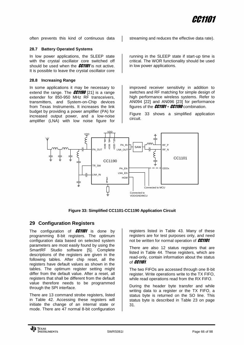
CC1101
SWRS061I Page 66 of 98
often prevents this kind of continuous data streaming and reduces the effective data rate).
28.7 Battery Operated Systems
In low power applications, the SLEEP state with the crystal oscillator core switched off
should be used when the CC1101 is not active. It is possible to leave the crystal oscillator core
running in the SLEEP state if start-up time is critical. The WOR functionality should be used in low power applications.
28.8 Increasing Range
In some applications it may be necessary to
extend the range. The CC1190 [21] is a range extender for 850-950 MHz RF transceivers, transmitters, and System-on-Chip devices from Texas Instruments. It increases the link budget by providing a power amplifier (PA) for increased output power, and a low-noise amplifier (LNA) with low noise figure for
improved receiver sensitivity in addition to switches and RF matching for simple design of high performance wireless systems. Refer to AN094 [22] and AN096 [23] for performance
figures of the CC1101 + CC1190 combination.
Figure 33 shows a simplified application circuit.
Figure 33: Simplified CC1101-CC1190 Application Circuit
29 Configuration Registers
The configuration of CC1101 is done by programming 8-bit registers. The optimum configuration data based on selected system parameters are most easily found by using the SmartRF Studio software [5]. Complete descriptions of the registers are given in the following tables. After chip reset, all the registers have default values as shown in the tables. The optimum register setting might differ from the default value. After a reset, all registers that shall be different from the default value therefore needs to be programmed through the SPI interface.
There are 13 command strobe registers, listed in Table 42. Accessing these registers will initiate the change of an internal state or mode. There are 47 normal 8-bit configuration
registers listed in Table 43. Many of these registers are for test purposes only, and need
not be written for normal operation of CC1101.
There are also 12 status registers that are listed in Table 44. These registers, which are read-only, contain information about the status
of CC1101.
The two FIFOs are accessed through one 8-bit register. Write operations write to the TX FIFO, while read operations read from the RX FIFO.
During the header byte transfer and while writing data to a register or the TX FIFO, a status byte is returned on the SO line. This status byte is described in Table 23 on page 31.
CC1101
Connected to VDD / GND / MCU
RF _ P
GDOx
RF _ N SAW
CC 1190
PA _ EN LNA _ EN
HGM B I A S
VDD
TR _ SW
LNA _ OUT PA _ OUT PA _ IN
LNA _ IN
V D D _ L N A
V D D _ P A 1
V D D _ P A 2
VDD
Connected to MCU

CC1101
SWRS061I Page 67 of 98
Table 45 summarizes the SPI address space. The address to use is given by adding the base address to the left and the burst and
read/write bits on the top. Note that the burst bit has different meaning for base addresses above and below 0x2F.
Address Strobe Name
Description
0x30 SRES Reset chip.
0x31 SFSTXON Enable and calibrate frequency synthesizer (if MCSM0.FS_AUTOCAL=1). If in RX (with CCA):
Go to a wait state where only the synthesizer is running (for quick RX / TX turnaround).
0x32 SXOFF Turn off crystal oscillator.
0x33 SCAL Calibrate frequency synthesizer and turn it off. SCAL can be strobed from IDLE mode without
setting manual calibration mode (MCSM0.FS_AUTOCAL=0)
0x34 SRX Enable RX. Perform calibration first if coming from IDLE and MCSM0.FS_AUTOCAL=1.
0x35 STX In IDLE state: Enable TX. Perform calibration first if MCSM0.FS_AUTOCAL=1.
If in RX state and CCA is enabled: Only go to TX if channel is clear.
0x36 SIDLE Exit RX / TX, turn off frequency synthesizer and exit Wake-On-Radio mode if applicable.
0x38 SWOR Start automatic RX polling sequence (Wake-on-Radio) as described in Section 19.5 if
WORCTRL.RC_PD=0.
0x39 SPWD Enter power down mode when CSn goes high.
0x3A SFRX Flush the RX FIFO buffer. Only issue SFRX in IDLE or RXFIFO_OVERFLOW states.
0x3B SFTX Flush the TX FIFO buffer. Only issue SFTX in IDLE or TXFIFO_UNDERFLOW states.
0x3C SWORRST Reset real time clock to Event1 value.
0x3D SNOP No operation. May be used to get access to the chip status byte.
Table 42: Command Strobes

CC1101
SWRS061I Page 68 of 98
Address Register Description Preserved in SLEEP State
Details on Page Number
0x00 IOCFG2 GDO2 output pin configuration Yes 71
0x01 IOCFG1 GDO1 output pin configuration Yes 71
0x02 IOCFG0 GDO0 output pin configuration Yes 71
0x03 FIFOTHR RX FIFO and TX FIFO thresholds Yes 72
0x04 SYNC1 Sync word, high byte Yes 73
0x05 SYNC0 Sync word, low byte Yes 73
0x06 PKTLEN Packet length Yes 73
0x07 PKTCTRL1 Packet automation control Yes 73
0x08 PKTCTRL0 Packet automation control Yes 74
0x09 ADDR Device address Yes 74
0x0A CHANNR Channel number Yes 74
0x0B FSCTRL1 Frequency synthesizer control Yes 75
0x0C FSCTRL0 Frequency synthesizer control Yes 75
0x0D FREQ2 Frequency control word, high byte Yes 75
0x0E FREQ1 Frequency control word, middle byte Yes 75
0x0F FREQ0 Frequency control word, low byte Yes 75
0x10 MDMCFG4 Modem configuration Yes 76
0x11 MDMCFG3 Modem configuration Yes 76
0x12 MDMCFG2 Modem configuration Yes 77
0x13 MDMCFG1 Modem configuration Yes 78
0x14 MDMCFG0 Modem configuration Yes 78
0x15 DEVIATN Modem deviation setting Yes 79
0x16 MCSM2 Main Radio Control State Machine configuration Yes 80
0x17 MCSM1 Main Radio Control State Machine configuration Yes 81
0x18 MCSM0 Main Radio Control State Machine configuration Yes 82
0x19 FOCCFG Frequency Offset Compensation configuration Yes 83
0x1A BSCFG Bit Synchronization configuration Yes 84
0x1B AGCTRL2 AGC control Yes 85
0x1C AGCTRL1 AGC control Yes 86
0x1D AGCTRL0 AGC control Yes 87
0x1E WOREVT1 High byte Event 0 timeout Yes 87
0x1F WOREVT0 Low byte Event 0 timeout Yes 88
0x20 WORCTRL Wake On Radio control Yes 88
0x21 FREND1 Front end RX configuration Yes 89
0x22 FREND0 Front end TX configuration Yes 89
0x23 FSCAL3 Frequency synthesizer calibration Yes 89
0x24 FSCAL2 Frequency synthesizer calibration Yes 90
0x25 FSCAL1 Frequency synthesizer calibration Yes 90
0x26 FSCAL0 Frequency synthesizer calibration Yes 90
0x27 RCCTRL1 RC oscillator configuration Yes 90
0x28 RCCTRL0 RC oscillator configuration Yes 90
0x29 FSTEST Frequency synthesizer calibration control No 91
0x2A PTEST Production test No 91
0x2B AGCTEST AGC test No 91
0x2C TEST2 Various test settings No 91
0x2D TEST1 Various test settings No 91
0x2E TEST0 Various test settings No 92
Table 43: Configuration Registers Overview

CC1101
SWRS061I Page 69 of 98
Address Register Description Details on page number
0x30 (0xF0) PARTNUM Part number for CC1101 92
0x31 (0xF1) VERSION Current version number 92
0x32 (0xF2) FREQEST Frequency Offset Estimate 92
0x33 (0xF3) LQI Demodulator estimate for Link Quality 92
0x34 (0xF4) RSSI Received signal strength indication 92
0x35 (0xF5) MARCSTATE Control state machine state 93
0x36 (0xF6) WORTIME1 High byte of WOR timer 93
0x37 (0xF7) WORTIME0 Low byte of WOR timer 93
0x38 (0xF8) PKTSTATUS Current GDOx status and packet status 94
0x39 (0xF9) VCO_VC_DAC Current setting from PLL calibration module
94
0x3A (0xFA) TXBYTES Underflow and number of bytes in the TX FIFO
94
0x3B (0xFB) RXBYTES Overflow and number of bytes in the RX FIFO
94
0x3C (0xFC) RCCTRL1_STATUS Last RC oscillator calibration result 94
0x3D (0xFD) RCCTRL0_STATUS Last RC oscillator calibration result 95
Table 44: Status Registers Overview
Table 45: SPI Address Space (see next page)

CC1101
SWRS061I Page 70 of 98
Write Read
Single Byte Burst Single Byte Burst
+0x00 +0x40 +0x80 +0xC0
0x00 IOCFG2
R/W
config
ura
tio
n r
egis
ters
, burs
t access p
ossib
le
0x01 IOCFG1
0x02 IOCFG0
0x03 FIFOTHR
0x04 SYNC1
0x05 SYNC0
0x06 PKTLEN
0x07 PKTCTRL1
0x08 PKTCTRL0
0x09 ADDR
0x0A CHANNR
0x0B FSCTRL1
0x0C FSCTRL0
0x0D FREQ2
0x0E FREQ1
0x0F FREQ0
0x10 MDMCFG4
0x11 MDMCFG3
0x12 MDMCFG2
0x13 MDMCFG1
0x14 MDMCFG0
0x15 DEVIATN
0x16 MCSM2
0x17 MCSM1
0x18 MCSM0
0x19 FOCCFG
0x1A BSCFG
0x1B AGCCTRL2
0x1C AGCCTRL1
0x1D AGCCTRL0
0x1E WOREVT1
0x1F WOREVT0
0x20 WORCTRL
0x21 FREND1
0x22 FREND0
0x23 FSCAL3
0x24 FSCAL2
0x25 FSCAL1
0x26 FSCAL0
0x27 RCCTRL1
0x28 RCCTRL0
0x29 FSTEST
0x2A PTEST
0x2B AGCTEST
0x2C TEST2
0x2D TEST1
0x2E TEST0
0x2F
0x30 SRES SRES PARTNUM
Com
mand S
trobes, S
tatu
s r
egis
ters
(r
ead o
nly
) and m
ulti byte
regis
ters
0x31 SFSTXON SFSTXON VERSION
0x32 SXOFF SXOFF FREQEST
0x33 SCAL SCAL LQI
0x34 SRX SRX RSSI
0x35 STX STX MARCSTATE
0x36 SIDLE SIDLE WORTIME1
0x37 WORTIME0
0x38 SWOR SWOR PKTSTATUS
0x39 SPWD SPWD VCO_VC_DAC
0x3A SFRX SFRX TXBYTES
0x3B SFTX SFTX RXBYTES
0x3C SWORRST SWORRST RCCTRL1_STATUS
0x3D SNOP SNOP RCCTRL0_STATUS
0x3E PATABLE PATABLE PATABLE PATABLE
0x3F TX FIFO TX FIFO RX FIFO RX FIFO

CC1101
SWRS061I Page 71 of 98
29.1 Configuration Register Details – Registers with preserved values in SLEEP state
0x00: IOCFG2 – GDO2 Output Pin Configuration
Bit Field Name Reset R/W Description
7 R0 Not used
6 GDO2_INV 0 R/W Invert output, i.e. select active low (1) / high (0)
5:0 GDO2_CFG[5:0] 41 (0x29) R/W Default is CHP_RDYn (See Table 41 on page 62).
0x01: IOCFG1 – GDO1 Output Pin Configuration
Bit Field Name Reset R/W Description
7 GDO_DS 0 R/W Set high (1) or low (0) output drive strength on the GDO pins.
6 GDO1_INV 0 R/W Invert output, i.e. select active low (1) / high (0)
5:0 GDO1_CFG[5:0] 46 (0x2E) R/W Default is 3-state (See Table 41 on page 62).
0x02: IOCFG0 – GDO0 Output Pin Configuration
Bit Field Name Reset R/W Description
7 TEMP_SENSOR_ENABLE 0 R/W Enable analog temperature sensor. Write 0 in all other register bits when using temperature sensor.
6 GDO0_INV 0 R/W Invert output, i.e. select active low (1) / high (0)
5:0 GDO0_CFG[5:0] 63 (0x3F) R/W Default is CLK_XOSC/192 (See Table 41 on page 62).
It is recommended to disable the clock output in initialization, in order to optimize RF performance.

CC1101
SWRS061I Page 72 of 98
0x03: FIFOTHR – RX FIFO and TX FIFO Thresholds
Bit Field Name Reset R/W Description
7 0 R/W Reserved , write 0 for compatibility with possible future extensions
6 ADC_RETENTION 0 R/W 0: TEST1 = 0x31 and TEST2= 0x88 when waking up from SLEEP
1: TEST1 = 0x35 and TEST2 = 0x81 when waking up from SLEEP
Note that the changes in the TEST registers due to the ADC_RETENTION bit setting are only seen INTERNALLY in the analog part. The values read from the TEST registers when waking up from SLEEP mode will always be the reset value.
The ADC_RETENTION bit should be set to 1before going into SLEEP mode if settings with an RX filter bandwidth below 325 kHz are wanted at time of wake-up.
5:4 CLOSE_IN_RX [1:0] 0 (00) R/W For more details, please see DN010 [8]
Setting RX Attenuation, Typical Values
0 (00) 0 dB
1 (01) 6 dB
2 (10) 12 dB
3 (11) 18 dB
3:0 FIFO_THR[3:0] 7 (0111) R/W Set the threshold for the TX FIFO and RX FIFO. The threshold is exceeded when the number of bytes in the FIFO is equal to or higher than the threshold value.
Setting Bytes in TX FIFO Bytes in RX FIFO
0 (0000) 61 4
1 (0001) 57 8
2 (0010) 53 12
3 (0011) 49 16
4 (0100) 45 20
5 (0101) 41 24
6 (0110) 37 28
7 (0111) 33 32
8 (1000) 29 36
9 (1001) 25 40
10 (1010) 21 44
11 (1011) 17 48
12 (1100) 13 52
13 (1101) 9 56
14 (1110) 5 60
15 (1111) 1 64

CC1101
SWRS061I Page 73 of 98
0x04: SYNC1 – Sync Word, High Byte
Bit Field Name Reset R/W Description
7:0 SYNC[15:8] 211 (0xD3) R/W 8 MSB of 16-bit sync word
0x05: SYNC0 – Sync Word, Low Byte
Bit Field Name Reset R/W Description
7:0 SYNC[7:0] 145 (0x91) R/W 8 LSB of 16-bit sync word
0x06: PKTLEN – Packet Length
Bit Field Name Reset R/W Description
7:0 PACKET_LENGTH 255 (0xFF) R/W Indicates the packet length when fixed packet length mode is enabled. If variable packet length mode is used, this value indicates the maximum packet length allowed. This value must be different from 0.
0x07: PKTCTRL1 – Packet Automation Control
Bit Field Name Reset R/W Description
7:5 PQT[2:0] 0 (0x00) R/W Preamble quality estimator threshold. The preamble quality estimator increases an internal counter by one each time a bit is received that is different from the previous bit, and decreases the counter by 8 each time a bit is received that is the same as the last bit.
A threshold of 4∙PQT for this counter is used to gate sync word detection.
When PQT=0 a sync word is always accepted.
4 0 R0 Not Used.
3 CRC_AUTOFLUSH 0 R/W Enable automatic flush of RX FIFO when CRC is not OK. This requires that only one packet is in the RXIFIFO and that packet length is limited to the RX FIFO size.
2 APPEND_STATUS 1 R/W When enabled, two status bytes will be appended to the payload of the packet. The status bytes contain RSSI and LQI values, as well as CRC OK.
1:0 ADR_CHK[1:0] 0 (00) R/W Controls address check configuration of received packages.
Setting Address check configuration
0 (00) No address check
1 (01) Address check, no broadcast
2 (10) Address check and 0 (0x00) broadcast
3 (11) Address check and 0 (0x00) and 255 (0xFF) broadcast

CC1101
SWRS061I Page 74 of 98
0x08: PKTCTRL0 – Packet Automation Control
Bit Field Name Reset R/W Description
7 R0 Not used
6 WHITE_DATA 1 R/W Turn data whitening on / off
0: Whitening off 1: Whitening on
5:4 PKT_FORMAT[1:0] 0 (00) R/W Format of RX and TX data
Setting Packet format
0 (00) Normal mode, use FIFOs for RX and TX
1 (01) Synchronous serial mode, Data in on GDO0 and data out on either of the GDOx pins
2 (10) Random TX mode; sends random data using PN9 generator. Used for test. Works as normal mode, setting 0 (00), in RX
3 (11) Asynchronous serial mode, Data in on GDO0 and data out on either of the GDOx pins
3 0 R0 Not used
2 CRC_EN 1 R/W 1: CRC calculation in TX and CRC check in RX enabled
0: CRC disabled for TX and RX
1:0 LENGTH_CONFIG[1:0] 1 (01) R/W Configure the packet length
Setting Packet length configuration
0 (00) Fixed packet length mode. Length configured in
PKTLEN register
1 (01) Variable packet length mode. Packet length configured by the first byte after sync word
2 (10) Infinite packet length mode
3 (11) Reserved
0x09: ADDR – Device Address
Bit Field Name Reset R/W Description
7:0 DEVICE_ADDR[7:0] 0 (0x00) R/W Address used for packet filtration. Optional broadcast addresses are 0 (0x00) and 255 (0xFF).
0x0A: CHANNR – Channel Number
Bit Field Name Reset R/W Description
7:0 CHAN[7:0] 0 (0x00) R/W The 8-bit unsigned channel number, which is multiplied by the channel spacing setting and added to the base frequency.

CC1101
SWRS061I Page 75 of 98
0x0B: FSCTRL1 – Frequency Synthesizer Control
Bit Field Name Reset R/W Description
7:6 R0 Not used
5 0 R/W Reserved
4:0 FREQ_IF[4:0] 15 (0x0F) R/W The desired IF frequency to employ in RX. Subtracted from FS base frequency in RX and controls the digital complex mixer in the demodulator.
IFFREQf
f XOSCIF _
210
The default value gives an IF frequency of 381kHz, assuming a 26.0 MHz crystal.
0x0C: FSCTRL0 – Frequency Synthesizer Control
Bit Field Name Reset R/W Description
7:0 FREQOFF[7:0] 0 (0x00) R/W Frequency offset added to the base frequency before being used by the frequency synthesizer. (2s-complement).
Resolution is FXTAL/214
(1.59kHz-1.65kHz); range is ±202 kHz to ±210 kHz, dependent of XTAL frequency.
0x0D: FREQ2 – Frequency Control Word, High Byte
Bit Field Name Reset R/W Description
7:6 FREQ[23:22] 0 (00) R FREQ[23:22] is always 0 (the FREQ2 register is less than 36 with 26-27 MHz
crystal)
5:0 FREQ[21:16] 30 (0x1E) R/W FREQ[23:0] is the base frequency for the frequency synthesiser in
increments of fXOSC/216
.
0:23216
FREQf
f XOSCcarrier
0x0E: FREQ1 – Frequency Control Word, Middle Byte
Bit Field Name Reset R/W Description
7:0 FREQ[15:8] 196 (0xC4) R/W Ref. FREQ2 register
0x0F: FREQ0 – Frequency Control Word, Low Byte
Bit Field Name Reset R/W Description
7:0 FREQ[7:0] 236 (0xEC) R/W Ref. FREQ2 register

CC1101
SWRS061I Page 76 of 98
0x10: MDMCFG4 – Modem Configuration
Bit Field Name Reset R/W Description
7:6 CHANBW_E[1:0] 2 (0x02) R/W
5:4 CHANBW_M[1:0] 0 (0x00) R/W Sets the decimation ratio for the delta-sigma ADC input stream and thus the channel bandwidth.
ECHANBW
XOSCchannel
MCHANBW
fBW
_2)·_4(8
The default values give 203 kHz channel filter bandwidth, assuming a 26.0 MHz crystal.
3:0 DRATE_E[3:0] 12 (0x0C) R/W The exponent of the user specified symbol rate
0x11: MDMCFG3 – Modem Configuration
Bit Field Name Reset R/W Description
7:0 DRATE_M[7:0] 34 (0x22) R/W The mantissa of the user specified symbol rate. The symbol rate is configured using an unsigned, floating-point number with 9-bit mantissa and 4-bit exponent. The 9
th bit is a hidden ‘1’. The resulting data rate is:
XOSC
EDRATE
DATA fMDRATE
R
28
_
2
2_256
The default values give a data rate of 115.051 kBaud (closest setting to 115.2 kBaud), assuming a 26.0 MHz crystal.

CC1101
SWRS061I Page 77 of 98
0x12: MDMCFG2 – Modem Configuration
Bit Field Name Reset R/W Description
7 DEM_DCFILT_OFF 0 R/W Disable digital DC blocking filter before demodulator.
0 = Enable (better sensitivity)
1 = Disable (current optimized). Only for data rates ≤ 250 kBaud
The recommended IF frequency changes when the DC blocking is disabled. Please use SmartRF Studio [5] to calculate correct register setting.
6:4 MOD_FORMAT[2:0] 0 (000) R/W The modulation format of the radio signal
Setting Modulation format
0 (000) 2-FSK
1 (001) GFSK
2 (010) -
3 (011) ASK/OOK
4 (100) 4-FSK
5 (101) -
6 (110) -
7 (111) MSK
MSK is only supported for data rates above 26 kBaud
3 MANCHESTER_EN 0 R/W Enables Manchester encoding/decoding.
0 = Disable
1 = Enable
2:0 SYNC_MODE[2:0] 2 (010) R/W Combined sync-word qualifier mode.
The values 0 (000) and 4 (100) disables preamble and sync word transmission in TX and preamble and sync word detection in RX.
The values 1 (001), 2 (010), 5 (101) and 6 (110) enables 16-bit sync word transmission in TX and 16-bits sync word detection in RX. Only 15 of 16 bits need to match in RX when using setting 1 (001) or 5 (101). The values 3 (011) and 7 (111) enables repeated sync word transmission in TX and 32-bits sync word detection in RX (only 30 of 32 bits need to match).
Setting Sync-word qualifier mode
0 (000) No preamble/sync
1 (001) 15/16 sync word bits detected
2 (010) 16/16 sync word bits detected
3 (011) 30/32 sync word bits detected
4 (100) No preamble/sync, carrier-sense above threshold
5 (101) 15/16 + carrier-sense above threshold
6 (110) 16/16 + carrier-sense above threshold
7 (111) 30/32 + carrier-sense above threshold
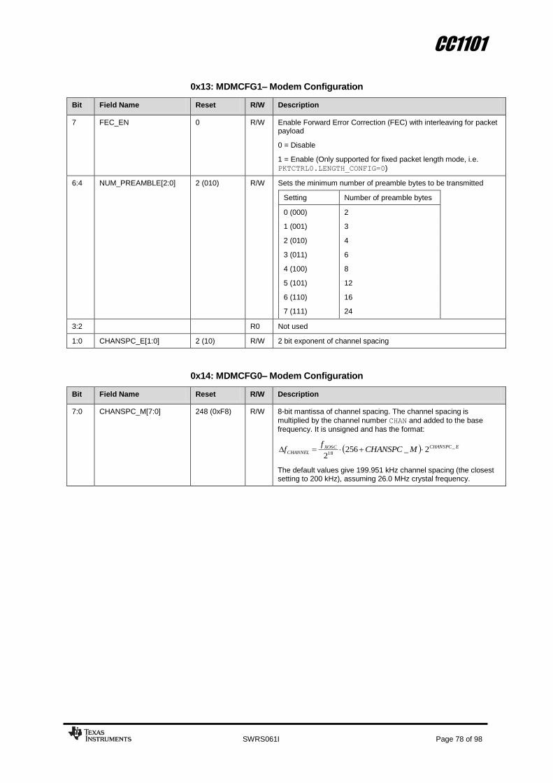
CC1101
SWRS061I Page 78 of 98
0x13: MDMCFG1– Modem Configuration
Bit Field Name Reset R/W Description
7 FEC_EN 0 R/W Enable Forward Error Correction (FEC) with interleaving for packet payload
0 = Disable
1 = Enable (Only supported for fixed packet length mode, i.e.
PKTCTRL0.LENGTH_CONFIG=0)
6:4 NUM_PREAMBLE[2:0] 2 (010) R/W Sets the minimum number of preamble bytes to be transmitted
Setting Number of preamble bytes
0 (000) 2
1 (001) 3
2 (010) 4
3 (011) 6
4 (100) 8
5 (101) 12
6 (110) 16
7 (111) 24
3:2 R0 Not used
1:0 CHANSPC_E[1:0] 2 (10) R/W 2 bit exponent of channel spacing
0x14: MDMCFG0– Modem Configuration
Bit Field Name Reset R/W Description
7:0 CHANSPC_M[7:0] 248 (0xF8) R/W 8-bit mantissa of channel spacing. The channel spacing is
multiplied by the channel number CHAN and added to the base
frequency. It is unsigned and has the format:
ECHANSPCXOSCCHANNEL MCHANSPC
ff _
182_256
2
The default values give 199.951 kHz channel spacing (the closest setting to 200 kHz), assuming 26.0 MHz crystal frequency.

CC1101
SWRS061I Page 79 of 98
0x15: DEVIATN – Modem Deviation Setting
Bit Field Name Reset R/W Description
7 R0 Not used.
6:4 DEVIATION_E[2:0] 4 (100) R/W Deviation exponent.
3 R0 Not used.
2:0 DEVIATION_M[2:0] 7 (111) R/W TX
2-FSK/
GFSK/
4-FSK
Specifies the nominal frequency deviation from the carrier for a ‘0’ (-DEVIATN) and ‘1’ (+DEVIATN) in a mantissa-exponent format, interpreted as a 4-bit value with MSB implicit 1. The resulting frequency deviation is given by:
EDEVIATIONxoscdev MDEVIATION
ff _
172)_8(
2
The default values give ±47.607 kHz deviation assuming 26.0 MHz crystal frequency.
MSK Specifies the fraction of symbol period (1/8-8/8) during which a phase change occurs (‘0’: +90deg, ‘1’:-90deg). Refer to the SmartRF Studio software [5] for correct DEVIATN setting when using MSK.
ASK/OOK This setting has no effect.
RX
2-FSK/
GFSK/
4-FSK
Specifies the expected frequency deviation of incoming signal, must be approximately right for demodulation to be performed reliably and robustly.
MSK/
ASK/OOK This setting has no effect.
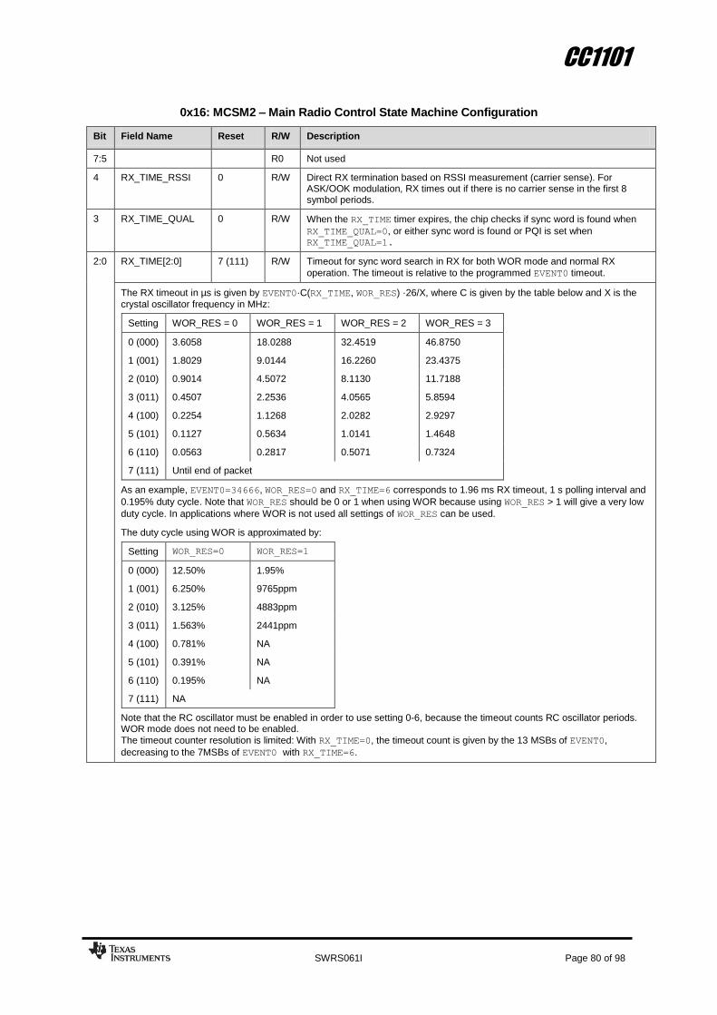
CC1101
SWRS061I Page 80 of 98
0x16: MCSM2 – Main Radio Control State Machine Configuration
Bit Field Name Reset R/W Description
7:5 R0 Not used
4 RX_TIME_RSSI 0 R/W Direct RX termination based on RSSI measurement (carrier sense). For ASK/OOK modulation, RX times out if there is no carrier sense in the first 8 symbol periods.
3 RX_TIME_QUAL 0 R/W When the RX_TIME timer expires, the chip checks if sync word is found when
RX_TIME_QUAL=0, or either sync word is found or PQI is set when RX_TIME_QUAL=1.
2:0 RX_TIME[2:0] 7 (111) R/W Timeout for sync word search in RX for both WOR mode and normal RX
operation. The timeout is relative to the programmed EVENT0 timeout.
The RX timeout in µs is given by EVENT0·C(RX_TIME, WOR_RES) ·26/X, where C is given by the table below and X is the
crystal oscillator frequency in MHz:
Setting WOR_RES = 0 WOR_RES = 1 WOR_RES = 2 WOR_RES = 3
0 (000) 3.6058 18.0288 32.4519 46.8750
1 (001) 1.8029 9.0144 16.2260 23.4375
2 (010) 0.9014 4.5072 8.1130 11.7188
3 (011) 0.4507 2.2536 4.0565 5.8594
4 (100) 0.2254 1.1268 2.0282 2.9297
5 (101) 0.1127 0.5634 1.0141 1.4648
6 (110) 0.0563 0.2817 0.5071 0.7324
7 (111) Until end of packet
As an example, EVENT0=34666, WOR_RES=0 and RX_TIME=6 corresponds to 1.96 ms RX timeout, 1 s polling interval and
0.195% duty cycle. Note that WOR_RES should be 0 or 1 when using WOR because using WOR_RES > 1 will give a very low
duty cycle. In applications where WOR is not used all settings of WOR_RES can be used.
The duty cycle using WOR is approximated by:
Setting WOR_RES=0 WOR_RES=1
0 (000) 12.50% 1.95%
1 (001) 6.250% 9765ppm
2 (010) 3.125% 4883ppm
3 (011) 1.563% 2441ppm
4 (100) 0.781% NA
5 (101) 0.391% NA
6 (110) 0.195% NA
7 (111) NA
Note that the RC oscillator must be enabled in order to use setting 0-6, because the timeout counts RC oscillator periods. WOR mode does not need to be enabled.
The timeout counter resolution is limited: With RX_TIME=0, the timeout count is given by the 13 MSBs of EVENT0,
decreasing to the 7MSBs of EVENT0 with RX_TIME=6.

CC1101
SWRS061I Page 81 of 98
0x17: MCSM1– Main Radio Control State Machine Configuration
Bit Field Name Reset R/W Description
7:6 R0 Not used
5:4 CCA_MODE[1:0] 3 (11) R/W Selects CCA_MODE; Reflected in CCA signal
Setting Clear channel indication
0 (00) Always
1 (01) If RSSI below threshold
2 (10) Unless currently receiving a packet
3 (11) If RSSI below threshold unless currently receiving a packet
3:2 RXOFF_MODE[1:0] 0 (00) R/W Select what should happen when a packet has been received
Setting Next state after finishing packet reception
0 (00) IDLE
1 (01) FSTXON
2 (10) TX
3 (11) Stay in RX
It is not possible to set RXOFF_MODE to be TX or FSTXON and at the same
time use CCA.
1:0 TXOFF_MODE[1:0] 0 (00) R/W Select what should happen when a packet has been sent (TX)
Setting Next state after finishing packet transmission
0 (00) IDLE
1 (01) FSTXON
2 (10) Stay in TX (start sending preamble)
3 (11) RX

CC1101
SWRS061I Page 82 of 98
0x18: MCSM0– Main Radio Control State Machine Configuration
Bit Field Name Reset R/W Description
7:6 R0 Not used
5:4 FS_AUTOCAL[1:0] 0 (00) R/W Automatically calibrate when going to RX or TX, or back to IDLE
Setting When to perform automatic calibration
0 (00) Never (manually calibrate using SCAL strobe)
1 (01) When going from IDLE to RX or TX (or FSTXON)
2 (10) When going from RX or TX back to IDLE automatically
3 (11) Every 4
th time when going from RX or TX to IDLE
automatically
In some automatic wake-on-radio (WOR) applications, using setting 3 (11) can significantly reduce current consumption.
3:2 PO_TIMEOUT 1 (01) R/W Programs the number of times the six-bit ripple counter must expire after
XOSC has stabilized before CHP_RDYn goes low [1]
.
If XOSC is on (stable) during power-down, PO_TIMEOUT should be set so that
the regulated digital supply voltage has time to stabilize before CHP_RDYn
goes low (PO_TIMEOUT=2 recommended). Typical start-up time for the
voltage regulator is 50 μs.
For robust operation it is recommended to use PO_TIMEOUT = 2 or 3 when
XOSC is off during power-down.
[1] Note that the XOSC_STABLE signal will be asserted at the same time as
the CHP_RDYn signal; i.e. the PO_TIMEOUT delays both signals and does not
insert a delay between the signals
Setting Expire count Timeout after XOSC start
0 (00) 1 Approx. 2.3 – 2.4 μs
1 (01) 16 Approx. 37 – 39 μs
2 (10) 64 Approx. 149 – 155 μs
3 (11) 256 Approx. 597 – 620 μs
Exact timeout depends on crystal frequency.
1 PIN_CTRL_EN 0 R/W Enables the pin radio control option
0 XOSC_FORCE_ON 0 R/W Force the XOSC to stay on in the SLEEP state.

CC1101
SWRS061I Page 83 of 98
0x19: FOCCFG – Frequency Offset Compensation Configuration
Bit Field Name Reset R/W Description
7:6 R0 Not used
5 FOC_BS_CS_GATE 1 R/W If set, the demodulator freezes the frequency offset compensation and clock recovery feedback loops until the CS signal goes high.
4:3 FOC_PRE_K[1:0] 2 (10) R/W The frequency compensation loop gain to be used before a sync word is detected.
Setting Freq. compensation loop gain before sync word
0 (00) K
1 (01) 2K
2 (10) 3K
3 (11) 4K
2 FOC_POST_K 1 R/W The frequency compensation loop gain to be used after a sync word is detected.
Setting Freq. compensation loop gain after sync word
0 Same as FOC_PRE_K
1 K/2
1:0 FOC_LIMIT[1:0] 2 (10) R/W The saturation point for the frequency offset compensation algorithm:
Setting Saturation point (max compensated offset)
0 (00) ±0 (no frequency offset compensation)
1 (01) ±BWCHAN/8
2 (10) ±BWCHAN/4
3 (11) ±BWCHAN/2
Frequency offset compensation is not supported for ASK/OOK. Always use FOC_LIMIT=0 with these modulation formats.

CC1101
SWRS061I Page 84 of 98
0x1A: BSCFG – Bit Synchronization Configuration
Bit Field Name Reset R/W Description
7:6 BS_PRE_KI[1:0] 1 (01) R/W The clock recovery feedback loop integral gain to be used before a sync word is detected (used to correct offsets in data rate):
Setting Clock recovery loop integral gain before sync word
0 (00) KI
1 (01) 2KI
2 (10) 3KI
3 (11) 4KI
5:4 BS_PRE_KP[1:0] 2 (10) R/W The clock recovery feedback loop proportional gain to be used before a sync word is detected.
Setting Clock recovery loop proportional gain before sync word
0 (00) KP
1 (01) 2KP
2 (10) 3KP
3 (11) 4KP
3 BS_POST_KI 1 R/W The clock recovery feedback loop integral gain to be used after a sync word is detected.
Setting Clock recovery loop integral gain after sync word
0 Same as BS_PRE_KI
1 KI /2
2 BS_POST_KP 1 R/W The clock recovery feedback loop proportional gain to be used after a sync word is detected.
Setting Clock recovery loop proportional gain after sync word
0 Same as BS_PRE_KP
1 KP
1:0 BS_LIMIT[1:0] 0 (00) R/W The saturation point for the data rate offset compensation algorithm:
Setting Data rate offset saturation (max data rate difference)
0 (00) ±0 (No data rate offset compensation performed)
1 (01) ±3.125 % data rate offset
2 (10) ±6.25 % data rate offset
3 (11) ±12.5 % data rate offset

CC1101
SWRS061I Page 85 of 98
0x1B: AGCCTRL2 – AGC Control
Bit Field Name Reset R/W Description
7:6 MAX_DVGA_GAIN[1:0] 0 (00) R/W Reduces the maximum allowable DVGA gain.
Setting Allowable DVGA settings
0 (00) All gain settings can be used
1 (01) The highest gain setting can not be used
2 (10) The 2 highest gain settings can not be used
3 (11) The 3 highest gain settings can not be used
5:3 MAX_LNA_GAIN[2:0] 0 (000) R/W Sets the maximum allowable LNA + LNA 2 gain relative to the maximum possible gain.
Setting Maximum allowable LNA + LNA 2 gain
0 (000) Maximum possible LNA + LNA 2 gain
1 (001) Approx. 2.6 dB below maximum possible gain
2 (010) Approx. 6.1 dB below maximum possible gain
3 (011) Approx. 7.4 dB below maximum possible gain
4 (100) Approx. 9.2 dB below maximum possible gain
5 (101) Approx. 11.5 dB below maximum possible gain
6 (110) Approx. 14.6 dB below maximum possible gain
7 (111) Approx. 17.1 dB below maximum possible gain
2:0 MAGN_TARGET[2:0] 3 (011) R/W These bits set the target value for the averaged amplitude from the digital channel filter (1 LSB = 0 dB).
Setting Target amplitude from channel filter
0 (000) 24 dB
1 (001) 27 dB
2 (010) 30 dB
3 (011) 33 dB
4 (100) 36 dB
5 (101) 38 dB
6 (110) 40 dB
7 (111) 42 dB

CC1101
SWRS061I Page 86 of 98
0x1C: AGCCTRL1 – AGC Control
Bit Field Name Reset R/W Description
7 R0 Not used
6 AGC_LNA_PRIORITY 1 R/W Selects between two different strategies for LNA and LNA 2 gain adjustment. When 1, the LNA gain is decreased first. When 0, the LNA 2 gain is decreased to minimum before decreasing LNA gain.
5:4 CARRIER_SENSE_REL_THR[1:0] 0 (00) R/W Sets the relative change threshold for asserting carrier sense
Setting Carrier sense relative threshold
0 (00) Relative carrier sense threshold disabled
1 (01) 6 dB increase in RSSI value
2 (10) 10 dB increase in RSSI value
3 (11) 14 dB increase in RSSI value
3:0 CARRIER_SENSE_ABS_THR[3:0] 0 (0000)
R/W Sets the absolute RSSI threshold for asserting carrier sense. The 2-complement signed threshold is programmed in steps of 1 dB and is relative to the MAGN_TARGET setting.
Setting Carrier sense absolute threshold
(Equal to channel filter amplitude when AGC has not decreased gain)
-8 (1000) Absolute carrier sense threshold disabled
-7 (1001) 7 dB below MAGN_TARGET setting
… …
-1 (1111) 1 dB below MAGN_TARGET setting
0 (0000) At MAGN_TARGET setting
1 (0001) 1 dB above MAGN_TARGET setting
… …
7 (0111) 7 dB above MAGN_TARGET setting

CC1101
SWRS061I Page 87 of 98
0x1D: AGCCTRL0 – AGC Control
Bit Field Name Reset R/W Description
7:6 HYST_LEVEL[1:0] 2 (10) R/W Sets the level of hysteresis on the magnitude deviation (internal AGC signal that determine gain changes).
Setting Description
0 (00) No hysteresis, small symmetric dead zone, high gain
1 (01) Low hysteresis, small asymmetric dead zone, medium gain
2 (10) Medium hysteresis, medium asymmetric dead zone, medium gain
3 (11) Large hysteresis, large asymmetric dead zone, low gain
5:4 WAIT_TIME[1:0] 1 (01) R/W Sets the number of channel filter samples from a gain adjustment has been made until the AGC algorithm starts accumulating new samples.
Setting Channel filter samples
0 (00) 8
1 (01) 16
2 (10) 24
3 (11) 32
3:2 AGC_FREEZE[1:0] 0 (00) R/W Control when the AGC gain should be frozen.
Setting Function
0 (00) Normal operation. Always adjust gain when required.
1 (01) The gain setting is frozen when a sync word has been found.
2 (10) Manually freeze the analogue gain setting and continue to adjust the digital gain.
3 (11) Manually freezes both the analogue and the digital gain setting. Used for manually overriding the gain.
1:0 FILTER_LENGTH[1:0] 1 (01) R/W 2-FSK, 4-FSK, MSK: Sets the averaging length for the amplitude from the channel filter.
ASK, OOK: Sets the OOK/ASK decision boundary for OOK/ASK reception.
Setting Channel filter samples
OOK/ASK decision boundary
0 (00) 8 4 dB
1 (01) 16 8 dB
2 (10) 32 12 dB
3 (11) 64 16 dB
0x1E: WOREVT1 – High Byte Event0 Timeout
Bit Field Name Reset R/W Description
7:0 EVENT0[15:8] 135 (0x87) R/W High byte of EVENT0 timeout register
RESWOR
XOSC
Event EVENTf
t _5
0 20750

CC1101
SWRS061I Page 88 of 98
0x1F: WOREVT0 –Low Byte Event0 Timeout
Bit Field Name Reset R/W Description
7:0 EVENT0[7:0] 107 (0x6B) R/W Low byte of EVENT0 timeout register.
The default EVENT0 value gives 1.0s timeout, assuming a 26.0 MHz crystal.
0x20: WORCTRL – Wake On Radio Control
Bit Field Name Reset R/W Description
7 RC_PD 1 R/W Power down signal to RC oscillator. When written to 0, automatic initial calibration will be performed
6:4 EVENT1[2:0] 7 (111) R/W Timeout setting from register block. Decoded to Event 1 timeout. RC oscillator clock frequency equals FXOSC/750, which is 34.7 – 36 kHz, depending on crystal frequency. The table below lists the number of clock periods after Event 0 before Event 1 times out.
Setting tEvent1
0 (000) 4 (0.111 – 0.115 ms)
1 (001) 6 (0.167 – 0.173 ms)
2 (010) 8 (0.222 – 0.230 ms)
3 (011) 12 (0.333 – 0.346 ms)
4 (100) 16 (0.444 – 0.462 ms)
5 (101) 24 (0.667 – 0.692 ms)
6 (110) 32 (0.889 – 0.923 ms)
7 (111) 48 (1.333 – 1.385 ms)
3 RC_CAL 1 R/W Enables (1) or disables (0) the RC oscillator calibration.
2 R0 Not used
1:0 WOR_RES 0 (00) R/W Controls the Event 0 resolution as well as maximum timeout of the WOR module and maximum timeout under normal RX operation:
Setting Resolution (1 LSB) Max timeout
0 (00) 1 period (28 – 29 μs) 1.8 – 1.9 seconds
1 (01) 25 periods (0.89 – 0.92 ms) 58 – 61 seconds
2 (10) 210
periods (28 – 30 ms) 31 – 32 minutes
3 (11) 215
periods (0.91 – 0.94 s) 16.5 – 17.2 hours
Note that WOR_RES should be 0 or 1 when using WOR because WOR_RES >
1 will give a very low duty cycle.
In normal RX operation all settings of WOR_RES can be used.

CC1101
SWRS061I Page 89 of 98
0x21: FREND1 – Front End RX Configuration
Bit Field Name Reset R/W Description
7:6 LNA_CURRENT[1:0] 1 (01) R/W Adjusts front-end LNA PTAT current output
5:4 LNA2MIX_CURRENT[1:0] 1 (01) R/W Adjusts front-end PTAT outputs
3:2 LODIV_BUF_CURRENT_RX[1:0] 1 (01) R/W Adjusts current in RX LO buffer (LO input to mixer)
1:0 MIX_CURRENT[1:0] 2 (10) R/W Adjusts current in mixer
0x22: FREND0 – Front End TX Configuration
Bit Field Name Reset R/W Description
7:6 R0 Not used
5:4 LODIV_BUF_CURRENT_TX[1:0] 1 (0x01) R/W Adjusts current TX LO buffer (input to PA). The value to use in this field is given by the SmartRF Studio software [5].
3 R0 Not used
2:0 PA_POWER[2:0] 0 (0x00) R/W Selects PA power setting. This value is an index to the
PATABLE, which can be programmed with up to 8 different
PA settings. In OOK/ASK mode, this selects the PATABLE index to use when transmitting a ‘1’. PATABLE index zero is
used in OOK/ASK when transmitting a ‘0’. The PATABLE settings from index ‘0’ to the PA_POWER value are used for
ASK TX shaping, and for power ramp-up/ramp-down at the start/end of transmission in all TX modulation formats.
0x23: FSCAL3 – Frequency Synthesizer Calibration
Bit Field Name Reset R/W Description
7:6 FSCAL3[7:6] 2 (0x02) R/W Frequency synthesizer calibration configuration. The value to write in this field before calibration is given by the SmartRF Studio software.
5:4 CHP_CURR_CAL_EN[1:0] 2 (0x02) R/W Disable charge pump calibration stage when 0.
3:0 FSCAL3[3:0] 9 (1001) R/W Frequency synthesizer calibration result register. Digital bit vector defining the charge pump output current, on an
exponential scale: I_OUT = I0·2FSCAL3[3:0]/4
Fast frequency hopping without calibration for each hop can be done by calibrating upfront for each frequency and saving
the resulting FSCAL3, FSCAL2 and FSCAL1 register values.
Between each frequency hop, calibration can be replaced by
writing the FSCAL3, FSCAL2 and FSCAL1 register values
corresponding to the next RF frequency.

CC1101
SWRS061I Page 90 of 98
0x24: FSCAL2 – Frequency Synthesizer Calibration
Bit Field Name Reset R/W Description
7:6 R0 Not used
5 VCO_CORE_H_EN 0 R/W Choose high (1) / low (0) VCO
4:0 FSCAL2[4:0] 10 (0x0A) R/W Frequency synthesizer calibration result register. VCO current calibration result and override value. Fast frequency hopping without calibration for each hop can be done by
calibrating upfront for each frequency and saving the resulting FSCAL3,
FSCAL2 and FSCAL1 register values. Between each frequency hop,
calibration can be replaced by writing the FSCAL3, FSCAL2 and FSCAL1
register values corresponding to the next RF frequency.
0x25: FSCAL1 – Frequency Synthesizer Calibration
Bit Field Name Reset R/W Description
7:6 R0 Not used
5:0 FSCAL1[5:0] 32 (0x20) R/W Frequency synthesizer calibration result register. Capacitor array setting for VCO coarse tuning. Fast frequency hopping without calibration for each hop can be done by
calibrating upfront for each frequency and saving the resulting FSCAL3,
FSCAL2 and FSCAL1 register values. Between each frequency hop,
calibration can be replaced by writing the FSCAL3, FSCAL2 and FSCAL1
register values corresponding to the next RF frequency.
0x26: FSCAL0 – Frequency Synthesizer Calibration
Bit Field Name Reset R/W Description
7 R0 Not used
6:0 FSCAL0[6:0] 13 (0x0D) R/W Frequency synthesizer calibration control. The value to use in this register is given by the SmartRF Studio software [5].
0x27: RCCTRL1 – RC Oscillator Configuration
Bit Field Name Reset R/W Description
7 0 R0 Not used
6:0 RCCTRL1[6:0] 65 (0x41) R/W RC oscillator configuration.
0x28: RCCTRL0 – RC Oscillator Configuration
Bit Field Name Reset R/W Description
7 0 R0 Not used
6:0 RCCTRL0[6:0] 0 (0x00) R/W RC oscillator configuration.

CC1101
SWRS061I Page 91 of 98
29.2 Configuration Register Details – Registers that Loose Programming in SLEEP State
0x29: FSTEST – Frequency Synthesizer Calibration Control
Bit Field Name Reset R/W Description
7:0 FSTEST[7:0] 89 (0x59) R/W For test only. Do not write to this register.
0x2A: PTEST – Production Test
Bit Field Name Reset R/W Description
7:0 PTEST[7:0] 127 (0x7F) R/W Writing 0xBF to this register makes the on-chip temperature sensor available in the IDLE state. The default 0x7F value should then be written back before leaving the IDLE state. Other use of this register is for test only.
0x2B: AGCTEST – AGC Test
Bit Field Name Reset R/W Description
7:0 AGCTEST[7:0] 63 (0x3F) R/W For test only. Do not write to this register.
0x2C: TEST2 – Various Test Settings
Bit Field Name Reset R/W Description
7:0 TEST2[7:0] 136 (0x88) R/W The value to use in this register is given by the SmartRF Studio software [5]. This register will be forced to 0x88 or 0x81 when it wakes up from SLEEP mode, depending on the configuration of FIFOTHR. ADC_RETENTION.
Note that the value read from this register when waking up from SLEEP always is the reset value (0x88) regardless of the ADC_RETENTION setting. The inverting of some of the bits due to the ADC_RETENTION setting is only seen INTERNALLY in the analog part.
0x2D: TEST1 – Various Test Settings
Bit Field Name Reset R/W Description
7:0 TEST1[7:0] 49 (0x31) R/W The value to use in this register is given by the SmartRF Studio software [5]. This register will be forced to 0x31 or 0x35 when it wakes up from SLEEP mode, depending on the configuration of FIFOTHR. ADC_RETENTION.
Note that the value read from this register when waking up from SLEEP always is the reset value (0x31) regardless of the ADC_RETENTION setting. The inverting of some of the bits due to the ADC_RETENTION setting is only seen INTERNALLY in the analog part.

CC1101
SWRS061I Page 92 of 98
0x2E: TEST0 – Various Test Settings
Bit Field Name Reset R/W Description
7:2 TEST0[7:2] 2 (0x02) R/W The value to use in this register is given by the SmartRF Studio software [5].
1 VCO_SEL_CAL_EN 1 R/W Enable VCO selection calibration stage when 1
0 TEST0[0] 1 R/W The value to use in this register is given by the SmartRF Studio software [5].
29.3 Status Register Details
0x30 (0xF0): PARTNUM – Chip ID
Bit Field Name Reset R/W Description
7:0 PARTNUM[7:0] 0 (0x00) R Chip part number
0x31 (0xF1): VERSION – Chip ID
Bit Field Name Reset R/W Description
7:0 VERSION[7:0] 20 (0x14)
R Chip version number. Subject to change without notice.
0x32 (0xF2): FREQEST – Frequency Offset Estimate from Demodulator
Bit Field Name Reset R/W Description
7:0 FREQOFF_EST R The estimated frequency offset (2’s complement) of the carrier. Resolution is FXTAL/2
14 (1.59 - 1.65 kHz); range is ±202 kHz to ±210 kHz, depending on XTAL
frequency.
Frequency offset compensation is only supported for 2-FSK, GFSK, 4-FSK, and MSK modulation. This register will read 0 when using ASK or OOK modulation.
0x33 (0xF3): LQI – Demodulator Estimate for Link Quality
Bit Field Name Reset R/W Description
7 CRC OK R The last CRC comparison matched. Cleared when entering/restarting RX mode.
6:0 LQI_EST[6:0] R The Link Quality Indicator estimates how easily a received signal can be demodulated. Calculated over the 64 symbols following the sync word
0x34 (0xF4): RSSI – Received Signal Strength Indication
Bit Field Name Reset R/W Description
7:0 RSSI R Received signal strength indicator

CC1101
SWRS061I Page 93 of 98
0x35 (0xF5): MARCSTATE – Main Radio Control State Machine State
Bit Field Name Reset R/W Description
7:5 R0 Not used
4:0 MARC_STATE[4:0] R Main Radio Control FSM State
Value State name State (Figure 25, page 50)
0 (0x00) SLEEP SLEEP
1 (0x01) IDLE IDLE
2 (0x02) XOFF XOFF
3 (0x03) VCOON_MC MANCAL
4 (0x04) REGON_MC MANCAL
5 (0x05) MANCAL MANCAL
6 (0x06) VCOON FS_WAKEUP
7 (0x07) REGON FS_WAKEUP
8 (0x08) STARTCAL CALIBRATE
9 (0x09) BWBOOST SETTLING
10 (0x0A) FS_LOCK SETTLING
11 (0x0B) IFADCON SETTLING
12 (0x0C) ENDCAL CALIBRATE
13 (0x0D) RX RX
14 (0x0E) RX_END RX
15 (0x0F) RX_RST RX
16 (0x10) TXRX_SWITCH TXRX_SETTLING
17 (0x11) RXFIFO_OVERFLOW RXFIFO_OVERFLOW
18 (0x12) FSTXON FSTXON
19 (0x13) TX TX
20 (0x14) TX_END TX
21 (0x15) RXTX_SWITCH RXTX_SETTLING
22 (0x16) TXFIFO_UNDERFLOW TXFIFO_UNDERFLOW
Note: it is not possible to read back the SLEEP or XOFF state numbers because setting CSn low will make the chip enter the IDLE mode from the SLEEP or XOFF states.
0x36 (0xF6): WORTIME1 – High Byte of WOR Time
Bit Field Name Reset R/W Description
7:0 TIME[15:8] R High byte of timer value in WOR module
0x37 (0xF7): WORTIME0 – Low Byte of WOR Time
Bit Field Name Reset R/W Description
7:0 TIME[7:0] R Low byte of timer value in WOR module

CC1101
SWRS061I Page 94 of 98
0x38 (0xF8): PKTSTATUS – Current GDOx Status and Packet Status
Bit Field Name Reset R/W Description
7 CRC_OK R The last CRC comparison matched. Cleared when entering/restarting RX mode.
6 CS R Carrier sense. Cleared when entering IDLE mode.
5 PQT_REACHED R Preamble Quality reached. If leaving RX state when this bit is set it will
remain asserted until the chip re-enters RX state (MARCSTATE=0x0D). The
bit will also be cleared if PQI goes below the programmed PQT value.
4 CCA R Channel is clear
3 SFD R Start of Frame Delimiter. In RX, this bit is asserted when sync word has been received and de-asserted at the end of the packet. It will also de-assert when a packet is discarded due to address or maximum length filtering or the radio enters RXFIFO_OVERFLOW state. In TX this bit will always read as 0.
2 GDO2 R Current GDO2 value. Note: the reading gives the non-inverted value
irrespective of what IOCFG2.GDO2_INV is programmed to.
It is not recommended to check for PLL lock by reading PKTSTATUS[2]
with GDO2_CFG=0x0A.
1 R0 Not used
0 GDO0 R Current GDO0 value. Note: the reading gives the non-inverted value
irrespective of what IOCFG0.GDO0_INV is programmed to.
It is not recommended to check for PLL lock by reading PKTSTATUS[0]
with GDO0_CFG=0x0A.
0x39 (0xF9): VCO_VC_DAC – Current Setting from PLL Calibration Module
Bit Field Name Reset R/W Description
7:0 VCO_VC_DAC[7:0] R Status register for test only.
0x3A (0xFA): TXBYTES – Underflow and Number of Bytes
Bit Field Name Reset R/W Description
7 TXFIFO_UNDERFLOW R
6:0 NUM_TXBYTES R Number of bytes in TX FIFO
0x3B (0xFB): RXBYTES – Overflow and Number of Bytes
Bit Field Name Reset R/W Description
7 RXFIFO_OVERFLOW R
6:0 NUM_RXBYTES R Number of bytes in RX FIFO
0x3C (0xFC): RCCTRL1_STATUS – Last RC Oscillator Calibration Result
Bit Field Name Reset R/W Description
7 R0 Not used
6:0 RCCTRL1_STATUS[6:0] R Contains the value from the last run of the RC oscillator calibration routine.
For usage description refer to Application Note AN047 [4]

CC1101
SWRS061I Page 95 of 98
0x3D (0xFD): RCCTRL0_STATUS – Last RC Oscillator Calibration Result
Bit Field Name Reset R/W Description
7 R0 Not used
6:0 RCCTRL0_STATUS[6:0] R Contains the value from the last run of the RC oscillator calibration routine.
For usage description refer to Application Note AN047 [4].
30 Soldering Information
The recommendations for lead-free reflow in IPC/JEDEC J-STD-020 should be followed.
31 Development Kit Ordering Information
Orderable Evaluation Module Description Minimum Order Quantity
CC1101DK433 CC1101 Development Kit, 433 MHz 1
CC1101DK868-915 CC1101 Development Kit, 868/915 MHz 1
CC1101EMK433 CC1101 Evaluation Module Kit, 433 MHz 1
CC1101EMK868-915 CC1101 Evaluation Module Kit, 868/915 MHz 1
Figure 34: Development Kit Ordering Information

CC1101
SWRS061I Page 96 of 98
32 References
[1] CC1101EM 315 - 433 MHz Reference Design (swrr046.zip) [2] CC1101EM 868 – 915 MHz Reference Design (swrr045.zip) [3] CC1101 Errata Notes (swrz020.pdf) [4] AN047 CC1100/CC2500 – Wake-On-Radio (swra126.pdf) [5] SmartRF
TM Studio (swrc046.zip)
[6] CC1100 CC2500 Examples Libraries (swrc021.zip) [7] CC1100/CC1150DK, CC1101DK, and CC2500/CC2550DK Examples and Libraries User
Manual (swru109.pdf) [8] DN010 Close-in Reception with CC1101 (swra147.pdf) [9] DN017 CC11xx 868/915 MHz RF Matching (swra168.pdf) [10] DN015 Permanent Frequency Offset Compensation (swra159.pdf) [11] DN006 CC11xx Settings for FCC 15.247 Solutions (swra123.pdf) [12] DN505 RSSI Interpretation and Timing (swra114.pdf) [13] AN058 Antenna Selection Guide (swra161.pdf) [14] AN067 Wireless MBUS Implementation with CC1101 and MSP430 (swra234.pdf) [15] DN013 Programming Output Power on CC1101 (swra168.pdf) [16] DN022 CC11xx OOK/ASK register settings (swra215.pdf) [17] DN005 CC11xx Sensitivity versus Frequency Offset and Crystal Accuracy (swra122.pdf) [18] DN501 PATABLE Access (swra110.pdf) [19] DN504 FEC Implementation (swra113.pdf) [20] DN507 FEC Decoding (swra313.pdf) [21] CC1190 Data Sheet (swrs089.pdf)
[22] AN094 Using the CC1190 Front End with CC1101 under EN 300 220 (swra356.pdf)
[23] AN096 Using the CC1190 Front End with CC1101 under FCC 15.247 (swra361.pdf)
[24] DN032 Options for Cost Optimized CC11xx Matching (swra346.pdf)
[25] DN036 CC1101+CC1190 600 kbps Data Rate, +19 dBm transmit power without FHSS in
902-928 MHz frequency Band (swrr078.pdf)
[26] TPS62730 Data Sheet (slvsac3.pdf)

CC1101
SWRS061I Page 97 of 98
33 General Information
33.1 Document History
Revision Date Description/Changes
SWRS061I 2013.11.05 Updated the package designator from RTK to RGP Changed description of VERSION. Reset value changed from 0x04 to 0x14
SWRS061H 2012.10.09 Added 256 Hz clock to Table 41: GDOx Signal Selection
SWRS061G 2011.07.26 Crystal NX3225GA added to application circuit BOM Added reference to CC1190 range extender Added reference to AN094 and AN096 Corrected settling times and PLL turn-on/hop time in Table 15 Added reference to design notes DN032 and DN036 Removed references to AN001 and AN050 Changed description of MCSM0.PO_TIMEOUT Removed link to DN009 Added more detailed information about how to check for PLL lock in Section 22.1
SWRS061F 2010.01.10 Changed from multi-layer to wire-wound inductors in Table 38. Included PA_PD and LNA_PD GDO signals Table 41 as they were erroneously removed in SWRS061E. Updated WOR current consumption figures in Table 4. The Gaussian filter BT is changed from 1.0 to 0.5. Changed minimum data rate to 0.6 kBaud. Updated Table 25 with 0.6 kBaud data rate. Added information that digital signals with sharp edges should not be routed close to XOSC_Q1 PCB track. Added information about 1/XOSC glitch in received data output when using asynchronous serial mode Added information that a 27 MHz crystal is recommended for systems targeting compliance with modulation bandwidth requirements in the 869 to 870 MHz frequency range under EN 300 220.
Updated overall state transition times in Table 34 and added table with frequency synthesizer calibration times (Table 35). Added -116 dBm 1% PER at 0.6 kBaud, 434 MHz Included information about 4-FSK modulation Added sensitivity figures for 4-FSK Added link to DN507 Updated PKTSTATUS.SFD. In TX this bit reads as 0. Updated PKTSTATUS.PQT_REACHED. Removed chapter on Packet Description Changed chapter on Ordering Information since this was duplicate information.
SWRS061E 2009.04.21 Maximum output power increased to +12/+11 dBm at 868/915MHz with the use of wire-wound inductors (Murata LQW15xx series). Changes to optimum PATABLE settings. Added typical output power over temperature and supply voltage. Changes to current consumption in TX mode. Added typical TX current consumption over temperature and supply voltage. Improved sensitivity figures at 868/915 MHz. Added typical sensitivity figures over temperature and supply voltage. Added typical RX current consumption over temperature and input power level. Changes to adjacent channel rejection at 38.4 kBaud. Changes to image rejection at 250 kBaud. Updates to selectivity/blocking plots. Changed bill of materials for 868/915 MHz application circuits to Murata LQW15xx series inductors. Changed analog temperature sensor temperature coefficient. Added links to DN501 and DN504 Changes to section 17.6. A low LQI value indicates a good link Changes to Package Description section Changes to Ordering Information section

CC1101
SWRS061I Page 98 of 98
Revision Date Description/Changes
SWRS061D 2008.05.22 Edited title and removed CC logo. Formatted and edited text. Put important notes in boxes. Corrected the 250 kBaud settings information from MSK to GFSK. Added plot over RX current variation versus input power level and temperature. Added tables for sensitivity, output power and TX current consumption variation versus temperature and supply voltage. Moved the selectivity plots to the electrical specification section and updated the 1.2 kBaud setting plot. Added load capacitance spec for the crystal oscillator. Updated links from AN039 to AN050. Updated information regarding optional filtering of 699 MHz emission, updated the 868/915 MHz application figure and bills of material, and added link to DN017. Updated and moved information regarding the crystal, a reference signal, the balun, and PCB layout recommendations to the section regarding the application circuit. Added information regarding antennas and link to the antenna selection guide AN058. Added link to DN005. Restructured Section 14.1 and added link to DN015. Moved improved spectrum information (GFSK info) to Section 16.1. Added information regarding the DEVIATN register in Chapter 16 and in the register description. Added information on ASK/OOK settings and added a link to DN022. Updated RSSI information and added link to DN505. Updated Section 18.2 information. Clarified the text describing Figure 27. Added link to DN013. Updated Figure 33. Updated Section 28.2. Updated information regarding serial synchronous mode. Added information regarding Wireless MBUS and added link to AN067. Updated info regarding the FIFOTHR register and TEST1 and TEST2. Updated info regarding the PKTSTAUS.SFD bit. Updated address for reading content from 0x3D. Updated registers information on bits that are not used. Updated Command Strobes section. Added link to DN009. Updated links in the reference chapter. Added link to the Community.
SWRS061C 2008.05.22 Added product information on the front page
SWRS061B 2007.06.05 Changed name on DN009 Close-in Reception with CC1101 to DN010 Close-in Reception with CC1101. Added info regarding how to reduce spurious emission at 699 MHz. Changes regarding this was done the following places: Table: RF Transmit Section, Figure 11: Typical Application and Evaluation Circuit 868/915 MHz, Table 20: Overview of External Components, and Table 21: Bill Of Materials for the Application Circuit. Changes made to Figure 27: Power-On Reset with SRES
SWRS061A 2007.06.30 Initial release.
SWRS061 2007.04.16 First preliminary data sheet release
Table 46: Document History

PACKAGE OPTION ADDENDUM
www.ti.com 9-Mar-2018
Addendum-Page 1
PACKAGING INFORMATION
Orderable Device Status(1)
Package Type PackageDrawing
Pins PackageQty
Eco Plan(2)
Lead/Ball Finish(6)
MSL Peak Temp(3)
Op Temp (°C) Device Marking(4/5)
Samples
CC1101RGP ACTIVE QFN RGP 20 92 Green (RoHS& no Sb/Br)
CU NIPDAU |CU NIPDAUAG
Level-3-260C-168 HR -40 to 85 CC1101
CC1101RGPR ACTIVE QFN RGP 20 3000 Green (RoHS& no Sb/Br)
CU NIPDAU |CU NIPDAUAG
Level-3-260C-168 HR -40 to 85 CC1101
CC1101RGPT ACTIVE QFN RGP 20 250 Green (RoHS& no Sb/Br)
CU NIPDAU |CU NIPDAUAG
Level-3-260C-168 HR -40 to 85 CC1101
(1) The marketing status values are defined as follows:ACTIVE: Product device recommended for new designs.LIFEBUY: TI has announced that the device will be discontinued, and a lifetime-buy period is in effect.NRND: Not recommended for new designs. Device is in production to support existing customers, but TI does not recommend using this part in a new design.PREVIEW: Device has been announced but is not in production. Samples may or may not be available.OBSOLETE: TI has discontinued the production of the device.
(2) RoHS: TI defines "RoHS" to mean semiconductor products that are compliant with the current EU RoHS requirements for all 10 RoHS substances, including the requirement that RoHS substancedo not exceed 0.1% by weight in homogeneous materials. Where designed to be soldered at high temperatures, "RoHS" products are suitable for use in specified lead-free processes. TI mayreference these types of products as "Pb-Free".RoHS Exempt: TI defines "RoHS Exempt" to mean products that contain lead but are compliant with EU RoHS pursuant to a specific EU RoHS exemption.Green: TI defines "Green" to mean the content of Chlorine (Cl) and Bromine (Br) based flame retardants meet JS709B low halogen requirements of <=1000ppm threshold. Antimony trioxide basedflame retardants must also meet the <=1000ppm threshold requirement.
(3) MSL, Peak Temp. - The Moisture Sensitivity Level rating according to the JEDEC industry standard classifications, and peak solder temperature.
(4) There may be additional marking, which relates to the logo, the lot trace code information, or the environmental category on the device.
(5) Multiple Device Markings will be inside parentheses. Only one Device Marking contained in parentheses and separated by a "~" will appear on a device. If a line is indented then it is a continuationof the previous line and the two combined represent the entire Device Marking for that device.
(6) Lead/Ball Finish - Orderable Devices may have multiple material finish options. Finish options are separated by a vertical ruled line. Lead/Ball Finish values may wrap to two lines if the finishvalue exceeds the maximum column width.
Important Information and Disclaimer:The information provided on this page represents TI's knowledge and belief as of the date that it is provided. TI bases its knowledge and belief on informationprovided by third parties, and makes no representation or warranty as to the accuracy of such information. Efforts are underway to better integrate information from third parties. TI has taken andcontinues to take reasonable steps to provide representative and accurate information but may not have conducted destructive testing or chemical analysis on incoming materials and chemicals.TI and TI suppliers consider certain information to be proprietary, and thus CAS numbers and other limited information may not be available for release.

PACKAGE OPTION ADDENDUM
www.ti.com 9-Mar-2018
Addendum-Page 2
In no event shall TI's liability arising out of such information exceed the total purchase price of the TI part(s) at issue in this document sold by TI to Customer on an annual basis.
OTHER QUALIFIED VERSIONS OF CC1101 :
• Automotive: CC1101-Q1
NOTE: Qualified Version Definitions:
• Automotive - Q100 devices qualified for high-reliability automotive applications targeting zero defects


IMPORTANT NOTICE AND DISCLAIMER
TI PROVIDES TECHNICAL AND RELIABILITY DATA (INCLUDING DATASHEETS), DESIGN RESOURCES (INCLUDING REFERENCEDESIGNS), APPLICATION OR OTHER DESIGN ADVICE, WEB TOOLS, SAFETY INFORMATION, AND OTHER RESOURCES “AS IS”AND WITH ALL FAULTS, AND DISCLAIMS ALL WARRANTIES, EXPRESS AND IMPLIED, INCLUDING WITHOUT LIMITATION ANYIMPLIED WARRANTIES OF MERCHANTABILITY, FITNESS FOR A PARTICULAR PURPOSE OR NON-INFRINGEMENT OF THIRDPARTY INTELLECTUAL PROPERTY RIGHTS.These resources are intended for skilled developers designing with TI products. You are solely responsible for (1) selecting the appropriateTI products for your application, (2) designing, validating and testing your application, and (3) ensuring your application meets applicablestandards, and any other safety, security, or other requirements. These resources are subject to change without notice. TI grants youpermission to use these resources only for development of an application that uses the TI products described in the resource. Otherreproduction and display of these resources is prohibited. No license is granted to any other TI intellectual property right or to any thirdparty intellectual property right. TI disclaims responsibility for, and you will fully indemnify TI and its representatives against, any claims,damages, costs, losses, and liabilities arising out of your use of these resources.TI’s products are provided subject to TI’s Terms of Sale (www.ti.com/legal/termsofsale.html) or other applicable terms available either onti.com or provided in conjunction with such TI products. TI’s provision of these resources does not expand or otherwise alter TI’s applicablewarranties or warranty disclaimers for TI products.
Mailing Address: Texas Instruments, Post Office Box 655303, Dallas, Texas 75265Copyright © 2018, Texas Instruments Incorporated

APENDICE K. MANUAL TI-CC1101
241

CCCCCCCC1101101101101111 MMMModuleoduleoduleodule GuideGuideGuideGuide
www.elechouse.com
BasicBasicBasicBasic FFFFeatureseatureseatureseatures
1. 315,433, 868, 915Mh frequency bands of ISM and SRD2. The maximum operating speed is 500kbps, supports modulation of 2-FSK,
GFSK and MSK
3. High sensitivity (-110dDm under 1.2kbps , 1% packet error rate)4. Built-in CRC error detection and point to multipoint communication
hardware address control5. Low current consumption (RX, 15.6mA, 2.4kbps, 433MHz)
6. Programmable output power control, support up to +10 dBm for allfrequencies
7. Support low-power electromagnetic activation8. Support Clear Channel Assessment (CCA), namaly Carrier Sense Multiple

Access (CSMA).9. Support frequency hopping10. Address can be set by software, and programming is very easy11. Standard DIP interfaces12. Separate 64-byte RX and TX data FIFO
IIIInterfacenterfacenterfacenterface circuitcircuitcircuitcircuit Description:Description:Description:Description:
VCC is connected with power supply between 1.9V~3.6V. Voltage morethan 3.6V will damage the module.Recommended voltage is 3.3V .
Except power supply VCC and , other pins can be directly connected to3V or 5V MCU IO ports.
9 feet, 10 feet is connected to GND Standard DIP pin with spacing of 2.54mm,other DIP interface can be
customized. For 51MCU, 10K pull-up resistor is necessary if connecting with P0 . While
connecting with other pins, it is not necessary. If MCU outputs 5V and more than 10mA, resistance is recommended to be
connected as a divider. Or it may damage the module. If the output is 3.3V,no divider is needed.
SSSStructuretructuretructuretructure andandandand pinpinpinpin descriptiondescriptiondescriptiondescription
This module uses the Chipcon CC1100 chip. It is operating at433/868/915MHZ of ISM band. It consists of a frequency modulator, a receiverwith demodulator, a power amplifier, a crystal oscillator and a regulator.Preamble and the CRC code are generated automatically, wich can be easilycinfigured through SPI interface.
PinNumber Pin Name Pin Type Description
1,2 VCC Power Input 1.9V~3.6V3 SI Digital Input Serial configuration interface, data input

4 SCLK Digital Input Serial configuration interface, clock input
5 SO(GD01)
DigitalOutput
Serial configuration interface, data output.Optional general output pin when CSn ishigh
6 GDO2 DigitalOutput
Digital output pin for general use:• Test signals• FIFO status signals• Clear Channel Indicator• Clock output, down-divided from XOSC• Serial output RX data
7 CSn Digital Input Serial configuration interface, chip select
8 GDO0 Digital I/O
Digital output pin for general use:• Test signals• FIFO status signals• Clear Channel Indicator• Clock output, down-divided from XOSC• Serial output RX data• Serial input TX dataAlso used as analog test I/O forprototype/production testing
9,10 GND Ground(analog) Analog ground connection
For more configuration information, please refer to CC1101CC1101CC1101CC1101 DatasheetDatasheetDatasheetDatasheet.
ProgrammingProgrammingProgrammingProgramming GuideGuideGuideGuide
/ / CC2500/CC1100 STROBE, CONTROL AND STATUS REGSITER
# Define CCxxx0_IOCFG2 0x00 / / GDO2 output pin configuration
# Define CCxxx0_IOCFG1 0x01 / / GDO1 output pin configuration
# Define CCxxx0_IOCFG0 0x02 / / GDO0 output pin configuration
# Define CCxxx0_FIFOTHR 0x03 / / RX FIFO and TX FIFO thresholds
# Define CCxxx0_SYNC1 0x04 / / Sync word, high INT8U
# Define CCxxx0_SYNC0 0x05 / / Sync word, low INT8U
# Define CCxxx0_PKTLEN 0x06 / / Packet length
# Define CCxxx0_PKTCTRL1 0x07 / / Packet automation control

# Define CCxxx0_PKTCTRL0 0x08 / / Packet automation control
# Define CCxxx0_ADDR 0x09 / / Device address
# Define CCxxx0_CHANNR 0x0A / / Channel number
# Define CCxxx0_FSCTRL1 0x0B / / Frequency synthesizer control
# Define CCxxx0_FSCTRL0 0x0C / / Frequency synthesizer control
# Define CCxxx0_FREQ2 0x0D / / Frequency control word, high INT8U
# Define CCxxx0_FREQ1 0x0E / / Frequency control word, middle INT8U
# Define CCxxx0_FREQ0 0x0F / / Frequency control word, low INT8U
# Define CCxxx0_MDMCFG4 0x10 / / Modem configuration
# Define CCxxx0_MDMCFG3 0x11 / / Modem configuration
# Define CCxxx0_MDMCFG2 0x12 / / Modem configuration
# Define CCxxx0_MDMCFG1 0x13 / / Modem configuration
# Define CCxxx0_MDMCFG0 0x14 / / Modem configuration
# Define CCxxx0_DEVIATN 0x15 / / Modem deviation setting
# Define CCxxx0_MCSM2 0x16 / / Main Radio Control State Machine configuration
# Define CCxxx0_MCSM1 0x17 / / Main Radio Control State Machine configuration
# Define CCxxx0_MCSM0 0x18 / / Main Radio Control State Machine configuration
# Define CCxxx0_FOCCFG 0x19 / / Frequency Offset Compensation configuration
# Define CCxxx0_BSCFG 0x1A / / Bit Synchronization configuration
# Define CCxxx0_AGCCTRL2 0x1B / / AGC control
# Define CCxxx0_AGCCTRL1 0x1C / / AGC control
# Define CCxxx0_AGCCTRL0 0x1D / / AGC control
# Define CCxxx0_WOREVT1 0x1E / / High INT8U Event 0 timeout
# Define CCxxx0_WOREVT0 0x1F / / Low INT8U Event 0 timeout

# Define CCxxx0_WORCTRL 0x20 / / Wake On Radio control
# Define CCxxx0_FREND1 0x21 / / Front end RX configuration
# Define CCxxx0_FREND0 0x22 / / Front end TX configuration
# Define CCxxx0_FSCAL3 0x23 / / Frequency synthesizer calibration
# Define CCxxx0_FSCAL2 0x24 / / Frequency synthesizer calibration
# Define CCxxx0_FSCAL1 0x25 / / Frequency synthesizer calibration
# Define CCxxx0_FSCAL0 0x26 / / Frequency synthesizer calibration
# Define CCxxx0_RCCTRL1 0x27 / / RC oscillator configuration
# Define CCxxx0_RCCTRL0 0x28 / / RC oscillator configuration
# Define CCxxx0_FSTEST 0x29 / / Frequency synthesizer calibration control
# Define CCxxx0_PTEST 0x2A / / Production test
# Define CCxxx0_AGCTEST 0x2B / / AGC test
# Define CCxxx0_TEST2 0x2C / / Various test settings
# Define CCxxx0_TEST1 0x2D / / Various test settings
# Define CCxxx0_TEST0 0x2E / / Various test settings
/ / Strobe commands
# Define CCxxx0_SRES 0x30 / / Reset chip.
# Define CCxxx0_SFSTXON 0x31 / / Enable and calibrate frequency synthesizer (ifMCSM0.FS_AUTOCAL = 1).
/ / If in RX / TX: Go to a wait state where only the synthesizer is
/ / Running (for quick RX / TX turnaround).
# Define CCxxx0_SXOFF 0x32 / / Turn off crystal oscillator.
# Define CCxxx0_SCAL 0x33 / / Calibrate frequency synthesizer and turn it off
/ / (Enables quick start).

# Define CCxxx0_SRX 0x34 / / Enable RX. Perform calibration first if coming from IDLE and
/ / MCSM0.FS_AUTOCAL = 1.
# Define CCxxx0_STX 0x35 / / In IDLE state: Enable TX. Perform calibration first if
/ / MCSM0.FS_AUTOCAL = 1. If in RX state and CCA is enabled:
/ / Only go to TX if channel is clear.
# Define CCxxx0_SIDLE 0x36 / / Exit RX / TX, turn off frequency synthesizer and exit
/ / Wake-On-Radio mode if applicable.
# Define CCxxx0_SAFC 0x37 / / Perform AFC adjustment of the frequency synthesizer
# Define CCxxx0_SWOR 0x38 / / Start automatic RX polling sequence (Wake-on-Radio)
# Define CCxxx0_SPWD 0x39 / / Enter power down mode when CSn goes high.
# Define CCxxx0_SFRX 0x3A / / Flush the RX FIFO buffer.
# Define CCxxx0_SFTX 0x3B / / Flush the TX FIFO buffer.
# Define CCxxx0_SWORRST 0x3C / / Reset real time clock.
# Define CCxxx0_SNOP 0x3D / / No operation. May be used to pad strobe commands to two
/ / INT8Us for simpler software.
# Define CCxxx0_PARTNUM 0x30
# Define CCxxx0_VERSION 0x31
# Define CCxxx0_FREQEST 0x32
# Define CCxxx0_LQI 0x33
# Define CCxxx0_RSSI 0x34
# Define CCxxx0_MARCSTATE 0x35
# Define CCxxx0_WORTIME1 0x36
# Define CCxxx0_WORTIME0 0x37
# Define CCxxx0_PKTSTATUS 0x38

# Define CCxxx0_VCO_VC_DAC 0x39
# Define CCxxx0_TXBYTES 0x3A
# Define CCxxx0_RXBYTES 0x3B
# Define CCxxx0_PATABLE 0x3E
# Define CCxxx0_TXFIFO 0x3F
# Define CCxxx0_RXFIFO 0x3F
/ / RF_SETTINGS is a data structure which contains all relevant CCxxx0 registers
typedef struct S_RF_SETTINGS
INT8U FSCTRL2; / /
INT8U FSCTRL1; / / Frequency synthesizer control.
INT8U FSCTRL0; / / Frequency synthesizer control.
INT8U FREQ2; / / Frequency control word, high INT8U.
INT8U FREQ1; / / Frequency control word, middle INT8U.
INT8U FREQ0; / / Frequency control word, low INT8U.
INT8U MDMCFG4; / / Modem configuration.
INT8U MDMCFG3; / / Modem configuration.
INT8U MDMCFG2; / / Modem configuration.
INT8U MDMCFG1; / / Modem configuration.
INT8U MDMCFG0; / / Modem configuration.
INT8U CHANNR; / / Channel number.
INT8U DEVIATN; / / Modem deviation setting (when FSK modulation is enabled).
INT8U FREND1; / / Front end RX configuration.
INT8U FREND0; / / Front end RX configuration.
INT8U MCSM0; / / Main Radio Control State Machine configuration.

INT8U FOCCFG; / / Frequency Offset Compensation Configuration.
INT8U BSCFG; / / Bit synchronization Configuration.
INT8U AGCCTRL2; / / AGC control.
INT8U AGCCTRL1; / / AGC control.
INT8U AGCCTRL0; / / AGC control.
INT8U FSCAL3; / / Frequency synthesizer calibration.
INT8U FSCAL2; / / Frequency synthesizer calibration.
INT8U FSCAL1; / / Frequency synthesizer calibration.
INT8U FSCAL0; / / Frequency synthesizer calibration.
INT8U FSTEST;
/ / Frequency synthesizer calibration control
INT8U TEST2; / / Various test settings.
INT8U TEST1; / / Various test settings.
INT8U TEST0; / / Various test settings.
INT8U IOCFG2; / / GDO2 output pin configuration
INT8U IOCFG0; / / GDO0 output pin configuration
INT8U PKTCTRL1; / / Packet automation control.
INT8U PKTCTRL0; / / Packet automation control.
INT8U ADDR; / / Device address.
INT8U PKTLEN; / / Packet length.
RF_SETTINGS;
ConfigureConfigureConfigureConfigure thethethethe CCCCCCCC1101101101101111 modulemodulemodulemodule bybybyby readingreadingreadingreading orororor writingwritingwritingwriting totototo configurationconfigurationconfigurationconfigurationregisterregisterregisterregister throughthroughthroughthrough SPISPISPISPI interfaceinterfaceinterfaceinterface.... SPISPISPISPI serialserialserialserial interfaceinterfaceinterfaceinterface consistsconsistsconsistsconsists ofofofof fourfourfourfour lineslineslineslines::::
MOSI: Master Output Slave Input (master write)

MISO: Master Input Slave Output (master read)
SCK: Serial clock signal, controlled by master
CSN: chip select signal, low active
/ / <SPI write and read Code>
INT8U SpiTxRxByte (INT8U dat)
INT8U i, temp;
temp = 0;
SCK = 0;
for (i = 0; i <8; i + +)
if (dat & 0x80)
MOSI = 1;
else MOSI = 0;
dat <<= 1;
SCK = 1;
_nop_ ();
_nop_ ();
temp <<= 1;
if (MISO) temp + +;
SCK = 0;
_nop_ ();

_nop_ ();
return temp;
NoteNoteNoteNote :::: DataDataDataData isisisis transmitransmitransmitransmittedttedttedtted fromfromfromfrom thethethethe highhighhighhigh bitbitbitbit totototo lowlowlowlow bitbitbitbit....
/ / Configure the CC1101 module through the SPI interface, reading and writinginto configuration register>
INT8U halSpiReadReg (INT8U addr)
INT8U temp, value;
temp = addr | READ_SINGLE; / / read register command
CSN = 0;
while (MISO);
SpiTxRxByte (temp);
value = SpiTxRxByte (0);
CSN = 1;
return value;
void halSpiWriteReg (INT8U addr, INT8U value)
CSN = 0;
while (MISO);
SpiTxRxByte (addr); / / write address
SpiTxRxByte (value); / / write configuration

CSN = 1;
/ / Configure RF1100
void halRfWriteRfSettings (void)
halSpiWriteReg (CCxxx0_FSCTRL0, rfSettings.FSCTRL2); / / Write register settings
halSpiWriteReg (CCxxx0_FSCTRL1, rfSettings.FSCTRL1);
halSpiWriteReg (CCxxx0_FSCTRL0, rfSettings.FSCTRL0);
halSpiWriteReg (CCxxx0_FREQ2, rfSettings.FREQ2);
halSpiWriteReg (CCxxx0_FREQ1, rfSettings.FREQ1);
halSpiWriteReg (CCxxx0_FREQ0, rfSettings.FREQ0);
halSpiWriteReg (CCxxx0_MDMCFG4, rfSettings.MDMCFG4);
halSpiWriteReg (CCxxx0_MDMCFG3, rfSettings.MDMCFG3);
halSpiWriteReg (CCxxx0_MDMCFG2, rfSettings.MDMCFG2);
halSpiWriteReg (CCxxx0_MDMCFG1, rfSettings.MDMCFG1);
halSpiWriteReg (CCxxx0_MDMCFG0, rfSettings.MDMCFG0);
halSpiWriteReg (CCxxx0_CHANNR, rfSettings.CHANNR);
halSpiWriteReg (CCxxx0_DEVIATN, rfSettings.DEVIATN);
halSpiWriteReg (CCxxx0_FREND1, rfSettings.FREND1);
halSpiWriteReg (CCxxx0_FREND0, rfSettings.FREND0);
halSpiWriteReg (CCxxx0_MCSM0, rfSettings.MCSM0);
halSpiWriteReg (CCxxx0_FOCCFG, rfSettings.FOCCFG);
halSpiWriteReg (CCxxx0_BSCFG, rfSettings.BSCFG);
halSpiWriteReg (CCxxx0_AGCCTRL2, rfSettings.AGCCTRL2);

halSpiWriteReg (CCxxx0_AGCCTRL1, rfSettings.AGCCTRL1);
halSpiWriteReg (CCxxx0_AGCCTRL0, rfSettings.AGCCTRL0);
halSpiWriteReg (CCxxx0_FSCAL3, rfSettings.FSCAL3);
halSpiWriteReg (CCxxx0_FSCAL2, rfSettings.FSCAL2);
halSpiWriteReg (CCxxx0_FSCAL1, rfSettings.FSCAL1);
halSpiWriteReg (CCxxx0_FSCAL0, rfSettings.FSCAL0);
halSpiWriteReg (CCxxx0_FSTEST, rfSettings.FSTEST);
halSpiWriteReg (CCxxx0_TEST2, rfSettings.TEST2);
halSpiWriteReg (CCxxx0_TEST1, rfSettings.TEST1);
halSpiWriteReg (CCxxx0_TEST0, rfSettings.TEST0);
halSpiWriteReg (CCxxx0_IOCFG2, rfSettings.IOCFG2);
halSpiWriteReg (CCxxx0_IOCFG0, rfSettings.IOCFG0);
halSpiWriteReg (CCxxx0_PKTCTRL1, rfSettings.PKTCTRL1);
halSpiWriteReg (CCxxx0_PKTCTRL0, rfSettings.PKTCTRL0);
halSpiWriteReg (CCxxx0_ADDR, rfSettings.ADDR);
halSpiWriteReg (CCxxx0_PKTLEN, rfSettings.PKTLEN);
rfSettings need to be defined and initialized as needed, for example:
/ / RF output power = 0 dBm
/ / RX filterbandwidth = 540.000000 kHz
/ / Deviation = 0.000000
/ / Datarate = 250.000000 kbps
/ / Modulation = (7) MSK
/ / Manchester enable = (0) Manchester disabled

/ / RF Frequency = 433.000000 MHz
/ / Channel spacing = 199.951172 kHz
/ / Channel number = 0
/ / Optimization = Sensitivity
/ / Sync mode = (3) 30/32 sync word bits detected
/ / Format of RX / TX data = (0) Normal mode, use FIFOs for RX and TX
/ / CRC operation = (1) CRC calculation in TX and CRC check in RX enabled
/ / Forward Error Correction = (0) FEC disabled
/ / Length configuration = (1) Variable length packets, packet length configured by the firstreceived byte after sync word.
/ / Packetlength = 255
/ / Preamble count = (2) 4 bytes
/ / Append status = 1
/ / Address check = (11) No address check
/ / FIFO autoflush = 0
/ / Device address = 0
/ / GDO0 signal selection = (6)
/ / GDO2 signal selection = (11) Serial Clock
const RF_SETTINGS rfSettings =
0x00,
0x0B, / / FSCTRL1 Frequency synthesizer control.
0x00, / / FSCTRL0 Frequency synthesizer control.
0x10, / / FREQ2 Frequency control word, high byte.
0xA7, / / FREQ1 Frequency control word, middle byte.

0x62, / / FREQ0 Frequency control word, low byte.
0x2D, / / MDMCFG4 Modem configuration.
0x3B, / / MDMCFG3 Modem configuration.
0x73, / / MDMCFG2 Modem configuration.
0x22, / / MDMCFG1 Modem configuration.
0xF8, / / MDMCFG0 Modem configuration.
0x00, / / CHANNR Channel number.
0x00, / / DEVIATN Modem deviation setting (when FSK modulation is enabled).
0xB6, / / FREND1 Front end RX configuration.
0x10, / / FREND0 Front end RX configuration.
0x18, / / MCSM0 Main Radio Control State Machine configuration.
0x1D, / / FOCCFG Frequency Offset Compensation Configuration.
0x1C, / / BSCFG Bit synchronization Configuration.
0xC7, / / AGCCTRL2 AGC control.
0x00, / / AGCCTRL1 AGC control.
0xB2, / / AGCCTRL0 AGC control.
0xEA, / / FSCAL3 Frequency synthesizer calibration.
0x0A, / / FSCAL2 Frequency synthesizer calibration.
0x00, / / FSCAL1 Frequency synthesizer calibration.
0x11, / / FSCAL0 Frequency synthesizer calibration.
0x59, / / FSTEST Frequency synthesizer calibration.
0x88, / / TEST2 Various test settings.
0x31, / / TEST1 Various test settings.
0x0B, / / TEST0 Various test settings.

0x0B, / / IOCFG2 GDO2 output pin configuration.
0x06, / / IOCFG0D GDO0 output pin configuration.
0x04, / / PKTCTRL1 Packet automation control.
0x05, / / PKTCTRL0 Packet automation control.
0x00, / / ADDR Device address.
0xff / / PKTLEN Packet length.
;
/ / Send data using the CC1100
void halRfSendPacket (INT8U * txBuffer, INT8U size)
halSpiWriteReg (CCxxx0_TXFIFO, size);
halSpiWriteBurstReg (CCxxx0_TXFIFO, txBuffer, size); / / write the data to be sent
halSpiStrobe (CCxxx0_STX); / / send data into the transmit mode
/ / Wait for GDO0 to be set -> sync transmitted
while (! GDO0);
/ / Wait for GDO0 to be cleared -> end of packet
while (GDO0);
halSpiStrobe (CCxxx0_SFTX);
/ / Receive data using the CC1100
INT8U halRfReceivePacket (INT8U * rxBuffer, INT8U * length)
INT8U status [2];
INT8U packetLength;

halSpiStrobe (CCxxx0_SRX); / / entry into the receiving state
while (! GDO1);
while (GDO1);
if ((halSpiReadStatus (CCxxx0_RXBYTES) & BYTES_IN_RXFIFO)) / / If the pick is not 0 bytes
packetLength = halSpiReadReg (CCxxx0_RXFIFO);
if (packetLength <= * length)
halSpiReadBurstReg (CCxxx0_RXFIFO, rxBuffer, packetLength);
* Length = packetLength; / / receive data to modify the length of the length of the current data
/ / Read the 2 appended status bytes (status [0] = RSSI, status [1] = LQI)
halSpiReadBurstReg (CCxxx0_RXFIFO, status, 2); / / read CRC, bit
halSpiStrobe (CCxxx0_SFRX); / / receive buffer wash
return (status [1] & CRC_OK); / / return successfully received if the verification is successful
else
* Length = packetLength;
halSpiStrobe (CCxxx0_SFRX); / / receive buffer wash
return 0;
else
return 0;