
MAGTROL - UPCommons
82
6510e/6530 Data Sheet Models 6510e and 6530 Power Analyzers www.magtrol.com MAGTROL FEATURES • Single/Three-Phase Capabilities: For single (6510e) or three-phase (6530) power measurements • Ranges: Up to 600 V rms @ 20 A continuous duty • Interfaces: RS-232 & IEEE-488 • Data Transfer Rates: Up to 100 per second • Accuracy: Up to 0.1% • Vacuum Fluorescent Display: High-quality, easy-to- read, customizable readout displays volts, amps, power and power factor • Measurement: Continuous or cycle-by-cycle • Bandwidth: DC up to 100 kHz • Input Power: Accepts 120/240 V rms , 60/50 Hz power at 20 VA max • Auto Ranging: Automatically scales instrument for most accurate range • Isolation: 1000 V rms to earth, 750 V rms line-to-line • Average: Displays running average of amps, volts and watts • Peak Hold: Stores the highest value read. Values can include amps, watts and volts in any combination • Analog Outputs: Plug-in module provides 12 channels of analog output corresponding to volts, amps and watts • External Shunt Input • Calibration Certificate: NIST Traceable • Rack Mounting: 19” (482.6 mm) with handles AC/DC Input Power Magtrol Dynamometer Motor Under Test Appliances, Ballasts, Drives, etc. MODEL 6510e SINGLE-PHASE POWER ANALYZER MODEL 6530 THREE-PHASE POWER ANALYZER AC/DC Input Power DSP6001 Dynamometer Controller A N A L O G O U T P U T A ± ± V ± V ± V ± A A ± EXT. SYNC. EARTH GROUND 20VA 50/60Hz FUSE (5x20mm) CAUTION: DOUBLE POLE FUSING 120V UL/CSA 250mA 250V SB 240V IEC 160mA 250V T RS-232C GPIB/IEEE-488 MAGTROL INC. AMPS VOLTS AMPS VOLTS AMPS VOLTS A N A L O G O U T P U T ± V A ± EXT. SYNC. EARTH GROUND 20VA 50/60Hz FUSE (5x20mm) CAUTION: DOUBLE POLE FUSING 120V UL/CSA 250mA 250V SB 240V IEC 160mA 250V T RS-232C GPIB/IEEE-488 MAGTROL INC. AMPS VOLTS RS-232 GPIB or M-TEST PC GPIB Card PC MODEL DSP6001 POWER POWER BRAKE STATUS SET POINT SET POINT P I D TORQUE SPEED STATUS SYSTEM CONFIGURATIONS APPLICATIONS • Calibration of Test and Measuring Instruments • Switching Power Supplies • Power Inverters • Transformers • Motors and Drives • Lighting Fixtures/Ballasts • Office Equipment • Household Appliances • Power Tools • HVAC Equipment The 6510e’s/6530’s data transfer rate makes it ideal for both static and dynamic tests. DESCRIPTION The Magtrol 6510e and 6530 Power Analyzers are easy- to-use instruments ideal for numerous power measurement applications. From DC to 100 kHz AC, the 6510e/6530 measures volts, amps, watts, volt-amps, frequency, crest factor, Vpeak, Apeak and power factor in one convenient display. They may be used either as stand-alone instruments or in conjunction with any Magtrol Hysteresis, Eddy-Current or Powder Brake Dynamometer; any Magtrol Dynamometer Controller and M-TEST Software for more demanding motor test applications.
-
Upload
khangminh22 -
Category
Documents
-
view
3 -
download
0
Transcript of MAGTROL - UPCommons

6510e/6530Data Sheet
Models 6510e and 6530Power Analyzers
www.magtrol.com
MAGTROL
Features• Single/Three-Phase Capabilities:Forsingle(6510e)
orthree-phase(6530)powermeasurements
• Ranges:Upto600Vrms@20Acontinuousduty
• Interfaces:RS-232&IEEE-488
• Data Transfer Rates:Upto100persecond
• Accuracy:Upto0.1%
• Vacuum Fluorescent Display:High-quality,easy-to-read,customizablereadoutdisplaysvolts,amps,powerandpowerfactor
• Measurement:Continuousorcycle-by-cycle
• Bandwidth:DCupto100kHz
• Input Power:Accepts120/240Vrms,60/50Hzpowerat20VAmax
• Auto Ranging:Automaticallyscalesinstrumentformostaccuraterange
• Isolation:1000Vrmstoearth,750Vrmsline-to-line
• Average:Displaysrunningaverageofamps,voltsandwatts
• Peak Hold:Storesthehighestvalueread.Valuescanincludeamps,wattsandvoltsinanycombination
• Analog Outputs:Plug-inmoduleprovides12channelsofanalogoutputcorrespondingtovolts,ampsandwatts
• External Shunt Input• Calibration Certificate:NISTTraceable
• Rack Mounting:19”(482.6mm)withhandles
AC/DCInput Power
Magtrol Dynamometer
Motor Under Test
Appliances, Ballasts,Drives, etc.
MODEL 6510eSINGLE-PHASE POWER ANALYZER
MODEL 6530THREE-PHASE POWER ANALYZER
AC/DCInput Power
DSP6001 Dynamometer Controller
ANALOG
OUTPUT
A
±±
V
±
V
±
V
±±± ±
AVA
± EXT.SYNC.
EARTHGROUND
20VA 50/60Hz
FUSE (5x20mm)
CAUTION: DOUBLE POLE FUSING
120V UL/CSA 250mA 250V SB240V IEC 160mA 250V T
RS-232CGPIB/IEEE-488
MAGTROL INC.
20 A
AMPS
750 V
VOLTS
MAX.
EXT.
MAX.1000 V
MAX.
MAX.±10 VSENSOR
20 A
AMPS
750 V
VOLTS
MAX.
EXT.
MAX.1000 V
MAX.
MAX. ±10 VSENSOR
20 A
AMPS
750 V
VOLTS
MAX.
EXT.
MAX.1000 V
MAX.
MAX. ±10 VSENSOR
ANALOG
OUTPUT
±
V A
± EXT.SYNC.
EARTHGROUND
20VA 50/60Hz
FUSE (5x20mm)
CAUTION: DOUBLE POLE FUSING
120V UL/CSA 250mA 250V SB240V IEC 160mA 250V T
RS-232CGPIB/IEEE-488
MAGTROL INC.
20 A
AMPS
750 V
VOLTS
MAX.
EXT.
MAX.1000 V
MAX.
MAX. ±10 VSENSOR
RS-232
GPIBor
M-TEST
PC
GPIBCard
PC
MODEL DSP6001DYNAMOMETER CONTROLLER
POWER
POWER
BRAKE STATUS SET POINT SET POINT P I D
TORQUE SPEED STATUS
system ConFigurations
appliCations• CalibrationofTestand
MeasuringInstruments• SwitchingPower
Supplies• PowerInverters• Transformers
• MotorsandDrives• LightingFixtures/Ballasts• OfficeEquipment• HouseholdAppliances• PowerTools• HVACEquipment
The6510e’s/6530’sdatatransferratemakesitidealforbothstaticanddynamictests.
DesCriptionThe Magtrol 6510e and 6530 PowerAnalyzers are easy-to-use instruments ideal fornumerouspowermeasurementapplications. From DC to 100 kHz AC, the 6510e/6530measures volts, amps, watts, volt-amps, frequency, crestfactor,Vpeak,Apeak and power factor in one convenientdisplay.Theymaybeusedeitherasstand-aloneinstrumentsorinconjunctionwithanyMagtrolHysteresis,Eddy-CurrentorPowderBrakeDynamometer;anyMagtrolDynamometerControllerandM-TESTSoftwareformoredemandingmotortestapplications.

6510e/6530
MAGTROL
Specifications
RS-232C and GPIB/IEEE-488 Interfaces(for Connection to Personal Computer)
CurrentInput
VoltageInput
ExternalSensor Input
External Sync. Input(Cycle-by-Cycle Synchronization)
Phase Input Module3 for 6530 (as shown), 1 for 6510e
Optional Analog Output(not shown)
Holds Current Value
Calculate Watts,Vrms × Arms andPower Factor
Continuous or Cycle-by-CycleMeasurement Mode
CurrentAuto Ranging
CustomDisplay
Setup
VoltageAuto Ranging
Readyfor RackMounting
Averaging of Volts,Amps and Watts
Cycle-by-CycleSynchronizedSource
Amp Readings(DC, RMS, Peak,Crest Factor and
Peak Hold/Inrush)
Volt Readings(DC, RMS, Peak,Crest Factor and
Peak Hold/Inrush)
Phase andSummation Data
Front panel
rear panel
DIMENSIONSWidth 19.0 in 483 mmHeight 3.5 in 89 mmDepth with handles
12.4 in13.8 in
315 mm351 mm
Weight 12.97 lb 5.88 kg
FREQUENCYSource V1, A1, V2, A2, V3, A3, LINE or EXT
(For Vx and Ax, source input must be >10% of range setting)Accuracy 20 Hz to 500 Hz; 0.05%EXT. Input BNC non-isolated, earth ground referenced Input Impedance 100 kΩ Voltage Level TTL / CMOS Maximum Voltage 50 V
VOLTAGE INPUT CURRENT INPUT EXTERNAL SENSOR INPUT POWERRanges 30 V, 150 V, 300 V, 600 V 1 A, 5 A, 10 A, 20 A 50 mV, 250 mV, 500 mV, 1 V ---Maximum Voltage 750 V AC/DC terminal (V)
to terminal (±) and 1000 V AC/DC terminal
to earth ground
1000 V AC/DC terminal to ground
±1 V AC/DC
---
Crest Factor 1.7 @ full scale input 2.7 @ full scale input 2.4 @ full scale input ---Impedance 2 MΩ 12 MΩ 17 MΩ ---Display Range 5 digits with 1 mV
resolution 5 digits with 1 mA
resolution 5 digits with 1 µV
resolution 5 digits with 1 mW
resolutionACCURACY
DC ±(0.1% Reading + 0.2% Range) 0.4% of VA range5 Hz – 500 Hz ±(0.1% Reading + 0.1% Range) 0.2% of VA range500 Hz – 10 kHz ±((0.015 × F(kHz)% Reading) + 0.3% Range) 0.6% of VA range10 kHz – 100 kHz ±((0.015 × F(kHz)% Reading) + 0.3% Range) 0.6% + (0.03% ×
F(kHz)% of VA range)> 100 kHz N/A (measurement band limited to DC–100 kHz)

6510e/6530
Due to the continual development of our products, we reserve the right to modify specifications without forewarning.
magtrol inC70 Gardenville ParkwayBuffalo, New York 14224 USAPhone: +1 716 668 5555Fax: +1 716 668 8705E-mail: [email protected]
magtrol saCentre technologique Montena1728 Rossens / Fribourg, SwitzerlandPhone: +41 (0)26 407 3000Fax: +41 (0)26 407 3001E-mail: [email protected]
Subsidiaries in:• Germany• France• Great Britain• ChinaWorldwide Network
of Sales Agents
www.magtrol.com
Options and Accessories
6510
e653
0-U
S 0
6/06
orDering inFormation6510e Single-Phase Power Analyzer
6510e-01 Single-Phase Power Analyzer with Analog Output Option
6530 Three-Phase Power Analyzer
6530-01 Three-Phase Power Analyzer with Analog Output Option
TheAnalogOutputisaplug-inmoduledesignedspecificallyforusewiththe6510eSingle-PhasePowerAnalyzerand6530Three-PhasePowerAnalyzer.Itprovidesupto12channels(3forthe6510e,12forthe6530)ofanalogoutputcorrespondingto volts, amps and watts. Each output is capable of, andcalibratedto,±10volts.Withtheanalogoutputoption,theusermayapplyascalefactortoalloutputs.Ampsscalingisappliedtoallampchannels,voltsscalingisappliedtoallvoltchannelsandwattsscalingisappliedtoallwattchannels.
Otherfeaturesinclude:
• SimpleInstallation:Plug-inmoduleautomaticallyconfigurespoweranalyzerforoperation
• FrequentOutputUpdates:Updatesevery5milliseconds
• OutputShortProtected
• FactoryCalibrated:Calibrationdata/valuesstoredonboard(EEPROM)
• IndustryStandard25-PinConnection
TheAnalogOutputcanbeusedalongwitha6510eor6530PowerAnalyzertooutputinformationtoastriprecorderorinterfacewithadataacquisitionsystem.TheAnalogOutputisalsousedasasafetyfeaturetohelptriggeralarmevents.
analog output option
SPECIFICATIONSResolution 14 bits
Temperature Coefficient 4 ppm FSR/°C (typical),20 ppm FSR/°C (maximum)
Output Range ± 10 V maximum
Number of Channels 3 (6510e) 12 (6530)
Basic Accuracy 3 least significant bitsOutput Update Rate(all channels) 200 samples/second (5 ms)
external shunts/sensorsIf currents continuously reach above 20 amps, an externalsensormustbeused.MagtroloffersthreedifferenttypesofexternalshuntsforusewithMagtrolmodels6510eor6530High-SpeedPowerAnalyzers.
TheHASeriesshunt,designedforpowercablehook-uputilizing3/8-16screws,hasan insulatingbaseandcanbemountedonconductivesurfaces. TheLABSeries shuntalsocomeswithaninsulatingbase,alongwith thumb screws for thepowerleadsandknurlednutsonthesensingterminals.TheFLSeriesisarelativelysmallbus,bar-mountedshuntwith large endblocks.Thecomparativelylargeendblocksandshort spacing aid in cooling andallowtheshunttooperateinmoreextremeenvironments.AllshuntsarecalibratedonequipmentwithcurrentcertificationstraceabletoN.I.S.T.
Sensor Substitution Wiring Connection
NOTE: For the 6530 Three-Phase Analyzer, any (or all) of the Amps inputs may be replaced with a shunt for any of the wiring modes.
ANALOG
OUTPUT
±
V A
± EXT.SYNC.
EARTHGROUND
20VA 50/60Hz
FUSE (5x20mm)
CAUTION: DOUBLE POLE FUSING
120V UL/CSA 250mA 250V SB240V IEC 160mA 250V T
RS-232CGPIB/IEEE-488
MAGTROL INC.
20 A
AMPS
750 V
VOLTS
MAX.
EXT.
MAX.1000 V
MAX.
MAX. ±10 VSENSOR
LOA
DMOV
CB
SHUNT
LOW
HIGH
EARTH
± A
6510e Single-Phase Power Analyzer
(HA Series)
SPECIFICATIONSHA Series LAB Series FL Series
Rated Current 50 to 500 A 750 to 1000 A 2000 to 3000 AOutput 50 mVBandwidth DC to 60 Hz
Accuracy± 0.25%
(± 0.1% accuracy with calibration certificate is available for an additional cost)
Operating Temperature
For optimum accuracy, temperature of shunt should be 30 °C to 70 °C
Available ModelsSeries P/N AmpsHA 004640 50HA 004641 100HA 004642 150HA 004643 200HA 004644 250HA 004645 300HA 004646 400HA 004647 500LAB 004648 750LAB 004649 1000FL 005214 2000FL 005286 3000

Model DSP6001
High Speed ProgrammableDynamometer Controller
User’s Manual

Magtrol Model DSP6001 Dynamometer ControllerChapter 1 – Introducton
ge
ne
ra
lin
fo
rm
at
ion
1.3 data sheet DSP6001Data Sheet
DSP6001 High-Speed Programmable Dynamometer Controller
www.magtrol.com
MAGTROL
Features• Two Channels: Enable the unit to support up to
two testing instruments with independent or tandemconfigurations.
• Built-in Alarm System: For power, speed, torque,temperature, air flow, water flow, electrical overloadand external inputs
• Torque/Speed Analog Outputs: For interface with adata acquisition system or strip chart recorder
• Interfaces: RS-232 and IEEE-488• High Speed Data Acquisition: 120 torque and speed
points per second via IEEE bus (approx. 60/sec. viaRS-232)
• High Quality, Easy-to-Read Vacuum Fluorescent Readout: Displays torque, speed, power, auxiliary andPID (proportional gain, integral and derivative) values
• Fast Full-Curve Data Acquisition: Free-run tolocked rotor in seconds
• Speed & Torque Operating Modes: Provideindependent PID settings for improved Dynamometercontrol
• Built-in Current-Regulated Supply: For use withHysteresis Dynamometer only
• Adjustable Torque Units: English, Metric and SI arestandard
• Dynamometer Overload Protection• Digital Filter: Removes undesired noise from torque
signals• Cross Loop Function: Allows closed loop control of
brake via torque transducer• Programmable Digital PID Values: Controlled and
stored via M-Test Software or controlled manually• Saving: Saves programmed values within
configuration• Auxiliary ± 10 VDC Analog Input: For additional
transducer• Single or Multi-point Torque and Speed Stabilized
Testing: Via M-TEST 5.0 Software• Closed Box Calibration• Rack Mounting: 19" (482.6 mm) with handles
DescriptionMagtrol’s Model DSP6001 High Speed ProgrammableDynamometer Controller employs state-of-the-art DigitalSignal Processing Technology to provide superior motor testing
capabilities. Designed for use with any Magtrol Hysteresis,Eddy-Current or Powder Dynamometer, Magtrol In-LineTorque Transducer or auxiliary instrumentation, the DSP6001can provide complete PC control via the IEEE-488 or RS-232interface. With 120 readings per second, the DSP6001 is ideallysuited for both the test lab and the production line.
applicationsIn the laboratory, the DSP6001’s high sample rate providessuperior resolution for data acquisition and curve plotting.This allows for capturing more usable motor test data duringswitching, breakdown and other transitional areas of themotor test curve. For production and incoming inspection,the DSP6001 displays torque, speed and power at all times,allowing the Controller to be used as a manual stand aloneunit or as part of a complete PC system.
Motor testing soFtwareMagtrol’s M-TEST 5.0 Software (sold separately) is a state-of-the-art motor testing program for Windows®-based dataacquisition. Used with the Magtrol DSP6001 Controller,Magtrol M-TEST 5.0 Software provides the control of anyMagtrol Dynamometer and runs test sequences in a mannerbest suited to the overall accuracy and efficiency of the MagtrolMotor Test System.The data that is generated by Magtrol’sMotor Testing Software can be stored, displayed and printedin tabular or graphic formats, and can be easily imported intoa spreadsheet.
Written in LabVIEW™, M-TEST 5.0 has the flexibility totest a majority of motor types in a variety of ways.Becauseof LabVIEW’s versatility, obtaining data from other sources(e.g. thermocouples), controlling motor power and providingaudio/visual indicators is relatively easy.
Magtrol’s M-TEST 5.0 Software is ideal for simulating loads,cycling the unit under test and motor ramping.Because it iseasy to gather data and duplicate tests, the software is idealfor use in engineering labs, production testing and incoming/outgoing inspection.

Magtrol Model DSP6001 Dynamometer Controller Chapter 1 – Introducton
ge
ne
ra
lin
fo
rm
at
ion
DSP6001
MAGTROL
Specifications
Front Panel
rear Panel
Set Desired Power Units(W, kW or Hp)
Set Desired Torque Units(oz.in., oz.ft., lb.in., lb.ft., g.cm, kg.cm, Nmm, Ncm, Nm)
Ready for Rack MountingDisplays Torque, Speed, Power,
Auxiliary and PID Values
Adjustable PID (Proportional Gain,Integral and Derivative) settingsprovide the best system response
Speed Control(up to 99,000 rpm)
RS-232 and GPIB/IEEE-488Interfaces for Connection to PC
For use with any Magtrol Dynamometer(Hysteresis, Eddy-Current, Powder Brake),
Magtrol Torque Transducer or auxiliary instrumentation
Connectors for ModelsDES310/DES311 Power Supplies(for WB/PB Dynamometers only)
Connector for Model 5241 Power Supply(for HD-825 Dynamometer only)
Torque/Speed Analog Output for Interfacing withData Acquisiton System or Strip Chart Recorder
MEASUREMENT CHARACTERISTICSMaximum Torque 10,000 units, ±5 V TSC1, ±10 V TSC2Maximum Speed 99,999 rpm
AccuracySpeed: 0.01% of reading from 10 rpm to 100,000 rpmTSC1: 0.02% of range (±1 mV)TSC2: 0.02% of range (±2 mV)
ELECTRICAL CHARACTERISTICS
Fuses (5 × 20 mm)
Brake: UL/CSA 1.25 A 250 V SBIEC 1.00 A 250 V T
Power (120 V): UL/CSA 800 mA 250 V SBPower (240 V): IEC 315 mA 250 V T
Power Requirements 75 VAVoltage Requirements 120/240 V 60/50 HzMax. Compliance Voltage 45 VDC, Brake OutputINPUTS AND OUTPUTS
Maximum Torque Input TSC1: ±5 VDCTSC2: ±10 VDC
Accessory Torque/Speed Output
Torque: ±10 VDCSpeed: ±10 VDC
Ctrl Out 0–3 VDCENVIRONMENTOperating Temperature 5 ºC to 40 ºCRelative Humidity < 80%Temperature Coefficient 0.004% of range/°C of 5 VDC for both channels
DIMENSIONSWidth 19.0 in 483 mmHeight 3.5 in 89 mmDepth
with handles12.4 in13.8 in
315 mm351 mm
Weight 16.73 lb 7.58 kg

Magtrol Model DSP6001 Dynamometer ControllerChapter 1 – Introducton
ge
ne
ra
lin
fo
rm
at
ion
DSP6001
MAGTROL
System Configurations
MotorUnderTest
OPTIONAL:
±10 voltsTSC2 only
14-pin connectorpin 13 = com
pin 14 = signal
Auxiliary Input
DYNAMOMETER / TSC1
AUX / TSC2
SUPPLY 2
SUPPLY 1 RS-232CGPIB/IEEE–488
BRAKE
ACCESSORYTORQUE–SPEED
OUTPUTCTRL OUT
BRAKE FUSE
CAUTION: DOUBLE POLE FUSING75VA 50/60Hz
EARTHGROUND
FUSE (5×20mm):120V UL/CSA 800mA 250V SB240V IEC 315mA 250V T
(5×20mm): UL/CSA 1.25A 250V SBIEC 1A 250V T MAGTROL, INC. BUFFALO, NY
No Connection
Hysteresis on TSC1 only
AC Mains
Hysteresis Dynamometer (HD)
DSP6001DYNAMOMETERCONTROLLER
GPIB
RS-232or
PC
M-TEST
– OR –
TM Torque Transducer
DYNAMOMETER / TSC1
AUX / TSC2
SUPPLY 2
SUPPLY 1 RS-232CGPIB/IEEE–488
BRAKE
ACCESSORYTORQUE–SPEED
OUTPUTCTRL OUT
BRAKE FUSE
CAUTION: DOUBLE POLE FUSING75VA 50/60Hz
EARTHGROUND
FUSE (5×20mm):120V UL/CSA 800mA 250V SB240V IEC 315mA 250V T
(5×20mm): UL/CSA 1.25A 250V SBIEC 1A 250V T MAGTROL, INC. BUFFALO, NY
TM TorqueTransducer
GPIBor
RS-232
PC
M-TEST
DSP6001 Dynamometer Controller
Excitation
Torque
TSC 401Torque-SpeedConditioner
DES Power Supply
Speed
Eddy-Current (WB)OR Powder Brake (PB)Dynamometer
±10 voltsTSC2 only
14-pin connectorpin 13 = com
pin 14 = signal
Auxiliary Input
– OR –
OPTIONAL:
DYNAMOMETER / TSC1
AUX / TSC2
SUPPLY 2
SUPPLY 1 RS-232CGPIB/IEEE–488
BRAKE
ACCESSORYTORQUE–SPEED
OUTPUTCTRL OUT
BRAKE FUSE
CAUTION: DOUBLE POLE FUSING75VA 50/60Hz
EARTHGROUND
FUSE (5×20mm):120V UL/CSA 800mA 250V SB240V IEC 315mA 250V T
(5×20mm): UL/CSA 1.25A 250V SBIEC 1A 250V T MAGTROL, INC. BUFFALO, NY
No Connection
Hysteresis on TSC1 only
Eddy-Current (WB)OR Powder Brake (PB)
Dynamometer
AC Mains
Hysteresis Dynamometer (HD)
Excitation
Torque
Speed
TSC 401Torque-SpeedConditioner
DES 31x Power Supply
MotorUnderTest
GPIB
RS-232or
PC
M-TEST
DSP6001DYNAMOMETERCONTROLLER
DSP6001 Connected to Hysteresis Dynamometer with Optional Auxiliary Input or In-Line Torque Transducer
DSP6001 Connected to Hysteresis Dynamometer and Eddy-Current or Powder Brake Dynamometer
DSP6001 Connected to Eddy-Current or Powder Brake Dynamometer (WB/PB)with Optional Auxiliary Input or In-Line Torque Transducer

Magtrol Model DSP6001 Dynamometer Controller Chapter 1 – Introducton
ge
ne
ra
lin
fo
rm
at
ion
DSP6001
MAGTROL
System Configurations
DYNAMOMETER / TSC1
AUX / TSC2
SUPPLY 2
SUPPLY 1 RS-232CGPIB/IEEE–488
BRAKE
ACCESSORYTORQUE–SPEED
OUTPUTCTRL OUT
BRAKE FUSE
CAUTION: DOUBLE POLE FUSING75VA 50/60Hz
EARTHGROUND
FUSE (5×20mm):120V UL/CSA 800mA 250V SB240V IEC 315mA 250V T
(5×20mm): UL/CSA 1.25A 250V SBIEC 1A 250V T MAGTROL, INC. BUFFALO, NY
Eddy-Current (WB)OR Powder Brake (PB)
Dynamometer
Excitation
Torque
Speed
TSC 401 Torque-SpeedConditioner
DES 31x Power Supply
Eddy-Current (WB)OR Powder Brake (PB)Dynamometer
Excitation
Torque
Speed
TSC 401 Torque-SpeedConditioner
DES 31x Power Supply
DSP6001DYNAMOMETER CONTROLLER
GPIB
RS-232or
PC
M-TEST
DYNAMOMETER / TSC1
AUX / TSC2
SUPPLY 2
SUPPLY 1 RS-232CGPIB/IEEE–488
BRAKE
ACCESSORYTORQUE–SPEED
OUTPUTCTRL OUT
BRAKE FUSE
CAUTION: DOUBLE POLE FUSING75VA 50/60Hz
EARTHGROUND
FUSE (5×20mm):120V UL/CSA 800mA 250V SB240V IEC 315mA 250V T
(5×20mm): UL/CSA 1.25A 250V SBIEC 1A 250V T MAGTROL, INC. BUFFALO, NY GPIB
orRS-232
PC
M-TEST
Clutch(EK)
DSP6001Dynamometer
Controller
Transformer
Powder BrakeDynamometer (PB)
Excitation
Torque
DES Power Supply
TSC 401Torque/SpeedConditioner
Eddy-Current BrakeDynamometer (WB)
Excitation
Torque
TSC 401Torque-SpeedConditioner
DES Power Supply
Speed
DYNAMOMETER / TSC1
AUX / TSC2
SUPPLY 2
SUPPLY 1 RS-232CGPIB/IEEE–488
BRAKE
ACCESSORYTORQUE–SPEED
OUTPUTCTRL OUT
BRAKE FUSE
CAUTION: DOUBLE POLE FUSING75VA 50/60Hz
EARTHGROUND
FUSE (5×20mm):120V UL/CSA 800mA 250V SB240V IEC 315mA 250V T
(5×20mm): UL/CSA 1.25A 250V SBIEC 1A 250V T MAGTROL, INC. BUFFALO, NY
Powder Brake (PB)Dynamometer
Eddy-Current (WB)Dynamometer
Excitation
Torque
Speed
TSC 401Torque-Speed Conditioner
DES 31x Power Supply
Powder Brake (PB)Dynamometer
Eddy-Current (WB)Dynamometer
Excitation
Torque
Speed
TSC 401Torque-Speed Conditioner
DES 31x Power Supply
GPIB
RS-232or
PC
M-TEST
OR
DSP6001DYNAMOMETER CONTROLLER
DSP6001 Connected to 2 Eddy-Current or Powder Brake Dynamometers (Independent Setup)
DSP6001 Connected to 2 Eddy-Current or 2 Powder Brake Dynamometers (Tandem Setup)
DSP6001 Connected to Eddy-Current and Powder Brake Dynamometer (Tandem Setup)

6
Magtrol Model DSP6001 Dynamometer ControllerChapter 1 – Introducton
ge
ne
ra
lin
fo
rm
at
ion
DSP6001
MAGTROL
DYNAMOMETER / TSC1
AUX / TSC2
SUPPLY 2
SUPPLY 1 RS-232CGPIB/IEEE–488
BRAKE
ACCESSORYTORQUE–SPEED
OUTPUTCTRL OUT
BRAKE FUSE
CAUTION: DOUBLE POLE FUSING75VA 50/60Hz
EARTHGROUND
FUSE (5×20mm):120V UL/CSA 800mA 250V SB240V IEC 315mA 250V T
(5×20mm): UL/CSA 1.25A 250V SBIEC 1A 250V T MAGTROL, INC. BUFFALO, NY
Torque Transducer(TM)
No Connection
DES 31x
HysteresisBrake
Eddy-Current/Powder Brake
ORDSP6001
DYNAMOMETERCONTROLLER
GPIB
RS-232
M-TEST
orPC
CustoM Motor test systeMThe DSP6001 can be incorporated into a Customized Motor Test System. These PC based, turn-key systems are custom designedand built to meet specific user requirements.
In-Line Torque Transducer Cross Loop Function
System Configurations
heavy-duty equipment rack
M-TEST Motor Testing Software
WB Eddy-Current Dynamometer
DES Power Supply
TSC Torque Signal Conditioner
AMF Adjustable Motor Fixture
DynamometerTable
HD Hysteresis Dynamometer
DSP6001 Dynamometer Controller
6530 Power Analyzer
keyboard drawer
side panel connectors allow for easy hook-up
space for rackmountedthird-party power supply and computer
LCD monitor
emergency stop button

Magtrol Model DSP6001 Dynamometer Controller Chapter 1 – Introducton
ge
ne
ra
lin
fo
rm
at
ion
DSP6001
Due to the continual development of our products, we reserve the right to modify specifications without forewarning.
Magtrol inc70 Gardenville ParkwayBuffalo, New York 14224 USAPhone: +1 716 668 5555Fax: +1 716 668 8705E-mail: [email protected]
Magtrol saCentre technologique Montena1728 Rossens /Fribourg, SwitzerlandPhone: +41 (0)26 407 3000Fax: +41 (0)26 407 3001E-mail: [email protected]
Subsidiaries in:• Germany• France• Great Britain• ChinaWorldwide Network
of Sales Agents
www.magtrol.com
Ordering Information
6001
-US
10/
06
systeM options anD accessories
orDering inForMation
DSP6001 High-Speed Programmable Dynamometer Controller 120 VACDSP6001A High-Speed Programmable Dynamometer Controller 240 VAC
CATEGORY DESCRIPTION MODEL / PART #
TESTINGDEVICES
Hysteresis Dynamometers HD series
Eddy-Current Dynamometers WB series
Powder Brake Dynamometers PB series
In-Line Torque Transducers TM/TMHS/TMB series
POWER ANALYZERS
High-Speed Single-Phase Power Analyzer 6510e
High-Speed Three-Phase Power Analyzer 6530
SOFTWAREM-TEST 5.0 Motor Testing Software SW-M-TEST5.0-WE
Temperature Testing Hardware HW-TTEST
POWER SUPPLIES
Closed-Loop Speed Control/Power Supply 6100
Power Supply 5200
Current-Regulated Power Supply 5210
Power Amplifier (required for HD-825 Dynamometer only) 5241
Power Supply for WB & PB Dynamometers series 2.7 and 43 DES 310
Power Supply for WB & PB Dynamometer series 65, 115 and 15 DES 311
MISC. Torque/Speed Conditioner(required for connecting WB/PB Series Dynamometers to DSP6001) TSC 401
CARDS &CABLES
GPIB Interface Card (PCI) 73-M023
GPIB Cable, 1 meter 88M047
GPIB Cable, 2 meters 88M048
Torque Transducer Connector Cable EB 113/01

Motores CC
Tipo DMR

3BSM013461-5 Rev 1.04
Generalidades
Los motores ABB tipo DMR DC se fabrican en tamaños de bastidor IEC entre 112 y 180.
EstructuraLos motores están completamente laminados y tienen cuatro polos. No están compensados y tienen aislamiento de la clase H.
A petición del cliente, se puede suministrar también el tamaño de bastidor 180 como motor compensado.
Los motores CC DMR pueden diseñarse también con ventilación radial forzada del tipo de protección IP23.

3BSM013461-5 Rev 1.0 5
Generalidades
DMR
Versión EN60034 IM B3 Bancada horizontal para tamaño 112-180
IM B5 Bancada horizontal para tamaño 112-160
IM B35 Bancada horizontal para tamaño 112-180
IM V1 Bancada vertical, extremo de eje abajo
IM V3 Bancada vertical, extremo de eje arriba
Tipo de protección IP23 Refrigeración interna, con ventilador (IP20 para versión V) EN60034-5
Conexión Conexión principal Caja de terminales
Conexión de control Conexión de tacómetro (codificador de impulsos opcional, conector de 12 patillas)
Freno Dentro de caja de terminales
Sensor térmico Dentro de caja de terminales
Tipo de refrigeración IC 06/17/37 Máquina de refrigeración interna con motor
Sensor térmico 2 relés térmicos
Aumento de temperatura Dq = 125 K Clase de aislamiento H según EN 60034
Intervalo de temperaturas 0...+ 40° C,
Almacenamiento -30° C...+85° C
Pintura Munsell 8B 4.5/3.25
Cojinetes $ 20,000 h Vida de servicio
Calidad de equilibrio N Según DIN EN 60034 -14
R, S A petición
Resistente a las vibraciones hasta 3g Mayor resistencia a las vibraciones a petición
Brida Según norma IEC 42948. Tolerancia axial o radial según DIN 42955N opción R
Extremo de eje Cilíndrico Según DIN 748 con chavetero DIN 6885. Centrado con rosca interna
Según DIN 332 forma D (también disponible sin chavetero). Dimensión d: Tolerancia (sin chavetero h6)
Freno de retención Opcional
Codificador de velocidad actual Tacómetro CC Codificador incremental (opcional)
Otros codificadores a petición

3BSM013461-5 Rev 1.06
Definición de prestaciones
Performance Definition The power output stated in the list applies to continuous running duty (S1) at nominal speed, at a maximum ambient temperature of 40° C and at a site altitude of less than 1000 m above sea level. The armature circuit is fed with direct current whose harmonic content does not exceed 25%.
The motor must be operated close to the nominal working point. Running the motor for a relatively long period of time and reaching less than 60% of the nominal power results in underload operation. In this case ask ABB to take special measures for this, otherwise the full warranty cannot be granted.
If motors are to be operated at an ambient temperature of more than 40° C or at site altitudes of more than 1000 m above sea level, the required list power PL is the product of factors k1 or k2 and the required power P.
Temperatura ambiente 40°C 45°C 50°C 55°C 60°C
Factor de corrección k1 aproximadamente 1 1.06 1.13 1.22 1.34
Altitud máxima sobre el nivel del mar 1000m 2000m 3000m 4000m 5000m
Factor de corrección k2 aproximadamente 1 1.07 1.16 1.27 1.55
A temperaturas ambiente por encima de 40°C y con motores de diseño cerrado, diríjase al fabricante para cualquier modi-ficación del diseño que pueda ser necesaria.
En el caso de lugares por encima de 1.000 m, donde la temperatura ambiente cae a razón de aproximadamente 10°C por 1000 m, no se necesita corrección de potencia.
Modos de operaciónConsulte a la fábrica sobre motores para carga periódica intermedia (S 3), operación continua bajo carga intermitente (S 6), operación de corta duración (S 2), y sobre motores para operación de conmutación (S 4, S 5, S 7). Si es necesario, indique los tiempos de operación y de interrupción, pares, relaciones de transformación, etcétera, y consulte a la fábrica. Se puede calcular de forma aproximada, según se indica más abajo, la potencia de lista necesaria, PL mediante el producto de k4 por la potencia de salida necesaria P para los modos de operación S 2, S 3 y S 6:
Aislamiento y calefacción de devanado Todas las máquinas de esta serie están diseñadas para cumplir con la clase H de material aislante según EN 60034, para una sobretemperatura del devanado permisible de 125 K a una temperatura ambiente de cómo máximo 40°C. El aisla-miento es resistente a los gases y los vapores de materiales inflamables y cumple con los requisitos establecidos para materiales resistentes a la humedad y adecuados para condiciones tropicales.
Hay aislamiento especial disponible a un coste adicional, que es necesario en las condiciones de vapor ácido concentrado o polvo de metal, o cuando la humedad relativa se mantiene permanentemente por encima del 80%. También se necesita aislamiento para proporcionar protección contra las termitas y el moho.
Carga periódica intermedia S 3 con ED 15% 25% 40% 60%
Con máquinas de refrigeración interna 0.6 0.7 0.8 0.9
Operación continua bajo carga intermitente S 6 con ED 15% 25% 40% 60%
Con máquinas de refrigeración interna factor k4 0.6 0.6 0.65 0.8
Operación de corta duración con S 2 con ED 10 min 30 min 60 min 90 min
Con máquinas de refrigeración interna factor k4 0.6 0.73 0.9 0.96

3BSM013461-5 Rev 1.0 7
Definición de prestaciones
nn Velocidad de rotación nominal
neléctrica máx. Velocidad de rotación de debilitamiento máximo de campo con Pn = constante
nmec. Velocidad de rotación de operación máxima permi-sible
Pn Potencia nominal, constante en intervalo de RPM de nn a nmáx or nelectr. máx
Pred Potencia a plena carga reducida (límite de conmu-tación segura)
Al efectuar el pedido, es necesario indicar las siguientes condiciones de funcionamiento y ambiente:
• Carga ligera, inferior al 60% de la carga nominal durante un periodo relativamente largo
• Temperatura del aire de refrigeración inferior a 10°C
• Humedad relativa menor del 10% o mayor del 80%
• Si hay gases y vapores, tales como los de cloro, sulfuro de hidrógeno, silicona o aceite, es necesario indicar el tipo y la concentración.
Capacidad de sobrecargaDe acuerdo con EN 60034, los motores tienen una capacidad de sobrecarga de 1,5 veces durante 45 segundos, a la tensión nominal y la excitación nominal (obsérvense los valores reducidos en la operación con debilitamiento del campo inductor).
Hay motores disponibles para cargas de pico más altas o más prolongadas, o para momentos de inercia de motor reducidos, a petición del cliente.
Reducción de velocidad controladaSe puede reducir la velocidad de rotación reduciendo la tensión del inducido.
Los motores CC en este catálogo tienen un par constante de hasta 50 RPM hacia abajo en el intervalo de control del inducido.
Aumento de velocidad controladoEl aumento de la velocidad de rotación se efectúa mediante debilitamiento del campo sin pérdidas, a partir de la veloci-dad de rotación básica. Con motivo de esto, se puede retener la potencia de lista de la velocidad de rotación básica por todo el intervalo de debilitamiento del campo, asumiendo que el aumento de la velocidad de rotación no exceda el valor neléctrico máx., indicado en la lista.
En el caso de la operación de corta duración o la carga periódica intermedia, está permitido aumentar la potencia por encima de la potencia de lista.
En la operación con debilitamiento del campo, hay una capacidad de sobrecarga limitada.
El debilitamiento del campo por encima de neléctrico máx. es posible en muchos casos, pero siempre da como resultado una reducción de la potencia.
En el caso de intervalos de control de campo extremos, es necesario proporcionar un devanado compensador para limitar la reacción del inducido.
ExcitaciónLas pérdidas de potencia excitadora en la lista se refieren a máquina excitadas separadamente sin un devanado estabilizador en serie.
En el caso de desconexión en el lado de corriente continua, se necesita un diodo de rueda libre que proteja el devanado de campo contra las sobretensiones de cierre.
Preferentemente, se debe usar la tensión estándar 310 V como tensión de campo. También es posible usar tensiones dife-rentes en este caso, especialmente la tensión de salida de 340 V que puede obtenerse del circuito puente con una alimen-tación de 400 V.
neléctrica máx.
nmec.
Pred
Pn
nn

3BSM013461-5 Rev 1.0 9
1) 1)
At the topEn la tapa
On right sideEn lado derecho
On left sideEn lado izquierdo
1) 1)
N 3 N 6 D 3 D 6
1) 1)
D 5N 2 N 5 D 2
N 1 N 4 D 1 D 4
1) La talla del motor quizás será afectada.
Tipos preferidos
IP Métodos de refrigeración Modes de refroidissement Kühlarten
IP 23 IC 06 IC 06 IC 06 Ventilador montado en Ventilateur monté sur Durchzugbelüftung motor y circulación libre moteur et circulation durch aufgebauten libre Fremdlüfter
IP 23 IC 17 IC 17 IC 17
Conductos de alimentación Conduits d’alimentation Durchzugbelüftung mit de aire y circulación libre d’air et circulation libre getrenntem Kühllufteintritt
IP 44 IC 37 IC 37 IC 37
Conductos de alimentación Conduits d’alimentation Getrennter Kühlluft- y de evacuación de aire et d’évacuation d’air eintritt und -austritt

3BSM013461-5 Rev 1.0 11
Datos técnicos
Velocidad n Poten- Poten- n eléctr. Corriente Par Par Eficacia Induc- Impedancia de Pedido DesiDMRtion Tensión de inducido cia cia máx. de inducido tividad circuito de Ua de: inducida
400 420 460 480 Pab Pab Ia M M eta A eta tot La Ra
[V] [V] [V] [V] [kW] [hp] [min-1] [A] [Nm] [lbfft] [%] [%] [mH] [Ohm]
3100 22,0 30 4500 62 67,8 50 89,3 87,3 5,20 0,32 DMR112SN- 472O
3270 23,2 31 4500 62 67,8 50 89,6 87,7 5,20 0,32 DMR112SN- 472P
3610 25,6 34 4500 62 67,8 50 90,3 88,5 5,20 0,32 DMR112SN- 472R
3770 26,8 36 4500 62 67,8 50 90,5 88,8 5,20 0,32 DMR112SN- 472T
2620 18,5 25 3900 52 67,4 50 88,3 86,0 7,10 0,43 DMR112SN- 47CO
2760 19,5 26 3900 52 67,4 50 88,7 86,5 7,10 0,43 DMR112SN- 47CP
3050 21,5 29 3900 52 67,4 50 89,4 87,4 7,10 0,43 DMR112SN- 47CR
3200 22,6 30 3900 52 67,4 50 89,7 87,8 7,10 0,43 DMR112SN- 47CT
2250 15,9 21 2900 46 67,5 50 86,6 84,0 9,20 0,58 DMR112SN- 47DO
2380 16,8 23 2900 46 67,5 50 87,1 84,7 9,20 0,58 DMR112SN- 47DP
2630 18,6 25 2900 46 67,5 50 88,0 85,7 9,20 0,58 DMR112SN- 47DR
2750 19,4 26 2900 46 67,5 50 88,3 86,1 9,20 0,58 DMR112SN- 47DT
1970 13,9 19 2900 41 67,4 50 85,6 82,7 11,70 0,75 DMR112SN- 473O
2080 14,7 20 2900 41 67,4 50 86,1 83,4 11,70 0,75 DMR112SN- 473P
2310 16,3 22 2900 41 67,4 50 87,1 84,6 11,70 0,75 DMR112SN- 473R
2420 17,1 23 2900 41 67,4 50 87,5 85,1 11,70 0,75 DMR112SN- 473T
1420 10,2 14 2600 31 68,6 51 82,5 78,9 20,70 1,32 DMR112SN- 474O
1500 10,8 14 2600 31 68,6 51 83,2 79,8 20,70 1,32 DMR112SN- 474P
1670 12,0 16 2600 31 68,6 51 84,5 81,2 20,70 1,32 DMR112SN- 474R
1760 12,6 17 2600 31 68,6 51 85,0 81,9 20,70 1,32 DMR112SN- 474T
1090 7,8 10 2000 25 68,3 50 79,3 75,0 32,20 2,03 DMR112SN- 475O
1160 8,3 11 2000 25 68,3 50 80,2 76,1 32,20 2,03 DMR112SN- 475P
1290 9,2 12 2000 25 68,3 50 81,6 77,8 32,20 2,03 DMR112SN- 475R
1360 9,7 13 2000 25 68,3 50 82,3 78,6 32,20 2,03 DMR112SN- 475T
Factordeforma <1.03 Potenciadeexcitación 560W Mododeoperación S1 Peso100kg
Veloc.mec.límite 6700RPM Corrientedeexcitacióna310V 1.8A Tipodeprotección IP23 Nocompensado
Momentodeinercia 0.05kgm2 Clasedematerialaislante H Tipoderefrigeración IC06/17/37
DMR 112 SN

3BSM013461-5 Rev 1.0 13
Velocidad n Poten- Poten- n eléctr. Corriente Par Par Eficacia Induc- Impedancia de Pedido DesiDMRtion Tensión de inducido cia cia máx. de inducido tividad circuito de Ua de: inducida
400 420 460 480 Pab Pab Ia M M eta A eta tot La Ra
[V] [V] [V] [V] [kW] [hp] [min-1] [A] [Nm] [lbfft] [%] [%] [mH] [Ohm]
3040 28,0 38 4800 79 87,9 65 88,7 86,7 3,70 0,21 DMR112LN- 47AO
3200 29,5 40 4800 79 87,9 65 89,0 87,2 3,70 0,21 DMR112LN- 47AP
3530 32,5 44 4800 79 87,9 65 89,7 88,0 3,70 0,21 DMR112LN- 47AR
3690 34,0 46 4800 79 87,9 65 90,0 88,3 3,70 0,21 DMR112LN- 47AT
2400 23,5 32 4200 66 93,5 69 88,4 86,1 5,70 0,29 DMR112LN- 47BO
2530 24,8 33 4200 66 93,5 69 88,8 86,7 5,70 0,29 DMR112LN- 47BP
2790 27,3 37 4200 66 93,5 69 89,5 87,5 5,70 0,29 DMR112LN- 47BR
2920 28,6 38 4200 66 93,5 69 89,9 87,9 5,70 0,29 DMR112LN- 47BT
1950 19,3 26 3800 56 94,5 70 86,4 83,8 8,20 0,46 DMR112LN- 472O
2060 20,4 27 3800 56 94,5 70 86,9 84,4 8,20 0,46 DMR112LN- 472P
2280 22,6 30 3800 56 94,5 70 87,8 85,5 8,20 0,46 DMR112LN- 472R
2390 23,7 32 3800 56 94,5 70 88,2 86,0 8,20 0,46 DMR112LN- 472T
1240 12,4 17 2600 37 95,5 70 83,0 79,3 18,60 1,00 DMR112LN- 473O
1310 13,1 18 2600 37 95,5 70 83,7 80,1 18,60 1,00 DMR112LN- 473P
1460 14,6 20 2600 37 95,5 70 84,9 81,6 18,60 1,00 DMR112LN- 473R
1530 15,3 21 2600 37 95,5 70 85,4 82,2 18,60 1,00 DMR112LN- 473T
DMR 112 LN
Factordeforma <1.03 Potenciadeexcitación 700W Mododeoperación S1 Peso152kg
Veloc.mec.límite 5300RPM Corrientedeexcitacióna310V 2.3A Tipodeprotección IP23 Nocompensado
Momentodeinercia 0.08kgm2 Clasedematerialaislante H Tipoderefrigeración IC06/17/37
Datos técnicos

Ca
tálo
go
M 1
1 •
20
03
/20
04
Motores con rotor de jaulaTamaños 56 a 450Potencias desde 0,06 kW hasta 1000 kW
motores deBAJA TENSIÓNBAJA TENSIÓNBAJA TENSIÓN

Siemens M 11 · 2003/20042/2
Motores con rotor de jaulaAclaraciones técnicas
Datos generales
2Motores con rotor de jaula
Referencia
1 2 3 4 5 6 7 8 9 10 11 12
– – Z
Posiciones 1 a 3 (número, letra, letra)
Motores con rotor de jaulacon refrigeración por la superficiegrado de protección IP55
Una velocidad, polos conmutables,ejecución de aluminio y fundición de hierro, rendimiento eff2 – improvedefficiency, rendimiento eff1 – high efficiency,potencia aumentada,para funcionamiento con convertidor
1
1
L
L
A
G
Seguridad aumentadaprotección EEx e II 1 M A
Antideflagrantesprotección contra explosiones EEx de IIC 1 M J
Posición 4 (número) Serie
Posiciones 5 a 7 (números) Tamaño constructivo, codificado de 56 a 450
Posición 8 (número) Número de polos
Posiciones 9 y10 (letras) Ejecución
Posición 11 (número) Tensión, conexión y frecuencia
Posición 12 (número) Forma constructiva
Ejecuciones especiales Indíquese adicionalmente el código y texto aclaratorio, si corresponde
Ejemplo de referencia
Motor trifásico IP55
4 polos, 50 Hz, 45 kW, 230 VB/400 V*,forma IM V 5 concubierta protectora
Ejecuciones especiales: 3 sondas PTC ventilación forzada
Referencia 1LA5223 –4AA. .
Identificador de la tensión – 1
Identificador de la forma constr. – 9
Ejecuciones especiales –Z
forma IM V 5 con cubierta M1F
3 sondas PTC A11
ventilación forzada G17
En el pedido se indicará: 1LA5223 –4AA19–ZM1F + A11 + G17

Normas, prescripciones y tolerancias
Siemens M 11 · 2003/2004 2/7
Motores con rotor de jaulaAclaraciones técnicas
2 Normas y prescripciones correspondientes
Prescripciones nacionales
Tolerancias de los datos eléctricos
Exportación de motores de baja tensión a China
Los motores cumplen las co-rrespondientes normas y pres-cripciones, especialmente las indicadas en la tabla.
Los motores cumplen las nor-mas IEC y las euronormas. Las euronormas sustituyen a las normas nacionales en los siguientes estados miembros europeos:Alemania (VDE), Francia (NF C), Bélgica (NBNC), Gran Bretaña (BS), Italia (CEI), Países Bajos (NEN), Suecia (SS), Suiza (SEV), entre otros.
Además, los motores cumplen diferentes prescripciones na-cionales. En la tabla de la dere-
cha se encuentran una serie de normas que se han adaptado a la publicación IEC 60 034-1 ó bien se han sustituido por la DIN EN 60 034-1, de forma que-los motores pueden funcionar con potencia nominal.
Para motores protegidos contra explosión rige lo siguiente:
Puesto que éstos cumplen las normas EN 50 014, EN 50 018, EN 50 019 y la directivar
CE/94/9 (ATEX), los certificados emitidos por los laboratorios au-torizados (PTB, DMT, etc.) es-tán reconocidos en todos los países miembros de la
Unión Europea. El resto de los miembros del CENELEC, en particular en Suiza y Chequia, aceptan asimismo estos certifi-cados.
Según DIN EN 60 034 se permi-ten las siguientes tolerancias:Para motores según DIN EN 60 034-1 rige una tole-rancia de tensión de ±5% y una tolerancia de frecuencia de ±2% (área A).
Sobre el margen nominal de tensiones rige asimismo una to-lerancia de ±5% según DIN EN 60 034-1, pudiendo ex-cederse la temperatura límite para la clase de utilización co-rrespondiente en 10 K aprove-chando esta tolerancia de ten-siones.
Rendimiento paraPN ≤ 50 kW: – 0,15 · (1 – η)PN > 50 kW: – 0,1 · (1 – η)
siendo η el rendimiento en tanto por uno.
Factor de potencia
• mínimo valor absoluto: 0,02• máximo valor absoluto: 0,07
Deslizamiento ±20% 1)Corriente dearranque +20% Par de arranque –15%a +25%Par máximo –10%Momento de inercia ±10%
Para motores 1MA rige:para la corriente de arranque +10% sobre el valor certificado.
CCC – China Compulsory Certification – clave D01Los “small power motors” para exportación a China tiene obli-gación de certificación hasta las potencias asignadas sigui-entes:2 polos: ≤ 2,2 kW 4 polos: ≤ 1,1 kW 6 polos: ≤ 0,75 kW 8 polos: ≤ 0,55 kW
Los motores 1LA7, 1LA9, 1MA7 y 1MJ6 de certificación obligatoria han sido certifica-dos por el CQC (China Quality Cert. Center). Si la referencia de pedido incluye la clave D01 la placa de características y el embalaje incluyen el logotipo “CCC” con el “Factory Code”.
Factory Code:
A005216 = fábrica de motores de Bad Neustadt
A010607 = fábrica de motores de Mohelnice
Nota:La Aduana china controla, en base al “número estadístico de mercancías”, los certificados de los productos importados que lo requieren. No hay obligación de presentar certificados para:– los motores que entren en
China incorporados en una máquina,
– piezas y conjuntos para repa-ración.
Título IEC DIN/EN
Especificaciones generales de máquinas eléctricas rotativas
IEC 60 034-1, IEC 60 085
DIN EN 60 034-1
Motores asíncronos trifásicos para uso generalcon dimensiones y potencias estándar
IEC 60 072sólo dimensiones
DIN EN 50 347
Arranque de máquinas eléctricas rotativas IEC 60 034-12 DIN EN 60 034-12Designación de terminales y sentido de giropara máquinas eléctricas rotativas
IEC 60 034-8 DIN EN 60 034-8
Denominación de formas constructivas, instalación y situación de la caja de bornes
IEC 60 034-7 DIN EN 60 034-7
Entrada de cables en la caja de bornes – prDIN 42 925 (08/99)Protección térmica incorporada IEC 60 034-11 –Límites de ruido en máquinas eléctricas rotativas IEC 60 034-9 DIN EN 60 034-9Tensiones normalizadas IEC IEC 60 038 DIN IEC 60 038Clases de refrigeración de máquinas eléctricas rotativas IEC 60 034-6 DIN EN 60 034-6Vibraciones mecánicas de máquinas eléctricas rotativas IEC 60 034-14 DIN EN 60 034-14Valores límite de vibración – DIN ISO 10 816Grados de protección de máquinas eléctricas rotativas IEC 60 034-5 DIN EN 60 034-5
Para motores EEx rigen además:Especificaciones generales IEC 60 079-0 DIN EN 50 014Blindaje antideflagrante “d” IEC 60 079-1 DIN EN 50 018Seguridad aumentada “e” IEC 60 079-7 DIN EN 50 019Protección contra explosiones “n” (antichispas) IEC 60 079-15 DIN EN 50 021
AS 1359 Australia(a partir del tamaño 250 M, el escalonamien-to de potencias es superior al de DIN EN 50 347)
CSA C22.2, No. 100 CanadáIS 325IS 4722
India
NEK – IEC 60 034-1 Noruega
–1– cosϕ
6
1) ±30% para motores < 1 kW

Siemens M 11 · 2003/20042/10
Motores con rotor de jaulaAclaraciones técnicas
Ejecución eléctrica
2 Tensiones, corrientes y frecuencias
Tensiones normalesAnte oscilaciones de tensión y frecuencia, EN 60034-1 diferen-cia entre la zona A (combina-ción de desviación de tensión de ±5% y de desviación de fre-cuencia de ±2%) y la zona B (combinación de desviación de tensión de ±10% y de desvia-ción de frecuencia de +3/–5%).Los motores pueden dar su par nominal tanto en la zona A como en la zona B. En la zona A, el calentamiento es aproxi-madamente 10 K superior al calentamiento en condiciones nominales de servicio. En la zona B, no se recomienda se-gún norma un funcionamiento durante más tiempo.
El grabado de las placas de ca-racterísticas se puede ver con algunos ejemplos en la página 2/15. En los datos de selección y pedido se indica la corriente nominal a 400 V. La norma DIN IEC 60 038 prescribe una tole-rancia de ±10% para las tensio-nes de red de 230 V, 400 V y 690 V.En las placas de características de los motores con cifra carac-terística de la tensión igual a “1” ó “6”, además de la tensión no-minal, se indica un margen no-minal de tensiones (véase ta-bla). Las intensidades nomina-les a 380 V y 420 V se encuen-tran en la tabla de la página 2/12 y en la placa de caracterís-ticas.
Para los motores 1LA8 en fun-cionamiento con convertidor, así como para los motores 1LA5, 1LA7 y 1LG6 con aisla-miento especial para 690 V, la tolerancia corresponde básica-mente a DIN EN 60 034-1, es decir, no se indica ningún mar-gen nominal de tensiones en la placa de características.En los motores 1LA y 1LG con tipo de protección contra explo-sión “n” (zona 2) no se indica tampoco ningún margen nomi-nal de tensiones.
Para motores 1MA rige:En el caso de desviaciones en la frecuencia, se modifican los tiempos tE y la potencia nominal indicados en las tablas de se-lección, precisándose un certifi-cado complementario o uno nuevo. En conexión dse debe prever una protección de so-brecarga con disparo por falta de fase.
Tensiones normales:
Tensiones de red Margen nominal de tensiones Indentifica-dor de tensión
Motores 1LA, 1LG y 1MJ230 Vd/400 V*, 50 Hz400 Vd/690 V*, 50 Hz
220 – 240 Vd/380 – 420 V*, 50 Hz380 – 420 Vd/660 – 725 V*, 50 Hz
16
Motores 1LA y 1LGPlaca de características bifrecuencia con datos a 50 y 60 Hz en tamaños 56 a 315 M, en motores 1LA9 y 1LG6 con potencia a 60 Hz además en HP460 V, 60 Hz 440 – 480 V, 60 Hz 1, 6Motores 1MA230 Vd/400 V*, 50 Hz400 Vd/690 V*, 50 Hz
218 – 242 Vd/380 – 420 V*, 50 Hz380 – 420 Vd/655 – 725 V*, 50 Hz
16

Ejecución eléctrica
Siemens M 11 · 2003/2004 2/11
Motores con rotor de jaulaAclaraciones técnicas
2 Tensiones, corrientes y frecuencias (continuación)
Códigos para otras tensiones nominales
Tensiones y/o frecuencias especialesPara todas las tensiones rige la tolerancia según DIN EN 60 034-1.Para algunas tensiones anor-males a 50 ó 60 Hz se han fijado una serie de códigos.(Posición 11 de la referencia = 9).
En el pedido se debe indicar en texto aclaratorio:tensión, frecuencia, conexión y potencia nominal en kW.
Este código determina sólo el precio de la ejecución.
Tensión a 50 Hz
Potencia deseadaa 50 Hz
Códigopara50 Hz, 1 velocidad1)
Tamaños para motores
1LA5,1LA7
1LA6,1LA9
1LG4, 1LG6
1LA8 1MA6, 1MA7 2)
1MJ6 1MJ7 1MJ8,1MJ1
220 Vd/380 V*(210 – 230 Vd/360 – 400 V*)
Potencia a 50 Hz L1R 56 – 225 56 – 200 180 – 315M – 63 – 315L 71 – 200 225 – 315 –
380 Vd/660 V*(360 – 400 Vd/625 – 695 V*)
Potencia a 50 Hz L1L 56 – 225 56 – 200 180 – 315L – 63 – 315L 71 – 200 225 – 315 –
415 V*(395 – 435 V*)415 Vd(395 – 435 Vd)
Potencia a 50 Hz
Potencia a 50 Hz
L1C
L1D
56 – 225
56 – 225
56 – 200
56 – 200
180 – 315M
180 – 315L
–
–
63 – 315L
63 – 315L
71 – 200
71 – 200
225 – 315
225 – 315
–
–
400 Vd (460 Vdbei 60 Hz)(380 – 420 Vd)
Potencia a 50 Hz L1U 56 – 225 56 – 200 180 – 315L – – – – –
Tensión a 60 Hz
Potencia deseadaa 60 Hz
Códigopara60 Hz, 1 velocidad
Tamaños para motores1LA5,1LA7
1LA6,1LA9
1LG4, 1LG6
1LA8 1MA6, 1MA7 2)
1MJ6 1MJ7 1MJ8,1MJ1
220 Vd/380 V*220 Vd/380 V*
Potencia a 50 HzPotencia a 60 Hz
L2AL2B
56 – 22556 – 225
56 – 20056 – 200
180 – 315M180 – 315M
––
63 – 315L–
71 – 20071 – 200
225 – 315225 – 280 S
–315 – 450
380 Vd/660 V*380 Vd/660 V*
Potencia a 50 HzPotencia a 60 Hz
L2CL2D
56 – 22556 – 225
56 – 20056 – 200
180 – 315L180 – 315L
315 – 450315 – 450
63 – 315L–
71 – 20071 – 200
225 – 315225 – 315
–315 – 450
440 V*440 V*440 Vd440 Vd
Potencia a 50 HzPotencia a 60 HzPotencia a 50 HzPotencia a 60 Hz
L2QL2WL2RL2X
56 – 22556 – 22556 – 22556 – 225
56 – 20056 – 20056 – 20056 – 200
180 – 315M180 – 315M180 – 315L180 – 315L
––315 – 450315 – 450
63 – 315L–63 – 315L–
71 – 20071 – 20071 – 20071 – 200
225 – 315225 – 315225 – 315225 – 315
–315 – 450–315 – 450
460 V*460 V*460 Vd460 Vd
Potencia a 50 HzPotencia a 60 HzPotencia a 50 HzPotencia a 60 Hz
L2SL2EL2TL2F
56 – 22556 – 22556 – 22556 – 225
56 – 20056 – 20056 – 20056 – 200
180 – 315M180 – 315M180 – 315L180 – 315L
––315 – 450315 – 450
63 – 315L–63 – 315L–
71 – 20071 – 20071 – 20071 – 200
225 – 315225 – 315225 – 315225 – 315
–315 – 450–315 – 450
575 V*575 V*575 Vd575 Vd
Potencia a 50 HzPotencia a 60 HzPotencia a 50 HzPotencia a 60 Hz
L2UL2LL2VL2M
56 – 22556 – 22556 – 22556 – 225
56 – 20056 – 20056 – 20056 – 200
180 – 315M180 – 315M180 – 315L180 – 315L
––315 – 450315 – 450
63 – 315L–63 – 315L–
71 – 20071 – 20071 – 20071 – 200
225 – 315225 – 315225 – 315225 – 315
–315 – 450–315 – 450
Tensión a 60 Hz
Potencia deseadaa 60 Hz
Códigopara60 Hz polos conmu-tables
Tamaños para motores1LA5,1LA7
1LA6,1LA9
1LG4 1LA8 1MA6, 1MA7 2)
1MJ6 1MJ7 1MJ8,1MJ1
220 V220 V
Potencia a 50 HzPotencia a 60 Hz
L4AL4B
63 – 20063 – 200
––
180 – 280180 – 280
––
––
––
––
––
380 V380 V
Potencia a 50 HzPotencia a 60 Hz
L4CL4D
63 – 20063 – 200
––
180 – 280180 – 280
––
––
––
––
––
440 V440 V
Potencia a 50 HzPotencia a 60 Hz
L4GL4E
63 – 20063 – 200
––
180 – 280180 – 280
––
––
––
––
––
460 V460 V
Potencia a 50 HzPotencia a 60 Hz
L4JL4H
63 – 20063 – 200
––
180 – 280180 – 280
––
––
––
––
––
575 V575 V
Potencia a 50 HzPotencia a 60 Hz
L4NL4M
63 – 20063 – 200
––
180 – 280180 – 280
––
––
––
––
––
L1X Devanado normalL1Y Devanado anormal
entre 200 V y 690 V(otras tensiones bajo consulta)
1) En los códigos L1C, L1D, L1L,L1R y L1U se indica además un margen de tensión nominal en la placa de características.
2) Se requiere certificación especial.

Siemens M 11 · 2003/20042/12
Motores con rotor de jaulaAclaraciones técnicas
Ejecución eléctrica
2 Tensiones, corrientes y frecuencias (continuación)
Valores nominales de corriente dentro del margen de tensión nominal de 380 V a 420 V a 50 Hz
Intensidades para tensión y número de polos380 V2 polos
420 V 380 V4 polos
420 V 380 V6 polos
420 V 380 V8 polos
420 V
A A A A A A A A
Motores 1LA7 y 1LA5 1LA7 0501LA7 053
0,270,33
0,260,32
0,210,30
0,210,31
––
––
––
––
1LA7 0601LA7 063
0,520,68
0,530,70
0,420,56
0,440,57
–0,48
–0,5
––
––
1LA7 0701LA7 073
1,051,38
1,021,41
0,801,07
0,771,06
0,660,80
0,640,80
0,360,51
0,360,52
1LA7 0801LA7 083
1,752,45
1,792,50
1,501,90
1,501,92
1,181,62
1,251,66
0,731,01
0,801,10
1LA7 0901LA7 096
3,404,70
3,354,65
2,603,50
2,603,50
2,103,0
2,152,95
1,151,63
1,181,60
1LA7 1061LA7 107
6,25–
6,15–
4,86,5
4,86,8
4,0–
4,1–
2,253,0
2,23,0
1LA7 113 8,2 7,7 8,4 8,3 5,4 5,3 4,1 4,21LA7 1301LA7 131
10,614,1
10,413,8
11,4–
11,9–
7,3–
7,5–
5,9–
6,0–
1LA7 1331LA7 134
––
––
15,4–
15,5–
9,513,0
9,713,1
7,9–
7,9–
1LA7 1631LA7 164
21,028,0
20,526,0
22,3–
21,5–
17,5–
17,3–
9,913,1
10,613,4
1LA7 166 34,0 32,0 29,5 28,5 24,8 24,7 17,6 18,41LA5 1831LA5 186
40–
38–
3642
3541
–32,7
–31
–26,5
–23,5
1LA5 2061LA5 207
5567
5264
–57
–54
4046,5
38,545,5
–34
–31
1LA5 2201LA5 223
–81
–76
6984
6478
–64
–63
4047
3743
Motores 1LA6 y 1LG41LA6 1061LA6 107
6,25–
6,15–
4,86,5
4,86,8
4,0–
4,1–
2,253,0
2,23,0
1LA6 113 8,2 7,7 8,4 8,3 5,4 5,3 4,1 4,21LA6 1301LA6 1311LA6 1331LA6 134
10,614,1
––
10,413,8
––
11,4–15,4
–
11,9–15,5
–
7,3–
9,513,0
7,5–
9,713,1
5,9–
7,9–
6,0–
7,9–
1LA6 1631LA6 1641LA6 166
21,028,034,0
20,526,032,0
22,3–29,5
21,5–28,5
17,5–24,8
17,3–24,7
9,913,117,6
10,613,418,4
1LG4 1831LG4 1861LG4 188
41,5–56
40–54
3642,559
3541,560
–30,538,5
–28,537
–25,534,5
–2534,5
1LG4 2061LG4 2071LG4 208
566782
526377
–5770
–5569
374561
3742,560
–33,540,5
–3239
1LG4 2201LG4 2231LG4 228
–83
100
–7590
7285
104
657794
–6073
–5466
40,546,564
36,54258
1LG4 2531LG4 258
100134
93128
104138
98134
7387
6881
6073
5769
1LG4 2801LG4 2831LG4 288
136162196
126150182
144168204
132156190
87106146
8097
134
7692
112
7084
1021LG4 3101LG4 3131LG4 3161LG4 3171LG4 318
198230280345–
188215255315–
205245295360–
194230275330–
142170205245295
136162190225275
110146174210250
104136164198240

Técnica descentralizada de accionamientos
Siemens M 11 · 2003/2004 2/47
Motores con rotor de jaulaAclaraciones técnicas
2 MICROSTARTER
El nuevo MICROSTARTER representa un paso más en la descentralización de sistemas de accionamientos. Se puede instalar como arrancador direc-to o inverso en motores con potencia hasta 4 kW (tamaños 63 M a 112 M).En lugar de la caja de bornes del motor se monta una caja de fundición de aluminio con grado de protección IP65 que contie-ne, además de la electrónica de control y evaluación, un contac-tor directo y (dependiendo de la versión) un contactor inverso.
El MICROSTARTER contiene siempre un termistor o sonda tipo PTC (código A11) y la co-rrespondiente electrónica de evaluación. Cuando se sobre-carga el motor, el MICROSTAR-TER dispara y desconecta el motor, por lo que no es necesa-rio ningún mecanismo de dispa-ro o desconexión externo para el termistor.
Como esclavo estándar del AS-Interface, el MICROSTAR-TER dispone de serie de 4 en-tradas y 4 salidas. Para la entra-da y evaluación de las señales del motor existen 2 entradas di-gitales a través de conector M12. Como alternativa a la co-nexión al AS-Interface, el MI-CROSTARTER se puede con-trolar por medio de una tensión externa de DC 24 V.La alimentación del motor se realiza mediante conectores enchufables HAN Q8 conforme a DESINA. De esta forma, el MICROSTARTER se puede incorporar al sistema ECOFAST. Opcionalmente, también se puede pedir el MICROSTARTER con entradas métricas de cables.
Como resultado de su alto grado de protección y de su diseño compacto, el MICROSTARTER es especialmente apropiado para sistemas de desplazamien-to.
Datos técnicos Ejecuciones
El MICROSTARTER se monta en motores trifásicos de tama-ños 63 M hasta 112 M. La ali-mentación (M25 ó HAN Q8) se encuentra a la derecha, con vista al lado del accionamiento.
A la hora de hacer el pedido, se debe indicar la referencia del motor y además el código co-rrespondiente.
Opciones que se pueden combinar con el MICROSTARTER(véase “Ejecuciones especiales” capítulo 3):
Además, se puede combinar también con todas las formas constructivas y ejecuciones es-peciales de “Pintura”, “Otros
accesorios de montaje” e “Ins-trucciones de seguridad y puesta en marcha/certificados”.
Ejemplo: motor 1LA7 con MICROSTARTER
Potencia nominal hasta 4 kW, tamaños constructivos de motor 63 M a 112 M
Grado de protección IP65Situación de montaje a voluntadTemperatura ambiente admisibleV durante el servicioV durante el transporte o almacena-
miento
–20 °C a +40 °C–20 °C a +70 °C
Robustez frente a choques 5 g/10 ms Robustez frente a vibraciones 3 gFrecuencia de conmutación en vacío 100 conmutaciones/horaTensión nominal 3 AC 50 Hz 380 V a 420 V ± 5%
3 AC 60 Hz 440 V a 480 V ± 5%Protección de sobrecarga Evaluación de termistores del motorProtección contra cortocircuito con alimentación porV conector ECOFAST
V entradas métricas de cable
protección contra cortocircuito con interruptor de potencia de máx. 40 Amáx. 25 A gL/gG (group fusing)
Alimentación ECOFAST (HAN Q8) o entradas métricas de cable (M25)
Pilotos LED (en el caso de conexión a AS-Interface)
AS-Interface, AUX, Power, STATE, Sensor 1, Sensor 2
Conexión de sensores externos (en el caso de conexión a AS-Interface)
2 unidades a través de conector M12
Mínima/máxima sección de conexión al contactor (en el caso de entrada métrica de cable)Arranque directo:V cables finos con terminales
V cable unipolar sin terminales
Arranque inverso:V cables finos con terminalesV cable unipolar sin terminales
2 x (0,75 a 1,5) mm2 ó1 x (0,75 a 2,5) mm2
2 x (1 a 2,5) mm2 ó1 x 4 mm2
2 x (0,75 a 1,5) mm2 ó2 x (1 a 1,5) mm2
AS-InterfaceV perfil de arrancador de motorV direccionamiento
V conexión para perfilde cable amarillo y negro
V consumo total de corriente
7Da través de conector de direccionamientocon dispositivo de direccionamientoa través de placa de conexión con técnica de atravesamiento≤ 250 mA
Alimenta-ción
Dimensiones (con vista a LA)alto x ancho x profundomm
Pesokg
Código
Arrancador directocon control aDC 24 V
M25 92 x 151 x 131 1,25 H90HAN Q8 92 x 167 x 131 1,30 H91
Arrancador directocon conexiónAS-Interface
M25 92 x 151 x 154 1,35 H92HAN Q8 92 x 167 x 154 1,40 H93
Arrancador inversocon conexiónAS-Interface
M25 92 x 151 x 154 1,50 H94HAN Q8 92 x 167 x 154 1,55 H95
Identificador de tensión
Técnica modularde montaje
Ejecucionesmecánicas
1 H57 (desde el tam.100) D30, D31, D40H58 (desde el tam. 100) K01, K16, K17G17 (desde el tam. 100) K20 (desde el tam. 100)H61 (desde el tam. 100) K30, K31
K40 (desde el tam. 100)K94L04, L13, L99Y82

Siemens M 11 · 2003/20043/2
Motores con rotor de jaula1 LA · Carcasa de aluminio · Ejecución básica
Datos de selección y pedido
3
Motores con rotor de jaula
Complementos de la referencia
Poten-cianomi-nal
Tama-ño
Referencia Clasederendi-miento
Valores de servicio a potencia nominal En conexión directa relación entre Clasedepar
Momen-to deinerciaJ
PesoComplementos de la referencia para tensión y forma constr. en la tabla a pie de página
Velo-cidadno-minal
Rendi-mientoη a
Fator de po-tenciacos ϕ
Corrien-te no-minala400 V
Parno-minal
par dearran-que ypar no-minal
corrien-te dearran-que ycorrien-te no-minal
parmáximoy parnomi-nal
FormaIM B 3
4/4p.c.
3/4aprox.
kW min–1 % % A Nm CL kg m2 kg
Motor de bajo consumo según CEMEP “Improved Efficiency” eff2, tipo de protección IP55, clase F
3000 min–1, 2 polos, 50 Hz0,090,12
56 M 1LA7 050–2AA . .1LA7 053–2AA . .
28302800
63,065,0
62,064,0
0,810,83
0,260,32
0,300,41
2,02,1
3,73,7
2,32,4
1616
0,000150,00015
33
0,180,25
63 M 1LA7 060–2AA . .1LA7 063–2AA . .
28202830
63,065,0
62,065,0
0,820,82
0,500,68
0,610,84
2,02,0
3,74,0
2,22,2
1616
0,000180,00022
44
0,370,55
71 M 1LA7 070–2AA . .1LA7 073–2AA . .
27402800
66,071,0
65,070,0
0,820,82
1,001,36
1,31,9
2,32,5
3,54,3
2,32,6
1616
0,000290,00041
56
0,751,1
80 M 1LA7 080–2AA . .1LA7 083–2AA . . 2
28552845
73,077,0
72,077,0
0,860,87
1,732,40
2,53,7
2,32,6
5,66,1
2,42,7
1616
0,000790,0010
911
1,52,2
90 S90 L
1LA7 090–2AA . .1LA7 096–2AA . .
22
28602880
79,082,0
80,082,0
0,850,85
3,254,55
5,07,3
2,42,8
5,56,3
2,73,1
1616
0,00140,0018
1316
3 100 L 1LA7 106–2AA . . 2 2890 84,0 84,0 0,85 6,10 9,9 2,8 6,8 3,0 16 0,0035 224 112 M 1LA7 113–2AA . . 2 2905 86,0 86,0 0,86 7,80 13 2,6 7,2 2,9 16 0,0059 295,57,5
132 S 1LA7 130–2AA . .1LA7 131–2AA . .
22
29252930
86,588,0
86,588,0
0,890,89
10,413,8
1824
2,02,3
5,96,9
2,83,0
1616
0,0150,019
3948
111518,5
160 M160 M160 L
1LA7 163–2AA . .1LA7 164–2AA . .1LA7 166–2AA . .
222
294029402940
89,590,091,0
89,590,291,2
0,880,900,91
20,026,532,0
364960
2,12,22,4
6,56,67,0
2,93,03,1
161616
0,0340,0430,051
687786
22 180 M 1LA5 183–2AA . . 2 2940 91,7 91,7 0,88 39,5 1) 71 2,5 6,9 3,2 16 0,077 1133037
200 L 1LA5 206–2AA . .1LA5 207–2AA . .
22
29452945
92,392,8
92,392,8
0,890,89
53,065,0 1)
97120
2,42,4
7,27,7
2,82,8
1616
0,140,16
159179
45 225 M 1LA5 223–2AA . . 2 2960 93,6 93,6 0,89 78,0 1) 145 2,8 7,7 3,4 16 0,20 209
1500 min–1, 4 polos, 50 Hz0,060,09
56 M 1LA7 050–4AB . .1LA7 053–4AB . .
13501350
56,058,0
55,057,0
0,770,77
0,200,29
0,420,64
1,91,9
2,62,6
1,91,9
1313
0,000270,00027
33
0,120,18
63 M 1LA7 060–4AB . .1LA7 063–4AB . .
13501350
55,060,0
54,060,0
0,750,77
0,420,56
0,851,3
1,91,9
2,83,0
2,01,9
1313
0,000290,00037
44
0,250,37
71 M 1LA7 070–4AB . .1LA7 073–4AB . .
13501370
60,065,0
60,065,0
0,780,78
0,771,06
1,82,6
1,91,9
3,03,3
1,92,1
1313
0,000520,00077
56
0,550,75
80 M 1LA7 080–4AA . .1LA7 083–4AA . .
13951395
67,072,0
67,072,0
0,820,81
1,441,86
3,85,1
2,22,3
3,94,2
2,22,3
1616
0,00140,0017
910
1,11,5
90 S90 L
1LA7 090–4AA . .1LA7 096–4AA . .
22
14151420
77,079,0
77,079,0
0,810,81
2,553,40
7,410
2,32,4
4,65,3
2,42,6
1616
0,00240,0033
1316
2,23
100 L 1LA7 106–4AA . .1LA7 107–4AA . .
22
14201420
82,083,0
82,583,5
0,820,82
4,706,40
1520
2,52,7
5,65,6
2,83,0
1616
0,00470,0055
2124
4 112 M 1LA7 113–4AA . . 2 1440 85,0 85,5 0,83 8,20 27 2,7 6,0 3,0 16 0,012 315,57,5
132 S132 M
1LA7 130–4AA . .1LA7 133–4AA . .
22
14551455
86,087,0
86,087,5
0,810,82
11,415,2
3649
2,52,7
6,36,7
3,13,2
1616
0,0180,023
4149
1115
160 M160 L
1LA7 163–4AA . .1LA7 166–4AA . .
22
14601460
88,590,0
89,090,2
0,840,84
21,528,5
7298
2,22,6
6,26,5
2,73,0
1616
0,0430,055
7385
18,522
180 M180 L
1LA5 183–4AA . .1LA5 186–4AA . .
22
14601460
90,591,2
90,591,2
0,830,84
35,5 1)41,5 1)
121144
2,32,3
7,57,5
3,03,0
1616
0,130,15
113123
30 200 L 1LA5 207–4AA . . 2 1465 91,8 91,8 0,86 55,0 196 2,6 7,0 3,2 16 0,24 1573745
225 S225 M
1LA5 220–4AA . .1LA5 223–4AA . .
22
14701470
92,993,4
92,993,4
0,870,87
66,0 1)80,0 1)
240292
2,82,8
7,07,7
3,23,3
1616
0,320,36
206232
Para potencias superiores, véanse las tablas “1LA/1LG · Carcasa de fundición de hierro” en páginas 3/12 y 3/13.
Tipo de motor Penúltima posición: identificador de la tensión Última posición: identificador de la forma constructiva50 Hz 60 Hz IM B 3 con sobreprecio230 Vd/ 400 Vd/ 500 V* 500 Vd 460 V* 460 Vd IM B 5 IM V 1 IM V 1 IM B 14 IM B 14 IM B 35400 V* 690 V*
(véase “Aclaraciones técni-cas” para potencias a 60 Hz)
sinc.p.
conc.p.
normal espe-cial
1LA7 050 a 1LA7 096 1 6 3 – 1 6 0 1 1 4 2 3 61LA7 106 a 1LA7 166 1 6 3 5 1 6 0 1 1 4 2 3 61LA5 183 a 1LA5 223 1 6 3 5 1 6 0 1 1 4 – – 6
Si se desean otras tensiones y/o frecuencias, la cifra característica es un “9”. En ese caso deben añadirse los códigos correspondientes (véase “Aclaraciones técnicas”, “Tensiones, corrientes y frecuencias”).
Véanse otras formas constructivas en “Aclaraciones técnicas”, “Formas constructivas”.
1) Al conectar a 230 V se precisan conductores en paralelo (véase
“Aclaraciones técnicas”, “Alimen-tación, conexión y cajas de bor-nes”).

15Polígono Industrial Molí dels Frares, Calle C, nº 1008620 SANT VICENÇ DELS HORTS - BARCELONATe léfono: 93 656 80 50 - Fax : 93 656 80 26E-mail: [email protected] - Web: www.tecnopower.es
Acoplamientos elásticos - Serie E
Selección del acoplamiento
Los criterios más importantes a considerar son: el partransmisible requerido, la rigidez torsional necesaria y ladesalineación solicitada en el montaje.Además es necesario conocer el diámetro mínimo ymáximo necesario, el rango de temperaturas necesario,
Ejemplo de pedido:
ESM-A 43 _ D1 = 24H6 D2 = 15H7
EKM 60 _ D1 = 24H6 D2 = 15H7
Acoplamiento serieTamaño (par nominal)Cubo 1 (Ø15...29) hasta (Ø12...24)Cubo 2 (Ø15...29) hasta (Ø12...24)
Ejemplos de aplicaciónEjemplos de aplicaciónEjemplos de aplicaciónEjemplos de aplicaciónEjemplos de aplicación
Acoplamiento EKM con tubo intermedio
Nota
Si la velocidad de trabajo supera en aproximadamente un75% la velocidad máxima indicada, es necesario equilibrar elacoplamiento (bajo demanda / coste adicional).Con las versiones estándar de los acoplamientos EKM, un
Factor de rigidez torsional fD:
Si la transmision del par debe ser exacta por ejemplo contransmisiones con servos o sistemas de medida, una altarigidez torsional es absolutamente necesaria.En estos casos el par motriz cosiderado debe sermultiplicado por un factor de trabajo de entre 3 y 10cuando se selecciona el tamaño del acoplamiento. En tal
Factor de temperatura fT:
Rango de temperaturas admisible para ciclo continuo Temperatura +30ºC +50ºC +70ºC +90ºC +110ºC
PUR 98 Sh – A : -30º C hasta + 90º C de trabajo -30ºC
PUR 72 Sh – D : -20º C hasta + 120º C Factor fT 1 1,3 1,6 1,8 2
Fórmula para el cálculo rápidoFórmula para el cálculo rápidoFórmula para el cálculo rápidoFórmula para el cálculo rápidoFórmula para el cálculo rápido
El par solicitado en el acoplamiento TK puede ser calculadode forma rápida mediante la siguiente fórmula:
TK = TA . fD . fD . fB
El par calculado en el acoplamiento TK no debe exceder elpar nominal del acoplamiento seleccionado. Durante un
factores de trabajo, la desalineación de ejes existente y siexiste o no desplazamiento radial. Principalmente laselección puede verse influenciada por el tamaño delacoplamiento y la dureza de la estrella.
TA: Par motrizfD: Factor de rigidez torsionalfD: Factor de temperaturafB: Factor de trabajo
corto periodo de tiempo y con carácter no continuo el parnominal puede ser sobrepasado.
caso es tambien posible utilizar un acoplamiento de fuellede los indicados en este catálogo.
Factor de trabajo fB:
Con este factor se tiene en cuenta el ciclo de trabajo de laaplicación en cuestion, así como la posible incidencia deposibles choques de carga, etc.
equilibrado de categoría Q 6.3 a 3000 rpm y con losacoplamientos tipo EKM, un equilibrado de categoría Q 2.5a 5000 rpm, es suficiente.
Acoplamiento ESM: Medidas s/DIN 69002

17Polígono Industrial Molí dels Frares, Calle C, nº 1008620 SANT VICENÇ DELS HORTS - BARCELONATe léfono: 93 656 80 50 - Fax : 93 656 80 26E-mail: [email protected] - Web: www.tecnopower.es
Acoplamientos elásticos Serie EKM Con sujeción por pinza
Dimensiones: (mm) longitud s/DIN 7168 (tolerancias de acabado)
Datos técnicos:
EKM Par Dureza Momento Rigidez Desalineación Rigidez Peso Par de aprieteNominal de Inercia torsional máxima estática radial de los tornillos
Medida (Nm) (10-3 kgm2) (Nm/rad) axial ± lateral (N/mm) (kg) (Nm)
8 8 98 Sh-A 0,01 160 0,5 0,1 600 0,06 4
15 15 98 Sh-A 0,03 820 0,5 0,1 2100 0,12 8
20 20 72 Sh-D 0,03 1200 0,5 0,07 2900 0,12 8
30 30 98 Sh-A 0,09 1400 0,5 0,1 2500 0,21 14
45 45 72 Sh-D 0,09 2000 0,5 0,07 3600 0,21 14
60 60 98 Sh-A 0,18 2100 0,5 0,1 2600 0,32 35
90 90 72 Sh-D 0,18 3100 0,5 0,07 3700 0,32 35
150 150 98 Sh-A 0,38 3600 1 0,1 3300 0,52 67 (35)**
200 200 72 Sh-D 0,38 5200 1 0,07 4600 0,52 67
300 300 98 Sh-A 1,0 6800 1 0,12 4500 0,9 115 (67)**
400 400 72 Sh-D 1,0 9800 1 0,1 6500 0,9 115
500 500 98 Sh-A 2,2 20.000 1 0,15 5900 1,5 115
700 700 98 Sh-A 5,2 24.000 1 0,15 7000 2,5 185
* ATENCIÓN: En los casos en que el Diámetro eje Dmin sea inferior al indicado, el par transmisible también será inferior al indicado en latabla. El ajuste entre eje y pinza de sujeción admite unos valores entre 0,01 y 0,04 mm (Ej. G6/h6).
** Opcional, para ejes de diámetro superior.
8 32 10,5 13,5 M 4 13 6 40 10,5 2 10 8,5 8 15
15 40 13,5 17 M 5 16 8 50 18 3 12 9,5 10 19
20 40 13,5 17 M 5 16 8 50 18 3 12 9,5 12 19
30 50 16,5 20 M 6 18 9 58 27 3 14 12,5 13 26
45 50 16,5 20 M 6 18 9 58 27 3 14 12,5 18 26
60 60 19,5 22 M 8 18 10 62 27 3 14 12,5 15 29
90 60 19,5 22 M 8 18 10 62 27 3 14 12,5 20 29
150 70 23 (25) 26,5 M10 (M8)** 20 12 73 30 4 15 14,5 22 (30)** 33 (38)**
200 70 23 26,5 M10 20 12 73 30 4 15 14,5 26 33
300 85 29 (30) 31 M12 (M10)** 24 14 86 38 4 18 16,5 30 (38)** 42 (46)**
400 85 29 31 M12 24 14 86 38 4 18 16,5 35 42
500 100 36 33 M12 28 16 94 47 5 22 20,5 38 56
700 120 44 38 M14 33 18 109 58 6 25 22,5 40 70
EKM a c e f g h l m n o p ØD 1/2 *Medida min. max.


TABData SheetMAGTROL
1 www.magtrol.com
TAB SeriesDynamometer Tables
TAB 0800LBasic table with dynamometer base plate also serving as table top
FEatUrES• Easy Mobility: Casters, which incorporate a high-
grade nylon wheel with a die-cast aluminum frame, provide 360° rotation
• Sturdy Construction: Made from extruded aluminum, the dynamometer table is lightweight, strong and corrosion-resistant
• Leveling Jacks: When at rest and in operation, hand-operated leveling jacks, with rubber pads for vibration control, lift the casters from the floor to provide a solid foundation
• Versatile: Its industry accepted T-slot extrusions accommodate standard fractional or metric fasteners allowing easy reconfiguration
• Blower Mounting: To accommodate blowers required for brake cooling of certain HD/ED Dynamometers, tables are drilled and tapped for convenient blower mounting underneath the table top.
• Built-in Shelf: For calibration beam, tools and accessories. Also used for mounting of TSC 401 Torque-Speed Conditioner and DES 31X Power Supply (for tables ordered with WB/PB Series Dynamometers).
DEScrIPtIonTest from a stationary position or move a dynamometer to alternate testing stations with ease with Magtrol’s Dynamometer Table. The stand is designed from lightweight aluminum with casters for smooth mobility, and is sturdy enough to support even the heaviest of Magtrol dynamometers. The design can be retrofitted to any Magtrol dynamometer and is easily reconfigured for added versatility.
cUStoM taBlE oPtIonS• 19” Rack Mounts: Can be added for dynamometer
controllers, readouts, power analyzers and other supporting electronics
• Table Height: Choose from 2 different working heights to allow testing from either a standing or seated position
• Locking Drawer: Ideal for a laptop computer
• Built-in Cabinet: For storage of tools and accessories
• Multiple Dynamometers: Up to 3 sets of mounting holes can be drilled and tapped to accommodate up to 3 dynamometers, depending on the model
• Fixtures and Protective Covers: Can be added to any basic table at an additional cost. Some assembly required.
Custom Table Example
ModelWidth Length Height
in mm in mm in mmTAB 1457S 20 508 41 1041 31 787TAB 1457L 20 508 41 1041 31 787TAB 0800L 20 508 41 1041 32 813TAB 0825L 20 508 67 1702 33 838TAB 0043 20 508 41 1041 31 787TAB 0065 20 508 41 1041 32 813TAB 0115 20 508 41 1041 32 813TAB 0015 20 508 67 1702 33 838
DIMEnSIonS
TAB 1457SBasic table with
grooved table top
See page 2 for descriptions of indivdual table models.

TAB
Due to the continual development of our products, we reserve the right to modify specifications without forewarning.
Magtrol Inc70 Gardenville ParkwayBuffalo, New York 14224 USAPhone: +1 716 668 5555Fax: +1 716 668 8705E-mail: [email protected]
Magtrol SaCentre technologique Montena1728 Rossens / Fribourg, SwitzerlandPhone: +41 (0)26 407 3000Fax: +41 (0)26 407 3001E-mail: [email protected]
Subsidiaries in:• Germany• France• Great Britain• ChinaWorldwide Network
of Sales Agents
www.magtrol.com
TAB
-US
05/
07
Model Comparison
Tables for HD/ED Dynamometers
For HD-100, 400, 500 and 700 Series Dynamometers with short base plate and ED-715 Dynamometers*
For HD-100, 400, 500 and 700 Series Dynamometers with long base plate
For HD-800 Series Dynamometers with long base plate and ED-815 Dynamometers*
For HD-825 Dynamometers with long base plate
Grooved table top with five M10 T-slots: one centered, two 250 mm apart and two 350 mm apart.
Mounting holes are pre-drilled and tapped.
Base of dynamometer also serves as the table top.
Grooved table top with three M12 T-slots: one centered and two 250 mm apart.
For tables ordered with HD-710 and HD-715 Dynamometers, blowers will be shipped mounted to the table.**
For tables ordered with HD-710 and HD-715 Dynamometers, blowers will be shipped mounted to the table (as shown).**
For tables ordered with HD-810 and ED/HD-815 Dynamometers, a blower mounting hardware kit will need to be purchased if under-the-table mounting (as shown) is desired. Assembly required.
For tables ordered with HD-825 Dynamometers, a blower mounting hardware kit will need to be purchased if under-the-table mounting (as shown) is desired. Assembly required.
* Mounting of ED Engine Dynamometers to dynamometer tables requires certain modifications. Contact Magtrol for details. ** If table is NOT ordered at the same time as the dynamometer, a blower mounting hardware kit may be purchased.
Tables for WB/PB Dynamometers
For WB/PB 43 Series Dynamometers
For WB/PB 65 Series Dynamometers
For WB/PB 115 Series Dynamometers
For 1 & 2 WB/PB 15 Series Dynamometers
Grooved table top with five M10 T-slots: one centered, two 160 mm apart and two 350 mm apart.
Grooved table top with three M12 T-slots: one centered and two 250 mm apart.
Grooved table top with three M12 T-slots: one centered and two 250 mm apart.
Grooved table top with three M14 T-slots: one centered and two 250 mm apart.
The TSC 401 Torque-Speed Conditioner and DES 31X Power Supply are shown mounted to a vibration-isolated plate which is bolted to the bottom shelf.
TAB 1457S TAB 1457L TAB 0800L TAB 0825L
TAB 0043 TAB 0065/0115 TAB 0065/0115 TAB 0015

Elgar 1.800.733.5427 858.450.0085 Fax 858.458.0267 9250 Brown Deer Road, San Diego, CA 92121 www.elgar.com email: [email protected]
DMAC II SERIES
PRODUCT OVERVIEWDMAC II NEW GENERATIONThe DMAC II sets a new standard ofperformance for power systems 12 kVA andgreater. Utilizing the latest in amplificationtechnology, the DMAC II achieves improvedperformance, smaller size, and modularconstruction, all at a lower cost per VA.Whether designing a new avionics ATEsystem, or replacing an older motorgenerator, the DMAC II offers the bestchoice for today’s demanding requirements.
DMAC II converters use less commercialpower and generate less heat, resulting insignificant savings in operating costs.
FEATURES ANDBENEFITS12 TO 480 kVA POWER RATINGThe DMAC II Series offers an extremelywide range of both single and three-phase systems.
MODULAR CONSTRUCTIONAll systems are assembled from the samebasic 10 kVA plug-in modules, regardlessof power level. Modular, interchangeablecomponents provide low MTTR andfacilitate upgrades and changing needs.
GPIB INTERFACE CAPABILITYThe DMAC II performs a full range ofprogrammable operations when used withan optional Elgar Plug-In Programmer (PIP).
EFFECTIVE LINE CONDITIONINGThe DMAC II Series eliminates the need foradded equipment to achieve a stable, lowdistortion, constant voltage and frequencyoutput. Because of the DMAC II’s efficiency,quiet operation and low cost, motorgenerators can effectively be replaced.
AUTOMATED OR MANUAL CONTROLAll models are available with manual and/oroptional programmable control of all functions.
PRECISION PERFORMANCEDMAC II’s feature the output purity standardof a linear supply of 0.5% THD into a linearload, while providing all the benefits ofswitching amplification.
SOFT STARTThis feature protects input service fromdisturbances while enhancing reliability.
PFC & LOW INPUT CURRENTDISTORTIONZig-Zag multi phase input rectificationensures under 5% THD and a reflectedpower factor greater than 0.98.
WIDE FREQUENCY RANGE45 to 500 Hz is standard; lower or higherfrequencies are optional.
APPLICATIONSElgar’s DMAC II power systems are idealfor facilities power because they featureline-drop compensation to overcomedistribution losses.
With the optional Elgar PIP, the DMAC IIbecomes a powerful tool for ATE, givingfull IEEE listener/talker capability. Whenused with the PIP 704, all critical ACparameters of MIL-STD 704D testing canbe performed with the DMAC. The PIP 9023 allows independent control of voltage on each phase and phase anglecontrol. The PIP 9012A is Elgar’s most costeffective programmer, providing full GPIBcontrol of voltage and frequency, as well as1-9 cycle dropout.
DMAC II
PIP 704
PIP 9023

33
DMAC II SERIES SPECIFICATIONS
Elgar 1.800.733.5427 858.450.0085 Fax 858.458.0267 9250 Brown Deer Road, San Diego, CA 92121 www.elgar.com email: [email protected]
SPECIFICATIONSOUTPUTConfiguration: 120/208 VAC, 3 phase, 5wire WYE. Output is fully isolated from chassisand ground; neutral may be grounded.
Voltage Range: 0 to 132 VAC L-N/0 to228 VAC L-L adjustment is via 10 turn potand a 10% trim for phases B & C (otheroutput configurations available, see chart).
Line Regulation: ±0.1% for ±10% inputvoltage change
Load Regulation: ±0.25% for 0-100%load changes. Regulation may be adjustedto “0.0” for known load conditions.
Output Frequency: Switch selectable,fixed frequencies of 50, 60 and 400 Hz,(variable 45-500 Hz). If operated fromoptional external signal source orprogrammable interface, full powerfrequency range = 10 Hz to 1 kHz
Frequency Accuracy: ±0.1%
Output Power: 12-480 kVA, full performance,0.8 lead or lag. Performance degradesslightly for more extreme power factor butis unconditionally stable into any load P.F.
Overload Current: Up to 150%, (250% on18 kVA models) of rated output current for10 seconds, at which time the output willbe gated off and require a manual restart
Repetitive Peak Current: 30 kVA andabove 2.9 to 1 on 12 kVA and 18 kVA
models (4.8 to 1 peak to RMS ratio)available at the crest of the sine wave fordriving non-linear type loads. Total kVAcannot exceed nominal rating on 12 kVAand 18 kVA models.
Output Voltage Distortion: 0.5% max forlinear loads, 47 to 500 Hz
Response Time: Corrects for 100% loadchange in < 150 ms
Load Imbalance: Maintains performancewith 100% load imbalance
Isolation: Output fully isolated from input.Output neutral may be grounded
INPUTInput Voltage: A muli-tapped inputtransformer allows a system to be quicklyconnected for any of the popular 3 phase forms.
Voltage tolerance for all ranges is ±10%208 VAC 3 Phase Wye*240 VAC 3 Phase Delta460 VAC 3 Phase Delta480 VAC 3 Phase Wye**
Frequency: 47 to 63 Hz (400 Hz inputsavailable as option)
Power Factor Correction: Input powerfactor greater than 0.98 regardless of outputload power factor or current waveform
Input Current Distortion: Less than 5% THD
Input Service Requirements: 125% ofsystem rating
Efficiency: 90% at full load, over 92% at75% load. Idle losses = less than 1.5 kWon a 30 kVA system
MONITORS AND CONTROLSOutput Voltmeter (true RMS): 3 1/2 digitmeter with 6 position selector switch.Selects each phase to phase and phase toneutral. Accuracy = 2% of full scale
Output Current Meter (true RMS): 3 1/2digit meter with 3 position phase selectswitch. Accuracy = 3% of full scale
Output Frequency Meter: Digital meterwith decimal point. Accuracy = ±0.1% offull scale
Amplitude Control: Master control variesall phases; a balance adjust is provided forB & C phases, each having a 10% range.
Oscillator Mode Select: Rotary switch,selects 50 Hz, 60 Hz, 400 Hz, variablefrequency and program output.
Variable Frequency Control: Highresolution 10 turn pot, varies frequentlyfrom 45 to 500 Hz
ENVIRONMENTALTemperature Range: 0 to 45 degreescentigrade
Humidity: 0 to 95% non-condensing
Audible Noise: at 3 meters at full load, < 60 dBA at half load, < 50 dBA*Not on 120 kVA and above**380, 400 & 416 Wye (standard)
DMAC II 3 3 3 A V 1Equipment ClassPower Module CapacityNumber of Installed ModulesNumber of Output PhasesPM10 Power Module UsageA = Individual or parallel C = Individual or parallel,high overloadB = Series connection D = Series connection, high overloadControl CharacteristicsV = Manual controls only
Output Configuration1=120/208 WYE (0-130 VAC L-N) 4=220/380 WYE (0-245 VAC L-N)
0-130 VAC for 1 phase outputs 0-245 VAC for 1 phase outputs2=120/208 WYE (0-152 VAC L-N) 5=460 Delta (0-528 L-L)
0-152 VAC for 1 phase outputs 6=277/480 WYE (0-305 L-N)3=240 Delta (0-264 VAC L-N) 0-305 VAC for 1 phase outputs X=Custom voltage range
DMAC II Standard Models
Model Output Size Weight Model Output Size WeightkVA Phases H x W x D Lbs kVA Phases H x W x D Lbs
Inches Inches
32-1-C 12 1 48 x 27 x 36 725 99-3 90 3 72 x 27 x 36 160033-1-C 18 1 48 x 27 x 36 750 1212-3 120 3 72 x 27 x 36 200033-3-C 18 3 48 x 27 x 36 750 2418-3 180 3 72 x 54 x 36 368033-1 30 1 48 x 27 x 36 810 2424-3 240 3 72 x 54 x 36 480033-2 30 3 48 x 27 x 36 810 3636-3 360 3 72 x 108 x 36 720066-3 60 3 72 x 27 x 36 1250 4848-3 480 3 72 x 135 x 36 9800

SG SeriesHigh Power Modular DC Power Supplies
Applications • Burn-in • Compliance Testing • Manufacturing Test • Materials Research • Process Control • Product Validation

SGA / SGI COMPARISON CHARTFeature SGA SGIModular Design • •Fast Load Transient • •Parallelable • •Analog & Digital Summing Optional •Direct Front Panel V/I Control • •3½ Digit LED Readout •Graphics Display •Sequencing •Save/Recall Setups •System Power Readouts •Constant Power Mode •
IEEE-488.2/RS232C OptionalRS232C (Std)
IEE-488.2Optional
SG SeriesHigh Power Modular DC Power SuppliesThe SG series represents the next generation of high power programmable DC power supplies. Designed for exceptional load transient response, low noise and the highest power density in the industry, the SG series is ideal for product vali-dation, automated manufacturing test, burn-in and process control applications.
At the heart of the SG series is a 5kW modular supply. One to six modules can be configured in a single chassis to deliver 5kW to 30kW of power. These chassis can then be easily paralleled to achieve power levels up to 150kW with minimal specification degradation. Available in two control versions, the SGA delivers outstanding value with basic analog controls, while the SGI provides advanced intelligent control features unmatched in the industry.
SGA (6U)
SGA (3U)
SGI (6U)
SGI (3U)
• Fast load transient response protects your load from undesired voltage excursions. • Low RMS and P-P noise suitable for the most sensitive applications. • High Power Density of up to 15kW in a 3U or 30kW in a 6U high chassis highest power density available. • Parallelable up to 150kW expandable as your requirement grows. • Modular design upgradeable for the ultimate in investment protection.
• Unique analog and digital summing capability allows direct modulation of the DC output with optional digital interface. • Easy-to-read displays ideal for any environment. • 16 bit resolution with optional IEEE-488.2/ RS232C provides precise control for critical applications • CE, UL & CUL • 5 Year Warranty
SG Series Features
SGI: Advanced Intelligent Control(Sorensen General purpose Intelligent)
The SGI combines onboard intelligent controls with the outstanding power electronics common to all SG Family sup-plies. These controls enable sophisticated sequencing, constant power mode and save/recall of common setups making the SGI ideal for repetitive testing using com-plex or compliance waveforms. An impres-sive vacuum florescent graphical display, context sensitive “soft” keys and front panel keyboard simplifies programming of the powerful capabilities of the SGI.
SGA: Outstanding Value - Analog Control(Sorensen General purpose Analog)
The SGA, with its industry leading price performance, is available for customers requiring simple front panel analog controls or external control. With the same high per-formance power electronics as the SGI, the SGA provides essential features like 10-turn potentiometers for setting voltage and cur-rent, 3 ½ digit LED readout plus front panel OVP preview/adjustment and reset.
Broadest Set of Features and Options
The SG Family is offered in voltage ranges from 0-60V up to 0-600V, in increments of 5kW from 5 to 30kW. The industry leading power density is enhanced by a stylish front air intake allowing supplies to be stacked without any required clearance between units. Available in three AC input versions; the SG Family is suitable for use throughout the world.
Optional features include a 16 bit IEEE-488.2/RS232C control interface (SGI model comes standard with RS232C), which allows both precise control resolution as well as a unique summing function with the analog input. This summing function pro-vides a method for direct modulation of the output DC. In addition an optional 5-channel isolated analog programming input/output is available to prevent ground loop prob-lems in closed loop control systems.

Vset
IsetCurrent
Constant Power Setting
Constant Power Mode Engine Startup
Volta
ge
0
5
10
15
Time
Bat
tery
Vol
tage
Time
Ramped Pulse Modulated DC Output
Volta
ge
Time
Volta
ge
Time
Overvoltage Limit
Undervoltage Limit0
100
200
300
400
500 270V DC Bus Testing
Volta
ge
Burn-in 'bump'
Volta
ge
ms
hours/daysetc.
Time
Variable output slew
Volta
ge
Time
Vset
IsetCurrent
Constant Power Setting
Constant Power Mode Engine Startup
Volta
ge0
5
10
15
Time
Bat
tery
Vol
tage
Time
Ramped Pulse Modulated DC Output
Volta
ge
Time
Volta
ge
Time
Overvoltage Limit
Undervoltage Limit0
100
200
300
400
500 270V DC Bus Testing
Volta
ge
Burn-in 'bump'Vo
ltage
ms
hours/daysetc.
Time
Variable output slew
Volta
ge
Time
Vset
IsetCurrent
Constant Power Setting
Constant Power Mode Engine Startup
Volta
ge
0
5
10
15
Time
Bat
tery
Vol
tage
Time
Ramped Pulse Modulated DC Output
Volta
ge
Time
Volta
ge
Time
Overvoltage Limit
Undervoltage Limit0
100
200
300
400
500 270V DC Bus Testing
Volta
ge
Burn-in 'bump'
Volta
ge
ms
hours/daysetc.
Time
Variable output slew
Volta
ge
Time
Vset
IsetCurrent
Constant Power Setting
Constant Power Mode Engine Startup
Volta
ge
0
5
10
15
Time
Bat
tery
Vol
tage
Time
Ramped Pulse Modulated DC Output
Volta
ge
Time
Volta
ge
Time
Overvoltage Limit
Undervoltage Limit0
100
200
300
400
500 270V DC Bus Testing
Volta
ge
Burn-in 'bump'
Volta
ge
ms
hours/daysetc.
Time
Variable output slew
Volta
ge
Time
Process Options:
Remote Interfaces:
Input Voltage:
Current:
Voltage:
Control Options:
Product Family
Vset
IsetCurrent
Constant Power Setting
Constant Power Mode Engine Startup
Volta
ge
0
5
10
15
Time
Bat
tery
Vol
tage
Time
Ramped Pulse Modulated DC Output
Volta
ge
Time
Volta
ge
Time
Overvoltage Limit
Undervoltage Limit0
100
200
300
400
500 270V DC Bus TestingVo
ltage
Burn-in 'bump'
Volta
ge
ms
hours/daysetc.
Time
Variable output slew
Volta
geTime
Applications
Process ControlWhether you are controlling ion beams for the
manufacturer of semiconductors, or driving a
solution for precise control in a plating process,
the SG series is an ideal choice with it’s small
size, reliable modular design and standard
analog programmability. Direct control of V and
I along with 0-10V outputs allowing monitoring
of the actual voltage and current, provides a
simple interface for your PLC or other type of
analog controller.
Product development, Testing & Burn-inDc-dc converters, laser diodes, automotive
and semiconductor components and aircraft
flight hardware are just a few of the items being
tested using the SG product family. From simple
front panel control to complex test sequences
for compliance testing, the SG series will grow
with your product needs.
ResearchA research environment presents some of the
most demanding requirements on your test
instrumentation. Equipment that is sufficient
today, may not meet the needs of the next
project. With the SG series this is no longer
a problem. With its modular design, you can
easily upgrade to higher power levels in the
future, or parallel units to acheive up to 150kW.
With the sophisticated sequencing capability of
the SGI model, you can build an infinite variety
of test or diagnostic programs and have them
execute directly from the power supply.Accessories
Paralleling Cable:P/N: 890-453-03, one cable required for each additional unit in parallel
Rack slides:3U – P/N: K550212-016U – P/N: K550213-01
1A: IEEE-488.2/RS232C (note RS232C is standard with SGI)1D: Isolated analog programming control of V/I/OVP and isolated V/I monitor outputs. Isolation up to 500V relative to the (-) output of the supply.1E: Shaft locks (SGA only)2A: Combine both options 1A and 1D. Contact factory for other option combinations
SG A 100 / 100 C - 1A AA
A: AnalogI: Intelligent
(See table.)
(See table.)
C: 187-242VAC, 3 phase, 3 wire plus groundD: 342-440VAC, 3 phase, 3 wire plus groundE: 396-528VAC, 3 phase, 3 wire plus ground
AA: No OptionsAB: Certificate of Calibration
MODEL CONFIGURATION, OPTIONS & ACCESSORIES
SGI model provides constant power mode allowing independent setting of the max voltage, current and power
From simple to complex sequences, the SGI model can be easily set up from the front panel or via an RS232C or IEEE-488.2 interface

SGA MODEL - ANALOG FRONT PANEL Programming:10-turn knobs for Voltage and Current control, preview/reset pushbutton and 4-turn recessed control for setting of OVP
Readout:3 ½ digit LED readouts for Voltage and Current
Indicators:Voltage mode, current mode, over voltage and fault
SGI MODEL – INTELLIGENT, DIGITAL FRONT PANEL Programming:Functions - voltage, current,over voltage, power, save/recall, sequencing, IEEE-488.2/RS232C setup, parallel setup, language select, front panel lock/unlock.
Voltage/Current/Power:Direct keyboard input, or incrementing using the up/down arrow keys.
Power Mode Control:Allows independent setting of power, maximum current, and maximum voltage.
Save/Recall:Save/recall up to 10 voltage, current, OVP, and power settings.
Sequencing:Number: 50 sequencesSteps: 20 steps maximum per sequence.
Each step to store voltage/ramp, current/ramp, power, on/off state, dwell time, and next step branch.
Branching:Continuous, pause, stop, loop (1-65535), call sequence number, go to sequence number, trigger (via GET or GPIB trigger command).
Dwell time: Up to 3,599,999,999 counts, with 1ms resolution (41.7 days).
IEEE-488.2/ RS232C setup:IEEE-488.2 address selection and serial baud rate selection of 2400/4800/9600/19200.
Parallel setup:Set maximum system current, system on/off display.
Language select:Select menu language (English, French, German, Italian, Spanish, Chinese, Japanese, Korean).
Readout:High visibility graphics vacuum florescent display.
Indicators:Voltage mode, current mode, power mode, output on, output off and remote.
ANALOG OR INTELLIGENT DIGITAL CONTROL
Two versions are offered in this family to address every requirement from the simplest set-and-forget application to the most de-manding testing sequence. The SGA version offers direct analog front panel control of voltage and current with 10-turn potentiom-eter knobs, bright 3 ½ digit LED readouts, and 4 status indicators. The SGI version provides a constant power mode along with the industry’s most powerful sequencing capability.
SGI Example Readouts
Vacuum florescent graphics display. Both numeric and graphic output representations
Soft keys reduce need for a complex menu structure
Direct input setting of voltage, current and OVP, or continuous incrementing using the
up/down arrow keys.
Powerful sequence operation, with sophisticated branching and looping. Easy setup and testing with
single step, pause, resume and run functions.
Language selection to enable local language menu readout.

Power 5kW 10kW 15kW 20kW 25kW 30kW Ripple Noise
Voltage Current RMS P-P
60 83 167 250 333 417 500 20mV 75mV
80 63 125 188 250 313 375 20mV 100mV
100 50 100 150 200 250 300 20mV 100mV
160 31 63 94 125 156 188 25mV 150mV
200 25 50 75 100 125 150 25mV 175mV
250 20 40 60 80 100 120 30mV 200mV
330 15 30 45 61 76 91 30mV 200mV
400 12 25 38 50 63 75 30mV 300mV
600 8 17 25 33 42 50 40mV 350mV
SGA/SGI Common SpecificationsVOLTAGE/CURRENT RANGESSee table below.
OUTPUTRipple & NoiseVoltage mode: (See table below.)Current mode: <+/- 0.04% of full scale rms current
Line Regulation Voltage Mode: +/- 0.01% of full scaleCurrent Mode: +/- 0.05% of full scale
Load RegulationVoltage Mode: +/- 0.02% of full scaleCurrent Mode: +/- 0.1% of full scale
Load Transient ResponseRecovers within 1ms to +/- 0.75% of steady-state output for a 50% to 100% or 100% to 50% load change
Efficiency87% typical at nominal line and max load
Stability±0.05% of set point after 8 hrs. warm-up at fixed line, load and temperature
Temperature Coefficient0.02%/°C of rated output
Output Float VoltageMaximum voltage differential from output (-) to chassis, +/- 150Vdc
INPUTVoltage187 – 242VAC, 3 phase, 3 wire plus ground standard; Optional 342 – 440VAC or 396 – 528VAC
Frequency47 – 63Hz
Power Factor>0.9 typical at 208/220 VAC input>0.78 typical at 380/400 VAC input
Protection½ cycle ride-though on all three phases, 3 cycle ride-through on single phase; missing phase shutdown
GENERALRemote Sense60V to 100V units: 5% of full-scale voltage per line (10% total)160V to 600V units: 2% of full-scale voltage per line (4% total)Note: Line drop subtracts from total available output
Remote Analog ProgrammingVoltage, current (0-100%) and OVP (5-110%) can be programmed by selectable 0-5V, 0-10V or 0-5kΩ resistance programming (optional isolated programming inputs see Options)
Programming AccuracyVoltage: ±0.25% of full scale outputCurrent: ±0.8% of full scale output
Remote Analog MonitoringVoltage and current can be monitored with 0-10V outputs corresponding to 0-100%, (optional isolated programming outputs see Options)
Over Voltage ProtectionProgramming range: 5-110% settable from front panel, remote analog or via optional digital inputs
Programming Accuracy: +/- 1% of full-scale output (Optional isolated programming input see Options)
Digital ProgrammingRS232C (Standard on SGI) and Optional IEEE-488.2 (see Options)
Programming & Readback Accuracy: Voltage +/- 0.1% of full scale output; Current +/- 0.4% of full scale output; Over voltage +/- 0.15% of full scale output
Programming & Readback Resolution+/- 0.002% of full-scale output
Modulation: Analog input is summed with the digital programming signal to allow modulation of the output voltage and current setting.
Operating FeaturesUp to 5 units may be paralleled for additional current. Additional cable required (see accessories).Up to 2 units may be put in series, within limitations of output float voltage.
SoftwareCVI drivers available at:www.elgar.com
Regulatory ComplianceCE mark, UL, CUL
ENVIRONMENTALOperating Temperature0 to 50ºC
Storage Temperature-25º to 65ºC
Humidity RangeRelative humidity up to 95% non-condensing, 0 – 50ºC
CoolingFront and side air inlet, rear exhaust.Units may be stacked without spacing.
PHYSICALDimensionsWidth: 19.00” (48.3 cm), Depth 25.0” (63.5 cm)
Height:5-15kW units 3U – 5.25” rack mount (13.34 cm)20-30kW units 6U – 10.5” rack mount (26.67 cm)
Weight:3U < 80 lbs. (36 kg)6U <160 lbs. (73 kg)
Shipping Weight:3U < 110 lbs. (50 kg)6U < 190 lbs. (86 kg)
OUTPUTVoltage andCurrent Ratings

3U T
OP
3U F
RON
T PA
NEL
3U R
EAR
PAN
EL
SG CASE (3U)6U
TO
P6U
FRO
NT
PAN
EL
6U R
EAR
PAN
EL
SG CASE (6U)
Dimensions in inches (millimeters)
P O W E R E V O L V E D
07/2004
3U
6U
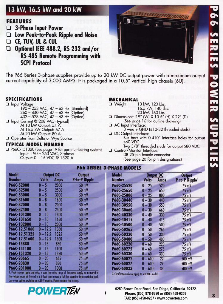
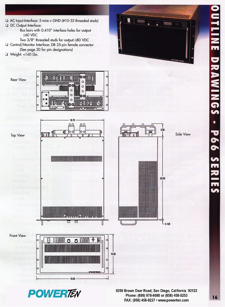

Programmable Precision DC Power SupplySG Series
5 kW - 150 kW // 40 V - 600 V
Product Validation
Production ATE
Burn-In
DC Bus Power For Further Information or Sales SupportContact Elgar Electronics Corporation
www.Elgar.com 858.450.0085Ethernet

Advanced Power Simulation
SGI model provides constant power mode allowing independent setting of the max
voltage, current and power
The SG series represents the next generation of high power programmable DC power supplies. Designed for exceptional load transient response, low noise and the highest power density in the industry. The industry leading power density is enhanced by a stylish front air intake allowing supplies to be stacked without any required clearance between units.
At the heart of the SG series is a 5 kW power module. Depending on the output voltage, one to six modules can be configured in a single chassis to deliver 5 kW to 30 kW of power. Combinations of these chassis can then be easily paralleled to achieve power levels up to 150 kW. Paralleled units operate like one single supply providing total system current. Available in two control versions, the SGA has basic analog controls, while the SGI provides intelligent control features
SGI: Advanced Intelligent Control(Sorensen General purpose Intelligent) The SGI combines onboard intelligent controls with the outstanding power electronics common to all SG family supplies. These controls enable sophisticated sequencing, constant power mode and save/recall of instrument settings. Looping of sequences makes the SGI idea for repetitive testing. An impressive vacuum fluorescent graphical display in eight languages, context sensitive “soft” keys and front panel keyboard simplify programming of the SGI.
SGA: Outstanding Value - Analog Control(Sorensen General purpose Analog) The SGA, with its industry leading price performance, is available for customers requiring simple front panel analog controls or external control. With the same high performance power electronics as the SGI, the SGA provides essential features like 10- turn potentiometers for setting voltage and current, 3 ½ digit LED readout plus front panel over-voltage protection (OVP) preview/adjustment and reset.
Overview
Feature SGA SGI
Modular Design • •
Fast Load Transient • •
Parallelable • •
Analog & Digital Summing Optional •
Direct Front Panel V/I Control • •
3½ Digit LED Readout •
Graphics Display •
Sequencing •
Save/Recall Setups •
System Power Readouts •
Constant Power Mode •
IEEE-488.2/RS-232C OptionalRS-232C StdIEEE-488.2
Optional LXI Compliant Ethernet Optional Optional
SGI / SGA Comparison Chart
Process Options: AA: No option AB: Certificate of Calibration (includes Test Data)Accessories: 890-453-03: Paralleling Cable (for up to 5 units, requires one cable
per unit placed in parallel) K550212-01: 3U Rack Slides (for 5kW, 10kW and 15kW models) K550213-01: 6U Rack Slides (for 20kW, 25kW and 30kW models)
-ASG
Control Designation
100
Voltage
1A AA
Remote Control Options
Process Options
100/
Current
C
Input Voltage Options
A = AnalogI = Intelligent
Control Options: A: Analog I: IntelligentInput Options: C: Input Voltage 187 / 242VAC, 3 Phase D: Input Voltage 342 / 440VAC, 3 Phase E: Input Voltage 396 / 528VAC, 3 PhaseRemote Control Options: 0A: No Option 1A: IEEE-488.2 + RS-232C 1C: Ethernet + RS-232C 1D: Isolated Analog Control 1E: Shaft Locks (SGA series only)Contact factory for other combinations
Options and Accessories
SGI / SGA Model Number Description
Compliant Ethernet

Applications Process ControlWhether you are controlling ion beams for the manufacture of semiconductors, or driving a current through electrolyte for precise control in a plating process, the SG series is an ideal choice with it’s small size, reliable modular design and standard analog programma-bility. Direct control of V and I along with monitoring of the actual voltage and current, provides a simple interface for your PLC or other type of analog controller.
Product DevelopmentTesting & Burn-in of DC-DC converters, laser diodes, automotive and semiconductor components and aircraft flight hardware are just a few of the items being tested using the SG product family. From simple front panel control to complex test sequences for compliance testing, the SG series will keep pace with your changing application needs.
ResearchA research environment presents some of the most demanding requirements on your test instrumentation. Equipment that is sufficient today, may not meet the needs of the next project. With the SG series this is no longer a problem. The modular design allows you to easily upgrade to higher power levels in the future, or parallel units to achieve up to 150 kW. With the sophisticated sequencing capability of the SGI model, you can build an infinite variety of test or diagnostic programs and have them execute directly from the power supply.
Automotive Component TestThe 16-bit resolution and Ethernet enabled hardware triggering allows for detailed sequencing associated with battery fluctuation simulation. The tight load regulation capability of the SG series makes it a superior source for validation and acceptance testing and burn-in of automotive components. The 40V models, in particular, provide a full range of testing to simulate battery conditions. Margin testing of components, such as electronic control units (ECU) and electromechanical components, is easily achieved.
Rackmount ATE SystemsThe high power density of the SG series makes it ideal for ATE System integration. The wide variety of voltage and current combinations in 3U and 6U heights allows multiple voltage outputs in a small amount of space. The wide variety of control methods possible, allows easy integration into legacy systems as well as high speed systems.
Battery ChargingThe SG series provides high accuracy voltage output to optimize battery charging. Battery charging requires high accuracy voltage and stable current output. With the remote interface options, the charging process can easily be automated for volume production.
Key Features
• High Power Density: Up to 15 kW in a 3U / 30 kW in a 6U chassis
• Wide Voltage Range: 0-40V up to 0-600V, in increments of 5 kW from 5 to 30 kW
• Fast Load Transient Response: Protection from undesired voltage excursions
• Low Ripple and Noise: Suitable for the most sensitive applications
• Parallelable up to 150 kW: Expandable as your requirement grows
• Modular Design: Upgradeable for the ultimate in investment protection.
• Sequencing: Program custom waveforms
• Easy-to-read Fluorescent Display: SGI supports English, French, German, Italian, Spanish, Chinese, Japanese, and Korean languages
• 16-bit Resolution: Optional IEEE-488.2 + RS-232C or Ethernet provides precise control
• Ethernet Control: LXI Class C compliant communication with integrated web server
• Direct Relay Control: Control output and sense isolation relays, along with polarity relays. (Ethernet Option Only)
• Hardware Trigger: Ethernet Option Only
• 5 Year Warranty
Burn-In Compliance Testing
Materials Research Process Control
Product Validation Automotive Electronics
Rackmount ATE Systems Battery Charging
See the SFA product brochure for very high current slew rate and low stored energy applications.
Applications

Common
Remote Sense Load-line loss compensation for models <= 100 V is 10% above full scale voltage total (5% per load-line), and models > 100 V is 4% above full scale voltage total (2% per load-line).
Parallel Operation Up to 5 units may be paralleled for additional cur-rent within the power supply single-unit specifica-tions, with exception of the DC output current set accuracy. Additional paralleled SG units will add 0.3% inaccuracy per unit. To parallel more than 5 units, contact factory.
Series Operation Up to 2 units (see Output Float Voltage)
Input
Nominal Voltage 3 phase, 3 wire + ground
208/220 VAC (operating range 187 - 242 VAC)380/400 VAC (operating range 342 - 440 VAC)440/480 VAC (operating range 396 - 528 VAC)* *Optional
Frequency 47 – 63Hz
Power Factor >0.9 typical at 208/220 VAC input>0.78 typical at 380/400 VAC input>0.69 typical at 440/480 VAC input
Protection ½ cycle ride-though on all three phases, 3 cycle ride through on single phase; missing phase shutdown
Output: Voltage and Current Ranges
3U 6U Ripple & Noise
Power5
kW10 kW
15 kW
20 kW
25 kW
30 kW
rms (20 Hz-
300 kHz)
p-p (20 Hz-
20 MHz)Voltage Current
40 125 250 375 500* 625* 750* 20 mV 75 mV
60 83 167 250 333 417 500 20 mV 75 mV
80 63 125 188 250 313 375 20 mV 100 mV
100 50 100 150 200 250 300 20 mV 100 mV
160 31 63 94 125 156 188 25 mV 150 mV
200 25 50 75 100 125 150 25 mV 175 mV
250 20 40 60 80 100 120 30 mV 200 mV
330 15 30 45 61 76 91 30 mV 200 mV
400 12 25 38 50 63 75 30 mV 300 mV
600 8 17 25 33 42 50 60 mV 350 mV
* By way of paralleling 5 kW, 10 kW & 15 kW supplies
Elgar Electronics Corp. • 9250 Brown Deer Road, San Diego, CA 92121. • 858.450.0085 • 858.458.0267 • [email protected] • www.Elgar.com
Product Specifications
Environmental
Operating Temperature 0 to 50º C
Storage Temperature -25º C to 65º C
Humidity Range Relative humidity up to 95% non-condensing, 0º C – 50º C
Altitude Operating full power available up to 5,000 ft. (~1,500 m), derate 10% of full power for every 1,000 feet higher; non-operating to 40,000 ft. (~12,000 m)
Cooling Front and side air inlet, rear exhaust.Units may be stacked without spacing.
Regulatory Certified to UL/CSA 61010 and IEC/EN 61010-1, CE Compliant, Semi-F47 Compliant
Physical
Dimensions Width: 19.00” (48.3 cm), Depth 25.0” (63.5 cm)Height: 5-15 kW units: 3U – 5.25” rack mount (13.34 cm) 20-30 kW units: 6U – 10.5” rack mount (26.67 cm)
Weight 3U < 80 lbs. (36 kg) 6U <160 lbs. (73 kg)
Shipping Weight See web site for more product & shipping weights.
Output
Ripple & Noise (Voltage Mode)
Ripple and noise, typical, measured at full load, nominal AC input. Noise measured with 6 ft. cable, 1µf at load.
Ripple (Current Mode) <+/- 0.04% of full scale rms current
DC Voltage Slew Rate 100 ms 5-95% of full scale typical(Contact factory for model specific slew rates)
DC Current Slew Rate 45A / ms typical
Line Regulation (±10% of nominal AC input, constant load)Voltage Mode: +/- 0.01% of full scaleCurrent Mode: +/- 0.05% of full scale
Load Regulation (no load to full load, nominal AC input)Voltage Mode: +/- 0.02% of full scaleCurrent Mode: +/- 0.1% of full scale
Load Transient Response
Recovers within 1ms to +/-0.75% of steadystate output for a 50% to 100% or 100% to 50% load change
Efficiency 87% typical at nominal line and max load
Stability ±0.05% of set point after 8 hrs. warm-up at fixed line, load and temperature
Temperature Coefficient 0.02%/ C of maximum output voltage rating for volt-age set point0.03%/ C of maximum output current rating for cur-rent set point
Output Float Voltage Negative terminal within +/- 150 V of chassis potential.
Programming & Read-back Specifications
Programming Read-Back / Monitoring
Accuracy Resolution Accuracy Resolution
Front panel Display
SGA: +/- (0.5%fs + 1 digit)SGI, Voltage: +/- 0.1% of full scaleSGI, Current: +/- 0.4% of full scale
SGA: 3.5 digitsSGI: 4.0 digits
SGA: +/- (0.5%fs + 1 digit)SGI, Voltage: +/- 0.1% of full scaleSGI, Current: +/- 0.4% of full scale
SGA: 3.5 digitsSGI: 4.0 digits Knob control & Display read-back
Remote Analog Interface
Voltage: +/-0.25% of full scale for 0-5 V range, +/-0.5% of full scale for 0-10 V rangeCurrent: 0.8% of full scale
NA +/-1.0% of full scale(0 - 10V) NA 25-pin D-sub connector (0~5 V or 0~10 V)
Remote Digital Interface
Voltage: +/- 0.1% of full scale, Current: +/- 0.4% of full scale
+/-0.002% of full scale
Voltage: +/- 0.15% of full scale, Current: +/- 0.4% of full scale
+/-0.002% of full scale
RS-232C (Standard on SGI), Optional IEEE-488.2 and Optional LXI Compliant 10/100 base-T Ethernet (see Options)
OVP +/- 1% of full scale +/-0.002% of full scale
Programming range: 5-110% Configured from front panel, remote analog or via optional digital inputs
User I/O Disconnect & Polarity-reversal relay control ( Only available with Ethernet Option ) Digital 10-pin Molex type connectorSee www.elgar.com/go/pinouts
Software IVI & CVI drivers available under SUPPORT at: www.Elgar.com
EEC032907

HD / EDData Sheet
HD Hysteresis DynamometersED Engine Dynamometers
www.magtrol.com
MAGTROL
HD Features• 16StandardModelswithMaximumTorquefrom
2.5oz·into500lb·in(18mN·mto56.5N·m)
• HysteresisBrakingSystem:providesprecisetorqueloadingindependentofshaftspeed
• MotorTesting:fromnoloadtolockedrotor
• StandardTorqueUnits:English,MetricandSI
• Accuracy:±0.25%to±0.5%(fullscale)
• AirFlowSensor:Forprotectionagainstoverheatingandoperatorerror
• BasePlates:availableinlongorshortversions
• CustomDynamometers:forspecialtorqueandspeedrequirements
• EasyCalibration
HD DescriptionHysteresisBrakeDynamometers(HDSeries)areversatileandidealfortestinginthelowtomediumpowerrange(maximum14kWintermittentduty).WithaHysteresisBrakingsystem,theDynamometersdonot requirespeed tocreate torque,andthereforecanprovideafullmotorrampfromfree-runtolockedrotor.Brakecoolingisprovidedbyconvection(noexternalsource),bycompressedairorbydedicatedblower,dependingonthemodel.AllMagtrolHysteresisDynamometershaveaccuracyratingsof±0.25%to±0.5%fullscale—dependingonsizeandsystemconfiguration.
Tobetterintegratedynamometersintosystems,Magtroloffers both long and short base plates. Theshorter baseplate facilitates easiermotormountingwhenusedwithT-slottablesand MagtrolAdjustable MotorFixtures,whereasthelongbaseplatesarebetter suited for tabletoptesting.
HD applicationsMagtrol motor test systems can be found in test labs, atinspectionstations,andonthemanufacturingfloorsofmostoftheworld’sleadingmanufacturers,usersandcertifiersofsmalltomediumsizedelectric,pneumaticandhydraulicmotors,as well as internal combustion engines. Magtrol suppliesmotortestsystemsforawidearrayofindustriesincluding:Appliance,Automotive,Aviation,Computer,HVAC,Lawnand Garden, Medical and Dental, Electric Motor, OfficeEquipmentandPowerTools.
eD DescriptionWith Magtrol’s Engine Dynamometers, high performance
motor testing is available to manufacturers andusers of small engines. Magtrol’sEngine Dynamometers have beendesignedtoaddressthesevere,highvibration conditions inherent ininternalcombustionenginetesting.
Magtrol’s Engine Dynamometersare highly accurate (± 0.25% of
full scale) and can be controlledeithermanuallyorviaaPCbasedController.Forasmallenginetest
stand, Magtrol offers a full line ofcontrollers,readoutsandsoftware.
AswithallMagtrolHysteresisDynamometers,engineloadingisprovidedbyMagtrol’sHysteresis
Brake,whichprovides:torqueindependentofspeed,including full load at 0 rpm; excellent repeatability;
frictionlesstorquewithnowearingparts(otherthanbearings);and long operating life with low maintenance. Magtrolprovides a NIST traceable certificate of calibration, andcalibrationbeamwitheachEngineDynamometer.
eD applicationsTheEngineDynamometersareideallysuitedforemissionstestingassetforthinCARBandEPACleanAirRegulations.TheDynamometerswilloffersuperiorperformanceon theproductionline,atincominginspectionorintheR&Dlab.
eD Features• MaximumTorque:from55lb·into250lb·in
(6.5N·mto28N·m)• HysteresisBrakingSystem• MotorTesting:fromnoloadtolockedrotor• StandardTorqueUnits:English,Metric&SIavailable• Accuracy:±0.25%(fullscale)• BlowerCooled:tomaximizeheatdissipation• AirFlowSensor:forprotectionagainstoverheating
andoperatorerror• SpeciallyReinforcedLoadCell:stainlesssteelpinat
contactpointpreventsprematurewearfromexcessvibration• LargerShaft:foradditionalstrength• GussetedPillowBlocks:foradditionalfrontandrear
support• EasyCalibration
Model HD-710Hysteresis Dynamometer
with long base plate

MAGTROL
HD / EDPrinciples and Selection
operating principles
AIR GAP
FIELD COIL
BALL BEARINGS
SHAFT
POLE STRUCTURE
HUB
ROTOR(Drag Cup)
Magtrol Hysteresis Dynamometers absorb power with auniqueHysteresisBrakingSystemwhichprovidesfrictionlesstorqueloadingindependentofshaftspeed. TheHysteresisBrakeprovidestorquebytheuseoftwobasiccomponents—areticulated pole structure and a specialty steel rotor/shaftassembly—fittedtogetherbutnotinphysicalcontact.Untilthepolestructureisenergized,thedragcupcanspinfreelyon its shaftbearings. Whenamagnetizing force from thefieldcoilisappliedtothepolestructure,theairgapbecomesafluxfieldandtherotorismagneticallyrestrained,providingabrakingactionbetweenthepolestructureandrotor.
complete pc controlMagtrol’sM-TEST5.0Software is a state-of-the-artmotortestingprogramforWindows®-baseddataacquisition. UsedwithaMagtrolProgrammableDynamometerController,MagtrolM-TEST5.0Softwareprovides the controlof anyMagtrolDynamometerandrunstestsequencesinamannerbestsuitedtotheoverallaccuracyandefficiencyoftheMagtrolMotorTestSystem.ThedatathatisgeneratedbyMagtrol’sMotorTestingSoftwarecanbestored,displayedandprintedintabularorgraphicformats,andcanbeeasilyimportedintoaspreadsheet.
Written inLabVIEW™,M-TEST5.0has theflexibility totestamajorityofmotortypesinavarietyofways.BecauseofLabVIEW’sversatility,obtainingdatafromothersources(e.g.thermocouples),controllingmotorpowerandprovidingaudio/visualindicatorsisrelativelyeasy.
Magtrol’sM-TEST5.0Softwareisidealforsimulatingloads,cyclingtheunitundertestandmotorramping.Becauseitiseasytogatherdataandduplicatetests,thesoftwareisidealforuseinengineeringlabs.Testscanbeprogrammedtorunontheirownandsavedforfutureuseallowingforvaluabletimesavingsinproductiontestingandincoming/outgoinginspection.
Dynamometer selectionMagtrol’sHysteresisDynamometerscoverawiderangeofTorque,SpeedandMechanicalPowerratings.ToselecttheappropriatesizeDynamometerforyourmotortestingneeds,youwillneed todetermine theMaximum Torque, Speed and PowerappliedtotheDynamometer.
Maximum Torque
The Magtrol HysteresisAbsorption Dynamometer willdevelopbrakingtorqueatanyspeedpoint,includinglowspeedandstall conditions (“0” rpm). It is important toconsideralltorquepointsthataretobetested,notonlyratedtorque,butalsolockedrotorandbreakdowntorque.Dynamometerselectionshouldinitiallybebasedonthemaximumtorquerequirement, subject to determining the maximum powerrequirements.
Maximum Speed
This rating is to be considered independent of torque andpower requirements, and is the maximum speed at whichtheDynamometercanbesafelyrununderfree-runorlightlyloadedconditions.Itisnottobeconsideredasthemaximumspeedatwhichfullbrakingtorquecanbeapplied.
Maximum Power Ratings
These ratings represent the maximum capability of theDynamometerBrakingSystemtoabsorbanddissipateheatgeneratedwhenapplyingabrakingloadtothemotorundertest. The power absorbed and the heat generated by theDynamometerisafunctionoftheTorque(T)appliedtothemotorundertest,andtheresultingSpeed(n)of themotor.Thisisexpressedinthesepower(P)formulas:
TheDynamometer’sabilitytodissipateheatisafunctionofhowlongaloadwillbeapplied.Forthisreason,themaximumpowerratingsgivenarebasedoncontinuousoperationunderload,aswellasamaximumof5minutesunderload.
To safely dissipate heat and avoid Dynamometer failure, the maximum power rating is the most important consideration in selecting a Dynamometer.
SI: P(watts)=T(N·m)×n(rpm)×(1.047×10⁻¹)
English:P(watts)=T(lb·in)×n(rpm)×(1.183×10⁻²)
Metric: P(watts)=T(kg·cm)×n(rpm)×(1.027×10⁻²)
All of Magtrol’s controllers, readouts and software calculate horsepower as defined by 1 hp = 550 lb·ft / s. Using this definition:
hp=P(watts)/745.7
HD / ED
Magtrol offers three types of dynamometer brakes to absorb load: Hysteresis, Eddy Current and Magnetic Powder. Each type of Dynamometer has advantages and limitations and choosing the correct one will depend largely on the type of testing to be performed. With over 50 models to choose from, Magtrol Sales professionals are readily available to assist in selecting the proper Dynamometer to meet your testing needs.

MAGTROL
HD / EDRatings
* Requires air cooling provided by user. Regulator and filter package is provided as standard equipment on these units.
ModelTorque
MeasureUnit Code
MaximumTorqueRange
Drag TorqueDe-Energizedat 1000 rpm
NominalInput Inertia
Max. Power Ratings MaximumSpeed
BrakeCoolingMethod
5 minute continuouslb·ft·s² kg·m² W W rpm
HD-1066N 2.50 oz·in 0.008 oz·in
7.04 × 10⁻⁷ 9.54 × 10⁻⁷ 35 7 30,000 Convection7N 180.0 g·cm 0.57 g·cm
8N 18.00 mN·m 0.056 mN·m
HD-1006N 11.00 oz·in 0.09 oz·in
3.40 × 10⁻⁶ 4.61 × 10⁻⁶ 75 20 25,000 Convection7N 800 g·cm 6.5 g·cm
8N 80.0 mN·m 0.64 mN·m
HD-4006N 40.0 oz·in 0.25 oz·in
1.55 × 10⁻⁵ 2.10 × 10⁻⁵ 200 55 25,000 Convection7N 2.80 kg·cm 0.02 kg·cm
8N 280 mN·m 2 mN·m
HD-5006N 120.0 oz·in 0.5 oz·in
8.05 × 10⁻⁵ 1.09 × 10⁻⁴ 400 80 25,000 Convection7N 8.50 kg·cm 0.05 kg·cm
8N 850 mN·m 5 mN·m
HD-5106N 120.0 oz·in 0.5 oz·in
8.05 × 10⁻⁵ 1.09 × 10⁻⁴ 750 375 25,000
Compressed Air *
(7 CFM @ 1.75 PSI)
7N 8.50 kg·cm 0.05 kg·cm
8N 850 mN·m 5 mN·m
HD-5056N 240 oz·in 1.0 oz·in
1.61 × 10⁻⁴ 2.18 × 10⁻⁴ 800 160 25,000 Convection7N 17.00 kg·cm 0.1 kg·cm
8N 1700 mN·m 10 mN·m
HD-5156N 240 oz·in 1.0 oz·in
1.61 × 10⁻⁴ 2.18 × 10⁻⁴ 1,500 900 25,000
Compressed Air *
(10 CFM @ 4 PSI)
7N 17.00 kg·cm 0.1 kg·cm
8N 1700 mN·m 10 mN·m
HD-7006N 440 oz·in 2.0 oz·in
5.51 × 10⁻⁴ 7.47 × 10⁻⁴ 700 150 25,000 Convection7N 31.0 kg·cm 0.14 kg·cm
8N 3.10 N·m 0.013 N·m
HD-7106N 440 oz·in 2.0 oz·in
5.51 × 10⁻⁴ 7.47 × 10⁻⁴ 1,500 935 25,000Blower
(included)7N 31.0 kg·cm 0.14 kg·cm
8N 3.10 N·m 0.013 N·m
HD-7056N 55.0 lb·in 0.2 lb·in
1.10 × 10⁻³ 1.49 × 10⁻³ 1,400 300 25,000 Convection7N 62.0 kg·cm 0.24 kg·cm
8N 6.20 N·m 0.023 N·m
HD-7156N 55.0 lb·in 0.2 lb·in
1.10 × 10⁻³ 1.49 × 10⁻³ 3,400 3,000 25,000Blower
(included)7N 62.0 kg·cm 0.24 kg·cm
8N 6.20 N·m 0.023 N·m
HD-8006N 125.0 lb·in 0.8 lb·in
4.43 × 10⁻³ 6.01 × 10⁻³ 2,800 1,800 12,000
CompressedAir *
(7.5 CFM @ 7 PSI)
7N 140.0 kg·cm 1.0 kg·cm
8N 14.00 N·m 0.10 N·m
HD-8106N 125.0 lb·in 0.8 lb·in
4.43 × 10⁻³ 6.01 × 10⁻³ 3,500 3,000 12,000Blower
(included)7N 140.0 kg·cm 1.0 kg·cm
8N 14.00 N·m 0.10 N·m
HD-8056N 250 lb·in 1.2 lb·in
8.81 × 10⁻³ 1.19 × 10⁻² 5,300 3,000 12,000
CompressedAir *
(15 CFM @ 7 PSI)
7N 280 kg·cm 1.5 kg·cm
8N 28.0 N·m 0.14 N·m
HD-8156N 250 lb·in 1.2 lb·in
8.81 × 10⁻³ 1.19 × 10⁻² 7,000 6,000 12,000Blower
(included)7N 280 kg·cm 1.5 kg·cm
8N 28.0 N·m 0.14 N·m
HD-8256N 500 lb·in 3.5 lb·in
1.85 × 10⁻² 2.51 × 10⁻² 14,000 12,000 8,000Blower
(included)7N 565 kg·cm 4.0 kg·cm
8N 56.5 N·m 0.22 N·m

MAGTROL
HD / ED
ModelBL-001 BL-002
in mm in mmØ A 6 152 6 152B 11 279 11 279C 6 152 6 152D 8 203 15 381E 4 102 4 102F 8 203 12 305G 1 25 1 25
Weight 8.5 lb 3.9 kg 18 lb 8.1 kg
Model Voltage VA Style RatingBL-001 120 V 600 UL/CSA 6.3 A 250 V SB
BL-001A 240 V 500 IEC 3.15 A 250 V T
BL-002 120 V 1000 UL/CSA 15 A 250 V SB
BL-002A 240 V 1000 IEC 6.3 A 250 V T
Blower Dimensions
120 VAC 60 Hz
Ø A
E
C
B
DFG
Air Filter
Dyno. BrakeAir Outlet
On/OffSwitch
Allow approximately 6in to 8 in(152mm to 203mm) between rearof dynamometer base plate andblower for connection hardware.Requiredhardwareissuppliedwiththedynamometer.
BL-002 Blower has two fi l terelements.
Blower power anD Fuses
electrical power anD Fuses
Model Voltage VA Style RatingHD-1XX-XN 120 V 25 UL/CSA 300 mA 250 V SB
HD-1XX-XNA 240 V 25 IEC 125 mA 250 V T
HD-4XX-XN 120 V 25 UL/CSA 300 mA 250 V SB
HD-4XX-XNA 240 V 25 IEC 125 mA 250 V T
HD-5XX-XN 120 V 25 UL/CSA 300 mA 250 V SB
HD-5XX-XNA 240 V 25 IEC 125 mA 250 V T
HD-800-XN 120 V 25 UL/CSA 300 mA 250 V SB
HD-800-XNA 240 V 25 IEC 125 mA 250 V T
HD-810-XN 120 V 55 UL/CSA 800 mA 250 V SB
HD-810-XNA 240 V 55 IEC 315 mA 250 V T
HD-805-XN 120 V 55 UL/CSA 800 mA 250 V SB
HD-805-XNA 240 V 55 IEC 315 mA 250 V T
HD/ED-815-XN 120 V 100 UL/CSA 1.25 A 250 V SB
HD/ED-815-XNA 240 V 100 IEC 630 mA 250 V T
HD-825-XN 120 V N/A N/A N/A
HD-825-XNA 240 V N/A N/A N/A
• ModelsHD-710,HD-715,HD-810andED-715includetheBL-001blower.
• ModelsHD-815andED-815includetheBL-002blower.
• ModelHD-825usestwoBL-002blowersforcoolingitstwobrakesets.
Ratings HD / ED
* The maximum speed will depend on what type of keyway (if any) is used on the shaft. Unless specified, the dynamometer shaft will be made without a keyway.
TorqueMeasure
Unit Code
MaximumTorqueRange
Drag TorqueDe-Energizedat 1000 rpm
Nominal Input Inertia
Max. Power Ratings MaximumSpeed *
BrakeCoolingMethod
Model 5 minute continuouslb·ft·s² kg·m² hp W hp W rpm
ED-7156N 55.0 lb·in 0.3 lb·in
Blower (included)
7N 62.0 kg·cm 0.36 kg·cm 1.27 × 10⁻³ 1.72 × 10⁻³ 5 3400 4 3000 25,000
8N 6.20 N·m 0.035 N·m
ED-8156N 250 lb·in 1.2 lb·in
Blower (included)
7N 280 kg·cm 1.4 kg·cm 9.61 × 10⁻³ 1.30 × 10⁻² 10 7000 8 6000 12,000
8N 28.0 N·m 0.14 N·m

5 MAGTROL
HD / EDDimensions
HD-100/400/500 series witH long Base plate
NOTE: Original dimensions are in English units. Dimensions converted to Metric units have been rounded and are for reference only.
E
A
H
J
ØN
MF
C
G
L
D
Q P
SHAFT END DETAIL (2:1)(FLAT)
ØB
Model units A Ø B C D E F G H J L* M* Ø N P Q Weight
HD-106in 0.50 0.1245/0.1247 3.5 17 9.38 10 0.5 6.3 8.5 15.5 8.5 0.37 0.015 0.375 12.0 lb
mm 12.7 3.162/3.167 89 432 238.3 254 13 159 216 394 216 9.4 0.38 9.53 5.4 kg
HD-100in 0.75 0.1870/0.1875 3.5 17 9.13 10 0.5 6.3 8.5 15.5 8.5 0.37 0.025 0.375 12.5 lb
mm 19.1 4.750/4.763 89 432 231.9 254 13 159 216 394 216 9.4 0.64 9.53 5.7 kg
HD-400in 0.67 0.2495/0.2497 3.5 17 9.13 10 0.5 6.3 8.5 15.5 8.5 0.37 0.03 0.438 15.0 lb
mm 17.0 6.337/6.342 89 432 231.9 254 13 159 216 394 216 9.4 0.76 11.13 6.8 kg
HD-500in 0.88 0.3745/0.3750 4.0 17 9.13 10 0.5 6.3 8.5 15.5 8.5 0.37 0.047 0.375 16.0 lb
mm 22.2 9.512/9.525 102 432 231.9 254 13 159 216 394 216 9.4 1.19 9.53 7.3 kg
HD-510in 0.88 0.3745/0.3750 4.0 17 9.13 10 0.5 6.3 8.5 15.5 8.5 0.37
N/A16.0 lb
mm 22.2 9.512/9.525 102 432 231.9 254 13 159 216 394 216 9.4 7.3 kg
HD-505in 0.88 0.3745/0.3750 4.0 20 9.64 10 0.5 6.3 8.5 18.5 8.5 0.37 0.05 0.375 18.0 lb
mm 22.2 9.512/9.525 102 508 244.9 254 13 159 216 470 216 9.4 1.27 9.53 8.1 kg
HD-515in 0.88 0.3745/0.3750 4.0 20 9.64 10 0.5 6.3 8.5 18.5 8.5 0.37
N/A18.0 lb
mm 22.2 9.512/9.525 102 508 244.9 254 13 159 216 470 216 9.4 8.1 kg
HD-100/400/500 series witH sHort Base plate
* These dimensions represent the distance between mounting holes. There are four (4) mounting holes on each base plate.
A
H
J
MF
C
G
L
D
ØN
E
Q P
SHAFT END DETAIL (2:1)(FLAT)
ØB
Model units A Ø B C D E F G H J L* M* Ø N P Q Weight
HD-106 in 0.50 0.1245/0.1247 3.5 7.0 0.33 11 0.5 6.3 8.5 6.0 9.84 0.35 0.015 0.375 7.5 lb
mm 12.7 3.162/3.167 89 177.8 8.4 279.4 13 159 216 152.4 250 9 0.38 9.53 3.4 kg
HD-100in 0.75 0.1870/0.1875 3.5 7.0 0.08 11 0.5 6.3 8.5 6.0 9.84 0.35 0.025 0.375 8.0 lb
mm 19.1 4.750/4.763 89 177.8 2.1 279.4 13 159 216 152.4 250 9 0.64 9.53 3.6 kg
HD-400in 0.67 0.2495/0.2497 3.5 7.0 0.08 11 0.5 6.3 8.5 6.0 9.84 0.35 0.03 0.438 11.0 lb
mm 17.0 6.337/6.342 89 177.8 2.1 279.4 13 159 216 152.4 250 9 0.76 11.13 5.0 kg
HD-500in 0.88 0.3745/0.3750 4.0 7.0 0.08 11 0.5 6.3 8.5 6.0 9.84 0.35 0.047 0.375 12.0 lb
mm 22.2 9.512/9.525 102 177.8 2.1 279.4 13 159 216 152.4 250 9 1.19 9.53 5.4 kg
HD-510in 0.88 0.3745/0.3750 4.0 8.0 0.13 11 0.5 6.3 8.5 7.0 9.84 0.35
N/A12.5 lb
mm 22.2 9.512/9.525 102 203.2 3.2 279.4 13 159 216 177.8 250 9 5.7 kg
HD-505in 0.88 0.3745/0.3750 4.0 9.5 0.10 11 0.5 6.3 8.5 8.5 9.84 0.35 0.05 0.375 13.0 lb
mm 22.2 9.512/9.525 102 241.3 2.6 279.4 13 159 216 215.9 250 9 1.27 9.53 5.9 kg
HD-515in 0.88 0.3745/0.3750 4.0 9.5 0.10 11 0.5 6.3 8.5 8.5 9.84 0.35
N/A13.0 lb
mm 22.2 9.512/9.525 102 241.3 2.6 279.4 13 159 216 215.9 250 9 5.9 kg

MAGTROL
HD / ED
* These dimensions represent the distance between mounting holes. There are four (4) mounting holes on each base plate.
E
A
H
J
MF
C
ØNG
LD
Q P
SHAFT END DETAIL (2:1)(FLAT)
ØB
Model units A Ø B C D E F G H J L* M* Ø N P Q Weight
HD-700in 1.25 0.4995/0.4997 5.875 24 12.75 11 0.625 9.5 10 22.5 9.5 0.375 0.06 0.63 39 lb
mm 31.8 12.687/12.692 149.2 609.6 323.9 279.4 15.9 241.3 254 571.5 241.3 9.5 1.6 15.9 17.63 kg
HD-710in 1.25 0.4995/0.4999 5.875 26 13.59 11 0.625 9.5 10 24.5 9.5 0.375
N/A45 lb
mm 31.8 12.687/12.697 149.2 660.4 345.2 279.4 15.9 241.3 254 622.3 241.3 9.5 20.30 kg
HD-705in 1.25 0.4995/0.4997 5.875 28 13.62 11 0.625 9.5 10 26.5 9.5 0.375 0.06 0.63 52 lb
mm 31.8 12.687/12.692 149.2 711.2 346.0 279.4 15.9 241.3 254 673.1 241.3 9.5 1.6 15.9 23.50 kg
HD-715in 1.25 0.4995/0.4999 5.875 30 14.29 11 0.625 9.5 10 28.5 9.5 0.375
N/A59 lb
mm 31.8 12.687/12.697 149.2 762.0 363.0 279.4 15.9 241.3 254 723.9 241.3 9.5 26.60 kg
HD-700 series witH long Base plate
HD-700 series witH sHort Base plate
E
A
H
J
M
F
C ØNG
LD
QP
SHAFT END DETAIL (2:1)(FLAT)
ØB
Model units A Ø B C D E F G H J L* M* Ø N P Q Weight
HD-700in 1.25 0.4995/0.4997 5.875 11.34 0.09 11 0.625 9.5 10 9.84 9.84 0.35 0.06 0.63 30 lb
mm 31.8 12.687/12.692 149.2 288.0 2.2 279.4 15.9 241.3 254 250.0 250 9 1.6 15.9 13.6 kg
HD-710in 1.25 0.4995/0.4999 5.875 12.50 0.09 11 0.625 9.5 10 11.00 9.84 0.35
N/A36 lb
mm 31.8 12.687/12.697 149.2 317.5 2.3 279.4 15.9 241.3 254 279.5 250 9 16.3 kg
HD-705in 1.25 0.4995/0.4997 5.875 14.45 0.07 11 0.625 9.5 10 12.95 9.84 0.35 0.06 0.63 43 lb
mm 31.8 12.687/12.692 149.2 367.0 1.8 279.4 15.9 241.3 254 329.0 250 9 1.6 15.9 19.5 kg
HD-715in 1.25 0.4995/0.4999 5.875 15.75 0.04 11 0.625 9.5 10 14.25 9.84 0.35
N/A50 lb
mm 31.8 12.687/12.697 149.2 400.0 1.1 279.4 15.9 241.3 254 362.0 250 9 22.7 kg
Dimensions
eD-series engine Dynamometers
Model units A Ø B C D E F G H L* M* Ø N P Q R Weight
ED-715in 1.72 0.7490/0.7495 6.87 16.00 18.13 11.00 1.00 10.50 14.50 9.50 0.37 0.64 1.00 0.187 75 lb
mm 43.7 19.025/19.037 174.5 406.4 460.5 279.4 25.4 266.7 368.3 241.3 9.4 16.35 25.4 4.83 34 kg
ED-815in 3.02 1.4995/1.5000 11.00 23.00 23.27 17.00 2.00 16.63 20.80 15.00 5/8-11
THD1.287 2.00 0.375 285 lb
mm 76.7 38.087/38.100 279.4 584.2 591.1 431.8 50.8 422.4 528.3 381.0 32.7 50.8 9.53 129.3 kg
C
B
A
H
MF
ØNG
LD
E
QP
ØB
R
SHAFT END DETAIL (2:1)(SQUARE KEY)

7 MAGTROL
HD / ED
Model units A Ø B C D E F G H J L* M* Ø N P Q R S T Weight
HD-825 in 2.83 1.4995/1.5000 11 38.5 38.93 17 2 16.6 14 36.5 15 0.54 1.287 2 0.376 2 1 400.0 lbmm 72 38.087/38.100 279 978 989 432 51 422 356 927 381 13.7 32.69 50.8 9.53 50.8 25.4 181.4 kg
EA
H
J
ØN
MF
C
G
LD
K
ØB
E
A
H
J
QP
ØB
RØN
MF
C
GT
L
D
SHAFT END DETAIL (2:1)(SQUARE KEY)S
HD-800 series witH long Base plate
HD-800 series witH sHort Base plate
Model units A Ø B C D E F G H J K L* M* Ø N Weight
HD-800 in 2.13 0.9995/1.0000 9 17.25 2.56 17 2 14.6 14 0.1 13.78 15.75 0.35 168.0 lbmm 54 25.387/25.400 229 438 65 432 51 371 356 2.5 350 400 9 76.2 kg
HD-810 in 2.09 0.9995/1.0000 9 18.00 2.59 17 2 14.6 14 0.1 14.06 15.75 0.35 164.0 lbmm 53 25.387/25.400 229 457 66 432 51 371 356 2.5 357 400 9 74.4 kg
HD-805 in 2.13 0.9995/1.0000 9 20.50 2.57 17 2 14.6 14 0.1 15.75 15.75 0.35 228.0 lbmm 54 25.387/25.400 229 520 65 432 51 371 356 2.5 400 400 9 103.4 kg
HD-815 in 2.12 0.9995/1.0000 9 23.00 2.59 17 2 14.6 14 0.2 19.09 15.75 0.35 236.0 lbmm 54 25.387/25.400 229 584 66 432 51 371 356 5.1 485 400 9 107.0 kg
EA
H
J
ØN
MF
C
G
LD
K
ØB
An HD-825 Dynamometer with long base plate is available if ordered with the accompanying dynamometer table (TAB 0825L). Contact Magtrol for details.
Dimensions
* These dimensions represent the distance between mounting holes. There are four (4) mounting holes on each base plate.
NOTE: For detailed dimension drawings of dynamometers with the T-slot base plate option, visit Magtrol’s Web site.
Model units A Ø B C D E F G H J K L* M* Ø N Weight
HD-800 in 2.13 0.9995/1.0000 9 38.5 23.81 17 2 14.6 14 21.4 36.5 15 0.54 237.0 lbmm 54 25.387/25.400 229 978 605 432 51 371 356 544 927 381 13.7 107.2 kg
HD-810 in 2.09 0.9995/1.0000 9 38.5 23.19 17 2 14.6 14 20.7 36.5 15 0.54 233.0 lbmm 53 25.387/25.400 229 978 589 432 51 371 356 526 927 381 13.7 105.3 kg
HD-805 in 2.13 0.9995/1.0000 9 38.5 20.57 17 2 14.6 14 18.2 36.5 15 0.54 287.0 lbmm 54 25.387/25.400 229 978 522 432 51 371 356 462 927 381 13.7 129.7 kg
HD-815 in 2.25 0.9995/1.0000 9 38.5 18.19 17 2 14.6 14 15.7 36.5 15 0.54 288.0 lbmm 57 25.387/25.400 229 978 462 432 51 371 356 399 927 381 13.7 130.1 kg

MAGTROL
HD / ED
Maximum Torque for Dynamometer
Maximum Kinetic Power Rating Curve for Continuous Duty: Area under curve equals the maximum speed and torque combinations for a continuous duty motor test.
Maximum Rated Speed for Dynamometer
Maximum Kinetic Power Rating Curve for Less Than Five Minutes: Area under curve equals the maximum speed and torque combinations for a motor test of less than five minutes.
TORQUE
SP
EE
D (
rpm
)
0
6000
12000
18000
24000
30000
36000
00
0.53.6
17.2
1.510.8
214.4
2.518
(oz·in)(mN·m)
Power Absorption Curves
HD-106
TORQUE
SP
EE
D (
rpm
)
0
6000
12000
18000
24000
30000
36000
00
0.53.6
17.2
1.510.8
214.4
2.518
(oz·in)(mN·m)
The power absorption curves represent the maximum power (heat) that the dynamometer can dissipate over time.
HD-100 HD-400
TORQUE
SP
EE
D (
rpm
)
0
5000
10000
15000
20000
25000
30000
00
2.216
4.432
6.648
8.864
1180
(oz·in)(mN·m)
TORQUE
SP
EE
D (
rpm
)
0
5000
10000
15000
20000
25000
30000
00
856
16112
24168
32224
40280
(oz·in)(mN·m)
HD-500 HD-510
TORQUE
SP
EE
D (
rpm
)
00
24170
48340
72510
96680
120850
(oz·in)(mN·m)
0
5000
10000
15000
20000
25000
30000
TORQUE
SP
EE
D (
rpm
)
0
5000
10000
15000
20000
25000
30000
00
24170
48340
72510
96680
120850
(oz·in)(mN·m)
HD-505 HD-515
TORQUE
SP
EE
D (
rpm
)
00
48340
96680
1441020
1921360
2401700
(oz·in)(mN·m)
0
5000
10000
15000
20000
25000
30000
TORQUE
SP
EE
D (
rpm
)
00
48340
96680
1441020
1921360
2401700
(oz·in)(mN·m)
0
5000
10000
15000
20000
25000
30000
0
5000
10000
15000
20000
25000
30000

MAGTROL
HD / ED
HD-700 HD-710
TORQUE
SP
EE
D (
rpm
)
(oz·in)(N·m)
0
500010000
15000
2000025000
30000
00
880.62
1761.24
2641.86
3522.48
4403.10
SP
EE
D (
rpm
)
0
500010000
15000
2000025000
30000
TORQUE
(oz·in)(N·m)
00
880.62
1761.24
2641.86
3522.48
4403.10
HD-705 HD-715 and ED-715
TORQUE
SP
EE
D (
rpm
)
(lb·in)(N·m)
0
5000
10000
15000
20000
25000
30000
00
111.24
222.48
333.72
444.96
556.20
TORQUES
PE
ED
(rp
m)
(lb·in)(N·m)
0
5000
10000
15000
20000
25000
30000
00
111.24
222.48
333.72
444.96
556.20
HD-800 HD-810
TORQUE
SP
EE
D (
rpm
)
0
3000
6000
9000
12000
15000
00
252.8
505.6
758.4
10011.2
12514.0
(lb·in)(N·m)
TORQUE
SP
EE
D (
rpm
)
0
3000
6000
9000
12000
15000
00
252.8
505.6
758.4
10011.2
12514.0
(lb·in)(N·m)
HD-805 HD-815 and ED-815
TORQUE
SP
EE
D (
rpm
)
0
3000
6000
9000
12000
15000
00
505.6
10011.3
15016.8
20022.4
25028
(lb·in)(N·m)
TORQUE
SP
EE
D (
rpm
)
0
3000
6000
9000
12000
15000
00
505.6
10011.3
15016.8
20022.4
25028
(lb·in)(N·m)
HD-825
TORQUE
SP
EE
D (
rpm
)
0
2000
4000
6000
8000
10000
00
10011.3
20022.6
30033.9
40045.2
50056.5
(lb·in)(N·m)
The power absorption curves represent the maximum power (heat) that the dynamometer can dissipate over time.
Power Absorption Curves

0 MAGTROL
HD / EDSystem Configurations
1 o---------- o---- o----------
HD / EDDYNAMOMETER
2 Pin Dynamometer Brake Cable PN88M070 (included with dynamometer)
14 Pin/14 Pin Instrument Cable PN88M007 (included with dynamometer)
DSP6001 CONTROLLER
PC GPIB or RS-232
M-TEST
Dynamometer with 6200 Controller
Dynamometer with DSP6001 Controller and M-TEST Software
1 o---------- o---- o----------
2 Pin Dynamometer Brake Cable PN88M070 (included with dynamometer)
6200 CONTROLLER
14 Pin/14 Pin Instrument Cable PN88M007 (included with dynamometer)
HD / EDDYNAMOMETER
1 o---------- o---- o----------
HD / EDDYNAMOMETER
2 Pin Dynamometer Brake Cable PN88M070 (included with dynamometer)
14 Pin/14 Pin Instrument Cable PN88M007 (included with dynamometer)
6510e POWER ANALYZER AC/DC
Input Power
DSP6001 CONTROLLER
PC
GPIB Card
M-TEST
open loop systemsMagtroloffersbothopenloopmanualtestsystemsandPC-basedclosedlooptestsystems.AtypicalopenloopsystemwillconsistofaDynamometerandaMagtrol6200Open-LoopController.AMagtrolSingleorThree-PhasePowerAnalyzer,whichallowsforthecapturingofvolts,amps,wattsandpowerfactor,canbeincludedasanoption.Anopenloopsystemisoftenusedforquickpass/failtestingontheproductionlineoratincominginspection.Magtrol’s6200Controllerprovidespass/failtestingasastandardfeature.
closeD loop systemsInaclosedloopmotor testsystem,data iscollectedonaPCusingMagtrol’sM-TESTSoftware,DSP6001ProgrammableDynamometerController,andrequisiteinterfacecardsandcables.Magtrol’sModel6200andDSP6001Controllerscomputeanddisplaymechanicalpower(inhorsepowerorwatts)inadditiontotorqueandspeed.ASingleorThreePhasePowerAnalyzer,a requiredcomponent ina test systemmeasuringmotorefficiency,canbe integrated into this systemaswellasMagtrol’sTemperatureTestingHardware.
Dynamometer with 6510e Power Analyzer, DSP6001 Controller and M-TEST Software

MAGTROL
HD / EDSystem Configurations
custom motor test systemHDSeriesHysteresisDynamometerscanbeincorporatedintoaCustomizedMotorTestSystem.ThesePCbased,turn-keysystemsarecustomdesignedandbuilttomeetspecificuserrequirements.
heavy-duty equipment rack
M-TEST Motor Testing Software
AMF Adjustable Motor Fixture
Dynamometer Table
HD Hysteresis Dynamometer
DSP6001 Dynamometer Controller
6530 Power Analyzer
keyboard drawer
side panel connectors allow for easy hook-up
space for rackmountedthird-party power supply and computer
LCD monitor
emergency stop button

HD / ED
Duetothecontinualdevelopmentofourproducts,wereservetherighttomodifyspecificationswithoutforewarning.
magtrol inc70 Gardenville ParkwayBuffalo, New York 14224 USAPhone: +1 716 668 5555Fax: +1 716 668 8705E-mail: [email protected]
magtrol saCentre technologique Montena1728 Rossens / Fribourg, SwitzerlandPhone: +41 (0)26 407 3000Fax: +41 (0)26 407 3001E-mail: [email protected]
Subsidiaries in:• Germany• France• Great Britain• ChinaWorldwide Network
of Sales Agents
www.magtrol.com
Ordering Information
HD
-US
06/
07
orDering inFormation
system options anD accessoriesCATEGORY DESCRIPTION MODEL / PART #
CONTROLLERSHigh-Speed Programmable Dynamometer Controller DSP6001Open Loop Dynamometer Controller 6200
POWER ANALYZERS
High-Speed Single-Phase Power Analyzer 6510eHigh-Speed Three-Phase Power Analyzer 6530
SOFTWAREM-TEST 5.0 Motor Testing Software SW-M-TEST5.0-WETemperature Testing Hardware HW-TTEST
POWERSUPPLIES
Closed Loop Speed Control/Power Supply 6100Power Amplifier – requiredforallHD-825dynamometers 5241
MISC.ELECTRONICS
Manually Controlled Switch Box 5500Direction Indicator 5600
DYNAMOMETERTABLES
Table (with grooved table top) for HD-100/400/500/700 series short base plate dynamometers and ED-715* TAB 1457S
Table (drilled and tapped) for HD-100/400/500/700 series long base plate dynamometers TAB 1457LTable for HD-800 series long base plate dynamometers and ED-815* (base of dynamometer also serves as the table top) TAB 0800L
Table for HD-825 long base plate dynamometers TAB 0825LADJUSTABLE
MOTORFIXTURES
Motor Fixture for HD-100/400/500 series short base plate dynamometers AMF-1Motor Fixture for HD-700 series short base plate dynamometers AMF-2Motor Fixture for HD-800 series dynamometers with T-slot base plate option AMF-3
CALIBRATION Calibration Beam Assemblies and Calibration Weights CB and WT Series
Dynamometer options
Encoder Options For Low Speed Testing
Forlowspeedmotors,suchasgearmotorswithmaximumspeedsoflessthan200rpm,Magtroloffersadditionalencoderoptionsthatallowforincreasedresolutionofthespeedsignal.
T-Slot Base Plate
ToaccommodateMagtrolAMF-3AdjustableMotorFixtures,agroovedbaseplatewith threeM12T-slots,onecenteredand two 250 mm apart, is available on all HD-800 seriesdynamometers.
custom Dynamometers
High Speed Testing
Forcertainmodels,MagtrolcanprovideDynamometerswhichcanoperateathigherthanratedspeeds.
Mechanical Modifications
Magtrolcanprovidecustomizedbaseplates,riserblocksandshaftmodifications.
* Mounting of ED Engine Dynamometers to dynamometer tables requires certain modifications. Contact Magtrol for details.
MODEL NUMBER: D – – N – 0
DYNAMOMETER TYPE• Hysteresis HD 100 – 825 • Engine ED 715 – 815
TORQUE UNITS• English (U.S.) 6N• Metric 7N• SI 8N
POWER OPERATION• 120 VAC (standard) (blank) • 240 VAC (option) A
BASE PLATE• long 0• short 1• long with T-slots (available on HD-800 series only) 2• ED dynamometers 0
SPEED ENCODER• 60 bit (standard) 00• 60 and 600 bit 30• 60 and 6000 bit 40


Catalogo RESUMEN II/2007 9/10/07 20:35 Pgina 1
Composicin
C M Y CM MY CY CMY K
RESUMEN II

Catalogo RESUMEN II/2007 9/10/07 20:35 Pgina 6
Composicin
C M Y CM MY CY CMY K
MULTIMETROS ANALOGICOS / MILIOHMETROS
06
CALIBRADORES / DECADAS
Características
SensibilidadTensión CATensión CCCorriente CACorriente CCResistenciaCapac./ ContinuidadComp. bateríasProtec fusibleProtec. gomaOtras
Rangos: 20m200m/2/20/200
2k/20kCon 4 pinzas paramayor precisiónde medidaAlarmas
Resoluc.: 0.01mFusible protecciónEquipo de bancoRed: 220V/50Hz
CE
Rangos:200m/2/20
200/2kNo
Con 4 pinzas paramayor precisión
NoResolución: 0.1mCarcasa compacta
NoRed: 220V/50Hz
CE
HIBOK 7032
10k /V200mV/600V200mV/600V
2/20/200mA/10A2/20/200mA/10A200/20M
Si/SiSi, 1.5V y 9V
SiSi
También digitalCAT. III 600V
HIBOK 64
20k /V10V/50/500V100mV/500V
No50uA /25mA/10A
2k/20MNo/SiNoSiSiNo
CAT. III 600V
RVX 7001
2k /V10V/50V/500V2.5V/10V/500V
No500μA/10/250mA
5k/500kNo/No
Si, 1.5V y 9VNoSi
BlisterCAT. II 300V
HIBOK 201 Milióhmetro
HIBOK 2002 Milióhmetro
Características
TipoRangos
Rango mínimoRango máximoPrecisiónCarcasaTamañoOtras
Década de inductanciasde Laboratorio16 rangos
-----10μH
111.1mH±(5%)
Material ABS106x117x33 mm
CE
Década de Capacidadesde Laboratorio20 rangos
-----100pF
11.111μF±(5%) + 50pFMaterial ABS
147x117x33 mmCE
Década de Resistenciasde Laboratorio28 rangos
-----1
11.111.110±(1%) + 0,3Material ABS
147x117x33 mmCE
Tensión/ CorrienteGenera y mide:0-20mA/0-24mAy 0 ± 200mV CC.10MA-0,1mV
-----±(0,25) + 1 d.Material ABS185x78x38mm
CE
LBOX 405CBOX 406RBOX 408CC 421 Calibrador

Features
• Type "K" Thermocouple Input • Switchable Resolution 0.1o/ 1o • With oC & oF switching • Max / MIN Function • Data Hold Function • Room Temperature Compensated • T1 & T2 dual points display • T1 - T2 differential measurement • Flip-up stand • Backlight LCD display
Specification Measuring range -50 °C - +1350°C, -58°F - 1999°F Sensor K Type Thermocouple Input Single Channel (TES-1311) / Dual Channel (TES-1312) Resolution -50 °C - +199.9°C: 0.1°C, -50°F – 199.9°F: 0.1°F, others 1°C / 1°F
Accuracy
TES-1311: -50 °C - +1350°C: ±(0.1%rdg + 1°C) -50°F - 1999°F: ±(0.1%rdg + 1°F) TES-1312: -50 °C - +1000°C: ±(0.3%rdg + 1°C) -50°F - 1832°F: ±(0.3%rdg + 2°F) 1000°C - +1300°C: ±(0.5%rdg + 1°C) 1832°F - 1999°F: ±(0.5%rdg + 2°F)
Temperature Coefficient
Less that 0.1 times the applicable accuracy specification per oC (oF)
Input Protection 60V DC or 24Vrms AC max. Sampling Rate 2.5 times/sec Power Source 6 pcs AAA battery Operating 0°C - 40°C < 70% R.H. Storage -10°C - 60°C < 80% R.H. Dimensions / weight 135 x 72 x 31 mm / 235g
Ther
mom
eter
s
TES-
1311
/ 13
12
GLOBAL FOCUS Kft. 1119 Budapest, Etele út 59-61. 1 em. 123. Tel: (1) 481-1233, 481-1231, 481-1161, 481-1162 Mobil: 30 555-6454, 30 555-6453, 30 525-1272 Fax: (1) 203-4355 E-mail: [email protected]

CONIMED S.A. Ingenieria de Mediciones
Modelos TI01 /02 y TV01 /02
Transformadores de medida de precisión para uso de laboratorio
Aplicaciones
• Mediciones de tensión o corriente donde
se requieran errores reducidos
• Mesas de contraste de medidores
• Ensayos de vacío y cortocircuito de
transformadores de distribución y
potencia
• Determinación de curvas de
magnetización
Características
• Se fabrican con rangos de tensión o
corriente según necesidad del usuario
• Exactitudes standard 0,1 y 0,2 %
• Opción exactitud hasta 0,005 %
• Presentación tipo laboratorio
Transformadores de medida de intensidad de corriente modelos TI01 y TI02 Son transformadores que se contruyen con rangos de corriente de acuerdo a necesidades del usuario. En general tienen un primario con varios alcances entre 5 y 250 A y en los de barra pasante se llega hasta 1500 A. La corriente secundaria nominal puede ser 1 ó 5 A y la prestación usual es entre 5 y 15 VA.
Transformadores de medida de tensión modelos TV01 y TV02 Al igual que los de corriente, son transformadores para uso en el laboratorio de ensayos. El modelo TV01 se encuadra en la clase de exactitud 0,1 y el TV02 en la clase 0,2. Las tensión secundarias usuales son 110 V - 110 / √3 - 100 V La prestación usual es entre 5 y 20 VA Tanto los transformadores de medida de corriente como los de tensión pueden proveerse con certificado de calibración del INTI.
CONIMED S.A. Ingeniería de Mediciones
Cantilo 1620 - (1676) Santos Lugares - Pcia. de Buenos Aires
Tel: ++54 11 4757 0383 - Fax: ++54 11 4859 6200

E-Mail: sales @ conimed.com - Website: www . conimed . com
El fabricante se reserva el derecho de modificar las especificaciones sin previo aviso -- 4/99

WB/PB 115Data Sheet
WB/PB 115 Series Eddy-Currentand Powder Dynamometers
www.magtrol.com
MAGTROL
Features• 4ModelswithMaximumTorquefrom50N·mto 200N·m(36lb·ftto147lb·ft)
• BrakingPower:5kWto30kW
• StableBrakingTorque,withoutShock
• LowMomentofInertia
• LowResidualTorque
• OperationinEitherRotationalDirection
• BrakingTorqueMeasurementIncluded
• HighRotationalSpeed
• RatedTorqueAvailableFromZeroSpeed(PowderDynamometers)
• IntegratedOpticalSpeedSensor
DescriptionEddy-currentBrakeDynamometers(WBseries)areidealforapplicationsrequiringhighspeedsandalsowhenoperatinginthemiddletohighpowerrange.Eddy-CurrentBrakesprovideincreasingtorqueasthespeedincreases,reachingpeaktorqueatratedspeed.Thedynamometershavelowinertiaasaresultofsmallrotordiameter.Brakecoolingisprovidedbyawatercirculationsystem,whichpassesinsidethestatortodissipateheatgeneratedbythebrakingpower.ThewatercoolingintheWBprovideshighcontinuouspowerratings(max.30kW).
Powder Brake Dynamometers (PBseries)areidealforapplicationsoperatingin the low to middle speed range orwhenoperating in themiddle tohightorque range.PowderBrakesprovidefulltorqueatzerospeedandarewater-cooled,allowingforpowerratingsupto10kW.BothWBandPBDynamometershaveaccuracyratingsof±0.3%to±0.5%fullscale,dependingonsizeandsystemconfiguration.
applicationsMountedontestbenches,WB/PB115SeriesDynamometersallowperformanceandreliabilitytestingondrivingelementssuchaselectricmotors,combustionengines,hand-helddrills,servomotors,fans,gearedmotors,reductiongears,pneumaticequipment,hydraulictransmissionsystems,startermotors,gasturbinesandturbocompressors.
Motor testing systeMsMagtrol’sM-TEST5.0Softwareisastate-of-the-artmotortestingprogramforWindows®-baseddataacquisition.Usedwith a Magtrol DSP6001 Programmable DynamometerController,MagtrolM-TEST5.0SoftwareprovidesthecontrolofanyMagtrolEddy-CurrentorPowderBrakeDynamometerandrunstestsequencesinamannerbestsuitedtotheoverall
accuracyandefficiencyoftheMagtrolMotorTestSystem. Thedata that isgeneratedbyMagtrol’sMotorTestingSoftwarecanbestored,displayedandprinted in tabularorgraphic formats,and can be easily imported into aspreadsheet.
WritteninLabVIEW™,M-TEST5.0has the flexibility to test a majorityof motor types in a variety of ways.Because of LabVIEW’s versatility,
obtaining data from other sources (e.g. thermocouples),controllingmotorpowerandprovidingaudio/visualindicatorsisrelativelyeasy.
Magtrol’sM-TEST5.0Softwareisidealforsimulatingloads,cyclingtheunitundertestandmotorramping.Becauseitiseasytogatherdataandduplicatetests,thesoftwareisidealforuseinengineeringlabs.Testscanbeprogrammedtorunontheirownandsavedforfutureuseallowingforvaluabletime savings in production testing and incoming/outgoinginspection.
Model 2 WB 115Eddy-Current Dynamometer
Magtrol offers three types of dynamometer brakes to absorb load: Hysteresis, Eddy- current and Magnetic Powder. Each type of Dynamometer has advantages and limitations and choosing the correct one will depend largely on the type of testing to be performed. With over 50 models to choose from, Magtrol Sales professionals are readily available to assist in selecting the proper Dynamometer to meet your testing needs.

MAGTROL
System Configurations
single DynaMoMeter conFigurationsTheDynamometerscanbecomplementedbyvariouselectronicmodulessuchastheDES311PowerSupply,TSC401Torque/SpeedConditionerandDSP6001HighSpeedProgrammableDynamometerController.
WB/PB 115
tanDeM conFigurationMagtroloffersEddy-CurrentandPowderDynamometersmountedintandem.Intandem,theuniquefeaturesofeachtypeofdynamometerbrakeareutilized,allowingtheunitundertesttobeappliedwithnominalbrakingtorquefromzerospeedtomaximumrotation.TheTandemDynamometersareavailableonanumberofWB/PBcombinations.
MagtrolalsooffersIn-LineTorqueTransducers,whichemployauniquenon-contactdifferentialtransformertorquemeasuringtechnologyprovidingextremelyaccuratetorqueandspeedmeasurementwithsuperiorelectricalnoiseimmunity.Foradynamic,high-precisionsystem,thetorquetransducercanbemountedinlinebetweentheunitundertestandthedynamometer.
DYNAMOMETER / TSC1
AUX / TSC2
SUPPLY 2
SUPPLY 1 RS-232CGPIB/IEEE–488
BRAKE
ACCESSORYTORQUE–SPEED
OUTPUTCTRL OUT
BRAKE FUSE
CAUTION: DOUBLE POLE FUSING75VA 50/60Hz
EARTHGROUND
FUSE (5×20mm):120V UL/CSA 800mA 250V SB240V IEC 315mA 250V T
(5×20mm): UL/CSA 1.25A 250V SBIEC 1A 250V T MAGTROL, INC. BUFFALO, NY
TM TorqueTransducer
GPIBor
RS-232
PC
M-TEST
DSP6001 Dynamometer Controller
Excitation
Torque
TSC 401Torque-SpeedConditioner
DES Power Supply
Speed
Eddy-Current (WB)OR Powder Brake (PB)Dynamometer
DYNAMOMETER / TSC1
AUX / TSC2
SUPPLY 2
SUPPLY 1 RS-232CGPIB/IEEE–488
BRAKE
ACCESSORYTORQUE–SPEED
OUTPUTCTRL OUT
BRAKE FUSE
CAUTION: DOUBLE POLE FUSING75VA 50/60Hz
EARTHGROUND
FUSE (5×20mm):120V UL/CSA 800mA 250V SB240V IEC 315mA 250V T
(5×20mm): UL/CSA 1.25A 250V SBIEC 1A 250V T MAGTROL, INC. BUFFALO, NY GPIB
orRS-232
PC
M-TEST
Excitation
Torque
TSC 401Torque-SpeedConditioner
DES Power Supply
Speed
Eddy-Current (WB)OR Powder Brake (PB)Dynamometer
DSP6001 Dynamometer Controller
DYNAMOMETER / TSC1
AUX / TSC2
SUPPLY 2
SUPPLY 1 RS-232CGPIB/IEEE–488
BRAKE
ACCESSORYTORQUE–SPEED
OUTPUTCTRL OUT
BRAKE FUSE
CAUTION: DOUBLE POLE FUSING75VA 50/60Hz
EARTHGROUND
FUSE (5×20mm):120V UL/CSA 800mA 250V SB240V IEC 315mA 250V T
(5×20mm): UL/CSA 1.25A 250V SBIEC 1A 250V T MAGTROL, INC. BUFFALO, NY GPIB
orRS-232
PC
M-TEST
Clutch(EK)
DSP6001Dynamometer
Controller
Transformer
Powder BrakeDynamometer (PB)
Excitation
Torque
DES Power Supply
TSC 401Torque/SpeedConditioner
Eddy-Current BrakeDynamometer (WB)
Excitation
Torque
TSC 401Torque-SpeedConditioner
DES Power Supply
Speed

MAGTROL
Specifications
WB DynaMoMeter ratings
TheWBEddy-CurrentDynamometersdeveloptheirfullpowerathighrotationspeeds.The115Seriesisparticularlyintended
* Voltage at 20 °C is 30 volts.
formotorswhichrotateathighspeeds,upto22,000rpm.Thebrakingtorquedependsontherotationspeed.
eDDy-current DynaMoMeter operating principles
WB torque–speeD–poWer curvesThediagrambelowshowsthecharacteristiccurvesforthe115SeriesEddy-CurrentDynamometers.
100 1000 10,000 100,000
0.1
1
100
0.1
1
1002865 rpm
10 10
18,000 rpm
Spe
ed li
mit
for
WB
2 WB 115 (T
ORQUE)
1 WB 115 (T
ORQUE)
Rotation Speed (rpm)
Torq
ue
(N·m
)
Po
wer
(kW
)
2 W
B 11
5 (P
OW
ER)
1 W
B 11
5 (P
OW
ER)
Optical Speed Sensor
Each115SeriesWBDynamometerhasanopticalspeedsensorwitha60-bitpulsewheeldeliveredasstandard.
Cooling Water Consumption
ForallWBmodels: ≈30l/kWhat∆t=30°C (Metric) ≈8gal/kWhat∆t=86°F (US)
ModelRated Torque Drag Torque
De-energized Nominal Input Inertia Rated Power
Rated Speed
Max. SpeedExcitation Current*standard
versionhigh-speed version (HS)
N·m lb·ft N·m lb·in kg·m² lb·ft·s² kW rpm rpm rpm A
1 WB 115 50 36.8 0.5 4.43 1.27 × 10⁻² 9.36 × 10⁻³ 15 2865 18,000 22,000 2.5
2 WB 115 100 73.7 1.0 8.85 2.57 × 10⁻² 1.89 × 10⁻² 30 2865 18,000 22,000 5
WB 115

MAGTROL
pB DynaMoMeter ratings
Specifications
* Voltage at 20 °C is 30 volts.
The PB Powder Dynamometers contain, as their namesuggests,amagneticpowder.Theelectricalcurrentpassingthroughthecoilgeneratesamagneticfield,whichchangesthepropertyofthepowder,thusproducingasmoothbraking
100
1000
10
1
1
10
0.1
0.011 10 100 1000
3000 rpm480 rpm
10,000
Spe
ed L
imit
for
PB
Rotation Speed (rpm)
Torq
ue
(N·m
)
Po
wer
(kW
)
2 PB 1
15 (P
OWER)
1 PB 1
15 (P
OWER)
2 PB 115 (TORQUE)
1 PB 115 (TORQUE)
torquethroughfrictionbetweenrotorandstator.ThePowderDynamometers (PB) produce their rated torque at zerospeed.Theelementtobetestedcanbeloadedatstandstilltodeterminethestartingtorque.
poWDer DynaMoMeter operating principles
pB torque–speeD–poWer curvesThediagrambelowshowsthecharacteristiccurvesforthe115SeriesPowderDynamometers.
Optical Speed Sensor
Each115SeriesPBDynamometerhasanopticalspeedsensorwitha60-bitpulsewheeldeliveredasstandard. Forbetterspeedresolutioninlowspeedapplications,Magtroloffersa600-bitor6000-bitspeedpickup(encoder)asanoption.
Cooling Water Consumption
ForallPBmodels: ≈30l/kWhat∆t=30°C (Metric) ≈8gal/kWhat∆t=86°F (US)
ModelRated Torque Drag Torque
De-energized Nominal Input Inertia Rated Power
Rated Speed
Max. Speed
Excitation Current*
N·m lb·ft N·m lb·in kg·m² lb·ft·s² kW rpm rpm A
1 PB 115 100 73.7 2 17.7 1.24 × 10⁻² 9.14 × 10⁻³ 5 480 3000 2.5
2 PB 115 200 147.5 4 35.4 2.50 × 10⁻² 1.84 × 10⁻² 10 480 3000 5
PB 115

5 MAGTROL
T (removable calibration arm)
500 mm (for mkp)X
510 mm (for N·m)*
F
E
M
ØU
N
P
S
R
YQ
C
B
A
H
J
GDD
Z
Center holeDIN 332-D M8
Cooling water connection Ø 15 mm (≈0.59 in)Reference surface
Tapping for calibration arm
INLETTORQUEEXCITATION SPEED
ØK
L
ØD
SS
W
V
* Use outergroove toachievecalibration in N·mwhen usingweight in kg
Specifications
single DynaMoMeter DiMensions
NOTE:Original dimensions are in Metric units. Dimensions converted to English units have been rounded up to 2 decimal places.
Model units A B C D E F G H J K L M N P
1 WB 115 / 1 PB 115mm 390 280 166 Ø 32h6 -40 54 360 430 470 Ø 11 20 40 200 280
in 15.35 11.02 6.54 Ø 1.25981.2593 -1.57 2.13 14.17 16.93 18.50 Ø 0.43 0.79 1.57 7.87 11.02
2 WB 115 / 2 PB 115mm 500 390 276 Ø 32h6 15 54 360 430 470 Ø 11 20 40 200 280
in 19.69 15.35 10.87 Ø 1.25981.2593 0.59 2.13 14.17 16.93 18.50 Ø 0.43 0.79 1.57 7.87 11.02
Model units Q R S T U V W X Y Z DD SS Weight
1 WB 115 / 1 PB 115mm 75 200 ±0.1 325 1038 Ø 250 10h9 38 125 30 197 55 80 80 kg
in 2.95 7.8787.870 12.80 40.87 Ø 9.84 0.3937
0.3932 1.50 4.92 1.18 7.76 2.17 3.15 176.37 lb
2 WB 115 / 2 PB 115mm 75 200 ±0.1 325 1038 Ø 250 10h9 38 125 30 235 55 80 130 kg
in 2.95 7.8787.870 12.80 40.87 Ø 9.84 0.3937
0.3932 1.50 4.92 1.18 9.25 2.17 3.15 286.60 lb
WB/PB 115

MAGTROL
tanDeM DynaMoMeter ratings
Tandem Specifications
* Voltage at 20 °C is 30 volts.
BecausethecharacteristicsoftheWBandPBdynamometersarecomplementary,Magtrol isable tooffer themmountedin a tandem setup. Each dynamometer (WB and PB) canautonomouslyoperateaccording to itsowncharacteristics.
An electromagnetic clutch is needed for this applicationwhichautomaticallyswitchesoffatthemaximumspeedofthePBPowderDynamometerandautomaticallyswitchesonatzerospeed.
tanDeM operating principles
tanDeM torque–speeD–poWer curvesThediagrambelowshowsthecharacteristiccurvesforthe115SeriesTandemDynamometers.
Sp
ee
d L
imit
for
Tan
de
m 1
15
Rotation Speed (rpm)
Torq
ue
(N·m
)
Po
wer
(kW
)
2 WB 115 + EK + 2 PB 115 (TORQUE)
2 WB 115 + EK + 1 PB 115 (TORQUE)
2 WB 1
15 +
EK +
2 P
B 115
(POW
ER)
2 WB 1
15 +
EK +
1 P
B 115
(POW
ER)
100
1000
10
10
100
1000
10
1
10 1000100 10,000
15,000 rpm480 rpm 2865 rpm
100,000
Optical Speed Sensor
Each115SeriesTandemDynamometerhasanopticalspeedsensorwitha60-bitpulsewheeldeliveredasstandard.
Cooling Water Consumption
ForallTandemmodels: ≈30l/kWhat∆t=30°C (Metric) ≈8gal/kWhat∆t=86°F (US)
ModelRated Torque Drag Torque
De-energized Nominal Input Inertia Rated Power
Rated Speed
Max. Speed
Excitation Current*
N·m lb·ft N·m lb·ft kg·m² lb·ft·s² kW rpm rpm A
2 WB 115 + EK + 1 PB 115 100 73.7 3 26.5 4.18 × 10⁻² 3.08 × 10⁻² 30 2865 15,000 5
2 WB 115 + EK + 2 PB 115 200 147.5 5 44.2 5.44 × 10⁻² 4.01 × 10⁻² 30 2865 15,000 5
WB/PB 115

MAGTROL
tanDeM DiMensions
Tandem Specifications
NOTE:Original dimensions are in Metric units. Dimensions converted to English units have been rounded up to 2 decimal places.
J
HL
CC GG EE ØKGDD
Y
P
NM
Q
R
S
T (removable calibration arm)
WV
BBAA
PB 115
A
WB 115
FØD
E
I n l e t I n l e t
Cooling water connection Ø 15 mm (≈0.59 in)
500 mm (for mkp)X
510 mm (for N·m)*
DRIVE SIDEElectromagnetic tooth clutch (EK)
* Use outergroove toachievecalibration in N·m whenusing weightin kg
Model units A D E F G H J K L M N P Q R
2 WB 115 + EK + 1 PB 115mm 500 Ø 32h6 4 54 388 685 915 Ø 13 115 35 250 310 135 260 ±0.2
in 19.69 Ø 1.25981.2593 0.16 2.13 15.28 26.97 36.02 Ø 0.51 4.53 1.38 9.84 12.20 5.31 10.244
10.228
2 WB 115 + EK + 2 PB 115mm 500 Ø 32h6 4 54 388 795 1025 Ø 13 115 35 250 310 135 260 ±0.2
in 19.69 Ø 1.25981.2593 0.16 2.13 15.28 31.30 40.35 Ø 0.51 4.53 1.38 9.84 12.20 5.31 10.244
10.228
Model units S T V W X Y AA BB CC DD EE GG Weight
2 WB 115 + EK + 1 PB 115mm 385 1038 10 38 125 50 390 15 127 60 160 ±0.1 280 214 kg
in 15.15 40.87 0.39 1.50 4.92 1.97 15.35 0.59 5.00 2.36 6.3036.295 11.02 471.79 lb
2 WB 115 + EK + 2 PB 115mm 385 1038 10 38 125 50 500 15 127 60 160 ±0.1 390 264 kg
in 15.15 40.87 0.39 1.50 4.92 1.97 19.69 0.59 5.00 2.36 6.3036.295 15.35 582.02 lb
WB/PB 115

WB/PB 115
Due to the continual development of our products, we reserve the right to modify specifications without forewarning.
Magtrol inc70 Gardenville ParkwayBuffalo, New York 14224 USAPhone: +1 716 668 5555Fax: +1 716 668 8705E-mail: [email protected]
Magtrol saCentre technologique Montena1728 Rossens / Fribourg, SwitzerlandPhone: +41 (0)26 407 3000Fax: +41 (0)26 407 3001E-mail: [email protected]
Subsidiaries in:• Germany• France• Great Britain• ChinaWorldwide Network
of Sales Agents
www.magtrol.com
Ordering Information
WB
PB
115-
US
11/
06
DynaMoMeter MoDels
systeM options anD accessories
DynaMoMeter optionsIndustrial Version (IS)
SingleWBandPBDynamometersarealsoavailable inanindustrialversionwhichincludesbearingsupports,butdoesnotprovideabaseplate,ortorqueandspeedmeasurement.
Vertical Mounting (V)
Vertical Mounting is available on the Eddy-Current (WB)Dynamometer only. The vertical version has an adaptedbearingfittinganditsmaximumspeedislimited.
Speed Pickup (DG)
Allmodels, including tandems,areequippedwitha60-bitoptical speed sensor. On PB Dynamometers, a 600-bit or6000-bitspeedpickup(encoder)isavailableasanoptionforlowspeedapplications.
Mechanical Rotor Blocking Device (MB)
Amechanicalrotorblockingdevice,whichallowslockedrotortesting,isavailablefortheWBDynamometer.
Example: 1 pB 115 - Dg - 600
Dynamometer Model
orDering inForMationIf one of the listed options is desired, please follow thedynamometermodel(seetableabove)withadashandthentheappropriatesuffix(asnotedinparenthesis).Forexample,aModel1PB115PowderDynamometerwithanoptional600-bitspeedpickupisa1PB115-DG-600.
Option
DESCRIPTION MODEL / PART #
EL
EC
TR
ON
ICS High Speed Programmable Dynamometer Controller DSP6001
Torque-Speed Conditioner (includes necessary cables) TSC 401/121
Power Supply (includes necessary cables) DES 311/121
High Speed Single-Phase Power Analyzer 6510e
High Speed Three-Phase Power Analyzer 6530
SO
FT-
WA
RE M-TEST 5.0 Motor Testing Software SW-M-TEST5.0-WE
Temperature Testing Hardware HW-TTEST
MIS
C
Dynamometer Table (with grooved table top) 005034
Transformer (24 VDC) for electromagnetic clutch of tandem dynamometers 234-311-920-011
Couplings, Thermostatic Sluice, Pressure Sensitive Switch On Request
Water Cooling System for Brake On Request
Calibration Weights On Request
Eddy-Current Powder Tandem1 WB 115 1 PB 115 2 WB 115 + EK + 1 PB 1152 WB 115 2 PB 115 2 WB 115 + EK + 2 PB 115

WB/PB 15Data Sheet
WB/PB 15 Series Eddy-Currentand Powder Dynamometers
www.magtrol.com
MAGTROL
Features• 7ModelswithMaximumTorquefrom140N·mto 1200N·m(103lb·ftto885lb·ft)
• BrakingPower:12kWto140kW
• StableBrakingTorque,withoutShock
• LowMomentofInertia
• LowResidualTorque
• OperationinEitherRotationalDirection
• BrakingTorqueMeasurementIncluded
• HighRotationalSpeed
• RatedTorqueAvailableFromZeroSpeed(PowderDynamometers)
• IntegratedOpticalSpeedSensor
DescriptionEddy-CurrentBrakeDynamometers(WBseries)areidealforapplicationsrequiringhighspeedsandalsowhenoperatinginthemiddletohighpowerrange.Eddy-CurrentBrakesprovideincreasingtorqueasthespeedincreases,reachingpeaktorqueatratedspeed.Thedynamometershavelowinertiaasaresultofsmallrotordiameter.Brakecoolingisprovidedbyawatercirculationsystem,whichpassesinsidethestatortodissipateheatgeneratedbythebrakingpower.ThewatercoolingintheWBprovideshighcontinuouspowerratings(max.140kW).
Powder Brake Dynamometers (PBseries)areidealforapplicationsoperatingin the low to middle speed range orwhenoperating in themiddle tohightorque range.PowderBrakesprovidefulltorqueatzerospeedandarewater-cooled,allowingforpowerratingsupto48kW.BothWBandPBDynamometershaveaccuracyratingsof±0.3%to±0.5%fullscale,dependingonsizeandsystemconfiguration.
applicationsMountedontestbenches,WB/PB15SeriesDynamometersallowperformanceandreliabilitytestingondrivingelementssuch as electric motors, combustion engines, servomotors,geared motors, reduction gears, pneumatic equipment,hydraulictransmissionsystems,startermotors,electromagneticclutches,gasturbinesandturbocompressors.
Motor testing systeMsMagtrol’sM-TEST5.0Softwareisastate-of-the-artmotortestingprogramforWindows®-baseddataacquisition.Usedwith a Magtrol DSP6001 Programmable DynamometerController,MagtrolM-TEST5.0SoftwareprovidesthecontrolofanyMagtrolEddy-CurrentorPowderBrakeDynamometerandrunstestsequencesinamannerbestsuitedtotheoverall
accuracyandefficiencyoftheMagtrolMotorTestSystem. Thedata that isgeneratedbyMagtrol’sMotorTestingSoftwarecanbestored,displayedandprinted in tabularorgraphic formats,and can be easily imported into aspreadsheet.
WritteninLabVIEW™,M-TEST5.0has the flexibility to test a majorityof motor types in a variety of ways.Because of LabVIEW’s versatility,
obtaining data from other sources (e.g. thermocouples),controllingmotorpowerandprovidingaudio/visualindicatorsisrelativelyeasy.
Magtrol’sM-TEST5.0Softwareisidealforsimulatingloads,cyclingtheunitundertestandmotorramping.Becauseitiseasytogatherdataandduplicatetests,thesoftwareisidealforuseinengineeringlabs.Testscanbeprogrammedtorunontheirownandsavedforfutureuseallowingforvaluabletime savings in production testing and incoming/outgoinginspection.
Model 4 WB 15Eddy-Current Dynamometer
Magtrol offers three types of dynamometer brakes to absorb load: Hysteresis, Eddy- Current and Magnetic Powder. Each type of Dynamometer has advantages and limitations and choosing the correct one will depend largely on the type of testing to be performed. With over 50 models to choose from, Magtrol Sales professionals are readily available to assist in selecting the proper Dynamometer to meet your testing needs.

MAGTROL
System Configurations
single DynaMoMeter conFigurationsTheDynamometerscanbecomplementedbyvariouselectronicmodulessuchastheDES311PowerSupply,TSC401Torque/SpeedConditionerandDSP6001HighSpeedProgrammableDynamometerController.
WB/PB 15
tanDeM conFigurationMagtroloffersEddy-CurrentandPowderDynamometersmountedintandem.Intandem,theuniquefeaturesofeachtypeofdynamometerbrakeareutilized,allowingtheunitundertesttobeappliedwithnominalbrakingtorquefromzerospeedtomaximumrotation.TheTandemDynamometersareavailableonanumberofWB/PBcombinations.
MagtrolalsooffersIn-LineTorqueTransducers,whichemployauniquenon-contactdifferentialtransformertorquemeasuringtechnologyprovidingextremelyaccuratetorqueandspeedmeasurementwithsuperiorelectricalnoiseimmunity.Foradynamic,high-precisionsystem,thetorquetransducercanbemountedinlinebetweentheunitundertestandthedynamometer.
DYNAMOMETER / TSC1
AUX / TSC2
SUPPLY 2
SUPPLY 1 RS-232CGPIB/IEEE–488
BRAKE
ACCESSORYTORQUE–SPEED
OUTPUTCTRL OUT
BRAKE FUSE
CAUTION: DOUBLE POLE FUSING75VA 50/60Hz
EARTHGROUND
FUSE (5×20mm):120V UL/CSA 800mA 250V SB240V IEC 315mA 250V T
(5×20mm): UL/CSA 1.25A 250V SBIEC 1A 250V T MAGTROL, INC. BUFFALO, NY
TM TorqueTransducer
GPIBor
RS-232
PC
M-TEST
DSP6001 Dynamometer Controller
Excitation
Torque
TSC 401Torque-SpeedConditioner
DES Power Supply
Speed
Eddy-Current (WB)OR Powder Brake (PB)Dynamometer
DYNAMOMETER / TSC1
AUX / TSC2
SUPPLY 2
SUPPLY 1 RS-232CGPIB/IEEE–488
BRAKE
ACCESSORYTORQUE–SPEED
OUTPUTCTRL OUT
BRAKE FUSE
CAUTION: DOUBLE POLE FUSING75VA 50/60Hz
EARTHGROUND
FUSE (5×20mm):120V UL/CSA 800mA 250V SB240V IEC 315mA 250V T
(5×20mm): UL/CSA 1.25A 250V SBIEC 1A 250V T MAGTROL, INC. BUFFALO, NY GPIB
orRS-232
PC
M-TEST
Excitation
Torque
TSC 401Torque-SpeedConditioner
DES Power Supply
Speed
Eddy-Current (WB)OR Powder Brake (PB)Dynamometer
DSP6001 Dynamometer Controller
DYNAMOMETER / TSC1
AUX / TSC2
SUPPLY 2
SUPPLY 1 RS-232CGPIB/IEEE–488
BRAKE
ACCESSORYTORQUE–SPEED
OUTPUTCTRL OUT
BRAKE FUSE
CAUTION: DOUBLE POLE FUSING75VA 50/60Hz
EARTHGROUND
FUSE (5×20mm):120V UL/CSA 800mA 250V SB240V IEC 315mA 250V T
(5×20mm): UL/CSA 1.25A 250V SBIEC 1A 250V T MAGTROL, INC. BUFFALO, NY GPIB
orRS-232
PC
M-TEST
Clutch(EK)
DSP6001Dynamometer
Controller
Transformer
Powder BrakeDynamometer (PB)
Excitation
Torque
DES Power Supply
TSC 401Torque/SpeedConditioner
Eddy-Current BrakeDynamometer (WB)
Excitation
Torque
TSC 401Torque-SpeedConditioner
DES Power Supply
Speed

MAGTROL
Specifications
WB DynaMoMeter ratings
TheWBEddy-CurrentDynamometersdeveloptheirfullpowerathighrotationspeeds.The15Seriesisparticularlyintended
* Voltage at 20 °C is 45 volts.
formotorswhichrotateathighspeeds,upto7500rpm.Thebrakingtorquedependsontherotationspeed.
eDDy-current DynaMoMeter operating principles
WB torque–speeD–poWer curvesThediagrambelowshowsthecharacteristiccurvesforthe15SeriesEddy-CurrentDynamometers.
100
1000
10
1
100
1000
10
110 100 1000
7500 rpm2390 rpm
10,000
Spe
ed L
imit
for W
B
Rotation Speed (rpm)
Torq
ue
(N·m
)
Po
wer
(kW
)
4 WB 15 (TORQUE)
3 WB 15 (TORQUE)
2 WB 15 (TORQUE)
1 WB 15 (TORQUE)
4 W
B 15
(POW
ER)
3 W
B 1
5 (P
OW
ER
)
2 W
B 15
(POW
ER)
1 W
B 15
(POW
ER)
Optical Speed Sensor
Each15SeriesWBDynamometerhasanopticalspeedsensorwitha60-bitpulsewheeldeliveredasstandard.
Cooling Water Consumption
ForallWBmodels: ≈30l/kWhat∆t=30°C (Metric) ≈8gal/kWhat∆t=86°F (US)
ModelRated Torque Drag Torque
De-energized Nominal Input Inertia Rated Power
Rated Speed
Max. Speed
Excitation Current*
N·m lb·ft N·m lb·in kg·m² lb·ft·s² kW rpm rpm A
1 WB 15 140 103 1.4 12.3 5.00 × 10⁻² 3.68 × 10⁻² 35 2390 7500 4
2 WB 15 280 206 2.8 24.7 1.00 × 10⁻¹ 7.37 × 10⁻² 70 2390 7500 7.5
3 WB 15 420 309 4.2 37.1 1.50 × 10⁻¹ 1.10 × 10⁻¹ 105 2390 7500 10
4 WB 15 560 413 5.6 49.5 2.00 × 10⁻¹ 1.47 × 10⁻¹ 140 2390 7500 12
WB 15

MAGTROL
pB DynaMoMeter ratings
Specifications
* Voltage at 20 °C is 45 volts.
The PB Powder Dynamometers contain, as their namesuggests,amagneticpowder.Theelectricalcurrentpassingthroughthecoilgeneratesamagneticfield,whichchangesthepropertyofthepowder,thusproducingasmoothbraking
1000
10,000
100
10
10
100
1
0.110 10 100 1000
2000 rpm382 rpm
10,000
Spe
ed L
imit
for
PB
Rotation Speed (rpm)
Torq
ue
(N·m
)
Po
wer
(kW
)4 PB 15 (TORQUE)
2 PB 15 (TORQUE)
1 PB 15 (TORQUE)
4 PB 1
5 (P
OWER)
2 PB 1
5 (P
OWER)
1 PB 1
5 (P
OWER)
torquethroughfrictionbetweenrotorandstator.ThePowderDynamometers (PB) produce their rated torque at zerospeed.Theelementtobetestedcanbeloadedatstandstilltodeterminethestartingtorque.
poWDer DynaMoMeter operating principles
pB torque–speeD–poWer curvesThediagrambelowshowsthecharacteristiccurvesforthe15SeriesPowderDynamometers.
Optical Speed Sensor
Each15SeriesPBDynamometerhasanopticalspeedsensorwitha60-bitpulsewheeldeliveredasstandard.Forbetterspeedresolutioninlowspeedapplications,Magtroloffersa600-bitor6000-bitspeedpickup(encoder)asanoption.
Cooling Water Consumption
ForallPBmodels: ≈30l/kWhat∆t=30°C (Metric) ≈8gal/kWhat∆t=86°F (US)
ModelRated Torque Drag Torque
De-energized Nominal Input Inertia Rated Power
Rated Speed
Max. Speed
Excitation Current*
N·m lb·ft N·m lb·in kg·m² lb·ft·s² kW rpm rpm A
1 PB 15 300 221 6 53 5.40 × 10⁻² 3.98 × 10⁻² 12 382 2000 4
2 PB 15 600 442 12 106 1.08 × 10⁻¹ 7.96 × 10⁻² 24 382 2000 7.5
4 PB 15 1200 885 24 212 2.16 × 10⁻¹ 1.59 × 10⁻¹ 48 382 2000 12
PB 15

5 MAGTROL
J
HL
X 510 mm (for N·m)*
500 mm (for kpm)
ØKTT
GDD
Y
P SS
NM
Q
R
S
T (removable calibration arm)
W
V
Z
C
A
B
FØD
E
I n l e t
Cooling water connection Ø 22 mm (≈0.87 in)
Tapping forcalibration armCenter hole
DIN 332-D M16
ØU
* Use outer grooveto achievecalibration in N·mwhen usingweight in kg
Specifications
single DynaMoMeter DiMensions
NOTE:Original dimensions are in Metric units. Dimensions converted to English units have been rounded up to 2 decimal places.
Model units A B C D E F G H J K L M N P
1 WB 15 / 1 PB 15mm 544 370 150 Ø 42g6 -53 68 490 590 650 Ø 15 30 75 250 400
in 21.42 14.57 5.91 Ø 1.65311.6526 -2.09 2.68 19.29 23.23 25.59 Ø 0.59 1.18 2.95 9.84 15.75
2 WB 15 / 2 PB 15mm 694 520 300 Ø 42g6 22 68 490 590 650 Ø 15 30 75 250 400
in 27.32 20.47 11.81 Ø 1.65311.6526 0.87 2.68 19.29 23.23 25.59 Ø 0.59 1.18 2.95 9.84 15.75
3 WB 15mm 844 670 450 Ø 42g6 -78 68 840 940 1000 Ø 15 30 75 250 400
in 33.23 26.38 17.72 Ø 1.65311.6526 -3.07 2.68 33.07 37.01 39.37 Ø 0.59 1.18 2.95 9.84 15.75
4 WB 15 / 4 PB 15mm 994 820 600 Ø 42g6 -3 68 840 940 1000 Ø 15 30 75 250 400
in 39.13 32.28 23.62 Ø 1.65311.6526 -0.12 2.68 33.07 37.01 39.37 Ø 0.59 1.18 2.95 9.84 15.75
Model units Q R S T U V W X Y Z DD SS TT Weight
1 WB 15 / 1 PB 15mm 110 300 ±0.2 498 1030 Ø 395 12 48 220 35 265 80 75 37 185 kg
in 4.33 11.81911.803 19.61 40.55 Ø 15.55 0.47 1.89 8.66 1.38 10.43 3.15 2.95 1.46 407.86 lb
2 WB 15 / 2 PB 15mm 110 300 ±0.2 498 1030 Ø 395 12 48 220 35 190 80 75 37 290 kg
in 4.33 11.81911.803 19.61 40.55 Ø 15.55 0.47 1.89 8.66 1.38 7.48 3.15 2.95 1.46 639.34 lb
3 WB 15mm 110 300 ±0.2 498 1030 Ø 395 12 48 220 35 290 80 75 37 385 kg
in 4.33 11.81911.803 19.61 40.55 Ø 15.55 0.47 1.89 8.66 1.38 11.42 3.15 2.95 1.46 848.78 lb
4 WB 15 / 4 PB 15mm 110 300 ±0.2 498 1030 Ø 395 12 48 220 35 215 80 75 37 520 kg
in 4.33 11.81911.803 19.61 40.55 Ø 15.55 0.47 1.89 8.66 1.38 8.46 3.15 2.95 1.46 1146.40 lb
WB/PB 15

MAGTROL
tanDeM DynaMoMeter ratings
Tandem Specifications
* Voltage at 20 °C is 45 volts.
BecausethecharacteristicsoftheWBandPBdynamometersarecomplementary,Magtrol isable tooffer themmountedin a tandem setup. Each dynamometer (WB and PB) canautonomouslyoperateaccording to itsowncharacteristics.
Spe
ed L
imit
for T
ande
m 1
5
Rotation Speed (rpm)
Torq
ue
(N·m
)
Po
wer
(kW
)
2 WB 15 + EK + 4 PB 15 (TORQUE)
2 WB 15 + EK + 2 PB 15 (TORQUE)
2 WB 15 + EK + 1 PB 15 (TORQUE)
2 WB 15 + EK + 4 PB 15 (P
OWER)
2 WB 15 + EK + 2 PB 15 (P
OWER)
2 WB 15 + EK + 1 PB 15 (P
OWER)
1000
10000
100
10
100
1000
10
110 100 1000
7500 rpm2390 rpm382 rpm
10,000
An electromagnetic clutch is needed for this applicationwhichautomaticallyswitchesoffatthemaximumspeedofthePBPowderDynamometerandautomaticallyswitchesonatzerospeed.
tanDeM operating principles
tanDeM torque–speeD–poWer curvesThediagramsbelowshowthecharacteristiccurvesforthe15SeriesTandemDynamometers.
Spe
ed L
imit
for T
ande
m 1
5
Rotation Speed (rpm)
Torq
ue
(N·m
)
Po
wer
(kW
)
4 WB 15 + EK + 4 PB 15 (TORQUE)
4 WB 15 + EK + 2 PB 15 (TORQUE)
4 WB 15 + EK + 1 PB 15 (TORQUE)
4 WB 15 + EK + 4 PB 15 (P
OWER)
4 WB 15 + EK + 2 PB 15 (P
OWER)
4 WB 15 + E
K + 1 PB 15 (P
OWER)
1000
10,000
100
10
100
1000
10
110 100 1000
7500 rpm2390 rpm382 rpm
10,000
Optical Speed Sensor
Each15SeriesTandemDynamometerhasanopticalspeedsensorwitha60-bitpulsewheeldeliveredasstandard.
Cooling Water Consumption
ForallTandemmodels: ≈30l/kWhat∆t=30°C (Metric) ≈8gal/kWhat∆t=86°F (US)
ModelRated Torque Drag Torque
De-energized Nominal Input Inertia Rated Power
Rated Speed
Max. Speed
Excitation Current*
N·m lb·ft N·m lb·in kg·m² lb·ft·s² kW rpm rpm A
2 WB 15 + EK + 1 PB 15 300 221 8.8 77 1.77 × 10⁻¹ 1.31 × 10⁻¹ 70 2390 7500 7.5
2 WB 15 + EK + 2 PB 15 600 442 14.8 130 2.31 × 10⁻¹ 1.70 × 10⁻¹ 70 2390 7500 7.5
2 WB 15 + EK + 4 PB 15 1200 885 26.8 237 3.39 × 10⁻¹ 2.50 × 10⁻¹ 70 2390 7500 12
4 WB 15 + EK + 1 PB 15 300 221 11.6 102 2.77 × 10⁻¹ 2.04 × 10⁻¹ 140 2390 7500 12
4 WB 15 + EK + 2 PB 15 600 442 17.6 155 3.31 × 10⁻¹ 2.44 × 10⁻¹ 140 2390 7500 12
4 WB 15 + EK + 4 PB 15 1200 885 29.6 261 4.39 × 10⁻¹ 3.23 × 10⁻¹ 140 2390 7500 12
WB/PB 15

MAGTROL
tanDeM DiMensions
Tandem Specifications
NOTE:Original dimensions are in Metric units. Dimensions converted to English units have been rounded up to 2 decimal places.
DRIVE SIDE Electromagnetic tooth clutch (EK)
JJJ HHL H
CC GGEE ØK
GDD
Y
P
NM
Q
R
S
T (removable calibration arm)
W
V
BB
AA
PB 15
A
WB 15
FØD
I n l e t I n l e t
Cooling water connection Ø 22 mm (≈0.87 in)
X 510 mm (for N·m)*
500 mm (for mkp)
* Use outer grooveto achievecalibration in N·mwhen usingweight in kg
Model units T V W X Y AA BB CC DD EE GG HH JJ Weight
2 WB 15 + EK + 1 PB 15mm 1030 12 48 225 125 544 14 260 117 270 ±0.1 405 371 371 485 kg
in 40.55 0.47 1.89 8.86 4.92 21.42 0.55 10.24 4.61 10.63410.626 15.94 14.61 14.61 1069.24 lb
2 WB 15 + EK + 2 PB 15mm 1030 12 48 225 125 694 14 260 117 270 ±0.1 555 471 421 590 kg
in 40.55 0.47 1.89 8.86 4.92 27.32 0.55 10.24 4.61 10.63410.626 21.85 18.54 16.57 1300.73 lb
2 WB 15 + EK + 4 PB 15mm 1030 12 48 225 125 994 14 260 117 270 ±0.1 855 521 521 820 kg
in 40.55 0.47 1.89 8.86 4.92 39.13 0.55 10.24 4.61 10.63410.626 33.66 20.51 20.51 1807.79 lb
4 WB 15 + EK + 1 PB 15mm 1030 12 48 225 125 544 14 260 117 270 ±0.1 405 471 421 715 kg
in 40.55 0.47 1.89 8.86 4.92 21.42 0.55 10.24 4.61 10.63410.626 15.94 18.54 16.57 1576.31 lb
4 WB 15 + EK + 2 PB 15mm 1030 12 48 225 125 694 14 260 117 270 ±0.1 555 521 521 820 kg
in 40.55 0.47 1.89 8.86 4.92 27.32 0.55 10.24 4.61 10.63410.626 21.85 20.51 20.51 1807.79 lb
4 WB 15 + EK + 4 PB 15mm 1030 12 48 225 125 994 14 260 117 270 ±0.1 855 590 683 1050 kg
in 40.55 0.47 1.89 8.86 4.92 39.13 0.55 10.24 4.61 10.63410.626 33.66 23.23 26.89 2314.85 lb
Model units A D F G H J K L M N P Q R S
2 WB 15 + EK + 1 PB 15mm 694 Ø 42g6 68 355 371 1253 Ø 17 70 40 460 530 200 390 ±0.2 588
in 27.32 Ø 1.65311.6526 2.68 13.98 14.61 49.33 Ø 0.67 2.76 1.57 18.11 20.87 7.87 15.362
15.346 23.15
2 WB 15 + EK + 2 PB 15mm 694 Ø 42g6 68 355 371 1403 Ø 17 70 40 460 530 200 390 ±0.2 588
in 27.32 Ø 1.65311.6526 2.68 13.98 14.61 55.24 Ø 0.67 2.76 1.57 18.11 20.87 7.87 15.362
15.346 23.15
2 WB 15 + EK + 4 PB 15mm 694 Ø 42g6 68 355 521 1703 Ø 17 70 40 460 530 200 390 ±0.2 588
in 27.32 Ø 1.65311.6526 2.68 13.98 20.51 67.05 Ø 0.67 2.76 1.57 18.11 20.87 7.87 15.362
15.346 23.15
4 WB 15 + EK + 1 PB 15mm 994 Ø 42g6 68 655 521 1553 Ø 17 70 40 460 530 200 390 ±0.2 588
in 39.13 Ø 1.65311.6526 2.68 25.79 20.51 61.14 Ø 0.67 2.76 1.57 18.11 20.87 7.87 15.362
15.346 23.15
4 WB 15 + EK + 2 PB 15mm 994 Ø 42g6 68 655 521 1703 Ø 17 70 40 460 530 200 390 ±0.2 588
in 39.13 Ø 1.65311.6526 2.68 25.79 20.51 67.05 Ø 0.67 2.76 1.57 18.11 20.87 7.87 15.362
15.346 23.15
4 WB 15 + EK + 4 PB 15mm 994 Ø 42g6 68 655 590 2003 Ø 17 70 40 460 530 200 390 ±0.2 588
in 39.13 Ø 1.65311.6526 2.68 25.79 23.23 78.86 Ø 0.67 2.76 1.57 18.11 20.87 7.87 15.362
15.346 23.15
WB/PB 15

WB/PB 15
Due to the continual development of our products, we reserve the right to modify specifications without forewarning.
Magtrol inc70 Gardenville ParkwayBuffalo, New York 14224 USAPhone: +1 716 668 5555Fax: +1 716 668 8705E-mail: [email protected]
Magtrol saCentre technologique Montena1728 Rossens / Fribourg, SwitzerlandPhone: +41 (0)26 407 3000Fax: +41 (0)26 407 3001E-mail: [email protected]
Subsidiaries in:• Germany• France• Great Britain• ChinaWorldwide Network
of Sales Agents
www.magtrol.com
Ordering Information
WB
PB
15-U
S 1
1/06
DynaMoMeter MoDels
systeM options anD accessories
DynaMoMeter optionsIndustrial Version (IS)
SingleWBandPBDynamometersarealsoavailable inanindustrialversionwhichincludesbearingsupports,butdoesnotprovideabaseplate,ortorqueandspeedmeasurement.
Vertical Mounting (V)
Vertical Mounting is available on the Eddy-Current (WB)Dynamometer only. The vertical version has an adaptedbearingfittinganditsmaximumspeedislimited.
Speed Pickup (DG)
Allmodels, including tandems,areequippedwitha60-bitoptical speed sensor. On PB Dynamometers, a 600-bit or6000-bitspeedpickup(encoder)isavailableasanoptionforlowspeedapplications.
Mechanical Rotor Blocking Device (MB)
Amechanicalrotorblockingdevice,whichallowslockedrotortesting,isavailablefortheWBDynamometer.
Example: 1 pB 15 - Dg - 6000
Dynamometer Model
orDering inForMationIf one of the listed options is desired, please follow thedynamometermodel(seetableabove)withadashandthentheappropriatesuffix(asnotedinparenthesis).Forexample,a Model 1 PB 15 Powder Dynamometer with an optional6000-bitspeedpickupisa1PB15-DG-6000.
Option
DESCRIPTION MODEL / PART #
EL
EC
TR
ON
ICS
High Speed Programmable Dynamometer Controller, 120 VAC DSP6001
High Speed Programmable Dynamometer Controller, 240 VAC DSP6001A
Torque-Speed Conditioner (includes necessary cables) TSC 401/121
Power Supply (includes necessary cables) DES 311/121
High Speed Single-Phase Power Analyzer 6510e
High Speed Three-Phase Power Analyzer 6530
SO
FT-
WA
RE M-TEST 5.0 Motor Testing Software SW-M-TEST5.0-WE
Temperature Testing Hardware HW-TTEST
MIS
C
Dynamometer Table for (with grooved table top) 1 & 2 WB/PB 15 Series Dynamometers 005476
Water Cooling Kit for DES 311/121 Power Supply (for 2, 3 and 4 WB or 2 and 4 PB 15) 234-311-900-011
Transformer (24 VDC) for electromagnetic clutch of tandem dynamometers 234-311-920-011
Couplings, Thermostatic Sluice, Pressure Sensitive Switch On Request
Water Cooling System for Brake On Request
Calibration Weights On Request
Eddy-Current Powder Tandem1 WB 15 1 PB 15 2 WB 15 + EK + 1 PB 152 WB 15 2 PB 15 2 WB 15 + EK + 2 PB 153 WB 15 4 PB 15 2 WB 15 + EK + 4 PB 154 WB 15 4 WB 15 + EK + 1 PB 15
4 WB 15 + EK + 2 PB 154 WB 15 + EK + 4 PB 15