
SMART TEXTiLES - UPCommons
144
European project semester smart textiles Ruben Beldé Lara Hernández Cores Daniël Lacko Alberto Moñux Arenas Alexander Ziegler antwerp 2 0 1 1 final report
-
Upload
khangminh22 -
Category
Documents
-
view
0 -
download
0
Transcript of SMART TEXTiLES - UPCommons

Europeanp r o j e c t semester
smart textiles
Ruben Beldé Lara Hernández Cores Daniël Lacko Alberto Moñux Arenas Alexander Ziegler
a n t w e r p 2 0 1 1
final report

Ruben Beldé Lara Hernández Cores Daniël Lacko Alberto Moñux Arenas Alexander Ziegler 2

Smart textiles European Project Semester 20113

Ruben Beldé Lara Hernández Cores Daniël Lacko Alberto Moñux Arenas Alexander Ziegler 4
Figure 1 Moodboard Tai chi

Smart textiles European Project Semester 20115
0123456789
10111213141516171819
IndexFirst specificationsSolutionsMorphologic mapSpecificationsQuick designsResearch on motionMethods for motion capturingFinal productPower supplyMaterials and methodsTai chiErgonomics and usabilityFeedbackInterfaceProduct presentationScenariosResultsreferencesAppendix
Index

Ruben Beldé Lara Hernández Cores Daniël Lacko Alberto Moñux Arenas Alexander Ziegler 6
Figure 2 Scenario Tai chi Middterm report

Smart textiles European Project Semester 20117
As a “smart textiles” team, we started with researching about our topic. Our first decision was that we wanted to develop something for elderly people. Based on this decision we started to do research in technology and in pos-sible target groups of elderly age.
In the beginning of our project we did research about every possibility we could do with smart textiles and elderly care. We came up with two broad fields, “active elderly” and “dementia”. After deeper research and a trade off we decided to go for active elderly.
In this field we created 5 scenarios: extreme active elderly, heart attack, reha-bilitation, locomotive problems and tai chi. After evaluation and discussions with companies like Verheart and Alcatel Lucent Bell labs we went for the Tai Chi scenario. In this report, we continue describing the different stages in the development of the suit and the development of the prototype.
1.1 Introduction
Figure 3 Tai Chi
1Firstspecifications
Ruben Beldé Lara Hernández Cores Daniël Lacko Alberto Moñux Arenas Alexander Ziegler 8
Firstspecifications
1. 2 to start 1.2.1 Items to develop
In the midterm report we came to our final idea with the help of structural research and trade offs. We researched both human related and technical related issues and decided that we were going to focus on the fifth scenario: tai chi, this scenario was the most interesting of all because of the multidisci-plinary of the project, it was the most social and gave the most opportunities.
In the next fases we divided the work: Daniel and Alex focussed on the tech-nical verifiction of the project and made an electronics protoype for this. Al-berto focussed on energy consumption and the components we need for the final prototype and battery. He also made the entire calculation and simula-tion of the battery circuit. Lara and Ruben dealt with the user related issues. These are related to the usability, ergonomics and the presentation of the product, but also about the integration of the electronics and the battery. Our goal was to combine our knowledge in order to find the best product which would be innovative in all of our study fields.
On the next pages we have some solutions for the part problems. They are divided in different categories and we will use a morphologic map to come to some final concepts we decided to create two different options and we will make a trade off to choose between them.
Wearable
Social
Measuring
Giving alarms
Design
Usability
Tablet Electronics

Smart textiles European Project Semester 20119
1. 3 concept design
Firstspecifications
1.3.1 Social
When using the product, social interaction with users improvesThe product is wearableThe product is fashionableThe product can be used in public places or in a closed environment
The product focuses on a target group above 60 years oldThe costs of the product will decrease, because, the industry invest a lot of money in the used technology
The product exists out of a suit and a tabletThe product must do measurements and give feedbackFeedback must be easily interpretableSmart textiles are incorporated into the productThe interface is adapted for elderly The suit comes in different sizes
Make elderly more activeImprove the health of elderlyGive the user feedback Improve social contactCreate a product that can be used everywhere without the use of a extern referenceImprove the knowledge of tai chiTeaching the base of tai chi
1.3.2 Economically
1.3.3 Technical
1.3.4 Design drivers

Ruben Beldé Lara Hernández Cores Daniël Lacko Alberto Moñux Arenas Alexander Ziegler 10
Figure 4 Drawing

Smart textiles European Project Semester 201111
2 . 1 Clothes
2Solutions
Figure 5 Clothes

Ruben Beldé Lara Hernández Cores Daniël Lacko Alberto Moñux Arenas Alexander Ziegler 12
2 . 2 Social
Solutions
Figure 6 SocialFigure 6 Social

Smart textiles European Project Semester 201113
2 . 3 Output
Solutions
Figure7 Output

Ruben Beldé Lara Hernández Cores Daniël Lacko Alberto Moñux Arenas Alexander Ziegler 14
2 . 4 Measurements
Solutions
Figure 8Measurements
Smart textiles European Project Semester 201115
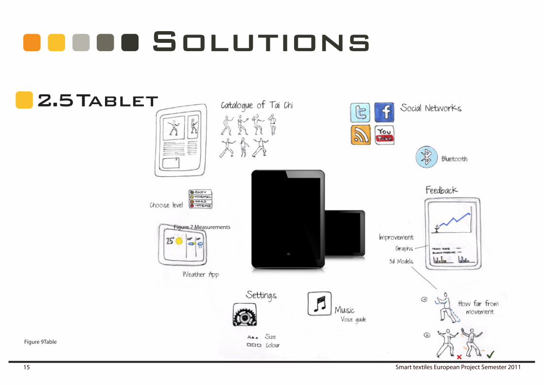
2 . 5 Tablet
Solutions
Figure 7 Measurements
Figure 9Table

Ruben Beldé Lara Hernández Cores Daniël Lacko Alberto Moñux Arenas Alexander Ziegler 16
Solutions
2 . 6 Closing clothing
Figure 10 Closing clothing

Smart textiles European Project Semester 201117
2 . 7 Sensors
Solutions
Figure 12 Drawing sensorsFigure 11 Sensors placement

Ruben Beldé Lara Hernández Cores Daniël Lacko Alberto Moñux Arenas Alexander Ziegler 18
2 . 8 Usability
2 . 9 Led’s andoleds
Solutions
flexible oled surface
Figure 13 Washability. Figure 14 Button . Figure 15 Leds and OLEDs

Smart textiles European Project Semester 201119
2 . 11 Connectivity2 . 10 Devices
Solutions
Figure 16 Touch screen . Figure 17 Connection

Ruben Beldé Lara Hernández Cores Daniël Lacko Alberto Moñux Arenas Alexander Ziegler 20
Clothes
Close
output
Measurements Heart rate Breathing
GSR
Muscle tension
Motioncapturing
3Morphologic map

Smart textiles European Project Semester 201121
Morphologic map
Usability
Social
Tablet
Wire
Place battery
Place buttons
Conexions
LED
OLED Washability

Ruben Beldé Lara Hernández Cores Daniël Lacko Alberto Moñux Arenas Alexander Ziegler 22
3 . 1Concept 1
high enough for personal use, information is relevant for giving a representation of the exercises on the tablet, but should not be extremely accurate.
relevant for the user and his close environment (tai chi teacher, family, friends) focussed on positive and negative feedback.
less measurements, not relevant for doctors, focussed on the user and the interpretation of the data
more user friendly for elderly, keep it simple without the highly technical information
feedback during exercise is more important then measure-ments
low power consumption
interface simplified for elderly, bright colours and dark back-grounds
calm, relaxed, easy to wear
combination of ZigBee, Bluetooth and wires
1 basic button for control for easy use control of the suit is on the tablet
Motion capturing
Feedback
Measurements
Focus on elderly
Complexity
Power supply
Tablet
Look
Connection
ButtonsFigure 18 Concept 1
Morphologic map

Smart textiles European Project Semester 201123
3 . 2Concept 2
high accuracy for perfect motion capturing for professional use
also relevant for doctors, higher reliability focussed on mea-surements.
measurements are double checked on two places on the body; more accuracy, can be used as medical information, more dif-ferent measurements in this concept like gsr and bloodpressure
more complexity in interpreting all the data
technical higher challenge (battery is critical, connecting all the sensors, processing speed)
higher power consumption
more measurements mean more functions on tablet, more difficult app
calm, relaxed, easy to wear
Bluetooth and wires
more control on the suit
Motion capturing
Feedback
Measurements
Focus on elderly
Complexity
Power supply
Tablet
Look
Connection
Buttons
Figure 19 Concept 2
Morphologic map

Ruben Beldé Lara Hernández Cores Daniël Lacko Alberto Moñux Arenas Alexander Ziegler 24
3 . 3 Trade-offWeigth concept 1 concept 2
motion capturing 5 4 5feedback 5 4 5measurements 4 3 5focus on elderly 5 5 3complexity 5 4 2power supply 2 4 1tablet 5 4 2look 2 4 4connection 3 4 2buttons 3 4 2
160 127
3 . 4ConclusionAfter completing the morphologic map we came out with two different con-cepts.
Concept one is focused on giving the right amount of information and feed-back to the user. The measurements have a lower accuracy because they aren’t double checked, which has as effect that we could give more feedback about how to do tai chi with the same battery consumption. It has lower con-trol on the suit and higher control on the tablet, what makes the challenge of the app interesting. The look of the two suits should be the same; the colors and styling have to be relaxing for the users and for the surrounding people.
Concept two has a higher measuring capacity; the values of the measure-ments are double checked in the suit. The different measurements consume more energy, which is why we can’t give more feedback on the suit. However, because of the accuracy we could use the values of the measurements in our medical report. There are more buttons integrated in the suit that gives us a higher control during our tai chi session.
Considering our target group, user functions are more important than exact-ness of measurements. The measurements are still exact in concept one but not accurate enough for medical issues. It is more important for elderly that they understand what they are doing, without the control of doctors or be-ing reminded about their health status. They want freedom and they want to understand the ways of tai chi.
Table 1 Trade off concepts
Morphologic map

Smart textiles European Project Semester 201125
4Specifications
4 . 1Measurements
Possible to measure respiration rateFeedback on tablet after exerciseFeedback during exercise in front of suitGive warning when respiration rate is too high? Give warning to teacher or surrounding persons when respiration rateis to highThe attention may not disturb the exercise
The attention point may not disturb the concentrationThe perfect breathing is called F6 breathing (4s breathing in, 6s breathing out)It starts measuring when the suit is activatedIt stops when the suit is deactivatedThe measurement is done with an stretch sensorThe measurement is done at the abdomenThe sensor detects the change in length
4.1.1 Heart rate
4.1.2 Respiration rate
4.1.3 Motion capturing
Possible to measure heart rateFeedback on tablet after exerciseFeedback during exercise in front of suit Give warning when heart rate is too highGive warning to teacher or surrounding persons when heart rate is too highThe attention may not disturb the exercise The attention may not disturb the concentrationThe moment the attention is given is personal based on the age220-age is the calculation for the maximum heart rate It starts measuring when the suit is activated It stops when the suit is deactivated The measurement is done by a sound sensor (see 8.3)The sensor is 6mm diameter and 1.3 mm thick The sensor is placed at the artery at the wristThe sensor is sewn in the suit
The motion and position of the person can be measured The measurements are done with accelerometersThe motion and position are reproduced on the tabletThe motion and position can be compared with the right exerciseOne sensor for each forearmOne sensor for each shin boneData of sensors are transmited to tablet
The Arduino Lillypads are placed close to the sensor for no resistive losses in the wireThe Arduino Lillypads are sewn in the suitThe Arduino Lillypads are connected with a ZigBee connection to a base pointThe base point Arduino Lillypad sends the data to the tablet with Bluetooth 15 m rangeThe Arduino Lillypads are to the sensors connected with conductive wires

Ruben Beldé Lara Hernández Cores Daniël Lacko Alberto Moñux Arenas Alexander Ziegler 26
The heart rate is visually explained to the user The heart rate is visually explained to the surrounding peopleThere is a visual attention point on the right wrist The heart rate is saved on the tabletThe heart rate can be checked after the exercise on the tablet The heart rate is represented by (user friendly) graphs on the tabletIt is possible to compare your heart rate of the exercise today with the heart rate of another exercise
The respiration rate is visually explained to the userThe respiration rate is visually explained to the surrounding peopleThere is a visual attention point on the left wristThe respiration rate is saved on the tabletThe respiration rate can be checked after the exercise on the tabletThe respiration rate is represented by means user friendly graphs on the tab-letIt is possible to compare your respiration rate of the exercise today with the heart of another exercise
Vibrating elements are sewn in the suitSewn at the tight part of the suit
Four vibrating elements placed around at 90° on each forearm and shinboneGives a vibration when the movement isn’t accurate enoughVibration makes you move to exact positionAccuracy is in different levels: easy 55%, moderate70% and hard 85%
Light in the suitLight guides movementLight is a reminderOLEDs are printed in the textileLight is diffused by the textileOn arms and legsStretched arm or leg is full lineWhen arm has to be bended line becomes shorterDirection of where to move with your limbs is visually reproduced
Motion capturing by sensors sent to tablet with BluetoothThe feedback of the motion capturing is shown in a 3D environment.Comparison between how you moved and how you should move suit.
4 . 2 Feedback4.2.1 Heart rate
4.2.2 Respiration rate
4.2.3 Feedback of movements in the suit
Negative vibrotactile feedback
Positive feedback
4.2.4 Feedback of movements in tablet
Specifications
4.2.5 Social
Color of the suit can merge with colorus of other suits in range of the 15m bluetoothMaximum 2 merges of coloursA person with a suit can send his movements to another suit with Bluetooth for doing tai chi together

Smart textiles European Project Semester 201127
You can choose different exercises in the tabletYou can choose templates of exercisesThere is a catalogue integrated where you can consult an explanation of each exercise, written and with a videoYou start with a basic level and when you improve your skills, by doing the exercises correctly, you go to the next stageWhen you upload your level some exercises will be unlocked and the accu-racy will be higher
The tablet can give feedback of the movements, the heart rate and the respi-ration rate of every day that you did tai chi
4 . 3 Tablet4.3.1 Exercise
4.3.2 Feedback
Specifications
4.3.3 Social
You can make a profile on the tabletYou can check your levelYou can make friends with people you meet with a suit via BluetoothYou could see your friends profile and exercisesThere is the possibility to see how your friend’s level of tai chi is and compare with them
Color Chakra Chakra location Alleged function Associated system Red First Base of the spine Grounding and Survival Gonads, kidneys,
spine, sense of smell Orange Second Lower abdomen,
genitals Emotions, sexuality Urinary tract,
circulation, reproduction
Yellow Third Solar plexus Power, ego Stomach, liver, gall bladder, pancreas
Green Fourth Heart Love, sense of responsibility
Heart, lungs, thymus
Blue Fifth Throat Physical and spiritual communication
Throat, ears, mouth, hands
Indigo Sixth Just above the center of the brow, middle of forehead
Forgiveness, compassion, understanding
Eye, pineal glands
Violet Seventh Crown of the head
Connection with universal energies, transmission of ideas and information
Pituitary gland, the central nervous system and the cerebral cortex
4.3.4 Options
Options have to be changed on tabletYou can choose the time of the exercise.The positive feedback (light) could be on or off. Choose between the training and the freedom mode (Light follows the movement instead of movement follows the light).
Change the color of the light.Each color has a specific meaningThe negative feedback (vibration) could be on or off
Table 2 Colours

Ruben Beldé Lara Hernández Cores Daniël Lacko Alberto Moñux Arenas Alexander Ziegler 28
Specifications
4 . 4 SuitExist of a double layer of cotton polymerTight part nylon stretchable at wrists and ankle Two piece suitBattery in pants at thighBattery ergonomically formedPerfect fit pocket for battery
Battery can by disconnectedBattery pocket can be closed with zipperBattery is connected with a jack to suitBattery has to be disconnected for rechargingTactile reminder of presence of battery with press but-Ton over the pocketConnection made between two pieces with the two Press buttonPress buttons are also on/off button of the suitBattery has to be out of the suit for washing2 buttons on the suit positioned at the right forearm
Change the intensity of the vibration The social mode in both can be turn on or off.You can have music or a voice guide and choose the level of it.The music can be active or relaxing.The voice can be a female or male.
Press both buttons together to pausePress back for repeat last exercisePress forward for go to next exercise The suit is hand washableThe suit can come in three different sizes: small medium and largeThickness of 2.5mmMax weight of suit is 1kgSuit is a unisex modelUpper part of the suit has a diagonal zipper for best wearability Upper part of pants is stretchable

Smart textiles European Project Semester 201129
5 Quick designs
Samurai
Respiration rate
Attention point
Figure 20 Suit design 1

Ruben Beldé Lara Hernández Cores Daniël Lacko Alberto Moñux Arenas Alexander Ziegler 30
Quick designs
Hood
Different styles of guide
VelcroFigure 21 Design suit 2

Smart textiles European Project Semester 201131
Quick designs
Button
Diagonal ZipperFigure 22 Suit design 3

Ruben Beldé Lara Hernández Cores Daniël Lacko Alberto Moñux Arenas Alexander Ziegler 32
Quick designs
Guide lines
Moving balls
Figure 23 Suit design 4

Smart textiles European Project Semester 201133
Quick designs
Ying Ynag inspiration
chakra lines
Figure 24 Suit design 5

Ruben Beldé Lara Hernández Cores Daniël Lacko Alberto Moñux Arenas Alexander Ziegler 34
Quick designs
2 types of layout
more simple layout
Figure 25 Interface design 1

Smart textiles European Project Semester 201135
Quick designs
Graphs of feedback
Explanation exercise
Options
Color mood
Choosing exerciseThere is different kind of cata-logues, one for warming, other for the proper exercise and the other for streching
Breathing
Heart
Figure 26 Interface design 2

Ruben Beldé Lara Hernández Cores Daniël Lacko Alberto Moñux Arenas Alexander Ziegler 36
Quick designs
Figure 27 layout sketch

Smart textiles European Project Semester 201137
6 Research onmotion
6 . 1 Motioncapturing
There are three senses that people rely on to get information about their en-vironment and how to act on it. Two of these, sight and sound, are the ones that get most credit and a lot of research has gone into recording them for later reference. The last one, often forgotten and neglected but invaluable nonetheless, is the sense of touch. Almost all of our everyday actions require some kind of motion, yet apart from in the movie or gaming industries mo-tion capturing is only slowly gaining popularity. However, it could offer major benefits for several areas of human life. For example, video games can be made more accessible, healthy and fun by mapping motion capturing data to a virtual environment. The Nintendo Wii and Xbox Kinect are prime ex-amples of this. As for health care, it could be used to improve recovery by techniques such as gait detection or rehabilitation and to prevent falling for elderly [11].One of the reasons of the slow adoption of motion capturing is that while audio or video capturing almost always happens in the same way, motion capturing can be done with a variety of different sensors and combinations. Similar to the trade-off between quality and compression in audio and vid-eo capturing, there is a trade-off between accuracy and sensor types when we’re dealing with motion. In this section a couple of techniques for motion capturing will be discussed. Generally, the techniques can be divided into two main parts: optical and non-optical systems. The optical systems are by far the most popular and will be discussed first.With optical motion capturing, there is always a camera involved. It can again be subdivided into two parts: with or without markers. In film making, where greater accuracy is generally required, the former are is mostly used. An actor
needs to wear some sort of markers on their body, which can later be filtered out of the video images using pattern recognition techniques and then stored in a motion capture dataset. Until recently this was the only reliable way of doing motion captur-ing, but now several markerless systems are being developed and even put on the market. A well-known and well-loved example is the Xbox Kinect, which uses a com-bination of video capturing and infrared light to determine the position and motion of a user. Using infrared has several advantages: it is not visible by humans and there isn’t much infrared light in everyday environments, which minimizes the chance of false positives or noisy measurements. The main disadvantage is the extra cost and complexity of the Kinect and the fact that the user always needs to stand right in front of the camera, without any kind of obstructions. Non-optical systems can be divided into three parts: electromagnetic, mechanical and inertial. Electromagnetic systems use an electromagnetic generator to create a fixed electromagnetic field in which the magnetic flux changes induced by smaller electromagnetic generators on a user’s body are detected. These fluxes can then be used to determine the movement of a person. In mechanical motion capturing systems stretch sensors are used to determine joint angles, from which a computer model of the motion can be made. However, the accuracy of these systems is highly dependent on the dimensions of the user. As such, a personalized system and per-sonalized calculations are always necessary. Lastly, inertial sensors such as acceler-ometers and gyroscopes can be used to determine the acceleration and the orienta-tion of a person. Combining these with an external reference point such as a camera, IR-sensor or ultrasound sensor [12] can provide accurate information about a user’s position and movement. An example of this is the Nintendo Wii, which uses control-lers with ADXL330 accelerometers to determine acceleration and tilt together with infrared light to determine distance and orientation. Additional mechanical sensors can also be used, such as the pressure sensor in the Wii Balance Board, to do a more complete mapping of the user’s movements to an animated video game character. While the Wii itself is a popular system, it has worse accuracy then systems such as

Ruben Beldé Lara Hernández Cores Daniël Lacko Alberto Moñux Arenas Alexander Ziegler 38
Research onmotion
the Kinect, while it has more disadvantages: extra infrastructure is needed (at least one WiiMote) and the user still needs to be right in front of the infrared receiver at all times. In the previous systems, an external reference point was always necessary, be it a camera, an EM-field generator, a precise dimensional model of the user or an IR-sensor. However, systems that do not depend on external reference points are being researched, for example using only accelerometers. One such a system is discussed in [13]. An Arduino board is used together with five ADXL330 accelerometers to get acceleration data from the user, which is then matched to an existing motion capturing dataset, in this cased built with a Vicon system. To have it work in the right way, a calibration is done between the real acceleration measured by the accelerometers and the vir-tual acceleration as it would be if the motion in the Vicon dataset was cap-tured with accelerometers in the same positions. This is necessary because the axes of the accelerometers should be aligned for an accurate matching. The strength of this idea is that in theory any hardware can be used together with any motion capture dataset. However, in order to make the dataset, a traditional optical motion capturing system is needed.
6 . 2 Motionguidance
In the previous section we’ve already discussed one application of motion capturing, namely controlling a video game character. In this section we will extrapolate on another major application. A lot of the motive actions people take are not thought through, but rather intuitive. Examples are tying shoe-laces, playing a musical instrument, performing a martial art and even walk-ing. We don’t need to think about every step we take, we just take the steps. This phenomenon is called muscle memory. Repeat one action often enough and your muscles will ‘remember’ how to do it without you having to actively tell them to do so. The time it takes to commit this action to muscle memory will depend on how effectively it is repeated. The first step in any motion learning process is to acquire information about how to perform the move-ment. The next step is translating this information to the actual motion, and this is where things can often go wrong, depending on the medium carrying the information and on the ability of a person to translate this information to motion. For example, learning a new martial arts move requires looking at a teacher, translating their body position to your own and mimicking the movement. In this process, it is often necessary for the teacher to perform some corrections to the movement because the translation didn’t happen efficiently. The same goes for learning how to play scales on a musical instru-ment such as a piano. Notes on a sheet of music have to be translated to finger movements, and afterwards a teacher can correct the movements or it can be matched with a previous recording to find out if the movements were correct. Generally, we can say that learning each movement requires the re-peating of the following steps: acquisition, translation, action and feedback.

Smart textiles European Project Semester 201139
Research onmotion
Figure 28 Graphical representation of motion learning
This is represented in Figure 28.
The acquisition of the information is relatively easy. A lot of instructional vid-eos and texts exist on the World Wide Web, instructional books can be found in libraries and teachers or schools can be found in the yellow pages. Similar-ly, performing the action itself depends solely on the motor skills of a person and will not pose problems in normal circumstances. The major difficulty lies
in the translation and feedback steps. The difficulty with both is that it’s not easy to translate information from one sense to another. For example, you will have a hard time explaining the colour blue to someone. The same goes for movement; therefore providing visual or audible instructions for move-ment is not very efficient and it will take a relatively long time for people to get the movement right when relying solely on these mediums. Move-ment is tied to the sense of feeling and thus the most efficient way to learn new movements is by tactile stimuli. These stimuli come in the form of heat, stretching, pressure or vibration. Heat and pressure can both be neglected because the skin is not that sensitive to temperature changes and it adapts to pressure, which makes it difficult to interpret varying intensities of these stimuli in the right way. Stretching is a good way to provide continual feed-back and is excellent for applications such as feedback of prosthetic limbs, but it does not provide good event cues and it takes some time for a user to get used to the feedback [14]. Vibration, however, has proven to be an effec-tive guide to motion, which we will show in the next section.

Ruben Beldé Lara Hernández Cores Daniël Lacko Alberto Moñux Arenas Alexander Ziegler 40
7Methods for motion capturing
7. 1 Feedback of the position
Out of these two, feedback about the position is by far the easiest one. Since most accelerometers also measure static acceleration, which is to say the ac-celeration due to the earth’s gravity, we can easily determine the pitch and roll of the accelerometer. Taking the accelerometer position in Figure 29 as a reference, we know that the z-axis will measure an acceleration of 1g towards the earth. If the accelerometer is tilted, meaning it’s rotated over the x-axis, the pitch α will increase. See Figure 30 for a reference of pitch, roll and yaw angles. Because the z- and y-axis are perpendicular to each other, we know that β will be equal to α. Using Formula 1 we can determine this angle using simple trigonometry.
In section 6, we’ve shown research related to our own work. In this section, we will work out our own motion capturing algorithms. We have tried to use as few components as necessary and thus the algorithms will be based only on accelerometer calculations. Every motion can be seen as the movement between a starting and a stopping position. Therefore, we can distinguish between two necessary feedback mechanisms: feedback on position and feedback on the movement.
Figure 29 – accelerometer rotating over its x-axis.
Figure 30 – pitch, roll and yaw.
Formula 1 – Determining the pitch of the accelerometer
However, using this method, we cannot determine which quadrant the ac-celerometer is moving in. The angle will have the same sign whether it’s pointing up or down. To remedy this, we can use a dual-axis accelerometer. Taking Figure 29 as reference, we can use Formula 1 to determine the magni-tude of the angle and then use the signs of x- and y-axis value to determine which quadrant the accelerometer is moving in, giving us a full 360° of tilt, see Figure 31 and Table 3.
Table 3 – sign of z- and y-value related to the quadrant.
1 Formulae
Formula a Determining the pitch of the accelerometer.
cos(β) =z
1g
β = arccos(z
1g)
Formula b Determining the pitch of the accelerometer using the y-axis.
cos(φ) =y
1g
φ = arccos(y
1g)
φ = 90− α
α = 90− φ = 90− arccos(y
1g)
α = arcsin(y
1g)
Formula c Cross-correlation function continuous signals.
(f � g)(t) =
∫ +∞
−∞f∗(τ)g(t+ τ) dτ.
Formula d Cross-correlation function discrete signals.
(f � g)(n) =∑m,n
f∗(n))g(m+ n).
Formula e Normalized cross-correlation, will peak at 1 at zero lag.
(f � g)(n) =1
N
∑m,n
f∗(n)g(m+ n).
1
Sign of z Sign of y Quadrant Calculation of α (z = [g]) + + I acos(|z|) - + II 180° - acos(|z|) - - III 180° + acos (|z|) + - IV 360° - acos(|z|)

Smart textiles European Project Semester 201141
1 Formulae
Formula a Determining the pitch of the accelerometer.
cos(β) =z
1g
β = arccos(z
1g)
Formula b Determining the pitch of the accelerometer using the y-axis.
cos(φ) =y
1g
φ = arccos(y
1g)
φ = 90− α
α = 90− φ = 90− arccos(y
1g)
α = arcsin(y
1g)
Formula c Cross-correlation function continuous signals.
(f � g)(t) =
∫ +∞
−∞f∗(τ)g(t+ τ) dτ.
Formula d Cross-correlation function discrete signals.
(f � g)(n) =∑m,n
f∗(n))g(m+ n).
Formula e Normalized cross-correlation, will peak at 1 at zero lag.
(f � g)(n) =1
N
∑m,n
f∗(n)g(m+ n).
1
Methods for motion capturingFigure 31 Dual-axis accelerometer rotat-ing over its x-axis
Figure 32 Accelerometer rotating over its x-axis, only using y value
If we only need 180° of tilt, we can use an alternative method with a single-axis accelerometer, see Figure 32. Because the pitch α and � are complemen-α and � are complemen- and � are complemen-� are complemen- are complemen-tary angles, we can use Formula 2 to determine the tilt of the accelerometer from -90° to 90° as well.
Lastly, we can determine the roll of the accelerometer as well by using the extra axis on a triple-axis accelerometer (the x-axis instead of the y-axis in the previous formulae). However, it’s much more difficult to determine the yaw because the x- and y-axis are both parallel to the ground. Generally, a gyroscope is determined to measure rotation of the z-axis.
Formula 2

Ruben Beldé Lara Hernández Cores Daniël Lacko Alberto Moñux Arenas Alexander Ziegler 42
1 Formulae
Formula a Determining the pitch of the accelerometer.
cos(β) =z
1g
β = arccos(z
1g)
Formula b Determining the pitch of the accelerometer using the y-axis.
cos(φ) =y
1g
φ = arccos(y
1g)
φ = 90− α
α = 90− φ = 90− arccos(y
1g)
α = arcsin(y
1g)
Formula c Cross-correlation function continuous signals.
(f � g)(t) =
∫ +∞
−∞f∗(τ)g(t+ τ) dτ.
Formula d Cross-correlation function discrete signals.
(f � g)(n) =∑m,n
f∗(n))g(m+ n).
Formula e Normalized cross-correlation, will peak at 1 at zero lag.
(f � g)(n) =1
N
∑m,n
f∗(n)g(m+ n).
1
Methods for motion capturing7. 2 Feedback on the movement
Providing exact and continuous feedback on the movements has proven to be difficult using only accelerometer calculations. In theory, the second inte-gral of the acceleration could be taken to determine the moved distance, but since we have only one reference point at the start of the exercise all of the small measuring errors during the movement will add up and make the final result very inaccurate. The longer the movement takes, the greater this error will be and thus simply using the second integral is not a favourable option.
Instead of trying to provide continuous movement feedback, we will first build a dataset by just capturing the values of an accelerometer over time and then comparing the new signal to dataset signals for every movement. Vibro-tactile guidance during the movements itself will be based only on the positions, but if a user feels they receive too much feedback, they can always check the mobile device to see how close their movement was to the intend-ed movement. In order to do this, we will use the cross-correlation function, see Formula3. Cross-correlation is a measure of the similarity of two signals when a lag is applied to one of them. In the case of a continuous signal this lag is a time difference, but in case of discrete signal such as the signals we are going to work with, the lag can simply be a number of bits, see Formula 4. However, to produce accurate estimates, the correlation function needs to be normalized using Formula 5. When doing an auto-correlation, which is a cross-correlation of a signal with itself, the normalized correlation function will always peak with amplitude 1 at zero lag.
Formula 3– Cross-correlation function continuous signals.
Formula 4– Cross-correlation function discrete signals.
Formula 5 – Normalized cross-correlation, will peak at 1 at zero lag.
This property can be used to determine how similar a new movement is to a movement from the dataset. Since we know that for an ideal match, there will be a peak zero, we can firstly look for the existence of such a peak. If there is no peak around zero lag, we know the signals don’t match. If there is a peak, there is a match between the signals, where the amplitude of the peak and the lag at which the peak occurs can both be used to determine how close the signal, and thus the movement, is to the original. The closer the signal is to zero lag and amplitude 1, the better the match. The user should receive visual information to indicate how he could improve his movements further. For example, a 3D-model could be made of the user or of their body parts and the captured movement could be played back.
1 Formulae
Formula a Determining the pitch of the accelerometer.
cos(β) =z
1g
β = arccos(z
1g)
Formula b Determining the pitch of the accelerometer using the y-axis.
cos(φ) =y
1g
φ = arccos(y
1g)
φ = 90− α
α = 90− φ = 90− arccos(y
1g)
α = arcsin(y
1g)
Formula c Cross-correlation function continuous signals.
(f � g)(t) =
∫ +∞
−∞f∗(τ)g(t+ τ) dτ.
Formula d Cross-correlation function discrete signals.
(f � g)(n) =∑m,n
f∗(n))g(m+ n).
Formula e Normalized cross-correlation, will peak at 1 at zero lag.
(f � g)(n) =1
N
∑m,n
f∗(n)g(m+ n).
1

Smart textiles European Project Semester 201143
8Final product
8 . 1 Motion capturing and guidance
Based on the methods in section 8.3. We will need at least five accelerom-eters: one at each lower leg and one at each forearm. We suggest using the ADXL335 because of its low power consumption, but any triple-axis acceler-ometer with a sensitivity of at least +/- 2g can be used. We will need micro-controllers to read out these accelerometers and relay the information to a computer or mobile device, and for this we have chosen the Arduino LilyPad. Arduino is a cheap, flexible and open-source electronics platform designed for quick prototyping; the LilyPad is an adaptation of the Arduino platform and various components designed to be sewn into clothing with conductive textile. To provide feedback we will use Arduino VibeBoards, and OLED strips will be used among other things to provide an indication of the upcoming movement.
8.1.1 Components list
Arduino LilyPad 328 Main Board This is the main board which we will use consisting of an ATmega328 with the Arduino bootloader, running at 8 MHz, see Figure 34. It is an e-textile technology with a minimum number of external components to keep it as small and as simple as possible and at the same time wearable. The board will run from 2V to 5V.
LilyPad VibeBoardThe LilyPad VibeBoard is an extension to the LilyPad mainboard, see Figure 35. It incorporates a vibration motor and operates at 5 V, which means it can be used with the LilyPad main board without voltage conversion. Driving the VibeBoard works exactly the same way as driving LEDs, so it’s very easy to implement.
Figure 34 LiLyPad 328 Main Board. Figure 35 LilyPad VibeBoard.
ADXL335 accelerometerThe ADXL335 is a small, thin, low power triple-axis accelerometer which can measure acceleration of up to +/- 3 g. A sample ADXL335 can be seen in Fig-ure 36.
OLEDsWe will use organic LEDS for motion guidance. They are described in more detail in section 8.7
Figure 36 ADXL335 accelerometer.

Ruben Beldé Lara Hernández Cores Daniël Lacko Alberto Moñux Arenas Alexander Ziegler 44
8 . 2 MonitoringIn order to monitor the respiration rate, we will use stretch sensors incor-porated in the trousers of the suit and placed on the abdomen of the user. The heart rate will be detected using sound, as discussed in section 7.5 In effect, any heart rate or respiration rate sensor can be used, as long as it can be plugged in to an Arduino main board. We will use the following parts for monitoring the vital signs.
8 . 3 Heart rateFor the heart rate detection we use the technology of phonocardiography (PCG). In this technique the tone of the heart is detected and analyzed [7]. Out of that it is possible to generate a heart analyzes, detect the heart rate and even possible to detect the blood pressure [7]. In comparison to other techniques it is a poor system, but has some significant advantages which are for our product very important: •lowcost •lowpower •maintenance-free •robustto60Hzpickup •noelectricalcontactwithbody
Battery for more detail see section 9.3
Chargerfor more detail see section 9.4
Interconnections wire of 3*2,25 mm2 section pvc isolated Wire of 2*1,5 mm2 section pvc isolated 2.1 mm connectors (x2)
Standard connector to 230 V 50 hz
Voltage regulatorisolated inside textile, based on LM317.
Final product
Smart textiles European Project Semester 201145
Final product
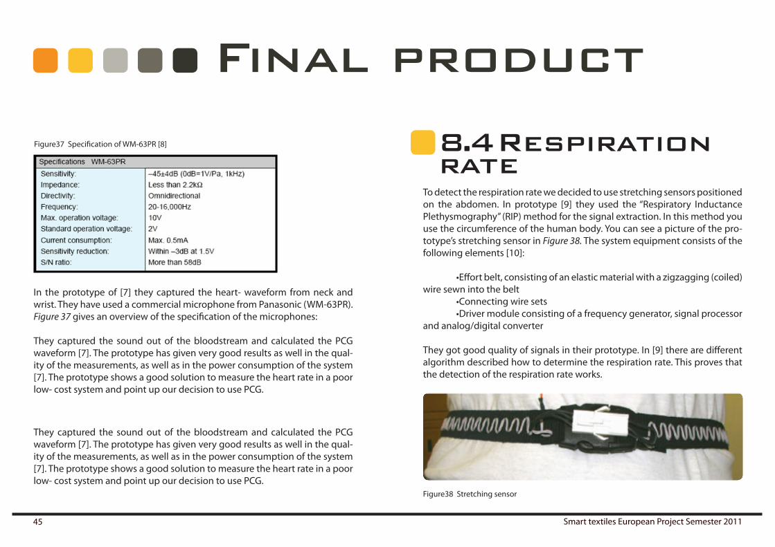
Figure37 Specification of WM-63PR [8]
They captured the sound out of the bloodstream and calculated the PCG waveform [7]. The prototype has given very good results as well in the qual-ity of the measurements, as well as in the power consumption of the system [7]. The prototype shows a good solution to measure the heart rate in a poor low- cost system and point up our decision to use PCG.
In the prototype of [7] they captured the heart- waveform from neck and wrist. They have used a commercial microphone from Panasonic (WM-63PR). Figure 37 gives an overview of the specification of the microphones:
They captured the sound out of the bloodstream and calculated the PCG waveform [7]. The prototype has given very good results as well in the qual-ity of the measurements, as well as in the power consumption of the system [7]. The prototype shows a good solution to measure the heart rate in a poor low- cost system and point up our decision to use PCG.
8 . 4 Respiration rate
To detect the respiration rate we decided to use stretching sensors positioned on the abdomen. In prototype [9] they used the “Respiratory Inductance Plethysmography” (RIP) method for the signal extraction. In this method you use the circumference of the human body. You can see a picture of the pro-totype’s stretching sensor in Figure 38. The system equipment consists of the following elements [10]:
•Effortbelt,consistingofanelasticmaterialwithazigzagging(coiled)wire sewn into the belt •Connectingwiresets •Drivermoduleconsistingofafrequencygenerator,signalprocessorand analog/digital converter
They got good quality of signals in their prototype. In [9] there are different algorithm described how to determine the respiration rate. This proves that the detection of the respiration rate works.
Figure38 Stretching sensor

Ruben Beldé Lara Hernández Cores Daniël Lacko Alberto Moñux Arenas Alexander Ziegler 46
8 . 5 CommunicationFor the communication between the components we will use Zigbee be-cause of its low power consumption. The reason we have chosen not to work with conductive thread is that it adds 14 Ohms of resistance per foot and we need to connect components over the entire length of the body. This imped-ance would decrease the accuracy of the measurements and so it’s safer to work with a wireless body area network. For communication between the system and the mobile device, we have decided to use Bluetooth, since it has an excellent range and is available in almost every mobile device on the market today. To decrease the impact of Bluetooth’s power consumption, we have developed a flexible communication protocol with as little as possible overhead. We will use the following components for communication:
LilyPad XBee ModuleThe LilyPad XBee modules are another extension for the LilyPad main board, see Figure 39. It’s very easy to set up a body area network using these com-ponents. A separate main board will be necessary to drive the XBee Module for each component where XBee communication is needed.
Bluetooth Mate GoldThis is a standard Bluetooth module that can be used together with any Ar-duino main board, including the LilyPad, see Figure e. When connected to the main board, the Arduino can use serial communication over Bluetooth to communicate with other device.
The following figures show the program data flow diagram. In Figure 41, the dabatabase or internal data model is shown; in Figure 42, the user model or external data model is shown and in Figure 43 the input/output model is shown
8 . 6 Product data flow diagram
Final product
Figure 40 Arduino Bluetooth Mate GoldFigure39 LilyPad Xbee Module

Smart textiles European Project Semester 201147
Final product
Figure 41 External data flow between the user, mobile device and textile system

Ruben Beldé Lara Hernández Cores Daniël Lacko Alberto Moñux Arenas Alexander Ziegler 48
Final product
Figure 42 Internal data flow between the user, mobile device and textile system.

Smart textiles European Project Semester 201149
Final product
Figure43 Input/output diagram.

Ruben Beldé Lara Hernández Cores Daniël Lacko Alberto Moñux Arenas Alexander Ziegler 50
Final product
8 . 7 OLEDsOLED stands for Organic Light Emitting Diodes. They offer more advantages than the LED or LCD technologies, but first we must explain how they work.
OLED works by passing electricity through micrometer layers of organic semiconductors sandwiched between two electrodes.
The electric current travels from the positive to the negative electrode through the organic film, causing the film to emit light. Using different ma-terials in the film causes the OLED to emit light of different colours (and not filtering out white light to give the appearance of color, as is the case with LCDs). To protect the organic layers, the OLED is completely sealed between two glass plates.It should be noted that a Human hair is 200X the thickness of the OLED layers what makes a good technology for our application because the size and the flexibility.
Potential of OLEDThe main characteristics of OLEDs are:They are suitable for thin, lightweight and printable displays, which is an important advantage for our application. They also have broad range and a good colour contrast.High resolution (<5 um pixel size).Fast switching (1-10 us).Wide viewing angle.And finally the low cost of materials.
It can be seen in both graphs that both the efficiency and luminance are high in the working point of our product, which is at about 4 to 5 volts.
Figure 44 OLED’s Figure 45 Graph OLED 1 Figure 46 Graph OLED 2

Smart textiles European Project Semester 201151
Small molecular OLEDMade by vacuum evaporating small molecules to the substrate similar to that used in semiconductor manufacturingWell proven on fabrication of up to about 15 inches in diameter (shadow mask)Crystallization due to low glass transition temperature shortens lifetime and reliability
Polymer OLEDMade by depositing the polymer materials on substrates through an inkjet printing process or other solution processing methods under ambient condi-tionsFabrication of large screen sizesOxidation of carbon-carbon bonds between the aromatic rings reduce the conjugation length of the polymer
Flexible displayFlexible substrate requirementsTransparentRobustnessLow costStabilityLow coefficient of thermal expansion Low moisture absorption Resistant to chemicals & solventsProcessing temperatures limited by:Deformation temperature of material layers
For common plastic materials, < 300 ºC
Polymer Materials: Conductive polymers:Polyaniline PolyethylenedioxythiopheneEmissive polymers:PolyphenylenevinylenePolyfluorene
There is another classification according to how they work:
RGB- Polymer emittersAdvantages:Power efficientLower production costMature ITO technologyDisadvantages:Emitters have to be optimized separatelyDifferential aging of emittersPatterning of emitters necessary
Color filters White emitter
8.7.1 OLED types
Final product

Ruben Beldé Lara Hernández Cores Daniël Lacko Alberto Moñux Arenas Alexander Ziegler 52
Advantages:Well established technology LCDNo patterning of emitter necessaryHomogeneous aging of emitter Disadvantages:Power inefficientITO (indium-tin-oxide) sputtering on filtersEfficient white emitter necessary
Color Changing Media (CCMs)Advantages:Homogeneous aging of emitter, More efficient than filtersNo patterning of emitter necessaryDisadvantages:ITO (indium-tin-oxide) Sputtering on CCMs stable blue emitter necessary ag-ing of CCMs
After comparing the two types of OLEDs, we have found that the polymer have better advantages then the small molecular OLEDs.
Final product

Smart textiles European Project Semester 201153
Power
Main board 1
Main board 2
Main board 3
Main board 4
Base station microcontroller
Right arm
Left arm
Right leg
Left leg
9 Power supply
9 .1 ElementsThe battery will provide energy in parallel for every main board and base station.
9 . 2 Maximum power consumption
In the following section, a calculation of the power needs for our system will be done. Firstly, we need to consider the maximum power ratings of each component to prevent the battery from damaging the circuit. As shown in section 8.1, there are five LilyPad main boards and one base station, which will all need to be powered. The main boards in their turn each need to pow-er four vibe boards, one accelerometer and a couple of LEDs. The rating for each of the components is as follows:
Arduino Lilypad 328 Main Board
Dimensions:50 mm outer diameterThin 0.8 mm PCBInput voltage: 2.7 – 5.5 VCurrent Consumption: 0.2 mA*The input voltage of every main board will be adjusted at 5 volts by voltage regulators de-fined later in this section.Consumption: 5 * 0.0002 = 0.001 W

Ruben Beldé Lara Hernández Cores Daniël Lacko Alberto Moñux Arenas Alexander Ziegler 54
LilyPad Vibe Board
Dimensions:5 x 11 mmThin 0.8 mm PCBOperating voltage: 5 VCurrent: 30 mAIn the system we will have 20 LEDs in each arm and each leg, so in total 80 LEDs.Consumption: 5 * 0.030 * 80 = 12 W
Bluetooth
Operating voltage: 3.3 VCurrent: 30 mA (Connected normal mode)Consumption: 3.3 * 30e-3 = 0.099 W = 0.1 W
Zigbee
Operating voltage: 3.3 VCurrent: 50 mA Consumption: 3.3 * 50e-3 = 0.165 W
Assuming the worst case scenario, where all the components are working at the same time, we calculate the maximum power as follows:
5 LilyPad main boards: 5 * 0.001= 0.005 W16 VibeBoards = 16 * 0.2 = 3.2 W4 Accelerometers = 0.00105 x 4 = 0.0042 W80 LEDs = 12 WBluetooth = 0.1 WZigbee = 5 * 0.165 = 0.825 WPrevision heart beat and respiration rate = 1 W
Total = 17.134 W
Maximum power
LilyPad Vibe Board
Dimensions:20 mm outer diameterThin 0.8 mm PCBThe vibe board diagram can be shown in Figure x. According to the datasheet, the vi-brating motor operates at 3 V, 75 mA. How-ever, each pin of the LilyPad main board can only support up to 40 mA. Consumption: 5 * 0.04 = 0.2 W
Figure 47 Lilypad vibe board
Power supply

Smart textiles European Project Semester 201155
9 . 3 Battery
The charge of the battery should last for at least 1.5 h of continuous use, and the maximum power consumption should always be lower than the maxi-mum discharge that the battery pack is able to develop.
C =1/h C [mAh]
A Lithium-Polymer (from here on referred to as Li-Po) element or cell has a nominal voltage of 3.7 V. The battery should never be discharged below 3.0 V per cell and it should never be charged more than 4.3 V per cell. The Li-Po items can be grouped in series (S), to increase the total voltage, or in paral-lel (P), to increase total capacity. For example, a 3S code indicates three ele-ments connected in series (3 * 3.7 = 11.1 V), a 4S2P code indicates 2 parallel groups of 4 elements in series (4 * 3.7 = 14.8 V with capacity doubling).
What is the “C” value?C has the value 1 if the battery is 1000 mAh. For such a battery, we can calcu-late the total current by the following formula: 1000 mAh * 1/h = 1000 mA =1 A.
Similarly, the total current at 2C for the same 1000mAh battery can be calcu-lated as follows: 2 * 1000 mAh * 1/h = 2000 mA = 2 A.A 10C pack is capable of discharging continuously up to 10 times its capacity. For a pack of 1000mAh this would mean10 * 1.000mAh * 1/h = 10000 mAh = 10 A of maximum continuous discharge.
9.3.1 Presumtions and terminology
It is recommended to charge the battery at between 0.2 and 0.7 C, and cer-tainly never more than 1 C. 2-cell Li-Po Battery: 3.7 * 2 = 7.4 VIabs = 171342/5 = 3.4268 A = 3426.8 mAConsidering that we need 1.5 h of battery life, we will need a battery of 5140,2 mAh.For discharging, a maximum of 2C should be considered: 2570.1 mAh
Battery 2S2 elements in series of 2500 mAh: (2C)Charging: between 0.2C and 0.7 CDischarging 2C = 5000 mA (> 3426.8 maximum real consumption)
Specifications:Nominal capacity: 2500 mAh 18.5 WhDensity: 92 wh/kgWeight = 18.5 wh/92wh/kg = 0.2 kg = 201 grams, with isolation and case 300 g.Life: > 500 TimesCharge: 1.75 A Max. (Between 0.2C - 0.7C)Discharge: 5A Max. (2C) Size (1 Cell): 66 Longitude x 60 wide x 5.5 thickness +/- 5%a
9.3.2 Calcul recomendations
Figure 48 Utextile
Power supply

Ruben Beldé Lara Hernández Cores Daniël Lacko Alberto Moñux Arenas Alexander Ziegler 56
9.3.3 Inside the battery:
This part will be composed by 2 cells, one next to the other, between two sheets to hold them. These cells will be isolated against heat etc. by a tight plastic film. They will then be encased inside a designed plastic box, together with the wires, interconnections and the wire-to-power plug adapter. This case will never have to be opened, except in case of failure. The battery has a female base (power output) in which the connector from the suit should plug in. This connector is a 2.1 mm power plug.
A circuit protection module (CPM) was not discussed in this project, but should be added to the battery system to stop the discharging when the battery is under a determined value. It will also prevent the battery from overcharging and limit the voltage over each battery cell to 3.7 V. All of this is done to prevent damage to the battery and textile.
Figure 49 Render battery
Power supply
Figure 50 Draft battery

Smart textiles European Project Semester 201157
9.3.4 Materials
For the box and battery protection and elements we’ve used thermosetting plastics. Thermosetting plastics have a good impact on resistance, solvent, the permeation and gases and extreme temperatures. The charger case is made of the same material.
To design the circuit of the charging source, we need to know the impedance offered by the battery charging source. That is, at the terminals of the charger design.
But, what is the impedance of a battery and why does matters?
By definition, the impedance is the opposition to the measure of an alternat-ing current. Electrical impedance means the idea of resistance to AC circuits, which accurately depicts the relative amplitude of voltage and current. The reason impedance is so important for a battery is mainly because the equiva-lent circuit of a battery is based on impedance, see Figure 51.
The diagram at right shows the equivalent circuit for one cell.
Rm, is the resistance of the metallic path through the cell including the ter-minals, electrodes and interconnections.
Ra, is the electrochemical resistance including electrolyte and separator.Cb, is the capacity of the parallel plates forming the electrodes of the cell.
Ri, is the nonlinear contact resistance between the plate or electrode and the
electrolyte.The typical internal resistance is in the order of milliohms. The impedance test is a modern, fast, inexpensive and non-destructive method to monitor the “internal strength” of the battery.In our case, without the battery physically constructed, it is impossible to know the exact impedance, but knowing our data and by searching databas-es for similar cases an estimate can be made in which the equivalent circuit for our two elements is seen in Figure 52 .
Figure 52 Equivalent circuit for both battery cells
Figure 51 Equivalent circuit of battery.
Power supply

Ruben Beldé Lara Hernández Cores Daniël Lacko Alberto Moñux Arenas Alexander Ziegler 58
9 . 4 Charger
Each battery needs a charger, and this charger must be specially designed for the battery. As calculated in section 8.1, we will charge the battery at a certain intensity of 0.2 C and 0.7 C, i.e. a maximum of 1.75 amps.
The charging operation when charging at a standard European outlet of 230 V, 50 Hz, is shown in Figure 53.
9.4.1 Introduction
For the design of this charger we used the following system[1], presented in figure 54, which goes through several stages to get the desired effect:
9.4.2 Theory
Figure 53 Charging operation of tex-tile at standard 23 0 V, 50 Hz outlet.
All of these physical elements are incorporated into the plastic box, as dis-cussed insection 9.3.Firstly, we need a voltage step-down transformer for voltage adaptation to our needs, this stage is AC. The second stage could be called the filter recti-fier, which basically goes from AC to DC, see figure 56, and finally a more pre-cise voltage regulator for our battery. It also includes a current limiter, which in our case will be through transistors.Below is a brief description of every stage.Diode rectifier: Full-wave rectifierWithout going into detail, this part is based on a diode Graetz bridge[2]see figure 55.
Figure 55 Diode Graetz bridge
Figure 54 Stages of charging.
Figure 56 AC to DC rectifier.
Power supply

Smart textiles European Project Semester 201159
In figure 58, you can also see the input signal Vs and the output Vo.Then this signal is filtered by capacitors to obtain a more uniform and straight signal. To do this in the calculation, we’ve used approximations:
Figure 58 Input signal Vs versus flattened output signal V0 with filter
Where
9.4.3 Voltage regulator
Finally the last step, voltage regulation[3], shall be done by the LM317, see figure 59.
The LM317 is a positive voltage regulator with only 3 terminals and an out-put voltage range from 1.25 to 37 volts.Where: Input (IN), Output (OUT), Adjustment (ADJ)
To achieve this change in voltage only requires 2 external resistors (one is a variable resistor).Its main features include current limiting and thermal overload protection. The voltage between ADJ and OUT pin is always 1.25 volts (voltage set inter-nally by the controller) and thus the current through the resistor R1 is: IR1 = V / R1 = 1.25/R1.
This same current flows through the resistance R2. Then the voltage in R2: VR2 = IR1 * R2. If we substitute IR1 in the last formula it yields the following equation: VR2 = 1.25 * R2 / R1.As the output voltage is:Vout = VR1 + VR2, then:Vout = 1.25 V. + (1.25 * R2 / R1) V.Simplifying (common factor)Vout = 1.25 V (1 + R2 / R1) V.
Figure 59 Schematic of a LM317 voltage regulator.
• If RC >> T ⇒ Vr smaller than Vpi
– vOmin = Vp - Vr ⇒ approximation
• vO ≈ Vp
• vO ≈ Vp - 0.5 Vr
• If ∆t small ⇒ approximation
• Vpi - Vr ≈ Vp·e -T/RC where T is the period.
• If RC >> T ⇒ approximation
Vpi·e -T/RC ≈
1pTV
RC ⋅ −
2p
r
VV
fRC=
pL
VI
R≈
( )1 12p
D L Lr
Vi I I fRCVπ π
= ⋅ + = ⋅ +
( )ˆ 1 2 1 22pi
D L Lr
Vi I I fRCVπ π
= ⋅ + = ⋅ +
With these approximations, the filtered signal becomes more straight, which can be seen in figure x.
• If RC >> T ⇒ Vr smaller than Vpi
– vOmin = Vp - Vr ⇒ approximation
• vO ≈ Vp
• vO ≈ Vp - 0.5 Vr
• If ∆t small ⇒ approximation
• Vpi - Vr ≈ Vp·e -T/RC where T is the period.
• If RC >> T ⇒ approximation
Vpi·e -T/RC ≈
1pTV
RC ⋅ −
2p
r
VV
fRC=
pL
VI
R≈
( )1 12p
D L Lr
Vi I I fRCVπ π
= ⋅ + = ⋅ +
( )ˆ 1 2 1 22pi
D L Lr
Vi I I fRCVπ π
= ⋅ + = ⋅ +
Power supply
Figure 57 Approximation
Formula 6

Ruben Beldé Lara Hernández Cores Daniël Lacko Alberto Moñux Arenas Alexander Ziegler 60
From this formula it is clear that if you modify R2 (variable resistor), it will adjust the voltage Vout. In the above formula has blocked the current (IADJ) circulating between the adjustment pin (ADJ) and the union of R1 and R2. This current can be neglected, has a maximum value of 100 µA and remains constant with varying load and/or input voltage.
In order to optimize the control resistor R1, it should be placed as close as possible to the regulator, while the terminal is grounded. Resistor R2 should be as close as possible to the ground of the load.
In our case, the desired output voltage is 7.4 volts. If we impose this volt-age Vout and a resistance of 500 Ohms R1, R2 is 2460 Ohms. Finally we have an approximate voltage of 7.5 volts, regardless of the Vin. (Provided it is be-tween 1.25 and 37 volts, as mentioned before, and the converter transformer is used)
9.4.4 Current and Voltage regulator limi-tation improved: Current limiting transis-tor based step:
In this circuit, shown in figure x, the NPN transistor whose collector is con-nected to the base of pass transistor goes into driving with a voltage drop of 0.6/0.7 V. This voltage is the product of the resistance and the maximum current.Therefore, we need to choose the value of resistance so that as we approach the maximum current, such a voltage drop occurs.
For example, if you want to pass only 1A, the resistance will be 0.7 Ohm, ac-cording to the equation V = I * R. When activated the control transistor cur-rent subtracted to the base of pass transistor thus reducing the collector cur-rent.[4]Between the pass transistor and the load resistance is inserted a small Rs2 whose value is taken so that it causes a voltage drop between its ends of ap-proximately 0.7 V. As the load resistance decreases, the load current increases and hence the voltage drop across the resistor Rs2 grows. When the voltage drop across Rs2 becomes large enough, Q2 will turn on, to turn the current of the base of transistor Q1, so the load current through the transistor Q1 is reduced and prevents any current through the additional load resistance.This is precisely what we need. We charge the battery with an intensity of between 0.2 C and 0.7C, i.e. a maximum of 1.75 A. Then, knowing the two R valus, remain the value calculated above. Now we calculate Rs2 as follows: Rs2 = 0.7 / Imax. Imax being the maximum current that we let pass,wWhile the output voltage remains previously estimated.Rs2 = 0.7 / 1.75 = 0.4 Ohms.Finally, some electrolytic capacitors should be added in order to improve transient response and ripple.
Power supply
Figure 60: Voltage regulator with limitation

Smart textiles European Project Semester 201161
9.4.5 The Multisim verification:
The basic outline of the charger output can be seen in Figure 61. [5] The de-vices whose name starts with the letter X are measuring devices and should not be included in the final battery.
Figure 61 Basic outline of charget output
As discussed, we then need to add the following components: first we have the rectifier with four diodes; in this case a virtual simulation is enough. How-ever, in order to build the real charger, we would have to compare several
models in order to find the best one. Then we have a filter with a 0.155 µF curling capacitor, followed by a voltage regulator with current limiting incor-porating electrolytic capacitors to improve transient response. The schemat-ic for this system can be seen in Figure 62; the simulated results in Figure 63 (together with the 50 Hz input signal). This shows that this system achieves a level output voltage, as desired.
Figure 62 Schematic of charger, voltage rectifier and current limiter
Power supply

Ruben Beldé Lara Hernández Cores Daniël Lacko Alberto Moñux Arenas Alexander Ziegler 62
Figure 63 Simulated charger output
In Figure 63, the battery is connected to the previous schematic to verify the current, which should be less than 0.8 C. (0.8 C = 2000 mA, 2 A). This theoreti-cal schematic [6] shows a current of 1.992 A, which is according to our needs.
Figure 64Simulation of charger system with battery connected.
Recharge time:
We have a battery of 2500 mAh, 7.4 Volts, and the calculated charger works approximately at 2 A. The recharge time can then be found with formula x.
(Battery capacity/Output intensity of charger) * safety value for slow process
(Formula x)
T = 2500 mAh / 2000 mA * 1.1 = 1.375 h
Time = approximately one and a half hour.
9.4.6 Real Aspect
The real aspect of the charger depends on the components used in the phys-ical fabrication of the product, but it should be done with the same materials as the cover of the battery, with a size of 150x70x30 mm. An example can be seen in figure64. The wires and connector are described below.
9.4.7 Recommendations
In the next section, we provide some extra information about the handling of these kinds of batteries, both lithium ion (Li-Ion) as lithium polymer (Li-Po). These types of batteries are used today in almost all existing mobile de-vices: phones, laptops, cameras, etc...
Power supply

Smart textiles European Project Semester 201163
Because of a lack of information and misinformation caused by previous generations of batteries (NiMH and NiCd), a lot of people have developed wrong charging habits, which can shorten battery life and even cause seri-ous damages.
Operation:The lithium ions that are inside the battery move from the cathode (negative electrode comprising a lithium alloy with other metals such as cobalt and manganese) to the anode (positive electrode consists of graphite) sponta-neously, through an electrolyte that allows the circulation of ions, but not electrons. When we close the circuit from the outside, the ions can travel from the cathode to the anode, because now the electrons can travel on our circuit to balance the loads. This movement of electrons produces energy. When all ions are in the anode, the flow of electrons will stop (the battery is discharged.)The charging process involves the application of electron flow in opposite direction of discharging (so-called “mirror chargers”), so that the ions now move from the anode to the cathode, recovering the starting position.Batteries consist of one or more cells with a voltage set at around 3.6 V and can be connected in series, parallel or a combination of both. It is because of these 3.6 V to these values we find such a voltage characteristics on the battery (11.1 V, 14.8 V, etc.).
Use of Li-Po batteries:The first charge-discharge cycles should be complete, leaving a charging batteries a couple hours after completion of the charge, and making the dis-charge as fast as possible: this is done because during a period of non-use, a film of lithium chloride (LiCl) forms on the anode of the battery, which de-creases the ion exchange and therefore the number of electrons in motion
by the circuit. This in turn decreases the number of mAh and therefore the amount of energy that can be generated.This layer is also formed when we keep the battery in storage for a long time (several months), after which the same procedure should be followed be-fore reuse. It is recommended to keep the battery at half charge when not in use, never empty or fully loaded. This does not affect the duration of load, and extends the battery life time and ensures that the Li-Cl film is removed gradually with use.Lithium batteries do not suffer from memory effect, in contrast with what is called “digital memory” caused by the internal meter charge on each cell (a maximum and a minimum level). It manifests itself in computers with more than one battery cell in series (typically on laptops) and occurs because not all cells are discharged at once. Usually the cells located at the ends are emp-tied before the ones in the centre, and thus, the centre is loaded before the end.If we consider that the charger is stopped as soon as you have a cell charged and the first cell that be exhausted, marks the point of zero charge, we can imagine that gradually increasing the imbalance between cells, and there-fore reduces the duration of the battery. To avoid this, always take a full charge cycle (fully discharge the battery and fully charged) after about 30 incomplete cycles.The great enemy of lithium batteries is heat (as a rule, with some exceptions of Li-Po), which greatly accelerates the oxidation process, increasing the in-ternal resistance of the cells and thus decreasing the operation time. This is because subjecting the battery to high consumption levels, the terminal voltage decreases due to the potential drop that occurs within and may give early warning of low battery. Therefore, it is not advisable to leave the battery permanently placed in hot places (e.g. the car). Keeping this in mind, charger should preferably be disconnected when charging is complete.
Power supply

Ruben Beldé Lara Hernández Cores Daniël Lacko Alberto Moñux Arenas Alexander Ziegler 64
It is not advisable to completely drain the battery in everyday use, but to ensure that daily use the charge does not drop below 20%. Otherwise, the number of life cycles will fall.Dead batteries should be handled with care, because a 0% load represents a voltage of approximately 3V, which still has a lot of energy inside.Original chargers should always be used. Since lithium batteries have a tol-erance of 0.25%, voltage differences of hundredths of a volt could damage them. Supermarket chargers should be avoided and a lithium battery should definitely not be charged in a car, where the output voltage constantly fluc-tuates and peaks.Do not use fast chargers: the slower the charging, the less traumatic the breaking of molecular bonds at the anode for the passage of ions to the cath-ode, and therefore the less wear.We must also take into account that only the original chargers usually have an electronic safety circuit to cut off charge from the battery when it reaches a critical temperature. Although the manganese cathode stop passing cur-rent if the battery overheats, this should not be trusted blindly.Its lifespan is about 500 full load (cycles), i.e., two battery charges with 50% added as a full charge, but due to oxidation within the cells, they never last more than 3 years. This is a point to keep in mind when purchasing a new battery, and although it is not unusual to see that date engraved on it if you can mark the date of purchase.
9 . 5Interconnections
The battery will be charged on AC, from 230 V, 50 Hz. We will use standard PVC isolated wired of 0.75 mm², which means we will need three of these: one for each phase and one for the ground. This translates to a wire with of 2.25 mm².
9.5.1 Between charger- home network
This will work on DC, which means calculate the size of the wire can be cal-culated with formula x.
S = 2 x L x I / 56 x % (Formula x)
WhereL: conductor length I: Intensity (in this case, charging is always 2 C at least)56: a constant (56 for copper, aluminum 35) %: the percentage of maximum admissible voltage drop (we considered 0.5 %) = 0.005 * 7.5 = 0.0375 VoltsThen,(2 * 0.75 * 2) / (56 * 0.0375) = 1.428 mm², approximately 1.5 mm²Since we need two wires, this will be 3 mm² and the wires will also be iso-lated by pvc.
9.5.2 Between battery-charger
Power supply

Smart textiles European Project Semester 201165
Between the battery and the beginning of the next regulator, the calcula-tion is the same as in section 9.5.2. In this case, the intensity depends on how active the “suit” is. It could be small, but it could also be the maximum con-sumption (3426.8 mA). The wire has to be able to hold these conditions.And (using formula x):
(2 * 0.4 * 3.5) / (56 * 0.0375) = 1.33 mm², approximately 1.5 mm².In this case we also have two wires together, again translating to a size of 3 mm² with PVC isolation.
We must note that the cable connecting the battery with the suit and the one connecting the battery with the charger are in the same section, so that the battery only has a single hole arranged to connect to 2.1 mm.
Once the battery is charged, we can start using our product by inserting it in the corresponding pocket and connecting the cable from upper and lower parts of the suit.
This battery is capable of delivering 7.4 volts. However, we must feed our product system with around 5 V, which is the operating voltage of most com-ponents. The output voltage should never exceed 6 V, because this could cause damage to the components. We used a voltage regulator based on a LM317 regulator . The final aspect of this controller is the printed circuit board, which should be made as small as possible, approximately 50x50 mm. The simulation model for the calculation and the findings are as follows:
9.5.3 Between battery-suitFigure 65
Voltage Ragulator based LM317
Where:
Vout = 1.25 * (1+R2/R1)R2 = (Vout/1.25-1) * R1Vout = 5 VR1 = 470 OhmsR2 = 1410 Ohms
Figure 66Simulation of voltage
regulation
Power supply

Ruben Beldé Lara Hernández Cores Daniël Lacko Alberto Moñux Arenas Alexander Ziegler 66
V1 in figure y, 7.4 V symbolizes the battery; the rest is part of the regulator and integrated in the suit. This shows that we get the required 5 V output voltage from the battery to our system.
This regulator will also be isolated with the same material as the battery in the other leg of the suit. It will be encased in a small box of about60 x 60 x 20 mm.
Power supply

Smart textiles European Project Semester 201167
10 . 2 Neededelements
In the follow list there is a definition of the needed components and a de-scription of the use:
•TabletThe tablet is used to design new exercises, upload them to the textile and show heart- rate in a visual illustration. •Microcontroller The microcontroller is responsible to control the application and textile (later should be included in textile) •Vibrating motorGives vibration for motion guidance (later should be included in textile) •LEDGives visual guidance for motion (later should be included in textile) •MemoryMemory should save information for motion guidance as well as the heart- rate during exercise (in microcontroller) •Conductive elements (wires)Connection of sensors and the microcontroller
10 Materials and methods
We have developed two different prototypes to verify the hypothesis in the previous section. The first prototype was used to verify the motion capturing and communication protocol and to implement and debug the motion guid-ance. The final prototype was built using almost the exact same elements, but with LilyPad components so it could be sewn into clothing. Apart from the motion capturing and communication protocol it also allowed us to test the motion guidance with LEDs and vibrating elements.
10 .1 Firstprototype
This prototype was meant to have the same functionality as one sensor/feed-back unit in suggested product, implemented on one main board. It was not meant to approach the look and feel of the final product, but to serve as a rapid prototype to test and debug both the mobile application and the sen-sor/feedback unit functions.
Ruben Beldé Lara Hernández Cores Daniël Lacko Alberto Moñux Arenas Alexander Ziegler 68
10.2.1 Communication protocol
The communication protocol will be designed to transmit information from the tablet to the microcontroller. The information should be transmitted as bytes. By the protocol it should be enable to configure the application of the microcontroller (means to upload exercises, switch on/off guiding compo-nents etc.) and to transmit measurements from the microcontroller to the tablet. Furthermore it should be designed to include easily a live transmis-sion during the exercises as well.
10.2.2 Motion guidance (Remembering)
The motion guidance should work to guide a person for movements, by vibration and light. They should be connected with the microcontroller by wires and also controlled by the user (via software or button on the proto-type). The guidance should be started and controlled with buttons connect-ed to the microcontroller. The motion guidance should work as a reminder for the exercises
10.2.3 Heart rate
Main characteristic of measuring the heart rate is the comfort of the mea-suring process. Especially measuring heart rate in neck and wrist should be focused. Therefore an alternative technology such as electrocardiography should be found to measure the heart rate. At first research for the possibil-ity of sound and light should be done. If there is no alternative, the common way of measuring the heart rate will be used. The heart rate should be saved in a local memory and after the exercise transmitted to the tablet. On the tablet the heart rate should be illustrated in a graphical way.
Materials and methods
•USB- cableEnergy supply and communication layer of the microcontroller and tablet •ButtonsButtons to switch on/off the application and to control the exercise guidance (go step back/ skip some movements…)In the next list you can see components we don’t need for the first prototype and the description why: •BatteryThe components of the first prototype won’t be in the textile. The compo-nents are permanently connected with wire which will be the energy supple-ment •BluetoothFor the first prototype is planned to use USB for transmitting informationIn the next list you can see components which might be needed and a de-scription of the reason: •Bluetooth- toggle Depending on the development time Bluetooth could be included at the end •Electrocardiography electrodes for heart rateDuring the development it will be tried to find a new way to measure the heart- rate. The electrodes will be needed if there is not an efficient way. •Sound/Light sensorIs used for an alternative way to measure heart rate instead of electrocardi-ography. After a research if it works there could be a need of these sensors

Smart textiles European Project Semester 201169
We used an Arduino Uno as a main board, see Figure a. For the motion guid-ance, we used three regular LEDs to represent the OLED strip, since OLED strips were not yet commercially available at the time of writing, and two more LEDs to represent the vibrating elements, since a LED and a VibeBoard are controlled in exactly the same way. Since this prototype was used for the verification of the motion capture, the most important component is the ac-celerometer. We decided to use the ADXL345 because it was easily available to us. It has a bit more capabilities than the ADXL335 suggested for the prod-uct and even consumes a bit less power, but since we only need to detect accelerations of +/- 2g this should not be a problem.
The board was programmed using the Arduino’s IDE and GVim on a Windows 7 Home Premium 64-bit system.
Materials and methods
10 . 3 Hardware implementation
10.3.1 Wiring the board
Figure 67 Arduino uno board
The Arduino Uno, see Figure 68, is a microcontroller board based on the At-mega328P running at 16 MHz. It has 14 digital input/output pins and 6 ana-log input pins. Pin 3, 5, 6, 9, 10 and 11 provide 8-bit Pulse Width Modulation output, which can be used to vary the output intensity. Therefore, we chose to connect the 3 LEDs to pins 9, 10 and 11; and the VibeVoard to pin 5 and 6. Digital pins 2 and 3 can be programmed for external interrupts. We will use pin 3 to trigger an external interrupt when a button is pressed. Communication between the accelerometer and the Arduino Uno is done according to the I²C protocol, which is a serial communication interface with a bus structure especially designed for communication between low-speed components on integrated chips. The Arduino Wire library allows for easy use of this I²C protocol.
The operation voltage of the ADXL345 is between 2.0 V and 3.6 V. The Ardui-no Uno has a 3.3 V output power which we will use to power the ADXL345. It will need to be connected to the VCC input on the ADXL345, as well as to the CS (Chip Select) to enable I²C communication. It should also be connected to the SDA (Serial Data) and SCL (Serial Clock) pins on the ADXL345, together with a couple of pull-down resistor to prevent small electrical fluxes to be seen as communication signals. The SDA and SCL need to be connected to the Arduino analog pins 4 and 5, respectively, to communicate with the main board. Lastly, the ADXL345 GND should be connected with the Arduino GND pin, as well as the SDO (which should never be left open). The INT1 and INT2 outputs can trigger hardware interrupt, but we will leave them open for now.

Ruben Beldé Lara Hernández Cores Daniël Lacko Alberto Moñux Arenas Alexander Ziegler 70
Materials and methods
The ADXL345 will send digital output to the Arduino controller in the form of signed integers. It has a 13-bit ADC resolution and the output values will range from 0 to 282 LSB for a sensitivity of +/- 2g. For the same sensitivity
it’s scale factor ranges from 3.5 to 4.3 mg/LSB, so the actual g values can be found either by dividing the LSB by the max LSB or by multiplying it by the sensitivity.
In Figure 68, a complete schematic of the first prototype can be seen.
10.3.2 Software implementation
Because of issues related to the timing it was necessary to split up the soft-ware implementation into several parts. Firstly, we created a PC application and the accompanying Arduino microprocessor code to test the communi-cation protocol. Secondly, we created a Processing application to read in the accelerometer data, calculate the tilt and provide a simple 3D-model of the microcontroller to give feedback about the position. Lastly, we adapted the Processing application to save the data in text files that could be read with a Matlab application in order to calculate the cross-correlation functions and give feedback about the movement. In the following sections, all of these parts will be discussed.
Figure 68 First prototype schematicsCreated with fretzeg

Smart textiles European Project Semester 201171
Materials and methods
10 . 4 PC applicationBase on the specification we started to make our models for development. The models are designed especially for the prototype and may be different to the specification of the design. First we built up some use case diagrams.
10.4.1 Use case diagram
Figure 69 Use case diagram of the smart textile
Figure 69 shows Use case about the smart textile. The system “smart textile” represents every components of the textile except the microcontroller. This includes transmission (e.g. Bluetooth), sensors, input and output elements, memories, batteries…

Ruben Beldé Lara Hernández Cores Daniël Lacko Alberto Moñux Arenas Alexander Ziegler 72
It shows what the textile is able to do. This use case has three actors:
•UserThe user of the textile •ThemicrocontrollerThe Microcontroller in the textile which controls the textile •WorkingstationThe working station which is not specially defined what it is. It can be a lap-top, computer, smart phone, tablet etc.In the following list, a description of the use cases is given: •StartGuidanceThis use case is used to start the guidance. It includes that the microcontroller starts to detect the heart rate and the motion detection. •StopGuidanceThis use case is used to stop guidance. It includes also that the microcon-troller stops the motion detection and the detection of the heart rate •SkipmotionThis use case skips the actually motion guidance to the next •RestartguidanceThis use case restarts the actually exercise •UploadheartrateThis use case uploads the detected heart rate on the one side from the textile to the microcontroller, on the other side to the working station •DownloadexerciseThis use case downloads the exercise on the one side to the working station on the other side to the microcontroller •UploadconfigurationThis use case uploads the configuration from the working station to the tex-tile, to configure the micro controller. On the other side the microcontroller
uploads the configuration to the working station to the textile(to send this to the working station) •DownloadconfigurationThis use case downloads the configuration from the working station to the textile and from the textile to the microcontroller
Figure 70 shows the use case diagram as a point of the working station. The system working station represents any components which communicate with the smart textile. It is not defined if it is a laptop, computer, smart phone, tablet… It is general designed to be flexible. It just shows the function and the responsibilities of the Working station. The use case diagram has 3 actors: •UserUser of the textile •SmarttextileThe smart textile (this time all components together) •DatabaseThe database behind the application •SmarttextileThis represents every components which is included in the smart textileIn the following list there is a description of the use cases: •CreateexerciseThe user has the possibility to create exercises on the working station. New exercise includes that it is saved in the database. •Changeexercise
Materials and methods

Smart textiles European Project Semester 201173
After finish up the use- case- diagrams we started up to make sequence dia-gram, to get deeper into the issue of the process how it should work.
For a save exercise should be given the possibility to change the exercise. This includes also to save in the database •PrepareexerciseThe user can prepare exercises. This includes that the existing exercises are load from the database and also uploaded to the textile •ConfiguretextileThe user can configure on the working station the smart textile. A finished configuration includes that they uploaded to the textile •DisplayheartrateThe user can display the heart rate. This includes also that the heart rate is loaded from the database •UploadheartrateThis indicates that the heart rate uploaded to the working station. There it can be displayed but always includes to be saved in the database
Figure 70 Use- case- diagram of the point of the working station
Materials and methods

Ruben Beldé Lara Hernández Cores Daniël Lacko Alberto Moñux Arenas Alexander Ziegler 74
Figure 71shows the sequence diagram of the finally system. It interacts be-tween 4 roles: Textile, microcontroller, user and base station. The role tex-tile represents in general the sensors, vibrating elements and lighting ele-ments… The microcontroller requests the values from the textile and sends them to the working station, which displays the values to the user and saves it. The sequence diagram is about starting and transmitting data during an exercise.
10.4.2 Secuence diagram
Figure 71 Sequence diagram of displaying heart rate and motion guidance
Materials and methods

Smart textiles European Project Semester 201175
10 . 5 RealizationBecause of time- limitation we had to change our specification and decided to skip the heart rate detection (just simulation) and make a guidance and motion detection prototype. We also changed the working station from a tablet to a normal laptop. Furthermore we didn’t include any memory to the micro controller. In the next chapter the communication protocol is de-scribed.
10.6.1 Introduction
To keep the dataflow as low as possible, the design of the protocol is based on a point- to- point protocol. The structure of each packet is strictly kept. It is possible to calculate the complete length of the received packet because the length of the data is included. For the parity Bit calculation, “start flag” and the parity Bit itself are ignored. If parity Bit- control failed, the last packet must be sent again. Every direction description in this protocol is from the perspective of the textile user.
10 . 6 Communicationprotocol
10.6.2 General structure
In figure 72 a basic structure of a packet is shown. It is divided into 5 parts: •StartflagA packet starts always with 0x0F
Figure 72 Basic structure of a packet
10.6.3 ACK, NAK, UNKNOWN (0x04)
•LengthofData(LOD) Within the length of the data and the fixed Bytes you can calculate the com-pletely length of the packet. •Command-BytesThe command is spit into 2 Bytes. The first Byte represents the family of the command and the second Byte the command itself. Based on the command you can identify which packet you have received •ParityBitFew transmission errors occur. However, to check for a correct transmission an even – parity Bit is set. The Bit will be calculated over the whole packet except the value of the Bit itself and the start flag. •DataThe length of the data is flexible and must appear in the second Byte of the packet. There is a maximum of length of 255 (0xff) Bytes.
Figure 73 shows the packets used for acknowledge received packets. There are 3 scenarios which may occur: •ACK(0x01)Signals a successfully received packet. It is sent as the first packet after suc-
Materials and methods

Ruben Beldé Lara Hernández Cores Daniël Lacko Alberto Moñux Arenas Alexander Ziegler 76
cessful connection. It is also used to signal that the base station is ready to receive measurements •Unknown(0x03)Notifies the user that a wrong packet has been sent and cannot be used in the current situation. •NAK(0x02)Is send for a received packet with a failed parity Bit control. If a NAK is re-ceived, the last packet must be sent again.
Figure 73 Packets used for acknowledge receipt
10.6.4 Start and Stop measurement + Disconnect
Figure 74 shows the structure of a “start measurement” packet. It is used to signal the base station that the exercise has begun.
The “stop measurement“- packet shown in figure 75 is used when the exercise has finished. After receiving this packet, the base station re-turns to the same status as after the first received “ACK”- packet. It can send “ACK” which signals ready for the exercise or a “Configuration”- packet. Furthermore it is possible to disconnect by the “Disconnect”-packet shown in figure 76. After sending this the connection closes.
Figure 74 Start measurement packet
Figure 75 Stop measurement packet
Figure 76 Disconnect packet
10.6.5 Configure the textile (0x01)
•Configureguidance(0x01)This packet is used to switch on or off sensing components as well as guiding components. That is realized by 1 Byte in the Data part of the packet. The fol-lowing list shows a description of the Bits: 1.Bit- vibration 2.Bit- light 3.Bit- Heart rate 4.Bit- Motion detectionA positioned Bit means that it is switched on. All other Bits are reserved for additional functions (not yet implemented). You can see the packets in figure 77.
Materials and methods

Smart textiles European Project Semester 201177
Figure 77 Configuration of the textile
10.6.6 Measuring packet (0x03)
Figure 78 Packet for transmitting acceleration information
Figure 79 Packet for vital parameters
10.6.7 Guidance packets (0x05)
The guidance packets are sent from the client to the server. First the number of guidance packets is sent. For this a packet shown in figure 80 is used.
In figure 81 there is shown a vibration guidance packet. For each sensor you
There are two different types of packets which are used to transmit measure-ment information.
•Acceleration dataFigure 78 shows the structure of an acceleration data. The length of the data can be flexible (depending on the amount of acceleration sensors). The infor-mation from 35 acceleration sensors can be implemented. The order of the information is always the same. First you have the identification of the sensor which delivers the information, then you have the values of x, y and z. These values can flexibly consist of one or two Bytes. You use two Bytes if you have a value higher than 63. The information for this is in the first Byte. The first Bit of the Byte signals if you need a second Byte for the value. The last Bit is the signe Bit.
•Vital signalsIn figure 79 there is a packet for transmitting vital parameters shown. Each parameter uses one Byte.
Materials and methods

Ruben Beldé Lara Hernández Cores Daniël Lacko Alberto Moñux Arenas Alexander Ziegler 78
use one Byte. The last Bit of the packet defines if the sensor is switched on or off. The rest of the byte is used for the identification of the sensor. The data part of this packet can be flexible up to a maximum of 127 bytes.
In figure 82 there is a light guidance packet shown. For each lighting group one Byte for configuration is reserved. For each Byte the first 6 Bit defines the identification of the lighting group. The 7th Bit of the Byte defines the direc-tion (as described in the figure 82. The 8th Bit defines if the lighting group is on or off. There is a maximum of 63 lighting groups possible. The length of the data- part remains flexible.
Figure 80 Amount of guidance packets
Figure 81 Vibration guidance
Figure 82 Light guidance packet
10.6.8 Sensor identification
Figure 83 illustrates the ID of the sensor. They are composed of numbers. The direction is always from the perspective of the user, standing straight and holding the hand horizontal to the front. The direction is described as follows: •forverticalgroup:asetBitmeansup/zeromeansdown •horizontalgroupawayfromthebody:asetBitmeansawayfromthebody/zero means towards the body •groupparalleltothebody:setBitmeanstotheleft/zeromeanstothe right
Figure 83 Described positioned definition
Materials and methods

Smart textiles European Project Semester 201179
10.6.9 Example
Figure 84 Sequence diagram of a communication
10 . 7 Softwaresolution
The prototype solution for the working station is done in C#. It is simply con-nected to the microcontroller by USB cable and communicates with a serial port. Before working with the prototype, the correct driver for the microcon-troller must be installed. The program is build up based on the Model- View- Controller principle. This offers a clear structure and fast change of communi-cation layer. The program consists of 8 classes. Figure 84 represents the class diagram. In the following list there is a description of the classes and their tasks:w •SmarTexThis class is part of the View- layer and represents the user- interface •PortIoThis class is part of the Controller- layer and handles the stream •CommunicationThis class handles the communication with the textile and calculated the in-formation out of each packaged. The communication occurs via thread. •PackageCreationThis class offers methods to create packages for the communication •DataThis class is part of the Model- layer and handles every received data •TiltThis class is part of the Model- layer and represents the data of tilt •AccelerationThis class is part of the Model- layer and represents data of acceleration •VitalThis class is part of the Model layer and represents every received vital pa-rameter
Materials and methods

Ruben Beldé Lara Hernández Cores Daniël Lacko Alberto Moñux Arenas Alexander Ziegler 80
10.7.1 Communication protocol arduino
The Arduino code follows the communication protocol sequence as ex-plained in section 10.6. We work with two byte array buffers in this code: a transmit buffer that can hold a maximum of 12 bytes (5 overhead, maximum 7 payload) and a receive buffer that can hold a maximum of 132 bytes (5 overhead, maximum 127 payload). The receive buffer is necessary to store the incoming packet. It will always be filled with one packet and according to the LOD field; this way there is no problem when the Arduino’s serial buf-fer gets overwritten with new input. It also allows us to easily check whether a received packet is one the Arduino is expecting by checking the second (CF) and third (CMD) index of the buffer. If the board gets a packet it did not expect, it responds with an UNKNOWN. When filling the receive buffer, the parity of the packet should also be checked. However, we did not implement this function yet.
The transmit buffer is needed so we can format the outgoing packet in the right way. This involves calculating the length of data and, in later versions of the program, calculating the parity. One thing to keep in when sending the accelerometer data is that we get the information from the accelerom-eter in the form of one signed integer for each axis, meaning two bytes us-ing two’s complement. For example, the value 127 is represented in bytes as 01111111, where the first byte stands for the sign. In standard notation, the value -127 would be represented as 11111111. However, in two’s comple-ment it is 10000001. The main advantages of two’s complement is that’s it’s easier to for computers to do byte operations and that there is only one value for 0, namely 00000000 (whereas in standard notation we both 00000000 and 10000000 could mean a value of 0). The complexity is increased further because we’ve implemented a non-standard byte format for the accelera-
tion measurements to make the data size flexible, where biggest value of a single byte can be 63 (6 bits) and the biggest value of a double byte 16383 (14 bits). We’ve solved this problem by formatting our data according to the following algorithm. A ‘sign’ and ‘complete’ byte are used as placeholders for the bit flags.
- Read integer. - If the integer is negative, set ‘sign’ byte to 10000000 and invert the sign of the integer. - If the integer is larger than 63, o Reset ‘complete’ byte to 00000000. o If the integer is bigger than 16383, set it to 16383. o Shift integer 8 bits to the right to get the 8 Most Significant Bits. o Shift the 8 MSB (of which the first two bits will always be 00) 1 bit to the left and bitwise or it with the ‘sign’ bit and the ‘complete’ bit. This will be the first byte in the data packet for that axis. o Set the first 8 MSB of the original integer to 0. We now have the 8 Least Significant Bits, which will be the second data packet for that axis. - Else (if the integer is smaller than 63), o Set the ‘complete’ byte to 00000001. o Shift the integer (of which the first two bits will always be 00) 1 bit to the left and bitwise or it with the ‘sign’ bit and the ‘ complete’ bit. This will be the only byte in the data packet for that axis.
Materials and methods

Smart textiles European Project Semester 201181
Materials and methods
The algorithm can best be illustrated by an example:
- Integer value = -2 (11111110 in two’s complement). - ‘Sign’ byte = 10000000 and integer value is now 2 (00000010). - ‘Complete’ byte = 00000001. - Data byte = 10000000 | 00000100 | 00000001 = 10000101.
Together with these acceleration measurements, the heart rate and respira-tion rate should also be sent. At the moment of writing, we have just imple-mented a test of this where the heart rate is always a random number be-tween 60 and 80, and the respiration rate is always 20.
Before the measurement start, a user needs to push the Start button. The Arduino board waits for input on pin 4 and sends a START MEASUREMENT once it gets this input. The board will continue sending measurements until the user presses the Stop button. In order to implement this, we used one of the hardware interrupt pins on the Arduino board, pin 3. In order use it to trigger hardware interrupts on its rising edge (when the output from the button goes from 0 to 1); we need to set the INT1 bit in the EIMSK register on the Atmega328P to 1, and the ISC11 and ISC10 bits in the EICRA. Other triggers are also possible, see Figure4. Lastly we need to write an Interrupt Service Routine that will stop the measurement when it is triggered.
Early debugging was done with the serial emulator program RealTerm, which was connected to the COM4 port the Arduino used on the develop-ment computer. The packets were manually send to the Arduino control-ler and the responses were monitored with the program. Figure 85 shows a screenshot of the debugging process.
Table 4 Excerpt from Atmega328P datasheet.
Figure 85 Debugging using RealTerm

Ruben Beldé Lara Hernández Cores Daniël Lacko Alberto Moñux Arenas Alexander Ziegler 82
Materials and methods
10.7.2 Motion capturing
We use the Arduino ADXL345 library to communicate with the accelerome-ter. This library will allow us to easily set the accelerometer’s registers without constantly referring to the datasheet. For example, turning the accelerom-eter and reading the values of the axis only requires two functions calls: adxl.poxerOn() and adxl.readAccel(&x, &y, &z). In comparison, manually turning the power on would require at three actions: writing 0 the ADXL345 power control register at address 0x2d, then writing 10000 to it and finally writing 1000 to it. This would take up numerous lines of code, especially if we had to implement the I²C communication ourselves instead of using the Arduino Wire library. In Figure 86, communication with the accelerometer using I²C is shown.
The motion guidance is very simple in this prototype. We simply implement a line of three LEDs and set a pattern for them to turn on an off in one direc-tion, either repeatedly from LED 1 to LED 3 or repeatedly from LED 3 to LED 1. The LEDs representing the vibration sensors can be turned on an off at a desired intensity by writing a PCM value to their input pins. In this prototype these functions will only serve to implement and debug the code that will control the actual motion guidance in the final prototype.
10.7.3 Motion guidance
Figure 86 I²C addressing
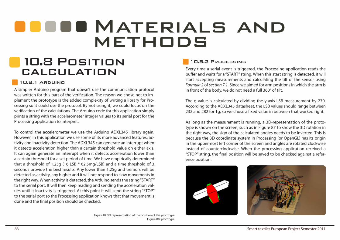
Smart textiles European Project Semester 201183
Materials and methods
10 . 8 Position calculation
10.8.1 ArduinoA simpler Arduino program that doesn’t use the communication protocol was written for this part of the verification. The reason we chose not to im-plement the prototype is the added complexity of writing a library for Pro-cessing so it could use the protocol. By not using it, we could focus on the verification of the calculations. The Arduino code for this application simply prints a string with the accelerometer integer values to its serial port for the Processing application to interpret.
To control the accelerometer we use the Arduino ADXL345 library again. However, in this application we use some of its more advanced features: ac-tivity and inactivity detection. The ADXL345 can generate an interrupt when it detects acceleration higher than a certain threshold value on either axis. It can again generate an interrupt when it detects acceleration lower than a certain threshold for a set period of time. We have empirically determined that a threshold of 1.25g (16 LSB * 62.5mg/LSB) and a time threshold of 3 seconds provide the best results. Any lower than 1.25g and tremors will be detected as activity, any higher and it will not respond to slow movements in the right way. When activity is detected, the Arduino sends the string “START” to the serial port. It will then keep reading and sending the acceleration val-ues until it inactivity is triggered. At this point it will send the string “STOP” to the serial port so the Processing application knows that that movement is done and the final position should be checked.
10.8.2 ProcessingEvery time a serial event is triggered, the Processing application reads the buffer and waits for a “START” string. When this start string is detected, it will start accepting measurements and calculating the tilt of the sensor using Formula 2 of section 7.1. Since we aimed for arm positions in which the arm is in front of the body, we do not need a full 360° of tilt.
The g value is calculated by dividing the y-axis LSB measurement by 270. According to the ADXL345 datasheet, the LSB values should range between 232 and 282 for 1g, so we chose a fixed value in between that worked right.
As long as the measurement is running, a 3D-representation of the proto-type is shown on the screen, such as in Figure 87 To show the 3D rotation in the right way, the sign of the calculated angles needs to be inverted. This is because the 3D coordinate system in Processing (or OpenGL) has its origin in the uppermost left corner of the screen and angles are rotated clockwise instead of counterclockwise. When the processing application received a “STOP” string, the final position will be saved to be checked against a refer-ence position.
Figure 87 3D representation of the position of the prototypeFigure 88 prototype

Ruben Beldé Lara Hernández Cores Daniël Lacko Alberto Moñux Arenas Alexander Ziegler 84
Materials and methods
10 . 9 Movementcalculation
10.9.1 arduino and processing
For this application the Arduino and Processing application of the previ-ous section are used. The only change we made in this version is to let the Processing application not only show a 3D-representation of the prototype while the measurement is running, but also log these the measurements to a file. This will allow the Processing application (or any other 3D application) to retrace the user’s movements on the screen and compare them to a refer-ence movement.We’ve built a dataset using three movements: for movement 1 the prototype is rotated over its x-axis towards the y-axis (clockwise) and back, for move-ment 2 the prototype is rotated over its y-axis towards the x-axis (clockwise) and for movement 3 it is rotated over the z-axis from the x-axis towards the y-axis (counterclockwise).
10.9.2 Matlab
In order to test how well the correlation functions would work, we logged each of the movements 25 times. Looking at the plots of the third data file for each of the movements in Figures 89 and 90, we can clearly see that only the first 100 samples will be significant. After these first 100 samples the sig-nal turns either to noise or to a constant level. We compared more data files with each other and this observation always seemed to hold true. Therefore, we have decided to cross-correlate only the first 100 samples of the data file from each movement.
Figure 89 – Plot of the values of each axis for third data file from each movement.

Smart textiles European Project Semester 201185
Materials and methods
To prove our concept that correlation could provide a good way to evaluate movements, we first calculate the auto-correlation for a random data file for a movement, and then we calculate the cross-correlation of this data file and other data files from the same movement, see Figure 91. We then calculate the cross-correlation of this data file and data files from other movements, see Figure 92 and Figure 93
Figure 90 Cross-correlation of the x-values of various data files from the same movement

Ruben Beldé Lara Hernández Cores Daniël Lacko Alberto Moñux Arenas Alexander Ziegler 86
Materials and methods
Figure 91 – Cross-correlation of the y-values of three data files from movement 1.

Smart textiles European Project Semester 201187
Looking at these figures, we see that if different data files for the same move-ment are compared the amplitude at the peak is always near 1 and the peak occurs within the range of -30 and 30 lags. Therefore, we will use these thresholds to determine whether a movement is similar or not. Whenever the signal’s maximum amplitude within lag -30 and 30 is lower than 0.6, we will consider the movements to be different. We’ve written a small Matlab program that compares to movements this way and simply answers whether they are similar or not to test these thresholds.
Figure 92 Cross-correlation of the y-values of different data files from movement 1Figure 93 Cross-correlation of the y-values of different data files from movement 3.

Ruben Beldé Lara Hernández Cores Daniël Lacko Alberto Moñux Arenas Alexander Ziegler 88
10 . 10 Final pro-totype
The final prototype was designed to be more like the actual product and uses most of the same components, though using the configuration and pin map-ping of the first prototype. The main board is a LilyPad with an Atmega328, which is connected to a LED strip containing 3 LilyPad LEDs and two Lily-Pad VibeBoards, see Figure 94. This configuration was chosen to verify the sewability and comfortability, as well as test the effectiveness of the motion guidance.
To test it, the Arduino and Processing programs, described from section 10.8 and 10.9, were altered to provide the guidance. The test user should hold their arm level at the start of the program. At this point, they have been notified of which movements they are allowed to make. The LEDs will then start blinking in upwards or downwards to indicate the direction of the next movement. The user will then move in the right way and stop moving when he feels he is in the right position. If he is not in the right position, the system will make the vibrating element opposite to the desired direction vibrate. After he reaches the right position, the feedback for that position will stop and the cycle will repeat over again.
Materials and methods
Figure 94 Final prototype 1
Figure 95 Final prototype 2

Smart textiles European Project Semester 201189
11 Tai chi
11 . 1 Tai chi classTo get familiar with tai chi Alex, Lara and Ruben did a tai chi class, we learned about different stages during a lesson of tai chi, the difficulties, some move-ments and the breathing. The respiration rate is the most important and most controllable during a session of Tai chi During a session of tai chi it is necessary to be as calm as possible this is possible by breathing 4 seconds in and 6 seconds out. That’s why at the beginning of each exercise there is a relaxing exercise focused on the breathing. Someone who starts with tai chi will be in beginners faze for over four years for elderly this will even take a longer period. With our product it should be possible to practice more, have a faster learning curve and easier understand the meaning of tai chi
Figure 98 Warming up
Figure 97 Respiration exercise 2
Figure 96 Respiration exercise

Ruben Beldé Lara Hernández Cores Daniël Lacko Alberto Moñux Arenas Alexander Ziegler 90
11 . 2 what is tai chi?
tai chi
Tai chi classes have become very popular in hospitals, clinics, elderly care homes, and community centers in the last twenty years. It is well known as a stress training for elderly that improves the balance and your inner peace. As a result of this popularity there has been some divergence between those who say tai chi is a martial art, those who practice it for aesthetic appeal (wushu) , and those who are doing it for the benefits it gives to the body. The wushu aspect is primarily for show. Lately tai chi teachers believe they have to keep the balance between all the forms like yin and yang have a balance.
Tai chi is a ritual movement, It stimulates flexibility and responsiveness and provide a sense of vitality as it considers the human body as an organism that contains vital energy or Ch’i. The energy flows through specific channels and the main function of the practice ofT’ai-ch’i is to ensure the continuity of this flow.
“To live well we need to know how to live, experience life, enjoy life and dis-tinguished life. Through the breathing you know that there is life and breath through experience over time and life while sipping a distinction at the end what is the best life. “
1 - There should be an overall sense of coordination, and the body should act as a unit.2 - The feet should be firmly located and the rest of the body relaxed, but not loose, so that the Ch’i can penetrate, hip and waist directed energy.3 - Every gesture and step is quiet and uninterrupted and the breathing un-forced and soft.4 - The focus will be on left and right, forward and backward, up and down, inside andoutside, full (“the substantial”) and empty (“insubstantial”)5- the movements are executed slow and concentrated.
Peter Yan
11.2.1 Form
Figure 99 Ritual movement

Smart textiles European Project Semester 201191
On the next pages we tried to prove and improve some of our design ideas with ergonomic and usability research. we made mockups and basic proto-types of the electronics and the styling part. We tested it on ourselves and on test persons. After doing the tests we used the information we gathered into our definitive design.
Test person one is a male person of 75 year who is still quiet active, he loves to ride his bike and to work in the garden, he has a problem with his knees and needs an operation for this problem but he still remains active waiting for his surgery. 10 years ago he broke his left shoulder and his collar bone with a biking accident because of this he lost some flexibility in his shoulder, he can’t reach the same places with his left as with his right hand. The test person has no problems with his condition or with his mental capacity. The test persons isn’t afraid of the new technology.
The second test person is a woman of 76 years old, sometimes during the day she has to rest because she is starting to feel a little bit tired. She is a little bit afraid of electronics in her clothing but she understands that it can lead to solutions for elderly persons. She also has broken her shoulder but after an operation she can’t feel any difference between her two shoulders. She went a lot to the physiotherapist and the problem healed completely. Mentally she has totally no problems but she feels like she can’t follow the latest technologies.
12 . 1 Preface
12Ergonomics and usability
Figure 100 Test userr 1. Figure 101 Test user 2

Ruben Beldé Lara Hernández Cores Daniël Lacko Alberto Moñux Arenas Alexander Ziegler 92
12 . 2 Light
The positive feedback system is critical in the project that is why we tested it with people of our target group. We designed a light-scenario on the cloth-ing and presented it to two persons out of our target group. We tried to simu-late the light on the clothing with tape and changed different aspects on the clothing and on the tape.
12.2.1 standing position testing
Figure 102 Light testing 1.Figure 103 Suit testing
Ergonomics and usability
Figure 104 Light testing 2

Smart textiles European Project Semester 201193
We tested the interpretation of the light, the visibility of the light, the posi-tion and the looks of the light. The conclusions were clear: it was too difficult for the test persons to interpret all the feedback at the same time. Therefore we adapted the scenario and made it simpler, we first wanted a complete guiding system with the light and simplified it to a reminding function with an indication in what way to move. This reminding function is very useful especially for elderly with a bad memory. With the implementation of this feedback they can practice without the help of a teacher and without the constant negative feedback. This kind of feedback is especially very interest-ing in the early stages of learning tai chi; the base of the sport can easily be taught with the light. Elderly start with simple slow movements and in most cases they don’t have the fast progress of a younger person the light can help fastening up their abilities of tai chi.
Warming up
Figure 106 Light testing 3. Figure 107 Light testing 4
Ergonomics and usability
Figure 105 Rendering light

Ruben Beldé Lara Hernández Cores Daniël Lacko Alberto Moñux Arenas Alexander Ziegler 94
12 . 3 Suit
The textile is cotton polyester this textile doesn’t need a lot of maintenance it doesn’t need to be ironed and it is easily hand washable. The price of this textile is also acceptable it’s only half the price of kimono’s made out of Japa-nese silk (€160). At the wrist and the ankle there is a more tight part this is made out of a stretchable nylon.
Clothing always comes in different sizes; this is also in tai chi clothing very important, especially because our clothing is focused on elderly. it should fit between the 5th and 95th percentile for woman and men between an age of 65 and 85. We can work in three different sizes small, medium and large. The values in the attached table are in centimeter. And fit these specifications. For the ankle and the wrist we will have to consider the stretchable textile, this gives us more freedom but we can’t stretch the textile too far.
12.3.1 Textile
12.3. 2 Sizes
small medium largeheight 157,8 167,4 177,2chest around 96,52 109 122waist around 71,12 81,28 91,44wrist around 144 160 178ankle around 190 204 218
Figure 108 Tai chi park
Ergonomics and usability
Table 5 Sizes
Figure 109 Ergonomics

Smart textiles European Project Semester 201195
The zipper goes diagonal from the left shoulder to the right thigh. This is the easiest way for elderly to open a vest.
12.3.3 Zipper and stretching part of the pants
Figure 112 Streching pants
Figure 111 Zipper
Figure 110 Shoulder test
The upper part of the pants consists out of two parts: the stretching area at the side and the measuring area in front of the pants. In the pants we mea-sure the respiration rate with a resistive wire. the stretching part takes care of a perfect fit.
Ergonomics and usability

Ruben Beldé Lara Hernández Cores Daniël Lacko Alberto Moñux Arenas Alexander Ziegler 96
12 . 4 Component placement
Our elderly target group shouldn’t be aware of the electronics inside the clothing; because of this the components will be hidden underneath a dou-ble layer of textile.. The sound sensor and vibrating elements are sewn on this tighter piece of textile. Most of the components are too small to feel inside the clothing only the arduino lillypads and the button on the right arm have to be an exact place for not noticing. All the components are sewn in on the inside and can’t be touched.
The vibrating elements have to be on the most effective place on the arms and the legs. During our project we tried to define what the most perfect place was. Daniel made a test setup out of two vibrating elements, a Arduino LyliPad battery holder, a AAA battery and a arduino LyliPad processor. This setup we placed on our legs. The vibrating elements can’t be pressed to hard on the skin because the vibration becomes invalid this way. The position of the vibrating element is also very important we place two pairs at each fore-arm and under part of the leg positioned in a corner of 180 degrees. They are sewn on the tight part made out of nylon close to the skin for the best effect. Every different person has a different sensitivity of the skin that is why the hardness of the vibration is changeable in the app on the tablet.
Ergonomics and usability
Figure115 Components in arm
Figure 113 Arm placement. Figure 114 ankle placement

Smart textiles European Project Semester 201197
arduino lilypad
arduino lilypad
battery
buttonheart rate sensor
arduino lilypad basepoint
12 . 5 place in suit
in the suit there are 5 arduino lilypads integrated, four of these are part of the motion capturing device and one as a base point for sending all the data to the tablet. The four microcontrollers are connected with the base point with a zigbee connection and the data at the base point is sent to the tablet with a Bluetooth 15 m range connection. At the right wrist there is a sound sensor for the heart rate detec-tion and at the left forearm the button is placed. Every com-ponent is connected to the battery with a conductive wire.
Ergonomics and usability
Figure 116 Component placement
12.5.1 COMPLETE SYSTEM SPECIFICA-TION
Since we have decided to use XBee for communication, we will need five separate LilyPad Main Boards, one for each sensor/feedback unit and one main board to handle information coming from all of them and send it to the microcontroller. We will refer to the former just as ‘main board’ and to the latter as ‘base station controller’. The base station controller will also directly receive input from the stretch sensors. The heart rate sensor will be incorpo-rated at the right wrist of the suit and connected to the sensor/feedback unit on the lower right arm. Figure 116 shows an image of where all of the components should go.

Ruben Beldé Lara Hernández Cores Daniël Lacko Alberto Moñux Arenas Alexander Ziegler 98
12 . 6 BatteryThere are two possible places of the battery in the back of the upper part and at the thigh. Because we are working with elderly the thigh is the best option. At the thigh the elderly is capable to see the battery when they have to remove or place it. It is also possible to have a tactile connection on this place with two press buttons. The battery fits perfect into the pocket and is connected with a cable to the suit.
Ergonomics and usability
Figure 120 Cable test
Figure 117 Defining place battery Figure 118 Battery placement
Figure 119 Battery with press buttons

Smart textiles European Project Semester 201199
Figure 122 Press button
Figure 123 Battery render
Ergonomics and usability
Figure 121 Render battery placement

Ruben Beldé Lara Hernández Cores Daniël Lacko Alberto Moñux Arenas Alexander Ziegler 100
12 . 7 ButtonThe button is one of the most important and difficult parts of the suit. We de-cided in the beginning to limit the number of control buttons to maximum three buttons, a pause button a button to start the last exercise and a button to skip to the next exercise. We could make more buttons but this would make the controls too difficult for elderly people. The pause button must be easily reachable for fast stops and therefore we placed the button combina-tion at the right forearm.
The arduino lylipad buttons we sew in are very small so we designed two plates consisting out of a sandwich of two materials, a harder PE and softer EVA foam for a bigger pressure surface. These plates can also be sewn in and will have as effect that the buttons easily can be pressed. Both at the same time with the whole hand to pause and one half to go last or next exercise. The diameter of the whole button is 40mm; this is more than big enough for elderly people who aren’t used to work with small buttons
Figure 124 Button. Figure 125 Place button test
Figure 126 Explosion view of the button
Ergonomics and usability

Smart textiles European Project Semester 2011101
Our interface is completely focus on elderly people and their abilities, a user friendly interface with a lot of tactile feedback would make it a lot easier for them.
The important part is that the icons and the meaning of the icons have to be perfectly understandable by elderly. With a touch screen we have a gestural interface that combines “direct” physical control with digital interface design. If we want to design an interface we have to know how a finger works and what possible combinations are feasible. Also, people are interacting with interfaces in a range of positions and contexts that go beyond simply stand-ing or sitting in front of a screen. So we will have to search further than only pointing, beyond fingertips, knowing how people can use their body to hold, view, reach and interact.
In other words, it is necessary to know your target group, and design for their requirements taking care of the ergonomic design.
Ergonomics and usability
Figure 127 Hands movements. Figure 128 Thumbs
12 . 8 The hand

Ruben Beldé Lara Hernández Cores Daniël Lacko Alberto Moñux Arenas Alexander Ziegler 102
12 . 9 Tablet
The integrated user-interface demands a high level of prototype integration, concept and usability testing.Having the first approach to our design, we developed quick and dirty user-interface prototypes for effective research. At the end of the process we did design prototyping and testing with physical mock-ups in order to prove and be sure about our stepsAt the beginning the interface was more complicatedand had a lot of but-tons and options. The goal was to give the user more freedom of choice, but after reconsidering our target group we decided to cut some of the options and design a simple and intuitive interface instead. The most difficult part of interface design is interpreting how the user will respond to the touch screen that requires them. All the buttons are designed To resemble real buttons by using shadow and lighting tricks, which makes the interface feel more natural to the elderly. We use visual feedback to indi-cate that an action has taken place (such as a button being pressed).
The test users found the selection of the exercise the most difficult part of the interface. Moving the square was not clear at first sight but once they had learned it, it became easier and more fun. We chose to stick to this design because a requiring to the user to simply press a square would increase the chance of uninteneded .At the end we’ll be able to empower the gestures that they already do and give them further influence and meaning.
12.9.1 Interface
Ergonomics and usability
Figure 129 User testing tablet. Figure 130 Interface

Smart textiles European Project Semester 2011103
12 . 10 feedback
The heart rate and respiration rate are shown at the chest and the abdomen. The position of the light should be clear for the user and for the surrounding people, for example the tai chi trainer. The way the light of the OLEDs interact should be as clear as possible and the visibility of the light should be tested.
The conclusions:The balls at the abdomen have to give less information; they may not give the F6 breathing and your own breathing at the same time that is why we have chosen for only showing your own breathing. A light at the warning point at the wrist will light up when the user don’t succeed in F6 breathing. And the surrounding person can see the persons breathing in only a glance.
The balls at the chest were clear for the test persons and the light at the chest is easy to observe during a tai chi session. Here we also implement a warning point for the heart rate at the wrist because this places it is the most notice-able on the body.
12.10 .1 Heart and respiration
Ergonomics and usability
Figure 131 Feedback testing

Ruben Beldé Lara Hernández Cores Daniël Lacko Alberto Moñux Arenas Alexander Ziegler 104
12 . 11 PatternTo make an end product we needed to know how the final product was going to be made, this is which is why we made a sewing pattern on pattern paper remove, with the help of a fashion designer. The sizes:(small, medium and large) can be based on this pattern by making the pattern larger or smaller. The pattern is a basic kimono vest and pants.
Ergonomics and usability
Figure 132 Pattern in construction
Figure 133 Vest pattern
Figure 135 Pants pattern Figure 134 Constructing patter
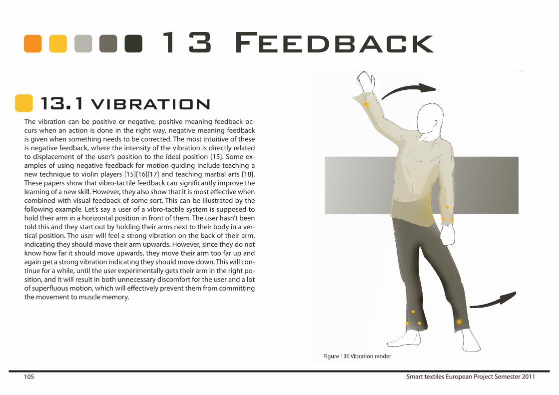
Smart textiles European Project Semester 2011105
13 . 1 vibration
13 Feedback
The vibration can be positive or negative, positive meaning feedback oc-curs when an action is done in the right way, negative meaning feedback is given when something needs to be corrected. The most intuitive of these is negative feedback, where the intensity of the vibration is directly related to displacement of the user’s position to the ideal position [15]. Some ex-amples of using negative feedback for motion guiding include teaching a new technique to violin players [15][16][17] and teaching martial arts [18]. These papers show that vibro-tactile feedback can significantly improve the learning of a new skill. However, they also show that it is most effective when combined with visual feedback of some sort. This can be illustrated by the following example. Let’s say a user of a vibro-tactile system is supposed to hold their arm in a horizontal position in front of them. The user hasn’t been told this and they start out by holding their arms next to their body in a ver-tical position. The user will feel a strong vibration on the back of their arm, indicating they should move their arm upwards. However, since they do not know how far it should move upwards, they move their arm too far up and again get a strong vibration indicating they should move down. This will con-tinue for a while, until the user experimentally gets their arm in the right po-sition, and it will result in both unnecessary discomfort for the user and a lot of superfluous motion, which will effectively prevent them from committing the movement to muscle memory.
Figure 136 Vibration render

Ruben Beldé Lara Hernández Cores Daniël Lacko Alberto Moñux Arenas Alexander Ziegler 106
Feedback
13 . 2 LightsTherefore, we propose a system where the acquisition and translation are done by mimicking a teacher or video, the positions are corrected during the action step itself using vibro-tactile feedback, and the evaluation of the movement is done by showing the user a 3D-model of his own movement and the ideal movement for the finer details of the movement. This would significantly shorten the translation and feedback phases, especially when using the system for a longer time. In the first few tries, the user would take instructions from a teacher, translate them to movement and require feed-back from the teacher in the usual way or from the 3D-model. When they get more proficient and they roughly know how to perform the movements, the vibro-tactile feedback will provide them with a way to correct their position and they can compare their movements to the 3D-model, eliminating the need for a new translation from the teacher’s movement to the user’s move-ment. When they get even more proficient in performing the movements, they will no longer need to rely on the 3D-model to compare their move-ments, but the vibro-tactile feedback will allow them to tine-tune their posi-tion, again eliminating a step in the feedback and translation system. At this point, the feedback is solely tactile and since movements and posi-tions also rely on feeling, the translation step will effectively be much shorter. Because this will allow the user to do more repetitions in a shorter time, the motion can be committed to muscle memory quicker and in a more comfort-able and intuitive way.
In the next page is explained how the lights work in order to give the positive feedback to the user.
The explanation about the OLEDs is given in the section 8.7
(Right page) Picture137 Feedback light

Smart textiles European Project Semester 2011107
Bending: the line goes down Stretching: the line goes up Full stretch Line is in the direction you have to move
Bended: the line is shorter Full stretch is a full line
Direction to move is indicated at the end of the sleeve. with a light thats moves around the wrist
Feedback

Ruben Beldé Lara Hernández Cores Daniël Lacko Alberto Moñux Arenas Alexander Ziegler 108
Feedback
The feedback of the heart rate is given at the middle of the chest on the right of the zipper. It exist out of 5 balls that are rotating among the same point at the centre of the balls. This circulating movement is a representation of the heart rate, the faster it rotates the faster your heartbeat is going. when the maximum heart rate of the user is reached a warning light at the left wrist will might up to give an attention to the user. The maximum healthy heart rate is for each user different, it is calculated with a simple formula: 220- age. Because there is a profile implemented on the tablet the suit will know your maximum heart rate.
The feedback of the respiration rate is given at the bottom of the vest on the left of the zipper. It exist out of 6 balls moving slowly trough each other and OLED light that will shine and fade away at the rhythm of the breathing. The moving of the balls is a representation of oxygen particles. The user will also have a warning light at the left wrist next to the other warning light but with another color when is breathing speed is too high. A perfect respiration rate is an F6 respiration rate, this means 4 seconds breathing in and 6 seconds breathing out.
13 . 3 Measurements
Figure 138 Feedback measurements Heart rate and respiration rate(Next three pages) Figure 139 Interface

Smart textiles European Project Semester 2011109
1 Exercise
Select between the four options: Exercise, Feedback, Options and Personal.
You have to move from the catalogue to your exercise.
First press the APP of the program
The options open like a pop up. When you press the excercise it appears an explanation of it.
14 Interface
On the next three pages we tried to de-fine in a simple way how to operate with the interface. We tried to use simple hand gestures for elderly people together with opportunities a tablet can give us. The ges-tures have to be clear and structured and they may not be misunderstanded.
elderly users

Ruben Beldé Lara Hernández Cores Daniël Lacko Alberto Moñux Arenas Alexander Ziegler 110
2 Feedback
You can move and see your level every day.
2.1 Select the exercise you want the feedback
2.3 Select the kind of graph
Interface

Smart textiles European Project Semester 2011111
3 Options
4 Personal
Select between the Lights, Vibration and sounds.
Profile, you could go directly to your feed-back with the buttons.
Friends, you can move between them. When you press you can see your friends level and their personaldetails
Interface

Ruben Beldé Lara Hernández Cores Daniël Lacko Alberto Moñux Arenas Alexander Ziegler 112
Interface

Smart textiles European Project Semester 2011113
15 Productpresentation
On the next pages we placed a detailed de-scription of how to use our product , we used some presentation renders of the product and images of the interface.
first we have two product presentations that explains the movement of tai chi. The suit can be used in every environment on any time. In China the practicing of tai chi is a part of life it can be done in team or alone at every part of the open city, nature or even inside.
appart for the guidance mode for training there is also a freedom that opens your possibilities.
15 . 1 presentation renders
Figure 140 Motion renderFigure 141 Enviromental render

Ruben Beldé Lara Hernández Cores Daniël Lacko Alberto Moñux Arenas Alexander Ziegler 114
Productpresentation
Figure 142 Render with tablet
The tablet is always at a range of 15 meter of the suit and it is used during tai chi for processing all the data.
The tablet doesn’t have to be out, it can be safe away in your backpack.

Smart textiles European Project Semester 2011115
Productpresentation
Figure 143 Social render
The social mode of the suit can be used for doing tai chi together with your friends or tai chi trainer.
the colors of the suit can merge to-gether into a new color
the vibration and light will now in-teract with the other suit and not with the tablet like before.

Ruben Beldé Lara Hernández Cores Daniël Lacko Alberto Moñux Arenas Alexander Ziegler 116
PANTONE DS 45 8-CC:31 M:26 Y:29 K:0
PANTONE 7CC:64 M:67 Y:61 K:57
Colours suit
Colours lights
life
emotions
powerenergy
mind
senses empathy
Productpresentation
life emotions power energy mind senses empathy
Figure 144 Render with colours

Smart textiles European Project Semester 2011117
Productpresentation
Figure 145 Interface1
APP logo Homepage
Move from the catalogue to your exercisebar for selecting a move-ment.
Options like a popup in the exercise menu.

Ruben Beldé Lara Hernández Cores Daniël Lacko Alberto Moñux Arenas Alexander Ziegler 118
Productpresentation
Figure 146 Interface 2
On the page Level the user gets information about his exercise, res-piration rate and heart rate. it is a friendly and simple way to give the necessary information to the user.
Feedback of the exer-cise menu
With the motion capturing we are able to give a 3D representation of your movement in the tablet.
This 3D representation we can compare with the perfect movement.
The user gets a motivational line of infor-mation with this feedback system.

Smart textiles European Project Semester 2011119
Productpresentation
Figure 147 Interface 3
Options menu
The light can be adapted in this menu.
The most important part in light is how to select the color of the suit that gives you the feedback of your mood.
There are similar pages for vibration and sound.

Ruben Beldé Lara Hernández Cores Daniël Lacko Alberto Moñux Arenas Alexander Ziegler 120
Productpresentation
Figure 148 Interface 4
Personal menu
At the profile page the user can see his level and go directly to the feedback pages.
In the page friends the user can see how his friends are doing. the size of the balls is an in-dication of there level. When the user touches a ball a profilepage of these person pops up with more information.

Smart textiles European Project Semester 2011121
Productpresentation
Timono is a smart textile suit together with an App on android that is perfect for learning and doing tai chi. The timono suit combines posi-tive feedback of light, negative feedback of vibration and measure-ment feedback into a device especially made for elderly who need an extra stimulation for being active. Timono is a new style of kimono with integrated technology based on the user.
15 . 2 What is timono?
app logo
Figure 149 Logo timono Figure 150 App timono
Typography: Bahuhaus Md Bt

Ruben Beldé Lara Hernández Cores Daniël Lacko Alberto Moñux Arenas Alexander Ziegler 122

Smart textiles European Project Semester 2011123
16 Scenarios
(next 7 pages) Figure 151 Scenarios

Ruben Beldé Lara Hernández Cores Daniël Lacko Alberto Moñux Arenas Alexander Ziegler 124
Scenarios
before a user can start with an exercise the tablet has to be set. In a the tablet a user can choose the exercise, the duration of the exer-cise, the color of the suit, etc. The tablet has the function of control. They can set the tablet on a time they want, it doesn’t have to beexactly before the exercise.
the user need to put on the suit before starting the exercise.
a last step before the tai chi practice can start is the battery, this has to be con-nected to the suit at the thigh and you can close the zipper.
when the battery is connected you can connect the two press buttons between the top and the lower part. This action will also function as an on/off button. The line next to the zipper will light up, this is the warn-ing that the suit is on the tablet is in range of the suit with a Bluetooth connection: max15m around you.

Smart textiles European Project Semester 2011125
before a tai chi session there is a warm up needed, this warm-up is the breathing exercise. The user has to breathe 1 minute and 30 seconds in F6 breathing to calm down. F6 breathing is 4seconds breathing in and 6 seconds breathing out. During this session the tablet cali-brates with the sensors for the mo-tion capturing in the suit. The suit gives already feedback about the breathing
when the breathing is 1minute 30 seconds in F6 breathing the suit will give a vibration at the wrist. This means that your breathing exercise is completed and you can start with the tai chi practice.
the start position is the posture a user takes when he or she wants to start the exercise. The suit measures the position.
Scenarios

Ruben Beldé Lara Hernández Cores Daniël Lacko Alberto Moñux Arenas Alexander Ziegler 126
when you stand 2 seconds in your starting position the light in the suit will blink twice. Af-ter this two blinks the exercise will start.
the positive and negative feed-back will start. The negative feed-back is a vibration at the fore arm or shinbone that will lead you to the right position. The posi-tive feedback is light emitted by OLED’s. The change of the sur-face of the OLED’s will indicate the movements to make.
if the movement comes at an end the user has to stand in a end position for completing the measurements.
for next movements you must repeat these 3 steps again.
Scenarios

Smart textiles European Project Semester 2011127
if necessary the exercises can be stopped by pressing the switch at the right forearm.
the pause button is divided in 2 parts after pressing the pause button you will have to choose between last exercise again < and next exercise > on this button.
Possibility of merging lights and follows the movements of somebody else: when a suit detects the proximity of another suit with Bluetooth, their colors of the timono suit can merge and they can do tai chi to-gether. It is also possible to send the movements of one suit to the other suit. In this case a master can teach the student how to do tai chi with the help of the suit.
Scenarios

Ruben Beldé Lara Hernández Cores Daniël Lacko Alberto Moñux Arenas Alexander Ziegler 128
the feedback of the heart is given on the chest with OLED light. The balls move in around in a circle like the bloodstream. The faster the circle is going the faster your heartbeat is.
the maximum heart rate of the user is defined by asimple rule: 220- age of the person. If the heart rate is higher than this value a red warning points gives you an alert on the wrist for calming down.
the feedback of the respira-tion is given on the abdomen with OLED light. The balls are fading away and come back on the rhythm of your breath-ing. The balls also move slowly trough each other like oxygen particles.
when the battery is connected you can connect the two press buttons between the top and the lower part. This action will also function as an on/off button. The line next to the zipper will light up, this is the warn-ing that the suit is on the tablet is in range of the suit with a Bluetooth connection: max15m around you.
Scenarios

Smart textiles European Project Semester 2011129
if the movement comes at an end the user has to stand in a end position for completing the measure-ments.
for turning of the suit the user have to open the press buttons. When the press buttons are disconnected there can’t be electricity in the suit
after turning the suit of you will be reminded by removing the press buttons about the battery. You have to disconnect the bat-tery and take it out of the suit for different reasons such as washing of the clothing and re-charging the battery.
after your tai chi training we can check the feedback on the tablet. You can share some information on a profile or just compare with your practices of before,…
Scenarios

Ruben Beldé Lara Hernández Cores Daniël Lacko Alberto Moñux Arenas Alexander Ziegler 130

Smart textiles European Project Semester 2011131
17 Results
Communication protocol
In this section, the results of the test we have done with the prototypes will be shown and discussed.
The computer running the PC application was connected to the Arduino us-ing a USB-cable and several possible scenarios were tested. Figure 152 shows a screenshot of the command sequence run one time. This means that one measurement is done and one guidance packet is sent for both the LEDs and the VibeBoards. Figure y shows the responses of actuators to these com-mand packages.
As Figures x and y show, the right packets are being sent from both sides, the data is received and interpreted in the right way and the Arduino responds to commands as expected. This means that the communication protocol is successfully implemented.
Figure 152 comand test mesuementse
Figure 153 Leds after the commands has been set

Ruben Beldé Lara Hernández Cores Daniël Lacko Alberto Moñux Arenas Alexander Ziegler 132
Position calculation
In Figure x, the prototype is held in a various different positions and the 3D-model on the screen is shown to follow these positions. However, there does seem to be a slight offset to the angles, probably because of the fixed maxi-mum LSB value (270) we used to determine g.
This result is good enough for a proof-of-concept, but in further applications a calibration should be added. This calibration could let the user hold their arms in a position where the z-axis of the accelerometer is turned up, mea-suring 1g, then in a position where the z-axis is pointed down to give the -1g value. The same should be done for the x- and y-axes. When enough samples are gathered for each axis, a 1g-offset for the each axis could be determined by taking the maximum LSB value. Dividing the measured LSB by this value to determine the pitch or roll would yield more accurate results.
Figure154 Position calculation test.
Results

Smart textiles European Project Semester 2011133
Movementevaluation
For the verification of the movement evaluation we have made a dataset of the 3 movements by taking the average of the first 100 samples for each axis of 25 data captures. Each movement was then performed a total of 10 times and compared to the movement in the dataset. The results for the move-ment evaluation can be found in Table x, which shows how each of the new movements was classified.
Overall, the detection rate is sufficient, except for the second movement. What’s even more promising is that we had no false detection. We are certain that cross-correlation would work with some more work on the algorithm. For example, we suspect it would work better if we would scale the input vectors instead of cutting everything but the first 100 samples of. By scaling the entire signal would be taken into consideration and this should improve the accuracy.
Results
Table 6 similarity of the movements

Ruben Beldé Lara Hernández Cores Daniël Lacko Alberto Moñux Arenas Alexander Ziegler 134
Figure 151 Enviroment render 2

Smart textiles European Project Semester 2011135
[1] Ruiz Robredo, G. “Electrónica básica para ingenieros”. Universidad de Cantabria. España, Junio 2001.[2] Robert Boylestad and Louis Nashelsky (1996). Electronic Devices and Circuit Theory, 7th Edition. Prentice Hall College Division. ISBN 978-0133757347. [3] R.C. Jaeger and T.N. Blalock (2004). Microelectronic Circuit Design (sec-ond ed.). McGraw-Hill. ISBN 0-07-232099-0.[4] Antonio F. Sánchez García, Miguel Castilla Fernández, Pedro F. Gayà Suñer. Edicions UPC, 2000. “ Circuits electronic basics, problems results “ Polithecnical University of Catalonia.[5] R. Jacob Baker (2010). CMOS Circuit Design, Layout and Simulation (Third ed.). New York: Wiley-IEEE. pp. 297, §9.2.1 and Figure 20.28, p. 636. ISBN 978-0-470-88132-3.[6] Thomas R.E., Rosa A.J. , Reverté 1992. Circuitos y señales: introducción a los circuitos lineales y de acoplamiento.[7] L.Turicchia, Bruno Do Valle, Jose L. Bohorquez, W.R. Sanchez, V. Misra, L. Fay, M. Tavakoli, R. Sarpeshkar. Ultralow-Power Electronics for Cardiac Moni-toring. s.l. : IEEE, 2010.[8] Panasonic. [Online] 2011. [Zitat vom: 06. 06 2011.] http://industrial.pana-sonic.com/www-cgi/jvcr13pz.cgi?E+SS+2+ABA5003+0+4+WW.[9] 1. R. Lukočius, J. A. Virbalis, J. Daunoras, A. Vegys. The Respiration Rate Estimation Method based on the Signal Maximums and Minimums Detec-tion and the Signal Amplitude Maximums and Minimums Detection and the Signal Amplitude. 2008.[10] 2. Mazeika G., Swanson R.,. Respiratory Inductance plethysmography. 2007.
[11] P. Kapur, M. Jensen, L. J. Buxbaum, S. A. Jax, K. J. Kuchenbecker, “Spa-tially Distributed Tactile Feedback for Kinesthetic Motion Guidance”, IEEE Haptics Symposium, Massachusetts, p.9, 2010.[12] D. Vlasic, R. Adelsberger, G. Vannucci, J. Barnwell, M. Gross, W. Matusik and J. Popovic, “Practical Motion Capture in Everyday Surroundings”, Massa-chusetts Institute of Technology, p. 9.[13] R. Slyper and J. K. Hodgins, “Action Capture with Accelerometers”, Eu-rographics/ACM SIGGRAPH Symposium on Computer Animation, Carnegie Mellon University, p. 7, 2008.[14] K. Bark, J. Wheeler, P. Shull, J. Savall and M. Cutkosky, “Rotational Skin Stretch Feedback: A Wearable Haptic Display for Motion”, IEEE Transactions, Vol. 3, No. 3, p.166-176, 2010. [15] J. van der Linden, E. Schoonderwaldt and J. Bird, “Good Vibrations: Guiding Body Movements with Vibrotactile Feedback”, Proceedings of the Third Workshop on Physicality, Cambridge, UK, p. 6, 2009. [16] J. van der Linden, E. Schoonderwaldt and J. Bird, “MusicJacket – Com-bining Motion Capture and Vibrotactile Feedback to Teach Violin Bowing”, Pervasive Interaction Lab, Department of Computing, The Open University, Milton Keynes, UK, p. 10.[17] R. Johnson, J. van der Linden, Y. Rogers, “MusicJacket: The efficacy of real-time vibro-tactile feedback for leaning to play the violin”, Department of Computing, The Open University, Milton Keynes, UK, p. 6, 2010. [18] A. Bloomfield and N. I. Badler, “Virtual Training via Vibrotactile Arrays”, Presence, Vol. 17, No. 2, p.103-120, Massachusetts Institute of Technology, 2008.
18 References

Ruben Beldé Lara Hernández Cores Daniël Lacko Alberto Moñux Arenas Alexander Ziegler 136
19 Appendix
see attachment

Smart textiles European Project Semester 2011137

1,500
6
1,500R
R
4R 3,500R4
R200
164
5,83
6R4
0,80
0161
6,50
0
10
63
10
12
20
1,50
0
10
DEBUR AND
EDGES
FINISH:
ANGULAR:
Q.A
MFG
APPV'D
CHK'D
part5WEIGHT:
A4
SHEET 1 OF 1SCALE:1:1
DWG NO.
NAME SIGNATURE
REVISIONDO NOT SCALE DRAWINGBREAK SHARP
Battery shellDATE
PUR
UNLESS OTHERWISE SPECIFIED:DIMENSIONS ARE IN MILLIMETERSSURFACE FINISH:TOLERANCES: LINEAR:
DRAWN
SolidWorks Student License Academic Use Only

number name page
Figure1 Moodboard midterm report 4
Figure2 Scenario tai chi midterm report 6Figure3 Tai chi 7
Figure4 Drawing 10
Figure5 Clothes 11
Figure6 Social 12
Figure7 Output 13
Figure8 Measurements 14
Figure9 Tablet 15
Figure10 Closing clothing 16
Figure11 Senor placement 17
Figure12 Drawing sensor 17
Figure13 Washabillity 18
Figure14 Button 18
Figure15 Led and OLED 18
Figure16 Touchscreen 19
Figure17 Connection 19
Figure18 Concept 1 22
Figure19 Concept 2 23
Figure20 Suit design 1 29
Figure21 Suit design 2 30
Figure22 suit design 3 31
Figure23 Suit design 4 32
Figure24 Suit design 5 33
Figure25 Interface design 1 34
Figure26 Interface design 2 35
Figure27 layout sketch 36
Figure28 Graphical representation of motion learning 41
Figure29 Accelerometer rotating over its x-axis. 42
Figure30 Pitch, roll and yaw. 42
Figure31 Dual-axis accelerometer rotating over its x-axis 43
Figure32 Accelerometer rotating over its x-axis, only using y value 43
Figure34 LiLyPad 328 Main Board. 45
Figure35 LilyPad VibeBoard. 45
Figure36 ADXL335 accelerometer. 45
Figure37 Specification of WM-63PR [2] 47
Figure38 Stretching sensor 47
Figure39 LilyPad Xbee Module 48
Figure40 Arduino Bluetooth Mate Gold 48
Figure41
External data flow between the user, mobile device and
textile system 49
Figure42
Internal data flow between the user, mobile device and
textile system. 50
Figure43 Input/output diagram. 51
Figure44 OLED’s 52
Figure45 Graph OLED 1 52
Figure46 Graph OLED 2 52
Figure47 Lilypad vibe board 56

Figure48 Utextile 57
Figure49 Render battery 58
Figure50 Draft battery 58
Figure51 Material 1 59
Figure52 Material 2 59
Figure53
Charging operation of textile at standard 230 V, 50 Hz
outlet 60
Figure54 Stages of charging 60
Figure55 Diode Graetz bridge 60
Figure56 AC to DC rectifier 60
Figure57 Approximation 61
Figure58
Input signal Vs versus flattened output signal Vo with
filter 61
Figure59 Schematic of a LM317 voltage regulator 61
Figure60 Voltage regulator with limitation 62
Figure61 Basic outline of charget output 63
Figure62
Schematic of charger, voltage rectifier and current
limiter 63
Figure63 Simulated charger output 64
Figure64 Simulation of charger system with battery connected 64
Figure65 Voltage regulator based LM317 67
Figure66 Simulation of voltage regulation 67
Figure67 Arduino uno board 71
Figure68 First prototype schematic, created with Fritzig. 72
Figure69 Use case diagram of the smart textile 73
Figure70 Use- case- diagram of the point of the working station 75
Figure71
Sequence diagram of displaying heart rate and motion
guidance 76
Figure72 Basic structure of a packet 77
Figure73 Packets used for acknowledge receipt 78
Figure74 Start measurement packet 78
Figure75 Stop measurement packet 78
Figure76 Disconnect packet 78
Figure77 Configuration of the textile 79
Figure78 Packet for transmitting acceleration information 79
Figure79 Packet for vital parameters 79
Figure80 Amount of guidance packets 80
Figure81 Vibration guidance 80
Figure82 Light guidance packet 80
Figure83 Described positioned definition 80
Figure84 Sequence diagram of a communication 81
Figure85 Debugging using RealTerm 83
Figure86 I²C addressing 84
Figure87 3D representation of the position of the prototype 85
Figure88 Prototype 85
Figure89
Plot of the values of each axis for third data file from
each movement 86
Figure90
Cross-correlation of the x-values of various data files
from the same movement 87

Figure91
Cross-correlation of the y-values of three data files from
movement 1 88
Figure92
Cross-correlation of the y-values of different data files
from movement 1 89
Figure93
Cross-correlation of the y-values of different data files
from movement 3 89
Figure94 Final prototype1 90
Figure95 Final prototype2 90
Figure96 Respiration exercise 1 93
Figure97 Respiration exercise 2 93
Figure98 Warming up 93
Figure99 Ritual movement 94
Figure100 Test user 1 95
Figure101 Test user 2 95
Figure102 Light testing 1 96
Figure103 Suit testing 96
Figure104 Light testing 2 96
Figure105 Rendering light 97
Figure106 Light testing 3 97
Figure107 Light testing 4 97
Figure108 Tai chi park 98
Figure109 Ergonomics 98
Figure110 Shoulder test 99
Figure111 Zipper 99
Figure112 Stretching pants 99
Figure113 Arm placement 100
Figure114 Ankle placement 100
Figure115 Components in arm 100
Figure116 Component placement 101
Figure117 Defining place battery 102
Figure118 Battery placement 102
Figure119 Battery with press buttons 102
Figure120 Cable test 102
Figure121 Render battery placement 103
Figure122 Press button 103
Figure123 Battery render 103
Figure124 Button 104
Figure125 Place button test 104
Figure126 Exploded view button 104
Figure127 Hand movement 105
Figure128 Thumbs 105
Figure129 User testing tablet 106
Figure130 Interface 106
Figure131 Feedback testing 107
Figure132 Pattern in construction 108
Figure133 Vest pattern 108
Figure134 Constructing pattern 108
Figure135 Pants pattern 108
Figure136 Vibration render 109
Figure137 Feedback light 110

Figure138 Feedback measurement heartrate and respiration rate 112
Figure139 Interface 113
Figure140 Motion render 117
Figure141 Environment render 117
Figure142 Render with tablet 118
Figure143 Social render 119
Figure144 Render with colors 120
Figure145 Interface 1 121
Figure146 Interface 2 122
Figure147 Interface 3 123
Figure148 Interface 4 124
Figure149 Logo Timono 125
Figure150 App Timono 125
Figure151 scenario's 126
Figure152 Command test measurement 133
Figure153 LEDs after the commands have been sent 133
Figure154 Position calculation test 134
Figure155 Environment render 2 137

Formula 1 – Determining the pitch of the accelerometer 42
formula 2 43
formula 3 Cross-correlation function continuous signals. 44
formula 4 Cross-correlation function discrete signals. 44
formula 5 Normalized cross-correlation, will peak at 1 at zero lag. 44

numbers name page
table1 tradeoff concept 24
table2 colours 28table3 sign of z- and y-value related to the quadrant. 42
table4 Excerpt from Atmega328P datasheet 83
table5 sizes 98
table6 Similarity of movements 134