A High Efficiency Surface Modification Process for Multiwalled Carbon Nanotubes by Electron...
6
A High Efficiency Surface Modification Process for Multiwalled Carbon Nanotubes by Electron Cyclotron Resonance Plasma Wen-Shou Tseng, † Chyuan-Yow Tseng, ‡ Pi-Kai Chuang, † An-Ya Lo, † and Cheng-Tzu Kuo* ,§ Department of Materials Science and Engineering, National Chiao Tung UniVersity, 1001 UniVersity Road, Hsinchu, Taiwan, Department of Vehicle Engineering, National Pingtong UniVersity of Science and Technology, 1, Hseuh Fu Road, Neipu Hsiang, Pingtung, Taiwan, and Institute of Materials and Systems Engineering, MingDao UniVersity, 369 Wen-Hua Road, Peetow, ChangHua, Taiwan ReceiVed: April 1, 2008; ReVised Manuscript ReceiVed: September 16, 2008 A novel process of surface modification for multiwalled carbon nanotubes (MWCNTs) by using electron cyclotron resonance plasma is proposed. The process uses a H 2 /O 2 gas mixture as etching gas and applies a bias voltage of -250 DCV to the process stage to extract and accelerate hydrogen and oxygen cations. The generated high density and high incident energy cations are employed to create defects on the surface of nanotubes through ion bombardment. The oxygen cations with high reduction potential are simultaneously applied, oxidizing the surface of the nanotubes so as to form functional groups on the side walls most effectively. Additionally, being far from the plasma sheath, the MWCNTs can be maintained at a lower temperature to prevent from being decomposed under the high energy plasma. The efficiency of this method was systematically analyzed using X-ray photoelectron spectroscopy, scanning electron microscopy, transmission electron microscopy, Raman spectroscopy, and thermogravimetric analysis. The experimental results have shown that the proposed method is a highly effective way to functionalize MWCNTs, resulting in the nanotubes with high concentration of oxygen-containing functional groups and minimal structural damage within very short process time. 1. Introduction Because of their fascinating mechanical and electrical proper- ties, 1 for the past decade carbon nanotubes (CNTs) have been considered as promising materials for many different applica- tions. 2-5 One of the key difficulties for application is the required separation of a single tube from agglomerated bundles by dispersing them in an aqueous or polymer matrix. Until recently, most approaches have attempted to functionalize the nanotubes by way of chemical modification, fluorination, and polymer wrapping. 6-8 The theory behind this is that the formation of polar functional groups on the surface of CNTs enhances their solubility and dispersion abilities in water or polymers. At present, the chemical modification method is the most common; in this process, CNTs are normally refluxed or sonicated in a strong acid, such as HNO 3 and/or H 2 SO 4 , to introduce oxygen- containing functional groups, such as -CdO, -C-OH, and -COOH, to the surface. However, the harsh conditions inherent in this method may introduce wall damage, decreasing their stability and even cleaving them into shorter pieces. 9-11 Wet processes may also give rise to some unfavorable issues such as waste treatment, as well as time and cost efficiency issues. As compared to the chemical modification processes, plasma treatment has gained lots of attention recently because it is a solvent-free, time efficient, versatile, and environmentally friendly procedure for surface modification. 12-26 In addition, this method can provide the greatest opportunity to scale up the production if the system is optimized. Therefore, plasma treatment has been used for a long time in deposition and etching processes in many industrial fields. In most cases for surface modification, CNTs are normally treated through exposure to the plasma. The generated ions, radicals, and UV light in plasma interact with the CNT surface, creating active defect sites and bonding functional groups to these sites. 18 Although plasma treatment has been shown to be effective in facial modification of CNTs, some have mentioned that it may cause serious structural damage due to the high energy and temperature plasma within very short time. 18,21 An alternative that circumvents these issues is placing the nanotubes away from plasma sheath and extracting plasma ions by applying a bias voltage so as to reduce temperature, radiation, and ion density. However, in most designs, plasma sources are working at around 0.1-1 Torr pressure, which leads to low mean-free-path; this in turn leads to low etching efficiency if the alternative is applied. Active plasma at higher-vacuum pressure may be an optimal solution, but this results in a low density plasma that cannot be activated. ECR plasma system has been a popular etching method in many applications because, with divergent magnetic flux and high bias voltage, this system can possess excellent features of high ionization efficiency, high density plasma generation in low-pressure vacuum, and effective plasma ion extraction and transportation. 27 These give the advantages that the positive or negative ions can be easily extracted and transported toward the specimen with high incident energy; the specimen can be placed far from plasma sheath and then treated at relative low temperature. These advantages are very important for conducting a highly efficient etching process and causing no severe structural damage of the specimen. On the basis of this idea, we propose a method to manage the difficulties in plasma treatment of CNTs mentioned above. The method involves using ECR plasma system and applying an H 2 /O 2 gas mixture as an etching gas to generate high density * To whom correspondence should be addressed. E-mail: kuoct@ mdu.edu.tw. † National Chiao Tung University. ‡ National Pingtong University of Science and Technology. § MingDao University. J. Phys. Chem. C 2008, 112, 18431–18436 18431 10.1021/jp8028165 CCC: $40.75 2008 American Chemical Society Published on Web 11/01/2008
-
Upload
independent -
Category
Documents
-
view
1 -
download
0
Transcript of A High Efficiency Surface Modification Process for Multiwalled Carbon Nanotubes by Electron...
A High Efficiency Surface Modification Process for Multiwalled Carbon Nanotubes byElectron Cyclotron Resonance Plasma
Wen-Shou Tseng,† Chyuan-Yow Tseng,‡ Pi-Kai Chuang,† An-Ya Lo,† and Cheng-Tzu Kuo*,§
Department of Materials Science and Engineering, National Chiao Tung UniVersity, 1001 UniVersity Road,Hsinchu, Taiwan, Department of Vehicle Engineering, National Pingtong UniVersity of Science andTechnology, 1, Hseuh Fu Road, Neipu Hsiang, Pingtung, Taiwan, and Institute of Materials and SystemsEngineering, MingDao UniVersity, 369 Wen-Hua Road, Peetow, ChangHua, Taiwan
ReceiVed: April 1, 2008; ReVised Manuscript ReceiVed: September 16, 2008
A novel process of surface modification for multiwalled carbon nanotubes (MWCNTs) by using electroncyclotron resonance plasma is proposed. The process uses a H2/O2 gas mixture as etching gas and applies abias voltage of -250 DCV to the process stage to extract and accelerate hydrogen and oxygen cations. Thegenerated high density and high incident energy cations are employed to create defects on the surface ofnanotubes through ion bombardment. The oxygen cations with high reduction potential are simultaneouslyapplied, oxidizing the surface of the nanotubes so as to form functional groups on the side walls most effectively.Additionally, being far from the plasma sheath, the MWCNTs can be maintained at a lower temperature toprevent from being decomposed under the high energy plasma. The efficiency of this method was systematicallyanalyzed using X-ray photoelectron spectroscopy, scanning electron microscopy, transmission electronmicroscopy, Raman spectroscopy, and thermogravimetric analysis. The experimental results have shown thatthe proposed method is a highly effective way to functionalize MWCNTs, resulting in the nanotubes withhigh concentration of oxygen-containing functional groups and minimal structural damage within very shortprocess time.
1. IntroductionBecause of their fascinating mechanical and electrical proper-
ties,1 for the past decade carbon nanotubes (CNTs) have beenconsidered as promising materials for many different applica-tions.2-5 One of the key difficulties for application is the requiredseparation of a single tube from agglomerated bundles bydispersing them in an aqueous or polymer matrix. Until recently,most approaches have attempted to functionalize the nanotubesby way of chemical modification, fluorination, and polymerwrapping.6-8 The theory behind this is that the formation ofpolar functional groups on the surface of CNTs enhances theirsolubility and dispersion abilities in water or polymers. Atpresent, the chemical modification method is the most common;in this process, CNTs are normally refluxed or sonicated in astrong acid, such as HNO3 and/or H2SO4, to introduce oxygen-containing functional groups, such as -CdO, -C-OH, and-COOH, to the surface. However, the harsh conditions inherentin this method may introduce wall damage, decreasing theirstability and even cleaving them into shorter pieces.9-11 Wetprocesses may also give rise to some unfavorable issues suchas waste treatment, as well as time and cost efficiency issues.
As compared to the chemical modification processes, plasmatreatment has gained lots of attention recently because it is asolvent-free, time efficient, versatile, and environmentallyfriendly procedure for surface modification.12-26 In addition,this method can provide the greatest opportunity to scale upthe production if the system is optimized. Therefore, plasmatreatment has been used for a long time in deposition and etching
processes in many industrial fields. In most cases for surfacemodification, CNTs are normally treated through exposure tothe plasma. The generated ions, radicals, and UV light in plasmainteract with the CNT surface, creating active defect sites andbonding functional groups to these sites.18 Although plasmatreatment has been shown to be effective in facial modificationof CNTs, some have mentioned that it may cause seriousstructural damage due to the high energy and temperature plasmawithin very short time.18,21 An alternative that circumvents theseissues is placing the nanotubes away from plasma sheath andextracting plasma ions by applying a bias voltage so as to reducetemperature, radiation, and ion density. However, in mostdesigns, plasma sources are working at around 0.1-1 Torrpressure, which leads to low mean-free-path; this in turn leadsto low etching efficiency if the alternative is applied. Activeplasma at higher-vacuum pressure may be an optimal solution,but this results in a low density plasma that cannot be activated.
ECR plasma system has been a popular etching method inmany applications because, with divergent magnetic flux andhigh bias voltage, this system can possess excellent features ofhigh ionization efficiency, high density plasma generation inlow-pressure vacuum, and effective plasma ion extraction andtransportation.27 These give the advantages that the positive ornegative ions can be easily extracted and transported towardthe specimen with high incident energy; the specimen can beplaced far from plasma sheath and then treated at relative lowtemperature. These advantages are very important for conductinga highly efficient etching process and causing no severestructural damage of the specimen. On the basis of this idea,we propose a method to manage the difficulties in plasmatreatment of CNTs mentioned above.
The method involves using ECR plasma system and applyingan H2/O2 gas mixture as an etching gas to generate high density
* To whom correspondence should be addressed. E-mail: [email protected].
† National Chiao Tung University.‡ National Pingtong University of Science and Technology.§ MingDao University.
J. Phys. Chem. C 2008, 112, 18431–18436 18431
10.1021/jp8028165 CCC: $40.75 2008 American Chemical SocietyPublished on Web 11/01/2008
and high incident energy hydrogen and oxygen cation streamto create high density defects on the surface of multiwalledcarbon nanotubes (MWCNTs) through highly efficient ionbombardment with minor negative consequences. Because oftheir high reduction potential, oxygen cations are simultaneouslyused to oxidize the MWCNT surface so as to form oxygen
functional groups with high concentration on the side walls.For comparison, acid treatment using HNO3/H2SO4 solution wasalso conducted for 9 h to functionalize MWCNTs. The resultingsurface structure was analyzed by X-ray photoelectron spec-troscopy (XPS). The morphology changes were observed usingscanning electron microscopy (SEM) as well as transmissionelectron microscopy (TEM). In addition, Raman spectroscopywas used to monitor the formation of defects, and thermogravi-metric analysis (TGA) was carried out to measure the thermalstability of the MWCNTs.
2. Experimental Section
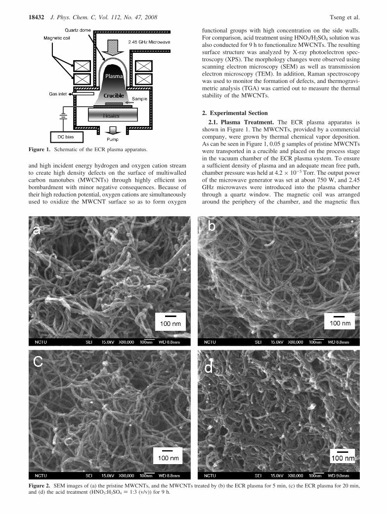
2.1. Plasma Treatment. The ECR plasma apparatus isshown in Figure 1. The MWCNTs, provided by a commercialcompany, were grown by thermal chemical vapor deposition.As can be seen in Figure 1, 0.05 g samples of pristine MWCNTswere transported in a crucible and placed on the process stagein the vacuum chamber of the ECR plasma system. To ensurea sufficient density of plasma and an adequate mean free path,chamber pressure was held at 4.2 × 10⁻³ Torr. The output powerof the microwave generator was set at about 750 W, and 2.45GHz microwaves were introduced into the plasma chamberthrough a quartz window. The magnetic coil was arrangedaround the periphery of the chamber, and the magnetic flux
Figure 1. Schematic of the ECR plasma apparatus.
Figure 2. SEM images of (a) the pristine MWCNTs, and the MWCNTs treated by (b) the ECR plasma for 5 min, (c) the ECR plasma for 20 min,and (d) the acid treatment (HNO3:H2SO4 ) 1:3 (v/v)) for 9 h.
18432 J. Phys. Chem. C, Vol. 112, No. 47, 2008 Tseng et al.
density was 875 Gauss to meet the ECR condition at themicrowave frequency used. A H2/O2 gas mixture with a flowratio of 25/25 (sccm/sccm) was used as an etching gas. A biasvoltage of -250 DCV was applied to the stage to extract andaccelerate the hydrogen and oxygen cations in the plasma towardthe specimens. Once the stage temperature reached 400 °C, theplasma treatment was conducted for 5 and 20 min.
2.2. Acid Treatment. 0.02 g of pristine MWCNT powderwas immersed in 10 mL of HNO3/H2SO4 (HNO3:H2SO4 ) 1:3(v/v)) solution, and the CNTs/acid mixture was then ultrasoni-cated for 9 h at room temperature. Subsequently, the mixturewas diluted with deionized water and filtered by using a 0.2µm porous polytetrafluoroethylene (PTFE) membrane disk toremove the excess acid from the solution. At last, the depositedblack powder was washed from the disk filter using ethanoland then dried at 110 °C on a hotplate for 16 h.
2.3. Material Characterization. To observe the morphologychanges, the samples of pristine MWCNTs and the MWCNTstreated by the ECR plasma and acid treatments were measuredby using a SEM (JEOL, JSM-6500F). Before the measurement,each sample was sonicated in ethanol for 30 min and dispersedonto a silicon wafer. Meanwhile, the microstructures of thesamples were characterized by TEM (JEOL JEM-2100).The samples were prepared by dispersing and then depositingthe black powder on lacy carbon grids by using ethanol.
XPS (Perkin-Elmer model PHI 1600) was performed todetermine the chemical changes on the surface of nanotubes.Being a sensitive technique, XPS is used to probe material fromthe surface down to 5 nm deep so as to estimate the extent ofaromatic group formation on the surface of the nanotubes. Priorto measurement, each specimen was attached to Scotch tape toavoid dispersion of the nanotubes in the vacuum chamber.Monochromated Al KR radiation (hν ) 1486.6 eV) was usedas the photon source, and photoelectrons were collected at anangle of 54.7° relative to the normal direction of the specimensurface. The energy resolution of the system was set to 0.2 eV.During C1s spectrum analysis (Spectral Data Processor (SDP)v4.0, XPS international, LLC), background noise was subtractedby using the “Linear” mode in the range between 281.5 and
293 eV, and the component peak fitting was performed by usingGaussian line shapes.
Raman spectroscopy (Jobin YVON LabRam HR800) pro-vided a rapid way to monitor the defect formation of MWCNTs.The exciting source was an Ar laser (514 nm) focused (50×)to a 2 µm spot size. All spectra were collected with fiveaccumulations of 3 s each. TGA (TA Q500) was used tocharacterize the changes in thermal stability with a heating rateof 10 °C/min in air flow (60 mL/min).
3. Results and Discussion
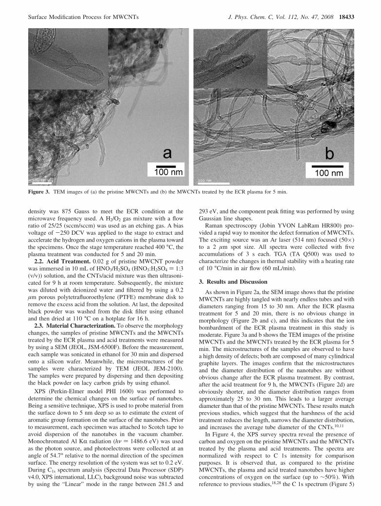
As shown in Figure 2a, the SEM image shows that the pristineMWCNTs are highly tangled with nearly endless tubes and withdiameters ranging from 15 to 30 nm. After the ECR plasmatreatment for 5 and 20 min, there is no obvious change inmorphology (Figure 2b and c), and this indicates that the ionbombardment of the ECR plasma treatment in this study ismoderate. Figure 3a and b shows the TEM images of the pristineMWCNTs and the MWCNTs treated by the ECR plasma for 5min. The microstructures of the samples are observed to havea high density of defects; both are composed of many cylindricalgraphite layers. The images confirm that the microstructuresand the diameter distribution of the nanotubes are withoutobvious change after the ECR plasma treatment. By contrast,after the acid treatment for 9 h, the MWCNTs (Figure 2d) areobviously shorter, and the diameter distribution ranges fromapproximately 25 to 30 nm. This leads to a larger averagediameter than that of the pristine MWCNTs. These results matchprevious studies, which suggest that the harshness of the acidtreatment reduces the length, narrows the diameter distribution,and increases the average tube diameter of the CNTs.10,11
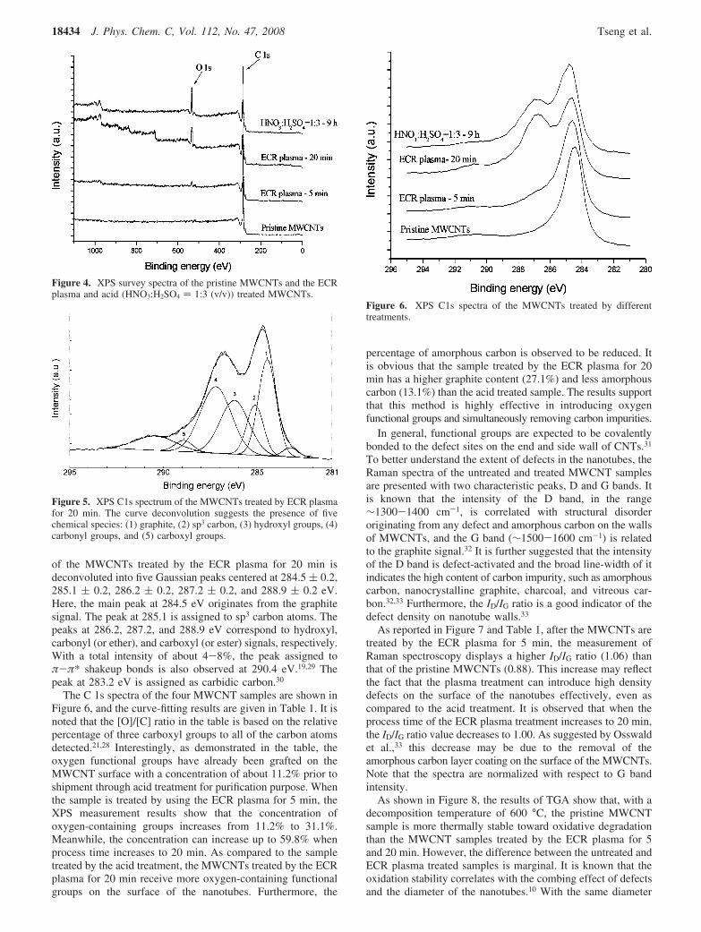
In Figure 4, the XPS survey spectra reveal the presence ofcarbon and oxygen on the pristine MWCNTs and the MWCNTstreated by the plasma and acid treatments. The spectra arenormalized with respect to C 1s intensity for comparisonpurposes. It is observed that, as compared to the pristineMWCNTs, the plasma and acid treated nanotubes have higherconcentrations of oxygen on the surface (up to ∼50%). Withreference to previous studies,18,28 the C 1s spectrum (Figure 5)
Figure 3. TEM images of (a) the pristine MWCNTs and (b) the MWCNTs treated by the ECR plasma for 5 min.
Surface Modification Process for MWCNTs J. Phys. Chem. C, Vol. 112, No. 47, 2008 18433
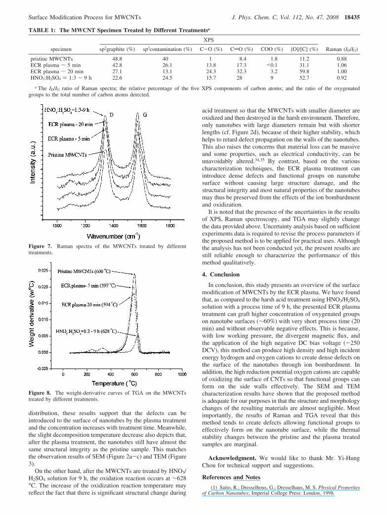
of the MWCNTs treated by the ECR plasma for 20 min isdeconvoluted into five Gaussian peaks centered at 284.5 ( 0.2,285.1 ( 0.2, 286.2 ( 0.2, 287.2 ( 0.2, and 288.9 ( 0.2 eV.Here, the main peak at 284.5 eV originates from the graphitesignal. The peak at 285.1 is assigned to sp3 carbon atoms. Thepeaks at 286.2, 287.2, and 288.9 eV correspond to hydroxyl,carbonyl (or ether), and carboxyl (or ester) signals, respectively.With a total intensity of about 4-8%, the peak assigned toπ-π* shakeup bonds is also observed at 290.4 eV.19,29 Thepeak at 283.2 eV is assigned as carbidic carbon.30
The C 1s spectra of the four MWCNT samples are shown inFigure 6, and the curve-fitting results are given in Table 1. It isnoted that the [O]/[C] ratio in the table is based on the relativepercentage of three carboxyl groups to all of the carbon atomsdetected.21,28 Interestingly, as demonstrated in the table, theoxygen functional groups have already been grafted on theMWCNT surface with a concentration of about 11.2% prior toshipment through acid treatment for purification purpose. Whenthe sample is treated by using the ECR plasma for 5 min, theXPS measurement results show that the concentration ofoxygen-containing groups increases from 11.2% to 31.1%.Meanwhile, the concentration can increase up to 59.8% whenprocess time increases to 20 min. As compared to the sampletreated by the acid treatment, the MWCNTs treated by the ECRplasma for 20 min receive more oxygen-containing functionalgroups on the surface of the nanotubes. Furthermore, the
percentage of amorphous carbon is observed to be reduced. Itis obvious that the sample treated by the ECR plasma for 20min has a higher graphite content (27.1%) and less amorphouscarbon (13.1%) than the acid treated sample. The results supportthat this method is highly effective in introducing oxygenfunctional groups and simultaneously removing carbon impurities.
In general, functional groups are expected to be covalentlybonded to the defect sites on the end and side wall of CNTs.31
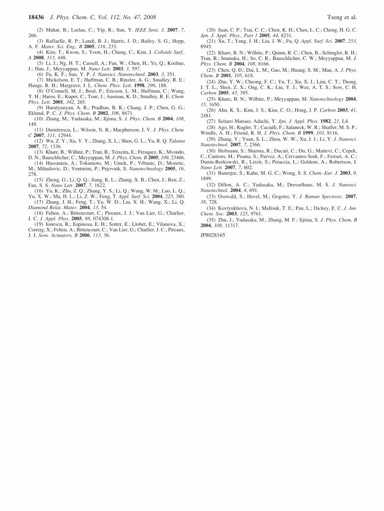
To better understand the extent of defects in the nanotubes, theRaman spectra of the untreated and treated MWCNT samplesare presented with two characteristic peaks, D and G bands. Itis known that the intensity of the D band, in the range∼1300-1400 cm-1, is correlated with structural disorderoriginating from any defect and amorphous carbon on the wallsof MWCNTs, and the G band (∼1500-1600 cm-1) is relatedto the graphite signal.32 It is further suggested that the intensityof the D band is defect-activated and the broad line-width of itindicates the high content of carbon impurity, such as amorphouscarbon, nanocrystalline graphite, charcoal, and vitreous car-bon.32,33 Furthermore, the ID/IG ratio is a good indicator of thedefect density on nanotube walls.33
As reported in Figure 7 and Table 1, after the MWCNTs aretreated by the ECR plasma for 5 min, the measurement ofRaman spectroscopy displays a higher ID/IG ratio (1.06) thanthat of the pristine MWCNTs (0.88). This increase may reflectthe fact that the plasma treatment can introduce high densitydefects on the surface of the nanotubes effectively, even ascompared to the acid treatment. It is observed that when theprocess time of the ECR plasma treatment increases to 20 min,the ID/IG ratio value decreases to 1.00. As suggested by Osswaldet al.,33 this decrease may be due to the removal of theamorphous carbon layer coating on the surface of the MWCNTs.Note that the spectra are normalized with respect to G bandintensity.
As shown in Figure 8, the results of TGA show that, with adecomposition temperature of 600 °C, the pristine MWCNTsample is more thermally stable toward oxidative degradationthan the MWCNT samples treated by the ECR plasma for 5and 20 min. However, the difference between the untreated andECR plasma treated samples is marginal. It is known that theoxidation stability correlates with the combing effect of defectsand the diameter of the nanotubes.10 With the same diameter
Figure 4. XPS survey spectra of the pristine MWCNTs and the ECRplasma and acid (HNO3:H2SO4 ) 1:3 (v/v)) treated MWCNTs.
Figure 5. XPS C1s spectrum of the MWCNTs treated by ECR plasmafor 20 min. The curve deconvolution suggests the presence of fivechemical species: (1) graphite, (2) sp3 carbon, (3) hydroxyl groups, (4)carbonyl groups, and (5) carboxyl groups.
Figure 6. XPS C1s spectra of the MWCNTs treated by differenttreatments.
18434 J. Phys. Chem. C, Vol. 112, No. 47, 2008 Tseng et al.
distribution, these results support that the defects can beintroduced to the surface of nanotubes by the plasma treatmentand the concentration increases with treatment time. Meanwhile,the slight decomposition temperature decrease also depicts that,after the plasma treatment, the nanotubes still have almost thesame structural integrity as the pristine sample. This matchesthe observation results of SEM (Figure 2a-c) and TEM (Figure3).
On the other hand, after the MWCNTs are treated by HNO3/H2SO4 solution for 9 h, the oxidation reaction occurs at ∼628°C. The increase of the oxidization reaction temperature mayreflect the fact that there is significant structural change during
acid treatment so that the MWCNTs with smaller diameter areoxidized and then destroyed in the harsh environment. Therefore,only nanotubes with large diameters remain but with shorterlengths (cf. Figure 2d), because of their higher stability, whichhelps to retard defect propagation on the walls of the nanotubes.This also raises the concerns that material loss can be massiveand some properties, such as electrical conductivity, can beunavoidably altered.34,35 By contrast, based on the variouscharacterization techniques, the ECR plasma treatment canintroduce dense defects and functional groups on nanotubesurface without causing large structure damage, and thestructural integrity and most natural properties of the nanotubesmay thus be preserved from the effects of the ion bombardmentand oxidization.
It is noted that the presence of the uncertainties in the resultsof XPS, Raman spectroscopy, and TGA may slightly changethe data provided above. Uncertainty analysis based on sufficientexperiments data is required to revise the process parameters ifthe proposed method is to be applied for practical uses. Althoughthe analysis has not been conducted yet, the present results arestill reliable enough to characterize the performance of thismethod qualitatively.
4. Conclusion
In conclusion, this study presents an overview of the surfacemodification of MWCNTs by the ECR plasma. We have foundthat, as compared to the harsh acid treatment using HNO3/H2SO4
solution with a process time of 9 h, the presented ECR plasmatreatment can graft higher concentration of oxygenated groupson nanotube surfaces (∼60%) with very short process time (20min) and without observable negative effects. This is because,with low working pressure, the divergent magnetic flux, andthe application of the high negative DC bias voltage (-250DCV), this method can produce high density and high incidentenergy hydrogen and oxygen cations to create dense defects onthe surface of the nanotubes through ion bombardment. Inaddition, the high reduction potential oxygen cations are capableof oxidizing the surface of CNTs so that functional groups canform on the side walls effectively. The SEM and TEMcharacterization results have shown that the proposed methodis adequate for our purposes in that the structure and morphologychanges of the resulting materials are almost negligible. Mostimportantly, the results of Raman and TGA reveal that thismethod tends to create defects allowing functional groups toeffectively form on the nanotube surface, while the thermalstability changes between the pristine and the plasma treatedsamples are marginal.
Acknowledgment. We would like to thank Mr. Yi-HungChou for technical support and suggestions.
References and Notes
(1) Saito, R.; Dresselhous, G.; Dresselhaus, M. S. Physical Propertiesof Carbon Nanotubes; Imperial College Press: London, 1998.
TABLE 1: The MWCNT Specimen Treated by Different Treatmentsa
XPS
specimen sp2graphite (%) sp3contamination (%) C-O (%) CdO (%) COO (%) [O]/[C] (%) Raman (ID/IG)
pristine MWCNTs 48.8 40 1 8.4 1.8 11.2 0.88ECR plasma s 5 min 42.8 26.1 13.8 17.3 <0.1 31.1 1.06ECR plasma s 20 min 27.1 13.1 24.3 32.3 3.2 59.8 1.00HNO3:H2SO4 ) 1:3 - 9 h 22.6 24.5 15.7 28 9 52.7 0.92
a The ID/IG ratio of Raman spectra; the relative percentage of the five XPS components of carbon atoms; and the ratio of the oxygenatedgroups to the total number of carbon atoms detected.
Figure 7. Raman spectra of the MWCNTs treated by differenttreatments.
Figure 8. The weight-derivative curves of TGA on the MWCNTstreated by different treatments.
Surface Modification Process for MWCNTs J. Phys. Chem. C, Vol. 112, No. 47, 2008 18435
(2) Mahar, B.; Laslau, C.; Yip, R.; Sun, Y. IEEE Sens. J. 2007, 7,266.
(3) Raffaelle, R. P.; Landi, B. J.; Harris, J. D.; Bailey, S. G.; Hepp,A. F. Mater. Sci. Eng., B 2005, 116, 233.
(4) Kim, T.; Kwon, S.; Yoon, H.; Chung, C.; Kim, J. Colloids Surf.,A 2008, 313, 448.
(5) Li, J.; Ng, H. T.; Cassell, A.; Fan, W.; Chen, H.; Ye, Q.; Koehne,J.; Han, J.; Meyyappan, M. Nano Lett. 2003, 3, 597.
(6) Fu, K. F.; Sun, Y. P. J. Nanosci. Nanotechnol. 2003, 3, 351.(7) Mickelson, E. T.; Huffman, C. B.; Rinzler, A. G.; Smalley, R. E.;
Hauge, R. H.; Margrave, J. L. Chem. Phys. Lett. 1998, 296, 188.(8) O’Connell, M. J.; Boul, P.; Ericson, L. M.; Huffman, C.; Wang,
Y. H.; Haroz, E.; Kuper, C.; Tour, J.; Ausman, K. D.; Smalley, R. E. Chem.Phys. Lett. 2001, 342, 265.
(9) Harutyunyan, A. R.; Pradhan, B. K.; Chang, J. P.; Chen, G. G.;Eklund, P. C. J. Phys. Chem. B 2002, 106, 8671.
(10) Zhang, M.; Yudasaka, M.; Iijima, S. J. Phys. Chem. B 2004, 108,149.
(11) Dumitrescu, L.; Wilson, N. R.; Macpherson, J. V. J. Phys. Chem.C 2007, 111, 12944.
(12) Wu, Z. Y.; Xu, Y. Y.; Zhang, X. L.; Shen, G. L.; Yu, R. Q. Talanta2007, 72, 1336.
(13) Khare, B.; Wilhite, P.; Tran, B.; Teixeira, E.; Fresquez, K.; Mvondo,D. N.; Bauschlicher, C.; Meyyappan, M. J. Phys. Chem. B 2005, 109, 23466.
(14) Hassanien, A.; Tokumoto, M.; Umek, P.; Vrbanic, D.; Mozetic,M.; Mihailovic, D.; Venturini, P.; Pejovnik, S. Nanotechnology 2005, 16,278.
(15) Zheng, G.; Li, Q. Q.; Jiang, K. L.; Zhang, X. B.; Chen, J.; Ren, Z.;Fan, S. S. Nano Lett. 2007, 7, 1622.
(16) Yu, K.; Zhu, Z. Q.; Zhang, Y. S.; Li, Q.; Wang, W. M.; Luo, L. Q.;Yu, X. W.; Ma, H. L.; Li, Z. W.; Feng, T. Appl. Surf. Sci. 2004, 225, 380.
(17) Zhang, J. H.; Feng, T.; Yu, W. D.; Liu, X. H.; Wang, X.; Li, Q.Diamond Relat. Mater. 2004, 13, 54.
(18) Felten, A.; Bittencourt, C.; Pireaux, J. J.; Van Lier, G.; Charlier,J. C. J. Appl. Phys. 2005, 98, 074308-1.
(19) Ionescu, R.; Espinosa, E. H.; Sotter, E.; Llobet, E.; Vilanova, X.;Correig, X.; Felten, A.; Bittencourt, C.; Van Lier, G.; Charlier, J. C.; Pireaux,J. J. Sens. Actuators, B 2006, 113, 36.
(20) Juan, C. P.; Tsai, C. C.; Chen, K. H.; Chen, L. C.; Cheng, H. G. C.Jpn. J. Appl. Phys., Part 1 2005, 44, 8231.
(21) Xu, T.; Yang, J. H.; Liu, J. W.; Fu, Q. Appl. Surf. Sci. 2007, 253,8945.
(22) Khare, B. N.; Wilhite, P.; Quinn, R. C.; Chen, B.; Schingler, R. H.;Tran, B.; Imanaka, H.; So, C. R.; Bauschlicher, C. W.; Meyyappan, M. J.Phys. Chem. B 2004, 108, 8166.
(23) Chen, Q. D.; Dai, L. M.; Gao, M.; Huang, S. M.; Mau, A. J. Phys.Chem. B 2001, 105, 618.
(24) Zhu, Y. W.; Cheong, F. C.; Yu, T.; Xu, X. J.; Lim, C. T.; Thong,J. T. L.; Shen, Z. X.; Ong, C. K.; Liu, Y. J.; Wee, A. T. S.; Sow, C. H.Carbon 2005, 43, 395.
(25) Khare, B. N.; Wilhite, P.; Meyyappan, M. Nanotechnology 2004,15, 1650.
(26) Ahn, K. S.; Kim, J. S.; Kim, C. O.; Hong, J. P. Carbon 2003, 41,2481.
(27) Seitaro Matsuo; Adachi, Y. Jpn. J. Appl. Phys. 1982, 21, L4.(28) Ago, H.; Kugler, T.; Cacialli, F.; Salaneck, W. R.; Shaffer, M. S. P.;
Windle, A. H.; Friend, R. H. J. Phys. Chem. B 1999, 103, 8116.(29) Zhang, Y.; Yuan, S. L.; Zhou, W. W.; Xu, J. J.; Li, Y. J. Nanosci.
Nanotechnol. 2007, 7, 2366.(30) Hofmann, S.; Sharma, R.; Ducati, C.; Du, G.; Mattevi, C.; Cepek,
C.; Cantoro, M.; Pisana, S.; Parvez, A.; Cervantes-Sodi, F.; Ferrari, A. C.;Dunin-Borkowski, R.; Lizzit, S.; Petaccia, L.; Goldoni, A.; Robertson, J.Nano Lett. 2007, 7, 602.
(31) Banerjee, S.; Kahn, M. G. C.; Wong, S. S. Chem.-Eur. J. 2003, 9,1899.
(32) Dillon, A. C.; Yudasaka, M.; Dresselhaus, M. S. J. Nanosci.Nanotechnol. 2004, 4, 691.
(33) Osswald, S.; Havel, M.; Gogotsi, Y. J. Raman Spectrosc. 2007,38, 728.
(34) Kovtyukhova, N. I.; Mallouk, T. E.; Pan, L.; Dickey, E. C. J. Am.Chem. Soc. 2003, 125, 9761.
(35) Zhu, J.; Yudasaka, M.; Zhang, M. F.; Iijima, S. J. Phys. Chem. B2004, 108, 11317.
JP8028165
18436 J. Phys. Chem. C, Vol. 112, No. 47, 2008 Tseng et al.