STRUCTURE, SYNTHESIS, APPLICATIONS AND COMPARISON OF SINGLE WALLED AND MULTI WALLED CARBON...
14
[Wani*, 4.(7): July, 2015] ISSN: 2277-9655 (I2OR), Publication Impact Factor: 3.785 http: // www.ijesrt.com © International Journal of Engineering Sciences & Research Technology [383] IJESRT INTERNATIONAL JOURNAL OF ENGINEERING SCIENCES & RESEARCH TECHNOLOGY STRUCTURE, SYNTHESIS, APPLICATIONS AND COMPARISON OF SINGLE WALLED AND MULTI WALLED CARBON NANOTUBES Waseem Ahmad Wani*, Shabir Ahmad Sofi, Aijaz Ahmad Wani * Department Of Physics IFTM University Moradabad Department Of Physics IFTM University Moradabad Department Of Physics IFTM University Moradabad ABSTRACT Carbon nanotubes (CNTs) are allotropes of carbon. These cylindrical carbon molecules have interesting properties that make them potentially useful in many applications in nanotechnology, electronics, optics and other fields of materials science, as well as potential uses in architectural fields. They exhibit extraordinary strength and unique electrical properties, and are efficient conductors of heat. Their final usage, however, may be limited by their potential toxicity. Various methods have been thoroughly investigated for the growth of C N Ts. The best and the most commonly used method is Chemical Vapour Deposition (CVD ). The various techniques include Reaction Chamber heating, Plasma Enhanced CV D, Hot filament CVD , Microwave CVD. The structural uniformity of carbon nanotubes produced by plasma enhanced Chemical Vapour Deposition gives uniform height and diameter. This paper discusses about all the methods listed above and detail comparisons are listed. We have simulated the single layer and multi layer Carbon nanotube using nano explorer tool and enumerated its properties for various applications like power storage and medical applications. The simulated properties of CNT would be used for energy storage purpose as well for transmission of electrical energy. Though it is known that CNT’s have high aspect ratio, Young’s modulus over one terra Pascal, Tensile strength of 200 Gigapascal, these properties never remain the same for all the CNT’S. It depend s upon the method of preparation, catalyst used etc. So the properties of C N T are studied for specific conditions. Here it is proposed CNT can be modeled for particularly electrical storage purpose. KEYWORDS: Carbon nanotube, chemical vapour deposition, Plasma enhanced CV D, Multiwall nanotubes. INTRODUCTION In the recent years miniaturized components plays important role in all type of applications. One such structure is carbon nanotube; Carbon nanotubes (CNTs) are hollow cylinders of carbon atoms. Their appearance is that of rolled tubes of graphite, such that their walls are hexagonal carbon rings, and they are often formed in large bundles. The ends of CNTs are domed structures of six-membered rings, capped by a five-membered ring. There are two types of nanotubes: single-walled nanotubes (SWNTs) and multiwalled nanotubes (MWNTs), which differ in the arrangement of their graphene cylinders. SWNTs have only one single layer of graphene cylinders; while MWNTs have many layers (approximately 50) [1] [2].There are three types of nanotubes, armchair, zigzag, and chiral. Carbon nanotube can be a metal, an insulator or a semi-conductor. They differ symmetrically and can vary in function due to the way they “roll up.” The diameter of a carbon nanotube can be 50,000 times thinner than a human hair yet a nanotube is stronger than steel per unit weight. This paper discusses 1) Comparison of different methods about synthesis of carbon nanotube 2) Study of structure of SWNT, DWNT and MWNT carbon nanotube and calculated structure related parameters of three types of CNTs 3) Simulation of carbon nanotubes with different distortions 4) Study about the properties of carbon nanotube for Energy storage and Medical applications. CARBON NANOTUBE SYTHESIS –COMPARISON Generally, three techniques are being used for producing CNTs: 1) the carbon arc-discharge technique [3], [4][5]; 2) the laser-ablation technique [6][7]; and 3) the chemical vapor deposition (CVD) technique [8] –[9]. Among the CNTs, MWNTs were first discovered by Ijima in 1991 by the arc-discharge method [3]. After two years, Ijima and Ichihashi
-
Upload
independent -
Category
Documents
-
view
1 -
download
0
Transcript of STRUCTURE, SYNTHESIS, APPLICATIONS AND COMPARISON OF SINGLE WALLED AND MULTI WALLED CARBON...

[Wani*, 4.(7): July, 2015] ISSN: 2277-9655
(I2OR), Publication Impact Factor: 3.785
http: // www.ijesrt.com © International Journal of Engineering Sciences & Research Technology
[383]
IJESRT INTERNATIONAL JOURNAL OF ENGINEERING SCIENCES & RESEARCH
TECHNOLOGY
STRUCTURE, SYNTHESIS, APPLICATIONS AND COMPARISON OF SINGLE
WALLED AND MULTI WALLED CARBON NANOTUBES Waseem Ahmad Wani*, Shabir Ahmad Sofi, Aijaz Ahmad Wani
* Department Of Physics IFTM University Moradabad
Department Of Physics IFTM University Moradabad
Department Of Physics IFTM University Moradabad
ABSTRACT Carbon nanotubes (CNTs) are allotropes of carbon. These cylindrical carbon molecules have interesting properties
that make them potentially useful in many applications in nanotechnology, electronics, optics and other fields of
materials science, as well as potential uses in architectural fields. They exhibit extraordinary strength and unique
electrical properties, and are efficient conductors of heat. Their final usage, however, may be limited by their potential
toxicity. Various methods have been thoroughly investigated for the growth of C N Ts. The best and the most
commonly used method is Chemical Vapour Deposition (CVD ). The various techniques include Reaction Chamber
heating, Plasma Enhanced CV D, Hot filament CVD , Microwave CVD. The structural uniformity of carbon
nanotubes produced by plasma enhanced Chemical Vapour Deposition gives uniform height and diameter. This paper
discusses about all the methods listed above and detail comparisons are listed. We have simulated the single layer and
multi layer Carbon nanotube using nano explorer tool and enumerated its properties for various applications like power
storage and medical applications. The simulated properties of CNT would be used for energy storage purpose as well
for transmission of electrical energy. Though it is known that CNT’s have high aspect ratio, Young’s modulus over
one terra Pascal, Tensile strength of 200 Gigapascal, these properties never remain the same for all the CNT’S. It
depend s upon the method of preparation, catalyst used etc. So the properties of C N T are studied for specific
conditions. Here it is proposed CNT can be modeled for particularly electrical storage purpose.
KEYWORDS: Carbon nanotube, chemical vapour deposition, Plasma enhanced CV D, Multiwall nanotubes.
INTRODUCTIONIn the recent years miniaturized components plays important role in all type of applications. One such structure is
carbon nanotube; Carbon nanotubes (CNTs) are hollow cylinders of carbon atoms. Their appearance is that of rolled
tubes of graphite, such that their walls are hexagonal carbon rings, and they are often formed in large bundles. The
ends of CNTs are domed structures of six-membered rings, capped by a five-membered ring. There are two types of
nanotubes: single-walled nanotubes (SWNTs) and multiwalled nanotubes (MWNTs), which differ in the arrangement
of their graphene cylinders. SWNTs have only one single layer of graphene cylinders; while MWNTs have many
layers (approximately 50) [1] [2].There are three types of nanotubes, armchair, zigzag, and chiral. Carbon nanotube
can be a metal, an insulator or a semi-conductor. They differ symmetrically and can vary in function due to the way
they “roll up.” The diameter of a carbon nanotube can be 50,000 times thinner than a human hair yet a nanotube is
stronger than steel per unit weight. This paper discusses
1) Comparison of different methods about synthesis of carbon nanotube
2) Study of structure of SWNT, DWNT and MWNT carbon nanotube and calculated structure related
parameters of three types of CNTs
3) Simulation of carbon nanotubes with different distortions
4) Study about the properties of carbon nanotube for Energy storage and Medical applications.
CARBON NANOTUBE SYTHESIS –COMPARISON Generally, three techniques are being used for producing CNTs: 1) the carbon arc-discharge technique [3], [4][5]; 2)
the laser-ablation technique [6][7]; and 3) the chemical vapor deposition (CVD) technique [8]–[9]. Among the CNTs,
MWNTs were first discovered by Ijima in 1991 by the arc-discharge method [3]. After two years, Ijima and Ichihashi

[Wani*, 4.(7): July, 2015] ISSN: 2277-9655
(I2OR), Publication Impact Factor: 3.785
http: // www.ijesrt.com © International Journal of Engineering Sciences & Research Technology
[384]
[10] and Bethune et al. [11] produced SWNTs. The SWNTs were produced using metal catalyst in the arc-discharge
method. Thess et al. [6] synthesized bundles of aligned SWNTs by the laser- ablation technique. For the first time,
catalytic growth of MWNTs by CVD was proposed by Yacaman et al. [8]. The arc-discharge technique produces high
quality MWNTs and SWNTs. MWNTs do not need a catalyst for growth, while SWNTs can only be grown in the
presence of a catalyst in this method first time, Ebbesen and Ajayan [12] synthesized high-quality MWNTs having
diameters in the range of 2–20 nm and lengths of several micrometers at the gram level. SWNTs produced by laser-
ablation were ropes (or bundles) of 5–20 nm diameter and tens to hundreds of micrometers. SWNTs produced by
laser-ablation were ropes (or bundles) of 5–20 nm diameter and tens to hundreds of micrometers of length. When
synthesizing SWNTs, the by-products in the case of the arc-discharge and laser-ablation techniques are fullerenes,
graphitic polyhedrons with enclosed metal particles, and amorphous carbon [13]. The density and growth rate of CNTs
in Chemical vaporization Technique increase with an increase in temperature. Also, as the temperature increases, the
CNTs tend to be vertically aligned. By using CVD, excellent alignment and positional control on the nanometer scale
can be achieved in addition to controlling the diameter and the growth rate. A major drawback with the CVD technique
is that there are high defect densities in the MWNT structures grown by this process. It is believed that it is most likely
due to the lack of sufficient thermal energy for annealing CNTs because of relatively low growth temperature [13].
Usually the diameter of SWNT is in the range of 1.2 to 1.4 nm in arc discharge method [14], by using inert gas in arc
discharge method the diameter is plasma control in arc discharge method the diameter is around 1.37 nm [16]. But by
using chemical vapour deposition the diameter of SWNT is in the range of 0.6 to 1.2 nm. If both electrodes are graphite
in arc discharge method the main product will be Multi –Wall Nanotubes. But next to MWNTs a lot of side products
are formed such as fullerenes, amorphous carbon, and some graphite sheets. Purifying the MWNTs, means loss of
structure and disorders the walls [15]. Typical sizes for MWNTs are an inner diameter of 1-3 nm and an outer diameter
of approximately 10 nm. MWNT can be synthesized with low amount of defects in arc discharge method. Laser
vaporization method results in a higher yield for SWNT synthesis and the nanotubes have better properties and a
narrower size distribution than SWNTs produced by arc-discharge [15]. Nanotubes produced by laser ablation are
purer (up to about 90 % purity) than those produced in the arc discharge process.
The different techniques for the Carbon nanotubes synthesis with CVD have been developed, such as plasma enhanced
CVD, thermal chemical CVD, alcohol catalytic CVD, vapour phase growth, aero gel-supported CVD and laser-
assisted CVD. The plasma enhanced CVD method generates a glow discharge in a chamber or a reaction furnace by
a high frequency voltage applied to both electrodes. Figure 1 shows a schematic diagram of a typical plasma CVD
apparatus with a parallel plate electrode structure.
Figure 1: Schematic diagram of plasma CVD apparatus Taken from with permission. [15]
A substrate is placed on the grounded electrode. In order to form a uniform film, the reaction gas is supplied
from the opposite plate. Catalytic metal, such as Fe, Ni and Co are used on for example a Si, SiO2, or glass
substrate using thermal CVD or sputtering. After nanoscopic fine metal particles are formed, carbon nanotubes
will be grown on the metal particles on the substrate by glow discharge generated from high frequency power.
The catalyst has a strong effect on the nanotube diameter, growth rate, wall thickness, morphology and
microstructure. The diameter of the MWNTs is approximately 15 nm. The highest yield of carbon nanotubes
achieved was about 50% and was obtained at relatively low temperatures (below 3300 C). When growing
carbon nanotubes on a Fe catalytic film by thermal CVD, the diameter range of the Carbon nanotubes depends

[Wani*, 4.(7): July, 2015] ISSN: 2277-9655
(I2OR), Publication Impact Factor: 3.785
http: // www.ijesrt.com © International Journal of Engineering Sciences & Research Technology
[385]
on the thickness of the catalytic film. By using a thickness of 13 nm, the diameter distribution lies between
30 and 40 nm. When a thickness of 27 nm is used, the diameter range is between 100 and 200 nm.
The carbon nanotubes formed are multiwalled Carbon nanotubes]. Vapour phase growth is another synthesis
method of carbon nanotubes, directly supplying reaction gas and catalytic metal in the chamber without a
substrate [17]. The diameter of the carbon nanotubes by using vapour phase growth is in the range of 2–4 nm
for SWNTs and between 70 and 100 nm for MWNTs [17]. In aero-gel supported CVD method SWNTs are
synthesized by disintegration of carbon monoxide on an aero gel-supported Fe/Mo catalyst. Because of the
high surface area, the porosity and ultra-light density of the aero gels, the productivity of the catalyst is much
higher than in other methods]. In laser-assisted thermal CVD (LCVD) a medium power, continuous wave
CO2 laser, which was perpendicularly directed onto a substrate, pyrolyses sensitized mixtures of Fe(CO)5
vapour and acetylene in a flow reactor. The carbon nanotubes are formed by the catalyzing action of the very
small iron particles. By using a reactant gas mixture of iron pent carbonyl vapour, ethylene and acetylene both
single- and multi-walled carbon nanotubes are produced. Silica is used as substrate. The diameters of the
SWNTs range from 0.7 to 2.5 nm. The diameter range of the MWNTs is 30 to 80 nm [15]. In comparing all
three process PECVD has got typical yield of 20 to 100 % and also long tubes in μm with diameter of 0.6 to
4 m. Even MWNT of diameter 10 to 240 nm is possible in PECVD [15]. Only drawback is little bit structural
defects in MWNT in PECVD process.
CNT TYPES – STUDY OF ITS STRUCTURES A single wall carbon nanotube can be described as a graphene sheet rolled into a cylindrical shape so that the structure
is one-dimensional with axial symmetry Nanotubes have caps on each end of the graphene sheets, which contain six
pentagons. The caps are placed perfectly to fit the long cylindrical section. Carbon nanotubes are approximately a
nanometer wide and a few microns long. The classifications of the different symmetries of nanotubes are dependent
on the unit cell. The unit cell is a section of the carbon nanotube, which is broken down into vectors that describe the
spiral symmetry of the nanotube. Nanotube structures are represented by the following parameters [17]
1) Chiral vector = Ch = na1 + na2 ≡(n, m)
2) Translational vector = T = t1a1 + t2a2 ≡ (t1, t2)
3) Chiral angle = cosθ = (2n +m)/(2*√(n² + m² + n*m))
4) Length of chiral vector = L = a√(n²+ m²+ n* m)
Where a is the lattice constant
5) Diameter = dt = L/π
6) Number of hexagons in the unit cell = N = (2*(n² + m²+ n* m)/dR)
7) Symmetry vector = R = pa1 + qa2 ≡(p, q)
8) Pitch of the symmetry vector = τ= ((m*p – n*q)*T)/N
9) Rotation angle of the symmetry vector=ѱ= 2π/N (in radians)
where t1 = (2m + n)/dR ; t2 = -(2n + m)/dR ; dR = gcd(2n+m, 2m+n), n,m are length of chiral vector.[28]
CNT ARM CHAIR TYPE The symmetrical classification of an armchair nanotube is an achiral nanotube. Achiral means the nanotube has a
structure that is a mirror image of the original one. An armchair nanotube has a chiral vector where n = m, therefore
Ch =(n, n). The chiral angle θ is equal to 30°. For example, if Ch = (4,4) the nanotube is an armchair nanotube where
the chiral angle is equal to 30°. Figure 2 a and b shows the armchair type [4,4] and [10,10] carbon nanotube simulated
in nanotube modeler].

[Wani*, 4.(7): July, 2015] ISSN: 2277-9655
(I2OR), Publication Impact Factor: 3.785
http: // www.ijesrt.com © International Journal of Engineering Sciences & Research Technology
[386]
Figure 2.a shows SWNT of chiral vector (10,10) of bond
length 1.41 A0 and tube length 20 A0. Courtesy Nanotube modeler / jcrystal.com
Figure 2.b shows SWNT of chiral vector (4,4) of bond length 1.41 A° and tube length 20 A° . Courtesy Nanotube
modeler / jcrystal.com
CNT ZIG ZAG TYPE The symmetrical classification of a zigzag nanotube is an achiral nanotube, the same as an armchair nanotube. Achiral
means the nanotube has a structure that is a mirror image of the original one, which is illustrated in Figure 3. A zigzag
nanotube has a chiral vector where m = 0, therefore Ch = (n, 0). The chiral angle θ is equal to 00 . For example, if Ch
= (10, 0) the nanotube is a zigzag nanotube where the chiral angle is equal to 00 . To verify that we can use the formula
mentioned above. Figure 3 shows the Zigzag type of chiral vector (10,0) and has chiral angle always angle =00.
Figure 3 shows SWNT of chiral vector (10,0) of bond
length 1 .41 A0 and tube length 20 A0. Courtesy Nanotube
modeler / jcrystal .com
The symmetrical classification of a chiral nanotube is a chiral nanotube. Chiral means the nanotube has a
spiral symmetry, which does not give it an identically structured mirror image. Figure 4 illustrates the
structure of a chiral nanotube. A chiral nanotube has general n and m values, therefore Ch = (n, m). The
chiral angle θ is between 00 and 300, therefore 00 < θ < 300. For example, if Ch = (4, 2) the nanotube is a
chiral nanotube where the chiral angle is between 00 < θ < 300 [18].

[Wani*, 4.(7): July, 2015] ISSN: 2277-9655
(I2OR), Publication Impact Factor: 3.785
http: // www.ijesrt.com © International Journal of Engineering Sciences & Research Technology
[387]
Figure 4 shows SWNT of chiral vector (10,6) of bond
length 1 .41 A° and tube length 20A°. Courtesy Nanotube modeler / jcrystal .com
CNT – DOUBLE WALLED AND MULTIWALLED TYPES Double walled tube is constructed using Nano explorer and the separation between the sheets is around d + 0.34 nm
where „d „ is the diameter of the inner tube. Figure 5 a and b shows the Double walled carbon nanotube and figure 6
a and b shows the multiwalled carbon nanotube.
Figure 5 a double walled carbon nanotube from Nano explorer tool
Figure 5 b shows double walled carbon nanotube with separation of d + 0.34 nm, length of CNT = 25
A°. No of atoms = 894, No of bonds = 1297. Courtesy Nanotube modeler
Figure 6 a Multi walled carbon nanotube without cap Courtesy Nanotube modeler front View, Armchair
[10, 10]

[Wani*, 4.(7): July, 2015] ISSN: 2277-9655
(I2OR), Publication Impact Factor: 3.785
http: // www.ijesrt.com © International Journal of Engineering Sciences & Research Technology
[388]
Figure 6 b Multi walled carbon nanotube without cap – side view Courtesy Nano explorer
CNT CAPPED TYPE – GRAPH ENE SHEET All the above-simulated diagrams are without caps, Figure 7 a gives carbon nanotube with cap structure from nanotube
modeler. Figure 7b gives graphite sheet generated using the simulation program written in nanotube modeler with
height 15 A0 and width 20 A0 (No of rows and columns being 10). Figure 7c gives graphite sheet of 260 atoms with
364 bonds using Nanotube modeler of armchair CNT (10, 10)
Figure 7 a capped carbon nanotube of armchair type [5,5] Courtesy Nanotube modeler.
Figure 7 b is graphite sheet generated using Nanotube modeler
Figure 7 c is graphite sheet for arm chair carbon nanotube of [10, 10] using nanotube modeler.
In this session we have simulated some of the basic structures of carbon nanotube using Nano explorer and
Nano modeler, calculated and tabulated the structure parameters of three types of CNT and also generated
simple graphite sheet of CNT.

[Wani*, 4.(7): July, 2015] ISSN: 2277-9655
(I2OR), Publication Impact Factor: 3.785
http: // www.ijesrt.com © International Journal of Engineering Sciences & Research Technology
[389]
CNT SIM ULATIONS AND STRUCTURAL EFFECTS Distortion in carbon nanotubes mainly depends on the properties of carbon nanotube, its synthesis and growth etc.
Here we have simulated about the structural defects in carbon nanotube. There are mainly five basic important
distortions
1. XY distortion
2. Z distortion
3. Twist
4. Bend
5. Deformation due to hetero junction
The XY and Z distortions are due to structural deformations may rise due to carbon nanotube synthesis and
growth.When we measure the electrical and mechanical properties of the carbon nanotube through ATM and STM
probe, the tip of the probe may also distort the structure of carbon nanotube. Figure 8 a, b, c, d shows the XY and Z
distortion for (10, 10) armchair carbon nanotube. The minimum deformation in XY plane and Z plane is measured to
be 0.5 A°.
Figure 8 a Deformation in X-Y plane of (10,10) Armchair nanotube with length of tube 20 A0 and Bond length 1 .43 A0
Figure 8b Deformation in Z plane of (10,10) Armchair nanotube with length of tube 20A0 and Bond length 1.43A0
Figure 8 c Deformation due to both XY and Z plane courtesy: Nanotube modeler

[Wani*, 4.(7): July, 2015] ISSN: 2277-9655
(I2OR), Publication Impact Factor: 3.785
http: // www.ijesrt.com © International Journal of Engineering Sciences & Research Technology
[390]
In figure 8c the deformation of Carbon nanotube on all directions are shown. Figure 8d and e shows the twist in angle
of carbon nanotube and bend in length of carbon nanotube. Angle distortion in the simulation mainly due to lattice
mismatch and structural deformations etc. We have shown angle twist of Armchair nanotube due to non-uniform
arrangements of carbon atoms. The bend of the tube is due to increase in length of carbon nanotube as well as due to
formation hetero junctions. If the twist is above 2° the more structural deformation takes place. Figure 8 e shows the
bend in the length of the tube with angle of 2° and bend factor of 5. These types of tube distortions are simulated using
nanotube modeler. These types are called basic types of nanotube distortions. This type of distortions arises due to the
properties of CNT. These distortions are also useful in studying the structure of nanotube required for many
applications.
Figure 8 d shows the twist in angle of 20 Of Armchair Carbon nanotube [10,10]of length 20 nm – Courtesy Nanotube
modeler.
Figure 8 e shows the bend factor of 5 with angle 2° of armchair tube [10, 10] Courtesy Nanotube modeler.
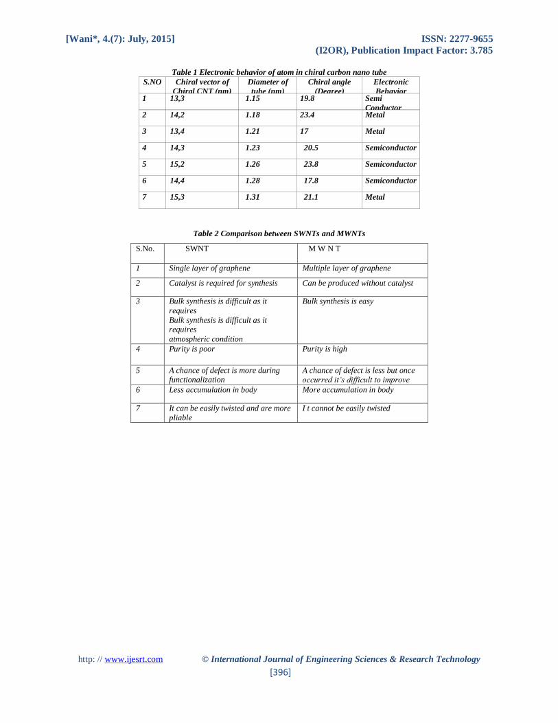
Now we will investigate about the metallic and semiconductor nature of some of the carbon nanotubes. It was stated
that when the difference of integers n and m has divisible by 3 then the atoms behaves as metallic otherwise semi
conducting [18]. Table 1 gives the metallic and semi conducting behavior of carbon nanotubes. It was proved from
the table when n-m is divisible by 3 then the behavior of tube is metallic otherwise semi conducting.
This session gives in details about the distortions occurring in the nanotube due to structure as well as angles. We also
gave the electronic behavior of carbon nanotube as metals and semiconductor.
CNT PROPERTIES – STRUCUTRAL DEFECTS C NT’S APPLICATIONS - Energy storage
Graphite, carbonaceous materials and carbon fiber electrodes are commonly used in fuel cells, batteries and other
electrochemical applications. Advantages of considering nanotubes for energy storage are their small dimensions,
smooth surface topology and perfect surface specificity. The efficiency of fuel cells is determined by the electron
transfer rate at the carbon electrodes, which is the fastest on nanotubes following ideal Nernstian behaviour. The
energy storage and medical applications of CNT are reviewed in this section and calculation of Energy per atom of
CNT with respect its distance for storage applications are also plotted.

[Wani*, 4.(7): July, 2015] ISSN: 2277-9655
(I2OR), Publication Impact Factor: 3.785
http: // www.ijesrt.com © International Journal of Engineering Sciences & Research Technology
[391]
1 HYDROGEN STORAGE
The advantage of hydrogen as energy source is that its combustion product is water. In addition, hydrogen can be
easily regenerated. For this reason, a suitable hydrogen storage system is necessary, satisfying a combination of both
volume and weight limitations. The two commonly used means to store hydrogen are gas phase and electrochemical
adsorption [15]. Because of their cylindrical and hollow geometry, and nanometer-scale diameters, it has been
predicted that carbon nanotubes can store a liquid or a gas in the inner cores through a capillary effect.
The hydrogen storage requirements of 6.5 % by weight as the minimum level for hydrogen fuel cells. It is reported
that SWNTs were able to meet and sometimes exceed this level by using gas phase adsorption (physisorption). Yet,
most experimental reports of high storage capacities are rather controversial so that it is difficult to assess the
applications potential. What lacks, is a detailed understanding of the hydrogen storage mechanism and the effect of
materials processing on this mechanism. Another possibility for hydrogen storage is electrochemical storage. In this
case not a hydrogen molecule but an H atom is adsorbed. This is called chemisorption. It was proved that hydrogen
storage of 4 % even 6.5% of the weight storage is possible in CNT’s [15]. We have calculated energy of an atom in
CNT with respect to distance in A0 as per the given equation [15]
Ec = K a2 / 24 ρ R2 1.1
Ec be the energy per atom K.Cal / mol, a lattice constant, ρ be the density in gram / c.c R be the distance in A°. Table
5 gives the calculated energy for Zigzag, circular and non circular carbon nanotube. Figure 9 shows the energy per
atom with respect R in A°. We found from the table 5 non-circular type CNT of atom has lesser energy than uniform
circular type.
Figure 9 a shows plot of Energy per atom in CNT versus Radius (Distance).
Circular type CNT has energy storage maximum than over collapsed or elongated CNT’s. As radius increases the
energy decays and reaches constant value. The above information useful for energy storage of hydrogen and lithium
applications in CNT. We also calculated minimum Relative energy of atom in chiral tube CNT with respective to
distance of no of iterations using Nanoexplorer tool by steepest descent method.
Figure 10 Chiral Carbon nanotube of relative energy calculations of atom Vs Radius.

[Wani*, 4.(7): July, 2015] ISSN: 2277-9655
(I2OR), Publication Impact Factor: 3.785
http: // www.ijesrt.com © International Journal of Engineering Sciences & Research Technology
[392]
CNT – MEDICAL APPLICATIONS - CANCER CELL IDENTIFICATION This paper attempts to report the existing and future applications of CNTs in the biomedical industry exclusively. We
attempt to review the usage of CNT’s particularly for cancer treatment. Then we report some of the properties of CNT
and simulated the structure for the given properties using Nano Explorer tool. A nanometer is a billionth of a meter.
Nanotechnology is the creation of useful materials, devices, and systems through the manipulation of matter on this
miniscule scale. Nanodevices being developed that have a potential to improve cancer detection, diagnosis, and
treatment. Anticancer drug polyphosphazene platinum given with nanotubes had enhanced permeability ,distribution
and retention in the brain due to controlled lipophilicity of nanotubes[19]. Nano materials have large surface areas
relative to their volumes, phenomena like friction and sticking are more important than they are in larger systems.
Nanostructures can be so small that the body may clear them too rapidly for them to be effective in detection or
imaging. Larger nanoparticles may accumulate in vital organs, creating a toxicity problem.
Most animal cells are 10,000 to 20,000 nanometers in diameter. This means that nanoscale devices (less than 100
nanometers) can enter cells and the organelles inside them to interact with DNA and proteins. Tools developed through
nanotechnology may be able to detect disease in a very small amount of cells or tissue. Detection of cancer at early
stages is a critical step in improving cancer treatment. Currently, detection and diagnosis of cancer usually depend on
changes in cells and tissues that are detected by a doctor's physical touch or imaging expertise. The potential for
nanostructures to enter and analyze single cells suggests they could meet this need. Figure 11 and 12 shows the
nanodevices which are capable to enter the cell and also trace the structure of DNA to find any mutation on the DNA
structure thereby identifying the cancerous cells.[20-26].
Figure 11 shows the size of nanodevice that can enter the human cell and to determine cancerous or precancerous cells

[Wani*, 4.(7): July, 2015] ISSN: 2277-9655
(I2OR), Publication Impact Factor: 3.785
http: // www.ijesrt.com © International Journal of Engineering Sciences & Research Technology
[393]
Figure 12 Carbon nanotube gliding over the surface of carbon nanotube to find the mutation on the surface. Above diagram
11 and 12 shows nanodevice like carbon nanotube predicts and differentiates the cancerous cell with the ordinary cell.
CNT PHYSICAL AND CHEMICAL PROPERTIES The properties of CNT are important because of miniature size. These properties tend to change as size, angle, and
chiral vector of CNT’s changes. We have taken some physical, electrical and mechanical properties from reference
[27-30]. We simulated the CNT structure for above mentioned properties using Nanoexplorer tool.
CNT PROPERTIES 1. Given Chiral vector ex (10,10) Armchair tube, Diameter of tube1.2nm, Carbon bond length – 1.42 A°,
Overlap energy 2.5 ev, Lattice constant - 17 A° , density – 1.40 g/cm3, spacing between atoms 3.39Ao
2. Thermal Conductance – 1/12.9 kW -1
3. Resistivity – 1 0-4W - cm at 300oK
4. Conductivity – 107 A / cm2
5. Young’s modulus – 1 Tpa, Tensile strength – 30 gpa (yu etal)
6. Carbon bond length – 1.42 A°, overlap energy – 2.5ev, Lattice constant
7. Thermal conductivity – 1800 – 6000 w/m-k, carrier lifetime – 10e-11 sec. Figure 13 a and 13 b shows the
simulated structure for the above-mentioned properties of Zigzag (10, 0) CNT. Figure 14 shows the
armchair type of CNT with above mentioned properties.
Figure 13 a shows the properties with the structure of Zigzag CNT

[Wani*, 4.(7): July, 2015] ISSN: 2277-9655
(I2OR), Publication Impact Factor: 3.785
http: // www.ijesrt.com © International Journal of Engineering Sciences & Research Technology
[394]
Figure 13 b shows the structure of (10,0) CNT. Nano explorer tool
Figure 14 shows the (10,10) armchair type of CNT from Nano explorer
COMPARISON BETWEEN SWNTS AND MWNTS
The comparison between SWNTs and MWNTs is given in table 2 and has been taken from the reference [31]
CONCLUSION This paper describes the review of synthesis of carbon nano tube. It describes about the advantage of plasma
enhanced CVD technique. Then we described about the simulation of CNT structures. Then we mentioned about
the various tube distortions in CNT .We reviewed two important applications of CNT and some of the properties
of CNT being mentioned and simulated the structure according to the structure. Finally we made a comparison
between SWNTs and MWNTs.
REFERENCES
[1] Niraj sinha, John yeow CARBON NANO TUBE IEEE transaction on Nano science Vol 4 No 2 June 2005.
[2] Lawerence Berkley net.labs [online] Available: http//www.lbl.gov
[3] S.Ijma “Helical microtubules of graphite carbon”, Nature Volume 354, pp –56 – 58 1991.
[4] S.Ijma, P.M.Ajayan “ Growth model for carbon nano tubes” Phys rev lette, Vol 69, no 21, pp –3100 –
3103,1992 [5] C.Journet, W.K.Master,P.Berneir, A.Loisequ “ Large scale prodution of single wall carbon
nano tubes by electric arc technique” Nature volume 388, pp 756 – 758, 1997
[5] A.Thess, R.Lee, P.Nikolav, P.Petut, J.Robert, C.H.Xu, Y.H.Lee, S.G.Kim, A.G.Rinzler “ Crystalline ropes
of carbon nano tubes” science volume 273, no 5274, pp 483 – 487, 1996.
[6] R.L.WanderWal, Berger, T.M.Ticich “ Carbon nano tube synthesis in a flame using laser ablation for insitu
catalyst generation” Applied Physics Volume 77, no 7, pp 885 – 889, 2003.
[7] M.J.Yaceman, M.M.Yoshida, .Rendson,J,G.Santiestaban “ Catalytic growth of carbon micro tubules with
fullerneess structure” Applied physics letter colume – 62, pp 202 –204, 1993.

[Wani*, 4.(7): July, 2015] ISSN: 2277-9655
(I2OR), Publication Impact Factor: 3.785
http: // www.ijesrt.com © International Journal of Engineering Sciences & Research Technology
[395]
[8] J.K.Vohs, J.J Brege,J.E.Raymond, A.E.Bnrown G.L.Williams and B.D>Feblayer “ Low temperature growth
of carbon nanotubes from the catalystic decomposition of carbon tetrachloride “ J.Amer. Chemistry society
Vol 126, N0 –32, pp – 9936 – 9937
[9] S.Ijima and T.Ichihashi “Single cell carbon nano tube of 1 nanometer diameter” Nature Volume 363, pp –
220 – 221,1992.
[10] D.S.Bethune, C.H.Kiang, G.Gorman, R.Savoy, J.Vazquez and R.Bayers “ Cobalt catalyst growth of CNT of
single atomic layer walls “ Nature volume 363, page – 305, 1993.
[11] T.W.Ebbesan and P.M.Ajayan “large scale synthesis jof carbon nano tube: Nature volume 358, pp –220 –
221, 19092.
[12] H.Dai “ Nano tube growth and charecterization “ Top appl.physics vol 80, pp – 29 –54,2001.
[13] C.Jounet and Bernier P, Applied physics material science and processing 67, page 1 –9, 1998.
[14] World of carbon nano tube – a review jof current carbon nano tube technologies Tule – Eindhoven university.
[15] Farhet s, Hinkor, I.Chappelle, DI Fan,SS Li and Scott Nasa control publications 2001.
[16] Schematic structure of SWNT; 2014. Ref Type: Generic.
[17] R.Saito,G,Dresselhaus,MS resselhaus “Physical properties of carbon nanotubes”
[18] Pai P, Nair K, Jamade S, Shah R, Ekshinge V, Jadhav N. Pharmaceutical applications of carbon tubes and
nanohorns.Current Pharma esearch Journal; 1:11-15, 2006.
[19] A. Star et al., Label-free detection of DNA hybridization using carbon nanotube network field-
effecttransistors. Proc. Natl. Acad. Sci. U.S.A. 103, 921 (2006). doi:10.1073/pnas.0504146103 Medline
[20] Harrison BS, Atala A: Carbon nanotube applications for tissue engineering. Biomaterials 2007, 28(2):344–
353.
[21] Singh R, Pantarotto D, Lacerda L, Pastorin G, Klumpp C, Prato M, Bianco A, Kostarelos K: Tissue
biodistribution and blood clearance rates of intravenously administered carbon nanotube radiotracers. Proc
Natl. Acad. Sci. U S A 2006, 103(9):3357–3362.
[22] Wang SF, Shen L, Zhang WD, Tong YJ: Preparation and mechanical properties of chitosan/carbon nanotubes
composites. Biomacromolecules 2005, 6(6):3067–3072.
[23] MacDonald RA, Laurenzi BF, Viswanathan G, Ajayan PM, Stegemann JP: Collagen-carbon nanotube
composite materials as scaffolds in tissue engineering. J Biomed Mater Res A 2005, 74(3):489–496.
[24] Castillo JJ, Svendsen WE, Rozlosnik N, Escobar P: Detection of cancer cells using a peptide nanotube-folic
acid modified graphene electrode. Analyst 2013, 138(4):1026–1031.
[25] Eatemadi A, Daraee H, Zarghami N, Hassan Melat Y, Abolfazl A: Nanofiber: synthesis and biomedical
applications, artificial cells, nanomedicine, and biotechnology. 2014, 43(7):1–11
[26] Harris, P. Carbon nanotubes and related structures: new materials for the 21st century. Cambridge,
Cambridge University Press, 1999.
[27] H. Dai, A. Javey, E. Pop, D. Mann, and Y. Lu, ―Electrical transport properties and field-effect transistors
of carbon nanotubes, NANO: Brief Reports and Reviews, vol. 1, no. 1, pp. 1–4, 2006.
[28] E. Pop, D. Mann, Q. Wang, K. Goodson, and H. Dai, ―Thermal conductance of an individual single-wall
carbon nanotube above room temperature,‖ Nano Letters, vol. 6, no. 1, pp. 96–100, 2006.
[29] Stahl, H., J. Appenzeller, R. Martel, P. Avouris and B. Lengeler ―Intertube coupling in ropes of single-wall
carbon nanotubes.‖ Physical Review Letters 85(24): 5186-5189, 2000.
[30] Rajashree Hirlekar, Manohar Yamagar, Harshal Garse, Mohit Vij, Vilasrao Kadam. Carbon Nanotubes and
Its Applications: A Review. Asian Journal of Pharmaceutical and Clinical Research, Vol.2 Issue 4, October-
December 2009.
[Wani*, 4.(7): July, 2015] ISSN: 2277-9655
(I2OR), Publication Impact Factor: 3.785
http: // www.ijesrt.com © International Journal of Engineering Sciences & Research Technology
[396]
Table 1 Electronic behavior of atom in chiral carbon nano tube
S.NO Chiral vector of
Chiral CNT (nm)
Diameter of
tube (nm)
Chiral angle
(Degree)
Electronic
Behavior 1 13,3 1.15 19.8 Semi
Conductor 2 14,2 1.18 23.4 Metal
3 13,4 1.21 17 Metal
4 14,3 1.23 20.5 Semiconductor
5 15,2 1.26 23.8 Semiconductor
6 14,4 1.28 17.8 Semiconductor
7 15,3 1.31 21.1 Metal
Table 2 Comparison between SWNTs and MWNTs
S.No. SWNT M W N T
1 Single layer of graphene Multiple layer of graphene
2 Catalyst is required for synthesis Can be produced without catalyst
3 Bulk synthesis is difficult as it
requires
Bulk synthesis is difficult as it requires
atmospheric condition
Bulk synthesis is easy
4 Purity is poor Purity is high
5 A chance of defect is more during functionalization
A chance of defect is less but once occurred it‘s difficult to improve
6 Less accumulation in body More accumulation in body
7 It can be easily twisted and are more
pliable
I t cannot be easily twisted