Stabilization of polycarbonate/ABS blends with mixtures of ...
Upload
independentCategory
view
1download
0
IOP PUBLISHING NANOTECHNOLOGY
Nanotechnology 18 (2007) 095708 (7pp) doi:10.1088/0957-4484/18/9/095708
Controlled nanostructure and high loadingof single-walled carbon nanotubesreinforced polycarbonate compositeShiren Wang1, Zhiyong Liang1,3, Giang Pham1, Young-Bin Park1,Ben Wang1, Chuck Zhang1, Leslie Kramer2 and Percy Funchess2
1 High-Performance Materials Institute (HPMI), Department of Industrial and ManufacturingEngineering, FAMU-FSU College of Engineering, Florida State University, 2525 PottsdamerStreet, Tallahassee, FL 32310-6046, USA2 Lockheed Martin Missiles and Fire Control-Orlando, Orlando, FL 32819-8907, USA
E-mail: [email protected]
Received 29 September 2006, in final form 19 December 2006Published 24 January 2007Online at stacks.iop.org/Nano/18/095708
AbstractThis paper presents an effective technique to fabricate thermoplasticnanocomposites with high loading of well-dispersed single-walled carbonnanotubes (SWNTs). SWNT membranes were made from a multi-stepdispersion and filtration method, and then impregnated with polycarbonatesolution to make thermoplastic nanocomposites. High loading of nanotubeswas achieved by controlling the viscosity of polycarbonate solution. SEMand AFM characterization results revealed the controlled nanostructure in theresultant nanocomposites. Dynamic mechanical property tests indicated thatthe storage modulus of the resulting nanocomposites at 20 wt% nanotubesloading was improved by a factor of 3.4 compared with neat polycarbonatematerial. These results suggest the developed approach is an effective way tofabricate thermoplastic nanocomposites with good dispersion and highSWNT loading.
(Some figures in this article are in colour only in the electronic version)
1. Introduction
Carbon nanotubes (CNTs) are one of the strongest and stiffestmaterials, having exceptional tensile strength and modulus buta low density [1, 2]. CNTs also possess superior thermaland electrical properties [2]. Lightweight multifunctionalnanocomposites can be produced with outstanding strength,stiffness and electric conductivity by effectively incorporatingCNTs into matrix materials. However, effective utilizationof nanotubes in composites applications is dependent on theability to disperse nanotubes uniformly throughout the matrix.Nanocomposites produced by conventional methods, such asdirect mixing, melt blending or solution casting, usually failto yield significant improvements in composite performancebecause these methods cannot solve several manufacturingproblems, including non-uniform CNTs dispersion, inadequatetube loading and lack of nanotube alignment.
3 Author to whom any correspondence should be addressed.
Polycarbonate (PC) is a high molecular-weight, amor-phous engineering thermoplastic that demonstrates exception-ally high impact strength over a wide temperature range.PC is characterized by an excellent combination of tough-ness, heat resistance, flame resistance and dimensional sta-bility, making PC advantageous for producing high perfor-mance CNTs/PC nanocomposites. Researchers have fabri-cated CNTs/PC nanocomposites via melt processing and so-lution casting [3–6]. However, PC’s high melting temperatureand viscosity makes fabricating high-quality CNTs/PC com-posites through injection or extrusion molding difficult. Theconcomitant viscosity problem with increasing tube loadingalso presents a challenge in both melting processing and solu-tion casting, especially for fabricating high-loading nanotubescomposites. We have demonstrated a resin-infiltration tech-nique for fabricating high-loading epoxy composites [7]. Nowwe extend this technique to the nanotubes reinforced thermo-plastic composites. This paper reports a method of fabricating
0957-4484/07/095708+07$30.00 1 © 2007 IOP Publishing Ltd Printed in the UK
Nanotechnology 18 (2007) 095708 S Wang et al
500 nm
(a)
(b)
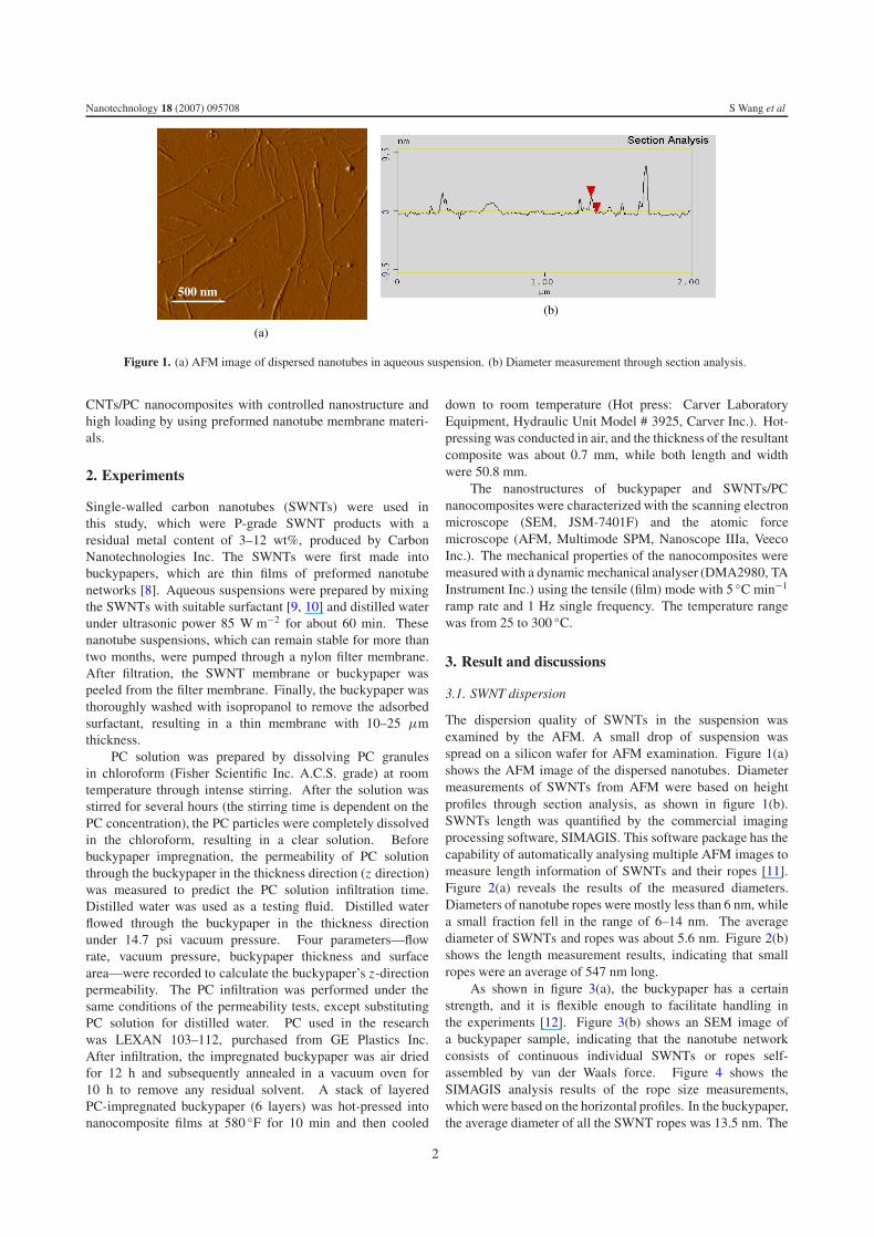
Figure 1. (a) AFM image of dispersed nanotubes in aqueous suspension. (b) Diameter measurement through section analysis.
CNTs/PC nanocomposites with controlled nanostructure andhigh loading by using preformed nanotube membrane materi-als.
2. Experiments
Single-walled carbon nanotubes (SWNTs) were used inthis study, which were P-grade SWNT products with aresidual metal content of 3–12 wt%, produced by CarbonNanotechnologies Inc. The SWNTs were first made intobuckypapers, which are thin films of preformed nanotubenetworks [8]. Aqueous suspensions were prepared by mixingthe SWNTs with suitable surfactant [9, 10] and distilled waterunder ultrasonic power 85 W m−2 for about 60 min. Thesenanotube suspensions, which can remain stable for more thantwo months, were pumped through a nylon filter membrane.After filtration, the SWNT membrane or buckypaper waspeeled from the filter membrane. Finally, the buckypaper wasthoroughly washed with isopropanol to remove the adsorbedsurfactant, resulting in a thin membrane with 10–25 μmthickness.
PC solution was prepared by dissolving PC granulesin chloroform (Fisher Scientific Inc. A.C.S. grade) at roomtemperature through intense stirring. After the solution wasstirred for several hours (the stirring time is dependent on thePC concentration), the PC particles were completely dissolvedin the chloroform, resulting in a clear solution. Beforebuckypaper impregnation, the permeability of PC solutionthrough the buckypaper in the thickness direction (z direction)was measured to predict the PC solution infiltration time.Distilled water was used as a testing fluid. Distilled waterflowed through the buckypaper in the thickness directionunder 14.7 psi vacuum pressure. Four parameters—flowrate, vacuum pressure, buckypaper thickness and surfacearea—were recorded to calculate the buckypaper’s z-directionpermeability. The PC infiltration was performed under thesame conditions of the permeability tests, except substitutingPC solution for distilled water. PC used in the researchwas LEXAN 103–112, purchased from GE Plastics Inc.After infiltration, the impregnated buckypaper was air driedfor 12 h and subsequently annealed in a vacuum oven for10 h to remove any residual solvent. A stack of layeredPC-impregnated buckypaper (6 layers) was hot-pressed intonanocomposite films at 580 ◦F for 10 min and then cooled
down to room temperature (Hot press: Carver LaboratoryEquipment, Hydraulic Unit Model # 3925, Carver Inc.). Hot-pressing was conducted in air, and the thickness of the resultantcomposite was about 0.7 mm, while both length and widthwere 50.8 mm.
The nanostructures of buckypaper and SWNTs/PCnanocomposites were characterized with the scanning electronmicroscope (SEM, JSM-7401F) and the atomic forcemicroscope (AFM, Multimode SPM, Nanoscope IIIa, VeecoInc.). The mechanical properties of the nanocomposites weremeasured with a dynamic mechanical analyser (DMA2980, TAInstrument Inc.) using the tensile (film) mode with 5 ◦C min−1
ramp rate and 1 Hz single frequency. The temperature rangewas from 25 to 300 ◦C.
3. Result and discussions
3.1. SWNT dispersion
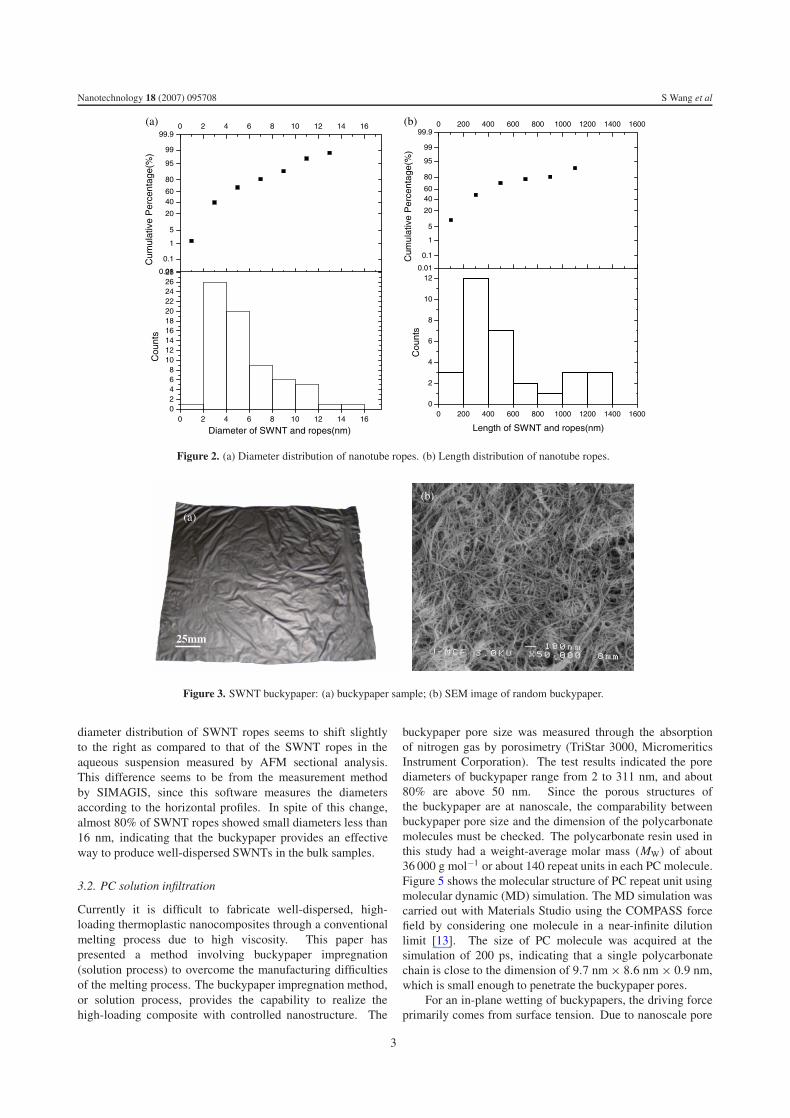
The dispersion quality of SWNTs in the suspension wasexamined by the AFM. A small drop of suspension wasspread on a silicon wafer for AFM examination. Figure 1(a)shows the AFM image of the dispersed nanotubes. Diametermeasurements of SWNTs from AFM were based on heightprofiles through section analysis, as shown in figure 1(b).SWNTs length was quantified by the commercial imagingprocessing software, SIMAGIS. This software package has thecapability of automatically analysing multiple AFM images tomeasure length information of SWNTs and their ropes [11].Figure 2(a) reveals the results of the measured diameters.Diameters of nanotube ropes were mostly less than 6 nm, whilea small fraction fell in the range of 6–14 nm. The averagediameter of SWNTs and ropes was about 5.6 nm. Figure 2(b)shows the length measurement results, indicating that smallropes were an average of 547 nm long.
As shown in figure 3(a), the buckypaper has a certainstrength, and it is flexible enough to facilitate handling inthe experiments [12]. Figure 3(b) shows an SEM image ofa buckypaper sample, indicating that the nanotube networkconsists of continuous individual SWNTs or ropes self-assembled by van der Waals force. Figure 4 shows theSIMAGIS analysis results of the rope size measurements,which were based on the horizontal profiles. In the buckypaper,the average diameter of all the SWNT ropes was 13.5 nm. The
2
Nanotechnology 18 (2007) 095708 S Wang et al
0.01
0.1
1
5
20
4060
80
95
99
99.90 200 400 600 800 1000 1200 1400 1600
0 200 400 600 800 1000 1200 1400 16000
2
4
6
8
10
12
Cou
nts
Length of SWNT and ropes(nm)
Cum
ulat
ive
Per
cent
age(
%)
0.01
0.1
1
5
20
4060
80
95
99
99.90 2 4 6 8 10 12 14 16
0 2 4 6 8 10 12 14 1602468
10121416182022242628
Cou
nts
Diameter of SWNT and ropes(nm)
Cum
ulat
ive
Per
cent
age(
%)
(a) (b)
Figure 2. (a) Diameter distribution of nanotube ropes. (b) Length distribution of nanotube ropes.
(b)
(a)
25mm
Figure 3. SWNT buckypaper: (a) buckypaper sample; (b) SEM image of random buckypaper.
diameter distribution of SWNT ropes seems to shift slightlyto the right as compared to that of the SWNT ropes in theaqueous suspension measured by AFM sectional analysis.This difference seems to be from the measurement methodby SIMAGIS, since this software measures the diametersaccording to the horizontal profiles. In spite of this change,almost 80% of SWNT ropes showed small diameters less than16 nm, indicating that the buckypaper provides an effectiveway to produce well-dispersed SWNTs in the bulk samples.
3.2. PC solution infiltration
Currently it is difficult to fabricate well-dispersed, high-loading thermoplastic nanocomposites through a conventionalmelting process due to high viscosity. This paper haspresented a method involving buckypaper impregnation(solution process) to overcome the manufacturing difficultiesof the melting process. The buckypaper impregnation method,or solution process, provides the capability to realize thehigh-loading composite with controlled nanostructure. The
buckypaper pore size was measured through the absorptionof nitrogen gas by porosimetry (TriStar 3000, MicromeriticsInstrument Corporation). The test results indicated the porediameters of buckypaper range from 2 to 311 nm, and about80% are above 50 nm. Since the porous structures ofthe buckypaper are at nanoscale, the comparability betweenbuckypaper pore size and the dimension of the polycarbonatemolecules must be checked. The polycarbonate resin used inthis study had a weight-average molar mass (MW) of about36 000 g mol−1 or about 140 repeat units in each PC molecule.Figure 5 shows the molecular structure of PC repeat unit usingmolecular dynamic (MD) simulation. The MD simulation wascarried out with Materials Studio using the COMPASS forcefield by considering one molecule in a near-infinite dilutionlimit [13]. The size of PC molecule was acquired at thesimulation of 200 ps, indicating that a single polycarbonatechain is close to the dimension of 9.7 nm × 8.6 nm × 0.9 nm,which is small enough to penetrate the buckypaper pores.
For an in-plane wetting of buckypapers, the driving forceprimarily comes from surface tension. Due to nanoscale pore
3

Nanotechnology 18 (2007) 095708 S Wang et al
0.01
0.1
1
5
20
4060
80
95
99
99.94 6 8 10 12 14 16 18 20 22 24 26 28 30 32 34
4 6 8 10 12 14 16 18 20 22 24 26 28 30 32 340
20
40
60
80
100
120
Cou
ntDiameter of SWNT ropes (nm)
Cum
ulat
ive
Per
cent
age
(%)
100nm
(a)
(b)
Figure 4. (a) Smart identifying SWNT ropes of buckypaper SEM image in SIMAGIS software. (b) Rope diameter distribution of thebuckypaper.
Figure 5. Molecular structure of polycarbonate repeat unit.
size, the in-plane permeability of the buckypapers is verysmall, and therefore impregnating buckypaper through in-planewetting is extremely difficult [14]. Therefore, a through-thickness infiltration system was designed to impregnatepolycarbonate solution into the buckypapers. Throughthickness (z direction) flow behaviour of the buckypaper can bemodelled with one-dimensional Darcy’s law. The z-directionpermeability Kz (saturated permeability) was calculated usingthe following equation derived from Darcy’s law [12]:
Kz = QηL
AP(1)
where Q is the flow rate; η is the viscosity of fluid; L isthe thickness of buckypaper; P is the vacuum pressure acrossbuckypaper; A is the surface area of buckypaper.
The results of z-direction permeability test on the resultingbuckypaper show the average value of buckypapers’ z-direction permeability was about 2 × 10⁻¹⁹ m2 [12]. On theother hand, infiltration flow rate is the ratio of flow volume toinfiltration time, as shown in equation (2):
Q = �V
�t= A�L
�t(2)
where Q is the flow rate; L is the thickness of buckypaper; Ais the surface area of buckypaper; �L is the flow distance in
the infiltration time of �t ; �t is the infiltration time; �V isthe flow volume in the infiltration time of �t .
Substituting equation (2) into equation (1) results inequation (3) to determine PC infiltration time:
�t = ηL�L
Kz P(3)
where η is the viscosity of PC solution; L is the thickness ofbuckypaper film; P is the vacuum pressure across buckypaper.�L is the flow distance in the infiltration time of �t ; Kz is thez-direction permeability.
Integrating equation (3) yields the formulation of theinfiltration time:
t =∫ L
0
ηL
Kz Pdl = 1
2
ηL2
Kz P(4)
where η is the viscosity of PC solution; L is the thickness ofbuckypaper film; P is the vacuum pressure across buckypaper;Kz is the z-direction permeability.
Based on equation (4), infiltration time can be estimated,as shown in figure 6. In the experiments, the infiltration timewas measured by a stopwatch from the switching-on of thepressure till observation of the solution coming out of thebuckypaper bottom. Infiltration time can be controlled viaPC solution viscosity, as shown in figure 6(a). Furthermore,it was observed that higher solution viscosity yielded higherPC concentration, thus resulting in lower SWNT loading in thefinal nanocomposites, as shown in figure 6(b). In other words,desired infiltration time and final nanotubes loading of thenanocomposites can be achieved with tailored viscosity of PCsolution. For instance, using a viscosity of about 10 cp wouldallow a short infiltration time and the final nanotubes loadingof around 50% in the materials. Hence, this simple techniqueis effective in achieving high, controlled SWNT concentrationand good tube dispersion.
4

Nanotechnology 18 (2007) 095708 S Wang et al
0 10 20 30 40 50 60 700
200
400
600
800
1000
1200
1400
Viscosity (centipoise)
Theoretical valueExperimental value
0 10 20 30 40 50 60 700
5
10
15
20
25
30
35
40
45
Viscosity (centipoise)
Infil
trat
ion
Tim
e (s
econ
d)
Tub
e lo
adin
g (%
)
(a) (b)
Figure 6. Effect of viscosity on the buckypaper impregnation: (a) infiltration time versus viscosity; (b) tube loading versus viscosity.
(a) (b)
Figure 7. Impregnated buckypaper: (a) macroscopic image of impregnated buckypaper; (b) SEM image of a cross section for the impregnatedbuckypaper.
Figure 7(a) shows a 6.5′′ × 6.5′′ dried PC-impregnatedbuckypaper. The buckypaper surface was thoroughly wettedby polycarbonate. Figure 7(b) shows an SEM image ofthe cross section of the impregnated buckypaper, whichindicates even impregnation throughout and intercalation withnanotubes. Nanotube ropes were homogeneously spreadover the polycarbonate, and continuous intercalation networksformed in the resultant composite. Aggregations of nanotubeswere not observed. The formative tube networks in thenanocomposite were almost the same as those in the previousimpregnated buckypaper and original buckypaper. Thisindicated that the impregnation of polycarbonate solutionthrough buckypaper yielded controlled nanostructure in thenanocomposite. Since nanocomposite with various nanotubeloading can be achieved by adjusting the viscosity ofpolycarbonate solution, this impregnation technique appears tobe an effective way to achieve thermoplastic composites withhigh-loading of nanotubes.
3.3. Nanostructure and properties of SWNT-buckypaper/PCnanocomposites
The SWNT-buckypaper/PC nanocomposite used for mechan-ical characterization was fabricated by hot-pressing six lay-ers of PC-impregnated buckypaper in a thickness-controlled
Temperature (°C)
Sto
rage
Mod
ulus
(M
Pa)
Figure 8. Dynamic mechanical analysis of SWNT reinforcedpolycarbonate composites: (A) pristine PC, (B) 2 wt% SWNTs/PCcomposite, (C) 20 wt% SWNT-buckypaper/PC composite.
flat mold. DMA tests were performed in single-frequency,temperature-ramping mode. Storage modulus indicates theamount of energy stored in the composite as elastic energy,which is highly influenced by the reinforcement mechanicalproperties, geometric characteristics, reinforcement loadingand interfacial bonding between reinforcement and the matrix.
5
Nanotechnology 18 (2007) 095708 S Wang et al
(a) (b)
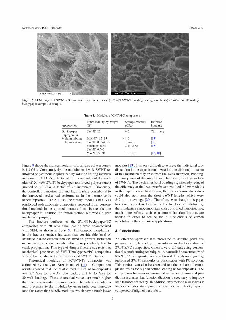
Figure 9. SEM images of SWNTs/PC composite fracture surfaces: (a) 2 wt% SWNTs loading casting sample; (b) 20 wt% SWNT loadingbuckypaper composite sample.
Table 1. Modulus of CNTs/PC composites.
Tubes loading by weight Storage modulus ReferredApproaches (%) (GPa) literature
Buckypaper SWNT: 20 6.2 This studyimpregnationMelting mixing MWNT: 1.5–15 ∼1.0 [15]Solution casting SWNT: 0.05–0.25 1.6–2.1 [3]
Functionalized 2.35–2.52 [16]SWNT: 0.5–2MWNT: 5–20 1.1–2.42 [17, 18]
Figure 8 shows the storage modulus of a pristine polycarbonateis 1.8 GPa. Comparatively, the modulus of 2 wt% SWNT re-inforced polycarbonate (produced by solution casting method)increased to 2.4 GPa, a factor of 1.3 increment, and the mod-ulus of 20 wt% SWNT-buckypaper reinforced polycarbonatejumped to 6.2 GPa, a factor of 3.4 increment. Obviously,the controlled nanostructure and high loading contributed tothe improved mechanical performance in the thermoplasticnanocomposites. Table 1 lists the storage modulus of CNTsreinforced polycarbonate composites prepared from conven-tional methods in the reported literature. It can be seen that thebuckypaper/PC solution infiltration method achieved a highermechanical property.
The fracture surfaces of the SWNT-buckypaper/PCcomposites with 20 wt% tube loading were characterizedwith SEM, as shown in figure 9. The dimpled morphologyin the fracture surface indicates that considerable level oflocalized plastic deformation occurred to prevent formationor coalescence of microvoids, which can potentially lead tocrack propagation. This type of dimple fracture suggests thatmechanical properties of SWNT-buckypaper/PC compositeswere enhanced due to the well-dispersed SWNT network.
Theoretical modulus of PC/SWNTs composite wasestimated by the Cox–Krench model [11]. Computationresults showed that the elastic modulus of nanocompositeswas 3.7 GPa for 2 wt% tube loading and 64.25 GPa for20 wt% loading. These theoretical values are much higherthan the experimental measurements. Theoretical calculationmay overestimate the modulus by using individual nanotubemodulus rather than bundle modulus, which have a much lower
modulus [19]. It is very difficult to achieve the individual tubedispersion in the experiments. Another possible major reasonof this mismatch may arise from the weak interfacial bonding,a consequence of the smooth and chemically inactive surfaceof SWNTs. The weak interfacial bonding significantly reducedthe efficiency of the load transfer and resulted in low modulusin the experiments. In addition, the low experimental valuescould also stem from the short SWNT lengths, which were547 nm on average [20]. Therefore, even though this paperhas demonstrated an effective method to fabricate high-loadingthermoplastics nanocomposites with controlled nanostructure,much more efforts, such as nanotube functionalization, areneeded in order to realize the full potentials of carbonnanotubes in the composite applications.
4. Conclusions
An effective approach was presented to acquire good dis-persion and high loading of nanotubes in the fabrication ofSWNTs/PC composites, which is very difficult using conven-tional manufacturing techniques. A controlled nanostructure ofSWNTs/PC composite can be achieved through impregnatingpreformed SWNT networks or buckypaper with PC solution.This method can also be extended to other suitable thermo-plastic resins for high nanotube loading nanocomposites. Thecomparison between experimental value and theoretical pre-diction indicates that functionalization is necessary to improveload transfer efficiency. In addition, this method also makes itfeasible to fabricate aligned nanocomposites if buckypaper iscomposed of aligned nanotubes.
6
Nanotechnology 18 (2007) 095708 S Wang et al
Acknowledgments
The authors would like to thank the support from LockheedMartin Missiles and Fire Control-Orlando.
References
[1] Wong E W, Sheehan P E and Lieber C M 1997 Nanobeatmechanics: elasticity, strength, and toughness of nanorodsand nanotubes Science 277 1971–5
[2] Thostenson E T and Chou T-W 2003 On the elastic propertiesof carbon nanotube-based composites: modeling andcharacterization J. Phys. D: Appl. Phys. 36 573–6
[3] Singh S, Pei Y, Miller R and Sundararajan P R 2003Long-range, entangled carbon nanotubes networks inpolycarbonate Adv. Funct. Mater. 13 868–72
[4] Potschke P, Bhattacharyya A R and Janke A 2004 Carbonnanotube-filled polycarbonate composite produced bymelted mixing and their use in blends with polyethyleneCarbon 42 965–9
[5] Potschke P, Bhattacharyya A R and Janke A 2004 Melt mixingof polycarbonate with multiwalled carbon nanotubes:microscopic studies on the state of dispersion Eur. Polym. J.40 137–48
[6] Potschke P, Fornes T D and Paul D R 2002 Rheologicalbehaviour of multiwalled carbon nanotube/polycarbonatecomposite Polymer 43 3247–55
[7] Wang Z, Liang Z, Wang B, Zhang C and Kramer L 2004Processing and property investigation of single-walledcarbon nanotube (SWNT) buckypaper/epoxy resin matrixnanocomposites Composite A 35 1225–32
[8] Sreekumar T V, Liu T and Kumar S 2003 Single-wall carbonnanotube films Chem. Mater. 15 175–8
[9] Islam M F, Rojas E, Bergey D M, Johnson A T and Yodh A G2003 High weight fraction surfactant solubilization ofsingle-wall carbon nanotubes in water Nano Lett. 3 269–73
[10] Paredes J I and Burghard M 2004 Dispersion of individualsingle-walled carbon nanotubes of high length Langmuir20 5149–52
[11] Wang S, Liang Z, Wang B and Zhang C 2006 Statisticalcharacterization of single-walled carbon nanotube lengthdistribution Nanotechnology 17 634–9
[12] Yeh C 2004 Characterization of nanotube buckypapermanufacturing process Thesis of Master of ScienceDepartment of Industrial and Manufacturing Engineering,Florida State University
[13] McQuaid M J, Sun H and Rigby D 2004 Development andvalidation of COMPASS force field parameters formolecules with aliphatic azide chains J. Comput. Chem.25 61–71
[14] Spuller M T and Hess D W 2003 Incomplete wetting ofnanoscale thin-film structures J. Electrochem. Soc.150 G476–80
[15] Sung Y T, Kum C K, Lee H S, Byon N S, Yoon H G andKim W N 2005 Dynamic mechanical and morphologicalproperties of polycarbonate/multiwalled carbon nanotubecomposites Polymer 46 5656–61
[16] Koratkar N, Suhr J, Joshi A, Kane R S, Schadler L S,Ajayan P M and Bartolucci S 2005 Characterizing energydissipation in single-walled carbon nanotube polycarbonatecomposites Appl. Phys. Lett. 87 063102–5
[17] Li Z, Li S, Yang M and Huang R 2005 A novel approach topreparing carbon nanotube reinforced thermoplastic polymercomposites Carbon 43 2413–6
[18] Mosca A 2005 Carbon nanotube reinforced thermoplasticsThesis of Master of Science Department of Applied Physicsand Mechanical Engineering, Lulea University ofTechnology
[19] Salvetat J, Briggs A, Bonard J, Bacsa R, Kulik A, Stockli T,Burnham N and Forro L 1999 Elastic and shear modulus ofsingle-walled carbon nanotube ropes Phys. Rev. Lett.82 944–7
[20] Wang S 2006 Functionalization of carbon nanotubes:characterization, modelling and composite applications PhDDissertation Department of Industrial & ManufacturingEngineering, Florida State University
7
Copyright © 2022 FDOKUMEN