Two-Dimensional Nanostructure-Reinforced Biodegradable Polymeric Nanocomposites for Bone Tissue...
10
Two-Dimensional Nanostructure-Reinforced Biodegradable Polymeric Nanocomposites for Bone Tissue Engineering Gaurav Lalwani, † Allan M. Henslee, ‡ Behzad Farshid, § Liangjun Lin, † F. Kurtis Kasper, ‡ Yi-Xian Qin, † Antonios G. Mikos, ‡ and Balaji Sitharaman* ,† † Department of Biomedical Engineering, Stony Brook University, Stony Brook, New York 11794-5281, United States ‡ Department of Bioengineering, Rice University, Houston, Texas 77251-1892, United States § Department of Materials Science and Engineering, Stony Brook University, Stony Brook, New York 11794, United States ABSTRACT: This study investigates the efficacy of two-dimensional (2D) carbon and inorganic nanostructures as reinforcing agents for cross-linked composites of the biodegradable and biocompatible polymer polypropylene fumarate (PPF) as a function of nanostructure concentration. PPF composites were reinforced using various 2D nanostructures: single- and multiwalled graphene oxide nanoribbons (SWGONRs, MWGONRs), graphene oxide nanoplatelets (GONPs), and molybdenum disulfide nanoplatelets (MSNPs) at 0.01−0.2 weight% concentrations. Cross-linked PPF was used as the baseline control, and PPF composites reinforced with single- or multiwalled carbon nanotubes (SWCNTs, MWCNTs) were used as positive controls. Compression and flexural testing show a significant enhancement (i.e., compressive modulus = 35−108%, compressive yield strength = 26−93%, flexural modulus = 15−53%, and flexural yield strength = 101− 262% greater than the baseline control) in the mechanical properties of the 2D-reinforced PPF nanocomposites. MSNP nanocomposites consistently showed the highest values among the experimental or control groups in all the mechanical measurements. In general, the inorganic nanoparticle MSNP showed a better or equivalent mechanical reinforcement compared to carbon nanomaterials, and 2D nanostructures (GONPs, MSNPs) are better reinforcing agents compared to one-dimensional (1D) nanostructures (e.g., SWCNTs). The results also indicated that the extent of mechanical reinforcement is closely dependent on the nanostructure morphology and follows the trend nanoplatelets > nanoribbons > nanotubes. Transmission electron microscopy of the cross-linked nanocomposites indicated good dispersion of nanomaterials in the polymer matrix without the use of a surfactant. The sol-fraction analysis showed significant changes in the polymer cross-linking in the presence of MSNP (0.01−0.2 wt %) and higher loading concentrations of GONP and MWGONR (0.1−0.2 wt %). The analysis of surface area and aspect ratio of the nanostructures taken together with the above results indicated differences in nanostructure architecture (2D vs 1D nanostructures), and the chemical compositions (inorganic vs carbon nanostructures), number of functional groups, and structural defects for the 2D nanostructures may be key properties that affect the mechanical properties of 2D nanostructure-reinforced PPF nanocomposites and the reason for the enhanced mechanical properties compared to the controls. ■ INTRODUCTION The limitations in the clinical treatment of bone defects using autologous or allogenous bone grafts and permanent prosthetic implants has led to emergence of bone tissue engineering strategies. 1 There has especially been a growing interest to develop nanoparticle-reinforced biodegradable polymer nano- composites for bone tissue engineering applications. 2−6 A major motivation behind these studies is to enhance the mechanical properties of the biodegradable polymer for improved structural integrity when implanted under load bearing conditions. Carbon nanostructures such as the zero- dimensional fullerenes and one-dimensional (1D) single-walled carbon nanotubes (SWCNTs) have been extensively inves- tigated as reinforcing agents in these studies. 2,3,5 Recently, the unique physiochemical properties of two- dimensional (2D) carbon and inorganic nanostructures such as graphene oxide nanoplatelets (GONPs), 7 graphene oxide nanoribbons (GONRs), 8 and molybdenum disulfide nano- platelets (MSNPs) 9,10 have been harnessed for a variety of potential applications such as water filtration membranes, 11 components in energy and semiconductor electronic devi- ces, 10,12 dispersing agents for processing of liquid crystals, 13 lubricants, 9 porous scaffolds for tissue engineering, 14,15 and agents for bioimaging and drug delivery. 13,16,17 Theoretical and experimental studies also show that 2D inorganic (e.g., MSNPs) and carbon (e.g., graphene nanoparticles) nanostruc- tures also show remarkable mechanical properties. 18−20 For instance, graphene has been predicted to have remarkable mechanical stiffness comparable to graphite, and fracture strength similar to SWCNTs. 7,21 Thus, for a 2D nanostruc- ture-reinforced polymer nanocomposite under mechanical stress, the 2D nanostructure possessing high stiffness should Received: December 26, 2012 Revised: February 7, 2013 Published: February 13, 2013 Article pubs.acs.org/Biomac © 2013 American Chemical Society 900 dx.doi.org/10.1021/bm301995s | Biomacromolecules 2013, 14, 900−909
-
Upload
independent -
Category
Documents
-
view
2 -
download
0
Transcript of Two-Dimensional Nanostructure-Reinforced Biodegradable Polymeric Nanocomposites for Bone Tissue...

Two-Dimensional Nanostructure-Reinforced BiodegradablePolymeric Nanocomposites for Bone Tissue EngineeringGaurav Lalwani,† Allan M. Henslee,‡ Behzad Farshid,§ Liangjun Lin,† F. Kurtis Kasper,‡ Yi-Xian Qin,†
Antonios G. Mikos,‡ and Balaji Sitharaman*,†
†Department of Biomedical Engineering, Stony Brook University, Stony Brook, New York 11794-5281, United States‡Department of Bioengineering, Rice University, Houston, Texas 77251-1892, United States§Department of Materials Science and Engineering, Stony Brook University, Stony Brook, New York 11794, United States
ABSTRACT: This study investigates the efficacy of two-dimensional (2D) carbon andinorganic nanostructures as reinforcing agents for cross-linked composites of thebiodegradable and biocompatible polymer polypropylene fumarate (PPF) as a function ofnanostructure concentration. PPF composites were reinforced using various 2Dnanostructures: single- and multiwalled graphene oxide nanoribbons (SWGONRs,MWGONRs), graphene oxide nanoplatelets (GONPs), and molybdenum disulfidenanoplatelets (MSNPs) at 0.01−0.2 weight% concentrations. Cross-linked PPF was usedas the baseline control, and PPF composites reinforced with single- or multiwalled carbonnanotubes (SWCNTs, MWCNTs) were used as positive controls. Compression and flexuraltesting show a significant enhancement (i.e., compressive modulus = 35−108%, compressiveyield strength = 26−93%, flexural modulus = 15−53%, and flexural yield strength = 101−262% greater than the baseline control) in the mechanical properties of the 2D-reinforcedPPF nanocomposites. MSNP nanocomposites consistently showed the highest values amongthe experimental or control groups in all the mechanical measurements. In general, the inorganic nanoparticle MSNP showed abetter or equivalent mechanical reinforcement compared to carbon nanomaterials, and 2D nanostructures (GONPs, MSNPs) arebetter reinforcing agents compared to one-dimensional (1D) nanostructures (e.g., SWCNTs). The results also indicated that theextent of mechanical reinforcement is closely dependent on the nanostructure morphology and follows the trend nanoplatelets >nanoribbons > nanotubes. Transmission electron microscopy of the cross-linked nanocomposites indicated good dispersion ofnanomaterials in the polymer matrix without the use of a surfactant. The sol-fraction analysis showed significant changes in thepolymer cross-linking in the presence of MSNP (0.01−0.2 wt %) and higher loading concentrations of GONP and MWGONR(0.1−0.2 wt %). The analysis of surface area and aspect ratio of the nanostructures taken together with the above resultsindicated differences in nanostructure architecture (2D vs 1D nanostructures), and the chemical compositions (inorganic vscarbon nanostructures), number of functional groups, and structural defects for the 2D nanostructures may be key properties thataffect the mechanical properties of 2D nanostructure-reinforced PPF nanocomposites and the reason for the enhancedmechanical properties compared to the controls.
■ INTRODUCTION
The limitations in the clinical treatment of bone defects usingautologous or allogenous bone grafts and permanent prostheticimplants has led to emergence of bone tissue engineeringstrategies.1 There has especially been a growing interest todevelop nanoparticle-reinforced biodegradable polymer nano-composites for bone tissue engineering applications.2−6 Amajor motivation behind these studies is to enhance themechanical properties of the biodegradable polymer forimproved structural integrity when implanted under loadbearing conditions. Carbon nanostructures such as the zero-dimensional fullerenes and one-dimensional (1D) single-walledcarbon nanotubes (SWCNTs) have been extensively inves-tigated as reinforcing agents in these studies.2,3,5
Recently, the unique physiochemical properties of two-dimensional (2D) carbon and inorganic nanostructures such asgraphene oxide nanoplatelets (GONPs),7 graphene oxidenanoribbons (GONRs),8 and molybdenum disulfide nano-
platelets (MSNPs)9,10 have been harnessed for a variety ofpotential applications such as water filtration membranes,11
components in energy and semiconductor electronic devi-ces,10,12 dispersing agents for processing of liquid crystals,13
lubricants,9 porous scaffolds for tissue engineering,14,15 andagents for bioimaging and drug delivery.13,16,17 Theoretical andexperimental studies also show that 2D inorganic (e.g.,MSNPs) and carbon (e.g., graphene nanoparticles) nanostruc-tures also show remarkable mechanical properties.18−20 Forinstance, graphene has been predicted to have remarkablemechanical stiffness comparable to graphite, and fracturestrength similar to SWCNTs.7,21 Thus, for a 2D nanostruc-ture-reinforced polymer nanocomposite under mechanicalstress, the 2D nanostructure possessing high stiffness should
Received: December 26, 2012Revised: February 7, 2013Published: February 13, 2013
Article
pubs.acs.org/Biomac
© 2013 American Chemical Society 900 dx.doi.org/10.1021/bm301995s | Biomacromolecules 2013, 14, 900−909

allow efficient transfer of load from the polymer matrix.22
Moreover, the 2D nanostructures show high surface area,structural defects, and the presence of functional groups(hydroxyl, carboxyl, or sulfide groups). These features shouldallow the formation of good interfaces with the polymer matrix;key requirements for efficient load transfer.22 Thus, due tothese potential benefits, the efficacy of 2D nanostructures asfillers to improve the mechanical properties of polymericcomposites needs to be systematically investigated.In this study, polymer polypropylene fumarate (PPF), an
injectable, cross-linkable, and biodegradable polymer widelyinvestigated for applications in bone tissue engineering, wasused as the polymer matrix.2−5,23−25 PPF nanocomposites werefabricated by dispersing 2D carbon (graphene oxide nano-platelets (GONPs), single-wall graphene oxide nanoribbons(SWGONRs), multi-wall graphene oxide nanoribbons(MWGONRs)), or inorganic (molybdenum disulfide nano-platelets (MSNPs)) nanostructures as fillers into PPF atloading concentrations between 0.01 and 0.2 weight%.Characterizations of the structural and mechanical as well ascross-linking densities of the nanocomposites were performedto investigate the effects of 2D nanostructure size, morphology,and chemical composition on their mechanical (compressionaland flexural) properties.
■ MATERIALS AND METHODSMaterials. Hydroquinone, N-vinyl-pyrrolidone (NVP), zinc
chloride, potassium permanganate, and benzoyl peroxide (BP) werepurchased from Sigma Aldrich (New York, USA). Propylene glycol,ethyl ether, methylene chloride, sodium sulfate, hydrogen peroxide,and chloroform (HPLC grade) were purchased from Fisher Scientific(Pittsburgh, PA, USA). Diethyl fumarate was purchased from AcrosOrganics (Fair Lawn, NJ, USA)SWCNTs (Cat. No. 698695), multiwalled carbon nanotubes
(MWCNTs, Cat. No. 636487), graphite flakes (Cat. No. 496596),molybdenum trioxide (Cat. No. M0753), and sulfur (Cat. No.414980) were purchased from Sigma Aldrich (New York, USA).Organic solvents were reagent grade and used as received.Synthesis of PPF. PPF was synthesized using a two-step reaction
of diethyl fumarate and propylene glycol as described previously, andcharacterized by 1H NMR, and gel permeation chromatography(GPC).26 Molecular weight distribution was measured by GPC systemwith a differential RI detector using a Styragel HR2 column (7.8 × 300mm, Waters, MA). Chloroform at 1 mL/min flow rate was used as themobile phase. A calibration curve using polystyrene standards (Fluka,Switzerland) was used to determine PPF molecular weights. PPFbatches of Mn = 3138 (PDI = 1.38) and Mn = 3808 (PDI = 1.44)were used for compression and three-point bending tests, respectively.Synthesis of Nanomaterials. SWGONRs and MWGONRs were
synthesized from SWCNTs and MWCNTs via the longitudinalunzipping method.8 GONPs were synthesized using a modifiedHummers method27 and nanohexagonal MSNPs were synthesizedusing previously reported method.28
Raman Spectroscopy. Raman spectroscopy was performed usinga WITec alpha300R Micro-Imaging Raman Spectrometer using a 532nm Nd:YAG excitation laser. Point spectra were recorded between 50and 3750 cm−1 at room temperature.Atomic Force Microscopy (AFM). Nanomaterials were dispersed
in 1:1 ethanol:water by probe sonication (Cole-Parmer UltrasonicatorLPX 750) for 1 min using a 1 s “on” and 2 s “off” cycle. Fiftymicroliters of homogenously dispersed nanomaterial solution was spincoated on freshly cleaved silicon wafers (Ted Pella, USA) at 3000 rpmfor 5 min and used for AFM Imaging. AFM images were obtainedusing a NanoSurf EasyScan 2 Flex AFM (NanoScience InstrumentsInc., Phoenix), operating in tapping mode, using a V-shaped cantilever(APP Nano ACL − 10, frequency fc = 145−230 kHz, L = 225 μm, W= 40 μm, tip radius < 10 nm, spring constant k = 20−95 N/m). All
images were collected under ambient conditions at 50% relativehumidity and 25 °C.
Surface Area Analysis. The surface area of nanostructures weremeasured using an ABET series Brunauer−Emmett−Teller (BET)sorptometer at 77 K using nitrogen as the adsorption gas for SWCNTsand MWCNTs and krypton for SWGONRs, MWGONRs, GONPs,and MSNPs at Porous Materials Inc., Ithaca, NY. Single point analysiswas performed for all the samples.
Nanocomposite Preparation. PPF and NVP were mixed inchloroform at a mass ratio of 1:1. Nanomaterials were dispersed inchloroform by bath sonication (Fisher Scientific) for 15 min followedby probe sonication (Cole Parmer, USA) for 1 min using a 1 s “on”and 2 s “off” cycle and then added to the PPF−NVP mixture atconcentrations of 0.1 to 2 wt %. The nanocomposite mixture was thensonicated for 15 min using a bath sonicator and chloroform wasremoved using a rotary evaporator (Buchi, Switzerland).
Thermal Cross-Linking and Specimen Fabrication. Thermalcross-linking of nanocomposite formulations was triggered by theaddition of 1 wt % BP (free radical initiator). BP was dissolved indiethyl fumarate at a concentration of 0.1 mg/mL and added to thenanocomposite mixture to initiate polymerization. The polymericmixture was poured into prefabricated Teflon (McMaster-Carr,Cleveland, OH) molds for compression testing (cylinders, 6.5 mmdiameter and 14 mm length) and flexural testing (strips, 70 mmlength, 12.7 mm width and 3.2 mm depth) and cured at 60 °C for 24h. The specimens for compression and flexural testing were cutaccording to ASTM standards using a low-speed diamond saw (model650, South Bay Technology, San Clemente, CA, USA). Compressiontesting specimen dimensions were 6.5 mm diameter and 12 mmlength. Flexural testing specimens were 65 mm long, 12.7 mm wide,and 3.2 mm thick.
Mechanical Testing. Compressive and flexural mechanical testingwere performed for n = 5 samples using a Material Testing Systemmechanical testing machine (858 mini Bionix II, MTS Systems, EdenPrairie, MN, USA) using a 5 kN load cell, at room temperature.American Society for Testing and Materials (ASTM) Standard D695-08 was followed for compression testing. Cylindrical specimens werecompressed along their longitudinal axis until failure and force anddisplacement were recorded throughout the tests that were convertedto stress and strain curves based on the initial sample dimensions. Theslope of the initial linear portion of the stress−strain curve gave thecompressive modulus. A line drawn parallel to the compressivemodulus at 1.0% strain offset intersected the stress−strain curve givingthe compressive yield strength.
Flexural testing was performed according to ASTM standard D790-07 using a three point bending apparatus. Samples were placed on twosupport spans 55 mm from each other and loaded midway until failure.Force and displacement values were recorded throughout the test.Flexural modulus was calculated using the following equation:
=E L m bd/4B3 3
Flexural strength was calculated using the equation:
σ = PL bd3 /2fM2
where EB = modulus of elasticity in bending (MPa), σfM = stress in theouter fibers at the midpoint (MPa), P = load at yield point at the load-deflection curve (N), L = support span (mm), b = width of the beamtested (mm), d = depth of the beam tested (mm), and m = slope ofthe tangent to the initial straight line portion of the load − deflectioncurve (N/mm).
Sol Fraction Analysis. Sol fraction analysis was performed toassess the changes in the cross-linking density of the polymer in thepresence of nanomaterials. Uncross-linked PPF, PPF/NVP, and theiroligomers are soluble in methylene chloride, whereas cross-linkedpolymer is not. For assessment, a sample of approximately 0.1 g wasweighed (Wi, accuracy 0.0001 g) and placed into a scintillation vialcontaining 20 mL methylene chloride. The vial was sealed and placedon the shaker (80 rpm) for 7 days. The remaining solid fraction wasfiltered with a weighed filter paper (Wp) and dried at room
Biomacromolecules Article
dx.doi.org/10.1021/bm301995s | Biomacromolecules 2013, 14, 900−909901

temperature for 1 h followed by 60 °C for an additional 1 h. The filterpaper was weighed again (Wp+s), and the sol fraction was assessed for n= 5 samples using the equation
=− −
×+⎛⎝⎜⎜
⎞⎠⎟⎟
W W W
WSol fraction
( )100i p s p
i
Transmission Electron Microscopy (TEM). TEM imaging forcharacterization of nanomaterials was carried out using JEOL 2100Fhigh-resolution analytical transmission electron microscope (Centrefor Functional Nanomaterials, Brookhaven National Laboratory, NY,USA) at an accelerating voltage of 200 kV. Samples were prepared bydispersing nanomaterials in 1:1 mixture of water/ethanol by probesonication for 1 min using a 2 s “on”, 1 s “off” cycle (Cole ParmerUltrasonicator LPX 750) followed by ultracentrifugation at 5000 rpmfor 5 min. The supernatant was dropped onto 300-mesh size, holeylacey carbon grids (Ted Pella, USA). Cross-linked nanocompositeswere sectioned into 50−100 nm thick sections, mounted on coppermesh grids, and imaged using a FEI BioTwinG2 transmission electronmicroscope at 80 kV.Statistical Analysis. All statistical analysis were performed for n =
5 samples using a 95% confidence interval. The data from mechanicaltesting and sol fraction analysis has been represented as mean ±standard deviation. One-way ANOVA followed by Tukey-Kramer posthoc analysis was used for comparisons between multiple groups.
■ RESULTS AND DISCUSSIONS
SWGONRs, MWGONRs, GONPs, MSNPs, and PPF weresynthesized by well-established literature methods.8,26−28 Thecross-linked nanoparticle-reinforced PPF nanocomposites andPPF composites were also fabricated according to literaturemethods.2,5 Nanomaterial loading concentrations between 0.01and 0.2 wt % were used to overcome several limitationsassociated with handling, processing, and fabrication of PPFnanocomposites for example, PPF nanocomposites possessinghigh nanomaterial loading (>0.2 wt % SWCNTs) behave asviscoelastic solids.3,5,24
Figure 1 A displays the structural characterization of the 2Dnanostructures by AFM and TEM. SWGONRs [Figure 1A(a)and (e)], and MWGONRs [Figure 1A(b) and (f)] are single-and multi-layered, respectively. Their nanoribbon structureappears uniform and smooth, with few edge defects. AFMimages of SWGONRs [Figure 1A(a)] show that they possessan average width of 3−6 nm and length 500−1000 nm;confirming complete unzipping of SWCNT (diameter 1−2 nm,length 1−1.5 μm, width of nanoribbon = π * diameter). AFMheight profile [inset, Figure 1A(a)] indicates that SWGONRsare single-layered graphene oxide sheets (Z ≈ 1 nm). Due tothe displacement of the sp3 hybridized carbon, and the presenceof oxygen, SWGONRs are expected to be slightly thicker thanpristine graphene sheet, which possesses a van der Waals
Figure 1. (A) AFM (a−d) and TEM (e−f) images of SWGONRs, MWGONRs, GONPs, and MSNPs, respectively. Inset in a−d are height profiles(Z) of nanostructures. (B) Representative Raman spectra of (a) SWCNTs, (b) MWCNTs, (c) SWGONRs, (d) MWGONsR, (e) GONPs, and (f)MSNPs, respectively.
Biomacromolecules Article
dx.doi.org/10.1021/bm301995s | Biomacromolecules 2013, 14, 900−909902

thickness of 0.34 nm.29,30 MWGONRs have an average widthof 60−90 nm corresponding to the complete unzipping ofMWCNTs possessing diameter ranging from 20 to 30 nm (π *diameter). MWGONRs are 500 to 1500 nm long and have aheight (Z) of about 7 nm [AFM height profile, inset Figure1A(a)] corresponding to ≈21 graphene layers (value calculatedassuming single layer graphene = 0.34 nm). GONPs [Figure1A(c) and (g)] are disk-shaped with ≈10−40 nm diameter and3−5 nm height, corresponding to ≈9−14 graphene layers.MSNPs [Figures 1A(d) and (h)] are hexagonal in shape, withdiameter between 50 and 200 nm and height (Z) ≈8 nm.The Raman spectra of SWGONRs, MWGONRs, GONPs,
and MSNPs are presented in Figure 1B. The spectrum ofpristine SWCNTs and MWCNTs has also been included forcomparative purposes. Raman peaks were observed at 1343cm−1 and 1596 cm−1 for SWGONRs, 1340 cm−1 and 1580cm−1 for MWGONRs, and 1351 cm−1 and 1604 cm−1 forGONPs. Increase in the D band intensity was observed in thespectra of SWGONRs, MWGONRs, and GONPs indicatingincrease in the disorder due to disruption of the sp2 domains(π-bonded CC networks).8,31 Characteristic peaks forMSNPs, observed at 278 cm−1 and 376 cm−1 correspond tothe E1g peak of crystalline MoS2 and hexagonal morphology ofMoS2, respectively.
28,32 The peaks observed at 231 cm−1 and330 cm−1 are the J2 and J3 peaks, corresponding to the existenceof a super lattice.33 Additionally, peaks at 816 cm−1 and 987cm−1 correspond to the presence of oxysulfide.28
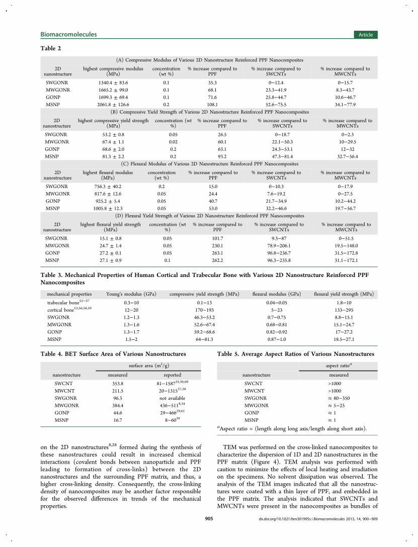
The experimental and control groups used for themechanical measurements are listed in Table 1. The mechanical
properties (compressive modulus, compressive yield strength,flexural modulus and flexural yield strength) of the 2Dnanostructure-reinforced cross-linked PPF nanocomposites asa function of 2D nanostructure concentration (0.01−0.2 wt %)are presented in Figure 2A−D. Also included are themechanical properties of the cross-linked PPF composite asbaseline control, and cross-linked PPF nanocompositesreinforced with 1D carbon nanostructures (SWCNTs andMWCNTs) as positive controls. Table 2A−D tabulates thehighest compressive modulus and yield strength, flexuralmodulus and yield strength, the corresponding loadingconcentration for each 2D nanostructure nanocomposite, and% increase compared to the baseline and positive controls.A significant increase in the compressive modulus (Figure
2A) and yield strength (Figure 2B) was observed for all the 2Dnanostructure nanocomposites at the various loading concen-trations compared to PPF composites. Most of the 2Dnanostructure nanocomposites, at various loading concentra-tions, also exhibited significant increases in the compressivemodulus and yield strength compared to 1D nanostructurenanocomposites. The highest compressive modulus values
(Table 2A) for the 2D nanostructure nanocomposites were35−108% greater compared to PPF composites, and up to 78%greater compared to the positive controls. The highestcompressive yield strength values (Table 2B) for the 2Dnanostructure nanocomposites were 27−93% greater comparedto PPF composites, and up to 81% greater compared to thepositive controls.The flexural modulus (Figure 2C) and yield strength (Figure
2D) for all the 2D nanostructure nanocomposites, at all theloading concentrations, also show a significant increasecompared to PPF composites. Furthermore, compared to 1Dnanostructure nanocomposites, most 2D nanostructure nano-composites, at various loading concentrations, showedsignificant increases in the flexural modulus and yield strength.The highest flexural modulus values (Table 2C) for the 2Dnanostructure nanocomposites were 15−53% greater comparedto PPF composites, and up to 47% greater compared to the 1Dnanostructure nanocomposites. The highest flexural yieldstrength values (Table 2D) for the 2D nanostructurenanocomposites were 102−262% greater compared to PPFcomposites, and up to 237% greater compared to the positivecontrols.The results of the mechanical properties (Figure 2A−D and
Table 2A−D) indicate a clear and consistent trend in the valuesfor the 2D nanostructure nanocomposites with MSNPnanocomposites > GONP nanocomposites > MWGONRnanocomposites > SWGONR nanocomposites. The resultstaken together also indicate that, among the 2D nanostructures,nanoplatelets are better reinforcing agents than nanoribbons,and that inorganic 2D nanostructures reinforce the PPFpolymer significantly better than 2D carbon nanostructures.The range of values of the Young’s modulus, compressivestrength, flexural modulus and flexural strength for the 2Dnanostructure-reinforced PPF nanocomposites are lower thanliterature values of cortical bone, but greater or comparable totrabecular bone. For load bearing applications, an orthopedicimplant should ideally have mechanical properties similar tonative bone. Orthopedic implants with lower or highermechanical properties compared to the native bone couldelicit structural failure or stress shielding, respectively. From theabove analysis (Table 3) it can inferred that PPF nano-composites can be fabricated with all 2D nanostructures asreinforcing agents toward tissue engineering strategies fortrabecular bone.The significantly higher mechanical properties of the 2D
nanostructure-reinforced nanocomposites compared to thebaseline or positive controls may be attributed to differencesin the dependence or interdependence of three importantfactors: surface area, aspect ratio, and cross-linking density.Higher surface area of the nanoparticles dispersed in polymermatrix has been shown to permit efficient load transfer from thepolymer matrix to the nanoparticles.34 The measured BETsurface areas of all the nanostructures are listed in Table 4. Thevalues follow the following trend: MWGONR > SWCNTs >MWCNTs > SWGONRs > GONPs > MSNPs. Surface areavalues of SWCNTs, MWCNTs, MWGONRs, GONPs, andMSNPs, are within the range reported in the literature.8,34−39
The values for SWGONRs have not been reported previously,and are lower than that of SWCNTs. Interestingly; the surfaceareas of graphene nanoparticles (SWGONRs, MWGONRs, andGONPs) are lower than the theoretical value of 2630 m2/g forindividual isolated graphene sheets. It is important to note that,for the solid nanostructure samples, a significant surface area is
Table 1. Experimental and Control Groups Used forMechanical Testing
Name Abbreviation
PPF polypropylene fumarateSWCNTs single-walled carbon nanotubesMWCNTs multi-walled carbon nanotubesSWGONRs single-walled graphene oxide nanoribbonsMWGONRs multi-walled graphene oxide nanoribbonsGONPs graphene oxide nanoplateletsMSNPs molybdenum disulfide nanoplatelets
Biomacromolecules Article
dx.doi.org/10.1021/bm301995s | Biomacromolecules 2013, 14, 900−909903

not available for nitrogen absorption due the presence ofnanoparticles as aggregated bundles.31,40 However, during thepreparation of polymeric nanocomposites, sonication coulddisrupt the aggregates, and further increase the surface area ofall the nanostructures. There is no method that allows directquantitative determination of the surface of the nanostructuresin the polymer matrix. Nevertheless, the above results suggestthat the surface area of nanostructures may not be the majorfactor responsible for the observed trends in the mechanicalproperties.The aspect ratio of fillers has been reported to affect the
mechanical properties of polymer composites.41 Table 5 liststhe aspect ratio of the various nanostructures used in this study.The values follow the trend nanoplatelets < nanoribbons <nanotubes; opposite of that observed for the mechanicalproperties. The trend suggests that decrease in the aspect ratio(an important measure of size) of the 2D nanostructures leadsto increase in the mechanical properties of the nanocomposites.However, this relationship between aspect ratio and mechanicalproperties cannot at least be extrapolated for hydrophilicpolymer nanocomposites reinforced with other 2D nanostruc-tures. For instance, a recent study on pristine graphene-reinforced poly(vinyl alcohol) (PVA) polymer nanocomposites
shows that its Young’s modulus increased with increase in theaspect ratio of pristine graphene sheets.42
Sol fraction analysis was performed to assess changes in thecross-linking density of PPF in the presence of 2Dnanostructures, since changes in the cross-linking densityhave been shown to alter the mechanical properties ofnanoparticle-reinforced polymer nanocomposites.43 A decreasein the sol fraction values signifies an increase in the cross-linking density of the polymer.24 Sol fractions measured forvarious cross-linked nanocomposites are reported in Figure 3.Sol fraction values for PPF, SWCNT, and MWCNTcomposites was ≈14%, ≈12.9−14.2%, and ≈12.1−14.2%,respectively. The sol fraction for 2D nanocomposite groupswas between 10.2 and 12.2% for SWGONR composites, 8.7−11.6% for MWGONR composites, 9.5−12.3% for GONPcomposites, and 8.5−10% for MSNP composites. Higher cross-linking density was observed for all loading concentrations ofMSNPs. Additionally, higher loading concentrations (0.1−0.2wt %) of GONPs and MWGONRs also resulted in significantincreases in the cross-linking density of nanocomposites. Thesol-fraction results suggest a cross-linking density trend of 2Dnanostructure nanocomposites > 1D nanostructures nano-composites > PPF composites. The presence of substantiallyhigher number hydroxyl, carboxyl, and sulfide functional groups
Figure 2. (A) compressive modulus, (B) compressive yield strength, (C) flexural modulus, and (D) flexural yield strength of PPF nanocomposites asa function of nanostructure loading concentration. Error bars represent mean ± standard deviation for n = 5. Groups with a significant differencecompared to PPF composite are marked with the symbol “*”, and those with a significant difference compared to positive controls (either SWCNTcomposites, or MWCNT composites, or both SWCNT and MWCNT composites) are marked with “#” (p < 0.05).
Biomacromolecules Article
dx.doi.org/10.1021/bm301995s | Biomacromolecules 2013, 14, 900−909904
on the 2D nanostructures8,28 formed during the synthesis ofthese nanostructures could result in increased chemicalinteractions (covalent bonds between nanoparticle and PPFleading to formation of cross-links) between the 2Dnanostructures and the surrounding PPF matrix, and thus, ahigher cross-linking density. Consequently, the cross-linkingdensity of nanocomposites may be another factor responsiblefor the observed differences in trends of the mechanicalproperties.
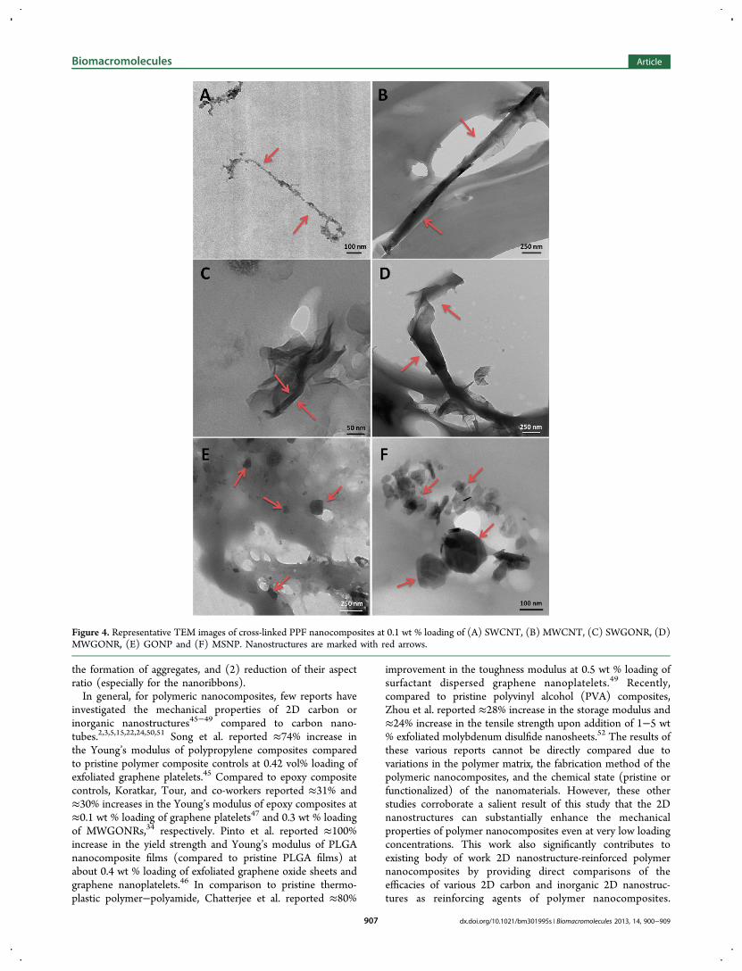
TEM was performed on the cross-linked nanocomposites tocharacterize the dispersion of 1D and 2D nanostructures in thePPF matrix (Figure 4). TEM analysis was performed withcaution to minimize the effects of local heating and irradiationon the specimens. No solvent dissipation was observed. Theanalysis of the TEM images indicated that all the nanostruc-tures were coated with a thin layer of PPF, and embedded inthe PPF matrix. The analysis indicated that SWCNTs andMWCNTs were present in the nanocomposites as bundles of
Table 2
(A) Compressive Modulus of Various 2D Nanostructure Reinforced PPF Nanocomposites
2Dnanostructure
highest compressive modulus(MPa)
concentration(wt %)
% increase compared toPPF
% increase compared toSWCNTs
% increase compared toMWCNTs
SWGONR 1340.4 ± 83.6 0.1 35.3 0−12.4 0−15.7MWGONR 1665.2 ± 99.0 0.1 68.1 23.3−41.9 8.3−43.7GONP 1699.3 ± 69.4 0.1 71.6 25.8−44.7 10.6−46.7MSNP 2061.8 ± 126.6 0.2 108.1 52.6−75.5 34.1−77.9
(B) Compressive Yield Strength of Various 2D Nanostructure Reinforced PPF Nanocomposites
2Dnanostructure
highest compressive yield strength(MPa)
concentration (wt%)
% increase compared toPPF
% increase compared toSWCNTs
% increase compared toMWCNTs
SWGONR 53.2 ± 0.8 0.05 26.5 0−18.7 0−2.3MWGONR 67.4 ± 1.1 0.02 60.1 22.1−50.3 10−29.5GONP 68.6 ± 2.0 0.2 63.1 24.3−53.1 12−32MSNP 81.3 ± 2.2 0.2 93.2 47.3−81.4 32.7−56.4
(C) Flexural Modulus of Various 2D Nanostructure Reinforced PPF Nanocomposites
2Dnanostructure
highest flexural modulus(MPa)
concentration(wt %)
% increase compared toPPF
% increase compared toSWCNTs
% increase compared toMWCNTs
SWGONR 756.3 ± 40.2 0.2 15.0 0−10.3 0−17.9MWGONR 817.6 ± 12.6 0.05 24.4 7.6−19.2 0−27.5GONP 925.2 ± 5.4 0.05 40.7 21.7−34.9 10.2−44.2MSNP 1005.8 ± 12.3 0.05 53.0 32.2−46.6 19.7−56.7
(D) Flexural Yield Strength of Various 2D Nanostructure Reinforced PPF Nanocomposites
2Dnanostructure
highest flexural yield strength(MPa)
concentration (wt%)
% increase compared toPPF
% increase compared toSWCNTs
% increase compared toMWCNTs
SWGONR 15.1 ± 0.8 0.05 101.7 9.3−87 0−51.5MWGONR 24.7 ± 1.4 0.05 230.1 78.9−206.1 19.5−148.0GONP 27.2 ± 0.1 0.05 263.1 96.8−236.7 31.5−172.8MSNP 27.1 ± 0.9 0.1 262.2 96.3−235.8 31.1−172.1
Table 3. Mechanical Properties of Human Cortical and Trabecular Bone with Various 2D Nanostructure Reinforced PPFNanocomposites
mechanical properties Young’s modulus (GPa) compressive yield strength (MPa) flexural modulus (GPa) flexural yield strength (MPa)
trabecular bone53−57 0.3−10 0.1−13 0.04−0.05 1.8−10cortical bone53,56,58,59 12−20 170−193 5−23 133−295SWGONR 1.2−1.3 46.3−53.2 0.7−0.75 8.8−15.1MWGONR 1.3−1.6 52.6−67.4 0.68−0.81 15.1−24.7GONP 1.3−1.7 59.2−68.6 0.82−0.92 17−27.2MSNP 1.5−2 64−81.3 0.87−1.0 18.5−27.1
Table 4. BET Surface Area of Various Nanostructures
surface area (m2/g)
nanostructure measured reported
SWCNT 353.8 81−158735,36,60
MWCNT 211.5 20−131537,38
SWGONR 96.3 not availableMWGONR 384.4 436−5118,34
GONP 44.6 29−46629,61
MSNP 16.7 8−6039
Table 5. Average Aspect Ratios of Various Nanostructures
aspect ratioa
nanostructure measured
SWCNT >1000MWCNT >1000SWGONR ≈ 80−350MWGONR ≈ 5−25GONP ≈ 1MSNP ≈ 1
aAspect ratio = (length along long axis/length along short axis).
Biomacromolecules Article
dx.doi.org/10.1021/bm301995s | Biomacromolecules 2013, 14, 900−909905

2−4 and 2−3 nanotubes, respectively (Figure 4A,B).SWGONRs were dispersed as bundles of a few (2−5)nanoribbons, and MWGONRs existed as individual nanorib-bons (Figure 4C,D). GONPs and MSNPs also existed asindividual nanoplatelets in the PPF matrix (Figure 4D,E). Theexistence of MWGONRs, GONPs and MSNPs as individualnanoparticles (observed in TEM analysis, Figure 4) furthercorroborates the hypothesis that during the preparation ofnanocomposites, sonication could effectively disrupt theaggregation of nanostructures, thereby increasing the surfacearea available for interaction with the polymer.The above surface area, aspect ratio, sol fraction, and TEM
analysis results taken together indicates differences innanostructure architecture (2D vs 1D nanostructures), as wellas number of functional groups, and structural defects for the2D nanostructures may be key properties that affect themechanical properties of 2D nanostructure-reinforced PPFnanocomposites and the reason for the enhanced mechanicalproperties compared to the controls. The presence of structuraldefects and functional groups could allow better nanomaterial−polymer physicochemical interactions such as increased non-covalent interaction of the polymer with the nanomaterialallowing the polymer to wrap efficiently over the nanomaterials,and formation of nanomaterial−polymer chemical bonds,leading to increases in the cross-linking density in thenanocomposites. Additionally, it could allow better dispersionof the 2D nanostructures in the polymer matrix and thusprevent the formation of large nanostructure aggregates, whichcan cause slippage between nanostructures, or act as sources ofstress concentrators, or crack initiators under applied loads.44
Among the 2D nanostructure nanocomposites, based on theconsistently higher values in the mechanical properties fornanoplatelets compared to nanoribbons, it can be inferred that,other than differences in cross-linking density, the lower aspect
ratio of nanoplatelets compared to nanoribbons may beresponsible for their better mechanical reinforcement.Furthermore, MSNPs lead to equivalent or better mechanicalreinforcement suggesting that chemical composition of thenanostructures may also play a role, and that inorganic 2Dnanostructures maybe more suitable to achieve enhancementfor certain mechanical properties (e.g., compressive mechanicalproperties) compared to carbon nanostructures.To the best of our knowledge, this is the first report
investigating and comparing the efficacy of nanotubes,nanoribbons, and nanoplatelets as well as inorganic and carbonnanomaterials as reinforcing agents toward the fabrication ofpolymeric nanocomposites as biomedical implants for bonetissue engineering. Previous studies have investigated theefficacy of fullerenes, and SWCNTs as reinforcing agents ofcross-linked PPF nanocomposites. In those studies, fullerenesmarginally increased the mechanical properties (∼10% increasein compressive or flexural modulus) compared to PPFcomposites. Pristine SWCNT-reinforced PPF nanocompositesshowed up to 65% increase in the compressive modulus and69% increase in the flexural modulus at a loading between 0.02and 0.1 wt % of SWCNTs.5 Functionalization or reduction inthe aspect ratio of the SWCNTs further improved (up to 2-foldincrease in compressive and flexural modulus) the mechanicalproperties.3,24 No direct comparisons can be made between theresults of this study with those results due to differences incross-linking agent (NVP vs PF-diacrylate), cross-linkingmethod (thermal vs photo-cross-linking) and/or curingtemperatures (60 °C vs 37 °C).5,24 Nonetheless, the resultsof those studies provide two additional strategies that can beemployed to further improve the mechanical properties of 2Dnanostructure-reinforced PPF nanocomposites: (1) Covalentfunctionalization of individual 2D nanostructures to furtherimprove their dispersion in the polymer matrix and to prevent
Figure 3. Sol fraction analysis of cross-linked PPF nanocomposites as a function of nanostructure loading (mean ± standard deviation for n = 5samples). Groups with a significant difference compared to PPF composite are marked with the symbol “*” (p < 0.05).
Biomacromolecules Article
dx.doi.org/10.1021/bm301995s | Biomacromolecules 2013, 14, 900−909906
the formation of aggregates, and (2) reduction of their aspectratio (especially for the nanoribbons).In general, for polymeric nanocomposites, few reports have
investigated the mechanical properties of 2D carbon orinorganic nanostructures45−49 compared to carbon nano-tubes.2,3,5,15,22,24,50,51 Song et al. reported ≈74% increase inthe Young’s modulus of polypropylene composites comparedto pristine polymer composite controls at 0.42 vol% loading ofexfoliated graphene platelets.45 Compared to epoxy compositecontrols, Koratkar, Tour, and co-workers reported ≈31% and≈30% increases in the Young’s modulus of epoxy composites at≈0.1 wt % loading of graphene platelets47 and 0.3 wt % loadingof MWGONRs,34 respectively. Pinto et al. reported ≈100%increase in the yield strength and Young’s modulus of PLGAnanocomposite films (compared to pristine PLGA films) atabout 0.4 wt % loading of exfoliated graphene oxide sheets andgraphene nanoplatelets.46 In comparison to pristine thermo-plastic polymer−polyamide, Chatterjee et al. reported ≈80%
improvement in the toughness modulus at 0.5 wt % loading ofsurfactant dispersed graphene nanoplatelets.49 Recently,compared to pristine polyvinyl alcohol (PVA) composites,Zhou et al. reported ≈28% increase in the storage modulus and≈24% increase in the tensile strength upon addition of 1−5 wt% exfoliated molybdenum disulfide nanosheets.52 The results ofthese various reports cannot be directly compared due tovariations in the polymer matrix, the fabrication method of thepolymeric nanocomposites, and the chemical state (pristine orfunctionalized) of the nanomaterials. However, these otherstudies corroborate a salient result of this study that the 2Dnanostructures can substantially enhance the mechanicalproperties of polymer nanocomposites even at very low loadingconcentrations. This work also significantly contributes toexisting body of work 2D nanostructure-reinforced polymernanocomposites by providing direct comparisons of theefficacies of various 2D carbon and inorganic 2D nanostruc-tures as reinforcing agents of polymer nanocomposites.
Figure 4. Representative TEM images of cross-linked PPF nanocomposites at 0.1 wt % loading of (A) SWCNT, (B) MWCNT, (C) SWGONR, (D)MWGONR, (E) GONP and (F) MSNP. Nanostructures are marked with red arrows.
Biomacromolecules Article
dx.doi.org/10.1021/bm301995s | Biomacromolecules 2013, 14, 900−909907

Additionally, the promising mechanical property results of the2D nanostructures reinforced PPF nanocomposites expandtheir biomedical application for possible bone tissue engineer-ing applications and opens avenues for in vitro and in vivostudies to assess their safety and efficacy.
■ CONCLUSIONSIn conclusion, biodegradable polymeric nanocomposites of PPFreinforced with various 2D nanostructures (SWGONRs,MWGONRs, GONPs, and MSNPs) at low loading concen-trations were fabricated toward the development of implantswith improved mechanical properties for bone tissue engineer-ing applications. The mechanical properties (compressivemodulus, compressive yield strength, flexural modulus, andflexural yield strength) of all the 2D nanostructure-reinforcedcross-linked PPF nanocomposites as a function of 2Dnanostructure concentration (0.01−0.2 wt %) were significantlyhigher in comparison to PPF composites. Most of the 2Dnanostructure nanocomposites, at various loading concentra-tions, also exhibited significant increases compared to 1Dnanostructure (pristine SWCNTs and MWCNTs) nano-composites. The extent of mechanical reinforcement is closelydependent on the nanostructure morphology and follows thetrend nanoplatelets > nanoribbons > nanotubes. The inorganic2D nanostructure MSNPs consistently showed better mechan-ical reinforcement than 1D or 2D carbon nanostructures. The2D nanostructures increase the cross-linking density of PPFnanocomposites compared to 1D nanostructures nanocompo-sites or PPF composites. All the 2D nanostructures exceptSWGONRs were present as individual particles in the PPFmatrix, while SWGONRs, SWCNTs and MWCNTs werepresent in the PPF matrix as small aggregates (bundles of 2−5nanoparticles). The study demonstrates that harnessing thereinforcing potential of 2D nanostructures could lead to wholenew classes of ultrastrong, lightweight biomaterials for tissueengineering applications.
■ AUTHOR INFORMATIONCorresponding Author*Mailing address: Department of Biomedical Engineering,Bioengineering Building Room 115, Stony Brook University,Stony Brook, NY 11794-5281. Tel: 631-632-1810. E-mail:[email protected] authors declare no competing financial interest.
■ ACKNOWLEDGMENTSThis work was supported by the National Institutes of Health(Grant No. 1DP2OD007394-01).
■ REFERENCES(1) Dinopoulos, H.; Dimitriou, R.; Giannoudis, P. V. Bone graftsubstitutes: What are the options? Surgeon 2012, 10 (4), 230−9.(2) Sitharaman, B.; Shi, X.; Walboomers, X. F.; Liao, H.; Cuijpers, V.;Wilson, L. J.; Mikos, A. G.; Jansen, J. A. In vivo biocompatibility ofultra-short single-walled carbon nanotube/biodegradable polymernanocomposites for bone tissue engineering. Bone 2008, 43 (2),362−70.(3) Sitharaman, B.; Shi, X.; Tran, L. A.; Spicer, P. P.; Rusakova, I.;Wilson, L. J.; Mikos, A. G. Injectable in situ cross-linkablenanocomposites of biodegradable polymers and carbon nanostructuresfor bone tissue engineering. J. Biomater. Sci. Polym. Ed. 2007, 18 (6),655−71.
(4) Mistry, A. S.; Pham, Q. P.; Schouten, C.; Yeh, T.; Christenson, E.M.; Mikos, A. G.; Jansen, J. A. In vivo bone biocompatibility anddegradation of porous fumarate-based polymer/alumoxane nano-composites for bone tissue engineering. J. Biomed. Mater. Res. A2010, 92 (2), 451−62.(5) Shi, X.; Hudson, J. L.; Spicer, P. P.; Tour, J. M.; Krishnamoorti,R.; Mikos, A. G. Rheological behaviour and mechanical character-ization of injectable poly(propylene fumarate)/single-walled carbonnanotube composites for bone tissue engineering. Nanotechnology2005, 16 (7), S531−8.(6) Cheng, Q.; Rutledge, K.; Jabbarzadeh, E. Carbon nanotube-poly(lactide-co-glycolide) composite scaffolds for bone tissue engineer-ing applications. Ann. Biomed. Eng. 2013, DOI: 10.1007/s10439-012-0728-8.(7) Stankovich, S.; Dikin, D. A.; Dommett, G. H. B.; Kohlhaas, K. M.;Zimney, E. J.; Stach, E. A.; Piner, R. D.; Nguyen, S. T.; Ruoff, R. S.Graphene-based composite materials. Nature 2006, 442 (7100), 282−286.(8) Kosynkin, D. V.; Higginbotham, A. L.; Sinitskii, A.; Lomeda, J. R.;Dimiev, A.; Price, B. K.; Tour, J. M. Longitudinal unzipping of carbonnanotubes to form graphene nanoribbons. Nature 2009, 458 (7240),872−6.(9) Dallavalle, M.; Sandig, N.; Zerbetto, F. Stability, dynamics, andlubrication of MoS2 platelets and nanotubes. Langmuir 2012, 28 (19),7393−400.(10) Radisavljevic, B.; Radenovic, A.; Brivio, J.; Giacometti, V.; Kis, A.Single-layer MoS2 transistors. Nat. Nanotechnol. 2011, 6 (3), 147−50.(11) Nair, R. R.; Wu, H. A.; Jayaram, P. N.; Grigorieva, I. V.; Geim,A. K. Unimpeded permeation of water through helium-leak-tightgraphene-based membranes. Science 2012, 335 (6067), 442−4.(12) Zhang, Y.; Nayak, T. R.; Hong, H.; Cai, W. Graphene: Aversatile nanoplatform for biomedical applications. Nanoscale 2012, 4(13), 3833−42.(13) Kim, J. E.; Han, T. H.; Lee, S. H.; Kim, J. Y.; Ahn, C. W.; Yun, J.M.; Kim, S. O. Graphene Oxide Liquid Crystals. Angew. Chem., Int. Ed.2011, 50 (13), 3043−3047.(14) Lalwani, G.; Kwaczala, A. T.; Kanakia, S.; Patel, S. C.; Judex, S.;Sitharaman, B. Fabrication and characterization of three-dimensionalmacroscopic all-carbon scaffolds. Carbon 2013, 53 (0), 90−100.(15) Shi, X.; Sitharaman, B.; Pham, Q. P.; Liang, F.; Wu, K.; EdwardBillups, W.; Wilson, L. J.; Mikos, A. G. Fabrication of porous ultra-short single-walled carbon nanotube nanocomposite scaffolds for bonetissue engineering. Biomaterials 2007, 28 (28), 4078−90.(16) Shen, J.; Zhu, Y.; Yang, X.; Li, C. Graphene quantum dots:Emergent nanolights for bioimaging, sensors, catalysis and photo-voltaic devices. Chem. Commun. 2012, 48 (31), 3686−3699.(17) Mullick Chowdhury, S.; Lalwani, G.; Zhang, K.; Yang, J. Y.;Neville, K.; Sitharaman, B. Cell specific cytotoxicity and uptake ofgraphene nanoribbons. Biomaterials 2013, 34 (1), 283−93.(18) Lee, C.; Wei, X.; Kysar, J. W.; Hone, J. Measurement of theelastic properties and intrinsic strength of monolayer graphene. Science2008, 321 (5887), 385−8.(19) Castellanos-Gomez, A.; Poot, M.; Steele, G. A.; van der Zant, H.S. J.; Agraït, N.; Rubio-Bollinger, G. Elastic Properties of FreelySuspended MoS2 Nanosheets. Adv. Mater. 2012, 24 (6), 772−775.(20) Bertolazzi, S.; Brivio, J.; Kis, A. Stretching and breaking ofultrathin MoS2. ACS Nano 2011, 5 (12), 9703−9.(21) Yu, M.-F.; Lourie, O.; Dyer, M. J.; Moloni, K.; Kelly, T. F.;Ruoff, R. S. Strength and Breaking Mechanism of Multiwalled CarbonNanotubes Under Tensile Load. Science 2000, 287 (5453), 637−640.(22) Ajayan, P. M.; Tour, J. M. Materials science: Nanotubecomposites. Nature 2007, 447 (7148), 1066−1068.(23) Mistry, A. S.; Mikos, A. G. Tissue engineering strategies forbone regeneration. Adv. Biochem. Eng. Biotechnol. 2005, 94, 1−22.(24) Shi, X.; Hudson, J. L.; Spicer, P. P.; Tour, J. M.; Krishnamoorti,R.; Mikos, A. G. Injectable nanocomposites of single-walled carbonnanotubes and biodegradable polymers for bone tissue engineering.Biomacromolecules 2006, 7 (7), 2237−42.
Biomacromolecules Article
dx.doi.org/10.1021/bm301995s | Biomacromolecules 2013, 14, 900−909908

(25) Yaszemski, M. J.; Payne, R. G.; Hayes, W. C.; Langer, R. S.;Aufdemorte, T. B.; Mikos, A. G. The ingrowth of new bone tissue andinitial mechanical properties of a degrading polymeric compositescaffold. Tissue Eng. 1995, 1 (1), 41−52.(26) Kasper, F. K.; Tanahashi, K.; Fisher, J. P.; Mikos, A. G. Synthesisof poly(propylene fumarate). Nat. Protoc. 2009, 4 (4), 518−25.(27) Paratala, B. S.; Jacobson, B. D.; Kanakia, S.; Francis, L. D.;Sitharaman, B. Physicochemical characterization, and relaxometrystudies of micro-graphite oxide, graphene nanoplatelets, and nanorib-bons. PLoS One 2012, 7 (6), e38185.(28) Castro-Guerrero, C. F.; Deepak, F. L.; Ponce, A.; Cruz-Reyes, J.;Valle-Granados, M. D.; Fuentes-Moyado, S.; Galvan, D. H.; Jose-Yacaman, M. Structure and catalytic properties of hexagonalmolybdenum disulfide nanoplates. Catal. Sci. Technol. 2011, 1 (6),1024−1031.(29) Stankovich, S.; Dikin, D. A.; Piner, R. D.; Kohlhaas, K. A.;Kleinhammes, A.; Jia, Y.; Wu, Y.; Nguyen, S. T.; Ruoff, R. S. Synthesisof graphene-based nanosheets via chemical reduction of exfoliatedgraphite oxide. Carbon 2007, 45 (7), 1558−1565.(30) Stankovich, S.; Piner, R. D.; Nguyen, S. T.; Ruoff, R. S.Synthesis and exfoliation of isocyanate-treated graphene oxidenanoplatelets. Carbon 2006, 44 (15), 3342−3347.(31) Srinivas, G.; Zhu, Y.; Piner, R.; Skipper, N.; Ellerby, M.; Ruoff,R. Synthesis of graphene-like nanosheets and their hydrogenadsorption capacity. Carbon 2010, 48 (3), 630−635.(32) Wieting, T. J.; Verble, J. L. Infrared and Raman studies of long-wavelength optical phonons in hexagonal MoS2. Phys. Rev. B 1971, 3(12), 4286−4292.(33) Yang, D.; Sandoval, S. J.; Divigalpitiya, W. M. R.; Irwin, J. C.;Frindt, R. F. Structure of single-molecular-layer MoS2. Phys. Rev. B1991, 43 (14), 12053−12056.(34) Rafiee, M. A.; Lu, W.; Thomas, A. V.; Zandiatashbar, A.; Rafiee,J.; Tour, J. M.; Koratkar, N. A. Graphene nanoribbon composites. ACSNano 2010, 4 (12), 7415−20.(35) Girishkumar, G.; Hall, T. D.; Vinodgopal, K.; Kamat, P. V.Single wall carbon nanotube supports for portable direct methanol fuelcells. J. Phys. Chem. B 2006, 110 (1), 107−14.(36) Agnihotri, S.; Mota, J. P.; Rostam-Abadi, M.; Rood, M. J.Structural characterization of single-walled carbon nanotube bundlesby experiment and molecular simulation. Langmuir 2005, 21 (3), 896−904.(37) Ajayan, P. M. Nanotubes from carbon. Chem. Rev. 1999, 99 (7),1787−1800.(38) Lehman, J. H.; Terrones, M.; Mansfield, E.; Hurst, K. E.;Meunier, V. Evaluating the characteristics of multiwall carbonnanotubes. Carbon 2011, 49 (8), 2581−2602.(39) Elizondo-Villarreal, N.; Velazquez-Castillo, R.; Galvan, D. H.;Camacho, A.; Jose Yacaman, M. Structure and catalytic properties ofmolybdenum sulfide nanoplatelets. Appl. Catal. A: Gen. 2007, 328 (1),88−97.(40) Kim, W. S.; Kim, Y. I.; Kim, H. J.; Hwanag, J. Y.; Moon, S. Y.;Park, N.-H.; Shim, K. B.; Kim, H. W.; Ham, H.; Huh, H. Fabrication ofa large scale transparent conducting film using transformed few-layeredgraphene nanoribbons obtained from unzipping of single wall carbonnanotubes. J. Mater. Chem. 2011, 21 (39), 15655−15659.(41) Kardos, J. L. Critical issues in achieving desirable mechanicalproperties for short fiber composites. Pure Appl. Chem. 1985, 57 (11),1651−1657.(42) May, P.; Khan, U.; O’Neill, A.; Coleman, J. N. Approaching thetheoretical limit for reinforcing polymers with graphene. J. Mater.Chem. 2012, 22 (4), 1278−1282.(43) Fisher, J. P.; Dean, D.; Mikos, A. G. Photocrosslinkingcharacteristics and mechanical properties of diethyl fumarate/poly-(propylene fumarate) biomaterials. Biomaterials 2002, 23 (22), 4333−43.(44) Ajayan, P. M.; Banhart, F. Strong bundles. Nat. Mater. 2004, 3(3), 135−6.(45) Song, P.; Cao, Z.; Cai, Y.; Zhao, L.; Fang, Z.; Fu, S. Fabricationof exfoliated graphene-based polypropylene nanocomposites with
enhanced mechanical and thermal properties. Polymer 2011, 52 (18),4001−4010.(46) Pinto, A. M.; Cabral, J.; Tanaka, D. A. P.; Mendes, A. M.;Magalhaes, F. D. Effect of incorporation of graphene oxide andgraphene nanoplatelets on mechanical and gas permeability propertiesof poly(lactic acid) films. Polym. Int. 2013, 62 (1), 33−40.(47) Rafiee, M. A.; Rafiee, J.; Wang, Z.; Song, H.; Yu, Z. Z.; Koratkar,N. Enhanced mechanical properties of nanocomposites at lowgraphene content. ACS Nano 2009, 3 (12), 3884−90.(48) Wang, Y.; Shi, Z.; Yin, J. Unzipped multiwalled carbonnanotubes for mechanical reinforcement of polymer composites. J.Phys. Chem. C 2010, 114 (46), 19621−19628.(49) Chatterjee, S.; Nuesch, F. A.; Chu, B. T. T. Comparing carbonnanotubes and graphene nanoplatelets as reinforcements in polyamide12 composites. Nanotechnology 2011, 22 (27), 275714.(50) Coleman, J. N.; Khan, U.; Blau, W. J.; Gun’ko, Y. K. Small butstrong: A review of the mechanical properties of carbon nanotube−polymer composites. Carbon 2006, 44 (9), 1624−1652.(51) Lin, C.; Wang, Y.; Lai, Y.; Yang, W.; Jiao, F.; Zhang, H.; Ye, S.;Zhang, Q. Incorporation of carboxylation multiwalled carbon nano-tubes into biodegradable poly(lactic-co-glycolic acid) for bone tissueengineering. Colloids Surf., B 2011, 83 (2), 367−75.(52) Zhou, K.; Jiang, S.; Bao, C.; Song, L.; Wang, B.; Tang, G.; Hu,Y.; Gui, Z. Preparation of poly(vinyl alcohol) nanocomposites withmolybdenum disulfide (MoS2): Structural characteristics and markedlyenhanced properties. RSC Adv. 2012, 2 (31), 11695−11703.(53) Rho, J. Y.; Ashman, R. B.; Turner, C. H. Young’s modulus oftrabecular and cortical bone material: Ultrasonic and microtensilemeasurements. J. Biomech. 1993, 26 (2), 111−9.(54) Schoenfeld, C.; Lautenschlager, E.; Meyer, P. Mechanicalproperties of human cancellous bone in the femoral head. Med. Biol.Eng. Comput. 1974, 12 (3), 313−317.(55) O’Kelly, K.; Tancred, D.; McCormack, B.; Carr, A. Aquantitative technique for comparing synthetic porous hydroxyapatitestructures and cancellous bone. J. Mater. Sci.: Mater. Med. 1996, 7 (4),207−213.(56) Choi, K.; Kuhn, J. L.; Ciarelli, M. J.; Goldstein, S. A. The elasticmoduli of human subchondral, trabecular, and cortical bone tissue andthe size-dependency of cortical bone modulus. J. Biomech. 1990, 23(11), 1103−13.(57) Du, C.; Ma, H.; Ruo, M.; Zhang, Z.; Yu, X.; Zeng, Y. Anexperimental study on the biomechanical properties of the cancellousbones of distal femur. Biomed. Mater. Eng. 2006, 16 (3), 215−222.(58) Reilly, D. T.; Burstein, A. H. The mechanical properties ofcortical bone. J. Bone Jt. Surg. Am. 1974, 56 (5), 1001−1022.(59) Suchy, T.; Balík, K.; Cerny, M.; Sochor, M.; Hulejova, H.;Pesakova, V.; Fenclova, T. A composite based on glass fibers andsiloxane matrix as a bone replacement. Ceram.−Silik. 2008, 52 (1),29−36.(60) Cinke, M.; Li, J.; Chen, B.; Cassell, A.; Delzeit, L.; Han, J.;Meyyappan, M. Pore structure of raw and purified HiPco single-walledcarbon nanotubes. Chem. Phys. Lett. 2002, 365 (1−2), 69−74.(61) Jeon, I. Y.; Shin, Y. R.; Sohn, G. J.; Choi, H. J.; Bae, S. Y.;Mahmood, J.; Jung, S. M.; Seo, J. M.; Kim, M. J.; Wook Chang, D.;Dai, L.; Baek, J. B. Edge-carboxylated graphene nanosheets via ballmilling. Proc. Natl. Acad. Sci. U.S.A. 2012, 109 (15), 5588−93.
Biomacromolecules Article
dx.doi.org/10.1021/bm301995s | Biomacromolecules 2013, 14, 900−909909