Nanostructure development in nylon 6-Cloisite® 30B composites. Effects of the preparation...
16
Macromolecular Nanotechnology Nanostructure development in nylon 6-Cloisite Ò 30B composites. Effects of the preparation conditions Massimo Paci, Sara Filippi, Pierluigi Magagnini * Dipartimento di Ingegneria Chimica, Università di Pisa, largo L. Lazzarino 1, 56126 Pisa, Italy article info Article history: Received 23 July 2009 Received in revised form 12 February 2010 Accepted 20 February 2010 Available online 24 February 2010 Keywords: PA6/Cloisite Ò 30B composites Melt compounding Static annealing Solution-blending Structure Organoclay degradation abstract PA6 composites with Cloisite Ò 30B (30B), prepared by different procedures, i.e., melt com- pounding, static annealing and solution blending, have been characterized by X-ray diffrac- tion and microscopic analyses (TEM, SEM, POM) in order to shed more light on the mechanism of nanostructure development. It has been demonstrated that intercalation of the PA6 chains within the 30B galleries takes place very rapidly, in the absence of applied stresses, even when the size of the clay particles is relatively large (tens of microns) and the clay loading is very high (even 50 wt.%). It has also been shown that, if, conversely, the filler content is low (10 wt.% or less) and the particles are tiny (e.g., as for polymer/ clay mixtures prepared by precipitation from a common solution), intercalation continues, under quiescent conditions, and leads in reasonable times to complete destruction of the silicate platelets stacking order. The composites with higher filler contents display a mixed exfoliated/intercalated morphology, with the intercalated silicate stacks characterized by an interlayer distance of about 3.7 nm. Contrary to statically annealed composites, the melt kneaded ones are characterized by a homogeneous dispersion of the filler particles and a local parallel orientation of the silicate platelets that induces, during polymer crystalliza- tion, an orientation of the polymer crystallites parallel to the faces of the compression molded specimens. Experiments carried out using 30B samples previously treated at 250 °C for 4 h under vacuum (30Bdegr) indicate that this treatment, probably due to the collapsed interlayer spaces, lowers the extent of PA6 chains intercalation. Thus, the rele- vant PA6/30Bdegr composites are characterized by the coexistence of unintercalated clay tactoids/agglomerates and individual silicate layers formed as result of intercalation on the edges of the filler particles. Ó 2010 Elsevier Ltd. All rights reserved. 1. Introduction Among the several potential approaches for the produc- tion of polymer/clay nanocomposites, melt compounding is commonly preferred because of its compatibility with existing processing technologies and equipment and be- cause it can be easily scaled to commercial quantities [1–4]. In this process, the system is subjected to shear and/or elongational flow and the applied stresses do obvi- ously assist dispersion of the filler particles within the polymer matrix. Most commercially available organoclays consist of powders whose particles have dimensions in the 1–30 lm range. The clay particles are formed by the intergrowth and agglomeration of individual crystallites (tactoids) formed by the regular stacking of tens of silicate platelets 1 nm thick and 50–300 nm wide, held together by van der Waals forces. These particles are large enough to crumble when blended with shear in a molten polymer, so that much smaller aggregates, primary particles or indi- vidual tactoids are produced which disperse uniformly within the polymer bulk. If, on the contrary, a mechanical dry blend of polymer and clay powders is held unstirred and annealed at temperatures above the glass transition 0014-3057/$ - see front matter Ó 2010 Elsevier Ltd. All rights reserved. doi:10.1016/j.eurpolymj.2010.02.012 * Corresponding author. Tel.: +39 050 2217822; fax: +39 050 2217866. E-mail address: [email protected] (P. Magagnini). European Polymer Journal 46 (2010) 838–853 Contents lists available at ScienceDirect European Polymer Journal journal homepage: www.elsevier.com/locate/europolj MACROMOLECULAR NANOTECHNOLOGY
-
Upload
independent -
Category
Documents
-
view
1 -
download
0
Transcript of Nanostructure development in nylon 6-Cloisite® 30B composites. Effects of the preparation...
European Polymer Journal 46 (2010) 838–853
MA
CRO
MO
LECU
LAR
NA
NO
TECH
NO
LOG
Y
Contents lists available at ScienceDirect
European Polymer Journal
journal homepage: www.elsevier .com/locate /europol j
Macromolecular Nanotechnology
Nanostructure development in nylon 6-Cloisite� 30B composites. Effectsof the preparation conditions
Massimo Paci, Sara Filippi, Pierluigi Magagnini *
Dipartimento di Ingegneria Chimica, Università di Pisa, largo L. Lazzarino 1, 56126 Pisa, Italy
a r t i c l e i n f o
Article history:Received 23 July 2009Received in revised form 12 February 2010Accepted 20 February 2010Available online 24 February 2010
Keywords:PA6/Cloisite� 30B compositesMelt compoundingStatic annealingSolution-blendingStructureOrganoclay degradation
0014-3057/$ - see front matter � 2010 Elsevier Ltddoi:10.1016/j.eurpolymj.2010.02.012
* Corresponding author. Tel.: +39 050 2217822; faE-mail address: [email protected] (P. Maga
a b s t r a c t
PA6 composites with Cloisite� 30B (30B), prepared by different procedures, i.e., melt com-pounding, static annealing and solution blending, have been characterized by X-ray diffrac-tion and microscopic analyses (TEM, SEM, POM) in order to shed more light on themechanism of nanostructure development. It has been demonstrated that intercalationof the PA6 chains within the 30B galleries takes place very rapidly, in the absence ofapplied stresses, even when the size of the clay particles is relatively large (tens of microns)and the clay loading is very high (even 50 wt.%). It has also been shown that, if, conversely,the filler content is low (�10 wt.% or less) and the particles are tiny (e.g., as for polymer/clay mixtures prepared by precipitation from a common solution), intercalation continues,under quiescent conditions, and leads in reasonable times to complete destruction of thesilicate platelets stacking order. The composites with higher filler contents display a mixedexfoliated/intercalated morphology, with the intercalated silicate stacks characterized byan interlayer distance of about 3.7 nm. Contrary to statically annealed composites, the meltkneaded ones are characterized by a homogeneous dispersion of the filler particles and alocal parallel orientation of the silicate platelets that induces, during polymer crystalliza-tion, an orientation of the polymer crystallites parallel to the faces of the compressionmolded specimens. Experiments carried out using 30B samples previously treated at250 �C for 4 h under vacuum (30Bdegr) indicate that this treatment, probably due to thecollapsed interlayer spaces, lowers the extent of PA6 chains intercalation. Thus, the rele-vant PA6/30Bdegr composites are characterized by the coexistence of unintercalated claytactoids/agglomerates and individual silicate layers formed as result of intercalation onthe edges of the filler particles.
� 2010 Elsevier Ltd. All rights reserved.
1. Introduction
Among the several potential approaches for the produc-tion of polymer/clay nanocomposites, melt compoundingis commonly preferred because of its compatibility withexisting processing technologies and equipment and be-cause it can be easily scaled to commercial quantities[1–4]. In this process, the system is subjected to shearand/or elongational flow and the applied stresses do obvi-ously assist dispersion of the filler particles within the
. All rights reserved.
x: +39 050 2217866.gnini).
polymer matrix. Most commercially available organoclaysconsist of powders whose particles have dimensions inthe 1–30 lm range. The clay particles are formed by theintergrowth and agglomeration of individual crystallites(tactoids) formed by the regular stacking of tens of silicateplatelets 1 nm thick and 50–300 nm wide, held together byvan der Waals forces. These particles are large enough tocrumble when blended with shear in a molten polymer,so that much smaller aggregates, primary particles or indi-vidual tactoids are produced which disperse uniformlywithin the polymer bulk. If, on the contrary, a mechanicaldry blend of polymer and clay powders is held unstirredand annealed at temperatures above the glass transition

M. Paci et al. / European Polymer Journal 46 (2010) 838–853 839
MA
CRO
MO
LECU
LAR
NA
NO
TECH
NO
LOG
Y
or the melting point of the polymer, the morphology of theresulting composite will expectedly be less uniform, withthe original clay particles simply embedded within the ma-trix polymer, as Brownian motions are clearly unable, atleast in reasonable times, to grant the same level of disper-sion achievable under flow conditions. In other words, ifprohibitive treatment times are avoided, quiescent anneal-ing of powder mixtures of polymer and clay is only ex-pected to yield composites with the inorganic filler in theform of micron-sized particles.
Besides melt kneading, another efficient procedureleading to extensive clay fragmentation and dispersionwithin the polymer matrix would be solution blending.In fact, if an appropriate solvent capable of swelling theorganoclay and dissolving the polymer is used and thepolymer–clay mixture is recovered from the common (col-loidal) solution by precipitation in a non-solvent or by filmcasting, the product can expectedly be obtained in theform of a composite comprising small tactoids, or evenindividual platelets, homogeneously dispersed in the poly-mer matrix. However, except for the particular cases wherewater can be a suitable solvent, this procedure is only ofinterest in the laboratory, as the use of organic solventsis preferably avoided on a commercial scale.
All the above considerations on the dependence of clayfragmentation and particles dispersion on the applied stres-ses or solvent swelling are generally accepted and are sup-ported by many experimental results in the scientificliterature. As far as nanoscale mixing is concerned, theoret-ical models indicate that it is only possible if the chemistryof polymer chains and silicate surfaces is such to grantfavorable energetic interactions [5–9]. Experiments con-firmed that by appropriately tuning the different structuralparameters of the polymers, including polarity, molecularweight and architecture, presence and distribution of func-tional groups (if any), etc., and those of the organic claymodifiers, including the number and the length of alkylchains, the grafting density, etc., thermodynamically stablenanocomposites can be obtained. These may possess anintercalated structure, if the macromolecules diffuse fromthe bulk polymer into the van der Waals galleries withoutdestroying the stacking order of the clay tactoids, or an ide-alized exfoliated nanomorphology, if all the silicate layersare individually dispersed within the polymer matrix withmutual distances exceeding the resolution in X-ray diffrac-tion (XRD) techniques (d0 0 1 > 5–6 nm). Given that thestructural parameters of both the polymer and the silicatecan be identified only as average figures, it is not surprisingthat experimental polymer/clay nanocomposites were of-ten found, by XRD and TEM, to display, in addition to theabove idealized structures, other thermodynamically sta-ble nanoscale morphologies, which are conveniently de-scribed as mixed ‘‘exfoliated-intercalated”, ‘‘disorderedintercalated”, etc.
Clearly, the morphologies of experimental nanocom-posites will also depend on the kinetics and the mecha-nism of the process used for their production and maydiffer more or less from the thermodynamically stableones. Thus, morphological changes may be expected to oc-cur during further processing operations. As for the mech-anism by which structure and morphology of the
nanocomposites approach their final configuration, thereis still a discussion, among scientists, especially with refer-ence to the relative importance of polymer/clay compati-bility, on one side, and the mechanical stresses applied tothe system during blending, on the other. A brief reviewof some relevant papers is given below.
In earlier studies on the microstructural evolution ofstatically annealed mixtures of polystyrenes and octadecy-lammonium exchanged fluorohectorite [10,11], it wasfound that the intercalation kinetics were of the same or-der of magnitude as transport by self-diffusion of polysty-rene. These results suggested that the intercalation processwas limited by the transport of polymer into the primaryparticles rather than inside the galleries of the organoclay.Subsequent studies by Manias et al. [12], carried out on dif-ferent polystyrene samples and organically modified flu-orohectorites by XRD, small- and intermediate-angleneutron scattering (SANS and IANS), allowed a detaileddescription of the effects of several parameters, such asthe length of the alkyl groups of the clay modifier, the poly-mer molar mass and the presence of bromine p-substitu-ents on the polystyrene chains, on the kinetics ofintercalation in polymer melts unassisted by shear. Yoonet al. [13] confirmed that simple annealing without shearcaused ready intercalation of polystyrene and other sty-rene copolymers into the organosilicate galleries. Staticannealing at 180 �C was also shown to lead to intercalationand partial exfoliation in blends of different functionalizedpolypropylenes with a dimethyldioctadecylammoniummodified clay [14]. Moreover, Manias, Chung et al. demon-strated that statically annealed (2 h at 190� under vacuum)dry blends of ammonium group-terminated PP (PP-t-NH3
+Cl�) and sodium montmorillonite (MMT) yieldedthermodynamically stable exfoliated nanocomposites, asdid analogous mixtures of the same functionalized poly-mer with a dimethyldioctadecylammonium modified clay[15]. The exfoliated nanomorphology of the above compos-ites was maintained after further mixing with neat PP andan additional static annealing cycle. A study by Denniset al. [16], on the effect of the melt processing conditionsfor nanocomposites based on polyamide-6 (PA6) and dif-ferent organoclays, showed that extensive exfoliation isobtained with almost any set of preparation procedureswhen matrix and nanofiller are highly compatible, whereasan optimization of the process conditions is needed in or-der to get good delamination from marginally compatiblepolymer and clay. An interesting study by Jo and collabora-tors [17] on the effect of shear on clay exfoliation was dealtwith analogous PA6/organoclay nanocomposites preparedby static annealing or melt kneading. The characterizationof the products was made by XRD only. In spite of this lim-itation, this work demonstrated very clearly that intercala-tion, followed by complete loss of silicate layers stackingorder, occurred when mixtures of PA6 with a highly compat-ible organoclay (Cloisite� 30B, by Southern Clay Prod. Inc.)were annealed in the absence of shear. The disappearanceof the clay basal reflection, ascribed to exfoliation, wasfaster when temperature was increased from 230 to 250 �Cand the Mn of PA6 was reduced from 48,000 to 14,000.In a more recent paper, dealt with polypropylene nano-composites compatibilized with PP-g-MA, Lertwimolnun

840 M. Paci et al. / European Polymer Journal 46 (2010) 838–853
MA
CRO
MO
LECU
LAR
NA
NO
TECH
NO
LOG
Y
and Vergnes [18] have shown that the level of intercala-tion, as measured by the interlayer spacing, is unaffectedby the processing parameters, whereas the extent of exfo-liation, monitored through rheological measurements, isimproved by increasing the shear stress and the mixingtime and/or lowering the mixing temperature. The resultsobtained by Ratinac et al. [19] from a comparison of thestructures of nanocomposites of poly(methyl methacry-late) with two different organoclays, prepared by in situpolymerization or melt compounding, were similar tothose found by Dennis et al. [16]: whereas the level ofintercalation was mainly influenced by the compatibilitybetween polymer and organoclay, higher levels of disper-sion were observed for the composites prepared by meltcompounding, compared to the shear-free bulk polymeri-zation, especially when the less compatible organoclaywas used. The influence of shear flow on the formation ofnanocomposites was also studied by Groeninckx and col-laborators [20] using different polymer/clay couples,including polycaprolactone, poly(ethylene oxide), PA12and PA6, different processing conditions and differentcharacterization techniques. On the basis of their detailedinvestigation, these authors came to the conclusion thatthe final morphology of the nanocomposites is mainlydetermined by the chemical compatibility of the constitu-ents and not through direct peeling of individual layersfrom the clay tactoids caused by shear stresses. However,the shear forces were said to be important on a kineticground, as they speed up the fragmentation of the clayagglomerates, that would be extremely slow in the absenceof shear, and take the individual platelets formed by theongoing exfoliation away from the edges of the interca-lated tactoids thus granting the progress of homogeniza-tion of the mixture. Melt intercalation of polymer chains,that these authors consider as the first step to silicate layerexfoliation, was shown to be quite fast for all the investi-gated systems, even in the absence of shear, as the shiftof the organoclay basal reflection toward lower angleswas found to occur completely during the time (about3 min) employed for sample preparation, before the firstXRD pattern could be recorded. Ingenious experiments re-ported recently by Bousmina [21] provided direct evidenceshowing that diffusion controlled intercalation, whichtakes place quite rapidly under quiescent or low shear con-ditions, is essential for the attainment of extensive exfolia-tion during the subsequent application of a high level ofshearing. This author calculated the energy of interactionbetween clay lamellae and found that shearing can leadto clay delamination, without degradation of the polymermatrix by breakage of the C–C bonds, only if the interla-mellar spacing exceeds a critical distance, i.e., if a sufficientlevel of intercalation has been achieved. Another directdemonstration that exfoliation can be obtained in un-stirred polymer/clay blends upon prolonged annealing attemperatures higher than the melting point of the hostpolymer was provided by Robello et al. [22]. These authorsset out to test the theoretical prediction by Singh and Ba-lazs [9] that star-shaped polymers might form thermody-namically stable exfoliated nanocomposites and annealedat 220 �C unstirred mixtures of a star-shaped polystyrenewith five arms (PS5) and two organoclays. Control experi-
ments were concurrently made with a linear polystyrenesample (PS1). The XRD patterns recorded after increasingannealing times on the mixtures containing the less com-patible 15A organoclay (Cloisite� 15A) showed that, withboth host polymers, the basal reflection shifted very rap-idly to lower angles, i.e., intercalation, but only for thePS5-based mixture this shift was followed by a progressivebroadening and subsequent disappearance of the XRDpeak. The process was found to be much faster for themixture containing the more compatible 10A organoclay(Cloisite� 10A). The TEM micrographs taken on the PS5/15A system, after 8 h annealing, confirmed that the nano-composite was highly exfoliated. In an interesting paperby Zhu and collaborators [23], the diffusion of poly(ethyl-ene oxide) chains out of the organoclay galleries during acooling cycle, induced by polymer crystallization, followedby back-intercalation during the subsequent heating cycle,was described. The influence of processing on the nanodi-spersion of Cloisite� 30B within a polylactide matrix wasalso studied by Bourbigot et al. [24]. These authors foundthat good delamination of the organoclay platelets andhigh levels of homogeneity were obtained by applicationof high mechanical energy for a short time followed bylow shear stress, whereas longer times and higher shearled to reagglomeration of the platelets.
On the other hand, the above interpretation of themechanism of nanocomposite formation, according towhich the effects of the stresses acting on the system dur-ing melt compounding are mainly limited to the kinetic as-pects of the process, is not shared by all researchers. Forexample, Paul and coworkers [25], based on detailed stud-ies on the optimization of the extrusion conditions for thepreparation of highly exfoliated melt-compounded PA6/clay nanocomposites, favor the view that dispersion ofthe silicate particles in the polymer melt is predominantlydriven by mechanical stresses imposed during melt pro-cessing and that intercalation is probably not a precursorto exfoliation. According to these authors, mechanicalforces do not only break up the organoclay aggregates:they also shear the tactoids into smaller ones and, if thepolymer and organoclay have an affinity for one another,their contacts are progressively increased by peeling oneby one the platelets from the silicate stacks until completeexfoliation is obtained. These authors maintain that thismechanism is more plausible than imagining the polymerchains diffusing into the galleries, i.e., intercalation, andeventually pushing them further and further apart untilan exfoliation state is reached [25]. Tang and collaborators[26,27] investigated the structural evolution and exfolia-tion process in nanocomposites based on PA12 and ther-moplastic polyurethanes and found that, provided theviscosity is appropriate and the polymer–clay interactionsare favorable, molecular diffusion leading to intercalationtakes place quite rapidly, even for statically annealed sys-tems. However, further diffusion of polymer chains intothe interlayer galleries becomes soon difficult and theapplication of shear stresses is needed in order to achievecomplete clay exfoliation. Exfoliation is envisaged as ashear stress driven slippage process, facilitated by theintercalated polymer chains, which lower the mutualattraction of the silicate layers. In recent studies by Utracki
M. Paci et al. / European Polymer Journal 46 (2010) 838–853 841
MA
CRO
MO
LECU
LAR
NA
NO
TECH
NO
LOG
Y
et al. [28,29] and La Mantia et al. [30] elongational flowwas shown to be even more effective than shear flow inpromoting clay delamination. On the other hand, Fracheet al. [31] prepared PP- and PA6-based nanocompositeseither by twin screw extrusion and by direct injectionmolding and found that their morphologies and mechani-cal properties were practically independent of the prepara-tion pathway.
In this work, we tried to shed more light on the mech-anism of PA6 intercalation and clay particles dispersionthrough a comparative structural and morphological char-acterization of the composites produced using differentprocedures, i.e., melt compounding, solution blendingand static annealing of mechanical blends. The same ap-proach was already used in previous studies to assess theeffect of the preparation conditions on structure and mor-phology of the nanocomposites based on polyethylenesfunctionalized by copolymerization with acrylic acid(EAA) [32], or by grafting with maleic anhydride (EMA)[33]. For both types of host polymers it was demonstratedthat very fast intercalation occurs when polymer/clay mix-tures are annealed at temperatures higher than the poly-mer melting point, independent of whether the mixturesare obtained by precipitation from a common solution orby mechanical blending of the constituents powders, andindependent of whether the thermal treatment is madestatically or under shear. The EAA-based nanocompositeswere shown to display a mixed exfoliated-intercalatedmorphology, independent of the clay loading and the prep-aration procedure. On the contrary, complete exfoliationwas observed, in agreement with literature reports, inEMA-based nanocomposites prepared by melt compound-ing (provided the clay loading was lower than about10 wt.%), whereas intercalation prevailed when the prepa-ration was made by static annealing of mechanical blendsof polymer and clay powders. An interesting new findingwas that, if the EMA/clay mixture was prepared by precip-itation from a common solution, and contained thereforesufficiently thin and well dispersed clay tactoids, shear-free compression molding was sufficient to produce anexfoliated, or disorderly intercalated, nanocomposite. Inother words, it was demonstrated that, provided the poly-mer and the organoclay are compatible, intercalation cancontinue, during static annealing, pushing the silicate lay-ers further and further apart until the stacks register is dis-rupted. The results of the present investigation suggestthat similar conclusion can be drawn for the PA6/Cloisite�
30B system as well.
2. Experimental
2.1. Materials
PA6 was kindly provided by Rhodia; it had a relativeviscosity equal to 3.66 in 95.7% sulfuric acid and contentsof amine and carboxyl groups of 34 and 35 mequiv. kg�1,respectively. The Cloisite� 30B organoclay (30B) was pur-chased from Southern Clay Products Inc. It was preparedfrom a sodium montmorillonite (MMT) having a cationexchange capacity (CEC) of 0.926 mequiv. g�1 by cation
exchange with 0.90 mequiv. g�1 of M(HE)2TNCl (methyl-bis(2-hydroxyethyl)-tallow ammonium chloride). Tallowis a blend of partly (�50%) unsaturated n-alkyl groups withapproximate composition: 65% C18; 30% C16; 5% C14. Theweight loss on ignition of 30B, determined by thermogravi-metric analysis (TGA) carried out in air by heating to 900 �Cwith a rate of 10 �C min�1, was about 30 wt.%, in agree-ment with the supplier’s technical bulletin. A 30B samplewas thermally treated at 250 �C for 4 h under high vacuumand was then used to prepare a few PA6 composites in or-der to assess the effect of a (partial) degradation of the or-ganic modifier on their morphology.
88% formic acid (FA), dimethylformamide (DMF) andother solvents were used as received from the commercialsuppliers (Aldrich and Fluka).
PA6 and the composites were dried under vacuum at120 �C for at least 10 h before any thermal treatment.30B was used as received, unless otherwise stated.
2.2. Preparation of the composites by melt compounding
Dried PA6 pellets (40 g) were fed to a Brabender Plasti-corder internal mixer of 50 mL capacity, preheated to250 �C. The loading and mixing operations were done un-der nitrogen flow. The rotor speed was held at 30 rpmwhile PA6 was loaded (about 3 min). After complete melt-ing (torque stabilization), the weighed amount of clay wascarefully added and the rotor speed was increased gradu-ally (in 30 s) to 60 rpm. During the kneading time(10 min), the temperature rose by 6–10 K, due to stressheating. The molten composites were extracted rapidlyfrom the mixer and let cool naturally. The materials werethen minced and stored in a desiccator. Specimens forthe characterizations were usually made by compressionmolding at 250 �C with a mold consisting of a 2 mm thickstainless steel plate with a hole of 20 mm diameter sand-wiched between two steel plates covered with anti-adher-ent film. After loading the samples, the mold was held inthe Carver press at 250 �C for 10 min before being cooledeither naturally or by immersion into ice-water.
2.3. Preparation of the composites from solution
PA6 was dissolved in 88% formic acid (FA) at room tem-perature to give a 5% wt/v solution. A suspension (5% wt/v)of the required amount of 30B in FA, or in a 90/10 v/vFA/DMF mixture, was prepared under stirring for 30 min.The clay suspension was then added to the PA6 solutionand stirring was continued for 1 h. The composite wasrecovered as a fibrous precipitate by pouring the FA solu-tion in a strong excess of vigorously stirred distilled water.It was then washed repeatedly with water and dried undervacuum at T < 50 �C for 24 h. Disk-shaped tablets (20 mmdiameter, 2 mm thickness) were finally prepared byroom-temperature dry molding using a Carver press.
2.4. Preparation of the composites by static annealing
The tablets obtained from the composites preparedfrom solution, as well as similar tablets prepared byroom-temperature compression of mixtures of PA6 and

842 M. Paci et al. / European Polymer Journal 46 (2010) 838–853
MA
CRO
MO
LECU
LAR
NA
NO
TECH
NO
LOG
Y
clay powders, were placed in the same mold employed forthe preparation of the melt-compounded specimens with-in the plates of a Carver press preheated to 250 �C. Anneal-ing at this temperature was continued for 10 min to allowthermal equilibration and the samples were then cooledslowly in the press.
2.5. Characterization techniques
Thermogravimetric analyses (TGA) were made with aQ500 TA Instruments balance to determine the loss on igni-tion of the organoclays and to check the clay contents of thecomposites. Samples of about 10 mg were used. The testswere carried out in air (60 mL min�1), in the 30–900 �Ctemperature range, with a scanning rate of 10 �C min�1.The 30B loading of the composites, as calculated from theweight of inorganic residue determined by TGA, correctedfor the loss of structural water, was always very close tothe nominal figure, thus showing that filler dispersionwas fairly homogeneous on a microscopic level. Polarizedoptical microscopy (POM) observations were made at250 �C on a Leitz Ortholux microscope equipped with a Lin-kam TMS 93 hot stage and a digital camera JVC TK-1085E. Asmall fragment of the composite samples was placed on athoroughly cleaned glass slide, melted at 250 �C on thehot stage and pressed with a cover slip to obtain a film of80–100 lm thickness. Observations were normally madeunder crossed polarizers, whereby the micron-sized clayagglomerates, if any, were easily revealed as highly bire-fringent particles. Scanning electron microscopy (SEM)analyses were made on the fracture surface of compressionmolded disks, using a Jeol JSM-5600LV microscope. Goldsputtering was omitted and observation was made underlimited vacuum in order to increase the contrast betweenthe phases. Transmission electron microscopy (TEM) obser-vations were made with a Zeiss EM 900 microscope, at80 kV. Ultra thin sections were cut from the compressionmolded disks at �120 �C, using a Leica EM FCS ultramicro-tome. X-ray diffraction measurements (Cu-Ka) were madein reflection mode with a Siemens D500 Krystalloflex 810apparatus, at a scan rate of 1.0� min�1. The clay wasanalyzed as a powder whereas the composites were in theform of disks, prepared by compression molding at250 �C, or tablets, obtained by room-temperature drymolding, of 2 mm thickness and 20 mm diameter.
3. Results and discussion
3.1. Composite characterization by X-ray diffraction
Melt compounding of PA6 with 30B has been shown inseveral studies [16,20,34–36] to lead to highly exfoliatednanocomposites. However, to our knowledge, the mor-phology of PA6 composites with organoclay loadingsexceeding 10 wt.% was only described by Shah et al. [37]for masters of high MW PA6 with an organoclay modifiedwith octadecyltrimethyl ammonium ions.
The XRD patterns of the melt-compounded PA6 com-posites containing 0, 5, 10, and 20 wt.% of 30B are shownin Fig. 1 (quenched samples) and in Fig. 2 (slowly cooled
samples), together with that of 30B. The latter displaysan intense, symmetric reflection at 2h � 4.8�, correspond-ing to an interlayer d0 0 1 spacing of 1.8 nm. The patternsof all quenched composites show a continuous increaseof diffracted intensity at small angles, with no distinctreflections ascribable to regularly stacked silicate layers,which is indicative of a high level of exfoliation. Also, nolow angle reflections are present in the XRD patterns ofthe slowly cooled composites with 5 and 10 wt.% 30B.However, the composite with 20 wt.% 30B shows a broadpeak at 2h � 2.4� suggesting the presence of intercalatedtactoids with d0 0 1 � 3.7 nm. The appearance of this reflec-tion can be interpreted considering that, during the slowcrystallization cycle of this sample, the silicate lamellaewere segregated in the amorphous regions, thus makingtheir concentration increase considerably, above the aver-age value, so that their aggregation to form intercalatedstacks was favored. An intercalated structure with d0 0 1 =3.68 nm was also found by Liu et al. [38] for nanocompos-ites of PA6 containing more than 10 wt.% of an organoclaymodified with octadecyl ammonium cations. Intercalationat high MMT loadings was also observed by Zhang andLoo [39] for nanocomposites of an amorphous polyamidewith an organoclay modified with dimethyl benzyl hydro-genated tallow ammonium ions.
The degree of crystallinity of the quenched samples, asqualitatively indicated by the intensity of the wide anglereflections in Fig. 1, is low and decreases as the nanofillercontent increases. Nevertheless, the XRD patterns demon-strate that, as expected [40,41], the c crystal structure pre-vails in all quenched samples including pure PA6. The cstructure is characterized by a single reflection ð0 0 1þ2 0 0þ 2 0 1Þ at 2h = 21.5� (d = 0.413 nm), plus a weaker0 2 0 reflection at lower angles (2h = 11.2�, d = 0.790 nm),due to the repeat distance of amide groups along the par-allel polymer chains packed in a pseudohexagonal array.On the contrary, in the slowly cooled samples, the thermo-dynamically stable a crystal structure is clearly demon-strated for pure PA6 by the presence of two stronglydiffracting planes: a mixture of 0 0 2 and 2 0 2 at 2h = 24�(d = 0.37 nm) plus the stronger 2 0 0 reflection at 2h =20.5� (d = 0.44 nm). Interestingly, in the slowly coolednanocomposites, the former reflection of the a crystal formappears with enhanced intensity, whereas that at 20.5� isalmost absent. This indicates that compression moldingof the melt-compounded nanocomposites causes a strongorientation of the clay platelets parallel to the disk facesand, thereby, a strong orientation of the PA6 crystallites,probably arising from confined crystallization betweenparallel clay platelets which are, on average, less than0.1 lm apart.
The XRD patterns of the composites prepared by staticannealing of mixtures of PA6 and 30B powders are shownin Fig. 3. The preparation involved the room-temperaturedry molding of the powder mixtures and a compressionmolding at 250 �C of the resulting tablets, followed by slowcooling to room temperature.
A comparison of Figs. 2 and 3 demonstrates that thepresence or absence of stress, during the preparation ofthe PA6/30B composites, has a strong effect on their XRDpatterns in both the wide angle and the small angle

1 3 5 7 9 11 13 15 17 19 21 23 25 27 29
2θ (deg)
Inte
nsity
(a.
u.)
30B
PA6/30B 5 wt%
PA6/30B 10 wt%
PA6/30B 20 wt%
PA6
d 001=1.8 nm
Fig. 1. XRD patterns of 30B and of the melt-compounded PA6/30B composite samples with 0, 5, 10, and 20 wt.% clay, compression molded and quenched inice-water.
M. Paci et al. / European Polymer Journal 46 (2010) 838–853 843
MA
CRO
MO
LECU
LAR
NA
NO
TECH
NO
LOG
Y
regions. In particular, for the composites prepared with noshear, the two reflections at 2h = 20.5� and 24� of the acrystal structure have comparable intensity. This indicatesthat, contrary to the melt-compounded samples, they pos-sess a much lower level of crystallites orientation, in agree-ment with expectation. As for the low angle region, onlythe XRD pattern of the composite with 5 wt.% of 30Bresembles that of the corresponding melt-compoundedmaterial, with no clear reflection ascribable to regularlypacked silicate layers stacks. On the contrary, the diffracto-grams of the statically annealed composites with 10 and20 wt.% organoclay display well resolved intensity peaksat 2h � 2.4� (d0 0 1 � 3.7 nm). The angular position of thesereflexes is practically coincident with that of the (less def-inite) peak present in the XRD trace of the melt-com-pounded composite with 20 wt.% clay. It may be inferred,therefore, that intercalated stacks with an interlayer spac-ing of about 3.7 nm are thermodynamically stable, in thePA6/30B system, when the organoclay concentration ex-ceeds a given limit, apparently in the range between 10and 20 wt.%. For the composites prepared in the melt withno applied stress, the filler dispersion is expected to be
much less uniform, at least on a micrometric scale, andtherefore the concentration of silicate particles can locallybe much higher than this limit, even for samples with anoverall clay concentration lower than 10 wt.%.
At first sight, the XRD patterns shown in Fig. 3 for the 10and 20 wt.% composites might be interpreted as indicativeof the presence of intercalated tactoids with a high level ofstacking regularity, not only because the basal reflectionsare rather sharp and symmetric, but also because theyare accompanied by smaller peaks at wider angles whichmight be taken as 0 0 2 reflections. However, the latterpeaks are seen at 2h � 5.7�, an angular position which isprobably too high to correspond to the d0 0 2 interlayerspacing. It cannot be excluded, therefore, that the observedpeaks at 2h � 5.7� are actually due to the overlapping ofthe second order of the 2h � 2.4� peak and of the reflectiondue to clay tactoids with a collapsed d0 0 1 spacing formedby thermal degradation of 30B. This point will be discussedin more detail below. The most important conclusiondrawn from the XRD characterization of the compositesprepared by static compression molding is that no hint ofthe presence of unintercalated 30B tactoids was seen in

1 3 5 7 9 11 13 15 17 19 21 23 25 27 292θ (deg)
Inte
nsity
(a.
u.)
30B
PA6/30B 5 wt%
PA6/30B 10 wt%
PA6/30B 20 wt%
PA6
d 001=1.8 nm
d 001=3.7 nm
Fig. 2. XRD patterns of 30B and of the melt-compounded PA6/30B composite samples with 0, 5, 10, and 20 wt.% clay, compression molded and cooledslowly to room temperature.
844 M. Paci et al. / European Polymer Journal 46 (2010) 838–853
MA
CRO
MO
LECU
LAR
NA
NO
TECH
NO
LOG
Y
the spectra. In fact, even when the XRD traces of the com-posites showed the presence of basal reflections, these al-ways corresponded to intercalated tactoids. Thus, inagreement with previous studies by others [17,20], it wasdemonstrated that intercalation of PA6 chains within thegalleries of 30B takes place quite rapidly under static con-ditions, provided the temperature is higher than the PA6melting point, and even leads to complete destruction ofthe stacking order when the clay concentration is suffi-ciently small (e.g., ffi5 wt.% or lower).
The possibility of a direct preparation of PA6/30B nano-composites from solution appeared unlikely on the basis ofthe information provided by the works of Liu et al. [38] andof Vaia and collaborators [42]. The first authors showedthat an organoclay modified with octadecyl ammoniumions subsided rapidly, after being blended in a FA solutionwith PA6, as soon as stirring stopped, whereas no settlingwas observed if a melt-compounded nanocomposite ofsimilar composition was dissolved in FA. The secondauthors blended PA6 with 30B in 1,1,1,3,3,3-hexafluoro-2-propanol (HFIP) with sonication. Film casting, madeunder vacuum at room temperature, yielded an uninterca-
lated composite, as shown by XRD. Although the abovestudies were made with different systems, the first forthe organoclay and the second for the solvent, their resultsmade us expect that blending of PA6 with 30B in a FA solu-tion would fail to yield nanocomposites. Nevertheless, weused this procedure with the aim of improving the disper-sion of the 30B particles within the bulk polymer and find-ing whether this would speed up, during the subsequentshear-free annealing step, the process by which continuingintercalation leads to complete destruction of the stackingorder of silicate tactoids. Previous studies carried out in ourlaboratories [43] had shown that 30B undergoes a struc-tural modification, with gradual collapse of interlayerspacing, when suspended in 88% FA, possibly due to substi-tution of the organic ammonium ions with hydrogen ionsaccording to the mechanism proposed by Lee and Char[44]. However, this effect was quite slow, compared tothe time schedule used for the solution blending experi-ments described in the experimental section.
The XRD patterns of some of the composites preparedby solution blending and room temperature drying, bothas tablets formed by r.t. compression, or as disks prepared

1 3 5 7 9 11 13 15 17 19 21 23 25 27 292θ (deg)
Inte
nsity
(a.
u.)
30B
PA6/30B 5 wt%
PA6/30B 10 wt%
PA6/30B 20 wt%
PA6
d 001=3.7 nm
d 001=1.8 nm
d =1.5 nm
Fig. 3. XRD patterns of 30B and of the composites with 0, 5, 10, and 20 wt.% clay, prepared by 250 �C compression molding of PA6/30B powders mixtures,followed by slow cooling.
M. Paci et al. / European Polymer Journal 46 (2010) 838–853 845
MA
CRO
MO
LECU
LAR
NA
NO
TECH
NO
LOG
Y
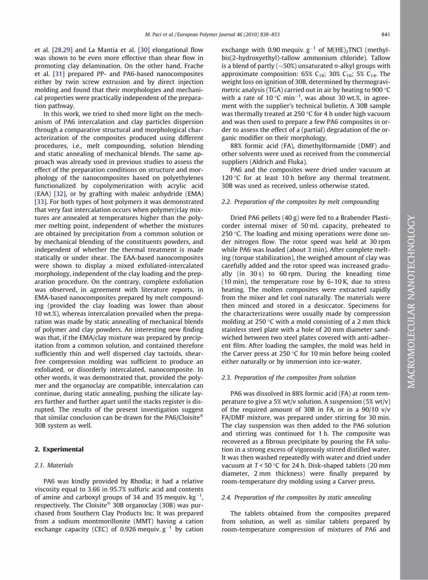
by statically melting the tablets at 250 �C and cooling themslowly in the press, are shown in Fig. 4.
A low angle reflection corresponding to the basal spac-ing of 30B (d0 0 1 � 1.8 nm) is present in the XRD patternsof all solution blended composites prepared at room tem-perature. This confirms that, as such, solution blendingfails to yield intercalation. The considerable increase of dif-fracted intensity observed at low angles for the compositewith 10 wt.% of 30B was tentatively interpreted consider-ing that this sample, prepared by blending the FA solutionof PA6 with a suspension of 30B in a 90/10 v/v mixture ofFA with DMF, might be partly exfoliated (DMF is known tobe highly compatible with 30B [42,45]). However, thishypothesis could not be confirmed by TEM.
After compression molding at 250 �C and slow coolingto room temperature, intercalation occurred and the basalreflection of unintercalated 30B practically disappeared,not only for the sample with 5 wt.% clay as already foundfor the analogous composite obtained by static annealingof a mechanical blend of PA6 and 30B powders (Fig. 3),but also for the sample with 10 wt.% of 30B, thus confirm-ing the expectation. The XRD pattern of the composite with
20 wt.% clay (not shown) was similar to that given in Fig. 3for the sample with 10 wt.% clay, prepared by annealing apowders mixture. Here a reflection of low intensity be-came discernible at 2h � 2.4�. Interestingly, even the solu-tion blended composite with a 30B loading of 50 wt.% wasalmost completely intercalated after compression moldingat 250 �C. In fact, the reflection visible in the XRD pattern at2h � 5� is probably the sum of three partially overlappedpeaks: the second order of the main basal reflection ofthe intercalated tactoids, plus the basal reflections of afew unintercalated 30B and thermally degraded 30Bstacks. This confirms that intercalation of the PA6 chainswithin the 30B galleries is extremely rapid and occurs al-most completely, even with very high clay loadings. More-over, if the size of the silicate particles is sufficiently small,intercalation continues and leads to complete destructionof the platelets stacking regularity.
3.2. Composite characterization by microscopic analyses
TEM micrographs of melt-compounded PA6/30B nano-composites with small organoclay loadings have been
1 3 5 7 9 11 13 15 17 19 21 23 25 27 29
2θ (deg)
Inte
nsity
(a.
u.)
5 wt%250°C
25°C
50 wt%250°C
10 wt%250°C
25°C
25°C
d 001=3.7 nm
d 001=1.8 nm
Fig. 4. XRD patterns of solution blended PA6/30B composites with 5, 10, and 50 wt.% clay, dry molded at 25 �C (lower curves) and compression molded at250 �C and cooled slowly to room temperature (upper curves).
846 M. Paci et al. / European Polymer Journal 46 (2010) 838–853
MA
CRO
MO
LECU
LAR
NA
NO
TECH
NO
LOG
Y
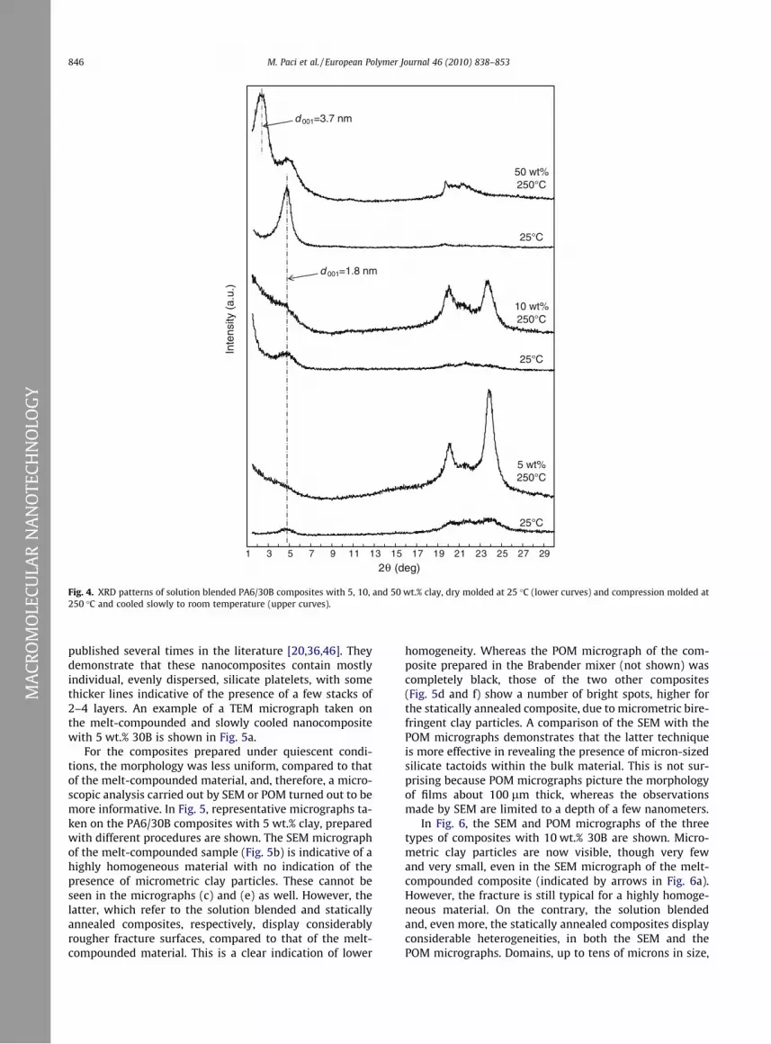
published several times in the literature [20,36,46]. Theydemonstrate that these nanocomposites contain mostlyindividual, evenly dispersed, silicate platelets, with somethicker lines indicative of the presence of a few stacks of2–4 layers. An example of a TEM micrograph taken onthe melt-compounded and slowly cooled nanocompositewith 5 wt.% 30B is shown in Fig. 5a.
For the composites prepared under quiescent condi-tions, the morphology was less uniform, compared to thatof the melt-compounded material, and, therefore, a micro-scopic analysis carried out by SEM or POM turned out to bemore informative. In Fig. 5, representative micrographs ta-ken on the PA6/30B composites with 5 wt.% clay, preparedwith different procedures are shown. The SEM micrographof the melt-compounded sample (Fig. 5b) is indicative of ahighly homogeneous material with no indication of thepresence of micrometric clay particles. These cannot beseen in the micrographs (c) and (e) as well. However, thelatter, which refer to the solution blended and staticallyannealed composites, respectively, display considerablyrougher fracture surfaces, compared to that of the melt-compounded material. This is a clear indication of lower
homogeneity. Whereas the POM micrograph of the com-posite prepared in the Brabender mixer (not shown) wascompletely black, those of the two other composites(Fig. 5d and f) show a number of bright spots, higher forthe statically annealed composite, due to micrometric bire-fringent clay particles. A comparison of the SEM with thePOM micrographs demonstrates that the latter techniqueis more effective in revealing the presence of micron-sizedsilicate tactoids within the bulk material. This is not sur-prising because POM micrographs picture the morphologyof films about 100 lm thick, whereas the observationsmade by SEM are limited to a depth of a few nanometers.
In Fig. 6, the SEM and POM micrographs of the threetypes of composites with 10 wt.% 30B are shown. Micro-metric clay particles are now visible, though very fewand very small, even in the SEM micrograph of the melt-compounded composite (indicated by arrows in Fig. 6a).However, the fracture is still typical for a highly homoge-neous material. On the contrary, the solution blendedand, even more, the statically annealed composites displayconsiderable heterogeneities, in both the SEM and thePOM micrographs. Domains, up to tens of microns in size,

Fig. 5. TEM (a), SEM (b, c, and e), and POM (d and f) micrographs of the PA6/30B composites with 5 wt.% clay prepared: by melt compounding (a and b);from solution and compression molding (c and d); by static annealing of a mechanical mixture of polymer and clay powders (e and f).
M. Paci et al. / European Polymer Journal 46 (2010) 838–853 847
MA
CRO
MO
LECU
LAR
NA
NO
TECH
NO
LOG
Y
are visible that are very rich of bright silicate particles(Fig. 6c–f). It may be interesting to observe, however, thatthese silicate domains, particularly for the solutionblended sample, appear to be soaked by molten polymer.
The results of the microscopic characterization of thePA6/30B composites prepared with different proceduresare in good agreement with the conclusions drawn fromthe XRD analyses. A scheme illustrating the mechanismof nanostructure formation under melt kneading andshear-free conditions is given in Fig. 7. When a mechanicalmixture of polymer and clay powders is used (schemes aand b), the clay particles are quite large (even tens of mi-crons): intercalation takes place very rapidly, but it doeslead to complete destruction of the stacking order, in rea-sonable times, only if a mechanical stress is applied onthe system (scheme a). Moreover, the filler distributionwithin the bulk polymer is poor for statically annealedcomposites. On the other hand, when the polymer claymixture is prepared by precipitation from a common solu-tion and the clay loading is low, intercalation continues
until the platelets stacking order is completely lost(scheme c). Nevertheless, the filler dispersion achievableunder static conditions is expected to be always lower thanthat attainable under flow. Moreover, poor orientation, ifany, of the silicate platelets/tactoids and of the polymercrystallites prevails in composites prepared under quies-cent conditions.
3.3. Thermal stability of 30B
The thermal stability of several commercially availableorganoclays, included 30B, has been studied extensively,in recent years [35,47–53], because the temperatures ofinitial breakdown of their organic component are often ex-ceeded during the preparation of polymer nanocomposites.In fact, thermogravimetric analyses have shown that orga-noclays start loosing weight at about 180 �C, in inertatmosphere. For 30B, and other one-tailed organoclays, itwas found that thermal degradation is accompanied by ashift of the basal reflection toward wider angles (from

Fig. 6. SEM (a, c, and e), and POM (b, d and f) micrographs of the PA6/30B composites with 10 wt.% clay prepared: by melt compounding (a and b); fromsolution and compression molding (c and d); by static annealing of a mechanical mixture of polymer and clay powders (e and f).
848 M. Paci et al. / European Polymer Journal 46 (2010) 838–853
MA
CRO
MO
LECU
LAR
NA
NO
TECH
NO
LOG
Y
2h � 4.8� to 2h � 6�), indicating a collapse of the interlayerspacing (from d0 0 1 � 1.8 to d0 0 1 � 1.4 nm) [35,54]. Sucheffect manifests itself quite slowly, and may require sev-eral hours to be observed cleanly, if treatment tempera-tures not higher than 190 �C are used [54]. On the otherhand, it was shown in many papers [53,54] that the inter-layer spacing collapse can also occur (more rapidly, i.e.,during the melt compounding operation) if 30B is meltblended with different polymers, even at temperatures inthe 120–150 �C range. It is noteworthy, therefore, that nohint of a reflection ascribable to stacks of degraded 30Bwas ever observed in the XRD scans of melt-compounded(or in situ polymerized) PA6/30B composites, whose pro-cessing temperatures are close to 250 �C [16,20,34,35].On the contrary, an XRD peak shift to wider angles wasalways seen, e.g., in the scans of the PA6/clay masters pre-pared with an organoclay modified with octadecyltrimeth-yl ammonium ions [36], as well as in nanocomposites ofpolycarbonate with 30B, extruded at 260 �C [55]. As dis-cussed in the previous paragraphs, none of the melt-com-
pounded PA6/30B samples prepared in this work,including those with a clay loading of 20 wt.%, displayeda shifted reflection ascribable to breakdown of the organicmodifier (cf. Figs. 1 and 2). Only for the composites with30B loadings P10 wt.% prepared by static annealing, didthe XRD scans show the presence of a peak at 2h � 5.7�that might be thought to comprise a contribution from col-lapsed 30B stacks. In fact, its angular position is probablytoo far to the right to be simply due to the second orderof the 2h � 2.4� basal reflection. However, this point couldnot be demonstrated directly because an attempt at dein-tercalating these composites failed. Indeed, the productobtained by dissolution of the composite in FA, precipita-tion in excess water, and room temperature drying,showed an XRD low angle pattern identical to that of thestarting composite.
In a recent paper by Monticelli et al. [35], it was shownthat a thermal treatment of 30B made for 4 h at 250 �C ininert atmosphere, i.e., under conditions miming those pre-vailing during the in situ polymerization of e-caprolactam

Fig. 7. Scheme of nanostructure formation under different conditions: (a) melt compounding; (b) static annealing of a mechanical mixture of polymer andclay powders; (c) static annealing of a polymer/clay mixture prepared by precipitation from a common solution.
M. Paci et al. / European Polymer Journal 46 (2010) 838–853 849
MA
CRO
MO
LECU
LAR
NA
NO
TECH
NO
LOG
Y
(CL), led to a weight loss of about 4% and a reduction of theinterlayer spacing from d0 0 1 � 1.8 to d0 0 1 � 1.29 nm.Nevertheless, the PA6 nanocomposite prepared by in situpolymerization of CL using such degraded 30B samplewas shown by TEM to be completely exfoliated, as that ob-tained with undegraded 30B. Thus, it might be argued thatthe reason why the PA6/30B composites prepared so farfailed to show the reflection at 2h � 6� might be that the30B platelets, even if degradation of the organic compo-nent does occur during the nanocomposite preparation, re-main compatible with PA6 and do not reaggregate intostacks with a collapsed structure.
On the other hand, a molecular modeling technique ap-plied by Tanaka and Goettler [56] to predicting bindingenergies for nanocomposites comprising exfoliated claylayers modified with different ammonium salts and dis-persed in a nylon 6,6 (PA66) matrix showed that pristine(unmodified) clay yields the highest interfacial strengthbetween the silicate surface and the PA66 chains, whereassuch binding energy decreases almost linearly withincreasing volume of the adsorbed quaternary ammoniumions. Based on this simulation, Utracki [57] argued thatpartial removal of the organic modifier (e.g., by thermaldegradation) may play a positive role and offer a chancefor the nylon chains to interact with the silicate surfaceand improve intercalation and exfoliation of theorganoclay.
In order to check this hypothesis, a 30B sample wastreated under high vacuum for 4 h at 250 �C and the prod-
uct (30Bdegr) was used to prepare 95/5 PA6 composites,either by melt compounding, followed by quenching orslow cooling, and with the static annealing procedure.The latter preparation method was also used to synthesizea composite with 20 wt.% clay. The results of the XRD anal-yses are illustrated in Fig. 8.
The XRD pattern of 30Bdegr expectedly shows a sharpreflection corresponding to the collapsed interlayer dis-tance of about 1.4 nm. A reflection corresponding to thesame distance is also visible in the XRD scans of all the95/5 PA6/30Bdegr composites (curves a, b, and c). Thisdemonstrates that unintercalated stacks of 30Bdegr arepresent in these materials. A comparison of the SEM andPOM micrographs shown in Fig. 9 with those in Fig. 5demonstrates that micron-sized clay particles are present,in a considerably larger number, not only in the sampleprepared by static annealing, but also in the melt-com-pounded one. Therefore, the XRD and microscopic charac-terizations of the composites filled with 5 wt.% 30Bdegrsuggest that the thermal treatment of the organoclay hasconsiderably lowered the extent of PA6 intercalation with-in the clay galleries.
However, a closer inspection of the XRD patterns of the95/5 PA6/30Bdegr composites (Fig. 8, curves a, b, and c)shows that, in the low angle region, the diffracted intensityincreases appreciably. Moreover, for the slowly cooledmelt-compounded sample (curve b), the intensity ratio ofthe reflections typical for the a crystal structure is stronglyaltered, as it was for the corresponding nanocomposites

1 3 5 7 9 11 13 15 17 19 21 23 25 27 292θ (deg)
Inte
nsity
(a.
u.)
d 001=1.4 nm
30Bdegr
a)
b)
c)
d)
Fig. 8. XRD patterns of 30Bdegr and of the PA6/30Bdegr composites, with filler loadings of 5 (a, b, and c) and 20 wt.% (d), prepared by melt compounding (aand b) and static annealing (c and d). Sample (a) was quenched, after compression molding, whereas (b), (c) and (d) were cooled slowly.
850 M. Paci et al. / European Polymer Journal 46 (2010) 838–853
MA
CRO
MO
LECU
LAR
NA
NO
TECH
NO
LOG
Y
with undegraded 30B (cf. Fig. 2), suggesting a pronouncedorientation of the PA6 crystallites. Both these characteris-tics of the XRD patterns are generally considered sugges-tive of (partial) exfoliation. To assess this point, the 95/5PA6/30Bdegr melt-compounded composite was analyzedby TEM: the relevant micrographs are included in Fig. 9.Together with large clay agglomerates (not shown in themicrographs) and micron-sized tactoids, clearly shown inFig. 9c, several individual platelets were actually visible,especially in the high magnification photograph (Fig. 9d).It must be inferred, therefore, that unintercalated clay tac-toids/agglomerates and exfoliated silicate platelets coexistin these composites. This can be accounted for consideringthat, although the penetration of the PA6 chains in the in-side of the 30Bdegr particles is hampered by insufficientintergallery space, intercalation can take place on theiredges and lead to partial delamination. The XRD patternof the 20 wt.% PA6/30Bdegr composite prepared by staticannealing (curve d, in Fig. 8) is in agreement with thisinterpretation. In fact, no reflection ascribable to interca-lated silicate stacks is seen in this spectrum, contrary towhat was found for the corresponding composite prepared
with undegraded 30B (Fig. 3), but the same strong increaseof diffracted intensity at low angles is observed, togetherwith the reflection of unintercalated 30Bdegr.
4. Conclusions
The preparation and the structural and morphologicalcharacterization of PA6/30B composites prepared by differ-ent pathways, i.e., melt compounding, solution blending,and static annealing, have been carried out with the aimof clarifying the mechanism by which intercalation and/or exfoliation of the organoclay take place. It has been con-firmed that 30B exfoliation occurs when the organoclay ismelt compounded with PA6 (under shear conditions), pro-vided the clay loading is not too high. For clay concentra-tions exceeding approximately 10 wt.%, an increasingpopulation of intercalated tactoids with an interlayer spac-ing of about 3.7 nm, accompanying the individual silicateplatelets, is observed. Independent of the presence of ap-plied stresses, intercalation of the PA6 chains within the30B galleries occurs very rapidly, even when 50/50 wt/wtmixtures of PA6 and 30B powders are statically annealed

Fig. 9. SEM (a and e), TEM (c and d), and POM (b and f) micrographs of the PA6/30Bdegr composites with 5 wt.% clay prepared: by melt compounding (a–d)and by static annealing of a mechanical mixture of polymer and clay powders (e and f).
M. Paci et al. / European Polymer Journal 46 (2010) 838–853 851
MA
CRO
MO
LECU
LAR
NA
NO
TECH
NO
LOG
Y
at 250 �C for 10 min. However, in the absence of forcedflow, intercalation leads to complete destruction of the sil-icate platelets stacking regularity only when the clay load-ing is sufficiently low and the size of the clay particles isalso small (as, e.g., when the polymer/clay blend is pre-pared by precipitation from a common solution). In meltkneaded systems, the silicate layers are homogeneouslydispersed within the bulk polymer and tend to orient par-allel to each other, forming nematic-like domains. Aftercompression molding of these materials, and polymer crys-tallization, a preferred orientation of both the clay plateletsand the polymer crystallites parallel to the major faces ofthe samples sets in, as demonstrated by XRD analysis. Onthe contrary, nearly isotropic, though less homogenous,morphologies are observed for the samples prepared underquiescent conditions.
No clear diffractometric evidence of degradation of theorganic component of 30B was found in this work, inagreement with literature reports. However, the resultsobtained in the present study on the composites prepared
by melt compounding or static annealing with a 30B sam-ple previously treated at 250 �C for 4 h (30Bdegr), to-gether with those found by Monticelli et al. [35] on asimilar composite obtained by in situ polymerization,provide an additional indirect evidence pointing to inter-calation as a precursor to exfoliation. Indeed, whereasintercalation by the PA6 chains occurs only on the edgesof the 30Bdegr particles, so that the morphology of theproducts (either melt-compounded and statically an-nealed) is characterized by the coexistence of individualsilicate platelets and unintercalated clay stacks, swellingof the clay by molten CL can still occur effectively, despitethe thermally induced collapse of interlayer spacing,and this grants the formation of a fully exfoliatednanocomposite.
Acknowledgment
The precious help of Mr. P. Narducci for the SEM analy-ses is gratefully acknowledged.

852 M. Paci et al. / European Polymer Journal 46 (2010) 838–853
MA
CRO
MO
LECU
LAR
NA
NO
TECH
NO
LOG
Y
References
[1] Giannelis EP, Krishnamoorti R, Manias E. Polymer-silicatenanocomposites: model systems for confined polymers andpolymer brushes. Adv Polym Sci 1999;138:107–47.
[2] Alexandre M, Dubois P. Polymer-layered silicate nanocomposites:preparation, properties and uses of a new class of materials. MaterSci Eng 2000;28:1–63.
[3] Dahman SJ. Polymer–silicate nanocomposites via meltcompounding. 2001; http://www.rtpcompany.com/news/updates/nano.pdf.
[4] Ray SS, Okamoto M. Polymer/layered silicate nanocomposites: areview from preparation to processing. Prog Polym Sci2003;28:1539–641.
[5] Vaia RA, Giannelis E. Lattice model of polymer melt intercalation inorganically-modified layered silicates. Macromolecules 1997;30:7990–9.
[6] Vaia RA, Giannelis E. Polymer melt intercalation in organically-modified layered silicates: model predictions and experiments.Macromolecules 1997;30:8000–9.
[7] Balazs AC, Singh C, Zhulina E. Modeling the interactions betweenpolymers and clay surfaces through self-consistent field theory.Macromolecules 1998;31:8370–81.
[8] Balazs AC, Singh C, Zhulina E, Lyatskaya Y. Modeling the phasebehavior of polymer/clay nanocomposites. Acc Chem Res1999;32:651–7.
[9] Singh C, Balazs AC. Effect of polymer architecture on the miscibilityof polymer/clay mixtures. Polym Int 2000;49:469–71.
[10] Vaia RA, Jandt KD, Kramer EJ, Giannelis EP. Kinetics of polymer meltintercalation. Macromolecules 1995;28:8080–5.
[11] Vaia RA, Jandt KD, Kramer EJ, Giannelis EP. Microstructural evolutionof melt intercalated polymer-organically modified layered silicatesnanocomposites. Chem Mater 1996;8:2628–35.
[12] Manias E, Chen H, Krishnamoorti R, Genzer J, Kramer EJ, GiannelisEP. Intercalation kinetics of long polymers in 2 nm confinements.Macromolecules 2000;33:7955–66.
[13] Yoon JT, Jo WH, Lee MS, Ko MB. Effects of comonomers and shear onthe melt intercalation of styrenics/clay nanocomposites. Polymer2001;42:329–36.
[14] Manias E, Touny A, Wu L, Strawhecker K, Lu B, Chung TC.Polypropylene/montmorillonite nanocomposites. Review of thesynthetic routes and materials properties. Chem Mater2001;13:3516–23.
[15] Wang ZM, Nakajima H, Manias E, Chung TC. Exfoliated PP/claynanocomposites using ammonium-terminated PP as the organicmodification for montmorillonite. Macromolecules 2003;36:8919–22.
[16] Dennis HR, Hunter DL, Chang D, White JL, Cho JW, Paul DR.Effect of melt processing conditions on the extent of exfoliationin organoclay-based nanocomposites. Polymer 2001;42:9513–22.
[17] Kim SW, Jo WH, Lee MS, Ko MB, Jho JY. Effects of shear on meltexfoliation of clay in preparation of nylon organoclaynanocomposites. Polym J 2002;34:103–11.
[18] Lertwimolnun W, Vergnes B. Influence of compatibilizer andprocessing conditions on the dispersion of nanoclay in apolypropylene matrix. Polymer 2005;46:3462–71.
[19] Ratinac KR, Gilbert RG, Ye L, Jones AS, Ringer SP. The effects ofprocessing and organoclay properties on the structure ofpoly(methyl methacrylate)–clay nanocomposites. Polymer2006;47:6337–61.
[20] Homminga D, Goderis B, Hoffman S, Reynaers H, Groeninckx G.Influence of shear flow on the preparation of polymer layeredsilicate nanocomposites. Polymer 2005;46:9941–54.
[21] Bousmina M. Study of intercalation and exfoliation processes inpolymer nanocomposites. Macromolecules 2006;39:4259–63.
[22] Robello DR, Yamaguchi N, Blanton T, Barnes C. Spontaneousformation of an exfoliated polystyrene–clay nanocompositeusing a star-shaped polymer. J Am Chem Soc 2005;126:8118–9.
[23] Sun L, Ertel EA, Zhu L, Hsiao BS, Avila-Orta CA, Sics I. Reversible de-intercalation and intercalation induced by polymer crystallizationand melting in a poly(ethylene oxide)/organoclay nanocomposite.Langmuir 2005;21:5672–6.
[24] Bourbigot S, Fontaine G, Bellayer S, Delobel R. Processing andnanodispersion: a quantitative approach for polylactide nano-composite. Polym Test 2008;27:2–10.
[25] Paul DR, Robeson LM. Polymer nanotechnology: nanocomposites.Polymer 2008;49:3187–204 (and references therein).
[26] Meng X, Wang Z, Zhao Z, Du X, Bi W, Tang T. Morphology evolutionsof organically modified montmorillonite/polyamide 12 nanocom-posites. Polymer 2007;48:2508–19.
[27] Meng X, Du X, Wang Z, Bi W, Tang T. The investigation of exfoliationprocess of organic modified montmorillonite in thermoplasticpolyurethane with different molecular weights. Compos SciTechnol 2008;68:1815–21.
[28] Nassar N, Utracki LA, Kamal MR. Melr intercalation in montmoril-lonite/polystyrene nanocomposites. Int Polym Proc 2005;20:423–31.
[29] Utracki LA, Sepehr M, Li J. Melt compounding of polymericnanocomposites. Int Polym Proc 2006;21:3–16.
[30] La Mantia FP, Tzankova Dintcheva N, Scaffaro R, Marino R.Morphology and properties of polyethylene/clay nanocompositedrawn fibers. Macromol Mater Eng 2008;293:83–91.
[31] Frache A, Monticelli O, Ceccia S, Brucellaria A, Casale A. Preparationof nanocomposites based on PP and PA6 by direct injectionmoulding. Polym Eng Sci 2008;48:2373–81.
[32] Filippi S, Mameli E, Marazzato C, Magagnini P. Comparison ofsolution-blending and melt-intercalation for the preparation ofpoly(ethylene-co-acrylic acid)/organoclay nanocomposites. EurPolym J 2007;43:1645–59.
[33] Filippi S, Marazzato C, Magagnini P, Famulari A, Arosio P, Meille SV.Structure and morphology of HDPE-g-MA/organoclay nanocompos-ites: Effects of the preparation procedures. Eur Polym J2008;44:987–1002.
[34] Homminga DS, Goderis B, Mathot VBF, Groeninckx G. Crystallizationbehavior of polymer/montmorillonite nanocomposites. Part III.Polyamide-6/montmorillonite nanocomposites, influence of matrixmolecular weight, and of montmorillonite type and concentration.Polymer 2006;47:1630–9.
[35] Monticelli O, Musina Z, Frache A, Bellucci F, Camino G, Russo S.Influence of compatibilizer degradation on formation and propertiesof PA6/organoclay nanocomposites. Polym Degrad Stab 2007;92:370–8.
[36] Samyn F, Bourbigot S, Jama C, Bellayer S, Nazare S, Hull R, et al.Crossed characterisation of polymer-layered silicate (PLS)nanocomposite morphology: TEM, X-ray diffraction, rheology andsolid-state nuclear magnetic resonance measurements. Eur Polym J2008;44:1642–53.
[37] Shah X, Paul DR. Nylon 6 nanocomposites prepared by a melt mixingmasterbatch process. Polymer 2004;45:2991–3000.
[38] Liu L, Qi Z, Zhu X. Studies on nylon-6/clay nanocomposites by melt-intercalation process. J Appl Polym Sci 1999;71:1133–8.
[39] Zhang X, Loo LS. Synthesis and thermal oxidative degradation of anovel amorphous polyamide/nanoclay nanocomposite. Polymer2009;50:2643–54.
[40] Fornes TD, Paul DR. Crystallization behavior of nylon 6nanocomposites. Polymer 2003;44:3945–61.
[41] Yalcin B, Valladares D, Cakmak M. Amplification effect of platelettype nanoparticles on the orientation behavior of injection moldednylon 6 composites. Polymer 2003;44:6913–25.
[42] Fong H, Liu W, Wang CS, Vaia RA. Generation of electrospun fibers ofnylon 6 and nylon 6-montmorillonite nanocomposite. Polymer2002;43:775–80.
[43] Filippi S. Unpublished results.[44] Lee D, Char K. Effect of acidity on the deintercalation of organically
modified layered silicates. Langmuir 2002;18:6445–8.[45] Burgentzlé D, Duchet J, Gérard JF, Jupin A, Fillon B. Solvent-based
nanocomposite coatings. I. Dispersion of organophilic montmoril-lonite in organic solvents. Colloid Interf Sci 2004;278:26–39.
[46] Chiu FC, Lai SM, Chen YL, Lee TH. Investigation on the polyamide 6/organoclay nanocomposites with or without a maleated polyolefinelastomer as a toughener. Polymer 2005;46:1160–9.
[47] Lee JW, Lim YT, Park OO. Thermal characteristics of organoclay andtheir effects upon the formation of polypropylene/organoclaynanocomposites. Polym Bull 2000;45:191–8.
[48] Xie W, Gao Z, Pan WP, Hunter D, Singh A, Vaia R. Thermaldegradation chemistry of alkyl quaternary ammoniummontmorillonite. Chem Mater 2001;13:2979–90.
[49] Osman MA, Ploetze M, Suter UW. Surface treatment of clay minerals– thermal stability, basal plane spacing and surface coverage. J MaterChem 2003;13:2359–66.
[50] Edwards G, Halley P, Kerven G, Martin D. Thermal stability analysisof organo-silicates, using solid phase microextraction techniques.Thermochimica Acta 2005;429:13–8.
[51] Cervantes-Uc JM, Cauich-Rodríguez JV, Vázquez-Torres H, Garfias-Mesías LF, Paul DR. Thermal degradation of commercially availableorganoclays studied by TGA-FTIR. Thermochim Acta 2007;457:92–102.

M. Paci et al. / European Polymer Journal 46 (2010) 838–853 853
[52] Bellucci F, Camino G, Frache A, Sarra A. Catalytic charring–volatilization competition in organoclay nanocomposites. PolymDegrad Stab 2007;92:425–6.
[53] Benali S, Peeterbroeck S, Larrieu J, Laffineur F, Pireaux JJ, AlexandreM, et al. Study of interlayer spacing collapse during polymer/claynanocomposite melt intercalation. J Nanosci Nanotechnol2008;8:1707–13 (and references therein).
[54] Filippi S, Marazzato C, Magagnini P, Minkova LI, TzankovaDintcheva N, La Mantia FP. Organoclay nanocomposites from
ethylene–acrylic acid copolymers. Macromol Mater Eng2006;291:1208–25.
[55] Yoon PJ, Hunter DL, Paul DR. Polycarbonate nanocomposites: Part 1.Effect of organoclay structure on morphology and properties.Polymer 2003;44:5323–39.
[56] Tanaka G, Goettler LA. Predicting the binding energy for nylon 6, 6/claynanocomposites by molecular modeling. Polymer 2002;43:541–53.
[57] Utracki LA. Polymeric nanocomposites: compounding andperformance. J Nanosci Nanotechnol 2008;8:1582–96.
MA
CRO
MO
LECU
LAR
NA
NO
TECH
NO
LOG
Y