Number of Teeth and Nutritional Status Parameters ... - MDPI
Upload
khangminh22Category
view
3download
0
MECHANICAL RETENTION OF ACRYLIC TEETH ONTO A PURE NYLON BASE by NADINE OLIVE VAN DER POEL Thesis submitted in fulfilment of the requirements for the degree Master of Technology: Dental Technology in the Faculty of Health and Wellness Sciences at the Cape Peninsula University of Technology Supervisor: Dr P A van Zyl Co-supervisor: Prof. D Gihwala Bellville August 2014
CPUT Copyright Information The thesis may not be published either in part (in scholarly, scientific or technical journals), or as a whole (as a monograph), unless permission has been obtained
from the university

ii
DECLARATION
I, Nadine Olive van der Poel, declare that the contents of this thesis represent my own unaided work, and that the thesis has not previously been submitted for academic examination towards any qualification. Furthermore, it represents my own opinions and not necessarily those of the Cape Peninsula University of Technology.
Signed Date

iii
ABSTRACT
A pure nylon denture base does not bond chemically to the acrylic teeth processed into the
denture. A mechanical bond is created by boring retention holes (diatorics) into the tooth
structure. Concerns are that this form of retention might be insufficient.
The purpose of this study is, firstly, to compare the retention of acrylic denture teeth in pure
nylon dentures with that of teeth in conventional acrylic denture bases (the acrylic test pieces
serving as the control standard), and secondly, to explore whether the technique prescribed
for creating diatorics in acrylic teeth for use with pure nylon denture bases potentially has a
weakening effect on the acrylic tooth structure.
Two sets of 26 identical anterior one-tooth test pieces were created. The first set, labelled N,
comprises two different pure nylon denture base materials labelled N1 and N2 – all have
diatorics in the acrylic teeth. The second set, labelled A, comprised the same acrylic denture
base. The set labelled A1 is the control standard without diatorics in the acrylic teeth and the
set labelled A2 has diatorics within the acrylic teeth. A compressive load was applied to
these test pieces at an angle of 45 degrees on the palatal surface of the tooth until fracture
occurred or maximum load was reached.
Resulting data from the first part of the research was analysed by One-Way ANOVA
analysis. Resulting data for the second part of the research was analysed via the Chi-square
cross- tabulation method.
The One-Way ANOVA test revealed that there is no statistical difference in the mean fracture
or maximum load in Newton values between the two A (acrylic denture base) groups. There
is also no statistical difference in the mean fracture or maximum load in Newton values
between the two N (pure nylon denture base) groups. There is, however, a statistically
significant difference in the mean fracture or maximum load in Newton values of Group A in
comparison to Group N. The Chi-square cross-tabulation indicated that the A groups have
very similar breakage patterns, and the N groups have similar breakage patterns
respectively. It is concluded that the mechanical retention of acrylic denture teeth in pure
nylon denture bases is weaker than the mechanical and chemical retention of acrylic denture
teeth in acrylic denture bases. It is also concluded that when diatorics are created as
prescribed within the tooth, these do not weaken the tooth structure.
iv
ACKNOWLEDGEMENTS
I wish to thank:
Dr P A van Zyl – Supervisor and Prosthetic lecturer, UWC Prof. D Gihwala – Co-supervisor and Dean of Health and Wellness Sciences, CPUT Mr L A Steyn – Head of Department Dental Sciences, CPUT Mr V Moni – Senior Technician, Department of Mechanical Engineering, CPUT Mrs C Uys – Statistician, Centre for Postgraduate Studies, CPUT Ms O Daniels – Research Administration, Faculty of Health and Wellness Sciences,
CPUT Direct Dental Supplies – Dental Laboratory Supply Company Mr J P van der Poel – Water bath builder Dr L van Aswegen – Language and bibliographic consultant

v
DEDICATION
For my family
Thank you for your support throughout my studies. Without your love, encouragement and belief in me it would not have been possible.

vi
TABLE OF CONTENTS
Declaration ii Abstract iii Acknowledgements iv Dedication v Glossary x
CHAPTER ONE: INTRODUCTION
1.1 Introduction 1 1.2 Statement of the research problem 3 1.3 Objectives of the research 3 1.4 Hypotheses 4
CHAPTER TWO: LITERATURE REVIEW 2.1 Background on flexible nylon denture base materials 5 2.2 The attractive properties of pure nylon denture base materials 6 2.2.1 Improved aesthetics 6 2.2.2 Use in areas with deep undercuts 6 2.2.3 Resistance to breakage 7 2.2.4 Comfort to patients 7 2.2.5 Biocompatibility 8 2.2.6 Accuracy 8 2.3 2.3.1 2.3.2 2.4 2.4.1 2.4.2 2.4.3 2.4.4 2.4.5 2.4.6 2.4.7 2.4.8
Concerning properties of pure nylon denture base materials Lack of chemical bond to acrylic teeth Surface roughness Difference in physical characteristics between acrylic and nylon Specific gravity Water absorption Young’s modulus Tensile strength Compressive strength Bonding strength Vickers hardness Impact strength
8 8 9 9
10 10 11 11 11 11 12 12
2.5 Former techniques for creating diatorics in acrylic denture teeth 12 2.6 New diatoric techniques appropriate for use in flexible denture
design 13
2.7 Possible causes of mechanical retention failure between acrylic teeth and pure nylon denture bases
14
2.7.1 Lack of intercoronal space 14 2.7.2 Design of diatorics 14 2.7.3 Wax contamination 14 2.7.4 Use of incompatible chemicals 15 2.8 2.9 2.9.1 2.9.2 2.9.3 2.9.4
Testing technique Other biological uses of nylon Surgical sutures Cell strainers Dental implants Bone replacements
15 18 18 18 18 19

vii
CHAPTER THREE: EXPERIMENTAL DESIGN
3.1 Introduction 20 3.2 Modifications made to Japanese Standard for Acrylic Resin Teeth 20 3.2.1 Modifications made to accommodate diatorics in acrylic teeth 20 3.2.2 Modifications made to accommodate the type of tensile testing
machine 21
3.2.3 Modifications made to accommodate multiple materials and surfaces
21
3.3 Design and manufacture of the master test piece 22 3.4 Duplication of the master test piece into wax patterns 22 3.5 Explanation of the grouping of test pieces 25 3.6 Flasking 26 3.7 Creating diatorics 26 3.7.1 Creating a jig for precise diatoric placement 27 3.7.2 Boring diatorics into the acrylic teeth 29 3.8 Finishing of the test pieces 29 3.9 Testing 30
CHAPTER FOUR: TEST RESULTS
4.1 Introduction 32 4.2 Test results 32 4.2.1 Group N1 (pure nylon denture base material A with diatorics in
acrylic teeth) 33
4.2.2 Group N2 (pure nylon denture base material B with diatorics in acrylic teeth)
34
4.2.3 Group A1 (control – acrylic without diatorics in acrylic teeth) 35 4.2.4 Group A2 (acrylic with diatorics in acrylic teeth) 37 4.3 Statistical results 38 4.3.1 Oneway ANOVA analysis 38 4.3.2 Chi-square cross-tabulation Analysis 40 4.4 Limitations of the study and possible further studies 42 4.4.1 Laboratory study 42 4.4.2 Testing technique 42 4.4.3 Testing materials 42 4.4.4 Test result deviations 42
CHAPTER FIVE: CONCLUSION
5.1 Introduction 44 5.2 The retention of acrylic denture teeth in pure nylon denture bases
compared to those in conventional acrylic denture bases 44
5.3 The influence of the diatorics on the tooth structure 44 5.4 Recommendations 45 5.4.1 Clinical testing 45 5.4.2 Diatoric T design 46 5.4.3 Further material development 46
REFERENCES 47
viii
APPENDIX Appendix A: Specifications of materials used 51
LIST OF FIGURES Figure 2.1: Graphic representation of nylon 12 Figure 2.2: Improved aesthetics provided by a nylon denture Figure 2.3: Flexibility of nylon dentures Figure 2.4: The difference in acrylic and nylon denture size Figure 2.5: Rose head bur
5 6
7 7
12 Figure 2.6: Twist drills in different sizes 13 Figure 2.7: Diatorics created by twist drills 14 Figure 2.8: Japanese test 17 Figure 2.9: Locator system 18 Figure 3.1: Modification 1 of the Japanese test 21 Figure 3.2: Modification 2 of the Japanese test 21 Figure 3.3: Mesial and distal axis of the tooth set to a 45-degree angle 22 Figure 3.4: Custom duplication ring 23 Figure 3.5: Single completed duplication 23 Figure 3.6: Some of the duplications as a group 23 Figure 3.7: Kettle used to melt wax 24 Figure 3.8: Temperature gauge at exactly 70 degrees Celsius 24 Figure 3.9: Wax poured into the moulds 24 Figure 3.10: 52 exact wax replicas of the master test piece 25 Figure 3.11: Grouping of test pieces 25 Figure 3.12: Embedding of wax test pieces in flask for acrylic denture bases 26 Figure 3.13: Embedding of wax test pieces in flask for pure nylon denture bases
26
Figure 3.14: Diatoric T drilled into acrylic tooth 27 Figure 3.15: Orthodontic wire placed within the T diatoric 27 Figure 3.16: Lab putty placed over tooth and orthodontic wire 28 Figure 3.17: New tooth placed into mould 28 Figure 3.18: Lead of mechanical pencil placed in mould guide 29 Figure 3.19: Marks in lead indicating exact drilling position 29 Figure 3.20: Tinius Olsen, Hounsfield Series S tensile testing machine 30 Figure 3.21: Test piece in grips of testing machine at starting position Figure 4.1: Stress and strain graph for Group N1 – Pure nylon denture base material A with diatorics
30 33
Figure 4.2: Typical Group N1 stress and strain graph 33 Figure 4.3: Stress and strain graph for Group N2 – Pure nylon denture base material B with diatorics Figure 4.4: Typical Group N2 stress and strain graph
34
35 Figure 4.5: Stress and strain graph for Group A1 – Acrylic denture base material without diatorics
36
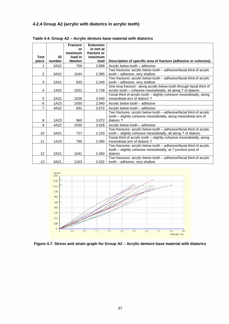
Figure 4.6: Typcial Group A1 stress and strain graph 36 Figure 4.7: Stress and strain graph for Group A2 – Acrylic denture base material with diatorics
37
Figure 4.8: Typical Group A2 stress and strain graph 38 Figure 4.9: Means plots 40
ix
LIST OF TABLES Table 2.1: Physical characteristics of acrylic denture base material vs. nylon denture base material Table 2.2: The national standards for determining the bond strength
10
16 Table 4.1: Group N1 – Pure nylon denture base material A with diatorics 33 Table 4.2: Group N2 – Pure nylon denture base material B with diatorics 34 Table 4.3: Group A1 – Acrylic denture base material without diatorics (control)
35
Table 4.4: Group A2 – Acrylic denture base material with diatorics 37 Table 4.5: Descriptive statistics of fracture or maximum load in Newton 38 Table 4.6: ANOVA statistics of fracture or maximum load in Newton 39 Table 4.7: Bonferroni multiple comparisons test of the fracture or maximum load in Newton
39
Table 4.8: Cross-tabulation of specific area of fracture of groups 41 Table 4.9: Chi-square tests 42

x
GLOSSARY Terms and abbreviations Definition/Explanation
Acrylic denture base Denture base material manufactured from thermosetting
polymethyl methacrylate (PMMA).
Adhesive failure Denture tooth is dislodged with no trace of denture base
material to it.
ANOVA Statistical method for analysis of variance.
Cohesive failure Remnants of the denture base material are found on the
tooth and tooth remnants are found on the denture base
material.
Diatorics The retention holes bored into acrylic teeth.
Elastic deformation Temporary shape change that is self-reversing after a
low-stress force is removed.
Kg/sq mm Kilogram per square millimetre (measurement of
pressure)
Mm Millimetre
Mesiodistal The plane or diameter joining and relating to the mesial
and distal surfaces of a tooth.
N Newton
Notch sensitivity The ability of a material to withstand the increased
stress at an indentation or incision on an edge or at the
surface of the material.
Nylon denture base Denture base material manufactured from resilient
synthetic polymers consisting of the recurring amide
group CONH (specifically polyamide 12).
Plastic deformation Permanent shape change during a high-stress force.

xi
1
CHAPTER ONE INTRODUCTION
1.1 Introduction
Although flexible denture base materials have been available since the 1950s (Stafford et al.,
1986), it only reached the South African commercial market in 2010. This is due to two
reasons: The restrictive legislative laws introduced in South Africa, known as apartheid,
which caused economic and diplomatic sanctions to be passed against South Africa by the
United Nations Security Council in 1962 (SAHO, 2000) and the very conservative prosthetic
dental community in South Africa.
The company Zenith was the first dental supplier in South Africa to import a flexible denture
base material, Deflex, in 2010. This material is manufactured in Buenos Aires, Argentina
(Deflex, 2000). Shortly thereafter in 2011, Nova Dental Supply Company imported a product
called Valplast from New York, United States of America (Valplast, 2004a). In 2012 Deon de
Lange Dental Supply Company acquired Perflex from Netanya, Israel (Perflex, 2007a).
Thereafter other dental supply companies started importing flexible denture base material to
South Africa.
Flexible dentures break two major rules in dentistry. Firstly the nylon from which the flexible
denture base materials are manufactured allows for relatively small dentures to be made due
to the flexible retention achieved. These small dentures are very comfortable and popular
with patients because the area in the mouth affected by the prosthetic appliance is reduced
significantly, albeit that general dental practice dictates that a denture should not be made so
small that it could be swallowed by the patient. Secondly, the flexibility of these dentures
allow for dynamic prostheses in which each saddle of the denture reacts to forces within the
mouth separately. Academic dental practice advocates rigid denture construction, relying on
intricate fulcrum design to counteract and balance forces within the mouth to which the
denture reacts as a whole. It is therefore understandable that dentistry communities
throughout the world are opposed to flexible denture wear (even labelling flexible dentures as
‘gum strippers’ without the support of clinical study documentation). This attitude has led to
little research being done on flexible dentures globally and a lack of description of flexible
dentures in literature. In spite of this, the popularity of flexible dentures still grows in private
dental practice.
The flexible denture base materials used in this study are Valplast and Perflex’s Flexi Nylon.
They are both monomer free nylon denture base materials (see section 2.1). The acrylic
denture base material used in this study is Vertex Rapid Simplified heat cure acrylic.
2
Valplast is generally known to be the very first nylon denture base material. It was developed
by dental technicians, Arpad and Tibor Nagy, in their Master-Touch Dental Laboratory in
New York, America in 1953. Initially, Valplast was an exclusive appliance category available
from Master-Touch Dental Laboratory only. Valplast was introduced commercially to Italy,
Greece, Germany, and the UK simultaneously under the respective brands Mastron and
Valplast (Nagy, 2014).
In 1959 the Nagy brothers founded the Valplast Corporation and set up a network of
regionally distributed Valplast franchised laboratories in the United States between 1959 and
1965. Included in this network were Master-Touch and 20 other laboratories that were
offered specific territories to market Valplast. After 1965 the market opened widely
throughout the United States and the product grew steadily for the next 30 years (Nagy,
2014).
By the year 2000, there were over 2500 Valplast processing laboratories. Formal technical
courses were also introduced during this period to ensure uniformity in denture construction
by laboratories. Valplast also became available in Mexico, Russia, China, and the rest of
Europe. Valplast was the first flexible denture material to obtain an Encumbrance Certificate
(CE Mark) when the European Union introduced this requirement for medical devices in the
1990’s. Valplast was also the first exclusive flexible denture base material manufacturer to
become International Organisation for Standardization (ISO 13485) certified (Nagy, 2014).
Perflex was founded in 2007 by dental technician Perla and partner Vidal Ben Simon
(Perflex, 2007b). The Ben Simons started the company in Netanya, Israel after extensive
research, engineering and improvements on aesthetic thermoplastic denture base materials
(Perflex, 2007b).
Unlike the Valplast Corporation which specialises in the manufacture of one kind of denture
base material, the Perflex Company provides an array of different kind of denture base
materials. These include Flexi Nylon for flexible partial dentures, Acetal for tooth shade
coloured clasps, Acry Free which is a non-allergenic acrylic material and T-Chrystal which is
their new flagship thermoplastic material for all denture types (Perflex, 2007b). As in the case
of the Valplast Corporation, Perflex provides extensive training to laboratories that use their
system and complies with ISO 13485, ISO 9001 and CE certification (Perflex, 2007b).
Although the tests in this research show no statistical difference between the results for
Perflex Flexi Nylon and Valplast, the physical differences between the materials are clear.
The colour of the standard pink Valplast material is darker and more translucent than that of

3
the standard pink Perflex Flexi Nylon. Perflex Flexi Nylon is slightly more rigid and harder to
polish than Valplast. When grinding both materials, Valplast gives off a finer particle-sized
waist material than Perflex Flexi Nylon.
As pure nylon denture base materials, Valplast and Perflex Flexi Nylon have one probable
dilemma in common. When acrylic teeth are processed onto a pure nylon denture base, they
do not bond chemically to the pure nylon denture base but rely on mechanical retention to
keep the teeth in place. This is in direct contrast to acrylic denture base materials where
acrylic teeth gain mechanical retention as well as chemical retention when processed onto
an acrylic denture base.
Manufacturers of nylon denture base materials provide guidelines to ensure optimisation of
the mechanical retention between the acrylic teeth and the pure nylon denture base. These
include guidelines for boring diatorics (see section 2.5) into the acrylic teeth as well as
guidelines for ensuring an adequate amount of intercoronal space. Dental technicians are
concerned that even though they adhere strictly to guidelines from suppliers, the retention
gained from this will not be sufficient to stop the teeth from ‘popping out’ or might even
weaken the tooth structure, causing it to shear.
Minimal research has been done on nylon denture bases; there is also a paucity of research
on the diatoric design within the denture teeth that provides the mechanical retention vital for
flexible denture longevity. Therefore no satisfactory answer to this perceived concern
currently exists.
The research in this study proposes to address these concerns, giving dental technicians a
greater understanding of and enabling them to construct even more durable flexible dentures
for their patients.
1.2 Statement of the research problem
A pure nylon denture base does not bond chemically to the acrylic teeth processed into the
denture. In order to address this problem, a mechanical bond is created by boring retention
holes (diatorics) into the tooth structure. The concern is that this form of retention might be
insufficient and have a weakening effect on the acrylic tooth.
1.3 Objectives of the research
Firstly, the purpose of this research is to compare the retention of acrylic denture teeth in
pure nylon denture bases with those in conventional acrylic denture bases (the latter serving
as the control standard).

4
Secondly the research will investigate the possible influence of the diatorics (holes created
within acrylic teeth for use in pure nylon denture bases) on the acrylic tooth structure.
1.4 Hypotheses
It is hypothesised that the bond strength of acrylic teeth onto a pure nylon denture base will
be less than that of acrylic teeth onto a conventional acrylic denture base.
It is further hypothesised that diatorics should not influence the acrylic tooth structure
detrimentally if created as prescribed.

5
CHAPTER TWO LITERATURE REVIEW
2.1 Background on flexible nylon denture base materials
Nylon belongs to the thermoplastic polymer class known as polyamides (Sepúlveda-Navarro
et al., 2011). It has a high tensile strength, high abrasion resistance, high resiliency, high
flexural strength and excellent biocompatibility (Stern, 2007). Nylon was originally identified
as a possible denture base material because it could be used in areas unsuited to acrylic
denture bases (Sepúlveda-Navarro et al., 2011). These include dentures in need of higher
levels of aesthetics, strength, accuracy, biocompatibility, comfort and flexibility for insertion
(Prashanti et al., 2010).
The development of nylon as an alternative to polymethyl methacrylate (PMMA) denture
base material started as early as the 1950s. Nylon 66 and 610 were used (Stafford et al.,
1986), which presented specific disadvantages such as processing shrinkage resulting in
warpage, deterioration in base colour because of high water absorption, surface roughness,
inability to repair and reline, difficulty in polishing and a lack of chemical bond between the
acrylic teeth and the nylon denture base (Stafford et al., 1986; Abuzar et al., 2010; Rickman
et al., 2012).
Further satisfactory development of nylon denture base material was completed with the use
of Nylon 12 in 1971 (Stafford et al., 1986). This material was a marked improvement on the
previous generation of nylons, solving the problems with water absorption and stiffening the
material by adding short glass fibres (Stafford et al., 1986; Abuzar et al., 2010). The linear
molecular formula for Nylon 12 is C12H23NO multiple (Chemnet 1997, Chemindustry, 1999). A
graphic representation of nylon 12 can be found in Figure 2.1.
Figure 2.1: Graphic representation of nylon 12 (Chemnet, 1997; Chemical Book, 2008)
Modern nylon denture base materials can be divided into two main groups: those containing
monomers (Duraflex, Flexite, Proflex, Impact, etc.) and those that are monomer-free

6
(Valplast, Lucitone FRS, etc.) (Shamnur et al., 2010). The true nylon denture base materials
(monomer-free) do not bond chemically with acrylic resin teeth. Creating mechanical
retention within the tooth structure itself is the only means of retaining the teeth within the
dentures (Dhiman & Chowdhury, 2009).
2.2 The attractive properties of pure nylon denture base materials
2.2.1 Improved aesthetics
Conventional partial removable dentures use unsightly metal clasps to facilitate denture
retention (Hamanaka et al., 2011). Nylon denture base material provides an improved level
of aesthetics for denture wearers. The semi-translucent tissue colour material picks up and
blends into the gingival colour, making clasps almost invisible (Stern, 2007; Prashanti et al.,
2010; Rickman et al., 2012). Figure 2.2 shows a flexible denture with a nylon clasp on a 22
tooth, which would normally be aesthetically displeasing when using metal clasps.
Figure 2.2: Improved aesthetics provided by a nylon denture (Barron Dental, 2012)
2.2.2 Use in areas with deep undercuts
The flexibility of nylon dentures allows for better retention and stability of the denture with
less tooth modification (Abuzar et al., 2010; Pusz et al., 2010). It can be easily placed and
removed from the mouth, even if used in areas where abutments have deep undercuts,
thereby adding to the comfort of the wearer (Prashanti et al., 2010; Hamanaka et al., 2011).
Figure 2.3 demonstrates the flexibility of a nylon denture.

7
Figure 2.3: Flexibility of nylon dentures (Westview Dental practice, 2012)
2.2.3 Resistance to breakage
Nylon’s crystalline polymer structure renders it insoluble in solvents. This property also adds
to the material being heat resistant as well as giving it high strength with ductility (Sepúlveda-
Navarro et al., 2011). In addition it has a predictable long-term performance with high fatigue
endurance and good wear characteristics (Pusz et al., 2010). The material’s lack of notch
sensitivity and crack propagation, coupled with a high resistance to breakage, makes it even
more attractive to prospective wearers (Negrutiu et al., 2005; Pusz et al., 2010; Rickman et
al., 2012).
2.2.4 Comfort to patients
Nylon dentures are readily accepted by wearers because they are lighter in weight and of
smaller design than acrylic dentures (Pusz et al., 2010; Rickman et al., 2012). The strength
of nylon denture base materials allow technicians to make the dentures very thin, which
further contributes to the comfort of the denture wearer (Prashanti et al., 2010; Pusz et al.,
2010). Figure 2.4 shows the difference between acrylic denture size on the left and nylon
denture size on the right.
Figure 2.4: The difference in acrylic and nylon denture size (Armagh Dental lab, 2014)

8
The acrylic denture fills most of the palatal area creating less tongue space, altered speech
patterns and food tactile sensation. The nylon denture is divided into two smaller sections,
leaving most of the palate open, which is much less disturbing to the tongue, speech and the
patient in general.
Full upper flexible nylon dentures have also been used successfully with patients that have
microstomia – a condition where limited opening of the mouth causes difficulty in inserting
and removing prostheses from the mouth. The flexibility of the denture allows for deformation
of the denture in order to slide through the abnormally small mouth opening comfortably
(Egan et al., 2012).
2.2.5 Biocompatibility
Nylon denture bases have a very low level of porosity, making them impervious to oral fluids
(Negrutiu et al., 2005; Pusz et al., 2010). This reduces the amount of stains, odours, and
biological build up on the dentures. It also ensures the colour and dimensional stability of the
dentures (Pusz et al., 2010). The material contains no monomers or metals, which are
usually the main cause of allergic reactions, thereby making the material user-friendly
(Abuzar et al., 2010; Prashanti et al., 2010: Pusz et al., 2010).
A study of mucus membrane irritation in hamsters was conducted by NAMSA (North
American Science Associates) using nylon denture base test articles. These were sutured to
the cheek mucosa of ten hamsters. After two weeks of exposure the hamsters were
euthanatized and their oral mucosa recovered for microscopic tissue evaluation. The
conclusion of the study was that the mucosa studied conformed to normal histomorphological
limits and that the nylon denture base test articles were not considered an irritant to the
hamster cheek mucosa (NAMSA, 1997).
2.2.6 Accuracy
The injection-moulded technique used to fabricate flexible dentures makes them more
accurate than its packed acrylic counterparts (Prashanti et al., 2010).
2.3 Concerning properties of pure nylon denture base materials
2.3.1 Lack of chemical bond to acrylic teeth
As previously mentioned, true nylon denture base materials do not bond chemically with
acrylic resin teeth. Creating mechanical retention within the tooth structure itself is the only
means of retaining the teeth within the dentures (Dhiman & Chowdhury, 2009).
9
Manufacturers of nylon denture base materials provide guidelines to ensure optimisation of
the mechanical retention between the acrylic teeth and the pure nylon denture base:
Retention holes are bored into the acrylic tooth structure with special drills in a T-shape (see
section 2.5) for optimum retention. The Deflex and Flex Star technique manuals recommend
an amount of 1mm space of nylon denture base material between the denture tooth and
tissues for sound denture construction (Deflex, 1999:2; Flex Star, 2012:5). Adequate
interarch space with sufficient acrylic tooth length is needed for proper mechanical retention.
Therefore inadequate vertical dimension is a contra-indication for flexible denture wear
(Dhiman et al., 2009; Prashanti et al., 2010).
2.3.2 Surface roughness
Nylon denture base material needs to be polished in three stages. The first stage involves
rough wet polishing with pumice. The second stage involves a form of burnishing with a
Tripoli compound. The last stage involves buffing with a high shine compound (Valplast
International Corporation, 2004:38; Perflex 2007:2; Flex Star, 2012:5). When polishing is
done through this method an arithmetic surface roughness (Ra) of 0.146µm is achieved.
Although this is rougher than the 0,046µm of polished PMMA, it is still below the accepted
norm of 0.2µm Ra (Abuzar et al., 2010).
When one of these stages are ignored by the technician who is manufacturing the nylon
denture, the surface roughness of the denture increases dramatically, causing an
accumulation of plaque and the adherence of Candida albicans to the denture, which in turn
causes denture-related stomatitis (Abuzar et al., 2010). Using incompatible chemicals to
clean nylon dentures may also cause surface changes to the denture as described in section
2.6.4.
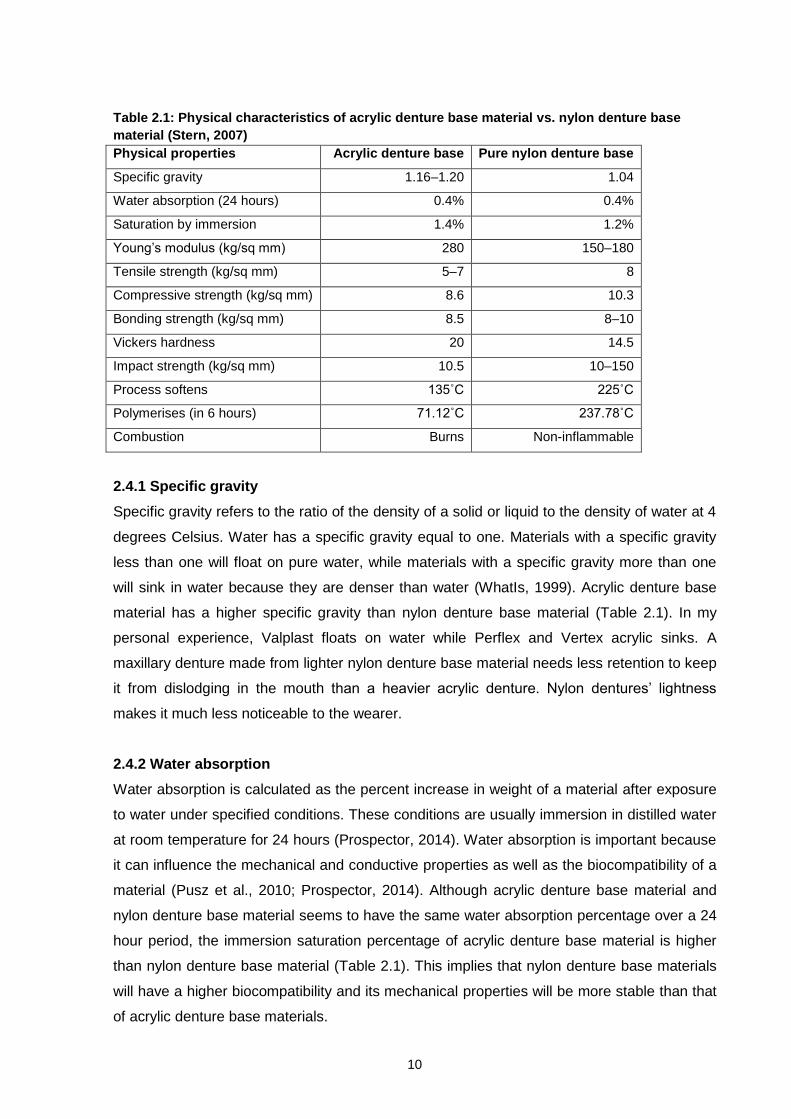
2.4 Difference in physical characteristics between acrylic and nylon
The difference in physical characteristics between an acrylic denture base material and a
nylon denture base material is summarised in Table 2.1.
10
Table 2.1: Physical characteristics of acrylic denture base material vs. nylon denture base
material (Stern, 2007)
Physical properties Acrylic denture base Pure nylon denture base
Specific gravity 1.16–1.20 1.04
Water absorption (24 hours) 0.4% 0.4%
Saturation by immersion 1.4% 1.2%
Young’s modulus (kg/sq mm) 280 150–180
Tensile strength (kg/sq mm) 5–7 8
Compressive strength (kg/sq mm) 8.6 10.3
Bonding strength (kg/sq mm) 8.5 8–10
Vickers hardness 20 14.5
Impact strength (kg/sq mm) 10.5 10–150
Process softens 135˚C 225˚C
Polymerises (in 6 hours) 71.12˚C 237.78˚C
Combustion Burns Non-inflammable
2.4.1 Specific gravity
Specific gravity refers to the ratio of the density of a solid or liquid to the density of water at 4
degrees Celsius. Water has a specific gravity equal to one. Materials with a specific gravity
less than one will float on pure water, while materials with a specific gravity more than one
will sink in water because they are denser than water (WhatIs, 1999). Acrylic denture base
material has a higher specific gravity than nylon denture base material (Table 2.1). In my
personal experience, Valplast floats on water while Perflex and Vertex acrylic sinks. A
maxillary denture made from lighter nylon denture base material needs less retention to keep
it from dislodging in the mouth than a heavier acrylic denture. Nylon dentures’ lightness
makes it much less noticeable to the wearer.
2.4.2 Water absorption
Water absorption is calculated as the percent increase in weight of a material after exposure
to water under specified conditions. These conditions are usually immersion in distilled water
at room temperature for 24 hours (Prospector, 2014). Water absorption is important because
it can influence the mechanical and conductive properties as well as the biocompatibility of a
material (Pusz et al., 2010; Prospector, 2014). Although acrylic denture base material and
nylon denture base material seems to have the same water absorption percentage over a 24
hour period, the immersion saturation percentage of acrylic denture base material is higher
than nylon denture base material (Table 2.1). This implies that nylon denture base materials
will have a higher biocompatibility and its mechanical properties will be more stable than that
of acrylic denture base materials.
11
2.4.3 Young’s modulus
Also known as elastic modulus, Young’s modulus is a measure of stiffness and is expressed
in force per unit area. It is calculated as the ratio of stress to strain. A material with a high
elastic modulus is classified as rigid (Phillips, 1991:33-34; Anusavice, 2003:73,80-82). In
Table 2.1 it is indicated that acrylic is more rigid than nylon which is more flexible. This
property is the greatest difference between acrylic denture base material and nylon denture
base material. It is the reason for nylon denture base materials being suitable for use in
areas where acrylic denture base materials are not (see section 2.1).
2.4.4 Tensile strength
Tensile strength is also referred to as ultimate strength. It is defined as the maximum stress
that a material can withstand while being pulled or stretched before failing or breaking. It is
the highest point on a stress-stain curve and is measured in force per unit area. Materials
that break sharply without plastic deformation during tensile testing are called brittle.
Materials that undergo plastic deformation during tensile testing are classified as ductile
(Phillips, 1991:38-39; Anusavice, 2003:77). Acrylic has a lower tensile strength than nylon
(Table 2.1). Acrylic dentures will shatter under high stress, possibly cutting and causing
trauma to soft tissues. High stress will cause nylon dentures to undergo elastic and then
plastic deformation but never sudden breakage, making it the ideal denture base material for
use by sportsmen and high risk workers such as firemen, policemen, etc.
2.4.5 Compressive strength
Compressive strength is the maximum stress that a material can withstand while under a
crushing load before failing or breaking. Some materials fracture at its compressive strength
limit while others undergo plastic deformation. Compressive strength is the highest point on a
stress-stain curve and is measured in force per unit area (Phillips, 1991:38-39; Anusavice,
2003:77). Acrylic has a lower compressive strength than nylon (Table 2.1).
2.4.6 Bonding strength
Bonding new acrylic to an existing acrylic denture base is achieved easily; the same cannot
be said for bonding new nylon to an existing nylon denture base. An etch has to be applied to
the existing nylon denture base to soften it in order for the new nylon material to be injected
onto it (Valplast International Corporation, 2004:42-43). Acrylic has a lower bonding strength
than nylon (Table 2.1). This would indicate that although additions to nylon dentures are
cumbersome, an addition done on a nylon denture would last longer than an addition done
on an acrylic denture.
12
2.4.7 Vickers hardness
As a micro hardness test method, Vickers hardness Test tests the resistance of a material to
indentation. A diamond indenter is used at a fixed force to make an indentation in the test
materials. The indentation is measured and converted to a hardness value. The smaller the
indentation, the harder the material (Newage, 2010). Acrylic has a higher Vickers hardness
than nylon (Table 2.1). Although nylon denture base material does scratch and dent easier
than acrylic denture base material, these dents and scratches do not cause notch sensitivity
and crack propagation as with acrylic denture bases (Rickman et al., 2012).
2.4.8 Impact strength
Impact strength is the capability of a material to withstand sudden load application. During
testing the impact energy needed to fracture a sample of material is measured. (Phillips,
1991:40-41; Anusavice, 2003:91-92). Acrylic has a lower impact strength than nylon (Table
2.1). As explained in section 2.4.4, with sudden load application acrylic dentures will shatter
while nylon dentures will undergo elastic and plastic deformation but never sudden breakage,
making it the ideal denture base material for use by sportsmen and high risk workers such as
firemen, policemen, etc.
2.5 Former techniques for creating diatorics in acrylic denture teeth
Traditionally, diatorics are prepared in acrylic teeth using similar methods as described by
Chai et al. (2000) and Bragaglia et al. (2009). A number eight rose head bur (Figure 2.5) is
used at low speed on the ridge lap area of the tooth to create a cavity that is 2mm deep and
2.3mm in diameter.
Figure 2.5: Rose head bur
The bond-strength testing by Bragaglia et al. (2009) indicated that the results of using these
kinds of design diatorics as a means of increasing bond strength between acrylic denture
base materials and acrylic denture teeth were highly ineffective (the test results rating it
below the control group which received no enhancement treatments). It was noted by
Bragaglia et al. (2009) that acrylic denture base material failure in the diatoric area could be
due to the sharpness of the cavity borders that might cause a collaboration of stress
concentration in this area.

13
In direct contrast, Takahashi et al. (2000) demonstrated that using diatorics could
significantly improve the bond strength between acrylic denture bases and acrylic denture
teeth. The acrylic denture base material that fills the diatoric space within the tooth structure
creates a path of resistance to fracture in a different direction than the tooth- to denture-base
resin interface, strengthening the bond mechanically.
The diatoric design used in the research of Dhiman and Chowdhury (2009) on complete
upper nylon denture bases is described only as ‘mechanical undercuts in the centre of each
tooth’. Their patients experienced dislodgement of teeth from the full upper nylon denture
base progressively in 3 to 24 months, ranging from 3.4% to 34.5% respectively in 38
subjects. It was noted that modification in tooth diatoric design should be explored to
overcome this problem.
2.6 New diatoric techniques appropriate for use in flexible denture design
A specialised bur called a twist drill is used to create all the diatoric holes (Figure 2.6). Twist
drills are available in three sizes: 006, 009 and 012.
Figure 2.6: Twist drills in different sizes
Firstly, a centre hole is created from the ridge lap area of the tooth with a wider drill.
Secondly a mesiodistal connection is drilled. The second drilling should connect with the
centre hole – thus forming a T-shaped connection indicated in pink in Figure 2.7. When
creating the diatorics care should be taken to avoid any visible openings on the facial and
occlusal surfaces of the acrylic teeth. The instruction manuals cautions against creating more
than one centre hole since it will not add to retentive strength, but will only serve to weaken
the tooth structure (Deflex, 1999:2; Valplast International Corporation, 2004:28; Flex Star,
2012:5).

14
Figure 2.7: Diatorics created by twist drills (Deflex, 1999:2)
2.7 Possible causes of mechanical retention failure between acrylic teeth and pure
nylon denture bases
2.7.1 Lack of intercoronal space
Pure nylon flexible denture base materials retain acrylic teeth by mechanical retention only,
therefore sufficient height of the denture tooth selected is needed (Prashanti et al., 2010).
Enough bulk of denture base material is also required mesio-distally, palatally and vertically
to ensure enough mechanical bond strength (Singh et al., 2011). Patients with little vertical
dimension are not suitable candidates for flexible nylon denture wear (Dhiman & Chowdhury,
2009).
2.7.2 Design of diatorics
The shape of the diatorics might cause failure in the denture base material passing through it
and this possibility should be investigated further (Bragaglia et al., 2009; Dhiman et al.,
2009).
It was noted by Bragaglia et al. (2009) that acrylic denture base material failure in the diatoric
area could be due to the sharpness of the cavity borders resulting in stress concentration in
this area.
2.7.3 Wax contamination
The bond between conventional acrylic denture base materials and acrylic denture teeth is
severely affected by improper wax removal during processing as seen in the research of
Cunningham and Benington (1996; 1999). The wax acts as a physical barrier between the
tooth and denture base material, which prevents any kind of contact or chemical bonding
between the materials (Thean et al., 1996; Geerts et al., 2012).
Similarly, the mechanical bond between the nylon denture base material and the acrylic teeth
can be weakened by wax contamination. If the T-shape diatorics (construction explained in
section 2.5) are drilled in the teeth during setup, some of the wax may remain in the junction

15
area of the T diatoric during processing, causing incomplete pressing of the nylon denture
base material within the T. A weakened three-finger design will result. The T connection is
vital for mechanical retentional strength (Singh et al., 2011).
2.7.4 Use of incompatible chemicals
It was noted by Yunus et al. (2005) that immersing a nylon denture base in an aldehyde-free,
oxygen releasing disinfectant solution (Perform) increased the rigidity of the nylon denture
base material.
A nylon denture base material instruction manual cautions against immersing the nylon
denture base in bleach or cleansers containing bleach which may cause loss of colour
pigment within the material (Valplast International Corporation, 2004:44). Using the
manufacturer’s own immersion solutions may reduce the risk of unwanted changes to the
properties of the various nylon denture base materials (Rickman et al., 2012). These
solutions comprise of potassium peroxymonopersulfate, citric acid, potassium bisulphate,
magnesium carbonate, potassium sulphate, peppermint extract, potassium peroxydisulphate
and sucrose (ValClean, 2014).
2.8 Testing technique
A review of national standards techniques that addressed denture tooth bonding was done
by Cunningham and Benington (1996) as well as Patil et al. (2006). The reviews included the
American National Standards, the Australian Standard, the International Organization for
Standardization, the British and South African Standards, and German Specifications, as well
as the Japanese Standard. These are summarised in Table 2.2, adapted from Patil et al.
(2006).
From this review it is clear that all of these techniques only tested the bond strength of the
artificial tooth to the denture base material in the ridge lap surface area of the tooth.
For the purpose of the research planned, one of these tests will have to be modified to
accommodate the T shape diatorics needed for sufficient mechanical retention of denture
teeth within the pure nylon denture base.
16
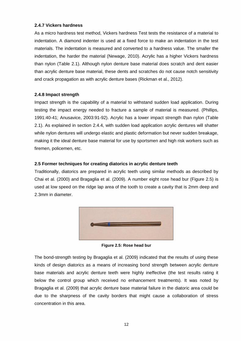
Table 2.2: The national standards for determining bond strength
National
Standard
Year
Specimen Fabrication
Number of
specimens
Type of load and
cross-head
speed of load
testing machine
Acceptable bond
strength values
The American
National
Standards /
American
Dental
Association
Specification
no. 15
(ANSI/ADA 15)
Approved
1956
Revised
1985
Cylindrical shaft
produced by
incorporating acrylic
teeth (>8.15mm
diameter) in denture
base resin; finally the
shaft machined to a
diameter of 6.35mm
3 Tensile
0.254mm/min
31MPa
The Australian
Standard (AS
1626)
1974 Similar to ADA 15 but
the length of the
cylindrical shaft longer
and clear acrylic
denture resin used
3 Tensile 5mm/min Not <32.0MPa
International
Organization for
Standardization
for synthetic
resin teeth (ISO
3336)
1977 A set of ground anterior
teeth processed
against resin held in a
metal form simulating
gumfitting dentures
Not stated Shear-tensile (or
peeling) rate of
load application
not stated
The bond
satisfactory if
fracture does not
follow the tooth
surface and some
denture base
resin remains
attached to the
tooth.
British Standard
(BS 3990)
1980 Based on the ISO specification and the testing requirements are identical
South African
Standard
(SABS 1342)
1982 Based on the ISO specification and the testing requirements are identical
German
Specification for
denture base
resin (DIN
13907) & for
synthetic resin
teeth (DIN
13914)
1983 Based on the ISO
specification. However,
a transverse three-point
loading is carried out
on 15×4×4mm
rectangular specimens
(tooth-resin interface
positioned in the centre
of the section)
6 Transverse
1mm/min
Not ˂70N/mm²
Japanese
Standard for
Acrylic Resin
Teeth (JIST
6506)
1989 Central incisors aligned
at 45° taper to acrylic
resin blocks of
8×10×20mm
10 Tensile
0.5mm/min (or a
loading speed of
120N/min)
110N for upper
teeth and 60N for
lower teeth
The Japanese standard for acrylic resin teeth was used as the research method basis in the
studies of Chai et al. (2000), Takahashi et al. (2000), and Bragaglia et al. (2009).
Bragaglia et al. (2009) state that an adaptation of the Japanese test is much more clinically
plausible because it involves the true shape of the anterior teeth and simulates the direction
of shear and compressive loads more accurately (Figure 2.8).
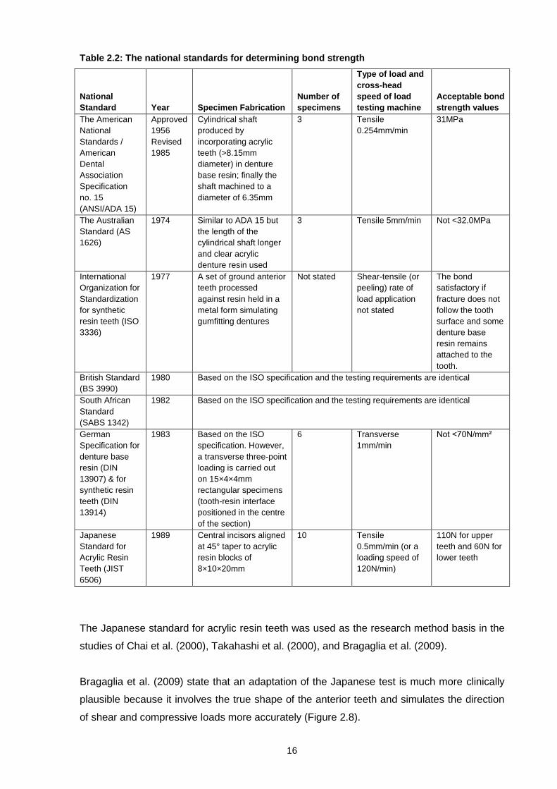
17
Figure 2.8: Japanese test (Adapted from Cunningham and Benington, 1996)
Chai et al. (2000) Takahashi et al. (2000) and Bragaglia et al. (2009) applied a compressive
load at a 45-degree angle (to the long axis of the tooth) on the palatal surface of anterior
teeth until fracture occurred.
The compressive load is applied through a cylindrical pin at a crosshead speed of
0.5mm/min. The rate of loading is extremely important during testing because it could
influence the results. The Japanese test is the only standard in which the stiffness factor of
the testing machine was taken into account when the rate of loading was established
(Cunningham & Bennigton, 1996). The fracture load is measured in Newton and can be
converted into kilogram force (Bragaglia et al., 2009).
The Japanese standard for acrylic resin teeth sets the acceptable bond strength value at
110N for upper teeth and requires ten test pieces (Patil et al., 2006). Bond strength failure
occurs either adhesively or cohesively. During adhesive failure the denture tooth is dislodged
with no trace of denture base material to it. (Denture base material within the diatoric does
not preclude failure from being adhesive.) During cohesive failure remnants of the denture
base material are found on the tooth and tooth remnants are found on the denture base
material (Takahashi et al., 2000).
According to Bragaglia et al. (2009), if during the bond strength testing the bond between the
parts resist until the materials fail (the tooth shears without debonding or fracture occurs
within the denture base material), the bond between the two would have fulfilled its
requirements.
18
2.9 Other biological uses of nylon
Nylon in general has been used in other biological areas very successfully.
2.9.1. Surgical sutures
Surgical sutures are commonly known as stitches. They are used to hold together the skin or
organs, repairing lacerations or closing incisions after surgery (Demetech, 2014; Dolphin
sutures, 2014a). Polyamide sutures are made of nylon 6 and nylon 6.6 (Demetech, 2014).
These sutures are non-absorbable and have a high tensile strength which leads to high
resistance to breakage. It moves easily through tissue because of its uniform diameter and
smooth texture, causing minimal tissue trauma. It also has less plasticity, making it easier to
use than polypropylene suture and giving it more knot security. It is highly sterile, giving it
minimal inflammatory reaction in tissue because it is free from irritants and impurities
(Demetech, 2014; Dolphin sutures, 2014b).
2.9.2 Cell strainers
Cell strainers are made from strong nylon mesh with evenly spaced pores. They are used to
isolate primary cells for single cell suspension from tissues. They remove clumps and debris
from cell suspensions and clinical samples before analysis. Cell strainers are sterilized by
gamma irradiation,easy to use and non-phyrogenic (Jetbiofil, 2012).
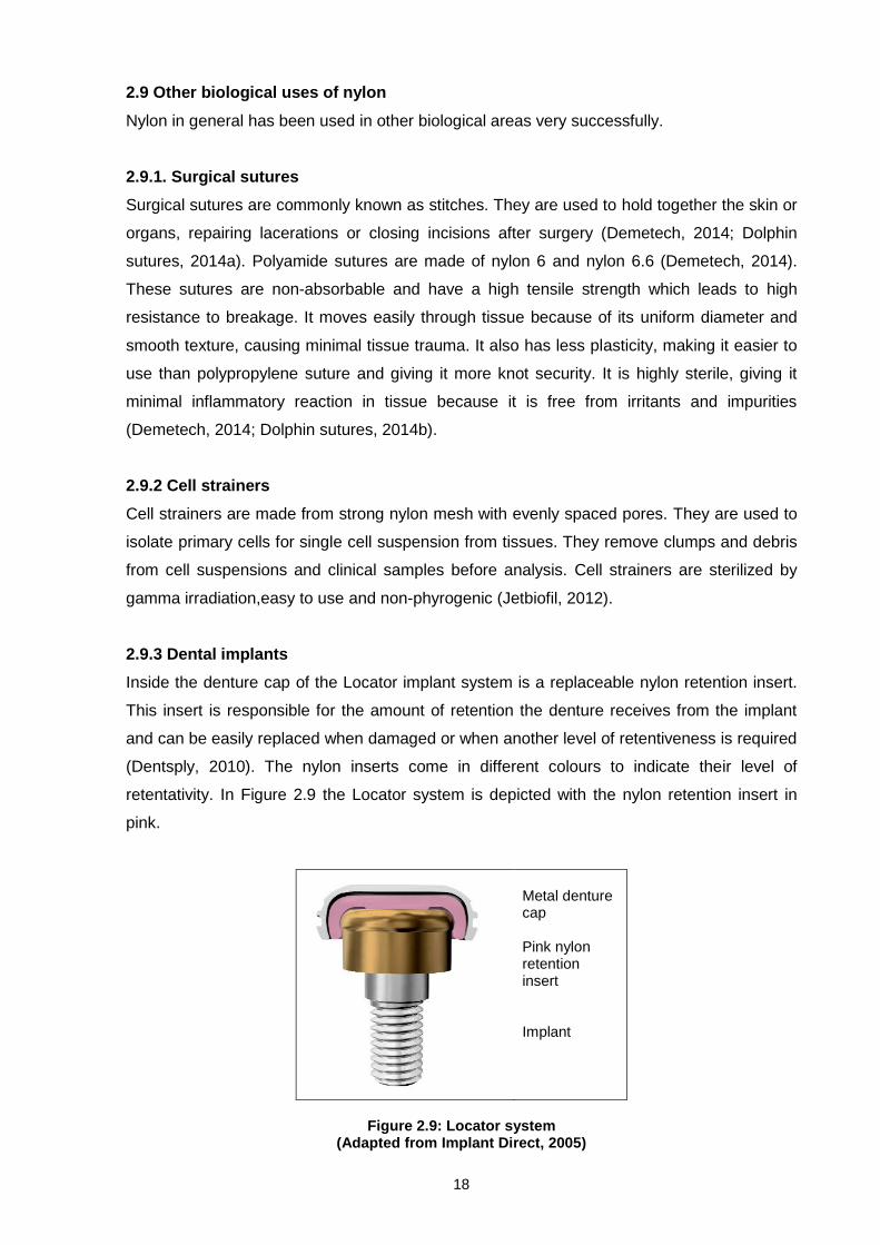
2.9.3 Dental implants
Inside the denture cap of the Locator implant system is a replaceable nylon retention insert.
This insert is responsible for the amount of retention the denture receives from the implant
and can be easily replaced when damaged or when another level of retentiveness is required
(Dentsply, 2010). The nylon inserts come in different colours to indicate their level of
retentativity. In Figure 2.9 the Locator system is depicted with the nylon retention insert in
pink.
Metal denture cap Pink nylon retention insert Implant
Figure 2.9: Locator system
(Adapted from Implant Direct, 2005)
19
2.9.4 Bone replacements
Traditionally the polymer of choice in orthopedic implant design has always been
polyethylene (Qmed, 2014). Recent experimentation with three dimensional (3D) scanners
and printing of bone and cartilage replacements has led to the evaluation of Nylon 618 as a
3D printing specific material. This material is well tolerated in the body, it is able to support
the weight of a human, its pliability allows for some resilience and its smooth surface texture
is ideal for joint movement (3ders, 2011).

20
CHAPTER THREE EXPERIMENTAL DESIGN
3.1 Introduction
The existing national standards for determining the bond strength techniques only test the
bond strength of the artificial tooth to the denture base material in the ridge lap surface area
of the tooth. Therefore one of these tests was modified to accommodate the T-shape
diatorics needed for sufficient mechanical retention of denture teeth within the pure nylon
denture base.
In this study it was decided to use the Japanese Standard for Acrylic Resin Teeth as
described by Cunningham & Benington, 1996, Chai et al., 2000, Takahashi et al., 2000, Patil
et al., 2006 and Bragaglia et al., 2009 in their research as the starting point for the tests. The
Japanese Standard is much more plausible clinically than the other standards, since it
involves the true shape of the anterior teeth and simulates the direction of shear and
compressive loads more accurately (Bragaglia et al., 2009).
3.2 Modifications made to Japanese Standard for Acrylic Resin Teeth
The Japanese Standard test applies a compressive load at a 45-degree angle (to the long
axis of the tooth) on the palatal surface of an anterior tooth via cylindrical pin at a crosshead
speed of 0.5mm/min until fracture occurs (Cunningham & Benington, 1996; Takahashi et al.,
2000; Patil et al., 2006; Bragaglia et al. 2009). The Japanese Standard test calls for test
sample blocks of 8×10×20mm with a 45-degree taper on the long side to which the ridge lap
surface of the tooth is bonded (Figure 2.8) (Cunningham & Benington, 1996).
3.2.1 Modifications made to accommodate diatorics in acrylic teeth
In this study the test piece shape was modified so that the denture base area around the
tooth included the neck as well as portions of the distal and mesial areas of the tooth in order
to facilitate the T-shape diatoric design (Figure 3.1). It was critical that the extra denture base
material added to these areas was precisely the same in all the test pieces to facilitate
accuracy in the tests. Therefore one master mould was created and duplicated in silicone to
create test pieces that were exactly alike.

21
Figure 3.1: Modification 1 of the Japanese test (Adapted from Cunningham & Benington, 1996)
3.2.2 Modifications made to accommodate the type of tensile testing machine
The tensile testing machine available to the researcher was a Tinius Olsen, Hounsfield
Series S. This machine does not allow for horizontal testing, therefore the base of the test
pieces had to be modified to fit in with the vertical testing machine. The test piece was
rotated to fit into the machine (Figure 3.2). The base was also modified so that the test
pieces could be accommodated in the specific grips of the machine. The dimensions of the
test piece bases were therefore changed from 8×10×20mm to 8×10×48mm.
Figure 3.2: Modification 2 of the Japanese test
3.2.3 Modifications made to accommodate multiple materials and surfaces
Since the pure nylon denture base materials are flexible, a pilot test was done beforehand to
ensure enough thickness of material for test piece stiffness so that the test piece itself did not
bend during testing, which would have influenced the results of the tests.
The Japanese Standard for Acrylic Resin Teeth calls for a rejection of any individual test
piece which has a fracture load failure varying more than 15% of the overall mean
22
(Cunningham & Benington, 1996). It should be remembered that this test was designed for
testing the bond strength between an acrylic tooth and an acrylic denture base material on a
single surface only. Taking into account that multiple materials would be used (acrylic as well
as two different pure nylon denture bases) and that the retention area involved many sides of
the acrylic tooth, variables greater than 15% were expected and therefore this rule was not
applied to the tests to be done.
The Japanese Standard for Acrylic Resin Teeth applies a compressive load to the acrylic test
pieces until fracture occurs. Given the plasticity of the pure nylon denture materials, the test
pieces manufactured from these materials may not fracture, but the material around the teeth
flexes and strains, until permanent deformation occurs. Therefore measurements were taken
for fracture or maximum load applied.
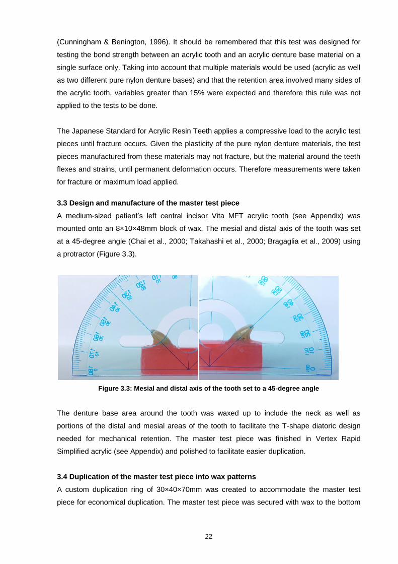
3.3 Design and manufacture of the master test piece
A medium-sized patient’s left central incisor Vita MFT acrylic tooth (see Appendix) was
mounted onto an 8×10×48mm block of wax. The mesial and distal axis of the tooth was set
at a 45-degree angle (Chai et al., 2000; Takahashi et al., 2000; Bragaglia et al., 2009) using
a protractor (Figure 3.3).
Figure 3.3: Mesial and distal axis of the tooth set to a 45-degree angle
The denture base area around the tooth was waxed up to include the neck as well as
portions of the distal and mesial areas of the tooth to facilitate the T-shape diatoric design
needed for mechanical retention. The master test piece was finished in Vertex Rapid
Simplified acrylic (see Appendix) and polished to facilitate easier duplication.
3.4 Duplication of the master test piece into wax patterns
A custom duplication ring of 30×40×70mm was created to accommodate the master test
piece for economical duplication. The master test piece was secured with wax to the bottom
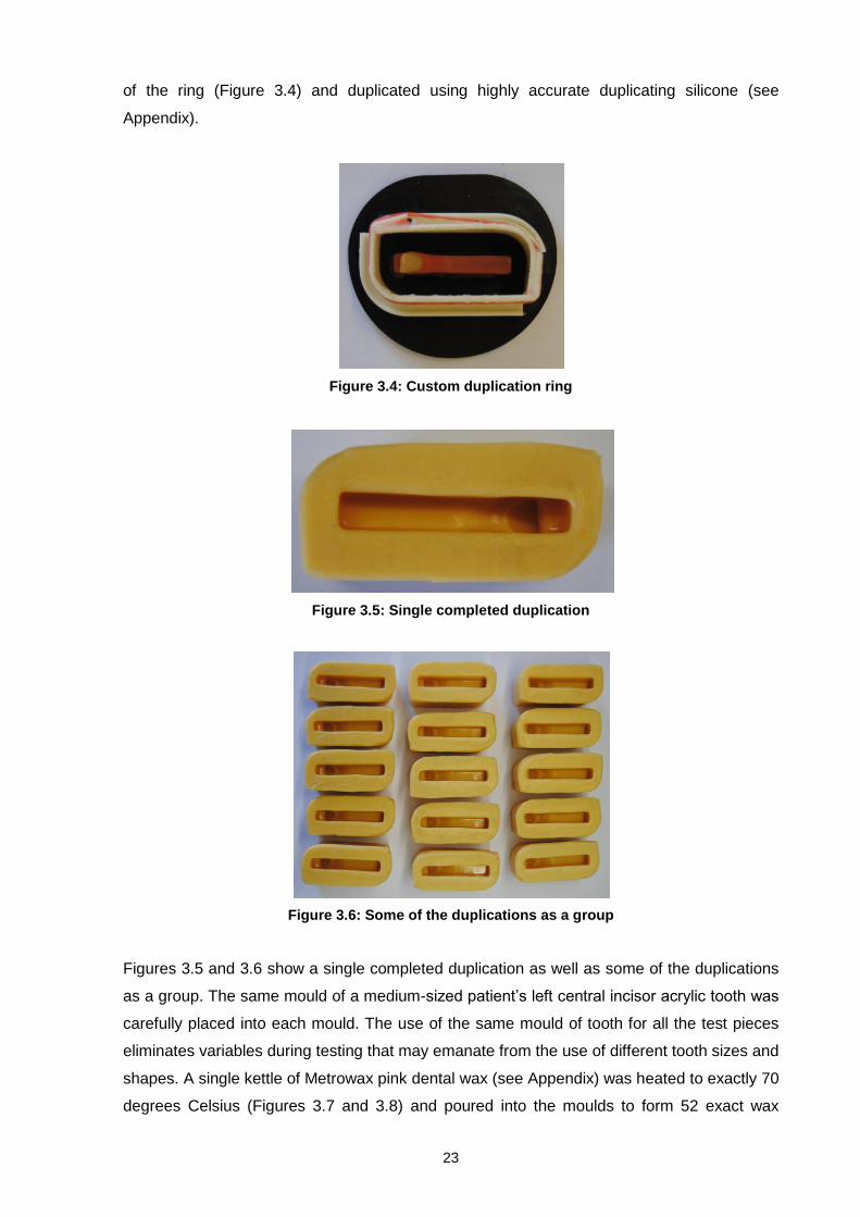
23
of the ring (Figure 3.4) and duplicated using highly accurate duplicating silicone (see
Appendix).
Figure 3.4: Custom duplication ring
Figure 3.5: Single completed duplication
Figure 3.6: Some of the duplications as a group
Figures 3.5 and 3.6 show a single completed duplication as well as some of the duplications
as a group. The same mould of a medium-sized patient’s left central incisor acrylic tooth was
carefully placed into each mould. The use of the same mould of tooth for all the test pieces
eliminates variables during testing that may emanate from the use of different tooth sizes and
shapes. A single kettle of Metrowax pink dental wax (see Appendix) was heated to exactly 70
degrees Celsius (Figures 3.7 and 3.8) and poured into the moulds to form 52 exact wax

24
replicas of the master test piece (Figures 3.9 and 3.10). After cooling the wax overflow on the
mould of each test piece was removed using a waxknife.
Figure 3.7: Kettle used to melt wax
Figure 3.8: Temperature gauge at exactly 70 degrees Celsius
Figure 3.9: Wax poured into the moulds

25
Figure 3.10: 52 exact wax replicas of the master test piece
3.5 Explanation of the grouping of test pieces
The identical anterior one-tooth test pieces were divided into sets of 26. The first set was
labelled N and comprised two different pure nylon denture base materials labelled N1 and N2
– all had diatorics in the acrylic teeth. The second set was labelled A and comprised the
same acrylic denture base; the set labelled A1 was the control standard without diatorics in
the acrylic teeth and the set labelled A2 had diatorics within the acrylic teeth. Figure 3.11
clarifies the explanation. All test pieces were marked in the wax stage to ensure any possible
confusion in respect of grouping was eliminated.
Figure 3.11: Grouping of test pieces
52
Test Pieces
Group N
Pure nylon denture base
materials
Group N1
Pure nylon denture base A with diatorics in
acrylic teeth
Group N2
Pure nylon denture base B with diatorics in
acrylic teeth
Group A
Acrylic denture base material
Group A1
Acrylic denture base without
diatorics in acrylic teeth (Control)
Group A2
Acrylic denture base with
diatorics in acrylic teeth

26
3.6 Flasking
The wax test pieces were embedded in the appropriate flasks for Group N and Group A (see
Figures 3.12 and 3.13). Group A used plaster (see Appendix) as mould medium while Group
N required yellow stone (see Appendix) as mould medium. The higher casting pressure
technique used in flexible denture manufacture requires yellow stone be used as mould
medium because white plaster is too soft. The wax patterns were eliminated using boiling
water and cleaned thoroughly using a dewaxer.
Figure 3.12: Embedding of wax test pieces in flask for acrylic denture bases
Figure 3.13: Embedding of wax test pieces in flask for pure nylon denture bases
3.7 Creating diatorics
Group N1, N2 and A2 needed T-shape diatorics. Group A1 served as the control standard;
since T-shaped diatorics are not the norm when finishing acrylic dentures, no diatorics were
needed in the control group.

27
3.7.1 Creating a jig for precise diatoric placement
One medium-sized patient’s left central incisor acrylic tooth was used to create a jig to
ensure that all the teeth had diatorics in exactly the same positions. Placing the diatorics in
exactly the same position would eliminate variables during testing that could emanate from
having diatorics in different positions on the acrylic teeth. Firstly, a centre hole from the ridge
lap area of the tooth was created with a wider drill. Secondly, a mesio-distal connection was
drilled into the tooth (Figure 3.14). The second drilling connected with the centre hole thereby
forming a T-shaped connection (Deflex, 1999:2; Valplast International Corporation, 2004:28;
Flex Star, 2012:5).
Figure 3.14: Diatoric T drilled into acrylic tooth
Orthodontic wire was placed into the T with extended arms and fastened to the tooth with
superglue. Lab putty (see Appendix) was placed over the tooth in such a way that it enclosed
the orthodontic wire in the mesial, distal and ridge lap areas where it emanated from the
tooth (Figures 3.15 and 3.16).
Figure 3.15: Orthodontic wire placed within the T diatoric

28
Figure 3.16: Lab putty placed over tooth and orthodontic wire
The tooth with the orthodontic wire was then removed from the lab putty mould and a new
tooth put in its place. The lead of a mechanical pencil could then be driven into the shaft
holes left by the orthodontic wires in the mould, leaving marks on the exact position that the
drill should enter the tooth so that the diatorics made on all the teeth would be the same (see
Figures 3.17, 3.18 and 3.19).
Figure 3.17: New tooth placed into mould

29
Figure 3.18: Lead of mechanical pencil placed in mould guide
Figure 3.19: Marks in lead indicating exact drilling position
3.7.2 Boring diatorics into the acrylic teeth
The acrylic teeth from groups N1, N2 and A2 were removed from their moulds and the
diatorics bored into place as described above. They were fixed back into their moulds using a
rubber-based glue (see Appendix) which would not take up any space within the mould or
damage the surface of the acrylic teeth as sometimes happens when using superglue
(Valplast International Corporation, 2004:28).
3.8 Finishing of the test pieces
Group N was pressed with the two kinds of pure nylon denture base materials (see
Appendix) and Group A was packed using an acrylic denture base material (see Appendix),
according to the manufacturers’ instructions (see Appendix). Moulds were removed using a
pneumatic chisel. Flash material and sprues were removed with a diamond disk and a fine
carbide bur. No further finishing or polishing was done to the test pieces to ensure that they
were worked as little as possible to eliminate latent cracks or stresses within.

30
3.9 Testing
The universal testing machine available to the researcher was a Tinius Olsen, Hounsfield
Series S (Figure 3.20).
Figure 3.20: Tinius Olsen, Hounsfield Series S tensile testing machine
The test pieces were placed into the clamp and the grips tightened securely. The pin was
dropped vertically until only touching the palatal surface of anterior teeth. If necessary,
further adjustments to the positioning of the test piece were made (Figure 3.21).
Figure 3.21: Test piece in grips of testing machine at starting position

31
A compressive load was applied by the pin at a crosshead speed of 0.5 mm/min until fracture
or maximum load occurred (Cunningham & Benington, 1996; Chai et al., 2000; Takahashi et
al., 2000; Patil et al., 2006; Bragaglia et al., 2009).

32
CHAPTER FOUR
TEST RESULTS
4.1 Introduction
During testing it became evident that although the Japanese Standard for Acrylic Resin
Teeth is more plausible clinically than the other standards (because it encompasses the true
shape of the anterior teeth and simulates the direction of shear and compressive loads more
accurately (Bragaglia et al., 2009)), it differs from the clinical situation in four very important
ways.
These are:
1. Lack of supporting teeth
In the natural situation, an anterior denture tooth is supported by the surrounding anterior
teeth that bear and share the shear and compressive loads together – not as single units.
2. Angulation of the teeth
According to Wolfart et al. (2004), the ideal natural angulation of the central incisor axes is
2.5 degrees. Thus the Japanese Standard for Acrylic Resin Teeth (JIST 6506)’s angulation
of 45 degrees is greatly exaggerated. In a pilot test the researcher noted that changing the
angulation of the teeth to that of the suggested natural angulation increased the level of
resistance of the test pieces dramatically.
3. Use of complete acrylic tooth structure
These tests have the advantage of using the complete acrylic central incisor tooth structure.
In true cases intra-oral space is often a concern, which means that technicians have to trim
the ridge lap and neck area of the acrylic tooth, which in turn leaves less tooth structure from
which to create mechanical retention.
4. Load application
The test machine produced the same amount of load at a preset increase for a relatively
short period of time on the test pieces. Clinically dynamic loads are applied to the denture
teeth over the extended time of denture wear.
4.2 Test results
Test results were recorded as shown in Tables 4.1 to 4.4. Stress and strain graphs as
recorded by the universal testing machine for each separate group are shown in Figures 4.1,
4.3, 4.5 and 4.7. The test machine attempts to make distinction between each individual test
easier by assigning graph lines with different colours.

33
4.2.1 Group N1 (pure nylon denture base material A with diatorics in acrylic teeth)
Table 4.1: Group N1 – Pure nylon denture base material A with diatorics
Test piece
ID number
Fracture or
maximum load
in Newton
Extension in mm at fracture
or maximum
load Description of specific area of fracture
1 1N11 126.9 1.270 Stretching and failure of nylon at mesiodistal diatoric exits on teeth
2 4N14 106.6 1.670 Stretching and failure of nylon at mesiodistal diatoric exits on teeth
3 2N13 99 2.050 Stretching and failure of nylon at mesiodistal diatoric exits on teeth
4 1N11 80.5 1.280 Stretching and failure of nylon at mesiodistal diatoric exits on teeth
5 2N14 73.8 1.500 Stretching and failure of nylon at mesiodistal diatoric exits on teeth
6 3N12 138.3 1.650 Stretching and failure of nylon at mesiodistal diatoric exits on teeth
7 1N11 99.5 1.87 Stretching and failure of nylon at mesiodistal diatoric exits on teeth
8 2N14 99.5 1.870 Stretching and failure of nylon at mesiodistal diatoric exits on teeth
9 3N13 131.6 1.620 Stretching and failure of nylon at mesiodistal diatoric exits on teeth
10 3N12 75 1.583 Stretching and failure of nylon at mesiodistal diatoric exits on teeth
11 3N12 82.7 0.940 Stretching and failure of nylon at mesiodistal diatoric exits on teeth
12 4N14 92.7 1.160 Stretching and failure of nylon at mesiodistal diatoric exits on teeth
13 2N13 83.5 1.410 Stretching and failure of nylon at mesiodistal diatoric exits on teeth
Figure 4.1: Stress and strain graph for Group N1 – Pure nylon denture base material A with diatorics
Figure 4.2: Typical Group N1 stress and strain graph

34
Figure 4.2 shows a typical Group N1 stress and strain graph. From starting point A to point B
the test piece undergoes elastic deformation around the tooth area. From point B to C the
test piece undergoes plastic deformation – during this period stretching and failure of the
pure nylon denture base material occurs at the mesiodistal diatoric exits on the teeth. At
point C the denture tooth bears down on the peripheral edge of the denture base material in
the neck area of the tooth which increases its resistance and causes secondary plastic
deformation up to point D. Point D is the point of maximum load for the test piece.
Resistance lessens and further deformation occurs until test is ended at E.
4.2.2 Group N2 (pure nylon denture base material B with diatorics in acrylic teeth)
Table 4.2: Group N2 – Pure nylon denture base material B with diatorics
Test piece
ID number
Fracture or
maximum load in
Newton
Extension in mm at fracture
or maximum
load Description of specific area of fracture
1 1N23 122.6 1.880 Snapping and failure of nylon at mesiodistal diatoric exits on teeth
2 3N22 65.3 1.0 Snapping and failure of nylon at mesiodistal diatoric exits on teeth
3 1N22 119.1 1.600 Snapping and failure of nylon at mesiodistal diatoric exits on teeth
4 1N22 116 0.936 Snapping and failure of nylon at mesiodistal diatoric exits on teeth
5 2N23 113 1.084 Snapping and failure of nylon at mesiodistal diatoric exits on teeth
6 3N24 100.6 1.096 Snapping and failure of nylon at mesiodistal diatoric exits on teeth
7 3N21 122.1 1.958 Snapping and failure of nylon at mesiodistal diatoric exits on teeth
8 2N23 82.3 0.940 Snapping and failure of nylon at mesiodistal diatoric exits on teeth
9 3N21 126.9 1.550 Snapping and failure of nylon at mesiodistal diatoric exits on teeth
10 4N24 81.2 2.240 Snapping and failure of nylon at mesiodistal diatoric exits on teeth
11 2N23 147.9 1.150 Snapping and failure of nylon at mesiodistal diatoric exits on teeth
12 2N24 166.8 1.275 Snapping and failure of nylon at mesiodistal diatoric exits on teeth
13 1N21 115.4 1.613 Snapping and failure of nylon at mesiodistal diatoric exits on teeth
Figure 4.3: Stress and strain graph for Group N2 – Pure nylon denture base material B with diatorics

35
Figure 4.4: Typical Group N2 stress and strain graph
Figure 4.4 shows a typical Group N2 stress and strain graph. From starting point F to point G
the test piece undergoes elastic deformation around the tooth area. At point G snapping and
failure of the pure nylon denture base material occur at the mesiodistal diatoric exits on the
teeth, plummeting resistance to point H. From point H to point I the test piece undergoes
plastic deformation. At point I the denture tooth bears down on the peripheral edge of the
denture base material in the neck area of the tooth which increases its resistance and
causes secondary plastic deformation up to point J. Point J is the point of maximum load for
the test piece. Resistance lessens and further deformation occurs until test is ended at K.
4.2.3 Group A1 (control – acrylic without diatorics in acrylic teeth)
Table 4.3: Group A1 – Acrylic denture base material without diatorics (control)
Test piece
ID number
Fracture or
maximum load in
Newton
Extension in mm at fracture
or maximum
load Description of specific area of fracture (adhesive or cohesive)
1 4A13
Test machine
crash
Test machine
crash Facial third of acrylic tooth – adhesive
2 2A12 550 2.82 Acrylic below tooth – adhesive
3 3A13 425 2.37 Two fractures: acrylic below tooth – adhesive/facial third of acrylic tooth – adhesive
4 2A11 640 2.38 Acrylic below tooth – adhesive
5 1A12 457 0.95 Facial third of acrylic tooth – slightly cohesive mesially
6 2A11 214 1.08 Acrylic below tooth – adhesive
7 3A14 554 1.7333 Facial third of acrylic tooth – slightly cohesive mesiodistally
8 1A11 302.5 2.963 Two fractures: acrylic below tooth – adhesive/facial third of acrylic tooth – slightly cohesive mesiodistally
9 1A12 806 2.720 Facial third of acrylic tooth – slightly cohesive mesiodistally
10 3A12 486 1.64 Facial third of acrylic tooth – slightly cohesive mesiodistally
11 2A11 340.4 1.190 Facial third of acrylic tooth – adhesive
12 3A13 527 1.92 Facial third of acrylic tooth – slightly cohesive mesiodistally
13 1A12 378 1.430 Facial third of acrylic tooth – slightly cohesive mesially

36
Figure 4.5: Stress and strain graph for Group A1 – Acrylic denture base material without diatorics
Figure 4.6: Typical Group A1 stress and strain graph
Figure 4.6 shows a typical Group N1 stress and strain graph. From starting point L to point M
the test piece undergoes elastic deformation around the tooth area. At point M to point N
plastic deformation occurs. At point N the test piece fractures and the test ends.
37
4.2.4 Group A2 (acrylic with diatorics in acrylic teeth)
Table 4.4: Group A2 – Acrylic denture base material with diatorics
Test piece
ID number
Fracture or
maximum load in
Newton
Extension in mm at
fracture or maximum
load Description of specific area of fracture (adhesive or cohesive)
1 3A22 756 2.888 Acrylic below tooth – adhesive
2 3A22 1044 2.380 Two fractures: acrylic below tooth – adhesive/facial third of acrylic tooth – adhesive, very shallow
3 2A21 633 2.240 Two fractures: acrylic below tooth – adhesive/facial third of acrylic tooth – adhesive, very shallow
4 1A22 1031 2.728 One long fracture: along acrylic below tooth through facial third of acrylic tooth – cohesive mesiodistally, all along T of diatoric
5 2A21 1026 3.040 Facial third of acrylic tooth – slightly cohesive mesiodistally, along mesiodistal arm of diatoric T
6 1A23 1030 2.940 Acrylic below tooth – adhesive
7 4A22 931 3.072 Acrylic below tooth – adhesive
8 1A23 960 3.072
Two fractures: acrylic below tooth – adhesive/facial third of acrylic tooth – slightly cohesive mesiodistally, along mesiodistal arm of diatoric T
9 4A22 1030 3.628 Acrylic below tooth – adhesive
10 3A21 727 2.220 Two fractures: acrylic below tooth – adhesive/facial third of acrylic tooth – slightly cohesive mesiodistally, all along T of diatoric
11 1A23 790 2.090 Facial third of acrylic tooth – slightly cohesive mesiodistally, along mesiodistal arm of diatoric T
12 2A21 1041 2.450
Two fractures: acrylic below tooth – adhesive/facial third of acrylic tooth – slightly cohesive mesiodistally, at T junction area of diatoric
13 3A21 1163 3.032 Two fractures: acrylic below tooth – adhesive/facial third of acrylic tooth – adhesive, very shallow
Figure 4.7: Stress and strain graph for Group A2 – Acrylic denture base material with diatorics

38
Figure 4.8: Typcial Group A2 stress and strain graph
Figure 4.8 shows a typical Group N2 stress and strain graph. From starting point O to
point P the test piece undergoes elastic deformation around the tooth area. At point
P to point Q plastic deformation occurs. At point Q the test piece fractures and the
test ends.
4.3 Statistical results
4.3.1 Oneway ANOVA analysis
The descriptive statistics of the fracture or maximum load in Newton values for all the
test groups are given in Table 4.5. Both Group A1 and Group A2 have significantly
higher fracture or maximum load values than Group N1 and Group N2. The ANOVA
statistics in Table 4.6 indicate that there is a statistically significant difference
between the mean fracture or maximum load in Newton values of the four groups (p-
value < 0.001).
Table 4.5: Descriptive statistics of fracture or maximum load in Newton
Group
Number
Mean
Std. deviation
Std. error
95% confidence interval for mean
Minimum
Maximum Lower bound
Upper bound
A1 Control acrylic
without diatorics
12 700.2000 747.35094 215.74163 225.3559 1175.0441 214.00 3025.00
A2 Acrylic with
diatorics 13 935.5385 157.80242 43.76652 840.1794 1030.8975 633.00 1163.00
N1 Pure nylon
material A with
diatorics
13 99.2000 21.49093 5.96051 86.2132 112.1868 73.80 138.30
N2 Pure nylon
material B with
diatorics
13 113.7846 27.24484 7.55636 97.3207 130.2485 65.30 166.80
Total 51 457.5137 516.51709 72.32686 312.2410 602.7865 65.30 3025.00
39
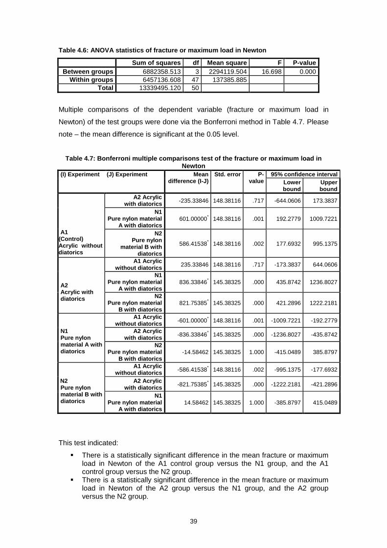
Table 4.6: ANOVA statistics of fracture or maximum load in Newton
Sum of squares df Mean square F P-value
Between groups 6882358.513 3 2294119.504 16.698 0.000
Within groups 6457136.608 47 137385.885
Total 13339495.120 50
Multiple comparisons of the dependent variable (fracture or maximum load in
Newton) of the test groups were done via the Bonferroni method in Table 4.7. Please
note – the mean difference is significant at the 0.05 level.
Table 4.7: Bonferroni multiple comparisons test of the fracture or maximum load in Newton
(I) Experiment (J) Experiment Mean difference (I-J)
Std. error P-value
95% confidence interval
Lower bound
Upper bound
A1
(Control) Acrylic without diatorics
A2 Acrylic with diatorics
-235.33846 148.38116 .717 -644.0606 173.3837
N1 Pure nylon material
A with diatorics 601.00000
* 148.38116 .001 192.2779 1009.7221
N2 Pure nylon
material B with diatorics
586.41538* 148.38116 .002 177.6932 995.1375
A2 Acrylic with diatorics
A1 Acrylic without diatorics
235.33846 148.38116 .717 -173.3837 644.0606
N1 Pure nylon material
A with diatorics 836.33846
* 145.38325 .000 435.8742 1236.8027
N2 Pure nylon material
B with diatorics 821.75385
* 145.38325 .000 421.2896 1222.2181
N1 Pure nylon material A with diatorics
A1 Acrylic without diatorics
-601.00000* 148.38116 .001 -1009.7221 -192.2779
A2 Acrylic with diatorics
-836.33846* 145.38325 .000 -1236.8027 -435.8742
N2 Pure nylon material
B with diatorics -14.58462 145.38325 1.000 -415.0489 385.8797
N2 Pure nylon material B with diatorics
A1 Acrylic without diatorics
-586.41538* 148.38116 .002 -995.1375 -177.6932
A2 Acrylic with diatorics
-821.75385* 145.38325 .000 -1222.2181 -421.2896
N1 Pure nylon material
A with diatorics 14.58462 145.38325 1.000 -385.8797 415.0489
This test indicated:
There is a statistically significant difference in the mean fracture or maximum load in Newton of the A1 control group versus the N1 group, and the A1 control group versus the N2 group.
There is a statistically significant difference in the mean fracture or maximum load in Newton of the A2 group versus the N1 group, and the A2 group versus the N2 group.
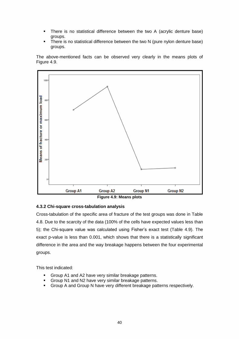
40
There is no statistical difference between the two A (acrylic denture base) groups.
There is no statistical difference between the two N (pure nylon denture base) groups.
The above-mentioned facts can be observed very clearly in the means plots of Figure 4.9.
Figure 4.9: Means plots
4.3.2 Chi-square cross-tabulation analysis
Cross-tabulation of the specific area of fracture of the test groups was done in Table
4.8. Due to the scarcity of the data (100% of the cells have expected values less than
5); the Chi-square value was calculated using Fisher’s exact test (Table 4.9). The
exact p-value is less than 0.001, which shows that there is a statistically significant
difference in the area and the way breakage happens between the four experimental
groups.
This test indicated:
Group A1 and A2 have very similar breakage patterns. Group N1 and N2 have very similar breakage patterns. Group A and Group N have very different breakage patterns respectively.

41
Table 4.8: Cross-tabulation of specific area of fracture of groups
Group
Total
A1 Control
A2
Acrylic with
diatorics
N1 Pure nylon
material A with
diatorics
N2 Pure nylon
material B with
diatorics
Specific area of fracture
Acrylic below tooth – adhesive
Count 3 4 0 0 7
% within experiment
23.1% 30.8% 0.0% 0.0% 13.5%
Facial third of acrylic tooth – adhesive
Count 2 0 0 0 2
% within experiment
15.4% 0.0% 0.0% 0.0% 3.8%
Facial third of acrylic tooth – slightly cohesive mesially
Count 2 0 0 0 2
% within experiment
15.4% 0.0% 0.0% 0.0% 3.8%
Facial third of acrylic tooth – slightly cohesive mesiodistally
Count 4 0 0 0 4
% within experiment
30.8% 0.0% 0.0% 0.0% 7.7%
Facial third of acrylic tooth – slightly cohesive mesiodistally, along mesiodistal arm of diatoric T
Count 0 2 0 0 2
% within experiment
0.0% 15.4% 0.0% 0.0% 3.8%
One long fracture: along acrylic below tooth through facial third of tooth – cohesive mesiodistally
Count 0 1 0 0 1
% within experiment
0.0% 7.7% 0.0% 0.0% 1.9%
Snapping and failure of nylon at mesiodistal diatoric exits on teeth
Count 0 0 0 13 13
% within experiment
0.0% 0.0% 0.0% 100.0% 25.0%
Stretching and failure of nylon at mesiodistal diatoric exits on teeth
Count 0 0 13 0 13
% within experiment
0.0% 0.0% 100.0% 0.0% 25.0%
Two fractures: acrylic below tooth – adhesive/facial third of acrylic tooth – adhesive
Count 1 0 0 0 1
% within experiment
7.7% 0.0% 0.0% 0.0% 1.9%
Two fractures: acrylic below tooth – adhesive/facial third of acrylic tooth – adhesive, very shallow
Count 0 3 0 0 3
% within experiment
0.0% 23.1% 0.0% 0.0% 5.8%
Two fractures: acrylic below tooth – adhesive/facial third of acrylic tooth – slightly cohesive mesially
Count 1 3 0 0 4
% within experiment
7.7% 23.1% 0.0% 0.0% 7.7%
Total
Count 13 13 13 13 52
% within experiment
100.0% 100.0% 100.0% 100.0% 100.0%
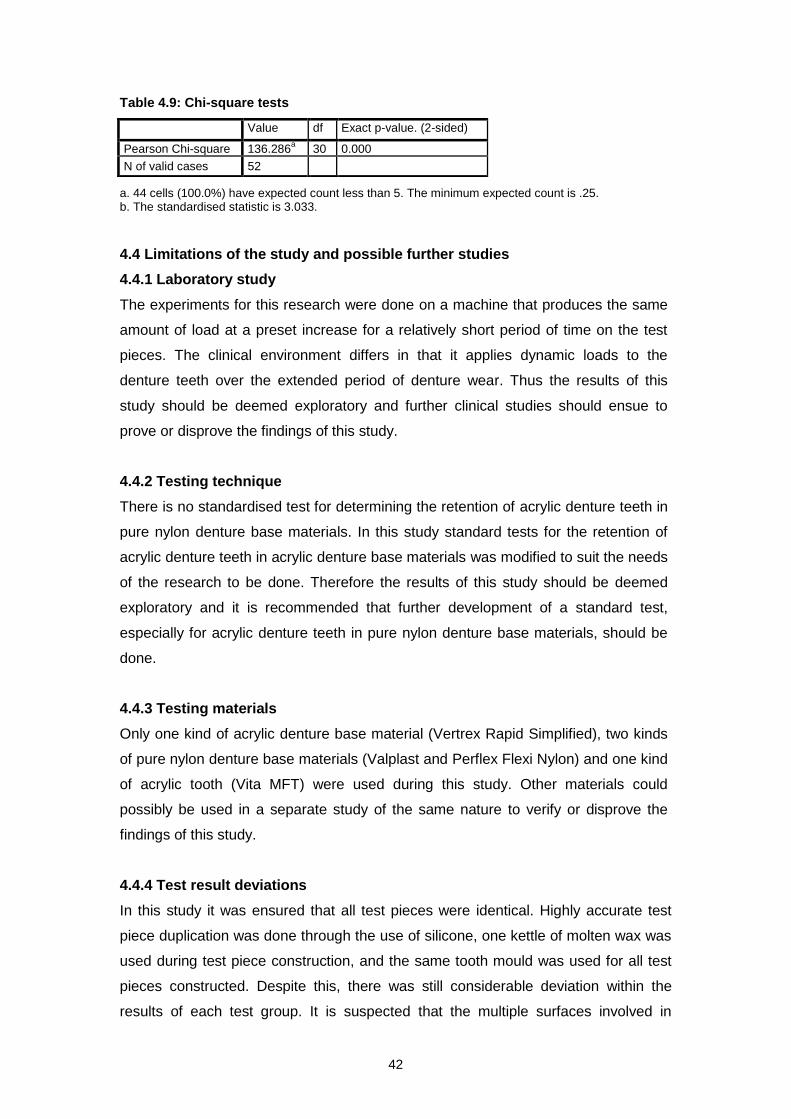
42
Table 4.9: Chi-square tests
a. 44 cells (100.0%) have expected count less than 5. The minimum expected count is .25. b. The standardised statistic is 3.033.
4.4 Limitations of the study and possible further studies
4.4.1 Laboratory study
The experiments for this research were done on a machine that produces the same
amount of load at a preset increase for a relatively short period of time on the test
pieces. The clinical environment differs in that it applies dynamic loads to the
denture teeth over the extended period of denture wear. Thus the results of this
study should be deemed exploratory and further clinical studies should ensue to
prove or disprove the findings of this study.
4.4.2 Testing technique
There is no standardised test for determining the retention of acrylic denture teeth in
pure nylon denture base materials. In this study standard tests for the retention of
acrylic denture teeth in acrylic denture base materials was modified to suit the needs
of the research to be done. Therefore the results of this study should be deemed
exploratory and it is recommended that further development of a standard test,
especially for acrylic denture teeth in pure nylon denture base materials, should be
done.
4.4.3 Testing materials
Only one kind of acrylic denture base material (Vertrex Rapid Simplified), two kinds
of pure nylon denture base materials (Valplast and Perflex Flexi Nylon) and one kind
of acrylic tooth (Vita MFT) were used during this study. Other materials could
possibly be used in a separate study of the same nature to verify or disprove the
findings of this study.
4.4.4 Test result deviations
In this study it was ensured that all test pieces were identical. Highly accurate test
piece duplication was done through the use of silicone, one kettle of molten wax was
used during test piece construction, and the same tooth mould was used for all test
pieces constructed. Despite this, there was still considerable deviation within the
results of each test group. It is suspected that the multiple surfaces involved in
Value df Exact p-value. (2-sided)
Pearson Chi-square 136.286a 30 0.000
N of valid cases 52

43
accommodating the diatorics in the tooth structure and denture base materials might
be responsible for this large deviation. More investigation is needed in this regard.

44
CHAPTER FIVE CONCLUSION AND RECOMENDATIONS
5.1 Introduction
The purpose of this study was to compare the retention of acrylic denture teeth in
pure nylon dentures to that of teeth in conventional acrylic denture bases (the acrylic
test pieces serving as the control standard). A further purpose was to explore
whether creating diatorics in acrylic teeth for use with pure nylon denture bases
potentially has a weakening effect on the tooth structure.
5.2 The retention of acrylic denture teeth in pure nylon denture bases
compared to those in conventional acrylic denture bases
The statistical research shows that the mechanical retention of acrylic denture teeth
in pure nylon denture bases is inferior to the mechanical and chemical retention of
acrylic denture teeth in acrylic denture bases. There is a statistically significant
difference in the mean fracture or maximum load in Newton of Group A versus Group
N (see section 4.3.1).
During testing of the pure nylon denture base pieces it was evident that the weakest
point of the pure nylon denture base material’s mechanical retention lies at the
mesial and distal diatoric exits on the teeth. Failure of the pure nylon denture base
material occurred at the mesial and distal diatoric exits on the teeth without exception
in every test piece within Group N.
The hypothesis that the bond strength of acrylic teeth onto a pure nylon denture base
will be less than that of acrylic teeth onto a conventional acrylic denture base was
correct.
5.3 The influence of the diatorics on the tooth structure
Group A1 served as the control standard during this study. As in conventional
practice, it consists of an acrylic denture base material and acrylic teeth without
diatorics. Group A2 consisted of the same acrylic denture base material and acrylic
teeth with diatorics. During testing no statistical difference in the mean fracture load
in Newton was found between the two A groups. Since the only difference between
the two groups is the diatorics, this would indicate that when the diatorics are created
as prescribed within the tooth, the tooth structure is not weakened.

45
As for the specific area of breakage of the test pieces, the Chi-square cross-
tabulation analysis indicated that the A groups have very similar breakage patterns.
More fractures in the diatoric area of the A2 group would have indicated that the
diatoric T weakens the tooth structure: Group A2 did not fracture more in the diatoric
area than Group A1, which leads to the conclusion that when the diatorics are
created as prescribed within the tooth, it does not weaken the tooth structure.
In respect of the N Group: with the pure nylon denture base material breaking off at
the mesial and distal diatoric T exits on the teeth without exception, the tooth
structure itself seems to be safe from any influence that drilling the diatoric T into the
teeth could have, as the mechanical retention at the mesial and distal diatoric T exits
always fails first.
The hypothesis that diatorics should not influence the acrylic tooth structure
detrimentally if created as prescribed is therefore correct.
5.4 Recommendations
5.4.1 Clinical testing
This study differs from the clinical situation in four very important ways. It lacked
supporting teeth; the tooth angulation was over exaggerated; the whole tooth
structure was used (which is not always possible in the clinical situation); and, load
application (see section 4.1).
In my personal experience of creating nylon dentures over the past few years, I have
only encountered two mechanical retention denture tooth failures. They were both on
single anterior tooth nylon dentures with limited mesiodistal space. In both cases the
retention failed in the mesial and distal diatoric T exit areas, exactly as described in
the research undertaken in this study.
In my experience with nylon dentures, l am of the opinion that although mechanical
retention failure of teeth in nylon dentures do occur, it does not do so at the rate that
this laboratory study would lead us to believe.
I therefore recommended that clinical testing be done to either verify or disprove the
conclusions of this study.

46
5.4.2 Diatoric T design
As this study has identified that the pure nylon denture base material has a weak
point on the mesial and distal diatoric T exits on the teeth, further investigation into
the design of the diatorics created for mechanical retention of acrylic teeth onto a
pure nylon denture base is needed.
In my own work experience I have found that the diatoric T design provides enough
retention for posterior teeth. However the shearing forces applied on the anterior
denture teeth, while biting, puts a significant amount of stress on the mechanical
retention provided by the diatoric T design. To help counter these stresses the
amount of tooth neck area covered with nylon was increased. This creates more
resistance against these forces. It was also found that if an extra diatoric on the
palatal surface of the anterior tooth which joins to the centre of the diatoric T design
was created, the mechanical retentional strength increases considerably.
This new design would require further investigation..
5.4.3 Further material development
Further development of pure nylon denture base material is needed to ensure a
better retention of acrylic denture teeth within the pure nylon denture base material.
It would be most advantageous if some form of chemical retention could be gained
alongside the mechanical retention in order to retain denture teeth better in nylon
dentures. In the past, nylon denture base material manufacturers have opted to
include methyl methacrylate in the flexible nylon denture base material mix in order
to gain chemical retention. The inclusion of this chemical has however had a
negative influence on the flexibility and strength properties of the nylon.
An alternative solution will have to be considered to ensure the longevity of flexible
nylon dentures.
47
REFERENCES
3ders. 2011. 3D Printing Bone replacements, Cartilage replacements, Medical devices and more with 618 Nylon. http://www.3ders.org/articles/20130218-3d-printing-bone-replacements-cartilage-replacements-medical-devices-with-618-nylon.html [24 April 2014]. Abuzar, M.A., Bellur, S., Duong, N., Kim, B.B., Lu, P., Palfreyman, N., Surendran, D., & Tran, V.T. 2010. Evaluating surface roughness of a polyamide denture base material in comparison with poly (methyl methacrylate). Journal of Oral Science, 52(4):577-581, December. Anusavice, K.J. 2003. Phillip’s science of dental materials. 11th ed. St. Louis, Missouri: Saunders Armagh Dental lab. 2014. Services. http://www.armaghdentallab.co.uk/valplast-flexible-dentures.php [15 April 2014]. Barron Dental. 2012. Dentures. http://www.barrondental.com/edinburgh_dentist_dentures.html [16 April 2014]. Bragaglia, L.E., Prates, L.H.M. & Calvo, M.C.M. 2009. The role of surface treatments on the bond between acrylic denture base and teeth. Brazilian Dental Journal, 20(2):156-161. Chai, J., Takahashi, Y., Takahashi, T. & Habu, T. 2000. Bonding durability of conventional resinous denture teeth and highly crosslinked denture teeth to a pour-type denture base resin. International Journal of Prosthodontics, 13(2):112-116, March–April. Chemical Book. 2008. Nylon 12. http://www.chemicalbook.com/Search_EN.aspx?keyword=nylon%2012 [15 January 2014]. Chemindustry. 1991. Nylon 12. http://www.chemindustry.com/chemicals/0371995.html [15 July 2014]. Chemnet. 1997. Nylon 12. http://www.chemnet.com/Suppliers/33300/Nylon-12--1075056.html [15 July 2014]. Cunningham, J.L. & Benington, I.C. 1996. A new technique for determining the denture tooth bond. Journal of Oral Rehabilitation, 23(3):202-209, March. Cunningham, J.L. & Benington, I.C. 1999. An investigation of the variables which may affect the bond between plastic teeth and denture base resin. Journal of Dentistry, 27(2):129-135, February. Deflex. 1999. Technical indications for the making of Deflex dentures. Beunos Aires, Argentina: Nuxen SRL. Deflex. 2000. http://www.deflex.com.ar/ingles/index.htm [15 April 2014] Demetech. 2014. Surgical suture information. http://www.demetech.us/sutures.php [16 April 2014]

48
Dentsply. 2010. Locator technique manual. http://www.dentsplyimplants.com/~/media/M3%20Media/BU%20Dental/Products/1210160%20LOCATOR%20Manual.ashx?filetype=.pdf [18 April 2014] Dhiman, R.K. & Chowdhury, S.K.R. 2009. Midline fractures in single maxillary complete acrylic vs flexible dentures. Medical Journal Armed Forces India, 65(2):141-145, September. Dolphin sutures. 2014a. Meaning - surgical sutures. http://www.dolphinsutures.com/resources/sutures-meaning#surgical-sutures [16 April 2014]. Dolphin sutures. 2014b. Information on polyamide. http://www.dolphinsutures.com/resources/information-on-polyamide#polyamide-sutures [16 April 2014]. Egan, G.E. & Swindells, S.A. 2012. A novel prosthodontic alternative for patients who are edentulous and have microstomia: a case report. Special Care in Dentistry, 32(4):160-164, July/August. Flex Star. 2012. Flex star flexible appliances instruction manual. Albany, NY: Nobilium. Geerts, G.A.V.M., & Stuhlinger, M.E. 2012. Bonding of acrylic denture teeth to resin denture bases. South African Dental Journal, 67(6):258-263, July. Hamanaka, I., Takahashi, Y. & Shimizu, H. 2011. Mechanical properties of injection-molded thermoplastic denture base resins. Acta Odontologica Scandinavica, 69(2):75-79, March. Implant Direct. 2005. Locator. http://www.implantdirect.it/documents/pdf/customer_support/Locatornew.pdf [18 April 2014]. Jetbiofil. 2012. Products. http://www.jetbiofil.com/english/ProductShow.asp? [16 April 2014]. Nagy, P. 2014. Email to Nadine van der Poel, 20 March 2014 Negrutiu, M., Sinescu, C., Romanu, M., Pop, D. & Lakatos, S. 2005. Thermoplastic resins for flexible framework removable partial dentures. Timisoara Medical Journal, 55(3):295-299. Newage. 2010. Vickers Hardness Testing. http://www.hardnesstesters.com/Applications/Vickers-Hardness-Testing.aspx [24 April 2014]. North American science associates (NAMSA). 1997. Mucous membrane irritation study in the hamster (ADA method). Irvine, CA: NAMSA. Patil, S.B., Naveen, B.H. & Patil, N.P. 2006. Bonding acrylic teeth to acrylic resin denture bases: a review. Gerodontology, 23(3):131-139, September. Perflex. 2007. Perflex Flexi Nylon manual. Netanya, Israel: Perflex.

49
Perflex. 2007a. About Perflex. http://www.perflexltd.com/content.asp?type=100001&title=About.Perflex [15 April 2014]. Perflex. 2007b. Contact us. http://www.perflexltd.com/contact.asp?type=100005&title=Contact/us [15 April 2014]. Phillips, R.W. 1991. Skinner’s science of dental materials. 9th ed. Philadelphia, PA: W.B Saunders Company Prashanti, E., Jain, N., Shenoy, V.K., Reddy, J.M., Shetty, B.T. & Saldanha, S. 2010. Flexible dentures: a flexible option to treat edentulous patients. Journal of Nepal Dental Association, 11(1):85-87, January–June. Prospector. 2014. Water Absorption – ISO 62. http://www.ides.com/property_descriptions/ISO62.asp [24 April 2014]. Pusz, A., Szymiczek, M. & Michalik, K. 2010. Aging process influence on mechanical properties of polyamide-glass composites applied in dentistry. Journal of Achievements in Materials and Manufacturing Engineering, 38(1):49-55. Qmed. 2014. What’s Hip in Orthopedic Implant Design. http://www.qmed.com/mpmn/article/whats-hip-orthopedic-implant-design [24 April 2014]. Rickman, L.J., Padipatvuthikul, P. & Satterthwaite, D. 2012. Contemporary denture base resins: part 2. Dental Update, 39(3):176-178, 180-182, 184 passim, April. SAHO (South African History Online). 2000. The UN requests States to terminate restrictions on economic relations with South Africa with immediate effect. http://www.sahistory.org.za/dated-event/un-requests-states-terminates-restrictions-economic-relations-south-africa-immediate-effe [30 April 2014]. Sepúlveda-Navarro, W.F., Arana-Correa, B.E., Borges, C.P.F., Jorge, J.H., Urban, V.M. & Campanha, N.H. 2011. Color stability of resins and nylon as denture base material in beverages. Journal of Prosthodontics, 20(8):632-638, December. Shamnur, S.N., Jagadeesh, K.N., Kalavathi, S.D. & Kashinath, K.R. 2010. “Flexible dentures” – an alternate for rigid dentures? Journal of Dental Sciences & Research, 1(1):74-79, February. Singh, J.P., Dhiman, R.K., Bedi, R.P.S. & Girish, S.H. 2011. Flexible denture base material: a viable alternative to conventional acrylic denture base material. Contemporary Clinical Dentistry, 2(4):313-317, October–December. Stafford, G.D., Huggett, R., MacGregor, A.R. & Graham, J. 1986. The use of nylon as a denture-base material. Journal of Dentistry, 14(1):18-22. Stern, M.N. 2007. Flexible partials: aesthetic retention for the removable dental prosthesis. Dental Practice, 7:28-29, July. Takahashi, Y., Chai, J., Takahashi, T. & Habu, T. 2000. Bond strength of denture teeth to denture base resins. International Journal of Prosthodontics, 13(1):59-65, January–February.
50
Thean, H.P.Y., Chew, CL. & Goh, K.L. 1996. Shear bond strength of denture teeth to base: a comparative study. Quintessence International Journal, 27:425-428. ValClean. 2014. Denture home care products. http://www.valclean.com/store/c/18-Denture-Home-Care-Products.aspx [15 January 2014]. Valplast International Corporation. 2004. Valplast processing technique manual. Long Beach, NY: Valplast International Corporation. Valplast. 2004a. Contact us. http://www.valplast.com/contact/ [15 April 2014]. Westview dental practice. 2012. Valplast dentures. http://www.westviewdental.co.uk/isleofman/dental-procedures/dentures/valplast-dentures/ [16 April 2014]. WhatIs. 1999. Specific gravity. http://www.whatis.techtarget.com/definition/specific-gravity [24 April 2014]. Wolfart, S., Brunzel, S., Freitag, S. & Kern, M. 2004. Assessment of dental appearance following changes in incisor angulation. International Journal of Prosthodontics, 17(2):150-154, March–April.
Yunus, N., Rashid, A.A., Azmi, L.L. & Abu-Hassan, M.I. 2005. Some flexural properties of a nylon denture base polymer. Journal of Oral Rehabilitation, 32(1):65-71, January.
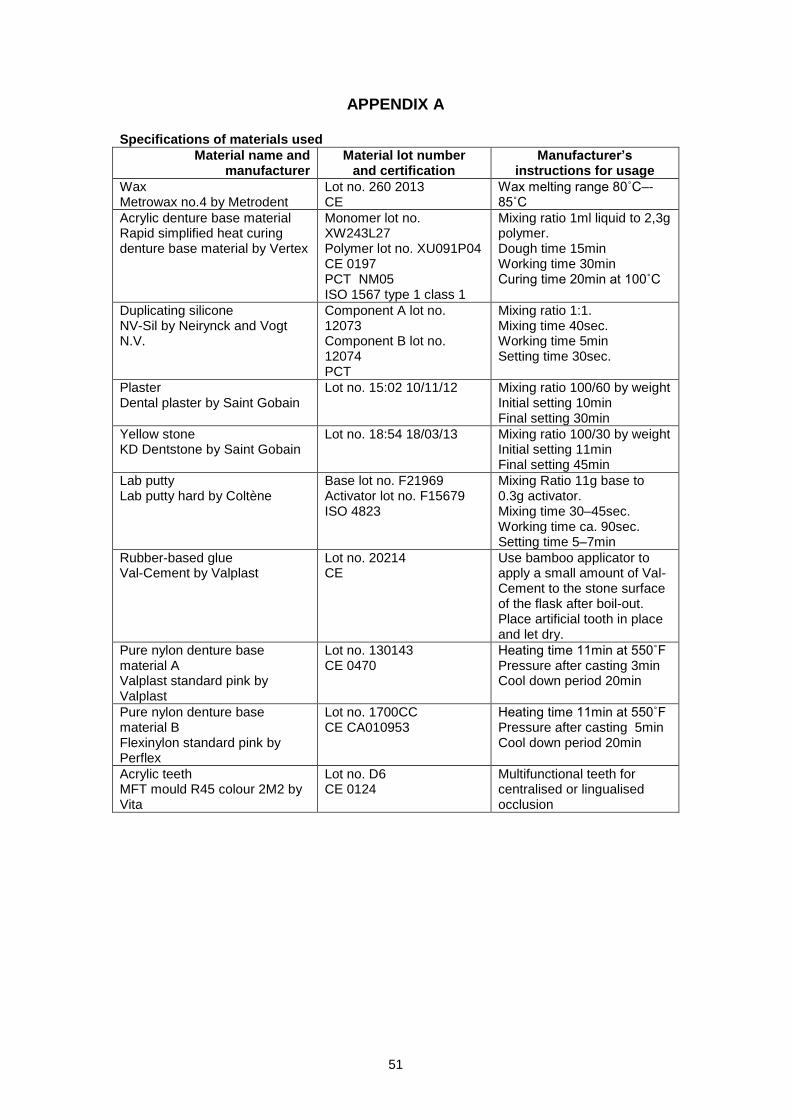
51
APPENDIX A Specifications of materials used
Material name and manufacturer
Material lot number and certification
Manufacturer’s instructions for usage
Wax Metrowax no.4 by Metrodent
Lot no. 260 2013 CE
Wax melting range 80˚C–- 85˚C
Acrylic denture base material Rapid simplified heat curing denture base material by Vertex
Monomer lot no. XW243L27 Polymer lot no. XU091P04 CE 0197 PCT NM05 ISO 1567 type 1 class 1
Mixing ratio 1ml liquid to 2,3g polymer. Dough time 15min Working time 30min Curing time 20min at 100˚C
Duplicating silicone NV-Sil by Neirynck and Vogt N.V.
Component A lot no. 12073 Component B lot no. 12074 PCT
Mixing ratio 1:1. Mixing time 40sec. Working time 5min Setting time 30sec.
Plaster Dental plaster by Saint Gobain
Lot no. 15:02 10/11/12 Mixing ratio 100/60 by weight Initial setting 10min Final setting 30min
Yellow stone KD Dentstone by Saint Gobain
Lot no. 18:54 18/03/13 Mixing ratio 100/30 by weight Initial setting 11min Final setting 45min
Lab putty Lab putty hard by Coltène
Base lot no. F21969 Activator lot no. F15679 ISO 4823
Mixing Ratio 11g base to 0.3g activator. Mixing time 30–45sec. Working time ca. 90sec. Setting time 5–7min
Rubber-based glue Val-Cement by Valplast
Lot no. 20214 CE
Use bamboo applicator to apply a small amount of Val-Cement to the stone surface of the flask after boil-out. Place artificial tooth in place and let dry.
Pure nylon denture base material A Valplast standard pink by Valplast
Lot no. 130143 CE 0470
Heating time 11min at 550˚F Pressure after casting 3min Cool down period 20min
Pure nylon denture base material B Flexinylon standard pink by Perflex
Lot no. 1700CC CE CA010953
Heating time 11min at 550˚F Pressure after casting 5min Cool down period 20min
Acrylic teeth MFT mould R45 colour 2M2 by Vita
Lot no. D6 CE 0124
Multifunctional teeth for centralised or lingualised occlusion
Copyright © 2022 FDOKUMEN