A Facile Approach to Fabricate Porous Nylon 6 Nanofibers Using Silica Nanotemplate Quan Shi,1...
9
A Facile Approach to Fabricate Porous Nylon 6 Nanofibers Using Silica Nanotemplate Quan Shi, 1 Narendiran Vitchuli, 1 Liwen Ji, 1 Joshua Nowak, 2 Marian McCord, 1 Mohamed Bourham, 2 Xiangwu Zhang 1 1 Fiber and Polymer Science Program, Department of Textile Engineering, Chemistry and Science, North Carolina State University, Raleigh, North Carolina 27695-8301 2 Department of Nuclear Engineering, North Carolina State University, Raleigh, North Carolina 27695-7909 Received 8 May 2010; accepted 9 August 2010 DOI 10.1002/app.33161 Published online 14 October 2010 in Wiley Online Library (wileyonlinelibrary.com). ABSTRACT: Porous Nylon 6 nanofibers were prepared using silica nanoparticles as the template. Firstly, Nylon 6/ silica composite nanofibers were prepared as precursors by electrospinning Nylon 6 solutions containing different con- tents of silica nanoparticles. Scanning electron microscopy (SEM) and transmission electron microscopy (TEM) were used to examine the surface morphology and the inner structure of composite nanofibers; where it was found that silica nanoparticles were distributed both inside and on the surface of nanofibers. Analytical techniques [Fourier trans- form infrared (FTIR), differential scanning calorimetry, ther- mal gravimetric analysis (TGA), and wide-angle X-ray diffraction) were used to study the structure and properties of these composite nanofibers. The glass transition, melting, and crystallization processes of the fibers were affected by the addition of silica nanoparticles. Secondly, porous Nylon 6 nanofibers were obtained by removing silica nanoparticles via hydrofluoric acid treatment. The removal of silica nano- particles was confirmed using FTIR and TGA tests. SEM and TEM observations revealed the formation of the porous structure in these nanofibers. After the formation of the po- rous structure, Brunauer–Emmett–Teller specific surface areas of nanofibers were increased as compared to solid Ny- lon 6 and composite nanofibers. V C 2010 Wiley Periodicals, Inc. J Appl Polym Sci 120: 425–433, 2011 Key words: electrospinning; nanocomposite; porous nanofibers; Nylon 6 INTRODUCTION Electrospun nanofibers are becoming a versatile cate- gory of materials for a multitude of applications. 1,2 By electrospinning, a variety of materials can be processed into nonwoven nanofiber mats with large specific surface area. The structure of these nanofib- ers can be easily controlled by manipulating electro- spinning parameters, such as solution concentration, accelerating voltage, and flow rate. 3–6 In recent years, electrospun nanofibers research has covered a broad range of fields including, but not limited to, protective textiles, 7 tissue engineering, 8,9 homogene- ous catalysis, 10 sensors, 11,12 and biomedical and bio- polymer applications. 13–17 So far, efforts have been made to control the inner structure of electrospun nanofibers to improve their properties. One popular method is to reinforce elec- trospun nanofibers by introducing inorganic nano- particles. It is well known that polymer/inorganic nanocomposites can combine advantages of two dis- tinct materials and hence lead to mechanical, electri- cal, and thermal properties that can be easily modi- fied for multifunctional applications. 18–23 Among many polymer/inorganic nanocomposite systems, the preparation of polymer/silica nanofibers is a simple and universal method to improve the tough- ness, durability, and permeability of polymer nano- fibers. 24,25 Some efforts have been reported to pre- pare polymer/silica composite nanofibers by the combination of sol-gel synthesis and electrospinning. PVA/silica, 26,27 PMMA/silica 28 , and PEO/silica 29 composite nanofibers have also been successfully obtained by this method. Recently, the authors pre- pared PAN/silica composite nanofibers by electro- spinning PAN solutions containing different content of silica nanoparticles without adding the sol-gel synthesis step, which presents a new and simple approach to prepare polymer/inorganic composite nanofibers. 30 Another advantage of polymer/silica nanocompo- sites is that they can be used as precursor to fabri- cate nanoporous nanofibers by removing silica nano- particles. Porous nanofibers, which have extra high specific surface area and porosity, are expanding the application scope of nanofibers in membranes, fil- ters, sensors, and coatings. 31,32 Porous fibers were prepared by several groups by electrospinning bicomponent polymer blends then selectively Correspondence to: X. Zhang ([email protected]). Contract grant sponsor: Defense Threat Reduction Agency; contract grant number: BB08PRO008. Journal of Applied Polymer Science, Vol. 120, 425–433 (2011) V C 2010 Wiley Periodicals, Inc.
Transcript of A Facile Approach to Fabricate Porous Nylon 6 Nanofibers Using Silica Nanotemplate Quan Shi,1...

A Facile Approach to Fabricate Porous Nylon 6Nanofibers Using Silica Nanotemplate
Quan Shi,1 Narendiran Vitchuli,1 Liwen Ji,1 Joshua Nowak,2 Marian McCord,1
Mohamed Bourham,2 Xiangwu Zhang1
1Fiber and Polymer Science Program, Department of Textile Engineering, Chemistry and Science,North Carolina State University, Raleigh, North Carolina 27695-83012Department of Nuclear Engineering, North Carolina State University, Raleigh, North Carolina 27695-7909
Received 8 May 2010; accepted 9 August 2010DOI 10.1002/app.33161Published online 14 October 2010 in Wiley Online Library (wileyonlinelibrary.com).
ABSTRACT: Porous Nylon 6 nanofibers were preparedusing silica nanoparticles as the template. Firstly, Nylon 6/silica composite nanofibers were prepared as precursors byelectrospinning Nylon 6 solutions containing different con-tents of silica nanoparticles. Scanning electron microscopy(SEM) and transmission electron microscopy (TEM) wereused to examine the surface morphology and the innerstructure of composite nanofibers; where it was found thatsilica nanoparticles were distributed both inside and on thesurface of nanofibers. Analytical techniques [Fourier trans-form infrared (FTIR), differential scanning calorimetry, ther-mal gravimetric analysis (TGA), and wide-angle X-raydiffraction) were used to study the structure and propertiesof these composite nanofibers. The glass transition, melting,
and crystallization processes of the fibers were affected bythe addition of silica nanoparticles. Secondly, porous Nylon6 nanofibers were obtained by removing silica nanoparticlesvia hydrofluoric acid treatment. The removal of silica nano-particles was confirmed using FTIR and TGA tests. SEMand TEM observations revealed the formation of the porousstructure in these nanofibers. After the formation of the po-rous structure, Brunauer–Emmett–Teller specific surfaceareas of nanofibers were increased as compared to solid Ny-lon 6 and composite nanofibers. VC 2010 Wiley Periodicals, Inc.J Appl Polym Sci 120: 425–433, 2011
Key words: electrospinning; nanocomposite; porousnanofibers; Nylon 6
INTRODUCTION
Electrospun nanofibers are becoming a versatile cate-gory of materials for a multitude of applications.1,2
By electrospinning, a variety of materials can beprocessed into nonwoven nanofiber mats with largespecific surface area. The structure of these nanofib-ers can be easily controlled by manipulating electro-spinning parameters, such as solution concentration,accelerating voltage, and flow rate.3–6 In recentyears, electrospun nanofibers research has covered abroad range of fields including, but not limited to,protective textiles,7 tissue engineering,8,9 homogene-ous catalysis,10 sensors,11,12 and biomedical and bio-polymer applications.13–17
So far, efforts have been made to control the innerstructure of electrospun nanofibers to improve theirproperties. One popular method is to reinforce elec-trospun nanofibers by introducing inorganic nano-particles. It is well known that polymer/inorganicnanocomposites can combine advantages of two dis-
tinct materials and hence lead to mechanical, electri-cal, and thermal properties that can be easily modi-fied for multifunctional applications.18–23 Amongmany polymer/inorganic nanocomposite systems,the preparation of polymer/silica nanofibers is asimple and universal method to improve the tough-ness, durability, and permeability of polymer nano-fibers.24,25 Some efforts have been reported to pre-pare polymer/silica composite nanofibers by thecombination of sol-gel synthesis and electrospinning.PVA/silica,26,27 PMMA/silica28, and PEO/silica29
composite nanofibers have also been successfullyobtained by this method. Recently, the authors pre-pared PAN/silica composite nanofibers by electro-spinning PAN solutions containing different contentof silica nanoparticles without adding the sol-gelsynthesis step, which presents a new and simpleapproach to prepare polymer/inorganic compositenanofibers.30
Another advantage of polymer/silica nanocompo-sites is that they can be used as precursor to fabri-cate nanoporous nanofibers by removing silica nano-particles. Porous nanofibers, which have extra highspecific surface area and porosity, are expanding theapplication scope of nanofibers in membranes, fil-ters, sensors, and coatings.31,32 Porous fibers wereprepared by several groups by electrospinningbicomponent polymer blends then selectively
Correspondence to: X. Zhang ([email protected]).Contract grant sponsor: Defense Threat Reduction
Agency; contract grant number: BB08PRO008.
Journal of Applied Polymer Science, Vol. 120, 425–433 (2011)VC 2010 Wiley Periodicals, Inc.

removing one of them.33,34 Porous structures canalso be obtained in nanofibers by controlling the hu-midity or molecular weight in the one-component elec-trospinning.35 Nylon 6 is one of the most widely usedpolymer materials in protective and filter fabrics.Porous structure in Nylon 6 fibers can improve theirsurface area and hence the filtration efficiency and cata-lyst-loading capacity. Recently, Gupta et al.36 haveexploited a new approach to produce porous nanofib-ers by electrospinning the Lewis acid–base complex ofNylon 6 and GaCl3, referred to as the ‘‘salt-induced’’process. All these methods require handling compli-cated interactions between the polymer matrix andpore generator, such as the secondary polymer, mois-ture, and salt. Compared with the existing methods,removing silica nanoparticles from composite nanofib-ers is a relatively simple process. This pore formationprocess is decoupled from the polymer-silica interac-tion. In addition, the porosity and pore size of the re-sultant porous nanofibers can be easily controlled byadjusting the content and size of silica nanoparticles.
The aim of this research is to establish a simple andefficient method to fabricate porous Nylon 6 nanofib-ers using silica nanoparticles as the template. In thiswork, we first prepared Nylon 6/silica compositenanofibers by the electrospinning of Nylon 6 solutionscontaining different contents of silica nanoparticles.Characterization of the effects of silica particles on thestructure of nanofibers was performed. Silica nano-particles were then removed from the compositenanofibers through treatment with hydrofluoric (HF)acid solution. Surface morphology, specific surfacearea, thermal properties, and crystal structure of thecomposite and porous fibers were investigated.
EXPERIMENTAL
Materials
Nylon 6, solvent 2,2,2-tri-fluoroethanol (TFE), andHF acid (35% in H2O solution) were purchased fromSigma-Aldrich. Silica nanoparticles (AEROSILVR 380,average primary particle size ¼ 7 nm, and specificsurface area ¼ 380 6 30 m2/g) were supplied byEvonik Degussa GmbH (Essen, Germany). All thesereagents were used without further purification.
Electrospinning
Nylon 6 was dissolved in TFE at a concentration of13 wt % to get a stock solution. Weighed silica nano-particles were dispersed in the solution by magneticstirring at 45�C for 24 h to get a homogeneous mix-ture. The resultant mixture was agitated in an ultra-sonic bath for 15 min before electrospinning. Electro-spinning uses a high-voltage power supply (GammaES40P-20W/DAM), which provided 15 kV during
these experiments. A plastic syringe attached with astainless steel needle tip was used to load the elec-trospinning solution. The syringe was controlled byan electric pump to obtain a fixed feed rate of 1.5mL/h. The needle was charged with positive voltageand the metal collector was grounded, and the dis-tance between the needle and collector was 15 cm.The electrospun fibers were collected on the alumi-num foil on the collector as a fibrous mat.
Formation of porous structure
A HF acid solution of 10 wt % was obtaining bydiluting the commercial HF solution (35 wt %) withdeionized water. Nanofiber mats were cut into 2 � 2in pieces and weighed precisely. Nanofiber matswere then immersed into the HF solution and keptfor 24 h. Afterward, nanofiber mats were washedthree times with deionized water, dried by vacuum,weighed, and collected for further use.
Morphology
Surface morphology of nanofibers was observed byJEOL JSM-6400F field emission scanning electron mi-croscopy (SEM; JEOL, Tokyo, Japan), with an accel-erating voltage of 15 kV. The distribution of silicananoparticles and pores inside the fibers wereobserved using a Hitachi HF-2000 transmission elec-tron microscopy (TEM; Hitachi High TechnologiesAmerica), with an accelerating voltage of 20 kV.
Surface analysis
Information about the surface composition of thenanofibers was obtained by collecting attenuatedtotal reflection Fourier transform infrared (ATR-FTIR) spectra on a Nicolet 560 FTIR spectrometer.The tests were performed in the wave number rangeof 3750–750 cm�1 at room temperature.
Thermal analysis
Thermal properties of electrospun fibers were meas-ured by differential scanning calorimetry (DSC; Per-kin–Elmer Diamond). The measurements werecarried out under nitrogen atmosphere in a tempera-ture range between �20 and 250�C, at a heating rateof 20�C/min. Thermal decomposition properties ofelectrospun fibers at elevated temperatures wasassessed by thermal gravimetric analysis (TGA; TAHi-Res 2950). The tests were performed in the tem-perature range of 25–800�C under nitrogen atmos-phere at a heating rate of 20�C/min.
Crystal structure
Crystal structure of the composite and porous fiberswas characterized by wide-angle X-ray diffraction(WAXD). Spectra were collected on a Philips XLF
426 SHI ET AL.
Journal of Applied Polymer Science DOI 10.1002/app

ATPS XRD 100 diffractometer (Cu Ka radiation). Theoperating voltage was 40.0 kV, and the current was60.0 mA. Data were collected at the interval of 0.02�
and the scanning rate of 1 s/step. Peak positions weredetermined by the APD 1700 (Version 4) software.
Surface specific area analysis
Surface specific areas of the composite and porousnanofibers were determined by Brunauer–Emmett–Teller (BET) nitrogen adsorption method. The sampleswere first stabilized in nitrogen atmosphere for 2 h at
Figure 1 SEM images of Nylon 6 and Nylon 6/silica composite nanofibers. Silica content: (a) 0, (b) 15, and (c) 30 wt %.
FABRICATION OF POROUS NYLON 6 NANOFIBERS 427
Journal of Applied Polymer Science DOI 10.1002/app
50�C. Nitrogen gas adsorption measurements weretaken at 5, 10, 15, 20, and 25% of saturation pressureon a Micromeritics Gemini 2360 instrument capable ofmeasuring surface area of 0.01 m2 g�1 and higher.
RESULTS AND DISCUSSION
Electrospun Nylon 6/silica composite nanofibers
Nylon 6/silica composite nanofibers containing 15 and30 wt % silica particles were obtained by electrospin-ning. SEM images show the surface morphology of Ny-lon 6 nanofibers (0, 15, and 30 wt % silica nanoparticles;Fig. 1). It is clear from the low-magnification imagesthat pure Nylon 6 nanofibers have smooth and continu-ous fibrous structures, with diameters ranging between200 and 400 nm. Nylon 6/silica nanofibers have arough surface, which may to be attributable to aggrega-tion of some of the silica nanoparticles. The addition ofhighly surface-active silica nanoparticles can increaseboth the viscosity and surface tension of electrospin-
ning solutions, which may also contribute to theincreased surface roughness of composite nanofibers.37
The diameters of the 30 wt % composite nanofibers aregenerally larger than those of 0 and 15 wt % nanofibers.The high-magnification SEM images in Figure 1
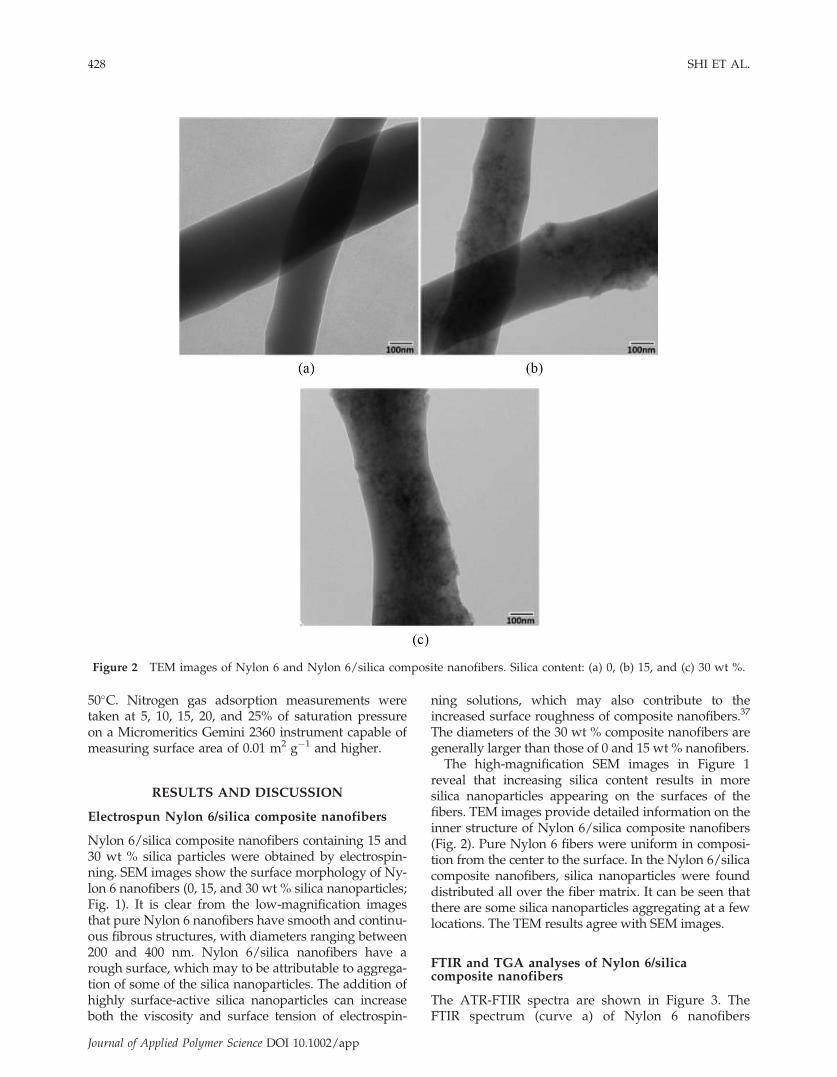
reveal that increasing silica content results in moresilica nanoparticles appearing on the surfaces of thefibers. TEM images provide detailed information on theinner structure of Nylon 6/silica composite nanofibers(Fig. 2). Pure Nylon 6 fibers were uniform in composi-tion from the center to the surface. In the Nylon 6/silicacomposite nanofibers, silica nanoparticles were founddistributed all over the fiber matrix. It can be seen thatthere are some silica nanoparticles aggregating at a fewlocations. The TEM results agree with SEM images.
FTIR and TGA analyses of Nylon 6/silicacomposite nanofibers
The ATR-FTIR spectra are shown in Figure 3. TheFTIR spectrum (curve a) of Nylon 6 nanofibers
Figure 2 TEM images of Nylon 6 and Nylon 6/silica composite nanofibers. Silica content: (a) 0, (b) 15, and (c) 30 wt %.
428 SHI ET AL.
Journal of Applied Polymer Science DOI 10.1002/app

presents typical peaks at 1547 cm�1 (NAH deforma-tion), and 1636 cm�1 (C¼¼O stretch), 3292 cm�1
(NAH stretch). These peaks can also be found in thespectra for the 15 and 30 wt % Nylon 6/silica com-posite nanofibers (curves b and c). The most signifi-cant difference in the spectra is the peak at 1100cm�1, which is the characteristic signal of SiAOASibond asymmetric stretching vibration and onlyexists in composite nanofibers.22
Results of the TGA studies were used to assess theactual content of silica nanoparticles in composite nano-fibers (Fig. 4). Pure Nylon 6 fibers give nearly 0 wt %
residuals after the temperature increased to 800�C asindicated in curve a. The 15 and 30 wt % compositenanofibers contain 15.0 and 23.9% residuals, as shownin curves b and c, respectively; this indicates the actualsilica content in the composite nanofibers.
Thermal properties and crystalline structureof Nylon 6/silica composite nanofibers
The DSC curves of both pure Nylon 6 fibers and Ny-lon 6/silica composite nanofibers are shown in
Figure 3 FTIR spectra of Nylon 6 and Nylon 6/silicacomposite nanofibers. Silica content: (a) 0, (b) 15, and(c) 30 wt %. [Color figure can be viewed in the onlineissue, which is available at wileyonlinelibrary.com.]
Figure 4 TGA thermograms of Nylon 6 and Nylon 6/silica composite nanofibers. Silica content: (a) 0, (b) 15, and(c) 30 wt %. [Color figure can be viewed in the onlineissue, which is available at wileyonlinelibrary.com.]
Figure 5 DSC Thermograms of Nylon 6 and Nylon 6/silica composite nanofibers. Silica content: (a) 0, (b) 15, and(c) 30 wt %. [Color figure can be viewed in the onlineissue, which is available at wileyonlinelibrary.com.]
Figure 6 WAXD spectra of Nylon 6 and Nylon 6/silicacomposite nanofibers. Silica content: (a) 0, (b) 15, and (c)30 wt %. [Color figure can be viewed in the online issue,which is available at wileyonlinelibrary.com.]
FABRICATION OF POROUS NYLON 6 NANOFIBERS 429
Journal of Applied Polymer Science DOI 10.1002/app
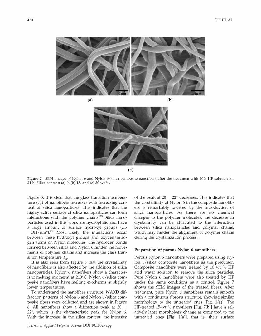
Figure 5. It is clear that the glass transition tempera-ture (Tg) of nanofibers increases with increasing con-tent of silica nanoparticles. This indicates that thehighly active surface of silica nanoparticles can forminteractions with the polymer chains.38 Silica nano-particles used in this work are hydrophilic and havea large amount of surface hydroxyl groups (2.5AOH/nm2).39 Most likely the interactions occurbetween these hydroxyl groups and oxygen/nitro-gen atoms on Nylon molecules. The hydrogen bondsformed between silica and Nylon 6 hinder the move-ments of polymer chains and increase the glass tran-sition temperature Tg.
It is also seen from Figure 5 that the crystallinityof nanofibers is also affected by the addition of silicananoparticles. Nylon 6 nanofibers show a character-istic melting exotherm at 219�C. Nylon 6/silica com-posite nanofibers have melting exotherms at slightlylower temperatures.
To understand the nanofiber structure, WAXD dif-fraction patterns of Nylon 6 and Nylon 6/silica com-posite fibers were collected and are shown in Figure6. All nanofibers show a diffraction peak at 2y ¼22�, which is the characteristic peak for Nylon 6.With the increase in the silica content, the intensity
of the peak at 2y ¼ 22� decreases. This indicates thatthe crystallinity of Nylon 6 in the composite nanofib-ers is remarkably lowered by the introduction ofsilica nanoparticles. As there are no chemicalchanges to the polymer molecules, the decrease incrystallinity can be attributed to the interactionbetween silica nanoparticles and polymer chains,which may hinder the alignment of polymer chainsduring the crystallization process.
Preparation of porous Nylon 6 nanofibers
Porous Nylon 6 nanofibers were prepared using Ny-lon 6/silica composite nanofibers as the precursor.Composite nanofibers were treated by 10 wt % HFacid water solution to remove the silica particles.Pure Nylon 6 nanofibers were also treated by HFunder the same conditions as a control. Figure 7shows the SEM images of the treated fibers. Aftertreatment, pure Nylon 6 nanofibers remain smoothwith a continuous fibrous structure, showing similarmorphology to the untreated ones [Fig. 1(a)]. TheHF-treated 15-wt % nanofibers [Fig. 7(b)] have a rel-atively large morphology change as compared to theuntreated ones [Fig. 1(a)], that is, their surface
Figure 7 SEM images of Nylon 6 and Nylon 6/silica composite nanofibers after the treatment with 10% HF solution for24 h. Silica content: (a) 0, (b) 15, and (c) 30 wt %.
430 SHI ET AL.
Journal of Applied Polymer Science DOI 10.1002/app

becomes much smoother after the removal of silicananoparticles. In the case of HF-treated 30-wt %nanofibers [Fig. 7(c)], the nanoparticles are alsoremoved, but the fiber surface remains rough due tothe high silica content in the untreated precursorfibers.
The SEM images are too low in resolution toreveal details about the pore structures within thefibers, however, the pores can be observed in theTEM images (Fig. 8). Large numbers of pores withsizes varying from several to dozens of nanometerscan be seen in Nylon 6 nanofibers obtained afterremoving silica from 30 wt % Nylon 6/silica precur-sor. The formation of the porous structure isexpected to greatly increase the specific surface areaof the electrospun Nylon 6 nanofiber mats, whichwill be discussed in ‘‘Surface area and pore volumeof composite and porous fibers’’ section.
FTIR and TGA analyses of porousNylon 6 nanofibers
Figure 9 shows the ATR-FTIR spectra of 30 wt %composite nanofibers before and after treatmentwith HF solution, respectively. The absorption peakat 1100 cm�1, which is attributed to SiAOASi bondasymmetric stretching vibration, disappears after thetreatment, indicating the removal of silica nanopar-ticles. The FTIR spectrum of pure Nylon 6 nanofib-ers is shown for comparison. All absorption peaks ofHF-treated composite fibers are almost identical tothose of the pure Nylon 6 fibers.
As shown in Figure 10, the HF-treated 30 wt %Nylon 6/silica composite nanofibers exhibit nearly 0wt % residual at 800�C, whereas the untreated com-
posite nanofibers have 23.9% residual. This indicatesthat most of the silica nanoparticles have beenremoved during the HF treatment.
Surface area and pore volume of compositeand porous fibers
Results of the BET analyses of pure Nylon 6 nanofib-ers, 15 wt % Nylon 6/silica composite nanofibers,and porous nanofibers prepared by removing silica
Figure 8 TEM images of porous Nylon 6 nanofibers prepared by treating 30 wt % Nylon 6/silica composite nanofiberswith 10% HF solution for 24 h. Magnification: (a) 15000� and (b) 30000�.
Figure 9 FTIR spectra of 30 wt % silica/Nylon 6 compos-ite fibers before (a) and after (b) the treatment with 10%HF solution. For comparison, FTIR spectrum of pure Ny-lon 6 nanofibers is also shown. [Color figure can beviewed in the online issue, which is available atwileyonlinelibrary.com.]
FABRICATION OF POROUS NYLON 6 NANOFIBERS 431
Journal of Applied Polymer Science DOI 10.1002/app

nanoparticles from 15 wt % composite nanofibersare listed in Table I. The 15% Nylon 6/silica com-posite nanofibers have slightly smaller surface areasand pore volumes than the pure Nylon 6 nanofibers,which may be attributed to the electrospinning pro-cess. The viscosity of the electrospinning solutionincreases with the addition of silica nanoparticles.As a result, under the same electrospinning condi-tion, composite nanofibers have slightly larger aver-age diameters than pure Nylon 6 nanofibers (Fig. 1),and consequently, the surface area decreases in com-posite nanofibers. However, after the removal ofsilica nanoparticles, both the surface specific areasand pore volumes increase. As shown in Table I, thespecific surface area increases by 162% (from 3.17 to8.31 m2/g). In addition, the surface area of poresincreases by 174% (from 2.34 to 6.41 m2/g) and thepore volume increases by 232% (from 0.0075 to0.0240 cm3/g), which indicate that the increased spe-cific surface area is mainly a result of the generationof pores. These results, especially the pore volumedata, suggest that a porous structure can be pre-pared by the removal of silica nanoparticles fromNylon/silica composite nanofiber. Porous nanofibersprepared by this method can have enormous poten-tial applications such as sensors, protective fabrics,filters, and catalysts. Future work will focus on theexploration of porous nanofibers in theseapplications.
CONCLUSIONS
Porous Nylon 6 nanofibers were fabricated usingsilica nanoparticles as a the template. Nylon 6/silicacomposite nanofibers as precursors were preparedby the electrospinning method. SEM and TEM obser-vations confirm the homogeneous distribution of
silica nanoparticles in electrospun composite fibers.DSC, TGA, and WAXD analysis results indicate thatsilica nanoparticles interact with the polymer tocause significant changes in morphology. It is alsodemonstrated that these interactions affect the ther-mal properties and crystallization behavior of Nylon6 nanofibers. Porous Nylon 6 nanofibers were thenprepared by treating composite nanofibers using HFsolution. ATR-FTIR and TGA tests show that thesilica nanoparticles have been successfully removedfrom the nanofibers. Analysis of SEM and TEMimages confirms the formation of the porous struc-ture. BET specific surface area measurement revealsa 162% increase of specific surface area after the re-moval of silica nanoparticles. Pore volume alsoincreased in the porous nanofibers. The structure ofsuch fabricated porous nanofibers indicates that theyhave potential applications in sensors, protective fab-rics, filters, and catalysts.
References
1. Li, D.; Xia, Y. Adv Mater 2004, 16, 1151.2. Kotek, R. Polym Rev 2008, 48, 221.3. Hagewood, J.; Wilkie, A. Nonwovens World 2003, 12, 69.4. Deitzel, J. M.; Kleinmeyer, J.; Harris, D.; Beck Tan N. C. Poly-
mer 2001, 42, 261.5. Frenot, A.; Chronakis, I. S. Curr Opin Colloid Interface Sci
2003, 8, 64.6. Bellan, L. M.; Craighead, H. G. J Manuf Sci Eng-Trans ASME
2009, 131, 4.7. Schreuder-Gibson, H.; Gibson, P.; Senecal, K.; Sennett, M.;
Walker, J.; Yeomans, W.; Ziegler, D.; Tsai, P. P. J Adv Mater2002, 34, 44.
8. Liao, S.; Li, B.; Ma, Z.; Wei, H.; Chan, C.; Ramakrishna, S.Biomed Mater 2006, 1, R45.
9. Boudriot, U.; Dersch, R.; Greiner, A.; Wendorff, J. H. ArtifOrgans 2006, 30, 785.
10. Michael, S.; Caren, R.; Nadine, R.; Florian, S.; Armido, S.;Andreas, G.; Joachim, H. W. Polymer 2007, 48, 5208.
11. Wang, X.; Drew, C.; Lee, S. H.; Senecal, K. J.; Kumar, J.;Samuelson, L. A. J Macromolecular Sci A 2002, 39, 1251.
12. Li, Z. Y.; Zhang, H. N.; Zheng, W.; Wang, W.; Huang, H. M.;Wang, C.; MacDiarmid, A. G.; Wei, Y. J Am Chem Soc 2008,130, 5036.
TABLE IBET Surface Area Analyses of Nylon 6 Nanofibers,Nylon 6/Silica Composite Nanofibers, and Porous
Nylon 6 Nanofibers
BET surfacearea (m2/g)
Surface areaof pores
(1.7–300 nm)(m2/g)
Porevolume(cm3/g)
Nylon 6 nanofibers 4.68 3.68 0.013315 wt% Nylon 6/silicacomposite nanofibers
3.17 2.34 0.0075
Porous Nylon6 nanofibersprepared from 15%composite precursor
8.31 6.41 0.0250
Figure 10 TGA Thermograms of 30 wt % silica compositefibers before (a) and after (b) the treatment with 10% HFsolution. [Color figure can be viewed in the online issue,which is available at wileyonlinelibrary.com.]
432 SHI ET AL.
Journal of Applied Polymer Science DOI 10.1002/app
13. Reneker, D. H.; Yarin, A. L.; Zussman, E.; Xu, H. Adv ApplMech 2007, 41, 44.
14. Agarwal, S.; Wendorff, J. H.; Greiner, A. Polymer 2008, 49, 5603.15. Schiffman, J. D.; Schauer, C. L. Polym Rev 2008, 48, 317.16. Seema, A.; Andreas, G.; Joachin, H. W. Adv Funct Mater 2009, 19, 1.17. Yang, D. Y.; Niu, X.; Liu, Y. Y.; Wang, Y.; Gu, X.; Song, L. S.;
Zhao, R.; Ma, L. Y.; Shao, Y. M.; Jiang, X. Y. Adv Mater 2008,20, 4770.
18. Sawicka, K. M.; Gouma, P. J Nanopart Res 2006, 8, 769.19. Huang, Z. M.; Zhang, Y. Z.; Kotaki, M.; Ramakrishna, S. Com-
pos Sci Technol 2003, 63, 2223.20. Jie, B.; Yaoxian, L.; Meiye, L.; Junlong, G.; Xinmin, Z.; Shu-
gang, W.; Chaoqun, Z.; Qingbiao, Y. Colloids Surf A Physico-chem Eng Asp 2008, 318, 259.
21. Yongzhi, W.; Yaoxian, L.; Songtao, Y.; Guangliang, Z.; Dong-min, A.; Ce, W.; Qingbiao, Y.; Xuesi, C.; Xiabin, J.; Yen,W. Nanotechnology 2006, 17, 3304.
22. Pavan Kumar, V. S.; Jagadeesh Babu, V.; Raghuraman, G. K.;Dhamodharan, R.; Natarajan, T. S. J Appl Phys 2007, 101, 4.
23. Kim, H. W.; Lee, H. H.; Knowles, J. C. J Biomed Mater Res A2006, 79, 643.
24. Hassan, M.; Mohammad, H.; Vinod, D.; Graham, B.; Justin, S.;Vijaya, R.; Xin, W.; Valery, K.; Shaik, J. Nanotechnology 2008,19, 445702.
25. Zhao, C.; Zhang, P.; Lu, S.; He, J.; Wang, X. J Mater Sci 2007,42, 9083.
26. Shao, C.; Kim, H.; Gong, J.; Lee, D. Nanotechnology 2002, 13, 635.27. Jin, Y.; Yang, D. Y.; Kang, D. Y.; Jiang, X. Y. Langmuir 2010,
26, 1186.28. Yi-zhang, C.; Zhan-peng, Z.; Jian, Y.; Zhao-Xia, G. J Polym Sci
B Polym Phy 2009, 47, 1211.29. Lim, J.-M.; Yi, G.-R.; Moon, J. H.; Heo, C.-J.; Yang, S.-M. Lang-
muir 2007, 23, 7981.30. Liwen, J.; Carl, S.; Saad, A. K.; Xiangwu, Z.; Nanotechnology
2008, 19, 085605.31. Michael, B.; Wolfgang, C.; Thomas, F.; Andreas, S.; Michael,
H.; Martin, S.; Andreas, G.; Joachim H. W. Adv Mater 2001,13, 70.
32. Megelski, S.; Stephens, J. S.; Chase, D. B.; Rabolt, J. F. Macro-molecules 2002, 35, 8456.
33. Zhang, L.; Hsieh, Y. Nanotechnology 2006, 17, 4416.34. Mikhail, B.; Thomas, F.; Martin, S.; Andreas, G.; Joachim,
H. W. Polym Eng Sci 2001, 41, 982.35. Casper, C. L.; Stephens, J. S.; Tassi, N. G.; Chase, D. B.; Rabolt,
J. F. Macromolecules 2003, 37, 573.36. Gupta, A.; Saquing, C. D.; Afshari, M.; Tonelli, A. E.; Khan, S.
A.; Kotek, R. Macromolecules 2008, 42, 709.37. Fong, H.; Chun, I.; Reneker, D. H. Polymer 1999, 40, 4585.38. Arrighi, V.; McEwen, I. J.; Qian, H.; Serrano Prieto, M. B. Poly-
mer 2003, 44, 6259.39. Basic Characteristics of AEROSILVR , Degussa Technical bulletin
Pigments Number 11, 2003.
FABRICATION OF POROUS NYLON 6 NANOFIBERS 433
Journal of Applied Polymer Science DOI 10.1002/app