Preparation of alumina-supported palladium catalysts for complete oxidation of methane
Upload
independentCategory
view
1download
0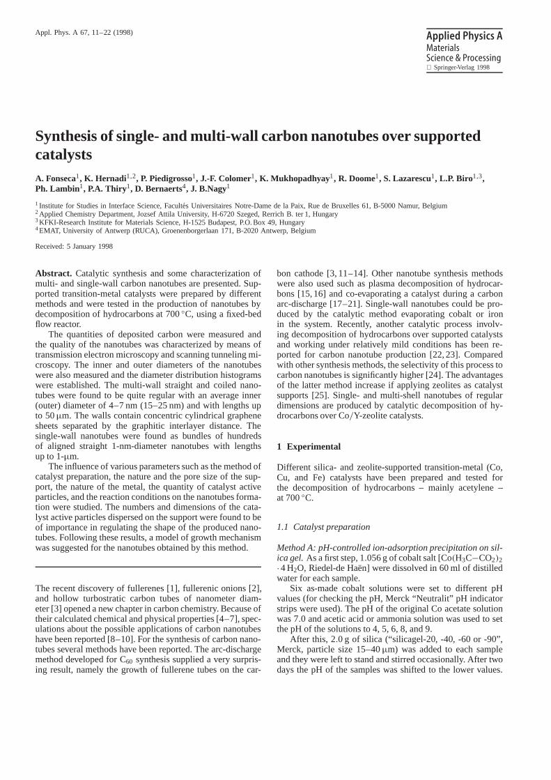
Appl. Phys. A 67, 11–22 (1998) Applied Physics AMaterialsScience & Processing Springer-Verlag 1998
Synthesis of single- and multi-wall carbon nanotubes over supportedcatalystsA. Fonseca1, K. Hernadi 1,2, P. Piedigrosso1, J.-F. Colomer1, K. Mukhopadhyay1, R. Doome1, S. Lazarescu1, L.P. Biro1,3,Ph. Lambin1, P.A. Thiry 1, D. Bernaerts4, J. B.Nagy1
1Institute for Studies in Interface Science, Facultes Universitaires Notre-Dame de la Paix, Rue de Bruxelles 61, B-5000 Namur, Belgium2Applied Chemistry Department, Jozsef Attila University, H-6720 Szeged, Rerrich B. ter 1, Hungary3KFKI-Research Institute for Materials Science, H-1525 Budapest, P.O. Box 49, Hungary4EMAT, University of Antwerp (RUCA), Groenenborgerlaan 171, B-2020 Antwerp, Belgium
Received: 5 January 1998
Abstract. Catalytic synthesis and some characterization ofmulti- and single-wall carbon nanotubes are presented. Sup-ported transition-metal catalysts were prepared by differentmethods and were tested in the production of nanotubes bydecomposition of hydrocarbons at700◦C, using a fixed-bedflow reactor.
The quantities of deposited carbon were measured andthe quality of the nanotubes was characterized by means oftransmission electron microscopy and scanning tunneling mi-croscopy. The inner and outer diameters of the nanotubeswere also measured and the diameter distribution histogramswere established. The multi-wall straight and coiled nano-tubes were found to be quite regular with an average inner(outer) diameter of4–7 nm (15–25 nm) and with lengths upto 50µm. The walls contain concentric cylindrical graphenesheets separated by the graphitic interlayer distance. Thesingle-wall nanotubes were found as bundles of hundredsof aligned straight1-nm-diameter nanotubes with lengthsup to1-µm.
The influence of various parameters such as the method ofcatalyst preparation, the nature and the pore size of the sup-port, the nature of the metal, the quantity of catalyst activeparticles, and the reaction conditions on the nanotubes forma-tion were studied. The numbers and dimensions of the cata-lyst active particles dispersed on the support were found to beof importance in regulating the shape of the produced nano-tubes. Following these results, a model of growth mechanismwas suggested for the nanotubes obtained by this method.
The recent discovery of fullerenes [1], fullerenic onions [2],and hollow turbostratic carbon tubes of nanometer diam-eter [3] opened a new chapter in carbon chemistry. Because oftheir calculated chemical and physical properties [4–7], spec-ulations about the possible applications of carbon nanotubeshave been reported [8–10]. For the synthesis of carbon nano-tubes several methods have been reported. The arc-dischargemethod developed forC60 synthesis supplied a very surpris-ing result, namely the growth of fullerene tubes on the car-
bon cathode [3, 11–14]. Other nanotube synthesis methodswere also used such as plasma decomposition of hydrocar-bons [15, 16] and co-evaporating a catalyst during a carbonarc-discharge [17–21]. Single-wall nanotubes could be pro-duced by the catalytic method evaporating cobalt or ironin the system. Recently, another catalytic process involv-ing decomposition of hydrocarbons over supported catalystsand working under relatively mild conditions has been re-ported for carbon nanotube production [22, 23]. Comparedwith other synthesis methods, the selectivity of this process tocarbon nanotubes is significantly higher [24]. The advantagesof the latter method increase if applying zeolites as catalystsupports [25]. Single- and multi-shell nanotubes of regulardimensions are produced by catalytic decomposition of hy-drocarbons over Co/Y-zeolite catalysts.
1 Experimental
Different silica- and zeolite-supported transition-metal (Co,Cu, and Fe) catalysts have been prepared and tested forthe decomposition of hydrocarbons – mainly acetylene –at700◦C.
1.1 Catalyst preparation
Method A: pH-controlled ion-adsorption precipitation on sil-ica gel.As a first step,1.056 gof cobalt salt [Co(H3C−CO2)2·4H2O, Riedel-de Haën] were dissolved in60 ml of distilledwater for each sample.
Six as-made cobalt solutions were set to differentpHvalues (for checking thepH, Merck “Neutralit” pH indicatorstrips were used). ThepH of the original Co acetate solutionwas7.0 and acetic acid or ammonia solution was used to setthepH of the solutions to 4, 5, 6, 8, and 9.
After this, 2.0 g of silica (“silicagel-20, -40, -60 or -90”,Merck, particle size15–40µm) was added to each sampleand they were left to stand and stirred occasionally. After twodays thepH of the samples was shifted to the lower values.

12
For example, thepH= 9 (pH= 8) value changed topH= 7(pH= 6.5). Then, the samples were filtered in a Büchner fun-nel, washed with2×50 ml of distilled water, and dried at100◦C. This procedure was followed by calcination in air at450◦C for 4.5 h.
In method A’ a portion (0.4 g) of each sample frommethod A was hydrogenated inH2/N2 (H2 flow, 35 ml/min,N2 flow, 75 ml/min) at 650◦C for 8 h. One of the sampleswas treated in air (instead of hydrogen) under the same con-ditions (method A”).
Method B: Porous impregnation of zeolites, clays and silicagels.For the catalyst preparation, the impregnation methodusing a silica (silicagel-60, Merck), clay, or zeolite (NaY,Union Carbide; NaZSM-5, NESTE, Finland;NaA) supportwas applied.Co- or Fe acetate solution was used in the cat-alyst preparation procedure. Catalyst samples were calcinedat 450◦C for 4.5 h. The finalCo or Fecontent of the impreg-nated samples was about2.5 wt%.
1.2 Characterization of the catalyst samples
The cobalt content of the different fresh catalyst samples wasdetermined by proton-induced X-ray emission (PIXE), usinga Van de Graaf system (High Voltage Engineering N.V.), op-erating at2.7-MeV proton beam.
Decomposition of acetylene was studied in a fixed-bedflow reactor (quartz tube of14 mm in diameter in a StantonRedcroft horizontal oven) at700±5 ◦C with a reaction timeof 30 min. Each reaction was carried out using the same flowof acetylene (8 ml/min, Alphagas) and nitrogen (75 ml/min,Alphagas) and a catalyst amount of about30 mg. The ex-act amounts of the initial catalyst and the carbon depositformed during the reaction were determined by weighing andthe reproducibility was within10%. After decomposition ofacetylene, the carbon yield was calculated for each reaction asfollows:
carbon yield(%)= 100(mtot−mcat)/mcat , (1)
wheremcat is the initial amount of the catalyst (before reac-tion) andmtot is the total weight of the sample after reaction.
The nature of the carbon deposit on the catalyst sur-face was characterized by transmission electron microscopy(TEM, Philips CM 20 and JEOL 200 CX). For samplepreparation, the catalyst samples after reaction were gluedon Rh−Cu grids. This method makes it possible to exam-ine a representative sample of the product. It is thereforea good technique for judging the general quality of the sam-ple. The gluing solution was made by suspending0.5 m oftape (Scotch,19 mm) in 100 ml of chloroform, followed byfiltration.
For the STM analysis, samples were prepared by ultrason-ication in toluene of the material (nanotubes and soot) result-ing from the chemical removal of the catalyst by HF dissolu-tion. As substrate, we used freshly cleaved highly orientatedpyrolitic graphite (HOPG). Several droplets of nanotubes sus-pension in toluene were deposited on a freshly cleaved HOPGsurface and the toluene was evaporated at room temperature.The samples were examined by STM under ambient condi-tions, using mechanically prepared Pt tips. Tunneling volt-ages in the range of100–400 mV and tunneling currents in
the range of0.2–1 nA were used. The horizontal and verti-cal calibration of the STM was checked against the HOPGsubstrate of the samples.
2 Results and discussion
The results on nanotube formation by catalytic decomposi-tion of hydrocarbons are first described separately applyingsilica or zeolite support. Afterwards, the results from bothof the sections are interpreted together, shedding some lighton the growth mechanism of catalytically produced carbonnanotubes.
2.1 Applying silica support (preparation method A)
Both quantitative and qualitative analyses of carbon nano-tube formation over differentCo/silica catalysts are given.The carbon yields of acetylene decomposition over differ-entCo/silica catalyst samples prepared by different methodsare given in Table 1. In the same table, cobalt contents ofthe different catalyst samples determined by PIXE are alsopresented. These cobalt contents are lower than0.1 wt% forsamples ofpH≤ 6, around1 wt% for samples ofpH 7 to 8,and higher than10 wt% for sample ofpH= 9.
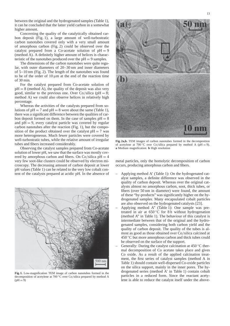
The general aspect of carbon nanotubes formed in thedecomposition of acetylene at700◦C over Co/silica is il-lustrated by the low-magnification TEM image in Fig. 1.Straight, coiled and helically wound carbon nanotubes can beobserved in that figure. Nanotube adhesion, as well as a largemass of small nanotubes at the silica surface (black area)can also be observed. From the TEM image point of view,the main differences among the different samples are the sil-ica surface coverage by nanotubes and the fraction of helicalnanotubes.
2.1.1 Effect of pH of catalyst preparation. – Applyingmethod A (Table 1): The highest activity was observed in thepresence of catalyst prepared from the Co-acetate solution ofpH= 8 both for the original and the hydrogenated samples(method A’). It is interesting to note that according to carbonyield data, there is no significant difference between catalystsprepared from solutions ofpH= 7 andpH= 8. Otherwise,decreasing or increasing thepH of initial Co-acetate solutionsresults in a decreasing carbon yield. By making a comparison
Table 1. Carbon yields (%±10 rel.%) of acetylene decomposition at700◦C over different Co/silica catalyst samples
Catalyst Carbon yield/wt%±10 rel.%
Initial Final Method A Method A’ Method A”pH Co Calc. at450◦C Hydr. at650◦C Calc. at650◦C
/wt% (air; 4.5 h) (H2/N2; 8 h) (air; 8 h)
4 < 0.01 7 15 —5 < 0.01 9 23 —6 0.04 51 45 —7 0.82 71 76 —8 1.74 74 83 —9 11.64 47 65 58
13
between the original and the hydrogenated samples (Table 1),it can be concluded that the latter yield carbon in a somewhathigher amount.
Concerning the quality of the catalytically obtained car-bon deposit (Fig. 1), a large amount of well-turbostraticcarbon nanotubes covered only with a very small amountof amorphous carbon (Fig. 2) could be observed over thecatalyst prepared from a Co-acetate solution ofpH= 9(method A). A definitely higher amount of helices is charac-teristic of the nanotubes produced over thepH= 9 samples.
The dimensions of the carbon nanotubes were quite regu-lar, with outer diameters of20–30 nm and inner diametersof 5–10 nm(Fig. 2). The length of the nanotubes was foundto be of the order of10µm at the end of the reaction timeof 30 min.
For the catalyst prepared from Co-acetate solution ofpH= 8 (method A), the quality of the deposit was also verygood, similar to the previous one. OverCo/silica (pH= 8;method A) we could also observe helices in relatively highpercentage.
Whereas the activities of the catalysts prepared from so-lutions ofpH= 7 andpH= 8 were about the same (Table 1),there was a significant difference between the qualities of car-bon deposit formed on them. In the case of samplespH= 8and pH= 9, every catalyst particle was covered by regularcarbon nanotubes after the reaction (Fig. 1), but the compo-sition of the product obtained over the catalystpH= 7 wasmore heterogeneous. Much fewer particles were covered bywell-turbostratic tubes, while the relative amount of irregulartubes and fibers increased considerably.
Observing the catalyst samples prepared fromCo-acetatesolution of lowerpH, we saw that the surface was mostly cov-ered by amorphous carbon and fibers. OnCo/silica pH= 4very few soot-like clusters could be observed by electron mi-croscopy. The decreasing amount of carbon deposit at lowerpH values (Table 1) can be related to the very low cobalt con-tent of the catalysts prepared at acidicpH. In the absence of
Fig. 1. Low-magnification TEM image of carbon nanotubes formed in thedecomposition of acetylene at700◦C overCo/silica prepared by method A(pH= 9)
Fig. 2a,b. TEM images of carbon nanotubes formed in the decompositionof acetylene at700◦C over Co/silica prepared by method A (pH= 9).a Medium magnification.b High resolution
metal particles, only the homolytic decomposition of carbonoccurs, producing amorphous carbon and fibers.
– Applying method A’ (Table 1): On the hydrogenated cat-alyst samples, a definite difference was observed in thequality of carbon deposit. Whereas over the original cat-alysts almost no amorphous carbon, soot, thick tubes, orfibers (over50 nm in diameter) were found, the amountof these “by-products” was significantly higher on the hy-drogenated samples. Many encapsulated cobalt particlesare also observed on the hydrogenated catalysts [23].
– Applying method A” (Table 1): One sample was pre-treated in air at650◦C for 8 h without hydrogenation(method A” in Table 1). The behaviour of this catalyst isintermediate between that of the original and the hydro-genated samples, considering both carbon yield and thequality of carbon deposit. The quality of the tubes is al-most as good as those obtained overCo/silica calcined at450◦C but more amorphous carbon and thick tubes couldbe observed on the surface of the support.
– Generally: During the catalyst calcination at450◦C ther-mal decomposition ofCo acetate takes place and givesCo oxide. As a result of the applied calcination treat-ment, the first series of catalyst samples (method A inTable 1) should contain well-dispersed Co-oxide particleson the silica support, mainly in the inner pores. The hy-drogenated series (method A’ in Table 1) contain cobaltparticles in a reduced form. Since the reactant acety-lene is able to reduce the catalyst itself under the above-
14
mentioned reaction conditions, reduction alone explainsneither the higher catalytic activity leading to a higher car-bon yield nor the appearance of amorphous carbon andthick fibers. According to our previous results [22], thediameter of the carbon nanotubes growing on aCo/silicaparticle depends mainly on the dispersion of the catalyst.During the hydrogenation treatment the catalyst was ex-posed to high temperature for a long time (compared tothe average reaction time of30 min). As a consequencecobalt particles had a chance to migrate from the innerpores to the outer surface and to assemble, reducing dis-persion. These particles outside the pores can be reachedby the reactant molecules more easily, which gives an ex-planation for the higher catalytic activity. At the sametime increasing the particle size can result in the higheramount of amorphous carbon and thick tubes obtainedover the hydrogenated catalyst samples. This shows thatlike long calcination at high temperature, hydrogenationalso has a disadvantageous effect on the catalyst perform-ance. Since acetylene is able to reduce Co-oxide particlesto a required extent, more fortunate if the active sites arebeing formed in situ at the beginning of acetylene decom-position [30], it means that the most selective catalyst canbe obtained during the induction period of the reaction.From electron microscope observations, it can be con-cluded that catalyst samples calcined at450◦C for 4.5 hgive better results in nanotube production than those thatwere calcined at650◦C or reduced prior to acetylene re-action.
It is also interesting to point out that on certain bad sam-ples – not selective in nanotube formation – it is possible tohave a very high carbon yield (deposited in the silica pores)and still no carbon nanotubes at all when observing the sam-ples by TEM. As it concerns mainly the samplespH= 4andpH= 5, the cobalt concentrations of which are very low(< 0.01 wt%), it can be concluded that when there is notenough cobalt on the catalyst surface to form clusters bigenough to have thenanotube formation selectivity, the lowcobalt content of the catalyst will only contribute to a veryhigh carbon deposition activity. The fact, that the carbon de-position is originated from the cobalt centers is in agreementwith the absence ofcarbon deposition activityon pure sil-ica. It behaves as if thecarbon deposition activitydependedmainly on the percentage of cobalt present on the catalystafter the set ofpH and washing steps, while the basicity of theinitial cobalt solution would control thenanotube formationselectivity.
2.1.2 Effect of transition-metal.Fe/silica prepared by the im-pregnation method (pH= 7) showed some inhomogeneity inthe quality of carbon deposit (besides carbon nanotubes itcontained some amorphous carbon and thick tubes havingdiameter larger than50 nmalso) and produced carbon yieldsof lower value, compared toCo/silica samples.
Using the ion-adsorption precipitation method (pH= 7)the properties of theFe/silica catalysts were improved re-markably. Whereas the value of carbon yield increased above100%, compared toCo/silica samples, the tubes became ho-mogeneous in diameter and less amorphous carbon was ob-served. According to TEM observations, all catalyst parti-cles are covered by carbon nanotubes of regular diameter.
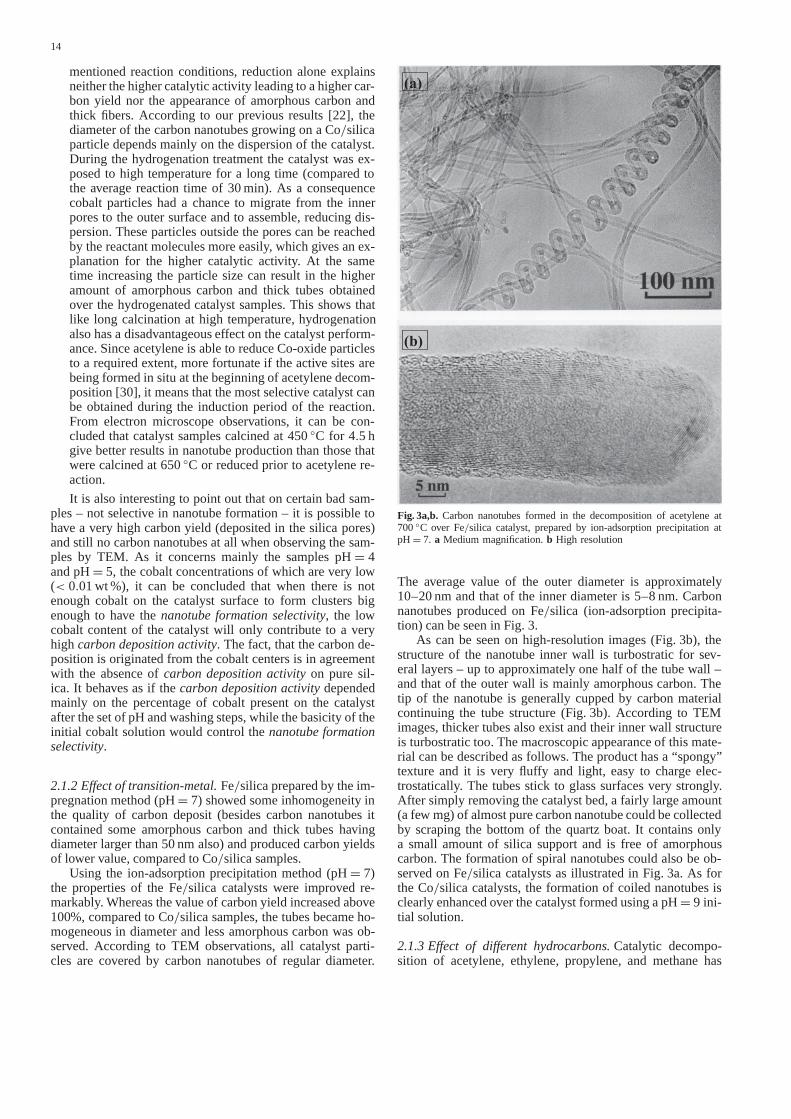
Fig. 3a,b. Carbon nanotubes formed in the decomposition of acetylene at700◦C over Fe/silica catalyst, prepared by ion-adsorption precipitation atpH= 7. a Medium magnification.b High resolution
The average value of the outer diameter is approximately10–20 nmand that of the inner diameter is5–8 nm. Carbonnanotubes produced onFe/silica (ion-adsorption precipita-tion) can be seen in Fig. 3.
As can be seen on high-resolution images (Fig. 3b), thestructure of the nanotube inner wall is turbostratic for sev-eral layers – up to approximately one half of the tube wall –and that of the outer wall is mainly amorphous carbon. Thetip of the nanotube is generally cupped by carbon materialcontinuing the tube structure (Fig. 3b). According to TEMimages, thicker tubes also exist and their inner wall structureis turbostratic too. The macroscopic appearance of this mate-rial can be described as follows. The product has a “spongy”texture and it is very fluffy and light, easy to charge elec-trostatically. The tubes stick to glass surfaces very strongly.After simply removing the catalyst bed, a fairly large amount(a fewmg) of almost pure carbon nanotube could be collectedby scraping the bottom of the quartz boat. It contains onlya small amount of silica support and is free of amorphouscarbon. The formation of spiral nanotubes could also be ob-served onFe/silica catalysts as illustrated in Fig. 3a. As forthe Co/silica catalysts, the formation of coiled nanotubes isclearly enhanced over the catalyst formed using apH= 9 ini-tial solution.
2.1.3 Effect of different hydrocarbons.Catalytic decompo-sition of acetylene, ethylene, propylene, and methane has
15
Table 2. Carbon yield as a function of reactant and reaction temperatureover Fe/silica catalyst (ion-adsorption precipitation,pH= 7, 30 min reac-tion)
Carbon yield (wt%±10 rel.%)
Reactant at700◦C at 750◦C at 800◦C
Acetylene 117 — —Ethylene 34 60 —Propylene 33 39 —Methane 0 0 ±0
been checked at different reaction temperatures (Table 2).In the decomposition of ethylene and propylene at700◦C,the carbon yield overFe/silica (ion-adsorption precipitation,pH= 7) is much lower than in that of acetylene and thequality of carbon nanotubes was much poorer, so the for-mation of amorphous carbon and thick tubes became signifi-cant; the nanotubes were “crumbled”, which showed that theorganization of the wall was not good enough. Increasingthe reaction temperature favoured the development of well-turbostratic structures and at the same time the amount of sootdiminished to a great extent. For example, the carbon yieldwas found to be60% at 750◦C in the reaction of ethylene(Table 2).Fe/silica was almost inactive in the decompositionof methane, even at800◦C. At this reaction temperature, nocarbon deposit could be weighed but a very small amount ofamorphous soot has been observed by electron microscopy.
2.1.4 Purification of the MWNT (multi-wall-nanotubes).TheMWNT produced over the different metal/silica catalystsgenerally contain some amorphous carbon and are linked tothe silica support through the active metal particle. Purifica-tion then means separation of the MWNT from the silica,metal, and amorphous carbon.
– Separation of the MWNT from the metal/silica catalyst:By using a silica support, nitric acid treatment removedthe transition-metal derivatives liberating the nanotubesfrom the catalyst surface. Afterwards, the ultrasound treat-ment was able to take some of the nanotubes into suspen-sion. They were in the liquid phase after the heavy silicaparticles were decanted. However, the yield of nanotubespurified by this method was very low (approximately1%)and – according to the X-ray diffractograms – the prod-uct still contained some small silica particles. Dissolvingsilica particles in HF seemed to be impossible, probablybecause of the carbon deposit covering the support. At thisstage of the purification the yield was1% for theFe/silicacatalyst and somewhat less for theCo/silica.
– Separation of the MWNT from the amorphous carbon:After the separation from the catalyst particles, the samplestill contained a few percent of amorphous carbon. For re-moving this contamination, hydrogenation of the samplewas carried out at900◦C, for 4.5 h. According to a previ-ous paper [23] this treatment is effective in the eliminationof elemental carbon having irregular structure. Comparingreactivity of different carbon structures to hydrogen, it canbe concluded that the reaction rate of amorphous carbon issignificantly higher, which makes the method suitable forits separation from the graphitic forms. The yield of thehydrogenation treatment is about25%.
2.2 Applying zeolite support (preparation method B)
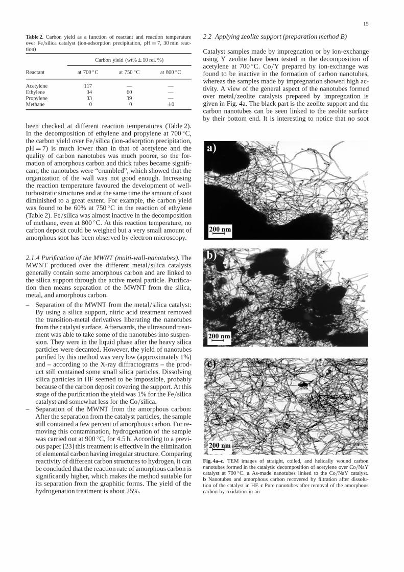
Catalyst samples made by impregnation or by ion-exchangeusing Y zeolite have been tested in the decomposition ofacetylene at700◦C. Co/Y prepared by ion-exchange wasfound to be inactive in the formation of carbon nanotubes,whereas the samples made by impregnation showed high ac-tivity. A view of the general aspect of the nanotubes formedover metal/zeolite catalysts prepared by impregnation isgiven in Fig. 4a. The black part is the zeolite support and thecarbon nanotubes can be seen linked to the zeolite surfaceby their bottom end. It is interesting to notice that no soot
Fig. 4a–c. TEM images of straight, coiled, and helically wound carbonnanotubes formed in the catalytic decomposition of acetylene overCo/NaYcatalyst at700◦C. a As-made nanotubes linked to theCo/NaY catalyst.b Nanotubes and amorphous carbon recovered by filtration after dissolu-tion of the catalyst in HF.c Pure nanotubes after removal of the amorphouscarbon by oxidation in air

16
or mass of small nanotubes can be observed on the zeolitesurface. This characteristic allows us to distinguish zeolite-from silica-supported catalysts covered with nanotubes, onthe TEM images.
Co particles on the outer surface of the impregnated sam-ples (in particular with Y zeolite) must be responsible forthe activity and in this case zeolite can be by considered asa catalyst support. Since ion-exchangedCoY samples containcobalt essentially in the inner pores, their inactivity in nano-tube formation can be interpreted by considering that the ion-exchangeable cations have no effect on catalyst performance.
The relatively small volume of inner pores (compared tosilica having pore diameters approximately ten times higher)provides the advantage that much less amorphous carbonis liberated from the inner pores during the purificationprocedure.
2.2.1 Effect of zeolite nature.Different zeolites such asHY,NaY, NaZSM-5, andNaA were used as catalyst support incarbon nanotube formation.
– Applying Fe/zeolite catalysts: No significant differencewas found among theFe/zeolite samples except thatFe/NaY catalyst gave better results thanFe/NaZSM-5or Fe/NaA. Nor was there any real difference observedbetween NaY and HY since the nature of the ion-exchangeable cations has no effect on catalyst perform-ance. Fe/NaA was found quite as active as Fe/NaY.UsingFe/NaZSM-5, not only was the activity decreasedto about half of that ofFe/NaY, but also the turbostraticquality of the carbon deposit was poorer. It appears thatthe structure of the zeolite support may modify the effec-tiveness of the catalyst particles, leading to the differencesobserved betweenFe/NaY, Fe/NaA and Fe/NaZSM-5samples
– Applying Co/zeolite catalysts: No significant differencewas found among theCo/zeolite samples, except thatCo/NaY catalyst gave better results thanCo/NaZSM-5andCo/NaA.
2.2.2 Effect of transition-metal.According to TEM obser-vations (Fig. 4) Co/NaY (prepared by the impregnationmethod) is able to produce regular nanotubes with average in-ner (outer) diameter of 2–9(8–28) nmand with length at least10µm. The activity of Fe/NaY is higher, so the amount of theweighed carbon deposit is bigger, but the quality of the nano-tubes (turbostratic nature) is better over cobalt samples. Thetubes fromFe/NaY seem to be more crumbled, just like thoseformed onFe/silica (Fig. 3). No long and regular helices werefound on the surface ofFe/NaY.
Other transition-metals such as palladium and platinumwere also tested in the decomposition of acetylene. NeitherPd/NaY nor Pt/NaY showed selectivity in nanotube forma-tion in our experimental conditions. AlthoughPt/NaY wasfound to be inactive,Pd/NaY could produce very few carbonnanotubes but the carbon deposit on its surface was composedmostly of irregular carbon nanofibers.
2.2.3 Separation of the nanotubes from the metal/zeolite cat-alyst.Separation of nanotubes and catalyst particles can becarried out by repeated dissolution of the zeolite support inhydrofluoric acid and filtering. The HF treatment (50 ml of
40% HF/g Co/NaY catalyst) was carried out on2.803 gofsample (composed of0.780 g carbon deposit and2.023 gCo/NaY catalyst). Although some loss of nanotubes also oc-curs during filtration, because of the high cohesion betweenthe nanotubes, filtration of the aggregated sample can be car-ried out with high efficacy. Comparing X-ray diffractogramsof catalystCo/Y, the sample after reaction, and the sam-ple after HF treatment, it can be concluded that while inthe first case the zeolite structure could be identified, in thelast sample noY zeolite was detected at all. On the TEMimages of purified carbon nanotubes after the second HFtreatment (Fig. 4b), carbon nanotubes and amorphous carbon(dark spots) released from the inner pores can be seen. It isalso possible to see lots of regular nanotubes and some opentips. These open tips are liberated by the dissolution of thecatalyst active particles in acidic media.
According to high-resolution electron microscope obser-vations, the structure of the nanotubes are well-turbostraticand not much amorphous carbon was found on the sur-face [25]. Compared to silica support [24], zeolite dissolvesmore easily in hydrofluoric acid and contains much lessamorphous carbon in the pores, which is released during thepurification procedure. After three HF treatments, the yieldof recovered carbon material is100% of the total amount ofcarbon deposited on the catalyst.
2.2.4 Identification of the multi- and single-wall nanotubesby STM.In nanotube samples, only separated from themetal/zeolite catalyst by HF dissolution, individual tubesand bundles of tubes with1-nm-diameter range have beenfound [31, 32]. A typical view of a large scale image of par-allel nanotubes of about1-nmdiameter is shown in Fig. 5.
The1-nm-diameter attribution to the nanotubes in the flat-lying bundle (Fig. 5a) was confirmed by many other plot pro-files similar to the one displayed in Fig. 5b. These single-wallnanotubes were only observed by STM and not yet by TEM.
Considering the pore opening ofY zeolite (7.4Å), onlythe formation of single-wall nanotubes (SWNT) with diam-eter smaller than that ofC60 (10.0Å) could be expected in theinner pores of the zeolite. But, at the places where half su-percage is on the surface, a metal particle the dimension ofwhich is regulated by the zeolite pore size (13.4Å) can be de-posited. The latter metal particle can catalyse the growth ofhalf C60. That halfC60, when extruded from the catalyst par-ticle, can either grow to completion (formingC60) or initiatethe formation of a single-wall nanotube.
The formation of the bundles of single-wall nanotubes ontheCo/NaY catalyst could be explained by the simultaneousgrowth of several nanotubes, out of the neighbouring zeoliteopen supercages at a zeolite crystallographic face. The centre-to-centre distance of the zeolite supercages being12.35Å,the most stable bundle of nanotubes to be produced on sucha surface would be in the12.35-Å-diameter range ((11,0)or (6,6) tubules for instance). In that case, the extra stabi-lization would be caused by intertubule distance being3.4Å(graphitic distance).
2.2.5 Identification ofC60 – the smallest SWNT – by HPLCand MS.The soxhlet extraction of the crude nanotubes andCo/NaY catalyst with toluene for48 hgives0.13 wt% of ful-lereneC60 relative to the deposited carbon. The structure attri-bution to theC60 was done according to mass spectrometry,

17
Fig. 5a–e.Constant-current STM imagesof a bundle of single-wall nanotubes sep-arated fromCo/NaY catalyst by HF dis-solution of the catalyst. Both pictureswere imaged with a mechanically cutPttip, in ambient conditions, at tunnelingcurrents of0.1–0.2 nA and at biases of0.3–0.5 V. a Large scale500×500Å im-age. b 200×200Å detail of the threenanotubes emerging from the lower right-hand corner ofa. c Profile of the threetubes from the imageb, along the direc-tion marked and labeled with 1.d ande Other STM images of SWNT
HPLC and13C NMR analysis of the extracted and purifiedC60 sample.
It is interesting to note that the only fullerenes identified inthe toluene extract of the nanotubes wereC60 and, in very lowproportion (5 times less thanC60), C70. The formation ofC70on the catalyst surface can be explained as being the smallestelongated single-wall nanotube. In that case, only one layer ofcarbon (fiveC=C moieties) is added to the halfC60 prior toits closure when extruded out of the catalyst particle.
2.2.6 Purification of the multi-wall carbon nanotubes.TheHF treated samples – nanotubes free of zeolite – can be sub-mitted to different oxidation [12, 26–29] and reduction [22]treatments to get rid of the amorphous carbon.
– Purification by permanganate oxidation: As a prelim-inary result of its oxidation, pure carbon nanotubes were
obtained in40% yield using theKMnO4/H2SO4 aq. oxi-dation procedure reported by Ebbesen et al. [28]. On theTEM images of the corresponding product, it is possible tosee lots of regular nanotubes of all shapes and with opentips. Moreover, no amorphous carbon was observed on thesenanotubes.
Except for one single case, when we analyzed purifiedmulti-wall nanotubes by STM, only tubes with diameters inthe 10 nm range were found. On the single occasion, thetwo nanotubes with the estimated diameter in the1-nm rangewere found partly embedded in amorphous carbon. The factthat these nanotubes were embedded in amorphous carbonmaterial suggests that they were partially uncovered by theultrasonication of the sample in toluene. The amorphous coat-ing may be the reason why they survived to the oxidationtreatment.
18
The surface area of the zeolite-free nanotubes – after HFtreatment – was653 m2g−1. For the further-purified sam-ple by KMnO4 oxidation – nanotubes free of zeolite andof amorphous carbon – the surface area was found to be312 m2g−1. This lower value can be explained by the strongcohesion which reduces the outer surface of the material.
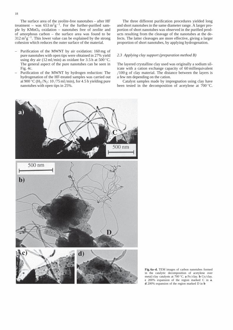
– Purification of the MWNT by air oxidation:160 mgofpure nanotubes with open tips were obtained in27% yieldusing dry air (12 ml/min) as oxidant for3.5 h at 500◦C.The general aspect of the pure nanotubes can be seen inFig. 4c.
– Purification of the MWNT by hydrogen reduction: Thehydrogenation of the HF-treated samples was carried outat900◦C (H2/N2: 10/75 ml/min), for 4.5 hyielding purenanotubes with open tips in25%.
Fig. 6a–d. TEM images of carbon nanotubes formedin the catalytic decomposition of acetylene overmetal/clay catalysts at700◦C. a Fe/clay. b Co/clay.c 200% expansion of the region marked C ina.d 200% expansion of the region marked D inb
The three different purification procedures yielded longand short nanotubes in the same diameter range. A larger pro-portion of short nanotubes was observed in the purified prod-ucts resulting from the cleavage of the nanotubes at the de-fects. The latter cleavages are more effective, giving a largerproportion of short nanotubes, by applying hydrogenation.
2.3 Applying clay support (preparation method B)
The layered crystalline clay used was originally a sodium sil-icate with a cation exchange capacity of60 milliequivalent/100 g of clay material. The distance between the layers isa fewnmdepending on the cation.
Catalyst samples made by impregnation using clay havebeen tested in the decomposition of acetylene at700◦C.
19
Co/clay andFe/clay were found to have low activity in theformation of carbon nanotubes (12% and10% carbon yieldfor a 30-min reaction, respectively). A view of the generalaspect of the nanotubes formed over metal/clay is given inFig. 6. In that figure, the grey-to-black part is the clay supportand the black dots are the metal particles – active catalystsfor nanotube-growing – formed under the reaction conditions.Only the metal particles on the outer surface of the clay sam-ples are responsible for the nanotube-growing activity. Theothers, being in the interlayer, are inactive for steric hindrancereasons.
In Fig. 6c, the carbon nanotubes can be seen linked to theclay surface by their bottom ends through the metal particle. Itis interesting to notice that no soot or mass of small nanotubescan be observed on the clay surface. Moreover, due to thetransparency of some clay layers, it is possible to observe lotsof particles in the interlayer of the clay support. As alreadyobserved forCo/silica catalysts [23], these catalyst particleshave diameters in the same range as the inner diameter of thenanotubes formed on them [33].
2.4 General observations
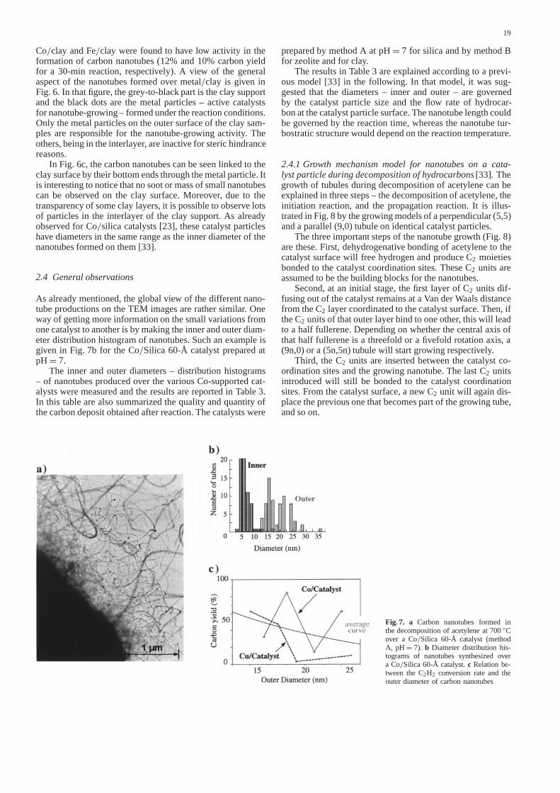
As already mentioned, the global view of the different nano-tube productions on the TEM images are rather similar. Oneway of getting more information on the small variations fromone catalyst to another is by making the inner and outer diam-eter distribution histogram of nanotubes. Such an example isgiven in Fig. 7b for theCo/Silica 60-Å catalyst prepared atpH= 7.
The inner and outer diameters – distribution histograms– of nanotubes produced over the variousCo-supported cat-alysts were measured and the results are reported in Table 3.In this table are also summarized the quality and quantity ofthe carbon deposit obtained after reaction. The catalysts were
Fig. 7. a Carbon nanotubes formed inthe decomposition of acetylene at700◦Cover a Co/Silica 60-Å catalyst (methodA, pH= 7). b Diameter distribution his-tograms of nanotubes synthesized overa Co/Silica 60-Å catalyst.c Relation be-tween theC2H2 conversion rate and theouter diameter of carbon nanotubes
prepared by method A atpH= 7 for silica and by method Bfor zeolite and for clay.
The results in Table 3 are explained according to a previ-ous model [33] in the following. In that model, it was sug-gested that the diameters – inner and outer – are governedby the catalyst particle size and the flow rate of hydrocar-bon at the catalyst particle surface. The nanotube length couldbe governed by the reaction time, whereas the nanotube tur-bostratic structure would depend on the reaction temperature.
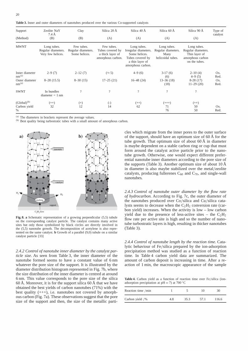
2.4.1 Growth mechanism model for nanotubes on a cata-lyst particle during decomposition of hydrocarbons[33]. Thegrowth of tubules during decomposition of acetylene can beexplained in three steps – the decomposition of acetylene, theinitiation reaction, and the propagation reaction. It is illus-trated in Fig. 8 by the growing models of a perpendicular (5,5)and a parallel (9,0) tubule on identical catalyst particles.
The three important steps of the nanotube growth (Fig. 8)are these. First, dehydrogenative bonding of acetylene to thecatalyst surface will free hydrogen and produceC2 moietiesbonded to the catalyst coordination sites. TheseC2 units areassumed to be the building blocks for the nanotubes.
Second, at an initial stage, the first layer ofC2 units dif-fusing out of the catalyst remains at a Van der Waals distancefrom theC2 layer coordinated to the catalyst surface. Then, iftheC2 units of that outer layer bind to one other, this will leadto a half fullerene. Depending on whether the central axis ofthat half fullerene is a threefold or a fivefold rotation axis, a(9n,0) or a (5n,5n) tubule will start growing respectively.
Third, theC2 units are inserted between the catalyst co-ordination sites and the growing nanotube. The lastC2 unitsintroduced will still be bonded to the catalyst coordinationsites. From the catalyst surface, a newC2 unit will again dis-place the previous one that becomes part of the growing tube,and so on.
20
Table 3. Inner and outer diameters of nanotubes produced over the variousCo-supported catalysts
Support ZeoliteNaY Clay Silica20Å Silica 40Å Silica 60Å Silica 90Å Type of7.4 Å catalyst
(Method) (B) (B) (A) (A) (A) (A)
MWNT Long tubes. Few tubes. Few tubes. Long tubes. Long tubes. Long tubes.Regular diameters. Regular diameters. Tubes covered by Irregular diameters. Regular diameters. Regular diameters.Very few helices. Some helices. a thick layer of Some helices. Many Thin layer of
amorphous carbon. Tubes covered by helicoidal tubes. amorphous carbona thin layer of on the tubes.
amorphous carbon.
Inner diameter 2–9 (7) 2–12 (7) (≈ 5) 4–9 (6) 3-17 (6) 2–10 (4) Ox.nm(a) (6) 4–9 (5) Red.Outer diameter 8–28 (15.5) 8–30 (15) 17–25 (21) 16–48 (24) 13–36 (18) 8-28 (17) Ox.nm(a) (18) 11–29 (20) Red.
SWNT In bundles ? ? ? ? ?diameter =1 nm
(Global)(b) (++) (+) (-) (++) (+++) (++)Carbon yield 32 12 14 62 71 50 Ox.% 76 50 Red.
(a) The diameters in brackets represent the average values.(b) Best quality being turbostratic tubes with a small amount of amorphous carbon.
Fig. 8. a Schematic representation of a growing perpendicular (5,5) tubuleon the corresponding catalyst particle. The catalyst contains many activesites but only those symbolized by black circles are directly involved inthe (5,5) nanotube growth. The decomposition of acetylene is also repre-sented on the same catalyst.b Growth of a parallel (9,0) tubule on a similarcatalyst particle [33]
2.4.2 Control of nanotube inner diameter by the catalyst par-ticle size.As seen from Table 3, the inner diameter of thenanotube formed seems to have a constant value of6 nmwhatever the pore size of the support. It is illustrated by thediameter distribution histogram represented in Fig. 7b, wherethe size distribution of the inner diameter is centred at around6 nm. This value corresponds to the pore size of the silica60Å. Moreover, it is for the support silica60Å that we haveobtained the best yields of carbon nanotubes (71%) with thebest quality (+++), i.e. nanotubes not covered by amorph-ous carbon (Fig. 7a). These observations suggest that the poresize of the support and then, the size of the metallic parti-
cles which migrate from the inner pores to the outer surfaceof the support, should have an optimum size of60Å for thetube growth. That optimum size of about60Å in diameteris maybe dependent on a stable carbon ring or cup that mustform around the catalyst active particle prior to the nano-tube growth. Otherwise, one would expect different prefer-ential nanotube inner diameters according to the pore size ofthe supports (Table 3). Another optimum size of about10Åin diameter is also maybe stabilized over the metal/zeolitecatalysts, producing fullerenesC60 andC70, and single-wallnanotubes.
2.4.3 Control of nanotube outer diameter by the flow rateof hydrocarbon.According to Fig. 7c, the outer diameter ofthe nanotubes produced overCo/silica andCu/silica cata-lysts seems to decrease when theC2H2 conversion rate (car-bon yield) increases. When the activity is low – low carbonyield due to the presence of less-active sites – theC2H2flow rate per active site is high and so the number of nano-tube turbostratic layers is high, resulting in thicker nanotubes(Table 3).
2.4.4 Control of nanotube length by the reaction time.Cata-lytic behaviour ofFe/silica prepared by the ion-adsorptionprecipitation method was studied as a function of reactiontime. In Table 4 carbon yield data are summarized. Theamount of carbon deposit is increasing in time. After a re-action of 1 min, the macroscopic appearance of the sample
Table 4. Carbon yield as a function of reaction time overFe/silica (ion-adsorption precipitation atpH= 7) at 700◦C
Reaction time/min 1 5 10 30
Carbon yield/% 4.8 35.3 57.1 116.6
21
did not allow us to reach a conclusion on the presence ofcarbon nanotubes since it was not black but grey. Neverthe-less, electron microscope observation verified the formationof nanotubes even after1 min but only a few particles arecovered by them. After5 min all of the particles are over-laid by the nanotubes. It is interesting to note that significantdeposition of amorphous carbon on the external surface ofthe nanotubes could not be observed even after a reactionof 30 min. At longer reaction times (> 1 h), deposition ofsoot begins on the outer surface of the tubes. It is also in-teresting to point out that there is no difference between thediameters of young (1 min) and old nanotubes (30 min). Onlythe length of the nanotubes is directly proportional to the re-action time and it is possible to interrupt the reaction andcontinue it later without affecting the quality of the producednanotubes [23].
2.4.5 Control of nanotube turbostratic structure by the reac-tion temperature.Over theCo/support catalysts, it is possibleto produce carbon nanotubes, of well-turbostratic structure,containing a very small amount of amorphous carbon by thedecomposition of acetylene at700◦C. Otherwise, decreas-ing or increasing the temperature by about100◦C causesa decrease in the conversion rate of acetylene or an in-crease in the amount of amorphous carbon on the outer sur-face of the nanotubes, respectively. The nanotubes grownat low temperature (500◦C) are relatively free of amorph-ous carbon but the crystallinity of the turbostratic layers ispoor. The deposition of amorphous carbon on the outer sur-face of the turbostratic nanotubes increases with the reac-tion temperature and with the reaction time. For a5-h re-action usingCo/silica the diameter of the amorphous car-bon layer is up to ten times superior to that of the initialturbostratic nanotube. It is consistent with an autocatalyticmechanism of amorphous carbon formation, by hydrocar-bon decomposition, over the turbostratic nanotubes wall. It isalso in agreement with the previous results on nanotubes andamorphous carbon formation by hydrocarbon decompositionon graphite [23].
3 Conclusions
It is established thatCo/silica catalysts which were preparedby ion-adsorption precipitation can produce carbon nano-tubes of well-turbostratic structure with high activity and se-lectivity. The carbon deposition activity seems to be relatedto the cobalt content of the catalyst whereas the interest-ing nanotube formation selectivity seems to be a functionof the pH of catalyst preparation. The calcination and/orhydrogenation steps of the catalyst preparation are not ne-cessary and can even have an unfavourable effect on thecatalyst performance. It is assumed that acetylene is ableto reduceCo oxide under reaction conditions to the re-quired extent, generating in situ the active sites for nanotubeproduction.
With changing thepH of the original solution (between7 and 9, method A), the quality of the carbon nanotubes,namely the amount of turbostratic straight and helical tubes,can be controlled to a certain extent.
Co/zeolite catalysts which were prepared by impregna-tion can also produce carbon nanotubes of well-turbostraticstructure with high activity and even higher selectivity thanCo/silica catalysts. Moreover, fullerenes and bundles ofsingle-wall nanotubes were also found among the multi-wallnanotubes produced onCo/zeolite catalysts.
Purification of the multi-wall nanotubes was described in0.25% and25%–40% yields, relative to the deposited carbon,applyingCo/silica andCo/zeolite catalysts, respectively.
The investigation of the effect of catalyst particle size andflow rate of hydrocarbon at the catalyst particle surface shedsome light on the growth mechanism of carbon nanotube pro-duced by the catalytic method previously proposed. As thediameter of the catalyst particle should be close to that of theinner tube, the number of turbostratic layers of each nanotubemight depend on the flow rate of acetylene per active site. Theturbostratic layers are assumed to be formed byC2 units onthe catalyst particle, exceeding those needed for the growthof the multi-shell nanotube inner layer. It behaves as if thenanotube length were governed by the reaction time, whereasthe nanotube turbostratic structure depends on the reactiontemperature.
Acknowledgements.The authors thank the European Commission (TMRProgram, NAMITECH network, Contract n◦ ERBFMRX96-0067, DG12-MIHT) and the Belgian Programme on Inter University Poles of Attractioninitiated by the Belgian State, Prime Minister’s Office for Scientific, Techni-cal and Cultural Affairs (OSTC-PAI-IUAP n 4/10 on Reduced Dimension-ality Systems).
References
1. H.W. Kroto, R.J. Heath, S. C O’Brien, R.F. Curl, R.E. Smalley: Nature318, 162 (1984)
2. S. Iijima: J. Phys. Chem.91, 3466 (1987)3. S. Iijima: Nature354, 56 (1991)4. H. Takaba, M. Katagiri, M. Kubo, R. Vetrivel, A. Miyamoto: Microp-
orous Mater.3, 449 (1995)5. K. Tanaka, K. Okahara, M. Okada, T. Yamabe: Fullerene Sci. Technol.
1, 137 (1993)6. E.G. Gal’pern, I.V. Stankevich, A.L. Chistykov, L.A. Chernozatonskii:
Chem. Phys. Lett.214, 345 (1993)7. N. Hamada, S. Sawada, A. Oshiyama: Phys. Rev. Lett.68, 1579 (1992)8. P.M. Ajayan, S. Iijima: Nature361, 333 (1993)9. D.H. Robertson, D.W. Brenner, J.W. Mintmire: Phys. Rev. B,45,
12529 (1992)10. J.W. Mintmire, B.I. Dunlap, C.T. White: Phys. Rev. Lett.68, 631
(1992)11. Y. Ando, S. Iijima: Jpn. J. Appl. Phys.32, 107 (1993)12. T.W. Ebbesen, P.M. Ajayan: Nature358, 220 (1992)13. S. Seraphin, D. Zhou, J. Jiao: Carbon31, 1212 (1993)14. R.E. Smalley: In Proc. of The Robert A. Welch Foundation Conference
on Chemical Research XXXVI “Regulation of Proteins by Ligands”(Houston, October 26-27 1992) p. 161
15. N. Hatta, K. Murata: Chem. Phys. Lett.217, 398 (1994)16. S. Iijima, T. Ichihashi: Nature363, 603 (1993)17. P.M. Ajayan, J.M. Lambert, P. Bernier, L. Barnedette, C. Colliex,
J.M. Planeix: Chem. Phys. Lett.215, 509 (1993)18. D.S. Bethune, C.H. Kiang, M.S. de Vries, G. Gorman, R. Savoy,
J. Vazquez, R. Beyers: Nature363, 606 (1993)19. S. Seraphin, D. Zhou, J. Jiao, J.C. Withers, R. Loutfy: Nature362, 503
(1993)20. J.H. Hwang, W.K. Hsu, C-Y. Mou: Adv. Mater.5, 643 (1993)21. A. Thess, R. Lee, P. Nikolaev, H. Dai, P. Petit, J. Robert, C. Xu, Y. Hee
Lee, S. Gon Kim, D.T. Colbert, G. Scuseria, D. Tomanek, J.E. Fischer,R.E. Smalley: Science273, 483 (1996)

22
22. V. Ivanov, J. B.Nagy, P. Lambin, A.A. Lucas, X.B. Zhang, X.F. Zhang,D. Bernaerts, G. Van Tendeloo, S. Amelinckx, J. Van Landuyt: Chem.Phys. Lett.223, 329 (1994)
23. V. Ivanov, A. Fonseca, J. B.Nagy, A.A. Lucas, P. Lambin, D. Bernaerts,X.B. Zhang: Carbon33, 1727 (1995)
24. K. Hernadi, A. Fonseca, J. B.Nagy, D. Bernaerts, J. Riga, A.A. Lucas:Synth. Met.77, 31 (1996)
25. K. Hernadi, A. Fonseca, J. B.Nagy, D. Bernaerts, A. Fudala, A.A. Lu-cas: Zeolites17, 416 (1996)
26. T.W. Ebbesen, P. M Ajayan, H. Hiura, K. Tanigaki: Nature367, 519(1994)
27. T.W. Ebbesen: Annu. Rev. Mater. Sci.24, 235 (1994)
28. H. Hiura, T.W. Ebbesen, K. Tanigaki: Adv. Mater.7, 275 (1995)29. P.M. Ajayan, T.W. Ebbesen, T. Ichihashi, S. Iijima, K. Tanigaki,
H. Hiura: Nature362, 522 (1993)30. G.A. Somorjai, M.X. Yang: J. Mol. Cat. A: Chem.115, 389 (1997)31. L.P. Biro, S. Lazarescu, Ph. Lambin, P.A. Thiry, A. Fonseca, J. B.Nagy,
A.A. Lucas: Phys. Rev. B56, 12490 (1997)32. L.P. Biro, J. B.Nagy, Ph Lambin, S. Lazarescu, A. Fonseca, P.A. Thiry,
A.A. Lucas: Proc. 11th International Winterschool on ElectronicProperties of Novel Materials, Molecular nanostructures, ed. by H. Kuz-many, J. Fink, M. Mehring, S. Roth (World Scientific 1997) p. 419
33. A. Fonseca, K. Hernadi, J. B.Nagy, Ph. Lambin, A.A. Lucas: Carbon33, 1759 (1995)
Copyright © 2022 FDOKUMEN