Effect of the activation atmosphere on the activity of Fe catalysts supported on SBA15 in the...
11
Effect of the activation atmosphere on the activity of Fe catalysts supported on SBA-15 in the Fischer–Tropsch Synthesis Leonardo A. Cano, María V. Cagnoli, José F. Bengoa, Ana M. Alvarez, Sergio G. Marchetti ⇑ CINDECA, CONICET, CICPBA, UNLP, Fac. Ciencias Exactas, Fac. Ingeniería. Calle 47, No. 257, 1900-La Plata, Argentina article info Article history: Received 9 September 2010 Revised 29 November 2010 Accepted 27 December 2010 Keywords: Fischer–Tropsch Synthesis Fe/SBA-15 Activation atmosphere Mössbauer spectroscopy abstract An iron catalyst supported on SBA-15 was prepared and activated in H 2 stream and in synthesis gas (H 2 :CO = 2:1) stream, in order to be used in the Fischer–Tropsch Synthesis. The different activation treat- ments led to different Fe species in fresh catalysts: a-Fe, Fe 3 O 4 and Fe 2+ diffused into the SBA-15 walls in H2-Fe/SBA-15 and v-Fe 5 C 2 , Fe 3 O 4 and Fe 2+ in H2:CO–Fe/SBA-15. These initial differences in the ‘‘bulk’’ structure of the solids disappear when both catalysts are ‘‘working’’. However, a higher production of total hydrocarbons, higher CO conversion and more CH 4 and light gases were obtained for H2-Fe/SBA- 15 over 6 days. Besides, a higher selectivity toward light olefins was obtained with H2-Fe/SBA-15 during the first 24 h on reaction stream, but this selectivity decreases with the reaction time. These results are explained considering that the iron carbides produced from a-Fe are more active and/or have smaller sizes than that obtained from a-Fe 2 O 3 . Ó 2010 Elsevier Inc. All rights reserved. 1. Introduction The Fischer–Tropsch Synthesis (FTS) is a process used to pro- duce hydrocarbons from syngas (a mixture of H 2 and CO) [1,2]: ð2n þ 1ÞH 2 þ nCO ! C n H 2nþ2 þ nH 2 O Different metals are active as catalysts in the FTS, but today, Co and Fe are the only reasonable commercial catalysts for this pro- cess [3]. When iron is used as catalyst, the FTS occurs simulta- neously with the water–gas shift (WGS) reaction. It consumes CO and water obtained from the FTS and produces additional H 2 and CO 2 . For this reason, the iron catalysts are the best choice when a syngas poor in hydrogen is used. This situation occurs if the syngas is produced by gasification of coal or biomass. Besides, the iron cat- alysts are preferred to Co catalysts, since they have lower cost, low- er methane selectivity, lower sensitivity to poisons, and higher flexibility to lead the selectivity to alkenes, oxygenates, or branched hydrocarbons according to the promoters or the opera- tive variables used. For these reasons, the precipitated or fused iron catalysts (unsupported catalysts) have been extensively studied. However, the purpose of the activation pretreatment of these cat- alysts is not clearly understood yet. Reduction in pure H 2 may lead to a-Fe, but upon exposure to syngas, it is rapidly transformed to iron carbide phase or a mixture of iron carbide phases [4–6]. At high syngas conversions, the reaction mixture becomes more oxi- dizing and magnetite is also produced [4]. Therefore, during the FTS, the iron phase may be distributed between several species such as carbides, oxides, and metallic iron. As a consequence, it is very hard to determine a correlation between the catalyst com- position and its activity and selectivity. Some authors have pro- posed that surface carbides are the active phase, with an underlying structure of bulk iron carbide [5,6]. In the so-called competition model, proposed by Niemantsverdriet and van der Kraan [7], iron atoms at the surface are considered as the active sites, and the bulk diffusion of carbon into metallic iron and hydro- carbon synthesis have a common surface carbidic C ⁄ . Other researchers have proposed that Fe 3 O 4 is the active phase in FTS [8,9]. There is evidence questioning [10,11] and supporting [12–14] this proposal. Taking into account the previous description, it can be con- cluded that the activation pretreatments have an important influ- ence on the FTS activity and selectivity when iron is used as catalyst. For this reason, there are many articles dealing with the effect of the activation conditions on the performance of iron cat- alysts, in particular when unsupported iron is used. In this way, Pennline et al. [15] found that coprecipitated Fe–Mn catalysts were nearly inactive when they were pretreated with pure H 2 or syngas and they only showed activity if they were activated with pure CO. Instead, Bukur et al. [16,17] have noticed that unsupported Fe/Cu/K catalysts were more active when they were pretreated with pure 0021-9517/$ - see front matter Ó 2010 Elsevier Inc. All rights reserved. doi:10.1016/j.jcat.2010.12.017 Abbreviation: FTS, Fischer–Tropsch Synthesis. ⇑ Corresponding author. Fax: +54 221 4210711. E-mail addresses: [email protected] (L.A. Cano), mavic@quimica. unlp.edu.ar (M.V. Cagnoli), [email protected] (J.F. Bengoa), anamalvz@ quimica.unlp.edu.ar (A.M. Alvarez), [email protected] (S.G. Marchetti). Journal of Catalysis 278 (2011) 310–320 Contents lists available at ScienceDirect Journal of Catalysis journal homepage: www.elsevier.com/locate/jcat
-
Upload
independent -
Category
Documents
-
view
2 -
download
0
Transcript of Effect of the activation atmosphere on the activity of Fe catalysts supported on SBA15 in the...
Journal of Catalysis 278 (2011) 310–320
Contents lists available at ScienceDirect
Journal of Catalysis
journal homepage: www.elsevier .com/locate / jcat
Effect of the activation atmosphere on the activity of Fe catalysts supported onSBA-15 in the Fischer–Tropsch Synthesis
Leonardo A. Cano, María V. Cagnoli, José F. Bengoa, Ana M. Alvarez, Sergio G. Marchetti ⇑CINDECA, CONICET, CICPBA, UNLP, Fac. Ciencias Exactas, Fac. Ingeniería. Calle 47, No. 257, 1900-La Plata, Argentina
a r t i c l e i n f o
Article history:Received 9 September 2010Revised 29 November 2010Accepted 27 December 2010
Keywords:Fischer–Tropsch SynthesisFe/SBA-15Activation atmosphereMössbauer spectroscopy
0021-9517/$ - see front matter � 2010 Elsevier Inc. Adoi:10.1016/j.jcat.2010.12.017
Abbreviation: FTS, Fischer–Tropsch Synthesis.⇑ Corresponding author. Fax: +54 221 4210711.
E-mail addresses: [email protected] (Lunlp.edu.ar (M.V. Cagnoli), [email protected] (A.M. Alvarez), [email protected]
a b s t r a c t
An iron catalyst supported on SBA-15 was prepared and activated in H2 stream and in synthesis gas(H2:CO = 2:1) stream, in order to be used in the Fischer–Tropsch Synthesis. The different activation treat-ments led to different Fe species in fresh catalysts: a-Fe, Fe3O4 and Fe2+ diffused into the SBA-15 walls inH2-Fe/SBA-15 and v-Fe5C2, Fe3O4 and Fe2+ in H2:CO–Fe/SBA-15. These initial differences in the ‘‘bulk’’structure of the solids disappear when both catalysts are ‘‘working’’. However, a higher production oftotal hydrocarbons, higher CO conversion and more CH4 and light gases were obtained for H2-Fe/SBA-15 over 6 days. Besides, a higher selectivity toward light olefins was obtained with H2-Fe/SBA-15 duringthe first 24 h on reaction stream, but this selectivity decreases with the reaction time. These results areexplained considering that the iron carbides produced from a-Fe are more active and/or have smallersizes than that obtained from a-Fe2O3.
� 2010 Elsevier Inc. All rights reserved.
1. Introduction
The Fischer–Tropsch Synthesis (FTS) is a process used to pro-duce hydrocarbons from syngas (a mixture of H2 and CO) [1,2]:
ð2nþ 1ÞH2 þ nCO! CnH2nþ2 þ nH2O
Different metals are active as catalysts in the FTS, but today, Coand Fe are the only reasonable commercial catalysts for this pro-cess [3]. When iron is used as catalyst, the FTS occurs simulta-neously with the water–gas shift (WGS) reaction. It consumes COand water obtained from the FTS and produces additional H2 andCO2. For this reason, the iron catalysts are the best choice when asyngas poor in hydrogen is used. This situation occurs if the syngasis produced by gasification of coal or biomass. Besides, the iron cat-alysts are preferred to Co catalysts, since they have lower cost, low-er methane selectivity, lower sensitivity to poisons, and higherflexibility to lead the selectivity to alkenes, oxygenates, orbranched hydrocarbons according to the promoters or the opera-tive variables used. For these reasons, the precipitated or fused ironcatalysts (unsupported catalysts) have been extensively studied.However, the purpose of the activation pretreatment of these cat-alysts is not clearly understood yet. Reduction in pure H2 may lead
ll rights reserved.
.A. Cano), [email protected] (J.F. Bengoa), [email protected] (S.G. Marchetti).
to a-Fe, but upon exposure to syngas, it is rapidly transformed toiron carbide phase or a mixture of iron carbide phases [4–6]. Athigh syngas conversions, the reaction mixture becomes more oxi-dizing and magnetite is also produced [4]. Therefore, during theFTS, the iron phase may be distributed between several speciessuch as carbides, oxides, and metallic iron. As a consequence, itis very hard to determine a correlation between the catalyst com-position and its activity and selectivity. Some authors have pro-posed that surface carbides are the active phase, with anunderlying structure of bulk iron carbide [5,6]. In the so-calledcompetition model, proposed by Niemantsverdriet and van derKraan [7], iron atoms at the surface are considered as the activesites, and the bulk diffusion of carbon into metallic iron and hydro-carbon synthesis have a common surface carbidic C⁄. Otherresearchers have proposed that Fe3O4 is the active phase in FTS[8,9]. There is evidence questioning [10,11] and supporting[12–14] this proposal.
Taking into account the previous description, it can be con-cluded that the activation pretreatments have an important influ-ence on the FTS activity and selectivity when iron is used ascatalyst. For this reason, there are many articles dealing with theeffect of the activation conditions on the performance of iron cat-alysts, in particular when unsupported iron is used. In this way,Pennline et al. [15] found that coprecipitated Fe–Mn catalysts werenearly inactive when they were pretreated with pure H2 or syngasand they only showed activity if they were activated with pure CO.Instead, Bukur et al. [16,17] have noticed that unsupported Fe/Cu/Kcatalysts were more active when they were pretreated with pure
L.A. Cano et al. / Journal of Catalysis 278 (2011) 310–320 311
H2, but they produced a higher quantity of CH4 and light hydrocar-bons. On the other hand, O’Brien et al. [18,19] have worked withunsupported Fe/Si/K catalysts and they found that the activationprocess at high pressure had a detrimental effect on the catalyticbehavior and the highest conversions were obtained when the acti-vation was done in pure CO. Similar results were obtained by Luoet al. [3] with precipitated Fe/Si/K catalysts.
As can be seen from this brief review, the activation studieshave been done mainly with unsupported iron catalysts, and theresults are contradictory since they have a strong dependence onthe structural characteristics of the solid precursors, the numberand the nature of the promoters, etc.
To our knowledge, the bibliography focused on the influenceof the activation pretreatments is scarce when supported ironcatalysts are used. One article reporting the use of iron moder-ately dispersed on SiO2 was published by Xu and Bartholomew[20]. These authors found that the initial activity changes withthe activation atmosphere following the sequence H2 > H2:CO =1 > CO. Besides, the amount of reactive atomic surface carbon(Ca) increases with increasing H2 content in pretreatment gas.The development of supported iron catalysts is highly desirablesince the most economical reactors in FTS are the slurry bubblecolumns, in which the unsupported iron catalysts undergo attri-tion at high velocity, leading to a catalyst loss and an increasein slurry viscosity.
On the other hand, it would be possible to increase the selectiv-ity of the synthesis by controlling the crystal size of the activephase. This method is based on the fact that in some heteroge-neous catalytic reactions, the activity of the solid is a function ofthe crystal size of the active phase, generally in the 1–10 nmrange. These reactions are known as ‘‘structure sensitive’’ [21]. Inthe literature, there is some early evidence that the FTS is ‘‘struc-ture sensitive’’ [22], and more recently, this property would beconfirmed by using supported Co and Fe catalysts [23–25]. Today,the concept of ‘‘structure sensitive’’ involves the activity and selec-tivity of the catalyst. This idea was recently verified by Bezemeret al. [26] using Co particles with sizes between 2.6 and 27 nmsupported on carbon nanofibers. These authors found that whenthe cobalt particle size was reduced from 16 to 2.6 nm, the turn-over frequency for CO hydrogenation decreased about twentytimes, while C5+ selectivity decreased from 85 to 51 wt.%. There-fore, it would be possible to achieve an improvement in the cata-lyst selectivity if particles of supported Fe oxides, with adetermined average diameter and a narrow size distribution, wereobtained. In order to get this scope, an ‘‘inert’’ support with a nar-row pore-size distribution and thermal stability would be selected.Besides, the pore diameters of the support must be large enoughto locate the iron oxide crystals inside the pores, avoiding theirmigration to the outer surface during the activation steps. Themesoporous solid named SBA-15 seems to fulfill the above condi-tions since it has a narrow pore-size distribution, with a hexagonalarrangement, whose diameters can be varied between 5 and30 nm, wall thickness between 3 and 6 nm, and specific surfacearea between 700 and 1000 m2/g [27,28]. The use of this type ofsupport is not enough to obtain a narrow crystal-size distributionin the desired size range of the active Fe species. In order to getthis scope, it is necessary to introduce the total iron loading insidethe support channels avoiding its migration to the outer surfacewhen the catalyst is ‘‘working’’ since the controlling effect onthe sintering process would be lost. Achieving these objectivesrepresents a real challenge.
Taking into account all previous considerations, the aim of thepresent work is to obtain an Fe/SBA-15 catalyst controlling thecrystal sizes of the iron species and to analyze the effect of the acti-vation atmosphere on the activity and selectivity of this catalyst inthe FTS.
2. Experimental
2.1. Catalyst preparation
The SBA-15 support was synthesized according to the method-ology proposed by Zhao et al. [27,28] using Pluronic triblockcopolymer P123 (EO20-PO70-EO20) as organic structure-directingagent and tetraethyl orthosilicate (TEOS) as silica source. Thus, 12 gof Pluronic P123 was dissolved in 360 ml of water and 60 ml of HClsolution (37%, w/w) with stirring at 313 K for 3 h. Then, 27 ml ofTEOS was added, and the solution was kept stirring at 313 K for24 h. The mixture was aged at 363 K overnight, without stirring.The solid was recovered by filtration, washed, and dried in air atroom temperature (RT). Calcination in air was carried out fromRT to 773 K at 1 K/min and kept at 773 K for 6 h.
SBA-15 was impregnated by the incipient wetness impregna-tion method with Fe(NO3)3�9H2O ethanolic solution to produce anominal Fe loading of 15% w/w in a single step. The solid Fe/SBA-15 was dried using a rotary evaporator at 313 K for 24 h and finallycalcined in a flow of NO (1% v/v)/He (100 cm3/min) from RT to723 K at a heating rate of 1 K/min and kept at this temperaturefor 4 h. The sample thus obtained was called p-Fe/SBA-15. A frac-tion of this precursor was activated in H2 flow (60 cm3/min) byheating from RT to 703 K for 80 min and kept at this temperaturefor 26 h. This solid was called H2-Fe/SBA-15. The other fractionof the precursor was activated in H2/CO (2:1) flow (20 cm3/min)by heating from RT to 703 K for 80 min. This solid was calledH2:CO–Fe/SBA-15. When the activation processes were completed,the catalytic test began.
2.2. Catalyst characterization
The samples were characterized by atomic absorption spectros-copy (AAS), X-ray diffraction (XRD) at low angles, N2 adsorption(BET), Mössbauer spectroscopy (MS) at 298 and 30 K, and temper-ature-programmed hydrogenation (TPH).
The Fe content of the solid was determined by atomic absorp-tion on an AA/AE Spectrophotometer 457 of Laboratory Instrumen-tation Inc. The sample was attacked in a mixture of HCl and HF upto complete dissolution and then was treated according to conven-tional methods for this technique.
The X-ray diffraction patterns at low angles were recorded inShimadzu equipment, XD3A model, using Cu Ka radiation gener-ated at 40 kV and 40 mA in the range 2h = 0.5–9� with steps of0.02� and counting time of 2 s/step.
The textural properties, specific surface area (Sg), specific porevolume (Vp) and pore diameter (Dp), were measured in Micromer-itics equipment ASAP 2020 V1.02 E.
The Mössbauer spectra were obtained in transmission geom-etry with a 512-channel constant acceleration spectrometer. Asource of 57Co in Rh matrix of nominally 50 mCi was used.Velocity calibration was performed against a 12-lm-thick a-Fefoil. All isomer shifts (d) mentioned in this paper are referredto this standard. The temperature was varied between 30 and298 K using a Displex DE-202 Closed Cycle Cryogenic System.The Mössbauer spectra were evaluated using a commercial pro-gram with constraints named Recoil [29]. Although some spec-tra display magnetic relaxation, for simplicity, Lorentzian lineswith equal widths were considered for each spectrum compo-nent. The spectra were folded to minimize geometric effects.The spectra of the activated and used samples were obtainedin their corresponding activation atmospheres, using a cell spe-cially built for this purpose, to be used inside the cryogenic sys-tem [30].
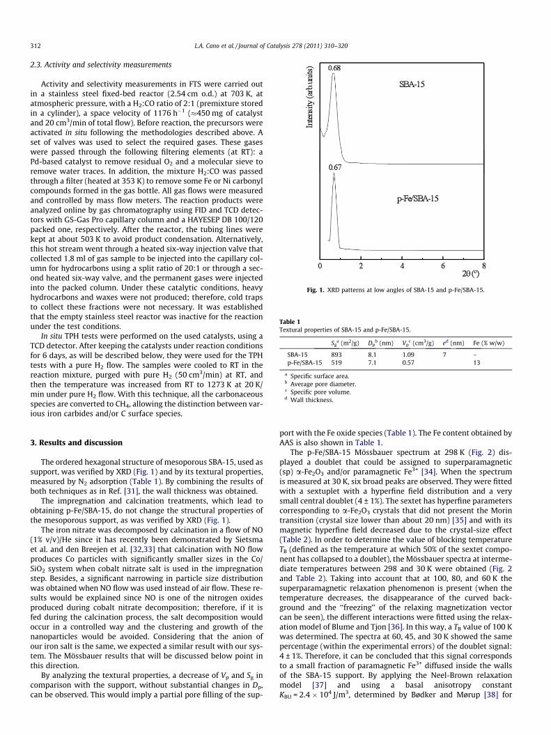
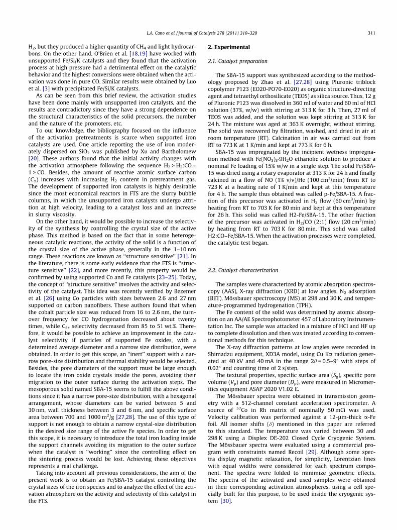
Fig. 1. XRD patterns at low angles of SBA-15 and p-Fe/SBA-15.
Table 1Textural properties of SBA-15 and p-Fe/SBA-15.
Sga (m2/g) Dp
b (nm) Vpc (cm3/g) ed (nm) Fe (% w/w)
SBA-15 893 8.1 1.09 7 –p-Fe/SBA-15 519 7.1 0.57 13
a Specific surface area.b Average pore diameter.c Specific pore volume.d Wall thickness.
312 L.A. Cano et al. / Journal of Catalysis 278 (2011) 310–320
2.3. Activity and selectivity measurements
Activity and selectivity measurements in FTS were carried outin a stainless steel fixed-bed reactor (2.54 cm o.d.) at 703 K, atatmospheric pressure, with a H2:CO ratio of 2:1 (premixture storedin a cylinder), a space velocity of 1176 h�1 (�450 mg of catalystand 20 cm3/min of total flow). Before reaction, the precursors wereactivated in situ following the methodologies described above. Aset of valves was used to select the required gases. These gaseswere passed through the following filtering elements (at RT): aPd-based catalyst to remove residual O2 and a molecular sieve toremove water traces. In addition, the mixture H2:CO was passedthrough a filter (heated at 353 K) to remove some Fe or Ni carbonylcompounds formed in the gas bottle. All gas flows were measuredand controlled by mass flow meters. The reaction products wereanalyzed online by gas chromatography using FID and TCD detec-tors with GS-Gas Pro capillary column and a HAYESEP DB 100/120packed one, respectively. After the reactor, the tubing lines werekept at about 503 K to avoid product condensation. Alternatively,this hot stream went through a heated six-way injection valve thatcollected 1.8 ml of gas sample to be injected into the capillary col-umn for hydrocarbons using a split ratio of 20:1 or through a sec-ond heated six-way valve, and the permanent gases were injectedinto the packed column. Under these catalytic conditions, heavyhydrocarbons and waxes were not produced; therefore, cold trapsto collect these fractions were not necessary. It was establishedthat the empty stainless steel reactor was inactive for the reactionunder the test conditions.
In situ TPH tests were performed on the used catalysts, using aTCD detector. After keeping the catalysts under reaction conditionsfor 6 days, as will be described below, they were used for the TPHtests with a pure H2 flow. The samples were cooled to RT in thereaction mixture, purged with pure H2 (50 cm3/min) at RT, andthen the temperature was increased from RT to 1273 K at 20 K/min under pure H2 flow. With this technique, all the carbonaceousspecies are converted to CH4, allowing the distinction between var-ious iron carbides and/or C surface species.
3. Results and discussion
The ordered hexagonal structure of mesoporous SBA-15, used assupport, was verified by XRD (Fig. 1) and by its textural properties,measured by N2 adsorption (Table 1). By combining the results ofboth techniques as in Ref. [31], the wall thickness was obtained.
The impregnation and calcination treatments, which lead toobtaining p-Fe/SBA-15, do not change the structural properties ofthe mesoporous support, as was verified by XRD (Fig. 1).
The iron nitrate was decomposed by calcination in a flow of NO(1% v/v)/He since it has recently been demonstrated by Sietsmaet al. and den Breejen et al. [32,33] that calcination with NO flowproduces Co particles with significantly smaller sizes in the Co/SiO2 system when cobalt nitrate salt is used in the impregnationstep. Besides, a significant narrowing in particle size distributionwas obtained when NO flow was used instead of air flow. These re-sults would be explained since NO is one of the nitrogen oxidesproduced during cobalt nitrate decomposition; therefore, if it isfed during the calcination process, the salt decomposition wouldoccur in a controlled way and the clustering and growth of thenanoparticles would be avoided. Considering that the anion ofour iron salt is the same, we expected a similar result with our sys-tem. The Mössbauer results that will be discussed below point inthis direction.
By analyzing the textural properties, a decrease of Vp and Sg incomparison with the support, without substantial changes in Dp,can be observed. This would imply a partial pore filling of the sup-
port with the Fe oxide species (Table 1). The Fe content obtained byAAS is also shown in Table 1.
The p-Fe/SBA-15 Mössbauer spectrum at 298 K (Fig. 2) dis-played a doublet that could be assigned to superparamagnetic(sp) a-Fe2O3 and/or paramagnetic Fe3+ [34]. When the spectrumis measured at 30 K, six broad peaks are observed. They were fittedwith a sextuplet with a hyperfine field distribution and a verysmall central doublet (4 ± 1%). The sextet has hyperfine parameterscorresponding to a-Fe2O3 crystals that did not present the Morintransition (crystal size lower than about 20 nm) [35] and with itsmagnetic hyperfine field decreased due to the crystal-size effect(Table 2). In order to determine the value of blocking temperatureTB (defined as the temperature at which 50% of the sextet compo-nent has collapsed to a doublet), the Mössbauer spectra at interme-diate temperatures between 298 and 30 K were obtained (Fig. 2and Table 2). Taking into account that at 100, 80, and 60 K thesuperparamagnetic relaxation phenomenon is present (when thetemperature decreases, the disappearance of the curved back-ground and the ‘‘freezing’’ of the relaxing magnetization vectorcan be seen), the different interactions were fitted using the relax-ation model of Blume and Tjon [36]. In this way, a TB value of 100 Kwas determined. The spectra at 60, 45, and 30 K showed the samepercentage (within the experimental errors) of the doublet signal:4 ± 1%. Therefore, it can be concluded that this signal correspondsto a small fraction of paramagnetic Fe3+ diffused inside the wallsof the SBA-15 support. By applying the Neel-Brown relaxationmodel [37] and using a basal anisotropy constantKBU = 2.4 � 104 J/m3, determined by Bødker and Mørup [38] for

Fig. 2. Mössbauer spectra of p-Fe/SBA-15 at 298, 100, 80, 60, 45, and 30 K.
L.A. Cano et al. / Journal of Catalysis 278 (2011) 310–320 313
hematite particles of 5.9 nm size, an estimation of the averagediameter value of crystal oxide of about 8 nm was obtained. Thereis a complete coincidence between this value and the diameter ofthe SBA-15 channels. Bearing in mind the numerous assumptionsof the models used, this coincidence would seem to be fortuitous.However, if we consider this result jointly with the textural mea-surements and with the fact that at room temperature the
Mössbauer spectrum did not show any magnetic signal, we canconclude that the total iron loading is located inside the SBA-15channels. Besides, the iron oxide has a narrow size distributionwith an average diameter of about 8 nm.
In order to establish the most adequate reaction temperaturefor FTS when the Fe/SBA-15 system is used as catalyst, the precur-sor p-Fe/SBA-15 was activated in pure H2 and H2:CO = 2:1 mixture,following the procedures previously described. Preliminary cata-lytic tests for both solids (H2-Fe/SBA-15 and H2:CO–Fe/SBA-15respectively) were realized at four temperatures, 543, 603, 653,and 703 K, in a consecutive way without changing the catalystloading and remaining in continuous reaction at least 24 h at eachtemperature. Fig. 3 shows the production of total hydrocarbons(HC molecules/g Fe. s), the CO conversion (%), and CH4 selectivity,defined as:
½CH4 �moles� C � number of CH4� � 100Pn
iþ1½\i" moles� C number of Ci�
The activity of these catalysts could be expressed as the turn-over rate. In order to obtain this expression, it would be necessaryto measure the available surface metallic iron on fresh catalysts.However, the metallic iron changes rapidly under the synthesisconditions. Therefore, this expression appears inappropriate foriron catalysts. To solve this difficulty, the group led by Iglesia pro-posed a new method, measuring irreversible CO chemisorption onused catalysts, to provide a quantitative measurement of activesites [39], but in a subsequent article published by Xu and Bar-tholomew [20], it was demonstrated that this method does notprovide good results on silica-supported iron. Therefore, further re-search appears as necessary to solve this problem, and we chosethe above expression to evaluate the activity of the present cata-lysts. The results showed that the production of total hydrocarbonsper gram of iron increased 50–100 times and the CO conversion in-creased 70–350 times, for both catalysts, when the reaction tem-perature was increased from 543 to 703 K. However, it isimportant to remark that the major change occurs between 653and 703 K. If the global reaction rate was controlled by the diffu-sion rate inside the channels of the SBA-15 support, the catalyticactivity would be expected to change in a proportional way withapproximately T3/2. We think that at temperatures 6653 K, thereaction occurs on the iron crystals located at the mouth of thepores, since these crystals inhibit the CO access and/or the productexit. The H2 access occurs since, as will be demonstrated below, alla-Fe2O3 disappears after reduction pretreatment with this gas.When the temperature reached the value of 703 K, the expansionof the mouth of the pores – produced by the different vibrationalbehaviors of the support and the active phase – would allow theCO access and/or the product exit. Therefore, under these condi-tions, the total metallic loading would be accessible and the pro-duction of total hydrocarbons per gram of iron and the COconversion would be significantly increased. A similar behaviorwas observed in previous work using Fe/MCM-41 as catalyst[24]. In this system, we could determine, using STEM-HAADFimages of the oxidic and reduced samples [40,41], that iron speciesare located along the channels as ‘‘nanocylinders’’ with diametersnearly equal to the channels of the mesoporous support. As a con-sequence, the empty spaces between the walls of the support andthe iron ‘‘nanocylinders’’ are extremely small. Besides, in Fig. 3, itcan be seen that CH4 selectivity decreases when the reaction tem-perature increases. This effect is particularly noticeable in H2:CO–Fe/SBA-15 and shows that higher temperatures are necessary toget the chain growth when the Fe/SBA-15 system – with all ironloading located inside the channels of the support – is used as cat-alyst. It is important to remark that this required high reactiontemperature is inappropriate for an industrial application, and
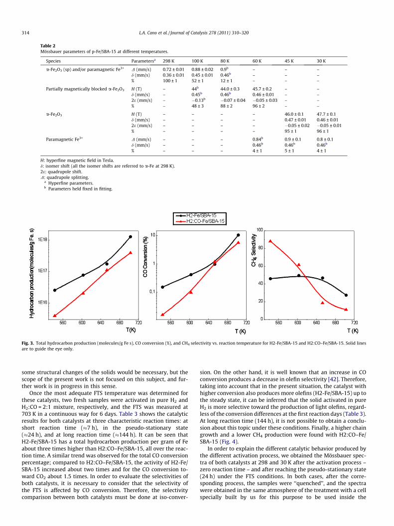
Table 2Mössbauer parameters of p-Fe/SBA-15 at different temperatures.
Species Parametersa 298 K 100 K 80 K 60 K 45 K 30 K
a-Fe2O3 (sp) and/or paramagnetic Fe3+ D (mm/s) 0.72 ± 0.01 0.88 ± 0.02 0.9b – – –d (mm/s) 0.36 ± 0.01 0.45 ± 0.01 0.46b – – –% 100 ± 1 52 ± 1 12 ± 1 – – –
Partially magnetically blocked a-Fe2O3 H (T) – 44b 44.0 ± 0.3 45.7 ± 0.2 – –d (mm/s) – 0.45b 0.46b 0.46 ± 0.01 – –2e (mm/s) – �0.13b �0.07 ± 0.04 �0.05 ± 0.03 – –% – 48 ± 3 88 ± 2 96 ± 2 – –
a-Fe2O3 H (T) – – – – 46.0 ± 0.1 47.7 ± 0.1d (mm/s) – – – – 0.47 ± 0.01 0.46 ± 0.012e (mm/s) – – – – �0.05 ± 0.02 �0.05 ± 0.01% – – – – 95 ± 1 96 ± 1
Paramagnetic Fe3+ D (mm/s) – – – 0.84b 0.9 ± 0.1 0.8 ± 0.1d (mm/s) – – – 0.46b 0.46b 0.46b
% – – – 4 ± 1 5 ± 1 4 ± 1
H: hyperfine magnetic field in Tesla.d: isomer shift (all the isomer shifts are referred to a-Fe at 298 K).2e: quadrupole shift.D: quadrupole splitting.
a Hyperfine parameters.b Parameters held fixed in fitting.
Fig. 3. Total hydrocarbon production (molecules/g Fe s), CO conversion (%), and CH4 selectivity vs. reaction temperature for H2-Fe/SBA-15 and H2:CO–Fe/SBA-15. Solid linesare to guide the eye only.
314 L.A. Cano et al. / Journal of Catalysis 278 (2011) 310–320
some structural changes of the solids would be necessary, but thescope of the present work is not focused on this subject, and fur-ther work is in progress in this sense.
Once the most adequate FTS temperature was determined forthese catalysts, two fresh samples were activated in pure H2 andH2:CO = 2:1 mixture, respectively, and the FTS was measured at703 K in a continuous way for 6 days. Table 3 shows the catalyticresults for both catalysts at three characteristic reaction times: atshort reaction time (�7 h), in the pseudo-stationary state(�24 h), and at long reaction time (�144 h). It can be seen thatH2-Fe/SBA-15 has a total hydrocarbon production per gram of Feabout three times higher than H2:CO–Fe/SBA-15, all over the reac-tion time. A similar trend was observed for the total CO conversionpercentage; compared to H2:CO–Fe/SBA-15, the activity of H2-Fe/SBA-15 increased about two times and for the CO conversion to-ward CO2 about 1.5 times. In order to evaluate the selectivities ofboth catalysts, it is necessary to consider that the selectivity ofthe FTS is affected by CO conversion. Therefore, the selectivitycomparison between both catalysts must be done at iso-conver-
sion. On the other hand, it is well known that an increase in COconversion produces a decrease in olefin selectivity [42]. Therefore,taking into account that in the present situation, the catalyst withhigher conversion also produces more olefins (H2-Fe/SBA-15) up tothe steady state, it can be inferred that the solid activated in pureH2 is more selective toward the production of light olefins, regard-less of the conversion differences at the first reaction days (Table 3).At long reaction time (144 h), it is not possible to obtain a conclu-sion about this topic under these conditions. Finally, a higher chaingrowth and a lower CH4 production were found with H2:CO–Fe/SBA-15 (Fig. 4).
In order to explain the different catalytic behavior produced bythe different activation process, we obtained the Mössbauer spec-tra of both catalysts at 298 and 30 K after the activation process –zero reaction time – and after reaching the pseudo-stationary state(24 h) under the FTS conditions. In both cases, after the corre-sponding process, the samples were ‘‘quenched’’, and the spectrawere obtained in the same atmosphere of the treatment with a cellspecially built by us for this purpose to be used inside the
Table 3Activity and selectivity results obtained at 703 K and three different reaction times: at short reaction time (�7 h), in the pseudo-stationary state (�24 h),and at long reaction time (�144 h).
H2-Fe/SBA-15 H2:CO–Fe/SBA-15
etr = 4650 etr = 15920 etr = 85170 etr = 4210 etr = 14410 etr = 86610
Prod. HCtotals (molecules/gFe. s)a 13.2 � 1017 17.3 � 1017 23.5 � 1017 4.3 � 1017 5.7 � 1017 7.0 � 1017
Rb 2.06 1.24 0.28 1.05 1.13 0.97% CO2
c – 8.3 – – 5.4 –XCO (%)d 19.9 20.1 18.7 8.6 12.1 10.0
a Prod. HCtotals: hydrocarbons production per gram of Fe.b R: (C¼2 þ C¼3 )/(C2 + C3).c % CO converted to CO2.d XCO (%): total CO conversion.e tr: reaction time.
Fig. 4. Selectivity diagram for H2-Fe/SBA-15 and H2:CO–Fe/SBA-15, evaluated at703 K in the pseudo-stationary state (�24 h).
L.A. Cano et al. / Journal of Catalysis 278 (2011) 310–320 315
cryogenic system [30]. In this way, the samples never were con-tacted with air.
The Mössbauer spectra of the fresh catalysts at 298 K (Fig. 5)display an asymmetric doublet with a shoulder on the positive-velocity side and broad lines, which could be attributed to para-magnetic and/or superparamagnetic (sp) species. To carry out thespecies assignments, the Mössbauer spectra at 30 K were obtained.It is important to remark that due to the extreme complexity of thespectra at low temperature, a real fitting process was not carriedout. Thus, initially, a set of hyperfine parameter distributions, typ-ical of the possible species present, were fixed and the areas werefitted freely. When they converged to a minimum, the areas werefixed and the values of isomer shift (d) and quadrupole splitting(D) of the doublets and the hyperfine magnetic fields (H) of thesextuplets were fitted freely. It was assumed that the hyperfinemagnetic fields could decrease due to the effects of the crystal size,but the isomer shifts and the quadrupole shifts (2e) were fixed,considering that these parameters would not be affected by thisvariable. It is possible that following this methodology, the fittingcould produce more than one minimum, with very small differ-ences between them. Therefore, to choose the best set of values,the story of the sample and physical and chemical concepts wereused too. The H2:CO–Fe/SBA-15 spectrum at 30 K was fitted with
five sextets for the five Fe3O4 crystallographic sites [43], three sex-tets assigned to the three sites of the v-Fe2C5 carbide [44], and twodoublets assigned to Fe2+ ions located in tetrahedral and octahe-dral sites within the walls of SiO2 [45] (Table 4 and Fig. 5). Theyare present in a superparamagnetic regime or as paramagnetic spe-cies in the spectrum at 298 K: a doublet of carbide (sp) [44], a sin-glet of Fe3O4 (sp) [46], and two doublets assigned to paramagneticFe2+ ions diffused into the SiO2 walls and/or Fe3O4 (sp) (Table 4).The steps of the fitting procedure for H2-Fe/SBA-15 Mössbauerspectrum at 30 K were the same as in H2:CO–Fe/SBA-15. Thehyperfine parameters obtained following this methodology areshown in Table 4. The more important difference between bothspectra is the presence of one sextet, which has hyperfine param-eters typical of a-Fe, instead of the three sextets assignable to v-Fe2C5 carbide. At room temperature, the a-Fe species is detectedas a singlet due to the superparamagnetic behavior [45]. In Table 5,it can be seen that within the experimental errors, the percentagesof a-Fe in H2-Fe/SBA-15 and v-Fe2C5 carbide in H2:CO–Fe/SBA-15are equal. Besides, the percentages of the other two species de-tected (Fe3O4 and paramagnetic Fe2+) are equal too. Therefore, itcan be concluded that in both atmospheres, just about 10% of thetotal iron loading can be reduced beyond Fe3O4 or Fe2+. On theother hand, the activation atmosphere has a decisive role to deter-mine whether the more reduced iron species present in the freshcatalysts – zero reaction time – is a-Fe or v-Fe2C5 carbide. Finally,an important diffusion process of the iron ions inside the SBA-15lattice occurs during the activation steps in both atmospheres,since in the precursor, only 4% of the total iron loading had diffusedinside the SBA-15 walls.
The Mössbauer spectra of the used catalysts under the FTS con-ditions for 24 h (pseudo-stationary state) (Fig. 6) do not showimportant differences either between them or with respect to thefresh solids when they were measured at 298 K. Both of them dis-play an asymmetric doublet with a shoulder on the positive-veloc-ity side and broad lines, which could be attributed to paramagneticand/or superparamagnetic (sp) species. However, when theMössbauer spectra at 30 K were obtained, some changes appeared.The spectra were fitted following the methodology previously de-scribed with the fresh catalysts. Again, the used H2:CO–Fe/SBA-15spectrum at 30 K was fitted with five sextets for the five Fe3O4
crystallographic sites [43], four sextets assigned to the three sitesof the v-Fe2C5 carbide [44] and the two sites of the e0-Fe2.2C carbide[47], and two doublets assigned to Fe2+ ions located in tetrahedraland octahedral sites within the walls of SiO2 [45] (Table 6 andFig. 6). It is important to remark that it was necessary to add an-other sextet, in comparison with the fresh catalyst, in order to ob-tain a satisfactory fitting. The new sextuplet was assigned to the IIcrystallographic site of the e0-Fe2.2C carbide. The I site of this car-bide shows an overlapped signal with the II site of the v-Fe2C5 car-bide. Taking into account these assignments, it can be concluded
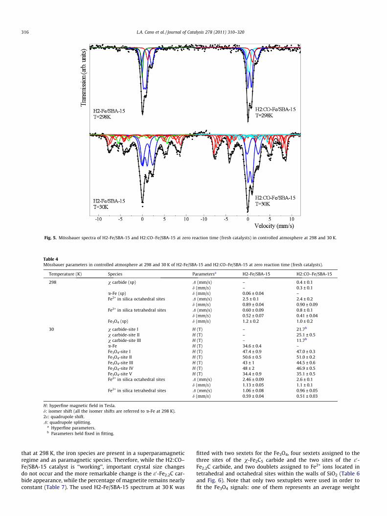
Fig. 5. Mössbauer spectra of H2-Fe/SBA-15 and H2:CO–Fe/SBA-15 at zero reaction time (fresh catalysts) in controlled atmosphere at 298 and 30 K.
Table 4Mössbauer parameters in controlled atmosphere at 298 and 30 K of H2-Fe/SBA-15 and H2:CO–Fe/SBA-15 at zero reaction time (fresh catalysts).
Temperature (K) Species Parametersa H2-Fe/SBA-15 H2:CO–Fe/SBA-15
298 v carbide (sp) D (mm/s) – 0.4 ± 0.1d (mm/s) – 0.3 ± 0.1
a-Fe (sp) d (mm/s) 0.06 ± 0.04 –Fe2+ in silica octahedral sites D (mm/s) 2.5 ± 0.1 2.4 ± 0.2
d (mm/s) 0.89 ± 0.04 0.90 ± 0.09Fe2+ in silica tetrahedral sites D (mm/s) 0.60 ± 0.09 0.8 ± 0.1
d (mm/s) 0.52 ± 0.07 0.41 ± 0.04Fe3O4 (sp) d (mm/s) 1.2 ± 0.2 1.0 ± 0.2
30 v carbide-site I H (T) – 21.7b
v carbide-site II H (T) – 25.1 ± 0.5v carbide-site III H (T) – 11.7b
a-Fe H (T) 34.6 ± 0.4 –Fe3O4-site I H (T) 47.4 ± 0.9 47.0 ± 0.3Fe3O4-site II H (T) 50.6 ± 0.5 51.0 ± 0.2Fe3O4-site III H (T) 43 ± 1 44.5 ± 0.6Fe3O4-site IV H (T) 48 ± 2 46.9 ± 0.5Fe3O4-site V H (T) 34.4 ± 0.9 35.1 ± 0.5Fe2+ in silica octahedral sites D (mm/s) 2.46 ± 0.09 2.6 ± 0.1
d (mm/s) 1.13 ± 0.05 1.1 ± 0.1Fe2+ in silica tetrahedral sites D (mm/s) 1.06 ± 0.08 0.96 ± 0.05
d (mm/s) 0.59 ± 0.04 0.51 ± 0.03
H: hyperfine magnetic field in Tesla.d: isomer shift (all the isomer shifts are referred to a-Fe at 298 K).2e: quadrupole shift.D: quadrupole splitting.
a Hyperfine parameters.b Parameters held fixed in fitting.
316 L.A. Cano et al. / Journal of Catalysis 278 (2011) 310–320
that at 298 K, the iron species are present in a superparamagneticregime and as paramagnetic species. Therefore, while the H2:CO–Fe/SBA-15 catalyst is ‘‘working’’, important crystal size changesdo not occur and the more remarkable change is the e0-Fe2.2C car-bide appearance, while the percentage of magnetite remains nearlyconstant (Table 7). The used H2-Fe/SBA-15 spectrum at 30 K was
fitted with two sextets for the Fe3O4, four sextets assigned to thethree sites of the v-Fe2C5 carbide and the two sites of the e0-Fe2.2C carbide, and two doublets assigned to Fe2+ ions located intetrahedral and octahedral sites within the walls of SiO2 (Table 6and Fig. 6). Note that only two sextuplets were used in order tofit the Fe3O4 signals: one of them represents an average weight
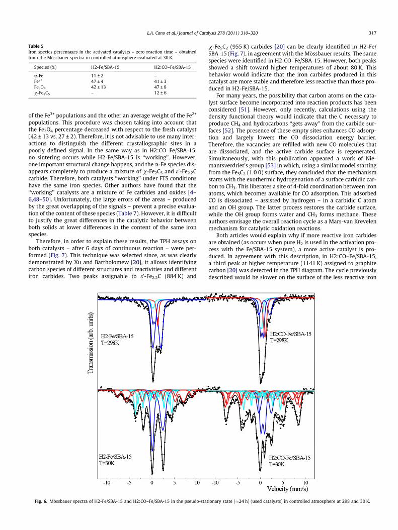
Table 5Iron species percentages in the activated catalysts – zero reaction time – obtainedfrom the Mössbauer spectra in controlled atmosphere evaluated at 30 K.
Species (%) H2-Fe/SBA-15 H2:CO–Fe/SBA-15
a-Fe 11 ± 2 –Fe2+ 47 ± 4 41 ± 3Fe3O4 42 ± 13 47 ± 8v-Fe2C5 – 12 ± 6
L.A. Cano et al. / Journal of Catalysis 278 (2011) 310–320 317
of the Fe3+ populations and the other an average weight of the Fe2+
populations. This procedure was chosen taking into account thatthe Fe3O4 percentage decreased with respect to the fresh catalyst(42 ± 13 vs. 27 ± 2). Therefore, it is not advisable to use many inter-actions to distinguish the different crystallographic sites in apoorly defined signal. In the same way as in H2:CO–Fe/SBA-15,no sintering occurs while H2-Fe/SBA-15 is ‘‘working’’. However,one important structural change happens, and the a-Fe species dis-appears completely to produce a mixture of v-Fe2C5 and e0-Fe2.2Ccarbide. Therefore, both catalysts ‘‘working’’ under FTS conditionshave the same iron species. Other authors have found that the‘‘working’’ catalysts are a mixture of Fe carbides and oxides [4–6,48–50]. Unfortunately, the large errors of the areas – producedby the great overlapping of the signals – prevent a precise evalua-tion of the content of these species (Table 7). However, it is difficultto justify the great differences in the catalytic behavior betweenboth solids at lower differences in the content of the same ironspecies.
Therefore, in order to explain these results, the TPH assays onboth catalysts – after 6 days of continuous reaction – were per-formed (Fig. 7). This technique was selected since, as was clearlydemonstrated by Xu and Bartholomew [20], it allows identifyingcarbon species of different structures and reactivities and differentiron carbides. Two peaks assignable to e0-Fe2.2C (884 K) and
Fig. 6. Mössbauer spectra of H2-Fe/SBA-15 and H2:CO–Fe/SBA-15 in the pseudo-stat
v-Fe5C2 (955 K) carbides [20] can be clearly identified in H2-Fe/SBA-15 (Fig. 7), in agreement with the Mössbauer results. The samespecies were identified in H2:CO–Fe/SBA-15. However, both peaksshowed a shift toward higher temperatures of about 80 K. Thisbehavior would indicate that the iron carbides produced in thiscatalyst are more stable and therefore less reactive than those pro-duced in H2-Fe/SBA-15.
For many years, the possibility that carbon atoms on the cata-lyst surface become incorporated into reaction products has beenconsidered [51]. However, only recently, calculations using thedensity functional theory would indicate that the C necessary toproduce CH4 and hydrocarbons ‘‘gets away’’ from the carbide sur-faces [52]. The presence of these empty sites enhances CO adsorp-tion and largely lowers the CO dissociation energy barrier.Therefore, the vacancies are refilled with new CO molecules thatare dissociated, and the active carbide surface is regenerated.Simultaneously, with this publication appeared a work of Nie-mantsverdriet’s group [53] in which, using a similar model startingfrom the Fe5C2 (1 0 0) surface, they concluded that the mechanismstarts with the exothermic hydrogenation of a surface carbidic car-bon to CH3. This liberates a site of 4-fold coordination between ironatoms, which becomes available for CO adsorption. This adsorbedCO is dissociated – assisted by hydrogen – in a carbidic C atomand an OH group. The latter process restores the carbide surface,while the OH group forms water and CH3 forms methane. Theseauthors envisage the overall reaction cycle as a Mars-van Krevelenmechanism for catalytic oxidation reactions.
Both articles would explain why if more reactive iron carbidesare obtained (as occurs when pure H2 is used in the activation pro-cess with the Fe/SBA-15 system), a more active catalyst is pro-duced. In agreement with this description, in H2:CO–Fe/SBA-15,a third peak at higher temperature (1141 K) assigned to graphitecarbon [20] was detected in the TPH diagram. The cycle previouslydescribed would be slower on the surface of the less reactive iron
ionary state (�24 h) (used catalysts) in controlled atmosphere at 298 and 30 K.
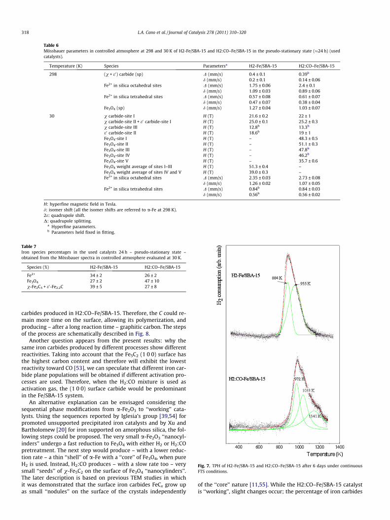
Table 6Mössbauer parameters in controlled atmosphere at 298 and 30 K of H2-Fe/SBA-15 and H2:CO–Fe/SBA-15 in the pseudo-stationary state (�24 h) (usedcatalysts).
Temperature (K) Species Parametersa H2-Fe/SBA-15 H2:CO–Fe/SBA-15
298 (v + e0) carbide (sp) D (mm/s) 0.4 ± 0.1 0.39b
d (mm/s) 0.2 ± 0.1 0.14 ± 0.06Fe2+ in silica octahedral sites D (mm/s) 1.75 ± 0.06 2.4 ± 0.1
d (mm/s) 1.09 ± 0.03 0.89 ± 0.06Fe2+ in silica tetrahedral sites D (mm/s) 0.57 ± 0.08 0.61 ± 0.07
d (mm/s) 0.47 ± 0.07 0.38 ± 0.04Fe3O4 (sp) d (mm/s) 1.27 ± 0.04 1.03 ± 0.07
30 v carbide-site I H (T) 21.6 ± 0.2 22 ± 1v carbide-site II + e0 carbide-site I H (T) 25.0 ± 0.1 25.2 ± 0.3v carbide-site III H (T) 12.8b 13.3b
e0 carbide-site II H (T) 18.6b 19 ± 1Fe3O4-site I H (T) – 48.3 ± 0.5Fe3O4-site II H (T) – 51.1 ± 0.3Fe3O4-site III H (T) – 47.8b
Fe3O4-site IV H (T) – 46.2b
Fe3O4-site V H (T) – 35.7 ± 0.6Fe3O4 weight average of sites I–III H (T) 51.3 ± 0.4 –Fe3O4 weight average of sites IV and V H (T) 39.0 ± 0.3 –Fe2+ in silica octahedral sites D (mm/s) 2.35 ± 0.03 2.73 ± 0.08
d (mm/s) 1.26 ± 0.02 1.07 ± 0.05Fe2+ in silica tetrahedral sites D (mm/s) 0.84b 0.84 ± 0.03
d (mm/s) 0.56b 0.56 ± 0.02
H: hyperfine magnetic field in Tesla.d: isomer shift (all the isomer shifts are referred to a-Fe at 298 K).2e: quadrupole shift.D: quadrupole splitting.
a Hyperfine parameters.b Parameters held fixed in fitting.
Table 7Iron species percentages in the used catalysts 24 h – pseudo-stationary state –obtained from the Mössbauer spectra in controlled atmosphere evaluated at 30 K.
Species (%) H2-Fe/SBA-15 H2:CO–Fe/SBA-15
Fe2+ 34 ± 2 26 ± 2Fe3O4 27 ± 2 47 ± 10v-Fe2C5 + e0-Fe2.2C 39 ± 5 27 ± 8
Fig. 7. TPH of H2-Fe/SBA-15 and H2:CO–Fe/SBA-15 after 6 days under continuousFTS conditions.
318 L.A. Cano et al. / Journal of Catalysis 278 (2011) 310–320
carbides produced in H2:CO–Fe/SBA-15. Therefore, the C could re-main more time on the surface, allowing its polymerization, andproducing – after a long reaction time – graphitic carbon. The stepsof the process are schematically described in Fig. 8.
Another question appears from the present results: why thesame iron carbides produced by different processes show differentreactivities. Taking into account that the Fe5C2 (1 0 0) surface hasthe highest carbon content and therefore will exhibit the lowestreactivity toward CO [53], we can speculate that different iron car-bide plane populations will be obtained if different activation pro-cesses are used. Therefore, when the H2:CO mixture is used asactivation gas, the (1 0 0) surface carbide would be predominantin the Fe/SBA-15 system.
An alternative explanation can be envisaged considering thesequential phase modifications from a-Fe2O3 to ‘‘working’’ cata-lysts. Using the sequences reported by Iglesia’s group [39,54] forpromoted unsupported precipitated iron catalysts and by Xu andBartholomew [20] for iron supported on amorphous silica, the fol-lowing steps could be proposed. The very small a-Fe2O3 ‘‘nanocyl-inders’’ undergo a fast reduction to Fe3O4 with either H2 or H2:COpretreatment. The next step would produce – with a lower reduc-tion rate – a thin ‘‘shell’’ of a-Fe with a ‘‘core’’ of Fe3O4, when pureH2 is used. Instead, H2:CO produces – with a slow rate too – verysmall ‘‘seeds’’ of v-Fe5C2 on the surface of Fe3O4 ‘‘nanocylinders’’.The later description is based on previous TEM studies in whichit was demonstrated that the surface iron carbides FeCx grow upas small ‘‘nodules’’ on the surface of the crystals independently
of the ‘‘core’’ nature [11,55]. While the H2:CO–Fe/SBA-15 catalystis ‘‘working’’, slight changes occur; the percentage of iron carbides
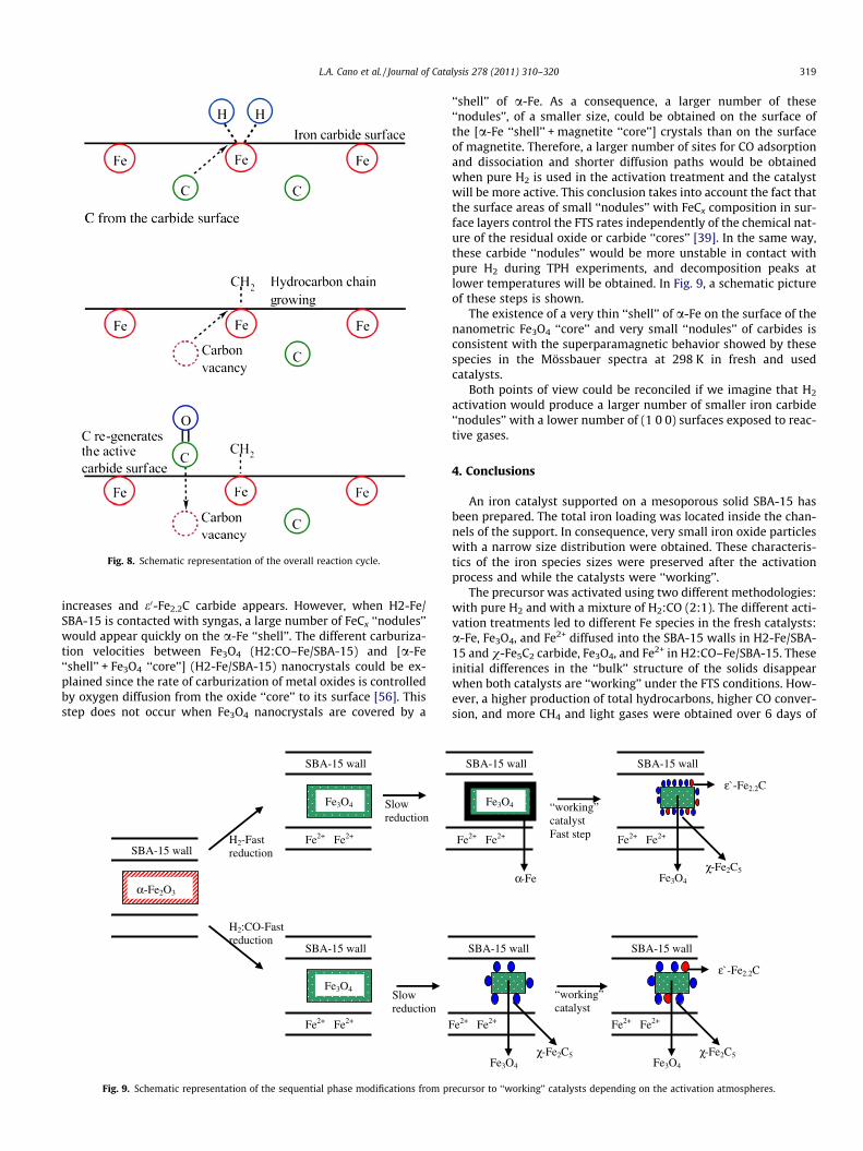
Fig. 8. Schematic representation of the overall reaction cycle.
L.A. Cano et al. / Journal of Catalysis 278 (2011) 310–320 319
increases and e0-Fe2.2C carbide appears. However, when H2-Fe/SBA-15 is contacted with syngas, a large number of FeCx ‘‘nodules’’would appear quickly on the a-Fe ‘‘shell’’. The different carburiza-tion velocities between Fe3O4 (H2:CO–Fe/SBA-15) and [a-Fe‘‘shell’’ + Fe3O4 ‘‘core’’] (H2-Fe/SBA-15) nanocrystals could be ex-plained since the rate of carburization of metal oxides is controlledby oxygen diffusion from the oxide ‘‘core’’ to its surface [56]. Thisstep does not occur when Fe3O4 nanocrystals are covered by a
SBA-15 wall
α-Fe2O3
H2-Fast reduction
H2:CO-Fast reduction
SBA-15 wall
Fe3O4
Fe2+ Fe2+
SBA-15 wall
Fe3O4
Fe2+ Fe2+
Slow reduction
F
Slow reduction
Fig. 9. Schematic representation of the sequential phase modifications from p
‘‘shell’’ of a-Fe. As a consequence, a larger number of these‘‘nodules’’, of a smaller size, could be obtained on the surface ofthe [a-Fe ‘‘shell’’ + magnetite ‘‘core’’] crystals than on the surfaceof magnetite. Therefore, a larger number of sites for CO adsorptionand dissociation and shorter diffusion paths would be obtainedwhen pure H2 is used in the activation treatment and the catalystwill be more active. This conclusion takes into account the fact thatthe surface areas of small ‘‘nodules’’ with FeCx composition in sur-face layers control the FTS rates independently of the chemical nat-ure of the residual oxide or carbide ‘‘cores’’ [39]. In the same way,these carbide ‘‘nodules’’ would be more unstable in contact withpure H2 during TPH experiments, and decomposition peaks atlower temperatures will be obtained. In Fig. 9, a schematic pictureof these steps is shown.
The existence of a very thin ‘‘shell’’ of a-Fe on the surface of thenanometric Fe3O4 ‘‘core’’ and very small ‘‘nodules’’ of carbides isconsistent with the superparamagnetic behavior showed by thesespecies in the Mössbauer spectra at 298 K in fresh and usedcatalysts.
Both points of view could be reconciled if we imagine that H2
activation would produce a larger number of smaller iron carbide‘‘nodules’’ with a lower number of (1 0 0) surfaces exposed to reac-tive gases.
4. Conclusions
An iron catalyst supported on a mesoporous solid SBA-15 hasbeen prepared. The total iron loading was located inside the chan-nels of the support. In consequence, very small iron oxide particleswith a narrow size distribution were obtained. These characteris-tics of the iron species sizes were preserved after the activationprocess and while the catalysts were ‘‘working’’.
The precursor was activated using two different methodologies:with pure H2 and with a mixture of H2:CO (2:1). The different acti-vation treatments led to different Fe species in the fresh catalysts:a-Fe, Fe3O4, and Fe2+ diffused into the SBA-15 walls in H2-Fe/SBA-15 and v-Fe5C2 carbide, Fe3O4, and Fe2+ in H2:CO–Fe/SBA-15. Theseinitial differences in the ‘‘bulk’’ structure of the solids disappearwhen both catalysts are ‘‘working’’ under the FTS conditions. How-ever, a higher production of total hydrocarbons, higher CO conver-sion, and more CH4 and light gases were obtained over 6 days of
SBA-15 wall
e2+ Fe2+
Fe3O4
χ-Fe2C5
“working” catalyst
SBA-15 wall
Fe2+ Fe2+
Fe3O4
χ-Fe2C5
ε`-Fe2.2C
SBA-15 wall
Fe3O4
Fe2+ Fe2+
α-Fe
SBA-15 wall
Fe2+ Fe2+
Fe3O4
χ-Fe2C5
ε`-Fe2.2C
“working” catalyst Fast step
recursor to ‘‘working’’ catalysts depending on the activation atmospheres.
320 L.A. Cano et al. / Journal of Catalysis 278 (2011) 310–320
continuous reaction when the activation in pure H2 was per-formed. Besides, a higher selectivity toward light olefins was ob-tained with the same solid during the first 24 h of reactionstream, but this selectivity decreases with the reaction time. Atlong reaction time (�144 h), definitive conclusions about this as-pect of the selectivity cannot be obtained due to the differencesin CO conversion.
These results are explained taking into account that the ironcarbides produced from a-Fe are more reactive than that obtainedfrom Fe2O3 in a direct way (activations in pure H2 and H2:CO mix-ture respectively). We speculate that when the iron carbides areobtained from iron oxide in a direct way, planes with the highestcarbon content (and therefore with the lowest reactivity towardCO) are predominant. A different velocity of iron carbide ‘‘nodule’’production on the surface of the nanocrystals – depending onwhether this appearance occurs on the Fe3O4 surface or the a-Fe‘‘shell’’ – could produce a larger number of these ‘‘nodules’’ withsmaller sizes in the latter case. Therefore, a larger number of sitesfor CO adsorption and dissociation and shorter diffusion pathswould be obtained, and the catalyst will be more active. A combi-nation of both effects would also be possible.
An active surface instead of an active site would exist in thismodel. This active surface is ‘‘alive’’, changing and regeneratingall the time while the catalysts are ‘‘working’’ under the FTSconditions.
Taking into account that the literature data related to the acti-vation process of the iron catalysts to be used in the FTS are contra-dictory and strongly depend on the catalyst characteristics(supported or not, with promoters or not, etc.), at the moment itdoes not seem appropriate to perform a generalization on this to-pic. Instead, a study for each Fe system in particular appears moreadvisable.
Acknowledgments
The authors acknowledge the financial support of ANPCyT (PICTNo. 22-38337 and 00549), which allowed the development of thiswork.
References
[1] A. Steynberg, M. Dry (Eds.), Fischer–Tropsch Technology, Stud. Surf. Sci. Catal.,Elsevier, Amsterdam, 2004.
[2] B.H. Davis, M.L. Occelli (Eds.), Fischer–Tropsch Synthesis, Catalysts andCatalysis, Stud. Surf. Sci. Catal., Elsevier, Amsterdam, 2007.
[3] M. Luo, H. Hamdeh, B.H. Davis, Catal. Today 140 (2009) 127.[4] R.B. Anderson, The Fischer–Tropsch Synthesis, Academic Press, Orlando, FL,
1984.[5] J.A. Amelse, J.B. Butt, L.H. Schwartz, J. Phys. Chem. 82 (1978) 558.[6] G.B. Raupp, W.N. Delgass, J. Catal. 58 (1979) 361.[7] J.W. Niemantsverdriet, A.M. van der Kraan, J. Catal. 72 (1981) 385.[8] J.P. Reymond, P. Meriadeau, S.J. Teichner, J. Catal. 75 (1982) 39.[9] F. Blanchard, J.P. Reymond, B. Pommier, S.J. Teichner, J. Mol. Catal. 17 (1982)
171.[10] R. Dictor, A.T. Bell, J. Catal. 97 (1986) 121.[11] M.D. Shroff, D.S. Kalakkad, K.E. Coulter, S.D. Köhler, M.S. Harrington, N.B.
Jackson, A.G. Sault, A.K. Datye, J. Catal. 156 (1995) 185.
[12] S. Soled, E. Iglesia, R.A. Fiato, Catal. Lett. 7 (1990) 271.[13] C.S. Kuivila, P.C. Stair, J.B. Butt, J. Catal. 118 (1989) 299.[14] J.B. Butt, Catal. Lett. 7 (1990) 61.[15] H.W. Pennline, M.F. Zarochak, J.M. Stencel, J.R. Diehl, Ind. Eng. Chem. Res. 26
(1987) 595.[16] D.B. Bukur, L. Nowicki, R.K. Manne, X. Lang, J. Catal. 155 (1995) 366.[17] D.B. Bukur, L. Nowicki, X. Lang, Catal. Today 24 (1995) 111.[18] R.J. O’Brien, L. Xu, R.L. Spicer, B.H. Davis, Energy Fuels 10 (1996) 921.[19] R.J. O’Brien, L. Xu, R.L. Spicer, S. Bao, D.R. Milburn, B.H. Davis, Catal. Today 36
(1997) 325.[20] J. Xu, C.H. Bartholomew, J. Phys. Chem. B 109 (2005) 2392.[21] M. Boudart, A. Delbouille, J.A. Dumesic, S. Khammouma, H. Topsøe, J. Catal. 37
(1975) 486.[22] M.A. McDonald, D.A. Storm, M. Boudart, J. Catal. 102 (1986) 386.[23] E.I. Mabaso, E. van Steen, M. Claeys, DGMK, Tagungsbericht 4 (2006) 93.[24] L.A. Cano, M.V. Cagnoli, N.A. Fellenz, J.F. Bengoa, N.G. Gallegos, A.M. Alvarez,
S.G. Marchetti, Appl. Catal. A 379 (2010) 105.[25] P.B. Radstake, J.P. den Breejen, G.L. Bezemer, J.H. Bitter, K.P. de Jong, V. Frøseth,
A. Holmen, Stud. Surf. Sci. Catal. 167 (2007) 85.[26] G.L. Bezemer, J.H. Bitter, H.P.C.E. Kuipers, H. Oosterbeek, J.E. Holewijn, X. Xu, F.
Kapteijn, A.J. van Dillen, K.P. de Jong, J. Am. Chem. Soc. 128 (12) (2006) 3956.[27] D. Zhao, J. Feng, Q. Huo, N. Melosh, G.H. Fredrickson, B.F. Chmelka, G.D. Stucky,
Science 279 (1998) 23.[28] D. Zhao, Q. Huo, J. Feng, B.F. Chmelka, G.D. Stucky, J. Am. Chem. Soc. 120 (1998)
6024.[29] K. Lagarec, D.G. Rancourt, Mossbauer Spectral analysis Software, Dep. of Phys.
University of Otawa, Version 1.0., 1998.[30] S.G. Marchetti, J.F. Bengoa, M.V. Cagnoli, A.M. Alvarez, N.G. Gallegos, A.A.
Yeramián, R.C. Mercader, Meas. Sci. Technol. 7 (1996) 758.[31] J.S. Beck, J.C. Vartuli, W.J. Roth, M.E. Leonowicz, C.T. Kresge, K.D. Schmidt,
C.T.W. Chu, D.H. Olson, E.W. Sheppard, S.B. McCullen, J.B. Higgins, J.L.Schlenker, J. Am. Chem. Soc. 114 (1992) 10834.
[32] J.R.A. Sietsma, J.P. den Breejen, P.E. de Jongh, A.J. van Dillen, J.H. Bitter, K.P. deJong, Stud. Surf. Sci. Catal. 167 (2007) 55.
[33] J.P. den Breejen, J.R.A. Sietsma, H. Friedrich, J.H. Bitter, K.P. de Jong, J. Catal. 270(2010) 146.
[34] E. Murad, J.H. Johnston, in: G.J. Long (Ed.), Mössbauer Spectroscopy Applied toInorganic Chemistry, vol. 2, Plenum Publishing Corporation, 1987.
[35] R.E. Vandenberghe, E. De Grave, C. Landuydt, L.H. Bowen, Hyperfine Interact 53(1990) 175.
[36] M. Blume, J.A. Tjon, Phys. Rev. 165 (1968) 446.[37] W.F. Brown Jr., Phys. Rev. 130 (1963) 1677.[38] F. Bødker, S. Mørup, Europhys. Lett. 52 (2000) 217.[39] S. Li, W. Ding, G.D. Meitzner, E. Iglesia, J. Phys. Chem. B 106 (2002) 85.[40] J.F. Bengoa, M.V. Cagnoli, N.G. Gallegos, A.M. Alvarez, L.V. Mogni, M.S. Moreno,
S.G. Marchetti, Micropor. Mesopor. Mater. 84 (2005) 153.[41] M.S. Moreno, M. Weyland, P.A. Midgley, J.F. Bengoa, M.V. Cagnoli, N.G.
Gallegos, A.M. Alvarez, S.G. Marchetti, Micron 37 (2006) 52.[42] M. Röper, in: W. Keim (Ed.), Catalysis in C1 Chemistry, D. Reidel Publishing
Company, Dordrecht, Boston, Lancaster, 1983, p. 41.[43] F.J. Berry, S. Skinner, M.F. Thomas, J. Phys.: Condens. Matter. 10 (1998) 215.[44] S.-Ch. Lin, J. Phillips, J. Appl. Phys. 58 (5) (1985) 1943.[45] B.S. Clausen, H. Topsøe, S. Mørup, Appl. Catal. 48 (1989) 327.[46] S. Mørup, H. Topsøe, J. Lipka, J. Phys. Colloq. 37 (1976) C6–287.[47] M. Pijolat, V. Perrichón, P. Bussiére, J. Catal. 107 (1987) 82.[48] R.B. Anderson, in: P.H. Emmett (Ed.), Catalysis, forth ed., Van Nostrand-
Reinhold, New York, 1956, p. 29.[49] M.E. Dry, in: J.R. Anderson, M. Boudart (Eds.), Catalysis: Science and
Technology, vol. 1, Springer, New York, 1981, p. 159.[50] C.N. Satterfield, R.T. Hanlon, S.E. Tung, Z. Zou, G.C. Papaefthymiou, Ind. Eng.
Chem. Prod. Dev. 25 (1986) 407.[51] H. Matsumoto, C.O. Bennett, J. Catal. 53 (1978) 331.[52] Ch.-F. Huo, Y.-W. Li, J. Wang, H. Jiao, J. Am. Chem. Soc. 131 (2009) 14713.[53] J.M. Gracia, F.F. Prinsloo, J.W. Niemantsverdriet, Catal. Lett. 133 (2009) 257.[54] S. Li, G.D. Meitzner, E. Iglesia, J. Phys. Chem. B 105 (2001) 5743.[55] N.B. Jackson, A.K. Datye, L. Mansker, R.J. O’Brien, B.H. Davis, Stud. Surf. Sci.
Catal. 111 (1997) 501.[56] S.T. Oyama, J.C. Schlatter, J.E. Metcalfe, J.M. Lambert Jr., Ind. Eng. Chem. Res. 27
(1988) 1639.