Synthesis of silica supported AuCu nanoparticle catalysts and the effects of pretreatment conditions...
11
This journal is c the Owner Societies 2011 Phys. Chem. Chem. Phys. Cite this: DOI: 10.1039/c0cp01859g Synthesis of silica supported AuCu nanoparticle catalysts and the effects of pretreatment conditions for the CO oxidation reaction J. Chris Bauer, a David Mullins, a Meijun Li, a Zili Wu, ab E. Andrew Payzant, b Steven H. Overbury ab and Sheng Dai* abc Received 18th September 2010, Accepted 10th December 2010 DOI: 10.1039/c0cp01859g Supported gold nanoparticles have generated an immense interest in the field of catalysis due to their extremely high reactivity and selectivity. Recently, alloy nanoparticles of gold have received a lot of attention due to their enhanced catalytic properties. Here we report the synthesis of silica supported AuCu nanoparticles through the conversion of supported Au nanoparticles in a solution of Cu(C 2 H 3 O 2 ) 2 at 300 1C. The AuCu alloy structure was confirmed through powder XRD (which indicated a weakly ordered alloy phase), XANES, and EXAFS. It was also shown that heating the AuCu/SiO 2 in an O 2 atmosphere segregated the catalyst into a Au–CuO x heterostructure between 150 1C to 240 1C. Heating the catalyst in H 2 at 300 1C reduced the CuO x back to Cu 0 to reform the AuCu alloy phase. It was found that the AuCu/SiO 2 catalysts were inactive for CO oxidation. However, various pretreatment conditions were required to form a highly active and stable Au–CuO x /SiO 2 catalyst to achieve 100% CO conversion below room-temperature. This is explained by the in situ FTIR result, which shows that CO molecules can be chemisorbed and activated only on the Au–CuO x /SiO 2 catalyst but not on the AuCu/SiO 2 catalyst. Gold has a full 5d band structure (thus no un-paired electrons) and a high ionization potential making it a relatively inert material. In fact, the dissociative adsorption of H 2 or O 2 on bulk gold does not occur 1–3 and it was previously thought to be catalytically inactive. However, in the late 1980’s Haruta et al. demonstrated that small dispersed Au particles (2–5 nm) on TiO 2 created highly active catalysts for the oxidation of CO at low temperatures (200 K). 4 Since that major discovery there have been a variety of methods created to synthesize highly active gold nanoparticles on many types of solid supports. The most traditional synthetic technique is the impregnation method which involves immersing the metal oxide support into an aqueous solution of HAuCl 4 , followed by calcination of the dry powder, and then reduction under H 2 . This process usually yields large spherical particles that are loosely attached to the metal oxide support as well as producing Cl ions that can poison the catalyst. A deposition–precipitation (DP) method was developed, to avoid the problems caused by the impregnation process, by converting an aqueous solution HAuCl 4 to Au(OH) 4 by the addition of a base and then can be deposited as Au(OH) 3 on the support. 5 The product could easily be washed in water to remove the remaining Cl ions and once dried could be reduced under hydrogen. Haruta showed that Au/TiO 2 synthesized using the DP method yielded high turnover frequencies (TOF) for the CO oxidation reaction due to the formation of hemispherical particles that were strongly attached to the support. 5 One drawback of the DP method is that metal oxide supports with isoelectric points below 5, such as SiO 2 , SiO 2 –Al 2 O 3 , and WO 3, cannot be used due to the highly negative surface charge in basic solution. The ability to use SiO 2 as a catalyst support is attractive because of its high surface-area, thermal stability, mechanical strength, and non-reducibility. Unfortunately, when silica is used as a catalyst support for gold in CO oxidation experiments, the catalytic activity is low. 6 One possible reason is that the Au–SiO 2 interaction is weak under typical DP conditions which can cause particle aggregation. This is because the basic conditions required to hydrolyze HAuCl 4 to Au(OH) 4 forms a highly negative silica surface due to its low isoelectric point (B2). Though there are examples of catalysts prepared by the DP method that yield small gold particles supported on silica that have shown decent catalytic activities 7,8 most attempts have yielded large gold particles and low activity at temperatures above 0 1C. 9–14 Haruta synthesized small disperse gold particles on silica by chemical vapor deposition to form highly active CO oxidation catalysts below 0 1C. 5 It was also demonstrated that a colloidal deposition–precipitation method could routinely deposit gold particles with a relatively uniform particle size on a Chemical Sciences Division, Oak Ridge National Laboratory, Oak Ridge, TN 37831, USA. E-mail: [email protected] b Center for Nanophase Material Sciences, Oak Ridge National Laboratory, Oak Ridge, TN 37831, USA c Department of Chemistry, University of Tennessee, Knoxville, TN 37996-1600, USA PCCP Dynamic Article Links www.rsc.org/pccp PAPER Downloaded by University of Tennessee at Knoxville on 27 January 2011 Published on 18 January 2011 on http://pubs.rsc.org | doi:10.1039/C0CP01859G View Online
-
Upload
independent -
Category
Documents
-
view
3 -
download
0
Transcript of Synthesis of silica supported AuCu nanoparticle catalysts and the effects of pretreatment conditions...

This journal is c the Owner Societies 2011 Phys. Chem. Chem. Phys.
Cite this: DOI: 10.1039/c0cp01859g
Synthesis of silica supported AuCu nanoparticle catalysts and the effects
of pretreatment conditions for the CO oxidation reaction
J. Chris Bauer,aDavid Mullins,
aMeijun Li,
aZili Wu,
abE. Andrew Payzant,
b
Steven H. Overburyab
and Sheng Dai*abc
Received 18th September 2010, Accepted 10th December 2010
DOI: 10.1039/c0cp01859g
Supported gold nanoparticles have generated an immense interest in the field of catalysis due to
their extremely high reactivity and selectivity. Recently, alloy nanoparticles of gold have received
a lot of attention due to their enhanced catalytic properties. Here we report the synthesis of silica
supported AuCu nanoparticles through the conversion of supported Au nanoparticles in a
solution of Cu(C2H3O2)2 at 300 1C. The AuCu alloy structure was confirmed through powder
XRD (which indicated a weakly ordered alloy phase), XANES, and EXAFS. It was also shown
that heating the AuCu/SiO2 in an O2 atmosphere segregated the catalyst into a Au–CuOx
heterostructure between 150 1C to 240 1C. Heating the catalyst in H2 at 300 1C reduced the CuOx
back to Cu0 to reform the AuCu alloy phase. It was found that the AuCu/SiO2 catalysts were
inactive for CO oxidation. However, various pretreatment conditions were required to form a
highly active and stable Au–CuOx/SiO2 catalyst to achieve 100% CO conversion below
room-temperature. This is explained by the in situ FTIR result, which shows that CO molecules
can be chemisorbed and activated only on the Au–CuOx/SiO2 catalyst but not on the AuCu/SiO2
catalyst.
Gold has a full 5d band structure (thus no un-paired
electrons) and a high ionization potential making it a relatively
inert material. In fact, the dissociative adsorption of H2 or O2
on bulk gold does not occur1–3 and it was previously thought
to be catalytically inactive. However, in the late 1980’s Haruta
et al. demonstrated that small dispersed Au particles (2–5 nm)
on TiO2 created highly active catalysts for the oxidation of CO
at low temperatures (200 K).4 Since that major discovery there
have been a variety of methods created to synthesize highly
active gold nanoparticles on many types of solid supports. The
most traditional synthetic technique is the impregnation
method which involves immersing the metal oxide support
into an aqueous solution of HAuCl4, followed by calcination
of the dry powder, and then reduction under H2. This process
usually yields large spherical particles that are loosely attached
to the metal oxide support as well as producing Cl� ions that
can poison the catalyst. A deposition–precipitation (DP)
method was developed, to avoid the problems caused by the
impregnation process, by converting an aqueous solution
HAuCl4 to Au(OH)4� by the addition of a base and then
can be deposited as Au(OH)3 on the support.5 The product
could easily be washed in water to remove the remaining Cl�
ions and once dried could be reduced under hydrogen. Haruta
showed that Au/TiO2 synthesized using the DP method
yielded high turnover frequencies (TOF) for the CO oxidation
reaction due to the formation of hemispherical particles that
were strongly attached to the support.5 One drawback of the
DP method is that metal oxide supports with isoelectric points
below 5, such as SiO2, SiO2–Al2O3, and WO3, cannot be used
due to the highly negative surface charge in basic solution.
The ability to use SiO2 as a catalyst support is attractive
because of its high surface-area, thermal stability, mechanical
strength, and non-reducibility. Unfortunately, when silica is
used as a catalyst support for gold in CO oxidation experiments,
the catalytic activity is low.6 One possible reason is that the
Au–SiO2 interaction is weak under typical DP conditions
which can cause particle aggregation. This is because the basic
conditions required to hydrolyze HAuCl4 to Au(OH)4� forms
a highly negative silica surface due to its low isoelectric point
(B2). Though there are examples of catalysts prepared by the
DP method that yield small gold particles supported on silica
that have shown decent catalytic activities7,8 most attempts
have yielded large gold particles and low activity at temperatures
above 0 1C.9–14 Haruta synthesized small disperse gold particles
on silica by chemical vapor deposition to form highly active
CO oxidation catalysts below 0 1C.5 It was also demonstrated
that a colloidal deposition–precipitation method could routinely
deposit gold particles with a relatively uniform particle size on
a Chemical Sciences Division, Oak Ridge National Laboratory,Oak Ridge, TN 37831, USA. E-mail: [email protected]
bCenter for Nanophase Material Sciences, Oak Ridge NationalLaboratory, Oak Ridge, TN 37831, USA
cDepartment of Chemistry, University of Tennessee, Knoxville,TN 37996-1600, USA
PCCP Dynamic Article Links
www.rsc.org/pccp PAPER
Dow
nloa
ded
by U
nive
rsity
of
Ten
ness
ee a
t Kno
xvill
e on
27
Janu
ary
2011
Publ
ishe
d on
18
Janu
ary
2011
on
http
://pu
bs.r
sc.o
rg |
doi:1
0.10
39/C
0CP0
1859
GView Online

Phys. Chem. Chem. Phys. This journal is c the Owner Societies 2011
a variety of support materials (including TiO2, ZnO, Al2O3,
and ZrO2).15 Another colloidal dispersion method was used
based on the weak interactions between metal nanoparticles
and the metal oxide substrates in aprotic solvents.16 This
process created homogenously dispersed nanoparticles that
were weakly attached on the metal oxide support and when
annealed 300 1C formed strongly bound supported nano-
particle catalysts. Since Au nanoparticle samples were made
under the same conditions with the same size and structure the
effects from the supports could be studied more accurately.
Recently, Zhu et al. has modified the solution-based DP
method to produce small and disperse gold nanoparticle
catalysts supported on SiO2, using a cationic gold species
([Au(en)2]3+, en = ethylenediamine), that are highly active
toward CO oxidation below 0 1C.17 It was observed that the
catalytic activity of the catalysts was greatly affected by pH
conditions and highly stable gold particles could be formed.
Wang and co-workers reported that the CO oxidation
reaction could be improved through the synergistic effects of
an aluminosilicate supported Ag–Au alloy nanoparticles due
to the easier absorption of O2 on the surface of the catalyst.18
It was concluded that molecular oxygen and the formation of
O2� formed on the Ag sites while CO absorbed on the Au sites.
Electron transfer occurred from the Ag to the anti-bonding
orbitals of O2 contributed to weakening the OQO bond and
the reaction with CO could occur easily. On the other hand, it
was discovered that phase segregating a NiAu catalyst to
Au–NiO formed a highly active and stable catalysts for CO
oxidation.19 AuNi alloy nanoparticles (known to be unstable
at low temperatures) were formed by kinetically trapping the
alloy phase with a fast butyl lithium reduction.19 After the
alloyed AuNi nanoparticles were supported on SiO2 they were
phase separated to Au@Ni core–shell particles through high
temperature annealing in H2 and then further annealed in O2
to form Au–NiO/SiO2. This process resulted in Au nano-
particles with an average of 3.6 nm diameter and a maximized
Au–NiO interaction. This catalyst was found to be ultra-stable
and extremely active toward CO oxidation at low-temperatures.
Xie and co-workers took a similar approach by subjecting
AuSn intermetallic nanoparticles to a series of heat treatments
to yield Au/SnO2, which showed increased catalytic activity
toward CO oxidation.20 It is believed that this phase segergation
process forms a close interaction between the Au nanoparticle
and the respective oxide that stablilizes the catalyst and
prevents sintering and thus preserves the small particle size.
Although supported gold nanoparticles have proven to be
extremely active catalysts, bimetallic catalysts may have a
remarkable ability to enhance reactivity, selectivity and stability,
achieved by controlling their structure and composition.
Bimetallic nanoparticle catalysts of Au–Ag,21 Pt–Au,22
Au–Pd,23 Au–In,24 and Au–Cu25 with heteroaggregate,
core–shell, or alloy structures have shown an improvement
toward catalytic activity and selectivity for a number of
chemical reactions (including CO oxidation, alcohol oxidation,
dehydrodechlorination, and hydrogenation). In fact, a recent
review by Hutchings et al. showed that AuCu nanoalloys look
like promising catalysts for CO oxidation, propene epoxidation,
and benzyl alcohol oxidation because of their enhanced
activity and stability when compared to Au nanoparticles25a
as well as glucose oxidation.25b A synergistic effect was observed
in the case of AuCu/SBA-15 catalysts which helped provide
increased CO conversions at lower temperatures even in the
presence of rich hydrogen mixtures.26 Another study showed
that when Cu was added to Au/Al2O3 the selectivity for CO
oxidation increased and the catalyst remained stable, even
under realistic SELOX conditions.27 It seems that all studies
done on the Au–Cu system have only dealt with alloys with
varying compositions or bimetallic Au–Cu systems. To date, it
does not appear that any catalytic studies have been conducted
on ordered Au–Cu alloys, also known as intermetallic
compounds.
Intermetallic compounds have been known to show superior
catalytic properties when compared to their constituent ele-
ments as was demonstrated in a variety of chemical reactions
such as hydrogenation,28 ammonia synthesis,29 formic acid
oxidation30 and methanol oxidation.31 They have attracted an
interest in catalysis because they are atomically ordered in a
crystal structure different from their monometallic constituents
and generally have well defined compositions. Unlike disordered
alloys, intermetallic compounds are not only homogenously
mixed, but tend to have a uniform surface geometry making
them ideal for use in catalysis.
The Au–Cu system is one of the most studied alloy phases
and many synthetic methods have been developed to form
nanocrystalline alloys. Several physical methods such as
implantation32 or sputtering33 have been developed to form
nanocrystalline disordered Au–Cu alloy thin films. In another
case, Au and Cu nanoparticle composites were annealed to
form intermetallic AuCu and AuCu3 at significantly lower
temperatures due to reduced diffusion distances.34 Sol gel35
and many solution based methods with the use of organic
stabilizers have been used to form AuCu alloy nanoparticles36
and nanorods.37 Recently, Chen and co-workers used a seed-
based method where Au nanoparticles were transformed into
AuCu and AuCu3 intermetallic nanocrystals.
In this study, we modified a previously reported method
to convert supported nanoparticles into an intermetallic
nanocrystal catalyst by solution synthesis.30 Gold nanoparticles
were first supported on silica using a DP method. The silica
supported Au nanoparticles were then added to a copper
acetate solution and under the appropriate conditions Cu2+
reduced to Cu0 and diffused into the supported gold nano-
particles to form a partially ordered alloy structure. This
process offers a method to precisely control the copper
concentration as well as reduce sintering at high temperatures
necessary for intermetallic formation. This paper aims to
study the synthesis and pretreatment conditions necessary
for the activation of the intermetallic AuCu/SiO2 nanoparticle
catalyst for the oxidation of CO.
Experimental section
Materials
All chemicals were used as received and purchased from
Aldrich unless otherwise stated, copper(II) acetate, 98%;
gold(III) chloride trihydrate, ACS reagent; 1-octadecene, tech,
90%; oleylamine, approximate C18 content 80–90%; oleic
Dow
nloa
ded
by U
nive
rsity
of
Ten
ness
ee a
t Kno
xvill
e on
27
Janu
ary
2011
Publ
ishe
d on
18
Janu
ary
2011
on
http
://pu
bs.r
sc.o
rg |
doi:1
0.10
39/C
0CP0
1859
GView Online

This journal is c the Owner Societies 2011 Phys. Chem. Chem. Phys.
acid technical grade, 90%; ethylenediamine, Reagentplus,
499%; and fumed silica, 99.8%.
Synthesis of Au(en)2Cl3 (en = ethylenediamine)
Au nanoparticles supported on silica were prepared by a
previously reported procedure.17 To synthesize the Au(en)2Cl3precursor, ethylenediamine (0.45 mL) was slowly added to an
aqueous solution of HAuCl4�3H2O (1.0 g in 10.0 mL of DI
H2O) to form a transparent brown solution. After stirring for
30 min. 70.0 mL of ethanol was added to induce precipitation.
The final product was centrifuged and washed in ethanol and
dried overnight.
Synthesis of the Au/SiO2 catalyst
According to a previously reported procedure17 40, 80, or
120 mg of Au(en)2Cl3 was dissolved in 100 mL of DI H2O to
make 1.6, 3.6, or 5 wt% Au loading on silica, respectively. A
1.0 M solution of NaOH was added drop wise to raise the pH
to 10.5. 1.0 g of SiO2 was added and the pH rapidly decreased.
Over the next 30 min 1.0 M NaOH solution was added to
maintain the pH at 10.5. The mixture was then transferred to a
60 1C water bath for 2 h. The final product was collected by
centrifugation, washed in H2O, dispersed by a vortexer and
centrifuged four times. The yellowish product was dried in a
vacuum oven for 5 h at 70 1C and reduced at 150 1C in 10%
H2/Ar for 1.0 h to obtain a red powder.
Synthesis of the AuCu/SiO2 catalyst
AuCu alloy nanoparticles supported on SiO2 were prepared by
first dissolving Cu(C2H3O2)2 (0.0501 mmol) into 1-octadecene
(20 mL), oleic acid (1.683 mmol), and oleylamine (1.683 mmol)
in a 100 mL 3-neck round-bottom flask. Then Au/SiO2
(180 mg, 3.6 wt% Au, 0.0387 mmol of Au) was added to the
solution and the mixture was magnetically stirred under
flowing Ar gas. The temperature was first raised to 120 1C
for 20 minutes to remove water then increased to 305 1C for
1.5 h. The heating mantle was removed and the reaction
mixture cooled to room-temperature, was diluted in ethanol,
and centrifuged at 7500 rpm for 7 min. The final product was
washed by suspending the powder in ethanol and centrifuging
four times before drying in air.
Characterization with XRD, TGA, and STEM
XRD data were collected at room temperature on a Siemens
D5005 diffractometer with Cu Ka radiation, in the range of
2y = 20–901 at a rate of 0.031 s�1. High-temperature XRD
data were collected on a PANalytical X’Pert Pro MPD
diffractometer with an Anton Paar XRK900 reaction chamber
in a 90% He–10% H2 atmosphere over the range from 20–901
2y using an X’Celerator RTMS detector. TG experiments were
conducted on a TGA 2950 instrument using a heating rate of
10 1C min�1 under N2 or air. TEM experiments were carried
out on a Hitachi HD-2000 STEM operated at 200 kV.
Catalytic experiments
To study the catalysts for CO oxidation 50 mg (unless
otherwise noted) of AuCu nanoparticles supported on SiO2
were packed into a U-shaped quartz tube (4 mm inner
diameter, i.d.) on an Altamira AMI 200 microreactor. The
catalysts were pretreated at 200–500 1C for 1 h in 10% O2 in
He, or at 400 1C in 10% O2 (He balance) followed by 300 1C in
10% H2 in Ar for 1 h. The catalyst was then cooled to room
temperature and the gas stream was switched to 1% CO
(balanced with air, H2O o 4 ppm) with a rate of 37 cm3
min�1. A portion of the product stream was extracted
periodically with an automatic sample valve and analyzed by
a dual-column gas chromatograph (GC) with a thermal
conductivity detector.
XAS/EXAFS measurements
The XAS data were recorded at the Cu k-edge (8979 eV) and
Au LIII-edge (11918 eV) at beamline X19a at the National
Synchrotron Light Source, Brookhaven National Laboratory.
Si(111) double crystal monochromator was used and detuned
by 30% at both edges to reject higher harmonics. The AuCu
nanoparticle sample was measured in a fluorescence mode
using a large area Passivated Implanted Planar Silicon (PIPS)
detector perpendicular to the upcoming beam. Ion chambers
for measuring Io and It were filled with nitrogen and a 50 : 50
mixture of N2 : Ar, respectively. The Au absorption was
measured out to k = 16. A small Zn impurity, less than
1% of the Cu concentration, limited the Cu absorption range
to k = 13.
The sample was ground to a fine powder, mixed with BN
and pressed into a 13 mm diameter pellet. The typical
absorbance of the analyte, m(x), was 0.1–0.2. The pellets weremounted in a Nashner–Adler38 reaction cell. A gas flow pipe
terminates near the sample’s surface to allow in situ studies of
temperature and gas-flow controlled experiments. A liquid
nitrogen dewar was placed on the top of the cell to enable
absorption measurements at low temperature (the lowest
temperature reached was about �110 1C) and, consequently,
minimize thermal disorder effects. The measurements were
recorded while the sample was in pure He. The sample was
heated by placing a heating element in place of the liquid
nitrogen dewar. Cu or Au foils were placed between the
sample and It during the measurements as an energy reference.
The programs ATHENA (version 0.8.056) and ARTEMIS
(version 0.8.012) were used to reduce and fit the data,
respectively.39 Data reduction consisted of pre-edge subtraction,
background determination, normalization and spectral averaging.
The k3-weighted and k1-weighted EXAFS functions, w(k),were Fourier transformed and fit in R space. The EXAFS
was fit over the first-shell neighbors, R = 1.0–3.0 A,
k = 2–13 A�1 at the Cu k-edge and R = 1.5–3.0 A,
k = 2–15 A�1 at the Au LIII-edge.
FTIR spectroscopy
An in situ FTIR study was conducted to study CO adsorption
on a diffuse reflectance cell (HC-900, Pike Technologies, cell
volume of about 6 cm3) which was used in a Nicolet Nexus
670 FTIR spectrometer with a MCT/A detector with a
spectral resolution of 4 cm�1. Approximately, 10.0 mg of
catalyst was used and after the desired pretreatments, a back-
ground spectrum was collected from the sample before CO
adsorption at room temperature using 256 scans and 4 cm�1
Dow
nloa
ded
by U
nive
rsity
of
Ten
ness
ee a
t Kno
xvill
e on
27
Janu
ary
2011
Publ
ishe
d on
18
Janu
ary
2011
on
http
://pu
bs.r
sc.o
rg |
doi:1
0.10
39/C
0CP0
1859
GView Online

Phys. Chem. Chem. Phys. This journal is c the Owner Societies 2011
resolution. Diffuse reflectance FTIR (DRIFTS) spectra were
collected at room temperature and obtained by subtracting the
background spectrum from subsequent spectra.
Results and discussion
The synthesis of a small and disperse Au/SiO2 catalyst is
difficult to achieve due to the weak interaction between gold
and silica. Therefore, a cationic gold species [Au(en)2Cl3] was
used to overcome the low isoelectric point of silica which
increased the interaction between the catalyst and support.
After the gold nanoparticles were formed from hydrogen
reduction the sample could then be used to form AuCu/SiO2
catalysts.
The synthetic procedure of ordered AuCu alloy nano-
particles supported on silica was adapted from a previous
reported method of forming a platinum-based intermetallic
catalyst by the conversion of supported platinum nano-
particles in a metal salt solution.30 In the case of AuCu,
Cu(C2H3O2)2 was dissolved in 1-octadecene, oleic acid, and
oleylamine followed by the addition of Au/SiO2 (after H2
reduction) and was heated at 305 1C. It should be noted that a
slight excess of Cu(C2H3O2)2 (1.5 molar ratio of Cu : Au) was
required to obtain a pure AuCu phase due to the possible
adsorption of some copper acetate on the support. In addition
to serving as a stabilizing agent, oleylamine also facilitated the
reduction of Cu2+ to Cu0 which could then diffuse into the
supported gold nanoparticles. In similar cases where nano-
particles are used as ‘‘seeds’’ or ‘‘reactive templates’’ it has
been shown that the reaction occurs through a solid-state
diffusion based process on the nanoscale.30,40 It is likely that
a galvanic replacement type reaction does not occur because
the reduction potential of Au0 is higher than Cu0. Previous
studies on the synthesis of AuCu nanocrystals in solution
indicate that the alloy formation begins as low as 150 1C
and weak ordering starts to occur around 250 1C.36a,41
In the X-ray powder diffraction pattern (XRD) of the
Au/SiO2 precursor is shown in Fig. 1 (bottom). It exhibits a
pattern indicative of a face-centered cubic pattern that is
referenced with simulated Au positions. The XRD pattern
exhibits short and broad peaks that confirm the formation of
nanocrystalline gold nanoparticles supported on silica after
the Au(en2)Cl3/SiO2 sample was reduced in H2. The AuCu
alloy made from the precursor is shown in Fig. 1 (top). An
XRD pattern shows a weak super lattice reflection (the 110
peak) as well as splitting reflections at the 200/002 and 220/202
peaks which indicate a tetragonal structure (P4/mmm (123)).
The 100 superlattice peak could not be observed due to the
overlap of a very broad silica peak with a maximum intensity
at B22.21 (not shown in Fig. 1). Though these features are
generally the characteristics of a AuCu intermetallic structure,
the intensities of these particular peaks are weak and may
indicate that a partially ordered alloy was formed. On the
other hand, the peak intensities increase for the 111, 200, 202,
311, and 222 peaks in the AuCu catalyst due to a more
crystalline sample from high reaction temperatures.
As seen in the bright field STEM images in Fig. 2a and b
the Au/SiO2 and AuCu/SiO2, respectively, show small and
disperse particles. Fig. 2c shows the histogram of the size
distribution of Au/SiO2 and indicates that the mean size is
approximately 4.9 � 1.4 nm. The small size corresponds to the
broad XRD diffraction peaks in Fig. 1a. Interestingly, the
mean size for AuCu/SiO2, shown in Fig. 2d, appears to have a
smaller diameter than the Au/SiO2 catalyst as well as shows a
tighter size distribution. As indicated in the histogram for
AuCu/SiO2, there is evidence that a small fraction of the
particles sinter, which accounts for particle diameters of up
to 14–15 nm, but a vast majority remain small and disperse.
The stability of the AuCu nanoparticles supported on silica
was studied by heating the catalysts in 10 1C increments for
30 minutes in an oxygen atmosphere and monitoring the
structural change by in situXRD. Fig. 3a shows XRD patterns
from the in situ experiment and it can be seen that upon
heating to 130 1C the 2y peak positions for the 111 and 200
peaks correspond to the AuCu phase at 40.491 and 45.7901,
Fig. 1 Powder XRD pattern of the intermetallic AuCu (L10 phase)
nanoparticles supported on SiO2 (top) made by reacting Au/SiO2
synthesized by the DP method after H2 reduction (bottom) with
Cu(C2H3O2)2 in a solution of 1-octadecene, oleylamine, and oleic acid.
Fig. 2 STEM image of (a) Au/SiO2 and (b) AuCu/SiO2. The corres-
ponding histograms showing the size distribution of Au/SiO2 and
AuCu/SiO2 are shown in (c) and (d), respectively.
Dow
nloa
ded
by U
nive
rsity
of
Ten
ness
ee a
t Kno
xvill
e on
27
Janu
ary
2011
Publ
ishe
d on
18
Janu
ary
2011
on
http
://pu
bs.r
sc.o
rg |
doi:1
0.10
39/C
0CP0
1859
GView Online

This journal is c the Owner Societies 2011 Phys. Chem. Chem. Phys.
respectively. When the catalyst is heated above 150 1C the
peaks begin to shift toward smaller angles until they reach the
positions that correspond to pure gold at 38.185 and 44.3931
2y. It is likely that the Cu oxidized and segregated from
the alloy structure to slowly form a composite of Au and
amorphous CuOx. Bulk-scale Au–Cu alloys do not show
evidence of oxidation below 200 1C42 whereas the oxidation
at lower temperature of the nanoscale alloys can be attributed
to a large surface-area to volume ratio and short diffusion
distances. The oxidized Au–Cu nanoparticles were exposed to
a 10% hydrogen/argon atmosphere at elevated temperatures
to reduce the CuOx. The XRD patterns in Fig. 3b show that
the 111 peak (at 38.21) is stable up to 200 1C, but begins to
shift towards a higher angle (40.51) by 220 1C indicating that
Cu diffused into Au to form the alloy. By 280 1C the AuCu
alloy was fully formed and ordered into the tetragonal AuCu
intermetallic phase at 300 1C, which is consistent with previous
reports of synthesizing AuCu nanoparticles.34,36a,41,43
The phase segregation of the silica supported AuCu
nanoparticles was also investigated by XANES. The X-ray
absorption for the AuCu/SiO2 sample was measured as
inserted and after heating the sample for one hour at 150 1C
in 20% O2/He. The X-ray absorption near edge structure
(XANES) was recorded at 25 1C in pure He. Fig. 4 and 5
show the XANES at the Cu k-edge and Au LIII-edge,
respectively. The XANES of Cu foil, CuO powder and Au
foil are also shown in Fig. 4 and 5 for comparison.
The Cu k-edge XANES from the Cu foil has absorption
between ca. 8977–8982 eV. In CuO the absorption is shifted by
ca. 3 eV to higher photon energy. The as inserted AuCu
sample shows a decrease in the absorption intensity near
8981 eV compared to the Cu foil. X-Ray absorption in this
region is associated with excitation of the core electron into an
unoccupied Cu d-band.44 Therefore the Cu XANES from the
AuCu particles indicates a partial filling of the Cu d-band. A
second influence on the absorption is the possible presence
of oxidized Cu in the sample. The shape of the absorption
above 8985 eV is more consistent with Cu(I) than Cu(II).45
The presence of a small amount of oxidized Cu is indicated in
the EXAFS data (see below).
The Au LIII-edge XANES from the AuCu particles show a
small increase in intensity above the Au foil in the region from
11920 eV–11930 eV. This is where the ‘‘white line’’ absorption
occurs indicating decreased electron density in the Au d-band.
The magnitude of the change in the white line is consistent with
what has been seen in bulk AuCu alloys.46 There is also a small
shift in the edge position to higher photon energies for the as
inserted sample. Note that the photon energy has been very
carefully calibrated using an Au foil downstream of the sample.
Measurements at the two edges lead to the counterintuitive
conclusion that there is electron transfer from the Au to the Cu.
This is surprising since Au is more electronegative than
Cu. However it has been noted that the changes observed at
the Cu k-edge and Au LIII-edge primarily reflect the occupation
of the metal d-bands.44,46 The loss of electrons in the Au d-band
is compensated by a gain in the s–p bands. The net result is a
slight transfer from Cu to Au. It has also been noted that other
factors can affect the white-line intensity such as particle size and
interaction with the substrate.47,48
Fig. 3 In situ XRD patterns showing the transformation of (a) the intermetallic AuCu/SiO2 catalyst heated in air and (b) the oxidized AuCu/SiO2
catalyst heated under a 10% H2 reducing atmosphere.
Fig. 4 Cu k-edge XANES.
Dow
nloa
ded
by U
nive
rsity
of
Ten
ness
ee a
t Kno
xvill
e on
27
Janu
ary
2011
Publ
ishe
d on
18
Janu
ary
2011
on
http
://pu
bs.r
sc.o
rg |
doi:1
0.10
39/C
0CP0
1859
GView Online
Phys. Chem. Chem. Phys. This journal is c the Owner Societies 2011
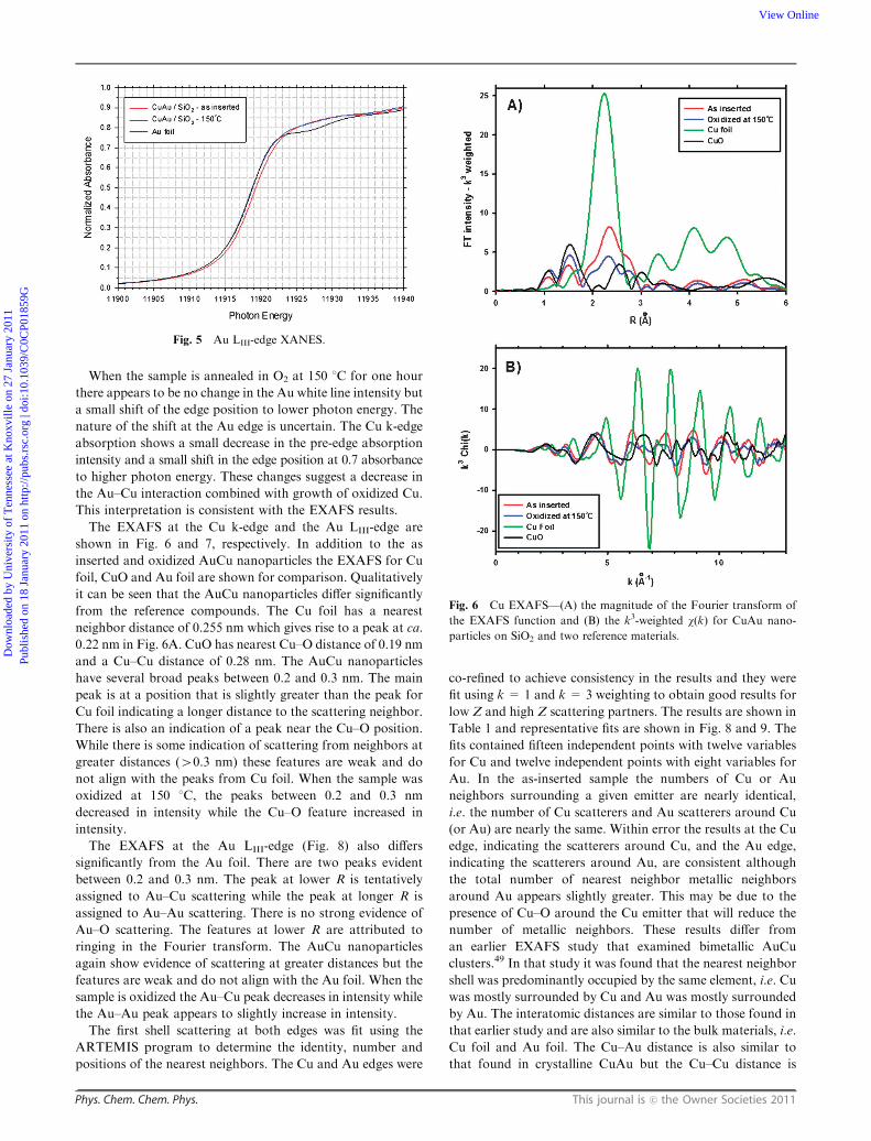
When the sample is annealed in O2 at 150 1C for one hour
there appears to be no change in the Au white line intensity but
a small shift of the edge position to lower photon energy. The
nature of the shift at the Au edge is uncertain. The Cu k-edge
absorption shows a small decrease in the pre-edge absorption
intensity and a small shift in the edge position at 0.7 absorbance
to higher photon energy. These changes suggest a decrease in
the Au–Cu interaction combined with growth of oxidized Cu.
This interpretation is consistent with the EXAFS results.
The EXAFS at the Cu k-edge and the Au LIII-edge are
shown in Fig. 6 and 7, respectively. In addition to the as
inserted and oxidized AuCu nanoparticles the EXAFS for Cu
foil, CuO and Au foil are shown for comparison. Qualitatively
it can be seen that the AuCu nanoparticles differ significantly
from the reference compounds. The Cu foil has a nearest
neighbor distance of 0.255 nm which gives rise to a peak at ca.
0.22 nm in Fig. 6A. CuO has nearest Cu–O distance of 0.19 nm
and a Cu–Cu distance of 0.28 nm. The AuCu nanoparticles
have several broad peaks between 0.2 and 0.3 nm. The main
peak is at a position that is slightly greater than the peak for
Cu foil indicating a longer distance to the scattering neighbor.
There is also an indication of a peak near the Cu–O position.
While there is some indication of scattering from neighbors at
greater distances (40.3 nm) these features are weak and do
not align with the peaks from Cu foil. When the sample was
oxidized at 150 1C, the peaks between 0.2 and 0.3 nm
decreased in intensity while the Cu–O feature increased in
intensity.
The EXAFS at the Au LIII-edge (Fig. 8) also differs
significantly from the Au foil. There are two peaks evident
between 0.2 and 0.3 nm. The peak at lower R is tentatively
assigned to Au–Cu scattering while the peak at longer R is
assigned to Au–Au scattering. There is no strong evidence of
Au–O scattering. The features at lower R are attributed to
ringing in the Fourier transform. The AuCu nanoparticles
again show evidence of scattering at greater distances but the
features are weak and do not align with the Au foil. When the
sample is oxidized the Au–Cu peak decreases in intensity while
the Au–Au peak appears to slightly increase in intensity.
The first shell scattering at both edges was fit using the
ARTEMIS program to determine the identity, number and
positions of the nearest neighbors. The Cu and Au edges were
co-refined to achieve consistency in the results and they were
fit using k = 1 and k = 3 weighting to obtain good results for
low Z and high Z scattering partners. The results are shown in
Table 1 and representative fits are shown in Fig. 8 and 9. The
fits contained fifteen independent points with twelve variables
for Cu and twelve independent points with eight variables for
Au. In the as-inserted sample the numbers of Cu or Au
neighbors surrounding a given emitter are nearly identical,
i.e. the number of Cu scatterers and Au scatterers around Cu
(or Au) are nearly the same. Within error the results at the Cu
edge, indicating the scatterers around Cu, and the Au edge,
indicating the scatterers around Au, are consistent although
the total number of nearest neighbor metallic neighbors
around Au appears slightly greater. This may be due to the
presence of Cu–O around the Cu emitter that will reduce the
number of metallic neighbors. These results differ from
an earlier EXAFS study that examined bimetallic AuCu
clusters.49 In that study it was found that the nearest neighbor
shell was predominantly occupied by the same element, i.e. Cu
was mostly surrounded by Cu and Au was mostly surrounded
by Au. The interatomic distances are similar to those found in
that earlier study and are also similar to the bulk materials, i.e.
Cu foil and Au foil. The Cu–Au distance is also similar to
that found in crystalline CuAu but the Cu–Cu distance is
Fig. 5 Au LIII-edge XANES.
Fig. 6 Cu EXAFS—(A) the magnitude of the Fourier transform of
the EXAFS function and (B) the k3-weighted w(k) for CuAu nano-
particles on SiO2 and two reference materials.
Dow
nloa
ded
by U
nive
rsity
of
Ten
ness
ee a
t Kno
xvill
e on
27
Janu
ary
2011
Publ
ishe
d on
18
Janu
ary
2011
on
http
://pu
bs.r
sc.o
rg |
doi:1
0.10
39/C
0CP0
1859
GView Online

This journal is c the Owner Societies 2011 Phys. Chem. Chem. Phys.
different.50 In crystalline AuCu the Cu–Cu distance is 0.28 nm.
Inclusion of a Cu–Cu shell at this distance reduced the quality
of the fits and could not be justified. Further, a Cu–Cu shell at
the nominal Cu foil distance, 0.26 nm, was necessary to obtain
an adequate fit. Therefore the EXAFS results indicate that the
AuCu nanoparticles were highly mixed, as opposed to a
core–shell or segregated structure, but the Au–Cu distances
were not consistent with crystalline AuCu.
When the sample was oxidized at 150 1C the number of
Cu–Cu neighbors decreased and the number of Cu–O neighbors
increased. There was also a slight decrease in the Au–Cu
neighbors and an increase in Au–Au suggesting that oxidation
depletes the Cu–metal interactions. As the Cu is removed from
first Au shell it is replaced by additional Au neighbors. The
nearest neighbor distances did not change at all following
oxidation. It can therefore be concluded, illustrated in
Scheme 1, that the silica supported Au catalysts do transform
into an AuCu alloy in solution and upon calcinations above
150 1C the Cu segregates and oxidizes forming an Au–CuOx
composite. The oxidized sample can then be transformed back
into the AuCu alloy under reducing conditions in H2.
The catalytic activity of intermetallic AuCu nanoparticles
supported on SiO2 was studied to observe the effects of
alloying copper with gold. The Au–Cu loading in silica is
approximately 4.6 wt%. The catalysts were subjected to a
series of heat treatments between room temperature and
500 1C in a 10% O2/He atmosphere for one hour to remove
moisture and organic residue from the surface of the catalysts.
The removal of organic residue is confirmed by thermal
gravimetric analysis (TGA), Fig. 10, which shows a large
decrease in weight (10%) between 250 1C and 400 1C. The
light off curves in Fig. 11 demonstrate how different pretreatment
conditions can influence the catalytic activity of the intermetallic
AuCu catalysts and how the activity of Au/SiO2 (calcined at
500 1C in 10% O2/He for 1 h) compares. As seen in Fig. 11a,
Au/SiO2 begins to catalyze the oxidation of CO near 0 1C,
however, after reaching its maximum conversion of 76% at
B43 1C it begins to deactivate as the temperature increases.
Previous reports of Au/SiO2 synthesized by similar methods
show similar light off temperatures that actually proceeded to
100% conversion and did not change as the temperature
increased, thus stability was not measured at higher
temperatures.51 The AuCu/SiO2 catalysts that were calcined
at 200 1C, 300 1C, 300 1C in 10% O2/He followed by annealing
10%H2/Ar at 300 1C displayed T50 conversion at approximately
220 1C, 176 1C, and 167 1C, respectively. The incomplete
removal of the organic surfactants from low temperature
calcinations may hinder access to the catalytically active sites
Fig. 7 Au EXAFS—(A) the magnitude of the Fourier transform of
the EXAFS function and (B) the k3-weighted w(k) for CuAu nano-
particles on SiO2 and Au foil.
Fig. 8 First shell Cu EXAFS fit for as inserted CuAu on SiO2—(A)
the magnitude of the Fourier transform of the EXAFS function and
the fit from 1.2–3.0 A and (B) the Fourier filtered k3-weighted w(q) dataalong with the fit.
Dow
nloa
ded
by U
nive
rsity
of
Ten
ness
ee a
t Kno
xvill
e on
27
Janu
ary
2011
Publ
ishe
d on
18
Janu
ary
2011
on
http
://pu
bs.r
sc.o
rg |
doi:1
0.10
39/C
0CP0
1859
GView Online

Phys. Chem. Chem. Phys. This journal is c the Owner Societies 2011
Table 1 Fitting results for CuAu nanoparticles on SiO2 and several reference materials
Sample Edge Path N R (0.01) s2 DE0 R factor
CuAu as inserted Cu Cu–Cu 3.5 (1.0) 2.58 0.012 2.0 0.00004Cu–Au 4.1 (1.0) 2.69 0.008 2.0Cu–O 0.9 (0.3) 1.92 0.003 5.1
Au Au–Au 4.6 (0.7) 2.86 0.006 5.1 0.0005Au–Cu 4.8 (0.7) 2.69 0.008 4.5
CuAu-oxidized Cu Cu–Cu 2.0 (1.0) 2.58 0.012 �4.38 0.0005Cu–Au 3.5 (1.0) 2.69 0.01 4.3Cu–O 1.5 (0.4) 1.92 0.003 8.7
Au Au–Au 5.5 (0.8) 2.86 0.006 6.1 0.001Au–Cu 3.8 (0.7) 2.70 0.008 5.1
Cu foil (25 1C) Cu Cu–Cu 12 2.54 0.008 3.6 0.00001CuO Cu Cu–O 4 1.95 0.002 11.9 0.001Au foil (�75 1C) Au Au–Au 12 2.87 0.005 4.6 0.00003
Fig. 9 First shell Au EXAFS fit for as inserted CuAu on SiO2—(A)
the magnitude of the Fourier transform of the EXAFS function and
the fit from 1.5–3.0 A and (B) the Fourier filtered k3-weighted w(q) dataalong with the fit.
Scheme 1 Illustration of the transformation process that silica sup-
ported gold catalysts undergo during the conversion process. The Au
nanoparticles are first transformed into weakly ordered AuCu alloy
catalysts, and then phase segregated during calcinations to Au–CuOx
heterostructures and finally can re-form the alloy under reducing
conditions.
Fig. 10 TGA curves of the AuCu/SiO2 catalyst under air (solid line)
and nitrogen (dashed line).
Fig. 11 Temperature-dependent CO oxidation over SiO2 supported
(a) Au nanoparticle catalysts pretreated at 500 1C in 10% O2/He
and intermetallic AuCu nanoparticle catalyst following different
pretreatment conditions: (b) 200 1C in 10% O2/He, (c) 300 1C
10% O2/He, (d) 300 1C in 10% O2/He for 1 h followed by 300 1C
in 10% H2/Ar for 0.5 h, (e) 400 1C 10% O2/He, and (f) 500 1C 10%
O2/He.
Dow
nloa
ded
by U
nive
rsity
of
Ten
ness
ee a
t Kno
xvill
e on
27
Janu
ary
2011
Publ
ishe
d on
18
Janu
ary
2011
on
http
://pu
bs.r
sc.o
rg |
doi:1
0.10
39/C
0CP0
1859
GView Online

This journal is c the Owner Societies 2011 Phys. Chem. Chem. Phys.
and may be partly responsible for the latent CO oxidation
activity. However, when the samples are calcined at 400 1C
and 500 1C (Fig. 11e and f) the T50 conversions occur at
dramatically lower temperatures (25 1C and 6 1C) and based
on the XRD data presented in Fig. 3, the active phase is a
Au–CuO composite. In the case of the AuCu/SiO2 sample that
was calcined at 300 1C (to remove the organic surfactants)
followed by H2 to obtain the intermetallic structure it can be
observed that the catalytic activity dramatically increases at
the temperature where copper begins to segregate and oxidize
to form a Au–CuO composite structure.
Though a light off curve is useful in scanning the temperatures
as a catalyst activates, its interpretation for bimetallic catalysts
may be ambiguous if the catalyst structure changes with
temperature. This is especially true when elements, such as
copper, which can easily be oxidized under reaction conditions.
As the catalyst’s activity is probed over a range of temperatures,
as well as undergoing a variety of heat treatments prior to the
catalytic experiment, the correlation between the catalytic
activity and the phase of the Au–Cu system comes into
question. To obtain a better understanding of phase changes
on activity the weakly ordered alloy of the AuCu/SiO2 catalyst
was subjected to different pretreatment conditions and then
the CO oxidation activity was measured at room temperature
for two hours, conditions that inhibit any changes in the
crystalline phase or structure. Fig. 12 shows that when the
AuCu/SiO2 was not subjected to any pretreatment or when it
was calcined at 200 1C prior to catalysis experiment, little to no
CO conversion was observed. Interestingly, the sample heated
at 300 1C in Fig. 12c started with low conversion and gradually
approached 100% conversion within the 2 h time period.
Pretreatment of the catalyst in an O2 atmosphere at 400 1C
for 1 h yielded a Au–CuO catalyst that gave 100% CO
conversion at room temperature. It is important to note that
unlike the light-off curves in Fig. 11, the same catalyst in
Fig. 12 was sequentially subjected to all heat treatment
conditions just mentioned which may have formed a slightly
more oxidized and thus a more active catalyst Au–CuO/SiO2
at 400 1C compared to the sample in Fig. 11. The same
Au–CuO/SiO2 catalyst was then reduced in a 10% H2/Ar
atmosphere at 300 1C for 1 h to form the intermetallic AuCu
nanoparticle catalyst. It should also be safe to assume that
after heating in air at 400 1C all organic surfactants were
removed and the surface of the catalyst should be clean.
It is also certain that the intermetallic AuCu nanoparticles
supported on silica are stable up to 130 1C and by testing the
catalytic activity at room temperature the intermetallic structure
will not change. As shown in Fig. 12e, when the Au–CuO
catalyst (calcined at 400 1C) was reduced in H2 at 300 1C to
form the intermetallic AuCu/SiO2 catalyst, the activity drops
from 100% CO conversion (from the Au–CuO phase) to near
0% conversion at room temperature.
In situ FTIR spectroscopy was conducted to clarify the
catalytic behavior observed in Fig. 12. Fig. 13A–C show that
when the alloyed AuCu/SiO2 catalyst was heated in 2% O2/He
at 250 1C, 300 1C, and 350 1C, two broad absorption components
at 2117 and 2127 cm�1 were observed. These results agree
relatively well with reported FTIR spectra of CO absorbed
onto metallic Au (B2115 cm�1)52 and oxidized Cu supported
on Al2O3 (B2120).53 The broad features observed are due to
adsorbed CO that is accompanied by gas phase CO peaks that
are also observed at 2165 cm�1 and at 2115 cm�1 that underlies
the surface CO bond. Previous FTIR studies indicate that CO
absorbed on a cationic Au species exhibits an IR band at
2142 cm�1 after calcination at 400 and 500 1C.54
After the sample was oxidized at 350 1C, it was then treated
with H2 at 350 1C and then 400 1C. As shown earlier, CuOx is
reduced under these conditions and the Cu diffuses back into
the Au particles to re-form the weakly ordered intermetallic
phase. Exposure of CO at room temperature upon this
reduced AuCu/SiO2 results in no adsorbed CO. Only gas
phase CO bands are seen (Fig. 13D and E). The reduced
Fig. 12 Time-dependent CO oxidation of SiO2 supported inter-
metallic AuCu (L10 phase) after being subjected to different pretreatment
conditions: (a) as-synthesized catalyst, (b) 200 1C in O2 for 1 h, (c) 300 1C
in O2 for 1 h, (d) 400 1C in O2 for 1 h, and (e) 300 1C in H2 for 1 h.
Fig. 13 Room temperature FTIR spectra of CO adsorbed on SiO2
supported L10 intermetallic AuCu nanoparticles pretreated at (A)
250 1C in O2, (B) 300 1C in O2, (C) 350 1C in O2, (D) 350 1C in O2
followed by 350 1C in H2, (E) 350 1C in O2 followed by 400 1C in H2,
(F) 350 1C in O2, then 400 1C in H2, followed by 400 1C in O2.
Dow
nloa
ded
by U
nive
rsity
of
Ten
ness
ee a
t Kno
xvill
e on
27
Janu
ary
2011
Publ
ishe
d on
18
Janu
ary
2011
on
http
://pu
bs.r
sc.o
rg |
doi:1
0.10
39/C
0CP0
1859
GView Online

Phys. Chem. Chem. Phys. This journal is c the Owner Societies 2011
sample was then re-treated in O2 at 400 1C to form a phase
segregated Au–CuOx catalyst. As shown in Fig. 13F the bands
at 2117 and 2127 cm�1 characteristic of surface adsorbed CO
reappeared. The FTIR spectra in Fig. 13 therefore indicate
that CO will not sufficiently adsorb onto AuCu alloy nano-
particles and this fact is responsible for the low activity
observed in Fig. 12e.
Conclusion
It has been shown that preformed Au nanoparticles supported
on SiO2 can be converted into supported intermetallic AuCu
nanocrystals in an organic solution in the presence oleylamine
and oleic acid. This synthetic method allows for the formation
AuCu nanoparticles with diameters averaging around 4.0 nm
with a tight distribution in size. In situ XRD indicate that
when the silica supported AuCu intermetallic nanoparticles
are heated above 150 1C in O2 the copper oxidizes and
segregates to form a Au–CuO/SiO2 heterostructure. XANES
and EXAFS also confirmed that the AuCu nanoparticles were
homogeneously mixed and upon heating to 150 1C Cu begins
to oxidize and segregate from the intermetallic structure. CO
oxidation light-off curves indicate that the intermetallic AuCu
nanoparticles show little activity until temperatures approach
150 1C. At this point amorphous CuO begins to form and then
the catalytic activity rapidly increases to 100% CO conversion.
Catalyst samples that are treated in O2 at 400–500 1C show
high activity at room temperature. These high temperature
oxidations yield Au and amorphous CuO heterostructures are
formed with a high degree of interfacial contact and increased
thermal stability. For instance, when the weakly ordered alloy
of the AuCu/SiO2 catalyst is oxidized to Au–CuO/SiO2 at
500 1C, 100% CO conversion is reached at temperature
slightly above 0 1C and is maintained through 300 1C. It has
also been shown that even when these highly stable and
active catalysts are reduced in H2 at 300 1C to reform the
intermetallic structure the catalyst deactivates.
It has become apparent through the studies conducted
here as well as in conjunction with previous reports that
NiAu/SiO218 and AuSn19 alloy catalysts can successfully be
manipulated through a series of heat treatment conditions to
yield highly active and stable catalyst for the oxidation of CO.
The advantage of alloying a catalytically active metal with a
second metal is that one can precisely control the composition
of the alloy and therefore the amount of the oxide that is
formed to stabilize the catalyst.
Acknowledgements
The research was sponsored by the Division of Chemical
Sciences, Geosciences, and Biosciences, Office of Basic Energy
Sciences, U.S. Department of Energy, under Contract No.
DE-AC05-00OR22725 with Oak Ridge National Laboratory,
managed and operated by UT-Battelle, LLC. Use of the
National Synchrotron Light Source, Brookhaven National
Laboratory, was supported by the US Department of Energy,
Office of Science, Office of Basic Energy Sciences, under
Contract No. DE-AC02-98CH10886. A portion of this research
was conducted at the Center for Nanophase Materials
Sciences, which is sponsored at Oak Ridge National Laboratory
by the Scientific User Facilities Division, U.S. Department of
Energy.
References
1 A. G. Sault, R. J. Madix and C. T. Campbell, Surf. Sci., 1986, 169,347.
2 N. Saliba, D. H. Parker and B. E. Koel, Surf. Sci., 1998, 410, 270.3 J. Wang and B. E. Koel, J. Phys. Chem. A, 1998, 102, 8573.4 (a) M. Haruta, N. Yamada, T. Kobayashi and S. Iijima, J. Catal.,1989, 115, 301; (b) M. Haruta, S. Tsubota, T. Kobayashi,H. Kageyama, M. J. Genet and B. Delmon, J. Catal., 1993, 144,175.
5 M. Haruta, CATTECH, 2002, 6, 102.6 M. Haruta, Catal. Today, 1997, 36, 153.7 S. Galvagno and G. Parravano, J. Catal., 1978, 55, 178.8 C. Mohr, N. Hofmeister, M. Lucas and P. Claus, Chem. Eng.Technol., 2000, 23, 324.
9 Y. S. Chi, H. P. Lin and C. Y. Mou, Appl. Catal., A, 2005, 284,199.
10 C. M. Yang, M. Kalwei, F. Schuth and K. J. Chao, Appl. Catal., A,2003, 254, 289.
11 S. H. Overbury, L. Ortiz-Soto, H. G. Zhu, B. Lee, M. D. Amiridisand S. Dai, Catal. Lett., 2004, 95, 99.
12 L. Guczi, G. Peto, A. Beck, K. Frey, O. Geszti, G. Molnar andC. Daroczi, J. Am. Chem. Soc., 2003, 125, 4332.
13 G. Martra, L. Prati, C. Manfredotti, S. Biella, M. Rossi andS. Coluccia, J. Phys. Chem. B, 2003, 107, 5453.
14 M. Okumura and M. Haruta, Chem. Lett., 2000, 396.15 M. Comotti, W.-C. Li, B. Spliethoff and F. Schuth, J. Am. Chem.
Soc., 2005, 128, 917.16 N. Zheng and G. D. Stucky, J. Am. Chem. Soc., 2006, 128, 14278.17 (a) H. G. Zhu, Z. Ma, J. C. Clark, Z. W. Pan, S. H. Overbury and
S. Dai, Appl. Catal., A, 2007, 326, 89; (b) H. G. Zhu, C. D. Liang,W. F. Yan, S. H. Overbury and S. Dai, J. Phys. Chem. B, 2006,110, 10842.
18 A.-Q. Wang, J.-H. Liu, S. D. Lin, T.-S. Lin and C.-Y. Mou,J. Catal., 2005, 233, 186.
19 (a) S. Zhou, Z. Ma, H. Yin, Z. Wu, B. Eichhorn, S. H. Overburyand S. Dai, J. Phys. Chem. C, 2009, 113, 5758; (b) S. Zhou, H. Yin,V. Schwartz, Z. Wu, D. Mullins, B. Eichhorn, S. H. Overbury andS. Dai, ChemPhysChem, 2008, 9, 2475.
20 K. Yu, Z. Wu, Q. Zhao, B. Li and Y. Xie, J. Phys. Chem. C, 2008,112, 2244.
21 (a) N. K. Chaki, H. Tsunoyama, Y. Negishi, H. Sakurai andT. Tsukuda, J.Phys. Chem. C, 2007, 111, 4885; (b) M. J. Kim,K. Y. Lee, G. H. Jeong, J. K. Jang and S. W. Han, Chem. Lett.,2007, 1350; (c) J.-H. Liu, A.-Q. Wang, Y.-S. Chi, H.-P. Lin andC.-Y. Mou, J. Phys. Chem. B, 2004, 109, 40; (d) M. Tominaga,T. Shimazoe, M. Nagashima, H. Kusuda, A. Kubo, Y. Kuwaharaand I. Taniguchi, J. Electroanal. Chem., 2006, 590, 37; (e) C. Wang,H. Yin, R. Chan, S. Peng, S. Dai and S. Sun, Chem. Mater., 2009,21, 433; (f) H. G. Zhu, L. L. Bao, S. M. Mahurin, G. A. Baker,E. W. Hagaman and S. Dai, J. Mater. Chem., 2008, 18, 1079.
22 (a) H. Lang, S. Maldonado, K. J. Stevenson and B. D. Chandler,J. Am. Chem. Soc., 2004, 126, 12949; (b) S. Mandal, A. B. Mandaleand M. Sastry, J. Mater. Chem., 2004, 14, 2868; (c) S. Zhou,K. McIlwrath, G. Jackson and B. Eichhorn, J. Am. Chem. Soc.,2006, 128, 1780; (d) S. H. Zhou, G. S. Jackson and B. Eichhorn,Adv. Funct. Mater., 2007, 17, 3099.
23 (a) D. A. Cadenhead and N. G. Masse, J. Phys. Chem., 1966, 70,3558; (b) F. Ksar, L. Ramos, B. Keita, L. Nadjo, P. Beaunier andH. Remita, Chem. Mater., 2009, 21, 3677; (c) M. O. Nutt,K. N. Heck, P. Alvarez and M. S. Wong, Appl. Catal., B, 2006,69, 115; (d) M. O. Nutt, J. B. Hughes and M. S. Wong, Environ.Sci. Technol., 2005, 39, 1346; (e) D. Wang, A. Villa, F. Porta,L. Prati and D. Su, J. Phys. Chem. C, 2008, 112, 8617.
24 C. Mohr, H. Hofmeister, J. Radnik and P. Claus, J. Am. Chem.Soc., 2003, 125, 1905.
25 (a) C. L. Bracey, P. R. Ellis and G. J. Hutchings, Chem. Soc. Rev.,2009, 38, 2231; (b) M. Tominaga, Y. Taema and I. Taniguchi,J. Electroanal. Chem., 2008, 624, 1.
Dow
nloa
ded
by U
nive
rsity
of
Ten
ness
ee a
t Kno
xvill
e on
27
Janu
ary
2011
Publ
ishe
d on
18
Janu
ary
2011
on
http
://pu
bs.r
sc.o
rg |
doi:1
0.10
39/C
0CP0
1859
GView Online

This journal is c the Owner Societies 2011 Phys. Chem. Chem. Phys.
26 X. Liu, A. Wang, X. Wang, C.-Y. Mou and T. Zhang, Chem.Commun., 2008, 3187.
27 T. S. Mozer, D. A. Dziuba, C. T. P. Vieira and F. B. Passos,J. Power Sources, 187, 209.
28 (a) A. Bahia, I. T. Caga, J. M. Winterbottom, J. M. Brown,C. E. King and I. R. Harris, Appl. Catal., 1986, 25, 199;(b) J. Barrault, D. Duprez, A. Guilleminot, A. Percheron-Gueganand J. C. Achard, Appl. Catal., 1983, 5, 99.
29 T. Takeshita, W. E. Wallace and R. S. Craig, J. Catal., 1976, 44,236.
30 J. C. Bauer, X. Chen, Q. S. Liu, T. H. Phan and R. E. Schaak,J. Mater. Chem., 2008, 18, 275.
31 E. Casado-Rivera, D. J. Volpe, L. Alden, C. Lind, C. Downie,T. Vazquez-Alvarez, A. C. D. Angelo, F. J. DiSalvo andH. D. Abruna, J. Am. Chem. Soc., 2004, 126, 4043.
32 C. Maurizio, G. Mattei, P. Mazzoldi, S. Padovani, E. Cattaruzza,F. Gonella, F. D’Acapito and F. Zontone, Nucl. Instrum. MethodsPhys. Res., Sect. B, 2003, 200, 178.
33 (a) E. Cattaruzza, G. Battaglin, F. Gonella, R. Polloni,B. F. Scremin, G. Mattei, P. Mazzoldi and C. Sada, Appl. Surf.Sci., 2007, 254, 1017; (b) M. Twardowski and R. G. Nuzzo,Langmuir, 2002, 18, 5529.
34 (a) A. K. Sra and R. E. Schaak, J. Am. Chem. Soc., 2004, 126,6667; (b) R. E. Schaak, A. K. Sra, B. M. Leonard, R. E. Cable,J. C. Bauer, Y.-F. Han, J. Means, W. Teizer, Y. Vasquez andE. S. Funck, J. Am. Chem. Soc., 2005, 127, 3506.
35 J.-H. Gwak, S.-J. Kim and M. Lee, J. Phys. Chem. B, 1998, 102,7699.
36 (a) A. K. Sra, T. D. Ewers and R. E. Schaak, Chem. Mater., 2005,17, 758; (b) T. Del Castillo-Castro, E. Larios-Rodriguez,Z. Molina-Arenas, M. M. Castillo-Ortega and J. Tanori,Composites, Part A, 2007, 38, 107.
37 A. Henkel, A. Jakab, G. Brunklaus and C. Sonnichsen, J. Phys.Chem. C, 2009, 113, 2200.
38 M. S. Nashner, A. I. Frenkel, D. L. Adler, J. R. Shapley andR. G. Nuzzo, J. Am. Chem. Soc., 1997, 119, 7760.
39 B. Ravel and M. Newville, J. Synchrotron Radiat., 2005, 12, 537.40 N. H. Chou and R. E. Schaak, J. Am. Chem. Soc., 2007, 129, 7339.
41 W. Chen, R. Yu, L. Li, A. Wang, Q. Peng and Y. Li, Angew.Chem., Int. Ed., 2010, 49, 2917.
42 V. A. Lavrenko, L. I. Kuznetsova and A. I. Malyshevskaya,Powder Metall. Met. Ceram., 2005, 44, 377.
43 R. E. Cable and R. E. Schaak, J. Am. Chem. Soc., 2006, 128, 9588.44 M. Kuhn, T. K. Sham, J. M. Chen and K. H. Tan, Solid State
Commun., 1990, 75, 861.45 A. Tadjeddine, A. Lahrichi and G. Tourillon, J. Electroanal.
Chem., 1993, 360, 261.46 M. Kuhn and T. K. Sham, Phys. Rev. B: Condens. Matter Mater.
Phys., 1994, 49, 1647.47 V. Schwartz, D. R. Mullins, W. Yan, B. Chen, S. Dai and
S. H. Overbury, J. Phys. Chem. B, 2004, 108, 15782.48 M. Varrkamp, J. T. Miller, F. S. Modica, G. S. Lane and
D. C. Koningsberger, Proc. 10th Intern. Congr. Catal., ed.L. Guczi, F. Tetenyi, Elsevier Sci. Pub., 1993, vol. A, p. 809.
49 G. H. Via, K. F. Drake, G. Meitzner, F. W. Lytle and J. H. Sinfelt,Catal. Lett., 1990, 5, 25.
50 E. Bjerkelund, W. B. Pearson, K. Selte and A. Kjekshus, ActaChem. Scand., 1967, 21, 2900.
51 H. Yin, Z. Ma, S. H. Overbury and S. Dai, J. Phys. Chem. C, 2008,112, 8349.
52 (a) M. A. P. Dekkers, M. J. Lippits and B. E. Nieuwenhuys, Catal.Lett., 1998, 56, 195; (b) J. C. Clark, S. Dai and S. H. Overbury,Catal. Today, 2007, 126, 135; (c) J. H. Yang, J. D. Henao,M. C. Raphulu, Y. Wang, T. Caputo, A. J. Groszek,M. C. Kung, M. S. Scurrell, J. T. Miller and H. H. Kung,J. Phys. Chem. B, 2005, 109, 10319; (d) M. Mihaylov,B. C. Gates, J. C. Fierro-Gonzalez, K. Hadjiivanov andH. Knozinger, J. Phys. Chem. C, 2007, 111, 2548; (e) F. Boccuzziand A. Chiorino, J. Phys. Chem. B, 2000, 104, 5414;(f) J. D. Henao, T. Caputo, J. H. Yang, M. C. Kung andH. H. Kung, J. Phys. Chem. B, 2006, 110, 8689; (g) D. C. Meierand D. W. Goodman, J. Am. Chem. Soc, 2004, 126, 1892.
53 O. Dulaurent, X. Courtois, V. Perrichon and D. Bianchi, J. Phys.Chem. B, 2000, 104, 6001.
54 Z. Wu, S. Zhou, H. Zhu, S. Dai and S. H. Overbury, J. Phys.Chem. C, 2009, 113, 3726.
Dow
nloa
ded
by U
nive
rsity
of
Ten
ness
ee a
t Kno
xvill
e on
27
Janu
ary
2011
Publ
ishe
d on
18
Janu
ary
2011
on
http
://pu
bs.r
sc.o
rg |
doi:1
0.10
39/C
0CP0
1859
GView Online