
Heat flow at nanoparticle interfaces
22
journal homepage: www.elsevier.com/locate/nanoenergy Available online at www.sciencedirect.com REVIEW Heat flow at nanoparticle interfaces Ronald J. Warzoha 1 , Amy S. Fleischer n Department of Mechanical Engineering, Villanova University, Villanova, PA 19010, USA Received 28 December 2013; received in revised form 20 March 2014; accepted 22 March 2014 Available online 29 March 2014 KEYWORDS Interfaces; Nanoparticles; Thermal boundary resistance; Substrate; Matrix; Phonon Abstract Nanoparticles are expected to significantly enhance future thermal energy generation systems, thermal energy storage materials, thermal interface materials and electronic devices. How- ever, very few of these technologies are able to take full advantage of the unique thermal properties of nanoparticles, primarily due to the unusual transport phenomena that occur at their interfaces. To this end, a wealth of recent research has focused on the characterization and control of heat flow at different types of nanoparticle interfaces. The goal of this review is to provide critical insight into the mechanisms that govern thermal transport at three different types of nanoparticle interfaces, including: nanoparticle–substrate, nanoparticle–matrix and nanoparticle–nanoparticle interfaces. As part of this effort, we quantify the magnitude of heat flow at each type of interface using a collection of data that is available in the literature. This data is used to determine which physical mechanisms govern thermal transport at each different type of interface. Recent progress in the development of state-of-the-art thermal characterization techniques is also examined within the context of each type of nanoparticle interface. Finally, methods to control heat flow at different nanoparticle interfaces are discussed and future research needs are projected. & 2014 Elsevier Ltd. All rights reserved. Contents Introduction .................................................................. 138 Fundamental heat flow physics at interfaces ........................................... 138 Heat flow at nanoparticle–substrate interfaces ............................................ 140 Heat flow physics at nanoparticle–substrate interfaces ..................................... 140 Thermal metrology and interfacial thermal resistance at nanoparticle–substrate interfaces .............. 142 Augmenting thermal transport at nanoparticle–substrate interfaces ............................. 144 Heat flow at nanoparticle–matrix interfaces .............................................. 145 http://dx.doi.org/10.1016/j.nanoen.2014.03.014 2211-2855/& 2014 Elsevier Ltd. All rights reserved. n Correspondence to: Villanova University, 800 Lancaster Ave., Villanova, PA 19085, USA. Tel.: + 1 610 519 4996. E-mail addresses: [email protected] (R.J. Warzoha), amy.fl[email protected] (A.S. Fleischer). 1 Villanova University, 800 Lancaster Ave., Villanova, PA 19085, USA. Nano Energy (2014) 6, 137–158
Transcript of Heat flow at nanoparticle interfaces

Available online at www.sciencedirect.com
journal homepage: www.elsevier.com/locate/nanoenergy
Nano Energy (2014) 6, 137–158
http://dx.doi.org/12211-2855/& 2014 E
nCorrespondenceE-mail addresses
1Villanova Univers
REVIEW
Heat flow at nanoparticle interfaces
Ronald J. Warzoha1, Amy S. Fleischern
Department of Mechanical Engineering, Villanova University, Villanova, PA 19010, USA
Received 28 December 2013; received in revised form 20 March 2014; accepted 22 March 2014Available online 29 March 2014
KEYWORDSInterfaces;Nanoparticles;Thermal boundaryresistance;Substrate;Matrix;Phonon
0.1016/j.nanoen.2lsevier Ltd. All rig
to: Villanova Unive: ronald.warzoha@ity, 800 Lancaster
AbstractNanoparticles are expected to significantly enhance future thermal energy generation systems,thermal energy storage materials, thermal interface materials and electronic devices. How-ever, very few of these technologies are able to take full advantage of the unique thermalproperties of nanoparticles, primarily due to the unusual transport phenomena that occur attheir interfaces. To this end, a wealth of recent research has focused on the characterizationand control of heat flow at different types of nanoparticle interfaces. The goal of this review isto provide critical insight into the mechanisms that govern thermal transport at three differenttypes of nanoparticle interfaces, including: nanoparticle–substrate, nanoparticle–matrix andnanoparticle–nanoparticle interfaces. As part of this effort, we quantify the magnitude of heatflow at each type of interface using a collection of data that is available in the literature. Thisdata is used to determine which physical mechanisms govern thermal transport at eachdifferent type of interface. Recent progress in the development of state-of-the-art thermalcharacterization techniques is also examined within the context of each type of nanoparticleinterface. Finally, methods to control heat flow at different nanoparticle interfaces are discussedand future research needs are projected.& 2014 Elsevier Ltd. All rights reserved.
Contents
Introduction. . . . . . . . . . . . . . . . . . . . . . . . . . . . . . . . . . . . . . . . . . . . . . . . . . . . . . . . . . . . . . . . . . 138Fundamental heat flow physics at interfaces . . . . . . . . . . . . . . . . . . . . . . . . . . . . . . . . . . . . . . . . . . . 138
Heat flow at nanoparticle–substrate interfaces . . . . . . . . . . . . . . . . . . . . . . . . . . . . . . . . . . . . . . . . . . . . 140Heat flow physics at nanoparticle–substrate interfaces. . . . . . . . . . . . . . . . . . . . . . . . . . . . . . . . . . . . . 140Thermal metrology and interfacial thermal resistance at nanoparticle–substrate interfaces . . . . . . . . . . . . . . 142Augmenting thermal transport at nanoparticle–substrate interfaces. . . . . . . . . . . . . . . . . . . . . . . . . . . . . 144
Heat flow at nanoparticle–matrix interfaces . . . . . . . . . . . . . . . . . . . . . . . . . . . . . . . . . . . . . . . . . . . . . . 145
014.03.014hts reserved.
rsity, 800 Lancaster Ave., Villanova, PA 19085, USA. Tel.: +1 610 519 4996.villanova.edu (R.J. Warzoha), [email protected] (A.S. Fleischer).Ave., Villanova, PA 19085, USA.

R.J. Warzoha, A.S. Fleischer138
Heat flow physics at nanoparticle–matrix interfaces . . . . . . . . . . . . . . . . . . . . . . . . . . . . . . . . . . . . . . 145Thermal metrology and interfacial thermal resistance at nanoparticle–matrix interfaces . . . . . . . . . . . . . . . 147Augmenting thermal transport at nanoparticle–matrix interfaces . . . . . . . . . . . . . . . . . . . . . . . . . . . . . . 149
Heat flow at nanoparticle–nanoparticle interfaces . . . . . . . . . . . . . . . . . . . . . . . . . . . . . . . . . . . . . . . . . . 151Heat flow physics at nanoparticle–nanoparticle interfaces. . . . . . . . . . . . . . . . . . . . . . . . . . . . . . . . . . . 151Thermal metrology and interfacial thermal resistance at nanoparticle–nanoparticle interfaces . . . . . . . . . . . . 152Augmenting thermal transport at nanoparticle–nanoparticle interfaces. . . . . . . . . . . . . . . . . . . . . . . . . . . 154
Concluding remarks and perspectives for the future . . . . . . . . . . . . . . . . . . . . . . . . . . . . . . . . . . . . . . . . . 155Acknowledgment . . . . . . . . . . . . . . . . . . . . . . . . . . . . . . . . . . . . . . . . . . . . . . . . . . . . . . . . . . . . . . . 156References . . . . . . . . . . . . . . . . . . . . . . . . . . . . . . . . . . . . . . . . . . . . . . . . . . . . . . . . . . . . . . . . . . 156
Introduction
The physics that occur at sub-micron length scales can bemanipulated in order to produce remarkable improvementsin the thermal, electrical, optical and mechanical propertiesof materials, allowing for the development of state-of-the-artthermoelectric devices, solar cells, battery electrodes, capa-citors, advanced coatings and composite structures [1–6].The extraordinarily wide range of thermal properties thathave been achieved by nanostructuring materials is primar-ily due to the reduction in their characteristic dimensions tothe point where quantum size effects and energy carrierscattering can be precisely controlled [7–9]. As a result,nanoparticles are beginning to transform future energytechnologies [10].
The intrinsic thermal properties of individual nanoparticleshave been manipulated and tuned to magnitudes that divergesignificantly from the thermal properties of bulk materials[11,12]. For instance, carbon allotropes are typically found toexhibit high thermal conductivities in bulk due to the strongcovalent bonds that exist between individual carbon atoms,which allow phonons to traverse through them at very highfrequencies. The usual example of a bulk carbon allotropewith a very high thermal conductivity is diamond, whose tetra-hedral lattice structure and sp3 atomic bonds allow for highrates of phonon transport, even in the presence of internalphonon–phonon, phonon–electron and/or phonon-defect scat-tering. At the nanoscale, the chemical and physical mechan-isms that govern heat flow in carbon allotropes are furtherenhanced. In these structures, sp2 atomic bonds are formedbetween neighboring carbon atoms, which allow for evenhigher rates of phonon transport when compared to their bulkcounterparts. Further, when the characteristic dimension of thenanoparticle is less than the mean free path of an energycarrier, its transport is considered to be ballistic (i.e. no internalenergy carrier scattering exists). This phenomenon has lead tothe development of carbon-based nanoparticles having thermalconductivities that are measured to be higher than monocrys-talline synthetic diamond [13]. Excellent reviews of the physicalmechanisms that control heat flow within carbon nanoparticlesare given in Refs. [14 and 15].
Alternatively, some nanoparticles are designed to possessextremely low thermal properties. These are exceptionallypromising for use in thermoelectric devices and highly insulat-ing composite materials. Researchers have computationallymanipulated the grain boundaries and atomic defects withinnanoparticles in order to increase internal boundary andUmklapp phonon scattering, thereby reducing heat flow rates
within the nanoparticle itself [16]. Nanoparticles have alsobeen impregnated within bulk materials in order to disruptharmonic phonon frequencies, which are shown to decreasethermal transport significantly [17]. An excellent review ofheat transfer physics in low-dimensional systems with reducedthermal transport properties can be found in ref. [18].
While nanoparticles offer remarkably high or low intrinsicthermal properties, their integration into devices remainschallenging from a thermal perspective. In typical devices,nanoparticles are often placed into contact with a sub-strate, another nanoparticle or are embedded within a hostmaterial (matrix). In this review, the mechanisms thatgovern heat flow at these junctions are discussed, andstate-of-the-art methods to measure and control the pho-non and/or electron scattering at nanoparticle interfacesare presented.
Fundamental heat flow physics at interfaces
Heat flow at interfaces remains an important topic in a widevariety of engineering disciplines, despite the abundance ofresearch that has been conducted in this field to date.A thermal resistance (or the degree to which the flow ofheat is impeded) is generally used to characterize heat flowat an interface (i.e. interfacial thermal resistance). The inter-facial thermal resistance can be classified in two ways: (1) bythermal contact resistance and (2) by thermal boundaryresistance (otherwise known as Kapitza resistance). Ther-mal contact resistance originates from mismatches in thesurface conditions of two solid bodies and is an importantparameter to quantify in electronics packaging, nuclearreactors, internal combustion engines and hypersonic flightvehicles [19,20]. An excellent review of thermal contactresistance at the nano scale can be found in Ref. [21]. In thisreview, we replace the term ‘contact resistance’ with‘constriction resistance’ in order to better elucidate therole of the nano-sized length scales that are associated withnanoparticles.
Thermal boundary resistance is distinctly different fromthermal contact resistance in that it still occurs over atom-ically ‘smooth’ interfaces. This form of interface resistance isdependent on the types of materials that are in contactwith one another; here, one material's pertinent energycarriers (phonons/electrons) are ‘deflected’ at its geo-metric boundaries due to the differences in the electronicand acoustic properties of the contacting material, muchthe same way that rock formations ‘scatter’ (or break up)

Figure 1 Contact morphology and heat flow between different nanoparticle interfaces: (a) nanoparticle–nanoparticle,(b) nanoparticle-matrix material and (c) a nanoparticle in contact with a substrate. Red coloring indicates an increased, non-dimensional temperature gradient at the interface. Figures are for illustration of the heat flow at nanoparticle interfaces only andare not to scale. (a) Contacting nanoparticles (two SWCNTs). (b) Nanoparticle embedded in a surrounding material (C60 fullerenesurrounded by a highly ordered solid). (c) Nanoparticle in contact with a substrate (SWCNT on semi-infinite substrate of arbitrarymaterial).
139Heat flow

982
y
h
dx dy
D/2 2b Isothermal
Planes
R.J. Warzoha, A.S. Fleischer140
hydraulic waves at coastal regions. Eq. (1) is often used tocalculate the thermal boundary resistance at an atomicallysmooth interface [22].
Q ¼GΔT ð1ÞIn Eq. (1), G is the thermal boundary conductance at theinterface (or the inverse of thermal boundary resistance)and ΔT is the temperature gradient across the interface.This type of interfacial thermal resistance can be orders ofmagnitude more significant for nanoparticle-based devicesthan contact resistance and is much more difficult toprecisely model and control. Scientists have developedtwo different analytical models to analyze the physicalbehavior that regulates the thermal boundary resistanceat different interfaces and across multiple length scales:(1) the diffuse mismatch model (DMM), which assumes thatthe energy carriers scatter across an imperfect interfaceand (2) the acoustic mismatch model (AMM), which assumesthat the energy carriers scatter across perfect interfacesand that phonon transfer is exclusively inelastic. Thesemodels (and subsequent advances in these models) havebeen critical for predicting interfacial thermal resistanceand have allowed scientists to develop general strategies toregulate scattering between materials [23,24]. However,while these general models have occasionally predictedthermal impedance across three-dimensional bulk materialswith relatively good accuracy, they are not suitable for low-dimensional nanoparticles.
Scientists are now beginning to examine interfacial heatflow between nanoparticles in more fundamental ways. Whennanoparticles come into contact with another material,thermal energy carrier propagation is generally known to beinhibited by three primary factors: (1) the contact areabetween the nanoparticle and the alternate material (thermalconstriction resistance), (2) the mismatch in the vibrationalharmonics of energy carriers (i.e. phonon spectra) and/or theflow of electronic energy carriers between the materials(thermal boundary resistance) and (3) how well the nanopar-ticle and alternate material are bonded together (thermalconstriction resistance). The contacting region(s) over whichthese phenomena are important are shown in Figure 1(a)–(c) for: contacting nanoparticles (Figure 1(a)), a nanoparticlein contact with a surrounding material (Figure 1(b)) and ananoparticle in contact with a substrate (Figure 1(c)). In thisreview, we discuss the relative importance of each of thesethree physical mechanisms for each of the configurationsshown in Figure 1(a)–(c). To this end, we review: (1) themagnitude of the interfacial thermal resistance that has beenexperimentally measured (or computationally determined) ateach type of interface, (2) the state-of-the-art experimentaltechniques that are currently being used for determining heatflow at each type of interface and (3) novel methods toaugment heat flow at different types of nanoparticle inter-faces. Several remaining issues that pertain to heat flow atnanoparticle interfaces are discussed and future researchneeds in this area are projected.
Figure 2 Model used for analytical analysis of heat flow atnanoparticle–substrate interface; nanoparticle (spherical orcylindrical) of diameter D rests on a semi-infinite substrate.Figure adapted from refs. [27] and [28].
Heat flow at nanoparticle–substrate interfaces
Many of the common components in future devices andmaterials are expected to feature some arrangement of
nanoparticles that are in contact with a substrate. Forinstance, it is expected that nanoparticles will be arrangedinto pathways in order to achieve high rates of electricaltransport using the quantum confinement of electrons forthe development of next-generation integrated circuitry[25,26]. This is made possible by the long mean free path ofelectrons in most metals; however, heat energy carriers(i.e. phonons) within nanoparticles do not have such longmean free paths. As a result, thermal transport is severelyimpeded at the region(s) where scattering is most likely tooccur (at defect sites for nanoparticles with characteristicdimensions 4100 nm and at physical interfaces for bothballistic- and diffusive-dominated transport regimes). This issuecan lead to catastrophic device failure for both semiconductingand metallic nanoparticles and substrates. Thus, it is essentialfor scientists and engineers to better understand the heat flowphysics at nanoparticle interfaces in order to precisely controlthermal transport within larger systems and devices.
Heat flow physics at nanoparticle–substrateinterfaces
Several analytical models have been developed that describethe physics of heat flow at the junction between a nanoparticleand a substrate. Bahadur et al. [27] were among the first toconstruct a physical model to analyze heat flow at this type ofjunction. In their study, the authors chose to model heat flow atthe interface between both spherical and cylindrical nanopar-ticles resting on top of a semi-infinite substrate, as shown inFigure 2.
In this analysis, the surfaces of both the nanoparticle andsubstrate are considered to be perfectly smooth. Additionally,the distance between the nanoparticle and substrate isestimated to be the sum of the van der Waals radii of thenanoparticle and substrate atoms. Thus, the van der Waalspotentials are said to dominate the contact force; as such, theweight of the nanoparticle can be neglected in the calculationof interfacial constriction resistance. The van der Waals forcesbetween all atoms are a function of the separation distance tothe sixth power, and are calculated according to Eq. (2).
Unanoatom substrateatom ¼ � β
s6ð2Þ

141Heat flow
In Eq. (2), Unanoatom substrateatom is the van der Waals potentialbetween a nanoparticle atom and a substrate atom, βrepresents the Lifshitz van der Waals constant and s is thedistance between the nanoparticle and substrate atoms. Thetotal van der Waals interaction force of all atoms acting uponone another in this arrangement is then computed accordingto Eq. (3).
Fvdw ¼ � Aπ
Z D
0
ffiffiffiffiffiffiffiffiffiffiffiffiffiffiffiffiffiðD�yÞy
pðyþ lÞ4 dy ð3Þ
In Eq. (3), A is the Hamaker constant (NsNnpβπ2, where Ns and
Nnp are the number of substrate atoms and nanoparticleatoms, respectively, that interact with one another accordingto the geometry of Figure 2), D is the diameter of thenanoparticle (nm) and l is the characteristic dimension of thenanoparticle (nm). The line contact width (denoted by ‘2b’ inFigure 2) can then be calculated by evaluating the elasticstrain of the nanoparticle, which is based on the van derWaals contact force (Eq. (3)) [27]. The thermal constrictionresistance at the interface is calculated based on a simpleresistance analysis; that is, the individual nanoparticlethermal resistance, substrate thermal resistance and gapthermal resistance are calculated and summed in series. Thegap thermal resistance is defined as the thermal resistancefrom the substrate through the surrounding medium (i.e. air,water, etc.) and subsequently into the nanoparticle. Eachthermal resistance is defined in Eqs. (4)–(7).
Rnp ¼1
lbπknpln
2Db
� �� 1
2lbknpð4Þ
Rs ¼1
lbπksln
Dπb
� �ð5Þ
Rgap ¼ 2lbkf cot sin �1 2bD
� �� π
2þ1
� �� ��1
ð6Þ
Rconstriction ¼ðRnpþRsÞRgap
ðRnpþRsÞþRgapð7Þ
In Eqs. (4)–(7), lb is the length of the nanoparticle that is incontact with the substrate, knp is the nanoparticle thermalconductivity, ks is the substrate thermal conductivity and kf isthe thermal conductivity of the material in the gap betweenthe nanoparticle and the substrate. It is clear that themodel's accuracy relies heavily on determining the precisethermal conductivity of each relevant material. Additionally,while the development of this model accounts for both theadhesion energy and the size of the constriction that isformed between a nanoparticle and a semi-infinite substrate,it does not take into account any additional microscalephysics that may affect thermal transport at the interface.
Prasher [28] reexamined the nature of this problem andmodified the work of Bahadur et al. [27] to include theeffects of additional microscale thermophysics at the inter-face between a non-metallic nanoparticle that is in contactwith a non-metallic substrate. The author apportioned thiswork into three distinct physical models that are based onadditional microscale thermophysics: (1) the diffusive limitwhen the phonon spectra between the nanoparticle and thesubstrate are equivalent (i.e. the characteristic dimensionof the constriction is much larger than the phonon meanfree path and the nanoparticle and substrate are composed
of the same material), (2) the ballistic limit when thephonon spectra between the nanoparticle and the substrateare equivalent (i.e. the characteristic dimension of theconstriction is smaller than the phonon mean free path andthe nanoparticle and substrate are composed of the samematerial) and (3) the ballistic limit when phonon spectrabetween the nanoparticle and the substrate are not equiva-lent (i.e. the characteristic dimension of the constriction issmaller than the phonon mean free path and the nanopar-ticle and substrate are composed of different materials).Eq. (8) defines the thermal constriction resistance betweena non-metallic nanoparticle and a non-metallic substratemade of the same material when phonon transport occurs inthe diffusive regime.
Rconstriction diffusive ¼1
4kbð8Þ
Eq. (8) is known as the Maxwell constriction resistance and isonly dependent on the contact geometry between the nano-particle and the substrate. Compared to the work done byBahadur et al. [27], this represents an even simpler physicalmodel and is accurate only for a handful of configurations duea lack of sufficient physics (such as the bonding energybetween the substrate and the nanoparticle).
On the other hand, ballistic transport through the constric-tion allows for the unimpeded passage of phonons within orthrough a structure. For this case, Prasher [28] considers theflow of phonons through a constriction to be analogous to theflow of gas molecules through an orifice; in both circum-stances, the mean free path of the pertinent energy carrier issignificantly larger than the interface geometry. This simplifiedmodel reduces the complexity of phonon transport in that onlyacoustic phonons need to be considered, as the group velocityof optical phonons is very small relative to that of acousticphonons. Considering transverse conduction only through theconstriction (‘2b’ in Figure 2), the authors construct an energybalance that describes the heat flux at the nanoparticle–substrate interface in Eq. (9).
q¼ vg4π
∑3
Z ωm
0
Z π=2
0
Z 2π
0
ℏωexpðℏω=kbTÞ
DðωÞdω dθ dφ ð9Þ
The heat flux shown in Eq. (9) (q) is based on the groupvelocity of the acoustic phonons, vg (m/s), the phonon fre-quency, ω, the phonon density of states, D(ω), the polar angleθ and the azimuthal angle φ of the atomic arrangement ofmolecules within the material. Upon applying a temperaturegradient across the junction along with using the traditionaldefinition of contact resistance at an interface (Rcontact=(ΔT)/qA), Eq. (9) can be solved to produce a thermal constrictionresistance at the nanoparticle–substrate interface when heatflow is considered to be in the ballistic regime. The result ofthis derivation is given in Eq. (10).
Rconstriction ballistic ¼4l
3keAð10Þ
As is shown in Eq. (10), heat flow in the ballistic regime is adirect function of the phonon mean free path, l (nm), theharmonic mean thermal conductivity at the constriction(ke=2k1k2/(k1+k2), W/mK) and the area of the constriction,A (nm2) when the nanoparticle and substrate are of the samematerial. In a comparison to the model developed by Bahaduret al. [27], Prasher [28] evaluates the same 1 μm long Si

Figure 3 3-ω measurement apparatus for determining nano-particle thermal conductivity and interfacial thermal resistancebetween a nanoparticle and a substrate. Figure adapted fromref. [30].
R.J. Warzoha, A.S. Fleischer142
nanowire on a Si substrate and finds that the model developedby Bahadur et al. [27] significantly underestimates the contactresistance at the interface. This is because the constrictionsize formed by the Si nanowire and Si substrate is �2 nm,whereas the mean free path of phonons in crystalline Si is�250 nm. Thus, most of the thermal constriction resistanceoccurs in the ballistic regime rather than the diffusive regime.
A more accurate determination of the thermal constrictionresistance can be obtained by summing the thermal resis-tances in both the diffusive and ballistic regimes. For ananoparticle resting on a substrate of the same material,the thermal constriction resistance at the junction can bereduced to a form that is a function of the Knudsen number(l/a) such that when Kn-0, the thermal constriction resis-tance is dependent only on the diffusive phonon physics,whereas when Kn-1, the thermal constriction resistanceis only a function of ballistic phonon physics. This type ofanalysis helps to elucidate the pertinent physics associatedwith heat flow at the interface between a nanoparticle andsubstrate made of the same material. However, very rarely arethese two materials the same when integrated into devices.Thus, it is imperative that additional physics be accounted forin an alternate model when dealing with dissimilar materials.
When the nanoparticle and substrate are composed ofdifferent materials, phonons will reflect at the boundarydue to the differences in the vibrational harmonics betweenlattice structures. This reflection is expressed in terms of atransmission coefficient, α, and can be used to construct anenergy balance in order to solve for heat flow across theinterface. The heat flow can then be related to Rcontact (aswas done for Eq. (10)) and the thermal boundary resistancecan be extracted. Using these relations, the thermalboundary resistance (Rb) is calculated according to Eq. (11).
Rb ¼4
α1-2C1vg1ð11Þ
In Eq. (11), the thermal boundary resistance is a function ofthe transmission of phonons from material 1 to material 2ðα1-2Þ, the heat capacity of material 1 and the phonon groupvelocity of material 1. However, calculating Rb analytically ischallenging due to the number of unknown parameters inEq. (11), which often require experiment or great computa-tional expense in order to determine their values where noanalytical formulations are present. Thus, the development ofa more accurate physical model describing the thermalboundary resistance at a nano-sized junction between twodissimilar materials will be critical for the successfulintegration of nanoparticles into future devices. Never-theless, one can use an experimentally determined valueof thermal boundary resistance in order to resolve the totalthermal boundary resistance at a nano-sized interfacebetween two dissimilar materials. As an example, the totalinterfacial thermal resistance across a circular constrictionwhen phonon transfer occurs within the ballistic regime isgiven in Eq. (12).
Rtot ¼1
2kA1þ 2
π
Rbk2b
� �ð12Þ
In this section, heat flow through a nano-sized interface isshown to depend on three primary factors: (1) the area ofthe interface, (2) the strength of the bond between thenanoparticle and the substrate and (3) the phonon spectra
mismatch when two dissimilar materials come into contactwith one another. It is also clear that the size of theinterface dictates the phonon transport regime, which hasa significant effect on heat flow across a nanoparticle–substrate junction. Additionally, when phonon transport isdiffusive, the adhesion energy between the nanoparticleand the substrate is considered to be the dominant mechan-ism affecting heat flow at the interface. Finally, when thenanoparticle and substrate are not fabricated from thesame material, the magnitude of phonon reflection at thejunction is the most significant contributor to heat flow atthe nanoparticle–substrate interface. These results suggestthat the selection of materials and their geometries shouldhave a significant impact on heat transfer in device archi-tectures. However, while these analytical models (and otheranalytical/computational models [29]) describe the physicsassociated with semiconducting materials fairly well, thereis still a need to develop more robust physical models thatdescribe the interaction between phonons and electronsat metallic/metallic and metallic/semiconducting nano-particle–substrate interfaces. Additionally, there have beenrelatively few theoretical studies that address modificationsto the adhesion energy at nanoparticle–substrate interfaces.Until reliable methods for determining the interfacial thermalresistance across multiple, low-dimensional material combina-tions are developed, scientists will be forced to rely on eitherexperiment or numerical simulation in order to extract theinterfacial thermal resistance between a nanoparticle and asubstrate.
Thermal metrology and interfacial thermalresistance at nanoparticle–substrate interfaces
The interfacial thermal resistance between a nanoparticleand a substrate has been measured in two ways: (1) using

143Heat flow
the 3-ω method and (2) using non-contact, optical methods.The 3-ω method uses a set of microheaters/thermometersthat act as both a heat source and heat sink in order tomeasure the thermal properties of a nanoparticle that issuspended across them. A current is applied to the circuitcontaining the metallic leads and the suspended material,and the voltage difference across the leads is measured usinga Wheatstone bridge and lock-in amplifier. The nanoparticle'scharacteristic length, thermal conductivity and the nanopar-ticle–substrate contact area can then be used to calculate thethermal resistance at the nanoparticle–substrate junction. Anexample of a 3-ω device is shown in Figure 3 [30].
Figure 4 Non-contact technique for measuring interfacial thermadapted from ref. [31].
Table 1 Interfacial thermal contact resistance between differ
No. Nanoparticle type Substratematerial
T (K) Con(2b)
1 Carbon nanofiber (d=125 nm) Pt 150 10.02 Carbon nanofiber (d=125 nm) Pt 300 10.03 MWCNT (d=25 nm) Cu 300 1.104 MWCNT (d=25 nm) Al 300 1.035 MWCNT (d=25 nm) Ni 300 1.086 MWCNT (d=25 nm) Au 300 1.317 MWCNT (d=25 nm) Ag 300 2.048 MWCNT (d=25 nm) Ti 300 0.969 MWCNT (d=25 nm) PMMAb 300 5.04
10 MWCNT (d=25 nm) EPb 300 –c
11 MWCNT (d=25 nm) S.E.b 300 –c
12 MWCNT (d=25 nm) PEb 300 5.0913 MWCNT (d=25 nm) PETb 300 5.1514 MWCNT (d=25 nm) PVCb 300 5.2315 InAs nanowire (d=70 nm) Pt 350 1.7016 MWCNT (d=14 nm) Pt 300 1.00
aExtracted directly from reference.bPMMA=Poly(methyl methacrylate), EP=Epoxy resin, S.E.=Silico
late), PVC=Poly(vinyl chloride).cInsufficient data available for analytical calculations.
One disadvantage of this method is that it can only be usedto measure the interfacial thermal resistance between acylindrical nanoparticle and a substrate due to its geometricalconstraints. Additionally, materials limitations restrict the useof this experiment to only a few nanoparticle–substratecombinations; in this case, the materials used to constructthe leads must have well-defined temperature coefficients ofresistance (such as platinum) in order to precisely measure thethermal transport rates across them. Despite its limitations,however, the 3-ω technique does allow for remarkable insightinto the physics that control heat flow at different types ofnanoparticle–substrate junctions.
al resistance between nanoparticles and a substrate. Figure
ent nanoparticle/substrate combinations.
tact width(nm)
Thermal boundaryresistance (experiment) m2 K/W
Reference
0a 2.30� 10�5 [34]0a 1.21� 10�5 [34]
2.39� 10�6 [32]3.02� 10�6 [32]2.28� 10�6 [32]3.95� 10�6 [32]3.84� 10�6 [32]2.76� 10�6 [32]9.32� 10�7 [32]1.53� 10�6 [32]1.72� 10�6 [32]1.79� 10�6 [32]1.79� 10�6 [32]1.49� 10�6 [32]
a 3.51� 10�7 [35]a 5.12� 10�7 [36]
ne elastomer, PE=Polyethylene, PET=Poly(ethylene terephtha-

Figure 5 Temperature-dependent thermal boundary resistanceat MWCNT–substrate junctions. Figure adapted from ref. [31].
R.J. Warzoha, A.S. Fleischer144
An alternative way to measure the thermal resistance atnanoparticle–substrate junctions is to drive a heat fluxthrough a series of aligned nanoparticles that are in contactwith a substrate. To accomplish this, Li et al. [31,32] direct alaser at the midpoint of a nanoparticle array, the ends ofwhich are in contact with different types of substrates. Oncethe system reaches a quasi-equilibrium state, a thermalresistance analogy is applied at the junction betweenMWCNTs and various substrates in order to extract a valuefor interfacial thermal resistance using Eqs. (13) and (14).
Q0nanoparticle ¼ΔTnanoparticle=Rnanoparticle ð13Þ
Rjunction ¼ΔTb
ΔTnanoparticle
Acontact
Across� section
� �ð14Þ
In Eqs. (13) and (14), Q0nanoparticle represents the steady-state
heat flux across the nanoparticle array that is supplied by thelaser, ΔTnanoparticle is the temperature drop from point L topoint M in Figure 4 (as measured by an infrared thermo-meter), Rnanoparticle is the intrinsic thermal resistance alongthe length of the nanoparticles (L to M in Figure 4), ΔTb is thetemperature difference between points A and B in Figure 4,Acontact is the real contact area between the nanoparticlesand the substrate, Across-section is the cross-sectional area ofthe nanoparticle sheet and Rjunction is the interfacial thermalresistance at the nanoparticle–substrate junction. Like the3-ω technique, this technique is only suitable for relativelylong, cylindrical nanoparticles. Additionally, the uncertaintyof this method is substantially higher than the 3-ω techniquedue to the unknown number of nanoparticles that may comeinto contact with one another. However, it is significantlymore economical to use than the 3-ω technique because itdoes not require any advanced nano scale manufacturing.Furthermore, when using this method to measure the inter-facial thermal resistance between different substrates andthe same type of nanoparticle, the results can reveal thesignificant physics at the nanoparticle–substrate interface.
In Table 1, experimentally obtained values of interfacialthermal resistance between different combinations ofnanoparticles and substrates are given. In this table, thenanoparticles are held at the surface by van der Waals forcesonly. Thus, comparing these experimental values allows us todetermine the effect of contact area and phonon spectramismatch on thermal transport across a nanoparticle–sub-strate interface.
Tests 1 and 2 in Table 1 reveal the effect of temperatureon the thermal boundary resistance between a carbon nano-fiber and a platinum substrate. It is clear from this study thatthe thermal boundary resistance between a low-dimensionalnanoparticle and a semi-infinite substrate is a strong functionof temperature. This was confirmed by Zhang et al. [31], whofound that both the trend describing thermal boundaryresistance in this arrangement and the degree to which thethermal boundary resistance is a function of temperaturevary greatly between different sets of nanoparticle/substratecombinations. A composite of this data is given in Figure 5,where the thermal boundary resistance is normalized againstthe intrinsic thermal resistance across the CNTs as well as thecontact area between the CNT and the substrate. It isinteresting to note that the carbon nanofiber–Pt substratethermal boundary resistance is significantly higher than any
of the other test samples in Table 1. This is potentially due tothe higher dimensionality of the nanoparticle, which can leadto poor thermal transport at interfaces and, consequently,low rates of thermal enhancement within bulk materials anddevices [33].
Tests 3–14 in Table 1 identify the effect of substratematerial properties on the thermal boundary resistance atnanoparticle–substrate junctions. For the purely metallicsubstrates (tests 3–8), the contact geometry appears to haveless to do with impeding heat flow than the substrate'sthermophysical properties. According to Eq. (11), this effectis likely due to the discrepancy between the phonon groupvelocities of the MWCNT and each corresponding substratematerial. For instance, the phonon group velocity in copper(4.6 km/s) is less than the phonon group velocity in aluminum(6.4 km/s), resulting in a higher interface resistance at theMWCNT–copper junction. When the Diffuse Mismatch Model isused to calculate α1-2 with these group velocities, phonontransmission at the MWCNT–aluminum interface is nearlydouble that of the MWCNT–copper interface. Thus, thethermal boundary resistance at the MWCNT–aluminum inter-face is nearly half that of the MWCNT–copper interfaceaccording to Eq. (11). When one takes into account thediscrepancy in the size of the constrictions between the twosamples as well as the error associated with the DiffuseMismatch Model, the results in Table 1 suggest that thegreatest contributor to heat flow impedance at nanoparticle–metallic substrate interfaces is the mismatch in phononspectra between the two materials. This is further elucidatedwhen one examines the differences in the values of thermalinterface resistance between metallic and polymer-basedsubstrates, the conclusion of which is supported by studiesthat examine the nature of heat flow at polymer wrappednanoparticle interfaces [37,38]. This remains true for theadditional nanoparticle–substrate material combinations listedin Table 1.
Augmenting thermal transport at nanoparticle–substrate interfaces
The data in Table 1 suggest that thermal transport atnanoparticle–substrate junctions varies widely dependingon both the nanoparticle and substrate materials that are in

145Heat flow
contact with one another as well as the contact area at theinterface. As a result, scientists are investigating ways toeither mitigate or enhance the thermal impedance at thistype of interface in order to increase the performance ofdifferent nanoparticle–substrate combinations for deviceapplications. A survey of one interfacial heat flow enhance-ment technique is provided in Table 2.
Several groups have deposited an interstitial material(platinum) at the interface between a nanoparticle and asubstrate in order to alter both the contact area and‘phonon coherence’ at the junction. To date, this is theonly technique whose heat flow performance enhancementhas been measured at a nanoparticle–substrate interface.However, several other techniques are available for increasingthe adhesion energy, contact area and phonon coherence atthis particular interface, including: chemical functionaliza-tion [39], atomic layer deposition [40] and polymer wrapping[41,42]. Furthermore, the adhesion energy can be quantifiedusing a nanoindenter with lateral force displacement, makingit feasible to obtain accurate calculations of thermal boundaryresistance as a function of the bonding strength betweennanoparticle–substrate interfaces [43]. It is critical that thesetypes of surface modifications be characterized and used foraltering thermal transport at nanoparticle–substrate interfacesin the future.
Heat flow at nanoparticle–matrix interfaces
Nanoparticles are lightweight, have high surface area-to-volume ratios and exhibit a wide range of thermal properties,making them excellent candidates for use in next-generationcomposite materials [44], thermal interface materials [45]and thermal energy storage materials [46–50]. Several groupshave found that the effective thermal conductivities ofnanocomposites with very low volume fractions (up to 1volume percent) are unusually high or low [51–53]. Theseresults suggest that the physics that occur within thesematerials are much different at the nanoscale than the physicsthat occur in composite materials containing macro-sized
Table 2 Interfacial thermal contact resistance between diffenhancement techniques.
No. Nanoparticletype
Substratematerial
T(K)
Contactwidth (2b)(nm)
Thermalaugmentattechnique
1 Carbonnanofiber(d=125 nm)
Pt 150 50.00b Platinumdeposition
2 Carbonnanofiber(d=125 nm)
Pt 300 50.00b Platinumdeposition
15 InAs nanowire(d=70 nm)
Pt 350 8.78b Platinumdeposition
17 MWCNT(d=14 nm)
Pt 300 –c Platinumdeposition
aThermal resistance without enhancement–Thermal resistance witbExtracted directly from reference.cInsufficient information for calculation.
particles. In this section, we review the physics that controlheat flow at the interface between a nanoparticle and asurrounding solid or fluid. Further, different thermal metrologytechniques are reviewed; these techniques are allowingscientists to determine additional physics at nanoparticle–matrix interfaces and are critical for the development of next-generation nanocomposite materials and devices. Finally, thethermal boundary resistance between different types ofnanoparticle–matrix interfaces, as well as techniques thatare used to modify heat flow at this type of interface, areevaluated by using a selective collection of studies that areavailable in the literature.
Heat flow physics at nanoparticle–matrix interfaces
The interfacial thermal resistance between a nanoparticleand a surrounding matrix material is typically determinedby finding a bulk nanocomposite's effective thermal con-ductivity at different nanoparticle volume concentrationsand subsequently applying a physical model to this data set.The physical models that relate the effective thermalconductivity to the nanoscale physics that control heat flowin nanocomposites typically include: (1) the intrinsic thermalproperties of each material, (2) the geometry of the nano-particle(s) and (3) the interfacial thermal resistance at thenanoparticle–matrix junction. Of course, the analytical modelsdetailed in the section describing the thermal resistancebetween a nanoparticle and a substrate could be extractedto fit this condition; however, there is ambiguity in definingthermal transport within fluids at this length scale withoutresorting to the use of complex statistical thermodynamics.Instead, more general models are used to describe the physicsat nanoparticle–matrix interfaces when the matrix is com-posed of a solid or a fluid [54–56]. Each of these models isdetailed in Table 3 and many more have been reviewedextensively in the literature [57,58]. One additional model,developed by Nan et al. [59], has become the leadinganalytical tool used by scientists and engineers to date forextracting the nanoparticle–matrix thermal boundary
erent nanoparticle/substrate combinations and associated
ionThermal resistance(experiment) m2 K/W
Relativeenhancementa
Reference
1.90� 10�5 1.21 [34]
1.06� 10�5 1.14 [34]
1.81� 10�7 1.94 [35]
3.07� 10�7 1.67 [36]
h enhancement

Table 3 Physical models used to determine nanoparticle-matrix interfacial thermal resistance. Rearranged fromRefs. [54–56].
Model name Modela Nanoparticle type(s) Reference
Hasselman–Johnson 2Km þKp �2φðKm �KpÞ�Keð2Km þKp þφðKm �KpÞÞ=Km
Keð2KmKp þKmKpφ=pÞ=Km �2KmKp=pþ2KmKpφ=pSpherical [54]
Prasher et al. 2Km þKp �2φðKm �KpÞ�Keð2Km þKp þφðKm �KpÞÞ=Kmð1þðPrRe=4ÞÞKeð2KmKp þKmKpφ=pÞ=Kmð1þðPrRe=4ÞÞ�2KmKp=pþ2KmKpφ=p
Spherical [55]
Nanda et al. dðKppφ=3KmððKe=KmÞ�1Þ�pÞ2Kp
Cylindrical [56]
aKm=matrix material thermal conductivity, Kp=nanoparticle thermal conductivity, φ=volume fraction of nanoparticles, p=nano-particle aspect ratio, Pr=Prandtl number, Re=Reynolds number, d=nanoparticle diameter.
R.J. Warzoha, A.S. Fleischer146
resistance due to its inclusion of many different factors,including complex geometries and nanoparticle orientation.As such, we briefly describe the significant physics associatedwith each of the models in Table 3 and provide an extendedinterpretation of the relevant physics included in the modeldeveloped by Nan et al. [59]. It should be noted that thisdiscussion is different than that which describes the physicsthat dictate effective thermal conductivity of larger macro-scale nanocomposites; a discussion on the effective thermalconductivity of bulk nanocomposites necessitates the inclusionof several other types of physics, including Brownian motion[60], clustering [61,62], interparticle potential [63] andthermophoresis [64]. Instead, we focus on the interfacialphysics associated with heat flow at nanoparticle–matrixjunctions. As such, the Nan model will be used to extractthe thermal boundary resistance between different nanopar-ticle–matrix combinations from the literature in the followingsections.
Each of the equations in Table 3 can be used to computethe interfacial thermal resistance between an individualnanoparticle and a surrounding solid or fluid. In the firstmodel, developed by Hasselman and Johnson, the thermalboundary resistance is primarily dependent on the aspectratio of the nanoparticle, p, and the ratio of the intrinsicthermal conductivity between the nanoparticle and thesurrounding fluid. In this equation (as well as with allothers) the volume fraction (φ) can be used in order toextract Rb in tandem with simple experimentation. Wedescribe this procedure in the next section. Conversely,the model developed by Prasher et al. [55] finds that thethermal boundary resistance between a nanoparticle and asurrounding matrix material is a function of Brownian fluidmovement in close proximity to the nanoparticle, in addi-tion to the physical mechanisms described by the Hassel-man–Johnson model [54]. This model is only applicablefor nanoparticle–fluid interfaces, while Brownian motionremains controversial in terms of its magnitude effect onthermal transport in bulk materials as well as at nano-sizedinterfaces. Finally, the model developed by Nanda et al.[56] reveals that the interfacial thermal resistance at ananoparticle–matrix interface is primarily a function of thenanoparticle's geometry.
Recently, a benchmark study was conducted in order toassess the validity of different thermal characterization tech-niques and physical models for determining the effectivethermal conductivity and nanoparticle–matrix thermal boundaryresistance for different nanoparticle/matrix combinations [65].
The authors of this study found that the model developed byNan et al. [59] most accurately captured the interfacialthermophysics between different nanoparticles and fluids. Thismodel has also been used extensively in studies that examinethe nature of heat flow between nanoparticles and solidmatrix materials. As such, it is critical to include a detaileddiscussion of the pertinent physics that are described bythis model.
The model developed by Nan et al. [59] is based on theassumption that an interstitial layer with thermal conduc-tivity Ks, whose thickness is represented by δ, residesbetween a surrounding matrix material and the nanoparti-cle. This interstitial layer is realistically meant to representdifferent phenomena that impede heat flow between thematrix and the nanoparticle, including: (1) phonon spectramismatch, (2) contact area, (3) adhesion at the interfaceand (4) the thickness and thermal transport of/through adisoriented layer of matrix material atoms that surround thenanoparticle. The authors begin their investigation of thesephysics by constructing a unit cell that contains a singlenanoparticle, a surrounding matrix material and an inter-stitial layer. Given an elliptical nanoparticle of i=n axes,Eq. (15) can be used to determine the axial equivalentthermal conductivity of the nanoparticle–interstitial layer–matrix composite.
kii ¼ ksksþLiiðkp�ksÞð1�νÞþνðkp�ksÞ
ksþLiiðkp�ksÞð1�νÞ ð15Þ
In Eq. (15), ν and Lii are parameters that are a directfunction of the nanoparticle's geometry [59]. Given that ksand δ are not known apriori, Eq. (15) cannot be used todirectly obtain the thermal boundary resistance betweenthe nanoparticle and the matrix. However, by passingthrough the limit δ-0 and ks-0, Eq. (15) can be rewrittenas Eq. (16).
kii ¼ kp=ð1þðγLiikp=kmÞÞ ð16ÞIn Eq. (16), γ is a function of interfacial thermal resistance,denoted by αk, and the nanoparticle geometry [59]. Theinterfacial thermal resistance is defined in Eq. (17).
αk ¼ RBDkm ð17ÞIn Eq. (17), RBD is the thermal boundary resistance betweenthe nanoparticle and the matrix and km is the thermalconductivity of the surrounding matrix material. Thus, onecan extract the thermal boundary resistance based entirelyon the thermal properties and geometry of the nanoparticle

147Heat flow
and surrounding matrix material. Currently, this representsthe most sophisticated model for describing the thermalboundary resistance between the nanoparticle and thesurrounding matrix material. It is clear, though, that thephonon transport in the ballistic regime should be consid-ered in order to further elucidate the role of nanoscalethermal transport at nanoparticle–matrix interfaces. Min-nich and Chen [66] offer an initial formulation for thethermal boundary resistance at a nanoparticle–matrix inter-face in the ballistic regime; however, a comparison toexperimental data is still needed for verification of themodel, while additional insight into electron–phonon cou-pling at metallic interfaces should also be investigated.Nevertheless, we use the model developed by Nan et al.[59] in order to extract the thermal boundary resistance atnanoparticle–matrix interfaces in the studies that are usedin the next section. We then compare this to state-of-the-art methods that are used to determine the interfacialthermal resistance at different types of nanoparticle–matrixinterfaces.
Thermal metrology and interfacial thermalresistance at nanoparticle–matrix interfaces
The interfacial thermal resistance between an individualnanoparticle and a surrounding matrix material is conven-tionally determined by measuring the effective thermalconductivity of a dilute nanocomposite and applying thephysical model developed by Nan et al. [59]. The effectivethermal conductivity of different nanocomposite materialscan be measured using a variety of different techniques,including: (1) the guarded hot-plate technique (for eithersolid or liquid nanocomposites) [67], (2) the transient hot-wire technique (for liquid nanocomposites, also known asnanofluids) [68], (3) the transient plane source technique(for either solid or liquid nanocomposites) [69,70], (4) the3-ω method (for liquid nanocomposites) [71], and (5) thelaser flash thermal diffusivity technique (for either solid orliquid nanocomposites) [72]. These techniques vary in
Figure 6 Technique for calculating thermal boundary resistance attheory. Data extracted from refs. [73] and [74]. The transient hconductivity of both types of nanoparticle suspensions in refs. [73]
accuracy and required measurement time, but all havebeen used extensively in the literature.
An illustration of the technique used to extract the thermalresistance at the nanoparticle–matrix interface with effectivemedium approximation is provided in Figure 6, which containsdistributions of the effective thermal conductivity as a func-tion of nanoparticle volume fraction and a correspondinglinear curve fit that is used to extract the thermal boundaryresistance. In this figure, ϕv represents the volume fraction ofnanoparticles, ϕc is the critical volume fraction at which thenanoparticles begin to percolate, ke is the effective thermalconductivity of the nanocomposite and km is the matrixmaterial thermal conductivity. In a study conducted by Zhanget al. [73], SWCNTs were embedded within an epoxy in thedilute limit. If we apply a linear curve fit to the data, we canextract the thermal boundary resistance by comparing theequation obtained by the curve fit to the equation that modelsthe thermal conductivity of randomly oriented cylindricalinclusions in ref. [66] and solve for Rb. A similar procedurewas used to derive the thermal boundary resistance at theAl2O3–H2O interface in the work by Xie et al. [74]. At firstglance, the data presented within this figure reveal that thethermal boundary resistance at a nanoparticle–matrix inter-face can vary substantially between different sets of nano-particle–matrix combinations. To date, no single study hascompared the results of multiple studies in order to observethe variances in thermal boundary resistance as a function ofnanoparticle type, nanoparticle geometry and matrix materialtype. In this review, we provide a limited interpretation ofsome of the physical mechanisms that alter the thermalboundary resistance based on the aforementioned para-meters. However, many additional studies are needed in orderto quantitatively assess the influence of these parameters, andothers, on interfacial heat flow at nanoparticle–matrix junc-tions with confidence.
An alternative method for determining the thermalboundary resistance at a nanoparticle–matrix interface isbeing used by a handful of research groups. This state-of-the-art technique uses transient absorption to measurethe thermal boundary resistance at nanoparticle–matrix
nanoparticle–matrix interfaces using modified effective mediumot-wire apparatus is used to measure the effective thermaland [74].

Figure 8 Example of absorption decay used to extract thethermal boundary resistance between a single nanoparticle anda surrounding matrix material using optical techniques. Extractedfrom Ref. [76].
R.J. Warzoha, A.S. Fleischer148
interfaces. Transient absorption measurements are made usinga modified modulated laser apparatus [75–77]. For this techni-que, the temperature decay of the nanoparticles after modula-tion is measured using a series of sub-picosecond pulseswithin relevant absorption spectra (graphene, for instance,exhibits absorption peaks within a wavelength range of740 nm4λ4840 nm). The resulting temperature decay timecan then be used to calculate the interface conductance (G)using Eq. (18):
τ¼ C=AG ð18Þ
In Eq. (1), τ is the temperature decay time (ps), C is the heatcapacity of the nanoparticle (J/K), A is the area of the nano-particle (m2) and G is the interface conductance (W/m2K).Examples of the transient absorption distribution resultingfrom a single measurement are shown in Figures 7 and 8.Because the spatial resolution is on the order of nm, theinterface conductance can be determined across differentatomic layer configurations. For instance, if a surfactant isused to stabilize the nanoparticle so as to avoid nanoparticlesettling, the interface conductance can be calculated for thenanoparticle–surfactant and surfactant–matrix interfaces bysimply manipulating the absorption spectra. For example, thistechnique has been used to determine that the thermalcontact conductance between a semiconducting CNT and asurfactant is significantly higher (11.5 MW/m2K) than betweena metallic CNT and a surfactant (9 MW/m2K) [76]. In thefuture, this will also allow for further insight into the effect ofheat flow across surface functional groups for tuning thermaltransport at nanoparticle–matrix interfaces.
The interfacial thermal resistance at a sampling ofseventeen total nanoparticle–matrix material junctions isshown in Table 4. The studies that were used to produce the
Figure 7 Example of absorption decay used to extract thethermal boundary resistance between a single nanoparticle anda surrounding matrix material using optical techniques. Extractedfrom Ref. [22].
data in Table 4 were chosen for this review based on twocriteria: (1) the nanoparticles are within the dilute limit(i.e. they do not percolate) and (2) all dimensions andthermophysical properties of the nanostructures are sup-plied by the studies' authors. We could not find additionalstudies beyond those listed in Table 4 that met both of thesecriteria. In order to satisfy our first criterion, Eq. (19) wasused to determine the volume fraction at which thenanoparticles begin to percolate (otherwise known as thecritical volume fraction, ϕc) [78].
ϕc ¼0:62p
ð19Þ
In Eq. (19), p represents the aspect ratio of the nano-particle. For this work, only studies that include three ormore data points at volume fractions below ϕc are usedto extract the thermal boundary resistances in Table 4. Thedata in Table 4 appear to suggest that the thermal boundaryresistance varies greatly as a function of nanoparticle geo-metry, type and materials combinations, which contra-dicts the results presented in a recent benchmark study thatclaimed the thermal boundary resistance at this interface ismore or less independent of these parameters [65]. Thisdiscrepancy is potentially due to the wider range of sampletypes examined in this review. Additionally, significant errormay result in [65] due an insufficient number of measure-ments for each type of nanoparticle (i.e. measurementsmust be taken for at least three volume loading levelsin order to create a highly accurate linear best fit curve forthe extraction of thermal boundary resistance; in manyinstances, measurements are reported at only two volumeloading levels). Results for one of the most common nano-fluids (Al2O3–H2O) suggest that the thermal boundary resis-tance at this type of interface can vary by over two ordersof magnitude, which is well above the error associated withthe individual measurement techniques and/or the curvefitting procedure used to solve for Rb. In this case, it is clearthat the size of the nanoparticle has a marked effect onthermal boundary resistance, though it should be noted thatnone of these studies describe the surface conditions of theindividual particles. It is therefore suggested that additionalbenchmarking studies be done in order to eliminate poten-tial discrepancies in surface characteristics and to verifythat the nanoparticle–matrix contact area can in fact have a

Table 4 Interfacial thermal resistance at different nanoparticle interfaces for selected nanoparticle composite materials.
Matrix material Nanoparticle type Nanoparticle shape Nanoparticlediameter (nm)
Nanoparticleaspect ratio
Thermal boundaryresistance (m2 K/W)
Ref.
H2O Al2O3 Spherical 36.0 1 1.8� 10�8 [79]H2O Al2O3 Spherical 20.0 1 1.0� 10�8 [73]H2O Al2O3 Spherical 47.0 1 1.9� 10�9 [80]H2O Al2O3 Spherical 45.0 1 1.3� 10�8 [81]H2O Al2O3 Spherical 60.4 1 2.0� 10�10 [74]EG SWCNT Cylindrical 1.0 100 6.5� 10�9 [82]EG SWCNT Cylindrical 1.2 300 2.4� 10�9 [83]EG Al2O3 Spherical 50.0 1 3.0� 10�9 [84]EG Al2O3 Spherical 45.0 1 3.2� 10�8 [81]EG Nanodiamond Spherical 4.0 1 4.5� 10�10 [85]Epoxy SWCNT Cylindrical 1.1 152 2.4� 10�9 [86]Epoxy Silica Spherical 32.5 1 5.2� 10�9 [87]Epoxy FLGa Plate 25.0b 1200 6.8� 10�7 [88]Paraffin HGNFc Cylindrical 100.0 1000 6.8� 10�4 [33]Cu MWCNT Cylindrical 12.5 400 8.3� 10�8 [89]
aFLG=Few Layer Graphene.bThickness.cHGNF=Herringbone Graphite Nanofiber.
149Heat flow
two-order of magnitude effect on thermal transport at thistype of interface.
A closer examination of Table 4 also reveals that thetypes of materials that are in contact with one another havea strong effect on the interfacial thermal resistancebetween them. For instance, when examining the SWCNT–matrix interfaces, one observes that the matrix material hasa significant impact on thermal transport at the junction.Here, the SWCNT–H2O thermal boundary resistance [22] isapproximately 8.3� 10�8 m2 K/W, whereas the thermalboundary resistance at both the SWCNT–ethylene glycoland SWCNT–epoxy interfaces is over an order of magnitudelower. These discrepancies highlight the strong effect ofphonon spectra mismatch at the interface due to either astronger molecular attachment between the matrix mate-rial atoms and the nanoparticle atoms, or a more orderedmolecular arrangement at the nanoparticle–matrix bound-ary. Interestingly, the thermal boundary resistance isremarkably high for nanoparticles whose surfaces are notcylindrical or spherical. The thermal boundary resistanceescalates considerably as the nanoparticle dimensionalityincreases based on the results for graphene nano platelets(2D) and graphite nanofibers (3D). Considering the relativelysmall sample size of the studies used to produce the data inTable 4, it is clear that additional experimental work isneeded to reveal greater insight into the nature of heat flowacross a nanoparticle–matrix material interface as a func-tion of materials combinations, atomic arrangements andnanoparticle surface conditions.
Several studies have attempted to gain insight into thesephenomena via atomistic simulations [90–96]. Xue et al. [95]used molecular dynamics simulations to determine the effectof liquid layering on thermal transport at a nanoparticle–liquidinterface. The authors alter the strength of the bondingenergy between liquid atoms in order to adjust the ordering
of the liquid at the interface. When a temperature gradient isimposed across the solid–liquid interface, the authors noticeno difference in thermal transport as a function of the degreeto which the liquid atoms are “ordered”, or arranged, at theinterface. Thus, the authors theorize that the arrangement ofatoms has little to do with thermal transport at the interface.In an additional study, the authors examine the role ofintermolecular interactions between solid and liquid atomson thermal transport at a nanoparticle–matrix interface [96].Interestingly, the authors find that the bonding strength (oradhesion energy) between the solid and liquid atoms has aprofound effect on thermal transport at the interface. Theirresults suggest that the thermal boundary resistance acrossthe interface can be varied by nearly an order of magnitudeover a relatively small range of adhesion energy between thesolid and matrix-material atoms, which agrees relatively wellwith the analytical predictions made by Prasher [97]. Whilethis result is promising, significantly more experimentalmeasurements are required for its validation. It is suggestedthat future experimental studies examine the atomic arrange-ment and bonding strength at the interface using transmissionelectron microscopy (TEM) and micro-Raman/x-ray diffraction(XRD) studies, respectively, in tandem with state-of-the-artthermal characterization techniques (such as the opticalabsorption technique).
Augmenting thermal transport at nanoparticle–matrix interfaces
Recently, scientists have attempted to adjust interfacial heatflow by modifying the nanoparticles' surface conditions.A sampling of studies that have examined the role ofnanoparticle surface characteristics on thermal transport atthe nanoparticle–matrix interface is given in Table 5. Most

Table 5 Enhancement of thermal boundary resistance using surface modifications at different nanoparticle interfaces forselected nanoparticle composite materials.
No. Matrix material Nanoparticletype
Enhancement method Nanoparticlediameter(nm)
Relativeenhancementa
Ref.
1 Octane (polymeric) SWCNT Covalent attachment of octanemolecules
0.7 3.40 [98]
2 Epoxy FLGb Nitric acid functionalization 25c 1.25 [88]3 H2O Silica �OH functionalization (n=8)d N/Ae 0.92 [99]4 H2O Silica Self-assembled monolayers (n=8)d N/Ae 2.0 [99]5 Silicone oil MWCNT HNO3/NaOH and
hexamethyldisiloxane40 1.5 [100]
6 Mineral oil Nanodiamond Oleic acid (non-covalent) 11 50 [101]7 H2O MWCNT �COOH functionalization 100 40 [102]8 Epoxy MWCNT �COOH functionalization 9.5 0.98–1.02f [103]9 Epoxy SWCNT �COOH functionalization 2 0.014 [103]
10 Octane FLGb C8-pyrene linker N/Ae 1.26 [104]11 Poly(ethylene vinyl
acetate)SWCNT Linear hydrocarbon chain
attachmentsN/Ae 48 [105]
12 Epoxy FLGb Py-PGMA functionalization 2.3c 200 [106]
aThermal resistance without enhancement–Thermal resistance with enhancement.bFLG=Few-layer grapheme.cThickness.dMolecular chain length.eData extracted from molecular dynamics simulations without mention of diameter.fDifference in thermal resistance is within uncertainty of the measurement technique.
R.J. Warzoha, A.S. Fleischer150
studies listed in Table 5 use functional groups that areattached covalently to a nanoparticle's surface in order to:(1) increase the surface area for heat transfer between thenanoparticle and the surrounding matrix material or (2)better match the vibrational spectra by linking molecularstructures that are similar to the surrounding matrix materialvia covalent bond to the nanoparticle. The covalent bondsthat are formed between the surface molecules and thenanoparticle are known to either form at defect sites orreplace carbon atoms at the surface. The latter results in ansp3 bond at the interface where there was previously an sp2
bond, which invariably decreases the intrinsic thermal con-ductivity of the nanoparticle [103]. However, it is possiblethat the reduction in thermal conductivity can be overcomeby increasing the adhesion energy at the nanoparticle inter-face and/or by providing an interstitial material to bridge thedifferent phonon spectra between the nanoparticle and thesurrounding matrix material.
Studies 6 and 7 in Table 5 help to illuminate the difficultiesin resolving the dominant physical mechanisms that controlthermal transport at nanoparticle interfaces. In study 6,MWCNTs are functionalized with –COOH groups in order tobetter match the phonon spectra at the MWCNT–H2O inter-face by providing a covalent bond between the MWCNT'scarbon atoms and the hydrogen/oxygen atoms of the func-tional group, which closely match the phonon spectra of thesurrounding matrix material. It is clear from this study thatby matching the phonon spectra at the interface, a 40-foldreduction in thermal interface resistance is possible despiteany reduction in the intrinsic thermal conductivity of thenanoparticle. This phenomenon is confirmed by the results
presented in studies 1–5. Study 7, however, contrasts theseprevious results; here, –COOH functional groups that areattached to the surface of different CNTs do not help toalleviate phonon spectra mismatch but instead increase it.This results in a significant reduction in thermal conductivityof the overall composite. When comparing studies 6 and 7, itis clear that the thermal transport at the interface (and thusthe thermal transport within bulk nanoparticle-laden compo-sites) can be tuned by controlling the interfacial surfaceconditions of the nanoparticle itself.
Non-covalent attachments also offer some control overthermal transport at nanoparticle–matrix material interfaces.In studies 8, 9 and 10, non-covalent linkers are attached tonanoparticle interfaces. Despite the weak adhesion energy atthe interface, these studies suggest that the rate of thermaltransport across the junction can be increased substantially bybridging the phonon spectra between the nanoparticle andsurrounding matrix. Further, these studies show that it ispossible to increase thermal transport across the interface bya large margin and within a wide range of values.
While it is undoubtedly possible to augment thermaltransport at the nanoparticle–matrix material interface usingsurface functional groups, the thermal boundary resistance atthe interface is predicted to span a range of over three ordersof magnitude based on modifications to the adhesion energy atthe interface alone. As a result, a great deal of additionalwork is needed to achieve precise tunability of thermaltransport at both nano and macro-scale resolutions. Addition-ally, the magnitude effect of replacing sp2 bonds with sp3
bonds on the intrinsic thermal conductivity of different typesof nanoparticles must be studied in greater detail in order to
151Heat flow
optimize the concentration of functional groups on nanopar-ticle surfaces in order to achieve high precision tunability ofheat flow at the interface.
Heat flow at nanoparticle–nanoparticleinterfaces
In next generation devices and materials, energy carriersare expected to traverse through contacting nanoparticles.The nanoparticles can be positioned such that the energycarriers are purposefully guided through pre-defined path-ways, such as in integrated circuitry [107,108], and thereforeconstitute an integral part of next-generation technologies.There are some indications that the state-of-the-art materialsnecessary to implement these technologies are already avail-able; however, it is critical that scientists understand howenergy carriers traverse through different sets of nanoparti-cles in order for nanotechnologies to be included in futuresystems and devices. In this section, we review the pertinentphysics associated with heat flow across the junction(s) of twoor more contacting nanoparticles. We then review the state-of-the-art measurement techniques that are presently beingused to determine the thermal boundary resistance at nano-particle–nanoparticle interfaces and offer a summation of theexperimental data that has been taken to date with respect tothermal boundary resistance. Finally, we examine severalrecent methods that have been developed in order to augmentheat flow at this type of interface and project future needs inthis area.
Heat flow physics at nanoparticle–nanoparticleinterfaces
Here we present the physical models that are typically usedto describe and calculate the thermal boundary resistancebetween two contacting nanoparticles. In the case ofcontacting nanoparticles, atomistic simulations are mostoften used to examine and extract the heat flow physicsacross interfacial regions [109–111]. Though atomistic simu-lations offer critical insight into the physics associated withheat flow at nanoparticle–nanoparticle interfaces, the pair-wise potentials that are used to model the adhesion energybetween the nanoparticles as well as the assumptions usedfor contact separation distance between the nanoparticlesare difficult to validate with reasonable accuracy. Thismakes it difficult to resolve the dominant physical mechan-isms that govern heat flow at this type of interface. Instead,we turn to analytical formulations that describe the physicsassociated with heat flow at nanoparticle–nanoparticleinterfaces, which can easily be compared to experiment inorder to determine the dominant physical mechanismsgoverning thermal transport across nanoparticle junctions.
Of course, the models developed by Bahadur et al. [27] andPrasher [28] can be used to analyze the nanoscale interfacialthermophysics across two individual, contacting nanoparticles.However, these models cannot be used to extract the thermalcontact resistance/thermal boundary resistance at nano-particle interfaces when using conventional experimentation.An alternative physical model that can be used to describe theinterfacial heat flow at nanoparticle–nanoparticle interfaces isprovided by Foygel et al. [112]. This model is typically used to
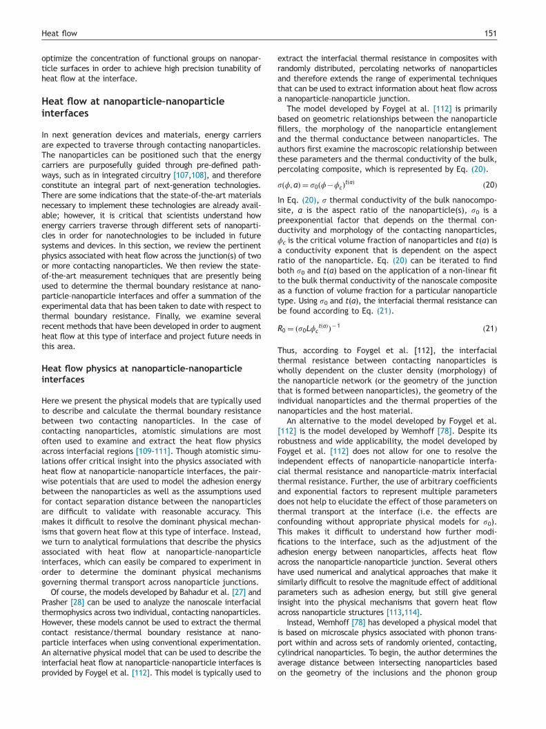
extract the interfacial thermal resistance in composites withrandomly distributed, percolating networks of nanoparticlesand therefore extends the range of experimental techniquesthat can be used to extract information about heat flow acrossa nanoparticle–nanoparticle junction.
The model developed by Foygel at al. [112] is primarilybased on geometric relationships between the nanoparticlefillers, the morphology of the nanoparticle entanglementand the thermal conductance between nanoparticles. Theauthors first examine the macroscopic relationship betweenthese parameters and the thermal conductivity of the bulk,percolating composite, which is represented by Eq. (20).
sðϕ; aÞ ¼ s0ðϕ�ϕcÞtðaÞ ð20ÞIn Eq. (20), s thermal conductivity of the bulk nanocompo-site, a is the aspect ratio of the nanoparticle(s), s0 is apreexponential factor that depends on the thermal con-ductivity and morphology of the contacting nanoparticles,ϕc is the critical volume fraction of nanoparticles and t(a) isa conductivity exponent that is dependent on the aspectratio of the nanoparticle. Eq. (20) can be iterated to findboth s0 and t(a) based on the application of a non-linear fitto the bulk thermal conductivity of the nanoscale compositeas a function of volume fraction for a particular nanoparticletype. Using s0 and t(a), the interfacial thermal resistance canbe found according to Eq. (21).
R0 ¼ ðs0LϕctðaÞÞ�1 ð21Þ
Thus, according to Foygel et al. [112], the interfacialthermal resistance between contacting nanoparticles iswholly dependent on the cluster density (morphology) ofthe nanoparticle network (or the geometry of the junctionthat is formed between nanoparticles), the geometry of theindividual nanoparticles and the thermal properties of thenanoparticles and the host material.
An alternative to the model developed by Foygel et al.[112] is the model developed by Wemhoff [78]. Despite itsrobustness and wide applicability, the model developed byFoygel et al. [112] does not allow for one to resolve theindependent effects of nanoparticle–nanoparticle interfa-cial thermal resistance and nanoparticle–matrix interfacialthermal resistance. Further, the use of arbitrary coefficientsand exponential factors to represent multiple parametersdoes not help to elucidate the effect of those parameters onthermal transport at the interface (i.e. the effects areconfounding without appropriate physical models for s0).This makes it difficult to understand how further modi-fications to the interface, such as the adjustment of theadhesion energy between nanoparticles, affects heat flowacross the nanoparticle–nanoparticle junction. Several othershave used numerical and analytical approaches that make itsimilarly difficult to resolve the magnitude effect of additionalparameters such as adhesion energy, but still give generalinsight into the physical mechanisms that govern heat flowacross nanoparticle structures [113,114].
Instead, Wemhoff [78] has developed a physical model thatis based on microscale physics associated with phonon trans-port within and across sets of randomly oriented, contacting,cylindrical nanoparticles. To begin, the author determines theaverage distance between intersecting nanoparticles basedon the geometry of the inclusions and the phonon group

Figure 9 SEM micrographs of two CNTs in contact with eachother in the following orientations: (a) cross-plane and (b) in-plane. Figure adapted from ref. [115].
R.J. Warzoha, A.S. Fleischer152
velocity attributed to the nanoparticle, as given in Eq. (22).
λ� vgtζτ
¼ π
4LDnð22Þ
In Eq. (22), vg represents the phonon group velocityattributed to the nanoparticle, t is the total time a phononexists in transit intrinsically within a nanoparticle, ζ is thenanoparticle–nanoparticle intersection frequency, λ is theaverage distance between intersecting nanoparticles, L isthe length of the nanoparticle, D is the diameter of thenanoparticle and n is the number of nanoparticle inclusionspresent within the matrix. Using Eq. (22), the equivalentthermal resistance between inclusions is written in Eq. (23).
Rnp�np ¼ AskpeA
0c
λ� kpA
0c
λ
" #ð23Þ
In Eq. (23), Rnp-np is the inter-nanoparticle thermal resis-tance, As is the average overlap area between contactingnanoparticles, kpe is the bulk thermal conductivity of thenanoparticle set (or network), kp is the intrinsic thermalconductivity of the nanoparticle and A
0c is the nanoparticle
cross-sectional area. Thus, the interfacial thermal resis-tance is dependent on the geometry of the nanoparticle,the intrinsic thermal conductivity of the nanoparticle andthe phonon-dominated scattering events within the nano-particle network.
In the following section we detail the thermal metrologyassociated with resolving heat flow at nanoparticle inter-faces experimentally. The different physical models des-cribed in this section will then be used to determine theinterfacial resistance at different types of nanoparticleinterfaces. Both models are used to determine the inter-facial thermal resistance at nanoparticle–nanoparticle junc-tions for experiments that measure heat flow throughcomposites with embedded, percolating nanoparticle struc-tures, while new state-of-the-art methods utilize the phy-sics associated with the models developed by Bahadur et al.[27] and Prasher [28] in order to resolve the magnitude ofheat flow at the junction between nanoparticles. The datagenerated in the next section will be used to quantitativelyassert the dominant mechanisms that are responsible forheat flow across individual nanoparticle junctions.
Thermal metrology and interfacial thermalresistance at nanoparticle–nanoparticle interfaces
For most of the work considered here, the methods used toextract the interfacial thermal resistance between contactingnanoparticles are the same that are used to determine theinterfacial thermal resistance between a nanoparticle–matrixinterface; that is, conventional techniques such as laser-flash,transient hot-wire and guarded hot plate are used to determinethe thermal conductivity of composite materials with randomlyoriented, contacting nanoparticles and physical models (like theFoygel et al. [112] and Wemhoff [78] models) are subsequentlyused to extract the interfacial thermal resistance at nanopar-ticle interfaces. Thus, in this section we review only the state-of-the-art methods that are used to quantify heat flow at thenanoparticle–nanoparticle interface.
Although significant insight into the heat flow physicsat nanoparticle–nanoparticle interfaces can be gained by
utilizing the standard techniques described previously,there is some variability in nanoparticle size distribution,nanoparticle orientation, etc., that result in a reasonabledegree of error in predicting the TBR at this type ofjunction. In order to minimize this error, researchers haveturned to the 3-ω technique, which has traditionally beenused to measure the thermal conductivity of individualnanoparticles. In a seminal study, Yang et al. [115] deter-mine the thermal contact resistance between two individualmultiwalled carbon nanotubes with the 3-ω technique. Theauthors utilize two SiNx membranes with integrated plati-num leads to serve as a heat source/sink network andsubsequently suspend two individual MWCNTs across them.The MWCNTs are placed into contact with one another intwo different orientations (in-plane, where the nanoparti-cles overlap one another along a line segment of atoms, andcross-plane, where the nanoparticle are oriented perpendi-cularly to one another and contact over a small, circulararea) in order to determine the effect of contact orienta-tion on heat flow between sets of nanoparticles. ScanningElectron Micrographs of the apparatus used for this testare shown in Figure 9. The goal of this study is to determinethe optimal orientation for nanoparticles to contact one
Table 6 Interfacial thermal resistance at different nanoparticle–nanoparticle junctions.
Nanoparticletype
Matrix type Nanoparticleshape
Nanoparticleaveragediameter(nm)
Nanoparticleaspect ratio
Thermal contactresistance (m2 K/W)(Foygel)
Model fitparameters(r0|t(a)|Ac)
a
Thermal contactresistance (m2 K/W)(Wemhoff)
Model fitparameters(Rnp-m|knp)
b
Ref.
Aligned MWCNTs(transversedirection)
Epoxy Cylindrical 8 �125,000 N/A N/A 1.02� 10�8 1.00� 10�11|5.42 [116]
Aligned MWCNTs(axial direction)
Epoxy Cylindrical 8 �125,000 N/A N/A 1.02� 10�9 1.00� 10�11|452 [116]
SWCNTs PMMA Cylindrical 1.5 666.77 1.41� 10�8 27|1.5|0.00001
N/A N/A [117]
SWCNTs High densitypolyethylene
Cylindrical 3 148 1.37� 10�8 36|1.6|0.00003
N/A N/A [118]
MWCNTs PDMS Cylindrical 15 5000 2.54� 10�9 350|1.2|0.0013
2.24� 10�9 5� 10�11|538 [119]
HGNFc Paraffin(Solid)
Cylindrical(3D)
100 1000 5.40� 10�5 20|1.4|0.04 N/A N/A [33]
Graphene Hexadecane(Liquid)
Platelet (2D) 5 200 2.40� 10�6 4000|1.7|0.00009
N/A N/A [120]
Graphene Hexadecane(Solid)
Platelet (2D) 5 200 2.20� 10�6 9000|1.8|0.00009
N/A N/A [120]
Few layer graphene Nylon-6 Platelet 7.5 1500 1.33� 10�7 250|1.8|0.0003
N/A N/A [121]
aUnits of s0 are W/m K, t(a) is a fitting parameter depending on the morphology of nanoparticle clusters, Ac=avg. contact area (μm2).bRnp-matrix=Nanoparticle-matrix thermal boundary resistance, knp=nanoparticle thermal conductivity.cHGNF=Herringbone Graphite Nanofiber.
153Heat
flow

R.J. Warzoha, A.S. Fleischer154
another in percolating composites in order to achieve thehighest bulk thermal conductivity of the composite. Theauthors find that the interfacial thermal resistance betweenindividual MWCNTs is on the order of 10�9 m2 K/W and thataligned contact offers a nearly two order of magnitudeincrease in the heat flow rate between nanoparticles thandoes cross-contact, likely due to the available area for heattransfer at the junction. However, while the results of thiswork offer a basis for designing composite materials for optimalthermal performance, the most important feature of this studyis its novelty in experimentally determining the interfacialthermal resistance between individual, contacting nanoparti-cles. The significance of this work can not be understated andshould lead to more accurate findings for interfacial thermaltransport between nanoparticles, including greater insight intothe physical mechanisms that control thermal transport at thenanoparticle–nanoparticle junction.
In order to understand the parameters that affect heat flowat the nanoparticle–nanoparticle interface, we apply thephysical models detailed in the previous section to the datasupplied in seven total data sets that we found in the literature[116–121]. The results are presented in Table 6. The criteriaused for selecting the data are as follows: (1) if the standardtechnique is used to extract the interfacial thermal resistance,the data set must contain at least four data points that arebeyond the percolation threshold, (2) if the standard techniqueis used to calculate the interfacial thermal resistance, allgeometrical properties, including the nanoparticle diameterand length/thickness, must be provided by the author(s) and(3) if the 3-ω technique is used, the authors must haveaccounted for the TBR at the nanoparticle–substrate interface.We also note that the data in Table 6 only represent a fractionof the data that is available in the literature; we choose toincorporate only enough data to illustrate the dominantphysical mechanisms governing thermal transport at the nano-particle–nanoparticle interface. Where possible, a secondarydata set is used to confirm the phenomena revealed by theoriginal data. Finally, both the Foygel et al. model [112] and theWemhoff model [78] are used to extract the interfacial thermalresistance between nanoparticles where appropriate. We notethat for the Foygel et al. model [112], it is necessary to multiplyR0 by the average contact area at the nanoparticle–nanoparticlejunction in order to compare the interfacial thermal resi-stances between groups. To calculate the average contactarea between nanoparticles, we use the methods developedby Wemhoff [78].
For the first two nanoparticle types listed in Table 6, weapply the Wemhoff model [78] to the data provided byMarconnet et al. [116] in order to extract the thermal contactresistance between aligned MWCNTs that randomly linktogether at sidewall locations. Although the Wemhoff model[78] was developed for randomly oriented cylindrical nanopar-ticles, the random linking of the vertically aligned nanoparticles(as is typically found in many common arrangements [122–124])allows for the use of this model to determine the magnitude ofheat flow at the interface. The data suggest that the thermalcontact resistance between MWCNTs is on the orderof�1� 10�8 m2K/W. The Wemhoff model [78] also predictsthe thermal conductivity of the individual MWCNTs within thesurrounding matrix material with remarkable accuracy. In thiscase, the model predicts an axial MWCNT thermal conductivityof 452 W/m K and a transverse MWCNT thermal conductivity of
5.42 W/m K, which are consistent with experimentally mea-sured values that are presented in the literature [125]. Similarresults are found for SWCNTs that are randomly dispersedwithin polymer matrices [117,118]. However, nearly an orderof magnitude reduction in interfacial thermal resistance isfound when much larger MWCNTs come into contact with oneanother [119]; in this case, the average contact area betweenthe MWCNTs is significantly greater than in each of thepreviously mentioned studies. This supports the theory thatthe size of the constriction between contacting nanoparticlescan have an enormous effect on the thermal transport betweenthem. Finally, it seems that the dimensionality of the nano-particle has an enormous effect on the interfacial thermalresistance across nanoparticle junctions. In one study (whichwas conducted by the authors of this paper), the thermalcontact resistance between sets of three-dimensional nanopar-ticles (HGNF) is shown to be four to five orders of magnitudehigher than between sets of SWCNTs and MWCNTs [33].Considering that this analysis normalizes against the nanopar-ticles' intrinsic thermal conductivities (kHGNF=25 W/m K [126],kSWCNT=3000 W/m K [125]), this result is striking. Further proofof this phenomenon is found in the results presented by Zhenget al. [120], whose two-dimensional graphene nanoparticlesexhibit a thermal contact resistance that is on the order of10�6 m2K/W. This is two orders of magnitude higher than theone-dimensional SWCNTs in references 117 and 118, and twoorders of magnitude lower than the three-dimensional HGNFused in ref. [33]. Although these data do provide some insightinto the physical mechanisms that control heat flow betweennanoparticles (i.e. size effects, nanoparticle dimensionality), alarger compilation of data is needed for both confirmation andfurther insight into the effects of contact area and phononspectra matching at nanoparticle–nanoparticle junctions. Wenote here that in order to do this in the future, research groupsmust report all of the relevant geometries and thermophysicalproperties of the individual materials that are in contact withone another, as well as report on the effective thermal con-ductivity of 4 or more volume fractions of nanoparticles inpercolating composite materials.
Augmenting thermal transport at nanoparticle–nanoparticle interfaces
Interfacial thermal transport between contacting nanopar-ticles has long been of interest to the scientific community.However, efforts to augment thermal transport betweencontacting nanoparticles is widely considered to be anemerging frontier in the fields of thermophysics and heattransfer. As a result, only a limited number of researchpublications exist in the literature that address heat flowaugmentation at nanoparticle–nanoparticle interfaces.Further, we could find only one study that can be used toanalyze the physics of heat flow across the junctionbetween nanoparticles. We have compiled the data fromthis study into Table 7 in order to illustrate the effectof surface modifications to nanoparticles on the thermaltransport between them. The interfacial thermal resistancebetween nanoparticles is quantified using both the Fogyelet al. [112] and Wemhoff [78] models described inthe previous section. The data in Table 7 offer promisingresults for future developments of nanoparticle–nanoparticle

Table7
Aug
men
tation
ofthermal
tran
sportat
nano
particle–nan
oparticleinterfac
esusingna
nopa
rticle
surfac
emod
ifica
tion
s.
Nan
oparticle
type
Matrix
type
Surfac
emod
ifica
tion
Nan
oparticle
shap
eNan
oparticle
averag
ediam
eter
(nm)
Nan
oparticle
aspe
ctratio
Thermal
contact
resistan
ce(m
2K/W
)(Foy
gel)
Mod
elfit
parameters
(r0|t(a)|A
c)a
Thermal
contact
resistan
ce(m
2K/W
)(W
emhoff)
Mod
elfit
parameters
(Rnp-m|knp)b
ηcRef.
Graph
ene
Epox
yAmine
func
tion
alization
Platelet
5068
1.18
�10
�7
250|2|0.00
8N/A
N/A
1.6
[127
]
aUnits
ofs 0
areW/m
K,t(a)
isafittingpa
rameter
depe
ndingon
themorph
olog
yof
nano
particle
clusters,Ac=av
g.co
ntac
tarea
(μm
2).
bR n
p-m
atrix=Nan
oparticle-matrixthermal
boun
dary
resistan
ce,k n
p=na
nopa
rticle
thermal
cond
uctivity.
cη=surfac
efunc
tion
alizationefficien
cy(TCR n
anoparticleswith
surface
enhancementin
matrix–TCR n
anoparticlesin
matrix
only).
155Heat flow
systems using surface modifications; in this case, thegrafting of amine groups onto the outer layers of grapheneallow for increased adhesion energy between the nanopar-ticles, which results in a 160% increase in thermal transportacross them [127].
While there is insufficient data to determine the domi-nant physical mechanisms that control heat flow acrossnanoparticle–nanoparticle junctions when nanoparticle sur-faces are modified, there are alternative studies thatqualitatively suggest that the thermal transport betweennanoparticles has been altered significantly. In one studyconducted by Gulotty et al. [103], the thermal conductivityof an MWCNT/epoxy composite in the percolating regimewas shown to decrease with increasing –COOH functionalgroups. Although these functional groups have been shown toincrease the thermal conductivity of other carbon nanoparticle-based composites, this study suggests that an oversaturation of–COOH groups on the MWCNT surface may lead to too large adegradation in the intrinsic thermal conductivity of the MWCNTto overcome the benefits of increased adhesion energy andphonon spectra coherence at the MWCNT–MWCNT interface.This is because for each functional group attachment, one sp3
atomic bond is eliminated in favor of an sp2 atomic bond,thereby reducing the high rate of heat transfer within theMWCNTs due to the original sp3 bonds. Other studies [128,129]involving boron nitride nanoparticles offer varying perspectiveson the ability to augment thermal transport at nanoparticle–nanoparticle interfaces by modifying the adhesion energy,contact area and/or phonon spectra at the surface. Thus, dueto the limited number of results that are used to analyzeinterfacial thermal transport between nanoparticles, additionalbenchmark studies and research are needed before makingdefinitive conclusions about the effect of these parameters onthermal transport across nanoparticle–nanoparticle interfaces.
Concluding remarks and perspectives for thefuture
In this review, the heat flow physics, thermal metrology andinterfacial thermal resistance are examined for three differenttypes of nanoparticle interfaces: (1) nanoparticle–substrateinterfaces, (2) nanoparticle–matrix interfaces and (3) nanopar-ticle–nanoparticle interfaces. These interfaces are particularlyimportant for the development of next-generation electronicdevices, renewable energy systems and materials.
In the first part of this review, the heat flow physics atnanoparticle–substrate interfaces are presented and ana-lyzed. In early studies, the geometry of the constrictionformed between the substrate and the contacting nanopar-ticle (i.e. the contact area) is used as the foundation foranalyzing heat flow across nanoparticle–substrate junctions.However, because the characteristic dimension of theconstriction is on the order of the mean free path ofphonons for most materials, this type of diffusive analysisis found to be insufficient for the accurate prediction ofheat flow between a nanoparticle and a substrate. Instead,both ballistic and diffusive heat flow are considered intandem with the geometry at the interface, which is foundto model heat flow across the nanoparticle–substrate junc-tion with a high degree of accuracy when both the substrateand the nanoparticle are made of the same type of material.

R.J. Warzoha, A.S. Fleischer156
When the two materials are different, however, it is necessaryto account for phonon reflection at the interface in order toaccurately capture the heat flow physics between them. Whenusing these models to analyze the data that are available inthe literature, thermal transport is heavily affected by thevibrational mismatch between the nanoparticle and substratematerials (more so than the contact area between thematerials). Attempts to modify nanoparticle–substrate inter-faces using platinum deposition have been made in order tomitigate phonon scattering between the materials due to thisvibrational mismatch; however, the degree to which increasingthe adhesion energy at the junction affects thermal transportvaries between studies by as much as two orders of magni-tude. Thus, there is a significant need for additional work tobe done in this area in order to determine the relevant phononphysics that can be manipulated in order to tailor heat flowacross different types of nanoparticle–substrate junctions.
Nanoparticle–matrix interfaces are expected to exist in aremarkably large number of materials and devices in thenear future. In this review, we examine the nature of heatflow at these interfaces and subsequently analyze the datathat are available in the literature in order to determine thedominant transport mechanisms that affect thermal trans-port at this type of junction. Typically, the interfacialthermal resistance at the nanoparticle–matrix interface isobtained by saturating a matrix with nanoparticles at avolume loading level that is below the percolation threshold(i.e. the nanoparticles are evenly dispersed and not incontact with one another). By evaluating the effectivethermal conductivity of the nanoparticle–matrix bulk com-posite material for at least three distinct volume fractionsbelow the percolation threshold, the data can be comparedto any number of existing effective medium formulationsand an interfacial thermal resistance can be extracted.While this technique is often associated with significanterror, it has allowed scientists to gain significant insight intothe mechanisms that govern heat flow between a nanopar-ticle and a surrounding matrix. Scientists have also devel-oped an alternative, optical pump-probe technique thatcan determine the interfacial thermal resistance across asingle nanoparticle. Although only a handful of studies haveeffectively utilized this technique to date, it does offer thepromise of greater insight into the governing physics across ananoparticle–matrix interface. When analyzing the data avail-able in the literature, we find that the contact area between ananoparticle and a matrix material can have up to a two-orderof magnitude effect on interfacial heat flow. Additionally, boththe types of materials that are in contact with one anotherand the dimensionality of the nanoparticle itself can have anenormous effect on thermal transport across the nanoparticle–matrix junction. Attempts to control the surface conditions ofthe nanoparticles in order to increase both the adhesionenergy between the nanoparticles and the surrounding matrixmaterial as well as the vibrational harmonics between thematerials can lead to as much as a 200-fold increase in thethermal transmission at this interface as well. It is expectedthat these surface modifications will open a diverse area ofresearch in the future and could potentially help to realize thefull benefits of incorporating nanoparticles with high or lowthermal conductivities into bulk materials.
Finally, in this review we analyze the flow of heat betweentwo contacting nanoparticles. Similar to the way that we obtain
heat flow at the nanoparticle–matrix interface, physical modelsare often applied to data sets (having four or more data points)that evaluate the effective thermal conductivity of nano-particle composites having randomly oriented nanoparticles atvolume fractions that are above the percolation threshold.However, the 3-ω technique has recently been used to evaluatethe thermal contact resistance between two individual nano-particles with great accuracy, which should offer improvedinsight into the heat flow physics at nanoparticle–nanoparticleinterfaces in the future. For this review, we apply the physicalmodels that describe the heat flow physics at nanoparticle–nanoparticle interfaces in order to determine the thermalcontact resistance between the same types of nanoparticles.We find that both the contact area and the dimensionality ofthe individual nanoparticle can have up to a four order ofmagnitude effect on thermal transport at the nanoparticle–nanoparticle junction. However, because this represents anemerging field, the data that are available and that qualify forthis review are not substantial enough to make statisticallyrelevant conclusions about the magnitude effect of differentparameters on heat flow across nanoparticle–nanoparticleinterfaces. As a result, we recommend that additional bench-marking studies be done in order to establish a path forward forresearch in this area.
Acknowledgment
The authors gratefully acknowledge the efforts of under-graduate student Robert Fichera in producing the images inFigure 1. RJW gratefully acknowledges support from the EPASTAR Fellowship program.
This material is based upon work supported by the NationalScience Foundation under Grant no. 0931507. Any opinions,findings, and conclusions or recommendations expressed in thismaterial are those of the author(s) and do not necessarilyreflect the views of the National Science Foundation. Theresearch described in this paper has also been funded in part bythe U.S. Environmental Protection Agency (EPA) under theScience to Achieve Results (STAR) Graduate Fellowship Programunder Grant no. FP917371. EPA has not officially endorsed thispublication and the views expressed herein may not reflect theviews of the EPA.
References
[1] R.J. Mehta, Y. Zhang, C. Karthik, B. Singh, R.W. Siegel,T. Borca-Tasciuc, G. Ramanath, Nat. Mater. 11 (2012)233–240.
[2] R.F. Service, Science 339 (2013) 263.[3] A.S. Arico, P. Bruce, B. Scrosati, J.-M. Tarascon, Nat. Mater. 4
(2005) 366–377.[4] P. Simon, Y. Gogotsi, Nat. Mater. 7 (2008) 845–854.[5] K.C. Krogman, T. Druffel, M.K. Sunkara, Nanotechnology 16
(2005) S338–S343.[6] A.C. Balazs, T. Emrick, T.P. Russell, Science 17 (2006) 1107–1110.[7] L. Wei, F. Yanhui, P. Jia, Z. Xinxin, J. Heat Trans.-T ASME 134
(2012) 092401.[8] A. Henry, G. Chen, Phys. Rev. Lett. 23 (2008) 235502–235505.[9] P.E. Hopkins, M. Baraket, E.V. Barnat, T.E. Beechem,
S.P. Kearney, J.C. Duda, J. Robinson, S. Walton, Nano Lett.12 (2012) 590–595.

157Heat flow
[10] M.F.L. De Volder, S.H. Tawfick, R.H. Baughman, A.J. Hart,Science 339 (2013) 535–539.
[11] S. Shen, A. Henry, J. Tong, R. Zheng, G. Chen, Nat.Nanotech. 4 (2010) 251–255.
[12] A. Henry, G. Chen, S.J. Plimpton, A. Thompson, Phys. Rev. B82 (2010) 144308.
[13] E. Pop, D. Mann, Q. Wang, K. Goodson, H. Dai, Nano Lett. 6(2005) 96–100.
[14] A.M. Marconnet, M.P. Panzer, K.E. Goodson, Rev. Mod. Phys.85 (2013) 1296–1327.
[15] A.A. Balandin, Nat. Mater. 10 (2011) 569–581.[16] N. Mingo, D.A. Stewart, D.A. Broido, D. Srivastava, Phys. Rev.
B. 77 (2008) 033418.[17] Y. Ma, R. Heijl, A.E.C. Palmqvist, J. Mater. Sci. 48 (2013)
2767–2778.[18] L. Shi, Nanosc. Microsc. Therm. 16 (2012) 79–116.[19] J. Xu, T. Fisher, Int. J. Heat Mass Transf. 49 (2006) 1658–1666.[20] M. Williamson, A. Majumdar, J. Heat Transf.-T ASME (1992)
802–810.[21] A.J. McNamara, Y. Joshi, Z. Zhang, Int. J. Therm. Sci. 62
(2012) 2–11.[22] S.T. Huxtable, D.G. Cahill, S. Shenogin, L. Xue, R. Ozisik,
P. Barone, M. Usrey, M.S. Strano, G. Siddons, M. Shim,P. Keblinski, Nat. Mater. 2 (2003) 731–734.
[23] J.C. Duda, T.E. Beechem, J.L. Smoyer, P.M. Norris,P.E. Hopkins, J. Appl. Phys. 108 (2010) 073515.
[24] P.E. Hopkins, J.C. Duda, P.M. Norris, J. Heat Transf. 133(2011) 062401.
[25] P.G. Collins, P. Avouris, Sci. Am. 283 (2000) 62–69.[26] E. Pop, K.E. Goodson, J. Electron. Packag. 128 (2006) 102–108.[27] V. Bahadur, J. Xu, Y. Liu, T.S. Fisher, J. Heat Transf.-T ASME,
127, 664–668.[28] R. Prasher, Nano Lett. 5 (2005) 2155–2159.[29] D. Singh, J.Y. Murthy, T.S. Fisher, J. Heat Transf.-T ASME,
133, 042402.[30] T.-Y. Choi, D. Poulikakos, J. Tharian, U. Sennhauser, Nano
Lett. 6 (2006) 1589–1593.[31] G. Zhang, C. Liu, S. Fan, ACS Nano 6 (2012) 3057–3062.[32] Q.W. Li, C.H. Liu, S.S. Fan, Nano Lett. 9 (2009) 3805–3809.[33] R.J. Warzoha, R.M. Weigand, A. Rao, A.S. Fleischer, Experi-
mental characterization of the thermal diffusivity of paraffinphase change material embedded with herringbone stylegraphite nanofibers, in: Proceedings of the ASME Summer HeatTransfer Conference, Rio Grande, PR, (2012), 307-315.
[34] C. Yu, S. Saha, J. Zhou, L. Shi, A.M. Cassell, B.A. Cruden,Q. Ngo, J. Li, J. Heat Transf.-T ASME 128 (2006) 234–239.
[35] F. Zhou, A. Persson, L. Samuelson, H. Linke, L. Shi, Appl.Phys. Lett. 99 (2011) 063110.
[36] P. Kim, L. Shi, A. Majumdar, P.L. McEuen, Phys. Rev. Lett. 87(2001) 215502.
[37] Z. Xu, M.J. Buehler, ACS Nano 3 (2009) 2767–2775.[38] Z. Xu, M.J. Buehler, Nano Lett. 9 (2009) 2065–2072.[39] M.D. Losego, M.E. Grady, N.R. Sottos, D.G. Cahill, P.V. Braun,
Nat. Mater. 11 (2012) 502–506.[40] M.I. Dafinone, G. Feng, T. Brugarolas, K.E. Tettey, D. Lee,
ACS Nano 5 (2011) 5078–5087.[41] A.B. Dalton, A. Ortiz-Acevedo, V. Zorbas, E. Brunner, W.
M. Sampson, S. Collins, J.M. Razal, M.M. Yoshida, R.H. Baughman, R.K. Draper, I.H. Musselman, M. Jose-Yacaman,G.R Dieckmann, Adv. Funct. Mater. 14 (2004) 1147–1151.
[42] Y.C. Zhang, A.A. Broekhuls, M.C.A. Stuart, T.F. Landaluce,D. Fausti, P. Rudolf, F. Picchioni, Macromolecules 41 (2008)6141–6146.
[43] I. Lahiri, D. Lahiri, S. Jin, A. Agarwal, W. Choi, ACS Nano 5(2011) 780–787.
[44] M.J. Biercuk, M.C. Llaguno, M. Radosavljec, J.K. Hyun,A.T. Johnson, Appl. Phys. Lett. 80 (2002) 2767–2769.
[45] R.J. Warzoha, D. Zhang, G. Feng, A.S. Fleischer, Carbon 61(2013) 441–457.
[46] O. Sanusi, R.J. Warzoha, A.S. Fleischer, Int. J. Heat MassTransf. 54 (2011) 4429–4436.
[47] K. Chintakrinda, R.J. Warzoha, R.D. Weinstein, A.S. Fleischer,J. Heat Transf.-T ASME 134 (2011) 071901.
[48] H. Babaei, P. Keblinski, J.M. Khodadadi, Phys. Lett. A 377(2013) 1358–1361.
[49] L. Fan, J.M. Khodadadi, Renew. Sustain. Energy Rev. 15(2011) 24–46.
[50] F. Yavari, H.R. Fard, K. Pashavi, M.A. Rafiee, Z. Zamiri, Z. Yu,R. Ozisik, T. Borca-Tasciuc, N. Koratkar, J. Phys. Chem. C 115(2011) 8753–8758.
[51] J.A. Eastman, S.U.S. Choi, S. Li, W. Yu, L.J. Thompson, Appl.Phys. Lett. 78 (2001) 718–720.
[52] S.K. Das, S.U.S. Choi, H.E. Patel, Heat Transf. Eng. 27 (2006)3–19.
[53] N. Yang, G. Zhang, B. Li, Nano Today 5 (2010) 85–90.[54] D.P.H. Hasselman, L.F. Johnson, J. Compos. Mater. 21 (1987)
508–515.[55] R. Prasher, P. Bhattacharya, P.E. Phelan, J. Heat Transf.-T
ASME 128 (2006) 588–595.[56] J. Nanda, C. Maranville, S.C. Bollin, D. Sawall, H. Ohtani,
J.T. Remillard, J.M. Ginder, J. Phys. Chem. C 112 (2008)654–658.
[57] J.J. Wang, R.T. Zheng, J.W. Gao, G. Chen, Nano Today 7(2012) 124–136.
[58] J. Fan, L. Wang, J. Heat Transf.-T ASME, 133, 040801.[59] C.-W. Nan, R. Birringer, D.R. Clarke, H. Gleiter, J. Appl.
Phys. 81 (1997) 6692–6699.[60] H. Babaei, P. Keblinski, J.M. Khodadadi, J. Appl. Phys. 113
(2013) 084302.[61] J.W. Gao, R.T. Zheng, H. Ohtani, D.S. Zhu, G. Chen, Nano
Lett. 9 (2009) 4128–4132.[62] W. Evans, R. Prasher, J. Fish, P. Meakin, P. Phelan,
P. Keblinski, Int. J. Heat Mass Transf. 51 (2008) 1431–1438.[63] A. Amrollahi, A.A. Hamidi, A.M. Rashidi, Nanotechnology 19
(2008) 315701.[64] Z. Haddad, E. Abu-Nada, H.F. Oztop, A. Mataoui, Int. J.
Therm. Sci. 57 (2012) 152–162.[65] J. Buongiorno, D.C. Venerus, N. Prabhat, T. McKrell,
J. Townsend, et al., J. Appl. Phys. 106 (2009) 094312–094326.[66] A. Minnich, G. Chen, Appl. Phys. Lett. 91 (2007) 073105.[67] S. Kaustav, B. Kavlicoglu, Y. Liu, F. Gordaninejad, O.
A. Graeve, J. Appl. Phys. 106 (2009) 064307.[68] Z.-T. Yu, X. Fang, L.-W. Fan, X. Wang, Y.-Q. Xiao, Y. Zeng,
X. Xu, Y.-C. Hu, K.-F. Cen, Carbon 53 (2013) 277–285.[69] R.J. Warzoha, A.S. Fleischer, Int. J. Heat Mass Transf. 71
(2014) 779–789.[70] R.J. Warzoha, A.S. Fleischer, Int. J. Heat Mass Transf. 71
(2014) 790–807.[71] D.-W. Oh, A. Jain, J.K. Eaton, K.E. Goodson, J.S. Lee, Int. J.
Heat Fluid Flow 29 (2008) 1456–1461.[72] S. Harikrishnan, A.A. Roseline, S. Kalaiselvam, IEE Trans.
Nanotechnol. 12 (2013) 629–635.[73] X. Zhang, H. Gu, M. Fujii, J. Appl. Phys. 100 (2006) 044325.[74] H. Xie, J. Wang, T. Xi, F. Ai, Q. Wu, J. Appl. Phys. 91 (2002)
4568–4572.[75] D.G. Cahill, K.E. Goodson, A. Majumdar, J. Heat Transf.-T
ASME 124 (2002) 223–241.[76] S.D. Kang, S.C. Lim, E.-S. Lee, Y.W. Cho, Y.-H. Kim,
H.-K. Lyeo, Y.H. Lee, ACS Nano 6 (2012) 3853–3860.[77] O.M. Wilson, X. Hu, D.G. Cahill, P.V. Braun, Phys. Rev. B. 66
(2002) 224301.[78] A.P. Wemhoff, Int. J. Heat Mass Transf. 62 (2013) 255–262.[79] C.H. Li, G.P. Peterson, J. Appl. Phys. 99 (2006) 084314.[80] J.-Y. Jung, J.Y. Yoo, Int. J. Heat Mass Transf. 52 (2009) 525–528.

R.J. Warzoha, A.S. Fleischer158
[81] B. Barbes, R. Paramo, E. Blanco, M.J. Pastoriza-Gallego,M.M. Pineiro, J.L. Legido, C. Casanova, J. Therm. Anal.Calorim. 111 (2013) 1615–1625.
[82] A. Amrollahi, A.A. Hamidi, A.M. Rashidi, Nanotechnology 19(2008) 315701.
[83] S. Harish, K. Ishikawa, E. Einarsson, S. Aikawa, S. Chiashi,J. Shiomi, S. Marayuma, Int. J. Heat Mass Transf. 55 (2012)3885–3890.
[84] M. Kole, T.K. Dey, J. Phys. D: Appl. Phys 43 (2010) 315501.[85] M. Yeganeh, N. Shahtahmasebi, A. Kompany, E.K. Goharshadi,
A. Youssefi, L. Siller, Int. J. Heat Mass Transf. 53 (2010)3186–3192.
[86] M.B. Bryning, D.E. Milkie, M.F. Islam, J.M. Kikkawa,A.G. Yodh, Appl. Phys. Lett. 87 (2005) 161909.
[87] R. Kothari, C.T. Sun, R. Dinwiddie, H. Wang, Int. J. Heat MassTransf. 66 (2013) 823–829.
[88] M.-T. Hung, O. Choi, Y.S. Ju, H.T. Hahn, Appl. Phys. Lett. 89(2006) 023117.
[89] I. Firkowska, A. Boden, A.-M. Vogt, S. Reich, J. Mater. Chem.21 (2011) 17541–17546.
[90] S. Shenogin, X. Liping, R. Ozisik, P. Keblinski, D.G. Cahill,J. Appl. Phys. 95 (2004) 8136–8144.
[91] S.T. Huxtable, D.G. Cahill, S. Shenogin, L. Xue, R. Ozisik,P. Barone, M. Usrey, M.S. Strano, G. Siddons, M. Shim,P. Keblinski, Nat. Mater. 2 (2003) 731–734.
[92] S. Hida, T. Hori, T. Shiga, J. Elliott, J. Shiomi, Int. J. HeatMass Transf. 67 (2013) 1024–1029.
[93] C.F. Carlborg, J. Shiomi, S. Maruyama, Phys. Rev. B 78 (2008)205406.
[94] D. Torii, T. Ohara, K. Ishida, J. Heat Transf.-TASME (2010)1–9.[95] L. Xue, P. Keblinski, S.R. Phillpot, S.U.S. Choi, J.A. Eastman,
Int. J. Heat Mass Transf. 47 (2004) 4277–4284.[96] L. Xue, P. Keblinski, S.R. Phillpot, S.U.S. Choi, J.A. Eastman,
J. Chem. Phys. 118 (2003) 337–339.[97] R. Prasher, Appl. Phys. Lett. 94 (2009) 041905.[98] S. Shenogin, A. Bodapati, L. Xue, R. Ozisik, P. Keblinski, Appl.
Phys. Lett. 85 (2004) 2229–2231.[99] J.V. Goicochea, M. Hu, B. Michel, D. Poulikakos, J. Heat
Transf.-T ASME 133 (2011) 082401.[100] L. Chen, H. Xie, Colloids Surf. A 352 (2009) 136–140.[101] B.T. Branson, P.S. Beauchamp, J.C. Beam, C.M. Lukehart,
J.L. Davidson, ACS Nano 7 (2013) 3183–3189.[102] S.S.J. Aravind, P. Baskar, T.T. Baby, R.K. Sabareesh, S. Das,
S. Ramaprabhu, J. Phys. Chem. C 115 (2011) 16737–16744.[103] R. Gulotty, M. Castellino, P. Jagdale, A. Tagliaferro,
A.A. Balandin, ACS Nano 7 (2013) 5114–5121.[104] S. Lin, M.J. Buehler, Nanotechnology 24 (2013) 165702.[105] T.C. Clancy, T.S. Gates, Polymer 47 (2006) 5990–5996.[106] C.-C. Teng, C.-C.M. Ma, C.-H. Lu, S.-Y. Yang, S.-H. Lee, M.-
C. Hsiao, M.-Y. Yen, K.-C. Chiou, T.-M. Lee, Thermal con-ductivity and structure of non-covalent functionalized gra-phene/epoxy composites, Carbon 49 (2011) 5107–5116.
[107] Q. Cao, H.-s. Kim, N. Pimparkar, J.P. Kulkarni, C. Wang,M. Shim, K. Roy, M.A. Alam, J.A. Rogers, Nature 454 (2008)495–500.
[108] S. Kim, S. Kim, J. Park, S. Ju, S. Mohammadi, ACS Nano 4(2010) 2994–2998.
[109] H. Zhong, J.R. Lukes, Phys. Rev. B 74 (2006) 125403.[110] J. Liu, M. Alhashme, R. Yang, Carbon 50 (2012) 1063–1070.[111] G. Domingues, S. Volz, K. Joulain, J.-J. Greffet, Phys. Rev.
Lett. 94 (2005) 085901.[112] M. Foygel, R.D. Morris, D. Anez, S. French, V.L. Sobolev, Phys.
Rev. B 71 (2005) 104201.[113] S. Kumar, M.A. Alam, J.Y. Murthy, Appl. Phys. Lett. 90 (2007)
104105.
[114] J. Ordonez-Miranda, R. Yang, J.J. Alvarado-Gil, Appl. Phys.Lett. 98 (2011) 233111.
[115] J. Yang, S. Waltermire, Y. Chen, A.A. Zinn, T.T. Xu, D. Li,Appl. Phys. Lett. 96 (2010) 023109.
[116] A.M. Marconnet, N. Yamamoto, M.A. Panzer, B.L. Wardle,K.E. Goodson, ACS Nano 5 (2011) 4818–4825.
[117] P. Bonnet, D. Sireude, B. Garnier, O. Chauvet, Appl. Phys.Lett. 91 (2007) 201910.
[118] R. Haggenmueller, C. Guthy, J.R. Lukes, J.E. Fischer,K.I. Winey, Macromolecules 40 (2007) 2417–2421.
[119] S.Y. Kwon, I.M. Kwon, Y.-G. Kim, S. Lee, Y.-S. Seo, Carbon 55(2013) 285–290.
[120] R.T. Zheng, J.W. Gao, J.J. Wang, G Chen, Nat. Commun. 2(2011).
[121] H. Fukushima, L.T. Drzal, B.P. Rook, M.J. Rich, J. Therm.Anal. Calorim. 85 (2006) 235–238.
[122] B.A. Cola, J. Xu, T.S. Fisher, Int. J. Heat Mass Transf. 52(2009) 3490–3503.
[123] Y. Won, Y. Gao, M.A. Panzer, K.E. Goodson, Proc. Natl. Acad.Sci. USA 110 (2013) 20426–20430.
[124] Y. Gao, T. Kodama, Y. Won, S. Dogbe, L. Pan, K.E. Goodson,Carbon 50 (2012) 3789–3798.
[125] M.T. Pettes, L. Shi, Adv. Funct. Mater. 19 (2009) 3918–3925.[126] M.H. Khadem, A.P. Wemhoff, J. Chem. Phys. 138 (2013)
084708.[127] S. Ganguli, A.K. Roy, D.P. Anderson, Carbon 46 (2008) 806–817.[128] X. Huang, C. Zhi, P. Jiang, D. Golberg, Y. Bando, T. Tanaka,
Adv. Funct. Mater. 23 (2013) 1824–1831.[129] Z. Lin, A. Mcnamara, Y. Liu, K.-s. Moon, C.-P. Wong, Compos.
Sci. Technol. 90 (2014) 123–128.
Ronald J. Warzoha is currently a Ph.D.student in the Mechanical EngineeringDepartment at Villanova University. He isalso a recipient of the prestigious EPA STARFellowship. His research interests includenanoscale energy transport, heat flowacross nano-sized interfaces, waste heatenergy recovery, two-phase heat and masstransfer, electronics cooling and heat con-duction mechanisms in nanocomposites.
Dr. Amy S. Fleischer is a Professor ofMechanical Engineering at Villanova Universitywhere she is also Associate Chair of MechanicalEngineering and Director of Graduate Studies.She also heads the NovaTherm Research Labo-ratory. Her research interests include thebroad topics of sustainable energy systemdesign and thermal management of electronicsystems. She has published extensively on thetopics of nano-enhanced materials, energy
storage in phase change materials, and waste heat recovery fromdata centers. Dr. Fleischer is a fellow of ASME and has chaired theASME Technical Committee on Electronics Thermal Management (2009–2011). She was named the “2010 ASME EPPD Women Engineer of theYear Award” which recognizes a women engineer with significanttechnical achievements in the area of electronic and photonicpackaging and was also the recipient of the 2011 ASME K-16 ClockAward for “Outstanding and continuing contributions to the scienceand engineering of heat transfer in electronics.”


![Dinamica Urbano-regional: Rede urbana e suas interfaces [Urban-Regional Dynamics:Urban Network and its Interfaces]](https://static.fdokumen.com/doc/165x107/631e4d8c05964b686800bf4c/dinamica-urbano-regional-rede-urbana-e-suas-interfaces-urban-regional-dynamicsurban.jpg)