Components for integrated poly(dimethylsiloxane) microfluidic systems
Click here to load reader
Upload
independentCategory
view
0download
0
Microfluidic Synthesis of Colloidal Silica
Saif A. Khan,† Axel Gunther,† Martin A. Schmidt,‡ and Klavs F. Jensen*,†
Department of Chemical Engineering and Microsystems Technology Laboratories,Massachusetts Institute of Technology, 77 Massachusetts Avenue,
Cambridge, Massachusetts 02139
Received January 12, 2004. In Final Form: June 30, 2004
We demonstrate the design, fabrication, and operation ofmicrofluidic chemical reactors for the synthesisof colloidal silica particles. Two reactor configurations are examined: laminar flowreactors and segmentedflow reactors. We analyze particle sizes and size distributions and examine their change with varyinglinear flow velocity and mean residence time. Laminar flow reactors are affected by axial dispersion athigh linear velocities, thus leading to wide particle size distributions under these conditions. Gas is usedto create a segmented flow, consisting liquidplugs separatedby inert gas bubbles. The internal recirculationcreated in the liquid plugs generates mixing, which eliminates the axial dispersion effects associated withlaminar flow reactors and produces a narrow size distribution of silica nanoparticles.
Introduction
Colloidalparticles in themicrometer size rangearesomeof the most commonly encountered forms of materials innature and in the physical sciences. Monodisperse spheri-cal colloids suchas silica suspensionsand their assemblieshavepotential applications in themanufactureofdisplays,optical coatings, and photocatalyst supports.1 The engi-neering of such materials with enhanced properties(electrical, optical, magnetic, chemical, and mechanical)depends to a large extent on the ability to successfullyprocess a wide variety of these colloidal particulatesystems.
Batch reactors are conventionally used for colloidsynthesis. There are several limitations associated withindustrial scale batch processing: inhomogeneous reac-tant and temperature distributions, inefficient mixing,and product variations from batch to batch. Continuousflowreactors areattractive because they operate at steadystate and ensure greater control and reproducibility.Several methods have been developed for macroscalecontinuous synthesis of ceramic powders.2-6 Ogihara etal.2,3 demonstrated a laminar flow reactor consisting of amixing unit for particle nucleation (packed bed, staticmixer or electromagnetic stirrer) connected in serieswitha Teflon aging tube (2-4 mm i.d.) for particle growth.Powder characteristics obtained from their reactor de-pended on the type of mixer used, and particles obtainedhad wider size distributions than those from the corre-sponding small-scale batchprocess due toaxial dispersioneffects, i.e., the variation in residence times caused by the
fluidmoving slowernear the tubewall than in the center.7Yonemoto et al.4 and Kaiser et al.6 introduced segmentedflow reactors consisting of mixers (packed bed or staticmixers)andTeflonaging tubes for thesynthesisof colloidaltitania and silica, respectively. In both cases gaswasusedas the segmenting fluid to create recirculationandmixingand eliminate axial dispersion otherwise associated withtube flow. These reactors gave particles with narrow sizedistributions comparable to small-scale batch synthesis.
Scaling down reactor dimensions to the sub-millimeterscale provides opportunities for improved size and com-position control of colloidal synthesis.8 Microfabricationalsoaffords increased flexibility in reactordesign.Complexreactant-contacting schemes that are difficult to achievein macroscale units can be realized,9 and flow patternscanbe accurately controlled.10 For colloidal synthesis, themicromixing and aging units can be integrated into oneunit, whereas in macroscale reactors they are typicallyseparateunits that are externally connected to each other.For example, Kubo et al.5 demonstrated a multistage(macroscale) segmented flow system for the continuoussynthesis of colloidal titania that consisted of four units(mixers and aging tubes) connected in series. The capa-bility to integrate several functional units into one deviceusing microfabrication greatly reduces the complexity ofsuch multistep synthesis systems.
Multiphase microreactors employing segmented flowfor chemistries other than particle synthesis have beendeveloped and characterized. Both gas-liquid (bubble)and liquid-liquid (droplet)multiphasemicroreactorshavebeen reported.11-14 Droplet microreactors employing im-miscible liquids are beneficial for reactions where bothfluids contain reactants.11,12 In these cases, there is a largeenhancement in mass transfer across the phases due to
* Corresponding author: e-mail, [email protected]; phone, +1-617-253-4589; fax, +1-617-258-8224.
† Department of Chemical Engineering.‡ Microsystems Technology Laboratories.(1) Yi, G. R.; Thorsen, T.; Manoharan, V. N.; Hwang, M. J.; Jeon, S.
J.; Pine, D. J.; Quake, S. R.; Yang, S. M. Adv. Mater. 2003, 15, 1300-+.(2) Ogihara, T.; Iizuka, M.; Yanagawa, T.; Ogata, N.; Yoshida, K. J.
Mater. Sci. 1992, 27, 55-62.(3) Ogihara, T.; Ikeda,M.;Kato,M.;Mizutani,N. J.Am.Ceram. Soc.
1989, 72, 1598-1601.(4) Yonemoto, T.; Kubo, M.; Doi, T.; Tadaki, T. Chem. Eng. Res. Des.
1997, 75, 413-419.(5) Kubo, M.; Yonemoto, T. Chem.Eng. Res. Des. 1999, 77, 335-341.(6) Kaiser, C. H.; Hanson, M.; Giesche, H.; Kinkel, J.; Unger, K. K.
In Fine Particles Science and Technology; Pelizzetti, E., Ed.; KluwerAcademic Publishers: Amsterdam, 1996; pp 71-84.
(7) Levenspiel, O. Chemical Reaction Engineering; John Wiley andSons: New York, 1972.
(8) Jensen, K. F. Chem. Eng. Sci. 2001, 56, 293-303.(9) Ajmera, S.K.;Delattre, C.;Schmidt,M.A.; Jensen,K. F. J.Catal.
2002, 209, 401-412.(10) Jeon, N. L.;Dertinger, S. K. W.;Chiu, D. T.;Choi, I. S.; Stroock,
A. D.; Whitesides, G. M. Langmuir 2000, 16, 8311-8316.(11) Burns, J. R.; Ramshaw, C. Lab Chip 2001, 1, 10-15.(12) Burns, J. R.; Ramshaw, C. Chem. Eng. Commun. 2002, 189,
1611-1628.(13) Hessel, V. 2000; 174-186.(14) Tice, J. D.; Song, H.; Lyon, A. D.; Ismagilov, R. F. Langmuir
2003, 19, 9127-9133.
8604 Langmuir 2004, 20, 8604-8611
10.1021/la0499012 CCC: $27.50 © 2004 American Chemical SocietyPublished on Web 09/03/2004

internal recirculation of the liquids. Tice et al.14 usedinternal recirculation in aqueous droplets separated byoil for rapid mixing in droplet-based microfluidic devices,and they elucidatedmechanisms ofdroplet formationandmixing.Typically, one liquidphase contains the reactants,while the other liquid serves only to segment the flowandinduce mixing. Gas-liquid segmented flow reactors areattractive due to the ease with which the gas can beseparated fromthe liquid.The segmentinggas, aside fromdividing the incoming liquid into small batches, can alsobe used to accelerate micromixing by a combination ofsmall segment dimensions and recirculation in eachsegment.
Recent research in the application of microfluidicreactors forparticle synthesishas focused on the synthesisof semiconductor nanoparticles,15-19 and in all caseslaminar flow reactors have been used. The objective ofthis work is to apply microreactors to the more generalclass of colloidal particles obtained fromsol-gel chemistryand to explore multiphase microreactors as a means ofobtaining narrow particle size distributions.
Colloidal silica (SiO2) serves as a model system in thepresentwork, since the fundamentalaspectsof this systemhave been investigated in experimental and theoreticalstudies.20-28 Moreover, silica particles with a narrow sizedistribution have important industrial applications inpigments, catalysts, thin films for photovoltaic, electro-chromic, photochromic, and electroluminescence devices,sensors, health-care, antireflective coatings, and chro-matography.28,29 Batch synthesis ofparticleswithnarrowsize distributions (∼5%) can be achieved by the Stobertechnique30 and its modifications. Working with a well-characterized materials synthesis system facilitates thesystematic study of the influence of reactor design andoperating variables (reactant contacting, flow rates,mixing time, etc.) on particle size distribution. Since theproduct from the Stober synthesis is monodisperse, anydeparture from monodispersity in the product from thereactor can be attributed to some aspect of reactor designor operation. Such information is valuable for rationaldesign of reactors for controlled synthesis of the generalclass of inorganic colloidal particles.
Several theoretical studies examine themechanisms ofsol-gel silica synthesis and offer explanations for theobserved monodispersity. Matsuokas and Gulari20-22
propose a monomer addition model, an extension of theclassic LaMer model,31 for the precipitation of uniformsilica particles. In their model, nucleation occurs by thereaction of two hydrolyzed TEOS (silicic acid, Si(OH)4)monomers. Particle growth occurs by monomer addition,through two possible pathways: diffusion or surfacereaction limited addition. TEOS hydrolysis, however, isthe overall rate-limiting step. Bogush et al.23-27 proposea mechanism of nucleation of marginally unstable par-ticles that grow through aggregation. According to theirmodel, nucleation occurs through a large part of thereaction, and final monodispersity is achieved throughsize-dependent aggregation rates.
Suspensions of colloidal silica prepared by the abovemethods range in size from 10 nm to around 1 µm andhave solid content between 1 and 10 wt %. There areseveral particle-handling issues to be considered whendesigning microsystems to process such suspensions.
(15) Yen, B. K. H.; Stott, N. E.; Jensen, K. F.; Bawendi, M. G. Adv.Mater. 2003.
(16) Chan, E. M.; Mathies, R. A.; Alivisatos, A. P. Nano Lett. 2003,3, 199-201.
(17) Edel, J. B.; Fortt, R.; deMello, J. C.; deMello, A. J. Chem.Commun. 2002, 1136-1137.
(18) Nakamura,H.;Yamaguchi,Y.;Miyazaki,M.;Maeda,H.;Uehara,M.; Mulvaney, P. Chem. Commun. 2002, 2844-2845.
(19) Nakamura,H.;Yamaguchi,Y.;Miyazaki,M.;Uehara,M.;Maeda,H.; Mulvaney, P. Chem. Lett. 2002, 1072-1073.
(20) Matsoukas, T.; Gulari, E. J. Colloid Interface Sci. 1988, 124,252-261.
(21) Matsoukas, T.; Gulari, E. J. Colloid Interface Sci. 1989, 132,13-21.
(22) Matsoukas, T.; Gulari, E. J. Colloid Interface Sci. 1991, 145,557-562.
(23) Bogush, G. H.; Tracy, M. A.; Zukoski, C. F. J. Non-Cryst. Solids1988, 104, 95-106.
(24) Bogush, G. H.; Zukoski, C. F. San Francisco Press: 1986; pp846-847.
(25) Bogush, G. H.; Zukoski, C. F. In Ultrastructure Processing ofAdvanced Ceramics; Mackenzie, J. D., Ulrich, D. R., Eds.; Wiley: NewYork, 1988; pp 477-486.
(26) Bogush, G. H.; Zukoski, C. F. J. Colloid InterfaceSci. 1991, 142,1-18.
(27) Bogush, G. H.; Zukoski, C. F. J. Colloid InterfaceSci. 1991, 142,19-34.
(28) Brinker, C. J.; Scherer, G. W. Sol-Gel Science:The Physics andChemistry of Sol-Gel Processing; Academic Press: Boston, 1990.
(29) Iler, R. K. The Chemistry of Silica; John Wiley and Sons: NewYork, 1979.
(30) Stober, W.; Fink, A.; Bohn, E. J. Colloid Interface Sci. 1968, 26,62-69.
(31) LaMer,V. K.;Dinegar, R. H. J.Am. Chem. Soc. 1950, 72, 4847-4854.
Figure 1. Schematics of microfluidic channels: (a) Design 1(LFR) has two liquid inlets (L1 and L2) and one outlet (O).Channels in the micromixing section (dotted) are 50 µm wideand 40 mm long, and those in the remaining device are 400 µmwideand0.975m long.All channels are 150µmdeep. (b)Design2 (SFR) has two liquid inlets (L1 and L2), a gas inlet (G), andan outlet (O). The channels are 400 µm wide, 150 µm deep, and0.975 m long. (c)Design 3 (SFR) has four liquid inlets (L1-L4),a gas inlet (G), and an outlet (O). Channels in the micromixingsection (dotted) are 50 µm wide and 56 mm long, and those inthe remaining device are 300 µm wide and 2.3 m long. Allchannels are 200 µm deep.
Figure 2. Photograph of segmented flowmicroreactor (design3): L1-L4 are the liquid inlets.
Microfluidic Synthesis of Colloidal Silica Langmuir, Vol. 20, No. 20, 2004 8605

These include deposition of the particles on channelwallsandblockingof channelsdue to irreversibleagglomeration.Particle deposition can be prevented by appropriatesurfacemodification.For example, theaging tubes inmostmacroscale reactors for synthesis2-6 rangedbetween2and4mm (inside diameter) andweremade of a fluoropolymersuchasPTFE.Robust operationwas reported in all cases.Hence, byanalogy,microchannel surfacespassivatedwithPTFE may be used for the microreactors.32 Irreversibleagglomeration, leading to catastrophic blockage, is pre-vented by the inherent characteristic of sol-gel particlesynthesis. A balance of repulsive electrostatic forces andattractive dispersion forces stabilizes the sol againstagglomeration.28 Aggregates are limited to low-ordermultiplets that are at least an order ofmagnitude smallerthan typical channel dimensions.
In this paper, we describe the design, fabrication, andoperation ofmicrofluidic chemical reactors for continuouscontrolled synthesis of colloidal silica particles. This isthe first demonstration of on-chip sol-gel synthesis formonodisperse spherical colloidal particles. Two reactorconfigurations are examined: single-phase laminar flowreactors (LFRs) and two-phase (gas-liquid) segmentedflow reactors (SFRs). We examine the effect of operatingvariables in the two reactors on particle sizes and sizedistributions. Results are compared with those obtainedfrom small-scale batch synthesis.
Experimental SectionMicroreactorDesignandFabrication.Themicroreactors
used in the present work are schematically depicted in Figure1. Design 1 (Figure 1a) is a LFR and consists of two liquid inletsleading into a micromixing section for silica particle nucleationand initial growth. The channel has a rectangular cross section,50 µm wide, 150 µm deep, and 40 mm long. Reactant streamsintroduced into themicromixing sectionare focused into streamsof 25 µm width each, and mixing takes place by moleculardiffusionacross thesestreams.The timethat is takes for reactantsto diffuse across streams, and hence mix completely, has to betranslated into length in a continuous flow system. Adequatelength has to be provided to ensure complete micromixing overthe whole range of linear flow velocities. The serpentine natureof this section is merely to pack a large mixing length within asmall area of thedevice (in thisparticulardesign40mm ofmixinglength within a linear distance of 7 mm). This is followed by anaging length section that is 400 µmwide, 150 µmdeep, and 0.975m long in which the silica particle size can be controlled by theresidence time. Design 2 (Figure 1b) is a SFR and consists of twoliquid inlets followed by a gas-injectionnozzle that is 25 µmwideand 150 µm deep. Slugs of liquid thus formed flow through anaging length section that is 400 µmwide, 150 µmdeep, and 0.975m long. In design 2, the injected gas segments the flow, and theresulting recirculation creates mixing. In design 3 (Figure 1c),micromixing is accomplished by fluid “layering”.33 Four liquidinlets lead intoa50µmwideand56mmlongmicromixingsection,where 12.5 µm wide liquid layers are formed, and mixing takesplace by molecular diffusion across these layers. Gas is theninjected to create slugswith recirculation andmixing during theaging process. A gas inlet (300 µm wide) is provided at the end
(32) Kanai, M.; Uchida, D.; Sugiura, S.; Shirasaki, Y.; Go, J. S.;Nakanishi, H.; Funatsu, T.; Shoji, S., Squaw Valley, California, USA2003; Transducers Research Foundation; 429-432.
(33) Jackman,R. J.;Floyd,T.M.;Ghodssi,R.;Schmidt,M.A.;Jensen,K. F. J. Micromech. Microeng. 2001, 11, 263-269.
Figure 3. Batch results. (a) SEM micrograph for recipe 1: 0.1 M TEOS, 1.0 M NH3, 13.0 M H2O, mean diameter ) 259 nm. (b)Recipe 1 summary: graph of mean diameter (d nm) and standard deviation (σ) expressed as a percentage of mean diameter versusresidence time (t min) in the batch reactor. (c) SEM micrograph for recipe 2: 0.2 M TEOS, 2.0 M NH3, 5.9 M H2O, mean diameter) 695 nm. (d) Recipe 2 summary: graph of mean diameter (d nm) and standard deviation (σ). In both SEM micrographs, the scalebar corresponds to 1 µm.
8606 Langmuir, Vol. 20, No. 20, 2004 Khan et al.

of this section and is followed by an aging length section wherethe channels are 300 µm wide and 2.3 m long. All channels inthis device are 200 µm deep.
Microreactors were fabricated in poly(dimethylsiloxane)(PDMS)byusing standard soft-lithographic techniques.34 PDMS(Dow Corning Sylgard Brand 184 Silicone Elastomer, Essex-Brownell, Inc., Atlanta, GA) was molded on masters fabricatedon silicon wafers using SU-8 (50) (negative photoresist, Micro-Chem Corp., Newton, MA). Typically, 150 µm thick SU-8 filmswere spun on 100 mm diameter silicon wafers (Silicon QuestInternational, Santa Clara, CA). Photolithography was used todefine negative images of the microfluidic channels, and finallythe wafers were developed using propylene glycol monomethylether acetate (MicroChem). Packaging of the microreactors wasaccomplished by the following sequence of steps. PDMS wasmolded on the SU-8 masters described above at 70 °C for 4-12h. The devices were peeled off the mold, cut, and cleaned. Inletand outlet holes (1/16-in. o.d.) were punched into the material.Individual devices were sealed to precleaned microscope slides(25 mm × 75 mm, 1 mm thick, VWR Scientific Inc., or 50 mm×75mm,1mmthick,Corning Inc.). Both surfaceswereactivatedin an oxygen plasma (Harrick Co., PDC-32G) for 35 s prior tosealing. PEEK tubing (1/16-in. o.d., 508 µm i.d., UpchurchScientific) was inserted in the inlet and outlet holes and gluedin place with 5-min epoxy (Devcon). Figure 2 is a photograph ofa sealed microreactor (design 3).
MaterialsSynthesis.TEOS (99.999%,AldrichChemicalCo.),ammonium hydroxide (28% NH3 in water, 99.99+%, AldrichChemicalCo.), ethylalcohol (absolute, anhydrous,PharmCo Inc.),and deionized water (reagent grade, 18 MΩ cm, Ricca ChemicalCo.) were used as obtained without further purification. Batchsynthesis of monodisperse spherical silica particles was carried
out using the Stober process.30 A typical synthesis procedureinvolved the preparation of two stock solutions: the first was adilute solutionofTEOSinethylalcohol, andsecondwasasolutionof ammonia, water, and ethyl alcohol. Equal volumes of the twostock solutions were then rapidly mixed in a small glass vial (20mL, borosilicate, precleaned; VWR Scientific). A magnetic stirbar (PTFE,VWRScientific.)agitated the solution. Inmost cases,faint turbidity was observed within 5 min, and the solutionsbecame progressively more turbid with time. A typical recipeused for comparing the performance of the microreactors withbatch reactor synthesis was 0.1 M TEOS, 1.0 M NH3, and 13.0M H2O (these concentrations corresponded to those in the finalmixture obtained after mixing the stock solutions). The Stoberprocess and itsmodificationsyieldedmonodisperseparticles overa wide range of concentrations.
Reactant solutionswerepumped into thereactorsusingsyringepumps from HarvardApparatus (PHD 2000 Infusion/Withdrawpumps)andCole-Parmer (74900Series).Deviceswere interfacedwith the pumps using PEEK fittings (Upchurch Scientific), andTeflon tubing (1/16-in. o.d., Cole-Parmer). Air was used as thesegmenting fluid in the segmented flowreactor andwas pumpedin through Hamilton gastight syringes (1 mL, 1700 series TTL;2.5 mL, 1002 series TTL). Two stock solutions were prepared formicroreactor operation. For the recipe mentioned above, thesewere (a) 0.2 M TEOS in ethyl alcohol and (b) 2.0 M NH3 and 26.0M H2O in ethyl alcohol. These were loaded into syringes, andequal flow rates of each were pumped into the reactor. Thesegmented flow reactor had an air stream pumped into thereactor, in addition to the two liquid streams.
CharacterizationofSegmentedFlow.Microscopicparticleimage velocimetry (µPIV)35,36 was used to quantify the velocityfield in the liquid phase of the transient gas-liquid flow.Ethanol
(34) Xia, Y. N.; Whitesides, G. M. Annu. Rev. Mater. Sci. 1998, 28,153-184.
(35) Santiago, J. G.; Wereley, S. T.; Meinhart, C. D.; Beebe, D. J.;Adrian, R. J. Exp. Fluids 1998, 25, 316-319.
Figure 4. Laminar flow reactor (LFR, design 1). Sequence of SEM micrographs for recipe 0.1 M TEOS, 1.0 M NH3, 13.0 M H2O,and corresponding to various residence times: (a) τ ) 3 min, davg ) 164 nm, σ ) 25%. (b) τ ) 6.5 min, davg ) 281 nm, σ ) 20%.(c) τ ) 16 min, davg ) 321 nm, σ ) 9%. (d) Graph of mean diameter (d nm) and standard deviation (σ) expressed as a percentageof mean diameter versus residence time (t min) in the reactor. In all SEM micrographs, the scale bar corresponds to 1 µm.
Microfluidic Synthesis of Colloidal Silica Langmuir, Vol. 20, No. 20, 2004 8607
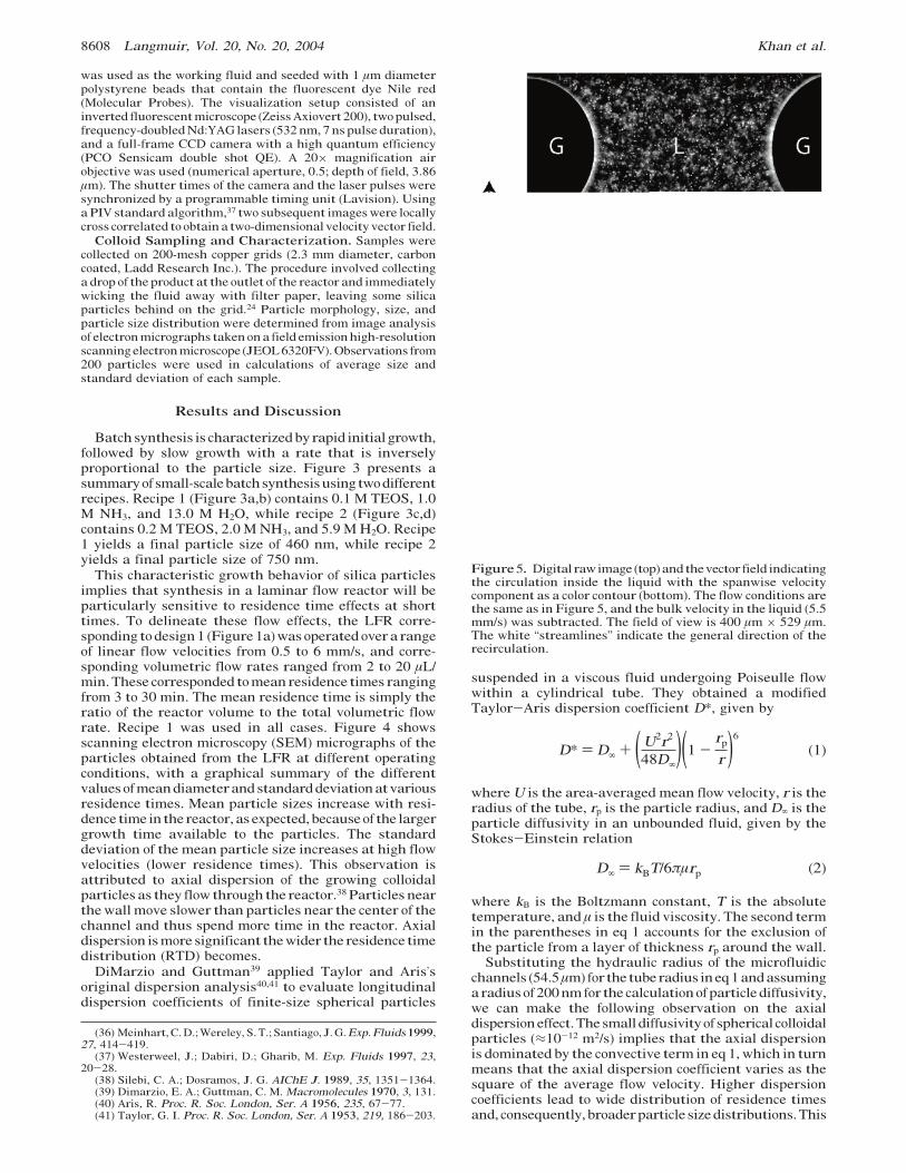
was used as the working fluid and seeded with 1 µm diameterpolystyrene beads that contain the fluorescent dye Nile red(Molecular Probes). The visualization setup consisted of aninverted fluorescentmicroscope (ZeissAxiovert 200), twopulsed,frequency-doubledNd:YAG lasers (532nm, 7ns pulse duration),and a full-frame CCD camera with a high quantum efficiency(PCO Sensicam double shot QE). A 20× magnification airobjective was used (numerical aperture, 0.5; depth of field, 3.86µm). The shutter times of the camera and the laser pulses weresynchronized by a programmable timing unit (Lavision). UsingaPIV standard algorithm,37 two subsequent imageswere locallycross correlated to obtain a two-dimensional velocity vector field.
Colloid Sampling and Characterization. Samples werecollected on 200-mesh copper grids (2.3 mm diameter, carboncoated, Ladd Research Inc.). The procedure involved collectinga drop of the product at the outlet of the reactor and immediatelywicking the fluid away with filter paper, leaving some silicaparticles behind on the grid.24 Particle morphology, size, andparticle size distribution were determined from image analysisof electronmicrographs taken ona field emissionhigh-resolutionscanningelectronmicroscope (JEOL6320FV).Observations from200 particles were used in calculations of average size andstandard deviation of each sample.
Results and Discussion
Batchsynthesis is characterizedby rapid initial growth,followed by slow growth with a rate that is inverselyproportional to the particle size. Figure 3 presents asummaryofsmall-scalebatchsynthesisusing twodifferentrecipes. Recipe 1 (Figure 3a,b) contains 0.1 M TEOS, 1.0M NH3, and 13.0 M H2O, while recipe 2 (Figure 3c,d)contains 0.2 M TEOS, 2.0 M NH3, and 5.9 M H2O. Recipe1 yields a final particle size of 460 nm, while recipe 2yields a final particle size of 750 nm.
This characteristic growth behavior of silica particlesimplies that synthesis in a laminar flow reactor will beparticularly sensitive to residence time effects at shorttimes. To delineate these flow effects, the LFR corre-sponding todesign1 (Figure1a)was operated overa rangeof linear flow velocities from 0.5 to 6 mm/s, and corre-sponding volumetric flow rates ranged from 2 to 20 µL/min.These corresponded tomeanresidence times rangingfrom 3 to 30 min. The mean residence time is simply theratio of the reactor volume to the total volumetric flowrate. Recipe 1 was used in all cases. Figure 4 showsscanning electron microscopy (SEM) micrographs of theparticles obtained from the LFR at different operatingconditions, with a graphical summary of the differentvaluesofmeandiameterandstandarddeviationatvariousresidence times. Mean particle sizes increase with resi-dence time in the reactor, as expected, becauseof the largergrowth time available to the particles. The standarddeviation of the mean particle size increases at high flowvelocities (lower residence times). This observation isattributed to axial dispersion of the growing colloidalparticles as they flowthrough the reactor.38 Particles nearthe wall move slower than particles near the center of thechannel and thus spend more time in the reactor. Axialdispersion ismore significant thewider the residence timedistribution (RTD) becomes.
DiMarzio and Guttman39 applied Taylor and Aris’soriginal dispersion analysis40,41 to evaluate longitudinaldispersion coefficients of finite-size spherical particles
suspended in a viscous fluid undergoing Poiseulle flowwithin a cylindrical tube. They obtained a modifiedTaylor-Aris dispersion coefficient D*, given by
where U is the area-averaged mean flow velocity, r is theradius of the tube, rp is the particle radius, and D∞ is theparticle diffusivity in an unbounded fluid, given by theStokes-Einstein relation
where kB is the Boltzmann constant, T is the absolutetemperature, and µ is the fluid viscosity. The second termin the parentheses in eq 1 accounts for the exclusion ofthe particle from a layer of thickness rp around the wall.
Substituting the hydraulic radius of the microfluidicchannels (54.5µm) for the tuberadius ineq1andassumingaradiusof200nm for the calculationofparticle diffusivity,we can make the following observation on the axialdispersioneffect.Thesmalldiffusivityof spherical colloidalparticles (≈10-12 m2/s) implies that the axial dispersionis dominated by the convective term in eq 1, which in turnmeans that the axial dispersion coefficient varies as thesquare of the average flow velocity. Higher dispersioncoefficients lead to wide distribution of residence timesand, consequently, broaderparticle sizedistributions.This
(36) Meinhart,C.D.;Wereley, S. T.;Santiago, J.G.Exp.Fluids1999,27, 414-419.
(37) Westerweel, J.; Dabiri, D.; Gharib, M. Exp. Fluids 1997, 23,20-28.
(38) Silebi, C. A.; Dosramos, J. G. AIChE J. 1989, 35, 1351-1364.(39) Dimarzio, E. A.; Guttman, C. M. Macromolecules 1970, 3, 131.(40) Aris, R. Proc. R. Soc. London, Ser. A 1956, 235, 67-77.(41) Taylor, G. I. Proc. R. Soc. London, Ser. A 1953, 219, 186-203.
Figure5. Digital raw image (top)andthevector field indicatingthe circulation inside the liquid with the spanwise velocitycomponent as a color contour (bottom). The flow conditions arethe same as in Figure 5, and the bulk velocity in the liquid (5.5mm/s) was subtracted. The field of view is 400 µm × 529 µm.The white “streamlines” indicate the general direction of therecirculation.
D* ) D∞ + (U2r2
48D∞)(1 -
rp
r )6
(1)
D∞ ) kBT/6πµrp (2)
8608 Langmuir, Vol. 20, No. 20, 2004 Khan et al.

phenomenon is particularly pronounced for lowresidencetimes corresponding to early stages of particle growth, asevident in panels a and b of Figure 4. This behavior isconsistentwith the batch synthesis experiments inwhichthe rate of particle growth is highest during the initialstages of growth (Figure 3). In the batch synthesis, theparticle size distribution changes less rapidly after thefirst 15min.Therefore, for sufficiently lowlinearvelocities(corresponding to residence times greater than 15 min),the sharpening of the RTD that results from furtherdecrease of linear velocity would be expected to havenegligible effect on the width of the particle size distribu-tion. This effect is observed in Figure 4d.
The segmented flow reactor (SFR) operates on theconcept of a reacting “macrofluid” being processed in aplug flow reactor.7 A “macrofluid” is defined as a fluidconsisting of a large number of small sealed “packets”,each containing a large number of molecules. Hence anSFR is equivalent toa flow of small batch reactors passingin succession through a plug flow reactor, with the RTDof fluid elements approaching a delta function centeredat the value of mean residence time. Since all the smallbatches spend the sameamount of time in the reactor, theproduct from an SFR is equivalent to the product from abatch reactor. The SFR therefore eliminates the problemof axial dispersion as encountered in the case of the LFR.
We first examine the performance of the SFR corre-sponding to design 2 (Figure 1b). Two liquid streamscontaining the reactants (recipe 1)are introducedat equalvolumetric flow rates into the SFR. Total volumetric flowrates range from4to30µL/min, corresponding to residencetimes ranging between 16 and 2 min. Gas is injected in
1:1 or 1:2 ratios with respect to the liquid. The gas andliquid flow rates are chosen such that an alternating flowof gas and liquid segments, a slug flow, is obtained. Theinjected gas segments the flow, and the resulting recir-culation createsmixing.Adjacent liquid segments (plugs)are connected through thin liquid films with thicknessesdepending on the relativemagnitude of viscous to surfacetension effects, given by the dimensionless capillarynumber42
where µ is the liquid viscosity, Ub is bubble velocity, andσ is the interfacial tension. A typical capillary numberrange for our flow conditions is 10-5-10-3. Two liquidsegments with a gas bubble in between are connectedthroughmenisci in the channel corners that cover, for ourcase, approximately 4.7% of the channel cross section.42
The gas-liquid flow develops downstream from the pointof gas introduction with increasing slug length, due tocoalescence of gas segments in the channel bends. Thethin liquid films connecting the slugs could provide amechanism for intermixing of particles in different slugs,as could themergingofadjacent slugsatbends.Thiswouldwiden the RTD from the sharp peak associated with anideal segmented, plug flow situation. The thin films canbe eliminated by appropriate surface modification of thechannel walls to make the reacting mixture nonwetting.In addition, since the incoming gas segments unmixed
(42) Wong, H.; Radke, C. J.; Morris, S. J. Fluid Mech. 1995, 292,71-94.
Figure 6. Segmented flow reactor (SFR, design 2). Sequence of SEM micrographs for recipe 0.1 M TEOS, 1.0 M NH3, 13.0 M H2O,and corresponding to various residence times: (a) τ ) 1.8 min; (b) τ ) 10 min, davg ) 277 nm, σ ) 9.5%; (c) τ ) 20 min, davg ) 390nm, σ ) 8.7%; (d) graph of mean diameter (d nm) and standard deviation (σ) expressed as a percentage of mean diameter versusresidence time (t min) in the reactor. In all SEM micrographs, the scale bar corresponds to 1 µm.
Ca ) µUb/σ (3)
Microfluidic Synthesis of Colloidal Silica Langmuir, Vol. 20, No. 20, 2004 8609

liquids in design 2, nonuniform reactant distributionbetweenadjacent slugs could occur, thus furtherwideningthe particle size distributions. To visualize and quantifythe recirculationwithin slugs, the liquidphasewas seededwith polystyrene beads and microscopic particle imagevelocimetry was used to quantify the recirculation in acenter plane of the channel (Figure 5). In the exampleshown, the average linear velocity of the liquid segmenthas been subtracted to clearly reveal the recirculatingflow within the liquid segment. The maximum spanwisevelocity accounts for up to 30% of the bulk velocity in theliquid segment, corresponding to a significant recircula-tion.
Figure 6 presents a summary of particle synthesisresults for the design 2 SFR. As expected, the segmentedflow (slug-flow) systemproduces sharper sizedistributionsthan the corresponding LFR in the low residence timeregime.However, thenarrowest size distribution that canbe obtained in the design 2 SFR (≈8%) is still wider thanthat from batch synthesis (≈5%) and is almost equal tothe corresponding LFR data. We attribute the deviationfrom batch synthesis to two principal factors: (i) non-uniformreactant distribution in adjacent segments at thegas inlet, and (ii) communication between the adjacentliquid segments and their merging at channel bends.
Incoming reactant liquids in the design 3 SFR (Figure1c) pass through a micromixing section prior to theintroduction of the gas. This design thus prevents anynonuniform reactant distribution effects. In addition, theaging section in this design is much longer (2.3×) than
those in designs 1 and 2, and stable noncoalescing slugdistributions are obtained. Figure 7 is an optical micro-graph of this device in operation and shows a typicallyuniform segmented flow. Synthesis results from thismicroreactor are summarized in Figure 8. We obtainmonodisperse particle size distributions (∼4.5%) that areequivalent to the corresponding batch results.
PDMS was used as a material of construction to takeadvantage of rapid prototyping and a relatively simplefabricationprocess.Thesmall amountof swellingofPDMSassociated with ethanol43 was not an issue for the presentapplication. However, other materials systems requiringorganic solvents that swell PDMS43 will require surfacemodification to make the microfluidic devices morechemically compatible. Alternatively, other materials ofconstruction such as silicon and glass could be used. Allmicroreactors in this work could be operated for longperiods of timeswithout agglomeration ofparticles on thewalls and subsequent plugging. Electron microscopy of aPDMSreactor surfaceaftera typical synthesis experimentlasting about 4 h revealed a surface covered by a thinlayer of silica particlessless than 2 µm thick (Figure 9).For themicroreactor,weusedPDMSaspreparedwithoutany surface modification beyond the oxygen plasmatreatment to bond the PDMS to the glass slide. Weattribute this lack of aggregation on the wall to electro-static effects of the initial thin layer of silica preventing
(43) Lee, J.;Park,C.;Whitesides,G.M.Anal. Chem.2003,75, 6544-6554.
Figure 7. Optical micrograph of segmented flow reactor (SFR, design 3) in operation: Uniform, noncoalescing gas-liquid flowis obtained.
8610 Langmuir, Vol. 20, No. 20, 2004 Khan et al.

furthergrowthofparticlesonthewallsin effect stabilizingthe wall particle interactions in a manner similar to theelectrostatic stabilization of the sol.
Conclusions
We have described basic principles of operation ofmicrofluidic reactors for synthesis of colloidal particles.
It is possible to tune sizes and size distributions in acontrolled fashion by varying the operating variables oflinear velocity and mean residence time. For a givenlaminar flow reactor design, monodisperse particle dis-tributionsareonly feasibleunder conditions thatminimizeaxial dispersion. This requirement is especially severefor low residence times, when particle growth rate is thefastest, and wide residence time distributions lead tocorresponding wide distributions of particle sizes. Seg-mented flow reactors eliminate axial dispersion effectsand could serve as useful tools for obtaining kinetic dataon growth mechanisms. These reactors show promise forsynthesis of ceramic particles such as titania (TiO2) andzirconia (ZrO2) that are considerably more difficult toprocess than the silica system used in present study.Furthermore, since these particles are charged, they canbe separated on-chip by incorporating electrophoresismodules, which would enable subsequent surface modi-fication of the colloidal nanoparticles.
Acknowledgment. Theauthors thankMikeFrongillo(MIT Center for Materials Science and Engineering,ElectronMicroscopyFacility) for assistancewith electronmicroscopy and Dr. Jamil El-Ali for assistance in Figure7. We are grateful to TSI for providing us with the PIVcorrelation engine. This research was funded by the MITMicrochemical Systems Technology Center and the Na-tional Science Foundation DMR-0213282.
LA0499012
Figure 8. Segmented flow reactor (SFR, design 3). Sequence of SEM micrographs for recipe 0.2 M TEOS, 2.0 M NH3, 5.9 M H2O,and corresponding to various residence times: (a) τ ) 9 min, davg ) 407 nm, σ ) 7.1%; (b) τ ) 14 min, davg ) 540 nm, σ ) 4.5%;(c) low magnification SEM of sample (b), the organization of particles into pseudocrystalline domains is an indicator of the highmonodispersity of the microreactor product; (d) graph of standard deviation (σ) expressed as a percentage of mean diameter versusresidence time (t min) in the SFR as compared to batch reactor data for recipe 2. In all SEM micrographs, the scale bar correspondsto 1 µm.
Figure 9. SEM micrograph of PDMS reactor wall after a 4 hsynthesis run (tilted view). Smooth surface represents a cutsection of the PDMS.
Microfluidic Synthesis of Colloidal Silica Langmuir, Vol. 20, No. 20, 2004 8611
Copyright © 2022 FDOKUMEN