MICROFLUIDIC DEVICES IN NANOTECHNOLOGY
422
-
Upload
khangminh22 -
Category
Documents
-
view
11 -
download
0
Transcript of MICROFLUIDIC DEVICES IN NANOTECHNOLOGY


MICROFLUIDIC DEVICESIN NANOTECHNOLOGY
Applications
Edited by
CHALLA S. KUMAR


MICROFLUIDIC DEVICESIN NANOTECHNOLOGY


MICROFLUIDIC DEVICESIN NANOTECHNOLOGY
Applications
Edited by
CHALLA S. KUMAR

Copyright � 2010 by John Wiley & Sons, Inc. All rights reserved
Published by John Wiley & Sons, Inc., Hoboken, New Jersey
Published simultaneously in Canada
No part of this publication may be reproduced, stored in a retrieval system, or transmitted in any form or by
any means, electronic, mechanical, photocopying, recording, scanning, or otherwise, except as permitted
underSection107or108of the1976UnitedStatesCopyrightAct,without either thepriorwrittenpermission
of the Publisher, or authorization through payment of the appropriate per-copy fee to the Copyright
Clearance Center, Inc., 222 Rosewood Drive, Danvers, MA 01923, (978) 750-8400, fax (978) 750-4470, or
on the web at www.copyright.com. Requests to the Publisher for permission should be addressed to the
Permissions Department, JohnWiley & Sons, Inc., 111 River Street, Hoboken, NJ 07030, (201) 748-6011,
fax (201) 748-6008, or online at http://www.wiley.com/go/permission
Limit of Liability/Disclaimer of Warranty: While the publisher and author have used their best efforts in
preparing this book, theymakeno representationsorwarrantieswith respect to the accuracyor completeness
of the contents of this book and specifically disclaim any impliedwarranties ofmerchantability or fitness for
a particular purpose. No warranty may be created or extended by sales representatives or written sales
materials. The advice and strategies contained herein may not be suitable for your situation. You should
consult with a professionalwhere appropriate. Neither the publisher nor author shall be liable for any loss of
profit or any other commercial damages, including but not limited to special, incidental, consequential, or
other damages.
For general information on our other products and services or for technical support, please contact our
Customer Care Department within the United States at (800) 762-2974, outside the United States at (317)
572-3993 or fax (317) 572-4002.
Wiley also publishes its books in a variety of electronic formats. Some content that appears in print may not
be available in electronic formats. For more information about Wiley products, visit our web site at www.
wiley.com.
Library of Congress Cataloging-in-Publication Data:
Microfluidic devices in nanotechnology. Applications / edited by Challa S. Kumar.
p. cm.
Includes bibliographical references and index.
ISBN 978-0-470-59069-0 (cloth)
1. Microfluidic devices. 2. Nanofluids. 3. Nanotechnology. 4. Fluidic
devices. I. Kumar, C. S. S. R. (Challa S. S. R.)
TJ853.4.M53M5325 2010
620.1006–dc22 2009051009
Printed in the United States of America
10 9 8 7 6 5 4 3 2 1

CONTENTS
Preface vii
Contributors xi
1 Microfluidics For Nanoneuroscience 1
Pamela G. Gross and Emil P. Kartalov
2 Nanoporous Membrane-Based Microfluidic Biosensors 47
Shalini Prasad, Yamini Yadav, Manish Bothara, Vindhya Kunduru, and
Sriram Muthukumar
3 Nanoparticle-Based Microfluidific Biosensors 91
Giovanna Marrazza
4 Microfluidic Enzymatic Reactors Using Nanoparticles 125
Chunhui Deng and Yan Li
5 Microfluidic Devices for Nanodrug Delivery 187
Clement Kleinstreuer and Jie Li
6 Microchip and Capillary Electrophoresis Using Nanoparticles 213
Muhammad J. A. Shiddiky and Yoon-Bo Shim
7 Pillars and Pillar Arrays Integrated in Microfluidic Channels:
Fabrication Methods and Applications in Molecular
and Cell Biology 255
Jian Shi and Yong Chen
v

8 Nanocatalysis in Microreactor for Fuels 281
Shihuai Zhao and Debasish Kuila
9 Microfluidic Synthesis of Iron Oxide and Oxyhydroxide
Nanoparticles 323
Ali Abou-Hassan, Olivier Sandre, and Val�erie Cabuil
10 Metal Nanoparticle Synthesis in Microreactors 361
Peter Mike G€unther, Andrea Knauer, and Johann Michael K€ohler
Index 395
vi CONTENTS

PREFACE
I hope you had an opportunity to go through the first volume. It gives me immense
satisfaction in placing the second volume of the two-volume book series—
Microfluidic Devices for Nanotechnology: Applications—in your hands. The second
volume is the first book ever to be published that covers nanotechnology applications
using microfluidics in a broad range of fields, including drug discovery, biosensing,
catalysis, electrophoresis, enzymatic reactions, and synthesis of nanomaterials.While
the first volume,Microfluidic Devices for Nanotechnology: Fundamental Concepts,
in its combined formprovides readers anup-to-date knowledgeof thefluid andparticle
kinetics, spatiotemporal control, fluid dynamics, residence time distribution, and
nanoparticle focusing within microfluidics, the second volume primarily captures up-
to-date applications. The book fills in a long-term gap that existed for the real-time
measurement of biomolecular binding in biosensors and justification for incorporating
nanoporousmembranes into “lab-on-a-chip” biosensing devices. Focusing on lab-on-
a-chip systems for drug delivery (also called bio-MEMS), separating bioanalytes
using electrophoresis, genomics, proteomics, and cellomics, the book is a must for
biologists and biochemists. Highlighting the importance of nanoneuroscience, the
book educates the reader on the discipline ofmicrofluidics to study the nervous system
at the single-cell level and decipher physiological processes and responses of cells of
neural origin. For a nanomaterials chemist interested in novel approaches for synthesis
of nanomaterials, this book is an excellent source of information covering a wide
variety of microfluidic-based approaches for synthesis of metallic and nonmetallic
nanomaterials. Finally, opening a window for the next-generation alternative energy
portable power devices, nanocatalyst development for industrially useful reactions in
silicon-basedmicroreactors is discussed especially in the contextof syngas conversion
to higher alkanes, which could solve current difficulties of storage and transportation
vii

by converting natural gas into liquid fuels. Overall, the book contains reviews by
world-recognized microfluidic and nanotechnology experts providing strong scaf-
folding for futuristic applications utilizing synergy between microfluidics and
nanotechnology.
Chapter 1 byDrs. Pamela G. Gross and Emil P. Kartalov focuses on the application
of microfluidic devices to study the nervous system at single-cell level using
nanotechnologies. This chapter describes various aspects of microfluidic chips
used to decipher physiological processes and responses of cells of neural origin
with examples of novel research not previously possible. Continuing on a similar
theme, Chapter 2 by Professor Shalini Prasad et al. provides a detailed account of real-
time biomolecular sensing through incorporation of nanoporous membranes, man-
made as well as natural, into “lab-on-a-chip” biosensing devices. In addition to
nanoporousmembranes, simple spherical nanoparticles are finding novel applications
when incorporated within the microchannels. Chapter 3 by Professor Giovanna
Marrazza reviews the most recent applications of nanoparticles within microfluidic
channels for electrochemical and optical affinity biosensing, highlighting some of
their technical challenges and the new trends. Chapter 4 by Professors Chunhui Deng
and Yan Li presents the recent advances in the field of immobilized microfluidic
enzymatic reactors (IMERs), which constitutes a new branch of nanotechnology. In
viewof the increasinguse of lab-on-a-chip systems in thehealthcare industry, there is a
growing demand for discovery, development, and testing of active nanodrug carriers
within the microfluidic environment for controlled drug delivery. Chapter 5 by
Professor Clement Kleinstreuer and Jie Li provides a comprehensive treatise on
fundamentals and applications of microfluidics and bio-MEMS with respect to
nanodrug targeting and delivery.
Capillary electrophoresis (CE) and microchip electrophoresis (MCE) are two
promising separation techniques for analyses of complex samples, in particular,
biological samples. Not surprisingly, these techniques have been profoundly influ-
enced by the advances in nanotechnologies. Chapter 6 by Muhammad J. A. Shiddiky
and Professor Yoon-Bo Shim covers the recent developments and innovative applica-
tions of nanomaterials as stationary and/or pseudostationary phases in CE and MCE.
This chapter illustrates the importance of various types of nanomaterials, including
metal and metal oxide nanoparticles, carbon nanotubes, silica nanoparticles, and
polymeric nanoparticles, in enhancing the separation of biological samples using CE
and MCE. The examples we have seen so far involve externally fabricated nanoma-
terials, which are later on utilized for a number of applications within themicrofluidic
channels. Chapter 7 by Drs. J. Shi and Yong Chen discusses pillars and pillar arrays
integrated into microfluidic chips in the fabrication process itself. This chapter
demonstrates how such an approach provides a large variety of functionalities for
molecule and cell biology studies.
The applications we have seen so far in the first seven chapters range from biology
to drug delivery. Chapter 8 by Shihuai Zhao and Professor Debasish Kuila is uniquely
placed in thebookas it bringsout the recent recognition formicroreactor as anovel tool
for chemistry and chemical process industry, such as fuel industry. This chapter
presents silicon-based microreactors for the development of nanocatalysts for
viii PREFACE

industriallyuseful reactions. For example,methanol steam reformer toproduceH2and
CO purifier is described in detail for potential microreactor applications in the next
generation of alternative energy for portable power devices.
The last example that the book provides is the application of microfluidic reactors
for the synthesis of nanomaterials. With the increase in the demand for high-quality
metal nanoparticles with narrow size, shape distribution, and homogeneous compo-
sition, the continuous-flow microfluidic processes are gaining attention as they are
particularly suited for realizing constant mixing, reaction, and quenching conditions
necessary for production of high-quality metallic nanomaterials. Chapter 9 by Dr. Ali
Abou-Hassan et al. reviews the recent scientific literature concerning the use of
microfluidics for the synthesis of the iron oxides nanomaterials. Chapter 10 by
Professor J. Michael K€ohler and coworkers is a fitting conclusion to the book
delineating a number of promising opportunities and challenges for the application
of microreaction technology for the synthesis and manipulation of metallic nano-
particles. In combination with the Chapter 9 in Volume 1, this will provide a strong
platform from both theoretical and experimental perspectives on synergism between
microfluidics and nanotechnology for automated microreactor-based controlled
synthesis and engineering of nanomaterials for a number of applications.
In conclusion, the two volumes bring out a clear understanding of theoretical and
experimental concepts of microfluidics in relation to nanotechnology in addition to
providing a seamless transition of knowledge between and micro- and nanofluidics.
The contributors for both the volumes are world-renowned experts exploiting the
synergy between microfluidics and nanotechnology. I am very much grateful to all of
them for sharing my enthusiasm and vision by contributing high-quality reviews, on
time, keeping in tunewith the original design and theme of both the volumes. Youwill
not be having this book in your hand but for their dedication, perseverance, and
sacrifice. I am thankful tomy employer, the Center for AdvancedMicrostructures and
Devices (CAMD), who has been supporting me in all my creative ventures. Without
this support, it would be impossible to make this venture of such magnitude a reality.
No words can express the understanding of my family in allowing me to make my
home a second office and bearing with my spending innumerable number of hours in
front of the computer. It is impossible to thank everyone individually in this preface;
however, I must make a special mention of the support fromWiley in general and the
publishing editorAnita Lekhwani in particular,whohas beenworking closelywithme
to ensure that this project becomes a reality. I am grateful for this support.
Note: Additional color versions of selected figures are available on ftp://ftp.wiley.
com/public/sci_tech_med/microfluidic_devices_concepts
CHALLA S. S. R. KUMARBaton Rouge, LA, USA
November 15, 2009
PREFACE ix


CONTRIBUTORS
Ali Abou-Hassan, Laboratoire de Physicochimie des Electrolytes Colloydes etSciences Analytiques (PECSA), UMR 7195, Equipe Colloydes Inorganiques,UniversitO Paris 6, Paris Cedex 5, France
Manish Bothara, Department of Electrical and Computer Engineering, PortlandState University, Portland, OR, USA
Valerie Cabuil, Laboratoire de Physicochimie des Electrolytes Colloydes etSciences Analytiques (PECSA), UMR 7195, Equipe Colloıdes Inorganiques,Universit�e Paris 6, Paris Cedex 5, France
Yong Chen, Institute for Integrated Cell-Material Sciences, Kyoto University,Kyoto, Japan
Chunhui Deng, Department of Chemistry, School of Pharmacy, Fudan University,Shanghai, China
Pamela G. Gross, Student Health and Wellness Center, University of Nevada atLas Vegas, Las Vegas, NV, USA
Peter Mike Gunther, Department of Physical Chemistry and Microreaction Tech-nology, Institute of Micro- and Nanotechnologies, Ilmenau University of Tech-nology, Ilmenau, Germany
Emil P. Kartalov, Keck School of Medicine, University of Southern California,Los Angeles, CA, USA
xi

Clement Kleinstreuer, Department of Mechanical and Aerospace Engineering andDepartment of Biomedical Engineering, North Carolina State University,Raleigh, NC, USA
Andrea Knauer, Department of Physical Chemistry and Microreaction Technol-ogy, Institute of Micro- and Nanotechnologies, Ilmenau University of Technol-ogy, Ilmenau, Germany
Johann Michael Kohler, Department of Physical Chemistry and MicroreactionTechnology, Institute of Micro- and Nanotechnologies, Ilmenau University ofTechnology, Ilmenau, Germany
Debasish Kuila, Institute for Micromanufacturing, Louisiana Tech University, Rus-ton, LA, USA; Department of Chemistry, North Carolina A&T State University,Greensboro, NC, USA
Vindhya Kunduru, Department of Electrical Engineering, Arizona State Univer-sity, Tempe, AZ, USA
Jie Li, Department of Mechanical and Aerospace Engineering, North CarolinaState University, Raleigh, NC, USA
Yan Li, Department of Chemistry, School of Pharmacy, Fudan University,Shanghai, China
Giovanna Marrazza, Dipartimento di Chimica, UnivesitA di Firenze, Via dellaLastruccia, Sesto Fiorentino, Italy
Sriram Muthukumar, Intel Corporation, Chandler, AZ, USA
Shalini Prasad, Department of Electrical Engineering, Arizona State University,Tempe, AZ, USA
Olivier Sandre, Laboratoire de Physicochimie des Electrolytes Colloıdes etSciences Analytiques (PECSA), UMR 7195, Equipe Colloıdes Inorganiques,Universit�e Paris 6, Paris Cedex 5, France
Jian Shi, Ecole Normale Sup�erieure, Paris, France
Muhammad J. A. Shiddiky, Department of Chemistry and Institute of BiophysioSensor Technology, Pusan National University, Busan, South Korea
Yoon-Bo Shim, Department of Chemistry and Institute of Biophysio Sensor Tech-nology, Pusan National University, Busan, South Korea
Yamini Yadav, Department of Electrical and Computer Engineering, Portland StateUniversity, Portland, OR, USA
Shihuai Zhao, Institute for Micromanufacturing, Louisiana Tech University,Ruston, LA, USA; Tianjin University, Tianjin, China
xii CONTRIBUTORS

1MICROFLUIDICS FORNANONEUROSCIENCE
PAMELA G. GROSS
Student Health and Wellness Center, University of Nevada at Las Vegas, Las Vegas,
NV, USA
EMIL P. KARTALOV
Keck School of Medicine, University of Southern California, Los Angeles, CA, USA
1.1 INTRODUCTION
The nervous system of an organism is like the information technology department of
an organization. Each of the billions of building blocks of the nervous system, called
neurons, is amultistate device similar to the transistors of amicroprocessor. But while
transistors are binary state devices, neurons are capable of being in many thousands
of states, and this adds many orders of magnitude to the complexity of possible
connections within a nervous system. In addition, each neuron has multiple connec-
tions with other neurons, and some of these connections are bundled into tracts and
nerves that travel within brain and spinal cord, and out to peripheral locations. In
computers, disconnection of one network cable, or disabling of the electronic circuits
in the server, can seriously compromise the function of the organization. Similarly,
traumatic injuries or neurodegenerative processes such as multiple sclerosis,
Alzheimer’s disease, or Parkinson’s disease can significantly impair the functionality
of an individual by damaging the neurons, tracts, and nerves. However, unlike
computer systems, medical repair processes do not yet exist because we do not yet
understand how the system operates in the healthy state. This may change in the near
future as cell biologists pursue stem cell interventions to regenerate or remodel
Microfluidic Devices in Nanotechnology: Applications, Edited by Challa S. KumarCopyright � 2010 John Wiley & Sons, Inc.
1

damaged areas of the nervous system. Simultaneously, engineers are teaming up
with biologists to design electronic implants and prostheses that can interface with
functioning tissue on either side of a damaged connection and act as a bridge to allow
restoration of injured neuronal circuits. Pharmaceutical researchers are using nano-
technologies to create novel systems capable of delivering targeted drugs and other
agents across the previously impenetrable blood–brain barrier,1,2 a feature of nervous
systems that chemically separates the system from the rest of the organism.
All these advances may be accelerated by knowledge derived from studies of
cellular physiology using tools designed to study biological processes at the single
cell level. As our ability to fabricate tools on the micro- and nanoscale levels has
progressed, we can now study cellular processes at a scale compatible with cell size,
and this is revealing new information about their operational responses, including how
they respond to physical and chemical cues from their immediate environment. It is
important that neuroscience researchers be aware of these new technologies, so that
their use can be optimized.
Recent advances in biological applications of micro- or nanotechnology have
included novel micro- or nanoscaled carriers for drug delivery,3–6 quantum dots that
operate as nanoscaled sensors at the cellular level,7–11 and nanoelectrodes.12 In
addition, self-assembled monolayers and scaffolding, as well as carbon nanotubes,
have been used as artificial nanotechnology matrices for cell culture.13–19 In neuro-
science specifically, nanoparticles have been used for free radical scavenging in
ischemic and neurodegenerative diseases.20 Scaffolds made of self-assembling
nanofibers are being developed to enhance neuroregeneration.21 The blood–brain
barrier has been successfully breached by drugs attached to special nanoparticles.22
High-resolution studies of the topography and material properties of live nervous
systemcells are beingcarriedout byatomic forcemicroscopy (AFM) (Figure 1.1).23,24
Single-molecule tracking using quantum dots has revealed details about the structure
and function of membrane receptors.10,25,26 Finally, nanotubes, nanowires, and
nanoneedles are being developed for use as relatively nontraumatic intracellular
electrodes.12,27,28 On a slightly larger scale, microfabrication technology has been
used to create microfluidic platforms that have been employed for a variety of
nanoneuroscience studies, and these platforms will now be discussed.
Microfluidics refers to a technology that utilizesmicroscale channels tomanipulate
fluid and suspended objects in a controlled manner at the nanoliter scale. Most
microfluidic chips are designed and constructed using the same techniques as used in
the development of microelectronic circuitry. Microfluidics has been advancing
rapidly over the past decade and has progressed from basic devices, for example, a
channel,29 a valve,30 and a pump,30 to large-scale two-dimensional integration of
components,31 three-dimensional architectures,32 and nonlinear autoregulatory sys-
tems.32 Simultaneously, the development of the fundamental technology has enabled
the advent of a plethora of specialized devices that have miniaturized important
macroscale applications such as protein crystallization,33,34 DNA sequencing,35 and
PCR (polymerase chain reaction), a technique for DNA detection and amplifica-
tion.36,37 The same development has also enabled the advent of novel techniques
to conduct fundamental research in a scale that was never previously possible.
2 MICROFLUIDICS FOR NANONEUROSCIENCE

More recently, some microfluidic chips incorporate other microtechnology and
nanotechnology hardware, such as electrodes,38–44 magnetic coils,45,46 and sur-
face-emitting lasers,47 to enhance their capabilities beyond fluid handling.
Manyof the first applications ofmicrofluidic chips involved studying the physics of
fluid dynamics at the microscale (characterized by low Reynolds numbers, laminar
flow, and fast diffusion), which is quite different from the flow characteristics of bulk
fluid at the macroscale (characterized by higher Reynolds numbers, turbulence, and
slow diffusion). The unusual behavior of fluid traversing microchannels has allowed
creation of new methodologies to manipulate molecules, in order to synthesize novel
nanomaterials and chemical/pharmaceutical moieties, and this has been described in
other chapters. For biologists,microfluidic platformshave emergedas invaluable tools
to study biology at small scales, even down to the single cell level. For neuroscientists,
these “lab-on-a-chip” platforms have enabled a novel approach for experiments on
the cellular physiology of the nervous system. Their usefulness in deciphering the
complicated interactions involved in the differentiation, growth, and maintenance of
neurons in health and in disease has become increasingly apparent within the past
5 years, asmore research in this field continues to be reported.Asmore neuroscientists
become familiar with this technology, we anticipate a rapid evolution of the field. This
chapter will review pertinent contributions in the use of microfluidics to study the
physiology and pathophysiology of neurons and their support cells and will hopefully
serve as a primer for neuroscientists unfamiliar with this technology, inspiring some
to develop new applications of microfluidics to the field of neuroscience.
FIGURE 1.1 Atomic force microscopy images of neural lineage cells. (a) Three-dimen-
sional rendering of an oligodendrocyte differentiated from a murine neural stem cell. Fixed
sequentiallywith 100%ethanol and 4%PFA, air dried, and then imaged on anAsylumResearch
MFP3DAFMusing anOlympusAC160 cantilever inACmode in air. Note the detailed process
formation. Scan size is 90mm� 90mm. (b) Three-dimensional rendering of a portion of a
living astrocyte derived from a human embryonic stem cell on a polyornithine/laminin-coated
substrate, imaged inmedia, inACmodewith anOlympusBiolever, and on anAsylumResearch
MFP 3D AFM. The image shows cytoskeletal fibrous elements visible through the cell
membrane in the proximal thicker area of the cell as they enter a broad, flat attachment
area. Scan size is 30mm� 30mm (unpublished data, Pamela G. Gross).
INTRODUCTION 3

Microfluidic platforms typically contain a series of chambers and channels that
each measure in the range of 1mm to a few hundred microns and are used to process
fluid at amicroscopic scale. For in vivo applications, microfluidic technology has been
integratedwith neural implants for precise delivery of solutions.48 Three-dimensional
electrodes with bundled microfluidic channels that can be implanted into severed
nerves to guide and monitor their regeneration while allowing infusion of drugs are
also under development.49 However, the most common biological application of
microfluidics has been for in vitro studies, such as the delivery and processing of
biochemical reactants for DNA sequencing35 and protein analysis,50 the sorting,
counting, and analysis of cells by flow cytometry,51 the delivery of cell adhesives
and cells for substrate micropatterning of cell populations,52,53 the development of
biomimetic three-dimensional tissues, complete with stromal support molecules,18,19
and the isolation and nurtured maintenance of individual cells to study basic cell
physiology and cell–cell interactions on a single (or near-single) cell basis.54–59
In addition, microfluidic platforms have been used to study the effect of laminar flow
and shear forces on the function of endothelial and other types of cells,60,61 to provide
artificial circulation through various organ-simulating cell culture chambers in
order to determine the pharmacokinetics of prospective pharmaceutical agents,62
and to deliver test samples containing potential toxins to cells acting as biosensors
(also known as “lab-in-a-cell” technology).63–65 Finally, microfluidics can be used to
study physiology within small organisms, such as the effects of anesthetics on the
regrowth of severed axons, or the recovery of axonal synapses after laser ablation
in Caenorhabditis elegans nematodes that have been captured and immobilized in
microfluidic chips.66,67
Microfluidic-based cell studies are a useful adjunct to conventional in vitro
techniques or mini culture systems68 because microfluidic chambers have the ability
to control both the amount of material (media, growth factors, etc.) used for cell study
and their exact distribution over well-defined periods. This can permit better control
of the experiment by limiting unanticipated extraneous factors and diffusion con-
straints that can occur in larger systems. The effects of cell population variability will
also be more limited in smaller systems and therefore individual differences among
similar cells will be less likely to influence results. From an economic standpoint,
small culture volumes allow cost savings since the required volume of expensive
media, hormones, and growth factors is orders of magnitude less than that used in
typical culture flasks. These platforms can also be designed for high throughput and
compatibility with automated laboratory equipment such as plate readers. In addi-
tion, the hardware is portable and it can be mass produced so inexpensively that it can
be very cost-effective to perform massively parallel microfluidic platform-based
experiments, in order to confirm results or test the effects of numerous agents
simultaneously.
These parallel experiments are necessary to verify results obtained on individual
cells since it is known that there can be significant variation in the behavior of
particular cells, even if they are cloned from the sameprecursor cell.69 Similarly, itwill
be imperative that the effect of microenvironment parameters such as mechanical
forces, shear stress, effective culture volume, and material interfaces be well
4 MICROFLUIDICS FOR NANONEUROSCIENCE

understood and controlled before interpreting single cell study results so that these
factors do not contribute to misleading conclusions.70 Nevertheless, observations
derived from studies of individual cells in a controlled microenvironment may be
muchmore likely to reveal true cellular physiology responses than those derived from
studying the responses of populations of cells simultaneously, as is done with
conventional in vitro studies.
Although the development of this technology has progressed significantly over the
past 5–7 years, its utility as a tool is just beginning to be appreciated by biologists.
There are many published reviews on the general topic of microfluidics for biological
applications,69–85 but there have only been a few that have focused on microfluidic
applications in neuroscience.80–82 This chapterwill update the reader on the discipline
ofmicrofluidics to study the nervous system at the single cell level. Specifically, it will
report on microfluidic chips used to decipher physiological processes and responses
of cells of neural origin, and it will also focus on examples of systems that combine
microfluidic chambers with other technologies for novel research not previously
possible.
Section 1.2 will begin with a description of current microfluidic chamber con-
struction techniques, starting with a discussion of the characteristics of the PDMS
polymer used in many microfluidic chambers and then moving on to cover step-
by-step fabrication processes. Various architectural designs of use for cellular studies
will then be introduced, followed by a description of alternative applications of PDMS
to create tools that are useful in customizing the substrate of microfluidic chips for
specific experiments. Practical limitations of microfluidic techniques will then be
discussed to present a balanced view of the topic.
In Section 1.3, gradient-generating designs will be reviewed, along with examples
of how they have been used to study cellular responses. Methods of incorporating
electrophysiological measurements into chip design, including patch clamping, will
be examined and then use of other integratedmicro- and nanoscaled analytical devices
will be considered. The theory andmethodology used for in vivo tissue simulationwill
be evaluated, since the natural behavior of cells is ultimately what most biological
research is attempting to discern.
Following this, a literature review of neuroscience research involvingmicrofluidic
platformswill bedetailed inSection1.4, startingwith cell identification and separation
tools, which is essential for researchers requiring specific subpopulations of neural
lineage cells. Studies on microfluidic analysis of neuropeptide release will follow,
which is of interest to individuals studying synapse formation and function. The use of
microchips to study the effects of physical and chemical guidance cues on single cells
will then be considered since this is a key to understanding how neural cells interact
with their environment and with each other.
Section 1.5 will focus on electrophysiology studies that use multielectrode arrays
(MEAs) as microfluidic chamber substrates. This is a popular field of endeavor since
these two technologies seem to be complementary and can allow studies on action
potential characteristics and propagation in single axons. The effect of growth factors
on neuronal responses of microfluidically cultured and isolated cells will be covered
after this, given its significance in understanding cell differentiation and maturation.
INTRODUCTION 5

The use of microfluidic chambers for gene therapy studies on neural cells will be
subsequently discussed. Although this is a relatively new area of study, preliminary
results are very promising and future research will likely take advantage of the unique
capabilities that microfluidic chips offer to this field. The final area of research to be
covered involves studies based on the microfluidic isolation of axons and neural cell
bodies. This approach to neural research is gaining great interest, given the potential
applications for those studying neural degeneration and regeneration processes, in
addition to those interested in axonal transport mechanisms, and synapse formation
and physiology. A general discussion with consideration of future perspectives will
complete the chapter. It is hoped that the readerwill gain an appreciation for the future
potential of these platforms to uncover previously hidden cell-based interactions in
the nervous system, and this will stimulate new applications of microfluidics for their
specific research programs.
1.2 PDMS MICROFLUIDIC DESIGN AND FABRICATION
1.2.1 Characteristics of PDMS
Initially, most microfluidic chamberswere constructed on siliconwafers using “hard”
lithography. Since those early studies, “soft” lithography has been developed and
various polymers and fabrication techniques have been investigated.86 Now, soft-
sided chambers made of polydimethylsiloxane (PDMS) are gaining increased popu-
larity, especially for biological applications. PDMS is a silicon-type elastomer and
can be purchased commercially as Sylgard� 184 by DowCorning or RTV by General
Electric. It can be molded into many different shapes to form valves, chambers, and
channels. PDMS is advantageous for biological studies since it is biocompatible,
optically transparent down to wavelengths as low as 280 nm, permeable to gases
needed for cellular respiration, autoclavable, and naturally inhibitory to cellular
adhesion.87,88 PDMS has therefore provenvery handy for cellular studies by allowing
long-term cultures, optical microscopy, and fluorescent/chemiluminescent studies,
while the cells are still in situ in the chip.64 A final advantage of this material for use
with cell culture systems is that PDMS has been shown to be an excellent protective
coating for on-chip solid-state analytical devices (such as surface-emitting lasers),
since PDMS is optically transparent yet prevents the detrimental effects of ions
migrating from the culture medium into sensitive electrical junctions.47
Native PDMS is hydrophobic, and this influences many of its surface properties,
including its interactions with fluid and molecules that are in contact with it. These
properties can be altered by physical and chemical treatments that can change
the hydrophobicity of the surface of the PDMS channels and change its adhesive
properties if this is desired.74 For example, the pretreatment of the PDMS channels
with bovine serumalbumin (BSA)will assist in blocking cell adhesion to its surface.54
Alternatively, PDMS can be made hydrophilic and supportive of cell growth by
treatmentwith oxygen plasma,88 orUV/ozone,89 that acts by changing themoieties on
the PDMS surface to increase the number of silanol groups and decrease the number
6 MICROFLUIDICS FOR NANONEUROSCIENCE

of siloxane groups. Polyethylene glycol (PEG) can also be used to alter the surface
chemistry of PDMS.35
The surface interactions of PDMS with adjacent molecules will also depend on
local flowconditions. Experimentally, proteins such as collagen andfibrinogen adhere
to both hydrophobic and hydrophilic (oxygen plasma-treated) PDMS. But under flow
conditions, the oxygen plasma-treated hydrophilic surfaces experienced only tempo-
rary adhesion, followed by rapid detachment of any adherent cells, whereas the
hydrophobic PDMS channels became permanently clogged with protein and cells.88
Therefore, systems that are designed to have continuous exposure to protein-laden
media and cellswill likely benefit frompretreatment of the PDMSwith oxygenplasma
to increase the functional lifetime of the channels.
1.2.2 PDMS Chip Fabrication Protocol
Microfluidic chip fabrication uses many of the same techniques used in electronic
circuit production. The process begins with the creation of an architectural design
using a computer-aided design (CAD) software program. The design is printed on a
transparency using a high-resolution printer, since the feature size on the final chip
will be determined by the resolution of features on the transparency. This transparency
acts as a photomask during the next step, in which it is placed over a substrate (silicon
wafer or glass) that is precoatedwith a thin layer of photoresist, a photocurable epoxy.
UV exposure polymerizes exposed areas for photoresists such as SU-8, so the
developer solution can strip away the unexposed areas because they are not poly-
merized, while the polymerized exposed structures remain. This type of photoresist is
called negative photoresist because the result is the reverse, or “negative,” of themask.
On the other hand, photoresists such as 5740, SPR-220, and the AZ family are called
“positive photoresists” because the result corresponds to the mask; that is, the result
is “positive” to the mask. UV exposure makes a chemical change in positive
photoresists that results in the material becoming more soluble, for example, in a
strong base. Thus, the developer solution removes the material from the exposed
areas, while the structures in the unexposed areas remain. In both cases, the result is
a mold where the features are built in photoresist. Since photoresist is softer than
silicon, the resulting mold is softer than traditional molds, and so the technique has
been named “soft lithography.”
In the next step, PDMS is combined with its catalyst in a 10:1 proportion and the
mixture is degassed in a vacuum chamber to remove bubbles. It is then poured onto the
master, allowed to cure, and then peeled off the mold. Access ports are punched after
casting (or silicon tube ports are placed during casting) to create connections to input
and drainage tubes. The PDMS slab is then placed onto a substrate such as a silicon
wafer or a glass slide to create the final microfluidic platform. The PDMS forms a
reversible conformal seal to the substrate, but optional treatment of the PDMS with
plasma oxidation of the PDMS surface after curing will render the surface more
hydrophilic and allow the PDMS to irreversibly bond to the substrate. After steriliza-
tion bymeans of autoclaving, UV treatment, or immersion in 70% ethanol, the system
is ready for use.
PDMS MICROFLUIDIC DESIGN AND FABRICATION 7

Although PDMS can reproduce features down to 10 nm in size,75 actual fabricated
channels in PDMS have not yet achieved a cross-sectional area smaller than 1mm2.74
This is because the feature size of the PDMS is determined by the printed resolution on
the photomask, which is determined by the printer used to create it. For example,
standard printers that have a resolution of 5080 dpi can reproduce features on the
photomask down to 25mm resolution, whereas photoplotters that print at 20,000 dpi
can achieve a resolution down to 8 mm.75,90 To reproduce smaller features, chrome
masks may be used, which are created with e-beam or laser writing and are much
more costly. In addition, the relative softness of PDMS makes it difficult to maintain
uniformly high quality of the reproduced features when the linear scale is decreased
below a few microns.
1.2.3 Architectural Designs of Microfluidic Platforms
The physical behavior of a fluid flowing throughmicroscale channels is very different
from the flow characteristics of the same fluid flowing through larger channels. For
example, fluid flow throughmicrofluidic channels is laminar, somixingdoes not occur
between solutes placed at different locations in the channel cross section, except by the
slow process of diffusion. Without turbulence, solute gradients will remain relatively
intact as fluid traverses downchannels of uniformwidth. If cells are localized at certain
areas of this channel, their exposure to specific concentrations of solute can be tightly
controlled. In fact, different parts of the cell can even be exposed to different and
controlled concentrations of the solute. This laminar flow behavior can also be used to
pattern and deposit specific solute concentrations onto the substrate or to pattern cell
adhesives and repellents next to each other onto the substrate prior to introduction of
cells. Alternatively, if mixed patterns are desired, deliberate oblique grooving of the
floor of the channel can be employed to create turbulence in order to mix solutes,91–93
and nanotopographic features can also be added to the platform substrate to influence
cell adhesion.94
Most microfluidic chips use some type of dynamic flow conditions, with flow
achieved by the use of syringe pumps, gravity-driven reservoirs,95 electrokinetic
control,96 or other more complicated functional PDMS valve structures. These valves
are designed by layering “control channels” that act as bladders across flow channels.
Application of pneumatic pressure in the “control channels” can then cause controlled
collapse of the underlying fluidic lumen, and this controlled deformation of the flow
channel’s lumen creates a functional valve.30 Digital control and sequential coordi-
nation of these valves can create peristaltic pumps. Rotary pumps based on similar
mechanisms have been designed and used for applications that require repeated
cycling of fluid for mixing, such as on-chip PCR, used in amplification and identifi-
cation of DNA strands in genetic engineering.97
Various structures have been devised to immobilize cells withinmicrofluidic chips.
These architectures must be able to catch and retain a cell from a passing stream of
media, while minimizing damage to the cell. Sieves have been used within the culture
chamber to retain cells while also producing a nutrient gradient.98 Channel walls can
be constructed at partial height to create a dam that allows flow from one channel to
8 MICROFLUIDICS FOR NANONEUROSCIENCE

another while gently transporting and immobilizing cells for later analysis.99 Inverted
T junctions that have small docks with tiny drain channels at the junction have been
used to immobilize single cells and then perform rapid on-chip calcium flux assays.54
Curved docking areas that can balance the forces exerted on cells (fluid flow versus
gravitation) have also been used to isolate individual cells for culture and study of
calcium mobilization.56,57 Gravity-induced flow has been combined with dielectro-
phoresis to trap and sort cellswithout physically contacting them.100 For the capture of
cells with variable dimensions such as pancreatic islets (used in diabetes research),
designs have combined one semiellipsoidal wall and one movable wall to create an
adjustable holding area that will allow studies on the regional effect of infused glucose
and drugs.59 Studies on pairs of cells have used intersecting channels that have been
designed to trap pairs of cells from different populations to study intercellular
communicationvia gap junctions between their cellmembranes.55 Finally, the surface
of PDMS has been microstructured with arrays of wells and coupled to a microfluidic
system to create a test platform for parallel experiments on single cells or small
groups of cells.101 As described above, a significant advantage of microfluidic
chambers is that the architectural design and the dimensions of the channels and
chambers can be customized for the morphology of the cells to be studied and to the
task to be accomplished. As new researchers enter this field, we expect to see awealth
of new designs for novel applications.
1.2.4 PDMS Tools
In many cases, it is desirable to have a microfluidic chip substrate that is patterned
with different molecules prior to assembly of the chip. This can be easily achieved by
creating a separate PDMS tool that contains the substrate pattern and can be used as a
stencil or a stamp. This tool is fabricated using the same techniques as outlined above.
After completion of the tool, it can be used for microcontact printing by dipping the
patterned area into a fluid with the desired concentration of solute molecules and
then transferring this pattern to the substrate. PDMS can also be formed into a two-
dimensional stencil sheet that allows patterned deposition of selected proteins or
agents onto the underlying substrate, and this PDMSstencil has the advantage of being
useful on irregular or curved substrate surfaces. Once the protein pattern has been
created on the substrate, the remaining platform can be constructed by applying the
matched PDMS chip so that its channels are complementary to it. With this arrange-
ment, future cell attachment and differentiation can be guided, and cocultures can be
created in controlled geometric patterns.102–104 Since this technique can help control
the exact position of neurons on a substrate, the resultant controlled neuronal patterns
can be very helpful in studying neural networks and interactions occurring within
synapses.69,102,103,105 These techniques have also been combined with selective
oxygen plasma treatment to create long-term and short-term cell repellent areas to
coculture cells in controlled geometric patterns.104 In this case, cell repellent polymers
were homogeneously deposited on a substrate, and a PDMS stencil was used to
selectively protect the repellent from plasma treatment in certain areas. Unprotected
areas lost their repellent nature and could then be treated with adhesives like
PDMS MICROFLUIDIC DESIGN AND FABRICATION 9

fibronectin and short-term repellents like BSA to create patterns of relative adhesivity
over time that could then be seeded as desired with different cell types.
1.2.5 Practical Considerations and Limitations
As with all new technologies, there are certain practical design considerations and
limitations that must be recognized before planning a microfluidic chamber for cell
studies. Cell viability has definitely been correlatedwith channel size and proportions,
closed versus open-channel configurations, and static versus dynamicmedia flow. For
example, it has been shown that in contrast to cells grown inconventional tissue culture
flasks, the proliferation rates of cells grown in microfluidic channels without media
flow depend on the height of the channel.106 This is likely due to loss of convective
movement of cell-expressed inhibitory factors away from cells, rather than lack of
nutrients or change in osmolarity or pHof the culturemedium. In a static systemwhere
there is no flowofmedia or connection of themedia in the channels to a bulk container,
secreted factors can only be dissipated by diffusion, and this can be insufficient to
remove their often deleterious effects.106 If continuous or intermittent flow is designed
into the system, the flow rate must be optimized to provide nutrients and remove
wastes, without producing excessive shear stress that can change morphology or
migration of the cells or even detach the cells.98,107 Similarly, certain secreted factors
maybeessential for cellular health, and if theflow is toohigh, then these factorsmaybe
washed out.
Pretreatment of the PDMS prior to the introduction of cells can have significant
effects on cell culture success. For example, Matsubara et al. showed that different
treatments to make the PDMS hydrophilic affected both the morphology and the
density of mast cells.64 Similarly, Prokop et al. found that extracellular matrix
deposition and plasma treatment of the PDMS improved subsequent cell cultures.98
Other important considerations include recognition of the fact that the tiny volume
ofmicrofluidic culture systems confers amuch less stable homeostatic system in terms
of temperature, carbon dioxide concentration, and humidity control compared to
standard Petri or tissue culture flasks. These chips equilibrate muchmore rapidly with
their environment than larger systems given their larger surface area to volume ratio,
so each time these chips are removed from the incubator, they are prone to more rapid
alteration of their temperature, atmosphere, and humidity. Temperature alone is
known to directly influence gene expression, biochemical reactions, and diffusion
speed. To maintain a stable system, steps must be taken to minimize losses of
environmental stability. Similarly, if media is fed into these chips via tubing that is
outside the incubator (i.e., if connected to a syringe pump), or if the tubing is part of
a “mini” culture system, it is important that media temperature and CO2 content do
not change during transport through the tubing.68 Therefore, although these micro-
scale systems are technically portable, control systems for their ambient environment
may be necessary if they require transport outside the incubator for time lapse imaging
or other interventions. We witnessed this effect directly when an isolated axon in
a microfluidic chip was observed to shrink back significantly within a few minutes
of removal from the incubator and placement onto the cold microscope stage
10 MICROFLUIDICS FOR NANONEUROSCIENCE

(unpublished data). Control of humidity is also critical because water diffuses into
PDMS according to Fick’s law of diffusion.108 From there, it can evaporate and lead to
increased osmolarity of the cell culture medium and premature cell death. Methods
to minimize evaporation, such as coating the PDMS with a thin layer of parylene,
have been successfully implemented and shown to prolong cell viability.108
The last practical consideration in usingPDMSas a culture chamber inmicrofluidic
systems involves the high ratio of chamber surface area to the volume of culture
medium and number of cells compared to standard culture flasks. This increased
surface area to volume ratio can lead to increased interactions between chamber
contents (media, cells) and chamber walls. For example, it is known that small
hydrophobic molecules may partition into the PDMS and therefore be less bioavail-
able when studying their effects on cells.109 This extraction of media solutes by the
PDMS can significantly change the concentration of some agents in media within
microfluidic channels by many orders of magnitude. The magnitude of this change
depends on the partition coefficient of the substance, the pH of the culture medium,
and the counterion pairing in the media. Major decreases in the media concentration
of neurotransmitters, hormones, and growth factors could change experimental
outcomes, and the cost savings for using small volumes of these agents inmicrofluidic
platforms can be lost if much larger quantity of the substance has to used to achieve
the same effect. Therefore, many individuals are now experimenting with different
surface treatments to decrease the porosity of the PDMS and avoid some of these
effects.
In addition to taking up biomolecules, the PDMSmay also release potentially toxic
agents from its polymer matrix.110 These can then be concentrated in a proportionally
smaller volume of culture medium and may affect more sensitive cells. Certainly,
neurons from different sources vary in their hardiness, and culturing sensitive neurons
at low density and in serum-free conditions can be difficult, even in the most tightly
controlled environments. For example, we have personally had difficulty maintaining
the viability of human neural stem cells in PDMS chips, whereas rat dorsal root
ganglion cells thrived in the same conditions (unpublished data).
One possible explanation of this phenomenon may be found in the work of Millet
et al., who hypothesized that there might be seepage of toxins from the PDMS.110 In
their research, they tried to improve neuron survival in open- and closed-channel
microfluidic chips by treating the PDMS with serial solvent-based extraction
processes (to remove potentially cytotoxic uncross-linked oligomers and residual
platinum catalyst in the PDMS) or with autoclaving (to drive cross-linking and outgas
solvents). They found that treatment with extraction improved neuron survival,
increased the development of neurites, and lowered platinum levels in the PDMS
more than did autoclaving. Specifically, the ratio of neuron survival was 3:28:51 for
native PDMS, autoclaved PDMS, and extracted PDMS, respectively. Overall cell
viability in low density, small volume, serum-free studies in closed-channel devices
was improved from less than 2 days in native PDMS to over 7 days for extracted
PDMS. If gravity-driven flow was added, survival could be further increased to over
11 days by improving nutrient delivery and waste removal compared to static
systems. These extraction processes will be imperative for future studies on
PDMS MICROFLUIDIC DESIGN AND FABRICATION 11

individual cells or cell-to-cell interactions in low-density cultures in microscale
culture volumes.
Perhaps the biggest impediment to the general acceptance of microfluidic plat-
forms as tools for biological investigation will be the initial need for interdisciplinary
teamsof researchers that include both engineerswhocandevise and fabricate the chips
andbiologistswhoknowwhenandwhere to best apply the technology.Aswith all new
technology, the developers may not be able to recognize its most useful niche, and the
users may not be aware of the technology or have the auxiliary tools and expertise
to operate it correctly. However, as more individuals take the steps to experiment with
the technology, it would become more commonplace and better utilized.
On the other hand, the novelty of the underlying technology and of the general
approach of combining neuroscience with microfluidics offers unique and exciting
opportunities to address fundamental problems with new tools in new ways. These
technologies thereby carry the immense promise of important breakthroughs and new
insights both in fundamental neuroscience and in its extensions to biomedical practice
in improving the treatment of many neurological diseases.
1.3 DESIGNS AND DEVICES FOR NEUROSCIENCE APPLICATIONS
1.3.1 Gradient-Generating Designs
As discussed above, the laminar flow that occurs in microscale channels can be used
advantageously to create high-resolution gradients of solutes and special factors
within the cell culture chamber, in order to assess the effects of these gradients on the
behavior of individual cells. These designs employ two or more inputs—one for the
studied factor and one for the dilutingmedium,with each connected to its own syringe
pump. The inputs connect to a network of serpentine, interconnected channels that
repeatedly split and remix, with each generation of splitting channels increasing in
number, until they finally coalesce back into a single larger channel (Figure 1.2). At
each branch point, some mixing occurs so that there is a gradient of concentrations
of the studied factor(s) that is oriented perpendicular to the flow direction at the final
exit channel, and this gradient has a range of resolution spanning from severalmicrons
to hundreds of microns. After exiting the gradient-generating device, the established
gradient is maintained by laminar flow. By varying the flow rate into one input,
dynamic and asymmetric gradients of variable shape (smooth, step, ormultiple peaks)
can also be created.52,111,112 These devices have been used to study the effects of IL8
(interleukin 8) on neutrophil chemotaxis,113EGF (epidermal growth factor) on breast
cancer cell chemotaxis,114 and various growth factors on neural stem cells.115
These gradient-generating devices are commonly used for research on the physi-
ology of neural lineage cells since the devices provide precise control over exposure
of growth and inhibitory factors to these cells. In addition, these same devices have
been used to etch a controlled gradient into the surface topology of chip substrates
by injecting etching reagents, or to lay down gradients of adhesives, self-assembled
monolayers (SAMs), and dyes.111 Finally, these gradient generators have been
12 MICROFLUIDICS FOR NANONEUROSCIENCE

combined with large chip-based arrays of cell culture chambers (10� 10) to simulta-
neouslyperform100parallel tests on the effect of anagent’s variousdilutions.116 Since
these chambers each had four individual access ports, repeated growth/passage cycles
of the cells could be performed on-board by microfluidic control, so the cell cultures
could be maintained over long periods. As demonstrated with the studies described
above, these gradient devices are very useful tools for investigations into cellular
responses to varying concentrations of specific factors, whether these factors are
substrate bound or dissolved in media.
FIGURE1.2 (a) Photograph showing amicrofluidic device used for generating gradients of
green and red dyes in solution. The three incoming channels (top part of the photograph) were
connected to syringes via tubings (not visible). After combining the streams into a single, wide
channel (bottom of the photograph shown in (a)), a gradient was formed across the channel,
perpendicular to the direction of flow. (b) Schematic explaining the nomenclature used for the
mathematical description of the network. (c) Schematic demonstrating the application of the
formulas governing the splitting ratios at the branching points. The dotted lines indicate the
boundary between the two combined streams. The concentrations at the end of the serpentine
channels can be calculated bymultiplying the concentration of the incoming streams (cp, cq, cr)
with the corresponding numbers of the splitting ratio (Vp þ 1)/B, (B�Vq)/B, (Vq þ 1)/B, and
(B�Vr)/B, as indicated). Reprinted with permission from Ref. 112. Copyright 2001 American
Chemical Society.
DESIGNS AND DEVICES FOR NEUROSCIENCE APPLICATIONS 13

1.3.2 Integrated Electrophysiology
For electrically active cells such as neurons and muscle cells, integrated electrical
recording is a very valuable addition to microfluidic platforms. An early example of
this was a unique system that was designed as a self-contained, portable unit for field
use as a cell-based biosensor. The unit incorporated a hybrid glass/PDMS/silicon
chamber for cell culture with integrated microfluidics, a microelectrode array
substrate modified with fibronectin and gelatin for cell growth, a temperature
regulation system, on-chip electronics for acquisition, analysis and display of action
potentials, and a transparent cover that makes the unit amenable to microscopic
inspection.65 This approach of creating a stand-alone unit with its own environmental
controls may eventually be required of many platforms in the future; however, most
neuronal studies have employed much simpler hardware, typically using commercial
MEAs as the substrate for a PDMSmicrofluidic chip. Thesewill be discussed inmore
detail in Section 1.4.4.
The “gold standard” for electrophysiological studies has always been patch
clamping, and many microfluidic platforms incorporating arrays of patch clamp
electrodes have been engineered and successfully demonstrated. Conventional patch
clamps use suction to attach the tip of a glass micropipette to a cell membrane, and
then break the membrane and record the intracellular potential using a conductive
fluid in the micropipette. In early microfluidic designs, these systems used PDMS
microfluidic channels to guide cells to pores micromachined into silicon wafers,117 or
they used cell-trapping pores in a horizontal PDMS substrate.118–120 These pores
simulated the tip of a conventional glass micropipette and were used to create a high-
resistance seal to the cell wall for subsequent electrical recording.
Ionescu-Zanetti et al. improved on this design by incorporating pores on a vertical
channelwall of the PDMS to facilitate the use of optical and fluorescentmicroscopy to
monitor the procedure.121 This vertical approach allows both the cell and the capillary
tube leading to the pore to be in the sameplaneof focus, and, therefore, it permits easier
guidance of the selected cell to the pore (using a combination of flow in the cell
chamber and suction from the pore). It also permits visual monitoring of the cell
condition and position during the recording. Each pore is connected to a capillary tube
that applies negative pressure (suction) to attach the cell and break the membrane
and to a silver/silver chloride electrode that then connects to a multiplexer circuit to
process the recorded signals. Using CHO (Chinese hamster ovary) cells, the seal
resistance between pores and cells was an average of 300megaohms, and the system
wasable to recordcurrentsdown to20 pA. Individual cell trappingcouldbeachieved in
less than 3 s, and the seal was stable for 20–40min (Figure 1.3). This group further
updated this system by raising the trapping pore above the chamber floor to avoid
deformation of the trapped cell. They also opened the ceiling of main chamber to
ensure rapid fluidic access for high-throughput drug profiling on the clamped cell. For
these authors, this microfluidic approach to patch clamping represented a much more
efficient system for pharmaceutical analysis than traditional patch clamp technology.122
Unfortunately, patch clamp resistance seals in the megaohm range as reported
above are not ideal, and other groups have been modifying their techniques to
14 MICROFLUIDICS FOR NANONEUROSCIENCE

improve this.ChenandFolchusede-beam lithography to create a1mmcell attachment
aperture in their patch clamp chip. This method was combined with standard
photolithography using high-resolution photomasks to create larger suction channels.
They also used O2 plasma treatment of their master and PDMS chip to smooth the
edges on the aperture, and they achieved reliable gigaohm seals and signal quality
that was similar to that obtained with traditional glass pipette patch clamps.123
Commercial forms of these microfluidic patch clamp technologies will likely be
available in the near future.
1.3.3 Other Integrated Sensors and Microfluidic Capabilities
Microfluidic chips have employed many other complementary microtechnologies in
recent years for application to biological studies. Although they have not all been used
specifically for neuroscience studies, theydo have this potential and they are presented
here for the interested and motivated reader. For example, as an alternative to using
electrodes, chargedmembrane-permeable, potential-sensitive dyes have been used in
a microfluidic device to determine the membrane potential of cells in a rapid, highly
FIGURE 1.3 Patch clamp array on a microfluidic platform. (a) Cell trapping is achieved by
applying negative pressure to recording capillaries that open into a main chamber containing
cells in suspension. Attached cells deform, protruding into the capillaries. Patch clamp
recordings are obtained by placing AgCl electrodes in each of the capillaries, as well as in
the main chamber. Signals are fed through a multiplexing circuit and into the data acquisition
system. (Multiplexer setup and microscope objective are not to scale.) The device is bonded to
a glass coverslip for optical monitoring. (b) Scanning electron micrograph of three recording
capillary orifices as seen from the main chamber. The capillary dimensions are 4mm� 3mm,
with a site-to-site distance of 20mm. (c) Dark-field opticalmicroscope image of cells trapped at
three capillary orifices. Trapping was achieved by applying negative pressure to the recording
capillaries. The device consists of 12 capillaries arrayed 6 along each side of the main chamber
fluidic channel along a 120mm distance. Reprinted with permission from Ref. 121. Copyright
2005 National Academy of Sciences USA.
DESIGNS AND DEVICES FOR NEUROSCIENCE APPLICATIONS 15

sensitive manner, with minimal consumption of reagents.124 Various electrical para-
meters including amperometry, impedance measurement, and potentiometry have
also been used to analyze cells and their ionic secretions inmicrofluidic chambers (see
the excellent review on this topic by Bao, Wang, and Lu).85
The relative acidity of the contents ofmicrofluidic channels has beenmonitored by
pH-sensitive fluorescently tagged monolayers (SAMs) that are bound to the substrate
of the microfluidic platform.125 An alternative pH meter with higher sensitivity has
used a different technology in microliter flow chambers to measure pH changes down
to 0.5� 10�3 pH units. This device has been useful in the study of cellular processes
that alter ATP levels, such as receptor activation and signal transduction.126 The
oxygen content in microscale cell cultures is another important parameter that can be
monitored by an on-chip oxygen sensor based on fluorescent quenching of ruthenium
dye particles encapsulated in the PDMS of the microfluidic culture device.62 Silicon
chips containingmultiplemicrosensors for bulk detection of extracellular pH, oxygen
consumption rates, and cell morphological alterations have also been developed.127
and although not yet applied to microfluidic single cell studies, it is reasonable to
expect that they might be adaptable to this purpose in the future.
More advanced technology has also been miniaturized for on-chip use. For
example, single nonperfused neurons have been studiedwithNMR (nuclearmagnetic
resonance) microcoils, and NMR spectroscopy has been used to determine their
metabolite content, but the need for continuous perfusion to prevent cell death was
noted.45 To address this issue, planar NMR probes have been incorporated into
microfluidic platforms and preliminary studies on their functionality are underway.46
Other advanced technologies such as surface-enhanced Raman scattering and confo-
calmicroscopy have been combinedwithmicrofluidics to study real-time intracellular
chemical dynamics of single live cells with high spatial and temporal resolution.128
Apoptosis (programmed cell death) is an important cellular process that is well
studied by both biologists and pharmaceutical companies since it is critical to
understanding how to control cancer and cell growth in general. Microfluidics
have beenused to study themultiplemorphologic andbiochemical changes associated
with apoptosis at the single cell level.72 Tamaki et al. noninvasively monitored the
change in cytochrome c distribution that occurred during apoptosis of single neuro-
blastoma–gliomahybrid cells confined in quartz glassmicrofluidic chambers by using
scanning thermal lens microscopy without the need for any labeling materials.129
Finally, on-chip single cell genetic evaluation and manipulation will be useful for
neuroscience cellular studies. One successful technique for this involved a combined
microfluidic/microelectroporation chip that could isolate and temporarily immobilize
individual prostate cancer cells in a channel, prior to application of a 10V, 100ms
electric pulse to puncture the cellmembrane and insert green fluorescent protein genes
into them.130 Inmore recentwork, a lower applied voltage of only 0.8V for 6.5mswas
focused at one location on the membrane of individually trapped HeLa cells and
resulted in successful electroporation.131 Because of the lower voltage requirement
and because this design was able to monitor the permeation of the membrane by
recording accompanying jumps in electrical current across the cell membrane, it
represented a definite improvement over previous technology.
16 MICROFLUIDICS FOR NANONEUROSCIENCE

Another example of a platform for genetic studies usedmicrofluidics to isolate cells
and then lyse them prior to purifying and recovering their mRNA, the genetic
instruction codes that cells use to synthesize proteins.132 Further development of
this technology from this same laboratory has yielded chips capable of performing
72 parallel, 450 pL reverse-transcriptase PCR reactions that could detect mRNA
levels down to 34 RNA templates.133 They have also used microfluidics to synthesize
cDNA from subpicogram mRNA templates isolated from single cells134 and per-
formed gene ligation with plasmids and successfully transformed the plasmid DNA
into competent cells.135 This technology has potential utility for neuronal studies.
1.3.4 Simulating In Vivo Tissues with Microfluidics
To draw reasonable conclusions about in vivo processes using data derived from our
in vitro experimental models, these models must simulate real tissues as closely as
possible. This is why many researchers have tried to consolidate multiple cell types
and extracellularmatrix proteins into a three-dimensional architecture.Otherwise, the
data may be misleading and oversimplified. For example, most muscle cells grown
in vitro have different morphology and function compared to those grown in vivo.
However, one group of researchers found that they could culture cardiac muscle
myocytes with more typical morphology if they cocultured fibroblasts alongside
of them on linear, intersecting patterns of collagen deposited within microfluidic
channels.136 Similarly, a perfused microfluidic platform built upon a substrate with
alternating cell adhesive (matrigel on poly-D-lysine) and cell repellent stripes (poly-
acrylamide and polyethylene glycol) was used to grow and fuse myoblasts into
realistic multinucleated myotubes.91
Based on studies such as these, it is now believed that many environmental
parameters can directly influence a cell’s cytoskeleton and subsequently alter cell
behaviors such as proliferation, motility, and migration, to name a few. To better
understand these interactions, the effect of variably sized and shaped microfabricated
cell culturewells has been studied. Preliminarywork shows that these single cell wells
(treated with cell adhesive material via PDMS microcontact printing) have been
successful in altering the three-dimensional shapeof the cell containedwithin them.137
Further study in this field may reveal how cell shape in vivo alters cell function.
In addition to controlling individual cell shape, environmental cues from cell
attachmentmatrices containing self-assembling proteins and gel-like substances have
influenced the three-dimensional shape of a group of cells in vitro.17 Microfluidics
have been used to build up realistic vascular tissue by sequentially depositing layers
containing different cell types and extracellular matrices (collagen, matrigel, etc.)
within a platform.18,19 These types of microfluidic platforms have the capability of
creatingmore biomimetic in vitro systems, but theymay also encounter the same type
of limitations on study that using live tissue sections do. Rather than trying to simulate
real tissue, it may bemore important in the in vitro study of individual cell physiology
to create a substrate with the right characteristics. For example, to be truly
“physiologic,” in vitro substrates must re-create several characteristics of normal
in vivo extracellular matrices, including mechanical properties (such as elasticity,
DESIGNS AND DEVICES FOR NEUROSCIENCE APPLICATIONS 17

rigidity, and strain), chemical properties (such as ligand density and orientation), and
topographic properties (such as surface curvature and fibrous contact guidance).
These characteristics control cell distribution in tissues and guide cell morphology,
behavior, gene expression, proliferation, differentiation, and apoptosis, presumably
through interactions with transmembrane integrin receptors.17,138,139 This theory is
reinforced by studies that show that neurons grow better on a “soft” bed of astrocytes
thanonglass.139As research in this field progresses,weexpect to seemorephysiologic
substrates being incorporated into microfluidic systems.
Researchers investigating neural prosthesis development are very interested in
trying to optimize substrate topography and chemistry. Their goal is to find the best
substrate thatwill prevent astrocytes fromovergrowing the implanted electrodes since
these cells can interfere with signal transmission by insulating the electrodes from
the neurons. Results from research on microfluidic substrates for neural growth and
on prosthesis optimization will likely benefit both fields. For example, studies have
shown that certain cells do prefer certain nanotopographies, as demonstrated by the
finding that astroglial cells preferentially attach to pillars over wells and respond to
the topography by changing their expression of cytoskeletal proteins such as actin and
vinculin.140
Independent chemical cues also have different effects on different cell types. For
example, substrate-bound peptides with the amino acid sequence IKVAV preferen-
tially promote neural adhesion, whereas the sequence RGD promotes fibroblast and
glial cell adhesion.141 In contrast to the goals of prosthesis development to limit
astrocyte attachments, neural stem cell researchers desire a controlled bed of astro-
cytes to generate a permissive environment for the differentiation of neural stem cells.
Research shows that combining topographic cues (in the form of substrate grooves)
with chemical cues (in the formof adsorbed lamininmolecules) can orient over 85%of
astrocytes in the direction of thegrooves.142 This can help to control the differentiation
of neural stem cells cultured over the astrocytic bed and hopefullywill permit directed
axon regeneration in future studies.
A final limitation of developing truly three-dimensional cultures in vitro has been
the difficulty of maintaining cell viability when cell density approaches the order of
magnitude seen in live tissues. Cullen et al. theorized that this might be due to lack of
adequate perfusion to supply nutrients and remove waste products.143 They used
microfluidics to create a cylindrical PDMSculture plate that hadmultiple inlet ports at
the base and peripheral (circumferential) outlet ports along the edge. The plate was
covered with FEP (fluorinated ethylene propylene) membrane to minimize evapora-
tive losses while allowing gas exchange, and the ports were connected to a syringe
pump to keep the culture volume constant, while using forced interstitial convection
at various perfusion rates. Cells were loaded into a 500 mm thick 3D matrigel matrix
preloaded in theplate.The researcherswere able todemonstrate that aperfusion rate of
10–11mLmin�1 allowed greater than 90% viability in neuronal or neuronal/astrocyte
cocultures, with cell densities that more closely matched the density of the brain than
prior successfulmodels (although still lower than that found in the brain cortex). Itwill
likely be imperative that three-dimensional systems incorporate excellent perfusion
systems to truly simulate an in vivo experience.
18 MICROFLUIDICS FOR NANONEUROSCIENCE

Rowe et al. approached the perfusion problem from a structural engineering
standpoint and actually engineered a three-dimensional scaffolding system made
of SU-8 photoresist and gold electrodes.144 The design included a system of integral
microchannels and ports within the major support struts, to simulate microvascular
perfusion, and the entire structurewas encased in a PDMSmanifold for fluid delivery.
Their preliminary results found that their 3D substrate successfully supported
neuronal cultures and the resultant neural networks that developed showed more
complexity than those grown on two-dimensional electrode arrays. Future studies
planned to include electrical recordings from the gold electrodes (Figure 1.4).
Regardless of whether future in vivo-type culture systems employ three-dimensional
support structures built up chemically or structurally, or using a combination of these
techniques, theywill likelyfigure prominently in research that is trying to decipher cell
behavior in complex geometries and communities.
1.4 NEUROPHYSIOLOGY EXPERIMENTS USINGMICROFLUIDIC CHIPS
1.4.1 Cell Separation Tools
One prerequisite for in vitro studies on cells of neuronal lineage is starting with the
right cells.Whenharvested from thenervous systemofdonor animals, samples of cells
contain a mixture of large neurons and generally smaller glial support cells. A
separation process must then be used to isolate the desired cell type. Wu et al. devised
FIGURE 1.4 Schematics showing the microscaffold system. (a) An 8� 8 array of hollow
microtowers with functional cross-connects along the x-direction and structural cross-connects
along the y-direction. The microtowers in this schematic project 1.5mm out the topside and
backside of the Si orifice plate. (b) A 3D cross section of the microscaffold device encased in
the PDMS fluid manifold. The fluid manifold allows continuous perfusion of the cells growing
within the active microscaffold. Reproduced with permission from the Royal Society of
Chemistry.144
NEUROPHYSIOLOGY EXPERIMENTS USING MICROFLUIDIC CHIPS 19

a method of microfluidic cell separation using the change in spatial distribution that
occurs when fluid streams of different viscosity are mixed across an expanding
channel.145 They suspended themixture of cell types in an aqueous solution of sodium
alginate that supported neuronal survival rates of greater than 90% during the
separation process. They then mixed a stream of this suspension with an eluent
stream traveling at a different flow rate. As the flow rate increases, the viscosity
decreases since the alginate polymers become more linearly aligned with the micro-
fluidic channel walls. As the flow rate decreases, the viscosity increases since the
polymer chain bunches and intertwines with itself. If the eluent stream has a higher
viscosity than the stream in which the cells are suspended, then the interface between
the two streams is moved in such a way that the cell suspension stream becomes
narrower and more closely applied to the channel wall. When this cell suspension
stream width approaches a certain minimal value, the larger cells are picked up by
the higher viscosity eluent stream and the smaller cells are left behind in the original
cell stream. When these streams then encounter a branching point, the cells can be
separated. The researchers were able to successfully separate neurons and glia at a
rate nearing 100% when flow rates and interface distributions were stringently
controlled.
Stem cells that are fated to differentiate into neurons or astrocytes cannot be
separated based on their size since they are indistinguishable by their morphology and
size. Separationbyflowcytometry is based on the elaboration of different antigens that
can be fluorescently tagged, but these may not be present early in the differentiation
process. Flanagan et al. devised a microfluidic chip that used the dielectric properties
of stem cells to characterize their fate bias.146 Electrodes applied an alternating
electric field to cells in a microfluidic channel. At low frequencies, the cells are
repelled from the electrodes, but as the frequency of the switching field is increased,
they are attracted to the electrodes. The frequency atwhich they are “trapped” between
repulsion and attraction is characteristic for the cell’s fate bias, and these differentiat-
ing dielectric properties can be demonstrated prior to the development of protein
markers. In this study, live cells could be distinguished from dead cells that do not
“trap.” Astrocytes were trapped at 0.3MHz, neurons trapped at 5MHz, and neural
stem cells trapped at 1MHz. In addition, neural stem cells harvested from embryos at
earlier developmental ages trap at a higher frequency than those harvested from
embryos at later developmental ages, consistentwith the fact thatmore stemcells from
young embryos differentiate into neurons and more stem cells from older embryos
differentiate into astrocytes. This technique can be used to measure heterogeneity in
cell cultures and has several advantages over flow cytometry and FACS since it can be
done on small numbers of cells, it can exclude dead cells, it is sensitive to minor
differences in cells, and it needs no antibody.
1.4.2 Neuropeptide Release
Neuropeptides are endogenous chemicals that play a major role in the differentiation,
maturation, and communication between cells of neuronal lineage. A significant
portion of neurophysiology research involves deciphering the factors involved in their
20 MICROFLUIDICS FOR NANONEUROSCIENCE

release, uptake, and induced responses in local and distant cells. The effect of
neuropeptides on developing neuromuscular junctions has been studied using micro-
fluidic chips. This research is exemplified by the work of Tourovskaia et al. who used
PDMS masks to apply micropatterns of cell adhesive and cell repellent molecules to
isolate singlemyotubes in thin parallel lines.147Amicrofluidic devicewas then placed
over this, myoblasts were allowed to attach to the substrate, and streams of media
containing agrin were microfluidically perfused perpendicular to the axis of the cells.
Agrin is a molecule released by the tip of growing axons when they contact muscle
cells. The study showed that focal application of agrin stabilized the acetylcholine
receptor aggregations in the myotubes, consistent with its presumed actions involved
in the early development of neuromuscular synapses (Figure 1.5).
Indirect measurement of neurotransmitter release from isolated single cells was
demonstrated by Huang et al.148 They used PDMS microchannels to guide single
pheochromocytoma PC12 cells into a chamber etched into glass. When this cell was
stimulated with nicotine, they could detect dopamine release by amperometric
monitoring using a carbon fiber microelectrode. Gold-covered single cell wells in
silicon chips were also used to record catecholamine release from adrenal chromaffin
cells.149 PDMS microchannels were used to immobilize PC12 cells and use ampero-
metry to record calcium-induced dopamine and norepinephrine release.150 In similar
work, Sun and Gillis were able to record quantal exocytosis of catecholamines after
stimulation of chromaffin cells in microfluidic channels with potassium solution.151
They recorded amperometric spikes using indium tin oxide (ITO) electrodes when the
catecholamines were oxidized on the electrode surface.
When trying to differentiate the complex interactions that occur between different
cells in mixed-type or pure-type cultures, it is important to determine the cell’s
chemical response to stimulation, in addition to its electrical and morphological
responses. Although the latter responses have been more readily studied at the single
cell or near-single cell level using microfluidics, the analysis of released chemicals at
this scale has been more difficult to achieve, given the extremely minute concentra-
tions of the chemicals to be studied, in addition to the fact that the exact chemical
speciesmay not be known in advance. Jo et al. designed amicrofluidic chip that would
allow off-line analysis of neuropeptides released in response to chemical stimulation
of neuronswith potassiumchloride (KCl).152 Theyusedmultichamberedmicrofluidic
chips that contained a cell culture chamber functionalized with poly-L-lysine to allow
attachment of Aplysia bag cell neurons. Valves were used to selectively connect this
chamber to three other chambers, each functionalized with a SAM that could adsorb
molecules (released neuropeptides) by hydrophobic interactions. The cell culture
chamber was exposed to the KCl that activated release of the neuropeptides, and
the cell culture fluid was sequentially flushed from the culture chamber into each of
the SAM-containing chambers before, during, and after KCL stimulation. Once the
connecting valves were closed and the solutions were allowed time to adsorb to the
SAM, the PDMS was peeled from the chip, exposing the SAMs for MALDI mass
spectrometry measurements and subsequent imaging. The results of the research
confirmed that this methodology could successfully detect two different released
neuropeptides and that the majority of the released peptides adsorbed onto the SAM
NEUROPHYSIOLOGY EXPERIMENTS USING MICROFLUIDIC CHIPS 21

FIGURE1.5 Synaptogenesis on a chip. (a) During development, neurons release agrin at the
site of contact between nerve and muscle. (b) Fluorescence micrograph of a portion of the
myotube microarray after staining the AChRs with Alexa Fluor 488-conjugated a-bungar-otoxin (BTX�). Scale bar is 50mm. (c) Three high-magnification fluorescence micrographs of
myotubes stained with BTX�, showing that aneural AChR clusters display intricate shapes
similar to those found in vivo. (d) Phase contrast micrograph of the microfluidic device
containing a ladder micropattern of myotubes during stimulation by a laminar stream of agrin
(spiked with Allura red dye for visualization). The black dashed box corresponds to the area
shown in (b). Reproduced from Ref. 147. Copyright 2008 Elsevier.
22 MICROFLUIDICS FOR NANONEUROSCIENCE

layer and not onto the PDMS walls. This innovative combination of microfluidic
control of cell bathing solution, with off-line mass spectrometry, has significant
potential to study known and previously unknown chemical responses of neurons
spatially and temporally.
Since both the concentrations and the volumes of released neuromediators are so
low, microfluidic-based on-chip analysis of these agents can represent an attractive
alternative to standard laboratory techniques. Mourzina et al. devised and optimized
an on-chip capillary electrophoresis system to separate neuromediators.89 They
experimented with various PDMS treatments and separation buffers to improve
electroosmotic pumping and decrease adsorption of the neuromediators onto the
PDMS surface. With the addition of field-amplified sample stacking, they were able
to achieve separation of fluorescently labeled neuropeptides (including oxytocin,
serotonin, glutamic acid, and others) within tens of seconds at 110 pL volume. Field-
amplified sample stacking utilizes a principlewhere the analyte is dissolved in a dilute
ionic solution that is sandwiched between higher concentration ionic solutions.
Application of fluid flow and electrical current causes formation of a stepped electric
field, resulting in migration of the analyte into the boundary area between these
solutions for easier separation. This work demonstrates the utility of using micro-
fluidic chips to process biologically relevant samples at minute scales.
Along similar lines, unpublished data fromother researchers (Phillips andWellner)
has demonstrated the adaptation of commercial microfluidic micromixer chips to
detect proteins such as proinflammatory cytokines in tiny samples of blood or
perspiration from patients with depression using recycling immunoaffinity chroma-
tography (online communication at http://www.nibib.nih.gov/HealthEdu/eAdvances/
30Jan09). Further refinement of these techniques will likely be forthcoming.
1.4.3 Physical and Chemical Guidance Cues
The ultimate goal ofmost neuroscience research involves learningways of preventing
degeneration and promoting repair and regeneration of neurons and their processes.
One key prerequisite for this is an understanding of how physical and chemical
guidance cues affect neurite growth. This is also of great interest to individuals who
study neural network design. Many studies in this field use microchannels to isolate
and observe axonal responses. An early study demonstrated the relative importance of
chemical guidance when neurites from chick spinal neurons that were otherwise
physically confined in “v”-shaped channels and pits on a silicon nitride substratewere
able to grow out of the channels if the substrate was pretreated with polylysine.53 The
effects of physical cues alone were demonstrated by studying neurite elaboration
by cells confined to square bottomed channels (constructed from polyimide walls
placed on a glass substrate).153 Narrow channels (20–30 mm in width) caused fewer
neurites to be elaborated from each cell, and each neurite was longer and more likely
to be oriented parallel to the channel wall. These changes might be due to inflexibility
of the cytoskeleton.
The effect of isolated chemical cues is the subject of many ongoing studies. In
one such study, a PDMS device with parallel stripes of channels was used to deliver
NEUROPHYSIOLOGY EXPERIMENTS USING MICROFLUIDIC CHIPS 23

poly-L-lysine (PLL) or collagen to a substrate pretreated with sequential 3-amino-
propyltriethoxysilane (APTES) and glutaraldehyde.154 This pretreatment allowed
PLL or collagen to bind covalently to the substrate, so it was more stable and
structurally homogeneous than those attached by simple protein adsorption. The
PDMS was then removed and Aplysia neurons were applied and monitored as their
neurites developed. Standard electrophysiology and mass spectrometry were used to
investigate any differences between neurons cultured on patterned versus uniform
layers of protein. The results showed that patterned substrates caused shorter, thicker,
less branched, and slower growing neurites and caused changes in the cell’s electrical
activity compared to neurons grown on uniform proteins.
The effect of substance gradients on neurite extensionwas also specifically studied
by Whitesides and colleagues.52 This group utilized the serpentine network of
microfluidic channels discussed in Section 1.3.1 to study and quantify the effect of
different laminin concentrations on neurite sprouting, differentiation (into dendrite
or axon), and directionality from hippocampal neurons. They deposited a layer of
poly-L-lysine onto channels in a plasma-treated PDMSchip and then created a gradual
gradient that ranged from pure BSA to pure laminin. This treated PDMS channel was
then cut from its substrate, inverted in a Petri dish, and seeded with hippocampal
neurons. Cells that grew alone in the center of the gradient (center of channel) were
observed and the length of their neurites was measured to determine axonal specifi-
cation (axons were typically four times the length of dendrites). The results showed
that approximately 60% of axons were oriented within a 120� arc in the direction of
increasing laminin concentration, and although the laminin concentration did not
guide the axonal growth, it did specify which early neuritewould become the axon. In
addition, the concentration of laminin required to influence axonal specification was
determined. It is of particular importance to understand the in vitro effects of laminin
since it has been shown to play a critical role in axonal pathfinding in the embryonic
CNS in vivo.155
The effect of the absolute concentration of a substance on axonal growth is just
one parameter that has been studied inmicrofluidic chips. The slope of the substance’s
concentration gradient also exerts effects on axonal growth on specific types of
neurons. Lang et al. demonstrated this with ephrin A5, which is a repulsive axon
guidance molecule.156 They used silicon wafers with etched microfluidic channels to
create multiple stripes of varying concentrations of ephrin A5. Themolecules in these
solutions were transferred to a PDMS stamp and ultimately into polystyrene culture
dishes into which chick retinal ganglion cells originating from nasal or temporal
locations on the retina were cultured. They tested the effects of both steep gradient
variations and shallow gradient variations on axonal growth. They found that axons
growing from neurons originating on the nasal portion of the retina do not respond to
ephrinA5 gradients at all. However, axons growing fromneurons originating from the
temporal portion of the retina are inhibited, grow farther into shallow gradients than
steep gradients, and halt their growth at a lower total ephrinA5 concentration and total
exposure in shallow gradients of this molecule than in steep gradients. This research
indicates the complicated inputs involved in the growth of axons of differentiated cells
and the usefulness of microfluidics in deciphering the signals controlling axonal
24 MICROFLUIDICS FOR NANONEUROSCIENCE

responses (Figure 1.6). These researchers published a detailed protocol on their
methodology, including the use of a second active protein to set up an overlapping or
countergradient.157
Similarly, gradient mixers have been used to create substrate-bound gradients with
multiple agents of defined concentrations and slopes.112 Li et al. used a syringe pump
connected to a PDMS gradient mixer to combine laminin, chondroitin sulfate
proteoglycans (CSPGs), and/or BSA to form various patterns on a glass substrate.158
After 12 h of adsorption, the PDMS superstructure was removed and DRG neurons
were applied. The study showed that cells adhered more strongly to higher laminin
and lowerCSPGconcentrations, neurites grew towardhigher laminin and lowerCSPG
concentrations, and double opposing gradients provided the strongest guidance cues.
This research confirmed that neurites can detect and respond to both the slope and the
fractional concentration change of substrate-bound gradients.
FIGURE 1.6 Temporal RGC axons stop in substrate-bound gradients produced by mFN.(a) Fluorescence images of a stepwise gradient of ephrin A5 spanning a distance of 320mm,
and the corresponding countergradient of Fc and temporal axons stained with phalloidin
invading the gradient. In the original articlewith color images, in (b–e) phalloidin-stained axons
are shown in black and antibody-stained Fc in green. (b) Temporal axons stopping in a steep
ephrin A5 gradient. (c) The stop zone shifts further into the gradient in a shallow gradient.
(d) Nasal axons in a steep gradient do not stop. (e) Temporal axons growing on laminin lanes
without underlying gradient. For scale, see (a).With kind permission from Springer Science þBusiness Media.156
NEUROPHYSIOLOGY EXPERIMENTS USING MICROFLUIDIC CHIPS 25
In reality, it may be an oversimplification to study the effect of individual agents on
neurons since it is more likely that they are programmed to respond to complex,
interacting, and synergistic forces, including topography, electromagnetic fields,
and chemical/biological cues. For example, when adult rat hippocampal progenitor
cells were cocultured with astrocytes aligned on laminin-coated substrate grooves,
there was enhanced neuronal differentiation and alignment of neurites parallel to
the astrocyte processes and substrate grooves. It is presumed that the astrocytes align
themselves on the grooves and then secrete soluble factors that are concentrated
locally by the topography, resulting in facilitated neuronal differentiation of the
progenitor cells.159
1.4.4 Electrophysiology and Microfluidics
Studies on neurons frequently involvemonitoring ofmultiple physiologic parameters,
including their electrical activity, as well as their morphology and expressed proteins.
Research in this field has been made easier by the availability of commercial MEAs,
which typically employ a glass substrate with electrically conductive microcontacts
and leads made of gold, platinum, or transparent ITO. Heuschkel et al. used an ITO
MEA and engineered a microfluidic chamber on its surface by layering negative
photoresist and using photolithography to pattern buriedmicrochannels in the resist.38
Once it was processed and baked, laminin and polyornithine were applied and chick
embryonic motoneurons were introduced via the microchannels. As the neurons
grew, their electrical activity was monitored via the microelectrodes. Although the
experiment was successful and the photoresist was found to be biocompatible, most
investigators now use PDMS to fabricate microfluidic channels intended for cell
culture.
For example, Morin et al. aligned the wells and channels of a PDMS microfluidic
chip to commercial and custom planar microelectrode array substrates.39 Poly-
L-lysine or laminin was applied to the chips prior to addition of chick or murine
cortical neurons. These cells remained viable and electrically active for weeks, as
demonstrated by optical microscopy and electrical responses to stimulation. Despite a
few problemswith isolating potentials from single cells, inhomogeneity of the cells in
eachwell (neuronversusglial), andPDMSadhesion to the commercialmicroelectrode
substrate, the authors felt that this system showed potential for the development of
neuronal networks. In similar work, Claverol-Tinture et al. used PDMS chips with
channels and wells over poly-L-lysine-coated planar ITO microelectrode arrays and
manually placed individual neurons in the wells.40 Once the axons grew, they were
able to record single cell spikes from the soma (contained in the well), or the axon
(contained in the channels), depending on how themicrofluidic channelswere aligned
on the electrodes (Figure 1.7). In follow-up studies, theywere able to achieve a signal-
to-noise ratio of 20 dB when recording electrical spike activity of up to 300mVamplitude from multiple sites on single neurites extending in microchannels.41
Thiebaud et al. also developed a PDMS microfluidic chamber that incorporated
microelectrode arrays.42 The first step in the fabrication process involved using a
PDMS microcontact stamp to deposit laminin onto an MEA substrate in parallel
26 MICROFLUIDICS FOR NANONEUROSCIENCE

stripes whose width was consistent with the size of microelectrode arrays. A PDMS
microfluidic apparatus with aligned microchannels then delivered culture medium
containing neuronal cells to the laminin stripes to establish the culture. Once the cells
attached, agents were injected into the parallel channels and delivered to the
established lines of cells via laminar flow to study the electrophysiological effects
of various pharmaceutical agents on the neurons.
Commercial microelectrode arrays have also been integrated into microfluidic
devices and used to study the effect of temperature changes on the electrical activity
of a subpopulation of cold-sensitive cells derived from the dorsal root ganglion.44
In this research, a microfluidic chip was used to deliver polylysine over the array prior
to the application of the cell suspension. There were two inlets to the chip—one
FIGURE 1.7 (a) Phase contrast image of a confined bipolar neuron after 12 days in vitro
sprouting two neurites along a microchannel. (b) Extracellular potentials associated with an
action potential and recorded by the eight microelectrodes shown in (a). (c) Raster plot
showing KCl and glutamate dose responses. Reproduced with permission from Ref. 41.
Copyright 2007 IEEE.
NEUROPHYSIOLOGY EXPERIMENTS USING MICROFLUIDIC CHIPS 27

providing culturemediumat 45�C, and the other providingmediumat 4�C.Byvaryingthe flow rate of each input, they could rapidly (<1 s) switch the culture medium
temperature flowing over cells from 35 to 16�C. Using amultichannel multiprocessor
recording system, they recorded action potentials from the array of electrodes and
found that certain cells consistently changed their firing rate from a mean of
0.028 spikes per second to a mean of 0.94 spikes per second in response to a switch
to a colder temperature. These cells had the same morphology as the others that were
not sensitive to temperature changes. This systemdemonstrated that the combined use
of two unique microtechnologies (microfluidics and microelectrodes) could charac-
terize and identify a special subpopulation of cells based on their electrophysiological
responses.
In a follow-up study, these researchersmodified theirmicrofluidic design by adding
small reservoirswith flexiblemembrane covers to the side channels.43 This essentially
introduced a “switch” that could rapidly perturb the relative flow from each input
and vary the temperature flowing over the cells over a 50ms pulse. Future physiologi-
cally relevant researchwill benefit from this potential to rapidly and transiently deliver
agents to cultured cells on a timescale that more closely matches a cell’s innate
responsiveness capabilities.
1.4.5 Growth Factor Effects
Asdiscussed in Section 1.3.1,microfluidic channels can be arranged to create gradient
generators to study the effects of special factors on cell physiology.One research study
examined the effect of various concentrations and combinations of growth factors
(epidermal growth factor, fibroblast growth factor 2, and platelet-derived growth
factor) on neural stem cell proliferation and differentiation.115 Chung et al. first
demonstrated that they could successfully culture human neural stem cells in
chambers thatwere precoatedwith poly-L-lysine and laminin, and kept under constant
low flow (0.1mLmin�1) of culture medium for at least 7 days. This low flow would
helpminimize autocrine and paracrine effects of secreted factors.When growth factor
gradients were added, they demonstrated that neural stem cells proliferated in direct
proportion to the growth factor concentration, whereas astrocytes differentiated in
inverse proportion to the growth factor concentration, and all cells demonstrated
increased migration toward areas with higher concentrations. The use of microfluidic
gradients in this study presented a significant advantage over routine in vitro culture
techniques and helped to elucidate the action of these specific factors on these cells.
Wittig et al. also investigated the use of microfluidic channels to deliver graded
concentrations of growth factors.160 They applied a reusable PDMS microfluidic
culturemediumand a factor delivery apparatus onto a standard poly-L-lysine/laminin-
coated Petri dish. Two channels delivering different additives in media coalesced in
a “Y” shape that was placed adjacent to a neonatal spiral ganglion explant culture
area. The base of the “Y” allowed growing neurites to sample two different media
choices and then to decide which arm of the “Y” they preferred to grow into. They
demonstrated that neurites preferred to grow toward culture medium containing
neurotrophin-3 and they anticipated that this approach could beveryuseful in studying
28 MICROFLUIDICS FOR NANONEUROSCIENCE

the various effects of growth and inhibitory factors on proliferation, neurite extension,
and cell migration.
In addition to allowing precise delivery of controlled concentrations of growth
factors spatially, microfluidic platforms with control valves have also been used to
control the timing of the delivery of these substances to cells to determine the
differentiation of cells. Nakashima and Yasuda used a microfluidic control valve
to release nerve growth factor (NGF) through nanopores to control the differentiation
and axonal growth of adrenal pheochromocytoma cells.161 They were able to switch
the microvalve on and off with controlled frequency and duty cycles to guide cellular
differentiation. They anticipated that the addition of an electrode to monitor real-time
cellular response to their pulsed release of growth factors would be very useful in
studying the physiological responses of cells during axonal regeneration processes.
1.4.6 Gene Therapy
An alternative method of delivering growth factors to cells involves the use of
microfluidic methods to genetically manipulate neurons by directly delivering the
DNAcodes for a givengrowth factor to them.Houchin-Ray et al. cultured neuronson a
substrate that had been microfluidically patterned with a mixture of lipoplexes and
plasmid DNA that coded for NGF and green fluorescent protein.162 They were able to
achievea transfection efficiencyof25%usingavector concentration 10 times less than
typically used in culturemedia. Neurons cultured on the patterned areas had improved
survival and enhanced neurite outgrowth, indicating that the NGF DNA had been
incorporated into the cells and expressed. They also determined that pretreatment of
the PDMSmicrofluidic chipwith pluronic (an amphiphilic copolymer with surfactant
properties) improved transfection rates since it made the PDMS less likely to bind the
cationic lipid/DNA complexes. The NGF concentration gradient could be adjusted
by changing the plasmid density in the solution and the size of the microchannels in
the PDMS chip used to pattern the substrate. The potential application of patterned
gene delivery and expression to specific cells in culture has significant promise for
studies of neural physiology, cell-to-cell interactions, and regenerative medicine.
Microfluidic chips that allow fluidic isolation of parts of neurons (Section 1.4.7)
have enabled selective delivery of nonviral DNA to either neurites or the cell body of
neurons to study the differences in processing that occurs at these locations. This is
important for eventual in vivo studies since access to both the soma and the axon may
not be possible given the long lengths ofmany axons. Since many studies are aimed at
axon regeneration after spinal cord injury, treatments may need to be specialized for
the site that is accessible. Bergen and Pun illustrated this point with their research that
microfluidically delivered DNA in culture medium to the isolated neurites or to the
isolated soma of PC12 neuron-like cells.163 The DNAwas attached to either a lipid-
based carrier (lipofectamine) or PEI (poly(ethylenimine)), a polymeric nanoparticle.
In general, both had 4–5 times the uptake if delivered at the soma, compared to the
neurite, although the lipid-based carriers had an uptake that was 5–7 times that for
thePEI carrier.Uptake seemed tobemediated byvesicle formation.Whendelivered to
the isolated neurites, the lipoplexed DNA could be taken up, but not transported,
NEUROPHYSIOLOGY EXPERIMENTS USING MICROFLUIDIC CHIPS 29

whereas the PEI-based DNAwas taken up and retrogradely transported in a saltatory
fashion, but never made it into the soma. Therefore, gene expression occurred only if
the gene-complexed carrier was delivered directly to the soma, and the transfection
efficiencywasmuch higher for the lipofectamine than for the PEI. This research sheds
light on the difficulties inherent in repairing a damaged spinal cord.
1.4.7 Axonal Isolation
As demonstrated in the above literature review,microfluidic chambers have been used
to isolate small numbers of cells of neuronal lineage and to study their individual
responses to stimuli, often with the aid of on-board analytical devices. However, none
of these studies were able to fluidically isolate cell segments (like axons) from their
soma, or from neighboring cells of various lineages. The only method to achieve this
in the past involved the use of Campenot chambers that used nerve growth factor or
brain-derived neurotrophic factor to “artificially” stimulate axonal growth from
macro-scaled cultures across grease layers.
However, Jeon’s group at the University of California at Irvine has successfully
designed and implemented a microfluidic platform that incorporates tiny grooves of
adequate size and length to allowfluidic isolation of axons from the regular cell culture
chamber, so that their physiology can be studied independently.164 Specifically, they
designed a PDMS chip with two chambers that were separated by a series of grooves
that each had dimensions of 10mm width, 3mm height, and 150mm length. These
grooves were used to guide neurite growth from a cell culture chamber into a second
chamber that could be used to study the isolated axons. The narrowness of the grooves
prevented cell bodies from penetrating them, and the length of the grooves prevented
the typically shorter dendrites from emerging into the axonal isolation chamber.A key
design element of the tiny grooves was their high resistance to fluid transport that
allowed them to achieve temporary (15 h) fluidic isolation of the somal compartment
from the axonal compartment by applying a slightly higher hydrostatic pressure in
the somal compartment. On doing this, there was one-way flow only, going from the
somal to the axonal compartment, in a very slow and restricted manner. This allows
independent chemical manipulation of the axon, without any direct effects on the
soma, unless the axondirectly transports the agents to the soma in a retrograde fashion.
These researchers used a patterned poly-L-lysine substrate to keep the axons
aligned in parallel stripes, so that they could be more easily identified along with
their respective cell body.164–166 They used several alternative tools for the patterning,
including a PDMS mold with tiny channels that could wick the agent in by capillary
action (micromolding in capillaries), a PDMS stamp to transfer the agent by micro-
contact printing, and a PDMSmask to selectively protect and preserve a uniform, pre-
applied, dried agent during plasma etching.
In follow-up research, Jeon’s group lengthened the microgrooves to 450mmto allow longer studies (14 days) that still isolated axons from dendrites
(Figure 1.8).164,165 They used this design to investigate axonal injury, regeneration,
and interactions with cocultured oligodendrocytes during myelination. In addition,
they proved that their isolated compartments could permit detection of purely axonal
30 MICROFLUIDICS FOR NANONEUROSCIENCE

FIGURE1.8 Themicrofluidic-based culture platform directs axonal growth of CNS neurons
and fluidically isolates axons. (a) The culture chamber consists of a PDMS mold containing a
relief pattern of somal and axonal compartments (1.5mm wide, 7mm long, 100mm high)
connected bymicrogrooves (10mmwide, 3mmhigh). The optically transparent PDMS adheres
to a polylysine-coated coverslip. Rat CNS neurons (medium gray spots) are added to the somal-
side reservoir and are drawn into the somal channel (black) by capillary action.Within 3–4 days,
axonal growth is guided into the axonal side (light gray) through the microgrooves. (b) A
volume difference between the somal side and the axonal side (�50mL) allows chemical
microenvironments to be isolated to axons for over 20 h owing to the high fluidic resistance of
the microgrooves. Similarly, the volume difference can be reversed to isolate a chemical
microenvironment to the somal side. (c) Fluidic isolation of Texas red dextran (top panel) to the
axonal compartment demonstrates that axonal or somatic microenvironments can be indepen-
dently manipulated using this culture platform. Axonally restricted application of CellTracker
Green (middle panel) backtracked neurons from their isolated axons. The bottom image is the
merged figure. Scale bar, 100mm. (d) Counts of radioactivity in samples from somal and
axonal compartments after [35S]methionine was localized to the axonal compartment for over
20 h. Counts in the somal compartment (3.7 c.p.m.� 1.5 s.e.m.) were similar to background
levels. Error bars, s.e.m. (n¼ 3). Reprinted with permission from Ref. 165. Copyright
2005Macmillan Publishers Ltd.
NEUROPHYSIOLOGY EXPERIMENTS USING MICROFLUIDIC CHIPS 31

mRNA, and they demonstrated changes in gene expression in the soma in response to
axonal chemical and physical manipulations. This chip has now become an important
tool used in research programs at different academic settings, given its potential to
reveal details of neuronal pathophysiology in neurodegenerative diseases and trau-
matic nerve damage.
When neuronal axons are damaged, the distal portion experiences a process called
Walleriandegeneration, inwhich the proximal portionof the axon shrinks back toward
the cell body. Regeneration of damaged axons is possible but seems to be hampered
by many complicated and interacting factors, including glial scar tissue that prevents
the regrowing axons fromfinding their target cells.One active inhibitorycomponent of
the scar tissue is a group of molecules composed of core proteins with carbohydrate
side chains, known as CSPGs. Neuroscientists studying axonal regeneration have
postulated that treatments that limited the production of these molecules at sites of
nerve damage might permit axonal regrowth and reestablishment of normal function.
Jeon’s group tested this hypothesis in their microfluidic chip by isolating axons in
a chamber with pre-applied stripes of alternating inhibitory and permissive mole-
cules.167 The inhibitory stripes contained these aggrecan proteins to mimic glial scars
that are generated after spinal cord injury. These inhibitory areas were effectively
neutralized when chondroitinasewas added to the axonal chamber of themicrofluidic
chip. This molecule acts to dissolve the carbohydrate glycosaminoglycan side chains
of the CSPGs, but left the core protein intact. Since the addition of the chondroitinase
allowedaxons to cross onto theCSPGstripe, theyconcluded that the core proteinof the
CSPG was not inhibitory, but the carbohydrate side chains were the active inhibitory
component of the CSPG molecule (Figure 1.9).
Other proteins inhibitory to axon growth have also been tested by this research
laboratory. Park et al. used their axon isolation chip to test the effects of two myelin-
associated proteins on axon regeneration.168 After the axons grew into the isolation
chamber (about 7 days), they were severed with vacuum aspiration and their
regeneration was monitored in the presence and absence of various concentrations
of NOGO-66 and MAG protein. Each of these proteins decreased the length of
regenerated axons by 75–80% compared to controls. Higher concentrations ofNOGO
lead to increased inhibition of regeneration, with the effect saturating at a concentra-
tion of 10 nM.
The effect of toxins on the electrophysiology and morphology of neurons has been
studied using similar axonal isolationmicrofluidic chips that are combinedwithMEA
substrates. Ravula et al. mated a PDMS superstructure onto a glass substrate with a
patternedMEAand recorded the spontaneous and stimulated electrical activities from
neurons that they cultured in this platform.169 They were able to record action
potentials from both the soma and the isolated axons when they added potassium
chloride. When the sodium channel blocker tetrodotoxin was added to the axonal
compartment, only axonal action potentials ceased. In follow-up work, Ravula et al.
tested the effects of other chemicals on the electrophysiology of fluidically isolated
neuronal soma and axons. They found that low-dose vincristine caused no effect if
directly applied to the soma of the neuron, but axonal application sequentially caused
a decreased excitability of the axon, an initial increase in excitability of the soma, and
32 MICROFLUIDICS FOR NANONEUROSCIENCE

an eventual degeneration of the axon.170 Higher dose vincristine caused degeneration
if applied to either compartment. The change in electrophysiology occurred approxi-
mately 6 h after vincristine exposure andwas an earlier indicator of degeneration than
were morphological changes. The degradation of the electrical response to a depolar-
izing dose of potassium chloride is first noted in the distal axon and then progresses
proximally. Eighteen hours after exposure, morphological degeneration begins and
progresses at a rate of 1–2mmper day. All the above studies indicate that microfluidic
axonal isolation chips, with or without electrical monitoring ability, hold promise for
high-throughput screening of many pharmaceutical agents that have effects on
neuronal health and might be useful in enhancing axon regeneration.
1.5 DISCUSSION AND FUTURE PERSPECTIVES
Neuroscientists have typically beenveryopen to the use of cutting edge technology for
the studyof neuronal physiologyandhave incorporated this technology into their daily
research. The challenges of applying novel micro- and nanofabricated hardware to
classic neurophysiology experiments will hopefully be matched by their potential
FIGURE 1.9 Effect of chondroitinase ABC treatment on axons growing in microfluidic strip
assay device. 10 DIV cortical neurons growing on aggrecan–PLL patterned strips on glass.
Axons avoid inhibitor-coated areas until a drug is applied to help axons overcome the inhibition
or break down the surface-bound inhibitors. Axons avoid aggrecan strips and are confined to
PLL strips during entire experimental period. Striking changes in growth conemorphology and
axonal projections were observed when the pattern was treated with chondroitinase ABC, an
enzyme that removes the CSPGs’ side chains without degradation of the core protein. After
30min ChABC treatment, axons are observed to randomly extend across the pattern. Higher
resolution micrographs indicate that aggrecan inhibition is overcome not only in the growth
cones but also in the middle of the stripes. Reprinted from Ref. 167. Copyright 2008 Elsevier.
DISCUSSION AND FUTURE PERSPECTIVES 33
yield. The strength of microfluidics is in the highly efficient utilization of the
reductionist approach in well-defined, tightly focused environments and problems.
Another advantage of microfluidics is the integrability with multiple methods of
interrogation, including chemical, optical, and electrical methods. Microfluidic plat-
forms have the ability to deliver individual cells to specific locations, and then allow
study of the effects of temporally and spatially controlled environmental perturbations
on isolated parts of the cells. Arrays of these platforms can be arranged to allow large
parallel experiments that can multiply experimental yield. When analytical compo-
nents (such as NMR coils, pH, and electrical and chemical sensors) are incorporated
into the microfluidic chips, real-time information on individual live cells can be
recorded and followed. It is possible that the conclusions drawn from studies of
conventional cell culture populations may not be borne out at the single cell level.
Determiningwhich in vitro cellular behaviors aremost consistentwith in vivo realities
will then become imperative since it is likely that the choice of culture techniquesmay
influence experimental results.
Initiating a microfluidic-based research program is much simpler than one might
think.Most clean room fabrication facilities at universities already have the technolo-
gy to create themaster for the PDMSplatform since it is the same as that used to create
silicon wafer-based electronics. If there is no access to these services locally,
commercial businesses and some universities (such as the University of California
at Irvine Integrated Nanosystems Research Facility Foundry171) do offer these
services for a fee. Once the master is available, the supplies and the equipment to
cast the PDMS chips are common and inexpensive. For example, PDMS (sold as
Sylgard� 184) is available from Fisher Scientific for about $60 for a 1.1 pound kit,
which will be sufficient for dozens of chips. Vacuum pumps (to degas the PDMS prior
to pouring), and ovens (to bake the mold), will improve the quality of the casting,
but these are not necessary for chips that lack very small features. The only other tools
that may be necessary are punches to gain access to the channels in the chip, and
syringe pumps, if called for in the design. Therefore, once a master is obtained, the
ability to produce multiple chips is within easy reach to life scientists.
For those who prefer to purchase their PDMS chips, complete microfluidic
fabrication foundries (such as those located at Stanford University and California
Institute of Technology) offer commercial services to build chips based on original
designs sent by researchers. Plasma treatment equipment confers the advantage of
temporarily altering the surface of the PDMS to make it more hydrophilic and able to
irreversibly bond to the substrate. However, reversible bonds are sufficient for most
low-pressure cell culture applications, and, if desired, the PDMS surface can be made
hydrophilic by simple exposure to media containing 10–15% serum.
Commercialmultielectrode arrays and supporting electronicmodules are available
frommany sources and can be used as the substrate for microfluidic chips. Substrates
with specialized nanotopographic features can be produced by most clean room
fabrication facilities. Patterned cell adhesives are easily obtained using dedicated
PDMS stencils or stamps. Three-dimensional scaffolding such as collagen sponges
from BD Biosciences or Inamed Biomaterials can be used within PDMS growth
chambers for studies on tissue engineering within microfluidic chips.
34 MICROFLUIDICS FOR NANONEUROSCIENCE

Interdisciplinary collaborations between neuroscientists and engineers may offer
the best chance for success for life scientists who plan to initiate a microfluidic
research program. In this setting, the engineers are often happy to provide technical
advice and hardware in exchange for biological applications for their technology. This
may be especially fruitful for eachmember of the team since federal funding agencies
are recognizing the importance of interdisciplinary work for innovative groundbreak-
ing fundamental research and industrial applications.
As we look toward the future, material science issues may become a critical factor
for the progress of microfluidic neuroscience. The literature cited above validates
the potential for microfluidics, but issues of possible chemical interactions between
the PDMSand the cells or the culturemediumwill have to be resolved. It is known that
many materials that are used in standard in vitro studies may interact with culture
contents. For example, proteins are known to adsorb onto polystyrene culture flasks
but the relative ratio of the culture medium volume to the polystyrene surface area
usually makes the impact of this phenomenon negligible for most applications.
However, molecular and fluid interactions with PDMS on tiny culture volumes
will be more likely to play a role in influencing results. Potential toxic effects of
the PDMS on sensitive neurons will also need to be controlled. It may be that PDMS
will have to be layered with other polymers, like parylene, to limit its interaction with
media.Or PDMSmayhave to be replacedwith other polymers that are not as “porous”
to water and solutes.
Finally, environmental controls may have to be built into the chips so that their
temperature, osmolarity, and atmosphere are preserved during manipulation and
imaging of the chip. Given the platform’s small volume and lower homeostatic
reserve, the heat, humidity, and carbon dioxide levels established in an incubator may
otherwise change very quickly as the chip is removed for microscopic examination or
media changes. The larger ratio of surface area to volume of these small culture
chambers may also lead to a greater tendency toward evaporation and osmotic
concentration of the media. All these issues can result in significant effects on the
cell’s physiological responses and viability. So, to take advantage of the platform’s
ability to precisely control the milieu of the cells it contains, we may first need to
engineer a controllable environment for the platform itself. Despite these challenges,
the application of microfluidic technology to appropriate in vitro neuroscience
research has the potential to offer new insights and to augment ongoing conventional
in vitro and in vivo investigations.
As with all technology, there are certain limitations and challenges to microfluidic
studies, as outlined in Section 1.2.5. The “ground-up” approach to studying cellular
interactions may yield truly novel results, but caution must be exercised before
generalizing information from single cell studies to either homogeneous or heteroge-
neous populations of cells. Moreover, as demonstrated in the field of tissue engineer-
ing, generalizing conclusions from any two-dimensional cell culture (whether
microfluidic or conventional in scale) to in vivo settings may also be misleading.
But, as long aswekeep our perspective,we can combine the results obtained fromboth
conventional and alternative methodologies to obtain a greater understanding of the
processes we are trying to decipher.
DISCUSSION AND FUTURE PERSPECTIVES 35

In conclusion, the science of studying individual neuronal cells is still in its infancy,
but we now have the tools needed for this endeavor in the form of microfabricated
microfluidic channels and electronic sensors that provide the platform for cell
proliferation, separation, differentiation, and monitoring. Newer designs also allow
isolationof individual axonson these cells,whichwill enable studyof localized axonal
physiology and its effects on the cell body. Combining microfluidics with other
nanotechnologies will enable truly novel experiments never previously possible. As
this chapter outlines, there are many applications of microfluidics to neuroscience,
and individuals who can make use of this technology may pioneer entire new areas of
research, including studiesof individual axons, individual synapses, or the interactions
of single neurons with other isolated CNS cells (microglia, oligodendrocytes, and
astrocytes).
Advances in other complementary microtechnologies, such as noninvasive single
cell electrical recording, monitors for other key markers of cellular physiology (such
as pH and ionic currents), tools for NMR spectroscopy, mass spectrometry, and
designs to allow on-chip genetic manipulation and evaluation, should allow rapid
advances to bemade toward understanding neuronal physiology. Oncewe understand
how these cells operate under controlled conditions, we may be able to use this
information to gain control of cell responses in disease, and design treatments and
possible cures for patients suffering from neurologic diseases.
ACKNOWLEDGMENT
We thank Raymond W. Glover, MD, for reviewing and editing the manuscript.
REFERENCES
1. Silva, G.A. Nanotechnology approaches for the regeneration and neuroprotection of the
central nervous system. Surg. Neurol. 2005, 63, 301–306.
2. Silva, G.A. Neuroscience nanotechnology: progress, opportunities and challenges. Nat.
Rev. Neurosci. 2006, 7, 65–74.
3. Moshfeghi, A.A.; Peyman, G.A.Micro- and nanoparticulates.Adv. DrugDeliv. Rev. 2005,
57, 2047–2052.
4. Rosi, N.L.; Giljohann, D.A.; Thaxton, C.S.; Lytton-Jean, A.K.R.; Han, M.S.; Mirkin, C.A.
Oligonucleotide-modified gold nanoparticles for intracellular gene regulation. Science
2006, 312, 1027–1030.
5. Svenson, S.; Tomalia, D.A. Dendrimers in biomedical applications—reflections on the
field. Adv. Drug Deliv. Rev. 2005, 57, 2106–2129 (commentary).
6. Yokoyama, M. Drug targeting with nano-sized carrier systems. J. Artif. Organs 2005, 8,
77–84.
7. Gomez, N.; Winter, J.O.; Shieh, F.; Saunders, A.E.; Korgel, B.A.; Schmidt, C.E.
Challenges in quantum dot-neuron active interfacing. Talanta 2005, 67, 462–471.
36 MICROFLUIDICS FOR NANONEUROSCIENCE

8. Michalet, X.; Pinaud, F.F.; Bentolila, L.A.; Tsay, J.M.; Doose, S.; Li, J.J.; Sundaresan, G.;
Wu, A.M.; Gambhir, S.S.; Weiss, S. Quantum dots for live cells, in vivo imaging, and
diagnostics. Science 2005, 307, 538–544.
9. Pinaud, F.; Michalet, X.; Bentolila, L.A.; Tsay, J.M.; Doose, S.; Li, J.J.; Iyer, G.; Weiss, S.
Advances in fluorescence imaging with quantum dot bio-probes. Biomaterials 2006, 27,
1679–1687.
10. Vu, T.Q.; Maddipati, R.; Blute, T.A.; Nehilla, B.J.; Nusblat, L.; Desai, T.A. Peptide-
conjugated quantum dots activate neuronal receptors and initiate downstream signaling
of neurite growth. Nano Lett. 2005, 5, 603–607.
11. Winter, J.O.; Liu, T.Y.; Korgel, B.A.; Schmidt, C.E. Recognition molecule directed
interfacing between semiconductor quantum dots and nerve cells. Adv. Mater. 2001,
13, 1673–1677.
12. Esplandiu, M.J.; Bittner, V.G.; Giapis, K.P.; Collier, C.P. Nanoelectrode scanning probes
from fluorocarbon-coated single-walled carbon nanotubes.Nano Lett. 2004, 4, 1873–1879.
13. Albrecht, D.R.;Underhill, G.H.;Wassermann, T.B.; Sah,R.I.; Bhatia, S.N. Probing the role
of multicellular organization in three-dimensional microenvironments. Nat. Methods
2006, 3, 369–375.
14. Hu, H.; Ni, Y.C.; Montana, V.; Haddon, R.C.; Parpura, V. Chemically functionalized
carbon nanotubes as substrates for neuronal growth. Nano Lett. 2004, 4, 507–511.
15. Mattson, M.P.; Haddon, R.C.; Rao, A.M.Molecular functionalization of carbon nanotubes
and use as substrates for neuronal growth. J. Mol. Neurosci. 2000, 14, 175–182.
16. Mohammed, J.S.; DeCoster, M.A.; McShane, M.J. Micropatterning of nanoengineered
surfaces to study neuronal cell attachment in vitro. Biomacromolecules 2004, 5,
1745–1755.
17. Stevens, M.M.; George, J.H. Exploring and engineering the cell surface interface. Science
2005, 310, 1135–1138.
18. Tan, W.; Desai, T.A. Layer-by-layer microfluidics for biomimetic three-dimensional
structures. Biomaterials 2004, 25, 1355–1364.
19. Tan, W.; Desai, T.A. Microscale multilayer cocultures for biomimetic blood vessels.
J. Biomed. Mater. Res. A 72A, 2005, 146–160.
20. Dugan, L.L.; Lovett, E.G.; Quick, K.L.; Lotharius, J.; Lin, T.T.; O’Malley, K.L. Fullerene-
based antioxidants and neurodegenerative disorders.Parkinsonism Relat. Disord. 2001, 7,
243–246.
21. Yang, F.; Murugan, R.; Ramakrishna, S.; Wang, X.; Ma, Y.X.; Wang, S. Fabrication of
nano-structured porous PLLA scaffold intended for nerve tissue engineering.Biomaterials
2004, 25, 1891–1900.
22. Tiwari, S.B.; Amiji, M.M. A review of nanocarrier-based CNS delivery systems. Curr.
Drug Deliv. 2006, 3, 219–232.
23. McNally, H.A.; Ben Borgens, R. Three-dimensional imaging of living and dying neurons
with atomic force microscopy. J. Neurocytol. 2004, 33, 251–258.
24. McNally, H.A.; Rajwa, B.; Sturgis, J.; Robinson, J.P. Comparative three-dimensional
imaging of living neurons with confocal and atomic force microscopy. J. Neurosci.
Methods 2005, 142, 177–184.
25. Dahan, M.; Levi, S.; Luccardini, C.; Rostaing, P.; Riveau, B.; Triller, A. Diffusion
dynamics of glycine receptors revealed by single-quantum dot tracking. Science 2003,
302, 442–445.
REFERENCES 37

26. Pathak, S.; Cao, E.; Davidson, M.C.; Jin, S.H.; Silva, G.A. Quantum dot applications to
neuroscience: new tools for probing neurons and glia. J. Neurosci. 2006, 26,
1893–1895.
27. Guillorn, M.A.; McKnight, T.E.; Melechko, A.; Merkulov, V.I.; Britt, P.F.; Austin, D.W.;
Lowndes, D.H.; Simpson, M.L. Individually addressable vertically aligned carbon nano-
fiber-based electrochemical probes. J. Appl. Phys. 2002, 91, 3824–3828.
28. Patolsky, F.; Timko, B.P.; Yu, G.H.; Fang, Y.; Greytak, A.B.; Zheng, G.F.; Lieber, C.M.
Detection, stimulation, and inhibition of neuronal signals with high-density nanowire
transistor arrays. Science 2006, 313, 1100–1104.
29. Duffy, D.C.; McDonald, J.C.; Schueller, J.A.; Whitesides, G.M. Rapid prototyping of
microfluidic systems in poly(dimethylsiloxane). Anal Chem. 1998, 70, 4974–4984.
30. Unger, M.A.; Chou, H.P.; Thorsen, T.; Scherer, A.; Quake, S.R. Monolithic microfabri-
cated valves and pumps by multilayer soft lithography. Science 2000, 113–116.
31. Thorsen, T.; Maerkl, S.J.; Quake, S. Microfluidic large-scale integration. Science 2002,
298, 580–584.
32. Kartalov, E.P.; Walker, C.; Taylor, C.R.; Anderson, W.F.; Scherer, A. Microfluidic vias
enable nested bioarrays and autoregulatory devices in Newtonian fluids. PNAS 2006, 103,
12280–12284.
33. Hansen, C.L.; Skordalakes, E.; Berger, J.M.; Quake, S. A robust and scalable microfluidic
meteringmethod that allows protein crystal growth by free interface diffusion.PNAS 2002,
99, 16531–16536.
34. Hansen, C.L.; Sommer, M.O.A.; Quake, S. Systematic investigation of protein phase
behavior with a microfluidic formulator. PNAS 2004, 101, 14431–14436.
35. Kartalov, E.P.; Quake, S.R. Microfluidic device reads up to four consecutive base pairs in
DNA sequencing-by-synthesis. Nucleic Acids Res. 2004, 2873–2879.
36. Liu, J.; Enzelberger,M.; Quake, S. A nanoliter rotary device for polymerase chain reaction.
Electrophoresis 2002, 23, 1531–1536.
37. Liu, J.; Hansen, C.L.; Quake, S. Solving the “world-to-chip” interface problem with a
microfluidic matrix. Anal. Chem. 2003, 75, 4718–4723.
38. Heuschkel, M.O.; Guerin, L.; Buisson, B.; Bertrand, D.; Renaud, P. Buried microchannels
in photopolymer for delivering of solutions to neurons in a network. Sens. Actuators B
Chem. 1998, 48, 356–361.
39. Morin, F.; Nishimura, N.; Griscom, L.; LePioufle, B.; Fujita, H.; Takamura, Y.; Tamiya, E.
Constraining the connectivity of neuronal networks cultured on microelectrode arrays
with microfluidic techniques: a step towards neuron-based functional chips. Biosens.
Bioelectron. 2006, 21, 1093–1100.
40. Claverol-Tinture, E.; Ghirardi, M.; Fiumara, F.; Rosell, X.; Cabestany, J. Multielectrode
arrays with elastomeric microstructured overlays for extracellular recordings from pat-
terned neurons. J. Neural. Eng. 2005, 2, L1–L7.
41. Claverol-Tinture, E.; Cabestany, J.; Rosell, X. Multisite recording of extracellular poten-
tials produced by microchannel-confined neurons in vitro. IEEE Trans. Biomed. Eng.
2007, 54, 331–335.
42. Thiebaud, P.; Lauer, L.; Knoll, W.; Offenhausser, A. PDMS device for patterned applica-
tion of microfluids to neuronal cells arranged by microcontact printing. Biosens.
Bioelectron. 2002, 17, 87–93.
38 MICROFLUIDICS FOR NANONEUROSCIENCE

43. Pearce, T.M.;Williams, J.J.; Kruzel, S.P.; Gidden,M.J.;Williams, J.C. Dynamic control of
extracellular environment in in vitro neural recording systems. IEEE Trans. Neural. Syst.
Rehabil. Eng. 2005, 13, 207–212.
44. Pearce, T.M.; Wilson, J.A.; Oakes, S.G.; Chiu, S.Y.; Williams, J.C. Integrated microelec-
trode array and microfluidics for temperature clamp of sensory neurons in culture. Lab
Chip 2005, 5, 97–101.
45. Grant, S.C.;Aiken,N.R.; Plant, H.D.;Gibbs, S.;Mareci, T.H.;Webb,A.G.; Blackband, S.J.
NMR spectroscopy of single neurons. Magn. Reson. Med. Sci. 2000, 44, 19–22.
46. Massin, C.; Vincent, F.; Homsy, A.; Ehrmann, K.; Boero, G.; Besse, P.A.; Daridon, A.;
Verpoorte, E.; de Rooij, N.F.; Popovic, R.S. Planar microcoil-based microfluidic NMR
probes. J. Magn. Reson. 2003, 164, 242–255.
47. Gourley, P.L.; Copeland, R.G.;Cox, J.D.;Hendricks, J.K.;McDonald,A.E.; Peterson, S.L.;
Sasaki, D.Y. Biocompatible semiconductor optoelectronics. J. Biomed. Opt. 2002, 7,
546–554.
48. Lee, K.; He, J.P.; Clement, R.; Massia, S.; Kim, B. Biocompatible benzocyclobutene
(BCB)-based neural implants with micro-fluidic channel. Biosens. Bioelectron. 2004, 20,
404–407.
49. Suzuki, T.; Kotake, N.;Mabuchi, K.; Takeuchi, S. Bundledmicrofluidic channels for nerve
regeneration electrodes. Proceedings of the 3rd International IEEE EMBS Conference on
Neural Engineering, 2007, pp. 17–18.
50. Kartalov, E.P.; Zhong, J.F.; Scherer, A.; Quake, S.R.; Taylor, C.R.; Anderson, W.F. High-
throughput multi-antigen microfluidic fluorescence immunoassays. Biotechniques 2006,
40, 85–90.
51. Fu, A.Y.; Chou, H.P.; Spence, C.; Arnold, F.H.; Quake, S.R. An integratedmicrofabricated
cell sorter. Anal. Chem. 2002, 74, 2451–2457.
52. Dertinger, S.K.W.; Jiang, X.Y.; Li, Z.Y.; Murthy, V.N.; Whitesides, G.M. Gradients of
substrate-bound laminin orient axonal specification of neurons.Proc. Natl. Acad. Sci. USA
2002, 99, 12542–12547.
53. Martinoia, S.; Bove, M.; Tedesco, M.; Margesin, B.; Grattarola, M. A simple microfluidic
system for patterning populations of neurons on silicon micromachined substrates.
J. Neurosci. Methods 1999, 87, 35–44.
54. Wheeler, A.R.; Throndset, W.R.; Whelan, R.J.; Leach, A.M.; Zare, R.N.; Liao, Y.H.;
Farrell, K.; Manger, I.D.; Daridon, A. Microfluidic device for single-cell analysis. Anal.
Chem. 2003, 75, 3581–3586.
55. Lee, P.J.; Hung, P.J.; Shaw, R.; Jan, L.; Lee, L.P. Microfluidic application-specific
integrated device formonitoring direct cell–cell communication via gap junctions between
individual cell pairs. Appl. Phys. Lett. 2005, 86.
56. Peng,X.Y.; Li, P.C.H.A three-dimensional flowcontrol concept for single-cell experiments
on a microchip. 2. Fluorescein diacetate metabolism and calcium mobilization in a single
yeast cell as stimulated by glucose and pH changes. Anal. Chem. 2004, 76, 7400–7400.
57. Peng, X.Y.; Li, P.C.H. A three-dimensional flow control concept for single-cell experi-
ments on a microchip. 1. Cell selection, cell retention, cell culture, cell balancing, and cell
scanning. Anal. Chem. 2004, 76, 5273–5281.
58. Peng, X.Y.; Li, P.C.H. A three-dimensional flow control concept for single-cell experi-
ments on a microchip. 2. Fluorescein diacetate metabolism and calcium mobilization in
REFERENCES 39

a single yeast cell as stimulated by glucose and pH changes. Anal. Chem. 2004, 76,
5282–5292.
59. Rocheleau, J.V.; Walker, G.M.; Head, W.S.; McGuinness, O.P.; Piston, D.W. Microfluidic
glucose stimulation reveals limited coordination of intracellular Ca2þ activity oscillations
in pancreatic islets. Proc. Natl. Acad. Sci. USA 2004, 101, 12899–12903.
60. Ma, N.; Koelling, K.W.; Chalmers, J.J. Fabrication and use of a transient contractional flow
device to quantify the sensitivity of mammalian and insect cells to hydrodynamic forces.
Biotechnol. Bioeng. 2002, 80, 428–437.
61. Gray, B.L.; Lieu, D.K.; Collins, S.D.; Smith, R.L.; Barakat, A.I.Microchannel platform for
the study of endothelial cell shape and function. Biomed. Microdevices 2002, 4, 9–16.
62. Sin, A.; Chin, K.C.; Jamil, M.F.; Kostov, Y.; Rao, G.; Shuler, M.L. The design and
fabrication of three-chamber microscale cell culture analog devices with integrated
dissolved oxygen sensors. Biotechnol. Prog. 2004, 20, 338–345.
63. Rothert, A.; Deo, S.K.; Millner, L.; Puckett, L.G.; Madou, M.J.; Daunert, S. Whole-cell-
reporter-gene-based biosensing systems on a compact disk microfluidics platform. Anal.
Biochem. 2005, 342, 11–19.
64. Matsubara, Y.; Murakami, Y.; Kobayashi, M.; Morita, Y.; Tamiya, E. Application of on-
chip cell cultures for the detection of allergic response. Biosens. Bioelectron. 2004, 19,
741–747.
65. DeBusschere, B.D.; Kovacs, G.T.A. Portable cell-based biosensor system using integrated
CMOS cell-cartridges. Biosens. Bioelectron. 2001, 16, 543–556.
66. Guo, S.X.; Bourgeois, F.; Chokshi, T.; Durr, N.J.; Hilliard, M.A.; Chronis, N.; Ben-Yakar,
A. Femtosecond laser nanoaxotomy lab-on-a-chip for in vivo nerve regeneration studies.
Nat. Methods 2008, 5, 531–533.
67. Allen, P.B.; Sgro, A.E.; Chao, D.L.; Doepker, B.E.; Edgar, J.S.; Shen, K.; Chiu, D.T.
Single-synapse ablation and long-term imaging in live C. elegans. J. Neurosci. Methods
2008, 173, 20–26.
68. Ho, C.L.; Mou, T.Y.; Chiang, P.S.; Weng, C.L.; Chow, N.H. Mini chamber system for
long-term maintenance and observation of cultured cells. Biotechniques 2005, 38,
267–273.
69. Chen, C.S.; Jiang, X.Y.; Whitesides, G.M. Microengineering the environment of mam-
malian cells in culture. MRS Bull. 2005, 30, 194–201.
70. Walker, G.M.; Zeringue, H.C.; Beebe, D.J. Microenvironment design considerations for
cellular scale studies. Lab Chip 2004, 4, 91–97.
71. Li, N.; Tourovskaia, A.; Folch, A. Biology on a chip: microfabrication for studying the
behavior of cultured cells. Crit. Rev. Biomed. Eng. 2003, 31, 423–488.
72. Qin, J.H.; Ye, N.N.; Liu, X.; Lin, B.C. Microfluidic devices for the analysis of apoptosis.
Electrophoresis 2005, 26, 3780–3788.
73. Vilkner, T.; Janasek, D.; Manz, A. Micro total analysis systems. Recent developments.
Anal. Chem. 2004, 76, 3373–3385.
74. Kartalov, E.P.; Anderson,W.F.; Scherer, A. The analytical approach to PDMSmicrofluidic
technology and its biological applications. J. Nanosci. Nanotechnol. 2006, 6, 2265–2277.
75. Sia, S.K.; Whitesides, G.M. Microfluidic devices fabricated in poly(dimethylsiloxane) for
biological studies. Electrophoresis 2003, 24, 3563–3576.
76. Park, T.H.; Shuler, M.L. Integration of cell culture and microfabrication technology.
Biotechnol. Prog. 2003, 19, 243–253.
40 MICROFLUIDICS FOR NANONEUROSCIENCE

77. Andersson, H.; van den Berg, A. Microtechnologies and nanotechnologies for single-cell
analysis. Curr. Opin. Biotechnol. 2004, 15, 44–49.
78. Andersson, H.; van den Berg, A. Microfluidic devices for cellomics: a review. Sens.
Actuators B Chem. 2003, 92, 315–325.
79. Andersson, H.; van denBerg,A.Microfabrication andmicrofluidics for tissue engineering:
state of the art and future opportunities. Lab Chip 2004, 4, 98–103.
80. Pearce, T.M.; Williams, J.C. Microtechnology: meet neurobiology. Lab Chip 2007, 7,
30–40.
81. Gross, P.G.; Weiner, L.P.; Kartalov, E.P.; Scherer, A. Microfluidic techniques for studying
the nervous system. Crit. Rev. Neurobiol. 2005, 17, 119–144.
82. Gross, P.G.; Kartalov, E.P.; Scherer, A.; Weiner, L.P. Applications of microfluidics for
neuronal studies. J. Neurol. Sci. 2007, 252, 135–143.
83. Meyvantsson, I.; Beebe, D.J. Cell Culture Models in Microfluidic Systems. Annu. Rev.
Anal. Chem. 2008, 1, 423–449.
84. Paguirigan, A.L.; Beebe, D.J. Microfluidics meet cell biology: bridging the gap by
validation and application of microscale techniques for cell biological assays.
Bioessays 2008, 30, 811–821.
85. Bao, N.; Wang, J.; Lu, C. Recent advances in electric analysis of cells in microfluidic
systems. Anal. Bioanal. Chem. 2008, 391, 933–942.
86. Becker, H.; Gartner, C. Polymer microfabrication methods for microfluidic analytical
applications. Electrophoresis 2000, 21, 12–26.
87. De Silva,M.N.; Desai, R.; Odde,D.J.Micro-patterning of animal cells on PDMS substrates
in the presence of serum without use of adhesion inhibitors. Biomed. Microdevices 2004,
6, 219–222.
88. Peterson, S.L.; McDonald, A.; Gourley, P.L.; Sasaki, D.Y. Poly(dimethylsiloxane) thin
films as biocompatible coatings for microfluidic devices: cell culture and flow studies with
glial cells. J. Biomed. Mater. Res. A 72A, 2005, 10–18.
89. Mourzina, Y.; Kalyagin, D.; Steffen, A.; Offenhausser, A. Electrophoretic separations of
neuromediators on microfluidic devices. Talanta 2006, 70, 489–498.
90. Linder, V.; Wu, H.K.; Jiang, X.Y.; Whitesides, G.M. Rapid prototyping of 2D structures
with feature sizes larger than 8 mu m. Anal. Chem. 2003, 75, 2522–2527.
91. Tourovskaia, A.; Figueroa-Masot, X.; Folch, A. Differentiation-on-a-chip: a microfluidic
platform for long-term cell culture studies. Lab Chip 2005, 5, 14–19.
92. Stroock, A.D.; Dertinger, S.K.; Whitesides, G.M.; Ajdari, A. Patterning flows using
grooved surfaces. Anal. Chem. 2002, 74, 5306–5312.
93. Stroock, A.D.; Dertinger, S.K.W.; Ajdari, A.; Mezic, I.; Stone, H.A.; Whitesides, G.M.
Chaotic mixer for microchannels. Science 2002, 295, 647–651.
94. Martines, E.;McGhee, K.;Wilkinson, C.; Curtis, A. A parallel-plate flow chamber to study
initial cell adhesion on a nanofeatured surface. IEEE Trans. Nanobioscience 2004, 3,
90–95.
95. Zhu,X.; YiChu, L.; Chueh, B.H.; Shen,M.;Hazarika, B.; Phadke,N.; Takayama, S.Arrays
of horizontally-oriented mini-reservoirs generate steady microfluidic flows for continuous
perfusion cell culture and gradient generation. Analyst 2004, 129, 1026–1031.
96. Erickson, D.; Liu, X.Z.; Venditti, R.; Li, D.Q.; Krull, U.J. Electrokinetically based
approach for single-nucleotide polymorphism discrimination using a microfluidic device.
Anal. Chem. 2005, 77, 4000–4007.
REFERENCES 41

97. Liu, J.; Enzelberger,M.; Quake, S. A nanoliter rotary device for polymerase chain reaction.
Electrophoresis 2002, 23, 1531–1536.
98. Prokop, A.; Prokop, Z.; Schaffer, D.; Kozlov, E.; Wikswo, J.; Cliffel, D.; Baudenbacher, F.
NanoLiterBioReactor: Long-term mammalian cell culture at nanofabricated scale.
Biomed. Microdevices 2004, 6, 325–339.
99. Yang, M.; Li, C.W.; Yang, J. Cell docking and on-chip monitoring of cellular reactions
with a controlled concentration gradient on a microfluidic device. Anal. Chem. 2002, 74,
3991–4001.
100. Boettcher, M.; Jaeger, M.; Kischbaum, M.; Mueller, T.; Schnelle, T.; Duschl, C.
Gravitation-driven stress-reduced cell handling. Anal. Bioanal. Chem. 2008, 390,
857–863.
101. Lovchik, R.; von Arx, C.; Viviani, A.; Delamarche, E. Cellular microarrays for use with
capillary-driven microfluidics. Anal. Bioanal. Chem. 2008, 390, 801–808.
102. Chang, J.C.; Brewer, G.J.; Wheeler, B.C. A modified microstamping technique enhances
polylysine transfer and neuronal cell patterning. Biomaterials 2003, 24, 2863–2870.
103. Cornish, T.; Branch, D.W.; Wheeler, B.C.; Campanelli, J.T. Microcontact printing: a
versatile technique for the study of synaptogenic molecules. Mol. Cell. Neurosci. 2002,
20, 140–153.
104. Tourovskaia, A.; Barber, T.; Wickes, B.T.; Hirdes, D.; Grin, B.; Castner, D.G.; Healy,
K.E.; Folch, A.Micropatterns of chemisorbed cell adhesion-repellent films using oxygen
plasma etching and elastomeric masks. Langmuir 2003, 19, 4754–4764.
105. Nam,Y.; Chang, J.C.;Wheeler, B.C.; Brewer, G.J.Gold-coatedmicroelectrode arraywith
thiol linked self-assembled monolayers for engineering neuronal cultures. IEEE Trans.
Biomed. Eng. 2004, 51, 158–165.
106. Yu, H.M.; Meyvantsson, I.; Shkel, I.A.; Beebe, D.J. Diffusion dependent cell behavior in
microenvironments. Lab Chip 2005, 5, 1089–1095.
107. Gu, W.; Zhu, X.Y.; Futai, N.; Cho, B.S.; Takayama, S. Computerized microfluidic cell
culture using elastomeric channels and Braille displays. Proc. Natl. Acad. Sci. USA 2004,
101, 15861–15866.
108. Heo, Y.S.; Cabrera, L.M.; Song, J.W.; Futai, N.; Smith, G.D.; Takayam, S.
Characterization and resolution of evaporation-mediated osmolality shifts that constrain
microfluidic cell culture in poly(dimethylsiloxane) devices. Anal. Chem. 2007, 79,
1126–1134.
109. Toepke, M.W.; Beebe, D.J. PDMS absorption of small molecules and consequences in
microfluidic applications. Lab Chip 2006, 6, 1484–1486.
110. Millet, L.J.; Stewart, M.E.; Sweedler, J.V.; Nuzzo, R.G.; Gillette, M.U. Microfluidic
devices for culturing primary mammalian neurons at low densities. Lab Chip 2007, 7,
987–994.
111. Jeon, N.L.; Dertinger, S.K.W.; Chiu, D.T.; Choi, I.S.; Stroock, A.D.; Whitesides, G.M.
Generation of solution and surface gradients usingmicrofluidic systems. Langmuir 2000,
16, 8311–8316.
112. Dertinger, S.K.W.; Chiu, D.T.; Jeon, N.L.; Whitesides, G.M. Generation of gradients
having complex shapes using microfluidic networks. Anal. Chem. 2001, 73, 1240–1246.
113. Lin, F.; Nguyen, C.M.C.; Wang, S.J.; Saadi, W.; Gross, S.P.; Jeon, N.L. Effective
neutrophil chemotaxis is strongly influenced by mean IL-8 concentration. Biochem.
Biophys. Res. Commun. 2004, 319, 576–581.
42 MICROFLUIDICS FOR NANONEUROSCIENCE

114. Wang, S.J.; Saadi, W.; Lin, F.; Nguyen, C.M.C.; Jeon, N.L. Differential effects of EGF
gradient profiles on MDA-MB-231 breast cancer cell chemotaxis. Exp. Cell Res. 2004,
300, 180–189.
115. Chung, B.G.; Flanagan, L.A.; Rhee, S.W.; Schwartz, P.H.; Lee, A.P.; Monuki, E.S.; Jeon,
N.L. Human neural stem cell growth and differentiation in a gradient-generating
microfluidic device. Lab Chip 2005, 5, 401–406.
116. Hung, P.J.; Lee, P.J.; Sabounchi, P.; Lin, R.; Lee, L.P. Continuous perfusion microfluidic
cell culture array for high-throughput cell-based assays. Biotechnol. Bioeng. 2005,
89, 1–8.
117. Pantoja,R.;Nagarah, J.M.; Starace, D.M.;Melosh,N.A.; Blunck,R.; Bezanilla, F.;Heath,
J.R. Silicon chip-based patch-clamp electrodes integrated with PDMS microfluidics.
Biosens. Bioelectron. 2004, 20, 509–517.
118. Sigworth, F.J.; Klemic, K.G. Microchip technology in ion-channel research. IEEE Trans.
Nanobioscience 2005, 4, 121–127.
119. Klemic, K.G.; Klemic, J.F.; Reed, M.A.; Sigworth, F.J. Micromolded PDMS planar
electrode allows patch clamp electrical recordings from cells.Biosens. Bioelectron. 2002,
17, 597–604.
120. Klemic, K.G.; Klemic, J.F.; Sigworth, F.J. An air-molding technique for fabricating
PDMS planar patch-clamp electrodes. Pflugers Arch. 2005, 449, 564–572.
121. Ionescu-Zanetti, C.; Shaw, R.M.; Seo, J.G.; Jan, Y.N.; Jan, L.Y.; Lee, L.P. Mammalian
electrophysiology on a microfluidic platform. Proc. Natl. Acad. Sci. USA 2005, 102,
9112–9117.
122. Lau, A.Y.; Hung, P.J.; Wu, A.R.; Lee, A.P. Open-access microfluidic patch-clamp array
with raised lateral cell trapping sites. Lab Chip 2006, 6, 1510–1515.
123. Chen, C.; Folch, A. A high-performance elastomeric patch clamp chip. Lab Chip 2006, 6,
1338–1345.
124. Farinas, J.; Chow, A.W.; Wada, H.G. A microfluidic device for measuring cellular
membrane potential. Anal. Biochem. 2001, 295, 138–142.
125. Mela, P.; Onclin, S.; Goedbloed, M.H.; Levi, S.; Garcia-Parajo, M.F.; van Hulst, N.F.;
Ravoo, B.J.; Reinhoudt, D.N.; van den Berg, A. Monolayer-functionalized microfluidics
devices for optical sensing of acidity. Lab Chip 2005, 5, 163–170.
126. Hafner, F. Cytosensor� microphysiometer: technology and recent applications. Biosens.
Bioelectron. 2000, 15, 149–158.
127. Brischwein, M.; Motrescu, E.R.; Cabala, E.; Otto, A.M.; Grothe, H.; Wolf, B.
Functional cellular assays with multiparametric silicon sensor chips. Lab Chip 2003,
3, 234–240.
128. Zhang, X.; Yin, H.; Cooper, J.M.; Haswell, S.J. Characterization of cellular chemical
dynamics using combined microfluidic and Raman techniques. Anal. Bioanal. Chem.
2008, 390, 833–840.
129. Tamaki, E.; Sato, K.; Tokeshi, M.; Aihara, M.; Kitamori, T. Single-cell analysis by a
scanning thermal lens microscope with a microchip: direct monitoring of cytochrome c
distribution during apoptosis process. Anal. Chem. 2002, 74, 1560–1564.
130. Huang, Y.; Rubinsky, B. Flow-through micro-electroporation chip for high efficiency
single-cell genetic manipulation. Sens. Actuators A Phys. 2003, 104, 205–212.
131. Khine, M.; Lau, A.; Ionescu-Zanetti, C.; Seo, J.; Lee, L.P. A single cell electroporation
chip. Lab Chip 2005, 5, 38–43.
REFERENCES 43

132. Hong, J.W.; Studer, V.; Hang, G.; Anderson, W.F.; Quake, S.R. A nanoliter-scale nucleic
acid processor with parallel architecture. Nat. Biotechnol. 2004, 22, 435–439.
133. Marcus, J.S.; Anderson, W.F.; Quake, S. Parallel picoliter RT-PCR assays using micro-
fluidics. Anal. Chem. 2006, 78, 956–958.
134. Marcus, J.S.; Anderson, W.F.; Quake, S.R. Microfluidic single cell mRNA isolation and
analysis. Anal. Chem. 2006, 78, 3084–3089.
135. Hong, J.W.; Chen, Y.; Anderson, W.F.; Quake, S.R. Molecular biology on a microfluidic
chip. J. Phys. Condens. Matter 2006, 18, 1–11.
136. Camelliti, P.; McCulloch, A.D.; Kohl, P. Microstructured cocultures of cardiac myocytes
and fibroblasts: a two-dimensional in vitromodel of cardiac tissue.Microsc. Microanal.
2005, 11, 249–259.
137. Dusseiller, M.R.; Schlaepfer, D.; Koch, M.; Kroschewski, R.; Tester, M. An inverted
microcontact printingmethod on topographically structured polystyrene chips for arrayed
micro-3-D culturing of single cells. Biomaterials 2005, 26, 5917–5925.
138. Schwarz, U.S.; Bischofs, I.B. Physical determinants of cell organization in soft media.
Med. Eng. Phys. 2005, 27, 763–772.
139. Discher, D.E.; Janmey, P.;Wang, Y.-l. Tissue cells feel and respond to the stiffness of their
substrate. Science 2005, 310, 1139–1143.
140. Turner, A.M.P.; Dowell, N.; Turner, S.W.P.; Kam, L.; Isaacson, M.; Turner, J.N.;
Craighead, H.G.; Shain, W. Attachment of astroglial cells to microfabricated pillar
arrays of different geometries. J. Biomed. Mater. Res. 2000, 51, 430–441.
141. Massia, S.P.; Holecko, M.M.; Ehteshami, G.R. In vitro assessment of bioactive coatings
for neural implant applications. J. Biomed. Mater. Res. 68A, 2004, 177–186.
142. Recknor, J.B.; Recknor, J.C.; Sakaguchi, D.S.; Mallapragada, S.K. Oriented astroglial
cell growth onmicropatterned polystyrene substrates.Biomaterials 2004,25, 2753–2767.
143. Cullen, D.K.; Vukasinovic, J.; Glezer, A.; Laplaca, M.C. Microfluidic engineered high
cell density three-dimensional neural cultures. J. Neural Eng. 2007, 4, 159–172.
144. Rowe, L.; Almasri, M.; Lee, K.; Fogleman, N.; Brewer, G.J.; Nam, Y.; Wheeler, B.C.;
Vukasinovic, J.; Glezer, A.; Frazier, A.B. Active 3-D microscaffold system with fluid
perfusion for culturing in vitro neuronal networks. Lab Chip 2007, 7, 475–482.
145. Wu, Z.; Hjort, K.; Wicher, G.; Svenningsen, A.F. Microfluidic high viability neural cell
separation using viscoelastically tuned hydrodynamic spreading. Biomed. Microdevices
2008, 10, 631–638.
146. Flanagan, L.A.; Lu, J.; Wang, L.; Marchenko, S.A.; Jeon, N.L.; Lee, A.P.; Monuki, E.S.
Unique dielectric properties distinguish stem cells and their differentiated progeny.
Stem Cells 2008, 26, 656–665.
147. Tourovskaia, A.; Li, N.; Folch, A. Localized acetylcholine receptor clustering dynamics
in response to microfluidic focal stimulation with agrin. Biophys. J. 2008, 95,
3009–3016.
148. Huang, W.-H.; Cheng, W.; Zhang, Z.; Pang, D.-W.; Wang, Z.-L.; Cheng, J.-K.; Cui, D.-F.
Transport, location and quantal release monitoring of single cells on a microfluidic
device. Anal. Chem. 2004, 76, 483–488.
149. Chen, P.; Xu, B.; Tokranova, N.; Feng, X.; Castracane, J.; Gillis, K.D. Amperometric
detection of quantal catecholamine secretion from individual cells on micromachined
silicon chips. Anal. Chem. 2003, 75, 518–524.
44 MICROFLUIDICS FOR NANONEUROSCIENCE

150. Li, M.W.; Spence, D.M.; Martin, R.S. A microchip-based system for immobilizing PC12
cells and amperometrically detecting catecholamines released after stimulation with
calcium. Electroanalysis 2005, 17, 1171–1180.
151. Sun, X.; Gillis, K.D. On-chip amperometric measurement of quantal catecholamine
release using transparent indium tin oxide electrodes. Anal. Chem. 2006, 78,
2521–2525.
152. Jo, K.; Heien, M.L.; Thompson, L.B.; Zhong, M.; Nuzzo, R.G.; Sweedler, J.V. Mass
spectrometric imaging of peptide release from neuronal cells withinmicrofluidic devices.
Lab Chip 2007, 7, 1454–1460.
153. Mahoney, M.J.; Chen, R.R.; Tan, J.; Saltzman, W.M. The influence of microchannels on
neurite growth and architecture. Biomaterials 2005, 26, 771–778.
154. Romanova, E.V.; Fosser, K.A.; Rubakhin, S.S.; Nuzzo, R.G.; Sweedler, J.V. Engineering
the morphology and electrophysiological parameters of cultured neurons by microfluidic
surface patterning. FASEB J. 2004, 18, 1267–1269.
155. Cohen, J.; Burne, J.F.; McKinlay, C.; Winter, J. The role of laminin and the laminin/
fibronectin receptor complex in the outgrowth of retinal ganglion cell axons. Dev. Biol.
1987, 122, 407–418.
156. Lang, S.; von Philipsborn, A.C.; Bernard, A.; Bonhoeffer, F.; Bastmeyer,M. Growth cone
response to ephrin gradients produced by microfluidic networks. Anal. Bioanal. Chem.
2008, 390, 809–816.
157. vonPhilipsborn,A.C.; Lang, S.; Jiang, Z.; Bonhoeffer, F.; Bastmeyer,M. Substrate-bound
protein gradients for cell culture fabricated by microfluidic networks and microcontact
printing. Sci. STKE 2007, 414, 1–11.
158. Li, G.N.; Liu, J.; Hoffman-Kim, D. Multi-molecular gradients of permissive and
inhibitory cues direct neurite outgrowth. Ann. Biomed. Eng. 2008, 36, 889–904.
159. Recknor, J.B.; Sakaguchi, D.S.; Mallapragada, S.K. Directed growth and selective
differentiation of neural progenitor cells on micropatterned polymer substrates.
Biomaterials 2006, 27, 4098–4108.
160. Wittig, J.H.; Ryan, A.F.; Asbeck, P.M.A reusablemicrofluidic platewith alternate-choice
architecture for assessing growth preference in tissue culture. J. Neurosci. Methods 2005,
144, 79–89.
161. Nakashima, Y.; Yasuda, T. Cell differentiation guidance using chemical stimulation
controlled by a microfluidic device. Sens. Actuators A Phys. 2007, 139, 252–258.
162. Houchin-Ray, T.; Whittlesey, K.J.; Shea, L.D. Spatially patterned gene delivery for
localized neuron survival and neurite extension. Mol. Ther. 2007, 15, 705–712.
163. Bergen, J.M.; Pun, S.H. Analysis of the intracellular barriers encountered by nonviral
gene carriers in amodel of spatially controlled delivery to neurons. J.GeneMed. 2007, 10,
187–197.
164. Taylor, A.M.; Rhee, S.W.; Tu, C.H.; Cribbs, D.H.; Cotman, C.W.; Jeon, N.L.Microfluidic
multicompartment device for neuroscience research. Langmuir 2003, 19, 1551–1556.
165. Taylor, A.M.; Blurton-Jones, M.; Rhee, S.W.; Cribbs, D.H.; Cotman, C.W.; Jeon, N.L.
A microfluidic culture platform for CNS axonal injury, regeneration and transport. Nat.
Methods 2005, 2, 599–605.
166. Rhee, S.W.; Taylor, A.M.; Tu, C.H.; Cribbs, D.H.; Cotman, C.W.; Jeon, N.L. Patterned
cell culture inside microfluidic devices. Lab Chip 2005, 5, 102–107.
REFERENCES 45

167. Vahidi, B.; Park, J.W.; Kim, H.J.; Jeon, N.L.Microfluidic-based strip assay for testing the
effects of various surface-bound inhibitors in spinal cord injury. J. Neurosci. Methods
2008, 170, 188–196.
168. Park, J.W.; Vahidi, B.; Joon, K.H.; Rhee, S.W.; Jeon, N.L. Quantitative analysis of CNS
axon regeneration using a microfluidic neuron culture device. BioChip J. 2008, 2, 44–51.
169. Ravula, S.K.; McClain, M.A.; Wang, M.S.; Glass, J.D.; Frazier, A.B. A multielectrode
microcompartment culture platform for studying signal transduction in the nervous
system. Lab Chip 2006, 6, 1530–1536.
170. Ravula, S.K.; Wang, M.S.; McClain, M.A.; Asress, S.A.; Frazier, B.; Glass, J.D.
Spatiotemporal localization of injury potentials in DRG neurons during vincristine-
induced axonal degeneration. Neurosci. Lett. 2007, 415, 34–39.
171. Minteer, S.D., Ed. Microfluidic Techniques: Reviews and Protocol, Humana Press:
Totowa, NJ, 2006.
46 MICROFLUIDICS FOR NANONEUROSCIENCE

2NANOPOROUS MEMBRANE-BASEDMICROFLUIDIC BIOSENSORS
SHALINI PRASAD AND VINDHYA KUNDURU
Department of Electrical Engineering, Arizona State University, Tempe, AZ , USA
YAMINI YADAV AND MANISH BOTHARA
Department of Electrical and Computer Engineering, Portland State University,
Portland, OR, USA
SRIRAM MUTHUKUMAR
Intel Corporation, Chandler, AZ, USA
2.1 INTRODUCTION
There has been a tremendous interest in the past decade in the use of nanoporous
membranes to develop sensors. These membrane-based technologies offer multiple
advantages in sensing: due to the nanoporosity of membranes that enables size-based
trapping of biomolecules, they can be manufactured using standard processes with
tremendous quality control in membrane specifications, they are biocompatible, and
they can be easily surface functionalized to ensure specificity in immobilization. This
chapter reviews the advances and current state of the art in nanomembrane technology
in the context of biosensing; key membrane manufacturing technologies have been
reviewed and the methodologies of incorporating them into microelectronic/micro-
fabricated platforms for developing biosensor devices have been reviewed.
This chapter explains in detail the need for real-time measurement of biomolecule
binding in biosensors and justification for incorporating nanoporous membranes into
“lab-on-a-chip” biosensing devices. Prior to understanding the complex procedure of
Microfluidic Devices in Nanotechnology: Applications, Edited by Challa S. KumarCopyright � 2010 John Wiley & Sons, Inc.
47

construction of a membrane-based biosensor, the basic concept of a biosensor and
different techniques to embed the nanoporous membrane have been reviewed. The
techniques of biomolecule entrapment including encapsulation, covalent bonding,
and adsorption that play an important role in determining the functionality and
performance of a nanoporous membrane-based biosensor have been looked at. We
have evaluated a number of applications for the nanoporous membrane-based
biosensors in healthcare and environmental monitoring. Awide range of nanoporous
membranes made from organic, inorganic, and hybrid nanomaterials have been
examined. Methods such as anodization, ion track etching, phase separation, sol–gel
rapid thermal annealing, focused ion beam, and lithography used for synthesis of
nanoporousmembrane have been described in this chapter.We have reviewed a range
of electrochemical detection methodologies that have been most commonly adopted
to perform detection with these membranes. The incorporation or integration of these
nanoporous membranes into microscale platforms has been reviewed. We have also
compared themultiple detectionmechanisms based on constraints such as sensitivity,
selectivity, time, and cost. Nanoporous membrane-based biosensors for detection of
microorganism such as bacteria, pathogens, and viruses and analysis of concentration
for body fluids such as glucose and cholesterol have been discussed. Finally, prospects
of the development of natural and biomimetic nanomembranes have been discussed.
The chapter has been organized to demonstrate the need for integration of
nanoporous membranes into microfluidics with specific applications in biosensing.
Oneof the emergingneeds in thedomainofbiosensing is the real-timemeasurement or
the kinetics of detection. This has a far-reaching impact on diagnostics in the areas of
healthcare and the environment. The next section articulates the motivation for
developing nanoporous microfluidic biosensors. The next section addresses the types
of biosensors and how label-free biosensors can be developed using nanoporous
membranes in conjunctionwithmicrofluidics. The next section focuses on addressing
the need for nanoporous membranes for detection of both small molecules and
molecular entities. The next section identifies the types of nanoporous membranes
that have been used for biosensing and analyzes the merits and disadvantages of the
multiple material systems. The next section focuses on methods of fabrication and
processing of the nanoporous membranes and the methods of integrating them into
platforms relevant to biosensing applications. The last section focuses on a number of
healthcare and environmental applications that employ nanoporous microfluidic
biosensors. The most distinguishing feature of this chapter is that it evaluates a
newclass ofminiaturized lab-on-a-chip platforms—the nanoporousmembrane-based
microfluidic biosensors. Contemporary leading reviews focus either on microfluidics
oron application for biosensors.This chapter is thefirst attempt to lookat anewclass of
biosensors that have been quietly emerging in the domain of lab-on-a-chip devices.
2.2 NEED FOR REAL-TIME MEASUREMENTS
Monitoring human health for early detection of disease conditions or health disorders
is vital for maintaining a healthy life. Many tissues, microorganisms, organelles, cell
receptors, enzymes, antibodies, nucleic acids, biomolecules, and so on help determine
48 NANOPOROUS MEMBRANE-BASED MICROFLUIDIC BIOSENSORS

the physiological state of a disease condition. In addition, analysis of food and
environment for perturbants such as pesticides and river water contaminants with
harmful biomolecules has also become invaluable for health diagnosis. Thus, there is
an ongoing need for rapid analysis, active continuous-time monitoring systems with
substantial accuracy for detecting biomolecules. A “real-time” biosensor that detects
the analytes of interest in a near-continuous-time manner plays an important role in
effective data generation and data processing, supporting real-time decision making,
and rapid manipulation. In order to meet these multiple requirements from multiple
environments, one of the standard approaches that have been adopted is developing
hybrid biochemical analysis systems. These multiscale biosensors are versatile
because they can monitor specific analytes from a wide range of environments at
ultralow concentrations. They comprise a combination of nanomaterials integrated
with microfluidic capabilities. This approach is similar to that followed by the
semiconductor industry in integrated circuits. Microfluidic research involves the
study of several fluid manipulation, detection, and separation techniques. Often,
these different components are integrated into essential electronics to develop a
complete “on-chip” analysis system. Well-established fabrication techniques are
adapted from the semiconductor industry such as micromachining, injection and
replica molding, soft lithography, wet etching, and photolithography. These techni-
ques enable miniaturization of fluid handling systems to palm-held “micrototal
analysis systems” or “lab-on-a-chip” devices that can perform a myriad of diagnostic
and analysis tasks associated with a standard clinical laboratory assay. Hence, a lot
of the present research in this area focuses on the integration of these complex
requirements of real-time measurements with on-chip detection capabilities to build
multifunctional biosensors.
Oneof the innovativeapproachesadopted toaddress these requirementshasbeen the
use of nanoporous membranes embedded into microfabricated structures to generate
multiscale platforms. These platforms are integrated into the appropriate microfluidics
to achieve size-based trapping of analytes of interest, which are then immobilized and
interrogated using a number of label-free methods that have been discussed in the
following sections of the chapter. Hence, nanoporous membrane embedded with a
microfluidic device provides a powerful tool for real-time measurement of “lab-on-a-
chip” biosensors. The following section explains the basic concepts of biosensors.
2.3 BASIC CONCEPTS OF BIOSENSORS
A label-free biosensor is a means of detecting biological agents such as antibodies,
nucleic acids, tissues, cells,microbes, andmetabolites. Theworkingprinciple consists
of binding bioanalytes of interest to bioreceptors, which in turn modulate the
physiochemical signal associated with binding. Later, the electrochemical or optical
transducer captures and converts the physiochemical signal into an electrical signal.
The variation in signal such as electric potential, current, conductance, impedance,
intensity and phase of the electromagnetic radiation, mass, temperature, and viscosity
is monitored. The analysis of variation in one or more of these parameters quantifies
the presence or absence of bioagents. This quantification is achieved without using
BASIC CONCEPTS OF BIOSENSORS 49

fluorescent tagsor labels.Figure2.1demonstratesaschematicdiagramofbiosensors. In
nanoporous membrane-based biosensors shown in Figure 2.2, the porous nanomem-
brane acts as an intermediate layer between biological agents and the physicochemical
detector component, or biological agents and transducer are combinedwith a nanopor-
ousmembrane toconstruct abiosensor. In theareaofnanomaterial-basedbiosensor,one
of thegenresofnanomaterials that are incorporated in thesensors is thenanomembrane.
The huge interest in nanomembranes is driven by their many desirable properties,
particularly the ability to tailor the size and structure and thereby optimize signal
transduction properties for sensing systems. These nanomembrane-based electrical
biosensors produce signal amplification, leading to lower limit of detection.
Applications in both clinical and nonclinical environments are discussed below.
2.4 APPLICATIONS OF NANOPOROUS MEMBRANE-BASED
MICROFLUIDIC BIOSENSORS
Most common applications of nanoporous membranes are self-regulated drug deliv-
ery, biomolecular separation devices, and biosensors. In biosensors, often the
t
fTransductionTransducer
Electrical signal
Physiochemical signal
Biomolecular complex
Recognition Bioreceptors
Bioanalytes
Signal processing
EnzymesAntibody
Nucleic acidTissue
MicrobialPolysaccharide
Electric potentialElectric curren
Electric conductanceElectric impedance
Intensity and phase oEM radiation
MassTemperature
Viscosity
FIGURE 2.1 Schematic prototype of a standard biosensor.
FIGURE 2.2 Integration of bioelements and transducer to construct a nanoporous mem-
brane-based biosensor.3
50 NANOPOROUS MEMBRANE-BASED MICROFLUIDIC BIOSENSORS

nanoporous membrane is incorporated for biomolecular separation. These nanopor-
ous membrane-based microfluidic biosensors are significantly smaller in size than
conventional fluid manipulation systems, rendering them portable and extremely
useful in the areas of nanobiotechnology, bioanalysis, pharmaceuticals, medicine, and
diagnostics. Advances in nanotechnology have impacted research in biotechnology
with the development of “smart devices” capable of molecular manipulation.
Microfabricated bioanalytical devices offer highly efficient platforms for genomic,
proteomic, andmetabolic studies. The nanoporous membrane plays an important role
in fabrication of biocompatible and cost-effective lab-on-a chip devices.
Moreover, analogous to the miniaturization of computer chips, bioanalytical
sensors are also undergoing reduction in their size. This offers the benefit of
shorter reaction speeds with faster analysis times. Multiple active sites on the
microfluidic chip offer parallel operation modes, thereby resulting in multiplexed
analysis and higher throughput. These membrane-based biosensors can be cost-
effectively produced on a large scale with a promise of higher analysis rates and
better efficiency, owing to the compactness and better process control; lower
analyte consumption lowers the cost incurred on expensive reagents and is environ-
ment friendly during disposal. Figure 2.3 illustrates the flowchart for different
applications of biosensors. The important part of membrane-based biosensor is their
thin porous membrane. The need for this nanoporous membrane is explained in
following sections.
2.4.1 Need for Nanoporous Membrane
Overall sensitivity of a sensor depends on signal transduction andmass transport effect.
Miniaturization of a sensor increases signal-to-noise (S/N) ratio, an inherent advantage
for signal transduction. It has been reported that mass transport of analytical solution
through the sensor surfaceplaysan important role indeterminingsensitivity.4Detection
limit for bioassays depends upon the amount of biomolecule interactionwith the sensor
surface. Whitman’s group at Naval Research Laboratory, Washington, DC, reported
FIGURE 2.3 Flowchart representation of a biosensor.3
APPLICATIONS OF NANOPOROUS MEMBRANE-BASEDMICROFLUIDIC BIOSENSORS 51

that femtomolar detection limits for bioassays are likely.Theypredicted that the limit of
detection will be due to analyte transport limitation, not due to signal transduction
limitation, and without directed transport of biomolecules, individual nanoscale
sensors will be limited to picomolar-order sensitivity for practical timescales.4
Total flux to the sensor was studied as a function of sensor geometry and volumetric
flow. Enhancing mass transport by conventional methods of decreasing height de-
creased volumetric flow rate, which in turn decreased total flux of the sensor. On the
other hand, directly injecting the analyte into the sensor rather thanmerely streaming it
past increasedmass transport effects, which in turn increased total flux of the sensor.4 It
was found that the sensor flux could be increased by using a nanoporous membrane.
Thus, the sensitivity of the sensor can be enhanced by incorporating nanoporous
membrane into the microfluidic biosensors.
2.4.2 Efficient Size Sorting
Membrane-based technology has been identified as a usefulmethod for the separation
of biomaterials including viruses, owing to its efficiency, ease of implementation, and
cost effectiveness. Due to nanometer-sized domain, and relatively thin membrane
thickness and narrow size distribution, the nanoporous membrane shows high flux,
mechanical strength, and high selectivity for biomaterial separation. Comparative
studies were performed between track-etched polycarbonate (PC) and anodized
aluminum oxide (AAO) membranes with a uniform pore size for virus separation;
it was found that the nanoporous AAO membrane yields an excellent selectivity and
high solution flux.
2.4.3 Design Considerations for Molecular Sorting
One of the important aspects of the porous membrane typically exploited in micro-
fluidic devices is the sorting of biomolecules on the basis of size from different
bioanalytes for downstream analysis of the bioagent on biosensor platform.
Depending on size and diffusion rate, pore size is determined. Adiga et al. explained
that the nanoporous membrane is evaluated in terms of porosity of the membrane that
is defined by solvent flux through unit area of the membrane under a unit pressure
difference.1
Lp ¼r2p
8h
!Ak
Dx
� �
where rp is thepore radius, 8h is the solvent viscosity, and (Ak/Dx) is the ratio of surfaceporosity to the pore length.
Earlier, electrophoresis was used as a mechanism for the separation of biomole-
cules.5 Increasing demand of real-time measurement and miniaturization of biosen-
sors to build a lab-on-a-chip device has led to the integration of the nanoporous
membrane into the microfluidic device. Kuo et al. have built a simple, rapid proto-
typing of porous nanostructures inside the microchannels for the separation of
52 NANOPOROUS MEMBRANE-BASED MICROFLUIDIC BIOSENSORS

DNA molecules.6 Periodic porous nanostructures with a cavity size of 300 nm and
interconnecting pore of 30 nm were fabricated inside the microchannels. The fabri-
cation process step using negative photoresist SU-8 is explained in Figure 2.4.
First, silica colloidal is grown inside the SU-8 microchannel, then the space between
colloidal crystals is filled with SU-8, which is then cured using ultraviolet light.
The silica nanoparticles are finally removed using BOE, creating pores in the
SU-8 structure.
2.5 TYPES OF NANOPOROUS MATERIALS
Porous membranes can be broadly classified depending upon their intrinsic materials
such as organic, inorganic, polymer, and composite membranes. Depending upon the
barrier structure, membranes are nonporous or have micropores, mesopores, and
macropores with pore diameters of <2 nm, 2–50 nm, and 50–500 nm, respectively.7
Lehrstuhl f€ur Technische Chemie II explained that porous barriers could be used for
very precise continuous permselective separations based on subtle differences in size,
shape, and/or functional groups.7 Many scientists are developing novel composites
andpolymers to tailorwell-definedporousmembranes in termsof pore size to increase
their functionality and selectivity. Furthermore, depending on the cross section,
membranes are classified as isotropic, anisotropic, bimultilayer, thin layer, or matrix
of mixed composite. Yang et al. synthesized a nanoporous membrane for virus
filtration with good dimensional stability under high pressures maintaining high
selectivity.8 Themembrane consists of a double layer. The upper layer is a nanoporous
film with a pore size of 17 nm and a thickness of 160 nm, which was prepared by
polystyrene-block-poly(methyl methacrylate) (PS-b-PMMA) copolymer. The lower
layer consists of conventional microfiltration membrane to enhance mechanical
strength. Phase separation, sol–gel method, interface reaction, stretching extrusion,
track etching, andmicrofabrication technique can also be used for the classification of
porous membranes. Inorganic membranes are made from oxides, ceramics, and
metals, while the most commonly used polymeric materials are Nafion, polycarbon-
ate, polyethylene terephthalate, or polysulfone. In comparison to polymer mem-
branes, inorganicmembranes are versatile, can be used at very high temperatures, and
are much more resistant to chemical attack. Different strategies for fabricating
and integrating the reviewed nanoporous membranes into sensing devices are
explained briefly in the following section.
FIGURE 2.4 Schematic diagram of a nanoporous structure in a microfluidic channel.6
TYPES OF NANOPOROUS MATERIALS 53

2.6 FABRICATION AND INTEGRATION OF NANOPOROUS
MEMBRANES INTO MICROFLUIDIC DEVICE
2.6.1 Anodization
Anodization is an “electrochemical etching” process. Traditionally, nanoporousAAO
membranes are fabricated by two ways: mild anodization (MA) or hard anodization
(HA).TheMAmethod produces self-ordered pore structureswith a limitation in terms
of slow process; the processing time requires several days, the oxide growth rate is
2–6mmh�1, and the process requires a narrow range of processing conditions called
self-ordering regimes. Being a slow process, MA is not suitable for mass production
and industrial processes.Another technique that iswidely found in the literature isHA.
HA is performed at a high voltage by using sulfuric acid at relatively low temperatures
and high current densities resulting in the rapid growth of a thick porous oxide layer of
approximately50–100mmh�1 for various applications.Comparative study shows that
porous oxide films formed by HA are disoriented compared to the pores formed by
MA. Moreover, they are mechanically unstable due to a strong tendency to develop
cracks under the influence of evenweakmechanical forces. These aspects have caused
serious problems in practical application of anodic films, especially in nanotechnolo-
gy research. A limitation with HA process is in controlling important structural
parameters, such as pore size, interpore distance, and the aspect ratio of the nanopores
of the resulting alumina membranes. A comparison between MA and HA based on
porosity, interpore distance, pore diameter, and pore density is provided in Table 2.1.
A schematic diagramprovided in Figure 2.5 illustrates the hexagonal structural layout
of AAO by the anodization method.
Researchers at Max Planck Institute of Microstructure Physics in Halle have
developed a novel approach for structural engineering of nanoporous alumina using a
pulse anodization method with oxalic acid.9 The process sequence of the pulse
anodization method is shown in Figure 2.6. In the pulse anodization method, low
and high potential pulses were applied alternatively to achieve mild and hard
anodization conditions, respectively.Thenewprocess is an effectivewayof improving
mechanical stability with a thickness of >100 mm of hard anodized alumina. In
addition, it also provides a unique opportunity for producing individual alumina
nanotubes with uniform diameter and length by taking advantage of cracking
phenomena in the hard anodization process. The interpore distances of the AAO
are approximately Dint¼ 200–300 nm that can be achieved only by mild anodization
TABLE 2.1 Comparison Between MA and HA in 0.3N H2C2O49
Parameter MA HA
Porosity (P, %) 10 3.3–3.4
Interpore distance (Dint, nm) 100 220–300
Pore diameter (Dp, nm) 40 49–59
Pore density (p; pores cm�2) 1.0� 1010 1.3–1.9� 109
54 NANOPOROUS MEMBRANE-BASED MICROFLUIDIC BIOSENSORS

FIGURE 2.5 Schematic diagram demonstrating a porous oxide film produced by the
anodization method.
FIGURE 2.6 Scheme for the fabrication of porous alumina with modulated pore diameters
by a combination of MA and HA of a prepatterned aluminum substrate.9
FABRICATION AND INTEGRATION OF NANOPOROUS MEMBRANES 55

processes. It offers substantial advantages over conventional anodization processes
in terms of processing time, allowing 2500–3500% faster oxide growthwith improved
ordering of nanopores. Perfectly ordered alumina membranes with high aspect
ratios (>1000) of uniform nanopores with periodically modulated diameters have
been realized.
In addition to sulfuric acid (H2SO4), oxalic acid (H2C2O4) and phosphoric acid are
also used for making AAO. Figure 2.7 illustrates different conditions for the synthesis
of hard and mild anodization nanoporous membranes. Shalini Prasad’s group from
Portland State University demonstrated uniform formation of pores onto an alumina
membrane fabricated using the anodization method.10 A combination of oxalic
(0.1M) and sulfuric acid (0.3M) was used as an oxidizing acid. Alumina membrane
fabricatedhada thicknessof 250 nmwithadistanceof separationbetweeneachporeof
10–15 nm, and the diameter of each pore was 200mm. The volume of each pore was
8� 10�21mL. The SEM characterization of AAO is shown in Figure 2.8.
2.6.2 Ion Track Etching
Track etching technologyconsists of chemical andphysicalmodifications of thinfilms
induced by energetic ion irradiation.11 The ion tracking process consists of irradiation
of polymeric thin foilswith heavy ions and subsequent chemical etching of the particle
tracks. Cylindrical, conical, funnel-like, or cigar-like pores with diameters ranging
from tens of nanometers to the micrometer range can be obtained.12 To obtain
nanopores, the etching is performed in an ion accelerator and controlled bymonitoring
etchable ion tracks of swift heavy ions. The energy of these specific ion tracks should
FIGURE 2.7 Graph illustrating different conditions for synthesis of hard and mild anodiza-
tion nanoporous membranes.9
56 NANOPOROUS MEMBRANE-BASED MICROFLUIDIC BIOSENSORS

be greater than 1MeV per nucleon. Each ion passing though the thin polymeric film
produced single ion track, which subsequently represents one pore. By controlling the
number of ion tracks, one can produce 109 pores cm�2 to 1 pore per sample.13 A single
ion is hit into a membrane to produce single pores.
Ametallic platewith a thickness of 0.2mm and an aperture of 0.2mm is inserted in
front of the track-etched templates for support. A semiconductor detector is placed
behind the sample to detect each ion passing through the aperture and then through the
sample. At such low fluxes, the probability of an ion passing through the aperture is 1
event s�1.14 This gives enough time to the automated system to switch off the beam
using a fast chopper after an ion hit is detected by the detector. The next step after
irradiating the polymer is chemical etching of the ion track to produce pores of desired
shape, with size up to 5–100 nm. Length to diameter ratio in the range 10–1000 can be
easily achieved.Chemical composition of the chemical etchants, optimum irradiation,
postirradiation treatments, and etching temperature conditions determine shape, size,
and density of the pores.
There are two parameters that determine the shape and size of the pore:
1. vb: the bulk etch rate (etching rate for nonirradiated material).
2. vt: the track etch rate (the etching rate along the ion track).
Typically, the etching results in a conical or double conical pore (depending on
whetheroneorbothfacesofthefoil, respectively,areexposedtotheetchingbath)withan
FIGURE 2.8 Scanning electron micrographs showing the alumina nanomembrane. (a)
Density of the pores is clearly visible from these micrographs. Panel (b) shows the uniformity
of the pores and the size distribution of each pore. (c and d)The pore goes all theway through the
membrane and creates uniform wells.
FABRICATION AND INTEGRATION OF NANOPOROUS MEMBRANES 57

opening angle a: tga¼ vb/vt. Alternatively, in the case of high-selectivity etching
conditions, that is, vt� vb, the shape of the pores can be approximated to be cylindrical.
Polycarbonate and polyethylene terephthalate are some of the polymers used for
synthesis of nanoporous membrane. Even though former polymers have lower
chemical, mechanical, and thermal stabilities, both cylindrical and conical pores
can be easily etched in comparison to other polymers. PC also has advantages in terms
of dissolving capability into several organic solvents such as dichloromethane. Using
this method, 100 nm pores were created in a PC membrane. The group of Voss,
Germany, investigated asymmetric nanopores in PET and polyimide (Kapton) mem-
branes.15 It was observed that the transient properties of the pores depend both on the
chemical structure of the polymer and on the irradiation and etching procedures used.
However, thismethod cannot be applied tometal foils, except for some special cases of
amorphous “glassy” metals, because swift heavy ions passing through a metal do not
generate tracks that could be etched to form holes.
2.6.3 Phase Separation
The phase separation method is the most common method for preparation and
production of polymeric porous membranes. There are three types of phase
separation techniques that are typically used to generate a polymeric membrane,
which include the wet phase separation method, the thermally induced phase
separation method, and the nonsolvent-induced phase separation method. In the first
method, a cast thin layer of a polymer solution is immersed in a liquid nonsolvent,
which is miscible with solvent.16 The exchange of the solvent from a thin layer of
polymer solution with a nonsolvent from the coagulation bath produces thermody-
namic instability in ternary systems. The thermodynamic instability is resolved by
separation into polymer-rich and polymer-lean phases.17 The polymer-rich phase
forms a solid membrane matrix, while the polymer-lean phase leaves a porous
structure by leaching out of the system. By varying the polymer concentration, the
thickness of the solution and coagulation medium, and temperature, a wide variety of
asymmetrical porous membranes with a very large variety of properties can be
synthesized. The ternary systems most commonly comprise polymers such as cellu-
lose acetate, polysulfone, poly(methyl methacrylate), polyamide, and polyurethane,
solvents such as acetone, N,N-dimethylformamide, and acetamide, and nonsolvent
such as water.18
Kawakami’s group from the Tokyo Metropolitan University fabricated three-
dimensional fluorinated polyimide microporous membranes of cylindrical structures
by the wet phase inversion process, which is formed by a ternary system of poly-
imide–solvent–water.19 Moreover, microporous polystyrene and polycaprolactone
(PCL) porousmembraneswere also synthesized by the phase separation process. PCL
has several advantages, including low cost, biocompatibility, and biodegradability.
Moreover, PCL is an FDA-approved material for implantable devices. Thus, it is a
superior material to fabricate affordable devices.
In polymeric systems, phase separation can also be induced by solvent evaporation,
temperature, or addition of a nonsolvent. The process where optimization of porous
58 NANOPOROUS MEMBRANE-BASED MICROFLUIDIC BIOSENSORS

property is performed by controlling the thermal conditions is called the thermally
induced phase separation (TIPS) process.20 The TIPS technique has been utilized for
making microporous materials such as porous membranes and foams from semicrys-
talline polymers. In the nonsolvent-induced phase separation method, the concentra-
tions of polymer, solvent, and nonsolvent are highly critical for fabrication of the
nanoporous membrane. Kuo’s group from the Center of Membrane Technology at
Taiwan prepared a polyvinylidene fluoride (PVDF) microporous membrane by using
alcohol as nonsolvent (coagulant).21 To prepare the PVDF membrane, the wet phase
inversion process was carried out by using water and n-propanol as nonsolvents.
An increase in the pore size of the PVDFmembrane was observed with an increase in
the immersion time in the n-propanol bath.
Comparative studies showed that TIPS could help a homogeneous solution reach
liquid–solid phase separation more quickly.22 Using this technique, phase-separated
solutions spend less time in the liquid–liquid separation region. Fast solidification can
avoid pore coalescence. Thus, porous membranes with high porosity can be prepared
with TIPS. Moreover, nanoscale pore size can be obtained via NIPS. Therefore,
nanoporous membranes with high porosity can be prepared via the combination of
TIPS and NIPS.
Recently, Kurt et al. developed a polymerization-induced phase separation
(PIPS) technique.23 Porous membranes were developed from a monomer and
solvent mixture using PIPS. This novel membrane has a potential application in
flow-through biosensors based on protein or DNA microarrays. Depending on
the requirements of the application, often high demands are put on specific properties
such as the control over pore size, pore size distribution, morphology, and surface
functionality, which is controlled by adjusting monomer concentration and UV
intensity.
2.6.4 Lithography
At present, novel nanoporous micromachined membranes using lithography techni-
ques are being developed for biosensor applications. Ferrari’s group from the
University of Illinois fabricated porous silicon membranes using simple standard
lithography techniques. These membranes are highly reproducible, extremely stable,
and have the ability to be integrated into the silicon-based platform technology. In
addition, these membranes exhibit selective permeability and low biofouling.
Filtration of biomolecules is desirable for biosensors. Membranes with pore sizes
as small as 20 nm are available. Even so, the filtration at these dimensions is far from
absolute. The use of ion track etching for the synthesis ofmembranes yieldsmillipores
with low porosities (<109 pores cm�2) and limited pore sizes, and the pores are
randomly distributed across the surface. In comparison, the anodization technique
yields alumina pores of higher densities, such as 1010 pores cm�2, but pore sizes
greater than 20 nm, and the pore configurations and arrangements are difficult to
control. The technology of micromachining allows fabrication of membranes with
multiple pore configurations and arrangements. Several microfabrication methods
have been used to create pore sizes in the tens of nanometers on silicon substrates using
FABRICATION AND INTEGRATION OF NANOPOROUS MEMBRANES 59

photolithography and deposition/selective removal of sacrificial layers.24 Figure 2.9
demonstrates a schematic diagram for themicrofabrication of nanoporousmembranes
with a pore thickness of 24.5 nm.
In the above example of the lithography process, a nitride layer is grown onto a
silicon wafer, which functions as an etch stop layer. On the top of the nitride layer, a
base layer of polysilicon is deposited that acts as a structural support. The holes are
then defined into the base layer by chlorine plasma. Later, thin sacrificial oxide is
grown using thermal oxidation. The thickness of the sacrificial layer determines the
final pore size. These pores are then completely filled with the polysilicon plug layer,
which is planarization through plug layer to base. The final step is to deposit nitride
layer and backside patterning. The protective, sacrificial, and etch stop layers are
removed by etching inHF. Similarly, the process sequence shown abovewas also used
byDesai’s group from theBostonUniversity for fabricationofporousmembraneswith
pore sizes ranging from 5 to 100 nm.25
In anothermethod for fabrication ofmicro- and nanoporousmembranes, pillar-like
templates are used. These pillar templates are fabricated using photolithography and
e-beam lithography.Grant’s group from theUniversity ofTexas atAustin built organic
polystyrene (PS) and inorganic (ZnO) pillar arrays as a template andpolysulfone (PSf)
porous films were fabricated.26 Figure 2.10 illustrates the complete process sequence
of template-based porous membrane fabrication.
FIGURE 2.9 Cross-sectional schematic depiction of the microfabrication process for
nanoporous silicon membrane fabrication.24
60 NANOPOROUS MEMBRANE-BASED MICROFLUIDIC BIOSENSORS

2.6.5 Focus Ion Beam Etching
A nanopore is most effective as a single-molecule detector when the diameter of the
pore is close to the diameter of the molecule, typically 2–10 nm, being detected.27
Nanoporous membranes have pore sizes ranging from<1 to 100 nm in diameter. The
focused ion beam (FIB) technique has been conventionally used for preparing
nanopores in thin films.28 This technique offers very good resolution and is able to
directly pattern arrays of well-defined pores. The anodization method has disadvan-
tages in termsof fabrication of pore sizes greater than20 nmand it is nearly impractical
to etch a pore below 30 nm in diameter reproducibly in terms of size and shape using
commercial FIB systems. It is possible to etch nanopores using a high-energy focused
ion beam.However, Losic’s group from theUniversity of SouthAustralia at Adelaide,
SA, overcame the system and pore size limitations and nanofabricated pore size less
than 10 nm onto AAO porous membranes using the FIB technique.29 The FIBmilling
technique can be successfully used for removing the oxide barrier film and controlled
pore opening of AAO to form a single nanopore or nanopore arrays. Figure 2.11
demonstrates the process sequence for fabricating the nanoporous membranes.
Bezryadin’s group from the University of Illinois at Urbana-Champaign has
demonstrated the fabrication of symmetric sub-5 nm nanopores using focused ion
and electron beams.27 FIB scans reduce the size of the pore.During the sequence of ion
scans, the gradual shrinking of the pore size and the change in pore geometry in a
regular fashion are observed. The beam provides some mobility to the material of the
membrane around the pore and allows the pores to shrink in diameter due to surface
tension. This sculpting process also allows an array or a pattern consisting of multiple
nanopores to be fine-tuned at the same time.
FIGURE 2.10 Schematic diagram for fabrication of a porous membrane using the template
method.26
FABRICATION AND INTEGRATION OF NANOPOROUS MEMBRANES 61

Similar to ion beam milling, electron beams are also used for micromachining
finely precise nanopore arrays in the nitride membrane. Meller from the Boston
University fabricated nanopores in thin Si3N4 films using the intense e-beam of
field emission.30 Si3N4 films were formed using standard lithography techniques and
low-pressure chemical vapor deposition (LPCVD). Different irradiation conditions
enabled nanopore fabrication in the range of 2–20 nm with exceptional size control
and greater than 0.5 nmvariability, thus resulting in an effective nanopore thickness of
17 nm. Similarly, David C. Bell from the Center for Nanoscale Systems, Harvard
University at Cambridge, fabricated small nanopores in SiN on the order of 1 nm
diameter with great accuracy and reproducibility.31,32
2.6.6 Rapid Thermal Annealing
Using the rapid thermal annealing (RTA) technique, Striemer et al. were able to
fabricate ultrathin porous nanocrystalline silicon (pnc-Si)membranes.33 These pnc-Si
porous membranes are approximately 10 nm in thickness. These nanomembranes are
highly fragile and the technique is very complex; rapid thermal annealing is not
commercially used for large-scale production. With RTA, the average pore size
created varies approximately from 5 to 25 nm. The pore size distributions in pnc-
Si membranes can be controlled through adjustment and by varying the temperature.
In the RTA process, during crystallization, voids are often spontaneously formed as
nanocrystals nucleate and it grows into a 15 nm thick amorphous silicon (a-Si)
film. The process sequence for the fabrication of the ultrathin pnc-Si membrane is
shown in Figure 2.12.
FIGURE 2.11 Schematic diagram demonstrating fabrication of a single pore to an array of
nanopores onto the AAO membrane using the FIB technique.29
62 NANOPOROUS MEMBRANE-BASED MICROFLUIDIC BIOSENSORS

2.6.7 Sol–Gel Technique
Sol–gel technology offers a cheap and quick alternative for producing bioactive
porous surfaces for variousbiosensors.The sol–gel thinfilm techniqueoffers a number
of advantages including low-temperature processing, ease of fabrication, and precise
microstructural and chemical control.34 Tailoring the thickness of themembrane, pore
size, and density provides an additional advantage to biocompatibility.Highly porous,
supercritically dried sol–gel low-density membranes formed using the sol–gel
technique are called aerogels. These biocompatible membranes are commonly
used in biosensors and electrochemical biosensors. Various types of inorganic
aerogels such as silica, carbon, and alumina are fabricated. Similarly, inorganic
aerogels such as SEAgel can also be synthesized.
The startingmaterials used in the preparation of the sol are usually inorganicmetal
salts or metal organic compounds such as metal alkoxides [M(OR)n], where M
represents a network forming element such as Si, Ti, Zr, Al, B, and so on and R is
typically an alkyl group.35,36 The most commonly used precursors are tetramethyl
orthosilicate (TMOS) and tetraethyl orthosilicate (TEOS) in the sol–gel process.37
The basic sol–gel reaction begins when metal alkoxide is mixed with water and a
mutual alcoholic solvent in the presence of acid/base catalyst. Thin films can be
produced on a piece of substrate by dip, spin, and spray coating. During the sol–gel
transformation, the viscosity of the solution gradually increases as the sol becomes
interconnected to forma rigid, porousnetworkof gel.38During thedryingprocess at an
ambient pressure, the solvent liquid is removed and substantial shrinkage occurs.
Extracting the liquid component of a gel through supercritical drying, a highly porous
FIGURE 2.12 Schematic block diagram representing formation of a nanoporous membrane
using rapid thermal annealing.33
FABRICATION AND INTEGRATION OF NANOPOROUS MEMBRANES 63

network known as an aerogel is produced. Silica aerogels are biocompatiblematerials
mostly used for bioapplications. Power et al. from the University of Virginia at
Charlottesville prepared sol–gel-based silica macroporous membranes. These porous
membranes were on the order of 10–100mm.39 These silica membranes were used to
trap viral bacteria Escherichia coli (pET-gfp). Similarly, Tiwari et al. prepared a
biopolymer–SiO2nanocomposite aerogel. The resulting composite aerogel consists of
a mesoporous material that was controlled by thermal curing.40 Recently, Li et al.
synthesized aprotein-encapsulatedbioaerogel, inwhich a recombinant redfluorescent
protein, DsRed, was chosen as a model protein.41 It was prepared using sol–gel
polymerization of TEOS with an ionic liquid as the solvent and pore-forming agent.
A bioaerogel formed showed high porosity. Recently, scientists from theUniversity of
Leeds,UK, for thefirst time explored the use of self-assembledpeptide organogels and
hydrogels as starting materials for the creation of new nanostructured aerogels.42 The
novel aerogels impart biological-like functionality for sensing applications. Peptides
such as P7-2, P9-2, P11-2, P24-2, and K2 were studied.
2.7 FUNCTIONALITY OF MEMBRANE IN BIOSENSORS
Membranes with various pore sizes, lengths, morphologies, and densities have been
synthesized from diverse materials for size exclusion-based separation. Specific
bioagent immobilization and detection remains a great technical challenge in
many biosensors. To achieve this, a material with controllable pore diameter, length,
and surface chemistry is needed. Selective capture requires two steps: collection and
immobilization. Membranes are well suited for this because of their enhanced
probability of interaction of the surface with the liquid being analyzed. In order to
create an excellent biosensor, the biological component has to be attached to
transducers. This process is known as immobilization. Membrane entrapment,
physical absorption, matrix entrapment, and covalent bonding are four ways to couple
a biosensing element to the membrane (Table 2.2). The bioagents are bonded to the
sensing element by one of these four ways. Figure 2.13 illustrates schematic block
diagram demonstrating functionality of the membrane in the biosensor.
The adsorption method is the simplest and involves minimal preparation. In this
method, although the bonding between bioagent and sensing transducer is weak, it is
extremelyuseful for exploratory research.Thephenomenonofphysical adsorptionvia
TABLE 2.2 Different Immobilization Techniques
Immobilization technique
Physical Adsorption,
entrapment,
confinement, and
encapsulation
Chemical Covalent binding and
cross-linking
64 NANOPOROUS MEMBRANE-BASED MICROFLUIDIC BIOSENSORS

van derWaals bonds is demonstrated by Prasad and coworkers from the Portland State
University in nanomonitor protein biosensors.10 The AAO membrane was used to
adsorb enzymes onto the sensing microelectrode array surfaces. Similarly, an anti-
body-based conductometric biosensor using porous filter membranes, developed by
Muhammad-Tahir and Alocilja, has been shown to detect bacteria and bovine viral
diarrhea virus antigens.43 In addition, Song et al. incorporated absorption techniques
inbiosensors to buildmembrane-based assay devices.44Other forces such as hydrogen
bonds, hydrophobic forces, and ionic forces are used to attach a biomaterial to the
surface of the sensor. At a single instance, multiple forces can also be used in a single
biosensor. However, the adsorption technique has a disadvantage: under mild con-
ditions, through the pores the enzyme drains from the carrier and alters the change in
pH or ionic strength.
Entrapment of the bioagent in the nanomembrane creates a good biorecognition
layer close to the transducer, which is mainly a gold microelectrode. The membrane
separates the analyst and the bioelement. This facilitates a better biosensor. Kueng et
al. immobilized a biorecognition element using an enzyme entrapment technique to
integrate amperometric ATP microbiosensors.45 A dual microdisk electrode configu-
ration was integrated to immobilize the enzymes at one of the microdisk electrodes.
Shan et al. constructed a novel glucose biosensor by electrochemical entrapment of
glucose oxidase (GOD) into porous poly(acrylonitrile-co-acrylic acid), which was
FIGURE 2.13 Schematic block diagram demonstrating physical and chemical functionality
of a nanoporous membrane in biosensors.3
FUNCTIONALITY OF MEMBRANE IN BIOSENSORS 65

synthesized via radical polymerization of acrylonitrile and acrylic acid.46 Similarly,
scientists from theKyushu Institute of Technology in Japan used nanoporous template
electrodes to enable efficient enzyme entrapment by simple physical adsorption.47
Template electrodes made of porous carbon were efficient nanomaterials for entrap-
ment of bioagents. The integrated biosensor using entrapment provides an increased
surface area and sensitivity to sense the biochemical reaction; however, the technique
has also demonstrated problems such as an easy leakage, serious diffusion constraints,
and lower stability48.
In the microencapsulation technique, the porous entrapment scheme forms a
porous encapsulation matrix around the biological analytes that helps binding to
the sensor transducer. The porous membrane facilitates transfer of electrons and ions.
Darder et al. demonstrated encapsulation of enzymes by alumina membranes of
controlled pore sizes.49 These AAO porous membranes created by anodization were
used for immobilization of the biologically active elements. Hexagonally structured
AAOmembranes allowedhigher amounts of glucose oxidase (GOx) enzymeuptake in
a thin film. This idea facilitated the construction of amperometric biosensors with the
nanoporous Al2O3 membrane. Similarly, in choline biosensors, enzyme choline
oxidase (ChOx) was immobilized and encapsulated in a hybrid mesoporous mem-
branewith 12 nmpore diameter.50Moreover,Kimet al. developed a glucose biosensor
based on a sol–gel-derived zirconia/Nafion composite film as an encapsulation
matrix.51 To conclude, in all these biosensors, the nanoporous structure film greatly
enhances the active surface area available for protein immobilization.
In covalent bonding techniques, biological elements are linked to biosensing
membranes by strong covalent bonds. Sensing surfaces are treated with reactive
chemical groups. De Stefano et al. created a covalent bond between the porous silicon
surface and the biomolecules, which specifically recognize the unknown analytes.52
It has been demonstrated that porous silicon-based optical microsensors help detect
L-glutamine from E. coli using the covalent bonding method. However, covalent
bonding and cross-linking produce more stable immobilization, but may degrade the
activity of enzyme by including drastic synthesis environment in the immobilization
process.48
2.8 DETECTION MECHANISM
Diagnostic biosensors are probably the largest area of research in the field of
bionanotechnology. Over the past few years, many new ideas and technologies
have been proposed in the literature. In this section, a comparative study of these
detection mechanisms will be discussed. Each detection mechanism significantly
differs in the design of the device, the fabrication methodology adopted for such a
design, and the area of application. Each mechanism has the same goals in mind that
include reducing the sensing elements to be equivalent to the size of the target species,
improving the sensitivity, reducing the reagent volumes, offsetting the costs of the
reagents, moving toward a real-time system to acquire the results and simultaneously
getting a lower detection limit, miniaturizing the entire system, and improving
66 NANOPOROUS MEMBRANE-BASED MICROFLUIDIC BIOSENSORS

portability. Based on the basic principles of detection, biosensor devices can be
broadly classified into two classes, namely, labeled detection and label-free detection.
2.8.1 Membrane-Based Labeled Detection
A label is generally a chemical such as fluorophore, which is tagged along with the
biochemical under observation for detection. In the labeled detection mechanism, as
demonstrated in Figure 2.14, a biomolecule that does not react to incident light, but
the chemical (label) reactive to light, is tagged to the biomolecule of interest.When the
complex matrix of biomolecule and label is irradiated with light, the complex gets
excited to give an output signal at the photodetector. Hence, detection of biomolecule
of interest by indirect detection of the label is called labeled detection. The most
popular labeled detection method is fluorescence detection and ELISA (enzyme-
linked immunosorbent assay).
Immobilized biomolecules are emerging as popular analytical tools given their
reusability and sensitivity. In a nanomembrane-based labeled detection biosensor,
immobilization of the antibody is performed by simply inserting the porous nano-
membrane into the reaction chamber.Membrane-based immunochemicalmethods are
gaining wide acceptance as they offer the advantages of sensitivity, specificity,
rapidity, simplicity, and cost effectiveness, which is important for routine testing.
However, they have significant disadvantages that label-free detection has been
striving to overcome and replace ELISA over the past decade.
2.8.2 Membrane-Based Label-Free Detection
When the biomolecule can be directly detectedwithout the help of external labels, it is
called label-free detection. In the label-free mechanism, detection and quantification
of the properties of interest of the biomolecule are achieved without the help of
external labels. This has a huge advantage as it is possible to measure the direct
interaction of the biomolecule with the substrate rather than its interaction with an
FIGURE 2.14 Schematic diagram demonstrating the labeled detection technique.
DETECTION MECHANISM 67

external label. It also eliminatesmultiple stepsof attaching the label to thebiomolecule
and the control steps to eliminate nonspecific binding of labels. It also eliminates
contamination due to external chemicals. The electrochemical or electrical method of
detection is a good example of label-free detectionwherein the electrical properties of
the biomolecules are observed and correlated for analysis.
Label-free detection has many advantages over labeled detection. It has lower cost
per assay, lower contamination, higher sensitivity, and significantly shorter detection
time. However, one of the important issues faced by label-free detection is the lack of
throughput.Most biomolecules have different yet very similar physical characteristics
when it comes to label-free detection. Because of the nature and size of the
biomolecules, it was difficult to distinguish them using detection systems that
were many orders of magnitude bigger. A large amount of sample volume is also
required to achieve high sensitivity, which also proved impractical, as it is not possible
to have tens of milliliters of blood every time the patient needs to be tested. These
issues were solved with the advent of nanotechnology. With the advent of nanofab-
rication techniques and nanomaterials, device setups around the same size of the
biomolecules could be designed. Much higher surface area of interaction with the
biomolecules is possible,which enables high sensitivity in detection. Sizematching of
the measuring arrangement to the biomolecules significantly reduces the sample
volume required and increases detection limit to very low analyte concentrations.
Hence, the label-free detection technique has become themost active area of research
in the field of proteomics in the past decade because of its promising trend to replace
ELISA as the predominantly used technique for protein detection.
Label-free nanoporous membrane-based biosensors can be classified on the basis
of detection mechanism, namely, electrical detection, optical detection, and mechan-
ical detection. Electrical biosensors can be further classified on the basis of the
electrical measurement, which includes voltammetric, amperometric/coulometric,
potentiometric, and impedance.
2.8.2.1 VoltammetryThe current–potential relationship of an electrochemical cell provides the basis for
voltammetric sensors. Amperometric sensors are also based on the current–potential
relationship of the electrochemical cell, which can be considered a subclass of
voltammetric sensors.53 In amperometric sensors, a fixed potential is applied to
the electrochemical cell, and a corresponding current due to the reduction or oxidation
reaction is obtained. This current can be used to quantify the species involved in the
reaction. The key consideration of an amperometric sensor is that it operates at a fixed
potential. However, a voltammetric sensor can operate in othermodes such as linear or
cyclic voltammetric modes. Consequently, the respective current–potential response
for each mode will be different. This technique measures the current associated with
electrons, which are on the surface of biomolecules during redox processes.
Shimomura et al. using amperometric mechanism detected choline with enzyme
immobilized in a hybrid mesoporous membrane.50 Such an ability of the hybrid
mesoporousmembraneF127Msuggests great promise for effective immobilization of
enzyme useful for electrochemical biosensors. Liu et al. developed a sensitive
68 NANOPOROUS MEMBRANE-BASED MICROFLUIDIC BIOSENSORS

amperometric biosensor based on gold nanoelectrode array (NEA). The gold nanoe-
lectrode array was fabricated in the template of PC membranes.54 A conventional
three-electrode system was used in all the above measurements. NEA and NEA/GOx
were used as a working electrode, Ag/AgCl was used as a reference electrode, and a
spiral platinum wire acted as a counter electrode. The enzyme electrode exhibits an
excellent response performance to glucose with a linear range from 10�5 to 10�2M
and a fast response time of 8 s. Figure 2.15 demonstrates immobilization of the PC
membrane on the Au electrode.
2.8.2.2 PotentiometryPotentiometric sensors are fundamentally based on the potential developed between
two electrodes.When a redox reaction takes place at an electrode surface, a potential is
developed at the electrode–electrolyte surface. This potential is found and used to
characterize the activity of the species involved in the reaction. Electrodes in
potentiometric sensors can be inert or active. An inert electrode merely provides
the surface for an electron transfer process. However, an active electrode either
donates or accepts ions in the reaction. One electrode is always used as the reference
electrode to complete the circuitry for the potentiometric sensor. A noninterference
half-cell reaction occurs on this electrode. Potentiometric or voltammetric techniques
are generally not used for protein detection because most proteins cannot be detected
based on oxidation states and redox reactions. It is quite difficult to exchange charges
between proteins and a medium for a change in oxidation state. These methods are
used to signify the importance of metals in detection, but are not actively used for
detection in biosensors in general. Shishkanova et al. demonstrated functionalization
of the PVC membrane with single-stranded oligonucleotides for a potentiometric
biosensor.55 Reddy et al. estimated triglycerides by porous silicon-based potentiomet-
ric biosensors.56 Lipase, an enzyme that hydrolyzes triglycerides, was immobilized on
PS and was thermally oxidized. Upon hydrolysis, the triglycerides result in the
formation of fatty acids, which changes the pH of the solution. The enzyme
Teflon cap
PC membrane
Au electrode
FIGURE 2.15 Integration of the PC membrane with the gold electrode.54
DETECTION MECHANISM 69

solution-oxidized PS–crystalline silicon structure was used to detect changes in pH
during the hydrolysis of tributyrin as a shift in the capacitance–voltage (C–V)
characteristics.
2.8.2.3 Impedance/CapacitanceThismethod of detection employs true electrical parameters for detection and is based
more on perturbations in the electrical components than on charge transfers or redox
reactions. It calculates the amount of perturbation introducedby thebiomolecule to the
system more than the inherent change in the properties of the biomolecule. The most
popular methodology used is electrochemical impedance spectroscopy (EIS). EIS is
the plot of the overall impedance and phase between two electrodeswith respect to the
frequency applied to the circuit. This method of detection requires at least a two-
electrode arrangement for a closed circuit. Interdigitated electrodes or working
electrode–counter electrode setups are the most popular and efficient electrode
arrangements. Interdigitated electrodes offer much higher surface area of interaction
than normal planar electrodes and therefore are more preferred. In a working
electrode–counter electrode setup, the counter electrode is built with much higher
surface area than theworking electrode. This difference in surface area creates a large
difference in the interaction between the electrodes and the biochemicals, thereby
providing a highly sensitive detection.Using one of such two-electrode arrangements,
the impedance or capacitance is measured between those electrodes. Capacitance is
preferred as a parameter of detection due to its high accuracy and reliability. It can be
greatly enhancedwith an increase in surface area of interaction and plays a crucial role
in determining selectivity. Thismethod iswell suited for detecting proteins, as it needs
tomeasure the amount of perturbation introduced by the proteins to the system and not
charge transfers or half-cell reactions. For such small protein biomolecules to perturb
an electrical component, a large surface area for interaction is required. For just planar
electrodes, such as planar interdigitated electrodes, theremight not be enough surface
area for the proteins to bind. The surface also needs to be highly sensitive to protein
interaction for significant perturbation.
Bothara and coworkers designed a membrane-based nanomonitor protein biosen-
sorusingan impedanceandcapacitivemeasurement technique.57Figure2.16 showsan
electric double-layer electrode on which the nanoporous structure exists. Electrons in
the electrode cause the free ions in the solution to adsorb at the metal–liquid interface
creating the double layer. Some of the solvated ions occupy these spaces and the
proteins, which are also charged, reach close to these surfaces, which modify
the double layer causing changes to the frequency at which the peaks in energy
occur. Figure 2.17 illustrates a schematic diagram of an impedance/capacitance
porous membrane-based biosensor.
The measurement is achieved by the redox reactions at the surface for optimal
charge transfer. The nonfaradaic conductance of the electrical double layer formed at
the electrode surface is sensitive to reactions and is the basis of nanomonitors. This
technique is advantageous since it does not require addition of any redox probes.
Furthermore, conductance measurements at different bias voltages can reveal much
information about dielectric and charge environment at the interface. The
70 NANOPOROUS MEMBRANE-BASED MICROFLUIDIC BIOSENSORS

nanomonitors comprise multiple sensing sites with each sensing site containing
approximately a quarter million nanowells. Using the nanomonitor immunoassay
technique, we were able to detect CRP and MPO with the present lower limit of
detection at 10 and 20 ngmL�1, respectively. The upper limit of detection for both the
antigens was 100 mgmL�1. The dynamic range for CRP was 100mgmL�1 to
10 ngmL�1 and that for MPO was 100 mgmL�1 to 20 ngmL�1.
2.8.2.4 Optical DetectionOptical detection techniques have been widely used in the field of biosensors for their
high sensitivity. The most common examples include ELISA and fluorimetry, as
discussed earlier. The detection mechanism involved is usually fluorescence or
chemiluminescence. Fluorescence detection techniques are based on fluorescent
markers that emit light at specific wavelengths when light is incident on it. The
change in intensity of light emitted or its absolute value, as in fluorescence resonance
energy transfer (FRET), determines occurrence of the binding reaction. Certain
advances in this technique have been able to identify as low as single-molecule
detection levels. Fluorescence-based detection has been used in chips designed for
FIGURE2.16 Schematic diagram illustrating charge distribution across the liquid–electrode
interface forming a double layer.57
DETECTION MECHANISM 71

the purpose of microarrays. These techniques are true lab-on-a-chip devices with
integrated fluidic channels to direct the biomolecules. Chemiluminescence is the
generation of energy in the form of light when a chemical reaction takes place. In
synthetic compounds, such chemiluminescence takes place when a highly oxidized
species such as peroxide emits energy during a chemical reaction. Sometimes,
synthetic compounds are added to the biomolecule for detection, which in turn forms
a conjugate that releases energy in the form of light. Bioluminescence is another type
of luminescent technique, which has been reported by using the firefly luciferase/
luciferin as the synthetic compound. Surface plasmon resonance (SPR) is a technique
that looks at the surface activity. In this technique, a longitudinal wave of a certain
charge density is propagated along the surface of the metal and the dielectric. Due to
the total internal reflection of light against materials such as gold or silver, the
evanescent wave or field created at the surface penetrates the interface into the dense
medium (metal). This evanescent light is able to couple with the free electrons on
the surface, called plasmons, and this creates a resonance wave, which is recorded.
Hence, in the presence of anybiomolecule layer located on the surface of themetal, the
SPR adsorption profile is obtained. Due to the properties of biomolecules, each SPR
spectrum is different, hence making it a valid detection technique. The biggest asset
FIGURE 2.17 The schematic diagram of an impedance/capacitance porous membrane-
based biosensor.57
72 NANOPOROUS MEMBRANE-BASED MICROFLUIDIC BIOSENSORS

and the biggest drawback of optical detection system is light. Optical detection
requires huge infrastructures, light sources, and other bulky instruments, making
it very expensive and not portable. It is also very difficult to integrate and
calibrate the light for detection. A tiny jitter in the system could make it completely
inoperable and take hours for a highly skilled personnel to fix it. Specificity is also an
issue with many optical detection techniques, but ELISA is considerably well
established in this respect.
De Stefano et al. demonstrated single-stranded DNA sensor using porous silicon
surface.58 Using photochemical functionalization process, the porous silicon passiv-
ated the surface of optical biosensors. Fluorescence measurements have been used to
investigate the stability of the DNA single strands bound to the nanostructured
material. A dose–response curve in the 6–80mM range for an optical label-free
biosensor has been realized. Similarly, Bonanno and DeLouise demonstrated a
membrane-based optical biosensor.59 The sandwich assay scheme incorporated in
the sensor comprises a linking biotin/streptavidin to attach biotinylated anti-rabbit
IgG receptor to detect rabbit IgG. The schematic diagram illustrating the working
principle is shown in Figure 2.18. The final detection range of rabbit IgG was
0.07–3mgmL�1 (0.23–9.8mgmm�2). In the detectionmechanism, a normal incident
beam of white light (spot size of <13mm2) was exposed to the sensor surface.
The optical reflectance spectrum was measured. The optical shift due to specific
binding interactions within the porous matrix was measured.
2.8.2.5 Mechanical DetectionMechanical detection for biochemical entities and reactions is generally through
the use of nanomembrane and micro- or nanoscaled cantilever sensors. They can
be further divided into mass sensors or stress sensors. Microgravimetric transducers
BB
B
B
BB
B
Biotin
APTMS SiO2
Streptavidin
Bioreceptor Biotin-α-rabbit IgG
Target Rabbit IgG
PSi
FIGURE 2.18 Schematic diagram of a silicon porous membrane-based optical label-free
biosensor.59
DETECTION MECHANISM 73

monitor mass changes that occur during the binding of target analytes to the surface-
confined recognition layer. Xue and Cui micropatterned carbon nanotube (CNT) and
cantilever arrays fabricated with layer-by-layer nano-self-assembly that has applica-
tion toward biosensors.60 In recent years, the areas of biomicroelectromechanical
systems (BioMEMS) and nanotechnology have gained a high level of prominence and
have become almost inseparable from biological applications including detection,
diagnostics, therapeutics, and tissue engineering. In the nanoporousmembrane-based
mechanical biosensor, the porous nanomembrane acts as a filter for a bioagent in the
microfluidic channel; later, the biomolecules are detected using a cantilever or a
piezoelectric crystal. In a mass biosensor, change in the mass caused by chemical
binding to small piezoelectric crystals is detected.Payen et al. demonstrated anMEMS
rf-interrogated biosensor. Figure 2.19 demonstrated the step-by-step sequence for
measuring the levelof pHandeventuallyglucose concentration (Brix) ingrapes.61The
biosensing structure consists of a microneedle, a functionalized gel, a tuned tank
oscillator circuit, and a miniature antenna.
A microneedle used was to puncture the organism. A two-membrane matrix was
integrated into the membrane–filter system. The membrane system was used to
separate the wet part of the hydrogel from the dry portion in which the tank oscillator
circuit is located.Thefirstmembranewas used to allowdiffusionof thegrape juice into
the hydrogel. The second compliant membrane was impermeable. Its function was to
separate the wet region of the hydrogel from integrated circuit and antenna. A rigid
porous membrane was incorporated to protect the hydrogel from biological fluids
and to prevent contamination by molecules. The change in pH induces a swelling of
the hydrogel. The hydrogel displacement depends on the hydrogel sensitivity and the
flexible membranes. The membrane displacement induces a change in capacitance.
The LC tank circuit frequency interrogation system determines the optimal frequency
for data collection.
Bioelements (crop)
Grapes, fruits, roots, etc.
Fluidic delivery Microchannel
Biosensor Hydrogel
Membrane matrix
Filter system
Transducer
Transduction mechanism Capacitor
FIGURE 2.19 Process sequence for the detection of pH and glucose in grapes.61
74 NANOPOROUS MEMBRANE-BASED MICROFLUIDIC BIOSENSORS

2.9 POROUS MEMBRANE-BASED BIOSENSOR FOR DETECTION
OF LIVING ORGANISM
2.9.1 E. coli Biosensor
Meat products are increasingly contaminated by foodborne pathogens, thereby
increasing product recalls in the United Stated. These products are contaminated
from a number of sources, including the environment and the animal itself.62 E. coli
serotype O157:H7 are harmful and deadliest bacteria found in meat and dairy
products. These O157:H7 bacteria cause food poisoning, gastroenteritis, urinary tract
infections, and neonatal meningitis. Thus, the microorganisms need to be detected at
an early stage of infection in human beings. Many researchers are conducting
experiments and spending billions of dollars to fabricate biosensors to detect the
disease in a short time frame andwith a high degree of accuracy.Wang et al. fabricated
a novel nanoporous biosensor based on single-stranded DNA (ssDNA) probe func-
tionalized AAO nanopore membranes for E. coli O157:H7 DNA detection.63 These
membrane-based biosensors offered low detection limit for DNA in picomoles and
rapid label-free and easy-to-use bacteria detection that holds the potential for future
lab-on-a-chip devices. Similarly, disposable porous filter membranes were used by
Abdel-Hamid et al. to develop a flow-through amperometric immunofiltration assay
system for rapid detection of E. coliO157:H7.64 In the experiment, nylon membranes
were used as a solid support for immobilization of antibodies. Two types of mem-
branes, Biodyne B and C, were tested on which antibodies to E. coli O157:H7 were
immobilized. These porous membranes were used for filtering the antigen-containing
solution through the antibody-coated filter membrane. This results in excellent
antigen–antibody binding, thereby significantly reducing the assay time. The effect
of membrane pore sizes of 0.45, 1.2, and 3mm determined the amount of immobilized
anti-E. coli antibodies. The detection limit of E. coli O157:H7 cells is 100 cellsmL�1
and theworking range is 100–600 cellsmL�1. A complete immunoassay is carried out
in 30min.
Again, Liu et al. conjugated CdSe/ZnS core–shell dendron nanocrystals with the
corresponding antibodies and then passed through the microporous membrane where
they attached to the membrane antigen–antibody.65 The membrane antigen–antibody
conjugated with the nanocrystals facilitated an efficient and stable photolumines-
cence. The biosensor built using this technique was used to detect not only E. coli but
also hepatitis B with a limit of detection as low as 2.3 CFUmL�1 and 5 ngmL�1,
respectively. Due to unique optical properties, nanocrystals were used as fluorescent
labels. A microporous membrane was chosen for its mechanical strength and
biocompatibility. The biosensor system comprises a flow chamber with an immuno-
filter interface with sensitive and robust dendron nanocrystals as the detection
indicators. By using a matrix of the membrane, the scientists observed an increase
in the efficiencyof the immunoreactionbetweenantibodies andpathogens, decrease in
the detection time, and reduction in the detection limit. The pore size was optimized
such that therewas an excellent immunoreaction between antibodies and pathogens in
a small hole and the liquid solution could be drained out. In the biosensor system, as
POROUS MEMBRANE-BASED BIOSENSOR FOR DETECTION OF LIVING ORGANISM 75

shown inFigure 2.20, the antibodies are immobilized onto themicroporousmembrane
using covalent bonding. Later, theE. coli antigens are capturedonto antibodies to form
immunocomplexes. The immunocomplexes formed on the surface of the membrane
continue to react with the dendron nanocrystal-conjugated antibodies and form
“sandwich” immunocomplexes. By measuring the photoluminescence from the
dendron nanocrystals, the targets, that is, E. coli antigens, are detected. Then, the
nanocrystal-labeled antibody solution was injected to form a sandwich immunocom-
plex of immobilized antibody–E. coli O157:H7–nanocrystal-labeled antibody.
The complex immunostructure using photoluminescence was measured by a
spectrofluorometer.
A common practice for the E. coli pathogen detection is to use an antibody-coated
filter porous membrane to immobilize E. coli O157:H7, and different detection
mechanism are used to detect the immunoreactions.
2.9.2 Salmonella enteritidis
A commercially produced foodstuff containing raw eggs such as ice cream often gets
contaminated with one of the deadliest pathogens S. enterica. These pathogens
suppress the human immunity system. Therefore, scientists are developing and
fabricating biosensors for detection of S. enteritidis. Zhang and Alocilja investigated
a label-free DNA electrochemical biosensor for the detection of S. enteritidis.66
A nanoporous silicon-based DNA biosensor consists of a porous silicon surface,
which was functionalized with DNA probes specific to the gene of S. enteritidis.
Electrical property of DNA, redox indicators, and cyclic voltammetry were used for
FIGURE 2.20 Schematic pictorial representation of a porous membrane-based biosensor for
detection of E. coli bacteria.65
76 NANOPOROUS MEMBRANE-BASED MICROFLUIDIC BIOSENSORS

the characterization of the biosensor. Porous silicon was fabricated using an anodiza-
tion process in an electrochemical Teflon cell. The anodization was carried out by
hydrofluoric acid. A uniform pore structure, with pore sizes ranging from 10 to 30 nm
pores,was connected, and an interpore space of 10–30 nmwasobserved.These porous
membranes were functionalized in two steps, which involved silanization of the chip
surface followed by DNA probe immobilization. By immobilizing the specific DNA
probe onto the PS layer, the biosensor had the ability to capture complementary DNA
(cDNA). Finally, a cyclic voltammogram of target DNA concentrations on porous
silicon chips was obtained. This DNA probe has high selectivity and affinity for the
target DNA. The redox marker has a greater affinity for dsDNA, and therefore, a
greater electrochemical response was observed when hybridization occurred.
When the concentration of target DNA increased, the charge transfer between the
redoxmarker and thePSelectrodewas enforced so that the peak current increasedwith
DNA concentration. The detection limit of the PS-based label-free DNA biosensor
was 1 ngmL�1.
2.9.3 Virus Detection
Multiple diseases are caused by a lethal submicroscopic infectious agent known as
virus. In themodernworld, serious diseases such as Ebola, AIDS, avian influenza, and
SARS are caused by viruses. Therefore, all around the world many researchers are
developing biosensors to detect viruses. Riccardi et al. designed a novel label-free
electrochemical detection system of DNA hybridization for detecting hepatitis C
virus.67 A porous polycarbonate membrane was integrated to detect short sequence
(18-mer) target DNA after diffusion. A voltammetric microbiosensor based on
immobilization of the 18-mer HCV-1 DNA probe was applied in combination with
SECM line scans to evaluate hybridization of DNA fragments diffusing through a
porous polycarbonate membrane. Rossi et al. were able to detect bacteriophage virus
MS2 using a porous silicon biosensor.68 For immobilization of the virus, covalent
bioconjugation of antibodies inside porous silicon films was carried out. By fluores-
cence, 2� 107 plaque-forming units per milliliter (pfumL�1) were detectable. The
nanoporousmembrane had an average pore size of approximately 50 nm. The internal
surfaces of porous silicon film are hydrogen terminated for bioconjugation chemistry.
The hydrogen is then replaced by a functional organic group, which can be linked by a
desired proteinmolecule using a cross-linker.Onto this linker, the unlabeled anti-MS2
antibodies are binded. The conjugation of either Alexa 488 to the antibodies or Alexa
532 fluorophores to MS2 viruses was carried out depending on the functionalization
methods. Once again, the porous silicon surfaces were used to immobilize unlabeled
anti-MS2 antibodies. The amounts of antibody and virus bound to the porous silicon
surface were evaluated by fluorescence intensity at the emission maximum.
Suggestions were made to improve the sensor performance by further optimization
of porous layer structure and thickness. Gyurcs�anyi mentioned about “passive”
nanopore counters for detecting icosahedral chlorella virus viruses.69 A real-time
monitoring of the antibody–virus binding was able to detect concentrations as low as
5� 107 particlesmL�1 by a label-free technique. Reichmuth developed a lab-on-a-
POROUS MEMBRANE-BASED BIOSENSOR FOR DETECTION OF LIVING ORGANISM 77

chip device for rapid and portable diagnostics for detecting zoonotic diseases.70
A microchip-based electrophoretic immunoassay with an integrated nanoporous
membrane incorporated into an open-channel electrophoresis and laser-induced
fluorescence detection with a labeled antibody was carried out to detect influenza
virus. The functionality of polymer membrane filtration eliminates the need for
washing, commonly required in surface-based immunoassays, increasing the speed of
the assay.Yanget al.were able tofilter human rhinovirus type 14major pathogen of the
common cold in humans using nanoporous block copolymers.8 These nanoporous
membranes showed excellent resistance to all organic solvents.
2.9.4 Glucose Detection
For the treatment of diabetes mellitus, the amount of glucose present in a mammal’s
blood is analyzed. Saha et al. fabricated a bioelectronic biosensor for the detection of
glucose.71 A nanoporous cerium oxide (CeO2) thin film deposited on a platinum (Pt)-
coated glass plate using pulsed laser deposition (PLD) has been utilized for immobili-
zation of glucose oxidase (GOx). Differential pulsed voltammetry (DPV) and optical
measurements show that the GOx/CeO2/Pt bioelectrode exhibits linearity in glucose
concentration ranging from 25 to 300mg dL�1. Immobilization of GOx onto CeO2
matrix was achieved by electrostatic interaction of positively charged CeO2 and
negatively chargedGOx enzyme at pH 7.0. Fourier transform infrared (FTIR), atomic
force microscopy (AFM), and DPV techniques helped investigation of the CeO2/Pt
electrode and GOx/CeO2/Pt bioelectrodes. Wei et al. had a novel approach for
detection of glucose oxidase.72 Glucose oxidase is entrapped into a complex nano-
composite film of chitosan/nanoporous ZrO2/multiwalled carbon nanotubes
(MWNTs). Nanoporous ZrO2 helped to enhance the stability of the immobilized
enzyme. Awide linear response range from 8mmol L�1 to 3mmol L�1 was obtained
by an amperometric glucose biosensor. The ability of CNTs to promote the electron
transfer of hydrogen peroxide (H2O2) suggested a promising idea for the construction
of oxidase-based amperometric biosensors. The organic–inorganic CHIT/ZrO2/
MWNT nanocomposite had an added advantage in terms of toughness of CHIT
and chemical and thermal stability of nanoporous ZrO2.
Another approach by Wang et al. demonstrated a nonenzymatic electrochemical
glucose sensor based on nanoporous PtPb networks.73 A reproducible one-step
hydrothermal method helped grow PtPb networks on Ti substrates. Voltammetry
and amperometric methods are used to evaluate the electrooxidation activities of the
synthesized electrodes toward nonenzymatic glucose oxidation in neutralmedia in the
absence and presence of chloride ions. The nanoporous PtPb electrodes have strong
and sensitive current responses to glucose. The excellent performance of the PtPb
electrode was achieved at an optimal PtPb composition of 50%. Not only thin films
with pores are used as a platform in a sensing device but also beads with pores are used
as a mechanism to trap GOx. Vamvakaki and Chaniotakis utilized porous silica beads
with pore sizes of 10 nm for the immobilization and stabilization of the GOx with
diameters on the order of 7 nm.74 The confinement of the GOx leads to enhanced
enzyme stability. Silica beads and porous polymer beads were embedded for the
78 NANOPOROUS MEMBRANE-BASED MICROFLUIDIC BIOSENSORS

development of novel and highly stable glucose biosensor systems. In order to
construct the GOx biosensor, the beads with the immobilized enzymes were placed
on platinum electrodes through Nafion membranes. The glucose biosensor used the
electrochemical measurement technique, which consists of a three-electrode system
of silver/silver chloride double junction reference electrode and a platinum counter
electrode. Silica beads have a well-defined pore size of 10 nm and a particle size of
60–80 mesh, while polymer beads (PLRP-S) with a spherical porous structure have
pore sizes of 10 and 30 nm and an average particle diameter of 50–70 mm. The
comparative study showed that the response time of the free enzyme biosensors was
between 30 and 60 s and that of the bead-adsorbed enzyme biosensorswas between 60
and 90 s. The free GOx biosensor had a remaining activity of 60% after 70 h of
continuous operation, while bead-adsorbed enzyme biosensors did not lose any of
their initial activity even after 70 h of continuous operation. In addition, it was evident
in the experiments that the size matching between the pore size and the molecular
diameter of the enzymes is very important to achieve high enzymatic activity and
prevent enzyme leaching.
Ekanayake et al. enhanced the adsorption of glucose oxidase by introducing
artificial porosity into polypyrrole-based glucose biosensors.75 It also enhanced
the performance of the sensor in terms of increasing high enzyme loading, stability,
sensitivity, reproducibility, and repeatability. The immobilization was done by
physical adsorption. Glutaraldehyde was used for cross-linking, while in enzyme
adsorption, the response current is increased. The reaction that produces H2O2 for
sensing is shown below.
GlucoseþO2 �!GOx Gluconic acidþH2O2
H2O2 !O2 þ 2Hþ þ 2e�
PF6� dopant helps produce microporous PPy films. This improves the porous
structure and the amperometric response of the electrodes. The thickness of the
nanoporous film is about 30–40mm. PF6� dopant introduced to the PPy led to a
significant improvement in sensor characteristics. Most recently, Fink et al. were able
to detect glucose using a reusable enzyme-modified ion track membrane sensor.76
The enzyme glucose oxidase covalently linked to nanopores by covalent linking. The
detection range of glucose concentrations is between10mMand1M.Theprinciple for
glucose sensor is described in Figure 2.21.
The glucose biosensor consists of PET foils of 4� 106 cm�2 conical nanopores
with a pore size of approximately 1.0� 0.1 mm at the wide end and approximately
30� 20 nm at the tip. The measurement compartment was separated by a sensing
membrane and electrodes were inserted into both parts of the vessel. The voltage and
transmission ion current were measured by applying sinusoidally shaped AC voltage
of up to 5Vpeak–peak operating at 1Hz. On the basis of the current–voltage character-
istics obtained, a diode-like rectification curve was obtained due to ion flow. The
soluble reaction products produced due to enzyme reaction diffuse away from pore tip
and avoid blocking of the pore, thereby rendering these sensors reusable. Using the
POROUS MEMBRANE-BASED BIOSENSOR FOR DETECTION OF LIVING ORGANISM 79

enzymeglucose oxidase (GOx) as the catalyst, the oxidation of glucose in the presence
of oxygen is performed for glucose biosensing purposes. The glucosewas oxidized by
GOx and not by any of the other components of the device. The linearity between the
measured ion current through the sensor and the applied glucose concentration was
recorded.
2.9.5 Cholesterol
Understanding and knowing cholesterol level in our bloodstream is extremely
essential to reduce the risk of a heart attack or stroke. Li et al. have fabricated a
cholesterol biosensor. Cholesterol oxidasewas entrapped in a silicic sol–gel matrix.77
The half-life of the biosensor is about 35 days. The cholesterol biosensor has a high
sensitivity and selectivity and can determine cholesterol oxidase ranging from
1� 10�6 to 8� 10�5mol L�1 with a detection limit of 1.2� 10�7mol L�1. They
also fabricated a selective cholesterol biosensor based on the composite film-modified
electrode for amperometric detection.78 A concentration range of approximately
10�510�4mol L�1 with a detection limit of 6� 10�7mol L�1 was determined.
The excellent sensitivity and selectivity were attributed to the PB/PPy layer on the
biosensor. Singh et al. immobilized cholesterol oxidase (ChOx) onto zinc oxide (ZnO)
nanoporous thin films grown on gold surface.79 The porous thin film was fabricated
using rf magnetron sputtering. A cyclic voltammetric measurement method was used
for detectionofChOxand the sensitivity of detectionwas in range 25–400mg dL�1. In
this voltammetric method, the ChOx/ZnO/Au bioelectrode was found to detect
cholesterol. Arya developed a ChOx biosensor using optical measurement. The
ChOx molecule was covalently bonded to the sensing ODT electrode. The life of
the ODT electrode-based biosensor was 2 months.80 Ansari et al. derived a sol–gel
nanoporous cerium oxide film.81 A nanostructured cerium oxide (NS-CeO2) film
deposited on the indium tin oxide (ITO)-coated glass substrate was used to detect
cholesterol oxide.
FIGURE 2.21 The pictorial representation of a glucose sensor.76
80 NANOPOROUS MEMBRANE-BASED MICROFLUIDIC BIOSENSORS

2.9.6 New Diverse Sensors
Recently, biomolecules were immobilized onto the sensing porous microelectrodes,
which are used as a means of detecting bioagents. Thesemicroelectrodes are porous in
nature, which help localize the bioagent for sensing. Song et al. developed a biosensor
for diagnosis and monitoring of liver disease. An electrochemical array of nanoporous
silicon electrodes is integrated for constructing these sensors.82 The liver plays amajor
role in metabolism, digestion, detoxification, and elimination of various substances
from the body. Biomarkers such as cholesterol, bilirubin, and aminotransferases
present in the serum help analyze the status of the liver. Using the silanization
technique, sensitivities of the device were recorded to be 0.2656mAmM�1 for
cholesterol, 0.15354mAmM�1 for bilirubin, 0.13698mA (U l�1)�1 for alanine ami-
notransferase (ALT), and 0.45439mA (U l�1)�1 for aspartate aminotransferase (AST).
Compared to traditional analyte measurement procedures, the novel analytical device
demonstrated high level of sensitivities for the analyses of multiple samples and
analytes without a marked cross-interference effect. A single device containing the
multiarray electrodes for sensing three different analytes is shown in Figure 2.22.
A readout within minutes of application of microvolumes of a sample, reduced
physical dimensions of the device, relative stability of the reagents used, and simple
electronic component assembly useful for point-of-care biomarker liver analyses are
some of the advantages of the liver biosensor discussed above.83
Measurement of urea in real urine samples is performed by a urea biosensor
developed by Yang et al.84 The urease was immobilized onto nanoporous alumina
membranes prepared by the two-step anodization method. Simple physical adsorption
andcross-linking techniqueused for immobilizationof theseenzymesandpiezoelectric
mechanical detection mechanism were used for analysis. In the urea biosensor, urease
was immobilizedontonanoporousaluminamembranes, and the frequency responsesof
the ESPS/FIA detection system with the alumina electrode and the alumina/urease
electrode were measured after the injection of 1.0 and 0.1mM urea solutions. The
catalytic reaction of the urease–urea system can be described by the equation below,
thereby increasing the conductivity due to change of uncharged urea molecule to three
ions. The frequency decrease is thereby attributed to the increase in conductivity.
NH2CONH2þ 2H2O�!urease 2NH4þ þCO3
2�
FIGURE 2.22 Schematic representation of a biosensor for liver diagnosis.83
POROUS MEMBRANE-BASED BIOSENSOR FOR DETECTION OF LIVING ORGANISM 81

The fabricated urea biosensor presented high-selectivity monitoring of urea,
better reproducibility (SD¼ 0.02, n¼ 6), 30 s shorter response time, wider linear
range from 0.5mM to 3mM, lower detection limit of 0.2 mM, and good long-
term storage stability with about 76% of the enzymatic activity retained after 30
days. The activity of enzyme increases with increasing pore length for large pore size,
while for correspondingly small pore size, enzymatic activity slightly depends on
pore length.85
A nanoporous membrane can also be used to interface biological materials with a
biohybrid system.Wolfrum et al. suspended nanoporous membranes as interfaces for
neuronal biohybrid systems. Specification of the porosity parameters showed change
in the transconductance of the nanopores and therefore helped control diffusion of
molecules through themembranes. The alumina nanoporous membranes are biocom-
patible with both primary vertebrate and insect neurons. The thin aluminum filmwith
500 nm nanopores was integrated onto silicon nitride/silicon oxide to create stable
suspended nanoporous Si3N4/SiO2 membranes by simple lithography anisotropic
chemical silicon etching from the backside of the wafer in combination with
anodization of thin aluminum films. Cells are genetically engineered and are placed
on alumina membrane, which serves as a voltage-gated potassium ion channel. The
cells showed adhesion and grew on the surface. The nanoporous membranes act as a
cell interface and facilitate control of the cell environment with minute quantities of
chemicals.
2.10 MICROFLUIDIC BIOSENSOR SYSTEMS
A long-term goal in the field of microfluidics is to create integrated, portable
clinical diagnostic devices for home and bedside use. Nanoporous membrane-based
biosensors are integral components of a microfluidic system. This section describes
the applications of microfluidic systems that have demonstrated the incorporation
of nanoporous membranes to develop sensor systems. The chip used for this system
is composed of an inexpensive and biocompatible polydimethylsiloxane (PDMS)
layer. This overlays a Pyrex glass substrate that contains arrays of microelectrodes,
which are used to detect the electrical signal in the biological environmental
system. These chips consist of a microchannel to dispense or flow enzymes and
analytes into the sensing area. These microfluidic biosensor systems provide low
cost, portable, and high-throughput analytical systems. The approach applied for
the construction of the microfluidic module provided a precise sample handling in
terms of volume and flow rates, minimal dead volume at the inlet and outlet holes,
that is, no sample losses during the analysis and approximately 100% waste
disposal, and the ability for quick interchange of channels with different geometries
and dimensions.86 Joo performed integration of a thin nanoporous platinum film
into a microfluidic system for nonenzymatic electrochemical glucose sensing.87
The schematic diagram of a biosensor embedded into a microfluidic is shown in
Figure 2.23.
82 NANOPOROUS MEMBRANE-BASED MICROFLUIDIC BIOSENSORS

Glucose sensors cause intrinsic problems in manufacturing, storage, and distribu-
tion due to a serious, unacceptable dependence on temperature and humidity.
Moreover, quality control difficulty and a short lifetime ultimately mean sizable
costs. Therefore, the glucose biosensor was integrated into microfluidic systems.
Programmed fluidic control of multiple reservoirs yields high-throughput analysis,
automatic calibration, and multiple uses.
Similarly, Metz et al. using micromachining and ion track technology fabricated
polyimide microfluidic devices with integrated nanoporous filtration systems.88
Figure 2.24 illustrates a schematic block diagram of a microfluidic biosensor with
embedded porous membrane.
The device consists of inlet and outlet openings with the buried channels. The
porous area is the filtration platform. One of the key advantages of a biosensor-based
microfluidic is the limited contamination from outer atmosphere. Maeng et al.
invented a novel microfluidic biosensor based on an electrical detection system for
alpha-fetoprotein,89 whereas Goral et al. detected nucleic acid sequences using an
electrochemical microfluidic biosensor.90 The microfluidic biosensor system was
made up of PDMS andwas integrated into an interdigitated ultramicroelectrode array,
and microchannels were fabricated in a glass chip. Encapsulation of biosensor area
into the closed system eliminated background signals to absolute nil and the IDUA
responded in a highly reversible manner to the injection of various volumes and
various concentrations of the electrochemicalmarker. Thus, the limit of detectionwas
pushed to 1 fmol per assay and the dynamic range was 1–50 fmol.
Similarly, Zaytseva et al. developed a microfluidic biosensor module with fluores-
cence detection for rapid and reliable identification of pathogenic organisms and
FIGURE 2.23 Schematic representation of a microfluidic system.87
FIGURE 2.24 Schematic diagram demonstrating a polyamide microfluidic device for
biosensor application.88
MICROFLUIDIC BIOSENSOR SYSTEMS 83

viruses.86 Themicrofluidic biosensor included a network ofmicrochannels fabricated
using soft lithography.Asexplained in theprevious example,PDMS,which is themost
commonly used polymeric substance, is used for fabricating the biomodule.
Integration of the micro total analysis system into a sensing element enabled sample
preparation and detection steps onto a single platform. A network of microchannels
comprising the microbiosensor is modeled using computer-aided design software,
nanofabricated in a silicon wafer by photolithography and etching techniques and
molded into a PDMS elastomer by replica molding. In addition, Kwakye et al.
developed an electrochemical microfluidic biosensor for the quantification of
RNA.Theconceptwas todemonstrate detectionofdenguevirusRNA.91Thedetection
mechanism was based on nucleic acid hybridization and liposome signal amplifica-
tion. In addition, integration of a minipotentiostat, an interdigitated ultramicroelec-
trode array, and a microfluidic biosensor was successfully exhibited. Microchannel
fluidic devices were fabricated using standard photolithography and dry etching.
Using soft lithography, the microchannels were realized in PDMS covered with a
glass slide consisting of interdigitated ultramicroelectrode arrays and packaged in a
Plexiglas housing. Incorporating microfluidic systems yields a potentially inexpen-
sive, portable, and disposable biosensor device that is easy to assemble and use.
Yu et al. demonstrated a nanoporous impedance sensing transducer for fast bacteria
patterning and detection at a low-frequency spectrum.92 A poly(ethylene glycol)
(PEG) hydrogel microfluidic chip included patterned nanoporous aluminum oxide
membrane (AOM) that allowed the detection limit to improve from 104 to around
102CFUmL�1, in comparison to the conventional impedance measurement system.
Vargas-Bernal presented multiple topologies based on the microfluidic device in
order to optimize the biosensor design for evaluation and detection of pesticides.93
Theaimwas to reduce the sizeof sample, reduceboth the analytical systemsize and the
test time, automate the operation, and finally ease the transportation. These require-
ments were met by using smart matrices for enzyme immobilization, microfluidic
systems, more sensitive enzymes, enzymes with more specific roles, and different
detecting methods.
2.11 SUMMARY AND FUTURE PERSPECTIVE
In conclusion, we believe that nanoporous membrane-based microfluidic systems
have a wide range of applications from development of biosensors for detection of
living microorganisms that cause harmful diseases to fabrication of membrane-based
drug delivery systems. These nanoporous membranes have opened a new field in the
area of membrane-based biosensors. These nanoporous microfluidic membrane-
based biosensors not only are tested in scientific laboratory but are also being tested
in clinical environments. Due to these reasons, there is a continuous need for rapid
improvement in sensitivity, stability, ease of formation of solvent-free membranes,
robustness, arrays, and cost. These requirements have led to various scientists
exploring new methods and strategies in membrane fabrication and development.
Natural membranes are now being used for fabrication of biosensors. Most common,
84 NANOPOROUS MEMBRANE-BASED MICROFLUIDIC BIOSENSORS

naturally found nanopores membranes are lipid membranes,94 and recently, micro-
scopic diatoms are being investigated in biosensors.
These biomimetic lipid membranes consist of natural greasy molecules that are
found in real membranes and some molecules that are not usually found in the body.
These membranes stick tightly to metal surfaces, and this makes them rugged enough
to provide a good home for membrane proteins even in industrial applications.
Diatoms are microscopic, single-celled algae that possess rigid cell walls composed
of hard and porous amorphous silica. Diatom biosensors are devices incorporating a
biological molecular recognition component connected to a transducer capable of
outputting a signal proportional to the concentration of the molecule being sensed.95
These low-cost and largely available natural materials found in microorganisms are
now being investigated as transducer elements for optical biosensors or as targeting
microcapsules for drug delivery.96 In addition, instead of nanoporous films, porous
electrodes are being designed and fabricated for building biosensors that possess
high sensitivity, outstanding selectivity, repeatability, and cost effectiveness.
Researchers are discovering porous structures of any form that are biocompatible
and can be embedded into a transducer for forming biosensing systems. In conclusion,
there is a paradigm shift from manufactured membranes toward using natural and
biomimetic membranes.
REFERENCES
1. Adiga, S.; Curtiss, L.; Elam, J.; Pellin, M.; Shih, C.-C.; Shih, C.-M.; Lin, S.-J.; Su, Y.-Y.;
Gittard, S.; Zhang, J.; Narayan, R. Nanoporous materials for biomedical devices.
JOM J. Miner. Met. and Mater. Soc. 2008, 60, 26–32.
2. Whitesides, G.M. The origins and the future of microfluidics.Nature 2006, 442, 368–373.
3. Mohanty, S.P.; Kougianos, E. Biosensors: a tutorial review. IEEE 2006, 6, 35–40.
4. Sheehan, P.E.; Whitman, L.J. Detection limits for nanoscale biosensors. Nano Lett. 2005,
5, 803–807.
5. Cheng, K.-L.; Sheng, Y.-J.; Jiang, S.; Tsao, H.-K. Electrophoretic size separation of
particles in a periodically constricted microchannel. J. Chem. Phys. 2008, 128, 101101.
6. Kuo, C.-W.; Shiu, J.-Y.; Wei, K.H.; Chen, P. Monolithic integration of well-ordered
nanoporous structures in the microfluidic channels for bioseparation. J. Chromatogr. A
2007, 1162, 175–179.
7. Ulbricht, M. Advanced functional polymer membranes. Polymer 2006, 47, 2217–2262.
8. Yang, S.Y.; Jinhwan, J.P.; Moonhor, Y.; Key, R.S.; Kim, J.J.K. Virus filtration membranes
prepared from nanoporous block copolymers with good dimensional stability under high
pressures and excellent solvent resistance. Adv. Funct. Mater. 2008, 18, 1371–1377.
9. Lee, W.; Ji, R.; Gosele, U.; Nielsch, K. Fast fabrication of long-range ordered porous
alumina membranes by hard anodization. Nat. Mater. 2006, 5, 741–747.
10. Reddy, R.K.; Bothara, M.G.; Barrett, T.W.; Carruthers, J.; Prasad, S. Nanomonitors:
protein biosensors for rapid analyte analysis. IEEE Sens. J. 2008, 8, 720–723.
11. Apel, P. Track etching technique in membrane technology. Radiat. Meas. 2001, 34,
559–566.
REFERENCES 85

12. Awasthi, K.; Kulshrestha, V.; Acharya, N.K.; Singh, M.; Vijay, Y.K. Ion transport through
track etched polypropylene membrane. Eur. Polym. J. 2006, 42, 883–887.
13. Dobrev, D.; Neumann, R.; Angert, N.; Vetter, J. Formation of metal membranes by direct
duplication of etched ion-track templates. Appl. Phys. A: Mater. Sci. Process. 2003, 76,
787–790.
14. Enculescu, I. Nanowires and nanotubes prepared using ion track membranes as templates.
Digest J. Nanomater. Biostruct. 2006, 1, 15–20.
15. Siwy, Z.; Apel, P.; Dobrev, D.; Neumann, R.; Spohr, R.; Trautmann, C.; Voss, K. Ion
transport through asymmetric nanopores prepared by ion track etching. Nucl. Instrum.
Methods Phys. Res. B: Beam Interact. Mater. Atoms 2003, 208, 143–148.
16. Vogrin, N.; Stropnik, C.;Musil, V.; Brumen,M. Thewet phase separation: the effect of cast
solution thickness on the appearance of macrovoids in the membrane forming ternary
cellulose acetate/acetone/water system. J. Membr. Sci. 2002, 207, 139–141.
17. Lee, H.J.; Jung, B.; Kang, Y.S.; Lee, H. Phase separation of polymer casting solution by
nonsolvent vapor. J. Membr. Sci. 2004, 245, 103–112.
18. Stropnik, C.; Kaiser, V. Polymeric membranes preparation by wet phase separation:
mechanisms and elementary processes. Desalination 2002, 145, 1–10.
19. Taketani, Y.; Nagaoka, S.; Kawakami, H. Fabrication of three-dimensionally ordered
microporous membrane by wet phase separation. J. Appl. Polym. Sci. 2004, 92,
3016–3021.
20. Li, D.; Krantz, W.B.; Greenberg, A.R.; Sani, R.L. Membrane formation via thermally
induced phase separation (TIPS): model development and validation. J. Membr. Sci. 2006,
279, 50–60.
21. Kuo, C.-Y.; Lin, H.-N.; Tsai, H.-A.; Wang, D.-M.; Lai, J.-Y. Fabrication of a high
hydrophobic PVDF membrane via nonsolvent induced phase separation. Desalination
2008, 233, 40–47.
22. Fu, X.Y.; Sotani, T.; Matsuyama, H. Effect of membrane preparation method on the outer
surface roughness of cellulose acetate butyrate hollowfibermembrane.Desalination 2008,
233, 10–18.
23. Kurt, R.; Simon, L.; Penterman, R.; Peeters, E.; de Koning, H.; Broer, D.J. Control over the
morphology of porous polymeric membranes for flow through biosensors. J. Membr. Sci.
2008, 321, 51–60.
24. Leoni, L.; Boiarski, A.; Desai, T.A. Characterization of nanoporous membranes for
immunoisolation: diffusion properties and tissue effects. Biomed. Microdevices 2002,
4, 131–139.
25. Lopez, C.A.; Fleischman, A.J.; Roy, S.; Desai, T.A. Evaluation of silicon nanoporous
membranes and ECM-based microenvironments on neurosecretory cells. Biomaterials
2006, 27, 3075–3083.
26. Yan, X.; Liu, G.; Dickey, M.; Willson, C.G. Preparation of porous polymer membranes
using nano- or micro-pillar arrays as templates. Polymer 2004, 45, 8469–8474.
27. Lo, C.J.; Aref, T.; Bezryadin, A. Fabrication of symmetric sub-5 nm nanopores using
focused ion and electron beams. Nanotechnology 2006, 17, 3264–3267.
28. Patterson, N.; Adams, D.P.; Hodges, V.C.; Vasile, M.J.; Michael, J.R.; Kotula, P.G.
Controlled fabrication of nanopores using a direct focused ion beam approach with
back face particle detection. Nanotechnology 2008, 19, 1–10.
86 NANOPOROUS MEMBRANE-BASED MICROFLUIDIC BIOSENSORS

29. Lillo, M.; Losic, D. Ion-beam pore opening of porous anodic alumina: the formation of
single nanopore and nanopore arrays. Mater. Lett. 2009, 63, 457–460.
30. Kim, M.J.; McNally, B.; Murata, K.; Meller, A. Characteristics of solid-state
nanometre pores fabricated using a transmission electron microscope. Nanotechnology
2007, 18, 1–5.
31. Kim, M.J.; Wanunu, M.; Bell, D.C.; Meller, A. Rapid fabrication of uniformly sized
nanopores and nanopore arrays for parallel DNA analysis. Adv. Mater. 2006, 18,
3149–3153.
32. Bell, D.C. Fabrication and application of nanopores using TEM, STEM and ion beams.
Microsc. Microanal. 2008, 14, 244–245.
33. Striemer, C.C.; Gaborski, T.R.; McGrath, J.L.; Fauchet, P.M. Charge- and size-based
separation of macromolecules using ultrathin silicon membranes. Nature 2007, 445,
749–753.
34. Balamurugan, A.; Kannan, S.; Rajeswari, S. Structural and electrochemical behaviour
of sol–gel zirconia films on 316L stainless-steel in simulated body fluid environment.
Mater. Lett. 2003, 57, 4202–4205.
35. D�ıaz-Garc�ıa, M.E.; La�ınno, R.B. Molecular imprinting in sol–gel materials: recent
developments and applications. Microchim. Acta 2005, 149, 19–36.
36. Kumar, A.; Gupta, R. Bioactive materials for biomedical applications using sol–gel
technology. Biomed. Mater. 2008, 3, 1–16.
37. Bhatia, R.B.; Brinker, C.J.; Gupta, A.K.; Singh, A.K. Aqueous sol–gel process for protein
encapsulation. Chem. Mater. 2000, 12, 2434–2441.
38. Collinson, M.M. Recent trends in analytical applications of organically modified silicate
materials. Trends Anal. Chem. 2002, 21, 31–39.
39. Power, M.; Hosticka, B.; Black, E.; Daitch, C.; Norris, P. Aerogels as biosensors: viral
particle detection by bacteria immobilized on large pore aerogel. J. Non-Crystalline Solids
2001, 285, 303–308.
40. Tiwari, A.; Mishra, A.P.; Dhakate, S.R.; Khan, R.; Shukla, S.K. Synthesis of electrically
active biopolymer–SiO2 nanocomposite aerogel. Mater. Lett. 2007, 61, 4587–4590.
41. Li, Y.K.; Chou, M.J.; Wu, T.-Y.; Jinn, T.-R.; Chen-Yang, Y.W. A novel method for
preparing a protein-encapsulated bioaerogel: using a red fluorescent protein as a model.
Acta Biomater. 2008, 4, 725–732.
42. Scanlon, S.; Aggeli, A.; Boden, N.; Koopmans, R.; Brydson, R.; Rayner, C.M. Peptide
aerogels comprising self-assembling nanofibrils. Micro Nano Lett. 2007, 2, 24–29.
43. Yueming, Z.; Chakrabartty, S.; Muhammad-Tahir, Z.; Pal, S.; Alocilja, E.C. Spatio-
temporal processing for multichannel biosensors using support vector machines. IEEE
Sens. J. 2006, 6, 1644–1651.
44. Song, X.; Kaylor, R. Membrane-Based Assay Device, Kimberly-Clark Worldwide, Inc:
Neenah, WI, 2002; p 24.
45. Kueng, A.; Kranz, C.; Mizaikoff, B. Imaging of ATPmembrane transport with dual micro-
disk electrodes and scanning electrochemical microscopy. Biosens. Bioelectron. 2005, 21,
346–353.
46. Shan, D.; He, Y.;Wang, S.; Xue,H.; Zheng,H.A porous poly(acrylonitrile-co-acrylic acid)
film-based glucose biosensor constructed by electrochemical entrapment. Anal. Biochem.
2006, 356, 215–221.
REFERENCES 87

47. Ekanayake, E.M.I.M.; Preethichandra, D.M.G.; Kaneto, K. Fabrication and characteriza-
tionof nanostructured conductingpolymer electrodes forglucosebiosensor applications. In
Second International Conference on Industrial and Information Systems, 2007, pp. 63–66.
48. Park, J.; Kim, H.K.; Son, Y. Glucose biosensor constructed from capped conducting
microtubules of PEDOT. Sens. Actuators B: Chem. 2008, 133, 244–250.
49. Darder, M.; Aranda, P.; Hern�andez-V�elez, M.; Manova, E.; Ruiz-Hitzky, E. Encapsulation
of enzymes in alumina membranes of controlled pore size. Thin Solid Films 2006, 495,
321–326.
50. Shimomura, T.; Itoh, T.; Sumiya, T.; Mizukami, F.; Ono, M. Amperometric determination
of cholinewith enzyme immobilized in a hybridmesoporousmembrane. Talanta 2009, 78,
217–220.
51. Kim, H.-J.; Yoon, S.H.; Choi, H.N.; Lyu, Y.-K.; Lee, W.-Y. Amperometric glucose
biosensor based on sol–gel-derived zirconia/Nafion composite film as encapsulation
matrix. Bull. Korean Chem. Soc. 2006, 27, 63–70.
52. De Stefano, L.; Rotiroti, L.; Rendina, I.;Moretti, L.; Scognamiglio, V.; Rossi,M.; D’Auria,
S. Porous silicon-based optical microsensor for the detection of L-glutamine. Biosens.
Bioelectron. 2006, 21, 1664–1667.
53. Bronzino, J.D.TheBiomedical EngineeringHandbook, BocaRaton, FL:CRCPress, 2000.
54. Liu, Y.; Zhu, Y.; Zeng, Y.; Xu, F. An effective amperometric biosensor based on gold
nanoelectrode arrays. Nanoscale Res. Lett. 2009, 4, 210–215.
55. Shishkanova, T.V.; Volf, R.; Krondak, M.; Kr�al, V. Functionalization of PVC membrane
with ss oligonucleotides for a potentiometric biosensor. Biosens. Bioelectron. 2007, 22,
2712–2717.
56. Reddy, R.R.K.; Basu, I.; Bhattacharya, E.; Chadha, A. Estimation of triglycerides by a
porous silicon based potentiometric biosensor. Curr. Appl. Phys. 2003, 3, 155–161.
57. Reddy, R.K.K.; Prasad, S.; Barrett, T.; Carruthers, J. Electrical immunoassays toward
clinical diagnostics: identification of vulnerable cardiovascular plaque. JALA 2008, 33–39.
58. De Stefano, L.; Arcari, P.; Lamberti, A.; Sanges, C.; Rotiroti, L.; Rea, I.; Rendina, I. DNA
optical detection based on porous silicon technology: from biosensors to biochips. Sensors
2007, 7, 214–221.
59. Bonanno, L.; DeLouise, L. Steric crowding effects on target detection in an affinity
biosensor. Langmuir 2007, 23, 5817–5823.
60. Xue, W.; Cui, T. Carbon nanotube micropatterns and cantilever arrays fabricated with
layer-by-layer nano self-assembly. Sens. Actuators A: Phys. 2007, 136, 510–517.
61. Payen, S.;Walther, D.C.; Pisano, A.P. AMEMSRF-interrogated biosensor. In Third IEEE/
EMBS Special Topic Conference on Microtechnology in Medicine and Biology, 2005, pp.
76–79.
62. Alocilja, E.C. Biosensors for detecting pathogenic bacteria in the meat industry. Meat
Biotechnol. 2008, 335–359.
63. Wang, L.; Liu, Q.; Hu, Z.; Zhang, Y.; Wu, C.; Yang, M.; Wang, P. A novel electrochemical
biosensor based on dynamic polymerase-extending hybridization for E. coli O157:H7
DNA detection. Talanta 2009, 78, 647–652.
64. Abdel-Hamid, I.; Ivnitski, D.; Atanasov, P.; Wilkins, E. Flow-through immunofiltration
assay system for rapid detection of E. coli O157:H7. Biosens. Bioelectron. 1999, 14,
309–316.
88 NANOPOROUS MEMBRANE-BASED MICROFLUIDIC BIOSENSORS

65. Liu, Y.; Brandon, R.; Cate, M. Sensitive and rapid detection of pathogens using lumines-
cent CdSe/ZnS dendron-nanocrystals and a porous membrane immunofilter. Anal. Chem.
2007, 79, 8796–8802.
66. Zhang, D.; Alocilja, E.C. Characterization of nanoporous silicon-basedDNAbiosensor for
the detection of Salmonella enteritidis. IEEE Sens. J. 2008, 8, 775–780.
67. Riccardi, C. d.S.; Kranz, C.; Kowalik, J.; Yamanaka, H.; Mizaikoff, B.; Josowicz, M.
Label-free DNA detection of hepatitis C virus based on modified conducting polypyrrole
films at microelectrodes and atomic force microscopy tip-integrated electrodes. Anal.
Chem. 2008, 80, 237–245.
68. Rossi, A.M.; Wang, L.; Reipa, V.; Murphy, T.E. Porous silicon biosensor for detection of
viruses. Biosens. Bioelectron. 2007, 23, 741–745.
69. Gyurcs�anyi, R.E. Chemically-modified nanopores for sensing. Trends Anal. Chem. 2008,
27, 627–639.
70. Reichmuth, D.S.;Wang, S.K.; Barrett, L.M.; Throckmorton, D.J.; Einfeld,W.; Singh, A.K.
Rapid microchip-based electrophoretic immunoassays for the detection of swine influenza
virus. Lab Chip 2008, 8, 1319–1324.
71. Saha, S.; Arya, S.K.; Singh, S.P.; Sreenivas, K.; Malhotra, B.D.; Gupta, V. Nanoporous
cerium oxide thin film for glucose biosensor. Biosens. Bioelectron. 2009, 24, 2040–2045.
72. Wei, W.-Z.; Zhai, X.-R.; Zeng, J.-X.; Gao, Y.-P.; Gong, S.-G. New amperometric glucose
biosensor by entrapping glucose oxidase into chitosan/nanoporous ZrO2/multiwalled
carbon nanotubes nanocomposite film. J. Central South Univ. Technol. 2007, 14, 73–77.
73. Wang, J.; Thomas, D.F.; Chen, A. Nonenzymatic electrochemical glucose sensor based on
nanoporous PtPb networks. Anal. Chem. 2008, 80, 997–1004.
74. Vamvakaki, V.; Chaniotakis, N.A. Immobilization of enzymes into nanocavities for the
improvement of biosensor stability. Biosens. Bioelectron. 2007, 22, 2650–2655.
75. Ekanayake, E.M.I.M.; Preethichandra, D.M.G.; Kaneto, K. Polypyrrole nanotube array
sensor for enhanced adsorption of glucose oxidase in glucose biosensors. Biosens.
Bioelectron. 2007, 23, 107–113.
76. Fink, D.; Klinkovich, I.; Bukelman, O.; Marks, R.S.; Kiv, A.; Fuks, D.; Fahrner, W.R.;
Alfonta, L. Glucose determination using a re-usable enzyme-modified ion trackmembrane
sensor. Biosens. Bioelectron. 2009, 2418, 2702–2708.
77. Li, J.; Peng, T.; Peng, Y. A cholesterol biosensor based on entrapment of cholesterol
oxidase in a silicic sol–gel matrix at a Prussian Blue modified electrode. Electroanalysis
2003, 15, 1031–1037.
78. Li, J.-P.; Gu, H.-N. A selective cholesterol biosensor based on composite film modified
electrode for amperometric detection. J. Chin. Chem. Soc. 2006, 53, 575–582.
79. Singh, S.P.; Sunil, K.A.; Pratibha, P.; Malhotra, B.D.; Shibu, S.; Sreenivas, K.; Vinay, G.
Cholesterol biosensor based on rf sputtered zinc oxide nanoporous thin film. Appl. Phys.
Lett. 2007, 91, 063901.
80. Arya, S.K.; Solanki, P.R.; Singh, S.P.; Kaneto, K.; Pandey,M.K.; Datta,M.;Malhotra, B.D.
Poly-(3-hexylthiophene) self-assembled monolayer based cholesterol biosensor using
surface plasmon resonance technique. Biosens. Bioelectron. 2007, 22, 2516–2524.
81. Ansari, A.A.; Kaushik, A.; Solanki, P.R.; Malhotra, B.D. Sol–gel derived nanoporous
cerium oxide film for application to cholesterol biosensor. Electrochem. Commun. 2008,
10, 1246–1249.
REFERENCES 89

82. Song, M.-J.; Yun, D.-H.; Min, N.-K.; Hong, S.-I. Electrochemical biosensor array for liver
diagnosis using silanization technique on nanoporous silicon electrode. J. Biosci. Bioeng.
2007, 103, 32–37.
83. Song, M.-J.; Yun, D.-H.; Min, N.-K.; Hong, S.-I. Electrochemical biosensor array for
liver diagnosis using a silanization technique on nano-porous silicon electrode.
In Nanotechnology Materials and Devices Conference, NMDC 2006, IEEE, 2006,
pp. 362–363.
84. Yang, Z.; Si, S.; Dai, H.; Zhang, C. Piezoelectric urea biosensor based on immobilization
of urease onto nanoporous alumina membranes. Biosens. Bioelectron. 2007, 22,
3283–3287.
85. Yang, Z.; Si, S.; Zhang, C. Study on the activity and stability of urease immobilized
onto nanoporous alumina membranes. Microporous Mesoporous Mater. 2008, 111,
359–366.
86. Zaytseva, N.V.; Goral, V.N.; Montagna, R.A.; Baeumner, A.J. Development of a micro-
fluidic biosensor module for pathogen detection. Lab Chip 2005, 5, 805–811.
87. Joo, S.; Park, S.; Chung, T.D.; Kim, H.C. Integration of a nanoporous platinum thin film
into a microfluidic system for non-enzymatic electrochemical glucose sensing. Anal. Sci.
2007, 23, 277–281.
88. Metz, S.; Trautmann, C.; Bertsch, A.; Renaud, P. Polyimide microfluidic devices with
integrated nanoporous filtration areas manufactured by micromachining and ion track
technology. J. Micromech. Microeng. 2004, 14, 324–331.
89. Maeng, J.-H.; Lee, B.-C.; Ko, Y.-J.; Cho,W.; Ahn, Y.; Cho, N.-G.; Lee, S.-H.; Hwang, S.Y.
A novel microfluidic biosensor based on an electrical detection system for alpha-fetopro-
tein. Biosens. Bioelectron. 2007, 23, 1319–1325.
90. Goral, V.N.; Zaytseva, N.V.; Baeumner, A.J. Electrochemical microfluidic biosensor for
the detection of nucleic acid sequences. Lab Chip 2006, 6, 414–421.
91. Kwakye, S.; Goral, V.N.; Baeumner, A.J. Electrochemical microfluidic biosensor for
nucleic acid detection with integrated minipotentiostat. Biosens. Bioelectron. 2006, 21,
2217–2223.
92. Yu, J.; Liu, Z.; Liu, Q.; Yuen, K.T.;Mak, A.F.T.; Yang,M.; Leung, P. A polyethylene glycol
(PEG) microfluidic chip with nanostructures for bacteria rapid patterning and detection.
Sens. Actuators A: Phys. 2009, 154(2), 288–294.
93. Vargas-Bernal, R. Topologies based on microfluidics of pesticides biosensors. In
Proceedings of the Electronics, Robotics and Automotive Mechanics Conference,
IEEE Computer Society, 2007.
94. Nikolelis, D.P.; Raftopoulou, G.; Nikoleli, G.-P.; Simantiraki, M. Stabilized lipid mem-
brane based biosensors with incorporated enzyme for repetitive uses. Electroanalysis
2006, 18, 2467–2474.
95. Parkinson, J.; Gordon, R. Beyond micromachining: the potential of diatoms. Trends
Biotechnol. 1999, 17, 190–196.
96. De Stefano, L.; Lamberti, A.; Rotiroti, L.; De Stefano, M. Interfacing the nanostructured
biosilica microshells of the marine diatom Coscinodiscus wailesii with biological matter.
Acta Biomater. 2008, 4, 126–130.
90 NANOPOROUS MEMBRANE-BASED MICROFLUIDIC BIOSENSORS

3NANOPARTICLE-BASEDMICROFLUIDIFIC BIOSENSORS
GIOVANNA MARRAZZA
Dipartimento di Chimica,Univesit�a di Firenze, Via della Lastruccia, SestoFiorentino, Italy
3.1 INTRODUCTION
Over the past decade, many important advances have been made in the use of
nanotechnology for biomolecular detection. The use of nanoscale materials for
biosensing has seen explosive growth in recent years following the discovery of
carbon nanotubes (CNTs) by Sumio Ijima in 1991. Recently, many advances were
achieved in the electrochemical and optical detection of DNA and immunoreactions,
through the use of innovative detection schemes (e.g., microfluidic platform) and new
materials, particularly the use of nanoparticles (NPs), nanotubes and nanowires. This
advanced technology has been extended throughout the field of biosensors and
biochips. Specifically, nanoparticles, made from metals, semiconductor, carbon,
and polymeric materials, have been widely investigated to enhance the reaction
signal of bioreceptors such as enzymes, antibodies, and oligonucleotides.
Use of nanoparticle labels has proved to be particularly advantageous in sensing
andbiosensing applications due to the fact that single biorecognition events (i.e., DNA
hybridization or immunoreaction) are typically translated into a significant effect on
its optical (change of the light absorption or emission) or electrochemical properties
(oxidationor reductioncurrent) onto a transducingplatform, offeringnovel options for
bioanalysis. Moreover, the application of nanoparticles in biosensors strongly relates
to their properties that derive to a certain extent from synthesis and later modifications
(chemical and biological).
Microfluidic Devices in Nanotechnology: Applications, Edited by Challa S. KumarCopyright � 2010 John Wiley & Sons, Inc.
91

Although the use of NPs in bioanalysis is a recent area of research, there are many
publications on their use as immobilization platform or labels for detecting numerous
analytes.
In the past few years, several excellent reviews have been published on the
application of nanoparticles1,2 and particularly on the use of metal nanoparticles
(gold nanoparticles)3,4 for the improvement of biosensing performance.
Tamanaha et al.5 report an overview of the various approaches developed for
magnetic labeling and detection as applied to biosensing.
Moreover, nanoparticles have been applied widely to microanalytical systems
(lab on a chip). For a biosensor to be used outside the laboratory, it either has to be as
simple or automated with regard to sample processing and reagent addition.
Automation and miniaturization of biological analytical techniques, as well as the
development of on-line and remotemeasurement equipment, can be achieved through
biosensor technology. Microfluidic systems are well recognized for their ability to
move small volumes of fluids through different processes and over a sensing surface.
The use of microfluidic technology presents many advantages, for example, cost
reducing because of reduced fabrication expense and decreased requirements for
costly reagents, reducing process and assay times that are proportional to liquid
volumes. Moreover, the microfluidic devices can be realized in different steps of
analytical procedure: (1) the microfluidic devices can be used for target preconcen-
tration and target separation from other sample components, (2) the sample pretreat-
ment (e.g., cell disruption or sample homogenization) can be performed in a
microfluidic system, (3) both active and passive mixers are available for combining
sample and assay reagents, (4) techniques for using solid-phase materials for
separations in microflow have been identified, and finally (5) on-chip temperature
control is available for temperature-dependent reactions such as PCR or simply for
maintaining stability of the system in harsh environments.
Therefore, microfluidic devices have found great application in the fields of
biosensor technology. An overview has been published by Merkoci and coworkers
on important aspects of microfluidic chip platforms as new materials for electro-
chemical sensing. It describes important trends in constructing detectors and
their electronics on microfluidic chip platforms, the importance of selecting appro-
priate detector materials, and the different detection modes in on-chip amperometry,
conductometry, and potentiometry.6 Rios et al. have presented a general overview on
the potential of analytical microsystems. They discuss the issues involved in the
analytical process and the different steps involved in chemical analysis. Moreover,
they identify challenges in applying analytical microsystems to these uses.7
Synergism between nanoparticle-based and microfluidics technologies may bring
to new miniaturized analytical devices for multiple targets in bioanalytical assays.8
Choi et al. have reviewed important nanotechnologies such as the application of
nanoparticles for the detection of biomolecules, the immobilizationof biomolecules at
nanoscale, nanopatterning technologies, and the microfluidic system for molecular
diagnosis.9
In a recent study, Ligler has discussed emerging science and technology that
will enable the creation of more efficient application-specific optical biosensors.
92 NANOPARTICLE-BASED MICROFLUIDIFIC BIOSENSORS

Biological recognition and signal amplification strategies, nanotechnology for
geometric control of the biochemistry and signal enhancement, microfluidic for
automated reagent delivery and reaction control, and emergence of optical elements
amenable to improved systems integration will play a critical role in this evolution.
The use of nanoparticles therefore allows miniaturization of biosensor, develop-
ment of microfluidic systems, and increase in the sensitivity of bioassays.10
Microfluidic approaches provide one of the most promising strategies to interface
nanoengineered biosensors in a wide spectrum of clinical and biomedical applica-
tions. Most biomedical samples are naturally in a liquid environment, so the sensors
must be combined with compelling fluid handling systems. Appropriate microfluidic
delivery systemscanbeused to eliminate contamination,minimize analysis times, and
enable portable systems.
Here, without pretending to being exhaustive, the most recent applications of
nanoparticles in microfluidic format for electrochemical and optical affinity biosen-
sors have been reported, highlighting some of their technical challenges and the new
trends by means of a set of selected recent applications.
3.1.1 Microfluidic in Bioassays
In recent years, the need for microfluidic devices has driven their continuous
development. Microfluidic-based microchips can improve analytic efficiency by
reducing analysis time and sample volume, increase both sensitivity and selectivity,
and allow for miniaturization of analytic devices. Because of these advantages,
microchips are widely used in clinical diagnosis, environmental toxicant detection,
bimolecular separation, and cell handling systems.
Microfluidic involves the manipulation, transport, and analysis of fluids in
micrometer-sized channels.
Integration into flow injection systems, capillary electrophoresis, and microfluidic
platforms is just the latest, logical step in the direction of automation. All these trends
are important and should occur in parallel in the future development of bioassay
methods for medical and clinical applications.
One of themost important issues to developmicrofluidic devices is the selection of
material because surface effects become enlarged as the device is miniaturized.
Thematerials for a microfluidic biodevice ought to be considered by the following
issues as well as process ability: (1) chemical stability; (2) price, for disposable
device to minimize contamination; (3) surface properties for biofouling; and
(4) thermal stability for nucleic acid amplification such as PCR. Other properties,
like optical transparency, can be preferred for testing modules. For example, for
optical transducers, glass-utilizing devices are preferred over silicon devices owing to
their optical properties.
Silicon, glass, and polymers are the three main types of materials used for
microfluidic fabrication. Although metals are one of the most widely used materials
in industries, many limitations in micromachining prevented the extensive use of
metal. The micro- and nanodimensions required by these devices can only be easily
fabricated with semiconductor technology; thus, silicon became one of the first
INTRODUCTION 93

materials to be used in the early 1990s. However, silicon is opaque and this prevented
the use of fluorescent labels for detection, which are very popular with immunoassays.
Biological molecules also tend to adsorb to silicon surfaces and these limitations
prompted the search of other fabrication materials. Naturally, glass became the next
material as it is transparent to nearly all absorption and emission wavelengths of
fluorescent labels. However, the difficult fabrication techniques and toxic chemicals
involved did not make glass a popular choice among researchers and manufacturers.
Recently, researchers have turned their attention to the use of polymers. Polymers
offer the advantages of being optically clear, non-toxic, and low cost. In addition,
easy fabrication techniques and a variety of surface modification methods are
available to improve the efficiency of these devices. Polycarbonate, polymethylmetha-
crylate (PMMA), polyethylene, polypropylene, and polystyrene are some examples of
polymers used widely in all fields of research and industries. One of the most
extensively used polymers in the past few years is polydimethylsiloxane, also known
as PDMS.
The elastomer PDMS has attracted attention as a material suitable for the easy and
rapid fabrication of microfluidic devices using soft lithography. PDMS has a number
of advantages: (1) features on the micrometer scale can be reproduced with high
accuracy, (2) it is optically transparent down to 280 nm, (3) it cures at low tem-
peratures, (4) it is not toxic, and (5) it can seal reversibly to itself and a range of other
materials bymakingmolecular (van derWaals) contact with the surface, or it can seal
irreversibly after exposure to an air plasma by formation of covalent bonds. These
characteristics made PDMS very compatible with biological studies.
Lim and Zhang have reviewed into some fabrication materials and techniques
available for microfluidic and have elaborated on the advantages of these devices for
immunoassays.11
3.1.2 Nanoparticles Used in Bioassays
Disease biomarkers and biological agents are often present at ultralow levels and
require ultrasensitivemethods for detection. Different strategies have been employed
for amplifying the transducing signals of bioassays. Most conventional amplification
strategies have relied on the use of labels, such as enzymes, electroactive molecules,
redox complexes, and metal ions. The emergence of nanotechnology is opening new
horizons for the use of nanomaterial labels in signal amplification. The applications of
nanomaterials in bioassays can be classified into two groups according to their
functions: (1) nanomaterial modified electrochemical transducers to facilitate
antibody/acid nucleic immobilization or improve properties of transducers and
(2) nanomaterial–bimolecular conjugates as labels for bioassays. In particular,
nanomaterial labels are showing the greatest promise for developing ultrasensitive
bioassays. Antibodies or nucleic acids labeled with nanomaterials can retain their
bioactivity and interact with their counterparts, and based on the electrochemical and
optical detection of those nanomaterials, the amount or concentration of analytes can
be determined. The enormous signal enhancement associated with the use of
nanomaterial amplifying labels provides the basis for ultrasensitive bioassays.11,12
94 NANOPARTICLE-BASED MICROFLUIDIFIC BIOSENSORS

Therefore, NPs have been used extensively in affinity biosensors for the detection
of nucleic acids and proteins. These particles are unique because their nanometer size
gives rise to a high reactivity and beneficial physical properties (electrical, electro-
chemical, optical, and magnetic) that are chemically tailorable.
The composition of NPs determines the compatibility and the suitability of the
probes with analytes and many assays are possible. Table 3.1 shows some of the NPs
that have been more frequently described in analytical biosensors, together with the
detection systems used.
The noble metal NPs, mainly gold nanoparticles (AuNPs), have been the most
extensively used for this purpose involving optical or electrochemical detection. They
exhibit bright colors due to the presence of a plasmon absorption band that is not
present in the spectrum of the bulk metal, which is a result of the resonance of the
incident photon frequencywith the collective excitation of the conductive electrons of
the particle. This effect is termed localized surface plasmon resonance (LSPR) and
depends on the size, shape and composition of the nanoparticles, the distance between
nanoparticles, and the refractive index of the environmental medium. Another feature
of these nanoparticles is their capability to produce surface-enhanced Raman scatter-
ing (SERS) effects. The different and interesting properties of AuNPs have been
widely explored in bioassays using a variety of detection systems.
The redox properties of AuNPs have led to their widespread use particularly as
electrochemical labels in protein and nucleic acid detection, with numerous config-
urations being explored.3
The application of underpotential deposition of Ag monolayer as a means of
enhancing the electrochemical sensitivity of biomolecular reaction has been success-
fully applied to the development of a new bioaffinity platform via metal-enhanced
electrochemical detection (MED sensors). This is based on the discovery that
immobilized metal layer, as continuous film, particle, colloids, or monolayer, signifi-
cantly amplifies the electrochemical signals,while reducing the reorganization energy
TABLE 3.1 Nanoparticles and Detection Systems Commonly Used in Analytical
Bioassays
Nanoparticles Detection systems
Noble metals (Au, Ag, Pt) Photometry, fluorimetry, Rayleigh and Raman scattering,
surface plasmon resonance, potentiometry, amperometry,
conductimetry, stripping voltammetry, quartz crystal
microbalance
Quantum dots Photometry, fluorimetry, FRET, stripping voltammetry
Silica or polystyrene
Dye doped Fluorimetry, phosphorimetry
Lanthanide chelate doped Fluorimetry, FRET
Ruthenium chelate doped Electrogenerated chemiluminescence
Carbon nanotubes Electrochemical
Dendrimers Fluorimetry
Source: Adapted from Ref. 2.
INTRODUCTION 95

following molecular recognition at sensor. Silver enhancement scheme has been
utilized in the recent biobarcode approach and provided the lowest detection limit to
date for both DNA (500 zM, PCR less) and protein targets ((3–30 aM).
Quantum dots (QDs) are inorganic semiconductor nanocrystals with interesting
luminescent and electrochemical properties extensively used in numerous bioassays.
Briefly, these NPs show broad excitation profiles and narrow emission peaks and can
emit in a range ofwavelengths by changing their size and composition.Also, they lack
photobleaching and have long fluorescence lifetimes. However, QDs can show
blinking characteristics when they are excited with high-intensity light, which could
be a limiting factor for fast scan systems, such as flow cytometry. Other limitations are
toxicity, size variation, agglomeration, and nonspecific binding. Surface oxidation of
QDs can occur under combined exposure to aqueous/UV light excitation, which can
lead (e.g., in CdSe-based QDs) to the release of cadmium ions, so that these NPs are
inadequate for in vivo applications, such as in vivo drug delivery assays.However, they
offer better imaging results than those achievedbyorganic dyes in cell-based or tissue-
based drug studies.
A large number of bioassays have used dye-doped silica NPs that consist of
luminescent organic or inorganic species dispersed inside a silica matrix. These NPs
enable significant amplification of the analytical signal due to the numerous dye
molecules inside each NP.
The silica-based NPs functionalized for coupling and containing stable lanthanide
and silica NPs containing ruthenium(II) chelates, mainly tris(2,20-bipyridyl)dichlor-
oruthenium(II) (RuBpy), have also been used in fluorescence resonance energy
transfer (FRET)-based assays andfluorescenceor chemiluminescence (CL)detection.
Carbon nanotubes represent an important group of nanomaterials with attractive
geometrical, electronic, and chemical properties. The structure of CNTs comprises
concentric cylinders, with a diameter of a few nanometers to hundreds of lumens in
length, that have interlinked hexagonal carbon rings. In addition to favorable
electronic properties, they show a large surface area and an electrocatalytic effect
that have been used in constructing electrochemical biosensors.
Conducting polymer nanowires (CPNWs) are attractive alternatives to silicon
nanowires and carbon nanotubes because of their tunable conductivity, flexibility,
chemical diversity, and ease of processing. CPNWs can be prepared using a variety of
protocols, such as chemical synthesis, template electrochemical synthesis, and
electrospinning, and some chemical and biological sensors based on CPNWs have
been reported. Wang et al. introduced a new approach for the in situ electrochemical
fabrication of an individually addressable array of CPNWs positioned within an
integrated microfluidic device and also demonstrated that such an integrated device
can be used as a chemical sensor immediately after its construction.14
There are other NPs that have so far found fewer applications in bioassays. This is
the case for dendrimers that are hyperbranched, tree-like structures having three
different regions (i.e., core, branches, and surface). They have been used in some
bioassays as reagents by adsorbing, caging, or covalently binding active molecules,
such as fluorescent dyes, inside or onto their surface.
Magnetic particles, which respond to an external magnetic field, have been used
extensively for separation and preconcentration purposes and in electrochemical
96 NANOPARTICLE-BASED MICROFLUIDIFIC BIOSENSORS

biosensors. Their unique properties allow magnetic particle-conjugated molecules to
be quickly agglomerated or resuspended in the medium according to the external
magnetic force, thus making them suitable for purifying biologically active com-
pounds, such as nucleic acids and proteins.5 They comprise a metal or metallic oxide
core, encapsulated in an inorganic or polymeric coating that renders the NPs
biocompatible and stable and that may serve as a support for biomolecules. Also,
the development of hybrid NPs, such as magnetic AuNPs or magnetic QDs, which
combine samplemanipulation and sensitive detection, is a very promising recent field
of research.
Another nanoparticles used in biosensor technology are liposomes. Liposomes
are composed of a lipid bilayer with the hydrophobic chains of the lipids forming the
bilayer and the polar headgroups of the lipids oriented toward the extravesicular
solution and the inner cavity. The sizes of the liposomes vary, ranging from
nanometers to several micrometers, which depends on the synthesis conditions.
Owing to its high surface area, large internal volume, and capability to conjugate
bilayer lipids with a variety of biorecognition elements, liposomes have beenwidely
used as bioassay labels by encapsulating enzymes, fluorescent dyes, electrochemi-
cal and chemiluminescent markers, DNA, RNA, ions, and radioactive isotopes. An
excellent review of the uses of liposomes in immunoassays is available in the
literature.15
There is a clear trend toward developing multiplexed bioassays using nanobar-
codes, which are based on the synthesis of particles that contain a mixture of NPs
functionalized with the corresponding recognition agents. These agents can be
antibodies or oligonucleotide sequences that recognize the targets of interest in
protein or nucleic acid detection, respectively. In fact, it is often necessary to monitor
or quantize several components in a complex system. For example, due to the limited
specificity and sensitivity of biomarkers for clinical diagnosis, the measurement of a
single biomarker is usually insufficient for diagnostic purpose. Some studies have
shown that the measurement of biomarkers panel can avoid false positive or false
negative results to improve their diagnostic value. Traditionally, bioassay of analytes
panel is performed as discrete tests, that is, one analyte per assay run, and several runs
are needed to detect all components in a complex system.Great consumptions of time,
reagent, and labor limit the application. To overcome these limitations, multiplexed
bioassays can measure two or more analytes in a single run. Compared to parallel
single analyte methods, multiplexed bioassay offers some remarkable advantages,
such as high sample throughput, improved assay efficiency, low sample consumption,
and reduced overall cost per assay.16
3.2 FUNDAMENTALS OF BIOSENSORS
A biosensor can be defined as an integrated receptor transducer device that is capable
of providing selective quantitative or semiquantitative analytical information using a
biological recognition element. A biosensor converts a biological event into
a detectable signal by the action of a transducer and a processor. The usual aim of
a biosensor is to produce either discrete or continuous digital electronic signals that are
FUNDAMENTALS OF BIOSENSORS 97

proportional to a single analyte or a related group of analytes. The principal
components and functions of biosensors are shown in Figure 3.1.
In a biosensor, the physical–chemical transformation due to the interaction
between the biological element and the analyte target is converted into a usable
signal by the transducer. The main purpose of the recognition system is to
provide specificity to the biosensor, thus creating a device capable to detect either
a specific target or a related family of compounds.
Immobilization of the biological component can be performed using a variety of
methods such as chemical or physical adsorption, physical entrapment within a
membrane or gel, cross-linking of molecules, or covalent binding.
In general, biosensors are classified by either their biological element or the
transducer used.
Biosensors can be subdivided into two classes based on the type of biorecognition
molecule. Catalytic biosensors employ enzymes and microorganisms as the biore-
cognition molecule that catalyses a reaction involving the analyte to give a product.
Common analytes for catalytic biosensors are small organic molecules such as
glucose.
The other category of biosensors is affinity biosensors. Biorecognition molecules
commonly used in affinity biosensors include antibodies, DNA, peptides, and lectins.
Affinity biosensors are characterized by a binding event between the biorecognition
molecule and the analyte (the affinity reaction), often with no further reaction
occurring. Hence, the challenge then becomes transducing the biorecognition event.
As this class of biosensor is compatible with the detection of virtually all biological
agents, it is this challenge that faces researchers attempting todevelopportabledevices
for detecting toxins, microbes, and viruses.
Transduction of affinity biosensors has been achieved using labeled species and
label-free approaches. If transduction is achieved using labeled species, the principles
are very similar to immunoassay, with the amount of analyte detected being inferred
from the amount of label that binds to the interface. Label-free methods most
frequently involve evanescent wave-based optical methods or using mass-sensitive
acoustic wave devices that monitor molecules binding to, or desorbing from, a
transducer surface.
The most common transducers for detecting labeled species are optical, where an
optically active label is detected, or electrochemical, where the label is electroactive.
FIGURE 3.1 Scheme of biosensors.
98 NANOPARTICLE-BASED MICROFLUIDIFIC BIOSENSORS

Electrochemical transduction transforms the effect of electrochemical interaction
between analyte and electrode into a primary signal. Such effects may be stimulated
electrically or result in a spontaneous interaction at the zero current condition.
Voltammetric, amperometric, potentiometric, solid electrolyte, gas sensor, and
chemically sensitized field effect transistor (CHEMFET) are distinct subgroups.
Optical transducers are basedonvarious technologies involvingoptical phenomena
that are the result of an interaction of analytewith receptor. This groupmay be further
subdivided according to the optical properties that have been applied in sensing
(i.e., absorbance, reflectance, luminescence, fluorescence, refractive index, surface
plasmon resonance (SPR), optothermal effect, and light scattering).A large number of
optical transduction techniques can be used for biosensor development.
In the case of both electrochemical and optical methods, one of the key factors that
limits biosensor performance is nonspecific binding. The problem of nonspecific
binding highlights the importance of interfacial design in a biosensor.
3.2.1 Affinity Biosensors
Affinitybiosensors are a subclassof biosensors: theyare analytical devices comprising
a biological or biomimetic affinity element (receptor). The sensing element is a highly
specific receptor, and it is generally biologic, for example, a receptor of natural origin
(bioreceptors): enzymes, antibodies, and nucleic acids. In the past few years, a great
interest in biomimetic biosensors has risen: they use artificial or semiartificial
receptors. This class of synthetic receptors includes PNA (peptide nucleic acid),
LNA (locked nucleic acid),MIPs (molecular imprinted polymers), oligopeptides, and
aptamers.
In this chapter, immunosensors and DNA biosensor using electrochemical and
optical transducers have been considered.
3.2.2 Immunoassay
Immunoassays are currently the predominant analytical technique for the quantitative
determination of a broad variety of analytes in clinical,medical, biotechnological, and
environmental significance.
The recognition elements are immunochemical antibody–antigen (Ab–Ag) inter-
actions. This type of device combines the principles of solid-phase immunoassaywith
physical–chemical transduction elements (electrochemical, optical, piezoelectric,
EW, and SPR).
3.2.2.1 AntibodiesThe use of highly specific antibodies is very popular not only in biosensor research but
also in bioanalytical chemistry. The most important applications of antibodies are
immunoassay, immunosensor, and immunoaffinity columns.
Antibodies are serum molecules produced by B lymphocytes; they represent the
soluble form of specific receptors for the antigen expressed by B lymphocytes.
FUNDAMENTALS OF BIOSENSORS 99

In plasma subjected to electrophoresis, antibodies are found as proteins related to
the gamma fraction, the highest in molecular weight (globulins) portion. Hence, the
protein fraction that contains antibodies is usually called immunoglobulin or Ig.
Different types of Ig exist: IgG, IgA, IgM, IgD, and IgE. All the antibodies have the
same base structure, but they differ in the region that binds the antigen.
Immunoglobulin G (IgG) is the most abundant immunoglobulin species in
serum and also the most commonly used antibody in sensor applications. The
molecule consist of four polypeptide chains, two identical heavy (H) chains and
two identical light (L) chains joined to form a “Y”-shaped unit (Figure 3.2a). The
length of the two chains is 450 amino acids for the H chain and 212 amino acids
FIGURE 3.2 (a) Scheme of a conventional IgG antibody. (b) Different bioassay formats:
(A) direct label-free detection of the target protein binding to immobilized antibodies,
(B) detection of labeled target proteins, (C) competitive assay, and (D) sandwich assay.
Adapted from Ref. 28.
100 NANOPARTICLE-BASED MICROFLUIDIFIC BIOSENSORS

for the L chain. The two identical H chains are connected via disulphide bridges.
The connection between the L chain and the H chain also consists of disulphide
bonds. Since all these bonds connect two chains, they are named interchain
disulphide bridges. Both chains, L and H, also have intrachain disulphide bridges.
The globular structure of the protein that is responsible for the name immuno-
globulin is a result of these intrachain bonds.
The binding site (paratope) is located within the VH and VL domains and each arm
contains one binding site. In the variable regions, amino acid sequences canvary from
antibody to antibody and allow the specific adaptation to certain antigens.
The exact regions within these variable regions that have very high amino acid
variability are called hypervariable regions, also known as complementary determin-
ing regions (CDRs). Three CDRs are integrated into the L chain and three into the H
chain, resulting in six CDRs for each arm.
Amolecule used to induce an immune response is called an immunogen. Anantigen
is a molecule that can bind to an antibody. The region of the antigen that binds to an
antibody is called epitope or antigenic determinant, and the corresponding part in the
antibody is named paratope. Antigens can be big or small molecules, but the small
moleculesareantigeniconlywhentheyarecoupledtoaproteincarrier.Suchcompounds
are namedhaptens. Themost used protein carriers are thebovine serumalbumin (BSA)
and ovalbumin (OVA).A spacer bridge is used to conjugate the hapten to the protein, in
order tohave thecorrectdistancebetweenthemandtoallowthecorrect immunizationof
the organismagainst the target. The spacer bridgeneeds to be amolecular chain lacking
in substituents groups to avoid immunization against the bridge.
The use of carrier proteins is not restricted to small nonimmunogenic compounds;
in fact, small proteins of low native immunogenicity have been coupled to carrier
proteins and successfully used to generate antibodies.
3.2.2.2 Antigen/Antibody InteractionAntigenic molecules are surrounded and trapped inside a pocket formed by the light
and heavy chains of an antibody. This is called the combinatory site and is where a
protein can be captured. The union between an antigen and an antibody is the result of
noncovalent interactions between the amino acidic residuals of the antigens and of the
combinatory site of the antibody. These bonds areweak interactions of different types
such as hydrogen bonds, electrostatic forces, van der Waals forces, and hydrophobic
interactions, but they all contribute to a binding of relevant energy. The strength of
these bonds depends critically on the distance d between reagent groups. This strength
is proportional to 1/d2 in the case of electrostatic forces and 1/d7 in the case of van der
Waals forces.
The affinity of an antibody toward an antigen can be expressed by the strength of
repulsive and attractive forces. An antibody with high affinity for an antigen fits
perfectly to its specific antigen. The law of mass action can be used to calculate the
affinity given by the equilibrium constant K (equation (3.1)).
AbþAg $ Ab�Ag
K ¼ ka
kd
ð3:1Þ
FUNDAMENTALS OF BIOSENSORS 101

where [Ab] represents the antibody concentration, [Ag] the antigen concentration
and [Ab–Ag] the antigen–antibody complex concentration. When the antibody is
added in a solution containing the antigen, binding sites of antibody are involved in
the antigen interaction; this reaction is regulated by antigen concentration in the
sample and by the equilibrium constants. This assumption can be used when
antibody and antigen are homogeneous, when the antigen has only one epitope
and the antibody has only one binding site, and the separation between the bound
and free forms is complete.
Affinity constants are a quantitative measurement of the affinity between the two
reagents and range from 106–1012M�1.
3.2.2.3 Conventional ImmunoassaysImmunoassaymakesuseof the specificand sensitiveantibody–antigen interactionand
can be used to determinate either antibody or antigen concentration. To monitor the
interaction, one of the species is conjugated with one of the many available labels. In
general, in an immunoassay, one of the reaction partners, antibody or antigen, is bound
to a surface and the binding of the second immunoreagent is detected bymeasuring the
concentration of the attached label. Various assay formats are used for different
applications.
Immunoassays can be catalogued based on the type of label in these categories:
(1) enzyme immunoassay (EIA); (2) radioimmunoassay (RIA); (3) fluorescent
immunoassay (FIA); (4) enzyme-linked immunosorbent assay (ELISA).
ELISA test is the most commonly used format for analysis. The factors
contributed to the success of this format are speed, sensitivity, selectivity, and
no use of radioactive materials. A typical ELISA is carried out in 96-well
microtiter plate automated plate; shakers, washers, and readers are available.
Immunoassays are well established in many fields of analytical interest for
screening purposes or accurate results; in fact, they are cheap, sensitive, and
allow many simultaneous analyses. Immunoassay procedures have been optimized
for numerous analytes, and commercial kits are available for a wide variety of
analytical compounds.
Immunoassays can be set up in a variety of formats (Figure 3.2b) and the most
important are competition, sandwich, and displacement formats. Themain difference
between the formats is the immobilized species, such as antibody, antigen, or hapten
conjugate, and the number of layers used. The decisionwhich of the formats is used for
a particular analytical problem is influenced by the nature of the analyte, the cost and
availabilityof antigen andantibody, and the required sensitivity.Most of thedeveloped
immunosensors are based on either competitive or sandwich assaywhen applied to the
detection of low (herbicides, toxins) and high (proteins, cells) molecular weight
molecules, respectively.
The sandwich assay is used when the molecular target has multiple epitopes that is
able to bindmore than one antibody at the same time; this is possiblewhen the epitopes
are spatially well separated. In a direct sandwich assay, the first antibody (called
capture antibody) is immobilized on the solid phase, and then the antigen (analyte) is
added. The solid phase is washed to remove the unreacted components and then
102 NANOPARTICLE-BASED MICROFLUIDIFIC BIOSENSORS

incubated with a secondary labeled antibody, able to react with the other epitope.
After the washing step, the amount of secondary antibody bound to solid phase is
determined.
A competitive assay is generally used when the target has only one epitope and, as
the name indicates, a competition reaction between two reagents for a third one exist.
In an indirect competitive assay, the solid phase is modified by the immobilization
of a spacer-linked antigen and labeled antibody and free antigen (analyte) are added.
The solid-phase-bound and free antigens, present in the tested solution, compete for
the antibody binding site. The extent of the affinity reaction is detected by adding a
secondary labeled antibody able to bind the first one. When the labeled antibody
concentration is kept constant, an increasing analyte concentration occupiesmore and
morebinding sites.Thismeans that less labeled antibodycanbind to the surface-bound
antigen. Increasing analyte concentrations cause decreasing signals.
In a direct competitive assay, the solid phase is modified by immobilization of the
specific antibody and free and labeled antigens are added. The concentration of
the labeled antigen is kept constant. Free antigen is added in a dilution series or as an
unknown sample. Free and labeled antigens compete for the binding site of the
immobilized antibody. High analyte concentrations occupy most of the binding sites
and results in a low signal. Low analyte concentration allows the labeled antigen to
bind. Increasing analyte concentrations cause a decrease in signal.
3.2.3 Immunosensor
Competitive binding assay formats are most used in immunosensors using optical or
electrochemical transducers.
The main limitation of electrochemical techniques is the detection of the
immunoreactions because it is necessary to use enzymes that will generate electro-
chemically active compounds.
In general, a vast number of optical transduction techniques can be used
for biosensor development. These may employ linear optical phenomenon (e.g.,
adsorption, fluorescence, phosphorescence, and polarization) or nonlinear phenome-
na (e.g., second harmonic generation). The choice of a particular optical method
depends on the analyte and the sensitivity needed.
Optical detection, absorbance, fluorescence, chemiluminescence, or evanescent
wave monitoring, is the most common form of detection used with immunoassays.
Evanescent field-coupled refractometric optical sensors have increased in popularity,
as they monitor immunological hybridization reactions in real time.
In a recent review, the state of the art and the recent developments in immu-
nosensor have been described.17 Homogeneous immunosensor, heterogeneous
immunosensor, integrated immunosensor, and biochip format immunosensor are
presented based on optical, electrochemical, magnetic, or mechanical detection/
transduction systems.
Most of the developed immunosensors include a sensing layer supporting a
particular immobilized antigen or antibody. The solid support used is generally in
closecontactwitha transducerneeded for thedetectionof the formed immunecomplex.
FUNDAMENTALS OF BIOSENSORS 103

In protein-sensing devices, the immobilized compound determines the specificity
of the device, and the immobilizationmethod frequently influences parameters such as
lower detection limit, sensitivity, dynamic range, reusability, or liability for unspecific
binding.Thus, varieties of immobilizationmethods are described that are applicable to
different supports onto which the compound has to be immobilized (immobilization
substrate).18 The choice of the immobilization substrate depends on the chosen assay
format and detection principle.
Many immunosensors in recent years have used different NPs as labels and have
given rise to the return of interest in metalloimmunoassays, taking into account the
metallic character ofmost of theseNPs. There is a trend to developmultiplexed assays,
but so far most of the immunoassays described only allow individual determinations,
partly because of the cross-reactivity limitations of the antibodies. However, some
recent examples show that NPs are useful for simultaneous determinations, which are
described below. Although other methods have been reported, the assays selected can
give an overview of the usefulness, as well as the versatility and the applicability of
NPs in immunoassays.
3.2.3.1 Electrochemical ImmunosensorElectrochemical immunosensors have been widely used in amperometric, potentio-
metric, and conductimetric configurations.
Over the past few years, DiagnoSwiss has developed polymer devices with the
advantages of microfluidic for bioanalytical applications.19 A new microfluidic
biosensor platform dubbed GRAVI is commercially available for running assays
with paramagnetic nanoparticles. Capture antibody is immobilized on nanoparti-
cles, which can be preincubated with sample, in tube. After incubation, the mixture
is flowed through the microchannels, and the paramagnetic nanoparticles are
trapped near the electrodes by virtue of a magnet array. The biological reactions
(occasionally requiring longer incubation times) can thus be freely adjusted in
function of the assay. Reactions leading to the formation of the immune complex can
be performed in tube or in the microchip, while washing steps and detection of the
enzymatic reaction take place in the microchannels. In this manner, the microchip
merely serves as physical biosensor, in which tests with a variety of microbeads can
be performed in successive runs. The flexibility to consecutively use nanobeads
functionalized with different capturing moieties translates into a full random access
solution.
Characterized by dramatically reduced time to result (<10min) and significantly
decreased sample/reagent consumption, the cost-efficient biosensor instrumentation
allows performing multimenu analysis with minimal laboratory infrastructure.
Coupled to a robotic liquid handler, the system dispenses samples and reagents
from conventional plates or tubes into microchannels of a microchip in which assays
are processed and results readout. As in conventional 96-well microtiter plates, the
microchannels have a standard spacing of 9mm to facilitate automation. With solely
gravity- and capillary force-driven fluidics within the microchannels, liquids are free
to flow, while magnetic beads, functionalized with the antibody of choice, are trapped
near incorporated electrodes byvirtue of amagnet array. Following assayperformance
104 NANOPARTICLE-BASED MICROFLUIDIFIC BIOSENSORS

and electrochemical signal detection in the parallel microchannels, chips are regen-
erated by magnet release and rinsing of beads out from the microchannels.20
Biosensors have emerged as anew technique formonitoring cancerous cells or their
specific interaction with different analytes. Microfluidic-based microchips have
become the focus of research interest for immunoassays and biomarker diagnostics.
This is because theconventional immunoassays require relatively longassay times and
large, complicated detection devices. Some important cancer biomarkers, alpha-
fetoprotein (AFP), carcinoembryonic antigen (CEA), and prostate-specific antigen
(PSA), have been detected by microfluidic-based immunosensing microchips for the
diagnosis of liver, colon, and ovarian cancers, respectively. An excellent review has
been published on the biosensor technology available today, areas that are currently
being developed and researched for cancer markers diagnosis, and a consideration of
future prospects for the technology.21
Maeng et al. have developed and characterized an immunoassay methodology
comprised of microbeads and microbiochips. In this method, microbeads are used to
filter and immobilize antibodies, and an immunogold silver staining (IGSS)method is
then used to amplify electrical signals that correspond to the bound antibodies. The
chip used for this system is composed of an inexpensive and biocompatible PDMS
layer over a Pyrex glass substrate that contains a platinum (Pt) microelectrode used to
detect the electrical signal in this system. The microelectrode is fabricated on the
substrate and a microchannel and pillar-type microfilter is formed in the PDMS layer.
A sandwich immunoassay approach was applied to detect AFP, a cancer biomarker,
using this system.The results of this study showed that the time required for a complete
assaywas reducedby1 handadetection limit as lowas1 ng/mLwasattainedwhen this
system used, which indicates that similar bead-based electrical detection systems
could be used for the diagnosis of many forms of cancer.22
In clinical diagnosis, detection of one biomarker cannot provide sufficient clinical
information for various cancer-related diseases, and the clinical information obtained
from biomarkers is often related to the stage of tumorigenesis, monitoring of
treatment, and the state of the patient. Therefore, it is important to develop the
microchip system with high multiplexing capabilities as well as an efficient detection
method. Researches related to immunosensing microchips have achieved efficient
multiplex detection of biomarkers.
A biobarcode assay (BCA) capable of achieving low detection limits and high
specificity for both protein and DNA targets was developed by Goluch et al.23 The
BCA utilizes AuNPs functionalized with oligonucleotides (the so-called biobarcodes
that serve as surrogate targets and amplifying agents) and a target recognition element
that may be an antibody for protein detection or an unique oligonucleotide sequence
for nucleic acid detection. The BCA also uses functionalizedmagnetic microparticles
(MMPs) adorned with antibodies that bind to the target. In the presence of targets
(protein or oligonucleotide molecules) in solution, the MMPs form a sandwich
complex with targets and gold nanoparticles, which can be localized and collected
under an applied magnetic field. The barcode oligonucleotide molecules are then
chemically released, identified, and quantified. The realization of a BCA in a
microfluidic format presents unique opportunities and challenges. A modified
FUNDAMENTALS OF BIOSENSORS 105

form of the BCA called the surface immobilized biobarcode assay (SI-BCA) was
developed by the same research group.24 The SI-BCA employs microchannel walls
functionalized with antibodies that bind with the intended targets (Figure 3.3).
Compared to the conventional BCA, it reduces the system complexity and results
in shortened process time, which is attributed to significantly reduced diffusion times
in the microscale channels. Raw serum samples, without any pretreatment, were
evaluatedwith this technique. Prostate-specific antigen in the samples was detected at
concentrations ranging from 40 pM to 40 fM. The entire assay, from sample injection
to final data analysis, was completed in 80min.
Wilson and Nie have developed a microchip for seven cancer biomarkers using an
electrochemical detection method. The above-mentioned microchip-based multiplex
immunosensing devices require a small quantity of sample and are time saving and
convenient. Nevertheless, some shortcomings, such as requiring high power source,
poor reproducibility, and no real-time monitoring, still remain.25 Yoomin and
coworkers have described the development of a microchip-based multiplex
FIGURE 3.3 Schematic diagram of the surface immobilized biobarcode assay protocol.24
(a) The walls of the capture region are coated with antibodies, (b) samples are flowed through
the capture region, (c) the target molecules attach to the antibodies on the channel walls, and
(d) the target proteins are tagged with cofunctionalized nanoparticles containing polyclonal
antibodies and unique barcode DNA oligonucleotides. (e) The barcode DNA is then released
from the nanoparticles and transferred to the detection region where the complementary
sequence is patterned. Steps (f)–(h) illustrate a scanometric detection protocol. (f) The barcode
molecules attach to the complementary sequences in the appropriate regions, (g) universal
nanoparticle probes are attached to the barcode DNA, and (h) the universal probes are silver
stained to facilitate visualization in the visible spectrum. The upper channels represent the
target capture region while the lower channels mark the barcode detection region of the device.
Pneumatic control channels are inserted for directing the flow of fluid.
106 NANOPARTICLE-BASED MICROFLUIDIFIC BIOSENSORS

electroimmunosensing system for simultaneous detection of cancer biomarkers using
gold nanoparticles and silver enhancer. The microchip is composed of biocompatible
poly (PDMS) and glass substrates. To fix the antibody immobilized microbeads, they
used pillar-type microfilters within a reaction chamber. An IGSS method was used to
amplify the electrical signal that corresponded to the immune complex. To demon-
strate this approach, the authors simultaneously assayed three cancer biomarkers,
AFP, CEA, and PSA, on themicrochip. The electrical signal generated from the result
of the immunoreaction was measured and monitored by a PC-based system. The
overall assay time was reduced from 3–8 h to about 55min when compared to
conventional immunoassays. The working range of the proposed microchip was
from 10�3 to 10�1mg/mL of the target antigen.26
Tang et al. have reported a novel method for the detection of tumor markers,
such as a-fetoprotein, CEA, cancer antigen 125 (CA 125), and CA 15-3 can
be found in the body (usually blood or urine) when cancer is present. They
synthesized magnet core/shell NiFe2O4/SiO2 nanoparticles and fabricated an
electrochemical magnetic controlled microfluidic device. The immunoassay sys-
tem consisted of five working electrodes and an Ag/AgCl reference electrode
integrated on a glass substrate. Each working electrode contained a different
antibody immobilized on the NiFe2O4/SiO2 nanoparticle surface and was capable
of measuring a specific tumor marker using noncompetitive electrochemical
immunoassay. Under optimal conditions, the multiplex immunoassay enabled
the simultaneous detection of four tumor markers. The sensor detection limit
was <0.5 mg/L for most analytes.27
The affinity biosensors have been widely applied for foodborne pathogen detec-
tions with the goal to overcome problems associated with traditional microbiological
detection techniques. These are very elaborate, time-consuming, and have to be
completed in a microbiology laboratory and are therefore not suitable for on-
site monitoring. Rapid and reliable detection methods of pathogenic, toxin
producing bacteria suchas Salmonella spp.,Listeriamonocytogenes,Escherichia coli
0157:H7, or Staphylococcus aureus that are responsible of some of the major
worldwide foodborne outbreaks are required. Biosensor-based tools offer the most
promising solutions and address some of the modern-day needs for fast and sensitive
detection of pathogens in real time or near real time. In particular, electrochemical
biosensors for the detection of food pathogens have the advantage of being highly
sensitive, rapid, inexpensive, and amenable toward microfabrication and were re-
viewed by Tamiya and coworkers.28
Asaprinciple of transduction, the impedance techniquehasbeenapplied in thefield
of microbiology as a means to detect and/or quantify foodborne pathogenic bacteria.
The integration of impedance with biological recognition technology for detection of
bacteria has led to the development of impedance biosensors that are finding
widespread use in the recent years. Yang and Bashir have reviewed the progress
and applications of impedance microbiology, particularly the new aspects that have
been added to this subject in the past few years, including the use of interdigitated
microelectrodes, the development of chip-based impedancemicrobiology, and the use
of equivalent circuits for analysis of the impedance systems.29
FUNDAMENTALS OF BIOSENSORS 107

Some researchers have continuously improved the impedance biosensor methods
by integrating newly developed nanoparticles and microfuidics with interdigitated
microelectrodes.
Varshney and Li30 have realized an IDA-based impedance biosensor coupled with
magnetic nanoparticle–antibody conjugates for rapid and specific detection of E. coli
O157:H7 in ground beef samples. Instead of immobilizing antibodies directly on the
electrode surface, antibodies were immobilized onmagnetic nanoparticles. Magnetic
nanoparticles (Fe3O4, 145 nm diameter) were conjugated with anti-E. coli antibody
through biotin–streptavidin chemistry. The conjugates were then used to separate and
concentrate E. coli cells from ground beef samples. The nanoparticle–cell complexes
in 0.1 Mmannitol solution were measured by impedance using IDA microelectrodes
with 50 pairs of finger electrodes, each measuring 15mm in width and space. When
2mL of the complexes solution was spreading on the IDA electrode surface, nano-
particle–cell complexes were concentrated into the active layer of the IDAwith the
assistance of a magnet field. The lowest detection limits of this biosensor system for
detection of E. coli O157:H7 in pure culture and ground beef were 7.4� 104 and
8.0� 105 cfu/Ml, respectively. This biosensor method has been later refined into a
microfluidic chip-based biosensor by the same group.31 The microfluidic chip had a
small detection chamber (60 nL) formed by a PDMS with embedded gold interdigi-
tatedmicroelectrodes on thebottomof the chamber.Magnetic particle–cell complexes
inmannitol solutionwere injected into the detection chamber for sensitive impedance
measurement. This microfluidic impedance biosensor was able to detect as low as
1.6� 102 and 1.2� 103 cfu/mL ofE. coli cells present in pure culture and ground beef
samples, respectively.
Boehmet al. have developed an on-chipmicrofluidic biosensor forE. coli detection
and identification. In this microfluidic biosensor, anti-E. coli antibodies were
immobilized on the glass surface that served as the bottom of the microfluidic
chamber; the impedance detection electrodes were however on the top cover of
the chamber. Bacteria in suspension passing through the microfluidic chamber were
selectively recognized and captured by the immobilized antibodies, thereby increas-
ing the measured impedance within the chamber. This biosensor was able to detect
about 104 cfu/mL of E. coli when a shallow chamber (2 mm) was used.32
The use of nanoparticles can improve the capture efficiency of antibodies to target
cells.31 The microfluidic-based sensors allow continuous injection/perfusion of
bacteria samples and accumulation/concentration of bacterial cells inside the imped-
ance detection chamber over time, which can enhance the detection sensitivity and is
particularly useful for detecting low concentrations of bacteria.32
These studies have brought attention to the impedance techniques suitable for
label-free detection and have important advantages such as speed, de-skilled analysis,
fewer numbers of steps, and the potential for the multianalyte detection.
Baeumner and coworkers33 have developed microfluidic biosensors for detecting
cholera toxin subunit B (CTB) as a model analyte using electrochemical and optical
transducers. They employed liposome-based signal amplification, encapsulating
labels within the liposomes. The microfluidic devices were made from PDMS using
soft lithography fromsilicon templates.Thepolymer channelswere sealedwith aglass
plate and packaged in a polymethylmethacrylate housing that provided leakproof
108 NANOPARTICLE-BASED MICROFLUIDIFIC BIOSENSORS

sealing and a connection to a syringe pump. In the electrochemical format, an
interdigitated ultramicroelectrode array (IDUA) was patterned onto the glass slide
usingphotolithography, gold evaporation, and lift-off processes. ForCTBrecognition,
CTB-specific antibodies were immobilized onto superparamagnetic beads and gan-
gliosideGM1was incorporated into liposomes. The fluorescence dye sulforhodamine
B (SRB) and the electroactive compounds potassium hexacyanoferrate (II)/hexacya-
noferrate(III) were used as detection markers that were encapsulated inside the
liposomes for the fluorescence and electrochemical detection formats, respectively.
The limits of detection (LOD) of both assay formats for CTBwere found to be 6.6 and
1.0 ngmL�1 for the fluorescence and electrochemical formats, respectively.Changing
the detection system was very easy, requiring only the synthesis of different marker-
encapsulating liposomes, as well as the exchange of the detection unit. It was found
that in addition to a lower LOD, the electrochemical format assay showed advantages
over the fluorescence format in terms of flexibility and reliability of signal recording.
Electrochemical biosensors have been studied formanyyears at a development and
research level, successfully applied in industries in the past few years, and now
accepted as a standard method for screening some bacterial cells in food samples.
Nanomaterials are claimed to improve electrochemical biosensor sensitivity. In
respect to other transducing principles, electrochemical techniques aremuch easier to
use and allow the miniaturization for the integration in handheld devices.
3.2.3.2 Optical ImmunosensorOptical biosensors have been used widely over the past decade to analyze biomolecu-
lar interactions providing detailed information on the binding affinity and kinetics of
interaction.
A novel interference localized surface plasmon resonance (iLSPR) biosensor for
the label-free detection of biomolecules in an arbitrary solution is reported by Tamiya
and coworkers. The experimental and simulation analysis of an original nanostructure
design constructed with plasmonic gold nanoparticles and photonic thin-film multi-
layers of silicondioxide (500 nmin thickness) and siliconona substratewaspresented.
The nanostructure substrate showed a high sensitivity for various refractive index
solutions and a prominent capacity for functionalizing alkanethiol molecules on the
gold surface and demonstrates great potential in the development of a microfluidic-
based biosensor for monitoring biotin–avidin interactions in real time.34
A reflection-based localized surface plasma resonance fiber-optic probe for
chemical and biochemical sensing, called fiber-optic localized plasma resonance
(FO-LPR), has been proposed.35 Biomolecular recognition has detected the unique
optical properties of self-assembled gold nanoparticles on the unclad portions of an
optical fiber whose surfaces aremodifiedwith a receptor. To enhance the performance
of the sensing platform, the sensing element is integrated with microfluidic chips to
reduce sample and reagent volume, to shorten response time and analysis time, and to
increase sensitivity. The main purpose of the present study is to simulate the
biochemical assays in the FO-LPR microfluidic chip and to investigate the effects
of parameters, such as inlet concentrations of analyte or the flow rate on the
biochemical binding kinetics. The geometry of the grooved channel is also proposed
to enhance the biochemical binding on the unclad optical fiber. The results reveal that
FUNDAMENTALS OF BIOSENSORS 109

the chaotic mixing generated by the grooves enhances the biochemical binding when
the injected flow rate is high and, because of this, limits the performance of the
molecular mixing. The enhancement of biochemical binding performance was
significant, especially at the low injected concentration of analyte.
Xu and coworkers have described a rapid and ultrasensitive detectionmethod using
a microfluidic chip for analyzing benzodiazepines. Benzodiazepines are mainly used
in the treatment of insomnia in clinical cases. Clonazepam (CZP) is a benzodiazepine
derivative, and 7-aminoclonazepam (7-ACZP) is the major urinary metabolite (target
metabolite) of clonazepam. A microfluidic chip-based immunoassay with laser-
induced fluorescence (LIF) detection based on the water-soluble denatured bovine
serum albumin (dBSA)-coatedCdTe quantumdotswas prepared for the ultrasensitive
detection of 7-ACZP. The detection of 7-ACZP could be completedwithin 5min. This
method was compared with ELISA and showed a good correlation. The results were
confirmed by high-performance liquid chromatography and tandem mass spectrom-
etry (LC-MS/MS).36
The immuno- and affinity assays using mobile support allow the probes to move
freely through a liquid media. The mobile support usually consists of microspheres
made of latex or magnetic materials, or nanospheres such as QDs or gold nanopar-
ticles. When using microspheres for multiplex assays, antibodies with fluorescent
labels are attached to the microsphere or fluorescent microspheres are used for
identification.
Original bioassay for multiple types of antibodies (multiplex assay) was presented
byYoon and coworkers.37 They used an immunoassay (a type of immuno- and affinity
assays) with mobile support. The QDs were conjugated onto microspheres both to
enable multiplex assays and to enhance the limit of detection. This configuration was
called “nano-on-micro”or “NOM.”Upon radiationwithUV light (380 nm), a stronger
light scattering signal is observed with NOMs than QDs or microspheres alone. In
addition, NOMs are easier to handle than QDs. Since QDs also provide fluorescent
emission, they are able to utilize an increase in light scattering for detecting anti-
gen–antibody reaction and a decrease in QD emission to identify which antibody (or
antigen) is present. Two types of NOM combinations were used. One batch of
microspheres was coated with QDs emitting at 655 nm and mouse IgG (mIgG) and
theotherwithQDsemittingat605 nmandBSA.Amixtureof these twoNOMswasused
to identify either anti-mIgG or anti-BSA. NOM particles and target solutions were
mixed in amicrofluidic device (using highly carboxylatedmicrospheres as previously
demonstratedbythesamegroup)andon-chipdetectionwasperformedusingproximity
opticalfibers.Forwardlightscatteringat380 nmwascollected.Withthepositivetarget,
the scattering signal was increased. The LOD was as low as 50 ngml�1 (330 pM).
Fluorescent emission (655 or 605 nm)was simultaneously collected.With the positive
target, the emission signal was attenuated. Therefore, they were able to detect two
different antibodies simultaneously with two different detection protocols.
Chan’s group has created a diagnostic system capable of multiplexed, high-
throughput analysis of infectious agents in human serum samples. They have
demonstrated, as a proof-of-concept, the ability to detect serum biomarkers of the
most globally prevalent bloodborne infectious diseases (i.e., hepatitis B, hepatitis C,
110 NANOPARTICLE-BASED MICROFLUIDIFIC BIOSENSORS

and HIV) with low sample volume, rapidity, and 50 times greater sensitivity than that
of currently available FDA approved methods.16
3.2.4 DNA Bioassay
The field of molecular diagnostics has expanded rapidly over the past decade.
Applications include the detection of mutations responsible for human inherited
disorders, disease-causing and food-contaminating viruses, and research into bacteria
and forensics.
Detection of infectious species and genetic mutations at the molecular level opens
up the possibility of performing reliable diagnosis even before any symptom of a
disease appears. In addition, the development of novel therapeutics based on the
regulation of gene expression provides revolutionary new opportunities in the area of
pharmaceutical science.
To improve patient care, molecular diagnostics laboratories have been challenged
to develop new tests that are reliable, cost-effective, and accurate and to optimize
existing protocols by making them faster and more economical.
Conventional methods for the analysis of specific gene sequences are based on
either direct sequencing or DNA hybridization. Because of its simplicity, DNA
hybridization is more commonly used in the diagnostic laboratory than the direct
sequencingmethod. In DNA hybridization, the target gene sequence is identified by a
DNA probe that can form a double-stranded hybrid with its complementary nucleic
acidwith high efficiency and extremely high specificity in the presence of amixture of
many different, non-complementary nucleic acids. DNA probes are single-stranded
oligonucleotides, labeled with either radioactive or non-radioactive material, that
provide detectable signals indicating DNA hybridization. Radioactive labels are
extremely sensitive but have the obvious disadvantages of short shelf life, risks
associated with exposure of personnel to radiation, cost, storage, and disposal
problems. On the other hand, non-radioactive probes, such as enzymatic or lumines-
cence labels, are less sensitive and flexible in terms of design and application but are
clearly safer and more environmentally friendly. Over the past few years, advances in
robotics, microfluidics, electronics, and high-resolution optics have driven the
impressive development of both DNA microarrays and real-time PCR systems.
The majority of commercial microarrays (pioneered by Affymetrix Inc. with their
GeneChip�)38 and all real-time PCR instruments (e.g., ABI Prism� 7900HT
Sequence Detection System)39 rely upon the detection and quantitation of a fluores-
cent reporter, whose signal increases proportionally to the amount of hybridized target
or amplified PCRproduct.Detection thus requires imaging equipment or fluorescence
readers that are generally very expensive. In addition to these technologies already
impacting on themarket, new commercial research tools are expected to have amajor
influence in the coming years.
3.2.4.1 Nucleic Acids StructuresThe double helix structure of double-stranded DNA (dsDNA) is well known and is
easily recognized not just within the scientific community. Although common, the
FUNDAMENTALS OF BIOSENSORS 111

double helix is not the only possible configuration for DNA to take, with some
configurations being radically different from theWatson andCrickproposed structure.
In physiological conditions, A-DNA, B-DNA (Watson and Crick structure), and Z-
DNA have all been observed. Figure 3.4a shows the crystal structures for two DNA
sequences, one is in the A conformation and the other is in the B. The conformation
assumedby a length ofDNAis dependent on avariety of factors including the base pair
sequence and the supporting environment. These three conformations consist of two
antiparallel strands bound together through hydrogen bonding. These single strands
(ssDNA) consist of twomain parts, namely, the phosphate–deoxyribose backbone that
forms the chain and the associated nucleobases (commonly referred to as bases). The
bases are carbon–nitrogen ring structures,which are of two types, the purines (adenine
(A) and guanine (G)) consisting of two fused rings and the pyrimidines (thymine (T)
and cytosine (C)) consisting of only one ring. These bases are joined to the phosphate
backbone and the order in which they occur provides the basic coding for genetic
material. The asymmetric ends of theDNAstrands are labeled as 50 that terminates in a
phosphate group and 30 that terminates with a hydroxyl group, and the nomenclature
refers to the position of the terminal carbon in the (deoxy)ribose ring. As a
FIGURE 3.4 (a) The crystal structures for two DNA sequences: one is in the A conforma-
tion and the other is in the B.48 (b) Chemical structures of the “Watson andCrick” paired bases;
adenine and thymine as well as guanine and cytosine.
112 NANOPARTICLE-BASED MICROFLUIDIFIC BIOSENSORS

consequence of both space constraints, and so as to maximize hydrogen bonding,
guanine preferentially binds to cytosine and adenine to thymine—this is known as
Watson and Crick base pairing, Figure 3.4b shows the chemical structures of these
nucleobases in their Watson and Crick pairs. Unlike the other two major conforma-
tions, Z-DNAdiffers in exhibiting a left-handed double helical structure (i.e., the helix
rotates around the axis in the opposite sense); this structure is found to often occurwith
G–C rich sequences in low salt conditions.With B-DNA the interwinding of the DNA
strands leads to a structure inwhich there are two distinct grooves spiraling around the
DNA duplex. The larger groove is called the “major groove” and the smaller one the
“minor groove”; these structural features are labeled in Figure 3.4a. The conformation
of DNAwhile attached to an electrode surface has been shown to depend upon the
strength of the interactions between the interface and the DNA strand. Through
heating dsDNA and breaking the weak hydrogen bonds, the two strands may be
separated. This process is known as “denaturation.” The melting temperature (Tm) at
which this occurs depends on both the length of the DNA chain and the constituent
bases. On cooling ssDNA, with a complementary sequence, the bases pair together to
form dsDNA. This is known as “hybridization.” It is possible for strands of DNA that
are not fully complementary to pair but the number of mismatches affects the stability
of the dsDNA and consequently lowers the melting temperature.
3.2.5 DNA Biosensors
DNA biosensors are analytical devices that result from the integration of a sequence-
specific probe (usually a short synthetic oligonucleotide) and a signal transducer. The
probe, immobilized onto the transducer surface, acts as the biorecognition molecule
and recognizes the targetDNA,while the transducer is the component that converts the
biorecognition event into a measurable signal. Assembly of numerous (up to a few
thousand) DNA biosensors onto the same detection platform results in DNA micro-
arrays (or DNA chips), devices that are increasingly used for large-scale transcrip-
tional profiling and single-nucleotide polymorphisms (SNPs) discovery. As clinical
diagnostics and other applications (e.g., environmental screening) do not generally
need themassive data accumulation typical of gene chips, alternative technologies are
in development whose promise is to provide flexible and economical alternatives for
applications that require relatively fewer measurements.
The DNA biosensor can be broadly divided into two main groups: label-free
systems and labeled. Those methods that use solution-phase reagents (e.g., metal
complexes or organic dyes) as markers of the hybridization process will be referred to
as label free. Label-free approaches typically rely on the measurement of changes in
the electrical and optical characteristics of sensing layer before and after the
hybridization reaction. By contrast, when organic and organometallic electroactive
compounds, nanoparticles, and catalytic and redox enzymes are permanently bound
(e.g., covalently or via (strept)avidin–biotin interactions) to one of the constituents of
the surface-tethered duplex, the method will be considered as label based. Sensitivity
and reliability of label-based approaches are often still unrivalled, as alsowitnessed by
the choice of these methodologies for the microarray platforms now on the market.
FUNDAMENTALS OF BIOSENSORS 113

Tremendous research activities have been carried out to miniaturize the conven-
tional DNA analytical procedures in microchip platforms. These microdevices enjoy
the miniaturization advantages of small size, low sample, reagent and power con-
sumption, enhancedanalytical performance (e.g., shorter assay time), andhigh levelof
integration. An ideal microanalyzer should feature sample in result out kind of
automated operation, without any human intervention between individual assay steps.
There are three essential components in a complete DNA assay protocol that include
sample preparation, target amplification, and product detection.
The following sections aim to give an outline of the wide variety of methods that
have to date been employed to electrochemically and optically detect specific DNA
sequences. Typically, the design of an electrochemical DNA biosensor involves the
following steps:
1. Immobilization of the DNA probe
2. Hybridization with the target sequence
3. Labeling and electrochemical investigation of the surface
Optimization of each step is required to improve the overall performance of the
DNA sensing.
3.2.5.1 DNA ProbeAs the specificity of the hybridization reaction essentially depends on the biorecogni-
tion properties of the capture oligonucleotide, design of the capture probe is undoubt-
edly the most important preanalytical step. Thus, a number of probes, variable for
chemical composition and conformational arrangement, have been used to assemble
DNA biosensors.
Oligonucleotides (ODNs) are regularly used as the DNA probe in a biorecognition
layer.ODNsare short sequences ofDNAgenerally 20bases or less in length.Design of
linear probes takes now great advantage of decades of experience, which has led to
many commercially available types of software.
DNA probes are typically short (18–40-mer) oligonucleotides that are able to
hybridize with specific target sequences. While earlier work employed simple DNA
probe sequences as a model (e.g., oligo d(G)20), recent reports describe the use of
disease- or microorganism-related oligonucleotide sequences. Some alternative
methods use PNA and LNA such as DNA analogues. PNA possess an uncharged
pseudopeptide backbone (instead of the chargedphosphate–sugar backbone of natural
DNA).Because of their neutral backbone, PNAprobes offer greater affinity in binding
to complementary DNA and improved distinction between closely related sequences
(including single-base mismatches). Such mismatch discrimination has a particular
importance in the detection of disease-related mutations.
Locked nucleic acids (LNA�)40 are a class of nucleic acid analogues in which the
ribose ring is “locked” by a methylene bridge connecting the 20-O atom with the 40-Catom.DNAoligos incorporatingLNAnucleosides show increased thermal and further
improved discriminative power with respect to single-base mismatched targets.
114 NANOPARTICLE-BASED MICROFLUIDIFIC BIOSENSORS

The probe immobilization step plays the major role in determining the overall
performance of an electrochemical DNA biosensor. The achievement of high sensi-
tivity and selectivity requires maximization of the hybridization efficiency and
minimization of nonspecific adsorption, respectively.Control of the surface chemistry
and coverage is essential for assuring high reactivity, orientation, accessibility, and
stability of the surface-confined probe, as well as for minimizing nonspecific
adsorption events.
3.2.5.2 Hybridization ReactionThe kinetics and mechanism of the hybridization reaction in solution has been
widely studied. Hybridization involves a two-step process: nucleation and zippering.
Nucleation is the rate-limiting step. It is assumed that the nature of the hybridization
reaction at solid surfaces closely approximates that of the solution-phase reaction,
but its rate is about 10–100 times slower. Efficient hybridization of a target to
surface-bound probes can be impeded by several phenomena. For example, the
immobilized probe may be not accessible for hybridization because of some steric
hindrance. The rate of hybridization and the stability of the duplex depend on several
factors, such as salt concentration, temperature, use of accelerating agents, base
composition (G þ C content), and length of the probe sequence. The salt concen-
tration markedly affects the rate of hybridization reaction. Below 0.1M NaCl, a
twofold increase of salt concentration increases the hybridization rate by 5–10-fold
or even more. The rate levels off when the concentration exceeds 1.2M NaCl.
However, since this high salt concentration stabilizes mismatched duplexes, the use
of high ionic strength solutions is not recommended for single-base mutation
analysis.
The rate of hybridization strongly depends on the temperature. The maximum
rate is observed 20–25�C below Tm of the duplex. However, depending on salt
concentration, annealing may effectively occur at temperatures well below the
optimum value.
The overall sensitivity of a hybridization assay is strongly influenced by the
hybridization time. Moreover, the hybridization process can be facilitated using
appropriate reagents. The presence of guanidine HCl in the target solution was shown
to highly increase the rate of hybridization. The stringency of hybridization can be
additionally altered using formamide. Formamide decreases the Tm of nucleic acid
hybrids. Use of 30–50% formamide in the hybridization solutions allows the incuba-
tion temperature to be reduced to 30–42�C.The effect of sequence length on hybridization rate is well known. The lower
hybridization yield of assays in which long probes and/or targets are used is attributed
to steric hindrance and also to the slower mass transport rate of the target toward the
surface immobilized probe.
3.2.5.3 Hybridization DetectionOnce the target DNA has been captured onto the sensor surface, a range of different
approaches can be used for transducing the biorecognition event. The transducing
principles can be broadly divided into reagentless, label-free, and label-based
FUNDAMENTALS OF BIOSENSORS 115

schemes. Labeling methods allow high sensitivity, and these approaches are devel-
oped to the point that they give reproducible results.
Among a range of options, current DNA hybridization detection methods have
mainly employed fluorescent labels, quantum dots, or heavy atom complex nanopar-
ticle labels.
3.2.5.4 Electrochemical DNA BiosensorThe recent appearance on the diagnosticmarket of electrochemical DNAmicroarrays
(e.g., Motorola eSensor�DNADetection System41 andXanthonXpressionAnalysis
System42) demonstrates the enormous potential of electrochemical DNA-based
biosensors. Electrochemical devices are highly sensitive, inexpensive, easy to use,
portable, and compatiblewithmicrofabrication technologies.Moreover, in contrast to
optical detection schemes, the electrical responses are independent of sample turbidi-
ty.TomakeDNAtestingmore convenient,more economically feasible, andultimately
morewidely used, the appealing promise of electrochemical detection technologies is
thus driving an intense research effort by hundreds of laboratories worldwide.
In the past few years, several excellent reviews have been published on both
electrochemical and DNA sensing.43–47
Moreover, the underlying physicochemical properties of DNA and its hybridiza-
tion as a basis for understanding howpresent electrochemicalmethodsmay enable the
detection of specific DNA sequences are reported by Compton and coworkers.48
In this section, only analytical procedures based on microfluidic platform coupled
to nanoparticles for hybridization electrochemical detection will be considered.
Liposomes encapsulating electroactive molecules have been used as labels for
DNA biosensor. A biosensor based on nucleic acid hybridization and liposome signal
amplification with an integrated microfluidic system and a minipotentiostat for the
quantification of denguevirusRNAwas reportedbyBaeumner and coworkers.49,50An
electrochemical microfluidic biosensor with an integrated minipotentiostat for the
quantification of RNA was developed based on nucleic acid hybridization and
liposome signal amplification. Specificity of the biosensor was ensured by short
DNAprobes that hybridizewith the targetRNAorDNAsequences. The reporter probe
was coupled to liposomes entrapping the electrochemically active redox couple
potassium ferri/ferrohexacyanide. The capture probes were coupled to superpara-
magnetic beads that were isolated on a magnet in the biosensor. Upon capture, the
liposomes were lysed to release the electrochemical markers that were detected on an
interdigitated ultramicroelectrode array in the biosensor just downstream of the
magnet. The current was measured, stored, and displayed byminiaturized instrumen-
tation (miniEC).
The same authors have presented an optimization of their studies.51 In the previous
study, IDUA were fabricated on Pyrex� 7740 as a substrate and overlaid PDMS
channels. Ingeneral, gold haspoor adhesionproperties tomost surfaces includingpoly
(methyl methacrylate). An intermediate adhesion layer of titanium is commonly used
between the substrate and the gold layer. However, for an electrochemical detection
system, a bimetallic system results in a galvanic cell with the less noble of the two
metals being solubilized. Since it cannot be guaranteed that the adhesion layer is not
116 NANOPARTICLE-BASED MICROFLUIDIFIC BIOSENSORS

coming in contact with the solution, it can result in limited lifetime of the electrode.
Alternatively, mercaptopropyltrimethoxysilane (MPTMS) has been used as an effec-
tive alternative to a metallic adhesion layer by providing the substrate surface with a
thiol monolayer. The gold electrodes are then adhered using gold–thiol interactions.
Although limitations were found for the usable applied potential, the electrodes were
more stable and had a longer lifetime compared to metallic adhesion systems. In the
recent study, cystamine was conjugated to the UV modified PMMA surface using
water-soluble carbodiimide chemistries, resulting in a thiolated surface. A liposomal
detection system was employed to aid in signal amplification. The liposome was
tagged with a DNA probe complementary to the target RNA. Superparamagnetic
beads tagged with a target complementary capture probewere used to immobilize the
target and the liposome complex over the IDUA (Figure 3.5a and b).
One of the major trend lines toward the research of novel diagnostic systems is the
concept of DNA chips (or DNA microarrays), usually associated to microfabrication
of diagnostic kits by screen printing techniques, inspired by planar, silicon-based
technologies.
The miniaturization of DNA analytical platforms has many advantages over the
conventional benchtop counterparts. These include low sample/reagent consumption
(volume of microliter down to picoliter) as well as short assay time (minutes rather
than days). Most important, they permit the integration of a number of functions
including sample preparation, target amplification, and product detection, thus
enabling a fully automated operation that can be used by untrained individuals.
Amplification of nucleic acids in biomedical and biochemical researches could be
used for diagnosing disease, sequencing, genotyping, and evolutionary studies. Such
applications of PCR require highly sensitive, fast, selective, and accurate detection
methods. Therefore, there has been recent interest in developing an accurate, sensitive,
selective, and fast detection method for PCR amplification.
Shiddiky et al.52 developed an electrochemical method for analyzing PCR ampli-
fication through the detection of inorganic phosphates (Pi). This method coupled a
microchip to a nanoparticle comprising poly-5,20-50,200-terthiophene-30-carboxylicacid (poly-TTCA)/pyruvate oxidase (PyO) modified microbiosensor. It detects Pi
produced from the pyrophosphate (PPi), which is released as a by-product of PCR.
After completion of PCR, PPi is hydrolyzed to Pi by inorganic pyrophosphatase. On
themicrobiosensor surface, pyruvatewas converted toH2O2 byPyO in the presence of
Pi and oxygen, and subsequently, the anodic current of enzymatically generatedH2O2
was detected at 10.5V versus Ag/AgCl. The CE-EC analysis was completed within
2min. An excellent operation stability of poly-TTCA/PyO was observed for a long
period of analysis.
Tin-doped indium oxide (ITO) is thematerial of choice for fabrication of a number
of optoelectronic devices. However, ITO electrodes have also found application for
DNA sequence-specific detection. An array of individually addressable ITO electro-
des was used as the transduction element in an integrated analytical device employed
for the multiplexed detection of E. coli and Bacillus subtilis cells. The choice of an
electrochemically driven immobilization strategy (electrochemical copolymerization
of pyrrole and pyrrole–oligonucleotide conjugates) allowed individual positioning of
FUNDAMENTALS OF BIOSENSORS 117

the predefined probes at selected ITO surfaces. Notably, such immobilization chem-
istry provided the probes sufficient stability to tolerate the repeated thermal cycling of
in situ PCR amplification of the target DNA.53
3.2.5.5 Optical DNA BiosensorIn a recent review, Krull and coworkers have discussed the application of QDs, gold
nanoparticles, and molecular switches in optical nucleic acid diagnostics. The size-
FIGURE 3.5 (a) Firstly, sandwich hybridizations bind the liposomes to magnetic beads.51
Then, the bead/liposome complex is captured by a magnet placed over the channel. Finally, a
detergent is passed through the channel resulting in the lysis of the liposomes. The liposome
contents are then pumped over the IDUA for concentration determination. (b) (A) SEM of a
gold IDUA formed on a PMMA substrate.51 (B) A PMMA sheet containing a hot embossed
channel was then bonded to the PMMA containing the IDUA. The finished device contained a
500mm channel positioned along the IDUA. (C) The finished chip containing two channels.
118 NANOPARTICLE-BASED MICROFLUIDIFIC BIOSENSORS

dependent optical properties of nanoscalematerials, aswell as the ability to tailor both
material and surface composition of NPs, create exciting new possibilities in nucleic
acid analyses. Similarly,molecular assemblies of nucleic acids that generate “on–off”
responses at the single-molecule (or particle) level offer significant advantages in
diagnostics 54.
In nature, DNA and RNA are found at extremely low concentrations. As a result,
determining the concentration of DNA, especially without amplification, is a great
challenge.Manydifferent single-molecule opticalmethods have beenused to quantify
and characterize DNA and RNA.
Today, an ideal biosensor platform is required to be not onlyminiaturized and cost-
efficient but also capable of simultaneous detection of multiple analytes. The current
trend toward creating point-of-care molecular diagnostic biosensors and massively
parallel biorecognition arrays (microarrays) has introduced new technical challenges
for the probes, transducers, and their detection apparatus.
In the case of nucleic acid analyses, the idea is that each probe oligonucleotide has
an associated spectral code. The spectral code is created by assigning combinations of
different fluorophores to a particular probe oligonucleotide. The most common form
of barcodes areNPormicroparticle carriers that are dopedwith a specific combination
of fluorescent dyes or QDs. QDs are particularly well suited to barcoding since
multiple colors can be excited with a single wavelength and since each QD offers a
narrow, symmetric emission profile. Hybridization can be detected by labeling target
with a fluorophore of either shorter (e.g., fluorescein) or longer wavelength (e.g., Cy5)
than the encodingQDs.Hybridization assays have been carried out usingQD-barcode
technology.
Combining a biobarcode with microfluidic chip-based format, Mirkin and
coworkers have developed a new version of the biobarcode assay named as
Genomic Bio Bar Code Assay 55 (Figure 3.6). The assay utilizes oligonucleo-
tide-functionalizedmagneticmicroparticles to capture the target of interest from the
sample. A critical step in the new assay involves the use of blocking oligonucleo-
tides during heat denaturation of the double-stranded DNA. These blockers bind to
specific regions of the target DNA upon cooling and prevent the duplex DNA from
rehybridizing, which allows the particle probes to bind. Following target isolation
using the magnetic particles, oligonucleotide-functionalized gold nanoparticles act
as target recognition agents. The oligonucleotides on the nanoparticle (barcodes)
act as amplification surrogates. The barcodes are then detected using the scano-
metricmethod. The limit of detection for this assaywas determined to be 2.5 fM, and
this is the first demonstration of a barcode-type assay for the detection of double-
stranded genomic DNA. B. subtilis was chosen as a model system since it is a close
family member of the lethal bacterium B. anthracis, which in its spore form is the
biological weapon anthrax.
Thiswork paves theway for the transition of the biobarcode assay froma laboratory
technique to one that can be deployed in the field for the rapid and accurate detection of
biological terrorism agents.
The method proposed by Nie et al. used color-coded nanoparticles and dual-color
coincidence detection to quantify an array of biomolecules including DNA, RNA,
FUNDAMENTALS OF BIOSENSORS 119

proteins, and viruses within a microfluidic channel. Red and green nanoparticles bind
to specific sites on the target molecule. Real-time coincidence measurements allow
discrimination of nanoparticle-bound target molecules and individual unbound
nanoparticles as they flow through the microfluidic channel. This method allows
the precise quantification of the biomolecules without the need for separation or
amplification.56
3.3 CONCLUSIONS AND FUTURE TRENDS
In this chapter, the new biosensor designs based on microfluidic and nanoparticles
have been presented. Compared to current state-of-the art DNA detection using
fluorophore labels and protein detection using ELISA, significant advances have been
made in terms of sensitivity, selectivity, and multiplexing capacity.
Nanotechnology is revolutionizing the development of biodevices, and it is
increasingly being used to design novel bioassays with high performance.
Nanotechnology-based biosensors have been integrated within tiny biochips with
on-board electronics, sample handling, and analysis. This greatly improves function-
ality by providing devices that are small, portable, easy to use, low in cost, disposable,
and highly versatile diagnostic instruments.
The combination of microfluidic technologies with nanoparticles is a very prom-
ising biosensor platform, and several examples have been presented.
FIGURE 3.6 Genomic Bio Bar Code Assay.56 The first step is to isolate the genomic DNA
from the bacterial cells and cut it with a restriction enzyme. This cut prevents the DNA from
supercoiling during heating and gives smaller target pieces. The next step is to introduce
blocking oligonucleotides designed to flank the probe binding sites and prevent strand
rehybridization after thermal denaturation. The blocking oligonucleotides are used in excess
to outcompete the native strand during hybridization. The target region is now “propped” open
and accessible for probe binding. Magnetic microparticles (oligo-MMPs) are used to capture
the targets from the sample and then washed. An excess of oligonucleotide modified gold
nanoparticle probes (oligo-AuNPs) is added to the assay solutions, which results in the
sandwiching of the target with the oligo-MMP. Unbound oligo-AuNPs are removed by
washing. The barcodes are chemically released for scanometric detection and quantification.
120 NANOPARTICLE-BASED MICROFLUIDIFIC BIOSENSORS

A special emphasis has placed on the challenges of integrating detection platforms
for encoded nanoparticles intomicrodevices for performingmultiplexed assay. This is
highly important in situations where the amount of sample is very limited, such as in
the analysis of blood from newborns, tumor tissue from biopsies, and so on. In
addition, multiplexing allows more efficient and therefore less expensive use of
reagents, and because the different targets are screened simultaneously, they experi-
ence equal conditions at each step of the assay procedure.
Overall, these microfluidic bioassays lead to inexpensive screening for multiple
diseases or biomolecule states in a simultaneous fashion,which should quickly change
theway inwhichmedicine is practiced, possibly leading to a preventionmindset rather
than a response after a diagnosis. Such applications will become more numerous. In
any case, the impact of nanoscale sensorswill have a profound effect onmedical, food,
and environmental testing.
REFERENCES
1. de la Escosura-Muniz A, Ambrosi A, Merkoci A. Electrochemical analysis with nanopar-
ticle-based biosystems. Trends Anal. Chem. 2008; 27(7); 568–584.
2. Gomez-Hens A, Fernandez-Romero JM, Aguilar-Caballos MP. Nanostructures as analyti-
cal tools in bioassays. Trends Anal. Chem. 2008; 27(5); 394–406.
3. Pingarron JM, Yanez-Sedeno P, Gonzalez-Cortes A. Gold nanoparticle-based electro-
chemical biosensors. Electrochim. Acta 2008; 53; 5848–5866.
4. Wang Z, Ma L. Gold nanoparticle probes. Coord. Chem. Rev. 2009; 253; 1607–1618.
5. Tamanaha CR, Mulvaney SP, Rife JC, Whitman LJ. Magnetic labeling, detection, and
system integration. Biosens. Bioelectron. 2008; 24; 1–13.
6. Pumera M, Merkoci A, Alegret S. New materials for electrochemical sensing VII.
Microfluidic chip platforms. Trends Anal. Chem. 2006; 25(3); 219–235.
7. Rıos A, Escarpa A, Gonzalez MC, Crevillen AG. Challenges of analytical microsystems.
Trends Anal. Chem. 2006; 25(5); 467–479.
8. Derveaux S, Stubbe BG, Braeckmans K, Roelant C, Sato K, Demeester J, De Smedt
SC. Synergism between particle-based multiplexing and microfluidics technologies
may bring diagnostics closer to the patient. Anal. Bioanal. Chem. 2008; 391;
2453–2467.
9. Choi J-W, Oh B-K, Kim Y-K, Min J. Nanotechnology in Biodevices. J. Microbiol.
Biotechnol. 2007; 17(1); 5–14.
10. Ligler FS. Perspective on optical biosensors and integrated sensor systems. Anal. Chem.
2009; 81(2); 519–526.
11. Lim CT, Zhang Y. Bead-based microfluidic immunoassays: the next generation. Biosens.
Bioelectron. 2007; 22; 1197–1204.
12. Liu G, Lin Y. Nanomaterial labels in electrochemical immunosensors and immunoassays.
Talanta 2007; 74; 308–317.
13. Tansil NC, Gao Z. Nanoparticles in biomolecular detection. Nanotoday 2006; 1(1);
28–37.
REFERENCES 121
14. Wang J, Bunimovich YL, Sui G, Savvas S, Wang J, Guo Y, Heath JR, Tseng H-R.
Electrochemical fabrication of conducting polymer nanowires in an integrated micro-
fluidic system. Chem. Commun. 2006; 3075–3077.
15. Edwards KA, Baeumner AJ. Liposomes in analyses. Talanta 2006; 68; 1421–1432.
16. Klostranec JM, Xiang Q, Farcas GA, Lee JA, Rhee A, Lafferty EI, Perrault SD, Kain KC,
Chan WCW. Convergence of quantum dot barcodes with microfluidics and signal
processing for multiplexed high-throughput infectious disease diagnostics. Nano Lett.
2007; 7(9); 2812–2818.
17. Marquette CA, BlumLJ. State of the art and recent advances in immunoanalytical systems.
Biosens. Bioelectron. 2006; 21; 1424–1433.
18. Bilitewski U. Protein-sensing assay formats and devices. Anal. Chim. Acta 2006; 568;
232–247.
19. www.diagnoswiss.com.
20. Rossier JS, Baranek S, Morier P, Vollet C, Vulliet F, De Chastonay Y, Reymond F. GRAVI:
Robotized microfluidics for Fast and Automated Immunoassays in Low Volume. JALA
2008; 13(6); 322–329.
21. Tothill IE. Biosensors for cancer markers diagnosis. Semin. Cell Dev. Biol. 2009; 20;
55–62.
22. Maeng JH, Lee BC, Ko YJ, Cho W, Ahn Y, Cho NG, Lee SH, Hwang SY. A novel
microfluidic biosensor based on an electrical detection system for alpha-fetoprotein.
Biosens. Bioelectron. 2008; 23; 1319–1325.
23. Goluch ED, Nam J-M, Georganopoulou DG, Chiesl TN, Shaikh KA, Ryu KS, Barron AE,
Mirkin CA, Liu C. A bio-barcode assay for on-chip attomolar-sensitivity protein detection.
Lab Chip 2006; 6(10); 1293–1299.
24. Goluch ED, Stoeva SI, Lee J-S, Shaikh KA, Mirkin CA, Liu C. A microfluidic detection
system based upon a surface immobilized biobarcode assay. Biosens. Bioelectron. 2009;
24; 2397–2403.
25. Wilson MS, Nie W. Multiplex measurement of seven tumor markers using an electro-
chemical protein chip. Anal. Chem. 2006; 78; 6476–6483.
26. Ko YJ, Maeng JH, Ahn Y, Hwang SY, Cho NG, Lee SH. Microchip-based multiplex
electro-immunosensing system for the detection of cancer biomarkers. Electrophoresis
2008; 29; 3466–3476.
27. Tang D, Yuan R, Chai Y. Magnetic control of an electrochemical microfluidic device with
an arrayed immunosensor for simultaneous multiple immunoassays.Clin. Chem. 2007; 53
(7); 1323–1329.
28. Ahmed MU, Hossain MM, Tamiya E. Electrochemical biosensors for medical and food
applications. Electroanalysis 2008; 20(6); 616–626.
29. Yang L, Bashir R. Electrical/electrochemical impedance for rapid detection of foodborne
pathogenic bacteria. Biotechnol. Adv. 2008; 26; 135–150.
30. VarshneyM, Li Y. Interdigitated array microelectrode based impedance biosensor coupled
with magnetic nanoparticle–antibody conjugates for detection of Escherichia coli O157:
H7 in food samples. Biosens. Bioelectron. 2007; 22; 2408–2414.
31. Varshney M, Li Y. Double interdigited array microelectrode-based impedance biosensor
for detection of viable Escherichia coli O15:H7 in growth medium. Talanta 2008; 74;
518–525.
122 NANOPARTICLE-BASED MICROFLUIDIFIC BIOSENSORS

32. Boehm DA, Gottlieb PA, Hua SZ. On-chip microfluidic biosensor for bacterial detection
and identification. Sens. Actuators B Chem. 2007; 126; 508–514.
33. BunyakulN, Edwards KA, Promptmas C, Baeumner AJ. Cholera toxin subunit B detection
in microfluidic devices. Anal. Bioanal. Chem. 2009; 393(1); 177–186.
34. Hiep HM, Yoshikawa H, Saito M, Tamiya E. An interference localized surface plasmon
resonance biosensor based on the photonic structure of Au nanoparticles and SiO2/Si
multilayers. ACS Nano 2009; 3(2); 446–452.
35. Jen C-P, Huang C-T, Lu Y-H. Simulation of biochemical binding kinetics on the micro-
fluidic biochip of fiber-optic localized plasma resonance (FO-LPR). Microelectron. Eng.
2009; 86; 1505–1510.
36. Chen W, Peng C, Jin Z, Qiao R, Wang W, Zhu S, Wang L, Jin Q, Xu C. Ultrasensitive
immunoassay of 7-aminoclonazepam in human urine based on CdTe nanoparticle bio-
conjugations by fabricated microfluidic chip. Biosens. Bioelectron. 2009; 24; 2051–2056.
37. Lucas LJ, Chesler JN, Yoon JY. Lab-on-a-chip immunoassay for multiple antibodies using
microsphere light scattering and quantum dot emission. Biosens. Bioelectron. 2007; 23;
675–681.
38. www.affymetrix.com.
39. www.appliedbiosystems.com.
40. www.exiqon.com.
41. www.motorola.com/lifesciences/esensor/.
42. www.xanthoninc.com.
43. Lucarelli F, Tombelli S, Minunni M, Marrazza G, Mascini M. Electrochemical and
piezoelectric DNA biosensors for hybridisation detection. Anal. Chim. Acta 2008; 609;
139–159.
44. Sadik OA, Aluoch AO, Zhou A. Status of biomolecular recognition using electrochemical
techniques. Biosens. Bioelectron. 2009; 24; 2749–2765.
45. Teles FRR, Fonseca LP. Trends in DNA biosensors. Talanta 2008; 77; 606–623.
46. Navani NK, Li Y. Nucleic acid aptamers and enzymes as sensors. Curr. Opin. Chem. Biol.
2006; 10; 272–281.
47. Lee TM, Hsing IM. DNA-based bioanalytical microsystems for handheld device applica-
tions. Anal. Chim. Acta 2006; 556; 26–37.
48. Batchelor-McAuley C, Wildgoose Gregory G, Compton RG. Biosens. Bioelectron. 2009;
doi: 10.1016/j.bios.2009.01.045.
49. Goral VN, Zaytseva NV, Baeumner AJ. Electrochemical microfluidic biosensor for the
detection of nucleic acid sequences. Lab Chip 2006; 6(3); 414–421.
50. Kwakye S, Goral VN, Baeumner AJ. Electrochemical microfluidic biosensor for nucleic
acid detection with integrated minipotentiostat. Biosens. Bioelectron. 2006; 21(12);
2217–2223.
51. Nugen SR, Asiello PJ, Connelly JT, Baeumner AJ. PMMAbiosensor for nucleic acids with
integrated mixer and electrochemical detection. Biosens. Bioelectron. 2009; 24;
2428–2433.
52. Shiddiky MJ, Rahman MA, Park JS, Shim Y-B. Analysis of polymerase chain reaction
amplifications through phosphate detection using an enzyme–based microbiosensor in a
microfluidic device. Electrophoresis 2006; 27; 2951–2959.
REFERENCES 123

53. Yeung S-W, Lee TM-H, Cai H, Hsing I-M. A DNA biochip for on-the-spot multiplexed
pathogen identification. Nucleic Acids Res. 2006; 34(18); e118.
54. Algar WR, Massey M, Krull UJ. The application of quantum dots, gold nanoparticles and
molecular switches to optical nucleic acid diagnostics. Trends Anal. Chem. 2009; 28(3);
292–306.
55. Hill HD, Vega RA, Mirkin CA. Non-enzymatic detection of bacterial genomic DNA using
the bio-barcode assay. Anal. Chem. 2007; 79; 9218–9223.
56. AgrawalA, ZhangC,Byasses T, TrippRA,Nie S. Counting single native biomolecules and
intact viruses with color-coded nanoparticles. Anal. Chem. 2006; 78; 1061–1070.
124 NANOPARTICLE-BASED MICROFLUIDIFIC BIOSENSORS

4MICROFLUIDIC ENZYMATICREACTORS USING NANOPARTICLES
CHUNHUI DENG AND YAN LI
Department of Chemistry, School of Pharmacy, Fudan University, Shanghai, China
4.1 INTRODUCTION
Enzymes are one of the catalysts that are useful for substance production in an
environment-friendly way and have high potential for analytical applications.1 The
use of enzymes for cleavage, synthesis, or chemical modification represents one of
the most common processes used in biochemical and molecular biology laboratories.
The continuing progress in medical research, genomics, proteomics, and related
emerging biotechnology fields has led to an exponential growth of applications of
enzymes and the development of modified or new enzymes with specific activities.2
In proteomic study, the rapid development of mass spectrometry and the associated
coupled technologies has provided an opportunity to perform protein and peptide
separation and identification in a highly automated and rapid fashion; hence, more
comprehensive protein mapping in cells or tissues can be obtained. Prior to protein
characterization by mass spectrometry analysis, it is necessary to perform the
controlled enzymatic degradation in a short time, resulting in well-defined and
reproducible peptide patterns. The ability of some proteases to cleave polypeptide
chains at specific cleavage sites makes them important tools of proteomics for
elucidation of the protein primary structure or post-translational modifications.3
However, the conventional techniques of in-solution digestion of proteins suffer
from limitations of long digestion time, chronic autodigestion of enzyme, and sample
loss, severely affecting the determination of comprehensive proteomic profiles.
Microfluidic Devices in Nanotechnology: Applications, Edited by Challa S. KumarCopyright � 2010 John Wiley & Sons, Inc.
125

On theother hand,microfluidic devices havebecomepowerful tools for performing
chemical or biological assays in recent years. Miniaturization to the microliter scale
reduces the requirements for reagents and solvents, providing flexibility in use and
faster reaction times, thereby supporting high-throughput experimentation.
Translation of processes from discovery to actual production could be accelerated
by using automated microscale processing methods that could lead to a reduction in
time and thus in cost for the product to reach the market. Microstructured reactors
minimally integrate the functionalmicrofluidic element in a suitable and appropriately
interfaced housing.4 Fluid flow as well as mass and heat transport are more easily
controlled on the microscale, often resulting in enhanced yield and improved
selectivity compared to conventional reactors.5–7
One of the promising solutions is the incorporation by patterning processes of
enzymes, such as proteases, within a microchannel to form a microfluidic enzymatic
reactor to carry out highly efficient and low-level protein digestion. Implementation of
enzymatic reactions inmicrochannels allows a decrease in the amount of consumables
and sample by several orders ofmagnitude.Detection sensitivity can also be improved
for a sample with small total volume since no dilution is necessary, and the smaller
scale increases the speed of diffusion-limited reactions allowing faster assays. Finally,
microfluidic enzymatic reactor may allow long-term higher automation and better
reproducibility.3
The aim of this chapter is to summarize recent advances in the field of immobilized
microfluidic enzymatic reactors (IMERs), which constitutes a new branch of nano-
technology.Without claiming tobe exhaustive, instead, this chapter focuseson IMERs
fabricatedwith enzyme-immobilized nanoparticles,while other formats of IMERs are
briefly discussed. Enzyme immobilization techniques and the main applications
of IMERs in the fields of peptide mapping, biosensing, and kinetic study are also
described.
4.2 ENZYME IMMOBILIZATION TECHNIQUES
Typically, enzymes have high efficiency under mild conditions and are highly
selective, but they are not stable for extended time in solution and during storage
their activity gradually decreases. Significant improvements in both the reaction rates
(much higher enzyme/substrate ratio can be achieved) and the storage stability can be
achieved with enzymes immobilized on the surface of a suitable carrier material.
Immobilized enzyme reactors are considerablymore stable and catalytically active for
a much longer duration than free enzymes.8,9 Immobilized molecules are more
resistant to the unfolding of their native structure that may be caused by heat and
pH changes. Besides, although solution-phase enzymatic reactors are simple, these
approaches canyield autodigestion, andmay require a delicate separation between the
enzyme and the reaction products. In contrast, the catalyst could be easily removed
from the reaction mixture when using immobilized enzyme, thus facilitating separa-
tion of product and recycled while its activity is preserved as well as avoiding
contamination of the digestion products by free enzyme molecules, which can be
126 MICROFLUIDIC ENZYMATIC REACTORS USING NANOPARTICLES

very detrimental to analysis.10 Also, continuous processes with the biocatalyst
immobilized on a solid support packed in a reactor could be designed. These
implementations were believed to significantly lower the cost of the biocatalyst
used per unit of product, which might represent significant savings in operations
requiring expensive enzymes.
Although immobilization may result in some changes in enzymatic activity,
optimum pH or affinity for the substrate, elimination of enzyme from the reaction
mixture, enhanced stability, reduced mixing and dilution-related problems, and the
possibility to reuse the reactors outweigh these changes.
Avariety ofmethods are nowavailable for immobilizationof enzymeon the surface
of the fused silica capillary or the channel of amicrofluidic chip or covalent binding to
the activated supports, physical adsorption of the enzyme on a solid matrix and
copolymerization of the enzyme with the polymers. The specific immobilization
chemistry depends on avariety of factors, character of the support, activationmethods,
and coupling procedure.2
4.2.1 Covalent Immobilization
The most intensively used immobilization technique is the formation of covalent
bonds between the protein and the support matrix,11 for example, immobilization in
the presence of carbodiimides, cross-linking by glutaraldehyde, or cyanogen bromide
activation of the support material. The main advantage of covalent binding to the
activated support is that it can prevent the desorption of enzyme from the support
matrix in thepresenceof substrates and solutions of high ionic strength andof reducing
spontaneous enzyme deactivation rates, as in proteases autodigestion. These benefits,
involving a longer IMER lifetime, are counterbalanced by the more easily altered
native tertiary structureof the enzymewith subsequent decrease in catalytic activity. In
addition, the use of a covalent binding mode involves a higher enzymatic thermal
stability since the strong interaction of enzyme to support causes rigidity of the protein
structure and consequently limits the thermal movement of the protein at a high
temperature. Therefore, the attached enzyme unfolds with difficulty, inactivation is
not so easily observed, and a higher reaction rate and fewer diffusional restrictions can
be achieved.12
Proteins usually have a number of potential immobilizing sites, corresponding to
particular functionalities on the molecules. The functional groups of the proteins
suitable for covalent binding include (i) the a-amino groups of the chain and the
e-amino groups of lysine and arginine, (ii) thea-carboxyl groups of the chain end andthe b- and g-carboxyl groups of aspartic and glutamic acids, respectively, (iii) the
phenol ring of tyrosine, (iv) the thiol group of cysteine, (v) the hydroxyl groups of
serine and threonine, (vi) the imidazole group of histidine, and (vii) the indole group
of tryptophan. The most common covalent immobilization procedures are summa-
rized in Figure 4.1.2
Themostwidely used, among all thesemethods, is based on the activation of amino
supports by using glutaraldehyde. The covalent Schiff’s base formation between the
aldehydic group and the e-amine group of lysine residue (Figure 4.1) is obtained under
ENZYME IMMOBILIZATION TECHNIQUES 127

mild reaction conditions (T, pH, and stirring) in accordancewith those required for the
optimal catalytic activity and enzymatic stability. However, the formation of Schiff’s
base is known to be reversible and could lead to gradual release of enzyme during
prolonged exposure to buffer solutions, particularly at elevated pH. Therefore,
reduction of Schiff’s base double bonds using a suitable reducing agent such as
NaCNBH3 has been proposed in order to produce a stable secondary amine that can
tolerate pH variations.13,14
Another preferablemethod for the covalent immobilizationof enzymes on supports
is via epoxide groups. A model study with beads having identical chemistry revealed
that e-amino group of lysine, indole group of tryptophan, and phenol group of tyrosine
residues were mostly involved in the reaction with epoxides forming a covalent bond
between the protein and the support.15While at neutral pH the reaction is slow and the
binding can take several days,16 it is much faster at pH above 9.11 Besides one-step
immobilization, enzyme can also be immobilized through a multistep binding
procedure. One of the most popular multistep immobilization techniques utilizing
the epoxide group involves themodification of epoxidegroupwith a diamine followed
by activation using a glutaraldehyde.17,18 The disadvantage of this immobilization
reaction is a potential for production of undesirable by-products, for example,
homoconjugates and various polymers.11 Another multistep binding procedure in-
volves hydrolysis of epoxide groups using hydrochloric acid or sulfuric acid.19 The
hydrolysis was followed by oxidation of hydroxide groups and reaction with TPCK-
trypsinmolecule.To suppress the reversibility of the formedSchiff’s base and stabilize
the bond with the enzyme, the immobilization was performed in the presence of a
reducing agent, sodiumcyanoborohydride.20Other functional groups that usually take
FIGURE 4.1 Schemes of immobilization procedures for covalent attachment of proteins:
(a) immobilization after support activation using cyanogen bromide; (b) immobilization
after support activation using trichlorotriazine; (c) immobilization of glycoprotein via their
carbohydrate moieties; (d) immobilization after support activation using glutaraldehyde;
(e) immobilization via epoxy group; (f) immobilization via azlactone group; and (g) immo-
bilization using carbodiimide as “zero linker.” Reprinted from Ref. 2, with permission.
128 MICROFLUIDIC ENZYMATIC REACTORS USING NANOPARTICLES

part in covalent binding are carboxyl, diol, phenolic groups, and so on (as shown
in Figure 4.1).
To prevent modification of the enzymatic activity or complete inactivation of the
immobilized protein, it is important that the catalytic functional groups of the enzyme
are not involved in the covalent linkage to the support. Unfortunately, many of
the reactivegroups suitable for immobilization are often situated in the active center of
the enzyme. This problem can be sometimes eliminated by immobilization in the
presence of the substrate21 or competitive inhibitor22 of the enzyme. This also helps
stabilize the tertiary structureof theenzymeduring immobilization. Immobilizationof
small molecules on a substrate is typically easy; however, the active center of larger
proteins may no longer be accessible after immobilization. In these cases, improve-
ment can be achieved by introducing a spacer molecule.23 Good steric accessibility of
active sites can be obtained by oriented immobilization of glycoprotein enzymes
through their carbohydrate moieties.24
At the end of immobilization (alternatively during this process), unreacted active
groups of solid support must be blocked by reaction with inert moieties providing that
the same group was used for ligand immobilization. This blocking reaction is
necessary to prevent further nonspecific reactions between support and ligand that
could decrease its stability or specificity.13,25
4.2.2 Physical Adsorption
Physical adsorption of the enzyme onto a solid support is probably the simplest way of
preparing immobilized ligand molecule.26,27 The method is based on nonspecific
physical adsorption between the enzyme molecule and the surface of the
supports. Binding forces involve ionic interactions, hydrogen bonds, van der
Waals forces, hydrophobic interactions, and so on. Because no reactive species are
involved, the conformational changes that might result in change in the biological
activity are less significant.An advantage of adsorption is that usually no reagents, and
only a minimum of activation steps, are required. Unfortunately, the stability of the
adsorbed layer is typically much weaker than in the case of covalent bond, and
desorption of the ligand resulting from changes in temperature, pH, or ionic strength is
often observed. This situation can be partially overcome by a simple regeneration
achieved by the removal of the deactivated enzyme and by reloading with a fresh
active catalyst.28–30
One of the commonly used physical adsorption method is based on the enzyme
binding to the support media via the Lewis acid–base interaction through the divalent
cation chelators such as iminodiacetic acid (IDA), which is chemically bound to the
matrix. The conventional procedures for immobilization of chelator on silica matrix
would be (i) the derivatization of silica with the silane agent and (ii) the chemical
linkage of themetal chelator to the silane-modified silicamaterial. Unfortunately, this
immobilization approach results in low ligand densities because the secondary
reaction has to be performed below pH 8 for protecting the siloxane bonds between
silane and silica matrix, yet the optimum pH at 10–12.31 To solve this problem, the
chelator silane reagent was synthesized at a high pH (pH¼ 11) first, and then
ENZYME IMMOBILIZATION TECHNIQUES 129

immobilized them on the inner capillary wall to increase the density of immobilized
IDA.30,32 Themetal ion of copper and subsequently enzymewas specifically adsorbed
onto the capillary30,33 or microchip32 surface to form the IMER.
4.2.3 Layer-by-Layer Assembly
The technique of layer-by-layer (LBL) assembly has been developed as a versatile
method to functionalize surfaces.34,35 The process is based on the sequential deposi-
tion of interactive polymers from their solutions by electrostatic, van der Waals,
hydrogen bonding, and charge transfer interactions.36 Since the layer-assembled
microstructures with tailored composition and architecture can be used to incorporate
functional biomolecules, such as proteins, enzymes, and drug molecules,37,38 it is
attractive for applications in biocatalysis, immunosensing, and other biochemical
analysis. The process is superior to other techniques for preparing multilayer thin
films. The assembly is based on spontaneous adsorptions, no stoichiometric control is
necessary to maintain surface functionality, and the assembled films have a good
thermal and mechanical stability. The physicochemical properties of films could be
controlled by adjusting the deposition conditions or the outermost layer of the films.39
A pair of biomacromolecules, positively charged chitosan and negatively charged
hyaluronic acid, was assembled on the surface of a PETmicrofluidic chip using layer-
by-layer deposition for the formation of amicrostructured and biocompatible scaffold
to immobilize trypsin40 (as shown in Figure 4.2). The constructed microreactor
provides a large surface area to volume ratio and a confined microenvironment,
resulting in an increased reaction rate for the sensitive proteolysis of standard proteins
at lower detection limits and also of real biological samples.41
4.2.4 Biospecific (Affinity) Adsorption
Compared to nonspecific adsorption, much better results can be obtained by using
biospecific (affinity) adsorption, for example, the biotin–avidin or streptavidin
technique.23,42 The bonds between the water-soluble vitamin, biotin, and the egg
white protein, avidin, or its bacterial counterpart, streptavidin, are among the strongest
known and can be used for oriented immobilization. The strength of the binding
between biotin and avidin is so strong (Kd¼ 10�15M) that it can tolerate extreme
conditions of temperature, pH, and different solvent systems.42
The biotinylated polylysine was physically immobilized on a glass surface to
capture streptavidin-conjugated alkaline phosphatase.43 This microreactor was
FIGURE 4.2 Depiction of layer-by-layer process for enzyme immobilization. Reprinted
from Ref. 41, with permission.
130 MICROFLUIDIC ENZYMATIC REACTORS USING NANOPARTICLES

applied for rapid determination of enzyme kinetics. Biotinylated lipid bilayer44 and
partial biotinylation by photopatterning on fibrinogen45 were also used for immobili-
zation. Themain advantage of the oriented immobilization is good steric accessibility
of the active binding site; however, theses methods are not suitable for long-term use
because of their instability. In addition, these applications are limited to streptavidin-
conjugated enzymes.
Anothermethod of immobilization using bioaffinity interaction is based on protein
A. Protein A, a coat protein extracted from the bacterium Staphylococcus aureus, has
the unique capacity to bind mammalian immunoglobulin G (IgG), especially Fc
constant region of IgG.One can also use other bacterial Fc binding proteins, instead of
protein A, such as streptococcal protein G, which has the advantage of binding to a
wider range of IgG species and subclasses.24 Pearson and coworkers developed a
new flow cytometry method allowing the rapid assessment of a large number of
particle-bound antibodies. Protein G-derivatized POROS beads were used to bind
affinity-purified antibodies specific for synthetic peptides designed from human
plasma proteins.46
4.2.5 Sol–Gel Encapsulation
Other approaches for immobilization may involve a physical step, for example, using
the low-temperature sol–gel technologies for protein encapsulation.47,48 The reaction
involves the hydrolysis and polycondensation of alkoxysilane monomers. During this
process, biomolecules are entrapped in the growing gel network rather than being
chemically or physically attached to the surfaces.49,50 There is no chemical bond
formation between protein and polymer matrix, but enzymes can be chemically
modified without loss of their activity by conjugation to one of the monomers of the
polymerization mixture prior to polymerization leading to covalent bond to the
matrix.51 Because encapsulation occurs under mild conditions, biomolecules retain
their structure and biological activity.With regard to stability, biomolecules entrapped
in sol–gel typically exhibit improved resistance to thermal and chemical denaturation
and increased storage and operational stability.49,52 Owing to the properties of sol–gel
such as large microstructured surface area, porous morphology, and hydrophilicity,
immobilization of enzymes in thematrix could result in high amount of loadingwith a
large extent of bioactivity remaining in the microfluidic device.53
So far, most sol–gel technologies for protein encapsulation describe the use of a
silica-based sol–gel. For example, Toyo’oka’s team developed a revised version of
tetramethoxysilane hydrogel for enzyme encapsulation.47 Trypsin encapsulation was
carried out in a single step under mild conditions within a capillary. In a similar
methodology by the same authors, the tetramethoxysilane hydrogel was applied to
fabricate a trypsin-encapsulated reactor within a sample reservoir of PMMA micro-
chip.48This encapsulated trypsin has proven tobe able to digestmodel peptides,which
were simply electrokinetically driven through the gel, or full proteins, which were
allowed to stay in the gel for 1 h. On-chip capillary electrophoresis (CE) with laser-
induced fluorescence (LIF) detection was then performed to analyze the digestion
products. Encapsulated trypsin was found to have a 19-fold higher activity than free
ENZYME IMMOBILIZATION TECHNIQUES 131

trypsin, and showed increased stability even after continuous use, compared to that in
free solution.
Despite the many advances that have been achieved in silica sol–gel processes for
bioencapsulation, the problem of miniaturization of the sol–gel structures on micro-
fluidic chips has not yet been resolved due to the fragility of the final gel structure,
manifested by shrinkage of thegel, pore collapse, and/or poor adhesion to the substrate
remains.54 Protein encapsulation techniques using themodified versions of titania and
alumina sol–gel matrixes were developed by Liu et al.55,56 They could get rid of the
fragility observed in silica gel structures and successfully perform the encapsulation of
enzyme to construct microfluidic enzymatic reactors for peptide mapping.57
Although sol–gel encapsulation possesses many advantages, there are still some
problems. The coating materials of sol–gel may hinder the conformational transition
of enzyme and the transport of substrate and product,58,59 resulting in low biocatalytic
activity. A promising solution is to fabricate a single-enzyme containing capsulate
with a thin, permeable coating.60,61 Kim and Grate have fabricated enzyme nano-
particles via a multistep procedure including surface modification, lyophilization,
polymerization in organic solvent, and shell condensation, and successfully obtained
enhanced enzyme stability at an insignificant increase in mass transfer resistance.62
Ouyang et al.63 presented a two-step procedure including surface acryloylation and in
situ aqueous polymerization to encapsulate a single enzyme in nanogel. Horseradish
peroxidase (HRP), an enzymewidely used in bioassay and biosynthesis but fragile to
phase transfer, was chosen as the model enzyme. Compared to the free HRP, the HRP
nanogel exhibited similar biocatalyticbehaviorwhile significantly improving stability
at high temperature and in the presence of polar organic solvent.
4.3 FABRICATION METHODS OF IMMOBILIZED MICROFLUIDIC
ENZYMATIC REACTORS
4.3.1 Immobilization of Enzyme on Microchannel Surface
So far, open-channel reactor designs that directly immobilize enzymes on a micro-
channel surface have been usedmost frequently for fabrication of IMERs, owing to the
relatively simple fabrication process. The continuing progress in microchip-based
bioanalysis will depend on the development of novel surface modification technolo-
gies in a simple and reliable fashion. The chemical patterning of a biocompatible
interface within microfluidic channels must be efficient to immobilize domains of
antibodies, enzymes, and other important biologically active compounds for a highly
sensitive detection. In particular, as protein analysis continues to push the limits, the
availability of new strategies will become more critical.41
Many of the reported microreactors are based on immobilization of enzyme
directly on the surface of a fused silica capillary. Amankwa andKuhr8,42 immobilized
the enzyme on the inner surface of a 50 mm ID aminoalkylsilane-treated fused silica
capillary via biotin–avidin–biotin coupling. Because the enzyme was coated on the
capillary wall, a very low flow rate (e.g., 40 nLmin�1) was needed to permit time for
132 MICROFLUIDIC ENZYMATIC REACTORS USING NANOPARTICLES

diffusion of the protein sample to the immobilized enzyme. Kuhr’s group64,65 later on
found that the proteolysis reaction rate could be enhanced by applying low-power
acoustic vibration to the capillary, with digestion carried out in a batch-wise proce-
dure. Efficient tryptic digestion of large proteins has been carried out in as few as
30min.66 The capillary microreactors were used for protein characterization by
trypsin, pepsin, and carboxypeptidase Y digestion. The introduction of a functional
group on the microchannel surface was also used for covalent binding of enzyme.
Laurell et al. reported an enzyme reactor with high aspect ratio channels.67,68 The
glucose oxidase was immobilized on the whole of the sidewalls of the microchannels
by sequentially pumping the silane, glutaraldehyde, and glucose oxidase through the
microchannels. Trypsin was also covalently attached to the ultraviolet (UV)-modified
PMMA surface using coupling reagents N-(3-dimethylaminopropyl)-N0-ethylcarbo-diimide hydrochloride (EDC) and hydroxysulfosuccinimide (sulfo-NHS).69 The
bioreactor provided efficient digestion of a test protein, cytochrome c, at a flow
rate of 1mLmin�1, producing a reaction time of 24 s to give adequate sequence
coverage for protein identification.
Although the direct immobilization methods are easy, they are limited by both the
low surface area to volume (S/V) ratio of the capillary or microchannel and long
diffusion times. Because of relatively lowS/V ratio and long diffusion distances, avery
low flow rate was needed to guarantee sufficient time (half an hour or more) for
diffusion of the protein molecules to the immobilized enzyme. The S/V ratio can be
increased byusingverynarrowbore capillaries ormicrochannels, for example,with an
inner diameter of 10mm or less.70 Alternatively, problems related to long diffusion
times and low S/V ratio of the open tubular bioreactor can be avoided by capillary or
microchannel surface modification. The fused silica capillary was pretreated with
NH4HF2, in order to increase the surface area and wettability, permitting a homoge-
neous spreading of the hydrophilic carboxylsilyl layer.30 The silanol groups on the
roughed surface of capillary were then activated using HCl accompanied by removal
of themetal ions from the capillary inner surface. After that, GLYMO-IDA-silanewas
introduced to react with the capillary wall, and then Cu2þ solution and the enzyme
buffer solution were introduced to form an immobilized enzyme capillary micro-
reactor. The time necessary to complete the digestion of standard proteins in a 100 cm
long capillary IMER was about 15–30min.
Ekstr€om et al. developed a modified sol–gel technique to form nanostructures
on a silica microchannel surface71 that modifies the microchannel surface first with
silanizationusing apolymerized copolymer of (3-aminopropyl)triethoxysilane and/or
methylsilane, followed by glutaraldehyde activation, and final enzyme coupling.
Using this method, an increased surface area was obtained, and at least 10 times more
enzymes can be immobilized on these nanostructures by covalent cross-linking
through amide bond formation, disulfide orHis-tag, or by using amodifying succinate
spacer, compared to single-layer immobilization.72 Amicroreactor with immobilized
cucumisin on the nanostructured surface could process substrate 15 times faster than
the batch-wise reaction.72
The surface of polymeric microchannel is commonly hydrophobic that results in
poor wettability with aqueous solvents and promotes nonspecific protein adsorption.
FABRICATION METHODS OF IMMOBILIZED MICROFLUIDIC ENZYMATIC 133

It is also relatively inert to direct chemical modification. Therefore, surface modifi-
cation must be performed before enzyme immobilization in polymeric microchip.
Chemical modification could be performed by introducing carboxyl groups to poly
(dimethylsiloxane) (PDMS) surface based on ultraviolet graft polymerization of
acrylic acid.73 The covalent and physical immobilization of trypsin was carried
out using activation reagent 1-ethyl-3-(3-dimethyl aminopropyl)carbodiimide
(EDC)/N-hydroxysuccinimide (NHS) and a coupling reagent poly(diallyldimethy-
lammoniumchloride) (PDDA), respectively. The lab-made devices provided effective
digestion of several model proteins even at the fast flow rate of 3.5mLmin�1 for the
EDC/NHS-made device and 0.8mLmin�1 for the PDDA-made device, which af-
fordedvery short residence timesof 5 s and20 s.Avinyl group-containingPDMSplate
was fabricated with liquid silicon rubber containing pyrogenic silicic acid as a filler.4
Apart from its effect on elastomer properties, the silicic acid is expected to provide
additional silanol groups for surface chemistry. Bas-relief microstructures were
incorporated every 2.5mm along each microchannel of a PDMS plate, alternating
between the left and the right wall4 (see Figure 4.3a). They were included as flow
obstacles to improve mass transfer to and from the microchannel surface through a
passive mixing effect.6,74 Covalent protein attachment was then utilized, via cross-
linking with glutaraldehyde on the amino-silanized microstructured surface of the
reaction plate. Comparison of the activated and the untreated microchannels using
FIGURE 4.3 (a) Photograph of the microstructured PDMS multichannel plate. An SEM
picture of a passive mixing element is shown in the inset; electron micrographs of identical
sections of (b) microstructured plates without treatment; (c) after aminosilanization and
activation with glutaraldehyde; and (d) characteristically uneven distribution of immobilized
enzymes across the channels of the microstructured plate. Reprinted from Ref. 4, with
permission.
134 MICROFLUIDIC ENZYMATIC REACTORS USING NANOPARTICLES

SEManalysis revealed surfacemodificationwith a layered structurewhose formation
is readily explained by the reaction of the surface silanol groups and most likely
requires the latter (see Figure 4.3b and c). SEM analysis was also used to characterize
b-glycoside hydrolase CelB immobilization with respect to spatial distribution of
enzyme along the microchannels. Protein binding was not uniform, and clusters of
aggregated protein were observed in the microchannels, often coating the passive
mixing elements (see Figure 4.3d)4.
Poly(methyl methacrylate) (PMMA) is another most commonly used polymer
substrate for IMER fabrication. Employing the strategy of silane-based chemistry to
introduce a variety of active groups, a craft copolymer has been designed and
synthesized, which afforded a firm, stable but easy-access silane-functionalized
chemical scaffold on a PMMA-based microchannel. These silane functional groups
readily reacted with the sol–gel to form a stable bonding through a silicon–oxygen–-
silicon bridge. Thus, anchorage of proteins could be realized on the hydrophobic
PMMA microchannels while preserving bioactivity.53
Surface modification methods incorporating the sol–gel technique were also
developed for IMERs fabricated with polymer substrates. A trypsin-encapsulated
titania (titanium dioxide) and alumina gel matrix was immobilized through the SiOH
group formed on a PDMS surface by plasma oxidation.57 These SiOH groups act as
anchors on themicrochannel wall linked covalently to the hydroxyl groups of trypsin-
encapsulated solmatrix.As a result, the trypsin-encapsulated gelmatrixwas anchored
to the wall of the microchannel, and the leakage of gel matrix from the microchannel
was effectively prevented. Using this device, digestion times were significantly
shortened (�2 s) and the application for high-throughput protein identification
was realized.
On the other hand, current chip fabrication protocols generally do not allow or will
destroy organic coatings when the two halves of the system are bonded. This means
that organic coatings must be applied to the fully fabricated channel system,
commonly by flowing reactants into the chip. The problem with this approach is
that reagents are dispersed throughout the channel system and all channels are coated.
This is undesirable in the case of some types of immobilized enzyme reactors. The
problem was addressed by using electroosmotic flow to direct reagents to specific
channels in a channel network.75 The route of transport, and thus the specificity of
channel coating, was controlled by the well to which negative potential was applied.
Flow in a multichannel network took the shortest route between the electrodes
delivering the motive potential. Different reagents in the reaction were delivered
from different wells and took different paths through the channel network. Only the
separation channel was in the flow path of all the reagents used in the coating process
and thus had channel-specific immobilization of the enzyme (Figure 4.4).
Rubloff et al. developedamethodology that enabled theprogrammableassemblyof
biomolecules on localized assembly sites inmicrochannels using electrodeposition of
the amine-rich polysaccharide chitosan to direct the assembly.76 They further dem-
onstrated that a metabolic pathway enzyme, S-adenosylhomocysteine nucleosidase
(Pfs), could be assembled in this way and that its catalytic action was retained in the
microfluidic environment, shownby conversion of substrate S-adenosylhomocysteine
FABRICATION METHODS OF IMMOBILIZED MICROFLUIDIC ENZYMATIC 135

(SAH) to products S-ribosylhomocysteine (SRH) and adenine (Figure 4.5a).77 While
promising as amethodology to replicatemetabolic pathways and search for inhibitors
as drug candidates, these investigations also revealed unintended (or parasitic) effects,
including products generated by the enzyme (1) in the homogeneous phase (in the
liquid) or (2) nonspecifically bound to microchannel surfaces. To reduce homoge-
neous reactions, a new packaging and assembly strategy was developed that
FIGURE 4.4 The flow direction of (a) the first-step chemical modification and (b) the
second-step chemical modification. The arrow indicates the direction of electroosmotic flow.
Reprinted from Ref. 75, with permission.
FIGURE 4.5 Minimize parasitic reactions by eliminating interconnect reservoirs and by
separating sequential flow directions in cross channels. To test the background signal
by parasitic reactions, Pfs enzyme solution was introduced without electroassembly followed
by buffer rinsing, then enzymatic substrate SAH was introduced, and products were collected
downstream to be analyzed by HPLC. (a) Single channel with interconnect reservoirs.
(b) Single channel without interconnect reservoirs. (c) Cross channel without interconnect
reservoirs. Reprinted from Ref. 78, with permission.
136 MICROFLUIDIC ENZYMATIC REACTORS USING NANOPARTICLES

eliminated fluid reservoirs that were commonly used for fluidic interconnects with
external tubing (Figure 4.5b). To suppress reactions by nonspecifically bound enzyme
onmicrochannelwalls, a cross-flowmicrofluidic network designwas implemented so
that enzyme flow for assembly and substrate/product for reaction shared only the
region where the enzymewas immobilized at the intended reaction site, as illustrated
in Figure 4.5c.78
4.3.2 Packing Microchannels with Enzyme-Immobilized Micro/Nanoparticles
To overcome the limitations caused by low specific inner surface of microchannels,
besides surface modification, another alternative is to immobilize enzyme molecules
on the surface of different supports (micro/nanoparticles), followed by fixing them in
the microchannel by weirs, frits, or membranes.
Theprocedures for fabrication of IMERswith packingmicro/nanoparticles include
choosing suitable supports, immobilization of enzyme on the support surface, and
assembling the supports into the microchannel. Immobilization methods have been
described in Section 4.2. Immobilization of enzymes on supports can be obtained
namely “in situ” or “in batch.” When employing the in batch process, the enzyme is
first immobilized on the support and then packed into the microchannel using a slurry
packing technique,whereas in the in situ approach the enzyme is directly immobilized
on the prepacked column. Although the in-batch process takes the advantages of
reduced cost due to mass producibility, better reproducibility, and quality control, it
could result in a loss of catalytic activity.Massolini et al.28 have compared in batch and
in situ techniques of penicillinGacylase (PGA) immobilization onvarious derivatized
silica supports concluding that the in situ technique is the best way to obtain
satisfactory results in terms of bound amount of PGAand enzymatic activity retention.
Choosing the right supports is vital and getsmore andmore complicated because of
the increase in thenumberofnatural and synthetic supports available that greatlydiffer
in mechanical and physical properties. Furthermore, it is also necessary, at the same
time, to meet many requirements such as low cost, non toxicity, maximum activity,
high retention of catalytic activity over a long period, enzymatic stability, ease of
protein availability, and immobilization. The surface of the supports, on which the
enzyme is immobilized, has an important role to play in retaining the tertiary structure
of the enzyme that highly influences the thermal stability and catalytic activity of the
immobilized enzyme. Indeed an immobilized enzyme is known to acquire novel
kinetic properties that canmodify theMichaelis–Menten constant (Km) andmaximum
velocity (Vmax) and cause a shift of the pH and temperature-activity profile. Likewise,
groups involved in the attachment of proteins to the support must be different from the
active sites of enzymes. Therefore, the choice of both the support and the technique
depends on the nature of the enzyme, on the nature of the support, and on its ultimate
application. For this reason, it is not possible to recommend any universal immobili-
zation methods. The toxicity of immobilization reagents should also be considered
when final applications concern the food processing and pharmaceutical industries.12
An important factor in the preparation of a bioactive reactor is the structure of the
support since this determines accessibility of active sites to substrates. The ideal
FABRICATION METHODS OF IMMOBILIZED MICROFLUIDIC ENZYMATIC 137

support must be inert, stable, and resistant to mechanical strength. However, the other
physical properties, such as form, shape, porosity, pore size distribution, swelling
capability, and charges, are also very important because they influence the kinetic
process. Indeed, the reaction rates of the immobilized enzyme depend on the
enzymatic intrinsic activity, on the substrate accessibility to interact with the
active sites, on the amount of the loaded enzyme, and on the substrate concentration
and diffusivity.
The substrates must be able to diffuse from the bulk phase toward the surface and
product away (external diffusion) and within the pores of immobilized enzyme
particles (internal diffusion). These effects of diffusion, which are enhanced when
the enzyme is entrappedwithin amatrix, limit the reaction rate because they affect the
concentration of the substrate/cofactor in the vicinity of the enzyme. In this way, a
diffusional layer around the immobilized enzymes is formed and its thickness is
correlated with mass transfer effects. Thin diffusion layer, as opposed to a thick
layer, results in a low diffusional resistance. Methods to minimize the diffusional
effects could be the decreasing of enzyme loading and the increasing of substrate
concentration and diffusivity. The latter feature is strongly influenced by a hydrody-
namic parameter such as the flow rate that, as it increases causes a decrease in the
diffusional layer.
Care must be taken also in selecting the support materials because their character-
istics strongly influence, as previously mentioned, the accessibility of active sites to
substrates. For example, the more the pore diameter and size distribution increase the
more the surface area decreases. Therefore, it is generally preferable to choose pores
with a small diameter if the substrate has similar molecular dimensions. If substrates
with high molecular weight are implicated in the enzymatic reaction and their
diffusion in the active site is sterically hindered, a significant intraparticular mass
transfer resistance,which in turn significantly decreases the overall reaction rate,must
be evaluated.
Another feature influencing the enzymatic activity is the particle size, as is known,
the bigger the particle size, the greater the effect of diffusion control and less the
activity. To make the correct choice, it is also important to consider the relation of
particle size with pressure drop that are correlated in an inverse mode.
Therefore, the evolution of microchannel packing material is to minimize the
diffusional limitations by decreasing the size and optimizing the geometry of
immobilized biocatalyst particles, by decreasing the substrate concentration, by
enhancing the flow rate, by increasing the porosity, and by optimizing the biocatalyst
distribution in the beads.
4.3.2.1 Nonmagnetic Supports
Inorganic Supports The main supports used in enzyme immobilization are porous
inorganic solids such as the controlled pore glass (CPG) and silica. CPG presents a
higher thermal stability and a resistance to acids, whereas silica is characterized by a
larger specific surface area. Both supports must be derivatized with functional groups
that can interact covalently with enzymes. This feature may be obtained in the
138 MICROFLUIDIC ENZYMATIC REACTORS USING NANOPARTICLES

laboratory or by using a commercial derivatized support.12 When uncoated CPG is
employed, the researchers use 3-aminopropyltriethoxysilane (APTES)79,80 to obtain
an aminopropyl-CPG that could be further activated with glutaraldehyde and then
reactedwith enzyme.81Microreactorswith enzymes immobilized on glass beads have
been prepared by filling the reaction chamber with beads; such a device was used for
the determination of xanthine using chemiluminescent detection82 and for online
protein digestion.81 In the case of uncoated silica, glicidoxypropyltrimethoxysilane83
is used to obtain epoxy-silica.
Organic Supports When the enzyme requires an alkaline medium, polymeric
supports are employed. Among these organic solids, poly(vinyl alcohol) (PVA)
activated with tresyl group is most used in in situ enzyme immobilization. The
performance of these phases depends on the kind of enzyme and on the number of
injections. In the case of leucine and 3-hydroxybutyrate dehydrogenase coupled to
NADHoxidase, a satisfactory reproducibility is obtainedwithin 10 days after 300 and
400 injections, respectively, of samples stored at 4�C when not in use.84 Crooks and
Seong developed advanced analytical microreactors using enzyme-immobilized
microbead mixing,85 and efficiently performed multistep enzyme reactions using
glucose oxidase and horseradish peroxidase immobilized on polystyrene.
Furthermore, the immobilization of enzymes on nickel–nitrilotriacetic acid
(Ni–NTA) agarose beads has also been reported and was applied to immobilize
bacterial P450;86 this immobilized enzyme was less denaturated because binding of
the enzyme was achieved using a histidine (His)-tag.
Manymethods have been reported for packing enzyme-immobilized supports into
microchannels. Microfabricated weirs87,88 or elevated structures (“bead stopper”)89
have been developed for keeping the supports packing in place. Andersson et al.
reported micromachined chambers surrounded by filter-like structures used for solid-
phase DNA sequencing.90 Sato et al. fabricated a barrier in a microchannel for
blocking derivatized beads used in chip-based immunoassays.91 A PDMS polymer
device for an on-chip, fritless, capillary electrochromatography has been realized,
characterized by a tapered column inwhich stationary phase particleswere retained.92
Fabrication using deep reactive ion etchingwas required to produce the siliconmaster.
Although successful to various extents, reported approaches often encountered
difficulties in the fabrication of on-chip packed column reactors, and procedures
commonly involved the use of sophisticated equipment, such as deep reactive ion
etching92 or microfabrication techniques involving multiple exposures to achieve
multiple-layered etching.89 Zhang et al. developed a novel fabrication approach that
enabled the enzyme-immobilizedmicrobeadswith controlled sizes to be placed at any
desired position on the microchip.93 The location of entrapped beads acting as the
support of enzymes can be easily controlled by spotting the slurry of beads at desired
position on the separation channel. The length of the immobilized beads region was
determined by the diameter of the spot, the low limitation of which is 0.5mm using a
10mL pipette tip. Different linear ranges of the biosensor can be obtained with varied
lengths. And the width of the region was controlled by the width of the separation
channel (200 mm). The concentration of microbeads slurry controlled the coverage
FABRICATION METHODS OF IMMOBILIZED MICROFLUIDIC ENZYMATIC 139

degree of microbeads immobilized on the surface of microchannels. The coverage
degree increased with the concentration of the slurry (Figure 4.6).
Even when successfully produced, the high backpressure generated even at low
flow rates often limits the use to relatively short column beds. To reduce the back-
pressure, functional groups could be directly attached to the walls of open-channel
reactors. However, such an approach significantly reduced the reactive capacity of
the reactor even after the surface modification. To decrease the flow resistance of
the nanoparticle-packed IMERs while maintaining reasonably high reactive area,
enzyme-immobilized nanoparticles could be immobilized on themicrochannel walls,
and left considerable space above the particles for low-resistance flow. CPG reactive
particles were immobilized on PDMSmicroreactor beds94 using a three-layer design
that was soft enough to allow implanting of the particles by applying gentle pressure
over the particles (Figure 4.7).
Following full polymerization, the particles were permanently immobilized. The
curing at a temperature of 37�C for 5 h produced no deleterious effects on the activity
of the immobilized glucose oxidase (GOD) particles. Silica nanoparticles were
immobilized on the surface using slow evaporation of the particle suspension in a
filled-in microchannel.95 The resultingmicrochannel was subjected to treatment with
3-aminopropyltriethoxysilane, and immobilization of enzyme was achieved by
covalent cross-linking through an amino group. Although physical stability needs
to be improved, a lipase-immobilized microreactor prepared by this method showed
1.5 times faster kinetics than those of a microreactor obtained by sol–gel surface
FIGURE 4.6 (a) Optical (left, A and C) and corresponding fluorescence images (right, B
and D) of the immobilization of microbeads with different concentrations. The concentrations
inA andCwere 1 and 30mgmL�1, respectively. Thewhite dots in optical images and the green
dots in fluorescence photos were the immobilized microbeads bonded with FITC-BSA.
(b) Optical image of microchannels with multireactors. The white part in the image represents
the enzyme reactors. Reprinted from Ref. 93, with permission.
140 MICROFLUIDIC ENZYMATIC REACTORS USING NANOPARTICLES

modification.96 This result showed good correlation with the surface area: particle
arrangement has approximately 1.5 times larger surface area and could immobilize
more enzymes. Because of its good biocompatibility, charge-stabilized gold nano-
particles (AuNPs) provide a mild microenvironment similar to that of proteins in
native states and give protein molecules more freedom in orientation. They are
biocompatible and nontoxic and can offer large specific surface areas for ready
binding of a large range of biomolecules such as amino acids, proteins, and anti-
bodies.97 PDDA/AuNP multilayer films containing protease were assembled on the
surface of poly(ethylene terephthalate) (PET)microchannels to obtain a flow-through
protein digestion biochip. Sequential alternate adsorption of the cationic polyelectro-
lyte PDDA and the anion-coated AuNPs led to the formation of a biocompatible and
large specific surface to volume ratio network to immobilize the enzymes.98
Zeolite nanoparticles have been widely studied in the last decade and have drawn
much interest due to their large external surface area compared to conventional zeolite
crystals, high dispersibility in both aqueous and organic solutions, high thermal and
hydrothermal stabilities, and tunable surface properties such as adjustable surface
charge and hydrophilicity/hydrophobicity.99 The unique properties make nanozeo-
lites promising candidates for microfluidic surface modification and enzyme immo-
bilization. Silicalite-1 (S-1, all-silicaMFI-typezeolite nanoparticles)was selected and
successfully used to modify the PMMA surface. The silanol groups were introduced
and readily reacted with sol–gel to form stable microstructure matrices in micro-
channels (Figure 4.8). Trypsin was then stably immobilized within the PMMA
microchannel to fabricate an enzymatic on-chip microreactor.100
4.3.2.2 Magnetic SupportsAs mentioned above, difficulties were often encountered in packing of the enzyme-
immobilized nanoparticles in the microchannel. Besides the requirements of elaborate
in-capillary/microchannel chemistry, the reproducible filling of the microchannel still
remains a challenge. During the past decade, magnetic nanoparticles are gaining
increasing attention due to their ease of manipulation and recovery. On this basis,
magnetic nanoparticles have many uniquemagnetic properties such as superparamag-
netic, high coercivity, low Curie temperature, high magnetic susceptibility, and so on.
Therefore, they are of great interest for researchers from a broad range of disciplines,
FIGURE 4.7 CCD images of (a) the GOD-CPG particles (200–400 mesh) immobilized on
the PDMS surface of a section of the reactor and (b) a cross section of the immobilized particle
bed. Reprinted from Ref. 94, with permission.
FABRICATION METHODS OF IMMOBILIZED MICROFLUIDIC ENZYMATIC 141

including magnetic fluids, data storage, catalysis, and bioapplications.101–105 Thanks
to the unique magnetic properties, the magnetic nanoparticles offer the advantage
of straightforward and fast handling by using magnets or magnetic coils. Accordingly,
the use of magnetic nanoparticles, which does not require elaborate in-channel
chemistry or the use of sophisticated equipment for reversible packing of the supports
in the microchannel, is shown to have significant potentials in microfluidic
device.106,107
Generally, magnetic nanoparticles were prepared by encapsulating inorganic
magnetic particles (usually magnetite or maghemite) with organic materials or
inorganic materials, such as polymers, silica, metals, metal oxide, and so on.108,109
Synthesis and surface fictionalization strategies of magnetic nanoparticles were
discussed by Jiang et al.110
Polymer Encapsulation Among the different organic materials that can be used to
encapsulate themagnetic nanoparticles, polymers are of particular interest because of
their wide range of properties. Polymer coating will increase repulsive forces to
balance the magnetic and the van der Waals attractive forces acting on the magnetic
nanoparticles. In addition, polymer coating on the surface of magnetic nanoparticles
offer a high potential in the application of several fields. To use these materials for
FIGURE 4.8 SEM images of microchannel modified with silicalite-1. (a) Planform of the
channel at low magnification. (b) Planform of the channel at high magnification. (c) Cross
section of modified microchannel at high magnification. Reprinted from Ref. 100, with
permission.
142 MICROFLUIDIC ENZYMATIC REACTORS USING NANOPARTICLES

fundamental or applied research, access to well-defined magnetic nanoparticle
samples whose properties can be “tuned” through chemical modification is necessary.
In a number of cases, it has now been shown that, through careful choice of the
passivating and activating polymers and/or reaction conditions, can producemagnetic
nanoparticles with tailored and desired properties. The use of polystyrene-encapsu-
lated superparamagnetic beads (2.8mmdiameter) has been exploredwith commercial
CE instrumentation for performing enzymatic and inhibition assays, as well as for
analysis of biological molecules such as antigens and substrates.107 Trypsin was
immobilized on nonporous COOH-functionalized polystyrenic magnetic particles
(�626 nm) andwas used for protein digestion.111Magnetic particles coated with poly
(N-isopropylacrylamide), polystyrene, poly(2-hydroxyethyl methacrylate-co-ethyl-
ene dimethacrylate), poly(glycidyl methacrylate), [(2-amino-ethyl)hydroxymethy-
len]biphosphonic acid or alginic acid were utilized for trypsin immobilization and
organized by an inhomogeneous external magnetic field in the microchannel.3
Silica Encapsulation Silica is also used for preparing the functionalized magnetic
nanoparticles. Easily replaceable and regenerable IMERs have been fabricated with
packing bed of magnetic silica nanoparticles that immobilized trypsin by metal-ion
chelated adsorption32,33 or covalent binding.13 Magnetic nanoparticles with small
size (�300 nm in diameter) and high magnetic responsivity to magnetic field
(68.2 emu g�1) were synthesized and modified with tetraethyl orthosilicate (TEOS)
(Figure 4.9a and b).
FIGURE 4.9 Schematic illustration of trypsin immobilization on magnetic silica nanopar-
ticles with (a) metal-ion chelated adsorption,32 and (b) covalent binding,13 and (c) amine-
functionalizedmagnetic nanoparticles.14 Reprinted fromRefs 32, 13, and 14, respectively, with
permission.
FABRICATION METHODS OF IMMOBILIZED MICROFLUIDIC ENZYMATIC 143

For metal-ion chelated adsorption of enzyme, the metal chelating agent of
iminodiacetic acid was reacted with glycidoxypropyltrimethoxysilane (GLYMO)
before its immobilization on the surface of magnetic silica nanoparticles. The metal
ion of copper and enzyme were subsequently adsorbed onto the surface
(Figure 4.9a).32,33 For covalent binding of enzyme, aminopropyltriethoxysilane
and glutaraldehyde (GA) were introduced to functionalize the magnetic silica
nanoparticles. Trypsin was then stably immobilized on the magnetic silica nanopar-
ticles through the reaction of primary amines of the proteins with aldehyde groups on
themagnetic silica nanoparticles (Figure4.9b).13However, despite popularity of silica
stationary phases in chromatography, application of silica-based supports for the
immobilization of proteins traditionally lags behind the use of organic polymers. The
reason may be the limited arsenal of reactive chemistries available for silica, the
danger of nonspecific interactions with surface silanols, and the limited hydrolytic
stability of the support.
The abovemethod proved to be effective and has been successfully used for protein
digestion. However, when using thesemethods,multiple steps of surfacemodification
on the magnetic microspheres were required prior to trypsin immobilization, which
resulted in a complicated and time-consuming procedure. Koh et al.112 modified
commercially available magnetic nanoparticles with APTES and then activated them
with glutaraldehyde prior to the immobilization of proteins on the nanoparticle
surface. Theirwork offered a simplerway of preparing protein-immobilizedmagnetic
nanoparticles; however, five reaction steps are still needed. The work done by
Nishimura et al.113 involves the in situ preparation ofmagnetic nanoparticles (mixture
of Fe3O4/g-Fe2O3) in the presence of trypsin at 4�C by chemical coprecipitation of
FeCl2 and FeCl3 using NH4OH as precipitator). This approach can directly lead to
trypsin-modifiedmagnetic nanoparticles; however, because the synthesis temperature
is too low, the obtained magnetic nanoparticles have poor crystallization as indicated
by theX-ray diffraction spectrum.As a result, themagnetic nanoparticles possess poor
magnetic response that may influence the practical application. In addition, because
the magnetic nanoparticles were synthesized in the trypsin aqueous solution, the
location of trypsin molecules in the trypsin-modified magnetic nanoparticles is ill
defined. Li et al. reported a novel and facile way of the preparation and application of
trypsin-immobilizedmagnetic nanoparticleswith superparamagetism.14First, amine-
functionalized magnetic nanoparticles were prepared through facile one-pot sol-
vothermal synthetic strategy. Then, magnetic nanoparticles were functionalized with
numerous aldehyde (–CHO) groups followed by immobilization of trypsin through
reaction of the aldehyde groups with amine groups of trypsin (Figure 4.9c). These
trypsin-immobilized magnetic nanoparticles were also successfully used for the
preparation of an easily replaceable on-chip enzymatic microreactor.114
One of the most interesting properties of a suspension of superparamagnetic
particles is its ability to self-organize in a magnetic field. When exposed to a uniform
external magnetic field, the magnetic particles acquire a magnetic moment. The
resulting dipole interactions cause an instantaneous self-organization of the suspen-
sion into a structure consisting of a columnar clustering in the direction of the field.
These columns are in turn organized in the direction perpendicular to the field, in
144 MICROFLUIDIC ENZYMATIC REACTORS USING NANOPARTICLES

structures that depend on the container geometry, particle density, and magnetic field
history. The magnetic field can be provided by permanent magnets or magnetic coils.
The enzyme-immobilized magnetic nanoparticles were locally packed into the
microchannel by the application of one permanent magnet115 or two magnets. Two
permanentmagnets could be placed in a repulsive conformation, with the polarization
making a small angle (30�)with a straight channel that created amagnetic field parallel
to the flowwith a strong gradient pointing through the center of the chip channel. In the
beginning, particles self-organize in chain-like columns along the channel direction
(Figure 4.10, inset). When the concentration increases, the plug becomes opaque,
probably due to the formation of a “labyrinth like” structure116 made of tortuous and
ramified “walls”with onedirection collinear to thefield. Thedistance betweenwalls is
maintained by dipole–dipole repulsion, keeping in the bulk of the plug channels
collinear to the flow, with a thickness of a few micrometers.111
Thingsweredifferentwhen the twomagnetswereplacedwithopposite poles facing
each other perpendicular to the channel axis.3 When approaching the magnets, the
nanoparticles got magnetized and arranged in free-floating growing chains oriented
perpendicular to the flow field. In about 60min, these chains close to the center finally
staggered to a dense plug of particle clusters (Figure 4.11).3 The time needed for
formation of packing bed could be reduced within 1min by using magnetic nano-
particles with higher magnetic responsivity to magnetic field.13
4.3.3 Monoliths
In recent years,monolithic phaseshaveemergedas an attractiveand increasinglymore
popular alternative to packed columns due to simplicity of preparation and virtually
unlimited choice of chemistries they offer. In addition, there is no need for retaining
frits, and very fast separations can be achieved due to the typically lower flow
resistance even with smaller pore sizes. Perhaps the most appealing aspect of
FIGURE 4.10 Microreactor with the plug of magnetic beads maintained between the two
magnets; the inset is a 1006 microphotograph of the columns at the beginning of the formation
of the plug. Reprinted from Ref. 111, with permission.
FABRICATION METHODS OF IMMOBILIZED MICROFLUIDIC ENZYMATIC 145

monolithic materials is the ease of preparation. The simple polymerization process
starts from liquidprecursors (polymerizationmixture) and is performeddirectly inside
the capillary or a microfluidic chip. In contrast to packed beds, monolithic structures
exhibit excellent dimensional stability. The through-pores ofmonolithicmaterials can
be easily controlled allowing high-speed flows at low backpressures and the surface of
themonoliths can be easily chemicallymodified. Suchflexibility is ideal for designing
and developing the enzymatic reactor tailored for specific applications. Petro et al.17
describedcomparative studies inwhich trypsinwas immobilizedonbothmacroporous
poly(glycidyl methacrylate-co-ethylene dimethacrylate) (poly(GMA-co-EDMA))
beads and on chemically analogous monolith. Monolith and beads were modified
by a multistep process involving the modification of epoxide groups with ethylene-
diamine followed by activation using glutaraldehyde and final modification with
trypsin. Despite the relatively small size of the monodisperse beads used to minimize
the diffusional path length, the processivity of the enzyme immobilized on the
monolithic material was nearly two times higher compared to that of the bead-based
conjugates.17 Immobilized proteolytic enzyme reactors with monoliths as supports
have been summarized by Svec.117
The current monoliths can be subdivided in two categories (inorganic monoliths
and organic synthetic polymer-basedmonoliths) according to thematerial fromwhich
they are prepared. Themost frequently used inorganicmonoliths are silica monoliths,
while some other inorganicmonolithic materials have also been exploited for enzyme
immobilization. Yi et al. developed a novel immobilized trypsin reactor with titania
monolith as the carrier.118 The material was prepared from biocompatible precursors
FIGURE 4.11 Filling of microchannel by magnetic nanoparticles. (a–d) Obtained after 10,
30, 45, and 60min; flow rate ofmobile phase 1mLh�1. Reprinted fromRef. 3, with permission.
146 MICROFLUIDIC ENZYMATIC REACTORS USING NANOPARTICLES

using aqueous processing conditions involving the formation of a glycerol–titania
composite sol and titania condensation.By adding poly(ethylene oxide),macroporous
titania monolith was obtained. g-Glutamyl transpeptidase, a clinically relevant
protease, was then entrapped in the monolithic network.
4.3.3.1 Silica MonolithThe conventional silica-based monolithic columns are usually prepared by sol–gel
approach, in which a porous silica rod could be formed by the hydrolytic polycon-
densation of alkoxysilane.Due to the existence ofmicrometer-size flow-throughpores
constituting amacroporousnetwork andnanometer-sizemesoporeson the skeleton, as
shown in Figure 4.12,119 silica-based monoliths have various merits, such as low
backpressure drop across the column, good permeability, and fast mass transfer
kinetics. So far, two different approaches have been used for the immobilization of
proteins on silica monoliths: activation of preformed silica monoliths followed by
enzyme immobilization or entrapment via sol/gel.
Activated Silica Column Calleri et al.120 used a thoroughly dried commercial
4.6mm ID monolithic silica column and activated its pore surface by reaction with
3-glycidoxypropyltrimethoxysilane in toluene. A combination of these two methods
enabled good characterization of the surface functionalities. b-Glucuronidase was
also immobilized on a silica monolith modified with 3-APTES and activated with N,
N0-disuccinimidylcarbonate,andwasusedfordeterminationofdextromethorphanand
dextrorphan in urine.121 Less typical is the immobilization of ascorbate oxidase by
physical immobilization on plain silica monolith prepared in situ in poly(ether ether
ketone) (PEEK) capillary and the use of the reactor for monitoring dopamine in the
presence of ascorbic acid.122 Presumably, the enzyme interacts with acidic silanol
functionalities.However, these coulombic forces arenotverystrongand the lifetimeof
the reactor can be significantly impaired.
Encapsulation in Sol–Gel The simplest, yet least used approach to immobilization
via sol/gel transition is encapsulation of the enzyme within the newly formed silica
matrix. Kawakami123 used immobilized protease P in a monolith formed in PEEK
capillary to afford a reactor for transesterification of vinyl butyrate. Kato and
FIGURE 4.12 SEM picture of the typical porous structure of (a) monolithic silica columns,
(b) the mesoporous structure of the silica skeleton, and (c) the macropores or through-pores.
Reprinted from Ref. 119, with permission.
FABRICATION METHODS OF IMMOBILIZED MICROFLUIDIC ENZYMATIC 147

coworkers developed a simple in situ encapsulation procedure to prepare the im-
mobilized trypsin reactor.124 After mixing with a fully or partially hydrolyzed silane,
trypsin could be well encapsulated in the hydrogel after several days. The enzymatic
activity of the resultantmonolithic reactor was about 700 times higher than that in free
solution. Itwas noteworthy that, by immobilizing trypsin in themonolith located at the
upstreamof a separation capillary, the authors enabled the enzymatic digestion andCE
separation in a single capillary. Thereafter, they improved this technique by coating
trypsin-containing gel on a porous silica monolith,125 which was subsequently fitted
into a 96-well plate for high-throughput proteome analysis. It was found that the
encapsulated trypsin within the gel matrix could offer high catalytic turnover rate
due to the large surface area of monoliths. All these experiments were carried out in
thebatchmode relayingon slowdiffusion to achieve themass transfer of both substrate
and products. As a result, the digestion is slow. Although interesting, this approach
does not fully utilize the potential of monolithic supports well demonstrated in flow-
through applications.
Photopolymerized Sol–Gels In contrast to the classical preparation of inorganic
monoliths using hydrolytically initiated polycondensation of alkoxysilanes, Zare’s
group126 introduced a novel approach to inorganic monolithic columns for CEC
combining photopolymerization and sol–gel transition. The monolith is obtained
in a single step during which both addition polymerization and polycondensation of
[3-(trimethoxysilyl)propyl] methacrylate simultaneously proceed in the presence of a
porogen. This photochemical route facilitates the exact placement of the monolith
within the device and the resulting material exhibits a high mechanical strength.
Perhaps themajor advantage of this approach is that there is no need for drying at high
temperature that may lead to cracking of the monolith. This technique was demon-
strated with a capillary integrating protein digestion into an immobilized enzyme
reactor with electrophoretic separation of the digest andmass spectrometric detection
of peptides.127Averyhigh percentage of protein in this solution (25%)was required to
achieve sufficient activity of the immobilized pepsin. Later on, they enhanced the
activity of enzymatic reactor by covalently bonding trypsin to such monolithic silica
via Schiff chemistry at room temperature, in which an alkoxysilane reagent with an
aldehyde functional group links to an inactive amine on trypsin to form an imine
bond.128 The results suggested that the proteolytic activity of such an immobilized
trypsin was increased by 2000-fold compared to that obtained in solution.
Another elegant approach includes the preparation of a 1 cm long monolithic plug
in a capillary via photopolymerization of amixture of condensed [3-(trimethoxysilyl)
propyl] methacrylate and PEG dimethacrylate followed by functionalization with a
toluene solution of (trimethoxysilyl) butyraldehyde passing through the monolith for
2 h.128 After a thorough wash with ethanol, the pores were filled with trypsin solution
and the immobilization reaction allowed to proceed for 19 h.
4.3.3.2 Organic Polymer MonolithsDue to a wide variety of chemistries and formats readily available, organic polymers
are very popular supports for enzyme immobilization.
148 MICROFLUIDIC ENZYMATIC REACTORS USING NANOPARTICLES

Acrylamide Copolymers The use of acrylamide gels is almost synonymous with
enzyme immobilization via entrapment.129 Polyacrylamide is hydrophilic, that is,
protein-friendly; its cross-linking density is readily controlled through the percentage
of bisacrylamide cross-linker, and the redox-initiated polymerization proceeds at the
room temperature.Mersal and Bilitewski130 used polyacrylamide gel in both capillar-
ies and microfluidic chips for entrapment of glucose oxidase and determination of
glucose. They also admixed acrylic acid in the polymerization mixture to generate
EOF and drive the analytes through the device.
Palm and Novotny131 developed an interesting approach with single-step fabrica-
tion of immobilized trypsin reactor in a capillary using their acrylamide-based
monolith. The polymerization mixture consisting of monomers acrylamide, methy-
lenebisacrylamide, and N-acryloylsuccinimide dissolved in buffer solution together
with PEG and a redox initiator (TEMED and ammonium peroxodisulfate) was mixed
with trypsin. The polymerization reaction and enzyme immobilization could be
completed within 2 h for the high activity of NAS to enzyme. This kind of monolithic
reactor offered high flow permeability and biocompatibility. Using the same single-
step technique, Palm and Novotny132 also immobilized peptide-N-glycosidase and
used the conjugate for deglycosylation of proteins. However, the content of
monomers in the polymerization mixture was restricted by the poor solvability of
monomers in aqueous solution, resulting in a loose structure and low amount enzyme
immobilized.133
Obviously, two processes related to the enzyme can be envisioned to simulta-
neously proceed during the polymerization: (i) reaction of lateral nucleophilic
functionalities of trypsin with succinimide moieties in both monomeric and already
polymerized form and (ii) entrapment of the enzyme in the acrylamide matrix.
The extent of each of these processes is difficult to judge since no comparative
experiments without the succinimide monomer were performed.
Glycidyl Methacrylate Copolymers
DIRECT IMMOBILIZATION VIA EPOXY FUNCTIONALITIES Epoxide groups represent a
common tool in the field of enzyme immobilization. Using this reaction,
Ben�cina et al.134 immobilized protein A, deoxyribonuclease, and trypsin on 3mm
thick 12mm diameter poly(GMA-co-EDMA) disks using both static (disk immersed
in the protein solution) and dynamic (solution of protein pumped through the disk)
techniques. Comparative experiments clearly demonstrated significant effect of
benzamidine on the activity of the immobilized enzyme.
HYDROLYSIS FOLLOWED BY OXIDATION Since the direct reaction of epoxide function-
alities with proteins is slow, several alternative approaches have also been developed.
One of the oldest, which found its inspiration in the area of polysaccharide-based
supports,135 includes hydrolysis of the epoxide ring to a 1, 2-diol and its oxidation
using periodate. Detailed studies of both these reactions were carried out with poly
(GMA-co-EDMA) beads almost three decades ago.136,19 The protein predominantly
reacts with this support via its lateral primary amine groups of lysine residues. Since
the imine --C¼N-- double bond that forms is not very stable and easily undergoes
FABRICATION METHODS OF IMMOBILIZED MICROFLUIDIC ENZYMATIC 149

hydrolysis liberating again the immobilized protein, hydrogenation with sodium
cyanoborohydride is often used to convert this group to a secondary amine function-
ality --C--NH--. Luo et al.137 used this method to activate poly(GMA-co-EDMA)
monolith and immobilized papain on this support. The amount of papain immobilized
on the 50� 4mm ID monolith was 7.1mg g�1, but its efficiency was rather low. This
was ascribed to the steric hindrance resulting from the close vicinity of the enzyme to
the surface. Other explanation could be a multipoint immobilization that would
change the tertiary structure of the enzyme and deform the active site with the
concomitant decrease in activity. K�renkov�a et al. prepared a capillary enzymatic
reactor with covalent immobilization of trypsin on poly(GMA-co-EDMA) monolith
using this hydrolysis followed by oxidation method.20 For comparison, they also
immobilized trypsin on monolith by a single-step binding procedure. Since the
reaction of carboxylic functionalities with epoxides is not very efficient, they have
attempted to mask the epoxide groups with amino groups of aspartic acid to
increase the hydrophilic character of the pore surface and immobilize trypsin through
reactions of epoxide functionalities with amino groups of the protein molecule. No
significant difference in the enzymatic activity or stability was observed for the
reactors prepared in these two methods.20
Although inspired in recent years, the above methods still have some disadvan-
tages: the hydrophilicity of diol functionalities originating from the hydrolyzed poly
(GMA-co-EDMA) monolith is not sufficient to avoid adsorption of hydrophobic
albumin in a highly aqueous mobile phase that limits the application of the IMERs for
digestion of high molecular protein. To solve this problem, Svec’s group recently
demonstrated a novel approach to modification of the surface chemistry of the poly
(GMA-co-EDMA)monolith.138 Themonolith was first hydrophilized via photograft-
ing of poly(ethylene glycol) methacrylate followed by photografting of a 4-vinyl-2,2-
dimethylazlactone to provide the pore surface with reactive functionalities required
for immobilization. This new approach reduced the undesired nonspecific adsorption
of proteins and peptides and facilitated control of both the enzyme immobilization and
the protein digestion processes.
AMINOLYSIS FOLLOWED BY DIALDEHYDE ACTIVATION Another traditional and often
used path facilitating immobilization of glycidyl methacrylate-based supports com-
prises aminolysis of the epoxide ring using ammonia or a diamine, followed by
activation with dialdehyde most often glutaraldehyde.139 The aldehyde functionality
is then used for the reaction with an enzyme, and similarly to the previous technique,
the labile imine double bondmust be hydrogenated. Poly(GMA-co-EDMA)monolith
prepared using thermally initiated polymerization in a 50mm� 4mm ID columnwas
modified with 1,6-diaminohexane and glutaraldehyde.137 This reaction path was
believed to afford a spacer arm onwhich papain could reside thus decreasing the steric
constrains. Indeed, compared to the approach comprising hydrolysis followed by
oxidation to aldehyde described above, the immobilized papain exhibited twofold
higher effectiveness asmeasured by digestion of human IgG despite the lower amount
of attached protein. Yet, the enzymatic activity of the immobilized papain was only
17% of that observed with free enzyme. As expected, the immobilized enzyme was
150 MICROFLUIDIC ENZYMATIC REACTORS USING NANOPARTICLES

significantlymore stable at a temperature of 75�C.Ye et al.18 developed amicroreactor
containing poly(GMA-co-EDMA) monolith prepared using thermally initiated po-
lymerization in a capillary. Aminolysis of the epoxide functionalities with 29%
aqueous ammonia solution afforded primary amine groups that were then activated
with glutaraldehyde. Finally, trypsin was immobilized in this monolith and stabilized
by reductionwith sodiumcyanoborohydride. The disadvantageof this immobilization
reaction is that it has a potential for producing undesirable by-products, for example,
homoconjugates and various polymers.
HYDROLYSIS FOLLOWED BY CARBONYLDIIMIDAZOLE ACTIVATION Carbonyldiimidazole
(CID) activation of hydroxyl groups containing supports for immobilization of
proteins was first suggested by Hearn et al.140 at the end of the 1970s, in response
to problems encountered at that time with widely used cyanobromide activation
method such as the formation of undesired ionized functionalities leading to nonspe-
cific interactions. Ben�cina et al.134 used this approach for immobilization of trypsin on
monolithic disks and achieved excellent activity. Once the immobilization was
complete, unreacted imidazole carbamate functionalities were quenched. The acti-
vated support contained 0.8mmolmL�1 imidazole carbamate functionalities. This is
said to be much less than the content of epoxide groups in the monolith. However, no
direct comparison between these two values can be made since a number of epoxide
functionalities are buried within the matrix. As the immobilization occurs only at the
pore surface, inaccessible groups cannot contribute to binding. In contrast, activation
with CID is likely to occur mostly on the pore surface where are located the most
accessible hydroxyl groups.
Vinylazlactone Copolymers Beads prepared by copolymerization of 1-vinyl-4, 4-
dimethylazlactone and methylenebisacrylamide using an inverse suspension process
were developedby3MCompanyat thebeginningof the 1990s.141 Their properties and
applications were summarized by Heilmann et al.142 in an excellent review. Due to
their enhanced reactivity to amine and thiol groups, they also found applications in
immobilization of various enzymes.143,144 An additional benefit of this chemistry is
the linkage of the protein through a dipeptide spacer that can contribute to enhance-
ment in activity.
Svec and coworkers introduced this chemistry in the field of monoliths and used it
for immobilization of trypsin.145 The initial monolith was prepared from amixture of
monomers that afforded reactivity (1-vinyl-4, 4-dimethylazlactone), hydrophilicity
(acrylamide), and cross-linking (ethylene dimethacrylate) dissolved in porogenic
solvent (tetradecanol). Azobisisobutyronitrile was used as the thermal initiator. The
porogen enabled formation ofmonolithswith a pore size of about 2.5mm.Trypsinwas
immobilized on this monolith located in a 20mm� 1mm PEEK tube by pumping its
solution through the device at a flow rate of 0.2mLmin�1 for 60min. The unreacted
azlactone functionalities were then quenched by reaction with 2-aminoethanol.
This protocol led to a conjugate with 38.8mgmL�1 or 90.7mg g�1 of immobilized
trypsin. They extended this azlactone chemistry to both capillary and microfluidic
formats.146–148
FABRICATION METHODS OF IMMOBILIZED MICROFLUIDIC ENZYMATIC 151

Since the ultimate goal is the fabrication of complex devices, the commonly
used thermally or redox-initiated free radical polymerization modes are not best
suited for the preparation of monoliths within a specific part of the capillary or a
microchip. To solve this problem, Svec further developed the photolithographic-like
technique involving photopolymerization through a mask.149 This simple approach
shown schematically in Figure 4.13 facilitates the formation of reactive porous
monoliths within a specific part of a microsystem. The as-prepared reactor afforded
suitable degrees of digestion of proteins even after very short residence time of less
than 1min.
4.3.4 Membrane
The incorporation of polymeric membranes into microfluidic networks has been
employed for enhancement in device functionality for years.150 Due to the porous
structures of membrane media, polymeric membranes exhibit a large surface to
volume ratio that serves to facilitate rapid solution exchange. Extremely large surface
area, at least 200 cm2 of internal surface per cm2 of frontal surface, is available for
protein adsorption and immobilization. Thus, the membranes containing adsorbed
proteins can be employed as miniaturized enzyme reactors.
FIGURE 4.13 Scheme of the preparation technique affording monolith with well-defined
size and location. (a) Empty capillary (or microfluidic chip); (b) capillary filled with the
polymerization mixture consisting of monomers, porogenic solvents, and a photoinitiator;
(c) capillary with attached photomask; (d) irradiation of the capillary contents through the
mask with UV light in the range of 220–330 nm for 10min to fabricate the monolith;
(e) removal of unreacted polymerization mixture from the dark parts and washing with a
solvent. Reprinted from Ref. 149, with permission.
152 MICROFLUIDIC ENZYMATIC REACTORS USING NANOPARTICLES

Gao et al. reported a miniaturized membrane reactor by fabricating the PDMS
microfluidic channel on the PDMS substrate and coupling it to a poly(vinylidene-
fluoride) (PVDF)membrane providing large internal surface area for enzyme adsorp-
tion (Figure 4.14a).26 Despite the large S/V ratio of porous membrane media, this
reactor had a high total dead volume due to capillary connections with the micro-
channel. This problem was eliminated by placing a hydrophobic and porous PVDF
membrane around the end of a polymer sleeve (Figure 4.14b).27 The assembly of
capillary fitting, containing a length of fused silica capillary, provided the necessary
flow paths and the membrane media for performing rapid and effective proteolytic
digestion. This membrane-based proteolytic reactor can be directly coupled with
nano-ESI-MS for achieving speedy protein identification in seconds instead of hours.
In the case ofmembrane clogging, themembrane-based reactor can be regenerated by
simply replacing theoldmembranewith anewPVDFstrip, followedbyadsorptionof a
fresh enzyme solution.
Hisamoto et al. reported that a nylonmembrane could be formed at the interface of
two solutions formed in a microchannel (Figure 4.15a). Peroxidase was immobilized
on this membrane, which was used as a chemicofunctional membrane;151 however,
immobilization of the membrane is technically difficult, and application of this
method is limited because the nylon membrane is unstable in organic solvents.
Maeda and coworkers have developed a method for the preparation of an enzyme-
immobilized microreactor by simple loading of the enzyme solution and a mixture of
glutaraldehyde and paraformaldehyde into the microchannel forms a cross-linked
enzyme aggregate membrane on the microchannel wall (Figure 4.15b).152
4.3.5 Other Formats
Protein digestion can also be performed on a trypsin-immobilizedMALDI probewith
the advantage of obviating the need to handle samples before carrying out MALDI-
TOF-MS (matrix-assisted laser desorption ionization time-of-flight mass spectrome-
try) measurements. As described by Nelson et al.,153,154 enzyme was covalently
attached to theMALDI probe via a gold-coated stainless steel sample target. Proteins
were digested onenzyme-linked probesbydepositing the sample directly on the active
FIGURE 4.14 Schematic representation of the miniaturized trypsin membrane reactor
(a) by fabricating the PDMS microfluidic channel and coupling it to a PVDF membrane;
(b) by placing the PVDFmembrane inside the capillary fitting. Reprinted fromRefs 26 and 27,
respectively, with permission.
FABRICATION METHODS OF IMMOBILIZED MICROFLUIDIC ENZYMATIC 153

surface. Digestion was terminated by adding theMALDImatrix prior toMS analysis.
Picomoles of proteins could be efficiently digested in less than 30min. Houston and
Reilly155 used this technique for hemoglobin characterization. Recently, Lubman and
coworkers156 developed amethod combining capillarymonolithicRP-HPLCwith on-
plate enzymatic digestion for obtainingprotein identifications for humanbreast cancer
cells, which is a simple protocol with the advantage of effectively minimizing sample
loss. However, because the matrix used to enhance ionization was applied directly to
the probe, the enzyme-linked MALDI probe could not be reused for consecutive
digestion. To solve this problem, Li et al. introduced trypsin-linked magnetic
nanoparticles into the on-probe digestions (Figure 4.16).25 Due to their magnetic
property, the trypsin-linkednanoparticles couldbeeasily removed from theprobe after
digestion, which would benefit sample–matrix cocrystallization and avoid causing
possible contamination on the ion source chamber inMS.What ismore important is its
feasibility for reuse of MALDI probe for consecutive digestion.
More recently, Ota et al. developed one kind of elegant trypsin immobilized
monolithic silica with pipette-tip formula for high-throughput protein digestion.157
The silica-basedmonolith was first chemicallymodified by 3-aminopropyltrimethox-
ysilane, and then fixed into a 200mL pipette tip by supersonic adhesion. After the
carriers were activated by disuccinimidyl suberate (DSS), trypsin was finally im-
mobilized. The tip enabled the digestion of reduced and alkylated protein within 20
timesoperation, and the enzymatic activityof the immobilized trypsin tipwas about 50
times higher than that of the conventional in-solution format.
FIGURE 4.15 (a) Single and parallel dual nylon membranes; (b) cross-linked enzyme
aggregate membrane prepared inside the microchannel. Reprinted from Refs 151 and 152,
respectively, with permission.
154 MICROFLUIDIC ENZYMATIC REACTORS USING NANOPARTICLES

Except for the above formats, Fan and Chen developed a fiber-packed channel
bioreactor for protein digestion by immobilizing trypsin on the fiberglass bundles
embedded in the substrate of a PMMA microchip (Figure 4.17a).158 A UV-sensitive
prepolymerized methyl methacrylate (MMA) molding solution containing a UV
initiator was sandwiched between a PMMA cover plate and a PMMA base plate
bearing glycerol-permeated fiberglass bundles and was exposed to UV light. During
polymerization, the fiberglass bundles were embedded in the PMMA substrate to
form fiberglass-packed microchannels. When the glycerol in the fiberglass bundles
sealed inside the PMMA substrate was flushed away with water, the obtained
porous fiberglass-packed microchannels could be employed as a support to immo-
bilize trypsin with the aid of chitosan (CTS) and glutaraldehyde. However, when
the enzyme activity decreased to some extent, the trypsin-immobilized layers
were permanently modified in the channel. Therefore, they further fabricated a
core-changeable needle enzymatic reactor by inserting a piece of trypsin-immobi-
lized glass fiber into the needle of a syringe (as shown in Figure 4.17b),159 which
could be regenerated by changing the core composed of a piece of glass fiber and
a layer of enzyme-entrapped polymer coating. The in-needle fiber bioreactor has
been coupled with MALDI-TOF MS for the digestion and peptide mapping of
model proteins.
FIGURE 4.16 (a) Trypsin-linkedmagnetic nanospheres were added to the protein solution.
(b) Nanospheres could be easily removed from the plate with a magnetized needle. (c) After
the removal of the nanospheres, the plate is ready for MALDI-MS analysis. Reprinted from
Ref. 25, with permission.
FIGURE 4.17 (a) SEM image of the cross section of a fiberglass-packed microchannel in
the PMMA substrate.158 (b) Schematic diagrams of the core-changeable needle bioreactor.159
Reprinted from Refs 158 and 159, respectively, with permission.
FABRICATION METHODS OF IMMOBILIZED MICROFLUIDIC ENZYMATIC 155

4.4 APPLICATION OF IMMOBILIZED MICROFLUIDIC
ENZYMATIC REACTORS
The fields of IMER application are becoming wider every year. A considerable
number of papers have been published reporting successful application of enzymatic
microreactors in chemistry and biochemistry. The principal field of application of
microreactors is tryptic digestion of proteins. Enzymatic microreactors also facilitate
characterization of enzyme activity as a function of substrate concentration, and
enable fast screening of new biocatalysts and their substrates. They may constitute
key parts of lab-on-a-chip and mTAS, assisting the analysis of biomolecules.160
Intentionally, in order to narrow the scope of this chapter, only applications in
peptide mapping, biosensing, and kinetic study are discussed in this section.
Readers interested in other application areas are advised to see comprehensive
reviews12,160–163 and recent publications.
4.4.1 Peptide Mapping
The ability to rapidly and efficiently digest and identify an unknown protein is of
great utility for proteome studies. Identification of proteins via peptide mapping is
generally accomplished through proteolytic digestion with enzymes such as trypsin.
Limitations of this approach consist in manual sample manipulation steps and
extended reaction times for proteolytic digestion. The use of immobilized trypsin
for cleavage of proteins is advantageous in comparison with application of its soluble
form. Thus, the greatest number of recent applications of IMERs refer to protein
analysis by peptide mapping, and for determination of post-translational modifica-
tions (PTMs) such as phosphorylation, glycosylation, and lipidylation, which are
essential in modulating biological functions of cells and can be associated with a
number of diseases.
Peptide mapping is typically performed using enzymatic cleavage of the protein
and the peptide fragments in the resulting mixture are identified using electrospray
ionizationmass spectrometry (ESI-MS) ormatrix-assisted laser desorption/ionization
mass spectrometry (MALDI-MS). In either case, separation of the peptidemixture, for
example, by micro-high-performance liquid chromatography (m-HPLC) or capillaryelectrophoresis, prior to mass spectrometric analysis, minimizes the ionization
suppression and improves the sequence coverage.164 One of the limiting steps in
peptide mapping is the manual sample manipulation and extended reaction times for
proteolytic digestion. Traditionally, enzymatic cleavage is performed in a homoge-
neous solution consisting of a mixture of the proteolytic enzyme and the protein.
K�renkov�aandForet summarized themost commonenzymesused for protein digestion
and their sites of cleavage in an excellent review (Table 4.1).2 Among these enzymes,
the most frequently used is trypsin, which catalyzes the process of protein digestion
through hydrolysis of peptide bonds at the C-end of the Arg and Lys residues and
typically provides peptides in a mass range suitable for high-resolution/high-sensi-
tivity mass mapping through mass spectrometry. A huge body of literature has been
reportedwith trypsin-immobilized IMERforpeptidemapping.Pepsin, an enzyme that
156 MICROFLUIDIC ENZYMATIC REACTORS USING NANOPARTICLES

cleaves proteins at pH 2 at C-end of Phe and Leu residues, can be seen as a
complementary tool that may be used to both determine and confirm the respective
order of each peptide fragment obtained from the tryptic digestion. Since pepsin
digests proteins at acidic pH, it facilitates the direct coupling of the pepsin-immo-
bilized reactorwithESI-MS.The specificity of pepsin is lower than that of trypsin, and
some amino acid sequences are not cleaved despite the presence of Phe andLeu, while
other sequences can be cleaved even in their absence. Although this would be
detrimental for protein identification, this lack of specificity can be utilized for
quantitative protein analysis.165,166 Due to miscleavages, pepsin digestion generates
longer peptides that provide a signature of a specific protein. Thus, pepsin digestion
has been successfully applied to quantitative protein analysis affording the reproduc-
ible formation of specific peptide markers.166 Endoproteinases such as GluC, ArgC,
and LysC have been gaining more popularity due to their highly specific points of
cleavages in recent years. Theyoffer additional benefits such as digestion resulting in a
smaller number of larger, information-rich peptide fragments that simplifies their
separation and facilitates protein identification. These enzymes are also useful in
mapping of post-translational modifications such as methionine oxidation since the
large peptides allow lower quantization limits to be achieved using typical UV
detection. The larger peptides formed during LysC digestion are also more likely
to containmultiple sites allowing charging such as internal arginines, which form ions
better suited for MS/MS analysis. Endoproteinase LysC is also a more robust enzyme
that, compared to trypsin, maintains its activity even at relatively high concentrations
of denaturants.138
To achieve efficient and reproducible digestion results, maintaining optimum pH,
temperature, protein to enzyme ratio, and reaction time is critical. The variations in
TABLE 4.1 Some of the Most Common Enzymes Used for Protein Digestion
Enzymes
IUBMB Enzyme
Nomenclaturea Site of Cleavage
Trypsin EC 3.4.21.4 C-terminus of Arg and Lys
Chymotrypsin EC 3.4.21.1 C-terminus of Phe, Tyr, Trp, Leu,
and Met
Endoproteinase LysC EC 3.4.21.50 C-terminus of Lys
Endoproteinase AspN EC 3.4.24.33 N-terminus of Asp
Endoproteinase GluC
(S. aureus V8, pH 4)
EC 3.4.21.19 C-terminus of Glu
Endoproteinase GluC
(S. aureus V8, pH 8)
EC 3.4.22.19 C-terminus of Glu and Asp
Endoproteinase ArgC
(clostripain)
EC 3.4.21.8 C-terminus of Arg
Thermolysin EC 3.4.24.27 N-terminus of Leu, Ile, Val, Phe,
Met, and Ala
Pepsin EC 3.4.23.1 C-terminus of Phe, met, Leu, and Trp
Reprinted from Ref. 2, with permission.a IUBMB, International Union of Biochemistry and Molecular Biology.
APPLICATION OF IMMOBILIZED MICROFLUIDIC ENZYMATIC REACTORS 157

size, structure, type, and level of PTM make proteins significantly different in their
susceptibility to enzymatic digestion. Depending on the accessibility of the cleavage
sites, complete digestionmay require times ranging fromseveralminutes to overnight.
In principle, the time of digestion can be reduced using high concentration of the free
enzyme;167 however, such an approach has several disadvantages. Besides the added
cost, the enzymes often lose their activity and specificity, and the enzyme autodiges-
tion results in undesirable formation of additional peptides, which may lead to the
ionization suppression in MS analysis and complicate the interpretation of data.
Immobilizing the enzymeona solid support eliminatesunwanted autodigestion andan
extremely high local concentration of proteolytic enzyme providing rapid catalytic
turnover.Moreover, due to the relatively long incubation time the current workflow of
protein analysis includes protein digestion as an off-line step. With miniaturized
IMER, complete protein digestion can be performed in less than 1min and direct
online coupling with further peptide concentration and separation steps become
possible.
For high-throughput proteome analysis, it is important that separation and detec-
tion are coupled online to proteolysis. The online digestion of proteinswith IMER can
enable faster and more automated protein identification. Moreover, the use of IMER
avoids manual sample handling and the consequent possible contamination of the
sample, and the reactor can be coupled online to separation and detection with the
advantage of automation. Several possibilities can be envisioned for coupling
IMER with a separation and identification system and they are outlined in
Figure 4.18.161
4.4.1.1 IMER Coupled with MSEnzymes can be bound to the inner walls of the capillary (see Section 4.3.1). In this
case, there are no backpressure constraints during sample injection. Such micro-
reactors can be easily attached to an electrospray ionization (ESI) interfacewith mass
spectrometry (MS), providing an online system.147,168A typical experimental setup of
IMER hyphenation with ESI-MS is depicted in Figure 4.19.20 In this online system
developed by Foret’s group, the protein solution was pumped through the IMER at
selected flow rates (50–300 nLmin�1), and the digestion products were mixed in a T-
joint with a constant flow rate (1.2mLmin�1) of the spray solution (50% aqueous
ACN, 1% formic acid) supplied by the second syringe pump. The resulting streamwas
analyzedwith themicrospray interface suppliedwith theMS instrument.Recently, the
samegroupprepared IMERswith L-1-tosylamido-2-phenylethyl chloromethyl ketone
(TPCK)-trypsin and pepsin A covalently immobilized on thewall of a 10 mm ID fused
FIGURE 4.18 Modes of combining enzyme reactors with separation and identification
systems. Reprinted from Ref. 161, with permission.
158 MICROFLUIDIC ENZYMATIC REACTORS USING NANOPARTICLES

silica capillary. The optimized reactorswere served as the nanospray needle in a liquid
junction interface for CE-ESI/TOF-MS analysis of protein mixtures. On-line diges-
tion of proteins on the capillary wall enabled faster and fully automated protein
identification using peptide mass fingerprinting.70
Enzymes can also be immobilized on a variety of nanoparticles and packed into the
microcolumn (seeSection4.3.2) and theproduct fractionsmaybe sampledprior to off-
line analysis by means of MALDI-TOF-MS.30,32,33,13 The primary advantage of the
MALDI approach compared to ESI, when coupling to microfluidic chips, is the
potential formultiplexing.Thedirectional control of theESI spray canbedifficultwith
a high-density array of spray tips. Furthermore, microfluidic chip interfaces with ESI
can suffer from stability problems when sprays are started or stopped. This limits the
speed of moving from one sample to another and therefore limits the throughput. In
most cases, digested peptides eluted from the IMERs were collected and deposited on
the MALDI probe followed by deposition of MALDI matrix. Alternatively, Lee et al.
developed an off-lineMALDI interface to combinematrix addition and deposition on
a MALDI target using a robotic plate spotter modified to accept the effluent from the
microfluidic chip automatically.69
Although less developed, online coupling with MALDI-MS can also be achieved.
For example, Ekstr€om et al.71 described a device that integrated them-chip IMERwith
a sample pretreatment robot and amicrofabricatedmicrodispenser to transfer digested
protein directly to a MALDI target plate for automated MS analysis (Figure 4.20).
Anodic etching in a hydrogen fluoride/ethanol solution was used to produce a porous
surface on the digestion chip. The use of porous silicon provided a 170-fold increase in
enzymatic activity compared to nonporous reactor.169,170 This increase in surface area
resulted in increased digestion efficiency and extremely fast digestions. The m-chipIMER allowed online enzymatic digestion of protein samples (1mL) within 1–3min,
FIGURE4.19 Schematic diagramof IMERhyphenated onlinewith ESI-MS.Reprinted from
Ref. 20, with permission.
APPLICATION OF IMMOBILIZED MICROFLUIDIC ENZYMATIC REACTORS 159

about 200–1000 faster than digestion in solution. This integrated system provided a
throughput of 100 samples in 3.5 h.
The most common strategy for protein analysis is based on two-dimensional
polyacrylamide gel electrophoresis (2D PAGE). Typically, the identification of a
proteinmixture involves separation, extraction, proteolytic digestion, andMSanalysis
of each protein spot. New technology developed by Cooper and Lee171 involved an
online combination of electrophoretic protein transfer from a polyacrylamide gel with
proteolytic digestion in membrane-based IMER. After electrokinetic-based protein
extraction and stacking, real-time proteolytic cleavage of extracted protein, and direct
depositionofprotein digest onto theMALDI target, thepeptideswere identifiedbyMS
analysis (Figure 4.21). The sensitivity of the technologywas demonstrated both by the
detection of standard proteins from a gel protein loading as low as 1 ng and by the
identification of low-abundance proteins in complex yeast cell lysates.
4.4.1.2 IMER Coupled with Liquid Chromatography SystemLiquid chromatography in combination with tandem mass spectrometry (LC–MS/
MS) can overcome many of the limitations of 2D gel electrophoresis in proteomic
studies. The advantage of LC separation systems is that the automated operation is
much easier to perform. Therefore, it is not surprising that a lot of publications deal
with the development of IMERs compatible with liquid chromatographic systems.
Inmost cases, IMERsare coupledwithLCsystemswith severalvalves.Calleri et al.
reported the immobilization of trypsin on silica-based monoliths via epoxy groups.
With such an immobilized enzyme reactor, they achieved the hyphenation of online
digestion with HPLC via a switching valve. It was found that the cleavage efficiency
(aminoacidic recovery, %AA) achieved in 20min by the online protocol was at least
FIGURE 4.20 Microfluidic system for MALDI protein analysis. (a) Automated sample
pretreatment and injection; (b) m-chip IMER (the photo inset shows a SEM picture of the
lamella structure with the porous layer); (c) microdispenser used to deposit sample into m-vials; (d) shallow nanovials (300mm� 300mm� 20mm) on the MALDI target plate; and
(e) automated MALDI-TOF-MS analysis. Reprinted from Ref. 71, with permission.
160 MICROFLUIDIC ENZYMATIC REACTORS USING NANOPARTICLES

comparable, or even better than the conventional off-line 4 h consuming method of
digestion. By using the online system, protein digestion and genetic variant identifi-
cation in serumsampleswere performedby the samegroup, andmutation sites in beta-
lactoglobulin A and B variants were successfully located.172 Markides’s group173
integrated IMER with a trapping column so that the peptides produced from the
enzymatic capillary reactor could be efficiently trapped and desalted that helped to
avoid detrimental signal suppression in the followingESI process. The peptides eluted
from the precolumnwere then separated on an analytical capillary column by a buffer
suitable for the ESI-MS process (Figure 4.22a). Different trapping columns were
tested in order to avoid losses of hydrophilic peptides during the elution from the
trypsin reactor on the separation column. The performance of the online system was
compared to that of the classical digestion in solution, with reference to peptide
FIGURE 4.21 Scheme of combined protein electronic transfer and miniaturized trypsin
membrane digestion for gel protein identification using MALDI-MS. (a) Electronic protein
transfer followed by (b) introduction of extracted proteins into a membrane reactor and
deposition of protein digest on a MALDI target. Reprinted from Ref. 171, with permission.
FIGURE 4.22 Schematic diagrams of IMERs coupled with LC. (a) Setup of online
proteolysis, peptide trapping/desalting, separation, and ESI-MS analysis. (b) Setup of online
system for peptide mapping of post-translational modified proteins. Reprinted from Refs 173
and 175, respectively, with permission.
APPLICATION OF IMMOBILIZED MICROFLUIDIC ENZYMATIC REACTORS 161

sequence coverage and sensitivity. The peptide sequence coveragewas increased from
about 25% to 55%.
Hsieh et al.174 developed a fully automated five-column chromatography system
coupled to an ESI-MS/MS for the isolation, digestion, and characterization of human
hemoglobin. The employment of the trypsin reactor and the application of a multi-
valved apparatus allowed automated, direct transfer of analytes between the various
operation units. For analysis of post-translational modified proteins, Riggs175
described an automated multidimensional chromatographic system consisted of
different steps: (i) reduction and alkylation of the proteins were achieved in the
autosampler; (ii) proteolytic digestionwas carried out on trypsin column; (iii) specific
classes of peptides were selected by affinity chromatographic column; (iv) the
selected peptides were transferred to a reversed-phase chromatographic column
and further fractionated. The analytes were transferred between columns through
valves (Figure 4.22b). The chromatographic effluent was analyzed by ESI-MS for the
signature peptide approach. The model system chosen for this study was phosphory-
lated milk proteins, and the total analysis time in the tandem column mode of
operation was under 2 h.
Geiser et al. have developed an online system containing capillaries with two
different porous polymer monoliths for protein digestion with immobilized pepsin,
peptide preconcentration, and nanoliquid chromatography separation coupled to
electrospray ionization mass spectroscopy (nLC–ESI-MS).148 The first monolith
with well-defined porous properties was prepared by in situ copolymerization of
2-vinyl-4, 4-dimethylazlactone and ethylene dimethacrylate (poly(GMA-co-
EDMA)) and used as support for covalent immobilization of pepsin. The second,
poly(laurylmethacrylate-co-ethylene dimethacrylate) (poly(LMA-co-EDMA))
monolith with a different porous structure served for the preconcentration of peptides
from the digest and their separation in reversed-phase liquid chromatography mode
(Figure 4.23a).With no need for adding a trapping column to the system, the top of the
separation capillary was also served as a preconcentrator, thus enabling the digestion
ofverydilute solutions of proteins in the bioreactor and increasing the sensitivity of the
mass spectrometric detection of the peptides using a time-of-flight mass spectrometer
with electrospray ionization. The schematic diagram of the online system is provided
in Figure 4.23b. Myoglobin, albumin, and hemoglobin were digested to demonstrate
feasibility of the concept of using the two monoliths online. Successive protein
injections confirmed both the repeatability of the results and the ability to reuse the
bioreactor for at least 20 digestions.More recently, on the basis of the abovework, they
further modified the surface of the first monolithic poly(GMA-co-EDMA) via
multistep/multilayer photografting to obtain support for enzyme immobilization
with both reactive azlactone functionalities as well as largely eliminated nonspecific
adsorption of proteins and peptides, and extended the application of this online system
to analysis of high molecular weight human IgG.138
4.4.1.3 IMER Coupled with Capillary Electrophoresis SystemCapillary electrophoresis (CE) has become an important separation technique for
peptide mapping because of its simplicity, speed, high separation efficiency, and low
162 MICROFLUIDIC ENZYMATIC REACTORS USING NANOPARTICLES

sample consumption. Different research groups have explored the possibility of
performing trypsin hydrolysis online with an electrophoretic separation. However,
online digestion of proteins before CE separation is difficult to accomplish due to the
challenges of manufacturing a bioreactor compatible with the small sample volumes
used inCE and because of the problems encountered in interfacing the reactorwith the
separation capillary. The two most common configurations are biocatalytic capillary
located upstreamof the separation capillary and trypsin immobilized in the first part of
the capillary devoted to separation.
IMER Coupled with CE Capillary In an on-capillary protein hydrolysis for peptide
mapping, a stop-flow incubation period within the capillary is required to allow
numerous hydrolysis products to accumulate before accomplishing their electropho-
retic separation. The resolving power of the separation suffers when diffusional
broadening of the reaction mixture zone becomes intolerable after lengthy incubation
FIGURE 4.23 (a) SEM micrographs of the cross section of 100 mm ID monoliths in
capillaries: (A) support for the enzymatic reactor; (B) HPLC column prepared. (b) Scheme
of the online system: (A) protein solution is injected into the immobilized pepsin reactor in 2%
aqueous formic acid, digested, and peptides are trapped on the top of HPLC column; (B) the
reactor is bypassed and peptides are separated in a gradient of acetonitrile. Reprinted from
Ref. 148, with permission.
APPLICATION OF IMMOBILIZED MICROFLUIDIC ENZYMATIC REACTORS 163
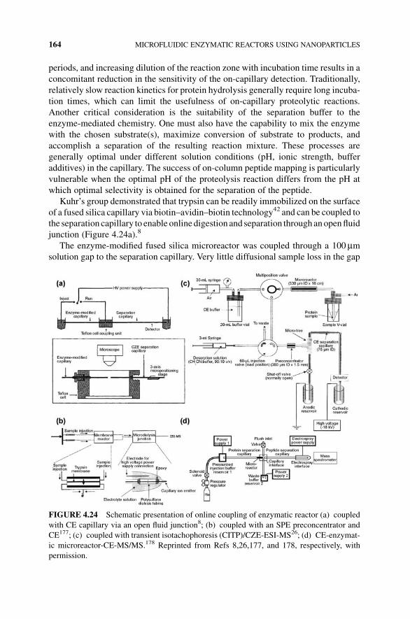
periods, and increasing dilution of the reaction zone with incubation time results in a
concomitant reduction in the sensitivity of the on-capillary detection. Traditionally,
relatively slow reaction kinetics for protein hydrolysis generally require long incuba-
tion times, which can limit the usefulness of on-capillary proteolytic reactions.
Another critical consideration is the suitability of the separation buffer to the
enzyme-mediated chemistry. One must also have the capability to mix the enzyme
with the chosen substrate(s), maximize conversion of substrate to products, and
accomplish a separation of the resulting reaction mixture. These processes are
generally optimal under different solution conditions (pH, ionic strength, buffer
additives) in the capillary. The success of on-column peptide mapping is particularly
vulnerable when the optimal pH of the proteolysis reaction differs from the pH at
which optimal selectivity is obtained for the separation of the peptide.
Kuhr’s group demonstrated that trypsin can be readily immobilized on the surface
of a fused silica capillary via biotin–avidin–biotin technology42 and can be coupled to
the separation capillary to enable online digestion and separation through anopenfluid
junction (Figure 4.24a).8
The enzyme-modified fused silica microreactor was coupled through a 100 mmsolution gap to the separation capillary. Very little diffusional sample loss in the gap
FIGURE 4.24 Schematic presentation of online coupling of enzymatic reactor (a) coupled
with CE capillary via an open fluid junction8; (b) coupled with an SPE preconcentrator and
CE177; (c) coupled with transient isotachophoresis (CITP)/CZE-ESI-MS26; (d) CE-enzymat-
ic microreactor-CE-MS/MS.178 Reprinted from Refs 8,26,177, and 178, respectively, with
permission.
164 MICROFLUIDIC ENZYMATIC REACTORS USING NANOPARTICLES

wasobserved at low ionic strength since thevoltagegradient across thegap is large and
the sample had little time for radial diffusion out of the junction. The utility of this
approach was that it not only offered an efficient mass transfer of the sample by
electromigration but also allowed subsequent separation of the transferred sample in
the second capillary without the need to move either capillary. This configuration
allowed independent optimization of digestion and separation conditions in an online
peptide mapping procedure. The enzyme-modified capillary was filled with the
protein solution and allowed to incubate at room temperature for approximately
2 h, during which proteolysis occurs. Subsequently, an aliquot of the digest was
injected into the separation capillary byapplying a potential across the two free ends of
both capillaries. The injected sample was then separated by applying the CZE
separation potential across the gap solution and the other end of the separation
capillary. Using this approach, they were able to perform online digestion and
separation of picomole quantities of protein by CZE in less than 3 h. The same
coupled capillary CZE instrument was used for further experiments and three
microreactors were prepared with two proteases (trypsin and pepsin) and a peptidase,
carboxypeptidase-Y.64 These proteolytic enzymes are distinguished by the large
differences in their specificities toward peptide bond cleavages and their pH of
greatest catalytic efficiency. Offline protein digestions in carboxypeptidase-Y and
trypsin-modified microreactors yielded C-terminal sequences and mass fingerprints,
by eitherMALDI-MSor plasma desorptionmass spectrometry,whichwere compared
with protein fragment databases for identification. On-line trypsin digestion followed
by CE/ESI-MS was also demonstrated to give the greatest efficiency in peptide
mapping analysis.65 Efficient digestion of the oxidized insulin b-chain occurred
within 40min, and the entire peptide mapping required about 1 h. The long digestion
time required in this system can be due to the fact that enzymes were directly
immobilized on the capillary inner wall with limited surface area that leads to a
low surface to volume ratio of the microreactor.
Bonneil et al.176 fabricated a microreactor with commercially available enzyme-
immobilized controlled pore glass beads packed in a capillary for peptidemapping by
capillary electrophoresis. The proteins were perfused through the microreactor for
about 2 h applying low pressure at the inlet. The digest was collected at the micro-
reactor outlet and the tryptic fragments were separated by CE and detected by UV
absorbance using a diode array detector. Subsequently, the microreactor was further
coupled online with an SPE preconcentrator and CE in an effort to improve mapping
sensitivity by minimizing sample handling that leads to peptide losses.177 The
proposed system depicted in (Figure 4.24b) allowed digestion of proteins and
preconcentration, separation, and detection of the peptides in 4 h. However, the
separation efficiency was poor due to the multiple-valve design of the system and
to the dispersion of the 60 nL desorption plug. Nevertheless, the maps were fairly
reproducible in terms of migration time.
On-line couplingof aminiaturizedmembrane reactor for proteolytic digestionwith
transient isotachophoresis (CITP)/CZE-ESI-MSwas proposed byGao et al.26 Trypsin
was adsorbed on a PVDF membrane. As reported in the schematic setup of
Figure 4.24c, proteins were forced by a syringe pump through pores into this
APPLICATION OF IMMOBILIZED MICROFLUIDIC ENZYMATIC REACTORS 165

membrane, and the digested proteins were focused by transient isotachophoresis,
separated by CE, and detected by ESI. The microfluidic system enabled rapid
identification of proteins in minutes and consumed very little sample (nanogram).
The rather large dead volume of this device resulted in poor separation efficiency for
the digested peptides; theoretical plate counts were about 1500 for the peptides
resulting from digestion of cytochrome c. However, the abilities of the platform to
concentrate and resolve peptide mixtures enhanced the sensitivity and the dynamic
range of ESI-MS detection for the identification of minor proteins. In order to reduce
the dead volume, analysis time, and sample consumption, the same research group
employed a commonly used capillary fitting for directly housing a miniaturized
trypsin membrane reactor.27 The nanoscale trypsin reactor was integrated into a
platform for the concentration and separation of the proteolytic digest using chro-
matographic and electrophoretic methods prior to mass spectrometry analysis. The
application of sample stacking and separation techniques contributed to further
enhancement in the dynamic range and detection sensitivity for the analysis of
complex protein mixtures. The proposed nanoscale reaction system enabled rapid
proteolytic digestion in seconds instead of hours for a protein concentration of less
than 10�8M.
Dovichi and coworkers have described the production of a macroporous monolith
with immobilized trypsin that was coupled to capillary electrophoresis for peptide
mapping, which produced over 300,000 theoretical plates for peptide separation.18
That system employed postcolumn labeling with fluorescence detection but did not
separate proteins before digestion. Recently, they further developed a fully automated
bottom-up approach to protein characterization.178 Proteins were first separated by
capillary electrophoresis. A pepsin microreactor was incorporated into the distal end
of this capillary. The reason for choosing pepsin rather than trypsin as the digestion
enzymewas that pepsin allows to use a volatile acetic acid–ammonium acetate buffer
that is beneficial for combination with ESI-MS. Peptides formed in the reactor were
then transferred to a second capillary, where they were separated by capillary
electrophoresis and characterized by mass spectrometry. While peptides generated
from one digestion were being separated in the second capillary, the next protein
fraction underwent digestion in the microreactor (Figure 4.24d).
Enzyme Immobilized in the First Part of the CE Capillary Construction of an
IMER coupled with CE capillary is a quite complex operation; its reproducibility in
fabrication is low, and ensuring electrical and fluidic connections is not trivial either.
As an alternative, the enzyme can be directly immobilized on a portion of a capillary
column; the first part containing the immobilized enzyme then acts as a microreactor
and the second part of the column is devoted to the separation of the peptides. This
approach can in principle reduce systematic errors associatedwithmoving the sample
from the microreactor into the separation zone. One of the most serious issues that
restricted the application of this approach is the difficulty in controlling the position
and the sizeof thepatchof immobilized enzymes.Another critical consideration is that
since the enzymatic reaction and the separation were performed in the same capillary
column, the buffers are exactly the same for both procedures. It is known that the
166 MICROFLUIDIC ENZYMATIC REACTORS USING NANOPARTICLES

optimal pH of the enzymatic reaction probably differs from the pH at which optimal
selectivity is obtained for the separation of the peptide. Therefore, the buffer
conditions should be carefully selected considering from both standpoints.
Trypsin was encapsulated in tetramethoxysilane-based hydrogel in a single step
under mild conditions within a capillary, and a 1.5-cm length of gel was formed at the
inlet of the capillary.47 The average amount of trypsin in the capillary was about
0.90mg cm�1 gel. The resultant monolithic reactor showed enzymatic activity ap-
proximately 700 times higher than that in free solution, without stopping the flow. The
substrates were introduced electrokinetically from the inlet of the capillary and then
cleaved into products while they flowed through the trypsin-encapsulated gel by
electrophoresis and EOF. Unreacted substrates and products were separated by
electrophoresis (Figure 4.25). The buffer conditionwas considered for both enzymatic
reaction and CE separation and 50mM Tris–HCl (pH 7.5) was finally selected. The
system was used successfully for hydrolyzing a-N-benzoyl-L-arginine ethyl ester
(BAEE) and separating its product without stopping the flow. However, the method
was tested only on peptides, as proteins larger than trypsin could not pass through the
hydrogel and were not digested, severely limiting the application of this system.
Enzyme can also be immobilized on a portion of silica capillary through a
photocoupling reaction. Bossi et al. constructed a CE-microreactor for peptide
mapping using this technology.179 The bioreactor was characterized by being a single
piece, thus ensuring no fluidic or electrical leakage typical of the reactors constructed
asmultiassemblies.The immobilization procedurewasoptimized, and the activity and
stability of the reactor were tested with proteins of different dimensions (cytochrome
c, hemoglobin, and carbonic anhydrase). Mapping online in the CE-microreactor was
quite competitive in terms of time (completed map within 15min) and exhaustive for
FIGURE 4.25 Schematic illustration of an online enzyme reactor integrated into CE.
Reprinted from Ref. 47, with permission.
APPLICATION OF IMMOBILIZED MICROFLUIDIC ENZYMATIC REACTORS 167

the mapping of small proteins. However, the CE-microreactor was not coupled toMS
for complete identification of the peptides mapped.
4.4.2 Immobilized Enzyme Biosensors
Immobilized enzymes have been used as component of detection device in various
analytical and biomedical applications. Some of these devices have been associated
with miniaturized electrochemical detectors and fluidic systems. Since numerous
oxidase and dehydrogenase enzymes generate oxidizable products (hydrogen perox-
ide and NADH, respectively), enzyme-based biochip assays were integrated with
various amperometric detectors byWang et al.180–182 Such electrochemical detectors
offer additional advantages for CE microchips, including compatibility with micro-
machining technologies, miniaturization of both the detector and control instrumen-
tation, and high sensitivity and selectivity. On-line precolumn and on-column
reactions of glucose oxidase and alcohol dehydrogenase have been employed both
for selective measurements of glucose (in the presence of ascorbic acid and uric
acid)180 and for the simultaneousmeasurements of glucose and ethanol (in connection
with electrophoretic separation of the peroxide and NADH products).181 On-chip
assay of amino acids based on their electrophoretic separation, postcolumn reaction
with amino-acid oxidase and amperometric detection of the hydrogen peroxide
product was also developed by the same group.182
L’Hostis et al.183 tested the enzymatic microreactor for glucose detection via
glucose oxidase immobilized to glass beads. Glucose detection was carried out by
electrochemical measurements of hydrogen peroxide generated enzymatically with a
platinum electrode. Glucosewas alsomeasuredwithmicrofluidic biosensors based on
immobilizing glucose oxidase in poly(dimethylsiloxane) electrophoretic micro-
chips.93 An immobilized enzymatic fluorescence capillary biosensor was developed
for determination of sulfated bile acid in urine.184 Amicroelectromechanical systems
(MEMS) device consisting of two identical freestanding polymer diaphragms, resis-
tive heaters, and a thermopile between the diaphragms was fabricated.185 Enzymes
specific to ametabolic analyte systemwere immobilized onmicrobeads packed in the
chambers. When a sample solution containing the analyte was introduced to the
device, the heat released from the enzymatic reactions of the analyte was detected by
the thermopile. The device had been tested with glucose solutions at physiologically
relevant concentrations and shown its potentiality for continuous monitoring of
glucose and other metabolites.
De Boer et al. designed and implemented a continuous-flowmicrofluidic assay for
screening (complex) mixtures for bioactive compounds.186 The microfluidic chip
featured two microreactors (1.6 and 2.4mL) in which an enzyme inhibition and a
substrate conversion reaction were performed, respectively. Enzyme inhibition was
detected by continuously monitoring the products formed in the enzyme–substrate
reaction by electrospray ionizationmass spectrometry. In order to enable the screening
of mixtures of compounds, the chip-based assay was coupled online to capillary
reversed-phase high-performance liquid chromatography with the HPLC column
being operated either in isocratic or in gradient elution mode. In order to improve the
168 MICROFLUIDIC ENZYMATIC REACTORS USING NANOPARTICLES

detection limits of the current method, sample preconcentration based on a micro
online solid-phase extraction column was employed (Figure 4.26).
IMERs are also utilized for screening inhibitors as potential drugs.187,188 Brennan
and coworkers recently prepared protein-doped monolithic silica columns for im-
mobilized enzyme reactors, which allowed the screening of enzyme inhibitors with
MS as the detector.189 Kang and coworkers created an immobilized capillary
acetylcholinesterase (AChE) reactor based on a layer-by-layer assembly for inhibitor
screening. A 0.5 cm long plug of solution of the cationic polyelectrolyte polydial-
lyldimethylammoniumwas injected into the capillary to produce a positively charged
coating on the surface of the capillary; subsequently, the enzyme solution with the
same plug length was injected into the capillary and incubated for 10min to
immobilize the enzyme on the capillary wall via electrostatic interaction; third,
PDDA solution with the same plug length was injected again into the capillary to
cover the immobilized enzyme by forming a PDDA–AChE–PDDA sandwich-like
structure. The substrate solution was injected and incubated for a short time, followed
by applying a voltage to separate the product from the unreacted substrate
FIGURE 4.26 (a) Schematic overview of the online continuous-flow system: 1, pump and
autosampler; 2, trapping column; 3, switching valve; 4, analytical column; 5, syringe pumps; 6,
microfluidic chip; 7, mass spectrometer. (b) The microfluidic chip as used for bioactivity
screening: 1, substrate solution; 2, LCeffluent; 3, enzyme solution; 4, open tubularmicroreactor
with a volume of 1.6mL; 5, open tubular microreactor with a volume of 2.4mL; 6, flow toward
mass spectrometer. Reprinted from Ref. 186, with permission.
APPLICATION OF IMMOBILIZED MICROFLUIDIC ENZYMATIC REACTORS 169

(Figure 4.27). Screening a small compound library containing 4 known AChE
inhibitors and 42 natural extracts was demonstrated, and species with inhibition
activity can be straightforwardly identified with the system.188
TwocytochromeP450 (CYP)-based immobilized enzyme reactorswere developed
to perform automated online phase I drug metabolism studies.190 For this purpose,
biotinylated recombinant CYP2D6 or CYP3A4 reconstituted systems were anchored
to the surface of two monolithic minicolumns (2mm� 6mm ID), which had been
covalently grafted with NeutrAvidin. After optimization of immobilization condi-
tions, the obtained IMERs were integrated online into a LC hyphenated to an
FIGURE 4.27 Schematic representation of the immobilized capillary enzyme reactor with
CE separation for inhibitor screening. Reprinted from Ref. 188, with permission.
170 MICROFLUIDIC ENZYMATIC REACTORS USING NANOPARTICLES

electrospray ionization MS/MS system. Studies with probe substrates and a known
competitive inhibitor were performed, showing the potential of CYP-based IMERs in
drug metabolism.
4.4.3 Kinetic Studies
Microreactors offer significant advantages for online monitoring of biocatalysis and
characterization of kinetics of supported enzymes. First, application of IMER offers a
great advantage by shortening the analysis time. Inmany cases, an enzymatic reaction
is very fast and can reach equilibrium within a single passage of substrate stream
through the microreaction channel. However, several biotransformations, for exam-
ple, those catalyzed by lipases, are slower. Scaling down the dimensions of the
microreactor, and immobilizing the enzyme (lipase) inside a fused silica capillary,
leads to very short times for the hydrolysis,191 while in batch reactions, completion of
enzyme-catalyzed transesterification may take days for some supported lipases.192
Second, application of IMER greatly decreases the amount of biocatalyst used. In
comparisonwith standard assays, the amount of enzymeusedwas very small: Seong et
al. estimated that only 200 pmol (3� 109 molecules of enzyme) was required for the
analysis.193 Moore et al. presented an assay for 500 lipase molecules that could be
applied to single cells.194
The kinetics model described by Lilly et al.195 is appropriate for systems with
continuous flow of the substrate and under steady-state conditions, and can be
summarized by the following equation:
PS0 ¼ K 0m lnð1�PÞþC=Q
where P is the fraction of substrate reacted in the column, S0 is the substrate
concentration at the beginning, K 0m denotes the apparent Michaelis constant, C is
the reaction capacity of the reactor, andQ is the flow rate of the substrate. This formula
allows determination of the apparentMichaelis constant of the catalytic process when
all other parameters are known. The Michaelis constant is typically measured with a
series of experiments at different substrate concentrations in a well-mixed container.
Seong et al. showed that theMichaelis constant determinedwith amicrofluidic device
with immobilized horseradish peroxidase was similar to the value obtained during
homogeneous catalysis in batchmode.193 If anymass transfer effects contribute to the
dynamics, an extrapolation to zero flow rate is required to obtain the value of the
Michaelis constant for comparisonwith that of free enzyme.193An interestingmethod
for determiningKm and nmax was presented by Jiang et al., who applied online frontal
analysis of peptides originating from the digestion by trypsin immobilized on glycidyl
methacrylate-modified cellulose.196 The Lineweaver–Burke diagrams were easily
constructed based on the effects of injection of different concentrations and variation
of flow rate of the substrate solution. Ristenpart et al. demonstrated a microfluidic
technique for measuring Michaelis–Menten rate constants with only a single experi-
ment.197 Enzyme and substratewere brought together in a coflowmicrofluidic device,
and they established analytically and numerically that the initial concentration of
APPLICATION OF IMMOBILIZED MICROFLUIDIC ENZYMATIC REACTORS 171

product scales with the distance x along the channel as x5/2. Measurements of the
initial rate of product formation, combined with the quasi-steady rate of product
formation further downstream, yielded the rate constants. They corroborated the x5/2scaling result experimentally using the bioluminescent reaction between ATP and
luciferase/luciferin as a model system.
Mass transfer is always an important issuewhen considering enzymes entrapped in
supports, and the ideal situation iswhen diffusion of substrate and product into and out
of the bulk solution is not the rate limiting process. Koh and Pishko determined
Michaelis constants of enzymes entrapped in hydrogel micropatches in microfluidic
channels using Lineweaver–Burke graphs.198 Values were found to be lower, by
approximately an order ofmagnitude, than those obtained from experiments using the
homogeneous enzymes. The influence of entrapment in the hydrogel nanostructure on
the kinetic properties of the enzymes was discussed.
4.5 SUMMARY AND FUTURE PERSPECTIVE
In this chapter, we have focused on the devolvement of immobilized microfluidic
enzymatic reactors using nanoparticles. Avariety ofmethods are now available for the
immobilization of enzymes on nanoparticles. Immobilization techniques, such as
physical adsorption, covalent binding, and copolymerization of enzyme with the
polymers are discussed in this chapter.The specific immobilization chemistrydepends
on a variety of factors, characters of the supports, activation methods, and coupling
procedure. The ideal supports for immobilization process should have the following
characteristics: (i) large surface area, (ii) permeability, (iii) hydrophilic character, (iv)
insolubility, (v) chemical, mechanical, and thermal stability, (vi) high rigidity, (vii)
chemical reactivity for coupling of the ligands, and (viii) resistance to microbial and
enzymatic attack.2 With the rapid acceleration of research in the area of nanotech-
nology, new nanoparticles (nonmagnetic or magnetic) that can serve as enzyme
immobilization supports emerge in increasing numbers with lower cost, nontoxicity,
higher activity, and stability, aswell as easier enzyme availability and immobilization.
Intentionally, several types of supports are now commercially available for immobi-
lization processes. Poros� particles (poly(styrene–divinylbenzene)) possessing large
through-pores that allow analyte molecules to “perfuse” rapidly through the interior
of the particles, as well as very short “diffusive” pores, have been introduced by
Applied Biosystems (Foster City, CA, USA) into the market as Poroszyme� Enzyme
trypsin bulk media and cartridges (30mm� 2.1mm ID) to perform rapid online
tryptic digestion of protein.173–175 CIM� Disk Monolithic Columns developed by
BIA Separations (Ljubjana, Slovenia) are also utilized for trypsin immobilization and
online protein digestion.199,200 In the light of current developments in nanotechnolo-
gy, it is to be hoped that the availability of new support materials will lead to faster,
more effective, and more stable IMERs.
Due to the flow-through format of IMERs, they can be easily combined with other
flow-through techniques such as HPLC or CE separation withMS detection, allowing
their broad applications in tremendous areas. However, some drawbacks such as band
172 MICROFLUIDIC ENZYMATIC REACTORS USING NANOPARTICLES

broadening due to nonspecific binding to the enzyme and the influence of the flow rate
on the substrate conversion efficiency in the case of specificmass transfer regimen can
limit the application of IMERs in an online system. Now with the introduction of
monolithic supports, it is possible to overcome all diffusion limitations so that the
enzymatic kinetic parameters are flow-unaffected.
IMERs are commonly used in medical diagnostics and therapy, enzyme-based
electrodes, organic synthesis, kinetic study, biosensors, and many other applications
such as removal of waste metabolites, blood detoxification, and/or corrections of
inborn metabolic deficiency. Among these applications, most of the IMER applica-
tions are aimed at protein analysis by peptide mapping. High immobilized enzyme
concentrations, in combination with the superior solute transport properties of
perfusivemedia, allow achievement of complete digestion inminutes or even seconds
rather than in hours when compared to solution-phase digest. Unlike solution-phase
methods, the degree of protein digestion can be controlled through the flow rate in the
IMER. The highly stable enzyme immobilization chemistry enables the reuse of the
same IMERs for times of assays,with reproducible results. The integration of different
steps (digestion, separation, and identification) in a single system is particularly
attractive for the analysis of complex protein mixtures. However, it is noticed that,
although numerous publications related to application of IMER contained online
system in protein analysis have been reported so far, most of these studies concerned
digestion of standard proteins, such as myoglobin, cytochrome c, R-lactalbumin,
bovine serumalbumin, andholo-transferrin. Incontrast, fewworks concernedanalysis
of proteins in real samples (tissue, cell, etc.).
Further technical improvements are needed to enable the IMERs contained online
system for the detection and characterization of low-abundance analytes, and to
increase the throughput of the methodologies. The final goal is to find robust,
automated, and sensitive high-throughput analytical tools in bioanalytical science
and in applied biotechnology.
REFERENCES
1. Miyazaki, M.; Maeda, H. Microchannel enzyme reactors and their applications for
processing. Trends Biotechnol. 2006, 24, 463–470.
2. K�rrenkov�a, J.; Foret, F. Immobilized microfluidic enzymatic reactors. Electrophoresis
2004, 25, 3550–3563.
3. B�ılkov�a, Z.; Slov�akov�a, M.;Minc, N.; F€utterer, C.; Cecal, R.; Hor�ak, D.; Benes, M.; Potier,
I.; K�renkov�a, J.; Przybylski, M.; Viovy, J.-L. Functionalized magnetic micro- and
nanoparticles: optimization and application to m-chip tryptic digestion. Electrophoresis
2006, 27, 1811–1824.
4. Thomsen, M.S.; Nidetzky, B. Microfluidic reactor for continuous flow biotransformations
with immobilized enzymes: the example of lactose hydrolysis by a hyperthermophilic b-glycoside hydrolase. Eng. Life Sci. 2008, 8, 40–48.
5. J€ahnisch, K.; Hessel, V.; L€owe, H.; Baerns, M. Chemistry in microstructured reactors.
Angew. Chem., Int. Ed. 2004, 43, 406–446.
REFERENCES 173

6. DeMello, A.J. Control and detection of chemical reactions inmicrofluidic systems.Nature
2006, 442, 394–402.
7. Watts, P.; Wiles, C. Recent advances in synthetic micro reaction technology. Chem.
Commun. 2007, 5, 443–67.
8. Amankwa, L.N.; Kuhr, W.G. Online peptide mapping by capillary zone electrophoresis.
Anal. Chem. 1993, 65, 2693–2697.
9. Cobb, K.A.; Novotny, M. High-sensitivity peptide mapping by capillary zone electropho-
resis and microcolumn liquid chromatography using immobilized trypsin for protein
digestion. Anal. Chem. 1989, 61, 2226–2231.
10. Davis, M.T.; Lee, T.D.; Ronk, M.; Hefta, S.A. Microscale immobilized protease reactor
columns for peptide mapping by liquid chromatography/mass spectral analyses. Anal.
Biochem. 1995, 224, 235–244.
11. Hermanson, G.T. Bioconjugate Techniques; Academic Press: San Diego, CA, 1996.
12. Girelli, A.M.; Mattei, E. Application of immobilized enzyme reactor in on-line high
performance liquid chromatography: a review. J. Chromatogr. B 2005, 819, 3–16.
13. Li, Y.; Yan, B.; Deng, C.-H.; Yu,W.-J.; Xu, X.-Q.; Yang, P.-Y.; Zhang, X.-M. Efficient on-
chip proteolysis system based on functionalized magnetic silica microspheres.
Proteomics 2007, 7, 2330–2339.
14. Li, Y.; Xu, X.-Q.; Deng, C.-H.; Yang, P.-Y.; Zhang, X.-M. Immobilization of trypsin on
superparamagnetic nanoparticles for rapid and effective proteolysis. J. Proteome Res.
2007, 6, 3849–3855.
15. Drobn�ık, J.; Vlas�ak, J.; Pila�r, J.; Svec, F.; K�alal, J. Synthetic polymers in the study of
protein immobilization on glycidylmethacrylate carriers.EnzymeMicrob. Technol. 1979,
1, 107–112.
16. Vodopivec, M.; Berovic, M.; Jancar, J.; Podgornik, A.; Strancar, A. Application of
convective interaction media disks with immobilised glucose oxidase for on-line glucose
measurements. Anal. Chim. Acta 2000, 407, 105–110.
17. Petro, M.; Svec, F.; Fr�echet, J.M.J. Immobilization of trypsin onto “molded” macro-
porous poly(glycidyl methacrylate-co-ethylene dimethacrylate) rods and use of the
conjugates as bioreactors and for affinity chromatography. Biotechnol. Bioeng. 1996,
49, 355–363.
18. Ye, M.; Hu, S.; Schoenherr, R.M.; Dovichi, N.J. On-line protein digestion and peptide
mapping by capillary electrophoresis with post-column labeling for laser-induced
fluorescence detection. Electrophoresis 2004, 25, 1319–1326.
19. Svec, F.; Hrudkova, H.; K�alal, J. Reactive polymers. 20. Preparation of a carrier with
aldehyde groups by oxidation of a macroporous glycidyl methacrylate-ethylenedi-
methacrylate copolymer with periodic acid. Angew. Makromol. Chem. 1978, 70,
101–108.
20. K�renkov�a, J.; Bilkov�a, Z.; Foret, F. Characterization of a monolithic immobilized trypsin
microreactor with on-line coupling to ESI-MS. J. Sep. Sci. 2005, 28, 1675–1684.
21. Jiang, H.-H.; Zou, H.-F.; Wang, H.-L.; Ni, J.-Y.; Zhang, Q.; Zhang, Y.-K. On-line
characterization of the activity and reaction kinetics of immobilized enzyme by high-
performance frontal analysis. J. Chromatogr. A 2000, 903, 77–84.
22. Xie, S.; Svec, F.; Fr�echet, J.M.J. Design of reactive porous polymer supports for high
throughput bioreactors: poly(2-vinyl-4,4-dimethylazlactone-co-acrylamide-co-ethyl
dimethacrylate) monoliths. Biotechnol. Bioeng. 1999, 62, 30–35.
174 MICROFLUIDIC ENZYMATIC REACTORS USING NANOPARTICLES

23. Nouaimi, M.; M€oschel, K.; Bisswanger, H. Immobilization of trypsin on polyester fleece
via different spacers. Enzyme Microb. Technol. 2001, 29, 567–574.
24. Turkov�a, J. Oriented immobilization of biologically active proteins as a tool for revealing
protein interactions and function. J. Chromatogr. B 1999, 722, 11–31.
25. Li, Y.; Yan, B.; Deng, C.-H.; Tang, J.; Liu, J.-Y.; Zhang, X.-M. On-plate digestion of
proteins using novel trypsin-immobilized magnetic nanospheres for MALDI-TOF-MS
analysis. Proteomics 2007, 7, 3661–3671.
26. Gao, J.; Xu, J.; Locascio, L.E.; Lee, C.S. Integrated microfludic system enabling protein
digestion, peptide separation, and protein identification. Anal. Chem. 2001, 73,
2648–2655.
27. Cooper, J.W.; Chen, J.; Li, Y.; Lee, C.S. Membrane-based nanoscale proteolytic reactor
enabling protein digestion, peptide separation, and protein identification using mass
spectrometry. Anal. Chem. 2003, 75, 1067–1074.
28. Massolini, G.; Calleri, E.; DeLorenzi, E.; Pregnolato,M.; Terreni,M.; Felix, G.; Gandini,
C. Immobilized penicillin G acylase as reactor and chiral selector in liquid chromatog-
raphy. J. Chromatogr. A 2001, 921, 147–160.
29. Calleri, E.; Temporini, C.; Furlanetto, S.; Loiodice, F.; Fracchiolla, G.; Massolini, G.
Lipases for biocatalysis: development of a chromatographic bioreactor. J. Pharm.
Biomed. Anal. 2003, 32, 715–724.
30. Guo, Z.; Xu, S.-Y.; Lei, Z.-D.; Zou, H.-F.; Guo, B.-C. Immobilized metal-ion chelating
capillary microreactor for peptide mapping analysis of proteins by matrix assisted laser
desorption/ionization-time of flight-mass spectrometry. Electrophoresis 2003, 24,
3633–3639.
31. Anspach, F.B. Silica-based metal chelate affinity sorbents. I. Preparation and characteri-
zation of iminodiacetic acid affinity sorbents prepared via different immobilization
techniques. J. Chromatogr. A 1994, 672, 35–49.
32. Li, Y.; Xu, X.-Q.; Yang, B.; Deng, C.-H.; Yu,W.-J.; Yang, P.-Y.; Zhang, X.-M.Microchip
reactor packed with metal-ion chelated magnetic silica microspheres for high efficient
proteolysis. J. Proteome Res. 2007, 6, 2367–2375.
33. Li, Y.; Yan, B.; Xu, X.-Q.; Deng, C.-H.; Yang, P.-Y.; Shen, X.-Z.; Zhang, X.-M. On-
column tryptic mapping of proteins using metal-ion-chelated magnetic silica micro-
spheres by matrix-assisted laser desorption/ionization time-of-flight mass spectrometry.
Rapid Commun. Mass Spectrom. 2007, 21, 2263–2268.
34. Lvov, Y.; Decher, G.; Mohwald, H. Assembly, structural characterization, and thermal
behavior of layer-by-layer deposited ultrathin films of poly(vinyl sulfate) and poly
(allylamine). Langmuir 1993, 9, 481–486.
35. Decher, G. Fuzzy nanoassemblies: toward layered polymeric multicomposites. Science
1997, 277, 1232–1237.
36. Serizawa, T.; Yamaguchi, M.; Akashi, M. Enzymatic hydrolysis of a layer-by-layer
assembly prepared from chitosan and dextran sulfate. Macromolecules 2002, 35,
8656–8658.
37. Ichinose, I.; Takaki, R.; Kuroiwa, K.; Kunitake, T. Electrostatic desorption of cytochrome
c on ultrathin ZrO2-gel layers and preparation of alternate multilayers. Langmuir 2003,
19, 3883–3888.
38. Salloum, D.S.; Schlenoff, J.B. Protein adsorption modalities on polyelectrolyte multi-
layers. Biomacromolecules 2004, 5, 1089–1096.
REFERENCES 175

39. Zhou, X.-C.; Wu, L.-Y.; Zhou, J.-Z. Fabrication of DNAmicroarrays on nanoengineered
polymeric ultrathin film prepared by self-assembly of polyelectrolyte multilayers.
Langmuir 2004, 20, 8877–8885.
40. Liu, Y.; Lu, H.-J.; Zhong,W.; Song, P.-Y.; Kong, J.-L.; Yang, P.-Y.; Girault, H.H.; Liu, B.-
H. Multilayer-assembled microchip for enzyme immobilization as reactor toward low-
level protein identification. Anal. Chem. 2006, 78, 801–808.
41. Liu, Y.; Zhong,W.;Meng, S.; Kong, J.-L.; Lu, H.-J.; Yang, P.-Y.; Girault, H.H.; Liu, B.-H.
Assembly-controlled biocompatible interface on a microchip: strategy to highly efficient
proteolysis. Chem. Eur. J. 2006, 12, 6585–6591.
42. Amankwa, L.N.; Kuhr, W.G. Trypsin-modified fused-silica capillary microreactor
for peptide mapping by capillary zone electrophoresis. Anal. Chem. 1992, 64,
1610–1613.
43. Gleason, N.J.; Carbeck, J.D. Measurement of enzyme kinetics using microscale steady-
state kinetic analysis. Langmuir 2004, 20, 6374–6381.
44. Mao, H.-B.; Yang, T.-L.; Cremer, P.S. Design and characterization of immobilized
enzymes in microfluidic systems. Anal. Chem. 2002, 74, 379–385.
45. Holden, M.A.; Jung, S.-Y.; Cremer, P.S. Patterning enzymes inside microfluidic channels
via photoattachment chemistry. Anal. Chem. 2004, 76, 1838–1843.
46. Anderson, N.L.;Haines, L.R.; Pearson, T.W.An effective and rapidmethod for functional
characterization of immunoadsorbents using POROS beads and flow cytometry. J.
Proteome Res. 2004, 3, 228–234.
47. Sakai-Kato, K.; Kato, M.; Toyo’oka, T. On-line trypsin-encapsulated enzyme reactors by
the sol–gel method integrated into capillary electrophoresis. Anal. Chem. 2002, 74,
2943–2949.
48. Sakai-Kato, K.; Kato, M.; Toyo’oka, T. Creation of on-chip enzyme reactors by
encapsulating trypsin in sol–gel on a plastic microchip. Anal. Chem. 2003, 75, 388–393.
49. Dave, B.C.; Dunn, B.; Valentine, J.S.; Zink, J.I. Sol–gel encapsulation methods for
biosensors. Anal. Chem. 1994, 66, 1120–1127.
50. Gill, I.; Ballesteros, A. Bioencapsulation within synthetic polymers. Part 1. Sol–gel
encapsulated biologicals. Trends Biotechnol. 2000, 18, 282–296.
51. Hahn, R.; Podgornik, A.; Merhar, M.; Schallaun, E.; Jungbauer, A. Affinity monoliths
generated by in situ polymerization of the ligand. Anal. Chem. 2001, 73, 5126–5132.
52. Kim, Y.-D.; Park, C.B.; Clark, D.S. Stable sol–gel microstructured and microfluidic
networks for protein patterning. Biotechnol. Bioeng. 2001, 73, 331–337.
53. Qu,H.-Y.;Wang,H.-T.; Huang,Y.; Zhong,W.; Lu,H.-J.; Kong, J.-L.; Yang, P.-Y.; Liu, B.-
H. Stable microstructured network for protein patterning on a plastic microfluidic
channel: strategy and characterization of on-chip enzyme microreactors. Anal. Chem.
2004, 76, 6426–6433.
54. Park, C.B.; Clark, D.S. Sol–gel encapsulated enzyme arrays for high-throughput screen-
ing of biocatalytic activity. Biotechnol. Bioeng. 2002, 78, 229–235.
55. Liu, Z.-J.; Liu, B.-H.; Kong, J.-L.; Deng, J.-Q. Probe trace phenols based onmediator-free
alumina sol–gel derived tyrosinase biosensor. Anal. Chem. 2000, 72, 4707–4712.
56. Jiang, D.-C.; Tang, J.; Liu, B.-H.; Yang, P.-Y.; Kong, J.-L. Ultrathin alumina sol–gel-
derived films: allowing direct detection of the liver fibrosis markers by capacitance
measurement. Anal. Chem. 2003, 75, 4578–4584.
176 MICROFLUIDIC ENZYMATIC REACTORS USING NANOPARTICLES

57. Wu, H.-L.; Tian, Y.-P.; Liu, B.-H.; Lu, H.-J.; Wang, X.-Y.; Zhai, J.-J.; Jin, H.; Yang, P.-Y.;
Xu, Y.-M.; Wang, H.-H. Titania and alumina sol–gel-derived microfluidic enzymatic-
reactors for peptide mapping: design, characterization, and performance. J. Proteome
Res. 2004, 3, 1201–1209.
58. Frenkel-Mullerad, H.; Avnir, D. Sol–gel materials as efficient enzyme protectors:
preserving the activity of phosphatases under extreme pH conditions. J. Am. Chem.
Soc. 2005, 127, 8077–8081.
59. Itoh, T.; Ishii, R.; Ebina, T.; Hanaoka, T.; Fukushima, Y.; Mizukami, F. Encapsulation of
myoglobin with a mesoporous silicate results in new capabilities. Bioconj. Chem. 2006,
17, 236–240.
60. Kumar, R.; Maitra, A.N.; Patanjali, P.K.; Sharma, P. Hollow gold nanoparticles encap-
sulating horseradish peroxidase. Biomaterials 2005, 26, 6743–6753.
61. Ma, D.; Li, M.; Patil, A.J.; Mann, S. Fabrication of protein/silica core–shell nanoparticles
by microemulsion-based molecular wrapping. Adv. Mater. 2004, 16, 1838–1841.
62. Kim, J.; Grate, J.W. Single-enzyme nanoparticles armored by a nanometer-scale organic/
inorganic network. Nano Lett. 2003, 3, 1219–1222.
63. Yan, M.; Ge, J.; Liu, Z.; Ouyang, P.-K. Encapsulation of single enzyme in nanogel
with enhanced biocatalytic activity and stability. J. Am. Chem. Soc. 2006, 128,
11008–11009.
64. Licklider, L.; Kuhr, W.G. Optimization of online peptide mapping by capillary zone
electrophoresis. Anal. Chem. 1994, 66, 4400–4407.
65. Licklider, L.; Kuhr, W.G.; Lacey, M.P.; Keough, T.; Purdon, M.P.; Takigiku, R. Online
microreactors/capillary electrophoresis/mass spectrometry for the analysis of proteins
and peptides. Anal. Chem. 1995, 67, 4170–4177.
66. Licklider, L.; Kuhr, W.G. Characterization of reaction dynamics in a trypsin-modified
capillary microreactor. Anal. Chem. 1998, 70, 1902–1908.
67. Laurell, T.; Rosengren, L. A micromachined enzyme reactor in (110)-oriented silicon.
Sens. Actuators B 1994, 19, 614–617.
68. Laurell, T.; Drott, J.; Rosengren, L. Silicon-wafer integrated enzyme reactors. Biosens.
Bioelectron. 1995, 10, 289–299.
69. Lee, J.; Musyimi, H.K.; Soper, S.A.; Murray, K.K. Development of an automated
digestion and droplet deposition microfluidic chip for MALDI-TOF MS. J. Am. Soc.
Mass Spectrom. 2008, 19, 964–972.
70. K�renkov�a, J.; Klep�arn�ık, K.; Foret, F. Capillary electrophoresis mass spectrometry
coupling with immobilized enzyme electrospray capillaries. J. Chromatogr. A 2007,
1159, 110–118.
71. Ekstr€om, S.; Onnerfjord, P.; Nilsson, J.; Bengtsson, M.; Laurell, T.; Marko-Varga, G.
Integrated microanalytical technology enabling rapid and automated protein identifica-
tion. Anal. Chem. 2000, 72, 286–293.
72. Miyazaki, M.; Kaneno, J.; Uehara, M.; Fujii, M.; Shimizu, H.; Maeda, H. Simple method
for preparation of nanostructure on microchannel surface and its usage for enzyme
immobilization. Chem. Commun. 2003, 5, 648–649.
73. Wu, H.-L.; Zhai, J.-J.; Tian, Y.-P.; Lu, H.-J.;Wang, X.-Y.; Jia,W.-T.; Liu, B.-H.; Yang, P.-
Y.; Xu, Y.-M.; Wang, H.-H. Microfluidic enzymatic-reactors for peptide mapping:
strategy, characterization, and performance. Lab Chip 2004, 4, 588–597.
REFERENCES 177

74. Hessel, V.; L€owe, H.; Sch€onfeld, F. Micromixers: a review on passive and active mixing
principles. Chem. Eng. Sci. 2005, 60, 2479–2501.
75. Xiong, L.; Regnier, F.E. Channel-specific coatings on microfabricated chips. J.
Chromatogr. A 2001, 924, 165–176.
76. Park, J.J.; Luo,X.-L.;Yi,H.-M.;Valentine, T.M.; Payne,G.F.; Bentley,W.E.;Ghodssi, R.;
Rubloff, G.W. Chitosan-mediated in situ biomolecule assembly in completely packaged
microfluidic devices. Lab Chip 2006, 6, 1315–1321.
77. Luo, X.; Lewandowski, A.T.; Yi, H.; Payne, G.F.; Ghodssi, R.; Bentley, W.E.
Programmable assembly of a metabolic pathway enzyme in a pre-packaged reusable
bioMEMS device. Lab Chip 2008, 8, 420–430.
78. Luo, X.-L.; Berlin, D.L.; Buckhout-White, S.; Bentley, W.E.; Payne, G.F.; Ghodssi, R.;
Rubloff, G.W. Design optimization for bioMEMS studies of enzyme-controlled meta-
bolic pathways. Biomed. Microdevices 2008, 10, 899–908.
79. Tomer, S.; Dorsey, J.G.; Berthod, A.Nonionicmicellar liquid chromatography coupled to
immobilized enzyme reactors. J. Chromatogr. A 2001, 923, 7–16.
80. Shu, H.-C.; Wu, N.-P. A chemically modified carbon paste electrode with D-lactate
dehydrogenase and alanine aminotranferase enzyme sequences for D-lactic acid analysis.
Talanta 2001, 54, 361–368.
81. Lim, L.W.; Tomatsu, M.; Takeuchi, T. Development of an on-line immobilized-enzyme
reversed-phase HPLC method for protein digestion and peptide separation. Anal.
Bioanal. Chem. 2006, 386, 614–620.
82. Richter, T.; Shultz-Lockyear, L.L.; Oleschuk, R.D.; Bilitewski, U.; Harrison, D.J. Bi-
enzymatic and capillary electrophoretic analysis of non-fluorescent compounds in
microfluidic devices determination of xanthine. Sens. Actuators B 2002, 81, 369–376.
83. Bertucci, C.; Petri, A.; Felix, G.; Perini, B.; Salvatori, P. Lipase-based HPLC stationary
phase: enantioselective synthesis of 2-substituted 1,3-propanediol monoacetates.
Tetrahedron: Asymmetry 1999, 10, 4455–4462.
84. Kiba, N.; Saegusa, K.; Furosawa, M. Post-column enzyme reactors for chemilumino-
metric detection of glucose 1,5-anhydroglucitol and 3-hydroxybutyrate in an anion-
exchange chromatographic system. J. Chromatogr. B 1997, 689, 393–398.
85. Seong, G.H.; Crooks, R.M. Efficient mixing and reactions within microfluidic channels
using microbead-supported catalysts. J. Am. Chem. Soc. 2002, 124, 13360–13361.
86. Srinivasan, A.; Bach, H.; Sherman, D.H.; Dordick, J.S. Bacterial P450-catalyzed
polyketide hydroxylation on a microfluidic platform. Biotechnol. Bioeng. 2004, 88,
528–535.
87. Oleschuk, R.D.; Shultz-Lockyear, L.L.; Ning, Y.-B.; Harrison, D.J. Trapping of bead-
based reagents within microfluidic systems: on-chip solid-phase extraction and electro-
chromatography. Anal. Chem. 2000, 72, 585–590.
88. Kerby, M.B.; Legge, R.S.; Tripathi, A. Measurements of kinetic parameters in a
microfluidic reactor. Anal. Chem. 2006, 78, 8273–8280.
89. Nakamura, H.; Murakami, Y.; Yokoyama, K.; Tamiya, E.; Karube, I. A compactly
integrated flow cell with a chemiluminescent FIA system for determining lactate
concentration in serum. Anal. Chem. 2001, 73, 373–378.
90. Andersson, H.; van der Wijngaart, W.; Enoksson, P.; Stemme, G. Micromachined flow-
through filter-chamber for chemical reactions on beads. Sens. Actuators B 2000, 67,
203–208.
178 MICROFLUIDIC ENZYMATIC REACTORS USING NANOPARTICLES

91. Sato, K.; Tokeshi,M.; Odake, T.; Kimura, H.; Ooi, T.; Nakao,M.; Kitamori, T. Integration
of an immunosorbent assay system: analysis of secretory human immunoglobulin A on
polystyrene beads in a microchip. Anal. Chem. 2000, 72, 1144–1147.
92. Ceriotti, L.; de Rooij, N.F.; Verpoorte, E. An integrated fritless column for on-chip
capillary chromatography with conventional stationary phases. Anal. Chem. 2002, 74,
639–647.
93. Zhang, Q.; Xu, J.-J.; Chen, H.-Y. Glucose microfluidic biosensors based on immobilizing
glucose oxidase in poly(dimethylsiloxane) electrophoretic microchips. J. Chromatogr. A
2006, 1135, 122–126.
94. Xu, Z.-R.; Fang, Z.-L. Composite poly(dimethylsiloxane)/glass microfluidic systemwith
an immobilized enzymatic particle-bed reactor and sequential sample injection for
chemiluminescence determinations. Anal. Chim. Acta 2004, 507, 129–135.
95. Miyazaki, M.; Kaneno, J.; Kohama, R.; Uehara, M.; Kanno, K.; Fujii, M.; Shimizu, H.;
Maeda, H. Preparation of functionalized nanostructures on microchannel surface and
their use for enzyme microreactors. Chem. Eng. J. 2004, 101, 277–284.
96. Miyazaki, M.; Kaneno, J.; Yamaori, S.; Honda, T.; Briones, M.P.P.; Uehara, M.;
Arima, K.; Kanno, K.; Yamashita, K.; Yamaguchi, Y.; Nakamura, H.; Yonezawa, H.;
Fujii, M.; Maeda, H. Efficient immobilization of enzymes on microchannel surface
through His-tag and application for microreactor. Protein Pept. Lett. 2005, 12,
207–210.
97. Merkoci, A.; Marta, A.; Tarraso’n, G.; Eritja, R.; Alegret, S. Toward an ICPMS-linked
DNA assay based on gold nanoparticles immunoconnected through peptide sequences.
Anal. Chem. 2005, 77, 6500–6503.
98. Liu, Y.; Xue, Y.; Ji, J.; Chen, X.; Kong, J.-L.; Yang, P.-Y.; Girault, H.H.; Liu, B.-H. Gold
nanoparticles assembly microfluidic reactor for efficient on-line proteolysis. Mol. Cell.
Proteomics 2007, 6, 1428–1436.
99. Tosheva, L.; Valtchev, V.P. Nanozeolites: synthesis, crystallization mechanism, and
applications. Chem. Mater. 2005, 17, 2494–2513.
100. Huang, Y.; Shan,W.; Liu, B.-H.; Liu,Y.; Zhang,Y.-H.; Zhao,Y.; Lu,H.-J.; Tang,Y.;Yang,
P.-Y. Zeolite nanoparticle modified microchip reactor for efficient protein digestion. Lab
Chip 2006, 6, 534–539.
101. Patel, D.; Moon, J.Y.; Chang, Y.; Kim, T.J.; Lee, G.H. Poly(D,L-lactide-co-glycolide)
coated superparamagnetic iron oxide nanoparticles: synthesis, characterization and in
vivo study as MRI contrast agent. Colloid Surf. A 2008, 313, 91–94.
102. Zhao, M.; Josephson, L.; Tang, Y.; Weissleder, R. Magnetic sensors for protease assays.
Angew. Chem., Int. Ed. 2003, 42, 1375–1378.
103. Mornet, S.; Vasseur, S.; Grasset, F.; Veverka, P.; Goglio, G.; Demourgues, A.; Portier, J.;
Pollert, E.; Duguet, E.Magnetic nanoparticle design formedical applications.Prog. Solid
State Chem. 2006, 34, 237–247.
104. Stevens, P.D.; Fan, J.; Gardimalla, H.M.R.; Yen, M.; Gao, Y. Superparamagnetic
nanoparticle-supported catalysis of Suzuki cross-coupling reactions. Org. Lett. 2005,
7, 2085–2088.
105. Jun, Y.-W.; Choi J.-S.; Cheon, J. Heterostructured magnetic nanoparticles: their versatil-
ity and high performance capabilities. Chem. Commun. 2007, 1203–1214.
106. Choi, W.; Oh, K.W.; Thomas, J.H.; Heineman, W.R.; Halsall, H.B.; Nevin, J.H.;
Helmicki, A.J.; Henderson, H.T.; Ahn, C.H. An integrated microfluidic biochemical
REFERENCES 179

detection system for protein analysis with magnetic bead-based sampling capabilities.
Lab Chip 2002, 2, 27–30.
107. Rashkovetsky, L.G.; Lyubarskaya, Y.V.; Foret, F.; Hughes, D.E.; Karger, B.L. Automated
microanalysis using magnetic beads with commercial capillary electrophoretic instru-
mentation. J. Chromatogr. A 1997, 781, 197–204.
108. Xu, X.; Friedman, G.; Humfeld, K.D.; Majetich, S.A.; Asher, S.A. Superparamagnetic
photonic crystals. Adv. Mater. 2001, 13, 1681–1684.
109. Lu, Y.; Yin, Y.; Mayers, B.T.; Xia, Y. Modifying the surface properties of superpar-
amagnetic iron oxide nanoparticles through a sol–gel approach. Nano Lett. 2002, 2,
183–186.
110. Wu,W.; He, Q.-G.; Jiang, C.-Z. Magnetic iron oxide nanoparticles: synthesis and surface
fictionalization strategies. Nanaoscale Res. Lett. 2008, 3, 397–415.
111. Slov�akov�a, M.; Minc, N.; B�ılkov�a, Z.; Smadja, C.; Faigle, W.; F€utterer, C.; Taverna, M.;
Viovy, J.-L. Use of self assembledmagnetic beads for on-chip protein digestion.LabChip
2005, 9, 935–942.
112. Koh, I.; Wang, X.; Varughese, B.; Isaacs, L.; Ehrman, S.E.; English, D.S. Magnetic iron
oxide nanoparticles for biorecognition: evaluation of surface coverage and activity. J.
Phys. Chem. B 2006, 110, 1553–1558.
113. Nishimura, K.; Hasegawa, M.; Ogura, Y.;et al. 4�C preparation of ferrite nanoparticles
having protein molecules immobilized on their surfaces. J. Appl. Phys. 2002, 91,
8555–8556.
114. Liu, J.-Y.; Lin, S.; Qi, D.-W.; Deng, C.-H.; Yang, P.-Y.; Zhang, X.-M. On-chip enzymatic
microreactor using trypsin-immobilized superparamagnetic nanoparticles for highly
efficient proteolysis. J. Chromatogr. A 2007, 1176, 169–177.
115. Hayes, M.A.; Polson, N.A.; Phayre, A.N.; Garcia, A.A. Flow-based microimmunoassay.
Anal. Chem. 2001, 73, 5896–5902.
116. Lawrence, E.M.; Ivey, M.L.; Flores, G.A.; Lui, J.; Bibette, J.; Richard, J. Field-induced
structure of confined ferrofluid emulsion. Int. J. Mod. Phys. B 1994, 8, 2765–2777.
117. Svec, F. Less common applications of monoliths. I. Microscale protein mapping with
proteolytic enzymes immobilized on monolithic supports. Electrophoresis 2006, 27,
947–961.
118. Yi, Y.Y.; Chen, Y.; Brook, M.A.; Brennan, J.D. Development of macroporous titania
monoliths by a biocompatible method. Part 2. Enzyme entrapment studies.Chem.Mater.
2006, 18, 5336–5342.
119. Cabrera, K. Applications of silica-basedmonolithic HPLC columns. J. Sep. Sci. 2004, 27,
843–852.
120. Calleri, E.; Massolini, G.; Lubda, D.; Temporini, C.; Loiodice, F.; Caccialanza, G.
Evaluation of amonolithic epoxy silica support for penicillinGacylase immobilization. J.
Chromatogr. 1031, 2004, 93–100.
121. Calleri, E.;Marrubini,G.;Massolini,G.; Lubda,D.; de Fazio, S.S.; Furlanetto, S.;Wainer, I.
W.; Manzo, L.; Caccialanza, G. Development of a chromatographic bioreactor based on
immobilized beta-glucuronidase onmonolithic support for the determination of dextrome-
thorphan and dextrorphan in human urine. J. Pharm. Biomed. Anal. 2004, 35, 1179–1189.
122. Chen, Z.; Hayashi, K.; Iwasaki, Y.; Kurita, R.; Niwa, O.; Sunaawa, K. On-line monolithic
enzyme reactor fabricated by sol–gel process for elimination of ascorbic acid while
monitoring dopamine. Electroanalysis 2005, 17, 231–238.
180 MICROFLUIDIC ENZYMATIC REACTORS USING NANOPARTICLES

123. Kawakami,K.; Sera, Y.; Sakai, S.; Ono, T.; Ijima,H.Development and characterization of
a silica monolith immobilized enzyme micro-bioreactor. Ind. Eng. Chem. Res. 2005, 44,
236–240.
124. Sakai-Kato,K.;Kato,M.;Toyo’oka,T.On-line trypsin-encapsulatedenzyme reactor by the
sol–gelmethod integrated intocapillaryelectrophoresis.Anal.Chem.2002,74, 2943–2949.
125. Kato, M.; Inuzuka, K.; Sakai-Kato, K.; Toyo’oka, T. Monolithic bioreactor immobilizing
trypsin for high-throughput analysis. Anal. Chem. 2005, 77, 1813–1818.
126. Dulay, M.T.; Quirino, J.P.; Bennett, D.C.; Kato, M.; Zare, R.N. Photopolymerized
sol–gel monoliths for capillary electrochromatography. Anal. Chem. 2001, 73,
3921–3926.
127. Kato, M.; Sakai-Kato, K.; Jin, H.M.; Kubota, K.; Miyano, H.; Toyo’oko, T.; Dulay, M.T.;
Zare, R.N. Integration of on-line protein digestion, peptide separation, and protein
identification using pepsin-coated photopolymerized sol–gel columns and capillary
electrophoresis/mass spectrometry. Anal. Chem. 2004, 76, 1896–1902.
128. Dulay, M.T.; Baca, Q.J.; Zare, R.N. Enhanced proteolytic activity of covalently bound
enzymes in photopolymerized sol gel. Anal. Chem. 2005, 77, 4604–4610.
129. Kostner, A.; Mandel, M. In Immobilized Enzymes; Mosbach, K., Ed.; Academic Press:
New York, 1976; pp 191–195.
130. Mersal, G.A.M.; Bilitewski, U. Development of monolithic enzymatic reactors in glass
microchips for the quantitative determination of enzyme substrates using the example of
glucose determination via immobilized glucose oxidase. Electrophoresis 2005, 26,
2303–2312.
131. Palm, A.; Novotny, M.V. Analytical characterization of a facile porous polymer mono-
lithic trypsin microreactor enabling peptide mass mapping using mass spectrometry.
Rapid Commun. Mass Spectrom. 2004, 18, 1374–1382.
132. Palm, A.; Novotny, M.V. A monolithic PNGase F enzyme microreactor enabling glycan
mass mapping of glycoproteins by mass spectrometry. Rapid Commun. Mass Spectrom.
2005, 19, 1730–1738.
133. Hilder, E.F.; Svec, F.; Fr�echet, J.M.J. Polymericmonolithic stationary phases for capillary
electrochromatography. Electrophoresis 2002, 23, 3934–3953.
134. Ben�cina, K.; Podgornik, A.; Strancar, A.; Ben�cina,M. Enzyme immobilization on epoxy-
and 1,10-carbonyldiimidazole-activated methacrylate-based monoliths. J. Sep. Sci. 2004,
27, 811–818.
135. Hermanson, G.T.; Mallia, A.K.; Smith, P.K. Immobilized Affinity Ligand Techniques;
Academic Press: New York, 1992.
136. Hrudkov�a, H.; Svec, F.; K�alal, J. Reactive polymers. 14. Hydrolysis of epoxide groups of
copolymer glycidylmethacrylate-ethylenedimethacrylate.Br. Polym. J. 1977, 9, 238–240.
137. Luo, Q.-Z.; Mao, X.-Q.; Huang, X.; Zou, H.-F. High-performance affinity chromatogra-
phy for characterization of human immunoglobulin G digestion with papain. J.
Chromatogr. B 2002, 776, 139–147.
138. K�renkov�a, J.; Lacher, N.A.; Svec, F. Highly efficient enzyme reactors containing trypsin
and endoproteinase LysC immobilized on porous polymer monolith coupled to MS
suitable for analysis of antibodies. Anal. Chem. 2009, 81, 2004–2012.
139. Valentov�a, O.; Marek, M.; Svec, F.; Stamberg, J.; Vodr�a�zka, Z. Comparison of different
methods of glucose oxidase immobilization. Biotechnol. Bioeng. 1981, 23, 2093–2104.
REFERENCES 181

140. Hearn, W.; Bethell, G.S.; Ayers, J.S.; Hancock, W.S. Application of 1,10-carbonyldii-midazone-activated agarose for the purification of proteins. II. The use of an activated
matrix devoid of additional charged groups for the purification of thyroid proteins. J.
Chromatogr. 1979, 185, 463–470.
141. Coleman, P.L.; Walker, M.M.; Milbrath, D.S.; Stauffer, D.M.; Rasmussen, J.K.; Krepski,
L.R.; Heilmann, S.M. Immobilization of proteinA at high density on azlactone-functional
polymeric beads and their use in affinity chromatography. J. Chromatogr. A 1990, 512,
345–363.
142. Heilmann, S.M.; Rasmussen, J.K.; Krepski, L.R. Chemistry and technology of 2-alkenyl
azlactones. J. Polym. Sci., Polym. Chem. 2001, 39, 3655–3677.
143. Drtina, G.J.; Haddad, L.C.; Rasmussen, J.K.; Gaddam, B.N.;et al. Azlactone-reactive
polymer supports for immobilizing synthetically useful enzymes. II. Important prelimi-
nary hydrogen bonding effects in the covalent coupling of penicillin G acylase. React.
Funct. Polym. 2005, 64, 13–24.
144. Heilmann, S.M.; Drtina, G.J.; Haddad, C.; Rasmussen, J.K.;et al. Azlactone-reactive
polymer supports for immobilizing synthetically useful enzymes. Part I. Pig liver esterase
on dispersion polymer supports. J. Mol. Catal. B 2004, 30, 33–42.
145. Xie, S.; Svec, F.; Fr�echet, J.M.J. Design of reactive porous polymer supports for high
throughput bioreactors: poly(2-vinyl-4,4-dimethylazlactone-co-acrylamide-co-ethyle-
nedimethacrylate) monoliths. Biotechnol. Bioeng. 1999, 62, 30–35.
146. Peterson, D.S.; Rohr, T.; Svec, F.; Fr�echet, J.M.J. Enzymatic microreactor-on-a-chip:
protein mapping using trypsin immobilized on porous polymer monoliths molded in
channels of microfluidic devices. Anal. Chem. 2002, 74, 4081–4088.
147. Peterson, D.S.; Rohr, T.; Svec, F.; Fr�echet, J.M.J. High-throughput peptidemass mapping
using a microdevice containing trypsin immobilized on a porous polymer monolith
coupled to MALDI TOF and ESI TOF mass spectrometers. J. Proteome Res. 2002, 1,
563–568.
148. Geiser, L.; Eeltink, S.; Svec, F.; Fr�echet, J.M.J. In-line system containing porous polymer
monoliths for protein digestion with immobilized pepsin, peptide preconcentration and
nano-liquid chromatography separation coupled to electrospray ionization mass spec-
troscopy. J. Chromatogr. A 2008, 1188, 88–96.
149. Svec, F. High-throughput peptide mass mapping using an integrated capillary device
coupled to a mass spectrometer. LC-GC Eur. 2005, 18, 17–20.
150. Wang, P.-C.; DeVoe, D.L.; Lee, C.S. Integration of polymeric membranes with micro-
fluidic networks for bioanalytical application. Electrophoresis 2001, 22, 3857–3867.
151. Hisamoto, H.; Shimizu, Y.; Uchiyama, K.; Tokeshi, M.; Kikutani, Y.; Hibara, A.;
Kitamori, T. Chemicofunctional membrane for integrated chemical processes on a
microchip. Anal. Chem. 2003, 75, 350–354.
152. Honda, T.; Miyazaki, M.; Nakamura, H.; Maeda, H. Immobilization of enzyme on a
microchannel surface through cross-linking polymerization. Chem. Commun. 2005,
5062–5064.
153. Dogruel, D.; Williams, P.; Nelson, R.W. Rapid tryptic mapping using enzymatically
active mass-spectrometer probe tips. Anal. Chem. 1995, 67, 4343–4348.
154. Nelson, R.W.; Dogruel, D.; Krone, J.R.; Williams, P. Peptide characterization using
bioreactive mass-spectrometer probe tips. Rapid Commun. Mass Spectrom. 1995, 9,
1380–1385.
182 MICROFLUIDIC ENZYMATIC REACTORS USING NANOPARTICLES

155. Houston, C.T.; Reilly, J.P. Toward a simple, expedient, and complete analysis of human
hemoglobin by MALDI-TOFMS. Anal. Chem. 1999, 71, 3397–3404.
156. Zheng, S.P.; Yoo, C.; Delmotte, N.; Miller, F.R.; Huber, C.G.; Lubman, D.M. Monolithic
column HPLC separation of intact proteins analyzed by LC-MALDI using on-plate
digestion: an approach to integrate protein separation and identification. Anal. Chem.
2006, 78, 5198–5204.
157. Ota, S.; Miyazaki, S.; Matsuoka, H.; Morisato, K.; Shintani, Y.; Nakanishi, K. High-
throughput protein digestion by trypsin-immobilized monolithic silica with pipette-tip
formula. J. Biochem. Biophys. Methods 2007, 70, 57–62.
158. Fan, H.-Z.; Chen, G. Fiber-packed channel bioreactor for microfluidic protein digestion.
Proteomics 2007, 7, 3445–3449.
159. Wang, S.; Chen, Z.; Yang, P.-Y.; Chen, G. Trypsin-immobilized fiber core in syringe
needle for highly efficient proteolysis. Proteomics 2008, 8, 1785–1788.
160. Urban, P.L.; Goodall, D.M.; Bruce, N.C. Enzymatic microreactors in chemical analysis
and kinetic studies. Biotechnol. Adv. 2006, 24, 42–57.
161. Massolini, G.; Calleri, E. Immobilized trypsin systems coupled on-line to separation
methods: recent developments and analytical applications. J. Sep. Sci. 2005, 28, 7–21.
162. Laurent, N.; Haddoub, R.; Flitsch, S.L. Enzyme catalysis on solid surfaces. Trends
Biotechnol. 2008, 26, 328–337.
163. Ma, J.-F.; Zhang, L.-H.; Liang, Z.; Zhang, W.-B.; Zhang, Y.-K. Recent advances in
immobilized enzymatic reactors and their applications in proteome analysis. Anal. Chim.
Acta 2009, 632, 1–8.
164. Foret, F.; Preisler, J. Liquid phase interfacing and miniaturization in matrix-assisted laser
desorption/ionization mass spectrometry. Proteomics 2002, 2, 360–372.
165. Julka, S.; Regnier, F.Quantification in proteomics through stable isotope coding: a review.
J. Proteome Res. 2004, 3, 350–363.
166. Bruyneel, B.; Hoos, J.S.; Smoluch, M.T.; Lingeman, H.; Niessen, W.M.A.; Irth, H. Trace
analysis of proteins using postseparation solution-phase digestion and electrospray mass
spectrometric detection of marker peptides. Anal. Chem. 2007, 79, 1591–1598.
167. Lazar, I.M.; Ramsey, R.S.; Ramsey, J.M.On-chip proteolytic digestion and analysis using
“wrong-way-round” electrospray time-of-flight mass spectrometry. Anal. Chem. 2001,
73, 1733–1739.
168. Peterson, D.S.; Rohr, T.; Svec, F.; Fr�echet, J.M.J. Dual-function microanalytical device by
in situ photolithographic grafting of porous polymer monolith: integrating solid-phase
extraction and enzymatic digestion for peptide mass mapping. Anal. Chem. 2003, 75,
5328–5335.
169. Drott, J.; Rosengren, L.; Lindstr€om, K.; Laurell, T. Pore morphology influence on
catalytic turn-over for enzyme activated porous silicon matrices. Thin Solid Films
1998, 330, 161–166.
170. Drott, J.; Rosengren, L.; Lindstr€om, K.; Laurell, T. Porous silicon carrier matrices in
micro enzyme reactors-influence of matrix depth.Mikrochim. Acta 1999, 131, 115–120.
171. Cooper, J.W.; Lee, C.S. Integrated and ultrasensitive gel protein identification. Anal.
Chem. 2004, 76, 2196–2202.
172. Calleri, E.; Temporini, C.; Perani, E.; Palma, A.D.; Lubda, D.; Mellerio, G.; Sala, A.;
Galliano, M.; Caccialanza, G.; Massolini, G. Trypsin-based monolithic bioreactor
REFERENCES 183

coupled on-linewith LC/MS/MS system for protein digestion and variant identification in
standard solutions and serum samples. J. Proteome Res. 2005, 4, 481.
173. Samskog, J.; Bylund, D.; Jacobsson, S.P.; Markides, K.E. Miniaturized on-line proteo-
lysis–capillary liquid chromatography–mass spectrometry for peptide mapping of lactate
dehydrogenase. J. Chromatogr. A 2003, 998, 83–91.
174. Hsieh,Y.L.F.;Wang,H.;Elicone,C.;Mark, J.;Martin,S.A.;Regnier,F.Automatedanalytical
system for the examination of protein primary structure. Anal. Chem. 1996, 68, 455–462.
175. Riggs, L.; Sioma,C.; Regnier, F.E. Automated signature peptide approach for proteomics.
J. Chromatogr. A 2001, 924, 359–368.
176. Bonneil, E.; Mercier, M.; Waldron, K.C. Reproducibility of a solid-phase trypsin
microreactor for peptide mapping by capillary electrophoresis. Anal. Chim. Acta
2000, 404, 29–45.
177. Bonneil, E.; Waldron, K.C. On-line system for peptide mapping by capillary electropho-
resis at sub-micromolar concentrations. Talanta 2000, 53, 687–699.
178. Schoenherr, R.M.; Ye, M.-L.; Vannatta, M.; Dovichi, N.J. CE-microreactor-CE-MS/MS
for protein analysis. Anal. Chem. 2007, 79, 2230–2238.
179. Bossi, A.; Guizzardi, L.; D’Acuto, M.R.; Righetti, P.G. Controlled enzyme-immobilisa-
tion on capillaries for microreactors for peptide mapping. Anal. Bioanal. Chem. 2004,
378, 1722–1728.
180. Wang, J.; Chatrathi, M.P.; Tian, B.; Polsky, R. Microfabricated electrophoresis chips for
simultaneous bioassays of glucose, uric acid, ascorbic acid, and acetaminophen. Anal.
Chem. 2000, 72, 2514–2518.
181. Wang, J.; Chatrathi, M.P.; Tian, B. Microseparation chips for performing multienzymatic
dehydrogenase/oxidase assays: simultaneous electrochemical measurement of ethanol
and glucose. Anal. Chem. 2001, 73, 1296–1300.
182. Wang, J.; Chatrathi, M.P.; Ib�anez, A.; Escarpa, A. Micromachined separation chips with
post-column enzymatic reactions of “class” enzymes and end-column electrochemical
detection: assays of amino acids. Electroanalysis 2002, 14, 400–404.
183. L’Hostis, E.; Michel, P.E.; Fiaccabrino, G.C.; Strike, D.J.; de Rooij, N.F.; Koudelka-Hep,
M.Microreactor and electrochemical detectors fabricated using Si and EPONSU-8. Sens.
Actuators B 2000, 64, 156–162.
184. Li, Y.-S.; Liu, W.-P.; Gao, X.-F.; Chen, D.-D.; Li, W.G. Immobilized enzymatic fluores-
cence capillary biosensor for determination of sulfated bile acid in urine. Biosens.
Bioelectron. 2008, 24, 538–544.
185. Wang, L.; Sipe, D.M.; Xu, Y.; Lin, Q. A MEMS thermal biosensor for metabolic
monitoring applications. J. Microelectromech. Syst. 2008, 17, 318–327.
186. De Boer, A.R.; Bruyneel, B.; Krabbe, J.G.; Lingeman, H.; Niessen, W.M.A.; Irth,
H. A microfluidic-based enzymatic assay for bioactivity screening combined with
capillary liquid chromatography and mass spectrometry. Lap Chip 2005, 5,
1286–1292.
187. Tang, Z.-M.; Wang, Z.-Y.; Kang, J.-W. Screening of acetylcholinesterase inhibitors in
natural extracts by CE with electrophoretically mediated microanalysis technique.
Electrophoresis 2007, 28, 360–365.
188. Tang, Z.-M.; Wang, T.-D.; Kang, J.-W. Immobilized capillary enzyme reactor based on
layer-by-layer assembling acetylcholinesterase for inhibitor screening by CE.
Electrophoresis 2007, 28, 2981–2987.
184 MICROFLUIDIC ENZYMATIC REACTORS USING NANOPARTICLES

189. Besanger, T.R.; Hodgson, R.J.; Green, J.R.A.; Brennan, J.D. Immobilized enzyme reactor
chromatography: optimization of protein retention and enzyme activity in monolithic
silica stationary phases. Anal. Chim. Acta 2006, 564, 106–115.
190. Nicoli, R.; Bartolini, M.; Rudaz, S.; Andrisano, V.; Veuthey, J.-L. Development of
immobilized enzyme reactors based on human recombinant cytochrome P450 enzymes
for phase I drug metabolism studies. J. Chromatogr. A 2008, 1206, 2–10.
191. Kaneno, J.; Kohama, R.; Miyazaki, M.; Uehara, M.; Kanno, K.; Fujii, M.; et al.
Development of surface modification method and its application for preparation of
enzyme-immobilized microreactor. Kagaku Kogaku Ronbunshu 2004, 30, 154–158.
192. Kamal, A.; Sandbhor, M.; Ramana, K.V. One-pot lipase-catalyzed synthesis of enantio-
pure secondary alcohols from carbonyl compounds: a new protocol for lipase-mediated
resolution. Tetrahedron: Asymmetry 2002, 13, 815–820.
193. Seong, G.H.; Heo, J.; Crooks, R.M.Measurement of enzyme kinetics using a continuous-
flow microfluidic system. Anal. Chem. 2003, 75, 3161–3167.
194. Moore, B.D.; Stevenson, L.; Watt, A.; Flitsch, S.; Turner, N.J.; Cassidy, C.; et al. Rapid
and ultra-sensitive determination of enzyme activities using surface-enhanced resonance
Raman scattering. Nat. Biotechnol. 2004, 22, 1133–1138.
195. Lilly, M.D.; Hornby, W.E.; Crook, E.M. Kinetics of carboxymethylcellulose ficin in
packed beds. Biochem. J. 1966, 100, 718–723.
196. Jiang, H.; Zou, H.; Wang, H.; Ni, J.; Zhang, Q.; Zhang, Y. On-line characterization of the
activity and reaction kinetics of immobilized enzyme by high-performance frontal
analysis. J. Chromatogr. A 2000a, 903, 77–84.
197. Ristenpart, W.D.; Wan, J.; Stone, H.A. Enzymatic reactions in microfluidic devices:
Michaelis–Menten kinetics. Anal. Chem. 2008, 80, 3270–3276.
198. Koh, W.-G.; Pishko, M. Immobilization of multi-enzyme microreactors inside micro-
fluidic devices. Sens. Actuators. B 2005, 106, 335–342.
199. Nicoli, R.; Gaud, N.; Stella, C.; Rudaz, S.; Veuthey, J.-L. Trypsin immobilization on three
monolithic disks for on-line protein digestion. J. Pharm. Biomed. Anal. 2008, 48,
398–407.
200. Nicoli, R.; Rudaz, S.; Stella, C.; Veuthey, J.-L. Trypsin immobilization on an ethylene-
diamine-based monolithic minidisk for rapid on-line peptide mass fingerprinting studies.
J. Chromatogr. A 2009, 1216, 2695–2699.
REFERENCES 185


5MICROFLUIDIC DEVICES FORNANODRUG DELIVERY
CLEMENT KLEINSTREUER
Department of Mechanical and Aerospace Engineering and Department of Biomedical
Engineering, North Carolina State University, Raleigh, NC, USA
JIE LI
Department of Mechanical and Aerospace Engineering, North Carolina State University,
Raleigh, NC, USA
5.1 INTRODUCTION
Nanodrug delivery, employing microscale devices, is a broad and complex research
topicwith severalmajor application areas. For example, cost-effective drug discovery,
development, and testing are of great concern to the pharmaceutical industry, while
clinical diagnostics and drug delivery, ideally in combined form, are of interest to
healthcare providers. The associated microfluidic devices include lab-on-a-chip
(LOC) systems for drug discovery/development and bio-MEMS (biological/biomed-
icalmicroelectromechanical system) for controlled biological processing and optimal
(nano-) drug delivery. Powered by microfluidics, the use of LOC devices can be a
robust and fast method to discover, refine, and test a drug. This is important in light
of the fact that presently only one-tenth of the drug compounds that enter the clinical
trial phase succeed in becoming commercially available (see 03/31/07 Report at
BioMarket Research.com).
Bio-MEMSs are being used for controlled biological processes, such as cell sorting
and multinodal bioimaging/identification, as well as for targeted drug delivery. The
Microfluidic Devices in Nanotechnology: Applications, Edited by Challa S. KumarCopyright � 2010 John Wiley & Sons, Inc.
187

latter entails biochemical or mechanical methodologies, that is, either a passivemode
or different active delivery modes.1
1. Passive multifunctional nanoparticle systems (MFNPSs) include injected
porous (micrometer) particles carrying nanodrugs and releasing them near/at
the desired site.
2. Active nanodrug carriers (NDCs) of engineered size, shape, and surface
characteristics circulate in the bloodstream and may actively attach to diseased
cells/tissues.
3. Active (mechanical) drug delivery systems (DDSs) concentrate on 100%
targeting methodologies, nanofluid flow in microchannels, nanodrug mixing,
and microdevice optimization.
This chapter focuses on both biochemical and mechanical drug delivery systems
with an emphasis on experimental/computational simulation aspects of bio-MEMSs,
where some function as implanted microfluidic devices for controlled nanodrug
release. In any case, the overriding optimization objectives include biocompatibility,
controlled nanodrug release, performance accuracy and reliability, minimization of
side effects, size reduction, and cost-effectiveness.
Previous reviews concentrated on particular topics. For example, Suh et al.2 discus-
sed biological MFNPSs in nanotechnology, stressing nanotoxicity concerns and
nanodrug applications to neuroscience, while Emerich and Thanos3 outlined the
potential of nanomedicine enabling targeted delivery of diagnostic and therapeutic
agents, and Kim et al.4 provided a past-to-future overview on nanotechnology in drug
delivery. Riehemann et al.5 outlined recent developments and applications in nanome-
dicine. Parallel reviews on nanodrug (and gene) delivery systems are treatment specific
toward particular diseases or organs. For example, Kasuya and Kuroda6 summarized
nanomedicine for the human liver and Subramani7 considered nanodrug treatment
applications for cancer and diabetes, while Kleinstreuer et al.8 reviewed targeted
delivery of inhaled drug aerosols to predetermined sites to combat lung tumors or
evensystemicdiseases,outliningtheunderlyingmethodologyofasmart inhalersystem.
5.2 MICROFLUIDIC DEVICES
To appreciate the mechanics of microfluidic devices as well as ongoing modeling and
simulation aspects, this section starts out reviewing a few basic elements of micro-
fluidics andmicrosystems as well as their modeling assumptions. This brief discourse
is especially useful for readers interested in a state-of-the-art sample application given
in Section 5.4.
The main focus of microscale research and development is on device fabrication
and expansion of microsystem application areas, which implies innovative advances
in the material sciences, manufacturing technology, as well as supportive design
software creation. Electromechanical components of consumer goods, vehicles, and
machinery, as well as entire devices, especially medical implants and laboratory test
188 MICROFLUIDIC DEVICES FOR NANODRUG DELIVERY

equipment, are being built on a microscale. Examples include MEMS, microheat
sinks, iPods, and appliance control parts, aswell as sensors anddrug-release patches in
medicine, or lab-on-a-chip units and reactors in biomedical and chemical engineering.
Clearly, it is the low production cost, compactnesswith a very high surface-to-volume
ratio, rapid throughput with very small sample volumes, and integrated multifunc-
tionality, for example, nanodrug mixing or particle separation or stream positioning,
that make microscale fluid devices attractive alternatives to conventional flow
systems.9
5.2.1 Microfluidics and Microsystems
Microfluidics is the study of transport processes in microchannels. Of interest are
methods and devices for controlling and manipulating fluid flow, finite liquid volume
delivery, and particle transport on a nano- and microscale. Although microfluidics
deals with fluid behavior in systems with “small” length scales, conventional (i.e.,
macroscale) flow theory is typically applied, at least for liquid flows inmicrochannels
with Dhydraulic� 10 mm and standard gas flows when Dh� 100 mm. However, for
microchannelgasflows in the slip regime, that is, 0:001 � Kn ¼ l=L � 0:1 (where theKnudsen number is the ratio of the molecular mean free path over a system length
scale), modification to the velocity and temperature boundary conditions has to be
made. Clearly, when the Knudsen number is above 0.1, alternative system equations
and numerical solution techniques have to be considered.
Microfluidic devices (or microsystems, or bio-MEMS) typically consist of re-
servoirs, channels, actuators, pumps, valves, mixers, sensors, controllers, filters,
and/or heat exchangers. Associated with microfluidic devices are the following
R&D areas:
. Microfabrication of components or entire devices, using silicon, glass, polymer,
or steel
. Microfluidic transport phenomena, includingmechanicalmicropumps aswell as
nonmechanical surface effects
. Task-specific devices, such as micrototal analysis systems (mTAS), LOC, orDDSs
. Reliable detection and measuring systems
. Power systems and microdevice packaging
. Data communication, including telemetry for monitoring system performance
. Biocompatibility and adherence to regulations
Bio-MEMSs for drug delivery are of interest in this chapter, where we focus on
nanodrug transport phenomena in microchannels. Such devices offer a number of
advantages, such as controlled drug release, reliable accurate dosing, targeted
treatment, and automated feedback control, all resulting in small size and operational
convenience, efficacy, and cost-effectiveness. Basic background information, includ-
ing microscale device manufacturing methods, may be found in the books by
Tabeling,10Nguyen andWereley,11Saliterman,12 andTesar.13Reviewsof engineering
MICROFLUIDIC DEVICES 189

flows in small devices have been provided by Stone et al.,14 Hilt and Peppas,15
Whitesides,16 Hu and Zengerle,17 and Geipel et al.,18 to name a few.
5.2.2 Microsystem Modeling Assumptions
One of the key elements of all microsystems is the microchannel (soon becoming a
nanochannel) with hydraulic diameters, that is, circular-tube-equivalent diameters,
typically ranging from 10 to 500 mm. This is rather small in light of the fact that the
diameter of the human hair is about 80 mm. When considering fluid flow in such tiny
conduits, we should recall that the underlying macroscale modeling assumptions
are valid only when
1. the fluid is “infinitely divisible,” that is, the fluid forms a continuum, and hence
we can use the conservation laws in terms of the continuity, momentum, and
heat/mass transfer equations, often summarized for all practical purposes as the
Navier–Stokes equations;
2. all flowquantities are in local thermodynamic equilibrium, that is, novelocity or
temperature jumps at fluid–wall interfaces.
Concerning the continuum assumption (1), the two main classes of fluids, that is,
gases (in case of nanospray delivery) and liquids (primarily nanodrugs in aqueous
solutions) differ primarily by their densities and by the degrees of interaction between
the constituent molecules. Focusing on aqueous solutions, water density is typically
rliquid � 103 kg m�3 with an intermolecular distance lIM ¼ 0:3 nm. Now, if the key
macroscopic length scale, for example, microchannel effective diameter (or height or
width), is of the order of 10 mm or more, fluids with those characteristics appear
continuous and hence the Navier–Stokes equations hold. The local thermodynamic
equilibrium condition (2) implies that all macroscopic quantities within the fluid have
sufficient time to adjust to their surroundings. That process depends on the time
betweenmolecular collisions and hence themagnitude of themean free path traveled.
Clearly, a rarefied gas in a small microchannel does not form a continuum and hence
would exhibit velocity and temperature jumps at the channel walls, requiring more
exotic solution methods, for example, the lattice Boltzmann method (LBM), direct
simulation Monte Carlo (DSMC), or molecular dynamics simulation (MDS).
The conventional driving force for flow in microchannels is still the net pressure
force, using micropumps, when substantial flow rates, that is, Re ¼ vh=u > 1:0, aredesired, as for rapid nanodrug mixing and delivery. However, certain microfluidic
devices for biomedical, chemical, and pharmaceutical applications employ more
esoteric driving forces, such as surface tension (i.e., capillary or Marangoni effects)
and electrokinetic phenomena (i.e., electrophoresis or electroosmosis). In general, the
surface-to-volume ratio varies as the inverse of the system�s length scale, that is, 1/L,and hence microsystems with relatively large surface areas may cause significant
viscous resistance. In turn, it would require relatively powerful actuators, including
pumps, valves, and so on, to operate a microfluidic device. In order to have such
pumps/actuators/valves as integral parts of the microfluidic device, new principles
190 MICROFLUIDIC DEVICES FOR NANODRUG DELIVERY

had to be employed. Thus, complementary to mechanical actuators with moving
parts, microscale phenomena were used when the inlet Reynolds number was low
(Re�O(1)), such as electrokinetic pumping (e.g., electroosmosis) and capillary
surface tension effects, electromagnetic force fields, and acoustic streaming.
Another contrasting macroscale versus submicrometer scale consideration is that
conventional fluid flow is described by velocity and pressure fields and by its
properties. Hence, they are characterized as interacting groups, such as kinematic
(i.e., velocity and strain rate), thermodynamic (i.e., pressure and temperature),
transport (i.e., viscosity, conductivity, and diffusivity), and miscellaneous parameters
(i.e., surface tension, vapor pressure, etc.). However, on the submicrometer scale,
matter, that is, solid, liquid, or gaseous, is more realistically described in terms of
interacting molecules. For example, molecules in a solid are densely packed and
arranged in a lattice, where each molecule is held in place by large repulsive forces
according to the Lennard-Jones (L-J) potential.19 Nevertheless, when solving pro-
blems of fluid flow in microchannels, the continuum mechanics assumption is
preferred over any molecular approach. For the latter approach, the state of each
molecule in terms of position and velocity has to be known, and then one has to
evolve/simulate that state forward in time for each molecule. That implies the
solution of Newton�s second law of motion with the L-J force (i.e., the spatial
derivative of the L-J potential) for billions of molecules. In contrast, when continuous
fluid flow behavior can be assumed, that is, system length scales Lgas> 100 mm (or
Kn� 0.1) andLliquid> 10 mm,we just numerically solve the conservation laws subject
to key assumptions and appropriate boundary conditions, as exemplified in
Section 5.4.1.
In summary, it is not surprising that fluid flow in microchannels may differ from
macrochannel flow behavior in terms of entrance, wall, and thermal flow effects.20
Specifically, because of the typically short microchannel length, entrance effects
(i.e., developing 2Dor 3Dflows)may be dominant. At themicrochannelwall, the “no-
slip” conditionsmaynot hold for hydrophobic liquids, electrokinetic forcesmay come
into play, and surface roughness effects may be substantial. Early onset of laminar-
to-turbulent flow transition may occur and viscous dissipation of heavy liquids in
high shear rate fields may increase the fluid temperature measurably.
5.2.3 Categories of Microfluidic Devices
The development and use of microfluidic devices, including bio-MEMS (see
Figure 5.1), are naturally being driven by application areas, that is, drug delivery
routes and targets for specific clinical treatment needs, and ultimately by business
interests. For successful treatment, rapid administration of the right dosage of
medication is important: too low a dosage may be ineffective and too high may be
harmful. Furthermore, dose frequency and duration, drug toxicity and interaction, as
well as allergies must all be considered on a patient- and disease-specific basis.
A smart drugdelivery system (SDDS) connects a patient, that is, the specificdisease
site, with an appropriate drug. An SDDS is a formulation (or device) with which
nanomedicine is introduced into the body, released at a controlled rate, and
MICROFLUIDIC DEVICES 191
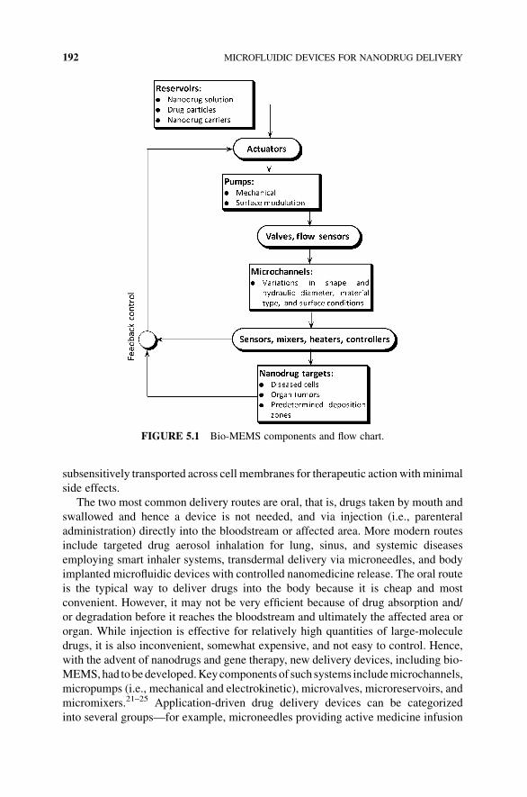
subsensitively transported across cell membranes for therapeutic action with minimal
side effects.
The two most common delivery routes are oral, that is, drugs taken by mouth and
swallowed and hence a device is not needed, and via injection (i.e., parenteral
administration) directly into the bloodstream or affected area. More modern routes
include targeted drug aerosol inhalation for lung, sinus, and systemic diseases
employing smart inhaler systems, transdermal delivery via microneedles, and body
implanted microfluidic devices with controlled nanomedicine release. The oral route
is the typical way to deliver drugs into the body because it is cheap and most
convenient. However, it may not be very efficient because of drug absorption and/
or degradation before it reaches the bloodstream and ultimately the affected area or
organ. While injection is effective for relatively high quantities of large-molecule
drugs, it is also inconvenient, somewhat expensive, and not easy to control. Hence,
with the advent of nanodrugs and gene therapy, new delivery devices, including bio-
MEMS,had tobedeveloped.Keycomponents of such systems includemicrochannels,
micropumps (i.e., mechanical and electrokinetic), microvalves, microreservoirs, and
micromixers.21–25 Application-driven drug delivery devices can be categorized
into several groups—for example, microneedles providing active medicine infusion
FIGURE 5.1 Bio-MEMS components and flow chart.
192 MICROFLUIDIC DEVICES FOR NANODRUG DELIVERY

through transdermal patches; drug-eluting stents maintaining patency of, say, coro-
nary arteries; smart inhalers, with which drug aerosol streams (nasal sprays) are
controlled, to improve targeted particle deposition; and self-contained external or
implantable bio-MEMS.
Possibly, the largest group directly benefitting from bio-MEMS is diabetic patients
ensuring exact glucose control via embeddedmonitors and insulin dispensers. Patients
with pacemakers or defibrillators may receive needed medication from an implanted
bio-MEMS during an arrhythmia event. Severe asthma patients typically requiring
several drugs, such as bronchodilators and anti-inflammatory medicine, may rely on
real-time disease analysis and subsequently controlled, targeted drug release. Pain
management can be handled by a programmable pump for, say, small-dose intraspinal
morphine administration toblockneurotransmitters fromreaching thebrain.Clearly, a
lot of R&Dwork and clinical testing have to be accomplished before most conceived
bio-MEMSgains public acceptance. The book edited byDesai and Bhatia26 discusses
bio-MEMS for drug delivery in several chapters, while the review by Elman et al.27
briefly summarizes next-generation bio-MEMS, which the authors classified as
passive or active delivery devices.
Microneedles,made out of silicon, polymer, steel, or metal oxides, are only a few
hundred micrometers long; that is, they generate microconduits past the outer skin
permeation barrier without encountering a nerve. In array formation, connected to a
liquid drug reservoir, they allow for dispersion and systemic uptake of macromolecu-
lar drugs, possibly replacing hypodermic injections, say, for vaccinations and insulin
delivery.28–30
Drug-eluting stents are slow-release nanodrug implants that mainly function as
scaffolds to keep arteries open after coronary angioplasty, reduce the likelihood of
restenosis, and reject foreign object. After initially very positive responseworldwide,
they have recently encountered mixed reviews because of postoperative complica-
tions, such as late stent thrombosis in some patients.31–35
Micropumps are vital for direct drug delivery when connected to a microreservoir,
or for nanodrug mixing in microchannels (see Section 5.4.1). Other micropump
applications include movement of nano- to microliter solutions in LOC and mTASdevices, molecular particle sorting with microfilters or via hydrodynamic focusing,
and flowmeasurements with microsensors. However, one should note that a majority
of hydrodynamic microscale and certainly most nanoscale processes are driven by
electrokinetic flow or surface-mediated transport.36 Thus, due to the very high
frictional resistance, pressure-driven flow in a nanofluidic device is inappropriate.
The reason is that Dp � L=D4h, where Dp is the pressure drop across the conduit of
length L and hydraulic diameterDh¼ 4A/P, with A being the cross-sectional area and
P the wetted perimeter. For example, Zahn37 reviewed the physics and fabrication
of mechanical and nonmechanical micropumps.
Hundreds ofmicroreservoirs can be embedded into a single silicon microchip that
is covered by a thinmetal or polymermembrane. Themicroreservoirsmay contain any
combination of drugs, chemicals, and/or biosensors, where the membrane seal can be
activated for controlled drug release, using preprogrammedmicroprocessors,wireless
telemetry, or biosensor feedback. Clearly, these microchips can store and release
MICROFLUIDIC DEVICES 193

nanodrugs in a controlled fashion, and they are advantageous because of their small
size, low power consumption, and absence of moving parts.
5.3 NANODRUG DELIVERY
It is apparent from the previous sections that drug delivery systems based on bio-
MEMSare just beginning to reach themarket. Self-regulated insulin delivery systems,
drug-eluting stents, and microneedle arrays with reservoirs on a chip are some of the
moremature examples. In this section (Figure 5.2), nanodrug carriers for biochemical
drug/gene delivery systems as well as associated clinical application areas and
mechanical nanodrug delivery methodologies are discussed.
5.3.1 Nanodrugs
Nanodrugs (or genetic material) embedded in nano/microspheres are promising
candidates for treatment of various diseases, such as cancer, infections, metabolic
and autoimmune diseases, and diseases related to the brain (http://nano.cancer.gov).
FIGURE 5.2 Strategies of targeted nanodrug delivery systems.
194 MICROFLUIDIC DEVICES FOR NANODRUG DELIVERY

Such nanomedicine carriers can be microparticles made of soluble, insoluble, or
naturally biodegradable polymers, microcapsules, porous particles, cells, liposomes,
and so on. Emerich and Thanos3 provided an overview of typical nanoparticles used
in drug and gene delivery, while Kasuya and Kuroda6 summarized the desirable
properties and characteristics of nanomedicine carriers. Their modified and updated
lists are given below.
5.3.1.1 Solid NanoparticlesCeramic nanoparticles aremade from inorganic nonmetallic compounds with porous
characteristics such as oxides, that is, silica (SiO2), alumina (Al2O3), hydroxyapatite
(HA), and zirconia (ZrO2). They are stable in the typical range of temperatures and
pH encountered in the body and can be used to deliver proteins and genes. However,
their lack of biodegradation and slowdissolution raises safety questions. For example,
it was found that those made of silica can efficiently transport therapeutic genes to
the spleen and trigger a potent immune response capable of attacking tumors.38 The
results released in 2008 in Chemical & Engineering News (http://pubs.acs.org/
isubscribe/journals/cen/86/i35/html/8635scic.html#6) showed that iron oxide nano-
particles caused little DNAdamage andwere nontoxic, zinc oxide nanoparticles were
slightly worse, and titanium dioxide caused only DNA damage.
Carbon nanotubes (CNTs) are extremely small tubes that can be categorized as
single-walled nanotubes (SWNTs) and multiwalled nanotubes (MWNTs). These
compounds havebecome increasingly popular invarious fields simplybecause of their
small size and amazing optical, electric, and magnetic properties when used alone
or with other materials, such as drugs. Carbon nanotubes have potential therapeutic
applications in the field of drug delivery, diagnostics, and biosensing. For example,
SWNTs have been shown to shuttle various cargos across cellular membrane without
cytotoxicity. SWNTs can be used as a platform for investigating surface–protein and
protein–protein binding. These nanotubes can act as highly specific electronic sensors
for detecting clinically important biomolecules such as antibodies associated with
human autoimmunediseases. Functionalized carbonnanotubes can also act as vaccine
delivery systems. The basic concept is to link the antigen to carbon nanotubes while
retaining its conformation, thereby inducing antibody response with the right speci-
ficity. Overall, the future use of carbon nanotubes in drug delivery systems may
enhance detection sensitivity in medical imaging, improve therapeutic effectiveness,
and decrease side effects.
Nanocrystals are aggregates of molecules that can be combined in a crystalline
formof the drug surroundedby a thin surfactant coating.Highdosages can be achieved
andpoorly soluble drugs canbe formulated for improvedbioavailability.Both oral and
parenteral delivery systems are possible and the limited carrier in the formulation
reduces potential toxicity. Limitations include poor drug stability.
Polymers such as albumin, chitosan, and heparin occur naturally and have been
a material of choice for the delivery of oligonucleotides, DNA, protein, and drugs.
The drug is physically entrapped in the polymer capsule. The characteristics can be
summarized as follows: (i) water soluble, nontoxic, and biodegradable; (ii) surface
modification (pegylation); (iii) selective accumulation and retention in tumor tissue;
NANODRUG DELIVERY 195

and (iv) specific targeting of cancer cells while sparing receptor-mediated targeting
of normal cells with a ligand. Polymer nanostructured fibers, core–shell fibers, hollow
fibers, and nanorods and nanotubes provide a platform for a broad range of applica-
tions. For example, biological objects, including drugs, of different complexities
carrying specific functions can be incorporated into such nanostructured polymer
systems. Biosensors, tissue engineering, drug delivery, and enzymatic catalysis are
just a few applications. Another example is superparamagnetic particles, known to
display strong interactions with external magnetic fields leading to large saturation
magnetization. By using periodically varying magnetic fields, the nanoparticles can
be heated to provide a trigger for drug release.
Solid lipid nanoparticles are lipid-based submicron colloidal carriers. They have a
solid hydrophobic core surrounded by a monolayer of phospholipid. The system is
stabilized by the inclusion of fairly high levels of surfactants. They are less toxic than
polymer nanoparticles and can be used to deliver drugs orally, topically, or via the
pulmonary route. While stability is a concern, it is better than that observed with
liposomes.
5.3.1.2 Colloidal Soft MatterDendrimers are artificial, polymer-basedmolecules formed frommonomers such that
each layer of branching units doubles or triples the number of peripheral groups (i.e.,
they look like a foam ball). The void area within a dendrimer, its ease of modification/
preparation, and size control offer great potential for targeted gene and drug delivery.
Improvements in cytotoxicity profiles, biocompatibility, and biodistribution are
needed. Dendrimers are repeatedly branched molecules. They are emerging as a
rather new class of polymeric nanosystems with applications in drug delivery. The
properties of dendrimers are dominated by the functional groups on the molecular
surface.Dendritic encapsulation of functionalmolecules allows for the isolation of the
active site, a structure that mimics the structure of active sites in biomaterials because
dendritic scaffolds separate internal and external functions. For example, a dendrimer
can bewater soluble when its end group is a hydrophilic group, like a carboxyl group.
It is theoretically possible to design a water-soluble dendrimer with internal hydro-
phobicity, which would allow it to carry a hydrophobic drug in its interior. Another
property is that the volume of a dendrimer increases when it has a positive charge.
If this property can be applied, dendrimers can be used for drug delivery systems that
can give medication to the affected part inside a patient�s body directly.
Hydrogels (also called aquagels) are a network of polymer chains that are water
insoluble, and sometimes found as a colloidal gel in which water is the dispersion
medium. Hydrogels are superabsorbent (they can contain over 99% water) natural
or synthetic polymers. Hydrogels also possess a degree of flexibility very similar to
natural tissue due to their significant water content. Hydrogels are responsive to
specific molecules, such as glucose or antigens, that can be used as biosensors as well
as in drug delivery system.
Liposomes were tiny bubbles (vesicles) made out of the same material as a cell
membrane. Liposomes are small spherical systems that are synthesized from
196 MICROFLUIDIC DEVICES FOR NANODRUG DELIVERY

cholesterol and nontoxic phospholipids. Liposomes can be filled with drugs and used
to deliver drugs for cancer and other diseases. Membranes are usually made of
phospholipids, which are molecules having a head group and a tail group. The head is
attracted towater and the tail,which ismadeof a longhydrocarbonchain, is repelledby
water. Because they are natural materials, liposomes are considered attractive,
harmless drug delivery carriers that can circulate in the bloodstream for a long
time.Another interesting property of liposomes is their natural ability to target cancer.
The endothelial wall of all healthy humanblood vessels is encapsulated by endothelial
cells that are bound together by tight junctions. These tight junctions stop any large
particle in the blood from leaking out of the vessel. Tumor vessels do not contain the
same level of seal between cells and are diagnostically leaky. This ability is known as
the enhanced permeability and retention effect. Liposomes of certain sizes, typically
less than 400 nm, can rapidly enter tumor sites from the blood but are kept in the
bloodstream by the endothelial wall in healthy tissue vasculature. Anticancer drugs
such as doxorubicin (Doxil), camptothecin, and daunorubicin (DaunoXome) are
currently being marketed in liposome delivery systems. Despite a relatively long
history of investigation, liposomes exhibit limited stability and have not made
significant medical impact.
Micelles provide considerable advantages among drug carrier systems for their
solubilization to contribute the increasing bioavailability of poorly soluble drugs and
the characteristics to stay in the blood long enough to afford a gradual accumulation in
aparticular area.Amicelle is an aggregate of surfactantmolecules dispersed in a liquid
colloid. A typical micelle in aqueous solution forms an aggregatewith the hydrophilic
“head” regions in contact with surrounding solvent, sequestering the hydrophobic tail
regions in the micelle center. This type of micelle is known as a normal phase micelle
(oil inwater micelle). Inversemicelles have the head groups at the center with the tails
extending out (water in oil micelle). Micelles are approximately spherical in shape.
Other phases including shapes such as ellipsoids, cylinders, and bilayers are also
possible. Micelle formation is essential for the absorption of fat-soluble vitamins and
complicated lipids within the human body. When membrane phospholipids are
disrupted, they can reassemble themselves into tiny spheres, smaller than a normal
cell, either as bilayers or as monolayers. The bilayer structures are liposomes and the
monolayer structures are called micelles.
Microemulsions have great thermodynamic stability, which allows for self-emul-
sification at a wide range of temperatures and affords easy preparation. The structural
variability of microemulsions together with its composition and the pH of the
environment can obviously influence the drug release rate. Other positive character-
istics include the low viscosity of the majority of the system.
Organogels are systems resembling the structure of microemulsions but are
semisolid. Most organogels utilized in pharmaceuticals are lecithin, gelatin, or
sorbitan ester-based systems in biocompatible solvents. Complex aqueous phases
such as vesicle suspensions entrapping drugs can be eventually incorporated into the
organogel systems. They can entrap hydrophilic or hydrophobic drugs and antigens;
it is possible to achieve controlled release systems.
NANODRUG DELIVERY 197

5.3.1.3 Desirable Characteristics of Nanodrug CarriersWith this large family of nanodrugs available (see Sections 5.3.1.1 and 5.3.1.2), it is
important to consider suitable (or even optimal) attributes of nanodrugs and their
carriers. Specifically, the following properties should be optimized for the in vivo use
of conventional nanoparticle carriers for drug or gene delivery.
1. Acceptability to Versatile Payloads: The nanoparticle carrier (NPC) should
allow payloads of various therapeuticmaterials. This facilitates the development
of a general purpose carrier and concurrent administration of different drugs.
2. Low or No Toxicity: The NPC should not be made of or contain potentially
dangerous materials.
3. Active Targeting: The NPC should recognize and attach target cells and tissues
by a sensormolecule displayed on its surface. NPC of about 100 nm are likely to
accumulate spontaneously in tumors after systemic injection, but this passive
targetingmechanism based on the enhanced permeability and retention effect39
is excluded from these criteria.
4. Appropriate Size: The size of NPC should be about 40–150 nm in diameter. Too
small nanoparticles (<40 nm) and too large nanoparticles (>150 nm) are
nonspecifically removed from blood circulation by the function of kidney
and reticuloendothelial system in the liver, respectively.40 NPC of about
40–150 nm could be used to target both tumors utilizing the enhanced perme-
ability and retention effect and hepatocytes by passing through the fenestrae in
liver endothelial cell.41
5. Appropriate Surface Charge: The surface charge of NPC is known to affect
severely the stability and biodistribution of systemically administrated nano-
particle carriers. For ideal delivery, the surface of nanoparticle carriers should
be optimized so as not to be entrapped by unexpected tissues. For example, one
positively charged nanoparticle (i.e., polyplex of polyethyleneimine and DNA)
was efficiently accumulated in the lung after systemic administration.42
6. Efficient Cell-Penetrating Activity: The nanoparticle carriers should possess
cell-penetrating activity for active and rapid intrusion across the plasma mem-
brane or the endosomal membrane of target cells and tissues because many
therapeutic materials (particularly, genes and siRNAs) function intracellularly.
7. Mechanism of Intracellular Targeting: The nanoparticle carriers in target cells
should bring and release payloads to the intracellular destination precisely (e.g.,
genes and siRNAs should be released in the nucleus and cytoplasm, respec-
tively, not in endosomes).
5.3.2 Nanodrug Targeting
Asmentioned, targeting is the ability to direct in controlled fashion the drug particles,
or a drug-loaded system, to the predetermined site of interest. There are mechanical
and biochemical methodologies of drug targeting (Figures 5.2 and 5.3a and b). As
Kaparissides et al.43 mentioned, in biochemical targeting two approaches can be
198 MICROFLUIDIC DEVICES FOR NANODRUG DELIVERY

distinguished, that is, passive and active targeting. Theygive as an example for passive
targeting the observed preferential accumulation of chemotherapeutic agents in
“solid” tumors as a result of the enhanced vascular permeability of tumor tissues
compared to healthy tissue (Figure 5.3a). As a variation to nanodrugs cruising in the
bloodstream and hopefully reaching the right site, drug carriers with surface func-
tionalities, for example, ligands interacting with tumor cell receptors, can seek out,
bind to, andpenetrate target cells (Figure 5.3b). In contrast,mechanical drug targeting
is the delivery of a controlled fluid–particle stream from an optimal release (or arterial
injection) point to a predetermined deposition site.44,45 Specifically, Kleinstreuer45
FIGURE 5.3 (a) Passive drug targeting by nanodrug carriers in blood vessels and (b) active
nanodrug targeting with conjugated antibodies.
NANODRUG DELIVERY 199

discussed several mechanical drug delivery applications within the framework of
fluid–structure interaction simulations. For example, targeted drug aerosol delivery
can be potentially accomplished with a smart inhaler system.46 Another application is
the targeting of liver tumors with radioactive microspheres,47 where the particles are
released, via a microcatheter, from an optimal inlet position of the hepatic artery.
Most of the drug targeting literature deals with biochemical targeting, especially
“colloidal soft matter” (see Section 5.3.1.2) as reviewed by Bonacucina et al.48 Such
“soft matter,” for example, microemulsions and organogels (as passive drug carriers)
as well as liposomes, micelles, and dendrimers (as active drug carriers), can increase
drug solubility and bioavailability and can attach/penetrate tumor cells, especially
wheremicelles are used. Clearly, all present biochemical targeting efforts are disease/
treatment specific.1,49–54
Drug targetingviamechanical deliverydevices include reservoirs, pumps, inhalers,
catheters, needles, drug-eluting stents, and implants releasing drugs (Section 5.2.3).
The next two sections provide some physical insight into the microfluidics of bio-
MEMSs, focusing on nanodrug mixing, microchannel flow, and device optimization.
5.4 Bio-MEMS APPLICATIONS
To illustrate some aspects of bio-MEMS research and development, nanodrugmixing
and microchannel designs are discussed in the next two sections.
5.4.1 Nanofluid Flow Simulations
Microfluidics deals with methods and devices for manipulating and controlling
fluid–particle flow in microchannels.55 A recent application area is nanomedicine
with the goal of controlled nanodrug delivery to specified target areas.12,56 A key
aspect of this goal is the development of integrated drug delivery systems to monitor
and control target cell responses to pharmaceutical stimuli, to understand biological
cell activities, or to facilitate drug development processes. An important part of such
drug delivery systems, belonging to the family of bio-MEMS, is active or passive
micromixers25,57 to assure near-uniform nanodrug concentrations. Static micromix-
ers, not requiring any external energy source, rely on chaotic advection and/or
enhanced diffusion, typically to mix two fluids.58,66 For example, Hardt et al.61
reviewed recent developments in micromixing technology, focusing on liquid mixing
with passive micromixers. Four kinds of mixers that employed different hydrody-
namic principles are discussed: hydrodynamic focusing, flow separation, chaotic
advection, and split and recombine flows. Diffusive mixing can be improved by
increasing the interfacial contact area between the different fluids and reducing the
diffusion length scale. Thus, selecting the right type of micromixer for a specific
application is very important.
Li and Kleinstreuer67 analyzed rapid nanoparticle mixing in a carrier fluid,
employing low-cost micromixers and heat transfer to achieve two system design
goals, that is, uniform exit particle concentration and minimum required channel
length. Specifically, a microfluidics device for controlled nanofluid flow in
200 MICROFLUIDIC DEVICES FOR NANODRUG DELIVERY

microchannels (Figure 5.4) is investigated for basic nanomedicine applications.
Presently planned for laboratory-scale testing, uniform,predetermined concentrations
of a stimulus (e.g., cocaine particles) should be delivered via multiple microchannels
to an array of wells containing brain cells to measure cell responses (e.g., dopamine
production levels). Their study focuses on device miniaturization in light of the
ultimate goal of bio-MEMS implantation into the diseased brain region of, say,
Parkinson�s patients. Most important, the impact of two types of static micromixers
(Figure 5.4c) is analyzed to achieve uniform nanoparticle concentrations at the exit of
a representative microchannel of minimum length.
Figure 5.5 shows Lmin(Pe) for the different scenarios. Clearly, any micromixer
module reduces Lmin significantly for all P�eclet numbers.While an increase in slotted
baffle plates reduces Lmin, the simple three-sided injection unit performs best.
FIGURE 5.4 Microfluidics system: (a) laboratory-scale nanodrug supply device, (b) rep-
resentative microchannels, and (c) static mixer inserts.
Bio-MEMS APPLICATIONS 201

Alternative to the P�eclet number, which is based on the average velocity of
nanofluid plus carrier fluid, the Reynolds number ratio of nanofluid to carrier fluid
is a suitable operational parameter. The associated Reynolds numbers are
Rei ¼ ðuDhÞini
ð5:1Þ
with i¼ 1 indicating the carrier fluid in the solution channel and i¼ 2 denoting the
nanofluid channel (Figure 5.4b). For the given system, Figure 5.6 indicates that the
main microchannel length can be below 4mm when employing an injection micro-
mixer, that is, a 70% reduction in channel length.
The addition of nanoparticles and certainly the installment of micromixers
increases the pressure drop in both channels and hence the pumping power require-
ments. Pumpingpower is defined as the product of the pressure drop across the channel
(Dp) and the volumetric flow rate (Q), that is,
P ¼ Dp �Q ð5:2ÞThe pressure differences occur between the nanofluid inlet or carrier fluid inlet and
the system outlet, that is, requiredminimal length. The volumetric flow rate is the sum
of the volumetric flow rates of both nanofluid and carrier fluid.
Figure 5.7a and b depicts the relationship of pressure drop and pumping power for
the two cases. Clearly, the addedmicromixer increases the local pressure drop, but the
decreased system length may reduce any negative effect caused by the micromixer.
As shown in Figure 5.8a and b, the power requirement even decreases in some cases,
FIGURE 5.5 Micromixer influence on minimal uniformity length/system dimension.67
202 MICROFLUIDIC DEVICES FOR NANODRUG DELIVERY

that is, when employing the injection micromixer. The employment of baffle-slit
micromixers slightly increases the pressure drop; however, when the pumping power/
volumetric flow rate gets larger and larger, the negative effect appears to be less and
less. For example, for the two- or four-baffle micromixer, the pressure drop is even
smaller than that without anymicromixer when the nanofluid supply rate is increased
to 8mm s�1. In summary, employing an appropriatemicromixer decreases the system
dimension and the associated power requirement.
A heat flux was used to ensure that mixture delivery to the living cells occurs at a
required temperature of 37 �C. The change of fluid properties and nanoparticle
diffusivity, caused by the added heat flux, also benefits system miniaturization. As
shown in Figure 5.6, the added heat flux greatly decreases the system dimension; that
is, an average 35% reduction is observed.
5.4.2 Device Optimization
It is obvious that the better an engineering device performs, the lower the (irreversible)
losses, that is, the closer it operates at an isentropic efficiency.This directly implies that_Sgen should be minimized as part of any device/process design or improvement.
For example, considering simple heat transfer from an ambient reservoir at T0 ¼ ¢,
the entropy balance equation can be written as
_Sgen ¼ @S
@t�X _Q
T0�X
_mSjin þX
_mSjout > 0 ð5:3Þ
FIGURE 5.6 Minimal uniformity length versus Reynolds number ratio.67
Bio-MEMS APPLICATIONS 203

FIGURE 5.7 Pressure drop versus pumping power: (a) carrier fluid inlet and (b) nanofluid
inlet.67
204 MICROFLUIDIC DEVICES FOR NANODRUG DELIVERY

Effectively, _Sgen � _W loss; that is, in general, power loss is due to system, heat
transfer, and fluid flow irreversibilities:
Ploss � _W loss ¼ T0 _Sgen ¼ T0@S
@t�
_Q
T0�X
_mSjin�X
_mSjout� �
ð5:4Þ
Focusing on friction (or viscous effects) as the main cause of irreversibilities and
hence entropy generation, the rate of irreversible conversion from flow energy to heat
can be expressed as
tij@vi@xj
� mF ¼ Ploss
8 ¼ T0_Sgen8 ð5:5Þ
Clearly, to minimize entropy production in pressure-driven microchannels, we
have to reduce the viscous dissipation function F, that is, achieve minimization of
_Sgen8 ¼ m
TF ¼ m
T
@u
@yþ @v
@x
� �2
þ 2@u
@x
� �2
þ 2@v
@y
� �2" #
ð5:6Þ
In general, and exclusively for fully developed flow, the term ðm=TÞð@u=@yÞ2 ismost important. If wall slip is significant, then u(y) velocity profile is greatly affected
and hence the channel pressure drop.
FIGURE 5.8 Heat flux influence on minimal uniformity length.67
Bio-MEMS APPLICATIONS 205

5.4.2.1 Liquid Flow in a MicrochannelMinimizationof entropygeneration as a design tool to determinebest devicegeometry
and operation, especially for heat exchangers, has been established for macroscale
configurations.68–75 However, fluid flow inmicrochannels exhibits dominant features
oftennonexistingor less influential inmacrochannels, for example,wall slip velocities
for somegases, entrance effects because of the short conduit length, significant surface
roughness in relation to microchannel height (or hydraulic diameter), and so on.11
Thus, application of entropy generation minimization principles may assist in the
optimal design of microchannel heat sinks and bio-MEMS in light of geometric and
operational conditions.67,76–79 Classical methods for enhanced heat transfer, for
example, an increase of heat transfer area and/or inlet Reynolds number, are limited
options for microchannel flow. Thus, the use of nanofluids as coolants, for example,
CuO or Al2O3 nanospheres with diameters in the range of 5 nm< dp< 150 nm in
water, oil, or ethylene glycol, is a third option. In case of nanomedicine delivery with
bio-MEMS, nanofluid flow analysis is important andmeasurable reduction of entropy
generation is desirable.
In this section, entropy generation is minimized for steady laminar pure water and
nanofluid flows in a representative trapezoidal microchannel in terms ofmost suitable
channel aspect ratio and Reynolds number range.
One effective operational parameter is the inlet Reynolds number; Figure 5.9
indicates a desirable range of 425�Re� 1100 for all fluids and aspect ratios
considered, ignoring “slit flow” for AR¼ 0.9337. Due to slightly enhanced frictional
FIGURE 5.9 System entropy generation versus Reynolds number.80
206 MICROFLUIDIC DEVICES FOR NANODRUG DELIVERY

effects (due to the increase of viscosity), Snanofluid
G;total > Swater
G;total. The overall flow
field entropy is generated for different scenarios in terms of the following integral
form:
SG;total ¼ 1
_mcp
ðððV
Sgen
8 dV ð5:7Þ
An important geometric design parameter is the aspect ratio. Figure 5.10 shows
SG;totalðARÞ for three fluids and different inlet Reynolds numbers. Specifically, for
Uin¼ 4m s�1 (implying Re¼ 425, 437, and 466 for water, 1% CuO nanofluids, and
4% CuO nanofluids, respectively), the larger aspect ratio generates smaller SG;totalvalues, while for Uin¼ 10m s�1 (implying Re¼ 1063, 1092, and 1165), the lower
aspect ratio generates smaller SG;total values. Clearly, the 1%CuO–water pairingyields
more favorable results than the nanofluid with 4% CuO particles.
Figure 5.10 also reveals that there are significant trend changes of SG;total(AR, Re)
for all three fluids occurring at critical values, that is, AR� 0.55 and Re� 700. The
main reasons are that with elevated Reynolds numbers, temperature gradients are
reduced and the frictional effects become dominant, even more pronounced as
AR ! 1.0. The additional test run for pure water at Re¼ 638 confirms that
Re� 700 is critical, while Figure 5.9 has these trend changes in SG;total embedded
as well.
FIGURE 5.10 System entropy generation as a function of aspect ratio and Reynolds
number.80
Bio-MEMS APPLICATIONS 207

5.5 CONCLUSIONS AND FUTURE PERSPECTIVE
The development of nanodrugs and their carriers and the design ofmicroscale devices
for optimal drug targeting are presently very important research topics. Particularly,
lab-on-a-chip systems for drug discovery, development and testing, active nanodrug
carriers that attach to tumor cells, and mechanical drug delivery systems (also called
bio-MEMSs) have attractedmuch attention and enjoy increasing use in the healthcare
industry.
This chapter summarizes some fundamentals and applications of microfluidics
and bio-MEMS. Then, it discusses types of nanodrugs and characteristics of their
carriers, aswell as biochemical andmechanical nanodrug targeting. To illustrate some
aspects of bio-MEMS components and applications, computational results for nano-
drug mixing and nanofluid flow in microchannels and optimal microchannel design/
operation are presented.
Future work will concentrate on the improvements in smart drug delivery systems
on themarket, ranging fromnanodrug carriers tomicrofluidic devices for optimal drug
targeting. One of the more challenging tasks will be to combine biochemically active
NDC with bio-MEMSs. They could deliver up to 100% of the NDCs to the pre-
determined, disease-related targetwhere theNDCs attach to the tumor cells, penetrate
them,and release thenanodrugs.Theunderlyingprincipleofparticle targeting isbased
on the backtracking methodology45 that can be applied to smart delivery of inhaled
drug aerosols and injected radioactive microspheres, NDCs, and so on.
REFERENCES
1. Jain, K.K. Drug Delivery Systems. Methods in Molecular Biology, Humana Press: 2008;
Vol. 437.
2. Suh, W.H.; Suslick, K.S.; Stucky, G.D.; Suh, Y.-H. Nanotechnology, nanotoxicology,
neuroscience. Prog. Neurobiol. 2009, 87, 133–170.
3. Emerich, D.F.; Thanos, C.G. Targeted nanoparticle-based drug delivery and diagnosis.
J. Drug Target. 2007, 15(3), 163–183.
4. Kim, S.; Kwon, I.I.K.; Kwon, I.C.; Park, K. Nanotechnology in drug delivery: past,
present, and future. In Nanotechnology in Drug Delivery; de Villiers, M.M.; Aramwit, P.;
Kwon, G.S., Eds.; Springer/AAPS Press: 2009.
5. Riehemann, K.; Schneider, S.W.; Luger, T.A.; Godin, B.; Ferrari, M.; Fuchs, H.
Nanomedicine: challenge and perspectives. Angew. Chem. Int. Ed. 2009, 48, 872–897.
6. Kasuya, T.; Kuroda, S. Nanoparticles for human liver-specific drug and gene delivery
systems: in vitro and in vivo advances. Expert Opin. Drug Deliv. 2009, 6(1), 39–52.
7. Subramani, K. Applications of nanotechnology in drug delivery systems for the treatment
of cancer and diabetes. Int. J. Nanotechnol. 2006, 3(4), 557–580.
8. Kleinstreuer, C.; Zhang, Z.; Donohue, J.F. Targeted drug-aerosol delivery in the human
respiratory system. Annu. Rev. Biomed. Eng. 2008, 10, 195–220.
9. Bayraktar, T.; Pidugu, S.B. Characterization of liquid flows in microfluidic systems. Int. J.
Heat Mass Transfer 2006, 49, 815–824.
208 MICROFLUIDIC DEVICES FOR NANODRUG DELIVERY

10. Tabeling, P. Introduction to Microfluidics, Oxford University Press: Oxford, UK, 2005.
11. Nguyen, N.-T.;Wereley, S.T. Fundamentals, Applications of Microfluidics, Artech House:
Boston, MA, 2006.
12. Saliterman, S.S. Fundamentals of bioMEMS and Medical Microdevices, Wiley–
Interscience/SPIE Press: Bellingham, WA, 2006.
13. Tesar, V. Pressure-Driven Microfluidics, Artech House: Norwood, MA, 2007.
14. Stone, H.A.; Stroock, A.D.; Ajdari, A. Engineering flows in small devices: microfluidics
toward a lab-on-a-chip. Annu. Rev. Fluid Mech. 2004, 36, 381–411.
15. Hilt, J.Z.; Peppas, N.A. Microfabricated drug delivery devices. Int. J. Pharm. 2005, 306,
15–23.
16. Whitesides, G.M. The origins and the future of microfluidics: insight overview. Nature
2006, 442, 368–373.
17. Hu, M.; Zengerle, R. Microfabricated devices for controlled biochemical release. In 10th
International Conference on New Actuators, Bremen, Germany, 2006, pp 263–271.
18. Geipel, A.; Goldschmidtboeing, F.; Jantscheff, P.; Esser, N.; Massing, U.;Woias, P. Design
of an implantable active microport system for patient specific drug release. Biomed.
Microdevices 2008, 10, 469–478.
19. Bird, G.A. Molecular Gas Dynamics and Direct Simulation of Gas Flow, Oxford
University Press: Oxford, UK, 1994.
20. Koo, J.; Kleinstreuer, C. Liquid flow in microchannels: experimental observations and
computational analysis of microfluidics effect. J. Micromech. Microeng. 2003, 13,
568–579.
21. Dutta, D.; Ramachandran, A.; Leighton, D.T. Jr Effect of channel geometry on solute
dispersion in pressure-driven microfluidic systems. Microfluid. Nanofluid 2006, 2,
275–290.
22. Zhang, C.; Xing, D.; Li, Y. Micropumps, microvalves, and micromixers within PCR
microfluidic chips: advances and trends. Biotechnol. Adv. 2007, 25, 483–514.
23. Oh, K.W.; Ahn, C.H. A review of microvalves. J. Micromech. Microeng. 2006, 16,
R13–R19.
24. Tsai, N.-C.; Sue, C.-Y. Review of MEMS-based drug delivery and dosing systems. Sens.
Actuators 2007, 134, 555–564.
25. Nguyen, N.-T. Micromixers: Fundamentals, Design and Fabrication, William Andrew:
Norwich, NY, 2008.
26. Desai, T.; Bhatia, S. Therapeutic Micro/Nano Technology, BioMEMS and Biomedical
Nanotechnology; Springer: 2006.
27. Elman,N.M.; Patta,Y.; Scott, A.W.;Masi, B.;Duc,H.L.H.; Cima,M.J. The next generation
of drug delivery microdevices. Clin. Pharmacol. Ther. 2009, 85, 544–547.
28. Kim, K.; Lee, J.-B. MEMS for drug delivery. In Bio-MEMS: Technologies and
Applications; Wang, W.; Soper, S.A. Eds.; CRC Press/Taylor & Francis: Boca Raton,
FL, 2007.
29. Roxhed, N.; Samel, B.; Nordquist, L.; Griss, P.; Stemme, G. Painless drug delivery through
microneedle-based transdermal patches featuring active infusion. IEEE Trans. Biomed.
Eng. 2008, 55(3), 1063–1071.
30. Wu, Y.; Qiu, Y.; Zhang, S.; Qin, G.; Gao, Y. Microneedle-based drug delivery: studies on
delivery parameters and biocompatibility. Biomed. Microdevices 2008, 10, 601–610.
REFERENCES 209

31. Nakazawa, G.; Finn, A.V.; Kolodgie, F.D.; Virmani, R. A review of current devices and a
look at new technology: drug-eluting stents. Expert Rev. Med. Devices 2009, 6(1), 33–42.
32. Melikian, N.; Wijns, W. Drug-eluting stents: a critique. Heart 2008, 94, 145–152.
33. Wykrzykowska, J.J.; Onuma, Y.; Serruys, P.W. Advances in stent drug delivery: the future
is in bioabsorbable stents. Expert Opin. Drug Deliv. 2009, 6(2), 113–126.
34. Kukreja, N.; Onuma, Y.; Daemen, J.; Serruys, P.W. The future of drug-eluting stents.
Pharmacol. Res. 2008, 57, 171–180.
35. Jamshidi, P.; Mahmoody, K.; Erne, P. Covered stents: a review. Int. J. Cardiol. 2008, 130,
310–318.
36. Karniadakis, G.; Beskok, A.; Aluru, N. Microflows and Nanoflows: Fundamentals and
Simulation, Springer: 2005.
37. Zahn, J.D. Micropump applications in bio-MEMS. In Bio-MEMS: Technologies and
Applications; Wang, W.; Soper, S.A.Eds.; CRC Press/Taylor & Francis: Boca Raton,
FL, 2007.
38. Tan, K.; Cheang, O.; Ho, I.A.; Lam, P.Y.; Hui, K.M. Nanosized bioceramic particles could
function as efficient gene delivery vehicleswith target specificity for the spleen.Gene Ther.
2007, 14, 828–835.
39. Maeda, H.; Wu, J.; Sawa, T.; Matsumura, Y.; Hori, K. Tumor vascular permeability and
the EPR effect in macromolecular therapeutics: a review. J. Control. Release 2000, 65,
271–284.
40. Drummond, C.D.; Meyer, O.; Hong, K.; Kirpotin, D.B.; Papahadjopoulos, D. Optimizing
liposomes for delivery of chemotherapeutic agents to solid tumors. Pharmacol. Rev. 1999,
51(4), 691–744.
41. Snoeys, J.; Lievens, J.; Jacobs, F.; Duimel, H.; Collen, D.; Frederik, P.; Geest, B.D. Species
differences in transgeneDNAuptake in hepatocytes after adenoviral transfer correlatewith
the size of endothelial fenestrae. Gene Ther. 2007, 14, 604–612.
42. Bragonzi, A.; Diana, G.; Villa, A.; Galori, G.; Biffi, A.; Bordignon, C.; Assael, B.M.;
Conese, M. Biodistribution and transgene expression with nonviral cationic vector/DNA
complexes in the lungs. Gene Ther. 2000, 7(20), 1753–1760.
43. Kaparissides, C.; Alexandridou, S.; Kotti, K.; Chaitidou, S. Recent advances in novel drug
delivery systems. J. Nanotechnol. 2006, 2, 1–11.
44. Kleinstreuer, C. Biofluid Dynamics: Principles and Selected Applications, Taylor &
Francis: Boca Raton, FL, 2006.
45. Kleinstreuer, C. Optimal drug delivery based on fluid-particle dynamic simulations.
ANSYS Advantage Vol. 3 (4), 2009.
46. Kleinstreuer, C.; Zhang, Z.; Li, Z.; Roberts, W.L.; Rojas, C. A new methodology for
targeting drug-aerosols in the human respiratory system. Int. J. Heat Mass Transfer 2008,
51, 5578–5589.
47. Kennedy, A.; Kleinstreuer, C.; Basciano, C.A.; Dezarn, A. Computer Modeling of 90Y
Microsphere Transport in the Hepatic Arterial Tree to Improve Clinical Outcomes. Int. J.
Radiol. Oncol. Biol. Phys. (Red Journal), 2010, 76(2), 631–637.
48. Bonacucina, G.; Cespi, M.; Misici-Falzi, M.; Palmieri, G. Review: colloidal soft matter as
drug delivery system. J. Pharm. Sci. 2009, 98(1), 1–42.
49. Tomioka, H.; Tatano, Y.; Yasumota, K.; Shimizu, T. Recent advances in anti-tuberculosis
drug development and novel drug targets. Expert Rev. Respir. Med. 2008, 2(4), 455–471.
210 MICROFLUIDIC DEVICES FOR NANODRUG DELIVERY

50. Muthu,M.S.; Singh, S. Targeted nanomedicines: effective treatment modalities for cancer,
AIDS and brain disorders. Nanomedicine 2009, 4(1), 105–118.
51. Lammers, T.; Hennink, W.E.; Storm, G. Tumor-targeted nanomedicines: principles and
practice. Br. J. Cancer 2008, 99, 392–397.
52. Tosi, G.; Bostantino, L.; Ruozi, B.; Forni, F.; Vandelli, M.A. Polymeric nanoparticles for
the drug delivery to the central nervous system. Expert Opin. Drug Deliv. 2008, 5(2),
155–174.
53. Polyak, B.; Friedman, G. Magnetic targeting for site-specific drug delivery: applications
and clinical potential. Expert Opin. Drug Deliv. 2009, 6(1), 53–70.
54. Bohmer, M.R.; Klibanov, A.L.; Tiemann, K.; Hall, C.S.; Gruell, H.; Steinbach, O.C.
Ultrasound triggered image-guided drug delivery. Eur. J. Radiol. 2009, 70(2), 242–253.
55. Kleinstreuer, C.; Li, J.; Koo, J. Microfluidics of nanodrug delivery. Int. J. Heat Mass
Transfer 2008, 51, 5590–5597.
56. Labhasetwar, V.; Leslie-Pelecky, D.L. Biomedical Applications of Nanotechnology,
Wiley–Interscience: Hoboken, NJ, 2007.
57. Nguyen,N.-T.;Wu, Z.Micromixers: a review. J.Micromech.Microeng. 2005,15, R1–R16.
58. Stroock, A.D.; et al. Chaotic mixer for microchannels. Science 2002, 295, 647–651.
59. Kim, D.S. A barrier embedded chaotic micromixer. J. Micromech. Microeng. 2004, 14,
798–805.
60. Munson, M.S.; Yager, P. Simple quantitative optical method for monitoring the extent of
mixing applied to a novel microfluidic mixer. Anal. Chim. Acta 2004, 507, 63–71.
61. Hardt, S.; Drese, K.S.; Hessel, V.; Schonfeld, F. Passivemicromixers for applications in the
microreactor and uTAS fields. Microfluid. Nanofluid. 2005, 1, 108–118.
62. Floyd-Smith, T.M.; Golden, J.P.; Howell, P.B.; Ligler, F.S. Characterization of passive
microfluidic mixers using soft lithography. Microfluid. Nanofluid. 2006, 2, 180–183.
63. Chang, C.-C.; Yang, R.-J. Electrokinetic mixing in microfluidic systems. Microfluid.
Nanofluid. 2007, 3, 501–525.
64. Chung, C.K.; Shih, T.R. Effect of geometry on fluid mixing of rhombic micromixers.
Microfluid. Nanofluid. 2008, 4, 419–425.
65. Kang, T.G.; Singh, M.K.; Kwon, T.H.; Anderson, P.D. Chaotic mixing using periodic and
aperiodic sequences of mixing protocols in a micromixer.Microfluid. Nanofluid. 2008, 4,
589–599.
66. Brotherton, C.M.; Sun, A.C.; Davis, R.H. Computational modeling and comparison of
three co-laminar microfluidic mixing techniques. Microfluid. Nanofluid. 2008, 5, 43–53.
67. Li, J.; Kleinstreuer, C. Microfluidics analysis of nanoparticle mixing in a microchannel
system. Microfluid. Nanofluid. 2009, 6, 661–668.
68. Bejan, A. Entropy Generation Minimization: The Method of Thermodynamic
Optimization of Finite-Size System and Finite-Time Processes, CRC Press: Boca
Raton, FL, 1996.
69. Bejan, A. Fundamentals of exergy analysis, entropy generation minimization, and genera-
tion of flow architecture. Int. J. Energy Res. 2002, 26, 545–565.
70. Sahin, A.Z. A second law comparison for optimum shape of duct subjected to constant wall
temperature and laminar flow. Heat Mass Transfer 1998, 33, 425–430.
71. Sahin, A.Z. Entropy generation in a turbulent liquid flow through a smooth duct subjected
to constant wall temperature. Int. J. Heat Mass Transfer 2000, 43, 1469–1478.
REFERENCES 211

72. Mahmud, S.; Fraser, R.A. The second law analysis in fundamental convective heat transfer
problems. Int. J. Thermal Sci. 2003, 42, 177–186.
73. Mansour, R.B.; Galanis, N.; Nguyen, C.T. Dissipation and entropy generation in fully
developed forced and mixed laminar convection. Int. J. Thermal Sci. 2006, 45, 998–1007.
74. Khan, W.A.; Culham, J.R.; Yovanovich, M.M. Optimal design of tube banks in crossflow
using entropy generation minimization method. J. Thermophys. Heat Transfer 2007,
21(2), 372–378.
75. Ko, T.H.; Wu, C.P. A numerical study on entropy generation induced by turbulent forced
convection in curved rectangular ductswith various aspect ratios. Int. Commun.HeatMass
Transfer 2009, 36, 25–31.
76. Chein, R.; Chuang, J. Analysis of microchannel heat sink performance using nanofluids.
Appl. Thermal Eng. 2005, 25, 3104–3114.
77. Heris, S.Z.; Etemad, S.G.; Esfahany, M.N. Experimental investigation of oxide nanofluids
laminar flow convective heat transfer. Int. Commun. Heat Mass Transfer 2006, 33,
529–535.
78. Jang, S.P.; Choi, S.U.S. Cooling performance of a microchannel heat sink with nanofluids.
Appl. Thermal Eng. 2006, 26, 2457–2463.
79. Kleinstreuer, C.; Li, J. Microscale Cooling Devices, Encyclopedia of Micro and
Nanofluidics, Li, D.; Ed.; Springer-Verlag: Heidelberg, 2008.
80. Li, J.; Kleinstreuer, C. Entropy generation analysis for nanofluid flow in microchannels.
ASME J. Heat Transfer, 2010, in press.
212 MICROFLUIDIC DEVICES FOR NANODRUG DELIVERY
6MICROCHIP AND CAPILLARYELECTROPHORESIS USINGNANOPARTICLES
MUHAMMAD J. A. SHIDDIKY AND YOON-BO SHIMDepartment of Chemistry and Institute of Biophysio Sensor
Technology, Pusan National University, Busan, South Korea
6.1 INTRODUCTION
Nanoparticles (NPs), generally defined as materials with a particle size of less than
100 nm in at least one dimension, are of interest because their chemical and physical
behavior is unprecedented and remarkably different from those in bulk form. They
have great potential for applications in electronic, chemical, ormechanical industries,
aswell as in technologies, including superconductors, catalysts, drug carriers, sensors,
magnetic materials, pigments, separation science, and in structural and electronic
materials. In separation science alone, significant advances have been made in
electrophoresis and microchip separations employing nanoparticles.1,2 The small
size of nanoparticles is responsible for their novel, unrevealed properties (electrical,
magnetic, chemical, optical, and mechanical).3 In addition, some nanoparticles
possess advantages such as a large surface area, good chemical and thermal stability,
significantmechanical strength, ease ofmodification, andbiomolecular compatibility.
Owing to these unique properties, nanoparticles have attracted immense attention in
separation science.
Chemical separations are inevitable for analysis of complex samples, in particular
biological samples. In this vein, capillary electrophoresis (CE) and microchip
electrophoresis (MCE) are, among all, two promising separation techniques.4–6
Microfluidic Devices in Nanotechnology: Applications, Edited by Challa S. KumarCopyright � 2010 John Wiley & Sons, Inc.
213

Since 1989, when nanoparticles were first applied as a pseudostationary phase in CE
by Wallingford and Ewing,1 new separation media containing a large variety of
nanoparticles with a wide range of chemically useful characteristics were developed
for CE and MCE analyses. A pseudostationary phase with a large surface area, in
combination with an electroosmotic flow (EOF)-driven system, has great potential in
a highly efficient separation technique. For example, commercially available silica
nanoparticles have been used as separation buffer additives in CE by Fujimoto and
Muranaka.7 In the past decade, extensive research on nanomaterial applications in CE
and MCE has evolved and different types of nanoparticles have been tested, such as
gold nanoparticles (AuNPs), silica nanoparticles, magnetic nanoparticles, polymer
nanoparticles, metal oxide nanoparticles, and carbon nanotubes. Until recently,
nanoparticle-mediated CE and MCE have been studied in the analysis of proteins,
DNA separation and sequencing, separation of drugs and drug delivery analysis in
biomedical sciences, separation of environmental pollutants (organic and inorganic),
and many other small molecule analyses. Much of the earlier works regarding use of
nanoparticles in CE andMCE separation has been summarized in several reviews.8–13
This chapter gives an overview of the new developments and innovative applications
of nanoparticles, including metal and metal oxide nanoparticles, carbon nanotubes,
silica nanoparticles, and polymeric nanoparticles as stationary and/or pseudosta-
tionary phases in CE and MCE. The use of nanoparticles in the pseudostationary
phases of CE and MCE is discussed in detail.
6.2 MICROCHIP ELECTROPHORESIS
6.2.1 Microfluidic Devices
Since the conception of the microfluidic bioanalytical device over a decade ago by
Widmer’s group,14 it has become a very efficient platform for the analysis of
biologically, clinically, and environmentally important analytes. The microfluidic
device frequently referred to either as lab-on-a-chip or micrototal analysis systems
(m-TAS), typically consists of microchannel networks, miniaturized chambers/reac-
tors, microseparation/detection units, and combinations thereof to accommodate
the sensitive and large-scale analysis of analytes. Among many other components
in a microfluidic device, valves and pumps, mixers, injectors, microreactors, pre-
concentrators and microseparators, filters, detectors, and temperature measurement
units are the major components.15
6.2.2 Advantages and Applications of Microfluidic Devices
Themicrofluidic devices have numerous advantages over traditional systems based on
robotics and conventional analysis instrumentation. First, mature microfabrication
techniques adapted from the semiconductor industry allowmass production of lab-on-
a-chipdevices, thereby reducingcost per device andallowingmassiveparallel systems
to be constructed easily. Other advantages include high speed, high efficiency, high
214 MICROCHIP AND CAPILLARY ELECTROPHORESIS USING NANOPARTICLES

throughput, low sample/reagent consumption, low waste generation, portability, and
disposability.16 Possible applications include clinical instrumentation for point-of-
care testing, real-timemonitoring for biodefense,methods for glucosemonitoring and
the subsequent release of insulin, forensic applications including DNA analysis at
crime scenes, and environmental applications such as on-site testing of explosives or
phenolic pollutants in groundwater.16–20
6.2.3 Separation Techniques in Microfluidic Devices
Separation in a microfluidic device is based on a variety of principles, from simple
microchip zone electrophoresis (MZE) to more complex methods, such as microchip
gel electrophoresis (MGE), micellar electrokinetic chromatography (MEKC), iso-
tachophoresis, microchip electrochromatography, isoelectric focusing, and micro-
emulsion electrokinetic chromatography.
6.2.3.1 Microchip Zone ElectrophoresisZone electrophoresis is the simplest form of microchip electrophoresis. In MZE, the
species to be separated are dissolved in buffer only, so that the ions can freely move
along the solution by diffusion and/or under the influence of an electric field. Every
charged molecule can be characterized by its electrophoretic mobility (mep), which is
largely determined by its size radius (r) and charge (q):
mep ¼ q=6prh ð6:1Þ
whereh is the viscosity of the buffer system.When there is no electroosmotic flow, the
final velocity (u) of a charged molecule is derived as
u ¼ uep ¼ mep �E ð6:2Þ
whereE is the electric field strength. However,most often, electroosmotic flow occurs
as well, and the final velocity is found as the vector sum of the electrophoretic velocity
(uep) and the electroosmotic velocity (ueo). Because the electroosmotic flow, and
hence the velocity associated with it, is a bulk property, it uniformly affects all
molecules. In addition, the absolutemagnitude of the electroosmotic velocity is larger
than anyof the electrophoretic velocities, and therefore all species, positively charged,
uncharged, or negatively charged, move in the same direction, namely, the direction
defined by the electroosmotic flow (Figure 6.1).
A sample containing both cations and anions can be injected at one end of
a capillary or microchannel and then, after separation has occurred, the individual
bands of ions can be detected at the other end. This makes the necessary experimental
set up forMZEmuch simpler. Separation in such systems is governed by the charge to
size ratio of the molecules. Therefore, the small, highly charged cations are first to
migrate through the channel and arrive at the detector, followed by larger, less charged
cations, then all unchargedmolecules, followedby larger, less chargedanions,with the
highly charged small anions arriving last at the detector (Figure 6.1). Due to the high
MICROCHIP ELECTROPHORESIS 215

separation power of MZE, even small differences in the charge to mass ratio can be
sufficient to achieve separation. In MZE, due to the absence of the other interaction
equilibrium, and ignoring contributions from the injection plug width and detector
geometry, the only source of dispersion is diffusion, the effects of which can be
minimized by decreasing the time from injection to detection.A large number ofMZE
separations have been performed mainly due to the relative ease of implementation
and good separation efficiency.22
6.2.3.2 Separation of DNA by Microchip Gel ElectrophoresisThe mobility of DNA depends on its charge to mass ratio. In a free solution, in tris-
acetate or tris-borate buffer (pH8.4), the difference of its charge tomass ratio is almost
FIGURE 6.1 (a) An open-ended microchannel extends between two reservoirs, across which
a high voltage is applied. This voltage causes analytes to migrate from the site of sample
application at the cathode buffer through a detector to the anode. The EOF that results fromwall
pumping drives the separation of analytes. Reproduced from Ref. 21, with permission. (b)
Vector addition of electrophoretic mobilities of individual ions and the electroosmotic mobility
(meo) to yield total mobility (mtot).
216 MICROCHIP AND CAPILLARY ELECTROPHORESIS USING NANOPARTICLES

identical for fragments from approximately 400 to 48,500 bp. DNA is a biopolymer
consisting ofmany repeating units called nucleotides, and the addition and subtraction
of such units change only the charge and absolutemass or size but not the ratio of these
two parameters. Because of this property, the separation of DNA fragments from
approximately 400 to 48,500 bp is not possible in a free solution.23 Thus, to separate
DNAmolecules, channels are typically filled with a polymer gel that acts as a sieving
matrix. This sieving matrix includes noncross-linked polymers, such as linear
polyacrylamide, polyethylene glycol, and cellulose derivatives, as well as cross-
linked polymers or gels, such as polyacrylamide and agarose. The entangled polymer
network inside the microchannel serves as a molecular sieve in which smaller DNA
and protein molecules migrate faster than larger ones.
Electrophoresis ofDNA in a gelmatrix can be thought of as a type of “gel filtration”
where a mixture of DNA molecules of different sizes is forced to move through the
pores of the matrix under the influence of an electric field. Any DNA fragment to be
fractionated encounters the gel network of polymer threads or pores that increases the
effective friction and consequently lowers the velocity of the molecules. Small
molecules move more rapidly through the gel, while large molecules move relatively
slow. The existence of the gel medium significantly contributes to the observed
electrophoretic mobility of the DNAmolecules. The pore size in the gel matrix plays
a critical role in determining the relative electrophoretic mobility and separation
efficiency of the DNA fragments.
Unlike MZE, electroosmotic flow is mostly undesired in MGE, particularly for
separation of negatively charged DNA fragments. In bare silica channels, a large
magnitudeof theEOFdrivesDNAmolecules toward the cathodeand thereforedistorts
the separation of the DNA. In some cases, electroosmotic forces within the channel
may cause the gel to migrate out of the channel. In addition, analyte–wall interactions
due to ionic interactions and hydrogen bonding significantly interfere with the
separation as well. Because of these issues, it is desirable to suppress EOF within
the channel for separation of DNA by MGE. EOF can be controlled by applying
a proper coating, either covalent or dynamic, at the inner surface of the channel.24 The
coatings can increase, decrease, reverse, or eliminate the EOF depending on the
presence or absence of certain functional groups contained within the coating
materials. Coated microchannels also prevent sample interaction with the channel
and feature good separation efficiencies and excellent run-to-run reproducibility in
migration times. Most DNA separations by MGE are conducted in coated channels
where the EOF is completely eliminated or significantly reduced to achieve high-
resolution separations.
6.2.3.3 Micellar Electrokinetic ChromatographyMEKC is particularly useful for separating small and neutral molecules, which has
been impossible by gel or zone electrophoresis.25 The separation mechanism is based
on partitioning of the analyte between themicelle and the surrounding aqueous phase.
MEKC can be performed by dissolving an ionic surfactant in the CE running solution
at a concentration higher than the critical micelle concentration (cmc), with no
MICROCHIP ELECTROPHORESIS 217

instrumental modification. In general, neutral or alkaline buffer solutions are used to
create conditions for a strong EOF that moves the entire liquid stream in the capillary
toward the cathode (Figure 6.2). Therefore, even anionic micelles such as sodium
dodecyl sulfate (SDS) migrate toward the cathode. The neutral analyte is not
solubilized by or is free from the micelle and thus migrates at the same velocity as
that of the EOF; the analyte that is totally incorporated into themicelle migrates at the
samevelocity as that of themicelle. Other neutral analytes are detected between t0 and
tmc, migration time of the EOF marker and the micelle, respectively. The interval
between t0 and tmc is called the migration time window. The wider the window, the
larger the peak capacity, which is the number of peaks that can be separated during
a run.Migration time can bemeasured by usingmarkers such asmethanol forEOFand
Sudan III for the micelle. The retention factor k can be defined as
k ¼ nmc=naq ð6:3Þ
in which nmc and naq are the number of moles of the analyte in the micelle and
surrounding aqueous phase, respectively; k can be measured by
k ¼ ðtR�t0Þ=ft0ð1�tR=tmcÞg ð6:4Þ
inwhich tR is themigration time of the analyte.26 The difference between this equation
and the conventional one used in chromatography is the limited migration time
window in MEKC. Although the micelle is not fixed inside the capillary, it plays the
same role as the stationary phase in chromatography and is therefore called the
pseudostationary phase. The MEKC resolution Rs, equation is
Rs ¼ pN=4½ða�1Þ=a� � ½k2=ð1þ k2Þ� � ð½ð1�t0=tmc�=½1þðt0=tmcÞk1�Þ ð6:5Þ
FIGURE 6.2 Separation principle of MEKC. Reproduced from Ref. 25, with permission.
218 MICROCHIP AND CAPILLARY ELECTROPHORESIS USING NANOPARTICLES

in which N is the plate number and a the selectivity factor equal to k2/k1.27
Equation 6.5 is similar to the one used in conventional chromatography, except for
the addition of the last term on the right-hand side. This variable comes from the
migration of the micelle or pseudostationary phase inside the capillary, thus, the
migrationof thepseudostationaryphase causes reductionof the column length.28 If the
micellemigration is completely suppressed or tmc is infinity, the resolution equation is
the same as the conventional one.
The third termon the right-hand side of equation (6.5) is the retention factor term. It
is not independent of the other variable because it includes k. The optimum kopt value
to maximize resolution is easily determined by25
kopt ¼ p ðtmc=t0Þ ð6:6Þ
which differentiates the product of the last two terms in equation (6.5). Under neutral
or acidic conditions, tmc/t0 is 3–4 and kopt is 1.7–2.0.25 To adjust k in MEKC, the
concentration of the surfactant can be increased or decreased since k can be expressed
as
k ¼ KVmc=Vaq ¼ KvðCsf � cmcÞ ð6:7Þ
in which K is the distribution coefficient of the analyte between the micelle and
the aqueous phase, Vmc and Vaq are the volume of the micelle and the aqueous
phase, respectively, v is the partial specific volume of the micelle, and Csf is the
surfactant concentration.27 As shown by equation (6.7), k is linearly proportional
to the surfactant concentration, an advantage of MEKC because the Csf needed to
obtain a given k can be calculated provided the cmc and k at a certain Csf are
known.
MEKC rarely separates extremely hydrophobic analytes with high k-values.
However, several strategies are possible. Adding an organic solvent significantly
reduces k and gives better resolution of extremely hydrophobic analytes. The organic
aqueous solution has a higher viscosity, and the migration times will be long. Adding
too much organic solvent may destroy the micellar structure and/or decrease the
migration timewindowbecause the electrophoreticmobility of themicelle is reduced,
a likely result of the reduced charge on the micelle or the increased size of the micelle
due to swelling caused by the organic solvent.25
6.3 APPLICATION OF NANOPARTICLES IN CE AND MCE
6.3.1 Why Nanoparticles
The emergence of nanotechnology is opening up new horizons for the application of
nanoparticles’ physics, chemistry, biology, medicine, materials science, and interdis-
ciplinary fields. In particular, nanoparticles are of considerable interest in separation
sciences due to their attractive physical and chemical properties. The unique
APPLICATION OF NANOPARTICLES IN CE AND MCE 219

properties of nanoparticles offer excellent prospects for the development of separation
media because of the following reasons:
1. Nanoparticles exhibit higher ratios of surface area to volume than their bulk
counterparts for organofunctional groups that can interact with the channel/
capillary surface, target analytes, or both leading to enhanced separation
selectivity and efficiency.
2. Nanoparticles offer additional interaction sites where the solute can interact
with the running buffer additives and therefore lead to a higher selectivity for
target molecules.
3. Some nanoparticles, particularly metal nanoparticles, can be conjugated with
polymeric materials (e.g., poly(diallyldimethylammonium chloride)) and also
act as an excellent pseudostationary phase that offers excellent separation
performances with advanced functional properties for constructing separation
media for DNA and proteins.
4. The use of the nanoparticles in detection is compatible with the miniaturization
and integration of the analytical instruments, alongwith the inherent simplicity,
speed, high selectivity, and excellent catalytic activity.
The application of nanoparticles inCE andMCEhas been studiedmainly due to the
enhanced separation performances (selectivity and efficiency) owing to these impor-
tant features.
6.3.2 Nanoparticle-Mediated Capillary Electrophoresis
Using nanoparticles as run buffer additives is similar to using micelle additives in
micellar electrokinetic chromatography.25–27,29 In both cases, the purpose of using the
additive is to provide additional interaction sites with which the solutes can interact.
Both MEKC and nanoparticle-mediated electrophoresis (NME) offer some definite
advantages. (i) The presence of nanoparticles andmicelles in the run buffer avoids the
need to pack the capillary with a stationary phase. (ii) Since there is no conventional
stationary phase, the need for frits and other retaining techniques is eliminated. (iii)
Micelles and nanoparticles in the run buffer move through the capillary with an
apparent mobility that takes into account the effects of both the electroosmotic flow
and their own native electrophoretic mobility. As a result, there is a constant turnover
in the interacting media. The solutes are moving under the influence of the electric
field and are separated on the basis of their different effective charges and by
differential partitioning between the aqueous buffer and the nanoparticle or micellar
pseudostationary phase. This additional partitioning effect increases the separation
degrees of freedom and allows separation not only of the charged solutes but also of
the neutral ones. Thus, the user can control the nature of interactions with additives
and tailor the CE system to specific analytes. Although the use of nanoparticles and
micelles in CE and MCE has many similarities, there are also some important
differences between these two additives. One main difference between MEKC and
220 MICROCHIP AND CAPILLARY ELECTROPHORESIS USING NANOPARTICLES

NME is that in the former approach the solutes can penetrate the core of the micelles,
whereas in NME, the interactions with the solutes occur always at the outer surface of
the nanoparticles. These interactions can be either with the surface itself or with the
organic moieties attached to the surface of the nanoparticle. In addition, NME extends
the operable range to much higher fields. The operable field in CE is limited to a large
extent by thermal effects induced by the applied voltage and the generated current.
Therefore, it is advantageous, whenever possible, to operate CE at a low ionic strength.
In the case of MEKC, it is necessary to use high surfactant concentrations that exceed
the critical micelle concentration. Stabilized nanoparticles do not suffer from this
drawback and stable colloidal solutions are attained even without dissolved species.
6.3.2.1 Gold NanoparticlesThe presence of gold nanoparticles in the run buffer in CE has the ability to
significantly affect the apparent mobility (map) of a certain solute and change the
electroosmotic mobility (meo) of the run buffer. Ovadia et al.29 used citrate-stabilized
AuNPs in conjunction with channels treated with poly(diallyldimethylammonium
chloride) (PDDC) tomanipulate the selectivity between solutes inCE.Modification of
the channel wall with only PDDC covers the silanol groups with positive quaternary
ammonium groups that adsorb the negatively charged gold nanoparticles. The
adsorption of PDDC on the capillary and the subsequent introduction of the cit-
rate-stabilized gold nanoparticles all change the apparent mobilities. Both the
apparent selectivities and the observed selectivities, which take into account the
effect of the electroosmotic flow, are affected. The extent of the change depends on
the charge of the solutes and their functional groups. With the negatively charged
solutes, the introduction of PDDC decreases the absolute value of the apparent
mobilities. The introduction of the citrate-stabilized gold nanoparticles to the run
buffer resulted in a further decrease in the apparent mobility of the solutes. Increasing
theconcentrationof thenanoparticles in thebuffer caused littlechange to themapvalues.
The electrophoretic selectivity (aef) is defined here as the ratio of the electropho-
retic mobilities (mef) of two neighboring solutes in an electropherogram:
aef ¼ mef;2 =mef;1 ð6:8ÞSimilarly, the apparent selectivity (aap) is the ratio of the two neighboring apparent
mobilities:
aap ¼ map;2 =map;1 ð6:9ÞIn the presence of the electroosmotic flow (meo), the observed selectivity (aobs) can
be substantially different from the electrophoretic or apparent selectivity. The EOF
vector can either enhance or diminish the electrophoretic or apparent selectivity. The
observed selectivity is described by
aobs ¼ tm;2=tm;1 ¼ mobs;2=mobs;1 ¼ map;2=map;1 þmeo=meo ð6:10Þ
where tm represents migration times and indexes 1 and 2 denote the solutes. For
the positively charged solutes, aobs decreases slightly with increasing meo. For the
APPLICATION OF NANOPARTICLES IN CE AND MCE 221

negatively charged solutes, since |meo|< |map|,1 the selectivities increasewith increas-
ingmeo. The presence of the PDDC-gold coatingmodifies the electroosmoticmobility
and the observed mobility of the solutes. These changes in the mobilities are
manifested in selective alterations and allow obtaining separations that cannot be
achieved without nanoparticles.
AuNPs have been employed as pseudostationary phases in AuNP-coated capillar-
ies for CE separation of acidic and basic proteins at low pH (3), achieving high plate
numbers and high run-to-run reproducibility.31 The AuNPs were first protected by
a bilayer of didodecyl dimethylammonium bromide (DDAB). The inner wall of the
capillary was then coated with these nanoparticles to prevent protein adsorption.
Another effect of the adsorbed, positively charged nanoparticle coating was a reversal
in EOF. In addition, the DDAB-capped gold nanoparticles were noncovalently
coated with polyethylene oxide (PEO) and dispersed in the electrolyte and used as
a pseudostationary phase to enhance interactions with proteins. PEO was attached
through the hydrophobic regions with the hydrophilic groups able to interact with
proteins. At neutral pH, plate numbers of 23,000 were achieved for bovine serum
albumin, which rose to 62,000 at pH 3.5. For lysozymes, respective plate numbers of
81,000 and 450,000were achieved. Introducing PEO also raised the theoretical plates
to over 1000,000 for lysozymes.
Li and coworkers reported the synthesis of bifunctional Au-Fe3O4 nanoparticles
that possess high catalytic activity for separation and detection of proteins.32 Au-
Fe3O4 nanoparticles combined the merits of both gold and Fe3O4 nanoparticles and
were formed by chemical bond linkage. Owing to the introduction of AuNPs, the
bifunctional Au-Fe3O4 nanoparticles can be easily modified with other functional
molecules to realize various nanobiotechnological separations and detections. For
example,Au-Fe3O4 nanoparticles can bemodifiedwith nitrilotriacetic acidmolecules
through Au–S interaction and used to separate proteins simply with the assistance of
a magnet. Bradford protein assay and sodium dodecyl sulfate–polyacrylamide gel
electrophoresis were performed to examine the validity of the separation procedure,
and the phosphate determination method suggested that the as-separated protein
maintained catalytic activity. This result showed the efficiency of such a material in
protein separation and suggested that its use could be extended tomagnetic separation
of other biosubstances. The author concluded that the developed synthetic strategy
could be useful for facile preparation of diverse bifunctional and evenmultifunctional
nanomaterials.
A method for enrichment and separation of acidic and basic proteins using
centrifugal ultrafiltration, followed by nanoparticle-filled capillary electrophoresis,
has been described by Tseng and coworkers.33 To improve stacking and separation
efficiencies of proteins, a separation buffer containing 1.6% PDDAwas added to the
AuNPs, PEO, cetyltrimethylammonium bromide (CTAB), and poly(vinyl alcohol).
The use of AuNP as additives exhibited better efficiency in separation, stacking,
and analysis time. The separation efficiencies of acidic and basic proteins remained
greater than 10,000 and 100,000 platesm�1, respectively. To further enhance detec-
tion sensitivity, protein samples were enriched using centrifugal ultrafiltration,
followed by our proposed stacking method. The detection sensitivity was improved
222 MICROCHIP AND CAPILLARY ELECTROPHORESIS USING NANOPARTICLES

up to 314-fold compared to normal hydrodynamic injection. In addition, the limits of
detection for most proteins were down to a nanomolar range. The proposed method
was also successfully applied to the analysis of egg-white proteins. More recently,
Tween 20-capped AuNPs were used as selective probes for extraction and preconcen-
tration of aminothiols from an aqueous solution (Figure 6.3).34 Tween 20 molecules
were noncovalently attached to the surface of AuNPs to form Tween 20–AuNPs.
Thesemodified-AuNPswere then used for selective extraction of aminothiols through
FIGURE 6.3 Online concentration and separation of urine samples by PDDA-filled CE (a)
before and (b and c) after extraction of 5.0mL urine using 100� Tween 20–AuNPs (200mL).
Urine samples (b) without and (c) with spiking of 5mM GSH, Cys, and HCys were hydrody-
namically injected by raising the capillary inlet 20 cm high for 180 s. Analytes attached to the
surface of AuNPs are released upon the addition of 500mM DTT (20mL). A 50 cm capillary
(20 cm to detector) is filled with 1.6% v/v PDDAC solution, which is prepared in 20mM
phosphate solution at pH 2.0. The applied voltage is �8.5 kV whereas the electric current is
80mA. The detection wavelength is set at 200 nm. Reproduced from Ref. 34, with permission.
APPLICATION OF NANOPARTICLES IN CE AND MCE 223

the formation of Au–S bonds. After extraction and centrifugation, aminothiols were
detached from the surface of AuNPs by addingDTT in high concentration. This probe
was then used in combination with CE and UV absorption detection. On-line
concentration and separation of the released aminothiols were performed using
1.6% v/v PDDA as an additive in CE. Under optimal extraction and stacking
conditions, the detection limit for glutathione (GSH), cysteine (Cys), and homocys-
teine (HCys) were 28, 554, and 456 nM, respectively. In comparison to the normal
injection without the extraction procedure, approximately 2280-, 998-, and 904-fold
improvement in sensitivity was observed for GSH, Cys, and HCys, respectively. It is
believed that this approach had a significant potential to be extended to clinical
diagnosis.
Spherical AuNPs with sizes ranging from 2.0 to 3.0 nmwere used for open-tubular
CE for separation of thiourea, naphthalene, biphenyl, and four polycyclic aromatic
compounds with high efficiency.35 The capillary was first etched with ammonium
hydrogen difluoride, followed by prederivatization with (3-mercaptopropyl)-tri-
methoxysilane and immobilization of the dodecanethiol-capped AuNPs. An etching
process was used to increase the surface area of the capillary inner wall, by a factor
of up to 1000. The methodology in the article presented high separation efficiencies
(up to 200,000 platesm�1), although the etching process is time consuming and
complicated.
For the development of a low-viscosity polymer solutionwith high sieving and self-
coating abilities in DNA sequencing by CE, Wang and coworkers prepared AuNPs
with particle sizes of approximately 20, 40, and 60 nm and added them to a quasi-
interpenetrating network (quasi-IPN) composed of linear polyacrylamide (LPA) with
different viscosity-averagemolecular masses of 1.5, 3.3, and 6.5MDa, and poly-N,N-
dimethylacrylamide (PDMA) to form polymer/metal composite matrices, respective-
ly.36 These matrices improve ssDNA sequencing performances due to interactions
betweenAuNPs andpolymer chains and the formationof physical cross-linkingpoints
as demonstrated by intrinsic viscosities and glass transition temperatures. Addition of
AuNPs to quasi-IPN containing 1.5MDa LPA could significantly improve sieving
ability for both small and large DNA fragments. The sieving ability of quasi-IPN/
AuNPs with lower molecular mass LPA and AuNPs approximated those of quasi-IPN
with higher molecular mass LPAwithout AuNPs. Thus, the use of quasi-IPN/AuNPs
with lower molecular mass LPA could avoid problems in relation to LPAwith higher
molecularmass, such as difficult preparation andveryhighviscosity, and thus promote
full automation. As a result of the interactions of AuNPs with polymer chains,
more dilute solutions with lower viscosities possessed much improved sieving
performances in terms of resolution and migration time than relatively concentrated
quasi-IPN, without AuNPs, containing the same LPA.
Understanding nanoparticle behavior in the presence of an electric field will have
a significant impact on separation science where nanoparticles can serve to improve
either the mobility or detection sensitivity of target molecules. In this effort, Haes and
coworkers exploited nanoparticle behavior in the presence of an electric field and
investigated their impacts on separation science where nanoparticles are employed
as pseudostationary phase comprising only 2% of the total capillary volume.37 The
224 MICROCHIP AND CAPILLARY ELECTROPHORESIS USING NANOPARTICLES

optical properties of covalently functionalized gold nanoparticles have been used to
investigate both the stability of nanoparticles and the mobility of dopamine, epineph-
rine, and pyrocatechol in capillary electrophoresis, with either primarily covalently
functionalized carboxylic acid (Au-COOH) or amine (Au-NH2) surface groups being
characterized using extinction spectroscopy, transmission electron microscopy, and
zeta potential measurements and utilized in separating neurotransmitters. The authors
anticipated at least three nanoparticle-specific mechanisms, those effecting the
separations. First, the degree of nanoparticle–nanoparticle interactions is quantified
using a new parameter termed the critical nanoparticle concentration (CNC). CNC is
defined as the lowest concentration of nanoparticles that induces predominant
nanoparticle aggregation under specific buffer conditions and is determined using
dual-wavelength photodiode array detection. Once the CNC has been exceeded,
reproducible separations are no longer observed. Second, nanoparticle–analyte
interactions are dictated by electrostatic interactions that depend on the pKa of the
analyte and surface charge of the nanoparticle. Finally, nanoparticle–capillary inter-
actions occur depending on surface chemistry. As a result of these three nanoparticle-
specific interactions, the mobility of neurotransmitters increases in the presence
of amine-terminated nanoparticles but decreases slightly with carboxyl-termi-
nated nanoparticles. Furthermore, these interactions also directly influence the
mobility of nanoparticles. They also found that run buffer viscosity was influ-
enced by the formation of a nanoparticle steady-state pseudostationary phase
along the capillary wall. Despite differences in buffer viscosity leading to
changes in neurotransmitter mobilities, no significant changes in electroosmotic
flow were observed.
6.3.2.2 Silica NanoparticlesChang and coworkers described two methods for the analysis of biologically active
amines using silica nanoparticles as a pseudostationary phase modifier in conjunction
with laser-induced native fluorescence detection.38,39 The methods were applied for
the analysis of urine samples. In the first method, the CE capillary wall was
dynamically coatedwith poly(vinylpyrrolidone) and poly(ethylene oxide) to suppress
EOF and minimize interactions between the capillary wall and analytes. Addition of
silica nanoparticles to the electrolyte caused an increase in EOF, thereby enhancing
separation speed, due to adsorption of silica nanoparticles onto the capillary wall. In
addition, the adsorption of the silica nanoparticles onto the capillary wall suppressed
nonspecific interactions of analytes with the inner wall of the capillary, enabling
sharper peaks and thus achieving higher plate numbers. In the second method,
capillaries were dynamically coated with silica nanoparticles and poly(L-lysine).
The EOF direction was controlled by varying the outermost layer of the capillaries
with poly(L-lysine) and SiO2 NPs. Over the pH range 3.0–5.0, the (poly(L-
lysine)–SiO2NP)n–poly(L-lysine) capillaries had an EOF toward the anodic end
and were more suitable for the separation of acids with respect to speed, while the
(poly(L-lysine)–SiO2NP)n capillaries had an EOF toward the cathodic end and were
more suitable for the separation of biogenic amines regarding speed and sensitivity.
The separation of standard solutions containing five amines and two acids by CE
APPLICATION OF NANOPARTICLES IN CE AND MCE 225

with LIF detection using (poly(L-lysine)–SiO2NP)2–poly(L-lysine) and (poly(L-
lysine)–SiO2NP)3 capillaries was accomplished within 10 and 7min, providing plate
numbers of 38,000 and 50,000 platesm�1 for 5-hydroxytryptamine, respectively.
A CE separation method employing aminopropyl-modified nanoparticles as
a pseudostationary phase was evaluated for improving separation efficiency using
a mixture of six aromatic acids.40 An average theoretical plate value of 10,000 plates
m�1 was achieved. Excellent reproducibility of the migration time, peak area, and
peak height were obtained. The ability to separate six aromatic acids with a plate
number greater than 50,000 platesm�1 and 100-fold enhanced sample capacity and
sensitivity suggested their method may hold great promise to be incorporated into
multidimensional separation approaches.
6.3.2.3 TiO2
For separation of oligopeptides and proteins in open-tubular CE,41 TiO2-based
nanoparticles were attached to the inner wall of the capillary by a condensation
reaction. Nanoparticles with a size of 10 nmwere stabilized by polyethylene glycol. It
was suggested that the main separation mechanismwas based on the ligand exchange
of the analytes with the phosphate ion groups adsorbed onto the TiO2-based nano-
particles. The CE system was used for separation of the angiotensin-type oligopep-
tides in phosphate buffer (pH 8.0), with an average separation efficiency of
31,000 platesm�1. In anotherwork, the systemwasused for separationof conalbumin,
apo-transferrin, ovalbumin, and bovine serum albumin.42 Egg-white proteins (lyso-
zyme, conalbumin, and ovalbumin a and b) were separated with an efficiency of
10,000 platesm�1 for ovalbumin, with five different glycol isoforms of ovalbumin
resolved. This was an interesting approach for protein separation at neutral pH and
moderate ionic strength with reasonable selectivity. However, plate numbers were
low and separation time was long. In addition, the capillary coating procedure is time
consuming and complicated.
6.3.2.4 Carbon NanotubesCarbon nanotubes (CNTs) have been widely used in a variety of areas, including
biosensors, solar cells, field emission devices, and molecular electronics.43 In
electrochemical assays, CNTs play a dual role in both the recognition and the
transduction events, namely, as a building block material for biomolecule attachment
via covalent bond formation between the carboxylic acid group of the CNTs and the
amine groups of the biomolecules, and as molecular wires to allow electrical
communication between the underlying electrode and the enzyme labels attached
to the ends of the CNTs.44 CNTs also possess a large surface area, good chemical
stability, and significant mechanical strength. These unique properties of CNTs make
them extremely attractive for CE and MCE separation.
The first use of CNTs as a pseudostationary phase in CE separation was described
byWang et al.45 who used carboxylic single-wall nanotubes (SWNTs) for separation
of caffeine and theobromine with improved resolution. Xu and Li described the use
ofmultiple-wall carbon nanotubes (MWCNs) for the separation ofDNA fragments by
a CE-contactless conductivity detection method with improved resolution.46 Na et al.
226 MICROCHIP AND CAPILLARY ELECTROPHORESIS USING NANOPARTICLES

compared the use of four different kinds of b-cyclodextrin (CD)-modified nanopar-
ticles, MWNTs, polystyrene nanoparticles, TiO2-based nanoparticles, and Al2O3-
based nanoparticle, as pseudostationary phases for enantioseparation of theb-blockerclenbuterol.47 The use of surfactants was necessary to form stable nanoparticle
suspensions. The use ofb-CD-modified nanoparticles improved resolution compared
to the use of the same amount of freeb-CDdue to the orientation of theb-CDadsorbed
onto the nanoparticles, which allowed a better contact with analytes. MWNTs were
alsoused for separationof sevenpurine andpyrimidinebases inCE.48 Themethodwas
also applied to determine purine and pyrimidine bases in yeast RNA. Separation of the
adenine and thymine bases was accomplished in an electrolyte containing carboxyl-
ated MWNTs, previously impossible in the absence of MWNTs. MWCNTs interact
with molecules via electrostatic interaction and hydrogen bonding. A network of
MWNTs with molecular sieving properties was proposed to be responsible for
separation. Itwas suggested that the presence ofMWNTs decreased analyte–capillary
wall interactions and stacked the analytes into narrower zones due to their large surface
area and abundance of functional groups on the surface. The use of such systems
could be favorable for protein separationwhere analyte-capillarywall interaction is an
issue.
6.3.2.5 Lipid-Based Liquid Crystalline NanoparticlesNanoparticle was utilized by Nilsson et al.49 for separation of proteins with similar
mass to charge ratio at neutral pH without organic modifier using a hydrophobic
interaction chromatography-based mechanism. Lipid-based liquid crystalline nano-
particles were prepared and used as pseudostationary phase. These nanoparticles have
potential benefits including high biocompatibility, ease of preparation, and suspension
stability at high concentrations.Using laser-induced fluorescence enabled detection at
high nanoparticle concentrations. Green fluorescent protein (GFP) and mutants of
GFP harboring single or double amino acid substitutions with the same charge were
separated in the described system but not in conventional capillary electrophoresis
(Figure 6.4). Separation was achieved by increasing the salt concentration to promote
hydrophobic interactions by shielding the repulsive electrostatic interactions. In
addition, the method was adapted to a capillary with an effective length of 6.7 cm,
enabling fast separations and future applications on chip.
Charged characteristics of biodegradable nanoparticles would influence not only
the particulate flocculation during preservation but also the colloidal drug-releasing
behavior and their interaction with biological cells. Hence, the electrophoretic
mobility and the zeta potential of bovine knee chondrocytes (BKCs) and the three
synthetic biocompatible NPs were evaluated under various ionic strengths and ionic
species. Kuo and Lin50 have studied the electrophoretic mobility, zeta potential, and
fixed charge density ofBKCs,methylmethacrylate-sulfopropylmethacrylate (MMA-
SPM) nanoparticles, polybutylcyanoacrylate (PBCA) NPs, and solid lipid nanopar-
ticles (SLNs) under the influences of Naþ , Kþ , and Ca2þ with various ionic
strengths. Results revealed that, for a specific cationic species, the absolute values
of the electrophoretic mobility, the zeta potential, and the fixed charge density
decreased with an increase in ionic strength. For a constant ionic strength, the effect
APPLICATION OF NANOPARTICLES IN CE AND MCE 227

of ionic species on the reduction in the absolute values of the electrophoretic mobility,
the zeta potential, and the fixed charge density followed the orderNaþ >Kþ >Ca2þ
for the negatively charged BKCs, MMA-SPM NPs, and SLNs. The reverse order is
true for the positively charged PBCA NPs.
6.3.3 Nanoparticle-Mediated Microchip Electrophoresis
Microchip capillary electrophoresis emerged in the early 1990s as a novel approach to
the high-speed separation of biological compounds, including DNA and proteins.
Since the early development in this area, growth in the research field has exploded and
now includes chemists and engineers focused on developing new and better micro-
chips, as well as biologists and biochemists who have begun to apply this exciting and
FIGURE6.4 (a) 3D structure of native green fluorescent protein (PDB ID: 1QYO) visualized
by PyMOL molecular graphics system (DeLano Scientific, Palo Alto, CA). (b) Separation of
GFP, (þ )GFP, (�)GFP, and (H)GFP on a nondenaturing 5% polyacrylamide gel in 0.75M
Tris–HCl, pH8.8. Electrophoresiswas conducted in 192mMglycine and 8.3mMTris–HCl, pH
8.3, for 30min at 150V. The fluorescence was visualized on a UV table set to an excitation
wavelength of 365 nm. (c) Electropherogram showing separation of GFP, (þ )GFP, and (�)
GFP by capillary electrophoresis. (d) Electropherograms showing separation of GFP and (H)
GFPby capillary electrophoresis. (c and d)Capillary: 17 cmeffective length, 24 cm total length,
50mm ID and 375mmOD; electrolyte: 100–250mM tricine, pH 7.5; separation voltage: 10 kV
(normal polarity); detection: laser-induced fluorescence, excitation at 488 nm and emission
at 520 nm; sample: GFP, (þ )GFP and (�)GFP (c) and GFP and (H)GFP (d), 0.01mgmL�1 of
each protein in 50mM tricine, pH 7.5; injection: 3 kV, 3 s. Reproduced from Ref. 49, with
permission.
228 MICROCHIP AND CAPILLARY ELECTROPHORESIS USING NANOPARTICLES

still relatively new methodology to real-world problems. A significant advance has
been achieved in microchip electrophoresis using nanoparticles.
6.3.3.1 Gold NanoparticlesWang and coworkers showed the use of AuNPs in conjunction with microchip
electrophoresis to improve the selectivities between solutes and to increase the
efficiency of separation.51 They coated the channel wall with a layer of PDDC,
followed by coating with citrate-stabilized AuNPs. The resolution and plate numbers
of the solutes were almost double in the presence of AuNPs. Such selectivity
improvements reflected changes in the observed mobility accrued from interaction
of solutes with the particle surfaces. They discussed that the addition of the AuNPs in
the separation buffer in MCE adds another separation vector to the orthogonal
electrophoretic vector. The coexistence of these two vectors resulted in resolution
and plate number enhancement of the solutes.
In this vein, Chang and coworkers tested DNA separation in AuNP-filled micro-
fluidic channels by MCE. To avoid the aggregation of the AuNPs and allow strong
interactions with the DNA molecules, AuNPs were modified with a polymer matrix,
poly(ethylene oxide) (PEO), via noncovalent bonding.52 Coating the separation
channels on a poly(methyl methacrylate) plate with PEO/AuNP composites was
effective in improving reproducibility and selectivity (Figure 6.5). To obtain more
hydrophilic and stable channels with high EOFs, Chen and coworkers described
a layer-by-layer assembly technique to coat the PDMSmicrochip channel with PDDA
and silica nanoparticles.53 The cationic polymer PDDAwas strongly attached to the
surface of the PDMS channel; negatively charged silica nanoparticles were then
immobilized by electrostatic interactions. In a similar manner, they also modified the
PDMS surfaces with AuNPs and polyethyleneimine.54 Both channels displayed
a long-time stability and good reproducibility and selectivity. Dopamine and
epinephrine were separated with good selectivity, employing the coated channels.
An EOF-switchable PDMS microfluidic channel modified with cysteine has been
developed by Zhang and coworkers, PDMS channels were coated with PDDA and
gold nanoparticles with a layer-by-layer technique to immobilize cysteine.55 The
electroosmotic mobility, and hence the observed mobility inside the PDDA-gold-
coated channels, can be reversibly switched between the cathodic (high pH) and
anodic direction (low pH) by varying the pH of the running buffer. This pH-dependent
selectivity can be divided into three surface charge states depending upon the
protonated degree of the amino and carboxyl groups of the cysteine: positively
charged, neutral, and negatively charged. At pH 5.0, near the isoelectric point of
the chemisorbed cysteine, the surfaces of the channels are neutral. When the pH is
above 6.0 or below 4.0, themagnitude of the observedmobility varies within a narrow
range. Separation of dopamine and epinephrine, as well as arginine and histidine, was
performed employing these AuNP-modified channels.
Liu et al. described a microchip reactor coated with an AuNP network entrapping
trypsin.56The reactor is designed for the proteolysis of low-level proteins and complex
extracts originating from mouse macrophages. The nanostructured surface coating
was assembled via a layer-by-layer electrostatic binding of PDDC and AuNPs. The
APPLICATION OF NANOPARTICLES IN CE AND MCE 229

PDDC/AuNP multilayer assembly constructed on the surface of a PET microfluidic
chip offered a biocompatible interface with a large surface area, desirable for the
controlled adsorption of trypsin. Due to a high concentration of trypsin confined to
the microchannel, low levels of the standard protein samples are rapidly digested
on the microchip reactor within a few seconds. Furthermore, the digestion of real
protein mixtures isolated frommouse macrophages illustrated the performance of the
online microchip bioreactor. The protein mixtures extracted from the mouse
FIGURE 6.5 Separations of a mixture of equal volume of 10mgmL�1 DNA markers Vand
VI under different conditions using a three-layer coated PMMA microdevice. PEO(GNPs)
(1.5%) solutions containing 0.5mgml�1 EtBr were prepared in 100mM glycine buffer, pH 9.1
in (a); 100mM glycine buffer, pH 9.1, containing 1M urea in (b); and 100mM glycine–citrate
buffer, pH 9.2 in (c). Current: 20mA in (a) and (b), 30mA in (c). The separations were
conducted at 2400V. Hydrodynamic injections were conducted by dipping the DNA sample
with a 30 cm� 350mm ID capillary. The separations were conducted at 2800V. Reproduced
from Ref. 52, with permission.
230 MICROCHIP AND CAPILLARY ELECTROPHORESIS USING NANOPARTICLES

macrophages were efficiently identified by online digestion and LC–ESI-MS/MS
analysis. This method is feasible for the characterization of various real protein
extracts.
Microfluidic-based bioreactors have become the focus of research interest for
immunoassays and biomarker diagnostics. Lin et al.57 and Ahn et al.58 developed
electroimmunosensing microchip bioreactors based on AuNPs for real-time mea-
surement of antigen–antibody reactions. Electrochemical impedance spectroscopy
was used by Lin et al. to detect the antigen–antibody interaction, where a 10-fold
detection sensitivity was observed employing AuNPs. In Ahn’s approach, using a
microfilter and microbeds, target proteins were immobilized in the detection zone of
the microreactor where the microelectrodes were located. The immunoreaction was
detected by measuring the electrical resistance between the microelectrodes using
AuNPs with silver enhancement. The electrical resistance varied according to the
concentration of the target antibody; the detection limit of the method was
10 ngmL�1. In another electroimmunosensing microchip bioreactor, Ahn et al.
utilized pillar-type microfilters within a reaction chamber and immunogold
silver staining to amplify the electrical signal that corresponded to the immune
complex.59 To demonstrate this approach, they simultaneously assayed three cancer
biomarkers, namely, alpha-fetoprotein, carcinoembryonic antigen, and prostate-
specific antigen (PSA), on the microchip. The electrical signal generated as a result
of immunoreaction was measured and monitored within 55min and the
working range of the proposed microchip was 10�3–10�1 mgmL�1 of the target
antigen.
A nanomosaic network of AuNPs for the detection of ultralow concentrations of
proteins was reported by Girault and coworkers using two planar microelectrodes
embedded in amicrochip (Figure 6.6) that permitted generation of capacitive coupling
to the nanomosaic system without the need for direct electrical contact with the
channel.60 By tailoring the microchannel surface using a sandwich configuration of
polyethylene terephthalate/AuNPs/poly(L-lysine), the surface charge was modified
following the biomolecule interactions and monitored using a noncontact admittance
technique. The main process governing the electrical properties of the sensor was the
adsorption of charged protein onto a highly sensitive polyethylene terephthalate/
AuNPs/poly(L-lysine) sandwich network. Under experimental conditions, the
b-lactoglobulin is negatively charged and its adsorption on the surface poly(L-lysine)layer caused a change in the charged region of the Gouy–Chapman layer. The surface
charge is modified during adsorption of macromolecules and monitored using
capacitive admittance tomoscopy. This nanodevice system behaves like a tunable
capacitor and can be employed for the detection of any kind of molecule. The
femtomolar detection of an anionic protein, such as b-lactoglobulin in phosphate
buffered saline medium, was taken as an example. AuNPs with fully matched DNA
duplexes on their surfaces aggregate together without molecular cross-linking at high
salt concentrations.
The mechanism of this noncross-linking interaction between the duplex with
different DNA sequence-modified AuNPs and a duplex-modified flat gold surface
has been explainedbyHosokawaand coworkers in a recent study.61They immobilized
APPLICATION OF NANOPARTICLES IN CE AND MCE 231

15-base single-stranded DNA (ssDNA) on the surfaces of AuNPs with a diameter of
40 nm and on a flat gold substrate. AuNPs were hybridized with 15-base ssDNA at
a low salt concentration. A microfluidic device was used for simultaneous delivery of
the following three components onto the gold substrate: the duplex-modified AuNPs,
15-base ssDNA to be hybridized onto the substrate, and NaCl at a high concentration.
Adsorption of the AuNPs onto the substrate was monitored using surface plasmon
resonance imaging.When the AuNPs and the substrate had an identical sequence, the
adsorption behaviorwas analogous to the aggregation behavior ofAuNPs in test tubes.
Furthermore, they also investigated cases in which the AuNPs and the substrate had
completely different sequences, and obtained results suggesting the noncross-linking
attraction force primarily depends on the terminal base pairs of the duplexes. They
claimed that the main mechanism of the noncross-linking interaction is likely to be
interduplex base stacking rather than formation of Holliday junctions.62
6.3.3.2 Magnetic NanoparticlesZhang and coworkers described a microchip enzymatic microreactor based on the
glass microchip with trypsin-immobilized superparamagnetic nanoparticles.63
Magnetic nanoparticles with a small size (d¼ 50 nm) and strong magnetism were
synthesized. At first, amine-functionalized magnetic nanoparticles are prepared
FIGURE 6.6 SEM images of (a) the PET photoablated microchannel with a cross section of
45mm� 100mmand a length of 1.4 cm; (b) trapezoidal section of themicrochannel; and (c) the
planarmicroelectrodes. Vertically, the two band electrodes beneath the horizontal flow channel.
The detection zone represents the area where capacitive coupling takes place. (d) Side view of
the contactless zone, which is about 5mm and represents the thickness separation between the
flowmicrochannel and the planar microelectrodes. Reproduced fromRef. 60, with permission.
232 MICROCHIP AND CAPILLARY ELECTROPHORESIS USING NANOPARTICLES

applying a facile one-pot strategy. Magnetic nanoparticles are then functionalized
with numerous aldehyde groups by treating the amine-functionalized magnetic
nanoparticles with glutaraldehyde. Finally, immobilization of trypsin on aldehyde-
functionalized magnetic nanoparticles is achieved through reaction of the aldehyde
groups with the amine groups of the trypsin. The magnetic nanoparticles are then
locally packed in the glass microchip by application of a strong magnetic field using
a magnet to form an on-chip magnetic nanoparticle packing bed. Capability of the
proteolyticmicroreactor is demonstrated by cytochrome c, bovine serumalbumin, and
myoglobin as model proteins. Complete protein digestion is achieved in a short time
(10 s) under a flow rate of 5.0mLmin�1. These results are expected to open up new
possibilities for proteolysis analysis as well as a new application of magnetic
nanoparticles. Replacement of nanoparticles and new microreactor construction is
facile, and the packing bed can be used at least five times without any treatment. Since
the preparation and surface functionality of magnetic nanoparticles is low-cost and
reproducible, the preparation method and application approach of magnetic nano-
particles may find much potential in proteome research.
Chen and coworkers described an integrated microfluidic sorting device that
utilized sugar-encapsulated magnetic nanoparticles to separate a specific strain of
bacteria from a mixture solution.64 In this system, a microfluidic device consisting
of two inlets and an electromagnet or permanent magnet is constructed by a soft
lithography process. The magnetic field generated by either the electromagnet or the
permanent magnet is strong enough to attract the bacteria bound to the magnetic
nanoparticles to cross the stream boundary of the laminar flow. The sorting efficiency
is found to depend on both flow rate and strength of the magnetic field. Themaximum
sorting efficiency was measured to be higher than 90% with selectivity near 100%.
The reactor was able to separate 1000 bacterial cells within 1minwithmore than 70%
sorting efficiency. However, the reactor has a drawback. The formation of large
aggregates at high bacterial and nanoparticle concentrations could block the
microchannels.
A stimuli-responsive magnetic nanoparticle-based microsystem for diagnostic
target capture and concentration has been developed for microfluidic lab card settings
by Stayton and coworkers.65 Telechelic poly(N-isopropylacrylamide) (PNIPAAm)
polymer chains were synthesized with dodecyl tails at one end and a reactive
carboxylate at the opposite end by the reversible addition fragmentation transfer
technique.ThesePNIPAAmchains self-associate intonanoscalemicelles andare used
as dimensional confinements to synthesize the magnetic nanoparticles. The resulting
superparamagnetic nanoparticles exhibited a Fe2O3 core (�5 nm) with a layer of
carboxylate-terminated PNIPAAm chains as a corona on the surface. The carboxylate
group was used to functionalize the magnetic nanoparticles with biotin and subse-
quently with streptavidin. The functionalized magnetic nanoparticles can be revers-
ibly aggregated in solution as the temperature is cycled through the PNIPAAm lower
critical solution temperature (LCST). While the magnetophoretic mobility of the
individual nanoparticles below the LCST is negligible, the aggregates formed
above the LCST are large enough to respond to an applied magnetic field.
Magnetic nanoparticles can associatewith biotinylated targets as individual particles,
APPLICATION OF NANOPARTICLES IN CE AND MCE 233

and then subsequent application of a combined temperature increase and magnetic
field can be used to magnetically separate the aggregated particles onto the poly
(ethylene glycol)-modified polydimethylsiloxane channel walls of a microfluidic
device. When the magnetic field is turned off and the temperature is reversed, the
captured aggregates redisperse into the channel flow stream for further downstream
processing (Figure 6.7). The dual magnetic- and temperature-responsive nanoparti-
cles can thus be used as soluble reagents to capture diagnostic targets at a controlled
time point and channel position. They can then be isolated and released after the
nanoparticles have captured the target molecules, overcoming the problem of low
magnetophoreticmobility of the individual particleswhile retaining the advantages of
FIGURE 6.7 Particle capture and release scheme (a) and the correspondingmicrographs (b).
The PNIPAAm mNP capture/release was demonstrated in PEGylated PDMS microfluidic
channels whose channel width was 500mm. The magnetic field was introduced by embedding
a magnet at the lower side of the channel. The mNP solution (4mgmL�1) was injected into the
channels with a constant flow (�1mLmin�1) during the entire experiment. mNPs are soluble
and free flowing in the PEGylated channels when temperature is below the LCSTof PNIPAAm.
As they flow into the heated region, the temperature is above the LCST of the PNIPAAm, and
the mNPs aggregate but do not stick to the nonfouling, PEGylated channel walls in the absence
of an applied magnetic field. mNPs are captured onto the PEGylated channel walls only when
the temperature is raised above the LCSTand the magnetic field is applied. The reversal of the
temperature and applied magnetic field results in the redissolution of the aggregated magnetic
nanoparticles and their diffusive re-entry into the flow stream. Reproduced from Ref. 65, with
permission.
234 MICROCHIP AND CAPILLARY ELECTROPHORESIS USING NANOPARTICLES

a high surface to volume ratio and faster diffusive properties during target capture.
These dual magnetic- and temperature-responsive magnetic nanoparticles are de-
signed to facilitate diagnostic target isolations and assays in point-of-caremicrofluidic
diagnostic devices.
A faster method of preparing an easily replaceable protease microreactor for
a microchip application is described.66 Magnetic particles coated with poly(N-
isopropylacrylamide), polystyrene, poly(2-hydroxyethyl methacrylate-co-ethylene
dimethacrylate), poly(glycidyl methacrylate), [(2-amino-ethyl)hydroxymethylen]bi-
phosphonic acid, or alginic acid, with immobilized trypsin, were utilized for hetero-
geneous digestion. To obtain the highest digestion efficiency, submicrometer spheres
were organized by an inhomogeneous external magnetic field perpendicular to the
direction of the channel. Kinetic parameters of the microchip-immobilized magnetic
enzyme reactor were determined. The capability of the proteolytic reactor was tested
with five model glycoproteins, ranging in molecular mass from 4.3 to 150 kDa.
Digestion efficiency of proteins invarious conformationswas investigated usingSDS-
PAGE, HPCE, RP-HPLC, and MS. The compatibility of the microchip-immobilized
magnetic enzyme reactor system with total and limited proteolysis of high molecular
weight glycoproteins was discussed, and subsequently paves the way for automated,
high-throughput proteomic microchip applications.
6.3.3.3 Zeolite NanoparticlesZeolite nanoparticles have drawn much interest in microchip-based applications due
to their excellent properties including large external surface areas compared to
conventional zeolite crystals, high dispersibility in both aqueous and organic solu-
tions, high thermal andhydrothermal stabilities, and tunable surface properties such as
adjustable surface charge and hydrophilicity/hydrophobicity. Yang and coworkers
fabricated an enzymatic microreactor based on the poly(methyl methacrylate)
(PMMA) microchip surface modified with zeolite nanoparticles.67 The hydropho-
bic–hydrophobic bonding interaction is used to immobilize zeolite nanoparticles on
the PMMA surface due to the surface hydrophobic property of silicalite-1, with an
aluminum-free framework. Immobilization of proteins on the silicalite-1/PMMA
surface occurred via a silicon–oxygen–silicon bridge. Using MALDI-TOF mass
spectrometry, the silicalite-1/PMMA microreactor provided an efficient digestion
of cytochrome c and bovine serum albumin at a flow rate of 4.0mLmin�1, affording
a reaction time of less than 5 s.
An on-chip microreactor has been developed for the acceleration of protein
digestion through the construction of a nanozeolite-assembled network.68 The
nanozeolite microstructure was assembled using a layer-by-layer technique based
on PDDA and zeolite nanocrystals. Adsorption of trypsin in the nanozeolite network
was theoretically studied based on the Langmuir adsorption isotherm model. It was
found that the controlled trypsin-containing nanozeolite networks assembled within
a microchannel could act as a stationary phase with a large surface to volume ratio for
the highly efficient proteolysis of both proteins at low levels and with complex
extracts. The maximum proteolytic rate of the adsorbed trypsin was measured to be
350mMmin�1mg�1, much faster than that in solution. Moreover, due the large
APPLICATION OF NANOPARTICLES IN CE AND MCE 235

surface to volume ratio and biocompatible microenvironment provided by the
nanozeolite-assembled films, as well as the microfluidic confinement effect, low-
level proteins down to 16 fmol per analysis were confidently identified using the
as-prepared microreactor within a very short residence time, coupled to matrix-
assisted laser desorption time-of-flight mass spectrometry. The approach was further
demonstrated in the identification of complex extracts from mouse macrophages
integrated with two-dimensional liquid chromatography–electrospray ionization-
tandem mass spectrometry. This microchip reactor is promising for the development
of a facile means of protein identification.
The electrophoretic mobility of AuNPs with different sizes was studied using
platinum-coated alumina membranes in a microfluidic device.69 The electrophoretic
mobility of gold nanoparticles depends on the nature of the mobile phase and
interfacial properties of the alumina channels. The transport performance of nano-
particles are improved with the addition of SDS to the mobile phase because SDS not
only decreases the physical adsorption of gold nanoparticles onto the nanochannel
wall of the alumina membrane but also reduces the thickness of the electric double
layer (decreasing apparent particle size). When the alumina membranes were modi-
fied with 6-aminohexanoic acid, it was further confirmed that the physical adsorption
played a key role in the electrophoretic mobility of AuNPs.
6.3.3.4 TiO2 NanoparticlesCremer and coworkers developed a facile and simple method for patterning metal
nanoparticle films of arbitrary geometry inside sealed PDMS/TiO2/glass microfluidic
devices and illustrated the ability to biofunctionalize these films with ligands for
protein capture (Figure 6.8).70 A 6.0 nm TiO2 film is first deposited onto a planar
Pyrex or a silica substrate subsequently bonded to a PDMS mold. UV light is then
exposed through the device to reduce the metal ions in an aqueous solution to create
a monolayer-thick film of metal nanoparticles of varying sizes by independently
controlling the solution conditions in each microchannel where the film is formed. In
terms of simplicity and design flexibility, this method has advantages overmultiphase
laminar flow-based assays. In addition, functionalizing nanoparticle films inside
microfluidic channels may afford new opportunities for biosensors or screening
assays. The ability to address individual ligands atop nanoparticle films inside
microfluidic devices could be combined with such technologies as transmission
surface plasmon resonance spectroscopy or surface-enhanced fluorescence, allowing
the development of powerful lab-on-a-chip devices with label-free detection or
fluorescence detection with enhanced sensitivity.
6.3.3.5 Polymer NanoparticlesLanger and coworkers demonstrated the interaction of PEGylated poly(lactic acid)
nanoparticles/microparticles and similar particles conjugated to aptamers that recog-
nize the transmembrane prostate-specific membrane antigen (PSMA), with cells
seeded in microchannels.71 Binding of particles to the cells that expressed or did not
express the PSMA (LNCaP or PC3) was evaluated with respect to changes in fluid
shear stress, PSMAexpressionon target cells, andparticle size.At static and lowshear,
236 MICROCHIP AND CAPILLARY ELECTROPHORESIS USING NANOPARTICLES

FIGURE 6.8 Schematic diagram for the deposition of a silver nanoparticle film. First,
a AgNO3 solution is introduced into the microchannel. Next, UV radiation is passed through
a photomask onto the backside of the TiO2 thin film. Agþ ions adsorbed at the interface are
selectively reduced by photoelectrons, which grow into nanoparticle films. This process can be
used in combination with thiol chemistry inside sealed microfluidic channels to address
surface chemistries in almost any desired location or pattern. Reproduced from Ref. 70,
with permission.
APPLICATION OF NANOPARTICLES IN CE AND MCE 237

nanoparticle–aptamer bioconjugates selectively adhered toLNCaP, and not PC3 cells,
but not under higher shear conditions. Control nanoparticles and microparticles
lacking aptamers and microparticle–aptamer bioconjugates did not adhere to
LNCaP cells, even under very low shear conditions. This model can be used to
determine the ideal particle size and ligand density on the particle surface for binding
to target cells under fluid flow conditions. The author claims that similar microfluidic
models can be designed to simultaneously test multiple parameters and therefore
maximally optimize the physical and chemical properties of therapeutic and diag-
nostic particles prior to their in vivo evaluation.
Ishihara and coworkers have reported amethod of preparing polymer nanoparticles
for the selective capture of a specific protein from amixturewith high effectiveness.72
The nanoparticle surfacewas coveredwith hydrophilic phosphorylcholine groups and
active ester groups for easy immobilization of antibodies. Phospholipid polymers
(PMBN) composed of 2-methacryloyloxyethyl phosphorylcholine, n-butyl methac-
rylate, and p-nitrophenyloxycarbonyl polyethyleneglycol methacrylate were synthe-
sized for the surfacemodificationofpoly(L-lactic acid) nanoparticles. Surface analysis
of the nanoparticles using laser-Doppler electrophoresis and X-ray photoelectron
spectroscopy revealed that the surface of nanoparticles was covered with PMBN.
Protein adsorption was evaluated with regard to nonspecific adsorption onto the
nanoparticles that was effectively suppressed by phosphorylcholine groups. The
immobilization of antibodies on nanoparticles was carried out under such physiologi-
cal conditions as to ensure specific binding of antigens. The antibody immobilized on
the nanoparticles exhibited high activity and strong affinity for the antigen similar to
that exhibitedbyanantibody in a solution.The selectivebindingof a specificprotein as
an antigen from a protein mixture was relatively high compared to that observed with
conventional antibody-immobilized polymer nanoparticles. The authors found that
the nanoparticles with both phosphorylcholine and active ester groups for antibody
immobilization have strong potential for use in highly selective separation based on
biological affinities between biomolecules.
6.3.3.6 Carbon NanotubesIn recent years, CNTs have attracted much attention as a novel monolithic stationary
phase for high-performance liquid chromatography and capillary electrochromato-
graphy.73 Both the retention and the separation efficiencies were enhanced by
incorporation of CNTs into the stationary phase. Carboxylic CNTs were used as
a pseudostationary phase in CE, as described above, where electrodiffusion and
adsorptionwere greatly suppressed between the capillarywall and solutes and thus led
to better peak shapes of isomers. Nevertheless, CNTs have attracted much interest for
their biocompatibility, especially for conjugation with proteins. Kong and coworkers
tested a PMMA microfluidic chip for enantioseparation of tryptophan enantiomers
using bovine serum albumin-conjugated CNTs as stationary phase.74 Successful
separation of tryptophan enantiomers was achieved within 70 s with a resolution
factor of 1.35, utilizing a separation length of 32mm. The theoretical plate number
was 24,000 platesm�1 for D-tryptophan and 7700 platesm�1 for L-tryptophan,
respectively.
238 MICROCHIP AND CAPILLARY ELECTROPHORESIS USING NANOPARTICLES

6.3.3.7 AuNP-Mediated On-Chip PreconcentrationThe use of the MCE method in trace analysis of analytes are somewhat
restricted owing to the small sample injection volume and short path length available
for optical measurements.75,76 To overcome this limitation, one promising alter-
native is to preconcentrate the sample prior to detection. In order to further enhance
the separation selectivity and detection sensitivity of the preconcentration method,
one can modify the separation and preconcentration buffers with charge-stabilized
metal nanoparticles. A detailed description of the experimental procedures
and principles associated with this method are included in a paper by Shiddiky
and Shim.77 They demonstrated an on-chip preconcentration method for DNA
preconcentration, separation, and EC detection employing AuNP-modified buffers
and electrodes (Figure 6.9). The device consisted of three parallel channels: the first
two were the field-amplified sample stacking (FASS) and subsequent field-amplified
sample injection (FASI) steps, the third was for microchip gel electrophoresis with
electrochemical detection step. The stacking and separation buffers containing the
hydroxypropyl cellulose (HPC) matrix were modified with AuNPs. The conducting
polymer/AuNP-modified electrode was used to detect amplified DNA based on their
direct oxidation in a solution phase.
When both the FASS and the FASI methods were sequentially applied, total
sensitivity was improved by approximately 25,000-fold compared to a conventional
MGE-ED analysis. In the FASS step, DNA stacking occurs at the boundary between
the low- and high-conductivity buffers due to the sharp decreases in the velocity of
DNAmigrating from the higher field strength (in low-conductivity sample buffer) to a
relatively lower (in high-conductivity stacking buffer) zone. In the FASI step, stacking
occurs in low-pH/high-conductivity stacking buffers containing HPC/AuNP matrix.
DNAs were stacked first at the boundary between the water and the low-pH/high-
conductivity buffer, possibly for the same reason as mentioned above for the FASS
step. The initially stacked DNA samples were subjected to a second stacking upon
interaction with the HPC/AuNP matrix present at the concentration boundary. The
second stacking occurred mainly because of retardation of the DNAmovement by the
HPC/AuNP matrix. In addition, the presence of trisodium citrate ions and citrate-
stabilized AuNPs in the stacking buffer solutionmight have affected the enhancement
of stacking efficiency due to three possibilities, the increase in relative conductivity of
the stacking buffer; adsorption of DNA onto HPC/AuNP surfaces through the
protruding part of the HPC matrix that adsorbed onto the AuNP surfaces; or
minimization of the DNA adsorption on the wall of the channel in the presence of
strongly adsorbed AuNPs.
6.3.3.8 Colloidal Au Self-Assembly in MCE SeparationSelf-assembled colloidal crystals have attracted interest in the fields of separation and
polymer dynamics owing to the relatively simple fabrication and uniquely ordered
porous structure. The microfluidic-based colloidal self-assembly technique dramati-
cally reduces preparation time and avoids formation of cracks caused by drying.Using
this technique, robust colloidal lattices of various pore sizes and materials can be
readily incorporated into microfluidic devices for rapid separation of biomolecules
APPLICATION OF NANOPARTICLES IN CE AND MCE 239

FIGURE6.9 Schematic illustration of the preconcentration, separation, and electrochemical
detection of DNA. (1) Sample loading: a voltage of þ 100V cm�1 was applied to R1 while R2
was grounded and R3 was left floating. (2) FASS step: (i) a potential of þ 200V cm�1 was
applied to R2 for 130 s while R3 was grounded and R1 and R4 were left floating. (ii) Water/
stacking buffer injection: during FASS step, a water plug was injected hydrodynamically from
R5 to R4 at a flow rate of approximately 0.1mLmin�1 for 110 s. Thereafter, the stacking buffer
was injected for 60 s at the same flow rate. (3) FASI step: initially preconcentrated sample was
then injected into channel 2 by applying a voltage of approximately 150V cm�1 to R3 with R5
grounded, leaving all other reservoirs floating. (4) Sample loading and injection: a voltage of
þ 100V cm�1 was applied to R7 for 40 s, while R4 was grounded and R3, R5, R6, and R8
remained floating. Injection was effected by applying an injection voltage of þ 200V cm�1 for
5 s to R4. (5) Separation and detection: MGE-ED was performed by applying separation field
strength of�340V to R6 and þ 1500V to R8with R3, R4, R5, and R7 floating. Amperometric
detection potential: þ 0.8V versus Ag/AgCl. Reproduced from Ref. 77, with permission.
240 MICROCHIP AND CAPILLARY ELECTROPHORESIS USING NANOPARTICLES

with a wide size distribution. Recently, Zeng and Harrison developed a facile,
microfluidic, colloidal self-assembly strategy to create ordered, robust, three-dimen-
sional nanofluidic sieves within microfluidic devices, with which a fast separation of
DNA and proteins of a wide size range was achieved.78 Fabrication and characteriza-
tion of self-assembled colloidal arrays within microfluidic systems is schematically
illustrated in Figure 6.10. This approach offers a significantly greater assembly speed
over conventional colloidal deposition approaches,which usually take tens of hours to
days to construct colloidal arrays within microdevices. The high assembly speed can
be attributed to the large surface area of the protruding evaporation interface.
Compared to the design of microfabricated barrier structures with a gap size smaller
than the particles to be trapped, this approach uses the air–liquid interface as a virtual
frit to retain the microspheres, offering advantages in terms of a much larger
FIGURE 6.10 Fabrication and characterization of self-assembled colloidal arrays within
microfluidic systems. (a) Schematic illustration of microfluidic colloidal self-assembly in
a one-dimensional separation microchip (PDMS chip layout: (1) buffer, (2) sample, (3) sample
waste, (4) buffer waste). (b) Optical micrograph of a translucent 0.9 mm silica sphere array
growing inside a microchannel (as indicated by the left arrow), showing a convex evaporation
interface at the channel opening. (c) Digital images of a PDMS chip packed with 0.9mm silica
spheres before drying. When illuminated by white light vertically from the bottom, the array
exhibited monochromic transmitted light at various angles due to Bragg diffraction. (d and e)
SEM images of a matrix of 330 nm silica spheres at different magnifications. (f) SEM image of
a hexagonally closed packed 2mm PS colloidal array fabricated within a microchannel. The
arrows indicate lattice defects. The scale bars are 200, 2, and 10 mm in (d–f), respectively.
Reproduced from Ref. 78, with permission.
APPLICATION OF NANOPARTICLES IN CE AND MCE 241

evaporation area and simplified device fabrication. The high-speed assembly allows
the packing of large particles of various materials.
Separation of Proteins and DNA Nanometer-sized interstices in the close-packed
sphere lattice create a nanofluidic sieve that consists of voids interconnected by
narrower pores, with an equivalent diameter approximately 15% of the sphere size.
Molecules experience a loss in entropy by steric constriction while traveling through
a constraining pore.79 Thus, the porous structure imposes periodically modulated,
free-energy barriers to molecular transport that are presumably responsible for size-
dependent separation of molecules with dimensions comparable to the narrower pore
sizes. Harrison’s approach thus provided separation of biomolecules with a wide size
distribution, ranging from proteins (20–200 kDa) to dsDNA (0.05–50 kbp). For
example, sieving-based protein separation in these porous beds was an obvious
objective,made challenging by thevery small pore size required. Figure 6.11a exhibits
separation of SDS-denatured protein markers using differently sized silica particles.
Four proteins of 20–205 kDa were separated in a matrix of 330 nm silica spheres, as
shown in Figure 6.11a. The resolution was 2.64, between the 20.1 and the 116 kDa
proteins, and 3.92, between the 116 and the 205 kDa proteins, respectively, which
indicate a better size selectivity for larger proteins than smaller ones. Four consecutive
runs of a lowDNAmass ladder containing six equimolar dsDNA fragments from 100
to 2000 bpwere performed in a 0.9mmsilica particle array; the electropherograms are
superimposed in Figure 6.11b. In this case, the detector was located 5.0mm from the
injection point. The device was operated for approximately 5 h before this reproduc-
ibility test. The standard deviation of the migration time between these runs was less
than2%, indicating the stability of the self-assembled colloidal sieveunder the applied
electric field. The bed stability is likely a result of van derWaals forces between silica
particles and the contribution from hydrogen bonds between the surfaces of close-
packed silica particles.
FIGURE6.11 (a) Separation of four proteins using 330 nm silica particles (E¼ 19.1V cm�1,
L¼ 8mm): (1) trypsin inhibitor, 20.1 kDa; (2) BSA, 66 kDa; (3) b-galactosidase, 116 kDa; and(4) myosin, 205 kDa. (b) Four consecutive runs of a low DNA mass ladder obtained using
0.9mm silica beads in a device that had been operated for approximately 5 h (E¼ 19.2V cm�1;
L¼ 5mm, and the microchip has approximately100 mm wide and approximately 20 mm deep
microchannels with a cross-injection design). Reproduced from Ref. 78, with permission.
242 MICROCHIP AND CAPILLARY ELECTROPHORESIS USING NANOPARTICLES

6.3.3.9 Surface Displacement Reactions on Colloidal Gold in MicrofluidicChannelsSpatial imaging of the fluorescence from derivatized organomercaptans in a flowing
microfluidic channel has been developed by Bohn and coworkers to monitor the
surface displacement kinetics of organomercaptans to the surface ofAuNPs.80 In these
experiments, surface displacement of the tagged reagent to the surface of the colloid is
accompanied by a fluorescence decrease associated with quenching of fluorescence
from the adsorbed fluorophore by coupling to the surface plasmon of Au. Several
characteristic features of the hybrid nanofluidic–microfluidic devices have been
exploited while making these measurements. The ability to electrokinetically inject
fluid across a nanocapillary array membrane separating two microfluidic channels
provides a convenient means of reaction initiation, and once begun, the constant
velocity of the microfluidic flow allows a distance–time conversion so that spatial
images canbe translateddirectly into temporal plots of reactant concentrations.As test
cases, the surface displacement kinetics of two fluorescently tagged species, a small
organomercaptan (SAMSA), and an octapeptide (CDWAK�WAD) have been mea-
sured. Excellent fits of the kinetic data toLangmuir kineticmodelswere obtained in all
cases, obviating the need to invoke more complicated kinetic models. However, the
surface displacement rate constants determined for thiol surface displacement on Au
nanoparticles were roughly one order of magnitude larger than those measured for
similar thiols on planarAu surfaces, indicating faster kinetics in the colloid–adsorbate
system. These results highlight the utility of colloidal Au nanoparticles as molecular
carriers for the sequestration of analytes, allowing the manipulation of mass-limited
samples and ultimately the capture and delivery of selected analytes from a micro-
fabricated device to an off-line detector.
6.3.3.10 Microchip-Based Bio-Barcode AssayA single disposable chip has been developed for carrying out a multistep process that
employed nanoparticles for single protein marker detection.81 To illustrate the
capability of this bio-bar code assay (BCA), Liu et al tested the presence of PSA in
buffer solution and goat serum. The proposed BCA protocol can be divided into two
stages—targetproteinseparation (stage1)andbarcodeDNAdetection (stage2).Major
steps are illustrated in Figure 6.12. In stage 1, magnetic microparticles are introduced
into a microfluidic channel reactor. The sample fluid is then flowed into the channel
along with functionalized AuNP probes. Hybridized magnetic microparticle–
protein–AuNPs sandwiches formwhen target proteins are present in the sample fluid.
Themagneticmicroparticles andmagnetic microparticle–protein–AuNPs conjugates
are then immobilized to thechannelwallwithamagnetwhile the supernatant iswashed
away with several column volumes of buffer. Subsequently, barcode DNA strands are
released from the AuNP probes by applying deionized water that dissociates the
barcode DNA from the AuNPs. For stage 2, the released barcode DNA strands are
transferred to a detection channel. The bottom surface of the detection channel is
functionalizedwithcapture strands thatarehalfcomplementary to thebarcodeDNA.A
second set of AuNP probes, functionalized with the remaining complimentary
sequence, is then introduced. It should be noted that the AuNP probes used here are
APPLICATION OF NANOPARTICLES IN CE AND MCE 243

not the same as the AuNP probes employed in the previous stage. The barcode DNA
molecules allow the functionalized NP probes to be hybridized to the surface. Chip-
immobilizedAuNP probes thus signify the presence of the barcodeDNA. The amount
of chip-immobilized AuNP probes can be detected with a number of methods. One
method involves detecting light scattering off the surface-bound AuNP probes.
Exposing the captured goldAuNP probes to a silver staining solution further enhances
the detectable optical signal.82 Gold serves as a catalyst for silver staining, hence
enlarging the size of thegold nanoparticles. Enhancedparticles arevisible to the naked
eye and can be detected using commercially available scanners. Detection was
accomplished at PSA concentrations as low as 500 aM. This corresponds to only
300 copies of protein analytes using 1mL total sample volume.
6.3.3.11 Microfluidic Fabrication of Biopolymer Micro- and NanoparticlesDue to the advantages of the formation of polymer-based microparticles using
microdevices over conventional emulsification techniques,with respect to size control
and polydispersity of the final sample, fabrication of simple, reliable, and robust
methods in microfluidic devices has gained interest. Kumacheva and colleagues
FIGURE 6.12 Implementation of the bio-barcode assay within a microfluidic device. First,
magnetic particles functionalized with monoclonal PSA antibodies are introduced into the
separation area of the chip. The particles are then immobilized by placing a permanent magnet
under the chip, followed by introduction of the sample and AuNPs that are decorated with both
polyclonal antibodies and barcode DNA. The barcode DNA is then released from the AuNPs
and is transported to the detection area of the chip. The detection area of the chip is patterned
with capture DNA. Salt and a second set of AuNPs functionalizedwith complementary barcode
DNA sequences are introduced into the detection area to allow hybridization. Finally, the signal
from the AuNPs is amplified using silver stain. Reproduced from Ref. 81, with permission.
244 MICROCHIP AND CAPILLARY ELECTROPHORESIS USING NANOPARTICLES

described two methods for the formation of monodispersed, polymer-based micro-
particles inmicrofluidicdevices frombiologicallyderivedandsyntheticpolymers.83,84
In the former method, they reported an approach generating capsules of biopolymer
hydrogels. Droplets of an aqueous solution of a biopolymer were emulsified in an
organic phase comprising a cross-linking agent. Polymer gelation was achieved in
a microfluidic chip by diffusion-controlled, ionic cross-linking of the biopolymer,
following the transfer of the cross-linking agent from the continuous phase to the
droplets. Collecting particles in a large pool of cross-linking, agent-free liquid
quenchedgelation.Microgel structure, fromcapsules togradientmicrogels toparticles
withauniformstructure,wascontrolledbyvaryingresidence timeof thedropletson the
microfluidic chip and concentration of the cross-linking agent in the continuous phase.
The described approach was applied to prepare capsules of several polysaccharides
such as alginate, carrageenan, and carboxymethylcellulose. For continuous and
scalableproductionofcoreshelldropletsandpolymercapsules inmicrofluidicdevices,
they employed a capillary instability-driven breakup of a liquid jet formed by two
immisciblefluidstoachieveprecisecontroloveremulsificationofeachliquid,allowing
the production of highlymonodispersed core shell droplets with a predetermined core
diameter and shell thickness. Polymer particleswithvarious shapes andmorphologies,
including spheres, truncated spheres and hemispheres, and single and multicore
capsules were obtained via fast photopolymerization of monomeric shells.
Lin and coworkers described the manipulation of Ca-alginate microspheres, using
a microfluidic chip, for the encapsulation of gold nanoparticles, based on hydrody-
namic focusing on the formation of a series of self-assembling sphere structures, the
so-called water-in-oil (w/o) emulsions, in the cross-junction microchannel.85 These
fine emulsions, consisting of aqueous Na-alginates, are then dripped into a solution of
20% calcium salt to accomplish Ca-alginate microspheres in an efficient manner.
Experimental data show that microspheres with diameters ranging from 50 to
2000mm, with a variation less than 5%, were precisely generated. The size and
gap of the droplets are tunable by adjusting the relative sheath/sample flow rate ratio.
Furthermore, the application of these particles toward encapsulated AuNPs was
successfully performed. Developed microfluidic chip fabrication and setup are
proficient and easily programmed to generate a large set of ordered Ca-alginate
microspheres.
Uniform, spherical, and molecularly imprinted polymer beads were prepared via
controlled suspension polymerization in a spiral-shaped microchannel using mineral
oil and a perfluorocarbon liquid as continuous phases.86 Monodisperse droplets
containing the monomers, template, initiator, and porogenic solvent were introduced
into the microchannel; particles of uniform size were produced by subsequent UV
polymerization, quickly and without wasting polymer materials. Change in flow
conditionswithin themicrofluidic device allowed for variation in droplet/particle size.
The diameter of the resulting products typically had a coefficient of variation below
2%. The specific binding sites created during the imprinting process were analyzed by
radioligand binding analysis. The molecularly imprinted microspheres produced in
the liquid perfluorocarbon continuous phase had a higher binding capacity compared
to the particles produced in themineral oil continuous phase, though it should be noted
APPLICATION OF NANOPARTICLES IN CE AND MCE 245

that the aim of this studywas not to optimize ormaximize imprinting performance but
rather to demonstrate broad applicability and compatibility with knownMIP produc-
tion methods. The successful imprinting against a model compound using two very
different continuous phases (one requiring a surfactant to stabilize the droplets, the
other not) demonstrates the wide-ranging of this approach.
Rondeau and Cooper-White described a microfluidic-based methodology for the
synthesis of monodispersed biopolymer (alginate) particles utilizing a multiphase
microfluidic device that relied upon a novel pseudoequilibrium solvent diffusion
process during laminar flow in PDMS-based microdevices.87 The two alternative
routes have been explored in detail in order to understand the parameters influencing
the resultant product, solvent diffusion, and competing condensation and/or cross-
linking reactions (Figure 6.13). A detailed description of the experimental procedures
and principles associated with this method, including the dependence of droplet
generation, solvent diffusion, and cross-linking kinetics on changes in device and flow
parameters and on polymer solution properties, is available in Ref. 87. These
microdevice formats were used to make microparticles of controlled size and
polydispersity and to reproducibly produce nanoparticles from alginate. The results
indicate the process will allow production of particles from any synthetic or biologi-
cally derived polymer that can be solvated within a liquid partially miscible with
FIGURE 6.13 Diagram showing the two processes used for producing alginate micropar-
ticles and nanoparticles. (a) In process 1, the alginate solution and the CaCl2 solution are
injected into the channel. The two solutions mix together before the droplet formation with
DMC as the continuous phase. As the droplets flow downstream, two processes are competing,
the water diffuses out of the drops that harden due to the alginate cross-linking reaction. The
particles are collected in a CaCl2 solution to achieve full extension of cross-liking and to store
the particles. (b) In process 2, the same alginate solution is injected via the two Y-shaped inlet
channels that join together to form the main flow channel. DMC is injected further downstream
via the secondary Y-shaped channels to generate alginate droplets at their junction with the
main flow channel. As the droplets flow downstream, the water is diffusing from the drops into
the DMC. The condensed alginate particles are collected in a highly concentrated CaCl2solution. Reproduced from Ref. 87, with permission.
246 MICROCHIP AND CAPILLARY ELECTROPHORESIS USING NANOPARTICLES

another liquid. The size of particles can be explicitly controlled through varying the
relative solvency of the two liquids, physical properties of the polymer solution,
including polymer concentration, configuration, ionic state, and solvent conditions,
and processing parameters, including flow rate, temperature, and device design.
A sensor for characterization of nanoparticle colloidal suspensions employing
a diffraction grating under total internal reflection for investigation of nanodisperse
fluids, passing through an integrated microfluidic channel, has been developed.88
Dispersions containing polymeric, metallic, and ferromagnetic nanoparticles were
studied and accurately determined in real time with the specific refractive index
for nanoparticle suspension and nanoparticle concentration. Nanoparticle concentra-
tions were calculated at a resolution of 0.3–0.5wt % for polymeric nanoparticles,
0.03–0.05wt % for metallic nanoparticles, and 0.05–0.1wt % for ferromagnetic
nanoparticles.This translatedtoeffective refractive indicesdeterminedwithanaccuracy
of 7� 10�4 for the polymeric and 2� 10�4 for the metallic and ferromagnetic
dispersions.
6.3.3.12 In-Channel Modification of Au MicroelectrodesEnhancing the coulometric efficiency (Ceff) of amperometric detection interfacedwith
capillary electrophoresis is of considerable importance. The Ceff is defined as the
percentage of the injected analyte detected at the amperometric detector, governed by
the following equation:
Ceff ¼ ðNd=NiÞ � 100% ð6:11ÞwhereNd andNi correspond to thenumberofmoles detected and injected, respectively.
Nd can be calculated based on Faraday’s equation:
QC ¼ nFNd ð6:12Þwhere n is the number of electrons, F is Faraday’s constant, and Qc the total charge
(Qc¼ i� t).Qc can be determined by integrating the area of the corresponding peak in
the electropherogram.However, a smooth surface restrains the interactionbetween the
analytes and the electrode, which results in lower sensitivity. Jankowiak and cow-
orkers described amethod for in-channel electrochemical deposition of gold particles
on a PDMS/glassmicrofluidic device in order to vertically increase the surface area of
the Au-sensing microelectrode.89 The modified electrodes provided well-resolved
separation of dopamine and catechol in less than 60 s with enhanced Ceff; no peak
broadening was observed, which can be attributed to vertical enlargement of the
electrode’s size. The electroplated Au microelectrode offered a stable detection
background current (<2 nA) with minimal noise level (<15 pA), which lowered
the LOD by a factor of 2 for dopamine and a factor of 3 for catechol.
6.4 CONCLUSIONS
Nanoparticles offer unique opportunities for designing excellent separationmedia for
analyte separation inCEandMCE.The studiesdescribed abovedemonstrate thebroad
CONCLUSIONS 247

potential of nanoparticles for new separation media with excellent selectivity and
efficiency.Although significant advances have beenmade in the area of nanoparticles,
many theoretical and technical problems still need to be solved. The successful
realization of these new systems requires proper attention to aggregation of nano-
particles that commonly controls the performances of the method. The remarkable
selectivity of the new nanoparticle-based CE and MCE protocols opens up the
possibility for detecting proteins, DNA, peptides, amino acids, or numerous target
agents that cannot be separated by conventional methods. All these approaches with
various nanoparticles have been designed with nanometer dimensions and may be
fully implemented in ultrasensitive detection and monitoring of biological events,
where the role of mechanics in these events will be fully appreciated.
REFERENCES
1. Wallingford, R. A.; Ewing, A. G. Capillary electrophoresis. Adv. Chromatogr. 1989, 29,
1–76.
2. Hayat, M. A.,Ed. Colloidal Gold: Principles. In Methods and Applications; Academic
Press: 1991.
3. Schmid, G. G., Ed. Clusters and Colloids; VCH: Weinheim, Germany, 1994.
4. Shiddiky, M. J. A.; Kim, R.-E.; Shim, Y.-B. Microchip capillary electrophoresis with
a cellulose-DNA-modified screen-printed electrode for the analysis of neurotransmitters.
Electrophoresis 2005, 26, 3043–3052.
5. Shiddiky, M. J. A.; Won, M.-S.; Shim, Y.-B. Simultaneous analysis of nitrate and nitrite in
a microfluidic device with a Cu-complex-modified electrode. Electrophoresis 2006, 27,
4545–4554.
6. Lee, K.-S.; Shiddiky, M. J. A.; Park, S.-H.; Park, D.-S.; Shim, Y.-B. Electrophoretic
analysis of food dyes using a miniaturized microfluidic system. Electrophoresis 2008, 29,
1910–1917.
7. Fujimoto, C.; Muranaka, Y. Electrokinetic chromatography using nanometer-sized silica
particles as the dynamic stationary phase. J. High Resolut. Chromatogr. 1997, 20,
400–402.
8. Wang, Y.; Ouyang, J.; Baeyens,W. R. G.; Delanghe, J. R. Use of nanomaterials in capillary
and microchip electrophoresis. Expert Rev. Proteomics 2007, 4, 287–298.
9. Nilsson, C.; Birnbaum, S.; Nilsson, S. Use of nanoparticles in capillary and microchip
electrochromatography. J. Chromatogr. A 2007, 1168, 212–224.
10. Nilsson, C.; Nilsson, S. Nanoparticle-based pseudostationary phases in capillary electro-
chromatography. Electrophoresis 2006, 27, 76–83.
11. Guihen, E.; Glennon, J. D. Nanoparticles in separation science—recent developments.
Anal. Lett. 2003, 36, 3309–3336.
12. Lin, Y.-W.; Huang, M.-F.; Chang, H.-T. Nanomaterials and chip-based nanostructures for
capillary electrophoretic separations of DNA. Electrophoresis 2005, 26, 320–330.
13. Zhang, Z.; Wang, Z.; Liao, Y.; Liu, H. Applications of nanomaterials in liquid chromatog-
raphy: opportunities for separation with high efficiency and selectivity. J. Sep. Sci. 2006,
29, 1872–1878.
248 MICROCHIP AND CAPILLARY ELECTROPHORESIS USING NANOPARTICLES

14. Manz,A.;Graber, N.;Widmer, H.M.Miniaturized total chemical analysis systems: a novel
concept for chemical sensing. Sens. Actuators B 1990, 1, 244–248.
15. Kutter, J. P.; Geschke, O. InMicrosystemEngineering of Lab-on-a-ChipDevices; Geschke,
O.; Klank, H.; Tellemann, P., Eds.; Wiley-VCH: Weinheim, Germany, 2004.
16. West, J.; Becker, M.; Tombrink, S.; Manz, A. Micro total analysis systems: latest
achievements. Anal. Chem. 2008, 80, 4403–4419.
17. Dittrich, P. S.; Tachikawa, K.;Manz, A.Micro total analysis systems. Latest advancements
and trends. Anal. Chem. 2006, 78, 3887–3908.
18. Wang, J. Real-time electrochemical monitoring: toward green analytical chemistry. Acc.
Chem. Res. 2002, 35, 811–816.
19. Shiddiky, M. J. A.; Park, D.-S.; Shim, Y.-B. Detection of polymerase chain reaction
fragments using a conducting polymer-modified screen-printed electrode in a microfluidic
device. Electrophoresis 2005, 26, 4656–4663.
20. Shiddiky, M. J. A.; Rahman, M. A.; Park, J.-S.; Shim, Y.-B. Analysis of polymerase chain
reaction amplifications through phosphate detection using an enzyme-based microbio-
sensor in a microfluidic device. Electrophoresis 2006, 27, 2951–2959.
21. Linhardt, R. J.; Toida, T. Ultra-high resolution separation comes of age. Science 2002, 298,
1441–1442.
22. Dolnik, V.; Liu, S.; Jovanovich, S. Capillary electrophoresis onmicrochip.Electrophoresis
2000, 21, 41–54.
23. Stellwagen, N. C.; Gelfi, C.; Pier Giorgio, R. The free solution mobility of DNA.
Biopolymers 1997, 42, 687–703.
24. Kato, M.; Gyoten, Y.; Sakai-Kato, K.; Nakajima, T.; Toyo’oka, T. Cationic starch
derivatives as dynamic coating additives for analysis of amino acids and peptides
using poly(methyl methacrylate) microfluidic devices. Anal. Chem. 2004, 76,
6792–6796.
25. Terabe, S. Micellar electrokinetic chromatography. Anal. Chem. 2004, 76, 240A–246A.
26. Terabe, S.; Otsuka, K.; Ichikawa, K.; Tsuchiya, A.; Ando, T. Electrokinetic separa-
tions with micellar solutions and open-tubular capillaries. Anal. Chem. 1984, 56,
111–113.
27. Terabe, S.; Otsuka, K.; Ando, T. Electrokinetic chromatographywithmicellar solution and
open-tubular capillary. Anal. Chem. 1985, 57, 834–841.
28. Zhang, C.-X.; Sun, Z.-P.; Lin, D.-K. Micellar electrokinetic capillary chromatography
theory based on conventional chromatography. J. Chromatogr. A 1993, 655, 309–316.
29. Neiman, B.; Grushka, E.; Lev, O. Use of gold nanoparticles to enhance capillary
electrophoresis. Anal. Chem. 2001, 73, 5220–5227.
30. Kenndler, E. InHigh Performance Capillary Electrophoresis; Khaledi, M. G., Ed.; Wiley:
New York, 1998; pp 25–76.
31. Yu, C. J.; Su, C. L.; Tseng, W. L. Separation of acidic and basic proteins by nanoparticle-
filled capillary electrophoresis. Anal. Chem. 2006, 78, 8004–8010.
32. Bao, J.; Chen, W.; Liu, T.; Zhu, Y.; Jin, P.; Wang, L.; Liu, J.; Wei, Y.; Li, Y. Bifunctional
Au-Fe3O4 nanoparticles for protein separation. ACS Nano 2007, 1, 293–298.
33. Lin, C.-Y.; Liu, C.-H.; Chang,H.-C.; Tseng,W.-L. Enrichment and separation of acidic and
basic proteins using the centrifugal ultrafiltration followed by nanoparticle-filled capillary
electrophoresis. Electrophoresis 2008, 29, 3024–3031.
REFERENCES 249

34. Li, M.-D.; Cheng, T.-L.; Tseng, W.-L. Nonionic surfactant-capped gold nanoparticles
for selective enrichment of aminothiols prior to CE with UV absorption detection.
Electrophoresis 2009, 30, 388–395.
35. Yang, L.; Guihen, E.; Holmes, J. D.; Loughran, M.; O’Sullivan, G. P.; Glennon, J. D. Gold
nanoparticle-modified etched capillaries for open-tubular capillary electrochromatogra-
phy. Anal. Chem. 2005, 77, 1840–1846.
36. Zhou, D.; Wang, Y.; Yang, R.; Zhang, W.; Shi, R. Effects of novel quasi-interpenetrating
network/gold nanoparticles composite matrices on DNA sequencing performances by CE.
Electrophoresis 2007, 28, 2998–3007.
37. Ivanov, M. R.; Bednar, H. R.; Haes, A. J. Investigations of the mechanism of gold
nanoparticle stability and surface functionalization in capillary electrophoresis. ACS
Nano 2009, 3, 386–394.
38. Kuo, I. T.; Huang, Y. F.; Chang, H. T. Silica nanoparticles for separation of biologically
active amines by capillary electrophoresis with laser-induced native fluorescence detec-
tion. Electrophoresis 2005, 26, 2643–2651.
39. Huang, Y.-F.; Chiang, C.-K.; Lin, Y.-W.; Liu, K.; Hu, C.-C.; Bair, M.-J.; Chang, H.-T.
Capillary electrophoretic separation of biologically active amines and acids using nano-
particle-coated capillaries. Electrophoresis 2008, 29, 1942–1951.
40. Liu, D. N.; Wang, J.; Guo, Y. G.; Yuan, R. J.; Wang, H.; Bao, J. J. Separation of aromatic
acids by wide-bore electrophoresis with nanoparticles prepared by electrospray as
pseudostationary phase. Electrophoresis 2008, 29, 863–870.
41. Hsieh, Y. L.; Chen, T. H.; Liu, C. P.; Liu, C. Y. Titanium dioxide nanoparticles-coated
column for capillary electrochromatographic separation of oligopeptides. Electrophoresis
2005, 26, 4089–4097.
42. Hsieh, Y. L.; Chen, T. H.; Liu, C. Y. Capillary electrochromatographic separation of
proteins on a coated titanium dioxide nanoparticles.Electrophoresis 2007, 27, 4288–4294.
43. Tasis, D.; Tagmatarchis, N.; Bianco, A.; Prato, M. Chemistry of carbon nanotubes. Chem.
Rev. 2006, 106, 1105–1136.
44. Gooding, J. J.;Wibowo, R.; Liu, J.; Yang,W.; Losic, D.; Orbons, S.; Mearns, F. J.; Shapter,
J. G.; Hibbert, D. B. Protein electrochemistry using aligned carbon nanotube arrays. J. Am.
Chem. Soc. 2003, 125, 9006–9007.
45. Wang, Z.; Luo, G.; Chen, J.; Xiao, S.; Wang, Y. Carbon nanotubes as separation carrier in
capillary electrophoresis. Electrophoresis 2003, 24, 4181–4188.
46. Xu, Y.; Li, S. F. Y. Carbon nanotube-enhanced separation of DNA fragments by a portable
capillary electrophoresis system with contactless conductivity detection. Electrophoresis
2006, 27, 4025–4028.
47. Na, N.; Hu, Y. P.; Jin, O. Y.; Baeyens, W. R. G.; Delanghe, J. R.; Taes, Y. E. C.; Xie, M. X.;
Chen, H. Y.; Yang, Y. P. On the use of dispersed nanoparticles modified with single layer
b-cyclodextrin as chiral selector to enhance enantioseparation of clenbuterolwith capillaryelectrophoresis. Talanta 2006, 69, 866–872.
48. Xiong, X.; Ouyang, J.; Baeyens, W. R. G.; Delanghe, J. R.; Shen, X. M.; Yang, Y. P.
Enhanced separation of purine and pyrimidine bases using carboxylic multiwalled carbon
nanotubes as additive in capillary zone electrophoresis. Electrophoresis 2006, 27,
3243–3253.
49. Nilsson, C.; Becker, K.; Harwigsson, I.; B€ulow, L.; Birnbaum, S.; Nilsson, S.
Hydrophobic interaction capillary electrochromatography of protein mutants. Use of
250 MICROCHIP AND CAPILLARY ELECTROPHORESIS USING NANOPARTICLES

lipid-based liquid crystalline nanoparticles as pseudostationary phase. Anal. Chem.
2009, 81, 315–321.
50. Kuo, Y.-C.; Lin, T.-W. Electrophoretic mobility, zeta potential, and fixed charge
density of bovine knee chondrocytes, methyl methacrylate-sulfopropyl methacrylate,
polybutylcyanoacrylate, and solid lipid nanoparticles. J. Phys. Chem. B 2006, 110,
2202–2208.
51. Pumera, M.; Wang, J.; Grushka, E.; Polsky, R. Gold nanoparticle-enhanced microchip
capillary electrophoresis. Anal. Chem. 2001, 73, 5625–5628.
52. Lin, Y.-W.; Huang, M.-J; Chang, H.-T. Analysis of double-stranded DNA by microchip
capillary electrophoresis using polymer solutions containing gold nanoparticles.
J. Chromatogr. A 1014, 2003, 47–55.
53. Wang, W.; Zhao, L.; Zhang, J.-R.; Wang, X.-M.; Zhu, J.-J.; Chen H.-Y. Modification of
poly(dimethylsiloxane) microfluidic channels with silica nanoparticles based on layer-by-
layer assembly technique. J. Chromatogr. A 2006, 1136, 111–117.
54. Wang, A.-J.; Xu, J.-J.; Zhang, Q.; Chen, H.-Y. The use of poly(dimethylsiloxane) surface
modification with gold nanoparticles for the microchip electrophoresis. Talanta 2006, 69,
210–215.
55. Wang,W.; Zhao, L.; Zhou, F.; Zhu, J.-J.; Zhang, J.-R. Electroosmotic flow-switchable poly
(dimethylsiloxane) microfluidic channel modified with cysteine based on gold nanopar-
ticles. Talanta 2007, 73, 534–539.
56. Liu,Y.;Xue,Y.; Ji, J.; Chen,X.; Kong, J.; Yang, P.; Girault, H.H.; Liu, B.Gold nanoparticle
assemblymicrofluidic reactor for efficient on-line proteolysis.Mol. Cell. Proteomics 2007,
6, 1428–1436.
57. Li, M.; Lin, Y.-C.; Su, K.-C.; Wang, Y.-T.; Chang, T. C.; Lin, H. P. A novel real-time
immunoassay utilizing an electro-immunosensing microchip and gold nanoparticles for
signal enhancement. Sens. Actuators B 2006, 117, 451–456.
58. Ko, Y. J.; Maeng, J. H.; Ahn, Y.; Hwang, S. Y.; Cho, N. G.; Lee, S.-H. Real-time
immunoassay with a PDMS-glass hybrid microfilter electro-immunosensing chip using
nanogold particles and silver enhancement. Sens. Actuators B 2008, 132, 327–333.
59. Ko, Y.-J.; Maeng, J.-H.; Ahn, Y.; Hwang, S. Y.; Cho, N.; Lee, S.-H. Microchip-based
multiplex electro-immunosensing system for the detection of cancer biomarkers.
Electrophoresis 2008, 29, 3466–3476.
60. Gamby, J.; Abid, J.-P.; Tribollet, B.;Girault, H.H.Nanomosaic network for the detection of
proteins without direct electrical contact. Small 2008, 4, 802–809.
61. Sato, Y.; Hosokawa, K.; Maeda, M. Detection of non-cross-linking interaction between
DNA-modified gold nanoparticles and a DNA-modified flat gold surface using surface
plasmon resonance imaging on a microchip. Colloids Surf. B: Biointerfaces 2008, 62,
71–76.
62. Ortiz-Lombardia, M.; Gonzalez, A.; Eritja, R.; Aymami, J.; Azorin, F.; Coll, M. Crystal
structure of a DNA Holliday junction. Nat. Struct. Biol. 1999, 6, 913–917.
63. Liu, J.; Lin, S.; Qi, D.; Deng, C.; Yang, P.; Zhang,X.On-chip enzymaticmicroreactor using
trypsin-immobilized superparamagnetic nanoparticles for highly efficient proteolysis.
J. Chromatogr. A 2007, 1176, 169–177.
64. Shih, P.-H.; Shiu, J.-Y.; Lin, P.-C.; Lin,C.-C.;Veres, T.; Chen, P.On chip sorting of bacterial
cells using sugar-encapsulated magnetic nanoparticles. J. Appl. Phys. 2008, 103, 07A316/
311–307A316/313.
REFERENCES 251

65. Lai, J. J.; Hoffman, J. M.; Ebara, M.; Hoffman, A. S.; Estournes, C.;Wattiaux, A.; Stayton,
P. S. Dual magnetic-/temperature-responsive nanoparticles for microfluidic separations
and assays. Langmuir 2007, 23, 7385–7391.
66. ZuzanaB�ılkov�a, Z.; Slov�akov�a,M.;Minc, N.; F€utterer, C.; Cecal, R.; Hor�ak, D.; Benes,M.;
Potier, I. I.; K�renkov�a, J.; Przybylski, M.; Viovy, J.-L. Functionalized magnetic micro- and
nanoparticles: optimization and application to m-chip tryptic digestion. Electrophoresis
2006, 27, 1811–1824.
67. Huang, Y.; Shan,W.; Liu, B.; Liu, Y.; Zhang, Y.; Zhao, Y.; Lu, H.; Tang, Y.; Yang, P. Zeolite
nanoparticle modified microchip reactor for efficient protein digestion. Lab Chip 2006, 6,
534–539.
68. Ji, J.; Zhang, Y.; Zhou, X.; Kong, J.; Tang, Y.; Liu, B. Enhanced protein digestion through
the confinement of nanozeolite-assembled microchip reactors. Anal. Chem. 2008, 80,
2457–2463.
69. Yuan, H.; Cheow, P.-S.; Ong, J.; Toh, C.-S. Characterization of the electrophoretic mobility
of gold nanoparticles with different sizes using the nanoporous aluminamembrane system.
Sens. Actuators B 2008, 134, 127–132.
70. Castellana, E. T.; Kataoka, S.; Albertorio, F.; Cremer, P. S. Direct writing of metal
nanoparticle films inside sealed microfluidic channels. Anal. Chem. 2006, 78, 107–112.
71. Farokhzad, O. C.; Khademhosseini, A.; Jon, S.; Hermmann, A.; Cheng, J.; Chin, C.;
Kiselyuk, A.; Teply, B.; Eng, G.; Langer, R. Microfluidic system for studying the
interaction of nanoparticles and microparticles with cells. Anal. Chem. 2005, 77,
5453–5459.
72. Goto, Y.; Matsuno, R.; Konno, T.; Takai, M.; Ishihara, K. Polymer nanoparticles covered
with phosphorylcholine groups and immobilizedwith antibody for high-affinity separation
of proteins. Biomacromolecules 2008, 9, 828–833.
73. Li, Y.; Chen, Y.; Xiang, R.; Ciuparu, D.; Pfefferle, L. D.; Horv�ath, C.; Wilkins, J. A.
Incorporationof single-wall carbonnanotubes intoanorganicpolymermonolithic stationary
phase form-HPLCand capillary electrochromatography.Anal.Chem. 2005, 77, 1398–1406.
74. Weng, X.; Bi, H.; Liu, B.; Kong, J. On-chip chiral separation based on bovine serum
albumin-conjugated carbon nanotubes as stationary phase in a microchannel.
Electrophoresis 2006, 27, 3129–3135.
75. Gong, M.; Wehmeyer, K. R.; Limbach, P. A.; Arias, F.; Heineman, W. R. On-line sample
preconcentration using field-amplified stacking injection in microchip capillary electro-
phoresis. Anal. Chem. 2006, 78, 3730.
76. Shiddiky, M. J. A.; Park, H.; Shim, Y.-B. Direct analysis of trace phenolics with
a microchip: in-channel sample preconcentration, separation, and electrochemical detec-
tion. Anal. Chem. 2006, 78, 6809–6817.
77. Shiddiky, M. J. A.; Shim, Y.-B. Trace analysis of DNA: preconcentration, separation, and
electrochemical detection in microchip electrophoresis using Au nanoparticles. Anal.
Chem. 2007, 79, 3724–3733.
78. Zeng, Y.; Harrison, D. J. Self-assembled colloidal arrays as three-dimensional nanofluidic
sieves for separation of biomolecules on microchips. Anal. Chem. 2007, 79, 2289–2295.
79. Giddings, J. C.; Unified Separation Science; Wiley: New York, 1991.
80. Kirk, J. S.; Sweedler, J. V.; Bohn, P. W. Nanofluidic injection and heterogeneous kinetics
of organomercaptan surface displacement reactions on colloidal gold in a microfluidic
stream. Anal. Chem. 2006, 78, 2335–2341.
252 MICROCHIP AND CAPILLARY ELECTROPHORESIS USING NANOPARTICLES

81. Goluch, E.D.;Nam, J.-M.;Georganopoulou,D.G.;Chiesl, T.N.; Shaikh,K.A.;Ryu,K. S.;
Barron, A. E.; Mirkin, C. A.; Liu, C. A bio-barcode assay for on-chip attomolar-sensitivity
protein detection. Lab Chip 2006, 6, 1293–1299.
82. Taton, T. A.; Mirkin, C. A.; Letsinger, L. R.; Scanometric, DNA array detection with
nanoparticle probes. Science 2000, 289, 1757–1760.
83. Nie, Z.; Xu, S.; Seo,M.; Lewis, P. C.; Kumacheva, E. Polymer particleswith various shapes
and morphologies produced in continuous microfluidic reactors. J. Am. Chem. Soc. 2005,
127, 8058–8063.
84. Zhang, H.; Tumarkin, E.; Peerani, R.; Nie, Z.; Sullan, R.M.A.;Walker, G. C.; Kumacheva,
E. Microfluidic production of biopolymer microcapsules with controlled morphology.
J. Am. Chem. Soc. 2006, 128, 12205–12210.
85. Huang, K.-S.; Lai, T.-H.; Lin, T.-C. Manipulating the generation of Ca-alginate micro-
spheres using microfluidic channels as a carrier of gold nanoparticles. Lab Chip 2006, 6,
954–957.
86. Zourob, M.; Mohr, S.; Mayes, A. G.; Macaskill, A.; P�erez-Moral, N.; Fielden, P. R.;
Goddard, N. J. A micro-reactor for preparing uniform molecularly imprinted polymer
beads. Lab Chip 2006, 6, 296–301.
87. Rondeau, E.; Cooper-White, J. J. Biopolymer microparticle and nanoparticle formation
within a microfluidic device. Langmuir 2008, 24, 6937–6945.
88. Sarov,Y. E.; Capek, I.; Ivanov, T. B.; Ivanova, K. Z.; Sarova, V.A.; Rangelow, I.W.On total
internal reflection investigation of nanoparticles by integrated microfluidic system. Nano
Lett. 2008, 8, 375–38.
89. Dawoud, A. A.; Kawaguchi, T.; Jankowiak, R. In-channel modification of electrochemical
detector for the detection of bio-targets on microchip. Electrochem. Commun. 2007, 9,
1536–1541.
REFERENCES 253


7PILLARS AND PILLAR ARRAYSINTEGRATED IN MICROFLUIDICCHANNELS: FABRICATIONMETHODS AND APPLICATIONS INMOLECULAR AND CELL BIOLOGY
JIAN SHIECOLE NORMALE SUP�eRIEURE, PARIS, FRANCE
YONG CHEN
Institute for Integrated Cell-Material Sciences, Kyoto University, Kyoto, Japan
7.1 INTRODUCTION
Nanofabrication and microdevice technologies are now becoming more and more
important for the continuous improvement of our basic understanding in cell biology
and our ability in diagnosis, drug discovery, environment control, and clinical
treatment.1–3 Among many others, nanofabrication can be used to pattern functional
surfaces to control cell adhesion, migration, differentiation, and so on, whereas
microdevices particularly designed for the manipulation of small volume of liquid
samples, that is, microfluidic chips, can be used for highly efficient cell handling,
biomolecule separation, high-throughput screening, and so on. The reasons are
obvious: the sizes of the fabricated elements (patterned features and channels) not
only are comparable to the size of cells and large biomolecules but can also be well
designed for highly integrated microsystems.4–9 In addition, it will be possible to
Microfluidic Devices in Nanotechnology: Applications, Edited by Challa S. KumarCopyright � 2010 John Wiley & Sons, Inc.
255

produce such systems with high throughput and low cost, leading to a similar impact
generated by CMOS-based semiconductor industry during the last few decades.
Pillars are certainly the simplest and universal pattern elements. Nature uses
pillars for different purposes. At micrometer scale, for example, one can observe
dense pillar arrays on lotus leaves for self-cleaning, whereas more complicated
pillar structures can be found on the butterfly wings showing splendid colors for
seduction and/protection10,11 (Figure 7.1). With the rapid progress in nanofabrica-
tion tools, one can now easily produce high-density pillars of different sizes
and different materials, also showing biomimetic or designed functionalities. In
particular, patterned pillars can be used as artificial gels for biomolecule separation
or preconcentration. They can also be used as artificial extracellular matrix (ECM)
for controlling and/or monitoring cell growth. On the other hand, microfluidic chips
are ideal systems for the integration of pillar arrays, although only a few investiga-
tions have been reported previously.
Microfluidics itself is an emerging field with great promises.12–14 Indeed, the
alreadydemonstrated applicationpotential has attracted a continuousgrowing interest
FIGURE 7.1 Photograph of lotus (a) and butterfly (c), and scanning electronic micrograph
(SEM) of pillars on the lotus leave (b) and wings of the butterfly (d).10,11
256 PILLARS AND PILLAR ARRAYS INTEGRATED IN MICROFLUIDIC CHANNELS

during the past 15 years. A large variety of functionalities can now be integrated for
molecular and cell biology studies. One can, for example, use integrated microelec-
trodes to trap, separate, or fuse cells.15–17 One can also use integrated fiber or
gratings for highly sensitive detection.18,19 The integrated pillars are often used as
barriers to trap cells or as filters to separate biomolecules. It should also be possible to
explore more functionalities based on their unique electric, magnetic, or mechanic
properties.
In this chapter, first we discuss pillars and pillar arrays integrated into microfluidic
chips. Then, fabricationmethods are reviewed and application examples are described
to illustrate different aspects of their utilities.
7.2 PATTERNING TECHNIQUES
Both top-down and bottom-up techniques can be used for the fabrication of high-
density pillars. The so-called “top-down” techniques have been issued from semicon-
ductor industry, where lithography and pattern transfer techniques play the most
essential role in the manufacturing of integrated circuits. By using standard photoli-
thography, for example, the designed features are transferred from a mask to a resist
layer coated on a substrate. Then, the features are produced in substrate by etching,
regrowth, doping, and liftoff to obtain desired functionalities. In contrast, the “bottom-
up” techniques are based on self-assembling at nanoscale or molecular levels.
Obviously, the two approaches can be combined and used for the fabrication of
highly integrated microdevices with enhanced functionalities.
7.2.1 Lithography and Related Techniques
Conventional lithography methods refer to optical lithography, electron beam lithog-
raphy, focused ion beam lithography, X-ray lithography, and extremeUV lithography
that are commonly used or studied by semiconductor industry and research laborato-
ries for different purposes. During the past decades, efforts have been extensively
devoted to the improvement of these methods in terms of resolution and throughput.
However, there is still no high-throughput method for themanufacturing of integrated
features of sizes down to 50 nm. Moreover, even for the fabrication of large features,
the ownership cost is excessively high and the required environment is not suitable for
different applications other than semiconductor industry. Electron beam lithography,
for instance, is a high-resolution technique based on sequential writing. Typically,
a high-energy (1–200 keV) electron beam is formed and projected on the samplewith
an electron beam optical column. The resolution of electron beam lithography is
limited by scattering of second electrons in the resist layer and substrate, providing a
feature size down to 10 nm.Although electron beam lithography is flexible and of high
resolution, it is not suitable formass production because of the limitation of its writing
speed. Similarly, focused ion beam lithography provides excellent resolution but low
processing speed. As high-energy ions penetrate thematerial, they lose their energy at
a rate several orders of magnitude higher than that of electrons because of their large
PATTERNING TECHNIQUES 257

mass values. For this reason, it is generally used for micromachining or localized
implantation.
Optical lithography is the commonmethod for pattern reproduction. The resolution
of projection optical lithography is defined by the Rayleigh criterion R¼ k1l/NA,wherel is thewavelength of the light,NA the numerical aperture of the optical system,
and k1 an empirical factor depending on details of experimental conditions. To
improve the resolution, sophisticated mask design, off-axial illumination, and top
surface image techniques are used, but most important is to utilize short-wavelength
exposure sources. The early projection systems worked with mercury lamp for
a wavelength range between 350 and 400 nm. Now, advanced production systems
use 248 or 193 nmwavelength radiation providedbykryptonfluoride or argonfluoride
excimer laser. To further improve the resolution, liquid is injected into thegap between
the focusing lens and the substrate to obtain a larger NA (immersion lithography).
Finally, extreme UV lithography has been studied for many years as candidate of the
so-called next-generation lithography because of its much reduced exposure wave-
length (11–13 nm). This technique is extremely complex and expensive, and it is not
clear yet when this technique will be applied for the mass production.
Unlike conventional methods, more recent techniques including soft lithography
and nanoimprint lithography are not based on the use of photon, electron, and ion
beams. Accordingly, these nonconventional methods are flexible, low cost, and
promising for a large variety of applications. Soft lithography has been proposed
in 1998 byWhitesides,20 which is based on the use of PDMS (polydimethylsiloxane)
as lithography template. Typically, it is used for microcontact printing where
molecules are released from template and then self-assembled in the contact area.
The printed features can be used for different purposes, but theymight be resistant for
wet etching. The resolution of microcontact printing is limited by the mechanical
stability of the template and the diffusion of inkingmolecules around the contact area.
In practice, features of sizes down to 200 nm can be obtained and it is possible to
achieve a higher resolution by using PDMS templates of improved stiffness and
molecules of smaller diffusion length. Actually, soft lithography refers to a large class
of patterning and device technologies that use PDMS features obtained by casting.
Nanoimprint lithography was proposed by Chou in 199521 and soon it became
a widespread method for both academic and industrial applications. Nanoimprint
lithography is based on pressure-induced deformationwith a high-resolutionmold. In
most cases, a resist layer deposited on substrate is patterned using amold fabricated by
electron beam lithography. After separation of themold, the resist pattern is treated by
reactive ion etching to remove the residual part of the imprinted area before further
processing. Nanoimprint lithography is intrinsically of high resolution, high through-
put, and low cost. No apparent limiting factor does exist, such as diffraction in optical
lithography or scattering in electron beam lithography. Nanoimprint tools can be
relatively simple since neither optical lens system for projection nor high-energy
column for beammanipulation is required. Finally, once amold is fabricated, it can be
used many times, which makes this technique attractive for low cost and mass
production. Currently, two types of nanoimprint methods coexist, that is, thermal
nanoimprint lithography initially proposed by Chou and UV nanoimprint lithography
258 PILLARS AND PILLAR ARRAYS INTEGRATED IN MICROFLUIDIC CHANNELS

(UV-NIL) that uses photocurable resin and UV light for solidification.22,23 UV
imprinting works at room temperature with a low pressure, which should be more
suitable for fine alignment compared to the thermal imprinting technique. For both
thermal andUV-based processes, themold fabrication is a critical issue because of the
high cost. Pattern replication over large area is also difficult because of the nonflatness
of wafers. Although large pressure can be applied, it is not reasonable to work with
fragile sample and fine aligning. One solution is to use a step-and-repeat strategy but
this may require a much more sophisticated imprinting tool. For these reasons, it is
interesting to use soft molds for a more conformable imprinting over large wafer
area.24,25 Soft molds such as PDMS can be easily produced by casting so that many
copies can be obtained at low cost. Furthermore, PDMS has low surface energy that
facilitates the mold separation after imprint. PDMS has, however, low Young�smodule that prevents the replication of both high resolution (<50 nm) and very large
features (>100 mm) because of the pressure-induced mechanic deformation.
Fortunately, pillar arrays of a typical feature size in the range between 50 nm and
100mm are useful for the most recent applications. Anyway, large features can be
easily replicated by photolithography and small features can be produced by electron
beam lithography. Then, mix-and-match techniques can be applied to cover all
feature sizes in a more cost-effectiveway.26 To illustrate the replication performance,
we show in Figure 7.2 a few examples of the fabrication ability of both thermal and
soft UV-NIL techniques.
FIGURE 7.2 SEM images of fabricated high-density dot and pillar arrays. (a and c) Nickel
dots (period 60 nm) and SiO2 pillars (period 300 nm) obtained by thermal nanoimprint
lithography; (b and d) PMMA pillars on silicon (diameter 120 nm) and in plexiglas (height
3mm) obtained by soft UV nanoimprint lithography.24–27
PATTERNING TECHNIQUES 259

7.2.2 Auto Assemblage
Nanopillars can also be produced by nonlithographic methods. One solution is to use
the so-called bottom-up approach where a functional material can be constructed by
self-assembly of elementary building blocks into ordered arrays. These building
blocks can be typically metallic or polymer nanoparticles. After assembling, the
pattern of the ordered arrays can be transferred to substrate by etch or other pattern
transfer techniques. Similarly, copolymer demixing can also be used for the fabrica-
tion of nanopillar arrays.
Monodispersed nanospheres made of silica, metal, and polymers are now com-
mercially available and a large number of investigations have already been reported on
their organization ontoflat or structured surfaces.Most of themethods used so farwere
basedoncapillary force assisted autoorganization. In the simplest casewhereadroplet
of the colloid suspension is dried slowly on an unpatterned polar surface, the particles
aggregate at the rim of the droplet because of the attractive capillary forces between
particles. Several methods including controlled deposition, dipping, and microfluidic
flowing have been proposed. By controlling more accurately the capillary force
and the evaporation, nanoparticles could be assembled on patterned substrates with
various geometries.27
Once highly ordered and large area particles are assembled, they can be used as
mask for etching or liftoff. When reactive ion etching technique is applied, the space
between the pillars can be controlled by adjusting the etch parameters. Otherwise,
pillar arrays of different periods can be obtained by using nanospheres of different
sizes.When liftoff technique is applied, a thinmetal layer is deposited and the resulted
hexagonal triangle pattern serves as etchmask for the substrate. By changing the angle
of metal deposition (shadow masking), other forms of patterned arrays could also be
obtained.28 Although both fabrication processes are simple, which can be used for a
number of applications, it is in general difficult to produce perfect and large surface
pillar arrays without defect.
Block copolymer demixing has been proposed to achieve ultrahigh-density
nanostructure patterning. A block copolymer consists of two chemically distinct
polymer chains covalently bound at one end. Because of the tendency of phase
separation for unlike chains and the constraint imposed by chain connectivity, the
block copolymer can be self-organized to form periodic domains on a molecular
length. In general, the competition between the interfacial and chain stretching
energies governs the bulk equilibrium phase behavior, and the relative volume
fractions of the blocks control the curvature, size, and the periodicity of the
nanodomains. In most cases, functionalized block copolymers can be used for
spontaneous organization on a flat substrate. However, the nanostructure formation
can be improved by using a patterned substrate. Other kinds of physical or
chemical means such as mechanic sliding and electric field induction can also
be used for the improvement of the pattern formation, resulting in regular line and
dot arrays with a feature size down to a few nanometers. Finally, the self-organized
copolymers can be used for selective ion etching or liftoff for further device
processing.
260 PILLARS AND PILLAR ARRAYS INTEGRATED IN MICROFLUIDIC CHANNELS

7.2.3 Growth
Chemical vapor deposition (CVD), physical vapor deposition (PVD), andmany other
derived deposition methods can be used for the fabrication of small features on
a substrate. Indeed, with or without mask, a large variety of materials could be
deposited as monocrystalline, polycrystalline, or amorphous, including silicon,
silicon–germanium, silicon dioxide, silicon carbide, silicon nitride and silicon
oxynitride, carbon fiber and carbon nanotubes, tungsten, titanium nitride, and various
high-k dielectrics. Electroplating using either electrolytic or electroless deposition
techniques can be applied to obtain high-density metallic pillars. With electrolytic
deposition, the surface on which the metal is to be deposited is used as cathode and
deposition occurs when themetal ions travel under the influence of the electric field in
the aqueous solution ofmetal salts. ADC voltage is applied between the substrate and
the metal to be deposited. With a patterned substrate, it is important to accurately
control the current density that strongly influences the deposition rate, plating
adherence, and plating quality. It is also important to note that in the case of high-
density nanopillar growth, the current density cannot be homogeneous over the plating
surface. In general, the current density can be significantly larger at the edge than in the
center of a patterned area.
7.3 OTHER FABRICATION ASPECTS
Depending on the application domain and the manufacturing cost, materials of
different types can be used. Among them, silicon-based materials and polymers
arewidely used because of their well-known physical and chemical properties and the
availability of their processing parameters. In many cases, surface fuctionalization is
needed to enhance the functionality of the fabricated pillar arrays.
7.3.1 Material Choice
Silicon and silicon-based materials are mainly used for the production of integrated
circuits by semiconductor industry. They are also commonly used for themanufactur-
ing of microelectromechanical systems (MEMS). More recently, silicon-based
materials are studied for the fabrication of integrated optoelectronic devices.
Silicon nanopillars can be easily obtained by lithography and reactive ion-etching
techniques, which explains why most nanopillars fabricated so far were based on
silicon processing. A thin layer of silicon dioxide can be easily obtained on the surface
of silicon by native or controlled oxidation, which is thermally stable and chemically
resistant to organic solvents and acids. Then, surface fuctionalization can be easily
done for different molecules. Compared to the polymers, silicon-based materials are,
however, more expensive and their batch processing sequences are in general more
complicated than the one-step replicationmethods. Finally, silicon is not desirable for
in vivo applications and it is not suited for applications such as electrophoresis with
a high electric field, observation with an inverted light microscope, and so on.
OTHER FABRICATION ASPECTS 261

The fabrication of polymer pillars can be simple and cost effective using
nonconventional techniques. Another advantage of using polymers is the availabil-
ity of a broad range of material choices, including PMMA, PS, PC, cyclic olefin,
elastomer, and others. In practice, the material choice depends on many factors such
as the processing ability, cost, optical transparency, mechanic stiffness, and
dielectric properties. When applied to microfluidics, appropriate sealing methods,
such as lamination, ultrasonic welding, thermal bonding, have to be carefully
studied to achieve the desired performance. Due to the limitation of the polymers�thermal stability and the stability against organic solvents, the fabricated pillars can
only be operated at temperature below the glass transition temperature and they
have to avoid many types of organic solvents also. Finally, a surface treatment is
generally required for microfluidic application since most of the polymers are not
hydrophilic.
Materials of other types are also studied to demonstrate more specific functionali-
ties. For example, metallic pillar structures have shown unique electrical, magnetic,
and optical properties. Gold pillar arrays can be used, in particular, for label-free
detection because of much enhanced surface plasmon effect. Although magnetic
nanopillars are generally considered as media for ultrahigh-density data recording,
they can also be used for bioprocessing or bioanalyses. Semiconductor nanopillars of
ZnOhave shownnot only interesting piezoelectric properties but also the usefulness in
the studyofUV lasers, dye-sensitized solar cells, antireflection coating, and soon.29–31
Therefore, functional materials should be more attractive than silicon and polymers,
and fortunately they can also be patterned and integrated into microdevices made of
silicon or polymers.
7.3.2 Surface Fuctionalization
To endow the nanopillars with more specific applications, one can apply different
physical or chemical methods to treat the surface of pillars made of silicon, silicon
dioxide, or polymers. In general, a treated surface has to be stable in time and the
appliedmethod has to be compatiblewith thewhole process of device fabrication. It is
also desirable to have a high resolution when a local surface modification is applied.
Typically, a hydrophilic surface treatment improves the device aqueous solubility and
the device biocompatibility. When appropriate biomolecules are bound to the pillars�surfaces, the fabricateddevices canbeused forbiosensing, sorting, or purification.The
surface treatment of pillars can be performedusing avariety of techniques for different
purposes. Physical modification can be done by CVD, PVD, spin coating, solution
cast, and plasma processes, whereas chemical modification can be obtained by
grafting and self-assembly. Both techniques can be applied for the improvement of
device biocompatibility and the reduction or elimination of solute interactions with
device surfaces. They can also be used for the modification of electroosmotic flow
and surface immobilization of reactive biomolecules such as enzymes, antibodies,
proteins, DNA, and so on. Finally, they can be used as sieving matrices in separation
devices.
262 PILLARS AND PILLAR ARRAYS INTEGRATED IN MICROFLUIDIC CHANNELS

7.3.3 Integration into Microdevices
Integration of pillar arrays is a critical issue for the functional device fabrication for
which different methods are studied. Conventional lithography methods such as
electron beam lithography and focused ion beam lithography can be used for device
prototyping, but they are not cost-effective and cannot be used for large-scale
manufacturing. Nanoimprint lithography and self-assembling are able to pattern
nanostructures cost-effectively, but it is more difficult to use them for the fabrication
of complex andmultilevel devices.One solution is to combine bothmethods, that is, to
produce nanopillar arrays by nanoimprint lithography or self-organized assembling
and other large features (cavities, channels, posts, etc.) by photolithography and soft
lithography.High-density nanopillars could be integrated intomicrofluidic devices by
in situ polymerization cast molding.32 The more general approach can be based on
“mix-and-match” lithography methods.26 Indeed, we obtained high-density nano-
pillars by soft UV nanoimprint lithography and microfluidic cross-channels and
reservoirs by standard optical lithography.As shown in Figure 7.3, softUV-NIL is first
applied. After the first liftoff with a thin film of nickel, larger features such as
microfluidic channels are defined by photolithography and the second liftoff of a thin
layer of nickel. Then, the substrate is etched by reactive ion etching and high-density
and high aspect ratio nanopillars are obtained simultaneously with microfluidic
channels. Finally, the device is sealed by a PDMS cover plate with connection holes.
Clearly, thismix-and-match approach has the following advantages: (1) It is easy to
control the nanoimprint process so that high-quality pattern definition can be achieved
without considering particular mold and process design. (2) It is easy to align
microfluidic channel pattern with the nanopillar areas, since the excess areas of
the nanopillar arrays will be simply masked by Ni layer of the second liftoff. (3) It is
FIGURE 7.3 Mix-and-match fabrication process for the integration of pillar arrays into a
microchannel.
OTHER FABRICATION ASPECTS 263

easy to cover the patterned structures with a flat PDMS plate, and there will be no
leakage problem since the nanopillar areas are completely integrated into the channel
with the same etched height. In a particular case, we demonstrated large DNA
separation by using this kind of microfluidic device. Obviously, the mix-and-match
approach is applicable for the fabrication of other types of microdevices with
integrated nanopatterns.
7.4 APPLICATION EXAMPLES
Pillar arrays can be used for different purposes in cell biology. Although their whole
application potential cannot be predicted at the present stage, we select the following
examples to illustrate the current efforts on several aspects without paying particular
attention on the pillars� geometric design or their device configuration. Indeed, all
fabricated patterns should be scalable and all pillar arrays could be integrated into
microfluidic devices.
7.4.1 Pillars for Genomics and Proteomics
Genomic and proteomic information is of great importance in cell biology, cancer
diagnostics, and drug discovery. Although the human genomics project was finished
earlier than expected, there are still remaining challenges for both fundamental
research and clinic uses. One of the challenges is the fabrication of miniaturized
biomedical devices for high-quality and high-throughput analyses. In such a context,
nanopillar arrays integrated into microfluidic devices hold a great promise for
improved genomic and proteomic investigation.
7.4.1.1 Biomolecule PreconcentrationOne critical issue in genomics and proteomics is the sample preparation. It is known
that more than 10,000 different biomolecule species with concentrations varying over
nine orders of magnitude exist in a typical blood sample. Such diversities of
molecules, as well as their huge differences in concentration, cause a big problem
for the sample preparation. In general, extracted and purified genomic materials are
limited in both concentration and volume, which makes it difficult for both analysis
processing and detection. For proteomics, advanced detection methods such as laser-
induced fluorescent and mass spectroscopy are often required. This issue is not
exceptional for the microfluidic analysis systems, although it is able to handle and
manipulate the liquid sample in pL–nL scale with high efficiency. Besides, in
proteomics, this problem is exacerbated by the fact that information-rich signaling
molecules are present only in trace concentrations (nM–pM range). Furthermore,
there is no signal amplification technique, such as polymerase chain reaction (PCR),
for proteins and peptides. Efficient tools for sample amplification or preconcentration
are required for the manipulation and detection of highly diluted analytes in extreme
small volumes. For this particular application, the integrated nanopillar arrays may
have some advantages.
264 PILLARS AND PILLAR ARRAYS INTEGRATED IN MICROFLUIDIC CHANNELS

Silicon microstructures with high surface to volume ratios have been used for
capturing, washing, and eluting short- (500 bp) and medium-size (48,000 bp) DNA.33
In this study, chaotropic (GuHCl) salt solutions were used as binding agents, whereas
ethanol-based solutions andwater were used as wash and elution agents, respectively.
DNA quantities approaching 40 ng cm�2 of binding area were captured from input
solutions in the 100–1000 ngmL�1 concentration range. For dilute samples of interest
for pathogen detection, PCR and gel electrophoresis were used to demonstrate
extraction efficiencies of about 50%, and concentration factors of about 10� using
bacteriophage l DNA as the target.
Alternatively, the ability to purify single-stranded DNA (ssDNA) sequencing
ladders has been demonstrated by using microfluidics-based solid-phase and revers-
ible immobilization technology.34 Here, hot embossing has been used for the
fabrication of polycarbonate (PC) containing microposts with large surface areas.
An immobilization bedwas prepared by exposing PC surfaces to UV radiation, which
resulted in the formation of surface carboxylate groups through a photooxidation
reaction. Such functionalities can serve as a capture medium for a wide range of
molecular weight-sized DNAs for the isolation, preconcentration, or purification of
DNAembedded in complex samplematrices. As observed byUVspectroscopy, a load
of 7.6� 1.6mgmL�1 of gDNAwas immobilized onto the PPC bed. The recovery of
DNA following purification was estimated to be 85� 5%.
Considerable efforts have also been made to the problem of microfluidics-based
protein preconcentration. In particular, porous silica membranes were used to pre-
concentrate protein samples prior to electrophoretic separations.35 The preconcen-
tration rate in such devices, however, could not be easily predicted because of the
problems of membrane clogging and aging.Most of the recent works have focused on
nanochannel-based preconcentration. It is known that co-ions of the surface charges
can be excluded from the nanochannel while counterions are enriched. If an electric
field is applied, the enhanced counterionic transport can be used for electroprecon-
centration of charged biomolecules. Four preconcentration regimes can then be
distinguished, and results suggested that both the mobility and the valence of the
species are important parameters in the determination of the preconcentration rates.36
Alternatively, protein samples can be prepared by isoelectrical focusing (IEF) with
patterned substrates.37 By using PDMS pillar arrays fabricated by soft lithography,
a proteinmixturewith pI ranging from4.7 to 10.6 has been successfully separatedwith
good resolution. Compared to the classical gel-based system, this method consider-
ably reduces the separation time from several hours to 10min. The pillar chips can be
reused several times while classical gels are disposable.
7.4.1.2 DNA Stretching and SeparationSeparation of DNA fragments by size is at the heart of genome mapping and
sequencing. It can substantially enhance the capabilities of diagnosis, pharmacoge-
netics, and forensic tests. Compared to the commonly used gel-based electrophoresis,
microfluidic channel electrophoresis provides clear advantages of improved separa-
tion speed, reduced consumption of reagents, and ease of automation.38–40However, it
is difficult to introduce high-viscous polymer solution intomicroscale channel anduse
APPLICATION EXAMPLES 265

such simple device for long DNA separation. Microfluidic devices with integrated
pillar arrays can then be used. On the one hand, using nanopillars obviates the
introduction of gel matrix. On the other hand, during electrophoresis, DNAmolecules
will not be trapped by nanopillar arrays as that happened in gel matrix. With such
a device, new separation mechanisms can be studied in correlation with theoretical
modeling.
The conformation change of long DNA molecules plays an important role during
electrophoretic separation. Normally, a long DNA molecule in its relax state has
a spherical shape. When migrating under electric field in nanopillars� sieving matrix,
the long DNA molecules are stretched. This deformation is not entropically favored
and the stretchedDNAmolecules try to escape from the trap. Indeed, real-time images
of a single T4 DNAmolecule in the nanopillar region under an electric field show the
step-by-step changes in conformation of theDNAmolecule from spherical to linear.41
In the same nanopillar arrays, themigrationmobility of different longDNAmolecules
is different. By varying the size and geometry of the nanopillar arrays, one can easily
adjust the migration speed of long DNAmolecules and hence separate them in a short
time limit.
By using electron beam lithography and reactive ion etching, Kaji et al. have
integrated high aspect ratio (100–500 nm diameter and 500–5000 nm tall) nanopillars
inside a microchannel42 (Figure 7.4). Then, DNA fragments of 1–38 kbp were
separated into clear bands in a detection window of 1450mm from the entrance of
the nanopillar channel (25mm in width and 2.7mm in height) in only 170 s. The
technique has also been applied to the separation of long DNA molecules (l-phageDNA: 48 kbp, T4 DNA: 165.6 kbp) in less than 30 s under a DC electric field.
By using nanoimprint lithography, it is also possible to produce some devices.
Thermal nanoimprint lithographyhas beenfirst used for the fabricationof a pillar array
FIGURE7.4 (a and b) Photography of amicrofluidic chip for electrophoresis. (c) SEM image
of integrated quartz pillars. (d and e) Fluorescence images of migrating single l DNA and T4
DNAmolecules in the pillar region. (f) Electropherograms of lDNA and T4 DNA recorded at
two detection points.42
266 PILLARS AND PILLAR ARRAYS INTEGRATED IN MICROFLUIDIC CHANNELS

of 150 nm diameter and 320 nm period into microfluidic channels.43 Alternatively,
a nanoembossing technique has been developed to demonstrate the feasibility of one-
step replication of nanopillar arrays and microfluidic channel for DNA molecule
separation.44 More recently, a highly parallel and mix-and-match fabrication method
based on soft UV nanoimprint lithography and contact photolithography has been
proposed.26 Two pillar arrays with same period but different pore size are integrated
intomicrochannels. Single DNAmoleculemigration behavior has been demonstrated
and, consequently, l DNA and T4 DNAwere successfully separated in a couple of
minutes. The advantage of this method relies on the much improved process latitude
of the soft UV-NIL and easy implementation of whole fabrication steps. It is also
versatile and relevant to manufacture this type of nanodevice at low cost and high
throughput.
7.4.1.3 DNA and Protein ArraysCurrently, DNA and protein arrays are widely used for different purposes. For
example, the microarray chips are used to obtain new insights into how genes and
proteins work and how they are linked to the disease. They are also used for cancer
diagnostic and disease analyses. To improve the performance of themicroarray chips,
one can, for instance, increase the density of the array, increase the signal to noise ratio,
and develop technologies based on “lab-on-chip.”
Among other possibilities, surface patterning can be used to increase both array
density and signal to noise ratio. Previously, we performed a proof of concept
experiment by integrating high aspect ratio and high-density nanopillars in the
hybridization zones of a microarray chip, all surrounded by superhydrophobic
surfaces. The nanopillars were produced by soft nanoimprint lithography and reactive
ion-etching techniques. Then, by using the protocol described in Ref. 45, IgG
molecules could be immobilized on the surfaces of nanopillars and fluorescent-
labeled antigens could be easily attached through the bioaffinity interaction between
antibody and antigen. As a result, the nanopillar areas show a higher fluorescent
intensity than that in the surrounding areas (Figure 7.5a). By changing the size and
FIGURE 7.5 (a) SEM images of a SiO2 pillar array of 800 nm period and 1.6mm height
obtained by soft UV nanoimprint lithography. (b) Fluorescence image (lower) and intensity
profile (upper) of top view of a microchannel with integrated pillars, observed after a surface-
dependent chemical reaction.47
APPLICATION EXAMPLES 267

height of the nanopillars, a linear dependence of the fluorescence intensity versus the
effective surface could be obtained (Figure 7.5b). To increase the detection sensitivity,
the surrounding areas were also patterned, which become superhydrophobic to
prevent the undesirable deposition or the cross-contamination.46 For demonstration,
the fabricateddevice has beenused to show that thepresenceof the high-density pillars
and the superhydrophobic areas improved both the bioreaction efficiency and the
detection sensibility. The surface-dependent enzymatic reaction has also been studied
in microfluidic channels. Figure 7.5c shows that increasing the effective surface per
unit area (by etching) leads to an increase of fluorescence intensity,which corresponds
to the increase of the total amount of the enzyme attached to the microfluidic channel
wall.47
7.4.2 Pillars for Cellomics
Cells are the elementary building blocks of mammalians and many other living
systems. For in vitro studies, cells can be cultured, proliferated, and differentiated in
a culture dish or on other types of supports. In particular, patterned substrates can be
used for the control of cell organization and cell kinetics.
The size of a cell is typically several tens of micrometers so that their growth
behavior is largely influenced by the topographic or chemical patterns of the
comparable sizes. It is also known that many key functionalities of cells are also
regulated by nanoscale complexes of subcellular systems. For example, the building
blocks of both cytoskeleton (microtubules and actin filaments) and extracellular
matrix have dimensions in the range of 10 nm.Therefore, it is interesting to investigate
the influence of synthetic surface made of high-resolution patterns. Knowing that
patternedmicro- andnanostructures can be easily integrated intomicrofluidic devices,
a large variety of cell culture and manipulation techniques such as on-chip cell
sampling, trapping, sorting, characterization, and so on can be developed.
7.4.2.1 Cell TrappingPillar arrays can be used for size-dependent and/or affinity-dependent cell trapping.
Nagrath et al. presented isolation of circulating tumor cells (CTCs) in cancer patients
with a simple microfluidic platform embedded with pillar arrays (Figure 7.6).48 The
pillar arrays are first coatedwith antiepithelial cell adhesionmolecule antibody.Under
precisely controlled laminar flow conditions, viable CTCs can be isolated from
peripheral whole blood samples, mediated by the interaction of target CTCs with
antibody without requisite of prelabeling or processing of samples. Indeed, CTCs in
the peripheral blood of patients with metastatic lung, prostate, pancreatic, breast, and
colon cancer can be trapped in 115 of 116 (99%) samples with a concentration in the
rangeof 5–1281CTCspermilliliter and50%purity. In addition,CTCswere isolated in
7/7 patients with early stage prostate cancer.
Magnetic cell trapping can be done by using magnetic beads, also mediated by
antibody–antigen interaction. By using microfluidic devices with patterned magnetic
microcolumns, cancer cells could be most efficiently trapped.49 In this study,
a hexagonal array of nickel pillars was fabricated by standard photolithography
268 PILLARS AND PILLAR ARRAYS INTEGRATED IN MICROFLUIDIC CHANNELS

and electroplating. Then, they were integrated into microfluidic channels. Using
a solenoid coil with an iron core, a largemagnetic field gradient could be generated in
the pillar areas so that supermagnetic beads were trapped reversibly. After an in situ
surface modification with wheat germ agglutinin, A549 cancer cells were effectively
captured from cell mixtures with trapping efficiency in the range from 62% to 74%.
Cell trapping can also be done based on dielectrophoretic interaction. More
generally, the dielectrophoretic forces allow manipulating single cell by changing
the voltage, frequency, or phase of the electrical signal applied to the electrodes of the
devices. For example, a negative dielectrophoretic (nDEP) force can be applied to
generate traps at the stagnation points of cylindrical pillars arranged in a regular
array.50 By carefully controlling the dielectrophoretic and hydrodynamic forces, both
single-particle traps (capable of discriminating particles based on size) and multipar-
ticle traps (capable of controlling the number of particles trapped) could be achieved
with high precision. Although most of the previous studies were performed with
polystyrene beads, such a trapping mechanism is certainly applicable for cells.
7.4.2.2 Cell CultivationNot surprisingly, the most recent works of cell cultivation on patterned surface were
motivated by tissue engineering, regenerative medicine, and implantable medical
devices. It now becomes also important to integrate them into microfluidic chips. The
advantage of using microfluidic devices for cell culture is multifold. Apart from the
most evident facts of single-cell manipulation and high-throughput screening with
much reduced samples and biochemical reagents, microfluidics allows the creation of
a controllable and biomimetic microenvironment with high spatial and temporal
resolution. In addition to the control of soluble cell factor, microfluidic devices also
allow to integrate different types of materials and patterns as extracellular matrix. In
FIGURE 7.6 Pillar-based trapping of circulating tumor cells: (a) the workstation setup,
showing the manifold housing of CTC chip, a rocker for continuous mixing, and a pneumatic
pressure-regulated pump for controlling the sample flow; (b) SEM image of a captured
NCI-H1650 lung cancer cell spiked into blood. The inset shows a high magnification view
of the cell.48
APPLICATION EXAMPLES 269

particular, nanopillars cannowbeproduced at lowcost andhigh throughput, providing
anewdimension for enhancedcell adhesion, proliferation, anddifferentiation.Finally,
hybrid micro-, nano-, and chemical patterns are useful for the controlled formation of
cellular networks.
For example, Turner et al. have studied attachment of astroglial cells on smooth
siliconandsiliconpillarsandstripswithvariouswidthandseparations.51Fluorescence,
reflectance, and confocal light microscopes, as well as scanning electron microscopy,
were used to observe the cell morphology and the distribution of cytoskeletal proteins
suchasactin andvinculinondifferent surfaces (Figure7.7). It turnedout that bothactin
and vinculin distributions were highly polarized when cells were placed on the pillar
arrays. Scanning electron microscopy clearly demonstrated that cells made contact
with the top of the surface pattern and they did not reach the bottom even when the
patterned features were separated from each other with a distance as large as 5.0mm.
These experiments support the use of surface topography to direct the attachment,
growth, and morphology of cells.
Investigations on other types of materials also showed the very significant
differences of the cell behaviors on flat and patterned surfaces, indicating that the
conventional dish-based (two-dimensional) culture will not be sufficient for under-
standing or generating mimetic (three-dimensional) tissues. Nomura et al. have
reported cell culture on nanopillar arrays.52 By using nanoimprint lithography,
nanopillars could be produced as a new type of cell culture medium. Then, HeLa
cells were cultured and analyzed, showing that the cell division and proliferation on
nanopillars were significantly different from that found with culture Petri dishes. In
addition, the use of nanopillar substrates allows an easy subculture without conven-
tional trypsinization.
More recently, Kim et al. used nanopillar arrays made of a poly(ethylene glycol)
(PEG) hydrogel to guide a 3D construct of primary rat cardiomyocytes.53 They
observed that thePEGnanopillars not only guided the extensionof cellmembranes but
also led to the 3D growth of cardiomyocytes with a new topographical guiding
mechanism. In colonizing cardiomyocytes, the PEG nanopillars stimulated self-
assembled aggregates among the contacting cells, in comparison to those on the
bare PEG and the glass control. Themyocytes cultured on the PEG nanostructure also
FIGURE 7.7 LRM55 cells after 6 h grown on strips of pillars. (a) Reflectance image,
(b) fluorescence image, and (c) merged image of (a) and (b) (scale bar: 50 mm).51
270 PILLARS AND PILLAR ARRAYS INTEGRATED IN MICROFLUIDIC CHANNELS

exhibited substantial beating capability with higher amplitude when compared to
those cultured on controls (Figure 7.8).
Finally, protein patterns can be integrated into microfluidic chambers for cell
attachment at single-cell level and long-term cell culture.54 After patterning and
device integration, cells were seeded in and cultured for more than one week. In
comparison to more conventional culture, significant changes of the cell morphology
andprotein expressioncouldbeobserved: cells can formhighly elongated features that
cannot be observed with a protein pattern or in a microchamber alone.
7.4.2.3 Cell CharacterizationIn living systems, cells adhere and interact with the extracellular matrix via cell–cell,
cell–materials contacts. They can sense and respond to the signal arising in their local
environment through ion channels and receptors present in their membranes, which
are often associatedwith groups of proteins linked to the cytoskeleton. To obtainmore
clear insights into the signaling pathways activated by the membrane proteins, new
functionalities are integrated into microfluidic devices. These integrated functionali-
ties can be used not only to monitor the microenvironment or the inner parameters of
cells but also to generate local stimulations for more precise determination of cellular
reactivity.
For example, integrated microelectrodes are used for analysis of intercellular or
intracellular parameters such as pH, conductivity and the concentration of signaling
molecules, and the electrochemical signature of peroxynitrite oxidation.55 For
chemical sensing, cell adhesion behaviors could be regulated by mono- or mixed
chemical patterns defined by different patterning techniques.56–58 In addition, the
pattern size could be turned frommicrometers to nanometers. For cellular mechanical
properties, different techniques such as magnetic tweezers, atomic microscopy,
microplates, and so on are used.59–61 Pillar arrays are also used for cell mechanical
sensing. Elastomeric pillars made of PDMS are first used to measure the cell traction
forces byTan et al. (Figure 7.9).Based on the knownphysical parameters of the PDMS
FIGURE 7.8 (a) SEM of aggregated cardiomyocytes cultured on PEG nanopillars, (b and c)
electric properties of rat cardiomyocytes cultured on the pillar array and glass using the whole
cell patch clamp technique (scale bars: 20mV/100ms). (d and e) Representative trace of action
potentials recorded with PEG pillar substrate and glass (scale bars: 20mV/2 s).53
APPLICATION EXAMPLES 271

pillars, deflections can be measured and forces can be derived more accurately. Then,
they found that the intracellular force generated in a cell varied with cell spreading
such that well spread cells exerted more average force per post than the less spread
counterparts. They also confirmed earlier studies that the magnitude of the force
exerted by cells correlated with the size of adhesion formed by attaching cells.62 By
using the same technique, Roure et al. measured dynamic traction forces exerted by
epithelial cells migration.63 In these two examples, the pillars are used as probe to
measure the forces that were exerted by the cells. Compared to the microbeads or
cantilever-based sensing, the pillar-based sensing is simpler and more accurate,
allowing the determination over a large range the forces exerted on cells. Pillars
can also be used to generate forces on cells to mimic the forces encountered in vivo.
Sniadecki et al. employed magnetic nanowires embedded in the PDMS pillars to
activate and measure the traction forces in cells.64 External forces up to 45 nN were
achieved with a uniformmagnetic field. Also, it was verified that the magnetic pillars
can be driven at frequencies up to 5Hz without significant damping effects.
FIGURE 7.9 (a) SEM of a smooth muscle cell attached to an array of posts uniformly coated
with fibronectin. (b) Schematic ofmicrocontact printing of protein. (c) Differential interference
contrast (upper) and immunofluorescence (lower) graphs of the same region, only a 2� 2 array
of posts printed with fibronectin. (d) SEM of a smooth muscle cell attached to posts where only
the tops of the posts have been printed with fibronectin. (e–g) Confocal images of immunoflu-
orescence staining of a smooth muscle cell on posts. The force exerted by cells (white arrows)
was calculated through the position change of the posts. The force map was spatially correlated
to immunofluorescence localization of the focal adhesion protein vinculin. (h) Plot of the force
generated on each post as a function of total area of focal adhesion staining per post (scale bars
indicate 10mm).62
272 PILLARS AND PILLAR ARRAYS INTEGRATED IN MICROFLUIDIC CHANNELS

7.4.3 Pillars for Biosensing
In biomedical research, healthcare, and environmental monitoring, analysis tools are
generally expensive but not enough flexible. Microfluidic devices are developed for
fast and cost-effective analyses. Then, the integration of different sensing elements
becomes important and many efforts have been devoted to this particular area.
Optofluidics, for example, has been developed by integrating both active and passive
optical elements into microfluidic chips.65 It is known that fluorescence detection is
the most sensitive one but it requires specified molecular labeling. The interaction
between the target and recognition molecules could be characterized by the intensity
of the fluorescence.Although the detection limit can reach a single-molecule level, the
contaminating materials in the sample can frequently interfere with the detection
system. For this reason, highly sensitive, label-free detection is desired for both in vivo
and in vitro analyses. As nanopillar arrays can be designed to have very particular
electromagnetic or optical properties, they can be used to improve the sensibility
of label-free detection in a microfluidic device. Among many others, three types of
substrates are nowwidely studied for improved label-free detection, including surface
plasmon detection, surface enhanced Raman spectroscopy (SERS), and photonic
crystal-based analyses, all relying on the fabrication of high-density nanopatterns.
For surface plasmon-based sensors, Chen and Jiang introduced hybrid arrays of
metallic nanostructures obtained by depositing a silver film on the fused silica
nanopillars.66 Such a structure was used to monitor the evaporation process of the
absolute ethanol on the sample surface, showing two distinct peaks in the extinction
spectrum of the p-polarized incident light, one at 585.3 nm and the other at 493.6 nm.
With the addition of absolute ethanol on the sample surface, a redshift of 32.9 nmwas
observed for the higher peak while a blueshift of 42.3 nm was observed for the lower
peak. It was also found that narrowest extinction peak appeared at normal incidence,
while the polarization of the incident light did not affect the experimental result due to
the symmetrical distribution of the nanostructures. SERS-based biosensing also
depends on the shape of individual pillars. In general, sharp corners provide more
pronounced SERS signals.
Raman spectroscopy is also an ideal label-free optical detection technique for
chemical and biomolecules. Lee and Liu described a low-cost and ultrasensitive
substrate for SERS measurement in a microfluidic device (Figure 7.10).67 PDMS
nanopillars were fabricated by soft lithography. After selective deposition of Ag thin
film, the pillars were integrated into a glass-based microfluidic chip with a suitable
opticalwindow forSERSspectroscopic imaging.Rhodamine 6GandadenosineSERS
spectra were then obtained by using a 785 nmwavelength laser excitation. As a result,
the observed Raman scattering signal enhancement on the nanopillar-basedAg SERS
substrate is more than 107 times higher than the control sample.
Photonic crystals have recently been demonstrated as optical biosensors. Due to
the highly localized confinement of the coupled light, photonic crystal sensors can be
incorporated into microfluidic devices to facilitate localized measurements of the
change in refractive index.Wu et al. presented the concept of using three-dimensional
photonic crystals for refractive index sensing in a microfluidic channel.68 It was
APPLICATION EXAMPLES 273

demonstrated that a change in the refractive indexof the fluid in amicrochannel results
in a shift in the band gap or band gap defect position of the photonic crystal. According
to Fourier transform infrared spectroscopy of the photonic crystal sensor, a change of
6� 10�3 in the refractive index of the fluid can be detected.
7.4.4 Other Applications
Pillar arrays integratedmicrofluidic chips can havemany other applications. Even for
the most explored domain, only a few aspects have been investigated. Sometimes,
one can use the same material and the same design to study different properties of
a fabricated pillar array. For example, a nanopillar arraymade of zinc oxide (ZnO) can
beused for optical detection, piezoelectric sensing, field emission, and so on.Owing to
its high chemical stability, Bie et al. used ZnO nanopillars as gas sensor for hydrogen
and ethanol.70 Their samples exhibited large responses of 18.29 and 10.41–100 ppm
ethanol and hydrogen, respectively. Alternatively, Pradhan et al. obtained ZnO
nanopillars by electrodeposition on indium tin oxide (ITO) glass substrates without
any template catalyst or seed layer.69 They showed that these pillars can be used to
achieve an excellent field emission performance, with a low turn-on electric field of
3.2Vmm�1 for 1.0mAcm�2 and a threshold field of 6.6 V mm�1 for 1.0mA cm�2.
FIGURE 7.10 (a) Schematic diagram of the chip with integrated patterns and the Raman
imaging system. (b and c)Optical image of amicrochannelwith a laser focal spot illuminated on
the surface of Ag/PDMS substrate with and without patterns. (d) SERS spectra of 1mM R6G
molecules taken on the area with (upper) or without (lower) patterns (1 s integration time).
(e) SERS spectra of, from top to bottom, 1mM, 10 nM, 100 pM, 1 pM, and 10 fM adenosine
molecules taken from the Ag/PDMS nanowell SERS substrate, DI water, and the Raman
spectrum of 10mM adenosine molecules taken from the smooth Ag/PDMS substrate,
respectively.67
274 PILLARS AND PILLAR ARRAYS INTEGRATED IN MICROFLUIDIC CHANNELS

7.5 CONCLUSION AND FUTURE OUTLOOK
We have attempted to review the current research topics on pillars and pillar arrays
integrated into microfluidic devices. Examples were given to illustrate their high
potential in genomics, proteomics, and cellomics studies andwe expect a fast growing
interest in this emerging field. From the fabrication point of view, new materials and
newsurface protocols can be used to enhance the functionality of pillars and integrated
pillar arrays. From the application point of view, new topics are to be explored for
both fundamental research and commercial purposes. With rapid progress in cell
and molecular biology, nanofabrication and microdevice technologies will be spread
as a general undertaking in coming years.
ACKNOWLEDGMENTS
Thisworkwas partially supported the EuropeanCommission through project contract
NMP4-CT-2003-505311 (Nabis) and project contract CP-FP 214566-2 (Nanoscales).
The authors would also like to thank colleagues and students of CNRS-LPN
(Marcoussis, France) and ENS (Paris, France) for collaboration and assistance.
REFERENCES
1. Roco,M.C.;Williams, R.S.; Alivisators, P. Biological, medical and health applications. In
Nanotechnology Research Directions; Kluwer Academic Publishers: 2000; Chapter 8.
2. Niemeyer, C.M.; Mirkin, C.A. Nanobiotechnology: Concepts, Applications and
Perspectives, Wiley: 2004.
3. Roco, M.C. Nanotechnology: convergence with modern biology and medicine. Curr.
Opin. Biotechnol. 2003, 14, 337–346.
4. Whitesides, G.M. The “right size” in nanobiotechnology. Nat. Biotechnol. 2003, 18,
760–763.
5. Fortina, P.; Krick, L.J.; Surrey, S.; Grodzinski, P. Nanobiotechnology: the promise
and reality of new approaches to molecular recognition. Trends Biotechnol. 2005, 23,
168–173.
6. Ball, P. Natural strategies for themolecular engineer.Nanotechnology 2002, 13, R15–R28.
7. Huang, S. Gene expression profiling, genetic networks, and cellular states: an integrating
concept for tumorigenesis and drug discovery. J. Mol. Med. 1999, 77, 469–480.
8. Ito, Y. Surface micropatterning to regulate cell functions. Biomaterials 1999, 20,
2333–2342.
9. Girard, P.P.; Cavalcanti-Adam, E.A.; Kemkemer, R.; Spatz, J.P. Cellular chemomechanics
at interfaces: sensing, integration and response. Soft Matter 2007, 3, 307–326.
10. Sun, M.H.; Luo, C.X.; Xu, L.P.; Ji, H.; Qi, O.Y.; Yu, D.P.; Chen, Y. Artificial lotus leaf by
nanocasting. Langmuir 2005, 21, 8978–8981.
11. Kert�esz, K.; B�alint, Z.; V�ertesy, Z.; M�ark, G.I.; Lousse, V.; Vigneron, J.P.; Rassart, M.;
Biro, L.P.; Phys. Rev. E 2006, 74, 1539–3755.
REFERENCES 275

12. Duffy, D.C.; McDonald, J.C.; Schueller, O.J.A.; Whitesides, G.M. Rapid prototyping of
microfluidic systems in poly(dimethylsiloxane). Anal. Chem. 1998, 70, 4974–4984.
13. Squires, T.M.; Quakes, S.R. Microfluidics: fluid physics at the nanoliter scale. Rev. Mod.
Phys. 2005, 77, 977–1026.
14. Unger, M.A.; Chou, H.P.; Thorsen, T.; Scherer, A.; Quake, S.R. Monolithic microfabri-
cated valves and pumps by multilayer soft lithography. Science 2000, 288, 113–116.
15. Andersson, H.; van den Berg, A. Microfluidic device for cellomics: a review. Sens.
Actuators B 2003, 92, 315–325.
16. McClain, M.; Culbertson, C.T.; Jacobson, S.C.; Allbritton, N.L.; Sims, C.E.; Ramsey, J.M.
Microfluidic devices for the high-throughput chemical analysis of cells.Anal. Chem. 2003,
75, 5646–5655.
17. Gao, J.; Yin, X.F.; Fang, Z.L. Integration of single cell injection, cell lysis, separation
and detection of intracellular constituents on a microfluidic chip. Lab Chip 2004, 4,
47–52.
18. Galas, J.C.; Torres, M.; Belotti, M.; Kou, Q.; Chen, Y. Microfluidic tunable dye laser with
integrated mixer and ring resonator. Appl. Phys. Lett. 2005, 86, 264101–264104.
19. Galas, J.C.; Peroz, C.; Kou, Q.; Chen, Y. Microfluidic dye laser intracavity absorption.
Appl. Phys. Lett. 2006, 89, 224101–224103.
20. Xia, Y.N.; Whitesides, G.M. Soft lithography. Angew. Chem. Int. Ed. 1998, 37, 550–575.
21. Chou, S.Y.; Krauss, P.R.; Renstrom, P.J. Imprint of sub-25 nm vias and trenches in
polymers. Appl. Phys. Lett. 1995, 67, 3114–3116.
22. Haisma, J.; Verheijen, M.; Heuvel, K.V.D.; Berg, J.V.D. Mould-assisted nanolithogra-
phy: a process for reliable pattern replication. J. Vac. Sci. Technol. B 1996, 14,
4124–4128.
23. Chen, Y.; Carcenac, F.; Ecoffet, C.; Lougnot, D.J.; Launois, H. Mold-assisted near-field
optical lithography. Microelectron. Eng. 1999, 46, 69–72.
24. Chen, Y.; Roy, E.; Kanamori, Y.; Belotti, M.; Decanini, D. Soft nanoimprint lithography.
Proc. SPIE 2005, 5645, 283–288.
25. Roy, E.; Kanamori, Y.; Belotti, M.; Chen, Y. Enhanced UV imprint ability with a tri-layer
stamp configuration. Microelectron. Eng. 78/79, 2005, 689–694.
26. Shi, J.; Fang, A.P.; Malaquin, L.; Pepin, A.; Decanini, D.; Viovy, J.L.; Chen, Y. Highly
parallel mix-and-match fabrication of nanopillar arrays integrated inmicrofluidic channels
for long DNA molecule separation. Appl. Phys. Lett. 2007, 91, 153114–153117.
27. Kraus, T.; Malaquin, L.; Delamarche, E.; Schmid, H.; Spencer, N.D.; Wolf, H. Closing the
gap between self-assembly andmicrosystems using self-assembly, transfer, and integration
of particles. Adv. Mater. 2005, 17, 2438–2442.
28. Kosiorek, A.; Kandulski, W.; Glaczynska, H.; Giersig, M. Fabrication of nanoscale rings,
dots, and rods by combining shadow nanosphere lithography and annealed polystyrene
nanosphere masks. Adv. Mater. 2005, 1, 439–444.
29. Tang, Z.K.; Wong, G.K.L.; Yu, P.; Kawasaki, M.; Ohtomo, A.; Koinuma, H.; Segawa, Y.
Room-temperature ultraviolet laser emission from self-assembled ZnO microcrystallite
thin films. Appl. Phys. Lett. 1998, 72, 3270–3272.
30. Rensmo, H.; Keis, K.; Lindstrom, H.; Solbrand, A.; Hagfeldt, A.; Lindquist, S.E. High
light-to-energy conversion efficiencies for solar cells based on nanostructured ZnO
electrodes. J. Phys. Chem. B 1997, 101, 2598–2601.
276 PILLARS AND PILLAR ARRAYS INTEGRATED IN MICROFLUIDIC CHANNELS

31. Fujibayashi, T.; Matsui, T.; Kondo, M. Improvement in quantum efficiency of thin film Si
solar cells due to the suppression of optical reflectance at transparent conducting oxide/Si
interface by TiO2/ZnO antireflection coating. Appl. Phys. Lett. 2006, 88, 183508–183510.
32. Chen, G.F.; McCandless, G.T.; McCarley, R.L.; Soper, S.A. Integration of large-area
polymer nanopillar arrays into microfluidic devices using in situ polymerization cast
molding. Lab Chip 2007, 7, 1424–1427.
33. Christel, L.A.; Petersen, K.; McMillan, W.; Northrup, M.A. Rapid automated nucleic acid
probe assays using siliconmicrostructures for nucleic acid concentration. J. Biomech. Eng.
1999, 121, 22–27.
34. Witek, M.A.; Llopis, S.D.; Wheatley, A.; McCarley, R.L.; Soper, S.A. Purification and
preconcentration of genomic DNA from whole cell lysates using photoactivated polycar-
bonate (PPC) microfluidic chips. Nucleic. Acids Res. 2006, 34, e74.
35. Foote, R.S.; Khandurina, J.; Jacobson, S.C.; Ramsey, J.M. Microfabricated porous
membrane structure for sample concentration and electrophoretic analysis. Anal.
Chem. 2005, 77, 57–63.
36. Plecis, A.; Nanteuil, C.; Haghiri-Gosnet, A.M.; Chen, Y. Electropreconcentration with
charge-selective nanochannels. Anal. Chem. 2008, 80, 9542–9550.
37. Dauriac, V.; Descroix, S.; Chen, Y.; Peltre, G.; S�en�echal, H. Isoelectric focusing in an
ordered micropillar array. Electrophoresis 2008, 29, 2945–2952.
38. Harrison, D.J.; Fluri, K.; Seiler, K.; Fan, Z.; Effenhauser, C.S.; Manz, A. Micromachining
aminiaturized capillary electrophoresis-based chemical analysis system on a chip. Science
1993, 261, 895–897.
39. Tegenfeldt, J.O.; Prinz, C.; Cao, H.; Huang, R.L.; Austin, R.H.; Chou, S.Y.; Cox, E.C.;
Sturm, J.C. Micro- and nanofluidics for DNA analysis. Anal. Bioanal. Chem. 2004, 378,
1678–1692.
40. Fu, J.; Schoch, R.B.; Stevens, A.L.; Tannenbaum, S.R.; Han, J. A patterned anisotropic
nanofilter array for continuous-flow separation of DNA and proteins. Nat. Nanotechnol.
2006, 2, 121–128.
41. Han, J.; Craighead, H.G. Separation of long DNAmolecules in a microfabricated entropic
trap array. Science 2000, 288, 1026–1029.
42. Kaji, N.; Tezuka, Y.; Takamura, Y.; Ueda, M.; Nishimoto, T.; Nakanishi, H.; Horiike, Y.;
Baba, Y. Separation of long DNA molecules by quartz nanopillar chips under a direct
current electric field. Anal. Chem. 2004, 76, 15–22.
43. Studer, V.; Pepin, A.; Chen, Y. Nanoembossing of thermoplastic polymers for microfluidic
applications. Appl. Phys. Lett. 2002, 80, 3614–3616.
44. Pepin, A.; Youinou, P.; Studer, V.; Lebib, A.; Chen, Y. Nanoimprint lithography for the
fabrication of DNA electrophoresis chips. Microelectron. Eng. 61/62, 2002, 927–932.
45. Zhang, Z.L.; Crozatier, C.; Le Berre, M.; Chen, Y. In situ bio-functionalization and cell
adhesion in microfluidic devices. Microelectron. Eng. 78/79, 2005, 556–562.
46. Guo, S.S.; Sun,M.H.; Shi, J.; Liu, Y.J.; Huang,W.H.; Combellas, C.; Chen, Y. Patterning of
hydrophilic micro arrays with superhydrophobic surrounding zones.Microelectron. Eng.
2007, 84, 1673–1676.
47. Shi, J.; Peroz, C.; Peyrade, D.; Salari, J.; Belotti, M.; Huang, W.H.; Chen, Y. Tri-layer soft
UV imprint lithography and fabrication of high density pillars.Microelectron. Eng. 2006,
83, 1664–1668.
REFERENCES 277

48. Nagrath, S.; Sequist, L.V.;Maheswaran, S.; Bell, D.W.; Irimia, D.; Ulkus, L.; Smith,M.R.;
Kwak, E.L.; Digumarthy, S.;Muzikansky,A.; Ryan, P.; Balis, U.J.; Tompkins, R.G.;Haber,
D.A.; Toner, M. Isolation of rare circulating tumor cells in cancer patients by microchip
technology. Nature 2007, 450, 1235–1239.
49. Liu, Y.J.; Guo, S.S.; Zhang, Z.L.; Huang,W.H.; Baigl, D.; Xie,M.; Chen, Y.; Pang, D.W. A
micropillar-integrated smart microfluidic device for specific capture and sorting of cells.
Electrophoresis 2007, 28, 4713–4722.
50. Cui, H.H.; Lim, K.M. Pillar array microtraps with negative dielectrophoresis. Langmuir
2009, 25, 3336–3339.
51. Turner, A.M.P.; Dowell, N.; Turner, S.W.P.; Kam, L.; Isaacson, M.; Turner, J.N.;
Craighead, H.G.; Shain, W. Attachment of astroglial cells to microfabricated pillar arrays
of different geometries. J. Biomed. Mater. Res., Part A 2000, 51, 430–441.
52. Nomura, S.; Kojima, H.; Ohyabu, Y.; Kuwabara, K.;Miyauchi, A.; Uemura, T. Cell culture
on nanopillar sheet: study of HeLa cells on nanopillar sheet. Jpn. J. Appl. Phys. 2005, 44,
1184–1186.
53. Kim, D.H.; Kim, P.; Song, I.; Cha, J.M.; Lee, S.H.; Kim, B.; Suh, K.Y. Guided three-
dimensional growth of functional cardiomyocytes on polyethylene glycol nanostructures.
Langmuir 2006, 22, 5419–5426.
54. Wang, L.; Lei, L.; Ni, X.F.; Shi, J.; Chen, Y. Patterning biomolecules for cell attachment at
single cell levels in PDMS microfluidic chips. Microelectron. Eng., doi: 10.1016/j.mee.
2009.01.030.
55. Amatore, C.; Arbault, S.; Bruce, D.; De Oliveira, P.; Erard, M.; Vuillaume, M.
Characterization of the electrochemical oxidation of peroxynitrite: relevance to oxidative
stress bursts measured at the single cell level. Chem. Eur. J. 2001, 19, 4171–4179.
56. Singhvi, R.; Kumar, A.; Lopez, G.P.; Stephanopoulos, G.N.; Wang, D.I.C.; Whitesides, G.
M.; Ingber, D.E. Engineering cell shape and function. Science 1994, 264, 696–698.
57. Thery, M.; Racine, V.; P�epin, A.; Piel, M.; Chen, Y.; Sibarita, J.B.; Bornens, M. Adhesion
controls the division axis of animal cells. Nat. Cell Biol. 2005, 7, 947–953.
58. Guo, L.J.; Cheng, X.; Chou, C.F. Fabrication of size-controllable nanofluidic channels
by nanoimprinting and its application for DNA stretching. Nano Lett. 2004, 4,
69–73.
59. Amblard, F.;Maggs, A.C.; Yurke, B.; Pargellis, A.; Leibler, S. Subdiffusion and anomalous
local viscoelasticity in actin networks. Phys. Rev. Lett. 1996, 77, 4470–4473.
60. Ando, T.; Kodera, N.; Naito, Y.; Kinoshita, T.; Furuta, K.; Toyoshima, Y.Y. A high-speed
atomic force microscope for studying biological macromolecules in action.
ChemPhysChem 2003, 4, 1196–1202.
61. Thoumine, O.; Ott, A. Time scale dependent viscoelastic and contractile regimes in
fibroblasts probed by microplate manipulation. J. Cell Sci. 1997, 110, 2109–2116.
62. Tan, J.L.; Tien, J.; Pirone, D.M.; Gray, D.S.; Bhadriraju, K.; Chen, C.S. Cells lying on a
bed of microneedles: an approach to isolate mechanical force. PNAS 2003, 100,
1484–1489.
63. du Roure, O.; Saez, A.; Buguin, A.; Austin, R.H.; Chavrier, P.; Silberzan, P.; Ladoux, B.
Force mapping in epithelial cell migration. PNAS 2005, 102, 2390–2395.
64. Sniadecki, N.J.; Anguelouch, A.; Yang, M.T.; Lamb, C.M.; Liu, Z.; Kirschner, S.B.; Liu,
Y.; Reich, D.H.; Chen, C.S. Magnetic microposts as an approach to apply forces to living
cells. PNAS 2007, 104, 14553–14558.
278 PILLARS AND PILLAR ARRAYS INTEGRATED IN MICROFLUIDIC CHANNELS

65. Psaltis, D.; Quake, S.R.; Yang, C.H. Developing optofluidic technology through the fusion
of microfluidics and optics. Nature 2006, 442, 381–386.
66. Chen, X.; Jiang, K. A large-area hybrid metallic nanostructure array and its optical
properties. Nanotechnology 2008, 19, 215303–215308.
67. Liu, G.L.; Lee, L.P. Nanowell surface enhanced Raman scattering arrays fabricated by
soft-lithography for label-free biomolecular detections in integrated microfluidics. Appl.
Phys. Lett. 2005, 87, 074101–074103.
68. Wu, J.; Day, D.; Gu,M.Amicrofluidic refractive index sensor based on an integrated three-
dimensional photonic crystal. Appl. Phys. Lett. 2007, 92, 071108–071110.
69. Pradhan, D.; Kumar, M.; Ando, Y.; Leung, K.T. Fabrication of ZnO nanospikes and
nanopillars on ITO glass by templateless seed-layer-free electrodeposition and their field-
emission properties. ACS Appl. Mater. Interfaces 2009, 126, 604–608.
70. Bie, L.J.; Yan, X.N.; Yin, J.; Duan, Y.Q.; Yuan, Z.H. Nanopillar ZnO gas sensor for
hydrogen and ethanol. Sens. Actuator B 2007, 126, 604–608.
REFERENCES 279


8NANOCATALYSIS INMICROREACTOR FOR FUELS
SHIHUAI ZHAO1,2
AND DEBASISH KUILA1,3
1Institute for Micromanufacturing, Louisiana Tech University, Ruston, LA, USA2Tianjin University, Tianjin, China3Department of Chemistry, North Carolina A&T State University, Greensboro, NC, USA
8.1 INTRODUCTION
The first computer occupied several rooms when it was born. Thanks to the
development of microelectronic technology, small personal computers with dra-
matically improved processing powers and memory capacity have now become
common at home and in the workplace. Even the palm-sized computer is not a fairy
tale anymore. Chemists and chemical engineers are trying to bring the same kind of
revolution to the chemical plants. Traditionally, the chemical industry operates
reactors in a few large facilities to achieve economies of scale. Today, a small group
of research institutes and companies in the chemical process industries are working
in the opposite direction, that is, developing micrometer-scaled reactors, the so-
called microreactor, as well as integrating microstructured heat exchangers, pumps,
valves, and other devices to go with them. The idea of chemical processing on a chip
is brought step by step into reality by employing the microelectronic and micro-
machining technology. Microreactors exhibit many practical advantages when
compared with conventional reactors, not least is the demand for a high standard
of safety, such as the transportation and storage of toxic, explosive, or harmful
materials.1 In such cases, microreactors offer the capability to carry out production
on site at the point of demand. The removal of potentially significant large-scale
plant accidents associated with thermal runaway reactions could also be envisaged
Microfluidic Devices in Nanotechnology: Applications, Edited by Challa S. KumarCopyright � 2010 John Wiley & Sons, Inc.
281

due to inherent thermal dissipation possible in microreactor devices. Indeed, it has
been demonstrated that reactions can be performed beyond their current explosive
limits by adopting microreactor technology.
In addition to the environmental and safety benefits of dealing with smaller
quantities of material, microreactors offer many performance benefits compared to
traditional batch-scale reactors. Most of these advantages stem from the high surface
to volume ratio, which is a consequence of the decrease in fluid layer thickness in
microscale reactors. The decrease of linear dimensions in a microreactor changes the
properties of chemical processing, such as temperature, pressure, and so on, which
refers to better heat transfer and mass transport. The heat management in microscale,
enabling mass and heat transfer to be extremely rapid, leads inevitably to a higher
level of reaction control and reactant manipulation at any one point within a
microreactor. In particular, microreactors’ narrow channels (typical width of
5–500mm) and thin walls (typical thickness of 5–100 mm) make them desirable
candidates for studying potentially explosive reactions. The small channels and the
large surface to volume ratios serve to both inhibit gas-phase free radical reactions
and improve heat transfer for exothermic reactions. Microreactors exhibit different
fluid dynamics from conventional reactors due to operations at the microscale.
Microchannels have large length to depth ratios proportional to the number of
molecular collisions with channel walls. Thus, the reaction efficiency is improved
with the enhanced collision frequency. Microreactors are also able to promote the
performance of some reactions by shortening the residence time and thereby avoiding
side reactions.2
Microreactors promise a relatively simple and quick means for commercializing a
chemical process. Conventional scale-up needs going from laboratory scale to a single
large reactor unit through a series of costly laboratory experiments, pilot plant stages,
and simulations. In contrast, withmicroreactor system, the desired product output can
be achieved simply by combining a number of microreactors in parallel, allowing
quick fabrication with low cost. The functional unit of a microreactor, such as mixing
zone, is repeated, and fluid connection between these units can be achieved by using
distribution lines and flow equipartition zones. Adopting a scale-out philosophy
coupled with large-scale microreactor fabrication technology, it is possible to extend
the optimization of reaction conditions on a single microdevice.1 Hence, the reaction
efficiencyand throughput capacity allowing the productionofmaterial on a supply and
demand basis could be achieved without the need for redesigning the reaction
methodology. A parallel array of microreactors guarantees that desired features of
a single unit will remainwhile thewhole system size is increased.Meanwhile, a larger
number of units result in higher flexibility in adapting production range to varying
demand since a certain number of systems can be turned off or additional systemsmay
beadded to theproductionplant.Thus,microreactors offergreater reactioncontrol and
selectivity in the field of chemical and biochemical synthesis, which in turn can be
optimized through a scale-out methodology creating a safe and efficient approach to
discovery and production.
The development, optimization, and improvement of catalysts for use in commer-
cially viable processes provides major challenges for scientific research, both with
282 NANOCATALYSIS IN MICROREACTOR FOR FUELS

respect to the complexities of the systems being investigated and the practical
challenges of the researcheffort.3Commercial catalysts, particularly inheterogeneous
systems, are often complexmultielemental, multicomponent systems that are usually
prepared via multistep procedures with the conditions under which each intermediate
step is performed often known as impact performance. The advent of combinatorial
chemistry in drug discovery, driven by the need to synthesize and screen a large
number of candidates for a variety of applications, has provided a new opportunity for
catalyst development and screening. A parallel array of microreactors is also a novel
tool for screening inorganic materials, catalysts, and so on. These new parallel
approaches aim to address the fundamental need to more effectively and efficiently
evaluate complex systems to a degree that still provides useful results.
On the basis of the advantages of microreactors discussed above, we could
obtain potential benefits, such as fast transfer from research results to production,
easier scale-up of production capacity, easier start of production at lower costs, and
more flexible response to market demand.4 The continuous process in microreac-
tors shortens the contact time of reactants and reaction times due to fast transfer in
thin fluid layers. Furthermore, conversion rates may increase due to short diffusion
distances, and selectivity may be improved due to more accurate control of contact
times in microreactors for gas and liquid-phase reactions covering heterogeneous
and homogeneous catalysis, catalytic oxidation, heterocyclic synthesis, and pho-
tochemical reactions. The chemical process miniaturization (CPM) technologies will
find applications in a variety of ways including environmental sensing and control,
improved operation of chemical processes, stronger economic performance through
reduced costs, and increased safety for processing hazardous materials, as well as
for research and teaching applications across a wide range of scientific disciplines.
One major application of microreactors is in battery replacement for portable
electric power devices. Various portable electronic devices have recently come into
use, and the performance of these devices has improved remarkably.5 However,
greater performance leads to greater consumption of electrical power, and it has
become difficult to secure a sufficiently long-lasting power source for these portable
electronic devices. This is often true even when a conventional lithium-ion battery is
used, despite the higher energy density available compared to other secondary
batteries. This energy demand is also expected to become more severe with the
advent of broadband network devices, and the higher power consumption contributes
to environmental pollution arising from the mass disposal of expended batteries. One
of the most promising fuel cell technologies appears to be the proton exchange
membrane fuel cell (PEMFC) fuelled by hydrogen. However, hydrogen fuel cells
present obvious problems with transportation, storage, and distribution. Because of
safety, onboard H2 generation by reforming a liquid fuel is being extensively studied
for commercialization. Among the liquid fuel to be reformed, methanol remains a
prominent candidate because of its lowcost, ease of handling, and high energydensity.
However, as a by-product of stream reforming of methanol (SRM), carbon monoxide
can poison the electrode catalyst (Pt) of fuel cells. Thus, a purification process,
preferential oxidation of carbon monoxide in H2-rich fuel cell feed, has to follow the
SRM process.
INTRODUCTION 283

The other important application of microreactors is on-site production or analysis
of chemicals. In petroleum engineering, the natural feedstocks are transported,
sometimes over long distances, to a central plant and converted therein to more
valuable products. The small size and remote location of a vast number of feedstocks
render exploitation not profitable since neither plant construction nor transport in
pipelines is economical.4 Processing in microreactors may be less expensive than
using conventional equipment. Gas-to-liquid (GTL) technology, for example, can
utilize microreactors on-site to produce higher alkanes from syngas (H2 and CO) for
easy transportation and storage. Installation and removal ofmicroreactor systemsmay
be sufficiently fast and flexible toward high productivity due to numbering up of the
single unit.
This chapter focuses on nanocatalyst development for industrially useful reactions
in silicon-based microreactors. Design and fabrication of microreactors were per-
formed using simulation and micromachining techniques used in microelectrome-
chanical systems (MEMS) and semiconductor industry. The use of cyclohexene for
hydrogenation and dehydrogenation was considered as a prototype reaction to
compare different catalyst coating methods in Si microreactors. The synthesized
catalysts for different reactions were characterized using modern tools of surface
science and chemical methods. Methanol steam reformer to produce H2 and CO
purifier is included for potential microreactor applications in next generation of
alternative energy for portable power devices.We have investigated Fischer–Tropsch
(FT) synthesis inmicroreactors, also knownasGTL technology, for syngas conversion
to higher alkanes. It could solve current difficulties of storage and transportation by
converting natural gas into liquid fuels. A parallel array system of microreactors was
designed and constructed for screening different nanocatalysts in GTL technology.
8.2 DESIGN OF MICROCHANNEL REACTORS: MICROMIXING
8.2.1 Principles and Types of Micromixing
Mixing has long been a critical issue in chemistry and chemical engineering. If the
mixing ispoor, the reactionprocessmaybe sloweddownby local shortage ofoneof the
reactants or thermal nonuniformities. Microreactors have the potential to be useful
tools for chemical syntheses and kinetics studies. The reduction of reactor dimensions
leads to a large surface to volume ratio of the reaction channel, which increases heat
and mass transfer efficiencies. This feature allows microreactors to suppress “hot
spots” and to be free from problems of mass transfer limitations. The reduction of
reactor dimensions also leads to a laminar flow with small Reynolds number at each
reactor channel. In other words, the mixing in microreactors is mainly driven by
molecular diffusion without any assistance of turbulence. The diffusion process is
almost accomplished between thin fluid layers that are formed by division of a
mainstream into many small substreams or reduction of the channel width along the
flow axis for one channel. Thus, large contact surfaces and small diffusion paths are
generated in microchannels.
284 NANOCATALYSIS IN MICROREACTOR FOR FUELS

The degree of mixing of reactants greatly influences the product composition for
multiple reactions and the kinetic measurements for a very fast reaction whose
reaction time is shorter than the mixing time. To achieve better mixing, there are
two basic principles to induce mixing at the microscale as defined by Hessel.6,7 In
active mixing, the external energy sources, such as ultrasound, acoustic, bubble-
induced vibrations, piezoelectric vibrating membranes, magnetohydrodynamic ac-
tion, and so on, are used to enhance themixingefficiency.However, this type ofmixing
requires additional design and construction of force-driving devices or structures,
which raise the complication and the cost of the whole mixing system. For passive
mixing, flow energy, such as pumping or hydrostatic potential, is applied to reform the
flowfor faster andbettermixing. Several types ofpassivemixinghavebeendeveloped,
such as chaotic mixing, microplume injection mixing, secondary flow mixing,
distributive mixing, and split-and-recombination mixing, and so on. However, these
techniques have their advantages and disadvantages.
In general, the influences of mixing on microchannel reactors’ performance are
investigated using computational fluid dynamics (CFD) simulations. Fluent� is an
example of such CFD codes and solves the conservation equations for mass,
momentum, and energy using the control volume method. The reduction of the
diffusion length is essential for fast mixing in microreactors, since mixing time is
proportional to the square of diffusion length. In many micromixers, which are
important parts ofmicroreactors, the reactant flow is split intomany laminar segments
to shorten the mixing time. However, few studies have quantitatively addressed the
relationship between the size of laminar segments in microreactors and the product
composition of multiple reactions, and how the size of laminar segments affects the
precision of the measurements of rate constants. These are very important factors for
establishing a design method of microreactors for industrial applications. Thus, it is
necessary to examine the beneficial effects of feeding reactants with a form of
lamination segments for multiple reactions and show the lamination width in micro-
reactors necessary to exhibit desired performance.
8.2.2 Omega Structure—A Novel Micromixing Technique
In this section, we discuss briefly about several microreactor designs, more specifi-
cally, a novel micromixing design termed omega channel mixing. Its mixing perfor-
mance is compared to that in straight and zigzag channels, the structures created for
secondary flow mixing developed by our group previously.
The dominant effect in micromixing is molecular diffusion, where the mixing
length is proportional to the mixing time and diffusion coefficient. Especially, in the
microscale reactor, the flow in microchannel is laminar; the mixing species is poorly
diffusive. Therefore, it is important to create chaotic and turbulent flows in micro-
channels. A novel omega-shaped microchannel reactor has been designed to create
profound chaotic flows in microchannels.8,9 A 3D fluidic dynamic simulation was
used to evaluate the mixing performance of the omega-shaped microchannel, which
is compared to common straight and zigzag microchannels. The 3D models of
microreactors with different microchannel structures were simulated using the
DESIGN OF MICROCHANNEL REACTORS: MICROMIXING 285

MemCFD module of CoventorWareTM software (Coventor Inc.). The flow of a fluid
through a fixed volume is governed by the Navier–Stokes equation. For fixed volume,
the flow is subjected to conservation of momentum.
The so-called omega channel microreactor consists of a network of omega-shaped
channels and they are integrated as shown in Figure 8.1. The channels adopt the
cellular structure of honeycombs. Figure 8.1 shows that the obstacles formed by the
shape of the omega channel induce a high velocity value. They force the flow
streamlines to comingle from center to the boundary channel wall and from boundary
channel wall to the center periodically. The flow velocity in the omega channel varies
significantly from point to point and the variance between the velocity values is large,
which is bigger than that in the straight and zigzag channels.
A gradual increase and decrease of path width in omega channel, the curve of
channel, and the changes of flow direction help uneven the local flow velocity and
generatevortices of the flow.Each omega channel has an impeding curve that impedes
the oncoming flow and split it into two streams, and the two streams will unite with
other flows from the adjacent omega channels. As a consequence, the chaotic motions
within the omega channel are created without active moving parts or external source.
The chaotic advection promotes the rapid changes (exponentially) of stretching and
foldingof themixing species interfaces byeither unsteadyfloworcomplex structureof
omega channel and rapidly increases the mixing efficiency.
The transport of vortices can be calculated from the conservation equations of
momentum. The incensement in vorticity is caused by promotion of stretching and
turning of the vortex lines and incensement of diffusion is caused by viscosity and
density inhomogeneity.Comparing thevorticity profile of the omega channelwith that
of zigzag channels in Figure 8.2 supportively shows that the omega channel generates
higher vorticity than the zigzag channels. The vortices generated in omega channel
tend to break up the streams into layers and each layer curls in a different manner.
These breaking and curling actions and the comingling of center streamline and the
edge streamline increase the chances ofdiffusionbetween themolecules of two liquids
in a mixing process. However, straight channels do not have such advantages.
In omega channel, the fluids flowing through channel are rotated as intended. There
are critical differences between the low and high Reynolds number flows. As fluids
pass through the omega channels with a periodically rotational shape, the fluids are
FIGURE 8.1 2D top view of velocity contours in omega channel microreactors.9
286 NANOCATALYSIS IN MICROREACTOR FOR FUELS

stretched and folded due to the inertial force. This convection widened the interfacial
area, inducing rapid mixing of fluids at a higher Reynolds number. As the Reynolds
number becomes bigger (but still in laminar domain), fluids are mixed more and the
interface of fluids becomes more distorted, recirculation occurs in the flow of omega
channel, and the streamline turns unsymmetrical. The backmixing as shown in
Figure 8.3 provides uniform distribution, and by increasing the residence time, a
nondiffusion character can be introduced by the obstacles in the microreactor. The
convection mixing action of the elements rapidly eliminates temperature gradients,
reducing thermal degradation.
To study the transitional properties of the mixing species, stochastic approach is
employed for presenting the cumulative probabilities of one particle exiting the
microreactor. The model presented is based on modeling the axial position of the
particle by means of aMarkov chain: the probability distribution of the axial position
of the particle at a given time step n depends only on its position at time step n�1 and a
set of transition probabilities. The transition probabilities are quantified in accordance
with the particle transport processes.9 As expected, a molecule in the omega channel
will take the longest time to exit the reactor among the three sets of reactors.Theomega
channel microreactor has a higher mean residence time than the other two micro-
reactors and the variance of the residence time is the biggest due to turbulence.
FIGURE 8.2 2D cross-sectional view of vorticities in (a) zigzag channel microreactor and
(b) omega channel microreactor.9
FIGURE 8.3 Unsymmetrical, recirculation flow in omega channels at Re> 200.8
DESIGN OF MICROCHANNEL REACTORS: MICROMIXING 287

To evaluate simulation results described above, the microreactors with omega-
shaped, straight, and zigzag channels were fabricated and tested using
Fischer–Tropsch synthesis (H2 þ CO) to higher alkanes, which is one of the major
gas-to-liquid technologies to convert natural gas or other gaseous hydrocarbons into
longer chain hydrocarbons for easy transportation and storage (discussed in
Section 8.6). The experimental results of conversion rates as shown in Figure 8.4
are in agreement with the previous simulation predictions. The conversion rates in
omega reactors are always higher than that of the straight and zigzag reactors under
various conditions. The conversion efficiency for the omega-shaped reactor is 17%
greater than that for the conventional straight channel microreactor and 12% greater
than that for the zigzag-shaped channel microreactor. The longer residence time
provides themolecules of different reaction speciesmoremixing time and breaking of
the C�O bond, thus promotes hydrocarbon chain (�CH2�)n growth, leads to more
collisions between reactant molecules and the catalyst, and encourages more CO
molecule consumption in the reaction. The advantage of omega reactor lies in the
mixing performances, and consequently this mixing privilege contributes to higher
conversion rate in omega reactor than that in the straight and zigzag channel reactors.
In short, as described above, a network of omega-shaped microchannels has been
designed and simulated by a Markov model for optimizing the channel geometry to
improve mixing efficiency in microreactors. The simulation results are in agreement
with the experimental data and show longer residence time and better mixing in
omega channels than in common straight channels and zigzag channels of micro-
reactors. In general, several mixing principles in microscale has been proposed. Most
of them have been verified by making devices and testing them with simple flow
visualization techniques and compared with predictions of CFD simulation. In future,
a detailed benchmarking may be needed for proper mixing comparison between the
different micromixers themselves, while dimensionless parameters are preferred.
Moreover, the microdevices need to be benchmarked to conventional equipment.
FIGURE 8.4 CO conversion in straight, zigzag, and omega microreactors with different
H2/CO gas ratios at H2/CO flow rate of 0.3/0.2, 0.2/0.1, and 0.3/0.1 sccm.8
288 NANOCATALYSIS IN MICROREACTOR FOR FUELS

Finally, mixing efficiency may not be the only factor when designing or fabricating
microreactors. The important factors, such as reactor functionality, reliability, and
cost, should also be considered to establish commercial chemical production
processes.
8.3 FABRICATION OF MICROCHANNEL REACTOR
8.3.1 Materials for Microreactor Construction
The advent of microreactor technology was initially supported by silicon micro-
fabrication techniques originally developed in the microelectronics and MEMS
industry. As discussed in the previous section, computer simulation studies are
performed prior to microfabrication. To date, a variety of materials and fabrication
methods are available for construction of microreactors and microprocess compo-
nents. In general, four types of materials are used as substrates for fabrication of
microreactors: metal, glass, polymer, and silicon.
Research at the Institut f€ur Mikrotechnik Mainz (IMM) was initially focused on
metal-based multichannel microreactors that could be produced using punching and
conventional machining techniques.4 Small channel dimensions and the relatively
high thermal conductivity of certain stainless steels result in extraordinary heat
transfer characteristics. Generally, the choice of a particular metal or alloy depends
on the application. Typical factors needed to be considered include resistance to
corrosion, thermal properties and thermal response, and ability to handle mechanical
stresses induced by the local process environment. Microfabrication techniques for
metal microreactors includemechanical micromachining, laser micromachining, wet
chemical etching, and selective laser melting.
The combined effects of both material cost and ease of fabrication create a
significant advantage for various polymers (plastics) overmetals.Microfluidic plastic
devices can be mass-produced using fabrication techniques such as hot embossing,
injection molding, and casting. The biggest disadvantage of plastic devices is the
maximum temperature that can be used without inducing material softening with
subsequent creep or flow, which is typically less than 200�C.10 However, for
applications where themaximum operating temperature is below the thermal stability
limits of the particular plastic materials used in the device, such as those used in
pharmaceuticals and bio-based material applications, plastics are an attractive alter-
native to metals.
A special-purpose photostructured glass called FOTURAN, which is based on
lithium aluminum silicate, is especially useful for creating microchannels and related
structureswith high aspect ratios, width ofwalls from50 to 500 mm, length ofwalls up
to 100mm, and diameter of holes down to 50mm. Sawing, grinding, polishing, and
edge-forming machining are the techniques used to produce the basic glass plates.11
Photolithographic methods (resist coating, exposure, and development) and the
subsequent chemical etching processes generate microstructures within the glass.
The etched components can be upgraded by different coating processes (sputtering,
FABRICATION OF MICROCHANNEL REACTOR 289

evaporation, screen printing, electroplating). Different bonding techniques (thermal
bonding, gluing, soldering) add to its technical potential. The disadvantages of glass
microreactors are that they are not suitable for high-temperature reactions (>400�C)and it is difficult to integrate them with heaters, sensors, and so on.
Compared to glass, silicon has played a prominent role in microreactor fabrication
due to the significant micromachining experience developed in both the integrated
circuit (IC) andMEMS industries. Silicon is an excellent material because of its large
operating temperature range and chemical inertness. It has been shown that the latter
feature can be improved further by modifying the surface. The high thermal conduc-
tivity of single-crystal silicon (236Wm�1 K�1) versus aluminum (157Wm�1 K�1)
also generates an advantage fromaconduction heat transfer perspective.10 In addition,
it is possible to integrate silicon-based microreactors with onboard sensors, such as
those used for measurement of flow, temperature, and pressure. This creates an
advantage of more precise control and performance information. This information
comes at a significant cost since the machining and fabrication require specialized
silicon processing equipment.
Mass production of silicon microreactors is possible, but high volumes are needed
to reduce the costs. Some research groups have focused on the use of silicon-based
microreactors because it allows sensors, actuators, and microstructures to be directly
integrated with microreactors.12 These features produce reactors with system char-
acteristics that cannot be duplicated either on the macroscale or on the microscale
using othermaterials, such as thermal time constants on the order ofmilliseconds, and
the ability to control temperature and size within a length scale of a fewmicrometers.
8.3.2 Microfabrication of Silicon Microchannel Reactors
The fabrication of silicon microreactors starts with cleaning of silicon surface by
trichloroethane, acetone, and isopropyl alcohol, followed by photolithography, which
is a well-developed microfabrication technique. The principle of photolithography is
similar to exposure and development of photos taken by traditional cameras. The
material to be exposed and developed to create intended patterns is called photoresist.
There are two types of photoresists: positive and negative. Photoresist is spun on to a
masking layer on a substrate, typically silicon oxide or nitride on a clean, polished
silicon wafer. A pattern is formed by placing a chromium-patterned glass mask
between a UV source and the silicon wafer. The resist is then developed to form a
patterned protected layer. The unprotected areas of the material are then etched using
either wet or dry etching when positive photoresist is used. There are two types of wet
etchants for silicon.The isotropic etchants etch at equal rates in all directions, resulting
in slightly rounded features. However, it is difficult to etch to high precision.
Anisotropic etchants etch at different rates in different crystallographic planes.13
Although precise etching is more easily obtained in anisotropic etching where etch
rates are low, it can result in rough surfaces.
As an alternative etching method, dry etching comprises plasma- or discharged-
based techniques. They etch accurately at small dimensions resulting in less under-
cutting and broadening of features to give good pattern transfer. The various methods
290 NANOCATALYSIS IN MICROREACTOR FOR FUELS

include chemical plasma etching, reactive ion etching, and ion beam etching.13,14
Recently, a deep reactive ion etching (DRIE) process was developed that utilizes a
chlorine-based system in conjunctionwith passivation to achieve structureswith large
aspect ratios. These processes are very sensitive to various parameters. For example,
temperature has a very strong effect and is one of the major causes of inconsistency.
Small amounts of contaminants can drastically affect the product by reacting with the
target or by changing the plasma chemistry. Combinations of dry and wet etching
techniques can allow fabrication of complicated structures.
One of theDRIE etching processes, inductively coupled plasma (ICP) etching,was
utilized in our study for micromachining the reactor channels on the silicon wafer.14
The process underlying this technology is the so-called Bosch process, which is well
developed andcurrentlywidely usedon ICPequipment forDRIE technology in silicon
micromachining. On the basis of Bosch process, Alcatel’s deep plasma etch technol-
ogy was designed to deliver superior process performance and to meet the needs of a
broad range of deep silicon etch applications. Its applications in MEMS and micro-
fluidic device fabrication include high aspect ratios, etch depths of as great as 500 mm,
etching through the wafer, etching into a buried cavity in the wafer, or etching onto
buried oxide. The etch technology uses a patented high-density ICP source and a
fluorine-based noncorrosive etch chemistry.
Thephotolithographyprocess canbe replacedbyLIGA, inwhichX-rays are used to
perform lithography on thick resist.4,10,13 After development, the gaps between the
remaining resist are filled by electroplating. The resist is then removed to leave ametal
mold insert for injectionor reactionmolding.Theuse of highly coherentX-rays results
in submicrometer resolution and large aspect ratios. Poly(methylmethacrylate)
(PMMA) was the traditional resist of choice due to its excellent contrast and stability.
However, due to its low sensitivity, a new negative resist based on a novolak resin was
developed. A large range of metals, alloys, and dispersion composites have been used
for electroplating, such as nickel, gold, copper, nickel, and cobalt. Suitable polymers
for molding include PMMA, polyoxymethylene (POM), polyvinyldenefluoride
(PVDF), polyaryl ether ether ketone (PEEK), and polycarbonate.
The microfabricated reactors along with different microchannel structures such as
straight, zigzag, and omega channels are shown in Figure 8.5. As mentioned above,
ICP etching allows high aspect ratios of the microchannels. It has been widely
embraced for MEMS processing due to its high etching selectivity, its ability to
precisely transfer photoresist patterns into silicon substrates, and its cleanliness and
compatibilitywithvacuumprocessing technologies.However, ICPetchinghas its own
specific problems that include “grass” formation, etching uniformity,mask selectivity,
and soon.Etchinggas cycle time, bias power, and chamber pressure are theparameters
adjusted to solve these unfavorable phenomena.14,15 The periodic change of different
gases for etching (SF6) and passivation (C4F8) can lead to very high aspect ratios and
very high etch rates. The surfacemorphologies of thewaferwith respect to the increase
of SF6 gas flow time change dramatically. The “grass” formation on the surface is the
result of particulate material sticking inadvertently on the silicon surface. This
material can locally mask the silicon during etching and can be formed due to
redeposition and growth of polymer material from the sidewall passivation step.
FABRICATION OF MICROCHANNEL REACTOR 291
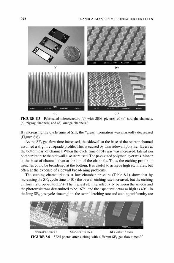
By increasing the cycle time of SF6, the “grass” formation was markedly decreased
(Figure 8.6).
As the SF6 gas flow time increased, the sidewall at the base of the reactor channel
assumed a slight retrograde profile. This is caused by thin sidewall polymer layers at
the bottom part of channel. When the cycle time of SF6 gas was increased, lateral ion
bombardment to the sidewall also increased.Thepassivatedpolymer layerwas thinner
at the base of channels than at the top of the channels. Thus, the etching profile of
trenches could be broadened at the bottom. It is useful to achieve high etch rates, but
often at the expense of sidewall broadening problems.
The etching characteristics at low chamber pressure (Table 8.1) show that by
increasing the SF6 cycle time to 10 s the overall etching rate increased, but the etching
uniformity dropped to 3.5%. The highest etching selectivity between the silicon and
the photoresist was determined to be 167:1 and the aspect ratiowas as high as 40:1. In
the long SF6 gas cycle time region, the overall etching rate and etching uniformity are
FIGURE 8.5 Fabricated microreactors (a) with SEM pictures of (b) straight channels,
(c) zigzag channels, and (d) omega channels.9
FIGURE 8.6 SEM photos after etching with different SF6 gas flow times.15
292 NANOCATALYSIS IN MICROREACTOR FOR FUELS

improved, and also the etching rate is nearly independent of the feature size. Increasing
bias power causes higher average etching rate but does not contribute to improving
etching uniformity to acceptable levels. Increasing bias power enhanced overall
etching rate, but the etching uniformitywas not improved. The surfacemorphology of
the silicon substrate was strongly affected by etching gas species and the gas flow
sequence time. However, the “grass” formation was not reduced at the low chamber
pressure. The formation of micro “grass” on the silicon surface could result from
several factors. Etching gas sequence time, bias power, and chamber pressure can all
greatly change the surface morphology of silicon surface. Grass formation was
dramatically reduced by increasing SF6 gas flow time. For the optimum conditions
of the ICP etching to fabricate siliconmicrochannel reactors, longer cycle time of SF6gas flow, high bias power, and low chamber pressure are all recommended.
Most of the fabrication methods can produce structures but cannot form sealed
structures that are imperative if the chemicals are to be contained in the channels. The
use of gaskets and a suitable housing that is kept tightly clamped is a common sealing
method, offering the advantage of easy assembly and disassembly. However, there are
no suitable procedures for microscale assembling and handling. The most popular
method for silicon microstructures is anodic bonding.14 Two wafers, one of which
must be at least semiconducting, are heated to 180–500�C and a direct current (DC)
voltage of 0.2–1 kV is applied across them. Silicon and Corning 7740 Pyrex glass are
most frequently used.Wafers must be cleaned and polished before the anodic bonding
procedure is started. The materials used must have similar thermal expansion
coefficients. Alternatively, silicon fusion bonding and lamination method also allow
the bonding of different materials.
In general, the composition of a specific material of construction will partially
dictate the preferred fabrication method. In many cases, a variety of materials may be
equally applicable due to their similar chemical and thermal compatibility character-
istics for the given process fluids as well as their ability to safely function over the
desired operating ranges for both temperature and pressure within the given process
safety settings.10 In these instances, the least expensive material with the most cost-
effective fabrication method is typically chosen. Ultimately, the cost and process
application requirementswill both dictate thefinal choice formaterials of construction
and fabrication methods. However, the enabling characteristics of miniaturization
TABLE 8.1 ICP Etching Characteristics with Variable Parameters15
SF6:C4F6(s)
Pressure
(Pa)
Bias Power
(W)
Etching rate
(mmmin�1)
Etching
Uniformity (%)
Grass
Formation
4:2 5 30 4.13 11.6 Lots
6:2 5 30 5.39 3.1 Little
8:2 5 30 5.90 2.4 None
10:2 5 30 6.40 3.5 None
4:2 5 40 3.91 8.7 Lots
4:2 5 50 4.86 8.3 Lots
4:2 3 30 3.16 6.8 Lots
FABRICATION OF MICROCHANNEL REACTOR 293

must also be considered. If the selected material and fabrication technology cannot
produce a microreactor that has step change advantages over a larger conventional
reactor, the additional expense for miniaturization is not justified. Hence, when
choosing a fabrication technology, the following factors should be considered by
users: process cost, accuracy, process reliability, material choice, and process time. It
is worthwhile after finishing a conceptual design of a specificmicroreaction system to
compare the different technologies with respect to the mentioned parameters.
Commonly, decisions are made on an overall evaluation of technological potential.
8.4 NANOCATALYST DEPOSITION ON THE MICROCHANNELS
8.4.1 Pretreatment of the Substrate and Coating Methods
Structuredcatalysts and reactors aregainingmore andmore importance due to industrial
applications. Themicrochannels in amicroreactor have high surface to volume ratio and
its geometric surface may be directly used for performing catalytic reactions, which is
not the case in traditional reactors. However, to enhance activity and efficiency of a
microreactor, it is necessary to increase the specific surface area by treatment of the
microchannel walls, usually by applying porous coatings. The porous layer can be
catalytically active or serve as a support for a catalytic phase. Micropacked beds of
powder catalysts can sometimes be used, but, in general, a very thin layer of catalyst that
sticks to the reactor wall is preferred because ofmass and/or heat transfer improvement.
Different methods can be used to deposit a catalyst layer on a surface, depending on the
properties of the surface and the catalyst that has to be deposited.
The pretreatment of the substrate to coat is important because it increases adhesion
of the catalytic layer and thus the lifetime of the structured catalyst. Two common
pretreatment methods are anodic oxidation and thermal treatment.16 The anodic
oxidation method is generally applied to structures containing aluminum with the
objective to obtain a porous alumina layer at the surface. Themethod is used either as a
pretreatment before applying another coating or as a way to obtain a thin porous layer
that can bedirectly impregnated. Like anodic oxidation, thermal oxidation is not really
a deposition method but a surface modification technique. However, it can be used
either as a pretreatment step to increase the catalyst adhesion or as a catalyst support.
The chemical oxidation of the substrate is sometimes carried out by acid treatment to
form metal oxide layers, such as Al2O3 layer, or to form a pseudolayer accessible to
chemisorption of small charged particles. For silicon and titanium-based substrates,
etching and/or oxidation of the surface can be obtained using an alkali treatment
procedure.
In general, two types of coating methods, chemical and physical, are used for
nanocatalysts in the microchannels. The chemical methods include suspension,
sol–gel, hybrid method between suspension and sol–gel, electrophoretic deposition
(EPD), electrochemical deposition, electroless plating, and chemical vapor deposition
(CVD).14,16 The physical methods consist of a mechanical method such as plasma
vapor sputtering (PVD) and thermal methods such as evaporation and electron beam
294 NANOCATALYSIS IN MICROREACTOR FOR FUELS

evaporation.14,16 These fabrication techniques are used inMEMS and semiconductor
industry and often referred to as silicon coating procedures.
In plasma vapor sputtering, capacitive plasma is generated between the surface to
coat and a target made of the material to be deposited. Sputtering is performed under
vacuum, the structured surface is operated as the anode, and the coating material is
operated as the cathode that emits atoms to the surface.16,17 The catalyticmetal (Pt, Fe,
Co, etc.) is often sputtered without a prior oxide layer. In electron beam evaporation,
the electron beam with high kinetic energy is directed to the target material for
evaporation. Upon impact, the high kinetic energy is converted into thermal energy
allowing the evaporation of the material. In pulsed laser deposition process, also
known as pulsed laser ablation deposition, a laser is used to ablate particles from a
target in a deposition chamber under reduced pressure and at elevated temperature.
The number of laser pulses is related to the thickness of the film deposited on the
substrate. Forflame-assisted vapor deposition, the deposition process can take place in
an open atmosphere without requiring the use of complex deposition chamber and/or
vacuumsystem like that inCVDorPVDmethods.Theatomizedchemical precursor of
the catalyst is burned in a flame. Themethod can thus be considered as a “dry” way of
deposition for the substrate that is placed in the combustion zone at controlled
distances and temperatures.
CVD technique requires the use of chemical precursors of the desired deposited
material.17 The precursor can be the same as that used in sol–gel method (discussed
below), but no solvent is required.Only thevolatile precursor and the structured object
are present in the deposition chamber. To enhance the deposition rate, the use of low
pressures and high temperatures may be required. Plasma-assisted CVD (PACVD)
also allows to perform the deposition at lower temperature and higher deposition rate.
EPD is a colloidal process in which a DC electric field is applied across a stable
suspension of charged particles attracting them to an oppositely charged electrode.16
One electrode (cathode) consists of the substrate to coat, the anode being either an
aluminum foil or stainless steel. The thickness of the coating depends on the distance
between the two electrodes (ca. 10mm), the DC voltage (can vary from 10 to 300V),
the properties of the suspension (e.g., pH), and the duration. This technique is often
used to deposit a layer of aluminum oxide (by oxidation of an aluminum layer) as a
precoating, to favor the adhesion of a catalyst, deposited in the second time by dip
coating in a suspension.
Electrochemical deposition and electroless plating use ionic solutions.16 The first
method, also called “electroplating,” produces a coating of metal on a surface by the
action of electric current. The deposition of a metallic coating onto an object is
achieved by putting a negative charge on the object to be coated (cathode) and
immersing it into a solution that contains a salt of the metal to be deposited.When the
positively chargedmetallic ions of the solution reach the negatively charged object, it
provides electrons to reduce the positively charged ions to pure metal.
All methods based on the dispersion of a finished material (catalyst support or
catalyst itself) have been gathered under the term “suspension method.” In some
preparations, the difference with sol–gel method is small because the suspension
method often implies some gelification steps. It is the most widely used method,
NANOCATALYST DEPOSITION ON THE MICROCHANNELS 295

namely, for ceramic monoliths. Powder (catalyst support or catalyst itself), binder,
acid, and water (or another solvent) are the standard ingredients. The concentration of
all ingredients varies largely from one experiment to another and also depends on the
nature of the surface to coat and on the desired layer thickness. The size of the
suspended particles has a great influence on the adhesion to the substrate.
In sol–gel method, the starting point is a solution of a chemical precursor of the
material tobedeposited.14–16 It involves the transitionof a system from the liquid sol to
a solid gel and creates a three-dimensional networkof inorganicmatter knownas “gel”
from a colloidal or molecular solution of the precursor (sol) by low-temperature
polymerization. It mainly involves the production ofmetal oxides by the hydrolysis of
appropriate precursor compounds. The hydrolytic reaction is utilized to provide
oxides in the form of thin films on the substrates or powders. Hydrolysis of the metal
alkoxides to metal hydroxides followed by dehydration to metal oxides can be shown
in the following equations:
MðORÞnþ nH2O!MðOHÞnþ nROH; where M ¼ Si; Al; Ti; Zr
M�OHþHO�M0 !�M�O�H0 þH2O
One important factor in sol–gel technology is the aging time allowing the gelation
of the sol. It can vary from a few minutes to several weeks, depending on the
concentrations in the sol and the characteristic size of the object to coat. The conditions
during sol formation have to be chosen to obtain oligomers with desired degree of
branching. Sols with high viscosities, obtained after long aging time, allow depositing
thicker layer but easy to crack. A compromise has to be found for each preparation and
substrate to coat. Sol–gel can also, in certain cases, be used to deposit a primer on the
support to coat. In contrast, impregnation is often used (as a posttreatment) to deposit a
catalytic active phase on thewashcoat and does not differ from powder impregnation.
Hybrid method does not differ very much from suspension method and sol–gel
method. In the present case, a sol not only acts as the binder but also participates in the
chemical and textural properties of the final deposited layer.
In general, the suspension and the sol–gel methods are applied to the structured
object using dip coating. An alternative to dip coating is spray coating. In the case of
coatingmicroreactor channels, thedropsof the sol–gel canbedeposited (dropcoating)
withpossible simultaneousheatingof themicroreactor channels. Spin coating canalso
be used for a silicon microreactor. In this deposition method, the film thickness is
related to the sol viscosity and the spin speed.14,18
When the different methods for thin films are compared, it appears that sol–gel
technique produces layers less than 10 mm thick, whereas PVD methods yield layer
thinner than 1 mm. The suspensionmethods can generate layers from 1 to 100mm, but
it is in general used to obtain thicker layers than that obtained by sol–gel. The sol–gel
method allows porosity of the foam material, whereas the use of the suspension
technology can result in blocking pores.16 To avoid the penetration of the oxide
precursor in the pores, a hybrid method between suspension and sol–gel is preferred
over sol–gel alone. The hybrid procedure indeed combines the advantages of the sol
296 NANOCATALYSIS IN MICROREACTOR FOR FUELS

(precise control and tuning of the catalyst microstructure) and that of the suspension
(ease of deposition).
8.4.2 Comparison of PVD with Sol–Gel Method Using Pt Catalyst
We can compare the chemical method (e.g., sol–gel technology) with the physical
method (e.g., PVD) to obtain metal (or metal oxide) catalysts on the surface of
microchannels. Platinum, used as a catalyst in the hydrogenation anddehydrogenation
of cyclohexene to cyclohexane and benzene (see below), has been deposited and
studied in a siliconmicroreactor.14,18 Silica or alumina, prepared by a sol–gel process,
is chosenas support becauseof its high specific surface area.Wecompareddip coating,
drop coating, and spin coating by depositing SiO2 on the channels of themicroreactor.
The selective deposition of catalysts was applied to both PVD and sol–gel methods.14
The silica and alumina films were characterized by scanning electron microscopy
(SEM), X-ray photoelectron spectroscopy (XPS), atomic force microscopy (AFM),
and Brunauer–Emmett–Teller (BET) surface area measurement techniques. The
microreactor was prepared by general lithography and ICP etching as discussed in
previous section. The conversion of cyclohexene was used for testing activity and
efficiency of the catalyst. Reaction results of supported Pt were compared to results
obtained in unsupported Pt microreactors.
The basic principle involved in the synthesis of the alumina coating solution is the
hydrolysis of aluminum alkoxide to form its hydroxide, peptization, and polymeriza-
tion to form the alumina. To allow the formation of a good three-dimensional network,
the reflux step was performed after acid addition to the resultant solution and before
coating on the channels of the microreactor. The silica sol–gel was prepared using
tetraethoxysilane (Si(OC2H5)4) as the precursor. We chose SiO2 acid instead of SiO2
basic because the surface area is expected to be approximately 10 times higher.19
Dip coating, spin coating, and drop coatingwere used to apply SiO2 orAl2O3 on the
channel region of the microreactor.14,18 Negative photoresist was chosen as the mask
for the selective deposition (Figure 8.7) because the unexposed channel part of
negative photoresist can be completely removed by developer, which minimizes
residual photoresist. Thephotoresistwasfirst spin coatedon the siliconwafer, and then
it was exposed in the UValigner. The development step opened the channel region of
microreactor. After coating SiO2 or Al2O3 solution, a 200�C, 20min baking step was
required to dry the sol–gel coating for good adhesion.
Ptwasdepositedon the catalyst support in the formofPtþ 2 by chemical deposition,
known as ion impregnation.16,20 Platinum(II)-2,4-pentanedionate (Pt(C5H702)2) was
dissolved completely in toluene and the solutionwas dropped into the channel area on
a hot plate at 70�C, with continued baking at the same temperature for 12 h. The
impregnated Ptþ 2 on the catalyst support was reduced to Pt0 in the presence of gas
mixture (40% H2 in N2, 0.2 Lmin�1) at 400�C for 4.5 h.
The chemical state and the atomic concentration of the elements present in the
coating of the catalyst support were studied using XPS. The ratio of Si:O in the silica
film prepared by the sol–gelmethod is 1:2, while the ratio of Al:O inAl2O3 is 1:1.242,
which is different from the stoichiometric ratio of 1:1.5. XPS analysis shows that the
NANOCATALYST DEPOSITION ON THE MICROCHANNELS 297

peak for Ptþ 2 after reduction (Pt0) shifts from 73.125 to 70.9 eV (Figure 8.8a). The
distance between the separation of the two peaks (70.9 and 74.2 eV) after reduction is
3.3 eV,which is in agreementwith that of the standard peaks. TheXPS depth profile of
Pt shows the uniform concentration and equal distribution of Pt inside silica film.
SEM analysis was performed on the channels that were coated with silica or
alumina to image the catalyst support and also to verify thickness of the film.TheSEM
images in Figure 8.9 confirm that the adhesion of alumina to silicon sidewall is worse
than that of silica. Some parts of the alumina film peeled off sidewall to yield bad
coating. Figure 8.10a shows that the particles of silicon film in the microchannels are
around 100 nm in diameter,which is confirmed byAFM image shown in Figure 8.10b.
These nanoparticles create the pore structure of silica with the specific surface area
FIGURE 8.8 (a) Binding energy of platinum before and after reduction and (b) XPS depth
profile of Pt deposited by sputtering.14
Step 1: Before PR coating
Step 2: After PR coating
Step 3: After exposing photoresist
Step 4: After SiO2 coating
Step 5: Strip PR with acetone
and coat Platinum
Step 6: Bond reactor with Pyrex
FIGURE 8.7 The process for selective deposition of catalyst in the microchannels.18
298 NANOCATALYSIS IN MICROREACTOR FOR FUELS

(SSA) of �500m2 g�1. The SSA study at different aging times and calcination
temperatures show that longer aging time and higher calcination temperature
decrease the specific surface area. SiO2, which has different aging time, was coated
on 5 and 100 mm channel micreactors by dip-coating, drop-coating, and spin-coating
techniques. The reactors with dip coating have larger surface area than those obtained
with drop-coating and spin-coating methods. Under similar conditions, the reactor
with 5mm channels has higher surface area compared to that with 100 mm channels
because there are more channels in the former.
After the characterization was completed, the prototype reaction on conversion of
cyclohexene was studied to test the activity and efficiency of supported catalyst.
C6H12 $ C6H10 þH2 $ C6H6þ 3H2
From the reaction results, we conclude:
1. For 100mm channel reactor, the conversion increases with increasing residence
time. Effect of residence time on conversion is much smaller on 5 mm channel
than that on 100 mm, as shown in Figure 8.11a.
2. For 100mm channels, the conversion on silica-supported Pt is much higher than
that on sputtered Pt (Figure 8.11b) due to the high surface area of silica support
with porous structure shown in Figure 8.10a.
FIGURE 8.10 (a) SEM picture of silica particles and (b) AFM image of silica particles.14
FIGURE 8.9 (a) Silica on 100mm channels and (b) alumina on 100mm channels.14
NANOCATALYST DEPOSITION ON THE MICROCHANNELS 299

3. The conversions with silica-supported Pt and 100mm channel are very close to
the conversion with sputtered Pt in 5mm channel when Figure 8.11a and b are
compared. Thus, wemay choose high reactant flow rate in 100 mmchannel with
sol–gel-supported Pt to receive more products at shorter time, which creates
high efficiency and high productivity.
4. Compared to silica-supported Pt, alumina-supported Pt gives higher conversion
of cyclohexene, but it deactivates faster. Moreover, the conversion on silica-
supported Pt increases when temperature rises, but keeps constant on alumina-
supported Pt and drops fast when the temperature is kept below 120�C.
We discussed previously two kinds of catalysts: supported (sol–gel method) and
unsupported (sputtering method). Sputter deposition is popular for coating thin,
uniform layers on the channels of microreactors. We can get different compositions
of catalyst layers by this method. But the disadvantage is that there is no surface area
enhancement. Supported catalysts can have high surface area, which provides more
reaction surface for high throughput. The sol–gel deposition process is cost-effective
since no expensive equipment is required. Due to its easy formulation and coating
processes, the high throughput of catalysts is the other benefit compared to sputter
deposition. In general, some methods concern only the oxide deposition (which can
further be impregnated by a catalyst precursor) and others concern the direct
deposition of a metal on substrate, without any oxide layer. The ease and the speed
of the PVD process are very advantageous in the case of parallel screening because it
allowsone toobtain an important catalyst library in a fewhours and thus provides rapid
information on the active metals to catalyze a reaction. However, due to their low
porosity, the activity of the obtained catalysts by PVD methods leads to low activity
catalysts compared to catalysts prepared by wet chemical procedures, such as sol–gel
method. The sol–gelmethod presents some advantages: it can be automated and it can
also be applied to closed microreactors.
However, liquid-phase handling to coat a microreactor is not preferable due to
nonuniform removal of solvent. In other words, to overcome the problems of low
FIGURE 8.11 Reaction results on conversion of cyclohexene: (a) conversion of cyclohex-
ene on sputtered Pt in 5 and 100mm channels; (b) conversion of cyclohexene on sputtered Pt
and silica-supported Pt in 100 mm at the same design point of the reaction.18
300 NANOCATALYSIS IN MICROREACTOR FOR FUELS

activity of catalysts from CVD and PVD methods, the use of flame spray synthesis is
recommended since it yields porous catalysts without handling a liquid precursor.
The main data based on current research concern metal-on-oxide catalysts for
which many methods exist. Some consider physical treatment of the surface to coat
(anodization, plating, PVD, etc.), others involve a more or less complex chemical
preparation (suspension and sol–gel). The properties of the deposited layer vary to a
large extent, for example, the thickness, from nanometer (PVD) to near millimeter
scale (suspension). The textural properties of the oxide supports can in certain cases
reach that of traditional catalysts (suspension, sol–gel, powder plasma spraying
methods). “Physical” methods in general lead to more adhesive layers, but to less
activecatalysts. Themostwidely usedmethod involves direct synthesis on the surface.
The nanostructure and microstructure and the size of the supports affect conversion
efficiency, space availability, catalyst loading, and so on.We can simulate commercial
catalyst practice by sol–gel and impregnation methods to realize optimized coating
situations for future industrial implementation.
8.5 HYDROGEN PRODUCTION AND PURIFICATION
IN A MICROREACTOR
8.5.1 Hydrogen Production from SRM: Current Status
The demand for power sources with superior performance has increased as a result of
the rapid growth of the portable electronics market. Greater performance leads to
greater consumption of electrical power, and it has become difficult to secure a
sufficiently long-lastingpower source for these portable electronic devices, evenusing
lithium-ion batteries. The proton exchange membrane fuel cell (PEMFC), using
hydrogen as a energy source, has attracted much attention for portable electronic
devices since it has higher high volumetric energy density (for example, 2500WhL�1
for liquid hydrogen) than lithium-ion battery (400WhL�1).21 Thus, hydrogen pro-
duction is getting a lot of attention from today’s researchers, and also due to
consumption of gasoline and environmental concern.22–26
Steam reforming is an alternative process to produce hydrogen from organic
sources with the aid of a catalyst. Of many candidates being considered for hydrogen
fuel sources, methanol, ethanol/bioethanol, gasoline, and diesel are readily available
and currently being investigated. The use ofmethanol for steam reforming is attractive
due to its high energy density, low cost, easy transportation, and low reforming
temperature. The main reactions involved in steam reforming of methanol may be
presented by the following equations.
1. Steam reforming of methanol:
CH3OHþH2O Ð 3H2 þCO2; DHr ¼ 49:5 kJ mol�1
2. Methanol decomposition:
CH3OH Ð 2H2þCO; DHr ¼ 90:6 kJ mol�1
HYDROGEN PRODUCTION AND PURIFICATION IN A MICROREACTOR 301

3. Water–gas shift reaction:
COþH2O Ð H2 þCO2; DHr ¼ �41:2 kJ mol�1
Considerable work already exists in the literature on SRM for hydrogen
production using conventional macroscale reactors. It has disadvantages in terms
of size and weight that affect the compactness of fuel processor. The catalyst in
packed bed form also exhibits high-pressure drop and possible channeling of gases.
The low gas velocity is maintained in the reformer to achieve high conversion, but it
lowers the effective thermal conductivity of the catalyst bed. For an endothermic
reaction such as methanol steam reforming, temperature gradient in the packed bed
leads to lowered catalyst activity and falsified kinetics. In addition, hot and cold
spots are commonly encountered in the catalyst bed that results in overall poor
performance.
The use of microreactors for steam reforming of methanol can compete with the
conventional reactors due to the advantages of microreactor systems, including
lightweight, compactness, rapid heat and mass transport due to large surface to
volume ratio, and precise control of process conditionswith higher product yields.24–26
The high heat exchange efficiency in microreactors allows one to carry out reactions
under isothermal conditions. Also, microchannel reactors working under laminar flow
conditions show low pressure drop compared to randomly packed bed reactors. The
short radial diffusion time in microreactors leads to narrow residence time distribution
of reaction gases, which allows an optimum contact time between reactants and
catalysts avoiding the formation of unwanted by-products.
The catalysts for SRM can be divided into two types: non-noble metal (typically
nickel) andnoblemetals fromGroupVIII elements (typically platinum).Due to severe
mass and heat transfer limitations, conventional steam reformers are limited to an
efficiency factor for the catalyst, which is typically less than 5%. Therefore, kinetics
and thus the activity of the catalyst are rarely the limiting factors with conventional
steam reformers. The mass and heat transfer limitations have been shown to be
overcome by employing microchannel-based reactors, enabling intrinsic kinetics of
steam reforming to be exploited. In these systems, the noble Group VIII metals are
preferred since they exhibit much higher specific activities than nickel catalysts.
However, the high cost of Group VIII metals is driving some researchers to develop
alternative catalysts. The catalyst performance is greatly influenced by the type of
supports. A number of commercial and research derived noble metals (such as Pt and
Rh) loaded onto metal oxide supports (such as CeO2, ZnO, MgO, Al2O3, SiO2, ZrO2,
and TiO2) including more than one type of catalyst support have been tested for
hydrogenproduction frommethanol and ethanol.Although a number of catalysts have
shown promising results, problems with deactivation of the catalysts with an ensuing
decrease in hydrogen and carbon dioxide and an increase in carbon monoxide
production have been reported. Currently, there is little understanding of the behavior
of these catalysts in steam reforming reactions carried out in microreactors. Thus,
more basic research is necessary to find the optimized combination of catalyst and
support for hydrogen production.
302 NANOCATALYSIS IN MICROREACTOR FOR FUELS

8.5.2 Non-Noble Nanocatalysts for SRM Reactions to Produce Hydrogen
This section focuses on the development of Ni and Co non-noble nanocatalysts on
silica support in microchannel reactors for SRM reactions to produce hydrogen. The
SRMmicroreactor is a silicon-based microdevice with the dimension of 1.6 cm� 3.1
cm. It consists of vias, feed inlet, product outlet, and reaction zone with a volume of
9.6mm3 and 120 straight channels of 50mm width and 100 mm depth.27,28
The microreactors coated with silica-supported Co or Ni nanocatalysts were
prepared by a sol–gel procedure as described in Section 8.4. The precursors for Co
andNi catalysts are cobalt nitrate and nickel nitrate. The catalyst-coated microreactor
was dried by gentle heating and treated with 10%NH4OH solution for 30min to form
hydroxides ofmetal catalysts, followed bywashingwith DIwater to remove residuals
from ammonia treatment. Calcination completed the formation of oxides from
hydroxides. The oxides of cobalt and nickel were finally reduced with hydrogen to
active metals before packaging of the microreactor.
The calcination temperature for SiO2 supported catalyst was obtained by differen-
tial thermal analysis (DTA). For Ni/SiO2 (Figure 8.12), endothermic peaks are
observed at�100�C,which can be attributed to evaporation ofwater. Due to ammonia
treatment during synthesis of the sol–gel encapsulated catalysts, most of metal nitrate
salts are converted to metal hydroxides that are further converted to metal oxides by
heating in air. The broad endothermic peaks observed at 100–150�C can be attributed
to water loss and some of the metal nitrate salts getting decomposed. One exothermic
peakmaybeeither due to themetal hydroxidesgettingconverted to theoxidesordue to
structural changes of the surface species. Thus, we may conclude that all of the metal
hydroxides are converted to the metal oxides in temperature range of 350–400�C,which can be considered the minimum temperature for calcination.
To optimize the calcination temperature for Ni/SiO2, X-ray Diffraction (XRD)
analysis was performed by annealing the samples from 450 to 1000 �C.27 The resultsshow that the sharpness and intensity of the XRD peaks increased due to formation of
larger crystallites during the increase of the annealing temperature. This represents
evolution of the particle size and corresponds well to crystal growth. The higher
FIGURE 8.12 Differential thermal analysis of silica sol–gel-supported Ni catalyst.27
HYDROGEN PRODUCTION AND PURIFICATION IN A MICROREACTOR 303

crystalline characteristics of the samples calcined at 1000 �C indicates that heating the
catalysts at very high temperatures may result in large crystallite sizes due to
aggregation. It has been reported that NiO crystallite in small size favors large Ni
surface area after reduction, which implies that higher calcination temperature is not
preferred for nanocatalysts. Similar observations of DTA and XRD were made for
Co/SiO2. Thus, we selected 450�C as the optimized calcination temperature for both
Ni and Co catalysts.
Since pure metallic Co and Ni are ferromagnetic, one can study the magnetic
properties of Co and Ni catalysts to understand the reduction efficiency during
hydrogenation and formation of chemical compounds of metal catalysts during
catalytic reactions. The saturation magnetization of the ferromagnetic component
in magnetic curves obtained fromVSMwas used along with the energy dispersive X-
ray (EDX) results to estimate the pure metallic Co and Ni in the catalysts.
Magnetization studies of the silica-supported Co catalyst before reduction with
hydrogen show paramagnetic behavior as cobalt is in its oxide forms (Figure 8.13),
which is also confirmed from the XRD and DTA results. Hydrogenation of the
catalyst reduces most, if not all, of the Co oxide to pure metal (the active phase for
SRM reaction), thus giving the catalyst the ferromagnetic behavior. The ferromag-
netic nature almost disappears in the postreaction catalyst sample as most of the
metallic Co yields nonferromagnetic species. Hence, the magnetization results
were used for ferromagnetic catalysts to estimate the pure metal percentage from
the saturation magnetization value of the ferromagnetic component obtained at
different stages.
The elemental analysis using EDX indicates both Ni and Co catalysts in the
microchannels show loadings of 5–6%. The EDX analysis at different locations of the
sample showsuniformdistributionof the catalyst in sol–gelmatrix.From transmission
electron microscopy (TEM) analysis shown in Figure 8.14, we can estimate the size
of the Co particles in silica sol–gel to be <10 nm. The BET analyses show that
–0.2
–0.15
–0.1
–0.05
0
0.05
0.1
0.15
0.2
1050–5–10
As-madeReducedAfter reaction
Applied Magnetic filed (kG)
Mag
neti
zati
on
(em
u g
–1)
FIGURE 8.13 Room-temperature magnetization curves of Co/SiO2 before reduction, after
reduction, and after SRM reaction using a vibrating sample magnetometer.27
304 NANOCATALYSIS IN MICROREACTOR FOR FUELS

specific surface area is 450m2 g�1 for Ni/SiO2 and 340m2 g�1 for Co/SiO2. The
Barrett–Joyner–Halenda (BJH) analyses show that the pore size of silica support is
32A�. With SiO2 porous structure, Ni and Co can be effectively distributed to obtain
larger surface area available for catalytic SRM reactions.
SRM reactions were conducted over Co or Ni nanocatalyst supported by silica
sol–gel in the temperature range of 180–240�C under atmospheric pressure. The flow
rates of 1:1 methanol/water between 5 and 20mLmin�1 were controlled using a
syringe pump (Figure 8.15). A cold trap was used to separate gaseous products from
aqueous methanol and water. Methanol conversion was calculated from volume
difference between the fed methanol–water mixture and the unreacted methanol–-
water mixture cooled with liquid N2 in the trap. The gaseous products containing H2,
CO2, and COwere diluted with helium and analyzed using a mass spectrometer (MS)
coupled with a residual gas analyzer (RGA) (QMS 200 gas analyzer from Stanford
Research Systems). Hydrogen selectivity was calculated on the basis of partial
pressures (proportional to moles) of different products.
FIGURE 8.14 TEM image of Co nanoparticles in silica synthesized by sol–gel method.27
FIGURE 8.15 Experimental setup for SRM reactions with Ni/SiO2 or Co/SiO2 catalyst.28
HYDROGEN PRODUCTION AND PURIFICATION IN A MICROREACTOR 305

The main products of SRM reaction are hydrogen and carbon dioxide with a small
amount of carbon monoxide. The methanol conversion decreases as the flow rate is
increased (Figure 8.16) for both Co/SiO2 and Ni/SiO2 nanocatalysts with slightly
higher conversion for Ni/SiO2. While our studies with Ni/SiO2 show 53% methanol
conversion, Co/SiO2 shows only 37% conversion at 5mLmin�1 flow rate and 200�C.Thismay be attributed to larger specific surface area ofNi/SiO2 catalyst. However, the
catalysts’ behavior in microreactors for SRM is not fully understood. The decrease in
methanol conversion with increasing flow rate may be explained by lower residence
time of the reactants in the microreactor at higher flow rates. The hydrogen selectivity
(Figure 8.17) also decreases with increasing flow rate. The maximum hydrogen
FIGURE 8.16 Methanol conversion (CH3OH:H2O ratio of 1:1) as a function of flow rate at
200�C using silica sol–gel-supported Ni/SiO2 and Co/SiO2 nanocatalysts in 50mm channel
microreactor.27
FIGURE 8.17 Hydrogen selectivity (CH3OH:H2O ratio of 1:1) as a function of flow rate at
200�C using silica sol–gel-supported Ni/SiO2 and Co/SiO2 nanocatalysts in 50mm channel
microreactor.27
306 NANOCATALYSIS IN MICROREACTOR FOR FUELS

selectivity is �74% for Ni/SiO2 catalyst and �67% for Co/SiO2 at 5mLmin�1 flow
rate and 200�C.The temperature in the range of 180–240�Cdoes not have a significant
effect on methanol conversion for both catalysts, but the hydrogen selectivity is
maximum at 200�C for Ni/SiO2 catalyst and at 220�C for Co/SiO2 catalyst.
All the reactions described above were carried out within 8 h and no significant
deactivation of the catalysts was observed during this period. However, when these
reactionswere carried out over 10 h, deactivation of the catalystswas noticed,which is
consistent with the VSM analysis. The VSM results from the postreaction catalyst
sample (Figure 8.4) provide an estimate of�90%Co and�85%Ni being converted to
nonferromagnetic species after SRM reactions over 10 h. These species may be Ni or
Co compounds such as their oxides, carbonyls, and carbides.
8.5.3 Platinum Catalyst for Preferential Oxidation of CO in Hydrogen
As mentioned previously, there is a little amount of carbon monoxide (CO) produced
during steam reforming of methanol to produce H2. In general, CO poisons the
electrode catalyst of fuel cell. Thus, it is necessary to develop robust catalysts for
preferential oxidation of CO in an atmosphere of H2.29–31 The reactions for preferen-
tial oxidation of CO are shown below:
Desired reaction: COþO2�!Pt CO2
Undesired reaction: H2þO2�!Pt H2O
Platinumwas chosen as the catalyst, and a sol–gel supportwas utilized tomaximize
the surface area. High conversion of CO is required to reduce its concentration to a
level that is not detrimental to a proton exchange membrane (PEM)-based fuel cell.
High selectivity to CO2 is desired because hydrogen is used to generate electricity in
the fuel cell. The side reaction on oxidation of hydrogen to water reduces the energy
available for the fuel cell.
Themicroreactor used for CO oxidationwas 3.1 cm long and 1.6 cmwidewith 119
microchannels of 25mm in width and 100 mm in depth. The reactant gases were
premixed before being allowed to flow in the channels of the microreactor. An inlet
manifold was designed to promote a uniform distribution of flow among the reaction
microchannels. The inlet manifold consisted of two channels symmetrically off-axis
from the single outlet.32
The effect of the ratio of O2/CO onCOoxidationwas studied by keeping themixed
gas at 1 sccm and changing the airflow rate from 0.02 to 0.4 sccm at a constant
temperature of 200�C.As expected, the selectivity of oxidation of COdecreases as the
O2 to CO ratio is increased above 2. Surprisingly, the conversion of CO did not appear
to significantly increase as the ratio of O2 to CO was increased above 2. The effect of
temperature showed that conversion and selectivity were both maximized at the
minimum temperature tested, 120�C.The lower stoichiometric excess ofO2 displayed
a higher sensitivity of conversion with respect to increase in temperature. The
sensitivity of conversion and selectivity on reactor residence time was tested to
HYDROGEN PRODUCTION AND PURIFICATION IN A MICROREACTOR 307

show that this particular catalyst and reactor combination favored the lowest space
velocity that could be achieved, 13 h�1. Additional experiments were then conducted
atWHSVof13 h�1 tofinalize theoptimal temperatureofoperation.The ratio ofO2/CO
was held constant at a stoichiometric ratio of 0.5. Figure 8.18 shows that 160�C is
optimal temperature of operation at these conditions. The catalyst deactivation study
showed that after 50 h of reaction both conversion of CO and selectivity to CO2
dropped significantly. We speculate that this could be due to two likely mechanisms:
(1) oxidation of the platinum and (2) sintering of the platinum nanoclusters into
larger particles. While limited recovery of the catalyst activity through repeated
reduction treatments suggests the former is more likely, the irreversible reduction in
exposed surface area through sintering of the platinumnanoclusters at the temperature
of operation is the likely cause for the remaining drop in activity. Carbon deposition is
not thought to be a major contributor due to the lack of a possible mechanism as
predicted by Chemkin simulations.33 Improvement of the catalyst activity and
efficiency will be a significant issue for future research and commercialization of
this technology in fuel cell applications.
The research described above for the development of catalysts for H2 production
and elimination of CO is very important for the development of microfuel cells.
Microfuel cells are high-energy-density sources for next-generation power portable
products such as personal digital assistant (PDA), laptop, cellular phone, and so on.
Fuel cells can provide more reliable, longer portable power than batteries. Microfuel
cell products compete with traditional power systems that utilize both direct and
indirect energy conversion methods. Direct methanol systems have the advantage of
room-temperature operation but offer only relatively low power density due to
methanol crossover through the proton exchange membrane and the low reaction
rate of methanol oxidation over the anode electrocatalyst. In contrast, reforming
systems generate electrical energy in the fuel cell from concentrated hydrogen
produced by steam reforming, for example, from methanol. Reforming systems
achieve high power density but are difficult to miniaturize due to the complexity
50.00%
55.00%
60.00%
65.00%
70.00%
75.00%
80.00%
85.00%
90.00%
95.00%
220200180160140120100
Temperature
Co
nvers
ion
or
sele
cti
vit
y
Conversion of CO
Selectivity to CO2
FIGURE 8.18 Temperature effect on the conversion of CO and selectivity to CO2 at a low
total flow rate of 0.2 sccm and O2/CO ratio of 0.5.32
308 NANOCATALYSIS IN MICROREACTOR FOR FUELS

of the required structure that includes not only a fuel reformer but also a vaporizer, a
CO removal unit, and various peripheral parts. However, themicrochannel fabrication
on a silicon substrate allows the various components of microfuel cell, such as steam
reformer, hydrogen purifier, driving units, sensors, and microvalves, to be integrated
by semiconductor technology andMEMS technology. Itmay also be possible, through
the use of these technologies, to achieve sufficient thermal insulation between the
reformer (with microreactor) and the periphery of the system, where the surface
temperature should be reasonable to touch. It is therefore expected that the small SRM
systems with high power density, sufficient to power portable electronic devices, will
be realized in the near future.
8.6 MICROREACTOR FOR GAS-TO-LIQUID TECHNOLOGY
Catalyst development for GTL technology using FT synthesis is a very active area of
research since it converts unconsumed natural gases into hydrocarbons that are
subsequently converted to fuels by hydrocracking for low-cost production and
easy transportation. Although FT synthesis has been developed by several worldwide
petroleum corporations such as Exxon Mobil, Shell, Sasol, Syntroleum, and Rentech
to help deliver the potential of the world’s untapped natural gas resources, a lot more
work is necessary to develop robust and stable catalysts in this regard.The catalysts for
FT synthesis generally contain metals such as cobalt, iron, nickel, and copper with
support materials of oxides and zeolites. More specifically, the influence of various
support materials such as titania, alumina, silica, and ceria on the activity of cobalt
catalysts forCOconversion have been studied.34–36Alumina is the primary choice as a
support for cobalt catalysts due to its thermal stability, although reduction of cobalt
oxide to cobalt is limited due to strong interaction between the support and cobalt
oxides. Addition of a second catalyst like iron may improve the selectivity to heavier
alkanes with less selectivity tomethane.37 Recent studies have shown that the catalyst
activity depends on the number of active sites located on the surface of the support
formed by the reduction process, determined by the particle size, loading, and the
degree to which the metal has been reduced.
8.6.1 Iron–Cobalt Mixed Catalysts for Fischer–Tropsch Synthesis
As discussed in earlier sections, microreactors are ideal systems for catalyst develop-
ment as they provide unique advantages such as low consumption of reactants, greater
speeds in catalyst characterization, and easy integration with other devices. More
significantly, high surface area ofmicrochannels to volume of the reactor inhibits gas-
phase free radical reactions and improves heat transfer for exothermic reactions, such
as FT synthesis to higher alkanes as shown below. Silicon microreactors with either 5
or 25 mmwide channels were coated with mixed metal Fe–Co in alumina sol–gel for
conversionof syngas (CO þ H2) to higher alkanes.Thevolumeof themicroreactors is
�9mm3 for both 5 mm (1200 in number) and 25mm (240 in number) wide channel
reactors.38–40
MICROREACTOR FOR GAS-TO-LIQUID TECHNOLOGY 309

COþH2�!200�300�C
Fe=Co on Al2O3 supportCH4þC2H6 þC3H8þ higher alkanes
Initial studies were performed in 5 mm channel reactors to study the conversion
rates at different ratios of H2:CO. The conversion of CO reachesmaximum (�32%) at
the H2:CO ratio of 3 with a total flow rate of 0.6 sccm and 230�C in 5mm channel
reactors. The lowCOconversion is likely due to insufficient coating of sol–gel in 5mmchannels of the reactor. This is indeed supported by higher conversion in 25mmchannel reactors (Figure 8.19) where sol–gel can penetrate easily (shown in
Figure 8.20b) allowing the reactants to have more interactions with the catalyst.
This may also explain the observed lower loading (�7%) than the intended loading
(12%) of supported catalysts from our EDX studies. We believe that the sol–gel
granules (less than 100 nm indicated by atomic force microscopy) and high viscous
nature of alumina sol–gel cause blocking of 5mm channels as shown in Figure 8.20a.
FIGURE 8.20 SEM image of alumina sol–gel encapsulated Fe/Co catalyst deposited on
(a) 5mmwide channelmicroreactor and (b) 25mmchannelmicroreactorwith 100mmdepth.38
FIGURE 8.19 Comparative studies on conversion of CO to alkanes in 5 and 25mm channel
reactors at different temperatures. Fixed H2/CO ratio of 3:1; 1 atm.38
310 NANOCATALYSIS IN MICROREACTOR FOR FUELS

However, the blockages of catalyst active sites in the microchannels may also occur
due to carbon formation from the water–gas shift reaction and can also decrease CO
conversion at higher temperature.
The study of temperature effect onCOconversion shows initial increasewith rising
temperature and decrease after 230�C due to exothermicity of the reaction as the
competition between activation and exothermicity progresses (Figure 8.19). The
effect of flow rate of syngas was also investigated. The reaction results show that the
conversion of CO decreases with increase in total flow rate as a result of decrease in
residence time of the reaction.
Although the conversion of CO is influenced by the width of the channels, the
selectivity toward different alkanes is not. Figure 8.21 shows the selectivity to
methane, ethane, and propane as a function of temperature in 5 and 25mm channel
reactors. Propane has been the major product of the reaction in both cases with
selectivity up to 78%. The residence time does not have any significant effect on
selectivity to alkanes in the microreactor.
The use of Fe–Co catalyst on alumina support for FT synthesis to higher alkanes is
basedon twoexperimental observations reported in the literature:while cobalt catalyst
inactivates water–gas shift reaction to some degree, iron has an advantage of
improving selectivity to higher alkanes with less selectivity to methane. Due to its
thermal stability, alumina with porous structure as a support for dispersing the metal
catalyst to a large total surface area with high catalytic conversion has been
investigated by Iglesia.34 However, reduction of cobalt oxide to cobalt is limited
due to strong interaction between alumina and cobalt oxide35 and formation of Co
aluminates.34 Furthermore, higher viscous nature of alumina solmakes the deposition
FIGURE 8.21 Selectivity of alkanes: methane, ethane, and propane in 5 and 25mm wide
channel reactors at 230�C; H2/CO ratio 3:1; 1 atm.38
MICROREACTOR FOR GAS-TO-LIQUID TECHNOLOGY 311

process in Si microreactor difficult and results in nonuniform coating. Thus, alumina
has been replaced with silica as the catalyst support to improve catalyst coating
performance and to increase syngas conversion to alkanes due to good adhesion
between silica and Si microchannels (Figure 8.9). The particle size of silica in 25mmchannels is<100 nm. The field emission scanning transmission electron microscopy
(FE-STEM) analyses indicate that the particle sizes of the nanocatalysts in the silica
support is�6 nm (Figure 8.22). The CO conversions increase from 52%with alumina
(Figure 8.19) to 63% (Figure 8.23) with silica in 25mm channel microreactors.
30
35
40
45
50
55
60
65
70
75
80
250240230220210200190
Temperature (ºC)
% C
O c
on
versi
on
H2/CO 3:1, without RuH2/CO 2:1, with RuH2/CO 2:1, without RuH2/CO 3:1, with Ru
FIGURE 8.23 Comparative studies on CO conversion to alkanes at different temperatures
and two H2:CO ratios, using silica-supported Fe–Co catalysts with and without Ru at 1 atm and
a total flow rate of 0.4 sccm.41
FIGURE 8.22 FE-STEM image of silica-supported Co synthesized by sol–gel method in
25mm microchannel showing the particle size of �6 nm.41
312 NANOCATALYSIS IN MICROREACTOR FOR FUELS

8.6.2 Ruthenium Added as a Promoter to Iron–Cobalt Catalyst
for CO Conversion
Ruthenium as a promoter was added to the mixed Fe–Co catalyst to improve CO
conversion since it is one of the most active catalysts and can work at lower
temperatures.36,37,41 The highest conversion of CO on Ru–Fe–Co/SiO2 catalyst
reaches �78% at 220�C by adding only 0.4wt.% Ru at H2:CO ratio of 3:1. This is
much higher than that observed for Fe–Co/SiO2 catalyst (63%). The effect of H2:CO
ratio on CO conversion is less with Ru than that observed without Ru (Figure 8.24).
With Ru, CO conversion is almost same for both 3:1 and 2:1 ratios of H2:CO at 200�C,whereas the H2:CO ratio effect is significant without Ru (40% at 2:1 to 49% at 3:1).
This indicates that the role of Ru is more important in CO conversion than that of H2:
CO ratio. Ru can improveCOconversion at lower temperaturemore efficiently than at
higher temperature for both H2:CO ratios of 2:1 and 3:1 (Figure 8.23).
Addition of Ru not only increases CO conversion but also affects the selectivity to
alkanes.WhileRu–Fe–Co/SiO2 catalyst atH2:CO ratio of 3:1 yields�70%selectivity
to propane, �20% to ethane, and �10% to methane (Figure 8.24), these values with
Fe–Co/SiO2 catalyst are �80%, 17%, and 3%, respectively. The lower selectivity to
higher alkanes for Ru–Fe–Co/SiO2 may be due to possible side reactions to carbon
formation with all the FT catalyst metals (Fe, Co, Ru). For FT synthesis, at�200�Cor
below, the consecutive reaction of carbon hydrogenation to the CH2 monomer and its
consumption for chain growth inhibits CH4 formation and a carbon phase on the
catalyst is not allowed to grow.42 The selectivity changes mainly to methane at
elevated temperature, with possible deposition of carbon and catalyst deactivation
(especially with iron) reducing average chain length of the product molecules.41
The results from our studies are consistent with the steady-state isotopic transient
kinetic analysis (SSITKA), which indicates higher amount of CH4 in the presence of
0
10
20
30
40
50
60
70
80
90
3.532.521.5
H2:CO ratio
Sele
cti
vit
y (
%)
Methane with Ru Ethane with Ru
Propane with Ru Methane without Ru
Ethane without Ru Propane without Ru
FIGURE 8.24 Selectivity to various alkanes at different H2:CO ratios using silica-supported
Fe–Co catalysts with andwithoutRu in 25mmwide channel reactors at 230�C, 1 atm, and a total
flow rate of 0.4 sccm.41
MICROREACTOR FOR GAS-TO-LIQUID TECHNOLOGY 313

Ru.41 Based on the increase in H2 chemisorption, Ru promotion increases the reaction
by increasing the Co metal dispersion, resulting in an increase in the number of
reaction sites. Similarly, Ru promotion of silica and titania-supported Co catalysts
exhibit a synergistic effect on CO hydrogenation, and higher hydrogenation ability of
Ru is due to a cleansing effect during COhydrogenation that prevents the formation of
carbon deposits on the catalyst surface. Meanwhile, it has been reported that Ru
promoter causes higher reducibility of Co ion and better dispersion of Cometal in the
catalyst support leading to higher CO conversion.34,35 In contrast, our magnetization
studies showaminimal effect of Ru onCo ion reduction and corroborate that Ru rather
has a synergistic effect on catalytic activities due to better dispersion of Co in the
catalyst support.41
8.7 PARALLEL MICROREACTOR SYSTEM FOR NANOCATALYST
SCREENING
Thedevelopment, optimization, and improvement of catalysts for use in commercially
viable processes face major challenges for scientific research with respect to the
complexities of the systems being investigated. Commercial catalysts, particularly
heterogeneous systems, are often complex multielemental, multicomponent
systems that are usually prepared via multistep procedures with the conditions under
which each intermediate step is performed often impact performance.3 Starting from
pharmaceutical research with respect to the identification and optimization of drugs,
combinatorial methods for synthesis and screening have become increasingly impor-
tant for other chemical and biological systems as well, for example, regarding
homogeneous or heterogeneous catalysts or other types of materials. The goal of
the development and application of parallel approaches to catalyst development is to
provide equivalent tools and techniques that significantly expand the ability to explore
the large complex parameter space addressed, while still generating results of an
adequate quality in terms of resolution and accuracy. The achievement of this goal
depends on a good understanding of how to integrate the parallel approach into the
target activities.
There are generally two approaches to combinatorial catalyst screening developed
among different research groups: (1) high sample throughput with less information
gained on each sample and (2) lower sample count with more complete information
obtained on each sample, depending on the preparation and screening techniques.43
The first approach normally pursues a large number of candidates (>100) to extract
10 or so “leads” based on relatively limited screening information. In contrast, the
second approach, which collects more detailed reaction information for a group of
leads, then facilitates further elimination of less effective candidates from this group.
In addition, the approach also yields information useful for process scaling and
deployment in actual industrial processes.
Specific advantages of using microreactors compared to conventional catalyst test
systems have been described previously. Due to unique mass and heat transfer
properties, as well as the uniform flow distribution, the microreactors are ideally
314 NANOCATALYSIS IN MICROREACTOR FOR FUELS

free of any dead zones. Micoreactors provide a well-defined setting of operating
conditions, and due to their small volume, fast changes in operating conditions can be
performed with minimal time required to reach equilibrium. More specifically,
microscale dimensions result in ultralow transport resistances such that the heat
and mass transfer are extremely fast. The capability of microreactors to test a number
of catalysts in separate reaction chambers, without any interference by flow mixing,
guarantees high accuracy and reliability of the results, while maintaining a high
analysis speed using compact devices. The microreactors consume reactant species
only very slowly, thus allowing extremely expensive or rare chemical systems to be
studiedmore economically. The small footprint of themicroreactor and its peripherals
need less infrastructure for operation, including floor space, energy supply, and
support personnel.43This compactness also allowsan experimental approachwhereby
anarrayofmicroreactors are connected to shareflowandanalysis equipment, allowing
a number of catalyst analysis experiments to be performed in parallel, increasing
experiment throughput with reducing time required for development. These technical
advantages are achievedwith added benefit that the small reactant volumes are highly
safe, being nearly exempt from explosion even when operating in what would
normally be considered explosive regimes. In addition, the environmental hazards
due to leakage are minimal.
Based on the combinatorial screening approach and our experience with micro-
fabricated reactor (microreactor) research described in previous sections, a silicon
microreactor-based parallel catalyst analysis system was developed for industrially
important reactions to dramatically decrease the catalyst development period and
reduce overall operating costs (Figure 8.25). Theflowof the reactantwas controlled by
Cole Parmer� mass flow controller. These flow meters also indicate the absolute
pressure in the line and are therefore useful for the alignment of the microreactors.44
Due to the low reactant flow rates required for themicroscale reactions, the pressure in
the system was built by carrier gas, helium, controlled by an Aalborg gas flow
FIGURE 8.25 A parallel array setup includes the following devices: (1) mass flow
controllers, (2) heating blocks with microreactors inside, (3) pressure gauges, (4) gas flow
controller of carrier gas, (5) multiline switching valve, (6) electrical connection, (7) mass
spectrometer, (8) gas chromatography, and (9) gases for calibration.44
PARALLEL MICROREACTOR SYSTEM FOR NANOCATALYST SCREENING 315

controller. This flow controller can provide a maximum of 10 sccm of flow rate. The
switching between the four lines was done by VALCO� multiposition valve that can
switch between amaximumof 16 reaction lines with the help of an electronic actuator
controlled both manually and automatically through the LabVIEW� program. The
pressure inside the setup is controlled by a Cole Parmer relief valve with the help of
LabVIEW and the inputs from the mass flow meter and pressure gauges are used to
open/close this relief valve such that the pressure inside the system ismaintained at the
set point provided by the user.
The analysis of the product stream can be performed with the help of Stanford
Research System� Residual Gas Analyzer/Mass Spectrometer or a Varian� Gas
Chromatograph (GC). The injection to the GC was done with help of an 8-port valve.
To achieve high-pressure synthesis, pressure has to be applied with the help of the
carrier gas controlled though an Aalborg valve (maximum 10 sccm) at downstream of
the multiposition valve. Since there is a pressure drop in nonselected streams by the
VALCOmultiposition valve, the downstream lines from the multiposition valvewere
vented out directly, and the carrier gas connection was made to the analyte line, thus
maintainingpressure for the active reaction line.The actual parallel array setup and the
complete process and instrument diagram (P&ID) are shown in Figures 8.25 and 8.26,
respectively.
The parallel array system of micoreactors with automatic control has been utilized
for FT synthesis (CO and H2) to alkanes. As discussed in the previous section, today’s
research groups in academia and industry have extensive interest to find a better
catalyst to increase productivity, to control hydrocarbon product distribution, and to
lengthen the catalyst life. The idea of using a parallel analysis system as a fast,
economic, and easy-to-scale-up solution for FT catalyst development fits these
requirements appropriately.
FIGURE 8.26 The P&ID of the parallel array setup of microreactors.44
316 NANOCATALYSIS IN MICROREACTOR FOR FUELS

To fully understand the activities of Fe/Co/Ru in FT synthesis described in the
previous section,we have tried to examine each catalyst in themicroreactor separately
using the parallel array system. Cobalt catalyst shows the highest CO conversion
(Table 8.2).44,45 From thevarious characterization studies,44 cobalt catalyst is found to
be well dispersed in the catalyst support matrix. This dispersion of catalyst allows a
larger surface area of the active metal to be in contact with the feed gases, and hence
higher conversion. The low conversion on the Ru catalyst (Table 8.2) can be attributed
to the low dispersion of the catalyst; also the agglomeration of the catalyst particles
reduced the amount of surface metal particles in contact with the feed gases. The
absence of water–gas shift reaction with cobalt catalyst compared to iron and
ruthenium is an indication of a different reaction mechanism. Iron and ruthenium
catalyst can be seen to promote the same reaction mechanism that can be the CO
insertion mechanism. The reaction temperature only increased the conversion of the
reaction and had no prominent effect on the selectivity to products formed. The
increase in residence time increased the production of long-chain compounds.
The smaller and better dispersed the metal particles are, the more surface area it
provides, and hence higherCOconversion is observed. From the above results, we can
conclude that in reactions involving nanocatalysis, dispersion, particle size, and
activity of supported metal catalysts play very significant roles.
In general, parallel catalyst screening approaches for heterogeneously catalyzed
gas-phase reactions have gained increasing popularity within the past years, as the
development of novel and better catalysts for chemical processes is still mainly an
empirical process utilizing existing technical know-how and experiences.
Simultaneous handling of many samples and large amounts of data impose a need
for the development of workflows and associated tool sets that minimize bottlenecks.
The key components of theworkflows are preparation system for synthesis, formation,
and treatment of arrays of samples, reactor system for evaluating the performance of
sample arrays for particularly target applications, characterization system for parallel
characterization of key properties of the sample arrays, and informatics system for
handling information and data flow between the various operations. Technical and
costs constraints have in general limited howeffectively themajor reactor sections can
be parallelized and for most groups have resulted in a systematic approach to the
implementation of parallel methodologies to catalyst screening.3
TABLE 8.2 COConversion on Three Different Catalysts in the Temperature Range
of 100–250�C44
Reaction Temperature (�C)
100 150 200 250
CO conversion on Co catalyst 31% 85% 92% 90%
CO conversion on Fe catalyst 74% 80% 82% 80%
CO conversion on Ru catalyst 31% 45% 52% 62%
PARALLEL MICROREACTOR SYSTEM FOR NANOCATALYST SCREENING 317

Typically, the highest level of parallelization functions as a primary screening tool,
providing evaluation of larger arrays of catalyst samples with a range of solutions
compromising on the degree to which they approximate conventional systems. The
secondary screening tools, which include the parallel array system described above,
aim to provide almost the same level of individual control of conditions and detailed
assessment of catalyst performance as typically performed on a bench-scale system.
The described parallel catalyst screening setup has the flexibility to optimize the
process conditions with accuracy equivalent to conventional units. This strategy of
integrating detailed catalyst screening and flexible process control within a large
parallel array system may help in the discovery of new commercial catalysts, the
results of which may be successfully validated at all levels from the miniaturized
parallel scale to final commercial operations.
8.8 SUMMARY
Microreactors are recognized in recent years as a novel tool for chemistry and
chemical process industry, such as fuel industry. The examples presented in this
chapter only represent a small fraction of the many studies for microreactors being
pursued by research groups worldwide. Invention of the next-generation process
technologies in fuel processing will strongly depend upon discovery of new catalyst
systems that result in attractive process economics with notably reduced environmen-
tal impact. The role of microreactor technology in the catalyst development and
commercialization is expected to gain more importance due to its various advantages
over conventional approaches. These advantages include improved safety character-
istics, enhanced rates of heat and mass transfer, reduced hardware footprint, lower
reagent costs, and ease of creating parallel systems for higher data throughput and
improved workflow efficiency. In contrast, micropacked-bed reactors are easy to
fabricate, butusually haveahigh-pressuredropduring thepassageofgases.Therefore,
thewalls ofmicroreactors aremore suitable for catalysis in this regard.Wehave used a
few reactions to illustrate the advantages of performing chemical reactions in
microreactors, which are particularly suited for highly exothermic and fast reactions.
However, some issues such as high cost of fabrication facilities, limitation to high-
pressure reactions, and catalyst coating still exist. Extensive efforts are being made to
address these problems.
Most of the new microreactor developments described here are the results from
studies of new chemistries with alternate synthetic routes, or as a result of scale-down
from a previous, more conventional multiphase reactor.10 As a result, a greater
opportunity exists to demonstrate the utility of microreactor as a robust enabling
technology for the discovery and development of newmultiphase catalyzed reactions.
Significant progress in scaling upmicrochannel process technology to commercial
scale has been made very recently. Focusing on solving challenges around device
fabrication, flow distribution and catalyst integration are the keys to success. Various
enabling technologies are allowing new microreactor designs to be fabricated.
Advances in MEMS and microelectronic industry from the perspectives of design
318 NANOCATALYSIS IN MICROREACTOR FOR FUELS

methodology, multifunctionality, new materials of construction, and fabrication
techniques have allowed the development of more sophisticated 3D geometries at
smaller length scales with increased spatial resolution. Adaptation of this knowledge
into microreactor technology will be an ongoing challenge, but it should create an
opportunity to combine various functionalities, such as onboard sensing and control
systems, with microreactors into an integrated package. Results from today’s flow
distribution models closely match experiments and are an integral tool for scaling
microchannel reactors to commercial capacities. Since the mechanism in micro-
fluidic flow is unique and distinct from that in conventional reactors, novel simulation
methods and tools are expected to be discovered and invented. Uniform coatings of
supported catalysts in the shape of thin films have been investigated extensively, but
the ideal solution is still unknown, which encourages chemists and chemical
engineers to pursue discovery of new technologies and effective modification of
current methods.
The larger task of integrating microreactors into functional microprocess systems
for small-scale fuel processing is in the early stages of development. Different
corporations and research centers, such as Sony, Casio, Exxon Mobil, and so on,
have made significant progress in microreactor technology. The microfuel processor
market can be divided into three device categories, portable electronics and portable
units for military and healthcare segments.23 There is a great potential for microfuel
processor to be integrated with microfuel cells to deliver more energy per volume or
weight than conventional batteries. The initial focus is to use it as a recharger. The use
of very small fuel cells in cell phones is a goal of many wireless carriers. When low
cost, high efficiency, and reasonably small size reach the required level in today’s
industry, and small enough to fit inside a cell phone, fuel cell powered electronic
devices would be the favorite of many electronics customers.
ACKNOWLEDGMENTS
We gratefully acknowledge the financial support of NSF-EPSCoR and Louisiana
BoR- RCS competitive Grant (to D.K.). We thank Drs. R. Besser, J. Palmer, and S.
Naidu for help and suggestions and the graduate students, V. S. Nagineni, A. Potluri,
W. Cao, Y. Liang, K. Shetty, and S.Mehta for their work described in this chapter.We
are indebted to these students and Mr. J. Fang who have helped us in simulation,
microfabrication, and experimental studies. We also thank Dr. K. Varaharamyan for
his support of this project.
REFERENCES
1. Haswell, S. J.; Skelton, V. Chemical and biochemical microreactors. Trends Anal. Chem.
2000, 19,6, 389–395.
2. Gavriilidis, A.; Angeli, P.; Cao, E.; Yeong, K. K. Y.; Wan, S. S. Technology and
applications of microengineered reactors. Trans. IChemE 2002, 80, 3–30, Part A.
REFERENCES 319

3. Karlsson, A.; Akporiaye, D. E.; Plassen, M.; Gillespie, R.; Holmgren, J. S. Parallel
heterogeneous reactor systems for catalyst screening. Microreactor Technology and
Process Intensification; ACS Symposium Series; Oxford University Press, 2005,
Chapter 4.
4. Ehrfeld, W.; Hessel, V.; L€owe, H.; State of the art of microreaction technology.
Microreactors: New Technology for Modern Chemistry; Wiley-VCH: Weinheim, 2000;
p 1–12.
5. Kawamura, Y.; Ogura, N.; Yamamoto, T.; Igarashi, A. A miniaturized methanol reformer
with Si-based microreactor for a small PEMFC. Chem. Eng. Sci. 2006, 61, 1092–1101.
6. Hessel, V.; L€owe, H.; Sch€onfeld, F. Micromixers—a review on passive and active mixing
principles. Chem. Eng. Sci. 2005, 60, 2479–2501.
7. Hessel, V.; L€owe, H. Mixing principles for microstructured mixers: active and passive
mixing. Microreactor Technology and Process Intensification; ACS Symposium Series;
Oxford University Press, 2005, Chapter 21.
8. Liang, Y.; Nassar, R.; Fang, J.; Kuila, D.; Varahramyan, K. Investigation of a novel
microreactor for enhancing mixing and conversion. Chem. Eng. Commun. 2008, 195(7),
745–757.
9. Liang, Y. Development of a novel microreactor for improved chemical reaction conver-
sion, PhD dissertation, 2005.
10. Mills, P. L.;Quiram,D. J.; Ryley, J. F.Microreactor technology andprocessminiaturization
for catalytic reactions—a perspective on recent developments and emerging technologies.
Chem. Eng. Sci. 2007, 62, 6992–7010.
11. http://www.mikroglas.com/index.php?PAGE_ID¼538&LANG_ID¼9.
12. Jensen, K. F. Microreaction engineering—is smaller better? Chem. Eng. Sci. 2001, 56,
293–303.
13. Fang, J.; Wang, W.; Zhao, S.; Fabrication of 3D microfluidic structures. Encyclopedia of
Microfluidics and Nanofluidics; Springer, 2008.
14. Zhao, S., Nano-scale platinum and iron-cobalt catalysts deposited in microchannel
microreactors for use in hydrogenation and dehydrogenation of cyclohexene, selective
oxidation of carbon monoxide and Fischer–Tropsch process to higher alkanes, PhD
dissertation, 2003.
15. Shin, W. C.; McDonald, J. A.; Zhao, S.; Besser, R. Etching characteristics of a micro-
machined chemical reactor using inductively coupled plasma. Proceedings of the 6th
International Conference onMicroreaction Technology (IMRET VI), p. 357, AIChE, New
Orleans, LA, 2002.
16. Meille, V. Review on methods to deposit catalysts on structured surfaces. Appl. Catal. A
2006, 315, 1–17.
17. Madou, M. Pattern transfer with additive techniques. Fundamentals of Microfabrication;
CRC Press, 1997, Chapter 3, p 89–144.
18. Zhao, S.; Besser, R. Selective deposition of supported platinum catalyst for hydrogenation
in a micromachined reactor. Proceedings of the 6th International Conference on
Microreaction Technology (IMRET VI), p. 289, AIChE, New Orleans, LA, 2002.
19. Okuzaki, S.; Okude, K.; Ohishi, T. Photoluminescence behavior of SiO2 prepared by
sol–gel processing. J. Non-Cryst. Solids 2008, 265, 61–67.
20. Campanati, M.; Fornasari, G.; Vaccari, A. Fundamentals in the Preparation of
Heterogeneous Catalysts. Catal. Today 2003, 77, 299–314.
320 NANOCATALYSIS IN MICROREACTOR FOR FUELS

21. Balat, M. Potential importance of hydrogen as a future solution to environmental and
transportation problems. Int. J. Hydrogen Energy 2008, 33, 4013–4029.
22. Holladay, J. D.; Hu, J.; King, D. L.; Wang, Y. An overview of hydrogen production
technologies. Catal. Today 2009, 139, 244–260.
23. Kundu, A.; Jang, J. H.; Gil, J. H.; Jung, C. R.; Lee, H. R.; Kim, S.-H.; Ku, B.; Oh, Y. S.
Micro-fuel cells—current development and applications. J. Power Sources 2007, 170,
67–78.
24. TaegyuKim, T.; Kwon, S. MEMS fuel cell system integrated with a methanol reformer for
a portable power source. Sens. Actuators A 2008, 204–211, available online.
25. Kundu,A.; Park, J.M.; Ahn, J. E.; Park, S. S.; Shul, Y. G.; Han, H. S.Micro-channel reactor
for steam reforming of methanol. Fuel 2007, 86, 1331–1336.
26. Men, Y.; Gnaser, H.; Zapf, R.; Hessel, V.; Ziegler, C.; Kolb, G. Steam reforming of
methanol over Cu/CeO2/g-Al2O3 catalysts in a microchannel reactor. Appl. Catal. A 2004,
277, 83–90.
27. Shetty, K.; Zhao, S.; Seetala, N. V.; Kuila, D. Synthesis and characteriztion of non-noble
nano-catalysts for hydrogen production in microreactors. J. Power Sources 2007, 163(2),
630.
28. Shetty, K.; Zhao, CaoW. S.; Seetala, N. V.; Kuila, D. Silica sol-gel supported nickel nano-
catalyst for hydrogen production using microreactors.Mater. Res. Soc. Symp. Proc. 2006,
885, 259.
29. Nikolaidis, G.; Baier, T.; Zapf, R.; Kolb, G.; Hessel, V.; Maier, W. F. Kinetic study of CO
preferential oxidation over Pt–Rh/g-Al2O3 catalyst in a micro-structured recycle reactor.
Catal. Today, 2008, available online.
30. Srinivasa, S.; Dhingrab, A.; Imb, H.; Gularia, E. A scalable silicon microreactor for
preferential co oxidation: performance comparison with a tubular packed-bed micro-
reactor. Appl. Catal. A 2004, 274, 285–293.
31. Snytnikov, P. V.; Popova,M.M.;Menc, Y.; Rebrov, E. V.; Kolb, G.; Hessel, V.; Schouten, J.
C.; Sobyanin, V. A. Preferential CO oxidation over a copper–cerium oxide catalyst in a
microchannel reactor. Appl. Catal. A 2008, 350, 53–62.
32. Zhao, S.; Hu, J.; Kuila, D.; Besser, R.; Nassar, R.; Palmer, J. Nano-scale platinum catalyst
in microreactors for preferential oxidation of CO amelioration in hydrogen fuel cell feeds.
Microreactor Technology and Process Intensification; ACS Symposium Series; Oxford
University Press, 2005, Chapter 8.
33. Ouyang, X.; Bednarova, L.; Ho, P.; Besser, R. S. Preferential oxidation of carbonmonoxide
in a thin-film catalytic microreactor: advantages and limitations. AIChE J. 2005, 51,6
1758–1772.
34. Iglesia, E. Design, synthesis, and use of cobalt-based Fischer–Tropsch synthesis catalysts.
Appl. Catal. A 1997, 161, 59–78.
35. Iglesia, E.; Soled, S. L.; Fiato, R. A.; Via, G. H. Bimetallic synergy in cobalt-ruthenium
Fischer–Tropsch synthesis catalysts. J. Catal. 1993, 143, 345–368.
36. Diehl, F.; Khodakov, A. Y. Promotion of cobalt Fischer–Tropsch catalysts with noble
metals: a review. Oil Gas Sci. Technol. Rev. IFP 2009, 64,1, 11–24.
37. Li, S.; Krishnamoorthy, S.; Li, A.;Meitzer, G. D.; Iglesia, E. Promoted iron-based catalysts
for the Fischer–Tropsch synthesis: design, synthesis, site densities, and catalytic proper-
ties. J. Catal. 2002, 206, 202–217.
REFERENCES 321

38. Nagineni, V. S.; Zhao, S.; Siriwardane, U.; Seetala, N. V.; Fang, J.; Palmer, J.; Kuila, D.
Microreactors for syngas conversion to higher alkanes: characterization of sol–gel
encapsulated nano-scale Fe–Co catalysts fabricated in the microchannels. Indus. Eng.
Chem. Res. 2005, 44(15), 5602.
39. Nagineni, V. S.; Zhao, S.; Indukuri, H.; Liang, Y.; Potluri, A.; Siriwardane, U.; Seetala, N.;
Fang, J.; Kuila, D. Characterization of alumina and silica sol–gel encapsulated Fe/Co/Ru
nanocatalysts in microchannel reactors for F–T synthesis of higher alkanes. Mater. Res.
Soc. Symp. Proc. 2004, 820, P51.
40. Zhao, S.; Nagineni, V. S.; Hu, J.; Liang, Y.; Fang, J.; Nassar, R.; Siriwardane, U.; Naidu, S.
V.; Varahramyan, K.; Palmer, J.; Kuila, D. Microreactor research and development at LA
Tech University: fabrication of silicon microchannel reactors for catalyst studies on
conversion of cyclohexene as a prototype and syngas to alkanes. Microreactor
Technology and Process Intensification; ACS Symposium Series; Oxford University
Press, 2005, Chapter 5.
41. Zhao, S.; Nagineni, V. S.; Seetala, N. V.; Kuila, D. Microreactors for syn-gas conversion to
higher alkanes: the promoter effect of ruthenium on silica supported iron–cobalt catalysts.
Ind. Eng. Chem. Res. 2008, 47(5), 1684.
42. Zhang,Y.;Hou, L.; Tierney, J.W.;Wender, I. Addition of acetylene to the Fischer�Tropsch
reaction. Energy Fuels 2007, 21(2), 640–645.
43. Ouyang, X.; Besser, R. S. Development of a microreactor-based parallel catalyst analysis
system for synthesis gas conversion. Cataly. Today 2003, 84, 33–41.
44. Mehta, S.; Thesis, M. S. Comparative studies of silica sol–gel supported iron, cobalt and
ruthenium catalysts for Fischer–Tropsch reaction in microreactors, Louisiana Tech
University, 2007.
45. Mehta, S.; Zhao, S.; Fang, J.; Kuila, D. Comparative studies of silica sol–gel supported Fe,
Co, and Ru catalysts for F–T reaction in Si-microreactors. Preprints Am. Chem. Soc., Div.
Fuel Chem. 2008, 53(2), 584–585.
322 NANOCATALYSIS IN MICROREACTOR FOR FUELS

9MICROFLUIDIC SYNTHESIS OFIRON OXIDE AND OXYHYDROXIDENANOPARTICLES
ALI ABOU-HASSAN, OLIVIER SANDRE, AND VAL�ERIE CABUIL
Laboratoire de Physicochimie des Electrolytes Collo€ıdes et Sciences Analytiques (PECSA),UMR 7195, Equipe Collo€ıdes Inorganiques, Universit�e Paris 6, Paris Cedex 5, France
9.1 INTRODUCTION
Iron oxides arewidespread in nature1 and are present almost everywhere in the global
system, even in Mars� soil.2 They are used for various applications in industry as
colored pigments, magnetic materials, ferrofluids, catalysts, and so on. There are 16
species of iron oxides, hydroxides, or oxyhydroxides, which will be collectively
referred to as iron oxyhydroxides in this chapter (Table 9.1). For more details on
different iron oxyhydroxides, the reader can refer to the book by Cornell and
Schwertmann.3
All the ironoxyhydroxides are ofgreat interest andhavenumerous applications, but
this chapter will focus only on materials widely studied in the past few years, that is,
magnetic iron oxides such asmagnetite Fe3O4 andmaghemite g-Fe2O3 nanoparticles.
These materials have wide-ranging technological applications when they are divided
into nanoparticles, ranging from navigation with magnetite (or Lodestone) to modern
high-density magnetic recording media and read head devices.
Magnetite Fe3O4 is a black ferrimagneticmineral containing both FeII and FeIII and
has an inverse spinel structure. Maghemite g-Fe2O3 is a red-brown ferrimagnetic
material, isostructural with magnetite but with cation-deficient sites.When the size of
Microfluidic Devices in Nanotechnology: Applications, Edited by Challa S. KumarCopyright � 2010 John Wiley & Sons, Inc.
323

magnetite or maghemite particles is reduced below about approximately 15 nm, the
particles are magnetic monodomains. It means that they have a permanent magnetic
moment whose intensity is proportional to their volume, but the direction depends
on the spontaneous fluctuations inside the grain. This magnetic moment is due to the
crystalline order, a characteristic of the spinel-like structure. For ultrasmall particles
(diameter smaller than a few nanometers), the surface disorder leads to a very
significant decrease in the moment.
Thus, nanometric ferro- or ferrimagnetic particles behave very differently from the
corresponding bulk materials and their magnetic behavior is called superparamag-
netism.4 The main characteristic of superparamagnetism is the spontaneous fluctua-
tion of the direction of themagnetic moment in the small magnetic grain, which is due
to the fact that, for very small ferromagnetic particles, themagnetic anisotropy energy
(KV) responsible for keeping the magnetization oriented in the easy axis of magneti-
zation is comparable to the thermal energy (kT). This results in zero magnetization in
zero field if the fluctuations are averaged over a timescale larger than their typical time
t.5 The fluctuation time t generally varies over a very broad timescale, depending on
the size of the particles (Figure 9.1)
Superparamagnetism also refers to the extremely large magnetic moments that
these nanoparticles bear (typically a few tens of thousand Bohr magnetons mB)
compared to themoment of isolated ions (5.4mB for Fe2þ and 5.9mB for Fe
3þ ).When
placed in external magnetic fields, the magnetization of a superparamagnetic suspen-
sion of nanoparticles is about 104 times larger than the magnetization of a paramag-
netic solution with an equivalent iron salt concentration.
Ferromagnetic bulk materials, once magnetized, show remanence (i.e., remain
partially magnetized even in the absence of an applied field) and therefore are used as
recording materials. In contrast, superparamagnetic materials differ from ferromag-
netic bulk substances because they do not retain any magnetization once the external
field is removed.6
Among others, superparamagnetic nanoparticles are largely used in magnetic
storage media,7 for biosensing applications,8 for medical applications, such as
TABLE 9.1 The Main Iron Oxyhydroxides
Oxide hydroxides and hydroxides Oxides
Goethite a-FeOOH Hematite a-Fe2O3
Lepidocrocite g-FeOOH Magnetite Fe3O4
Akagan�eite b-FeOOH Maghemite g-Fe2O3
Schwertmannite Fe16O16(OH)y(SO4)z � nH2O b-Fe2O3
d-FeOOH e-Fe2O3
Feroxyhyte d0-FeOOH W€ustite FeO
High-pressure FeOOH
Ferrihydrite Fe5HO8 � 4H2O
Bernalite Fe(OH)3Fe(OH)2
Readapted from Ref 3.
324 MICROFLUIDICSYNTHESISOF IRONOXIDEANDOXYHYDROXIDENANOPARTICLES

targeted drug delivery,9 as contrast agents in magnetic resonance imaging,10 and as
ferrofluids.11–14Formost of these applications, it is necessary to control theproduction
of magnetic nanoparticles, their monodispersity, and their states of aggregation, as
these physical parameters control their physical and physicochemical properties.
In the past few years, several research groups have proposed to use microfluidic
systems as a promising strategy for obtaining high-quality nanoparticles with high
monodispersity in a single-shot process without any subsequent size selection. This
chapter reviews the recent scientific literature concerning the use of microfluidics for
the synthesis of the iron oxide nanomaterials over the past 5 years. After a review of
the main synthesis methods used to prepare these materials in bulk chemistry, a few
works related to the synthesis of ferric oxide nanoparticles in microfluidics will be
introduced.
9.2 MAIN BULK PROCEDURES FOR THE SYNTHESIS
OF IRON OXIDE NANOPARTICLES
The chemistry of iron oxyhydroxides is very diversified and rich. Almost all the
species can be formed from solutions by a polycondensationmechanism, which is the
FIGURE9.1 (a) For very small ferromagnetic (FM) particles, themagnetic anisotropy energy
(responsible for keeping the magnetization oriented in certain direction) is comparable to
the thermal energy (kT). When this happens, the particles become superparamagnetic,
as thermal fluctuations randomly flip the magnetization direction between parallel and
antiparallel orientations. (b) Typical magnetization curve for superparamagnetic nanoparticles
(Langevin�s curve). Under a zeromagnetic field, the magnetic moments are randomly oriented,
but they progressively align parallel to the field direction when a magnetic field is applied.
When all the magnetic moments are aligned with the magnetic field, the curve attains a
saturationvalueMs, which is the product of the volume fractionF by the specificmagnetization
ms of the material (e.g., 3� 105Am�1 for colloidal maghemite, which corresponds to 33Bohr
magnetons per nm3).
MAIN BULK PROCEDURES FOR THE SYNTHESIS OF IRON OXIDE NANOPARTICLES 325

main topic of this section. For more details on the mechanisms and kinetics of the
precipitation from ionic solution, the reader can refer to Refs 15 and 16.
9.2.1 Metallic Cations in Solution and Polycondensation
Metal cationsMzþ inwater are solvatedbydipolarwatermolecules giving rise to aquo
cations [M(OH2)6]zþ .17 In the particular case of iron salts (chloride, nitrates, etc.),
dissolution inwater produces hexacoordinated aquo complexes [Fe(OH2)6]zþ , where
z¼ 2 or 3. The polarization of coordinatedwater molecules in the coordination sphere
strongly depends on the oxidation state and size of the cation. Charge transfer occurs
via the Fe–OH2 s-bond and electron density is transferred from the bonding 3a1molecular orbital of coordinated water molecules toward empty orbitals of the metal
cations.18
This charge transfer results in weakening of the O–H bond within the water
molecule, and the aquo complexes manifest Brønsted acid–base properties leading to
deprotonation of coordinated water molecules:
½FeðOH2Þ6�zþ þ hH2O!½FeðOHÞhðOH2Þ6�h�ðz�hÞþ þ hH3Oþ
The higher the oxidation state of the cation, the lower its size and the higher the
acidity of the complex. Thismakes the ferric aquo complexesmore acidic than ferrous
complexes and hydroxylation of the cations occurs at very distinct ranges of pH,
as indicated in Figure 9.2.
The hydroxylation ratio h of a complex increases when the pH increases and
aquohydroxo or oxohydroxo complexes are formed. In general, hydroxylated cation
monomers are instable in solution. They spontaneously condense because of the
nucleophilic character of the OH� ligands and the electrophilic character of cations.
Depending on the nature of the coordination sphere, two basic mechanisms of
the cations are proposed for the condensation of hydroxylated complexes.19
Aquohydroxo complexes condense through a nucleophilic substitution that proceeds
FIGURE9.2 Speciation of [Fe(OH)h(OH2)6�h](z�h)þ complexes of (a) Fe(II) and (b) Fe(III).
Reprinted with permission from Ref. 15. Copyright 2004 the Royal Society of Chemistry.
326 MICROFLUIDICSYNTHESISOF IRONOXIDEANDOXYHYDROXIDENANOPARTICLES

when the coordination number of the hydroxo ligand is increased andwatermolecules
are eliminated. This mechanism is called olation.
For oxyhydroxo complexes, there is no water molecule in the coordination sphere
of the complexes and therefore no leaving group. The condensation mechanism
proceeds in that case by two steps:
. First, association of the oxohydroxo complexes.
. Then, elimination of water molecule and formation of oxo bridges.
As long as charged complexes exist in solution, the condensation is limited and
polycationic species of 10–20 cationic atoms are formed. For iron complexes, which
are very reactive, ferric species condense very rapidly as soon as pH� 1 and it is
difficult to isolate polycationic species. On the contrary, ferrous complexes condense
only above pH 6, so some ferrous polycationic species have been isolated. When
only zero-charge complexes exist, the condensation is unlimited and a solid phase
precipitates:
n�MðOHÞzðOH2ÞN�z
�0 !½MðOHÞz�nþ nH2O
The precipitation is accompanied by the elimination of all the coordinated water
molecules and results in hydroxide formation. When the precipitated hydroxide is
unstable, it dehydrates spontaneously to form oxides and oxyhydroxides. For
example, alkalinization at room temperature of an aqueous solution of ferric ions
quasi-instantaneously leads to a poorly defined highly hydrated phase called ferri-
hydrite. Depending on the pH of the solution, the ferrihydrite suspension evolves
either to the oxyhydroxide phase a-FeOOH (goethite) or to the oxide phase a-Fe2O3
(hematite).
MAIN BULK PROCEDURES FOR THE SYNTHESIS OF IRON OXIDE NANOPARTICLES 327

9.2.2 Kinetic Steps for the Precipitation Process
To understand why precipitation leads to the formation of nanometric particles and
how microfluidics can be used as a tool to elucidate nanoprecipitation mechanisms,
we examine in this section the kinetics of the polycondensation process.
We refer to the solid precursor as the zero-charged complex [Fe(OH)z(OH2)N�z]0
obtained by hydroxylation of the iron salt solution by an alkaline solution, as we
introduced previously. In the following, we abbreviate the zero-charged complexes
by P.
Three steps are usually considered to describe the formation of solid particles:
nucleation, growth (primary growth), and aging (secondary growth). Nucleation can
be homogeneous nucleation, heterogeneous nucleation, or secondary nucleation.20
We consider here the simplest case of a homogeneous nucleation, also called classical
nucleation theory (CNT), which occurs in the absence of a solid interface and consists
in combining solute molecules to produce nuclei.
This step leads to the formation of small clusters with a number of iron atoms
sufficiently large to overcome the nucleation barrier. The global rate of such a process
can be written as v¼ k[P]a, where the values of a can range between 4 and 10, as
proposed by Nielsen.16 These high a-values mean that the nucleation process is not
an elementary reaction but the result of many chemical elementary steps.
As the concentration of the precursor P generated by hydroxylation increases,
and possibly reaches a critical concentration, the condensation rate increases,
leading to the formation of many nuclei. This induces a decrease in the precursor
concentration and in the condensation rate, which can be annulled if the concen-
tration of P is very low. For any chemical process, the driving force behind the
homogeneous nucleation is the total free energy of the supersaturated solution DG.The overall free energy of the nucleation phenomena can be written as
DG¼DG1 þ DG2, where DG1 is the volume contribution resulting from the
difference between the chemical potential of ions in the nuclei (mPn) and in solution
(mP) and DG2 is the contribution of the interfacial energy (g) when a solid–liquid
interface of surface area (A) is created.20
If we suppose that the global reaction leading to a nuclei formation from p
precursors is
pP , Pp
then DG1 and DG2 can be written as
DG1 ¼ pðmPn�mPÞ ¼ �pRT ln S and DG2 ¼ gA
S is called “supersaturation,” which represents the ratio of the precursor concen-
tration in the solution to the solubility Cb of the macroscopic (bulk) solid, that is,
S¼ [P]/Cb.
Spontaneous nucleation can occur if S> 1 (DG1< 0), while no nuclei can form
when S< 1 (DG1> 0). However, even if S> 1, the nuclei can disappear if their size is
328 MICROFLUIDICSYNTHESISOF IRONOXIDEANDOXYHYDROXIDENANOPARTICLES

not sufficient to overcome the energy barrier due to the competition with interfacial
energy DG2.
DG2 ¼ gp2=3ð36p�v2Þ1=3
The total free enthalpy is thus DG ¼ �pRTLnSþ gp2=3ð36p�v2Þ1=3The variation in the total free enthalpy with respect to p reaches a maximum when
q(DG)/qp¼ 0. This allows to define a critical number of precursor molecules p�, acritical spherical radius r� beyond which the growth of nuclei is spontaneous, and theenergetic barrier that the system should overcome to reduce its surface energy and to
minimize the total free energy DG, DG�:
p* ¼ 32p�v2g3
3ðRTLnSÞ3 ; r* ¼ 2�vgRTLnS
; and DG* ¼ 16
3
p�v2g3
ðRTLnSÞ2 ¼p*
2RTLnS
From the above equations, it follows that the higher the saturation ratio S, the
smaller the critical nuclei size r� and the higher theDG�. Indeed, for a givenvalue of S,all particles with r> r� will grow and all particles with r< r� will dissolve. Figure 9.3illustrates this thermodynamic approach for the nucleation process for several cases
of supersaturation.
When theconcentrationof theprecursor reduces below theminimumconcentration
for nucleation, the latter stops, whereas the growth continues until the saturation
equilibrium concentration of the precipitated species is reached (i.e., the solubilityCb
of the bulk solid). In the classical ion-mediated crystal growth, growth occurs by
addition of soluble species to the solid phase. The uniformity of the size distribution
can be achieved through a short nucleation period that generates all the particles
obtained at the end of the nucleation followed by a self-sharpening growth process. At
this stage, the system is under kinetic control; the smaller particles growmore rapidly
than the larger ones because the free energy driving force is larger for smaller particles
than for larger ones if the particles are slightly larger than the critical size r. Figure 9.4
shows the variation in the precursor concentration with time during the precipitation
in the ideal case when growth successively follows the nucleation step. This is the
(a)
(b)
(c)
ΔG
p
ΔG *
p*
FIGURE 9.3 Illustration of the overall free energy DG as a function of the number of the
precursors p in the nuclei. (a) S< 1; (b and c) S> 1 and Sc> Sb.
MAIN BULK PROCEDURES FOR THE SYNTHESIS OF IRON OXIDE NANOPARTICLES 329

famous model proposed first by LaMer and Dinegar to explain the mechanism of
formation of sulfur sols.21,22 But in most systems, depending on the concentration
of the precursor and the relative rates of the precursor formation and nucleation,
nucleation and growth can occur successively or at the same time.
Ideally, a requirement to achieve the monodispersity of the nanoparticles is that
nucleation and growth are separated, in time or in space (in separate vessels). In
practice, nearly monodisperse size distribution can be obtained by quickly stopping
the nucleation growth (thermal quenching) or by supplying a reactant source to keep
saturated conditions during the whole reaction.24
Growth processes are traditionally referred to as ripening or coarsening. Two
primary growthmechanisms, illustrated in Figure 9.5, are commonly active to varying
degrees during the ripening process.25 In the first growth mechanism, known as
Ostwald ripening, larger particles grow at the expense of smaller ones, which are less
stable because the solubility of a particle depends on its dimension, according to the
Gibbs–Thomson equation26
Cr ¼ Cb expð2sVm=rRTÞwhere Cr and Cb are the solubility values of the nanocrystals and the corresponding
bulk solid, respectively, s is the interfacial tension, Vm is the molar volume of the
materials, r is the radius of particles, R is the gas constant, and T is the temperature.
The coefficient 2sVm=RT called “capillary length” is usually on the order 1 nm.27 The
FIGURE 9.4 Cartoon illustration of nucleation and growth during the preparation of
monodisperse nanoparticles. Reprinted with permission from Ref. 23. Copyright 2004 the
Royal Society of Chemistry.
330 MICROFLUIDICSYNTHESISOF IRONOXIDEANDOXYHYDROXIDENANOPARTICLES

solubility based on the Gibbs–Thomson equation describes the solubility of colloidal
particles whose radius is larger than about 20 nm. For nanoparticles with r¼ 1–5 nm,
the value of the capillary length approaches the particle radius and the particle
solubility ln(Cr) becomes strongly nonlinear against r�1,28 presumably because the
interfacial tension s for a particle with a small number of atoms can no longer
be approximated by the value of the macroscopic solid phase. In addition, it is not
necessary that the nuclei are made of the thermodynamically stable crystalline phase;
they could be made either of an amorphous phase or of a metastable allotropic phase.
The kinetics of Ostwald ripening crystal growth can usually be described by the
following power law:29
DðtÞ ¼ D0þ k � t1=n
whereD0 is the initial particle size (diameter),D(t) is the size at time t, and k is a rate
constant for the limiting step. The exponent n is determined by the nature of the rate-
limiting step. It is equal to 1 when the rate of the growth is controlled by diffusion in
solution, equal to 2 when it is controlled by diffusion at the particle surface, and equal
to 3 when it corresponds to the interface dissolution/precipitation step.
In the secondgrowthmechanism,knownasSmoluchowski ripening, particles grow
by coalescence through convection or active mixing.
The nanoparticles themselves act as the building blocks for crystal growth. An
oriented pair of nanoparticles aggregates and fuses (like in thermal sintering),
eliminating the crystalline defects at their interface and releasing interfacial energy.31
Nucleation clusters
Crystal growth
Primary nanoparticles
> 3 nm
Amplifications
Single crystal
Mesoscale assembly
Iso-oriented crystal
FIGURE 9.5 Alternative mechanisms of growth for single crystals. The classical crystal
growthmodel is described by the path on the left. The path on the right involves the arrangement
of primary nanoparticles into an iso-oriented crystal via oriented attachment, which can form
a single crystal upon fusion of the nanoparticles and elimination of the grain boundaries.
Partially adapted from Ref. 30.
MAIN BULK PROCEDURES FOR THE SYNTHESIS OF IRON OXIDE NANOPARTICLES 331

This less known mechanism for nanoparticles growth through oriented attachment
wasfirst discovered in the samples ofhydrothermally treatednanocrystallineTiO2.32–34
Natural nanoparticles of iron oxy/hydroxyl oxides were also found to grow by this
mechanism under certain geochemical conditions.35
Despite its great popularity (565 citations according to ISIWebofScience inMarch
2009), the classicalmodel proposed byLaMer seems to be rigorously appropriate only
to the system it was developed for (sulfur sols) and other closely analogous systems
of inorganic molecular crystals.36 Shortly after LaMer�s work, Turkevich called it a
“theory of great tradition” but ultimately rejected it to interpret the kinetics of the
synthesis of gold sols by reduction of chloroauric acid with citrate ions.37 Another
issue in generalizing the LaMer mechanism to other systems is that at the end of the
nucleation period, nuclei aggregation or Ostwald ripening may have already started
to generate larger nuclei that are more stable than smaller ones, resulting in a range of
nuclei sizes.36,38 As another limitation of LaMer�s theory and its variants, diffusion isnot always the rate-determining step in particle growth.39
Microfluidics appears as a very relevant tool to study the kinetics of the synthesis of
particles. Indeed, in a reactor as the one illustrated in Figure 9.6, due to the steady-state
laminar flow, an almost linear relation exists between the position in the reactor and the
time.40 A direct observation of the reaction mixture at several points of the reactor, if
any suitable detection method is available, provides information about the kinetics of
the nucleation and growth processes.41 Mixing and observing at the same time will
reduce the dead time that is, even for highly efficientmixers, very long compared to the
rate of precipitation reactions. Mixing in continuous-flow microreactors operating
under laminar flow occurs by diffusion of the species at the point of confluence.42
Compared to bulk chemistry, where mean concentrations are used to describe
the chemical system, chemistry in laminar flows needs to account for the local
FIGURE 9.6 Cartoon showing a typical Y-shaped continuous-flow microfluidic reactor
operating under laminar flow, where the reagents mix by diffusion. At the interface, nano-
particles nucleate and grow.
332 MICROFLUIDICSYNTHESISOF IRONOXIDEANDOXYHYDROXIDENANOPARTICLES

concentration of species and their resulting gradients. In the case of the nucleation
process, a local precursor concentration can be defined at every point of the reactor,
giving rise to a local supersaturation and then to different nucleation phenomena. It
means that different nuclei with different sizes will be formed depending on the local
conditions. This normally should favor the increase in polydispersity of nanoparticles,
unless a fast mixing of the reagents can occur, creating a burst nucleation followed by
a fast growth.
Anyway, microfluidics appears as a versatile tool to screen the effect of several
parameters on the size and shape of particles. Indeed, mixing and residence times can
be easily manipulated.
9.2.3 Case of Magnetite and Maghemite Nanoparticles
Numerous bulk chemical methods can be used to synthesize magnetic nanoparticles:
coprecipitation of iron salts,43–46 sol–gel synthesis,47 hydrothermal reactions,48
hydrolysis and thermolysis of precursors,49 synthesis in microemulsions,50 flow
injection synthesis,51 and electrospray synthesis.52 Contrary to the case of silica or
titania, for which a large variety of organometallic precursors exist, providing a good
control of the precipitation kinetics, organometallic iron precursors are less abundant
and highly reactive; thus, synthesis involving these precursors cannot be used for the
synthesis of iron oxide particles.
Until now, only one process that has been extended to microfluidics for the
synthesis of magnetic nanoparticles is the most used technique in bulk chemistry,
that is, coprecipitation of ferrous and ferric salts in alkaline medium. As polyol
processes and thermal decomposition processes can be easily (with some conditions)
extended to microfluidics, they will also be discussed here.
9.2.3.1 CoprecipitationCoprecipitation is a facile andaconvenientway to synthesize ironoxides (eitherFe3O4
or g-Fe2O3) inwater froma stoichiometric aqueousFe2þ /Fe3þ salt solutionby adding
a base under inert atmosphere at room temperature or elevated temperature. The
chemical reaction of Fe3O4 formation may be written as
Fe2þ þ 2Fe3þ þ 8OH� ! Fe3O4þ 4H2O
This procedure is in fact a polycondensation process, with nucleation and growth
steps. Quantitative data on nucleation and growth of hydrous metal oxides or
hydroxides are rather limited. The reason is that during the precipitation of solids,
competing reactions such as hydrolysis, condensation, and anion coordination take
place concurrently. The elucidation of the processes is even more difficult when
several solute complexes become involved in solid phase formation.53 In the case of
iron oxides such as magnetite and maghemite, due to the high reactivity of Fe(II) and
Fe(III), fast hydrolysis and condensation occur, leading to concurrent nucleation
and growth (primary and secondary) and thus wide size distribution.
MAIN BULK PROCEDURES FOR THE SYNTHESIS OF IRON OXIDE NANOPARTICLES 333

According to thermodynamics of the precipitation reaction, complete precipitation
of Fe3O4 should be expected at a pH between 8 and 14, with a stoichiometric ratio of
2:1 (Fe3þ /Fe2þ ) in a nonoxidizing media.54 Experimental results show that the size,
shape, and composition of the magnetic nanoparticles strongly depend on the type of
anions associated with the ferric and ferrous cations (e.g., chlorides, sulfates, and
nitrates), themolar ratio (Fe3þ /Fe2þ ), the reaction temperature, the pH value, and the
ionic strength of the synthesis medium.
Magnetite Fe3O4 nanoparticles are sensitive to oxidation. Magnetite evolves into
maghemite g-Fe2O3 in the presence of oxygen. The latter is chemically stable in
alkaline and acidic media. During oxidation of magnetite to maghemite, various
electronor ion transfers are involveddependingon thepHof the suspension.Oxidation
under alkaline conditions involves the oxidation of the surface of particles, while
under acidic and anaerobic conditions, surface Fe2þ ions are desorbed as hexa-aqua
complexes in solution. Rapid and complete oxidation can be achieved in acidic
medium, as described by Massart and Cabuil.13
The main advantage of the coprecipitation process is that a large amount of
nanoparticles can be synthesized, without any surfactant. However, achieving by
this process a narrow particle size distribution without performing any size sorting is
still a challenge.
The first controlled preparation of superparamagnetic iron oxide particles by
alkalinization of an aqueous mixture of FeCl3 and FeCl2 salts was performed by
Massart in the 1980s.12 The synthesized nanoparticles were roughly spherical and
XRDmeasurements showed a diameter of 8 nm. Different parameters of this process
were largely studied to demonstrate the influence of the pH value, the base (ammonia,
CH3NH2, andNaOH), the added cations (N(CH3)4þ , CH3NH3
þ ,Naþ , Liþ ,Kþ , andNH4
þ ), and the Fe2þ /Fe3þ ratio, denoted x, on the coprecipitation yield, the
diameter, and the polydispersity of the nanoparticles. By modulating the different
parameters, magnetic nanoparticles with a mean diameter ranging between 16 and
4 nmwere prepared with a good reproducibility.13 The same results were obtained by
Vayssi�eres et al.55 and Jolivet et al.54,56–58 The latter explained the shape tailoring
by the variation of the electrostatic surface density of the nanoparticles determined
by the chemical composition of the crystal surface, the pH, and the ionic strength.
Babes et al.59 investigated the effect of iron concentration and the molar ratio x.
When x increased, the mean size of particles increased but the synthesis yield
decreased.
The particles synthesized by Massart�s process have been coated with a wide
range of molecular species such as amino acids, a-hydroxyacids (citric, tartric, andgluconic acids),60 hydroxamate (arginine hydroxamate),61dimercaptosuccinic acid
(DMSA),44,62 or phosphoryl choline.63 Bee et al.45 investigated the effect of the
concentration of citrate ions on the size of maghemite particles synthesized by
Massart�s process. Increasing the amount of citrate ions allows a decrease in the
diameter of citrate-coated nanoparticles from 8 to 3 nm. The authors explained these
results by the chelation effect of the citrate on the ferric and ferrous cations, preventing
nucleation, and by the adsorption of citrate on the nuclei, inhibiting the growth of the
latter. Also, the authors took advantage from the adsorbed citrate species to stabilize
334 MICROFLUIDICSYNTHESISOF IRONOXIDEANDOXYHYDROXIDENANOPARTICLES

the nanoparticles in aqueous dispersion at neutral pH.64 The effect of citrate during
the synthesis of ironoxidewasalso studiedbyLiu andHuang.65The crystallinityof the
synthesized nanoparticles decreased when the concentration of citrate was increased
during the synthesis, and the presence of citrate induced changes in the surface
geometry of the nanoparticles. Similarly, Barker et al.25 showed that by capping
the magnetite nanoparticles during the synthesis with heptanoic acid in trioctylamine
solvent, they were able to slow the ripening process, thus reducing the defects in the
nanoparticles.
Thus, the size and shape of the nanoparticles can be tailored by adjusting the pH, the
ionic strength, the temperature, the nature of the iron salts, and the Fe2þ /Fe3þ molar
ratio or by adding chelating organic anions (caboxylate, citric, gluconic, or oleic acid).
Other factors such as the mixing rate or the mixing manner can also affect the size
and polydispersity of particles. For example, a decrease both in the size and in the
polydispersity is observed when the base is added to the aqueous solution of metallic
salts compared to the opposite process where the solution of iron salts is added to the
alkaline solution.13 Surprisingly, injection flux rates do not seem to have a prepon-
derant influence on the nanoparticle synthesis.59
For magnetite nanoparticles, there were much more studies on the growth mecha-
nism and its consequences on the magnetic properties than on the nucleation step.
In the case of iron oxyhydroxide particles, dissolution–crystallization plays an
important role in growth mechanisms. It depends on several parameters such as
particle size, pH, ionic strength, presence of additives, and so on. Different values are
provided for the solubility products (Ks) of the several iron oxyhydroxides, according
to the authors. This may be due to differences in the characteristics of particles (size,
shape, surface state, etc.). In general, the Ks values of different iron oxyhydroxides
range from 10�44 to 10�34.3 Concerning the Fe3O4 solubility, there are in fact large
discrepancies in its solubility especially in alkaline medium.66 This is probably due to
the dissolution mechanism that involves the reduction of FeIII to FeII.67 As a result,
the solubility is a function of the reduction potential of the system, which is a real
problemunder alkaline conditions as dissolvedO2 is an extremely oxidizing agent and
kinetic effects may be important.
Ferrihydrite precipitation and aging in solution illustrates nicely how pH controls
the solubility and thus themechanisms of evolution of a population of nanoparticles in
suspension (Figure 9.7). The evolution of the small amorphous nuclei of ferrihydrite
obtained by alkaline precipitation of iron(III) salts (nitrate, chloride, etc.) strongly
depends on pH (thus on solubility): in the range 5� pH� 8, the insoluble ferrihydrite
germs transform by in situ dehydration and local rearrangement into very small
acicular particles of hematite a-Fe2O3, whereas for a higher solubility in acidic
(pH< 4) or alkaline (pH> 8) media, the transformation proceeds more easily via a
dissolution–crystallization process, leading to large goethite needles.
It seems that both Ostwald ripening and coalescence are involved in the growth of
the magnetite nanoparticles. Vayssi�eres et al.55 showed that the size of magnetite
precipitated in aqueous solution can be adjusted and stabilized against ripening by
controlling the pHand the ionic strength, the latter being imposed by anoncomplexing
salt in the precipitation medium.
MAIN BULK PROCEDURES FOR THE SYNTHESIS OF IRON OXIDE NANOPARTICLES 335

9.2.3.2 Thermal DecompositionDecomposition of organometallic compounds in high-boiling organic solvents con-
taining stabilizing surfactants is a procedure that has been widely used to produce
magnetic nanoparticles because these nanoparticles are obtained with a high level of
monodispersity and size control. The iron organic precursors are [Fe(acac)3] (acac¼acetylacetonate), Fe(Cup)3 (Cup¼N-nitrosophenylhydroxylamine, C6H5N(NO)O
�),or Fe(CO)5. Hexadecylamine, oleic acid, and fatty acids are often used as surfactants.
The size and morphology of the nanoparticles can be controlled by adjusting the
reaction times, as well as the aging period, the temperature, the concentration and
ratios of the reactants, the nature of the solvent and the precursors, and the addition
of seeds. The decomposition of iron pentacarbonyl (Fe(CO)5) in a mixture of octyl
ether and oleic acid and at 100�C, followed by oxidation by trimethylamine oxide
((CH3)3NO) at elevated temperature, resulted in the formation of monodisperse
maghemite nanocrystals with a size of approximately 13 nm.68 The decomposition
of [Fe(acac)3] in the presence of 1,2-hexadecanediol, oleylamine, or oleic acid in
phenol ether leads directly to oxides.69 The use of iron(III) chloride salts as a iron
FIGURE 9.7 Influence of pH on the solubility of iron and ferric (hydro) oxide crystal
structure. Reprinted with permission from Ref. 15. Copyright 2004 the Royal Society of
Chemistry.
336 MICROFLUIDICSYNTHESISOF IRONOXIDEANDOXYHYDROXIDENANOPARTICLES

source has been proposed for the preparation of magnetic nanoparticles.70,71 For
details, the reader can refer to the reviews by Tartaj and Sato et al.72,73 The
nanoparticles obtained by this procedure are dispersible in different organic solvents
(hexane and toluene) but not in water, and sophisticated postpreparative methods are
needed to make these nanocrystals water soluble.
Until now, microfluidic reactors have not been used for this kind of synthesis, but
the possibility to manipulate small volumes could be of great interest as soon as the
structure of microreactors and the volumetric rate flow of different reagents permit
the control of the reaction times and the aging periods of the chemical reactions. Also,
due to the small dimensions of the channels, a precise control of the temperatures and
the temperaturegradients could bemore precise than in bulk.However, even if thermal
decomposition enables the synthesis ofmonodisperse nanoparticles, this processmust
be largely improved to be suitable formicrofluidic preparation, especially because the
different organic solvents usually used in this chemistry and the high temperatures
needed for the decomposition of the precursors are both incompatible with typical
PDMS channels and will require the use of quartz microreactors. And, even if quartz
microreactors can be used, the extensionof this chemistry inmicrochannels has to face
the problem of the bubbling of the boiling solvents and the elimination of effluents
(sometimes toxic) resulting from the decomposition of organometallic precursors.
Finally, even if nontoxic precursors can be used, the nanoparticles generated through
this process are dispersible in organic solvents, although the main applications of
magnetic nanoparticles nowadays require water-soluble particles, for example, in
biotechnology.
9.2.3.3 The Polyol ProcessThepolyol process refers to the use of polyols (e.g., ethyleneglycol, diethyleneglycol,
etc.) as solvents for the synthesis ofmetal ormetal oxide nanoparticles. Owing to their
high dielectric constants, polyols act as solvents able to dissolve inorganic com-
pounds. They offer a wide range of operating temperature for producing inorganic
compounds due to their relatively high boiling points.74 They also play the role of
reducing agents, producing the metal particles from the precursor, and of stabilizers,
allowing control of the growth of particles and preventing interparticle aggregation.75
In this method, the metal precursor is suspended in a liquid polyol and the solution is
heated to a temperature close to its boiling point. This chemical approach has been
described for the preparation of well-defined shapes and controlled sizes of oxides
nano- and microparticles.76–83
Cai and Wan84 successfully synthesized magnetite nanoparticles in several
polyols (ethylene glycol, diethylene glycol, triethylene glycol, and tetraethylene
glycol) from Fe(acac)3 at high temperatures (Figure 9.8). The mixture was slowly
heated to 180�C and kept at that temperature for 30min, and then quickly heated to
reflux (280�C) and kept at reflux for another 30min. Joseyphus et al.85 reported the
synthesis of Fe nanoparticles in polyols, their magnetic properties, and the influence
of the nature of polyols on the formation of Fe nanoparticles, but no precisions
either on the temperature gradients or on the final temperatures were given by the
authors.
MAIN BULK PROCEDURES FOR THE SYNTHESIS OF IRON OXIDE NANOPARTICLES 337

Caruntu et al.86 described a new method for the synthesis of nanocrystalline
iron(II,III) oxide, based on the elevated temperature hydrolysis of chelate ion alkoxide
complexes in solutions of corresponding alcohol, diethylene glycol (DEG), and
N-methyl diethanolamine (NMDEA).
Polyol processes seem easy and efficient for the synthesis of iron and iron oxide
nanoparticles, but all the publications describe the manipulation and control of
temperature and temperature gradients. This control can be facilitated by using
microfluidic reactors due to the high surface to volume ratio. But at the same time,
if a polyol process has to be transposed in microreactors, one has to take into account
several important points. The precursor and the polyol have to be chemically
compatible with the reactor materials, which must also accept the high boiling
temperatures needed for this procedure as in the thermal decomposition of metal
complexes.
9.2.3.4 Synthesis in Constrained EnvironmentsDue to the importance of producingmagnetic monodisperse nanoparticles, numerous
methods havebeendeveloped toobtainnanoparticles ofmoreuniformdimensions and
well-defined size in constrained environments. These constrained environments
include reversed micellar structures of surfactants in nonpolar solvents,87–89 vesi-
cles,90 dendrimers,91 and cyclodextrins,92 and so on.
Here, we present a few examples of the synthesis in reverse micelles as they are
based on the same idea as the digital microfluidics, opposite to the synthesis in direct
micelles, using surfactants forwhich the counterion is themetallic cation.93The idea is
that the imprisonment of the reactions in smallmicro/nanoreactors can impose kinetic
FIGURE 9.8 Formation of metal-chelated complexes and their decomposition yielding
colloidal transition metal ferrites. Reprinted with permission from Ref. 86. Copyright 2004 the
American Chemical Society.
338 MICROFLUIDICSYNTHESISOF IRONOXIDEANDOXYHYDROXIDENANOPARTICLES

and thermodynamic constraints on particle formation and provide a confinement that
limits particle nucleation and growth.90
The first synthesis of magnetic nanoparticles in micelles was reported by Inouye
et al.,94 who prepared g-Fe2O3 and Fe3O4 by oxidation of Fe2þ salts. Recently, Lee
et al.95 described the use of the reverse micelles technology for the large-scale
synthesis of uniform and highly magnetic nanocrystals. The particle size is tuned
by varying the relative proportion of the iron salts, the surfactant, and the solvent.
Vidal-Vidal et al. presented a one-pot microemulsion method to produce monodis-
perse and coated small nanoparticles. The nanoparticles were formed by the copre-
cipitation reaction of ferrous and ferric salts with two organic bases cyclohexylamine
and oleylamine in a water-in-oil microemulsion. As the last example, the synthesis of
magnetic nanoparticles inside phospholipidic vesicles was reported in the literature
(magnetovesicles). Magnetoliposomes of 25 nm were prepared directly using the
phospholipid vesicle encapsulating FeII ions. The slow diffusion of the hydroxide ions
inside the vesicles causes the formation of magnetic nanoparticles.90
9.3 MICROFLUIDIC SYNTHESIS OF IRON OXYHYDROXIDENANOPARTICLES
g-Fe2O3 superparamagnetic iron oxide nanoparticles have been prepared for the first
time by our group in a continuous coaxial-flow microreactor that achieves small
diffusion distances and fast mixing times.1 In the same year, Frenz et al.96 reported the
use of droplet-basedmicroreactor for the synthesis of g-Fe2O3 nanoparticles. Later on,
the initial coaxial-flow setupwas improved by separating a nucleation reactor from an
aging reactor to synthesize another iron oxide, the antiferromagnetic goethite nano-
lathsa-FeOOH.97 This section reviews the different methods used for the preparation
of these nanoparticles in microfluidic reactors.
9.3.1 Synthesis of g-Fe2O3 Nanoparticles in Microfluidic Reactors
9.3.1.1 Synthesis in Continuous-Flow MicroreactorAs previously mentioned, there are several processes for the synthesis of magnetic
nanoparticles. Among them, only coprecipitation has been transposed in microreac-
tors, certainly because reactions occur in aqueous solution at room temperature.
It allows using PDMSmicroreactors without any sophisticated chemical engineering.
The chemical reaction summarizing the synthesis of magnetite nanoparticles is
Fe2þðaqÞ þ 2Fe3þðaqÞ þ 8OH�ðaqÞ ! Fe3O4ðsÞ þ 4H2OðlÞ
Thefirst trials of the synthesiswere run in a typical two-dimensionalY- orT-shaped
microreactors, made by lithography in polydimethyl siloxane (PDMS, Sylgard 184)
(Figure 9.9). In suchmicroreactors, evenwhen the concentration and the contact times
of the different reagents were varied, a magnetic precipitate appears at the interface
MICROFLUIDIC SYNTHESIS OF IRON OXYHYDROXIDE NANOPARTICLES 339

and clogs the channels, leading to noncontinuous synthesis process. Clogging is
probably due to the adsorptionof themagnetic nanoparticles,which are in contactwith
the PDMS walls on the top and the bottom of the 2D channel.
To avoid the technical problems of adsorption and clogging, a 3D coaxial-flow
microreactor to mix the two coaxial flows of miscible fluids, one containing the iron
“precursor salts” and the other one a strong base, has been designed (Figure 9.10). It
offers the opportunity to enable a precision positioning of the precursors flow at the
center of the channel in both longitudinal and lateral dimensions, and on the other
hand, it avoids adsorption of any precipitate species onto the PDMSwalls as the latter
are totally wetted by the alkaline outer flow.1
The length of the capillary from the confluence region to the outlet was 3 cm. A
polytetrafluoroethylene (PTFE) tube (500mm ID and 10 cm long) leading to a sample
FIGURE 9.10 Coaxial flow device operating under laminar regime. The inset shows the
outlet of the inner capillary with the solution of iron(II) and iron(III) flowing into the stream of
TMAOH alkaline solution. Reprinted with permission from Ref. 1. Copyright 2008 the Royal
Society of Chemistry.
FIGURE 9.9 Synthesis of magnetic nanoparticles inside a 2D Y-shaped microreactor
showing the clogging at the interface. In a typical test, a solution of total iron salts with
different concentrations and 0.5 as molar ratio Fe(II)/Fe(III) was injected in one microreactor
arm and a solution of the alkaline solution tetramethylammonium hydroxide ((CH3)4NOH,
TMAOH) in the other arm.
340 MICROFLUIDICSYNTHESISOF IRONOXIDEANDOXYHYDROXIDENANOPARTICLES

vial was connected to the reactor outlet. Depending on the two flow ratesQin andQout,
the residence times ranged between 10 and 48 s. The outer capillary with 1.7mm
diameter (d) was shaped by the molding of a cylindrical tubing (Upchurch Scientific)
in a Petri dish with PDMS (Sylgard 184) and subsequent removal when the resin is
cured. The central capillary with 150mm ID and 360mm OD was obtained by fixing
a glass capillary (Plymicro�, usually used for capillary electrophoresis) inside the tip
of a micropipette (Gilson), the conical shape of which enables a precise centering.
The iron (II/III) solution of total concentration 10�2 mol L�1 (Fe(II)/Fe(III)¼ 0.5)
was injected into the inner flow with a volumetric rate flow Qin (1<Qin<100mLmin�1). The alkaline solution of TMAOH of concentration 0.172mol L�1
was injected in the outer flow with a volumetric rate flow Qout (100<Qout<400mLmin�1). TMAOH was chosen prior to any other base as the TMAþ cations
afford enhanced stability of colloidal oxide dispersion.43
9.3.1.2 Flow and Transport Modeling in the Continuous Flow MicroreactorMicroreactors� modeling is frequent in chemical engineering to deduce the right
hydrodynamic and chemical parameters needed for the chemical synthesis. The
objective of the present section is to describe some aspects of the flow behavior in
the microreactor that are useful for the synthesis of iron oxide nanoparticles. Indeed,
there were a few studies on the flow and mass transport in coflow mixers and they
reported fundamentally the analytical aspects of mixing under laminar flow, rather
than the influenceofmixingon thephysicochemical parameters of a reaction.Andreev
et al.98 developed a mathematical model to describe the hydrodynamic and mass
transfer during an acid–base reaction and showed that themaximumof themeanvalue
product is obtainedwhen the inner flow is considerably higher than the outer flow rate.
The same group99 studied again the mixing in a coflow mixer for injection flow
analysis and deduced that the mixing time is independent of the total volumetric rate
flowQtot after the point of confluence but depends on the volumetric rate flow ratio of
the outer flow to the inner flow a, a¼Qout/Qin. Mixing times decreased when a was
increased.
Confocal laser scanning microscopy compared to the numerical model for pH
mapping in the microreactor has been described in detail in our submitted work.100
Here, we review in brief some of the results important for the synthesis of the
nanoparticles.
Transport Modeling: pH Gradients Studies in bulk (see Section 9.2) have shown
that for the synthesis of high-quality magnetic nanoparticles and the good reproduc-
ibility of the results, parameters such as the ratio Fe(II)/Fe(III), the pH, the mixing
manner, the temperature, and so on need to be controlled.
pH is the most important parameter, as it controls the hydrolysis, the polyconden-
sation, and then the precipitation of the iron oxides. As Fe(II) and Fe(III) hydrolysis
occurs in two different pH ranges, and as Fe(II) absorption is responsible for the
magnetic properties of the magnetite,18 a very fast elevation of the pH (and thus a fast
mixing) in the alkaline zone would minimize the formation of nonmagnetic iron(III)
oxyhydroxides and increase the yield in magnetic nanoparticles.101
MICROFLUIDIC SYNTHESIS OF IRON OXYHYDROXIDE NANOPARTICLES 341

To understand how different volumetric rate flows affect pH gradients in a
microreactor, a theoretical approach based on solving the underlying mass transport
for different chemical species in the reactor, coupled with the comparison to
experimental images from confocal laser scanningmicroscopy (CLSM) experiments,
was performed.
First, as precipitation reactions are complex, pH variations occurring during the
mixing in the microreactor described above due to a model reaction that is the
neutralization of a strong acid, HCl, by the strong base, TMAOH, were studied. HCl
and TMAOH concentrations were the same as those used in the typical chemical
synthesis of magnetic nanoparticles, that is, 0.794 and 0.172mol L�1, respectively.
The experimental methodology consists in using a micromolar concentration of
pH-dependent dye (fluorescein) in the inner stream containing the HCl solution to
map the pH changes in the central jet stream where the acid–base reaction proceeds.
The experimental results were compared with those of the modeling, the pH
distribution in the reactor and the local fluorescein concentration being predicted
by modeling the underlying mass transport of the various species in the system.
The evolution of the concentration Ci ¼ Ciðr; tÞ of solute particles i follows thecontinuity equation
qCi
qtþ divðCiuþ jiÞ ¼ si
where u is the hydrodynamic velocity in the channel, calculated from the
Navier–Stokes equation together with the compressibility condition. For a dilute
system, it can be identified as the local averagevelocity of the solvent.si is the creation
term and represents the local creation rate of particles due to the chemical reactions.
ji is the diffusive flux of species i. The general expression of ji can be obtained fromnonequilibrium thermodynamics. For a dilute solution, cross-correlations are negli-
gible and it reduces to the Nernst–Planck expression:
ji ¼ �Di grad Ci þ Di
kBTCiZieE
The electric field E is chosen to satisfy the Henderson field condition.
Consequently, at any time the charge distribution has the time to relax and the local
electroneutrality conditionX
iZiCi ¼ 0 is valid.
The various solute species i are Hþ(aq), OH
�(aq), Cl
�, TMAþ , and fluorescein.
Diffusion coefficients were estimated from the values at infinite dilution: DHþ ¼9:2� 10�9 m2 s�1, DCl� ¼ 2:03� 10�9 m2 s�1, DOH� ¼ 5:28� 10�9 m2 s�1, and
DTMAþ ¼ 2� 10�9 m2 s�1.
To simulate the different fluorescein species during the acid–base reaction between
HCl and TMAOH, the following assumptions were made: (i) Fluorescein is diluted
in the hydrochloric acid, so no need to account for its charge. Convection diffusion
equation with no chemical reaction can be solved to calculate the local concentration
map of the total fluorescein denoted Flu. (ii) Fluorescein is diluted compared to Hþ
342 MICROFLUIDICSYNTHESISOF IRONOXIDEANDOXYHYDROXIDENANOPARTICLES

concentration in the acidified fluorescein solution and cannot interfere during the
acid–base reaction. (iii) Different ionic species of the fluorescein have the same
diffusion coefficient D 0.2� 10�9m2 s�1.
After calculating the local pH in the microreactor, the convection diffusion
equationwas solved for the fluorescein dye. Since the acid–base reactions arevirtually
instantaneous, it has been assumed that chemical equilibria are locally achieved for
different fluorescein species.
Confocal laser scanning microscopy experiments were used to confirm these
modeling results. Fluorescein is a well-known pH-sensitive dye that progressively
deprotonates when pH increases, as shown in Figure 9.11, producing the dianion F2�,which is the only fluorescent species (monoanion F� is quite less fluorescent). As the
pH rises in aqueous solution, the fluorescence signal increases starting at pH
approximately 5 and saturates at a maximum value above pH approximately 7. To
verify the pH dependence of the signal, a stock solution of disodium fluorescein was
prepared and diluted at 6mMin different pH-buffered solutions. These solutions were
perfused in both the inner and the outer capillaries, and the correspondingfluorescence
imageswere capturedwith the CLSMat themedian plane of the channel (i.e., far from
the walls that produce an artifact due to possible adsorption of fluorescein onto
PDMS). The images appeared uniform across a 300mm� 300mm view field. By
Cation Neutral Monoanion Dianion
0
20
40
60
80
100
12108642
% L
igh
t In
ten
sit
y
pH
HO O O H
COOH
HO O O
COOH
HO O O
COO
O O O
COO
OH
H
OH OH
H H
F+1F0 F-1 F-2
(a)
pKa0 = 2.08 pKa1 = 4.31 pKa2 = 6.27
(b)
FIGURE 9.11 (a) Chemical structures of fluorescein based on different pH values.
Fluorescein is a cation at pH< 2.08, neutral at 2.08< pH< 4.31, an anion at 4.31< pH<6.27, and a dianion at pH> 6.27. (b) Percentage light intensity relative to the value at pH 11 as
a function of pH for a solution of 6mM disodium fluorescein. Copyright 2009 the American
Chemical Society.
MICROFLUIDIC SYNTHESIS OF IRON OXYHYDROXIDE NANOPARTICLES 343
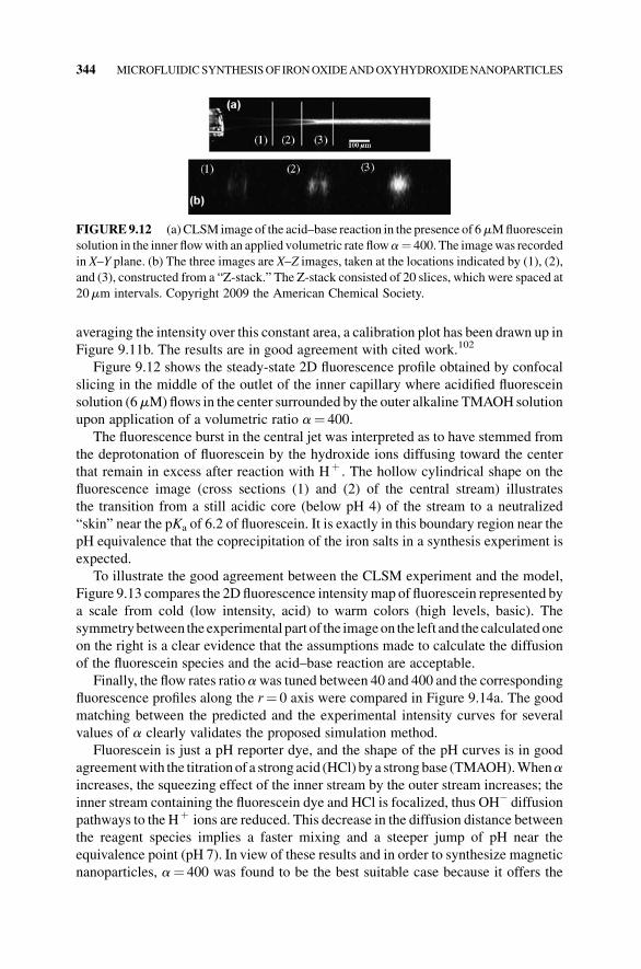
averaging the intensity over this constant area, a calibration plot has been drawn up in
Figure 9.11b. The results are in good agreement with cited work.102
Figure 9.12 shows the steady-state 2D fluorescence profile obtained by confocal
slicing in the middle of the outlet of the inner capillary where acidified fluorescein
solution (6mM)flows in the center surrounded by the outer alkaline TMAOH solution
upon application of a volumetric ratio a¼ 400.
The fluorescence burst in the central jet was interpreted as to have stemmed from
the deprotonation of fluorescein by the hydroxide ions diffusing toward the center
that remain in excess after reaction with Hþ . The hollow cylindrical shape on the
fluorescence image (cross sections (1) and (2) of the central stream) illustrates
the transition from a still acidic core (below pH 4) of the stream to a neutralized
“skin” near the pKa of 6.2 of fluorescein. It is exactly in this boundary region near the
pH equivalence that the coprecipitation of the iron salts in a synthesis experiment is
expected.
To illustrate the good agreement between the CLSM experiment and the model,
Figure 9.13 compares the 2Dfluorescence intensitymap of fluorescein represented by
a scale from cold (low intensity, acid) to warm colors (high levels, basic). The
symmetrybetween the experimental part of the imageon the left and thecalculatedone
on the right is a clear evidence that the assumptions made to calculate the diffusion
of the fluorescein species and the acid–base reaction are acceptable.
Finally, the flow rates ratioawas tuned between 40 and 400 and the corresponding
fluorescence profiles along the r¼ 0 axis were compared in Figure 9.14a. The good
matching between the predicted and the experimental intensity curves for several
values of a clearly validates the proposed simulation method.
Fluorescein is just a pH reporter dye, and the shape of the pH curves is in good
agreementwith the titrationof a strong acid (HCl) by a strongbase (TMAOH).Whenaincreases, the squeezing effect of the inner stream by the outer stream increases; the
inner stream containing the fluorescein dye and HCl is focalized, thus OH� diffusion
pathways to the Hþ ions are reduced. This decrease in the diffusion distance between
the reagent species implies a faster mixing and a steeper jump of pH near the
equivalence point (pH 7). In view of these results and in order to synthesize magnetic
nanoparticles, a¼ 400 was found to be the best suitable case because it offers the
FIGURE9.12 (a) CLSM image of the acid–base reaction in the presence of 6mMfluorescein
solution in the inner flowwith an applied volumetric rate flowa¼ 400. The imagewas recorded
in X–Y plane. (b) The three images are X–Z images, taken at the locations indicated by (1), (2),
and (3), constructed from a “Z-stack.” The Z-stack consisted of 20 slices, which were spaced at
20mm intervals. Copyright 2009 the American Chemical Society.
344 MICROFLUIDICSYNTHESISOF IRONOXIDEANDOXYHYDROXIDENANOPARTICLES

advantage of a fast mixing and a sharp pH jump. The choices a¼ 80 and 40 would
lead to a decrease in the yield in magnetic nanoparticles due to the precipitation of
antiferromagnetic iron hydroxides. These results were used for the preparation of the
stable colloidal and magnetic nanoparticles reported in our work1 using the coaxial-
flow microreactor and that will be resumed in the next section.
Application for the Synthesis of g-Fe2O3 Nanoparticles For nanoparticle synthesis
experiments, the inner solutionwas amixtureof iron saltswith a total ferric and ferrous
salt concentration of c¼ 10�2mol L�1 and amolar ratio Fe(II)/Fe(III) of 0.5, prepared
by mixing FeCl3 and “fresh” FeCl2�4H2O salts in diluted and degassed hydrochloric
acid (pH 0.10). The outer flow was an alkaline solution of tetramethylammonium
(TMAOH,0.172mol L�1),whichwas injectedwith an outer volumetric rate flowQout.
The reaction was “quenched” by fast solvent extraction (using didodecyl dimethyl
ammonium bromide in cyclohexane) to prevent any aging of the nanoparticles in the
aqueous solution.
The suspensions obtained in cyclohexanewere always stable and the nanoparticles
produced in the channel were fairly spherical with an average size around 7 nm. The
evidence of their crystallinity was provided by the electronmicrodiffraction pattern in
the inset of Figure 9.15, which shows the presence of the maghemite phase g-Fe2O3.
Although suspensions obtained in cyclohexanewere stable in a zeromagnetic field,
they sediment in the presence of amagnetic field gradient (e.g., on a strong permanent
FIGURE9.13 Comparison of the experimental and predicted fluorescence intensities inX–Y
plane with (a) the left half-plane representing the experimental fluorescence intensity and (b)
the right half-plane with the predicted fluorescence intensity for a¼ 400. Copyright 2009 the
American Chemical Society.
MICROFLUIDIC SYNTHESIS OF IRON OXYHYDROXIDE NANOPARTICLES 345

magnet), which suggests a magnetic character. This observation was confirmed by
magnetization measurements (using a vibrating sample magnetometer) on a stable
unquenched (aqueous) suspension: the magnetization curve (Figure 9.16) followed
the Langevin law typical of superparamagnetism, calculated for an assembly of
nanoparticles with a rather narrow distribution of diameters fitted by a log-normal law
of parameters d0¼ 6 nm and s¼ 0.2.
Bymeasuring both the volume fraction of nanoparticles f¼ 5.7� 10�5 (from iron
titration by atomic spectroscopy) and the saturation magnetizationMsat¼ 7.9Am�1
for the suspension, the specific magnetization of the materials was deduced ms¼Msat/f¼ 1.4� 105Am�1, which is much below the bulk value ofmaghemite g-Fe2O3
(3.5� 105Am�1), but not so far from thems value of about 2.6� 105Am�1 usually
obtained for nanoparticles of approximately the same sizes preparedwith the standard
large-scale synthesis. Therefore, it can be deduced that nanoparticles prepared within
few seconds in a millifluidic channel exhibit only a small decrease in ordering of their
magnetic moments compared to particles obtained within about 30min in bulk.
FIGURE 9.14 (a) Evolution of the experimental fluorescence profiles (&) when a¼ 40, 80,
and 400 along the symmetry axis (r¼ 0). The lines represent the predicted fluorescence
intensities calculated for each case from the simulated F2� concentrations. (b) Simulated pH
profiles along the symmetry axis (r¼ 0) for a¼ 40, 80, and 400. Copyright 2009 the American
Chemical Society.
346 MICROFLUIDICSYNTHESISOF IRONOXIDEANDOXYHYDROXIDENANOPARTICLES

FIGURE 9.15 TEM image of nanoparticles prepared in the channel (for flow rates
Qin¼ 100mLmin�1 and Qout¼ 400mLmin�1). The inset shows the electron microdiffraction
pattern with the Miller indices of g-Fe2O3. Reprinted with permission from Ref. 1. Copyright
2008 the Royal Society of Chemistry.
FIGURE9.16 Magnetization curve of a stable suspension inwater of nanoparticles produced
in the millifluidic device. The inset curves represent the fitting log-normal laws for the number
distribution (solid line) and the volume distribution (dotted line) of diameters. Reprinted with
permission from Ref. 1. Copyright 2008 the Royal Society of Chemistry.
MICROFLUIDIC SYNTHESIS OF IRON OXYHYDROXIDE NANOPARTICLES 347
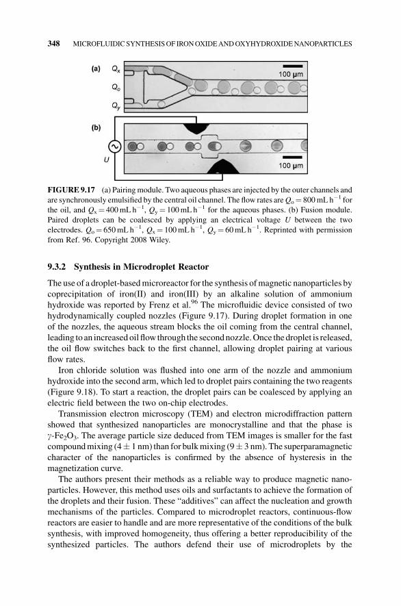
9.3.2 Synthesis in Microdroplet Reactor
The use of a droplet-basedmicroreactor for the synthesis ofmagnetic nanoparticles by
coprecipitation of iron(II) and iron(III) by an alkaline solution of ammonium
hydroxide was reported by Frenz et al.96 The microfluidic device consisted of two
hydrodynamically coupled nozzles (Figure 9.17). During droplet formation in one
of the nozzles, the aqueous stream blocks the oil coming from the central channel,
leading to an increased oil flow through the secondnozzle.Once thedroplet is released,
the oil flow switches back to the first channel, allowing droplet pairing at various
flow rates.
Iron chloride solution was flushed into one arm of the nozzle and ammonium
hydroxide into the second arm, which led to droplet pairs containing the two reagents
(Figure 9.18). To start a reaction, the droplet pairs can be coalesced by applying an
electric field between the two on-chip electrodes.
Transmission electron microscopy (TEM) and electron microdiffraction pattern
showed that synthesized nanoparticles are monocrystalline and that the phase is
g-Fe2O3. The average particle size deduced from TEM images is smaller for the fast
compoundmixing (4� 1 nm) than for bulkmixing (9� 3 nm). The superparamagnetic
character of the nanoparticles is confirmed by the absence of hysteresis in the
magnetization curve.
The authors present their methods as a reliable way to produce magnetic nano-
particles. However, this method uses oils and surfactants to achieve the formation of
the droplets and their fusion. These “additives” can affect the nucleation and growth
mechanisms of the particles. Compared to microdroplet reactors, continuous-flow
reactors are easier to handle and are more representative of the conditions of the bulk
synthesis, with improved homogeneity, thus offering a better reproducibility of the
synthesized particles. The authors defend their use of microdroplets by the
FIGURE9.17 (a) Pairingmodule. Two aqueous phases are injected by the outer channels and
are synchronously emulsified by the central oil channel. The flow rates areQo¼ 800mLh�1 for
the oil, and Qx¼ 400mLh�1, Qy¼ 100mLh�1 for the aqueous phases. (b) Fusion module.
Paired droplets can be coalesced by applying an electrical voltage U between the two
electrodes. Qo¼ 650mLh�1, Qx¼ 100mLh�1, Qy¼ 60mLh�1. Reprinted with permission
from Ref. 96. Copyright 2008 Wiley.
348 MICROFLUIDICSYNTHESISOF IRONOXIDEANDOXYHYDROXIDENANOPARTICLES

enhancement inmixingby convectionand thedecrease in the reagent dispersion due to
the droplets that act as spatially isolatedmicroreactors. This concept is in fact the same
as the one evoked for the synthesis of nanoparticles inside vesicles or microemul-
sions.93–95 The faster mixing time reported in this system is 2ms, which is far larger
than the nucleation time. Moreover, this time is difficult to define as it is totally
arbitrary and depends on the concentration of reagents.
9.3.3 Synthesis of a-FeOOH Nanoparticles in Microfluidic Reactors
Another interesting iron oxyhydroxide phase is goethite (a-FeOOH), which is widelyfound in iron-rich soils.35 This claymineral constitutes the natural ochre pigment, and
because of its elongated shape, synthetic goethite is often used as a precursor of a-Fe“hard magnet” particles for magnetic recording.103 Because of this elongated shape,
suspensions of antiferromagnetic goethite/plate-like nanostructures (nanolaths) ex-
hibit an original magneto-optical effect and spontaneously self-assemble into a
nematic liquid–crystal phase above a threshold concentration.104 The importance
of particle shape for the improvement of magnetic properties, or the control of the
particle assembly, requires control of the synthetic conditions of these particles.105
The bulk methods reported for the synthesis of acicular (needle-like) goethite
particles are based on the agingof ferrihydrite nanoparticles obtainedbyalkalinization
of iron(III) salt solutions.106 They are indeed easily transferable to microfluidic
devices as illustrated by Abou-Hassan et al.97
FIGURE 9.18 Characterization of the iron oxide particles produced. (a) TEM image of the
nanoparticles. Inset: HRTEM image of a particle showing (220) spinel planes. (b) Electron
diffraction pattern indicating different planes of the spinel structure. (c) Magnetization M/Ms
(Ms is the saturation magnetization) as a function of the magnetic field H. Reprinted with
permission from Ref. 96. Copyright 2008 Wiley.
MICROFLUIDIC SYNTHESIS OF IRON OXYHYDROXIDE NANOPARTICLES 349

As discussed earlier, the alkalinization at room temperature of a solution of ferric
salts byanalkaline solution leads to theprecipitationof anamorphousoxidehydroxide
precipitate of ferrihydrite. At its minimum of the solubility, ferrihydrite can evolve to
hematite through an internal dehydration process, while in high-solubility domains
(very acidic or very alkaline solutions), the transformation via a dissolution–preci-
pitation mechanism is possible and leads to the formation of goethite. Goethite is the
most thermodynamically stable phase, but due to the low solubility of iron oxides, the
transformation into goethite is very slow, offering the possibility of a good separation
between nucleation and growth. Another possible mechanism for the formation of
goethite nanoparticles is the oriented attachment of iso-oriented ferrihydrite nano-
particles and then crystallization into goethite nanoparticles.107
Acomplexmicrofluidic device (Figure 9.19)was proposedbyAbou-Hassan et al.97
in order to physically separate the process of nucleation of the ferrihydrite nanopar-
ticles from their growth, leading to goethite particles. The nucleation of the primary
ferrihydrite nanoparticles is induced by diffusive mixing at room temperature in a
microreactor that is based on coaxial-flow geometry (R1). This mixing reactor is the
same as described for the synthesis of magnetic nanoparticles and is based on a three-
dimensional coaxial-flow device of two streaming reagents. At the outlet of this
micromixer, the suspended ferrihydrite nanoparticles are directly injected into the
microtubular aging coil R2,which consists of a transparent PTFE tube of 1.7mm inner
diameter and 150 cm total length continuously heated in a water bath at 60�C.Temperature profiles were calculated to determine the tubing length (and thus the
time) required for thefluid to reach a steady state.At the outlet ofR1 (before aging) and
FIGURE 9.19 The experimental setup used for the preparation of the ferrihydrite and
goethite nanoparticles. TMAOH¼ tetramethylammonium hydroxide. Reprinted with permis-
sion from Ref. 97. Copyright 2009 Wiley.
350 MICROFLUIDICSYNTHESISOF IRONOXIDEANDOXYHYDROXIDENANOPARTICLES

R2 (after aging), the resulting suspension is collected and analyzed by TEM and by
high-resolution TEM (HRTEM).
TEM pictures of the particles obtained after R1 show well-defined spherical
ferrihydrite nanoparticles (nanodots) about 4� 1 nm in size (Figure 9.20a).
HRTEM measurements (Figure 9.20b) show that the nanoparticles are monocrystal-
line, exhibiting atomic planes with an interplanar distance of about 2.5A�, which is
consistent with ferrihydrite nanoparticles.
Under the givenflow rate, the ferrihydrite solution reaches 60�C in about 1 s, that is,
within the first centimeter after it has entered the heated zone of the tubing. The
effective residence time is about 15min, as estimated from the length of the tubing
along which the fluid has reached the stationary temperature of 60�C.After aging for 15min under continuous flow in the aging coil R2, goethite plate-
like nanostructures were observed with an average length L¼ 30� 17 nm and width
w¼ 7� 4 nm (Figure 9.21a). This short aging time appeared to be sufficient for the
growth of crystalline and anisotropic goethite nanoparticles that differ only in smaller
sizes compared to those obtained after complete aging (1 day at 60�C).108
Moreover, the presence of few remaining ferrihydrite nuclei undergoing aggrega-
tion in the batch after 15min and even after 24 h at 60�C (data not shown) supports the
idea that goethite nanoparticles were formed by the aggregation mechanism rather
than by dissolution/reprecipitation.
Thus, the use ofmicrofluidic device allows to significantly accelerate the synthesis
of goethite nanoparticles from ferrihydrite nuclei. The novelty of this approach lies in
the separation of the nucleation of the primary particles (ferrihydrite) and the growth
of the goethite nanoparticles in two independent microreactors operating in different
conditions. In the nucleation microreactor, the streaming reagents are mixed by
molecular diffusion at room temperature in a flow-focusing geometry. The homoge-
neity of the mixture is ensured by the fast mixing time and the technical difficulty of
microchannel clogging owing to the fact that precipitation onto the walls is avoided
FIGURE 9.20 (a) TEM picture of the sample taken after precipitation in the microreactor R1
(before aging), showing ferrihydrite nuclei of 4� 1 nm diameter. The selected area diffraction
pattern (inset) is typical of two-line ferrihydrite. (b)HRTEM image of an individual ferrihydrite
nanoparticle with a 2.5A�lattice fringe. Reprinted with permission from Ref. 97. Copyright
2009 Wiley.
MICROFLUIDIC SYNTHESIS OF IRON OXYHYDROXIDE NANOPARTICLES 351

by 3D geometry. The use of a microfluidic device for aging, by minimizing local
temperature gradients, ensures a regular laminar flow, and finally leads to crystalline
plate-like nanostructures. These particles have approximately the same values of
aspect ratio and polydispersity index as those obtained in bulk synthesis (bulk
synthesis usually yields goethite nanoparticles with a typical length of about
250 nm and a width of 40 nm, with a polydispersity index of about 50% for both
dimensions109) but are smaller in size. The time required for aging decreases to 15min
(for a velocity of 0.1 cm s�1) compared to bulk synthesis (several hours or days). This
may originate from the small diameter of the aging reactor, causing a shear stress
that prealigns the primary ferrihydrite nanoparticles and speeds up their oriented
aggregation process.
9.4 PERSPECTIVES
Among all the ferric oxide nanoparticles, superparamagnetic ones (superparamag-
netic iron oxide nanoparticles, SPIONs) are of special interest because of their
applications in the field of imagery and therapy. At present, the screening of the
relation properties/structure is neither very easy nor economic in bulk, and continuous
microfluidic systems, enabling to add reagents along the entire length of the channel,
can be a very useful tool for screening the different parameters (size, surface
functionalization, and aggregation) allowing to optimize given properties. This
idea is illustrated in Figure 9.22 and can be summarized by three operations: adding,
mixing, and reacting.
Indeed, if several microreactors Ri are associated to form a series of microunit
operations, the synthesis ofSPIONnanoparticles and their surfacemodificationwould
FIGURE 9.21 (a) TEM image of the nanolaths after aging for 15min in the microtubular
loop R2, produced at pH 13 and under laminar flow. (b) HRTEM image of a nanorod particle.
Lattice fringe spacing is consistent with goethite. The dashed lines serve to highlight the
morphology and texture of the particle. Reprinted with permission from Ref. 97. Copyright
2009 Wiley.
352 MICROFLUIDICSYNTHESISOF IRONOXIDEANDOXYHYDROXIDENANOPARTICLES

be possible in an unique online process. The surface coating of the SPIONs by silica is
a good example. Silica has been extensively exploited as a coating material for
magnetic nanoparticles110–112 in order to get a protective, biocompatible, inert, and
hydrophilic surface with excellent anchoring points for derivatizing molecules.113
Several methods have been reported in the literature for the formation of super-
paramagnetic iron oxide silica nanocomposites including reactions performed under
St€ober conditions,114,115 microemulsions,116 emulsions,117 and aerosol pyrolysis.118
It seems that core–shell SPION silica nanoparticles and SPION luminescent silica
nanoparticles canbeobtained inmicrofluidic reactorswithout theuse of anysurfactant
(Abou-Hassan, unpublished results).
In the field of on-chip magnetic separation, there were many works devoted to the
separation of micrometric magnetic particles, but to date no separation of nanometric
particles on the microfluidic scale has been reported.119 A continuous-flow method
capable of both separating magnetic from nonmagnetic particles and separating
different magnetic particles from each other can be very helpful in synthetic
chemistry.
But the most important challenge in the field of nanomaterials� synthesis in
microfluidic lies in developing online characterization methods. For quantum
dots or metallic nanoparticles, optical characterizations allowing establishment of
a simple relation with particle size are available. That is not the case for ferric oxide
nanoparticles. As the latter have magnetic properties, online magnetic measurements
can perhaps be designed.On the samekind of idea, but of course generally for anykind
of materials, online characterizations using small-angle X-ray or neutron scattering
have to be developed. These are thus important in designing online nanoparticle
characterization techniques.
FIGURE 9.22 Cartoon illustrating the idea of online synthesis of functional nanomaterials.
PERSPECTIVES 353

REFERENCES
1. Abou-Hassan,A.; Sandre,O.;Cabuil,V.; Tabeling, P. Synthesis of iron oxide nanoparticles
in a microfluidic device: preliminary results in a coaxial flow millichannel. Chem
Commun. 2008, 1783.
2. http://marsrover.nasa.gov/.
3. Cornell, R.M.; Schwertmann, U. The Iron Oxides: Structure, Properties, Reactions,
Occurrences and Uses, Wiley-VCH: 2003.
4. Dormann, J.L.; Firoani, D. Magnetic Properties of Fine Particles, Amsterdam: North-
Holland, 1992.
5. Eisenmenger, J.; Schuller, I.K.Magnetic nanostructures: overcoming thermal fluctuations.
Nat Mater. 2003, 2, 437.
6. Ferrucci, J.T.; Stark, D.D. Iron oxide-enhancedMR imaging of the liver and spleen: review
of the first 5 years. Am J. Roentgenol. 1990, 155, 943.
7. Sun, S.; Murray, C.B.; Weller, D.; Folks, L.; Moser, A. Monodisperse FePt nanoparticles
and ferromagnetic FePt nanocrystal superlattices. Science 2000, 287, 1989.
8. Miller, M.M.; Prinz, G.A.; Cheng, S.F.; Bounnak, S. Detection of amicron-sized magnetic
sphere using a ring-shaped anisotropic magnetoresistance-based sensor: a model for a
magnetoresistance-based biosensor. Appl Phys. Lett. 2002, 81, 2211.
9. Chourpa, I.; Douziech-Eyrolles, L.; Ngaboni-Okassa, L.; Fouquenet, J.F.; Cohen-
Jonathan, S.; Souce, M.; Marchais, H.; Dubois, P. Molecular composition of iron oxide
nanoparticles, precursors formagnetic drug targeting, as characterized by confocal Raman
microspectroscopy. Analyst 2005, 130, 1395.
10. Martina,M.S.;Fortin,J.P.;Menager,C.;Clement,O.;Barratt,G.;Grabielle-Madelmont,C.;
Gazeau, F.; Cabuil, V.; Lesieur, S. Generation of superparamagnetic liposomes revealed as
highlyefficientMRIcontrastagents for invivo imaging.JAm.Chem.Soc.2005,127, 10676.
11. Massart, R.;French Patent 79-188-42, 1979.
12. Massart, R. Preparation of aqueous magnetic liquids in alkaline and acidic media. IEEE
Trans. Magn. 1981, 17, 1247.
13. Massart, R.; Cabuil, V. Synth�ese en milieu alcalin de magn�etite collo€ıdale: controle durendement et de la taille des particules. J. Chim. Phys. 1987, 7, 84.
14. Massart, R.; Dubois, E.; Cabuil, V.; Hasmonay, E. Preparation and properties of
monodisperse magnetic fluids. J Magn. Magn. Mater. 1995, 149, 1.
15. Jolivet, J.-P.; Chaneac, C.; Tronc, E. Iron oxide chemistry. From molecular clusters to
extended solid networks. Chem. Commun. 2004, 481.
16. Nielsen, A.E.; Kinetics of Precipitation, Oxford: 1964.
17. Baes, C.F.; Mesmer, R.E. The Hydrolysis of Cations, Wiley: New York, 1976.
18. Jolivet, J.P.Metal Oxide Chemistry and Synthesis. From Solution to Solid State, Wiley:
Chichester, 2000.
19. Jolivet, J.P.; De la solution �a l�oxyde, EDP Sciences: 1998.
20. Kashciev,D.NucleationBasic Theorywith Applications; Butterworth-Heinemann; 2000.
21. LaMer, V.K.; Dinegar, R.H. Theory, production and mechanism of formation of mono-
dispersed hydrosols. J Am. Chem. Soc 1950, 72, 4847.
22. KerKer, M.; LaMer, V.K. Particle size distribution in sulfur hydrosols by polarimetric
analysis of scattered light. J. Am. Chem. Soc 1950, 72, 3516.
354 MICROFLUIDICSYNTHESISOF IRONOXIDEANDOXYHYDROXIDENANOPARTICLES

23. deMello, A.J.; deMello, J.C. Microscale reactors: nanoscale products. Lab Chip 2004,
4, 11N.
24. Zhang, Q.; Liu, S.-J.; Yu, S.-H. Recent advances in oriented attachment growth and
synthesis of functional materials: concept, evidence, mechanism, and future. J Mater.
Chem. 2009, 19, 191.
25. Barker, A.J.; Cage, B.; Russek, S.; Stoldt, C. Ripening during magnetite nanoparticle
synthesis: resulting interfacial defects and magnetic properties. J Appl. Phys. 2005, 98,
063528.
26. Sugimoto, T. Preparation of monodispersed colloidal particles.Adv Colloid Interface Sci.
1987, 28, 65.
27. Kabalnov, A.S.; Shchukin, E.D. Ostwald ripening theory: applications to fluorocarbon
emulsion stability. Adv Colloid Interface Sci. 1992, 38, 69.
28. Talapin, D.V.; Rogach, A.L.; Haase, M.; Weller, H. Evolution of an ensemble of
nanoparticles in a colloidal solution: theoretical study. J Phys. Chem. B. 2001, 105, 12278.
29. Borg, R.; Dienes, G.; The Physical Chemistry of Solids, Academic Press: Boston, MA,
1992.
30. C€olfen, H.; Mann, S. Higher-order organization by mesoscale self-assembly and trans-
formation of hybrid nanostructures. Angew. Chem., Int. Ed. 2003, 42, 2350.
31. Gilbert, B.; Zhang, H.; Huang, F.; Finnegan, M.; Waychunas, G.; Banfield, J. Special
phase transformation and crystal growth pathways observed in nanoparticles. Geochem
Trans. 2003, 4, 20.
32. Penn, R.L.; Banfield, J.F.Morphology development and crystal growth in nanocrystalline
aggregates under hydrothermal conditions: insights from titania. Geochem Cosmochim.
Acta 1999, 63, 1549.
33. Penn, R.L.; Banfield, J.F. Oriented attachment and growth, twinning, polytypism, and
formationofmetastablephase: insightsfromnanocrystallineTiO2.AmMiner.1998,83,1077.
34. Oskam, G.; Hu, Z.; Penn, R.L.; Pesika, N.; Searson, P.C. Coarsening of metal oxide
nanoparticles. Phys Rev. E 2002, 66, 11403.
35. Banfield, J.F.; Welch, S.A.; Zhang, H.; Ebert, T.T.; Penn, R.L. Aggregation-based crystal
growth and microstructure development in natural iron oxyhydroxide biomineralization
products. Science 2000, 289, 751.
36. Watzky, M.A.; Finke, R.G. Transition metal nanocluster formation kinetic and mecha-
nistic studies. A new mechanism when hydrogen is the reductant: slow, continuous
nucleation and fast autocatalytic surface growth. J. Am. Chem. Soc. 1997, 119, 10382.
37. Turkevich, J.; Stevenson, P.C.; Hillier, J. A study of the nucleation and growth processes
in the synthesis of colloidal gold. Discuss Faraday Soc. 1951, 11, 55.
38. Matijevic,E.Preparationandpropertiesofuniformsizecolloids.ChemMater.1993,5,412.
39. Overbeek, J.Th.G. Monodisperse colloidal systems, fascinating and useful. Adv Colloid
Interface Sci. 1982, 15, 251.
40. Salmon, J.-B.; Dubrocq, C.; Tabeling, P.; Charier, S.; Alcor, D.; Jullien, L.; Ferrage, F. An
approach to extract rate constants from reaction–diffusion dynamics in a microchannel.
Anal Chem. 2005, 77, 3417.
41. Sounart, T.L.; Safier, P.A.; Voigt, J.A.; Hoyt, J.; Tallant, D.R.; Matzke, C.M.; Michalske,
T.A. Spatially-resolved analysis of nanoparticle nucleation and growth in a microfluidic
reactor. Lab Chip 2007, 7, 908.
REFERENCES 355

42. Knight, J.B.; Vishwanath, A.; Brody, J.P.; Austin, R.H. Hydrodynamic focusing on a
silicon chip: mixing nanoliters in microseconds. Phys Rev. Lett. 1998, 80, 3863.
43. Cabuil, V.; Massart, R.; Bacri, J.C.; Perzynski, R.; Salin, D. Ionic ferrofluids: towards
fractional distillation. J Chem. Res. 1987, S, 130.
44. Fauconnier, N.; Pons, J.N.; Roger, J.; Bee, A. Thiolation of maghemite nanoparticles by
dimercaptosuccinic acid. J Colloid Interface Sci. 1997, 194, 427.
45. Bee, A.; Massart, R.; Neveu, S. Synthesis of very fine maghemite particles. J Magn.
Magn. Mater. 1995, 149, 6.
46. Neveu-Prin, S.; Cabuil, V.; Massart, R.; Escaffre, P.; Dussaud, J. Encapsulation of
magnetic fluids. J Magn. Magn. Mater. 1993, 122, 42.
47. Biddlecombe, G.B.; Gun�ko, Y.K.; Kelly, J.M.; Pillai, S.C.; Coey, J.M.D.; Venkatesan,
M.; Douvalis, A.P. Preparation of magnetic nanoparticles and their assemblies using a
new Fe(II) alkoxide precursor. J Mater. Chem. 2001, 11, 2937.
48. Wan, J.; Cai, W.; Feng, J.; Meng, X.; Liu, E. In situ decoration of carbon nanotubes with
nearly monodisperse magnetite nanoparticles in liquid polyols. J Mater. Chem. 2007,
17, 1188.
49. Kimata, M.; Nakagawa, D.; Hasegawa, M. Preparation of monodisperse magnetic
particles by hydrolysis of iron alkoxide. Powder Technol. 2003, 132, 112.
50. Chin, A.B.; Yaacob, I.I. Synthesis and characterization of magnetic iron oxide nano-
particles via w/o microemulsion and Massart�s procedure. J Mater. Process. Technol.
2007, 191, 235.
51. Salazar-Alvarez, G.; Muhammed, M.; Zagorodni, A.A. Novel flow injection synthesis
of iron oxide nanoparticles with narrow size distribution. Chem Eng. Sci. 2006, 61,
4625.
52. Basak, S.; Chen, D.R.; Biswas, P. Electrospray of ionic precursor solutions to synthesize
iron oxide nanoparticles: modified scaling law. Chem Eng. Sci. 2007, 62, 1263.
53. Bell, A.; Matijevic, E. Growth mechanism of hydrous chromium(III) oxide spherical
particles of narrow size distribution. J Phys. Chem. 1974, 78, 2621.
54. Jolivet, J.P.; Froidefond, C.; Pottier, A.; Chan�eac, C.; Cassaignon, S.; Tronc, E.; Euzen, P.Size tailoring of oxide nanoparticles by precipitation in aqueous medium. A semi-
quantitative modelling. J. Mater. Chem. 2004, 14, 3281.
55. Vayssi�eres, L.; Chan�eac, C.; Tronc, E.; Jolivet, J.P. Size tailoring of magnetite particles
formed by aqueous precipitation: an example of thermodynamic stability of nanometric
oxide particles. J Colloid Interface Sci. 1998, 205, 205.
56. Jolivet, J.P.; Belleville, P.; Tronc, E.; Livage, J. Influence of Fe(II) on the formation of the
spinel iron oxide in alkaline medium. Clays Clay Miner. 1992, 40, 531.
57. Jolivet, J.P.; Vayssi�eres, L.; Chan�eac, C.; Tronc, E. Synthesis of iron oxide-based
magnetic nanomaterials and composites. Mater Res. Symp. Proc. 1997, 432, 145.
58. Jolivet, J.P.; Chan�eac, C.; Tronc, E. Synthesis of iron oxide-basedmagnetic nanomaterials
and composites. Comp. Rend. Series 2002, 5, 659.
59. Babes, L.; Denizot, B.; Tanguy, G.; Le Jeune, J.J.; Jallet, P. Synthesis of iron oxide
nanoparticles used as MRI contrast agents: a parametric study. J. Colloid Interface. Sci.
1999, 212, 474.
60. Fauconnier, N.; Bee, A.; Roger, J.; Pons, J.N. Adsorption of gluconic and citric acids on
maghemite particles in aqueous medium. Prog Colloid Polym. Sci. 1996, 100, 212.
356 MICROFLUIDICSYNTHESISOF IRONOXIDEANDOXYHYDROXIDENANOPARTICLES

61. Fauconnier, N.; Bee, A.; Roger, J.; Pons, J.N. Synthesis of aqueous magnetic liquids by
surface complexation of maghemite nanoparticles. J Mol. Liq. 1999, 83, 233.
62. Roger, J.; Pons, J.N.; Massart, R.; Halbreich, A.; Bacri, J.C. Some biomedical applica-
tions of ferrofluids. Eur Phys. J. Appl. Phys. 1999, 5, 321.
63. Denizot, B.; Tanguy, G.; Hindre, F.; Rump, E.; LeJeune, J.J.; Jallet, P. Phosphorylcholine
coating of iron oxide nanoparticles. J Colloid Interface Sci. 1999, 209, 66.
64. Fauconnier, N.; B�ee, A.; Roger, J.; Pons, J.N. Synthesis of aqueous magnetic liquids by
surface complexation of maghemite nanoparticles. J Mol. Liq. 1999, 83, 233.
65. Liu, C.; Huang, P.M. Atomic force microscopy and surface characteristics of iron oxides
formed in citrate solutions. Soil Sci Soc. Am. J. 1999, 63, 65.
66. Tremaine, P.R.; LeBlanc, J.C. The solubility of magnetite and the hydrolysis and
oxidation of Fe2þ in water to 300�C. J Sol. Chem. 1980, 9, 415.
67. Sweeton, F.H.; Baes, C.F. The solubility of magnetite and hydrolysis of ferrous ion in
aqueous solutions at elevated temperatures. J Chem. Thermodyn. 1970, 2, 479.
68. Hyeon, T.; Lee, S.S.; Park, J.; Chung, Y.; Na, H.B. Synthesis of highly crystalline and
monodisperse maghemite nanocrystallites without a size-selection process. J Am. Chem.
Soc. 2001, 123, 12798.
69. Sun, S.; Zeng, H. Size-controlled synthesis of magnetite nanoparticles. J Am. Chem. Soc.
2002, 124, 8204.
70. Jana, N.R.; Chen, Y.; Peng, X. Size- and shape-controlledmagnetic (Cr,Mn, Fe, Co, Ni)
oxide nanocrystals via a simple and general approach. Chem. Mater. 2004, 16,
3931.
71. Park, J.; An,K.;Hwang,Y.; Park, J.-G.;Noh,H.-J.; Kim, J.-Y.; Park, J.-H.;Hwang,N.-M.;
Hyeon, T. Ultra-large-scale syntheses of monodisperse nanocrystals. Nat Mater. 2004,
3, 891.
72. Tartaj, P.; Serna, C.J. Synthesis of monodisperse superparamagnetic Fe/silica nano-
spherical composites. J Am. Chem. Soc. 2003, 125, 15754.
73. Sato, S.;Murakata, T.; Yanagi, H.;Miyasaka, F.; Iwaya, S. Hydrothermal synthesis of fine
perovskite PbTiO3 powders with a simple mode of size distribution. J Mater. Sci. 1994,
29, 5657.
74. J�ez�equel, D.; Guenot, J.; Jouini, N.; Fie�evet, F. Submicrometer zinc oxide particles:
elaboration in polyol medium and morphological characteristics. J. Mater. Res. 1995,
10, 77.
75. Feldmann, C.; Jungk, H.-O. Polyol-mediated preparation of nanoscale oxide particles.
Angew. Chem., Int. Ed. 2001, 40, 359.
76. Tzitzios, V.K.; Petridis, D.; Zafiropoulou, I.; Hadjipanayis, G.; Niarchos, D. Synthesis
and characterization of L10 FePt nanoparticles from Pt–Fe3O4 core–shell nanoparticles.
J Magn. Magn. Mater. 2005, 294, e95.
77. Chow, G.M.; Kurihara, L.K.; Kemner, K.M.; Schoen, P.E.; Elam,W.T.; Ervin, A.; Keller,
S.; Zhang, Y.D.; Budnick, J.; Ambrose, T. Structural, morphological, and magnetic study
of nanocrystalline cobalt–copper powders synthesized by the polyol process. J Mater.
Res. 1995, 10, 1546.
78. Viau, G.; Ravel, F.; Acher, O.; Fivet-Vincent, F.; Fivet, F. Preparation and microwave
characterization of spherical and monodisperse Co20Ni80 particles. J. Appl. Phys. 1994,
76, 6570.
REFERENCES 357

79. Viau, G.; Ravel, F.; Acher, O.; Fivet-Vincent, F.; Fivet, F. Preparation and microwave
characterization of spherical and monodisperse Co–Ni particles. J Magn. Magn. Mater.
1995, 140, 377.
80. Viau, G.; Fivet-Vincent, F.; Fivet, F. Nucleation and growth of bimetallic CoNi and FeNi
monodisperse particles prepared in polyols. Solid State Ionics 1996, 84, 259.
81. Mercier, D.; Lvy, J.C.S.; Viau, G.; Fivet-Vincent, F.; Fivet, F.; Toneguzzo, P.; Acher, O.
Magnetic resonance in spherical Co–Ni and Fe–Co–Ni particles. Phys. Rev. B: Condens.
Matter 2000, 62, 532.
82. Feldmann, C. Preparation of nanoscale pigment particles. Adv Mater. 2001, 13, 1301.
83. Giri, A.K.; Chowdary, K.M.; Majetich, S.A. ACmagnetic properties of compacted FeCo
nanocomposites. Mater. Phys. Mech. 2000, 1, 1.
84. Cai, W.; Wan, J. Facile synthesis of superparamagnetic magnetite nanoparticles in liquid
polyols. J Colloid Interface Sci. 2007, 305, 366.
85. Joseyphus, R.J.; Kodama, D.; Matsumoto, T.; Sato, Y.; Jeyadevan, B.; Tohji, K. Role of
polyol in the synthesis of Fe particles. J. Magn. Magn. Mater. 2007, 310, 2393.
86. Caruntu, D.; Caruntu, G.; Chen, Y.; O�Connor, C.J.; Goloverda, G.; Kolesnichenko, V.L.Synthesis of variable-sized nanocrystals of Fe3O4 with high surface reactivity. Chem
Mater. 2004, 16, 5527.
87. Dresco, P.A.; Zaitsev, V.S.; Gambino, R.J.; Chu, B. Preparation and properties of
magnetite and polymer magnetite nanoparticles. Langmuir 1999, 15, 1945.
88. Santra, S.; Tapec, R.; Theodoropoulou, N.; Dobson, J.; Hebard, A.; Tan,W. Synthesis and
characterization of silica-coated iron oxide nanoparticles in microemulsion: the effect of
nonionic surfactants. Langmuir 2001, 17, 2900.
89. Meldrum, F.C.; Heywood, B.R.; Mann, S. Magnetoferritin: in vitro synthesis of a novel
magnetic protein. Science 1992, 257, 522.
90. Sangregorio, C.; Wieman, J.K.; Connor, C.O�.; Rosenzweig, Z. A new method for the
synthesis of magnetoliposomes. J Appl. Phys. 1999, 85, 5699.
91. Strable, E.; Bulte, J.W.M.; Moskowitz, B.; Vivekanandan, K.; Allen, M.; Douglas, T.
Synthesis and characterization of soluble iron oxide–dendrimer composites. Chem
Mater. 2001, 13, 2201.
92. Bonacchi, D.; Caneschi, A.; Dorignac, D.; Falqui, A.; Gatteschi, D.; Rovai, D.;
Sangregorio, C.; Sessoli, R. Nanosized iron oxide particles entrapped in pseudo-single
crystals of g-cyclodextrin. Chem Mater. 2004, 16, 2016.
93. Pileni, M.P.; Duxin, N. Micelle technology for magnetic nanosized alloys and compo-
sites. Chem Innov. 2000, 30, 25.
94. Inouye, K.; Endo, R.; Otsuka, Y.;Miyashiro, K.; Kaneko, K.; Ishikawa, T.Oxygenation of
ferrousionsinreversedmicelleandreversedmicroemulsion.JPhys.Chem.1982,86,1465.
95. Lee, Y.; Lee, J.; Bae, C.J.; Park, J.G.; Noh, H.J.; Park, J.H.; Hyeron, J.H. Large-scale
synthesis of uniform and crystalline magnetite nanoparticles using reverse micelles as
nanoreactors under reflux conditions. Adv Funct. Mater. 2005, 3, 503.
96. Frenz, L.; El-Harrak, A.; Pauly,M.; B�egin-Colin, S.; Griffiths, A.D.; Baret, J.-C. Droplet-based microreactors for the synthesis of magnetic iron oxide nanoparticles. Angew.
Chem., Int. Ed. 2008, 47, 6817.
97. Abou-Hassan, A.; Sandre, O.; Neveu, S.; Cabuil, V. Synthesis of goethite by separation of
the nucleation and growth processes of ferrihydrite nanoparticles using microfluidics.
Angew. Chem., Int. Ed. 2009, 48, 2342.
358 MICROFLUIDICSYNTHESISOF IRONOXIDEANDOXYHYDROXIDENANOPARTICLES

98. Andreev, V.P.; Koleshko, S.B.; Holman, D.A.; Scampavia, L.D.; Christian, G.D.
Hydrodynamics and mass transfer of the coaxial jet mixer in flow injection analysis.
Anal Chem. 1999, 71, 2199.
99. Scampavia, L.D.; Blankenstein, G.; Ruzicka, J.; Christian, G.D. A coaxial jet mixer for
rapid kinetic analysis in flow injection and flow injection cytometry. Anal Chem. 1995,
67, 2743.
100. Abou-Hassan, A.; Dufreche, J.F.; Sandre, O.; M�eriguet, G.; Bernard, O.; Cabuil, V.Confocal laser scanning microscopy for pH mapping in a coaxial flow microreactor:
application in the synthesis of superparamagnetic nanoparticles. J. Phys. Chem. C 2009,
113, 18097.
101. Kim, D.K.; Mikhaylova, M.; Zhang, Y.; Muhammed, M. Protective coating of super-
paramagnetic iron oxide nanoparticles. Chem Mater. 2003, 15, 1617.
102. Margulies, D.;Melman, G.; Shanzer, A. Fluorescein as amodelmolecular calculator with
reset capability. Nat Mater. 2005, 4, 768.
103. Nunez, N.O.; Morales, M.P.; Tartaj, P.; Serna, C.J. Preparation of high acicular and
uniform goethite particles by amodified-carbonate route. JMater. Chem. 2000, 10, 2561.
104. Vroege,G.J.; Thies-Weesie, D.M.E.; Petukhov,A.V.; Lemaire, B.J.; Davidson, P. Smectic
liquid-crystalline order in suspensions of highly polydisperse goethite nanorods. Adv.
Mater. 2006, 18, 2565.
105. Lemaire, B.J.; Davidson, P.; Ferr�e, J.; Jamet, J.P.; Petermann, D.; Panine, P.; Dozov, I.;
Jolivet, J.P. Physical properties of aqueous suspensions of goethite (a-FeOOH) nanorods.Part I. In the isotropic phase. Eur. Phys. J. E 2004, 13, 291.
106. Schwertmann, U.; Murad, E. Effect of pH on the formation of goethite and hematite from
ferrihydrite. Clays Clay Miner. 1983, 31, 277.
107. Penn, R.L.; Banfield, J.F. Imperfect oriented attachment: dislocation generation in defect-
free nanocrystals. Science 1998, 279, 1519.
108. Krehula, S.; Popovic, S.;Music, S. Synthesis of aciculara-FeOOHparticles at a very high
pH. Mater Lett. 2002, 54, 108.
109. Thies-Weesie, D.M.E.; de Hoog, J.P.; Hernandez Mendiola, M.H.; Petukhov, A.V.;
Vroege, G.J. Synthesis of goethite as a model colloid for mineral liquid crystals.
Chem Mater. 2007, 19, 5538.
110. Stjerndahl, M.; Andersson, M.; Hall, H.E.; Pajerowski, D.M.; Meisel, M.W.; Duran, R.S.
Superparamagnetic Fe3O4/SiO2 nanocomposites: enabling the tuning of both the iron
oxide load and the size of the nanoparticles. Langmuir 2008, 24, 3532.
111. Alcala, M.D.; Real, C. Synthesis based on the wet impregnation method and characteri-
zation of iron and iron oxide–silica nanocomposites. Solid State Ionics 2006, 177, 955.
112. Gushikem, Y.; Rosatto, S.S. Metal oxide thin films grafted on silica gel surfaces: recent
advances on the analytical applicationof thesematerials. JBraz.Chem. Soc.2001,12, 695.
113. Sharma, P.; Brown, S.; Walter, G.; Santra, S.; Moudgil, B. Nanoparticles for bioimaging.
Adv Colloid Interface Sci. 2006, 123, 471.
114. Barnakov, Y.A.; Yu, M.H.; Rosenzweig, Z. Manipulation of the magnetic properties of
magnetite–silica nanocomposite materials by controlled St€ober synthesis. Langmuir
2005, 21, 7524.
115. Deng, Y.H.; Wang, C.C.; Shen, X.Z.; Yang, W.L.; An, L.; Gao, H.; Fu, S.K. Preparation,
characterization, and application of multistimuli-responsive microspheres with fluores-
cence-labeled magnetic cores and thermoresponsive shells.Chem Eur. J. 2005, 11, 6006.
REFERENCES 359

116. Lu, A.H.; Salabas, E.L.; Schueth, F. Magnetic nanoparticles: synthesis, protection,
functionalization, and application. Angew. Chem., Int. Ed. 2007, 46, 1222.
117. Xu, Z.Z.; Wang, C.C.; Yang, W.L.; Fu, S.K. Synthesis of superparamagnetic Fe3O4/SiO2
composite particles via sol–gel process based on inverse miniemulsion. J. Mater. Sci.
2005, 40, 4667.
118. Tartaj, P.; Gonzalez-Carreno, T.; Bomati-Miguel, O.; Serna, C.J.; Bonville, P. Magnetic
behavior of superparamagnetic Fe nanocrystals confined inside submicron-sized spheri-
cal silica particles. Phys Rev. B: Condens. Matter 2004, 69, 094401.
119. Pamme, N. Magnetism and microfluidics. Lab Chip 2006, 6, 24.
360 MICROFLUIDICSYNTHESISOF IRONOXIDEANDOXYHYDROXIDENANOPARTICLES

10METAL NANOPARTICLE SYNTHESISIN MICROREACTORS
PETER MIKE G€uNTHER, ANDREA KNAUER, AND JOHANN MICHAEL K€oHLERDepartment of Physical Chemistry and Microreaction Technology, Institute of Micro- and
Nanotechnologies, Ilmenau University of Technology, Ilmenau, Germany
10.1 INTRODUCTION
Metal nanoparticles are the oldest nanomaterials used by mankind for achieving
specific functional material properties. Colloidal gold was generated in ancient glass
matrix for coloring vine glasses or windows in middle age churches. Therefore, the
tendency of gold to form homogeneous distributed nanoparticles under moderate
reducing conditions and the efficient specific plasmon absorption were used. The
optical properties of a nanocomposite material were the first reason for the synthesis
and application of metal nanoparticles.
Liquid colloidal solutions of noble metals such as gold were also known since the
middle age. In the nineteenth century, Michael Faraday discovered basic laws of
electrochemistry, investigated colloidal solutions of gold, and explained their nature
based on the fundamental of understanding redox processes and chargedparticles. The
particles inside the colloidal solutions were stabilized by charges that led to a high
thermodynamic stability. For this reason, colloidal solutions were stable over decades
and centuries not only in a rigid inorganic glassmatrix but also inside a highlymovable
liquid.
Metal nanoparticles are characterized by high surface to volume ratios, special
chemical activities of surface sites, and as possessing different shapes and sizes like
nanoparticles of othermaterial classes. The particular interest inmetal nanoparticles is
due to the delocalization of electrons inmetals. In contrast to dielectric solids,metallic
Microfluidic Devices in Nanotechnology: Applications, Edited by Challa S. KumarCopyright � 2010 John Wiley & Sons, Inc.
361

solids can be described as a system consisting of cations fixed in a crystal lattice and a
cloud of highly movable electrons compensating the positive charges of the multi-
cationic lattice andmediating the bonds inside thewhole system. The typical metallic
properties such as metallic shine and reflectivity, high thermal and electrical conduc-
tivity, and high refractive index are caused by the long-range delocalization of outer
electrons. The particular properties of electrons, their high movability, and energy
states make metallic nanoparticle completely different from nanoparticles of other
materials.
The small dimensions of nanoparticles restrict the delocalization range and the
number of interacting electrons. This leads to a significant change of electronic and
optical properties if the size of a metallic solid is shrinked down to the submicron and
further down to the nanometer scale. Separated metal nanoparticles are charge
confinements. Electron density exchange between metal nanoparticles depends on
barriers at the particle surface. Thin adsorbate films, monomolecular capping layers,
or a narrow vacuum gap can act as barriers that can be passed by electrons using the
tunneling effects. Metal nanoparticles inside a chain, a matrix, or a network of such
tunnel contacts act as chargeable islands in a charge transfer system controlled by
Coulomb blockade effects. Thicker insulating surface films or the embedding ofmetal
nanoparticles can suppress the charge transport between particles completely.
The cloud of movable electrons inside the metal nanoparticles can be polarized by
electricfields.This polarizationoccurs by static fields aswell as byalternatingfields of
lower and higher frequencies. A temporal or oscillating polarization with very high
frequency is also caused by interaction of metal nanoparticles with the photons of
electromagnetic fields. The restricted number of atoms andmovable electrons inside a
metal nanoparticle lead to the formation of distinct energy levels in contrast to the
energetic continuumrepresentedby theband structureof abulkyconductive solid.The
number of distinct energy levels decreases with decreasing number of atoms and
electrons inside the particle. The specific interaction of nanoparticlewith photons and
the distinct energy levels for electron states are responsible for the specific optical
properties of metal nanoparticles and their dependence on elementary composition,
size, and shape.
The strong dependence of electronic and optical properties on the particle para-
meters is an important reason for all recent demands formethods of producing particle
populations of very high homogeneity. This demand is valid for nanoparticles of pure
metals, but still more important for composite nanoparticles, where the spatial
distribution of components represents an additional parameter with high impact on
the electronic behavior of the particles and their interaction with the electromagnetic
field.
The demand for high-quality metal nanoparticles with narrow size and shape
distribution aswell as homogeneous composition can be satisfied by highly controlled
preparation techniques. Continuous-flow processes are particularly suited for realiz-
ing constant mixing, reaction, and quenching conditions. The introduction of micro-
reaction technology gives the possibility for realizing mixing, thermal activation, or
cooling down within shortest time intervals. Consequently, microcontinuous-flow
processes are of particular interest for the synthesis of metal nanoparticles in research
362 METAL NANOPARTICLE SYNTHESIS IN MICROREACTORS

and development and for using this technique for production of high-quality metallic
nanomaterials, too.
10.2 MECHANISM OF METAL NANOPARTICLE FORMATION
10.2.1 Nucleation
For the synthesis of metal nanoparticles in the liquid phase, solutions of metal salts or
complex compounds (as sources for the nanoparticle formation) are used. In these
reactants, themetal is always present in an oxidized state (positive oxidation number).
Therefore, the formation of metal nanoparticles from the liquid phase must always
include a reduction step. One or more electrons have to be transferred from the
reducing agent of the suited redox potential to themetal ion or the complex compound.
So, in particular the first step of particle formation, namely, the nucleation, is a
rather complex process. This step realizes the transition from the molecular disperse
state (chemical solution) to the initial phase of the solid state (colloidal solution). It
includes the following partial processes:
. Electron transfer from the reducing agent to the metal ion
. Exchange or removal of ligands from the primary coordination sphere of the
metal ion
. Aggregation of a small group of metal atoms forming a nucleus
All threeprocessesmustoccur simultaneously.So, the reaction conditionsmust suit
to all these different reactions. On the one hand, the ligand exchange removal is
normally strongly dependent on pH value. Low pH values lead to the destruction of
many complexes since the protons can successfully compete with the metal ions. For
example, ammonium or nitrogen-containing ligands that are applied frequently are
protonatedat lowpHvalues resulting ina strongdecrease in thecoordinationability.At
higher pH values, the complexes are more stable. On the other hand, the reduction
power of reducing agents increases frequently with increasing pH. Thus, the nucle-
ationprobability decreases inmanycaseswith loweringpHdue to the increase in redox
potential of the reducing agent. Furthermore, the pH value, together with existing
ligands, surfactants, and the solution ionic strength, is responsible for the charge of
forming metal nuclei. Uncharged nuclei will come together fast and can bind,
aggregate, and sediment. As a consequence, large particles and irregular precipitates
are formed. Charging is responsible for negative electrostatic interaction between the
forming particles and contributes to the suppression of nanoparticle aggregation.
The formation of small, well-defined, stable nuclei frequently depends on specific
ligands supporting the complex mechanism of nucleation. It has been shown that
appropriate derivatives of phosphoric acid can be applied to selectively form cluster
species with exactly 11 or 55 gold atoms.1 Also, in case of particles of other sizes,
ligands adsorbed at the particle surface support the electrostatic stabilization of the
particles in the colloidal-dissolved state.
MECHANISM OF METAL NANOPARTICLE FORMATION 363

In contrast to nucleation, the growth of metal nanoparticles can be described by an
electrochemical process, a mechanism well known from macroscopic heterogeneous
chemistry: The electron transfer for conversion of metal ions or complex compounds
into the neutral metal atoms of the solid state is divided into two partial processes that
are electrically coupled by the electrochemical potential of the forming nanoparticle.
The whole system has no electron exchange by a power supply. The formed
electrochemical potential results from the superposition of an anodic and a cathodic
process, which electrically compensate each other. The nanoparticle acts as a mixed
electrode. The cathodicpartial process is representedby the reductionof themetal ions
to metal. Its potential depends on the position of the metal in the electrochemical
series. It is influenced by the ligands of an original complex compound and by other
species acting as ligands in the cathodic partial process. The anodic partial process is
represented by the oxidation of the reducing agent. The electrode potential of this
process is determined by the electrochemical standard potential of this oxidation
process, the concentration of the reducing agent in the solution, and the pH.
Despite the general importance of redox properties of involved species in both
processes, the reaction rates for nucleation and nanoparticle growth may differ
considerably. Nucleation is normally strongly nonlinear dependent on the reactant
concentration. It goes on only above a critical concentration. The consumption of
metal ions and reducing molecules leads to a decrease in the concentrations of these
essential reaction partners, so that they can drop below the nucleation threshold. In
contrast, the rate of the electrochemical processes in crystal growth of the forming
nanoparticles follows the electrochemical laws and monotonously falls with decreas-
ing reactant concentrations.
The formation of nanoparticles of equal size can be expected if the nucleation
occurs rapidly. After a short time interval with nucleation, the nucleation threshold
should be achieved and then the further process is marked by the nanoparticle growth
exclusively.Ahomogeneousgrowth of all nanoparticles can be expected if the time for
crystal growth is much longer than the time for nucleation and if the local reactant
concentrations are equal for all parts of the reaction solution during nanoparticle
growth.
Therefore, techniques are required for ensuring a very fast mixing of the reactants.
This requirement is met by microreaction technology. Under homogeneous condi-
tions, static micromixers can be used to realize fast mixing. So, multilamination
mixers possess very short diffusion lengths, which results in short diffusion times. A
certain disadvantage of processes under homogeneous-phase conditions is the fluid
dispersion, leading to abroaddistributionof residence times.A seconddisadvantage is
the wall contact, leading to wall adhesion of particles, in particular under the high
surface to volume ratios of microchannels. Both problems are overcome by introduc-
tion of the segmented flow technique for nanoparticle synthesis (see below).
10.2.2 Particle Growth
The microreaction technology is suited for a combination of fast nucleation and
growth initiation and moderate or slow nanoparticle growth. Different shapes of
364 METAL NANOPARTICLE SYNTHESIS IN MICROREACTORS

nanoparticles can be addressed by choosing between transport or surface-controlled
metal deposition during the growth of nanoparticles: A low electrochemical potential
at the nanoparticle surface caused by high concentrations of a strong reducing agent
possessing a low electrochemical overpotential at the particle surface leads to a fast
reduction of metal ions on the surface. This results in concentration gradients in the
environment of the nanoparticles and a transport control in the anodic partial process.
Under these conditions, local differences in the surface energy are negligible formetal
deposition. As a consequence, the particles grow as spheres.
A slower growth of nanoparticles can be realized by weaker reducing agents and
lower concentration as well as by the application of ligands forming more stable
complexeswith themetal cations or are preferentially bonded to certain bindingplaces
at the particle surface. The electrochemical open circuit potential of the growing
nanoparticles is higher and nearly no concentration gradients appear under these
conditions. So, small differences in local chemical properties and surface energyof the
single binding places at the particle surface play an important role for the cathodic
partial process, with implications for themetal deposition. As a result, crystallograph-
ic growth can be observed and the possibility of formation of triangles, hexagons, and
cubes increases. The shape of nanoparticles and the ratio of different nanocrystal types
can be influenced by the choice of reducing agent, ligands, solvent, and temperature.
10.2.3 Surface Capping
The surface state of nanoparticles is important for the energetic state of the whole
nanoparticle as well as for its chemical behavior. So, the ligand shell of a nanoparticle
or adsorbed polymer molecules influence the plasmon absorption spectrum of the
particle and modify the charge transfer behavior, the electrochemical properties, and
the specific binding behavior between the particle and other particles, molecules, or
surfaces. In addition, surface capping is always related to a change in the electrical
particle charge. So, the aggregation behavior, the stability of colloidal solutions, the
solubility properties, and precipitation are altered by surface modification.
Surface capping is very important for the chemical and physical properties of
nanoparticles and can be used for the extension of tuning ranges for nanoparticle
parameters. The deposition of monomolecular layers, molecular bilayers, and multi-
layers allow controlling precisely the electronic and energetic coupling between a
metallic nanoparticle and its environment. So, well-defined barriers for electron
tunneling can be realized, which are of interest, for example, for single-electron
devices. Different electronic properties of capping layers can be generated by
application of monomolecular films containing organic conductors and semiconduc-
tormolecules. The orientated incorporation of asymmetrically functionalized organic
molecules into capping layers allows the construction of diode-like or transistor-like
systems with metal nanoparticles. The integration of dye molecules can be used for
addressing of electronic energybetween themetal core and the organic chromophores.
This is used for resonance Raman spectroscopy. Plasmon energy of themetal core can
be transferred into electronically excited states of organic chromophores and vice
versa. In the future, such systems could also be of interest for nanoparticle-based
MECHANISM OF METAL NANOPARTICLE FORMATION 365

optoelectronic devices for nanometer-sized light sources, for solar cells, or for
artificial photosynthesis. But all these applications require a high reproducibility
in the formation of capping films and, therefore, well-controlled formation
procedures.
Micromixing is a convenientmethod for fast additionof surface capping reagents to
colloidal solutions. It is of particular interest for two-step andmultistep reactions with
short residence times for fast switching of reaction conditions. So, nanoparticles,
ligands, or parameters such as salt concentrations, pH, and ion strength can be varied
quickly by fastmixing.Microreaction technologyoffers best possibilities for fastmass
transfer to get highest homogeneity in the formation of capping layers.
In addition, the thermal activation and the temperature dependence of adsorption
equilibriums can be easily and quickly addressed by fast heat transfer and temperature
changes under microfluidic conditions. Fast local convection, small channel dia-
meters, and thin walls support the fast heat transfer in microreactors or in micro-
segmented flow.
The synthesis of capping layer is often connected with a complete change in the
solubility of nanoparticles. Frequently, metal nanoparticle capping is coupled with a
transfer of nanoparticles between different solvents. Surfactants are used as phase
transfer catalysts and form shells of surfactants or support the formation of shells of
additional molecules.2 There are several approaches of microreaction technology for
such phase transfer procedures. They can be realized by microcontactors, by seg-
mented flow, and in particular by segmented flow three-phase systems consisting of an
aqueous and a water-immiscible organic phase, both embedded in an inert carrier
phase of a perfluorinated liquid. A third strategy for phase transfer processes in
nanoparticle synthesis is based on the application of staticmicromixers for generation
of emulsions and following reaction and phase separation.
10.3 NP PRODUCT AND PROCESS CHARACTERIZATION
10.3.1 Spectrometry
The plasmon absorption ofmetal nanoparticles, first theoretically have been described
byMie,3 provides an opportunity for optical spectrometry of nanoparticle dispersions.
Plasmons are density oscillations of charge carriers in metals or semimetals. In
quantum mechanics, they act as quasiparticles (quantums) with energy EPl (given by
equation (10.1)), where vPl is the frequency of the plasmon and h the reduced Planck
constant. The resulting energyEPl is valid for the so-called volume plasmons of solids.
EPl ¼ vPl�h ð10:1Þ
For small particles, the plasmon is described by the Mie theory and called Mie
plasmon.4Mie plasmons are surface plasmonsof a sphere andpossess discrete spectra.
Plasmon absorptions can be described as resonance of oscillating electrons of the
conduction bandwith the exciting electromagnetic field (e.g., radiation in the range of
366 METAL NANOPARTICLE SYNTHESIS IN MICROREACTORS

visible light). Therefore, it is possible to calculate the absorbanceof colloidal solutions
ofmetal nanoparticles if the size of nanoparticle ismuch lower than thewavelength of
exciting light radiation (e.g., fulfilled by Au-NP with diameter of 25 nm and less) and
known dielectric function of the nanoparticle material. For these small particles, the
dipole approximation is valid5 and leads to equation (10.2).
el ¼ 18pNPVe3=2D e2
l e1 þ 2eDð Þ2 þ e22ð10:2Þ
where Np is the number of nanoparticles, V is the volume of nanoparticles, eD is the
dielectric constant of dispersionmedium, l is thewavelength of absorbed light, and e1and e2 are real part and imaginary part of dielectric function of the nanoparticle
material, respectively.
The extinction coefficient el of nanoparticle dispersions grows with the volume of
particles and can reach values much higher than organic dyes, but low nanoparticle
numbers in dispersions reduce el to the known values of metal organic compounds of
about 3000–4000 Lmol�1 cm�1.
A very important part of plasmon absorptions is the fact of dependency from the
particle diameter (Figure 10.1). This means that the particle size influences the
absorption behavior, leading to shift of radiation absorption.6
Gold nanoparticles with diameter in the order of magnitude of 20 nm show a
characteristic plasmon absorption with a maximum at about 526 nm. Larger gold
particles and particle aggregates are characterized by an increase in the absorption at
wavelengths above 600 nm. A shift in the optical properties can also be used for the
detection ormonitoring of the surface state of particles. Changing particle charges and
the formation of adsorbate films influencing the electronic state of the particle result in
changed plasmon absorption. Thereby, frequently a bathochromic shift can be
observed.
Silver nanoparticles as well as the formation of silver shells on gold cores can be
easily detected bymeans of the sharp plasmon absorption at about 410 nm.Additional
FIGURE 10.1 Au and Ag nanoparticle dispersions with different nanoparticle sizes showing
different colors.
NP PRODUCT AND PROCESS CHARACTERIZATION 367

longer wavelength shoulders or maxima indicate larger or nonspherical silver
nanoparticles. Alloy-like binary particles have absorption maxima between the
gold and the silver peak. Core/shell particles or other composite particles show, in
general, broader peaks, double peaks, or shoulders.
The size dependency of plasmon absorption opens an easy way to determine
quickly the particle dimension or to observe the kinetics of particle growth by using
commonUV–Vis spectrometer.But the plasmon spectra are strongly dependent on the
nanoparticle composition,7 the morphology of the particles,8 the chemical composi-
tion, the particle surface7,9 (e.g., type of surface ligands), the dispersion agent itself,
and the grade of aggregation.6
A further interesting spectrometric method of nanoparticle characterization is the
MALDI-TOF (time-of-flight) mass spectrometry,10 especially for ligand characteri-
zation on the particle surface. However, this method is limited to very small Au
nanoparticles (<2 nm) as well as Au clusters due to mass restriction. Nanoparticles
with higher diameter are too heavy to fly and reach the detectors of TOF mass
spectrometer.
10.3.2 Optical Microscopy
Abbe�s theory of imaging (equation (10.3)) describes the “problem” of optical
microscopes with nanoparticles. In the range of visible light (400–780 nm), optical
microscopes are not able to resolve dimensions of nanoparticles with diameters
smaller than or equal to 100 nm.
s ¼ ln sin a
¼ lNA
ð10:3Þ
where s is the resolving capacity of amicroscope, l thewavelength of used light, n therefractive index of medium, and NA the numerical aperture.
In the best case (l¼ 400 nm, high NA of about 2), it is possible to detect
nanoparticle with minimum size greater than or equal to 200 nm as single object.
A special method to detect nanoparticlewith sizes smaller or equal to 100 nm is the
dark-field microscopy. This technique uses the ability of very small objects to scatter
light perpendicular to the beaming direction. To get dark-field images, a special dark-
field condenser lens system is used that leads the incoming light in very small angle to
the microscope objective. Due to this small angle, only scattered light from the
nanoparticles passes the objective lens and is detectable. Nanoparticle scatters light
very well due to the Mie scattering. The obtained images (Figure 10.2) show a dark
background and very bright scattering centers. But these bright spots do not give
correct information about the nanoparticle size and morphology.
It is, however, important that the microscopic sample possess a high purity since
impurities act as strong scattering centers. The detection and analysis of the scattered
light from a single metallic nanoparticle (single plasmon resonance methods) with a
spectrometer provides information about the particle size, morphology, and the
chemical environment of the nanoparticle.11–14
368 METAL NANOPARTICLE SYNTHESIS IN MICROREACTORS

10.3.3 Ultramicroscopy
Typical methods to determine the nanoparticle size and morphology are electron
microscopic methods such as SEM (scanning electron microscope) and TEM (trans-
mission electron microscope), as well as scanning probe microscopic methods like
AFM (atomic force microscopy).
Electron microscopic methods use a beam of electrons with certain energy to scan
the object (e.g., Au nanoparticles in Figure 10.3) through interactions of the electron
FIGURE 10.2 Dark-field image of Au/Ag core/shell nanoparticles embedded in a thin
polymer film on glass substrate (glass slide).
FIGURE 10.3 SEM image from Au nanoparticles on silicon substrate.
NP PRODUCT AND PROCESS CHARACTERIZATION 369

beamwith thematerial of the sample. These electron beam interactions depend on the
material density, the chemical composition of the sample, electric properties of the
sample material, and the energy of the electron beam.
Electron microscopic methods can be used only for electroconductive samples. In
the case of metal nanoparticle, this requirement is fulfilled.
The difference between SEM and TEM, besides resolution varieties, is the manner
of sample illumination. TEMs transmit the electronbeam through the sample,whereas
SEMs illuminate the sample surface (compare thedifference inFigures 10.3 and10.4).
The sample preparation is therefore different and in case of TEMs quite laborious. For
this reason, the SEM is the preferred method for routine analyses. TEMs and SEMs
deliver two-dimensional pictures of samples (Figures 10.3 and 10.4).
AFMs are further important microscopes for the determination of nanoparticle
properties such as size (Figure 10.5) and morphology. They work with a mechanical
probe (cantilever) in several working modes. The most important modes are the
tappingmodewith anoscillatingcantilever tip innanometer distance to sample surface
and the contact mode where the cantilever pin gets in direct contact with the sample
surface.
In contrast to electron microscopes, the scanning speed is much lower, but the
AFMgives real three-dimensional information of samples with a resolution down to
few nanometers. Furthermore, AFMs can determine interactions between nano-
particles and their chemical environment.15 With chemically modified AFM tips, it
should be possible to get information about the ligand sphere on the nanoparticle
surface.
FIGURE 10.4 TEM image of Au/Ag core/shell nanoparticles. The Au cores are distinguish-
able in bigger particle (darker than Ag shell) due to stronger interactions with the electron
beam.
370 METAL NANOPARTICLE SYNTHESIS IN MICROREACTORS

10.3.4 Differential Centrifugal Sedimentation
The differential centrifugal sedimentation (DCS) is used to determine the size
distribution of particle-supported systems such as dye pigment suspensions. The
size of typical detectable particle ranges from 20 nm up to 30 mm. Formaterials with a
high density like Au nanoparticles, the lower detection limit is about 3–5 nm
(Figure 10.6).
Detection times depend on sample�s size distribution and density. Typical detectiontimes are between some minutes (e.g., for metal nanoparticle) and hours (e.g., for
polymer nanoparticles).
FIGURE 10.5 Three-dimensional AFM image of Au nanoparticles.
FIGURE 10.6 DCS spectrum of Au nanoparticles with sizes below 5 nm (device: DC 20000,
CPS Instruments, USA).
NP PRODUCT AND PROCESS CHARACTERIZATION 371

Sedimentation methods use the fact of particle separation by g-forces (through the
earth gravity or centrifuges) in media with known density and viscosity. For particle
size determination, parameters such as the migration time or velocity are important to
know. The active principle of sedimentation methods is described by the Stokes
equation (10.4). The sedimentation velocity ns is dependent on particle diameter Dp,
particle density rp, sedimentation medium density rs, and viscosity hs, as well as the
acting g-forces a.
ns ¼aD2
p rp�rs
� �18hs
ð10:4Þ
Low differences between sedimentationmedium density and particle density (e.g.,
polymer nanoparticle) lead to a decrease of the sedimentation speed, whereas very
high-density differences in case of metal nanoparticle dispersions increase the
sedimentation rate.
The Stokes equation is valid in case of smooth, spherical, and inelastic particles if
the volume of sedimentationmedium ismuch greater than the particle volume and the
molecules of sedimentation medium are much smaller than the particle, as well as
under nonturbulent or convective conditions.
To separate particles smaller than 100 nm, the g-forces have to be higher than
9.81m s�2 of the earth gravity force. For this reason, the nanoparticle sedimentation
can be done in special centrifuges with several ten thousands rpm. In this case, the
Stokes equationneeds amodification because theg-forces change thevalue depending
on the distance from the rotation center. If the separation medium temperature and
angular speed vc of the centrifuge are constant over measurement time and the start
point R0t, as well as end point RE of sedimentation is known, the particle diameter Dp
depends on the sedimentation time ts (equation (10.5)).
Dp ¼ffiffiffiffiffiffiffiffiffiffiffiffiffiffiffiffiffiffiffiffiffiffiffiffiffiffiffiffiffiffi18hsln RE=R0ð Þ
rp�rs
� �v2c
vuut 1ffiffiffiffits
p ð10:5Þ
Adensity gradient is used inside the centrifuge to support the sedimentationprocess
and suppress sedimentation instabilities like the so-called streaming.
10.4 METAL NP SYNTHESIS IN HOMOGENEOUS FLUIDS
In the past 5–6 years, an increasing interest in nanoparticle syntheses inmicroreactors
or microfluidic devices is observed.16–18 Several types of nanoparticles were synthe-
sized in microstructure containing arrangements ranging from semiconductor parti-
cles such as CdS,19,20 inorganic pigments21,22, and metallic nanoparticles such as Ag
and Au nanoparticles with several morphologies23,24,26–28 to Au/Ag core/shell
nanoparticles25 as well as Pt nanoparticles.29
372 METAL NANOPARTICLE SYNTHESIS IN MICROREACTORS

But what is the most important reason to use the microreaction technology? There
are some known advantages of nanoparticle syntheses in microreactor in contrast to
batch syntheses. Microreactors or microfluidic channels allow more effective heat as
well as mass transfer due to larger surface to volume ratios. Smaller dimensions of
microchannels result in shorter mixing times compared to common batch reactors or
streaming tubes, and in shorter mean diffusion length ofmolecules. Inmicrochannels,
the conditions for nanoparticle formation (nucleation and growth) are fulfilled as
discussed in Sections 10.2.1 and 10.2.2 required. Due to better mixing, the nucleation
step is preferred instead of the growth step. This results in a higher amount of
nanoparticles in contrast to batch syntheses. Furthermore, the half-width of size
distributions of microreactor produced nanoparticle was lowered to 50% of batch
produced nanoparticles (Figure 10.7). This effect depends on the flow rates in the
microchannels. In general, higher flow rates result in smaller size distributions and
normally smaller nanoparticles (Figure 10.8).
The size distribution and the nanoparticle size are affected not only by the flow rate
but also by chemical conditions (e.g., pH value of reaction solution) or additives such
as polymers (e.g., polyvinyl pyrrolidone (PVP)), or surfactants (e.g., sodium dodecyl
sulfate (SDS)),which influence the diffusion behavior of the reactants and particularly
the surface tension.
But an important aspect using microreactors to form nanoparticles is the so-called
reactor fouling.Thismeans theprecipitationor depositionof thenanoparticle-forming
materials on the reactor channel walls. One reason is the formation of nucleation
FIGURE 10.7 Size distributions of Au nanoparticle synthesized by reduction of tetrachloro-
auric acid with ascorbic acid in a batch experiment and in a microreactor; cHAuCl4 ¼0:001 mol L�1, cascorbic acid ¼ 0:020 mol L�1, pH 9.5, and 0.25% PVP.
METAL NP SYNTHESIS IN HOMOGENEOUS FLUIDS 373

centers not only inside the reaction mixture but also on the channel surface. To avoid
the reactor fouling, a few approaches are known.
The simplest way is to minimize the residence time of reactants through high flow
rates. In this case, the microreactor or micromixer just provides a goodmixing but the
nuclei formation takes place outside. The procedure works if the residence time is
much lower than the nucleation kinetics.
A second approach is to use hydrophobic channels for aqueous solutions. This can
be realized by using hydrophobic materials (e.g., silicon chips made of PDMS) or by
means of hydrophobization of glass channels. In this case, the formation of nucleation
centers on the channel walls is reduced by the high interface energy (surface tension).
The increased value of surface tension avoids the contact of the reactants with the
channel surface. However, one disadvantage is low chemical resistance of hydro-
phobized glass channels.
A third approach is to adjust the chemical behavior of the reactant solution or
formed nanoparticles and the channel walls in such amanner that no nucleation on the
walls can occur. One example for this is the preparation of Au nanoparticles by
reduction ofHAuCl4with citric or ascorbic acid in glassmicroreactors. Using high pH
values during the formation of the negative stabilized Au nanoparticles (due to the
negatively charged surface ligands ascorbate or citrate), the reactor fouling is reduced.
The reason is thedeprotonationof the superficialOHgroupsof theglass surface,which
causes a negative surface charge. In this case, the negatively charged nanoparticles are
repulsed by the negative charge of the glass channel surface. Another method to avoid
reactor fouling is using the segmented flow principle (see Section 10.5).
As per description in Section 10.3.1, the characteristic plasmon absorption of
nanoparticles offers a convenient way for noninvasive monitoring of the metal
nanoparticle formation in microcontinuous-flow synthesis. Experiments with a
time-resolved multichannel monitoring show that the formation and growth of Au
FIGURE 10.8 Particle diameter and half-width of size distribution of Au nanoparticles
prepared in continuous-flow microreactor syntheses: cHAuCl4 ¼ 0:001 mol L�1, cascorbic acid ¼0:020 mol L�1, pH 9.5, and 0.025% PVP.
374 METAL NANOPARTICLE SYNTHESIS IN MICROREACTORS

and Au/Ag nanoparticles cannot be simply described by a continuous increase of a
certain plasmon absorption.
The nucleation and the growth of nanoparticles is always connected with a change
in the electronic and optical properties of the particles. This effect is due to the size
dependence of the electronic states of particles. The situation becomes complicated by
the formation of binary or ternary metal nanoparticles because the changing compo-
sition and the growing size of the particles affect the change of the plasmon absorption
during the particle formation. The response of optical properties of the reaction
solution on the changing particle properties is well suited for the monitoring and
detection of intermediate states.Changing optical properties including shifting aswell
as increasing plasmon absorption, for example, were measured by a six-channel
arrangement of microflow-through spectrometers (see Figure 10.9) in a continuous-
flow synthesis of Au/Ag core/shell particles under segmented flow regime.
10.5 METAL NP SYNTHESIS UNDER SEGMENTED FLOW
CONDITIONS
10.5.1 Specificity of Segmented Flow Conditions
Liquid/liquid two-phase systems as emulsions are well known for long time and
applied in a lot of special materials and technical processes. Normally, they are
marked by a more or less statistical distribution of the single phases. In contrast, a
well-organized series of segments connected with a homogeneous size and regular
distance between the single phases was introduced for FIA analysis about 30 years
ago.30,31 Droplets of analyte were embedded in a phase of a chemically inert and
immiscible carrier liquid. So, well-defined portions of analyte solution can be
transported by an ideal plug flow and the sequence of droplets can be used for
precise analytical measurements. This principle became particularly important for
FIGURE 10.9 Scheme of setup for onlinemonitoring by flow-throughmicrospectrophotome-
try in Au/Ag core/shell nanoparticle syntheses under continuous segmented flow conditions.
METAL NP SYNTHESIS UNDER SEGMENTED FLOW CONDITIONS 375

serial sample handling in high-throughput biomolecular analytical procedures,32–34
for miniaturized cellular screenings,35–38 and is of particular interest for a minia-
turized chemistry.39–42
The microsegmented flow is marked by several specific features making this
approach particularly suited for nanoparticle synthesis. An ideal decoupling in the
reaction solution can be achieved if the inner surface of the wall has well-adapted
properties to optimal interaction of the carrier liquid and the wall and the interaction
of the embedded phase with the wall is suppressed. In case of mineral oil or
aliphatic separation phase, an alkyl silanization is a possibility to reduce the wall
wetting by an aqueous phase considerably. The silanization supports a good wall
wetting by the lipophilic phase. The wetting behavior determines the geometry of
the liquid/liquid interface. High wettability for the organic phase and low wettabil-
ity for the aqueous phase result in a high contact angle for the aqueous phase.
Segments can be completely released from the channel surface under fluid actuation
and segment motion.
A second important advantage of segmented flow is the residence time behavior.
Homogeneous fluids moving through a channel form a laminar flow in case of lower
Reynolds numbers, which is typical in the case of microfluidics. The consequence of
laminar flow is that fluid volumes near the wall are moved much slower than fluid
volume elements at the center of the channel. This effect leads to a strong fluidic
dispersion. A sharp rectangular concentration signal applied to a microfluidic
channel—for example, a reactant for nanoparticle formation—is reduced and spread
over a larger region during the fluidic transport. As a consequence, large distributions
of residence time are observed. The residence time distribution increases with
increasing channel length. Segmentedflowshows the opposite behavior. The transport
of droplets or slugs is an ideal plug-like motion. The residence time behavior is very
sharp and independent of the length of the transport path. The order of segments
remains constant. All processed segments have the same residence time.
10.5.2 Mixing in Segmented Flow
A third important advantage is the convective behavior related to the plug-like
transport of fluid segments. The constant motion of the segment and suppression
of normal laminar flow structuremust be compensated by a radial motion component.
Themotion of segments induces a strong segment-internal conversion. Inside the fluid
segments, pairs of vortices are formed. This increased convection must be compen-
sated by an increase in fluidic pressure drop.43–45 However, the energy for segment-
internal flow-induced convection represents a unique opportunity for fast mixing
inside fluid segments. Segment-internal convection leads to very efficient mixing, in
particular at higher flow rates.
Besides mixing, the heat transfer from the walls into the liquid is also strongly
supported by the segment-internal convection. The strong radial component of liquid
motion inside segments contributes veryefficiently to the transport of heat between the
inner part of the liquid and thewalls. The heat transfer by segment-internal convection
also increases with increasing flow rate.
376 METAL NANOPARTICLE SYNTHESIS IN MICROREACTORS

The application of microsegmented flow for nanoparticle synthesis is a compro-
mise between a maximum mixing rate or heat transfer efficiency and a high
reproducibility in segment formation. In general, higher homogeneity in segment
formation can be achieved at lower flow rates because the hydrodynamic conditions
are more stable than in case of higher flow rates. In contrast, the transfer rates during
mixing as well as the convection-induced heat transfer are intensified by increasing
flow velocities. A homogeneous segment formation, dosing, or fusion behavior is an
essential precondition of homogeneous product quality and narrow distribution of
particle properties. Fluctuations in segment size and segment distances cause a shift in
the concentration ratios of educts after dosing or droplet fusion, which results in
changing conditions in particle formation. These problems are well illustrated by the
consequences of formation of alternating droplet sizes or alternating droplet distances
in some experiments at high flow rates. Such a behavior is responsible for formation of
segments with periodically changing reactant ratios. The colloidal product solutions
of such synthesis experiments are frequently marked by a bimodal or a multimodal
particle size distribution (Figure 10.10) depending on droplet size distribution.
Changing droplet sizes are a result of inhomogeneous droplet formation
(Figure 10.12), which leads to longer segmentswith higher concentrations and shorter
segments with lower concentrations of the added compound.
10.5.3 Process Homogeneity and Product Quality
The control of segment parameters is important for the optimization of flow rate and
reaction conditions inside the microfluidic segments. The quality of segment se-
quences can be characterized by fast microphotometric measurements applied for a
direct monitoring of segment formation. The key parameters such as “segment size”
and “segment distance” are determined by an automatic procedure. The quality of the
whole process can be characterized by segment size/segment distance plots. They
show the modality and the distribution width of the generated segments for the
FIGURE 10.10 Bimodal size distribution of Au/Ag core/shell nanoparticles due to alternat-
ing droplet sizes.
METAL NP SYNTHESIS UNDER SEGMENTED FLOW CONDITIONS 377

complete segment sequence generated and used in a synthesis experiment. Examples
are given in Figure 10.11a and b. Alternating segment distances result in alternating
particle sizes in the single segments (Figure 10.12), which is well reflected in the
centrifugal sedimentation spectra (Figure 10.10).
High homogeneity of particles can be achieved if the conditions of formation of
microfluid segments, dosing, and mixing are well controlled. Monomodal particle
distributions were obtained if the segments are formed regularly and with constant
frequency. The product quality can be enhanced by increasing flow rate. High total
flow rates of carrier liquid are always connected with high segment-internal convec-
tion. An increase of the local convection reduces the time needed for diffusivemixing
considerably. So, optimal conditions for fast and homogeneous nucleation, fast
termination of nucleation, and homogeneous particle growth can be realized.
900700500300100
400
900
1400
1900
2400
2900
(a)
Seg
men
t d
ista
nce (
ms)
Segment length (ms)
99.0 %
55045035025015050
200
500
800
1100
1400
1700(b)
Seg
men
t d
ista
nce (
ms)
Segment length (ms)
80.3%
7%
7%
FIGURE 10.11 Scatterplot of segment size and segment distance with (a) monomodal
segment distribution and (b) trimodal segment distribution. Percentage shows the amount of
segments in the respective scatterplot.
378 METAL NANOPARTICLE SYNTHESIS IN MICROREACTORS

The specific advantage ofmicrofluidics and, in particular, of segmentedflow for the
formation of nanoparticles is the control of fast mixing for process initiation and for
process quenching. So, fast reaction steps undermicrocontinuous-flow conditions can
be combined with very precise and narrow residence time for growth processes. One
strategy for composite metal nanoparticle synthesis can be the combination between
fast continuous-flow nucleation or growth initiation and a following slow growth
process in batch. Another strategy is the combination of fast steps with longer
residence loops for the realization of a combination of fast initiation and a slow
surface-specific depositionprocess under completemicrocontinuous-flowconditions.
10.5.4 Core/Shell Metal Nanoparticles Generated by Use
of Microsegmented Flow
Themicrosegmented flow is of particular interest for the formation of core/shell metal
particles with high homogeneity. Fast nucleation of the core material and the fast
initiation of deposition of the shell material can be achieved by fast mixing in
microfluidic segments. It is very important to silanize the internal device surfaces
if glass/glass or glass/silicon double injector chips are used. Then, very homogeneous
segment formationandhomogeneousdosing intoperformed segments canbe realized.
Core/shell metal nanoparticles can also be synthesized in tube arrangements.
T-junctions of PTFE are well suited for segment generation and for injection and
dosing. The reproducibility of segment formation is not as high as in the case of
silanized chip devices, but it is, however, sufficient for forming high-quality core/shell
nanoparticles.
The flow conditions and the rate of mixing not only are important for the initial
nucleation and growth of nanoparticles but also influence the quality of core/shell
particles. Flow rate-dependent particle diameters were found if gold seeds are
introduced into microfluid segments and are mixed with reducing agent and silver
FIGURE 10.12 Schematic of segment formation with alternating composition caused by
alternating segment distances at constant injector flow rate.
METAL NP SYNTHESIS UNDER SEGMENTED FLOW CONDITIONS 379

FIGURE 10.13 Au/Ag core/shell nanoparticles prepared by reduction of tetrachloroauric
acid and silver nitrate in aqueous solution at ambient temperature by application of micro-
continuous-flow synthesis for starting silver shell formation: (a) initial Au/Ag core/shell
particles with size of about 60 nm, (b) enforcement of silver shell at lower silver salt
concentration resulting in particle diameters of about 120 nm, (c) enforcement of silver shell
at higher silver salt concentration; Au seed particles with a diameter of 50 nmwere enforced by
1.4mmol L�1 AgNO3 solution by reduction with ascorbic acid (4.0mmol L�1) in the presence
of thiourea (1.0mmol L�1) resulting in larger particles of about 250 nm diameter.
380 METAL NANOPARTICLE SYNTHESIS IN MICROREACTORS

salts. This effect is obviously caused by a selection between gold seeds for silver
deposition. The percentage of gold particles covered by silver is enhanced with
increasing flow rate. At lower flow rates, larger particles were obtained while smaller
particles were found at high flow rates. It is assumed that a fast mixing of the colloidal
solution of gold seeds with the silver salt is responsible for a homogeneous start of
silver deposition on the gold seeds. Different thicknesses of silver shells can be
realized by enforcement of primary formed gold particles through further silver
deposition (Figure 10.13). Slower mixing in case of lower flow rates results in
concentration gradients inside the microfluid segments in timescales comparable
to the silver shell growth,which could explain the observed thicker shells at lower flow
rates.
The development of microfluidic synthesis for binary and ternary nanoparticles in
microfluid segments always demands for an adaptation of flow conditions for high
segment quality and fast mixing at the same time. Unfortunately, the regularity of
segment formationoftendecreaseswith increasingflowrate.This fact is obviouslydue
to a bifurcation in the flow and droplet formation behavior, convective fluctuations,
and also transition to turbulent conditions at very high flow rates. It leads to changes in
segment size and in particular in segment distances causing differences in concentra-
tions and also in concentration ratios if dosing by injection of reactants into preformed
segments is applied. Larger particle size distribution and bimodal or multimodal
nanoparticle peaks are obtained. Thus, a compromise for flow rates has to be found
allowing sufficient high segment-internal convection on the one side and stable and
regular segment formation on the other side.
10.6 CHALLENGES OF METAL NP SYNTHESIS IN MICROREACTION
TECHNOLOGY
10.6.1 Addressing of Morphological Classes and Yield Improvement for
Nonspherical Particles
Future demands on the technical development of microreactors, microfluidics, and
new miniaturized procedures for synthesis of metal nanoparticle result from the
general requirements and vision of nanoparticle fabrication and from the specific
properties andpossible applications ofmetal nanoparticles.Microreaction technology
should contribute by their specific features as fast heat and mass transfer and fast
switching of reaction conditions to the further development of nanomaterials. So,
microreaction technology will probably become one of the most important classes of
technological procedures for production of high-quality nanoparticles.
Microreaction technology has tomeet the requirements for differentmetals, alloys,
and compounds for a large spectrum of new composite functional materials. Besides
the elementary composition, the addressing of specific nanoparticle shapes and the
reproducibility of morphology and size of the generated particles are a big challenge.
Despite the recent progress in synthesis of metal and semiconductor nanoparticles
by microcontinuous-flow synthesis, the development of synthesis protocols and
CHALLENGES OF METAL NP SYNTHESIS IN MICROREACTION TECHNOLOGY 381

microreaction tools for a larger spectrum of metals and even less noble elements must
be intensified. Protocols and reactor arrangements must be qualified in order to
become suited for the continuous-flow generation of a large spectrum of metals and
alloys and a large spectrum of size classes and morphological types.
A particular need is the generation of nonspherical nanoparticles with high yield.
The advantages of microreaction technology should be utilized consequently for
realizing a selection of particle types by suitablemixing, reaction, and flow conditions
in order to become able to synthesize a certain shape type exclusively. A high
selectivity in nanoparticle shape is necessary to avoid any later selection or separation
steps. In principle, microreaction technology should allow to find reaction conditions
andoptimal process chains resulting ina free addressability of shapeand size classes of
nanoparticles.
10.6.2 Improvement of Homogeneity, Shape-Identical, and Size-Identical
Particle Populations
The technical application of nanomaterials is mainly dependent on the properties of
single components. So, nanoparticle production should be able to ensure constant
quality in the particle parameters. The demands result from the homogeneity
requirements in production, processing, and application. The properties and the
parameter distribution of nanoparticles determine the chemical behavior, the
density, and the mechanical, optical, and other physical parameters of composite
materials. For automated processing and larger technical applications, constant
properties of nanoparticles and constant distribution are absolutely needed.
Longtime stability, aging effects, and response of materials against any kind of
stress depend on the properties of the nanoparticles, their spatial distribution, and
the distribution of their properties.
It is well known that the application of suitable ligands can be used for the synthesis
of metal clusters consisting of an exactly defined number of metal atoms. These metal
clusters are a special type of small nanoparticles with absolutely monodispersity in
composition, size, and shape. The definition of atom number and position of atoms
inside these particles make them an analogue to molecular objects. In contrast, the
overwhelming number of metal nanoparticles is formed by a more or less statistical
deposition ofmetal atoms on the surface of a growing core resulting always in a certain
size and shape distribution.
A strict control of local transport and reaction conditions could help to achieve a
nucleation and particle growth that goes on always following the same atomic
interactions and the same scheme of deposition of atoms at the particle surface.
Such a process can be thought in analogy to the epitactic growth of single-crystalline
films known from solid-state semiconductor techniques using gas phase deposition. It
is imaginable that the strict control of fluid motion, diffusion, and rates of surface
reactions at different crystallographic planes of a growingparticle can result in a strong
reduction of statistical effects and an important improvement of reproducibility in
growth of the individual nanoparticles.
382 METAL NANOPARTICLE SYNTHESIS IN MICROREACTORS

The ultimate demand would be the synthesis of nanoparticles of a certain type of
shape with an absolute identical number and arrangement of the involved atoms. The
idea is to synthesize nanoparticles having the quality similar to that of molecules of a
pure substance. Nanoparticles of this quality are small solids with the character of a
three-dimensional macromolecule from the point of view of the definition of spatial
organization. It is assumed that the goal of obtaining nanoparticle populations of
complete identical shape and size can only be realized by the application of micro-
reaction technology.
10.6.3 Continuous-Flow Synthesis of Composite Nanoparticles
by Two and Multistep Reactions
The architecture of composite nanoparticles is influenced by the character of the
components, the applied precursors and reagents, and the temporal order of particle
forming reactions. So, the reaction protocol can decide if an alloy or doped nanoparti-
cle or a nanoparticle consisting of two regionswith different elementary compositions
is formed.
Complex composite nanoparticleswith different regions are obtained, for example,
by deposition of one material after the completion of nucleation and deposition of the
first material. Such synthesis succeeds if the nucleation of the second material occurs
only at a selected surface areas of the primary particle formed by the first material.
Normally, these surface-sensitive processes are slow reactions. It is not the
transport but the surface reaction that must be the rate-determining step. A high
reproducibility can be expected if the secondmaterial is deposited only on planeswith
a specific crystallographic orientation.
Slow processes are normally carried out in batch synthesis. A combination of fast
steps of reaction initiation and formation of stable nuclei must be combined with a
surface control of primaryparticle growth.Therefore, it couldbeof importance to have
well-defined conditions of local convection and particle motion inside the reaction
mixture in order to have optimal condition of particle growth and to avoid aggregation,
wall adsorption, and sedimentation. That is why microreaction technology could also
be interesting for the slow steps of thewhole process chain. These reaction steps must
be realized by longer residence loops. This demand corresponds well with the
principle of slowly moved fluid segments for the synthesis of different types of
nanoparticles in the so-calledSFTR (segmentedflow tube reactor).46This technique is
the key for slow ongoing microcontinuous-flow reactions that can be combined with
fastmixing stepsor fast temperature changes toeitherget nucleationswithhigh rates in
a small time frame or change quickly the conditions of surface binding of effector
molecules modulating the deposition of metals on different crystallographic planes.
The definition of nucleation and growth phases of a second, third, or further
material on the surface of preformed initial nanoparticles in a microcontinuous-flow
process demand for good insights into the mechanisms. Changes in pH, temperature,
or ligand concentration as well as the application of reducing agents with different
redox potentials are tools for controlling the anodic and cathodic partial processes of
open circuit metal deposition. Under certain conditions, the dissolution of metal
CHALLENGES OF METAL NP SYNTHESIS IN MICROREACTION TECHNOLOGY 383

particles or a competition between metal deposition and dissolution can occur. The
control of outer currentless electrode potential of nanoparticles is essential for giving
the formation process of composite metal nanoparticles the right direction and
performance. Obviously, the application of ligands binding selectively to certain
crystallographic planes can control the deposition or redissolution of metal in the
critical potential range. Besides the study of the elementary reaction steps, process
monitoring can help to optimize the reaction conditions, the temporal order, and the
speed of the single reaction steps.
The types of obtained composite particles can vary considerably depending on the
deposition conditions. Same crystallographic planes on the surface of the primary
formed nanoparticle should undergo identical nucleation and growth for the second
material if statistical effects are not dominating for the nucleation.Asymmetric shapes
can be obtained if a nucleation of one crystallographic plane will alter the nucleation
conditions drastically enough for inhibiting a nucleation of another surface area of the
same crystallographic type. Such conditions can result from stronger changes in the
electrochemical potential of the nanoparticle due to the first nucleation step.
10.6.4 Regional Functionalization and Three-Dimensional Self-Assembling
of Nanoparticle
A second possibility for generating composite nanoparticles is the connection of two
or more preformed nanoparticles. In principle, nanoparticles can be moved in liquids
by the thermally actuated Brownian motion. They stick together if the binding energy
is higher than the thermal activation. The formation of stable chemical bonds leads to
irreversible aggregation. In principle, all nanoparticles tend to aggregate.Aggregation
takes place if solvation and electrostatic repulsion are too weak to inhibit a direct
contact of nanoparticles. Metal nanoparticles are particularly sensitive against
aggregation due the possibility of forming metal bonds. Metal bonds are much
stronger than van der Waals interactions, for example, and can take place in all cases
of direct contact between “naked” metal surfaces.
Thus, the problem for building of nanoparticle assemblies is not to aggregate them,
but to avoid undesired aggregation and enable the particles to a highly selective
bindingbehavior.The constructionofwell-definedparticle aggregatesdemands stable
colloidal solutions of reactants on the one side and specific chemical interaction
between particles on the other side.
The simplest strategy of binary assembling was found by the principle of
complementary surface functionalization. This principle was realized, for example,
by covering two populations of gold nanoparticles with complementary chains of
thiolated oligonucleotides.47–51 The cooperative effect of hybridization with a
sufficient high number of hydrogen bonds leads to an overcoming of repulsion
due to negative excess charge between the colloidal particles. The surface functio-
nalization of nanoparticles can be performed in batch as well as in microreactors.
Besides the formation of particle dimers, more types of aggregates can be found due
to the coverage of the complete particle surface by the binding molecules
(Figure 10.14).
384 METAL NANOPARTICLE SYNTHESIS IN MICROREACTORS

A well-defined geometric condition for particle binding requires a regional
functionalization. This demand means that the most important challenge for nano-
particle self-assembling is the realization of regional complementary functionalized
nanoparticles. Nanoparticle pairs are formed by two particle types with one comple-
mentary region.Twocomplementary regions on the sameparticle or double regionally
functionalized particles of two complementary types are forming chains or rings.
Three or more binding domains will allow the formation of three-dimensional
nanoparticle assemblies (Figure 10.14).
A regional functionalization can be based in principle on selective reaction of
different crystallographic planes of surfaces of a nanocrystal, but spherical nanopar-
ticles or particles with low differences should be functionalized differently in two or
three surface regions.
How microreaction technology can support the formation and the assembling of
regionally functionalized nanoparticles? Regional functionalization could be sup-
ported by enrichment of nanoparticles at liquid/liquid interfaces. A two-region
functionalization could be realized if the affinity to both phases is regionally enhanced
by two different chemical surface reactions in the two different liquid phases. The
surface modification will enhance the stability of particles at the interface
(Figure 10.15). The process could be realized under continuous-flow conditions if
emulsions or microfluid segments are applied as liquid/liquid two-phase system.
A three-region functionalization ismore difficult to achieve. It could be realized by
application of two different succeeding liquid pairs. Two differently functionalized
surface regions are generated in the first step. One of the two regions must then
additionally be functionalized by a third reaction modifying only a part of this region
by application of a second liquid pair. Therefore, the wetting conditions in all three
liquids must be well adapted. The three-region functionalization allows in principle
the construction of anykind of two- or three-dimensional objects by self-assembling if
a suitable complementarity of surface functionalization is chosen (Figure 10.16). So,
FIGURE 10.14 Formation of nanoparticle aggregates depending on binding molecules.
CHALLENGES OF METAL NP SYNTHESIS IN MICROREACTION TECHNOLOGY 385

more or less compact objects consisting of nanoparticles can be realized and more or
less dense three-dimensional nanoparticle networks can be formed.
10.6.5 Nanoparticle-Based and Catalytic Nanomachines
The vision of nanoparticle-based nanomachines could be realized if the self-assem-
bling of nanoparticles leads to combinations of rigid and flexible structure elements in
one nanosystem. In analogy to biomacromolecules, such nanoparticlemachines could
be actuated by molecular energizers and operated in dependence on substrates,
initiators, promoters, and inhibitors.
From a chemical point of view, such systems would work like a catalyst. From a
mechanical point of view, they would work as a mechanical machine. Metals and
metal compounds are well known for a lot of different catalytic effects. They could
FIGURE 10.15 Stabilization of particles at the liquid/liquid interface by phase-specific
surface modification.
FIGURE10.16 Examples of different assembly types in case of particles with three different
functions.
386 METAL NANOPARTICLE SYNTHESIS IN MICROREACTORS

support, for example, redox processes or the transfer of atoms or atom groups in
molecules or from one molecule to another. In principle, different metals or alloys
can be combined in composed nanosystems by nanoparticle self-assembling. The
construction of nanoparticle-based catalytic assemblies and the connection of
chemical activity on specific reaction sites with movability of the nanoenvironment
of this reaction site would open a lot of possibilities for well-designed artificial
catalysts.
The so-formed catalytic nanosystems are thought to operate similarly to biological
enzymes. Many highly efficient biocatalysts contain metal complexes in their active
centers. It could be imagined to combine nanoparticle self-assembling alsowith more
or less movable molecular structures. So, a large spectrum of new nanomachines for a
huge number of different functions is imaginable. Additional electrochemical effects
can be achieved by using the metal nanoparticles inside the particle assemblies for
redox processes with local charge transfer via the nanoparticle surface. The nanopar-
ticle acts as an open circuit electrodewithmixed potential in this case. Photochemical
processes and localized photothermal processes can be supported, in addition, by
using the plasmon absorption band of suitable metal nanoparticles that are incorpo-
rated into the nanoparticle assembly.
All these processes require well-controlled chemical and electrochemical condi-
tions in the environment of the nanoparticle-based machines. Microfluidics and
microreaction technology are challenged to supply the needed local fluidic conditions
for operating the nanomachines. Microreaction technology is also required for the
realizationof compartments and for switchingoperation conditions to realize different
catalytic processes in parallel and the desired temporal order.
10.6.6 Electronic and Optoelectronic Devices Formed by Self-Assembled
Metal Nanoparticles
Metal nanoparticles are ofparticular interest, in general, due to their specificelectronic
and optical properties. It is assumed that combinations of metal nanoparticles and
molecules will play an important role after the era of integrated solid-state electronics
using semiconductors. Future electronic devices will probably have to meet require-
ments of highly locally movable electrons, fast switching, well-defined tunneling
barriers, and strong localization. The basics for one kind of future electronics were
already created in the frame of single-electron tunneling devices. Networks of metal
nanoparticles, dielectric shells, and molecular components will probably best suit for
the realization of this type of future information processing system.
Metal nanoparticles are also of interest for new classes of optoelectronic devices.
The higher number of possible electron states distinguishes the metal nanoparticles
from molecules and the discretization of electron states instead of a continuous band
structure that distinguishes them from bulk metals or semiconductors. So, resonant
interactions ofmetal nanoparticles and nanoparticle/molecule architectureswith light
lead to phenomena ofmolecular excitation and relaxation aswell as solid-state effects,
as known from photoelectrochemistry. So, nanoparticle systems including metal
components seem to be suitable for conversion of light into electrical energy and
CHALLENGES OF METAL NP SYNTHESIS IN MICROREACTION TECHNOLOGY 387

vice versa. This is of interest for light emitters and optical sensors as well as for
nanolocal energy conversion and for development of new information processing
systems integrating the handling and conversion of single photons, excitons, plas-
mons, bipolarons, and electric charges.
10.6.7 Microfluidic Strategies for Particle-Based Information Processing
and Multichannel Interfaces
The connection of three-dimensional nanoparticle assemblingwith fluidics could also
open the way for highly integrated three-dimensional systems for information
processing and storage.On theonehand, nanoparticle assemblingcouldhelp construct
nanochannels and compartments for nanofluidics. On the other hand, nanofluidics can
support the transport and addressing of nanoparticles. Probably, nanoparticle func-
tionalization, nanoparticle self-assembling, and nanofluid-based particle handling
will become key elements for future information processing systems.
A simple three-dimensional operation of information in microfluidic networks
could be realizedby encoding informationbynanoparticle combinations inmicrofluid
segments. The whole system could consist of a hierarchy of information storage and
handling including the following levels:
. Fluid strings: segments of liquid embedded in an immiscible carrier liquid inside
micro- or nanochannels
. Larger nanoparticles inside the fluid segments
. Small nanoparticles assembled in the larger particles
. Molecules bond on the surface of smaller nanoparticles
Presently, the typical segment size in microfluidics is in the range between about
1mL and some dozen of nanoliters. But there are many reports on smaller liquid
portions handled by the principle of microsegmented flow. So, it is possible to scale
down this principle to the femtoliter range. A femtoliter segment is large enough for
containing 1000 nanoparticles with a diameter of 50 nm. Each of these nanoparticles
can be composed of hundreds of smaller nanoparticles with diameters of 5 nm, which
can carry hundreds ofmolecules on their surface. So, each femtoliter segment could, in
principle, contain 107–108 elementary information units corresponding to about
100MB. The space need for a femtoliter fluid segment in the plane is 10mm2.
That means that about 1000 TB could be stored in a planar microchannel system
of 1 cm2. A three-dimensional microchannel system with 1000 fluid microchannel
levels would possess an estimated storage capacity of about 1 billion TB.
New strategies in liquid handling and nanoparticle management are necessary for
writing and reading in this nanoparticle-based information handling system and for
logic operations. Probably, the liquid handling operations will be similar to recent
strategies of generation, switching, splitting, and fusion in segmented flow micro-
fluidics. It can be expected that the development of microreaction technology for
synthesis and modification of nanoparticles will prepare the first steps into a
hypothetic future “fluidoparticle informatics” (Figure 10.17).
388 METAL NANOPARTICLE SYNTHESIS IN MICROREACTORS

10.7 CONCLUSIONS
There are a lot of very promising opportunities and challenges for the application of
microreaction technology for the synthesis and manipulation of nanoparticles. This
technique is under development for the generation of nanoparticles with very high
homogeneity in particle properties. The possibility of sharp residence time distribu-
tion, fast mixing, and fast heating offers the best conditions for a homogeneous
nucleation and short nucleation phases during the nanoparticle formation. Thus,
narrow distributions of particle sizes can be achieved. The high quality of micro- and
nanoparticles generated by the segmented flow tubular reactor (SFTR) is mainly
attributed to these effects. Further effort in understanding mechanisms of nucleation
and control of nucleation processes should help improve this critical process step for
different types of nanoparticles. In all cases, the nucleation should start under same
conditions in each volume element of a reaction mixture, go on under the same
conditions, and be finished after the same time interval. This time interval should be as
short as possible to avoid different starting conditions and different times for the
growth of nanoparticles following the nucleation. So, for the different nanoparticles,
special protocols are realization for realizationof simultaneous initiationofnucleation
and for very fast nucleation processes.
The possibility of generating homogeneous particle qualities is not restricted on
chemically uniform nanoparticles only. The advantages of microfluidics can also be
used for producing binary and other more complex nanoparticles with constant
structural and composition features. So, themixing and reaction activation conditions
can be optimized under microcontinuous flow, so that only one of several possible
nanoparticle types is formed.Forexample, the formationofbinarymetal nanoparticles
might be restricted by reaction condition in such a way that alloy nanoparticles, core/
shell particles, twin particles, or higher aggregates are formed.
FIGURE 10.17 Schematic of a possible “fluidoparticle informatics.”
CONCLUSIONS 389

The application of different strategies for microreactor-based nanoparticle synthe-
sis opens a wide spectrum of reaction conditions for addressing different particle
properties with narrow parameter distribution. It is expected that these possibilities
will be used in future for further improvement in synthesis methods for metal
nanoparticleswith specific catalytic, optical, and electronic properties; for specifically
functionalized metal nanoparticles with selective aggregation and binding behavior;
and for very different applications integrating the specific advantages of molecule-
like, solid-like, and mesoscale behavior of nanoparticles. These specific features are
very important for new generations of electronic and optoelectronic devices as well as
for new approaches in catalyst design and nanochemistry. It is assumed that micro-
fluidicswill help in future to qualify the automatedmicrosynthesis andmodification of
metal nanoparticles into new principles of nanoengineering, combinatorial develop-
ment of particle-based nanoarchitectures, developing of nanodevices, and nanoparti-
cle-based information handling.
ACKNOWLEDGMENT
Wewould like to thank J.Wagner,M.Brust, andT.R. Tshikhudo for their cooperation,
S. Schneider and F.M€oller for their support of the experimental work, and F. Jahn and
H. Romanus for ultramicroscopic images.
REFERENCES
1. Foos, E. E.; Twigg, M. E.; Snow, A. W.; Ancona, M. G. Competition between thiol and
phosphine ligands during the synthesis of Au nanoclusters. J. Cluster Sci. 2008, 19,
573–589.
2. Levy, R.; Thanh,N. T.K.; Doty, R. C.; Hussain, I.; Nichols, R. J.; Schiffrin, D. J.; Brust,M.;
Fernig, D. G. Rational and combinatorial design of peptide capping ligands for gold
nanoparticles. J. Am. Chem. Soc. 2004, 126, 10076.
3. Mie, G. Ann. Phys. 1908, 25(3), 377–455.
4. Bohren, C. F.; Huffman, D. R. Absorption and Scattering of Light by Small Particles,
Wiley–Interscience, 1983.
5. Kreibig, U.; Vollmer, M. Optical Properties of Metal Clusters, Springer: Berlin, 1995.
6. Link, S.; El-Sayed, M. A. Size and temperature dependence of the plasmon absorption of
colloidal gold nanoparticles. J. Phys. Chem. B 1999, 103, 4212–4217.
7. Sun,Y.G.; Xia,Y.N. Increased sensitivity of surface plasmon resonance of gold nanoshells
compared to that of gold solid colloids in response to environmental changes. Anal. Chem.
2002, 74(20), 5297–5305.
8. Link, S.; El-Sayed, M. A. Spectral properties and relaxation dynamics of surface plasmon
electronic oscillations in gold and silver nanodots and nanorods. J Phys. Chem. B 1999,
103, 8410–8426.
9. Linnert, T.; Mulvaney, P.; Henglein, A. Surface chemistry of colloidal silver: surface
plasmon damping by chemisorbed I-, SH-, andC6H5S-. J. Phys. Chem. 1993, 97, 679–682.
390 METAL NANOPARTICLE SYNTHESIS IN MICROREACTORS

10. Dass, A.; Stevenson, A.; Dubay, G. R.; Tracy, J. B.; Murray, R. W. Nanoparticle
MALDI-TOF mass spectrometry without fragmentation: Au25(SCH2CH2Ph)18 and
mixed monolayer Au25(SCH2CH2Ph)18�x(L)x. J. Am. Chem. Soc. 2008, 130,
5940–5946.
11. S€onnichsen, C.; Franzl, T.; Wilk, T.; von Plessen, G.; Feldmann, J.; Wilson, O.; Mulvaney,
P. Drastic reduction of plasmon damping in gold nanorods. Phys. Rev. Lett. 2002, 88(7),
0774021–0774024.
12. Mock, J. J.; Oldenburg, S. J.; Smith, D. R.; Schultz, D. A.; Schultz, S. Composite plasmon
resonant nanowires. Nano Lett. 2002, 2(5), 465–469.
13. Kalkbrenner, T.; Hakanson, U.; Sandoghdar, V. Tomographic plasmon spectroscopy of a
single gold nanoparticle. Nano Lett. 2004, 4(12), 2309–2314.
14. Song, Y.; Zhang, T.; Yang,W.; Albin, S. Correlating plasmon resonance spectra with three-
dimensional morphology of single silver nanoparticles. J Phys. Chem. C 2008, 112,
10767–10772.
15. McNamee, C. E.; Pyo, N.; Higashitani, K. Atomic force microscopy study of the specific
adhesion between a colloid particle and a living melanoma cell: effect of the charge and
the hydrophobicity of the particle surface. Biophys. J. 2006, 91(5), 1960–1969.
16. deMello, A. J. Control and detection of chemical reactions inmicrofluidic systems.Nature
2006, 442(7101), 394–402.
17. Watts, P.; Wiles, C. Recent advances in synthetic micro reaction technology. Chem.
Commun. 2007, 5, 443–467.
18. Song, Y.; Hormes, J.; Kumar, C. S. S. R. Microfluidic synthesis of nanomaterials. Small
2008, 4(6), 698–711.
19. Edel, J. B.; Fortt, R.; deMello, J. C.; deMello, A. J. Microfluidic routes to the controlled
production of nanoparticles. Chem. Commun. 2002, 10, 1136–1137.
20. Uehara, M.; Nakamura, H.; Maeda, H. Preparation of ZnS/CdSe/ZnS quantum dot
quantum well by using a microfluidic reactor. J. Nanosci. Nanotechnol. 2009, 9(1),
577–583.
21. Kockmann, N.; Kastner, J.;Woias, P. Reactive particle precipitation in liquidmicrochannel
flow. Chem. Eng. J. 2008, 135(S1), S110–S116.
22. Su, Y. -F.; Kim, H.; Kovenklioglu, S.; Lee, W. Y. Continuous nanoparticle production by
microfluidic-based emulsion, mixing and crystallization. J. Solid State Chem. 2007, 180
(9), 2625–2629.
23. Wagner, J.; K€ohler, J. M. Continuous synthesis of gold nanoparticles in a microreactor.
Nano Lett. 2005, 5(4), 685–691.
24. Boleininger, J.; Kurz, A.; Reuss, V.; Soennichsen, C. Microfluidic continuous flow
synthesis of rod-shaped gold and silver nanocrystals. Phys. Chem. Chem. Phys. 2006,
8(33), 3824–3827.
25. K€ohler, J. M.; Held,M.; H€ubner, U.;Wagner, J. Formation of Au/Ag nanoparticles in a two
step micro flow-through process. Chem. Eng. Technol. 2007, 30(3), 347–354.
26. Wagner, J.; Tshikhudo, T. R.; K€ohler, J. M. Microfluidic generation of metal nanoparticles
by borohydride reduction. Chem. Eng. J. 2008, 135(1), 104–109.
27. Shalom, D.; Wootton, R. C. R.; Winkle, R. F.; Cottam, B. F.; Vilar, R.; deMello, A. J.;
Wilde, C. P. Synthesis of thiol functionalized gold nanoparticles using a continuous flow
microfluidic reactor. Mater. Lett. 2007, 61, 1146–1150.
REFERENCES 391

28. Tsunoyama, H.; Ichikuni, N.; Tsukuda, T. Microfluidic synthesis and catalytic
application of PVP-stabilized, similar to 1 nm gold clusters. Langmuir 2008, 24(20),
11327–11330.
29. Niesz, K.; Hornyak, I.; Borcsek, B.; Darvas, F. Nanoparticle synthesis completed with in
situ catalyst preparation performed on a high-pressure high-temperature continuous flow
reactor. Microfluid. Nanofluid. 2008, 5(3), 411–416.
30. Ruzicka, J.; Hansen, E. H. Flow injection analyses. 1. New concept of fast continuous-flow
analysis. Anal. Chim. Acta 1975, 78(1), 145–157.
31. Ruzicka, J.; Hansen, E. H. Flow injection analyses. 10. Theory, techniques and trends.
Anal. Chim. Acta 1978, 99(1), 37–76.
32. Petrlova, J.; Mikelova, R.; Stejskal, K.; Kleckerova, A.; Zitka, O.; Petrek, J.; Havel, L.;
Zehnalek, J.; Adam, V.; Trnkova, L.; Kizek, R. Simultaneous determination of eight
biologically active thiol compounds using gradient elution-liquid chromatography with
Coul-Array detection. J. Sep. Sci. 2006, 29(8), 1166–1173.
33. Alonso, A.; Almendral, M. J.; Curto, Y.; Criado, J. J.; Rodriguez, E.; Manzano, J. L.
Determination of the DNA-binding characteristics of ethidium bromide, proflavine, and
cisplatin by flow injection analysis: usefulness in studies on antitumor drugs. Anal.
Biochem. 2006, 355(2), 157–164.
34. Chen, X. W.; Chen, M. L.; Chen, S. A.; Wang, J. H. Flow-based analysis: a versatile,
powerful platform for DNA assays. Trends Anal. Chem. 2008, 27(9), 762–770.
35. Ivnitski, D.; Abdel-Hamid, I.; Atanasov, P.; Wilkins, E. Biosensors for detection of
pathogenic bacteria. Biosens. Bioelectron. 1999, 14(7), 599–624.
36. Borland, L. M.; Kottegoda, S.; Phillips, K. S.; Allbritton, N. L. Chemical analysis of single
cells. Annu. Rev. Anal. Chem. 2008, 1, 191–227.
37. Funfak, A.; Br€osing, A.; Brand, M.; K€ohler, J. M. Micro fluid segment technique
for screening and development studies on Danio rerio embryos. Lab Chip 2007, 7,
1132–1138.
38. Martin, K.; Lemke, K.; Henkel, T.; Grodrian, A.; K€ohler, J. M.; Metze, J.; Roth, M. Neue
Kultivierungstechnologie zur Suche nach seltenen Mikroorganismen. Biospektrum 2006,
7, 743–745.
39. K€ohler, J. M.; Henkel, Th.; Grodrian, A.; Kirner, Th.; Roth, M.; Martin, K.; Metze, J.
Digital reaction technology by micro segmented flow—components, concepts and appli-
cations. Chem. Eng. J. 2004, 101(1–3), 201–216.
40. Fukuyama, T.; Rahman, T.; Sato,M.; Ryu, I. Adventures in inner space:microflow systems
for practical organic synthesis. Synlett 2008, 2, 151–163.
41. Salazar-Alvarez, G.; Muhammed, M.; Zagorodni, A. A. Novel flow injection synthesis of
iron oxide nanoparticles with narrow size distribution. Chem. Eng. Sci. 2006, 61(14),
4625–4633.
42. Teh, S. Y.; Lin, R.; Hung, L. H.; Lee, A. P. Droplet microfluidics. Lab Chip 2008, 8(2),
198–220.
43. Vanapalli, S. A.; Banpurkar, A. G.; van den Ende, D.; Duits, M. H. G.; Mugele, F.
Hydrodynamic resistance of single confined moving drops in rectangular microchannels.
Lab Chip 2009, 9(7), 982–990.
44. Adzima, B. J.; Velankar, S. S. Pressure drops for droplet flows in microfluidic channels. J.
Micromech. Microeng. 2006, 16(8), 1504–1510.
392 METAL NANOPARTICLE SYNTHESIS IN MICROREACTORS

45. Groß, G. A.; Thyagarajan, V.; Kielpinski, M.; Henkel, T.; K€ohler, J. M. Viscosity-
dependent enhancement of fluid resistance in water/glycerol micro fluid segments.
Microfluid. Nanofluid. 2008, 5, 281–287.
46. Donnet, M.; Bowen, P.; Jongen, N.; Lemaıtre, J.; Hofmann, H. Use of seeds to control
precipitation of calcium carbonate and determination of seed nature. Langmuir 2005, 21,
100–108.
47. Ding,Y.;Gu,G.;Xia,X.H.;Huo,Q.Cysteine-grafted chitosan-mediated gold nanoparticle
assembly: from nanochains to microcubes. J. Mater. Chem. 2009, 19(6), 795–799.
48. Dillenback, L. M.; Goodrich, G. P.; Keating, C. D. Temperature-programmed assembly of
DNA: Au nanoparticle bioconjugates. Nano Lett. 2006, 6(1), 16–23.
49. Hussain, I.; Brust, M.; Barauskas, J.; Cooper, A. I. Controlled step growth of molecularly
linked gold nanoparticles: from metallic monomers to dimers to polymeric nanoparticle
chains. Langmuir 2009, 25(4), 1934–1939.
50. Park, S. Y.; Lytton-Jean, A. K. R.; Lee, B.;Weigand, S.; Schatz, G. C.; Mirkin, C. A. DNA-
programmable nanoparticle crystallization. Nature 2008, 451(7178), 553–556.
51. Lee, J. S.; Lytton-Jean, A. K. R.; Hurst, S. J.; Mirkin, C. A. Silver nanoparticle-
oligonucleotide conjugates based on DNA with triple cyclic disulfide moieties. Nano
Lett. 2007, 7(7), 2112–2115.
REFERENCES 393


INDEX
A549 cancer cells, 269
Abbe’s theory of imaging, 368
acid-base reaction, 344
CLSM image, 344
Acrylamide copolymers, 149
N-Acryloylsuccinimide, 149
Activated silica column, 147
Active nanodrug carriers (NDCs), 188
Affinity biosensors, 99, 107
Alginate microparticles/nanoparticles, 246
diagram, 246
Alzheimer’s disease, 1
Amine-terminated nanoparticles, 225
7-Aminoclonazepam (7-ACZP), 110
Aminolysis, 150
Aminopropyl-modified nanoparticles, 226
3-Aminopropyltriethoxysilane (APTES),
24, 139
Ammonium/nitrogen-containing
ligands, 363
Anodic partial process, 364
Anodization, 54–56
Anodized aluminum oxide (AAO)
membranes, 52
Antibodies, 99–100
Antibody-antigen (Ab-Ag) interactions, 99
Anticancer drugs, 197
camptothecin, 197
daunorubicin (DaunoXome), 197
doxorubicin (Doxil), 197
Aplysia neurons, 24
Apoptosis, 16, 18
Aquagels, See Hydrogels
Astrocytes, 3, 18, 20, 26, 28, 36
Atomic force microscopy (AFM), 2, 3,
369, 370
AuNPs, see Gold nanoparticles (AuNPs)
a-N-Benzoyl-l-arginine ethyl ester(BAEE), 167
Bio-barcode assay (BCA), 105, 243
implementation, 243
Biodegradable nanoparticles,
characteristics, 227
Microfluidic Devices in Nanotechnology: Applications, Edited by Challa S. KumarCopyright � 2010 John Wiley & Sons, Inc.
395

Biological/biomedical microelectromecha-
nical system (Bio-MEMS), 74, 187,
191, 193, 209
applications, 200–208
components/flow chart, 192
experimental/computational simulation
aspects, 188
family of, 200
goal, 201
use, 187
Bioluminescent reaction, 172
Biopolymer-SiO2 nanocomposite aerogel, 64
Biosensing, 126
pillars for, 273
Biosensors, 49–51
for liver diagnosis, 81
for membrane-based labeled detection, 67
for membrane-based label-free detection,
67–68
impedance/capacitance, 70–71
mechanical detection, 73–74
optical detection, 71–73
potentiometric, 69–70
voltammetry, 68–69
functionality of membrane in, 64–66
Biotin-avidin-biotin coupling, 132
Biotinylated polylysine, 130
Block copolymer, 260
Blood-brain barrier, 2
Bottom-up approach, 257, 260
Bovine knee chondrocytes (BKCs), 227
fixed charge density, 227
zeta potential, 227
Bovine serum albumin (BSA), 6, 101
Bradford protein assay, 222
Brownian motion, 384
Caenorhabditis elegans, 4
Capacitance, 70, 72, 74
Capillary electrophoresis (CE), 131, 213
ESI/TOF-MS analysis of protein
mixtures, 159
microreactor for peptide mapping, 167
nanomaterial applications, 214
pseudostationary phase, 214
separation buffer additives, 214
using nanoparticles, 213
Carbon nanotubes (CNTs), 91, 195, 226, 238
bovine serum albumin-conjugated, 238
multiwalled nanotubes (MWNTs), 195,
226, 227
single-wall nanotubes (SWNTs), 195, 226
use, 226
Carbonyldiimidazole (CID) activation, 151
Catalytic nanosystems, 387
Cathodic partial process, 364, 365
role, 365
Cell-based biosensor, 14
Cellomics, pillars for, 268
cell characterization, 271–272
cell cultivation, 269–271
cell trapping, 268
Cell viability, 10
Ceramic nanoparticles, 195
Cetyltrimethylammonium bromide
(CTAB), 222
Chemically sensitized field effect transistor
(CHEMFET), 99
Chemical vapor deposition (CVD), 261
Chemiluminescence (CL), 72
detection, 96
Chip-based immunoassays, 139
Chitosan (CTS), 130, 155
Cholera toxin subunit B (CTB), 108
Circulating tumor cells (CTCs), 268
isolation, 268
pillar-based trapping, 269
Clonazepam (CZP), 110
CMOS-based semiconductor industry, 256
Colloidal self-assembly strategy, 241
Commercial multielectrode arrays, 34
Competitive binding assay formats, 103
Composite nanoparticles, 383, 384
architecture, 383
continuous-flow synthesis, 383
formation process, 384
Computational fluid dynamics (CFD)
simulations, 285
Computer-aided design (CAD), 7
Conductingpolymer nanowires (CPNWs), 96
Confocal laser scanning microscopy
(CLSM), 341–343
Continuous-flow processes, 362
Conventional lithography methods, 263
Conventional silica-based monolithic
columns, 147–148
Coulometric efficiency, 247
definition, 247
396 INDEX

CoventorWareTM software, 286
Critical nanoparticle concentration (CNC),
definition, 225
Cross-linking agent, concentration, 245
Crystal lattice, metallic properties, 362
Curie temperature, 141
Current density, 261
b-Cyclodextrin (CD)-modified
nanoparticles, 227
Cyclohexene, 299–300
Cytochrome P450 (CYP)-based immobilized
enzyme reactors, 170
based IMERs in drug metabolism, 171
Dendrimers, 196
properties, 196
water-soluble dendrimer, 196
Designs and devices. See also PDMS
microfluidic design
for neuroscience applications
for generating gradients of green and red
dyes, 13
gradient-generating designs, 12–13
integrated electrophysiology, 14–15
Diagnostic biosensors, See Biosensor
Dialdehyde activation, 150
Didodecyl dimethylammonium bromide
(DDAB), 222
capped gold nanoparticles, 222
Diethylene glycol (DEG), 338
Differential centrifugal sedimentation
(DCS), 371
Diffusion coefficient, 285, 342, 343
Dipole-dipole repulsion, 145
Direct simulation Monte Carlo (DSMC), 190
Disuccinimidyl suberate (DSS), 154
DNA, 216, 217, 229, 240
bioassay, nucleic acids structures, 111–113
dsDNA fragments, 242
electrophoresis, 217
hybridization, 111
mobility, 216
molecules, 217
role, 266
preconcentration, 239
on-chip preconcentration method, 239
separation/electrochemical detection,
240
probes, 114–115
protein arrays, 267
sequencing, 4
DNA biosensors, 113–114
electrochemical, 116–118
hybridization, 115
detection, 115–116
reaction, 115
optical, 118–120
probe, 114–115
Drug, 198
conventional nanoparticle carriers, 198
Drug delivery systems (DDSs), 188, 208
Drug-loaded system, 198
Electrical biosensors, See Biosensors
Electrochemical DNA biosensor, 116–118
Electrochemical immunosensors, 104–109
Electrochemical impedance spectroscopy,
231
Electrochemical transduction, 99
Electron beam interactions, 370
Electron beam lithography, 257, 266
Electron microscopic methods, 369, 370
scanning electron microscope (SEM), 369
transmission electron microscope (TEM),
369
Electroosmotic flow (EOF)-driven system,
214, 217, 218, 225
Electrophoresis, microfluidic chip, 266
Electrophysiology
and mass spectrometry, 24
and microfluidics, 26–28
change in, 33
effect of toxins on, 32
integrated, 14–15
Electroporation, 16
Electrospray ionization mass spectroscopy,
162
Electrostatic forces, 101
Entropy balance equation, 206
Enzyme immobilization techniques,
126–127
biospecific (affinity) adsorption, 130–131
covalent immobilization, 127–129
layer-by-layer assembly, 130
physical adsorption, 129–130
Enzyme immunoassay (EIA), 102
Enzyme-linked immunosorbent assay
(ELISA), 102
INDEX 397

Enzymes, 125
immobilized magnetic nanoparticles, 145
modified fused silica microreactor, 164
Escherichia coli, 64, 107
biosensor, 75–76
Esoteric driving forces, surface tension, 190
Extinction coefficient, 367
Extracellular matrix (ECM), 256
Fabricated high-density dot/pillar arrays, 259
SEM images, 259
Fabricated urea biosensor, 82
Faraday’s constant, 247
Faraday’s equation, 247
Fast diffusion, 3
Femtoliter segment, 388
Fiber-optic localized plasma resonance
(FO-LPR) 109
microfluidic chip, 109
Field-amplified sample injection (FASI), 239
Field-amplified sample stacking (FASS), 239
Flow cytometry, 4
Fluidoparticle informatics, 389
schematic presentation, 389
Fluorescein, chemical structures, 343
Fluorescence detection, 273
Fluorescence resonance energy transfer
(FRET), 71
Fluorescent immunoassay (FIA) analysis,
102, 375
Fluorinated ethylene propylene (FEP) mem-
brane, 18
Focused ion beam (FIB), 61
Gel-based electrophoresis, 265
Gene therapy, 29–30
Genomics/proteomics, pillars for, 264–268
biomolecule preconcentration, 264–265
DNA and protein arrays, 267–268
DNA stretching and separation, 265–267
g-forces, 372
Glicidoxypropyltrimethoxysilane, 139
Globulins, 100
Glucose biosensor, 79, 80
Glucose detection, See Porous membrane-
based biosensor
Glucose oxidase (GOx), 80
biosensor, 79
g-Glutamyl transpeptidase, 147
Glutaraldehyde (GA), 24, 144
Glycidoxypropyltrimethoxysilane
(GLYMO), 144
Glycidyl methacrylate copolymers, 149
GOD-CPG particles, 141
Goethite (a-FeOOH), nanoparticles, 349Gold nanoparticles (AuNPs), 95, 141,
214, 221–225, 229–232, 244, 367
core/shell, 370, 375
bimodal size distribution, 377
flow-through microspectrophotometry,
375
preparation, 380
TEM image, 370
dark-field image of, 369
DCS spectrum, 371
dispersions, 367
electrophoretic mobility, 236
nanomosaic network, 231
percentage, 381
probes, 243, 244
SEM image, 369
size distributions, 373, 374
thiol surface displacement, 243
three-dimensional AFM image, 371
use, 214, 229
Gold pillar arrays, 262
Green fluorescent protein (GFP), 227
3D structure, 228
mutant, 227
Growth factor, 28–29
Harrison’s approach, 242
Heat flux, 205
influence on minimal uniformity length,
205
HeLa cells, 16, 270
High refractive index, 362
High-throughput method, 257
High-throughput screening, 269
Homogeneity, improvement, 382
Horseradish peroxidase (HRP), 132
Human genomics project, 264
Hybridization, 115–116
Hybrid nanofluidic-microfluidic devices, 243
characteristic features, 243
Hydrogels, 196
Hydrogen production. See also Platinum
catalyst
398 INDEX

from SRM, 301–302
non-noble nanocatalysts for SRM
reactions to, 303–307
Hydrophobic-hydrophobic bonding
interaction, 235
Hydrophobic PMMA microchannels, 135
3-Hydroxybutyrate dehydrogenase, 139
Hydroxypropyl cellulose (HPC) matrix, 239
Hydroxysulfosuccinimide (sulfo-NHS), 133
Iminodiacetic acid (IDA), 129
based impedance biosensor, 108
Immobilization techniques, 64
Immobilized capillary acetylcholinesterase
(AChE) reactor, 169
Immobilized enzymes, 168
biosensors, 168–171
Immobilized glucose oxidase (GOD)
particles, 140
Immobilizedmicrofluidic enzymatic reactors
(IMERs), 126
application, peptide mapping, 156–158
capillary electrophoresis system,
162–168
liquid chromatography system,
160–162
MS, 158–160
online coupling, 164
Immobilized protease P, 147
Immobilizing sites, of proteins, 127
Immunoassays, formats, 100, 102–103
Immunoglobulin G (IgG), 100
Immunosensors, 103–104
Impedance/capacitance, 70–71
Indium tin oxide (ITO) electrodes, 21,
274
glass substrates, 274
Integrated sensors, 15
Interdigitated ultramicroelectrode array
(IDUA), 109
Interference localized surface plasmon
resonance (iLSPR) biosensor, 109
Iron oxide (Fe2O3) nanoparticles, 323
g-Fe2O3 nanoparticles, 339, 345
for magnetite and maghemite
nanoparticles, 333
coprecipitation, 333–335
influence of pH, 336
polyol process, 337–338
synthesis in constrained environments,
338–339
thermal decomposition, 336–337
synthesis, 325
metallic cations and polycondensation,
326–327
precipitation process, kinetic steps,
328–333
Iron oxyhydroxide nanoparticles, 323–324
microdroplet reactor, synthesis in,
348–349
microfluidic synthesis, 339
synthesis of a-FeOOH nanoparticles,
349–352
synthesis of g-Fe2O3 nanoparticles,
339–348
Isoelectrical focusing (IEF), 265
Knudsen number, 189
Label-free biosensor, 49–50
Lab-in-a-cell technology, 4
Lab-on a-chip devices, 214
mass production, 214
Labyrinth like structure, 145
Laminar flow, 3, 12
Langmuir adsorption isotherm model, 235
Langmuir kinetic models, 243
Laser-Doppler electrophoresis, 238
Laser-induced fluorescence (LIF), 110
detection, 131
Lattice Boltzmann method (LBM), 190
Lennard–Jones (L-J) potential, 191
Liftoff technique, 260
Linear polyacrylamide (LPA), 224
Lipid-based liquid crystalline nanoparticles,
227–228
Liposomes, 97, 196, 197
property, 197
Lithography, 59–60
Localized surface plasmon resonance
(LSPR), 95
Locked nucleic acids (LNA�), 99, 114
Lodestone, 323
Lower critical solution temperature (LCST),
233
Low-pressure chemical vapor deposition
(LPCVD), 62
LRM55 cells, 270
INDEX 399

Macroscopic heterogeneous chemistry, 364
Magnetic anisotropy energy, 325
Magnetic cell trapping, 268
Magnetic microparticles (MMPs), 105
Magnetic nanoparticles, 232–235
Magnetite, 323
Fe3O4 nanoparticles, 334
Matrix-assisted laser desorption/ionization
mass spectrometry (MALDI-MS),
156
probe, 153–154
TOF (time-of-flight) mass spectrometry,
235, 368
for the digestion and peptide mapping,
155
Mass spectrometry (MS), 158
Membrane-based biosensor, 48
Membrane-based technology, 52. See also
Nanoporous membrane
Mercaptopropyltrimethoxysilane
(MPTMS), 117
Metal-chelated complexes, 338
Metal nanoparticles, 362, 364, 366, 382, 384
colloidal solutions, 366
core/shell, generated by microsegmented
flow use, 379–381
formation mechanism, 363
nucleation, 363–364
particle growth, 364–365
surface capping, 365–366
growth, 364
interaction, 362
plasmon absorption, 366
synthesis, 372, 375
in homogeneous fluids, 372–375
in microreaction technology,
challenges, 381
under segmented flow conditions,
375–381
overwhelming number, 382
Methyl methacrylate (MMA), 155
Methylmethacrylate-sulfopropylmethacrylate
(MMA-SPM) nanoparticles, 227
Micellar electrokinetic chromatography
(MEKC), 215, 217–219
advantage, 219
separation principle, 218
Micelle, 197
vs. drug carrier systems, 197
Michaelis–Menten constant (Km), 137, 171
Microchannels
and microfluidics, 189
blockages of catalyst active sites in, 311
coated, 217
degree of microbeads immobilized on, 140
enzymatic reactions in, 126
flow rates in, 373
fluid-particle flow in, 200, 206
high surface area of, 309
nanocatalyst deposition on, 294
nanodrug transport phenomena in, 189
network comprising of, 84
network of omega-shaped, 288
optical image of, 140
packing with, 137
selective deposition of catalyst in, 298
silica and alumina on, 299
turbulent flows in, 285
unusual behavior of fluid traversing, 3
Microchip-based bio-barcode assay, 243
Microchip electrophoresis (MCE), 213
microfluidic devices, 214–219
advantages and applications, 214
separation techniques, 215
size, 213
using nanoparticles, 213
Microchip enzymatic microreactor, 232
Microchip for cancer biomarkers, 106
Microchip gel electrophoresis (MGE), 215
separation of DNA, 216
Microchip-immobilized magnetic enzyme
reactor system, 235
compatibility, 235
Microchip zone electrophoresis (MZE),
215–216
Microdroplet reactor, 348
Microelectromechanical systems
(MEMS), 261
rf-interrogated biosensor, 74
Microemulsions, 197
Microfluidic channels, 255
application examples, 264–268, 274
pillars for biosensing, 273–274
pillars for cellomics, 268–272
pillars for genomics and proteomics,
264–268
introduction, 255–257
other fabrication aspects, 261–264
400 INDEX

integration into microdevices, 263
material choice, 261–262
surface fuctionalization, 262
patterning techniques, 257–261
auto assemblage, 260
growth, 261
lithography and related techniques,
257–259
pillars and pillar arrays, 255
Microfluidic chips, 15, 29, 255
chip based biosensor, 108
combining a biobarcode with, 119
fabrication, 7
FO-LPR, 109
for analyzing benzodiazepines, 110
for electrophoresis, 266
for microelectronic circuitry, 2
glass-based, 273
ideal systems for, 256
interfaces with ESI, 159
manipulation of Ca-alginate microspheres
using, 245
miniaturization of the sol-gel structures
on, 132
multiple active sites on, 51
neurophysiology experiments using,
See Neurophysiology
pillar arrays integrated, 274
PMMA for enantioseparation, 238
to improve neuron survival, 11
Microfluidic devices, 187, 191, 214–219,
266, 268
advantages and applications, 214
Bio-MEMS system, 187
categories, 191–194
development, 191
lab-on-a-chip (LOC) systems, 187
mechanics, 191
microfluidics and microsystems, 189–190
microsystem modeling assumptions,
190–191
R&D areas, 189
separation techniques, 215–219
DNA separation by microchip gel
electrophoresis, 216–217
micellar electrokinetic chromatography,
217–219
microchipzoneelectrophoresis, 215–216
use, 191
Microfluidic platforms, 4
architectural designs, 8–9
Microfluidics system, 83, 201, 241, 388, 389
advantages, 389
analysis systems, 264
based cell studies, 4
based colloidal self-assembly technique,
239
based culture platform, 31
based microchips, 231
biosensor systems, 82–84
chambers for gene therapy, 6
for MALDI protein analysis, 160
in bioassays, 93–94
operation of information, 388
self-assembled colloidal arrays,
fabrication/characterization, 241
sorting device, 233
synthesis, development, 381
technology, defined, 2
to synthesize cDNA, 17
Micro-high-performance liquid
chromatography (m-HPLC), 156
Micromixer
baffle-slit, 203
influence, 202
pumping power, 202
Micromixing, 366
omega structure, technique, 285–289
principles and types, 284–285
Microreaction technology, 364, 366, 381,
385, 387
advantages, 382
approaches, 366
development, 388
Microreactors, 361, 381
based nanoparticle synthesis, 390
construction, materials for, 289–290
for gas-to-liquid technology, 309–314
iron-cobalt mixed catalysts, 309–312
ruthenium as promoter, 312–314
for kinetic studies, 171–172
for steam reforming of methanol, 302
hydrogen production and purification, 301
metal nanoparticle synthesis, 361
technical development, 381
Microscaffold system, 19
Micrototal analysis systems (m-TAS), 214Mie plasmon, 366
INDEX 401

Mie theory, 366
Migration time window, 218
Mild anodization (MA), 54
Mix-and-match lithography methods, 259,
263, 264
advantages, 263
Mobility
apparent mobility, 221
electroosmotic mobility, 221
Molecular dynamics simulation (MDS), 190
Monolithic phases, 145–147
Multichannel interfaces, 388
microfluidic strategies for, 388
Multielectrode arrays (MEAs), 5
Multiple sclerosis, 1
Nanocatalyst
calcination temperature, 304
deposition on microchannels, 294
coating methods, 294–297
CVD technique, 295
electrochemical deposition, 295
pretreatment of substrate, 294–297
PVD vs. sol-gel method, 297–301
sol-gel method, 296
in GTL technology, 284
non-noble, for SRM reactions to produce
hydrogen, 303
particle sizes of, 312
screening, parallel microreactor system
for, 314–318
SRM reactions conducted over, 305
Nanocrystalline iron (II, III) oxide, 338
Nanocrystals, 62, 75, 76, 96, 195, 330, 336,
337
Nanodevice system, 231
Nanodrug delivery systems, 187, 194–200
bio-MEMS applications, 200–208
device optimization, 203
nanofluid flow simulations, 201–203
conclusions/future perspective, 208
introduction, 187–190
microfluidic devices, 188–194
categories, 191–194
microfluidics and microsystems,
189–190
microsystem modeling assumptions,
190–191
strategies, 194
Nanodrugs, 194–200
carriers, passive drug targeting, 199
colloidal soft matter, 196–198
development, 211
nanodrug carriers, desirable
characteristics, 198
solid nanoparticles, 194–196
targeting, 198–200
Nanoelectrodes, 2
Nanoimprint lithography, 258, 263, 266
Nanolaths, TEM image, 352
Nanomaterials, application, 382
Nanometric ferro/ferrimagnetic
particles, 324
Nanoneedles, 2
Nanoparticle-mediated capillary
electrophoresis, 220
carbon nanotubes, 226
gold nanoparticles, 221–225
lipid-based liquid crystalline nanoparticles
227–228
silica nanoparticles, 225
TiO2 226
Nanoparticle-mediated electrophoresis
(NME), 220, 221
Nanoparticle-mediated microchip
electrophoresis, 228
Au microelectrodes, in-channel
modification, 247
AuNP-mediated on-chip preconcentration,
239
biopolymer micro/nanoparticles,
microfluidic fabrication, 244
carbon nanotubes, 238–239
colloidal Au self-assembly, 239–243
gold nanoparticles, 229–232
magnetic nanoparticles, 232–235
microchip-based bio-barcode
assay, 243
polymer nanoparticles, 236–238
surface displacement reactions, 243
TiO2 nanoparticles, 236
zeolite nanoparticles, 235–236
Nanoparticles (NPs), 213, 219, 362, 364, 383
aggregation, 248
aggregates formation, 385
application in CE and MCE, 219
nanoparticle-mediated capillary
electrophoresis, 220–228
402 INDEX

nanoparticle-mediated microchip
electrophoresis, 228
based catalytic assemblies, construction,
387
based/catalytic nanomachines, vision, 386
based information handling system, 388
carrier, 198
size, 198
surface charge, 198
colloidal suspensions, characterization, 247
definition, 213
filled capillary electrophoresis, 222
formation, 364
growth, 365
plasmon absorption, 374
polybutylcyanoacrylate (PBCA), 227
product/process characterization, 366–372
differential centrifugal sedimentation,
371–372
optical microscopy, 368–369
spectrometry, 366–368
ultramicroscopy, 369–371
properties, 220
regional functionalization, 384
shape, 365
silica-based, 96
small dimensions, 362
surface capping, 365
surface state, 365
synthesis, 373, 383
advantages, 373
TEM image, 347
three-dimensional self-assembling, 384
used in bioassays, 94–97
Nanopillars, 260
arrays, 267
Nanoporous membrane, 47
aluminum oxide membrane (AOM), 84
basedmicrofluidic biosensors, application,
50–51
efficient size sorting, 52
molecular sorting, design considerations
for, 52–53
fabrication and integration into
microfluidic device, 54
anodization, 54–56
focus ion beam etching, 61–62
ion track etching, 56–58
lithography, 59–60
phase separation, 58–59
rapid thermal annealing (RTA)
technique, 62
sol-gel technology, 63–64
need for, 51–52
Si3N4/SiO2 membranes, 82
types of, 53
Nanotechnology hardware, 3
Nanowires, 2, 91, 272
Navier–Stokes equation, 286, 342
Negative dielectrophoretic (nDEP) force, 269
Nerve growth factor (NGF), 29
Nervous system, 1
Neural lineage cells, 3
Neural prosthesis development, 18
Neuroblastoma-glioma hybrid cells, 16
Neurodegenerative processes, 1
Neurons, 1
Neuropeptides, 20
Neurophysiology
experiments using microfluidic chips, 19
axonal isolation, 30, 32–33
cell separation tools, 19–20
electrophysiology, 26–28
gene therapy, 29–30
growth factor effects, 28–29
neuropeptide release, 20–23
physical and chemical guidance cues,
23–26
Newton’s second law of motion, 191
N-hydroxysuccinimide (NHS), 134
Nickel-nitrilotriacetic acid (Ni-NTA), 139
N-methyl diethanolamine (NMDEA), 338
NMR spectroscopy, 16
Noncross-linking interaction mechanism,
231
Nonspherical particles, 381
generation, 382
morphological classes, 381
yield improvement, 381
Nucleation mechanism, 363–364, 383
definition, 383
centers, formation, 374
Nucleic acids structures, 111–113
Oligonucleotides (ODNs), 114
Omega channel microreactors, 286–288
On-chip microreactor, 235
Open-channel reactor designs, 132
INDEX 403

Open-ended microchannel, 216
Optical detection techniques, 71–73
Optical DNA biosensor, 118–120
Optical immunosensor, 109–111
Optical lithography, 258
Organic polymer monoliths, 148–152
Organogels, 197
Organomercaptans, 243
surface displacement kinetics, 243
Ovalbumin (OVA), 101
Oxidase-based amperometric biosensors, 78
Packing microchannels, with micro/
nanoparticles, 137–138
magnetic supports, 141–145
nonmagnetic supports, 138–139
organic supports, 139–141
Parkinson’s disease, 1
Particles, 386
assembly types, 387
based information processing, 388
microfluidic strategies for, 388
capture and release scheme, 234
stabilization, 386
Particle-supported systems, 371
dye pigment suspensions, 371
Passive multifunctional nanoparticle systems
(MFNPSs), 188
Patch clamp array, 15
Patterning techniques, 257–261
auto assemblage, 260
growth, 261
lithography and related techniques,
257–259
P�eclet numbers, 201, 202
Penicillin G acylase (PGA), 137
Pepsin, 156
Peptide mapping, 126
microfluidic enzymatic reactors for, 132
Phase transfer processes, 366
Photonic crystal sensor, 274
Fourier transform infrared spectroscopy,
274
Photopolymerization, 148
Physical vapor deposition (PVD), 261
Platinum catalyst
for preferential oxidation of CO
in hydrogen, 307–309
in PDMS, 11
Polyacrylamide, 149
Polycarbonate (PC), 52, 58, 94
Poly(diallyldimethylammoniumchloride)
(PDDA), 134
filled CE, 223
made device, 134
Poly(diallyldimethylammonium chloride)
(PDDC), 221
adsorption, 221
Polydimethylsiloxane (PDMS), 6, 82, 258,
271
architectural designs, 8–9
based microdevices, 246
characterstics, 6–7
chip fabrication protocol, 7–8
culture plate, 18
elastomer, 94
growth chambers, 34
microchannels, 21
microchip channel, 229
microfluidic design, 6–7
practical considerations and limitations,
10–12
tools, 9–10
use, 258
Poly(ether ether ketone) (PEEK), 147
Polyethylene, 94
terephthalate, 58
Poly(ethylene glycol) (PEG) hydrogel,
7, 270
microfluidic chip, 84
nanopillars, aggregated cardiomyocytes,
271
Poly(ethylene oxide) (PEO), 222, 229
Poly(ethylene terephthalate) (PET)
microchannels, 141
microfluidic chip, 230
photoablated microchannel, 232
SEM images, 232
Poly(ethylenimine) (PEI), 29
based DNA, 30
Poly(glycidyl methacrylate-co-ethylene
dimethacrylate), 146, 150
Polyimide (Kapton) membranes, 58
Poly-L-lysine (PLL), 24
Polymerase chain reaction (PCR), 264
Polymer-based microparticles, advantages,
244
Polymer encapsulation, 142–143
404 INDEX

Polymeric membranes, incorporation into
microfluid, 152–153
Polymerization-induced phase separation
(PIPS), 59
Polymer (s), 195, 262
advantage, 262
characteristics, 195
fabrication, 262
nanoparticles, 236
pillars, 262
Polymethylmethacrylate (PMMA), 94, 135,
235
Poly-N,N dimethylacrylamide (PDMA), 224
Polyols, 337
Polypropylene, 94
Polystyrene, 94
Polystyrene-block-poly(methyl methacrylate)
(PS-b-PMMA) copolymer, 53
Polysulfone (PSf) porous films, 60
Poly(vinyl alcohol) (PVA), 139
Poly(vinylidenefluoride) (PVDF)membrane,
59, 153
Polyvinyl pyrrolidone (PVP), 373
Porous membrane-based biosensor
as cholesterol biosensor, 80
E. coli biosensor, 75–76
for detection of S. enteritidis, 76–77
for treatment of diabetes mellitus, 78–80
for virus detection, 77–78
new diverse sensors, 81–82
Post-translational modified proteins, 162
Potassiumchloride (KCl), 21
Potentiometric sensors, 69–70
Pressure drop vs. pumping power, 207
Programmed cell death, See Apoptosis
Prostate-specificmembrane antigen (PSMA),
236
Protein digestion, 139, 153
enzymes for, 157
Protein encapsulation techniques, 132
Proteolysis analysis, 233
Proton exchange membrane fuel cell
(PEMFC), 301
Pyrex� 7740, 116
Quantum dots (QDs), 2, 96
CdSe-based, 96
Radioimmunoassay (RIA), 102
Raman imaging system, 274
chip with integrated patterns, schematic
diagram, 274
Raman spectroscopy, 273
Rapid thermal annealing (RTA), 62
Rayleigh criterion, 258
Reactive ion etching technique, 260
Real-time biosensor, 49
Real-time measurements, 48–49
Retention factor, definition, 218
Reynolds number, 3, 191, 202, 209, 210, 284
ratio vs. minimal uniformity length, 203
vs. system entropy generation, 206, 207
Ruthenium dye particles, 16
S/V ratio, 133
S-adenosylhomocysteine (SAH), 135–136
Salmonella enteritidis, 76–77
Scanning electron microscope (SEM), 270,
369, 370
images of microchannel modified with
silicalite-1, 142
micrographs of ID monoliths, 163
picture of typical porous structure, 147
Scanning probe microscopic methods, 369
atomic force microscopy (AFM), 369
Schiff’s base, 127
Sedimentation methods, 372
principle, 372
Segmented flow conditions, 375
advantage, 376
mixing in, 376
process homogeneity/product quality, 377
scatterplot, 378
segment formation, 379
specificity, 375
Segmented flow tube reactor (SFTR), 383,
389
Self-assembled metal nanoparticles, 387
electronic/optoelectronic devices, 387
Self-assembled monolayers (SAMs), 12
analysis, 135
Silica, See Silicon dioxide (SiO2)
Signal-to-noise (S/N) ratio, 51
Silicalite-1, 141
Silicon
based materials, 261
microchannel reactors, 290–294
microstructures, 265
INDEX 405

Silicon (Continued )
nanopillars, 261
porous membrane-based optical label-free
biosensor, 73
Silicon dioxide (SiO2), 109, 242, 261, 262,
299
AFM image, 299
encapsulation, 143–145
nanoparticles, 225
photonic thin-film multilayers, 109
pillar array, SEM images, 267
SEM picture, 299
Silver nanoparticles, 367
core/shell, 370
bimodal size distribution, 377
flow-through microspectrophotometry,
375
preparation, 380
TEM image, 370
dark-field image of, 369
dispersions, 367
film deposition, schematic diagram, 237
Simulation, in vivo tissueswithmicrofluidics,
17–19
Single plasmon resonance methods, 368
Single-stranded DNA (ssDNA), 232
sequencing ladders, 265
Smart drug delivery system (SDDS), 192
Smooth muscle cell, SEM, 271
Sodium dodecyl sulfate (SDS), 218, 373
denatured protein markers, 242
Soft lithography process, 233
Soft nanoimprint lithography, 267
UV lithography, 267
Sol-gel encapsulation, 132
Solid lipid nanoparticles (SLNs), 196, 227
Solid-phase immunoassay, 99
antibody in sensor applications, 100–101
antigen/antibody interaction, 101–102
Solid-state semiconductor techniques, 382
Solid tumors, chemotherapeutic
agents, 199
SPION nanoparticles, 352
S-ribosylhomocysteine (SRH), 136
Staphylococcus aureus, 131
Stem cells, 20
Stokes equation, 372
Streaming process, 372
Streptococcal protein G, 131
Superparamagnetic nanoparticles,
196, 324
Superparamagnetism, 324
Surface-dependent enzymatic
reaction, 268
Surface enhanced Raman spectroscopy
(SERS), 273
based biosensing, 273
Surface immobilized biobarcode assay
protocol, 106
Surface plasmon-based sensors, 273
Surface plasmon resonance (SPR), 99
Surface-sensitive processes, 383
Surfactants, 366
Synaptogenesis on chip, 22
Synergism, 92
Tetraethyl orthosilicate (TEOS), 63
Tetramethyl orthosilicate (TMOS), 63
Thermal energy (kT), 324
Thermally induced phase separation (TIPS),
59
Tin-doped indium oxide (ITO), 117
TiO2-based nanoparticles, 226, 236
Top-down techniques, 257
L-1-Tosylamido-2-phenylethyl chloromethyl
ketone (TPCK)-trypsin, 128, 158
Transmission electron microscope (TEM),
348, 369, 370
Traumatic injuries, 1
Tris(2,20-bipyridyl)dichlororuthenium(II)
(RuBpy), 96
Trypsin
encapsulation, 131
in tetramethoxysilane-based hydrogel,
167
immobilized MALDI probe, 153
linked magnetic nanospheres, 155
membrane reactor, 153
modified magnetic nanoparticles, 144
Tumor cell receptors, 199
Tumor markers, detection, 107
Two-dimensional polyacrylamide
gel electrophoresis (2D PAGE),
160
Ultraviolet (UV)-modified PMMA
surface, 133
UV lithography, 258
406 INDEX

UV nanoimprint lithography (UV-NIL),
258–259
UV spectroscopy, 265
UV-Vis spectrometer, 368
van der Waals bonds, 65
van der Waals forces, 101, 242
Vinylazlactone copolymers, 151–152
Voltammetric sensors, 68–69
Water-in-oil (w/o) emulsions, 245
X-ray photoelectron spectroscopy, 238
Zeolite nanoparticles, 235
Zinc oxide (ZnO), 274
INDEX 407