Deformation-induced crystallization in amorphous Al85Ni10La5 alloy
Upload
khangminh22Category
view
3download
0
FROM AMORPHOUS SILICA MEMBRANES TO CRYSTALLINE
HIGH-SILICA ZEOLITE MEMBRANES
FROM
AMO
RPHO
US SILIC
A MEM
BRANES TO
CRYSTALLIN
E HIG
H-SILIC
A ZEOLITE M
EMBRAN
ES PELIN
KARAKILIÇ
PELIN KARAKILIÇ

From amorphous silica membranes to crystalline high-silica zeolite membranes New avenues for the fabrication of microporous inorganic membranes for gas separation applications
Pelin Karakılıç

Promotion Committee:
Prof. dr. J.L. Herek (chairman) University of Twente
Prof. dr. ir. A. Nijmeijer (promotor) University of Twente
Prof. dr. A.J.A. Winnubst (promotor) University of Science and Technology of China & University of Twente
Prof. dr. ir. J.E. ten Elshof University of Twente
Prof. dr. G. Mul University of Twente
Prof. dr. F. Kapteijn Delft University of Technology
Prof. dr. ir. M. van Sint Annaland Eindhoven University of Technology
Prof. dr. J.C. Diniz da Costa The University of Queensland
This work was carried out at the Inorganic Membranes group of MESA+ Institute for Nanotechnology in the Faculty of Science and Technology of University of Twente, Enschede, The Netherlands. This work was financially supported by the Netherlands Technology Foundation (STW) with project number 13941.
From amorphous silica membranes to crystalline high-silica zeolite membranes – New avenues for the fabrication of microporous inorganic membranes for gas separation applications
ISBN: 978-90-365-4915-8 DOI: 10.3990/1.9789036549158 URL: https://doi.org/10.3990/1.9789036549158 Cover design by: Fenna Schaap Printed by: Proefschriftmaken Copyright © 2019 by Pelin Karakılıç, Enschede, The Netherlands.
All rights reserved. No part of the material protected by this copyright notice may be reproduced or utilized in any form or by any means, electronic or mechanical, including photocopying, recording or by any information storage and retrieval system, without the prior permission of the author.

FROM AMORPHOUS SILICA MEMBRANES TO CRYSTALLINE
HIGH-SILICA ZEOLITE MEMBRANES
NEW AVENUES FOR THE FABRICATION OF MICROPOROUS INORGANIC MEMBRANES FOR
GAS SEPARATION APPLICATIONS
DISSERTATION
to obtain the degree of doctor at the University of Twente,
on the authority of the rector magnificus Prof. Dr. T.T.M. Palstra,
on account of the decision of the graduation committee, to be publicly defended
on Wednesday 4 December 2019 at 12:45
by
Pelin Karakılıç
Born on 27 April 1990 in Iskenderun, Turkey

This dissertation has been approved by the promotors:
Prof. dr. ir. A. Nijmeijer
Prof. dr. A.J.A. Winnubst


“It is good to have an end to journey towards; but it is the journey that matters, in the end.”
― Ursula K. Le Guin (1929 – 2018), The Left Hand of Darkness


Contents
Contents Summary ............................................................................................................. 1
Samenvatting ....................................................................................................... 9
1 Introduction ................................................................................................ 17 1.1. Membrane separation ........................................................................................... 19 1.2. Scope and outline of the thesis ........................................................................... 22 1.3. References .............................................................................................................. 24
2 Sol-gel processed magnesium-doped silica membranes with improved H2/CO2 separation ............................................................................................. 31
2.1. Introduction ........................................................................................................... 33 2.2. Experimental .......................................................................................................... 35 2.3. Results and discussion .......................................................................................... 38 2.4. Conclusion ............................................................................................................. 50 2.5. References .............................................................................................................. 52
3 Understanding the challenges and recent advancements in gas separation zeolite membranes ............................................................................................ 57
3.1. Zeolite membranes ............................................................................................... 59 3.2. Preparation of zeolite membranes ..................................................................... 62 3.3. Details of zeolite synthesis: nucleation and growth......................................... 67 3.4. Characterization of zeolite membranes ............................................................. 70 3.5. Challenges in zeolite membrane fabrication ..................................................... 71 3.6. Gas transport in zeolite membranes .................................................................. 75 3.7. Possible applications ............................................................................................. 76 3.8. MFI and CHA zeolites as membrane materials ............................................... 79 3.9. Concluding remarks .............................................................................................. 85 3.10. References .............................................................................................................. 86
4 From amorphous to crystalline: Transformation of silica membranes into silicalite-1 (MFI) zeolite layers ......................................................................... 107
4.1. Introduction ......................................................................................................... 109 4.2. Experimental ........................................................................................................ 112 4.3. Results and discussion ........................................................................................ 113 4.4. Conclusions .......................................................................................................... 122 4.5. References ............................................................................................................ 123

Contents
5 In situ synthesis of b-oriented silicalite-1 (MFI) zeolite membranes for Xenon recovery ................................................................................................. 129
5.1 Introduction ......................................................................................................... 131 5.2 Experimental ........................................................................................................ 132 5.3 Results and discussion ........................................................................................ 134 5.4 Conclusion ........................................................................................................... 145 5.5 References ............................................................................................................ 146
6 Uniformly b-oriented MFI zeolite membranes with tuneable Si/Al ratio by secondary growth method ................................................................................ 151
6.1. Introduction ......................................................................................................... 153 6.2. Experimental ........................................................................................................ 154 6.3. Results and discussion ........................................................................................ 157 6.4. Conclusion ........................................................................................................... 167 6.5. Acknowledgements ............................................................................................. 167 6.6. References ............................................................................................................ 167
7 Defect-free high-silica CHA zeolite membranes with high selectivity for light gas separation .......................................................................................... 175
7.1. Introduction ......................................................................................................... 177 7.2. Experimental ........................................................................................................ 179 7.3. Results and discussion ........................................................................................ 182 7.4. Conclusions .......................................................................................................... 202 7.5. Acknowledgements ............................................................................................. 203 7.6. References ............................................................................................................ 203
8 Towards thinner high-silica CHA zeolite membranes for CO2/CH4 and CO2/Xe separation ........................................................................................... 209
8.1. Introduction ......................................................................................................... 211 8.2. Experimental ........................................................................................................ 215 8.3. Results and discussion ........................................................................................ 218 8.4. Conclusions .......................................................................................................... 232 8.5. Acknowledgements ............................................................................................. 233 8.6. References ............................................................................................................ 233
9 Reflections and Perspectives .................................................................... 239 9.1. Introduction ......................................................................................................... 240 9.2. Reflections on microporous amorphous sol-gel derived silica membranes and metal doping ...................................................................................................................... 240

Contents
9.3. Reflections on high-silica MFI zeolite membranes ....................................... 243 9.4. Reflections on high-silica CHA zeolite membranes ...................................... 246 9.5. Conclusions .......................................................................................................... 249 9.6. References ............................................................................................................ 250
Acknowledgements .......................................................................................... 253
About the Author .............................................................................................. 261
Scientific Output .............................................................................................. 263 Peer-reviewed journal articles ......................................................................................... 263 Selected conference presentations ................................................................................. 263


Summary
“The explorer who will not come back or send back his ships to tell his tale is not an explorer, only an adventurer.”
― Ursula K. Le Guin (1929 – 2018), The Dispossessed


Summary
3
Microporous ceramic and zeolite membranes are of great interest for the separation of various light gases in industrial process streams as well as for the recovery of precious gases. This thesis provides novel approaches for the synthesis of ceramic and zeolite membranes for light gas separation.
The introduction in Chapter 1 starts with an overview on gas separation using membranes, followed by the classification of membranes based on their geometry, pore diameter and membrane materials. Next, a brief account is given on the chemical structure, preparation methods and appropriate gas separation for different inorganic membrane materials, namely metallic, ceramic and zeolite membranes. Finally, the chapter provides the scope and outline of the thesis.
Chapter 2 describes a fabrication method of pure and magnesium doped sol-gel derived amorphous silica membranes. Mg is incorporated to the silica systems for the first time. The structure of the separation layer remained amorphous upon doping with magnesium. However, with an increase of Mg concentration in the silica network, the pore structure changed and the pore size narrowed, resulting in a lower gas permeance. Through a silica membrane doped with 20% Mg no CO2 permeance could be detected, while all other gases still permeated through this membrane, even CH4 having a bigger gas kinetic diameter than CO2. At any temperatures (from 50 till 200 °C), the CO2 permeance through 20% Mg doped silica membranes were below the detection limit of the gas permeation set-up. By having no detectable permeance of CO2 as a result of 20% Mg-doping, the H2/CO2 permselectivity remarkably increased from 9 to 350, for undoped and Mg-doped silica membranes, respectively. This increase in permselectivity is not only due to the reduced pore sizes but also to the interaction between the CO2 and basic sites formed as a result of doping the silica network with an alkaline earth metal like Mg. In this way, the CO2 is adsorbed on the pores blocking its own permeance.
Zeolites are widely used in catalysis, sensors, adsorption and membrane separation. Chapter 3 is a review chapter on the current status and challenges of zeolite membranes. It starts with an overview on zeolite materials, focusing on chemical composition, pore structure and different types of frameworks. Further, several fabrication methods for zeolite membranes are presented as well as a description of the basics of zeolite synthesis: nucleation and crystal growth. The most used characterization techniques for zeolite membranes are introduced. Subsequently, in this review chapter the challenges in zeolite membrane fabrication are indicated. Here the main attention is paid on searching for methods to reduce the formation of defects during the fabrication of zeolite membranes and the possibilities to obtain a preferred

Summary
4
orientation of the zeolite crystals in the separation layer. Finally, the gas transport in zeolite membranes and possible gas separation applications of these membranes are introduced. Particular emphasis is given to the MFI and CHA type zeolite membranes as these are the membranes studied in this thesis.
Chapter 4 is a transition chapter between the microporous, amorphous, sol-gel silica membranes and the high-silica crystalline zeolite membranes. In this chapter the synthesis of a high-silica (silicalite-1) MFI zeolite layer is described, starting from an amorphous silica layer, which is transformed to a zeolite layer by a hydrothermal treatment. Here the silica layer acts as a sacrificial layer to provide as silica source and nucleation centres. The transformation of an amorphous silica layer into a crystalline MFI layer is a rather novel technique. The synthesis parameters such as the type and concentration of the silica precursor, the crystallisation time and temperature were studied in detail. The monomeric silica precursor tetraethyl orthosilicate (TEOS) was found to promote an orientation of the MFI crystals in the b-direction. Besides, thanks to its slower crystallisation kinetics, the use of TEOS as precursor strongly reduces the formation of crystals in the liquid phase which can deposit on the membrane surface in random orientation. The zeolite layers were formed in the preferred b-orientation when the optimal synthesis parameters were blended and the thickness was reduced to 3 µm. However, the MFI layers, obtained in this way, were found to be defective and not suitable for gas separation applications.
In the followed-up Chapter 5, the one-step silica transformation method was optimized by introducing a zeolite growth modifier (ZGM). Here, tributylphosphine oxide (TBPO) was used as ZGM, which facilitated the in-plane growth of the zeolite layers, providing the formation of large b-oriented faces. The TBPO isolates the nanoparticles in the synthesis solution, so that the concentration of active silica species were reduced, mitigating the twinning growth and enhancing the in-plane growth. The transformed zeolite layers were found to be defect-free and could be subjected to single gas permeation and mixed gas separation experiments. Here CO2/Xe separation factors of 5–6 were obtained through mixed gas separation experiments, which were larger than the measured permselectivity (1.9), obtained via single gas permeation tests, and the calculated Knudsen selectivity (1.7). These findings confirmed the defect-free nature of these MFI membranes as a result of using ZGM in the one-step silica transformation method.
Chapter 6 presents the synthesis of MFI zeolite membranes with tuneable Si/Al ratio (25–∞). Here the membranes were made by a secondary growth method, while in the previous chapters (Chapter 4 and 5) a one-step in-situ method was used for MFI

Summary
5
membrane synthesis. Three different supports were subjected to zeolite crystal attachment: α-Al2O3, γ-Al2O3 and SiO2. Crystal attachment was done via manual assembly, or so-called “rubbing”. A large coverage of the zeolite crystals was achieved when γ-Al2O3 supports were used. This stronger attachment of crystals on γ-Al2O3 supports compared to the other supports can be explained by the adequate properties of this support in terms of low surface roughness, high concentration of hydroxyl groups and opposite charge of MFI crystals and γ-Al2O3 surface. In the second part of this chapter the secondary growth was employed without the use of the expensive structure directing agent (SDA). Instead EtOH was used and Na+ was added as a mineralizing agent. This provided the formation of well-intergrown zeolite membrane layers by promoting the lateral crystal growth while suppressing the formation of intercrystalline defects.
Chapter 7 addresses the fabrication of defect-free, thin, high-silica (SSZ-13) CHA zeolite membranes. Adequate control of the synthesis parameters during secondary growth is required to reduce the zeolite layer thickness and to avoid defect formation. An adapted temperature program was introduced for removing the SDA after hydrothermal treatment. This program contains intermediate dwells and a lower final temperature, preventing the formation of defects, which often can occur through thermal treatments. The SSZ-13 membranes exhibit high N2/SF6 permselectivity values of more than 300. Also, CO2/CH4 permselectivity values of 25–30 were achieved which was further increased to 176 after using an O2 plasma pre-treatment, prior to SDA removal by calcination. A mechanism of pore narrowing was proposed, where the O2 plasma leads to a reaction between the structure directing agent and the pore walls of the zeolite layer. This mechanism was confirmed by XPS studies.
Chapter 8 continues on the synthesis of SSZ-13 membranes. This time the aim was to reduce the thickness of the zeolite layer by synthesizing small sized (sub-µm) SSZ-13 crystals. The synthesis parameters were optimised and crystal sizes of 280–430 nm were achieved, instead of 1.6 μm sized crystals as used for the fabrication of SSZ-13 membranes, described in Chapter 7. These small crystals were grown into a 1.1 µm thick zeolite layer as being the thinnest SSZ-13 membrane layer achieved in this PhD work. The membranes exhibited a CO2/CH4 permselectivity of 40. The mixed gas separation performance of this 1.1 μm thick membrane was studied and the results were compared with the thicker (2.2 and 3.6 µm) SSZ-13 membranes, which fabrication details are described in Chapter 7. The thicker zeolite membranes outperformed the thin zeolite membranes by having CO2/CH4 separation factors of 43 whereas the thinner membrane exhibited a value of only 3.6. The CO2/Xe mixed-gas separation

Summary
6
performance of the SSZ-13 membrane with a thickness of 3.6 μm was also studied. It was found that this membrane had an outstanding performance with separation factors of 1500. This is the highest ever reported CO2/Xe separation factor for zeolite membranes. This final result shows the suitability of the these SSZ-13 membranes in closed circuit anaesthetic xenon recovery.
Chapter 9 reflects on the results and main findings presented in this thesis. This chapter also discusses possible new research directions such as Mg/Zr co-doping to synthesis H2/CO2 selective and hydrothermally stable metal doped silica membranes, use of thermally stable organic linkers, such as phosphonates and alkenes, for grafting of zeolites via organic linkers and developing an empirical model for faster and less chemical waste containing zeolite membrane synthesis. Finally, it provides a general conclusion of the work described in this thesis.

Summary
7


Samenvatting


Samenvatting
11
Microporeuze keramische en zeoliet membranen zijn van groot belang voor de scheiding van verschillende lichte gassen (zoals H2, CO2 en CH4) in industriële processtromen en voor het herwinnen van kostbare gassen, zoals Xe. Dit proefschrift gaat in op nieuwe benaderingen voor de synthese van keramische en zeoliet membranen voor scheiding van deze gassen.
Het inleidende hoofdstuk 1 begint met een overzicht van gasscheiding met behulp van membranen, gevolgd door een classificatie van membranen op basis van geometrie, porie diameter en membraanmaterialen. Vervolgens wordt een korte uiteenzetting gegeven over de chemische structuur, bereidingsmethoden en gasscheidingseigenschappen van verschillende anorganische membranen, namelijk metallische, keramische en zeoliet membranen. Ten slotte geeft dit hoofdstuk een overzicht van de verdere inhoud van dit proefschrift.
Hoofdstuk 2 beschrijft de fabricage en gas transport eigenschappen van silica en magnesium-gedoteerde silica membranen, welke met de sol-gel methode zijn gemaakt. Dit is de eerste keer dat Mg in silica systemen wordt gedoteerd voor membraan toepassingen. De structuur van de scheidingslaag blijft amorf na dotering met magnesium. Echter, de poriegrootte neemt af als Mg wordt toegevoegd aan het silica netwerk. Door een silica membraan, gedoteerd met 20 % Mg, kan geen CO2-permeëren, terwijl alle andere gassen nog steeds door dit membraan gaan, zelfs CH4 dat een grotere kinetische gas diameter heeft dan CO2. Bij elke temperatuur (van 50 tot 200 °C) is de CO2-permeatie door 20 % Mg-gedoteerde silica membranen onder de detectiegrens van de gaspermeatie opstelling. Vanwege het feit dat geen detecteerbaar transport van CO2 plaats vindt in 20 % Mg-gedoteerd silica membraan, is de H2/CO2 permselectiviteit sterk toegenomen van 9 naar 350 in vergelijking met ongedoteerde silica membranen. Deze toename van de permselectiviteit is niet alleen te wijten aan de gereduceerde poriegrootte, maar ook aan de interactie tussen de CO2 en de alkalische sites, die aanwezig zijn als gevolg van het doteren met een aard-alkali metaal zoals Mg. Op deze manier wordt de CO2 geadsorbeerd op de poriën, zodat de permeatie hiervan wordt geblokkeerd.
Zeolieten worden veel gebruikt in de katalyse, in sensoren, als adsorbens en in membraanscheiding. Hoofdstuk 3 geeft een overzicht van de huidige stand van zaken en uitdagingen die er zijn voor verdere ontwikkeling van zeoliet membranen. Het begint met een overzicht van de verschillende zeoliet materialen, onderverdeeld in chemische samenstelling, porie morfologie en kristalstructuur. Verder worden de verschillende fabricagemethoden voor zeoliet membranen gepresenteerd, evenals een inleiding in de

Samenvatting
12
basisprincipes van zeoliet synthese: nucleatie en kristalgroei. Een introductie wordt gegeven van de meest gebruikte karakteriseringstechnieken voor zeoliet membranen. Bij de mogelijke uitdagingen van zeoliet membraan fabricage wordt vooral aandacht besteed aan het zoeken naar methoden om de vorming van defecten tijdens de fabricage van deze membranen tegen te gaan en de mogelijkheden om een voorkeurs oriëntatie van de zeoliet kristallen in de scheidingslaag te verkrijgen. Ten slotte wordt ingegaan op het gastransport in zeoliet membranen en mogelijke gasscheidingstoepassingen van deze membranen. De meeste aandacht wordt besteed aan MFI en CHA type zeoliet membranen, aangezien dit de membranen zijn die in dit proefschrift worden beschreven.
In hoofdstuk 4 wordt de synthese behandeld van MFI zeoliet membraanlagen met een hoog percentage silica (silicalite-1). Hierbij wordt uitgegaan van een amorfe silica laag op een poreuze drager, die wordt omgezet in een zeoliet laag door middel van een hydrothermale behandeling met een Si-houdende precursor oplossing in een autoclaaf. Hier fungeert de silica laag als een silica bron en als nucleatie centrum voor de vorming van zeoliet kristallen. Deze transformatie van een amorfe silica laag in een kristallijne MFI-laag is een relatief nieuwe techniek. De synthese parameters voor de vorming van deze zeoliet laag, zoals type en concentratie van de silica precursor, de kristallisatie tijd en temperatuur, zijn in detail bestudeerd. De monomere silica precursor tetraethylorthosilicaat (TEOS) bevordert de oriëntatie van de MFI-kristallen in de b-richting, loodrecht op het membraanoppervlak. Daarnaast neemt de homogene kristallisatie van MFI kristallen af door gebruik te maken van TEOS. Deze in de vloeibare fase gevormde zeoliet kristallen zetten zich in willekeurige oriëntaties op het membraanoppervlak af, waardoor de gewenste b-oriëntatie moeilijker verkregen kan worden. Onder de juiste proces omstandigheden heeft zich een 3 μm dikke zeoliet laag gevormd in de voorkeurs b-oriëntatie. De op deze manier verkregen MFI-lagen vertonen defecten en zijn daarom niet geschikt voor gasscheiding toepassingen.
Hoofdstuk 5 beschrijft een verdere optimalisatie van de silica-transformatie methode, beschreven in hoofdstuk 4, om een defect-vrije zeoliet laag te verkrijgen. Een zogenaamde zeoliet groei “modifier” (ZGM) wordt toegevoegd aan het reactie mengel tijdens de hydrothermale synthese. Tributylfosfine oxide (TBPO) is gebruikt als ZGM, die de groei van de zeoliet lagen aan het oppervlak verder vergemakkelijkt. Het TBPO isoleert namelijk de in de synthese oplossing gevormde nano (amorfe) silicadeeltjes, zodat de concentratie van actieve silica, nodig voor de vorming van zeoliet kristallen, wordt verlaagd. Hierdoor ontstaat er een toename in de laterale groei van de zeoliet

Samenvatting
13
kirstallen op het membraan oppervlak, wat resulteert in defect-vrije zeoliet lagen. Gasscheidingsexperimenten van een 1:1 CO2/Xe gasmengsel geven CO2/Xe-scheidingsfactoren van 5 - 6. Deze waarden zijn groter dan de gemeten permselectiviteit (1,9), verkregen via enkelvoudige gaspermeatie tests, en de berekende Knudsen selectiviteit (1,7). Deze bevindingen bevestigen de defect-vrije aard van MFI (silicalite-1) membranen, welke zijn verkregen door het toevoegen van een ZGM tijdens de één-staps silica-transformatie synthese, zoals beschreven in hoofdstuk 4.
Hoofdstuk 6 presenteert de synthese van MFI-zeoliet membranen met verschillende Si/Al-verhoudingen (25 - ∞). De membranen, zoals beschreven in dit hoofdstuk, zijn gemaakt door middel van een secundaire groei methode, terwijl in de vorige hoofdstukken (hoofdstuk 4 en 5) een in-situ of één-staps methode wordt gebruikt voor MFI-membraan synthese. Drie verschillende dragers zijn onderzocht: α-Al2O3, γ-Al2O3 en SiO2. Het aanbrengen van de (primaire) kristallen gebeurt hier op een handmatige manier, het zogenaamde “wrijven” of “rubbing”. De beste bedekking van de zeoliet kristallen wordt bereikt voor de γ-Al2O3 dragers, wat komt door de unieke eigenschappen van deze drager, zoals een lage oppervlakte ruwheid, een hoge concentratie van hydroxylgroepen en een tegengestelde lading tussen MFI-kristallen en γ-Al2O3 oppervlak. In het tweede deel van dit hoofdstuk wordt de secundaire groei beschreven voor de vorming van een zeoliet laag, waarbij geen gebruik gemaakt is van een relatief kostbaar “template” (Structure Directing Agent: SDA) maar van ethanol waar Na+ aan is toegevoegd als mineraliserend middel. Dit resulteert in het goed naar elkaar groeien van de zeoliet kristallen op het oppervlak, waardoor zich geen interkristallijne defecten vormen.
Hoofdstuk 7 behandelt de fabricage van defect-vrije, dunne, hoog-silica (SSZ-13) CHA zeoliet membranen. Een goede controle van de synthese parameters tijdens de secundaire groei is vereist om een zo dun mogelijke zeoliet laag te krijgen en defectvorming tegen te gaan. Daarnaast is voor het verwijderen van de SDA na de hydrothermale synthese de thermische behandeling geoptimaliseerd. De temperatuur wordt hierbij stapsgewijs verhoogd, waardoor een lagere eindtemperatuur nodig is voor het verwijderen van de SDA en de vorming van defecten wordt voorkomen. Deze SSZ-13 membranen vertonen hoge N2/SF6 permselectiviteit waarden van meer dan 300. Ook zijn hoge CO2/CH4 permselectiviteit waarden van 25 – 30 bereikt met zelfs nog hogere waarden tot 176 als het membraan een O2 plasma behandeling heeft ondergaan, voorafgaand aan de thermische behandeling voor SDA verwijdering. Een mechanisme van porie vernauwing wordt voorgesteld, waarbij het O2 plasma leidt tot een reactie

Samenvatting
14
tussen de SDA en de porie wanden van de zeoliet laag. Dit mechanisme is bevestigd met XPS-studies.
Hoofdstuk 8 gaat verder in op de synthese van SSZ-13 membranen. Deze keer is het doel om de dikte van de zeoliet laag nog verder te verminderen door het synthetiseren van zeer kleine (sub-micrometer) SSZ-13 (kiem) kristallen. De synthese parameters zijn verder geoptimaliseerd wat resulteert in een kristalgrootte van 280 - 430 nm, in plaats van 1,6 μm grote kristallen, zoals gebruikt voor de fabricage van SSZ-13 membranen, beschreven in hoofdstuk 7. Secundaire groei van deze kleine kristallen geeft een 1,1 μm dikke zeoliet laag, wat het dunste SSZ-13 membraan is in dit onderzoek. De membranen vertonen een CO2/CH4 ideale (of perm-)selectiviteit waarde van 40. De scheiding van een 1:1 CO2/CH4 gasmengsel door dit 1,1 μm dikke membraan is vergeleken met die door de dikkere (2,2 en 3,6 μm) SSZ-13 membranen, welke fabricage details worden beschreven in hoofdstuk 7. De dikkere zeoliet membranen presteren in dit geval beter dan de dunne zeoliet membranen. De CO2/CH4 scheidingsfactor van de dikkere membranen is 43 terwijl het dunnere membraan een waarde van slechts 3,6 vertoont. De scheiding van een equimolair CO2/Xe-gasmengsel door het SSZ-13-membraan met een dikte van 3,6 μm is ook bestudeerd. Dit membraan geeft een uitstekende prestatie met een scheidingsfactor van 1500. Dit is de hoogste ooit gerapporteerde CO2/Xe-scheidingsfactor voor zeoliet membranen. Dit eindresultaat toont de geschiktheid aan van deze SSZ-13 membranen voor de herwinning van het anestheticum Xenon in een gesloten circuit.
Hoofdstuk 9 geeft een evaluatie van de resultaten en de belangrijkste bevindingen die in dit proefschrift zijn gepresenteerd. Dit hoofdstuk bespreekt ook mogelijke nieuwe onderzoeksrichtingen zoals Mg/Zr co-doping voor de synthese van H2/CO2 selectieve en hydrothermaal stabiele metaal-gedoteerde amorfe silica membranen. Ook de mogelijkheden worden bediscussieerd van het gebruik van thermisch stabiele organische moleculen (linkers), zoals fosfonaten en alkenen, voor het aanbrengen van zeoliet kiemen op het drageroppervlak via deze organische linkers. Als laatste is een eerste stap gemaakt voor het opzetten van een empirisch model voor een meer directe aanpak om de juiste synthese parameters te kiezen voor de fabricage van defect-vrije, dunne zeoliet membranen. Hoofdstuk 9 eindigt met een algemene conclusie van het in dit proefschrift beschreven werk.

Samenvatting
15


1
Introduction

Chapter 1
18
ABSTRACT
Microporous ceramic and zeolite membranes are expected to be of key interest for application in energy efficient molecular separations in industrial process streams as well as for recovery of precious gases. The need of highly selective, stable and easy to fabricate membranes is of considerable importance for the (petro)chemical industry. Cost-effective membranes are relevant for many separation processes such as H2/CO2 separation in pre-combustion carbon capture and CO2/CH4 separation for natural gas purification. Health is another important field that is gaining an increasing interest in society. Closed-circuit anaesthesia, using membranes for recovery of the valuable anaesthetic gas xenon, is the only economically acceptable technique for the use of Xe. Appropriate membranes for this application are not available yet. The regular pore structure of microporous zeolite membranes enables these systems to discriminate between molecules of different size and shape. However, existing zeolites membranes lack in reproducibility with regard to performance. Especially mesoporous defects between the zeolites spoils the shape and size selectivity of these membranes. In this introduction chapter, a general overview on membrane separation and membrane materials is given, followed by a description of scope and outline of this thesis.

Chapter 1
19
1.1. Membrane separation
Membrane separation technology is a promising, significantly developing, and energy-efficient way of separation. In chemical industry, separation technologies account for 40 to 70% of capital and operating costs [1]. Therefore, it is required to look for low energy intensive processes which directs us to membrane separation. It has advantages in terms of economical, environmental and technical aspects in terms of implementation over conventional separation technologies such as distillation, absorption and adsorption.
The first recorded gas separation experiment was performed by Thomas Graham in 1829 [2], using polymeric membranes for dialysis. The first application of membranes for gas separation on industrial scale was in the 1980s, where a membrane gas separation unit was made of polysulfone hollow fibers, used for the separation and recovery of H2 from the purge gas streams within the ammonia production process [3]. This unit was developed by Permea containing PRISM® membranes. Since then, research on gas separation membranes has grown exponentially, as shown in Figure 1.1.
Figure 1.1: Annual number of scientific publications on “gas separation membranes” between 1980 and 2018 in Scopus.com.

Chapter 1
20
Membranes can be used in various gas separation applications such as:
• Separation of H2/CO2 in pre-combustion carbon capture using dense metallic membranes or microporous inorganic membranes such as zeolites, amorphous silica or carbon-based membranes [4],
• Separation of CO2/CH4 for landfill gas upgrading and acid gas treatment using zeolite membranes [5],
• Separation of O2/N2 in air for high purity oxygen production using dense, mixed ionic-electronic conducting (MIEC), ceramic-based membranes such as perovskites [6],
• Separation of H2O/air for air dehydration processes (conventionally done by refrigeration and use of desiccant drying) [7],
• Separation of H2O/hydrocarbons for natural gas dehydration (the conventional method is the glycol process) using rubbery (e.g. polyethylene, polydimethylsiloxane, Nafion® and Pebax®) and glassy (e.g. polycarbonate, polyimide) polymeric membranes [8] as well as LTA zeolite membranes [9].
There are various ways to classify membranes, based on their geometry: flat sheet [10,11], hollow fiber [12–14], spiral wound [15] and tubular [16,17], their pore diameter: macroporous (dp > 50 nm), mesoporous (50 > dp > 2 nm) and microporous (dp < 2 nm) or dense, and the materials they are made of: polymeric or inorganic.
Polymeric membranes are well-developed and widely used in membrane separation thanks to their ease of preparation, economic competitiveness and flexibility in membrane configurations. Examples of polymer membrane materials used in gas separation processes are cellulose acetates, polyphenylene oxides, polytetrafluoroethylene, polycarbonates, polyethylenes, polysulfones, polyimides, polyaramids and polysiloxanes [18]. Even though membrane separation is largely dominated by polymeric membranes, they have several drawbacks such as low thermal and chemical stability.
Inorganic membranes, on the other hand, show a high thermal, mechanical and chemical stability. They usually have an asymmetric structure, consisting of several layers of the same or different inorganic materials. An example is given in Figure 1.2, where the support (with pore sizes in the order of 100 nm) provides the mechanical strength of the membrane. Very often one or more intermediate layers (with pore sizes down to 5 nm) are applied between support and the actual separation layer, in order to

Chapter 1
21
create a smooth surface and to counteract penetration of the very small particles, of which the separation layer often consists, into the large pores of the support layer.
Figure 1.2: The cross-sectional image of an asymmetric silica membrane consisting of a microporous silica layer, a mesoporous γ-Al2O3 layer and a macroporous α-Al2O3 support [19].
Inorganic membranes are classified as:
i. Metallic membranes: Metallic membranes are made by coating thin, dense, metal films on porous metallic or ceramic supports by electroless plating, chemical vapour deposition or sputtering [20]. Palladium membranes are among the most used metallic membranes for hydrogen separation. Despite the fact that palladium membranes are able to separate hydrogen with 100% selectivity at elevated temperatures (300–600°C), they lose ductility upon exposure to hydrogen, known as hydrogen embrittlement, causing cracking of the metal [21]. In addition, phase transformation (from α to β phase) occurs upon hydrogen absorption which results in the formation bulk and grain boundary defects [21]. Lastly, the exposure to unsaturated hydrocarbons, sulphur or carbon monoxide causes surface deactivation/poisoning [22]. To overcome these problems, coupled with the high cost of pure palladium, Pd-alloy membranes have been widely studied and developed [23].
ii. Ceramic membranes: Ceramic membranes are inorganic, oxides, carbides or nitrides of metals or silicon, primarily held in ionic or covalent bonds. Gas separation ceramic membranes can be either dense or porous. Dense ceramic membranes are made from crystalline materials having e.g. the perovskite

Chapter 1
22
(general formula of ABO3 where A is a big, i.e. Sr or Ba, and B is a small, i.e. Fe, Cu, Ni, Cr or Co, metal ion) or fluorite (general formula of MO2 where M is a large tetravalent ion such as Hf4+, Zr4+, Ce4+, U4+ or Th4+) crystal structure [24]. The permeation of oxygen (in mixed ionic-electronic conducting, MIEC, membranes) or hydrogen (proton-electron conducting ceramic membranes) in its ionic stages takes place through the crystal lattice which gives extremely high selectivity towards oxygen or hydrogen [25–27]. The gas transport through microporous ceramic membranes takes place via Knudsen diffusion and/or molecular sieving together with surface diffusion/adsorption. Porous ceramic membranes have either an amorphous (e.g. silica) or crystalline (e.g. zirconia) structure. Among the amorphous membranes, microporous silica membranes are widely used. These microporous silica membranes are prepared by either sol-gel technique or chemical vapour deposition [28–30]. In addition to the silica membranes, zirconia and titania membranes are also among the microporous ceramic membranes prepared by sol-gel method [31–34].
iii. Zeolite membranes: Zeolites are crystalline alumino-silicate materials with microporous structures. Zeolite membranes are of great interest due to their high thermal stability, chemical resistance and uniform pore structure, which enables size-selective separation. In addition, they have a high adsorption capacity and surface area in the order of magnitude of 300–700 m2/g [35]. These features allow zeolite membranes to also be utilized as catalysts [36–42], sensors [43–48], adsorbents [49–52] in addition to their use in as membrane materials [53–57].
1.2. Scope and outline of the thesis
The research, as described in this thesis, is dedicated to the fabrication and characterization of amorphous silica and high-silica MFI and CHA zeolite membranes, utilized for light gas separation applications. Despite the intensive research in fabricating and utilizing amorphous silica membranes for light gas separation, these membranes do not exhibit very high selectivity for H2/CO2 separation due to broad pore size distribution. Therefore, one aim of the research, described in this thesis, is to look for possibilities to improve the H2/CO2 separation performance of amorphous silica membranes, by adapting its microstructure. However, the main aim of this research is to develop novel synthesis techniques for the fabrication of zeolite membranes and to systematically study the relation between synthesis parameters and resulting microstructure in order to obtain highly permeable, thin and defect free ceramic membranes for light gas separation.

Chapter 1
23
Chapter 2 presents the effect of magnesium doping on sol-gel derived amorphous, microporous, silica membranes on H2/CO2 separation performance.
Chapter 3 is a review chapter on the current status of zeolite membranes. Several methods are described for the synthesis of zeolite membranes. Also, approaches are discussed on overcoming the presence of defects in the final membrane, which is regarded as one of the biggest challenges in zeolite membrane fabrication. MFI and CHA type frameworks are discussed more in detail, as these zeolite frameworks are the ones to be studied in this thesis.
Chapter 4, is regarded as a “transition chapter” between the amorphous silica membranes and crystalline MFI zeolite membranes. Here, the amorphous, microporous, silica membrane layer is used as a sacrificial layer to provide as silica source and nucleation centres for the formation of a layer of MFI crystals. The parameters for this novel approach of silica transformation are investigated in detail. Another aim of this chapter is to find the optimal process conditions to obtain a preferential orientation of the zeolite crystals in the b-direction perpendicular to the membrane surface.
In Chapter 5, the silica transformation method as described in chapter 4 is brought one step further by introducing zeolite growth modifiers resulting in defect-free MFI zeolite membranes. In this chapter also preliminary results on xenon recovery are discussed.
Chapter 6 describes methods on how to tune the Si/Al ratio in the MFI membranes allowing them to be used in a wide range of applications, while avoiding the use of template for the growth of MFI crystals into a zeolite layer.
Chapter 7 presents a systematic approach for the fabrication of defect-free high-silica CHA zeolite membranes exhibiting high CO2/CH4 and N2/SF6 separation performance.
Chapter 8 presents an understanding and control on the layer thickness of the CHA zeolite membranes while preserving the defect-free nature and high gas separation performance. The CO2/CH4 and CO2/Xe mixed gas separation performance of the CHA membranes were studied at a range of pressures and temperatures.
Chapter 9 reflects on the main findings and experimental details as given in this thesis. Suggestions are proposed on possible routes for future research in the field of inorganic zeolite membranes for gas separation applications.

Chapter 1
24
1.3. References
[1] B.K. Dutta, Principles of Mass Transfer and Separation Process, Phi Learning, 2007. [2] P. Pandey, R.S. Chauhan, Membranes for gas separation, Prog. Polym. Sci. 26 (2001) 853–893. doi:10.1016/S0079-6700(01)00009-0. [3] P. Bernardo, G. Clarizia, 30 Years of Membrane Technology for Gas Separation, Chem. Eng. Trans. 32 (2013) 1999–2004. doi:10.3303/CET1332334. [4] P. Li, Z. Wang, Z. Qiao, Y. Liu, X. Cao, W. Li, J. Wang, S. Wang, Recent developments in membranes for efficient hydrogen purification, J. Memb. Sci. 495 (2015) 130–168. doi:10.1016/j.memsci.2015.08.010. [5] S. Li, J.L. Falconer, R.D. Noble, SAPO-34 membranes for CO2/CH4 separation, J. Memb. Sci. 241 (2004) 121–135. doi:10.1016/j.memsci.2004.04.027. [6] J. Sunarso, S. Baumann, J.M. Serra, W.A. Meulenberg, S. Liu, Y.S. Lin, J.C. Diniz da Costa, Mixed ionic-electronic conducting (MIEC) ceramic-based membranes for oxygen separation, J. Memb. Sci. 320 (2008) 13–41. doi:10.1016/j.memsci.2008.03.074. [7] W.J. Koros, R. Mahajan, Pushing the limits on possibilities for large scale gas separation: which strategies?, J. Memb. Sci. 181 (2001) 141. doi:10.1016/S0376-7388(00)00676-1. [8] H. Lin, S.M. Thompson, A. Serbanescu-Martin, J.G. Wijmans, K.D. Amo, K.A. Lokhandwala, B.T. Low, T.C. Merkel, Dehydration of natural gas using membranes. Part I: Composite membranes, J. Memb. Sci. 432 (2013) 106–114. doi:10.1016/j.memsci.2012.12.049. [9] S. Shirazian, S.N. Ashrafizadeh, Synthesis of substrate-modified LTA zeolite membranes for dehydration of natural gas, Fuel. 148 (2015) 112–119. doi:10.1016/j.fuel.2015.01.086. [10] S.A. Hashemifard, A.F. Ismail, T. Matsuura, Co-casting technique for fabricating dual-layer flat sheet membranes for gas separation, J. Memb. Sci. 375 (2011) 258–267. doi:10.1016/j.memsci.2011.03.053. [11] X. Wang, H. Chen, L. Zhang, R. Yu, R. Qu, L. Yang, Effects of coexistent gaseous components and fine particles in the flue gas on CO2 separation by flat-sheet polysulfone membranes, J. Memb. Sci. 470 (2014) 237–245. doi:10.1016/j.memsci.2014.07.040. [12] B.F.K. Kingsbury, K. Li, A morphological study of ceramic hollow fibre membranes, J. Memb. Sci. 328 (2009) 134–140. doi:10.1016/j.memsci.2008.11.050.

Chapter 1
25
[13] X. Tan, S. Liu, K. Li, Preparation and characterization of inorganic hollow fiber membranes, J. Memb. Sci. 188 (2001) 87–95. doi:10.1016/S0376-7388(01)00369-6. [14] D. Wang, K. Li, W.K. Teo, Preparation and characterization of polyvinylidene fluoride (PVDF) hollow fiber membranes, J. Memb. Sci. 163 (1999) 211–220. doi:10.1016/S0376-7388(99)00181-7. [15] M. Sairam, X.X. Loh, Y. Bhole, I. Sereewatthanawut, K. Li, A. Bismarck, J.H.G. Steinke, A.G. Livingston, Spiral-wound polyaniline membrane modules for organic solvent nanofiltration (OSN), J. Memb. Sci. 349 (2010) 123–129. doi:10.1016/j.memsci.2009.11.039. [16] G. Xomeritakis, C.Y. Tsai, Y.B. Jiang, C.J. Brinker, Tubular ceramic-supported sol-gel silica-based membranes for flue gas carbon dioxide capture and sequestration, J. Memb. Sci. 341 (2009) 30–36. doi:10.1016/j.memsci.2009.05.024. [17] Q. Zhao, J. Wang, N. Chu, X. Yin, J. Yang, C. Kong, A. Wang, J. Lu, Preparation of high-permeance MFI membrane with the modified secondary growth method on the macroporous α-alumina tubular support, J. Memb. Sci. 320 (2008) 303–309. doi:10.1016/j.memsci.2008.04.035. [18] M. Ulbricht, Advanced functional polymer membranes, Polymer. 47 (2006) 2217–2262. doi:10.1016/j.polymer.2006.01.084. [19] P. Karakiliç, C. Huiskes, M.W.J. Luiten-Olieman, A. Nijmeijer, L. Winnubst, Sol-gel processed magnesium-doped silica membranes with improved H2/CO2 separation, J. Memb. Sci. 543 (2017) 195–201. doi:10.1016/j.memsci.2017.08.055. [20] Y.S. Lin, Microporous and dense inorganic membranes: Current status and prospective, Sep. Purif. Technol. 25 (2001) 39–55. doi:10.1016/S1383-5866(01)00089-2. [21] S. Yun, S. Ted Oyama, Correlations in palladium membranes for hydrogen separation: A review, J. Memb. Sci. 375 (2011) 28–45. doi:10.1016/j.memsci.2011.03.057. [22] S.N. Paglieri, J.D. Way, Innovations in Palladium Membrane Research, Sep. Purif. Methods. 31 (2006) 1–169. doi:10.1081/SPM-120006115. [23] S. Nayebossadri, S. Fletcher, J.D. Speight, D. Book, Hydrogen permeation through porous stainless steel for palladium-based composite porous membranes, J. Memb. Sci. 515 (2016) 22–28. doi:10.1016/j.memsci.2016.05.036. [24] C. Chatzichristodoulou, P. Norby, P. V. Hendriksen, M.B. Mogensen, Size of oxide vacancies in fluorite and perovskite structured oxides, J. Electroceramics. 34 (2015) 100–107. doi:10.1007/s10832-014-9916-2.

Chapter 1
26
[25] Z. Tao, L. Yan, J. Qiao, B. Wang, L. Zhang, J. Zhang, A review of advanced proton-conducting materials for hydrogen separation, Prog. Mater. Sci. 74 (2015) 1–50. doi:10.1016/j.pmatsci.2015.04.002. [26] H.J.M. Bouwmeester, A.J. Burggraaf, Dense ceramic membranes for oxygen separation, in: A.J. Burggraaf, L. Cot (Eds.), Fundam. Inorg. Membr. Sci. Technol., Elsevier Science B.V., 1996: pp. 435–528. doi:10.1016/S0927-5193(96)80013-1. [27] D. van Holt, E. Forster, M.E. Ivanova, W.A. Meulenberg, M. Müller, S. Baumann, R. Vaßen, Ceramic materials for H2 transport membranes applicable for gas separation under coal-gasification-related conditions, J. Eur. Ceram. Soc. 34 (2014) 2381–2389. doi:10.1016/j.jeurceramsoc.2014.03.001. [28] H.R. Lee, T. Shibata, M. Kanezashi, T. Mizumo, J. Ohshita, T. Tsuru, Pore-size-controlled silica membranes with disiloxane alkoxides for gas separation, J. Memb. Sci. 383 (2011) 152–158. doi:10.1016/j.memsci.2011.08.046. [29] H. Verweij, Y.S. Lin, J. Dong, Microporous silica and zeolite membranes for hydrogen purification, MRS Bull. 31 (2006) 756–764. doi:10.1557/mrs2006.189. [30] S. Gopalakrishnan, J.C. Diniz da Costa, Hydrogen gas mixture separation by CVD silica membrane, J. Memb. Sci. 323 (2008) 144–147. doi:10.1016/j.memsci.2008.06.016. [31] C.C. Coterillo, T. Yokoo, T. Yoshioka, T. Tsuru, M. Asaeda, Synthesis and characterization of microporous ZrO2 membranes for gas separation at 200oC, Sep. Sci. Technol. 46 (2011) 1224–1230. doi:10.1080/01496395.2011.556098. [32] J. Sekulic, J.E. Ten Elshof, D.H.A. Blank, Synthesis and characterization of microporous titania membranes, J. Sol-Gel Sci. Technol. 31 (2004) 201–204. doi:10.1023/B:JSST.0000047987.50901.15. [33] R.J.R. Uhlhorn, K. Keizer, A.J. Burggraaf, Gas transport and separation with ceramic membranes. Part II. Synthesis and separation properties of microporous membranes, J. Memb. Sci. 66 (1992) 271–287. doi:10.1016/0376-7388(92)87017-R. [34] L.Q. Wu, P. Huang, N. Xu, J. Shi, Effects of sol properties and calcination on the performance of titania tubular membranes, J. Memb. Sci. 173 (2000) 263–273. doi:10.1016/S0376-7388(00)00369-0. [35] S.M. Auerbach, K.A. Carrado, P.K. Dutta, Handbook of Zeolite Science and Technology, 1st ed., 2003. doi:10.1002/chin.200438229. [36] B. Yilmaz, U. Müller, Catalytic applications of zeolites in chemical industry, Top. Catal. 52 (2009) 888–895. doi:10.1007/s11244-009-9226-0. [37] Y. Yan, X. Guo, Y. Zhang, Y. Tang, Future of nano-/hierarchical zeolites in catalysis: gaseous phase or liquid phase system, Catal. Sci. Technol. 5 (2015) 772–785. doi:10.1039/C4CY01114G.

Chapter 1
27
[38] M.S. Holm, E. Taarning, K. Egeblad, C.H. Christensen, Catalysis with hierarchical zeolites, Catal. Today. 168 (2011) 3–16. doi:10.1016/j.cattod.2011.01.007. [39] J. Weitkamp, Zeolites and catalysis, Solid State Ionics. 131 (2000) 175–188. doi:10.1016/S0167-2738(00)00632-9. [40] I. Yarulina, A. Dikhtiarenko, F. Kapteijn, J. Gascon, Consequences of secondary zeolite growth on catalytic performance in DMTO studied over DDR and CHA, Catal. Sci. Technol. 7 (2017) 300–309. doi:10.1039/C6CY02307J. [41] I. Yarulina, J. Goetze, C. Gucuyener, L. van Thiel, A. Dikhtiarenko, J. Ruiz-Martinez, B.M. Weckhuysen, J. Gascon, F. Kapteijn, Methanol-to-olefins process over zeolite catalysts with DDR topology: effect of composition and structural defects on catalytic performance, Catal. Sci. Technol. 6 (2016) 2663–2678. doi:10.1039/C5CY02140E. [42] D. Fu, J.E. Schmidt, Z. Ristanović, A.D. Chowdhury, F. Meirer, B.M. Weckhuysen, Highly oriented growth of catalytically active zeolite ZSM-5 films with a broad range of Si/Al ratios, Angew. Chemie - Int. Ed. 56 (2017) 11217–11221. doi:10.1002/anie.201704846. [43] A. Dubbe, Influence of the sensitive zeolite material on the characteristics of a potentiometric hydrocarbon gas sensor, Solid State Ionics. 179 (2008) 1645–1647. doi:10.1016/j.ssi.2008.01.024. [44] W.L. Rauch, M. Liu, Development of a selective gas sensor utilizing a perm-selective zeolite membrane, J. Mater. Sci. 38 (2003) 4307–4317. doi:10.1023/A:1026331015093. [45] P. Yang, X. Ye, C. Lau, Z. Li, X. Liu, J. Lu, Design of efficient zeolite sensor materials for n-hexane, Anal. Chem. 79 (2007) 1425–1432. doi:10.1021/ac061811+. [46] A. Satsuma, D. Yang, K. Shimizu, Effect of acidity and pore diameter of zeolites on detection of base molecules by zeolite thick film sensor, Microporous Mesoporous Mater. 141 (2011) 20–25. doi:10.1016/j.micromeso.2009.12.002. [47] X. Xu, J. Wang, Y. Long, Zeolite-based materials for gas sensors, Sensors. 6 (2006) 1751–1764. doi:10.3390/s6121751. [48] S. Mintova, S. Mo, T. Bein, Humidity sensing with ultrathin LTA-type molecular sieve films grown on piezoelectric devices, Chem. Mater. 13 (2001) 901–905. doi:10.1021/cm000671w. [49] R.V. Siriwardane, M.S. Shen, E.P. Fisher, J. Losch, Adsorption of CO2 on zeolites at moderate temperatures, Energy and Fuels. 19 (2005) 1153–1159. doi:10.1021/ef040059h.

Chapter 1
28
[50] Y. Wang, T. Du, Y. Song, S. Che, X. Fang, L. Zhou, Amine-functionalized mesoporous ZSM-5 zeolite adsorbents for carbon dioxide capture, Solid State Sci. 73 (2017) 27–35. doi:10.1016/j.solidstatesciences.2017.09.004. [51] S.M. Kuznicki, V.A. Bell, S. Nair, H.W. Hillhouse, R.M. Jacubinas, C.M. Braunbarth, B.H. Toby, M. Tsapatsis, A titanosilicate molecular sieve with adjustable pores for size-selective adsorption of molecules, Nature. 412 (2001) 720–724. doi:10.1038/35089052. [52] S. Velu, X. Ma, C. Song, Selective adsorption for removing sulfur from jet fuel over zeolite-based adsorbents, Ind. Eng. Chem. Res. 42 (2003) 5293–5304. doi:10.1021/ie020995p. [53] J.L. Hang Chau, C. Tellez, K.L. Yeung, K. Ho, The role of surface chemistry in zeolite membrane formation, J. Memb. Sci. 164 (2000) 257–275. doi:10.1016/S0376-7388(99)00214-8. [54] N. Kosinov, C. Auffret, C. Gücüyener, B.M. Szyja, J. Gascon, F. Kapteijn, E.J.M. Hensen, High flux high-silica SSZ-13 membrane for CO2 separation, J. Mater. Chem. A. 2 (2014) 13083–13092. doi:10.1039/C4TA02744B. [55] L. Sandström, E. Sjöberg, J. Hedlund, Very high flux MFI membrane for CO2 separation, J. Memb. Sci. 380 (2011) 232–240. doi:10.1016/j.memsci.2011.07.011. [56] J. Jiang, L. Wang, L. Peng, C. Cai, C. Zhang, X. Wang, X. Gu, Preparation and characterization of high performance CHA zeolite membranes from clear solution, J. Memb. Sci. 527 (2017) 51–59. doi:10.1016/j.memsci.2017.01.005. [57] Y. Hasegawa, T. Ikeda, T. Nagase, Y. Kiyozumi, T. Hanaoka, F. Mizukami, Preparation and characterization of silicalite-1 membranes prepared by secondary growth of seeds with different crystal sizes, J. Memb. Sci. 280 (2006) 397–405. doi:10.1016/j.memsci.2006.01.044.

Chapter 1
29


2
Sol-gel processed magnesium-doped silica membranes with improved
H2/CO2 separation
This chapter is published as:
P. Karakiliç, C. Huiskes, M.W.J. Luiten-Olieman, A. Nijmeijer, L. Winnubst, Sol-gel processed magnesium-doped silica membranes with improved H2/CO2 separation, J. Memb. Sci. 543 (2017) 195–201. doi:10.1016/j.memsci.2017.08.055.

Chapter 2
32
ABSTRACT
Magnesium-doped silica membranes were synthesized and a large increase in H2/CO2 permselectivity was achieved as compared to undoped silica membranes. Three magnesium concentrations were studied, namely 10, 15 and 20 mol%, in order to find the optimal Mg-concentration for the highest H2/CO2 separation performance. The physical properties of the sol-gel derived Mg-doped silica gels and membranes were characterized by dynamic light scattering, X-ray diffraction and high-resolution scanning electron microscopy. After the incorporation of magnesium into amorphous silica network, the membrane structure remained amorphous. Membrane performance was tested by single gas permeance of He, H2, CO2, N2 and CH4. With 20 mol% Mg doping, H2/CO2 permselectivity values of more than 350 were achieved with a H2 permeance of 70 x 10-9 mol m-2 s-1 Pa-1. For pure silica membranes, a H2/CO2 permselectivity of 9 was observed with a H2 permeance of 526 x 10-9 mol m-2 s-1 Pa-1.

Chapter 2
33
2.1. Introduction
Membrane separation technology has developed rapidly over recent decades because it is a low-cost and energy-efficient process compared to other separation methods such as pressure swing adsorption and distillation [1]. Ceramic membranes have great potential thanks to their mechanical, thermal and chemical stability [2], which allow them to be used in gas separation applications. Among the ceramic membranes used for gas separation, microporous silica membranes are of great interest due to their uniform and controllable pore size in the sub-nanometer range which makes them an excellent candidate for molecular sieving applications.
Silica membranes are generally synthesized by sol-gel or chemical vapour deposition (CVD) methods [3]. The CVD method provides a denser structure compared to the sol-gel method, resulting in higher selectivity but lower permeability [4–7]. By using the sol-gel method, the pore size can be controlled and a relatively thin (100 nm or less) separation layer can be obtained, which is necessary to achieve high permeability [8–10]. The two main routes in sol-gel synthesis are the colloidal route and the polymeric route [11]. However, for gas separation membranes, which requires pore sizes less than 1 nm, only the polymeric route is applicable. Sol-gel derived microporous silica membranes are fabricated starting from a sol, prepared by an acid catalysed hydrolysis and subsequent polycondensation of a tetraethyl orthosilicate (TEOS) precursor [12].
Gas separation performance of these membranes have been extensively studied and they show high permselectivities for hydrogen over larger gases such as nitrogen and methane [13]. However, the separation of hydrogen from carbon dioxide remains low and needs to be improved.
Metal doping into the silica network is one of the methods to improve the gas separation performance of these membranes [14–18]. It is often found that after the addition of metals, the membrane structure has become denser, which especially lowers the permeability of larger gases. Also, some metals have a strong interaction with specific gases, which also influences the membrane performance. Igi et al. [14] investigated the effect of cobalt doping into sol gel-derived silica membranes, using tetraethyl orthosilicate (TEOS) as a silica precursor. It was reported that the H2/N2 permselectivity increased from 70 to 730 while doping with 33% of cobalt, which shows the great improvement that can be achieved by the addition of a metal. In another study reported by Kanezashi et al. [15], the effect of aluminium doping into bis(triethoxysilyl)methane (BTESM) derived membranes on the membrane

Chapter 2
34
performance was investigated. They found that the H2/CH4 permselectivity was doubled from 30 to 60 after the addition of 20% aluminium. Another study, investigating the effect of niobium doping into organic linked silica membrane, was reported by Qi et al. [16], who fabricated 25% Nb-doped bis(triethoxysilyl)ethane (BTESE) derived silica membranes. The pure BTESE membrane showed H2/CO2 permselectivity of 4, while the Nb-doped membranes resulted in an higher H2/CO2 permselectivity of 220. Ten Hove et al. [17] investigated the effect of 9% zirconia doping into BTESE-derived silica membranes and found that the permselectivities of H2/CO2 and H2/N2 were increased from 4 to 16 and from 12 to 100, respectively. Nijmeijer [18] fabricated pure, 2.5% Pt-doped and 0.5/0.5% Mg/Al-doped TEOS-derived silica membranes and reported that the H2/CO2 permselectivities increased from 45 to 70 and 110 as a result of Pt and Mg/Al doping, respectively. All these results show that, in all cases, the ideal separation factors (permselectivities) increased after metal doping as compared to the values obtained by using pure silica membranes. The improved gas permselectivities as a result of metal doping into silica membranes were given in Table 2.1.
Table 2.1: Progresses in gas permselectivities after metal doping into different types of silica membranes.
Ref. Silica
precursor Metal
dopant Gas
components Permselectivity
undoped Permselectivity
metal-doped [14] TEOS 33% Co H2/N2 70 730 [15] BTESM 20% Al H2/CH4 30 60 [16] BTESE 25% Nb H2/CO2 4 220
[17] BTESE 9% Zr H2/N2 4 16
H2/CO2 12 100
[18] TEOS 2.5% Pt
H2/CO2 45 70
0.5/0.5% Mg/Al
45 110
Since metal doping turns the silica structure into a denser network, the increase in the metal dopant loading leads to lower permeances with higher permselectivity values. Boffa et al. [19] fabricated TEOS-derived silica membranes with 25 and 44% Nb-doping and reported that the H2/CO2 permselectivity increased from 43 to 70 while the hydrogen permeance reduced by a factor of ten. Similar results were observed in the research reported by Yoshida et al. [20] where TEOS derived silica membranes were doped with zirconia. As the Zr-doping concentration was changed from 10% to 30%,

Chapter 2
35
H2/CO2 permselectivities increased from 15 to 40 accordingly. However, it was also clear in this research that when the concentration of zirconia was increased further to 50%, the H2 permeance decreased more significantly than that of CO2, resulting in a H2/CO2 permselectivity of 7.
It is known that alkaline-earth ceramic oxides, such as MgO, have high CO2 capture capacities over a wide temperature range [21]. By the incorporation of alkaline-earth metals into the silica membrane structure, basic sites are eventually created. The basic sites in amorphous Mg-Al mixed oxides are shown to be capable of adsorbing CO2 at 200 °C by the given mechanism [22]:
𝑀𝑀𝑀𝑀 − 𝑂𝑂 + 𝐶𝐶𝑂𝑂2 → 𝑀𝑀𝑀𝑀 − 𝑂𝑂…𝐶𝐶𝑂𝑂2 (𝑎𝑎𝑎𝑎𝑎𝑎)
Therefore, we have decided to fabricate and study Mg-doped silica membranes for H2/CO2 separation in order to investigate the improvement in the gas separation performance as a result of Mg doping. Furthermore, the influence of dopant concentration was examined by fabricating membranes with three different dopant concentrations. Pure silica membranes without Mg-doping were also prepared for comparison purposes.
To our knowledge, this is the first work that discusses the effect of magnesium doping on the gas separation performance of amorphous silica membranes. It is hoped that it will inspire future studies on alkaline metal doping into silica membranes.
2.2. Experimental
2.2.1. Membrane fabrication
Commercially available, polished, α-Al2O3 discs (diameter 39 mm, thickness 2 mm, porosity 35% and pore size 80 nm, supplied from Pervatech B.V. the Netherlands) were used as a support. On the top of the α-Al2O3 supports, a mesoporous γ-Al2O3 layer was applied in order to serve as an intermediate layer between the macroporous α-Al2O3 support and the microporous amorphous silica separation layer. The γ-Al2O3 layer was prepared by dip-coating the α-Al2O3 support into a solution of a colloidal 0.5 M boehmite (γ-AlOOH) (60 vol.%) and 0.5 mM polyvinyl alcohol (PVA) solution (40 vol.%), followed by calcination at 650 °C for 2 hours with a heating and cooling rate of 1 °C/min. The dipping and calcination procedures were performed twice in order to avoid any possible defect formation. Further details of the fabrication of the γ-Al2O3 intermediate layer are given in [8].

Chapter 2
36
The procedure for the fabrication of the amorphous silica layer was adapted from the work of De Lange et al. [23]. The silica sol was prepared by an acid-catalysed sol-gel reaction of tetraethyl orthosilicate (TEOS, Sigma Aldrich) in ethanol after the addition of 1 M HNO3. During the addition of the acid, the TEOS-ethanol solution was put into an ice bath in order to avoid pre-hydrolysis and stirred continuously to obtain a homogeneous solution. After that, the solution was refluxed under continuous stirring at 60 °C for 3 hours. The final mixture has a molar ratio of TEOS:EtOH:H2O:HNO3 of 1:3.8:6.2:0.085. After 3 hours of reflux, the solution was put into an ice-bath to stop the reaction and diluted 19 times with ethanol to obtain the final dip solution. The γ-Al2O3 coated membrane was dipped into the silica dip solution, which had been filtered previously (Schleicher & Schuell, with a pore size of 0.2 μm). Dip-coating was done in a clean room (class 100) using a dip-coater (Velterop DA 3960/02) with an angular dipping rate of 0.06 rad s-1. After that, the dip-coated membranes were put into an air-furnace and calcined at 600 °C for 3 hours with a heating and cooling rate of 0.5 °C/min. The calcination temperature was set at 600 °C to obtain the high permselectivity values as suggested by De Vos and Verweij [8]. The dipping and calcining processes were repeated once more in order to minimize the defect concentration on the silica layer.
As a magnesium precursor for the Mg-doped silica, magnesium nitrate hexahydrate (Mg(NO3)2.6H2O, Sigma Aldrich) was used, which was dissolved into a 1 M HNO3 solution and added to the TEOS-ethanol solution, and then refluxed at 60 °C for 3 h under continuous stirring. The undiluted 10 mol%, 15 mol% and 20 mol% magnesium-doped silica sols (sample codes respectively Mg10SiO2, Mg15SiO2 and Mg20SiO2) have final molar compositions of TEOS:EtOH:Mg(NO3)2:H2O:HNO3 of 1:3.8:0.11:6.2:0.085, 1:3.8:0.17:6.2:0.085 and 1:3.8:0.25:6.2:0.085, respectively. H2O originated from Mg(NO3)2.6H2O was included for the final molar composition. After the synthesis, the sol was diluted in ethanol in order to obtain the same Si molarity as in the final dip sol of the pure silica. Identical dip-coating and calcination procedures, as applied for pure silica membranes, were used at this stage.
The unsupported pure and Mg-doped silica powders were prepared to be analysed by X-ray diffraction (XRD), gas adsorption and thermogravimetric analysis (TGA). For this reason, the ethanol diluted final dip sol was poured into a petri dish and dried overnight at room temperature. After drying, the flakes were calcined at 600 °C for 3 h under air with a heating and cooling rate of 0.5 °C/min and a dwell of 3 h.

Chapter 2
37
2.2.2. Characterization
The particle size distribution (PSD) of the sols was determined by the dynamic light scattering (DLS) technique using a Malvern Zetasizer Nano ZS instrument. By means of the DLS technique, the intensity-weighted PSD is obtained. The crystalline structure of the membranes was analysed by X-ray diffraction using a Bruker D2 Phaser with Cu-Kα radiation (λ = 1.5418 Å). The thickness of the membrane and the morphology of the microporous top layer were determined by using a JEOL JSM 6400 high-resolution scanning electron microscope (HR-SEM). CO2 gas adsorption measurement was performed on unsupported pure and Mg-doped silica powder using Quantachrome Autosorb-1MP at 0 °C. Prior to measurement, the powder was degassed at 300 °C under vacuum for 3 hours. Thermogravimetric Analysis (STA 449 F3 Jupiter®, NETZSCH) was used to determine the mass change on the unsupported powders upon the change of gas atmosphere. The calcined powders first heated to 200 °C with 10 °C/min and then kept under N2 flow for 1 hour. Then, the gas flow was changed to CO2:N2 (5:2) mixture and the mass changes upon the exposure of CO2 is recorded. The gas permeability of the membranes were carried out on a Convergence OSMO single gas permeation set-up, which works in a dead-end mode in which the selective layer of the membrane was exposed to the gas feed. During the measurements, the feed pressure and the permeate pressure were kept at 3 and 1 bar, respectively, which gives a 2 bar transmembrane pressure. The gases were measured in the given order (gas kinetic diameter): He (0.255 nm), N2 (0.364 nm), CH4 (0.389 nm), H2 (0.289 nm) and CO2 (0.33 nm). The gas permeation data were recorded for each gas when it reached a steady state. The detection limit of the single gas permeance for an applied transmembrane pressure of 2 bar was calculated as 0.2 x 10⁻⁹ mol m-2 s-1 Pa-1 using the minimum detectable flow of the mass flow meters. The permselectivity is calculated from the ratio of permeances of single gases. A schematic representation of the experimental set-up is shown in Figure 2.1.

Chapter 2
38
Figure 2.1: Schematic representation of the gas permeation set-up.
2.3. Results and discussion
The particle size and particle size distribution of the sol are critical parameters for obtaining a defect-free separation layer on the γ-Al2O3 intermediate layer. Particles that are too large and/or have a too broad particle size distribution would easily result in defect formation in the layer after calcination, while the particle size must be large enough to be suitable for coating on the γ-Al2O3 without penetrating into its pores [23]. The intensity-weighted particle size distributions of the various sols are shown in Figure 2.2.

Chapter 2
39
Figure 2.2: Dynamic light scattering intensity of particle sizes of the pure and Mg-doped silica sols.
The mean average intensity-based particle size of SiO2, Mg10SiO2, Mg15SiO2 and Mg20SiO2 were calculated as 9.5, 10.5, 12.8 and 13.9 nm, respectively. All the sols were found to be suitable for coating on the intermediate γ-Al2O3 layer with a pore size of 5 nm.
The XRD patterns of the pure and Mg-doped silica membranes were analysed to see if any crystal phase is formed in the separation layer after metal doping (see Figure 2.3). For comparison, an XRD pattern of a γ-Al2O3 coated α-Al2O3 support was also recorded. As can be seen from Figure 2.3, all five XRD patterns are identical. The XRD patterns only showed signals that could be attributed to the α-Al2O3 or γ-Al2O3 phase. As the silica is amorphous, it does not give any XRD pattern belonging to the silica structure.

Chapter 2
40
Figure 2.3: X-Ray Diffraction patterns of the Mg20SiO2, Mg15SiO2, Mg10SiO2, SiO2 and support.
In addition to the XRD analysis of the membranes, where the selective top layer is relatively thin as compared to the support layer, an unsupported 20% Mg-doped silica powder was also analysed. The XRD pattern of this calcined powder, as given in Figure 2.4, confirms its amorphous structure and no crystalline phase is formed as a result of magnesium doping.

Chapter 2
41
Figure 2.4: X-Ray Diffraction patterns of a calcined 20% Mg-doped SiO2 powder.
The surface and cross-sectional morphologies of the pure and Mg-doped silica membranes were analysed by HR-SEM and the results are given in Figure 2.5.

Chapter 2
42
Figure 2.5: HR-SEM images of several membranes: a) cross-section of SiO2; b) surface and cross section of SiO2; c) surface and cross section of Mg10SiO2; and d) surface and cross section of Mg20SiO2.
The boundary between the selective layer and the γ-Al2O3 intermediate layer of the support is clearly visible for all membranes, showing no penetration of the selective layer into the pores of intermediate layer. For all membranes, the thicknesses of the γ-Al2O3 intermediate layer were found to be identical and within the range of 3.5–3.6 µm. The pure silica membrane shows a homogeneous, smooth and defect-free surface whereas Mg-doped membranes, regardless of the concentration of the doped metal, have some pits distributed all over the membrane surface (see Figure 2.5c and Figure 2.5d). For all membranes the thickness of the selective layer was found to be in the range of 65 to 75 nm. The width of the pits were found to be smaller for lower concentration of magnesium, with diameters varying from 50 to 95 nm for 10% Mg-doped silica, whereas wider pits or even collapsed pits with sizes in the range of 100 to 400 nm were observed for 20% Mg-doped silica membranes. From the SEM images, the depths of the pits were found to be in the range of 10 to 20 nm. Hence, a separation layer with a thickness of at least 45 nm is still present at the “bottom” of these pits. Furthermore, a Rhodamine-B test was performed in order to ensure that these pits do not reach the intermediate γ-Al2O3 layer, so that there is a continuous silica separation layer lying on the intermediate layer. Rhodamine B solution is used as a staining dye and

Chapter 2
43
it gives a pink colour upon contact with the Al2O3 layer. A few drops of this solution were poured onto the membranes and, after rinsing the excess solution with ethanol, no pink colour was observed on the membrane surface, indicating that the silica membranes are defect-free and that the pits formed on the Mg-doped membranes do not reach the intermediate γ-Al2O3 layer. Also, the results of gas permeation measurements – as will be discussed later – are an indication that an intact separation layer was present on the membrane surface.
For each composition, four membranes from two sols were fabricated for studying single gas permeation. By using eight membranes for each composition, the reproducibility of the results can be evaluated. Figure 2.6 shows the average gas permeances measured at 200 °C at a transmembrane pressure of 2 bar through pure and Mg-doped silica membranes as a function of gas kinetic diameters. The error bars represent the standard error calculated from the standard deviation divided by the square root of number of samples tested. The average gas permeance through each type of membrane is given in Table 2.2. The permselectivity values were calculated for each single membrane, and these values were averaged. The values given after the plus-minus sign represent the standard errors calculated from the standard deviation of each result from the average values divided by the number of samples analysed.

Chapter 2
44
Figure 2.6: Gas permeance as a function of gas kinetic diameter for the pure and Mg-doped silica membranes measured at 200 °C and 2 bar trans membrane pressure (lines are a guide to the eye).
As shown in Figure 2.6 the gas permeances decrease with an increasing gas kinetic diameter as expected as the pores of the separation layer are in the microporous regime. As the gas permeance values decrease with increasing gas kinetic diameter, and the fact that permselectivity values are much higher than the Knudsen selectivities (which are resp. 4.69 for H2/CO2 and 3.74 for H2/N2), molecular sieving can be regarded as the (main) gas transport mechanisms for all membranes. However, in pure silica, the permeance of H2 is higher than that of He. As the molecular weight of H2 (2) is lower than the molecular weight of He (4), it is assumed that Knudsen selectivity is the separation mechanism for these gases in pure silica membranes. This Knudsen selectivity for the relative smaller gases changes to molecular sieving, when Mg is doped to the silica membranes, especially for 15 and 20% Mg-doped silica membranes (see Table 2.2), which exhibit higher He permeances as compared to H2.

Chapter 2
45
Table 2.2: The single gas permeances and H2/CO2 permselectivity of both pure and Mg-doped silica membranes at 200 °C and 2 bar.
* Permeances are below the detection limit of the equipment (0.2 x 10⁻⁹ mol m-2 s-1 Pa-1).
In general, by the incorporation of magnesium into the amorphous silica network, lower gas permeances are observed, suggesting that the pore structure is denser in this case (see Table 2.2). This decrease is more pronounced for larger gases which in return results in increased permselectivities of H2 over the bigger gases (CO2, N2 and CH4). This is an indication that especially the bigger pores (sizes > 0.3 nm) decrease in size and/or amount after doping with Mg. This has already been observed after 10% Mg-doping, where the decreases in CO2 and N2 permeances were more pronounced than those for He and H2 if compared with pure silica resulting in doubling of the of H2/CO2 and H2/N2 permselectivities compared with undoped silica membranes. Besides, the CH4 permeance of 0.9 x 10⁻⁹ mol m-2 s-1 Pa-1 was found to be just above the detection limit of the equipment (0.2 x 10⁻⁹ mol m-2 s-1 Pa-1). At an increasing dopant concentration to 15%, the amount and/or size of bigger pores (sizes > 0.3 nm) decrease even more as shown by the almost undetectable methane permeance and increasing H2/N2 permselectivity. When the dopant concentration was increased to 20%, there was no detectable CO2 permeance. None of the eight studied 20% Mg-doped SiO2 membranes showed any detectable CO2 permeance, resulting in average H2/CO2 permselectivities higher than 350. As several membranes were studied from two sets of sols, the reproducibility of the results on the non-detectable CO2 permeance and improved H2/CO2 permselectivity is demonstrated.
Surprisingly, for these 20% Mg-doped SiO2 membranes the permeance of larger gases, N2 and CH4, were found to be just above the detection limit. Having detectable permeance for the relative bigger gases, N2 and CH4, while no permeance for the smaller gas, CO2, indicates that CO2 transport may not only be determined by the size of the gas as occurs in the molecular sieving transport but also by the interaction between CO2 and the 20% Mg-doped silica membrane. This interaction can be due to the available basic sites in alkaline metal oxides, in this case MgO, having a large CO2 adsorption
Membranes Gas permeance
[10-9 mol m-2 s-1 Pa-1] H2/CO2 H2/N2 He H2 CO2 N2 CH4
SiO2 488 ± 67 526 ± 87 75 ± 23 11 ± 5 3.0 ± 1 9 ± 3 88 ± 35 Mg10SiO2 240 ± 41 210 ± 39 12 ± 2.5 1.6 ± 0.5 0.9 ± 0.6 19 ± 4 164 ± 41 Mg15SiO2 320 ± 6 220 ± 15 11 ± 2.7 1.0 ± 0.2 0.2 ± 0 24 ± 4 249 ± 38 Mg20SiO2 130 ± 12 70 ± 2 * 0.5 ± 0.2 0.4 ± 0.1 > 350 204 ± 45

Chapter 2
46
capacity [21]. When acidic CO2 molecules pass through the pores, CO2 starts to be adsorbed on the walls where the basic sites are located. The adsorption of CO2 narrows the pore openings, avoiding the permeation which results in non-detectable CO2 flow on the permeate side. This mechanism is described in Figure 2.7. As seen, CO2 permeates easily through the pores of SiO2 where the pore sizes are below 0.5 nm but still larger than the kinetic diameter of CO2 (0.33 nm). In Mg20SiO2 membranes, the densification of the Mg-doped silica membrane structure resulted in decreased gas permeances for CO2, N2 and CH4 due to having pores smaller than 0.33 nm. Through the larger pores of Mg20SiO2 (denoted as pore sizes between 0.33 and 0.5 nm in Figure 2.7), N2 and CH4 were still able to pass through the permeances as can also be seen from their gas permeance values given in Table 2.2. However, due to the interaction with the basic sites as a result of Mg doping, CO2 was adsorbed on the pore walls and prevented its own permeation.

Chapter 2
47
Figure 2.7: Schematic presentation of the single gas permeance of CO2 in pure (a) and 20% Mg-doped silica membrane (b).
In order to show whether CO2 adsorption is reversible, a second CH4 single gas permeation was performed after the CO2 permeation test. As CH4 is larger than CO2, CH4 could not pass through the pores if they were occupied or narrowed as a result of still adsorbed CO2. However, no decrease in CH4 permeation was observed. This

Chapter 2
48
suggest that all adsorbed CO2 is removed demonstrating the reversibility of the interaction.
The gas permeances through a 20% Mg-doped silica membrane were also measured at various temperatures (50, 100, 150 and 200 °C) and a transmembrane pressure of 2 bar. These results are given in Figure 2.8 and summarized in Table 2.3.
Figure 2.8: The gas permeances through 20% Mg-doped membranes at varying temperatures from 50 to 200 °C with a transmembrane pressure of 2 bar (lines are a guide to the eye).
Table 2.3: The single gas permeances and H2/CO2 permselectivity of Mg20SiO2 at a varying temperature from 50 to 200 °C with a pressure difference of 2 bar.
Temperature [°C]
Gas permeance [10-9 mol m-2 s-1 Pa-1]
He H2 CO2 N2 CH4 50 36 7.1 * 0.3 *
100 72 23.0 * 0.2 *
150 95 41.0 * 0.5 0.3 200 150 72.0 * 0.4 0.3
*:Permeances are below the detection limit of the equipment (0.2 x 10⁻⁹ mol m-2 s-1 Pa-1).

Chapter 2
49
Gas permeances of molecules with small kinetic diameter, such as He and H2, increase with increasing temperature, suggesting an activated transport mechanism [24]. At each single temperature, no detectable CO2 permeances were observed. As the H2 permeance increases with an increasing temperature while CO2 permeance remains undetectable, a temperature increase leads to an increase in H2/CO2 permselectivity. For larger gases such as N2 and CH4, the gas permeances were close to the detection limit and did not change as a function of temperature as much as smaller gases did. By showing no detectable CO2 permeance at each single temperature up to 200 °C, it is proven that the 20% Mg-doped silica membranes exhibited an excellent affinity to CO2 over a wide temperature range (50–200 °C). Besides, permeance of the bigger, but “inert”, gas N2 was even observed at low temperatures, again indicating the affinity of 20% Mg-doped silica membranes towards CO2.
CO2 adsorption measurements on pure and 20% Mg-doped silica powders were performed at 0 °C and the adsorption isotherms were analysed as a function of relative pressure (Prel = P/P0 where P0 is the saturation pressure of the adsorbate) up to 0.032. The adsorption isotherms are given in Figure 2.9.
Figure 2.9: CO2 adsorption isotherms of Mg20SiO2 and SiO2.
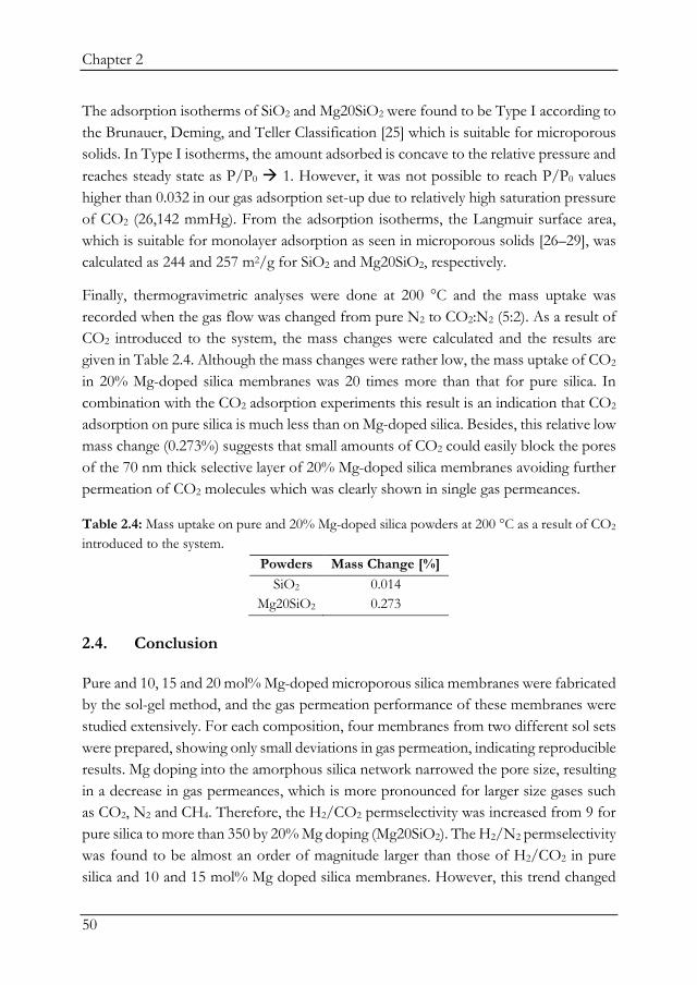
Chapter 2
50
The adsorption isotherms of SiO2 and Mg20SiO2 were found to be Type I according to the Brunauer, Deming, and Teller Classification [25] which is suitable for microporous solids. In Type I isotherms, the amount adsorbed is concave to the relative pressure and reaches steady state as P/P0 1. However, it was not possible to reach P/P0 values higher than 0.032 in our gas adsorption set-up due to relatively high saturation pressure of CO2 (26,142 mmHg). From the adsorption isotherms, the Langmuir surface area, which is suitable for monolayer adsorption as seen in microporous solids [26–29], was calculated as 244 and 257 m2/g for SiO2 and Mg20SiO2, respectively.
Finally, thermogravimetric analyses were done at 200 °C and the mass uptake was recorded when the gas flow was changed from pure N2 to CO2:N2 (5:2). As a result of CO2 introduced to the system, the mass changes were calculated and the results are given in Table 2.4. Although the mass changes were rather low, the mass uptake of CO2 in 20% Mg-doped silica membranes was 20 times more than that for pure silica. In combination with the CO2 adsorption experiments this result is an indication that CO2 adsorption on pure silica is much less than on Mg-doped silica. Besides, this relative low mass change (0.273%) suggests that small amounts of CO2 could easily block the pores of the 70 nm thick selective layer of 20% Mg-doped silica membranes avoiding further permeation of CO2 molecules which was clearly shown in single gas permeances.
Table 2.4: Mass uptake on pure and 20% Mg-doped silica powders at 200 °C as a result of CO2 introduced to the system.
Powders Mass Change [%] SiO2 0.014
Mg20SiO2 0.273
2.4. Conclusion
Pure and 10, 15 and 20 mol% Mg-doped microporous silica membranes were fabricated by the sol-gel method, and the gas permeation performance of these membranes were studied extensively. For each composition, four membranes from two different sol sets were prepared, showing only small deviations in gas permeation, indicating reproducible results. Mg doping into the amorphous silica network narrowed the pore size, resulting in a decrease in gas permeances, which is more pronounced for larger size gases such as CO2, N2 and CH4. Therefore, the H2/CO2 permselectivity was increased from 9 for pure silica to more than 350 by 20% Mg doping (Mg20SiO2). The H2/N2 permselectivity was found to be almost an order of magnitude larger than those of H2/CO2 in pure silica and 10 and 15 mol% Mg doped silica membranes. However, this trend changed

Chapter 2
51
for 20% Mg-doped silica, to permselectivity values of 204 and 350 for respectively H2/N2 and H2/CO2, indicating that the CO2 permeance is lower than the permeance of the bigger gas N2. CO2 trapping, by preferential adsorption, results in almost no CO2 permeation through this Mg-doped silica membranes. The difference in CO2 gas permeances through 15% and 20% Mg-doped silica membranes can be explained by the optimal amount of Mg doping (20%) to create sufficient basic sites on the membrane pores, which causes the adsorption of CO2 molecules and blocked its further permeance. Study of gas permeance through Mg20SiO2 membrane as function of temperature showed that this membrane exhibits a high CO2 affinity from 50 °C up to 200 °C. The reversibility of this interaction between CO2 and Mg-doped silica membrane was tested by performing the permeation of CH4 both before and after CO2 permeance. Detecting no decrease in CH4 permeance after CO2 permeance tests confirms the reversibility of the interaction.
The Rhodamine-B test and the gas permeation results showed that the pits on the surface of the Mg-doped silica membrane, as observed by SEM, do not reach the intermediate γ-Al2O3 layer and therefore there must be an intact separation layer underneath these pits.
The interaction between CO2 and Mg-doped silica membranes were analysed by thermogravimetric analysis. Upon the change of the gas flow from pure N2 to N2 - CO2 mixture, 20% Mg-doped silica was found to have mass uptake of 0.273% which is 20 times higher in pure silica. Even though the adsorbed CO2 values at 200 °C are rather low, it suggests that very low amount of CO2 uptake would be sufficient to block the pores of 20% Mg-doped silica for further CO2 permeation.
More research needs to be conducted into the interaction between the Mg-doped sites and CO2 that leads to such remarkable increases in H2/CO2 permselectivity. Furthermore, a better understanding of the formation of the pits is necessary to help optimizing the performance of Mg-doped silica membranes to have a promising future in industry.

Chapter 2
52
2.5. References
[1] M. Takht Ravanchi, T. Kaghazchi, A. Kargari, Application of membrane separation processes in petrochemical industry: a review, Desalination. 235 (2009) 199–244. doi:10.1016/j.desal.2007.10.042. [2] T. van Gestel, D. Sebold, F. Hauler, W.A. Meulenberg, H.P. Buchkremer, Potentialities of microporous membranes for H2/CO2 separation in future fossil fuel power plants: Evaluation of SiO2, ZrO2, Y2O3–ZrO2 and TiO2–ZrO2 sol–gel membranes, J. Memb. Sci. 359 (2010) 64–79. doi:10.1016/j.memsci.2010.04.002. [3] D. Uhlmann, S. Liu, B.P. Ladewig, J.C. Diniz da Costa, Cobalt-doped silica membranes for gas separation, J. Memb. Sci. 326 (2009) 316–321. doi:10.1016/j.memsci.2008.10.015. [4] G.R. Gavalas, C.E. Megiris, S.W. Nam, Deposition of H2-permselective SiO2 films, Chem. Eng. Sci. 44 (1989) 1829–1825. [5] D. Lee, L. Zhang, S.T. Oyama, S. Niu, R.F. Saraf, Synthesis, characterization, and gas permeation properties of a hydrogen permeable silica membrane supported on porous alumina, J. Memb. Sci. 231 (2004) 117–126. doi:10.1016/j.memsci.2003.10.044. [6] H.Y. Ha, S.W. Nam, S.-A. Hong, W.K. Lee, Chemical vapor deposition of hydrogen-permselective silica films on porous glass supports from tetraethylorthosilicate, J. Memb. Sci. 85 (1993) 279–290. doi:10.1016/0376-7388(93)85281-Z. [7] M. Nomura, H. Aida, S. Gopalakrishnan, T. Sugawara, S.-i. Nakao, S. Yamazaki, T. Inada, Y. Iwamoto, Steam stability of a silica membrane prepared by counterdiffusion chemical vapor deposition, Desalination. 193 (2006) 1–7. doi:10.1016/j.desal.2005.08.019. [8] R.M. de Vos, H. Verweij, High-selectivity, high-flux silica membranes for gas separation, Science. 279 (1998) 1710–1711. [9] K. Kusakabe, S. Sakamoto, T. Saie, S. Morooka, Pore structure of silica membranes formed by a sol–gel technique using tetraethoxysilane and alkyltriethoxysilanes, Sep. Purif. Technol. 16 (1999) 139–146. doi:10.1016/S1383-5866(98)00120-8. [10] D.-W. Lee, S.-E. Nam, B. Sea, S.-K. Ihm, K.-H. Lee, Synthesis of silica membranes on a porous stainless steel by sol-gel method and effect of preparation conditions on their permselectivity, Bull. Korean Chem. Soc. 25 (2004) 1371–1378. [11] A. Ayral, A. Julbe, V. Rouessac, S. Roualdes, J. Durand, Microporous silica membrane: basic principles and recent advances, in: R. Mallada, M. Menendez (Eds.), Membr. Sci. Technol., 2008: pp. 33–79. doi:10.1016/S0927-5193(07)13002-3.

Chapter 2
53
[12] M. Kanezashi, K. Yada, T. Yoshioka, T. Tsuru, Design of silica networks for development of highly permeable hydrogen separation membranes with hydrothermal stability, J. Am. Chem. Soc. 131 (2009) 414–415. doi:10.1021/ja806762q. [13] R.M. de Vos, H. Verweij, Improved performance of silica membranes for gas separation, J. Memb. Sci. 143 (1998) 37–51. doi:10.1016/S0376-7388(97)00334-7. [14] R. Igi, T. Yoshioka, Y.H. Ikuhara, Y. Iwamoto, T. Tsuru, Characterization of Co-doped silica for improved hydrothermal stability and application to hydrogen separation membranes at high temperatures, J. Am. Ceram. Soc. 91 (2008) 2975–2981. doi:10.1111/j.1551-2916.2008.02563.x. [15] M. Kanezashi, S. Miyauchi, H. Nagasawa, T. Yoshioka, T. Tsuru, Gas permeation properties through Al-doped organosilica membranes with controlled network size, J. Memb. Sci. 466 (2014) 246–252. doi:10.1016/j.memsci.2014.04.051. [16] H. Qi, J. Han, N. Xu, Effect of calcination temperature on carbon dioxide separation properties of a novel microporous hybrid silica membrane, J. Memb. Sci. 382 (2011) 231–237. doi:10.1016/j.memsci.2011.08.013. [17] M. ten Hove, A. Nijmeijer, L. Winnubst, Facile synthesis of zirconia doped hybrid organic inorganic silica membranes, Sep. Purif. Technol. 147 (2015) 372–378. doi:10.1016/j.seppur.2014.12.033. [18] A. Nijmeijer, Hydrogen-selective Silica Membranes for Use in Membrane Steam Reforming, PhD Thesis, University of Twente, 1999. [19] V. Boffa, J.E. ten Elshof, R. Garcia, D.H.A. Blank, Microporous niobia–silica membranes: Influence of sol composition and structure on gas transport properties, Microporous Mesoporous Mater. 118 (2009) 202–209. doi:10.1016/j.micromeso.2008.08.038. [20] K. Yoshida, Y. Hirano, H. Fujii, T. Tsuru, M. Asaeda, Hydrothermal stability and performance of silica-zirconia membranes for hydrogen separation in hydrothermal conditions, J. Chem. Eng. Japan. 34 (2001) 523–530. doi:10.1252/jcej.34.523. [21] M.J. Ramírez-Moreno, I.C. Romero-Ibarra, J. Ortiz-Landeros, H. Pfeiffer, Alkaline and alkaline-earth ceramic oxides for CO2 capture, separation and subsequent catalytic chemical conversion, in: C.R. V. Morgado, V.P.P. Esteves (Eds.), CO2 Sequestration and Valorization, 2014: pp. 403–441. doi:10.5772/57444. [22] M.K. Ram Reddy, Z.P. Xu, G.Q. Lu, J.C. Diniz da Costa, Layered double hydroxides for CO2 capture: Structure evolution and regeneration, Ind. Eng. Chem. Res. 45 (2006) 7504–7509. doi:10.1021/ie060757k. [23] R.S.A. de Lange, J.H.A. Hekkink, K. Keizer, A.J. Burggraaf, Formation and characterization of supported microporous ceramic membranes prepared by sol-gel

Chapter 2
54
modification techniques, J. Memb. Sci. 99 (1995) 57–75. doi:10.1016/0376-7388(94)00206-E. [24] J.C. Diniz da Costa, G.P. Reed, K. Thambimuthu, High temperature gas separation membranes in coal gasification, Energy Procedia. 1 (2009) 295–302. doi:10.1016/j.egypro.2009.01.041. [25] K.S.W. Sing, D.H. Everett, R.A.W. Haul, L. Moscou, R.A. Pierotti, J. Rouquérol, T. Siemieniewska, Reporting physisorption data for gas/solid systems with special reference to the determination of surface area and porosity, Pure Appl. Chem. 57 (1985) 603–619. doi:10.1351/pac198557040603. [26] X. Gao, J.C. Diniz da Costa, S.K. Bhatia, Adsorption and transport of gases in a supported microporous silica membrane, J. Memb. Sci. 460 (2014) 46–61. doi:10.1016/j.memsci.2014.02.028. [27] B. Bettens, A. Verhoef, H.M. van Veen, C. Vandecasteele, J. Degrève, B. Van Der Bruggen, Adsorption of pure vapor species on microporous silica membranes and silica pellets, J. Phys. Chem. C. 114 (2010) 9416–9423. doi:10.1021/jp101600t. [28] B.L. Newalkar, S. Komarneni, Synthesis and characterization of microporous silica prepared with sodium silicate and organosilane compounds, J. Sol-Gel Sci. Technol. 18 (2000) 191–198. doi:10.1023/A:1008782117894. [29] T. Yoshioka, T. Tsuru, M. Asaeda, Experimental studies of gas permeation through microporous silica membranes, Sep. Purif. Technol. 25 (2001) 441–449. doi:10.1002/aic.690470916.

Chapter 2
55


3
Understanding the challenges and recent advancements in
gas separation zeolite membranes
This chapter is in preparation to be submitted as: P. Karakiliç, F. Kapteijn, A. Nijmeijer, L. Winnubst, Understanding the challenges and recent advancements in gas separation zeolite membranes.

Chapter 3
58
ABSTRACT
There is an extensive research dedicated to the synthesis and fabrication of zeolite materials, as they are widely used in catalysis [1–7], sensors [8–13], adsorption [14–17], and membrane separation [18–22]. Here, in this review chapter, we focus on their membrane separation applications. After an introduction on zeolite membranes, fabrication and characterization of zeolite membranes are discussed in detail. Subsequently, the main challenges of zeolite membrane fabrication are discussed. After that, the gas transport in zeolite membranes are examined followed by possible gas separation applications of zeolite membranes. Special attention is paid to the mostly studied framework type, MFI, and one of the smallest-size frameworks, CHA, of which pore sizes are suitable for light gas separation.

Chapter 3
59
3.1. Zeolite membranes
The first zeolite was discovered in 1756 by the Swedish mineralogist Axel F. Cronstedt, who observed that upon heating the mineral looks like as it was boiling [23]. Therefore, the name zeolite originates from the Greek words zéō (to boil) and líthos (stones). This boiling phenomenon, as we now know, is caused by evaporation of water from the cages and pores of zeolites.
The basic building units (BBUs) of zeolites are tetrahedrons, TO4 with T = Si, or Al, forming [SiO4]4- and [AlO4]5-. By the combination of these primary building units, more complex building units are formed. The general chemical formula of zeolites is represented by:
Ma/n.(AlO2)a.(SiO2)b.wH2O
where Mn+ is an alkali or alkaline earth metal ion (e.g. Na+, K+, Ca2+ or Mg2+) to balance the negative charge introduced by the Al-containing tetrahedron.
As the oxygen ions are shared by nearby Si4+ or Al3+ ions, the zeolite framework has a metal-to-oxygen ratio of 2 and therefore, it is represented as TO4/2. Because of the shared oxygen ions between tetrahedrons, a ring structure is formed. The number of tetrahedrons in the ring structure defines the pore aperture of the ring. The pore dimensions of zeolites typically ranges between 0.5–1.5 nm [24]. The most known zeolites have 8-, 10- and 12-membered ring structures but larger rings also exist. The structures of 8-, 10- and 12-membered rings and the pore apertures are shown in Figure 3.1.
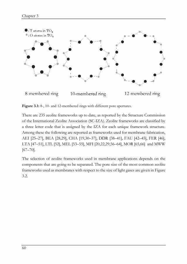
Chapter 3
60
Figure 3.1: 8-, 10- and 12-membered rings with different pore apertures.
There are 235 zeolite frameworks up to date, as reported by the Structure Commission of the International Zeolite Association (SC-IZA). Zeolite frameworks are classified by a three letter code that is assigned by the IZA for each unique framework structure. Among these the following are reported as frameworks used for membrane fabrication, AEI [25–27], BEA [28,29], CHA [19,30–37], DDR [38–41], FAU [42–45], FER [46], LTA [47–51], LTL [52], MEL [53–55], MFI [20,22,29,56–64], MOR [65,66] and MWW [67–70].
The selection of zeolite frameworks used in membrane applications depends on the components that are going to be separated. The pore size of the most common zeolite frameworks used as membranes with respect to the size of light gases are given in Figure 3.2.
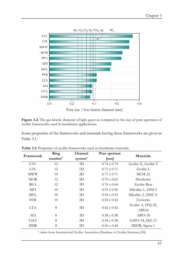
Chapter 3
61
Figure 3.2: The gas kinetic diameter of light gases as compared to the size of pore apertures of zeolite frameworks used in membrane applications.
Some properties of the frameworks and materials having these frameworks are given in Table 3.1.
Table 3.1: Properties of zeolite frameworks used as membrane materials.
Framework Ring
number* Channel system*
Pore aperture [nm]
Materials
FAU 12 3D 0.74 x 0.74 Zeolite X, Zeolite Y LTL 12 1D 0.71 x 0.71 Zeolite L
MWW 10 2D 0.71 x 0.71 MCM-22 MOR 12 2D 0.70 x 0.65 Mordenite BEA 12 3D 0.76 x 0.64 Zeolite Beta MFI 10 3D 0.53 x 0.56 Silicalite-1, ZSM-5 MEL 10 3D 0.54 x 0.53 Silicalite-2, ZSM-11 FER 10 2D 0.54 x 0.42 Ferrierite
LTA 8 3D 0.42 x 0.42 Zeolite A, ITQ-29,
AlPO4 AEI 8 3D 0.38 x 0.38 AlPO-18 CHA 8 3D 0.38 x 0.38 SAPO-34, SSZ-13 DDR 8 2D 0.36 x 0.44 DD3R, Sigma-1
*: taken from International Zeolite Association Database of Zeolite Structure [24]

Chapter 3
62
As seen in Table 3.1, each framework has its specific ring number, channel system and pore size. However, there are different materials having the same framework, for instance silicalite-1 and ZSM-5, both having MFI structure. The main difference between these materials is the elemental ratio of their tetrahedral atoms. Silicalite-1 is an all-silica zeolite, whereas ZSM-5 contains alumina in addition to silica. The Si/Al ratio of a zeolite is important because different materials suit better to different applications. For instance, for ion-exchange applications, a low Si/Al ratio is preferred [71–73] because the maximum density of exchangeable cation sites is reached if the zeolite framework has an equal number of aluminium and silicon atoms (Si/Al = 1) where each oxygen atom is connected to one aluminium and one silicon. On the other hand, for catalytic applications, the more siliceous framework is preferred as high Si/Al ratios makes the framework resistant to high temperatures which encounters during the catalytic and regeneration cycles [74]. Low silica zeolites are hydrophilic and their hydrothermal stability is lower (up to 700 °C) as compared to the hydrophobic high silica zeolites (up to 1300 °C). In addition to the hydrothermal stability, acid stability is another issue for low silica zeolites. Therefore, high-silica zeolites are preferred for membrane applications in humid and/or acidic environment.
3.2. Preparation of zeolite membranes
The first synthesis of a zeolite was carried out by Barrer in 1948 [75]. Zeolite membranes, just like zeolite crystals, are mostly synthesized by hydrothermal synthesis. For zeolite membrane fabrication, the membrane support is put into an autoclave together with the synthesis solution to form the zeolite layer at temperatures between 60 and 200 °C at autogenous pressure.
The synthesis solution consists of a silica and an aluminium source which can be amorphous hydroxides or hydrous oxides. The silica and alumina precursors can be in different physical states such as precipitated gels, colloidal suspension or fumed powder before being added into the solution. Also, a structure-directing agent (SDA) which is usually an organic amine or a quaternary ammonium is required to serve as a “template’’ or “space-filler’’ in the zeolite framework and strongly affects the crystalline phase by probing the synthesis reaction to yield a specific framework. The third element is the cation which can be present in a hydrated or anhydrous from and is required for charge compensation of the alumina tetrahedra. Additionally, a mineralizer (mineralizing agent), which is either hydroxide (OH-) or fluorine (F-), is used to catalyse the reactants by converting them into a more mobile and reactive phase. The mineralizer can be

Chapter 3
63
added to the system through the hydrolysed silica and/or alumina source or the hydrolysed cation. Lastly, a solvent is necessary as the medium of the hydrothermal (in case of water, which is the most used solvent) or solvothermal synthesis.
For zeolite membrane preparation three main approaches are defined for the synthesis of the zeolite, namely:
i. In situ synthesis, ii. Secondary (seeded) growth, iii. Dry gel conversion.
3.2.1. In situ synthesis
In situ hydrothermal crystallization is a one-step process, which involves placing a porous support in contact with a synthesis solution or gel, allowing zeolite crystals to nucleate and grow on the support surface at elevated temperatures [76]. The main advantage of this method is the minimal number of preparation steps, which makes it relatively easy for the fabrication of zeolite membranes [77]. Also, the in situ synthesis results in a strong adhesion of the zeolite layer to a range of different substrates avoiding the use of specially designed substrates and hence, provide easy coating of surfaces with complex shapes [78]. A schematic of this synthesis method is shown in Figure 3.3.
Figure 3.3: Schematic representation of the zeolite membrane synthesis on a porous support via in situ synthesis method.
For in situ hydrothermal synthesis, the synthesis mixture contains silica and alumina precursors, structure-directing agent (SDA), alkaline molecule, (usually sodium hydroxide) and water. This mixture is first homogenized by stirring/aging and then poured in an autoclave in which the support is placed. Then, the autoclave is placed into

Chapter 3
64
an oven for heating. Under autogenous pressure for several hours or days, the crystallization takes place where the zeolite crystals nucleate on the support. By intergrowth of the crystals, a zeolite membrane layer is formed on the porous support. However, due to the simultaneously occurring of crystal nucleation and crystal growth, which require high supersaturation and low saturation, respectively, it is difficult to control the orientation of the seed crystals.
3.2.2. Secondary (seeded) growth
In the secondary (seeded) growth method, also called ex situ layer formation, the nucleation step is decoupled from the crystal growth. The nucleation step takes place at high supersaturation, while on the contrary crystal growth occurs at low supersaturation. By decoupling these processes, the seeds can grow in low concentrated solutions whereas in this stage (secondary) nucleation is avoided. This method starts with the formation of the seed crystals (usually with sizes of 100–2000 nm) in the absence of the support in an autoclave containing the nutrients; i.e. the precursor solution as well as the structure directing agent.
Subsequently the seed crystals are attached on the surfaces via various coating methods such as:
• Electrophoretic deposition (EPD) [79–83] for coating of charged particles on a porous conducting substrates of opposite charge in a uniform and continuous way. The main advantage of this method is obtaining a uniform deposition where the deposited layer thickness can be controlled easily [84].
• Immersion of the support into a seed solution by dip-coating [85–87]. This is a rather easy process as no pre-treatment of the support is required and it can be applied for large surfaces. However, the main requirement of this technique is to have a stable zeolite particle dispersion as colloidal instability causes uncovered surfaces or non-homogeneously covered surfaces, resulting in crack formation after secondary growth. In order to achieve colloidal stability, e.g. the pH of the aqueous medium can be adjusted for charge stabilization [88].
• Manual assembly, or so-called rubbing, of zeolite crystals on the substrate surface [7,89–94],
• Pulsed-laser ablation [69,95–97], • Vacuum-seeding [98,99].

Chapter 3
65
After the attachment of the seed crystals, the seeded support is brought into contact with the nutrients in the secondary growth solution in an autoclave for the crystal growth as schematically illustrated in Figure 3.4.
Figure 3.4: Schematic representation of the zeolite membrane synthesis on a porous support via secondary growth method.
As the composition and concentration of the seed synthesis solution and secondary growth solution are controlled individually, the desired crystalline phase in a desired orientation is much easily obtained as compared to the in situ synthesis.
3.2.3. Dry gel conversion
In addition to the liquid-phase zeolite preparation methods, dry gel conversion (DGC) [100,101] is also used. Firstly, an amorphous gel is applied on the support, then the support is placed in the autoclave without direct contact with the liquid phase (Figure 3.5).
Figure 3.5: Schematic representation of the dry gel method showing the membrane placement in the autoclave.

Chapter 3
66
The DGC method can be divided into two sub-methods depending on the way of adding the organic template:
i) Steam-assisted conversion (SAC) method where the SDA is in the dry gel together with the alumina and silica nutrients. In this case, the liquid phase only contains water.
ii) Vapour-phase transport (VPT) method where template is added in the liquid phase and will be carried to the support with water vapour upon heating the autoclave.
Upon heating the autoclave in an oven, the gel-applied support is subjected to water vapour at elevated pressure and temperature during hydrothermal treatment for the crystallization of the amorphous gel. By using this DGC method, the thickness of the zeolite membrane layer is controlled and the consumption of the chemicals is minimized.
Li et al. [102] developed a combined method where a thin gel layer is formed on the support surface by the hydrothermal synthesis of a seeded support. It is followed by a dry-gel conversion method where the treated substrate was placed in an empty autoclave to convert the gel layer into a SAPO-34 zeolite membrane.
It is claimed that this dry gel conversion method gives the thinnest zeolite membrane layers [102]. However, most research on fabrication of zeolite membranes is done on the liquid phase-derived methods (in situ synthesis and secondary growth).
3.2.4. Influence of the support
As a support for zeolite membranes, porous inorganic discs or tubes, made of alumina, silica, titania and stainless steel, are mainly used [103]. The roughness and pore size of the support have a direct effect on the nucleation of zeolite seeds. Therefore, well-defined supports are necessary for the reproducible synthesis of zeolite membranes. The pore size is important whether the zeolite crystals are desired to deposit only on the surface instead of inside the support pores. Another issue is that the support can partially dissolve in the synthesis solution, which could change the elemental structure of the zeolite layer. For instance, partly dissolving of alumina supports raises the Si/Al ratio. Therefore, a stable support under hydrothermal and alkaline conditions is crucial.

Chapter 3
67
3.3. Details of zeolite synthesis: nucleation and growth
Zeolite crystallization takes place in three steps:
i. Firstly, pre-nucleation stage where the reactants are only mixed and aged for some time.
ii. Then, nucleation of discrete amorphous particles into a crystalline phase. iii. Lastly, growth of zeolite crystal.
The zeolite crystal synthesis is schematically represented in Figure 3.6.
Figure 3.6: Schematic representation of zeolite crystallisation.
When the reactants, containing silica and alumina precursors, are mixed with a cation source in water and placed in the autoclave, the reactants remain amorphous until the nucleation starts. There are two separate amorphous phases: primary and secondary amorphous phases [104]. The primary amorphous phase refers to a visible gel just after mixing the reactants and is heterogeneous, so not yet in equilibrium. This primary state can be regarded as a precipitation or coagulation product of the reactants in water. Further aging is required to get a more ordered structure. After some aging time, the mixture turns into a pseudo-steady-state intermediate where the first stable intermediates are formed. This state is referred to as the secondary amorphous phase, where the mixture becomes homogeneous and in equilibrium. It is more structurally oriented compared to the primary state, but without forming the periodic zeolite lattice yet [104]. These secondary amorphous phases are the small silicate and aluminate species formed as a result of the condensation reaction as given below:

Chapter 3
68
(𝑂𝑂𝑂𝑂)3𝑇𝑇 − 𝑂𝑂 − 𝑂𝑂 + 𝑂𝑂 − 𝑂𝑂 − 𝑇𝑇(𝑂𝑂𝑂𝑂)3 ⟺ (𝑂𝑂𝑂𝑂)3𝑇𝑇 − 𝑂𝑂 − 𝑇𝑇(𝑂𝑂𝑂𝑂)3 + 𝑂𝑂2𝑂𝑂
where T represents Si or Al.
Nucleation is the next step where the ordered zeolite nuclei are formed. The different types of nucleation can be summarised as follows:
i. Primary nucleation which could be homogeneous by the spontaneous arrangement of molecules to small clusters in a solution at super saturation, or heterogeneous which is caused by foreign species that help nucleation at lower saturation.
ii. Secondary nucleation which is the growth of new crystal material by introducing seed crystals [104]. The secondary nucleation is regarded as a kind of heterogeneous nucleation because it is favourable and occurs at lower supersaturation. To promote nucleation, seed crystals are also added to the mixture which provide a surface on which zeolites can grow [105]. By doing so, the need of self-generated primary nucleation is avoided and the zeolite crystallisation goes faster.
Finally, the crystal growth takes place where the ordered nuclei grow into ordered framework of crystalline zeolite product.
There are numerous parameters affecting the crystallization process, either in the same way for nucleation and growth, or oppositely. Even a small change in the composition of the synthesis mixture may disrupt the crystallization pathway, and in some cases results in the formation of another zeolite phase [106]. It is important to control these parameters during the synthesis, instead of using post-treatments in order for zeolite membranes to be industrially utilized more economically.
Among the synthesis parameters, Naskar et al. [107] reported that an increase of temperature or crystallisation time enhances the crystallinity as well as the size of the seed crystals of silicalite-1. This is due to the faster nucleation rate and to a much greater degree to the crystal growth rate.
Li et al. [108] studied the effect of silica sources on the nucleation and crystallization time of silicalite-1 zeolites and found that using TEOS (tetraethyl orthosilicate) as a silica source provides fast nucleation (about 72 h) and a very strong increase in crystal population with a narrower crystal size distribution, whereas by using colloidal silica sources the nucleation time extended to 120 h and resulted in a much broader crystal size distribution. Similarly, Mintova and Valtech [109] showed the effect of silica source

Chapter 3
69
(monomeric TEOS, colloidal silica LUDOX LS-30 and fumed silica Cab-O-Sil®) on the formation of nanosized silicalite-1 zeolites by in situ dynamic light scattering. They also found that the TEOS-containing solution crystallized faster and formed smaller silicalite-1 crystals. Combined silica sources of colloidal silica and monomeric TEOS were used by Hrabanek et al. [110] for the synthesis of preferential oriented silicalite-1 layers where the partial replacement of monomeric silica precursor (TEOS) with a colloidal one resulted in accelerated crystallization which promoted the crystal intergrowth. However, much larger crystal sizes were observed which is due to the larger size of the colloidal silica precursor (TOSIL, 6–8 nm) as compared to the monomeric silica (TEOS, 4 nm).
In addition to the silica precursor, also the SDA concentration has a big influence on the seed formation and its microstructure. Soydaş et al. [111] studied the effect of template concentration on the crystallisation rate and crystal size of silicate-1 and showed that the nucleation rate increases and crystal size reduces as the template concentration increases.
Wong et al. [112,113] studied the effect of many synthesis parameters, such as the chemical composition, alkalinity and temperature, on the MFI zeolite membrane morphology and growth. Even though the parameters studied in both papers are the same, it is important to understand the effect of synthesis parameters on these two distinct phenomena separately.
Naskar et al. [107] studied three different ways of silicalite-1 layer preparation: i) single-stage in situ, ii) double-stage in situ (two times applied in situ synthesis) and iii) ex situ (secondary) crystal growth. They reported that the single- and double-stage in situ resulted in b-oriented layer formation, whereas the ex situ growth caused random oriented crystals. Also, double-stage in situ was advantageous in terms of having less intercrystalline gaps (and therefore higher permselectivity of O2/N2) as compared to the single-stage one.
Zhang et al. [114] studied the influence of seed size on the microstructure of silicalite-1 zeolite membranes and reported that the smallest seeds (100 nm) results in the most uniform and dense membrane layer whereas larger seeds (3 µm) causes poor intergrowth of the membrane layer.
Even though most of the zeolite synthesis takes place in alkaline media, fluoride containing solutions were also widely used [115–118]. It is specifically important to work under more neutral conditions by introducing hydrogen fluoride to systems which

Chapter 3
70
have silica substrates or intermediate layers because silica easily dissolves in alkaline media [119]. However, the use of HF is not desirable due to its corrosiveness. Therefore, Peng et al. [120] developed synthesis methods for the b-oriented MFI zeolite film fabrication under neutral conditions without using HF.
3.4. Characterization of zeolite membranes
There are a lot of characterization techniques that can be used for zeolite membranes as well as zeolite powders. X-ray diffraction (XRD) is a crucial method to identify the type of the framework that is synthesized as well as the orientation of the crystals in a zeolite layer. Scanning electron microscopy (SEM) is another technique commonly used to envisage the size and shape of a zeolite crystal, how the crystals are dispersed on a support, the presence of intercrystalline defects and whether the crystals are grown into a continuous layer. Also, the thickness of the zeolite layer can easily be determined by SEM. If the SEM is coupled with an Energy Dispersive X-ray Spectrometer (EDX), also a semi-quantitative elemental analysis can be done. Transmission electron microscopy (TEM) is also used to elucidate the surface morphology of zeolite crystals in high-resolution. TEM is used for specimens which are less than 100 nm thick. X-ray fluorescence (XRF) is used for more complete elemental analysis on zeolite seeds. X-ray photoelectron spectroscopy (XPS) is a surface sensitive technique and used to measure the elemental composition, chemical state and electronic state of the elements present within a depth of 10 nm. Thermogravimetric analysis (TGA) is a technique to determine the mass loss of a zeolite powder upon heating to any temperature. So, the template removal can be optimized easily without applying any excessive temperature treatment. Dynamic light scattering (DLS) determines the particle size distribution of synthesized seed crystals. Nitrogen adsorption/desorption analysis is useful for the calculation of surface area and micropore volume of zeolite crystals. Contact angle measurement is used to interpret the hydrophobicity of the prepared zeolite membrane. The hydrophobicity of the membrane varies by the Si/Al ratio. Permporometry determines the pore size in the range of 2–20 nm) and can therefore be used for the analysis of defects with sizes in the low mesoporous regime. Fourier transform infrared spectroscopy (FTIR) is used for the quantitative and qualitative analysis of organic compounds, which could be, in zeolite membrane characterization, transformed into a tool to analyse the presence of structure directing agents. Atomic force microscopy (AFM) is a high-resolution tool to determine the surface roughness of the support or zeolite surface. Also, the growth of zeolite crystals can be in situ analysed by AFM. Nuclear magnetic resonance

Chapter 3
71
(NMR) spectroscopy is a useful tool for the coordination environment around Si and Al atoms as well as for the Si/Al ratio.
3.5. Challenges in zeolite membrane fabrication
The basic requirement for a zeolite membrane to have the desired separation performance is a defect-free and continuous zeolite layer on the support surface. Hence, the gases flow through the pores of the zeolite instead of the inter crystalline pores or defects such as pinholes and cracks [121]. Therefore, understanding and controlling the nucleation and growth mechanisms of zeolites is one of the challenges to develop defect-free zeolite membranes [122]. Another challenge is to make the zeolitic separation layer as thin as possible in order to achieve high permeate flows as the thickness of the separation layer contributes to permeate flow resistance.
3.5.1. Defect formation
Defects are inter-crystalline pores (non-zeolitic pores) which are larger than the zeolite pores. These defects strongly decrease membrane selectivity [123]. Numerous factors determine the formation of defects during the formation of a zeolite separation layer [124].
One issue is the mismatch in thermal expansion coefficient between zeolite film and support. Many zeolite materials have negative coefficients of thermal expansion (CTE), whereas many ceramic materials, such as alumina, have a positive CTE [125]. Also, some zeolites have both a positive and negative CTE, depending on the temperature. For instance, MFI has a positive CTE at low temperatures (< 75 °C), but at higher temperatures (> 120 °C), a displacive phase transition occurs from a monoclinic to orthorhombic phase [126]. During this displacive phase transition the symmetry of the crystal only changes through a small atomic shifts in the zeolite structure[127]. At temperatures above this phase transition, a negative CTE is observed [128]. The CTE mismatch during thermal treatment is more problematic for small-pore size zeolites since they require higher temperature for the removal of structure directing agent (700–950 °C) [129].
Another issue is the presence of silanol (SiOH) groups due to not complete condensation between two adjacent tetrahedra resulting in nonbridging defects [130].
Moreover, high silica zeolite can form siloxy (SiO-) defects in order to balance the positive charge of the cation in the structure directing agent if there are no or not

Chapter 3
72
sufficient aluminium ions who have a negative charge in the TO2 unit [131]. These siloxy defects usually occur in hydroxide-mediated systems, where as in fluorine-mediated systems (where HF is used instead of metal hydroxides) less defects are formed as a result of charge compensation [132]. In fluorinated media, the SiO2/H2O values are much lower (around 3–15) than in hydroxide media (30–60). Also, higher content of SDA is required (SiO2/(SDA = HF) of 2, pH is also much lower, around 6–8).
Zeolite defects are classified based on their size: macro-defects (> 50 nm), meso-defects (2–50 nm), micro-defects (< 2 nm). The SiOH and SiO2 defects are relatively small and can be regarded as intracrystalline micro defects. On the other hand, intercrystalline (grain boundary) defects form while growing the crystals into a zeolite layer corresponds to the micro- or meso-defects [133]. In addition, during template removal by calcination, pinholes or cracks, which correspond to the macro-defects, can be formed, due to the mismatch between the thermal expansion coefficient (CTE) of zeolite layer and substrate [134,135].
The most commonly used method to overcome the grain boundary defects is rapid thermal processing (RTP) instead of a conventional calcination step [136–138]. Also, ozonisation is used as a detemplating technique where an oxygen/ozone mixture (approximately 2% of ozone) is brought into contact with the zeolite layer at elevated temperatures at which highly reactive atomic oxygen and radical species are formed and remove the template by avoiding crack formation during calcination [139–141].
Additionally, various post-treatment methods were widely studied to reduce the number and size of defects. Xomeritakis et al. [142] sealed the post-calcination cracks by dip-coating MFI membranes into a surfactant-templated mesostructured silica sol. Karimi et al. [143] deposited a thin amorphous silica layer on the top of an MFI membrane to block the defects. Similar to that, chemical vapor deposition of silica via reaction with a silicon alkoxide or other silylation agents helps to eliminate smaller defects by reducing the pore openings on the external surface [144]. Another method for defect-patching is chemical liquid deposition of a silsesquizocane/silica hybrid by the co-hydrolysis and co-condensation reactions of tetraethoxy orthosilica (TEOS) and (3-chloropropyl)triethoxy silanes on the top of defective zeolite membranes [145]. Furthermore, Yushan et al. [146] impregnated MFI membranes with liquid 1,3,5-tri-isopropylbenzene and heated them to high temperature to fill the intercrystalline defects via coking. A similar coking technique for plugging the grain boundary defects in MFI membranes was applied by Korelskiy et al. [147] using isopropanol. They have found

Chapter 3
73
that the permeance through the intercrystalline defects reduced by 70% as a result of coking.
3.5.2. Orientation of zeolite crystals
In addition to having defect-free zeolite layers for high separation performances, the orientation of the zeolite crystals is of crucial importance to maximise the permeance of the desired products. For instance, the MFI zeolite crystal has different pore geometries along a- and b- orientations as shown in Figure 3.7.
Figure 3.7: MFI zeolite crystal with sinusoidal a- and straight b- channels.
The MFI structure has sinusoidal channels (0.55 x 0.51 nm) in the a-direction and straight channels in b-orientation (0.54 x 0.56 nm). As straight channels have a shorter pathway, reducing the mass transfer resistance, b-oriented MFI membranes are favoured to maximise the flux [120,148–150].
Mis-orientation of the crystals might also cause defect formation during the secondary growth. Therefore, by controlling the crystal orientation, in addition to maximise the membrane permeance performance, defect formation can be also prevented.
To study this, the crystallographic preferred orientation (CPO) is defined which is calculated by the ratio of the intensity of two different peaks in the XRD pattern [151]:
𝐶𝐶𝐶𝐶𝑂𝑂 (𝑋𝑋)(𝑌𝑌) =
𝐼𝐼𝑆𝑆𝑋𝑋𝐼𝐼𝑆𝑆𝑦𝑦
−𝐼𝐼𝑝𝑝𝑋𝑋
𝐼𝐼𝑝𝑝𝑋𝑋
𝐼𝐼𝑆𝑆𝑋𝑋𝐼𝐼𝑆𝑆𝑦𝑦
Chapter 3
74
where I is the peak intensity in counts per step, (X) and (Y) are the two different peaks in the XRD pattern, corresponding to the two different orientations, and S and P subscripts denote the XRD patterns of the zeolite layer on the substrate and randomly oriented powder, respectively.
3.5.2. Fabrication of (ultra-) thin zeolite membranes
The thickness of zeolite membranes affects the diffusion, and therefore the permeance of any gas or liquid which is transferred through a zeolite layer. Therefore, it is important to reduce the thickens to maximise the permeances.
In addition to the many common methods to reduce the thickness of the zeolite layers, using smaller seed crystals even up to nanocrystals [152], shorten the crystal growth time and so on, many unique strategies were developed for the synthesis of ultra-thin (sub-100 nm) zeolite layers.
Ultra-thin zeolite layers were developed by Corma et al. [153] by an exfoliation method resulting in formation of around 2.5 nm thick ITQ-2 (MWW) zeolite sheets.
The use of ultra-thin MFI (2.6 ± 0.3 nm) and MWW (3.4 ± 0.3 nm) nanosheets as membrane layer was developed by Varoon et al. [154]. They prepared exfoliated zeolite nanosheets and added them into toluene to create a coating suspension which was applied on porous alumina disks by vacuum filtration. The membranes had nanometer-sized gaps between crystals which were reduced by a subsequent hydrothermal treatment.
Agrawal et al. [91] prepared 50 nm thick silicalite-1 nanosheets by exfoliation of multilamellar MFI and deposited these on silica supports. The layer was then grown by gel-less secondary growth to heal the nanosized gaps between the nanosheets. This approach uses sacrificial Stöber silica nanoparticles on a silica substrate for the growth of silicalite-1 layers. The secondary growth yielded in the formation of 100–250 nm thick zeolite layers and these membranes resulted in high permeance and selectivity for the separation of butane and xylene isomers. Also a control experiment was performed by Argarwal et al., where conventional secondary growth was applied, resulting in an identical layer thickness (200 nm). However, the stability in p-xylene permeance of the conventional grown membranes was only 3 days and after that, the permeance dropped by more than one order of magnitude, while the gel-less grown zeolite membrane remained stable during a test for 45 days, after which they stopped the experiment.

Chapter 3
75
Even though, very thin and selective zeolite membrane layers were formed by all above-mentioned studies using exfoliation methods, it is a top-down approach which is more time consuming and costly. Therefore, bottom-up approaches are more desirable for faster, highly yield and economically viable synthesis methods. The synthesis of single-unit-cell MFI nanosheets was developed by Choi et al. [155] where the zeolite nanosheets were only 2 nm thick. This was achieved by using a bi-functional surfactant, C22H45-N+(CH3)2-C6H12- N+(CH3)2-C6H13, as developed by Choi et al. This surfactant consists of two quaternary ammonium groups acting as an SDA for MFI zeolites, while the long chain alkyl tail (C22) provides a lamellar structure and avoids further growth of the zeolite. In a follow-up research [156], these multilamellar zeolite nanosheets, still containing the above-mentioned surfactant, were infiltrated with TEOS. Here, TEOS acts as silica pillars between adjacent zeolite nanosheets through hydrolysis. After template removal a pillared multilamellar MFI structure is obtained. Later, Jeon et al. [57] synthesized ultrathin (4.6 ± 0.5 nm) zeolite nanosheets using diquaternary ammonium cations, (C3H7)3N+(CH2)5N+(C3H7)3 as a template. The nanosheets were deposited on silica fiber substrates by vacuum filtration. These membranes exhibit very high selectivities for xylene isomer (p-xylene/o-xylene) separation and also found suitable for ethanol/water pervaporation and n-/i-butane separation.
3.6. Gas transport in zeolite membranes
Gas permeation through zeolite membranes takes place via [128]:
i. Adsorption on the external surface or selective adsorption in the zeolite pores, ii. Surface diffusion, iii. Molecular sieving.
So, the total permeation of gases through zeolite membranes depends on the product of the concentration of the adsorbed molecules in the zeolitic pores and diffusion coefficient of molecules.
Separation of gas mixtures takes place by differences in adsorption and diffusion rates as well as the molecular sieving properties of zeolites. Adsorption selectivity occurs at low to moderate temperatures in the presence of one molecule being adsorbed more strongly than the other. This adsorbed molecule can block the permeation of other molecules by either partially or completely blocking the pores. Adsorption based separation mechanisms works effectively in applications where a strongly adsorbing

Chapter 3
76
molecule should be removed, such as dewatering and CO2 capture as H2O has a large dipole and CO2 has a large quadrupole moments [103].
Diffusion consists of surface diffusion and gaseous (activated) diffusion. Surface diffusion increases with increasing temperature since the adsorbed component concentration is lowered at high temperatures. Also, the gaseous diffusion increases with temperature since gases become more mobile with temperature.
For molecular sieving, the membrane must be defect-free in order to retain the large gases by its shape selective porous structure.
The crystallographic structure (determining the zeolite pore size) and chemical composition (affinity) determine the separation properties of a given zeolitic material. The pore size plays an important role in diffusion and molecular sieving. The adsorption capacity of the zeolite depends on its polarity. When the zeolite has a higher Al content, it becomes more polar, which in turn allows stronger affinity/adsorption. It is possible to predict the membrane separation performance, i.e. permeance and separation, by using the adsorption and diffusion data and incorporate it into the transport models such as Fick and Maxwell-Stefan transport models [123]. Maxwell-Stefan surface diffusion with dual-site Langmuir adsorption can be used to model the transport behaviour of gases through zeolite membranes. Also, single-site Langmuir adsorption was used by Gardner et. al. [157] to predict the transport.
3.7. Possible applications
There are various gas separation applications where zeolite membranes can be used. In this work, the main interest is on pre-combustion CO2 capture in power plants, natural gas purification, as well as xenon and sulfur hexafluoride recovery.
3.7.1. Pre-combustion CO2 capture in power plants
Pre-combustion capture is the partial oxidation of a fuel with oxygen or steam to form synthesis gas (syngas) which is a mixture of carbon monoxide and hydrogen. This is followed by the water-gas-shift reaction (WGSR) of carbon monoxide with steam in a catalytic reactor (shift converter) in order to produce more H2 and gives CO2 as a by-product. The CO2 concentration in the mixture is still high, between 15–50 mol%, which needs to be separated for the further utilization of hydrogen [158].
As the gas stream has a high temperature (around 300 °C), inorganic membranes are needed for gas separation. The pore size of the zeolite should be around 0.3 nm in order

Chapter 3
77
to separate the gases based on molecular size (where the gas kinetic diameter of H2 and CO2 are 0.289 and 0.33 nm, respectively). Sol-gel derived amorphous membranes such as SiO2 show very high separation factors and fluxes, but have a very limited hydrothermal stability which is a problem in the case of the steam containing streams at high temperatures [159]. Zeolite membranes, on the other hand, offers much better thermal and hydrothermal stability and are suitable to be used in these streams.
3.7.2. Natural gas purification
Natural gas has different compositions depending on the type, depth and location of the reservoirs. Besides some ethane, propane and butane, the methane content of such reservoirs varies between of 55–85 mol% where the CO2 and N2 compositions can be in the range of 1–15% [160]. According to U.S. pipeline composition specification, CO2 content should be less than 2% whereas the total inert (N2, H2, Ar) concentration is specified to be less than 4% [160] in order to meet the specified pipeline quality in terms of high energetic value and less corrosive potential. Therefore, it is essential to separate CH4 from N2 and CO2. In addition, CO2 is acidic and corrosive in the presence of water which would be harmful to the process line [31]. It is economically beneficial to remove CO2 while keeping the natural gas stream at high pressures to reduce recompression costs [92].
Natural gas processing, where CO2 is usually removed by adsorption before sending to the pipeline (where the allowable concentration is below 2–3%), is a costly process. Polymeric membranes, such as cellulose acetate membranes, are the cheapest options whereas the stability of the polymeric membrane is the main limitation, especially when used under a high pressure, around 7 MPa [31]. As said above, natural gas contains easily absorbed gases like CO2, which easily plasticizes the polymeric membrane material at high partial pressures [161]. Therefore ceramic membranes, like zeolite membranes are more suitable materials in terms of stability for the treatment of CO2 containing gas streams. Also, the small-pore zeolites such as DDR (0.36 x 0.44 nm) and CHA (0.38 x 0.38 nm) have pore sizes similar to CH4 but larger than CO2 which allows these membranes to exhibit high CO2/CH4 selectivities thanks to the combination of differences in diffusion and adsorption.
3.7.3. Xenon recovery
Xenon (Xe) is an expensive gas due to its scarcity in the earth atmosphere (0.087 ppm) and production via cryogenic fractional distillation is costly [162]. It is an important gas which is used in lighting, electrical, aerospace and medical applications [163]. In medical
Chapter 3
78
applications, xenon is an ideal anaesthetic gas with many medical and environmental advantages over the conventional anaesthetic gas nitrous oxide, N2O because Xe has a low risk of hypoxia as well as not being neurotoxic [164]. Therefore, it is a promising anaesthetic if it can cost-effectively be recovered from the exhaled breath of the patient. A simple calculation shows that for an average adult with 12–20 breaths per minute with an average volume of 0.5 litre requires average of 480 litre inhalation per hour. The anaesthetic gas is 65–70% of the inhaled breath [165], meaning that one hour of surgery would cost between 3500–5000 Euros due to use of xenon (with a price varying between 10–15 Euros/L). With this high price and scarcity, it is crucial to recover Xe. Xenon is a much larger molecule (0.41 nm) than other components in the exhaled breath (mostly CO2, 0.33 nm, and N2, 0.364 nm) and can be recovered using zeolite membranes thanks to their molecular sieving ability at sub-nm level [166].
In addition, xenon is found in the radioactive waste products generated during nuclear fission. These waste products should be purified prior to waste storage to minimize the volume where the separation of krypton (Kr) from Xe is required [167]. The conventional separation method of these gas pair is cryogenic distillation, which is rather expensive due to low boiling points (-153 °C and -113 °C for Kr and Xe, respectively). This brings us to zeolite membranes, which are resistant to the radiation degradation and have molecular sieving abilities with pore sizes between the kinetic diameter of Kr (0.36 nm) and Xe (0.41 nm) to effectively separate Kr/Xe again directing us to the small-pore size zeolites such as DDR and CHA.
3.7.4. Sulfur hexafluoride recovery
Sulfur hexafluoride is a colourless, odourless, non-flammable and one of the heaviest (5 times denser than air) gases [168]. It is widely used in various industrial applications: as gaseous insulating materials in electrical transmittance systems and high voltage switchgear, as melt protection gas in the magnesium industry and as arc quenching medium in circuit breakers [169]. Even though it has an indispensable use in industry, it can causes long-term problems due to its high global warming potential (GWP) which is 23,900 times greater than that of CO2 as well as long lifespan of 3,200 years [170,171]. Therefore, its separation is of great significance for the recovery of this expensive and high global warming potential gas.

Chapter 3
79
3.8. MFI and CHA zeolites as membrane materials
The zeolite frameworks that are focused in this review are MFI and CHA structures. A detailed information on structure, preparation methods and properties of these zeolite frameworks are given in the following sections.
3.8.1. MFI framework
Among the more than 200 different types of zeolites available, MFI (Mordenite Framework Inverted) is one of the most used zeolite. It was successfully prepared for the first time in early 1990s. It is a 10-membered ring zeolite with pore size of around 0.55 nm [172]. The MFI zeolite structure is of particular interest in membrane separation thanks to the well-developed understanding of its synthesis through three decades and its suitable size for many separation applications. The framework of MFI structure is not symmetric and the projection along a-, b- and c-orientations are given in Figure 3.8.
Figure 3.8: The MFI framework projection along a-, b- and c-direction.
MFI membranes have straight channels in the b-orientation (0.54 x 0.56 nm) and sinusoidal channels (0.55 x 0.51 nm) in the a-direction. As minimization of the pathway maximises the gas permeance, the b-orientation is highly favoured.
Depending on the Si/Al ratio, the MFI zeolite has two framework analogues, ZSM-5 (Zeolite Socony Mobil - five) and its Al-free analogue, silicalite-1. The Si/Al ratio changes the properties of the zeolite layer. High aluminium concentrations increase the hydrophilicity, which benefits for the water/alcohol separation, however lowers the

Chapter 3
80
stability under humid atmosphere. Additionally, the mesopore concentration in the MFI membrane increases with an increasing Al content [173]. So, high-silica zeolites exhibit better molecular sieving performance, and are especially interesting for separation under humid conditions.
Early studies on the crystallisation and growth of silicalite-1 zeolites were conducted in the beginning of 1990s [174,175]. In the same period, the fabrication of silicalite-1 membranes on porous stainless steel or alumina supports was performed for gas permeation experiments [176–182]. Here, the silicalite-1 membrane layer was still relatively thick (> 10 µm) and not completely ordered in b-direction.
Therefore, in the early 2000s, the research was more focused in the formation of thin [61,62,183] and oriented [77,184–187] silicalite-1 zeolite membranes in order to obtain higher permeances. Pham et al. [29] developed facile and precise methods to grow silicalite-1 films in a desired (purely a- or b-) orientation while avoiding formation of self-crystallization in the bulk liquid and the deposition in a random orientation. Besides, thanks to compactness and higher surface to volume ratio, as compared to flat geometries, tubular silicalite-1 membranes were developed [60,188–191]. A solution-filling method was applied by Chen et al. [192] for the preparation of tubular membranes before the hydrothermal synthesis by filling the tubular supports with a water-glycerol mixture so that only on the outer surface as zeolite layer was formed. In another work the inner surface of the tubular alumina supports was coated for the fabrication of highly oriented silicalite-1 membranes [193].
In order to minimize the thickness of the zeolite layer, fabrication of small zeolite seeds also gained great interest. While the zeolite seeds were becoming smaller, it is important to consider their ingress into the support pores. So, masking techniques were developed to fill the support pores with a wax to avoid ingress of the seeds as well as to reduce irregularities of the support [194]. On the contrary, it can also be desired that zeolites grow within the pores of the substrate instead of on the top of it. This so called pore-plugging technique is beneficial for layer preparation on larger areas by avoiding the initial imperfection of the substrate. Thus, it avoids defect formation and provides a good control on the layer thickness [195,196].
Also, using ammonium salts as crystallization-mediating agent is one of the approaches for MFI membrane fabrication, since the silicalite-NH4+ interactions are more stronger than the TPA-NH4+ interactions, which results in suppression of nucleation during the secondary growth [197].

Chapter 3
81
Template-free synthesis is also one of the main interests in the fabrication of silicalite-1 zeolite membranes to reduce the cost of using structure-directing agent [59,198].
In later years microwave-assisted hydrothermal treatments for the fabrication of silicalite-1 membranes were developed [63,199]. Microwave-assisted heating uses wavelengths which lie between infrared and radio waves of the electromagnetic spectrum, meaning a wavelength range between 0.01 m and 1 m, and therefore in the frequency range of 0.3 to 30 GHz [200]. In many researches, using microwave heating for the synthesis of zeolite membranes, a frequency of 2.45 GHz was used [201–203]. The reason can be explained by the maximum microwave energy absorption of water in this frequency range [200]. Thanks to the higher energy, microwave-assisted hydrothermal treatment is faster [204] and takes around 30–150 minutes as compared to the conventional heating of 24–72 h and microwave heating is more homogeneous than conventional heating, which results in formation of thinner and more selective zeolite membranes with a more narrow crystal size distribution [205]. Therefore, microwave-assisted hydrothermal treatment is used for the fabrication of several types of zeolite membranes such as LTA [48] and FAU [42]. Another method, which is compatible with the microwave-assisted heating in terms of providing fast synthesis is ultrasonic irradiation or so-called “sonothermal synthesis’’ which is applied to DDR [206] and EMT [207] type zeolite synthesis.
In addition to the conventional synthesis of silicalite-1, some novel methods were also developed such as transformation of amorphous silica into silicalite-1 zeolites [64,208] which allows the use of already deposited thin and smooth silica layer as silica nutrient whereas avoiding the Al-leaching from the substrate.
Also, covalent linkers were used for the modification of the ceramic support surface for the attachment of zeolite seeds. Naskar et al. [209] examined the modification of ceramic substrate surfaces by grafting aminopropyl-tri-ethoxy silane (APTES) for the fabrication of silicalite-1 membranes and they observed that the APTES modified systems had a better zeolite surface coverage and more dense packing as compared to the unmodified one. The use of APTES linker was also applied to the other zeolite frameworks for the direct in-situ synthesis of FAU [210] and LTA [211] zeolite membranes.

Chapter 3
82
3.8.2. CHA framework
The chabazite (CHA) type zeolite framework has a 3-dimensional interconnected pore system with 8-membered rings having a pore size of 0.38 x 0.38 nm [212]. The framework density, which is defined as the number of tetrahedrally coordinated atoms per 1000 Å3, of CHA is 15.1 whereas for MFI this value is 18.4, meaning that CHA has more porous structure. The CHA framework along a-, b- and c-orientation is shown in Figure 3.9.
Figure 3.9: The CHA framework projection along a-, b- and c-orientation.
CHA zeolites are possible in a wide range of Si/Al ratios (varying from 0.05 [213] to infinity) and are extensively used for separation and catalytic applications. Depending on the Si/Al ratio and the presence of other metal ions (such as phosphorus in addition to silicon and aluminium), silicoaluminophosphate-34 (SAPO-34) [30,32,35], low-silica chabazite [115], high-silica SSZ-13 [214–216] and all silica (Si-CHA) [217,218] and aluminophosphate-4 (AlPO-4) [219] are among the materials having CHA structure. Just like MFI zeolites as described in the previous section, high-silica CHA exhibits higher stability under humid conditions as compared to the higher aluminium containing ones due to the hydrophilicity of this system [214].
Zeolite SSZ-13 with Si/Al ratio of about 12 was first synthesized in 1995 by Zones [220] using N,N,N-trimethyl-1-adamantammonium (TMAda+) as a surface directing agent (SDA) and colloidal silica as a silica precursor. As follow-up, in 1998 the first all silica CHA was synthesized by Dias-Cabanas et al. [221] using tetraethyl orthosilicate (TEOS) as a silica precursor and TMAdaOH solution as the SDA in the presence of fluoride, since the F- anion is required to provide the charge balance.
Eilertsen et al. prepared CHA zeolites with Si/Al ratios ranging from 15 to 133 [222] where Cab-O-Sil M5® fumed silica is used as a silica precursor and the crystallisation

Chapter 3
83
takes place in an autoclave at 160 °C for 7 days. In another work of Eilertsen et al. [223], they prepared CHA seeds with a Si/Al ratio varying from 20 to infinity, they used TEOS as a silica precursor and the solution was crystallised at 155 °C for 40 h. They noted the importance of the synthesis parameters on the stability of the SSZ-13, because longer synthesis time, higher temperature and high H2O/SiO2 ratio would yield SSZ-23 with a STT topology.
Kalipcilar et al. [33] fabricated SSZ-13 zeolite membranes on the inner surface of porous stainless steel tubes to be used for separation of light gases and pervaporation. The membranes were prepared by a seeded (secondary) growth method where the seeds were synthesized in an autoclave at 160 °C for 120 h. After the seed attachment, the crystals were grown under the same synthesis conditions as during seed synthesis. The single-gas permeances of H2 (0.289 nm), N2 (0.364 nm), CH4 (0.389 nm) and n-C4H10 (0.43 nm) was measured at 25 °C with a transmembrane pressure of 1.38 bar. The ideal selectivity (or permselectivity) of CO2/CH4, H2/CH4 and H2/n-C4H10 were 11, 9.0 and 63, respectively.
Kosinov et al. [19] prepared high silica (Si/Al=100) SSZ-13 membranes on α-Al2O3 hollow fiber supports. They reported that a low aluminium content resulted in a very low number of defects in the membrane which could also be covered by a little amount of water as it blocks the hydrophilic, non-zeolite defect pores. Hence, an ideal selectivity of H2/SF6 of over 500 was achieved. Also, the mixed gas separation performance of the membranes were tested using an equimolar feed composition. Separation factors of 42 and 12 for CO2/CH4 and CO2/N2, respectively, were obtained.
Yang et al. [216] prepared SSZ-13 membranes on hollow fibers and used ultraviolet irradiation for the first time in SSZ-13 membrane synthesis to remove the SDA. These UV-treated membranes were defect-free and with an equimolar feed composition, they exhibit CO2/CH4 separation factors of 90, whereas membranes made with conventional calcination showed a much lower separation factors of 5.
Zheng et al. [36] prepared high silica CHA membranes on the outside of mullite tubes by rubbing the seeds on the substrate and subsequent secondary growth. They have used different SDAs (TMAdaOH, TEAOH and TMAOH) with varying concentrations in the secondary growth mixture to see the effect on the layer growth. It is reported that the crystallinity and membrane thickness increase with longer synthesis time in the secondary growth. In addition, using single TMAOH, single TEAOH or the binary SDAs of TMAOH and TMAdaOH did not provide a continuous SSZ-13 layer. On the

Chapter 3
84
contrary, single TMAdaOH or binary TMAdaOH and TEAOH SDAs results in the formation of continuous layers. Furthermore, the membrane performance was also affected by TEAOH content. The CO2/CH4 separation factor, using an equimolar gas mixture and measured at 30 °C and 0.2 MPa, increased from 85 to 300 when the TEAOH/SiO2 ratio in the secondary growth mixture increased from 0.25 to 0.5. However, further increase of TEAOH/SiO2 to a ratio 1 yielded a CO2/CH4 separation factor of 60 as a result of higher defect density due to the increased alkalinity as a result of higher TEAOH content.
Regarding the chemistry of the structure directing agent (SDA) used in the synthesis of high silica CHA zeolites, Kubota et al. [224] studied the importance of the carbon/nitrogen (C/N) ratio of the SDA used to synthesize high silica CHA zeolites. They reported that the extreme hydrophobicity of an SDA (high C/N ratios) affects the crystallization adversely as the solubility of the SDA in aqueous medium is limited. On the contrary, very small sizes of SDAs tend to form small cages and nonporous structures. Therefore, C/N ratios between 11 to 15 are found to be optimal in the synthesis of high silica CHA zeolites [224].
There is also some work on SDA-free synthesis of CHA zeolites. By using a seed-assisted method (addition of previously prepared seed crystals) combined with the use of additional alkali (potassium and cesium) cations, Imai et al. [225] prepared highly crystalline CHA zeolites with a Si/Al ratio of 4-5. Liu et al. [115] synthesized low-silica CHA in fluoride media without using any SDA or zeolite seeds. As a result, large crystals of 15–20 µm were formed which size later was decreased by adding seeds into the gel to promote the crystallization rate. Nasser et al. [117] synthesized Al-rich CHA without using templates and reported the importance of Si/Al and H2O/SiO2 ratios of the gel to control the CHA synthesis since impurities of another zeolite phase (MER) can be formed due to absence of SDA.
It is also important to consider the thermal treatment wisely for CHA zeolites during the template removal step, because CHA is one of the most strongly contracting zeolite material with a thermal expansion coefficient varying from -0.5 x 10⁻⁶ to 16.7 x 10⁻⁶ °C-
1 in the temperature range of 20 to 600 °C whereas other zeolites show a much smaller variation; for instance the thermal expansion coefficient of ITQ-4 is from from -2.2 x 10⁻⁶ to -3.7 x 10⁻⁷ °C-1 in the same temperature range [226]. This makes template removal extremely crucial for a defect-free and size-selective CHA membrane fabrication.

Chapter 3
85
3.9. Concluding remarks
Even though there are many studies focusing on fabrication and characterization of zeolite membranes, it is still a developing field. The number of scientific publications on zeolite membranes are still one tenth of the total number of papers in the field of gas separation membranes as can be seen in Figure 3.10.
Figure 3.10: Annual number of scientific publications on “gas separation membranes” and “gas separation zeolite membranes” in Scopus.com between 1980 and 2018.
Undoubtedly, there are more studies to come within the zeolite membranes field for gas separation. A good understanding of all these solid and significant steps for zeolite membrane fabrication are important for a reproducible fabrication of these membranes. In this way the desired properties can be obtained to utilise them amongst others in chemical industries for gas separation but also for small scale use, e.g. in medical applications (for Xe recovery as discussed earlier in this chapter).

Chapter 3
86
3.10. References
[1] B. Yilmaz, U. Müller, Catalytic applications of zeolites in chemical industry, Top. Catal. 52 (2009) 888–895. doi:10.1007/s11244-009-9226-0. [2] Y. Yan, X. Guo, Y. Zhang, Y. Tang, Future of nano-/hierarchical zeolites in catalysis: gaseous phase or liquid phase system, Catal. Sci. Technol. 5 (2015) 772–785. doi:10.1039/C4CY01114G. [3] M.S. Holm, E. Taarning, K. Egeblad, C.H. Christensen, Catalysis with hierarchical zeolites, Catal. Today. 168 (2011) 3–16. doi:10.1016/j.cattod.2011.01.007. [4] J. Weitkamp, Zeolites and catalysis, Solid State Ionics. 131 (2000) 175–188. doi:10.1016/S0167-2738(00)00632-9. [5] I. Yarulina, A. Dikhtiarenko, F. Kapteijn, J. Gascon, Consequences of secondary zeolite growth on catalytic performance in DMTO studied over DDR and CHA, Catal. Sci. Technol. 7 (2017) 300–309. doi:10.1039/C6CY02307J. [6] I. Yarulina, J. Goetze, C. Gücüyener, L. van Thiel, A. Dikhtiarenko, J. Ruiz-Martinez, B.M. Weckhuysen, J. Gascon, F. Kapteijn, Methanol-to-olefins process over zeolite catalysts with DDR topology: effect of composition and structural defects on catalytic performance, Catal. Sci. Technol. 6 (2016) 2663–2678. doi:10.1039/C5CY02140E. [7] D. Fu, J.E. Schmidt, Z. Ristanović, A.D. Chowdhury, F. Meirer, B.M. Weckhuysen, Highly oriented growth of catalytically active zeolite ZSM-5 films with a broad range of Si/Al ratios, Angew. Chemie Int. Ed. (2017) 1–6. doi:10.1002/anie.201704846. [8] A. Dubbe, Influence of the sensitive zeolite material on the characteristics of a potentiometric hydrocarbon gas sensor, Solid State Ionics. 179 (2008) 1645–1647. doi:10.1016/j.ssi.2008.01.024. [9] W.L. Rauch, M. Liu, Development of a selective gas sensor utilizing a perm-selective zeolite membrane, J. Mater. Sci. 38 (2003) 4307–4317. doi:10.1023/A:1026331015093. [10] P. Yang, X. Ye, C. Lau, Z. Li, X. Liu, J. Lu, Design of efficient zeolite sensor materials for n-hexane, Anal. Chem. 79 (2007) 1425–1432. doi:10.1021/ac061811+. [11] A. Satsuma, D. Yang, K. Shimizu, Effect of acidity and pore diameter of zeolites on detection of base molecules by zeolite thick film sensor, Microporous Mesoporous Mater. 141 (2011) 20–25. doi:10.1016/j.micromeso.2009.12.002. [12] X. Xu, J. Wang, Y. Long, Zeolite-based materials for gas sensors, Sensors. 6 (2006) 1751–1764. doi:10.3390/s6121751.

Chapter 3
87
[13] S. Mintova, S. Mo, T. Bein, Humidity sensing with ultrathin LTA-type molecular sieve films grown on piezoelectric devices, Chem. Mater. 13 (2001) 901–905. doi:10.1021/cm000671w. [14] R. V. Siriwardane, M.S. Shen, E.P. Fisher, J. Losch, Adsorption of CO2 on zeolites at moderate temperatures, Energy and Fuels. 19 (2005) 1153–1159. doi:10.1021/ef040059h. [15] Y. Wang, T. Du, Y. Song, S. Che, X. Fang, L. Zhou, Amine-functionalized mesoporous ZSM-5 zeolite adsorbents for carbon dioxide capture, Solid State Sci. 73 (2017) 27–35. doi:10.1016/j.solidstatesciences.2017.09.004. [16] S.M. Kuznicki, V.A. Bell, S. Nair, H.W. Hillhouse, R.M. Jacubinas, C.M. Braunbarth, B.H. Toby, M. Tsapatsis, A titanosilicate molecular sieve with adjustable pores for size-selective adsorption of molecules, Nature. 412 (2001) 720–724. doi:10.1038/35089052. [17] S. Velu, X. Ma, C. Song, Selective adsorption for removing sulfur from jet fuel over zeolite-based adsorbents, Ind. Eng. Chem. Res. 42 (2003) 5293–5304. doi:10.1021/ie020995p. [18] J.L. Hang Chau, C. Tellez, K.L. Yeung, K. Ho, The role of surface chemistry in zeolite membrane formation, J. Memb. Sci. 164 (2000) 257–275. doi:10.1016/S0376-7388(99)00214-8. [19] N. Kosinov, C. Auffret, C. Gücüyener, B.M. Szyja, J. Gascon, F. Kapteijn, E.J.M. Hensen, High flux high-silica SSZ-13 membrane for CO2 separation, J. Mater. Chem. A. 2 (2014) 13083–13092. doi:10.1039/C4TA02744B. [20] L. Sandström, E. Sjöberg, J. Hedlund, Very high flux MFI membrane for CO2 separation, J. Memb. Sci. 380 (2011) 232–240. doi:10.1016/j.memsci.2011.07.011. [21] J. Jiang, L. Wang, L. Peng, C. Cai, C. Zhang, X. Wang, X. Gu, Preparation and characterization of high performance CHA zeolite membranes from clear solution, J. Memb. Sci. 527 (2017) 51–59. doi:10.1016/j.memsci.2017.01.005. [22] Y. Hasegawa, T. Ikeda, T. Nagase, Y. Kiyozumi, T. Hanaoka, F. Mizukami, Preparation and characterization of silicalite-1 membranes prepared by secondary growth of seeds with different crystal sizes, J. Memb. Sci. 280 (2006) 397–405. doi:10.1016/j.memsci.2006.01.044. [23] J. Cejka, H. van Bekkum, A. Corma, F. Schuth, eds., Introduction to Zeolite Science and Practice, Elsevier B. V., 2007. [24] Database of Zeolite Structures, (n.d.). http://www.iza-structure.org/databases/ (accessed April 27, 2018).

Chapter 3
88
[25] Y. Hasegawa, C. Abe, T. Ikeda, K. Sato, Influence of change in the unit cell parameters on permeation properties of AEI-type zeolite membrane, J. Memb. Sci. 499 (2016) 538–543. doi:10.1016/j.memsci.2015.11.020. [26] T. Wu, B. Wang, Z. Lu, R. Zhou, X. Chen, Alumina-supported AlPO-18 membranes for CO2/CH4 separation, J. Memb. Sci. 471 (2014) 338–346. doi:10.1016/j.memsci.2014.08.035. [27] M.L. Carreon, S. Li, M.A. Carreon, AlPO-18 membranes for CO2/CH4 separation, Chem. Commun. 48 (2012) 2310–2312. doi:10.1039/c2cc17249f. [28] A. Avhale, D. Kaya, G.T.P. Mabande, T. Selvam, W. Schwieger, T. Stief, R. Dittmeyer, Defect-free zeolite membranes of the type BEA for organic vapour separation and membrane reactor applications, Elsevier B.V., 2008. doi:10.1016/S0167-2991(08)80287-X. [29] T.C.T. Pham, H.S. Kim, K.B. Yoon, Growth of uniformly oriented silica MFI and BEA zeolite films on substrates, Science. 334 (2011) 1533–1538. doi:10.1126/science.1212472. [30] L. Bai, N. Chang, M. Li, Y. Wang, G. Nan, Y. Zhang, D. Hu, G. Zeng, W. Wei, Ultrafast synthesis of thin SAPO-34 zeolite membrane by oil-bath heating, Microporous Mesoporous Mater. 241 (2017) 392–399. doi:10.1016/j.micromeso.2016.12.019. [31] M.A. Carreon, S. Li, J.L. Falconer, R.D. Noble, Alumina-supported SAPO-34 membranes for CO2/CH4 separation, J. Am. Chem. Soc. 130 (2008) 5412–5413. doi:10.1021/ja801294f. [32] M. Hong, S. Li, J.L. Falconer, R.D. Noble, Hydrogen purification using a SAPO-34 membrane, J. Memb. Sci. 307 (2008) 277–283. doi:10.1016/j.memsci.2007.09.031. [33] H. Kalipcilar, T.C. Bowen, R.D. Noble, J.L. Falconer, Synthesis and Separation Performance of SSZ-13 Zeolite Membranes on Tubular Supports, Chem. Mater. 14 (2002) 3458–3464. doi:10.1021/cm020248i. [34] K. Kida, Y. Maeta, K. Yogo, Preparation and gas permeation properties on pure silica CHA-type zeolite membranes, J. Memb. Sci. 522 (2017) 363–370. doi:10.1016/j.memsci.2016.09.002. [35] J.C. Poshusta, V.A. Tuan, E.A. Pape, R.D. Noble, J.L. Falconer, Separation of light gas mixtures using SAPO-34 membranes, AIChE J. 46 (2000) 779–789. doi:DOI 10.1002/aic.690460412. [36] Y. Zheng, N. Hu, H. Wang, N. Bu, F. Zhang, R. Zhou, Preparation of steam-stable high-silica CHA (SSZ-13) membranes for CO2/CH4 and C2H4/C2H6 separation, J. Memb. Sci. 475 (2015) 303–310. doi:10.1016/j.memsci.2014.10.048.
Chapter 3
89
[37] Z. Zong, X. Feng, Y. Huang, Z. Song, R. Zhou, S.J. Zhou, M.A. Carreon, M. Yu, S. Li, Highly permeable N2/CH4 separation SAPO-34 membranes synthesized by diluted gels and increased crystallization temperature, Microporous Mesoporous Mater. 224 (2016) 36–42. doi:10.1016/j.micromeso.2015.11.014. [38] S. Yang, Z. Cao, A. Arvanitis, X. Sun, Z. Xu, J. Dong, DDR-type zeolite membrane synthesis, modification and gas permeation studies, J. Memb. Sci. 505 (2016) 194–204. doi:10.1016/j.memsci.2016.01.043. [39] J. van den Bergh, A. Tihaya, F. Kapteijn, High temperature permeation and separation characteristics of an all-silica DDR zeolite membrane, Microporous Mesoporous Mater. 132 (2010) 137–147. doi:10.1016/j.micromeso.2010.02.011. [40] C. Gücüyener, J. van den Bergh, A.M. Joaristi, P.C.M.M. Magusin, E.J.M. Hensen, J. Gascon, F. Kapteijn, Facile synthesis of the DD3R zeolite: performance in the adsorptive separation of buta-1,3-diene and but-2-ene isomers, J. Mater. Chem. 21 (2011) 18386–18397. doi:10.1039/c1jm13671b. [41] J. van den Bergh, W. Zhu, J. Gascon, J.A. Moulijn, F. Kapteijn, Separation and permeation characteristics of a DD3R zeolite membrane, J. Memb. Sci. 316 (2008) 35–45. doi:10.1016/j.memsci.2007.12.051. [42] G. Zhu, Y. Li, H. Zhou, J. Liu, W. Yang, Microwave synthesis of high performance FAU-type zeolite membranes: Optimization, characterization and pervaporation dehydration of alcohols, J. Memb. Sci. 337 (2009) 47–54. doi:10.1016/j.memsci.2009.03.026. [43] L. Sandström, M. Palomino, J. Hedlund, High flux zeolite X membranes, J. Memb. Sci. 354 (2010) 171–177. doi:10.1016/j.memsci.2010.02.050. [44] T.F. Mastropietro, E. Drioli, S. Candamano, T. Poerio, Crystallization and assembling of FAU nanozeolites on porous ceramic supports for zeolite membrane synthesis, Microporous Mesoporous Mater. 228 (2016) 141–146. doi:10.1016/j.micromeso.2016.03.037. [45] S. Oyama, Y. Gu, D. Lee, Hydrogen-selective silica-based membrane, US20050172811 A1, 2005. [46] N. Nishiyama, T. Matsufuji, K. Ueyama, M. Matsukata, FER membrane synthesized by a vapor-phase transport method: its structure and separation characteristics, Microporous Mater. 12 (1997) 293–303. doi:10.1016/S0927-6513(97)00076-X. [47] A. Huang, Q. Liu, N. Wang, X. Tong, B. Huang, M. Wang, J. Caro, Covalent synthesis of dense zeolite LTA membranes on various 3-chloropropyltrimethoxysilane functionalized supports, J. Memb. Sci. 437 (2013) 57–64. doi:10.1016/j.memsci.2013.02.058.

Chapter 3
90
[48] Y. Li, J. Liu, W. Yang, Formation mechanism of microwave synthesized LTA zeolite membranes, J. Memb. Sci. 281 (2006) 646–657. doi:10.1016/j.memsci.2006.04.051. [49] A. Huang, J. Caro, Highly oriented, neutral and cation-free AlPO4 LTA: from a seed crystal monolayer to a molecular sieve membrane., Chem. Commun. (Camb). 47 (2011) 4201–3. doi:10.1039/c1cc00029b. [50] I. Tiscornia, S. Valencia, A. Corma, C. Téllez, J. Coronas, J. Santamaría, Preparation of ITQ-29 (Al-free zeolite A) membranes, Microporous Mesoporous Mater. 110 (2008) 303–309. doi:10.1016/j.micromeso.2007.06.019. [51] Y.. Ma, Y. Zhou, R. Poladi, E. Engwall, The synthesis and characterization of zeolite A membranes, Sep. Purif. Technol. 25 (2001) 235–240. doi:10.1016/S1383-5866(01)00107-1. [52] F. Ghoroghchian, H. Aghabozorg, F. Farhadi, H. Kazemian, Controlled synthesis of a thin LTL zeolitic membrane using nano-sized seeds: Characterization and permeation performance, Chem. Eng. Technol. 33 (2010) 2066–2072. doi:10.1002/ceat.200900543. [53] S. Li, V.A. Tuan, R.D. Noble, J.L. Falconer, ZSM-11 Membranes: Characterization and Pervaporation Performance, AIChE J. 48 (2002) 269–278. doi:10.1002/aic.690480211. [54] N. Kosinov, E.J.M. Hensen, Synthesis and separation properties of an α-alumina-supported high-silica MEL membrane, J. Memb. Sci. 447 (2013) 12–18. doi:10.1016/j.memsci.2013.07.028. [55] M. Raileanu, M. Popa, J.M.C. Moreno, L. Stanciu, L. Bordeianu, M. Zaharescu, Preparation and characterization of alumina supported silicalite membranes by sol-gel hydrothermal method, J. Memb. Sci. 210 (2002) 197–207. doi:10.1016/S0376-7388(02)00262-4. [56] M. Zhou, D. Korelskiy, P. Ye, M. Grahn, J. Hedlund, A uniformly oriented MFI membrane for improved CO2 separation, Angew. Chemie - Int. Ed. 53 (2014) 3492–3495. doi:10.1002/anie.201311324. [57] M.Y. Jeon, D. Kim, P. Kumar, P.S. Lee, N. Rangnekar, P. Bai, M. Shete, B. Elyassi, H.S. Lee, K. Narasimharao, S.N. Basahel, S. Al-Thabaiti, W. Xu, H.J. Cho, E.O. Fetisov, R. Thyagarajan, R.F. DeJaco, W. Fan, K.A. Mkhoyan, J.I. Siepmann, M. Tsapatsis, Ultra-selective high-flux membranes from directly synthesized zeolite nanosheets, Nature. 543 (2017) 690–694. doi:10.1038/nature21421. [58] Z.A.E.P. Vroon, K. Keizer, A.J. Burggraaf, H. Verweij, Preparation and characterization of thin zeolite MFI membranes on porous supports, J. Memb. Sci. 144 (1998) 65–76. doi:10.1016/S0376-7388(98)00035-0.

Chapter 3
91
[59] M. Pan, Y.S. Lin, Template-free secondary growth synthesis of MFI type zeolite membranes, Microporous Mesoporous Mater. 43 (2001) 319–327. doi:10.1016/S1387-1811(01)00212-8. [60] M. Noack, P. Kölsch, R. Schäfer, P. Toussaint, I. Sieber, J. Caro, Preparation of MFI membranes of enlarged area with high reproducibility, Microporous Mesoporous Mater. 49 (2001) 25–37. doi:10.1016/S1387-1811(01)00396-1. [61] J. Hedlund, J. Sterte, M. Anthonis, A.J. Bons, B. Carstensen, N. Corcoran, D. Cox, H. Deckman, W. de Gijnst, P.P. de Moor, F. Lai, J. McHenry, W. Mortier, J. Reinoso, J. Peters, High-flux MFI membranes, Microporous Mesoporous Mater. 52 (2002) 179–189. doi:10.1016/S1387-1811(02)00316-5. [62] C. Algieri, P. Bernardo, G. Golemme, G. Barbieri, E. Drioli, Permeation properties of a thin silicalite-1 (MFI) membrane, J. Memb. Sci. 222 (2003) 181–190. doi:10.1016/S0376-7388(03)00286-2. [63] J. Motuzas, A. Julbe, R.D. Noble, A. van der Lee, Z.J. Beresnevicius, Rapid synthesis of oriented silicalite-1 membranes by microwave-assisted hydrothermal treatment, Microporous Mesoporous Mater. 92 (2006) 259–269. doi:10.1016/j.micromeso.2006.01.014. [64] S. Aguado, E.E. McLeary, A. Nijmeijer, M. Luiten, J.C. Jansen, F. Kapteijn, b-Oriented MFI membranes prepared from porous silica coatings, Microporous Mesoporous Mater. 120 (2009) 165–169. doi:10.1016/j.micromeso.2008.08.059. [65] A. Tavolaro, A. Julbe, C. Guizard, A. Basile, L. Cot, E. Drioli, Synthesis and characterization of a mordenite membrane on an α-Al2O3 tubular support, J. Mater. Chem. 10 (2000) 1131–1137. doi:10.1039/b000047g. [66] M. Asghari, A. Hassanvand, T. Mohammadi, Fabrication and characterization of highly crystalline mordenite membranes on α-alumina disks via a seeded in situ template-free hydrothermal treatment, Adsorption. 19 (2013) 903–908. doi:10.1007/s10450-013-9505-8. [67] K. Makita, Y. Hirota, Y. Egashira, K. Yoshida, Y. Sasaki, N. Nishiyama, Synthesis of MCM-22 zeolite membranes and vapor permeation of water/acetic acid mixtures, J. Memb. Sci. 372 (2011) 269–276. doi:10.1016/j.memsci.2011.02.007. [68] A.S. Barbosa, A.S. Barbosa, M.G.F. Rodrigues, Synthesis of zeolite membrane (MCM-22/alpha-alumina) and its application in the process of oil-water separation, Desalin. Water Treat. 56 (2015) 3665–3672. doi:10.1080/19443994.2014.995719. [69] K.J. Balkus, G. Gbery, Z. Deng, Preparation of partially oriented zeolite MCM-22 membranes via pulsed laser deposition, Microporous Mesoporous Mater. 52 (2002) 141–150. doi:10.1016/S1387-1811(02)00271-8.

Chapter 3
92
[70] J. Choi, M. Tsapatsis, MCM-22/silica selective flake nanocomposite membranes for hydrogen separations, J. Am. Chem. Soc. 132 (2010) 448–449. doi:10.1021/ja908864g. [71] Y. Hasegawa, T. Tanaka, K. Watanabe, B.-H. Jeong, K. Kusakabe, S. Morooka, Separation of CO2-CH4 and CO2-N2 systems using ion-exchanged FAU-type zeolite membranes with different Si/Al ratios, Korean J. Chem. Eng. 19 (2002) 309–313. doi:10.1007/BF02698420. [72] M. Hong, S. Li, H.F. Funke, J.L. Falconer, R.D. Noble, Ion-exchanged SAPO-34 membranes for light gas separations, Microporous Mesoporous Mater. 106 (2007) 140–146. doi:10.1016/j.micromeso.2007.02.037. [73] G. Guan, K. Kusakabe, S. Morooka, Gas Permeation Properties of Ion-Exchanged Lta-Type Zeolite Membranes, Sep. Sci. Technol. 36 (2001) 2233–2245. doi:10.1081/SS-100105915. [74] Q. Zhu, J.N. Kondo, R. Ohnuma, Y. Kubota, M. Yamaguchi, T. Tatsumi, The study of methanol-to-olefin over proton type aluminosilicate CHA zeolites, Microporous Mesoporous Mater. 112 (2008) 153–161. doi:10.1016/j.micromeso.2007.09.026. [75] R.M. Barrer, Synthesis of a Zeolitic Mineral with Chabazite-like Sorptive Properties, J. Chem. Soc. (1948) 127–132. [76] C. Feng, K.C. Khulbe, T. Matsuura, R. Farnood, A.F. Ismail, Recent Progress in Zeolite/Zeotype Membranes, J. Membr. Sci. Res. 1 (2015) 49–72. [77] Z. Wang, Y. Yan, Oriented zeolite MFI monolayer films on metal substrates by in situ crystallization, Microporous Mesoporous Mater. 48 (2001) 229–238. doi:10.1016/S1387-1811(01)00357-2. [78] W. Chaikittisilp, M.E. Davis, T. Okubo, TPA+ -Mediated Conversion of Silicon Wafer into Preferentially-Oriented MFI Zeolite Film under Steaming, Chem. Mater. 19 (2007) 4120–4122. doi:10.1021/cm071475t. [79] M. Abdollahi, S.N. Ashrafizadeh, A. Malekpour, Preparation of zeolite ZSM-5 membrane by electrophoretic deposition method, Microporous Mesoporous Mater. 106 (2007) 192–200. doi:10.1016/j.micromeso.2007.02.051. [80] W. Shan, Y. Zhang, W. Yang, C. Ke, Z. Gao, Y. Ye, Y. Tang, Electrophoretic deposition of nanosized zeolites in non-aqueous medium and its application in fabricating thin zeolite membranes, Microporous Mesoporous Mater. 69 (2004) 35–42. doi:10.1016/j.micromeso.2004.01.003. [81] T. Seike, M. Matsuda, M. Miyake, Preparation of FAU type zeolite membranes by electrophoretic deposition and their separation properties, J. Mater. Chem. 12 (2002) 366–368. doi:10.1039/b106774p.
Chapter 3
93
[82] T. Uchikoshi, L. Kreethawate, C. Matsunaga, S. Larpkiattaworn, S. Jiemsirilers, L. Besra, Fabrication of ceramic membranes on porous ceramic supports by electrophoretic deposition, Adv. Appl. Ceram. 113 (2014) 3–7. doi:10.1179/1743676113Y.0000000111. [83] K. Ueno, H. Negishi, T. Okuno, T. Saito, H. Tawarayama, S. Ishikawa, M. Miyamoto, S. Uemiya, Y. Sawada, Y. Oumi, High-performance silicalite-1 membranes on porous tubular silica supports for separation of ethanol/water mixtures, Sep. Purif. Technol. 187 (2017) 343–354. doi:10.1016/j.seppur.2017.06.071. [84] H. Negishi, S. Reuß, W. Schwieger, A.R. Boccaccini, Preparation of ZSM-5 Zeolite Membranes by Combined Hydrothermal Synthesis and Electrophoretic Deposition, Key Eng. Mater. 654 (2015) 47–52. doi:10.4028/www.scientific.net/KEM.654.47. [85] X. Wang, Z. Yang, C. Yu, L. Yin, C. Zhang, X. Gu, Preparation of T-type zeolite membranes using a dip-coating seeding suspension containing colloidal SiO2, Microporous Mesoporous Mater. 197 (2014) 17–25. doi:10.1016/j.micromeso.2014.05.046. [86] M.C. Lovallo, A. Gouzinis, M. Tsapatsis, Synthesis and characterization of oriented MFI membranes prepared by secondary growth, AIChE J. 44 (1998) 1903–1913. doi:10.1002/aic.690440820. [87] N. Kosinov, V.G.P. Sripathi, E.J.M. Hensen, Improving separation performance of high-silica zeolite membranes by surface modification with triethoxyfluorosilane, Microporous Mesoporous Mater. 194 (2014) 24–30. doi:10.1016/j.micromeso.2014.03.034. [88] T. Kuzniatsova, Y. Kim, K. Shqau, P.K. Dutta, H. Verweij, Zeta potential measurements of zeolite Y: Application in homogeneous deposition of particle coatings, Microporous Mesoporous Mater. 103 (2007) 102–107. doi:10.1016/j.micromeso.2007.01.042. [89] T.C.T. Pham, T.H. Nguyen, K.B. Yoon, Gel-free secondary growth of uniformly oriented silica MFI zeolite films and application for xylene separation, Angew. Chemie - Int. Ed. 52 (2013) 8693–8698. doi:10.1002/anie.201301766. [90] X. Lu, Y. Peng, Z. Wang, Y. Yan, Rapid fabrication of highly b-oriented zeolite MFI thin films using ammonium salts as crystallization-mediating agents, Chem. Commun. 51 (2015) 11076–11079. doi:10.1039/C5CC02980E. [91] K.V. Agrawal, B. Topuz, T.C.T. Pham, T.H. Nguyen, N. Sauer, N. Rangnekar, H. Zhang, K. Narasimharao, S.N. Basahel, L.F. Francis, C.W. Macosko, S. Al-Thabaiti, M. Tsapatsis, K.B. Yoon, Oriented MFI membranes by gel-less secondary growth of

Chapter 3
94
sub-100 nm MFI-nanosheet seed layers, Adv. Mater. 27 (2015) 3243–3249. doi:10.1002/adma.201405893. [92] M.A. Carreon, S. Li, J.L. Falconer, R.D. Noble, SAPO-34 seeds and membranes prepared using multiple structure directing agents, Adv. Mater. 20 (2008) 729–732. doi:10.1002/adma.200701280. [93] Y. Peng, Z. Zhan, L. Shan, X. Li, Z. Wang, Y. Yan, Preparation of zeolite MFI membranes on defective macroporous alumina supports by a novel wetting-rubbing seeding method: Role of wetting agent, J. Memb. Sci. 444 (2013) 60–69. doi:10.1016/j.memsci.2013.05.013. [94] D. Fu, J. Schmidt, P. Pletcher, P. Karakilic, X. Ye, C. Vis, P. Bruijnincx, M. Filez, L. Mandemaker, L. Winnubst, B.M. Weckhuysen, Uniformly Oriented Zeolite ZSM-5 Membranes with Tunable Wettability on a Porous Ceramic, Angew. Chemie Int. Ed. (2018) 12458–12462. doi:10.1002/anie.201806361. [95] N.M. Peachey, R.C. Dye, P.D. Ries, M. Warren, M. Olken, Pulsed Laser Deposition of Zeolitic Thin Films: Novel Structures for Molecular Recognition, J. Porous Mater. 2 (1996) 331–339. [96] D. Coutinho, K.J. Balkus, Preparation and characterization of zeolite X membranes via pulsed-laser deposition, Microporous Mesoporous Mater. 52 (2002) 79–91. doi:10.1016/S1387-1811(02)00273-1. [97] T.J. Pisklak, K.J. Balkus, Preparation and Characterization of Mordenite Thin Films via Pulsed Laser Deposition, J. Porous Mater. 11. 11 (2004) 191–209. [98] A. Huang, Y.S. Lin, W. Yang, Synthesis and properties of A-type zeolite membranes by secondary growth method with vacuum seeding, J. Memb. Sci. 245 (2004) 41–51. doi:10.1016/j.memsci.2004.08.001. [99] Y. Liu, X. Wang, Y. Zhang, Y. He, X. Gu, Scale-up of NaA zeolite membranes on α-Al2O3hollow fibers by a secondary growth method with vacuum seeding, Chinese J. Chem. Eng. 23 (2015) 1114–1122. doi:10.1016/j.cjche.2015.04.006. [100] N. Nishiyama, K. Ueyama, M. Matsukata, Synthesis of defect-free zeolite-alumina composite membranes by a vapor-phase transport method, Microporous Mater. 7 (1996) 299–308. doi:10.1016/S0927-6513(96)00053-3. [101] S.G. Thoma, D.E. Trudell, F. Bonhomme, T.M. Nenoff, Vapor phase transport synthesis of un-supported ZSM-22 catalytic membranes, Microporous Mesoporous Mater. 50 (2001) 33–39. doi:10.1016/S1387-1811(01)00432-2. [102] M. Li, J. Zhang, X. Liu, Y. Wang, C. Liu, D. Hu, G. Zeng, Y. Zhang, W. Wei, Y. Sun, Synthesis of high performance SAPO-34 zeolite membrane by a novel two-step hydrothermal synthesis + dry gel conversion method, Microporous Mesoporous Mater. 225 (2016) 261–271. doi:10.1016/j.micromeso.2015.11.056.

Chapter 3
95
[103] N. Kosinov, J. Gascon, F. Kapteijn, E.J.M. Hensen, Recent developments in zeolite membranes for gas separation, J. Memb. Sci. 499 (2016) 65–79. doi:10.1016/j.memsci.2015.10.049. [104] C.S. Cundy, P.A. Cox, The hydrothermal synthesis of zeolites: Precursors, intermediates and reaction mechanism, Microporous Mesoporous Mater. 82 (2005) 1–78. doi:10.1016/j.micromeso.2005.02.016. [105] Z. Liu, T. Wakihara, C. Anand, S.H. Keoh, D. Nishioka, Y. Hotta, T. Matsuo, T. Takewaki, T. Okubo, Ultrafast synthesis of silicalite-1 using a tubular reactor with a feature of rapid heating, Microporous Mesoporous Mater. 223 (2016) 140–144. doi:10.1016/j.micromeso.2015.11.001. [106] V. Valtchev, S. Mintova, Nano-Microporous Materials: Hydrothermal Synthesis of Zeolites, Encycl. Inorg. Bioinorg. Chem. (2011). doi:10.1002/9781119951438.eibc0334. [107] M.K. Naskar, D. Kundu, M. Chatterjee, Understanding the role of process parameters on the preparation of silicalite-1 zeolite seed crystals and thin films, Int. J. Appl. Ceram. Technol. 8 (2011) 1163–1172. doi:10.1111/j.1744-7402.2010.02551.x. [108] Q. Li, B. Mihailova, D. Creaser, J. Sterte, The nucleation period for crystallization of colloidal TPA-silicalite-1 with varying silica source, Microporous Mesoporous Mater. 40 (2000) 53–62. doi:10.1016/S1387-1811(00)00242-0. [109] S. Mintova, V. Valtchev, Effect of the silica source on the formation of nanosized silicalite-1: an in situ dynamic light scattering study, Microporous Mesoporous Mater. 55 (2002) 171–179. doi:10.1016/S1387-1811(02)00401-8. [110] P. Hrabanek, A. Zikanova, J. Drahokoupil, O. Prokopova, L. Brabec, I. Jirka, M. Matejkova, V. Fila, O. de la Iglesia, M. Kocirik, Combined silica sources to prepare preferentially oriented silicalite-1 layers on various supports, Microporous Mesoporous Mater. 174 (2013) 154–162. doi:10.1016/j.micromeso.2013.03.007. [111] B. Soydaş, P.Z. Çulfaz, H. Kalipçilar, A. Çulfaz, Crystallization of silicalite-1 from clear synthesis solutions: Effect of template concentration on crystallization rate and crystal size, Cryst. Res. Technol. 44 (2009) 800–806. doi:10.1002/crat.200900113. [112] W.C. Wong, L.T.Y. Au, P.P.S. Lau, C.T. Ariso, K.L. Yeung, Effects of synthesis parameters on the zeolite membrane morphology, J. Memb. Sci. 193 (2001) 141–161. doi:10.1016/S0376-7388(01)00454-9. [113] W.C. Wong, L.T.Y. Au, C.T. Ariso, K.L. Yeung, Effects of synthesis parameters on the zeolite membrane growth, J. Memb. Sci. 191 (2001) 143–163. doi:10.1016/S0376-7388(01)00453-7.

Chapter 3
96
[114] X. Zhang, H. Liu, K.L. Yeung, Influence of seed size on the formation and microstructure of zeolite silicalite-1 membranes by seeded growth, Mater. Chem. Phys. 96 (2006) 42–50. doi:10.1016/j.matchemphys.2005.06.031. [115] B. Liu, Y. Zheng, N. Hu, T. Gui, Y. Li, F. Zhang, R. Zhou, X. Chen, H. Kita, Synthesis of low-silica CHA zeolite chabazite in fluoride media without organic structural directing agents and zeolites, Microporous Mesoporous Mater. 196 (2014) 270–276. doi:10.1016/j.micromeso.2014.05.019. [116] S.I. Zones, S.J. Hwang, S. Elomari, I. Ogino, M.E. Davis, A.W. Burton, The fluoride-based route to all-silica molecular sieves; a strategy for synthesis of new materials based upon close-packing of guest-host products, Comptes Rendus Chim. 8 (2005) 267–282. doi:10.1016/j.crci.2004.12.009. [117] G.A. Nasser, O. Muraza, T. Nishitoba, Z. Malaibari, T.K. Al-Shammari, T. Yokoi, OSDA-free chabazite (CHA) zeolite synthesized in the presence of fluoride for selective methanol-to-olefins, Microporous Mesoporous Mater. 274 (2019) 277–285. doi:10.1016/j.micromeso.2018.07.020. [118] L. Qiu, I. Kumakiri, K. Tanaka, X. Chen, H. Kita, Effect of seed crystal size on the properties of silicalite-1 membranes synthesized in a fluoride containing medium, J. Chem. Eng. Japan. 50 (2017) 345–350. doi:10.1252/jcej.16we043. [119] M.L. Gualtieri, A.F. Gualtieri, M. Prudenziati, Seeded growth of TPA-MFI films using the fluoride route, Microporous Mesoporous Mater. 111 (2008) 604–611. doi:10.1016/j.micromeso.2007.09.006. [120] Y. Peng, X. Lu, Z. Wang, Y. Yan, Fabrication of b-oriented MFI zeolite films under neutral conditions without the use of hydrogen fluoride, Angew. Chemie - Int. Ed. 54 (2015) 5709–5712. doi:10.1002/anie.201412482. [121] S.M. Auerbach, K.A. Carrado, P.K. Dutta, Handbook of Zeolite Science and Technology, 1st ed., 2003. doi:10.1002/chin.200438229. [122] J. Coronas, Present and future synthesis challenges for zeolites, Chem. Eng. J. 156 (2010) 236–242. doi:10.1016/j.cej.2009.11.006. [123] M. Yu, R.D. Noble, J.L. Falconer, Zeolite membranes: Microstructure characterization and permeation mechanisms, Acc. Chem. Res. 44 (2011) 1196–1206. doi:10.1021/ar200083e. [124] P. Bernardo, E. Drioli, G. Golemme, Membrane gas separation: A review/state of the art, Ind. Eng. Chem. Res. 48 (2009) 4638–4663. doi:10.1021/ie8019032. [125] F. Akhtar, A. Ojuva, S.K. Wirawan, J. Hedlund, L. Bergstrom, Hierarchically porous binder-free silicalite-1 discs: A novel support for all-zeolite membranes, J. Mater. Chem. 21 (2011) 8822–8828. doi:10.1039/c1jm10584a.

Chapter 3
97
[126] R. Grau-Crespo, E. Acuay, A. Rabdel Ruiz-Salvador, A free energy minimisation study of the monoclinic-orthorhombic transition in MFI zeolite, Chem. Commun. 8 (2002) 2544–2545. doi:10.1039/b208064h. [127] M. Dove, Theory of displacive phase in minerals transitions, Am. Mineral. 82 (1997) 213–244. doi:https://doi.org/10.2138/am-1997-3-401. [128] J. Caro, M. Noack, P. Kölsch, R. Schäfer, Zeolite membranes – state of their development and perspective, Microporous Mesoporous Mater. 38 (2000) 3–24. doi:10.1016/S1387-1811(99)00295-4. [129] P. Gorgojo, Ó.de la Iglesia, J. Coronas, Preparation and Characterization of Zeolite Membranes, Membr. Sci. Technol. 13 (2008) 135–175. doi:10.1016/S0927-5193(07)13005-9. [130] J.M. Chezeau, L. Delmotte, J.L. Guth, Z. Gabelica, Influence of synthesis conditions and postsynthesis treatments on the nature and quantity of structural defects in highly siliceous MFI zeolites: A high-resolution solid-state 29Si n.m.r. study, Zeolites. 11 (1991) 598–606. doi:10.1016/S0144-2449(05)80011-9. [131] H. Koller, R.F. Lobo, S.L. Burkett, M.E. Davis, SiO-...HOSi Hydrogen Bonds in As-Synthesized High-Silica Zeolites, J. Phys. Chem. 99 (1995) 12588–12596. doi:10.1021/j100033a036. [132] Z. Qin, L. Lakiss, L. Tosheva, J.P. Gilson, A. Vicente, C. Fernandez, V. Valtchev, Comparative study of nano-ZSM-5 catalysts synthesized in OH- and F- media, Adv. Funct. Mater. 24 (2014) 257–264. doi:10.1002/adfm.201301541. [133] H. Maghsoudi, Defects of Zeolite Membranes: Characterization, Modification and Post-treatment Techniques, Sep. Purif. Rev. 45 (2016) 169–192. doi:10.1080/15422119.2015.1103270. [134] M. Lassinantti Gualtieri, C. Andersson, F. Jareman, J. Hedlund, A.F. Gualtieri, M. Leoni, C. Meneghini, Crack formation in α-alumina supported MFI zeolite membranes studied by in situ high temperature synchrotron powder diffraction, J. Memb. Sci. 290 (2007) 95–104. doi:10.1016/j.memsci.2006.12.018. [135] J. Dong, Y.S. Lin, M.Z.C. Hu, R.A. Peascoe, E.A. Payzant, Template-removal-associated microstructural development of porous-ceramic-supported MFI zeolite membranes, Microporous Mesoporous Mater. 34 (2000) 241–253. doi:10.1016/S1387-1811(99)00175-4. [136] W.C. Yoo, J.A. Stoeger, P.S. Lee, M. Tsapatsis, A. Stein, High-performance randomly oriented zeolite membranes using brittle seeds and rapid thermal processing, Angew. Chemie - Int. Ed. 49 (2010) 8699–8703. doi:10.1002/anie.201004029.

Chapter 3
98
[137] J. Choi, H.-K. Jeong, M.A. Snyder, J.A. Stoeger, R.I. Masel, M. Tsapatsis, Grain Boundary Defect Elimination in a Zeolite Membrane by Rapid Thermal Processing, Science. 325 (2009) 590–593. doi:10.1016/B978-0-12-373660-4.00017-X. [138] J.A. Stoeger, J. Choi, M. Tsapatsis, Rapid thermal processing and separation performance of columnar MFI membranes on porous stainless steel tubes, Energy Environ. Sci. 4 (2011) 3479–3486. doi:10.1039/c1ee01700d. [139] J. Kuhn, J. Gascon, J. Gross, F. Kapteijn, Detemplation of DDR type zeolites by ozonication, Microporous Mesoporous Mater. 120 (2009) 12–18. doi:10.1016/j.micromeso.2008.09.018. [140] N. Kosinov, C. Auffret, V.G.P. Sripathi, C. Gücüyener, J. Gascon, F. Kapteijn, E.J.M. Hensen, Influence of support morphology on the detemplation and permeation of ZSM-5 and SSZ-13 zeolite membranes, Microporous Mesoporous Mater. 197 (2014) 268–277. doi:10.1016/j.micromeso.2014.06.022. [141] S. Heng, P.P.S. Lau, K.L. Yeung, M. Djafer, J.C. Schrotter, Low-temperature ozone treatment for organic template removal from zeolite membrane, J. Memb. Sci. 243 (2004) 69–78. doi:10.1016/j.memsci.2004.05.025. [142] G. Xomeritakis, Z. Lai, M. Tsapatsis, Separation of Xylene Isomer Vapors with Oriented MFI Membranes Made by Seeded Growth, Ind. Eng. Chem. Res. 40 (2001) 544–552. doi:10.1021/ie000613k. [143] S. Karimi, D. Korelskiy, L. Yu, J. Mouzon, A. Khodadadi, Y. Mortazavi, M. Esmaeili, J. Hedlund, A simple method for blocking defects in zeolite membranes, J. Memb. Sci. 489 (2015) 270–274. doi:10.1016/j.memsci.2015.04.038. [144] A. Tavolaro, E. Drioli, Zeolite membranes, Adv. Mater. 11 (1999) 975–996. doi:10.1002/(SICI)1521-4095(199908)11:12<975::AID-ADMA975>3.0.CO;2-0. [145] B. Zhang, C. Wang, L. Lang, R. Cui, X. Liu, Selective defect-patching of zeolite membranes using chemical liquid deposition at organic/aqueous interfaces, Adv. Funct. Mater. 18 (2008) 3434–3443. doi:10.1002/adfm.200800054. [146] Y. Yushan, M.E. Davis, G.R. Gavalas, Preparation of highly selective zeolite ZSM-5 membranes by a post-synthetic coking treatment, J. Memb. Sci. 123 (1997) 95–103. doi:10.1016/S0376-7388(96)00206-2. [147] D. Korelskiy, P. Ye, M.S. Nabavi, J. Hedlund, Selective blocking of grain boundary defects in high-flux zeolite membranes by coking, J. Mater. Chem. A. 5 (2017) 7295–7299. doi:10.1039/C7TA01268C. [148] Z. Lai, G. Bonilla, I. Diaz, J.G. Nery, K. Sujaoti, M. A. Amat, E. Kokkoli, O. Terasaki, R.W. Thompson, M. Tsapatsis, D.G. Vlachos, Microstructural optimization of a zeolite membrane for organic vapor separation., Science. 300 (2003) 456–460. doi:10.1126/science.1082169.

Chapter 3
99
[149] D. Korelskiy, M. Grahn, P. Ye, M. Zhou, J. Hedlund, A study of CO2/CO separation by sub-micron b-oriented MFI membranes, RSC Adv. 6 (2016) 65475–65482. doi:10.1039/C6RA14544B. [150] X. Lu, Y. Peng, Z. Wang, Y. Yan, Rapid fabrication of highly b-oriented zeolite MFI thin films using ammonium salts as crystallization-mediating agents, Chem. Commun. 51 (2015) 2–5. doi:10.1039/C5CC02980E. [151] J.P. Verduijn, A.-J. Bons, M.H.C. Anthonis, L.R. Czarnetzki, W.J. Mortier, Molecular sieves and processes for their manufacture, WO 96/01683, n.d. [152] L. Tosheva, V.P. Valtchev, Nanozeolites: Synthesis, crystallization mechanism, and applications, Chem. Mater. 17 (2005) 2494–2513. doi:10.1021/cm047908z. [153] A. Corma, V. Fornes, S.B. Pergher, T.L.M. Maesen, J.G. Buglass, Delaminated zeolite precursors as selective acidic catalysts, Nature. 396 (1998) 353–356. [154] K. Varoon, X. Zhang, B. Elyassi, D.D. Brewer, M. Gettel, S. Kumar, J.A. Lee, S. Maheshwari, A. Mittal, C.Y. Sung, M. Cococcioni, L.F. Francis, A.V. McCormick, K.A. Mkhoyan, M. Tsapatsis, Dispersible exfoliated zeolite nanosheets and their application as a selective membrane, Science. 334 (2011) 72–75. doi:10.1126/science.1208891. [155] M. Choi, K. Na, J. Kim, Y. Sakamoto, O. Terasaki, R. Ryoo, Stable single-unit-cell nanosheets of zeolite MFI as active and long-lived catalysts, Nature. 461 (2009) 246–249. doi:10.1038/nature08288. [156] K. Na, M. Chol, W. Park, Y. Sakamoto, O. Terasakl, R. Ryoo, Pillared MFI zeolite nanosheets of a single-unit-cell thickness, J. Am. Chem. Soc. 132 (2010) 4169–4177. doi:10.1021/ja908382n. [157] T.Q. Gardner, J.L. Falconer, R.D. Noble, Adsorption and diffusion properties of zeolite membranes by transient permeation, Desalination. 149 (2002) 435–440. doi:10.1016/S0011-9164(02)00772-5. [158] A.Y. Ku, P. Kulkarni, R. Shisler, W. Wei, Membrane performance requirements for carbon dioxide capture using hydrogen-selective membranes in integrated gasification combined cycle (IGCC) power plants, J. Memb. Sci. 367 (2011) 233–239. doi:10.1016/j.memsci.2010.10.066. [159] J. Caro, M. Noack, Zeolite membranes - Status and prospective, Elsevier, 2010. doi:10.1016/S1878-7959(09)00101-7. [160] B. Shimekit, H. Mukhtar, Natural Gas Purification Technologies–Major Advances for CO2 Separation and Future Directions, in: Adv. Nat. Gas Technol., 2012: pp. 235–270. doi:10.5772/38656. [161] S. Li, J.L. Falconer, R.D. Noble, SAPO-34 membranes for CO2/CH4 separation, J. Memb. Sci. 241 (2004) 121–135. doi:10.1016/j.memsci.2004.04.027.

Chapter 3
100
[162] D. Banerjee, C.M. Simon, S.K. Elsaidi, M. Haranczyk, P.K. Thallapally, Xenon Gas Separation and Storage Using Metal-Organic Frameworks, Chem. 4 (2018) 466–494. doi:10.1016/j.chempr.2017.12.025. [163] T. Wu, J. Lucero, M.A. Sinnwell, P.K. Thallapally, M.A. Carreon, Recovery of xenon from air over ZIF-8 membranes, Chem. Commun. 54 (2018) 8976–8979. doi:10.1039/c8cc04154g. [164] N.P. Franks, General anaesthesia: From molecular targets to neuronal pathways of sleep and arousal, Nat. Rev. Neurosci. 9 (2008) 370–386. doi:10.1038/nrn2372. [165] S. Lagorsse, F.D. Magalhães, A. Mendes, Xenon recycling in an anaesthetic closed-system using carbon molecular sieve membranes, J. Memb. Sci. 301 (2007) 29–38. doi:10.1016/j.memsci.2007.05.032. [166] X. Wang, P. Karakiliç, X. Liu, M. Shan, A. Nijmeijer, L. Winnubst, J. Gascon, F. Kapteijn, One-Pot Synthesis of High-Flux b-Oriented MFI Zeolite Membranes for Xe Recovery, ACS Appl. Mater. Interfaces. 10 (2018) 33574−33580. doi:10.1021/acsami.8b12613. [167] Y.H. Kwon, C. Kiang, E. Benjamin, P. Crawford, S. Nair, Krypton-Xenon Separation Properties of SAPO-34 Zeolite Materials and Membranes, AIChE J. 63 (2017) 761–769. doi:10.1002/aic. [168] A. Wolińska-Grabczyk, A. Jankowski, R. Sekuła, B. Kruczek, Separation of SF6 from binary mixtures with N2 using commercial poly(4-methyl-1-pentene) films, Sep. Sci. Technol. 46 (2011) 1231–1240. doi:10.1080/01496395.2011.560916. [169] C.Y. Chuah, Y. Yang, T.H. Bae, Hierarchically porous polymers containing triphenylamine for enhanced SF6 separation, Microporous Mesoporous Mater. 272 (2018) 232–240. doi:10.1016/j.micromeso.2018.06.039. [170] J.W. Choi, S. Lee, B. An, S.B. Kim, S.H. Lee, Separation of sulfur hexafluoride from a nitrogen/sulfur hexafluoride mixture using a polymer hollow fiber membrane, Water. Air. Soil Pollut. 225 (2014) 1807. doi:10.1007/s11270-013-1807-7. [171] D.H. Kim, Y.H. Ko, T.H. Kim, J.S. Park, H.K. Lee, Separation of N2/SF6 binary mixtures using polyethersulfone (PESf) hollow fiber membrane, Korean J. Chem. Eng. 29 (2012) 1081–1085. doi:10.1007/s11814-011-0294-z. [172] H.H. Funke, M.G. Kovalchick, J.L. Falconer, R.D. Noble, Separation of Hydrocarbon Isomer Vapors with Silicalite Zeolite Membranes, Ind. Eng. Chem. Res. 35 (1996) 1575–1582. doi:10.1021/ie950495e. [173] J. Caro, M. Noack, P. Kölsch, Zeolite membranes: From the laboratory scale to technical applications, Adsorption. 11 (2005) 215–227. doi:10.1007/s10450-005-5394-9.

Chapter 3
101
[174] B.J. Schoeman, J. Sterte, J.-E. Otterstedt, Analysis of the crystal growth mechanism of TPA-silicalite-1, Zeolites. 14 (1994) 568–575. doi:10.1016/0144-2449(94)90192-9. [175] N.N. Feoktistova, S.P. Zhdanov, W. Lutz, M. Büllow, On the kinetics of crystallization of silicalite I, Zeolites. 9 (1989) 136–139. doi:10.1016/0144-2449(89)90063-8. [176] G. Xomeritakis, A. Gouzinis, S. Nair, T. Okubo, M. He, R.M. Overney, M. Tsapatsis, Growth, microstructure, and permeation properties of supported zeolite (MFI) films and membranes prepared by secondary growth, Chem. Eng. Sci. 54 (1999) 3521–3531. doi:10.1016/S0009-2509(98)00515-6. [177] X. Xu, M. Cheng, W. Yang, L. Lin, Synthesis and gas permeation properties of silicalite-1 zeolite membrane, Sci. China, Ser. B Chem. 41 (1998) 325–330. doi:10.1007/BF02879715. [178] W.J.W. Bakker, F. Kapteijn, J. Poppe, J.A. Moulijn, Permeation characteristics of a metal-supported silicalite-1 zeolite membrane, J. Memb. Sci. 117 (1996) 57–78. doi:10.1016/0376-7388(96)00035-X. [179] Z.A.E.P. Vroon, K. Keizer, M.J. Gilde, H. Verweij, A.J. Burggraaf, Transport properties of alkanes through ceramic thin zeolite MFI membranes, J. Memb. Sci. 113 (1996) 293–300. doi:10.1016/0376-7388(95)00128-X. [180] F. Kapteijn, W.J.W. Bakker, G. Zheng, J.A. Moulijn, H. van Bekkum, Permeation and separation behaviour of a silicalite (MFI) membrane, Stud. Surf. Sci. Catal. 98 (1995) 215–216. doi:10.1016/S0167-2991(06)81160-2. [181] F. Kapteijn, W.J.W. Bakker, G. Zheng, J.A. Moulijn, Temperature- and occupancy-dependent diffusion of n-butane through a silicalite-1 membrane, Microporous Mater. 3 (1994) 227–234. doi:10.1016/0927-6513(94)00035-2. [182] E.R. Geus, H. van Bekkum, W.J.W. Bakker, J.A. Moulijn, High-temperature stainless steel supported zeolite (MFI) membranes: Preparation, module construction, and permeation experiments, Microporous Mater. 1 (1993) 131–147. doi:10.1016/0927-6513(93)80019-Q. [183] C. Algieri, G. Golemme, S. Kallus, J.D.F. Ramsay, Preparation of thin supported MFI membranes by in situ nucleation and secondary growth, Microporous Mesoporous Mater. 47 (2001) 127–134. doi:10.1016/S1387-1811(01)00393-6. [184] J. Hedlund, S. Mintova, J. Sterte, Controlling the preferred orientation in silicalite-1 films synthesized by seeding, Microporous Mesoporous Mater. 28 (1999) 185–194. doi:10.1016/S1387-1811(98)00300-X.

Chapter 3
102
[185] Z. Wang, Y. Yan, Controlling crystal orientation in zeolite MFI thin films by direct in situ crystallization, Chem. Mater. 13 (2001) 1101–1107. doi:10.1021/cm000849e. [186] S.M. Lai, L. Tak, Y. Au, K.L. Yeung, Influence of the synthesis conditions and growth environment on MFI zeolite film orientation, Microporous Mesoporous Mater. 54 (2002) 63–77. [187] Z. Lai, M. Tsapatsis, J.P. Nicolich, Siliceous ZSM-5 membranes by secondary growth of b-oriented seed layers, Adv. Funct. Mater. 14 (2004) 716–729. doi:10.1002/adfm.200400040. [188] H. Richter, I. Voigt, G. Fischer, P. Puhlfürß, Preparation of zeolite membranes on the inner surface of ceramic tubes and capillaries, Sep. Purif. Technol. 32 (2003) 133–138. doi:10.1016/S1383-5866(03)00025-X. [189] M.P. Bernal, G. Xomeritakis, M. Tsapatsis, Tubular MFI zeolite membranes made by secondary (seeded) growth, Catal. Today. 67 (2001) 101–107. doi:10.1016/S0920-5861(01)00269-3. [190] X. Shu, X. Wang, Q. Kong, X. Gu, N. Xu, High-flux MFI zeolite membrane supported on YSZ hollow fiber for separation of ethanol/water, Ind. Eng. Chem. Res. 51 (2012) 12073–12080. doi:10.1021/ie301087u. [191] K. Ueno, H. Negishi, T. Okuno, T. Saito, H. Tawarayama, S. Ishikawa, M. Miyamoto, S. Uemiya, Y. Sawada, Y. Oumi, A simple secondary growth method for the preparation of silicalite-1 membrane on a tubular silica support via gel-free steam-assisted conversion, J. Memb. Sci. 542 (2017) 150–158. doi:10.1016/j.memsci.2017.08.005. [192] H. Chen, Y. Li, W. Yang, Preparation of silicalite-1 membrane by solution-filling method and its alcohol extraction properties, J. Memb. Sci. 296 (2007) 122–130. doi:10.1016/j.memsci.2007.03.021. [193] Q. Wang, A. Wu, S. Zhong, B. Wang, R. Zhou, Highly ( h0h )-oriented silicalite-1 membranes for butane isomer separation, J. Memb. Sci. 540 (2017) 50–59. doi:10.1016/j.memsci.2017.06.009. [194] J. Hedlund, F. Jareman, A.J. Bons, M. Anthonis, A masking technique for high quality MFI membranes, J. Memb. Sci. 222 (2003) 163–179. doi:10.1016/S0376-7388(03)00285-0. [195] S. Miachon, E. Landrivon, M. Aouine, Y. Sun, I. Kumakiri, Y. Li, O.P. Prokopová, N. Guilhaume, A. Giroir-Fendler, H. Mozzanega, J.A. Dalmon, Nanocomposite MFI-alumina membranes via pore-plugging synthesis. Preparation and morphological characterisation, J. Memb. Sci. 281 (2006) 228–238. doi:10.1016/j.memsci.2006.03.036.

Chapter 3
103
[196] M. Tawalbeh, F.H. Tezel, B. Kruczek, S. Letaief, C. Detellier, Synthesis and characterization of silicalite-1 membrane prepared on a novel support by the pore plugging method, J. Porous Mater. 20 (2013) 1407–1421. doi:10.1007/s10934-013-9726-y. [197] X. Lu, Y. Peng, Z. Wang, Y. Yan, Rapid fabrication of highly b-oriented zeolite MFI thin films using ammonium salts as crystallization-mediating agents, Chem. Commun. 51 (2015) 11076–11079. doi:10.1039/C5CC02980E. [198] M. Kanezashi, J. O’Brien, Y.S. Lin, Template-free synthesis of MFI-type zeolite membranes: Permeation characteristics and thermal stability improvement of membrane structure, J. Memb. Sci. 286 (2006) 213–222. doi:10.1016/j.memsci.2006.09.038. [199] W. Xiao, Z. Chen, L. Zhou, J. Yang, J. Lu, J. Wang, A simple seeding method for MFI zeolite membrane synthesis on macroporous support by microwave heating, Microporous Mesoporous Mater. 142 (2011) 154–160. doi:10.1016/j.micromeso.2010.11.029. [200] Y. Li, W. Yang, Microwave synthesis of zeolite membranes: A review, J. Memb. Sci. 316 (2008) 3–17. doi:10.1016/j.memsci.2007.08.054. [201] L. Cot, A. Ayral, J. Durand, C. Guizard, N. Hovnanian, A. Julbe, A. Larbot, Inorganic membranes and solid state sciences, Solid State Sci. 2 (2000) 313–334. doi:10.1016/S1293-2558(00)00141-2. [202] Y. Li, H. Chen, J. Liu, W. Yang, Microwave synthesis of LTA zeolite membranes without seeding, J. Memb. Sci. 277 (2006) 230–239. doi:10.1016/j.memsci.2005.10.033. [203] X. Xu, Y. Bao, C. Song, W. Yang, J. Liu, L. Lin, Microwave-assisted hydrothermal synthesis of hydroxy-sodalite zeolite membrane, Microporous Mesoporous Mater. 75 (2004) 173–181. doi:10.1016/j.micromeso.2004.07.019. [204] K. Sun, B. Liu, S. Zhong, A. Wu, B. Wang, R. Zhou, H. Kita, Fast preparation of oriented silicalite-1 membranes by microwave heating for butane isomer separation, Sep. Purif. Technol. 219 (2019) 90–99. doi:10.1016/j.seppur.2019.03.018. [205] J.A. Moulijn, A. Julbe, R.D. Noble, A. van der Lee, Z.J. Beresnevicius, Rapid synthesis of oriented silicalite-1 membranes by microwave-assisted hydrothermal treatment, Microporous Mesoporous Mater. 92 (2006) 259–269. doi:10.1016/j.micromeso.2006.01.014. [206] M. Mubashir, Y.F. Yeong, N.S.B.M. Nazri, K.K. Lau, Accelerated synthesis of deca-dodecasil 3 rhombohedral (DDR3) zeolite crystals via hydrothermal growth coupled with ultrasonic irradiation method, Rsc Adv. 5 (2015) 22658–22664. doi:10.1039/c5ra00009b.

Chapter 3
104
[207] E.P. Ng, H. Awala, J.P. Ghoy, A. Vicente, T.C. Ling, Y.H. Ng, S. Mintova, F. Adam, Effects of ultrasonic irradiation on crystallization and structural properties of EMT-type zeolite nanocrystals, Mater. Chem. Phys. 159 (2015) 38–45. doi:10.1016/j.matchemphys.2015.03.047. [208] P. Karakiliç, R. Toyoda, F. Kapteijn, A. Nijmeijer, L. Winnubst, From amorphous to crystalline: Transformation of silica membranes into silicalite-1 (MFI) zeolite layers, Microporous Mesoporous Mater. 276 (2019) 52–61. doi:10.1016/j.micromeso.2018.09.020. [209] M.K. Naskar, D. Kundu, M. Chatterjee, Silicalite-1 zeolite membranes on unmodified and modified surfaces of ceramic supports: A comparative study, Bull. Mater. Sci. 32 (2009) 537–541. doi:10.1007/s12034-009-0080-2. [210] A. Huang, N. Wang, J. Caro, Seeding-free synthesis of dense zeolite FAU membranes on 3-aminopropyltriethoxysilane-functionalized alumina supports, J. Memb. Sci. 389 (2012) 272–279. doi:10.1016/j.memsci.2011.10.036. [211] A. Huang, N. Wang, J. Caro, Synthesis of multi-layer zeolite LTA membranes with enhanced gas separation performance by using 3-aminopropyltriethoxysilane as interlayer, Microporous Mesoporous Mater. 164 (2012) 294–301. doi:10.1016/j.micromeso.2012.06.018. [212] C. Baerlocher, L.B. McCusker, D.H. Olson, Atlas of Zeolite Framework Types, Sixth Edit, Elsevier Science B.V., 2007. doi:10.1016/B978-044453064-6/50287-5. [213] S. Li, J.L. Falconer, R.D. Noble, SAPO-34 membranes for CO2/CH4 separations: Effect of Si/Al ratio, Microporous Mesoporous Mater. 110 (2008) 310–317. doi:10.1016/j.micromeso.2007.06.016. [214] J. Jiang, L. Peng, X. Wang, H. Qiu, M. Ji, X. Gu, Effect of Si/Al ratio in the framework on the pervaporation properties of hollow fiber CHA zeolite membranes, Microporous Mesoporous Mater. 273 (2019) 196–202. doi:10.1016/j.micromeso.2018.07.015. [215] L. Liang, M. Zhu, L. Chen, C. Zhong, Y. Yang, T. Wu, H. Wang, I. Kumakiri, X. Chen, H. Kita, Single Gas Permeance Performance of High Silica SSZ-13 Zeolite Membranes, Membranes (Basel). 8 (2018) 43. doi:10.3390/membranes8030043. [216] S. Yang, Y.H. Kwon, D.Y. Koh, B. Min, Y. Liu, S. Nair, Highly Selective SSZ-13 Zeolite Hollow Fiber Membranes by Ultraviolet Activation at Near-Ambient Temperature, ChemNanoMat. (2019) 61–67. doi:10.1002/cnma.201800272. [217] M. Miyamoto, T. Nakatani, Y. Fujioka, K. Yogo, Verified synthesis of pure silica CHA-type zeolite in fluoride media, Microporous Mesoporous Mater. 206 (2015) 67–74. doi:10.1016/j.micromeso.2014.12.012.

Chapter 3
105
[218] K. Kida, Y. Maeta, K. Yogo, Pure silica CHA-type zeolite membranes for dry and humidified CO2/CH4 mixtures separation, Sep. Purif. Technol. 197 (2018) 116–121. doi:10.1016/j.seppur.2017.12.060. [219] G.T. Park, D. Jo, N.H. Ahn, J. Cho, S.B. Hong, Synthesis and Structural Characterization of a CHA-type AlPO4 Molecular Sieve with Penta-Coordinated Framework Aluminum Atoms, Inorg. Chem. 56 (2017) 8504–8512. doi:10.1021/acs.inorgchem.7b01194. [220] S.I. Zones, Zeolite SSZ-13 and Its Method of Preparation, US Pat. 4544538, 1985. [221] M.J. Diaz-Cabanas, P.A. Barrett, M.A. Camblor, Synthesis and structure of pure SiO2 chabazite: the SiO2 polymorph with the lowest framework density, (1998) 1881–1882. [222] E.A. Eilertsen, M.H. Nilsen, R. Wendelbo, U. Olsbye, K.P. Lillerud, Synthesis of high silica CHA zeolites with controlled Si/Al ratio, in: A. Gedeon, P. Massiani, F. Babboneau (Eds.), Stud. Surf. Sci. Catal., Elsevier B.V., 2008: pp. 265–268. doi:10.1016/S0167-2991(08)80193-0. [223] E.A. Eilertsen, B. Arstad, S. Svelle, K.P. Lillerud, Single parameter synthesis of high silica CHA zeolites from fluoride media, Microporous Mesoporous Mater. 153 (2012) 94–99. doi:10.1016/j.micromeso.2011.12.026. [224] Y. Kubota, M.M. Helmkamp, S.I. Zones, M.E. Davis, Properties of organic cations that lead to the structure-direction of high-silica molecular sieves, Microporous Mater. 6 (1996) 213–229. doi:10.1016/0927-6513(96)00002-8. [225] H. Imai, N. Hayashida, T. Yokoi, T. Tatsumi, Direct crystallization of CHA-type zeolite from amorphous aluminosilicate gel by seed-assisted method in the absence of organic-structure-directing agents, Microporous Mesoporous Mater. 196 (2014) 341–348. doi:10.1016/j.micromeso.2014.05.043. [226] D.A. Woodcock, P. Lightfoot, L.A. Villaescusa, M.J. Díaz-Cabañas, M.A. Camblor, D. Engberg, Negative thermal expansion in the siliceous zeolites chabazite and ITQ-4: A neutron powder diffraction study, Chem. Mater. 11 (1999) 2508–2514. doi:10.1021/cm991047q.


4
From amorphous to crystalline: Transformation of silica membranes
into silicalite-1 (MFI) zeolite layers
This chapter is published as:
P. Karakiliç, R. Toyoda, F. Kapteijn, A. Nijmeijer, L. Winnubst, From amorphous to crystalline: Transformation of silica membranes into silicalite-1 (MFI) zeolite layers, Microporous Mesoporous Mater. 276 (2019) 52–61. doi:10.1016/j.micromeso.2018.09.020.

Chapter 4
108
ABSTRACT
The transformation of microporous, amorphous silica membranes into b-oriented silicalite-1 (MFI) zeolite layers via in situ crystallisation was investigated. The effect of synthesis parameters, such as the type and concentration of the silica precursor, crystallisation time and temperature, on the morphology of silicalite-1 (MFI) zeolite layers was studied. By optimizing these parameters, silicalite-1 zeolite layers were formed from the already-deposited silica layers, which promotes the crystallisation from the surface in the preferred b-orientation. The use of a monomeric silica precursor, which has slower hydrolysis kinetics than a colloidal one, resulted in the formation of zeolite crystals via heterogeneous nucleation on the surface and suppressed the formation of crystal nuclei in the liquid media via homogeneous nucleation, which then would further deposit onto the surface in a random orientation. Lastly, by optimizing the crystallisation time and temperature of the synthesis, thickness, coverage and orientation of silicalite-1 zeolite layers were controlled.

Chapter 4
109
4.1. Introduction
Zeolites are promising membrane materials for industrial separation applications thanks to their uniform pore size and chemical, thermal and mechanical stability under harsh conditions. In order to maximize the permeance by keeping high separation performance, the zeolite membrane layer should be well-defined in terms of thickness, homogeneity, orientation of the crystals and of a defect-free nature. A myriad of papers have been published about the synthesis and fabrication of zeolite materials, as they are widely used in catalysis [1–5], sensors [6–10], adsorbers [11–13], and in membranes [14–18]. There are 235 zeolite frameworks up to date reported by Structure Commission of the International Zeolite Association (SC-IZA). Among these are the following frameworks reported as zeolite structures used for membrane preparation: AEI [19], BEA [20], CHA [21,22], DDR [23,24], FAU [25,26], FER [27], LTA [28,29], LTL [30], MEL [31], MFI [32–34], MOR [35] and MWW [36]. MFI is the most studied structure due to having micropores which can accommodate and/or separate industrially high-valued molecules. Silicalite-1 is the all-silica zeolite having the MFI framework whereas ZSM-5 is the Al-containing analogue of it.
The channel system of the MFI framework is asymmetric and varies by the orientation of the crystal. The a-orientation (h00) has sinusoidal channels, which creates resistance against mass transfer, whereas the b-orientation (0k0) has straight channels, as shown in Figure 4.1. The diffusion along these straight channels are three times higher as compared to that along the sinusoidal channels, as reported by Caro et al. [37] and therefore, the b-oriented zeolite layer is preferred to maximise permeance.
Figure 4.1: The channel system along the a- and b-direction of MFI zeolite crystals.

Chapter 4
110
The most common method to prepare zeolite membranes is growing zeolite crystals on a porous support. Ways of forming these layers are in situ synthesis and secondary (seeded) growth methods. In the in situ synthesis method, the porous support is placed in a zeolite precursor solution and the zeolite layer is formed via hydrothermal synthesis in an autoclave under autogenous pressure. Here, nucleation and growth of a crystal takes place simultaneously as being a one-step mechanism. On the contrary, the secondary growth method implies separate nucleation and growth steps. In the first step, the nucleation of the crystal occurs in an autoclave in the absence of the porous support, where these seed crystals are recovered from the solution and then deposited on the support. This seed attachment can be done by several methods such as electrophoretic deposition [38,39], dip-coating [40], rubbing [41], pulsed-laser ablation [42] and vacuum seeding [43]. Finally, the seeded support is grown into a continuous layer via a second hydrothermal treatment in the autoclave.
Wang and Yan [44] prepared continuous b-oriented zeolite MFI monolayer films with a thickness of less than 0.4 µm on metal substrates (stainless steel and an aluminium alloy) by in situ crystallisation at 165 °C using a solution with a molar ratio of 1 SiO2:0.32 TPAOH:165 H2O where a silica precursor of (monomeric) tetraethyl orthosilicate (TEOS) or colloidal silica (LUDOX-30) was used. They reported that the continuity of the film with b-orientation was provided by using a silica source with a low degree of polymerisation such as TEOS, whereas a colloidal silica source, like LUDOX-30 resulted in the formation of randomly oriented large crystals.
Shan et al. [45] prepared silicalite-1 membranes on porous α-Al2O3 hollow fibers by the secondary growth method. They used TEOS as a silica precursor and analysed the effect of the crystallisation time (2–12 h) and the concentration of structure directing agent tetrapropylammonium hydroxide (TPAOH) in the secondary growth solution having a molar ratio of 1 SiO2:0.12–0.32 TPAOH:165 H2O. They reported that a low concentration of TPAOH resulted in a smoother surface. However extremely low concentrations of the TPAOH template caused poor intergrowth of the crystals and formation of intercrystalline pores because of preferential growth of the seed crystals along the c-axis. In addition, the layer thickness and the zeolite crystal size were increasing after longer crystallisation time, providing continuity of the membrane layer, whereas a short synthesis time resulted in empty spots and gaps.
Mintova and Valtchev [46] investigated the effect of different silica precursors, tetraethyl orthosilicate (TEOS), colloidal silica (LUDOX LS-30) and fumed silica (Cab-

Chapter 4
111
O-Sil®), on the synthesis of nanosized silicalite-1 zeolites using a molar composition of 25 SiO2:9 TPAOH:0.13 Na2O:420 H2O:100 EtOH. They reported that the size of the silicalite-1 nanocrystals was 15, 25 and 50 nm using TEOS, Cab-O-Sil® and LUDOX AS-30 precursors, respectively, as measured by in situ dynamic light scattering (DLS) using the backscattering technique. So clearly an influence of precursor used on silicalite-1 crystal size is observed.
Decoupling the nucleation and growth as in the case of the secondary growth method results in a better control of zeolite growth compared with in situ synthesis. Yet, the optimization of the thickness of the zeolite layer as well as the possibility to obtain an oriented crystal structure by this method are issues still to be tackled for the zeolite membrane fabrication. Hence, it is important to develop new approaches for the fabrication of thin, preferentially-oriented and defect-free zeolite membranes.
Transformation of sol-gel derived amorphous microporous silica layers into zeolite membranes is a recent and novel strategy used for the formation of a zeolite layer. The benefit of this method is that the silica layer can act as a smooth nucleation layer to form all-silica zeolite membranes by in situ zeolite layer formation. As the zeolite crystals are formed from a silica precursor that is already deposited on the surface (i.e. the amorphous silica layer), this method triggers the formation of b-oriented silicalite-1 zeolite crystals. Aguado et al. [47] proved the applicability of using an amorphous microporous silica layer deposited on alumina discs by using colloidal silica as a precursor to prepare b-oriented MFI layers. Moreover, Deng and Pera-Titus [48] used 200 nm thick mesoporous silica coated alumina discs and prepared 500 nm thick b-oriented MFI films. Furthermore, Zhang et al. [49] showed that mesoporous silica coated alumina substrates improved the formation of b-oriented MFI zeolite layers whereas no silica layer coated alumina substrates yielded in random orientation of crystals with poor crystal intergrowth.
Here, in this work, we extend the investigation on transformation of microporous amorphous silica membranes into zeolite layers. By studying several process parameters such as the crystallisation time, crystallisation temperature, concentration and type of silica precursors used during the hydrothermal synthesis, a fundamental understanding on the formation of zeolite layers by transforming the amorphous microporous silica membranes was gained.

Chapter 4
112
4.2. Experimental
The asymmetric silica membranes are prepared by sol-gel chemistry and the final structure is composed of the following three layers: 1) a macroporous, polished and disc-shaped α-Al2O3 substrate with 2 mm thickness, 35% porosity and 80 nm pore size were obtained from Pervatech B.V. the Netherlands; 2) a mesoporous γ-Al2O3 layer with a pore size of 5 nm and thickness of 3.5 µm coated on the α-Al2O3 disc in order to create an intermediate layer working as a bridge to avoid penetration of the relatively small silica particles into the large pores of the α-Al2O3 layer; 3) an amorphous silica top layer with a uniform microstructure having a pore size of much less than 0.5 nm and thickness around 100 nm was coated via sol-gel techniques on the γ-Al2O3 intermediate layer [50,51]. The detailed preparation procedure of these silica multilayer membranes is described in [52].
The sides and bottom of these alumina-supported silica membranes were covered with Teflon tape to make sure that zeolite crystals were only formed via the amorphous silica layer. Then, the surface of the membrane was soaked in a tetrapropylammonium hydroxide (TPAOH, 1.0 M in H2O, Sigma Aldrich) solution for 2 h prior to the hydrothermal synthesis for the activation of silica centres on the surface to react them for the further transformation to the zeolite crystals. In this way all nutrients required for the zeolite synthesis, being the structure directing agent and the silica source, are available on the membrane surface.
For this in situ zeolite synthesis method two different silica precursors were used: LUDOX® AS-40 colloidal silica (40 wt.% suspension in H2O, Sigma Aldrich) and tetraethyl orthosilicate (TEOS, ≥ 99.0% (GC), Sigma Aldrich) as a monomeric silica. The LUDOX® AS-40 colloidal silica precursor solution was prepared by mixing 7.76 g LUDOX AS-40 with 3.15 g of TPAOH, 0.32 g of sodium hydroxide (NaOH, ACS reagent ≥ 98% pellets, Sigma Aldrich) and 27.65 g Milli-Q water. In this way a molar ratio of 1 Si:0.05 TPAOH:0.15 NaOH:37.5 H2O was obtained. The TEOS precursor solution was prepared by mixing 10.8 g of TEOS with 3.15 g of TPAOH, 0.32 g of NaOH and 37.5 g Milli-Q water, resulting in a molar ratio of 1 Si:0.05 TPAOH:0.15 NaOH:37.5 H2O. So, both precursor solutions have identical concentrations.
In both cases the solution was aged for 1.5 h under vigorous stirring. After that, the solutions were diluted with Milli-Q water to obtain the final molar ratios of 1 Si:0.05 TPAOH:0.15 NaOH:94 H2O and 1 Si:0.05 TPAOH:0.15 NaOH:130 H2O, and continued to stir for an additional 30 min. The TPAOH-activated silica membranes

Chapter 4
113
were placed horizontally on the bottom of the 125 mL Teflon-lined stainless steel autoclave (Parr Instrument Company) and 70 mL of the solution was added. After sealing, the autoclave was placed into a furnace (FED 56, BINDER) for the hydrothermal synthesis under autogenous pressure. After cooling the autoclave, the membranes were recovered and washed thoroughly with Milli-Q water and dried at 80 °C for 12 h in BINDER FED 56 drying oven.
The surface morphology and thickness of the zeolite layers were determined by JEOL JSM 6010LA scanning electron microscope (SEM) at an accelerating voltage of 5 kV. The surface and cross section of the membrane layers were coated with 5 nm thick Cr which was deposited by sputter coating prior to the analysis.
The XRD patterns are collected by a Bruker D2 Phaser X-ray diffraction with Cu-Kα radiation (λ = 1.5418 nm) in the 2θ range 5–45°, using steps of 0.02°. The peaks were normalized with respect to the highest intensity peak in the 2θ spectrum from 5 to 45°. Then, the crystal structure and orientation of the zeolite layer was analysed by comparing the measured XRD patterns with the reference pattern obtained from the website of the International Zeolite Association [53].
4.3. Results and discussion
4.3.1. Zeolite layers using colloidal and monomeric silica precursors at different crystallisation time
In a first series of experiments, the zeolite layers were fabricated by using two different silica precursors: Colloidal silica (LUDOX® AS-40) and monomeric silica (TEOS). The in situ synthesis took place at 170 °C using a molar composition of 1 Si:0.05 TPAOH:0.15 NaOH:94 H2O for a varying synthesis times as given in Table 4.1.

Chapter 4
114
Table 4.1: Thickness and crystal orientation of zeolite layers, made by the in situ synthesis mechanism, using different silica precursors and crystallization time. In all cases the crystallization temperature was 170 °C and the molar composition was 1 Si:0.05 TPAOH:0.15 NaOH:94 H2O.
Sample No Precursor Crystallisation time
[h] Thickness
[µm] Orientation
S1 Colloidal (LUDOX) 17 200 random S2 Colloidal (LUDOX) 14 147 random S3 Colloidal (LUDOX) 10 56 random S4 Colloidal (LUDOX) 4 20 random S5 Monomeric (TEOS) 10 80 random S6 Monomeric (TEOS) 7 65 random S7 Monomeric (TEOS) 4 18 b-oriented*
*: minor amounts of a-oriented crystals
The effect of the crystallisation time on the thickness of the zeolite layer is clearly shown, an increase in crystallisation time results in an increase in layer thickness. In addition to the formation of the crystals on the surface via heterogeneous nucleation, at longer crystallisation time also seed crystals are formed in the solution by homogeneous nucleation and deposited on the surface. Therefore, at longer crystallisation time, due to the random deposition of the crystals formed via homogeneous nucleation in the solution, the zeolite layer was found to be randomly oriented (as determined by XRD).
In addition to the crystallisation time, also the effect of precursor type, colloidal or monomeric, was studied. For 4 hours of synthesis, even though the thickness of the colloidal silica and monomeric silica derived zeolite layers are similar (20 µm for S4 and 18 µm for S7), the crystal orientation was found to be random when using a colloidal silica precursor. On the other hand, the use of monomeric silica results in b-oriented structure with only minor amounts of a-oriented crystals after 4 hours of hydrothermal treatment at 170 °C. This influence of the type of precursor used on crystallographic orientation can be seen from the XRD patterns as given in Figure 4.2. By using the monomeric silica, b-oriented silicalite-1 layer was formed which has all the reference peaks of (0k0). On the contrary, colloidal silica derived silicalite-1 layer has many other peaks showing the random orientation of the crystals.

Chapter 4
115
Figure 4.2: XRD patterns of layers formed using a) monomeric b) colloidal silica precursor with the same molar ratio in the in situ synthesis solution of 1 Si:0.05 TPAOH:0.15 NaOH:94 H2O at 170 °C and for 4 h of synthesis. Ref stands for b-oriented (0k0) crystal peaks of MFI structure obtained from [53] and asterisk (*) represents the peaks origining from the alumina substrate.
Wang and Yan [44] argued that the low degree of condensation in the TEOS precursor favours the formation of oriented layers whereas a colloidal silica precursor results in randomly oriented zeolite layers. This difference can be explained by the fact that crystallisation using a monomeric silica, like TEOS, is three times slower compared to colloidal silica, like LUDOX AS-40 [54]. Therefore, compared to colloidal silica, the formation of nuclei (by homogeneous nucleation) in the liquid phase is suppressed when using a monomeric silica. When colloidal silica is used, deposition of the homogeneously nucleated crystals on the membrane surface results in the formation of an irregular arrangement of zeolite crystals and a relative thick layer on the surface (see Figure 4.3b). So, by using monomeric silica mainly heterogeneous nucleation occurs from the already deposited amorphous silica layer. This promotes formation from the surface of a zeolite layer along the b-orientation. This is also visible on the surface images of TEOS and LUDOX derived zeolite layers as given in Figure 4.3.

Chapter 4
116
Figure 4.3: The surface images of zeolite layers using a) monomeric and b) colloidal silica precursor with the same molar ratio in the in situ synthesis solution of 1 Si:0.05 TPAOH:0.15 NaOH:94 H2O and for 4 h of synthesis at 170 °C.
The results, as summarized in Table 4.1 showed that the layer thickness can be reduced by reducing the synthesis time and that TEOS silica precursor promotes the formation of a b-oriented layer. Therefore, in the next sections only TEOS as precursor is discussed in the search for the most optimal experimental conditions to obtain a thin and b-oriented silicalite-1 layer homogeneously covered on a porous support.
4.3.2. Influence of Si:H2O ratio and crystallisation time
TEOS as precursor and 4 h of synthesis time were used while studying the effect of the Si concentration in the precursor solution on silicalite-1 layer formation. Two zeolite layers were prepared using precursor solutions with Si:H2O ratios of 1:94 and 1:130. The cross-sectional SEM images of these layers are given in Figure 4.4.
Figure 4.4: Cross-sectional SEM images of TEOS-derived silicalite-1 zeolite membrane with different dilution of the precursor solution, a) and b) represent the Si:H2O ratio of 1:94 and 1:130 respectively, using TEOS silica precursor, at 170 °C and for 4 h of synthesis.

Chapter 4
117
The α-alumina support and γ-alumina layer remained intact and are visible in the SEM images. The transformed zeolite layer with lower silica concentration (Si:H2O of 1:130) showed a thinner layer (8 μm, Figure 4.4b) if compared to the one with the higher silica concentration (Si:H2O of 1:94, 18 μm, Figure 4.4b). Also, the XRD patterns were studied and given in Figure 4.5.
Figure 4.5: XRD patterns of layers formed using Si:H2O ratio of a) 1:94 b) 1:130 using TEOS silica precursor, at 170 °C and for 4 h of synthesis. Ref stands for b-oriented (0k0) crystal peaks of MFI structure obtained from [53] and asterisk (*) represents the peaks originating from the alumina substrate.
XRD results of both zeolite layers were found to have almost similar peaks, as can be seen in Figure 4.5. Most of the peaks correspond to the b-orientation (0k0). In addition a small (501) signal was found, while the zeolite layer, made from a precursor with a lower silica concentration (Si:H2O of 1:130), also showed a peak belonging to (101). Both (501) and (101) signals confirm the presence of a small amount of randomly oriented crystals formed using higher silica concentration.
Based on these results of having thinner layer and less randomly oriented crystals, further studies were done with the lower Si:H2O ratio of 1:130. In order to investigate at which point the crystallisation starts and the surface is completely covered with b-oriented zeolite crystals, the crystallisation time (170 °C) was further decreased from 4

Chapter 4
118
h to 3.5, 3 and 2 h respectively, while keeping TEOS as a silica precursor and the molar ratio of 1 Si:0.05 TPAOH:0.15 NaOH:130 H2O. The results of these experiments are summarized in Figure 4.6. As can be seen form these SEM images a synthesis time shorter than 4 h only results in the formation of a few crystals and not in the formation of a complete zeolite layer on the γ-alumina layer of the support.
Figure 4.6: The cross-sectional (left) and surface images (right) of TEOS derived silicalite-1 layers formed after a) 2 h, b) 3 h, c) 3.5 h and d) 4 h of synthesis at 170 °C.

Chapter 4
119
The XRD patterns of these layers, formed after different crystallisation times, were given in Figure 4.7.
Figure 4.7: The XRD pattern of the layers produced for a) 2 h, b) 3 h, c) 3.5 h and d) 4 h of crystallization time. Ref stands for b-oriented (0k0) crystal peaks of MFI structure obtained from [53] and asterisk (*) represents the XRD signals of the alumina substrate.
After 2 and 3 h of synthesis the XRD peaks with the highest intensity originate from the Al2O3 substrate (Figure 4.7a and Figure 4.7b). This is due to the incomplete zeolite layer formation. The peaks belonging to the (0k0) b-oriented silicalite-1 structure become more visible when the synthesis time was increased. Only in the layer formed for 4 h of synthesis, all b-orientation peaks were visible in addition to some weak peaks such as (501) due to randomly placement of some crystals as also found in Figure 4.6d. After 3.5 h of synthesis time the surface was not completely covered with a zeolite layer (Figure 4.6c) So, it was concluded that the 4 h of synthesis is required to form complete and b-oriented zeolite layer while keeping TEOS precursor and the Si:H2O ratio of 1:130.
4.3.3. Influence of crystallisation temperature
Finally the crystallisation temperature was varied in order to find the optimal synthesis conditions. The molar composition was kept on 1 Si:0.05 TPAOH:0.15 NaOH:130

Chapter 4
120
H2O, while TEOS was used as silica precursor and 4 h crystallization time where the crystallisation temperature was varied from 130 to 190 °C. The results of the different surface morphologies as a function of crystallisation temperature are summarized in Figure 4.8.
Figure 4.8: The effect of synthesis temperature on the size of crystals and surface coverage of the zeolite layer where letters represent the synthesis temperature: a) 130 °C, b) 140 °C, c) 150 °C, d) 160 °C, e) 170 °C, f) 180 °C and g) 190 °C.

Chapter 4
121
Clearly it can be seen that 130 °C was far too low for transforming the amorphous silica layer into silicalite-1 crystals and covering the surface completely (Figure 4.8a). When temperature was increased to 140 °C, the layer was covered with crystals. Further increase in temperature to 150 °C and 160 °C gave b-oriented monolayer coverage of the crystals on the surface with some visible gaps in between the crystals. At 170 °C, the complete coverage of b-oriented zeolite was visible on the membrane surface together with some loosely bound secondary crystals on the surface as seen in Figure 4.8e. These latter crystals were presumably formed by homogeneous nucleation of zeolite crystals from the solutions and subsequently deposited on the surface. When the crystallisation temperature increased even further to 180 and 190 °C, the crystals grew too rapidly and deposited randomly on the surface as also observed in other work [44,55]. The XRD pattern of the layers formed at different crystallisation temperatures are provided in Figure 4.9.
Figure 4.9: The powder pattern of the layers formed at a) 130 °C, b) 140 °C, c) 150 °C, d) 160 °C, e) 170 °C, f) 180 °C and g) 190 °C. Ref stands for b-oriented (0k0) crystal peaks of MFI structure obtained from [53] and asterisk (*) represents the peaks coming from the alumina substrate.

Chapter 4
122
The intensity of the (0k0) peaks (ascribed to b-orientation) from the layers at lower temperatures (130 °C and 140 °C) were too low and insignificant as compared to the peaks coming from the alumina support due to incomplete coverage of the zeolite layer, which was also clearly seen in Figure 4.8. The peaks, corresponding to the b-orientation, were all visible in the samples synthesized at 150 °C, 160 °C and 170 °C. The random crystal orientation of the layers prepared at 180 °C and 190 °C were also visible in the XRD patterns, as also clearly shown in the SEM images in Figure 4.8f and Figure 4.8g, having many other peaks rather than those belong to b-orientation. Also, the lower signal from the substrate as compared to the zeolite layer peaks is clearly observed in these two layers which is due to very thick layer formation consisting of large crystals. Furthermore, at these high temperatures the crystals were randomly oriented due to the rapid growth and random deposition of the crystals.
From all these results, as described in this paper, it is evident that the thinnest b-oriented silcalite-1 layer that homogeneously cover a porous support can be formed from an amorphous silica coated support by using a solution with a molar ratio of 1 Si:0.05 TPAOH:0.15 NaOH:130 H2O and TEOS as a silica precursor, which is further crystallized in an autoclave for 4 hours between 150 to 170 °C.
4.4. Conclusions
In this work it is shown that the type of silica precursor, its concentration, the crystallisation time and temperature play role in the in situ transformation of microporous amorphous silica membranes into silicalite-1 zeolite layers with a preferred b-oriented structure. When compared with a colloidal precursor like LUDOX with a relative high degree of hydrolysis (polymerization), the use of a monomeric silica precursor, like tetraethyl orthosilicate (TEOS), with slower crystallisation kinetics, helps to avoid the crystal formation in the liquid medium and deposition on the surface. So, the zeolite layer formation occurs on the surface. Therefore, the growth from the already prepared silica layer can be the solution to control the orientation of the formed zeolite. By optimising all these parameters, a monolayer and complete coverage of b-oriented silicalite-1 layer was obtained and more understanding on how pre-deposited silica layer behaves and was transformed under certain synthesis parameters were shown. More research should be dedicated to applying various post-treatment methods in order to heal any defects or pinholes between these zeolite crystals in order to take advantage of these preferably-oriented layers as a membrane material.

Chapter 4
123
4.5. References
[1] X. Lu, Y. Peng, Z. Wang, Y. Yan, Rapid fabrication of highly b-oriented zeolite MFI thin films using ammonium salts as crystallization-mediating agents, Chem. Commun. 51 (2015) 11076–11079. doi:10.1039/C5CC02980E. [2] M.S. Holm, E. Taarning, K. Egeblad, C.H. Christensen, Catalysis with hierarchical zeolites, Catal. Today. 168 (2011) 3–16. doi:10.1016/j.cattod.2011.01.007. [3] J. Weitkamp, Zeolites and catalysis, Solid State Ionics. 131 (2000) 175–188. doi:10.1016/S0167-2738(00)00632-9. [4] D. Fu, J.E. Schmidt, Z. Ristanović, A.D. Chowdhury, F. Meirer, B.M. Weckhuysen, Highly oriented growth of catalytically active zeolite ZSM-5 films with a broad range of Si/Al ratios, Angew. Chemie - Int. Ed. 56 (2017) 11217–11221. doi:10.1002/anie.201704846. [5] I. Yarulina, A. Dikhtiarenko, F. Kapteijn, J. Gascon, Consequences of secondary zeolite growth on catalytic performance in DMTO studied over DDR and CHA †, Catal. Sci. Technol. 7 (2017) 300–309. doi:10.1039/C6CY02307J. [6] W.L. Rauch, M. Liu, Development of a selective gas sensor utilizing a perm-selective zeolite membrane, J. Mater. Sci. 38 (2003) 4307–4317. doi:10.1023/A:1026331015093. [7] P. Yang, X. Ye, C. Lau, Z. Li, X. Liu, J. Lu, Design of efficient zeolite sensor materials for n-hexane, Anal. Chem. 79 (2007) 1425–1432. doi:10.1021/ac061811+. [8] A. Satsuma, D. Yang, K. Shimizu, Effect of acidity and pore diameter of zeolites on detection of base molecules by zeolite thick film sensor, Microporous Mesoporous Mater. 141 (2011) 20–25. doi:10.1016/j.micromeso.2009.12.002. [9] X. Xu, J. Wang, Y. Long, Zeolite-based materials for gas sensors, Sensors. 6 (2006) 1751–1764. doi:10.3390/s6121751. [10] S. Mintova, S. Mo, T. Bein, Humidity sensing with ultrathin LTA-type molecular sieve films grown on piezoelectric devices, Chem. Mater. 13 (2001) 901–905. doi:10.1021/cm000671w. [11] R.V. Siriwardane, M.S. Shen, E.P. Fisher, J. Losch, Adsorption of CO2 on zeolites at moderate temperatures, Energy and Fuels. 19 (2005) 1153–1159. doi:10.1021/ef040059h. [12] S.M. Kuznicki, V.A. Bell, S. Nair, H.W. Hillhouse, R.M. Jacubinas, C.M. Braunbarth, B.H. Toby, M. Tsapatsis, A titanosilicate molecular sieve with adjustable pores for size-selective adsorption of molecules, Nature. 412 (2001) 720–724. doi:10.1038/35089052.
Chapter 4
124
[13] S. Velu, X. Ma, C. Song, Selective adsorption for removing sulfur from jet fuel over zeolite-based adsorbents, Ind. Eng. Chem. Res. 42 (2003) 5293–5304. doi:10.1021/ie020995p. [14] J.L. Hang Chau, C. Tellez, K.L. Yeung, K. Ho, The role of surface chemistry in zeolite membrane formation, J. Memb. Sci. 164 (2000) 257–275. doi:10.1016/S0376-7388(99)00214-8. [15] N. Kosinov, C. Auffret, C. Gücüyener, B.M. Szyja, J. Gascon, F. Kapteijn, et al., High flux high-silica SSZ-13 membrane for CO2 separation, J. Mater. Chem. A. 2 (2014) 13083–13092. doi:10.1039/C4TA02744B. [16] L. Sandström, E. Sjöberg, J. Hedlund, Very high flux MFI membrane for CO2 separation, J. Memb. Sci. 380 (2011) 232–240. doi:10.1016/j.memsci.2011.07.011. [17] J. Jiang, L. Wang, L. Peng, C. Cai, C. Zhang, X. Wang, X. Gu, Preparation and characterization of high performance CHA zeolite membranes from clear solution, J. Memb. Sci. 527 (2017) 51–59. doi:10.1016/j.memsci.2017.01.005. [18] Y. Hasegawa, T. Ikeda, T. Nagase, Y. Kiyozumi, T. Hanaoka, F. Mizukami, Preparation and characterization of silicalite-1 membranes prepared by secondary growth of seeds with different crystal sizes, J. Memb. Sci. 280 (2006) 397–405. doi:10.1016/j.memsci.2006.01.044. [19] T. Wu, B. Wang, Z. Lu, R. Zhou, X. Chen, Alumina-supported AlPO-18 membranes for CO2/CH4 separation, J. Memb. Sci. 471 (2014) 338–346. doi:10.1016/j.memsci.2014.08.035. [20] T.C.T. Pham, H.S. Kim, K.B. Yoon, Growth of uniformly oriented silica MFI and BEA zeolite films on substrates, Science. 334 (2011) 1533–1538. doi:10.1126/science.1212472. [21] H. Kalipcilar, S.K. Gade, R.D. Noble, J.L. Falconer, Synthesis and separation properties of B-ZSM-5 zeolite membranes on monolith supports, J. Memb. Sci. 210 (2002) 113–127. doi:10.1016/S0376-7388(02)00380-0. [22] K. Kida, Y. Maeta, K. Yogo, Preparation and gas permeation properties on pure silica CHA-type zeolite membranes, J. Memb. Sci. 522 (2017) 363–370. doi:10.1016/j.memsci.2016.09.002. [23] S. Yang, Z. Cao, A. Arvanitis, X. Sun, Z. Xu, J. Dong, DDR-type zeolite membrane synthesis, modification and gas permeation studies, J. Memb. Sci. 505 (2016) 194–204. doi:10.1016/j.memsci.2016.01.043. [24] C. Gücüyener, J. van den Bergh, A.M. Joaristi, P.C.M.M. Magusin, E.J.M. Hensen, J. Gascon, F. Kapteijn, Facile synthesis of the DD3R zeolite: performance in the adsorptive separation of buta-1,3-diene and but-2-ene isomers, J. Mater. Chem. 21 (2011) 18386–18397. doi:10.1039/c1jm13671b.

Chapter 4
125
[25] L. Sandström, J. Lindmark, J. Hedlund, Separation of methanol and ethanol from synthesis gas using MFI membranes, J. Memb. Sci. 360 (2010) 265–275. doi:10.1016/j.memsci.2010.05.022. [26] T.F. Mastropietro, E. Drioli, S. Candamano, T. Poerio, Crystallization and assembling of FAU nanozeolites on porous ceramic supports for zeolite membrane synthesis, Microporous Mesoporous Mater. 228 (2016) 141–146. doi:10.1016/j.micromeso.2016.03.037. [27] N. Nishiyama, T. Matsufuji, K. Ueyama, M. Matsukata, FER membrane synthesized by a vapor-phase transport method: its structure and separation characteristics, Microporous Mater. 12 (1997) 293–303. doi:10.1016/S0927-6513(97)00076-X. [28] A. Huang, F. Liang, F. Steinbach, J. Caro, Preparation and separation properties of LTA membranes by using 3-aminopropyltriethoxysilane as covalent linker, J. Memb. Sci. 350 (2010) 5–9. doi:10.1016/j.memsci.2009.12.029. [29] I. Tiscornia, S. Valencia, A. Corma, C. Téllez, J. Coronas, J. Santamaría, Preparation of ITQ-29 (Al-free zeolite A) membranes, Microporous Mesoporous Mater. 110 (2008) 303–309. doi:10.1016/j.micromeso.2007.06.019. [30] F. Ghoroghchian, H. Aghabozorg, F. Farhadi, H. Kazemian, Controlled synthesis of a thin LTL zeolitic membrane using nano-sized seeds: Characterization and permeation performance, Chem. Eng. Technol. 33 (2010) 2066–2072. doi:10.1002/ceat.200900543. [31] N. Kosinov, E.J.M. Hensen, Synthesis and separation properties of an α-alumina-supported high-silica MEL membrane, J. Memb. Sci. 447 (2013) 12–18. doi:10.1016/j.memsci.2013.07.028. [32] Z.A.E.P. Vroon, K. Keizer, A.J. Burggraaf, H. Verweij, Preparation and characterization of thin zeolite MFI membranes on porous supports, J. Memb. Sci. 144 (1998) 65–76. doi:10.1016/S0376-7388(98)00035-0. [33] M. Zhou, D. Korelskiy, P. Ye, M. Grahn, J. Hedlund, A uniformly oriented MFI membrane for improved CO2 separation, Angew. Chemie - Int. Ed. 53 (2014) 3492–3495. doi:10.1002/anie.201311324. [34] M.Y. Jeon, D. Kim, P. Kumar, P.S. Lee, N. Rangnekar, P. Bai, M. Sheye, B. Elyassi, H.S. Lee, K. Narasimharao, S.N. Basahel, S. Al-Thabaiti, W. Xu, H.J. Cho, E.O. Fetisov, R. Thyagarajan, R.F. DeJaco, W. Fan, K.A. Mkhoyan, J.I. Siepmann, M. Tsapatsis, Ultra-selective high-flux membranes from directly synthesized zeolite nanosheets, Nature. 543 (2017) 690–694. doi:10.1038/nature21421.

Chapter 4
126
[35] A. Tavolaro, A. Julbe, C. Guizard, A. Basile, L. Cot, E. Drioli, Synthesis and characterization of a mordenite membrane on an α-Al2O3 tubular support, J. Mater. Chem. 10 (2000) 1131–1137. doi:10.1039/b000047g. [36] K. Makita, Y. Hirota, Y. Egashira, K. Yoshida, Y. Sasaki, N. Nishiyama, Synthesis of MCM-22 zeolite membranes and vapor permeation of water/acetic acid mixtures, J. Memb. Sci. 372 (2011) 269–276. doi:10.1016/j.memsci.2011.02.007. [37] J. Caro, M. Noack, J. Richter-Mendau, F. Marlow, D. Petersohn, M. Griepentrog, J. Kornatowski, Selective sorption uptake kinetics of n-hexane on ZSM-5. A new method for measuring anisotropic diffusivities, J. Phys. Chem. 97 (1993) 13685–13690. doi:10.1021/j100153a043. [38] M. Abdollahi, S.N. Ashrafizadeh, A. Malekpour, Preparation of zeolite ZSM-5 membrane by electrophoretic deposition method, Microporous Mesoporous Mater. 106 (2007) 192–200. doi:10.1016/j.micromeso.2007.02.051. [39] T. Seike, M. Matsuda, M. Miyake, Preparation of FAU type zeolite membranes by electrophoretic deposition and their separation properties, J. Mater. Chem. 12 (2002) 366–368. doi:10.1039/b106774p. [40] X. Wang, Z. Yang, C. Yu, L. Yin, C. Zhang, X. Gu, Preparation of T-type zeolite membranes using a dip-coating seeding suspension containing colloidal SiO2, Microporous Mesoporous Mater. 197 (2014) 17–25. doi:10.1016/j.micromeso.2014.05.046. [41] T.C.T. Pham, T.H. Nguyen, K.B. Yoon, Gel-free secondary growth of uniformly oriented silica MFI zeolite films and application for xylene separation, Angew. Chemie - Int. Ed. 52 (2013) 8693–8698. doi:10.1002/anie.201301766. [42] D. Coutinho, K.J. Balkus, Preparation and characterization of zeolite X membranes via pulsed-laser deposition, Microporous Mesoporous Mater. 52 (2002) 79–91. doi:10.1016/S1387-1811(02)00273-1. [43] A. Huang, Y.S. Lin, W. Yang, Synthesis and properties of A-type zeolite membranes by secondary growth method with vacuum seeding, J. Memb. Sci. 245 (2004) 41–51. doi:10.1016/j.memsci.2004.08.001. [44] Z. Wang, Y. Yan, Oriented zeolite MFI monolayer films on metal substrates by in situ crystallization, Microporous Mesoporous Mater. 48 (2001) 229–238. doi:10.1016/S1387-1811(01)00357-2. [45] L. Shan, J. Shao, Z. Wang, Y. Yan, Preparation of zeolite MFI membranes on alumina hollow fibers with high flux for pervaporation, J. Memb. Sci. 378 (2011) 319–329. doi:10.1016/j.memsci.2011.05.011.

Chapter 4
127
[46] S. Mintova, V. Valtchev, Effect of the silica source on the formation of nanosized silicalite-1: an in situ dynamic light scattering study, Microporous Mesoporous Mater. 55 (2002) 171–179. doi:10.1016/S1387-1811(02)00401-8. [47] S. Aguado, E.E. McLeary, A. Nijmeijer, M. Luiten, J.C. Jansen, F. Kapteijn, b-Oriented MFI membranes prepared from porous silica coatings, Microporous Mesoporous Mater. 120 (2009) 165–169. doi:10.1016/j.micromeso.2008.08.059. [48] Z. Deng, M. Pera-Titus, In situ crystallization of b-oriented MFI films on plane and curved substrates coated with a mesoporous silica layer, Mater. Res. Bull. 48 (2013) 1874–1880. doi:10.1016/j.materresbull.2013.01.020. [49] F. Zhang, M. Fuji, M. Takahashi, In situ growth of continuous b-oriented MFI zeolite membranes on porous α-alumina substrates precoated with a mesoporous silica sublayer, Chem. Mater. 17 (2005) 1167–1173. doi:10.1021/cm048644j. [50] R.M. de Vos, H. Verweij, High-selectivity, high-flux silica membranes for gas separation, Science. 279 (1998) 1710–1711. [51] M. ten Hove, M.W.J. Luiten-Olieman, C. Huiskes, A. Nijmeijer, L. Winnubst, Hydrothermal stability of silica, hybrid silica and Zr-doped hybrid silica membranes, Sep. Purif. Technol. 189 (2017) 48–53. doi:10.1016/j.seppur.2017.07.045. [52] P. Karakiliç, C. Huiskes, M.W.J. Luiten-Olieman, A. Nijmeijer, L. Winnubst, Sol-gel processed magnesium-doped silica membranes with improved H2/CO2 separation, J. Memb. Sci. 543 (2017) 195–201. doi:10.1016/j.memsci.2017.08.055. [53] Database of Zeolite Structures, (n.d.). http://www.iza-structure.org/databases/ (accessed April 27, 2018). [54] M.D. Oleksiak, J.A. Soltis, M.T. Conato, R.L. Penn, J.D. Rimer, Nucleation of FAU and LTA zeolites from heterogeneous aluminosilicate precursors, Chem. Mater. 28 (2016) 4906–4916. doi:10.1021/acs.chemmater.6b01000. [55] A.E. Persson, B.J. Schoeman, J. Sterte, J.-E. Otterstedt, The synthesis of discrete colloidal particles of TPA-silicalite-1, Zeolites. 14 (1994) 557–567. doi:10.1016/0144-2449(94)90191-0.


5
In situ synthesis of b-oriented silicalite-1 (MFI) zeolite membranes
for Xenon recovery
This chapter is based on:
X. Wang, P. Karakiliç, X. Liu, M. Shan, A. Nijmeijer, L. Winnubst, J. Gascon, F. Kapteijn, One-Pot Synthesis of High-Flux b-Oriented MFI Zeolite Membranes for Xe Recovery, ACS Appl. Mater. Interfaces. 10 (2018) 33574−33580. doi:10.1021/acsami.8b12613.

Chapter 5
130
ABSTRACT
A one-pot synthesis of b-oriented MFI zeolite membranes by transforming an amorphous silica layer coated on alumina substrates is developed. By using tributylphosphine oxide (TBPO) as zeolite growth modifier, the in-plane growth of the crystals was improved, providing large b-oriented face dimensions and eliminating defects. Secondly, TBPO prevents the deposition of individual silica nanoparticles by isolating them from the surface and therefore reduces the thickness of the synthesized zeolite layers. The separation performance of the zeolite membranes was tested by single gas permeance analysis of He, CO2, Ar, N2, Xe and SF6 gases and also by the mixed gas separation of CO2/Xe using equimolar feed composition. The separation factors of 5–6 were obtained at temperatures ranging from 25 °C to 200 °C.

Chapter 5
131
5.1 Introduction
Xenon (Xe) is an expensive gas due to its low concentration in the Earth’s atmosphere (0.087 ppm) and high production cost via cryogenic fractional distillation [1]. It is an important gas which is used in lighting, electrical, aerospace and medical applications [2]. In medical applications, xenon is an ideal anaesthetic gas with many medical and environmental advantages over the conventional anaesthetic gas nitrous oxide, N2O, because Xe has low risk of hypoxia as well as not being a neurotoxin [3]. Therefore, it is a promising anaesthetic if it can be economically recovered from the exhaled breath. Xenon is a larger molecule (0.41 nm) than other components in the exhaled breath (mostly CO2, 0.33 nm, and N2, 0.364 nm) and could be recovered using zeolite membranes thanks to their molecular sieving ability at sub-nm level.
Zeolites are crystalline aluminosilicate materials with sub-nm pore sizes. MFI zeolites exhibit two channel geometries along the a- (101) and b- (010) orientation. The diffusion coefficient along the b-direction is three times higher than that on the a-orientation due to having straight b-channels whereas the a-orientation consists of sinusoidal channels [4]. This makes the control of the orientation of the zeolite layer crucial to maximise the membrane permeance. To control the orientation of the MFI layers, various approaches were studied. It is reported that functionalization of the support via covalent linkers such as organic polycations can be used to facilitate the b-oriented MFI zeolite layers by secondary growth [5]. Also, manual assembly of the seed crystals, so-called “rubbing’’, is investigated by many groups and reported to be a successful way to achieve b-oriented MFI zeolite layers [6,7]. Furthermore, the use of dynamic interfacial assembly [8–10], polymer-mediated assembly [11] and Langmuir-Schaefer [12] or Langmuir-Blodgett [13] depositions are among the techniques used for the development of b-oriented MFI zeolite layers. Replacing the traditional structure directing agent (SDA) for MFI synthesis, tetrapropylammonium hydroxide (TPAOH), by bis-N,N-(tripropylammoniumhexamethylene) di-N,N-propylammonium trihydroxide (trimer-TPAOH) [5], triethanolamine [14] or tetraethylammonium hydroxide (TEAOH) [6,13] is reported to facilitate the b-oriented MFI seed growth. Moreover, the use of neutral [13] or fluoride-containing [6,15,16] solutions were explored to suppress the rotational intergrowth of the seeds and preserve the b-orientation.
However, to avoid the use of multiple steps in the secondary growth method, and directly synthesize the b-oriented layers, in situ synthesis is the preferred method in terms of cost and time efficiency. One of the ways to control the crystal orientation

Chapter 5
132
during in situ synthesis is using the correct composition of the synthesis solution because Si/OH- and Na+/TPA+ ratios play a strong role in controlling crystal orientation during in situ synthesis [17]. Also, it is reported that the b-oriented MFI zeolite membranes can be grown by in situ crystallisation on an alumina layer supporting a mesoporous [18,19] or microporous silica layers [20,21].
Here, a versatile in situ crystallisation approach was developed for the synthesis of b-oriented MFI layers by transforming sacrificial amorphous silica layers, pre-coated on alumina substrates. To control the in-plane growth of the MFI crystals, zeolite growth modifiers (ZGM), such as tributyl phosphine oxide (TBPO), triethylenetetramine (TETA, C6H18N4) and spermine (C10H26N4) [23], can be used instead of the complex trimer-TPAOH or environmentally hazardous HF containing solutions. In this study, TBPO was used as a ZGM for a one-step synthesis of b-oriented MFI zeolite membranes. By the use of a zeolite growth modifier, the MFI layers forms larger b-face dimensions which improves the layer continuity and eliminates intercrystalline gaps.
5.2 Experimental
5.2.1 Membrane fabrication
For the membrane synthesis, the chemicals used are as follows: Tetrapropylammonium hydroxide (TPAOH, 1 M aqueous solution, Sigma Aldrich), tetraethyl orthosilicate (TEOS, 98%, Sigma Aldrich), tributyl phosphine oxide (TBPO, 95%, Sigma Aldrich), ammonium fluoride (NH4F, 96%, VWR International B.V.). The macroporous α-Al2O3 discs were supplied from Pervatech B.V. The Netherlands. These discs were used for the deposition of first the mesoporous intermediate γ-Al2O3 layer (3 µm thick, 5 nm pore size) and then the sol-gel amorphous silica layer. The details on the synthesis of silica layers were described in [22].
MFI zeolite membranes were prepared by in situ synthesis. The synthesis solution with a molar composition of 1 SiO2:0.2 TPAOH:110 H2O:4 EtOH was stirred for 6 h. Then, 0–0.5 wt.% TBPO was added (as shown in Table 5.1). The solution was poured in a 45 mL Teflon-lined stainless steel autoclave (Parr Instrument Company) where bare α-Al2O3 or silica-coated α-Al2O3 discs were placed vertically. The hydrothermal synthesis took place at 150 °C for a specific time period as given in Table 5.1. Then, the membranes were recovered, thoroughly washed with deionized water and ethanol. After washing with NH4F for 4 hours, the unreacted silica gel attached on the top surface was removed. For the removal of the template, TPA+, the calcination procedure takes place

Chapter 5
133
at: 400 °C with 2 h of dwell and heating and cooling rates of 1 °C/min. All calcinations were done in air. The details of the synthesis conditions are listed in Table 5.1. It must be noted here that sample S1 (bare alumina) is an α-alumina support, without an amorphous silica layer, while during the synthesis of sample S2 no silica (TEOS) was added to the synthesis solution.
Table 5.1: Membrane designation based on the used support, TBPO concentration and synthesis time.
Sample Support Type TBPO conc.
[wt.%] Synthesis Time
[h] S1 Bare alumina 0 3 S2 Silica coated alumina 0 3 S3 Silica coated alumina 0 4 S4 Silica coated alumina 0 5 S5 Silica coated alumina 0 6 S6* Silica coated alumina 0 6 S7 Silica coated alumina 0.1 6 S8 Silica coated alumina 0.2 6 S9 Silica coated alumina 0.3 6 S10 Silica coated alumina 0.4 6 S11 Silica coated alumina 0.5 6
*: synthesized from a silica-free synthesis solution, having a molar composition of 0.2 TPAOH:110 H2O
5.2.2 Characterization
Powder X-ray diffraction (PXRD) data were collected by a Bruker-D8 ADVANCE diffractometer using Co-Kα radiation (λ = 1.78897 Å) and scanned in the 2θ range of 5–50° using steps of 0.05°.
The surface morphology of the MFI zeolite powder and the membranes, and the cross-sectional analysis of the membranes were envisaged by JEOL JSM 6010LA scanning electron microscope (SEM).
Atomic force microscopy (AFM) images were collected in noncontact tapping mode using a Solver NEXT AFM instrument from NT-MDT. A silicon cantilever (HA_NC/50) with spring constants ranging from 0.4 to 2.7 N/m (resonant frequency of 140 kHz) was used. Nova Px 3.2.5 software was used for data acquisition and analysis.
For the single gas permeance tests, the as-synthesized b-oriented MFI zeolite membrane was sealed into a stainless steel cell using a Viton O-ring. The effective membrane area

Chapter 5
134
for permeation was 3.14 cm2. The temperature was controlled by an oven from room temperature to 200 °C. He, CO2, N2, Ar, Xe, and SF6 single gas permeation through the membranes was measured in a steady-state gas permeation setup. The pressure at the feed side (absolute pressure ranging from 1.2 to 3 bar) was controlled using a back-pressure controller and the permeate side was connected to a bubble flow meter at atmospheric pressure (absolute pressure of 1 bar) without sweep gas.
For the mixed gas separation, CO2/Xe mixtures were used with a total feed flow rate of 55 mL/min. Ar was used as sweep gas with a constant volumetric flow rate of 60 mL/min to eliminate concentration polarization and carry the permeate to a two-channel gas chromatograph (Interscience Compact GC) for composition determination. The channel, equipped with a ShinCarbon ST 80/100 column (1 m × 0.53 mm) and a thermal conductivity detector, was used to separate and analyse CO2 and Xe. At each permeation condition, the system was stabilized for more than 2 h and the measurement was repeated with at least 10 injections.
5.3 Results and discussion
5.3.1 Membrane fabrication and characteristics
Firstly, the bare α-Al2O3 substrate (sample S1) was subjected to the in situ crystallisation. After 3 h of reaction, MFI crystals were found to be sparsely present on the surface as seen in Figure 5.1.
Figure 5.1: SEM image of MFI crystals formed by in situ synthesis on bare alumina, sample S1.

Chapter 5
135
These results show, that the formation of zeolite crystals, covering the surface completely, is not possible when only the silica synthesis solution is used as Si source. Therefore, a silica-coated sample was used in the in situ synthesis to benefit from the presence of already-coated silica layers, acting both as silica source and as nucleation centres. To investigate the reactivity and sufficiency of the silica precursor coming from the surface, no silica precursor was added into the in situ synthesis solution for sample S2. Compared to just a few MFI crystals formed on bare alumina (S1, Figure 5.1), some more crystals were formed when a silica coated alumina substrate was used and no silica in the synthesis solution (sample S2, Figure 5.2).
Figure 5.2: SEM images of MFI crystals formed by in-situ synthesis on silica-coated alumina using a Si-precursor free synthesis solution, sample S2.
This proves the reactivity of the silica layer during the formation of b-oriented zeolite crystals after a hydrothermal treatment using only TPAOH and H2O containing solution in the absence of additional silica source. However, it is also clear that the silica coming from the silica layer is not sufficient to form a complete MFI layer on the porous substrate. Therefore, it is decided to use the silica coated alumina substrates to benefit from their transformability into a zeolite layer together with an additional silica precursor in the synthesis solution, as also described in [21]. In this way much higher coverage of MFI crystals was found and after 3 h of hydrothermal treatment the porous support was almost completely covered with MFI zeolites (see Figure 5.3). X-ray diffraction indicated that these MFI crystals have the b-orientation (see Figure 5.6), while from SEM pictures an average crystal size along the a- and c- directions of 1.2 x 0.9 µm was calculated, giving a lateral size of 1.08 µm2 after 3 h of reaction (see Figure 5.3a). The thickness of the layer was measured as 350 nm as indicated in Figure 5.3b).

Chapter 5
136
Figure 5.3: SEM images of surface morphology and cross-section of b-oriented MFI layer formed by in-situ synthesis of silica-coated alumina, sample S3.
As shown in Figure 5.3a, there were some visible gaps between the b-oriented MFI crystals of sample S2, 3 h synthesized sample. To avoid this, the crystal growth time is extended to 4, 5 and 6 h, which results as shown in Figure 5.4.
Figure 5.4: SEM images of MFI layers formed by in-situ synthesis at different synthesis time: a) 3 h (sample S3), b) 4 h (sample S4), c) 5 h (sample S5), and d) 6 h (sample S6).

Chapter 5
137
However, the visible gaps were still present even at longer crystallisation time, preventing the formation of defect-free MFI layer. This was also observed in our previous work where the effect of type and concentration of silica precursor, crystallisation time and temperature was investigated for the fabrication of b-oriented thin silicalite-1 (MFI) layers, yet the layers remained defective [21].
Therefore, it is decided to use a zeolite growth modifier (ZGM). TPBO as a ZGM was chosen because it has the highest efficiency reported among the other commercial ZGMs, such as triethylenetetramine (TETA, C6H18N4) and spermine (C10H26N4) [23], which are used to reduce the thickness of the b-oriented [0k0] dimensions of MFI zeolites.
When 0.1 wt.% TBPO was added to the synthesis solution and the reaction takes place for 6 hours, b-oriented MFI zeolite membranes without visible gaps and consisting of two layers with a thickness of 1.1 ± 0.1 µm for the monolayer and 2.2 ± 0.3 µm for the bilayer were obtained (see Figure 5.5).
Figure 5.5: SEM images of the surface morphology and cross section of MFI layers formed in the presence of 0.1wt.% TBPO, sample S7.
Figure 5.6 shows the XRD patterns of the MFI powder and three samples: S1 synthesized from bare α-Al2O3, S3 synthesized from silica coated sample without the use of ZGM and S7 synthesized from silica coated sample with the ZGM. S3 and S7 only show the [0k0] peaks belonging to the b-oriented MFI structure, whereas S1 shows peaks of randomly oriented crystals, as also visually confirmed by previous SEM images.

Chapter 5
138
Figure 5.6: XRD patterns of random- (sample S1) and b-oriented (sample S3 and S7) MFI zeolite membranes. The splitting of the [060] and [080] peaks is due to the presence of two different wavelengths in the X-ray source (Co Kα1 and Kα2).
As described earlier, the in-plane growth of the zeolite crystals is important to remove the gaps between the crystals, i.e. to avoid the presence of defects after in-situ formation of the MFI layer. To investigate the effect of TBPO and synthesis time on the in-plane growth of MFI zeolite, the lateral size of the crystals was studied. The results are shown in Figure 5.7.

Chapter 5
139
Figure 5.7: Lateral size of the crystals of the b-oriented MFI zeolite membranes as function of synthesis time and presence of TBPO as zeolite growth modifier (ZGM).
Clearly, the lateral size of the b-face dimension of the MFI crystals increases after synthesis times of more than 3 hours. Moreover, it is found that the b-face dimension (lateral size) is larger for syntheses longer than 3 hours when TBPO is present if compared with the lateral sizes obtained without ZGM. For 6 hours synthesis time, an increase of 210 % in lateral dimension was achieved as a result of using 0.1 wt.% TBPO, explaining the well-intergrown b-oriented MFI monolayer with a b-face area of 11.9 µm2. This improvement in the in-plane growth provided the elimination of visible gaps within the monolayer.
To investigate the role of ZGM further, AFM was used to analyse the surface morphology of the ZGM-containing and ZGM-free samples, as given in Figure 5.8.
Figure 5.8: AFM image of the b-face of MFI layer derived from a) 0.1 wt.% TBPO-containing (sample S7) and b) TBPO-free (sample S5) synthesis solution.

Chapter 5
140
Terraces with a height of 1.5 ± 0.1 nm are observed on the ZGM-used sample (Figure 5.8a) showing that terrace spreading rather than surface nucleation dominates crystal growth [24]. However, hillocks with a 10 times bigger height of 15 nm were observed in the case of a ZGM-free sample (Figure 5.8b), which is due to the non-classical growth mechanism of MFI zeolites based on the aggregation of metastable silica nanoparticles [25].
On basis of these results, we proposed the following mechanism for the role of the TBPO as schematically shown in Figure 5.9.
Figure 5.9: Illustration for the proposed mechanism of TBPO in MFI crystal nucleation and growth.
TBPO molecules attach and cover the surface of wet silica nanoparticles by hydrogen bonding of the P=O groups with adsorbed water molecules and surface silanol groups. Consequently, these isolated silica nanoparticles could not participate in MFI zeolite nucleation and growth. Hence, the concentration of active silica species was lowered, causing delayed nucleation and mitigated twinning growth [14]. It is known that the b-face of the MFI crystal is potentially favorable for the adsorption of ZGMs as proven by calculations and experimental results [23,26]. Therefore, the adsorbed TBPO molecules on b-faces of the MFI zeolites impedes the addition of soluble silica units

Chapter 5
141
(classical mechanism) and agglomerated precursors (non-classical mechanism). Hence, it reduces the twinning growth and enhances the in-plane growth [23,27].
Further increase in the concentration of TBPO shows the slowed-down nucleation and growth, resulting in a non-complete layer formation as shown in Figure 5.10.
Figure 5.10: SEM images of MFI zeolite membranes formed by in-situ synthesis with different concentration of TBPO: a) 0.2 wt.% (sample S8), b) 0.3 wt.% (sample S9), c) 0.4 wt.% (sample S10) and d) 0.5 wt.% (sample S11).
This shows that there is a critical Si/ZGM ratio for making a defect free layer. When the ZGM concentration is increased, more silica nanoparticles are isolated and cannot participate in the zeolite layer growth. This causes the formation of visible gaps. Therefore, it is concluded that the use of 0.1 wt.% of ZGM provides the most optimal MFI zeolite membrane layer synthesis conditions in terms of orientation and defect-free nature of the MFI layer. Hence, this membrane (sample S7) was used for the gas permeance and separation performance analysis.
5.3.2 Gas permeance and separation performance of the membranes
Prior to the calcination of the membrane to remove the SDA and opening of the zeolite channels, the membrane S7 exhibits very low N2 permeances of around 5 x 10⁻¹⁰ mol m-2 s-1 Pa-1 proving the absence of pinholes.

Chapter 5
142
After the removal of the SDA by calcination, the single gas permeances were measured. A clear trend of decreasing permeances in the order of increasing gas kinetic diameters was found as shown in Figure 5.11a. The permselectivities for light gases (up to and including Xe) were found to be in the Knudsen regime, for instance CO2/Xe of 1.9, N2/Xe of 2 and N2/CO2 of 1.1. However, the permselectivities of light gases over SF6 was higher than the Knudsen selectivity (see Figure 5.11b). This demonstrates the presence of a continuous as well as a defect-free zeolite layer on the porous support.

Chapter 5
143
Figure 5.11: Single gas permeance of sample S9 at room temperature and 2 bar of pressure difference a) Single gas permeances after calcination and b) ideal selectivity (permselectivity) and Knudsen selectivity of light gases over SF6.

Chapter 5
144
Despite many studies for the separation of Xe from Kr or air by using many different membranes such as zeolite membranes made of SAPO-34 [28–31] and AlPO-18 [29], as well as metal organic framework (MOF) membranes made of ZIF-8 [29,32,33], the separation of CO2/Xe mixtures has only been studied by using microporous carbon molecular sieving membranes [34]. An approach for the anesthetic Xe recovery from exhaled breath is proposed, which could be used to continuously remove CO2 as major contaminant from the closed-circuit anesthesia system.
Membrane S7 was subjected to a mixed gas feed containing an equimolar composition of CO2 and Xe. The CO2/Xe separation performance of b-oriented MFI zeolite membranes was studied at different temperatures as shown in Figure 5.12.
Figure 5.12: Mixed gas separation performance of MFI zeolite membrane at a pressure difference of 1.5 bar, showing the individual gas permeances of the components and CO2/Xe separation factor.
In the temperature range from 25 to 200 °C a CO2/Xe separation factor of 4.7-5.6 was observed. This CO2/Xe separation factor was found to be larger than the ideal selectivity (1.9) and Knudsen selectivity (1.7). This relative high value of the mixed-gas separation factor indicates that the competitive adsorption between CO2 and Xe plays

Chapter 5
145
an important role for the separation of CO2/Xe. A similar effect was also observed by other adsorptive gas mixtures, such as ethane/methane and propane/methane in MFI membranes [35].
Since the mixed-gas separation factor for CO2/Xe is higher than the single gas permselectivity (1.7), the CO2-selective separation is attributed to the high CO2 diffusivity in MFI zeolite membranes [36]. This is further supported by the slight increase of separation factor with temperature, which is the result of a stronger reduction in Xe adsorption because of its higher heat of adsorption than that of CO2 [37,38].
These results show that these membranes have a great potential for practical applications of Xe recovery from exhaled breath by providing CO2/Xe selectivities higher than the Knudsen selectivity while keeping high CO2 permeances of around 4 x 10⁻⁷ mol m-2 s-1 Pa-1.
5.4 Conclusion
A facile in situ synthesis of b-oriented MFI zeolite membranes was reported. Silica layers on top of alumina supports act as silica precursor and nucleation centres improving the b-oriented layer deposition. The addition of TBPO acting as a zeolite growth modifier improved the in-plane growth, avoided deposition of aggregated silica nanoparticles and resulted in the formation of defect-free MFI membranes. The defect-free b-oriented zeolite membranes exhibited exceptionally high CO2 permeances through their straight channels along the b-orientation. Also, the mixed gas separation performance, demonstrating real-world conditions, shows a high possibility for the Xe recovery from exhaled breath by the separation of CO2 from Xe allowing these membranes to be used in medical applications.

Chapter 5
146
5.5 References
[1] D. Banerjee, C.M. Simon, S.K. Elsaidi, M. Haranczyk, P.K. Thallapally, Xenon Gas Separation and Storage Using Metal-Organic Frameworks, Chem. 4 (2018) 466–494. doi:10.1016/j.chempr.2017.12.025. [2] T. Wu, J. Lucero, M.A. Sinnwell, P.K. Thallapally, M.A. Carreon, Recovery of xenon from air over ZIF-8 membranes, Chem. Commun. 54 (2018) 8976–8979. doi:10.1039/c8cc04154g. [3] N.P. Franks, General anaesthesia: From molecular targets to neuronal pathways of sleep and arousal, Nat. Rev. Neurosci. 9 (2008) 370–386. doi:10.1038/nrn2372. [4] J. Caro, M. Noack, J. Richter-Mendau, F. Marlow, D. Petersohn, M. Griepentrog, J. Kornatowski, Selective sorption uptake kinetics of n-hexane on ZSM-5. A new method for measuring anisotropic diffusivities, J. Phys. Chem. 97 (1993) 13685–13690. doi:10.1021/j100153a043. [5] Z. Lai, G. Bonilla, I. Diaz, J.G. Nery, K. Sujaoti, M. Amat, E. Kokkoli, O. Terasaki, R.W. Thompson, M. Tsapatsis, D.G. Vlachos, Microstructural optimization of a zeolite membrane for organic vapor separation., Science. 300 (2003) 456–460. doi:10.1126/science.1082169. [6] T.C.T. Pham, H.S. Kim, K.B. Yoon, Growth of uniformly oriented silica MFI and BEA zeolite films on substrates, Science. 334 (2011) 1533–1538. doi:10.1126/science.1212472. [7] D. Fu, J. Schmidt, P. Pletcher, P. Karakilic, X. Ye, C. Vis, P. Bruijnincx, M. Filez, L. Mandemaker, L. Winnubst, B.M. Weckhuysen, Uniformly Oriented Zeolite ZSM-5 Membranes with Tunable Wettability on a Porous Ceramic, Angew. Chemie Int. Ed. (2018) 12458–12462. doi:10.1002/anie.201806361. [8] Y. Liu, Y. Li, W. Yang, Fabrication of highly b-oriented MFI film with molecular sieving properties by controlled in-plane secondary growth, J. Am. Chem. Soc. 132 (2010) 1768–1769. doi:10.1021/ja909888v. [9] M. Zhou, J. Hedlund, Oriented monolayers of submicron crystals by dynamic interfacial assembly, J. Mater. Chem. 22 (2012) 3307. doi:10.1039/c2jm15990b. [10] D. Kim, M.Y. Jeon, B.L. Stottrup, M. Tsapatsis, para-Xylene Ultra-selective Zeolite MFI Membranes Fabricated from Nanosheet Monolayers at the Air–Water Interface, Angew. Chemie - Int. Ed. 57 (2018) 480–485. doi:10.1002/anie.201708835. [11] B. Zhang, M. Zhou, X. Liu, Monolayer assembly of oriented zeolite crystals on α-Al2O3 supported polymer thin films, Adv. Mater. 20 (2008) 2183–2189. doi:10.1002/adma.200701271.

Chapter 5
147
[12] N. Rangnekar, M. Shete, K.V. Agrawal, B. Topuz, P. Kumar, Q. Guo, I. Ismail, A. Alyoubi, S. Basahel, K. Narasimharao, C.W. Macosko, K.A. Mkhoyan, S. Al-Thabaiti, B. Stottrup, M. Tsapatsis, 2D zeolite coatings: Langmuir-Schaefer deposition of 3 nm thick MFI zeolite nanosheets, Angew. Chemie - Int. Ed. 54 (2015) 6571–6575. doi:10.1002/anie.201411791. [13] M. Shete, M. Kumar, D. Kim, N. Rangnekar, D. Xu, B. Topuz, K.V. Agrawal, E. Karapetrova, B. Stottrup, S. Al-Thabaiti, S. Basahel, K. Narasimharao, J.D. Rimer, M. Tsapatsis, Nanoscale Control of Homoepitaxial Growth on a Two-Dimensional Zeolite, Angew. Chemie Int. Ed. (2017) 535–539. doi:10.1002/anie.201607063. [14] D. Fu, J.E. Schmidt, Z. Ristanović, A.D. Chowdhury, F. Meirer, B.M. Weckhuysen, Highly oriented growth of catalytically active zeolite ZSM-5 films with a broad range of Si/Al ratios, Angew. Chemie Int. Ed. (2017) 1–6. doi:10.1002/anie.201704846. [15] M. Zhou, D. Korelskiy, P. Ye, M. Grahn, J. Hedlund, A uniformly oriented MFI membrane for improved CO2 separation, Angew. Chemie - Int. Ed. 53 (2014) 3492–3495. doi:10.1002/anie.201311324. [16] T.C.T. Pham, H.S. Kim, K.B. Yoon, Large increase in the second-order nonlinear optical activity of a hemicyanine-incorporating zeolite film, Angew. Chemie - Int. Ed. 52 (2013) 5539–5543. doi:10.1002/anie.201300326. [17] Z. Wang, Y. Yan, Controlling crystal orientation in zeolite MFI thin films by direct in situ crystallization, Chem. Mater. 13 (2001) 1101–1107. doi:10.1021/cm000849e. [18] Z. Deng, M. Pera-Titus, In situ crystallization of b-oriented MFI films on plane and curved substrates coated with a mesoporous silica layer, Mater. Res. Bull. 48 (2013) 1874–1880. doi:10.1016/j.materresbull.2013.01.020. [19] F.Z. Zhang, M. Fuji, M. Takahashi, In situ growth of continuous b-oriented MFI zeolite membranes on porous α-alumina substrates precoated with a mesoporous silica sublayer, Chem. Mater. 17 (2005) 1167–1173. doi:10.1021/cm048644j. [20] S. Aguado, E.E. McLeary, A. Nijmeijer, M. Luiten, J.C. Jansen, F. Kapteijn, b-Oriented MFI membranes prepared from porous silica coatings, Microporous Mesoporous Mater. 120 (2009) 165–169. doi:10.1016/j.micromeso.2008.08.059. [21] P. Karakiliç, R. Toyoda, F. Kapteijn, A. Nijmeijer, L. Winnubst, From amorphous to crystalline: Transformation of silica membranes into silicalite-1 (MFI) zeolite layers, Microporous Mesoporous Mater. 276 (2019) 52–61. doi:10.1016/j.micromeso.2018.09.020.

Chapter 5
148
[22] P. Karakiliç, C. Huiskes, M.W.J. Luiten-Olieman, A. Nijmeijer, L. Winnubst, Sol-gel processed magnesium-doped silica membranes with improved H2/CO2 separation, J. Memb. Sci. 543 (2017). doi:10.1016/j.memsci.2017.08.055. [23] A.I. Lupulescu, J.D. Rimer, Tailoring silicalite-1 crystal morphology with molecular modifiers, Angew. Chemie - Int. Ed. 51 (2012) 3345–3349. doi:10.1002/anie.201107725. [24] L.I. Meza, M.W. Anderson, J.R. Agger, C.S. Cundy, C.B. Chong, R.J. Plaisted, Controlling relative fundamental crystal growth rates in silicalite: AFM observation, J. Am. Chem. Soc. 129 (2007) 15192–15201. doi:10.1021/ja0739887. [25] A.I. Lupulescu, J.D. Rimer, In Situ Imaging of Silicalite-1 Surface Growth Reveals the Mechanism of Crystallization, Science. 344 (2014) 729–733. doi:10.1126/science.1250984. [26] Z. Shan, H. Wang, X. Meng, S. Liu, L. Wang, C. Wang, F. Li, J.P. Lewis, F.S. Xiao, Designed synthesis of TS-1 crystals with controllable b-oriented length, Chem. Commun. 47 (2011) 1048–1050. doi:10.1039/c0cc03613g. [27] R. Li, A. Smolyakova, G. Maayan, J.D. Rimer, Designed Peptoids as Tunable Modifiers of Zeolite Crystallization, Chem. Mater. 29 (2017) 9536–9546. doi:10.1021/acs.chemmater.7b03798. [28] T. Wu, J. Lucero, J.M. Crawford, M.A. Sinnwell, P.K. Thallapally, M.A. Carreon, SAPO-34 membranes for xenon capture from air, J. Memb. Sci. 573 (2019) 288–292. doi:10.1016/j.memsci.2018.12.021. [29] T. Wu, J. Lucero, Z. Zong, S.K. Elsaidi, P.K. Thallapally, M.A. Carreon, Microporous Crystalline Membranes for Kr/Xe Separation: Comparison Between AlPO-18, SAPO-34, and ZIF-8, ACS Appl. Nano Mater. 1 (2018) 463–470. doi:10.1021/acsanm.7b00343. [30] Y.H. Kwon, C. Kiang, E. Benjamin, P. Crawford, S. Nair, Krypton-Xenon Separation Properties of SAPO-34 Zeolite Materials and Membranes, AIChE J. 63 (2017) 761–769. doi:10.1002/aic. [31] X. Feng, Z. Zong, S.K. Elsaidi, J.B. Jasinski, R. Krishna, P.K. Thallapally, M.A. Carreon, Kr/Xe Separation over a Chabazite Zeolite Membrane, J. Am. Chem. Soc. 138 (2016) 9791–9794. doi:10.1021/jacs.6b06515. [32] T. Wu, J. Lucero, M.A. Sinnwell, P.K. Thallapally, M.A. Carreon, Recovery of xenon from air over ZIF-8 membranes, Chem. Commun. 54 (2018) 8976–8979. doi:10.1039/c8cc04154g. [33] T. Wu, X. Feng, S.K. Elsaidi, P.K. Thallapally, M.A. Carreon, Zeolitic Imidazolate Framework-8 (ZIF-8) Membranes for Kr/Xe Separation, Ind. Eng. Chem. Res. 56 (2017) 1682–1686. doi:10.1021/acs.iecr.6b04868.

Chapter 5
149
[34] S. Lagorsse, F.D. Magalhães, A. Mendes, Xenon recycling in an anaesthetic closed-system using carbon molecular sieve membranes, J. Memb. Sci. 301 (2007) 29–38. doi:10.1016/j.memsci.2007.05.032. [35] F. Kapteijn, J.A. Moulijn, R. Krishna, The generalized Maxwell-Stefan model for diffusion in zeolites: Sorbate molecules with different saturation loadings, Chem. Eng. Sci. 55 (2000) 2923–2930. doi:10.1016/S0009-2509(99)00564-3. [36] J.M. van de Graaf, F. Kapteijn, J.A. Moulijn, Modeling permeation of binary mixtures through zeolite membranes, AIChE J. 45 (1999) 497–511. doi:10.1002/aic.690450307. [37] M. Bülow, U. Härtel, U. Müller, K.K. Unger, Sorption Kinetics of Xenon on MFI-Type Zeolite Molecular Sieves, Berichte Der Bunsengesellschaft Für Phys. Chemie. 94 (1990) 74–76. doi:10.1002/bbpc.19900940115. [38] L. Ohlin, M. Grahn, Detailed investigation of the binary adsorption of carbon dioxide and methane in zeolite Na-ZSM-5 studied using in situ ATR-FTIR spectroscopy, J. Phys. Chem. C. 118 (2014) 6207–6213. doi:10.1021/jp4110097.


6
Uniformly b-oriented MFI zeolite membranes with tuneable Si/Al ratio
by secondary growth method
This chapter is based on:
D. Fu, J. Schmidt, P. Pletcher, P. Karakiliç, X. Ye, C. Vis, P. Bruijnincx, M. Filez, L. Mandemaker, L. Winnubst, B.M. Weckhuysen, Uniformly Oriented Zeolite ZSM-5 Membranes with Tunable Wettability on a Porous Ceramic, Angew. Chemie Int. Ed. (2018) 12458–12462. doi:10.1002/anie.201806361

Chapter 6
152
ABSTRACT
Facile fabrication of well-intergrown and preferentially b-oriented MFI membranes was achieved by a secondary growth method. The seeds were attached by manual assembly on porous substrates and the suitability of the various substrates was investigated for the most stable adhesion. The seed monolayer was grown to a membrane layer by secondary growth without using the traditional structure directing-agent (SDA) TPAOH in order to avoid any high temperature treatment for the removal of this template, which often causes crack formation. The Si/Al ratio of the layers was tuned by controlling the Si/Al ratio in the secondary growth solution. The layers with the lowest and highest Si/Al ratio were found to be defective, due to the absence of the TPAOH which was replaced by ethanol. To avoid defective membranes, the addition of Na+ is studied. By adding Na+ as mineralizing agent, the layers did grow defect-free and preserved their high quality defect-free structure after removal of the organic additive EtOH.

Chapter 6
153
6.1. Introduction
Zeolites membranes are prepared on porous substrates which give mechanical strength to the zeolite layers to be used in separation applications. The performance of zeolite membranes is greatly influenced by the presence of a continuous and preferentially oriented layer. Therefore, the ultimate aim in zeolite membrane fabrication is to achieve the formation of a thin and defect-free layer, while maintaining the desired crystal orientation. Especially for MFI frameworks, it is crucial to have oriented layers because the pore openings of the MFI crystal are in a- and b-orientation which are different in size and geometry: sinusoidal channels (0.55 x 0.51 nm) in the a-direction and straight channels in b-orientation (0.54 x 0.56 nm). As straight channels have a shorter pathway, reducing the mass transfer resistance, b-oriented MFI membranes are favoured to maximise the flux [1–4]. The mis-orientation of the crystals also causes defect formation during the secondary growth. Therefore, by controlling the crystal orientation, in addition to maximise the gas permeance, defect formation can also be prevented.
The preparation of zeolite membranes can be divided in 2 main methods: i) in situ synthesis which is a one-step hydrothermal synthesis to directly fabricate the zeolite layer on the porous support, ii) secondary growth method, which consists of multiple steps of seed synthesis, attachment on the substrate and growth into a zeolite layer. In situ synthesis is a fast method whereas the control of crystal nucleation and growth is difficult because both are taking place simultaneously which may cause mis-orientation of the crystals. Whereas, the secondary growth method offers a robust control on the growth of the crystals in a deposited oriented way. In the previous chapters [5,6] the in situ fabrication of MFI zeolite membranes is discussed. In this chapter, a secondary growth method is discussed where the seed crystals are manually assembled on porous supports which is followed by the growth of the seeds into a b-oriented MFI monolayer with tuneable composition of Si/Al = 25–∞.
There are various ways to deposit zeolite crystals on porous supports such as electrophoretic deposition [7–11], dip-coating [12–14], pulsed-laser ablation [15–18], vacuum seeding [19,20] and manual assembly, or so called rubbing [21–26]. For manual assembly, often anchoring groups are first applied on the porous support by using ionic [27,28] or covalent linkers [29–32]. This functionalization is required for a firm attachment of the zeolite seed crystals on the support by the formation and/or increase of anchoring groups to by means of using ionic [27,28] or covalent linkers [29–32].

Chapter 6
154
The work, as described in this chapter, focuses on developing a manual assembly strategy for zeolite crystals deposition without an additional surface functionalization step and therefore to have a more cost-effective synthesis of MFI zeolite membranes with tuneable Si/Al ratio.
Developing synthesis methods for tuneable Si/Al ratios of MFI is important because the Si/Al ratio is an efficient tool to control the wettability, sorption potential, cation exchange capacity and concentration of Brønsted acid sites. Each of these parameters are important for various aspects: Wettability for oil-water separation [33–38], sorption potential [39], while the cation exchange capacity of MFI membranes, as discussed in [40], can be used for ion-exchange applications [41] such as heavy metal removal [42,43], and lastly the Brønsted acid site concentration can be applied for the hydrocarbon cracking in fluidized catalytic cracking applications. In the latter case MFI zeolites are utilized as membrane reactor and serve as membrane as well as catalyst [44–46]. Brønsted acid (i.e. proton donor) sites are formed when the negative charge on the zeolite framework, due to the presence of Al ions in the TO4 tetrahedra, is compensated by a proton. Alternatively, if for charge compensation a metal cation is introduced in the zeolite framework and binds to one or more oxygen atoms close to the Al3+, this cation acts as an electron-pair acceptor, i.e. Lewis acid sites in the zeolite. These Brønsted and Lewis acid sites are of utmost importance for the catalytic activity of zeolites [47]. The Si/Al ratio also determines the stability of zeolite membranes. Higher Si/Al ratio results in a more hydrophobic surface, higher hydrothermal stability and a more stable system towards acids [48,49]. Therefore, it is important to be able to control Si/Al ratio to utilise zeolite membranes for various applications.
6.2. Experimental
6.2.1. Membrane fabrication
In order to develop a manual assembly strategy without surface functionalization, three different supports are analysed: macroporous α-Al2O3, mesoporous γ-Al2O3 (coated on alpha alumina), and microporous silica (SiO2), coated on a γ-Al2O3 coated alpha alumina support. Details on preparation and microstructural characteristics of these supports are given in our earlier work [50]. The α-Al2O3 powder is prepared by breaking and grinding the discs obtained from Pervatech B.V. the Netherlands. The SiO2 and γ-Al2O3 powders are prepared as described in [50].

Chapter 6
155
The silicalite-1 seeds with a size of around 2 x 1.5 µm2 were synthesized by Yoon’s method [51], from a solution with molar composition of 6 TEOS:0.9 TPAOH:620 H2O. The used chemicals are as follows: Tetra-propylammonium hydroxide (TPAOH, 1 M aqueous solution, Alfa Aesar) and tetraethyl orthosilicate (TEOS, 98%, Sigma Aldrich). The silica precursor, TEOS, is added to a solution containing TPAOH and H2O, which is then stirred for 24 h at room temperature. Then, the clear solution is filtered with filter paper and poured into a Teflon-lined autoclave which is placed in an oven for the hydrothermal reaction at 150 °C for 12 h.
Prior to the attachment of the seeds on the substrates by manual assembly, the substrates are pre-treated by deionized (DI) water to generate surface charges by protonation and dissociation processes. They are first immersed into DI water for 30 minutes at room temperature, then rinsed with DI water and dried at 60 °C in air.
The seeds were applied to the surface as follows: approximately 30 mg of silicalite-1 crystals were put onto the substrate and rubbed manually using a clean soft latex glove to avoid any contamination. Then, the substrate was heated to 150 °C prior to secondary growth.
The secondary growth of the seeded supports was conducted at 175 °C for 24 h in an autoclave. The secondary growth solution was prepared by adding Al2(SO4)3.18H2O (98%, Sigma Aldrich), H2SO4 (95%, reagent grade, Fischer Scientific) and H2O into a sodium silicate, H2O and ethanol (ETOH, absolute, Biosolve) containing solution to provide the molar compositions as given in Table 6.1. Sodium silicate is used as silica source which also offers basic conditions (pH around 11.5) for the zeolite membrane growth. After 10 min stirring at room temperature, Na+, in the form of NaF (> 99%, Merck) or Na2SO4 (> 99%, Merck KGaA), was added to the clear solution and stirred for another 30 min at room temperature. This solution was transferred into the autoclave with the seeded substrate. After hydrothermal treatment the zeolite membrane was washed with copious amounts of deionized water and dried in air at 60 °C. Subsequently, the membranes were treated with 0.2 M NH4F solution for 2 h to remove the outermost amorphous silica layers and then heated to 150 °C overnight under vacuum to remove the organic additive ethanol.

Chapter 6
156
Table 6.1: The different secondary growth solution molar composition for the fabrication of MFI membranes with tuneable Si/Al ratios.
Sample* SiO2 EtOH H2O H2SO4 Al2(SO4)3 Na+
(from NaF)
Na+ (from
Na2SO4) Si/Al
#1 1 1.611 200 0.182 0 0 0 ∞ #2a 1 1.611 200 0.182 0 0.44 0 ∞ #2b 1 1.611 200 0.182 0 0 0.44 ∞ #3 1 1.611 200 0.182 0.004 0 0 125 #4 1 1.611 200 0.182 0.011 0 0 45 #5a 1 1.611 200 0.182 0.011 0.44 0 45 #5b 1 1.611 200 0.182 0.011 0 0.44 45 #6 1 1.611 200 0.182 0.02 0 0 25 #7a 1 1.611 200 0.182 0.02 1.40 0 25 #7b 1 1.611 200 0.182 0.02 0 1.40 25
*a and b represent the same molar ratios from different sources of Na+ additive: a) from NaF and b) from Na2SO4.
6.2.3. Characterization
The surface roughness of the α-Al2O3, γ-Al2O3 and SiO2 supports were measured by an atomic force microscopy (AFM) (Veeco-Bruker Dimension 3100 AFM) working in tapping mode under ambient conditions. The AFM measurements were made on a 10 x 10 µm area on each sample. The collected data were divided in sub-areas (2 x 2 µm) and the roughness parameters were calculated by Gwyddion software.
Fourier-Transform Infrared (FT-IR) spectroscopy in transmission mode was performed using a Perkin-Elmer 2000 instrument with a DTGS detector. Each measurement averaged 25 scans per spectrum at a resolution of 4 cm−1. Approximately 18–23 mg of pure γ-Al2O3, α-Al2O3, SiO2 powders or silicalite-1 crystals were pressed onto a self-supported wafer and placed into a well-sealed cell with CaF2 window. This cell was then evacuated, heated to 220 °C at a rate of 5 °C/min, held for 1 h, and then the measurement was taken.
Images of the seed layers and membranes were made using a Scanning Electron Microscope (SEM) from Phenome or XL-30 (Philips) operating at an accelerating voltage of 5 kV. Before measurement, the surface of the materials was coated with a Pt layer of about 5 nm to avoid charging effects.

Chapter 6
157
The Zeta (ζ) potential of synthesized silicalite-1 crystals, the SiO2, γ-Al2O3 and α-Al2O3 powders were measured using a Malvern Zetasizer Nano-Z (Malvern Instruments, Malvern, UK). The measurements were performed by dispersing 1 wt.% of particles in distilled water (Gradient A10 Milli-Q water distiller, Millipore, Billerica, MA). After 15 min of ultrasonication of the suspension, the zeta potential was measured at room temperature 6 times to calculate the average value.
X-ray Diffraction (XRD) was used to confirm the crystal structure and the orientation of the as-synthesized zeolite seed layers and membranes. Diffraction patterns were collected on a Bruker D2 Phaser (2nd Gen) instrument using a cobalt radiation source, Co Kα = 1.789 Å. The samples were rotated at 15 revolutions/min. The intensity of all XRD patterns were normalized to the highest peak (020) and their positions were calibrated to the standard position of 10.209°.
Water contact angle (CA) measurements were conducted using a Dataphysics OCA 15 optical contact angle measuring setup. The calcined membranes were placed in a glass container and a droplet of Milli-Q water was vertically dispensed on top of the membranes.
6.3. Results and discussion
The morphology and characteristics of the support are of great importance for the deposition of zeolite seed crystals by manual assembly. First of all, the roughness of the support is important because seed crystals on a rough substrate tend to tilt, causing irregularities in the orientation, which would result in imperfections on the layer during crystal intergrowth. In addition, the concentration of the surface –OH groups and the surface charge are important parameters which determine seed attachment.
The surface roughness of the substrates is given in Figure 6.1.
Figure 6.1: AFM micrographs showing the surface roughness of α-Al2O3, γ-Al2O3 and SiO2 layers.

Chapter 6
158
As can be seen from Figure 6.1, the SiO2 and γ-Al2O3 surfaces are found to be much smoother and therefore more suitable for oriented zeolite seeds deposition by having one order of magnitude less surface roughness as compared to that of α-Al2O3.
Also, the abundance of the hydroxyl (–OH) groups of the substrate is of importance because the hydroxyl groups present on the surface act as an anchoring group for better attachment of highly-oriented silicalite-1 monolayer. The FTIR spectra (in Figure 6.2) shows the abundance of the –OH groups on α-Al2O3, γ-Al2O3 and SiO2 layers.
Figure 6.2: Fourier-Transform Infrared (FT-IR) transmission spectra of the –OH stretch region the pure silicalite-1, α-Al2O3, SiO2, γ-Al2O3 at 220 °C after 60 min under vacuum. The intensity of the adsorption bands between 3800–3400 cm-1 show the concentration of –OH groups.
Here, the trend of the concentration of surface –OH groups are found as SiO2 > γ-Al2O3 > α-Al2O3, indicated as the order of decrease in transmittance of the IR bands between 3800 and 3400 cm-1 (See Figure 6.2). So, in addition to the surface smoothness, the higher concentration of the surface –OH groups suggests the silica and gamma alumina layers to be the most suitable candidates for the attachment of zeolite crystals. Therefore, SiO2 and γ-Al2O3 surfaces were used for manual assembly of seeds.
Figure 6.3 shows the SiO2 and γ-Al2O3 supports after manually applying silicalite-1 seeds on its surface. It is observed that silicalite-1 coverage on SiO2 is much less than on γ-Al2O3.

Chapter 6
159
Figure 6.3: SEM images of silicalite-1 zeolite seeds on a) SiO2 and b) γ-Al2O3 surfaces.
The difference in coverage reveals another parameter of great importance: surface charge. When the difference in charge between silicalite-1 and the surface is higher, the interaction between the seeds and surface becomes stronger. The zeta potential values of the silicalite-1 seed crystals and support, measured in deionized water, are given in Table 6.2. Silicate-1 and γ-Al2O3, having opposite charge and therefore the possibility for electrostatic interaction, is therefore the best combination for the formation of a uniform, homogeneous monolayer of seeds on a support.
Table 6.2: Zeta potential of the silicalite-1 seed crystals and powdered α-Al2O3, γ-Al2O3 and SiO2 substrates. 1wt.% of particles dispersed in distilled water and sonicated for 15 min.
Material Zeta Potential [mV] Silicalite-1 -55.1 ± 1.0 α-Al2O3 +6.8 ± 1.3 γ-Al2O3 +32.9 ± 1.8
SiO2 -2.4 ± 0.9
The XRD analysis of the silicalite-1 seed layer as attached on a γ-Al2O3 support, and given in Figure 6.4, only shows the peaks belonging to the b-oriented MFI phase (0k0). So, this layer is a good start for secondary growth to form a MFI b-oriented membrane.

Chapter 6
160
Figure 6.4: X-ray Diffraction (XRD) patterns of A) bare γ-Al2O3 and B) silicalite-1 monolayer on γ-Al2O3.
To control robustness of the attachment of the seeds, the monolayer attached surfaces were subjected to ultrasonication in water for 15 min prior to heating to 150 and 500 °C. The surface SEM images and the XRD profile after ultrasonication and heat treatment are given in Figure 6.5.

Chapter 6
161
Figure 6.5: a-c) Scanning Electron Microscope (SEM) images of silicalite-1 monolayers on γ-Al2O3 support after 15 min ultrasonication followed by heat treatment of a) room temperature drying, b)150 and c) 500 °C calcination. d) X-ray Diffraction (XRD) profiles of the silicalite-1 membranes after ultrasonication and heat treatment.
Figure 6.5 shows complete and robust coverage of the b-oriented crystals being stable under harsh mechanical and thermal conditions.
All these results show that γ-Al2O3 is the most suitable support for the manual assembly of zeolite crystals provided by electrostatic adsorption, while this silicalite-1 monolayer remains stable after ultrasonication and thermal treatment.
Therefore, in the next part, γ-Al2O3 supports are used for the development of tuneable Si/Al ratio MFI membranes via a secondary zeolite-growth step. The composition of

Chapter 6
162
the different solutions, used for secondary growth are given in Table 6.1. The Si/Al ratio in the secondary growth medium (SGM) was altered to tune the Si/Al ratio in the final zeolite membrane layers. It was reported that tetrapropylammonium cation (TPA+) is used to direct the growth of highly b-oriented MFI membranes with Si/Al ratio of 139 when no extra Al source is present in the SGM, while Al comes from the alumina substrate as an unavoidable Al source [52,53]. However, for Si/Al ratios less than 125 a disruption in orientation occurs in the TPA+ directed membranes [21]. For the secondary growth of MFI films on quartz plates with tuneable Si/Al ratio, ethanol was used in the SGM which could easily be removed at low temperatures, so that crack formation can be avoided [21]. In this work, ethanol was used in the SGM for the growth of the zeolite layers with Si/Al ratios of ∞, 125 and 45. Therefore, in this work, ethanol was used in the SGM without TPA+. The XRD profiles of the membranes are given in Figure 6.6, showing only the peaks corresponding to the substrate and b-oriented MFI crystals (0k0).
Figure 6.6: X-ray Diffraction (XRD) profiles of MFI membranes with Si/Al ratios of a) ∞ (sample #1), b) 125 (sample #3) and c) 45 (sample #4) using ethanol as organic additive.
Figure 6.7 shows SEM pictures of the surfaces of these membranes. Clearly large defects were found on some of the grown MFI layers.

Chapter 6
163
Figure 6.7: Scanning Electron Microscope (SEM) images of MFI membranes on γ-Al2O3 layer with Si/Al ratio of a) ∞ (sample #1), b) 125 (sample #3) and c) 45 (sample #4) using ethanol as organic additive.
The reason of these defects might be that dissolution of aluminium suppresses the growth of the zeolite crystals because the kinetics of the autocatalytic crystallization, using ethanol as an organic additive, are sensitive to the Al concentration. It is known that in the presence of EtOH, acting as a SDA, MFI crystals are not formed in the pure state and impurities such as mordenite (MOR) or analcime (ANA) might form which would cause disruptions in forming a well intergrown zeolite layer [54]. Similar discontinuities were also observed here at Si/Al = 45 and ∞. Zeolite layers were found to be defective as seen in Figure 6.7a and Figure 6.7c. Si/Al = 125 (Figure 6.7b) might be an optimal composition and with this, a successful growth was achieved.
In order to eliminate these intercrystalline defects for low and high Si/Al ratios, Na+ (in the form of NaF or Na2SO4 with the same Na+ content) is added to the SGM which works as mineralizing agent (for the interaction of Na+ and AlO4-). The molar compositions of the secondary growth solutions are given in Table 6.1. A higher amount of Na+ additive is used for Si/Al=25 to balance the higher Al content. The resulting membranes were studied with SEM and the obtained images are given in Figure 6.8.

Chapter 6
164
Figure 6.8: SEM Images of MFI membranes with Si/Al ratios of a) ∞ (sample #2a), b) 45 (sample #5a), c) 25 (sample #7a) using NaF as Na+ source, and d) ∞ (sample #2b), e) 45 (sample #5b), f) 25 (sample #7b) using Na2SO4 as Na+ source.
The addition NaF resulted in the formation of well-intergrown and highly b-oriented layers as seen in Figure 6.8a-c for all Si/Al ratios from ∞ to 25. However, due to safety concerns of using NaF, Na2SO4 was also studied with the same Na molar concentrations in the SGM. Figure 6.8d-f shows that Na2SO4 also promotes the growth for the formation of well-intergrown and highly oriented MFI membranes only with small defects for Si/Al=25 due to higher concentration of Al. The comparison of Figure 6.8c and f shows the importance of the fluoride ion as a superior mineralizing agent at higher Al content. However, a safer substitute would also lead to similar results for the Si/Al ratios from 45 to ∞.
To open the pores in the zeolite crystals by removing the organic additive, ethanol, the membranes were calcined at 150 °C under vacuum. The low temperature heating avoids crack formation, which is known as one of the biggest challenge for zeolite membrane synthesis [55,56]. The pre-calcined and calcined zeolite membranes surfaces are analysed by SEM and the images are given in Figure 6.9.

Chapter 6
165
Figure 6.9: Scanning Electron Microscope (SEM) images of zeolite membranes with Si/Al ratio of a) ∞ (sample #2a), b) 125 (sample #3), c) 45 (sample #5a) and d) 25 (sample #7a) before and e-h) after calcination at 150 °C under vacuum.
Figure 6.9 shows no crack formation in any of the membranes after complete removal of ethanol at 150 °C under vacuum overnight, and the membranes preserved their defect-free nature.
Finally, the wetting of the different MFI membranes is studied. The Si/Al ratio has an influence on the hydrophilicity of the membrane layers. While MFI with Si/Al = ∞ is slightly hydrophilic, the layers become highly hydrophilic as the Al content increased to Si/Al of 25. The wettability was analysed by contact angle measurements and the water penetration time recorded, until the water droplet stopped being soaked by the membrane – i.e. reaching to a steady system. Results are shown in Figure 6.10.

Chapter 6
166
Figure 6.10: The water/membrane contact angle images of MFI membranes with Si/Al ratios of a) ∞ (sample #2a), b) 125 (sample #3), c) 45 (sample #5a) and d) 25 (sample #7a) using NaF additive. 0 s represents the initial contact angle and the penetration time shows the contact angle when the water droplet reached to a steady position.
The contact angle results show that the wettability of the membranes can be controlled by changing the Si/Al ratio. The MFI membrane with highest Al content (Si/Al = 25, Figure 6.10d) gave high wetting characteristics with a penetration time (19 s) of almost one order of magnitude lower than that of the membrane with Si/Al = ∞ (180 s). This tuneable wettability correlates with the polarity of the zeolite membranes allowing them to separate gas couples with similar sizes but different quadrupoles [53,57] such as H2/CO2 for hydrogen purification and CO2/N2 for post-combustion capture.

Chapter 6
167
6.4. Conclusion
It is clearly demonstrated that well-intergrown and highly b-oriented MFI membranes with tuneable Si/Al varying from 25–∞ can be prepared on γ-Al2O3 supports by the secondary growth method. Robust seed attachment by manual assembly was achieved thanks to the electrostatic interaction between negatively charged seeds and positively charged γ-Al2O3 support surface. No organic linker or other modifications of the support was necessary for strong seed attachment. The use of Na+ as an additive leads to the formation of well-intergrown membranes by promoting the lateral crystal growth while suppressing the surface nucleation to eliminate intercrystalline defects. The development of tuneable Si/Al ratio MFI membrane synthesis methods by organic-free monolayer assembly and halogen-free secondary growth on well-defined ceramic substrates allow them to be used in industrial applications for separation and catalysis.
6.5. Acknowledgements
We thank Yiğitcan Uzun from University of Twente, Nanoelectronics group for his help with the atomic force microscopy (AFM) measurements, Louis van Bloois, Yanna Liu and Haili Shi from Utrecht University for ζ-potential measurements.
6.6. References
[1] Z. Lai, G. Bonilla, I. Diaz, J.G. Nery, K. Sujaoti, M.A. Amat, E. Kokkoli, O. Terasaki, R.W. Thompson, M. Tsapatsis, D.G. Vlachos, Microstructural optimization of a zeolite membrane for organic vapor separation., Science. 300 (2003) 456–460. doi:10.1126/science.1082169. [2] D. Korelskiy, M. Grahn, P. Ye, M. Zhou, J. Hedlund, A study of CO2/CO separation by sub-micron b-oriented MFI membranes, RSC Adv. 6 (2016) 65475–65482. doi:10.1039/C6RA14544B. [3] Y. Peng, X. Lu, Z. Wang, Y. Yan, Fabrication of b-oriented MFI zeolite films under neutral conditions without the use of hydrogen fluoride, Angew. Chemie - Int. Ed. 54 (2015) 5709–5712. doi:10.1002/anie.201412482. [4] X. Lu, Y. Peng, Z. Wang, Y. Yan, Rapid fabrication of highly b-oriented zeolite MFI thin films using ammonium salts as crystallization-mediating agents, Chem. Commun. 51 (2015) 2–5. doi:10.1039/C5CC02980E. [5] X. Wang, P. Karakiliç, X. Liu, M. Shan, A. Nijmeijer, L. Winnubst, J. Gascon, F. Kapteijn, One-Pot Synthesis of High-Flux b-Oriented MFI Zeolite Membranes for

Chapter 6
168
Xe Recovery, ACS Appl. Mater. Interfaces. 10 (2018) 33574−33580. doi:10.1021/acsami.8b12613. [6] P. Karakiliç, R. Toyoda, F. Kapteijn, A. Nijmeijer, L. Winnubst, From amorphous to crystalline: Transformation of silica membranes into silicalite-1 (MFI) zeolite layers, Microporous Mesoporous Mater. 276 (2019) 52–61. doi:10.1016/j.micromeso.2018.09.020. [7] M. Abdollahi, S.N. Ashrafizadeh, A. Malekpour, Preparation of zeolite ZSM-5 membrane by electrophoretic deposition method, Microporous Mesoporous Mater. 106 (2007) 192–200. doi:10.1016/j.micromeso.2007.02.051. [8] W. Shan, Y. Zhang, W. Yang, C. Ke, Z. Gao, Y. Ye, Y. Tang, Electrophoretic deposition of nanosized zeolites in non-aqueous medium and its application in fabricating thin zeolite membranes, Microporous Mesoporous Mater. 69 (2004) 35–42. doi:10.1016/j.micromeso.2004.01.003. [9] T. Seike, M. Matsuda, M. Miyake, Preparation of FAU type zeolite membranes by electrophoretic deposition and their separation properties, J. Mater. Chem. 12 (2002) 366–368. doi:10.1039/b106774p. [10] T. Uchikoshi, L. Kreethawate, C. Matsunaga, S. Larpkiattaworn, S. Jiemsirilers, L. Besra, Fabrication of ceramic membranes on porous ceramic supports by electrophoretic deposition, Adv. Appl. Ceram. 113 (2014) 3–7. doi:10.1179/1743676113Y.0000000111. [11] K. Ueno, H. Negishi, T. Okuno, T. Saito, H. Tawarayama, S. Ishikawa, M. Miyamoto, S. Uemiya, Y. Sawada, Y. Oumi, High-performance silicalite-1 membranes on porous tubular silica supports for separation of ethanol/water mixtures, Sep. Purif. Technol. 187 (2017) 343–354. doi:10.1016/j.seppur.2017.06.071. [12] X. Wang, Z. Yang, C. Yu, L. Yin, C. Zhang, X. Gu, Preparation of T-type zeolite membranes using a dip-coating seeding suspension containing colloidal SiO2, Microporous Mesoporous Mater. 197 (2014) 17–25. doi:10.1016/j.micromeso.2014.05.046. [13] M.C. Lovallo, A. Gouzinis, M. Tsapatsis, Synthesis and characterization of oriented MFI membranes prepared by secondary growth, AIChE J. 44 (1998) 1903–1913. doi:10.1002/aic.690440820. [14] N. Kosinov, V.G.P. Sripathi, E.J.M. Hensen, Improving separation performance of high-silica zeolite membranes by surface modification with triethoxyfluorosilane, Microporous Mesoporous Mater. 194 (2014) 24–30. doi:10.1016/j.micromeso.2014.03.034.

Chapter 6
169
[15] N.M. Peachey, R.C. Dye, P.D. Ries, M. Warren, M. Olken, Pulsed Laser Deposition of Zeolitic Thin Films : Novel Structures for Molecular Recognition, J. Porous Mater. 2 (1996) 331–339. [16] K.J. Balkus, G. Gbery, Z. Deng, Preparation of partially oriented zeolite MCM-22 membranes via pulsed laser deposition, Microporous Mesoporous Mater. 52 (2002) 141–150. doi:10.1016/S1387-1811(02)00271-8. [17] D. Coutinho, K.J. Balkus, Preparation and characterization of zeolite X membranes via pulsed-laser deposition, Microporous Mesoporous Mater. 52 (2002) 79–91. doi:10.1016/S1387-1811(02)00273-1. [18] T.J. Pisklak, K.J. Balkus, Preparation and Characterization of Mordenite Thin Films via Pulsed Laser Deposition, J. Porous Mater. 11. 11 (2004) 191–209. [19] A. Huang, Y.S. Lin, W. Yang, Synthesis and properties of A-type zeolite membranes by secondary growth method with vacuum seeding, J. Memb. Sci. 245 (2004) 41–51. doi:10.1016/j.memsci.2004.08.001. [20] Y. Liu, X. Wang, Y. Zhang, Y. He, X. Gu, Scale-up of NaA zeolite membranes on α-Al2O3 hollow fibers by a secondary growth method with vacuum seeding, Chinese J. Chem. Eng. 23 (2015) 1114–1122. doi:10.1016/j.cjche.2015.04.006. [21] D. Fu, J.E. Schmidt, Z. Ristanović, A.D. Chowdhury, F. Meirer, B.M. Weckhuysen, Highly oriented growth of catalytically active zeolite ZSM-5 films with a broad range of Si/Al ratios, Angew. Chemie Int. Ed. (2017) 1–6. doi:10.1002/anie.201704846. [22] T.C.T. Pham, T.H. Nguyen, K.B. Yoon, Gel-free secondary growth of uniformly oriented silica MFI zeolite films and application for xylene separation, Angew. Chemie - Int. Ed. 52 (2013) 8693–8698. doi:10.1002/anie.201301766. [23] X. Lu, Y. Peng, Z. Wang, Y. Yan, Rapid fabrication of highly b-oriented zeolite MFI thin films using ammonium salts as crystallization-mediating agents, Chem. Commun. 51 (2015) 11076–11079. doi:10.1039/C5CC02980E. [24] K.V. Agrawal, B. Topuz, T.C.T. Pham, T.H. Nguyen, N. Sauer, N. Rangnekar, H. Zhang, K. Narasimharao, S.N. Basahel, L.F. Francis, C.W. Macosko, S. Al-Thabaiti, M. Tsapatsis, K.B. Yoon, Oriented MFI membranes by gel-less secondary growth of sub-100 nm MFI-nanosheet seed layers, Adv. Mater. 27 (2015) 3243–3249. doi:10.1002/adma.201405893. [25] M.A. Carreon, S. Li, J.L. Falconer, R.D. Noble, SAPO-34 seeds and membranes prepared using multiple structure directing agents, Adv. Mater. 20 (2008) 729–732. doi:10.1002/adma.200701280.

Chapter 6
170
[26] Y. Peng, Z. Zhan, L. Shan, X. Li, Z. Wang, Y. Yan, Preparation of zeolite MFI membranes on defective macroporous alumina supports by a novel wetting-rubbing seeding method: Role of wetting agent, J. Memb. Sci. 444 (2013) 60–69. doi:10.1016/j.memsci.2013.05.013. [27] G.S. Lee, Y.J. Lee, K.B. Yoon, Layer-by-layer assembly of zeolite crystals on glass with polyelectrolytes as ionic linkers, J. Am. Chem. Soc. 123 (2001) 9769–9779. doi:10.1021/ja010517q. [28] J.S. Lee, H.K. Jae, J.L. Young, C.J. Nak, B.Y. Kyung, Manual assembly of microcrystal monolayers on substrates, Angew. Chemie - Int. Ed. 46 (2007) 3087–3090. doi:10.1002/anie.200604367. [29] K. Ha, Y.-J. Lee, H.J. Lee, K.B. Yoon, Facile Assembly of Zeolite Monolayers on Glass, Silica, Alumina, and Other Zeolites Using 3-Halopropylsilyl Reagents as Covalent Linkers, Adv. Mater. 12 (2000) 1114–1117. doi:10.1002/1521-4095(200008)12:15<1114::AID-ADMA1114>3.0.CO;2-5. [30] Y. Wang, H. Li, B. Liu, Q. Gan, Q. Dong, G. Calzaferri, Z. Sun, Fabrication of oriented zeolite L monolayer via covalent molecular linkers, J. Solid State Chem. 181 (2008) 2469–2472. doi:10.1016/j.jssc.2008.06.023. [31] S.Y. Choi, Y.J. Lee, Y.S. Park, K. Ha, K.B. Yoon, Monolayer assembly of zeolite crystals on glass with fullerene as the covalent linker, J. Am. Chem. Soc. 122 (2000) 5201–5209. doi:10.1021/ja000113i. [32] B. Zhang, M. Zhou, X. Liu, Monolayer assembly of oriented zeolite crystals on α-Al2O3 supported polymer thin films, Adv. Mater. 20 (2008) 2183–2189. doi:10.1002/adma.200701271. [33] Z. Wang, M. Elimelech, S. Lin, Environmental Applications of Interfacial Materials with Special Wettability, Environ. Sci. Technol. 50 (2016) 2132–2150. doi:10.1021/acs.est.5b04351. [34] Z. Xue, Y. Cao, N. Liu, L. Feng, L. Jiang, Special wettable materials for oil/water separation, J. Mater. Chem. A. 2 (2014) 2445–2460. doi:10.1039/c3ta13397d. [35] Y. Wei, H. Qi, X. Gong, S. Zhao, Specially Wettable Membranes for Oil–Water Separation, Adv. Mater. Interfaces. 5 (2018) 1–27. doi:10.1002/admi.201800576. [36] J.J. Li, Y.N. Zhou, Z.H. Luo, Smart Fiber Membrane for pH-Induced Oil/Water Separation, ACS Appl. Mater. Interfaces. 7 (2015) 19643–19650. doi:10.1021/acsami.5b04146. [37] N. Gao, Y. Fan, X. Quan, Y. Cai, D. Zhou, Modified ceramic membranes for low fouling separation of water-in-oil emulsions, J. Mater. Sci. 51 (2016) 6379–6388. doi:10.1007/s10853-016-9934-3.

Chapter 6
171
[38] L. Hu, S. Gao, Y. Zhu, F. Zhang, L. Jiang, J. Jin, An ultrathin bilayer membrane with asymmetric wettability for pressure responsive oil/water emulsion separation, J. Mater. Chem. A. 3 (2015) 23477–23482. doi:10.1039/c5ta03975d. [39] Y. Yurekli, Removal of heavy metals in wastewater by using zeolite nano-particles impregnated polysulfone membranes, J. Hazard. Mater. 309 (2016) 53–64. doi:10.1016/j.jhazmat.2016.01.064. [40] V.J. Inglezakis, The concept of “capacity” in zeolite ion-exchange systems, J. Colloid Interface Sci. 281 (2005) 68–79. doi:10.1016/j.jcis.2004.08.082. [41] A. Hedstrom, Ion Exchange of Ammonium in Zeolites: A Literature Review, J. Environ. Eng. 127 (2001) 673–681. doi:10.1016/j.profnurs.2010.10.006. [42] S.K. Pitcher, R.C.T. Slade, N.I. Ward, Heavy metal removal from motorway stormwater using zeolites, Sci. Total Environ. 334–335 (2004) 161–166. doi:10.1016/j.scitotenv.2004.04.035. [43] K.C. Khulbe, T. Matsuura, Removal of heavy metals and pollutants by membrane adsorption techniques, Appl. Water Sci. 8 (2018) 19. doi:10.1007/s13201-018-0661-6. [44] C. Kong, J. Lu, J. Yang, J. Wang, Catalytic dehydrogenation of ethylbenzene to styrene in a zeolite silicalite-1 membrane reactor, J. Memb. Sci. 306 (2007) 29–35. doi:10.1016/j.memsci.2007.08.018. [45] C. Zhang, Z. Hong, X. Gu, Z. Zhong, W. Jin, N. Xu, Silicalite-1 zeolite membrane reactor packed with HZSM-5 catalyst for meta-xylene isomerization, Ind. Eng. Chem. Res. 48 (2009) 4293–4299. doi:10.1021/ie801606s. [46] B.H. Jeong, K.I. Sotowa, K. Kusakabe, Catalytic dehydrogenation of cyclohexane in an FAU-type zeolite membrane reactor, J. Memb. Sci. 224 (2003) 151–158. doi:10.1016/j.memsci.2003.08.004. [47] S.M.T. Almutairi, B. Mezari, G.A. Filonenko, P.C.M.M. Magusin, M.S. Rigutto, E.A. Pidko, E.J.M. Hensen, Influence of Extraframework Aluminum on the Brønsted Acidity and Catalytic Reactivity of Faujasite Zeolite, ChemCatChem. 5 (2013) 452–466. doi:10.1002/cctc.201200612. [48] J. Jiang, L. Peng, X. Wang, H. Qiu, M. Ji, X. Gu, Effect of Si/Al ratio in the framework on the pervaporation properties of hollow fiber CHA zeolite membranes, Microporous Mesoporous Mater. 273 (2019) 196–202. doi:10.1016/j.micromeso.2018.07.015. [49] G. Cruciani, Zeolites upon heating: Factors governing their thermal stability and structural changes, J. Phys. Chem. Solids. 67 (2006) 1973–1994. doi:10.1016/j.jpcs.2006.05.057.

Chapter 6
172
[50] P. Karakiliç, C. Huiskes, M.W.J. Luiten-Olieman, A. Nijmeijer, L. Winnubst, Sol-gel processed magnesium-doped silica membranes with improved H2/CO2 separation, J. Memb. Sci. 543 (2017) 195–201. doi:10.1016/j.memsci.2017.08.055. [51] T.C.T. Pham, H.S. Kim, K.B. Yoon, Growth of uniformly oriented silica MFI and BEA zeolite films on substrates, Science. 334 (2011) 1533–1538. doi:10.1126/science.1212472. [52] M. Zhou, D. Korelskiy, P. Ye, M. Grahn, J. Hedlund, A uniformly oriented MFI membrane for improved CO2 separation, Angew. Chemie - Int. Ed. 53 (2014) 3492–3495. doi:10.1002/anie.201311324. [53] D. Korelskiy, P. Ye, S. Fouladvand, S. Karimi, E. Sjöberg, J. Hedlund, Efficient ceramic zeolite membranes for CO2/H2 separation, J. Mater. Chem. A. 3 (2015) 12500–12506. doi:10.1039/c5ta02152a. [54] E. Costa, M. Uguina, A. Lucas, J. Blanes, Synthesis of ZSM-5 Zeolites in the C2H5OH-Na2O-Al2O3-SiO2-H2O System, J. Catal. 107 (1987) 317–324. doi:10.1016/0021-9517(87)90298-3. [55] N. Chang, H. Tang, L. Bai, Y. Zhang, G. Zeng, Optimized rapid thermal processing for the template removal of SAPO-34 zeolite membranes, J. Memb. Sci. 552 (2018) 13–21. doi:10.1016/j.memsci.2018.01.066. [56] J. Kuhn, J. Gascon, J. Gross, F. Kapteijn, Detemplation of DDR type zeolites by ozonication, Microporous Mesoporous Mater. 120 (2009) 12–18. doi:10.1016/j.micromeso.2008.09.018. [57] M. Pera-Titus, Porous Inorganic Membranes for CO2 Capture: Present and Prospects, Chem. Rev. 114 (2014) 1413–1492. doi:10.1021/cr400237k.

Chapter 6
173


7
Defect-free high-silica CHA zeolite membranes with
high selectivity for light gas separation
This chapter is published as:
P. Karakiliç, X. Wang, F. Kapteijn, A. Nijmeijer, L. Winnubst, Defect-free high-silica CHA zeolite membranes with high selectivity for light gas separation, J. Memb. Sci. 586 (2019) 34–43. doi:10.1016/j.memsci.2019.05.047

Chapter 7
176
ABSTRACT
A systematic approach is described for the fabrication of defect-free high-silica zeolite membranes with CHA (SSZ-13) topology. Home-made hydrothermally-synthesized CHA seeds were coated on porous α-alumina substrates with a pore diameter of 80 nm and by means of a further hydrothermal treatment a zeolite membrane layer was formed. In order to obtain a thin and defect-free zeolite layer, the influence on the final microstructure of seed concentration during coating, coating method (rubbing, dip- or spin-coating) and crystal growth time was investigated. The template removal procedure was optimized to avoid the formation of cracks or defects. For an optimal thermal treatment, using a step-wise temperature increase to 500 °C, the membranes exhibit CO2/CH4 permselectivities of 25–30 with CO2 permeances of around 2 x 10⁻⁷ mol m-2 s-1 Pa-1 at 22 °C and 2 bar of pressure difference. O2 plasma pre-treatment prior to template removal increased the CO2/CH4 permselectivity to 176, while maintaining the same CO2 permeance values when no pre-treatment was used. The SF6 permeances, both at low (22 °C) and high (200 °C) temperatures, were below the detection limit (2 x 10⁻¹⁰ mol m-2 s-1 Pa-1), which in return results in very high N2/SF6 permselectivities of more than 700.

Chapter 7
177
7.1. Introduction
Zeolite membranes have great potential for the separation of liquids and gases thanks to their high thermal, chemical and mechanical stability as well as their uniform and molecular-sized pore structures, which is unique for each type of framework. Among the 235 different zeolite frameworks with a unique porous structure, only around 10 were studied as zeolite membrane material. The CHA-type framework has a 3-dimensional interconnected pore system with 8-membered rings and one of the smallest pore size (0.38 x 0.38 nm) for zeolite structures used as membrane material. Depending on the elemental structure, CHA has three analogues: low silica (chabazite), high-silica (SSZ-13) and silicoaluminophosphate-34 (SAPO-34) which are widely used for catalytic applications [1,2] and separations [3,4].
High-silica zeolites are the most thermal-stable ones (up to 800 °C), since more energy is necessary to break the Si–O bond than the Al–O bond [5]. In addition, high-silica zeolites are found to be less defective, and therefore more suitable for gas separation [6]. Furthermore, high-silica zeolites are more hydrophobic that would minimise the need of completely drying the feed gas and have better performance for the separation of CO2/CH4 gas mixtures [7].
High-silica (SSZ-13) CHA zeolites were prepared using various silica precursors such as colloidal silica LUDOX AS-40 [8], monomeric tetraethyl orthosilicate (TEOS) [9,10], and fumed silica Cab-O-Sil® M5 [11] by using N,N,N-trimethyl-1-adamantammonium (TMAda+) as structure directing agent (SDA) at temperatures ranging from 135 to 170 °C.
High separation performances and maximization of the product flux can be accomplished by fabricating thin, defect-free and oriented zeolite layers in a reproducible manner, which is regarded as the main challenge for large-scale implementation of the zeolite membrane separation technology in the chemical industry. The defect formation during the fabrication of zeolite membranes is often inevitable [12]. Grain boundary (intercrystalline) defects form while growing the seed crystals into a zeolite layer, which correspond to micropore or mesopore defects [13]. In addition, during the template removal by temperature treatments, pinholes or cracks (macropore defects) form due to the mismatch in thermal expansion coefficient (CTE) between zeolite layer and substrate [14,15]. Formation of these defects, which have larger sizes than the pore openings of zeolite crystals, results in low selectivity in gas separation as gases simply permeate through these defects without being rejected by the

Chapter 7
178
separation layer. Besides, the CHA structure is more prone to have defects during thermal treatments as its accessible volume of 17.27% [16] for the template is much higher than that of other zeolite frameworks such as MFI (9.81%) and DDR (9.21%). The higher template loading creates higher stress during detemplation, which causes difficulties in fabricating defect-free SSZ-13 CHA films [17].
The most commonly used method to overcome the formation of grain boundary defects in zeolite membranes is rapid thermal processing (RTP) instead of a conventional calcination [18–20]. Additionally, various post-treatment methods were widely studied to reduce the defects density, e.g. by filling defects with various chemicals, surfactants or sols [21–23]. Besides, ozonication is used as a detemplation technique where an oxygen/ozone mixture (approximately 2% ozone) is brought into contact with the zeolite layer at elevated temperatures (around 250 °C) at which ozone decomposes into atomic oxygen and radical species, which are highly reactive, remove the SDA by oxidation. In this way crack formation as a result of high calcination temperatures is avoided [17,24,25]. Finally, ultraviolet irradiation was also used to decompose and remove the SDA from the pores of SSZ-13 hollow fiber membranes [26]. This is a rather easy process as it can be done in ambient air as the ultraviolet irradiation excites the SDA and forms activated species that would react with oxygen to form molecules such as CO2, H2O and N2.
In this paper we report a detailed study on fabrication of thin and defect-free high-silica (SSZ-13) CHA zeolite membranes by controlling many important parameters in the synthesis such as the seeding method, seed concentration, crystal growth time, and template removal conditions. The membranes exhibit high separation selectivities which are necessary for light gas separation applications such as CO2/CH4 separation in natural gas purification and also for SF6 recovery. SF6 is indispensably used as insulating gas in the electrical transmittance systems thanks to its high dielectric and arc-quenching properties [27], and has to be recovered from N2 due to its high global warming potential (23,900 times greater than that of CO2) which makes it an extremely potent greenhouse gas [27].
O2 plasma was also applied as a pre-treatment technique before the thermal removal of the SDA. Although studied for detemplation of zeolite samples, this is the first paper discussing the effect of O2 plasma as a pre-treatment method on the permeance and separation performance of SSZ-13 membranes. Thus, more understanding on developing defect-free SSZ-13 membranes is gained, resulting in a reproducible

Chapter 7
179
fabrication of SSZ-13 zeolite membranes, which brings these SSZ-13 membranes a step further to commercial gas separation application.
7.2. Experimental
7.2.1. Membrane fabrication
The macroporous, polished and disc-shaped α-alumina supports with 39 mm diameter, 2 mm thickness, 35% porosity and 80 nm pore diameter are obtained from Pervatech B.V. the Netherlands.
The SSZ-13 high-silica CHA seeds were synthesized using the recipe of Yarulina et al. [28] with some adaptations. A seed precursor solution was prepared by using fumed silica (CAB-O-SIL® M-5, Cabot) as silica precursor, N,N,N-trimethyl-1-adamantammonium hydroxide (TMAdaOH, 25% in water, SACHEM, Inc.) as Structure Direction Agent (SDA), sodium hydroxide pellets (NaOH, ≥ 97%, Sigma Aldrich), sodium aluminate (NaAlO2, Sigma Aldrich) and deionized water. TMAdaOH, NaOH, NaAlO2 and H2O were mixed in a PTFE beaker and stirred with a magnetic stirrer (900 rpm) at room temperature until the total dissolution of NaOH and NaAlO2. After addition of fumed silica the mixture was stirred for 6 h to form a gel with a molar composition of 1 SiO2:0.19 TMAdaOH:0.18 NaOH:0.02 NaAlO2:42.75 H2O. This gel mixture was poured in a 125 mL Teflon-lined stainless steel autoclave (Parr Instrument Company) and the hydrothermal synthesis took place at 160 °C for 6 days. The obtained seed crystals were recovered through wash, centrifuge and ultrasonic treatments. These treatments were repeated until the solution became pH neutral (pH of the supernatant between 7–8). The seeds were dried at 110 °C overnight in a BINDER FED 56 drying oven and calcined in an air furnace at 650 °C for 8 h with a heating and cooling rate of 1 °C/min for removing the SDA template. These initial hydrothermally-synthesized seeds were used for further seed fabrication, in order to shorten the synthesis time from 6 days to 3 days, as also reported by Yang et al. [26]. During this seed-assisted CHA seed synthesis, 2 mL of an aqueous solution of 0.125 wt.% seeds was added to the 6 hour-aged gel mixture, as described above, and this gel was aged for another 15 min, subsequently treated in an autoclave for 3 days at 160 °C and finally washed, dried and calcined as described above.
After synthesis and template removal from the seeds via calcination, the seeds were deposited on α-Al2O3 substrates via rubbing, spin-coating or dip-coating using a water suspension having different concentration of seeds (0.25, 0.125 and 0.0625 wt.% seeds).

Chapter 7
180
Rubbing was done using Latex gloves and rubbing the seed crystals on the support surface. For spin coating a WS-400B-6NPP/LITE spin-coater (Laurell Technologies Corporation) was used at 2500 rpm for 30 s. Clean-room conditions (class 100) were used for dip-coating of the seeds and the porous supports were brought to contact with the seed containing solution using a dip-coater (Velterop DA 3960/02) with an angular dipping rate of 0.06 rad s-1. After coating the substrates, the seed-coated discs were dried overnight at 110 °C and stored under ambient conditions until the seed growth.
The seed growth solution, used for membrane layer formation, was prepared by using a lower amount of NaAlO2 than for the solution used for seed synthesis, to reduce the Si/Al ratio of the final zeolite layer. In this case the mixture had a molar composition of 1 SiO2:0.19 TMAdaOH:0.18 NaOH:0.01 NaAlO2:42.75 H2O and after aging for 6 h it was poured into the autoclave. The seed-coated substrates, of which the sides and bottom were wrapped with PTFE tape so that the zeolite crystals were only formed on the seed-coated layer, were placed in the autoclave vertically. The reaction temperature was kept at 160 °C and crystal growth times of 5, 9, 18, 36, 72 and 144 h were used. Then, the membranes were washed with an excess amount of water and dried at 110°C overnight.
The membranes were calcined under air to remove the structure directing agent at two different heating programs, one at temperature of 500 °C for 2 h with intermediate dwells of 2 h at 400 and 450 °C and a second one at 600 °C with 8 h of dwell time without intermediate dwell. In both cases heating and cooling rates of 0.5 °C/min were used.
Additionally, O2 plasma as a pre-treatment prior to calcination was applied to relax the layer for the removal of the structure directing agent from the pores of the membranes without causing defect-forming stress on the zeolite layer. An oxygen plasma is supplied by a Femto low-pressure plasma cleaner (Diener) with an oxygen pressure of 1.00 mbar applied during a plasma treatment of 15 min.
7.2.2. Characterization
The X-ray diffraction (XRD) patterns of the seed crystals and zeolite membranes were analysed by a Bruker D2 Phases X-ray diffraction with Cu-Kα radiation (λ = 1.5418 nm) in the 2θ range of 5–90°, using steps of 0.02°. The normalized reflections were compared with the reported reference patterns from the International Zeolite Association [16].

Chapter 7
181
The elemental composition (Si/Al ratio) of the SSZ-13 zeolite seeds were monitored by a Bruker S8 Tiger X-ray Fluorescence (XRF) using QUANT-EXPRESS analysis method.
The particle size distribution (PSD) of zeolite seed crystals that were synthesized and used in the coating suspension was analysed by a Malvern Zetasizer Nano ZS instrument using dynamic light scattering (DLS) technique.
Thermogravimetric analysis (TGA) in air was performed on a STA 449F3 Jupiter® (Netzch) to measure the weight loss of the uncalcined seeds as a function of temperature to determine the optimal thermal treatment for the removal of the SDA. A blank correction with an empty TGA cup were carried out prior to the TGA analysis.
To envisage the coverage of the seeds after the seed-coating step, the samples were analysed by a KEYENCE VK-9700 3D laser scanning confocal microscope (LSCM).
The size and shape of the synthesized seeds as well as the thickness and the surface morphology of the grown zeolite layer were analysed by a JEOL JSM 6010LA scanning electron microscope (SEM) at an acceleration voltage of 5 kV. The SEM was equipped with an energy dispersive X-ray spectrometer (EDX) to have a semi-quantitative elemental analysis of the samples. Prior to the SEM analysis, the samples were sputter-coated with a 5 nm chromium layer.
The gas permeability of the membranes was analysed by a Convergence OSMO single gas permeation set-up working in a dead-end mode. Details of the set-up are given in [29]. During a measurement, the permeate side was kept at 1 bar and the gas feed pressure was varied to work at different transmembrane pressure (TMP = Pfeed - Ppermeate). The zeolite layer was placed facing the feed side. The pure gas permeances of He (hydrodynamic diameter 0.255 nm), H2 (0.289 nm), CO2 (0.33 nm), N2 (0.364 nm), CH4 (0.389 nm) and SF6 (0.55 nm) were measured by mass flow meters.
X-ray photoelectron spectroscopy (XPS) was used to collect the element specific binding energies from the outermost 3–5 nm of a sample. The data was obtained with a Quentera SXM (scanning X-ray microscope) XPS from Physical Electronics using an Al-Kα source of 1486.6 eV.

Chapter 7
182
7.3. Results and discussion
7.3.1. Seed crystal characteristics
XRD analysis (Figure 7.1) confirms that the seed crystals have the high-silica CHA (SSZ-13) topology, based on the verified XRD pattern of SSZ-13 [30].
Figure 7.1: X-ray diffraction patterns of synthesized high-silica CHA (SSZ-13) seed crystals and comparison with literature [30].
The elemental composition of the SSZ-13 crystals determined by XRF yielded a Si/Al ratio of 142 (99.3% Si and 0.7% Al). Both XRD and XRF results confirm that the seed crystals have the targeted high-silica (SSZ-13) CHA structure.
The particle size distribution of the seed crystals measured by DLS (Figure 7.2) shows a monodispersed size of seed crystals in the range of 1 µm, indicating that the seeds are suitable for coating on alumina substrates which have a pore diameter of 80 nm.

Chapter 7
183
Figure 7.2: Dynamic light scattering intensity of the SSZ-13 seed crystals.
In addition, the SSZ-13 seed crystals analysed by SEM (Figure 7.3) were found to have the expected cubic shape with an average diameter of 1 µm, in agreement with DLS.
Figure 7.3: SEM image of the synthesized SSZ-13 seed crystals.

Chapter 7
184
The supports were seeded by one of the attachment methods: dip-coating, spin-coating or rubbing. From the coverage of the seed crystals as observed via laser scanning confocal microscopy and shown in Figure 7.4, dip-coating was found to be the better and more reproducible seed application technique.
Figure 7.4: Confocal microscopy images of the SSZ-13 on the alumina substrate to indicate the seed crystal coverage as applied via a) dip-coating, b) spin-coating and c) rubbing using 0.25 wt.% seed concentration.
Therefore, the membrane supports were further dip-coated with aqueous suspensions containing 0.25, 0.125 or 0.0625 wt.% of seed crystals.
7.3.2. Membrane fabrication and characteristics
After the attachment of the seed crystals by dip-coating with three different seed concentrations (0.25, 0.125 and 0.0625 wt.%), the seeds were grown into a complete CHA layer for 144, 72, 36 or 18 h and for the low concentration also 9 and 5 h. In this way several experimental conditions were studied in order to get insight in the most optimal experimental conditions for making a complete, uniform, thin and defect-free zeolite layer. These samples will be referred by using the sample codes as given in Table 7.1.

Chapter 7
185
Table 7.1: Sample designations based on their seed concentrations and growth time. Seed Concentration
[wt.%] Secondary growth time
[h] Sample code
H: high, 0.25 wt.% 144 S-H-144 H: high, 0.25 wt.% 72 S-H-72 H: high, 0.25 wt.% 36 S-H-36 H: high, 0.25 wt.% 18 S-H-18
M: medium, 0.125 wt.% 144 S-M-144 M: medium, 0.125 wt.% 72 S-M-72 M: medium, 0.125 wt.% 36 S-M-36 M: medium, 0.125 wt.% 18 S-M-18
L: low, 0.0625 wt.% 144 S-L-144 L: low, 0.0625 wt.% 72 S-L-72 L: low, 0.0625 wt.% 36 S-L-36 L: low, 0.0625 wt.% 18 S-L-18 L: low, 0.0625 wt.% 9 S-L-9 L: low, 0.0625 wt.% 5 S-L-5
After hydrothermally growing the attached seed crystals, the zeolite membranes were subjected to a gas permeation measurement to determine their gas tightness. If the membranes are impermeable, the defect-free nature of the zeolite layer prior to the thermal treatment is shown and the membranes can be brought to the next step: temperature treatment for SDA removal.
An SEM image of the S-H-144 is shown in Figure 7.5. The main layer has a thickness of 12 µm which was formed by the growth of the seed crystals for 144 h. Clearly a secondary layer is formed, having a thickness of 85 µm. This secondary layer is due to the formation of crystals in the seed growth solution. Further deposition of secondary crystals on the already seeded support is also observed in the literature [31]. All membranes with high seed coating concentration (H) broke in the membrane module of the gas permeation set-up upon exposure to gases even without applying any thermal treatment because of the thick layer (almost 100 μm, see Figure 7.5). Even the minor forces applied on these membranes, caused by sealing it in the permeation set-up and applying a gas pressure of 2 bar, are sufficient to completely fracture the membrane. Therefore, the S-H membranes were found to be vulnerable to any mechanical stress and were not used for further investigations. So, further results and discussions only concern the S-M and S-L samples.

Chapter 7
186
Figure 7.5: Cross-sectional SEM image of S-H-144 showing the primary layer with thickness of 12 µm and a secondary layer with thickness of 85 µm.
First of all the elemental composition of the membranes were analysed by EDS point analysis to determine the Si/Al ratio of the grown zeolite layers. It is found that the Si/Al ratio is varying between 50 and 60 proving the desired high-silica content of the SSZ-13 membrane layers [4,8,11].
The crystal structure of zeolite layers, grown on medium- and low-seeded membrane supports, was analysed. All membranes gave the same XRD pattern, only showing the peaks belonging to SSZ-13 and the α-alumina support. An example is given in Figure 7.6.

Chapter 7
187
Figure 7.6: XRD patterns of the grown SSZ-13 crystals on an alumina support with medium seeded (S-M-36) membranes. Asterisk (*) represents the peaks origining from the α-alumina support.
The membrane layers, formed by secondary growth from dip-coated layers with medium (0.125 wt.%) and low (0.0625 wt.%) seed concentrations, were found to be defect-free before thermal treatment. The gas permeance results of S-M-72 are given as an example in Figure 7.7, showing no detectable permeation of the light gases, before removing the template (SDA) by thermal treatments, so indicating a defect-free layer. However, after a thermal treatment at 600 °C in air (with a dwell time of 8 h, and heating and cooling rate of 0.5 °C/min), the membranes did not exhibit any selectivity regarding the size of the gas molecules tested. The single-gas permeance values as given in Figure 7.7 are more resembling the α-alumina indicating that the zeolite layer on top of the α-alumina support does not provide any gas selectivity and only yields some permeation resistance.

Chapter 7
188
Figure 7.7: Single gas permeances through S-M-72 membrane before and after thermal treatment at 600 °C (8 h dwell time with heating and cooling rate of 0.5 °C/min) and bare α-alumina support, measured at 22 °C and 2 bar of transmembrane pressure (lines are a guide to the eye).
Therefore, the focus was put on determining the optimal conditions for the removal of the template from the membranes prepared with the medium and low concentration seeds in order to preserve their defect-free nature through the template removal step.
In literature, various template removal conditions, as discussed in the introduction part of this paper, have been applied in addition to many different thermal treatment conditions. Details of thermal treatments, applied to SSZ-13 membranes, which resulted in defect-free membranes after thermal treatment, as confirmed by gas permeation tests, are given in Table 7.2.

Chapter 7
189
Table 7.2: Template removal conditions from the SSZ-13 membrane pores.
Reference Temperature
[°C] Dwell Time
[h] Heating Rate
[°C/min] Cooling Rate
[°C/min] [3] 580 12 0.5 0.5 [4] 480 6 0.5 0.5 [7]* 450 80 0.2 0.2 [10] 480 6 0.5 0.5 [28] 600 6 Not given Not given [32] 480 6 0.5 0.5 [33] 480 15 0.6 1.8
*: pure O2 furnace. Rest: air furnace.
Since different template removal temperatures in the range of 480 to 600 °C were used in the literature, it is important to find the optimal conditions for our synthesized material. Therefore, thermogravimetric (TGA) analysis was applied to investigate the weight loss of the as-synthesized zeolite seed crystals as a function of temperature and time. Figure 7.8 shows the TGA results, using two different temperature programs: one with intermediate dwells for 1 h at every 50 °C (Figure 7.8a) and one without intermediate dwell, and directly heated to 900 °C (Figure 7.8b), using heat rate of 5 °C/min in both.

Chapter 7
190
Figure 7.8: Thermogravimetric analysis on SSZ-13 seed crystals using a heating rate of 5°C/min a) with and b) without intermediate dwell time.
The weight loss due to the removal of water (up to 150 °C) is about 2%. Then, a slow weight loss occurs due to the partly decomposition of the SDA, TMAda+, and it starts to completely decompose at around 400 °C in both cases, with and without intermediate dwell time. A weight loss of 18% (so up to a total sample weight loss of 20%) is an indication for the complete removal of the TMAda+ as the accessible volume of CHA

Chapter 7
191
framework is given as 17.27% [16]. This weight loss is reached at lower temperatures (500 °C) in the system with intermediate dwell time (Figure 7.8a) as it gives more time to oxidize the SDA whereas higher temperatures (600 °C) are required without intermediate dwells (Figure 7.8b). Therefore, to avoid higher calcination temperatures which would result in defect formation and non-selective gas permeance (as shown in Figure 7.7) due to the difference in the thermal expansion coefficients of the alumina substrate and the zeolite layer [17], the most suitable calcination conditions were analysed and it was shown that lower temperature would be sufficient to burn out the SDA by adding intermediate dwells.
So, the defect-free membranes were calcined at 500 °C for 2 h dwell time with additional intermediate dwells of 2 h at 400 and 450 °C, with a heating and cooling rate of 0.5 °C/min. These membranes preserved their defect-free nature by having no SF6 (which has a larger kinetic diameter, 0.55 nm, than the pore size of SSZ-13, 0.38 nm) permeance as measured at 2 bar and 22 °C. The membranes exhibited size selective properties. The permeance values of He, H2, CO2, N2 and CH4, and CO2/CH4 permselectivities are given in Table 7.3.
Table 7.3: Single gas permeances and CO2/CH4 permselectivities of the membranes (calcined at 500 °C with intermediate dwells) at 22 °C and 2 bar of transmembrane pressure.
Membranes Gas Permeance
[10-9 mol m-2 s-1 Pa-1] Permselectivity
CO2/CH4 He H2 CO2 N2 CH4 S-M-36 4.1 10 138 4.1 5.9 23 S-M-18 23 88 356 22 12 31 S-L-36 5.5 16 111 2.4 4.3 26 S-L-18 55 250 336 59 11 31 S-L-9 182 575 353 143 81 4
The ideal CO2/CH4 permselectivities were quite similar for the membranes having different seed concentration during substrate coating and different secondary growth times (Table 7.3). The CO2/CH4 permselectivity (ideal selectivity) values are between 23 to 31, which are in the range (10–40) of the CO2/CH4 permselectivity values, reported in the literature for SSZ-13 membranes [33,34]. However, the differences in single gas permeances were notable for the different membranes. This was expected considering the thickness of the membranes as a result of growth time. Both S-M and S-L membranes show higher permeances for all gases when the membranes were grown for 18 h as compared to those with 36 h of crystal growth. To confirm this idea and get

Chapter 7
192
more insight about the structure of these membranes, the cross-sections of the membranes were visually analysed by SEM (Figure 7.9).
Figure 7.9: Cross-sectional SEM images of a) S-M-36, b) S-M-18, c) S-L-36 and d) S-L-18. The thickness of the SSZ-13 layers is indicated (in μm).
All SSZ-13 membrane layers were found to be compact and continuous on the α-alumina support. The thickness was dominated by the crystal growth time instead of the seed concentration. Also, the thinner the zeolite layer, the more permeable the membrane.
The effect of a shorter crystal growth time of 9 h (S-L-9) and 5 h (S-L-5) was investigated. In total, 6 membranes with synthesis method S-L-9 were prepared, and were all gas-tight prior to calcination by using the optimized temperature treatment. Their single gas permeance performance is provided in Table 7.3. SEM analysis of an S-L-9 sample indicated that in this case the SSZ-13 layer has a thickness of 1.8 μm (see Figure 7.10).

Chapter 7
193
Figure 7.10: Cross-sectional SEM image of S-L-9 membrane showing a zeolite layer thickness of 1.8 µm.
The higher gas permeances through S-L-9 membranes (Table 7.3) could be as a result of the thinner layer, 1.8 µm, due to shorter crystal growth time, or a more open structure by internal imperfections. Indeed, the CO2/CH4 permselectivity is not as high as the ones where the CH4 permeance is lower due to the formation of a denser structure after a longer crystal growth time.
None of the four S-L membranes prepared with 5 h crystal growth time (S-L-5) were gas tight prior to the thermal treatment. Clearly, 5 hours of secondary growth is insufficient for completely growing the seed crystals into a continuous layer. The gas permeances had a trend similar to the α-alumina support (see Figure 7.7). The SEM image of the surface of an as-synthesized S-L-5 membrane also shows the incomplete intergrowth to a continuous zeolite layer on the α-alumina support (Figure 7.11).

Chapter 7
194
Figure 7.11: SEM image of S-L-5 membrane showing the incomplete crystal growth into a continuous layer.
These results give us the boundaries of fabrication of defect-free SSZ-13 zeolite layers. A too high seed concentration (S-H samples) or too short reaction time at low seed concentration (S-L-5) results in both cases in defective layers after synthesis. For the S-H samples this is caused by stresses because of a too thick zeolite layer, while for S-H-5 an incomplete CHA layer was formed. All other samples, as indicated in Table 7.1, gave a defect-free layer when a calcination treatment was given for 2 h at 500 °C, with intermediate dwells for 2 h at 400 and 450 °C. A lower seed concentration, but especially a reduction in crystal growth time, results in thinner zeolite layers with higher single gas permeances for the small gases. In conclusion, this study on material preparation provided us insight in the optimal fabrication of defect-free CHA membranes in a relatively fast way.
In addition to the room temperature tests, the gas permeances at elevated temperature (200 °C), while keeping a pressure difference of 2 bar, were measured. The single gas permeances through S-L-18 membranes at 22 °C (as tabulated in Table 7.3) and at 200 °C are compared in Figure 7.12.

Chapter 7
195
Figure 7.12: The single gas permeances through S-L-18 membrane at 200 °C and 22 °C with 2 bar of transmembrane pressure (lines are a guide to the eye).
At 200 °C, higher permeance values for He, H2, N2 and CH4 were obtained than at 22 °C due to the fact that the gas transport of these weakly adsorbing molecules increases at elevated temperatures, due to an activated diffusion mechanism [35]. However, for CO2, the permeance was slightly lowered because two phenomena contribute to its flux and have an opposite effect as a function of temperature. Adsorption and activated diffusion through the pores determine the CO2 transport through CHA structures. As CO2 is highly adsorbed on many zeolites including CHA [7,10], the high loading results in faster transport of CO2 compared to the other components. At high temperatures this loading in the CHA decreases due to the exothermicity of adsorption, but the diffusivity increases. Since the increase of the latter is less than the decrease in loading the overall CO2 permeance decreases with temperature. In the Henry regime the permeance activation energy is the sum of the adsorption enthalpy and the diffusivity activation energy.
𝐸𝐸𝑝𝑝𝑝𝑝𝑝𝑝𝑝𝑝𝑎𝑎𝑝𝑝𝑝𝑝 = 𝐸𝐸𝑑𝑑𝑑𝑑𝑑𝑑𝑑𝑑 + Δ𝑂𝑂𝑎𝑎𝑑𝑑𝑎𝑎

Chapter 7
196
In case of the more bulky methane the diffusivity activation energy is larger than its heat of adsorption and overall the permeance increases with temperature. Similar observations have been made for DDR and MFI membranes [36,37].
So, at low temperatures, in SSZ-13 zeolites, a stronger adsorption of CO2 than CH4 is expected [38]. This adsorption behaviour, next to the molecular size effect, contributes to a higher CO2 permeance than CH4 resulting in a high permselectivity. However, at higher temperatures the opposite effects for CO2 and CH4 result in lower CO2/CH4 permselectivity values (6) than at 22 °C (31).
Finally, the membrane selectivity of SF6 with regard to the smaller gases was studied. All membranes were found to be SF6 impermeable, both at low (22 °C) and high (200 °C) temperatures, meaning that SF6 is completely rejected by the membranes. So, the light gas ideal permselectivities with regard to SF6 were found to be very high for as shown in Table 7.4 (taking into account a detection limit of our gas permeation equipment of 0.2 x 10⁻⁹ mol m-2 s-1 Pa-1).
Table 7.4: Permselectivity values of light gases over SF6 in S-L-18 membranes at 2 bar of pressure difference.
Gas Pair Permselectivity* 22 °C 200 °C
H2/SF6 > 1250 > 1720 He/SF6 > 280 > 720
CO2/SF6 > 1680 > 900 N2/SF6 > 300 > 260
* The SF6 permeance was taken as the detection limit of the set-up (0.2 x 10⁻⁹ mol m-2 s-1 Pa-1).
These light gas permselectivities over SF6 were found to be extremely high, especially for the N2/SF6 separation which is desired for SF6 recovery.
The S-L-9 membranes were found to be SF6 impermeable as well. The permeances of the light gases of S-L-9 (He, H2, CO2, N2 and CH4) show the highest values of all membranes investigated (see Table 7.3). A N2 permeance of 143 x 10-9 mol m-2 s-1 Pa-1 was measured, while the detection limit of the set-up is 0.2 x 10⁻⁹ mol m-2 s-1 Pa-1, meaning that for S-L-9 the N2/SF6 permselectivity was found to be more than 700. To the best of our knowledge this value is higher than ever reported in the literature [39–41].

Chapter 7
197
The effect of eventual defects in the membrane is more obvious when higher pressures are used during permeation tests. Therefore, single gas permeance measurements at higher transmembrane pressures of 3, 4 and 5 bar were conducted on S-L-18 membranes, while keeping the temperature at 22 °C. The membranes were found SF6 impermeable also at higher pressures. Moreover, almost identical CO2/CH4 permselectivities were observed at all transmembrane pressures. Thus, no significant effect of pressure on CO2/CH4 permselectivity was observed and the membranes remain impermeable for SF6, which is another indication that defects are not present or present in very small amounts and small sizes.
7.3.3. Effect of O2 plasma pre-treatment before calcination
Since the S-L-18 membrane had the highest CO2/CH4 permselectivity, this membrane was chosen to study the effect of an O2 plasma treatment prior to the optimized temperature treatment at 500 °C with intermediate dwells for 2 h at 400 and 450 °C.
Also after the plasma pre-treatment the membranes were still impermeable to all of the gases. After the optimized thermal treatment for complete removal of the template the single gas permeances at 22 °C and 2 bar of pressure difference were determined (see Table 7.5).
Table 7.5: The single gas permeances at 22 °C through S-L-18 membranes with O2 plasma as a pre-treatment prior to optimized temperature treatment (low temperature, intermediate dwells).
Membranes Gas Permeance
[10-9 mol m-2 s-1 Pa-1] Permselectivity CO2/CH4 He H2 CO2 N2 CH4
Without O2 plasma 55 250 336 59 11 31 With O2 plasma 8.1 37 260 8.1 1.5 176
For comparison, the single gas permeance values of S-L-18 samples with and without O2 plasma pre-treatment are shown in Figure 7.13.

Chapter 7
198
Figure 7.13: Single gas permeance through S-L-18 membranes at 22 °C and 2 bar of pressure difference, after the membranes were exposed to either a direct thermal treatment (at 500 °C with intermediate dwells) or O2 plasma and then a thermal treatment. Between O2 plasma and thermal treatment, the membrane was impermeable. (Lines are a guide to the eye).
The effect of O2 plasma pre-treatment on gas permeances is remarkable. The 7–8 times lowered gas permeance values indicate that the pore structure is narrowed, and only the CO2 permeance keeps similar values as compared to that of the direct thermal treated membranes. The strong decrease in methane permeance leads to a much higher CO2/CH4 permselectivity of 176 for the plasma treated membrane.

Chapter 7
199
Figure 7.14: a) the SDA (trimethyl adamantylammonium hydroxide) molecule and b) the CHA structure with enlarged the chemical structure, showing the silicon atoms connected to three oxygen atoms and one hydroxyl groups.
The following mechanism is proposed to occur during O2 plasma and subsequent temperature treatment. During O2 plasma pre-treatment, the methyl groups of the SDA, bonded to nitrogen (N) of the SDA (as seen in Figure 7.14), are removed by the oxygen plasma [42,43] and as a result, the nitrogen atom becomes reactive. Besides, the oxygen plasma creates active Si–O– groups at the pore openings of the CHA structure. Subsequently, this is followed by a reaction of Si–O– with N to form a stable Si–O–N structure. During the temperature treatment after O2 plasma, the large adamantyl group is burnt, which opens the pore. However, the Si–O–N bond is stable and remains after thermal treatment and causes a slight pore narrowing at the pore openings as schematically shown in Figure 7.15.
Figure 7.15: Schematic presentation of the pore openings a) without and b) with O2 plasma pre-treatment.

Chapter 7
200
Therefore, the gas permeances decrease while keeping the CO2 permeance of the same order of magnitude as for non (O2 plasma) pre-treated SSZ-13 membranes (Figure 7.13) due to the high CO2 adsorption capacity of SSZ-13 membranes [44] which governs its low temperature permeance. Hence, the narrowed pore opening as a result of O2 plasma resulted in lower CH4 permeance and consequently much higher CO2/CH4 permselectivities.
In order to verify this proposed mechanism, two SSZ-13 membranes, one with and one without O2 plasma pre-treatment followed by calcination, were analysed by XPS in order to study the bonds in the N 1s spectra (see Figure 7.16).

Chapter 7
201
Figure 7.16: XPS N 1s spectra of CHA membranes a) without b) with an O2 plasma pre-treatment step, prior to the SDA removal.
The well-defined signal at 400 eV corresponds to nitrogen in C-N bonds [45] which is 85% of the nitrogen peak in the sample without O2 plasma treatment and the small peak

Chapter 7
202
at 403.3 eV is tertiary amine [46]. However, the O2 plasma treated membrane showed a secondary peak at 402.3 eV which is 64% of the total nitrogen peak area. This peak at 402.3 eV corresponds to N-O bonds [47] proving the prominent presence of N-O bonds in the zeolite layer after O2 plasma treatment as suggested in Figure 7.15.
In addition, crystal imperfections such as internal silanol defects [48], which are formed due to fast crystal growth [28], are presumably repaired by O2 plasma, which would also yield a decrease in CH4 permeance and therefore an increase in CO2/CH4 permselectivity.
7.4. Conclusions
High-silica (SSZ-13) CHA zeolite membranes were fabricated via a seeded growth method. Synthesis parameters, such as seed attachment method, seed concentration and seed crystal growth time, were optimized for the formation of thin and defect-free zeolite membranes. The thermal treatment for the removal of template was studied in detail. It was found that a temperature treatment at 500 °C for 2 h with intermediate dwells at 400 and 450 °C was the most optimal condition for synthesis of a defect-free CHA layer. These membranes exhibit good size selective separation values. The best results in terms of CO2/CH4 separation performance were obtained with 0.065 wt.% seeded membranes which were grown for 18 h. The membrane layer obtained with this procedure has a thickness of around 2 µm and exhibited a CO2/CH4 permselectivity of 30 at 22 °C and 2 bar of TMP with a CO2 permeance of around 3.4 x 10⁻⁷ mol m-2 s-1 Pa-1. In addition, 9 h grown 0.065 wt.% seeded membranes were found to be more suitable for SF6 recovery as these membranes were more permeable to the light gases whereas still impermeable to SF6. Therefore, the permselectivities of light gases over SF6 were found to be extremely high (N2/SF6 > 700) making these membranes suitable for SF6 recovery both at room temperature and temperatures of at least 200 °C.
When the membranes were pre-treated with O2 plasma prior to the temperature treatment, the pore openings are narrowed and the internal silanol imperfections are repaired. This denser and more ideal structure gives much higher CO2/CH4 permselectivity values reaching to 176, with similar CO2 permeances of 1–3 x 10⁻⁷ mol m-2 s-1 Pa-1 but with much lower permeances of the other gases, compared to the non-plasma treated membranes. It is proposed that the O2 plasma, combined with a temperature treatment, results in the formation of a Si–O–N bonding on the walls of the zeolite and subsequently in a pore narrowing if compared with non-O2 plasma pre-treated membranes.

Chapter 7
203
7.5. Acknowledgements
This research is supported by Netherlands Technology Foundation (STW-13941). The authors acknowledge Cindy Huiskes and Mieke Luiten-Olieman from University of Twente for their helpful discussion in this work, the department of Mechanics of Solids, Surfaces and Systems (MS3) from University of Twente for providing LSCM, Tom Velthuizen from University of Twente for X-ray Fluorescence (XRF) measurements, Gerard Kip from University of Twente for X-ray photoelectron spectroscopy (XPS) measurements and Frank Morssinkhof from University of Twente for technical support. Also, we would like to thank Cabot Corporation (Riga, Latvia) for providing us CAB-O-SIL® M-5 high purity fumed silica for research purposes.
7.6. References
[1] Q. Zhu, J.N. Kondo, R. Ohnuma, Y. Kubota, M. Yamaguchi, T. Tatsumi, The study of methanol-to-olefin over proton type aluminosilicate CHA zeolites, Microporous Mesoporous Mater. 112 (2008) 153–161. doi:10.1016/j.micromeso.2007.09.026. [2] G. Liu, P. Tian, J. Li, D. Zhang, F. Zhou, Z. Liu, Synthesis, characterization and catalytic properties of SAPO-34 synthesized using daaiethylamine as a template, Microporous Mesoporous Mater. 111 (2008) 143–149. doi:10.1016/j.micromeso.2007.07.023. [3] K. Kida, Y. Maeta, K. Yogo, Pure silica CHA-type zeolite membranes for dry and humidified CO2/CH4 mixtures separation, Sep. Purif. Technol. 197 (2018) 116–121. doi:10.1016/j.seppur.2017.12.060. [4] Y. Zheng, N. Hu, H. Wang, N. Bu, F. Zhang, R. Zhou, Preparation of steam-stable high-silica CHA (SSZ-13) membranes for CO2/CH4 and C2H4/C2H6 separation, J. Memb. Sci. 475 (2015) 303–310. doi:10.1016/j.memsci.2014.10.048. [5] G. Cruciani, Zeolites upon heating: Factors governing their thermal stability and structural changes, J. Phys. Chem. Solids. 67 (2006) 1973–1994. doi:10.1016/j.jpcs.2006.05.057. [6] J. Caro, M. Noack, P. Kölsch, Zeolite membranes: From the laboratory scale to technical applications, Adsorption. 11 (2005) 215–227. doi:10.1007/s10450-005-5394-9. [7] N. Kosinov, C. Auffret, G.J. Borghuis, V.G.P. Sripathi, E.J.M. Hensen, Influence of the Si/Al ratio on the separation properties of SSZ-13 zeolite membranes, J. Memb. Sci. 484 (2015) 140–145. doi:10.1016/j.memsci.2015.02.044.

Chapter 7
204
[8] S.I. Zones, Zeolite SSZ-13 and Its Method of Preparation, US Pat. 4544538, 1985. [9] M.J. Diaz-Cabanas, P.A. Barrett, M.A. Camblor, Synthesis and structure of pure SiO2 chabazite: the SiO2 polymorph with the lowest framework density, Chem. Commun. (1998) 1881–1882. doi:10.1039/A804800B. [10] K. Kida, Y. Maeta, K. Yogo, Preparation and gas permeation properties on pure silica CHA-type zeolite membranes, J. Memb. Sci. 522 (2017) 363–370. doi:10.1016/j.memsci.2016.09.002. [11] E.A. Eilertsen, M.H. Nilsen, R. Wendelbo, U. Olsbye, K.P. Lillerud, Synthesis of high silica CHA zeolites with controlled Si/Al ratio, in: A. Gedeon, P. Massiani, F. Babboneau (Eds.), Stud. Surf. Sci. Catal., Elsevier B.V., 2008: pp. 265–268. doi:10.1016/S0167-2991(08)80193-0. [12] G. Bonilla, M. Tsapatsis, D.G. Vlachos, G. Xomeritakis, Fluorescence confocal optical microscopy imaging of the grain boundary structure of zeolite MFI membranes made by secondary (seeded) growth, J. Memb. Sci. 182 (2001) 103–109. doi:10.1016/S0376-7388(00)00549-4. [13] H. Maghsoudi, Defects of Zeolite Membranes: Characterization, Modification and Post-treatment Techniques, Sep. Purif. Rev. 45 (2016) 169–192. doi:10.1080/15422119.2015.1103270. [14] M. Lassinantti Gualtieri, C. Andersson, F. Jareman, J. Hedlund, A.F. Gualtieri, M. Leoni, C. Meneghini, Crack formation in α-alumina supported MFI zeolite membranes studied by in situ high temperature synchrotron powder diffraction, J. Memb. Sci. 290 (2007) 95–104. doi:10.1016/j.memsci.2006.12.018. [15] J. Dong, Y.S. Lin, M.Z.C. Hu, R.A. Peascoe, E.A. Payzant, Template-removal-associated microstructural development of porous-ceramic-supported MFI zeolite membranes, Microporous Mesoporous Mater. 34 (2000) 241–253. doi:10.1016/S1387-1811(99)00175-4. [16] Database of Zeolite Structures, (n.d.). http://www.iza-structure.org/databases/ (accessed April 27, 2018). [17] N. Kosinov, C. Auffret, V.G.P. Sripathi, C. Gücüyener, J. Gascon, F. Kapteijn, E.J.M. Hensen, Influence of support morphology on the detemplation and permeation of ZSM-5 and SSZ-13 zeolite membranes, Microporous Mesoporous Mater. 197 (2014) 268–277. doi:10.1016/j.micromeso.2014.06.022. [18] W.C. Yoo, J.A. Stoeger, P.S. Lee, M. Tsapatsis, A. Stein, High-performance randomly oriented zeolite membranes using brittle seeds and rapid thermal processing, Angew. Chemie - Int. Ed. 49 (2010) 8699–8703. doi:10.1002/anie.201004029.

Chapter 7
205
[19] J.A. Stoeger, J. Choi, M. Tsapatsis, Rapid thermal processing and separation performance of columnar MFI membranes on porous stainless steel tubes, Energy Environ. Sci. 4 (2011) 3479–3486. doi:10.1039/c1ee01700d. [20] J. Choi, H.-K. Jeong, M.A. Snyder, J.A. Stoeger, R.I. Masel, M. Tsapatsis, Grain Boundary Defect Elimination in a Zeolite Membrane by Rapid Thermal Processing., Science. 325 (2009) 590–593. doi:10.1002/chin.200941223. [21] G. Xomeritakis, Z. Lai, M. Tsapatsis, Separation of Xylene Isomer Vapors with Oriented MFI Membranes Made by Seeded Growth, Ind. Eng. Chem. Res. 40 (2001) 544–552. doi:10.1021/ie000613k. [22] Y. Yushan, M.E. Davis, G.R. Gavalas, Preparation of highly selective zeolite ZSM-5 membranes by a post-synthetic coking treatment, J. Memb. Sci. 123 (1997) 95–103. doi:10.1016/S0376-7388(96)00206-2. [23] D. Korelskiy, P. Ye, M.S. Nabavi, J. Hedlund, Selective blocking of grain boundary defects in high-flux zeolite membranes by coking, J. Mater. Chem. A. 5 (2017) 7295–7299. doi:10.1039/C7TA01268C. [24] J. Kuhn, J. Gascon, J. Gross, F. Kapteijn, Detemplation of DDR type zeolites by ozonication, Microporous Mesoporous Mater. 120 (2009) 12–18. doi:10.1016/j.micromeso.2008.09.018. [25] S. Heng, P.P.S. Lau, K.L. Yeung, M. Djafer, J.C. Schrotter, Low-temperature ozone treatment for organic template removal from zeolite membrane, J. Memb. Sci. 243 (2004) 69–78. doi:10.1016/j.memsci.2004.05.025. [26] S. Yang, Y.H. Kwon, D.Y. Koh, B. Min, Y. Liu, S. Nair, Highly Selective SSZ-13 Zeolite Hollow Fiber Membranes by Ultraviolet Activation at Near-Ambient Temperature, ChemNanoMat. 5 (2019) 61–67. doi:10.1002/cnma.201800272. [27] A.A. Lindley, A. McCulloch, Regulating to reduce emissions of fluorinated greenhouse gases, J. Fluor. Chem. 126 (2005) 1457–1462. doi:10.1016/j.jfluchem.2005.09.011. [28] I. Yarulina, A. Dikhtiarenko, F. Kapteijn, J. Gascon, Consequences of secondary zeolite growth on catalytic performance in DMTO studied over DDR and CHA, Catal. Sci. Technol. 7 (2017) 300–309. doi:10.1039/C6CY02307J. [29] P. Karakiliç, C. Huiskes, M.W.J. Luiten-Olieman, A. Nijmeijer, L. Winnubst, Sol-gel processed magnesium-doped silica membranes with improved H2/CO2 separation, J. Memb. Sci. 543 (2017) 195–201. doi:10.1016/j.memsci.2017.08.055. [30] L.T. Yuen, S.I. Zones, CHA SSZ-13 Si(93), Al(7), in: H. Robson, K.P. Lilleruc (Eds.), Verif. Synth. Zeolitic Mater., 2nd ed., Elsevier Science B.V., 2001: pp. 126–128. [31] P. Karakiliç, R. Toyoda, F. Kapteijn, A. Nijmeijer, L. Winnubst, From amorphous to crystalline: Transformation of silica membranes into silicalite-1 (MFI)

Chapter 7
206
zeolite layers, Microporous Mesoporous Mater. 276 (2019) 52–61. doi:10.1016/j.micromeso.2018.09.020. [32] T. Wu, M.C. Diaz, Y. Zheng, R. Zhou, H.H. Funke, J.L. Falconer, R.D. Noble, Influence of propane on CO2/CH4 and N2/CH4 separations in CHA zeolite membranes, J. Memb. Sci. 473 (2015) 201–209. doi:10.1016/j.memsci.2014.09.021. [33] H. Kalipcilar, T.C. Bowen, R.D. Noble, J.L. Falconer, Synthesis and Separation Performance of SSZ-13 Zeolite Membranes on Tubular Supports, Chem. Mater. 14 (2002) 3458–3464. doi:10.1021/cm020248i. [34] N. Kosinov, C. Auffret, C. Gücüyener, B.M. Szyja, J. Gascon, F. Kapteijn, E.J.M. Hensen, High flux high-silica SSZ-13 membrane for CO2 separation, J. Mater. Chem. A. 2 (2014) 13083–13092. doi:10.1039/C4TA02744B. [35] H. Li, K. Haas-Santo, U. Schygulla, R. Dittmeyer, Inorganic microporous membranes for H2 and CO2 separation—Review of experimental and modeling progress, Chem. Eng. Sci. 127 (2015) 401–417. doi:10.1016/j.ces.2015.01.022. [36] F. Kapteijn, J.M. van de Graaf, J.A. Moulijn, One-component permeation maximum: Diagnostic tool for silicalite-1 membranes?, AIChE J. 46 (2000) 1096–1100. doi:10.1002/aic.690460521. [37] J. van den Bergh, W. Zhu, J. Gascon, J.A. Moulijn, F. Kapteijn, Separation and permeation characteristics of a DD3R zeolite membrane, J. Memb. Sci. 316 (2008) 35–45. doi:10.1016/j.memsci.2007.12.051. [38] Y. Luo, H.H. Funke, J.L. Falconer, R.D. Noble, Adsorption of CO2, CH4, C3H8, and H2O in SSZ-13, SAPO-34, and T-Type Zeolites, Ind. Eng. Chem. Res. 55 (2016) 9749–9757. doi:10.1021/acs.iecr.6b02034. [39] J.W. Choi, S. Lee, B. An, S.B. Kim, S.H. Lee, Separation of sulfur hexafluoride from a nitrogen/sulfur hexafluoride mixture using a polymer hollow fiber membrane, Water. Air. Soil Pollut. 225 (2014) 1807. doi:10.1007/s11270-013-1807-7. [40] P.J. Kim, Y.W. You, H. Park, J.S. Chang, Y.S. Bae, C.H. Lee, J.K. Suh, Separation of SF6 from SF6/N2 mixture using metal–organic framework MIL-100(Fe) granule, Chem. Eng. J. 262 (2015) 683–690. doi:10.1016/j.cej.2014.09.123. [41] A. Nouri, M. Jafari, M. Kazemimoghadam, T. Mohammadi, Potential Separation of SF6 from Air Using Chabazite Zeolite Membranes, Chem. Eng. Technol. 37 (2014) 317–324. doi:10.1002/ceat.201300297. [42] M.J. Owen, P.J. Smith, Plasma treatment of polydimethylsiloxane, J. Adhes. Sci. Technol. 8 (1994) 1063–1075. doi:10.1163/156856194X00942. [43] S. Bhattacharya, A. Datta, J.M. Berg, S. Gangopadhyay, Studies on Surface Wettability of Studies on Surface Wettability of Poly (Dimethyl) Siloxane (PDMS) and

Chapter 7
207
Glass Under Oxygen-Plasma Treatment and Correlation With Bond Strength, J. Microelectromechanical Syst. 14 (2005) 590–597. doi:10.1109/JMEMS.2005.844746. [44] N. Kosinov, J. Gascon, F. Kapteijn, E.J.M. Hensen, Recent developments in zeolite membranes for gas separation, J. Memb. Sci. 499 (2016) 65–79. doi:10.1016/j.memsci.2015.10.049. [45] S.R. Venna, M.A. Carreon, Amino-functionalized SAPO-34 membranes for CO2/CH4 and CO2/N2 separation, Langmuir. 27 (2011) 2888–2894. doi:10.1021/la105037n. [46] X. Sun, C. Brückner, Y. Lei, One-pot and ultrafast synthesis of nitrogen and phosphorus co-doped carbon dots possessing bright dual wavelength fluorescence emission, Nanoscale. 7 (2015) 17278–17282. doi:10.1039/c5nr05549k. [47] K. Yamamoto, Y. Koga, S. Fujiwara, XPS studies of amorphous SiCN thin films prepared by nitrogen ion-assisted pulsed-laser deposition of SiC target, Diam. Relat. Mater. 10 (2001) 1921–1926. doi:10.1016/S0925-9635(01)00422-8. [48] E. Dib, J. Grand, S. Mintova, C. Fernandez, Structure-Directing Agent Governs the Location of Silanol Defects in Zeolites, (2015) 7577–7579. doi:10.1021/acs.chemmater.5b03668.


8
Towards thinner high-silica CHA zeolite membranes for
CO2/CH4 and CO2/Xe separation
This chapter is in preparation to be submitted as:
P. Karakiliç, I. Lammerink, X. Wang, F. Kapteijn, A. Nijmeijer, L. Winnubst, Towards thinner high-silica CHA zeolite membranes for CO2/CH4 separation.

Chapter 8
210
ABSTRACT
A systematic approach on developing small-sized high-silica (SSZ-13) CHA crystals was conducted for the fabrication of thin and defect-free zeolite membranes by means of secondary crystal growth. SSZ-13 crystals with a size of less than half a micron (280–430 nm) were synthesized and coated on macroporous (80 nm pore diameter) α-alumina substrates. Subsequently, SSZ-13 membranes were fabricated by means of a hydrothermal treatment (HT) for the growth of zeolite crystals into a complete, defect-free layer with a minimum thickness of 1.1 μm. Single gas permeance and gas separation performance for CO2/CH4 was evaluated and compared with thicker (2.2 and 3.6 µm) SSZ-13 membranes made from a coating of 1.6 μm-sized crystals. The thinner membranes provided very high CO2 permeances of 5.2 x 10⁻⁷ mol.m-2.s-1.Pa-1, which is close to that of the bare α-alumina support (6.7 x 10⁻⁷ mol.m-2.s-1.Pa-1) and therefore showing very low mass transfer resistance from the zeolite layer. In addition, a high CO2/CH4 permselectivity of 40 was reached with these thin SSZ-13 membranes. For the mixed gas separation with equimolar composition, the thin (1.1 μm) membrane exhibited a CO2/CH4 separation factor of 3.6 at 1 bar whereas a thicker membrane (3.3 μm) shows much higher CO2/CH4 separation factors, varying from 43 to 70 at 1 and 5.5 bar, respectively. Furthermore, these thicker SSZ-13 membranes exhibited the highest reported CO2/Xe separation factor reaching to 1500 with a CO2 permeance of 8.7 x 10⁻⁸ mol.m-2.s-1.Pa-1.

Chapter 8
211
8.1. Introduction
Zeolites are porous silicoaluminates consisting of tetrahedrons, TO4 (T=Si or Al), which form a porous network. Among more than 200 zeolite frameworks, CHA is of great interest in light gas separation applications thanks to its small pore size (0.38 x 0.38 nm) and three-dimensional interconnected pore system. Depending on the Si/Al ratio and the presence of elements other than aluminium and silicon the main CHA analogues are low silica (chabazite), high-silica CHA (SSZ-13), silicoaluminophosphate-34 (SAPO-34) and aluminiumphosphate-4 (AlPO-4). A low Si/Al ratio is preferred for ion exchange applications because the maximum ion exchange capacity is reached when an equal number of aluminium and silicon is present (Si/Al = 1) [1,2]. On the other hand, high-silica zeolites are hydrophobic and more thermally stable which makes them suitable candidates for applications under hydrothermal conditions. Therefore, they are preferred to be utilised for gas separation applications.
High-silica CHA membranes were studied for the separation of many gas pairs such as CO2/N2, CO2/CH4, H2/CH4, N2/CH4, N2/SF6 and C2H4/C2H6 [3–9]. Yet, the most investigated gas pair is CO2/CH4 as the SSZ-13 zeolite pore size (0.38 x 0.38 nm) is slightly smaller than the gas kinetic diameter of CH4 (0.389 nm).
Moreover, Xenon (Xe, 0.41 nm) is an important gas, being used in electrical and medical applications [10]. It has a great potential to be used as an anaesthetic gas over the conventional anaesthetic gas nitrous oxide, N2O, because Xe has low risk of hypoxia as well as not being a neurotoxin [3]. However, due to low concentration and costly production of Xe, it is expensive to replace the conventional anaesthetic gas N2O. Therefore, Xe recovery remains as a challenging topic to be achieved by means of membrane separation processes. SSZ-13 zeolite membranes are interesting to solve this problem by having a smaller pore size (0.38 nm) than the kinetic diameter of Xe (0.41 nm) and can be separated by molecular sieving from other components from exhaled breath, such as CO2 (0.33 nm) and N2 (0.364 nm).
For gas separation zeolite membranes, the main challenge is in the fabrication of thin and defect-free layers, required to maximise permeance as well as to maintain high separation factors. Thinner layers are achieved by combining different parameters in the synthesis process. Zeolite membranes can be either synthesized via in situ growth or seeded (secondary) growth. In the in situ synthesis, a porous support is placed in an autoclave together with a “precursor” solution and under high temperature and autogenous pressure crystallisation and formation of a complete zeolite layer takes place

Chapter 8
212
in one step. On the other hand, seeded growth has multiple steps: preparation of the zeolite crystals in an autoclave by hydrothermal synthesis, attachment of the crystals on the porous support and a second hydrothermal treatment step for crystal growth. Even though the secondary growth method is more time and material consuming, dividing the zeolite crystallization and layer growth processes into two different steps allows to treat them separately and in a better controlled way [11,12]. The secondary growth method is used in this work.
Synthesis parameters, which influence zeolite membrane fabrication, are summarized in Figure 8.1. The crystal synthesis step controls the structure, elemental ratio and size of the crystals. After obtaining the desired crystals, crystal deposition on the support is the next step introducing different parameters in terms of the way of coating. After crystal deposition, crystal growth for layer formation takes place.

Chapter 8
213
Figure 8.1: Parameters which control the zeolite membrane synthesis using the secondary growth method.
In earlier work, we developed a methodology for the fabrication of defect-free and high-silica (SSZ-13) CHA zeolite layers [3]. However, the thinnest membrane was 2.2 µm thick which was limited because crystals of around 1.5 µm in size were used for growing into a zeolite layer. In order to reduce the zeolite layer thickness further, it is required to reduce the crystal size used for secondary growth.

Chapter 8
214
The formation of zeolite crystals during a hydrothermal treatment takes place in 3 steps: induction, nucleation and crystal growth [13]. It starts with a precursor mixture, which contains all the reactants for the zeolite syntheses, including a surface directing agent (SDA). This mixture is called the “primary amorphous phase’’ [13]. The time of mixing, or aging time, has an influence on the final zeolite crystal size after hydrothermal treatment. Aging is used to control the crystal size and enhance the crystallinity of zeolite because the amorphous phase of the reaction mixture becomes more ordered during aging [14]. After placing the aged mixture into the autoclave, the induction period starts during heating the system to the reaction temperature. During this induction stage the primary amorphous state transforms into a pseudo-steady-state intermediate or “secondary amorphous state’’, formed by dissolving and re-precipitating of T units (T–O–T, where T can be Si or Al) during condensation reactions as given below [13]:
𝑇𝑇 − 𝑂𝑂𝑂𝑂 + 𝑂𝑂 − − 𝑇𝑇 ↔ 𝑇𝑇 − 𝑂𝑂 − 𝑇𝑇 + 𝑂𝑂𝑂𝑂−
𝑇𝑇 − 𝑂𝑂𝑂𝑂 + 𝑂𝑂𝑂𝑂 − 𝑇𝑇 ↔ 𝑇𝑇 − 𝑂𝑂 − 𝑇𝑇 + 𝑂𝑂2𝑂𝑂
By assembling of the T-units (T–O–T) around a structure directing agent (SDA), the amorphous phase becomes ordered and forms lattice periodicity. With the presence of this first crystalline product, nucleation starts. If the nucleus size is larger than the critical nucleus size, meaning that a stable nucleus is formed, it grows into a crystal until all the nutrients are consumed or if the reaction is stopped by cooling down the mixture.
Introducing seed crystals to the precursor mixture is a way to crystallize more rapidly to the desired zeolite phase. The seeds provide a surface from where the new crystals grow, which reduces the induction time and therefore also the total synthesis time.
After these zeolite crystals are deposited on the porous support, it is followed by membrane layer formation through secondary hydrothermal growth.
It is clear from the discussion above that several parameters must be optimized in order to have a good control on zeolite membrane fabrication and it is important to know how to combine these parameters and to what extent. Here, we report a detailed study on how these parameters affect the size of the crystals and the thickness of the resulting zeolite layers. Along with the material characterization, the gas permeation and separation performance of the membranes were studied and compared to previously reported results on thicker SSZ-13 membranes. For the gas separation studies CO2:CH4 and CO2:Xe gas pairs were used.

Chapter 8
215
8.2. Experimental
8.3.1. Fabrication of zeolite crystals and membranes
Polished, disc-shaped, macroporous α-alumina supports (39 mm diameter, 2 mm thickness, 35% porosity and 80 nm pore diameter) are provided by Pervatech B.V. the Netherlands.
The SSZ-13 high-silica CHA crystals were synthesized based on the recipe reported in our earlier work [3] with some adaptations. The chemicals used are: fumed silica (CAB-O-SIL® M-5, Cabot), N,N,N-trimethyl-1-adamantammonium hydroxide (TMAdaOH, 25% in water, SACHEM, Inc), sodium hydroxide pellets (NaOH, ≥ 97%, Sigma Aldrich), sodium aluminate (NaAlO2, Sigma Aldrich) and deionized water. First, the TMAdaOH, NaOH, NaAlO2 and H2O were mixed and stirred at room temperature for about 20 to 30 minutes until complete dissolution of the solid species. Then, the fumed silica was added and the mixture was aged for 4, 17 or 24 hours at room temperature. The final molar ratio of the synthesis solution was: 1 SiO2:0.19 TMAdaOH:0.02 NaAlO2:0.18 NaOH:42.75 H2O. Finally, 2 mL of 0.5 wt.% of SSZ-13 seeds were added to the synthesis mixture and stirred for an additional 15 minutes. Three different types of seeds were used: Seed A, with a size of 1.6 µm [3], Seed B with a size of 300 nm [15] and Seed C with a size of 200 nm, obtained by manually grinding for 10 minutes in a mortar and pestle of one type of crystals as made in this work (C-4 crystals: for further details see later). This final mixture was placed in an autoclave and the hydrothermal reaction took place for the zeolite crystallisation at 160 °C for 16 or 72 hours. The crystals were washed with water and centrifuged several times until pH of 8 is reached. Following, they are dried at 110 °C overnight in a BINDER FED 56 drying oven and calcined in an air furnace at 650 °C for 8 h with a heating and cooling rate of 0.5 °C/min for the removal of the template. Details on the variation of parameters during the crystal synthesis are given in Table 8.1.

Chapter 8
216
Table 8.1: Crystal sample designations based on their aging time, hydrothermal synthesis time, seed type and seed concentration.
Crystal Code Aging Time
[hr] Synthesis Time
[hr] Seed Type*
Seed Conc. [wt.%]
C-1 4 72 Seed A 0.5 C-2 17 72 Seed A 0.5 C-3 24 72 Seed A 0.5 C-4 24 16 Seed A 0.5 C-5 24 16 Seed B 0.5 C-6 24 16 Seed C 0.5 C-7 24 16 Seed C 2 C-8 24 16 Seed C 10
* Seed A: 1.6 μm [3], Seed B: 300 nm [15], Seed C: 200 nm, from C-4 crystals ground for 10 minutes.
For membrane fabrication, the crystals were deposited on the polished side of α-Al2O3 supports via dip-coating. For the dip-coating seed suspension, 3 different crystal concentrations were used: 0.03125, 0.0625 and 0.125 wt.%. After adding the crystals to water, the suspension was ultrasonically treated for 10 minutes and further continuously stirred before dip-coating. The dip-coating process takes place under clean-room conditions (class 100) using an angular dip-coater (Velterop DA 3960/02) with a dipping rate of 0.06 rad.s-1. The crystal-coated supports were dried at 110 °C overnight before secondary growth.
The solution, used for secondary growth, had a molar composition of 1.0 SiO2 :0.01 NaAlO2 :0.05 NaOH:0.1 TMAdaOH:x H2O, where x is 40 or 80. This solution was aged for 6 hours before adding to the autoclave where a crystal-coated support was placed vertically. To avoid any nutrient deposition on other areas, the bottom and sides of the support was covered with PTFE tape so that only its top (coated) surface was left open to the solution. The hydrothermal treatment took place at 160 °C with crystal growth times of 9 and 18 hours. After this reaction, the membranes were removed from the autoclave, washed with excess water and dried overnight at 110 °C. For the template removal, the membranes were heated at a ramp of 0.5 °C/min to 500 °C for 2 hours with intermediate holds at 400 and 450 °C for 2 hours at each temperature. Details on membrane synthesis are given in Table 8.2.

Chapter 8
217
Table 8.2: Membrane sample designations based on the crystal type and concentration during dip-coating, H2O:SiO2 ratio and crystal growth time.
Membrane Code Crystal Type Concentration
[wt.%] H2O:SiO2
Growth Time [hr]
M-1 C-6 0.125 80 18 M-2 C-6 0.0625 80 18 M-3 C-6 0.03125 80 18 M-4 C-6 0.03125 40 18 M-5 C-6 0.03125 80 9 M-6 C-8 0.03125 80 18 M-7* Seed A 0.0625 43 18 M-8* Seed A 0.0625 43 36
*: The details of the synthesis of M-7 and M-8 were described in the earlier work [3].
For comparison, SSZ-13 zeolite membranes were prepared using the synthesis method as described in detail in [3].
8.3.2. Characterization
The crystal structure of crystals and zeolite membrane layers were analysed by X-ray diffraction (XRD), using a Bruker D2 Phases X-ray diffractometer with Cu-Kα radiation (λ = 1.5418 nm) in the 2θ range of 5–90° and a step size of 0.02°. The measured intensities were normalized and compared with the XRD patterns of SSZ-13, accepted by the International Zeolite Association (IZA) [16].
The Si/Al ratio of the crystals were analysed by a Bruker S8 Tiger X-ray Fluorescence (XRF). For the analysis, the QUANT-EXPRESS method was used.
The particle size distribution (PSD) of zeolite crystals were analysed by: i) Malvern Panalytical Mastersizer 3000 coupled with Hydro 2000S for crystals larger than 1 µm, ii) Malvern Zetasizer Nano ZS instrument using dynamic light scattering (DLS) technique for crystals smaller than 1 µm.
Visual assessment of the seed crystals and the shape, surface morphology and thickness of the zeolite membranes was done by a JEOL JSM 6010LA scanning electron microscope (SEM) and a JEOL JSM-7610F field emission SEM (FE-SEM). Prior to the analysis, the samples were coated with a 10 nm chromium or platinum layer.
The initial defect-free nature of the uncalcined membranes and the gas permeability of the calcined membranes were tested by a Convergence OSMO single gas permeation

Chapter 8
218
set-up which works in a dead-end mode [17]. The single gas permeances of He (0.255 nm), H2 (0.289 nm), CO2 (0.33 nm), N2 (0.364 nm), CH4 (0.389 nm) and SF6 (0.55 nm) were measured at various temperatures and pressures.
Details on the mixed gas separation set-up are given in [18] using equimolar CO2/CH4 and CO2/Xe mixtures with 1 bar of pressure difference and at room temperature.
8.3. Results and discussion
8.3.1. Crystal synthesis
To confirm if the crystals have the desired high-silica CHA (SSZ-13) topology, the synthesized crystals are analysed by XRD and all have the same XRD patterns. As an example, the XRD pattern of one of the crystals (C-4) is given in Figure 8.2 and is in agreement with the verified XRD pattern of reference SSZ-13, given in [19].
Figure 8.2: XRD patterns of the SSZ-13 crystals (C-4) and comparison with reference [19].
The Si/Al ratio of the crystals was determined as 55 proving its high-silica structure by having a Si/Al ratio of more than 20 [20,21].
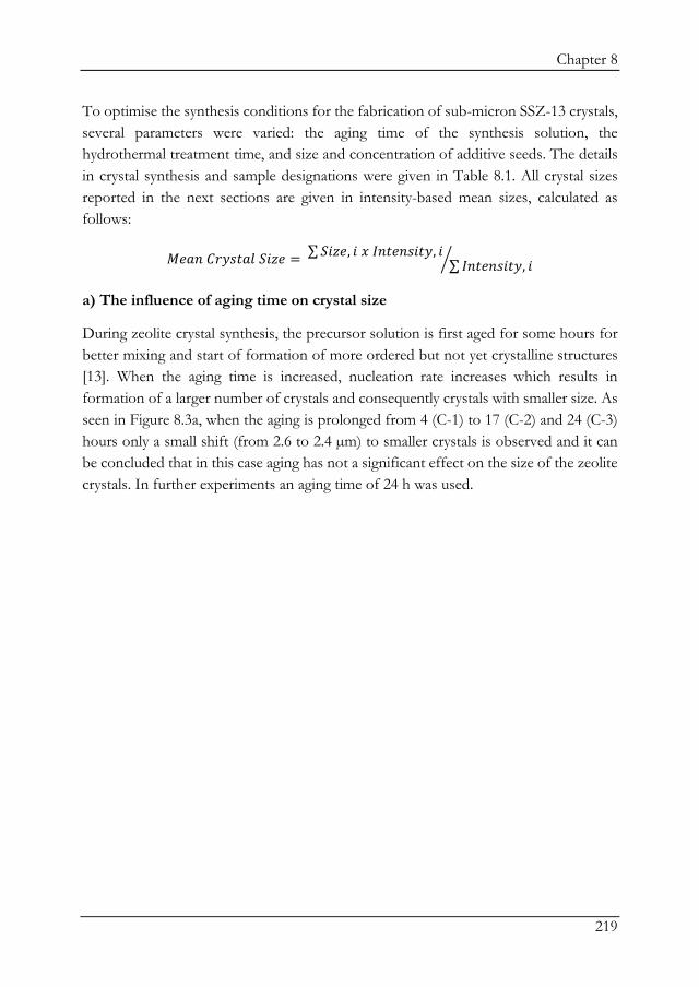
Chapter 8
219
To optimise the synthesis conditions for the fabrication of sub-micron SSZ-13 crystals, several parameters were varied: the aging time of the synthesis solution, the hydrothermal treatment time, and size and concentration of additive seeds. The details in crystal synthesis and sample designations were given in Table 8.1. All crystal sizes reported in the next sections are given in intensity-based mean sizes, calculated as follows:
𝑀𝑀𝑀𝑀𝑎𝑎𝑀𝑀 𝐶𝐶𝐶𝐶𝐶𝐶𝑎𝑎𝐶𝐶𝑎𝑎𝐶𝐶 𝑆𝑆𝑆𝑆𝑆𝑆𝑀𝑀 = ∑𝑆𝑆𝑆𝑆𝑆𝑆𝑀𝑀, 𝑆𝑆 𝑥𝑥 𝐼𝐼𝑀𝑀𝐶𝐶𝑀𝑀𝑀𝑀𝑎𝑎𝑆𝑆𝐶𝐶𝐶𝐶, 𝑆𝑆∑ 𝐼𝐼𝑀𝑀𝐶𝐶𝑀𝑀𝑀𝑀𝑎𝑎𝑆𝑆𝐶𝐶𝐶𝐶, 𝑆𝑆�
a) The influence of aging time on crystal size
During zeolite crystal synthesis, the precursor solution is first aged for some hours for better mixing and start of formation of more ordered but not yet crystalline structures [13]. When the aging time is increased, nucleation rate increases which results in formation of a larger number of crystals and consequently crystals with smaller size. As seen in Figure 8.3a, when the aging is prolonged from 4 (C-1) to 17 (C-2) and 24 (C-3) hours only a small shift (from 2.6 to 2.4 µm) to smaller crystals is observed and it can be concluded that in this case aging has not a significant effect on the size of the zeolite crystals. In further experiments an aging time of 24 h was used.

Chapter 8
220
Figure 8.3: a) Particle size distribution of C-1, C-2 and C-3 crystals as a function of aging time, b) Particle size distribution of C-3 and C-4 as a function of hydrothermal treatment time c) Particle size distribution of C-4 seeded by seed A (1.6 µm) and C-5 seeded by seed B (300 nm).

Chapter 8
221
b) The influence of hydrothermal synthesis time on crystal size
A hydrothermal treatment time of 16 and 72 h was applied (C-3, C-4) and it was found that the mean crystal size was reduced slightly from 2.4 µm (72 h) to 2.1 µm (16 h) as seen in Figure 8.3b.
The cubic structure of SSZ-13 was obtained even after the short crystal growth time as seen in Figure 8.4.
Figure 8.4: SEM images of a) C-3 (72 h synthesis) and b) C-4 (16 h synthesis).
The 16 h synthesized crystals, as others, were found to have well-distinguished and completely fitting XRD patterns belonging to SSZ-13 (see Figure 8.2) confirming that even 16 h of hydrothermal treatment is sufficient for the synthesis of SSZ-13 crystals under the given conditions. Therefore, in further experiments a crystal growth time of 16 h was used.
c) The influence of seed size and concentration on crystal size
Even though several synthesis parameters were varied up till now, the smallest crystal size was only around 20 % of that of the biggest one (2.1 to 2.6 µm). In order to investigate whether the crystal size is limited by the size of the seeds used in the solution, two other seeds were studied. So far, results from seeds with a size of around 1.6 µm (seed A, Table 8.1) were used which was described in our earlier work [3]. In one experiment (crystals C-5) seeds with a size of around 300 nm (seed B) were used, as kindly provided from Delft University of Technology [15]. When seed B was used, a sharp decrease in crystal size was obtained from 2.6 µm (using seed A) to 1.3 µm (using seed B) as seen in Figure 8.3, Figure 8.5a and Figure 8.5b.

Chapter 8
222
Figure 8.5: SEM images of the crystals synthesized by using a) seed A (C-4), b) seed B (C-5), c-d) seed C (C-6) (d: FE-SEM).
The influence of the seed size on the final crystal size was clearly demonstrated. Another way to produce smaller seeds is by milling larger seeds. Therefore the C-4 crystals were ground to fabricate smaller seeds. The mean size of the new seeds (seed C) was 200 nm as shown in Figure 8.6a.

Chapter 8
223
Figure 8.6: a) Particle size distribution of seed C (ground and filtered C-4) and b) of the crystals C-6, C-7 and C-8 using respectively an increasing amount of seed C.
Subsequently crystals were synthesized by using these 200 nm seeds and the crystal size is even found to be reduced to 430 nm (Figure 8.6b, C-6), which is the smallest size achieved as a result of the reduced size of initial seeds. The SEM images of these crystals (seeded by seed C) are shown in Figure 8.5c and Figure 8.5d.

Chapter 8
224
Furthermore, the effect of seed concentration was investigated using seed C. The seed concentration in the crystal synthesis solution was increased from 0.5 to 2 and 10 wt.%. The particle size distribution of the crystals are shown in Figure 8.6b.
It was observed that, besides the seed size, also the seed concentration has a significant effect on the crystal size. Even though the seed concentration was increased 5 times (2 to 10 wt.%), the change in the resulting crystal size was very small (320 to 280 nm). Therefore, it is decided not to continue increasing the seed concentration for further reducing the crystal size.
The mean sizes of the synthesized crystals are summarised in Table 8.3.
Table 8.3: The mean size of the SSZ-13 crystals synthesized in this study. Crystal C-1 C-2 C-3 C-4 C-5 C-6 C-7 C-8
Size [µm] 2.6 2.5 2.4 2.1 1.3 0.43 0.32 0.28
8.3.2. Membrane synthesis via secondary growth
The crystals having particle sizes of 280 nm (C-8), 430 nm (C-6) and 1.6 µm (seed A) with a monodispersed particle size distribution were used to be dip-coated on the alumina substrate. These seeds were all big enough for suitably coating on α-alumina substrates, which have a pore diameter of 80 nm. During dip-coating, the crystal concentration in the suspension was varied. Also, a range of H2O:SiO2 ratios and hydrothermal treatment times were used during the secondary growth stage. The microstructure and performance of the membranes were studied by SEM, single gas permeance and CO2/CH4 as well as CO2/Xe gas separation measurements.
a) The influence of concentration of crystal suspension during dip-coating
The concentration of the crystal suspension was varied to optimize the concentration resulting in complete coverage. In this case crystals with size of 430 nm (C-6) were used.
The thickness of the membranes was found to be decreasing by decreasing the seed concentration as seen in Figure 8.7.

Chapter 8
225
Figure 8.7: Cross-sectional SEM images of the membranes grown using a) 0.125 wt.% (M-1), b) 0.0625 wt.% (M-2) and c) 0.03125 wt.% (M-3) crystal containing dip-coating suspension. C-6 crystals were used during dip-coating.
When the crystal concentration during dip coating is reduced by a factor of 4, the zeolite layer reduces almost 50% in thickness. This is as expected considering that a higher amount of crystals can result in a faster growing of the layer and subsequently a thicker layer. It was also observed that membrane M-1 has some small pin-holes visible in the cross-sectional images showing that this layer is not as compact as the other ones (M-2 and M-3). These pin-holes can be regarded as defects, formed due to an excessive amount of crystals growing at the same time, causing stresses and resulting in the formation of a less compact layer.
The single gas permeance of these membranes were measured and plotted in Figure 8.8.

Chapter 8
226
Figure 8.8: Single gas permeance of M-1, M-2 and M-3 at room temperature and 2 bar of transmembrane pressure.
From these results it can be seen that M-1 and M-2 exhibited higher gas permeances than M-3 despite their layers being thicker. This could be due to the pin-holes visible in membrane M-1, which maybe also present on a smaller scale in M-2. These defects can behave as additional pathways for gas transport. Membranes M-2 and M-3 showed almost similar CO2 permeances whereas less N2 and CH4 permeated through M-3. Therefore, the highest CO2/CH4 permselectivity was obtained for M-3 as indicated in Table 8.4. The relative high CO2 permeance values is caused by the fact that the transport of CO2 takes place via adsorption and diffusion whereas for other gases diffusion is the dominating transport mechanism [3,22]. The low permeance values for N2 and CH4 of M-3 is also an indication that this membrane is more compact and/or contains less defects than membranes M-1 and M-2.

Chapter 8
227
Table 8.4: Gas permeances measured at room temperature (22 °C) and 2 bar of transmembrane pressure and calculated CO2/CH4 permselectivities.
Membranes Gas Permeance
[10-9 mol m-2 s-1 Pa-1] Permselectivity
CO2/CH4 Thickness
[µm] He H2 CO2 N2 CH4
M-1 250 1060 934 230 92 10 1.9 M-2 234 766 436 178 59 7 1.5 M-3 48 211 518 32 13 40 1.1 M-4 66 199 421 55 31 14 1.8 M-5 371 943 535 236 282 2 1.2 M-6 177 904 819 166 39 21 1.3 M-7* 5.5 16 111 2.4 4.3 26 2.2 M-8* 55 575 353 143 81 31 3.6
*: These single gas permeances were also reported in earlier work [3].
b) The influence of the H2O:SiO2 ratio in the secondary growth solution
In order to increase the nutrients concentration and to promote crystal growth, while avoiding the formation of any possible defects, the H2O:SiO2 ratio was decreased from 80 to 40. However, as seen in Table 8.4, the membrane performance of the concentrated system (M-4) was not improved as compared to the less diluted one (M-3). The CH4
permeance in M-4 was found to be higher and therefore the CO2/CH4 permselectivity was not as high as in the case of M-3. Moreover, the CO2 permeance was also lower which was due to the increased layer thickness from 1.1 to 1.8 µm.
Hence, it is concluded that the diluted systems (H2O:SiO2 of 80) works better in terms of a higher CO2 permeance as a result of thinner layer. An excess of nutrients would possibly cause too fast growth and defect/crack formation. Therefore, in the next membrane preparations, a diluted crystal growth solution was used.
c) The influence of hydrothermal treatment time
The hydrothermal treatment time was reduced from 18 to 9 h in order to see if in this way a thinner zeolite could be obtained, while preserving a compact and defect-free layer. Here the same synthesis conditions were used as that of the thinnest membrane obtained until now, M-3. However, the resulting membrane (M-5) was found to be defective and has high gas permeances before the removal of the structure directing agent by calcination, as seen in Figure 8.9. The calcined membrane M-5 has similar gas permeances as the bare α-alumina support, proving the large defect density. Here, the

Chapter 8
228
gas transport mainly takes place through the defects instead of the pores of the zeolite layer.
Figure 8.9: Single gas permeance of M-5, calcined and uncalcined, in comparison to alumina support gas permeances as measured at room temperature and 2 bar of transmembrane pressure.
d) The influence of crystal size
The smallest crystal, C-8 (280 nm), was also used to synthesize a membrane (M-6) under the same conditions as M-3 in terms of concentration of coated crystals, H2O:SiO2 ratio and crystal growth time. The thickness of membrane M-6 (1.3 µm) was found to be almost similar to that of M-3 (1.1 µm). However, as seen in Table 8.4, the gas permeances were found to be much higher than that of M-3, especially for larger gases, which in turn results in a lower CO2/CH4 permselectivity of 21 whereas M-3 exhibits a value of 40. This in combination with the higher gas permeances of M-6 compared to M-3 indicates that the M-6 layer contains defects. Indeed, the H2/CO2 and H2/CH4 permselectivities of 1.76 and 3.34 for M-6 are close to the Knudsen selectivities (4.69 and 2.82, respectively) proving that the layer contains defects in the Knudsen regime ( > 2 nm).

Chapter 8
229
From all these layer characterization and gas performance results, M-3 was found to be the most optimal membrane in terms of layer thickness, gas permeances (of CO2) and permselectivities as reported in Table 8.4. Therefore this membrane was further studied on mixed gas separation performance, together with the membranes M-7 and M-8 as developed in previous work [3].
e) Gas separation performances of thin and thick SSZ-13 membranes
Gas separation measurement with an equimolar CO2/CH4 mixture was performed on SSZ-13 membranes with layer thicknesses of 1.1 µm (M-3), 2.2 µm (M-7) and 3.6 µm (M-8). These membranes showed the highest permselectivity (or ideal selectivity) values for all samples studied, where the thinnest one (M-3) shows the highest value (see Table 8.4). The gas CO2/CH4 separation values at 25 °C and 1 bar are shown in Table 8.5.
Table 8.5: Mixed gas separation performance of M-3, M-7 and M-8 membranes using CO2:CH4 mixture with equimolar ratio at 25 °C and 1 bar of transmembrane pressure.
Membranes Layer Thickness
[µm] CO2 permeance
[10-7 mol m-2 s-1 Pa-1] 𝜶𝜶𝑪𝑪𝑪𝑪𝟐𝟐/𝑪𝑪𝑪𝑪𝟒𝟒
M-3 1.1 0.67 3.6 M-7 2.2 1.27 15 M-8 3.6 1.00 43
Here, the membrane performance in terms of CO2/CH4 separation factors were found to be higher when the membrane layer is thicker. A thicker membrane layer creates much higher gas transport resistance for CH4, while for CO2 the gas transport mechanism is via diffusion and selective adsorption in the zeolite pores resulting in relative high CO2 permeances even though the layers are thicker. The M-3 membrane was found to have lower CO2/CH4 separation factors compared to its ideal selectivity (40, see Table 8.4). This suggests that M-3 might have some defects which enables CH4 to transport. This resulted in lower CO2/CH4 separation factors than those of the thicker membranes (M-7 and M-8). The thicker membranes, on the other hand, show higher separation factors than their ideal CO2/CH4 selectivities (see Table 8.4) proving the compact and defect-free nature of the layers. These defect-free layers become a much stronger barrier for CH4 diffusion with increased thickness while the CO2 is still selectively adsorbed in the SSZ-13 pores and therefore hinder the CH4 permeance, which is a weaker adsorbing gas.

Chapter 8
230
The CO2/CH4 mixture selectivity of M-8 was found to be 1.5 times higher than the permselectivity which also confirms that the separation is based on adsorption and diffusion selectivity. Since the best separation performance was obtained by membrane M-8, the CO2 and CH4 permeances and CO2/CH4 separation factors of this membrane were further investigated at a range of transmembrane pressures and temperatures, as shown in Figure 8.10.
Figure 8.10: Mixed gas CO2/CH4 (1:1) separation performance of M-8 as a function of a) pressure and b) temperature.

Chapter 8
231
The positive influence of pressure (see Figure 8.10a) on the separation factor is clearly visible. This is again due to the preferential adsorption of CO2 in the zeolite pores where CH4 weakly interacts. As a result, the separation factors significantly increased from 43 to 70 at 5.5 bar as also observed in the work of Kosinov et al. [23] with separation factors increasing from 32 to 37 when the pressure was increased from 1 to 6 bar.
The influence of temperature on the separation factor was also studied (see Figure 8.10b). Temperature has a positive effect on diffusion and a negative effect on adsorption selectivity [24]. Therefore, the CO2 permeance was lower at higher temperatures and the CH4 permeance increased. The lack of competitive adsorption selectivity at higher temperatures results in a decrease in separation factor.
Furthermore, M-8 was tested for another gas pair, CO2:Xe, in an equimolar feed. The results are shown in Figure 8.11.
Figure 8.11: Mixed gas CO2/Xe (1:1) separation performance of M-8 at different temperatures.
The membrane exhibits also very high CO2:Xe separation factors. The CO2 permeance was slightly lower than that observed in CO2:CH4 mixtures due to the strong adsorption of Xe [18]. Xe is a sticky gas which adsorbs at the pore entrance and therefore blocks the pathway for CO2 permeance. Yet, the CO2/Xe separation factor reaches values as high as 1500 because of the relatively large gas kinetic diameter of Xe (0.41 nm)

Chapter 8
232
compared to the small pores (0.38 x 0.38 nm) of the SSZ-13 membranes. As also observed in the CO2:CH4 mixtures, the CO2 permeance is decreased with temperature due to lowered adsorption selectivity. However, even at 200 °C a separation factor of 260 was observed, showing the good performance of the SSZ-13 membranes for the separation of CO2:Xe mixtures both at low and high temperatures. A separating factor of 1500 as observed in the low temperature experiments is found to be the highest ever reported in literature as shown Table 8.6 where the previous highest values of 620 were achieved by DDR membranes and 500 by SAPO-34 [25].
Table 8.6: The CO2/Xe selectivities of different membrane materials.
Reference Membrane Pressure
[bar] Temperature
[°C] CO2/Xe
[26] CMS 2 27 160* [25] SAPO-34 1 22 500** [27] PIM-1 1 40 42** [28] PDMS 1.7 30 1.4** [18] MFI 1.5 25 4.7* [29] DDR 1.2 25 620*
This work SSZ-13 1 25 1500*
[*]: separation factor, [**]: ideal selectivity (or permselectivity)
The high separation factor together with high CO2 permeance shows that the SSZ-13 membrane, as described in this paper has a great potential to be used for the recovery of Xe from exhaled breath.
8.4. Conclusions
Sub-micron sized SSZ-13 crystals were fabricated via hydrothermal treatment and used for zeolite membrane fabrication. Several synthesis parameters such as hydrothermal treatment time, aging time, seed size and seed concentration were studied to show their effect on the crystal size. Many parameters were found to have very slight effect on the final crystal size except the size of the SSZ-13 seeds used to catalyse the formation of SSZ-13 crystals. By the use of small seeds with a size of 200 nm, obtained by grinding of bigger seeds, sub-micron (down to 0.4 μm) SSZ-13 crystals were fabricated. Here also a slight decrease in crystal size was observed when the concentration of seed crystals in the precursor solution was increased. These sub-micron SSZ-13 crystals were coated on a porous support for membrane layer formation via secondary growth.

Chapter 8
233
For the membrane synthesis, many parameters such as crystal concentration during coating, H2O:SiO2 ratio and hydrothermal treatment time were varied to find out the best performing and thinnest membrane. The thinnest, defect-free, membrane obtained had a thickness of 1.1 µm and exhibited high CO4/CH4 ideal selectivity of 40 with very high CO2 permeances 5.2 x 10⁻⁷ mol.m-2.s-1.Pa-1, which is very close to that of the bare α-alumina support (6.7 x 10⁻⁷ mol.m-2.s-1.Pa-1). However, the separation performance of a CO2:CH4 gas mixture was found to be lower (3.6) compared to thicker (3.3 µm) SSZ-13 membranes. These thicker SSZ-13 membranes showed a relatively high CO2/CH4 separation factor of 43 and 70 at 1 and 5.5 bar, respectively. Also, they exhibited an extremely high separation performance in the CO2:Xe mixtures. CO2/Xe separation factors of 1500 were reached which are the highest values reported so far. These results show the suitability of the promising SSZ-13 membranes to be used for the recovery of valuable anaesthetic Xe gas in medical applications.
8.5. Acknowledgements
This research is supported by Netherlands Technology Foundation (STW-13941). The authors acknowledge Tom Velthuizen from University of Twente for X-ray Fluorescence (XRF) measurements, Cindy Huiskes and Frank Morssinkhof from University of Twente for technical support. Also, we would like to thank Cabot Corporation (Riga, Latvia) for providing us CAB-O-SIL® M-5 high purity fumed silica for research purposes.
8.6. References
[1] M. Hong, S. Li, H.F. Funke, J.L. Falconer, R.D. Noble, Ion-exchanged SAPO-34 membranes for light gas separations, Microporous Mesoporous Mater. 106 (2007) 140–146. doi:10.1016/j.micromeso.2007.02.037. [2] G. Guan, K. Kusakabe, S. Morooka, Gas Permeation Properties of Ion-Exchanged Lta-Type Zeolite Membranes, Sep. Sci. Technol. 36 (2001) 2233–2245. doi:10.1081/SS-100105915. [3] P. Karakiliç, X. Wang, F. Kapteijn, A. Nijmeijer, L. Winnubst, Defect-free high-silica CHA zeolite membranes with high selectivity for light gas separation, J. Memb. Sci. 586 (2019) 34–43. doi:10.1016/j.memsci.2019.05.047. [4] N. Kosinov, C. Auffret, C. Gücüyener, B.M. Szyja, J. Gascon, F. Kapteijn, E.J.M. Hensen, High flux high-silica SSZ-13 membrane for CO2 separation, J. Mater. Chem. A. 2 (2014) 13083–13092. doi:10.1039/C4TA02744B.

Chapter 8
234
[5] B. Wang, Y. Zheng, J. Zhang, W. Zhang, F. Zhang, W. Xing, R. Zhou, Separation of light gas mixtures using zeolite SSZ-13 membranes, Microporous Mesoporous Mater. 275 (2019) 191–199. doi:10.1016/j.micromeso.2018.08.032. [6] S. Yang, Y.H. Kwon, D.Y. Koh, B. Min, Y. Liu, S. Nair, Highly Selective SSZ-13 Zeolite Hollow Fiber Membranes by Ultraviolet Activation at Near-Ambient Temperature, ChemNanoMat. 5 (2019) 61–67. doi:10.1002/cnma.201800272. [7] H. Kalipcilar, T.C. Bowen, R.D. Noble, J.L. Falconer, Synthesis and Separation Performance of SSZ-13 Zeolite Membranes on Tubular Supports, Chem. Mater. 14 (2002) 3458–3464. doi:10.1021/cm020248i. [8] L. Liang, M. Zhu, L. Chen, C. Zhong, Y. Yang, T. Wu, H. Wang, I. Kumakiri, X. Chen, H. Kita, Single Gas Permeance Performance of High Silica SSZ-13 Zeolite Membranes, Membranes (Basel). 8 (2018) 43. doi:10.3390/membranes8030043. [9] S. Song, F. Gao, Y. Zhang, X. Li, M. Zhou, B. Wang, R. Zhou, Preparation of SSZ-13 membranes with enhanced fluxes using asymmetric alumina supports for N2/CH4 and CO2/CH4 separations, Sep. Purif. Technol. 209 (2019) 946–954. doi:10.1016/j.seppur.2018.09.016. [10] T. Wu, J. Lucero, M.A. Sinnwell, P.K. Thallapally, M.A. Carreon, Recovery of xenon from air over ZIF-8 membranes, Chem. Commun. 54 (2018) 8976–8979. doi:10.1039/c8cc04154g. [11] L.C. Boudreau, J.A. Kuck, M. Tsapatsis, Deposition of oriented zeolite A films: In situ and secondary growth, J. Memb. Sci. 152 (1999) 41–59. doi:10.1016/S0376-7388(98)00166-5. [12] C. Algieri, G. Golemme, S. Kallus, J.D.F. Ramsay, Preparation of thin supported MFI membranes by in situ nucleation and secondary growth, Microporous Mesoporous Mater. 47 (2001) 127–134. doi:10.1016/S1387-1811(01)00393-6. [13] C.S. Cundy, P.A. Cox, The hydrothermal synthesis of zeolites: Precursors, intermediates and reaction mechanism, Microporous Mesoporous Mater. 82 (2005) 1–78. doi:10.1016/j.micromeso.2005.02.016. [14] Y.S. Yoo, H.J. Ban, K.H. Cheon, J.L. Lee, The effect of aging on synthesis of zeolite at high temperature, Mater. Sci. Forum. 620 622 (2009) 225–228. doi:10.4028/www.scientific.net/MSF.620-622.225. [15] N. Kosinov, C. Auffret, C. Gücüyener, B.M. Szyja, J. Gascon, F. Kapteijn, E.J.M. Hensen, High flux high-silica SSZ-13 membrane for CO2 separation, J. Mater. Chem. A. 2 (2014) 13083. doi:10.1039/C4TA02744B. [16] Database of Zeolite Structures, (n.d.). http://www.iza-structure.org/databases/ (accessed April 27, 2018).

Chapter 8
235
[17] P. Karakiliç, C. Huiskes, M.W.J. Luiten-Olieman, A. Nijmeijer, L. Winnubst, Sol-gel processed magnesium-doped silica membranes with improved H2/CO2 separation, J. Memb. Sci. 543 (2017) 195–201. doi:10.1016/j.memsci.2017.08.055. [18] X. Wang, P. Karakiliç, X. Liu, M. Shan, A. Nijmeijer, L. Winnubst, J. Gascon, F. Kapteijn, One-Pot Synthesis of High-Flux b-Oriented MFI Zeolite Membranes for Xe Recovery, ACS Appl. Mater. Interfaces. 10 (2018) 33574−33580. doi:10.1021/acsami.8b12613. [19] L.T. Yuen, S.I. Zones, CHA SSZ-13 Si(93), Al(7), in: H. Robson, K.P. Lilleruc (Eds.), Verif. Synth. Zeolitic Mater., 2nd ed., Elsevier Science B.V., 2001: pp. 126–128. [20] N. Kosinov, C. Auffret, C. Gücüyener, B.M. Szyja, J. Gascon, F. Kapteijn, E.J.M. Hensen, High flux high-silica SSZ-13 membrane for CO2 separation, J. Mater. Chem. A. 2 (2014) 13083–13092. doi:10.1039/c4ta02744b. [21] Z. Bohström, B. Arstad, K.P. Lillerud, Preparation of high silica chabazite with controllable particle size, Microporous Mesoporous Mater. 195 (2014) 294–302. doi:10.1016/j.micromeso.2014.03.030. [22] Y. Luo, H.H. Funke, J.L. Falconer, R.D. Noble, Adsorption of CO2, CH4, C3H8, and H2O in SSZ-13, SAPO-34, and T-Type Zeolites, Ind. Eng. Chem. Res. 55 (2016) 9749–9757. doi:10.1021/acs.iecr.6b02034. [23] N. Kosinov, C. Auffret, C. Gücüyener, B.M. Szyja, J. Gascon, F. Kapteijn, E.J.M. Hensen, High flux high-silica SSZ-13 membrane for CO2separation, J. Mater. Chem. A. 2 (2014) 13083–13092. doi:10.1039/c4ta02744b. [24] N. Kosinov, J. Gascon, F. Kapteijn, E.J.M. Hensen, Recent developments in zeolite membranes for gas separation, J. Memb. Sci. 499 (2016) 65–79. doi:10.1016/j.memsci.2015.10.049. [25] T. Wu, J. Lucero, Z. Zong, S.K. Elsaidi, P.K. Thallapally, M.A. Carreon, Microporous Crystalline Membranes for Kr/Xe Separation: Comparison Between AlPO-18, SAPO-34, and ZIF-8, ACS Appl. Nano Mater. 1 (2018) 463–470. doi:10.1021/acsanm.7b00343. [26] S. Lagorsse, F.D. Magalhães, A. Mendes, Xenon recycling in an anaesthetic closed-system using carbon molecular sieve membranes, J. Memb. Sci. 301 (2007) 29–38. doi:10.1016/j.memsci.2007.05.032. [27] P.M. Budd, K.J. Msayib, C.E. Tattershall, B.S. Ghanem, K.J. Reynolds, N.B. McKeown, D. Fritsch, Gas separation membranes from polymers of intrinsic microporosity, J. Memb. Sci. 251 (2005) 263–269. doi:10.1016/j.memsci.2005.01.009. [28] M. Malankowska, C.F. Martins, H.S. Rho, L.A. Neves, R.M. Tiggelaar, J.G. Crespo, M.P. Pina, R. Mallada, H. Gardeniers, I.M. Coelhoso, Microfluidic devices as

Chapter 8
236
gas – Ionic liquid membrane contactors for CO2 removal from anaesthesia gases, J. Memb. Sci. 545 (2018) 107–115. doi:10.1016/j.memsci.2017.09.065. [29] X. Wang, Y. Zhang, X. Wang, E. Andres-Garcia, P. Du, L. Giordano, L. Wang, Z. Hong, X. Gu, S. Murad, F. Kapteijn, Xe Recovery by DD3R Zeolite Membranes ‐ Application in Anaesthetics, Angew. Chemie - Int. Ed. (2019). doi:10.1002/anie.201909544.

Chapter 8
237


9
Reflections and Perspectives

Chapter 9
240
9.1. Introduction
This thesis deals with the design and characterization of microporous ceramic and zeolite membranes for application in energy efficient molecular separations in industrial process streams as well as for recovery of precious gases. It aims to develop robust, reproducible and easy to scale-up approaches for the production of thin, defect-free and highly performing membrane materials. This project was done in a collaboration between the Inorganic Membranes group of the University of Twente and the Catalysis Engineering group of the Delft University of Technology. Within this collaboration, the expertise on inorganic membrane synthesis and characterization developed and researched at the University of Twente and the knowledge on zeolite materials at the Delft University of Technology were blended to develop a fundamental understanding on novel approaches for zeolite membrane synthesis and characterization.
In this thesis, different inorganic membrane materials and their performance were investigated and they can be realized as consisting of three main parts.
i. Microporous amorphous sol-gel derived silica membranes and metal doping of these silica membranes as described in Chapter 2,
ii. High-silica MFI zeolite membranes fabricated by sol-gel derived silica membrane transformation and secondary growth methods in Chapter 4, Chapter 5 and Chapter 6,
iii. High-silica CHA zeolite membranes presented in Chapter 7 and Chapter 8.
This chapter reflects on the above three research lines, giving brief information on the importance of the findings, challenges – overcome and still present – and future possibilities for each part.
9.2. Reflections on microporous amorphous silica membranes and metal
doping
The sol-gel derived microporous amorphous silica membranes were developed in the early 90s of the last century by Uhlhorn and de Lange [1,2] in the group of K. Keizer and A.J. Burggraaf at the University of Twente. Their work gave lots of inspiration to many research groups for the further development and utilisation of these membranes in the membrane separation field. The developed silica membranes were coated on α-Al2O3 supported γ-Al2O3 layers. The γ-Al2O3 layer creates a buffer in terms of pore size and roughness, so that the silica particles of around 5 nm would not penetrate into the

Chapter 9
241
large pores, 80 nm, of the α-Al2O3 support. As a result, very thin, 70 nm, and homogeneous silica layers with an average roughness of 1 nm were prepared. The developed membranes have pore sizes of approximately 0.5 nm which allows the membranes to be utilised for gas pairs in the lower and upper regime of sub-nm levels. However, for lighter gas pairs, such as H2/CO2, the permselectivities were not extremely high, with maximum values of around 70. Therefore, in the current work, metal doping strategies were used to enhance the H2/CO2 selectivity. Pure magnesium doping was used for the first time. Magnesium is selected as being an alkaline earth metal with an affinity to CO2. It was found that by the incorporation of Mg, the single gas permeances of all gases were lowered because of pore narrowing of the amorphous silica matrix. When 20% Mg, the maximum concentration in this study, was used, the CO2 permeance was found to be below the detection limit while the permeance of larger gases (N2 and CH4) was still detectable meaning that it was not only the pore narrowing but also higher concentrations of Mg that caused the CO2 molecules to be adsorbed on the pore walls, avoiding its own permeance. The results were reproducible and 8 membranes showed the same gas permeance trend. In addition to the reported results, experiments were conducted using other metals such as Zr, but the changes were not as significant as in the case of Mg.
The preparation of the intermediate γ-Al2O3 layer and the sol-gel derived silica and/or metal-doped silica membrane took place in a cleanroom. The dip-coating sol (as coated in the cleanroom) was filtered several times to ensure that it was free of any dust particles. This is crucial for the fabrication of such delicate layers because even very small synthesis errors caused these membranes to contain defects, as observed when these synthesis experiments were conducted for the first time by students working on their graduation assignments as well as practical courses.
Regarding the reproducible characteristics of these membranes, it was difficult to repeat the single gas permeance measurements at high temperatures (around 200 °C) because the O-ring, used for sealing in the set-up, was strongly sticking to these membranes and the very thin SiO2 layer was removed together with the O-ring after the measurement. This was observed by the Rhodamine-B test. Rhodamine-B creates a pink layer when adsorbed on alumina, hence areas where the Rhodamine-B can reach the alumina layer (and hence where the defects are located) are pink coloured as shown in Figure 9.1.

Chapter 9
242
Figure 9.1: SiO2 membrane stained by Rhodamine B solution after high temperature single gas permeation analysis. Rhodamine-B does not react with SiO2 but is adsorbed on Al2O3. This “Rhodamine test” visually proves that the silica layer did not remain intact after high temperature gas permeance measurements due sticking of the sealing ring to the silica layer.
Another drawback of silica membranes is the lack of hydrothermal stability. When the membrane is exposed to water vapour, the siloxane bonds are broken and silanol groups are formed:
≡ 𝑆𝑆𝑆𝑆 − 𝑂𝑂 − 𝑆𝑆𝑆𝑆 ≡ + 𝑂𝑂2𝑂𝑂 ↔ 2 ≡ 𝑆𝑆𝑆𝑆𝑂𝑂𝑂𝑂
As the hydroxyl groups are the active sites for water interaction, condensation of surface silanol groups by steam exposure results in densification and collapse of micropores. So, the small pores are closed by the condensation and the larger pores are widened, which is detrimental to the membrane selectivity [3]. Many studies are done to improve the hydrothermal stability of silica membranes. The first one is by using organically-bridged silicon-alkoxides, like BTESE, instead of TEOS [4]. However, with the addition of these organic groups, the membrane is no longer inorganic and does not have stability at high temperatures (above 400 °C). Another method is metal-doping using transition metals since they form more stable bonds with oxygen than silicon does [5] and also a more closely packed and denser structure can be obtained due to the larger coordination number of these metal [6]. In our study with Mg-doping, we did not observe an improvement in the hydrothermal stability of the membrane. So, for future studies, co-doping of Mg and Zr could be an option while benefiting from the interaction of Mg and CO2 to have high H2/CO2 selectivities as well as the transition metals’ advantage on the hydrothermal stability improvement.

Chapter 9
243
9.3. Reflections on high-silica MFI zeolite membranes
The high-silica MFI membrane fabrication started with the “transition chapter”, Chapter 4, where the sol-gel derived amorphous silica were transformed into crystalline MFI layers. The reason of not using the most known and studied zeolite synthesis methods such as in situ synthesis and secondary growth methods as described in the review chapter, Chapter 3, was to benefit from the sacrificial silica layer which was already present on the surface and acts as silica source as well as providing nucleation centres on the support surface. The procedure, as described by Aguado et al. [7] was followed, where the structure directing agent (SDA) is introduced to the silica layers before hydrothermal treatment. This introduction of the SDA was by soaking the silica layers into an SDA solution for a given time which was not a very well controlled technique and small changes in weight (1–2% wt.%) were observed after SDA soaking.
After the hydrothermal synthesis, zeolite crystals were formed on the surface in many different sizes, numbers and orientation, depending on the experimental conditions. Many parameters were studied in detail to find the best layer formation, meaning thin, b-oriented and defect-free zeolite layers. However, these layers did either not fully cover the support due to insufficient growth of the crystals or many layers formed of arbitrarily deposited crystals which made the membrane layer much thicker. The synthesis parameter optimization allowed to obtain a relatively thin (3 µm) and completely b-oriented zeolite layer. However, these membrane layers were not suitable for gas separation due to defects as a result of not sufficiently intergrown crystals. The main reason for not obtaining a thin and well intergrown layer was due to the insufficient silica precursor coming from the 70 nm thick silica membrane. On the other hand, while the concentration of silica precursor added to the synthesis solution was increased, the crystals did form and were deposited on the support did not follow the preferred b-orientation. Thicker amorphous silica layers as precursor layers were not possible to synthesize with the sol-gel procedure that we were familiar with, and we were not able to develop a thicker mesoporous silica layer on alumina substrates with the used templated synthesis strategies as described in the work of Kao et al [8]. Therefore, the results as discussed in Chapter 4 provided us with a better understanding on silica transformation from amorphous to crystalline zeolites, while more research needs to be conducted – especially with thicker silica layers – to obtain defect-free and well intergrown layers suitable for light gas separation applications.
One possibility for future experiments would be developing the techniques of metal doping of the amorphous silica layer followed by silica transformation in order to

Chapter 9
244
fabricate zeolite membranes having different Si/Al ratios. For example using aluminium and phosphorus bi-doping, silicoaluminphosphate (SAPO) structures could be obtained. Also, the SDA, that the membrane was soaked into, could be varied in order to achieve the transformation of the silica layer into other zeolite frameworks.
In the follow-up research, as described in Chapter 5, done in collaboration with our project partners, it was shown that the silica transformation method coupled with the use of a zeolite growth modifier (ZGM) results in further intergrown b-oriented MFI crystals into a complete MFI zeolite layer in a one-step process. In the approach of coupling silica transformation and the use of zeolite growth modifiers, the aim of having high quality zeolite membranes was achieved with shorter synthesis times and less chemicals use. This strategy resulted in possible pathways for the (amorphous) silica transformation method and its extension to different zeolite materials and frameworks by metal doping into the initial zeolite layers.
The MFI zeolite membranes were also fabricated by the secondary growth method as discussed in Chapter 6. In many studies, the secondary growth method is regarded as the best way to control the zeolite synthesis and growth separately. In this way, thin, defect-free and b-oriented MFI layers were fabricated more easily as compared to the in situ synthesis like the one-step methods. The suitability of the attachment of zeolite seeds by manual assembly, or so-called “rubbing” on different supports were studied. When compared with an amorphous SiO2 or bare α-Al2O3 surface, the γ-Al2O3 layer, was found to be the most optimal layer for full coverage of seed crystals. Further in this work secondary zeolite growth was employed without the use of an expensive SDA, but with EtOH, which method was developed by our collaborators at the University of Utrecht [9]. Different Si/Al ratios were used in the secondary growth solution. The problems, which may arise from the absence of a conventional SDA could be overcome by a critical adjustment of the synthesis parameters and introducing mineralizers and allows the formation of a defect-free and well intergrown layer with tuneable Si/Al ratios. This work shows that the choice of the support not only depends on its mechanical strength, which is regarded as the first reason of using supported membranes, but also other properties are important for a strong and sufficient attachment for zeolite seeds, such as surface roughness, the presence and concentration of –OH groups and surface charge.
Also some preliminary studies were done on the use of organic linking agents for the attachment of MFI zeolites on the surface of a porous support, as schematically described in Figure 9.2.

Chapter 9
245
Figure 9.2: Conceptual scheme for grafting of zeolite crystals via organic linkers.
This work was introduced by Huang et al. [10,11] for FAU and LTA type zeolites, where they used 3-aminopropyl-tri-ethoxysilane (APTES) as covalent linking agent, with the ethoxy groups being the anchoring group, attached to the surface of the support, while the amino group is the functional group for chemically bonding of the zeolite. We have obtained a successful grafting of APTES on alumina supports, as confirmed by contact angle measurements. However no zeolite crystals were formed after hydrothermal synthesis which could be due to the stability of the APTES. APTES is known to be stable up to 110–130 °C at 1 bar [12,13]. At higher temperatures, the hydrogen bond between the silane molecule and surface hydroxyl groups breaks. The thermal stability in our case is lower considering the higher energy brought by high pressure during the hydrothermal synthesis (pressure of 10–15 bar). The thermal stability of APTES was not a problem for the synthesis of FAU and LTA as applied by Huang et al. [10,11] because the in situ synthesis of FAU and LTA takes place at 75 °C and 60 °C, respectively, whereas MFI zeolite synthesis requires much higher temperatures of around 150–170 °C. At that time, due to the time spent on this approach which was not fruitful, we changed our direction. However, looking back to this work now shows that other linkers for surface modification might have allowed us to synthesize zeolite membranes in this way. Especially, the phosphonate and alkene organic linkers are known to react at higher temperature and are more thermally stable than silane linkers [14,15] which would be a direction for anyone who would like to use support functionalisation techniques by the use of organic linkers for the fabrication of zeolite membranes.

Chapter 9
246
9.4. Reflections on high-silica CHA zeolite membranes
CHA zeolites have an 8-membered ring structure with smaller pore sizes (0.38 nm) than the 10-membered ring structure of MFI (0.55 nm) which allow them to be more suitable for light gas separations. Also, CHA zeolites have symmetric 3D porous structures meaning that the orientation is no longer a problem as in the case of MFI zeolites with 2D pore structures with different tortuosity: sinusoidal channels in the a-orientation and straight channels in the b-orientation.
However, for CHA structures, the more complex SDA, N,N,N-trimethyl-1-adamantammonium hydroxide (TMAdaOH), is used as compared to the SDA, tetrapropylammonium hydroxide (TPAOH), used in MFI synthesis as shown in Figure 9.3.
Figure 9.3: The structure directing agents a) TPAOH (for MFI framework) and b) TMAdaOH (for CHA framework).
It is known that there are numerous reasons why zeolite membranes are prone to form defects during their synthesis. When a more complex SDA (like TMAdaOH) is caged in the smaller pores of CHA, even the calcination process becomes problematic to avoid any defect or crack formation. In Chapter 7, a systematic approach was developed, where every step in the CHA membrane synthesis was studied. For the removal of the SDA, when using high calcination temperatures of up to 600 °C, as suggested by many researchers and confirmed by our TGA study, defects are formed. However, another suggested option [16,17] for low-temperature calcination (480 °C) caused incomplete burning of the SDA as visibly shown by the yellow/brown colour in Figure 9.4a and Figure 9.4b. Therefore, stepwise calcination treatment at moderate temperatures was developed as described in Chapter 7, which avoids formation of any defects/cracks. As

Chapter 9
247
shown in Figure 9.4c, the membrane has a relatively modest colour change showing that there was only very limited incomplete burning of SDA, which was also proven by XPS. This residual carbon did not cause any separation performance decrease as compared to the higher temperature calcined membranes. The low temperature calcination still opens the pores and also prevents formation of cracks induced by high temperature calcination. The SDA was removed from the pores as confirmed by the gas permeation analysis. The formed membranes were permeable for gases, especially N2 and CH4 whose kinetic diameters are very close to the CHA pore sizes.
Figure 9.4: Photographs of the CHA membranes and CHA zeolite crystals after calcination: a) CHA membrane calcined at 480 °C, b) CHA crystals calcined at 480 °C and c) CHA membranes calcined with a stepwise heating program up to 500 °C.
The CHA membranes exhibit decent permeances and permselectivities for CO2/CH4 separation. In a further step, oxygen plasma was used as a pre-treatment before calcination with the aim of relaxation of SDA, so that less stress is created, and easier removal. However, an unexpected effect of oxygen plasma was found: activating the surface hydroxyl groups of the SDA, followed by a reaction between the –OH groups of the surface and –N of the SDA which in turn narrowed the pore sizes of CHA membranes by formation of –N–OH groups at the pore entrance. In this way, while still keeping the high CO2 permeance, a much lower CH4 permeance was obtained, increasing the permselectivity value drastically.
Since the permeance of the gases are limited by the thickness of the zeolite layer, we have studied the ways to decrease the layer thickness other than by controlling the secondary growth conditions. The seed crystals which were used in Chapter 7 were around 1 µm. These crystals were grown into a complete layer in the secondary growth step. This resulted in a defect-free zeolite membrane layer with a thickness of 2.2 µm. The study on the size of CHA zeolite seed crystals, as given in Chapter 8, were conducted by varying many parameters during the seed synthesis. It was found that the

Chapter 9
248
greatest effect on the final crystal size was originating from the size of the seeds used in the synthesis. Therefore, starting seeds with a size of 1.6 μm were ground and these pieces were used as seeds for the following crystal synthesis. Depending on the seed ratio, crystals with a size of 200–400 nm were obtained. Membrane preparation using 400 nm crystals resulted in a dense layer with a thickness of 1.1 µm. Clearly, the seed size determined the layer thickness, and consequently the gas permeance values. These thinner membranes (1.1 μm) gave a more than 3 times higher CO2 permeance as compared to the thicker CHA membrane (2.2 μm) (resp. 7–9 and 2–3 x 10⁻⁷ mol m-2 s-
1 Pa-1 ) and slightly higher CO2/CH4 permselectivities (thicker: 25 ± 5, thinner: 35 ± 5). Here, the CO2 permeance was found to be almost at its highest possible value because it was very similar to the CO2 permeance through the bare α-Al2O3 support (around 7 x 10⁻⁷ mol m-2 s-1 Pa-1) showing that the main mass transfer limitation of this membrane is no longer coming from the zeolite layer but from the support itself. Therefore, to obtain even higher permeances, the (micro) structure of the support needs to be adapted, e.g. higher porosity, larger pore sizes and/or thinner supports. However, the support should have a suitable pore size (smaller than the size of the crystals, in our case 200 nm) to have a layer on the top but not inside its pores – which would cause much lower permeances.
Chapter 7 and Chapter 8 give the overall understanding on the fabrication of high quality, thin and defect-free CHA zeolite membranes. Even though different sizes of the seeds were used, a model can be built including the effect of the most important parameters which could be written down by a very simple empirical equation as:
𝑍𝑍𝑀𝑀𝑍𝑍𝐶𝐶𝑆𝑆𝐶𝐶𝑀𝑀 𝑀𝑀𝑀𝑀𝑀𝑀𝑀𝑀𝐶𝐶𝑎𝑎𝑀𝑀𝑀𝑀 𝑄𝑄𝑄𝑄𝑎𝑎𝐶𝐶𝑆𝑆𝐶𝐶𝐶𝐶 = 𝐴𝐴 𝑥𝑥 (𝑎𝑎𝑀𝑀𝑀𝑀𝑎𝑎 𝑎𝑎𝑆𝑆𝑆𝑆𝑀𝑀)𝑤𝑤 + 𝐵𝐵 𝑥𝑥 (𝑎𝑎𝑀𝑀𝑀𝑀𝑎𝑎 𝑐𝑐𝑍𝑍𝑀𝑀𝑐𝑐𝑀𝑀𝑀𝑀𝐶𝐶𝐶𝐶𝑎𝑎𝐶𝐶𝑆𝑆𝑍𝑍𝑀𝑀)𝑥𝑥 +𝐶𝐶 𝑥𝑥 (𝑎𝑎𝑍𝑍𝐶𝐶𝑄𝑄𝐶𝐶𝑆𝑆𝑍𝑍𝑀𝑀 𝑐𝑐𝑍𝑍𝑀𝑀𝑐𝑐𝑍𝑍𝑎𝑎𝑆𝑆𝐶𝐶𝑆𝑆𝑍𝑍𝑀𝑀)𝑦𝑦 + 𝐷𝐷 𝑥𝑥 (ℎ𝐶𝐶𝑎𝑎𝐶𝐶𝑍𝑍𝐶𝐶ℎ𝑀𝑀𝐶𝐶𝑀𝑀𝑎𝑎𝐶𝐶 𝐶𝐶𝐶𝐶𝑀𝑀𝑎𝑎𝐶𝐶𝑀𝑀𝑀𝑀𝑀𝑀𝐶𝐶 𝐶𝐶𝑆𝑆𝑀𝑀𝑀𝑀)𝑧𝑧
where A, B, C and D are constants and w, x, y and z are the powers showing to which degree the parameters affect the final zeolite membranes. Of course, more experiments need to be conducted to build such an exact relation. A detailed parametric study must be done to define the constants of the empirical model. A major extension for the future study could be the investigation of the interactive effects of these parameters. If one can develop such an empirical model, it could be used to predict the best recipe for the synthesis of zeolite membranes. This model would result in faster synthesis routes with less chemical waste for the development of the desired zeolite membranes, specifically for the symmetric 3D interconnected porous systems. For asymmetric zeolite frameworks, the formula should include the parameters affecting the seed orientation because of the difficulties caused by the differences in the pore channels along different

Chapter 9
249
directions (as in the case for MFI structure), or no channels in one direction (as in the case for 2D zeolite frameworks). Following this, new techniques for controlling the seed orientation, such as by different attachment methods as well as using zeolite growth modifiers as described in this thesis, could be implemented into the use of this empirical model in order to extend it into 2D or asymmetric channel containing zeolite frameworks.
9.5. Conclusions
Membrane fabrication requires fundamental understanding and knowledge about the membrane materials and engineering of membranes. In this thesis, three inorganic membrane materials were extensively studied each allowing to be used for different gas separation applications. All three type of membranes consist of silica either in amorphous form or crystalline zeolite form. We also demonstrated the transition from the amorphous silica to crystalline high-silica zeolite. The gas separation performance of amorphous silica membranes was improved by Mg-doping which is a novel dopant to silica systems. The transformation of amorphous silica layers into MFI zeolite layers was studied in detail to build an understanding on the synthesis parameters. The formation of defects of these transformed layers was prevented by the use of zeolite growth modifiers. Also, for MFI zeolite membrane synthesis, the secondary growth method is used to form Si/Al ratio tuneable zeolite membranes. In addition to MFI membranes, we have conducted a systematic study for the synthesis of defect-free SSZ-13 membranes. The calcination-related defect formation was overcome by optimization of the temperature program using stepwise dwells. The use of O2 plasma on SSZ-13 membranes allowed us to narrow down the size of pore entrances, by which we reduced the permeance of larger gases and obtained higher separation performances. Moreover, a detailed study was conducted to control the crystal size of the seeding crystals which allowed us to control the membrane layer thickness. A fundamental understanding on the fabrication, optimization and utilization of amorphous silica and crystalline high-silica zeolite membranes was developed. We have demonstrated the applicability of these membranes in the chemical industry for the separation of H2/CO2 and CO2/CH4. We have also broadened utilization area of these membranes to CO2/Xe, to medical applications, where the recovery of anaesthetic gas Xe is necessary. The closed-circuit anaesthetic xenon recovery using SSZ-13 membranes has high possibility to be a niche application of the developed membranes. Further research should be done on developing methods for applying zeolite layers on larger areas of supports with flat and tubular geometries, while preserving the defect-free and homogeneous nature.

Chapter 9
250
9.6. References
[1] R.J.R. Uhlhorn, K. Keizer, A.J. Burggraaf, Gas transport and separation with ceramic membranes. Part II. Synthesis and separation properties of microporous membranes, J. Memb. Sci. 66 (1992) 271–287. doi:10.1016/0376-7388(92)87017-R. [2] R.S.A. de Lange, J.H.A. Hekkink, K. Keizer, A.J. Burggraaf, Formation and characterization of supported microporous ceramic membranes prepared by sol-gel modification techniques, J. Memb. Sci. 99 (1995) 57–75. doi:10.1016/0376-7388(94)00206-E. [3] M.C. Duke, J.C. Diniz da Costa, D.D. Do, P.G. Gray, G.Q. Lu, Hydrothermally robust molecular sieve silica for wet gas separation, Adv. Funct. Mater. 16 (2006) 1215–1220. doi:10.1002/adfm.200500456. [4] M. ten Hove, M.W.J. Luiten-Olieman, C. Huiskes, A. Nijmeijer, L. Winnubst, Hydrothermal stability of silica, hybrid silica and Zr-doped hybrid silica membranes, Sep. Purif. Technol. 189 (2017) 48–53. doi:10.1016/j.seppur.2017.07.045. [5] S. Khanmohammadi, E. Taheri-Nassaj, Microporous silica-yttria membrane by sol-gel method: Preparation and characterization, Ceram. Int. 40 (2014) 9403–9411. doi:10.1016/j.ceramint.2014.02.010. [6] V. Boffa, G. Magnacca, L.B. Jørgensen, A. Wehner, A. Dörnhöfer, Y. Yue, Toward the effective design of steam-stable silica-based membranes, Microporous Mesoporous Mater. 179 (2013) 242–249. doi:10.1016/j.micromeso.2013.05.020. [7] S. Aguado, E.E. McLeary, A. Nijmeijer, M. Luiten, J.C. Jansen, F. Kapteijn, b-Oriented MFI membranes prepared from porous silica coatings, Microporous Mesoporous Mater. 120 (2009) 165–169. doi:10.1016/j.micromeso.2008.08.059. [8] K.C. Kao, C.H. Lin, T.Y. Chen, Y.H. Liu, C.Y. Mou, A General Method for Growing Large Area Mesoporous Silica Thin Films on Flat Substrates with Perpendicular Nanochannels, J. Am. Chem. Soc. 137 (2015) 3779–3782. doi:10.1021/jacs.5b01180. [9] D. Fu, J.E. Schmidt, Z. Ristanović, A.D. Chowdhury, F. Meirer, B.M. Weckhuysen, Highly oriented growth of catalytically active zeolite ZSM-5 films with a broad range of Si/Al ratios, Angew. Chemie - Int. Ed. 56 (2017) 11217–11221. doi:10.1002/anie.201704846. [10] A. Huang, F. Liang, F. Steinbach, J. Caro, Preparation and separation properties of LTA membranes by using 3-aminopropyltriethoxysilane as covalent linker, J. Memb. Sci. 350 (2010) 5–9. doi:10.1016/j.memsci.2009.12.029.

Chapter 9
251
[11] A. Huang, N. Wang, J. Caro, Seeding-free synthesis of dense zeolite FAU membranes on 3-aminopropyltriethoxysilane-functionalized alumina supports, J. Memb. Sci. 389 (2012) 272–279. doi:10.1016/j.memsci.2011.10.036. [12] M. Hijazi, V. Stambouli, M. Rieu, V. Barnier, G. Tournier, T. Demes, J.P. Viricelle, C. Pijolat, Synthesis and characterization of tin dioxide thick film modified by APTES in vapor and liquid phases, J. Mater. Sci. 53 (2018) 727–738. doi:10.1007/s10853-017-1541-4. [13] D.V. Quang, T.A. Hatton, M.R.M. Abu-Zahra, Thermally Stable Amine-Grafted Adsorbent Prepared by Impregnating 3-Aminopropyltriethoxysilane on Mesoporous Silica for CO2 Capture, Ind. Eng. Chem. Res. 55 (2016) 7842–7852. doi:10.1021/acs.iecr.5b04096. [14] S.P. Pujari, L. Scheres, A.T.M. Marcelis, H. Zuilhof, Covalent surface modification of oxide surfaces, Angew. Chemie - Int. Ed. 53 (2014) 6322–6356. doi:10.1002/anie.201306709. [15] G. Guerrero, J.G. Alauzun, M. Granier, D. Laurencin, P.H. Mutin, Phosphonate coupling molecules for the control of surface/interface properties and the synthesis of nanomaterials, Dalt. Trans. 42 (2013) 12569–12585. doi:10.1039/c3dt51193f. [16] T. Wu, M.C. Diaz, Y. Zheng, R. Zhou, H.H. Funke, J.L. Falconer, R.D. Noble, Influence of propane on CO2/CH4 and N2/CH4 separations in CHA zeolite membranes, J. Memb. Sci. 473 (2015) 201–209. doi:10.1016/j.memsci.2014.09.021. [17] Y. Zheng, N. Hu, H. Wang, N. Bu, F. Zhang, R. Zhou, Preparation of steam-stable high-silica CHA (SSZ-13) membranes for CO2/CH4 and C2H4/C2H6 separation, J. Memb. Sci. 475 (2015) 303–310. doi:10.1016/j.memsci.2014.10.048.


Acknowledgements
“Let us be grateful to the people who make us happy; they are the charming gardeners who make our souls blossom.”
– Marcel Proust (1871 – 1922)


Acknowledgements
255
Here starts the most read pages of a PhD thesis and I hope I can manage to express my gratitude to all of you who was with me with their friendship, encouragement and support during my 4-year PhD adventure.
First of all, I would like to express my thanks and appreciation to my promotor, Arian Nijmeijer for giving me the opportunity to conduct my PhD in Inorganic Membranes group. I met him during my MSc thesis assignment in the same group where gladly stayed here for my PhD studies. Thank you Arian for your support, guidance and providing me the opportunities to present my work in many international conferences and have fun in all the activities you granted me to attend.
I would like to thank to my daily supervisor Louis Winnubst. Louis, I feel the luckiest PhD candidate in this universe to have a supervisor like you. You were always there whenever I needed, your door was open anytime despite how late my experiments were running in the evening and I could still go to your office for a quick chat or brainstorming on my work. Even though you are every year for some months away in China, you always have time for me. It is not only scientific supervision you have given me but also I learned a lot from you: how to think or approach to a situation differently, how to be a good supervisor for my students, how to orient Dutch culture and language, and so many other things that would take pages. I have never regretted, not a single moment, that I had chosen staying here for my PhD instead of going to any other place. You were like a friend to me as much as a supervisor. Thank you Louis, you shaped me a lot to be the person and scientist as I am today! And also thank you for attending my wedding this summer and, all the dances and fun we had together!
I would like to also acknowledge my project partners. My co-supervisor Freek Kapteijn, I learned a lot from you during our fruitful discussions in the meetings. Xuerui Wang, who joined me on the last 2 years of this project as a PostDoc and contributed us to finalize the project faster and successfully. I also thank Shell, Pervatech and Atlas Copco together with NWO for financial support of my project.
I would like to thank my committee members for reading and approving my thesis: André ten Elshof, Guido Mul, Freek Kapteijn, Martin van Sint Annaland and Joe da Costa.
My paranymphs, Renaud and Mariël, thank you for being my dear friends and my paranymphs. Renaud, you are the oldest friend of mine in this PhD journey. We had our MSc in France, Czech Republic and the Netherlands together and stayed together in the same group for our PhDs. You are a great friend, you were there any time for me

Acknowledgements
256
whenever I was in need of talk and wrote you “Bro, coffee break?”. I learned a lot from you, had so much fun in and outside the university with you and I know you will stay as a dear friend of mine in the future. Mariël, you are a great friend of mine, and I feel so lucky to sit close to you in the office to have a quick chat or update in our lives any time, both PhD-related and personal. I am happy to think of all the memories we shared and I know we will have more in the future. I would like to thank both of you, Renaud and Mariël for sharing and celebrating my happiness in my wedding!
I would like to express my gratitude to all the former and current members of Inorganic Membranes (IM) group and Membrane Science and Technology (MST) cluster. Cindy, you are a great mentor since my MSc time until the end of my PhD. All the things that I learned from you is so valuable and I appreciate your help, support and encouragement. Frank, a group without you cannot be thought of! Not only your help on the technical problems, but also your cheerful attitude whenever I see you made my every day. My current officemates Mariël, Anne, Akbar, Zainab, Jason, Farzaneh, Renaud, Nikos and Shaochen and old officemates Kristianne, Evelien, Rian, Patrick, Emiel and Michiel: Thank you for keeping ME236b great and fun! It was a more than 40 hours working place for me for most of the weeks, and I enjoyed it a lot with you all. Nieck, Henny, Mieke, Antoine, Rob, Wiebe, Jeff, Marie, Susanne, Annet, Jan, Ineke, Bob, Alberto, Denys, Herman, Harmen: thank you for your help and discussions we had. Special thanks to the winterschool team who made it a great fun and also helped me to improve my skiing skills! Hani and Donna, you are the smiling faces of our group making me smile as well, thank you for this! Anne, it was great to sit next to you because I love talking with you and appreciate the peaceful feeling you give me every time! My MSc students, Ryo Toyoda and Ilse Lammerink: Not only I taught you membranes and gas separation, but also I learned a lot from you. Thank you for your contribution to my project. Many thanks to all other members of our MST cluster: Abimbola, Almohanad, Ameya, Arputha, Audrey, Aura, Baig, Dennis, Elif, Erik, Esra, Heleen, Iske, Joanna, Joris, Josh, Jurjen, Khalid, Liniker, Mees, Mehrdad, Moritz, Nicole, Oğuz, Özlem, Pim, Piotr, Rosalind, Shuyana, Tymen, Walter, Willi, Wouter and Youri. It was a great pleasure to working with you all!
To my group-in-law, Nanoelectronics group, thank you for accepting me as a member of your group via Yiğitcan and all the fun we had together, special thanks to Robert, Michal, Bram, Pavel and Sander.

Acknowledgements
257
Here, I learned that, while I was living away from my family, friends became my family. Merve, Durubalim, my closest friend since my bachelor time, you were always with me any time I needed, you listened to me and supported me during these years, came from Turkey for all the concerts and festivals we attended in the Netherlands, and now you being in Eindhoven makes me even happier that we shortened the distances and can spend more time together. İlknur, my great friend, thank you for your friendship and support despite the distances, I feel so lucky to have you. Bilge and Cemre, my dear friends since high school times, I am so glad to have you with me all these years spent with great friendship and nice memories. Sinem, thank you for one year we spent in the university before your graduation and also the years after. We shared a lot, you listened me any time I needed you and you were always there for me. Ertuğ, my dear spirit brother, you gave me support and energy any time I needed and now I am so happy that you and Dilek will be closer to me after you started living in Amsterdam. Ozan, we shared a lot, we talked a lot and I am so grateful to have you as my dear friend. Erkan and Sıla, you make me feel that I am surrounded by the sincere friendship I was missing since my METU times until I met you and your friendship gives me happiness and peace. Beybin, what a great friend you are with your always positive nature, thank you for your support during all these years. Together with Onur, I enjoyed spending time together. Senem and Ozan Ç., seeing your sincere smile makes my day every time. Laila, I appreciate your energy and support, I was so happy that you stayed in Europe after our MSc instead of returning back to Mexico, so that we had a lot together. My Turkish lunch group, not only spending lunch breaks together but also outside time of gathering, BBQs, moving/cleaning anyone’s new house and partying: Akın, Armağan, Burcu, Cihan, Deniz, Derya Atac, Derya Demirtas, Devrim, Güner, Muharrem, Nurcan, Oğuzhan, Seda and Tuğçe. Thank you for all the memories we shared together, your help and friendship.
My dear family.. Annecim, thank you for raising me with strong personality and ethics. Your support is the most valuable thing in my life, and I know no matter how difficult it was to be separated since my MSc, you have always supported me and I always felt you being with me whenever I needed and missed you. You were my role model to stay strong, responsible and proud of my actions. Babacim, thank you for all the effort you put to raise me with strong background, being my first teacher after you retired and laying the foundation of my education with reading, writing and basic of math skills when I was 4 years old. Esincim, Ablacim, you are the greatest sister and I feel the luckiest person having you. You supported me with everything, from my early age, and I cannot thank you enough for this. A life without your sisterhood would be so lonely.

Acknowledgements
258
My brother-in-law, Mehmet Abi, I admire your kind personality and intelligent way of thinking and expressing your thoughts. I learned a lot from you, and mostly how I should proceed to be successful and be on the way that I am now. My dear nephew, Demir, you are the cheer of my life! Most of the time, I felt so sorry not to be with you when you were growing up while I was away abroad, but I always think of you and in the hard times, the brilliant and funny videos of yours always made me smile. You are an extraordinary child and I am so grateful that you are my nephew!
I also would like to thank my family in-laws who became the other half of my family thanks to their care and support despite a few years to know each other: My mother-in-law, Yıldız Anne, thank you for your positive and respectful character and your support. My father-in-law, İrfan Baba, you make me smile anytime talking to you and I appreciate you being always supportive and generous by asking me every time if I need of anything. My brother-in-law, Selim Abi, despite the short time we spent together, I feel so close to you and appreciate your good nature and colourful personality.
And lastly, my dear husband, Yiğitcan, the words are just not enough to express my feelings and gratitude towards you. You have done everything for me to make me happy and strong, especially in the hard times of PhD. You are my light, always enlightening me and our house with your cheerful and positive nature despite the dark and depressing rainy days or hard times. You give me energy to stand again to overcome any difficult situation and supported me every time. With you, I am who I am now: happier, stronger and serene. The greatest coincidence and surprise of life for me is definitely finding you here, when both of us were away from our countries. When I now look back to the memories we had together, the words became insufficient to express my happiness. I feel the luckiest woman in the world to have such great, caring and loving husband. You became my best friend, and my family. I am grateful for everything we had together and looking forward to future which will bring us even more lovely days. Seni seviyorum!

Acknowledgements
259


261
About the Author
Pelin Karakılıç was born on the 27th of April 1990 in Iskenderun, Turkey. In 2013, she graduated from Chemical Engineering department at the Middle East Technical University among the top students and obtained an high honour degree. After her bachelor studies, she continued with master studies in Erasmus Mundus Master in Membrane Engineering (EM3E) programme where she fulfilled the requirements of all three universities and obtained three MSc diplomas from University of Montpellier, Institute of Chemical Technology Prague and University of Twente. She completed her master thesis entitled as: “Sol-gel processed metal-doped silica membranes for gas separation” at the Inorganic Membranes group at University of Twente in July 2015.
Starting from October 2015, she has been working as a PhD candidate at the Inorganic Membranes group at the University of Twente under the supervision of Prof. Dr. Louis Winnubst on the fabrication of ceramic and zeolite membranes. Her research was presented at multiple international conferences and workshops, including the Gordon Research Conference on Nanoporous Materials and Their Applications (2018, Andover, USA) GEZ School on Zeolites (2017, Madrid, Spain), International Conference on Inorganic Membranes (2018, Dresden, Germany) and International Zeolite Membrane Meeting (2019, Luleå, Sweden).
Starting from February 2020, she will be working as a New Technology Material Scientist at Sibelco, Maastricht.


263
Scientific Output
Peer-reviewed journal articles
Per September 2019
1. Karakiliç, P., Wang, X., Kapteijn, F., Nijmeijer, A., Winnubst, L. (2019). Defect-free high-silica CHA zeolite membranes with high selectivity for light gas separation. Journal of Membrane Science, 586, 34-43.
2. Karakiliç, P., Toyoda, R., Kapteijn, F., Nijmeijer, A., Winnubst, L. (2019). From amorphous to crystalline: Transformation of silica membranes into silicalite-1 (MFI) zeolite layers. Microporous and Mesoporous Materials, 276, 52-61
3. Wang, X., Karakiliç, P., Liu, X., Shan, M., Nijmeijer, A., Winnubst, L., Gascon, J., Kapteijn, F. (2018). One-Pot Synthesis of High-Flux b-Oriented MFI Zeolite Membranes for Xe Recovery. ACS Applied Materials and Interfaces, 10(39)33574-33580.
4. Fu, D., Schmidt, J.E., Pletcher, P., Karakiliç, P., Ye, X., Vis, C.M., Bruijnincx, P.C.A., Filez, M., Mandemaker, L.D.B., Winnubst, L., Weckhuysen, B.M. (2018). Uniformly Oriented Zeolite ZSM-5 Membranes with Tunable Wettability on a Porous Ceramic. Angewandte Chemie – International Edition, 57(38), 12458-12462.
5. Karakiliç, P., Huiskes, C., Luiten-Olieman, M.W.J., Nijmeijer, A., Winnubst, L. (2017). Sol-gel processed magnesium-doped silica membranes with improved H2/CO2 separation. Journal of Membrane Science, 543, 195-201.
Selected conference presentations
1. Karakiliç P. (oral presentation), Nijmeijer A., Winnubst L. (2019). High silica (SSZ-13) CHA membranes for gas separation applications, 8th International Zeolite Membrane Meeting, IZMM2019, 16-20 June, Luleå, Sweden.
2. Karakiliç P. (oral presentation), Nijmeijer A., Winnubst L. (2018). New Avenues for the Fabrication of Zeolite Membranes for Gas Separation Applications, 15th International Conference on Inorganic Membranes, 18-22 June, Dresden, Germany.

264
3. Karakiliç P. (oral presentation), Toyoda R., Nijmeijer A., Winnubst L. (2017). New Avenues for the Fabrication of Zeolite Membranes for Gas Separation Applications, GEZ School on Zeolites, 27-29 September 2017, Universidad Rey Juan Carlos, Madrid, Spain.
4. Karakiliç P. (poster presentation), Toyoda R., Nijmeijer A., Winnubst L. (2017). New Avenues for the Fabrication of Zeolite Membranes for Gas Separation Applications, Gordon Research Conference (GRC) on Nanoporous Materials and Their Applications, 5-11 August 2017, Andover, NH, USA.
Copyright © 2022 FDOKUMEN