Nguyen 2012 Ethanol electro oxidation activity of Nb doped Ti O2 supported Pd Ag catalysts in...
10
Applied Catalysis B: Environmental 113–114 (2012) 261–270 Contents lists available at SciVerse ScienceDirect Applied Catalysis B: Environmental jo ur n al homepage: www.elsevier.com/locate/apcatb Ethanol electro-oxidation activity of Nb-doped-TiO 2 supported PdAg catalysts in alkaline media Son Truong Nguyen, Yanhui Yang, Xin Wang ∗ School of Chemical and Biomedical Engineering, Nanyang Technological University, 62 Nanyang Drive, Singapore 637459, Singapore a r t i c l e i n f o Article history: Received 18 July 2011 Received in revised form 17 October 2011 Accepted 27 November 2011 Available online 6 December 2011 Keywords: Ethanol oxidation Palladium-silver Direct ethanol fuel cell Nb-doped TiO2 a b s t r a c t Various mesoporous Nb-doped titania materials were synthesized by a hydrothermal method and exam- ined as catalyst support for PdAg alloy particles for alkaline direct ethanol fuel cell (ADEFC). X-ray diffraction, nitrogen adsorption/desorption, transmission electron microscopy (TEM), cyclic voltammetry (CV) and chronoamperometry (CA) were used to investigate the properties of the supports and catalysts. 700 ◦ C was found as the optimal activation temperature for Nb-doped TiO 2 due to the high electronic con- ductivity achievement and mesoporosity conservation. X-ray diffraction (XRD) revealed that Nb x Ti 1−x O 2 had a structure of mixed anatase and rutile phases. PdAg/Nb x Ti 1−x O 2 exhibited excellent performance for the electrooxidation of ethanol and higher durability in alkaline solution compared with PdAg/C and PdAg/commercial TiO 2 . The results open a new way to develop durable and effective electrocatalysts for ADEFC. © 2011 Elsevier B.V. All rights reserved. 1. Introduction Support materials for catalysts play an important role in poly- mer electrolyte membrane fuel cells (PEMFCs). Major requirements for support material include (1) large surface area for the dispersion and stabilization of catalyst nanoparticles, (2) good electrical con- ductivity to ensure efficient electron conduction and (3) stability in fuel cell operating environment. Carbon materials, such as car- bon black and graphite, are commonly used as catalyst supports for PEMFCs. However, carbon-based materials are susceptible to oxi- dation during the fuel cell working process and start-up/shut-down cycles [1–7]: C + 2H 2 O → CO 2 + 4H + + 4e − (1) C + 6OH − → CO 3 2− + 3H 2 O + 4e − (2) The corrosion of the supports cause agglomeration of metal par- ticles, resulting in a decrease of electrochemical active surface area (ECSA) of the catalysts. Furthermore, the carbon corrosion leads to a contact loss between the metal particles and the supports. As a result, the charge transfer process is inhibited. These phenomena reduce the electrocatalytic activity of fuel cell catalysts and thus, decrease the performance and durability of the fuel cells [8–14]. To overcome the drawback of carbon-based materials, there have been several efforts in searching for oxidation-resistant ∗ Corresponding author. Tel.: +65 6316 8866; fax: +65 6794 7553. E-mail address: [email protected] (X. Wang). non-carbon catalyst supports. Among various materials, TiO 2 has attracted researchers’ attention due to its high corrosion-resistance in fuel cell working environment [15,16]. Huang et al. synthesized a Pt/mesoporous TiO 2 catalyst and tested it as a cathode electro- catalyst for an acidic PEMFC. The catalyst showed a comparable performance to that of a commercial Pt/C. After a durability test at 1.2 V for 80 h, the Pt/C catalyst lost 93% of its ECSA while the Pt/TiO 2 still kept 80% of its ECSA [15,16]. The addition of TiO 2 to Pt/C was found to improve both of its stability and catalytic activity for ORR as well as its methanol tolerance in direct methanol fuel cell (DMFC) [17,18]. Although TiO 2 showed impressive effects on the stability and activity of fuel cell catalysts, the low electrical conductivity of TiO 2 at temperatures below 200 ◦ C inhibits its application in PEM- FCs. Therefore, it is essential to improve the electronic conductivity of titania for its practical use as a promising replacement of carbon black in PEMFCs. There are two approaches to enhance the electrical conductivity of titania. The first way is to convert TiO 2 into sub-stoichiometric titania Ti n O 2n−1 . The conductivity of Ti n O 2n−1 was reported to be highly improved, compared to TiO 2 , as a result of the band gap narrowing effect of oxygen vacancies and titanium inter- stitials [11,19,20]. It was found that Pt supported on Ti 4 O 7 showed similar activity for ORR as Pt/C, but higher stability than that of Pt/C [21–23]. However, during the fuel cell operation, sub-stoichiometric titania can be oxidized and converted to the sto- ichiometric one, which is nonconductive [3,4]. The second approach involves the doping of TiO 2 with a donor-type element [20]. This method creates no anion vacancy in the structure and thus, the resulting material is more stable to thermal and electrochemical 0926-3373/$ – see front matter © 2011 Elsevier B.V. All rights reserved. doi:10.1016/j.apcatb.2011.11.046
-
Upload
independent -
Category
Documents
-
view
0 -
download
0
Transcript of Nguyen 2012 Ethanol electro oxidation activity of Nb doped Ti O2 supported Pd Ag catalysts in...

Ea
SS
a
ARRAA
KEPDN
1
mfadibPdc
C
C
t(arrd
h
0d
Applied Catalysis B: Environmental 113– 114 (2012) 261– 270
Contents lists available at SciVerse ScienceDirect
Applied Catalysis B: Environmental
jo ur n al homepage: www.elsev ier .com/ locate /apcatb
thanol electro-oxidation activity of Nb-doped-TiO2 supported PdAg catalysts inlkaline media
on Truong Nguyen, Yanhui Yang, Xin Wang ∗
chool of Chemical and Biomedical Engineering, Nanyang Technological University, 62 Nanyang Drive, Singapore 637459, Singapore
r t i c l e i n f o
rticle history:eceived 18 July 2011eceived in revised form 17 October 2011ccepted 27 November 2011vailable online 6 December 2011
a b s t r a c t
Various mesoporous Nb-doped titania materials were synthesized by a hydrothermal method and exam-ined as catalyst support for PdAg alloy particles for alkaline direct ethanol fuel cell (ADEFC). X-raydiffraction, nitrogen adsorption/desorption, transmission electron microscopy (TEM), cyclic voltammetry(CV) and chronoamperometry (CA) were used to investigate the properties of the supports and catalysts.
◦
eywords:thanol oxidationalladium-silverirect ethanol fuel cellb-doped TiO2
700 C was found as the optimal activation temperature for Nb-doped TiO2 due to the high electronic con-ductivity achievement and mesoporosity conservation. X-ray diffraction (XRD) revealed that NbxTi1−xO2
had a structure of mixed anatase and rutile phases. PdAg/NbxTi1−xO2 exhibited excellent performancefor the electrooxidation of ethanol and higher durability in alkaline solution compared with PdAg/C andPdAg/commercial TiO2. The results open a new way to develop durable and effective electrocatalysts forADEFC.
. Introduction
Support materials for catalysts play an important role in poly-er electrolyte membrane fuel cells (PEMFCs). Major requirements
or support material include (1) large surface area for the dispersionnd stabilization of catalyst nanoparticles, (2) good electrical con-uctivity to ensure efficient electron conduction and (3) stability
n fuel cell operating environment. Carbon materials, such as car-on black and graphite, are commonly used as catalyst supports forEMFCs. However, carbon-based materials are susceptible to oxi-ation during the fuel cell working process and start-up/shut-downycles [1–7]:
+ 2H2O → CO2 + 4H+ + 4e− (1)
+ 6OH− → CO32− + 3H2O + 4e− (2)
The corrosion of the supports cause agglomeration of metal par-icles, resulting in a decrease of electrochemical active surface areaECSA) of the catalysts. Furthermore, the carbon corrosion leads to
contact loss between the metal particles and the supports. As aesult, the charge transfer process is inhibited. These phenomena
educe the electrocatalytic activity of fuel cell catalysts and thus,ecrease the performance and durability of the fuel cells [8–14].To overcome the drawback of carbon-based materials, thereave been several efforts in searching for oxidation-resistant
∗ Corresponding author. Tel.: +65 6316 8866; fax: +65 6794 7553.E-mail address: [email protected] (X. Wang).
926-3373/$ – see front matter © 2011 Elsevier B.V. All rights reserved.oi:10.1016/j.apcatb.2011.11.046
© 2011 Elsevier B.V. All rights reserved.
non-carbon catalyst supports. Among various materials, TiO2 hasattracted researchers’ attention due to its high corrosion-resistancein fuel cell working environment [15,16]. Huang et al. synthesizeda Pt/mesoporous TiO2 catalyst and tested it as a cathode electro-catalyst for an acidic PEMFC. The catalyst showed a comparableperformance to that of a commercial Pt/C. After a durability test at1.2 V for 80 h, the Pt/C catalyst lost 93% of its ECSA while the Pt/TiO2still kept 80% of its ECSA [15,16]. The addition of TiO2 to Pt/C wasfound to improve both of its stability and catalytic activity for ORRas well as its methanol tolerance in direct methanol fuel cell (DMFC)[17,18]. Although TiO2 showed impressive effects on the stabilityand activity of fuel cell catalysts, the low electrical conductivity ofTiO2 at temperatures below 200 ◦C inhibits its application in PEM-FCs. Therefore, it is essential to improve the electronic conductivityof titania for its practical use as a promising replacement of carbonblack in PEMFCs.
There are two approaches to enhance the electrical conductivityof titania. The first way is to convert TiO2 into sub-stoichiometrictitania TinO2n−1. The conductivity of TinO2n−1 was reported tobe highly improved, compared to TiO2, as a result of the bandgap narrowing effect of oxygen vacancies and titanium inter-stitials [11,19,20]. It was found that Pt supported on Ti4O7showed similar activity for ORR as Pt/C, but higher stability thanthat of Pt/C [21–23]. However, during the fuel cell operation,sub-stoichiometric titania can be oxidized and converted to the sto-
ichiometric one, which is nonconductive [3,4]. The second approachinvolves the doping of TiO2 with a donor-type element [20]. Thismethod creates no anion vacancy in the structure and thus, theresulting material is more stable to thermal and electrochemical
2 B: Env
ofasita[tcectat[lsEbOhazaom[
mlcafl[feoofddscwNttab
2
2
41H4bwpd
62 S.T. Nguyen et al. / Applied Catalysis
xidation [3–5]. Nb has been observed as a good donor-dopantor titania and the use of Nb-doped titania as catalyst support incidic media has been reported [4,5,8,10,12,13,15]. In Park et al.’study, Pt/NbTiO2 showed a higher ORR current compared with Pt/Cn 0.5 M H2SO4. The excellent activity of Pt/NbTiO2 was believedo derive from the well dispersion of Pt particles on the supportnd an interaction between the metal catalyst and the support13]. Chhina et al. found that rutile Nb0.1Ti0.9O2 was more conduc-ive than anatase Nb0.1Ti0.9O2 while W doped-TiO2 was much lessonductive than rutile Nb0.1Ti0.9O2. Pt/Nb0.1Ti0.9O2 and Pt/C werexamined their activity and durability as cathode catalysts in half-ell and full-cell tests. Pt/C showed a bit better ORR performancehan Pt/Nb0.1Ti0.9O2 before the stability test. However, the catalyticctivity of Pt/C was considerably reduced after the fixed-potentialest while Pt/Nb0.1Ti0.9O2 nearly remained its activity after the test4,5]. Rutile Nb-doped TiO2 was also investigated as cathode cata-yst support for PEMFC in Huang et al.’s work. At first, Nb0.25Ti0.75O2upported Pt catalyst presented similar ORR activity to that of aTEK Pt/C. However, after an accelerated durability test by cyclingetween 0.6 and 1.4 V, Pt/Nb0.25Ti0.75O2 showed 10-time higherRR activity compared to Pt/C. A full-cell test indicated that Pt/Cad no activity after 1000 cycles while Pt/Nb0.25Ti0.75O2 only lost
small voltage (0.11 V at 0.6 A cm−2) after 3000 cycles [12]. In Ele-ovic et al.’s research, Pt/anatase Nb0.005Ti0.995O2 was synthesizednd investigated for its ORR activity in acidic solutions with or with-ut the appearance of methanol. Higher ORR activity and betterethanol tolerance of Pt/Nb0.005Ti0.995O2 was also demonstrated
8].Alkaline direct ethanol fuel cell (ADEFC) has been attracting
ore and more scientists’ attention due to the high specific energy,ow toxicity and easiness of mass production of ethanol from agri-ultural products as well as the ability of using non-platinum metalss electrocatalysts in alkaline environments [24–31]. Pd has beenound to be more active for ethanol electrooxidation than Pt in alka-ine condition. Moreover, it is much more abundant than Pt on earth32–34]. Despite of its good activity for ethanol oxidation, the per-ormance of Pd still needs to be improved. There have been somefforts to improve the performance of Pd by combining Pd withther metals, metal oxides or metal carbides [35–39]. In our previ-us study, the alloying Pd with Ag was found to be highly effectiveor the electrooxidation of ethanol in basic condition [40]. Up toate, there have been rare studies on the use and durability of Nb-oped TiO2 as a catalyst support for ADEFCs. Besides, a systematictudy of the effect of Nb ratio and synthesis temperature on theonductivity of Nb-doped TiO2 is lacking. Therefore, in this work,e synthesized PdAg supported on Nb-doped TiO2 with differentb contents and investigated the effect of various Nb/Ti ratios on
he conductivity, durability and catalytic activity of the catalysts forhe ethanol oxidation in alkaline media. A comparison of PdAg cat-lysts supported on Nb-doped TiO2, commercial TiO2 and carbonlack was carried out in the work.
. Experimental
.1. Preparation of Nb-doped TiO2 with 2, 5, 10, 20 and 30% Nb
The materials were synthesized by a hydrothermal method:.073 g of Pluronic P123 (Aldrich) was dissolved completely in00 ml of deionized (DI) water at 40 ◦C. Then 1.5 g of concentrated2SO4 was added into the solution. This mixture was stirred at0 ◦C. The second solution was formed from acetylacetone, nio-
ium ethoxide and titanium isopropoxide (Aldrich): acetylacetoneas added into a mixture of niobium ethoxide and titanium iso-ropoxide and stirred for 10 min. This solution then was addedropwise into the first solution and the mixture was stirred at 40 ◦Cironmental 113– 114 (2012) 261– 270
for 30 min. A yellow powder was formed after a while. The mixturewas aged at 55 ◦C for 12 h without stirring. Then it was transferredinto a Teflon autoclave and aged at 90 ◦C for 24 h. The solid productwas separated by filtration and washed several times by DI water.After drying at 65 ◦C for overnight, the solid powder was calcinedat 500 ◦C for 4 h with a rate of 1 ◦C min−1 in flowing air to removethe template. Then the material was annealed at high temperaturefor 2 h under hydrogen flow to activate Nb donor dopant in TiO2[4,5,12,13].
2.2. Preparation of PdAg electrocatalysts
The preparation procedure of the 10 wt% Pd–10 wt% Ag catalystswas modified from the literature [41,42]. In a typical preparation,100 mg of a support (carbon black, commercial TiO2, NbxTi1−xO2)was dispersed in 50 ml of 0.1 M NaOH in ethylene glycol (EG). Then27 mg of Pd(NO3)2·xH2O and 20 mg of AgNO3 were added andmixed with the solution. The mixture was refluxed at 180 ◦C for3 h. After reflux, the mixture was filtered or centrifuged and thesolid was washed several times with DI water. Finally, it was driedat 65 ◦C for overnight.
2.3. Sample preparation for conductivity measurement
Pellets (diameter of 6.1 mm) were made from dry powder usinga Carver hydraulic press (model 4128) with a pressure of 457 MPa.All the pellets were dried at 105 ◦C for overnight before conductivitymeasurement.
2.4. Physical and electrochemical characterization
Structure of the samples was investigated by X-ray diffraction(XRD) with a D8 Bruker AXS X-ray diffractometer (Cu K� radiation,40 kV, 20 mA, 2� ranges of 20–90◦, scan rate 0.025◦ s−1).
Transmission electron microscopy (TEM, JEOL 2010) at an accel-eration voltage of 200 keV was used to examine the morphology ofthe samples.
Electrical conductivity measurement was performed at roomtemperature by a two – Pt probe DC technique with an AutolabPGSTAT302 potentiostat (Eco Chemie). The electrical resistance ofthe samples was determined from the slopes of linear voltage vs.current curves.
N2 adsorption/desorption isotherms were measured at −196 ◦Cwith an Autosorb 6B (Quanta Chrome). Prior to the measurement,the samples were degassed at 250 ◦C for overnight. The specificsurface area was calculated by the Brunauer–Emmett–Teller (BET)method.
Electrochemical investigation was performed with the AutolabPGSTAT302 potentiostat using a three-electrode cell with a Pt wireand a Hg/HgO (1 M KOH) electrode as the counter and referenceelectrode, respectively. To prepare the working electrode for elec-trochemical tests, 3.3 mg of each catalyst was mixed with 1 ml ofethanol. From this mixture, 10 �l was dropped onto a glassy car-bon electrode (GCE) and the GCE was dried in air. The catalyst layerwas fixed to the electrode by 5 �l of 0.5% Nafion solution. N2 gaswas purged into the test solutions for deaeration. All current valuesin electrochemical results were normalized by the electrochemicalactive surface area (ECSA) of the catalysts determined by the PdOreduction peak of the blank cyclic voltammetry (CV) test in 1 MKOH solution with the assumption that a value of 405 mC/cm2 isneeded for the reduction of PdO monolayer.
2.5. Durability tests
Durability tests were carried out with a PAR VMP2 Multichan-nel Potentiostat (Princeton Applied Research) using two different
S.T. Nguyen et al. / Applied Catalysis B: Env
FN
matct1r
3
3
3
NpTosaarasa
i[ottrw7tcb2oa5saa
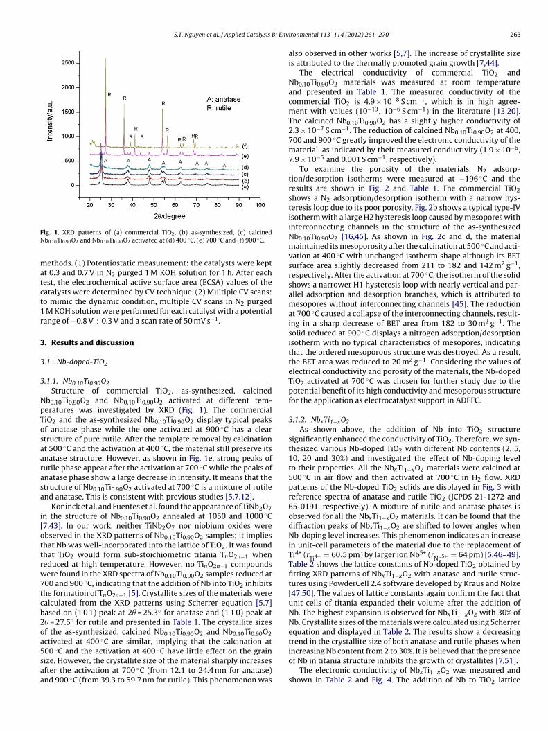
ig. 1. XRD patterns of (a) commercial TiO2, (b) as-synthesized, (c) calcinedb0.10Ti0.90O2 and Nb0.10Ti0.90O2 activated at (d) 400 ◦C, (e) 700 ◦C and (f) 900 ◦C.
ethods. (1) Potentiostatic measurement: the catalysts were keptt 0.3 and 0.7 V in N2 purged 1 M KOH solution for 1 h. After eachest, the electrochemical active surface area (ECSA) values of theatalysts were determined by CV technique. (2) Multiple CV scans:o mimic the dynamic condition, multiple CV scans in N2 purged
M KOH solution were performed for each catalyst with a potentialange of −0.8 V ÷ 0.3 V and a scan rate of 50 mV s−1.
. Results and discussion
.1. Nb-doped-TiO2
.1.1. Nb0.10Ti0.90O2Structure of commercial TiO2, as-synthesized, calcined
b0.10Ti0.90O2 and Nb0.10Ti0.90O2 activated at different tem-eratures was investigated by XRD (Fig. 1). The commercialiO2 and the as-synthesized Nb0.10Ti0.90O2 display typical peaksf anatase phase while the one activated at 900 ◦C has a cleartructure of pure rutile. After the template removal by calcinationt 500 ◦C and the activation at 400 ◦C, the material still preserve itsnatase structure. However, as shown in Fig. 1e, strong peaks ofutile phase appear after the activation at 700 ◦C while the peaks ofnatase phase show a large decrease in intensity. It means that thetructure of Nb0.10Ti0.90O2 activated at 700 ◦C is a mixture of rutilend anatase. This is consistent with previous studies [5,7,12].
Koninck et al. and Fuentes et al. found the appearance of TiNb2O7n the structure of Nb0.10Ti0.90O2 annealed at 1050 and 1000 ◦C7,43]. In our work, neither TiNb2O7 nor niobium oxides werebserved in the XRD patterns of Nb0.10Ti0.90O2 samples; it implieshat Nb was well-incorporated into the lattice of TiO2. It was foundhat TiO2 would form sub-stoichiometric titania TnO2n−1 wheneduced at high temperature. However, no TinO2n−1 compoundsere found in the XRD spectra of Nb0.10Ti0.90O2 samples reduced at
00 and 900 ◦C, indicating that the addition of Nb into TiO2 inhibitshe formation of TnO2n−1 [5]. Crystallite sizes of the materials werealculated from the XRD patterns using Scherrer equation [5,7]ased on (1 0 1) peak at 2� = 25.3◦ for anatase and (1 1 0) peak at� = 27.5◦ for rutile and presented in Table 1. The crystallite sizesf the as-synthesized, calcined Nb0.10Ti0.90O2 and Nb0.10Ti0.90O2ctivated at 400 ◦C are similar, implying that the calcination at
00 ◦C and the activation at 400 ◦C have little effect on the grainize. However, the crystallite size of the material sharply increasesfter the activation at 700 ◦C (from 12.1 to 24.4 nm for anatase)nd 900 ◦C (from 39.3 to 59.7 nm for rutile). This phenomenon wasironmental 113– 114 (2012) 261– 270 263
also observed in other works [5,7]. The increase of crystallite sizeis attributed to the thermally promoted grain growth [7,44].
The electrical conductivity of commercial TiO2 andNb0.10Ti0.90O2 materials was measured at room temperatureand presented in Table 1. The measured conductivity of thecommercial TiO2 is 4.9 × 10⁻⁸ S cm−1, which is in high agree-ment with values (10−13, 10−6 S cm−1) in the literature [13,20].The calcined Nb0.10Ti0.90O2 has a slightly higher conductivity of2.3 × 10−7 S cm−1. The reduction of calcined Nb0.10Ti0.90O2 at 400,700 and 900 ◦C greatly improved the electronic conductivity of thematerial, as indicated by their measured conductivity (1.9 × 10−6,7.9 × 10−5 and 0.001 S cm−1, respectively).
To examine the porosity of the materials, N2 adsorp-tion/desorption isotherms were measured at −196 ◦C and theresults are shown in Fig. 2 and Table 1. The commercial TiO2shows a N2 adsorption/desorption isotherm with a narrow hys-teresis loop due to its poor porosity. Fig. 2b shows a typical type-IVisotherm with a large H2 hysteresis loop caused by mesopores withinterconnecting channels in the structure of the as-synthesizedNb0.10Ti0.90O2 [16,45]. As shown in Fig. 2c and d, the materialmaintained its mesoporosity after the calcination at 500 ◦C and acti-vation at 400 ◦C with unchanged isotherm shape although its BETsurface area slightly decreased from 211 to 182 and 142 m2 g−1,respectively. After the activation at 700 ◦C, the isotherm of the solidshows a narrower H1 hysteresis loop with nearly vertical and par-allel adsorption and desorption branches, which is attributed tomesopores without interconnecting channels [45]. The reductionat 700 ◦C caused a collapse of the interconnecting channels, result-ing in a sharp decrease of BET area from 182 to 30 m2 g−1. Thesolid reduced at 900 ◦C displays a nitrogen adsorption/desorptionisotherm with no typical characteristics of mesopores, indicatingthat the ordered mesoporous structure was destroyed. As a result,the BET area was reduced to 20 m2 g−1. Considering the values ofelectrical conductivity and porosity of the materials, the Nb-dopedTiO2 activated at 700 ◦C was chosen for further study due to thepotential benefit of its high conductivity and mesoporous structurefor the application as electrocatalyst support in ADEFC.
3.1.2. NbxTi1−xO2As shown above, the addition of Nb into TiO2 structure
significantly enhanced the conductivity of TiO2. Therefore, we syn-thesized various Nb-doped TiO2 with different Nb contents (2, 5,10, 20 and 30%) and investigated the effect of Nb-doping levelto their properties. All the NbxTi1−xO2 materials were calcined at500 ◦C in air flow and then activated at 700 ◦C in H2 flow. XRDpatterns of the Nb-doped TiO2 solids are displayed in Fig. 3 withreference spectra of anatase and rutile TiO2 (JCPDS 21-1272 and65-0191, respectively). A mixture of rutile and anatase phases isobserved for all the NbxTi1−xO2 materials. It can be found that thediffraction peaks of NbxTi1−xO2 are shifted to lower angles whenNb-doping level increases. This phenomenon indicates an increasein unit-cell parameters of the material due to the replacement ofTi4+ (rTi4+ = 60.5 pm) by larger ion Nb5+ (rNb5+ = 64 pm) [5,46–49].Table 2 shows the lattice constants of Nb-doped TiO2 obtained byfitting XRD patterns of NbxTi1−xO2 with anatase and rutile struc-tures using PowderCell 2.4 software developed by Kraus and Nolze[47,50]. The values of lattice constants again confirm the fact thatunit cells of titania expanded their volume after the addition ofNb. The highest expansion is observed for NbxTi1−xO2 with 30% ofNb. Crystallite sizes of the materials were calculated using Scherrerequation and displayed in Table 2. The results show a decreasingtrend in the crystallite size of both anatase and rutile phases when
increasing Nb content from 2 to 30%. It is believed that the presenceof Nb in titania structure inhibits the growth of crystallites [7,51].The electronic conductivity of NbxTi1−xO2 was measured andshown in Table 2 and Fig. 4. The addition of Nb to TiO2 lattice
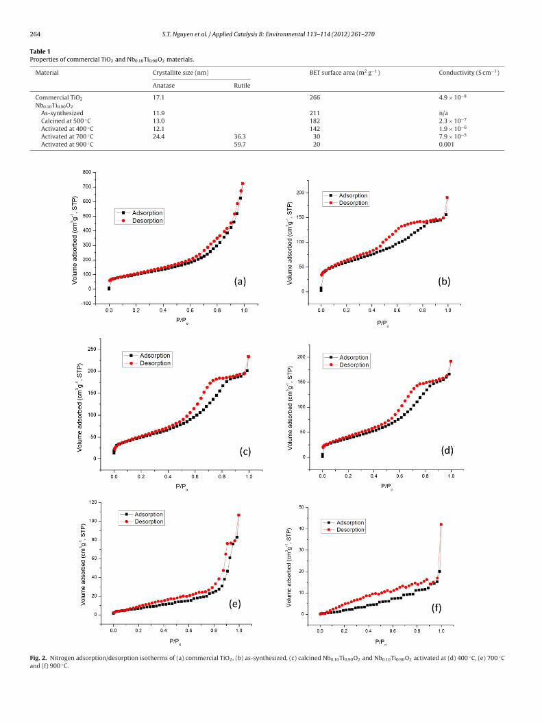
264 S.T. Nguyen et al. / Applied Catalysis B: Environmental 113– 114 (2012) 261– 270
Table 1Properties of commercial TiO2 and Nb0.10Ti0.90O2 materials.
Material Crystallite size (nm) BET surface area (m2 g−1) Conductivity (S cm−1)
Anatase Rutile
Commercial TiO2 17.1 266 4.9 × 10⁻⁸
Nb0.10Ti0.90O2
As-synthesized 11.9 211 n/aCalcined at 500 ◦C 13.0 182 2.3 × 10⁻⁷
Activated at 400 ◦C 12.1 142 1.9 × 10⁻⁶
Activated at 700 ◦C 24.4 36.3 30 7.9 × 10⁻⁵
Activated at 900 ◦C 59.7 20 0.001
Fig. 2. Nitrogen adsorption/desorption isotherms of (a) commercial TiO2, (b) as-synthesized, (c) calcined Nb0.10Ti0.90O2 and Nb0.10Ti0.90O2 activated at (d) 400 ◦C, (e) 700 ◦Cand (f) 900 ◦C.

S.T. Nguyen et al. / Applied Catalysis B: Environmental 113– 114 (2012) 261– 270 265
Table 2Properties of NbxTi1−xO2 materials compared with commercial TiO2.
Material Lattice constant (nm) Crystallite size (nm) BET surface area (m2 g−1) Conductivity (S cm−1)
Anatase Rutile Anatase Rutile
Commercial TiO2 a = b = 0.37853 17.1 266 4.9 × 10⁻⁸
c = 0.95070Nb0.02Ti0.98O2 a = b = 0.37864 a = b = 0.45979 33.0 45.7 22 8.9 × 10⁻⁷
c = 0.95190 c = 0.29611Nb0.05Ti0.95O2 a = b = 0.37909 a = b = 0.46033 28.0 39.9 31 9.6 × 10⁻⁷
c = 0.95246 c = 0.29637Nb0.10Ti0.90O2 a = b = 0.38170 a = b = 0.46380 24.4 36.3 30 7.9 × 10⁻⁵
c = 0.95263 c = 0.29804Nb0.20Ti0.80O2 a = b = 0.38261 a = b = 0.46504 23.0 30.5 36 0.0012
c = 0.95501 c = 0.29847Nb0.30Ti0.70O2 a = b = 0.38326 a = b = 0.46607 21.7
c = 0.95774 c = 0.29937
F(
sf7cget
ig. 3. XRD patterns of NbxTi1−xO2 activated at 700 ◦C with x = 0.02 (a), 0.05 (b), 0.10c), 0.20 (d) and 0.30 (e).
tructure dramatically improved the conductivity of the materialrom 4.9 × 10⁻⁸ S cm−1 of anatase TiO2 to 8.9 × 10⁻⁷, 9.6 × 10⁻⁷,.9 × 10−5, 0.0012 and 0.0014 S cm−1 of Nb-doped TiO2 with Nbontents of 2, 5, 10, 20 and 30%, respectively. TiO has large band
2aps (3.2 eV of anatase and 3.0 eV of rutile), which result in its lowlectrical conductivity [12,13,51]. Nb atom has five outer-shell elec-rons. When it substitutes Ti sites in TiO2 lattice, only four electronsFig. 4. Electrical conductivity of NbxTi1−xO2 with different Nb contents.
25.6 46 0.0014
are used for bonding. The extra electron is in donor state whichis 0.02–0.03 eV below the conduction band minimum and there-fore, is easy to be donated into the conduction band to increasethe charge carrier concentration [12,48,52]. As a result, Nb dopingenhances the electronic conductivity of the material:
Nb2O5 → 2NbTi• + 4Oo
x + 2e′ + 1/2O2 (3)
However, it can be seen that the conductivity of Nb-doped TiO2with 30% of Nb (0.0014 S cm−1) is only a bit higher than that of theone with 20% of Nb (0.0012 S cm−1). This phenomenon is consis-tent with the literature [46]. This fact can be explained by severalpossible ways. Firstly, when Nb is doped into TiO2 lattice, the Fermienergy will move towards the conduction band. Consequently, theformation energy of Ti vacancy will decrease. At some points, thisformation energy is so low that Ti vacancies will form sponta-neously (Eq. (4)) and weaken the donor effect (Eq. (3)) [46,53,54].
2Nb2O5 → 4NbTi• + VTi
′′′′ + 10Oox (4)
Secondly, the substitution of Nb for Ti can also create oxygeninterstitials – another type of electron killer, which reduce the elec-tronic conductivity of Nb-doped TiO2. Thirdly, the incorporationof Nb into the titania structure also causes a lattice deformation,which can lead to a decrease in electron mobility [46,52–54].
The porosity of the NbxTi1−xO2 materials was examined by N2adsorption/desorption at −196 ◦C and the results are displayed inFig. 5 and Table 2. Adsorption/desorption isotherms of all the solidshave the same shape as that of Nb0.10Ti0.90O2 indicating that allof them possess mesoporous structures with no interconnectingchannels. It can be observed that BET area of the NbxTi1−xO2 solidsincreases with the raise of Nb-doping level. The lowest area of22 m2 g−1 was found for Nb0.02Ti0.98O2 while the maximum valueof 36 m2 g−1 was seen with Nb0.30Ti0.70O2. As stated previously, theNb doping prevents the grain growth, and thus, increases the BETspecific surface area of NbxTi1−xO2 [7].
3.2. PdAg/Nb-doped TiO2
Fig. 6 shows XRD profiles of PdAg alloy supported on carbonblack, commercial TiO2 and various NbxTi1−xO2. PdAg/C displaystypical (1 1 1), (2 0 0), (2 2 0) and (3 1 1) peaks of face-centered cubic(FCC) structure of PdAg alloy at 38.8◦, 44.6◦, 65.5◦ and 78.8◦. InXRD patterns of PdAg/commercial TiO2 and PdAg/NbxTi1−xO2, thepeaks of PdAg alloy are overlapped by strong diffraction peaks ofthe supports.
The electrocatalytic activity for ethanol oxidation of the cata-
lysts was examined in an aqueous solution of 1 M C2H5OH and1 M KOH by cyclic voltammetry (CV) technique and the resultsare shown in Fig. 7. PdAg supported on commercial TiO2 andNbxTi1−xO2 show a 75 mV more negative onset potential for ethanol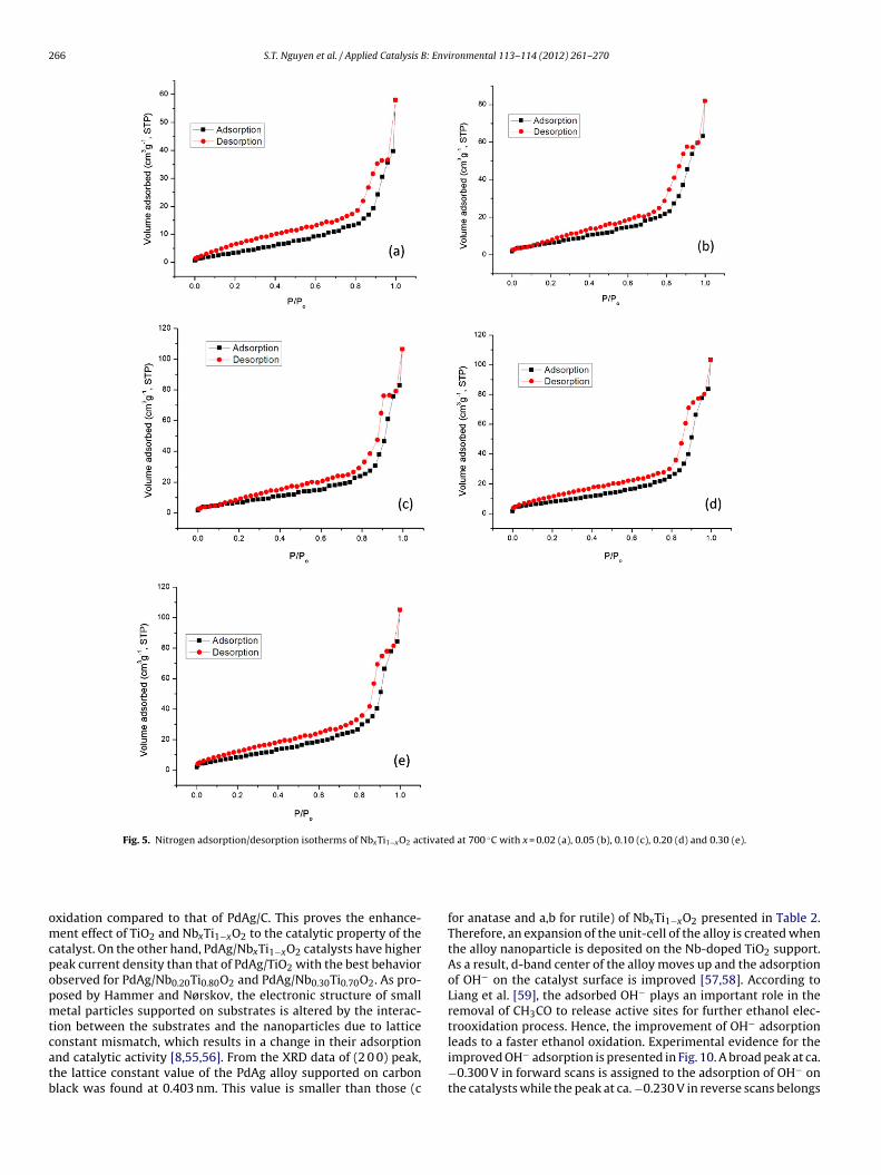
266 S.T. Nguyen et al. / Applied Catalysis B: Environmental 113– 114 (2012) 261– 270
Fig. 5. Nitrogen adsorption/desorption isotherms of NbxTi1−xO2 activated at 700 ◦C with x = 0.02 (a), 0.05 (b), 0.10 (c), 0.20 (d) and 0.30 (e).
omcpopmtcatb
xidation compared to that of PdAg/C. This proves the enhance-ent effect of TiO2 and NbxTi1−xO2 to the catalytic property of the
atalyst. On the other hand, PdAg/NbxTi1−xO2 catalysts have highereak current density than that of PdAg/TiO2 with the best behaviorbserved for PdAg/Nb0.20Ti0.80O2 and PdAg/Nb0.30Ti0.70O2. As pro-osed by Hammer and Nørskov, the electronic structure of smalletal particles supported on substrates is altered by the interac-
ion between the substrates and the nanoparticles due to lattice
onstant mismatch, which results in a change in their adsorptionnd catalytic activity [8,55,56]. From the XRD data of (2 0 0) peak,he lattice constant value of the PdAg alloy supported on carbonlack was found at 0.403 nm. This value is smaller than those (cfor anatase and a,b for rutile) of NbxTi1−xO2 presented in Table 2.Therefore, an expansion of the unit-cell of the alloy is created whenthe alloy nanoparticle is deposited on the Nb-doped TiO2 support.As a result, d-band center of the alloy moves up and the adsorptionof OH− on the catalyst surface is improved [57,58]. According toLiang et al. [59], the adsorbed OH− plays an important role in theremoval of CH3CO to release active sites for further ethanol elec-trooxidation process. Hence, the improvement of OH− adsorption
leads to a faster ethanol oxidation. Experimental evidence for theimproved OH− adsorption is presented in Fig. 10. A broad peak at ca.−0.300 V in forward scans is assigned to the adsorption of OH− onthe catalysts while the peak at ca. −0.230 V in reverse scans belongs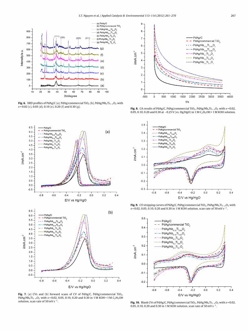
S.T. Nguyen et al. / Applied Catalysis B: Environmental 113– 114 (2012) 261– 270 267
Fig. 6. XRD profiles of PdAg/C (a), PdAg/commercial TiO2 (b), PdAg/NbxTi1−xO2 withx = 0.02 (c), 0.05 (d), 0.10 (e), 0.20 (f) and 0.30 (g).
Fig. 7. (a) CVs and (b) forward scans of CV of PdAg/C, PdAg/commercial TiO2,PdAg/NbxTi1−xO2 with x = 0.02, 0.05, 0.10, 0.20 and 0.30 in 1 M KOH + 1 M C2H5OHsolution, scan rate of 50 mV s−1.
Fig. 8. CA results of PdAg/C, PdAg/commercial TiO2, PdAg/NbxTi1−xO2 with x = 0.02,0.05, 0.10, 0.20 and 0.30 at −0.25 V (vs. Hg/HgO) in 1 M C2H5OH + 1 M KOH solution.
Fig. 9. CO stripping curves of PdAg/C, PdAg/commercial TiO2, PdAg/NbxTi1−xO2 withx = 0.02, 0.05, 0.10, 0.20 and 0.30 in 1 M KOH solution, scan rate of 50 mV s−1.
Fig. 10. Blank CVs of PdAg/C, PdAg/commercial TiO2, PdAg/NbxTi1−xO2 with x = 0.02,0.05, 0.10, 0.20 and 0.30 in 1 M KOH solution, scan rate of 50 mV s−1.
268 S.T. Nguyen et al. / Applied Catalysis B: Environmental 113– 114 (2012) 261– 270
Fx
tp−Nboo
PtCgitrvitrrtd
dtc
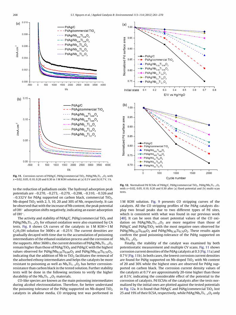
ig. 11. Corrosion curves of PdAg/C, PdAg/commercial TiO2, PdAg/NbxTi1−xO2 with = 0.02, 0.05, 0.10, 0.20 and 0.30 in 1 M KOH solution at (a) 0.3 V and (b) 0.7 V, 1 h.
o the reduction of palladium oxide. The hydroxyl adsorption peakotentials are −0.270, −0.273, −0.279, −0.298, −0.310, −0.326 and0.332 V for PdAg supported on carbon black, commercial TiO2,b-doped TiO2 with 2, 5, 10, 20 and 30% of Nb, respectively. It cane observed that with the increase of Nb content, the peak potentialf OH− adsorption shifts negatively, indicating an easier adsorptionf OH−.
The activity and stability of PdAg/C, PdAg/commercial TiO2 anddAg/NbxTi1−xO2 for ethanol oxidation were also examined by CAests. Fig. 8 shows CA curves of the catalysts in 1 M KOH + 1 M2H5OH solution for 3600 s at −0.25 V. The current densities areradually decayed with time due to the accumulation of poisoningntermediates of the ethanol oxidation process and the corrosion ofhe supports. After 3600 s, the current densities of PdAg/NbxTi1−xO2emain higher than those of PdAg/TiO2 and PdAg/C with the highestalues observed for PdAg/Nb0.20Ti0.80O2 and PdAg/Nb0.30Ti0.70O2,ndicating that the addition of Nb to TiO2 facilitates the removal ofhe adsorbed ethoxy intermediates and helps the catalysts be moreesistant to poisoning as well as NbxTi1−xO2 has better corrosion-esistance than carbon black in the tested solution. Further stabilityests will be done in the following sections to verify the higherurability of the NbxTi1−xO2 materials.
CO-like species are known as the main poisoning intermediatesuring alcohol electrooxidation. Therefore, for better understandhe poisoning tolerance of the PdAg supported on Nb-doped TiO2atalysts in alkaline media, CO stripping test was performed in
Fig. 12. Normalized Pd ECSAs of PdAg/C, PdAg/commercial TiO2, PdAg/NbxTi1−xO2
with x = 0.02, 0.05, 0.10, 0.20 and 0.30 after (a) fixed-potential and (b) multi-scantests.
1 M KOH solution. Fig. 9 presents CO stripping curves of thecatalysts. All the CO stripping profiles of the PdAg catalysts dis-play two broad peaks due to two different types of Pd sites,which is consistent with what was found in our previous work[40]. It can be seen that onset potential values of the CO oxi-dation on PdAg/NbxTi1−xO2 are more negative than those ofPdAg/C and PdAg/TiO2 with the most negative ones observed forPdAg/Nb0.20Ti0.80O2 and PdAg/Nb0.30Ti0.70O2. These results againconfirm the good poisoning-tolerance of the PdAg supported onNbxTi1−xO2.
Finally, the stability of the catalyst was examined by bothpotentiostatic measurement and multiple CV scans. Fig. 11 showscorrosion current densities of the PdAg catalysts at 0.3 (Fig. 11a) and0.7 V (Fig. 11b). In both cases, the lowest corrosion current densitiesare found for PdAg supported on Nb-doped TiO2 with Nb contentof 20 and 30% while the highest ones are observed for PdAg sup-ported on carbon black. The corrosion current density values ofthe catalysts at 0.7 V are approximately 20-time higher than thoseat 0.3 V, indicating the considerable effect of the potential to the
corrosion of catalysts. Pd ECSAs of the catalysts after the tests nor-malized by the initial ones are plotted against the tested potentialsin Fig. 12a. It is found that PdAg/C and PdAg/commercial TiO2 lost25 and 19% of their ECSA, respectively, while PdAg/NbxTi1−xO2 only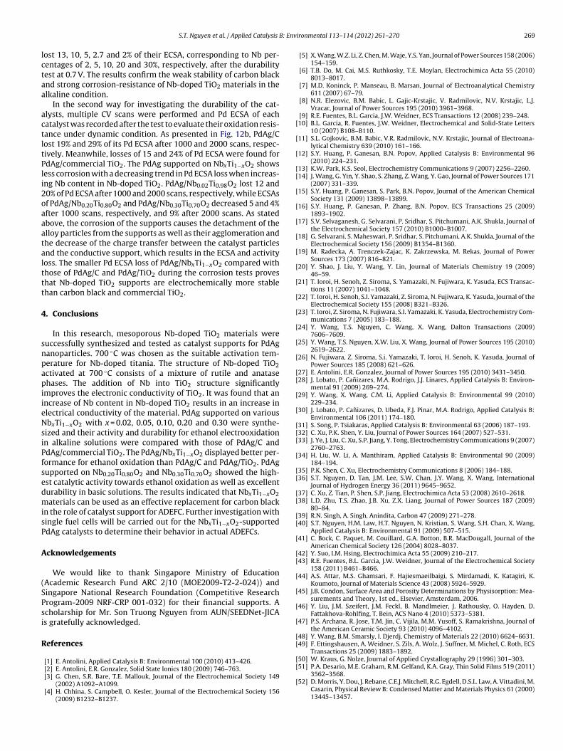
: Env
lctaa
actltPli2oaaatalttt
4
snpapiieNsiPfsedmisP
A
(SPsi
R
[
[
[
[[
[
[
[
[
[
[
[
[
[
[
[
[
[[
[
[
[[[
[
[[
[[
[[
[
[[
[
[
[
[
[[
[
S.T. Nguyen et al. / Applied Catalysis B
ost 13, 10, 5, 2.7 and 2% of their ECSA, corresponding to Nb per-entages of 2, 5, 10, 20 and 30%, respectively, after the durabilityest at 0.7 V. The results confirm the weak stability of carbon blacknd strong corrosion-resistance of Nb-doped TiO2 materials in thelkaline condition.
In the second way for investigating the durability of the cat-lysts, multiple CV scans were performed and Pd ECSA of eachatalyst was recorded after the test to evaluate their oxidation resis-ance under dynamic condition. As presented in Fig. 12b, PdAg/Cost 19% and 29% of its Pd ECSA after 1000 and 2000 scans, respec-ively. Meanwhile, losses of 15 and 24% of Pd ECSA were found fordAg/commercial TiO2. The PdAg supported on NbxTi1−xO2 showsess corrosion with a decreasing trend in Pd ECSA loss when increas-ng Nb content in Nb-doped TiO2. PdAg/Nb0.02Ti0.98O2 lost 12 and0% of Pd ECSA after 1000 and 2000 scans, respectively, while ECSAsf PdAg/Nb0.20Ti0.80O2 and PdAg/Nb0.30Ti0.70O2 decreased 5 and 4%fter 1000 scans, respectively, and 9% after 2000 scans. As statedbove, the corrosion of the supports causes the detachment of thelloy particles from the supports as well as their agglomeration andhe decrease of the charge transfer between the catalyst particlesnd the conductive support, which results in the ECSA and activityoss. The smaller Pd ECSA loss of PdAg/NbxTi1−xO2 compared withhose of PdAg/C and PdAg/TiO2 during the corrosion tests proveshat Nb-doped TiO2 supports are electrochemically more stablehan carbon black and commercial TiO2.
. Conclusions
In this research, mesoporous Nb-doped TiO2 materials wereuccessfully synthesized and tested as catalyst supports for PdAganoparticles. 700 ◦C was chosen as the suitable activation tem-erature for Nb-doped titania. The structure of Nb-doped TiO2ctivated at 700 ◦C consists of a mixture of rutile and anatasehases. The addition of Nb into TiO2 structure significantly
mproves the electronic conductivity of TiO2. It was found that anncrease of Nb content in Nb-doped TiO2 results in an increase inlectrical conductivity of the material. PdAg supported on variousbxTi1−xO2 with x = 0.02, 0.05, 0.10, 0.20 and 0.30 were synthe-
ized and their activity and durability for ethanol electrooxidationn alkaline solutions were compared with those of PdAg/C anddAg/commercial TiO2. The PdAg/NbxTi1−xO2 displayed better per-ormance for ethanol oxidation than PdAg/C and PdAg/TiO2. PdAgupported on Nb0.20Ti0.80O2 and Nb0.30Ti0.70O2 showed the high-st catalytic activity towards ethanol oxidation as well as excellenturability in basic solutions. The results indicated that NbxTi1−xO2aterials can be used as an effective replacement for carbon black
n the role of catalyst support for ADEFC. Further investigation withingle fuel cells will be carried out for the NbxTi1−xO2-supporteddAg catalysts to determine their behavior in actual ADEFCs.
cknowledgements
We would like to thank Singapore Ministry of EducationAcademic Research Fund ARC 2/10 (MOE2009-T2-2-024)) andingapore National Research Foundation (Competitive Researchrogram-2009 NRF-CRP 001-032) for their financial supports. Acholarship for Mr. Son Truong Nguyen from AUN/SEEDNet-JICAs gratefully acknowledged.
eferences
[1] E. Antolini, Applied Catalysis B: Environmental 100 (2010) 413–426.
[2] E. Antolini, E.R. Gonzalez, Solid State Ionics 180 (2009) 746–763.[3] G. Chen, S.R. Bare, T.E. Mallouk, Journal of the Electrochemical Society 149(2002) A1092–A1099.[4] H. Chhina, S. Campbell, O. Kesler, Journal of the Electrochemical Society 156
(2009) B1232–B1237.
[
[
ironmental 113– 114 (2012) 261– 270 269
[5] X. Wang, W.Z. Li, Z. Chen, M. Waje, Y.S. Yan, Journal of Power Sources 158 (2006)154–159.
[6] T.B. Do, M. Cai, M.S. Ruthkosky, T.E. Moylan, Electrochimica Acta 55 (2010)8013–8017.
[7] M.D. Koninck, P. Manseau, B. Marsan, Journal of Electroanalytical Chemistry611 (2007) 67–79.
[8] N.R. Elezovic, B.M. Babic, L. Gajic-Krstajic, V. Radmilovic, N.V. Krstajic, L.J.Vracar, Journal of Power Sources 195 (2010) 3961–3968.
[9] R.E. Fuentes, B.L. Garcia, J.W. Weidner, ECS Transactions 12 (2008) 239–248.10] B.L. Garcia, R. Fuentes, J.W. Weidner, Electrochemical and Solid-State Letters
10 (2007) B108–B110.11] S.L. Gojkovic, B.M. Babic, V.R. Radmilovic, N.V. Krstajic, Journal of Electroana-
lytical Chemistry 639 (2010) 161–166.12] S.Y. Huang, P. Ganesan, B.N. Popov, Applied Catalysis B: Environmental 96
(2010) 224–231.13] K.W. Park, K.S. Seol, Electrochemistry Communications 9 (2007) 2256–2260.14] J. Wang, G. Yin, Y. Shao, S. Zhang, Z. Wang, Y. Gao, Journal of Power Sources 171
(2007) 331–339.15] S.Y. Huang, P. Ganesan, S. Park, B.N. Popov, Journal of the American Chemical
Society 131 (2009) 13898–13899.16] S.Y. Huang, P. Ganesan, P. Zhang, B.N. Popov, ECS Transactions 25 (2009)
1893–1902.17] S.V. Selvaganesh, G. Selvarani, P. Sridhar, S. Pitchumani, A.K. Shukla, Journal of
the Electrochemical Society 157 (2010) B1000–B1007.18] G. Selvarani, S. Maheswari, P. Sridhar, S. Pitchumani, A.K. Shukla, Journal of the
Electrochemical Society 156 (2009) B1354–B1360.19] M. Radecka, A. Trenczek-Zajac, K. Zakrzewska, M. Rekas, Journal of Power
Sources 173 (2007) 816–821.20] Y. Shao, J. Liu, Y. Wang, Y. Lin, Journal of Materials Chemistry 19 (2009)
46–59.21] T. Ioroi, H. Senoh, Z. Siroma, S. Yamazaki, N. Fujiwara, K. Yasuda, ECS Transac-
tions 11 (2007) 1041–1048.22] T. Ioroi, H. Senoh, S.I. Yamazaki, Z. Siroma, N. Fujiwara, K. Yasuda, Journal of the
Electrochemical Society 155 (2008) B321–B326.23] T. Ioroi, Z. Siroma, N. Fujiwara, S.I. Yamazaki, K. Yasuda, Electrochemistry Com-
munications 7 (2005) 183–188.24] Y. Wang, T.S. Nguyen, C. Wang, X. Wang, Dalton Transactions (2009)
7606–7609.25] Y. Wang, T.S. Nguyen, X.W. Liu, X. Wang, Journal of Power Sources 195 (2010)
2619–2622.26] N. Fujiwara, Z. Siroma, S.i. Yamazaki, T. Ioroi, H. Senoh, K. Yasuda, Journal of
Power Sources 185 (2008) 621–626.27] E. Antolini, E.R. Gonzalez, Journal of Power Sources 195 (2010) 3431–3450.28] J. Lobato, P. Canizares, M.A. Rodrigo, J.J. Linares, Applied Catalysis B: Environ-
mental 91 (2009) 269–274.29] Y. Wang, X. Wang, C.M. Li, Applied Catalysis B: Environmental 99 (2010)
229–234.30] J. Lobato, P. Canizares, D. Ubeda, F.J. Pinar, M.A. Rodrigo, Applied Catalysis B:
Environmental 106 (2011) 174–180.31] S. Song, P. Tsiakaras, Applied Catalysis B: Environmental 63 (2006) 187–193.32] C. Xu, P.K. Shen, Y. Liu, Journal of Power Sources 164 (2007) 527–531.33] J. Ye, J. Liu, C. Xu, S.P. Jiang, Y. Tong, Electrochemistry Communications 9 (2007)
2760–2763.34] H. Liu, W. Li, A. Manthiram, Applied Catalysis B: Environmental 90 (2009)
184–194.35] P.K. Shen, C. Xu, Electrochemistry Communications 8 (2006) 184–188.36] S.T. Nguyen, D. Tan, J.M. Lee, S.W. Chan, J.Y. Wang, X. Wang, International
Journal of Hydrogen Energy 36 (2011) 9645–9652.37] C. Xu, Z. Tian, P. Shen, S.P. Jiang, Electrochimica Acta 53 (2008) 2610–2618.38] L.D. Zhu, T.S. Zhao, J.B. Xu, Z.X. Liang, Journal of Power Sources 187 (2009)
80–84.39] R.N. Singh, A. Singh, Anindita, Carbon 47 (2009) 271–278.40] S.T. Nguyen, H.M. Law, H.T. Nguyen, N. Kristian, S. Wang, S.H. Chan, X. Wang,
Applied Catalysis B: Environmental 91 (2009) 507–515.41] C. Bock, C. Paquet, M. Couillard, G.A. Botton, B.R. MacDougall, Journal of the
American Chemical Society 126 (2004) 8028–8037.42] Y. Suo, I.M. Hsing, Electrochimica Acta 55 (2009) 210–217.43] R.E. Fuentes, B.L. Garcia, J.W. Weidner, Journal of the Electrochemical Society
158 (2011) B461–B466.44] A.S. Attar, M.S. Ghamsari, F. Hajiesmaeilbaigi, S. Mirdamadi, K. Katagiri, K.
Koumoto, Journal of Materials Science 43 (2008) 5924–5929.45] J.B. Condon, Surface Area and Porosity Determinations by Physisorption: Mea-
surements and Theory, 1st ed., Elsevier, Amsterdam, 2006.46] Y. Liu, J.M. Szeifert, J.M. Feckl, B. Mandlmeier, J. Rathousky, O. Hayden, D.
Fattakhova-Rohlfing, T. Bein, ACS Nano 4 (2010) 5373–5381.47] P.S. Archana, R. Jose, T.M. Jin, C. Vijila, M.M. Yusoff, S. Ramakrishna, Journal of
the American Ceramic Society 93 (2010) 4096–4102.48] Y. Wang, B.M. Smarsly, I. Djerdj, Chemistry of Materials 22 (2010) 6624–6631.49] F. Ettingshausen, A. Weidner, S. Zils, A. Wolz, J. Suffner, M. Michel, C. Roth, ECS
Transactions 25 (2009) 1883–1892.50] W. Kraus, G. Nolze, Journal of Applied Crystallography 29 (1996) 301–303.
51] P.A. Desario, M.E. Graham, R.M. Gelfand, K.A. Gray, Thin Solid Films 519 (2011)3562–3568.52] D. Morris, Y. Dou, J. Rebane, C.E.J. Mitchell, R.G. Egdell, D.S.L. Law, A. Vittadini, M.
Casarin, Physical Review B: Condensed Matter and Materials Physics 61 (2000)13445–13457.

2 B: Env
[
[[
70 S.T. Nguyen et al. / Applied Catalysis
53] S.B. Zhang, S.H. Wei, A. Zunger, Physica B: Condensed Matter 273–274 (1999)976–980.
54] A. Zunger, Applied Physics Letters 83 (2003) 57–59.55] B. Babic, J. Gulicovski, L. Gajic-Krstajic, N. Elezovic, V.R. Radmilovic, N.V. Krstajic,
L.M. Vracar, Journal of Power Sources 193 (2009) 99–106.
[[
[[
ironmental 113– 114 (2012) 261– 270
56] B. Hammer, J.K. Nørskov, Advances in Catalysis 45 (2000) 71–129.57] J. Greeley, J.K. Nørskov, M. Mavrikakis, Annual Review of Physical Chemistry
(2002) 319–348.58] B. Hammer, J.K. Nørskov, Advances in Catalysis (2000) 71–129.59] Z.X. Liang, T.S. Zhao, J.B. Xu, L.D. Zhu, Electrochimica Acta 54 (2009) 2203–2208.