Electrochemical and electrophoretic deposition of enzymes: Principles, differences and application...
11
Electrochemical and electrophoretic deposition of enzymes: Principles, differences and application in miniaturized biosensor and biofuel cell electrodes Malika Ammam n Faculty of Mathematics and Natural Sciences, Products and Processes for Biotechnology—Institute for Technology, Engineering & Management, University of Groningen, Nijenborgh 4, 9747 AG Groningen, The Netherlands article info Article history: Received 16 December 2013 Received in revised form 5 February 2014 Accepted 10 February 2014 Available online 26 February 2014 Keywords: Enzymes Electrochemical and electrophoretic deposition Miniaturized biosensor and biofuel cell electrodes abstract Recent advances in nano-biotechnology have made it possible to realize a great variety of enzyme electrodes suitable for sensing and energy applications. In coating miniaturized electrodes with enzymes, there is no doubt that most of the available deposition processes suffer from the difficulty in depositing uniform and reproducible coatings of the active enzyme on the miniature transducer element. This mini- review highlights the promising prospects of two techniques, electrochemical deposition (ECD) and electrophoretic deposition (EPD), in enzyme immobilization onto miniaturized electrodes and their use as biosensors and biofuel cells. The main differences between ECD and EPD are described and highlighted in the sense to make it clear to the reader that both techniques employ electric fields to deposit enzyme but the conditions from which each process is achieved and hence the mechanisms are quite different. Many aspects dealing with deposition of enzyme under ECD and EPD are considered including surface charge of enzyme, its migration under the applied electric field and its precipitation on the electrode. Still all issues discussed in this mini-review are generic and need to be followed in the future by extensive theoretical and experimental research analysis. Finally, the advantages of ECD and EPD in fabrication of miniature biosensor and biofuel cell electrodes are described and discussed. & 2014 Elsevier B.V. All rights reserved. Contents 1. Introduction ........................................................................................................ 121 2. Principles and mechanisms of deposition of enzymes subjected to electric fields................................................. 122 2.1. Step 1: Surface charge of enzymes ................................................................................ 122 2.2. Step 2: Migration of enzymes .................................................................................... 123 2.3. Step 3: Adhesion of enzymes on electrodes ......................................................................... 124 3. Deposition of enzymes under electric fields .............................................................................. 124 3.1. Electrochemical deposition (ECD) ................................................................................. 124 3.2. Electrophoretic deposition (EPD) ................................................................................. 125 4. Application of enzyme electrodes by ECD and EPD ......................................................................... 127 4.1. As biosensor electrodes ......................................................................................... 127 4.2. As biofuel cell anodes and cathodes ............................................................................... 128 5. Summary and conclusions ............................................................................................ 130 6. Future perspectives .................................................................................................. 130 Acknowledgements ...................................................................................................... 130 References ............................................................................................................. 130 Contents lists available at ScienceDirect journal homepage: www.elsevier.com/locate/bios Biosensors and Bioelectronics http://dx.doi.org/10.1016/j.bios.2014.02.030 0956-5663 & 2014 Elsevier B.V. All rights reserved. n Corresponding author. Tel.: þ31503639237; fax: þ31503632990. E-mail addresses: [email protected], [email protected] Biosensors and Bioelectronics 58 (2014) 121–131
-
Upload
independent -
Category
Documents
-
view
3 -
download
0
Transcript of Electrochemical and electrophoretic deposition of enzymes: Principles, differences and application...

Electrochemical and electrophoretic deposition of enzymes: Principles,differences and application in miniaturized biosensor and biofuelcell electrodes
Malika Ammam n
Faculty of Mathematics and Natural Sciences, Products and Processes for Biotechnology—Institute for Technology, Engineering & Management,University of Groningen, Nijenborgh 4, 9747 AG Groningen, The Netherlands
a r t i c l e i n f o
Article history:Received 16 December 2013Received in revised form5 February 2014Accepted 10 February 2014Available online 26 February 2014
Keywords:EnzymesElectrochemical and electrophoreticdepositionMiniaturized biosensor and biofuel cellelectrodes
a b s t r a c t
Recent advances in nano-biotechnology have made it possible to realize a great variety of enzymeelectrodes suitable for sensing and energy applications. In coating miniaturized electrodes with enzymes,there is no doubt that most of the available deposition processes suffer from the difficulty in depositinguniform and reproducible coatings of the active enzyme on the miniature transducer element. This mini-review highlights the promising prospects of two techniques, electrochemical deposition (ECD) andelectrophoretic deposition (EPD), in enzyme immobilization onto miniaturized electrodes and their useas biosensors and biofuel cells. The main differences between ECD and EPD are described and highlightedin the sense to make it clear to the reader that both techniques employ electric fields to deposit enzymebut the conditions from which each process is achieved and hence the mechanisms are quite different.Many aspects dealing with deposition of enzyme under ECD and EPD are considered including surfacecharge of enzyme, its migration under the applied electric field and its precipitation on the electrode. Stillall issues discussed in this mini-review are generic and need to be followed in the future by extensivetheoretical and experimental research analysis. Finally, the advantages of ECD and EPD in fabrication ofminiature biosensor and biofuel cell electrodes are described and discussed.
& 2014 Elsevier B.V. All rights reserved.
Contents
1. Introduction . . . . . . . . . . . . . . . . . . . . . . . . . . . . . . . . . . . . . . . . . . . . . . . . . . . . . . . . . . . . . . . . . . . . . . . . . . . . . . . . . . . . . . . . . . . . . . . . . . . . . . . . 1212. Principles and mechanisms of deposition of enzymes subjected to electric fields. . . . . . . . . . . . . . . . . . . . . . . . . . . . . . . . . . . . . . . . . . . . . . . . . 122
2.1. Step 1: Surface charge of enzymes . . . . . . . . . . . . . . . . . . . . . . . . . . . . . . . . . . . . . . . . . . . . . . . . . . . . . . . . . . . . . . . . . . . . . . . . . . . . . . . . 1222.2. Step 2: Migration of enzymes . . . . . . . . . . . . . . . . . . . . . . . . . . . . . . . . . . . . . . . . . . . . . . . . . . . . . . . . . . . . . . . . . . . . . . . . . . . . . . . . . . . . 1232.3. Step 3: Adhesion of enzymes on electrodes. . . . . . . . . . . . . . . . . . . . . . . . . . . . . . . . . . . . . . . . . . . . . . . . . . . . . . . . . . . . . . . . . . . . . . . . . 124
3. Deposition of enzymes under electric fields . . . . . . . . . . . . . . . . . . . . . . . . . . . . . . . . . . . . . . . . . . . . . . . . . . . . . . . . . . . . . . . . . . . . . . . . . . . . . . 1243.1. Electrochemical deposition (ECD) . . . . . . . . . . . . . . . . . . . . . . . . . . . . . . . . . . . . . . . . . . . . . . . . . . . . . . . . . . . . . . . . . . . . . . . . . . . . . . . . . 1243.2. Electrophoretic deposition (EPD) . . . . . . . . . . . . . . . . . . . . . . . . . . . . . . . . . . . . . . . . . . . . . . . . . . . . . . . . . . . . . . . . . . . . . . . . . . . . . . . . . 125
4. Application of enzyme electrodes by ECD and EPD . . . . . . . . . . . . . . . . . . . . . . . . . . . . . . . . . . . . . . . . . . . . . . . . . . . . . . . . . . . . . . . . . . . . . . . . . 1274.1. As biosensor electrodes . . . . . . . . . . . . . . . . . . . . . . . . . . . . . . . . . . . . . . . . . . . . . . . . . . . . . . . . . . . . . . . . . . . . . . . . . . . . . . . . . . . . . . . . . 1274.2. As biofuel cell anodes and cathodes . . . . . . . . . . . . . . . . . . . . . . . . . . . . . . . . . . . . . . . . . . . . . . . . . . . . . . . . . . . . . . . . . . . . . . . . . . . . . . . 128
5. Summary and conclusions . . . . . . . . . . . . . . . . . . . . . . . . . . . . . . . . . . . . . . . . . . . . . . . . . . . . . . . . . . . . . . . . . . . . . . . . . . . . . . . . . . . . . . . . . . . . 1306. Future perspectives . . . . . . . . . . . . . . . . . . . . . . . . . . . . . . . . . . . . . . . . . . . . . . . . . . . . . . . . . . . . . . . . . . . . . . . . . . . . . . . . . . . . . . . . . . . . . . . . . . 130Acknowledgements . . . . . . . . . . . . . . . . . . . . . . . . . . . . . . . . . . . . . . . . . . . . . . . . . . . . . . . . . . . . . . . . . . . . . . . . . . . . . . . . . . . . . . . . . . . . . . . . . . . . . . 130References . . . . . . . . . . . . . . . . . . . . . . . . . . . . . . . . . . . . . . . . . . . . . . . . . . . . . . . . . . . . . . . . . . . . . . . . . . . . . . . . . . . . . . . . . . . . . . . . . . . . . . . . . . . . . 130
Contents lists available at ScienceDirect
journal homepage: www.elsevier.com/locate/bios
Biosensors and Bioelectronics
http://dx.doi.org/10.1016/j.bios.2014.02.0300956-5663 & 2014 Elsevier B.V. All rights reserved.
n Corresponding author. Tel.: þ31503639237; fax: þ31503632990.E-mail addresses: [email protected], [email protected]
Biosensors and Bioelectronics 58 (2014) 121–131
1. Introduction
Nowadays, the development of high performance and reliableminiaturized enzyme electrodes is an important goal worthpursuing in the field of nano-biotechnology. The reason for thishas to do with the fact that miniaturization offers numerousadvantages (Dahlin, 2012). First, miniaturized enzyme electrodesare useful in analysis of small sample volumes, hence practicalif only small amounts of biological fluids are provided or, wastesaving if larger quantities are available. Second, because of theirsmall areas, miniaturized enzyme electrodes can integrate intonew technologies like microarray sensor for microfluidic systems.Third, if used in in vivo implantation, miniaturized enzymeelectrodes create less damage of the tissue and hence quickhealing. Obviously, there are several methods with which enzymescan be deposited onto the transducer element including but notlimited to entrapment and crosslinking (Sheldon and van Pelt,2013). However, an important problem in the application ofenzymes for the development of miniaturized electrodes is thedifficulty in depositing uniform and reproducible coatings of theactive enzyme on the transducer element. To this end, electro-chemical (ECD) and electrophoretic deposition (EPD) are techni-ques, which employ electric fields to produce apparently uniformand reproducible multilayer coatings of enzymes over very smallareas. The latter is due to the ability to precisely manipulate theforces exerted on the charged enzymes by the applied externalelectric field and drive them to deposit on electrodes via electricforces.
ECD and EPD have recently gained increasing interest both inacademia and partly in industrial sector because of being versatileand require simple apparatus. Historically, ECD of enzymes isknown for several decades that date back to the early 1970s
(Wang and Vieth, 1973). By contrast, EPD of enzymes is quiterecent (Ammam and Fransaer, 2009). From the fundamental andapplication standpoints, the basic phenomena involved in ECD andEPD are not very well known and have not yet been the subject ofextensive theoretical and experimental research analysis. Hence,further research and development work needs to be done in orderto develop a full, quantitative understanding of the fundamentalmechanisms of ECD and EPD of enzymes in order to optimize theworking parameters for a broader use of especially in the fabrica-tion of miniaturized enzyme electrodes. This mini-review dis-cusses some aspects of enzyme deposition under ECD and EPD andthe application of the miniaturized enzyme electrodes in biosen-sors and biofuel cells.
2. Principles and mechanisms of deposition of enzymessubjected to electric fields
The deposition process of enzymes subjected to externalelectric fields requires three important steps.
2.1. Step 1: Surface charge of enzymes
When it comes to deposit enzymes on electrodes, the first stepthat one has to think of is to enhance the surface charge of thedissolved/suspended enzyme in the fluid. It has to be kept in mindthat the fluid employed for enzyme dissolution/suspension isusually water. When enzyme molecules make contact with water,the polarity of the solvent water promotes formation of anelectrically charged interface (Shaw, 1980). This surface chargearises from essentially the ionization of the functional groupscarried out by the aminoacid residues that yields either a positive
Fig. 1. (A) Structure of the globular protein of an enzyme shown as molecular model. (B) Is (A) binding to substrate (analyte) at the active site of the enzyme. (C) Represents aschematic model of this enzyme that will be used in some of the coming illustrations. (D) Represents scheme showing migration of a negatively charged enzyme towards theanode under an applied electric field. (E) Depiction of the surface charge of a negatively charged enzyme in aqueous media. The enzyme is surrounded by a fixed Stern layerof oppositely charged ions (in this case, positive ions) and outside this layer is a diffuse layer with ions of different polarities. The potential at the shear level in the diffuselayer is known as the zeta potential (ζ).
M. Ammam / Biosensors and Bioelectronics 58 (2014) 121–131122

or a negative charge. For electroneutrality, when an enzyme isdissolved/suspended in water, a cloud of ions will surround thecharged enzyme (Fig. 1E). Ions of opposite charge (counterions)will be attracted towards the surface of the charged enzyme toformwhat is known as Stern layer, while ions of similar charge willbe pushed away from that surface to form what is known asdiffuse double layer (Stern, 1924). The latter yields a net electricalcharge on one side of the interface and a charge of opposite signon the other side of the interface, forming what is called theelectrical double layer of the enzyme. The enzyme surface at theshare level between Stern and the diffuse layer is characterized bya potential called zeta potential (ζ, expressed in millivolts)(Lyklema, 1977; Velev and Bhatt, 2006). Fig. 2 illustrates a typicalexample on how ζ varies with pH for amylase enzyme dissolved intwo media of low and high ionic strengths (Salgın et al., 2012). Inacidic pH, the net charge of enzymes is usually positive, whereasin alkaline pH, the charge is negative (Salgın et al., 2012; Schultzaet al., 2008). At a certain pH, enzymes will have no net charge,called isoionic point, which is between pH 3–4 for amylase,depending on nature of the electrolyte (Fig. 2). At neutral pH,enzymes are usually negatively charged (Salgın et al., 2012;Schultza et al., 2008). In general, elevated values of ζ are requiredfor enzymes to avoid coagulation, which in turn facilitate theirmigration upon application of an electric field. However, asillustrated in Fig. 2, higher ζ are obtained in alkaline pHs at whichenzyme activities may be altered and decreased. To keep max-imum enzyme activities, it is thus recommended to operatearound neutral pH, despite of having moderate values of ζ.
The ionic strength and nature of the supporting electrolyte aretwo other key parameters to consider in surface charge of dissolved/suspended enzymes. As illustrated in Fig. 2, very low ionic strength ofthe supporting electrolyte leads to elevated ζ. In addition, thecomposition of the supporting electrolyte, in terms of anions andcations affect ζ. In general, ζ of enzymes decreases following more orless the reverse Hofmeister series (Salgın et al., 2012):
For anions: CO32�4SO4
2�4HPO42�4OH�4F�4HCOO�4
CH3COO�4Cl�4Br�4NO3�4ClO3
�4 I�4ClO4�4SCN� .
For cations: Ca2þ4Mg2þ4Liþ4Naþ 4Kþ4Rbþ4Csþ4NH4
þ .
In other words, higher ζ should be obtained by using very lowionic strength electrolytes composed of ions like: NO3
� , ClO3� , I� ,
ClO4� , SCN� and their counterparts Rbþ , Csþ and NH4
þ . The reasonfor this has to do with the fact that divalent ions like CO3
2� , SO42,
Ca2þ , Mg2þ are more effective at salting out the enzyme solution/suspension than monovalent ions as ClO4
� , SCN� , Csþ and NH4þ
(Baldwin, 1996). As a result, divalent ions induce higher ionicstrength solutions/suspensions of enzymes, thus reducing theirabsolute ζ. On the other hand, it has to be kept in mind thatcommercialized enzymes usually contain salts for electroneutral-ity, thus, their dissolution/dispersion, even in ultrapure watergives rise to high conductivity solutions/suspensions, which inturn may decrease their ζ. To this end, if feasible, it is recom-mended to eliminate salts present in commercialized enzymes bywashing them by means of chromatography for example.
The last factor worth considering in order to enhance ζ is viasurface charge engineering of enzymes by substitution of somecharging aminoacids on the protein surface (Koh et al., 2003;Russell and Fersht, 1987). Although from the synthetic standpointthis method might be complicated to accomplish, if it is welldesigned and successfully carried out, it may lead to a much-elevated values of ζ.
2.2. Step 2: Migration of enzymes
The second step in deposition process of enzymes has to dowith migration of the charged enzyme dissolved/suspended inwater under the applied electric field. If we assume a negativelycharged enzyme surrounded by Stern and diffuse layers, uponapplication of an electric field, some of the ions outside the Sternlayer can be sheared away and induce a migration of the enzymetowards the electrode of opposite charge (Fig. 1D). One importantcharacteristic of the charged enzyme subjected to an electric fieldis its electrophoretic mobility (μeph). This quantity can be definedas the coefficient of proportionality between the electric fieldstrength (E) and the enzyme velocity (Veph) (Velev and Bhatt,2006; Oddy and Santiago, 2004).
μephðenzymeÞ ¼ VephðenzymeÞ=E ð1Þ
In turn, μeph increases with surface charge (ζ) and decreaseswith viscosity of the media (η). The coefficient of correlationbetween μ and ζ depends on size of the enzyme. μeph can bedefined as equals to 2/3εε0/ηζ (ε, ε0 are the dielectric permittivity ofwater and vacuum, respectively) if the enzyme has a radius rmuchsmaller than the Debye length of the counterionic atmosphere. Forenzymes with higher radius r, μeph can be defined as equals toεε0/ηζ.
Fig. 2. Zeta potential of amylase enzyme as a function of pH and ionic strength of the electrolyte of 0.001 M (A) and 0.1 M (B). Image taken from Salgın et al. (2012) withpermission of Int. J. Electrochem. Sci.
M. Ammam / Biosensors and Bioelectronics 58 (2014) 121–131 123

By combining these quantities, it is possible to estimate themigration of a charged enzyme subjected to a uniform directelectric field in terms of its displacement x for a finite time t (Oddyand Santiago, 2004):
xðenzymeÞ ¼ μephðenzymeÞEtþx0ðenzymeÞ ð2Þ
where the constant x0(enzyme) determines the initial location of theenzyme between the two electrodes.
Hence, migration of a charged enzyme dissolved/suspended inwater is affected by three factors: voltage, time and electrophore-tic mobility. Strong applied electric fields for longer periods shouldinduce larger migrations. With regard to this, it is worth notingthat miniaturized electrodes (microelectrodes) offer a number ofadvantages over “normal” sized electrodes. The small size ofmicroelectrodes and the short distance between the anode andthe cathode increase spatial and temporal resolution when com-pared to their larger counterparts, thus allows for a short migra-tion time scale of the charged enzymes. On the other hand,substantial electrophoretic mobilities, which are directly relatedto ζ, yields larger migrations. In sum, strong electric fields, longerdeposition times and elevated ζ will theoretically yield substantialmigrations or displacement of charged enzymes from bulk ofthe solution/suspension towards the electrode of opposite charge.Nevertheless, interfering phenomena such as water electrolysisinduced by strong applied electric fields, low ζ of enzymes due tothe lack of using appropriate charging agents are limiting factorsin achieving this goal.
2.3. Step 3: Adhesion of enzymes on electrodes
After migration of the charged enzyme from bulk of thesolution/suspension to the electrode of opposite charge, the finalstep in the deposition process under an applied electric field is theadhesion of enzymes on the electrode (Fig. 1D). For decades, theterm “electrodeposition” was used to describe enzyme depositionby means of electric fields. However, it is worth noting that theterm “electrodeposition” describes a process that uses electricalfield to reduce metal cations from a solution to coat a conductivemetal surface with thin films of that particular metal (Bicelli et al.,2008). For example, application of an electric field to a simpleelectroplating system containing copper sulphate solution inducesmigration of the positively charged copper cations towards thecathode where they are discharged and deposited as metalliccopper (Cu2þþ2e�¼Cumetal). In contrast to metal cations,enzymes do not carry out net charges as metal cations. Therefore,enzymes do not adhere on electrodes via charge neutralization asmetal cations do. However, the most possible hypothesis toexplain adhesion of enzymes on electrodes is via precipitation.In other words, application of an electric field to a negativelycharged enzyme dissolved/suspended in water will induce elec-trolysis of water at the electrodes. The decrease in pH at theimmediate vicinity of the positively charged electrode (anode)drives the enzymes present nearby that surface to neutralization(ζ¼0 as shown in Fig. 2 and Eq. (3)), hence induce theirprecipitation on the electrode (Im et al., 1995; Matsumoto et al.,2002; Ammam and Fransaer, 2009). In this process, size of theelectrode may have a big impact on the deposition yield. Forminiaturized electrodes (microelectrodes), the small size creates alow double-layer capacitance, which induces minimum dropcurrent in the electrochemical double layer and thus most of thecurrent will be Faradaic (Prieve et al., 2010). In turn, this inducesan effective electric strength in the bulk of the enzyme solution/suspension, yielding substantial migration distances, which in turnleads to deposition of thick coatings of enzymes if compared to
normal sized electrodes.
enzymeζ ðsolutionÞ þHþ ¼ enzyme0ðprecipitateÞ ð3Þ
3. Deposition of enzymes under electric fields
3.1. Electrochemical deposition (ECD)
ECD or commonly reported under the name of electrodeposi-tion consists of applying a direct current (DC) electric field to anelectrochemical cell containing the enzyme solution. It is commonthat ECD is accomplished from high conductivity solutions (buf-fers). As a result, low applied potentials (0–2 V vs. referenceelectrode) are employed to prevent generation of high amountsof water electrolysis and extreme heat that may affect the activityof the immobilized enzyme (Ammam and Fransaer, 2011b).Because low strength electric fields are utilized in ECD combinedto the moderate ζ created by the high ionic strength buffersolutions, as a result, the migration of enzymes in ECD is generallyinsignificant (Eq. (2)). The latter yields deposition of thin enzymecoatings because only enzymes present nearby vicinity of theelectrode surface precipitate. Fig. 3 depicts an example of thick-ness of an enzyme coating produced via ECD (Matsumoto et al.,2002). It can be seen that only few tens of nanometer areproduced. The thickness of the enzyme coating can be increasedto reach few hundreds of nanometers if a surfactant Triton X-100is added to the enzyme solution prior to its deposition. Although itis not clear what role did Triton X-100 played in enzyme electro-kinetics to yield thicker deposited films and only experimentsshould shed more light, theoretically Triton X-100 may affect theenzyme in two ways. On the one hand, Triton X-100 is a nonionicsurfactant that contains large number of oxygen centers in itschain. This may induce a negative non-formal charge and hencefacilitates the drifting of the enzymes towards the positivelycharged electrode (anode) and deposit. On the other hand, it iswell known that a number of Triton X-100 molecules maysurround a particle like enzyme to form micelles. Formation ofmicelles yields particles with larger sizes and improved suspen-sion/solution stability. These conditions boost migration ofenzyme-surfactant under the applied electric field to form thickerenzyme coatings on the electrode.
A survey of literature shows that ECD is one of the mostmethods employed for enzyme immobilization. The reason forthis has to do with the fact that ECD requires an electrochemicalapparatus that is simple, cost effective and easy to use. In addition,ECD is fully automated because a single system operator is theonly direct labor required to achieve the task. As a result,throughout the years, ECD has passed by several developmentsof the process. For instance, ECD can be employed to driveenzymes alone to deposit on electrodes. But, it can also bemodified to drive enzymes with other components including butnot limited to: (i) Proteins like collagen and bovine serum albumin(Wang and Vieth, 1973; Johnson et al., 1994). (ii) Nobel metal saltslike Pt or Pd to form metal catalysts with the deposited enzymes(Ikariyama et al., 1987; Johnson, 1991; Dong et al., 1993).(iii) Monomers such as pyrrole, phenol, 1,3-diaminobenzene, ortheir derivatives to form insoluble matrices in which the enzymesare entrapped (Fortier et al., 1990; Rishpon and Gottesfeld, 1991;Malitesta et al., 1990; Bartlett and Cooper, 1993; Curulli andPalleschi, 1997; Zhang et al., 1996; Gao et al., 2002). (iv) Smallredox mediator molecules like prussian blue and ferrocene orredox centers attached to monomers to form enzymes-polymer-redox mediators coatings (Fei et al., 2003; Smutok et al., 2006;Polsky et al., 2007; Chiu et al., 2009; Qiu et al., 2009; Ackermannet al., 2010). (v) Non-polymeric matrices like sol–gels (Remirez and
M. Ammam / Biosensors and Bioelectronics 58 (2014) 121–131124

Caruana, 2006), clay minerals (Mignani et al., 2006), and metal–organic films (Lei et al., 2011) utilized to stabilize the immobilizedenzymes. (vi) Nano-materials like carbon nanotubes and metalnanoparticles deposited with enzymes (Chiu et al., 2009,Crumbliss et al., 1992; Stonehuerner et al., 1992; Lim et al., 2005;Diaconu et al., 2010; Li et al., 2012). (vii) Combinations betweensome of these processes (Wang et al., 2005; Kim and Oh, 1996;Chen et al., 2002). In all cases, it has to be kept in mind that thefinal goal of all these attempts is of course to produce enzymeelectrodes with appropriate characteristics in terms of preservedactivity, enhanced kinetics and stability to fit with the intendedapplication. In terms of activity, a number of studies have shownthat enzyme activities are usually preserved after ECD (Strike et al.,1993; Hoshi et al., 1994). In general, the activity of the enzymeelectrodes prepared by ECD depends on thickness of the enzymefilms (Im et al., 1995; Johnson, 1991; Almeida et al., 1993). Largethicknesses yield high activities, whereas thin films leads tomoderate activities. Large thicknesses can be achieved by usingvoltages in the oxygen-evolution region, where decrease in pHnear the anode drive larger amounts of enzymes to precipitate(Im et al., 1995). In terms of kinetics, several studies reported thatenzymes deposited under ECD may or may not keep similarkinetics as dissolved enzymes (Iwuoha et al., 1997; Vidal et al.,1999; Morrin et al., 2003; Eftekhari, 2004). This depends on themicroenvironment of the deposited enzyme coating and whether
the enzyme is deposited alone or in presence of other componentslike conducting polymers or redox/electron promoters. Hence, thekinetics may become faster or slower with respect to dissolvedenzyme. Finally, in terms of stability, enzyme electrodes fabricatedvia ECD of enzymes alone or in presence of other proteins or metalcatalysts have usually moderate stabilities. The latter can beimproved if monomers are electrochemically co-deposited withthe enzymes to form enzyme encapsulated within insolublematrices (Trojanowicz et al., 1995; Pałys et al., 2010).
3.2. Electrophoretic deposition (EPD)
The basic difference between ECD and EPD is that the latteris based on enzyme dissolved/suspended in low ionic strengthaqueous solvent whereas the former is based on solution of salts(buffers) (Ammam, 2012). In other words, ECD is performed fromhigh conductivity solutions/suspensions (enzymeþelectrolytesalts), whereas EPD is conducted from low conductivity aqueoussolutions/suspensions (enzymeþwater with some chargingagent). In turn; this induces high ζ of enzymes in EPD if comparedto ECD. Furthermore, whereas ECD needs few volts to depositenzymes, EPD requires high strength electric fields that may reachseveral hundreds of volts to move the charged enzymes from bulkof the solution/suspension to the electrode. Both parametersof elevated ζ and high strength electric field yield significant
Fig. 3. Atomic Force Microscopy (AFM) images for glucose oxidase coating deposited under ECD at 1.3 V vs. AgCl/Ag for 1 h in a solution containing 10 mg/mL glucoseoxidase without the surfactant Triton X-100 (A) and with 0.8 mM Triton X-100 (B). On the left side is shown the estimated thickness of the deposited enzyme coatings inboth cases. Image taken from Matsumoto et al. (2002) with permission of ACS publications. In yellow background is shown the DC signal used to deposit the enzyme in bothcases. (For interpretation of the references to color in this figure legend, the reader is referred to the web version of this article.)
M. Ammam / Biosensors and Bioelectronics 58 (2014) 121–131 125
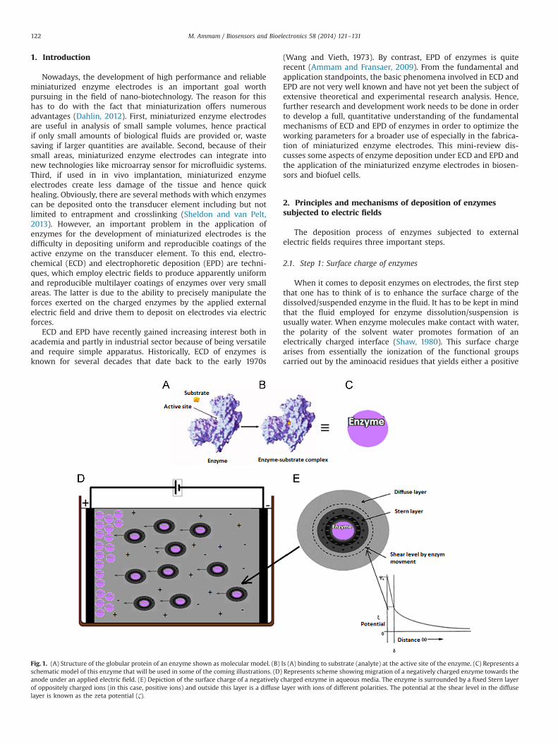
migration of enzymes under EPD if compared to ECD (Eq. (2)).As a result, more enzymes reach the surface of the electrodeand precipitate to form thick-deposited coatings (Ammam andFransaer, 2009, 2010c). However, it is important to bear in mindthat if high strength electric fields are employed in EPD, contin-uous direct current (DC) can no longer be utilized because itinduces heat and extensive evolution of water electrolysis. Thiscauses dramatic changes in temperature and pH near the electro-des, which in turn will decrease the activity of the depositedenzymes (Ammam and Fransaer, 2011b). To overcome the pro-blem, two other categories of electric fields can be employed inEPD of enzymes: pulsed direct current (PDC) and alternatingcurrent (AC).
Because PDC contains an OFF time where no or low electricfield is applied to the electrodes, it is possible to have the controlover the amount of water electrolysis if duration of ON time isshort enough to prevent evolution of gases (insert of Fig. 4B). Thus,substantial voltages can be applied for short periods that
according to Eq. (2) will lead to higher migrations of the chargedenzymes. Therefore, thick enzyme films maybe formed under PDC.As shown in EQCM results of Fig. 4, the deposited mass of glucoseoxidase subjected to PDC are several 10-folds higher than thoseprepared via continuous direct current (CDC). Furthermore,because PDC generates less water electrolysis, it induces minimumshift in pH nearby the electrode surface, leading to preservation ofmaximum enzymes activities. In this view, Ammam et al. recordedan increase in activity of the deposited enzyme by �25% whenthey switched from CDC to PDC under the same conditions(Ammam and Fransaer, 2010c).
The other category of electric fields that is used in EPD ofenzymes is based on AC, which if compared to DC contains bothpositive and negative voltage/current components (Ammam andFransaer, 2009). It is important to keep in mind that in AC there isno fixed anode or cathode but the polarization of each electrodechanges continuously between the positive and negative signs.Thus, if a negatively charged enzyme is subjected to a symmetricalAC signal (inset of Fig. 5A0), it should only oscillate in one locationbecause the migration achieved during the first half cycle whenone of the electrodes is positively charged should be neutralizedduring the second half cycle when the other electrode becomespositively charged. Thus, the net migration of the negativelycharged enzyme under symmetrical signals is actually zero. As aresult, only thin enzyme coatings can be deposited as shown inFig. 5A (Ammam and Fransaer, 2009). By contrast, if an asymme-trical AC signal with no net DC component is applied to anegatively charged enzyme (insert of Fig. 5B0), the difference involtage height and time duration between the two half-cycles ofthe period, shall push the charged enzyme to migrate significantdistance just like in DC fields, if the applied voltage is sufficientlyhigh. The latter can be described by adding a second terms toEq. (1) with the cubic dependence on the electric field strength toyield Eq. (4) (Dukhin and Dukhin, 2005).
VephðenzymeÞ ¼ μephEþμeph;3E3 ð4Þ
Hence, under asymmetrical AC fields, large amount of enzymesaccumulate nearby the electrode surface and because minimumbut sufficient electrolysis of water is also induced, the enzymesprecipitate to yield thick-deposited coatings (Fig. 5B). In the maintime, because AC fields generate minimum water electrolysis andohmic heat at the electrodes if compared to DC or PDC, thusmaximum enzyme activities are preserved after deposition(Ammam and Fransaer, 2009, 2010d, 2010e). Therefore, EPD ofenzymes under asymmetric AC fields can successfully be used toproduce thick enzyme coatings with higher activities. For thisreason, enzymes immobilization under AC is quite investigateddespite of being very recent. This can be seen in the numerousenzymes which have been successfully deposited (Ammam andFransaer, 2009, 2010e, 2012a, 2010b, 2011a, 2012b, 2013). When itcomes to deposit enzymes under EPD, one goal is to determine theoptimal parameters under which thick and active enzymes coat-ings are produced. In this respect, Ammam et al. determined fiveparameters that may affect thickness and activity of the enzymecoatings. The first two parameters deal with voltage and time ofwhich the deposition yield of enzymes is seen to increase quasi-linearly with polarization time and applied voltage then reaches asaturation plateau. At high-applied voltage-time, extensive elec-trolysis of water may take place, which in turn will play the rolenot in precipitating more enzymes on the electrode but washingpart of it. The third parameter has to do with the frequency ofwhich the deposition rate is recorded to increase up to a certainfrequency value then levels off or decreases. If the frequency ischanging faster, the charged enzymes will no longer follow the AC
Fig. 4. Electrochemical quartz crystal microbalance (EQCM) mass change duringECD of GOx from (A) phosphate buffer pH 7.4 at 1 V vs. Ag/AgCl and, (B) ultrapurewater using square wave potential 4 V vs. Ag/AgCl for 30 s and 0.5 V vs. Ag/AgCl for10 s. Image taken from Ammam and Fransaer (2010c) with permission of Elsevier.In yellow background is shown the DC and PDC signals used to deposit the enzymein both cases. (For interpretation of the references to color in this figure legend, thereader is referred to the web version of this article.)
M. Ammam / Biosensors and Bioelectronics 58 (2014) 121–131126

field because of their inertia, hence their net migration is sig-nificantly reduced and so the deposited yield. The fourth para-meter has to do with the enzyme concentration for which thedeposited yield is observed to increase up to a certain value thendecreases. Because commercialized enzymes contain salts forelectroneutrality, an increase in concentration yields high con-ductivity solution/suspension of enzymes, which in turn induceevolution of elevated rates of water electrolysis. Finally, shape ofthe applied AC signal affects also the deposited yield. For instance,triangular asymmetric waves result in higher deposition rates ifcompared to rectangular and sine waves. In sum, elevated voltagesand deposition times that are associated with low water electro-lysis, intermediate frequencies and enzyme concentrations underan applied asymmetrical AC triangular wave should yield thick andactive enzyme coatings. Table 1 gives a brief comparison betweenboth ECD and EPD techniques.
4. Application of enzyme electrodes by ECD and EPD
4.1. As biosensor electrodes
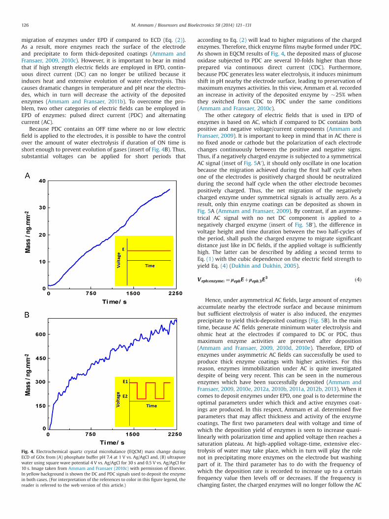
An enzyme-based biosensor is an analytical device that isemployed to determine and measure a particular analyte. It iscomposed of an immobilized layer of enzymes deposited on atransducer element (electrode). If the properties and activity of theenzyme is preserved after deposition, it will react and recognizethe analyte. The molecular recognition between enzyme-analyteinduces a signal that defines the biosensor characteristics (Fig. 6A).When it comes to enzyme deposition, the final goal is to produce abiosensor with appropriate characteristics in terms of substantialsensitivity towards the analyte, low response to interferences,extended linear range, short response time and stability (Mehrvarand Abdi, 2004; Wilson and Ammam, 2007). In this respect, ECD
Fig. 5. Scanning electron microscopy (SEM) images showing a cross section of a platinum wire without (A) and with (B) glucose oxidase enzyme modification usingsymmetrical (A) and asymmetrical (B) AC at 30 Hz, 160 Vp-p for 20 min. (A0) and (B0) are close-ups of the platinum-resin interface. Image taken from Ammam and Fransaer(2009) with permission of Elsevier. In yellow background is shown the symmetrical and asymmetrical triangular signals employed to deposit the enzyme. (For interpretationof the references to color in this figure legend, the reader is referred to the web version of this article.)
Table 1Comparison between ECD and EPD of enzymes alone. Because additives like nanomaterials, conducting polymers, redox mediators and others may boost both techniques,hence not relevant for comparison.
ECD EPD
Representative references Matsumoto et al. (2002), Chen et al. (2002),Ammam and Fransaer (2010c)
Ammam and Fransaer (2009, 2010c, 2010d)
Equipment Potentiostat (amperometry, potentiometry orcyclic voltammetry)
Function generator (DC or AC power supplies),amplifier. Potentiostat
Electrolyte High conductivity solutions (buffers) Low conductivity solutions (water with somecharging agent)
Surface charge of enzymes (ζ) Moderate HighNature of applied electric field DC PDC, ACApplied electric field strength Low (less than 2 V) It could very high ( up to 200 V AC)Thickness of deposited enzyme coatings Thin (monolayers of no more than few hundred of nm) Thick (multilayers that may be over 10 μm)Morphology of the deposited enzyme coatings Smooth RoughActivity of the enzyme coatings Moderate HighSensitivities of the enzyme electrodes Moderate (e.g. for glucose oxidase �74 nA mM�1 mm�2) Large (e.g. for glucose oxidase 430 nA mM�1 mm�2)
M. Ammam / Biosensors and Bioelectronics 58 (2014) 121–131 127
and EPD are versatile techniques, meaning that a variety ofparameters such as applied voltage, frequency, deposition time,nature of the applied electric signal, enzyme concentration can becontrolled to yield enzyme films with desired characteristics andthus better responses under the optimized conditions. Further-more, because under ECD and EPD, enzymes are driven via electricforces, thus they can be manipulated to coat miniaturized electro-des that have complex shapes with uniform enzyme films. As aresult, using ECD and EPD, a number of biosensors with improvedsensitivities have been fabricated to detect analytes like glucose,lactose, glutamate, cholesterol, H2O2 and others (Dong et al., 1993;Chen et al., 2002; Chiu et al., 2009; Mignani et al., 2006; Lei et al.,2011; Ammam and Fransaer, 2010d, 2010e, 2010b, 2011a). In termsof selectivity towards the interferences, ECD and EPD of enzymeswithout other components is usually not sufficient to preventinterferences from passing through the enzyme coating to reachthe transducer element and induce a signal. To overcome theproblem, several ways have been considered. One avenue is todeposit very thick and dense enzyme coatings on electrodes viaEPD. The large thickness will prevent part of the interferencesfrom travelling through the enzyme coating (Ammam andFransaer, 2009, 2010d, 2011a). Another efficient means to excludeinterferences is by co-depositing enzymes with polymers, sol–gelsand other materials to yield enzymes entrapped in matrices (Chenet al., 2002; Smutok et al., 2006; Iwuoha et al., 1997; Ciriello et al.,2000; Guerrieri et al., 2009). The morphology of the matrices andtheir low porosity prevent interferences with high molecularweights from travelling through the enzyme-matrix coating toreach the transducer. Because polymers or sol–gels have lowersolubilities in aqueous media, the matrix is also beneficial inextending the lifetime and stability. Hence, the biosensors mayfunction for long periods (Chen et al., 2002; Pałys et al., 2010; Qiuet al., 2009; Li et al., 2012). Another advantage of the matrix is thatit can also play an important role in boosting the linearity of thebiosensor's response, especially if it is applied as an outer layer toregulate the diffusion of the analyte to the enzyme coating. Thisallows measurement of elevated concentrations of analytes. Onthe other hand, if compared to coatings containing only enzymes,the presence of the matrix may affect the response time of thebiosensor (Lyklema, 1977; Chen et al., 2002). This is quite under-standable because the matrix slows down diffusion of the analytetowards the enzyme coating. Since the final goal of the biosensortechnology is the measurement of analytes in real samples andreal time, a number of biosensors fabricated via ECD and EPD arefound dependable for determination of analytes in real samplessuch as cultivated plants, serum, milk, blood and living human
hepatoma cells (Diaconu et al., 2010; Vidal et al., 1999; Ammamand Fransaer, 2010d, 2010e; Rui et al., 2010). The latter is promis-ing if we consider the challenging aspects of biosensors in realsamples.
4.2. As biofuel cell anodes and cathodes
Compared to an enzyme biosensor where only one electrode isrequired in the device construction, an enzyme biofuel cellrequires two enzyme electrodes (Fig. 6B): one to act as a bioanode(electrons generator) and another to act as a biocathode (electronsreceiver). When the two enzyme electrodes are connectedtogether in presence of the respective analytes (or fuels) like,glucose at the bioanode and O2 at the biocathode, the electro-chemical reactions induced from oxidation/reduction of the ana-lytes lead to an electron flow through the external circuit. Thisflow is driven by an electromotive force that is raised from thedifference in potential between the two enzyme electrodes(Palmore et al., 1998; Katz et al., 1999; Cooney et al., 2008;Meredith and Minteer, 2012; Mano et al., 2003). Compared to abiosensor where electron communication between the depositedenzyme and the electrode may not be necessary (for first andthird-generation biosensors) because an induced by-product likeH2O2 from the immobilized enzyme-analyte reaction or O2 con-sumption by the immobilized enzyme suffice to induce a signalthat will define the characteristics of the biosensor. By contrast,electron communication between the enzyme and the electrode isnecessary in enzyme biofuel cells to induce an electron flow andhence power. The reason for this has to do with enzymes thatgenerally have their redox centers buried inside their complexstructures and hence distant from the electrode. To this end,electron mediators/promoters are required to wire the gener-ated/received electrons between deposited enzymes and theelectrodes. When it comes to deposit enzymes on electrodes foruse as miniaturized biofuel cells, the final goal is to produceenzyme electrodes with enhanced characteristics in terms ofhigh output power and good stability. The power density(Pcell¼Ecell� Jcell) is determined by cell voltage (Ecell) and cellcurrent density (Jcell). An up to date overview of literature revealsthat enzyme electrodes prepared by ECD and EPD have thepotential to be used as biofuel cells electrodes. However, ifcompared to their wide use as biosensors, their application inbiofuel cells is still far less. The reason for this is related to thepreparation of the enzyme electrodes that require more elaborateprocedures to be used as biofuel cells than as biosensors. In otherwords, when enzymes without electron mediators/promoters are
Fig. 6. Scheme representing enzyme electrodes functioning as a biosensor (A) and as an enzyme biofuel cell (B).
M. Ammam / Biosensors and Bioelectronics 58 (2014) 121–131128

immobilized on electrodes, they can be useful as first-generationbiosensors. However, they cannot be employed as biofuel cellsbecause electron communication between redox centers of theimmobilized enzymes and the electrode is not sufficient (Meredithand Minteer, 2012). To this end, because ECD and EPD are versatiletechniques, electron mediators/promoters such as conductingpolymers, small organic redox mediators and nanomaterials canalso be driven by means of electric forces to deposit with theenzymes in one or several steps. In view of this, polymerscontaining Os-complexes deposited via ECD are found to be excellentin shuttling electrons from electrodes to the deposited enzymes likebilirubin oxidase (Karnicka et al., 2007; Shen et al.; 2013) or laccase(Ackermann et al., 2010) to induce an efficient reduction of O2 at thebiocathode. Other alternatives based on imidazolium ionic liquids,carbon nanotubes and monomers deposited using ECD and EPD arefound to promote a better electron-relay between enzyme-electrode
to generate high power outputs (Ammam and Fransaer, 2010a,2012b, 2013, 2012a). The presence of these electron mediators/promoters facilitates the oxidation/reduction of analytes likeglucose/O2 or glucose/O2–H2O2 at bioanode/biocathode. This efficientelectron mediation induces shifts in the starting potentials of theelectrooxidation/ electroreduction towards earlier values, which inturn improves cell voltages and thus power outputs. As for biosen-sors, the final goal of miniaturized enzyme biofuel cells fabricated viaECD and EPD is their use to generate energy from real samples and inreal time. Examples include providing microelectronic devices likeimplantable micro-sensors transmitters or artificial organs withsufficient power (Barton et al., 2004; Bullen et al., 2006). To thisend, a number of newly constructed enzyme biofuel cells via ECDand EPD are found to be dependable for use in biological fluids likehuman serum (Ammam and Fransaer, 2012b, 2010a). However, inbiological fluids, reductions in power densities are generally observed
Table 2A brief comparison between the characteristics of biosensor and biofuel cell electrodes constructed by ECD and EPD.
Depositionmethod
Biosensor electrodes Biofuel cell electrodes
Sensitivity Selectivity Linearity Response time Stability Power output Stability
ECD � If compared toEPD, thesensitivities aremoderate
� Optimalsensitivities canbe obtained iflarge amounts ofenzymes aredeposited on thetransducers (i.e.,optimal highvoltage-time areapplied withoutgenerating largeamounts ofelectrolysis).
The selectivities aremoderate becauseECD of enzymesalone do not formdense films thatmay preventinterferences fromtravelling throughthe film.
� The linearity canbe extended byco-depositingenzymes withpolymers toregulate thediffusion ofanalytes fluxesreaching theenzyme or by co-depositing theenzymes withredox mediators.
� It depends onthe filmthickness andits porosity.
� If the enzymefilm is thickand dense,response timeto analyte willbe long and ifthe film isthin, theresponse timeshouldbe short.
� Stabilitiesaremoderate ifonlyenzymesaredeposited.
� Can beimprovedby usingstabilizerslikepolymersco-depositedwith theenzymes orapplied asoutermembranes.
� It depends notonly on howmuch enzyme isdeposited on theelectrode butmore importantlyon how thegenerated/collectedelectrons aredelivered to/fromthe currentcollector.
� Electronmediator/promoters such asconductingpolymers, smallorganic redoxmediators andnanomaterials arekey factors ingetting highoutput power.
� The stability ofthe enzymeelectrodes can beimproved byusing stabilizerslike polymers co-deposited withthe enzymes orapplied as outermembranes.� Co-deposition
of polymers orothermembranes arerequired topreventinterferencesfrom reachingthe transducer
� Themembranes canalso be appliedas inner/outerlayers
EPD � The sensitivitiescan be very high ifappropriateconditions areemployed (i.e.,high asymmetricAC voltage,triangular waves,low ionic strengthsolutions, longerdepositionperiods withoutgenerating highamounts of waterelectrolysis)
� Becauseenzyme filmsfabricated viaEPD maybevery thick anddense, thusthey canexclude part oftheinterferences
� However, ingeneral,stabilizers likepolymersapplied asouter or innermembranes arerequired forenhancedselectivities
� Because enzymefilms by EPD arevery thick anddense, hence theycan self-regulatethe diffusion ofanalyte to theimmobilizedenzyme, resultingin relativelyextendedlinearities
� Can be increasedby depositingouter membranesof polymers/sol–gels or byincorporatingadditional redoxmediators withthe depositedenzymes
� It depends onthe filmthickness
� Responsetimes maybelong becausethick films aregenerallydepositedunder EPD
� The morethe film isthick anddense, themore thestabilityincreases
� However,stabilizerslikepolymers/sol–gelsapplied asouter layersare requiredto extendlifetime ofthebiosensors
� Because EPD deposithigh amounts ofenzymes onelectrodes, if redox/electron promoters aresuccessfullyincorporated, it mayyield to much higherpower outputs ifcompared to BFCsfabricated via ECD
� Because EPDforms dense andthick enzymefilms, thestability isrelatively betterthan filmsproduced viaECD
� The stability ofthe enzymeelectrodes byEPD can beboosted usingstabilizers likepolymers co-deposited withthe enzymes orapplied as outermembranes
Selectedreferences
Ammam and Fransaer (2009, 2010d, 2011a), Chen et al. (2002), Smutok et al. (2006), Iwuoha et al. (1997),Ciriello et al. (2000), Guerrieri et al. (2009), Pałys et al. (2010), Qiu et al. (2009), Li et al. (2012), Lyklema(1977)
Ammam and Fransaer (2010a, 2012b, 2013,2012a), Ackermann et al. (2010), Karnickaet al. (2007), Shen et al. (2013)
M. Ammam / Biosensors and Bioelectronics 58 (2014) 121–131 129
if compared to buffers. The latter is related to chemicals/ proteinfragments found in biological fluids that after their adsorption on theelectrode surface restrict diffusion of analyte molecules to theenzyme coating. In terms of stability, if compared to enzymeelectrodes employed as biosensors, biofuel cells generally suffer fromlower stabilities. This is caused by water electrolysis and heatemission induced in biofuel cells, which decrease the enzymeactivities and result in a quick deterioration. By contrast, a biosensorcan be polarized at fixed potentials where electrolysis and heatemission could be minimized or avoided. Table 2 compares thecharacteristics of the resulting biosensor and biofuel cell electrodesfabricated via ECD and EPD.
5. Summary and conclusions
The reviewed literature revealed that ECD and EPD are promisingtechniques in deposition of enzymes and manufacturing of biosen-sors and biofuel cells. Both ECD and EPD employ electric forces tomanipulate and drive charged enzymes to deposit on electrodes.Thus, ECD and EPD are suitable to deposit enzymes on electrodeshaving smaller areas and complex shapes. From the fundamentalviewpoint, there are differences between ECD and EPD. ECD iscarried out from high conductivity solutions/suspensions containingenzyme with salts. Under these conditions, enzymes gain low valuesof ζ. Furthermore, because high ionic strength are used, only lowelectric fields could be utilized to deposit enzymes and preventmassive evolution of water electrolysis that may decrease theenzyme activities. As a result, enzymes migrate meaningless dis-tances to form thin enzyme coatings. By comparison, EPD of enzymesis carried out from low conductivity solutions/suspensions. Thisenables enzymes to gain substantial ζ. In addition, because low ionicstrength solutions are utilized, hence high electric field strengths canbe applied without inducing massive water electrolysis. This in turninduces significant migration of enzymes from bulk of solution/suspension to the electrode of opposite charge, resulting in formationof thick and active enzyme coatings. ECD and EPD techniques havethe advantage of being versatile, easy to use, automated and requirea simple apparatus. Hence, useful for the manufacturing of enzymeelectrodes with higher reproducibilities. Furthermore, if properfixturing is utilized, numerous electrodes can be prepared simulta-neously. As a result, using ECD and EPD, a number of miniaturizedbiosensors with improved properties in terms of relevant sensitivityand selectivity, extended linear range and stability suitable for use inreal samples and real time have been developed. Enzyme electrodesmanufactured by ECD and EPD can also be employed as biofuel cells.This can be accomplished by incorporating electron mediators/promoters like conducting polymers, redox mediators and nanoma-terials in order to boost the electron transfer and communicationbetween the immobilized enzymes and the electrodes.
6. Future perspectives
Because of the importance of enzyme biosensors and biofuelcells in today's nano-biotechnology, further quantitative studies ofenzyme deposition under ECD and EPD will allow in depth under-standing of the principles and mechanisms of the depositionprocesses. This can be done by using the state of the arts of variousphysicochemical techniques and their combinations. On the otherhand, since parameters like surface charge and particle size are veryimportant in successful enzyme deposition, much attention shouldbe paid for optimizing the preparation conditions of enzymes such asemploying appropriate charging agents to enhance ζ of enzymes inorder to enhance their migrations under the applied electric fields.This may seem at first exploratory, but if well targeted using
synthetic methods, it may lead to elevated ζ of enzymes. The lattershould be combined with the use of appropriate electrolytes (anionsand cations) as well as low ionic strength electrolytes for dissolution/suspension of enzymes in order to allow higher strength electricfields to be employed without inducing high rates of water electro-lysis. If all these factors are well controlled, the characteristics of thedeposited enzymes films will be improved to fit with the design andfabrication of high quality enzyme coatings suitable for novelgeneration of future advanced enzyme biosensors and biofuel cells.
Acknowledgements
The author would like to thank the University of Groningen forsupport through the Rosalind Franklin Fellowship.
References
Ackermann, Y., Guschin, D.A., Eckhard, K., Shleev, S., Schuhmann, W., 2010.Electrochem. Commun. 12, 640–643.
Almeida, N.F., Beckman, E.J., Ataai, M.M., 1993. Biotechnol. Bioeng. 42, 1037–1045.Ammam, M., Fransaer, J., 2009. Biosens. Bioelectron. 25, 191–197.Ammam, M., 2012. RSC Adv. 2, 7633–7646.Ammam, M., Fransaer, J., 2010a. Biosens. Bioelectron. 25, 1474–1480.Ammam, M., Fransaer, J., 2010b. Biosens. Bioelectron. 25, 1597–1602.Ammam, M., Fransaer, J., 2010c. Electrochim. Acta 55, 9125–9131.Ammam, M., Fransaer, J., 2010d. Sens. Actuators, B 145, 46–53.Ammam, M., Fransaer, J., 2010e. Sens. Actuators, B 148, 583–589.Ammam, M., Fransaer, J., 2011a. Sens. Actuators, B 160, 1063–1069.Ammam, M., Fransaer, J., 2011b. J. Electroanal. Chem. 23, 755–763.Ammam, M., Fransaer, J., 2012a. Electrochim. Acta 81, 129–137.Ammam, M., Fransaer, J., 2012b. Biotechnol. Bioeng. 109, 1601–1609.Ammam, M., Fransaer, J., 2013. Biosens. Bioelectron. 39, 274–281.Baldwin, R.L., 1996. Biophys. J. 71, 2056–2063.Bartlett, P.N., Cooper, J.M., 1993. J. Electroanal. Chem. 362, 1–12.Barton, S.C., Gallaway, J., Atanassov, P., 2004. Chem. Rev. 104, 4867–4886.Bicelli, L.P., Bozzini, B., Mele, C., D'Urz, L., 2008. Int. J. Electrochem. Sci. 3, 356–408.Bullen, R.A., Arnot, T.C., Lakeman, J.B., Walsh, F.C., 2006. Biosens. Bioelectron. 21,
2015–2045.Chen, X., Matsumoto, N., Hu, Y., Wilson, G.S., 2002. Anal. Chem. 74, 368–372.Chiu, J.Y., Yu, C.M., Yen, M.J., Chen, L.C., 2009. Biosens. Bioelectron. 24, 2015–2020.Ciriello, R., Cataldi, T.R.I., Centonze, D., Guerrieri, A., 2000. Electroanalysis 12,
825–830.Cooney, M.J., Svoboda, V., Lau, C., Martin, G., Minteer, S.D., 2008. Energy Environ.
Sci. 1, 320–337.Crumbliss, A.L., Perine, S.C., Stonehuerner, J., Tubergen, K.R., Zhao, J., Henkens, R.W.,
1992. Biotechnol. Bioeng. 40, 483–490.Curulli, A., Palleschi, G., 1997. J. Electroanal. Chem. 9, 1107–1112.Dahlin, A.B., 2012. Sensors 12, 3018–3036.Diaconu, M., Litescu, S.C., Radu, G.L., 2010. Sens. Actuators, B 145, 800–806.Dong, S., Deng, Q., Cheng, G., 1993. Anal. Chim. Acta 279, 235–240.Dukhin, A.S., Dukhin, S.S., 2005. Electrophoresis 26, 2149–2153.Eftekhari, A., 2004. Synth. Met. 145, 211–216.Fei, J., Wu, Y., Ji, X., Wang, J., Hu, S., Gao, Z., 2003. Anal. Sci. 19, 1259–1263.Fortier, G., Brassard, E., Belanger, D., 1990. Biosens. Bioelectron. 5, 473–490.Gao, Z.Q., Binyamin, G., Kim, H.H., Barton, S.C., Zhang, Y.C., Heller, A., 2002. Angew.
Chem. Int. Ed. 41, 810–813.Guerrieri, A., Ciriello, R., Centonze, D., 2009. Biosens. Bioelectron. 24, 1550–1556.Hoshi, T., Anzai, J.I., Osa, T., 1994. Anal. Chim. Acta 289, 321–327.Ikariyama, Y., Yamauchi, S., Yukiashi, T., Ushioda, H., 1987. Anal. Lett. 20, 1791–1801.Im, D.M., Jang, D.H., Oh, S.M., Striebel, C., Wiemhoefer, H.D., Gauglitz, G., Goepel, W.,
1995. Sens. Actuators, B 24, 149–155.Iwuoha, E.I., Saenz de Villaverde, D., Garcia, N.P., Smyth, M.R., Pingarron, J.M., 1997.
Biosens. Bioelectron. 12, 749–761.Johnson, K.W., 1991. Sens. Actuators, B 5, 85–89.Johnson, K.W., Allen, D.J., Mastrototaro, J.J., Morff, R.J., Nevin, R.S., 1994. ACS Symp.
Ser. (556), 84–95Karnicka, K., Eckhard, K., Guschin, D.A., Stoica, L., Kulesza, P.J., Schuhmann, W.,
2007. Electrochem. Commun. 9, 1998–2002.Katz, E., Willner, I., Kotlyar, A.B., 1999. J. Electroanal. Chem. 479, 64–68.Kim, C.S., Oh, S.M., 1996. Electrochim. Acta 41, 2433–2439.Koh, H., Igarashi, S., Sode, K., 2003. Biotechnol. Lett. 25, 1695–1701.Lei, L., Cao, Z., Xie, Q., Fu, Y., Tan, Y., Ma, M., Yao, S., 2011. Sens. Actuators, B 157,
282–289.Lyklema, J., 1977. J. Colloid Interface Sci. 58, 242–250.Li, D., Wen, Y., He, H., Xu, J., Liu, M., Yue, R., 2012. J. Appl. Polym. Sci. 126, 882–893.Lim, S.H., Wei, J., Lin, J., Li, Q., KuaYou, J., 2005. Biosens. Bioelectron. 20, 2341–2346.Malitesta, C., Palmisano, F., Torsi, L., Zambonin, P.G., 1990. Anal. Chem. 62,
2735–2740.Meredith, M.T., Minteer, S.D., 2012. Annu. Rev. Anal. Chem. 5, 157–179.
M. Ammam / Biosensors and Bioelectronics 58 (2014) 121–131130

Mano, N., Mao, F., Heller, A., 2003. J. Am. Chem. Soc. 125, 6588–6594.Morrin, A., Guzman, A., Killard, A.J., Pingarron, J.M., Smyth, M.R., 2003. Biosens.
Bioelectron. 18, 715–720.Matsumoto, N., Chen, X., Wilson, G.S., 2002. Anal. Chem. 74, 362–367.Mehrvar, M., Abdi, M., 2004. Anal. Sci. 20, 1113–1126.Mignani, A., Scavetta, E., Tonelli, D., 2006. Anal. Chim. Acta 577, 98–106.Oddy, M.H., Santiago, J.G., 2004. J. Colloid Interface Sci. 269, 192–204.Palmore, G.T.R., Bertschy, H., Bergens, S.H., Whitesides, G.M., 1998. J. Electroanal.
Chem. 443, 155–161.Pałys, B., Marzec, M., Rogalski, J., 2010. Bioelectrochemistry 80, 43–48.Polsky, R., Harper, J.C., Dirk, S.M., Arango, D.C., Wheeler, D.R., Brozik, S.M., 2007.
Langmuir 23, 364–366.Prieve, D.C., Sides, P.J., Wirth, C.L., 2010. Curr. Opin. Colloid Interface Sci. 15,
160–174.Qiu, J.D., Wang, R., Liang, R.P., Xia, X.H., 2009. Biosens. Bioelectron. 24, 2920–2925.Remirez, C.P., Caruana, D.J., 2006. Electrochem. Commun. 8, 450–454.Rishpon, J., Gottesfeld, S., 1991. Biosens. Bioelectron. 6, 143–149.Rui, Q., Komori, K., Tian, Y., Liu, H., Luo, Y., Sakai, Y., 2010. Anal. Chim. Acta 670,
57–62.Russell, A.J., Fersht, A.R., 1987. Nature 328, 496–500.Salgın, S., Salgın, U., Bahadır, S., 2012. Int. J. Electrochem. Sci. 7, 12404–12414.
Schultza, N., Metreveli, G., Franzrebc, M., Frimmel, F.H., Syldatkd, C., 2008. ColloidsSurf., B 66, 39–44.
Shaw, D.J., 1980. Introduction to Colloid and Surface Chemistry, third ed. Butter-worth and Co., London
Sheldon, R.A., van Pelt, S., 2013. Chem. Soc. Rev. 42, 6223–6235.Shen, W., Deng, H., Teo, A.K.L., Ga, Z., 2013. J. Power Sources 226, 27–32.Stern, O.Z., 1924. Electrochemical 30, 508–516.Smutok, O., Ngounou, B., Pavlishko, H., Gayda, G., Gonchar, M., Schuhmann, W.,
2006. Sens. Actuators, B 113, 590–598.Stonehuerner, J.G., Zhao, J., O'Daly, J.P., Crumbliss, A.L., Henkens, R.W., 1992.
Biosens. Bioelectron. 7, 421–428.Strike, D.J., de Rooij, N.F., Koudelka-Hep, M., 1993. Sens. Actuators, B 13, 61–64.Trojanowicz, M., Geschke, O., Krawczyński vel Krawczyk, T., Cammann, K., 1995.
Sens. Actuators, B 28, 191–199.Vidal, J.C., Garcıa, E., Castillo, J.R., 1999. Sens. Actuators, B 57, 219–226.Velev, O.D., Bhatt, K.H., 2006. Soft Matter 2, 738–750.Wang, J., Myung, N.V., Yun, M., Monbouquette, H.G., 2005. J. Electroanal. Chem. 575,
139–146.Wang, S.S., Vieth, W.R., 1973. Biotechnol. Bioeng. 15, 93–115.Wilson, G.S., Ammam, M., 2007. FEBS J. 274, 5452–5461.Zhang, Z., Liu, H., Deng, J., 1996. Anal. Chem. 68, 1632–1638.
M. Ammam / Biosensors and Bioelectronics 58 (2014) 121–131 131