Preparation and application of carbon nanotubes flexible ...
11
Preparation and application of carbon nanotubes flexible sensors Shuo Li 1 , Xiao Feng 1 , Hao Liu 1 , Kai Wang 1, † , Yun-Ze Long 2, † , and S. Ramakrishna 3 1 College of Electrical Engineering, Qingdao University, Qingdao 266071, China 2 Collaborative Innovation Center for Nanomaterials and Devices, College of Physics, Qingdao University, Qingdao 266071, China 3 NUS Centre for Nanofibers and Nanotechnology, Department of Mechanical Engineering, National University of Singapore, Singapore Abstract: Based on the good extensibility and conductivity, the flexible sensors (FSs) have a wide range of applications in the field of the electrochemical energy storage and variable stress sensors, which causes that the preparation of FSs also become a hot spot of research. Among the materials for preparing the FSs, the flexible carbon matrix composites (FCMCs) have become the widely used material since the good performance in the properties of electrochemistry and mechanics, which could be di- vided into three types: the carbon nanofibers (CNFs), the carbon nanospheres (CNSs) and the carbon nanotubes (CNTs). Com- pared with CNFs and CNSs, the CNTs wrapped by the polydimethylsiloxane (PDMS) have the advantages of the excellent extens- ibility and electrochemical stability. Therefore, the CNTs flexible sensor (CFS) could be well used in the field of the FSs. The pur- pose of this review is summarizing the preparation methods and application fields of CFS and proposing the research direc- tion of CFS in the future. In this paper, two methods for fabricating the CFS have been designed by consulting the methods men- tioned in the literature in recent years, and the advantages and disadvantages between the two methods have been explained. The application fields of CFS in recent years are enumerated, and the conclusion that the application fields of CFS are very wide is drawn. At the end of this paper, the review concludes with an overview of key remaining challenges in the application fields of the CFS. Key words: CNTs; PDMS; CFS; preparation methods; application fields Citation: S Li, X Feng, H Liu, K Wang, Y Z Long, and S Ramakrishna, Preparation and application of carbon nanotubes flexible sensors[J]. J. Semicond., 2019, 40(11), 111606. http://doi.org/10.1088/1674-4926/40/11/111606 1. Introduction With the development of various industries, including electronic industry, material industry, and medical industry, the quality requirements of electronic products are higher. How to ensure the high flexibility, high energy density, high power density and good stability of electronic products has become a research hotspot in the electronic field. As a new type of electrodes, compared with the traditional electrodes, the flexible sensors (FSs) that are made of flexible materials have the advantages of the good elastic strain, the excellent conductivity and the fantastic durability, which enables FSs to satisfy the requirements mentioned above and lets FSs be widely used in the two-stage matrix converter, the single poly- aniline tube, the electrodes in lithium-ion batteries, solar cells and other energy storage components [1−3] . As for the materials consisting of FSs, in order to guaran- tee the good of mechanical flexibility and the good of electric- al conduction, materials of FSs mainly include the graphene, the electrospinning, the oxides of transition metal and the conductive polymers [4, 5] . Among those kinds of materials, based on the excellent electrical conductivity, the high ther- mal conductivity, the high strength, the low expansion coeffi- cient, the good friction performance, the high dimensional sta- bility and the good performance of resisting thermal shock, the research and the application of the flexible carbon mat- rix composites (FCMCs), which are made of the matrix of the material of carbon element and the reinforcement of materi- al of carbon fiber or silicon carbide, are more extensive [6−9] . The several application fields of FCMCs are as follow [10−14] : (1) FCMCs can be used as the electronic transmission chan- nels in FSs because of their excellent electrical conductivity. (2) FCMCs can be used as the materials of supporting the electrodes in FSs since their excellent properties of bending and folding. (3) Because of the strong plasticity of the material of carbon element, FCMCs can be easily shaped into various shapes, including the nanostructures of one-dimensional, two-dimensional and three-dimensional, which could have a positive effect on the transmission of current and improve the conductivity of FCMCs. In summary, the FCMCs play an important role in FSs and become one of the most popular materials which consisting of FSs. In the field of FCMCs, the material of nano-carbon (NC) has become the popular material due to its small size and strong plasticity. According to the forming structure, NC materials are divided into three types [15−19] . 1.1. Carbon nanofibers Carbon nanofibers (CNFs) are made of the flaky materi- als of the polyacrylonitrile fibers, the asphalt fibers, the vis- cose filaments or the phenolic fibers, which are stacked along the axial direction of the fibers and then carbonized and graph- Correspondence to: K Wang, [email protected]; Y Z Long, [email protected] Received 29 AUGUST 2019; Revised 23 OCTOBER 2019. ©2019 Chinese Institute of Electronics REVIEWS Journal of Semiconductors (2019) 40, 111606 doi: 10.1088/1674-4926/40/11/111606
-
Upload
khangminh22 -
Category
Documents
-
view
1 -
download
0
Transcript of Preparation and application of carbon nanotubes flexible ...
Preparation and application of carbon nanotubes flexiblesensors
Shuo Li1, Xiao Feng1, Hao Liu1, Kai Wang1, †, Yun-Ze Long2, †, and S. Ramakrishna3
1College of Electrical Engineering, Qingdao University, Qingdao 266071, China2Collaborative Innovation Center for Nanomaterials and Devices, College of Physics, Qingdao University, Qingdao 266071, China3NUS Centre for Nanofibers and Nanotechnology, Department of Mechanical Engineering, National University of Singapore, Singapore
Abstract: Based on the good extensibility and conductivity, the flexible sensors (FSs) have a wide range of applications in thefield of the electrochemical energy storage and variable stress sensors, which causes that the preparation of FSs also become ahot spot of research. Among the materials for preparing the FSs, the flexible carbon matrix composites (FCMCs) have becomethe widely used material since the good performance in the properties of electrochemistry and mechanics, which could be di-vided into three types: the carbon nanofibers (CNFs), the carbon nanospheres (CNSs) and the carbon nanotubes (CNTs). Com-pared with CNFs and CNSs, the CNTs wrapped by the polydimethylsiloxane (PDMS) have the advantages of the excellent extens-ibility and electrochemical stability. Therefore, the CNTs flexible sensor (CFS) could be well used in the field of the FSs. The pur-pose of this review is summarizing the preparation methods and application fields of CFS and proposing the research direc-tion of CFS in the future. In this paper, two methods for fabricating the CFS have been designed by consulting the methods men-tioned in the literature in recent years, and the advantages and disadvantages between the two methods have been explained.The application fields of CFS in recent years are enumerated, and the conclusion that the application fields of CFS are verywide is drawn. At the end of this paper, the review concludes with an overview of key remaining challenges in the applicationfields of the CFS.
Key words: CNTs; PDMS; CFS; preparation methods; application fields
Citation: S Li, X Feng, H Liu, K Wang, Y Z Long, and S Ramakrishna, Preparation and application of carbon nanotubes flexiblesensors[J]. J. Semicond., 2019, 40(11), 111606. http://doi.org/10.1088/1674-4926/40/11/111606
1. Introduction
With the development of various industries, includingelectronic industry, material industry, and medical industry,the quality requirements of electronic products are higher.How to ensure the high flexibility, high energy density, highpower density and good stability of electronic products hasbecome a research hotspot in the electronic field. As a newtype of electrodes, compared with the traditional electrodes,the flexible sensors (FSs) that are made of flexible materialshave the advantages of the good elastic strain, the excellentconductivity and the fantastic durability, which enables FSsto satisfy the requirements mentioned above and lets FSs bewidely used in the two-stage matrix converter, the single poly-aniline tube, the electrodes in lithium-ion batteries, solar cellsand other energy storage components[1−3].
As for the materials consisting of FSs, in order to guaran-tee the good of mechanical flexibility and the good of electric-al conduction, materials of FSs mainly include the graphene,the electrospinning, the oxides of transition metal and theconductive polymers[4, 5]. Among those kinds of materials,based on the excellent electrical conductivity, the high ther-mal conductivity, the high strength, the low expansion coeffi-cient, the good friction performance, the high dimensional sta-
bility and the good performance of resisting thermal shock,the research and the application of the flexible carbon mat-rix composites (FCMCs), which are made of the matrix of thematerial of carbon element and the reinforcement of materi-al of carbon fiber or silicon carbide, are more extensive[6−9].The several application fields of FCMCs are as follow[10−14]:
(1) FCMCs can be used as the electronic transmission chan-nels in FSs because of their excellent electrical conductivity.
(2) FCMCs can be used as the materials of supporting theelectrodes in FSs since their excellent properties of bendingand folding.
(3) Because of the strong plasticity of the material ofcarbon element, FCMCs can be easily shaped into variousshapes, including the nanostructures of one-dimensional,two-dimensional and three-dimensional, which could have apositive effect on the transmission of current and improvethe conductivity of FCMCs.
In summary, the FCMCs play an important role in FSs andbecome one of the most popular materials which consistingof FSs. In the field of FCMCs, the material of nano-carbon(NC) has become the popular material due to its small sizeand strong plasticity. According to the forming structure, NCmaterials are divided into three types[15−19].
1.1. Carbon nanofibers
Carbon nanofibers (CNFs) are made of the flaky materi-als of the polyacrylonitrile fibers, the asphalt fibers, the vis-cose filaments or the phenolic fibers, which are stacked alongthe axial direction of the fibers and then carbonized and graph-
Correspondence to: K Wang, [email protected]; Y Z Long,
[email protected] 29 AUGUST 2019; Revised 23 OCTOBER 2019.
©2019 Chinese Institute of Electronics
REVIEWS
Journal of Semiconductors(2019) 40, 111606
doi: 10.1088/1674-4926/40/11/111606

itized. CNFs are a kind of inorganic material made entirely bymanual intervention. The structure characterization of theCNFs made by Yang et al. is shown in the Fig. 1[15].
The advantages of CNFs include the high strength, thehigh modulus, the low density, the ultra-high temperatureresistance in non-oxidation environment, the low thermal ex-pansion coefficient, the good anisotropy and the good corro-sion resistance. The disadvantage of CNFs is the high cost, be-cause the production of carbon nanofibers requires theplenty of the manpower, the raw materials and the time,which restricts the production of the FSs of CNFs[16].
1.2. Carbon nanospheres
Carbon nanospheres (CNSs) can be obtained by the mix-ture of carbon raw materials and catalysts, which experiencethe program of heating at the constant temperature and theprogram of cooling respectively[17].
Park et al. fabricated the CNSs by using the porous hol-low microcapsules, whose structure is shown as the Fig. 2[18].The CNSs have the same advantages as CNFs except theanisotropy. However, for FSs, the CNSs cannot satisfy the char-acteristics that FSs need to be folded freely.
1.3. Carbon nanotubes
Carbon nanotubes (CNTs) are the hollow tubular carbonmaterials which are seamless, which are made of graphitesheets of single or multi-layer that curled around the left at acertain angle[19]. CNTs not only have the same advantages asCNFs, but also have the advantage of low cost of production,which is suitable for the preparation of FSs.
Although CNTs can be used to fabricate FSs, CNTs fabric-ated from powders cannot be directly used as FSs installed in
batteries, and must be attached to a carrier. In theory, materi-als that can fix the shape of CNTs, such as the material ofSiO2, Au and Pd, can be used as the carriers of CNTs[20−24].However, in order to ensure that the ductility and conductiv-ity of CNTs are not affected, the carriers of CNTs must havethe good insulation and ductility.
The polydimethylsiloxane (PDMS) is a kind of the hydro-phobic silicone material, which has the color of colorless orpale yellow, the taste of tasteless, the high transparency andthe non-toxic. PDMS shows the excellent performance in ductil-ity, heat resistance, cold resistance, hydrophobicity, thermalconductivity, insulation, physiological inertia and chemical sta-bility[25−27]. Based on the advantages of it, PDMS can be usedas a kind of the material of the carrier of CNTs. The CNTs/PDMS composite can be obtained by coating and fasteningCNTs with PDMS[26−28]. The CNTs flexible sensor (CFS) can beobtained by inserting two conductive metal strips into thearea of CNTs in the CNTs/PDMS composite.
Starting from the structure and properties of the CNTs,this paper introduces in detail the preparation methods andthe application fields of the CFS in recent years, expoundsthe advantages and disadvantages of the preparation meth-ods of the CFS, and shows the application prospects of theCFS in the future.
2. The structure of the CNTs flexible sensor
2.1. The structure and characterization of CNTs
As a kind of the materials of the one-dimensional
(a)
(b)
Fig. 1. Structure characterization of the CNFs. (a) Image of the CNFs un-der the SEM. (b) Image of the CNFs under the TEM. (Reproduced withpermission from Ref. [15].)
SEM
TEM
(a)
(b)
Fig. 2. Structure characterization of the CNSs. (a) Image of the CNSs un-der the SEM. (b) Image of the CNSs under the TEM. (Reproduced withpermission from Ref. [18].)
2 Journal of Semiconductors doi: 10.1088/1674-4926/40/11/111606
S Li et al.: Preparation and application of carbon nanotubes flexible sensors

quantum with special structures, the CNTs are mainly com-posed of coaxial tubes with several to dozens of layers of car-bon atoms arranged in a hexagonal arrangement. The the-ory model of the CNTs is shown as the Fig. 3.
About the method of obtaining the CNTs structure charac-terization, Liao et al. transferred the silver paste/CNTs film onan indium tin oxide (ITO) glass using a single laser shot,which obtained the structure characterization that showed un-der the scanning electron microscope (SEM) as shown in theFig. 4[29].
According to the different orientation of the carbon hex-agon along the axis, CNTs can be divided into three types: zig-zag, armchair and spiral. The spiral CNTs have the chirality,while the CNTs of zigzag and armchair have no chirality[30].
According to the number of layers of carbon atoms,CNTs can be divided into the single-walled carbon nan-otubes (SWCNTs) and the multi-walled carbon nanotubes (MW-CNTs). The SWCNTs are formed by one layer of carbon atomscurling around the left of rotation, which causes the good uni-formity and stability since the differences in the size andshape between each carbon atom in SWCNTs are little[31]. TheMWCNTs are made of two or more layers of carbon atomscurled around the left of rotation. Compared with SWCNTs,the advantage of MWCNTs is that they can carry more cata-lysts, because there are sandwiches between the layers of car-
bon atoms that make up the MWCNTs, which can store addi-tional materials. Nevertheless, the uniformity and stability ofMWCNTs are not as good as that of SWCNTs, because of thevan der Waals force between each layer of carbon atoms,which will weaken the bonding force between each layer ofcarbon atoms and further interfere with the stability of MW-CNTs[32].
In order to reflect the levels of the rotational energy andthe vibrational energy of molecules and reflect dipole mo-ments of chemical molecules inside the CNTs, it is necessaryto test the Raman characterization and the UV–vis spectro-scopy characterization of the CNTs. In the work of Nguyenet al., under the interference of different materials, the CNTsshowed different Raman spectra. And the Raman spectra ofpristine (thin solid), I2-intercalated (thick solid), and deintercal-ated (dashed) SWNTs taken by the 514.5-nm line of Ar-ionlaser was shown in Fig. 5[33].
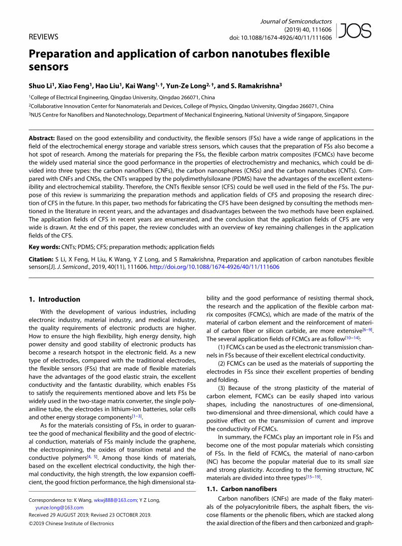
In the work of Tsai et al., the UV–vis spectroscopy of theSWCNT with the 9 anthracene carboxylic acid in deionizedwater (DI water) was shown in Fig. 6[34].
Based on the internal structure, CNTs can be used as thestructural materials and the functional materials. As the struc-tural materials, CNTs have high strength because of the cova-lent bonds between carbon atoms in CNTs. As a functionalmaterial, CNTs have good electrical conductivity, thermal con-ductivity, ductility and other properties, and can be appliedin many fields (such as the composite materials and nano-mechanical).
Fig. 3. Theory model of the CNTs.
CNTs
Fig. 4. Structure characterization of the CNTs. (Reproduced with permis-sion from Ref. [29].)
(b) λ = 647.1 nm
175
192
116
156
150 200 250Raman shift (cm−1)
Inte
nsi
ty
300 350 400100
Deintercalated
PristinedIntercalated
(a) λ = 514.5 nm
180
166
108
350
373
174
150
Fig. 5. Raman spectra of pristine (thin solid), I2-intercalated (thick sol-id), and deintercalated (dashed) SWNTs in the low Raman shift rangetaken by: (a) the 514.5-nm line of an Ar-ion laser and by (b) the 647.1-nm line of Kr-ion laser. (Reproduced with permission from Ref. [33].)
Journal of Semiconductors doi: 10.1088/1674-4926/40/11/111606 3
S Li et al.: Preparation and application of carbon nanotubes flexible sensors
2.2. The structure and function of PDMS
PDMS is an organic material composed of dimethyl silox-ane, which has good biocompatibility. The adhesion of PDMSvaries little under the changes of temperature, the surface ten-sion of PDMS is small, and the shear resistance of PDMS isvery high. Based on these advantages, PDMS is widely usedin the fields of the thin film and the physical carrier[27].
3. Preparation of CNTs flexible sensors
3.1. The hydrothermal auxiliary method
The hydrothermal auxiliary method, which promote thecombination between the CNTs and PDMS, could be used forpreparing the CFS. Tang et al. provide a method using the hy-drothermal assistance for preparing the redox graphene(RG)/PDMS composite flexible sensor, which can be used tofabricate the CFS[35]. The steps of hydrothermal auxiliary meth-od of preparing the RG/PDMS composite flexible sensor areshown in Fig. 7. Several important equipment and their spe-cification used in this method are as follow in Table 1.
The improved preparation method of the CFS is as fol-lows:
(1) The copper mesh is pretreated by the hydrochloricacid/acetone solution to remove various impurities such as ox-ides adhering to the surface of copper mesh.
(2) The CNTs dispersions are diluted with water.(3) The copper mesh, whose specification parameters
have been shown in Table 1, is placed in a 50 ml autoclave,and then the 35 ml of the CNTs diluted water dispersion is ad-ded into the autoclave. After standing for a period of time,CNTs dispersions would deposit on the copper mesh andform a mixture of CNTs and copper mesh (CNTs/Cu).
(4) The solution containing CNTs/Cu in a high-pressureautoclave is put into the oven and heat-treated for 12 h at180 °C.
(5) Remove the autoclave from the oven and add deion-ized water into the autoclave. Carefully clean the CNTs/Cuwith deionized water in order to eliminate the CNTs powderwhich do not attach to the copper mesh.
(6) CNTs/Cu cleaned with deionized water is dried in anoven at 50 °C. This step be not completed until all of the wa-ter in the autoclave evaporates.
(7) CNTs/Cu removed from the autoclave are divided in-
to two areas: the electrode area and the protected area. Theelectrode region serves as a connection between CNTs andelectrodes, which will not be covered by PDMS because ofthe good insulation of PDMS. Protected areas protect theCNTs from external interference, which will be covered byPDMS.
(8) The mixed solution of PDMS which is pulled out bydropper was stirred for more than 30 min to achieve the pur-pose of fully mixing the components in the solution.
(9) The mixed solution of PDMS whose components havebeen mixed fully is dripped into the protective area of CNTs/Cu. In this step the mixture of CNTs/PDMS/Cu could be ob-tained.
(10) The CNTs/PDMS/Cu is dried for 2.5 h in a vacuum en-vironment at 120 °C, which ensured that the PDMS monomeris initially polymerized in the protective area of CNTs/PDMS/Cu.
(11) Under the room temperature, the protected regionof CNTs/PDMS/Cu has been immersed in the mixed solutionof FeCl3/HCl for 12 h. In this solution, the copper mesh canbe oxidized to Cu2+ by Fe3+ that exists in FeCl3, which can bedissolved into the solution. The expressions involved are:
Fe+ + Cu = Fe+ + Cu+. (1)
In this step, the CNTs/PDMS could be obtained.(12) CNTs/PDMS obtained by step (11) is carefully
cleaned several times with ionic water to remove the remain-ing etching solution and dry in air.
(13) The CCFS can be obtained by installing an electrodein the electrode region of the CNTs/PDMS.
3.2. The chemical vapor deposition method
The chemical vapor deposition (CVD) is a chemical techno-logy, which forms thin films by chemical reaction on the sub-strate surface by using gas phase compounds or simple sub-stances containing thin film elements. Jeong et al. provide amethod for making the strain sensors by using the CVD tech-nology to mix the graphene foams (GF) and PDMS, whichcould be used for preparing the CFS[36]. The steps of CVD meth-od of preparing the GF/PDMS composite flexible sensor areshown in Fig. 8. Several important equipment and their spe-cification used in this method are as follow in Table 2.
The preparation scheme of CFS improved by this meth-od is as follows:
(1) Using the chemical vapor deposition technology, theCNTs is adhered to the foam nickel template.
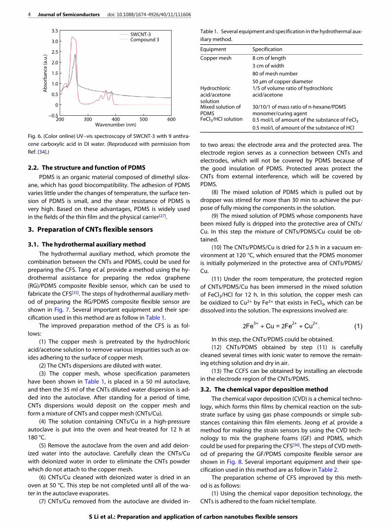
Table 1. Several equipment and specification in the hydrothermal aux-iliary method.
Equipment Specification
Copper mesh 8 cm of length3 cm of width80 of mesh number50 μm of copper diameter
Hydrochloricacid/acetonesolution
1/5 of volume ratio of hydrochloricacid/acetone
Mixed solution ofPDMS
30/10/1 of mass ratio of n-hexane/PDMSmonomer/curing agent
FeCl3/HCl solution 0.5 mol/L of amount of the substance of FeCl30.5 mol/L of amount of the substance of HCl
Wavenumber (nm)
Ab
sorb
an
ce (
a.u
.)
400 600200−0.5
300 500
SWCNT-3Compound 3
2.0
2.5
3.0
0
0.5
1.5
1.0
3.5
Fig. 6. (Color online) UV–vis spectroscopy of SWCNT-3 with 9 anthra-cene carboxylic acid in DI water. (Reproduced with permission fromRef. [34].)
4 Journal of Semiconductors doi: 10.1088/1674-4926/40/11/111606
S Li et al.: Preparation and application of carbon nanotubes flexible sensors

(2) Etching the nickel foam template with hot solution ofHCl.
(3) The CNTs is immersed in a small bottle containing isop-ropanol solution, and is broken for 20 min by an edd y cur-rent mixer, which causes that the flake of CNTs is dispersed inisopropanol.
(4) Stewing the mixed solution of CNTs/isopropanol for24 h to make the plate-like CNTs precipitate.
(5) Using the micropipette to inlay CNTs/isopropanolonto glass sheets which are arranged in a rectangular (3 ×20 mm2) pattern with polyimide tape to rearrange CNTs. Be-cause the cost of making electrode pattern with polyimidetape is low, the electrodes with various shapes and sizes canbe conveniently designed[32]. Because the concentration ofCNTs/isopropanol is constant, the amount of CNTs used tomake CFS could be controlled by the volume of micropipette.
(6) Put the glass sheet containing the CNTs/isopropanolin the oven with a temperature of 50 °C to evaporate the isop-ropanol and take out the glass sheet from the oven after finish-ing evaporating the isopropanol.
(7) Polyimide tape is removed from glass slide and PDMS
is poured onto glass slide. After curing and peeling, a compos-ite strain sensor film of CNTs/PDMS is prepared.
The comparison between two methods is shown inTable 3.
As shown in the preparation process of two methodsand the Table 3, compared with the CFS prepared by theCVD method, the CFS prepared by the hydrothermal auxili-ary method has several advantages, which are shown as fol-low:
(1) short preparation time,(2) materials that be got easily (such as the solution of hy-
drochloric acid/acetone and the solution of FeCl3/HCl), whichcould reduce the cost and the difficulty of preparation.
The disadvantage of the hydrothermal auxiliary methodis the need for more experimental steps, which leads to moredetails to pay attention to.
4. Application fields of CNTs composite flexiblesensors
CFS have been used in various fields for the excellent sta-
Table 2. Several equipment and specification in the method of CVD.
Equipment Specification
Nickel foam template 2 × 2 cm2 of sizeGlass slide 3 × 20 mm2 of size of the rectangular shapeFGF/isopropyl alcohol(IPA) solution
4.9 mg/ml of the concentration
Galinstan eutecticalloy
68.5%/21.5%/10% of atomic percentage ofGa/In/Sn
Table 3. Comparison between hydrothermal auxiliary method andCVD method.
Aspect Hydrothermal auxiliary method CVD method
Time (h) 12 26Steps number 13 7Equipment number 14 14Complexity degree Normal HardReference 35 36
Cu meshes
Copper wire
Cu@RGO Cu@RGO@PDMS
PDMS
coating Etching
Hydrothermal
assembly
RGO microtubes
Strain sensor
PDMS
Fig. 7. (Color online) Fabrication steps of the RG/PDMS composite flexible sensor. (Reproduced with permission from Ref. [35].)
CVD-grown graphene Fragmentation
etching of Ni
Stretchable over 70 % strain
Nickel foam
with IPA
Graphene foam Graphene foam
fragments
Drop castingPatterned graphene foam fragments
(by using polyimide tape)
Liquid metal
PDMS
Glass substrate
Fig. 8. Schematic of the process of CVD method of preparing the GF/PDMS strain sensors. (Reproduced with permission from Ref. [36].)
Journal of Semiconductors doi: 10.1088/1674-4926/40/11/111606 5
S Li et al.: Preparation and application of carbon nanotubes flexible sensors

bility, ductility and conductivity. At present, there are two ap-plication forms of carbon nanotube flexible sensors:
(1) Other materials are added into the CFS to form theCNTs composite flexible sensor (CCFS).
(2) A new system is composed of CFS or CCFS and otherdevices.
Both of these two methods could improve the conductiv-ity and electrochemical performance of CFS, and expand theapplication field of CFS, including the fields of electronics, mi-cromechanical, and thermal management.
4.1. Application in the field of electronics
A flexible symmetric supercapacitor based on TiO2 andCNTs was invented, and a hybrid electrode design was intro-duced in the work of Chien et al.[8]. The specific capacitancewas further improved by combining titanium dioxide nan-otubes with CNTs. Vertically oriented titanium dioxide nan-otube arrays were prepared by anodic oxidation and used asthe porous pseudo electrodes with small density and largesurface area. A conductive multi-walled carbon nanotube(MWNT) network was coated on the titanium dioxide nan-otubes to form a composite electrode. Fig. 9(a) showed thecyclic voltammograms of supercapacitors of TiO2 nanotube, PE-DOT–MWNT film and TiO2 nanotube with PEDOT–MWNT filmin 1 M aqueous electrolyte of H2SO4. As shown in the Fig. 9,compared with pure CNTs electrodes, the specific capacit-ance of these electrodes which used the electrolyte of H2SO4
were increased by about 30%. The good capacitance char-acteristics of them were shown by the electrochemicalimpedance spectroscopy (EIS), whose figures were shown inFig. 9(b).
High-speed DC circuit breaker played a very importantrole in the circuit, and the optimization of the contact materi-al of high-speed DC circuit breaker became the cornerstoneof the reliable function of high-speed DC circuit breaker.Among many materials, pure metal materials had high affin-ity for welding. The Ag/CdO materials did not meet the require-ments of European Union. The SnO2, ZnO and the graphite,which worked normally at low current, had not been optim-ized for high current applications (such as the railway in-dustry). Based on the situation, a kind of material of Ag/CNTswas designed in the work of Jaüimoviül et al.[37]. Ag/CNTswas chemically similar to Ag/graphite, but the uniform distribu-tion of CNTs could reduce the combustion rate, which couldprevent or reduce the occurrence of re-arc. As shown inFig. 10, the test results of welding tendency tester for electric-al contact materials showed that the composite of Ag/CNTswith a small amount of solid lubricant had the solid poten-tial as electrical contacts in high-speed DC circuit breakersbecause they exhibited high welding resistance in a newstate.
Chang et al. demonstrated the superior performance ofthin film transistors with a functionalized SWCNTs-blendedpoly (3-hexylthiophene) (F-SWCNT-P3HT) channel and multi-
Voltage (V)
(a)
(b)
Working
electrode
Device
electrode
Device
electrode
Spacer and
electrolyte
Counter
electrode
TiO2 nanolubesPEDOT-MWNT filmTiO2 nanotubes + PEDOT-MWNT film
TiO2 nanolubesTi substrate + PEDOT-MWNT filmTiO2 nanotubes + PEDOT-MWNT film
Cu
rre
nt
(A/g
)
0.3 0.60−1.0
−0.6
1.0
0.6
−0.2
0.2
0.2 0.50.1 0.4
1.4
ZRe (Ω)
Zlm
(Ω
)
4000 100
0
300 500200
200
400
600
800
1000
1200
Fig. 9. (Color online) (a) Respective cyclic voltammograms of TiO2 nanotube supercapacitor, PEDOT–MWNT film supercapacitor and TiO2 nan-otube + PEDOT–MWNT film supercapacitor in 1 M H2SO4 aqueous electrolyte. (b) Nyquist plots of TiO2 nanotube supercapacitor, PEDOT–MWNTfilm supercapacitor, and TiO2 nanotube + PEDOT–MWNT film supercapacitor from high frequency to low frequency. (Reproduced with permis-sion from Ref. [8].)
6 Journal of Semiconductors doi: 10.1088/1674-4926/40/11/111606
S Li et al.: Preparation and application of carbon nanotubes flexible sensors

walled CNTs source and drain electrodes[38]. The effects of F-SWCNT-hybrid P3HT channel and MWCNTs/DS devices weresystematically researched. As shown in Figs. 11(a) and 11(b),the contact resistance of devices using F-SWCNT-P3HT andMWCNTs/DS decreased, and the mobility increased. It wasproved that transistors with F-SWCNT-P3HT channel and MW-CNTs/DS had excellent performance. Mobility has been im-proved by an order of magnitude or more.
On the structure of digitized gold electrode, for the detec-tion of CO, NH3, CO2 and other gases, the gas sensor of sulfon-ated CNTs (s-CNTs) and the mixture gas sensor of CNTs/poly-aniline (PANI) were prepared respectively[39]. The electrochem-ical performance and the structural stability of two kinds ofgas sensing micro-sensors were also described. As shown inFig. 12, the experimental results showed that the sensors notonly had different resistivity values for various gases, but also
had the high sensitivity and selective potential for the meas-ured chemical analytes. In addition, the two kinds of gas micro-sensors had the advantages of high sensitivity, small size,light weight, and long service life, which could be applied toimprove the life of sensor batteries and other fields.
Carbon nanotube flexible sensors could also detect chem-ical gases. Based on the flexible carbon nanotube sensor andusing the non-equilibrium Green's function, a kind of tunneltype carbon nanotube field effect transistor (CNTFET) whichcould be used to detect the toxic gas in the tunnel was de-signed, which was shown in Fig. 13[40]. At the temperature of200, 300, and 400 K, respectively, the conductivity of theCNTs was measured in different gases (SO2, acetonitrile, sarinand carbonyl chloride). From the Fig. 14, the experimental res-ults showed that the higher the temperature was, the higherthe dielectric constant was. As shown in Fig. 15, at the sametemperature, the higher the gas concentration, the greaterthe conduction current of the transistor. Therefore, the nano
Ag/WS2 5%Ag/MoS2 5%Ag/MoS2 1%Ag/WS2 1%
Ag/CdOAg/CNT
T (K)
ρ (
μΩ
·cm
)
3000 1000
200
2
4
6
Fig. 10. (Color online) Temperature dependence of resistivity of sever-al materials. (Reproduced with permission from Ref. [37].)
L (μm)
W = 600 μm
Au/Ti
P3HT
4E9 1E9
1.5E83E8
fSWCNTs + P3HT
fSWCNTs + P3HTP3HTAu/Ti S/D
MWCNT S/D
MWCNT S/D
Ro
nW
(1
08 Ω
μm
)
Ro
nW
(1
08 Ω
μm
)
1000 20 40 60 8010020 40 60 80 0
10
30
50
70100
300
500
700
900
10
30
50
90
70
50
150
250
350−40 V−50 V
Vg
−60 V
Vg (V)
(a)
(b)
W/L = 600 μm/25 μm
I d (
A)
6020 40−60 −40 −20 010−9
10−8
10−7
10−6
10−5
Fig. 11. (Color online) (a) The values of contact resistance. (b) Character-istics of drain current versus gate voltage of transistors with a P3HT orF-SWCNT-P3HT channel and gold or MWCNT S/Ds. (Reproduced withpermission from Ref. [38].)
Time (s)
(a)
Re
sist
an
ce
(Ω
)
160140 200 220180
s-CNT
PANI 0.1 M
PANI 0.2 M
0 4020 80 12060 100500
504
502
506
510
508
512
514
Time (s)
(c)
Re
sist
an
ce
(Ω
)
256224 320288
s-CNT
PANI 0.1 M
PANI 0.2 M
0 6432 128 19296 1600
1200
1000
1400
1800
1600
200
400
600
800
2000
Time (s)
(b)
Re
sist
an
ce
(Ω
)
160140 200180
s-CNT
PANI 0.1 M
PANI 0.2 M
0 4020 80 12060 10096
102
100
104
108
106
110
112
Fig. 12. (Color online) Resistance evolution of resulting structures as afunction of gas concentrations. (a) CO. (b) CO2. (c) NH3. (Reproducedwith permission from Ref. [39].)
Journal of Semiconductors doi: 10.1088/1674-4926/40/11/111606 7
S Li et al.: Preparation and application of carbon nanotubes flexible sensors

sensor is suitable for toxic gas detection under different tem-perature conditions.
4.2. Application in the micromechanical system
Sha et al. invented electroplated Ni-CNT nanocompos-ites for micromechanical resonator applications[41]. In thispaper, the electroplated Ni-CNT nanocomposites were syn-thesized and used as structural materials for micromechanic-al resonators. As shown in Fig. 16, CNTs were well dispersedin electrolytes and could be incorporated into Ni films bysodium sulfate dodecyl pretreatment.
4.3. Application in the electron field
Wu et al. provided the idea of applying CNTs to the emis-sion devices in the cold cathode electron field and describedthe cathode ray tubes[42]. Driven by the direct mode of gridCNTs emitters and the transistor feeding applications, a meth-od based on the technology of laser-induced forward transmis-sion (LIFT) was proposed to realize the concepts of the coldcathode electron field emission devices of CNTs and the cath-ode ray tubes of CNTs. Based on this idea, a new kind ofscheme of laser material transfer (SLM) was proposed, whichcould deposit both of CNTs and silver slurry layer at the sametime. This method confined the transferable area to the laserirradiated area, which proved the feasibility of transferring ma-terials in the mask protection area. The results show that theprepared double-layer CNTs/silver slurry CNTs emitters hadgood characteristics of the field emission.
A MEMS/NEMS electron impact gas ion generator basedon the CNTs, which had an integrated extractor gate for port-able mass spectrometry, was constructed in the work of Huet al.[43]. The ion generator used the sparse forest of CNTs
LG
LDLS
tox
VD
VG
VS
p-CNT n-CNTi-CNT
Fig. 13. (Color online) Two-dimensional circuit model for ballistic CNT-FET. (Reproduced with permission from Ref. [40].)
Dielectric constant
I DS (
μA
)
2.1 2.2
T = 200 K
T = 300 K
T = 400 K
1.7 1.8 1.9 2.01.60
1.70
1.65
1.75
1.80
1.90
1.85
1.95
2.00
Fig. 14. (Color online) Drain-source current diagram versus dielectricconstant. (Reproduced with permission from Ref. [40].)
VGs (V)
VDS = 0.4 V
VDS = 0.2 V
(a)
I DS (
μA
)
Sulfur dioxide
Dot-lines: T = 200 KDash-lines: T = 300 K
Lines: T = 400 K
Dot-lines: T = 200 KDash-lines: T = 300 K
Lines: T = 400 K
Dot-lines: T = 200 KDash-lines: T = 300 K
Lines: T = 400 K
Dot-lines: T = 200 KDash-lines: T = 300 K
Lines: T = 400 K
0 0.5 1.010−10
10−5
100
VGs (V)
VDS = 0.4 V
VDS = 0.2 V
(b)
I DS (
μA
)
Acetonitrile
0 0.5 1.010−10
10−5
100
VGs (V)
VDS = 0.4 V
VDS = 0.2 V
(c)
I DS (
μA
)
Sarin gas
0 0.5 1.010−10
10−5
100
VGS (V)
VDS = 0.4 V
VDS = 0.2 V
(d)
I DS (
μA
)
Carbonyl chloride
0 0.5 1.010−10
10−5
100
Fig. 15. (Color online) Transport features. (a) Sulfur Dioxide. (b) Acetoni-trile. (c) Sarin Gas. (d) Carbonyl Chloride at logarithmic scale for VDS =0.2, 0.4 V. (Reproduced with permission from Ref. [40].)
8 Journal of Semiconductors doi: 10.1088/1674-4926/40/11/111606
S Li et al.: Preparation and application of carbon nanotubes flexible sensors

that were produced by the plasma enhanced chemical vapordeposition (PECVD) as the grid of field emitter and proximalextractor to realize low voltage ionization. The extractor gate
was integrated into the ionizer using a high-voltage MEMSpackaging technology based on the definition of deep react-ive ion etching (DRI) silicon spring. The ion generator also in-cluded a high aspect ratio silicon structure, which contrib-uted to the sparse CNTs growth and enabled uniform cur-rent emission.
4.4. Application in the back-end interconnection
Liang et al. introduced the method of combining electric-al measurement with atomic pair circuit simulation, studiedthe conductivity of doped SWCNTs and doped MWCNTs, andprovided a feasible choice for the next generation of back-end interconnection[44]. The initio simulation predicted thedoping-related displacement of Fermi level. By convertingthe semiconductor shell into metal, the chiral variability ofthe shell could be reduced and the resistivity could be in-creased by 90%. The electrical testing of platinum salt dopedCNTs provided up to 50% of the reduction of resistance,which was a milestone in the future of the technology ofCNTs interconnection.
4.5. Application in the thermal management
Because of the thermodynamic properties, CNTs materi-als were also widely used in the field of thermal manage-ment applications. In the process of thermal management ap-plications, it was necessary to estimate the thermal proper-ties of CNTs. For the estimation of the thermal properties ofCNTs, CNTs were arranged vertically on the mounted Pt/Si mi-cro-hot plate in the work of Silvestri et al., and then thethermal properties of CNTs were estimated directly[45]. In addi-tion, the electrothermal simulation (finite element modeling)was also carried out to evaluate the experimental results andgenerate valuable instruments for the design of customized fit-ting geometric structures with specific power dissipation con-straints. The simulation was consistent with the experimentalresults in the whole temperature range. Therefore, the toolcould predict the optimal design and geometry of chip-levelheat dissipation in microdevices encapsulated by CNTs.
4.6. Application in the medicine and the
anthroponomy
Jung et al. prepared a kind of the dry ECG electrode ofthe CNTs/PDMS composite, which could be easily connectedto the traditional ECG equipment, and showed the long-termwearable monitoring ability and the robustness to exerci-se[46]. It was proved that this dry ECG electrode overcame thelimitations of traditional dry or wet electrodes. Even after aweek of continuous use, the electrode did not have any obvi-ous side effects, such as itching or irritation. Compared withAg/AgCl electrode, the signal quality did not decrease withthe passage of time. The experimental results showed thatthe composite electrode had good biocompatibility and ro-bustness under the condition of exercise and sweating, andwas suitable for long-term electrocardiogram monitoring.
Rezaei et al. provided an application of the mixed elec-trodes of MWCNTs/modified carbon quantum dots/pencilgraphite in the field of electrochemical determination of dex-tromethorphan (DXM)[47]. Through this application, we couldknow that the MWCNTs composites modified by the nano-particles of carbon quantum dots could be used as a suitablemodifier in the electrochemical method for the determina-tion of DXM. And the platinum group elements modified by
Frequency (GHz)
(a)
Re
fle
ctio
n lo
ss (
dB
)
2 mm2.5 mm3 mm3.5 mm4 mm
5 mm4.5 mm
642 10 1812 14 168−5
−4
−3
−2
−1
Frequency (GHz)
(b)
ε a
nd
μ
ε’
ε”
μ’
μ”
642 10 1812 14 168
0
10
20
30
40
50
60
70
80
Frequency (GHz)
(c)
Re
fle
ctio
n lo
ss (
dB
)
2 mm2.5 mm3 mm3.5 mm4 mm
5 mm4.5 mm
642 10 1812 14 168
−3
−2
−1
0
−4
Frequency (GHz)
(d)
ε a
nd
μ
ε’ε”μ’μ”
642 10 1812 14 168
0
1
2
Fig. 16. (Color online) (a) and (c) Reflection losses of raw CNTs and Niwith 2−5 mm thickness. (b) and (d) Complex permittivity ε and per-meability μ of the raw CNTs and Ni. (Reproduced with permissionfrom Ref. [41].)
Journal of Semiconductors doi: 10.1088/1674-4926/40/11/111606 9
S Li et al.: Preparation and application of carbon nanotubes flexible sensors

the MWCNTs/modified carbon quantum dots/pencil graphitehad good synergistic effect on DXM oxidation.
Xie et al. pointed out a kind of CNTs water dispersionwhich was used in the thermal effect of microwave[48]. The wa-ter dispersion took the H2SO4:HNO3 as the functional group,successfully realized the functionalization of the functionalgroup, ensured the stability and the high concentration ofCNTs. After ultrasonic treatment, the water dispersant hadvery high dielectric properties and could be applied in clinic-al related fields. In addition, the length of CNTs would affecttheir water dispersion. The shorter the length of CNTs, the bet-ter their biocompatibility and dispersion stability.
CNTs/PDMS composite film which is the part of CCFScould also be used in single monitoring of human body.Yang et al. provided a kind of flexible Ag/CNTs/PDMS compos-ite membrane sensor[49]. The mechanism of force-electricitywas based on the micro-crack of silver film in the process of ex-ternal forcing, which resulted in the change of resistance. Thesensor had the advantages of high sensitivity, wide strainrange, good stability and good durability, low cost and suit-able for large-scale production because of the use of thewrinkled film of CNTs. Preliminary application in human monit-oring showed that the sensor could detect weak tremor,breathing depth, breathing frequency as well as the corres-ponding heartbeat response. In addition, as a kind of elec-tromechanical sensor, it was expected to be widely used inmany fields, such as human-computer cooperation and the ro-botic systems.
5. Conclusion
In this paper, the preparation methods of the CFS are pro-posed, and several cases of the application of CFS and CCFSwhich containing CNTs and other materials in recent yearsare described, which could prove that either CFS or CCFS hasa wide use in various fields, such as the energy storage sys-tems, the artificial skin and the nanocomposites. However,there are several remaining challenges in the applicationfields of the CFS. That the CFS is improved on the basis of theexisting technology in order to be used as the elastic elec-tromyogram (EMG) sensor could control the muscle activityin the human body easily. Being used as the material sup-port for the flexible electronic devices with flexibility, the CFScould promote the development of the wearable devices. Inaddition, based on the good ductility and electric conductiv-ity, CFS could be used as the carrier devices for the human-computer interactive motion monitoring, which could pro-mote the development of automatic control.
Acknowledgments
This work was supported by the Qingdao PostdoctoralFund and Key Research (No. 2015118), the Development Planof Shandong Province (No. 2017GGX50114 and No.2018GGX105007) and the Scientific Research DevelopmentPlan of Shandong Higher Education Institutions (No.J18KA316), National Natural Science Foundation of China (No.60123456).
References
Wang K, Li L W, Lan Y, et al. Application research of chaotic carri-[1]
er frequency modulation technology in two-stage matrix con-verter. Math Probl Eng, 2019, 2019(1), 1Wang K, Zhou S Z, Zhou Y T, et al. Synthesis of porous carbon byactivation method and its electrochemical performance. Int JElectrochem Sci, 2018, 13(11), 10766
[2]
Long Y Z, Zhang L J, Chen Z J, et al. Electronic transport in singlepolyaniline and polypyrrole microtubes. Phys Rev B, 2005, 71(16),165412
[3]
Wang K, Li L W, Wen X, et al. Electrodeposition synthesis ofPANI/MnO2/graphene composite materials and its electrochem-ical performance. Int J Electrochem Sci, 2017, 12(9), 8306
[4]
Wang K, Pang J B, Li L W, et al. Synthesis of hydrophobic carbonnanotubes/reduced graphene oxide composite films by flashlight irradiation. Front Chem Sci Eng, 2018, 12(3), 376
[5]
Qiu H J, Song W Z, Wang X X, et al. A Calibration-free self-powered sensor for vital sign monitoring and finger tap commu-nication based on wearable triboelectric nanogenerator. NanoEnergy, 2019, 58(2019), 536
[6]
Wang X X, Song W Z, You M H, et al. Bionic single electrode elec-tronic skin unit based on piezoelectric nanogenerator. ACS Nano,2018, 12(8), 8588
[7]
Chien C J, Deora S S, Chang P C, et al. Flexible symmetric superca-pacitors based on TiO2 and carbon nanotubes. IEEE Trans Nano-technol, 2011, 10(4), 706
[8]
Chen H, Iyer A R, Harley R G, et al. Dynamic grid power routing us-ing controllable network transformers (CNTs) with decoupledclosed-loop controller. IEEE Trans Ind Appl, 2015, 51(3), 2361
[9]
Tabib-Azar M, Xie Y. Sensitive NH3OH and HCl gas sensors usingself-aligned and self-welded multiwalled carbon nanotubes. IEEESens J, 2007, 7(9), 1435
[10]
Shahshahan M, Keinänen P, Vuorinen J. The effect of ultrasonicdispersion on the surface chemistry of carbon nanotubes in theJeffamine D-230 polyetheramine medium. IEEE Trans Nanotechn-ol, 2017, 16(5), 741
[11]
Cheon J, Choi S, Heo Y J, et al. Fabrication of n-type CNT field-ef-fect transistor using energy band engineering layer between CNTand electrode. IEEE Electron Device Lett, 2013, 34(11), 1436
[12]
Long Y Z, Li M M, Sui W M, et al. Electrical, dielectric and surfacewetting properties of multi-walled carbon nanotubes/nylon-6nanocomposites. Chin Phys B, 2009, 18(3), 1221
[13]
Zhang Z, Delgado-Frias J G. Carbon nanotube SRAM design withmetallic CNT or removed metallic CNT tolerant approaches. IEEETrans Nanotechnol, 2012, 11(4), 788
[14]
Zheng J, Sun B, Lonf Y Z, et al. Fabrication of nanofibers by low-voltage near-field electrospinning. Adv Mater Res, 2012, 486(1),60
[15]
Yang Z T, Xu J, Wang J Q, et al. Design and preparation of self-driven BSA surface imprinted tubular carbon nanofibers and theirspecific adsorption performance. Chem Eng J, 2019, 373(2019),923
[16]
Gyulassy A, Knoll A, Lau K C, et al. Interstitial and interlayer iondiffusion geometry extraction in graphitic nanosphere batterymaterials. IEEE Trans Visual Comput Graph, 2016, 22(1), 916
[17]
Park G W, Yoo J B, Kim G J. Fabrication of spherical CNT skeinsformed by self-entangled fibers from hollow type mesoporoussilica microcapsules. J Ind Eng Chem, 2019, 76(2019), 457
[18]
Dubin R A, Callegari G, Kohn J, et al. Carbon nanotube fibers arecompatible with mammalian cells and neurons. IEEE Trans Nano-Biosci, 2008, 7(1), 11
[19]
Lee Y C, Li M H, Cheng Y T, et al. Electroplated Ni-CNT nanocom-posite for micromechanical resonator applications. IEEE ElectronDevice Lett, 2012, 33(6), 872
[20]
Li H, Evans E J Jr, Mullins C B, et al. Ethanol decomposition on Pd-Au alloy catalysts. J Phys Chem C, 2018, 122(38), 22024
[21]
Li H, Henkelman G. Dehydrogenation selectivity of ethanol onclose-packed transition metal surfaces: a computational study of
[22]
10 Journal of Semiconductors doi: 10.1088/1674-4926/40/11/111606
S Li et al.: Preparation and application of carbon nanotubes flexible sensors

monometallic, Pd/Au, and Rh/Au catalysts. J Phys Chem C, 2017,121(49), 27504Li H, Shin K, Henkelman G. Effects of ensembles, ligand, andstrain on adsorbate binding to alloy surfaces. J Chem Phys, 2018,149(17), 1
[23]
Li H, Luo L, Kunal P, et al. Oxygen reduction reaction on classic-ally immiscible bimetallics: a case study of RhAu. J Phys Chem C,2018, 122(5), 2712
[24]
Hwang Y H, Seo D, Roy M, et al. Capillary flow in PDMS cylindricalmicrofluidic channel using 3-D printed mold. J Microelec-tromechan Syst, 2016, 25(2), 238
[25]
Guo H H, Lou L, Chen X D, et al. PDMS-coated piezoresistiveNEMS diaphragm for chloroform vapor detection. IEEE ElectronDevice Lett, 2012, 33(7), 1078
[26]
Ryu D, Castaño N. Multivariate characterization of light emissionfrom ZnS: Cu-PDMS self-sensing composites under cyclic tensilestrains. IEEE Sens Lett, 2018, 2(2), 1
[27]
Zhu Y B, Yang B, Liu J Q, et al. An integrated flexible harvestercoupled triboelectric and piezoelectric mechanisms usingPDMS/MWCNT and PVDF. J Microelectromechan Syst, 2015,24(3), 513
[28]
Liao H Y, Ho J R, Chang-Jian S K. Fabrication of carbon nanotubefield-emission cathodes by laser-induced transfer of carbon nan-otubes and silver paste. J Display Technol, 2014, 10(12), 1083
[29]
Binesh A R, Kamali R. Effects of chirality on single-file water per-meability and diffusivity through single wall carbon nanotubes.Micro Nano Lett, 2017, 12(2), 109
[30]
Zhang Q R, Han Y, Wu L C. Influence of electrostatic field on theadsorption of phenol on single-walled carbon nanotubes: Astudy by molecular dynamics simulation. Chem Eng J, 2019,363(1), 278
[31]
Chen R M, Liang J, Lee J, et al. Variability study of MWCNT local in-terconnects considering defects and contact resistances—Part I:pristine MWCNT. IEEE Trans Electron Devices, 2018, 65(11), 4955
[32]
Nguyen V M, Yang I, Jung Y, et al. Resonance raman study of I2-intercalated single-walled carbon nanotubes. IEEE Trans Nano-technol, 2007, 6(1), 126
[33]
Tsai T J, Wang P C. Preparation and characterization of aqueousdispersions based on single-walled carbon nanotubes functional-ized with carboxyl anthracenes. The 12th International Microsys-tems, Packaging, Assembly and Circuits Technology Conference,2017, 299
[34]
Tang Y C, Zhao Z B, Hu H, et al. Highly stretchable and ultrasensit-ive strain sensor based on reduced graphene oxide microtubes-elastomer composite. ACS Appl Mater Interfaces, 2015, 7(49),27432
[35]
Jeong Y R, Park H, Jin S W, et al. Highly stretchable and sensitivestrain sensors using fragmentized graphene foam. Adv Funct Ma-ter, 2015, 25(27), 4228
[36]
Jacimovic J, Felberbaum L. Electro-mechanical properties andwelding characteristics of Ag/MoS2, Ag/WS2, Ag/CNTs andAg/CdO materials for high-DC current contact applications. The27th International Conference on Electrical Contacts, 2014, 132
[37]
Chang C H, Chien C H. Functionalized single-walled carbon-nan-otube-blended P3HT-based thin-film transistors with multi-walled carbon-nanotube source and drain electrodes. IEEE Elec-tron Device Lett, 2011, 32(10), 1457
[38]
Ilarion E, Spiridon S I, Monea B F. Comparative study of gas sens-ing microsensors based on sulfonated CNTs and CNTs/polyanil-ine mixture. International Conference and Exposition on Electric-al and Power Engineering, 2016, 65
[39]
Ghodrati M, Farmani A, Mir A. Nanoscale sensor-based tunnel-ing carbon nanotube transistor for toxic gases detection: a first-principle study. IEEE Sens J, 2019, 19(17), 7373
[40]
Sha L N, Gao P, Wu T T, et al. Chemical Ni-C bonding in Ni-carbonnanotube composite by a microwave welding method and its in-duced high-frequency radar frequency electromagnetic wave ab-sorption. ACS Appl Mater Interfaces, 2017, 9(46), 40412
[41]
Wu L C, Han Y, Zhang Q R, et al. Effect of external electric field onnanobubbles at the surface of hydrophobic particles during airflotation. RSC Adv, 2019, 9(4), 1792
[42]
Hu C F, Lin C M, Fang W. Integration of Pdms-infiltrated CNTs andSi bulk-micromachining for monolithic physical sensors applica-tion. The 17th International Conference on Solid-State Sensors,Actuators and Microsystems, 2013, 1565
[43]
Liang J, Chen R M, Ramos R, et al. Investigation of Pt-salt-doped-standalone-multiwall carbon nanotubes for on-chip intercon-nect applications. IEEE Trans Electron Devices, 2019, 66(5), 2346
[44]
Silvestri C, Picciafoco P, Morana B, et al. Electro-thermal simula-tion and characterization of vertically aligned CNTs directlygrown on a suspended microhotplate for thermal managementapplications. IEEE Sens, 2014, 2014(1), 827
[45]
Jung H C, Moon J H, Baek D H, et al. CNT/PDMS composite flex-ible dry electrodes for long-term ECG monitoring. IEEE Trans Bio-med Eng, 2012, 59(5), 1472
[46]
Rezaei B, Irannejad N, Ensafi A A, et al. Application of modifiedcarbon quantum dots/multiwall carbon nanotubes/pencil graph-ite electrode for electrochemical determination of dextrometh-orphan. IEEE Sens J, 2016, 16(8), 2219
[47]
Xie S X, Gao F Q, Patel S C, et al. Clinically relevant CNT disper-sions with exceptionally high dielectric properties for microwavetheranostic applications. IEEE Trans Biomed Eng, 2014, 61(11),2718
[48]
Yang Y P, Luo C Z, Jia J J, et al. A wrinkled Ag/CNTs-PDMS com-posite film for a high-performance flexible sensor and its applica-tions in human-body single monitoring. Nanamaterials, 2019,9(6), 1
[49]
Journal of Semiconductors doi: 10.1088/1674-4926/40/11/111606 11
S Li et al.: Preparation and application of carbon nanotubes flexible sensors