Flexible Methods for Microfluidics
7
FLEXIBLE METHODS FOR MICROFLUIDICS B iotechnology is increas- ingly about large numbers of experiments, such as analy- ses of DNA or of drugs, screen- ing of patients, and combina- torial syntheses. All of these procedures require handling fluids. As the number of experiments has grown, the devices used to carry them out have shrunk, and the strategy of “smaller is better” has begun to transform the world of fluidics as it has transformed the world of electronics. The need in biotechnology applications to manipulate fluids moving in small channels—a process called microfluidics—has stimulated three new areas of research: development of new methods for fabricating flu- idic systems, invention of components from which to assemble functionally complex fluidic devices, and exami- nation of the fundamental behavior of fluids in small channels. 1 Developments in microfluidic technology are also contributing to new experiments in fundamental biol- ogy, materials science, and physical chemistry. Interest in microfluidics has been largely motivated by applications, and dimensions and fluids are dictated by these applications. The most mature microfluidic technolo- gy is ink-jet printing, which uses orifices less than 100 mm in diameter for the generation of drops of ink. Ink-jet print- ing is rapidly finding a place in biotechnology for the deliv- ery of reagents to microscopic reactors and for the deposition of DNA into arrays on the surface of biochips. Capillary elec- trophoresis—a widely used technique for separating differ- ent chemical species in aqueous solutions of biological sam- ples—manipulates samples in capillaries that are typically 50 mm in inner diameter. Hand-held systems developed by I-Stat Corp for hospital-based analysis of serum electrolytes were the first commercially developed small analytical sys- tems, and use submillimeter-sized channels. The complex devices now being developed for biological applications— with the analysis of DNA (for genetics and genomics) and proteins (proteomics), and biodefense being the most impor- tant—typically involve aqueous solutions and 50- to 100-mm channels. A number of companies are now pursuing the commercialization of microfluidic devices. Unlike microelectronics, in which the current empha- sis is on reducing the size of transistors, microfluidics is focusing on making more complex systems of channels with more sophisticated fluid-handling capabilities, rather than reducing the size of the channels. These sys- tems require the same types of components as larger fluid-handling systems: pumps, valves, mixers, filters, separators, and the like. Although the sizes of channels are large relative to the size of features in microelectron- ic devices, they are small enough so that flows in them behave quite differently than do the large-scale flows that are familiar from everyday life. The components needed at small scales are therefore often quite different from those used at large scales. To design the compo- nents required for complex microfluidic systems, it is first necessary to understand the properties of fluids flowing in small channels. Fortu- nately, new, flexible methods of fabricating microchan- nels, combined with imaging techniques such as confocal microscopy that make it possible to quantify flows in these channels, allow the physics of microflows to be examined at previously unattainable resolution. The first microfluidic devices, developed by Andreas Manz (now at Imperial College), Jed Harrison (now at the University of Alberta), Michael Ramsey (Oak Ridge National Laboratory), and others in the early 1990s, were fabricated in silicon and glass by conventional, planar fab- rication techniques—photolithography and etching— adapted from the microelectronics industry. 2 These meth- ods are precise but expensive, inflexible, and poorly suit- ed to exploratory work. Recently, our laboratory and oth- ers have applied soft lithography to the fabrication of microfluidic devices. Described in box 1, these non- photolithographic microfabrication methods are based on printing and molding organic materials, and are much more straightforward than photolithography for making both prototype devices and special-purpose devices for physical investigations. These methods also make it prac- tical to build three-dimensional (3D) networks of channels and components. They thus offer access to new types of fluidic elements, such as valves and pumps fabricated of elastomeric materials. In addition, they offer the high level of control over the molecular structure of the chan- nel surfaces that is required in biological applications. Perhaps most important, they bring the technology need- ed to fabricate complex microfluidic devices out of clean rooms and into the laboratories of the biologists and chemists who are the users of these devices. Flows in microchannels Laminar flow is the definitive characteristic of microflu- idics. Fluids flowing in channels with dimensions on the order of 50 mm and at readily achievable flow speeds are characterized by low Reynolds number, Re. As described in box 2, flows in this regime are laminar, not turbulent: The surfaces of constant flow speed are smooth over the typical dimension of the system, and random fluctuations of the flow in time are absent. In the long, narrow geome- tries of microchannels, flows are also predominantly uni- axial: The entire fluid moves parallel to the local orienta- tion of the walls. The significance of uniaxial laminar flow is that all transport of momentum, mass, and heat in the direction normal to the flow is left to molecular mecha- 42 JUNE 2001 PHYSICS TODAY © 2001 American Institute of Physics, S-0031-9228-0106-020-3 GEORGE WHITESIDES is Mallinckrodt Professor of Chemistry and Chemical Biology and ABRAHAM STROOCK is a graduate student in the department of chemistry and chemical biology at Harvard University in Cambridge, Massachusetts. Devices for handling nanoliter quantities of fluids are creating new fabrication challenges and finding new applications in biology, chemistry, and materials science. George M. Whitesides and Abraham D. Stroock
-
Upload
independent -
Category
Documents
-
view
2 -
download
0
Transcript of Flexible Methods for Microfluidics
FLEXIBLE METHODS FOR
MICROFLUIDICSBiotechnology is increas-
ingly about large numbersof experiments, such as analy-ses of DNA or of drugs, screen-ing of patients, and combina-torial syntheses. All of theseprocedures require handlingfluids. As the number ofexperiments has grown, thedevices used to carry them outhave shrunk, and the strategyof “smaller is better” hasbegun to transform the worldof fluidics as it has transformed the world of electronics.
The need in biotechnology applications to manipulatefluids moving in small channels—a process calledmicrofluidics—has stimulated three new areas ofresearch: development of new methods for fabricating flu-idic systems, invention of components from which toassemble functionally complex fluidic devices, and exami-nation of the fundamental behavior of fluids in smallchannels.1 Developments in microfluidic technology arealso contributing to new experiments in fundamental biol-ogy, materials science, and physical chemistry.
Interest in microfluidics has been largely motivated byapplications, and dimensions and fluids are dictated bythese applications. The most mature microfluidic technolo-gy is ink-jet printing, which uses orifices less than 100 mmin diameter for the generation of drops of ink. Ink-jet print-ing is rapidly finding a place in biotechnology for the deliv-ery of reagents to microscopic reactors and for the depositionof DNA into arrays on the surface of biochips. Capillary elec-trophoresis—a widely used technique for separating differ-ent chemical species in aqueous solutions of biological sam-ples—manipulates samples in capillaries that are typically50 mm in inner diameter. Hand-held systems developed byI-Stat Corp for hospital-based analysis of serum electrolyteswere the first commercially developed small analytical sys-tems, and use submillimeter-sized channels. The complexdevices now being developed for biological applications—with the analysis of DNA (for genetics and genomics) andproteins (proteomics), and biodefense being the most impor-tant—typically involve aqueous solutions and 50- to 100-mmchannels. A number of companies are now pursuing thecommercialization of microfluidic devices.
Unlike microelectronics, in which the current empha-sis is on reducing the size of transistors, microfluidics isfocusing on making more complex systems of channelswith more sophisticated fluid-handling capabilities,rather than reducing the size of the channels. These sys-tems require the same types of components as largerfluid-handling systems: pumps, valves, mixers, filters,separators, and the like. Although the sizes of channelsare large relative to the size of features in microelectron-
ic devices, they are smallenough so that flows in thembehave quite differently thando the large-scale flows thatare familiar from everydaylife. The components neededat small scales are thereforeoften quite different fromthose used at large scales.
To design the compo-nents required for complexmicrofluidic systems, it isfirst necessary to understand
the properties of fluids flowing in small channels. Fortu-nately, new, flexible methods of fabricating microchan-nels, combined with imaging techniques such as confocalmicroscopy that make it possible to quantify flows inthese channels, allow the physics of microflows to beexamined at previously unattainable resolution.
The first microfluidic devices, developed by AndreasManz (now at Imperial College), Jed Harrison (now at theUniversity of Alberta), Michael Ramsey (Oak RidgeNational Laboratory), and others in the early 1990s, werefabricated in silicon and glass by conventional, planar fab-rication techniques—photolithography and etching—adapted from the microelectronics industry.2 These meth-ods are precise but expensive, inflexible, and poorly suit-ed to exploratory work. Recently, our laboratory and oth-ers have applied soft lithography to the fabrication ofmicrofluidic devices. Described in box 1, these non-photolithographic microfabrication methods are based onprinting and molding organic materials, and are muchmore straightforward than photolithography for makingboth prototype devices and special-purpose devices forphysical investigations. These methods also make it prac-tical to build three-dimensional (3D) networks of channelsand components. They thus offer access to new types offluidic elements, such as valves and pumps fabricated ofelastomeric materials. In addition, they offer the highlevel of control over the molecular structure of the chan-nel surfaces that is required in biological applications.Perhaps most important, they bring the technology need-ed to fabricate complex microfluidic devices out of cleanrooms and into the laboratories of the biologists andchemists who are the users of these devices.
Flows in microchannelsLaminar flow is the definitive characteristic of microflu-idics. Fluids flowing in channels with dimensions on theorder of 50 mm and at readily achievable flow speeds arecharacterized by low Reynolds number, Re. As describedin box 2, flows in this regime are laminar, not turbulent:The surfaces of constant flow speed are smooth over thetypical dimension of the system, and random fluctuationsof the flow in time are absent. In the long, narrow geome-tries of microchannels, flows are also predominantly uni-axial: The entire fluid moves parallel to the local orienta-tion of the walls. The significance of uniaxial laminar flowis that all transport of momentum, mass, and heat in thedirection normal to the flow is left to molecular mecha-
42 JUNE 2001 PHYSICS TODAY © 2001 American Institute of Physics, S-0031-9228-0106-020-3
GEORGE WHITESIDES is Mallinckrodt Professor of Chemistry andChemical Biology and ABRAHAM STROOCK is a graduate student inthe department of chemistry and chemical biology at Harvard Universityin Cambridge, Massachusetts.
Devices for handling nanoliterquantities of fluids are creating new
fabrication challenges and finding new applications in biology, chemistry,
and materials science.
George M. Whitesides and Abraham D. Stroock
nisms: molecular viscosity, molecular diffusivity, and ther-mal conductivity.
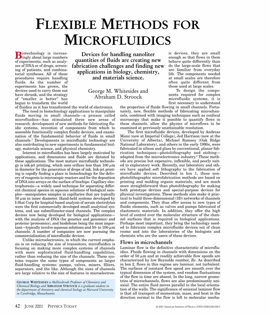
Pumping in microfluidic systems is accomplishedusing either pressure or, for water and other very polarsolvents, electric fields. Pressure-driven motion, termedPoiseuille flow, is well understood but has two disadvan-tages. First, designing and fabricating reliable mechani-cal pumps in the traditional materials of silicon and glasshas been difficult: These devices require multiple levels offabrication, and are easily damaged by particles of dustand contaminants in the fluid. Second, as illustrated infigure 1a, Poiseuille flow is characterized by a parabolicvelocity profile over the cross section of the channel, withzero velocity at the walls and a maximum at the channel’scenter. This nonuniformity in flow speed occurs becausethe imposed pressure exerts a uniform force over thecross-sectional area of the channel, but momentum leavesthe flow, due to interactions with the solid boundary, onlyat the walls (see box 2). The parabolic flow profile distortsa volume of fluid as it flows down the channel. When usedto separate different molecules in solution, such a flowspatially broadens the bands of distinct species.3
Electrically driven flow, known as electroosmosis,offers a useful alternative to pressure-driven flow of
water, but has its own weaknesses:sensitivity to impurities that adsorbon the wall of the channel, ohmic gen-eration of heat in the fluid, and theneed for high voltages (on the order ofkilovolts). In electroosmosis, illustrat-ed in figure 1b, an electric field gener-ates a net force on the fluid near theinterface of the fluid with its solidboundaries, where a small separationof charge occurs due to the equilibri-um adsorption and desorption of ions.For water in contact with silica, theionization of silanol groups (Si–OH�Si–O⊗ + H⊕) leads to about one nega-tive charge per 16 nm2 of the silicasurface. The excess cations are local-
ized near the interface by Coulombic interactions. Thischarged region near the interface, called the Debyescreening layer, has a thickness lD that is typically lessthan 10 nm for aqueous buffers used in biochemistry. Asthe fluid in the Debye layer moves toward the oppositelycharged electrode, it carries with it the bulk of the liquidin the channel. As a result, the velocity profile is essen-tially flat across the channel.3 This type of flow is ideal forseparations based on the charge-to-size ratio of the molec-ular components of biological samples in solution, sincebroadening of the separated bands of differing speciesoccurs only by diffusion, not as a result of the differencesin flow velocity across the channel. Because of this ten-dency to separate species, electroosmotic flow is usuallynot well suited for transporting multicomponent solutionswhen separation is not desired.
In the laminar flows generated by these pumpingschemes, adjacent streams of fluids with different chemi-cal composition remain distinct except for diffusive mix-ing at their interface. We have studied this diffusionprocess in Poiseuille flows using fluorescence confocalmicroscopy. The confocal microscope allows us to visualizethe 3D shape of the diffusively mixed region betweenstreams of solutions that contain molecules that becomefluorescent when they react with one another. We found
http://www.physicstoday.org JUNE 2001 PHYSICS TODAY 43
– ––
++ +
+ ++ + +
+
z
y
x
100 mm
75 mm
∇
lD~10 nm
E
a
b
P–
FIGURE 1. FLOW PROFILES IN
microchannels. (a) A pressure gradient, ⊗∇∇P, along a channel generates a para-bolic or Poiseuille flow profile in thechannel. The velocity of the flow variesacross the entire cross-sectional area ofthe channel. On the right is an experi-mental measurement of the distortion ofa volume of fluid in a Poiseuille flow.The frames show the state of the volumeof fluid 0, 66, and 165 ms after the cre-ation of a fluorescent molecule. (b) Inelectroosmotic (EO) flow in a channel,motion is induced by an applied electricfield E. The flow speed only varies with-in the so-called Debye screening layer, ofthickness lD. On the right is an experi-mental measurement of the distortion ofa volume of fluid in an EO flow. Theframes show the state of the fluorescentvolume of fluid 0, 66, and 165 ms afterthe creation of a fluorescent molecule.3
that the width of the intermixed region grows as (Dt)1/2
near the center of the channel, where the flow speed isalmost uniform, and as (Dt)1/3 near the top and bottomwalls, where the flow speed is changing rapidly as a func-tion of the distance from the wall. Here, D is the molecu-lar diffusivity and t is the time that the two streams havebeen in contact. These results agree with dimensionalscaling arguments that extend the classic result in trans-port theory, known as the Lévêque problem, for diffusionperpendicular to the walls.4
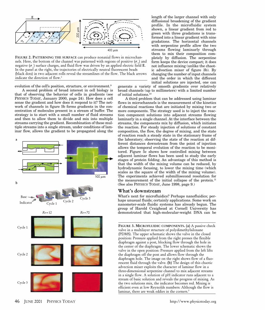
More complicated, nonuniaxial fluid motion can begenerated by creating patterns along the walls ofmicrochannels. The dependence of the speed and directionof electroosmotic flow on the charge of a channel’s wallsmeans that flows can be tailored by controlling surfaceproperties. Figure 2 shows an example in which anapplied field parallel to a surface patterned with regionsof positive and negative charge generates convection rolls
inside a microchannel.5 Armand Ajdari of ESPCI in Parishas modeled a variety of effects related to electroosmosisin the presence of nonuniform distributions of surfacecharge and variable channel geometry.
Another pumping scheme that involves patterningthe properties of the walls of a microchannel uses surfacetension to move drops of a fluid surrounded by air. Spatialvariations in the temperature of the walls of the channelcreate gradients in the tension of the liquid–vapor inter-face of the drop: The surface tension decreases as the tem-perature increases. By building resistive heating ele-ments into the microchannel wall, the group of MarkBurns at the University of Michigan can move drops offluid in a channel by heating the wall near the rear of thedrop. The decrease in the surface tension from the front tothe back of the drop pulls the drop through the channel.The advantage of moving independent drops of solution inmicrochannels is that the contents of each drop may be
44 JUNE 2001 PHYSICS TODAY http://www.physicstoday.org
The standard methods for fabricating microfluidic deviceswere inherited from the microelectronics industry. Pat-
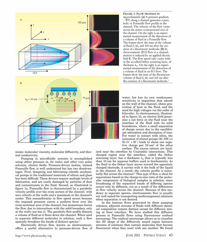
terns of etch resists are defined on rigid, planar substrates suchas silicon with photolithography or electron-beam lithography,and relief structures are then created with reactive-ion or wetetching.2,6 The advantages of this methodology are high spatialresolution (about 100 nm) and parallel processing—photoli-thography and etching create all features in a single step. Thehighly developed methods of photolithography, however, havedisadvantages for the fabrication of microfluidic devices: Theyare expensive, they require inconvenient methods for the seal-ing of channel structures, and they provide no simple methodof interconnecting channel systems (such as for sample collec-tion, introduction, and analysis).
Organic polymers offer an alternative technology for thefabrication of microfluidic systems. These materials are espe-cially useful for biological applications, in which aqueous solu-tions are almost universally used and the highest temperaturesrequired (about 120°C for sterilization) are easily tolerated bymany polymers. Molding and printing are the technologiesmost commonly used to fabricate microstructures from poly-mers. We and others have developed a set of methods for therapid prototyping of microfluidic devices based on soft lithog-raphy. We commonly make the microfluidic devices out of thesilicone elastomer PDMS (polydimethylsiloxane). PDMS has anumber of useful properties, including low cost, low toxicity,and commercial availability; transparency from the visible intothe near ultraviolet; chemical inertness; versatile surface chem-istry; and mechanical flexibility and durability. Sealing can beachieved by oxidizing the PDMS surface; adhesives are notrequired.
The figure shows how we use a transparency printed on ahigh-resolution printer as a mask for photolithography. Aprinter using about 5000 dots per inch generates smooth 50-mmfeatures, and 20-mm features with substantial edge roughness.With a single structure defined in photoresist by photolithog-raphy, we can generate many replicas in PDMS by molding. Toform a sealed channel structure, we oxidize the surface of thePDMS replica in a low-temperature plasma and bring it intocontact with clean glass, silica, or another piece of surface-activated PDMS. This seal can withstand pressures up to 5 bars.Without oxidation, PDMS will also form a watertight, non-covalent seal when pressed against itself, glass, or most othersmooth surfaces; these reversible seals are useful when ademountable fluidic device is required.14
Variations on these soft lithographic methods have beendeveloped recently by Steve Quake’s group at Caltech andDavid Beebe’s group at the University of Wisconsin.15
Photoresist onSi wafer
PDMS withchannel imprint
Relief structurein photoresist
Bufferreservoir
Sample injection reservoirs
Bufferreservoir
ExposeDevelopCast PDMS
Drill reservoirsOxidizeSeal to flat surface
Transparencyphotomask
PDMS, glass, . . .
Box 1. Fabricating Microfluidic Devices
kept separate from that of neighboring drops.6 (See alsoPHYSICS TODAY, January 2000, page 9.)
Microfluidic componentsPumps, valves, and mixers are some of the basic buildingblocks of any integrated microfluidic system. There is stillno broad agreement on the best designs for these compo-nents or even on the materials to be used for their con-struction; the technology is still a work in progress. Ulti-mately, most bioanalytical systems will probably be madeof polymers because these materials are inexpensive.Applications involving organic solvents or high tempera-tures may require glass.
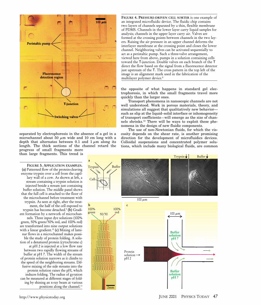
Figure 3a shows an example from our group of a valvethat exploits the elastomeric character of polydimethyl-siloxane (PDMS). This passive check valve is a fluidic rec-tifier: Pressure in one side of the device prevents fluidfrom flowing through the device; pressure in the otherside opens a flap and allows the fluid to flow.
Figure 3b shows a mixer designed by David Beebe’sgroup at the University of Wisconsin (formerly at the Uni-versity of Illinois) and illustrates the types of new devicesthat must be developed to perform familiar functions whenturbulence is no longer available as an aid. This 3D serpen-tine channel acts as a passive mixer for laminarly flowingfluids based on a type of chaotic flow known as chaoticadvection. Chaotic advection appears in certain steady 3Dflows and time-dependent 2D flows, and mixes the fluid bycontinuously stretching different volumes of the fluid andfolding them into one another. In a qualitative sense, thepath taken by a given fluid element in the flow depends in asensitive way on its encounters with a series of weak sec-ondary flows or eddies, present even at low Re in the cornersof channels, that transport the element across the flow.7
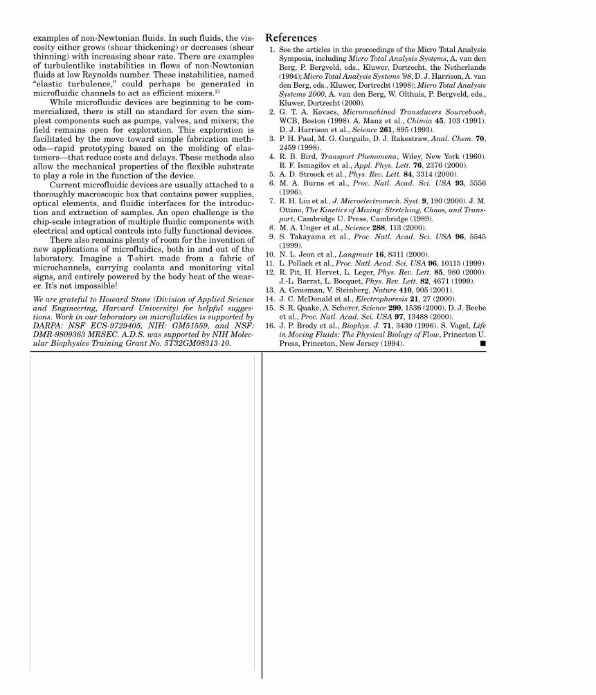
The integration of components into a functional deviceis facilitated by the use of soft lithography. Steve Quakeand coworkers at Caltech8 have integrated pumps andvalves to generate a micro flow cytometer, a device thatsorts biological cells using a T-junction with pumps andvalves in the arms controlled based on the signal from afluorescence microscope (see figure 4). A similar T-junctionchannel system can measure the size of individual, fluo-rescently labeled DNA fragments and sort them based ontheir size. The small detection volume (less than 1 pL) inthese microfabricated sorters increases the sensitivity ofthe device for the detection of single cells or molecules bydecreasing the background signal due to the carrier fluid.
Microfluidics in the laboratoryWith the availability of simple techniques for fabricationand basic designs for components, microfluidic devicesbecome versatile tools. One problem addressed by thesedevices is that of delivering reagents to the surface of a cellwith subcellular accuracy. The strategy we have used is toallow the cell to attach to the floor of a Y-shaped microchan-nel system and then to deliver reagents to it in streams oflaminarly flowing buffer, as shown in figure 5a. The cell liesdownstream from the Y. Two different aqueous streams arepumped into the two arms of the Y. One is an aqueousbuffer solution of trypsin, an enzyme that cleaves proteins,commonly used in biology to disconnect an attached cellfrom its substrate by cleaving the proteins that connect thetwo. The second stream contains buffer alone. Becausetrypsin has a high molecular weight (about 35 000 atomicmass units) and thus a low diffusivity (about 10–6 cm2/s),blurring of the interface between the two streams is rela-tively slow. The position of the interface in the channel canbe controlled with an accuracy of a few microns by control-
ling the rate at which liquid flows into the two arms of theY. In this experiment, the interface between the streamswas centered over a cell. The trypsin released half of thecell from the substrate; the half exposed only to buffer wasunaffected. This ability to treat a portion of a cell selective-ly with a reagent present in a stream of flowing buffer pro-vides new capabilities to cell biology. For example, scien-tists can conduct experiments on one part of a cell and usethe other part as a control, or they can label part of the cellsurface (or, in some cases, the cell interior) and monitor the
http://www.physicstoday.org JUNE 2001 PHYSICS TODAY 45
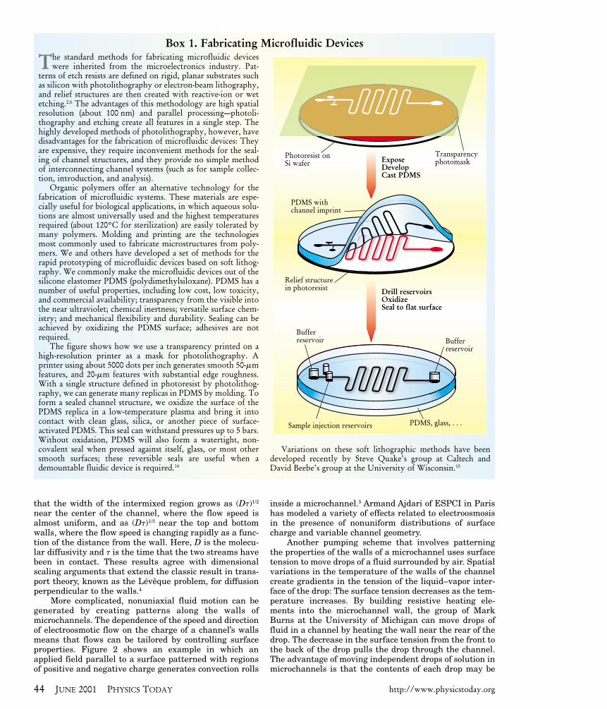
Box 2. Fluid Mechanics in Microchannels
The first step in modeling a flow is to predict if the flowwill be laminar or turbulent based on the Reynolds num-
ber, Re. The Reynolds number is the ratio of the inertialforces to the viscous forces acting on a small element of fluid.In microchannel flow, the Reynolds number can be writtenas the ratio of the kinetic energy of a volume of liquid in theflow to the energy dissipated by that volume in the shearcaused by interactions with its solid boundaries:Re ⊂ rU2V/mUS ⊂ rUL/m, where m is the viscosity, r is thedensity, and U is the average flow speed of the fluid. Thecharacteristic linear dimension L is the ratio of the volume Vof the fluid to the surface area S of the walls that bound it. Forexample, for a microchannel that is 1 cm long, 1 mm wide, and100 mm deep, L is 50 mm. It is found empirically that in pipes(for which L is the diameter) with smooth walls, flows are lam-inar for Re < 2000. Taking L ⊂ 50 mm for a microchannel andr ⊂ 1 g/cm3 and m ⊂ 0.01 g/(cm s) for water, we find thatflows in microchannels should be laminar for flow speeds lessthan 10 m/s. Standard flow speeds in microfluidic applicationsare 1 cm/s or less, giving Re � 1, so we can be confident inapplying low-Re models to microfluidic flows.
At low Re, the infamous nonlinearities associated with theNavier–Stokes equation are absent. A uniaxial, incompress-ible flow at low Re is governed by
Here, the coordinates are as defined in figure 1a, ux is the veloc-ity field along the channel, p is the pressure, and fb is the netforce per unit volume acting on the fluid, known as the bodyforce (due, for instance, to gravity or electromagnetic interac-tions). The boundary condition at a solid interface is ux ⊂ 0.(Recent experiments have cast doubt on the universal validityof this no-slip condition, but for most cases, slip is negligible.12)
Note the similarity of this equation to the diffusion equation (]c/]t ⊂ D∇2c) for the temporal evolution of theconcentration of chemical species in a fluid, and the heatequation (]T/]t ⊂ a∇2T ) for the temporal evolution of dis-tributions of temperature. In equation 1, we see that pressuregradients and body forces act as sources or sinks of fluidmotion, and this motion spreads across the fluid diffusivelywith an effective diffusion constant of n ⊂ m/r, called thekinematic viscosity. Like the molecular diffusivity D andthermal diffusivity a, n has its origins in the dynamics andinteractions of molecules that transfer motion (coherentflowing motion in the case of n) through the fluid.
While micrometer-scale structures are small enough toensure low-Re behavior, they are not so small that moleculargraininess of fluids becomes important. Even for gases inmicrochannels, many billions of molecules occupy a character-istic volume element of the flow in a microchannel with volumeL3; the fluid behaves like a continuum, and the Navier–Stokesequation gives an accurate description of the flow.16
]]
mr r r
ut
upx
fxx b
dd
= − +∇2 1 1. (1)
evolution of the cell’s position, structure, or environment.9A second problem of broad interest in cell biology is
that of observing the behavior of cells in gradients (seePHYSICS TODAY, January 2000, page 24). How does a cellsense the gradient and how does it respond to it? The net-work of channels in figure 5b forms gradients in the con-centration of molecules present in a stream of buffer. Thestrategy is to start with a small number of fluid streamsand then to allow them to divide and mix into multiplestreams carrying the gradient. Recombination of these mul-tiple streams into a single stream, under conditions of lam-inar flow, allows the gradient to be propagated along the
length of the larger channel with onlydiffusional broadening of the gradientprofile. In the microfluidic systemshown, a linear gradient from red togreen with three gradations is trans-formed into a linear gradient with ninegradations. The horizontal channelswith serpentine profile allow the twostreams flowing laminarly throughthem to mix their composition com-pletely by diffusion. The serpentineform keeps the device compact; it doesnot influence mixing (unlike the chaot-ic advection mixer of figure 3b). Bychanging the number of input channelsand the order in which the differentinitial solutions are injected, one can
generate a variety of smooth gradients over relativelybroad channels (up to millimeters) with a limited numberof initial solutions.10
A third problem that can be addressed using laminarflows in microchannels is the measurement of the kineticsof chemical reactions that are initiated by mixing two ormore components. The strategy used is to inject the reac-tion component solutions into adjacent streams flowinglaminarly in a single channel. At the interface between thestreams, the components mix by diffusion, which initiatesthe reaction. For steady injection of solutions of constantcomposition, the flow, the degree of mixing, and the stateof reaction reach a steady state in the stationary frame ofthe laboratory; observing the state of the reaction at dif-ferent distances downstream from the point of injectionallows the temporal evolution of the reaction to be moni-tored. Figure 5c shows how controlled mixing betweenadjacent laminar flows has been used to study the earlystages of protein folding. An advantage of this method isthat the width of the mixing volume can be reduced, byhydrodynamic focusing, to lower the mixing time (whichscales as the square of the width of the mixing volume).The experiments achieved submillisecond resolution forthe measurement of the initial collapse of the protein.11
(See also PHYSICS TODAY, June 1998, page 9.)
What’s downstreamWhat’s next for microfluidics? Perhaps nanofluidics; per-haps unusual fluids; certainly applications. Some work onnanometer-scale fluidic systems has already begun. Thegroup of Harold Craighead at Cornell University hasdemonstrated that high-molecular-weight DNA can be
a
b
500 mm
Cycle 1
Cycle 1
Cycle 2
Cycle 3
Cycle 2Cycle 3Base
Indicator
Re=12 Re=70
400 mm
200
mm
E
s+ s+s– s–
FIGURE 2. PATTERNING THE SURFACE can produce nonaxial flows in microchan-nels. Here, the bottom of the channel was patterned with regions of positive (s+) andnegative (s– ) surface charges, and fluid flow was driven by an applied electric field E.In the panel at the right, the trajectories of electrically neutral fluorescent beads(black dots) in two adjacent rolls reveal the streamlines of the flow. The black arrowsindicate the direction of flow.5
FIGURE 3. MICROFLUIDIC COMPONENTS. (a) A passive checkvalve in a multilayer structure of polydimethylsiloxane(PDMS). The upper schematic shows the valve in the closedposition: Pressure applied from the right presses the flexiblediaphragm against a post, blocking flow through the hole inthe center of the diaphragm. The lower schematic shows thevalve in the open position: Pressure applied from the left liftsthe diaphragm off the post and allows flow through thediaphragm hole. The image on the right shows flow of a fluo-rescent fluid through the valve. (b) The design of this chaoticadvection mixer exploits the character of laminar flow in athree-dimensional serpentine channel to mix adjacent streamsin a single flow. A solution of pH indicator runs adjacent to astream of basic solution and reveals the progress of mixing. Asthe two solutions mix, the indicator becomes red. Mixing isefficient even at low Reynolds numbers: Although the flow islaminar, there are weak eddies in the corners.7
46 JUNE 2001 PHYSICS TODAY http://www.physicstoday.org
separated by electrophoresis in the absence of a gel in amicrochannel about 50 mm wide and 10 cm long with adepth that alternates between 0.1 and 1 mm along itslength. The thick sections of the channel retard theprogress of small fragments morethan large fragments. This trend is
the opposite of what happens in standard gel elec-trophoresis, in which the small fragments travel morequickly than the larger ones.
Transport phenomena in nanoscopic channels are notwell understood. Work in porous materials, theory, andsimulations all suggest that qualitatively new behavior—such as slip at the liquid–solid interface or inhomogeneityof transport coefficients—will emerge as the size of chan-nels shrinks.12 There will be ways to exploit these phe-nomena in the design of new fluidic components.
The use of non-Newtonian fluids, for which the vis-cosity depends on the shear rate, is another promisingdirection for the development of microfluidics devices.Colloidal suspensions and concentrated polymer solu-tions, which include many biological fluids, are common
Trypsin Buffer
Cell
a
b c
Trypsin Buffer
100 mm
100 mm100%green
100%red
Buffersolution
pH 7
Buffersolution
pH 7
50/50
2mm
ProteinsolutionpH 2
100 mm100 mm
Peristaltic pumpPeristaltic pump
Fluorescencedetection region
Fluorescencedetection region
Switching valvesSwitching valves
T-junctionT-junction
FIGURE 4. PRESSURE-DRIVEN CELL SORTER is one example ofan integrated microfluidic device. The fluidic chip containstwo layers of channels separated by a thin, flexible membraneof PDMS. Channels in the lower layer carry liquid samples foranalysis; channels in the upper layer carry air. Valves areformed at the crossing points between channels in the two lay-ers. Raising the air pressure in an upper channel deforms theinterlayer membrane at the crossing point and closes the lowerchannel. Neighboring valves can be activated sequentially toact as a peristaltic pump. Such a three-valve arrangement,viewed here from above, pumps in a solution containing cellstoward the T-junction. Double valves on each branch of the Tdirect the flow based on the signal from a fluorescence detectorjust upstream of the T. The cross pattern in the top left of theimage is an alignment mark used in the fabrication of the multilayer polymer device.8
FIGURE 5. APPLICATION EXAMPLES.(a) Patterned flow of the protein-cleavingenzyme trypsin over a cell from the capil-
lary wall of a cow. As shown at left, astream containing a trypsin solution isinjected beside a stream just containing
buffer solution. The middle panel showsthat the full cell is attached to the floor of
the microchannel before treatment withtrypsin. As seen at right, after the treat-
ment, the half of the cell exposed totrypsin has become detached.9 (b) Gradi-
ent formation by a network of microchan-nels. Three input dye solutions (100%
green, 50% green/50% red, and 100% red)are transformed into nine output solutionswith a linear gradient.10 (c) Mixing of lami-
nar flows in a microchannel makes possi-ble the study of protein folding. A solu-
tion of a denatured protein (cytochrome c)at pH 2 is injected at a low flow rate
between two rapidly flowing streams ofbuffer at pH 7. The width of the stream
of protein solution narrows as it climbs tothe speed of the neighboring streams. Dif-fusive mixing of the side streams into the
protein solution raises the pH, whichinduces folding. The radius of gyration
can be measured at different stages of fold-ing by shining an x-ray beam at various
positions along the channel.11
http://www.physicstoday.org JUNE 2001 PHYSICS TODAY 47
examples of non-Newtonian fluids. In such fluids, the vis-cosity either grows (shear thickening) or decreases (shearthinning) with increasing shear rate. There are examplesof turbulentlike instabilities in flows of non-Newtonianfluids at low Reynolds number. These instabilities, named“elastic turbulence,” could perhaps be generated inmicrofluidic channels to act as efficient mixers.13
While microfluidic devices are beginning to be com-mercialized, there is still no standard for even the sim-plest components such as pumps, valves, and mixers; thefield remains open for exploration. This exploration isfacilitated by the move toward simple fabrication meth-ods—rapid prototyping based on the molding of elas-tomers—that reduce costs and delays. These methods alsoallow the mechanical properties of the flexible substrateto play a role in the function of the device.
Current microfluidic devices are usually attached to athoroughly macroscopic box that contains power supplies,optical elements, and fluidic interfaces for the introduc-tion and extraction of samples. An open challenge is thechip-scale integration of multiple fluidic components withelectrical and optical controls into fully functional devices.
There also remains plenty of room for the invention ofnew applications of microfluidics, both in and out of thelaboratory. Imagine a T-shirt made from a fabric ofmicrochannels, carrying coolants and monitoring vitalsigns, and entirely powered by the body heat of the wear-er. It’s not impossible!
We are grateful to Howard Stone (Division of Applied Scienceand Engineering, Harvard University) for helpful sugges-tions. Work in our laboratory on microfluidics is supported byDARPA: NSF ECS-9729405, NIH: GM51559, and NSF:DMR-9809363 MRSEC. A.D.S. was supported by NIH Molec-ular Biophysics Training Grant No. 5T32GM08313-10.
References1. See the articles in the proceedings of the Micro Total Analysis
Symposia, including Micro Total Analysis Systems, A. van denBerg, P. Bergveld, eds., Kluwer, Dortrecht, the Netherlands(1994); Micro Total Analysis Systems ’98, D. J. Harrison, A. vanden Berg, eds., Kluwer, Dortrecht (1998); Micro Total AnalysisSystems 2000, A. van den Berg, W. Olthuis, P. Bergveld, eds.,Kluwer, Dortrecht (2000).
2. G. T. A. Kovacs, Micromachined Transducers Sourcebook,WCB, Boston (1998). A. Manz et al., Chimia 45, 103 (1991).D. J. Harrison et al., Science 261, 895 (1993).
3. P. H. Paul, M. G. Garguilo, D. J. Rakestraw, Anal. Chem. 70,2459 (1998).
4. R. B. Bird, Transport Phenomena, Wiley, New York (1960).R. F. Ismagilov et al., Appl. Phys. Lett. 76, 2376 (2000).
5. A. D. Stroock et al., Phys. Rev. Lett. 84, 3314 (2000).6. M. A. Burns et al., Proc. Natl. Acad. Sci. USA 93, 5556
(1996).7. R. H. Liu et al., J. Microelectromech. Syst. 9, 190 (2000). J. M.
Ottino, The Kinetics of Mixing: Stretching, Chaos, and Trans-port, Cambridge U. Press, Cambridge (1989).
8. M. A. Unger et al., Science 288, 113 (2000).9. S. Takayama et al., Proc. Natl. Acad. Sci. USA 96, 5545
(1999).10. N. L. Jeon et al., Langmuir 16, 8311 (2000).11. L. Pollack et al., Proc. Natl. Acad. Sci. USA 96, 10115 (1999).12. R. Pit, H. Hervet, L. Leger, Phys. Rev. Lett. 85, 980 (2000).
J.-L. Barrat, L. Bocquet, Phys. Rev. Lett. 82, 4671 (1999).13. A. Groisman, V. Steinberg, Nature 410, 905 (2001).14. J. C. McDonald et al., Electrophoresis 21, 27 (2000).15. S. R. Quake, A. Scherer, Science 290, 1536 (2000). D. J. Beebe
et al., Proc. Natl. Acad. Sci. USA 97, 13488 (2000).16. J. P. Brody et al., Biophys. J. 71, 3430 (1996). S. Vogel, Life
in Moving Fluids: The Physical Biology of Flow, Princeton U.Press, Princeton, New Jersey (1994). �