Electrocatalytic oxygen reduction on nitrogen-doped graphene in alkaline media
8
Applied Catalysis B: Environmental 147 (2014) 369–376 Contents lists available at ScienceDirect Applied Catalysis B: Environmental jo ur nal ho me p age: www.elsevier.com/locate/apcatb Electrocatalytic oxygen reduction on nitrogen-doped graphene in alkaline media Merilin Vikkisk a , Ivar Kruusenberg a , Urmas Joost b , Eugene Shulga b , Ilmar Kink b , Kaido Tammeveski a,∗ a Institute of Chemistry, University of Tartu, Ravila 14a, 50411 Tartu, Estonia b Institute of Physics, University of Tartu, Riia 142, 51014 Tartu, Estonia a r t i c l e i n f o Article history: Received 19 June 2013 Received in revised form 4 September 2013 Accepted 9 September 2013 Available online 19 September 2013 Keywords: Graphene Nitrogen doping Oxygen reduction Electrocatalysis Alkaline membrane fuel cell a b s t r a c t Nitrogen-doped graphene nanosheets were prepared from nitrogen precursor and graphene oxide (GO), which was synthesised from graphite by modified Hummers’ method. Melamine, urea and dicyandi- amide (DCDA) were used as nitrogen precursors and the doping was achieved by pyrolysing GO in the presence of these nitrogen-containing compounds at 800 ◦ C. The N-doped graphene (NG) samples were characterised by scanning electron microscopy and X-ray photoelectron spectroscopy, the latter method revealed successful nitrogen doping. The oxygen reduction reaction (ORR) was examined on NG-modified glassy carbon (GC) electrodes in alkaline media using the rotating disk electrode (RDE) method. It was found on the basis of the RDE results that nitrogen-containing catalysts possess higher electrocatalytic activity towards the ORR than the annealed GO. Oxygen reduction on this GO material and on NG catalysts prepared by pyrolysis of GO-melamine and GO-urea followed a two-electron pathway at low overpo- tentials, but at higher cathodic potentials the desirable four-electron pathway occurred. For NG catalyst prepared from GO-DCDA a four-electron O 2 reduction pathway dominated in a wide range of potentials. The half-wave potential of O 2 reduction on this NG catalyst was close to that of Pt/C catalyst in 0.1 M KOH. These results are important for the development of alkaline membrane fuel cells based on non-platinum cathode catalysts. © 2013 Elsevier B.V. All rights reserved. 1. Introduction Nowadays mainly Pt and Pt-based catalysts have been employed as cathode catalysts in low-temperature fuel cells. Because of the high price and scarcity of Pt, a great deal of work has been made to develop new electrocatalysts for oxygen reduction reaction (ORR) in alkaline and acidic media. In order to replace platinum, different carbon-based materials that possess lower price, better availability and improved chemical stability have been studied [1–4]. It is well known that the greater the extent of graphitisation of the carbon material, the better its durability [5]. Few-layer graphene, its char- acteristics and production is attracting as much attention as carbon nanotubes (CNTs) received during the last decade [6]. Despite the fact that CNTs have unique structure and high electrical conductiv- ity, their electrochemical performance is still suffered due to their low stability against oxidation by peroxide intermediates leading to fuel cell catalyst degradation [7]. In addition, comparing to alkaline media, CNT-based catalysts show lower activity towards the ORR ∗ Corresponding author. Tel.: +372 7375168; fax: +372 7375181. E-mail addresses: [email protected], [email protected] (K. Tammeveski). in acids [8–11]. These might be few reasons why there has been an immense research activity in the search for alternative carbon materials for ORR [4]. Graphene is a flexible and expandable two-dimensional (2D) monolayer carbon material consisting of sp 2 carbon atoms [12,13]. It is an attractive material thanks to several features: the unique chemistry of the edges of a graphene sheet, the mechanical strength, high thermal and chemical stability, high electrical con- ductivity and large surface area [6,12–16]. Graphene has been used in various electrochemical applications like batteries, fuel cells, electrochemical energy storage and supercapacitor electrodes due to its high electrical conductivity and remarkable electronic prop- erties [17,18]. Because of these promising applications a facile, environmentally friendly and cost-effective method for mass pro- duction of graphene is needed [19]. The most promising graphene synthesis method is based on the reduction of graphene oxide (GO), where graphite is chemically exfoliated into GO, followed by chem- ical or thermal elimination of oxygen groups [20]. Recently, Zhu and Dong reviewed the application of graphene- based electrocatalysts for ORR [21]. Nitrogen-doped carbon materials have been considered as promising cathode catalysts for low-temperature fuel cells [22,23]. For the chemical doping 0926-3373/$ – see front matter © 2013 Elsevier B.V. All rights reserved. http://dx.doi.org/10.1016/j.apcatb.2013.09.011
-
Upload
independent -
Category
Documents
-
view
2 -
download
0
Transcript of Electrocatalytic oxygen reduction on nitrogen-doped graphene in alkaline media
Ea
MIa
b
a
ARRAA
KGNOEA
1
ahdicakmanfilfm
0h
Applied Catalysis B: Environmental 147 (2014) 369– 376
Contents lists available at ScienceDirect
Applied Catalysis B: Environmental
jo ur nal ho me p age: www.elsev ier .com/ locate /apcatb
lectrocatalytic oxygen reduction on nitrogen-doped graphene inlkaline media
erilin Vikkiska, Ivar Kruusenberga, Urmas Joostb, Eugene Shulgab,lmar Kinkb, Kaido Tammeveskia,∗
Institute of Chemistry, University of Tartu, Ravila 14a, 50411 Tartu, EstoniaInstitute of Physics, University of Tartu, Riia 142, 51014 Tartu, Estonia
r t i c l e i n f o
rticle history:eceived 19 June 2013eceived in revised form 4 September 2013ccepted 9 September 2013vailable online 19 September 2013
eywords:rapheneitrogen dopingxygen reduction
a b s t r a c t
Nitrogen-doped graphene nanosheets were prepared from nitrogen precursor and graphene oxide (GO),which was synthesised from graphite by modified Hummers’ method. Melamine, urea and dicyandi-amide (DCDA) were used as nitrogen precursors and the doping was achieved by pyrolysing GO in thepresence of these nitrogen-containing compounds at 800 ◦C. The N-doped graphene (NG) samples werecharacterised by scanning electron microscopy and X-ray photoelectron spectroscopy, the latter methodrevealed successful nitrogen doping. The oxygen reduction reaction (ORR) was examined on NG-modifiedglassy carbon (GC) electrodes in alkaline media using the rotating disk electrode (RDE) method. It wasfound on the basis of the RDE results that nitrogen-containing catalysts possess higher electrocatalyticactivity towards the ORR than the annealed GO. Oxygen reduction on this GO material and on NG catalysts
lectrocatalysislkaline membrane fuel cell
prepared by pyrolysis of GO-melamine and GO-urea followed a two-electron pathway at low overpo-tentials, but at higher cathodic potentials the desirable four-electron pathway occurred. For NG catalystprepared from GO-DCDA a four-electron O2 reduction pathway dominated in a wide range of potentials.The half-wave potential of O2 reduction on this NG catalyst was close to that of Pt/C catalyst in 0.1 M KOH.These results are important for the development of alkaline membrane fuel cells based on non-platinumcathode catalysts.
© 2013 Elsevier B.V. All rights reserved.
. Introduction
Nowadays mainly Pt and Pt-based catalysts have been employeds cathode catalysts in low-temperature fuel cells. Because of theigh price and scarcity of Pt, a great deal of work has been made toevelop new electrocatalysts for oxygen reduction reaction (ORR)
n alkaline and acidic media. In order to replace platinum, differentarbon-based materials that possess lower price, better availabilitynd improved chemical stability have been studied [1–4]. It is wellnown that the greater the extent of graphitisation of the carbonaterial, the better its durability [5]. Few-layer graphene, its char-
cteristics and production is attracting as much attention as carbonanotubes (CNTs) received during the last decade [6]. Despite the
act that CNTs have unique structure and high electrical conductiv-ty, their electrochemical performance is still suffered due to their
ow stability against oxidation by peroxide intermediates leading touel cell catalyst degradation [7]. In addition, comparing to alkalineedia, CNT-based catalysts show lower activity towards the ORR
∗ Corresponding author. Tel.: +372 7375168; fax: +372 7375181.E-mail addresses: [email protected], [email protected] (K. Tammeveski).
926-3373/$ – see front matter © 2013 Elsevier B.V. All rights reserved.ttp://dx.doi.org/10.1016/j.apcatb.2013.09.011
in acids [8–11]. These might be few reasons why there has beenan immense research activity in the search for alternative carbonmaterials for ORR [4].
Graphene is a flexible and expandable two-dimensional (2D)monolayer carbon material consisting of sp2 carbon atoms [12,13].It is an attractive material thanks to several features: the uniquechemistry of the edges of a graphene sheet, the mechanicalstrength, high thermal and chemical stability, high electrical con-ductivity and large surface area [6,12–16]. Graphene has been usedin various electrochemical applications like batteries, fuel cells,electrochemical energy storage and supercapacitor electrodes dueto its high electrical conductivity and remarkable electronic prop-erties [17,18]. Because of these promising applications a facile,environmentally friendly and cost-effective method for mass pro-duction of graphene is needed [19]. The most promising graphenesynthesis method is based on the reduction of graphene oxide (GO),where graphite is chemically exfoliated into GO, followed by chem-ical or thermal elimination of oxygen groups [20].
Recently, Zhu and Dong reviewed the application of graphene-based electrocatalysts for ORR [21]. Nitrogen-doped carbonmaterials have been considered as promising cathode catalystsfor low-temperature fuel cells [22,23]. For the chemical doping

3 B: Env
ocfnsarmpdtawiigtdibctpNgospOf[
ttIael
iddgccneVteotti[
dtOnemBttt
70 M. Vikkisk et al. / Applied Catalysis
f carbon materials, nitrogen is considered to be an excellenthoice, because it has comparable atomic size with carbon and itorms strong bonds with carbon atoms. The lone electron pairs ofitrogen atoms can form a delocalised conjugated system with thep2-hybridised carbon frameworks, which improves the reactivitynd electrocatalytic performance of graphene [24]. Sheng et al.eached nitrogen level up to 10% in the N-doped graphene (NG)aterial and the obtained catalyst exhibited an outstanding
erformance for O2 reduction in fuel cell [25]. Nitrogen atoms canonate electrons to the conjugated � orbital in carbon, polarisinghe C atoms into C (ı+), making it easy to adsorb the O2 moleculend also helping to form a strong chemical bond between C and O,hich splits the O–O bond [14,26]. Introducing abundant defects
s another possible approach to enhance the ORR activity [7]. Its well known that the electrocatalytic activity of nitrogen-dopedraphene is related not only to the nitrogen level, but also tohe type of nitrogen [21]. Typically, the NG catalysts consist ofifferent types of N-containing groups. This makes it difficult to
nterpret the electrocatalytic behaviour of NG towards the ORR,ecause one cannot unequivocally relate the ORR activity to aertain type of N sites. According to XPS analysis, the followingypes of nitrogen have been detected in N-doped carbon materials:yridinic N, quaternary N (graphitic N), pyrrolic N and pyridine--oxide [22,23]. Some research groups have claimed that theraphitic nitrogen is responsible for the high ORR activity and thether N functionalities that mainly exist on the edges of NG havemaller impact [27]. Others state that pyridinic N and the smallores of the catalyst are responsible for electrocatalysis of theRR [28]. Which type of C–N bonding configuration is responsible
or improved electrocatalytic activity is still under the debate21].
Several groups have reported that NG possesses excellent elec-rocatalytic activity towards the ORR in alkaline media, but in acidhe activities comparing to Pt/C catalyst are much lower [25,29–31].t also needs to be stressed that NG is more stable than Pt/C duringccelerated degradation test and it shows significantly better tol-rance towards methanol and CO. This is particularly attractive forow-temperature fuel cell application [21].
For nitrogen doping, there are different opportunities includ-ng chemical and physical synthesis and each method createsoped graphene with different characteristics. Chemical vapoureposition (CVD) is capable of producing high-quality N-dopedraphene sheets, but suffers from complicated equipment, highost and is not suitable for mass production [32]. Nitrogen speciesan be incorporated into graphene by annealing of GO in ammo-ia [32]. Thermal decomposition method has been frequentlymployed for the preparation of nitrogen-doped graphene [22].arious nitrogen precursors were used for the high tempera-
ure pyrolysis in the presence of GO. Urea has also served as anxpansion–reduction agent for graphene generation [6,16]. The usef an expansion-reducing agent will not only create volatile specieshat mechanically expand GO, but will also allow the volatile gaseso reduce oxygen-containing groups on the surface of GO, whichs favourable for incorporating nitrogen into graphene structure6,16].
Recently, we have studied the reduction of oxygen on N-oped CNTs prepared by CVD [33] and by post-depositionreatment of CNTs with urea [34]. Both materials showed highRR activity in alkaline media. In current work, we synthesiseditrogen-doped graphene via reducing GO with three differ-nt nitrogen-containing compounds (dicyandiamide, urea andelamine) by high-temperature pyrolysis in an inert atmosphere.
y controlling the experimental conditions, including pyrolysisemperature and mass ratio between GO and nitrogen precursor,he overall content and type of nitrogen could be modified. The elec-rochemical reduction of oxygen has been studied on NG materials
ironmental 147 (2014) 369– 376
in alkaline media using linear sweep voltammetry and the rotatingdisk electrode method.
2. Experimental
2.1. Preparation of graphene oxide (GO)
GO is a highly oxidised form of graphene and contains manycarbon–oxygen functionalities on the surface, for example car-boxylic, carbonyl, epoxy and hydroxyl groups [35]. GO is welldispersed in water, because the oxygen-containing groups arehydrophilic and carboxyls bring negative charges to the GO sur-face [35]. The GO material used in this work was synthesisedfrom graphite powder (Graphite Trading Company) by a modifiedHummers’ method [15,36]. Firstly, 50 ml of concentrated sulphuricacid and 2.0 g of graphite powder were mixed in a 250 ml beakerat room temperature. Then, the mixture was sonicated for 1 h.Next, sodium nitrate (2.0 g) and potassium permanganate (6.0 g)divided to smaller portions were slowly added into the beaker in asequence. At the same time the mixture was stirred on a magneticstirrer. Afterwards, the mixture was heated at 35 ◦C for 18 h. Whenthe heating was completed, the beaker was put into an ice bath and80 ml of deionised water was added into the solution. Few minuteslater, 20 ml of H2O2 (30%) was added. The mixture was then washedfew times with 10% HCl solution and with water on a vacuum filter.Finally, the obtained brown solid was dried in vacuum at 75 ◦C.
2.2. Synthesis of N-doped graphene (NG)
Three different precursors were used for nitrogen doping.Melamine, urea and dicyandiamide (DCDA) were all purchasedfrom Aldrich. Firstly, GO and some polyvinyl pyrrolidone (PVP)were dispersed in deionised water and after that nitrogen precursorwas added. To compare different materials, GO/melamine, GO/ureaand GO/DCDA with ratio 1/20 were prepared. These materials aredesignated as 1-NG, 2-NG and 3-NG, respectively. All the mixtureswere sonicated for 2 h and after that dried at 75 ◦C in vacuum. Next,the materials were pyrolysed in flowing argon atmosphere at 800 ◦Cfor 2 h. After maintaining the temperature for 2 h, the furnace wascooled to room temperature and the final black product was col-lected. In order to compare the properties of undoped substrate inthe same conditions the synthesised GO material was annealed ininert atmosphere at 800 ◦C for 2 h prior to electrochemical testing.
2.3. Surface characterisation of NG samples
The surface morphology of NG materials was examined withscanning electron microscope HeliosTM NanoLab 600 (FEI). For themorphological characterisation, Si plate served as the substratematerial. To assess material’s average characteristics, many dif-ferent areas of the sample were observed. X-ray photoelectronspectroscopy (XPS) was used to analyse the surface compositionof N-doped materials. NG suspensions in 2-propanol (3 mg ml−1)were pipetted onto Si plates (1.1 × 1.1 cm) and then the plates weredried in an oven at 80 ◦C until the entire solvent was evaporated.The XPS analysis was carried out with SCIENTA SES-100 spectrom-eter. The materials were studied with a non-monochromatic twinanode X-ray tube (XR3E2) with characteristic energies of 1253.6 eV(Mg K�1,2, FWHM 0.68 eV) and 1486.6 eV (Al K�1,2 FWHM 0.83 eV).A source power of 300 W was used and the pressure in the anal-
ysis chamber was below 10−9 Torr. To collect the survey scan thefollowing parameters were used: energy range = 800 to 0 eV, passenergy = 200 eV, step size = 0.5 eV. For high resolution scans in spe-cific regions pass energy of 200 eV and step of 0.1 eV were used.
B: Environmental 147 (2014) 369– 376 371
2
t(CestisAtaefeCc
(pmpQNippic
iPf(t
3
3
tsaaaomdoaiotsmSd
spGN
M. Vikkisk et al. / Applied Catalysis
.4. Electrode preparation and electrochemical measurements
The rotating disk electrode (RDE) method was used to performhe oxygen reduction measurements. The electrode rotation rateω) was varied from 360 to 4600 rpm. The RDE was equipped withTV101 speed control unit and EDI101 rotator (Radiometer). Lin-ar sweep voltammetry (LSV) was also used for the O2 reductiontudies. Electrochemical experiments were carried out at roomemperature (23 ± 1 ◦C) in 0.1 M KOH solution (p.a. quality, Merck)n a three-electrode electrochemical cell. For electrochemical mea-urements the solutions were saturated with O2 (99.999%, AGA) orr (99.999%, AGA). During the experiments the gas flow was main-
ained over the solution. Saturated calomel electrode (SCE) serveds a reference electrode and all the potentials are referred to thislectrode. Pt foil served as a counter electrode and was separatedrom the solution with a glass frit. The potential was applied tolectrodes using Autolab potentiostat/galvanostat PGSTAT30 (Ecohemie B.V., The Netherlands) and General Purpose Electrochemi-al System (GPES) software was used to control the experiments.
Glassy carbon (GC) was used as a substrate material. GC disksGC-20SS, Tokai Carbon) with geometric area (A) of 0.2 cm2 wereressed into a Teflon holder and the electrodes were polished to airror finish with 1 and 0.3 �m alumina slurries (Buehler). After
olishing, the electrodes were sonicated in 2-propanol and Milli- water for 5 min. The GC disk electrodes were modified withG aqueous suspensions (1 mg ml−1) containing Tokuyama OH−
onomer AS-04 (0.25%). The NG suspensions were sonicated for 1 hrior electrode modification. After that a 20 �l aliquot of the sus-ension was pipetted onto the GC surface and was allowed to dry
n air. Care was taken to cover the surface of GC uniformly withatalyst layer.
For comparison purposes the reduction of oxygen was also stud-ed on Pt/C catalysts deposited on GC. The commercial 20 wt%t catalyst supported on Vulcan XC-72 carbon was purchasedrom E-TEK, Inc. (Frimingham, MA, USA) and dispersed in ethanol1 mgcatalyst ml−1). The Pt loading was 20 �g cm−2of geometric elec-rode area.
. Results and discussion
.1. Surface morphology and XPS analysis of NG samples
The surface morphology of NG and GO samples was charac-erised by scanning electron microscopy (SEM). A drop of aqueoususpension of these materials was applied onto the Si substratend the SEM micrographs of the NG catalyst and undoped GOre shown in Fig. 1. The NG layer contains micron-sized flakesnd three dimensional (3D) particles that have size of hundredsf nanometers. Typical graphene structure (crumpled sheet-likeorphology and porous architecture) revealing a high exfoliation
egree is in evidence (Fig. 1a). No larger amorphous carbon particlesr other impurities are visible on the image. Graphene nanosheetss two-dimensional materials tend to stack together through �–�nteractions, which causes the blocking of catalytically active sitesn the NG catalysts [21]. Further efforts need to be made to decreasehe electrochemical deactivation caused by the stacking on theurface. For comparison purposes the SEM image of undoped GOaterial is presented in Fig. 1b. As can be seen from these two
EM images, no major change in the surface morphology occurreduring the N-doping.
The elemental composition and chemical surrounding of N
pecies in N-doped graphene materials was characterised by X-rayhotoelectron spectroscopy. In the wide scan spectrum of annealedO only C1s and O1s XPS peaks are present (data not shown). ForG samples also N1s peak appears. The high-resolution C1s peakFig. 1. SEM images of (a) nitrogen-doped graphene and (b) undoped GO.
appears at 284.8 eV, O1s at 532.1 eV and N1s at 398.2 eV. The highresolution spectra in the C1s region (Fig. 2) indicate the presenceof different species: C=C (284.6 eV), C–C (285.5 eV), C=N (285.5 eV),C–O (286.6 eV) and O–C=O (288.1 eV) [25,26,37]. Different carbon-oxygen functionalities are present on the NG surface. It is suggestedthat majority of oxygen is removed below 400 ◦C by pyrolysis of theoxygen-containing functional groups [38,39]. This oxygen speciesremoval process might provide active sites for nitrogen doping intographene framework [25]. In the high resolution N1s spectrum(Figure 2), the peak can be deconvoluted into four components:quaternary N (401 eV), pyrrolic N (400 eV), pyridinic N (398 eV) andpyridine-N-oxide (403 eV). The quaternary nitrogen corresponds toN atoms that are linked with three carbon atoms in graphene basalplane, replacing the C atoms in graphene hexagonal ring [22,23].Pyrrolic N occurs in five-member ring and can contribute to the�-conjugated system in the graphene layers with two p-electrons[25]. Pyridinic N occurs in six-member ring and can donate one p-electron to the aromatic � system [25]. The total nitrogen content
in 1-NG was 5 at%, from which pyridinic N constitutes 33 at%, qua-ternary N 15 at%, pyrrolic N 26 at% and pyridine-N-oxide 25 at%.In 2-NG samples the overall N content was found to be approxi-mately 3 at%, from which pyridinic N constitutes 42 at%, quaternary
372 M. Vikkisk et al. / Applied Catalysis B: Environmental 147 (2014) 369– 376
F � = 12G
Ncdanwg
ig. 2. High-resolution XPS spectra of NG samples in the N1s and C1s regions (hO–melamine, (b), (e) GO–urea and (c), (f) GO–DCDA at 800 ◦C for 2 h.
24 at%, pyrrolic N 26 at% and pyridine-N-oxide 8 at%. The overall Nontent in 3-NG samples was found to be ca. 5 at%, from which pyri-inic N constitutes 45 at%, quaternary N 21 at%, pyrrolic N 29 at%
nd pyridine-N-oxide 5 at%. The XPS analysis clearly shows thatitrogen doping was successful and four different N-type speciesere present, from which the main component is pyridinic nitro-en.
53.6 eV, scan step 0.1 eV). The NG catalysts were prepared by pyrolysing (a), (d)
3.2. Oxygen reduction in alkaline media
In this work the electrocatalytic activity of different graphene-
based catalysts towards the ORR was explored. Graphene oxide wasprepared from graphite powder and for nitrogen doping melamine,urea and DCDA were used. First, the electrocatalytic properties ofundoped GO annealed at 800 ◦C were investigated in 0.1 M KOH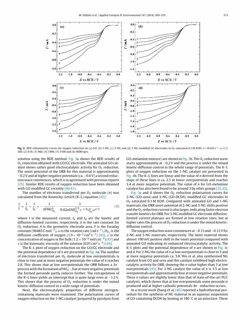
M. Vikkisk et al. / Applied Catalysis B: Environmental 147 (2014) 369– 376 373
F G and3
sOaT−t[w
c
wdOcdc�
toc2pttTk
co
ig. 3. RDE voltammetry curves for oxygen reduction on (a) GO, (b) 1-NG, (c) 2-N60, (2) 610, (3) 960, (4) 1900, (5) 3100 and (6) 4600 rpm.
olution using the RDE method. Fig. 3a shows the RDE results of2 reduction obtained with GO/GC electrode. The annealed GO cat-lyst shows rather good electrocatalytic activity for O2 reduction.he onset potential of the ORR for this material is approximately0.2 V and at higher negative potentials (ca. −0.6 V) a second reduc-
ion wave commences, which is in agreement with previous reports25]. Similar RDE results of oxygen reduction have been obtainedith GO modified GC recently [40,41].
The number of electrons transferred per O2 molecule (n) wasalculated from the Koutecky–Levich (K–L) equation [42]:
1I
= 1Ik
+ 1Id
= − 1
nFAkcbO2
− 1
0.62nFAD2/3O2
�−1/6cbO2
ω1/2(1)
here I is the measured current, Ik and Id are the kinetic andiffusion-limited currents, respectively, k is the rate constant for2 reduction, A is the geometric electrode area, F is the Faradayonstant (96485 C mol−1), ω is the rotation rate (rad s−1), DO2 is theiffusion coefficient of oxygen (1.9 × 10⁻⁵ cm2 s−1) [43], � is theoncentration of oxygen in the bulk (1.2 × 10⁻⁶ mol cm−3) [43] and
is the kinematic viscosity of the solution (0.01 cm2 s−1) [44].The K–L plots of oxygen reduction on the GO/GC electrode and
he potential dependence of n are presented in Fig. 4a. The numberf electrons transferred per O2 molecule at low overpotentials islose to two and at more negative potentials the value of n reaches.8. This shows that at low overpotentials the ORR follows a 2e−
rocess with the formation of HO2−, but at more negative potentials
he formed peroxide partly reduces further. The extrapolation ofhe K–L lines yields an intercept that is quite large even at −1.2 V.his shows that the process of O2 reduction is under the mixed
inetic-diffusion control in a wide range of potentials.Next, the electrocatalytic properties of different nitrogen-ontaining materials were examined. The polarisation curves ofxygen reduction on the 1-NG catalyst (prepared by pyrolysis from
(d) 3-NG modified GC electrodes in O2-saturated 0.1 M KOH. v = 10 mV s−1, ω = (1)
GO-melamine mixture) are shown in Fig. 3b. The O2 reduction wavestarts approximately at −0.2 V and the process is under the mixedkinetic-diffusion control in the whole range of potentials. The K–Lplots of oxygen reduction on the 1-NG catalyst are presented inFig. 4b. The K–L lines are linear and the value of n derived from theslope of these lines is ca. 2.5 at lower overpotentials and reaches3.4 at more negative potentials. The value of n for GO-melaminecatalyst has also been found to be around 3 by other groups [25,35].
Fig. 3c and d shows the O2 reduction polarisation curves for2-NG (GO-urea) and 3-NG (GO-DCDA) modified GC electrodes inO2-saturated 0.1 M KOH. Compared with annealed GO and 1-NGmaterials, the ORR onset potential of 2-NG and 3-NG shifts positiveand the O2 reduction current is also larger, indicating faster electrontransfer kinetics for ORR. For 3-NG modified GC electrode diffusion-limited current plateaus are formed at low rotation rates, but athigher rates the process of O2 reduction is under the mixed kinetic-diffusion control.
The oxygen reduction wave commences at −0.15 and −0.12 V for2-NG and 3-NG materials, respectively. The latter material showsalmost 100 mV positive shift in the onset potential compared withannealed GO indicating its enhanced electrocatalytic activity. TheK–L plots and the potential dependence of n are shown in Fig. 4cand d. For 2-NG the value of n at low overpotentials is close to 3 andat more negative potentials ca. 3.8. Wu et al. also synthesised NGcatalyst from GO and urea and this catalyst exhibited high electro-catalytic activity for ORR, showing the n value higher than 3 at lowoverpotentials [45]. For 3-NG catalyst the value of n is 3.5 at lowoverpotentials and approximately four at more negative potentials.These n values are slightly lower than that of state-of-the-art Pt/Ccatalysts, which shows that at low overpotentials some peroxide is
produced and at higher cathodic potentials 4e− reduction occurs.In a recent work Zhang et al. [46] reported a hydrothermal pro-cedure for the synthesis of NG material in an aqueous suspensionof GO containing DCDA by heating at 180 ◦C in an autoclave. These

374 M. Vikkisk et al. / Applied Catalysis B: Environmental 147 (2014) 369– 376
F -NG/G( ntial d
aNtstobtpp
G(mcwtweponThqptcei2
this particular NG catalyst consisted of largest amount of pyridinicnitrogen. At the same time the 1-NG material, which showed low-est activity, had also the smallest amount of pyridinic nitrogen. It is
ig. 4. Koutecky–Levich plots for oxygen reduction on (a) GO/GC, (b) 1-NG/GC, (c) 2�) −0.7, (�) −0.8, (�) −0.9, (�) −1.0, (�) −1.1 and (�) −1.2 V. Inset shows the pote
uthors reported that the O2 reduction wave on reduced GO and-doped graphene commences at the same potential. For the lat-
er material the n value was only 2.6 at −0.5 V vs. Ag/AgCl, whichhows that peroxide pathway dominates on that NG catalyst. Inhe present research the reduction current was significantly largern the 3-NG catalyst and the process of O2 reduction proceededy a 4-electron pathway, which indicates about the superiority ofhe NG catalyst used in this work. Obviously the high-temperatureyrolysis yields a more active catalyst for ORR than a wet chemicalrocedure suggested in Ref. [46].
The RDE results of O2 reduction that compare the undopedO and different NG catalysts at a single electrode rotation rate
ω = 1900 rpm) are shown in Fig. 5. The onset potential for all NGaterials is higher compared with the annealed GO material. The
atalyst prepared by the pyrolysis of the mixture of GO and DCDAith ratio of 1/20 (designated as 3-NG) shows the largest O2 reduc-
ion current and the highest electrocatalytic activity. Comparedith 1-NG and 2-NG, the ORR activity of 3-NG is significantly
nhanced. Which type of nitrogen is responsible for improved ORRerformance is not exactly known [14], but it is obvious on the basesf these results that incorporating nitrogen into carbon materials isecessary to obtain catalyst with better electrocatalytic properties.he investigation of oxygen molecule dissociation energy barrieras shown that it can be reduced by all types of nitrogen and theuaternary N reduces the energy barrier more efficiently than theyridinic N, which might be one of the reasons for improved elec-rocatalytic activity on N-doped carbon catalysts [47]. Ruoff and
o-workers stated that the content of graphitic N determines thelectrocatalytic activity and pyridinic N is responsible for improv-ng the onset potential and converting the ORR mechanism from-electron pathway to 4-electron process [48]. Some investigatorsC and (d) 3-NG/GC electrodes in 0.1 M KOH solution. E = (�) −0.4, (�) −0.5, (�) −0.6,ependence of n. Data derived from Fig. 3.
claim that quaternary nitrogen is responsible for the enhanced cat-alytic activity, but some others state that it is the pyridinic nitrogen[27,28]. On the basis of the results obtained in this work, we con-clude that the main reason for enhanced electrocatalytic activityof these electrocatalysts could be the higher content of pyridinicnitrogen. The 3-NG material possessed the highest ORR activity and
Fig. 5. Comparison of RDE results of oxygen reduction on bare GC, GO/GC,NG/GC and Pt/C modified GC electrodes in O2-saturated 0.1 M KOH. v = 10 mV s−1,ω = 1900 rpm.

M. Vikkisk et al. / Applied Catalysis B: Env
F0
icvfpbrmeaaiom
gtaaops
sKfrro3Ntpcb
4
ge8ioc
[[
[
[[
[
[[[[[
[[[
[[
[
[[[[
[
[[
[
[
[[
[
[
ig. 6. LSV curves for oxygen reduction on a 3-NG/GC electrode in O2-saturated.1 M KOH. v = 10–200 mV s−1.
mportant to note, that at low overpotentials the GO materialatalyses a two-electron O2 reduction, but for NG materials thealue of n significantly increases. Several groups have studied theuel tolerance of NG catalysts for ORR and it was found that NGossesses excellent tolerance to the crossover effect accompaniedy high cycling stability [21,27]. As expected, the overall oxygeneduction activity of the Pt/C catalyst is higher than that of NGaterials (Fig. 5). However, it needs to be stressed that the differ-
nce in the E1/2 value between the most active NG catalyst (3-NG)nd Pt/C is only ca. 50 mV. This indicates the excellent electrocat-lytic activity of 3-NG towards the ORR in alkaline media. These aremportant results from the point of view of practical applicationf NG materials as cathode catalysts for low-temperature alkalineembrane fuel cell.Very recently a hybrid catalyst of nitrogen-doped
raphene/carbon nanotubes was prepared by pyrolysis of DCDA inhe presence of carbon nanomaterials [49]. This catalyst showed
good electrocatalytic property for ORR in acid media. The ORRctivity of undoped catalyst was significantly lower [49]. The typef nitrogen species that is active for ORR might depend on solutionH. Therefore the ORR performance of N-doped nanocarbons istrongly affected by pH [50].
The electrocatalytic property of 3-NG catalyst material was alsotudied by linear sweep voltammetry (LSV) in O2-saturated 0.1 MOH solution. The LSV measurements were carried out using dif-
erent potential scan rates (10–200 mV s−1). Fig. 6 presents the LSVesponses of the 3-NG modified GC electrode in 0.1 M KOH. The O2eduction wave of 3-NG has more positive onset potential than thatf the GO catalyst (data not shown) and also the peak currents for-NG are higher than for GO/GC electrodes, which shows again that-doping is necessary for an efficient O2 reduction electrocatalysis
o occur. The reduction current peak appeared at a rather positiveotential, indicating superior electrocatalytic properties of this NGatalyst. In the next stage of work the most active NG material wille tested in the fuel cell conditions.
. Conclusions
In this work the electrocatalysis of O2 reduction on annealedraphene oxide and nitrogen-doped graphene catalysts has beenxplored. Nitrogen doping was achieved by pyrolysis of GO at
◦
00 C in the presence of melamine, urea or dicyandiamide. Accord-ng to the XPS results the nitrogen doping level up to 5 at% wasbserved. The synthesised NG materials were electrochemicallyharacterised in alkaline media and the RDE and LSV results[
[[
ironmental 147 (2014) 369– 376 375
revealed that these catalysts possess a high electrocatalytic activitytowards O2 reduction. The NG material synthesised in the presenceof DCDA showed the best ORR performance. DCDA as a nitrogenprecursor is easy to handle (non-flammable), making N-dopingmethod feasible for the preparation of N-containing graphenecathodes for low-temperature fuel cell applications.
Acknowledgements
This research was financially supported by the Estonian ScienceFoundation (Grant No. 9323) and by the Estonian Nanotechnol-ogy Competence Center. We also acknowledge support from theArchimedes Foundation (Project No. 3.2.0501.10-0011).
References
[1] A. Rabis, P. Rodriguez, T.J. Schmidt, ACS Catal. 2 (2012) 864–890.[2] R. Othman, A.L. Dicks, Z. Zhu, Int. J. Hydrogen Energy 37 (2012) 357–372.[3] Z.W. Chen, D. Higgins, A.P. Yu, L. Zhang, J.J. Zhang, Energy Environ. Sci. 4 (2011)
3167–3192.[4] Y.Y. Shao, J.H. Sui, G.P. Yin, Y.Z. Gao, Appl. Catal., B 79 (2008) 89–99.[5] D.A. Stevens, M.T. Hicks, G.M. Haugen, J.R. Dahn, J. Electrochem. Soc. 152 (2005)
A2309–A2315.[6] S. Wakeland, R. Martinez, J.K. Grey, C.C. Luhrs, Carbon 48 (2010) 3463–3470.[7] Y. Li, W. Zhou, H. Wang, L. Xie, Y. Liang, F. Wei, J.-C. Idrobo, S.J. Pennycook, H.
Dai, Nat. Nanotechnol. 7 (2012) 394–400.[8] I. Kruusenberg, N. Alexeyeva, K. Tammeveski, Carbon 47 (2009) 651–658.[9] I. Kruusenberg, N. Alexeyeva, K. Tammeveski, J. Kozlova, L. Matisen, V. Sam-
melselg, J. Solla-Gullon, J.M. Feliu, Carbon 49 (2011) 4031–4039.10] G. Jürmann, K. Tammeveski, J. Electroanal. Chem. 597 (2006) 119–126.11] N. Alexeyeva, K. Tammeveski, Electrochem. Solid-State Lett. 10 (2007)
F18–F21.12] K.S. Novoselov, A.K. Geim, S.V. Morozov, D. Jiang, Y. Zhang, S.V. Dubonos, I.V.
Grigorieva, A.A. Firsov, Science 306 (2004) 666–669.13] A.K. Geim, K.S. Novoselov, Nat. Mater. 6 (2007) 183–191.14] Q. Liu, H. Zhang, H. Zhong, S. Zhang, S. Chen, Electrochim. Acta 81 (2012)
313–320.15] L. Sun, L. Wang, C. Tian, T. Tan, Y. Xie, K. Shi, M. Li, H. Fu, RSC Adv. 2 (2012)
4498–4506.16] Z. Lei, L. Lu, X.S. Zhao, Energy Environ. Sci. 5 (2012) 6391–6399.17] E. Antolini, Appl. Catal., B 123-124 (2012) 52–68.18] M.D. Stoller, S. Park, Y. Zhu, J. An, R.S. Ruoff, Nano Lett. 8 (2008) 3498–3502.19] C. Soldano, A. Mahmood, E. Dujardin, Carbon 48 (2010) 2127–2150.20] S. Stankovich, D.A. Dikin, R.D. Piner, K.A. Kohlhaas, A. Kleinhammes, Y. Jia, Y.
Wu, S.T. Nguyen, R.S. Ruoff, Carbon 45 (2007) 1558–1565.21] C. Zhu, S. Dong, Nanoscale 5 (2013) 1753–1767.22] H. Wang, T. Maiyalagan, X. Wang, ACS Catal. 2 (2012) 781–794.23] Z. Yang, H. Nie, X. Chen, X. Chen, S. Huang, J. Power Sources 236 (2013)
238–249.24] K. Gong, F. Du, Z. Xia, M. Durstock, L. Dai, Science 323 (2009) 760–764.25] Z.H. Sheng, L. Shao, J.J. Chen, W.J. Bao, F.B. Wang, X.H. Xia, ACS Nano 5 (2011)
4350–4358.26] Z. Luo, S. Lim, Z. Tian, J. Shang, L. Lai, B. MacDonald, C. Fu, Z. Shen, T. Yu, J. Lin,
J. Mater. Chem. 21 (2011) 8038–8044.27] Z. Lin, G. Waller, Y. Liu, M. Liu, C.-P. Wong, Adv. Energy Mater. 2 (2012) 884–888.28] Y. Sun, C. Li, G. Shi, J. Mater. Chem. 22 (2012) 12810–12816.29] L. Qu, Y. Liu, J.-B. Baek, L. Dai, ACS Nano 4 (2010) 1321–1326.30] K.R. Lee, K.U. Lee, J.W. Lee, B.T. Ahn, S.I. Woo, Electrochem. Commun. 12 (2010)
1052–1055.31] C.-W. Tsai, M.-H. Tu, C.-J. Chen, T.-F. Hung, R.-S. Liu, W.-R. Liu, M.-Y. Lo,
Y.-M. Peng, L. Zhang, J. Zhang, D.-S. Shy, X.-K. Xing, RSC Adv. 1 (2011)1349–1357.
32] H. Liu, Y. Liu, D. Zhu, J. Mater. Chem. 21 (2011) 3335–3345.33] N. Alexeyeva, E. Shulga, V. Kisand, I. Kink, K. Tammeveski, J. Electroanal. Chem.
648 (2010) 169–175.34] M. Vikkisk, I. Kruusenberg, U. Joost, E. Shulga, K. Tammeveski, Electrochim. Acta
87 (2013) 709–716.35] Z.Y. Lin, M.K. Song, Y. Ding, Y. Liu, M.L. Liu, C.P. Wong, Phys. Chem. Chem. Phys.
14 (2012) 3381–3387.36] W.S. Hummers, R.E. Offeman, J. Am. Chem. Soc. 80 (1958) 1339.37] V. Datsyuk, M. Kalyva, K. Papagelis, J. Parthenios, D. Tasis, A. Siokou, I. Kallitsis,
C. Galiotis, Carbon 46 (2008) 833–840.38] H.C. Schniepp, J.L. Li, M.J. McAllister, H. Sai, M. Herrera-Alonso, D.H. Adamson,
R.K. Prud’homme, R. Car, D.A. Saville, I.A. Aksay, J. Phys. Chem. B 110 (2006)8535–8539.
39] S. Chandra, S. Sahu, P. Pramanik, Mater. Sci. Eng., B Solid 167 (2010) 133–136.
40] I. Kruusenberg, J. Mondal, L. Matisen, V. Sammelselg, K. Tammeveski, Elec-trochem. Commun. 33 (2013) 18–22.41] F. Lima, G.V. Fortunato, G. Maia, RSC Adv. 3 (2013) 9550–9560.42] A.J. Bard, L.R. Faulkner, Electrochemical Methods, second ed., Wiley, New York,
2001.

3 B: Env
[[
[[[
[
76 M. Vikkisk et al. / Applied Catalysis
43] R.E. Davis, G.L. Horvath, C.W. Tobias, Electrochim. Acta 12 (1967) 287–297.
44] D.R. Lide, CRC Handbook of Chemistry and Physics, 82nd ed., CRC, Press, BocaRaton, 2001.45] J.J. Wu, D. Zhang, Y. Wang, B.R. Hou, J. Power Sources 227 (2013) 185–190.46] Y. Zhang, K. Fugane, T. Mori, L. Niu, J. Ye, J. Mater. Chem. 22 (2012) 6575–6580.47] S. Ni, Z.Y. Li, J.L. Yang, Nanoscale 4 (2012) 1184–1189.
[
[
ironmental 147 (2014) 369– 376
48] L.F. Lai, J.R. Potts, D. Zhan, L. Wang, C.K. Poh, C.H. Tang, H. Gong, Z.X. Shen, Y.
Lin, R.S. Ruoff, Energy Environ. Sci. 5 (2012) 7936–7942.49] C.H. Choi, M.W. Chung, H.C. Kwon, J.H. Chung, S.I. Woo, Appl. Catal. B 144 (2014)760–766.
50] W.Y. Wong, W.R.W. Daud, A.B. Mohamad, A.A.H. Kadhum, K.S. Loh, E.H. Majlan,Int. J. Hydrogen Energy 38 (2013) 9370–9386.