High-temperature lubrication mechanism of alkaline borates
231
University of Wollongong University of Wollongong Research Online Research Online University of Wollongong Thesis Collection 2017+ University of Wollongong Thesis Collections 2019 High-temperature lubrication mechanism of alkaline borates High-temperature lubrication mechanism of alkaline borates Bach Tran University of Wollongong Follow this and additional works at: https://ro.uow.edu.au/theses1 University of Wollongong University of Wollongong Copyright Warning Copyright Warning You may print or download ONE copy of this document for the purpose of your own research or study. The University does not authorise you to copy, communicate or otherwise make available electronically to any other person any copyright material contained on this site. You are reminded of the following: This work is copyright. Apart from any use permitted under the Copyright Act 1968, no part of this work may be reproduced by any process, nor may any other exclusive right be exercised, without the permission of the author. Copyright owners are entitled to take legal action against persons who infringe their copyright. A reproduction of material that is protected by copyright may be a copyright infringement. A court may impose penalties and award damages in relation to offences and infringements relating to copyright material. Higher penalties may apply, and higher damages may be awarded, for offences and infringements involving the conversion of material into digital or electronic form. Unless otherwise indicated, the views expressed in this thesis are those of the author and do not necessarily Unless otherwise indicated, the views expressed in this thesis are those of the author and do not necessarily represent the views of the University of Wollongong. represent the views of the University of Wollongong. Recommended Citation Recommended Citation Tran, Bach, High-temperature lubrication mechanism of alkaline borates, Doctor of Philosophy thesis, School of Mechanical, Materials, Mechatronic and Biomedical Engineering, University of Wollongong, 2019. https://ro.uow.edu.au/theses1/700 Research Online is the open access institutional repository for the University of Wollongong. For further information contact the UOW Library: [email protected]
-
Upload
khangminh22 -
Category
Documents
-
view
1 -
download
0
Transcript of High-temperature lubrication mechanism of alkaline borates
University of Wollongong University of Wollongong
Research Online Research Online
University of Wollongong Thesis Collection 2017+ University of Wollongong Thesis Collections
2019
High-temperature lubrication mechanism of alkaline borates High-temperature lubrication mechanism of alkaline borates
Bach Tran University of Wollongong
Follow this and additional works at: https://ro.uow.edu.au/theses1
University of Wollongong University of Wollongong
Copyright Warning Copyright Warning
You may print or download ONE copy of this document for the purpose of your own research or study. The University
does not authorise you to copy, communicate or otherwise make available electronically to any other person any
copyright material contained on this site.
You are reminded of the following: This work is copyright. Apart from any use permitted under the Copyright Act
1968, no part of this work may be reproduced by any process, nor may any other exclusive right be exercised,
without the permission of the author. Copyright owners are entitled to take legal action against persons who infringe
their copyright. A reproduction of material that is protected by copyright may be a copyright infringement. A court
may impose penalties and award damages in relation to offences and infringements relating to copyright material.
Higher penalties may apply, and higher damages may be awarded, for offences and infringements involving the
conversion of material into digital or electronic form.
Unless otherwise indicated, the views expressed in this thesis are those of the author and do not necessarily Unless otherwise indicated, the views expressed in this thesis are those of the author and do not necessarily
represent the views of the University of Wollongong. represent the views of the University of Wollongong.
Recommended Citation Recommended Citation Tran, Bach, High-temperature lubrication mechanism of alkaline borates, Doctor of Philosophy thesis, School of Mechanical, Materials, Mechatronic and Biomedical Engineering, University of Wollongong, 2019. https://ro.uow.edu.au/theses1/700
Research Online is the open access institutional repository for the University of Wollongong. For further information contact the UOW Library: [email protected]

High-temperature lubrication mechanism
of alkaline borates
A thesis submitted for the conferral of the degree of
Doctor of Philosophy
from
UNIVERSITY OF WOLLONGONG
by
BACH TRAN
B. Eng
School of Mechanical, Materials, Mechatronic and Biomedical Engineering
Faculty of Engineering and Information Sciences
Declaration
I
DECLARATION
I, Bach Tran, declare that this thesis submitted in fulfilment of the requirements for the
conferral of Doctor of Philosophy, from the University of Wollongong, is wholly my own
work unless otherwise referenced or acknowledged. This document has not been submitted
for qualifications at any other academic institutions.
Bach Hoang Tran,
Wollongong, August 2019
Acknowledgements
II
ACKNOWLEDGEMENTS
I am sincerely grateful to Professor Anh Kiet Tieu for giving me the opportunity to
embark on my postgraduate study. His constant maintenance, guidance and advices are
invaluable to me during all these years.
I owe a thank you to my co-supervisors, Dr. HongtaoZhu and Dr. Shanhong Wan for
their support. I also would like to thank Dr. Buyung Kosasih and Dr. Shaogang Cui for
their help in the early days of my study. I specifically appreciate the staffs within the
Faculty of Engineering and Information Sciences, Mr. Steward Rodd, Mr. Andrew Scobie,
Mr. Keith Maywald, Mr. Matthew Franklin, Mr. Carl Rindlisbacher and Mr. Leighton Hill
for their kind assistance in sample preparation and equipment repair.
I would like to thank Dr. Mitchell Nancarrow and Dr. David Mitchel for their
professional assistance on electron microscope works.
My research would have been impossible without the financial aid from the University
of Wollongong.
Finally, I am eternally indebted to my family, particularly my beloved wife Mrs. Dung
Tran for her care, encouragement and sharing throughout my journey.
List of publications
III
LIST OF PUBLICATIONS
1. B. Tran, A. K. Tieu, S. Wan, H. Zhu, D.R.G. Mitchell, M.J. Nancarrow,
Multifunctional Bi-Layered Tribofilm Generated on Steel Contact Interfaces Under
High-Temperature Melt Lubrication, The Journal of Physical Chemistry C, 2017.
2. B. Tran, K. Tieu, S. Wan, H. Zhu, L. Riu, Hot corrosion of borate melt and interface
chemistry of borate-coated steel under tribological stimulation, Corrosion Science,
2018.
3. B. Tran, K. Tieu, S. Wan, H. Zhu, S. Cui, L. Wang, Understanding the tribological
impact of alkaline element in lubrication performance of binary borate melt, RSC
Advances, 2018.
4. B. Tran, K. Tieu, S. Wan, H. Zhu, Lubricant as a sticking-scale inhibitor on high
temperature sliding contact, Tribology International, 2019.
5. S. Wan, B. Tran, A. K. Tieu, Y. Xia, H. Zhu, S. Cui, Q. Zhu, The Influence of Water
Addition on High-Temperature Tribological Properties of Interstitial Free Sliding
against Different Counterparts, Tribology Transactions, 2018.
6. S. Wan, A. K. Tieu, Y. Xia, H. Zhu, B. Tran, S. Cui, An overview of inorganic
polymer as potential lubricant additive for high temperature tribology, Tribology
International, 2016.
7. S. Wan, A. K. Tieu, Y. Xia, L. Wang, D. Li, G. Zhang, H. Zhu, B. Tran, D.R.G.
Mitchell, Tribochemistry of adaptive integrated interfaces at boundary lubricated
contacts, Scientific Reports, 2017.

List of publications
IV
8. C. Sun, Q. Xue, J. Zhang, S. Wan, A.K. Tieu, B. Tran, Growth behavior and
mechanical properties of Cr-V composite surface layer on AISI D3 steel by thermal
reactive deposition, Vacuum, 2017.
9. S. Cui, H. Zhu, S. Wan, K. Tieu, B. Tran, L. Wang, Q. Zhu, Effect of loading on the
friction and interface microstructure of lubricated steel tribopairs, Tribology
International, 2017.
10. S. Cui, H. Zhu, S. Wan, B. Tran, L. Wang, K. Tieu, Investigation of different
inorganic chemical compounds as hot metal forming lubricant by pin-on-disc and hot
rolling, Tribology International, 2018.
11. S. Wan, H. Wang, Y. Xia, A.K. Tieu, B. H. Tran, H. Zhu, G. Zhang, Q. Zhu,
Investigating the corrosion-fatigue wear on GrN coated piston rings from laboratory
wear tests and field trial studies, Wear, 2019.

Abstract
V
ABSTRACT
Like any other metalworking processes, lubrication plays a crucial role in hot metal
forming (e.g. hot rolling). An effective lubrication ensures high energy efficiency, low
material loss and optimal product quality. The current study investigates potential
lubrication properties of alkaline borates at elevated temperature by extensive experimental
work. Advanced microscopy analysis allows insights into working mechanics of the
lubricants at different scales which help addressing some fundamental questions arise from
the past literatures.
Tribological behaviors of sodium borate were thoroughly studied by pin-on-disc testing.
With a transition point around 525oC, the material exhibits exceptional lubrication
performance over the range of 600oC-800oC on sliding steel pair (GCr15/mild steel). This
is demonstrated by remarkable reduction in friction coefficient and wear loss volume on
both contact surfaces lubricated by sodium borate compared to the unlubricated case. For
instance, under borate lubrication at 800oC, the friction coefficient drops by 58% while the
wear loss is reduced by 95% and 80% on the disc and the ball, respectively. Detailed
analysis revealed tribofilm formation on both contact surfaces. On the ball, a chemically-
complex film (~20nm thick) is observed lying on top of ultra-fined grains of iron oxides.
Electron Energy Loss Spectroscopy (EELS) indicates a conversion between BO4 to BO3
species in the boundary film which could be triggered by the shearing stress. On the
lubricated mild-steel disc, the tribofilm has a dual-layered structure with a total thickness
of 50nm: an upper layer rich in Boron (B) and the lower layer rich in Sodium (Na). The Na
layer is accountable for good adherence to the oxide surface while the upper film provides

Abstract
VI
a load-supporting capacity through a self-polymerization mechanism. A static oxidation
testing between the borate melt and oxide scale discloses the thermally-activated nature of
Na adsorption on the iron oxide interface aided by the ionic characteristics of sodium
borate melt at high temperature. The borate tribofilm generated on the disc is significantly
depleted in Oxygen that in turn provides a considerable oxidation resistance. This is
reflected by reduced thickness of the oxide scale lubricated by sodium borate, the reduction
rate is approximately 50% compared to a freely-oxidized surface. Regarding microscopy
strategy, High Angle Annular Dark Field (HAADF) imaging technique has shown to be a
useful tool to observe B-containing tribofilm.
The roles of Sodium in lubricating mechanics of borate lubricant were revealed by
comparing lubrication behavior between two systems: sole B2O3 and binary oxides Na2O-
B2O3 on sliding steel pairs at 800oC. The binary system outperforms the singular system in
terms of friction and wear loss reduction, which explicitly underlines the critical presence
of Na. Further analysis shows that the adsorption of Na on both contact surfaces is
regarded as the foundation for the exceptional lubrication performance of sodium borate.
While the addition of Na results in the ionic characteristic, B2O3 provides the polymeric
nature which determines the viscous fluid behavior of the lubricant melt on the heated
sliding surfaces. A clear correlation between the oxide microstructure and adsorption
behavior of Na is established as the Na layer is thicker on oxide scale grown from a highly-
alloyed steel substrate. In addition, the role of oxide scale as a supporting medium for
lubricant is also emphasized.

Abstract
VII
Sodium borate demonstrates an ability to eliminate adhesive wear/oxide transfer on
sliding High Speed Steel tool surface. This is reflected by reduced thickness of the oxide
scale compared to unlubricated case (~88% after 5mins and 80% after 15mins sliding test).
The formation of borate tribofilm provides a consistent lubrication, effectively separates
asperities contacts and suppresses the sticking tendency of adhesive wear. Prolonged
exposure to borate lubrication however alters the oxidation sequence and results in
Hematite-to-Magnetite transformation of the underlying oxide scale. Under borate
lubrication, the resistance against oxide transfer is also evident in steel rolling contact.
Although the passivated rolling module is not able to fully represent actual hot rolling, the
contact pressure is set close to real process parameter (>500MPa) and the interactions
between sodium borate melt and iron oxides are determined in details. After rolling in the
presence of sodium borate melt, the oxide scale experiences a phase transformation as
Magnetite becomes the most dominating type while Hematite is prevalent in unlubricated
case. This transformation is suggested to facilitate the subsequent pickling process.
A potassium borate was synthesized and evaluated on pin-on-disc testing at maximum
temperature of 900oC. It displays a superior performance compared to sodium borate at
900oC regarding friction and wear loss reduction. The lubrication failure of sodium borate
at 900oC is mainly due to its low viscosity. Despite the difference in activity between two
elements, the working mechanism of potassium borate appears similar to sodium borate.

List of figures
VIII
LIST OF FIGURES
Figure 2-1: Involved phenomena during tribological process at high temperature [5] .... 3
Figure 2-2: Oxidation mechanism of pure iron above 570oC [11] ................................... 5
Figure 2-3: Hardness ratio between oxide scale and steel substrate as a function of
temperature and strain rate by 4 point bending test [14] ....................................................... 6
Figure 2-4: Plastic behavior of oxide scale as a function of temperature and reduction in
hot rolling [17] ...................................................................................................................... 7
Figure 2-5: Friction coefficient evolution of steel pair at 950oC by pin-on-disc testing
[22] ........................................................................................................................................ 8
Figure 2-6: Schematic of diffusion-controlled growth of multi-layered scales on alloyed
steel at high temperature [11] ................................................................................................ 9
Figure 2-7: A typical plot of Stribeck curve [27] ........................................................... 11
Figure 2-8: Coexistence of multiple lubrication regimes at the role bite during hot
rolling of steel [2] ................................................................................................................ 12
Figure 2-9: Working temperature range of additive elements [33] ................................ 13
Figure 2-10: Friction coefficient curves and wear loss volume from sliding test on rare
earth oxides-bonded surface [40] ........................................................................................ 15
Figure 2-11: Rolling force/reduction rate from hot rolling of stainless steel lubricated by
CaCO3-added oil and the size effect on anti-seizure performance [41] .............................. 16
Figure 2-12: Proposed working mechanism of high polymer compound in hot forging
[34] ...................................................................................................................................... 17

List of figures
IX
Figure 2-13: Working temperature range of different lubricant classes in air atmosphere
[47] ...................................................................................................................................... 18
Figure 2-14: Typical composition of glass lubricant ...................................................... 19
Figure 2-15: Glass composition and dependence of friction coefficient on glass
viscosity at 1373K [55] ....................................................................................................... 20
Figure 2-16: Type of coatings in reference [68] ............................................................. 26
Figure 2-17: Working principles of each coating type [68] ........................................... 27
Figure 2-18: Compositional gradient within a ZDDP-originated tribofilm [69] ............ 28
Figure 2-19: Structural transformation in Lithium Phosphorowolframates [84] ........... 29
Figure 2-20: Friction coefficient as a function of load and amount of graphite inclusion
in water glass lubrication [86] ............................................................................................. 30
Figure 2-21: Compositional gradient of Na/K polyphosphate tribofilm [69] ................ 31
Figure 3-1: Simplified schematic of the high-temperature tribometer UMT2 ............... 35
Figure 3-2: Cross-sectional schematic of the high temperature LCM and the specimen
shape .................................................................................................................................... 36
Figure 3-3: Typical design of optical interferometer ..................................................... 38
Figure 3-4: Photograph of the FEI Helios NanoLab G3 CX [96] .................................. 39
Figure 3-5: Cross-sectional view of a typical EELS acquisition assembly below the
viewing screen [97] ............................................................................................................. 40
Figure 4-1: Vibrational spectroscopy spectrum of sodium borate, a) Raman, b) FTIR
and c) X-ray diffraction pattern of the material .................................................................. 43
Figure 4-2: Snapshots of sodium borate particle through its transition point in Laser
Confocal Microscopy .......................................................................................................... 44

List of figures
X
Figure 4-3: DSC and TGA curves of sodium borate. ..................................................... 45
Figure 4-4: (a) Wear loss volumes of the tribo-pair and (b) average friction coefficients
in lubricated tests versus load at 600oC. .............................................................................. 49
Figure 4-5: (a) Wear loss volumes of the tribo-pair and (b) average friction coefficients
in lubricated tests versus load at 700oC. .............................................................................. 50
Figure 4-6: (a) Wear loss volumes of the tribo-pair and (b) average friction coefficients
in lubricated tests versus load at 800oC. .............................................................................. 51
Figure 4-7: Friction coefficient curves of dry sliding and lubrication tests at 600oC,
700oC and 800oC (load of 30N, sliding speed of 0.1m/s). .................................................. 51
Figure 4-8: Wear loss volumes of the tribopair at varying temperatures in (a) dry
sliding condition and (b) lubrication condition. .................................................................. 52
Figure 4-9: Friction coefficient evolution of unlubricated and melt-lubricated steel pair
(at 800oC, 10N, 0.1m/s). ...................................................................................................... 53
Figure 4-10: Wear loss volumes of unlubricated and lubricated steel pair (at 800oC,
10N, 0.1m/s). ....................................................................................................................... 54
Figure 4-11: SEM micrographs of the worn surfaces and the corresponding X-ray
spectrum after dry sliding test a) ball, b) disc. .................................................................... 55
Figure 4-12: SEM micrographs of melt-lubricated steel components and the
corresponding X-ray spectrum after friction test a) ball, b) disc. ....................................... 56
Figure 4-13: a) Bright Field (BF) image from the GCr15 ball interface lubricated by
borate melt, b) application of Hurst filter underlining the nano-grained interface. ............ 57
Figure 4-14: EDS phase mapping with corresponding composition spectra of the ball
interface. .............................................................................................................................. 58

List of figures
XI
Figure 4-15: Extracted EELS spectra of B-K edge and C-K edge from a) melt
reference, b) interfacial film (Phase III) and c) iron oxide. ................................................. 59
Figure 4-16: BF image of the tribofilm generated on the ball and the corresponding EDS
mapping. .............................................................................................................................. 61
Figure 4-17: HAADF image of the tribo-interface generated on the disc (a), detailed
image of the dual-layered structure (b) and EDS line scan across the tribofilm (c). .......... 62
Figure 4-18: Simplified schematic of tribologically-induced polymerization in borate
tribofilm ............................................................................................................................... 65
Figure 4-19: BF image of cross-sectional scale/steel interface of GCr15 ball after
friction test. .......................................................................................................................... 67
Figure 4-20: Simplified chemical structure of borate tribofilm and participating
interfaces ............................................................................................................................. 68
Figure 5-1: a) SEM micrograph of borate-coated oxidized steel from non-contact area
and b) the corresponding EDS spectrum. ............................................................................ 73
Figure 5-2: Cross-sectional view of borate-coated steel ................................................ 74
Figure 5-3: STEM-BF image of the borate-steel interface from unworn area and the
corresponding phases determination with EDS spectrum. .................................................. 75
Figure 5-4: a) STEM-BF image of the borate-steel interface from unworn area, b) a scan
profile across the interface and c) corresponding EDS mapping of Na, O and Fe. (Yellow
line indicates scanning direction) ........................................................................................ 76
Figure 5-5: Electron Diffraction pattern of a) borate melt and b) oxide scale. .............. 76
Figure 5-6: a) EELS B-K edge intensity profile of B across the interface and b) EELS
spectra of B-K edge of the borate melt. .............................................................................. 77

List of figures
XII
Figure 5-7: a) SEM micrograph of the wear track lubricated by borate and b)
corresponding EDS spectrum. ............................................................................................. 77
Figure 5-8: a) STEM-HAADF image of the worn track area, b) a scan profile across the
interface and c) corresponding EDS mapping of Na, O and Fe. (Yellow line represents
scanning direction) .............................................................................................................. 79
Figure 5-9: SIMS depth profiles of B, Na and Fe on the worn track (Dashed area
approximates the interface). ................................................................................................ 80
Figure 5-10: TEM image of the boundary interface showing a thin film of Na as a result
of heterogeneous reaction. ................................................................................................... 81
Figure 5-11: XRD pattern of a) iron oxides and b) thermally treated borate-iron oxides
............................................................................................................................................. 83
Figure 5-12: Friction coefficient curve from lubricationt test of borate on steel/steel
contact (800oC, 10N, 0.1m/s) .............................................................................................. 84
Figure 5-13: Cross-sectional view of the steel subtrate lubricated by borate (a), coated
by borate (b) and under pure oxidation (c) at 800oC (Intensity unit is counts) ................... 86
Figure 5-14: Variation of oxide scale thickness under free oxidation, borate-coating and
borate lubrication at different loads (800oC, sliding duration of 5mins, sliding velocity of
0.1m/s) ................................................................................................................................. 87
Figure 6-1: X-ray diffraction pattern of boron oxide ..................................................... 90
Figure 6-2: X-ray diffraction pattern of HSS ................................................................. 91
Figure 6-3: SEM micrographs of different carbide morphologies a) MC, b) M2C, c)
M7C3 and d) AFM height profile of a polished HSS subtrate ............................................. 92
Figure 6-4: Elemental mapping of a polished HSS surface ........................................... 93

List of figures
XIII
Figure 6-5: a) Friction coefficient curves of HSS/SS316 pair lubricated different melt
systems and b) corresponding wear loss volumes on the disc ............................................ 95
Figure 6-6: a) Worn morphologies of SS316 disc lubricated by B2O3, b) magnified
image of the track and c) EDS spectrum collected from inside and outside the track ........ 97
Figure 6-7: a) Worn morphologies of HSS pin lubricated by B2O3 and b) higher
magnification of the contact area ........................................................................................ 97
Figure 6-8: Worn morphologies of steel pair lubricated by binary system Na2O-B2O3
and the corresponding EDS spectrum a) SS316 disc, b) HSS pin (S.D = sliding direction)
............................................................................................................................................. 98
Figure 6-9: Variation of average friction coefficient and disc loss volume versus
increasing load under Na2O-B2O3 lubrication ..................................................................... 99
Figure 6-10: Worn morphologies of steel tribopair lubricated by Na2O-B2O3 at 40N and
the corresponding EDS spectrum a) SS316 disc, b) HSS pin ........................................... 100
Figure 6-11: AFM height profile of the wear track after the friction test under Na2O-
B2O3 lubrication at 40N ..................................................................................................... 101
Figure 6-12: a) STEM-BF image of contact interface on SS316 disc lubricated by
Na2O-B2O3 at 30N, b) EDS mapping and c) EDS line scan across the interface (yellow
arrow indicates scanning direction) ................................................................................... 102
Figure 6-13: EELS spectrum of B K-edge on the contact interface of SS316 disc
lubricated by Na2O-B2O3 at 30N ....................................................................................... 104
Figure 6-14: a) STEM-BF image of contact interface on HSS pin lubricated by Na2O-
B2O3 at 30N, b) EDS mapping and c) EDS line scan across the interface (yellow arrow
indicates scanning direction) ............................................................................................. 105

List of figures
XIV
Figure 6-15: EELS spectrum of B K-edge on the contact interface of HSS pin lubricated
by Na2O-B2O3 at 30N ........................................................................................................ 106
Figure 6-16: a) TEM image of the lubricated HSS pin showing the interfacial Na-rich
film and Electron Diffraction of b) the lubricant film, c) the oxide scale ......................... 107
Figure 6-17: Infiltration of Na into the SS316 surface under Na2O-B2O3 lubrication (at
30N) ................................................................................................................................... 109
Figure 6-18: a) Na-rich film on oxidized mild-steel and b) the corresponding ED pattern
of the oxide (Chapter 5) .................................................................................................... 110
Figure 6-19: Friction/wear behaviors between different tribopair under borate
lubrication at 800oC ........................................................................................................... 111
Figure 7-1: Temperature record of HSS pin during pre-oxidation and friction test ..... 115
Figure 7-2: AFM image of HSS specimen before (a) and after oxidation (b) at 700oC
for 10 mins, (c) XRD pattern of the oxidized HSS .......................................................... 117
Figure 7-3: Friction coefficient curves from HSS/SS316 tribopair with and without
lubrication .......................................................................................................................... 118
Figure 7-4: Worn morphologies of HSS pin without lubrication after 5 mins (a, b) and
15 mins (c, d) ..................................................................................................................... 119
Figure 7-5: Cross-sectional views of HSS worn surfaces without lubrication after a)
5mins and b) 15mins (specimens were tilted at 54o) ......................................................... 120
Figure 7-6: Worn morphology of HSS pin in lubrication test after 5 mins (a) and EDS
spectrum (b). ...................................................................................................................... 121
Figure 7-7: STEM-BF images of cross-sectional HSS pins after lubrication test a) 5mins
and b) 15mins .................................................................................................................... 122

List of figures
XV
Figure 7-8: 3D profile images of HSS pin after dry sliding test (a-5mins, b-15mins) and
lubrication test (c-5mins, d-15mins) ................................................................................. 123
Figure 7-9: TEM images of HSS pin cross sections in a) 5mins lubrication, b) 15mins
lubrication and c) 15mins static oxidation with corresponding intensity profiles from
SAED ................................................................................................................................ 125
Figure 7-10: Magnified oxide microstructure after lubrication tests, a) 5mins, b) 15mins
and c) Fe3O4 (102) nanoparticle with indicated d-spacing ................................................ 126
Figure 7-11: a) Variation of oxide thickness on HSS pin with various lubricating
condition and b) wear track profiles on SS316 disc after 5mins (below) and 15mins
(above) test ........................................................................................................................ 127
Figure 7-12: Worn morphologies of SS316 disc after 15mins test, (a) without
lubrication and (b) with lubrication (below are magnified images, double-arrowed line
indicates track width) ........................................................................................................ 128
Figure 7-13: Individual phase spectrum and elemental distribution across the lubricated
HSS pin after 5mins test .................................................................................................... 130
Figure 7-14: Localization of Chromia on HSS metal base/scale interface after 5mins
lubrication test (a) and its disintegration after 15mins test (b) .......................................... 131
Figure 8-1: a) XRD pattern of starting HSS and b) its microstructure ......................... 137
Figure 8-2: Simplified schematic of a) upper roll assembly, b) lower specimen and c)
high temperature testing apparatus .................................................................................... 137
Figure 8-3: Optical microscope images of lower specimen surface after rolling test
against fresh HSS roll (scale bar of 50 µm) ...................................................................... 141

List of figures
XVI
Figure 8-4: Rolling friction coefficient as a function of temperature and load in case of
fresh roll ............................................................................................................................ 143
Figure 8-5: Optical microscope images of HSS surface a) before and b) after rolling
test (scale bar of 10µm) ..................................................................................................... 144
Figure 8-6: SEM micrographs of oxidized HSS surface with different oxidation
duration, a) 0.5 hr, b) 1hr, c) 2hrs and d) their corresponding XRD patterns ................... 146
Figure 8-7: Optical images of lower specimen surface after rolling test against oxidized
roll (scale bar of 50 µm) .................................................................................................... 148
Figure 8-8: Rolling friction coefficient as a function of temperature and load using
oxidized roll ....................................................................................................................... 149
Figure 8-9: Rolling friction under a) dry and b) lubrication condition with respect to
lubricant viscosity ............................................................................................................. 150
Figure 8-10: Optical images of HSS surface after test (scale bar of 10µm) ............... 151
Figure 8-11: SEM micrograph of transferred lubricant (a) and the corresponding X-ray
spectrum (b) ....................................................................................................................... 151
Figure 8-12: SEM micrographs of lower specimen surface after a) dry tests and b)
lubrication tests (double-arrowed line indicates moving direction) .................................. 152
Figure 8-13: Areal surface parameters of lower specimen after pickling .................... 153
Figure 8-14: 3D images of rolled surfaces after a) dry rolling and b) lubricated rolling
(top-to-bottom order: 600oC, 650oC, 700oC) .................................................................... 154
Figure 8-15: Rolling friction coefficient from roller-on-roller experiments as a function
of slip ratio [187] ............................................................................................................... 155
List of figures
XVII
Figure 8-16: Cross-sectional views of mild steel surface and the corresponding
compositional phase analysis after lubrication test at 650oC, 150N ................................. 157
Figure 8-17: Cross-sectional views of mild steel surface and the corresponding
compositional phase analysis after lubrication test at 600oC, 150N ................................. 157
Figure 8-18: Cross-sectional views of mild steel surface and the corresponding
compositional phase analysis after lubrication test at 700oC, 150N ................................. 158
Figure 8-19: Magnified images of the oxide/steel substrate interface after lubricant test
at a) 600oC, b) 650oC and c) 700oC (load of 150N) .......................................................... 159
Figure 8-20: XRD patterns of rolled surfaces under a) lubrication and b) dry condition
........................................................................................................................................... 160
Figure 9-1: a) X-ray diffraction pattern, b) FTIR spectrum and GTA/DSC curve of
synthesized potassium borate ............................................................................................ 165
Figure 9-2: Friction coefficient curves at a) 850oC, b) 900oC and c) wear loss volume of
SS316 disc in different lubrication conditions .................................................................. 167
Figure 9-3: Worn morphologies on a) the disc, b) magnified image on the disc and c)
the pin without lubrication at 850oC ................................................................................. 168
Figure 9-4: Worn morphologies on a) the disc, b) magnified image on the disc and c)
the pin without lubrication at 900oC ................................................................................. 168
Figure 9-5: SEM micrographs of a) disc and b) pin after Na borate lubrication at 850oC
and the corresponding X-ray analysis ............................................................................... 169
Figure 9-6: Worn morphologies of a) disc, b) magnified image of a, c) pin and the
corresponding X-ray analysis after Na borate lubrication at 900oC .................................. 170

List of figures
XVIII
Figure 9-7: EDS mapping of SS316 surface lubricated by Na borate lubrication with
solid-like particles ............................................................................................................. 171
Figure 9-8: SEM micrographs of a) disc and b) pin after K borate lubrication at 850oC
and the corresponding X-ray analysis ............................................................................... 171
Figure 9-9: SEM micrographs of a) disc and b) pin after K borate lubrication at 900oC
and the corresponding X-ray analysis ............................................................................... 172
Figure 9-10: a) STEM-BF image of melt/oxide interface after K borate lubrication and
b) phase composition, c) elemental mapping (at 900oC)................................................... 173
Figure 9-11: An STEM image of the immediate sliding surface with elemental mapping
........................................................................................................................................... 174
Figure 9-12: Variation of friction coefficient from HSS/SS316 lubricated (10N, 0.1m/s)
by a) Na borate and b) K borate with temperature ............................................................ 175
Figure 9-13: Oxide scale thickness on SS316 disc after lubrication tests at different
temperatures ...................................................................................................................... 176

List of tables
XIX
LIST OF TABLES
Table 2-1: A summarized table of patents using glass lubricants in hot metal forming
processes .............................................................................................................................. 25
Table 6-1: Chemical composition of HSS (weight %) ................................................... 90
Table 8-1: Chemical composition of HSS (weight %) ................................................. 136
Table 8-2: Variation of surface parameters from non-rolled area on lower specimen 142
Table 8-3: Variations of surface parameters from rolled area on lower specimen across
different testing conditions ................................................................................................ 142
Table 8-4: Surface parameters of pristine HSS ........................................................... 143
Table 8-5: Variations of surface parameters from HSS across different testing
conditions .......................................................................................................................... 143
Table 8-6: Variations of surface parameters on oxidized HSS prior to testing ............ 147
Table 8-7: Variations of surface parameters on oxidized HSS after testing at 650oC . 147
Table 8-8: Variations of surface parameters from mild steel surface after rolling against
oxidized HSS at 650oC ...................................................................................................... 147

List of contents
XX
LIST OF CONTENTS
DECLARATION ............................................................................................................. I
ACKNOWLEDGEMENTS .......................................................................................... II
LIST OF PUBLICATIONS ......................................................................................... III
ABSTRACT ................................................................................................................... V
LIST OF FIGURES ................................................................................................... VIII
LIST OF TABLES ..................................................................................................... XIX
LIST OF CONTENTS ................................................................................................ XX
CHAPTER 1: Introduction ........................................................................................... 1
CHAPTER 2: Literature review ................................................................................... 3
High temperature tribology .......................................................................................... 3
The roles of oxidation on the contact surface ............................................................... 4
Lubrication at high-temperature processing ............................................................... 10
Oil-based lubricants............................................................................................. 12
Solid and other lubricants .................................................................................... 14
Melt lubricant ............................................................................................................. 17
Brief review ......................................................................................................... 19
Glass-like lubrication at low temperature ........................................................... 27

List of contents
XXI
Glass-like lubrication at high temperature .......................................................... 29
Research scopes .......................................................................................................... 32
CHAPTER 3: Experimental methodology and characterization ............................ 34
High-temperature tribometer ...................................................................................... 34
Ball-on-disc ......................................................................................................... 34
Roller on flat........................................................................................................ 35
Analytical methodology ............................................................................................. 35
Thermal analysis ................................................................................................. 35
X-ray diffraction .................................................................................................. 37
Nanoindentation .................................................................................................. 37
3D Interferometer ................................................................................................ 37
Scanning Electron Microscope (SEM) ................................................................ 38
Focus Ion Beam Microscope (FIB) ..................................................................... 39
(Scanning) Transmission Electron Microscope (STEM) .................................... 39
Electron Energy Loss Spectroscopy (EELS) ...................................................... 40
CHAPTER 4: Tribological performance of sodium borate at elevated
temperatures ...................................................................................................................... 42
Experimental details ................................................................................................... 43
Molecular structure and thermal behavior of sodium borate .............................. 43

List of contents
XXII
Tribopair preparation........................................................................................... 45
Friction tests ........................................................................................................ 45
Characterization .................................................................................................. 47
Results ........................................................................................................................ 48
Tribological performance of sodium borate over a wide range of testing
conditions 48
Analysis on the worn surfaces at 800oC .............................................................. 52
Tribo-interface on the ball after test at 800oC ..................................................... 56
Tribo-interfacial on the disc ................................................................................ 60
Discussions ................................................................................................................. 63
Conclusions ................................................................................................................ 68
CHAPTER 5: Interface reaction of borate melt/oxidized steel and the anti-
oxidation capacity of lubricant melt ................................................................................ 70
Experimental details ................................................................................................... 71
Material preparation ............................................................................................ 71
Oxidation and tribological test ............................................................................ 71
Characterizations ................................................................................................. 72
Interfacial reaction between borate melt and oxidized steel ....................................... 72
Effect of stressed shearing on the interface chemistry ............................................... 77
Discussions ................................................................................................................. 80

List of contents
XXIII
Conclusions ................................................................................................................ 87
CHAPTER 6: The role of Na in the lubrication behavior of sodium borate ......... 88
Experimental details ................................................................................................... 89
Lubricant preparation .......................................................................................... 89
Tribopair preparation........................................................................................... 90
Friction test .......................................................................................................... 93
Characterization .................................................................................................. 94
Result .......................................................................................................................... 94
Lubrication performances of B2O3 and binary system Na2O-B2O3 .................... 94
Load-carrying capacity of binary system Na2O-B2O3......................................... 99
Contact interfaces lubricated by binary system Na2O-B2O3 ............................. 102
Discussion ................................................................................................................. 107
Conclusions .............................................................................................................. 112
CHAPTER 7: Borate melt as a sticking-scale inhibitor on a High Speed Steel
surface .............................................................................................................................. 113
Experimental details ................................................................................................. 114
Materials preparation......................................................................................... 114
Friction test ........................................................................................................ 114
Characterization ................................................................................................ 116

List of contents
XXIV
Results ...................................................................................................................... 116
Microstructural evolution of HSS at high temperature and its tribological
behaviors against SS316 ...................................................................................................... 116
Effect of lubrication on the tribological behavior of HSS pin .......................... 120
Effect of lubrication on iron oxides microstructure .......................................... 123
Discussion ................................................................................................................. 126
Conclusions .............................................................................................................. 133
CHAPTER 8: Tribological behaviors of sodium borate in rolling contacts ........ 135
Experimental details ................................................................................................. 136
Material preparation .......................................................................................... 136
Tribological test................................................................................................. 137
Characterization ................................................................................................ 139
Results ...................................................................................................................... 140
Effects of temperature and load on rolling characteristics at 550oC-650oC ...... 140
Effects of oxidized HSS on rolling characteristics............................................ 144
Rolling under lubrication .................................................................................. 149
Pickling of rolled surfaces ................................................................................. 152
Discussion ................................................................................................................. 154
Conclusions .............................................................................................................. 161
List of contents
XXV
CHAPTER 9: Synthesis of potassium borate and its tribological behaviors above
800oC ................................................................................................................................. 162
Material preparation ................................................................................................. 162
Synthesis of potassium borate ........................................................................... 162
Friction test ........................................................................................................ 163
Characterization ................................................................................................ 163
Results ...................................................................................................................... 164
Molecular structure and thermal behavior of synthesized potassium borate .... 164
Friction and wear behavior of K/Na borate ....................................................... 165
Worn area analysis under dry sliding ................................................................ 167
Worn area analysis under Na/K borate lubrication ........................................... 168
Discussion ................................................................................................................. 172
Conclusions .............................................................................................................. 176
CHAPTER 10: General conclusions and recommendations for future work ..... 177
Tribological performance of sodium borate at high temperature ......................... 177
Thermally-activated and tribochemical reaction on borate-lubricated surfaces ... 178
The role of Na in binary sodium borate lubrication and effect of oxide
microstructure on adsorption behavior of Na .......................................................................... 178
Adhesive wear resistance of sodium borate on sliding HSS surface .................... 179

List of contents
XXVI
Tribological behavior of sodium borate in rolling contact and surface interaction
with iron oxide scale ............................................................................................................... 180
Synthesis of potassium borate and understanding of alkaline borate lubrication . 180
Recommendations for future work ....................................................................... 180
Bibliography ................................................................................................................ 182
Appendices .................................................................................................................. 192
CHAPTER 1:
Page | 1
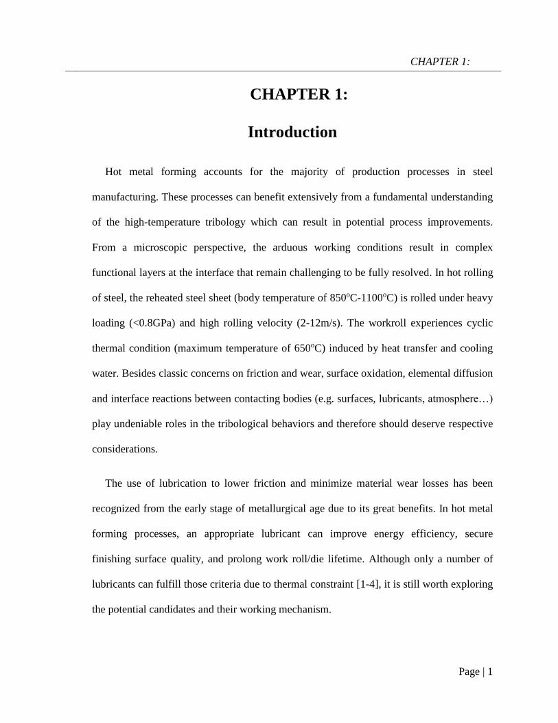
CHAPTER 1:
Introduction
Hot metal forming accounts for the majority of production processes in steel
manufacturing. These processes can benefit extensively from a fundamental understanding
of the high-temperature tribology which can result in potential process improvements.
From a microscopic perspective, the arduous working conditions result in complex
functional layers at the interface that remain challenging to be fully resolved. In hot rolling
of steel, the reheated steel sheet (body temperature of 850oC-1100oC) is rolled under heavy
loading (<0.8GPa) and high rolling velocity (2-12m/s). The workroll experiences cyclic
thermal condition (maximum temperature of 650oC) induced by heat transfer and cooling
water. Besides classic concerns on friction and wear, surface oxidation, elemental diffusion
and interface reactions between contacting bodies (e.g. surfaces, lubricants, atmosphere…)
play undeniable roles in the tribological behaviors and therefore should deserve respective
considerations.
The use of lubrication to lower friction and minimize material wear losses has been
recognized from the early stage of metallurgical age due to its great benefits. In hot metal
forming processes, an appropriate lubricant can improve energy efficiency, secure
finishing surface quality, and prolong work roll/die lifetime. Although only a number of
lubricants can fulfill those criteria due to thermal constraint [1-4], it is still worth exploring
the potential candidates and their working mechanism.

CHAPTER 1:
Page | 2
This dissertation focuses on the tribological characteristics of a family of inorganic
alkaline borates at elevated temperatures, pressure and shear. Friction and wear behaviors
of the alkaline borates are thoroughly studied on both sliding and rolling contacts of steel
counterparts. In addition, the anti-oxidation capacity of lubricant is also among central
subjects. The current work has a strong emphasis on the interface chemistry between the
lubricant and oxidized steel since these interactions predominantly govern the lubricant
macro-behaviors. Thermally-activated reactions, tribochemical reactions and the effects of
oxide microstructures are revealed in details and elaborated regarding their effects on
friction, wear and anti-oxidation characteristics. Furthermore, the fundamental roles of
each constituent element in the lubricant composition are also explored.
The dissertation starts with investigations on sodium borate, then a synthesized
potassium borate is also evaluated at a different temperature range. The outcome in this
work is originally applied for hot rolling of steel, but one could find it relevant for other
metal forming processes such as hot forging, wire drawing, hot extrusion and seamless
pipe manufacturing

CHAPTER 2:
Page | 3
CHAPTER 2:
Literature review
High temperature tribology
The term “high-temperature tribology” refers to science of interacting surfaces in
relative motion at elevated temperature. This temperature is generally assigned to the body
temperature of the tribo-component and it varies from one process to another. Such nature
of contact can often be found in most hot metal forming processes such as metal sheet
rolling, forging, stamping, drawing…Apart from conventional friction and wear aspects,
the use of heat results in drastic changes in the bulk properties of the contact materials
which in turn affect considerably their tribological behaviors. Microstructural evolution,
thermal softening and thermal fatigue are among the critical factors on friction/wear
characteristics. In addition, oxidation, heat transfer and elemental diffusion also deserve
consideration as their roles on the contact surfaces should not be taken lightly. Figure 2-1
illustrates the complex events that occur during a typical sliding contact at high
temperature [5], although one can expect a similarity on rolling contact.
Figure 2-1: Involved phenomena during tribological process at high
temperature [5]
CHAPTER 2:
Page | 4
Although there has been a volume of work dedicated to tribological behaviors of solid
lubricants at high temperature (300oC-1000oC) [1, 3, 4, 6], basic research on the actual
lubrication mechanism remains quite limited at this extreme condition. In the presence of
lubricant, the tribosystem becomes even more complicated when it has to take into account
interface reactions between lubricant elements and sliding surfaces, atomic diffusion
within the lubricant and cross-phase diffusion… Because of significant benefits of
lubrication, there are always pressing needs to gain further understanding on this particular
subject. As the current work revolves around steel processing, past literature on
tribological behaviors of the material at high temperature will be summarized.
The roles of oxidation on the contact surface
Oxidation can be regarded as the most influential factor on the contact surfaces since an
oxidized surface has totally different mechanical/chemical properties in comparison to a
pristine surface. At elevated temperature, steel experiences oxidation under open
atmosphere which is manifested by a growing and protective oxide scale on the steel
surface. The microstructure and chemical composition of grown oxide scale varies with
temperature, exposure time and reactivity of oxidizing atmosphere [7]. Oxidation of low
alloy steels has been thoroughly studied in the past [7-10] and a simplified oxidation
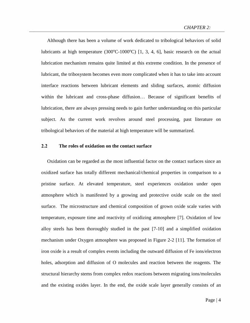
mechanism under Oxygen atmosphere was proposed in Figure 2-2 [11]. The formation of
iron oxide is a result of complex events including the outward diffusion of Fe ions/electron
holes, adsorption and diffusion of O molecules and reaction between the reagents. The
structural hierarchy stems from complex redox reactions between migrating ions/molecules
and the existing oxides layer. In the end, the oxide scale layer generally consists of an
CHAPTER 2:
Page | 5
innermost layer of FeO, a middle layer of Fe3O4 and an outermost layer of Fe2O3. The
layered structure of oxide scale has been widely reported during the hot rolling of steel [12,
13]. Since the oxide scale on the surface is exposed to the contact, their microstructure and
mechanical attributes are expected to play a significant role in the tribological behaviors.
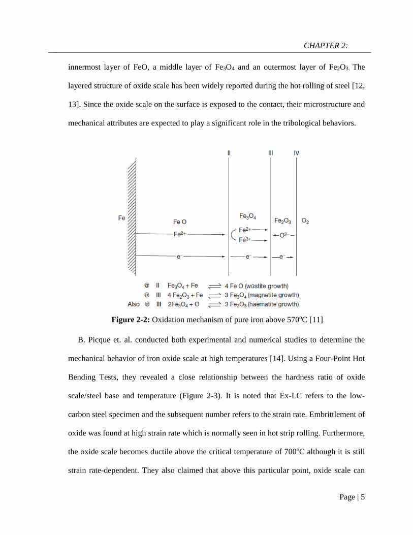
B. Picque et. al. conducted both experimental and numerical studies to determine the
mechanical behavior of iron oxide scale at high temperatures [14]. Using a Four-Point Hot
Bending Tests, they revealed a close relationship between the hardness ratio of oxide
scale/steel base and temperature (Figure 2-3). It is noted that Ex-LC refers to the low-
carbon steel specimen and the subsequent number refers to the strain rate. Embrittlement of
oxide was found at high strain rate which is normally seen in hot strip rolling. Furthermore,
the oxide scale becomes ductile above the critical temperature of 700oC although it is still
strain rate-dependent. They also claimed that above this particular point, oxide scale can
Figure 2-2: Oxidation mechanism of pure iron above 570oC [11]

CHAPTER 2:
Page | 6
demonstrate a high lubricity. Similarly, H. Echsler revealed a concrete dependence of
oxide flow stress on temperature and strain rate at 800oC-1000oC on mild steel [15]. The
decreasing flow stress could mean less frictional resistance of the oxide scale under
shearing at higher temperature. After conducting a large number of hot rolling
experiments, Utsunomiya et al. on the other hand assigned 850oC as the transition point
between brittle-ductile characteristics of the oxide scale [16]. By comparing different
studies, Krzyzanowski et al. [17] detailed plastic behavior variation of the oxide scale with
rolling temperature and reduction, as shown in Figure 2-4. It is conclusive that the
mechanical properties of oxide scale changes significant with temperature and process
parameters (rolling speed, reduction rate…).
Scale thickness also affects friction/wear behaviors in a certain manner. Luong et al.
found that thicker oxide scale induces lower friction coefficient in a simulated forging test
[18], although they also observed scale pick-up on the die surface which is perceived
detrimental. Likewise, a thicker oxide scale reportedly led to a lower friction coefficient in
the hot rolling steel [19]. However, Utsunomiya claimed that a thin and uniform oxide
Figure 2-3: Hardness ratio between oxide scale and steel substrate as a
function of temperature and strain rate by 4 point bending test [14]

CHAPTER 2:
Page | 7
scale (critical thickness is a function of temperature) is preferred since it created a defect-
free rolled surface [16], although there was no statement regarding frictional behaviors.
During the hot rolling of steel, the same author observed an increase in relative sliding
when the oxide scale thickens which subsequently results in ductile-to-brittle transition of
the oxide scale at 1000oC-1100oC [20]. As FeO generally takes up the largest proportion in
the oxide scale (FeO thickness is 90-95% of total oxide thickness at 800-1000oC [8, 10]), it
has received much attention regarding its intrinsic lubricity. A number of researcher
indicated that the hot ductility of FeO has a major contribution to the global brittle-to-
ductile transition of the oxide scale which leads to a defect-free rolled surface [16, 21].
However, others found negligible influence of FeO in the friction behavior [18]. In short,
findings about the tribological response of each individual iron oxide type remain
divergent.
Figure 2-4: Plastic behavior of oxide scale as a
function of temperature and reduction in hot rolling [17]

CHAPTER 2:
Page | 8
Frictional behaviors of oxide scale were investigated in numerous laboratory tribology
tests. Interrupted testing in combination with monitoring friction coefficient curve can
provide indications about the roles of oxide scale. By using a pin-on-disc configuration,
Vergne et al. found a firm correlation between the sliding friction coefficient and the
formation of the oxide transfer layer on the pin surface [22, 23]. A typical friction
coefficient curve between cast iron pin and AISI 1018 disc at 950oC is given in Figure 2-5.
During the running-in period, there are three stages with distinct frictional behavior. The
friction drop in the 2nd stage arises from the attrition act of the outgrown oxide scale while
the adhesion and wear particles aggregation is believed to trigger the subsequent jump in
friction (Stage 3). Zhu et al. revealed a similar pattern by testing mild-carbon steel disc
against a High Speed Steel pin [24]. However, they claimed that the spallation of
transferred oxide layer on the pin produces a growing friction after the initial drop.
There are other microstructural factors that can exert certain impact on the friction and
wear behaviors of oxidized steel surface. H. Kato explored critical roles of particles
Figure 2-5: Friction coefficient evolution of steel pair at 950oC
by pin-on-disc testing [22]

CHAPTER 2:
Page | 9
dimension on the wear rate on sliding pair of carbon steel (~0.45% wt. of C). A clear
transition from severe to mild wear regime is observed when the contact is supplied with
Fe/Fe2O3 particles with a diameter less than 0.5µm [25]. On the contact surface, the
formation of a protective oxide scale is considered as the origin for such favorable wear
transition. It is also evident that the tribo-oxide layer could also lose its efficiency at higher
load [26]. Although the above studies were conducted at room temperature, their
implications can be translated for a high-temperature contact since the oxide scale grows in
different grain size depending on temperature, steel grade and oxidizing atmosphere [7].
Alloying elements indirectly affects the tribological behaviors of parent steel by their
participation in the oxidation reaction. In brief, those active elements (Al, Si, Cr…)
preferably react with oxygen to form an interlayer on scale/base metal interface [7, 11].
This highly-adherent layer improves significantly the scale adhesion with the base metal
which reduces the detachment tendency of the oxide scale upon contact. Figure 2-6
illustrates the growth of layered oxide on steel with inclusion of active elements.
Figure 2-6: Schematic of diffusion-controlled growth of
multi-layered scales on alloyed steel at high temperature [11]
CHAPTER 2:
Page | 10
In lubrication research at room/moderate temperature, the surface chemistry plays a
very crucial role. It determines the reactivity towards lubricant elements/additives which is
regarded as the central part in the formation of the so-called tribofilm. At high temperature,
this aspect is often overlooked due to the limited amount of research related to lubrication.
Lubrication at high-temperature processing
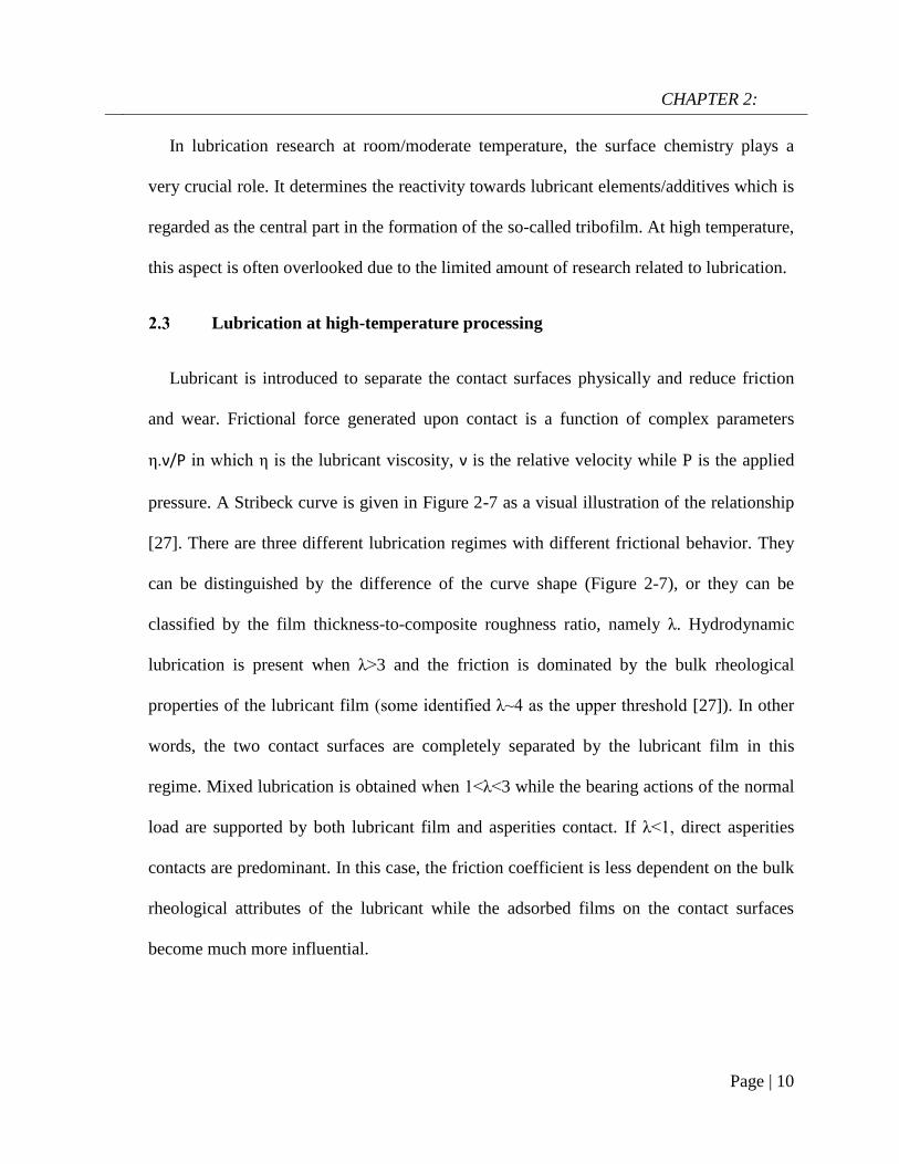
Lubricant is introduced to separate the contact surfaces physically and reduce friction
and wear. Frictional force generated upon contact is a function of complex parameters
η.ν/P in which η is the lubricant viscosity, ν is the relative velocity while P is the applied
pressure. A Stribeck curve is given in Figure 2-7 as a visual illustration of the relationship
[27]. There are three different lubrication regimes with different frictional behavior. They
can be distinguished by the difference of the curve shape (Figure 2-7), or they can be
classified by the film thickness-to-composite roughness ratio, namely λ. Hydrodynamic
lubrication is present when λ>3 and the friction is dominated by the bulk rheological
properties of the lubricant film (some identified λ~4 as the upper threshold [27]). In other
words, the two contact surfaces are completely separated by the lubricant film in this
regime. Mixed lubrication is obtained when 1<λ<3 while the bearing actions of the normal
load are supported by both lubricant film and asperities contact. If λ<1, direct asperities
contacts are predominant. In this case, the friction coefficient is less dependent on the bulk
rheological attributes of the lubricant while the adsorbed films on the contact surfaces
become much more influential.

CHAPTER 2:
Page | 11
The Stribeck curve was originally derived for journal bearings at room temperature
[27], however it can also have some significance for high-temperature tribology. In the hot
rolling of steel, there is often a combination of lubrication regimes due to the non-
conformity of contact surfaces. Figure 2-8 shows a cross-section of a roll bite in which
combined lubrication regimes can certainly exist [2]. The entry zone is often filled with a
relatively thick lubricant (hydrodynamic lubrication) while mixed/boundary lubrication are
likely found in the middle of the roll bite. As the strip temperature is very high (850-
1150oC), lubricant film experiences a certain degree of thermal decomposition/transition or
boiling upon contact with the strip surface. Thermally-activated reactions, adsorption and
diffusion will be accelerated under this extreme condition. Shearing actions on these
particular complex layers of material become complicated and often difficult to elucidate
fully.
Figure 2-7: A typical plot of Stribeck curve [27]

CHAPTER 2:
Page | 12
Oil-based lubricants
From 1960s, oil-based lubricants have been used worldwide in hot rolling of steel to
reduce rolling load and increase work roll lifespan. Their performance has been
demonstrated through a large number of research work. In general, an oil-in-water
emulsion is used since it is more cost-efficiency and delivers cooling effect on the roll. By
conducting hot rolling of AISI 1018 steel at 850oC lubricated by water, neat oil and oil-in-
water (1:1000) emulsion, Shirizly et al. found that the use of either neat lubricant or
emulsion reduces the mill load significantly [28, 29]. At low reductions (<30%), the use
of lubricant or emulsion decreased the roll force from 15% to 50%. In addition, they also
revealed insulating capacity of the lubricant, although it appeared difficult to define the
exact optimal oil-to-water ratio. Imae et al. surveyed the effects of emulsion concentration
on the rolling load reduction in laboratory rolling test of carbon steel (with a reduction of
Figure 2-8: Coexistence of multiple lubrication regimes at the role bite during
hot rolling of steel [2]

CHAPTER 2:
Page | 13
50% and a rolling speed of 100m/min). They found that a higher emulsion concentration
leads to more reduction in the rolling force [30]. Azushima et al. carried out an in-depth
study on the lubricity of a wide range of natural and synthetic oil on sliding-rolling tribo-
simulator at 800oC while effects of additives/lamellar solid materials (graphite, MoS2,
mica) were also investigated [31, 32]. They found an optimal concentration for most
lubricants to be 1% regardless of lubricant composition, at which the rolling friction
remains relatively low (~0.15). The same authors later proposed two lubrication
mechanisms for the optimal oil/water ratio, one above the optimal ratio and one below it.
The effects of oil additives on the lubrication performance were rarely reported in hot
rolling of steel. Nevertheless, some suggested a strong dependence of lubricity on the
operating temperature (up to 500oC), as shown in Figure 2-9 [33]. Despite showing
significant benefits, the thermal decomposition of oil-based lubricants at high temperature
might impose some drawbacks [1, 3, 4].
Figure 2-9: Working temperature range of additive
elements [33]

CHAPTER 2:
Page | 14
Solid and other lubricants
Apart from dissolvable additives, solid materials have been often formulated in
lubricant composition for enhanced performance. Two-dimensional materials gain wide
recognition due to their superb lubricity which stems from their low shearing strength.
Graphite has been considered the most popular that is stilled used in hot metal forming
processes (up to 500oC) [34, 35], although lately it becomes more restricted due to
environmental concerns [33, 34]. Other candidates can have similar lubrication potential
such as transition metal dichalcogenides (WS2, MoS2), hexagonal Boron Nitride (hBN),
mica and talc [35, 36]. In general, the 2D materials are dispersed into an aqueous/water-
based form to facilitate their application. A. Petrov at el. [37] used ring-compression tests
to evaluate the properties of several water-based colloidal lubricants containing either
graphite or MoS2. They found that friction coefficient is reduced and die life is
significantly increased (by 10%) in the presence of graphite-based lubricant compared to
the base lubricant. G. Ngaile [38] investigated the lubrication mechanism in warm forging
of aluminum by using two variants of BN-silicone lubricants. While the siloxane is
believed to provide hydrostatic/hydrodynamic lubrication, BN acted as a barrier film that
reduced friction at 260oC. The lubrication mechanism drastically changes at 370oC where
the depolymerization of siloxanes lead to the formation of SiO2, this eventually combined
with BN provide a low shear strength layer. However, most 2D materials lose their
intrinsic lubricity above 500oC due to thermal degradation, particularly under air
atmosphere. For instance, graphite is prone to burn at 450oC while MoS2 decomposes to
CHAPTER 2:
Page | 15
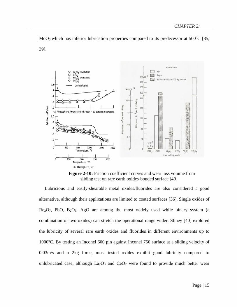
MoO3 which has inferior lubrication properties compared to its predecessor at 500oC [35,
39].
Lubricious and easily-shearable metal oxides/fluorides are also considered a good
alternative, although their applications are limited to coated surfaces [36]. Single oxides of
Re2O7, PbO, B2O3, AgO are among the most widely used while binary system (a
combination of two oxides) can stretch the operational range wider. Sliney [40] explored
the lubricity of several rare earth oxides and fluorides in different environments up to
1000oC. By testing an Inconel 600 pin against Inconel 750 surface at a sliding velocity of
0.03m/s and a 2kg force, most tested oxides exhibit good lubricity compared to
unlubricated case, although La2O3 and CeO2 were found to provide much better wear
Figure 2-10: Friction coefficient curves and wear loss volume from
sliding test on rare earth oxides-bonded surface [40]

CHAPTER 2:
Page | 16
resistance (Figure 2-10). In addition, the lubricating oxides perform much better in air
atmosphere than H2 atmosphere.
Calcium carbonate submicron-particles were reportedly studied as a lubricant additives
in hot rolling oil [41]. Naoshi et al. conducted hot rolling of stainless steel (SS440 and
SUS444) at 900oC-1000oC with a rolling speed of 0.24m/s, they found that increase in
Calcium carbonate content results in a significant drop in the rolling force (shown in
Figure 2-11). The effect of CaCO3 particles size was also investigated by testing two
lubricants: a semi-fluid type (ST) with a particle size of 1µm and a fluid type (FT) with a
particle size of 15nm. It was found that micron-scale particles outperform nano-scale
particles in term of rolling force reduction and anti-seizure performance (Figure 2-11).
Likewise, TiO2 nanoparticles demonstrated a good lubricity properties in laboratory hot
rolling of steel, significantly reduced rolling load and produced a better surface finish [42-
44]. N. Ikeda proposed a concept of using high molecular compounds and bonding agents
to create an in-situ pseudo lubricant film which can provide an effective lubrication. The
compound is extremely viscous when water evaporates [45]. Figure 2-12 shows the
working principle of the high molecular lubricant in hot forging [34]. Likewise, Dubois et
Figure 2-11: Rolling force/reduction rate from hot rolling of stainless steel
lubricated by CaCO3-added oil and the size effect on anti-seizure performance [41]

CHAPTER 2:
Page | 17
al. [46] tested a range of “white lubricants” which basically contains water soluble high-
molecular weight polymers and other additives on Warm and Hot Upsetting-Sliding tests
to simulate forging contact (maximum contact pressure of 400MPa). They found that the
use of “white lubricants” lead to a friction coefficient similar to graphite-based lubricant,
however they lose their efficiency as sliding length increases above 10mm.
Melt lubricant
It has been demonstrated that temperature plays a great role in determining the working
range of any type of lubricant. This arises from the thermal stability of each class which
closely depends on the molecular structure and reactivity with atmosphere. Figure 2-13
summarizes the working temperature range of typical lubricant classes from sub-zero
degree to over 1000oC [47]. At the extreme end, only the viscous products that can
function effectively are alkali phosphates and glasses. These materials gain lubricity when
they transition into viscous melt above their melting point. One of the most remarkable
Figure 2-12: Proposed working mechanism of high polymer
compound in hot forging [34]

CHAPTER 2:
Page | 18
features of glass-based lubricant is the ability to tune the working range by manipulating
chemical composition.
In general, a typical glass lubricant is formulated by three major constituents and other
minor components as shown in Figure 2-14. The major composition includes alkaline (or
alkaline earth) oxides, glass-forming compounds (poly-oxides) and multi-valent metals
(Fe, Zn, Mo…). In addition, minor components such as modifiers, binders or coupling
agents are often found to improve the overall performance. According to Schey [47], glass-
forming compounds are regarded as the building block of glass melt with P2O5, B2O3 and
SiO2 being the representatives. With a high molecular connectivity, they provide polymeric
natures and high melting point for glasses. The inclusion of alkaline (alkaline earth)
elements enables active adjustment to both the melting point and viscosity while multi-
valent elements are meant to increase the cross-linking which enhances mechanical
Figure 2-13: Working temperature range of different lubricant classes
in air atmosphere [47]

CHAPTER 2:
Page | 19
attributes of the glass. Despite the great potentials of these lubricants, past research on melt
lubrication was often empirical and lacks a systematic approach.
Brief review
Roger investigated the lubricity of a series of glass in hot extrusion and claimed
beneficial effects associated with the softening lubricants [48]. Kaplakjian summarized
widely accepted glasses of silicate and borate family with varying composition and
corresponding extrusion temperature [49]. By studying the effects of a series of soda lime
and borosilicate glass on the hot extrusion of stainless steel at 1000-1200oC, Gupta found
that only a subtle change in the glass composition can affect its flowability despite having
the same melting point [50]. Kovalev [51, 52] proposed a variety of glass composition
(predominantly sodium silicate) which can deliver an effective lubrication and desired
oxidation resistance in hot forging and stamping while some of them can be applied by
means of water-suspension. A complex glass (including borax, binder and other additives)
was reportedly used in plastic forging of Ti-alloy at 1050oC and demonstrates remarkable
protective effects [53]. Li et al. [54] revealed a firm dependence of friction coefficient on
temperature and strain rate by means of ring compression test lubricated by a glass with a
Figure 2-14: Typical composition of glass lubricant

CHAPTER 2:
Page | 20
softening point of 740oC. They found that the friction coefficient reduces with temperature
while it remains insensitive to strain rate at temperature below 950oC. During the hot
extrusion of a stainless steel tube, glass lubrication is found to be in hydrodynamic
condition which is manifested by a close relationship between the friction coefficient and
the melt viscosity [55].
Besides publications and technical notes, the use of glass melts in hot metal forming
processes have been widely mentioned in patents. Table 2-1 summaries a number of past
patents that investigated glass lubrication for a wide range of applications with details
related to chemical composition. The roles of each component were occasionally
discussed, although the statements were hardly backed with evidence. Likewise, friction
and wear reduction resulted by the glass lubricants were sometimes mentioned, but mostly
not in a quantitative way. Some information was not available in the original written
record.
Figure 2-15: Glass composition and dependence of friction coefficient on
glass viscosity at 1373K [55]

CHAPTER 2:
Page | 21
Patent number Working
Temperature range (oC)
Load/ pressure
range Compositions Tribotest types Applications Notes
Dispersive medium
US3186945 ~1000 Multicomponents lubricant: Alkali
oxides/phosphate + divalent metal phosphate and borate
Forming austenitic steel tubes, metal
rolling
Alkaline cations: make polyphosphate dissolved in water. Polyphosphate: act
as lubricant Water
Preferable composition: 50-90% alkali metal
phosphate, 10-50% alkali borate and balance potassium phosphate
Viscosity of 10% solution: 8-10 cP at 50oC
Preferable
WO 92/01050 899-1149
Composition: glass powder, binder, rheological agent, weetting and viscosity modifie. Glass frit viscosity 102 ~ 104 P at 900~1150C, softening
point 650C with particle size 150micron~ 0.5mm (Al2O3 + PbO + MgO +CaO +Na2O +SiO2). Rheological agents: BN, Ni,Cr2O3
·
Forging operation, titanium alloy at 950C-1000C,
aerospace engines
Glass powder: principle lubricant. Binder: improve surface adhesion.
Rheological agents: control liquid flow of glass lubricant, supports the load
and prevent asperities contact.
Water
EP2014747A1 ~1200
Glass frits composition: first glass frit (SiO2, Al2O3, CaO and optional MgO, ZnO, K2O),
second glass frit, dispersion-suspension agent, other components. Glass frits are different in
softening temperatures
Actual production line of seamless steel pipe (with
temp. over 1200oC)
Metal working Each glass frit has corresponding softening point to maintain desired
viscosity and adherence Clay
US2010029818 700-1300
Glass frits composition: calcium phosphate, fatty acid or fatty acid salt, boric acid and
akaline metal phosphates with mean grain size <150 micron
Actual production line of seamless pipe (with temp.
over 1200oC)
Hot metal processing
Calcium phosphate: suitable trickle flow at high temp Fatty acid: lump formation inhibitor. Boric acid: improves uniform distribution and reduces scaling. Alkali
phosphate: contribute to scale dissolution. Small grain size: favor flow
characteristics
Not mentioned
JPH1192169 1000-1300 Lubricant composition: SiO2, Al2O3, B2O3,
alkaline earth metal oxides, alkali metal oxides, P2O5
Hot extrusion
SiO2: glass skeleton. Al2O3: prevent characteristic change due to phase
separation. B2O3: melt generated scale on surface. Metal oxides: achieve vitrification.P2O5: lower viscosity
Not mentioned
US8846152B2 600-1300
Glass frits composition: high melting point (m.p) frit (SiO2, Al2O3, CaO and optional MgO, ZnO, K2O), medium m.p frit, low m.p frit and other
components
Mannesmann pipe making process
Anti-scaling in metal production
Each glass frit has corresponding softening point to maintain desired
viscosity and adherence Water
NASA TN103776
~900 Composition: BaF2/CaF2 eutectic was plasma sprayed to form self-lubricating mechanism
Tested on pin-on-disk tribometer in
air, H2 and He
Glass forming, metal working, rotary
engines, bearings.
NASA TND7556 ~900 5000psi Composition: (1) Nichrome-glass, (2)
Nichrome-glass-CaF2 associated with plasma sprayed coating
Tested on pin-on-disk tribometer in air, bearing test
Aerospace applications

CHAPTER 2:
Page | 22
EP0611817A1 700-1100 50kg/m
m2
Composition: graphite with preferable size of 0.5~30 micron, selected metal oxides
(TiO2,PbO, ZnO, CaO,Al2O3) with particle size of 0.01~20micron
COF test and carburizing test
Hot plastic working
JPH07118687 1100-1200
Composition: graphite, water soluble polymer of iron oxide with 10um, glass powder with viscosity of 1000P at 1000C (SiO2, B2O3,
Al2O3...)
Mannesmann-mandrel mill
method
Seamless steel pipe and alloy steel manufacturing
Water
JPH11166188 1000 200g/m2 Composition: alkaline earth metal borate (Ca,
Ba, Mg, Na salt) with preferable particle size of 2-20um or more preferably 5-15um.
Rolling cylinder Seamless steel pipe Water
JPH05271684 1000 98N/mm
2
Composition: metal oxide powder with preferable particle size of 20-60um. Sodium
silicate Rotating cylinder Water
US8082767 1000-1300 Composition: combination of lamellar silicate,
sodium borate, alkali carbonate
5 stand full retractable
mandrell mill
Seamless steel pipe manufacturing
Water
US5691282 800-1300
Composition: Glass powder, glass frit, graphite, alkali metal silicate, water soluble Na polyphosphate, water in-soluble Na
polyphosphate, thickener: polysaccharide, borax. Preferred viscosity at 25oC: 1000-
7000MPa.s
Adhesive ability, film forming ability and mechanical strength at 800-
1050C
Hot metal forming
Glass powder: chief component for lubricity (preferred size<100um), glass
frit: maintain film-forming property (<100um), graphite (<100um): excellent
lubricity, alkali silicate: binder, Na metaphosphate: avoid foam forming,
thickener: maintain viscosity and lubricant dispersion, borax: coupling
agent
Water
US 3254401 ~1370 Composition: Outer harder glass with >94%
SiO2, inner softer glass: SiO2-Na2O-K2O-CaO-MgO-Al2O3
Oxidation test at 1200C
Hot working operation
As inner softer glass fuses forming protective layer overlying metal surface, outer glass cloth held inner glass from flowing away. As outer harder glass fuses and dissolves into first glass,
viscosity increase and reduce flowing-out tendency
Water
US 4228670 ~1000 Composition: SiO2, Na2O, CaO, predominant
B2O3, Al2O3 with preferred diameter of less than 1um
Spraying onto metal surface at 4-
5 bar pressure Forging, pressing
US 4402838 >1000 Composition: silicate, phosphoric alkali salt,
borate
Forging and extrusion
Water
US 5242506 >1000
Composition: glass powder with preferred size >30um (Al2O3, PbO, MgO, CaO, Na2O, SiO2), binder, rheological agent, wetting and viscosity
modifier
Forging and
extrusion
Glass powder: provide principle lubricity, binder: forming mechanical bond with surface, rheological agent: control the flow and prevent asperities
contact
inorganic compounds:
xylene
US 3293894 1500-2200F Composition: SiO2, B2O3, Na2O Tube drawing

CHAPTER 2:
Page | 23
US 4096076 ~1800F Composition: BN, glass frits (B2O3, SiO2, CoO),
binder Forging
BN: provide lubricity, Glass frit: protect BN and form low shear film, CoO: binding agent increase adherence
inorganic compounds:
xylene
US 3357220 ~1800F Composition: SiO2, B2O3, Na2O, Al2O3, K2O.
Ground to fine powder Oxidation test at
1800F Oxidation protection
US 4358544 800-1000 Composition: SiO2, B2O3, Na2O, CaO, Al2O3
with average size of 20-30um, desired viscosity of 104P at working temperature
acrylic acid,
xylene
US 8863564 700-1200
Composition: 2 glass frits with different content of SiO2, B2O3, K2O, CaO, Al2O3 and desired viscosity of 103-106P at 700-1200oC, friction
controlling agent and others
Rolling test Hot rolling process Each glass frit has corresponding softening point to maintain desired
viscosity and adherence
Organic solvent: acrylic or
ester. Possibly inorganic
powder like bentonite
GB 1359430 ~1100 Composition: P2O5, B2O3, Na2O, K2O, Al2O3
and other optional metal oxides Extrusion, piercing Hot forming metal
Water/ highly dispered
silica
US 4402838 >1000
Forging pressure:1000-1600 tons
Composition: (1) P2O5, B2O3, Na2O, K2O. (2) Synthetic or natural silica with layered structure
suspended in water Forging, extrusion Water
US 5983689 850-1000 Composition: alkali silicate, silane coupling,
alkali compound (carbonate, borate, hydroxide, salt), possibly iron oxide
Seamless steel pipe Water
US3248234 ~1000C Composition: P2O5, Al2O3, alkali oxides alloy drawing alkali oxides: change fusibility,
tendency toward devitrification, B2O3: increase chemical stability
US 8863564 1200-1300 Composition: first glass frits, second glass frits containing SiO2, Al2O3, CaO, optionally MgO,
ZnO, K2O Hot metal working
1. Glass frits with different softening point to provide adaptive viscosity 2.
first glass frit viscosity 103-106 dPas at 1200oC, second glass frit viscosity 103-106 dPas at 700oC 3. Using controlling agents 4. Can be either used as solid
or liquid component atroom temperature
Water/ using dispersion agent like
clay, bentonite and
organic solvent like acrylic acid
ester
US 6177386 1100-1300 Composition: graphite, phosphate mixture, bentonite, sodium silicate, silico-phosphate
Hot metal working

CHAPTER 2:
Page | 24
US 5437802 800-1200
Composition: (A) solid powder of condensed phosphoric acid salt: KPO3, NaPO3, K4P2O7, sodium silicate, chromic acid salt, halides.(B)
inorganic powder: BN, Si3N4, amorphous carbon, K3PO4, Ca3(PO4)2, bentonite, SiO2,
ZnO.
Hot rolling process heat insulating agent (A) with excellent
heat conductivity
US 4052323 >900
Composition:(1) graphite, alkylene homopolymer or copolymer, dispersive agent
(2) graphite, alkylene homopolymer or copolymer, auxiliary suspension agent, film
stabilizer
Water
US 3390079 >900 Composition:B2O3, SiO2, Na2O, CaO, Al2O3 Hot extrusion Desired viscosity 102-103 poise at
working temperature Water
US 3379642 ~1000 Composition: melamine phosphates, possibly
graphite, MoS2, BN Hot extrusion
Desired viscosity 102-103 poise at working temperature
Water
JPH 10121088 800-1200
Composition: oxide-based layered materials (white mica, kaolin, pyrophyllite), binder (B2O3 and Boron derivaties), metal hydroxide (Ti, Mg,
Si, Al…)
Mannesmann stage
Oxide-based layered materials: provide lubricity at high temperature, binder:
provide uniform dispersibility of lubricating agents, metal hydroxide:
avoid carburization
Water
US 3368970 1000 Composition: condense phosphate (pyro/poly),
alkali metal oxides, ferric oxide, Al2O3
Extrusion of seamless steel
tubes
Silicate results in high degree of wear and tear of the work tool. Using
combination of Fe2O3 and (KPO3)n reduces wear, friction and increases
lifespan of the work tool
Water
US 3179524 1000 Composition: alkali metal polymetaphosphate Water
JP-A-7-303915 1100-1200 Composition: CaO(10-25%), Al2O3(3-10%),K2O(10-30%), balanced SiO2
Hot extrusion CaO: reduces viscosity, Al2O3:
imparting agent, K2O,Na2O: viscosity adjustment
JP2011-121095 1080-1170 Composition: SiO2-Al2O3-B2O3-CaO
Hot extrusion
JP 2015-071521 1100-1250 Composition: SiO2:47.2-64.8%, B2O3:4.2-11%, Al2O3:8.0-17.6%, MgO: 1.6-3.5%. Sum of Na2O
& K2O: 11.0-17% Hot extrusion
B2O3 dissolve scale, SiO2 may dissolve but not sufficiently than B2O3
JP 2010-234375 1000-1250 Composition: <20% B2O3, Na2O, K2O, SiO2 Hot extrusion Iron oxide melts into the glass, the oxidation of steel surface by glass
increases lubricant adhesion
JP 2010-227997 1000-1250 Composition: 12-30% alkali oxides, total
Al2O3,CaO, MgO:20-40%,<25% B2O3, balanced SiO2
Hot extrusion
Alkali metal oxides are responsible for lubricant adhesion. Al2O3, CaO, MgO exhibit reducing behavior. Na2O has more oxidizing capacity than K2O
JP 2003-113387 800-900 Composition: glass lubricant with 150-200
mesh size particles. Hot extrusion Application viscosity: 300-100Pas
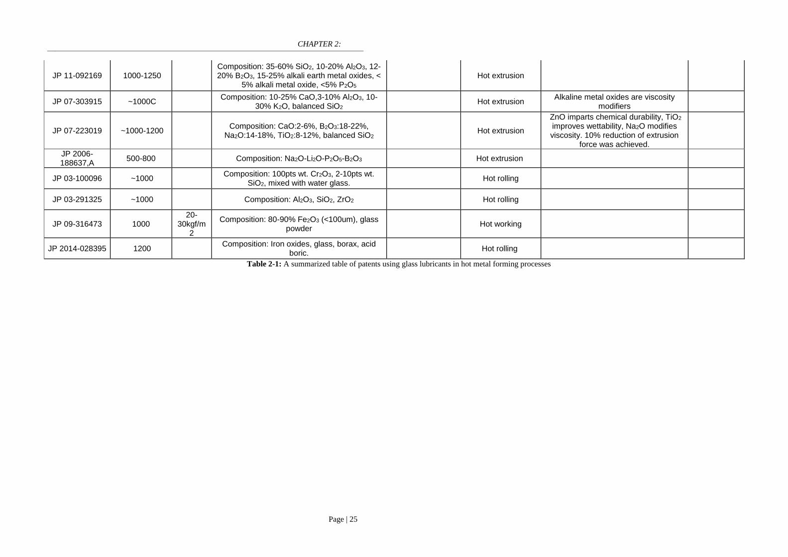
CHAPTER 2:
Page | 25
JP 11-092169 1000-1250 Composition: 35-60% SiO2, 10-20% Al2O3, 12-20% B2O3, 15-25% alkali earth metal oxides, <
5% alkali metal oxide, <5% P2O5 Hot extrusion
JP 07-303915 ~1000C Composition: 10-25% CaO,3-10% Al2O3, 10-
30% K2O, balanced SiO2 Hot extrusion
Alkaline metal oxides are viscosity modifiers
JP 07-223019 ~1000-1200 Composition: CaO:2-6%, B2O3:18-22%,
Na2O:14-18%, TiO2:8-12%, balanced SiO2 Hot extrusion
ZnO imparts chemical durability, TiO2 improves wettability, Na2O modifies viscosity. 10% reduction of extrusion
force was achieved.
JP 2006-188637,A
500-800 Composition: Na2O-Li2O-P2O5-B2O3 Hot extrusion
JP 03-100096 ~1000 Composition: 100pts wt. Cr2O3, 2-10pts wt.
SiO2, mixed with water glass. Hot rolling
JP 03-291325 ~1000 Composition: Al2O3, SiO2, ZrO2 Hot rolling
JP 09-316473 1000 20-
30kgf/m2
Composition: 80-90% Fe2O3 (<100um), glass powder
Hot working
JP 2014-028395 1200 Composition: Iron oxides, glass, borax, acid
boric. Hot rolling
Table 2-1: A summarized table of patents using glass lubricants in hot metal forming processes

CHAPTER 2:
Page | 26
Oxidation-resistant capacity is also a valuable characteristic of glass-based lubricants.
High-temperature oxidation results in the formation of oxide scale which can be considered
as material losses and cause many other concerns. For example, about 30% of the yield
loss stems from oxide scale-related defects according to the Iron and Steel Institute of
Japan [56]. Glass-based coatings have been widely used to enhance corrosion resistance of
various alloys at elevated temperatures [57-67]. In hot rolling mill, Riaz et al. [68]
proposed a management strategy to suppress oxide scale during re-heating stage by using
glass coatings. The application of glass coating resulted in a remarkable reduction in oxide
growth. A range of coating composition is given in Figure 2-16 and the corresponding
working mechanism of each type is shown in Figure 2-17. Apart from friction and wear
reducing-effects, the anti-oxidation capacity of glass compounds lubricants makes them a
potential fit for high-temperature lubrication.
Figure 2-16: Type of coatings in reference [68]

CHAPTER 2:
Page | 27
Glass-like lubrication at low temperature
Glass-like lubrication has been reported at low temperature range. Zinc
Dialkyldithiophosphate (ZDDP) is regarded as the most successful oil additive and has
been broadly recognized in modern tribology history. It is often formulated in engine oil
and many other industrial lubricants due to their exceptional wear resistance. Research has
shown that after experiencing complex tribological reaction, ZDDP generally forms a
glass-like tribofilm which is mainly constructed from polyphosphate backbones. From the
macroscopic point of view, ZDDP generally has a patchy and gradient-like structure with
long-chain polyphosphate overlying short-chain phosphate network (as shown in Figure 2-
18) [69, 70]. Beside the wear-reducing effect, ZDDPs is also known as an excellent
oxidation inhibitors due to their ability to decompose hydroperoxides radicals throughout a
complex chemical reactions [69]. The amorphous nature of ZDDP tribofilm renders low-
shearing stress which results in low frictional force upon contact [71-73].
Figure 2-17: Working principles of each coating type [68]

CHAPTER 2:
Page | 28
Hard-soft-acid-base theory has been extensively used to elaborate the formation
mechanism of ZDDP tribofilm on ferrous contact surfaces [69, 74]. A combination of
computational studies and advanced analytical techniques also indicated complex
mechano-chemical reactions including wear particles digestion, depolymerization and
polymerization of phosphate network [75-77]. Other metal polyphosphates also received
attentions regarding their tribological behaviors. Gauvin [78] investigated pure α-
Zn3(PO4)2 crystalline powder whose structure changes greatly to achieve favorable friction
and wear responses. While investigating a number of bulk polyphosphate glass, Spender
found that the depolymerized-glassy film favored friction and wear reduction [79]. V.I
Kolesnikov [80] proposed an anti-wear and anti-scoring additives in plastic greases used
for heavily loaded railway which primarily composes of hetero-molybdophosphate
NaPMoO6. Later, Lithium molybdophosphate was proved effective in Puma lubricating oil
[81]. In addition, a series of binary metal polyphosphates were found to improve
tribological performance of Puma and Buksol lubricants [82, 83]. Adaptive molecular
transformation, elimination of oxidizing agents and active adsorption are suggested to be
Figure 2-18: Compositional gradient within a ZDDP-originated tribofilm [69]

CHAPTER 2:
Page | 29
the principle mechanism of this family of polyphosphate-based lubricant (Figure 2-19) [84,
85].
Glass-like lubrication at high temperature
While research on glass-like lubrication received plenty of attention at low/moderate
temperature, there has been fewer work carried out at high temperature. Matsumoto
investigated tribological performance of water-glass (silicate based) by means of pin-on-
disc testing at maximum temperature of 1200oC [86]. They found a strong correlation
between the friction coefficient and the glass viscosity while the effects of amorphous
graphite addition were also illustrated (Figure 2-20). However, no further implications
regarding wear reduction and chemical analysis on the worn area were provided. Wan et al.
published a review work on the application of inorganic polymer in high temperature
tribology and indicated the potential lubrication performance of such class in hot metal
forming processes [2].
Figure 2-19: Structural transformation in Lithium Phosphorowolframates [84]

CHAPTER 2:
Page | 30
Tieu et al. studied tribological response of an alkaline polyphosphate by means of pin-
on-disc testing on steel pair [87, 88]. The polyphosphate composite compound delivers
exceptional friction- and wear-reducing effects on the sliding surfaces. A hierarchical
structure of the tribofilm was revealed with phosphate melt penetrating deeply into the
oxide scale bulk while chemical analysis indicated strong reactions between polyphosphate
and iron oxide surface. Later, the compositional complexity of the Na/K polyphosphate
tribofilm was resolved by a combination of advanced chemical analysis [89] (Figure 2-21).
The lubricant was also capable of reducing rolling force in actual hot rolling of Interstitial-
Free (IF) steel, up to maximum 25% compared to unlubricated case. Cui et al. [90]
determined the roles of starting molecular structure on tribological behaviors of a range of
different Na polyphosphates (orthophosphate, pyrophosphate and metaphosphate). He
found that the short-chained polyphosphate lead to a superior frictional and wear behavior
Figure 2-20: Friction coefficient as a function of load and amount of
graphite inclusion in water glass lubrication [86]

CHAPTER 2:
Page | 31
which is quite contrary to what established previously. The lubrication performance of
sodium polyphosphate was also justified in laboratory hot rolling of mild-carbon steel [91].
There were also substantial simulation works to substantiate the working mechanism of
alkaline polyphosphate melts at high temperature. Ta et al. [92] used Density Functional
Theory (DFT) calculations to understand the chemical absorption route of pyrophosphate
(Na4P2O7) and orthophosphate (Na3PO4) (at 1073K). They found that Fe-O-P linkage is
accountable for the absorption while Na4P2O7 was shown to have a stronger binding
towards both Fe and Fe2O3 surfaces than Na3PO4. Later, Le et al. [93] demonstrated the
bonding nature of P-O, Na-O and Fe-O linkages on the immediate interface between
pyrophosphate/triphosphate and iron oxide (Fe2O3). The study illustrates the important role
of iron oxide in the decomposition process of phosphate network. The adsorption behavior
of a sodium pyrosilicate (Na6Si2O7) was also studied in-depth at higher temperature range
(maximum 1500K) [94].
Figure 2-21: Compositional gradient of Na/K polyphosphate tribofilm [69]

CHAPTER 2:
Page | 32
Research scopes
As stated previously, there are three glass-forming compounds upon which melt
lubricant is generally formulated: phosphate, borate and silicate. While phosphate and
silicate melts have been investigated thoroughly (particularly phosphate), borate melt
received little attention although it has been often included in the lubricant composition for
hot metal processing (Table 2-1). Even in the patents that included borate, there were lack
of detailed analysis to elucidate the exact function and working mechanism of the material.
The current work sets to provide a fundamental understanding about the tribological
behaviors of alkaline borates and explore their lubrication potential in the hot rolling of
steel which is unprecedented.
The friction and wear characteristics of sodium borate are studied on sliding
steel surfaces at elevated temperatures. Microstructural and chemical
characteristics of borate tribofilm are unveiled in details. Experiments are also
designed to distinguish thermally-activated reaction and mechanical-chemical
reaction.
The roles of each individual element in borate melt (alkaline element and boron
oxide) on the collective lubrication performance are highlighted. This
unprecedented piece of understanding allows a better control over lubricant
fomulation to fit a specific working circumstance.
The tribological behavior of sodium borate is investigated in rolling contact.
While the passivated rolling module is not entirely representative of actual hot

CHAPTER 2:
Page | 33
rolling, the interactions between lubricant and oxide scale under such condition
are fully characterized.
Synthesis of potassium borate is carried out and their tribological behaviors are
also determined. Working range of individual alkaline borate is then deduced.

CHAPTER 3:
Page | 34
CHAPTER 3:
Experimental methodology and characterization
This chapter describes experimental apparatus and analytical instruments used thorough
the study. A brief introduction regarding working principle, technical specifications is also
included.
High-temperature tribometer
Sliding and rolling contacts are simulated by using high-temperature tribometers under
controlled conditions.
Ball-on-disc
Friction tests are extensively conducted on a Bruker CETR UMT2 tribometer which is
capable of testing up to maximum temperature of 1000oC. Ball-on-disc is the mainly used
configuration in this study. A 2-dimensional DFH load cell has a minimum force
resolution of 10mN while the maximum normal load achievable is 200N. Upper linear
stage enables precise positioning down to 1µm. Lower rotary spindle can operate in range
of 0.001 to 5000rpm. Both normal and lateral forces are simultaneously recorded by an
integrated program (UMT) during the friction test. Tests are performed via designed scripts
which allow automated movement of each component. The system provides a highly
precise acquisition of friction force with good repeatability. In case of lubrication testing,
the lubricant is introduced to the disc through a steel tube with an inner diameter of 2mm.
A simplified sketch of the tribometer is given in Figure 3.1.

CHAPTER 3:
Page | 35
Roller on flat
A state-of-the-art Bruker UMT3 was used to simulate the rolling contact at high
temperature. It is an upgraded version of the UMT2 with additional utilities, particularly in
flexible testing configuration. The module not only allows conventional rotary testing (e.g.
ball-on-disc), but also reciprocating testing at high temperature (maximum 1000oC). The
roller-on-flat is built on the reciprocating unit in which the roller specimen is heavily
pressed against the lower flat specimen under back-and-forth reciprocating motion.
Although the unit is not able to represent the actual hot rolling condition, high contact
pressure during free rolling contact can generate useful insights into the surface-related
phenomenon. A detailed apparatus configuration will be provided in Chapter 8.
Analytical methodology
Advanced characterization methods used throughout this study are described below,
although there will be some minor tools that are also mentioned when needed.
Thermal analysis
Figure 3-1: Simplified schematic of the high-temperature tribometer
UMT2

CHAPTER 3:
Page | 36
High-temperature thermal behavior of interested lubricant was studied by a combination
of high-temperature Laser Confocal Microscope (LCM) and Thermal Gravitational
Analysis and Differential Scanning Calorimetry (TGA/DSC). In-situ LCM allows a real-
time observation of surface oxidation, melting, phase transformation under controlled
environments at high temperature [95].A schematic illustration of the LCM is shown in
Figure 3-2. The specimen is focally heated by a 1.5kW-halogen lamp while the upper CCD
camera captures at 25 frames per second and stores into a video file. The instrument allows
a direct observation of the lubricant transition close to its melting point.
TGA/DSC is a popular thermo-analytical technique to study thermal behavior of
materials. The instrument is capable of detecting melting, oxidation, recrystallization due
to the change that is associated with the heat flux of each occurrence, e.g. melting requires
energy in form of heat while recrystallization releases energy in the form of heat. In this
study, a NETZSCH STA 449 DSC was used and a Rh/PT crucible was chosen for the
experiment. The specimen is heated at a rate of 10oC/min under pure Argon gas.
Figure 3-2: Cross-sectional schematic of the high temperature LCM
and the specimen shape

CHAPTER 3:
Page | 37
X-ray diffraction
A GBC MMA Diffractometer with a Cu Cu-Kα source and a step size of 0.02o was used
to determine crystallite structure of interested compounds. The operating voltage and
current of X-ray was set at 35kV and 28.6mA, respectively. The received patterns were
processed by HighScore Plus with a data base of Powder Diffraction Files (PDF) 4+ 2018.
Nanoindentation
Mechanical properties of steel components were determined by a Hysitron
Triboindenter TI950. The instrument is calibrated using a standard Quartz specimen with
known Hardness and Young modulus. It is equipped with a Berkovich tip with an apex
radius of 150nm, this allows an accurate measurement on carbides precipitates in High
Speed Steel material (in Chapter 6, 7 and 8).
3D Interferometer
Surface topography measurements were made using a 3D Interferometer Optical
Microscope (Bruker Contour GT-K). Typical design of the instrument is given in Figure 3-
3. The measurement is carried out based on the analysis of interference between the
reference wavefront and the reflected wavefront from the sample surface. The output
consists of raw quantified data which can be subjected to further processing if necessary.
The instrument also enables graphical representation from 3D data set and generation of
2D profiles. On the disc, wear loss volume was calculated by measuring the cross-sectional
area of the wear track at 4 different points. In this work, wear loss volume is reported.
Table A-4 to A7 (Appendices) refer to specific wear rate.

CHAPTER 3:
Page | 38
Scanning Electron Microscope (SEM)
Microscopic imaging of sample surfaces was extensively carried out by a JOEL JSM-
6490LA Scanning Electron Microscope (SEM). The instrument is equipped with a 30kV
conventional tungsten filament and adjustable operating pressure. It has a maximum
resolution of 3.5nm at 30kV with 2 main detectors: Secondary Electron (SE) detector and
Backscattered Secondary Electron (BSE) detector. The 80x80mm2 SSD Energy Dispersive
X-ray (EDX) detector allows a rapid quantitative microanalysis and precise elemental
mapping. Microanalysis processing is performed on an integrated Aztec Oxford software
suit.
Figure 3-3: Typical design of optical interferometer

CHAPTER 3:
Page | 39
Focus Ion Beam Microscope (FIB)
In this work, Focus Ion Beam Microscope (FIB) was mainly used as a sectioning tool to
produce a high quality electron-transparent specimen for Transmission Electron
Microscope (TEM) work. A FEI Helios NanoLab G3 CX [96] is equipped with Gallium
source for ion milling beside conventional functionality of a SEM such as Secondary
Electron (SE) imaging and microanalysis (EDS).
(Scanning) Transmission Electron Microscope (STEM)
(Scanning) Transmission Electron Microscope has been widely regarded as a powerful
tool in materials science research. On the basic of working principle, a high-energy
electron beam is illuminated through a thin specimen (<200nm) and the transmitted
electrons are recorded on a viewing screen, forming an image. In tribology, the microscope
works mostly aim to observe and understand the cross-sectional tribo-interface at the
nanoscale. In this thesis, electron-transparent TEM specimens were produced by the FIB
mentioned earlier. The STEM work was extensively carried out on a JOEL JEM-
ARM200F. The state-of-the-art instrument features aberration-correction probe which is
Figure 3-4: Photograph of the FEI Helios NanoLab G3 CX [96]
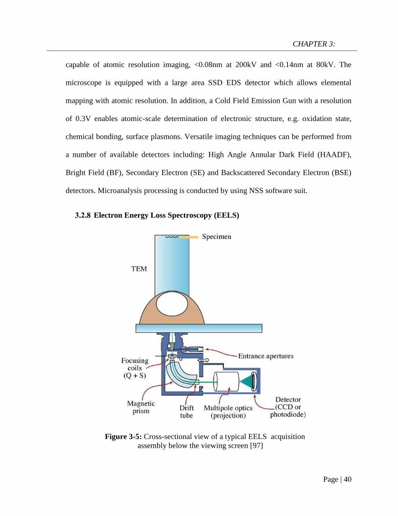
CHAPTER 3:
Page | 40
capable of atomic resolution imaging, <0.08nm at 200kV and <0.14nm at 80kV. The
microscope is equipped with a large area SSD EDS detector which allows elemental
mapping with atomic resolution. In addition, a Cold Field Emission Gun with a resolution
of 0.3V enables atomic-scale determination of electronic structure, e.g. oxidation state,
chemical bonding, surface plasmons. Versatile imaging techniques can be performed from
a number of available detectors including: High Angle Annular Dark Field (HAADF),
Bright Field (BF), Secondary Electron (SE) and Backscattered Secondary Electron (BSE)
detectors. Microanalysis processing is conducted by using NSS software suit.
Electron Energy Loss Spectroscopy (EELS)
Figure 3-5: Cross-sectional view of a typical EELS acquisition
assembly below the viewing screen [97]

CHAPTER 3:
Page | 41
Another powerful function of the JOEL JEM-ARM200F is its capacity in resolving
electronic structure by means of Electron Energy Loss Spectroscopy (EELS). The
transmitted electrons experience inelastic-scattering after traversing the thin TEM
specimen in which a certain amount of their energy is lost. This energy deviation carries
useful information regarding electronic structure of a specific element, which in turn can
be correlated to their bonding/valence state and other chemistry characteristics [97]. The
JOEL JEM-ARM200F is equipped with a GIF Quantum imaging filter which allows
acquisition of energy-loss dispersion spectrum. In this work, EELS was performed on
STEM mode and the resulting energy-loss spectrum is processed by a tool in Digital
Micrograph software [98]. An image of EELS acquisition assembly is given below [97].

CHAPTER 4:
Page | 42
CHAPTER 4:
Tribological performance of sodium borate
at elevated temperatures
* This chapter content was published in The Journal of Physical Chemistry C, 2017,
121, 45, 25092-25103
As previously stated, melt lubricants [2] are considered as good candidates for high-
temperature lubrication as they possess a desirable set of thermal and chemical
characteristics. The concept of melt lubrication is based on utilizing viscous state of the
melt lubricant for tribological contact. Sodium polyphosphates reportedly delivered
friction and wear reducing effects on sliding steel pairs at the maximum temperature of
800oC [87, 99]. It is believed that polymeric melts of boron and silicate can also hold
significant potential. Although borates have been studied widely at moderate temperature
[100], it is still unclear how the Boron-bearing melts behave in response to tribological
exposure at high temperature. The present chapter aims to evaluate tribological properties
of an inorganic sodium borate on steel contact at elevated temperature by means of pin-on-
disc testing. Hot tribotests were carried out over a wide range of temperature and loading
while the lubrication effectiveness is justified by a direct comparison between lubricated
and non-lubricated tests. In addition, a thorough analysis was also conducted to reveal
microstructure and chemical nature of the tribo-interfaces on both sliding counterparts.
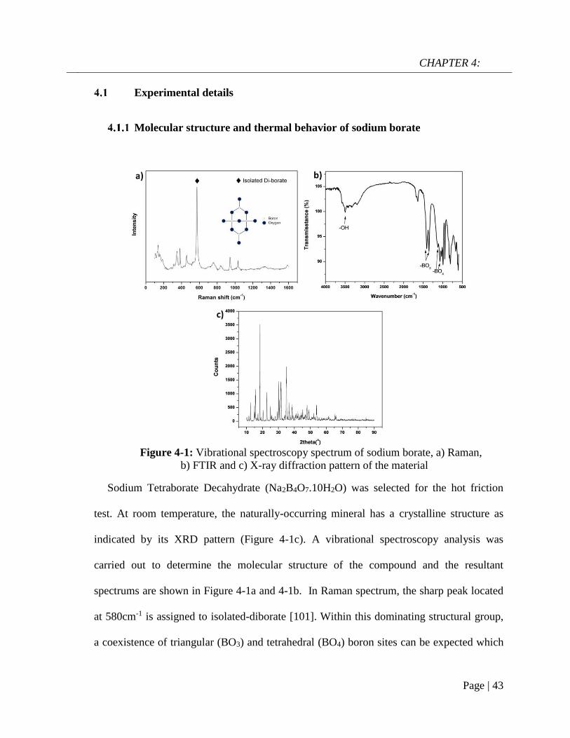
CHAPTER 4:
Page | 43
Experimental details
Molecular structure and thermal behavior of sodium borate
Sodium Tetraborate Decahydrate (Na2B4O7.10H2O) was selected for the hot friction
test. At room temperature, the naturally-occurring mineral has a crystalline structure as
indicated by its XRD pattern (Figure 4-1c). A vibrational spectroscopy analysis was
carried out to determine the molecular structure of the compound and the resultant
spectrums are shown in Figure 4-1a and 4-1b. In Raman spectrum, the sharp peak located
at 580cm-1 is assigned to isolated-diborate [101]. Within this dominating structural group,
a coexistence of triangular (BO3) and tetrahedral (BO4) boron sites can be expected which
Figure 4-1: Vibrational spectroscopy spectrum of sodium borate, a) Raman,
b) FTIR and c) X-ray diffraction pattern of the material

CHAPTER 4:
Page | 44
is confirmed by the FTIR analysis. In FTIR spectrum, the band at 3498 cm-1 is associated
with H-O-H bending while bands at 1411cm-1, 1360cm-1 and 1127 cm-1, 1075 cm-1 can be
assigned to asymmetric stretching of B-O in BO3 and BO4, respectively [102]. A 5%
(weight percentage) aqueous solution of borate was prepared for friction testing.
Transition temperature of sodium borate was determined by mean of high temperature
Laser Confocal Microscope (LCM) coupled with a CDCD camera. A mild-carbon cuboid
substrate (3x3x2.5mm) with roughness of 10nm was fixed onto a 5mm-diameter alumina
crucible. A small amount of lubricant powder was gently located on the steel specimen
which was subsequently inserted into an ellipsoidal infrared heating furnace. The specimen
was then heated by an infrared source to 800oC at a rate of 1.5oC/s under Argon
atmosphere (99.999% Ar). The schematic illustration of the testing apparatus is shown in
Figure 3-2. In-situ observation of the physical state variation was accomplished by a
continuous video recording through objective lens. At 525oC, the solid particle gradually
transforms from solid state into a highly viscous liquid (Figure 4-2), marking the transition
point of sodium borate.
Figure 4-2: Snapshots of sodium borate particle through its transition point in Laser
Confocal Microscopy

CHAPTER 4:
Page | 45
0 200 400 600 800
-3
-2
-1
0
1
DSC
TGA
Temperature (oC)
He
at
flo
w (
mW
/mg
) Tm= 525
oC
50
60
70
80
90
100
Ma
ss
pe
rce
nta
ge
(%)
DSC/TGA analysis was further used to support the melting behavior of borate (Figure
4-3). The material experiences a significant dehydration around 120oC-160oC indicated by
two endothermal peaks then it totally melts at ~525oC.
Figure 4-3: DSC and TGA curves of sodium borate.
Tribopair preparation
A 6.35mm-diameter Chromium GCr15 ball (C:Si:Cr:Fe = 0.98:0.35:1.48:balanced-
%wt.) was selected as the stationary component with an initial roughness of ~20nm and a
hardness of 5.9GPa. Mild carbon (MC) steel (~0.3%C) with a hardness of 4.7GPa was
chosen for the disc material. The round disc of 3mm in thickness and 50mm in diameter,
was polished to achieve a roughness of 1µm. Prior to a friction test, both steel components
were ultrasonically cleaned by ethanol and acetone respectively for contaminants removal.
Friction tests

CHAPTER 4:
Page | 46
Hot friction tests were performed on the Bruker UMT2-CETR high temperature ball-
on-disc tribometer. Steel counterparts were firstly installed into the tribometer then the
furnace was heated to a set temperature. The non-isothermal heating period was divided
into multiple sequences to minimize the risk of thermal overshooting. MC disc rotates at
5rpm during heating stage to ensure a homogenous heat distribution while the GCr15 ball
is located at 5mm above the disc surface. Sliding tests were carried out at temperature
range of 600oC-800oC while the nominal load was kept at 10N-30N with a linear sliding
velocity of 0.1m/s. An external thermocouple was embedded into the ball to monitor its
temperature and a typical plot is provided at the set point of 800oC in Figure A-1
(Appendices). The maximum contact pressure was calculated according to the reduced
young modulus of the oxide scales at testing temperature, reaching a value around
1.14GPa, 1.43GPa, 1.64GPa at 10N, 20N and 30N respectively [103]. The sliding duration
is 5 minutes and the tribopairs were immediately retrieved and cooled in air after each test
to prevent further oxidation. During the lubrication tests, lubricant solution was fed onto
the rotating disc with a rate of 0.01ml/s through an external monitor. The onset of lubricant
introduction is 2 minutes before contact engagement. A number of tests were repeated for
each testing condition to ensure repeatability.
The maximum contact pressure is calculated by Hertzian stress theory as shown in
Equation 4-1[104]. Since the steel tribopair were pre-oxidized prior to sliding test, the
Young modulus of oxide scale at different temperature is used to determine the generated
stress [103] (Equation 4-2). These equations are used throughout this study to calculate
maximum contact pressure, unless stated otherwise.

CHAPTER 4:
Page | 47
a = √3RF
4E∗
3
1
E∗= 1 − v1
2
E1+1 − v2
2
E2
Pmax =3
2
F
πa2 (Eq. 4 − 1)
ET = Eoxo (1 + n(T − 25) (Eq. 4 − 2)[103]
n = −4.7. 10−4; Eoxo = 240GPa
a: radius of contact area;
R: ball radius (mm);
F: applied force (N);
E1,E2: young modulus of each contact
body (GPa);
v1,v2: Poison’s ratio of each contact
body (=0.3 [81])
ET: Young modulus of oxide scale at
temperature T (oC)
Characterization
The molecular structure of sodium borate was analyzed by a JY HR800 Raman
spectrometer and a Shimadzu Fourier Transform Infrared Spectrometer. Morphologies of
worn surfaces were examined by JOEL JSM-6490LV Scanning Electron Microscopy
coupled with Energy Dispersive Spectroscopy (EDS). Low accelerating voltage (5keV)
was used in this case to increase x-ray yield of low-Z atom. Ball loss volume was
calculated from the worn scar dimension while the according figure was measured by a
Stylus Profiler (Dektak 150 Surface Profilometer) on the disc wear track.
Thin lamellars were produced by Dual Beam FEI Helios NanoLab G3 CX while
microscope observations of the cross-sectional interface were performed on aberration-
corrected JOEL ARM 200F Scanning Transmission Electron Microscopy (STEM). Since
the lubricant melt is formulated with Boron which is typically a light element, detection of
CHAPTER 4:
Page | 48
such component is restricted by the low yield of X-ray signal. To overcome this issue,
High-angle Annular Dark Field (HAADF) imaging is employed besides conventional
Bright Field imaging (BF). Based on Rutherford scattering, collected signal from high-
angle incoherent electrons is heavily dependent on atomic number (Z2) [105] of the
element. Therefore, STEM-HAADF images can exhibit a high sensitivity toward
compositional contrast (with negligible lamellar thickness deviation) and were already
used in various applications to differentiate elements with great Z disparity [106, 107].
Spectroscopy (EELS) analysis was operated in STEM mode to mitigate radiation damage
with beam dispersion of 0.1eV. The spectra underwent background-subtraction by fitting
the pre-edge to a power function law AE-r, where E is the energy loss and A and r are
constants.
Results
Tribological performance of sodium borate over a wide range of testing
conditions
Average friction coefficients and wear loss volumes of tribopairs lubricated by sodium
borate under different loads (10N, 20N and 30N) at 600oC, 700oC and 800oC are shown in
Figure 4-4, 4-5 and 4-6, respectively. The sliding velocity remains at 0.1m/s in every case.
It can be seen that friction rises marginally with increasing load, although it still falls in a
range of ~0.18-0.2 regardless of testing temperatures. The wear loss volumes share a
similar upward tendency when the applied load increases. However, the disc seems to
suffer a lower material loss than its counter-surface at harsher condition. The disc loss
volume is recorded at 0.122 mm3 at 600oC under 30N and it jumps to 0.163 mm3 at 800oC

CHAPTER 4:
Page | 49
under the same load. On the other hand, the ball loss volume appears more sensitive to
both variables, particularly at a higher temperature range, although the order of magnitude
is much lower than the disc. At 600oC, the ball loss volume registers a value of 0.63.10-2
mm3 under 10N, the figure rises to 0.73.10-2 mm3 and 0.81.10-2 mm3 at 20N and 30N,
respectively. At 700oC, the corresponding value at increasing load is approximately 3
times higher than those at 600oC. The test at 800oC sees the highest ball loss volumes with
a steeper slope than that obtained at lower temperatures as the gap between the two
extremes (10N and 30N) is nearly 2.10-2 mm3. It is clear that borate lubrication yields
relatively low friction coefficients under a wide range of conditions, although the wear loss
increases slightly with load and temperature. The wear behavior might arise from the
varying effect of oxidation on the steel pair which in turn is a function of temperature.
10 20 30
0.0
0.1
0.2
0.3
0.4
0.5
0
1
2
3
4
5
30N20N10N
Ball
Disc
Ball
Lo
ss V
olu
me (
.10
-2 m
m3)
a) b)
0.0
0.1
0.2
0.3
0.4
0.5
Dis
c L
oss V
olu
me (m
m3)
CO
F ()
Load (N)
Figure 4-4: (a) Wear loss volumes of the tribo-pair and (b) average
friction coefficients in lubricated tests versus load at 600oC.

CHAPTER 4:
Page | 50
10 20 30
0.0
0.1
0.2
0.3
0.4
0.5
0
1
2
3
4
5
10N 30N20N
Ball
Disc
Ball
Lo
ss V
olu
me (
.10
-2 m
m3)
a) b)
0.0
0.1
0.2
0.3
0.4
0.5
Dis
c L
oss V
olu
me (m
m3)
CO
F ()
Load (N)
The lubrication effects of sodium borate are clearly demonstrated by the reduction of
friction coefficient and wear loss on both steel counterparts in comparison to unlubricated
cases. It is noted that the normal load and the linear speed were kept constant at 30N and
0.1m/s, respectively. The evolution of friction coefficient versus sliding time of lubricated
and unlubricated tests at 600oC, 700oC and 800oC are displayed in Figure 4-7. During the
running-in stage, the friction coefficient fluctuates considerably possibly due to the contact
between the hard oxide scale while the steady state sees a stabilization in the friction
coefficient. It can be observed that unlubricated sliding contact is characterized by growing
friction with increasing temperature. The average friction coefficient is 0.44 at 600oC then
increases to 0.50 and 0.55 at 700oC and 800oC respectively. On the other hand, exposure to
borate lubrication clearly improves frictional behavior by reducing the coefficient
considerably at all testing temperature. Under borate lubrication, the friction coefficients
converge at roughly ~0.18-0.2 with the reduction of 60%, 64% and 67% at 600oC, 700oC
and 800oC, respectively compared to unlubricated condition at the corresponding
temperature.
Figure 4-5: (a) Wear loss volumes of the tribo-pair and (b) average friction
coefficients in lubricated tests versus load at 700oC.

CHAPTER 4:
Page | 51
10N 20N 30N
0.0
0.1
0.2
0.3
0.4
0.5
0
1
2
3
4
5
30N20N10N
Ball
Disc
Ball
Lo
ss V
olu
me (
.10
-2 m
m3)
a) b)
0.0
0.1
0.2
0.3
0.4
0.5
Dis
c L
oss V
olu
me (m
m3)
CO
F ()
Load (N)
0 50 100 150 200 250 300
0.0
0.1
0.2
0.3
0.4
0.5
0.6
0.7
0.8
0.9
1.0
Fri
cti
on
co
eff
icie
nt
()
Sliding time (s)
600oC_Dry
700oC_Dry
800oC_Dry
600oC_Lubricated
700oC_Lubricated
800oC_Lubricated
Figure 4-8 shows the wear loss volumes of the sliding pairs in unlubricated and
lubricated condition at 600oC, 700oC and 800oC. It is note that the normal load was kept at
30N while sliding velocity was set at 0.1m/s. Dry sliding yields progressive increments of
the material loss with temperature on both sliding surfaces, except the loss volume on the
MC disc at 800oC which is slightly over half of that at 700oC. The introduction of sodium
Figure 4-6: (a) Wear loss volumes of the tribo-pair and (b) average friction
coefficients in lubricated tests versus load at 800oC.
Figure 4-7: Friction coefficient curves of dry sliding and lubrication
tests at 600oC, 700oC and 800oC (load of 30N, sliding speed of 0.1m/s).

CHAPTER 4:
Page | 52
0
2
4
6
8
10
600oC 700
oC800
oC
Ball
Disc
Ball
Lo
ss V
olu
me (
.10
-2 m
m3)
a) b)
0
2
4
6
8
10
12
Dis
c L
oss V
olu
me (m
m3)
0
2
4
6
8
10
600oC 800
oC700
oC
Ball
Lo
ss V
olu
me (
.10
-2m
m3)
0.00
0.05
0.10
0.15
0.20
Dis
c L
oss V
olu
me (m
m3)
borate reduces significantly the wear loss on both sliding counterparts. On the ball,
although the wear reduction looks subtle at 600oC, it becomes more significant at higher
temperature range as the volume difference increases. Wear losses on the lubricated discs
are so minor compared to what recorded in dry sliding condition that the corresponding
figures have been represented in a much smaller scale to illustrate the increasing trend
(Figure 4-8b). For instance, at 600oC the lubricated disc wears an amount of only 5% of its
unlubricated counterpart.
Analysis on the worn surfaces at 800oC
This section and the following two provide an in-depth analysis on the worn surfaces
after friction test at the temperature of 800oC, those at lower temperatures can be found in
Figure A-5 to A-9 (Appendices). Friction coefficient curves and wear loss volumes of
unlubricated and lubricated friction tests (at 800oC, 10N, 0.1m/s) are illustrated in Figure
4-9 and 4-10. Again, it can be seen that characteristically high friction coefficient is
yielded in the case of dry sliding ~0.42 while the introduction of molten sodium borate
Figure 4-8: Wear loss volumes of the tribopair at varying temperatures in
(a) dry sliding condition and (b) lubrication condition.

CHAPTER 4:
Page | 53
0 50 100 150 200 250 300
0.1
0.2
0.3
0.4
0.5
0.6
0.7
~58% reduction
Lubricated
Fri
cti
on
co
eff
icie
nt
()
Sliding time (s)
Unlubricated
leads to a dramatic drop of friction by approximately 58%. Through the entire lubrication
test, the melt lubricant shows a steady and rapid response to sheared stress condition
initiated by a 50-second running-in period. In the case of dry sliding test, worn loss
volumes were recorded at 5,01.10-2 mm3 and 2,44 mm3 on the ball and the disc,
respectively. The corresponding figures recorded substantial drop on both steel
counterparts when exposed to the melt lubrication. On the ball, the volume loss is five-fold
lower than that produced in unlubricated condition, reaching roughly 1.10-2 mm3 while the
degree of wear reduction registers at remarkably ~95% of that on the opposing disc.
Figure 4-9: Friction coefficient evolution of unlubricated and melt-lubricated
steel pair (at 800oC, 10N, 0.1m/s).

CHAPTER 4:
Page | 54
0
2
4
6
8
~95%
Lubricated
Ball
Disk
Unlubricated
Ba
ll lo
ss
vo
lum
e, (.
10
-2m
m3)
~80%
0
1
2
3
Dis
k lo
ss
vo
lum
e (m
m3)
After dry sliding test, worn surface morphologies of steel tribo-pair are shown in Figure
4-11. Micrograph of the ball scar shows a variety of surface damages such as
microgrooves, ploughing and plastic smearing. Across the worn area, a large amount of
wear debris can be observed which can act as a third-body abrasive source. Likewise, the
wear track is moderately grooved parallel to sliding direction and featured with dominant
iron oxides debris. The magnified zone (in Figure 4-11b) displays a continuous and
relatively smooth patch interrupted by multiple shattered fragments of oxides. This can be
attributed to the dynamic formation of a compact surface glaze which is originated from
sheared stress-induced agglomeration of oxides debris. Some believed that the protective
glaze layer can provide a wear resistance in some extent [108, 109]. Under extreme
temperature and oxygen availability, the oxidation of abrasive oxide is spontaneous,
leading to the formation of Hematite (Fe2O3) which is the hardest among 3 types of iron
oxide [110]. The abrasive Hematite is considered as the main component causing severe
fractures on both rubbing surface. It is further evidenced by the X-ray diffraction of debris
Figure 4-10: Wear loss volumes of unlubricated and lubricated steel pair
(at 800oC, 10N, 0.1m/s).

CHAPTER 4:
Page | 55
oxides (in Figure A-2) where Hematite accounts for the majority accompanied by a small
fraction of Magnetite (Fe3O4). EDS spectra of magnified zones also indicate the
predominance of O and Fe on the worn surfaces of mating counterparts (Figure 4-11). The
pattern similarity suggests the occurrence of adhesive wear where oxide debris was
embedded into the worn area of the ball which yielded plastically. At elevated temperature,
it can be deduced that dry sliding contact of steel pairs is characterized by a severe state of
abrasive/adhesive wear and plastic deformation which result in high friction and
substantial materials loss.
SEM micrographs of steel tribo-pair lubricated by borate melt are shown in Figure 4-12.
High-magnification image (Figure 4-12b) displays featureless morphology on the wear
track except hexagonal platelets residing on a smooth and glassy surface. Those micro-
platelets could be the products of borate melt recrystallization upon cooling. Across the
worn scar island-like patches can be observed although it is unclear if they represent the
actual morphology of the contact area. X-ray analysis points out the expected lubricant
Figure 4-11: SEM micrographs of the worn surfaces and the corresponding X-ray
spectrum after dry sliding test a) ball, b) disc.

CHAPTER 4:
Page | 56
elements (B, Na and O) on the contact surfaces with relatively weak signal from Fe which
implies the presence of a relatively thick film of lubricant melt overlying the worn area.
Since the borate melt remains viscous [111] after the friction test, it is likely that the
molten lubricant moved back onto the worn area and visually masked the intrinsic rubbing
interface. The cooled melt itself transforms into glassy solid whose appearance is clearly
not related to shearing action. In order to unfold the true interface, cross-sectional
observations are conducted and discussed in the following sections.
Tribo-interface on the ball after test at 800oC
SEM image of the whole thin FIB lamellar (12µmx8µm) extracted from ball scar
lubricated by borate melt is given in Figure A-3 (Appendices). As suggested from the top-
view EDS analysis on the ball scar, it is confirmed that the interface is covered by an
residual lubricant layer with a thickness of 4-5µm (Figure A-3). The cross-section area was
selected perpendicular to the sliding direction and the interface appears very smooth. High-
magnified BF image of the ball interface is given in Figure 4-13 which displays an ultra-
Figure 4-12: SEM micrographs of melt-lubricated steel components and the
corresponding X-ray spectrum after friction test a) ball, b) disc.

CHAPTER 4:
Page | 57
fine grained region above a coarser base. The nanograin layer is comprised of iron oxide
with average size of 50-150nm whereas the confinement range is 200-300nm from the
interface boundary. Popularly known for its intrinsically peculiar mechanical properties,
the interface-controlled nanolayer can play a significant role in surface characteristics
during the sliding contact. By applying Hurst filter to increase textural differences in grey
scales, the ultrafine oxide grains are clearly illustrated in Figure 4-13b.
EDS phase mappings of the ball interface are illustrated in Figure 4-14 where three
Phases are distinguished with a different chemical makeup. It is noted that Cu comes from
the re-deposition of Cu grid during FIB milling which is inevitable. It is obvious that Phase
1 with the predominant composition of Fe and O, is attributed to the oxides scale on the
steel ball. Phase 2 can be assigned to the residual melt which is composed of mainly Na, O
and B. Accounted for the least area, Phase 3 distributes itself on the boundary region
between Phase 1 and Phase 2 with an estimated thickness of 10-20nm. The interfacial film
Figure 4-13: a) Bright Field (BF) image from the GCr15 ball interface lubricated
by borate melt, b) application of Hurst filter underlining the nano-grained interface.

CHAPTER 4:
Page | 58
runs along the outer boundary of the ultrafine grains layer and consists of Na, O, Fe, C and
possibly B. EELS characterizations were conducted across the interface region to
determine the chemical fingerprints of B-K edge and C-K edge, the resultant spectra and
that of the melt reference are shown in Figure 4-15.
Figure 4-14: EDS phase mapping with corresponding
composition spectra of the ball interface.

CHAPTER 4:
Page | 59
The fine structure of Boron-K edge have been previously resolved with characteristic
peaks referring to 2 different configurations of BO3 and BO4 by means of EELS [112,
113]. Previous studies have shown that an intense π* peak at 194eV is assigned to the
transition of 1s electron to unoccupied pz orbital which defines trigonal [3]B units, whereas
σ* peak at 198.6 eV typically represents tetrahedral [4]B units. Peak located 204 eV is
mainly associated to three-fold coordinated [3]B.
In Figure 4-15, it can be expected that the spectrum from the oxide base without the
inclusion of Boron and Carbon, reveals no sign of excitation edge from the elements. The
Figure 4-15: Extracted EELS spectra of B-K edge and C-K edge from
a) melt reference, b) interfacial film (Phase III) and c) iron oxide.

CHAPTER 4:
Page | 60
melt reference spectrum displays a sharp peak A located at 194.8eV followed by a broad
hump B with maximum intensity at 202eV (Figure 4-15a). The spectrum shape provides a
strong indication about the co-existence of trigonal [3]B and tetrahedral [4]B in the structure
of alkali borate glass which is consistent with past studies [114, 115]. In contrast, the
spectrum extracted from interfacial film (phase 3) shows an intense peak A at 194.8 eV
followed by a broad peak C at 204.2 eV which implies the predominance of planar BO3
within the film composition. The conversion from [4]B to [3]B could be a result of
tribochemical reaction. Regarding Carbon, the resultant spectrum suggests the formation of
amorphous carbon in the interfacial film (phase 3). The peak located at 286eV is due to the
transitions from core 1s state to the π* state followed by a broad peak which is associated
to the transition from 1s to σ* state [116, 117]. It is likely that the origin of C arises from
decaburization which will be discussed in the following section. It is noted that spikey
appearance might be due to partial radiation damages (from intense electron beam) as the
glass lubricant is intrinsically non-conductive.
Tribo-interfacial on the disc
A FIB thin lamellar (9µmx6µm) of the tribo-interface on the disc is shown in Figure A-
4 (Appendices) and the rubbing surface appears rougher than that on the ball. A relatively
thick layer of residual melt (2-3µm) can also be observed. Figure 4-16 illustrates a STEM
BF image of the disc interface with the corresponding EDS mapping. The formation of a
tribofilm can be seen as a continuous and homogenous layer with an approximated
thickness of 50-60nm. Close examination suggests that the tribofilm consists of structural
layers which can be distinguished by a contrast difference. Elemental mapping of Fe and

CHAPTER 4:
Page | 61
melt compositions (except B) are provided to determine their distributions across the
tribofilm. Fe is predominantly found in the oxide scale while it is less likely to be included
in the tribofilm as well as the residual melt. Apart from homogenous distribution among
the residual melt, it is clear that Na heavily concentrates onto the lower region of the
tribofilm. On top of that, it is most notable that O is significantly deprived in the tribofilm
bulk in comparison to both the residual melt and the underlying oxide scale.
In order to visually underline the layered structure of the induced tribofilm, HAADF
imaging was employed and shown in Figure 4-17. Apart from boundary region, the
residual melt presumably contains a homogenous composition from point to point,
Figure 4-16: BF image of the tribofilm generated on the ball and the
corresponding EDS mapping.

CHAPTER 4:
Page | 62
exhibiting a uniform contrast. However, a bi-layer structure can be seen in the tribofilm
(Figure 4-17b) where the upper layer (II) appears darker than the underlying counterpart
(I). In accordance to EDS mapping, it can be deduced that the bottom layer corresponds to
the Na-rich region. In addition, it is very likely that the top layer is composed of highly-
concentrated light elements characterized by its stark contrast compared to the remaining
regions. On the basis of HAADF imaging, the contrast disparity not only suggests
compositional differences but also indicates a concentration gradient of heavy/light
elements. A representative EDS line scan is given to determine intensity profile across the
boundary film of O, Na and Fe (Figure 4-17c). It can be seen that O is significantly
depleted within the tribofilm bulk whereas the intensity of Na suddenly increases followed
by an abrupt drop when it comes to the oxide substrate. By the combination of EDS and
HAADF imaging, the local chemical structure of the bi-layered tribofilm can be revealed
and discussed in details in the following section.
Figure 4-17: HAADF image of the tribo-interface generated on the disc (a), detailed
image of the dual-layered structure (b) and EDS line scan across the tribofilm (c).

CHAPTER 4:
Page | 63
Discussions
The current chapter presents a good lubrication properties of inorganic sodium borate
above its melting temperature. The lubrication performance is demonstrated by a
considerable reduction in friction coefficient and wear loss over a wide range of testing
conditions on the steel tribopair. In order to understand the mechanism of melt lubrication,
the physical chemistry aspect of the molten inorganic poly-oxides deserves further
consideration. In the molecular structure of sodium borate, there is coexistence of covalent
bonding and ionic bonding: the former one is largely attributed to B-O linkage while the
latter refers to O-Na interaction. Upon melting, the compound transitions from a rigid state
into a highly viscous liquid. The melt viscosity drops progressively with temperature
which is associated with a gradual breakdown of the large anionic segments within the
glassy network [118]. Eventually, the vitreous melt is characterized by the formation of
charged individuals: cationic Na and anionic B-containing units (predominantly BO33-).
The ionic disassociation has been previously proven by the increased electric conductivity
at the molten state [118, 119]. The lubricant melt thus could be considered as a high-
temperature ionic liquid which dictates the tribological responses.
As illustrated in the TEM images, there appears a bi-layered tribofilm generated on the
disc interface after the friction test. The chemical composition of each layer is correlated to
different response of ionic components under shearing effect at high temperature. It is
evidenced by EDS mapping that the Na-dense layer (~10-20nm thick) is the foundation of
the bi-layered structure. The oxide surface is expected to be rich in electron to attract the
Na ions in the lubricant melt. This could stem from exo-electron emission [120] or the

CHAPTER 4:
Page | 64
intrinsic chemistry nature of the oxide scale at high temperature [7]. Generally, the bottom
layer plays a critical role in the properties of a boundary film, notably governing the
adhesion strength between that film and the underlying surface. Within the tribofilm
structure generated by Zinc Diakyldithiophosphate – the most widely used additive in
engine oil, the Sulfur-concentrated layer is accountable for the extreme pressure tolerance
and increased scuffing resistance [121, 122].
Since the observation of Boron distribution by EDS mapping is difficult due to its low
atomic number, HAADF imaging was used as an alternative approach. With a high
sensitivity towards Z-number differences reflected by an image contrast, the technique is
capable of distinguishing elements with great Z disparity and providing the concentration
gradient. It is shown by X-ray spectra and EELS analysis that the melt lubricant is
comprised of B, O and Na with an increasing atomic number Z = 5, 8 and 11, respectively.
From HAADF image of the disc interface (Figure 4-17), a stark contrast between oxide
base and the overlaying glassy film can be seen as the substrate appears much brighter than
the remaining region. These arise from the presence of Fe in the oxide scale which is much
heavier (Z=26) than any other melt elements. Within the tribofilm, the dual layers exhibit
different contrast as the upper layer is darker than its underlying counterpart. This
explicitly points to the inclusion of light element in chemical makeup with a greater
concentration compared to other areas. In accordance to EDS analysis, the base layer is
assigned to be Na-rich and the whole bi-layered tribofilm is considerably deprived of O.
Furthermore, since B is the lightest element among the tribosystem, it is plausible that the
upper layer is mainly compounded of vitreous boron oxides. The upper layer is then
highly-concentrated in B but heavily depleted in O. This is a possible indication of

CHAPTER 4:
Page | 65
polymerization occurrence under the effect of stressed shearing. In principle, B exists in its
most stable form when screened by O atoms in inorganic boron oxides [123] and the
polymerization can be triggered through additional formation of bonding-oxygens. An
illustrative schematic of the tribologically-driven process is proposed in Figure 4-18. The
self-adaptation behavior can be considered as a smart response of the tribofilm to
accommodate the shearing stress. The upper layer thus dominates the anti-wear capacity
due to an increased cohesive strength of the tribofilm bulk. Besides, the friction reduction
capability of the tribofilm can originate from the amorphous nature of the tribofilm. The O
depletion not only provides reasonable evidence about the possible polymerization in the
tribofilm, but also underlines the potential anti-oxidation.
On the opposing contact surface, the interface structure is also complex with the
formation of ultra-fine grained iron oxides beneath a boundary thin film. While the
overlying film comprises mainly lubricant elements, the nano-grain oxide layer can also
plays a crucial part in the properties of the sliding interface. It could be due to the
combined effects of oxidation and surface deformation at high temperature. Ultrafine-
Figure 4-18: Simplified schematic of tribologically-induced polymerization
in borate tribofilm

CHAPTER 4:
Page | 66
grained materials have been known for their unusual mechanical features including high
yield strength, excellent impact toughness and good fatigue strength [124-126]. Superior
mechanical characteristics are associated with the substantial boundaries density within the
microstructure. Herein, the nano-grained oxides (average diameter of 50-150nm) can
significantly enhance the mechanical strength of the rubbing interface and consequently
increase its wear resistance [127, 128]. As shown previously, the astonishing smoothness
observed can be attributed to the improved wear resistance when asperities contacts are
minimized under such surface quality. The nanoscale grains neatly arrange themselves on
the interface within a refinement range of ~200-300nm without being scattered outwards.
Apart from reinforcement capacity, nano-size grains are also characterized by high
boundary diffusion coefficient [129, 130] which can contribute to the complex chemistry
of the overlying film. The film is chemically made up with expected melt elements (B, O,
Na) with Fe and C. The inclusion of C and Fe could stem from the effect of high
temperature as this always induces outward diffusion of Fe and decarburization. As the
GCr15 ball consists of approximately 1% C, decarburization is reasonably likely [9]. The
decarburization process corresponds to competitive oxidation of solute [C] species in the
steel base which produces a mixture of carbonaceous gases as: [C] + FexOy → Fe +
CO/CO2. Under the effect of constant tribological exposure and tremendous heat, complex
reactions can take place which eventually transforms carbon-bearing gases into amorphous
carbon. In the tribofilm, the amorphous carbon is considered intrinsic, given that thin
lamellar was constantly kept in the vacuum condition until TEM examination,
contamination was therefore very negligible. This is also supported by the total absence of
C in the oxide scale as well as in the upper residual film indicated by the EELS analysis.

CHAPTER 4:
Page | 67
TEM micrograph of the steel substrate extracted from the ball scar displays continuous
voids along the scale/steel base interface (Figure 4-19). Outward diffusion of iron through
interstitial sites is considered rate-determining stage in scaling process when the oxide
scale thickens [7]. Again, the nanograins can accelerate Fe diffusion and subsequently
incorporate it into the tribofilm. With a variable coordination number, Fe has been known
to increase the network connectivity of the glassy film which results in an increased
strength [131]. As previously shown, the conversion from BO4 to BO3 is apparent which
can be explained by the favorable formation of easy-to-shear species under sliding (BO3
has much lower shearing strength than BO4 due to its planar structure).
Under borate lubrication, the boundary interfaces are microstructurally and chemically
complex (Figure 4-20), due to tribological responses of borate which related closely to its
physical chemistry at high temperature. There are some difficulties in attempting to
understand the tribological reactions at this extreme condition. The highly kinetic
aftermath has great chances to distort the actual state of the tribofilm structure. By
Figure 4-19: BF image of cross-sectional scale/steel interface of GCr15 ball
after friction test.
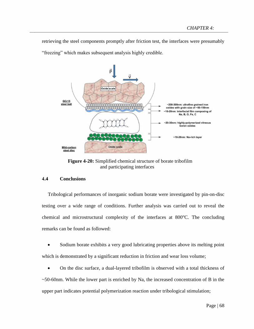
CHAPTER 4:
Page | 68
retrieving the steel components promptly after friction test, the interfaces were presumably
“freezing” which makes subsequent analysis highly credible.
Conclusions
Tribological performances of inorganic sodium borate were investigated by pin-on-disc
testing over a wide range of conditions. Further analysis was carried out to reveal the
chemical and microstructural complexity of the interfaces at 800oC. The concluding
remarks can be found as followed:
Sodium borate exhibits a very good lubricating properties above its melting point
which is demonstrated by a significant reduction in friction and wear loss volume;
On the disc surface, a dual-layered tribofilm is observed with a total thickness of
~50-60nm. While the lower part is enriched by Na, the increased concentration of B in the
upper part indicates potential polymerization reaction under tribological stimulation;
Figure 4-20: Simplified chemical structure of borate tribofilm
and participating interfaces

CHAPTER 4:
Page | 69
On the ball surface, a tribofilm composing of Na, O, B, C and Fe overlays on an
ultra-fined oxides scale. There is a conversion from BO4 into BO3 species in the vitreous
film;
The physical chemistry of borate melt plays a critical role in its tribological
responses.
CHAPTER 5:
Page | 70
CHAPTER 5:
Interface reaction of borate melt/oxidized steel and the
anti-oxidation capacity of lubricant melt
* This chapter content was published in Corrosion Science, 2018, 140, 231-240.
Like other engineering operations that involve high-temperature exposure, oxidation
management is very critical in the hot rolling of steel, although it is sometimes overlooked.
The intensive growth of oxide scale during reheating and subsequent deformation process
accounts for a substantial amount of material loss. From a tribological perspective, oxide
scale is considered as the major origin of abrasive/adhesive wear that deteriorates the
surface conditions of both mating surfaces and increases chances of seizure [132]. After
rolling, the unwanted oxide scale on the workpiece is often hard to remove, which requires
costly downstream processes (such as pickling).
Fundamentally, the nature of oxidation depends on a number of factors including
temperature, exposure duration, chemistry of the substrate and the corroding environment.
The majority of oxidation sequences take place at the phase boundary with heterogeneous
reactions. Glass-based coatings have been used to improve the high-temperature oxidation
resistance of many alloys and steel [58, 60, 61]. The coating is expected to act as a
hermetic seal which can physically separate metal substrate and oxidizing offenders. Apart
from the restriction of oxygen diffusion through the coating bulk, redox reactions at the
coating/base boundary result in the formation of an interlayer which governs the oxidation

CHAPTER 5:
Page | 71
kinetics. Ideally, the interlayers are characterized by a low oxygen diffusivity while their
formation is based on thermodynamically-favored reaction which further inhibits corrosion
of more valuable elements in the substrate [57, 59, 63-67, 133, 134]. Although there are
plenty of studies associated with static oxidation at high temperature, only little attention is
spent on the oxidation of sliding surfaces.
The present chapter discusses the chemical nature on the borate melt/oxidized steel
interface and the influences of shearing stress on that particular confined region. As
tribofilm formation was acknowledged previously (Chapter 4), further insights on the anti-
oxidation capacity of such thin film are also given.
Experimental details
Material preparation
In the high-temperature friction test, material selection was kept the same as it was
presented in Chapter 4 (GCr15 as the ball and mild steel as the disc). Surface conditions of
the steel pair also remain unchanged. Aqueous solution of 5%wt. of sodium borate was
prepared for the friction test.
Oxidation and tribological test
Both static oxidation test and tribological test were carried out on the UMT2-CETR
ball-on-disc tribometer. Testing temperature was selected at 800oC while the load was kept
at 10N with a sliding speed of 0.1m/s. During lubrication test, the lubricant was fed onto
the disc 2mins prior to contact engagement. Distilled water is only considered as a carrier
which immediately vaporizes when the lubricant reaches the heated disc. The remaining

CHAPTER 5:
Page | 72
borate certainly melts at the testing temperature (given its transition temperature is 525oC).
After sliding test (which lasts 5mins), the steel disc was immediately retrieved and cooled
in air to avoid further oxidation. It can be predicted that there are 2 distinct areas on the
disc after test: non-contact and contact. The former is associated with the region where
oxidized steel is coated with borate while the latter one refers to the worn track where the
borate/steel interface was subject to shearing exposure.
Characterizations
The majority of characterization tools used in this chapter is similar to what described in
section 4.1.4. In addition, Secondary Ion Mass Spectroscopy (SIMS) analysis was
performed on a CAMECA IMS 5FE7 to determine elemental distribution across the
lubricated interface, particularly B which is difficult to detect by EDS mapping. A focused
5.0keV Cs+ primary ion beam with a current of 100nA was employed over a raster of
180x180 µm2 area. The depth profile was obtained from sputtered MCs+ (where M is B,
Na and Fe) to minimize potential matrix effects.
Interfacial reaction between borate melt and oxidized steel
Figure 5-1 shows the top-view surface microstructure from non-contact area on the
tribo-disc. It can be seen that the surface morphology appears glassy and smooth. The X-
ray spectrum clearly indicates melt elements such as Na, O and B while Fe is not
detectable. From the cross-sectional view (Figure 5-2), the total thickness of borate
deposition is around 50µm.

CHAPTER 5:
Page | 73
As the oxidation sequences occur mainly at the phase boundary, Figure 5-3 illustrates a
STEM-BF image of the interaction zone (marked in Figure 5-2) together with the EDS
phase and spectrum. From the BF image (Figure 5-3), there are 2 different phases which
can be distinguished from their contrasts. The bright phase which looks uniform, is likely
associated with the borate coating while its darker counterpart can be assigned to the oxide
scale. EDS spectra were provided to differentate compositionally the contributing phases.
According to the spectrum, Phase 1 with predominant composition of Fe and O is clearly
attributed to the grown oxide scale. In contrast, Phase 2 consists mainly of B, Na and O
which can be ascribed to the borate melt. At the glass/scale interface, a substaintial amount
of sub-micron particles are in contact with the borate phase. Fluxing behavior of the borate
melt is clearly illustrated as a fraction of borate melt infiltrates into oxide scale while the
oxide particles appear to be pulled out of the substrate at the same time. This phenomenon
could result in interface roughening which was shown in Figure 5-2. It is noted that the
increased vertical intensity (top-to-bottom) is attributed to the increased thickness from the
top to the bottom of the thin lamellar, rather than an intrinsic feature of the interface.
Figure 5-1: a) SEM micrograph of borate-coated oxidized steel from non-
contact area and b) the corresponding EDS spectrum.

CHAPTER 5:
Page | 74
.
In order to examine the immediate interface between the borate melt and oxide scales,
BF image of higher magnification with corresponding EDS mapping and line scan are
given in Figure 5-4. It is clear that O is present in both phases with a higher concentration
in the iron oxide than that of the borate melt. In addition, there is a very small amount of
Fe in the melt. Apart from uniform distribution in borate phase, it is notable that Na
concentrates heavily on the interface of iron oxide as a continous thin film. The sudden
increase of Na signal when it comes to the iron oxide interface justifies the presence of Na-
rich film in Figure 5-4. This interface layer could be the result of heterogenous reaction
between borate melt and iron oxides that governs the dissolution characteristic. Selected
Area Electron Diffraction patterns from borate and oxide phase are shown in Figure 5-5a
and 5-5b, respectively. As expected, the diffuse ring pattern (Figure 5-5a) reveals the
amorphous nature of borate melt whereas the spot-like pattern (Figure 5-5b) is attributed to
the (1 0 0) and (1 1 0) planes of cubic iron oxides.
Figure 5-2: Cross-sectional view of borate-coated steel

CHAPTER 5:
Page | 75
Due to the limited sensivity toward X-ray detection, EELS was employed to identify the
distribution of B and its intensity profile across the phase boundary is given in Figure 5-6a.
It is clear that there is almost no trace of B in the oxide scale while the element becomes
significantly abundant in the borate phase. Figure 5-6b presents the energy loss spectrum
of B-K edge in the borate phase. There is a sharp peak located at 194.8eV followed by a
broad hump B with maximum intensity at 202eV. The intense π* peak at 194e.8V
corresponds to the transition of 1s electron to unoccupied pz orbital which defines trigonal
[3]B unit while the subsequent broad hump indicates a possible co-existence of trigonal [3]B
and tetrahedral [4]B [114, 115]. Elemental distribution and microstructure characterization
Figure 5-3: STEM-BF image of the borate-steel interface from unworn
area and the corresponding phases determination with EDS spectrum.
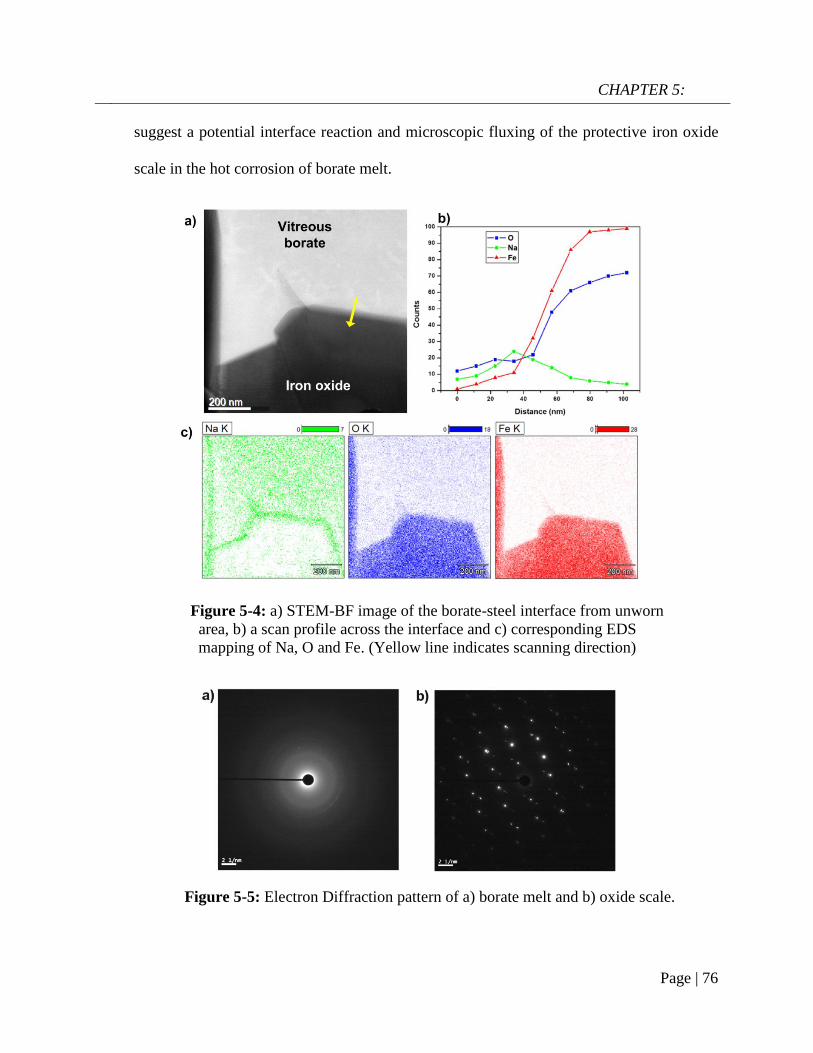
CHAPTER 5:
Page | 76
suggest a potential interface reaction and microscopic fluxing of the protective iron oxide
scale in the hot corrosion of borate melt.
Figure 5-4: a) STEM-BF image of the borate-steel interface from unworn
area, b) a scan profile across the interface and c) corresponding EDS
mapping of Na, O and Fe. (Yellow line indicates scanning direction)
Figure 5-5: Electron Diffraction pattern of a) borate melt and b) oxide scale.

CHAPTER 5:
Page | 77
Effect of stressed shearing on the interface chemistry
The surface morphology of the area under tribological exposure is shown in Figure 5-7.
The worn surface looks smooth while X-ray spectrum points to the presence of lubricant
melts and Fe. In comparison to the coating case where Fe is very weak, this arises from a
thin deposition of the borate melt on the wear track (<1µm, shown in Figure A-4) after the
ball-on-disc test.
Figure 5-6: a) EELS B-K edge intensity profile of B across the interface and
b) EELS spectra of B-K edge of the borate melt.
Figure 5-7: a) SEM micrograph of the wear track lubricated by borate and
b) corresponding EDS spectrum.

CHAPTER 5:
Page | 78
Figure 5-8 details the STEM-HAADF image of borate-lubricated interface with
corresponding EDS mapping and line scan. Although already presented in Chapter 4, it is
worth recalling the image that highlights the effects of tribological exposure on the
chemistry of borate/oxidized steel interface. A tribofilm (50-60nm) is found residing on
top of the iron oxide surface. Similar to what observed in out-of-track area, Na highly
localizes on the iron oxide interface as part of the inherent interfacial reaction. However, it
is noteworthy that the boundary film is significantly depleted in O (Figure 5-8c) which was
not seen in the case of static oxidation. A representative scan line across the interface
further confirms an abrupt decrease in the intensity of O in the tribofilm bulk. As borate
becomes viscous at testing temperature, it is likely that out-of-track melt flows into the
worn area and eventually form a residual layer after the high-temperature test. By
assuming uniform elemental distribution in the residual layer, compositional differences
between the tribologically-generated boundary film and the reference glass bulk can be
demonstrated. Therefore, it can be deduced that the interface chemistry experienced
remarkable changes induced by the shearing effect.

CHAPTER 5:
Page | 79
As suggested that the interfacial film mainly comprises of B, SIMS was employed to
provide supportive evidence. SIMS has been widely used in characterization of structurally
layered materials. In this case, depth profiles of B and Na are given in respect to Fe to
determine the gradient changes across the interface (Figure 5-9). As expected, the melt
elements (B and Na) concentrate on the interface and their intensities share a similarly
decreasing pattern as sputtering time increases. In contrast, Fe initially starts with
negligible intensity which increases sharply to a stabilization stage after 1000s of
sputtering. It is noted that the profile was extracted from the contact interface including a
residual layer with an estimated sputtering rate of 0.43nm/s. The gradient changes are
Figure 5-8: a) STEM-HAADF image of the worn track area, b) a scan profile
across the interface and c) corresponding EDS mapping of Na, O and Fe.
(Yellow line represents scanning direction)

CHAPTER 5:
Page | 80
attributed to not only element distribution within the residual film, but also to the
inherently rough lubricant melt/oxide interface.
Discussions
At elevated temperatures, oxidation of metals is accelerated by the deposition of melted
salt [135]. The hot corrosion may involve fluxing action of the protective oxides initiated
by potential chemical reactions between heterogeneous phases. The underlying mechanism
is primarily governed by the physical chemistry of the melt. As previously stated in
Chapter 4, the sodium borate melt is regarded as an ionic liquid above its melting point.
The structural disassociation upon heating induces the formation of free Na cations and
depolymerized boron oxide network. The equilibria correspond to the disassociations of
borate melt components can be described as followed:
0 1000 2000 3000 4000
103
104
105
106
11B
23Na
Co
un
ts (
a.u
.)
Time (s)
56Fe
Figure 5-9: SIMS depth profiles of B, Na and Fe on the worn track
(Dashed area approximates the interface).
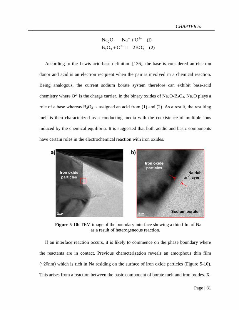
CHAPTER 5:
Page | 81
22
22 3 2
(1)
(2)
Na O Na O
B O O 2BO
According to the Lewis acid-base definition [136], the base is considered an electron
donor and acid is an electron recipient when the pair is involved in a chemical reaction.
Being analogous, the current sodium borate system therefore can exhibit base-acid
chemistry where O2- is the charge carrier. In the binary oxides of Na2O-B2O3, Na2O plays a
role of a base whereas B2O3 is assigned an acid from (1) and (2). As a result, the resulting
melt is then characterized as a conducting media with the coexistence of multiple ions
induced by the chemical equilibria. It is suggested that both acidic and basic components
have certain roles in the electrochemical reaction with iron oxides.
If an interface reaction occurs, it is likely to commence on the phase boundary where
the reactants are in contact. Previous characterization reveals an amorphous thin film
(~20nm) which is rich in Na residing on the surface of iron oxide particles (Figure 5-10).
This arises from a reaction between the basic component of borate melt and iron oxides. X-
Figure 5-10: TEM image of the boundary interface showing a thin film of Na
as a result of heterogeneous reaction.

CHAPTER 5:
Page | 82
ray powder diffraction was used to determine possible phase formation between borate
melt and iron oxides powder (mainly Fe2O3) subject to heat treatment (Figure 5-11). The
high specific area of oxide powder (particles size of 10~20µm) enables a higher conversion
of the interface reaction. The mixture was heated at 800oC for 7 minutes which is equal to
the exposure duration in tribological/oxidation test. It can be seen that apart from the
expected dominance of Fe2O3, XRD pattern of the heat-treated mixture shows relevant
peaks attributed to NaFeO2 at 20.6o and 22.9o [137]. Due to the fact that the reaction layer
is only confined on the oxide interface, the resulting phase constituent is thus inferior to
the iron oxides. Ryutaro et al. [138] attempted to measure the solubility of Fe2O3 and
Cr2O3 in a fused mixture of Na2B4O7-B2O3 under air atmosphere. While Cr2O3 exhibits a
negligible solubility due to its superior corrosion resistance, Fe2O3 displays a magnitudes-
higher value caused by a proposed basic dissolution which aligns with the present study.
The interfacial adsorption of Na can alternatively be attributed to the ionic attraction
between positively-charged Na ions and the oxides surface featured with a high O density.
This occurs regardless of the presence of external shearing and pressure. With respect to
the acidic component, it is less likely for boron oxide to chemically react with Fe2O3.
Theoretically, Hematite can be considered as a weak base due to its unwillingness to
liberate oxygen while B2O3 is a weak acid, the reaction between such two reactants is not
thermodynamically favorable. It can be deduced that the basic dissolution is the primary
reaction in the hot corrosion of borate melt and can be described as followed:
2 2 3 2 (3)Na O Fe O 2NaFeO
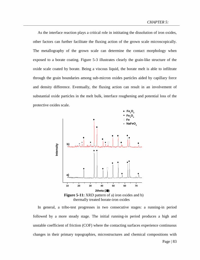
CHAPTER 5:
Page | 83
10 20 30 40 50 60 70
NaFeO2
Fe
Fe3O
4
Fe2O
3
b)
Inte
ns
ity
2theta (2)
a)
As the interface reaction plays a critical role in inititating the dissolution of iron oxides,
other factors can further facilitate the fluxing action of the grown scale microscopically.
The metallography of the grown scale can determine the contact morphology when
exposed to a borate coating. Figure 5-3 illustrates clearly the grain-like structure of the
oxide scale coated by borate. Being a viscous liquid, the borate melt is able to infiltrate
through the grain boundaries among sub-micron oxides particles aided by capillary force
and density difference. Eventually, the fluxing action can result in an involvement of
substantial oxide particles in the melt bulk, interface roughening and potential loss of the
protective oxides scale.
In general, a tribo-test progresses in two consecutive stages: a running-in period
followed by a more steady stage. The initial running-in period produces a high and
unstable coefficient of friction (COF) where the contacting surfaces experience continuous
changes in their primary topographies, microstructures and chemical compositions with
Figure 5-11: XRD pattern of a) iron oxides and b)
thermally treated borate-iron oxides

CHAPTER 5:
Page | 84
0 50 100 150 200 250 300
0.0
0.1
0.2
0.3
0.4
0.5
Steady stageRunning-in
Fri
cti
on
co
eff
icie
nt
()
Sliding time (s)
probable involvement of third-body particles. On the other hand, the steady stage indicates
that the rubbing interfaces reach equilibrium state mechanically and chemically (Figure 5-
12). Particularly under lubrication condition, the COF plays an important role in judging
the lubricant performance which depends closely on the effective tribofilm formation.
Detailed chemical analysis was performed from the lubricated area where interface
equilibrium was reached with the tribofilm formation.
External oxidation occurs when the outwardly-migrating Fe ion reaches the interface
and reacts with adsorbed oxidizing species while internal oxidation occurs when the
oxidaizing species penetrate through the protective scale then react with the base metal [7].
As a result, the oxide scale thickens progressively. The borate tribofilm generated on the
interface is characterized by a significantly low O density, thus has a great potential in
mitigating the oxidation severity. The borate tribofilm is capable of inhibiting O diffusion
onto the interface which is one determining factor in oxidation kinetic. If oxidizing species
Figure 5-12: Friction coefficient curve from lubricationt test
of borate on steel/steel contact (800oC, 10N, 0.1m/s)

CHAPTER 5:
Page | 85
manage to infiltrate through the boundary film, their adsorption probability wil be hindered
by the dense and continuous film of Na. In addition, the outward migrating Fe is likely
curbed by the Na film. By obstructing the pathway of reagents transport, the tribofilm can
play a role as an effective anti-oxidation layer.
Figure 5-13 illustrates cross-sectional view of the steel substrate exposed to different
conditions with corresponding element profiles. It can be seen that the grown scale under
borate lubrication is the thinnest (8~10µm) despite signs of interface damages. In the case
of borate-coated sample without tribology contact (Figure 5-13b), the melt/oxide scale
interface appears rougher and the scale is 2~3µm thicker than that on the worn area. Lastly,
the oxidation of bare steel substrate (no lubricant coating, no tribology contact) yields an
uniform scale with the greatest thickness of 16µm. Compared to the unprotected substrate,
borate coating can prevent the oxidation of steel substrate in some extent due to its ability
to separate physically the substrate and oxygen in the atmosphere. On the lubricated
substrate, the interface benefits substantially from the oxidation resistance of O-depleted
boundary film and produces the thinnest oxide scale although the wear loss can not be
underestimated. Ultimately, due to its favorable locality, the tribofilm not only imposes an
anti-oxidation capacity on the disc surface but also on the opposing surface. When the
normal load was increased up to 30N, the sodium borate melt still retains its oxidation
resistance on the sliding surface, as shown in Figure 5-14.

CHAPTER 5:
Page | 86
Figure 5-13: Cross-sectional view of the steel subtrate lubricated by
borate (a), coated by borate (b) and under pure oxidation (c) at 800oC
(Intensity unit is counts)

CHAPTER 5:
Page | 87
0
2
4
6
8
10
12
14
16
18
30N20N10NCoat only
Ox
ide
th
ick
ne
ss
(m
)
Free
Oxidation
Conclusions
The interface chemistry of borate melt/oxidized steel was revealed and the influences of
ribological exposure on the boundary region were also understood. Some conclusions can
be drawn from this chapter as listed bellowed:
The oxidation reaction of borate melt on oxidized steel is characterized by the
interface reaction and fluxing action of the oxide particles;
The formation of thin Na film on iron oxide interface is observed regardless of the
presence of shearing stress;
Tribological exposure leads to the tribofilm formation which is significantly
depleted in Oxygen;
The tribofilm formation enhances oxidation resistance by reducing the oxide
growth.
Figure 5-14: Variation of oxide scale thickness under free
oxidation, borate-coating and borate lubrication at different loads
(800oC, sliding duration of 5mins, sliding velocity of 0.1m/s)

CHAPTER 6:
Page | 88
CHAPTER 6:
The role of Na in the lubrication behavior
of sodium borate
* This chapter content was published in RSC Advances, 2018, 8, 28847-28860.
It has been acknowledged that the chemical makeup of the tribofilm, often quite
complex in its nature, plays a crucial role in the lubricant performance at high temperature.
The compositional complexity can originate from the diverse elements involved in the
tribosystem (from lubricant, additives, contact surfaces and environment) and also the
structural gradients that exist across the tribofim thickness. In engine oil, the ZDDP (Zinc
DialkylDiothioPhosphate) additive creates a hierarchically-structural tribofilm in which
functions of individual elements still draws plenty of debate till now [139].
As previously stated, melt lubricant can be formulated from two primary constituents:
alkaline (or alkaline-earth) element and glass-forming compound. Each of the components
has certain roles in defining the overall physico-chemical characteristics of the melt at
elevated temperature. Condensed polyphosphate (P2O5), boron oxide (B2O3) and silicon
oxide (SiO2) are the most fundamental network-building blocks. These structural groups
are the foundations of polymeric nature that renders thermal stability and high transition
point. The introduction of cationic moieties modifies the degree of polymerization which
helps tuning melting temperature and viscosity. The relative ratio between the two
constituents dictates high-temperature behaviors of the melt and there have been plenty of
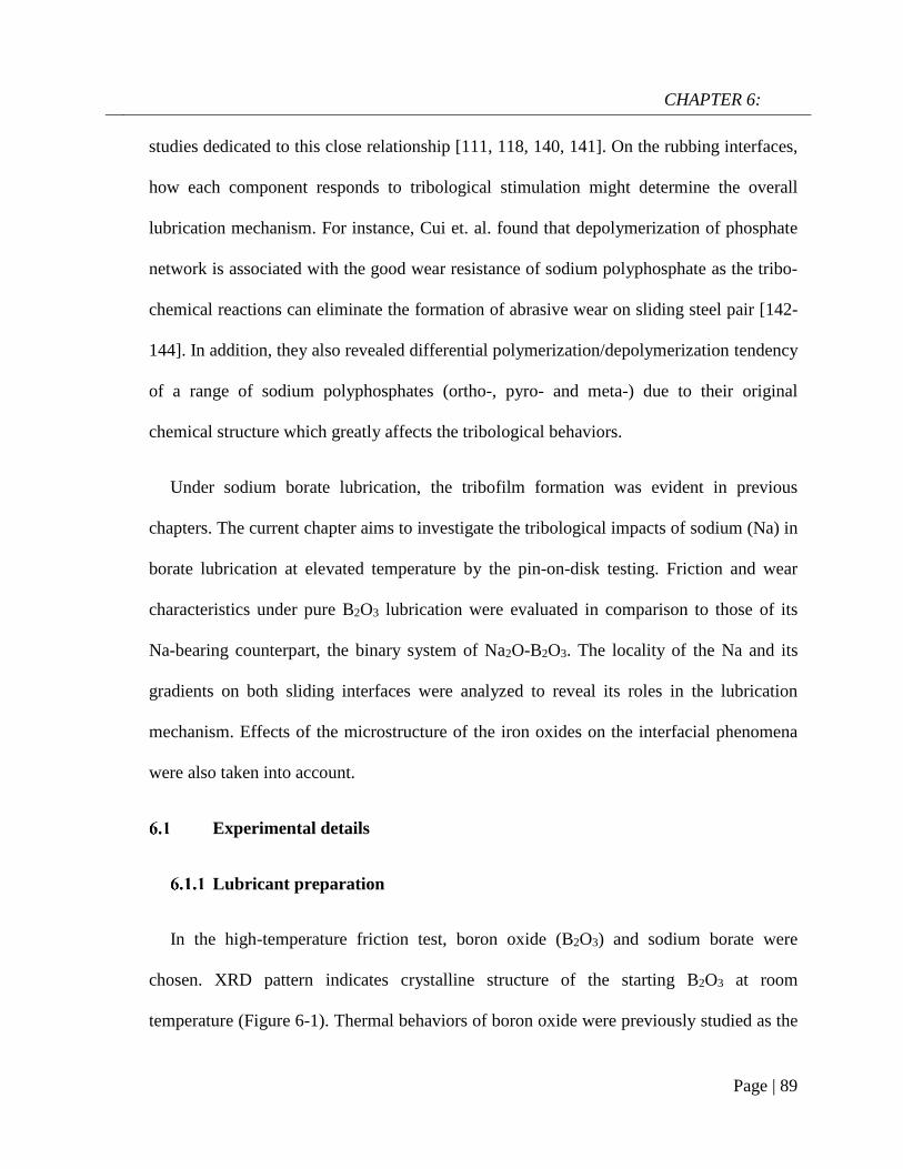
CHAPTER 6:
Page | 89
studies dedicated to this close relationship [111, 118, 140, 141]. On the rubbing interfaces,
how each component responds to tribological stimulation might determine the overall
lubrication mechanism. For instance, Cui et. al. found that depolymerization of phosphate
network is associated with the good wear resistance of sodium polyphosphate as the tribo-
chemical reactions can eliminate the formation of abrasive wear on sliding steel pair [142-
144]. In addition, they also revealed differential polymerization/depolymerization tendency
of a range of sodium polyphosphates (ortho-, pyro- and meta-) due to their original
chemical structure which greatly affects the tribological behaviors.
Under sodium borate lubrication, the tribofilm formation was evident in previous
chapters. The current chapter aims to investigate the tribological impacts of sodium (Na) in
borate lubrication at elevated temperature by the pin-on-disk testing. Friction and wear
characteristics under pure B2O3 lubrication were evaluated in comparison to those of its
Na-bearing counterpart, the binary system of Na2O-B2O3. The locality of the Na and its
gradients on both sliding interfaces were analyzed to reveal its roles in the lubrication
mechanism. Effects of the microstructure of the iron oxides on the interfacial phenomena
were also taken into account.
Experimental details
Lubricant preparation
In the high-temperature friction test, boron oxide (B2O3) and sodium borate were
chosen. XRD pattern indicates crystalline structure of the starting B2O3 at room
temperature (Figure 6-1). Thermal behaviors of boron oxide were previously studied as the
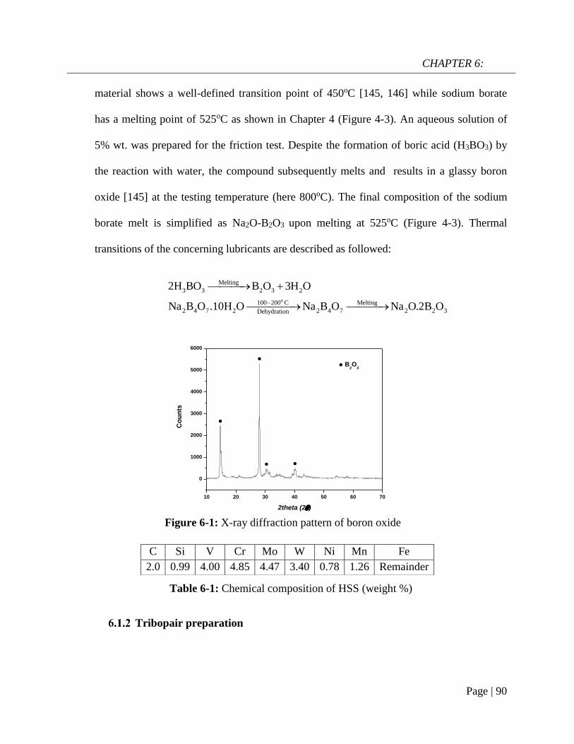
CHAPTER 6:
Page | 90
10 20 30 40 50 60 70
0
1000
2000
3000
4000
5000
6000
Co
un
ts
2theta (2)
B2O
3
material shows a well-defined transition point of 450oC [145, 146] while sodium borate
has a melting point of 525oC as shown in Chapter 4 (Figure 4-3). An aqueous solution of
5% wt. was prepared for the friction test. Despite the formation of boric acid (H3BO3) by
the reaction with water, the compound subsequently melts and results in a glassy boron
oxide [145] at the testing temperature (here 800oC). The final composition of the sodium
borate melt is simplified as Na2O-B2O3 upon melting at 525oC (Figure 4-3). Thermal
transitions of the concerning lubricants are described as followed:
o
Melting
3 3 2 3 2
100 200 C Melting
2 4 7 2 2 4 7 2 2 3Dehydration
2H BO B O 3H O
Na B O .10H O Na B O Na O.2B O
Tribopair preparation
C Si V Cr Mo W Ni Mn Fe
2.0 0.99 4.00 4.85 4.47 3.40 0.78 1.26 Remainder
Table 6-1: Chemical composition of HSS (weight %)
Figure 6-1: X-ray diffraction pattern of boron oxide
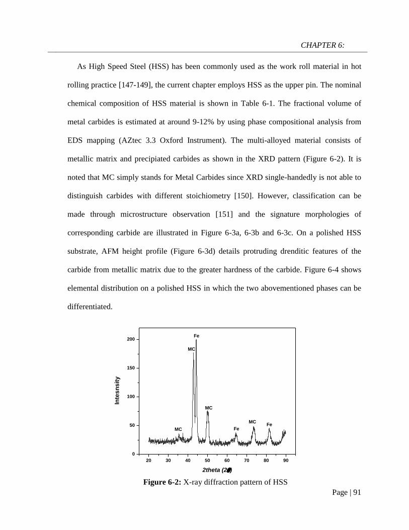
CHAPTER 6:
Page | 91
20 30 40 50 60 70 80 90
0
50
100
150
200
FeMC
Fe
MC
Fe
MC
Inte
sn
sit
y
2theta (2)
MC
As High Speed Steel (HSS) has been commonly used as the work roll material in hot
rolling practice [147-149], the current chapter employs HSS as the upper pin. The nominal
chemical composition of HSS material is shown in Table 6-1. The fractional volume of
metal carbides is estimated at around 9-12% by using phase compositional analysis from
EDS mapping (AZtec 3.3 Oxford Instrument). The multi-alloyed material consists of
metallic matrix and precipiated carbides as shown in the XRD pattern (Figure 6-2). It is
noted that MC simply stands for Metal Carbides since XRD single-handedly is not able to
distinguish carbides with different stoichiometry [150]. However, classification can be
made through microstructure observation [151] and the signature morphologies of
corresponding carbide are illustrated in Figure 6-3a, 6-3b and 6-3c. On a polished HSS
substrate, AFM height profile (Figure 6-3d) details protruding drenditic features of the
carbide from metallic matrix due to the greater hardness of the carbide. Figure 6-4 shows
elemental distribution on a polished HSS in which the two abovementioned phases can be
differentiated.
Figure 6-2: X-ray diffraction pattern of HSS

CHAPTER 6:
Page | 92
The HSS pins were fabricated out of an industrial work roll without heat treatment.
They are wire cut into cylinders then one end is machined by a ceramic tip to achieve a
6.35mm-diameter hemispherical end with an average roughness of 1µm. Total length of
the HSS pin is 4mm. The metallic matrix has a hardness of 8±0.6GPa and a Young
modulus of 222±5GPa while the corresponding values for carbides are 19±3.26GPa and
300-373GPa depending on carbide type. Commercial stainless steel (SS316, hardness of
4.3GPa, Young modulus of 180GPa) was chosen as the rotational component in the hot
friction test. The SS316 round disc is 3mm thick with a diameter of 50mm and its surface
was polished to achieve a roughness of 1µm. Mild-carbon steel was also used in this work
to reveal the effect of different oxide microstructure on lubrication. The steel pairs were
ultrasonically cleaned by ethanol and acetone prior to each friction test.
Figure 6-3: SEM micrographs of different carbide morphologies a) MC,
b) M2C, c) M7C3 and d) AFM height profile of a polished HSS subtrate

CHAPTER 6:
Page | 93
Friction test
High-temperature friction test was performed on the Bruker UMT2-CETR ball-on-disc
tribometer. The testing procedure was slightly different from previous chapter as the pin
was pre-oxidized for a fixed duration prior to sliding. The SS316 disc was first installed
into the furnace chamber followed by heating to 800oC. Once the furnace temperature
reached the set point, the upper stage carrying HSS pin was automated to descend to a
distance of 3mm away from the disc surface. Pre-oxidation of HSS pin lasted for 10
minutes. During this stage, the disc rotated at 5rpm to ensure uniform heat distribution.
Lubricant solution was dropped onto the heated disc at 2 minutes before contact
engagement with a rate of 0.01ml/s. The sliding velocity was kept constant at 0.1m/s while
Figure 6-4: Elemental mapping of a polished HSS surface

CHAPTER 6:
Page | 94
testing duration was fixed at 5 minutes. The applied load varied from 10-40N (with an
interval of 10N) corresponding to the maximum Hertzian contact pressure ranging from
1.14GPa to 1.84GPa (Equation 4-1). When the friction test finished, the tribopairs were
retrieved immediately and cooled in the air to prevent further oxidation and preserve the
intrinsic chemical state of the contact interfaces.
Characterization
The wear loss volume of the track was measured by a Surface Profiler (Hommel Etamic
W10, JENOPTIK). X-ray Diffractometer (GBC MMA) was used to determine crystalline
structure of the as-received lubricant powders and HSS material. An Atomic Force
Microscopy (Digital Instrument Dimensions 3100) was employed to generate height
profiles of polished HSS substrate and lubricated track. Morphologies of the worn surfaces
were examined by the same routine in Chapter 4 and Chapter 5. As EDS mapping is not
effective in resolving the presence of Boron, EELS was used to detect the element on the
lubricated sliding surfaces.
Result
Lubrication performances of B2O3 and binary system Na2O-B2O3
Figure 6-5a illustrates friction coefficient curves of steel contact exposed to different
lubricating melts: pure B2O3 and binary system Na2O-B2O3. The normal load was kept at
10N in these tests. Under B2O3 lubrication, the curve displays an increasing trend
accompanied by an intense fluctuation of the friction coefficient ranging from 0.4 to 0.6.
The frictional behavior resembles unlubricated sliding contact between steel counterparts

CHAPTER 6:
Page | 95
which is typically characterized by high friction [24, 152]. Despite using different mating
material, Chapter 4 also confirms high friction coefficient from unlubricated steel pair
(GCr15/Mild steel). In stark contrast, after only 25 seconds of running-in period, the
tribopair lubricated by Na-containing B2O3 exhibits a steadily low COF of 0.12 thorough
the rest of the test. A comparison of wear volume losses (Figure 6-5b) indicates a
significant difference in anti-wear capacity of the concerning lubricants. The sole B2O3
lubrication demonstrates a relatively poor wear resistance, yielding a volume loss of 0.34
mm3 which is 9 times greater than the case where Na was involved in the melt. It can be
deduced that the addition of Na exerts remarkable influences on B2O3 lubrication as the
binary oxides outperforms the lone B2O3 in terms of friction and wear reduction.
Figure 6-6 presents SEM micrographs and the relevant X-ray analysis of the disc worn
surfaces lubricated by lone B2O3. The wear track appears broad and deep filled with
surface damages parallel to the sliding direction. Higher magnification image (Figure 6-6b)
reveals severe pitting and ploughing while scratching is considered as the most
predominant damage type. EDS spectrum extracted from inside the wear track reveals no
sign of B but only elements associated with oxidized steel including Fe, Ni and O. The
Figure 6-5: a) Friction coefficient curves of HSS/SS316 pair lubricated different
melt systems and b) corresponding wear loss volumes on the disc

CHAPTER 6:
Page | 96
high intensity of O suggests adverse oxidation that occurred on the rubbing surface. Melt
elements B and O are only detected outside of the worn area while there is no trace of Fe.
A further examination of Figure 6-6a points out that the vicinity of the wear track looks
much brighter than the contact area due to the charging effect of B2O3 whose electronic
conductivity is very poor [153]. This stems from the accumulation of incident electrons on
B2O3 surface which subsequently reflects all the incoming beam and eventually results in
visually ambiguous contrast. It is deduced that B2O3 melt was unable to withstand the
stressed shearing on the contact area and subsequently squeezed out to both sides of the
sliding track. As a result, the steel tribopair became fully exposed without lubrication so
direct asperities contacts evidently result in rising friction, excess wear loss and severe
worn morphologies [24, 152, 154]. Figure 6-7 displays the contact surface of opposing SS
pin lubricated by B2O3. A higher magnification image shows aggregation of smearing
glaze which could be transferred from the countered surface. As the pin material is very
hard, it does not wear significantly and results in a worn circle on the contact area similar
to that in Chapter 4. Instead, the most dominating wear occurrence is adhesive wear and
material transfer. EDS mapping reveals an oxidized pin surface without any trace of
lubricant melt (Figure A-10).
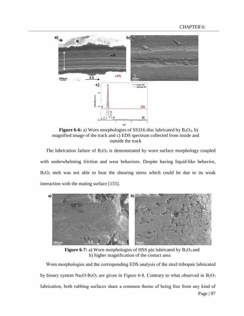
CHAPTER 6:
Page | 97
The lubrication failure of B2O3 is demonstrated by worn surface morphology coupled
with underwhelming friction and wear behaviors. Despite having liquid-like behavior,
B2O3 melt was not able to bear the shearing stress which could be due to its weak
interaction with the mating surface [155].
Worn morphologies and the corresponding EDS analysis of the steel tribopair lubricated
by binary system Na2O-B2O3 are given in Figure 6-8. Contrary to what observed in B2O3
lubrication, both rubbing surfaces share a common theme of being free from any kind of
Figure 6-7: a) Worn morphologies of HSS pin lubricated by B2O3 and
b) higher magnification of the contact area
Figure 6-6: a) Worn morphologies of SS316 disc lubricated by B2O3, b)
magnified image of the track and c) EDS spectrum collected from inside and
outside the track

CHAPTER 6:
Page | 98
surface damages. X-ray spectrum clearly points out chemical fingerprints of the melt
lubricant including B, O and Na alongside a minor trace of Fe on both worn surfaces. The
presence of lubricant elements on the wear track after friction test suggests that the binary
system Na2O-B2O3 was able to endure the tribological exposure without being squeezed
out. This attribute is the most critical factor for sodium borate superior lubrication
compared to B2O3 melt. The addition of Na into B2O3 clearly has a significant impact on
friction and wear behaviors of the lubricant.
Figure 6-8: Worn morphologies of steel pair lubricated by binary system
Na2O-B2O3 and the corresponding EDS spectrum a) SS316 disc, b) HSS pin
(S.D = sliding direction)
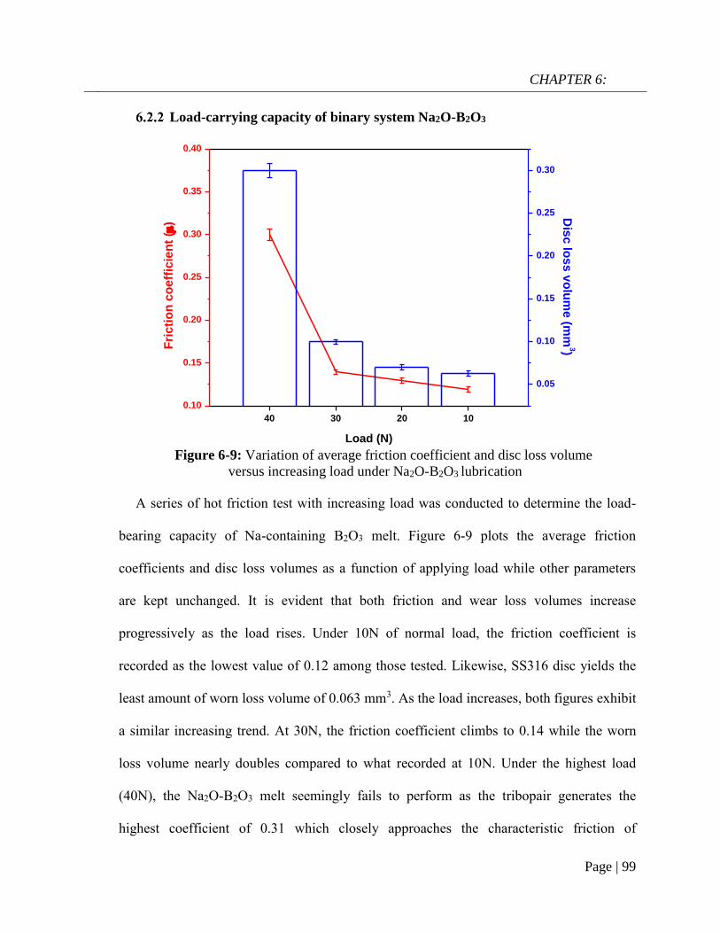
CHAPTER 6:
Page | 99
40 30 20 10
0.10
0.15
0.20
0.25
0.30
0.35
0.40
Load (N)
Fri
cti
on
co
eff
icie
nt
()
0.05
0.10
0.15
0.20
0.25
0.30
Dis
c lo
ss
vo
lum
e (m
m3)
Load-carrying capacity of binary system Na2O-B2O3
A series of hot friction test with increasing load was conducted to determine the load-
bearing capacity of Na-containing B2O3 melt. Figure 6-9 plots the average friction
coefficients and disc loss volumes as a function of applying load while other parameters
are kept unchanged. It is evident that both friction and wear loss volumes increase
progressively as the load rises. Under 10N of normal load, the friction coefficient is
recorded as the lowest value of 0.12 among those tested. Likewise, SS316 disc yields the
least amount of worn loss volume of 0.063 mm3. As the load increases, both figures exhibit
a similar increasing trend. At 30N, the friction coefficient climbs to 0.14 while the worn
loss volume nearly doubles compared to what recorded at 10N. Under the highest load
(40N), the Na2O-B2O3 melt seemingly fails to perform as the tribopair generates the
highest coefficient of 0.31 which closely approaches the characteristic friction of
Figure 6-9: Variation of average friction coefficient and disc loss volume
versus increasing load under Na2O-B2O3 lubrication

CHAPTER 6:
Page | 100
unlubricated contact [24]. Furthermore, the disc wears by an amount of 0.3mm3 which is
nearly 3-fold of the 30N testing point.
Characterization by SEM/EDS on the worn surfaces lubricated by Na2O-B2O3 at 20N
and 30N was performed and reported in Figure A-11 and A-12 (Appendices). Those worn
morphologies display identical features to those at 10N with no sign of surface damages
while being covered by the lubricant melt.
The sudden disruption in friction/wear behaviors at the highest load 40N suggests
lubrication failure and surface examination of the worn pairs is given in Figure 6-10 to
provide further evidences. It can be recognized that both contact surfaces reveal different
worn morphologies compared to those under successful lubrication at lower loads. There
are signs of scoring damages parallel to sliding direction in conjunction with minor
delamination on the wear track (Figure 6-10a). The opposing surface exhibits several types
Figure 6-10: Worn morphologies of steel tribopair lubricated by Na2O-B2O3 at
40N and the corresponding EDS spectrum a) SS316 disc, b) HSS pin

CHAPTER 6:
Page | 101
of damage ranging from adhesive wear to plastic smearing (Figure 6-10b). The
corresponding EDS spectrum suggest oxidized contact areas with the absence of B and
only small amount of Na. Figure 6-11 illustrates AFM image of the worn track at the point
of lubrication failure (at 40N). The nano-grain morphology belongs to the exposed oxide
scale grown on stainless steel [66] and will be confirmed in the following analysis. As the
lubricant film was likely destroyed, the sliding contact became unlubricated which resulted
in incremental friction and wear losses (Figure 6-9). As sole B2O3 evidently failed to
lubricate at the lowest load, it can be predicted that the melt is not able to perform under
harsher conditions. The addition of Na into B2O3 not only radically reverses the lubricity of
the beneficiary, but also renders a stable lubrication performance over a certain range of
load.
Figure 6-11: AFM height profile of the wear track after the friction test
under Na2O-B2O3 lubrication at 40N
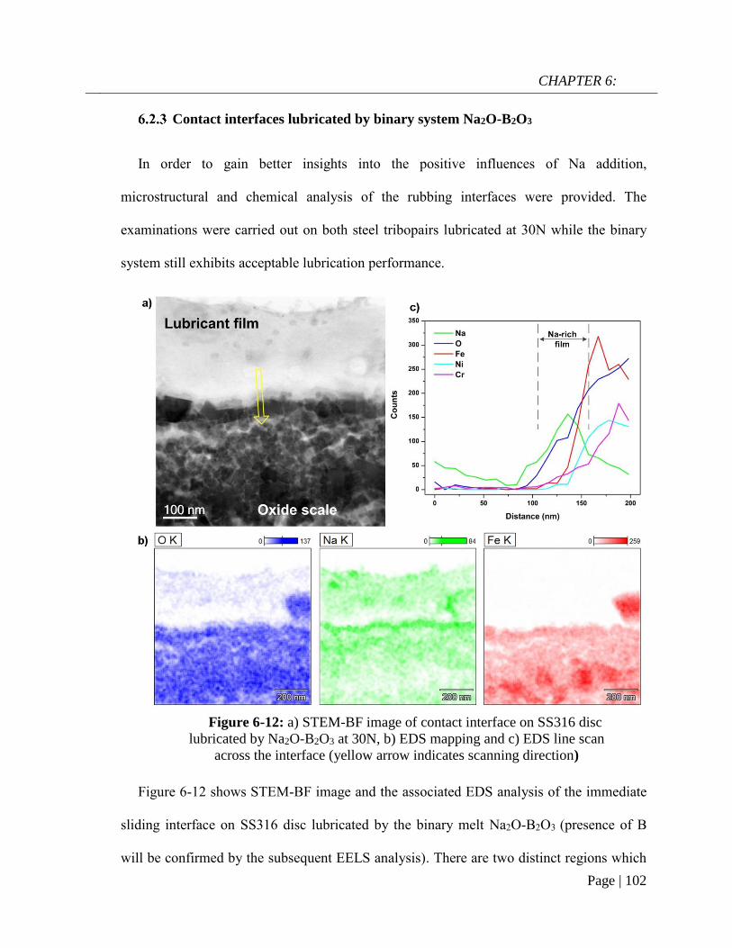
CHAPTER 6:
Page | 102
Contact interfaces lubricated by binary system Na2O-B2O3
In order to gain better insights into the positive influences of Na addition,
microstructural and chemical analysis of the rubbing interfaces were provided. The
examinations were carried out on both steel tribopairs lubricated at 30N while the binary
system still exhibits acceptable lubrication performance.
Figure 6-12 shows STEM-BF image and the associated EDS analysis of the immediate
sliding interface on SS316 disc lubricated by the binary melt Na2O-B2O3 (presence of B
will be confirmed by the subsequent EELS analysis). There are two distinct regions which
Figure 6-12: a) STEM-BF image of contact interface on SS316 disc
lubricated by Na2O-B2O3 at 30N, b) EDS mapping and c) EDS line scan
across the interface (yellow arrow indicates scanning direction)

CHAPTER 6:
Page | 103
can be differentiated by their contrasts. The bright upper layer can be assigned to the
lubricant melt while the underlying counterpart with grain-like characteristic can be
designated to the iron oxide scales. It can be observed that the immediate sliding surface is
composed of fine oxide grains whose lateral dimension is below 50nm. In addition, there
are also signs of voids and pores within the oxide scale which are considered as intrinsic
features in the oxide microstructure grown on alloyed steel at high temperature. EDS
mapping apparently differentiate the oxide scales from the overlying lubricant layer. Fe
signal is more intense in the oxide scale while O density appears much higher in the oxide
scale than in the lubricant melt. Na exhibits an interesting distribution pattern as the
element concentrates heavily on top of the iron oxide surface to form a continuous film.
The representative EDS scan is provided to underline the existence of Na-rich film by the
sudden increase in the Na signal when it approaches the oxide scale. The thickness of this
Na film is estimated around ~50nm. Due to its relative position on the sliding interface, the
Na film can play a pivotal role in prohibiting immediate asperity contacts, particularly
under boundary lubrication regime. In addition, Na is also detected underneath the
immediate sliding surface. It tends to distribute among the subsurface voids and pores,
although it is less dense than the interfacial film (Figure 6-12b). At high temperature, the
inward infiltration of lubricant melt could be due to the extreme stressed shearing in
combination with the voids formation within the oxide microstructure of SS316. On the
other hand, O looks depleted just above the Na-rich film. Apart from the predominant iron
oxides, the oxides of Ni and Cr are also formed since the elements are typically included in
stainless steel composition for improved oxidation resistance.

CHAPTER 6:
Page | 104
Boron was detected at the sliding interface and its chemical fingerprint is given in the
EELS spectrum (Figure 6-13). The characteristic excitation edges are located at 195eV and
204eV corresponding to the π* and σ* transition, respectively [113-115] which indicate the
dominant presence of trigonal BO3 species.
180 190 200 210 220
0
20000
40000
60000
80000
100000
120000
Co
un
ts (
a.u
.)
Energy Loss (eV)
Figure 6-13: EELS spectrum of B K-edge on the contact interface of SS316
disc lubricated by Na2O-B2O3 at 30N

CHAPTER 6:
Page | 105
A similar characterization routine was accomplished on the opposing HSS pin and the
outcomes were shown in Figure 6-14. The BF image illustrates 2 different regions with
varying contrasts, a top transparent layer of lubricant melt residing on the oxide substrate.
In addition, there appears a very thin boundary film with a distinct contrast running along
the oxide interface. Again, the grain-like morphology of the oxide scale is visible.
However, the HSS oxide scale appears tightly compact as the oxide scale look very dense
without any sign of internal porosity. This could be attributed to the superior oxidation
resistance and excellent mechanical properties of HSS material. EDS mapping reveals the
Figure 6-14: a) STEM-BF image of contact interface on HSS pin
lubricated by Na2O-B2O3 at 30N, b) EDS mapping and c) EDS line
scan across the interface (yellow arrow indicates scanning direction)

CHAPTER 6:
Page | 106
180 190 200 210 220
0
20000
40000
60000
80000
100000
120000
Co
un
ts (
a.u
.)
Energy Loss (eV)
apparent boundary between the two contacting phases as Fe and O are predominantly
found in the oxidized surface while the upper layer contains a significant amount of Na. In
accordance to the elemental mapping, the interfacial film in BF image turns to be rich in
Na with an approximated thickness of ~50-60nm. The penetration of Na appears less
significant compared to what occurred on the opposing SS316 surface. The chemical
signature of boron on the interface was detected and presented in the EELS spectrum
(Figure 6-15) with excitation edges identical to that extracted on the disc interface.
TEM image capturing the HSS contact interface on a wider field of view is given in
Figure 6-16. Despite having a similar contrast with the lubricant layer, Na-rich film can be
readily distinguished as a thin continuous layer superimposing on the oxide surface. In
addition, it can be observed that the nano-sized grains are rigidly held together with no
voids among them. Electron Diffractions (ED) of both contacting phases are shown in
Figure 6-16. The lubricant layer expectedly produces a diffusive ring suggesting
amorphous nature of the binary borate melt. On the other hand, a ring-like ED pattern was
Figure 6-15: EELS spectrum of B K-edge on the contact interface of
HSS pin lubricated by Na2O-B2O3 at 30N
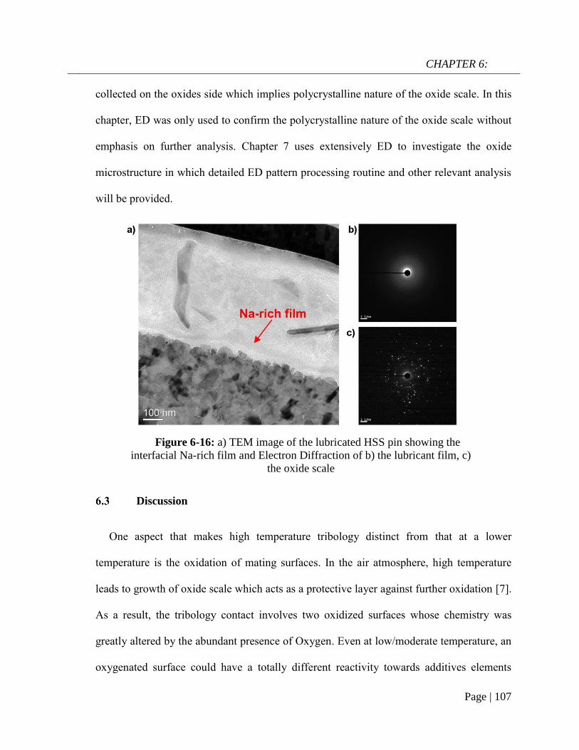
CHAPTER 6:
Page | 107
collected on the oxides side which implies polycrystalline nature of the oxide scale. In this
chapter, ED was only used to confirm the polycrystalline nature of the oxide scale without
emphasis on further analysis. Chapter 7 uses extensively ED to investigate the oxide
microstructure in which detailed ED pattern processing routine and other relevant analysis
will be provided.
Discussion
One aspect that makes high temperature tribology distinct from that at a lower
temperature is the oxidation of mating surfaces. In the air atmosphere, high temperature
leads to growth of oxide scale which acts as a protective layer against further oxidation [7].
As a result, the tribology contact involves two oxidized surfaces whose chemistry was
greatly altered by the abundant presence of Oxygen. Even at low/moderate temperature, an
oxygenated surface could have a totally different reactivity towards additives elements
Figure 6-16: a) TEM image of the lubricated HSS pin showing the
interfacial Na-rich film and Electron Diffraction of b) the lubricant film, c)
the oxide scale

CHAPTER 6:
Page | 108
compared to an oxygen-free surface. Jun et al. discovered that treating a TiAlV alloy with
an oxygen-diffusion process stimulates the formation of ZDDP-based tribofilm which in
turn reduces the wear rate by up to six orders of magnitude [156]. In addition, mechanical
properties and microstructure of the developed scale are also believed to play a significant
role in the tribological behaviors.
As clearly stated in Chapter 4&5, there is a coexistence of covalent and ionic bonding in
the binary system Na2O.B2O3 upon melting. The former is assigned to B-O-B network
while the latter refers to the Na-O interaction. The addition of Na introduces ionic
characteristic into otherwise purely covalent B2O3 melt. With small atomic radius and high
mobility, the electrophilic Na cations are attracted by the oxidized steel where electron
density is high due to the presence of Oxygen. The strong adsorption of cationic Na
renders the binary system a superior affinity towards iron oxide surface than its Na-
excluding counterpart. It is exhibited by the formation of continuous Na-rich layers
residing on both contact surfaces as observed in Figure 6-12 and Figure 6-14. On one hand,
the interface reaction can enhance the wettability of the binary melt on oxidized surface in
a similar fashion to hydro bonding on most hydrophilic surfaces [157, 158]. On the other
hand, it also helps the Na2O-B2O3 melt to sustain the stressed shearing on the interface and
subsequently function as an effective lubricant. This is the primary foundation for the
excellent lubricating properties of the binary melt including friction reduction, wear
resistance and high load-bearing capacity. Under boundary lubrication, direct asperity
contacts can be mitigated by the boundary film which results in low wear rate and low
friction. The extended load-bearing capacity could be attributed to the robustness and
resilience of Na thin film. At room temperature, electrolytic lubricating medium reportedly

CHAPTER 6:
Page | 109
demonstrates promising performance [120, 159-161] and surface adsorption is claimed to
be the fundamental factor for such behaviors. In addition, some believed that the repulsion
between similarly-charged atoms on opposing surfaces can further reduce frictional loss
[159].
Beside the chemical origin of the lubricant melt, the effects of microstructure of the
grown oxide scale on lubrication mechanism also deserve consideration. It was evident that
the mating surfaces are comprised of ultrafine oxide grains which are well-known for their
high strength [124, 162]. On the sliding interface of the disc, disintegration of the scale
microstructure was shown with voids formation among the oxide scale bulk (Figure 6-12).
The liquid-like lubricant melt is drawn into the subsurface region evidenced by the
migration of Na into the internal structure of the deformed scale (Figure 6-17). This could
arise from intense capillary forces in combination with shearing stress. The lubricant
infiltration effectively creates pocket reservoirs which could extend the loading capacity of
the binary melt (Figure 6-9). When the outermost oxide surface wears out during sliding
contact, the melt lubricant hosted in the subsurface scale emerges to provide healing effect.
Figure 6-17: Infiltration of Na into the SS316 surface
under Na2O-B2O3 lubrication (at 30N)
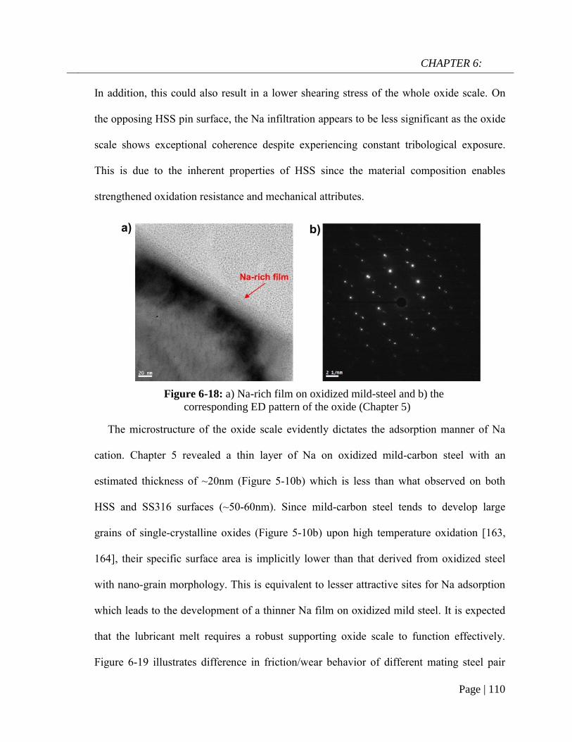
CHAPTER 6:
Page | 110
In addition, this could also result in a lower shearing stress of the whole oxide scale. On
the opposing HSS pin surface, the Na infiltration appears to be less significant as the oxide
scale shows exceptional coherence despite experiencing constant tribological exposure.
This is due to the inherent properties of HSS since the material composition enables
strengthened oxidation resistance and mechanical attributes.
The microstructure of the oxide scale evidently dictates the adsorption manner of Na
cation. Chapter 5 revealed a thin layer of Na on oxidized mild-carbon steel with an
estimated thickness of ~20nm (Figure 5-10b) which is less than what observed on both
HSS and SS316 surfaces (~50-60nm). Since mild-carbon steel tends to develop large
grains of single-crystalline oxides (Figure 5-10b) upon high temperature oxidation [163,
164], their specific surface area is implicitly lower than that derived from oxidized steel
with nano-grain morphology. This is equivalent to lesser attractive sites for Na adsorption
which leads to the development of a thinner Na film on oxidized mild steel. It is expected
that the lubricant melt requires a robust supporting oxide scale to function effectively.
Figure 6-19 illustrates difference in friction/wear behavior of different mating steel pair
Figure 6-18: a) Na-rich film on oxidized mild-steel and b) the
corresponding ED pattern of the oxide (Chapter 5)

CHAPTER 6:
Page | 111
0.0
0.5
1.0
1.5
2.0
2.5
20N
HSS/SS316
HSS/MC
Average COF
10N
Dis
c lo
ss
vo
lum
e (
mm
3)
0.10
0.15
0.20
0.25
0.30
0.35
0.40
Avera
ge
CO
F
under binary borate lubrication. While HSS/SS316 shows good lubricity and low wear rate
at both testing load, the HSS/mild-carbon steel (MC) appears to fail at both conditions. As
the oxide scale on SS316 has a good adherence with the steel base due to the formation of
Cr-rich layer (evidenced in Figure 6-17), it provides a strong foundation for an effective
lubrication. Plenty of studies have proved the superior adhesion strength of the oxide scale
grown on Cr-containing steel [165-167]. On the other hand, oxide scale grown on mild or
low-carbon steel often demonstrate weak adhesion with the steel base due to the absence of
the reactive elements (Cr, Al, Si…) [7]. The lack of strong supporting oxide scale results in
the lubrication failure which is indicated by high wear loss and high friction coefficient
(Figure 6-19).
B2O3 singly provides little or no lubrication effect and this poor behavior could be
attributed to its inertness towards iron oxides. Since B2O3 is considered as a weak acid
while iron oxides are also regarded as weak bases on the basis of chemical hardness theory
Figure 6-19: Friction/wear behaviors between different tribopair
under borate lubrication at 800oC

CHAPTER 6:
Page | 112
[168], reaction between those two bodies is unlikely due to unfavorable thermodynamic.
By classifying the lubricity of different oxides systems based on a crystal-chemical model,
Erdemir [155] found that B2O3 has little or no chemical interaction with other cations in
the tribosystem due to its high ionic potential. However, the role of B2O3 in the lubrication
performance of the binary system cannot be undermined. As a structural-building block,
boron oxide provides the viscous characteristic with low shearing strength for the binary
melt. The fluidity rendered by boron oxide also facilitates the transport of lubricant into the
contact area and subsequently allows Na absorption on the oxidized surface, which has
been proven critical for the lubrication performance.
Conclusions
The current chapter aims to refine the role of sodium on the tribological behaviors of
binary oxides Na2O-B2O3 on coupled steel pair HSS/SS316 at 800oC. There are some
concluding remarks which can be found as followed:
Addition of Na into pure B2O3 drastically improves the lubrication performance
of the beneficiary;
The binary system Na2O-B2O3 also exhibits a good load-bearing capacity;
Adsorption of Na onto both contact surfaces close to the iron oxide surface is the
driving force for the excellent lubrication performance of sodium borate;
There is a close relationship between Na film thickness and the oxide
microstructure;
Oxide scale grown from stainless steel proves a better foundation for lubricant
adsorption.

CHAPTER 7:
Page | 113
CHAPTER 7:
Borate melt as a sticking-scale inhibitor
on a High Speed Steel surface
* This chapter content was published in Tribology International, 2019, 140, 105860
Apart from friction/wear concerns, material transfer between work roll and workpiece
can result in detrimental consequences during tandem hot rolling. The roll surface can be
covered by a layer of sticking oxide which originates from the workpiece surface in
reheating stage. As the transferred scale thickens, it is prone to peeling-off which results in
roll banding and the quality of rolled products is significantly deteriorated from the
emerging defects [27, 169]. In fact, the sticking occurrence could be due to poor oxidation
management in the reheating stage and ineffective lubrication in subsequent rolling
proceses.
High speed steel (HSS) is a specialized micro-alloyed material which has been widely
used as the work roll due to its high hot hardness and exceptional wear resistance at high
temperature. Much effort have been made to evaluate the tribological properties of HSS in
various operating conditions. By using a dry rolling-sliding configuration on HSS/carbon
steel tribopair, Pellizzari [152] correlated the low wear rate of HSS roll with its high
hardness while wear mechanism was claimed to be a complex combination of adhesion,
abrasion and tribo-oxidation. On the contact surface, the formation of an oxide layer was
believed to transition friction/wear characteristics into a milder regime which otherwise

CHAPTER 7:
Page | 114
would be severe if direct metal-metal contact occurs. In the case of pure sliding contact,
transferred oxide scale is also observed on HSS surface when it pairs with mild steel [23,
24] and ferritic stainless steel [170, 171] at elevated temperature.
The current chapter specifically focuses on the wear characteristics of HSS surface
under sliding contact at high temperature in the presence of sodium borate. Stainless steel
is chosen as the counterpart material since it exhibits great sticking tendency in actual hot
rolling process [169, 172]. The normal load was chosen (5N) to generate a maximum
contact pressure of 0.9GPa which is close to actual parameters in hot rolling [173].
Besides, the effects of lubrication on oxidation behavior of the subsurface oxides are also
revealed.
Experimental details
Materials preparation
Material selection for the tribotest is similar to Chapter 6 as HSS was chosen as the pin
and Stainless Steel 316 (SS316) was selected as the disc material. The mechanical
properties and chemical composition of the steel tribopair remain unchanged. The disc
surface was ground and polished to achieve an average roughness of 0.1µm. The HSS pin
has a hemispherical diameter of 6.35mm with a roughness of 1µm. The steel pair was
cleaned with ethanol/acetone prior to friction test. A 5% wt. aqueous solution of sodium
borate was prepared for lubrication test.
Friction test

CHAPTER 7:
Page | 115
0 5 10 15 20 25
450
500
550
600
650
700
Friction testing
Te
mp
era
ture
(oC
)
Time (mins)
Preoxidation
Hot friction test was conducted on the UMT2-CETR pin-on-disc tribometer. The disc
sample was first placed in the furnace followed by a series of heating sequences to avoid
overshooting. Once the set temperature was reached, the HSS pin was lowered to a
distance of 2-3mm above the SS316 disc surface. HSS pin was oxidized for 10 mins prior
to sliding. A thermocouple was embedded into the pin body (with a distance of 2mm to the
contact surface) to monitor its temperature. As illustrated in Figure 7-1, the temperature of
the pin sharply rises after the first 5 mins followed by stabilization at 695oC. An
engagement of the steel pair further increases HSS surface temperature to nearly 700oC.
The heating program was designed to represent actual working condition in which HSS
surface temperature typically lies between 650oC and 750oC during hot rolling [24, 174].
Lubricant was dropped onto the hot disc 2 mins at a rate of 0.01ml/s prior to sliding. Linear
sliding velocity was kept at 0.096m/s with two different durations: 5 mins and 15 mins.
The normal load was fixed at 5N corresponding to 0.9GPa (Equation 4-1). When friction
test stops, the HSS pin was immediately retrieved from the furnace to avoid further
oxidation. At least three tests were performed at each condition to ensure the repeatability.
Figure 7-1: Temperature record of HSS pin during pre-oxidation and friction test

CHAPTER 7:
Page | 116
Characterization
An Atomic Force Microscopy (Digital Instrument Dimensions 3100) was used to
generate height profiles of the polished HSS substrate. Worn morphologies on HSS pins
were captured by the 3D Interferometer Optical Microscope (Bruker Contour GT-K).
Similar to Chapter 6, microscope works were conducted to observe the worn surface
morphologies and the cross section of the contact area. During STEM/EDS, elemental
phase mapping was achieved by the comparison of X-ray spectrum between pixels and
those with similar statistic are collated into one specific phase. Selected Area Electron
Diffraction (SAED) was performed on the FIB lamellas at several locations and three
representatives are reported. All the calibrated diffraction patterns were processed by a suit
of software tool (DiffTools) in Digital Micrograph, a widely-known platform software for
TEM images processing [175, 176]. Intensity profiles as a function of reciprocal distance
were then derived, normalized and compared between different testing conditions.
Referenced d-spacings of relevant crystallites were collected from Powder Diffraction
Files 4+ 2018.
Results
Microstructural evolution of HSS at high temperature and its tribological
behaviors against SS316

CHAPTER 7:
Page | 117
Since HSS is composed of two different phases (in Chapter 6), their individual
oxidation behaviors at high temperature collectively contribute to the overall properties of
the sliding surface. It has been acknowledged that oxidation of metal carbides are more
thermodynamically favorable due to a low energy barrier [150, 177]. Carbide-free matrix is
subsequently oxidized with the development of iron oxides. XRD pattern of oxidized HSS
substrate at 700oC for 10 mins reveals a major formation of Fe2O3 and a minor fraction of
Fe3O4 (Figure 7-2c). AFM images (Figure 7-2b, 7-2c) clearly illustrate superior growing
kinetic of metal carbides than that of metallic matrix during high temperature oxidation.
Nevertheless, it is expected that the native oxide scale from the metallic matrix plays a
critical role on the contact interfaces due to their dominating proportion in the starting
material (volume fraction of carbide is around ~9-12%).
Figure 7-2: AFM image of HSS specimen before (a) and after oxidation
(b) at 700oC for 10 mins, (c) XRD pattern of the oxidized HSS

CHAPTER 7:
Page | 118
0 300 600 900
0.0
0.3
0.6
0.9
1.2
1.5
CO
F (
µ)
Sliding time (s)
Unlubricated
Lubricated
Friction coefficient curves generated from HSS/SS316 sliding contact are given in
Figure 7-3. Under lubrication-free condition, it can be seen that friction coefficient
fluctuates widely between 0.4-0.9 at the first 400 seconds before stabilizing at an average
value of 0.23±0.05. During the running-in period, high friction coefficient is likely
attributed to contact between hard metal oxides [171]. On the other hand, the following
steady stage indicates potential formation of tribolayer with friction-reducing effect. It is
evident in Figure 7-4 where transferred material on HSS pin is observable on both
unlubricated tests, regardless of testing duration. At 5mins mark (Figure 7-4a), the worn
morphologies are characterized by plateau build-up and progressive smearing of the
adhered layer. As sliding test continues, the contact area enlarges with apparent flattening
effect which consequently reduces the contact pressure. The complete formation of the
tribo-layer significantly alleviates wear severity which can be indicated by smooth rubbing
surface with the only damage being minor fracture in the sub-surface region (Figure 7-4d).
Figure 7-3: Friction coefficient curves from HSS/SS316 tribopair with
and without lubrication

CHAPTER 7:
Page | 119
Figure 7-5 illustrates cross-sectional views of HSS worn surfaces along with relevant
elemental mapping after dry sliding tests. After 5mins, by contrast difference, the
transferred layer can be distinguished from the HSS substrate which is characteristically
filled with carbides chunks (Figure 7-5a). The transferred layer thickness ranges from 4.5
to 6.6µm at 5mins mark then it soars to roughly 34µm as sliding duration triples. The
oxygen signal indicates that the adhered material is predominantly composed of oxides.
However, there could be inclusion of stainless steel debrises in the transferred layer,
although they were likely oxidized as the test progresses. It is noteworthy that the tribo-
oxide layer which is exclusive of any sign of carbides implies the foreign nature of
transferred material. Although the native oxide scale developed during pre-oxidation
accounts for a definite fraction of the oxide scale, it is conclusive that transferred (and
Figure 7-4: Worn morphologies of HSS pin without lubrication
after 5 mins (a, b) and 15 mins (c, d)

CHAPTER 7:
Page | 120
adhesive) oxide scale to the pin is the most dominating wear occurrence on HSS surface
sliding against SS316.
Effect of lubrication on the tribological behavior of HSS pin
As shown in Figure 7-3, frictional behavior of HSS/SS316 sliding contact clearly
benefits from the borate lubrication. The use of melt lubricant clearly shortens running-
period, as friction coefficient enters stabilization stage roughly after 200 seconds of
sliding. The downward trend could be associated with the gradually decreasing shearing
stress by the presence of the lubricant melt on the contact surface. In addition, the average
friction is quite low at 0.1±0.02 during the steady period which is reduced by 2.3 times in
comparison to unlubricated case. Figure 7-6 displays SEM micrograph of HSS pin surface
after 5mins-lubrication test while the one after 15mins-test is not provided due to
similarity. Worn morphology reveals no major damages but only a few scratches along
sliding direction. Supporting EDS spectrum exhibits intense signals of lubricant elements
Figure 7-5: Cross-sectional views of HSS worn surfaces without
lubrication after a) 5mins and b) 15mins (specimens were tilted at 54o)

CHAPTER 7:
Page | 121
including B, O and Na with relatively weak peak of Fe which suggests a layered structure
in which lubricant film resides on the iron oxide base.
In order to unfold the immediate sliding interface, cross-sectional observations of HSS
pins exposed to lubrication are given in Figure 7-7. By a contrast difference, it can be seen
that there are 3 distinct layers corresponding to the lubricant film, oxide scale and HSS
substrate as denoted in each image. In the case of 5mins test, it is clear that the oxide scale
is composed of nanoparticles in the range of ~20-100nm. This is in a good agreement with
Chapter 6. The oxide structure remains remarkably compact with no sign of cavities or
pores. In addition, the scale has an average thickness of 0.65 µm which is approximately
10 times lower than what observed with the lubricant-free test. There are signs of slight
tearing damages in the HSS substrate which is likely to occur during the running-in
process. As the sliding time increases, the scale on HSS thickens to approximately
6~6.5µm with some microstructure changes (Figure 7-7b). However, it is still significantly
thinner than that observed in dry sliding counterpart (which is approximately 34µm). It is
noteworthy that the immediate oxide/lubricant interface appears fairly smooth despite
experiencing high local pressure during the friction test (Figure 7-7).
Figure 7-6: Worn morphology of HSS pin in lubrication test after 5 mins (a)
and EDS spectrum (b).

CHAPTER 7:
Page | 122
Apart from friction-reducing effect, it is evident that sodium borate lubricant inhibits
sticking oxide scale on HSS surface reflected by the oxide thickness reduction. After
lubricant removal, 3D surface plots of HSS pin are given along unlubricated counterparts
for worn morphology examination (Figure 7-8). Contrary to the apparent material transfer
during dry sliding (Figure 7-8a, 7-8b), HSS pins practically shows no sign of adhered
material across the whole contact areas exposed to the lubricant (Figure 7-8c, 7-8d),
although some damages are visible in the longer duration. A closer examination reveals
craters produced from FIB work, mostly on the top region of the worn area where oxide
scale thicknesses were extracted.
Figure 7-7: STEM-BF images of cross-sectional HSS pins after lubrication test
a) 5mins and b) 15mins

CHAPTER 7:
Page | 123
Effect of lubrication on iron oxides microstructure
It is expected that the presence of a lubricant film can exert certain influences on the
high-temperature oxidation behavior of the underlying oxide scale. Figure 7-9 shows
cross-sectional TEM micrographs of HSS surface under different lubrication/oxidation
conditions. Electron diffraction was performed on the FIB lamellas and the processed
intensity profiles are also provided to determine the crystal structure of iron oxides. In the
case of 5mins lubrication test, it is clear that the oxide scale is composed of sub-micron
particles with the major constituent being Hematite (Fe2O3) (Figure 7-9a). As sliding times
triples, there emerges a phase evolution as Magnetite (Fe3O4) (mostly (102), (200) and
(016)) replaces Hematite to become the most dominant phase as evidenced in the adjacent
profile. Similar analysis routine was accomplished on purely oxidized HSS, which was
Figure 7-8: 3D profile images of HSS pin after dry sliding test (a-5mins, b-15mins)
and lubrication test (c-5mins, d-15mins)

CHAPTER 7:
Page | 124
extracted from non-contact area after 15mins lubrication test (Figure 7-9c). There are 3
layers in top-to-bottom order: Pt cap, oxide scale and HSS substrate with the presence of
carbides precipitates. The oxide layer thickness varies from 1 to 2µm across the whole
lamella while the oxidescale is largely composed of Hematite with a minor fraction of
Magnetite as evidenced in the complementary profile. This aligns well with X-ray
diffraction result (Figure 7-2c). Chromia (110) (Cr2O3) is also present in a fair amount
which likely concentrates on scale/substrate interface [177, 178].
The phase transformation over sliding time is further substantiated by the morphology
change of iron oxide particulates. Figure 7-10 exhibits magnified TEM micrographs of the
oxide scale formed under lubrication after increasing sliding durations. It can be seen that
the iron oxide nanograins (with average dimension <100nm) appear to have poly facets
when exposed to 5mins-lubrication test (Figure 7-10a). This could be the cause of the
highly compact scale as each individual grain can accommodate geometry changes from
the surrounding with ease, especially under the effect of shearing. The oxide grains from
static oxidation test resemble the one achieved from 5mins lubrication test. On the other
hand, prolonged exposure to lubrication evidently leads to shape transformation as the
oxide nanoparticles exhibit an unambiguous cubic morphology (Figure 7-10b). The
nanocubes seem to be geometrically distorted as a result from tribological effect. Figure 7-
10c illustrates a typical cubic oxide particle with sharp edges and indicative d-spacing of
Magnetite (102). The Magnetite nanoparticles with such characteristic shape were found
across the whole scale. Contrary to a compact scale observed with the shorter test, the

CHAPTER 7:
Page | 125
loose oxide scale with emerging voids and porosity can be attributed to the phase
transformation under extended sliding duration.
Figure 7-9: TEM images of HSS pin cross sections in a) 5mins
lubrication, b) 15mins lubrication and c) 15mins static oxidation
with corresponding intensity profiles from SAED

CHAPTER 7:
Page | 126
Discussion
It has been shown (Figure 7-4) that carbides oxides are present on the pre-contact
surface of oxidized HSS alongside iron oxide matrix. However, despite protruding through
the oxide scale, those carbides oxide particles are likely to be ejected upon contact due to
their poor adherence with the underlying substrate. This is justified by the total absence of
carbides oxides on the sliding surface from cross-sectional observation (Figure 7-5). The
current work is in good agreement with past literatures. In their study regarding oxidation
behaviors of HSS at high temperature under dry and wet atmosphere, Qiang et al. [177,
178] observed various types of carbide oxides (mostly V-based) that are loosely held on
top of a more compact scale. After conducting sliding test against mild-steel at high
Figure 7-10: Magnified oxide microstructure after lubrication tests,
a) 5mins, b) 15mins and c) Fe3O4 (102) nanoparticle with indicated d-spacing

CHAPTER 7:
Page | 127
temperature (900oC), there was no sign of carbide-based particles on the front-most contact
area [24]. On the other hand, the native oxide matrix is able to withstand the high shearing
stress due to their excellent deformability and strong bonding with the metal substrate,
mostly through the formation of anchoring FeCr2O3 spinels [150, 177, 178].
The formation of the tribo-layer (Figure 7-4) is likely originated from combined effects
of adhesive wear, particles sintering and tribo-oxidation [179]. The development of such a
layer is largely dominated by microstructural characteristics of the associated oxide
particles while its endurance is also a function of loading amplitude and sliding velocity.
Previous studies on sliding HSS/mild steel pair revealed tribo-oxide layer formation and its
subsequent disintegration [22-24]. Particle omission by spallation leads to intermittent
coverage of the glaze layer and increases friction coefficient as a result. This might arise
from the fact that iron oxides tend to grow into coarse particles with poor deformability on
mild steel which undermines the tribo-layer formability. In contrast, finer oxide particles
have been shown to accelerate the tribo-layer formation on the sliding surface [25]. Native
oxides of highly-alloyed steel reportedly grow as nano-scale grains [108, 180]. In addition,
Figure 7-11: a) Variation of oxide thickness on HSS pin with various
lubricating condition and b) wear track profiles on SS316 disc after 5mins
(below) and 15mins (above) test

CHAPTER 7:
Page | 128
Chapter 6 evidently revealed the nanograin oxide scale grown on SS316 which favors
robust establishment of the glaze layer. The consolidation rate of the tribo-layer is believed
to outweigh the omission rate of debris particles indicated by the growing thickness of
glaze layer over time (by nearly 6 times as sliding time extends from 5mins to 15mins).
Although the presence of tribolayer is commensurate with friction-reducing and -
stabilizing effects, it is still considered unfavorable as it is developing at the expense of
sacrificial wear of the opposing surface.
Figure 7-12: Worn morphologies of SS316 disc after 15mins test, (a)
without lubrication and (b) with lubrication (below are magnified
images, double-arrowed line indicates track width)

CHAPTER 7:
Page | 129
It is obvious that the employment of borate melt markedly inhibits adhered/transferred
material on HSS pin as shown by the reduced scale thickness (Figure 7-11). The total
reduction rate is estimated at ~88% after 5mins and ~80% after 15mins compared to
unlubricated counterparts. Furthermore, the suppressed adhesive wear on HSS surface is
indicative of a lower material loss on the opposing SS316 disc (Figure 7-11b) with the
maximum reduction of 76% compared to unlubricated case. The exceptional wear
resistance of borate lubricant is regarded as the most principle factor in the causation of
anti-sticking behavior. Material transfer fundamentally occurs when there emerges either
wear debris or third-body object on the contact interface. A reduced wear rate on the disc
practically means less scale-sticking probability. Worn morphologies of SS316 disc after
15mins tests are given in Figure 7-12 to justify the wear mechanism under different
lubrication conditions. In the absence of borate lubricant, catastrophic damages are visible
including ploughing, abrasion coupled with a formation of discontinuous oxide patches. In
contrast, the borate lubrication induces negligible wear severity as indicated by a reduced
track width alongside a smooth worn surface (Figure 7-12b). It is noted that SEM
micrograph was captured after the lubricant removal to reveal the true surface morphology.

CHAPTER 7:
Page | 130
Beside friction-reducing effect (Figure 7-3), the resistance against adhesive wear arises
from an effective lubrication and it is believed that the tribofilm plays a core role in these
desirable behaviors. The surface chemistry of the immediate sliding interface is further
examined to reveal the lubrication mechanism. Figure 7-13 shows the cross-sectional view
of lubricated HSS interface after 5mins sliding test alongside relevant phase and elemental
mapping. There are 3 different phases which can be compositionally distinguished by the
complementary phase mapping. The uppermost layer (phase 1) is assigned to the lubricant
layer with an abundance of Na, B and O while the two underlying layers are associated
with oxide matrix (phase 2) and HSS substrate (phase 3), respectively. On the immediate
Figure 7-13: Individual phase spectrum and elemental distribution
across the lubricated HSS pin after 5mins test
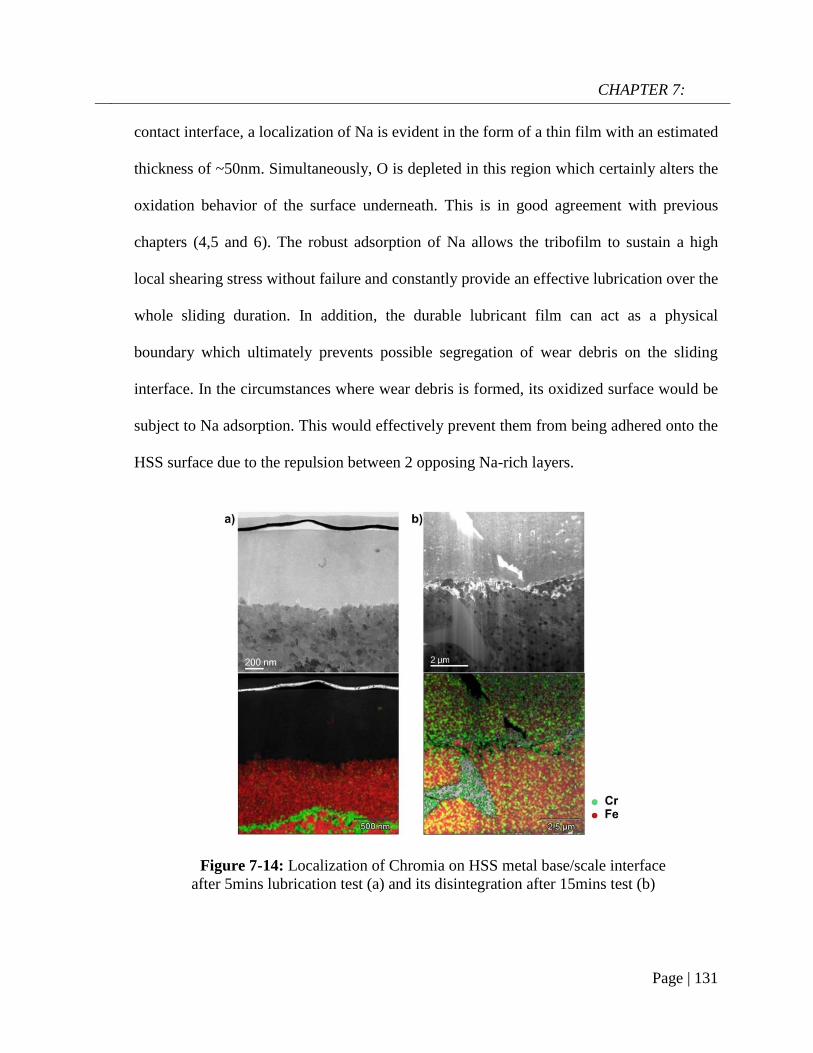
CHAPTER 7:
Page | 131
contact interface, a localization of Na is evident in the form of a thin film with an estimated
thickness of ~50nm. Simultaneously, O is depleted in this region which certainly alters the
oxidation behavior of the surface underneath. This is in good agreement with previous
chapters (4,5 and 6). The robust adsorption of Na allows the tribofilm to sustain a high
local shearing stress without failure and constantly provide an effective lubrication over the
whole sliding duration. In addition, the durable lubricant film can act as a physical
boundary which ultimately prevents possible segregation of wear debris on the sliding
interface. In the circumstances where wear debris is formed, its oxidized surface would be
subject to Na adsorption. This would effectively prevent them from being adhered onto the
HSS surface due to the repulsion between 2 opposing Na-rich layers.
Figure 7-14: Localization of Chromia on HSS metal base/scale interface
after 5mins lubrication test (a) and its disintegration after 15mins test (b)

CHAPTER 7:
Page | 132
As stated previously, the steel chemistry also plays a definite role in the high-
temperature oxidation responses with alloying elements (Cr, Al, Si, Ni...) being introduced
to enhance the oxidation resistance [7]. Due to their strong affinity with oxygen, oxidation
of these sacrificial elements is more thermodynamically favorable with the development of
an interlayer oxide [177, 178, 180-184]. Herein, SAED profiles are indicative of Chromia
formation in the scales from static oxidation test and 5mins lubrication test (Figure 7-9). In
addition, Figure 7-14 clearly illustrates a highly-localized Chromia film which
continuously runs along the scale/substrate interface with a thickness of 100nm after 5mins
lubrication test. The formation of Cr oxides interlayer (and possibly FeCr2O3 spinel) has
been known for inhibiting further oxidation. The compact layer renders a low atomic
diffusion rate which obstructs the outward migration of Fe ions. However, a prolonged
sliding imposes the disintegration of Chromia layer as evidenced in Figure 7-14b where Cr
signal is found scattering across the scale/base metal interface. The delocalization of
Chromia is believed to free outward diffusion of Fe ions which occur along the grain
boundary [7] and this could result in an increased oxidation (Fig. 10). Migrating Fe ions
appeares to react with the existing Hematite to form Magnetite due to limited O activity on
the interface (Figure 7-13). The resulting internal reduction of Hematite is evidenced by a
rising proportion of Magnetite (Figure 7-9) with an apparent morphology evolution of the
oxide nanoparticles (Figure 7-10). The reaction route is proposed as Fe (migrating) +
Fe2O3 → Fe3O4 which is greatly facilitated by a consistent lubrication effect and
continuous tribological exposure on the HSS pin. However, as diffusion of atmospheric O
into molten glass is well-acknowledged [185], one could not rule out its potential reaction
with Fe ions which can thicken oxide scale over testing time despite the fully-formed

CHAPTER 7:
Page | 133
lubricant film. As the load-bearing capacity of sodium borate has been demonstrated in
Chapter 6 (10-30N), it is likely that the lubricant can retain its anti-sticking characteristic
over that range.
The current work used pin-on-disc platform to simulate the sticking occurrence
between steel surfaces at high temperature and evaluate the influence of lubrication on
such event. In real metal working processes where the fresh workpiece is continuously fed
into the contact with the tool surface, the extent of sticking depends on many variables
(temperature of steel piece, relative speed, steel grade…) and might be different from what
observed in laboratory-scale testing. Thus, it is of necessity to justify the effectiveness of
the concerning lubricant in actual working condition.
Conclusions
The current chapter aims to evaluate the effect of lubrication on wear behavior of High
Speed Steel in contact with SS316 under high-temperature sliding condition. Several
conclusions can be made as followed:
HSS surface suffers negligible adhesive/transferred wear under borate lubrication
contrary to the unlubricated case.
The anti-sticking behavior is closely governed by the tribofilm formation on the
immediate sliding.
Adsorption of alkaline element (herein Na) on oxide surface has proved to be not
only the foundation for effective lubrication but also the driving force to inhibit material
transfer between pairing surfaces

CHAPTER 7:
Page | 134
Prolonged exposure leads to phase transformation of iron oxides in which
Hematite was transformed into Magnetite.

CHAPTER 8:
Page | 135
CHAPTER 8:
Tribological behaviors of sodium borate
in rolling contacts
Surface characteristics of the workpiece change rapidly when passing from one mill to
another due to differential rolling variables. To ensure a high surface quality of the rolled
workpiece is one of primary priorities while consideration of the surface profile on the
work roll is also equally important. However, the latter has not been often critically
examined due to certain inconveniences, e.g. excessive physical dimension of the roll.
Therefore, to have the capacity to evaluate both participating surfaces in the laboratory
scale will provide significant benefit from the practical viewpoint. As the tribological
behaviors of sodium borate have been extensively examined on sliding interfaces in
previous chapters, the current chapter aims to determine its lubrication performance on
rolling contacts with high pressure. A laboratory rolling platform was used to investigate
surface-related occurrences of the rolling processes at high temperature. In addition, the
effect of oxidation on the roll performance was also considered. It is noteworthy that the
current testing configuration is not able to simulate the real hot rolling process. However,
by setting loading amplitude close to actual processing parameter, complex interactions
between lubricant and oxide scale on the rolling interface can be studied.

CHAPTER 8:
Page | 136
Experimental details
Material preparation
The present chapter employs High Speed Steel (HSS) as the work roll specimen. HSS
roll specimens were cut from of an industrial roll into cylinder of 8.60mmxØ8.60mm with
a ground surface (initial roughness of 0.2 µm, Table 8-4). X-ray diffraction pattern (Figure
8-1) of the starting HSS shows coexistence of metallic matrix and metal carbides.
Microscopic image of a polished HSS (Figure 8-1) confirms the presence of two discrete
phases with apparent morphology contrast. The chemical makeup of HSS is given in Table
8-1. The hardness and Young modulus of metallic matrix are 9.45±0.81GPa and
207±6.37GPa, while the corresponding figures of metal carbides are 24.41±4.43GPa and
275±12.53GPa. It is noted that this HSS material has slightly different chemical
composition compared to that used in Chapter 6&7.
C Si V Cr Mo W Ni Mn Fe
2.0 0.94 5.61 4.69 5.83 3.97 0.87 0.95 Remainder
Table 8-1: Chemical composition of HSS (weight %)
Mild carbon steel (~0.3%C) was selected as the workpiece specimen with an initial
roughness of ~1µm. The hardness and Young modulus of the material is 4.55±0.48GPa
and 200±13.18GPa, respectively. The specimen shape and dimension are schematically
depicted in Figure 8-2b with an effective length of rolling contact being 5mm. Prior to
each test, both steel pairs were thoroughly cleaned by ethanol/acetone to remove
contaminant. An aqueous solution of 5% wt. of sodium borate was prepared for lubricated
rolling test

CHAPTER 8:
Page | 137
.
Tribological test
Tribology test was conducted on the Bruker UMT3 high-temperature reciprocating
module whose simplified schematic is given in Figure 8-2c. During the test, the HSS
specimen was pressed against a lower specimen in a force-controlled mode and freely rolls
as the lower specimen proceeds back-and-forth motion. The maximum contact pressure P
Figure 8-2: Simplified schematic of a) upper roll assembly,
b) lower specimen and c) high temperature testing apparatus
Figure 8-1: a) XRD pattern of starting HSS and b) its microstructure
CHAPTER 8:
Page | 138
is calculated from the following Hertzian equation. For the sake of simplicity, Young
modulus of the metallic matrix is chosen for the upper body because of its dominance in
the starting material (fractional volume of carbide is only 12-15%)
P =2F
πbL(Eq. 8 − 1)
b = √4F(
1−v12
E1+1−v2
2
E2)
π(1
R1+1
R2)(Eq. 8 − 2)
v1,2: Poisson ratio of each component
(0.3)
E1,2: Young modulus of each
component
F: applied force (N)
L: length of contact (mm)
Testing temperature was chosen from 550oC to maximum 700oC. The normal load was
selected in the range of 50-150N corresponding to maximum contact pressure of 300-540
MPa which matches the rolling pressure in practice [174]. The traverse distance was set at
10mm with a frequency of 0.8Hz. These testing conditions were designed with careful
consideration regarding operational limit of the ceramic bearings in the supporting rolls
(Figure 8-2a). As the traverse length is less than half of the roll circumference, there is no
material exchange (most likely oxide scale) between the supporting rolls and the specimen
roll which could alter the roll contact surface after each cycle. The lower specimen was
loaded into the furnace and heated to set temperature in 30minutes followed by 10 minutes
of stabilization. In case of lubrication test, the lubricant solution was fed onto the testing
area 2 minutes prior to the rolling with a flow velocity of 0.01ml/min. Next, the upper roll
assembly was commanded to descend and press against the lower specimen, the normal
load increased to a pre-determined point then the rolling subsequently proceeded in full 5
cycles. After the test finishes, both upper assembly and lower specimens were immediately
retrieved out of the furnace and cooled in air to avoid further oxidation.

CHAPTER 8:
Page | 139
Since there is little slip and the rolling friction is generally very low, the determination
of friction coefficient requires an extra care. In the current study, the 2-dimensional load
cell used to detect the normal and lateral force has a minimum force resolution of 10mN.
Contrary to tribotest in which relative movement is kept unchanged over the whole testing
course (e.g. rotary pin-on-disc), the reciprocating direction reverses at the end of each
stroke which normally involves increased uncertainty in lateral force. Herein, only 80%
data in the middle of a single stroke is considered in the calculation of average rolling
friction coefficient. Detailed description on friction coefficient acquisition can be found in
supplemental information (Figure A-13)
Characterization
The characterization route is similar to what described in previous chapters. Viscosity
measurement of sodium borate was carried out by a high temperature Rheometer (Physica
MCR 301 Anton Paar). Firstly, the lubricant powders were dehydrated at 500oC. Then pre-
melting was performed in a Mo-crucible at 1000oC with a holding time of half an hour.
The molten material was then cooled at a rate of 10K/min.
The Bruker Contour GK-T 3D was used to examine the rolled surfaces and generate
geometrical parameters. It is noted that the surface parameters are reported from an area
perspective rather than a line profile perspective. There are 4 principle magnitude
parameters being monitored including Sa, Sq, Skw, and Sku. Sa is the arithmetical mean
height which could be considered as the extension of average roughness Ra to a surface. Sq
is the root mean square length of the scale limited surface. Ssk (Skewness) reflects the
symmetry of topography height distribution while Sku (Kurtosis) is an indication of height

CHAPTER 8:
Page | 140
profile sharpness. At least 5 separate measures were made on each specimen and the
average values are reported.
Results
Effects of temperature and load on rolling characteristics at 550oC-650oC
To understand the effects of rolling parameters on surface characteristics of both steel
components, tribology tests were conducted over a wide range of conditions. Temperature
was selected at 550oC, 600oC and 650oC while normal load varied from 50N to maximum
150N at each testing temperature. It is noted that a new HSS roll is used in each
experimental subset. Figure 8-3 illustrates optical micrographs of mild steel surface after
rolling test. While the non-rolling surface remains unchanged regardless of testing
temperature, rolled area morphology displays dramatic changes across different
temperature and loading condition. In contrast to dense parallel groves outside of the
rolling area which is likely caused by machining, the rolled surface exhibits severe
ploughing evidenced by deep scratches when the load is above 50N. Particularly at the
highest load (150N), oxide delamination is observable at 550oC and 600oC while cracks
were also visible at 650oC. Areal parameters of the concerning specimens are given in
Table 8-2 and Table 8-3. Outside rolling area, the surface roughness tends to increase with
testing temperature (Table 8-2). In addition, it becomes increasingly rougher after rolling
irrespective of temperature and loading amplitude (Table 8-3). The rolled surface appears
to be skewed opposite to the original state by a combination of higher load and higher
temperature. The change in Skw also indicates increasing proportion of protruding spikes

CHAPTER 8:
Page | 141
on the rolled surfaces. In addition, the increase in Sku suggests a spikey characteristic of
the rolled surfaces (Table 8-3).
Figure 8-3: Optical microscope images of lower specimen surface after rolling test
against fresh HSS roll (scale bar of 50 µm)

CHAPTER 8:
Page | 142
Regarding the HSS roll surface, its relevant surface parameters across different testing
conditions are given in Table 8-4 and Table 8-5. Contrary to mild steel whose surface
roughness demonstrated a great sensitivity towards temperature and load, HSS surface
roughness overall exhibits little change for all testing conditions. In fact, it slightly
increases at lower temperature range and yields a minor decrease when loading increases at
650oC. While Sku appears as similar as the starting state, the rolled HSS surface seems to
experience a certain extent of skewing as figures are shifting towards zero, particularly at
high load regime. This could be attributed to the oxide scale transfer from the lower
specimen. Fig 8-5 shows optical micrographs of HSS surface before and after rolling tests.
Oxide scale transfer is apparent with smeared reddish patches on a different background of
the virgin surface. The extent of material transfer intensifies as testing condition becomes
Outside rolling area
Sa(µm) Sq(µm) Ssk Sku
550oC 0.99±0.05 1.27±0.05 -0.55±0.13 3.8±0.37
600oC 1.10±0.05 1.4±0.07 -0.40±0.12 3.40±0.36
650oC 1.26±0.04 1.57±0.05 -0.26±0.05 2.90±0.09
Table 8-2: Variation of surface parameters from
non-rolled area on lower specimen
550oC 600oC 650oC
550oC 600oC 650oC
Sa(µm) Sq(µm)
50N 1.10±0.02 1.39±0.05 1.1±0.06 50N 1.43±0.03 1.88±0.08 1.49±0.1
100N 1.15±0.03 1.35±0.05 1.37±0.06 100N 1.47±0.05 1.78±0.09 1.8±0.1
150N 1.25±0.02 1.51±0.04 1.26±0.07 150N 1.65±0.04 2.03±0.06 1.7±0.1
Ssk Sku
50N -0.36±0.23 -0.40±0.15 -0.44±0.24 50N 4.05±0.42 5.76±0.65 5.23±0.59
100N -0.07±0.01 0.60±0.17 0.45±0.26 100N 4.00±0.94 6.56±2.09 5.33±0.96
150N 1±0.1 0.83±0.12 0.91±0.07 150N 4.23±2.9 6.21±0.18 7.14±0.49
Table 8-3: Variations of surface parameters from rolled area on
lower specimen across different testing conditions

CHAPTER 8:
Page | 143
50N 100N 150N
0.00
0.01
0.02
0.03
0.04
0.05
0.06
Ro
llin
g C
OF
(
Load
550oC
600oC
650oC
progressively harsher as evidenced by the increasing coverage of adhered oxide scale. The
variation of rolling friction coefficient as a function of testing condition is shown in Figure
8-4. The friction coefficient follows an upward trend with increasing load at any
temperature, although the recorded figures are only in range of 0.01-0.025.
Original surface
Sa(µm) Sq(µm) Ssk Sku
0.19±0.01 0.29±0.01 -0.71±0.01 8.12±0.14
Table 8-4: Surface parameters of pristine HSS
550oC 600oC 650oC
550oC 600oC 650oC
Sa(µm) Sq(µm)
50N 0.21±0.01 0.22±0.02 0.23±0.01 50N 0.31±0.01 0.33±0.03 0.31±0.01
100N 0.25±0.01 0.23±0.01 0.19±0.01 100N 0.36±0.01 0.33±0.01 0.29±0.02
150N 0.21±0.15 0.21±0.01 0.16±0.01 150N 0.32±0.02 0.32±0.01 0.25±0.01
Ssk Sku
50N -0.09±0.42 -0.16±0.12 0.20±0.024 50N 7.93±0.50 7.34±0.58 7.83±0.35
100N -0.28±0.12 0.12±0.24 0.18±0.03 100N 6.47±0.91 8.29±2.59 7.37±0.30
150N -0.17±0.09 -0.15±0.1 0.14±0.25 150N 7.38±0.53 7.51±0.79 9.04±1.28
Table 8-5: Variations of surface parameters from HSS
across different testing conditions
Figure 8-4: Rolling friction coefficient as a
function of temperature and load in case of fresh roll

CHAPTER 8:
Page | 144
Effects of oxidized HSS on rolling characteristics
In practice, work roll experiences a certain extent of oxidation during the warm/hot
rolling process due to the heat transfer from the hot work piece. For instance, the
maximum surface temperature of the work roll varies periodically in range of 550oC-650oC
during the hot rolling of steel [174, 186]. Depending on the duration of exposure albeit for
a very short time, this inevitably results in the formation of oxide scale on the contact
surface with considerable changes in morphological nature and mechanical properties
compared to the fresh surface. Several tests were carried out to determine the potential
influences of oxidized roll surface on the rolling behaviors. The HSS roll specimens were
pre-oxidized at 650oC in a muffle furnace with durations of 0.5 hr, 1 hr and 2 hrs. The
Figure 8-5: Optical microscope images of HSS surface
a) before and b) after rolling test (scale bar of 10µm)

CHAPTER 8:
Page | 145
testing temperature was kept at 650oC with varying normal force (50-150N). Figure 8-6
illustrates surface morphology of oxidized rolls after different oxidation times and the
corresponding X-ray diffraction patterns. After 0.5hr of oxidation, the HSS surface reveals
island-like plateaus of protruding oxides which surround the lower matrix. Increased
oxidation time causes rapid propagation of the island-like oxide patches. However, the
fully-oxidized HSS surface (2hrs) shows a nearly homogenous morphology in which the
previous two surface entities are no longer can be distinguishable. The island-like patches
are likely associated with V-based oxides while the slowly-oxidized area is enriched by Cr
which can be justified in complementary EDS mapping (Figure A-14, Figure A-15 and
Figure A-16). Such non-uniform growing characteristics of oxide scale can be attributed to
differential oxidation kinetics of metallic matrix and metal carbide on HSS which have
been reported previously [150, 177, 178]. XRD patterns suggests the formation of iron
oxides with Fe2O3 being the most dominating type as the oxidation progresses (Figure 8-
6d). Geometrical parameters of pre-oxidized HSS surface at varying duration are given in
Table 8-6. Compared to the virgin counterpart, the surface roughness increases rapidly
with oxidation duration as the oxidized surface is twice as rough as the starting surface
after 2hr of oxidation. In addition, the increase in Ssk and decrease in Sku are mainly
associated with the formation of protruding oxides which are illustrated in Figure 8-6.
It is clear that the oxidation results in dramatic morphology changes on the roll surface.
After rolling test at 650oC, the roughness of the rolled area does not show any recognizable
changes compared to that observed prior to rolling (Table 8-7). On the other hand,

CHAPTER 8:
Page | 146
marginal drops in both Ssk and Sku suggest a certain extent of flattening effect on the
rolled HSS.
Table 8-8 illustrates the geometrical changes on the lower specimen rolled against
oxidized HSS. Compared to out-of-roll area (Table 8-2), surface roughness increases after
rolling regardless of testing condition. Furthermore, rolled surface is skewed heavily in
case of mildly oxidized HSS, even though the value is edging towards zero at high load
range. For the fully-oxidized roll, Ssk shows a reverse tendency as it is close to zero in
moderate load but jumps significantly when subject to 150N. Regarding Sku, it exhibits
overall increases in most tests compared to the non-rolling area. The changes in surface
parameters are indicative of increasing formation of spikes due to repetitive rolling
Figure 8-6: SEM micrographs of oxidized HSS surface with different oxidation
duration, a) 0.5 hr, b) 1hr, c) 2hrs and d) their corresponding XRD patterns

CHAPTER 8:
Page | 147
contacts. Rolled surface morphologies of the lower specimens are given in Figure 8-7.
Quite similarly to what observed in case of fresh roll, ploughing- and scratching-related
damages remain the most predominant. The damage severity appears to be amplified by
increased load and longer oxidation time of the roll surface.
Outside rolling area
Sa Sq Ssk Sku
0.5hr 0.29±0.01 0.40±0.02 0.32±0.09 5.56±0.64
1hr 0.35±0.03 0.47±0.03 0.45±0.14 5.36±0.79
2hrs 0.43±0.03 0.56±0.04 0.24±0.07 4.29±0.53
Table 8-6: Variations of surface parameters on oxidized HSS prior to testing
0.5hr 1hr 2hrs
0.5hr 1hr 2hrs
Sa Sq
50N 1.48±0.06 1.25±0.06 1.19±0.02 50N 1.92±0.01 1.58±0.09 1.51±0.05
100N 1.48±0.01 1.50±0.03 1.50±0.05 100N 1.93±0.03 1.93±0.06 1.89±0.07
150N 1.27±0.02 1.13±0.05 1.45±0.04 150N 1.63±0.03 1.43±0.04 1.85±0.05
Ssk Sku
50N 0.61±0.12 -0.21±0.09 0.08±0.18 50N 4.9±0.48 3.45±0.18 4.12±0.62
100N 0.66±0.06 0.10±0.07 0.06±0.15 100N 4.9±0.51 4.14±0.67 4.08±0.07
150N 0.20±0.26 0.06±0.06 0.32±0.08 150N 4.10±0.39 4.5±0.26 4.1±0.28
Table 8-8: Variations of surface parameters from mild steel surface
after rolling against oxidized HSS at 650oC
0.5hr 1hr 2hrs
0.5hr 1hr 2hrs
Sa(µm) Sq(µm)
50N 0.29±0.01 0.36±0.02 0.36±0.01 50N 0.39±0.02 0.48±0.03 0.47±0.02
100N 0.30±0.02 0.35±0.01 0.37±0.02 100N 0.42±0.03 0.46±0.01 0.49±0.03
150N 0.31±0.03 0.30±0.01 0.38±0.02 150N 0.42±0.03 0.41±0.02 0.51±0.02
Ssk Sku
50N 0.27±0.06 0.33±0.07 0.23±0.07 50N 4.81±0.20 4.29±0.19 3.9±0.13
100N 0.50±0.14 0.22±0.03 0.37±0.07 100N 4.81±0.01 4.07±0.14 5.16±1.41
150N 0.26±0.03 0.39±0.07 0.12±0.05 150N 4.80±0.58 4.30±0.20 4.96±1.06
Table 8-7: Variations of surface parameters on oxidized HSS after testing at 650oC
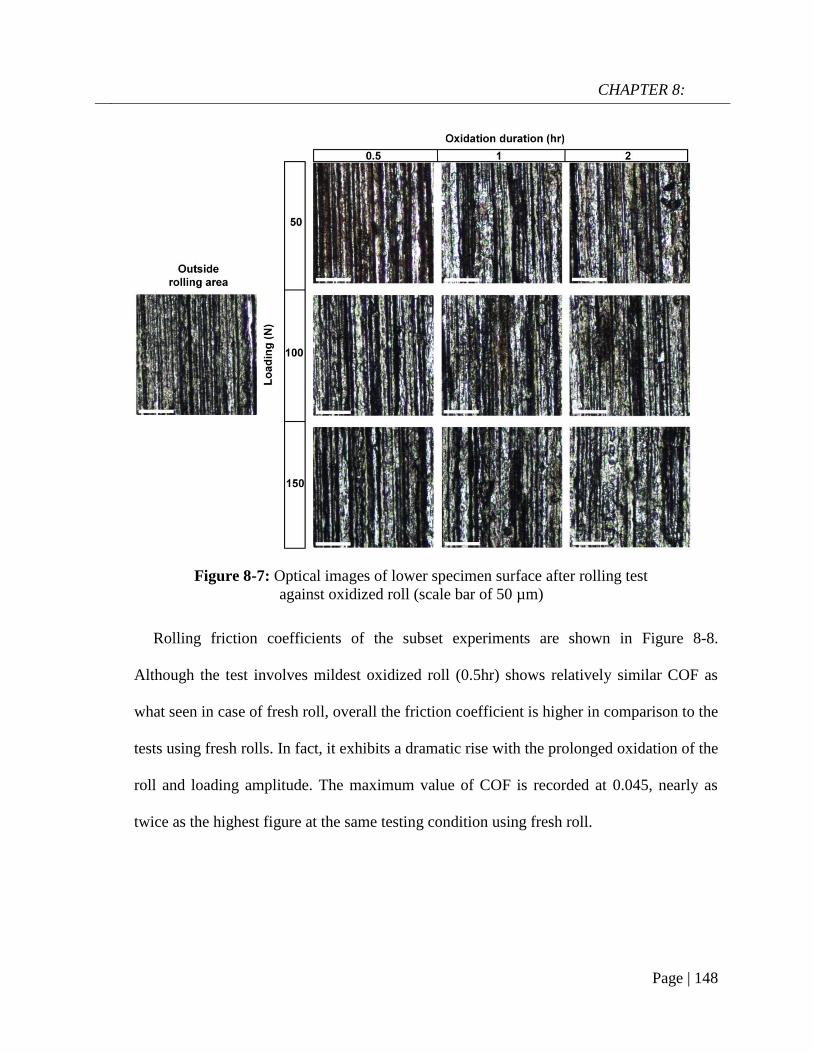
CHAPTER 8:
Page | 148
Rolling friction coefficients of the subset experiments are shown in Figure 8-8.
Although the test involves mildest oxidized roll (0.5hr) shows relatively similar COF as
what seen in case of fresh roll, overall the friction coefficient is higher in comparison to the
tests using fresh rolls. In fact, it exhibits a dramatic rise with the prolonged oxidation of the
roll and loading amplitude. The maximum value of COF is recorded at 0.045, nearly as
twice as the highest figure at the same testing condition using fresh roll.
Figure 8-7: Optical images of lower specimen surface after rolling test
against oxidized roll (scale bar of 50 µm)
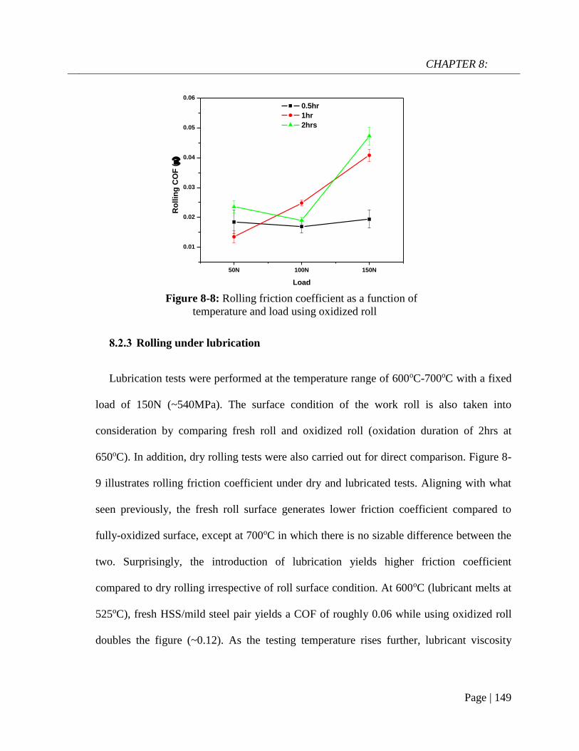
CHAPTER 8:
Page | 149
50N 100N 150N
0.01
0.02
0.03
0.04
0.05
0.06
Ro
llin
g C
OF
(
Load
0.5hr
1hr
2hrs
Rolling under lubrication
Lubrication tests were performed at the temperature range of 600oC-700oC with a fixed
load of 150N (~540MPa). The surface condition of the work roll is also taken into
consideration by comparing fresh roll and oxidized roll (oxidation duration of 2hrs at
650oC). In addition, dry rolling tests were also carried out for direct comparison. Figure 8-
9 illustrates rolling friction coefficient under dry and lubricated tests. Aligning with what
seen previously, the fresh roll surface generates lower friction coefficient compared to
fully-oxidized surface, except at 700oC in which there is no sizable difference between the
two. Surprisingly, the introduction of lubrication yields higher friction coefficient
compared to dry rolling irrespective of roll surface condition. At 600oC (lubricant melts at
525oC), fresh HSS/mild steel pair yields a COF of roughly 0.06 while using oxidized roll
doubles the figure (~0.12). As the testing temperature rises further, lubricant viscosity
Figure 8-8: Rolling friction coefficient as a function of
temperature and load using oxidized roll

CHAPTER 8:
Page | 150
rapidly declines and the resulting COF follows a decreasing trend in both cases although
the slope is much steeper in the case of oxidized roll.
Figure 8-10 shows optical images of fresh HSS roll surface after dry and lubricated test
(with 150N). Again, dry rolling results in a considerable amount of adhered oxide scale on
the roll surface and the transferred layer looks thicker as temperature rises. On the other
hand, the introduction of lubricant completely inhibits the oxide pickup as evidenced at
600oC and 650oC. Specimen at 700oC also does not show any sign of transferred oxide,
although the lubricant appears to stick on the HSS surface after test. Experiments using
oxidized HSS see relatively similar behaviors when the lubricant adherence only occurs at
700oC. Figure 8-11 illustrates the morphology of adhered lubricant on the HSS roll (which
occurred at 700oC) with its characteristic chemical fingerprint. The viscous lubricant melt
was likely stretched out by a shearing force which produces such feather-like appearance
upon solidifying. SEM micrographs of rolled mild steel surfaces under different lubrication
conditions are illustrated in Figure 8-12. Without lubrication, the rolled surfaces are
Figure 8-9: Rolling friction under a) dry and b) lubrication condition
with respect to lubricant viscosity

CHAPTER 8:
Page | 151
commonly characterized by parallel grooves and scratches which is quite similar to what
observed previously (Figure 8-3 and Figure 8-7). Under lubrication, rolled surfaces show a
stark contrast since the lubricant was able to remain on the rolled area after 5-cycles of
rolling. The platelets lying on the rolled surfaces can be assigned to recrystallized borate
upon cooling (similar to Chapter 4). This is also justified by the apparent changes in
friction coefficient in the presence of lubricant (Figure 8-9). A detailed characterization in
later part (section 8.3) will confirm the existence of the lubricant film after the rolling test.
Figure 8-10: Optical images of HSS surface after test
(scale bar of 10µm)
Figure 8-11: SEM micrograph of transferred lubricant (a) and
the corresponding X-ray spectrum (b)

CHAPTER 8:
Page | 152
Pickling of rolled surfaces
The rolled surfaces under different lubrication conditions are subjected to pickling for
scale removal. HCL (10% volume in distilled water) is chosen as pickling liquor. The
rolled specimens were immersed into a becker of pickling liquor for 4 minutes at 28oC and
then washed rigorously 3 times by water and ethanol, respectively. The resulting surface
parameters of pickled surfaces are reported in Figure 8-13. It is shown that lubricated
rolled surfaces have a lower average roughness than unlubricated counterparts after
pickling, particularly at high temperature range. Also, Ssk appears shifting towards zero at
high temperature end although unlubricated surface has a larger deviation. Lastly, Skur is
significantly lower when the lower specimen is rolled in the presence of lubricant. The
changes in surface parameters suggest that exposure to borate lubrication results in a
Figure 8-12: SEM micrographs of lower specimen surface after a) dry tests
and b) lubrication tests (double-arrowed line indicates moving direction)
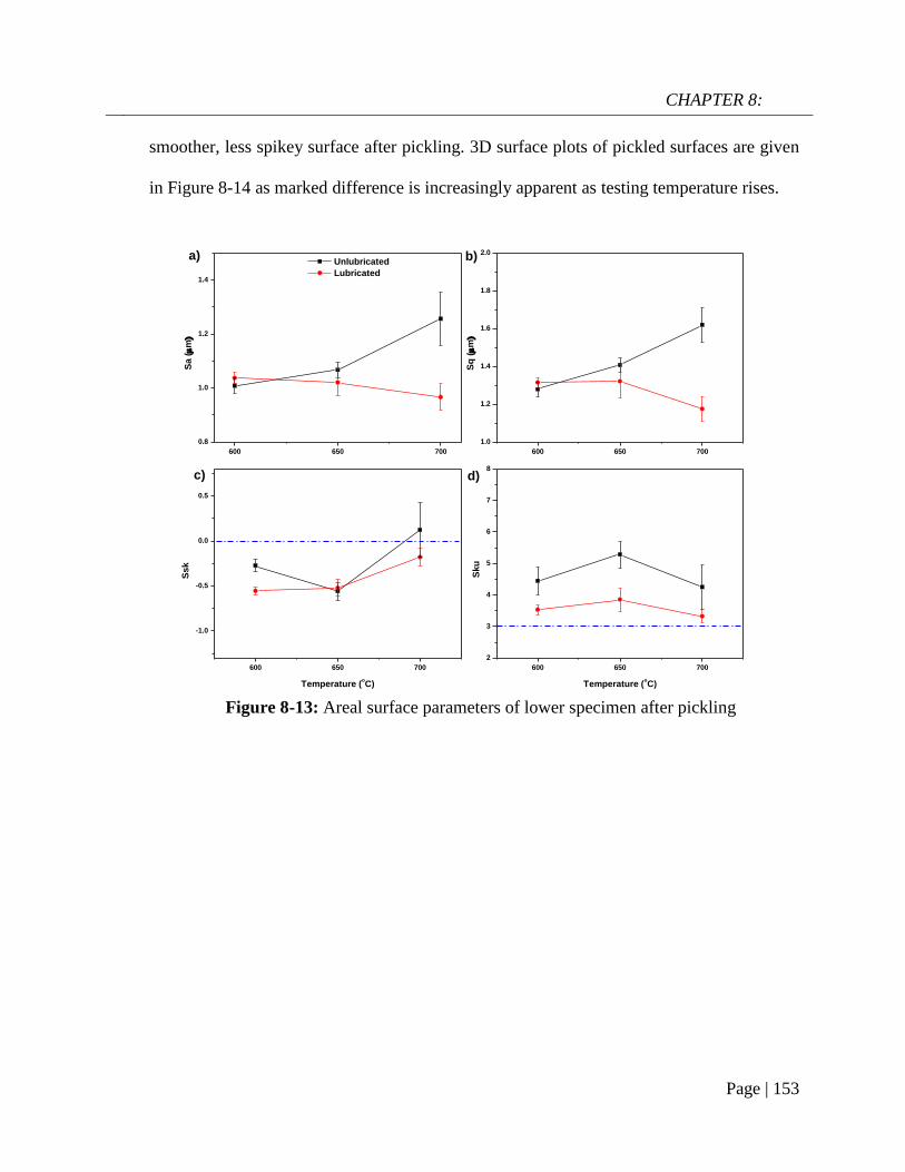
CHAPTER 8:
Page | 153
600 650 700
0.8
1.0
1.2
1.4
600 650 700
1.0
1.2
1.4
1.6
1.8
2.0
600 650 700
-1.0
-0.5
0.0
0.5
600 650 700
2
3
4
5
6
7
8
Sa (m
Unlubricated
Lubricated
Sq
(m
d)c)
b)
Ssk
Temperature (oC)
a)
Sku
Temperature (oC)
smoother, less spikey surface after pickling. 3D surface plots of pickled surfaces are given
in Figure 8-14 as marked difference is increasingly apparent as testing temperature rises.
Figure 8-13: Areal surface parameters of lower specimen after pickling

CHAPTER 8:
Page | 154
Discussion
It has been demonstrated that the temperature of the work piece and loading amplitude
collectively govern the oxide transfer occurrence on the roll surface. Increase in
temperature leads to the formation of a thicker oxide scale as the specimen is heated in air
atmosphere [7]. In fact the oxide scale thickness is roughly 2µm, 2.8µm and 3.8µm at
600oC, 650oC and 700oC, respectively after the non-isothermal heating stage. This in turn
amplifies the probability of scale sticking as evidenced by microscopy examination (Figure
8-4 and Figure 8-10). Moreover, higher loading magnitude can create a local spalling or
even delamination of the grown scale (Figure 8-3) which consequently yields more intense
material transfer. The continuous removal of oxide in combination with the mentioned
Figure 8-14: 3D images of rolled surfaces after a) dry rolling and
b) lubricated rolling (top-to-bottom order: 600oC, 650oC, 700oC)

CHAPTER 8:
Page | 155
0 2 4 6 8 10
0.0
0.1
0.2
0.3
0.4
0.5
0.6
Y =0.03577+0.20641 X-0.03017 X
2+0.00186 X
3-3.95551E-5 X
4
Av
era
ge
Fri
cti
on
Co
eff
icie
nt
()
Slip ratio (%)
Fitting curve
surface damages due to repetitive rolling contact increase the surface roughness and
intensify the spikiness of the rolled surface regardless of roll surface condition (Table 8-3
and Table 8-8).
Ma et al. [187] conducted roller-on-roller experiments (between two mating steel
surfaces) and revealed a close relationship between slip ratio and friction coefficient
(Figure 8-15). By using extrapolation, there was little slip during the present rolling test
(the slip ratio is less than 0.04% when friction coefficient is 0.044). In this work, the low
slip ratio is the origin of low friction coefficient despite the heavy rolling load.
The surface condition of HSS roll plays a crucial role in friction behaviors of the rolling
contact. While using pristine roll surface generates relatively low rolling COF which
appears quite insensitive towards loading magnitude (Figure 8-5), oxidation of roll surface
quickly escalates the friction coefficient (Figure 8-8). This could be attributed by the
considerable changes in surface geometry induced by oxide scale growth upon high
Figure 8-15: Rolling friction coefficient from roller-on-
roller experiments as a function of slip ratio [187]
CHAPTER 8:
Page | 156
temperature. It has been acknowledged that metal carbides and metallic matrix possess
differential high-temperature oxidation kinetics as the former outgrows the latter due to
favorable thermodynamics [177, 178]. This is justified by localized formation of oxides on
carbide-based precipitates at the early stage of oxidation followed by the subsequent oxide
growth on metallic matrix as oxidation progresses (Figure 8-6). As a result, this imposes
surface roughening on HSS (Table 8-6) which consequently elevates the number of micro-
asperities collisions and rolling resistance [188, 189]. While mild oxidation leads to an
insignificant rise in friction coefficient, the effect becomes more obvious in the case of
heavily oxidized roll as shown in Figure 8-8. This is in a good agreement with the past
study [190].
It has been shown that the introduction of borate lubrication drastically change the
rolling behaviors of the steel pair. The formation of the lubricating film was able to remain
on the rolled area after test without being squeezed out as evidenced in Figure 8-12. This
could be attributed to potential surface reaction between the lubricant melt and rolled
surface which allows the lubricant to sustain such high contact pressure (>500MPa). The
formation of the lubrication film can also be justified by the change in friction coefficient
compared to the unlubricated tests (Figure 8-9b) regardless of the roll surface condition.
This might arise from the adhesion between the lubricant film and the roll surface which
potentially elevates the rolling resistance. Bulk properties of lubricant melt also play a
crucial role on friction behaviors as lower viscosity induces lower friction. This partially
reflects the hydrodynamic nature of the concerning lubrication system, although the
inclusion of mixed or boundary lubrication is more likely. Previous chapters revealed

CHAPTER 8:
Page | 157
strong affinity between sodium borate melt and oxidized steel surfaces at elevated
temperature. This could lead to a stronger lubricant adherence which consequently requires
greater work to overcome the rolling resistance in the case of pre-oxidized HSS.
Figure 8-17: Cross-sectional views of mild steel surface and the
corresponding compositional phase analysis after lubrication test at 600oC, 150N
Figure 8-16: Cross-sectional views of mild steel surface and the
corresponding compositional phase analysis after lubrication test at 650oC, 150N

CHAPTER 8:
Page | 158
The use of borate lubricant evidently suppresses the material transfer which otherwise
readily occurs during unlubricated tests (Figure 8-10). The oxide pickup has been known
for its detrimental consequences in metal forming practice [27] . This positive effect is
originated from the presence of lubricant film which can act as a physical boundary and
minimize the chances of contact between the oxide scale and the work roll surface. Figure
8-16, 8-17 and 8-18 illustrate cross-sectional views of rolled area exposed to lubrication at
different temperatures. There are 3 distinct layers in top-to-bottom order: lubricant layer,
oxide scale and the steel substrate. The TEM lamellar specimen at 650oC partially sacked
due to overmilling during FIB process (Figure 8-17), although the boundary between
layers is still recognizable. It is clear that the oxide scales are fully contained by the
lubricant film which effectively prevents them from approaching the work roll surface.
Figure 8-18: Cross-sectional views of mild steel surface and the
corresponding compositional phase analysis after lubrication test at 700oC, 150N

CHAPTER 8:
Page | 159
There appears a microstructural evolution of the oxide scale exposed to lubrication. At
the lowest testing temperature (600oC), the oxide scale consists of an abundance of sub-
micron particles which are heavily scattered. Since the oxide scale is thin prior to contact
(2µm), it is likely shattered upon heavy loading and the formation of subsequent oxide
scale is a result of complex reaction between the lubricant melt, shattered oxide scale and
possible the outward-diffusing Fe from the steel substrate. At higher testing temperatures
(650oC and 700oC), the oxide scale is formed in bulk and becomes thicker (Figure 8-19).
XRD analysis on the rolled area substantiates the apparent effect of borate lubricant on
the formation of iron oxide scale (Figure 8-20). As expected, the untreated rolled areas are
composed of 3 types of iron oxides (FeO, Fe3O4, Fe2O3) with Hematite (Fe2O3) being the
most predominant constituent. In addition, the formation of complex compound
Figure 8-19: Magnified images of the oxide/steel substrate interface after
lubricant test at a) 600oC, b) 650oC and c) 700oC (load of 150N)

CHAPTER 8:
Page | 160
FeO.FeBO3 is likely due to the reaction between the lubricant melt and the outward-
diffusing Fe ions. Besides that, the use of borate lubricant evidently transforms the iron
oxide structure characterized by the rising dominance of Magnetite (Fe3O4). The
microstructure evolution of iron oxide by lubrication favor the subsequent pickling process
since Hematite is considered hard-to-remove oxide due to its sluggish dissolution in
pickling acid [191, 192].
It is noteworthy that the current rolling configuration is not representative of the actual
hot rolling process in which there is a reduction of rolled workpiece thickness coupled with
considerable deformation and 2-5% slip. However, as the contact pressure can be set
closely to real processing parameter (>0.5GPa), the above results can be used to
understand the complex interface reactions, particularly in the presence of lubricant.
Figure 8-20: XRD patterns of rolled surfaces under
a) lubrication and b) dry condition

CHAPTER 8:
Page | 161
Conclusions
In this study, a large volume tribology tests is conducted to study the surface
interactions in rolling contacts over a wide range of conditions. There are some
conclusions that can be found as followed:
Oxide scale transfer occurs readily on the HSS surface under dry conditions and
the extent grows with temperature and loading amplitude
Pre-oxidation of HSS elevates the rolling friction coefficient compared to the case
where fresh rolls are used
The application of lubricant drastically hinders the material transfer on the HSS
roll surface which is attributed to the formation of a lubricant film, although it raises the
rolling friction coefficient
Compared to dry rolling, the use of lubricant also transforms oxide microstructure
on the rolled surface in which Magnetite replaces Hematite to become the most
predominating phase. This conversion is beneficial for the subsequent pickling process.

CHAPTER 9:
Page | 162
CHAPTER 9:
Synthesis of potassium borate and
its tribological behaviors above 800oC
As shown in section 2.4, there is a fair amount of studies dedicated to the tribological
behavior of sodium-based glass melt at high temperature. On the other hand, potassium-
based glass melts have not received a reasonable attention. This chapter describes a simple
method to synthesize potassium borate as a potential lubricant at high temperature. The
tribological behaviors of synthesized potassium borate are compared with sodium borate at
temperature up to 900oC. Thorough characterization was performed to understand the
molecular structure, thermal behavior and lubrication mechanism of synthesized material.
Material preparation
Synthesis of potassium borate
Potassium borate was synthesized by the condensation reaction between potassium
hydroxide (KOH) and boric acid (H3BO3) in water. A 2.5g of KOH pellets was added into
a 250ml of distilled water at 80oC. Next, a 5.8g of H3BO3 in powder form was introduced
into the KOH aqueous solution while the temperature was kept unchanged. The solution
was vigorously stirred at roughly 300rpm for 8 hours. After that, temperature was
increased to 200oC to allow water vaporization and condensation. The product was
retrieved in the white powder form with the nominal composition of K2O.2B2O3. The
condensation reaction is given as followed:

CHAPTER 9:
Page | 163
KOH + H3BO3 + H2O 80oC→ K2O. 2B2O3(a)
200oC→ K2O. 2B2O3(s)
In hot friction test, High Speed Steel was chosen as the pin and Stainless Steel 316
(SS316) was selected as the disc material. The mechanical properties and chemical
composition of the steel tribopair can be found in section 6.1.2. The disc surface was
ground and polished to achieve an average roughness of 0.1µm. The steel pair was cleaned
with ethanol/acetone prior to friction test. A 5% wt. aqueous solution of potassium borate
was prepared for lubrication test.
Friction test
High-temperature friction test was performed on the UMT2-CETR ball-on-disc
tribometer. The SS316 disc was first installed into the furnace chamber followed by
sequential heating to set temperature (850oC and 900oC). Once the furnace temperature
reached the set point, the upper stage carrying HSS pin was automated to descend to a
distance of 3mm away from the disc surface. The pre-oxidation of HSS pin lasted for 5
minutes. Lubricant solution was dropped onto the heated disc at 2 minutes before contact
engagement with a rate of 0.01ml/s. Sliding velocity was kept constant at 0.1m/s while the
testing duration was fixed at 3 minutes with a fixed load of 10N. When the friction test
finishes, the tribopairs were retrieved immediately and cooled in the air to prevent further
oxidation.
Characterization
The 3D Interferometer Optical Microscope (Bruker Contour GT-K) was used to
generate wear track profiles on the disc. Morphologies of the worn surfaces were examined

CHAPTER 9:
Page | 164
by the JOEL JSM-6490LV Scanning Electron Microscopy (SEM) equipped with Energy
Dispersive Spectroscopy (EDS). Specimens for STEM work were prepared by the Dual
Beam FEI Helios NanoLab G3 CX (FIB). The cross sections of the tribo-interfaces were
observed by the aberration-corrected JOEL ARM 200F Scanning Transmission Electron
Microscopy (STEM) at 200keV.
Results
Molecular structure and thermal behavior of synthesized potassium borate
Figure 9-1 presents a series of analysis on the synthesized potassium borate. It shows
that the as-received potassium borate has a relatively poor crystallinity, evidenced by weak
diffraction peaks and peak broadening in the XRD pattern. The material is likely
constructed by plural constituents that possess short-range order structure. Unlike sodium
borate, the synthesized potassium borate does not hold much adsorbed water as indicated
by the absence of the peak at 3500cm-1 in FTIR spectrum. The peak at 1336cm-1 can be
attributed to asymmetric stretching of B-O in trigonal BO3 while the out-of-plane bending
of B-O in BO3 contribute to the peak of 708cm-1 [102]. In addition, the peak located at
1024cm-1 can be associated with terminal symmetric stretching of B-O while the peak at
922cm-1 refers to the B-O ring stretching [193]. Compared to sodium borate (Figure 4-1),
the synthesized potassium borate shows little trace of tetrahedral BO4 presence. It can be
seen from the GTA/DSC curve (Figure 9-1), only 8% mass loss is observed which
confirms the lack of absorbed water molecules in the potassium borate structure, the
corresponding figure in the case of sodium borate is >40% (Figure 4-1). Moreover, the
DSC curve shows three consecutive endothermic peaks at 660oC, 720oC and 800oC
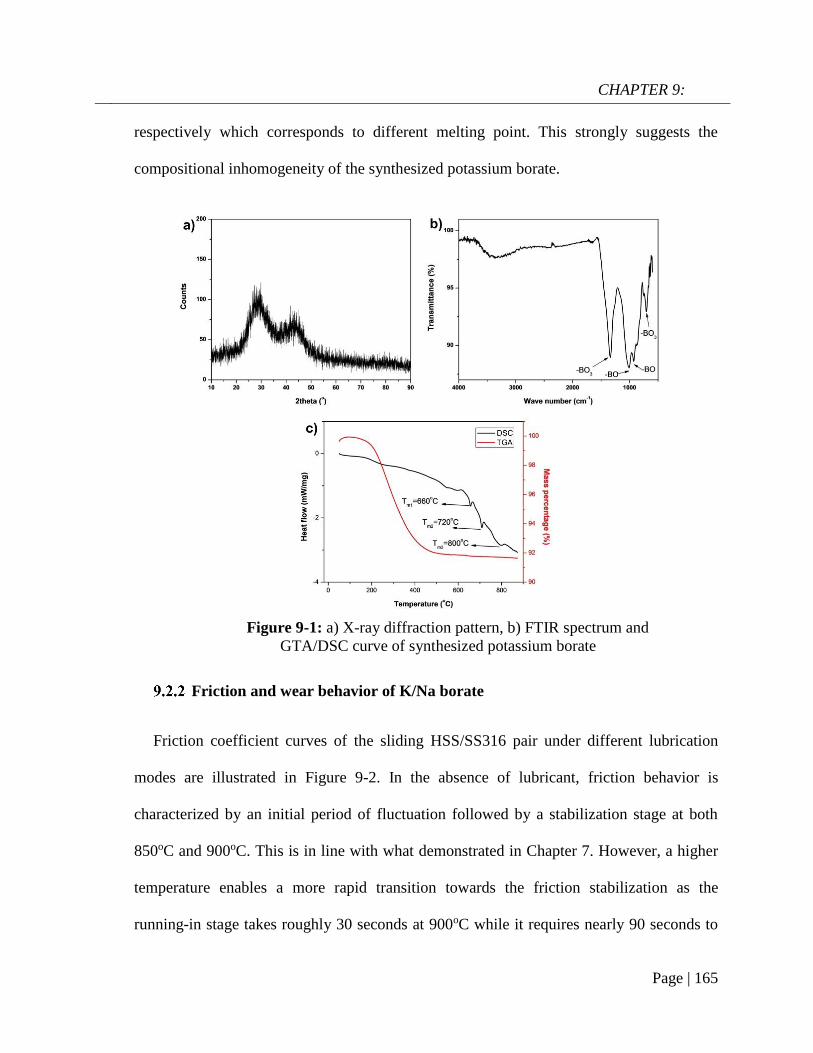
CHAPTER 9:
Page | 165
respectively which corresponds to different melting point. This strongly suggests the
compositional inhomogeneity of the synthesized potassium borate.
Friction and wear behavior of K/Na borate
Friction coefficient curves of the sliding HSS/SS316 pair under different lubrication
modes are illustrated in Figure 9-2. In the absence of lubricant, friction behavior is
characterized by an initial period of fluctuation followed by a stabilization stage at both
850oC and 900oC. This is in line with what demonstrated in Chapter 7. However, a higher
temperature enables a more rapid transition towards the friction stabilization as the
running-in stage takes roughly 30 seconds at 900oC while it requires nearly 90 seconds to
Figure 9-1: a) X-ray diffraction pattern, b) FTIR spectrum and
GTA/DSC curve of synthesized potassium borate

CHAPTER 9:
Page | 166
approach the steady stage at 850oC. The friction coefficient stabilizes at 0.19 and 0.18 at
850oC and 900oC, respectively. Alkaline borates lubrication clearly results in a much
shorter running-in process regardless of the alkaline elements, although K borate produces
a lower average friction coefficient than the Na counterpart, 0.14 versus 0.16 at 850oC at
the same sliding speed and load. However, Na borate appears to fail at 900oC as the
friction coefficient surges to 0.23. On the other hand, K borate retains its lubricity over the
majority of sliding time with a steady friction coefficient of 0.13 despite a slight increase at
the end of the test. Regarding the wear loss volume, the unlubricated contact leads to a
higher material loss in comparison to the lubricated contact at both testing temperatures. At
850oC, the unlubricated pair yields roughly 1.3mm3 of wear volume on the disc while
borate lubrication reduces the figure by at least 6 times (0.2mm3) without any noticeable
difference between the two alkaline elements. For the unlubricated case at 900oC, the wear
rate drops on lubrication-free case compared to 850oC, although it is still higher than
lubricated tests. In addition, there is a marked difference of wear resistance between the
two alkaline borates, with K borate outperforming the Na counterpart. The volume loss
resulted from Na borate lubrication is 1.5 times of that from K borate.

CHAPTER 9:
Page | 167
Worn area analysis under dry sliding
Wear morphologies on the unlubricated steel pair at 850oC and 900oC are shown in
Figure 9-3 and 9-4, respectively. Although the disc has a narrower wear track width at
higher temperature, the worn morphologies are similar for both testing temperatures. It is
predominantly characterized by ploughing, plastic deformation and adhesive wear. On the
opposing surface, a fully-formed transferred layer is observed with a smooth contact
surface and negligible damages. The more rapid transition in COF curve at the higher
temperature (Figure 9-2) strongly suggests more rapid formation of a tribo-layer on the pin
surface which leads to a reduced wear loss volume on the disc when the temperature
reached 900oC.
Figure 9-2: Friction coefficient curves at a) 850oC, b) 900oC and c) wear loss
volume of SS316 disc in different lubrication conditions

CHAPTER 9:
Page | 168
Worn area analysis under Na/K borate lubrication
Under Na borate lubrication, worn surface morphologies and corresponding X-ray
analysis are shown in Figure 9-5 and 9-6. At 850oC, there are signs of scoring and
scratching on both sliding counterparts. This is quite different to what observed at lower
Figure 9-3: Worn morphologies on a) the disc, b) magnified image
on the disc and c) the pin without lubrication at 850oC
Figure 9-4: Worn morphologies on a) the disc, b) magnified
image on the disc and c) the pin without lubrication at 900oC

CHAPTER 9:
Page | 169
temperature (800oC) in section 6.2.1 where the worn surfaces are covered by the residual
melt without any clear surface features. Analysis collected from the worn areas suggests
the presence of lubricant melt elements (Na, O, B) and a minor peak of Fe. The
characteristic glassy appearance of lubricant melt is no longer seen at 900oC, particularly
on the disc surface. Instead, the worn surface is composed of solid-like particles as shown
in the magnified image (Figure 9-6b). The corresponding EDS mapping (Figure 9-7)
indicates that the solid-like particles are predominantly associated with oxides (Iron oxides
and Chromium oxides). Although melt elements (Na & B) are still detected on the worn
area, their intensities are significantly lower than what seen in lower temperature range.
The changes in worn morphologies at 900oC could be closely associated with potential
lubrication failure of Na borate shown by increased friction and wear loss volume (Figure
9-2).
Figure 9-5: SEM micrographs of a) disc and b) pin after Na borate
lubrication at 850oC and the corresponding X-ray analysis
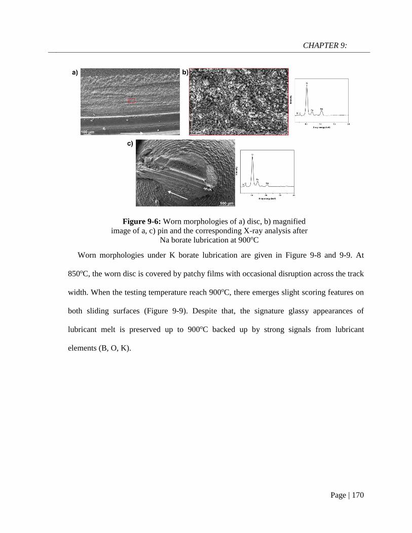
CHAPTER 9:
Page | 170
Worn morphologies under K borate lubrication are given in Figure 9-8 and 9-9. At
850oC, the worn disc is covered by patchy films with occasional disruption across the track
width. When the testing temperature reach 900oC, there emerges slight scoring features on
both sliding surfaces (Figure 9-9). Despite that, the signature glassy appearances of
lubricant melt is preserved up to 900oC backed up by strong signals from lubricant
elements (B, O, K).
Figure 9-6: Worn morphologies of a) disc, b) magnified
image of a, c) pin and the corresponding X-ray analysis after
Na borate lubrication at 900oC

CHAPTER 9:
Page | 171
Figure 9-8: SEM micrographs of a) disc and b) pin after K borate
lubrication at 850oC and the corresponding X-ray analysis
Figure 9-7: EDS mapping of SS316 surface lubricated by Na borate
lubrication with solid-like particles

CHAPTER 9:
Page | 172
Discussion
In order to understand the lubrication mechanism of the synthesized K borate at 900oC,
cross-sectional observation in combination with chemical analysis is given in Figure 9-10.
From the STEM image, the upper transparent layer can be ascertained to the lubricant melt
while the darker phase is assigned to oxide scale. The complementary phase compositional
analysis (X-ray spectrum) clearly confirms the lubricant/oxide interface. Individual
element mapping illustrates K enrichment on the immediate oxide interface. The behavior
is identical to what observed in the case of Na borate lubrication. However, K does appear
to infiltrate into the subsurface region, but in a limited manner and not as much an extent
as with Na at lower temperature (Figure 6-17). The element is mostly confined above the
oxide scale surface as shown in Figure 9-11.
Figure 9-9: SEM micrographs of a) disc and b) pin after K borate
lubrication at 900oC and the corresponding X-ray analysis

CHAPTER 9:
Page | 173
It is expected that melting point of alkaline borate plays a crucial role in its working
temperature range. For instance, having a transition point of 525oC, sodium borate
evidently functions well in the range of 600-850oC which has been demonstrated
throughout this study. The synthesized potassium borate has a multiple melting point due
to its compositional inhomogeneity with the final melting point at 800oC. Thus, it can
potentially retain its lubrication performance from 800oC upwards which was justified by
the test at 900oC (Figure 9-2). Both Na and K borate share a considerable similarity in their
working principle as their strong absorption tendency on the oxide scale surface is
repeatedly proved critical for desirable friction/wear behaviors. However, since the K atom
radius is larger than that of Na (~1.86Å/1.52Å), this could have a certain impact on the
Figure 9-10: a) STEM-BF image of melt/oxide interface after K borate
lubrication and b) phase composition, c) elemental mapping (at 900oC)

CHAPTER 9:
Page | 174
atom mobility upon interaction with the oxide scale. The charge-to-radius ratio of K is
smaller than that of Na which can make the former element less mobile and less reactive
towards the oxide surface. This is partly demonstrated by the lack of K borate infiltration
towards the subsurface as shown in Figure 9-10, although the oxide scale stills show signs
of cavities. It is expected that the lack of lubricant infiltration can result in poor load-
bearing capacity. In contrast, the Na borate lubrication with good mobility results in a
significant lubricant penetration into the subsurface associated with the formation of
pocket reservoir (Figure 6-17).
Although the reactivity of alkaline elements is of paramount importance in the
lubrication mechanism of alkaline borate, the role of viscosity should not be diminished. It
provides the lubricant with the fluidity to move and remain on the contact surface. The low
shearing stress of a fluid medium is mainly accountable for such low friction coefficient on
the lubricated sliding surfaces. The lubrication failure of Na borate at 900oC is likely
associated with its low viscosity at this temperature range. Figure 9-12 plots the
Figure 9-11: An STEM image of the immediate sliding surface with
elemental mapping

CHAPTER 9:
Page | 175
dependence of friction coefficient on the viscosity of Na borate on the sliding HSS/SS316
pair. This follows well with the Stribeck principle and also confirms the mixed lubrication
regime in the tribotest. The viscosity of K borate is not available, although the material
exhibited a consistently low friction coefficient over the tested temperature (700-900oC)
(Figure 9-12b). The lubrication failure of Na borate at 900oC also results in poor oxidation
resistance on the sliding surface, as shown by the oxide scale thickness after lubrication
tests in Figure 9-13. While both alkaline borates are similarly effective at 850oC, K borate
lubrication yields slightly better anti-oxidation performance at 900oC. The anti-oxidation
capacity of borate lubricants on SS316 is not as significant as what shown in Chapter 5
(where mild steel was used) which is due to the intrinsic oxidation resistance of SS316.
The popularity of Na in complex glass lubricant composition is evident in Table 2-1
(Chapter 2). This could be mainly attributed to its abundant availability, high reactivity and
high efficiency in adjusting the viscosity of the lubricant melt. Combined with previous
chapters, it is highly credible to determine a universal working mechanism of alkaline
Figure 9-12: Variation of friction coefficient from HSS/SS316 lubricated
(10N, 0.1m/s) by a) Na borate and b) K borate with temperature
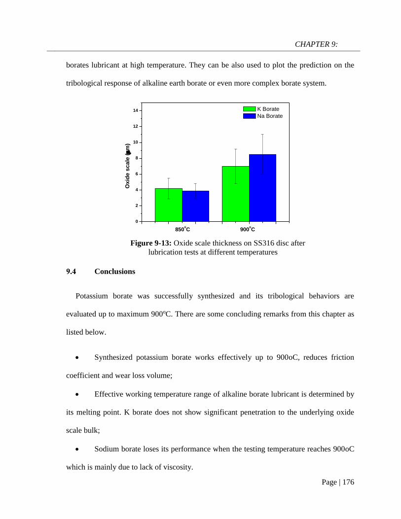
CHAPTER 9:
Page | 176
0
2
4
6
8
10
12
14
900oC
Ox
ide
sc
ale
(m
)
850oC
K Borate
Na Borate
borates lubricant at high temperature. They can be also used to plot the prediction on the
tribological response of alkaline earth borate or even more complex borate system.
Conclusions
Potassium borate was successfully synthesized and its tribological behaviors are
evaluated up to maximum 900oC. There are some concluding remarks from this chapter as
listed below.
Synthesized potassium borate works effectively up to 900oC, reduces friction
coefficient and wear loss volume;
Effective working temperature range of alkaline borate lubricant is determined by
its melting point. K borate does not show significant penetration to the underlying oxide
scale bulk;
Sodium borate loses its performance when the testing temperature reaches 900oC
which is mainly due to lack of viscosity.
Figure 9-13: Oxide scale thickness on SS316 disc after
lubrication tests at different temperatures

CHAPTER 10:
Page | 177
CHAPTER 10:
General conclusions and recommendations
for future work
The current dissertation thoroughly studied tribological properties of alkaline borates at
elevated temperatures. By conducting a large volume of experimental work and detailed
analysis, the lubrication mechanism and other fundamentals aspects of borate lubrication
have been revealed. The final chapter aims to highlight general conclusions and
suggestions for further work.
Tribological performance of sodium borate at high temperature
During high temperature pin-on-disc testing on a steel tribopair (600oC-800oC),
sodium borate demonstrated exceptional lubricating properties over its melting
point which is reflected by a significant reduction in friction and wear loss
volume in comparison to unlubricated test.
At 800oC, on the disc surface, a chemically hierarchical tribofilm is observed
with a thickness of ~50-60nm. The tribofilm consists of 2 layers: the bottom
layer is rich in Na with a thickness of ~20nm while B heavily concentrates in the
upper part. The Na-rich film is believed to provide the necessary adhesion on
oxidized steel surface while the self-adaptive polymerization of the upper part
enhances the cohesive strength of the whole tribofilm.

CHAPTER 10:
Page | 178
At 800oC, on the ball surface, a complex tribofilm comprising of Na, O, B, C
and Fe is found lying on a layer of ultra-fine grains of iron oxides. With
exceptional toughness and strength, the ultra-fine oxide grains provide concrete
ongoing support for the tribofilm. There is a conversion from BO4 into BO3
species in the tribofilm which is caused by the effect of shearing stress.
Thermally-activated and tribochemical reaction on borate-lubricated
surfaces
A formation of thin Na film on iron oxide interface is observed regardless of the
presence of external shearing stress. This implies that the absorption of Na is
thermally-driven. During the static oxidation, beside interface reaction, borate
melt causes the disintegration of the oxide scale bulk by penetrating through the
grain boundary which eventually roughens the melt/oxide interface.
Tribological reactions result in the formation of tribofilm which is significantly
depleted in Oxygen. This chemical feature enhances oxidation resistance by
reducing the oxide growth considerably in comparison to static oxidation and
untreated cases. It has been shown that shearing stress not only induces
molecular structure changes in borate melt, but also the compositional change.
The role of Na in binary sodium borate lubrication and effect of oxide
microstructure on adsorption behavior of Na
The binary system Na2O-B2O3 outperforms B2O3 in term of friction and wear
reduction in pin-on-disc testing between High Speed Steel and Stainless Steel

CHAPTER 10:
Page | 179
316 surfaces. An addition of Na into pure B2O3 drastically improves the
lubrication performance of the beneficiary. In addition, the binary system Na2O-
B2O3 also exhibits a good load-bearing capacity.
The adsorption of Na onto both contact surfaces is the driving force for the
excellent lubrication performance of binary sodium borate. However, the role of
B2O3 in the binary system should not be diminished as it provides the
polymeric/viscous nature of the lubricant upon melting.
There is a close relationship between Na-adsorbed film thickness and the oxide
microstructure. While it is ~20nm on an oxidized mild steel surface, it is
estimated at 50~60nm on an oxidized alloyed steel (HSS and SS316). In
addition, weakly-adhered oxide scale grown on mild steel did not support as an
effective lubrication as the oxide scale grown on stainless steel.
Adhesive wear resistance of sodium borate on sliding HSS surface
Under borate lubrication, High Speed Steel surface experiences no adhesive
wear damages in comparison to lubricant-free case. The anti-sticking behavior is
closely governed by the tribofilm formation on the immediate sliding.
Adsorption of Na element on oxide surface is the main driving force to inhibit
material transfer.
The borate lubricant film alters significantly the oxidation characteristics of the
underlying oxide scale on High Speed Steel. Extended exposure leads to
Hematite-to-Magnetite conversion.

CHAPTER 10:
Page | 180
Tribological behavior of sodium borate in rolling contact and surface
interaction with iron oxide scale
Oxide scale transfer occurs readily on the HSS surface under dry conditions and
the extent grows with temperature and loading amplitude. Pre-oxidation of HSS
results in increase of rolling friction coefficient compared to the case where
fresh rolls are used.
The application of lubricant drastically hinders the material transfer on the HSS
roll surface which is attributed to the formation of a lubricant film. The exposure
to borate lubrication under rolling changes the oxide composition significantly,
with Magnetite replaces Hematite to become the most dominating type. This
favorable transformation can facilitate the pickling process.
Synthesis of potassium borate and understanding of alkaline borate
lubrication
Synthesized potassium borate lubricates effectively up to 900oC by reducing
friction coefficient and wear loss volume on Stainless Steel surface. On the other
hand, Sodium borate loses its performance when the testing temperature reaches
900oC which is mainly due to low of viscosity
Potassium borate shares great similarity with sodium borate with respect to their
lubrication mechanism at high temperature.
Recommendations for future work

CHAPTER 10:
Page | 181
Although lubrication mechanism of sodium borate has already been revealed in
great details in pin-on-disc testing and passivated rolling testing, further
experimental work and analysis should be carried out on real hot rolling
platform to justify the lubricant effectiveness.
By accomplishing a firm understanding about glass chemistry, it is feasible to
proceed the synthesis of other binary borate system such as alkaline earth borate
(Mg, Ca) as potential candidates for high-temperature lubrication. It is expected
that this family of borate glasses has a higher working temperature range than
alkaline borate. Mixtures of different kinds of borate-based glasses should also
be considered.
The passivated rolling module has been successfully utilized. It can be modified
further to represent actual hot rolling contact. However, there are a number of
technical restraints that prevents wider range of testing condition. Efforts should
be spent on finding better ceramic bearing material which can cope a with
higher temperature and heavier load testing. In addition, slippage should be
introduced to simulate realistically the rolling process
The chemical state at the lubricant/surface interface can be readily distorted if
the samples are still exposed to high-temperature condition after the tribology
tests finish. Thus, it is of paramount importance to isolate the processed samples
after high-temperature testing to ensure the credibility of the subsequent
characterization.

Bibliography
Page | 182
Bibliography
[1] Peterson MB, Murray SF, Florec K. Consideration of lubricants for temperature above 1000oF.
ASLE Technical Publication. 1959;2:225-34.
[2] Wan S, Tieu AK, Xia Y, Zhu H, Tran BH, Cui S. An Overview of Inorganic Polymer as
Potential Lubricant Additive for High Temperature Tribology. Tribology International.
2016;102:620-35.
[3] Sliney HE. Solid lubricant materials for high-temperatures. Tribology International.
1982;15:303-15.
[4] Allam IM. Solid lubricants for applications at elevated-temperatures - a review. Journal of
Materials Science. 1991;26:3977-84.
[5] Hardell J, Hernandez S, Mozgovoy S, Pelcastre L, Courbon C, Prakash B. Effect of oxide
layers and near surface transformations on friction and wear during tool steel and boron steel
interaction at high temperatures. Wear. 2015;330-331:223-9.
[6] Zhu S, Cheng J, Qiao Z, Yang J. High temperature solid-lubrication materials: A review.
Tribology International. 2019;133:206-23.
[7] Young DJ. High Temperature Oxidation and Corrosion of Metals: Elsevier 2016.
[8] Chen RY, Yuen WYD. Review of The High-Temperature Oxidation of Iron and Carbon Steels
in Air or Oxygen. Oxidation of Metals. 2003;59:433-68.
[9] Malik AU, Whittle DP. Oxidation of Fe-C Alloys in The Temperature Range 600-850oC.
Oxidation of Metals. 1981;16:339-53.
[10] Chang Y-N, Wei F-I. Review High temperature oxidation of low alloy steels. Journal of
Materials Science. 1989;24:14-22.
[11] Dawson K, Tatlock GJ. High Temperature Crossoion of Low Alloy Steel: Elsevier B.V; 2010.
[12] Sun W, Tieu AK, Jiang Z, Lu C. High temperature oxide scale characteristics of flow carbon
steel in hot rolling. Journal of Materials Processing Technology. 2004;155-156:1307-12.
[13] Chen RY, Yuen WYD. Oxide-Scale Structures Formed on Commercial Hot-Rolled Steel Strip
and Their Formation Mechanisms. Oxidation of Metals. 2001;56:89-118.
[14] Pique B, Bouchard P-O, Montmitonnet P, Picard M. Mechanical Behavior of Iron Oxide
Scale: Experimental and Numerical Study. Wear. 2006;260:231-42.
[15] Echsler H, ito S, Schutze M. Mechanical Properties of Oxide Scales on Mild Steel at 800 to
1000oC. Oxidation of Metals. 2003;60:241-69.
[16] Utsunomiya M, Hara K, Matsumoto R, Azushima A. Formation mechanism of surface scale
defects in hot rolling process. CIRP Annals - Manufacturing Technology. 2014;63:261-4.
[17] Krzyzanowski M, Beynon JH, Farrugia DCJ. Oxide Scale Behaviour in High Temperature
Metal Processing: Wiley-VCH; 2010.
[18] Luong LS, Heijkoop T. The influence of scale on friction in hot metal working. Wear.
1981;71:93-102.
[19] Munther PA, Lenard JG. The effect of scaling on interfacial friction in hot rolling of steels.
Journal of Materials Processing Technology. 1999;88:105-13.
[20] Utsunomiya H, Nakagawa T, Matsumoto R. Mechanism of oxide scale to decrease friction in
hot steel rolling. Procedia Manufacturing. 2018;15:46-51.
[21] Hidaka Y, Anraku T, Otsuka N. Deformation of Iron Oxide upon Tensile Test at 600-1250oC.
Oxidation of Metals. 2003;71:S1282.
[22] Verge C, Boher C, Gras R, Levaillant C. Influence of oxides on friction in hot rolling:
Experimental investigations and tribological modelling. Wear. 2006;2006:957-75.
[23] Verge C, Boher C, Levaillant C, Gras R. Analysis of the friction and wear behavior of hot
work tool scale: application to the hot rolling process. Wear. 2001;250:322-33.

Bibliography
Page | 183
[24] Zhu H, Zhu Q, Tieu AK, Kosasih B, Kong C. A simulation of wear behaviour of high-speed
steel hot rolls by means of high temperature pin-on-disc tests. Wear. 2013;302:1310-8.
[25] Kato H. Severe-mild wear transition by supply of oxide particles on sliding surface. Wear.
2003;255:426-9.
[26] Hiratsuka K, Muramoto K. Role of wear particles in severe-mild wear transition. Wear.
2005;259:467-76.
[27] Azushima A. Tribology in Sheet Rolling Technology: Springer International Publishing; 2016.
[28] Shirizly A, Lenard JG. The effect of lubrication on mill loads during hot rolling of low carbon
steel strips. Journal of Materials Processing Technology. 2000;97:61-8.
[29] Shirizly A, Lenard JG. The effect of scaling and emulsion delivery on heat transfer during the
hot rolling of steel strips. Journal of Materials Processing Technology. 2000;101:250-9.
[30] Imae T, Kanenari S. Symposium tex in division of processing for quality products of ISIJ (in
Japanese). 1997:15-9.
[31] Azushima A, Xue WD, Yoshida Y. ISIJ International. 2009;49-6:868-73.
[32] Azushima A, Xue W, Yoshida Y. Influence of Lubricant Factors on Coefficient of Friction
and Clarification of Lubrication Mechanism in Hot Rolling. ISIJ International. 2009;49:868-73.
[33] Bay N, Azushima A, Groche P, Ishibashi I, Merklein M, Morishita M, et al. Environmentally
benign tribo-systems for metal forming. CIRP Annals-Manufacturing Technology. 2010;59:760-
80.
[34] Tekkaya AE, Homberg W, Brosius A. 60 Excellent inventions in metal forming: Springer;
2015.
[35] Friedman PA, Luckey SG. 4 - High-temperature lubricants for superplastic forming of metals.
Superplastic Forming of Advanced Metallic Materials. 2011:72-82.
[36] Erdemir A. Modern Handbook of Tribology - Chapter 22: Solid Lubricants and Self-
Lubricating Films: CRC Press; 2001.
[37] Petrov A, Petrov P, Petrov M. Research into water-based colloidal-graphite lubricants for
forging of carbon steels and Ni-based alloys. International Journal of Material Forming.
2010;3:311-4.
[38] Nagaile G, Botz F. Performance of Graphite and Boron-Nitride-Silicone Based Lubricants and
Associated Lubrication Mechanisms in Warm Forging of Aluminum. Journal of Tribology.
2008;130:021801.
[39] Feher R. Graphite-based lubricants. Encyclopedia of Lubricants and Lubrication. 2014:758-
69.
[40] Sliney HE. Rare Earth FLuorides and Oxides - An Exploratory Study of Their Use as Solid
Lubricants at Temperatures up to 1800oF. NASA TN D-5301. 1969.
[41] Shimotamai N, Ihara H, Nanao H. A Study of Hot Rolling Oil with Calcium Carbonate for
Stainless Steel Process. Tribology Online. 2010;5:181-6.
[42] Xia W, Zhao J, Wu H, Huai S, Zhao X, Zhang X, et al. A novel nano-TiO2 additive Oil-in-
water lubricant for hot steel rolling. Materials Science Forum. 2016;861:201-6.
[43] Xia W, Zhao J, Wu H, Zhao X, Zhang X, Xu J, et al. Effects of nano-TiO2 additive in Oil-in-
Water Lubricant on contact angle and antiscratch behavior. Tribology Transactions. 2016:1-11.
[44] Zhu Z, Sun J, Wei H, Niu T, Zhu Z. Research on lubrication behaviors of nano-TiO2 in water-
based hot rolling liquid. Advanced Materials Reserach. 2013;643:139-43.
[45] Hibi T. Aqueous high molecular weight polymer lubricant for hot forging. Technical Review
by Forging Technology Institute of Japan. 1993;18:41-8.
[46] Dubois A, Dubar M, Dubar L, Tlili B. Tribological performances of two white lubricants in
hot steel forging. Key Engineering Material. 2012;504-506:561-6.
[47] Schey JA. Tribology in Metalworking: Friction, Lubrication, and Wear. Journal of Applied
Metalworking. 1984;3:173.
Bibliography
Page | 184
[48] A.S.M.E. Take Another Look at Lubrication in Metal Processing. Industrial Lubrication and
Tribology. 1967;19:56-62.
[49] Kaplakjan S. Metal deformation process - friction and lubrication. 1970.
[50] Gupta AK, Hughes KE, Sellars CM. Glass-lubricated hot extrusion of stainless steel. Metal
technology. 1980:324-31.
[51] Kovalev LK. The use of glass lubricants for hot deformation of chrome-nickel and titanium
alloys. Glass and Ceramics. 1960;17:181-3.
[52] Kovalev LK, Ryabov VA. Glass lubricants in metallurgy. Glass and Ceramics. 1958;15:352-7.
[53] Feng Z, Hu X, Guo H, Yao Z, Lu Z, Gong P. Study on protective lubricant technology for
isothermal super plastic forging of Ti-1023 titanium alloy. Forging and Stamping Technology.
2011.
[54] Li LX, Peng DS, Liu JA, Liu ZQ, Jiang Y. An experimental study of the lubrication behavior
of A5 glass lubricant by means of the ring compression test. Journal of materials processing
technology. 2000;102:138-42.
[55] Furugen M, Matsuo H, Fukuyasu T, Nakanishi T, Yanagimoto J. Characteristics of
deformation in hot extrusion process of stainless steel tube. Tetsu-to-Hagane. 1999;85:801-5.
[56] Yoshida K. The Iron and Steel Institute of Japan. 2005:3-4.
[57] Chen M, Li W, Shen M, Zhu S, Wang F. Glass-ceramic coatings on titanium alloys for high
temperature oxidation protection: Oxidation kinetics and microstructure. Corros Sci. 2013;74:178-
86.
[58] Chen M, Li W, Shen M, Zhu S, Wang F. Glass coatings on stainless steels for high-
temperature oxidation protection: Mechanism. Corros Sci. 2014;82:316-27.
[59] Chen M, Shen M, Zhu S, Wang F, Wang X. Effect of sand blasting and glass matrix
composite coating on oxidation resistance of a nickel-based superalloy at 1000oC. Corros Sci.
2013;73:331-41.
[60] Donald IW, Mallinson PM, Metcalfe BL, Gerrard LA, Fernie JA. Recent developments in the
preparation, characterization and applications of glass- and glass-ceramic-to-metal seals and
coatings. J Mater Sci. 2011;46:1975-2000.
[61] Frolenkov KY, Frolenkova LY, Shadrin IF. High-Temperature Oxidation of Low-alloyed
Steel under Glass Coatings. Prot, Met Phys Chem Surf. 2010;46:103-9.
[62] Lefort HG, Friedberg AL. Quantitative High-Temperature Oxidation of Porcelain Enameled
Iron. J Am Ceram Soc. 1958;41:216-26.
[63] Moskalewicz T, Smeacetto F, Cempura G, Ajitdoss LC, Salvo M, Czyrska-Filemonowicz A.
Microstructure and properties characterization of the double layered glass-ceramic coating on near-
α titanium alloy. Surf Coat Technol. 2010;204:3509-16.
[64] Ritchie D, Schaeffer HA, White D. The presence of an iron oxide layer at the enamel/steel
interface in one-coat porcelain enamelling. J Mater Sci. 1983;18:599-604.
[65] Sarkar S, Datta S, Das S, Basu D. Oxidation protection of gamma-titanium aluminide using
glass-ceramic coatings. Surf Coat Technol. 2009;203:1797-805.
[66] Shen M, Zhu S, Chen M, Wang F. The oxidation and oxygen permeation resistance of quartz
particle-reinforced aluminosilicate glass coating on titanium alloy. J Am Ceram Soc.
2011;94:2436-41.
[67] Wang L, Meng C, Liu L, Wang L. Glass-ceramic protective coating for titanium alloys. J Am
Ceram Soc. 2002;85:2867-9.
[68] Riaz S, Bugdol M, Farrugia D. Oxidation management in hot rolling processes. European
Comission2013.
[69] Spikes H. The history and mechanism of ZDDP. Tribology Letters. 2004;17:469-88.
[70] Martin J-M, Onodera T, Minfray C, Dassenoy F, Miyamoto A. The origin of anti-wear
chemistry of ZDDP. Royal Society of Chemistry. 2012;156:311-23.
Bibliography
Page | 185
[71] Nicholls MA, Norton PR, Bancroft GM, Kasrai M, Do T, Frazer BH, et al. Nanometer scale
chemomechanical characterization of antiwear films. Tribology Letters. 2004;17:205-16.
[72] Demmou K, Bec S, Loubet JL, Martin JM. Temperature effects of mechanical properties of
zinc dithiophosphate tribofilms. Tribology International. 2006;39:1558-63.
[73] Bec S, Tonck A, Georges JM, Coy RC, Bell JC, Roper GW. Relationship between mechanical
properties and structures of zinc dithiophosphate anti-wear films. Proceedings of the Royal Society
of London. 1998;455:4181-203.
[74] Martin JM. Antiwear mechanism of Zinc dithiophosphate: A chemical hardness approach.
Tribology Letters. 1999;15:199-209.
[75] Minfray C, Mogne TL, Martin J-M. Experimental and molecular dynamics simulations of
tribochemical reactions with ZDDP: Zinc phosphate-Iron oxide reaction. Tribology Transactions.
2008;51:589-601.
[76] Hoshino K, Yagishita K, Tagawa K, Spikes H. Tribological properties of sulphur-free
antiwear additivies Zinc Diakylphosphate (ZDPs). SAE International. 2012;5:504-10.
[77] Minfray C, Martin JM, Tsujimoto T, Igarashi J. Alternative to ZDDP additive: Study of Zinc
Diakylphosphate Lubricant Properties. STLE/ASME 2008 International Joint Tribology
Conference: ASME Proceedings. 2008.
[78] Gauvin M, Dassenoy F, Belin M, Minfray C, Piecourt CG, Bec S, et al. Boundary lubrication
by pure crystalline Zinc Orthophosphate powder in Oil. Tribology Letter. 2008;31:139-48.
[79] Crobu M, Rossi A, Spencer ND. Effect of chain-length and counterface on the tribochemistry
of bulk Zinc Polyphosphate glasses. Tribology Letter. 2012;48:393-406.
[80] Kolesnikov VI, Savenkova MA, Bulgarevich SB, Chelokhyan AV, Bulavina EA, Boyko MV.
Investigation of the triboengineering characteristics of plastic railway greases with inorganic
polymeric additives. Journal of Friction and Wear. 2008;29:200-4.
[81] Kolesnikov VI, Ermakov SF, Sychev AP, Myasnikova NA, Savenkova MA, Luneva EI.
Improvement of the triboengineering and physicochemical properties of Puma lubricating
compositions with Lithium Molybdophosphate additive. Journal of Friction and Wear.
2009;30:182-7.
[82] Kolesnikov VI, Savenkova MA, Avilov VV, Migal YF. Properties of Luma and Buksol
lubricants modified by inorganic additives of binary polyphosphates. Journal of Friction and Wear.
2014;36:205-12.
[83] Kolesnikov VI, Ermakov SF, Daniel F, Savenkova MA, Myasnikova NA, Luneva EI.
Synthesis and study of triboengineering characteristics of a new nanosize ceramic Nickel
Phosphoromolybdate additive to greases. Journal of Friction and Wear. 2009;31:426-32.
[84] Migal YF, Kolesnikov VI, Savenkova MA, Solodovnikova DN. Interaction of molecules of
phosphorus-containing inorganic additives with iron surfaces: Quantum-chemical analysis and
tribotechnical testing. Advances in Materials Physics and Chemistry. 2013;3:281-8.
[85] Kolesnikov VI, Migal YF, Savenkova MA, Mizhiritskaya SN. Adsorption of
heteropolyphosphate of alkaline metals in iron surface. Journal of Friction and Wear. 2009;30:404-
10.
[86] Matsumoto K, Izawa M, Nakanishi T, Tsubouchi K. Tribological properties of water glass
lubricant for hot metalworking. Tribology Transactions. 2009;52:553-9.
[87] Tieu AK, Kong N, Wan S, Zhu H, Zhu Q, Mitchell DRG, et al. The Influence of Alkali Metal
Polyphosphate on The Tribological Properties of Heavily Load Steel on Steel Contacts at Elevated
Temperatures. Advanced Materials Interfaces. 2015;2:1-14.
[88] Tieu AK, Wan S, Zhu Q, Zhu H. Excellent melt lubrication of alkali metal polyphosphate
glass for high temperature applications. Royal Society of Chemistry Advances. 2015;5:1796-800.
[89] Wan S, Tieu K, Zhu Q, Zhu H, Cui S, Mitchell DRG, et al. Chemical nature of alkaline
polyphosphate boundary film at heated rubbing surfaces. Scientific Reports. 2016;6:1-16.

Bibliography
Page | 186
[90] Cui S, Wan S, Zhu Q, Tieu AK, Zhu H, Wang L, et al. Tribochemical Behavior of Phosphate
Compounds at an Elevated Temperature Journal of Physical Chemistry C. 2016;120:25745-51.
[91] Cui S, Zhu H, Wan S, Tran B, Wang L, Tieu K. Investigation on different inorganic chemical
compounds as hot metal forming lubricant by pin-on-disc and hot rolling. Tribology International.
2018;125:110-20.
[92] Huong TTT, Tieu AK, Zhu H, Yu H, Ta TD, Wan S, et al. Chemical Origin of Sodium
Phosphate Interactions on Iron and Iron Oxide Surfaces by First Principle Calculations. Journal of
Physical Chemistry C. 2018;122:635-47.
[93] Le MH, Tieu AK, Zhu H, Ta DT, Yu H, Ta TTT, et al. Depolymerization of sodium
phosphates on an iron oxide surface at high temperature. Physical Chemistry Chemical Physics.
2018;20:7819.
[94] Tran NV, Tieu AK, Zhu H, Ta HTT, Ta TD, Le MH. First-Principles Study of the Adsorption
and Depolymerization Mechanisms of Sodium Silicate on Iron Surfaces at High Temperature.
Journal of Physical Chemistry C. 2018;122:20827-40.
[95] Griesser S, Pierer R, Reid M, Dippenaar R. SolTrack: an automatic video processing softwar
for in-situ interface tracking. Journal of Microscopy. 2012;248:42-8.
[96] https://www.uow.edu.au/research-and-innovation/our-research/research-institutes-and-
facilities/australian-institute-for-innovative-materials/uow-electron-microscopy-centre/emc-
facilities/.
[97] Williams DB, Carter CB. Transmission Electron Microscopy A Textbook for Materials
Science: Springer; 2009.
[98] Mitchell DRG, Schaffer B. Scripting-Customised Microscopy Tools for Digital MicrographTM.
Ultramicroscopy. 2005;103:319-32.
[99] Wan S, Tieu AK, Zhu Q, Zhu H, Cui S, Mitchell DRG, et al. Chemical Nature of Alkaline
Polyphosphate Boundary Film at Heated Rubbing Surfaces. Scientific Reports. 2016;6:26008.
[100] Shah FU, Glavatskih S, Antzutkin ON. Boron in Tribology: From Borates to Ionic Liquids.
Tribology Letters. 2013;51:281-301.
[101] Konijnendijk WL, Stevels JM. The Structure of Borate Glasses Studied by Raman Scattering.
Journal of Non-Crystalline Solids. 1975;18:307-31.
[102] Goel N, Sinha N, Kumar B. Growth and properties of sodium tetraborate decahydrate single
crystals. Materials Research Bulletin. 2013;48:1632-6.
[103] Morrel R. Handbook of Properties of Technical and Engineering Ceramics: HMSO, London;
1987.
[104] Williams JA, Dwyer-Joyce RS. Modern Handbook of Tribology - Chapter 3: Contact
Between Solid Surfaces: CRC Press; 2001.
[105] Otten MT. High-Angle Annular Dark-Field Imaging on a TEM/STEM System. Journal of
Electron Microscopy Technique. 1991;17:221-30.
[106] Araujo D, Alegre MP, Pinero JC, Fiori A, Bustarret E, Jomard F. Boron Concentration
Profiling by High Angle Annular Dark Field-Scanning Transmission Electron Microscopy in
Homoepitaxial Doped Diamond Layers. Applied Physics Letters. 2013;103:042104.
[107] Utsunomiya S, Ewing RC. Application of High-Angle Annular Dark Field Scanning
Transmission Electron Microscopy, Scanning Transmission Electron Microscopy-Energy
Dispersive X-ray Spectrometry, and Energy-Filtered Transmission Electron Microscopy to The
Characterization of Nanoparticles in The Environment. Environmental Science Technology.
2003;37:786-91.
[108] Inman IA, Datta S, Du HL, Burnell-Gray JS, Luo Q. Microscopy of Glazed Layers Formed
During High Temperature Sliding Wear at 750oC. Wear. 2003;254:461-7.

Bibliography
Page | 187
[109] Stott FH, Lin DS, Wood GC. The Structure and Mechanism of Formation of The "Glaze"
Oxide Layers Produced on Nickel-Based Alloys During Wear at High Temperatures. Corrosion
Science. 1973;13:449-69.
[110] Lundberg S-E, Gustafsson T. The Influence of Rolling Temperature on Roll Wear,
Investigated in A New High Temperature Test Rig. Journal of Materials Processing Technology.
1994 42:239-91.
[111] Shartsis L, Capps W, Spinner S. Viscosity and Electrical Resistivity of Molten Alkali
Borates. Journal of American Ceramic Society. 1953;36:319-26.
[112] Sauer H, Brydson R, Rowley PN, Engel W, Thomas JM. Determination of Coordinations and
Coordination-Specific Site Occupancies by Electron Energy-Loss Spectroscopy: An Investigation
of Boron-Oxygen Compounds. Ultramicroscopy. 1993;49:198-209.
[113] Garvie LAJ, Craven AJ. Parallel Electron Energy-Loss Spectroscopy (PEELS) Study of B in
Minerals: The Electron Energy-Loss Near-Edge Structure (ELNES) of The B K Edge. American
Mineralogist. 1995;80:1132-44.
[114] Yang G, Mobus G, Hand RJ. Cerium and Boron Chemistry in Doped Borosilicate Glasses
Examined by EELS. Micron. 2006;37:433-41.
[115] Cheng S, Yang G, Zhao Y, Peng M, Skibsted J, Yue Y. Quantification of Boron Speciation
In Alkali Borosilicate Glasses by Electron Energy Loss Spectroscopy. Scientific Reports.
2015;5:17526.
[116] Murooka Y, Tanaka N, Hirono S, Hibino M. Electron Energy-Loss Spectroscopy of Carbon
Films Prepared by Electron-Cyclotron-Resonance Plasma Sputtering. Materials Transactions.
2002;43:2092-6.
[117] Havenbergh KV, Turner S, Driesen K, Bridel J-S, Tendeloo GV. Solid-Electrolyte Interphase
Evolution of Carbon-Coated Silicon Nanoparticles for Lithium-Ion Batteries Monitored by
Transmission Electron Microscopy and Impedance Spectroscopy. Energy Technology. 2015;3:699-
708.
[118] Mackenzie JD. The Physical Chemistry of Simple Molten Glasses. Chemical Reviews.
1956;56:455-70.
[119] Ehrt D, Keding R. Electrical Conductivity and Viscosity of Borosilicate Glasses and Melts.
Physics and Chemistry of Glasses. 2009;50:165-71.
[120] Minami I. Ionic Liquids in Tribology. Molecules. 2009;14:2286-305.
[121] Ito K, Martin J-M, Minfray C, Kato K. Low-friction tribofilm formed by the reaction of
ZDDP on iron oxide. Tribology International. 2006;39:1538-44.
[122] Miyajima M, Kitamura K, Matsumoto K. In Situ Raman Tribometry for the Formation and
Removal Behavior of FeS2 Tribofilm in the Scuffing Process. Tribology Online. 2016;11:382-8.
[123] Lee SK, Eng PJ, Mao H-K, Meng Y, Newville M, Hu MY, et al. Probing of Bonding
Changes in B2O3 Glasses at High Pressure with Inelastic X-Ray Scattering. Nature Materials.
2005;4:851-4.
[124] Leinonen JI. Superior Properties of Ultra-Fine-Grained Steels. Acta Polytechnica.
2004;44:37-40.
[125] Valiev RZ. Structure and Mechanical Properties of Ultrafine-Grained Metals. Materials
Science & Engineering A. 1997;A234-236:59-66.
[126] Valiev RZ, Korznikov AV, Mulyukov RR. Structure and Properties of Ultrafine-Grained
Materials Produced by Severe Plastic Deformation. Materials Science & Engineering A.
1993;A168:141-8.
[127] Nie X, Zhang P, Weiner AM, Cheng Y-T. Nanoscale Wear and Machining Behavior of
Nanolayer Interfaces. Nanoletters. 2005;5:1992-6.

Bibliography
Page | 188
[128] Shakhvorostov D, Gleising B, Buscher R, Dudzinski W, Fischer A, Scherge M.
Microstructure of Tribologically Induced Nanolayers Produced at Ultra-Low Wear Rates. Wear.
2007;263:1259-65.
[129] Divinski S, Wilde G. Diffusion in Ultrafine Grained Materials. Materials Science Forum.
2008;584-586:1012-7.
[130] Sauvage X, Wilde G, Divinski SV, Horita Z, Valiev RZ. Grain Boundaries in Ultrafine
Grained Materials Processed by Severe Plastic Deformation. Materials Science & Engineering A.
2012;540:1-12.
[131] Mosey NJ, Woo TK, Kasrai M, Norton PR, Bancroft GM, Muser MH. Interpretation of
Experiments on ZDDP Anti-Wear Films Through Pressure-Induced Cross-Linking. Tribology
Letters. 2006;24:105-14.
[132] Schey JA. Tribology in Metalworking: Friction, Lubrication and Wear: American Society for
Metals; 1983.
[133] Borom MP, Pask JA. Kinetics of Dissolution and Diffusion of the Oxides of Iron in Sodium
Disilicate Glass. J Am Ceram Soc. 1968;51:490-8.
[134] Xiong Y, Zhu S, Wang F, Lee C. Effect of vitreous enamel coating on the oxidation behavior
of Ti6Al4V and TiAl alloys at high temperatures. J Coat Technol Res. 2008;5:93-8.
[135] Rapp RA. Hot corrosion of materials: a fluxing mechanism? Corros Sci. 2002;44:209-21.
[136] Sun K-H, Silverman A. Lewis acid-base theory applied to glass. J Am Ceram Soc.
1945;28:8-11.
[137] Zou X, Gu S, Cheng H, Lu X, Zhou Z, Li C, et al. Facile Electrodeposition of Iron Films
from NaFeO2 and Fe2O3 in Alkaline Solutions. J Electrochem Soc. 2015;162:D49-D55.
[138] Toki R, Doi T, Otsuka N. Solubility measurements of Fe2O3 and Cr2O3 in fused Na2B4O7-
B2O3 in air at 1173K. Mater Trans. 2016;57:143-7.
[139] Soltanahmadi S, Morina A, Eijk MCPv, Nedelcu I, Neville A. Experimental observation of
zinc dialkyl dithiophosphate (ZDDP)-induced iron sulphide formation. Applied Surface Science.
2017;414:41-51.
[140] Kuppinger CM, Shelby JE. Viscosity and Thermal Expansion of Mixed-Alkali Sodium-
Potassium Borate Glasses. J Am Ceram Soc. 1985;68:463-7.
[141] Gaylord S, Tincher B, Petit L, Richardson K. Viscosity properties of sodium borophosphate
glasses. Mater Res Bull. 2009;44:1031-5.
[142] Cui S, Wan S, Zhu Q, Tieu AK, Zhu H, Cowie BCC, et al. Tribochemical Behavior of
Phosphate Compounds at an Elevated-Temperature. J Phys Chem C. 2016;120:25742-51.
[143] Le HM, Tieu AK, Zhu H, Ta DT, Yu H, Ta TTH, et al. Depolymerization of sodium
polyphosphates on an iron oxide surface at high temperature. Phys Chem Chem Phys.
2018;20:7819-35.
[144] Ta HTT, Tieu AK, Zhu H, Yu H, Ta TD, Wan S, et al. Chemical Origin of Sodium
Phosphate Interactions on Iron and Iron Oxide Surfaces by First Principle Calculations. J Phys
Chem C. 2018;122:635-47.
[145] Sparado F, Rossi A, Laine E, Hartley J, Spencer ND. Mechanical and tribological properties
of boron oxide and zince borate glasses. Phys Chem Glasses B. 2016;57:233-44.
[146] Balc S, Sezgi NA, Eren E. Boron Oxide Production Kinetics Using Boric Acid as Raw
Material. Ind Eng Chem Res. 2012;51:11091-6.
[147] Iwadoh S, Mori T. Effect of Work Roll Materials and Progress of Manufacturing Technology
on Cold Rolling and Future Developments in Japan. ISIJ Int. 1992;32:1131-40.
[148] Nilsson M, Olsson M. An investigation of worn work roll materials used in the finishing
stands of the hot strip mill for steel rolling. Proc Inst Mech Eng J Eng Tribol. 2013;227:838-44.
[149] Belzunce FJ, Ziadi A, Rodriguez C. Structural integrity of hot strip mill rolling rolls. Eng
Fail Ana. 2004;11:789-97.

Bibliography
Page | 189
[150] Kim H-H, Lim J-W, Lee J-J. Oxidation Behavior of High-Speed Steels in Dry and Wet
Atmospheres. ISIJ International. 2003;43:1983-8.
[151] Vitry V, Nardone S, Breyer J-P, Sinnaeve M, Delaunois F. Microstructure of two centrifugal
cast high speed steels for hot strip mills applications. Mater Des. 2012;34:372-8.
[152] Pellizzari M, Cescato D, Flora MGD. Hot friction and wear behaviour of high speed steel and
high chromium iron for rolls. Wear. 2009;267:467-75.
[153] Kim KH, Akase Z, Suzuki T, Shindo D. Charging Effects on SEM/SIM Contrast of
Metal/Insulator System in Various Metallic Coating Conditions. Mater Trans. 2010;51:1080-3.
[154] Tran BH, Tieu AK, Wan S, Zhu H, Mitchell DRG, Nancarrow MJ. Multifuntional Bi-
Layered Tribofilm Generated on Steel Contact Interfaces under High-Temperature Melt
Lubrication. J Phys Chem C. 2017;121:25092-103.
[155] Erdemir A. A Crystal-Chemical Approach to Lubrication by Solid Oxides. Tribology Letters.
2000;8:97-102.
[156] Qu J, Blau PJ, Howe JY, Meyer HM. Oxygen diffusion enables anti-wear boundar film
formation on titanium surfaces in zinc-dialkyl-dithiophosphate (ZDDP)-containing lubricants.
Scripta Materialia. 2009;60:886-9.
[157] Wu X, Sacher E, Meunier M. The effects of hydrogen bonds on the adhesion of inorganic
oxide particles on hydrophilic silicon surfaces. J Appl Phys. 1999;86:1744-8.
[158] Drelich J, Chibowski E, Meng DD, Terpilowski K. Hydrophilic and superhydrophilic
surfaces and materials. Soft Matter. 2011;7:9804-28.
[159] Klein J. Hydration lubrication. Friction. 2013;1:1-23.
[160] Raviv U, Giasson S, Kampf N, Gohy J-F, Jerome R, Klein J. Lubrication by charged
polymers. Nature. 2003;425:163-5.
[161] Ma L, A.G-Kipnis, Kamps N, Klein J. Origins of hydration lubrication. Nat Commun.
2015;6:1-6.
[162] Valiev RZ, Korznikov AV, Mulyukov RR. Structure and Properties of Ultrafine-Grained
Materials Produced by Severe Plastic Deformation. Mater Sci Eng, A. 1993;A168:141-8.
[163] Juricic C, Pinto H, Cardinali D, Klaus M, Genzel C, Pyzalla AR. Evolution of Microstructure
and Internal Stresses in Multi-Phases Oxide Scales Grown on (110) Surfaces of Iron Single
Crystals at 650oC. Oxid Met. 2010;73:115-38.
[164] Sun W, Tieu AK, Jiang Z, Zhu H, Lu C. Oxide scales growth of low-carbon steel at high
temperatures. J Mater Process Technol. 2004;155-156:1300-6.
[165] Cheng X, Jiang Z, wei D, Wu H, Jiang L. Adhesion. friction and wear analysis of a
chromium oxide scale on a ferritic stainless steel. Wear. 2019;429-427:1212-21.
[166] Jianian S, Longjiang Z, Tiefan L. High-temperature oxidation of Fe-Cr alloys in wet oxygen.
Oxidation of Metals. 1997;48:347-56.
[167] Li MS, Hou PY. Improved Cr2O3 adhesion by Ce ion implantation in the presence of
interfacial sulfur segregation. Acta Materialia. 2007;55:443-53.
[168] Martin JM, Onodera T, Bouchet M-IDB, Hatakeyama N, Miyamoto A. Anti-wear Chemistry
of ZDDP and Calcium Borate Nano-additive. Coupling Experiments, Chemical Hardness
Predictions, and MD Calculations. Tribol Lett. 2013;50:95-104.
[169] Jin W, Choi J-Y, Lee W-Y. Nucleation and Growth Process of Sticking Particles in Ferritic
Stainless Steel. ISIJ International. 2000;40:789-93.
[170] Cheng X, Jiang Z, Kosasih B, Wu H, Luo S, Jiang L. Influence of Cr-Rich Oxide Scale on
Sliding Wear Mechanism of Ferritic Stainless Steel at High Temperature. Tribol Lett. 2016;63:28.
[171] Hao L, Wu H, Wei D, Cheng X, Zhao J, Luo S, et al. Wear and friction behavior of high-
speed steel and indefinite chill material for rolling ferritic stainless steels. Wear. 2017;376-
377:1580-5.

Bibliography
Page | 190
[172] Son G-Y, Kim CK, Ha DJ, Lee S, Lee JS, Kim KT, et al. Mechanism of Sticking
Phenomenon Occurring during Hot Rolling of Two Ferritic Stainless Steels. Metallurgical and
Materials Transactions A. 2007;38A:2776-87.
[173] Spuzic S, Strafford KN, Subramanian C, Savage G. Wear of hot rolling mill rols: an
overview. Wear. 1994;176:261-71.
[174] Spuzic S, Strafford KN, Subramanian C, Savage G. Wear of hot rolling mill rolls: an
overview. Wear. 1994;1994:261-71.
[175] Mitchell DRG. Circular Hough transformation diffraction analysis: A software tool for
automated measurement of selected area electron diffraction patterns within Digital MicrographTM.
Ultramicroscopy. 2008;108:367-74.
[176] Mitchell DRG. DiffTools: Electron Diffration Software Tools for DigitalMicrographTM.
Microsc Res Tech. 2008;71:588-93.
[177] Zhu Q, Zhu HT, Tieu AK, Kong C. Three dimensional microstructure study of oxide scale
formed on a high-speed steel by means of SEM, FIB and TEM. Corros Sci. 2011;53:3603-11.
[178] Zhu Q, Zhu HT, Tieu AK, Reid M, Zhang LC. In-situ investigation of oxidation behaviour in
high-speed steel roll material under dry and humid atmospheres. Corros Sci. 2010;52:2707-15.
[179] Pearson SR, Shipway PH, Abere JO, Hewitt RAA. The effect of temperature on wear and
friction of a high strength steel in fretting. Wear. 2013;303:622-31.
[180] Higginson RL, Jepson MAE, West GD. Use of EBSD to characterise high temperature
oxides formed on low alloy and stainless steels. Mater Sci Technol. 2006;22:11:1325-32.
[181] Ha DJ, Lee JS, Kim NJ, Lee S. Effects of Alloying Elements on High-Temperature
Oxidation and Sticking Occurring During Hot Rolling of Modified Ferritic STS430J1L Stainless
Steel. Metall Mater Trans A. 2012;43A:74-86.
[182] Segerdahl K, Svensson J-E, Johansson L-G. The high temperature oxidation of 11%
chromium steel: Pat I - Influence of pH2O. Mater Corros. 2002;53:247-55.
[183] Zou D, Zhou Y, Zhang W, Han Y. High temperature oxidation behavior of a high Al-
containing ferritic heat-resistant stainless steel. Mater Charact. 2018;136:435-43.
[184] Trindade V, Christ H-J, Krupp U. Grain-Size Effects on the High-Temperature Oxidation
Behaviour of Chromium Steels. Oxid Met. 2010;73:551-63.
[185] Bach H, Baucke FKG, Krause D. Electrochemistry of Glasses and Glass Melts, Including
Glass Electrodes: Springer-Verlag Berlin Heidelberg; 2001.
[186] Pellizzari M, Molinari A, Straffelini G. Tribological behavior of hot rolling rolls. Wear.
2005;259:1281-9.
[187] Ma L, He CG, Zhao XJ, Guo J, Zhu Y, Wang WJ, et al. Study on wear and rolling contact
fatigue behaviors of wheel/rail materials under different slip ratio conditions. Wear. 2016;366-
367:13-26.
[188] Azushima A, Nakata Y, Toriumi T. Prediction of effect of rolling speed on coefficient of
friction in hot sheet rolling of steel using sliding rolling tribo-simulator. J Mater Process Technol.
2010;210:110-5.
[189] Cross R. Effect of surface roughness on rolling friction. European Journal of Physics.
2015;36:065029.
[190] Tieu AK, Zhu Q, Zhu H, Lu C. An investigation into the tribological behaviour of a work roll
material at high temperature. Wear. 2011;273:43-8.
[191] Jatuphaksamphan Y, Phinichka N, Prapakorn K, Supradist M. Pickling kinetics of tertiary
oxide scale formed on hot-rolled steel strip. Journal of Metals, Materials and Minerals. 2010;20:33-
9.
[192] Yamaguchi S, Yoshida T, Saito T. Improvement in Descaling of Hot Strip by Hydrochloric
Acid. ISIJ International. 1994;34:670-8.

Bibliography
Page | 191
[193] Job CB. Growth and Characterization of Sodium Penta Borate Crystal. International Journal
of ChemTech Research. 2015;8:898-904.

Appendices
Page | 192
0 100 200 300 400 500 600
600
650
700
750
800
850
Sliding stage
T
em
pe
ratu
re (
oC
)
Time (s)
MC disc
GCr15 ball
Stabilization stage
Appendices
Figure A- 1: Temperature evolution of steel counterparts
during stabilization stage and sliding stage.
Figure A- 2: XRD pattern of wear debris collected from
dry sliding test (at 800oC, 10N, 0.1m/s).

Appendices
Page | 193
.
Figure A- 3: SEM image of thin lamellar extracted from the
ball scar after lubrication test
Figure A- 4: SEM image of thin lamellar extracted from
the wear track after lubrication test.

Appendices
Page | 194
Figure A- 5: SEM micrographs of the worn surfaces after dry sliding test at
(a) 600oC, (b) 700oC and (c) 800oC (ball scars are on the left, wear tracks are on
the right, the scale bar is of 500 µm and 20µm) (30N, 0.1m/s)

Appendices
Page | 195
30 40 50 60 70
Fe
Fe3O
4
800oC
700oC
No
rma
lize
d In
ten
sit
y
2theta (2)
600oC
Fe2O
3
Figure A- 6: X-ray powder diffraction of wear debris collected
from dry sliding test at different temperatures.
Figure A- 7: Worn morphologies and corresponding X-ray spectrum of lubricated
tribopairs at 600oC: a) ball, b) disc (scale bar is of 500 µm and 20µm) (30N, 0.1m/s)

Appendices
Page | 196
Figure A- 8: Worn morphologies and corresponding X-ray spectrum of lubricated
tribopairs at 700oC: a) ball, b) disc (scale bar is of 500 µm and 20µm) (30N, 0.1m/s)
Figure A- 9: Worn morphologies and corresponding X-ray spectrum of lubricated
tribopairs at 800oC: a) ball, b) disc (scale bar is of 500 µm and 20µm) (30N, 0.1m/s)
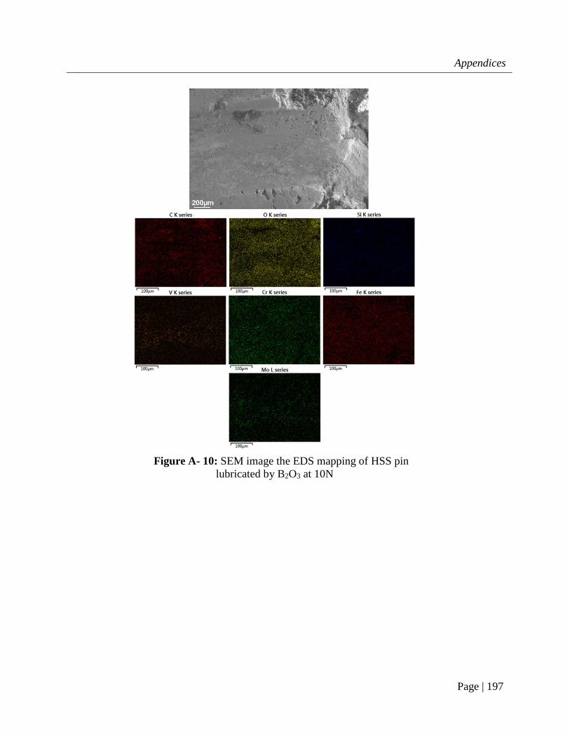
Appendices
Page | 197
Figure A- 10: SEM image the EDS mapping of HSS pin
lubricated by B2O3 at 10N
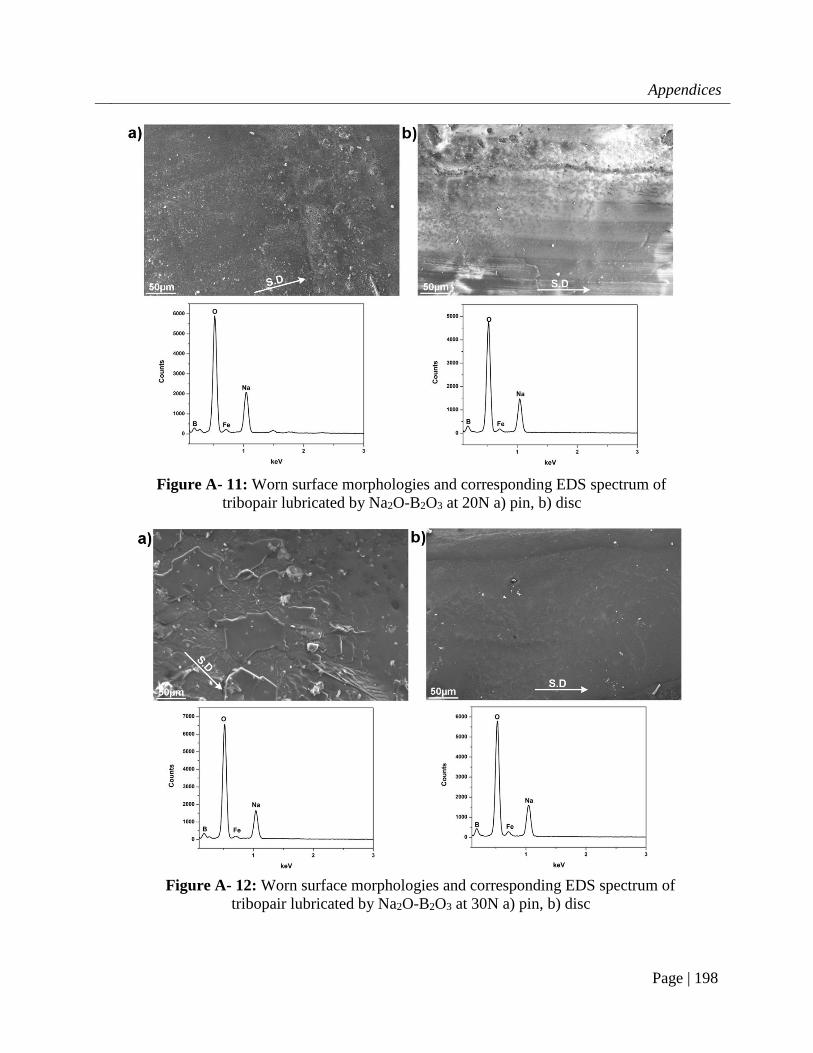
Appendices
Page | 198
Figure A- 11: Worn surface morphologies and corresponding EDS spectrum of
tribopair lubricated by Na2O-B2O3 at 20N a) pin, b) disc
Figure A- 12: Worn surface morphologies and corresponding EDS spectrum of
tribopair lubricated by Na2O-B2O3 at 30N a) pin, b) disc

Appendices
Page | 199
Only 80% in the middle of each stroke was taken into calculating the average rolling
friction. Lateral force tends to rise at the end of a stroke which increases the uncertainty of
data acquisition. Also, the first and last strokes were also excluded due to the frequency
change.
Figure A- 13: A typical data window from reciprocating test

Appendices
Page | 200
Figure A- 14: SEM micrographs of HSS surface being oxidized at 650oC for 0.5hr
and the corresponding elemental mapping

Appendices
Page | 201
Figure A- 15: SEM micrographs of HSS surface being oxidized at 650oC for
1hr and the corresponding elemental mapping

Appendices
Page | 202
Temperature (oC)
600 700 800
Ball Disc Ball Disc Ball Disc
Load (N)
10 0.002093 0.00035 0.006067 0.000413 0.008533 0.00046333
20 0.001218 0.000188 0.00345 0.00022 0.0058 0.00023667
30 0.00091 0.000136 0.002611 0.000161 0.004822 0.00018111
Table A- 1: Specific wear rates of steel tribopair under borate lubrication in Chapter 4 (the
unit is 10-2.mm3/(N.m) and mm3/(N.m) for GCr15 ball and mild steel disc, respectively)
Figure A- 16: SEM micrographs of HSS surface being oxidized at
650oC for 2hr and the corresponding elemental mapping

Appendices
Page | 203
600oC 700oC 800oC
Ball Disc Ball Disc Ball Disc
Lubricated 0.0091 0.001356 0.026111 0.001611 0.048222 0.00181111
Unlubricated 0.0106 0.027778 0.053778 0.110722 0.077222 0.06171111
Table A- 2: Specific wear rate of steel tribopairs under unlubricated and lubricated conditions
in Chapter 4 (the unit is 10-2.mm3/(N.m) and mm3/(N.m) for GCr15 ball and mild steel disc,
respectively)
10N 20N 30N 40N
Borax lubrication 0.00021 0.000117 0.000111 0.00025
B2O3 lubrication 0.001133 Table A- 3: Specific wear rate of SS316 disc lubricated by sodium borate and B2O3 at 800oC
in Chapter 6 (the unit is mm3/(N.m))
850oC 900oC
Unlubricated 0.007444 0.0055
Lubricated by NaB 0.0013 0.003889
Lubricated by KB 0.001267 0.002516
Table A- 4: Specific wear rate of SS316 under different lubrication conditions in Chapter 9
(the unit is mm3/(N.m))