Adsorption of CO2 and Coadsorption of H and CO2 on Potassium-Promoted Cu(115)
Upload
universitasislamriauCategory
view
1download
0
CO2 Process Mechanism
By Muslim

What is the Flood Process?

CO2 Flooding
Mechanism of CO2 Flooding
Miscible
First Contact
Multiple Contact
Immiscible

Miscible Mechanism
• Multiple contact process
• CO2 and oil become one phase
• CO2 vaporize the lighter oil fraction
• Mobilize and reduce Sor post water flooding

Immiscible Mechanism
• Pi or Pr < MMP
• Suitable for viscous and heavy oil reservoirs
• Main mechanism, oil swelling, viscosity reduction

FCM• First Contact Miscibility (FCM): the displacing solvent and displaced oil mix in all portions to form a single phase.
Water + EthanolButane + Crude Oil
or

MCM
• Multiple Contact Miscibility (MCM): miscibility is achieved through the mass transfer of components between the oil and solvent phases

Displacement Processes in Multiple Contact
Three MechanismVaporizing
(CH4, N2, CO2)
Condensing(Propane ) Combined

Miscibility and Drive Mechanism

Vaporizing Mechanism• Intermediate components vaporized from the crude oil (volatile oil)
• C2 – C6 (CO2 can extract up to C30)
• The vaporizing gas drive occurs trails the front
• Deep reservoirs/high pressure
Forward Contact (Vaporizing)
CO2 vaporizing C2 up C30 component in crude oil CO2 carry oil (moderate component) to production well

Forward Contact (Vaporizing Mechanism)
Injection Gas (G)
G1 G2 G3Reservoir Oil (L)
Near Critical
FluidBackward Contact (Condensing Mechanism)
Injection Gas (G)
L3 L2 L1Reservoir Oil (L)
Near Critical Fluid
Injection Gas (G)
Reservoir Oil (L)
Near Critical Fluid
G2 L3 L1L2G2
Forward Contact Backward ContactFC + BC = Combination Mechanism
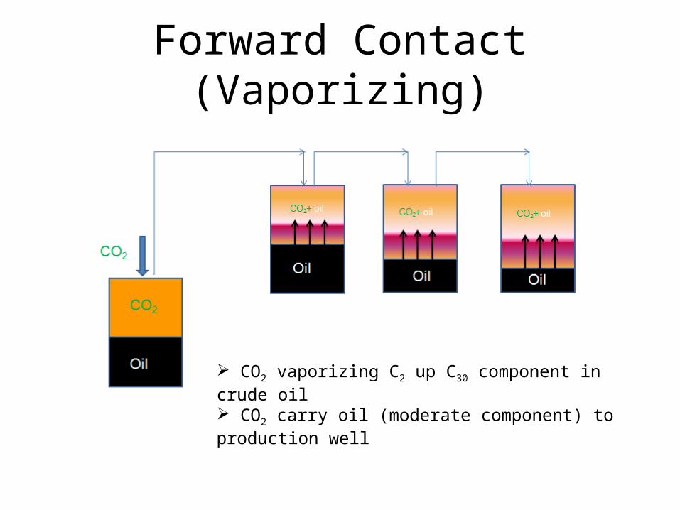
Vaporizing Gas Displacement
Interm
ediat
esin
Gas
InjectedG a s
P artly E nriched G asN ot M iscible w ithR eservoir F luid
E nriched G a sM iscible w ith
R eservoir F luid
R eservoirF luid
T W O P H A S E R E G IO N
ABCD
D IS T A N C Efrom injector to produce r
Interm e dia tes vaporize into ga s phase

Condensing Mechanism• Intermediate components (Propane) from gas phase condense into oil
• Miscibility achieved ahead of front and near from well
• Solvent is enriched with c2-6 fraction to promote miscibility

Backward Contact (Condensing or Enriched Gas)
C3 condense in oil: oil phase rich C3 (oil swelling and reduce viscosity) Oil more easy flowing to well production

Condensing Gas Displacement
Interm
ediat
esin
Gas
R ich G asInjection
V ery V ola tile O ilM iscible w ithInjected G as
R elatively R ich G asIm m iscible w ithR ese rvoir F lu id
R eservoirF luid
T W O P H A S E Z O N E
ABCD
D IS T A N C Efrom in jector to p ro duce rIn jecto r P rod ucer
G a s lose s inte rm ediate s to oil
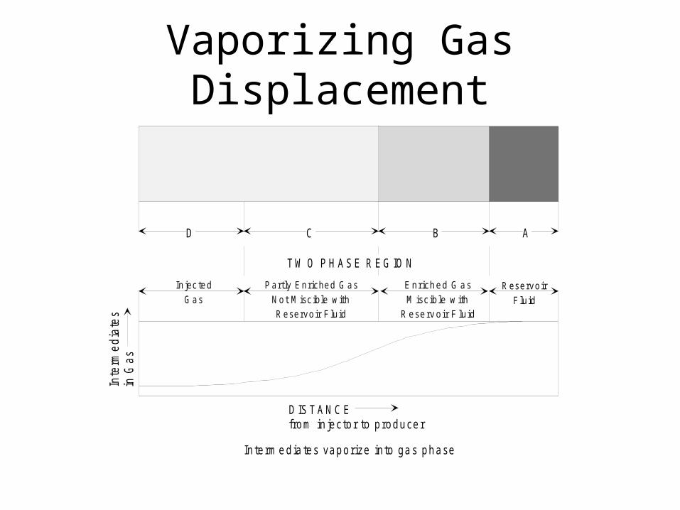
Condensing Gas Drive Process
E n ric h e dG a s S lu g
R e sid u a l O il
Inje cted W a ter fro m W a te rflo o d
C o n n a te W a te r
M iscib le Z o n e F o rm e d b y O ilB e co m in g E n rich e d w ith C - C2 6
O il B an k L e a n G a s

Combined Vaporizing and Condensing Mechanism
• A combined drive mechanism is more likely than a pure condensing gas drive when enrich gas in injected into reservoir oil
• Combine drive mechanism is a process that exhibits a sharp near-miscible front. (Zick, SPE 15493)
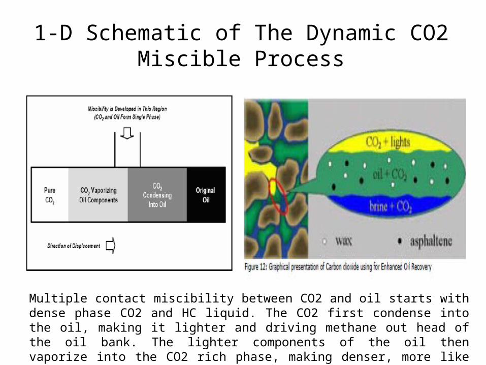
1-D Schematic of The Dynamic CO2 Miscible Process
Multiple contact miscibility between CO2 and oil starts with dense phase CO2 and HC liquid. The CO2 first condense into the oil, making it lighter and driving methane out head of the oil bank. The lighter components of the oil then vaporize into the CO2 rich phase, making denser, more like the oil, and thus more easily soluble in the oil

Effect CO2 to displace the oil from the rock pores
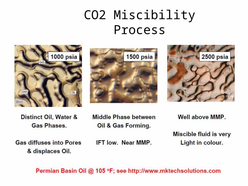
CO2 Miscibility Process
Copyright © 2022 FDOKUMEN