MECHANISM DIAGRAM - Jofrab
13
SYM 8. V-BELT DRIVING SYSTEM/KICK STARTER ARM/STARTER CLUTCH 8-1 MECHANISM DIAGRAM .................... 8-1 MAINTENANCE DESCRIPTION ........ 8-2 TROUBLE DIAGNOSIS ...................... 8-2 LEFT CRANKCASE COVER .............. 8-3 KICK STARTER ARM ........................ 8-3 DRIVING BELT................................... 8-4 SLIDING PULLEY .............................. 8-6 CLUTCH/DRIVEN PULLEY ............... 8-9 MECHANISM DIAGRAM 3.5~4.5kgf-m 5.0~6.0kgf-m 5.0~6.0kgf-m 0.8~1.2kgf-m
-
Upload
khangminh22 -
Category
Documents
-
view
2 -
download
0
Transcript of MECHANISM DIAGRAM - Jofrab

SYM 8. V-BELT DRIVING SYSTEM/KICK STARTER ARM/STARTER CLUTCH
8-1
MECHANISM DIAGRAM ....................8-1 MAINTENANCE DESCRIPTION ........8-2 TROUBLE DIAGNOSIS......................8-2 LEFT CRANKCASE COVER..............8-3
KICK STARTER ARM ........................8-3 DRIVING BELT...................................8-4 SLIDING PULLEY ..............................8-6 CLUTCH/DRIVEN PULLEY............... 8-9
MECHANISM DIAGRAM
3.5~4.5kgf-m
5.0~6.0kgf-m
5.0~6.0kgf-m
0.8~1.2kgf-m

8. V-BELT DRIVING SYSTEM/KICK STARTER ARM/STARTER CLUTCH SYM
8-2
MAINTENANCE DESCRIPTION PRECAUTIONS IN OPERATION GENERAL INFORMATION ‧ Driving pulley, clutch, and driven pulley can be serviced on the motorcycle. ‧ Driving belt and driving pulley surface must be free of grease.
Specification Unit: mm Item Standard value Limit
Driving belt width 17.50 16.8 ID of sliding pulley bush 20.035~20.085 20.150 OD of roller 15.920~16.080 15.570 ID of clutch outer 107.00~107.20 107.50 Thickness of clutch pad 4.000 2.0 Free length of drive pulley
i97.20 96.5
OD of driven pulley 33.965~33.985 33.940
ID of sliding pulley 34.000~34.025 34.060 ID: Inner Diameter OD: Outer diameter Torque value Sliding pulley nut: 5.0~6.0kgf-m Clutch outer nut: 5.0~6.0kgf-m driving pulley nut: 3.5~4.5kgf-m
Special Service Tools Clutch spring compressor Bearing puller (inner type) Clutch mounting nut wrench Universal fixture
TROUBLE DIAGNOSIS Engine can be started but motorcycle can not be moved 1. Worn driving Belt 2. Worn tilt plate 3. Worn or damaged clutch lining 4. Broken driven pulley Shudder or misfire when driving 1. Broken clutch lining 2. Worn clutch lining
Insufficient horsepower or poor high speed performance 1. Worn driving belt 2. Insufficient spring capacity of driven
pulley 3. Worn roller 4. Driven pulley operation un-smoothly

SYM 8. V-BELT DRIVING SYSTEM/KICK STARTER ARM/STARTER CLUTCH
8-3
LEFT CRANKCASE COVER Left crankcase cover removal Remove air cleaner. (2 bolts) Remove kick starter arm. (1 bolt) Loosen vent strap on the front-left side of cover, and then remove the vent. Remove engine left-side cover (8 bolts).
KICK STARTER ARM Disassembly Remove the return spring, starter shaft. Remove driving gear, friction spring and washer. Inspection Check if starter shaft, driving gear, for wear or damage. Replace it with new one if necessary. Check the return spring for spring force or damaged. Replace it with one if poor parts found. Reassembly Apply with some specified grease on the gear, shaft. Install the friction spring of driving gear onto convex part of the case cover. Install, return spring and starter shaft as diagram shown. Install kick starter arm temporary. Rotate the lever and then align driving gear with width-tooth on the starter shaft. Install thrust washer and socket onto starter shaft. Installation of the left crankcase cover Install the left crankcase cover. (8 bolts) Install front vent tube of left cover and tighten the strap. Install kick starter arm. (1 bolt) Tighten the air cleaner. (2 bolts)
Return springStarter shaft Starter shaftFriction spring
Driving gear
driving gear
starter shaft gear
Kick starter arm shaft
Strap Bolts
air cleaner lock nut kick starter arm
8. V-BELT DRIVING SYSTEM/KICK STARTER ARM/STARTER CLUTCH SYM
8-4
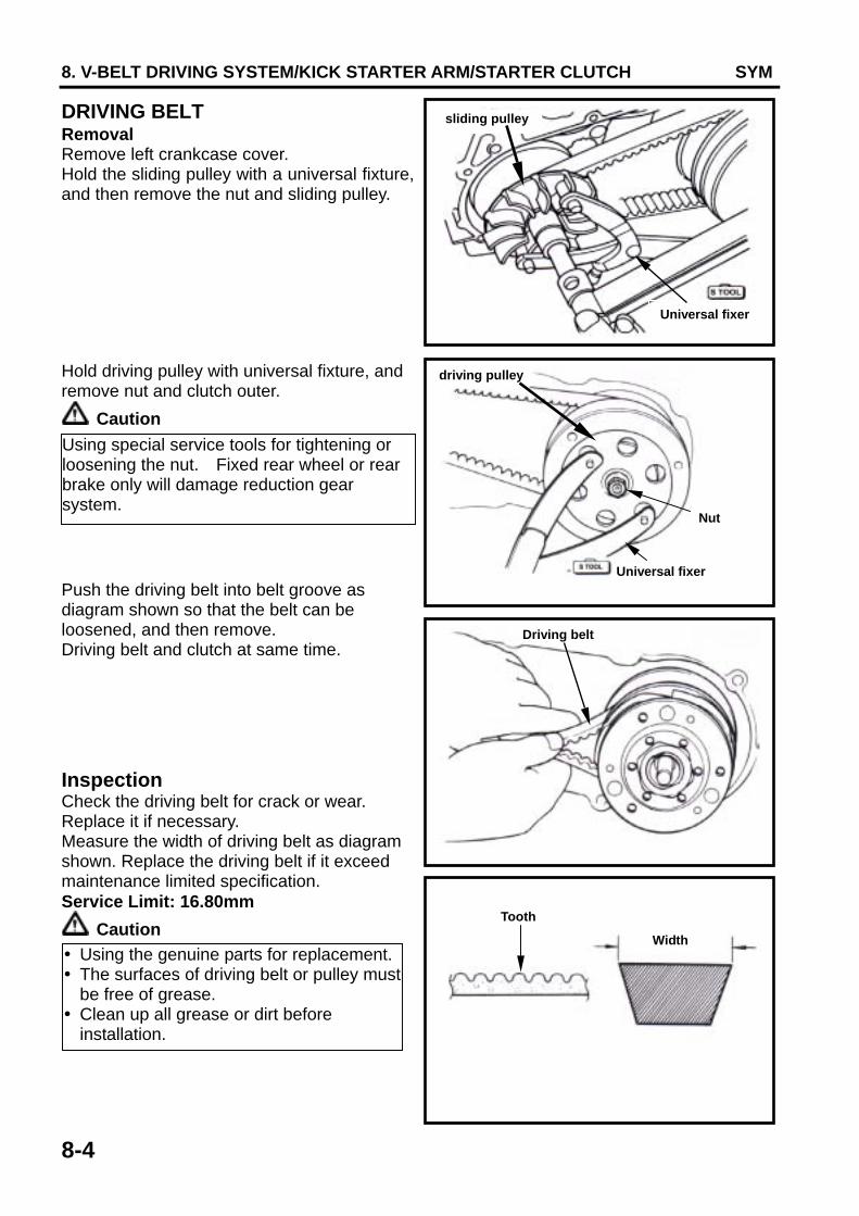
DRIVING BELT Removal Remove left crankcase cover. Hold the sliding pulley with a universal fixture, and then remove the nut and sliding pulley. Hold driving pulley with universal fixture, and remove nut and clutch outer.
Caution Push the driving belt into belt groove as diagram shown so that the belt can be loosened, and then remove. Driving belt and clutch at same time. Inspection Check the driving belt for crack or wear. Replace it if necessary. Measure the width of driving belt as diagram shown. Replace the driving belt if it exceed maintenance limited specification. Service Limit: 16.80mm
Caution
Using special service tools for tightening or loosening the nut. Fixed rear wheel or rear brake only will damage reduction gear system.
Using the genuine parts for replacement. The surfaces of driving belt or pulley must be free of grease. Clean up all grease or dirt before installation.
Width
Tooth
Driving belt
Universal fixer
sliding pulley
Nut
Universal fixer
driving pulley

SYM 8. V-BELT DRIVING SYSTEM/KICK STARTER ARM/STARTER CLUTCH
8-5
Installation Pull out the driving pulley and then insert the driving pulley.
Caution Install the starter gear. Install the clutch set with driving belt onto the driving shaft. Install the sliding pulley on the other end of belt. Install clutch outer. Install the clutch with universal fixture, and then tighten nut to specified torque value. Torque value: 3.5~4.5 kgf-m
Caution
Pull out driving pulley and then insert the driving belt into the driving pulley so that the driving belt set can be installed onto sliding pulley more easily.
When install the driving belt, if there is a arrow mark, then the arrow mark must point to rotation motion. If not, the letters on the belt must be forwarded to assembly direction.
Sliding driven pulley
Clutch outer
Nut
Universal fixer
clutch outer
starter gear
sliding pulley

8. V-BELT DRIVING SYSTEM/KICK STARTER ARM/STARTER CLUTCH SYM
8-6
SLIDING PULLEY REMOVAL Remove left crankcase cover. Hold driving pulley with universal fixture, and then remove driving pulley nut. Remove driving pulley. Remove the sliding pulley fixing nut and remove the driving belt from the sliding pulley. Remove the driving belt from the sliding pulley. Remove the limited speed bush. Remove the bush and remove the sliding pulley from the crankshaft. Remove tilt plate. Remove weight rollers from sliding pulley.
Tilt plate
Sliding pulley
Roller
driving pulley
nut
Starter gear
Bush
Sliding pulley
Limited speed bush
Crankshaft

SYM 8. V-BELT DRIVING SYSTEM/KICK STARTER ARM/STARTER CLUTCH
8-7
Inspection The operation of sliding pulley is means of the weight roller to pressing on it with centrifuge force. And then the speed is changed by the title plate rotation. Thus, if weight rollers are wear out or damage, the centrifuge force will be effected. Check if rollers are wear out or damage. Replace it if necessary. Measure each rollers’ outer diameter. Replace it if exceed the service limit. Service limit: 15.57 mm Measure the inner diameter of the sliding pulley. Service limit: 34.06 mm Measure the inner diameter of the pulley bush. Replace it if exceed the service limit. Service limit: 20.15 mm Assembly/Installation Install the weight rollers. Install the title plate guide boot onto the title plate. Install the title plate.
Weight roller
Sliding pulley
Pulley hub
Guide boot
Tilt plate
Weight roller

8. V-BELT DRIVING SYSTEM/KICK STARTER ARM/STARTER CLUTCH SYM
8-8
Apply with grease 4~5 g to inside of driving shaft hole, and install driving pulley hub.
Caution Install siding pulley assembly onto crankshaft. Driving pulley install Press driving belt into pulley groove, and then press down the up & down sides of the driving belt to separate it away from the driving pulley hub.
Caution Install driving pulley, washer and nut.
Caution Hold driving pulley with universal fixture. Tighten nut to specified torque. Torque value: 5.0~6.0 kgf-m Install left crankcase cover.
The pulley surface has to be free of grease. Clean it with cleaning solvent.
Make sure that two sides of pulley surfaces have to be free of grease. Clean it with cleaning solvent.
To press down the up & down sides of the driving belt can avoid to pressing and damaging the belt when installing the driving pulley, and also can make sure that the driving pulley can be tighten.
Driving belt
Press down
Pulley bush
Sliding pulley
Limited speed bush
Crankshaft
Pulley surface
Pulley bush

SYM 8. V-BELT DRIVING SYSTEM/KICK STARTER ARM/STARTER CLUTCH
8-9
CLUTCH/DRIVEN PULLEY DISASSEMBLY Remove driving belt and clutch/driven pulley. Install clutch spring compressor onto the pulley assembly, and operate the compressor to let nut be installed more easily.
Caution Hold the clutch spring compressor onto bench vise, and then remove mounting nut with special nut wrench. Release the clutch spring compressor and remove clutch and spring from driven pulley. Remove socket from driven pulley. Remove oil seal from driven pulley. Remove guide pin, guide pin roller, and sliding pulley, and then remove O-ring & oil seal seat from sliding pulley. INSPECTION Clutch outer Measure the inner diameter of clutch outer friction face. Replace the clutch outer if exceed service limit. Service limit: 107.5 mm
Do not press the compressor too much.
Clutch outerInner
diameter
O-ring Guide pin Guide pin roller
Guide pinOil seal Sliding pulley
Socket
Clutch spring compressor
Special nut wrench

8. V-BELT DRIVING SYSTEM/KICK STARTER ARM/STARTER CLUTCH SYM
8-10
Clutch lining Measure each clutch lining thickness. Replace it if exceeds service limit. Service limit: 2.0mm Driven pulley spring Measure the length of driven pulley spring. Replace it if exceeds service limit. Service limit: 93.2mm Driven pulley Check following items; ‧ If both surfaces are damage or wear. ‧ If guide pin groove is damage or wear. Replace damaged or worn components. Measure the outer diameter of driven surface and the inner diameter of driven pulley. Replace it if exceeds service limit. Service limit: Outer diameter 33.94mm Inner diameter 34.06mm Driven Pulley Bearing Inspection Check if the inner bearing oil seal is damage. Replace it if necessary. Check if needle bearing is damage or too big clearance. Replace it if necessary. Rotate the inside of inner bearing with fingers to check if the bearing rotation is in smooth and silent.
Free length
Guide pin groove Sliding disc
Driven pulley
Clutch
Clutch lining
Needle bearing
Outer ball bearing

SYM 8. V-BELT DRIVING SYSTEM/KICK STARTER ARM/STARTER CLUTCH
8-11
Clutch Block Replacement Remove snap and washer, and the remove clutch block and spring from driving plate. Check if spring is damage or insufficient elasticity. Check if shock absorption rubber is damage or deformation. Replace it if necessary. Apply with grease onto setting pins. Apply with grease onto setting pins. But, the clutch block should not be greased. If so, replace it. Install new clutch block onto setting pin and then push to specified location.
Caution Install the spring snap into groove with pliers.
Grease or lubricant will damage the clutch block and effect the block’s connection capacity.
Shock absorption rubber
Clutch block
Spring
Spring Driving plate
Snap ring
Clutch block
Shock absorption rubber
Setting pin

8. V-BELT DRIVING SYSTEM/KICK STARTER ARM/STARTER CLUTCH SYM
8-12
Install snap ring and mounting plate onto setting pin. REPLACEMENT OF DRIVEN PULLEY BEARING Remove inner bearing.
Caution Remove snap ring and then push bearing forward to other side of inner bearing. Place new bearing onto proper position and its sealing end should be forwarded to outside. Apply with specified grease. Recommended to use the KING MATE G-3. Install the snap ring and hold the bearing. Install a new inner bearing.
Caution Align oil seal lip with bearing, and then install the new oil seal (if necessary).
Its sealing end should be forwarded to outside as bearing installation. Install needle bearing with hydraulic presser. Install ball bearing by means of hydraulic presser.
If the inner bearing equipped with oil seal on one side in the driven pulley, then remove the oil seal firstly. If the pulley equipped with ball bearing, it has to remove snap ring and then the bearing.
Snap ring
Inner bearing
Sealing end
Oil seal
Inner needle bearing
Outer bearing
Snap ring
Snap ring
Outer bearing
Sealing end
Specified grease
SYM 8. V-BELT DRIVING SYSTEM/KICK STARTER ARM/STARTER CLUTCH
8-13
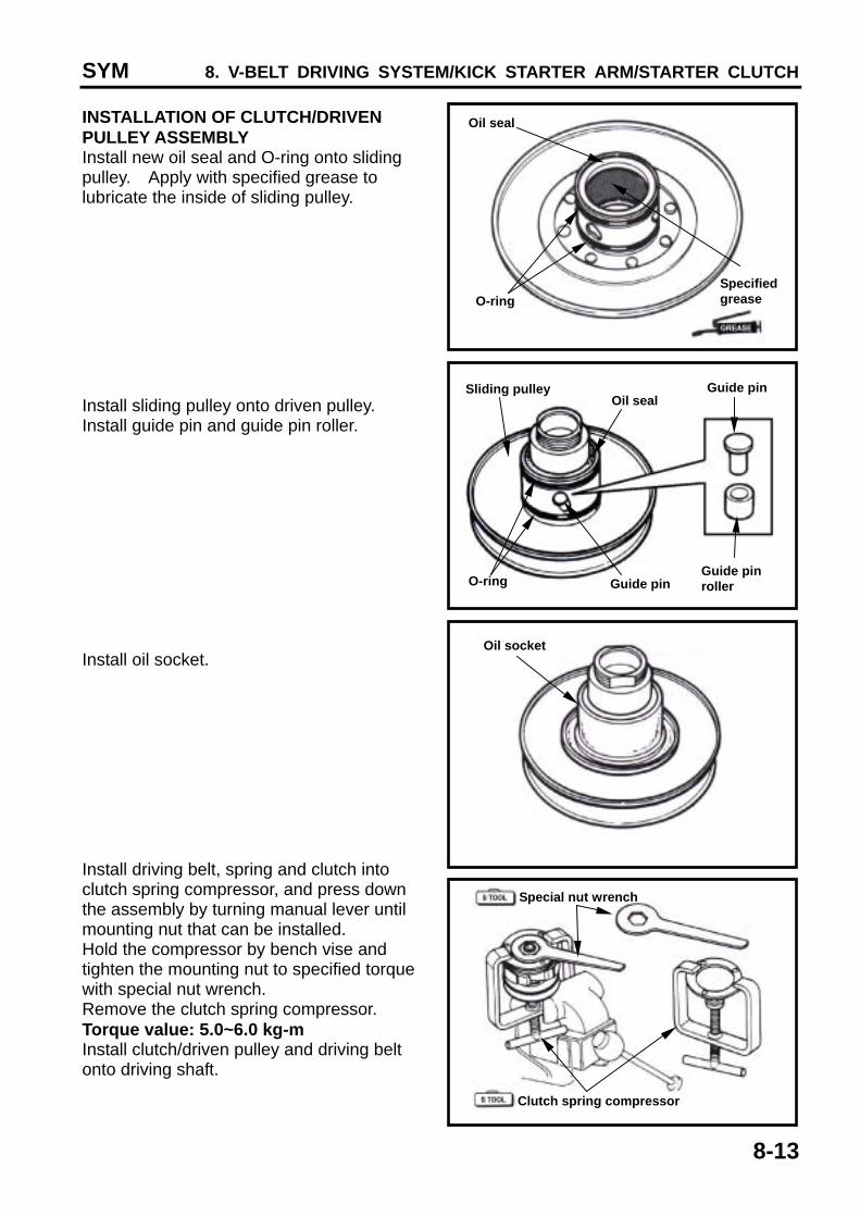
INSTALLATION OF CLUTCH/DRIVEN PULLEY ASSEMBLY Install new oil seal and O-ring onto sliding pulley. Apply with specified grease to lubricate the inside of sliding pulley. Install sliding pulley onto driven pulley. Install guide pin and guide pin roller. Install oil socket. Install driving belt, spring and clutch into clutch spring compressor, and press down the assembly by turning manual lever until mounting nut that can be installed. Hold the compressor by bench vise and tighten the mounting nut to specified torque with special nut wrench. Remove the clutch spring compressor. Torque value: 5.0~6.0 kg-m Install clutch/driven pulley and driving belt onto driving shaft.
Oil seal
O-ring Specified grease
Oil socket
O-ring Guide pin Guide pin roller
Guide pin Oil seal
Sliding pulley
Clutch spring compressor
Special nut wrench