APPENDIX E - Ladder diagram instructions - KELM
82
Ladder diagram instructions Introduction "Ladder" is the most frequent method of programming PLC controllers at present. We could divide instructions on the input ones for stating the conditions and the output ones that are executed when the conditions are fulfilled. By combining the two, logical blocks are created according to the logic of the system being automated. The purpose of this appendix is to introduce these instructions and to give details on flags and limitations of each of these. INDIRECT ADDRESSING Placing the character “*” ahead of operand from DM memory area allows us to use the indirect addressing. Simply put, value in the word *DM will be the address of the word that is the true operand. The picture below shows the MOV instruction with one operand given indirectly. The contents of location DM0003 equal “1433” which is actually a pointer marking the address DM1433 with contents “0005”. The result of this instruction will be moving the value “0005” from word DM1433 to word LR00. In order to use the indirect addressing, contents of the word that is the indirect operand have to be in BCD format. Besides that, value of the contents of indirect operand must not be greater than the number of addresses in DM area. INSTRUCTION FORMAT Operand is the address of a word or a bit in PLC controller memory (most of the instructions has one or more operands). The common term for a word is just “operand” and in the case of bit we call it “operand bit”. Also, operand can be a direct numerical value marked by character “#” placed ahead of the value (i.e.. #12, #345 etc). The state of operand bit can be ON or OFF. ON means that its logic state equals “1”, while OFF stands for “0”. Besides these, terms “set” and “reset” are also used. Symbols SV and PV commonly appear in instruction syntax. These abbreviations stand for “Set Value” and “Present Value” and are most frequently encountered with instructions concerning counters and timers. DIFFERENTIAL INSTRUCTION FORM
-
Upload
khangminh22 -
Category
Documents
-
view
1 -
download
0
Transcript of APPENDIX E - Ladder diagram instructions - KELM

Ladder diagram instructions
Introduction
"Ladder" is the most frequent method of programming PLC controllers at present. We could divideinstructions on the input ones for stating the conditions and the output ones that are executed when theconditions are fulfilled. By combining the two, logical blocks are created according to the logic of thesystem being automated. The purpose of this appendix is to introduce these instructions and to givedetails on flags and limitations of each of these.
INDIRECT ADDRESSING
Placing the character “*” ahead of operand from DM memory area allows us to use the indirectaddressing. Simply put, value in the word *DM will be the address of the word that is the true operand.The picture below shows the MOV instruction with one operand given indirectly. The contents of locationDM0003 equal “1433” which is actually a pointer marking the address DM1433 with contents “0005”. Theresult of this instruction will be moving the value “0005” from word DM1433 to word LR00.
In order to use the indirect addressing, contents of the word that is the indirect operand have to be inBCD format. Besides that, value of the contents of indirect operand must not be greater than the numberof addresses in DM area.
INSTRUCTION FORMAT
Operand is the address of a word or a bit in PLC controller memory (most of the instructions has one ormore operands). The common term for a word is just “operand” and in the case of bit we call it “operandbit”. Also, operand can be a direct numerical value marked by character “#” placed ahead of the value(i.e.. #12, #345 etc).
The state of operand bit can be ON or OFF. ON means that its logic state equals “1”, while OFF stands for“0”. Besides these, terms “set” and “reset” are also used.
Symbols SV and PV commonly appear in instruction syntax. These abbreviations stand for “Set Value”and “Present Value” and are most frequently encountered with instructions concerning counters andtimers.
DIFFERENTIAL INSTRUCTION FORM

Differential form is supported by almost all of the instructions. What differs this form from the classicalone is the character “@” placed ahead of the name of the instruction. This form ensures that theinstruction with condition fulfilled will not be executed in every cycle, but only when its conditionchanges state from OFF to ON. Differential from is commonly used because it has a lot of applications inreal-life problems.
DIFFERENCE BETWEEN BINARY AND BCD REPRESENTATIONS OF WORD CONTENTS
Generally, there are two dominant ways for comprehending values of memory locations. The first isbinary and is related to the contents of the word which is treated as a union of 16 bits. Value iscalculated as a sum of each bit (0 or 1) multiplied by 2 on power n, where n represents the position of bit in the word. Bit of the least value has position zero, while bit of greatest value has position 15.
BCD is an abbreviation for “Binary Coded Decimal number”. It is nothing more than representing eachdecimal figure with 4 bits, similar to binary coding hence the name comes from. The picture below showsthe difference between binary and BCD representations of the number. Same contents can beinterpreted as either 612 or 264. For that reason, proper attention should be given to the format of thevalue within the word that will be sent to the instruction as an operand.
LADDER DIAGRAM INSTRUCTIONS
Instructions may be divided into several basic groups according to their purpose :
- Input instructions- Output instructions- Control instructions - Timer/counter instructions- Data comparison instructions- Data movement instructions- Increment/decrement instructions- BCD/binary calculation instructions- Data conversion instructions- Logic instructions- Special calculation instructions
- Subroutine instructions- Interrupt control instructions- I/O units instructions- Display instructions- High-speed counter control instructions- Damage diagnosis instructions- Special system instructions
Each of these instruction groups is introduced with a brief description in the following tables and withmore detailed examples and descriptions afterwards.
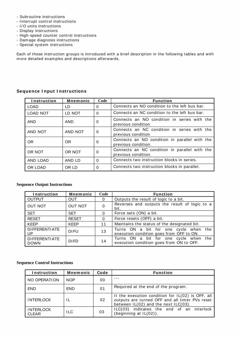
Sequence Input Instructions
Instruction Mnemonic Code FunctionLOAD LD 0 Connects an NO condition to the left bus bar.
LOAD NOT LD NOT 0 Connects an NC condition to the left bus bar.
AND AND 0 Connects an NO condition in series with theprevious condition
AND NOT AND NOT 0 Connects an NC condition in series with theprevious condition
OR OR 0 Connects an NO condition in parallel with theprevious condition.
OR NOT OR NOT 0 Connects an NC condition in parallel with theprevious condition.
AND LOAD AND LD 0 Connects two instruction blocks in series.
OR LOAD OR LD 0 Connects two instruction blocks in parallel.
Sequence Output Instructions
Instruction Mnemonic Code FunctionOUTPUT OUT 0 Outputs the result of logic to a bit.
OUT NOT OUT NOT 0 Reverses and outputs the result of logic to abit.
SET SET 0 Force sets (ON) a bit.RESET RESET 0 Force resets (OFF) a bit.KEEP KEEP 11 Maintains the status of the designated bit.DIFFERENTIATEUP DIFU 13 Turns ON a bit for one cycle when the
execution condition goes from OFF to ON.DIFFERENTIATEDOWN DIFD 14
Turns ON a bit for one cycle when theexecution condition goes from ON to OFF.
Sequence Control Instructions
Instruction Mnemonic Code Function
NO OPERATION NOP 00 ---
END END 01 Required at the end of the program.
INTERLOCK IL 02It the execution condition for IL(02) is OFF, alloutputs are turned OFF and all timer PVs resetbetween IL(02) and the next ILC(03).
INTERLOCKCLEAR ILC 03
ILC(03) indicates the end of an interlock(beginning at IL(02)).

JUMP JMP 04 If the execution condition for JMP(04) is ON, allinstructions between JMP(04) and JME(05) aretreated as NOP(OO).
JUMP END JME 05 JME(05) indicates the end of a jump (beginningat JMP(04)).
Timer/Counter Instructions
Instruction Mnemonic Code Function
TIMER TIM 0 An ON-delay (decrementing) timer.
COUNTER CNT 0 A decrementing counter.
REVERSIBLECOUNTER CNTR 12 Increases or decreases PV by one.
HIGH-SPEEDTIMER TIMH 15 A high-speed, ON-delay (decrementing) timer.
Data Comparison Instructions
Instruction Mnemonic Code Function
COMPARE CMP 20 Compares two four-digit hexadecimal values.
DOUBLECOMPARE CMPL 60 Compares two eight-digit hexadecimal values.
BLOCKCOMPARE (@)BCMP 68 Judges whether the value of a word is within 16
ranges (defined by lower and upper limits).
TABLECOMPARE (@)TCMP 85 Compares the value of a word to 16 consecutive
words.
Data Movement Instructions
Instruction Mnemonic Code Function
MOVE (@)MOV 21 Copies a constant or the content of a word to aword.
MOVE NOT (@)MVN 22 Copies the complement of a constant or thecontent of a word to a word.
BLOCKTRANSFER (@)XFER 70
Copies the content of a block of up to 1,000consecutive words to a block of consecutivewords.
BLOCK SET (@)BSET 71 Copies the content of a word to a block ofconsecutive words.
DATA EXCHAGE
(@)XCHG 73 Exchanges the content of two words.
SINGLE WORDDISTRIBUTE (@)DIST 80
Copies the content of a word to a word (whoseaddress is determined by adding an offset to aword address).
DATA COLLECT (@)COLL 81Copies the content of a word (whose address isdetermined by adding an offset to a wordaddress) to a word.
MOVE BIT (@)MOVB 82 Copies the specified bit from one word to thespecified bit of a word.
MOVE DIGIT (@)MOVD 83 Copies the specified digits (4-bit units) from aword to the specified digits of a word.
Shift Instructions

Instruction Mnemonic Code Function
SHIFTREGISTER
SFT 0/10Copies the specified bit (0 or 1) into therightmost bit of a shift register and shifts theother bits one bit to the left.
WORD SHIFT (@)WSFT 16 Creates a multiple-word shift register thatshifts data to the left in one-word units.
ASYNCHRONOUSSHIFT REGISTER (@)ASFT 17
Creates a shift register that exchanges thecontents of adjacent words when one is zeroand the other is not.
ARITHMETICSHIFT LEFT
(@)ASL 25 Shifts a 0 into bit 00 of the specified word andshifts the other bits one bit to the left.
ARITHMETICSHIFT RIGHT
(@)ASR 26 Shifts a 0 into bit 15 of the specified word andshifts the other bits one bit to the right.
ROTATE LEFT (@)ROL 27Moves the content of CY into bit 00 of thespecified word, shifts the other bits one bit tothe left, and moves bit 15 to CY.
ROTATE RIGHT (@)ROR 28Moves the content of CY into bit 15 of thespecified word, shifts the other bits one bit tothe left, and moves bit 00 to CY.
ONE DIGITSHIFT LEFT
(@)SLD 74Shifts a 0 into the rightmost digit (4-bit unit) ofthe shift register and shifts the other digits onedigit to the left.
ONE DIGITSHIFT RIGHT
(@)SRD 75Shifts a 0 into the rightmost digit (4-bit unit) ofthe shift register and shifts the other digits onedigit to the right.
REVERSIBLESHIFT REGISTER (@)SFTR 84 Creates a single or multiple-word shift register
that can shift data to the left or right.
Increment/Decrement Instructions
Instruction Mnemonic Code Function
INCREMENT (@)INC 38 Increments the BCD content of the specifiedword by 1.
DECREMENT (@)DEC 39 Decrements the BCD content of the specifiedword by 1.
BCD/Binary Calculation Instructions
Instruction Mnemonic Code Function
BCD ADD (@)ADD 30 Adds the content of a word (or a constant).
BCD SUBTRACT (@)SUB 31Subtracts the contents of a word (or constant)and CY from the content of a word (orconstant).
BDC MULTIPLY (@)MUL 32 Multiplies the content of two words (orcontents).
BCD DIVIDE (@)DIV 33 Divides the contents of a word (or constant) bythe content of a word (or constant).
BINARY ADD (@)ADB 50 Adds the contents of two words (or constants)and CY.

BINARY SUBTRACT (@)SBB 51
Subtracts the content of a word (or constant)an CY from the content of the word (orconstant).
BINARY MULTIPLY
(©)MLB 52 Multiplies the contents of two words (orconstants).
BINARY DIVIDE (@)DVB 53Divides the content of a word (or constant) bythe content of a word and obtains the resultand remainder.
DOUBLE BCD ADD
(@)ADDL 54 Add the 8-digit BCD contents of two pairs ofwords (or constants) and CY.
DOUBLE BCDSUBTRACT (@)SUBL 55
Subtracts the 8-digit BCD contents of a pair of words(or constants) and CY from the 80digit BCD contentsof a pair of words (or constants)
DOUBLE BCDMULITPLY (@)MULL 56
Multiplies the 8-digit BCD contents of two pairs ofwords (or constants).
DOUBLE BCD DIVIDE (@)DIVL 57
Divides the 8-digit BCD contents of a pair of words (orconstants) by the 8–digits BCD contents of a pair ofwords (or constants)
Data Conversion Instructions
Instruction Mnemonic Code Function
BCD TO BINARY (@)BIN 23 Converts 4-digit BCD data to 4-digit binarydata.
BINARY TO BCD (@)BCD 24 Converts 4-digit binary data to 4 digit BCDdata.
4 to 16 DECODER (@)MLPX 76
Takes the hexadecimal value of the specifieddigit(s) in a word and turn ON thecorresponding bit in a word(s).
16 to 4 DECODER (@)DPMX 77
Identifies the highest ON bit in the specifiedword(s) and moves the hexadecimal value(s)corresponding to its location to the specifieddigit(s) in a word.
ASCII CODE CONVERT
(@)ASC 86 Converts the designated digit(s) of a word intothe equivalent 8-bit ASCII code.
Logic Instructions
Instruction Mnemonic Code Function
COMPLEMENT (@)COM 29 Turns OFF all ON bits and turns ON all OFF bitsin the specified word
LOGICAL AND (@)ANDW 34 Logically ANDs the corresponding bits of twoword (or constants)
LOGICAL OR (@)ORW 35 Logically ORs the corresponding bits of twoword (or constants)
EXCLUSIVE OR (@)XORW 36 Exclusively ORs the corresponding bits of twowords (or constants)
EXCLUSIVE NOR (@)XNRW 37 Exclusively NORs the corresponding bits of twowords (or constants).
Special Calculation Instructions
Instruction Mnemonic Code Function
BIT COUNTER (@)BCNT 67 Counts the total number of bits that are ON inthe specified block
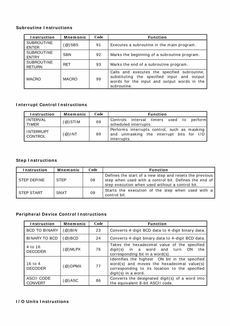
Subroutine Instructions
Instruction Mnemonic Code FunctionSUBROUTINE ENTER
(@)SBS 91 Executes a subroutine in the main program.
SUBROUTINE ENTRY
SBN 92 Marks the beginning of a subroutine program.
SUBROUTINE RETURN
RET 93 Marks the end of a subroutine program.
MACRO MACRO 99
Calls and executes the specified subroutine,substituting the specified input and outputwords for the input and output words in thesubroutine.
Interrupt Control Instructions
Instruction Mnemonic Code FunctionINTERVAL TIMER
(@)STIM 69 Controls interval timers used to performscheduled interrupts.
INTERRUPT CONTROL (@)INT 89
Performs interrupts control, such as maskingand unmasking the interrupt bits for I/Ointerrupts.
Step Instructions
Instruction Mnemonic Code Function
STEP DEFINE STEP 08Defines the start of a new step and resets the previousstep when used with a control bit. Defines the end ofstep execution when used without a control bit.
STEP START SNXT 09Starts the execution of the step when used with acontrol bit.
Peripheral Device Control Instructions
Instruction Mnemonic Code Function
BCD TO BINARY (@)BIN 23 Converts 4-digit BCD data to 4-digit binary data.
BINARY TO BCD (@)BCD 24 Converts 4-digit binary data to 4-digit BCD data.
4 to 16 DECODER (@)MLPX 76
Takes the hexadecimal value of the specifieddigit(s) in a word and turn ON thecorresponding bit in a word(s).
16 to 4 DECODER (@)DPMX 77
Identifies the highest ON bit in the specifiedword(s) and moves the hexadecimal value(s)corresponding to its location to the specifieddigit(s) in a word.
ASCII CODE CONVERT
(@)ASC 86 Converts the designated digit(s) of a word intothe equivalent 8-bit ASCII code.
I/O Units Instructions

Instruction Mnemonic Code Function7-SEGMENT DECODER
(@)SDEC 78 Converts the designated digit(s)of a word into an8-bit, 7-segment display code.
I/O REFRESH (@)IORF 97 Refreshes the specified I/O word.
Display Instructions
Instruction Mnemonic Code FunctionMEASSAGE (@)MSG 46 Reads up to 8 words of ASCII code (16
characters) from memory and displays the message on the Programming Console or otherPeripheral Device.
High Speed Counter Control Instructions
Instruction Mnemonic Code FunctionMODE CONTROL
(@)INI 61 Starts and stops counter operation, compares andchanges counter PVs, and stops pulse output.
PV READ (@)PRV 62 Reads counter PVs and status data.
COMPARE TABLE LOAD
(@)CTBL 63 Compares counter PVs and generates a directtable or starts operation.
Damage Diagnosis Instructions
Instruction Mnemonic Code Function
FAILURE ALARM (@)FAL 06
Generates a non-fatal error when executed. TheError/Alarm indicator flashes and the CPU continues operating.
SEVERE FAILURE ALARM
FAL 07Generates a fatal error when executed. TheError/Alarm indicator lights and the CPU stopsoperating.
Special System Instructions
Instruction Mnemonic Code FunctionSET CARRY (@)STC 40 Sets Carry Flag 25504 to 1.CLEAR CARRY (@)CLC 41 Sets Carry Flag 25504 to 0.
E.1 LOAD - Normally open output
Description First condition, that any logical block in the ladder diagram starts with,corresponds to LOAD or LOAD NOT instructions. Both of these instructionsrequire one line in mnemonic code. On the right of these instructions anyexecutive instruction may be used.

Ladder symbol
Limitations There are no limitations, except that it is used as the first instruction from left toright.
Flag It has no effect on any particular flag.
Example
Pressing the button on the input “00” in the word IR000 activates the relay “00”on the output of PLC controller. Conditional instruction doesn’t have be frominput memory area; it can be any bit from other memory areas, i.e. SR area asin the following example.
When one of the instructions activates the bit “00” in the word SR200, bit “00” isactivated in the output word IR010. In a word, every ON state of the bit at inputcauses the ON state at output.
E.2 LOAD NOT - Normally closed input
Description First condition, that any logical block in the ladder diagram starts with,corresponds to LOAD or LOAD NOT instructions. Both of these instructionsrequire one line in mnemonic code. On the right of these instructions anyexecutive instruction may be used.
Ladder symbol
Limitations There are no limitations, except that it is used as the first instruction from left toright.
Flag It has no effect on any particular flag.
Example
Pressing the button on the input “00” in the word IR000 activates the relay “00”on the output of PLC controller. Conditional instruction doesn’t have be frominput memory area; it can be any bit from other memory areas, i.e. SR area asin the following example.
When one of the instructions activates the bit “00” in the word SR200, bit “00” isactivated in the output word IR010. In a word, every ON state of the bit at inputcauses the OFF state at output.

E.3 AND - Logical "AND" with normally open contacts
Description When two are linked serially in one instruction line, first of them corresponds toinstructions LOAD or LOAD NOT, while the other represents instructions AND orAND NOT.
Ladder symbol
Limitations There are no limitations.
Flag It has no effect on any particular flag.
Example
After the LOAD instruction on ‘00’ input, AND instruction is linked to input ‘01’.Instruction on the right will be executed only when both of the conditions fromthe line are fulfilled, i.e. when both inputs ‘00’ and ‘01’ are in the ON state.
E.4 AND NOT - Logical "AND" with normally closed contacts
Description When two or more conditions are linked serially in one instruction line, first ofthem corresponds to instruction LOAD or LOAD NOT, while the other representsinstruction AND or AND NOT.
Ladder symbol
Limitations There are no limitations.
Flag It has no effect on any particular flag.
Example
After the LOAD instruction on ‘00’ input, AND NOT instruction is linked to input‘01’. Instruction on the right will be executed only when both of the conditionsfrom the line are fulfilled, i.e. when input ‘00’ is in ON state and input ‘01’ is inOFF state.
E.5 OR - Logical "OR" with normally open contacts
Description When two or more conditions coexist on separate, paralel lines that connect at agiven point, the first condition corresponds to LOAD or LOAD NOT instructions,while others correspond to OR or OR NOT instructions.
Ladder symbol

Limitations There are no limitations.
Flag It has no effect on any particular flag.
Example
Inputs ‘00’ and ‘01’ are in OR relation with the output ‘00’. One of the inputswith ON state is sufficient to activate the output ‘00’.
E.6 OR NOT - Logical "OR" with normally closed contacts
Description When two or more conditions coexist on separate, paralel lines that connect at agiven point, the first condition corresponds to LOAD or LOAD NOT instructions,while others correspond to OR or OR NOT instructions.
Ladder symbol
Limitations There are no limitations.
Flag It has no effect on any particular flag.
Example
Inputs ‘000.00’ and ‘000.01’ are in OR NOT relation with the output ‘010.00’. Bit‘010.00’ will retain ON state until bit “01” changes to ON state (thus breakingthe connection, because it is normally closed). One of the inputs with ON state issufficient to activate the output ‘00’.
E.7 OUTPUT - Normally open output
Description The easiest way for getting results that fulfill input conditions is their directconnection to the instructions OUTPUT and OUTPUT NOT. These instructions areused for controlling the status bit, which is defined as the instruction carrier.When OUTPUT instruction is used, bit assigned to it will be ON if the executioncondition is ON, and it will be OFF if the execution condition is OFF.
Ladder symbol
Limitations Attention should be paid not to “overlap” the instructions concerning the bitbeing controlled.

Flag It has no effect on any particular flag.
Example
Bit IR010.00 will remain ON as long as bit IR000.00 is ON. When bit IR000.00changes to OFF, bit IR010.00 also changes to OFF.
This instruction cannot be used for assigning ON or OFF states to more than onebit. In case that there is a need for assigning values to all of the bits in word, itcan be done only one bit at a time.
E.8 OUTPUT NOT - Normally closed output
Description The easiest way for getting results that fulfill input conditions is their directconnection to the instructions OUTPUT and OUTPUT NOT. These instructions areused for controlling the status bit, which is defined as the instruction carrier.When OUTPUT instruction is used, bit assigned to it will be ON if the executioncondition is OFF, and it will be OFF if the execution condition is ON.
Ladder symbol
Limitations Attention should be paid not to “overlap” the instructions concerning the bitbeing controlled.
Flag It has no effect on any particular flag.
Example
Bit IR010.00 will remain ON as long as bit IR000.00 is OFF, while prelaskomchanging bit IR000.00 to ON changes bit IR010.00 to OFF.
This instruction cannot be used for assigning ON or OFF states to more than onebit. In case that there is a need for assigning values to all of the bits in word, itcan be done only one bit at a time.
E.9 SET - Changes bit state to ON
Description Instruction changes the state of the specified bit to ON when the executioncondition is ON. In case that the condition is OFF, bit state remains unchanged(unlike the instruction OUT which changes bit state to OFF even when the condition is OFF).
Ladder symbol
Limitations There are no limitations.
Flag It has no effect on any particular flag.

Example
If condition state on bit IR000.00 changes to ON, state of bit IR200.00 alsochanges to ON. When condition state of bit IR000.00 changes from ON to OFF,bit IR200.00 remains ON.
E.10 RESET - Changes bit state to OFF
Description Instruction changes the state of the specified bit to OFF when the executioncondition is ON. In case that the condition is OFF, bit state remains unchanged.
Ladder symbol
Limitations There are no limitations.
Flag It has no effect on any particular flag.
Example
If condition state on bit IR000.00 changes to ON, state of bit IR200.00 changesto OFF. When condition state of bit IR000.00 changes from ON to OFF, bitIR200.00 remains OFF.
E.11 KEEP - Changes bit state according to 2 inputs
Description Instruction is used for maintaining the status of corresponding bit according to 2inputs. The first input changes bit state to ON whenever the condition of the firstline is fulfilled, while the second changes bit state to OFF whenever the conditionof the second line is fulfilled. Bit state remains unchanged as long as inputsremain unchanged.
Ladder symbol
Flag It has no effect on any particular flag.
Example

When the state of bit IR000.00 changes to ON bit IR200.00 also changes to ON.If bit IR000.01 changes to ON, bit IR200.00 changes to OFF and remains OFFuntil state of bit IR000.00 is ON again.
E.12 DIFFERENTIATE UP - Changes bit state to ON for duration of one cycle
Description Instruction changes bit state to ON during one cycle when the precedingcondition is fulfilled.
Ladder symbol
Flag It has no effect on any particular flag.
Example
Instruction changes state of bit IR200.00 to ON for duration of one cycle. If bitIR000.00 is ON, bit IR200.00 changes to ON for duration of one scan cycle.
E.13 DIFFERENTIATE DOWN - Changes bit state to OFF for duration of onecycle
Description Instruction changes bit state to OFF during one cycle when the precedingcondition is fulfilled.
Ladder symbol
Flag It has no effect on any particular flag.
Example
If bit IR000.00 is ON, state of bit IR200.00 changes to OFF for duration of onescan cycle.
E.14 NO OPERATION - No operation
Description Generally, usage of this instruction in programs is not recommended. When PLC

gets to this instruction nothing happens and the following instruction isexecuted.
Ladder symbol
Flag It has no effect on any particular flag.
E.15 INTERLOCK - Interlock
Description Instruction IL is always used in pair with the instruction ILC. Their purpose is toreset all the outputs, flags, control bits, timers and counters that are withininstructions between IL and ILC. Timers and counters stop working and retainvalues they had at the moment of executing IL instruction. It is possible to havemultiple IL instructions and to reset one or more parts of the program,accordingly. Instruction is executed when condition state changes from ON toOFF!
Ladder symbol
Flag It has no effect on any particular flag.
E.16 INTERLOCK CLEAR - End of the program part encompassed by interlock
Description Instruction ILC is always used in pair with instruction IL. When the condition ofinstruction IL is fulfilled all the outputs, flags, control bits, timers and countersthat are within instructions between IL and ILC are reset. Timers and countersstop working and retain values they had at the moment of executing ILinstruction.
Ladder symbol
Flag It has no effect on any particular flag.
E.17 END - End of program
Description This is mandatory instruction at the end of every program. Any instructionfollowing this one will not be executed. It can be used for debugging purposes inprogram, so as to designate the point where the monitoring of programexecution stops. If the program uses subroutines, it is necesssary to haveinstruction END following the last subroutine.
Ladder symbol
Limitations There are no limitations.
Flag Changes states of flags ER, CY, GR, EQ and LE to OFF.
E.18 JUMP - Jump to another location in the program
Description Certain part of the program may be skipped depending on the state of defined

condition for jump execution. Jumps can be created using JUMP (JMP(04)) orJUMP END (JME(05)) instructions. If condition state is ON, program executesnormally, as if the instruction was never used. If status of execution condition isOFF, program execution continues from the JUMP END instruction correspondingto JUMP instruction. Which JUMP END corresponds to which JUMP instruction isdefined with a number that follows the instruction. Value 0 can be usedunlimited number of times in the course of program for this purpose, while eachof other 99 available numbers may be used only once.
Ladder symbol
Limitations Total number of JUMP and JUMP END pairs cannot exceed 99. Each value from1-99 range can be used only once.
Flag It has no effect on any particular flag.
E.19 JUMP END - Location where the program execution continues after JUMP
Description Instruction JME is used in pair with JMP instruction as integral part of it. If thereis no JME assigned to JMP instruction, program will report an error.
Ladder symbol
Limitations Total number of JUMP and JUMP END pairs cannot exceed 99. Each value from1-99 range can be used only once.
Flag It has no effect on any particular flag.

Example
When the state of bit IR000.00 changes to OFF, jump instruction skips all theinstruction lines between itself and the corresponding JME instruction.
Another way for using jump instruction is assigning value “0” to JMP instruction.Unlimited number of jumps can be programmed in this way and the destinationfor each of these is a unique location defined with instruction JUMP END withindex 0. Instruction JUMP END with parameter 0 may be used multiple times inthe program. In that case, program execution after the jump defined with JUMP(index 0) continues from the first following JUMP END instruction with this index.Time of execution with this form of jump function is somewhat longer, as theprogram must first locate the closest appropriate JUMP END instruction. Thefollowing example demonstrates programming greater number of jump functionsending at the same destination:
Changing the state of bits IR000.00 or IR000.03 to OFF executes the jump tothe line containing instruction JME.

E.20 TIMER - Timer with 0.1s resolution
Description Timers are complex instructions with the purpose of separating two programmingactions. Changing the state of condition to ON starts the timing with 0.1s incrementsstarting from zero.
Value of parameter SV (abbreviation for Set Value) is multiplied by 0.1 s, the resultbeing total time in seconds. Value given in the middle part of the block is called TCnumber. Each TC number can be used for defining one couner or timer. It can takevalues from 000 - 127 range. Lower part of the block is reserved for displaying thestarting value of timer. Word with this role can belong to sectors IR, AR, DM, HR, LR orcan be given as a constant, with values from 000.0 - 999.9 range. The most commonand the simplest way to apply a timer is to have a constant here, whether given directlyor programmed on some memory location (if parameter SV is given as a constant, it isnecessary to put character “#” ahead of value).

Ladder symbol
Limitations The number of timer cannot be used for counter or another timer.
Flag Affects the appropriate flag in TC area.
Example
Changing the state of bit IR000.00 to ON starts the timing (in this case, time is100*0.1s=10 seconds). After the passing of given period of time, the appropriate bitIM002 changes state to ON, thus fulfilling the condition for executing the instructions onthe right (in this case bit IR010.01 changes state to ON).
Condition bit must be constantly ON for a given time period for bit TIM002 to be set. Ifcondition state changes to OFF during the given time period, timer resets and goes backto the beginning of period.

E.21 HIGH-SPEED TIMER - Timer with 0.01s resolution
Description This instruction is identical to the previous TIM instruction, except for theresolution of decrementing. In case of TIM instruction this interval equals 0.1s,while with TIMH instruction it equals 0.01s. Changing the condition to ON startsthe countdown with 0.01s decrements from the predefined value down to zero. Ifthe state of condition changes to OFF timer will be reset. Value of parameter SV(abbreviation for Set Value) is multiplied by 0.01 s resulting in total time inseconds. Value given in the middle part of the block is called TC number. Each TCnumber can be used for defining one couner or timer. It can take values from000 - 127 range. Lower part of the block is reserved for displaying the startingvalue of timer. Word with this role can belong to sectors IR, AR, DM, HR, LR orcan be given as a constant, with values from 00.00 - 99.9.9 range. If parameterSV is given as a constant, it is necessary to put character “#” ahead of value.
Ladder symbol
Limitations The number of timer cannot be used for a counter or another timer. Value of SVmust be in 00.00 - 99.99 range. Recommended range for a number of timer is000 - 003.
Flag Affects the appropriate flag in TC area.
Example
Changing the state of condition bit IR000.00 to ON starts the countdown (in thiscase for 27*0.01s=0.27 seconds). After the passing of given period of time, theappropriate bit IM003 changes state to ON, thus fulfilling the condition forexecuting the instructions on the right (in this case bit IR010.01 changes state toON).
Condition bit must be constantly ON for a given time period for bit TIM002 to beset. If condition state changes to OFF during the given time period, timer resetsand goes back to the beginning.

E.22 COUNTER - Counter
Description Counter decrements the value given with SV for every ON state of the condition on CP line(abbreviation for Count Pulse). Each time the state on CP line changes from OFF to ONvalue of SV is decremented by one. Fulfilling the condition on R (reset) line sets thecounter to a starting state with a given SV value. When the zero is reached, instructionchanges the state of appropriate bit from TC area corresponding to the number of acounter (bit can be returned to OFF state by fulfilling the condition on reset line). Ifparameter SV is given as a constant, it is necessary to place a character “#” ahead ofvalue.
Ladder symbol
Limitations The number of timer cannot be used for a counter or another timer.
Flag Affects the appropriate flag in TC area.
Example
When the state of bit IR000.00 changes from OFF to ON, counter value decreases to 299,next change of bit IR000.00 lowers it to 298 and so on. When counter value reaches zero,state of bit CNT004 changes to ON, fulfilling the condition for executing instructions on theright (in this case, it is a normally closed contact that will open).

E.23 REVERSIBLE COUNTER - Incrementing / decrementing counter
Description This instruction is an extension of the previous one, having the added input for increasingcounter value by one. Counter CNTR has two counting inputs: incrementing and decrementing. Decrementing input is identical to one from CNT instruction. For every ONstate of condition on II line (Increment Input) counter value increases by one. If this valuereached SV, counter value remains unchanged. Every time state on DI line (DecrementInput) changes from OFF to ON, value of SV decreases by one. If counter value reachedzero it remains unchanged. Fulfilling the condition on R (reset) line sets the counter to astarting state given with value of SV. With reaching the zero, instruction changes the stateof bit in TC area appropriate to the number of the counter. This bit can be returned to OFFstate by fulfilling the condition on na reset line or increment II line. If the parameter SV isgiven as a constant it is necessary to place the character “#” ahead of value.
Ladder symbol
Limitations Number of a counter cannot be used for a timer or another counter.
Flag Affects the appropriate bit in TC area.
Example
When the state of bit IR000.00 changes from OFF to ON, counter value decreases to 122,next change of bit IR000.00 lowers it to 121 and so on. When the state of bit IR000.01changes counter value increases by one. When counter value reaches zero, state of bit

CNT006 changes to ON fulfilling the condition for executing instructions on the right (in thiscase, it is normally closed contact that will open). ON state of bit IR00.02 will return thecounter to a given value, while a bit CNT006 returns it to OFF state.
E.24 COMPARE - Compares two memory locations
Description Instruction CMP(20) compares two words upon fulfilling the preceding condition.Depending on the relation of the two words, output can be:
1. Equal - state of bit EQ in SR memory area changes to ON.2. Cp1 is lower than Cp2 - state of bit LE in SR memory area changes to ON.3. Cp1 is greater than Cp2 - state of bit GR in SR memory area changes to ON.
Flag Address Cp1<Cp2 Cp1=Cp2 Cp1>Cp2GR 25505 OFF OFF ONEQ 25506 OFF ON OFFLE 25507 ON OFF OFF
Ladder symbol
Limitations Comparations that include the current values of timer or a counter require valuesin BCD format. Checking the flags GR, LE and EQ should take place immediatelyafter the CMP(20) instruction, because another instruction may affect theirstates.
Flag Affects the flags GR, LE and EQ in SR memory area.

Example
When the state of bit IR000.00 changes to ON, condition for comparing thevalues of memory locations IR200 and IR201 is fulfilled. If value of IR200 isgreater than IR201, state of bit IR010.00 changes to ON. If value of IR200 islesser than IR201, state of bit IR010.02 changes to ON. In case of equal valuesof locations IR200 and IR201, state of bit IR010.01 changes to ON.
E.25 DOUBLE COMPARE - Compares two consecutive words
Description Instruction CMPL(60) compares the two consecutive words with other twoconsecutive words. Depending on the relation, output can be:
1. Equal - state of bit EQ in SR memory area changes to ON.2. Cp1+1, Cp1 is lower than Cp2+1, Cp2 - state of bit LE in SR memory areachanges to ON.3. Cp1+1, Cp1 is greater than Cp2+1, Cp2 - state of bit GR in SR memory areachanges to ON.
Flag Address Cp1+1,Cp1<Cp2+1,Cp2
Cp1+1,Cp1=Cp2+1,Cp2Cp1+1,Cp1>Cp2+1,Cp2
GR 25505 OFF OFF ONEQ 25506 OFF ON OFFLE 25507 ON OFF OFF

Ladder symbol
Limitations Checking the flags GR, LE and EQ should take place immediately after theCMP(20) instruction, because another instruction may affect their states.
Flag Affects the flags GR, LE and EQ in SR memory area.
Example
When the state of bit IR000.00 changes to ON, condition for comparing thevalues of memory locations IR200+IR2001 and HR00+HR01 is fulfilled. If valueof the first operand is greater, state of bit IR010.00 changes to ON. If value ofthe first operand is lesser, state of bit IR010.02 changes to ON. In case of equalvalues, state of bit IR010.01 changes to ON.
E.26 BLOCK COMPARE - Block compare
Description Instruction BCMP compares the value of memory location CD with values of memorylocations CB - CB+31. The method consists of finding the pair of CB locations where thevalue of CD location fits in between. Upon locating that area, the appropriate bit is set inthe result word R. Based on this information, the programmer knows the general area ofvalue of location CD.

Ladder symbol
Limitations Values of CB block must be in order, so that the value of location CB is lesser than valueof CB+1.
Flag It has no effect on any particular flag.
Example
Comparation will be executed for as long as the state of condition is ON. If value oflocation HR00 equals “0210”, then it will be set between DM0014 and DM0015correspoding to the second bit of the result word LR05.
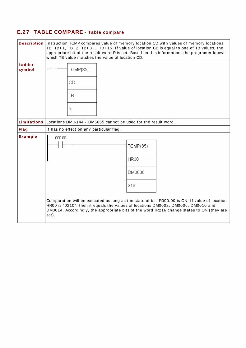
E.27 TABLE COMPARE - Table compare
Description Instruction TCMP compares value of memory location CD with values of memory locationsTB, TB+1, TB+2, TB+3 ... TB+15. If value of location CB is equal to one of TB values, theappropriate bit of the result word R is set. Based on this information, the programer knowswhich TB value matches the value of location CD.
Ladder symbol
Limitations Locations DM 6144 - DM6655 cannot be used for the result word.
Flag It has no effect on any particular flag.
Example
Comparation will be executed as long as the state of bit IR000.00 is ON. If value of locationHR00 is “0210”, then it equals the values of locations DM0002, DM0006, DM0010 andDM0014. Accordingly, the appropriate bits of the word IR216 change states to ON (they areset).

E.28 MOVE - Moves the contents of one memory location to another
Description Instruction MOVE is used for moving the contents of one memory location toanother. The operand S represents the word whose contents should be moved toa word that is operand D. Operand S can be a constant, if the character “#” isplaced ahead of four-digit value.
Ladder symbol
Limitations Words DM6144 - DM6655 cannot be used as operand D. The current state oftimer or counter also cannot be used as operand D. Instruction BSET(17) shouldbe used for that purpose.
Flag Flag EQ from TC area changes state to ON when all zeros are written intooperand D. Therefore, flag EQ provides us with information if the moved valueequals zero. In case of error, state of flag ER changes to ON.
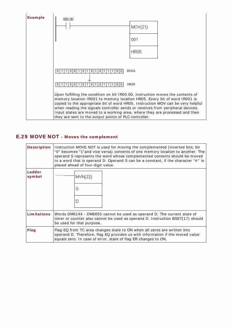
Example
Upon fulfilling the condition on bit IR00.00, instruction moves the contents ofmemory location IR001 to memory location HR05. Every bit of word IR001 iscopied to the appropriate bit of word HR05. Instruction MOV can be very helpfulwhen reading the signals controller sends or receives from peripheral devices.Input states are moved to a working area, where they are processed and thenthey are sent to the output points of PLC controller.
E.29 MOVE NOT - Moves the complement
Description Instruction MOVE NOT is used for moving the complemented (inverted bits, bit“0” becomes “1”and vice versa) contents of one memory location to another. Theoperand S represents the word whose complemented contents should be movedto a word that is operand D. Operand S can be a constant, if the character “#” isplaced ahead of four-digit value.
Ladder symbol
Limitations Words DM6144 - DM6655 cannot be used as operand D. The current state oftimer or counter also cannot be used as operand D. Instruction BSET(17) shouldbe used for that purpose.
Flag Flag EQ from TC area changes state to ON when all zeros are written intooperand D. Therefore, flag EQ provides us with information if the moved valueequals zero. In case of error, state of flag ER changes to ON.

Example
Upon fulfilling the condition on bit IR00.00, instruction moves the complementedcontents of memory location IR001 to memory location HR05. Every bit of wordIR001 is complemented and copied to the appropriate bit of word HR05.
E.30 BLOCK TRANSFER - Copies one block of words to another
Description Instruction BLOCK TRANSFER copies the contents of one memory block of words toanother. Parametar “N” represents the number of memory locations copied, “S” isthe address of starting source memory location, while “D” represents the addressof the starting destination memory location.
Ladder symbol
Limitations Words DM6144 - DM6655 cannot be used as operand D. S and S+N have to befrom the same memory area. D and D+N also have to be from the same memoryarea. N has to be a BCD number.
Flag State of ER flag changes to ON if N is not a BCD number or in case that S andS+N, D and D+N are not from the same memory area.

Example
Upon fulfilling the condition on bit IR00.00, instruction moves the contents of tenmemory locations IR200 - IR210 to memory locations HR00 - HR10.
E.31 BLOCK SET - Copies the contents of one memory location to multiple locations
Description Instruction copies the contents of one memory location S to a block of memorylocations from St to E. Parameter St contains the starting address of the block andparameter E contains the ending address of the block. It is possible to change thecontents of the current timer/counter values with this instruction, unlike withinstructions MOV and MVN. Operand S can be a constant, if the character “#” isplaced ahead of four-digit value.
Ladder symbol
Limitations Words DM6144 - DM6655 cannot be used as operands St and E. Address in theoperand St has to be lesser than the addreess in operand E. Both the operands Stand E have to be from the same memory block.
Flag State of ER flag changes to ON if St and E do not belong to the same memory blockor in the case that the second parameter is greater than first.

Example
Upon fulfilling the condition on bit IR00.00, instruction moves the contents ofmemory location IR000 (zero) to locations HR00 - HR05. In this way, it is possibleto clear the memory block or to set it to a certain value. Same effect could beachieved if constant “#0000” was used instead of memory location IR200containing all zeros.
E.32 DATA EXCHANGE - Exchanges values of two memory locations
Description Instruction exchanges the values of memory locations E and E1.
Ladder symbol
Limitations Words DM6144 - DM6655 cannot be used as operands E1 and E2.
Flag State of ER flag changes to ON if non-existing indirect address of location from DMarea is used as an operand.

Example
Upon fulfilling the condition on bit IR00.00 instruction exchanges the contents ofmemory locations IR000 (all zeros) and IR201 (all ones). As a result, memorylocation IR201 contains all ones and memory location IR200 contains all zeros.
E.33 SINGLE WORD DISTRIBUTE - Creates a stack
Description Instruction can be used in two ways depending on the states of bits 12, 13, 14and 15 of memory location in parameter C. If these 4 bits have value between 0and 8, then the instruction copies the word from parameter S (or a constant if itis given with character “#” ahead) to an address calculated by adding the baseaddress from parameter DBs and the shift defined in the rest of the word ofparameter C. When bits 12-15 in memory location of parameter C form the number 9, thenthe instruction is used for stack operations. The rest of the value of word ofparameter C now defines number of the words in stack (from 000 to 999) andthe contents of DBs represent the stack pointer.
Ladder symbol
Limitations Words DM6144 - DM6655 cannot be used as operand DBs. Address of theoperand DBs has to be in the same memory block with BDs + shift. Theargument C has to be BCD number.
Flag EQ flag changes state to ON when the contents of memory location in parameterS equal zero. State of ER flag changes to ON in case of error.

Examples
Bits 12-15 in the word LR10 from parameter C formthe number “0011”, which isin 0 - 8 range. Therefore, the instruction is used in the first form. Upon fulfillingthe condition on bit IR00.00, instruction copies the constant #00FF to an addresscalculated by adding the base address (in this case HR10) and three lowernumbers from the word LR10.

Bits 12-15 in the word IR216 from parameter C form the number “0101”, whichexceeds 8. Therefore, the instruction is used in the second form. The exampleabove shows how to create a stack between memory locations DM0001 andDM0005. Location DM0000 is used as a pointer marking the top of the stack.
E.34 DATA COLLECT - FIFO, LIFO stack
Description Instruction can be used in three different ways depending on the states of bits12-15 in the word of parameter C: 1. If four bits have value between 0 and 7, the instruction copies the word D toan address calculated by adding the address of the word SBs with the rest of theword C. 2. If value of four bits of word C equals 9, instruction creates the FIFO stack(First In First Out). The rest of the bits of the word C determines the number ofthe words in stack (000 to 999), while SBs represents the pointer marking thetop of the stack.3. If value of four bits of word C equals 8, instruction creates the LIFO stack(Last In First Out). The rest of the bits of the word C determine the number ofthe words in stack (000 to 999), while SBs represents the pointer marking thetop of the stack.
Ladder symbol
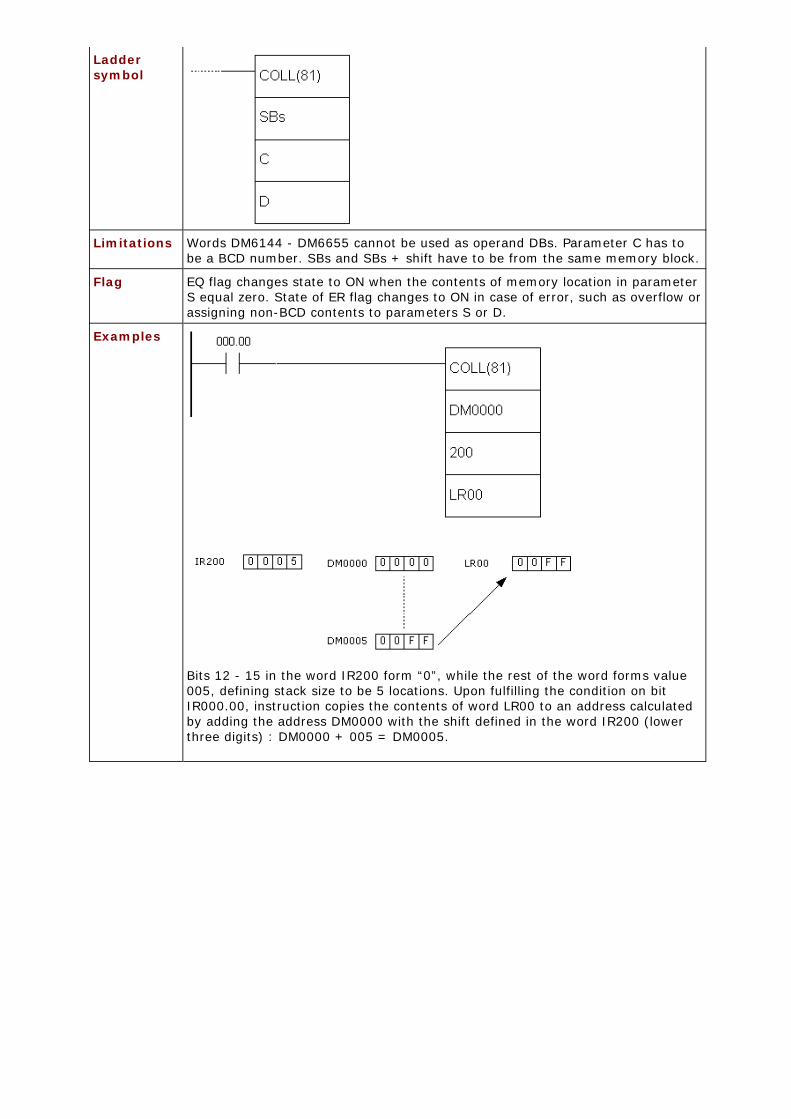
Limitations Words DM6144 - DM6655 cannot be used as operand DBs. Parameter C has tobe a BCD number. SBs and SBs + shift have to be from the same memory block.
Flag EQ flag changes state to ON when the contents of memory location in parameterS equal zero. State of ER flag changes to ON in case of error, such as overflow orassigning non-BCD contents to parameters S or D.
Examples
Bits 12 - 15 in the word IR200 form “0”, while the rest of the word forms value005, defining stack size to be 5 locations. Upon fulfilling the condition on bitIR000.00, instruction copies the contents of word LR00 to an address calculatedby adding the address DM0000 with the shift defined in the word IR200 (lowerthree digits) : DM0000 + 005 = DM0005.

Bits 12 - 15 in word IR216 form a number “9”, while the rest of the word formsvalue 005, defining the stack size to be 5 locations. Number “9” as the first digitof word IR216 determines that the instruction works with FIFO stack. Uponfulfilling the condition on bit IR000.00, instruction moves the contents of thestack by one address, so that the element that first came into the stack (“AAAA”)is copied to the word IR001, while the stack pointer decreases by one.
Bits 12 - 15 of the word IR216 form a number “8”, while the rest of the wordforms value 005, defining the stack size to be 5 locations. Number “8” as the firstdigit of the word IR216 means that the instructions works with LIFO stack. Uponfulfilling the condition on bit IR000.00, instruction copies the value of the lastword that came into stack to the location IR001, while the stack pointer

decreases by one.
E.35 MOVE BIT - Copies a bit from one word to another
Description Instruction copies a specified bit from the word S to a specified bit of word D.The word Bi determines the positions of bits in question. The upper 2 digitsdetermine the destination bit, while lower 2 determine the source bit.
Ladder symbol
Limitations Values of destination and source bits has to be between 0 and 15. WordsDM6144 - DM6655 cannot be used as operands Bi or D.
Flag
Example
E.36 MOVE DIGIT - Moves a digit from one word to another
Description Instruction copies a specified digit from the word S to a specified digit of theword D. The word Di determines the positions of digits in question.

Ladder symbol
Limitations Value of destination and source bit has to be between 0 and 15. Words DM6144 -DM6655 cannot be used as operands Bi or D.
Flag ER flag changes state to ON if at least one of three digits in the word Di isn’t inthe specified range (between 0 and 3).
Example The examples below show copying digits from one word to another depending onthe value of word Di.
E.37 SHIFT REGISTER - Shifts the contents of a word for 1 bit to the left
Description Instruction shifts the contents of word St for 1 bit to the left. The highest bit ofthe word St moves to the place of the lowest bit in the word St+1, the highestbit of the word St+1 moves to the position of the lowest bit in the word St+2 andso forth, up to the word E. The highest bit of the word E is irreversibly lost withevery shifting. Input I defines whether “0” or “1” fills the lowest bit position. Ifthe state of I line is ON, value is one, while OFF defines zero. Input P is used asclock for the instruction and switching it from OFF to ON changes the bit shift.State on R line can be OFF when the instruction can be executed and ON whenall the bits within word range from St to E are set to “0”. As long as the state ofR line isn’t set to OFF state, instruction cannot be executed.

Ladder symbol
Limitations E has to be greater or equal to the address in parameter St.
Flag ER flag changes state to ON if St is lower address than E or if they are not in thesame memory area.
Example
Upon fulfilling the condition on bit IR000.00, instruction uses one-second clockon bit 255.02 in order to move the contents of the word HR00. Bit IR200.00 willbe ON every time the bit HR00.07 equals one.
E.38 WORD SHIFT - Shifts whole words
Description Instruction shifts the whole contents of the word St to an address greater by onethan the current. Value of the word from the parameter St is moved to St+1 upto the the word defined with parameter E. Word that equals zero fills the placeon the right for every shifting. Value of the word on the address from parameterE is irreversibly lost.
Ladder symbol

Limitations E has to be greater or equal address to the one from parameter St. WordsDM6144 - DM6655 cannot be used as operands St and E.
Flag ER flag changes state to ON if St is lower address than E or if they are not fromthe same memory area.
E.39 ARITHMETIC SHIFT LEFT - Arithmetic shift left
Description Instruction shifts the contents of the word Wd for one bit to the left. The lowestbit becomes “0”, while the highest bit is moved to carry bit.
Ladder symbol
Limitations Words DM6144 - DM6655 se ne mogu koristiti za operand Wd.
Flag EQ flag changes state to ON if the contents of the word Wd equal zero. CY flagtakes the value of the highest bit of theword Wd and changes state accordingly.
E.40 ARITHMETIC SHIFT RIGHT - Arithmetic shift right
Description Instruction shifts the contents of the word Wd for 1 bit to the right. The highestbit takes value “0”, while the lowest bit moves to carry bit (CY).
Ladder symbol
Limitations Words DM 6144 - DM6655 cannot be used as operand Wd.
Flag EQ flag changes state to ON if the contents of the word Wd equal zero. CY flagtakes the value of the lowest bit of the word Wd and changes state accordingly.
E.41 ROTATE LEFT - Rotates the contents of a word for 1 bit to the left
Description Instruction shifts the contents of the word Wd for one bit to left, using the carrybit CY. Bit from CY is then moved to the lowest bit to close the circle.

Ladder symbol
Limitations Word DM6144 - DM6655 cannot be used as operand Wd.
Flag EQ flag changes state to ON if the contents of the word Wd equal zero. CY flagtakes value of the highest bit of the word Wd and changes state accordingly.
E.42 ROTATE RIGHT - Rotates the contents of a word for 1 bit to the right
Description Instruction shifts the contents of the word Wd for one bit to the right, using thecarry bit CY. Bit from CY is then moved to the highest bit to close the circle.
Ladder symbol
Limitations Word DM6144 - DM6655 cannot be used as operand Wd.
Flag EQ flag changes state to ON if the contents of the word Wd equal zero. CY flagtakes value of the lowest bit of the word Wd and changes state accordingly.
E.43 ONE DIGIT SHIFT LEFT - Shifts word for one digit to the left
Description Instruction shifts the contents of the word St for one digit to the left. The highestdigit of the word E is irreversably lost and the lowest digit of the word St takeszero value.

Ladder symbol
Limitations Words DM 6144 - DM6655 cannot be used as operands St and E. Operands Stand E have to be in the same memory area, while the address of operand E hasto be greater or equal to the address of operand St.
Flag ER flag changes state to ON if St and E are not from the same memory area or incase that the address of parameter E is lower than the address of parameter St.
E.44 ONE DIGIT SHIFT RIGHT - Shifts word for one digit to the right
Description Instruction shifts the contents of the word St for one digit to the right. Thelowest digit of the word E is irreversably lost and the lowest digit of the word Sttakes zero value.
Ladder symbol
Limitations Words DM 6144 - DM6655 cannot be used as operands St and E. Operands Stand E have to be in the same memory area and the address of the operand Ehas to be lower or equal to the address of the operand St.
Flag ER flag changes state to ON if St and E are not from the same memory area or incase that the address of parameter E is higher than the address of parameter St.
E.45 REVERSIBLE SHIFT REGISTER - Shifts words to the left or to the right
Description Instruction is used for shifting one or several words in both directions, accordingto the states of the highest 4 bits in the control word C. The control worddetermines shifting direction, input value, clock and reset input.

Ladder symbol
Limitations Words DM 6144 - DM6655 cannot be used as operands C, St and E. Operands Sti E have to be from the same memory area and the address of the operand Sthas to be lower or equal to the address of the operand E.
Flag ER flag changes state to ON if St and E are not from the same memory area orthe address of parameter St is higher than the address of parameter E. CYchanges according to the state of the lowest bit of the word St or the highest bitof the word E, depending on the shifting direction set in the control word C.
Example
First instruction line determines the shifting direction, second determines input,third determines the clock and fourth determines reset. The shifting directiondepends on the bit 12 of the control word. Depending on it, data bit moves to CYcarry bit, while the opposite end becomes “0” or “1” depending on bit 13 of thecontrol word. Condition for executing this instruction is located in the bitIR000.04, but besides this it is necessary to have the clock (bit 14 of the controlword) ON. If the instruction is being executed with reset bit (bit 15 of the controlword) OFF, all data bits as well as carry bit CY are set to “0”.
E.46 BCD INCREMENT - Increases the contents of a word by 1
Description Instruction increases the contents of the word Wd by one when the condition is
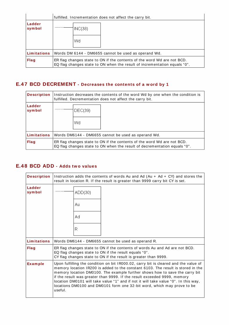
fulfilled. Incrementation does not affect the carry bit.
Ladder symbol
Limitations Words DM 6144 - DM6655 cannot be used as operand Wd.
Flag ER flag changes state to ON if the contents of the word Wd are not BCD.EQ flag changes state to ON when the result of incrementation equals “0”.
E.47 BCD DECREMENT - Decreases the contents of a word by 1
Description Instruction decreases the contents of the word Wd by one when the condition isfulfilled. Decrementation does not affect the carry bit.
Ladder symbol
Limitations Words DM6144 - DM6655 cannot be used as operand Wd.
Flag ER flag changes state to ON if the contents of the word Wd are not BCD.EQ flag changes state to ON when the result of decrementation equals “0”.
E.48 BCD ADD - Adds two values
Description Instruction adds the contents of words Au and Ad (Au + Ad + CY) and stores theresult in location R. If the result is greater than 9999 carry bit CY is set.
Ladder symbol
Limitations Words DM6144 - DM6655 cannot be used as operand R.
Flag ER flag changes state to ON if the contents of words Au and Ad are not BCD.EQ flag changes state to ON if the result equals “0”.CY flag changes state to ON if the result is greater than 9999.
Example Upon fulfilling the condition on bit IR000.02, carry bit is cleared and the value ofmemory location IR200 is added to the constant 6103. The result is stored in thememory location DM0100. The example further shows how to save the carry bitif the result was greater than 9999. If the result exceeded 9999, memorylocation DM0101 will take value “1” and if not it will take value “0”. In this way,locations DM0100 and DM0101 form one 32-bit word, which may prove to beuseful.

E.49 SUBTRACT - Subtracts two values
Description Instruction subtracts the contents of the word Su and a value of carry bit CY fromthe contents of the word Mi. The result is stored in the memory location R If theresult is negative, carry bit CY is set and a 10’complement of the result is storedinto R. To get the real result, just subtract the value in R from zero.
Ladder symbol
Limitations Words DM 6144 - DM6655 cannot be used as operand R.
Flag ER flag changes state to ON if the contents of words Mi and Su are not BCD.EQ flag changes state to ON if the result equals “0”.CY flag changes state to ON if the result is negative.

Example
Carry bit status should be checked before the subtraction. It is best to clear itwith CLC instruction. The check is more necessary after the subtraction, becausethere is chance of misinterpretation. If the carry bit is set (value is “1”) the resultof subtraction is negative and the result word contains 10’ complement of the realresult. When the condition is fulfilled on bit IR000.02, carry bit is cleared and the valueof memory location DM0100 is subtracted from value of location IR201. Theresult is stored in the location HR10. Upon subtraction, carry bit CY is checked. Ifit is set, condition on SR255.04 (the very carry bit) will be fulfilled, clearing itanew and commencing the new subtraction in order to get the real result of thefirst subtraction. The second subtraction instruction subtracts the value of theresult word HR10 from zero, storing the result into HR10 again. It is useful to set a certain bit for a programmer to have information on negativeresult. In the following example this bit is HR1100. Changing the state of carry bitto OFF doesn’t change the state of bit HR1100.

Character “@” ahead of SUB(31) represents the differencial form of theinstruction, or simply put, this instruction will not execute non-stop while thecondition is fulfilled. Only changing the condition from OFF to ON executes theinstruction. This means that the second subtraction instruction won’t take placeimmediately after the first one. Before executing the second instruction, it isnecessary that bit IR000.02 changed state from OFF to ON at least once.
E.50 BCD MULTIPLY - Multiplies two values
Description Instruction multiplies values of locations Md and Mr and stores the result intomemory locations R and R+1.
Ladder symbol
Limitations Words DM6144 - DM6655 cannot be used as operand R.
Flag ER flag changes state to ON if the contents of words Mr and Md are not BCD.EQ flag changes state to ON if the result equals “0”.CY flag changes state to ON if the there is a carry in the result.
Example
Upon fulfilling the condition on bit IR000.00, instruction multiplies the values ofmemory locations IR013 and DM0005. The result is stored into two sequentialmemory locations HR07 and HR08. The result is stored so that HR08 containshigher bits and that HR07 contains lower bits.

E.51 BCD DIVIDE - Divides two values
Description Instruction divides the contents of location Dd with contents of location Dr. Theresult of division is stored in locations R and R+1. The first contains the roundedoff result of division, while R+1 contains the fraction.
Ladder symbol
Limitations Words DM6144 - DM6655 cannot be used as operand R.
Flag ER flag changes state to ON if the contents of words Dd and Dr are not BCD.EQ flag changes state to ON if the result equals “0”.
Example
Upon fulfilling the condition on bit IR000.00, instruction divides the value ofmemory location IR216 by the value of memory location HR09. The result isstored into two sequential memory locations DM0017 and DDM0018. The resultis stored so that DM0017 contains round number and DM0018 contains thefraction.
E.52 DOUBLE BCD ADD - Adds two 32-bit words
Description Instruction adds values from addresses Au and Au+1 to values from addressesAd, Ad+1 and carry bit CY. If the result exceeds 99999999 carry bit CY is set.

Ladder symbol
Limitations Word DM6144 - DM6655 cannot be used as operand R.
Flag ER flag changes state to ON if the contents of words Au and Ad are not BCD.EQ flag changes state to ON if the result equals “0”.CY flag changes state to ON if there is a carry in the result.
E.53 DOUBLE BCD SUBTRACT - Subtracts two 32-bit words
Description Instruction subtracts the contents of two words Su+1 and Su with carry bit CYadded from the contents of words Mi+1 and Mi. The result is stored into memorylocations R+1 and R. If the result is negative, carry bit CY is set and10’complement of the result is stored into R. To get the real result, contents of Rshould be subtracted from zero.
Ladder symbol
Limitations Words DM6144 - DM6655 cannot be used as operand R.
Flag ER flag changes state to ON if the contents of words Mi, Mi+1, Su, Su+1 are notBCD.EQ flag changes state to ON if the result equals “0”.
CY flag changes state to ON if the result is negative.
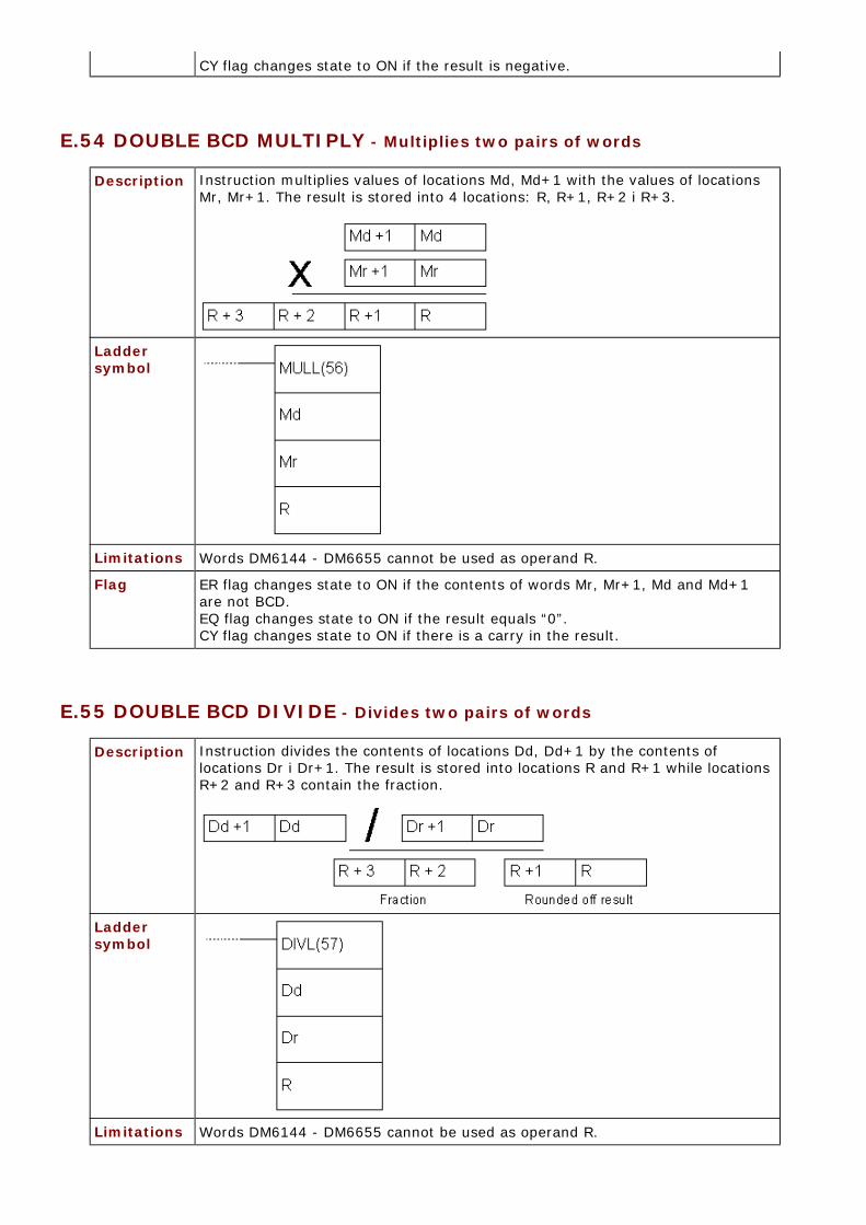
E.54 DOUBLE BCD MULTIPLY - Multiplies two pairs of words
Description Instruction multiplies values of locations Md, Md+1 with the values of locationsMr, Mr+1. The result is stored into 4 locations: R, R+1, R+2 i R+3.
Ladder symbol
Limitations Words DM6144 - DM6655 cannot be used as operand R.
Flag ER flag changes state to ON if the contents of words Mr, Mr+1, Md and Md+1are not BCD.EQ flag changes state to ON if the result equals “0”.CY flag changes state to ON if there is a carry in the result.
E.55 DOUBLE BCD DIVIDE - Divides two pairs of words
Description Instruction divides the contents of locations Dd, Dd+1 by the contents oflocations Dr i Dr+1. The result is stored into locations R and R+1 while locationsR+2 and R+3 contain the fraction.
Ladder symbol
Limitations Words DM6144 - DM6655 cannot be used as operand R.
Flag ER flag changes state to ON in two cases, if the contents of words Dd, Dd+1, Drand Dr+1 are not BCD or if the contents of locations Dr and Dr+1 equal zero. EQ flag changes state to ON if the result equals “0”.
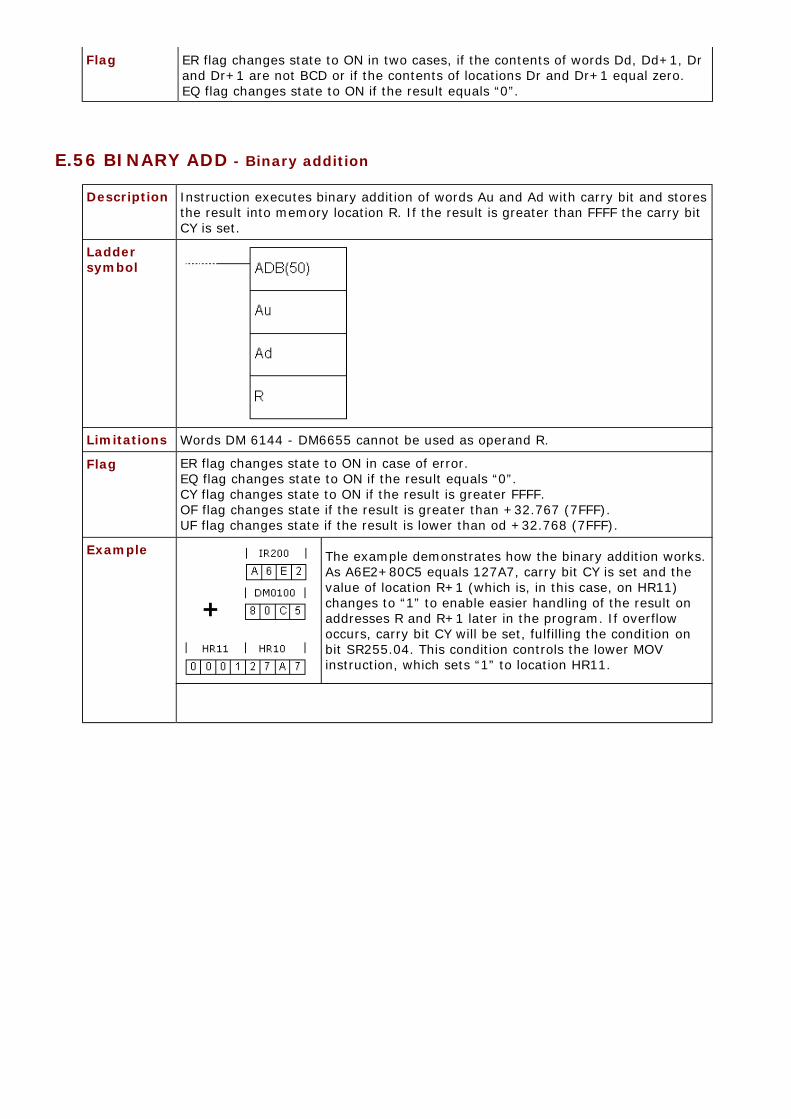
E.56 BINARY ADD - Binary addition
Description Instruction executes binary addition of words Au and Ad with carry bit and storesthe result into memory location R. If the result is greater than FFFF the carry bitCY is set.
Ladder symbol
Limitations Words DM 6144 - DM6655 cannot be used as operand R.
Flag ER flag changes state to ON in case of error.EQ flag changes state to ON if the result equals “0”.CY flag changes state to ON if the result is greater FFFF.OF flag changes state if the result is greater than +32.767 (7FFF).UF flag changes state if the result is lower than od +32.768 (7FFF).
Example The example demonstrates how the binary addition works.As A6E2+80C5 equals 127A7, carry bit CY is set and thevalue of location R+1 (which is, in this case, on HR11)changes to “1” to enable easier handling of the result onaddresses R and R+1 later in the program. If overflowoccurs, carry bit CY will be set, fulfilling the condition onbit SR255.04. This condition controls the lower MOVinstruction, which sets “1” to location HR11.

E.57 BINARY SUBTRACT - Binary subtraction
Description Instruction subtracts values Su+CY from the value Mi and stores the result intolocation R. If the result is negative, carry bit CY is set and the 2’complement ofthe real result is stored into location R.
Ladder symbol
Limitations Words DM6144 - DM6655 cannot be used as operand R.
Flag ER flag changes state to ON in case of error.EQ flag changes state to ON if the result equals “0”.CY flag changes state to ON if the result is negative.OF flag changes state if the result is greater than +32.767 (7FFF)UF flag changes state if the result is lower than +32.768 (7FFF).

ExampleThe example subtracts the value of location LR00increased by the state of carry bit CY from the value oflocation IR200. As the result is positive, carry bit CY willnot be set. In case of negative result, location HR01would contain 2’complement of the result, so that aconversion would be necessary for getting the realresult.
E.58 BINARY MULTIPLY - Binary multiplication
Description Instruction multiplies values of location Md by the value of location Mr. Theresult is stored in two memory locations R and R+1.
Ladder symbol
Limitations Words DM6144 - DM6655 cannot be used as operand R.
Flag ER flag changes state u ON in case of error.EQ flag changes state u ON if the result equals “0”.
E.59 BINARY DIVIDE - Binary division

Description Instruction divides the value of location Dd with the value of location Dr. Theresult is stored into location R, while the fraction is stored in R+1.
Ladder symbol
Limitations Words DM6144 - DM6655 cannot be used as operand R and the instructioncannot be used for dividing signed numbers.
Flag ER flag changes state to ON in case that Dr contains value “0”.EQ flag changes state to ON if the result equals “0”.
E.60 BCD TO BINARY - Converts decimal number to a binary number
Description Instruction converts binary representation of decimal number from the word Sto binary number in the word R. Contents of the word S remains unchanged.
Ladder symbol
Limitations Words DM6144 - DM6655 cannot be used as operand R.
Flag ER flag changes state to ON if the contents of the word S are not BCD.EQ flag changes state to ON if the result equals “0”.

Example
Upon fulfilling the condition on bit IR000.00, instruction changes the contents ofmemory location IR200 so that its numerical value remains unchanged; in otherwords, only the representation of the location’s contents changes. If thecontents of the location IR200 is “164” decimal, this instruction would convert itto “0000000010100100”. One of the purposes of this instruction is preparing thecontents of memory location for one of the binary operations.
E.61 BINARY TO BCD - Converts binary number to a decimal number
Description Instruction converts binary represented number from the word S to a decimalnumber in the word R. Contents of the word S remains unchanged.
Ladder symbol
Limitations Word DM6144 - DM6655 cannot be used as operand R.
Flag ER flag changes state to ON in case of error.EQ flag changes state to ON if the result equals “0”.

Example
Upon fulfilling the condition on bit IR000.00, instruction changes the contents ofmemory location IR200 so that its numerical value remains unchanged; in otherwords, only the representation of the location’s contents changes. If thecontents of location IR200 is “000000101100100” binarny, this instruction wouldconvert it to “740” decimaly. One of the purposes of this instruction is preparingthe contents of memory location for one of BCD operations.
E.62 4 TO 16 DECODER - 4 to 16 decoder
Description Instruction converts up to four 4-bit hexadecimal digits of values from 0 to 15.The result of the instruction is stored into memory locations from address R toR+3, depending on how many digits was converted. Converted digit in the resultis represented with a set bit on a position corresponding to the value of a digit.If the value of a digit is “C” (12 decimaly) the twelfth bit of the result word willbe set.
The first digit to be converted, as well as the number of digits to be converted,is determined in the control word Di. If the number of digits for conversion isgreater than the number of digits remaining in the word S, then the missingdigits are taken from the starting digit anew. The structure of the control wordDi is shown on the picture below.
Some of the combinations of control word values along with their meaning are

given below:
Ladder symbol
Limitations Two rightmost digits of the word Di have to be between 0 and 3. Words DM6144- DM6655 cannot be used as operand R.
Flag ER flag changes state to ON in case that (R + number of digits) exceeds therange of a given memory block.

Example
Upon fulfilling the condition on bit IR000.00, instruction converts three digitsfrom the digit no.1 in the word DM0020. As there are three digits to beconverted, the result will take three memory locations starting from HR10. Digit0 in the word DM0020 is not converted.
E.63 16 TO 4 ENCODER - 16 to 4 encoder
Description Instruction determines the highest set bit in SB and according to it, stores the4-bit hexadecimal value to a certain place in the result word R.In the example below, bit 12 of the location on address SB is set, which wouldbe “C” in a hexadecimal representation.
Precise place for storing the converted value in the word R is determined by acontrol word Di. The same word also determines the number of words to beconverted, starting from the address of the word SB. For this example, thecontrol word would be “0001”.

The first digit to be converted, as well as the number of digits to be converted, isdetermined in the control word Di. If the number of digits for conversion isgreater than the number of digits remaining in the word S, then the missingdigits are taken from the starting digit anew. The structure of the control wordDi is shown on the picture above.
Some of the combinations of control word values along with their meaning aregiven below:
Ladder symbol
Limitations Two rightmost digits of the word Di have to be between 0 and 3. Words DM6144- DM6655 cannot be used as operands R, SB and Di.
Flag ER flag changes state to ON if (SB + number of digits) exceeds the range of agiven memory block or if the word to be converted equals zero.

Example
Upon fulfilling the condition on bit IR000.00, first DMPX instruction converts twowords, IR200 and IR201. The control word is “0010”, meaning that two wordsare converted (digit 1) and stored starting from the zero digit in the result(rightmost digit 0). After the first DMPX instruction, the second one is executed,converting two words from addresses LR10 and LR11 and storing them in theresult word HR10, starting from the digit no.2. Therefore, the word HR10contains four converted words in the following order: IR200, IR201, LR10, LR11.More detailed explanation of how the instruction works is given on the followingpicture.

Presuming that binary value is the one from locations IR200, IR201, LR10 andLR11, as in example, the result of conversion in the result word HR10 would be“5B7D”.
E.64 ASCII CONVERT - Converts to ASCII code
Description Instruction converts digits from the word S to their ASCII equivalent and storesthe result in the words starting from the address D. The control word Didetermines the first converted digit, the number of digits to be converted andwhich half of the word D contains the first 8-bit ASCII converted code. IIf thenumber of digits for conversion is greater than the number of digits remaining inthe word S, then the missing digits are taken from the starting digit anew fromthe word S. Digit with the highest position of the word Di has a role of parity bitand it can take values between 0 and 2 - not having parity, parity andnon-parity. Parity bit is actually a highest bit of the 8-bit ASCII code. When thethird digit of the word Di equals zero, this bit is always zero. If the third digit ofthe word Di equals one, then this bit represents parity, or simply put, this bit isset when the number of ones in the other 7 bits of ASCII is odd making thenumber of ones even. If the ASCII value equals “31” (binary “0011 0001”), evenparity would change the highest bit to one, changing the ASCII number to “10110001” or “B1”. The status of parity bit does not affect the interpretation of ASCIIcode. Odd parity bit behaves in similar fashion, but with the opposite function.It’s purpose is to ensure that the number of ones in ASCII code is always odd.The following picture represents interpreting the value of word Di and thepicture after that gives several versions of values of the word Di and how theyaffect the instruction.

Ladder symbol
Limitations Two lower digits of the words Di must have values betweenmoraju imati 0 and3. Words DM6144 - DM6655 cannot be used as operand D.
Flag ER flag changes state to ON if two rightmost digits of the word Di do not fallwithin the specified range (0-3) or the result word exceeds the boundaries ofmemory area.
E.65 COMPLEMENT - Complements a word
Description Instruction executes the second complement of the word Wd and stores it intoword Wd again. The second complement means that ones become zeros andvice versa.
Ladder symbol
Limitations Words DM6144 - DM6655 cannot be used as operand Wd.

Flag ER flag changes state to ON in case of error.EQ flag changes state to ON if the result equals zero.
E.66 LOGICAL AND - Operation logical "AND" on the contents of a word
Description Instruction executes the operation logical “AND” on words I1 and I2. The resultof the operation is stored into word R. Operation logical “AND” puts one in theresult only if the same position of words I1 and I2 also contain one.
Ladder symbol
Limitations Words DM 6144 - DM6655 cannot be used as operand R.
Flag ER flag changes state to ON in case of error.EQ flag changes state to ON if the result equals zero.
E.67 LOGICAL OR - Operation logical "OR" on the contents of a word
Description Instruction executes the operation logical “OR” on words I1 and I2. The result ofthe operation is stored into the word R. Operation logical “OR” puts the one inthe result if at least one of the words I1 and I2 contains one on that position.
Ladder symbol
Limitations Words DM6144 - DM6655 cannot be used as operand R.
Flag ER flag changes state to ON in case of error.EQ flag changes state to ON if the result equals zero.
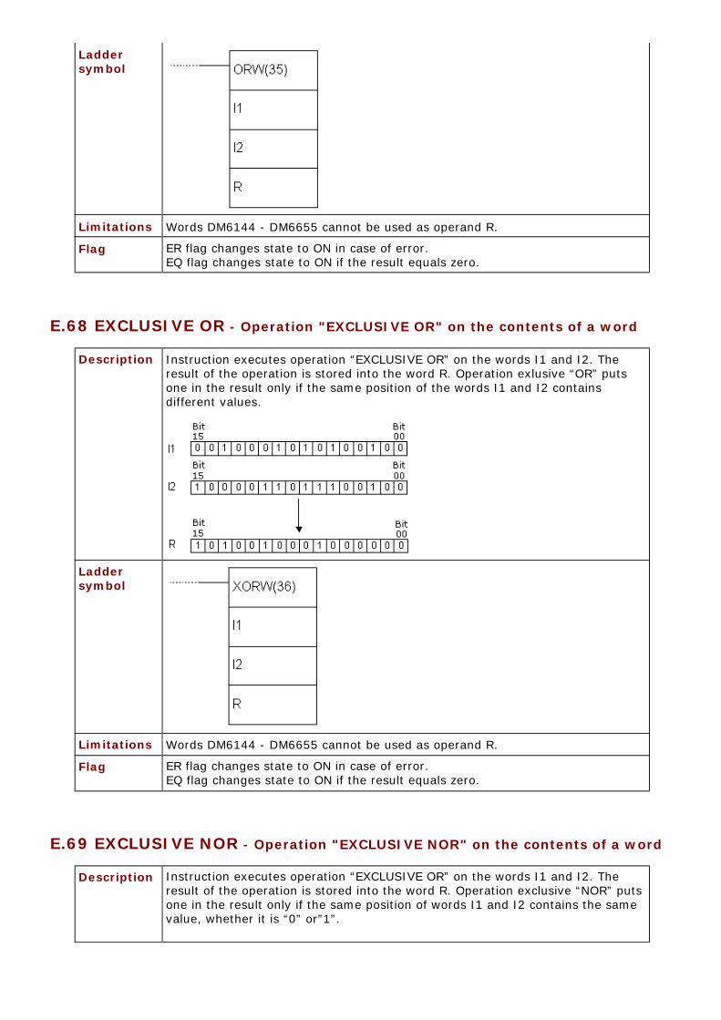
E.68 EXCLUSIVE OR - Operation "EXCLUSIVE OR" on the contents of a word
Description Instruction executes operation “EXCLUSIVE OR” on the words I1 and I2. Theresult of the operation is stored into the word R. Operation exlusive “OR” putsone in the result only if the same position of the words I1 and I2 containsdifferent values.
Ladder symbol
Limitations Words DM6144 - DM6655 cannot be used as operand R.
Flag ER flag changes state to ON in case of error.EQ flag changes state to ON if the result equals zero.
E.69 EXCLUSIVE NOR - Operation "EXCLUSIVE NOR" on the contents of a word
Description Instruction executes operation “EXCLUSIVE OR” on the words I1 and I2. Theresult of the operation is stored into the word R. Operation exclusive “NOR” putsone in the result only if the same position of words I1 and I2 contains the samevalue, whether it is “0” or”1”.

Ladder symbol
Limitations Words DM6144 - DM6655 cannot be used as operand R.
Flag ER flag changes state to ON in case of error.EQ flag changes state to ON if the result equals zero.
E.70 BIT COUNTER - Counts the number of ones in a given word
Description Instruction counts the number of bits with the state “1” in words from addressSB to SB+(N-1) and puts the result on the address of the word R.
Ladder symbol
Limitations Words DM6144 - DM6655 cannot be used as operand R. Word N cannot havezero value.
Flag ER flag changes state to ON in case that N isn’t BCD number or in case that SBand SB+(N-1) don’t belong to the same memory area.EQ flag changes state to ON if the result equals zero.

E.71 SUBROUTINE ENTRY - Enters the subroutine
Description Instruction changes the course of the main program towards subroutine, at theinstruction line of the main program which contains the instruction SBS. Numberof instructions N has to be in 000 - 049 range. When the instruction condition isfulfilled, all the instructions between SBN(92) and the first RET(92) instructionare executed. Upon processing the RET instruction, program returns to the lineimmediately following the instruction SBS which called the subroutine in the firstplace. The same subroutine may be called from several places in the program.
Ladder symbol
Limitations Number of subroutine has to be in 000 - 049 range.
Flag ER flag changes state to ON when non-existing subroutine is called, when thesubroutine calls itself or when the subroutine being executed at the moment iscalled.
E.72 SUBROUTINE DEFINE - Beginning of a subroutine
Description Instruction marks the beginning of a subroutine. Each subroutine is defined withits number N. All subroutines have to be placed after the main program andinstruction END has to follow the last RET instruction of the last subroutine SBN.

Ladder symbol
Limitations Number of the subroutine has to be in 000 - 049 range. Each number may beused only once.
Flag It has no effect on any particular flag.
E.73 SUBROUTINE RETURN - Return from a subroutine
Description Instruction executes the return from the subroutine to the main program. Eachsubroutine must contain the RET instruction. This instruction jas on number ofits own, naturally assuming that it belongs to the previous SBN instruction.
Ladder symbol
Limitations Number of the subroutine has to be in 000 - 049 range. Each number may beused only once.
Flag It has no effect on any particular flag.
E.74 MACRO - Macro
Description Instruction MCRO enables one subroutine to substitiute several subroutineshaving the same structure, but different operands. Instruction has 4 input wordsSR232 to SR235 and 4 output words SR236 to SR239 used for sending orreceiving the subroutine parameters. Upon fulfilling the condition, the instructioncopies the contents of locations I1 - I3 to words SR232 - SR235. Upon executionof subroutine N, values of the words SR236 - SR239 are copied to words O1 -O3.

Ladder symbol
Limitations Number of the subroutine has to be in 000 - 049 range. Each number may beused only once.
Flag ER flag changes state to ON when non-existing subroutine is called, when thesubroutine calls itself or when the subroutine, being executed at the moment, is called.
Example
Instruction MCRO calls the subroutine with the number 010. Contents of wordsDM0010 - DM0013 is copied to SR232 - SR235 and upon execution of theinstruction, contents of words SR236 - SR239 is copied to the words DM0020 -DM0023.
E.75 INTERRUPT CONTROL - Interrupt control
Description Instruction controls the interrupts and executes one of the seven functions presentedin the table below, according to the value of the word C1.
C1 Function000 Mask/unmask interrupts001 Clear the interrupt input002 Read the current mask for interrupt inputs003 Reset decrement counter and unmask interrupts004 Reset increment counter and unmask interrupts100 Mask all interrupts200 Unmask all interrupts
NOTE: Value of the word C1 004 refers to models CPM2A/CPM2C of PLC controller, so it will not bedetailed here.
C1=000

Function is used for masking and unmasking the interrupt inputs 00003 - 00006.Masked interrupts are registered, but the part of the program assigned to them willnot be executed until the mask is off. Upon unmasking interrupt input, interruptroutine will immediately take place (unless, in the meantime the bit corresponding tothat interrupt input is reset with the instruction INT, parameter C1=001). The inputbeing masked or unmasked is determined by parameter C2 according to the followingscheme (bear in mind that we work with bits and not with digits of the word C2). Bits4, 5, 6...15 should be set to zero. All interrupt inputs are masked upon starting thePLC controller.
C1=001Function resets the registered interrupts, so that interrupt routine cannot take placeupon unmasking the interrupt input. Bits 4, 5, 6...15 of the word C2 should be set tozero.
C1=002Function reads the status of the mask for interrupt inputs 00003 - 00006 and storesthe read state into the word C2. Interrupt input is masked if the state of thecorresponding bit equals “1”. Bits 00 - 03 correspond to interrupt inputs 00003 -00006.
C1=003Function restarts the interrupt inputs in the counter mode. The current counter value(SR240 - SR243) is set to the starting state and the interrupt is unmasked. IfC1=003, decremental counter is restarted, while in the case of C1=004 incrementalcounter is restarted. As CPM1A model of PLC does not feature incremental counter,this option should not be used. When using the options C1=003 or C1=004differencial form of the instruction shoud be used @INT or else the current counterstate (PV) will be reset to the starting state (SV) and the interrupt will never begenerated. Writing the value “0000” to the starting counter state and executing theINT instruction with parameter C1=003 stops the counter and disables interrupts.
To start the counter again, non-zero value should be written to a starting value SVand the instruction INT executed. Interrupts in the counter mode can be masked byexecuting the instruction INT with parameter C1=000 and set corresponding bit in C2.If same is done, but with “0” for the appropriate position in the word C2 interruptinput will behave as a regular interrupt ulaz and not as counter interrupt input.

C1=100Function masks all the interrupts including the interval timer interrupts and thehigh-speed counter interrupts. Masked interrupts are registered, but are not executed.This function is also called a global interrupt mask and it does not affect the masks ofspecific interrupts. This option should be used for temporary disabling all theinterrupts. It is cmmonly used in pair, one function masks all the interrupts and theother one unmasks them. Function cannot be used within the interrupt routine.
C1=200Function unmasks all the interrupts including the interval timer interrupts and thehigh-speed counter interrupts. If the specific interrupt is masked, global unmaskingdoes not affect the state of the specific interrupt input state. Function cannot be usedwithin the interrupt routine.
Ladder symbol
Flag ER flag changes state to ON if:C1 is not 000, 001, 002, 003, 004, 100 or 200. C2 is not in 0000 - 000F range.INT instruction is executed with C1=100 or 200 within the interrupt routine.

INT instruction is executed with C1=100 when all inputs are already masked. INT instruction is executed with C1=200 when all inputs are already unmasked.
E.76 INTERVAL TIMER - Interval timer
Description Instruction is used for controling the timer interrupt. Instruction mode isdetermined according to the value of the word C1.
C1 Function000 Start the interrupt timer with only one timer003 Start the timer with periodical interrupts006 Read the current timer value010 Stop the timer
C1=001 or 003C2 can be either a constant or an address of a word in PLC controller memory.
C2=constantIf C2 is a constant, then it represents the starting value of decremental counterin BCD format (form 0000 to 9999 which is equivalent to 0 - 9.999 ms) and C3represents the number of the interrupt routine (from 000 to 049).
C2=address of a word in memoryIf C2 is a word in PLC controller memory, then its contents is a starting value ofdecremental counter in BCD format. Cotents of the word C2+1 represents themeasurement unit (BCD, 0005 - 0320) in 0.1s decrements. Interval is, in thatcase, 0.5 - 32ms. Starting value of the timer is calculated as C2 * (C2+1) *0.1s. C3 represents the number of the interrupt routine.
C1=006Function reads the current timer state. Parameter C2 represents the memoryaddress where the read timer state is stored, while C2+1 stores themeasurement unit. Parameter C3 reresents the memory address where the dataconcerning the time passed since the last decrementation of timer in BCD formatis stored in 0.1s units.
C1=010Function stops the timer. Parameters C2 and C3 are without function and shouldbe set to “0000”.
Ladder symbol
Flag ER flag changes state to ON if C1 is not 000, 003, 006 or 010 or in case that thenumber of interrupt routine is not within 0000 - 0049 range.
E.77 7-SEGMENT DECODER - Seven-segment decoder

Description Instruction translates the digits of the word S to 8-bit 7-segment code andstores it into destination word D. The control word Di determines the first digitof S to be translated, number of digits to be translated and which half of theword D will contain the result of the first translation. The following pictureinterprets the values of digits of the word Di and the picture after that displays afew versions of the word Di and how they affect the instruction.
Ladder symbol
Limitations Words DM6144 - DM6655 cannot be used as operand D.
Flag ER flag changes state to ON in case of error.

Example
E.78 I/O REFRESH - Premature writing to I/O table
Description Instruction checks the states of words from the address St to the address E andrefreshes them according to the current state of the program. Instruction isused when we want to know the state of certain bit without waiting it to berefreshed in the course of regular cycle of refreshing the inputs and outputs ofPLC controller (IR000 - IR019).
Ladder symbol
Limitations Address of the word St has to be lower or equal to the address of the word E.

Flag ER flag changes state to ON if words St and E do not belong to IR000 - IR019range or in case that the address of the word St is greater than the address ofthe word E.
E.79 MESSAGE - Displays message in the programming console
Description Instruction reads the contents of eight words from the address FM and displaysthem in the program console. Contents of the word has to be in ASCII format,with every word containing 2 ASCII characters. If not all the words are to bedisplayed in the console, displaying can be stopped if the string “OD” is put intofollowing word.
Ladder symbol
Limitations Words DM6144 - DM6655 cannot be used as operand FM.
Flag ER flag changes state to ON in case of error.
E.80 MODE CONTROL - Controls the high-speed counter or the pulse output
Description Instruction controls the high-speed counter. There are several functionsdepending on parameters P, C and P1. Parameter P defines if either high-speedcounter or pulse output will be controlled with this instruction.
P Function
000 Designates the input of PLC controller that will be used ashigh-speed counter (000.00, 000.01 and 000.02). Determinesmono-phase signal of logical zero with noacceleration/deceleration (outputs 010.00 and 010.01)
Determines mono-phase signal of logical zero with trapezoidacceleration/deceleration (output 010.00)
010* Determines mono-phase signal "1" with noacceleration/deceleration (output 010.01)
100* Designates interrupt input 0 in counter mode (input 000.03)
101* Designates interrupt input 1 in counter mode (input 000.04)
102* Designates interrupt input 2 in counter mode (input 000.05)
103* Designates interrupt input 3 in counter mode (input 000.06)
NOTE: * refers to CPM2A/CPM2C PLC controller models.
C P1 Function
000 000 Starts comparing the current value withthe values from comparison table (CTBL)
001 000 Stops comparing the current value withthe values from comparison table (CTBL)

002 New value of the current state (PV)
Changes the current value PV ofhigh-speed counter or interrupt input in counter mode
003 000 Stops the pulse output
005* New value of the current state (PV) Changes the current state of pulse output
006* 000 Stops the synchronized pulse output
NOTE: * refers to CPM2A/CPM2C PLC controller models.
C=000 or C=001Function starts or stops comparing the current value of high-speed counter PVwith the values from the comparison table created with instruction CTBL. If thecomparison table wasn’t created ahead of executing the INI instruction, theerror occurs. Generally, when INI instruction with C=000 is used, differentialform @INI is recommended, because one set of starting comparisons issufficient.
C=002 Function changes value of the current state of the high-speed counter or theinterrupt in the counter mode.
Fast counter PV ( P=0 )Function changes the contents of PV to 8-digit BCD number contained in thewords P1 and P1+1. If differential-phase mode or ”up/down “ input mode isused, PV can have value between F838 8608 and 0838 8607, where “F” as thefirst digit is treated as a minus sign. PV can have value between 000 0000 and1677 7215 in incremental mode.
Interrupt counter input PV ( P=100, P=101, P=102, P=103)Function changes the contents of PV to 4-digit hexadecimal number from theword P1 (from 0000 to FFFF).
C=003Function stops the pulse output.
C=004Function changes the value of the current PV pulse output state to an 8-digitBCD value in the words P1 and P1+1. Change cannot be done while the pulseoutput is in function. New value can be from -16.777.215 to +16.777.215. Bitno.15 of the word P1+1 behaves like a sign: “0” stands for positive, “1” standsfor negative number.
C=003Function stops the synchronized pulse output.
Ladder symbol
Limitations If CPM1 or CPM1A PLC controller is used, parameter P has to be 000 andparameter C has to be 000, 001, 002 or 003. P1 has to be 000 if C is not 002 or004. If an address from DM memory area is used as parameter P1, reading andwriting to that location has to be enabled.
Flag ER flag changes state to ON if comparison table exceeds one memory area.

E.81 HIGH-SPEED COUNTER PV READ - Reads the current value of high-speed counter
Description Instruction controls the current state of high-speed counter, pulse output,interrupt input in counter mode or input frequency for synchronized input. Thereare several functions depending on parameters P, C and D.
Parameter P defines if either high-speed counter or pulse output will becontrolled with this instruction.
P Function
000 Designates the input of PLC controller that will be used ashigh-speed counter (inputs 000.00, 000.01 and 000.02).Designates input frequency for synchronized pulse input(inputs 000.00, 000.01 and 000.02). Determines mono-phasesignal of logical zero with no acceleration/deceleration(outputs 010.00 and 010.01)
Determines mono-phase signal of logical zero with trapezoidacceleration/deceleration (output 010.00)
010* Determines mono-phase signal "1" with noacceleration/deceleration (output 010.01)
100* Designates interrupt input 0 in counter mode (input 000.03)
101* Designates interrupt input 1 in counter mode (input 000.04)
102* Designates interrupt input 2 in counter mode (input 000.05)
103* Designates interrupt input 3 in counter mode (input 000.06)
NOTE: * refers to CPM2A/CPM2C PLC controller models.
Control word determines the type of data to be accessed.
C Destination word
Function
000 D and D+1Reads the current state of high-speed counter,of interrupt input in counter mode or inputfrequency of synchronized pulse control
001 D Reads the status of high-speed counter or pulseoutput
002 D Reads the results of comparing with values fromcomparison table
003 D and D+1 Reads the current value of pulse output
NOTE: * refers to CPM2A/CPM2C PLC controller models.
C=000Function reads the current value of PV of the specified high-speed counter or theinterrupt input in counter mode.
Fast counter PV or input frequency (P=000) When the output is used as the high-speed counter, instruction reads thecurrent value of the specified fast counter and writes an 8-digit BCD value to Dand D+1.If differential-phase mode or ”up/down “ input mode is used, PV can have value

between F838 8608 and 0838 8607, where “F” as the first digit is treated as aminus sign. PV can have value between 000 0000 and 1677 7215 in incrementalmode. When the input is used as synchronic pulse input, the instruction readsthe input frequency and writes an 8-digit BCD value to D and D+1. Range of theinput frequency is 0000 0000 - 0002 0000.
Interrupt counter input PV ( P=100, P=101, P=102, P=103)Function changes the contents of PV to 4-digit hexadecimal number from theword D (from 0000 to FFFF).
C=001Function reads the status of the high-speed counter or the pulse input andstores the data into D.
Status of the high-speed counter or the pulse input 0 (P=000) The table below shows the function of bits in the word D when P=000. Bits notmentioned are not used and are always zero.
For... Bit Function
High-speed counter00
Status of comparing high-speedcounter with values from comparisontable (0: not compared, 1:compared)
01High-speed counter below/above thespecified value (0: in range, 1:out ofrange)
Pulse output05
Total number of pulses defined forpulse output 0 (0: number of pulses notdefined, 1:number of pulses defined)
06 Defined number of pulses on output 0executed (0: not executed, 1:executed)
07 Pulse output 0 state (0: stopped, 1:executing)
08 Current state PV of pulse output (0: inrange, 1:out of range)
09 Rate on pulse output 0 (0: constant, 1:accelerates/decelerates)
Status of the pulse output 1 (P=010) The table below shows the function of bits in the word D when P=010. Bits notmentioned are not used and are always zero.
Bit Function
05 Total number of pulses defined for pulse output 1 (0: number of pulses not defined, 1:number of pulses defined)
06 Defined number of pulses on output 1 executed (0: notexecuted, 1:executed)
07 Pulse output 1 state (0: stopped, 1:executing)
08 Current state PV of pulse output (0: in range, 1:out of range)
09 Rate on pulse output 1 (0: constant, 1:accelerates/decelerates)
C=002Function reads the result of comparing the current value PV with 8 areas definedby instruction CTBL and stores data into D. Bits 0 to 7 contain the results ofcomparing with 8 ranges from the comparison table (0: not in range, 1: inrange).
C=003

Function reads the value of current state of PV pulse output and stores it to8-digit BCD value in words D and D+1. PV can have value from -16.777.215 to+16.777.215. Bit no.15 of the word D+1 behaves like a sign: “0” stands forpositive, “1” stands for negative number.
Ladder symbol
Limitations If CPM1 or CPM1A PLC controller is used, parameter D has to be 000 andparameter C has to be 000, 001 or 002. If an address from DM memory area isused as parameter D, reading and writing to that location has to be enabled. D and D+1 have to belong to the same memory area.
Flag ER flag changes state to ON if an error concerning the value of instructionoperand occurred.
E.82 COMPARISON TABLE LOAD - Defines a comparison table
Description Instruction forms the comparison table for working with high-speed counter.Depending on parameter C, comparison can be immediate or it can be calledupon with instruction INI.
C Function
000 Registers comparison table containing values and startscomparing
001 Registers comparison table containing ranges and startscomparing
002 Registers comparison table containing values. Comparingstarts with INI instruction
003 Registers comparison table containing ranges. Comparingstarts with INI instruction
When the current value of PV matches some of the specified table values or itbelongs to one of the specified ranges, the appropriate subroutine is called. Ifthe high-speed counter is not enabled in PC area (DM6642) instruction CTBLcannot be executed.
Comparing with valuesComparison table can have up to 16 values. Each of these values is assigned anumber of subroutine that is called when the current value matches the tablevalue. With CPM1 and CPM1A models, comparison is done one at a time in eachcycle, while with models CPM2A and CPM2C comparison is done for all tablevalues simultaneously. After comparing with the last table value, comparisonstarts from the first value again. The table below shows the structure of thecomparison table containing values. Each value is assigned three words in the table. If the value “FFFF” is used asthe number of subroutine, no subroutine will be executed in case of a match.

TB Number of values that current value is compared with (0001 to0016, BCD)
TB+1 Value no.1 (lower four digits in BCD format)
TB+2 Value no.1 (higher four digits in BCD format)
TB+3 Number of subroutine for matching the first value
...
Comparing with a range of valuesComparison table with ranges contains 8 ranges, which the current value PV iscompared with. Ranges can overlap, allowing that the current value PV falls intoseveral of these; in this case, the subroutine of the first matching area is called.If the value “FFFF” is used as the number of subroutine, no subroutine will beexecuted in case of a match.
TB Lower value no.1 (lower four digits in BCD format)
TB+1 Lower value no.1 (higher four digits in BCD format)
TB+2 Higher value no.1 (lower four digits in BCD format)
TB+3 Higher value no.1 (higher four digits in BCD format)
TB+4 Number of subroutine in case that the current value PV iswithin range no.1
... TB+35 Lower value no.8 (lower four digits in BCD format)
TB+36 Lower value no.8 (higher four digits in BCD format)
TB+37 Higher value no.8 (lower four digits in BCD format)
TB+38 Higher value no.8 (higher four digits in BCD format)
TB+39 Number of subroutine in case that the current value PV iswithin range no.8
Ladder symbol
Limitations In each area lower border has to be lower than the upper border. Number ofsubroutine can be used for several ranges.Table has to belong to a single memory area. Parameter D has to be 000 andthe parameter C has to be 000, 001, 002 or 003.
Flag ER flag changes state to ON if an error concerning the value of instructionoperand occurred.
E.83 FAILURE ALARM AND RESET - Generates error code
Description Instruction generates the code of an error that took place, so that theprogrammer can use that information for debugging or program maintenance.Error code is stored in the first 8 bits of the word SR253 and has value between01 and 99.

In case of multiple errors, only one code will be displayed. To display the othercodes, it is necessary to reset bits 00-07 of the word SR253 via instruction FALwith parameter N=00. Upon each reset, new error code will be displayed (ifthere is more than one error). Error code remains in PLC controller memoryafter the power is off. When error occurs, besides the code, programmer will benotified with blinking diode on the casing of PLC controller.
Instruction FAL with parameter N=0 may be used for resetting the messagecreated with the instruction MSG.
Ladder symbol
E.84 SEVERE FAILURE ALARM - Generates fatal error code
Description Instruction generates the code of an error that took place, so that theprogrammer can use that information for debugging or program maintenance.Error code is stored in the first 8 bits of the word SR253 and has value between01 and 99. Upon occurence of fatal error, diode ALARM/ERROR turns on on thecasing of PLC controller and the PLC stops operating.
PLC controller continues the program execution only when cause of error isremoved. Error code remains written and may be read.
Ladder symbol
E.85 SET CARRY - Sets carry bit
Description Instruction changes the state of carry bit CY to ON. Carry bit is an integral partof the word SR255, and its address is SR255.04.
Ladder symbol
E.86 CLEAR CARRY - Resets carry bit
Description Instruction changes state of carry bit CY to OFF. Carry bit is an integral part ofthe word SR255, and its address is SR255.04.
Ladder symbol

© C o p y r i g h t 2 0 0 3. m i k r o E l e k t r o n i k a. All Rights Reserved.